Embed Size (px)
Citation preview
CONCRETE PIPE&
BOX CULVERT
INSTALLATION

American Concrete Pipe Association • www.concrete-pipe.org�
American Concrete Pipe Association • www.concrete-pipe.org �
TableofContents
I. CONCRETE PIPE INSTALLATION MANUAL... 5Introduction................................................... 5
PRE-CONSTRUCTION...................................... 6Precautions................................................... 6Ordering, Receiving And Handling............... 6Unloading...................................................... 7Stockpiling.................................................. 10
INSTALLATION................................................ 12Line And Grade........................................... 12Excavation Limits........................................ 17Excavated Material..................................... 19Dewatering.................................................. 19Standard Installations................................. 20Class A Bedding......................................... 27Class B Bedding......................................... 27Class C Bedding......................................... 28Class D Bedding......................................... 29Jointing....................................................... 38 Rubber.................................................... 38 Mastic......................................................42 Mortar..................................................... 42 Geotextile Filter Fabrics.......................... 43 External Bands....................................... 43
Joint Procedures.........................................44Service Connections................................... 46Curved Alignment....................................... 46Final Backfilling........................................... 50
Acceptance Tests....................................... 50Soil Density................................................. 51Line And Grade........................................... 52Visual Inspection......................................... 52Infiltration.................................................... 53Exfiltration................................................... 56Air Testing................................................... 58Vacuum Testing.......................................... 61
American Concrete Pipe Association • www.concrete-pipe.org�
Joint Testing-Air.......................................... 62Joint Testing-Water..................................... 62
II. BOX CULVERT INSTALLATION MANUAL.... 64Introduction................................................. 64
PRE-INSTALLATION...................................... 65Precautions................................................. 65Ordering, Receiving & Handling................. 65Scheduling / Unloading / Placing /
Sequence..................................... 66Storing........................................................ 67
SITE PREPARATION...................................... 69Excavation.................................................. 69Trenchwater................................................ 70Bedding/grade............................................. 70
INSTALLATION............................................... 73Box Alignment............................................. 73Box Placement............................................ 73Jointing....................................................... 73Connecting the Boxes................................. 75Completion.................................................. 76Backfill........................................................ 76Minimum Cover For Construction Loads.... 77Visual Inspection......................................... 78
III. SPECIFICATIONS ........................................79
IV. APPENDIX...................................................... 87Definitions................................................... 87Feet Head of Water into Pressure, Pounds Per Square Inch...............90Feet Head of Water into Kilopascals (kN/m2)........................90
American Concrete Pipe Association • www.concrete-pipe.org �
I. CONCRETEPIPEINSTALLATIONMANUAL
INTRODUCTION
This manual presents a guide for the proper in-stallation of concrete pipe. For many years, the American Concrete Pipe Association has conduct-ed comprehensive research and analysis of the factors which affect the field performance of con-crete pipe. The knowledge and beneficial practices gained through research and experience are pre-sented in this manual.
While focusing on the construction of the pipe-soil system, this manual also addresses those fac-tors critical to the completion of the entire system, from delivery of the concrete pipe to the jobsite, to the acceptance of the installed pipeline.
This manual is intended as a guide and is not to supersede the project specifications.
American Concrete Pipe Association • www.concrete-pipe.org�
PRE-CONSTRUCTION
PRECAUTIONS
Federal regulations covering safety for all types of construction, including sewer and culvert instal-lations, are published in the Safety and Health Reg-ulations for Construction under the Department of Labor, Occupational Safety and Health Administra-tion (OSHA). These regulations are applicable to all prime contractors and subcontractors involved in any type of construction, including alterations and repair work.
The installer should also review installation prac-tices with the engineer’s design assumptions, par-ticularly in relation to the use of trench boxes and compaction requirements of the backfill.
ORDERING,RECEIVINGANDHANDLING
Although the ordering of materials is the contrac-tor’s responsibility, supplier and engineer familiarity with the contractor’s proposed schedule will en-able better coordination to avoid mistakes and pos-sible delays in pipe deliveries. Pipe manufactur-ers stock a wide range of pipe sizes and strengths, but production facilities must frequently be adapted to meet specific project requirements, particularly when large quantities and/or special types of pipe are involved. Information required to initiate a pipe order should be in writing and include:
name and location of project pipe size, laying length and strengthtotal footage of each type and size of pipe type of jointsize and quantity of manhole base sections, riser sections, cone sections and grade ringslist of fittings and specials including radius pipe
•••••
•
American Concrete Pipe Association • www.concrete-pipe.org �
laying sequencerequired specificationsmaterial test requirementsjoint material and quantityinvoicing instructions
The pipe should be checked for the following in-formation, clearly marked on each pipe section:
specification designationpipe class or strength designationspan, rise, table number, top of box and de-sign earth cover for ASTM C 1433(M) or C 1577(M), or AASHTO M259(M) or M273(M) box sectionsdate of manufacturename or trademark of the manufacturerfor reinforced pipe with elliptical or quadrant reinforcement orientation, the letters E or Q, respectively and “top”.
UNLOADING
Unloading of pipe should be coordinated with the construction schedule and installation sequence to avoid re-handling and unnecessary equipment movement. Access to the jobsite shall be provided by the contractor to ensure that the pipe manufac-turer’s trucks can deliver pipe to the unloading area under their own power.
Each shipment of pipe is loaded, blocked and tied down at the plant to avoid damage during tran-sit. However, it is up to the receiver to make cer-tain, damage has not occurred in delivery from the plant to the construction site. An overall inspection of each pipe shipment should be made on arrival, before the pipe is unloaded. Total quantities of each item should be checked against the delivery slip and any damaged or missing items recorded on
•••••
•••
•••
American Concrete Pipe Association • www.concrete-pipe.org�
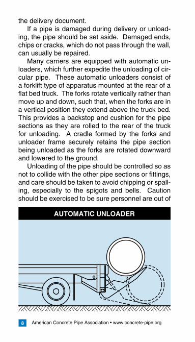
AUTOMATIC UNLOADER
the delivery document.If a pipe is damaged during delivery or unload-
ing, the pipe should be set aside. Damaged ends, chips or cracks, which do not pass through the wall, can usually be repaired.
Many carriers are equipped with automatic un-loaders, which further expedite the unloading of cir-cular pipe. These automatic unloaders consist of a forklift type of apparatus mounted at the rear of a flat bed truck. The forks rotate vertically rather than move up and down, such that, when the forks are in a vertical position they extend above the truck bed. This provides a backstop and cushion for the pipe sections as they are rolled to the rear of the truck for unloading. A cradle formed by the forks and unloader frame securely retains the pipe section being unloaded as the forks are rotated downward and lowered to the ground.
Unloading of the pipe should be controlled so as not to collide with the other pipe sections or fittings, and care should be taken to avoid chipping or spall-ing, especially to the spigots and bells. Caution should be exercised to be sure personnel are out of
American Concrete Pipe Association • www.concrete-pipe.org �
the path of the pipe as it is lowered.If the pipe has to be moved after unloading, the
sections should be rolled or lifted and should never be dragged. Pipe sections should not be rolled over rough or rocky ground.
The use of mechanical equipment is necessary for unloading arch, elliptical and box sections and larger size circular pipe, and can usually simplify and speed up the unloading of smaller pipe. When using mechanical equipment for unloading, the lifting device, which connects to the pipe, should enable proper and safe handling without damage to the pipe. Lifting devices such as slings, chain, steel wire, cable and rope should be placed around the pipe and arranged so that the pipe is lifted in a horizontal position. If the lifting device could chip or damage the pipe, padding should be provided between the pipe and lifting device. These types of lifting devices should not be passed through the pipe. Other devices, which are designed to pass into or through the pipe, should not touch the spig-ot or bell jointing surfaces, and should extend far enough beyond the end of the pipe for adequate clearance of lifting lines.
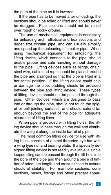
When pipe is provided with lifting holes, the lift-ing device should pass through the wall and distrib-ute the weight along the inside barrel of pipe.
The most common lifting device for use with lift-ing holes consists of a steel threaded eye bar with a wing type nut and bearing plate. If a specially de-signed lifting device is not readily available, a single looped sling can be passed through the lift hole into the bore of the pipe and then around a piece of tim-ber of adequate length and cross-section to assure structural stability. For manhole sections, cone sections, bases, fittings and other precast appur-
American Concrete Pipe Association • www.concrete-pipe.org10
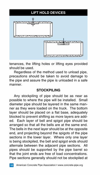
LIFT HOLD DEVICES
tenances, the lifting holes or lifting eyes provided should be used.
Regardless of the method used to unload pipe, precautions should be taken to avoid damage to the pipe and assure the pipe is unloaded in a safe manner.
STOCKPILING
Any stockpiling of pipe should be as near as possible to where the pipe will be installed. Small diameter pipe should be layered in the same man-ner as they were loaded on the truck. The bottom layer should be placed on a flat base, adequately blocked to prevent shifting as more layers are add-ed. Each layer of bell and spigot pipe should be arranged so that all the bells are at the same end. The bells in the next layer should be at the opposite end, and projecting beyond the spigots of the pipe sections in the lower layer. Where only one layer is being stockpiled, the bell and spigot ends should alternate between the adjacent pipe sections. All pipes should be supported by the pipe barrel so that the joint ends are free of load concentrations. Pipe sections generally should not be stockpiled at
American Concrete Pipe Association • www.concrete-pipe.org 11
the job site in a greater number of layers than would result in a height of 6 ft. (2 m).
All flexible gasket materials not cemented to the pipe, including joint lubrication compounds, should be stored in a cool dry place to be distrib-uted as needed. Rubber gaskets and preformed or bulk mastics should be kept clean, away from oil, grease, and excessive heat and out of the direct rays of the sun.
American Concrete Pipe Association • www.concrete-pipe.org1�
INSTALLATION
LINEANDGRADE
For sewer and culvert construction, line and grade are usually established by one or a combina-tion of the following methods:
reference line established by a helium-neon lasercontrol points consisting of stakes, spikes, plugs or shiners set at the ground surface and offset a certain distance from the proposed sewer centerlinecontrol points established at the trench bottom after the trench is excavated.trench bottom and pipe invert elevations while excavation and pipe installation progresses
Specially designed helium-neon lasers are avail-able for sewer and culvert construction. Basically the instrument converts input power into a beam of light, which is projected as a narrow beam rather than shining in all directions as does a light bulb. The light beam is a continuous, uninterrupted string line, which does not sag and can be used for dis-tances up to 1,000 ft. (90 to 150 m). The laser proj-ects a beam of light the diameter of which depends on the distance being projected and on the optics of the particular instrument. Usually the beam is about the size of a pencil. Since the laser beam is a light beam, it is seen by either looking back at the instrument or intercepting the beam with target, which reflects the light.
As with any surveying instrument, the initial set-ting is most important. But once a laser is set as to direction and grade, it provides a constant refer-ence line from which measurements can be taken at any point along the beam. A workman with any
•
•
•
•
American Concrete Pipe Association • www.concrete-pipe.org 1�
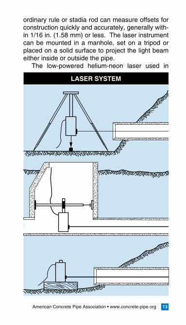
ordinary rule or stadia rod can measure offsets for construction quickly and accurately, generally with-in 1/16 in. (1.58 mm) or less. The laser instrument can be mounted in a manhole, set on a tripod or placed on a solid surface to project the light beam either inside or outside the pipe.
The low-powered helium-neon laser used in
LASER SYSTEM
American Concrete Pipe Association • www.concrete-pipe.org1�
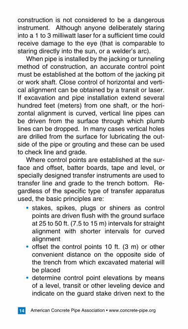
construction is not considered to be a dangerous instrument. Although anyone deliberately staring into a 1 to 3 milliwatt laser for a sufficient time could receive damage to the eye (that is comparable to staring directly into the sun, or a welder’s arc).
When pipe is installed by the jacking or tunneling method of construction, an accurate control point must be established at the bottom of the jacking pit or work shaft. Close control of horizontal and verti-cal alignment can be obtained by a transit or laser. If excavation and pipe installation extend several hundred feet (meters) from one shaft, or the hori-zontal alignment is curved, vertical line pipes can be driven from the surface through which plumb lines can be dropped. In many cases vertical holes are drilled from the surface for lubricating the out-side of the pipe or grouting and these can be used to check line and grade.
Where control points are established at the sur-face and offset, batter boards, tape and level, or specially designed transfer instruments are used to transfer line and grade to the trench bottom. Re-gardless of the specific type of transfer apparatus used, the basic principles are:
stakes, spikes, plugs or shiners as control points are driven flush with the ground surface at 25 to 50 ft. (7.5 to 15 m) intervals for straight alignment with shorter intervals for curved alignmentoffset the control points 10 ft. (3 m) or other convenient distance on the opposite side of the trench from which excavated material will be placeddetermine control point elevations by means of a level, transit or other leveling device and indicate on the guard stake driven next to the
•
•
•
American Concrete Pipe Association • www.concrete-pipe.org 1�
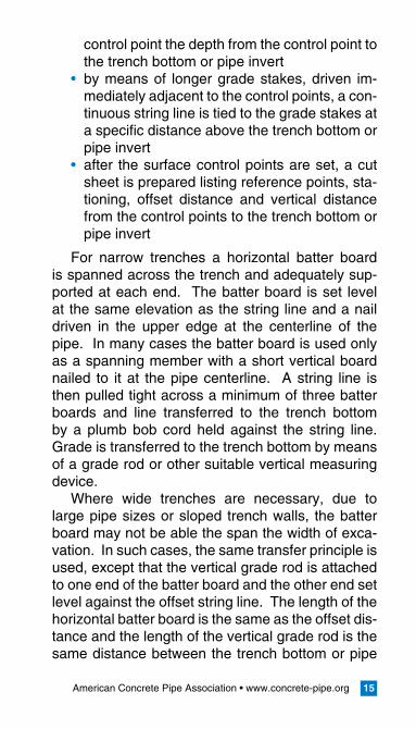
control point the depth from the control point to the trench bottom or pipe invertby means of longer grade stakes, driven im-mediately adjacent to the control points, a con-tinuous string line is tied to the grade stakes at a specific distance above the trench bottom or pipe invertafter the surface control points are set, a cut sheet is prepared listing reference points, sta-tioning, offset distance and vertical distance from the control points to the trench bottom or pipe invert
For narrow trenches a horizontal batter board is spanned across the trench and adequately sup-ported at each end. The batter board is set level at the same elevation as the string line and a nail driven in the upper edge at the centerline of the pipe. In many cases the batter board is used only as a spanning member with a short vertical board nailed to it at the pipe centerline. A string line is then pulled tight across a minimum of three batter boards and line transferred to the trench bottom by a plumb bob cord held against the string line. Grade is transferred to the trench bottom by means of a grade rod or other suitable vertical measuring device.
Where wide trenches are necessary, due to large pipe sizes or sloped trench walls, the batter board may not be able the span the width of exca-vation. In such cases, the same transfer principle is used, except that the vertical grade rod is attached to one end of the batter board and the other end set level against the offset string line. The length of the horizontal batter board is the same as the offset dis-tance and the length of the vertical grade rod is the same distance between the trench bottom or pipe
•
•

American Concrete Pipe Association • www.concrete-pipe.org1�
invert and the string line. Specially designed instru-ments are available which incorporate a measuring tape, extendable arm and leveling device. These instruments are based on the same principle, but eliminate the need to construct batter boards and supports and are portable.
The transfer of surface control points to stakes along the trench bottom is sometimes necessary because of the deep trenches or unstable soils re-quiring the trench sides to be sloped back. Stakes should be set along the trench bottom at 50 ft. (15 m) intervals and a string line drawn between two
EXAMPLE BATTER BOARD SET-UP
GradeStake
Grade Rod RegisteringGrade of Invert
BatterBoard
GradeString
Grade Rod RegisteringGrade of Trench
American Concrete Pipe Association • www.concrete-pipe.org 1�
or three control points. Where line and grade are established as excavation proceeds, a transit, level or laser setup is usually used.
In setting line and grade for culverts installed at about the same elevation as the original ground, culvert control points are usually established during the construction survey. Stakes are then set along the culvert length by means of a hand level or sur-vey instrument. If the embankment is first built up and then a sub-trench excavated, the same proce-dures as for trench excavations can be used.
EXCAVATIONLIMITS
The most important excavation limitations are trench width and depth. As excavation progress-es, trench grades should be continuously checked against the elevations established in the sewer or culvert profile. Improper trench depths can result in high or low spots in the line, which may adversely affect the hydraulic capacity of the sewer or culvert and require correction or additional maintenance after the line is completed.
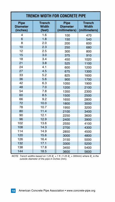
The backfill load transmitted to the pipe is direct-ly dependent on the trench width. To determine the backfill load, the designer assumes a certain trench width and then selects a pipe strength ca-pable of withstanding this load. If the constructed trench width exceeds the width assumed in design, the pipe could be overloaded and possibly structur-ally distressed. Because the backfill loads and pipe strength requirements are a function of the trench width, maximum trench widths are usually estab-lished in the plans or standard drawings. Where maximum trench widths are not indicated in any of the construction contract documents, trench widths should be as narrow as possible, with side clear-
American Concrete Pipe Association • www.concrete-pipe.org1�
TRENCH WIDTH FOR CONCRETE PIPE
Pipe Trench Pipe Trench Diameter Width Diameter Width (inches) (feet) (millimeters) (millimeters)
4 1.6 6 1.8 8 2.0 10 2.3 12 2.5 15 3.0 18 3.4 21 3.8 24 4.1 27 4.5 33 5.2 36 5.6 42 6.3 48 7.0 54 7.8 60 8.5 66 9.2 72 10.0 78 10.7 80 11.4 90 12.1 96 12.9 102 13.6 108 14.3 114 14.9 120 15.6 126 16.4 132 17.1 138 17.8 144 18.5
100 470 150 540 200 600 250 680 300 800 375 910 450 1020 525 1100 600 1200 675 1300 825 1600 900 1700 1050 1900 1200 2100 1350 2300 1500 2500 1650 2800 1800 3000 1950 3200 2100 3400 2250 3600 2400 3900 2550 4100 2700 4300 2850 4500 3000 4800 3150 5000 3300 5200 3450 5400 3600 5600
NOTE: Trench widths based on 1.25 Bc + 1 ft. (1.25 Bc + 300mm) where Bc is the outside diameter of the pipe in inches (mm).
American Concrete Pipe Association • www.concrete-pipe.org 1�
ance adequate enough to insure proper compac-tion of backfill material at the sides of the pipe. The following trench widths can be used as a general guide for circular concrete pipe:
EXCAVATEDMATERIAL
If excavated material is to be stored on top of the pipeline, special consideration should be given to surcharge loading during the design of the pipe.
Stockpiling excavated material adjacent to the trench causes a surcharge load, which may cave in the trench walls. The ability of the trench walls to stand vertically under this additional load depends on the cohesive characteristics of the particular type of material being excavated. This surcharge load should be considered when evaluating the need to provide trench support. It may be necessary where deep or wide trenches are being excavated to haul away a portion of the excavated soil or spread the stockpile with a bulldozer or other equipment. If the excavated material is to be used as backfill, the stockpiled material should be visually inspected for rocks, frozen lumps, highly plastic clay or other objectionable material. If the excavated soil differs significantly from the intended backfill material set forth in the plans, it may be necessary to haul the unsuitable soil away and bring in select backfill ma-terial.
DEWATERING
Control of surface and subsurface water is re-quired so that dry conditions will be provided dur-ing excavation and pipe laying. Ground water conditions should be investigated before they are encountered during the course of excavation.
American Concrete Pipe Association • www.concrete-pipe.org�0
STANDARDINSTALLATIONS
Through consultations with contractors and engi-neers, four Standard Installations were developed and are presented in the following pages. The fol-lowing ideas, formulated from past experience, were confirmed with parameter studies. These Standard Installations represent an improved understand-ing of the installation factors effecting pipe perfor-mance and reflect modern construction techniques. They are designed to improve pipe performance by emphasizing beneficial construction and installa-tion requirements. By providing installations, which utilize a wide range of backfill materials, including native materials, the Standard Installations offer the owner, engineer, and contractor more versatility in selecting the installation to meet their unique com-bination of site conditions, backfill materials and de-sired construction and inspection materials. Some of the ideas included in the Standard Installations confirm the following concepts:
The soil in the haunch area from the foundation to the pipe springline provides significant sup-port to the pipe and reduces pipe stresses.Loosely placed, uncompacted bedding directly under the invert of the pipe significantly reduc-es stresses in the pipe.Installation materials and compaction levels below the springline have a significant effect on pipe structural requirements.Soil in those portions of the bedding and haunch areas directly under the pipe is difficult to compact.Compaction level of the soil directly above the haunch, from the pipe springline to the top of the pipe grade level, has negligible effect
•
•
•
•
•
American Concrete Pipe Association • www.concrete-pipe.org �1
on pipe stresses. Compaction of the soil in this area is not necessary unless required for pavement structures.
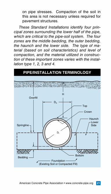
These Standard Installations identify four prin-cipal zones surrounding the lower half of the pipe, which are critical to the pipe-soil system. The four zones are the middle bedding, the outer bedding, the haunch and the lower side. The type of ma-terial (based on soil characteristics) and level of compaction, and the material utilized in construc-tion of these important zones varies with the instal-lation type 1, 2, 3 and 4.
PIPE/INSTALLATIONTERMINOLOGY
Do
Di
Bottom
Crown
Foundation(Existing Soil or Compacted Fill)
Bedding
Springline
H
Haunch
Top
LowerSide
Overfill
American Concrete Pipe Association • www.concrete-pipe.org��
Do
Do/6 (Min.)Do (Min.)
Do/3
Di
Middle bedding loosely placed uncompacted bedding except Type 4
Outer bedding materials and compaction each side, same
requirements as haunch
Foundation
BeddingSee Tables 1 & 2
H
Haunch
Lower SideSpringline
Overfill SoilCategory I, II, III
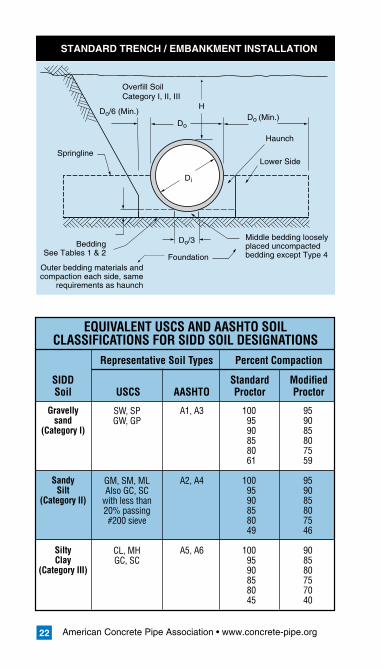
STANDARDTRENCH/EMBANKMENTINSTALLATION
SIDD Standard Modified Soil USCS AASHTO Proctor Proctor
Representative Soil Types Percent Compaction
Gravellysand
(Category I)
SandySilt
(Category II)
SiltyClay
(Category III)
SW, SPGW, GP
GM, SM, MLAlso GC, SC
with less than20% passing#200 sieve
CL, MHGC, SC
A1, A3
A2, A4
A5, A6
1009590858061
1009590858049
1009590858045
EQUIVALENT USCS AND AASHTO SOILCLASSIFICATIONS FOR SIDD SOIL DESIGNATIONS
959085807559
959085807546
908580757040
American Concrete Pipe Association • www.concrete-pipe.org 23
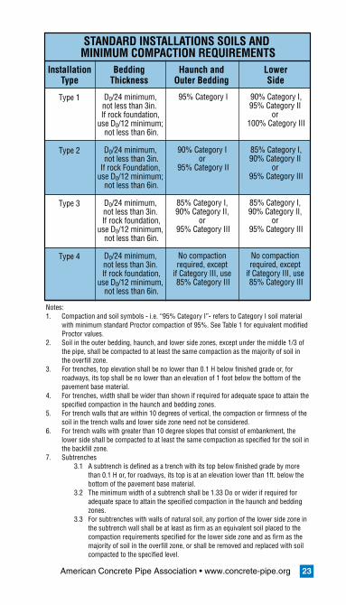
Installation Bedding Haunch and Lower Type Thickness Outer Bedding Side
Type 1
Type 2
Type 3
Type 4
D0/24 minimum, not less than 3in. If rock foundation,
use D0/12 minimum; not less than 6in.
D0/24 minimum, not less than 3in.
If rock Foundation, use D0/12 minimum;
not less than 6in.
D0/24 minimum, not less than 3in.
If rock foundation, use D0/12 minimum,
not less than 6in.
D0/24 minimum, not less than 3in.
If rock foundation, use D0/12 minimum,
not less than 6in.
95% Category I
90% Category I or
95% Category II
85% Category I, 90% Category II,
or 95% Category III
No compaction required, except
if Category III, use 85% Category III
90% Category I,95% Category II
or 100% Category III
85% Category I,90% Category II
or 95% Category III
85% Category I, 90% Category II,
or 95% Category III
No compaction required, except
if Category III, use 85% Category III
STANDARD INSTALLATIONS SOILS AND MINIMUM COMPACTION REQUIREMENTS
Notes:1. Compaction and soil symbols - i.e. “95% Category I”- refers to Category I soil material
with minimum standard Proctor compaction of 95%. See Table 1 for equivalent modified Proctor values.
2. Soil in the outer bedding, haunch, and lower side zones, except under the middle 1/3 of the pipe, shall be compacted to at least the same compaction as the majority of soil in the overfill zone.
3. For trenches, top elevation shall be no lower than 0.1 H below finished grade or, for roadways, its top shall be no lower than an elevation of 1 foot below the bottom of the pavement base material.
4. For trenches, width shall be wider than shown if required for adequate space to attain the specified compaction in the haunch and bedding zones.
5. For trench walls that are within 10 degrees of vertical, the compaction or firmness of the soil in the trench walls and lower side zone need not be considered.
6. For trench walls with greater than 10 degree slopes that consist of embankment, the lower side shall be compacted to at least the same compaction as specified for the soil in the backfill zone.
7. Subtrenches 3.1 A subtrench is defined as a trench with its top below finished grade by more
than 0.1 H or, for roadways, its top is at an elevation lower than 1ft. below the bottom of the pavement base material.
3.2 The minimum width of a subtrench shall be 1.33 Do or wider if required for adequate space to attain the specified compaction in the haunch and bedding zones.
3.3 For subtrenches with walls of natural soil, any portion of the lower side zone in the subtrench wall shall be at least as firm as an equivalent soil placed to the compaction requirements specified for the lower side zone and as firm as the majority of soil in the overfill zone, or shall be removed and replaced with soil compacted to the specified level.
American Concrete Pipe Association • www.concrete-pipe.org��
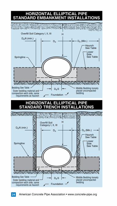
HORIZONTALELLIPTICALPIPESTANDARDEMBANKMENTINSTALLATIONS
HORIZONTALELLIPTICALPIPESTANDARDTRENCHINSTALLATIONS
Do
Do/6 (min.)Do (Min.)
Do/3 Middle Bedding loosely placed uncompacted bedding
Foundation
Springline
H
HaunchSee Table
LowerSideSee Table
Overfill Soil Category I, II, III
Outer bedding material and compaction each side, same
requirements as haunch
Bedding See Table
Overfill Soil Category I, II, III
Do
Do/6 (min.)Do (Min.)
Do/3 Middle Bedding loosely placed uncompacted bedding
Foundation
Springline
H
HaunchSee Table
LowerSideSee Table
Outer bedding material and compaction each side, same
requirements as haunch
Bedding See Table
American Concrete Pipe Association • www.concrete-pipe.org ��
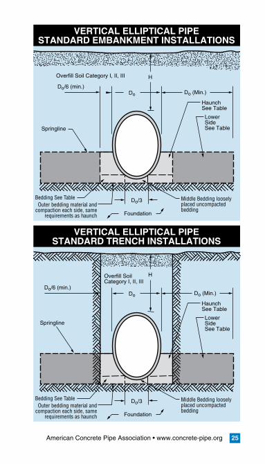
VERTICALELLIPTICALPIPESTANDARDEMBANKMENTINSTALLATIONS
VERTICALELLIPTICALPIPESTANDARDTRENCHINSTALLATIONS
Do
Do/6 (min.)Do (Min.)
Do/3 Middle Bedding loosely placed uncompacted bedding
Foundation
Springline
H
HaunchSee Table
LowerSideSee Table
Overfill Soil Category I, II, III
Outer bedding material and compaction each side, same
requirements as haunch
Bedding See Table
Overfill Soil Category I, II, III
Do
Do/6 (min.)Do (Min.)
Do/3 Middle Bedding loosely placed uncompacted bedding
Foundation
Springline
H
HaunchSee Table
LowerSideSee Table
Outer bedding material and compaction each side, same
requirements as haunch
Bedding See Table
American Concrete Pipe Association • www.concrete-pipe.org��
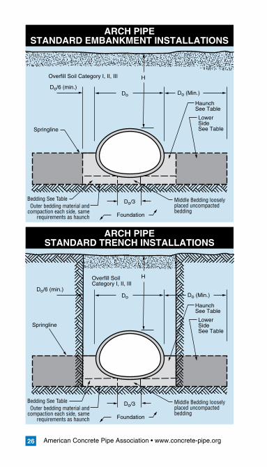
ARCHPIPESTANDARDEMBANKMENTINSTALLATIONS
ARCHPIPESTANDARDTRENCHINSTALLATIONS
Do
Do/6 (min.)Do (Min.)
Do/3 Middle Bedding loosely placed uncompacted bedding
Foundation
Springline
H
HaunchSee Table
LowerSideSee Table
Overfill Soil Category I, II, III
Outer bedding material and compaction each side, same
requirements as haunch
Bedding See Table
Overfill Soil Category I, II, III
Do
Do/6 (min.)Do (Min.)
Do/3 Middle Bedding loosely placed uncompacted bedding
Foundation
Springline
H
HaunchSee Table
LowerSideSee Table
Outer bedding material and compaction each side, same
requirements as haunch
Bedding See Table
American Concrete Pipe Association • www.concrete-pipe.org ��
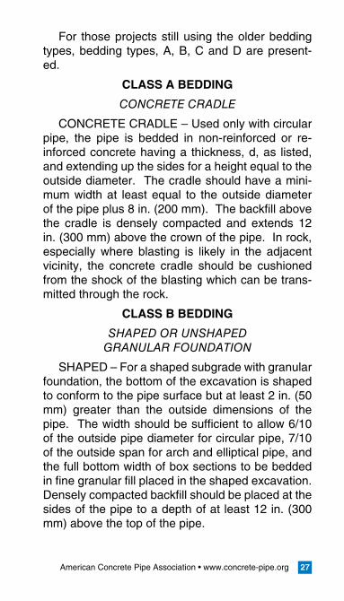
For those projects still using the older bedding types, bedding types, A, B, C and D are present-ed.
CLASSABEDDING
CONCRETE CRADLE
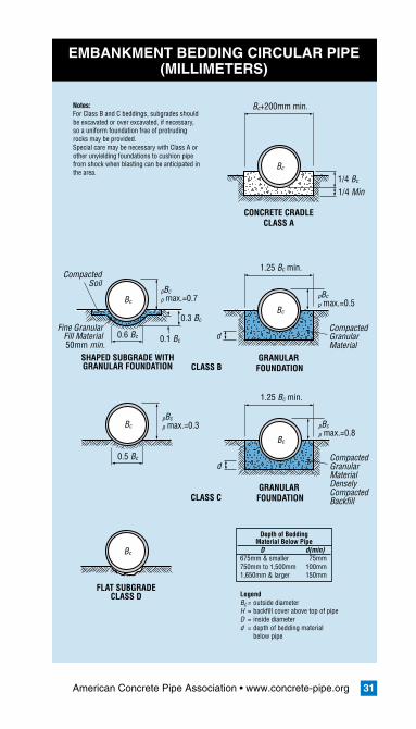
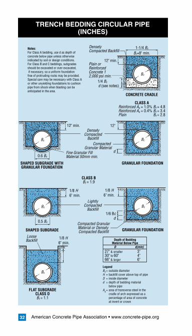
CONCRETE CRADLE – Used only with circular pipe, the pipe is bedded in non-reinforced or re-inforced concrete having a thickness, d, as listed, and extending up the sides for a height equal to the outside diameter. The cradle should have a mini-mum width at least equal to the outside diameter of the pipe plus 8 in. (200 mm). The backfill above the cradle is densely compacted and extends 12 in. (300 mm) above the crown of the pipe. In rock, especially where blasting is likely in the adjacent vicinity, the concrete cradle should be cushioned from the shock of the blasting which can be trans-mitted through the rock.
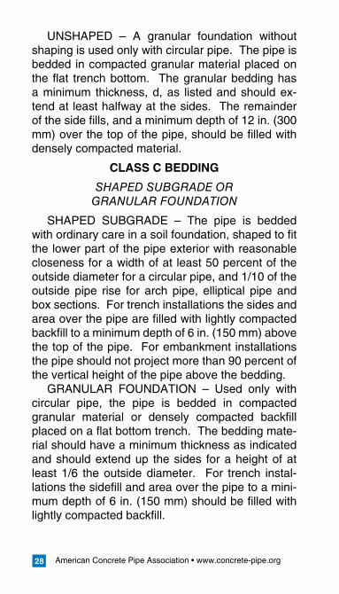
CLASSBBEDDING
SHAPED OR UNSHAPED GRANULAR FOUNDATION
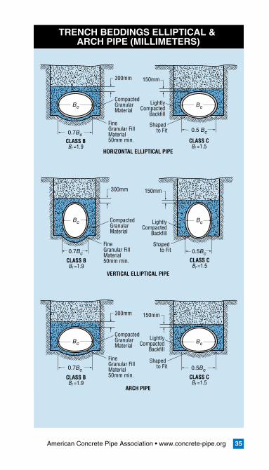
SHAPED – For a shaped subgrade with granular foundation, the bottom of the excavation is shaped to conform to the pipe surface but at least 2 in. (50 mm) greater than the outside dimensions of the pipe. The width should be sufficient to allow 6/10 of the outside pipe diameter for circular pipe, 7/10 of the outside span for arch and elliptical pipe, and the full bottom width of box sections to be bedded in fine granular fill placed in the shaped excavation. Densely compacted backfill should be placed at the sides of the pipe to a depth of at least 12 in. (300 mm) above the top of the pipe.
American Concrete Pipe Association • www.concrete-pipe.org��
UNSHAPED – A granular foundation without shaping is used only with circular pipe. The pipe is bedded in compacted granular material placed on the flat trench bottom. The granular bedding has a minimum thickness, d, as listed and should ex-tend at least halfway at the sides. The remainder of the side fills, and a minimum depth of 12 in. (300 mm) over the top of the pipe, should be filled with densely compacted material.
CLASSCBEDDING
SHAPED SUBGRADE OR GRANULAR FOUNDATION
SHAPED SUBGRADE – The pipe is bedded with ordinary care in a soil foundation, shaped to fit the lower part of the pipe exterior with reasonable closeness for a width of at least 50 percent of the outside diameter for a circular pipe, and 1/10 of the outside pipe rise for arch pipe, elliptical pipe and box sections. For trench installations the sides and area over the pipe are filled with lightly compacted backfill to a minimum depth of 6 in. (150 mm) above the top of the pipe. For embankment installations the pipe should not project more than 90 percent of the vertical height of the pipe above the bedding.
GRANULAR FOUNDATION – Used only with circular pipe, the pipe is bedded in compacted granular material or densely compacted backfill placed on a flat bottom trench. The bedding mate-rial should have a minimum thickness as indicated and should extend up the sides for a height of at least 1/6 the outside diameter. For trench instal-lations the sidefill and area over the pipe to a mini-mum depth of 6 in. (150 mm) should be filled with lightly compacted backfill.
American Concrete Pipe Association • www.concrete-pipe.org ��
CLASSDBEDDING
Used only with circular pipe, little or no care is exercised either to shape the foundation surface to fit the lower part of the pipe exterior, or to fill all spaces under and around the pipe with granular materials. However, the gradient of the bed should be smooth and true to established grade. This class of bedding also includes the case of pipe on rock foundations in which an earth cushion is pro-vided under the pipe but is so shallow that the pipe, as it settles under the influence of vertical load, ap-proaches contact with the rock.
American Concrete Pipe Association • www.concrete-pipe.org�0
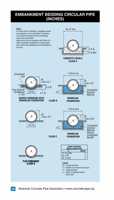
EMBANKMENTBEDDINGCIRCULARPIPE(INCHES)
Bc
FLAT SUBGRADECLASS D
Bc
0.6 Bc
Bc+ 8" min.
pBc p max.=0.5
pBc p max.=0.3
0.1 Bc
0.3 Bc
pBc p max.=0.7
1.25 Bc min.
1/4 Bc
1/4 Min
CONCRETE CRADLECLASS A
Compacted Granular Material
CompactedSoil
Fine Granular Fill Material
2" min.
Bc
SHAPED SUBGRADE WITHGRANULAR FOUNDATION
GRANULAR FOUNDATION
Bc
d
pBc p max.=0.8
1.25 Bc min.
Compacted Granular MaterialDenselyCompactedBackfill
GRANULAR FOUNDATION
Bc
d
LegendBc = outside diameterH = backfill cover above top of pipeD = inside diameterd = depth of bedding material below pipe
0.5 Bc
Bc
FLAT SUBGRADECLASS D
CLASS C
CLASS B
Notes:For Class B and C beddings, subgrades should be excavated or over excavated, if necessary, so a uniform foundation free of protruding rocks may be provided.Special care may be necessary with Class A or other unyielding foundations to cushion pipe from shock when blasting can be anticipated in the area.
Depth of Bedding Material Below Pipe D d(min)27" & smaller 3"30" to 60" 4"66" & larger 6"
American Concrete Pipe Association • www.concrete-pipe.org �1
EMBANKMENTBEDDINGCIRCULARPIPE(MILLIMETERS)
Bc
0.6 Bc
Bc+200mm min.
pBc p max.=0.5
pBc p max.=0.3
0.1 Bc
0.3 Bc
pBc p max.=0.7
1.25 Bc min.
1/4 Bc
1/4 Min
CONCRETE CRADLECLASS A
Compacted Granular Material
Bc
SHAPED SUBGRADE WITHGRANULAR FOUNDATION
GRANULAR FOUNDATION
Bc
d
pBc p max.=0.8
1.25 Bc min.
Compacted Granular MaterialDenselyCompactedBackfill
GRANULAR FOUNDATION
Bc
d
LegendBc = outside diameterH = backfill cover above top of pipeD = inside diameterd = depth of bedding material below pipe
0.5 Bc
Bc
Bc
FLAT SUBGRADECLASS D
CLASS C
CLASS B
Notes:For Class B and C beddings, subgrades should be excavated or over excavated, if necessary, so a uniform foundation free of protruding rocks may be provided.Special care may be necessary with Class A or other unyielding foundations to cushion pipe from shock when blasting can be anticipated in the area.
Depth of Bedding Material Below Pipe D d(min)675mm & smaller 75mm750mm to 1,500mm 100mm1,650mm & larger 150mm
CompactedSoil
Fine Granular Fill Material 50mm min.
American Concrete Pipe Association • www.concrete-pipe.org32
TRENCHBEDDINGCIRCULARPIPE(INCHES)
LegendBc = outside diameterH = backfill cover above top of pipeD = inside diameterd = depth of bedding material below pipeAs = area of transverse steel in the cradle of arch expressed as a percentage of area of concrete at invert or crown
Notes:For Class A bedding, use d as depth of concrete below pipe unless otherwise indicated by soil or design conditions.For Class B and C beddings, subgrades should be excavated or over excavated, if necessary, so a uniform foundation free of protruding rocks may be provided.Special care may be necessary with Class A or other unyielding foundations to cushion pipe from shock when blasting can be anticipated in the area.
Bc
1-1/4 Bc
0.6 Bc
Bc+8" min.
1/4 Bcd (see notes)
12" min.
CONCRETE CRADLE
1/8 H 6" min.
LightlyCompacted
Backfill
LooseBackfill
DenselyCompacted
Backfill
DenselyCompacted Backfill
Plain or ReinforcedConcrete 12,000 psi min.
Compacted GranularMaterial or Densely Compacted Backfill
Compacted Granular Material
Fine Granular FillMaterial 50mm min.
1/8 H 6" min.
1/8 H 6" min.
Bc
12" min. 12"
SHAPED SUBGRADE WITHGRANULAR FOUNDATION
GRANULAR FOUNDATION
Bc
d
FLAT SUBGRADECLASS DBf = 1.1
CLASS AReinforced As = 1.0% Bf = 4.8Reinforced As = 0.4% Bf = 3.4Plain Bf = 2.8
CLASS BBf = 1.9
Bc
0.5 Bc
Bc
SHAPED SUBGRADE GRANULAR FOUNDATION
Bc
d1/6 Bc
Depth of Bedding Material Below Pipe D d(min)27" & smaller 3"30" to 60" 4"66" & larger 6"
American Concrete Pipe Association • www.concrete-pipe.org 33
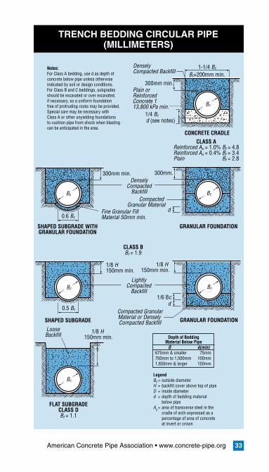
TRENCHBEDDINGCIRCULARPIPE(MILLIMETERS)
Notes:For Class A bedding, use d as depth of concrete below pipe unless otherwise indicated by soil or design conditions.For Class B and C beddings, subgrades should be excavated or over excavated, if necessary, so a uniform foundation free of protruding rocks may be provided.Special care may be necessary with Class A or other unyielding foundations to cushion pipe from shock when blasting can be anticipated in the area.
Bc
1-1/4 Bc
Bc+200mm min.
1/4 Bcd (see notes)
300mm min.
CONCRETE CRADLE
DenselyCompacted Backfill
Plain or ReinforcedConcrete 113,800 kPa min.
0.6 Bc
1/8 H 150mm min.
LightlyCompacted
Backfill
LooseBackfill
DenselyCompacted
Backfill
Compacted GranularMaterial or Densely Compacted Backfill
Compacted Granular Material
Fine Granular FillMaterial 50mm min.
1/8 H 150mm min.
1/8 H 150mm min.
Bc
300mm min. 300mm.
SHAPED SUBGRADE WITHGRANULAR FOUNDATION
GRANULAR FOUNDATION
Bc
d
FLAT SUBGRADECLASS DBf = 1.1
LegendBc = outside diameterH = backfill cover above top of pipeD = inside diameterd = depth of bedding material below pipeAs = area of transverse steel in the cradle of arch expressed as a percentage of area of concrete at invert or crown
CLASS AReinforced As = 1.0% Bf = 4.8Reinforced As = 0.4% Bf = 3.4Plain Bf = 2.8
CLASS BBf = 1.9
Bc
0.5 Bc
Bc
SHAPED SUBGRADE GRANULAR FOUNDATION
Bc
d1/6 Bc
Depth of Bedding Material Below Pipe D d(min)675mm & smaller 75mm750mm to 1,500mm 100mm1,650mm & larger 150mm

American Concrete Pipe Association • www.concrete-pipe.org��
TRENCHBEDDINGSELLIPTICAL&ARCHPIPE(INCHES)
0.7Bc
0.7Bc
Bc
Bc
CompactedGranularMaterial
Shaped to Fit
Shaped to Fit
Shaped to Fit
LightlyCompacted
Backfill
LightlyCompacted
Backfill
LightlyCompacted
Backfill
FineGranular FillMaterial 2" min.
CompactedGranularMaterial
FineGranular FillMaterial 2" min.
12"
0.7Bc
Bc
CompactedGranularMaterial
FineGranular FillMaterial 2" min.
0.5 Bc
0.5Bc
Bc
Bc
6"
HORIZONTAL ELLIPTICAL PIPE
VERTICAL ELLIPTICAL PIPE
ARCH PIPE
12" 6"
12" 6"
CLASS BBf =1.9
CLASS CBf =1.5
CLASS BBf =1.9
CLASS CBf =1.5
CLASS BBf =1.9
0.7Bc
Bc
CLASS BBf =1.5
American Concrete Pipe Association • www.concrete-pipe.org 35
TRENCHBEDDINGSELLIPTICAL&ARCHPIPE(MILLIMETERS)
0.7Bc
0.7Bc
Bc
Bc
CompactedGranularMaterial
Shaped to Fit
Shaped to Fit
LightlyCompacted
Backfill
LightlyCompacted
Backfill
Shaped to Fit
LightlyCompacted
Backfill
FineGranular FillMaterial 50mm min.
CompactedGranularMaterial
FineGranular FillMaterial 50mm min.
300mm
0.7Bc
Bc
CompactedGranularMaterial
FineGranular FillMaterial 50mm min.
300mm
300mm
0.5 Bc
0.5Bc
Bc
Bc
150mm
0.5Bc
Bc
150mm
150mm
HORIZONTAL ELLIPTICAL PIPE
VERTICAL ELLIPTICAL PIPE
ARCH PIPE
CLASS BBf =1.9
CLASS CBf =1.5
CLASS BBf =1.9
CLASS CBf =1.5
CLASS BBf =1.9
CLASS CBf =1.5
American Concrete Pipe Association • www.concrete-pipe.org��
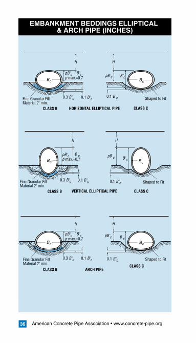
EMBANKMENTBEDDINGSELLIPTICAL&ARCHPIPE(INCHES)
Bc Bc
pB'cp max.=0.7
B'cB'c
B'c
0.3 B'c
H H
0.1 B'c
Bc Bc
Shaped to Fit
Shaped to Fit
Shaped to Fit
Fine Granular FillMaterial 2" min.
HORIZONTAL ELLIPTICAL PIPE
VERTICAL ELLIPTICAL PIPE
ARCH PIPE
CLASS B
pB'cp max.=0.7 pB'c
pB'c
pB'c
B'c B'c
0.3 B'c
H H
0.1 B'c 0.1 B'c
0.1 B'c
0.1 B'c
Fine Granular FillMaterial 2" min.
CLASS B CLASS C
CLASS C
Bc Bc
pB'cp max.=0.7
B'c
0.3 B'c
H H
0.1 B'cFine Granular FillMaterial 2" min.
CLASS BCLASS C
American Concrete Pipe Association • www.concrete-pipe.org ��
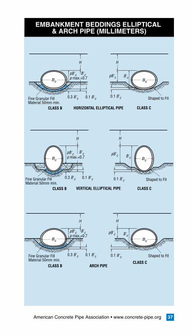
EMBANKMENTBEDDINGSELLIPTICAL&ARCHPIPE(MILLIMETERS)
Bc Bc
pB'cp max.=0.7
B'cB'c
B'c
0.3 B'c
H H
0.1 B'c
Bc Bc
Shaped to Fit
Shaped to Fit
Shaped to Fit
Fine Granular FillMaterial 50mm min.
HORIZONTAL ELLIPTICAL PIPE
VERTICAL ELLIPTICAL PIPE
ARCH PIPE
CLASS B
pB'cp max.=0.7 pB'c
pB'c
pB'c
B'c B'c
0.3 B'c
H H
0.1 B'c 0.1 B'c
0.1 B'c
0.1 B'c
Fine Granular FillMaterial 50mm min.
CLASS B CLASS C
CLASS C
Bc Bc
pB'cp max.=0.7
B'c
0.3 B'c
H H
0.1 B'cFine Granular FillMaterial 50mm min.
CLASS BCLASS C
American Concrete Pipe Association • www.concrete-pipe.org��
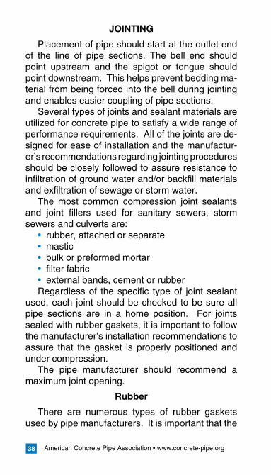
JOINTING
Placement of pipe should start at the outlet end of the line of pipe sections. The bell end should point upstream and the spigot or tongue should point downstream. This helps prevent bedding ma-terial from being forced into the bell during jointing and enables easier coupling of pipe sections.
Several types of joints and sealant materials are utilized for concrete pipe to satisfy a wide range of performance requirements. All of the joints are de-signed for ease of installation and the manufactur-er’s recommendations regarding jointing procedures should be closely followed to assure resistance to infiltration of ground water and/or backfill materials and exfiltration of sewage or storm water.
The most common compression joint sealants and joint fillers used for sanitary sewers, storm sewers and culverts are:
rubber, attached or separatemasticbulk or preformed mortarfilter fabricexternal bands, cement or rubber
Regardless of the specific type of joint sealant used, each joint should be checked to be sure all pipe sections are in a home position. For joints sealed with rubber gaskets, it is important to follow the manufacturer’s installation recommendations to assure that the gasket is properly positioned and under compression.
The pipe manufacturer should recommend a maximum joint opening.
Rubber
There are numerous types of rubber gaskets used by pipe manufacturers. It is important that the
•••••
American Concrete Pipe Association • www.concrete-pipe.org ��
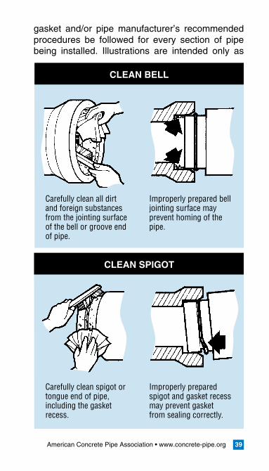
gasket and/or pipe manufacturer’s recommended procedures be followed for every section of pipe being installed. Illustrations are intended only as
CLEANBELL
CLEANSPIGOT
Carefully clean all dirt and foreign substances from the jointing surface of the bell or groove end of pipe.
Improperly prepared bell jointing surface may prevent homing of the pipe.
Carefully clean spigot or tongue end of pipe, including the gasket recess.
Improperly prepared spigot and gasket recess may prevent gasket from sealing correctly.
American Concrete Pipe Association • www.concrete-pipe.org�0
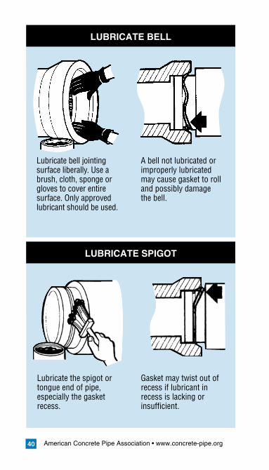
LUBRICATEBELL
LUBRICATESPIGOT
Lubricate bell jointing surface liberally. Use a brush, cloth, sponge or gloves to cover entire surface. Only approved lubricant should be used.
A bell not lubricated or improperly lubricated may cause gasket to roll and possibly damage the bell.
Lubricate the spigot or tongue end of pipe, especially the gasket recess.
Gasket may twist out of recess if lubricant in recess is lacking or insufficient.

American Concrete Pipe Association • www.concrete-pipe.org �1
LUBRICATEGASKET
INSTALLGASKET
Lubricate the gasket thoroughly before it is placed on the spigot or tongue.
Excess force will be required to push the pipe to the home position if gasket is not well lubricated.
Fit the gasket carefully. Equalize the rubber gasket stretch by running a smooth, round object, inserted between gasket and spigot, around the entire circumference several times.
Unequal stretch could cause bunching of gasket and may cause leaks in the joint or crack the bell.
American Concrete Pipe Association • www.concrete-pipe.org��
a guide and do not replace or supersede project specifications, contract documents, or specific manufacturer’s recommendations.
Mastic
Mastic sealants consist of rubber compounds or bitumen and inert mineral filler, which are usually applied at ambient temperatures. The joint surfac-es are thoroughly cleaned, dried and prepared in accordance with the manufacturer’s recommenda-tions. A sufficient amount of sealant should be used to fill the annular joint space with some squeeze out. During cold weather, better workability of the mastic sealant can be obtained if the mastic and joint surfaces are warmed.
Mortar
Mortar consists of portland cement paste, sand
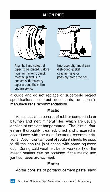
ALIGNPIPE
Align bell and spigot of pipes to be jointed. Before homing the joint, check that the gasket is in contact with the entry taper around the entire circumference.
Improper alignment can dislodged gasket causing leaks or possibly break the bell.
American Concrete Pipe Association • www.concrete-pipe.org ��
and water. The joint surface is thoroughly cleaned and soaked with water immediately before the joint is made. A layer of paste or mortar is placed in the lower portion of the bell or groove end of the in-stalled pipe and on the upper portion of the tongue or spigot end of the pipe section to be installed. The tongue or spigot is then inserted into the bell or groove of the installed pipe until some mortar is squeezed out. Any annular joint space between the adjacent pipe ends is filled with mortar and the excess mortar on the inside of the pipe wiped and finished to a smooth surface.
GeotextileFilterFabrics
As an alternative measure, where groundwater and joint configurations warrant, a band of geotex-tile filter fabric, usually 1 to 2 feet (.3 to .6 meters) wide may be wrapped around the exterior of the pipe joint and secured with either tape or stitching to prevent soil infiltration into joints of storm and culvert pipe.
ExternalBands
Portland cement mortar bands are sometimes specified around the exterior of the pipe joint. A slight depression is excavated in the bedding ma-terial to enable mortar to be placed underneath the pipe. The entire external joint surface is then cleaned and soaked with water. Special canvas or cloth diapers can be used to hold the mortar as it is placed. Backfill material should be immediately placed around the pipe.
Rubber-mastic bands also can be used around the exterior of the pipe joint. The bands are stretched tightly around the barrel of the pipe and held firmly in place by the weight of the backfill material.
American Concrete Pipe Association • www.concrete-pipe.org��
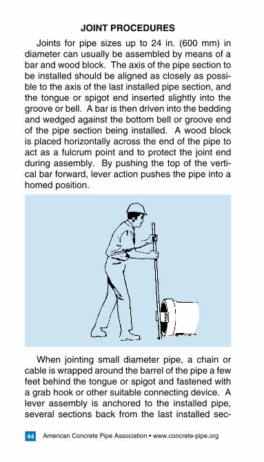
JOINTPROCEDURES
Joints for pipe sizes up to 24 in. (600 mm) in diameter can usually be assembled by means of a bar and wood block. The axis of the pipe section to be installed should be aligned as closely as possi-ble to the axis of the last installed pipe section, and the tongue or spigot end inserted slightly into the groove or bell. A bar is then driven into the bedding and wedged against the bottom bell or groove end of the pipe section being installed. A wood block is placed horizontally across the end of the pipe to act as a fulcrum point and to protect the joint end during assembly. By pushing the top of the verti-cal bar forward, lever action pushes the pipe into a homed position.
When jointing small diameter pipe, a chain or cable is wrapped around the barrel of the pipe a few feet behind the tongue or spigot and fastened with a grab hook or other suitable connecting device. A lever assembly is anchored to the installed pipe, several sections back from the last installed sec-

American Concrete Pipe Association • www.concrete-pipe.org ��
tion, and connected by means of a chain or cable to the grab hook on the pipe to be installed. By pulling the lever back, the tongue or spigot of the pipe being jointed is pulled into the bell or groove of the last installed pipe section. To maintain close control over the alignment of the pipe, a laying sling can be used to lift the pipe section slightly off the bedding foundation.
When jointing larger diameter pipe, when gran-ular bedding is used, mechanical pipe pullers are required. Several types of pipe pullers or come-along devices have been developed but the basic force principles are the same.
Large diameter pipe can be jointed by placing a dead man blocking inside the installed pipe, sev-eral sections back from the last installed section,
which is connected by means of a chain or cable to a strong back placed across the end of the pipe section being installed. The pipe is pulled home by lever action similar to the external assembly.
Mechanical details of the specific apparatus used for pipe pullers or come-along devices may vary, but the basic lever action principle is used to
American Concrete Pipe Association • www.concrete-pipe.org46
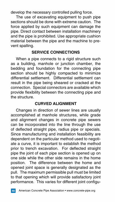
develop the necessary controlled pulling force.The use of excavating equipment to push pipe
sections should be done with extreme caution. The force applied by such equipment can damage the pipe. Direct contact between installation machinery and the pipe is prohibited. Use appropriate cushion material between the pipe and the machine to pre-vent spalling.
SERVICECONNECTIONS
When a pipe connects to a rigid structure such as a building, manhole or junction chamber, the bedding and foundation for the connecting pipe section should be highly compacted to minimize differential settlement. Differential settlement can result in the pipe being sheared or cracked at the connection. Special connectors are available which provide flexibility between the connecting pipe and the structure.
CURVEDALIGNMENT
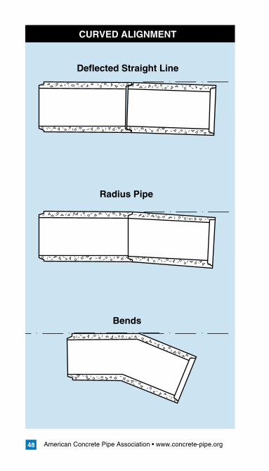
Changes in direction of sewer lines are usually accomplished at manhole structures, while grade and alignment changes in concrete pipe sewers can be incorporated into the line through the use of deflected straight pipe, radius pipe or specials. Since manufacturing and installation feasibility are dependent on the particular method used to negoti-ate a curve, it is important to establish the method prior to trench excavation. For deflected straight pipe the joint of each pipe section is opened up on one side while the other side remains in the home position. The difference between the home and opened joint space is generally designated as the pull. The maximum permissible pull must be limited to that opening which will provide satisfactory joint performance. This varies for different joint configu-
American Concrete Pipe Association • www.concrete-pipe.org 47
rations and is best obtained from the pipe manu-facturer.
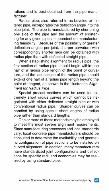
Radius pipe, also referred to as beveled or mi-tered pipe, incorporates the deflection angle into the pipe joint. The pipe is manufactured by shortening one side of the pipe and the amount of shorten-ing for any given pipe is dependent on manufactur-ing feasibility. Because of the possibility of greater deflection angles per joint, sharper curvature with correspondingly shorter radii can be obtained with radius pipe than with deflected straight pipe.
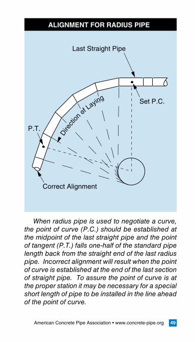
When establishing alignment for radius pipe, the first section of radius pipe should begin within one half of a radius pipe length of the point of curva-ture, and the last section of the radius pipe should extend one half of a radius pipe length beyond the point of tangent, as shown in the illustration Align-ment for Radius Pipe.
Special precast sections can be used for ex-tremely short radius curves which cannot be ne-gotiated with either deflected straight pipe or with conventional radius pipe. Sharper curves can be handled by using special short lengths of radius pipe rather than standard lengths.
One or more of these methods may be employed to meet the most severe alignment requirements. Since manufacturing processes and local standards vary, local concrete pipe manufacturers should be consulted to determine the availability and geomet-ric configuration of pipe sections to be installed on curved alignment. In addition, many manufacturers have standardized joint configurations and deflec-tions for specific radii and economies may be real-ized by using standard pipe.
American Concrete Pipe Association • www.concrete-pipe.org48
CURVED ALIGNMENT
Deflected Straight Line
Radius Pipe
Bends
American Concrete Pipe Association • www.concrete-pipe.org 49
When radius pipe is used to negotiate a curve, the point of curve (P.C.) should be established at the midpoint of the last straight pipe and the point of tangent (P.T.) falls one-half of the standard pipe length back from the straight end of the last radius pipe. Incorrect alignment will result when the point of curve is established at the end of the last section of straight pipe. To assure the point of curve is at the proper station it may be necessary for a special short length of pipe to be installed in the line ahead of the point of curve.
ALIGNMENT FOR RADIUS PIPE
Last Straight Pipe
Set P.C.
Correct Alignment
P.T.
Dire
ction
of Layin
g
American Concrete Pipe Association • www.concrete-pipe.org50
FINALBACKFILLING
Once the envelope of backfill material is placed and properly compacted, the remainder of the fill or backfill should be placed and compacted to prevent settlement at the surface. Several types of com-paction equipment are available and certain types are best for particular types of soils. The steel wheeled roller is best suited for compacting coarse aggregate such as slag, coarse gravel and graded rock aggregates. The sheepsfoot roller is best for cohesive clays or silts, but is not suitable for use on granular soils. Specially designed rubber tired rollers, which provide both static weight and knead-ing action, are applicable to many soils from clays to sand.
Regardless of the type of compaction equipment used, the backfill or fill material should be consis-tent with density requirements of the particular bed-ding specified.
ACCEPTANCETESTS
The physical tests included in the material speci-fications, under which the pipe is purchased, as-sure that pipe delivered to the job site meets or ex-ceeds the requirements established for a particular project. The project specifications usually include acceptance test requirements to assure that rea-sonable quality control of workmanship and ma-terials has been realized during the construction phase of the project. Soil density, line and grade, and visual inspection are all applicable tests for all storm sewer, sanitary sewer and culvert projects. For sanitary sewers, limits are usually established for infiltration and exfiltration.
American Concrete Pipe Association • www.concrete-pipe.org 51
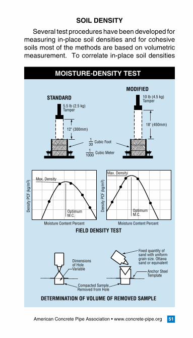
SOILDENSITY
Several test procedures have been developed for measuring in-place soil densities and for cohesive soils most of the methods are based on volumetric measurement. To correlate in-place soil densities
MOISTURE-DENSITY TEST
Compacted SampleRemoved from Hole
Moisture Content Percent
Dens
ity P
CF (k
g/m
3 )
Dens
ity P
CF (k
g/m
3 )Max. DensityMax. Density
OptimumM.C.
12" (300mm)
5.5 lb (2.5 kg) Tamper
10 lb (4.5 kg) Tamper
18" (450mm)
OptimumM.C.
Moisture Content Percent
DETERMINATION OF VOLUME OF REMOVED SAMPLE
FIELD DENSITY TEST
STANDARD
MODIFIED
Dimensionsof HoleVariable
Fixed quantity ofsand with uniformgrain size. Ottawasand or equivalent
Cubic Meter11000
Cubic Foot130
Anchor SteelTemplate
American Concrete Pipe Association • www.concrete-pipe.org52
with the maximum density of a particular soil, it is first necessary to determine the optimum moisture content for maximum compaction and then use this as a guide to determine the actual compaction of the fill or backfill. The most common methods used to determine optimum moisture content and maxi-mum density are the standard tests for moisture-density relations, frequently termed Standard Proc-tor Test and Modified Proctor Test.
ASTM and AASHTO Specifications related to soil density and moisture content are:
ASTM D 698 AASHTO T 99ASTM D 1557 AASHTO T 180ASTM D 2922 AASHTO T 238
LINEANDGRADE
Line and grade should be checked as the pipe is installed, and any discrepancies between the de-sign and actual alignment and pipe invert elevations should be corrected prior to placing the backfill or fill over the pipe. Obtaining manhole invert levels for the preparation of as-built drawings, combined with visual inspection of the sewer or culvert, pro-vides an additional check that settlement has not occurred during backfill or fill operations.
VISUALINSPECTION
Larger pipe sizes can be entered and examined while smaller sizes must be inspected visually from each manhole or by means of TV cameras. Follow-ing is a checklist for an overall visual inspection of a sewer or culvert project:
debris and obstructionsexcessive cracksjoints properly sealedinvert smooth and free of sags or high points
••••
American Concrete Pipe Association • www.concrete-pipe.org 53
stubs properly grouted and pluggedhookups, diversions and connections properly madecatch basins and inlets properly connectedmanhole frames and covers properly installedsurface restoration and all other items perti-nent to the construction properly completed.
INFILTRATION
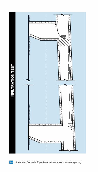
The infiltration of excessive ground water into a sanitary sewer can overload the capacity of a sew-er collection system and treatment facilities. The in-filtration test, conducted in accordance with ASTM C 969 (C 969M), is intended to demonstrate the integrity of the installed materials and construction procedures, as related to the infiltration of ground water, and therefore, is only applicable if the water table level is at least 2 ft. (600 mm) above the crown of the pipe for the entire length of the test section. Although the test is a realistic method of determin-ing water tightness, there are inherent difficulties in applying the test criteria because of seasonal fluctuations in the water table and the problem of correlating high ground water level conditions with actual test conditions.
Before conducting the test, the water table should be allowed to stabilize such that water completely surrounds the pipe during the test period. The test is usually conducted between adjacent manholes with the upstream end of the sewer bulkheaded in a suitable manner to isolate the test section. All service laterals, stubs and fittings should be prop-erly plugged or capped at the connection to the test pipe section to prevent the entrance of ground water at these locations. A V-notch weir or other suitable measuring device should be installed in the
••
•••
American Concrete Pipe Association • www.concrete-pipe.org54
INF
ILT
RA
TIO
N T
ES
T
American Concrete Pipe Association • www.concrete-pipe.org 55
inlet pipe to the downstream manhole. Infiltrating water is then allowed to build up and level off be-hind the weir until steady-uniform flow is obtained. When steady flow occurs over the weir, leakage is determined by direct reading from graduations on the weir or converting the flow quantity to gallons per unit length of pipe per unit of time.
An important factor in applying the test criteria is to properly account for the variable water head over the length of sewer being tested. The downstream end of the test section will often be subjected to a greater external water pressure than the upstream end. To compensate for this variable external pres-sure, the test pressure should be that pressure cor-responding to the average head of water over the test section. Certain test sections may exceed the allowable infiltration, limits, but the average infiltra-tion for the total project should be within the leak-age limits established for the particular project. The effect of increased depth of groundwater on infiltra-tion allowances must be considered. An average head of 6 ft. (1.8 m) of groundwater over the pipe is established as the base head. With heads of more than 6 ft. (1.8 m), the infiltration limit is increased by the ratio of the square root of the actual aver-age head to the square root of the base head. For example, with an average groundwater head of 12 ft. (3.7 m), the 200 gallons per inch (18.5 liters per mm) of diameter per 1.0 mile (1.67 km) of pipe per day infiltration limit should be increased by the ratio or the square root of the actual average head, 12 ft. (1.8 m), to the square root of the base head 6 ft. (1.8 m), which results in an allowable infiltration limit of 282 gallons per inch (26.2 liters per mm) of diameter per mile (km) of pipe per day.
American Concrete Pipe Association • www.concrete-pipe.org56
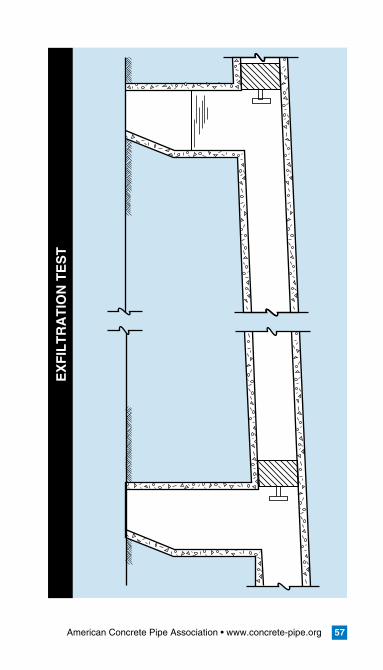
EXFILTRATION
The exfiltration test is used in lieu of the infiltra-tion test for small diameter sewers where individual joints cannot be tested. Although actual infiltration will normally be less than that indicated by the wa-ter exfiltration test, the test does provide a positive method of subjecting the completed sewer system to an actual pressure test. Since sanitary sewers are not designed or expected to operate as a pres-sure system, care must be exercised in conducting the test and correlating the results with the allow-able exfiltration limits.
The test is usually conducted between adjacent manholes in accordance with ASTM C 969M (C 969). Prior to the test, all service laterals, stubs and fittings within the test section should be plugged or capped and adequately braced or blocked to with-stand the water pressure resulting from the test. If manholes are to be included in the test, the inlet pipe to each manhole should be bulkheaded and the test section filled with water through the upstream manholes. To allow air to escape from the sewer, the flow should be at a steady rate until the water level in the upstream manholes is at the specified level above the crown of the pipe. If necessary, provisions should be made to bleed off entrapped air during the filling of the test section. Once the test section is filled the water should be allowed to stand for an adequate period of time to allow water absorption into the pipe and manhole. After wa-ter absorption has stabilized, the water level in the upstream manhole is brought up to the proper test level. This level is established by measuring down from the manhole cover or other convenient datum point.
After a set period of time, the water elevation
American Concrete Pipe Association • www.concrete-pipe.org 57
EX
FIL
TR
AT
ION
TE
ST
American Concrete Pipe Association • www.concrete-pipe.org58
should be measured from the same reference point and the loss of water during the test period calculat-ed, or the water can be restored to the level existing at the beginning of the test, and the amount added used to determine the leakage.
To exclude both manholes from the test, it is nec-essary to bulkhead the outlet pipe of the upstream manhole. Provisions must be made in the bulkhead for filling the pipe and expelling trapped air.
ASTM C 969 (C 969M) recommends the water level at the upstream manhole to be a minimum of 2 ft. (600 mm) above existing groundwater, or 2 ft. (600 mm) above the crown of the upstream pipe, whichever is greater. Since a sewer is installed on a grade, the test section downstream will be sub-jected to greater pressure. When the average head on the test section is greater than 3 ft. (900 mm), the allowable exfiltration limit should be adjusted in direct relationship to the ratio of the square root of the average test head to the square root of the specified base head, 3 ft. (900 mm).
The measured leakage of any individual section tested may exceed the leakage allowance speci-fied, provided the average of all sections tested does not exceed the specified leakage allowance.
AIRTESTING
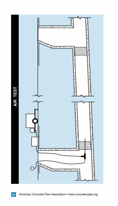
The low-pressure air test conducted in accor-dance with ASTM C 924 (C 924M) is a test, which determines the rate at which air under pressure es-capes from an isolated section of sewer. The rate of air loss is intended to indicate the presence or absence of pipe damage and whether or not the joints have been properly constructed. The test is not intended to indicate water leakage limits as no correlation has been found between air loss and
American Concrete Pipe Association • www.concrete-pipe.org 59
water leakage. The section of pipe to be tested is plugged at each end by means of inflatable stop-pers. The ends of all laterals, stubs and fittings to be included in the test should be plugged to prevent air leakage, and securely braced to prevent pos-sible blowout due to internal air pressure. One of the plugs should have an inlet tap, or other provi-sion for connecting a hose to a portable air control source. The air equipment should consist of nec-essary values and pressure gauges to control the rate at which air flows into the test section and to enable monitoring of the air pressure within the test section.
Air is added to the test section until the internal air pressure is raised to a specified level and al-lowed to stabilize with the temperature of the pipe walls. The test is conducted by the pressure drop method, whereby, the air supply is disconnected and the time required for the pressure to drop to a certain level is determined by means of a stop-watch. This time interval is then used to compute the rate of air loss. In applying low-pressure air testing to sanitary sewers intended to carry fluid under gravity conditions, several important factors should be understood and precautions followed during the test:
the air test is intended to detect defects in con-struction and pipe or joint damage and is not intended to be a measure of infiltration or exfil-tration leakage under service conditions, as no correlation has been found between air loss and water leakage.air test criteria are presently limited to concrete pipe 24 in. (600 mm) in diameter and smaller by ASTM C924 (C 924M). Additional data is required to confirm the safety and applicability
•
•
American Concrete Pipe Association • www.concrete-pipe.org60
AIR
TE
ST
American Concrete Pipe Association • www.concrete-pipe.org 61
or develop criteria for pipe larger than 24 in. in diameter.plugs should be securely braced to prevent the unintentional release of a plug which can be-come a high velocity projectile. Plugs should not be removed until all air pressure in the test section has been released.for safety reasons, no one should be allowed in the trench or manhole while the test is being conducted.the testing apparatus should be equipped with a pressure relief device to prevent the possibil-ity of loading the test section with the full com-pressor capacity
VACUUMTESTING
The vacuum (negative air pressure) test is gov-erned by ASTM C 1214 (C 1214M) for pipe and C 1244 (C 1244M) for manholes. This test involves removing air from the pipe or manhole to a specified pressure less than atmospheric. The ability to hold a vacuum or a slow drop indicates an acceptable pipe or manhole. This test is not quantitative but provides economical testing of large samples. Oth-er benefits include the inherent safety and economy of vacuum systems over pressurized systems.
This test method for pipe covers 4 to 36 in. (100 mm to 900 mm) diameter circular concrete pipe sewer lines utilizing gasketed joints and may be performed in the field or at the plant as a prelimi-nary test. The ends of all laterals, stubs, and fit-tings should be plugged to prevent air leakage. Air is evacuated from the pipeline until a specified neg-ative air pressure is reached. The drop in vacuum during the test period is recorded. The vacuum loss in cubic feet per minute (cubic meters per second) is calculated and compared to the allowable value.
•
•
•
American Concrete Pipe Association • www.concrete-pipe.org62
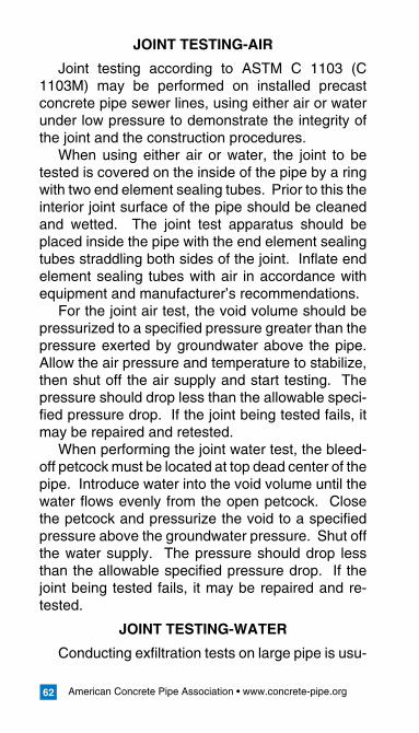
JOINTTESTING-AIR
Joint testing according to ASTM C 1103 (C 1103M) may be performed on installed precast concrete pipe sewer lines, using either air or water under low pressure to demonstrate the integrity of the joint and the construction procedures.
When using either air or water, the joint to be tested is covered on the inside of the pipe by a ring with two end element sealing tubes. Prior to this the interior joint surface of the pipe should be cleaned and wetted. The joint test apparatus should be placed inside the pipe with the end element sealing tubes straddling both sides of the joint. Inflate end element sealing tubes with air in accordance with equipment and manufacturer’s recommendations.
For the joint air test, the void volume should be pressurized to a specified pressure greater than the pressure exerted by groundwater above the pipe. Allow the air pressure and temperature to stabilize, then shut off the air supply and start testing. The pressure should drop less than the allowable speci-fied pressure drop. If the joint being tested fails, it may be repaired and retested.
When performing the joint water test, the bleed-off petcock must be located at top dead center of the pipe. Introduce water into the void volume until the water flows evenly from the open petcock. Close the petcock and pressurize the void to a specified pressure above the groundwater pressure. Shut off the water supply. The pressure should drop less than the allowable specified pressure drop. If the joint being tested fails, it may be repaired and re-tested.
JOINTTESTING-WATER
Conducting exfiltration tests on large pipe is usu-
American Concrete Pipe Association • www.concrete-pipe.org 63
ally not practical because of the considerable quan-tity of water required. If the pipe is large enough to be entered, each individual joint can be visually inspected, and if necessary, subjected to a water exfiltration test by means of test apparatus special-ly designed for this purpose. In this procedure, the joint is isolated with an expanding shield equipped with gaskets, which fit tightly against the pipe walls on each side of the joint being tested. Through appropriate piping, water is introduced into the an-nular space isolated by the shield and the leakage measured. The allowable leakage for individual joints is that which would occur on the basis of the allowable water leakage for one pipe section.
American Concrete Pipe Association • www.concrete-pipe.org64
II.BOXCULVERTINSTALLATIONMANUAL
INTRODUCTION
With the development of national standards for design and manufacturing, box culverts are rapidly becoming a large part of the precast industry. One of the unique benefits of precast concrete boxes is their fast and easy installation, even under ad-verse field and weather conditions. Precast boxes, like concrete pipe, can be custom fabricated to any configuration needed or desired in the field. Where larger waterway capacity is required, multiple sec-tions can be placed side-by-side or connected in rows to provide an excellent storm water detention system for areas with outfall flow restrictions or re-quirements for on-site detention.
This manual presents a guide for the proper installation of concrete box culverts. While focus-ing on the construction of the box-soil system, this manual also addresses those factors critical to the completion of the entire system, from delivery of the box culverts to the jobsite, to the acceptance of the installed box line.
This manual is intended as a guide and is not to supersede the project specifications.
American Concrete Pipe Association • www.concrete-pipe.org 65
PRE-INSTALLATION
PRECAUTIONS
The Safety and Health Regulations for Construc-tion under the Department of Labor, Occupational Safety and Health Administration (OSHA), are published federal regulations covering safety mea-sures for all types of construction, including sewer and box culvert installations. All prime contractors and subcontractors are subject to these regulations when involved in any type of construction, includ-ing alterations and repair work. Installers should be aware of these regulations.
Reviewing proper installation practices, while considering the engineer’s design assumptions (in relation to the use of trench boxes and backfill com-paction requirements) will help to ensure worker safety as well as culvert longevity.
ORDERING,RECEIVING&HANDLING
Although the contractor is ordering the product, both the engineer and the supplier should be aware of the proposed schedule of the contractor. Coordi-nation between the three parties will prevent unnec-essary delays. Much of the time the manufacturer stocks a wide range of box sizes for varied depths, however, manufacturing facilities must frequently adapt to meet job requirements. Therefore, for spe-cial box types and large orders, prior knowledge will assist in correct and on-time delivery. When order-ing box culverts, specifications should be in writing and should include:
Specification designation Name and location of projectBox size, laying length and the bury depthTotal footage of each type and size of box
••••
American Concrete Pipe Association • www.concrete-pipe.org66
Design live loadType of jointList of fittingsMaterial test requirementsJoint material and quantity Invoicing instructions
The following information should be clearly marked on each box section:
Specification designationMinimum and maximum bury depthSpan, rise, table number, top of box and de-sign earth cover for ASTM C 1433 (Standard), C 1577 (LRFD)Date of manufactureName or trademark of the manufacturer
SCHEDULING/UNLOADING/PLACING/SEQUENCE
It is important to be prepared for the delivery of every box. The proper machinery should be avail-able to handle the unloading and placing of each section. Each shipment is tied down to avoid dam-age during transport. However, it is the responsi-bility of the contractor to make certain no damage has occurred during transit. An overall inspection should be performed upon arrival of the boxes. Be-fore unloading, the delivered box should be checked against the order invoice to ensure accurate deliv-ery of all items.
If a box has been damaged it should be set aside and recorded to ensure its proper order in the installation sequence. In some cases damaged ends, chips and cracks, which do not pass through the wall, can be repaired on site, while others are irreparable and may have to be returned to the sup-plier for replacement.
••••••
•••
••

American Concrete Pipe Association • www.concrete-pipe.org 67
When unloading boxes, caution should be ex-ercised to ensure no personnel are in the path of the box as it is being moved. The box should be handled per manufacturer’s recommendations. Use only manufacturer approved lifting devices to handle box culvert sections. The box should be lift-ed and never dragged to avoid damage. If the lifting device could chip the box, padding should be pro-vided between the box and the lifting mechanism.
When a box is provided with lifting holes, the lift-ing device should pass through the wall and distrib-ute the weight along the inside wall of the box.
If the box is going to be installed directly from the truck trailer to the final location, a crane with stabi-lizers should be used. Be aware that some crawlers without outriggers, or backhoes, may not have the stability or maneuverability needed to line up the units for proper installation.
If the box is going to be stored on-site, alterna-tive means can be used to transport the sections to their temporary location. Care must be taken at all times and handling of boxes should be limited. The manufacturer’s handling recommendations should be followed at all times. Mishandling can result in cracked bells and spigots.
Special boxes are normally shipped in the order they should be installed and therefore should be stored in the order of delivery.
STORING
Storing of boxes should be done as near to the final installation destination as possible. If stacking of boxes is advisable, a flat surface with no rocks should be chosen for the first layer. Follow the manufacturer’s recommendations for an accept-able stack height.
American Concrete Pipe Association • www.concrete-pipe.org68
Gaskets and sealing materials should be stored in a cool dry place until needed. Rubber gaskets and bulk mastic or preformed mastics should be kept clean and away from excessive heat. Some mastics may need to be heated under extreme cold conditions, and tar joint compound should also be heated for optimum behavior during application.
American Concrete Pipe Association • www.concrete-pipe.org 69
SITEPREPARATION
EXCAVATION
Trenches should be excavated to the dimensions and grade specified on the plans or as ordered by the owner. The width of the trenches should be kept to the minimum required for installation of the box sections (ASCE 26-97). The trench width should take into account the machinery needed to prop-erly install the box section. Over excavated areas should be backfilled with approved materials and compacted to the Standard Proctor density speci-fied for the leveling course.
Preparation of the site should establish a good level grade, using fine to medium granular mate-rial. When ledge rock, compacted rocky, or other unyielding foundation material is encountered, it should be removed to the requirements shown on the plans. The foundation should be moderately firm to hard in-situ soil, stabilized soil or compacted fill material. If unstable or unsuitable material is en-countered, it should be removed and replaced with stable material approved by the engineer.
Stockpiling excavated material adjacent to the trench could cause a surcharge load, which may cave-in the trench walls. The ability of the trench walls to stand vertically under this additional load depends on the cohesive characteristics of the par-ticular type of material being excavated. This sur-charge load should be considered when evaluat-ing the need to provide trench support. It may be necessary where deep or wide trenches are being excavated to haul away a portion of the excavated soil or spread the stockpile with a bulldozer or other equipment. If the excavated material is to be used as backfill, the stockpiled material should be visu-
American Concrete Pipe Association • www.concrete-pipe.org70
ally inspected for rocks, frozen lumps, highly plastic clay or other objectionable material. If the excavat-ed soil differs significantly from the intended backfill material set forth in the plans, it may be necessary to haul the unsuitable soil away and bring in select backfill material.
TRENCHWATER
In the case where the water table is located in the trench zone, dewatering methods must be em-ployed to remove the water. The future location of the water table must also be considered due to its effect on backfill material and the box section. The presence of water around the box could cause flo-tation of the box section, or migration of the backfill material. Migration of soil should be prevented, as the backfill is a means of support for the box.
There are different methods that can be used to remove this water: pumping, ditching, and/or piping of the water. It should be noted that all pumping should be through a filtered discharge.
BEDDING/GRADE
Precast reinforced concrete box sections are de-signed for installed conditions rather than test con-ditions. Designs are presented in ASTM Standards C 1433(M) and C 1577(M), and AASHTO M 259(M) and M 273(M). Bedding details for box sections are as illustrated. A proper foundation for a box cul-vert consists of specified bedding material having uniform flat surface characteristics (no low or high points), as these could create stress concentrations in the box after installation. The box, once installed, will not normally settle; it cannot be forced down to grade. Coarse bedding materials are not beneficial due to their irregular shape and sharp angles; in-stead medium to fine granular material should be
American Concrete Pipe Association • www.concrete-pipe.org 71
used (less than 1 1/2 in. preferred but no larger than 2 in.). If the construction site is located in a re-gion where the ground is frozen, remove the frozen lumps and replace them with designer approved material.
A bedding thickness of no less than 3 in. (75 mm) should be used except when the foundation is rock, in which case the bedding thickness should be 6 in. (150 mm). The width of the bedding material should equal the width of the box (span plus twice the wall thickness) and the length of the bedding material should equal the length of the box.
The box will tend to pull some bedding material toward the connection as it is aligned with the pre-vious box. Excess bedding material trapped in the joint will prevent a proper alignment and connec-tion and hence should be prevented. Therefore, at the connection end, a small trench (a shovel length wide and running the length of the bedding mate-rial) should be dug. This allows for the bedding ma-terial to fall into the trench instead of the joint when the box is pulled into place.
All bedding material characteristics should cor-respond to code and designer’s plans for the specif-ic project. Correct installation requires that the box culvert be installed on properly graded bedding. Any discrepancies in the installation of the culvert regarding bedding or grade should be addressed with the engineer for remedial action.
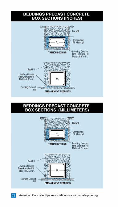
American Concrete Pipe Association • www.concrete-pipe.org72
BEDDINGSPRECASTCONCRETEBOXSECTIONS(INCHES)
Leveling Course Fine Granular Fill Material 3” min.
CompactedFill MaterialBc
Backfill
TRENCH BEDDING
Leveling Course Fine Granular Fill
Material 3” min.
Existing GroundFill
Bc
Backfill
EMBANKMENT BEDDINGS
BEDDINGSPRECASTCONCRETEBOXSECTIONS(MILLIMETERS)
Leveling Course Fine Granular Fill Material 75 mm.
CompactedFill MaterialBc
Backfill
TRENCH BEDDING
Leveling Course Fine Granular Fill Material 75 mm.
Existing GroundFill
Bc
Backfill
EMBANKMENT BEDDINGS
American Concrete Pipe Association • www.concrete-pipe.org 73
INSTALLATION
BOXALIGNMENT
It is critical that the first box sections be installed correctly as they will determine the line and grade of the following boxes. If these are not correct, fu-ture connections may be affected.
BOXPLACEMENT
Placement of boxes should start at the outlet end of the line of box sections. The bell end should point upstream and the spigot or tongue should point downstream. Unless otherwise approved by the owner, loads from construction equipment trans-ferred to a box section before, during, or after fill placement, either directly or through the fill, should not be greater than the loads assumed in the de-sign (ASCE 26-97). Using excavating machinery for the purpose of pushing boxes into place should be avoided, since this could cause cracking, requir-ing on-site repairing. Also, dropping or dragging the section over gravel or rock is not advised.
A proper foundation for construction equipment should be available in order to ensure that no dam-age is caused to the leveling course and the side-walls of the excavation area.
JOINTING
Jointing is important in reducing the migration of soil fines and water between box sections and their surroundings. Depending on the use of the box cul-vert, various materials and methods may be used for sealing the joints.
Box culverts specified for a soil-tight joint can be sealed between the joint with a bituminous mastic sealant. Either liquid butyl (bulk mastic) or non-shrink grout can be added to the outside top slab
American Concrete Pipe Association • www.concrete-pipe.org74
and applied down the sidewall 12 in. (300 mm) as well as applied to the inside bottom slab and in-side sidewalls; or butyl sealant 1 in. (25 mm) thick and placed on the inside bottom and halfway up the sides of the bell end (approximately 1/2 in. (13 mm) from edge) and placed on the outside top and halfway down the sides of the spigot end (approx-imately 1/2 in. (13 mm) from edge) can be used to seal a soil tight joint. In cold weather it may be necessary to heat the butyl sealant with a hot wa-ter bath, bottle gas torch, or both. Placing this joint material in a sunny location, just prior to use, will allow heat absorption and make it more workable. Different grades of joint material are available for different temperatures.
Another joint commonly used is an extruded sealant which is placed between the joints. The ex-truded sealant can be applied in the same manner as the bituminous sealant, applied to the bell and spigot end of the sections being joined. In some areas, rubber gasket box joints may be available. Pre-made foam gaskets can also be used to seal joints. However these forms of sealant will have to be manually attached to the bottom of the spigot end of the box to prevent sagging.
If the seal is insufficient then an added layer of adhesive joint wrap (butyl rubber laminated to poly-ethylene vapor retarder) can be used on the out-side of the box to prevent infiltration. The external sealing band can also be non-woven geotextile and should be placed on the sides and top of the box after installation. In certain situations all four sides can be wrapped. In this case the geotextile material can be slipped under the box before it is set then the sides and top can be sealed after the box is in place. It is desirable for the sealant to be one con-
American Concrete Pipe Association • www.concrete-pipe.org 75
tinuous strip, however if this is not practical, then the top strip should be one piece and extend down the sides of the box a distance of 12 in. (300 mm) and overlap with the strip extending from the bot-tom.
CONNECTINGTHEBOXES
When joining boxes together, chains or winches should be used. Direct contact between installation machinery and the box sections is prohibited. Use appropriate cushion material between the box sec-tion and the machine to prevent spalling.
Before placing the box culvert in its final location, check to see that the grade is correct, the joint sur-face is cleared of all bedding material and the joint sealant is properly seated.
A workman should be in a position to guide the crane operator as the box is being aligned. The workman in the alignment position should direct the crane operator to lower the box until the top slab of the box section is approximately two feet above the top slab of the previously placed box. The box should be lowered in such a way that the sides of the boxes are flush and the spigot end of the in-stalled box slips in line with the bell end of the re-ceiving section. Even though the box is in the right position the weight of the section should be main-tained by the crane.
Now the joint needs to be secured. This can be done through the use of winches or come-a-longs. Place one end of the come-a-long or winch at the far end of the installed sections and over the outer end of the next section taking care not to spall each surface. This works best if a pair of winches or come-alongs are used, one on each side. Gradu-ally tighten the chains until the box section is snug against the previously placed box. This winching
American Concrete Pipe Association • www.concrete-pipe.org76
should be done uniformly. If the joint is not within the maximum allowable joint opening, the crane should carefully lift the section slightly without breaking out the joint on top while the winches are pulling the chains taut. If this does not fix the open joint – re-move the section and re-screed the bedding. Also check the sections to make sure that the dimen-sional tolerances will allow the joint to go home. When the box is in the right position the crane can gradually release the box so that the bedding mate-rial carries the entire weight of the box and then it can be disconnected. The chains are held securely until the crane is disconnected, and then they are released.
COMPLETION
After the boxes have been joined together the lift holes should be plugged according to the manufac-turer’s recommendation.
BACKFILL
Backfill should be placed in uniform layers along the sides of the boxes and over the top of the box sections. These layers should be no greater than the maximum allowed to achieve the required density. The characteristics of the backfill material should be determined from the contract specifications and should contain no debris, organic matter, frozen material or large stones with a diameter greater than 1/2 the thickness of the compacted layers be-ing placed. When vibratory methods are needed to compact the backfill material, care should be taken so that no damage is done to the box section.
If sheathing and trench shields are used and are not part of the designer’s soil structure plan, they should be incrementally removed, depending on the availability and readiness of backfill material.
American Concrete Pipe Association • www.concrete-pipe.org 77
When trench shields are removed take care not to disturb the installed boxes. Restraining the box may be necessary to hold it in place. If any voids are created in the side fill material they should be filled and compacted.
Once the envelope of backfill material is placed and properly compacted, the remainder of the fill or backfill should be placed and compacted to pre-vent settlement at the surface. Compaction and equipment loads should not exceed the pipe design strength. Several types of compaction equipment are available and certain types are best for particu-lar types of soils. The steel wheeled roller is best suited for compacting coarse aggregate such as slag, coarse gravel and graded rock aggregates. The sheepsfoot roller is best for cohesive clays or silts, but is not suitable for use on granular soils. Specially designed rubber tired rollers, which pro-vide both static weight and kneading action, are ap-plicable to many soils from clays to sand.
Regardless of the type of compaction equipment used, the backfill or fill material should be consis-tent with density requirements of the particular in-stallation specified.
MINIMUMCOVERFORCONSTRUCTIONLOADS
If construction equipment is going to travel over installed box sections, compacted backfill should be placed to a minimum of 3 ft. (1 m) over the top of the box section unless the box has been spe-cifically designed for the anticipated construction loads. Above all, the loads applied to the box sec-tion should not exceed those specified by the de-signer. In an embankment installation, the minimum amount of backfill should extend one box section

American Concrete Pipe Association • www.concrete-pipe.org78
span or 3 ft. (1 m), whichever is larger, in each di-rection to prevent lateral displacement. If construc-tion traffic is large, the crossing point should be oc-casionally changed so that lateral displacement is minimized.
VISUALINSPECTION
Large box sections can be entered and exam-ined. TV cameras are another means of visually inspecting installed boxes. A checklist is provided below for an overall visual inspection of a sewer or culvert project.
DebrisExcessive cracks or large cracksJoints properly sealed Invert smooth and free of sags or high pointsLift holes properly filledHookups, diversions and connections properly madeCatch basins and inlets properly connectedManhole frames and covers properly installedSurface restoration and all other items perti-nent to the construction properly completed.
••••••
•••
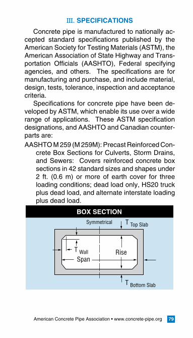
American Concrete Pipe Association • www.concrete-pipe.org 79
III.SPECIFICATIONS
Concrete pipe is manufactured to nationally ac-cepted standard specifications published by the American Society for Testing Materials (ASTM), the American Association of State Highway and Trans-portation Officials (AASHTO), Federal specifying agencies, and others. The specifications are for manufacturing and purchase, and include material, design, tests, tolerance, inspection and acceptance criteria.
Specifications for concrete pipe have been de-veloped by ASTM, which enable its use over a wide range of applications. These ASTM specification designations, and AASHTO and Canadian counter-parts are:AASHTO M 259 (M 259M): Precast Reinforced Con-
crete Box Sections for Culverts, Storm Drains, and Sewers: Covers reinforced concrete box sections in 42 standard sizes and shapes under 2 ft. (0.6 m) or more of earth cover for three loading conditions; dead load only, HS20 truck plus dead load, and alternate interstate loading plus dead load.
BOX SECTION
T Top Slab
T Wall
T Bottom Slab
Symmetrical
RiseSpan
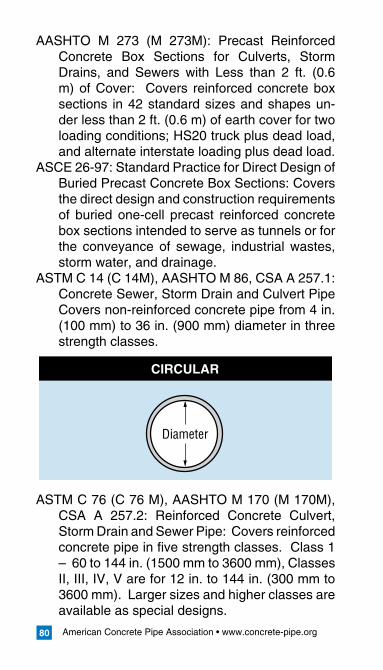
American Concrete Pipe Association • www.concrete-pipe.org80
AASHTO M 273 (M 273M): Precast Reinforced Concrete Box Sections for Culverts, Storm Drains, and Sewers with Less than 2 ft. (0.6 m) of Cover: Covers reinforced concrete box sections in 42 standard sizes and shapes un-der less than 2 ft. (0.6 m) of earth cover for two loading conditions; HS20 truck plus dead load, and alternate interstate loading plus dead load.
ASCE 26-97: Standard Practice for Direct Design of Buried Precast Concrete Box Sections: Covers the direct design and construction requirements of buried one-cell precast reinforced concrete box sections intended to serve as tunnels or for the conveyance of sewage, industrial wastes, storm water, and drainage.
ASTM C 14 (C 14M), AASHTO M 86, CSA A 257.1: Concrete Sewer, Storm Drain and Culvert Pipe Covers non-reinforced concrete pipe from 4 in. (100 mm) to 36 in. (900 mm) diameter in three strength classes.
ASTM C 76 (C 76 M), AASHTO M 170 (M 170M), CSA A 257.2: Reinforced Concrete Culvert, Storm Drain and Sewer Pipe: Covers reinforced concrete pipe in five strength classes. Class 1 – 60 to 144 in. (1500 mm to 3600 mm), Classes II, III, IV, V are for 12 in. to 144 in. (300 mm to 3600 mm). Larger sizes and higher classes are available as special designs.
CIRCULAR
Diameter
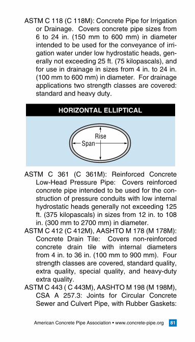
American Concrete Pipe Association • www.concrete-pipe.org 81
ASTM C 118 (C 118M): Concrete Pipe for Irrigation or Drainage. Covers concrete pipe sizes from 6 to 24 in. (150 mm to 600 mm) in diameter intended to be used for the conveyance of irri-gation water under low hydrostatic heads, gen-erally not exceeding 25 ft. (75 kilopascals), and for use in drainage in sizes from 4 in. to 24 in. (100 mm to 600 mm) in diameter. For drainage applications two strength classes are covered: standard and heavy duty.
ASTM C 361 (C 361M): Reinforced Concrete Low-Head Pressure Pipe: Covers reinforced concrete pipe intended to be used for the con-struction of pressure conduits with low internal hydrostatic heads generally not exceeding 125 ft. (375 kilopascals) in sizes from 12 in. to 108 in. (300 mm to 2700 mm) in diameter.
ASTM C 412 (C 412M), AASHTO M 178 (M 178M): Concrete Drain Tile: Covers non-reinforced concrete drain tile with internal diameters from 4 in. to 36 in. (100 mm to 900 mm). Four strength classes are covered, standard quality, extra quality, special quality, and heavy-duty extra quality.
ASTM C 443 ( C 443M), AASHTO M 198 (M 198M), CSA A 257.3: Joints for Circular Concrete Sewer and Culvert Pipe, with Rubber Gaskets:
HORIZONTAL ELLIPTICAL
SpanRise
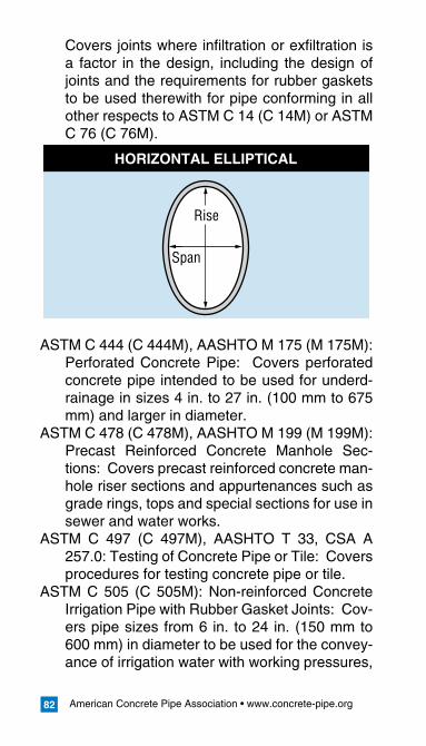
American Concrete Pipe Association • www.concrete-pipe.org82
Covers joints where infiltration or exfiltration is a factor in the design, including the design of joints and the requirements for rubber gaskets to be used therewith for pipe conforming in all other respects to ASTM C 14 (C 14M) or ASTM C 76 (C 76M).
ASTM C 444 (C 444M), AASHTO M 175 (M 175M): Perforated Concrete Pipe: Covers perforated concrete pipe intended to be used for underd-rainage in sizes 4 in. to 27 in. (100 mm to 675 mm) and larger in diameter.
ASTM C 478 (C 478M), AASHTO M 199 (M 199M): Precast Reinforced Concrete Manhole Sec-tions: Covers precast reinforced concrete man-hole riser sections and appurtenances such as grade rings, tops and special sections for use in sewer and water works.
ASTM C 497 (C 497M), AASHTO T 33, CSA A 257.0: Testing of Concrete Pipe or Tile: Covers procedures for testing concrete pipe or tile.
ASTM C 505 (C 505M): Non-reinforced Concrete Irrigation Pipe with Rubber Gasket Joints: Cov-ers pipe sizes from 6 in. to 24 in. (150 mm to 600 mm) in diameter to be used for the convey-ance of irrigation water with working pressures,
HORIZONTAL ELLIPTICAL
Span
Rise
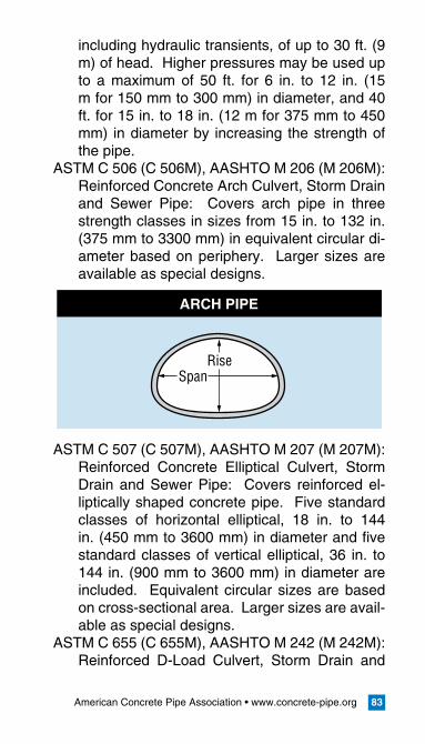
American Concrete Pipe Association • www.concrete-pipe.org 83
including hydraulic transients, of up to 30 ft. (9 m) of head. Higher pressures may be used up to a maximum of 50 ft. for 6 in. to 12 in. (15 m for 150 mm to 300 mm) in diameter, and 40 ft. for 15 in. to 18 in. (12 m for 375 mm to 450 mm) in diameter by increasing the strength of the pipe.
ASTM C 506 (C 506M), AASHTO M 206 (M 206M): Reinforced Concrete Arch Culvert, Storm Drain and Sewer Pipe: Covers arch pipe in three strength classes in sizes from 15 in. to 132 in. (375 mm to 3300 mm) in equivalent circular di-ameter based on periphery. Larger sizes are available as special designs.
ASTM C 507 (C 507M), AASHTO M 207 (M 207M): Reinforced Concrete Elliptical Culvert, Storm Drain and Sewer Pipe: Covers reinforced el-liptically shaped concrete pipe. Five standard classes of horizontal elliptical, 18 in. to 144 in. (450 mm to 3600 mm) in diameter and five standard classes of vertical elliptical, 36 in. to 144 in. (900 mm to 3600 mm) in diameter are included. Equivalent circular sizes are based on cross-sectional area. Larger sizes are avail-able as special designs.
ASTM C 655 (C 655M), AASHTO M 242 (M 242M): Reinforced D-Load Culvert, Storm Drain and
ARCH PIPE
SpanRise
American Concrete Pipe Association • www.concrete-pipe.org84
Sewer Pipe: Covers acceptance of pipe design and production pipe based upon the D-load concept and statistical sampling techniques for concrete pipe to be used for the conveyance of sewage, industrial waste and storm water and construction of culverts.
ASTM C 822 (C 822M), AASHTO M 262 (M 262M): Definition of Terms Relating to Concrete Pipe and Related Products: Includes definitions for words and terms occurring in concrete pipe standards.
AASTM C 877 (C 877M): External Sealing Bands for Noncircular Concrete Sewer, Storm Drain and Culvert Pipe: Covers external sealing bands for noncircular concrete pipe conforming to ASTM C 506 (C 506M), C 507 (C 507M), C 1433 (C 1433M), C 1504 (C 1504M), C 1577 (C 1577M).
ASTM C 923 (C 923M): Resilient Connectors Be-tween Reinforced Concrete Manhole Structures and Pipes: Covers the minimum performance and material requirements for resilient connec-tions between pipe and reinforced concrete manholes conforming to ASTM C 478M (C 478).
ASTM C 924 (C 924M): Testing Concrete Pipe Sewer Lines by Low-Pressure Air Test Method: Covers procedures for testing concrete pipe sewer lines by low-pressure air test to demon-strate the integrity of the installed material and the construction procedures.
ASTM C 969 (C 969M): Practice for Infiltration and Exfiltration Acceptance Testing of Installed Pre-cast Concrete Pipe Sewer Lines: Covers pro-cedures for testing installed precast concrete pipe sewer lines using either water infiltration
American Concrete Pipe Association • www.concrete-pipe.org 85
or exfiltration acceptance limits to demonstrate the integrity of the installed materials and con-struction procedures.
ASTM C 985 (C 985M): Non-reinforced Concrete Specified Strength Culvert Storm Drain, and Sewer Pipe: Covers non-reinforced concrete pipe designed for specified strengths and in-tended to be used for the conveyance of sew-age, industrial wastes, and storm water and for the construction of culverts.
ASTM C 990 (C 990M): Specification for Joints for Concrete Pipe, Manholes, and Precast Box Sections Using Preformed Flexible Joint Seal-ants: Covers joints for precast concrete pipe and box, and other sections using preformed flexible joint sealants for use in storm sewers and culverts which are not intended to operate under internal pressure, or are not subject to infiltration or exfiltration limits.
ASTM C 1103 (C 1103M): Practice for Joint Accep-tance Testing of Installed Precast Concrete Pipe Sewer Lines: Covers procedures for test-ing the joints of installed precast concrete pipe sewer lines, when using either air or water un-der low pressure to demonstrate the integrity of the joint and the construction procedures.
ASTM C 1214 (C 1214M): Test Method for Con-crete Pipe Sewer Lines by Negative Air Pres-sure (Vacuum) Test Method: Covers using the negative air pressure test for 4 in. to 36 in. (100 mm to 900 mm) in diameter circular concrete pipe sewer lines utilizing gasketed joints.
ASTM C 1244 (C 1244M): Standard Test Method for Concrete Sewer Manholes by the Negative Air Pressure (Vacuum) Test Method: Covers using the negative air pressure test for concrete sewer manholes utilizing gasketed joints.
American Concrete Pipe Association • www.concrete-pipe.org86
ASTM C 1433 (C 1433M): Precast Reinforced Con-crete Box Sections for Culverts, Storm Drains, and Sewers: Covers single-cell reinforced con-crete box sections intended to be used for the construction of culverts and for the conveyance of storm water industrial wastes and sewage.
ASTM C 1479: Standard Practice for Installation of Precast Concrete Sewer, Storm Drain, and Cul-vert Pipe Using Standard Installations: covers the installation of precast concrete pipe intend-ed to be used for the conveyance of sewage, industrial wastes, and storm water and for the construction of culverts.
ASTM C 1577 (C 1577M): Precast Reinforced Con-crete Box Sections for Culverts, Storm Drains, and Sewers Designed According to AASHTO LRFD: Covers single-cell precast reinforced concrete box sections intended to be used for the construction of culverts, and for the convey-ance of storm water, industrial wastes and sew-age.
ASTM C 1619: Standard Specification for Elasto-meric Seals for Joining Concrete Structures: covers the physical property requirements of elastromeric seals (gaskets) used to seal the joint of precast concrete structures conform-ing to specifications C 14 (C 14M), C 118 (C 118M), C 361 (C 361M), C 443 (C 443M) or C 505 (C 505M) used in gravity and low head pressure applications.
AASTM C 1628: Standard Specifications for Joints for Concrete Gravity Flow Sewer Pipe, Using Rubber Gaskets: covers flexible leak resistance joints for concrete gravity flow sewer pipe us-ing rubber gaskets for sealing the joints, where measurable or defined infiltration or exfiltration is a factor of the design.
American Concrete Pipe Association • www.concrete-pipe.org 87
IV. APPENDIX
DEFINITIONS
BackfillorSideFill: the layer of soil placed around or above the pipe or box unit.
Bedding: the material used to cushion and evenly distribute the soil reaction at the bottom of the structure.
BellEnd: that portion of the end of the pipe or box unit, regardless of its shape or dimensions, which overlaps a portion of the end of the ad-joining pipe or box culvert.
BoxCulvert/Section: A culvert with a rectangular cross section
Concrete: a homogeneous mixture of Portland ce-ment, fine aggregate, coarse aggregate, and water. The mixture may also contain admix-tures, or other cementitious materials, or both.
Culvert: a pipeline or box intended to convey wa-ter under a highway, railroad, canal, or similar facility.
External Sealing Bands: flexible wrappings that are applied to the outside of a concrete pipe, box section, or manhole section joint intend-ed to control the movement of fluids or solids through the joint.
Gradation: the distribution of particles of granu-lar material among standard sizes usually ex-pressed in terms of cumulative percentages larger or smaller than each of a series of sieve openings.
HandlingReinforcement: reinforcement intended to reduce the risk of collapse of the pipe or sec-tion during handling or storage prior to and dur-ing final placement.
Infiltration: the volume of groundwater entering a
American Concrete Pipe Association • www.concrete-pipe.org88
sewer and its connections through pipe, boxes, joints, connections or appurtenances.
InstalledLength: final length, along the centerline, of a pipe or box section in place including the longitudinal joint separation between the sec-tion and the last section placed.
Invert: the bottom or lowest point of the internal sur-face of the transverse cross section of a pipe.
Joint: a connection of two pipe, manhole, or box section ends, made either with or without the use of additional parts and/or materials.
LiftHole: a small hole cast or drilled in the wall of the pipe or section for inserting a bolt, loop of cable or other device used in handling the pipe or section.
Lot: an assemblage of concrete pipe or box culverts, all being of like size, material, and strength des-ignation, manufactured by the same process. The lot size may differ from the quantity desig-nated in the contract or order.
Manhole: a Precast concrete structure for vertical access to a pipeline or other closed structure.
O-Ring Gasket: a solid gasket of circular cross section that is recessed in a groove on the pipe tongue or spigot and then confined by the bell or groove after the joint is completed.
Permeability: that property which permits move-ment of a liquid through the pores and interstic-es of the concrete
Pipe: a tube or elongated hollow concrete structure intended to transmit flow between locations.
PipeDiameter: the inside diameter of a concrete pipe
PipeSection: a single pipe.Pipeline: pipe sections joined together. PreformedFlexibleJointSealant: pliable mate-
American Concrete Pipe Association • www.concrete-pipe.org 89
rial formed into a defined cross section that is applied to the surface of a pipe, box section, or manhole section joint, intended to control the movement of fluids or solids through the joint.
ReinforcedConcretePipe: a pipe structure com-prised of concrete and steel reinforcement. Such reinforcement is comprised of steel wire, welded wire fabric, or bars, of known strength, formed into a cage and positioned in the con-crete wall in a specific location in such a man-ner that the two materials act together to resist stresses.
Reinforcement: steel in the form of wire, welded wire fabric, or bars embedded in concrete in such a manner that the above referenced con-crete and steel act together to resist stresses.
ResilientConnector: a flexible connection for join-ing pipe to structures capable of being deformed and deflected without rupture or leakage.
RubberGasket: rubber formed and used as a seal in concrete pipe joints.
Spigot: that portion of the end of the pipe, regard-less of its shape or dimensions, which is over-lapped by a portion of the end of the adjoining pipe.
Springline: the points on the internal surface of the transverse cross section of a pipe intersected by the line of maximum horizontal dimension; or in box sections, the mid-height of the internal vertical wall.
Watertight: will restrain the passage of water to not exceed a specified limit.
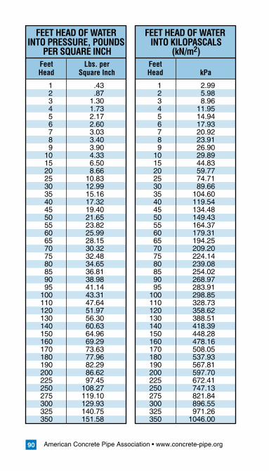
American Concrete Pipe Association • www.concrete-pipe.org90
Feet Lbs. per Head Square Inch
Feet Head kPa
1 .43 2 .87 3 1.30 4 1.73 5 2.17 6 2.60 7 3.03 8 3.40 9 3.90 10 4.33 15 6.50 20 8.66 25 10.83 30 12.99 35 15.16 40 17.32 45 19.40 50 21.65 55 23.82 60 25.99 65 28.15 70 30.32 75 32.48 80 34.65 85 36.81 90 38.98 95 41.14 100 43.31 110 47.64 120 51.97 130 56.30 140 60.63 150 64.96 160 69.29 170 73.63 180 77.96 190 82.29 200 86.62 225 97.45 250 108.27 275 119.10 300 129.93 325 140.75 350 151.58
1 2.99 2 5.98 3 8.96 4 11.95 5 14.94 6 17.93 7 20.92 8 23.91 9 26.90 10 29.89 15 44.83 20 59.77 25 74.71 30 89.66 35 104.60 40 119.54 45 134.48 50 149.43 55 164.37 60 179.31 65 194.25 70 209.20 75 224.14 80 239.08 85 254.02 90 268.97 95 283.91 100 298.85 110 328.73 120 358.62 130 388.51 140 418.39 150 448.28 160 478.16 170 508.05 180 537.93 190 567.81 200 597.70 225 672.41 250 747.13 275 821.84 300 896.55 325 971.26 350 1046.00
FEET HEAD OF WATER INTO PRESSURE, POUNDS
PER SQUARE INCH
FEET HEAD OF WATER INTO KILOPASCALS
(kN/m2)
1303 West Walnut Hill Lane, Suite 305Irving, Texas 75308-3008
Phone: 972.506.7216Fax: 972.506.7682
Copyright 2007Resource No 01-103