Embed Size (px)
Citation preview
Wisconsin Department of Transportation
Wisconsin Highway Research Program
Request for Proposal
Concrete Placed Underwater – Literature Search & Synthesis
Questions submitted to [email protected] regarding the content of this RFP are due no later than
4:30 PM (CST) on December 12, 2016
Responses to questions will be posted to the WisDOT Research and Library
website http://wisdotresearch.wi.gov/rfps-and-proposals by 4:30 PM (CST) by December 19, 2016
Researchers must submit a PDF version of their proposal by 4:30 PM (CST) by January 20, 2017
Researchers will be notified of the proposal review decision by May 1, 2017
For more information regarding this RFP contact the WisDOT Research Program at: [email protected]. This RFP is posted to the Internet at:
http://wisdotresearch.wi.gov/rfps-and-proposals
RFP: Concrete Placed Underwater – Literature Search & Synthesis 2
Wisconsin Highway Research Program Request for Proposals
Structures Technical Oversight Committee
Concrete Placed Underwater – Literature Search & Synthesis
I. Background and Problem Statement Wisconsin Department of Transportation (WisDOT) uses pier and abutment types that may be constructed in aquatic environments without cofferdams. Typically, just formwork and erosion control will be used during these construction operations of a number of our pier and abutment types. These types of substructures include the WisDOT Bridge Manual Pile Encased Pier (Standard 13.03), A1 Integral Abutment (Standard 12.01), and A5 Pile Encased Abutment (Standard 12.08). Construction of piers or abutments without cofferdams in aquatic environments can be challenging and at times and the quality of the products may be less than desirable. There may be issues in adequately excavating to the desired bottom of pier elevation and maintaining the excavation open so that adequate embedment into the streambed can be attained. During placement of concrete under water, there have been issues with segregation of the concrete and loss of the cement paste. As a result, quality and strength of the concrete can be greatly compromised to the point that week concrete that can be easily removed by probing with hand tools. This concrete quality issue may also pertain to challenges with placements of seals in cofferdam/pier construction. Factors during placement may include water velocities, depth of water, method of confinement, method of placement, or concrete mix design. These issues lead to concrete that is highly compromised with respect to strength and long-term performance. Some questions that also need to be addressed relate to the type of inspection that is desired to help ensure the appropriate level of quality. This may include the need or benefit for diving inspection after installation and/or other remote inspection technology. This research synthesis report aims at assessing WisDOT current policy, standards, and specifications, the policy and practices of other DOTs, and current industry practices (including other marine environment construction industries) to provide guidance to be used in improving WisDOT policy, standards, and specifications related to underwater concrete placement. This research synthesis would develop information that would be used to update the current department Bridge Manual and Construction and Materials Manuals policy on the placement of concrete underwater. This project would also have potential impact on specifications and standards used to construct concrete piers and abutments in water environments. These updates would also potentially address:
1. Techniques to minimize environmental impact 2. Techniques to limit segregation 3. Placement around piles and reinforcement vs. seals (placement around reinforce and
piles has been more challenging).
RFP: Concrete Placed Underwater – Literature Search & Synthesis 3
4. Techniques to excavate and form substructures in aquatic environments.
II. Objectives
The objective of this research is to examine best practices of DOTs and other related industries related to placement of concrete underwater and make recommendations to WisDOT Manuals, standards, specifications, and policy that will promote higher quality concrete substructures in aquatic environments.
III. Scope of Work
A. An initial WisDOT Literature Search that will be provided to Researchers as part of this RFP. Proposers are expected to complete their own comprehensive literature beyond what is provided to complete the scope of work as necessary. A literature search of current information related to policy, standards, and specifications, the policy and practices of other DOTs, and current industry practices (including other marine environment construction industries) is expected.
B. Collection of relevant DOT policies and practices related to the placement of concrete underwater.
C. Search WisDOT Highway Structures Information System (HSIS) to identify bridges with documented aquatic substructure quality issues.
D. Contact WisDOT Regional Bridge Inspection Program Managers to request identification of known bridges with aquatic substructure quality issues.
E. Identify and contact WisDOT Underwater Inspection contractors to ask for their input on known bridges with aquatic substructure quality issues.
F. Contact construction industry members involved with pier and abutment construction in water environments to collect relevant input.
G. Formulate recommendations and documentation that would serve as the basis for updated policy, guidance, specifications, details on the placement of concrete underwater.
H. Develop recommendations and guidelines in a format consistent with WisDOT Bridge Manual, Construction Materials Manual and associated presentation materials for WisDOT practitioners.
IV. WisDOT/TOC Contribution WisDOT will provide the following support through the WHRP Project Oversight Committee (POC), Technical Oversight Committee (TOC) and Regional Bridge Maintenance Engineers:
A. Work will be conducted with project oversight by the WisDOT Bureau of Structures and WHRP Structures POC.
B. The research team will not assume the availability of WisDOT staff or equipment in the proposal. If WisDOT or another entity donates equipment, a letter of commitment must be included in the proposal.
RFP: Concrete Placed Underwater – Literature Search & Synthesis 4
C. WisDOT staff will assist the research team in accessing the WisDOT Bureau of Structures Web Application - HSIS for demographic and condition information related to concrete substructures in aquatic environments in Wisconsin.
D. Expected level by staff/TOC members: Maximum of 20 hours over the duration of the project. POC members will consult with research team in the selection of project sites.
V. Required Travel
This project may require travel for a meeting to finalize the initial project Work Plan with the POC, and travel to Madison is required to report the results of the study to the POC/TOC. Other interim reporting may be requested for the researcher’s data collection efforts. A final presentation in Madison, Wisconsin by the researcher is expected.
VI. Deliverables
A. Reporting Requirements: Six (6) hard copies and an electronic copy of the final report
delivered to WisDOT by the contract end date. This includes the report, special provisions, and structural details. Please refer to the Implementation section for further details.
B. Recommendation for the Bridge Manual and Construction Materials Manual Policy related to placement of concrete underwater. This will include draft manual(s) chapter text.
C. Recommendations related to construction details and specifications for pier construction in aquatic environment.
D. Development of PowerPoint presentation to serve as a training tool for WisDOT Bridge designers and Regional construction/project staff that illustrated the findings of this research project. WisDOT staff will provide the associated training.
E. Presentation Requirements: All projects require the PI to give an in-person closeout presentation to the POC/TOC after submittal of the draft final report.
VII. Budget and Schedule
A. Project Budget shall not exceed $60,000. B. Proposed project duration is 12 months starting around October 1, 2017.
• Deadline for submittal of draft final report is three months prior to contract end date to allow for report review activities.
• Deadline for research close out presentation is 4-6 weeks prior to contract end date. • Deadline for submittal of the Final Report is the contract end date.
VIII. Implementation
Successful implementation of this research will be achieved through the development of the following items: C. Summary of a significant number of DOTs and their policies related to the placement of
concrete underwater.
RFP: Concrete Placed Underwater – Literature Search & Synthesis 5
D. Recommendations to modify our policies, standards, and specifications to promote higher quality pier and abutment construction and products in aquatic environments.
E. Recommendations on inspection techniques that promote placement of quality concrete in aquatic environments.
F. Update the current department Bridge Manual and Construction and Materials Manuals policy on the placement of concrete underwater.
G. Development of PowerPoint presentation to serve as a training tool for WisDOT Bridge Designers, Maintenance, and Regional Planning staff.
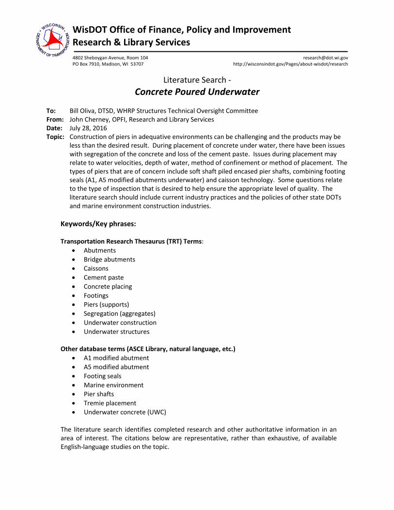
WisDOT Office of Finance, Policy and Improvement Research & Library Services 4802 Sheboygan Avenue, Room 104 [email protected] PO Box 7910, Madison, WI 53707 http://wisconsindot.gov/Pages/about-wisdot/research
Literature Search -
Concrete Poured Underwater
To: Bill Oliva, DTSD, WHRP Structures Technical Oversight Committee From: John Cherney, OPFI, Research and Library Services Date: July 28, 2016 Topic: Construction of piers in adequative environments can be challenging and the products may be
less than the desired result. During placement of concrete under water, there have been issues with segregation of the concrete and loss of the cement paste. Issues during placement may relate to water velocities, depth of water, method of confinement or method of placement. The types of piers that are of concern include soft shaft piled encased pier shafts, combining footing seals (A1, A5 modified abutments underwater) and caisson technology. Some questions relate to the type of inspection that is desired to help ensure the appropriate level of quality. The literature search should include current industry practices and the policies of other state DOTs and marine environment construction industries.
Keywords/Key phrases: Transportation Research Thesaurus (TRT) Terms:
• Abutments • Bridge abutments • Caissons • Cement paste • Concrete placing • Footings • Piers (supports) • Segregation (aggregates) • Underwater construction • Underwater structures
Other database terms (ASCE Library, natural language, etc.)
• A1 modified abutment • A5 modified abutment • Footing seals • Marine environment • Pier shafts • Tremie placement • Underwater concrete (UWC)
The literature search identifies completed research and other authoritative information in an area of interest. The citations below are representative, rather than exhaustive, of available English-language studies on the topic.
The listing below provides links to online copies of cited literature when available. Contact the WisDOT Library to obtain print versions of any citations or electronic full-text copies of an item not freely accessible.
Findings
Monitoring of Scour around Bridge Piers and Abutments Lukasz Topczewskia; Juliusz Cieslaa; Pawel Mikolajewskib; Pawel Adamskib; Zenon Markowskib In Transportation Research Procedia 2016, vol. 14, pp. 3963-3971 Contact library staff for copy Abstract: Scour of the riverbeds around bridge supports is the most frequent cause of their failures. Maintenance and repair costs of the bridges damaged by scour effects are significant, but it is estimated that the social costs are five times higher than the direct repair and replacement costs. The bridge supports are subjected to the scour effects due to the erosive action of the flowing water, involving soil loosening from the bottom and the banks of the watercourse. The condition for the proper monitoring of scour is to understand its nature. The knowledge of the phenomena occurring during the high water flow in the area of the bridge supports is crucial to properly assess the current condition and to develop proper maintenance actions. Scour may be the consequence of:
• narrowing the watercourse – a natural or man-made, including construction of a bridge • lateral movement or lowering of the stream bed • hydraulic works shortening the length of the meandering section of the watercourse • changes occurring in the catchment area of the watercourse • other changes in watercourse hydrology
Construction of a bridge in the certain area disturbs natural stream flow conditions, especially the flood water and may change the terms of the normal water flow. The presence of a bridge causes the stream flow cross-section reduction, which increases the speed and intensity of erosion of the streambed. River tends to stabilize its bed in order to restore the natural flow section. Bridge supports also change the laminar water flow and turbulent flow. Scour present around a bridge supports can be monitored by the mobile and fixed devices. Portable scour monitoring devices are mainly: different types of probes such as: sticks, tape or rope with weights and bars used by divers and sonar acoustic measuring devices. Stationary equipment is used for continuous or regular scour monitoring of the bridge supports of the bridge, for example once a day, once a week. They are stationary devices including various types of robotic probes and stationary hydroacoustic measurement systems. Stationary device can be installed on a support or near the bridge, usually at the head of the pillar, or in the ground near the bottom of the
Reports
watercourse. It should be installed near the site of the anticipated greatest scour. The device interacts with the data logger, which can be read on the site or transmitted to a remote control unit. The article presents the principles of scour monitoring near the bridge supports, developed during the project “Monitoring system for bridge supports and their surrounding areas” co-founded by the Polish National Centre for Research and Development under the program Innotech. During the project monitoring system for bridge supports was developed with specialized software for online data visualization. The article presents selected measurement results from the sonar measurements. Durability Performance of Submerged Concrete Structures - Phase 2 M.T. Walsh and A.A. Sagüés University of South Florida (USF) and Florida Department of Transportation September 2015 http://www.dot.state.fl.us/research-center/Completed_Proj/Summary_SMO/FDOT-BDV25-977-12-rpt.pdf Abstract: This project determined that severe corrosion of steel can occur in the submerged portions of reinforced concrete structures in marine environments. Field studies of decommissioned pilings from Florida bridges revealed multiple instances of strong corrosion localization, showing appreciable local loss of steel cross-section. Quantitative understanding of the phenomenon and its causes has been developed, and a predictive model was created based on that understanding. Corrosion rate estimates and the extent of corrosion localization from the field observations were consistent with the results of the predictive model. The most likely explanation for the phenomenon is that cathodic reaction rates under oxygen diffusional limitation that are negligible in cases of uniform corrosion can support substantial corrosion rates in cases of localized corrosion. Modeling projected that, with use of sacrificial anode cathodic protection, corrosion in the submerged zone could be virtually eliminated, together with significant reduction of the rate of corrosion damage progression in the low elevation zone above water. Continuation work should be conducted to define an alternative limit state other than visible external cracks and spalls for submerged reinforced concrete, and for determination of the possible structural consequences of this form of corrosion, as well as to assess the technical feasibility and cost/benefit aspects of incorporating protective anodes in new pilings. Open Caisson: Underwater Construction Technique and Placement Jitesh Mehta; Jayeshkumar Pitroda; J.J.Bhavsar BVM Engineering College, Gujarat, India April 2015 Contact library staff for copy Abstract: Underwater construction works as observed by the engineers and designers are considered as the most difficult work. Caissons are sunk through ground or water to exclude water and semi-fluid material during the process of excavation of foundations and which subsequently becomes an integral part of the substructure. In this paper, a brief description of the open caisson is done which is constructed using under water techniques. tremie method for concrete placement is discussed. The general description of open caisson in detail, its technical aspects, improvement in new techniques and also its advantages and disadvantages are discussed. The aim of this paper is to focus on small aspects included in under water
construction through caisson which are highly cost consuming structures, to give a better and stable foundation for carrying heavy and dynamic load. Comparison of Conventional and Self-Consolidating Concrete for Drilled Shaft Construction Rupnow, Tyson D; Icenogle, Patrick Louisiana Transportation Research Center and the Louisiana Department of Transportation and Development April 2015 Summary: https://www.ltrc.lsu.edu/pdf/2015/ts_533.pdf Final Report: http://www.ltrc.lsu.edu/pdf/2015/FR_533.pdf Abstract: Many entities currently use self-consolidating concrete (SCC), especially for drilled shaft construction. This project investigated the use of SCC and various test methods to assess the suitability of SCC in underwater placement conditions. Eight mixtures were prepared in the laboratory; the fresh properties of slump-flow, J-ring, set time, and washout characteristics were measured. Hardened properties tested included compressive and flexural strength, modulus of elasticity, and surface resistivity. The fresh concrete results of SCC showed that SCC produced with a No. 8 crushed stone or No. 8 gravel is adequate in terms of workability and strength with the use of a high range water reducer. The L-box test results were varied across all mixtures and the method was abandoned in favor of the washout test. The washout test results showed that for SCC mixtures being placed in an underwater condition, the addition of a viscosity modifying agent (VMA) greatly enhances the resistance of said concrete to washout. Compressive and flexural strengths showed that SCC will be adequate for nearly all structural concrete and drilled shaft applications. The modulus of elasticity values for mixtures tested were slightly increased compared to traditional concrete values showing that the SCC mixtures are particularly suited for drilled shaft construction. Surface resistivity values were slightly depressed for laboratory mixtures at 28-days of age, but field cast SCC mixtures will incorporate, not only additional SCMs but a greater proportion of SCMs, leading to increased resistivity values to meet the specification. Field construction results showed that the mixture was resistant to washout, exhibited excellent workability properties, and had excellent strength characteristics. The authors recommend incorporating SCC into the standards and specifications for Departmental use. At a minimum, Sections VIII and IV should be amended to include appropriate language allowing the use of said mixtures. The use of SCC in an underwater placement condition should require the use of a viscosity modifier. Bridge Inspection Handbook - Underwater Operations Team Massachusetts Department of Transportation, Highway Division 2015, Chapter 7 https://www.massdot.state.ma.us/Portals/8/docs/bridgeManual/InspectionHandbook/Chapter7.pdf Introduction: This chapter introduces MassDOT’s Underwater Operations Team (UOT). The primary function of the Underwater Operations Team is to conduct underwater inspections of all state, city and town bridges where required in accordance with the National Bridge Inspection Standards (NBIS). The Team conducts underwater inspections on a year round basis for structures throughout the Commonwealth of Massachusetts. Additional duties of the Underwater Operations Team includes assistance to state and
municipal departments in repairing bridge substructure elements and installing scour countermeasures, assisting in search and recovery efforts, debris removal and other related underwater work associated with bridges. Durability Assessment of Concrete Structures in HZM Sea Link Project for Design Life of 120 Years K. F. Li; Q. W. Li; Q. M. Zhang In 4th International Conference on the Durability of Concrete Structures, Purdue University July 2014 http://docs.lib.purdue.edu/cgi/viewcontent.cgi?article=1025&context=icdcs Abstract: This article presents the durability assessment of the concrete structures in the ongoing Hong Kong–Zhuhai–Macao (HZM) sea link project for a design service life of 120 years. During the preliminary study phase, the durability design of concrete structures has been performed by a model-based method with a partial factor scheme for chloride-induced corrosion process. On the basis of the actual design options adopted in the detailed design phase, the durability assessment of concrete structures is performed for the achieved durability and reliability levels. For this purpose, the durability assessment retains the same model for chloride-induced corrosion as in the preliminary design phase, and takes into account the actual design options for concrete elements such as concrete surface coating, epoxy-coated steel bars, and stainless steel bars. The probabilistic approach is adopted for the durability assessment to evaluate the reliability levels for the design life of 120 years. Following the same probabilistic analysis, the maintenance scheme of concrete elements is investigated with specified reliability levels for different maintenance strategies. Underwater Concrete Core Testing Report: Memorial Bridge Concrete Characterization and Condition Assessment, Actual and Future Deterioration New Hampshire Department of Transportation November 2009 https://www.nh.gov/dot/projects/portsmouthkittery13678E/documents/underwater_concrete_coretesting_report.pdf Introduction and scope: Materials Service Life, LLC (MSL) was mandated by Appledore Marine Engineering, Inc. (AME) to characterize the concrete and to assess the service life of the underwater concrete piers from two bridges located at Portsmouth, New Hampshire. The mandate also covered the assessment of different repair options and recommendations for maintaining the pier in good condition. The service life assessment was done with simulations performed with STADIUM, a predictive modeling software. This investigation was undertaken to identify the cause of the concrete degradation of the underwater concrete piers, to generate information on the residual service-life of the structure and to analyze the influence of different remediation strategies. The work scope included a laboratory investigation and a service life modeling. The field work, including the cores selection and the core extraction were performed by Appledore Marine Engineering (AME) personnel. Six 2 ¾ -in. diameter cores were extracted in the underwater portion of the piers.
Underwater Inspection and Evaluation of New Jersey Bridges Guidelines Manual New Jersey Department of Transportation Revised August 2008 http://www.state.nj.us/transportation/eng/structeval/pdf/UnderwaterInspectionEvaluation.pdf Introduction: Approximately 86% of all bridges nationwide span waterways according to FHWA statistics. A recent survey of bridge failures determined that over sixty percent were due to hydraulic related reasons. The need, therefore, to inspect and evaluate those portions of the bridge that are underwater, and therefore not readily apparent, is essential to maintain the structural integrity of the nation's bridges. This condition was brought to light in the late 1980s with three highly publicized waterway bridge failures. In all three, the failure was in some way attributable to inadequacies in the underwater inspection procedures that were in place at the time. It was determined by the FHWA that the existing conditions were either inadequately inspected or not documented in sufficient detail to provide a warning of the potential problems. It was also determined that many waterway bridges have elements which pose a higher than normal potential for collapse. Additionally, due to the nature of these failures, a need for improved record keeping was found to be required. Underwater Concrete in Drilled Shafts: the Key Issues and Case Histories Sam X. Yao and Robert B. Bittner 2006 http://www.bittner-shen.com/publication/Drilled_Shafts/Underwater_Concrete_for_Drilled_Shafts_the_Key_Issues_and_Case_Histories.pdf Abstract: In construction of drilled shafts under water, placing concrete in the shafts is technically demanding and involves complex construction logistics. Past construction experience has demonstrated that high quality concrete can be placed in drilled shafts under water with a proper concrete mix and proper placement techniques. However, a significant number of failures have occurred which have resulted in excessive cost overruns and delays. These problems may have occurred because proper underwater concrete construction techniques have not been widely disseminated within the industry. This is a technical area where competent design and sound construction planning can achieve a significant reduction in both risk and cost. This paper will discuss some key technical issues in the concrete mix design, concrete production and placement for the drilled shaft construction. The paper also describes two lesson-learned case histories from drilled shaft construction projects. Introduction: Placing concrete in the shafts is one of the most critical and complex operations that often determine success or failure of many drilled shaft construction projects. If the concrete is placed under water, the construction is even more technically demanding and involves complex construction logistics. A number of failures have occurred due to improper concrete mix or improper construction procedures. The following sections present some important technical issues that are frequently encountered in underwater construction of drilled shafts. Because concrete placed underwater is inherently susceptible to cement washout, laitance, segregation, cold joints, and water entrapment, it must possess some unique properties that are not otherwise required.
Seminar Report on Underwater Construction Rakesh Borker Dayananda Sagar College of Engineering November 2009 Contact library staff for copy Introduction: Underwater concrete construction is a critical component of the entire project. It is technically demanding, usually on the critical path of the project. It is technically demanding, usually on the critical path of the project schedule, and involves complex construction logistics. Therefore, its significance in the project far beyond the concreting operations themselves, in essence, underwater concrete can be constructed with the same degree of reliability as above water construction. But if it is not carried out properly, with the proper concrete mixture and placement procedure, underwater concrete construction can result in a major cost and schedule overrun. This is the area where sound design and competent construction planning can achieve a meaningful reduction in risk and cost. For those used to concreting on dry land, concreting under water presents various challenges. Transporting, compacting, quality control, finishing and accuracy must all be carried out successfully in this different, and often difficult, environment. There are, however, many common aspects, chief of which is that air is not required for the setting and hardening of concrete – it sets and hardens just as well, and often even better, under water – but it must be fluid enough to flow into position and be self-compacting as conventional vibration is not practicable under water. The caissons and cofferdams are the techniques used for the construction of underwater structures. A caisson is a retaining, watertight structure used, for example, to work on the foundations of a bridge pier, for the construction of a concrete dam, or for the repair of ships. Caissons are sunk through ground or water to exclude water and semi-fluid material during the process of excavation of foundations and which subsequently becomes an integral part of the substructure. A cofferdam is an enclosure within a water environment constructed to allow water to be displaced by air for the purpose of creating a dry work environment. Commonly used for oil rig construction and repair, bridge and dam work, the cofferdam is usually a welded steel structure that is temporary, typically dismantled after work is completed. Its components consist of sheet piles, wales, and cross braces. Underwater Concrete A. K. AL-TAMIMI In Developments in the Formulation and Reinforcement of Concrete 2008, pp. 136-153 Contact library staff for copy Introduction: Underwater concrete “UWC” is one special type of high performance concrete used in the past, present, and in the foreseeable future as long as there is need to construct bridges, with foundations in soil with high water levels, and almost all off- and on-shore structures. The term high performance concrete refers to concrete that performs particularly well in at least three key performance indicators: strength, workability, and service life.
Therefore, underwater concrete should meet these performance criteria and it remains a viable and economic choice for consultants and contractors. UWC requires special and careful monitoring during all stages of construction; i.e. special considerations for selecting the right materials, specialized apparatus for the quality control, design, and methods of construction. Underwater concrete was specially designed to enhance constructability and performance in water environments. Using the underwater concrete technique may avoid engineers using the “old-style” of construction by isolating the water, and therefore, minimize interruption to plant operation and result in high savings. “UWC” is a highly flowable concrete that can spread into place under its own weight and achieve good compaction in the absence of vibration, without exhibiting defects due to segregation and bleeding. Underwater concrete technology has developed dramatically in recent years, so that the mix can be proportioned to ensure high fluidity as well as high resistance of washout and segregation. The construction of a wide range of structures including bridge piers, harbors, sea and river defenses over many decades, and the development of offshore oilfields, has required placement of concrete underwater. This process can be successfully carried out and sound, high-quality concrete can be produced if sufficient attention is paid to the concrete mix design and the production method applied. Minimizing the Impact on Water Quality of Placing Grout Underwater to Repair Bridge Scour Damage G. Michael Fitch Virginia Department of Transportation 2003 http://www.virginiadot.org/vtrc/main/online_reports/pdf/03-r16.pdf Abstract: The Virginia Department of Transportation (VDOT) has routinely used what is commonly referred to as tremie concrete (concrete or grout placed underwater by way of pumping through a metal tremie pipe) to repair bridge substructure and scour damage. VDOT also recently began to place concrete underwater to repair scour by pumping it directly into grout bags. Many of VDOT’s rehabilitation projects that involve underwater concrete placement require environmental permits that VDOT’s Environmental Division is responsible for securing from various regulatory agencies. Because the effects of tremie concrete on water quality have been a concern for some of these agencies, namely the Virginia Department of Environmental Quality and the U.S. Army Corps of Engineers, the acquisition of these permits has become a problem. As a consequence, the agencies put a number of VDOT projects on hold until the problems with tremie concrete were better documented and/or until VDOT developed a better method of repairing bridge scour. The Department of Environmental Quality requested that all in-stream scour repairs, with few exceptions, be conducted “in the dry.” The purpose of this study was to determine a way to allow VDOT to remain in compliance with current state and federal water quality standards and regulations while rehabilitating structures with significant scour using concrete placed underwater. The study included the monitoring of 31 sites in the field and a laboratory component to compare the effects of various placement methods on various water quality parameters.
Assessment of Underwater Concrete Technologies for In-the-Wet Construction of Navigation Structures Sam X. Yao; Dale E. Berner; Ben C. Gerwick U.S. Army Corps of Engineers September 1999 http://tinyurl.com/gvhbdxr Abstract: In recent years, the U.S. Army Corps of Engineers (USACE) has launched major developments in underwater construction of locks and dams, the so called "in-the-wet" or "offsite prefabricated" construction method. This innovative method uses precast concrete modules as the in situ form into which tremie concrete is placed directly without use of a cofferdam. The tremie concrete is designed to work in composite with the precast concrete. In 1993, the USACE's Task Force on Design and Construction Innovation issued a feasibility study report (USACE 1993) that outlined the background and concepts of the in-the-wet method. Since then, comprehensive feasibility studies and preliminary design of navigation locks and dams have been carried out for various potential sites of the U.S. inland waterways. In-depth studies have shown that the in-the-wet construction method will lead to substantial savings in cost and construction time, in addition to minimizing the effect on river traffic during construction and substantially reducing or eliminating the impact on navigation during rehabilitation. The experience with the design and feasibility studies highlighted the importance of underwater concrete construction as a major component of the new construction method. Many outstanding examples exist of high-quality concrete placed underwater by the tremie process. However, a significant number of failures have occurred which have resulted in excessive cost overrun and delays. These failures have been due in large part to improper concrete mixtures and improper placement procedures. These problems may have occurred because proper underwater concrete construction techniques and experience have not been widely disseminated to engineers and contractors. Thus, a review of the state-of-the-art underwater concrete technology is important for successful implementation of the USACE's program for in-the wet construction.
Water Dynamics in Cement Paste at Early Age Prepared With Pozzolanic Volcanic Ash and Ordinary Portland Cement Using Quasielastic Neutron Scattering Kupwade-Patil, Kunal; et al. In Cement and Concrete Research August 2016, vol. 86, pp. 55-62 Contact library staff for copy Abstract: Early age hydration kinetics of Portland cement with pozzolanic volcanic ash was examined using quasielastic neutron scattering. Volcanic ash consisting of two different particle sizes was used to prepare cement pastes with different ratios of Portland cement to volcanic ash. The concentration of the volcanic ash played a major role in the bound water index and self-diffusion coefficients of hydration water confined in the cement paste. An increase in the particle size of the volcanic ash affected the degree of hydration by allowing more free and mobile water in the gel pores, suggesting that volcanic ash may not have completely reacted during the experimental time frame. This study shows that the
Journal articles

particle size along with variation in volcanic ash composition governs the early age hydration process in volcanic ash cements. An Optimal Sonar Placement Approach for Detecting Underwater Threats Under Budget Limitations Biobaku, Taofeek; et al. In Journal of Transportation Security June 2016, vol. 9, no. 1-2, pp. 17-34 Contact library staff for copy Abstract: Providing surveillance to maritime infrastructures against imminent threats is studied in this paper. Surveillance is achieved with the aid of optimally placed sonars. Under a budget-limited deployment strategy involving both static and mobile sonars, a new optimization model using hexagonal grid systems is proposed. Numerical results suggest our approach delivers acceptable detection coverage under a multi-period placement scheme. Autonomous Inspection of Underwater Structures Marco Jacobi In Robotics and Autonomous Systems May 2015, vol. 67, pp. 80-86 Contact library staff for copy Abstract: In the future our resource on land will be over exploited. The exploration of new resources in the ocean is in progress. Mining will be done on the bottom of the sea. The sea is also a big source of renewable energy. Off shore wind parks and tide plants are built. Also, the major world trade is handled over sea routes and several big harbors. All this maritime facilities are getting older and there are effects like corrosion or malfunctions. In general, they need to be inspected frequently. For deep sea applications, security reasons and cost reduction autonomous underwater vehicles (AUVs) will be the first choice. The project “CView” addresses one of these inspection problems, the harbor inspection. But the algorithms, we present in this article can be adapted to many other inspection tasks. One of the main goals in this project is to find cracks or damaged areas at the underwater buildings or to observe critical sections under water with cost effective methods. The platform for developing the guidance algorithms for inspection is the AUV “SeaCat”. This underwater vehicle has a control software system with an user interface for mission planning, a mission control system, a precise navigation system, optimized motor control with an autopilot and sensors for obstacle detection and inspection. For obstacle and inspection target detection, a scanning sonar is used. The sonar images are automatically processed with edge detection and line extraction algorithms to get a simplified environment description, which is used by the guidance methods presented in this article. A pan–tilt enabled sensor head with camera, laser measurement and MBES (Multi Beam Echo Sounder) is used to inspect the detected objects. Additionally, these sensors provide distance information to the inspection object which can be used by the inspection guidance.
This article presents methods for inspection using the online information from the vehicle sensors to guide the vehicle efficient and safely. It is also important to handle the interaction between mission planning and execution. During mission planning, the operator will define the type of the inspection object (wall, vessel, sluice, etc.). The algorithms we develop use the information from the mission planning and the online data from the vehicle sensors to guide the vehicle to get the optimal inspection results. Therefore, a precise distance control to the inspection object, collision avoidance and object recognition are needed. Use of CEM Approach to Develop and Optimize High-Performance Underwater Concrete Joseph J. Assaad, Yehia Daou and Jacques Harb In Journal of Materials in Civil Engineering July 2011, vol. 23, no. 7, pp. 1094-1102 Contact library staff for copy Abstract: The development and optimization of underwater concrete (UWC) characteristics (i.e., washout loss, threshold water head prior to concrete deterioration, and residual compressive strength) require considerable time, effort, and energy for testing. This paper seeks to propose a new testing method developed on the basis of the concrete-equivalent-mortar (CEM) approach to optimize and simplify evaluating the effect of mixture composition on washout characteristics of UWC cast under different conditions. Washout of CEM was determined using an adapted version of the commonly used CRD C61 test method as well as by simulation using an air-pressurized tube measuring 300 mm in height. Test results showed that CEM mixtures proportioned without coarse aggregates can adequately be used to predict washout characteristics of UWC. Statistical regression models were developed to enable direct estimation of washout loss and threshold water head of CEM and UWC mixtures. Application of FRP Composites for Underwater Piles Repair Rajan Sen; Gray Mullins In Composites Part B: Engineering July-September 2007, vol. 38, nos. 5-6, pp. 751-758 Contact library staff for copy Abstract: The lightweight, high strength and corrosion resistance of fiber reinforced polymers (FRP) make them ideally suited for quick and effective structural repairs. As a result, they have been favoured for conducting emergency bridge repairs where speed is of essence. The availability of resins that can cure under water has made it possible to similarly extend its application to substructure elements such as partially submerged damaged piles. Such repairs can be carried out using the same strategies that were successfully used in recent demonstration projects in which FRP was used to repair and rehabilitate corrosion-damaged piles. In the projects two disparate FRP systems – a pre-preg and a wet layup – were used and both carbon and glass evaluated. Access to the piles in the deep waters was provided by a custom-designed, lightweight modular scaffolding system that was assembled around the piles. An overview of the project is provided with particular emphasis on changes that would allow its adoption for emergency repairs.
Durability of Marine Concrete Structures: Field Investigations and Modelling Rob B. Polder In HERON 2005, vol. 50, no. 3, pp. 133-153 http://heronjournal.nl/50-3/1.pdf Abstract: This article presents a series of investigations on six concrete structures along the North Sea coast in The Netherlands. They had ages between 18 and 41 years and most of them were made using Blast Furnace Slag cement. Visual inspections showed corrosion damage in only one structure, related to relatively low cover depths. All structures showed considerable chloride ingress with a large scatter within the relatively small tested areas. The interpretation was based on the DuraCrete model for chloride ingress. Curve fitting to chloride profiles produced chloride surface contents and apparent diffusion coefficients. Comparison was made to previously published data on chloride ingress and electrical resistivity of similar concretes. It was found that a single mean value and standard deviation applied to all concrete up to 7 m above mean sea level for the chloride surface content. Above 7 m, the local microclimate had a decisive influence, either increasing or reducing the chloride surface content. Apparent chloride diffusion coefficients did not depend on height above sea level. Their age dependency was expressed in a single value for the exponential aging coefficient. A simplified environmental factor was adopted from literature. A probabilistic model for corrosion initiation in Blast Furnace Slag Cement concrete in marine environment was proposed, the DuMaCon version of the DuraCrete model. Its application is explained for design of new structures and for assessment of existing structures. Issues for further research are the critical chloride content and the target failure probability for corrosion initiation, the effect of drying out on chloride transport in the marine splash zone and the nature and influence of spatial variation of chloride ingress. Underwater Concrete. Part 3: Construction Issues Yao, S. X.; Gerwick Jr., B. C. In Concrete International March 2004, vol. 26, no. 3, pp. 60-64 Contact library staff for copy Abstract: This paper examines some technical considerations in the production and delivery, placement and protection, and form pressure of underwater concrete. Selecting a concrete batch plant is a crucial decision, since the choice has a significant impact on construction cost, risk and quality control. The benefits and limitations of an offshore batch plant, a batch plant on shore that requires concrete to be transported by barge, and a remote batch pant with concrete delivery by trucks to the shore and then by pump line over the water, are discussed. Once a concrete batch plant is selected, the minimum mixing time required is critical in determining the peak concrete production and placement rates. A field mock-up test for determining the mixing time is desirable. A proper underwater concreting plan for a project also depends on the site conditions, engineering requirements, availability of equipment and cost. The tremie method and the pump method are the most common placement methods. Since unique features define the characteristics of underwater concrete form pressure, the authors propose a calculation for form pressure that requires only the performance of a slope retention test and the
recording of the time for the concrete to reach zero slump. Underwater Concrete. Part 1: Design Concepts and Practices Yao, S. X.; Gerwick Jr., B. C. In Concrete International January 2004, vol. 26, no. 1, pp. 79-83 Contact library staff for copy Abstract: Technical advances in design concepts and practices have opened up a variety of applications for underwater concrete as a structural material. This article describes a number of these advances, including the bell pier method for bridge foundation construction, deep tremie placements, and in-the-wet construction of structures such as locks and dams. The placement of underwater concrete in thin layers over large areas imposes special demands on concrete performance since this exposes the concrete to more of the washout action of water. However, extensive research to establish sound engineering knowledge on this topic makes it possible to place high-quality underwater concrete in thin layers, such as for reef restoration or underwater repair of stilling basins. Factorial design modelling of mix proportion parameters of underwater composite cement grouts Mohammed Sonebi In Cement and Concrete Research November 2001, vol. 31, no. 11, pp. 1553-1560 Contact library staff for copy Abstract: There is an increasing need to identify the rheological properties of cement grout using a simple test to determine the fluidity, and other properties of underwater applications such as washout resistance and compressive strength. This paper reviews statistical models developed using a factorial design that was carried out to model the influence of key parameters on properties affecting the performance of underwater cement grout. Such responses of fluidity included minislump and flow time measured by Marsh cone, washout resistance, unit weight, and compressive strength. The models are valid for mixes with 0.35–0.55 water-to-binder ratio (W/B), 0.053–0.141% of antiwashout admixture (AWA), by mass of water, and 0.4–1.8% (dry extract) of superplasticizer (SP), by mass of binder. Two types of underwater grout were tested: the first one made with cement and the second one made with 20% of pulverized fuel ash (PFA) replacement, by mass of binder. Also presented are the derived models that enable the identification of underlying primary factors and their interactions that influence the modelled responses of underwater cement grout. Such parameters can be useful to reduce the test protocol needed for proportioning of underwater cement grout. This paper attempts also to demonstrate the usefulness of the models to better understand tradeoffs between parameters and compare the responses obtained from the various test methods that are highlighted.
Concrete Placement with Inclined Tremie for Small Underwater Repairs Khayat, K. H.; Gerwick Jr, B. C.; Hester, W. T. In Concrete International April 1993, vol. 15, no. 4, pp. 49-56. Contact library staff for copy Abstract: Concrete mixes suitable for underwater repairs have been developed usign a variety of materials, particularly, anti-washout admixtures (AWA). The concretes intended for repairing submerged small and shallow scour holes with average depths less than 3 ft. should be proportioned to be highly fluid. However, because of this fluidity, the concrete may not be cohesive enough to permit free-fall in water. The advantages of using an inclined tremie pipe are pointed out. An inclined tremie pipe can be suitable for placing concrete under water because it decreases the differential velocity at the interface between the discharged concrete and surrounding water. Comments are made on concretes suitable for repairing small and relatively shallow scour holes. Further comments are made on the use of such concretes for underwater repairs.
Standard Test Method for Slump of Hydraulic-Cement Concrete ASTM International Designation C143-15 2015 Contact library staff for copy Scope: This test method covers determination of slump of hydraulic-cement concrete, both in the laboratory and in the field. Standard Test Method for Slump Flow of Self-Consolidating Concrete ASTM International Designation C1611-14 2014 Contact library staff for copy Scope: This test method covers the determination of slump flow of self-consolidating concrete (SCC). Standard Test Method for Abrasion Resistance of Concrete (Underwater Method) ASTM International Designation C1138-12 2012 Contact library staff for copy
Specifications
Scope: This test method covers a procedure for determining the relative resistance of concrete (including concrete overlays and impregnated concrete) to abrasion under water. This procedure simulates the abrasive action of waterborne particles (silt, sand, gravel, and other solids). Drilled Shaft Foundations Texas Department of Transportation Item 416 2004 http://ftp.dot.state.tx.us/pub/txdot-info/cmd/cserve/specs/1993/standard/e416.pdf Description: This Item shall govern for the construction of foundations consisting of reinforced concrete drilled shafts and/or non-reinforced concrete drilled shafts, with or without bell footings of the size and at the location shown on the plans.
Marine Concrete Structures: Design, Durability and Performance Edited by: Mark Alexander Woodhead Publishing Series in Civil and Structural Engineering 2016 Contact library staff for copy Chapter titles and authors, abstracts and additional keywords:
• Chapter 1 - Introduction: Importance of marine concrete structures and durability design M.G. Alexander and G. Nganga Abstract: This introductory chapter sets the scene for the book. It mentions the importance of marine or coastal localities in terms of concentrations of world population and economic activity, and therefore the need for construction in these environments. It argues that concrete will continue to be the dominant construction material in marine environments in the foreseeable future because of its inherent robustness, strength and durability. Nevertheless, it is stressed that, with developmental pressures on marine localities in the future, greater robustness and resilience will be needed from marine concrete infrastructure, with increasing demands for greater durability. The chapter, therefore, briefly describes the fundamental requirements for marine concrete structures, particularly materials selection and design, as well as structural selection and form. It introduces the role and importance of design standards and guidelines, but it stresses the need for additional guidance when designing and constructing in the marine environment. Last, the chapter indicates that this book provides useful information on many important aspects of marine concrete structures, and it reinforces this information by way of informative case studies.
Books
Keywords: Coastal; Concrete structures; Exposure; Loading; Marine; Maritime; Standards
• Chapter 2 - Types of marine concrete structures
P.E. Smith Abstract: Concrete is used in a wide variety of structures and applications in the marine environment. The largest and more obvious marine concrete structures are port structures, such as quay walls and jetties, but concrete is also used in less noticeable applications such as tidal pools and boat ramps. In the marine environment, concrete can form the main structural components, or serve another role such as coating weights providing stability for a submarine pipeline, or as a protective cladding to prevent corrosion. The chapter gives an overview of the typical marine concrete applications and provides an introduction to the methods utilized in their design and construction. Keywords: Breakwater; Caisson; Hydraulic; Jetty; Quay; Retaining; Seawall
• Chapter 3 - Design and specification of marine concrete structures
P.E. Smith Abstract: The materials used in typical marine concrete structures are described, and recommendations for the design and specification of plain and reinforced concrete elements in such structures are given, with the emphasis being on durability design. The design and specification recommendations are based on the Eurocode suite of codes. In addition, the main durability aspects of other national codes are presented. Particular design and specification aspects of some common marine structural components are described, including the unique factors that should be considered for each. Keywords: Admixtures; Cement; Codes of practice; Concrete design; Concrete materials; Durability; Performance based design; Prescriptive based design; Reinforcement
• Chapter 4 - Construction methodologies and challenges for marine concrete structures
S.N. Allen and G.A.C. Moore Abstract: While marine construction is often viewed as a specialized area and cloaked in mystery, ‘best left to the experts’, there are many aspects of marine construction that fall within the ambit of general civil engineering construction practice. It is not the purpose here to describe these common aspects which are widely known and generally accepted. The purpose of this chapter is to outline the more specialist nature of the construction of marine concrete structures and give guidelines on construction methodologies, pitfalls, and particular aspects of underwater concreting, along with comments on future challenges. Keywords: Challenges; Design; Early contractor involvement; Methodologies; Renewable energy; Underwater
• Chapter 5 - Deterioration of concrete in the marine environment M. Santhanam and M. Otieno Abstract: A complex interplay of physical and chemical factors affects the performance of concrete in marine structures. This chapter presents reviews of the mechanisms of deterioration of concrete in the marine environment. The marine exposure conditions are described first, followed by a critical review of the transport mechanisms and deterioration processes in this environment. The mechanisms of deterioration are further classified into chemical and physical, and each of these is described separately in order to understand their varied effects on concrete microstructure and mechanical properties. The critical role of the type of binder is addressed briefly, primarily with respect to the corrosion of steel in the marine environment. Keywords: Capillary absorption; Chloride-induced corrosion; Diffusion; Permeability; Transport mechanisms
• Chapter 6 - The durability of concrete for marine construction: Materials and properties
M. Thomas Abstract: This chapter discusses the selection of materials and mixture proportions for achieving durable concrete in a marine environment and the testing of relevant concrete properties to ensure the durability requirements are met. The materials, proportions and properties required depend on the precise nature of the exposure conditions and may vary with the microclimate in a single structure. The use of supplementary cementing materials (SCM), such as pozzolans and slag, can significantly increase the concrete's resistance to chloride-ion penetration thereby conferring protection on the embedded steel reinforcement; SCM's also decrease the risk of damage due to alkali-silica reaction and sulfate attack. Further enhancement to the durability can be achieved by the judicious use of chemical admixtures, and corrosion-resistant or non-ferrous reinforcement. Keywords: Admixtures; Aggregates; Binders; Corrosion; Properties; Proportioning; Reinforcement; Testing
• M. Otieno and M. Thomas,
Chapter 7 - Marine exposure environments and marine exposure sites Abstract: This chapter presents a broad view of the different marine exposure environments around the world with respect to their severity to concrete structures. It begins by discussing the factors affecting the severity of marine environments followed by a discussion on the classification of marine environments, in general, with respect to their geographical locations, and how this affects their severity to concrete structures. Even though designers may appreciate the importance of marine environments, little attention is placed on the specific zones within a marine environment – tidal, splash, airborne and submerged. A brief discussion highlighting the need for a holistic approach to quantifying the severity of a marine environment is presented. Examples of marine exposure environments around the world together with past practical lessons with respect to the performance of concrete structures are presented. The chapter concludes by briefly discussing the areas in which, in the view of the authors, future research and design efforts should focus.
Keywords: Chloride-induced corrosion; Deterioration; Marine exposure; Salinity; Seawater; Severity
• Chapter 8 - The Confederation Bridge
P. C. Aïtcin; S. Mindess and W.S. Langley Abstract: One of the most severe environments that concrete structures can experience is that of marine exposure in northern, temperate regions. The concrete will be subjected to freeze–thaw cycles, wave action, cycles of wetting and drying, ice abrasion and chemical attack by seawater. For such structures to have an extended service life, careful attention must be paid to all phases of the project, including proper structural design, choice of materials, concrete mix design, mixing, placing and curing of the concrete and appropriate post-construction monitoring. The 12.9-km-long Confederation Bridge, which links the Canadian provinces of Prince Edward Island and New Brunswick, is the longest in the world crossing ice-covered water. It provides an excellent example of how this can be achieved. Keywords: Bridge; Durability; Field performance; Freeze–thaw; High-performance concrete; Ice abrasion; Ice shields; Precast concrete; Seawater attack; Wave action
• Chapter 9 - Marinas in the Arabian Gulf region, In Marine Concrete Structures
K. Heath Abstract: This chapter addresses the subject of marine concrete structures with reference to marinas in the Arabian Gulf region. The emphasis is on the durability and long-term performance of these structures. The first part of this chapter provides the reader with information on the development of marine concrete structures in the Arabian Gulf, including the historical background, the challenges of executing the construction in this environment and the types of marine structures used for marinas in the Arabian Gulf region. In the second part of the chapter, a case study of a significant marina is presented in which the measures implemented to ensure the long-term durability of the reinforced concrete elements are presented with regard to the durability specification, concrete mixture, service life predictions and quality assurance procedures adopted on site. The monitoring and results of the durability testing conducted on site are presented and discussed. Rapid chloride permeability (RCP) testing, carried out in accordance with ASTM C1202–05, was specified for precast concrete wall projects situated on the coast of Abu Dhabi in the Arabian Gulf, to provide a rapid indication (within 28 days) of resistance to the penetration of chloride ions and serve as an indicator of the potential durability of the concrete. This second part of the chapter describes how the service-life of the concrete was predicted, making allowance for the Arabian Gulf conditions (temperature and salinity), using the UCT service-life model. It describes how acceptable limits were set for the RCP test and compares these with the values obtained from testing on site. The RCP test results failed to meet the specification early during construction, and an investigation was undertaken into the reasons for the high RCP test values. This case study confirms that quality control testing using the RCP test is effective and appropriate for use in concrete durability specifications. Keywords: Arabian Gulf; Compressive strength; Diaphragm wall; Durability specification; Initial surface
absorption; Marinas; Marine concrete structures; Quality assurance procedures; Rapid chloride permeability; Reinforced concrete L-wall; Service-life prediction; Unreinforced block wall; Water absorption; Water permeability
• Chapter 10 - Notable Southern African marine structures
P.E. Smith Abstract: Five notable Southern African projects are described, which between them include a wide variety of marine structures. They range from the marine infrastructure for the Victoria & Alfred Waterfront development in Cape Town to the major commercial ports of Durban and Ngqura. The structure types described include quay walls, jetties, breakwater armour units and caissons. Important or unique features and aspects of the projects and structures are highlighted. Keywords: Durban Harbour; Granger Bay; Maydon Wharf; New Marina Basin; Ngqura Harbor; St Helena Island; Victoria & Alfred Waterfront; Marine structures
• Chapter 11 - Danish strait crossings: Lillebælt, Storebælt, Oresund and Femern Bælt
M.W. Braestrup Abstract: The bridging of the Danish straits, starting with the 1-km Lillebælt Bridge opened in 1935 and culminating with the 18-km Storebælt Link completed in 1998 and the 16-km Oresund Link, operational since 2000, represents major societal investments in road and rail infrastructure. The chapter describes the development of durability philosophy from the pre-World War II days, when structural concrete was considered virtually maintenance free, to the present, where the provision of corrosion-monitoring devices are written into the contract documents, and operation and maintenance manuals are prepared in the construction phase. It is emphasized that in addition to obvious issues like concrete mix design, execution and inspection, structural lifetime performance is also determined by contract philosophy, quality assurance, and management approach. These aspects are reviewed, with particular emphasis on the experience from the Storebælt Link and the Oresund Link, and implementation in the planned 19-km Femern Bælt Tunnel is outlined. Keywords: Bridges; Concrete durability; Femern Bælt Tunnel; Lillebælt bridges; Mix design; Oresund Link; Storebælt Link; Tunnels
• Chapter 12 - Coastal protection structures in the Netherlands
J. Gulikers Abstract: The Netherlands has many important marine concrete structures, particularly the coastal protection structures built within the Delta Project that have a design service life of at least 100 years. Long-term-experience gained for all these structures has clearly demonstrated the benefits of blast furnace slag in achieving structures with outstanding performance. In view of the 200-year design service life imposed for the Eastern Scheldt Storm Surge Barrier, serious attention was given to durability, especially with respect to chloride-induced reinforcement corrosion. The advanced thinking at that time (1974–78) is reflected in the use of mathematical
models for both the initiation and propagation stage and the provisions taken to minimize cracking as to achieve the required maintenance-free operational service life. The chloride profiles measured for the condition assessment performed in 2002, ie, after 18 years of exposure, clearly demonstrated the high resistance of concrete made with blast furnace slag cement against chloride ingress. The case study of the Eastern Scheldt Storm Surge Barrier has indicated the great value of executing frequent post-construction investigations of structures. Although uniform marine exposure conditions may prevail, chloride ingress into concrete will exhibit a wide variability, implying that a significant number of concrete samples should be retrieved to obtain a reliable and sound condition assessment. The field investigations have shown that chloride ingress remains limited even after a reasonable period of time, predominantly due to the consistent use of blast furnace slag cement, adequate measures to limit surface cracking, proper quality control during construction and adequate curing. Keywords: Chloride profiles; Condition assessment; Delta Project; Durability design; Eastern Scheldt; Exposure conditions; Storm surge barrier
• Chapter 13 - Hong Kong—Zhuhai—Macau sea link project, China
K. Li; Q. Li; Z. Fan Abstract: The Hong Kong–Zhuhai–Macau (HZM) project links Zhuhai city and Macau city on the China mainland to the city of Hong Kong across the Ling'ding Ocean near the southeastern coast of China. The project consists of 26 km of sea bridges, two offshore artificial islands and an immersed tube tunnel of 6.8 km, with a design working life of 120 years. This chapter introduces first the general layout and structural elements of the project, and then it focuses on the durability design of the concrete structures for the 120-year design life, and the subsequent quality control in construction. On the basis of the collected data, a durability assessment is performed on the concrete elements for the achieved durability level. The strategy of life-cycle management of concrete structures is elaborated through the inspection/monitoring scheme, the maintenance planning and the real-time durability assessment. Keywords: Artificial island; Concrete structure; Design working life; Durability assessment; Durability design; HZM project; Immersed tube tunnel; Life-cycle management; Quality control; Sea bridge
• Chapter 14 - Concrete durability in small harbors: The Southern African experience
K.P. Mackie Abstract: This chapter provides an introduction to the dynamics of open, high-energy shores to the extent that this affects the durability of concrete, both plain and reinforced, located in or near the sea shore, typically the shores of Southern Africa. It presents examples of different types of structures, old and new, on this coast and commentary on their performance. Keywords: Accelerated high water corrosion; Accelerated low water; Breakwaters; Coastal dynamics; Corrosion; Dry Docks; Jetties; Piers; Quays; Sea Walls; Small harbors; Tides; Waves; Wharfs
• Chapter 15 - Concrete durability of the new Panama Canal: Background and aspects of testing C. Andrade; N. Rebolledo; F. Tavares: R. Pérez; M. Baz Abstract: The Panama Canal, vital to international trade, connects the Pacific Ocean and the Caribbean Sea, through the Gatun inland lake (which is almost entirely freshwater). The canal is now 100 years old. Since 2011, new lanes and locks have been or are being built, which will greatly enhance capacity and accommodate vessels with a much deeper draft. This is being done under the Panama Canal Authority (ACP) by a consortium named Grupo Unidos por el Canal, GUPC), whose engineering division is headed by the firm Sacyr, S.A. Although the concrete on the earlier existing canal is not reinforced, the design for the new canal structures calls for reinforcing steel as an anti-seismic precaution. In its specifications, the ACP requires a 100-year service life for the concrete in all members, which is defined to mean conformity with the 1000-C electrical charge requirement of ASTM C1202, and an application of a reliable method for calculating service life. This chapter describes the tests performed on cores drilled from the old canal and the working program developed with GUPC for demonstrating the requirements, together with complementary test methods. The main tests were the measurement of concrete resistivity, as well as natural chloride diffusion found by ponding. The model used was the LIFEPRED numerical model, using the natural diffusion coefficients. The ageing of the diffusion coefficient was also measured through the resistivity evolution with time. The relationship between electrical charge and resistivity values is shown, along with the variation in these parameters over time. Also given are the chloride diffusion values obtained in four concrete mixes used as examples and their ‘age factor’, which proved to have an even more critical effect on predictions than the diffusion coefficient itself. Keywords: Chlorides; Concrete; Pozzolans; Resistivity; Service life; Silica fume
Chapter 16 - Durability design of new concrete infrastructure for future development of Singapore City O.E. Gjørv
Abstract: Singapore has an extremely limited land area; therefore, the creation of additional space has become an important strategic issue. In 2011, a 5-year research program at Nanyang Technological University in Singapore was started, the objective of which was to develop the technical basis for future space creation and development of the city based on a large number of offshore concrete structures extending from the seabed to above sea level. For such important concrete infrastructure, the highest possible durability, reliability and service life would be of vital importance. As part of the research program, a proper basis for durability design of the concrete structures had to be established, and for this, the probability-based DURACON Model was adopted. To provide a certain basis for selecting proper combinations of concrete quality based on constituent materials locally available and concrete cover that would give the highest possible durability of the future concrete structures, an experimental program was also undertaken. In the present chapter, the basis for the durability design is briefly outlined and discussed. A brief outline of the experimental investigations is also given, selected results from which are used as input to some durability analyses to demonstrate how future concrete structures with a very low corrosion probability for exposure to the given environment could be produced.
Keywords: Achieved construction quality; Concrete infrastructure; Concrete quality control and quality assurance; Durability; Probability-based durability design; Reliability; Service life
Waterfront Facilities Inspection and Assessment Ronald E Heffron, editor American Society of Civil Engineers 2015 Contact library staff for copy Abstract: Waterfront Facilities Inspection and Assessment supplies engineers with guidelines and tools for inspecting and evaluating the condition of waterfront structures located in seawater and freshwater environments. Inspections are essential to an effective waterfront facility management program that ensures public safety, reliable service, environmental protection, and reduced maintenance costs. Because distress to a waterfront structure may not be recognizable from above water, the inspection must include an assessment of the extent and severity of deterioration from above and underwater. This Manual of Practice provides guidance on eight different types of inspection and explains how to match inspection types to project needs. It considers existing waterfront facilities that are constructed of concrete, masonry, metals, composites, and wood; facility locations may be near-shore, waterfront, riverine, or inland. Guidelines are not limited to the structure alone, but rather include comprehensive coverage of all aspects of the facility, including fender systems, mechanical and electrical utilities, appurtenant structures, and anchor systems. Recommendations on standards of practice and estimation of service life are included, as well as discussions of documentation, reporting, and several administrative issues. An extensive appendix addresses special considerations for a variety of specific structure types and systems, such as fixed utilities, equipment, mooring hardware, topside paving and drainage, and safety features. Other appendixes outline the types and causes of defects; describe specialized inspection techniques, such as infrared thermography and ground-penetrating radar; and define inspection nomenclature and key terms.