Embed Size (px)
Citation preview
CONDUCTIVE EMI TEST OF MAGNET POWER SUPPLY IN NSRRC*
Yung-Hui Liu#, Chen-Yao Liu, Jui-Chi Chang NSRRC, 101Hsin-Ann Road, Hsinchu Science Park, 30076, Taiwan
Abstract The purpose of this paper is to estimate the conductive
Electromagnetic Interference (EMI) from magnet power supply in NSRRC. A LISN (Line Impedance Stabilizing Network) system with a wide frequency range was conducted to measure the EMI spectrum of power supply. The noise level for the commercial and user used power supplies were tested, and the noise level reduced by using EMI filter. For the future works in TPS (Taiwan Photon Source), the EMI must be diminished. Therefore reducing and eliminating the interference of electromagnetic waves will be a very important issue. The EMI prevention scheme will be used in the future.
INTRODUCTION The LISN is very important for noise measurement and
evaluate the conducted EMI level [1, 2]. It will affect the stability of the power line and cause error message or trigger signal for the subsystems in the storage ring. According to the operation experiences in the TLS synchrotron light source, the pulsed power systems, AC/DC power transformers, frequency convertors or RF system could be the possible sources induced error actions. Therefore, established the LISN system and tested subsystems before installed in the storage ring should be necessary [3]. Especially conducted EMI often occurred in user made or developed systems.
CONDUCTED EMI STANDARDS According to FCC Part 15/VDE 0871 standards,
conducted EMI in the frequency range from 9 kHz to 30 MHz should be tested. Class A is suit for industrial product and Class B is for residential product.
Figure 1: EMI standards.
Although there are some different levels for different standards, the basic concept is the same. The acceptable noise level for residential product is lower than industrial product. The noise level is showed in Fig. 1. The blue line is the VDE 0871A standard and the green line is the VDE 0871B standard. There are four frequency section for the noise standard. From 9 kHz to 150 kHz is the lowest frequency range, the noise level is inverse proportional to frequency. From 150 kHz to 450 kHz is the second frequency range, the noise level is 66 dBμV for the Class A and 54 dBμV for the Class B. From 450 kHz to 1.6 MHz, the noise level is 60 dBμV for the FCC Class A and 48 dBμV for the Class B. From 1.6 MHz to 30 MHz, the noise level is 69.5 dBμV for the FCC Class A and 48 dBμV for the Class B.
EXPERIMENTAL SETUP The experimental setup for LISN measurement was
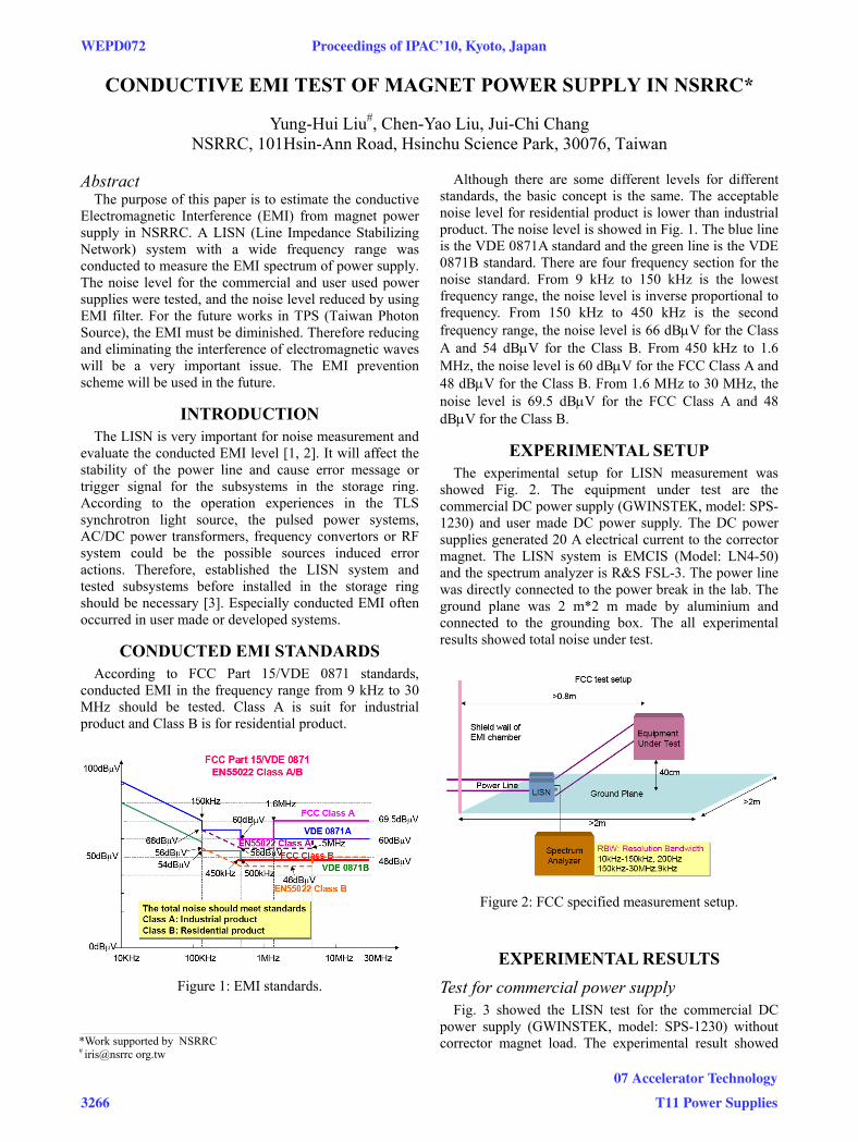
showed Fig. 2. The equipment under test are the commercial DC power supply (GWINSTEK, model: SPS-1230) and user made DC power supply. The DC power supplies generated 20 A electrical current to the corrector magnet. The LISN system is EMCIS (Model: LN4-50) and the spectrum analyzer is R&S FSL-3. The power line was directly connected to the power break in the lab. The ground plane was 2 m*2 m made by aluminium and connected to the grounding box. The all experimental results showed total noise under test.
Figure 2: FCC specified measurement setup.
EXPERIMENTAL RESULTS
Test for commercial power supply Fig. 3 showed the LISN test for the commercial DC
power supply (GWINSTEK, model: SPS-1230) without corrector magnet load. The experimental result showed
___________________________________________
*Work supported by NSRRC # iris@nsrrc org.tw
WEPD072 Proceedings of IPAC’10, Kyoto, Japan
3266
07 Accelerator Technology
T11 Power Supplies
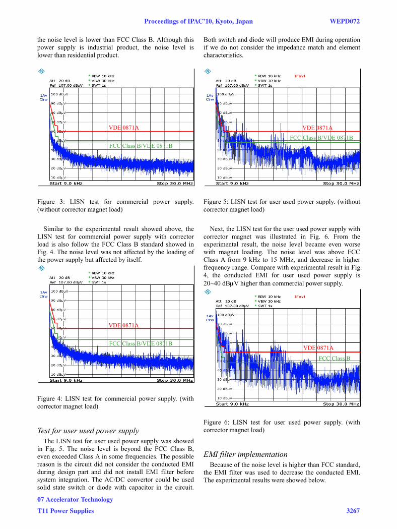
the noise level is lower than FCC Class B. Although this power supply is industrial product, the noise level is lower than residential product.
Figure 3: LISN test for commercial power supply. (without corrector magnet load)
Similar to the experimental result showed above, the
LISN test for commercial power supply with corrector load is also follow the FCC Class B standard showed in Fig. 4. The noise level was not affected by the loading of the power supply but affected by itself.
Figure 4: LISN test for commercial power supply. (with corrector magnet load)
Test for user used power supply The LISN test for user used power supply was showed
in Fig. 5. The noise level is beyond the FCC Class B, even exceeded Class A in some frequencies. The possible reason is the circuit did not consider the conducted EMI during design part and did not install EMI filter before system integration. The AC/DC convertor could be used solid state switch or diode with capacitor in the circuit.
Both switch and diode will produce EMI during operation if we do not consider the impedance match and element characteristics.
Figure 5: LISN test for user used power supply. (without corrector magnet load)
Next, the LISN test for the user used power supply with
corrector magnet was illustrated in Fig. 6. From the experimental result, the noise level became even worse with magnet loading. The noise level was above FCC Class A from 9 kHz to 15 MHz, and decrease in higher frequency range. Compare with experimental result in Fig. 4, the conducted EMI for user used power supply is 20~40 dBμV higher than commercial power supply.
Figure 6: LISN test for user used power supply. (with corrector magnet load)
EMI filter implementation Because of the noise level is higher than FCC standard,
the EMI filter was used to decrease the conducted EMI. The experimental results were showed below.
VDE 0871A
FCC Class B/VDE 0871B
VDE 0871A FCC Class B/VDE 0871B
VDE 0871A
FCC Class B/VDE 0871B VDE 0871A
FCC Class B
Proceedings of IPAC’10, Kyoto, Japan WEPD072
07 Accelerator Technology
T11 Power Supplies 3267
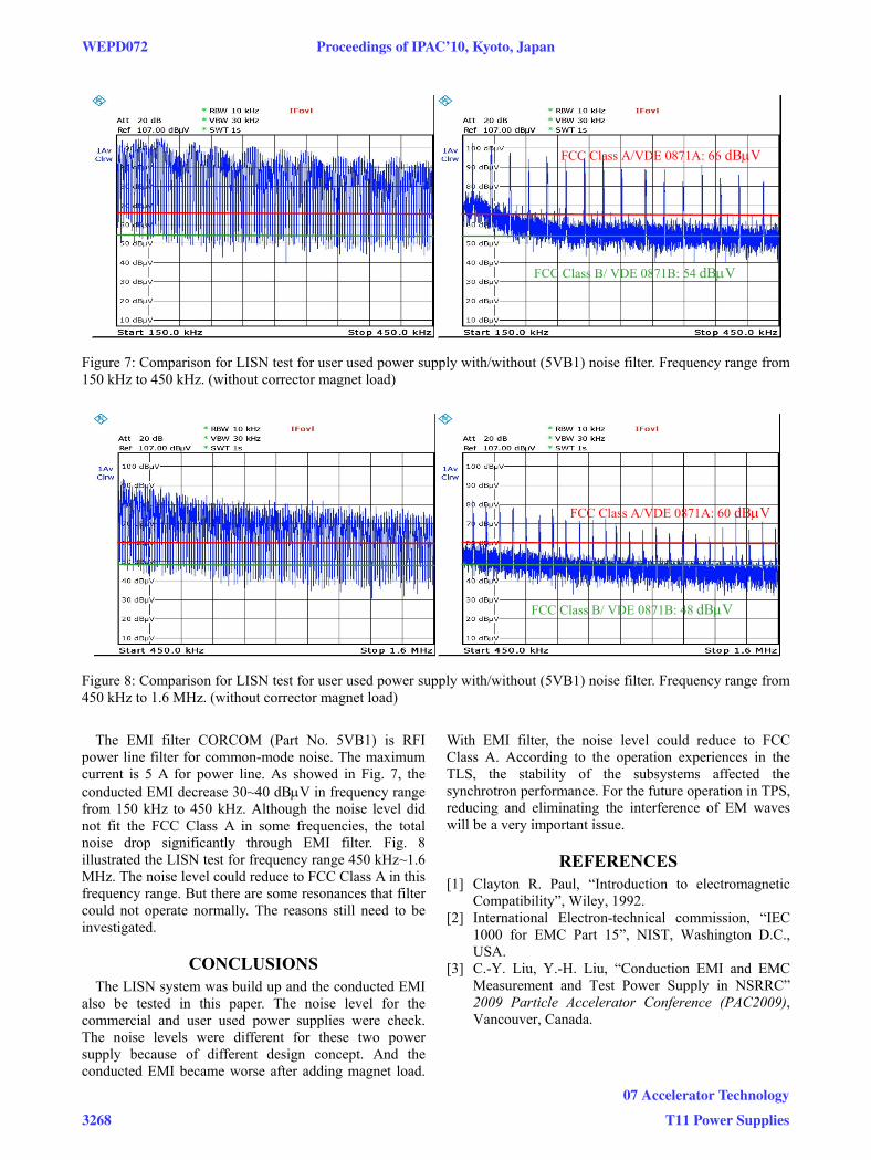
Figure 7: Comparison for LISN test for user used power supply with/without (5VB1) noise filter. Frequency range from 150 kHz to 450 kHz. (without corrector magnet load)
Figure 8: Comparison for LISN test for user used power supply with/without (5VB1) noise filter. Frequency range from 450 kHz to 1.6 MHz. (without corrector magnet load)
The EMI filter CORCOM (Part No. 5VB1) is RFI
power line filter for common-mode noise. The maximum current is 5 A for power line. As showed in Fig. 7, the conducted EMI decrease 30~40 dBμV in frequency range from 150 kHz to 450 kHz. Although the noise level did not fit the FCC Class A in some frequencies, the total noise drop significantly through EMI filter. Fig. 8 illustrated the LISN test for frequency range 450 kHz~1.6 MHz. The noise level could reduce to FCC Class A in this frequency range. But there are some resonances that filter could not operate normally. The reasons still need to be investigated.
CONCLUSIONS The LISN system was build up and the conducted EMI
also be tested in this paper. The noise level for the commercial and user used power supplies were check. The noise levels were different for these two power supply because of different design concept. And the conducted EMI became worse after adding magnet load.
With EMI filter, the noise level could reduce to FCC Class A. According to the operation experiences in the TLS, the stability of the subsystems affected the synchrotron performance. For the future operation in TPS, reducing and eliminating the interference of EM waves will be a very important issue.
REFERENCES [1] Clayton R. Paul, “Introduction to electromagnetic
Compatibility”, Wiley, 1992. [2] International Electron-technical commission, “IEC
1000 for EMC Part 15”, NIST, Washington D.C., USA.
[3] C.-Y. Liu, Y.-H. Liu, “Conduction EMI and EMC Measurement and Test Power Supply in NSRRC” 2009 Particle Accelerator Conference (PAC2009), Vancouver, Canada.
FCC Class A/VDE 0871A: 60 dBμV
FCC Class B/ VDE 0871B: 48 dBμV
FCC Class A/VDE 0871A: 66 dBμV
FCC Class B/ VDE 0871B: 54 dBμV
WEPD072 Proceedings of IPAC’10, Kyoto, Japan
3268
07 Accelerator Technology
T11 Power Supplies