Embed Size (px)
Citation preview
ConnectPort™ X Family User’s Guide
ConnectPort™ X Family:ConnectPort X2, ConnectPort X4, ConnectPort X8
90000832_A

2 U s e r ’ s G u i d e
©Digi International Inc. 2007. All Rights Reserved.
The Digi logo is a registered trademarks of Digi International, Inc.
Digi Connect, Connectware Manager, ConnectPort, Digi SureLink, are trademarks of Digi International, Inc.
All other trademarks mentioned in this document are the property of their respective owners.
Information in this document is subject to change without notice and does not represent a commitment on the part of Digi International.
Digi provides this document “as is,” without warranty of any kind, either expressed or implied, including, but not limited to, the implied warranties of fitness or merchantability for a particular purpose. Digi may make improvements and/or changes in this manual or in the product(s) and/or the program(s) described in this manual at any time.
This product could include technical inaccuracies or typographical errors. Changes are periodically made to the information herein; these changes may be incorporated in new editions of the publication.
C o n t e n t s
ContentsContents...........................................................................................................................................................3
About this guide............................................................................................................................................15Purpose .................................................................................................................................................15Audience...............................................................................................................................................15Scope ....................................................................................................................................................15Where to find more information...........................................................................................................16
General release documentation ..................................................................................................16Additional product information on www.digi.com....................................................................17
Digi contact information ......................................................................................................................17
Chapter 1: Introduction.............................................................................................................................19ConnectPort X Family products ...........................................................................................................20Features ................................................................................................................................................21
User interfaces............................................................................................................................21Quick reference for configuring features ...................................................................................22Hardware features ......................................................................................................................29Network interface features .........................................................................................................29Configurable network services...................................................................................................29IP protocol support .....................................................................................................................30
Serial data communication over TCP and UDP...............................................................31Dynamic Host Configuration Protocol (DHCP) ..............................................................32Auto-IP .............................................................................................................................32Simple Network Management Protocol (SNMP).............................................................32
Supported RFCs and MIBs..................................................................................... 32Supported SNMP traps ........................................................................................... 33
Secure Sockets Layer (SSL)/Transport Layer Security (TLS).........................................33Telnet................................................................................................................................33Remote Login (rlogin)......................................................................................................33Line Printer Daemon (LPD).............................................................................................33
3
C o n t e n t s
HyperText Transfer Protocol (HTTP)HyperText Transfer Protocol over Secure Socket Layer (HTTPS) ................................. 34Internet Control Message Protocol (ICMP)..................................................................... 34Point-to-Point Protocol (PPP) .......................................................................................... 34Network Address Translation (NAT)/Port Forwarding................................................... 34Advanced Digi Discovery Protocol (ADDP)................................................................... 34Generic Routing Encapsulation (GRE) PassthroughEncapsulating Security Payload (ESP)ESP Passthrough .............................................................................................................. 35
Mobile/Cellular features and protocol support .......................................................................... 35Provisioning wizard ......................................................................................................... 35Digi SureLink™............................................................................................................... 35Mobile/Cellular protocols ................................................................................................ 36Global System for Mobile communication (GSM) ......................................................... 36Code-Division Multiple Access (CDMA) ....................................................................... 36General Packet Radio Service (GPRS) ............................................................................ 37Enhanced Data Rates for GSM Evolution (EDGE)......................................................... 37Universal Mobile Telecommunications Service (UMTS) ............................................... 37Evolution-Data Optimized (EV-DO, EVDO, or 1xEV-DO) ........................................... 38
IP address assignment alternatives............................................................................................. 39RealPort software....................................................................................................................... 40
Encrypted RealPort .......................................................................................................... 40Alarms........................................................................................................................................ 41Modem emulation ...................................................................................................................... 41Security features......................................................................................................................... 42Configuration management........................................................................................................ 43Customization capabilities ......................................................................................................... 43
Supported connections and data paths in Digi devices ........................................................................ 44Network services.............................................................................................................. 44
Network services associated with specific serial ports .......................................... 44Network services associated with serial ports in general ....................................... 45Network services associated with the command-line interface ............................. 45
Network/serial clients ...................................................................................................... 46Autoconnect behavior client connections .............................................................. 46
4
C o n t e n t s
Command-line interface (CLI)-based client connections....................................... 46Modem emulation (pseudo-modem) client connections ........................................ 46
Configuration capabilities and interfaces .............................................................................................47Configuration capabilities ..........................................................................................................47Configuration interfaces .............................................................................................................48
The Digi Device Setup wizard .........................................................................................49Digi Device Discovery utility ..........................................................................................51The Web interface ............................................................................................................53Command-line interface...................................................................................................55Connectware Manager interface.......................................................................................56Simple Network Management Protocol (SNMP).............................................................58
Standard MIBs supported ....................................................................................... 59Digi enterprise MIBs supported ............................................................................. 59Additional SNMP resources ................................................................................... 59
Monitoring capabilities and interfaces .................................................................................................60Monitoring interfaces .................................................................................................................60
Web Interface ...................................................................................................................60Command-line interface...................................................................................................61Connectware Manager......................................................................................................61SNMP...............................................................................................................................61
Administration tasks.............................................................................................................................62
Chapter 2: Configure Digi devices............................................................................................................63Default IP address ................................................................................................................................64Alternate methods for assigning an IP address ....................................................................................64
Configure an IP address using the Digi Device Setup Wizard ..................................................64Configure an IP address using DHCP ........................................................................................65Configure an IP address using Auto-IP......................................................................................65Configure an IP address from the command-line interface........................................................66IP addresses and Connectware Manager ....................................................................................66Test the IP address configuration ...............................................................................................67
Configuration through the web interface.............................................................................................68Open the web interface...............................................................................................................69
5

C o n t e n t s
By entering the Digi device’s IP address in a web browser ............................................ 69By using the Digi Device Discovery utility..................................................................... 69
Install Digi Device Discovery utility ..................................................................... 69Discover devices .................................................................................................... 70
Organization of the web interface.............................................................................................. 71The Home page ................................................................................................................ 72Configuration pages ......................................................................................................... 72Application pages ............................................................................................................ 73Apply and save changes................................................................................................... 73Cancel changes ................................................................................................................ 73Restore the Digi device to factory defaults...................................................................... 73Online help....................................................................................................................... 73
Change the IP address from the web interface, as needed ......................................................... 74Configure network communications.......................................................................................... 75
Alternatives for configuring network communications ................................................... 76IP settings......................................................................................................................... 76DHCP server settings....................................................................................................... 77
DHCP terminology................................................................................................. 77Addresses in the DHCP server settings.................................................................. 79DHCP server configuration settings....................................................................... 79Manage the DHCP server....................................................................................... 81
Network services settings ................................................................................................ 82Supported network services and their default network port numbers.................... 83Network services and IP pass-through ................................................................... 86
Dynamic DNS update settings ......................................................................................... 87Settings ................................................................................................................... 87Status and history information ............................................................................... 89
IP filtering settings........................................................................................................... 90IP forwarding settings ...................................................................................................... 91
Example.................................................................................................................. 92Socket tunnel settings ...................................................................................................... 93IP pass-through settings ................................................................................................... 94
How IP pass-through works ................................................................................... 94How IP pass-through affects network access to Digi devices................................ 96
6
C o n t e n t s
Using pinholes to manage the Digi device ............................................................. 96Remote device management and IP pass-through.................................................. 97Steps to configure IP pass-through......................................................................... 97
Virtual Private Network (VPN) settings ..........................................................................99Uses for VPN-enabled Digi devices....................................................................... 99Example VPN configuration ................................................................................ 100How VPN tunnels work........................................................................................ 100IP address requirements for VPN tunnels............................................................. 101GSM GPRS/EDGE APN type needed.................................................................. 101CDMA carrier requirements ................................................................................. 101HQ router / VPN appliance configuration............................................................ 101Using a console port ............................................................................................. 102Configure VPN settings........................................................................................ 102Manual-keyed IPSEc/ESP VPN tunnel security settings ..................................... 112ISAKMP VPN tunnel security settings ................................................................ 115VPN tunnel proposal configuration for ISAKMP tunnels.................................... 117
Advanced network settings ............................................................................................118Configure mobile (cellular) settings.........................................................................................119
Information required from mobile service provider.......................................................119Different processes used for CDMA and GSM provisioning ........................................119
CDMA-based mobile service providers ............................................................... 119GSM-based mobile service providers................................................................... 119
Set mobile configuration settings to factory defaults.....................................................120Mobile service provider settings ....................................................................................120Provision a mobile device ..............................................................................................121
Launch the Mobile Device Provisioning Wizard ................................................. 121Automatic versus manual provisioning ................................................................ 122Example: provision ConnectPort WAN VPN for Sprint™ PCS.......................... 122Re-provision a Digi device ................................................................................... 124
Mobile connection settings.............................................................................................125Digi SureLink™ settings................................................................................................125
Hardware reset thresholds .................................................................................... 126Link integrity monitoring settings ........................................................................ 126
Status and statistical information for mobile connections .............................................129
7
C o n t e n t s
Configure Mesh/ZigBee network settings ............................................................................... 130Mesh network terms ............................................................................................ 130ZigBee protocol terms.......................................................................................... 131
Mesh Network configuration settings............................................................................ 133Basic radio settings............................................................................................... 135Advanced radio settings ....................................................................................... 136
For more information on Mesh networks and the ZigBee protocol .............................. 136Configure serial ports............................................................................................................... 137
About port profiles......................................................................................................... 137Select and configure a port profile................................................................................. 137RealPort profile.............................................................................................................. 138Console Management profile......................................................................................... 138TCP Sockets profile ....................................................................................................... 139
Automatic TCP connections (autoconnection) .................................................... 139RFC 2217 support ................................................................................................ 139TCP and UDP network port numbering conventions........................................... 140
UDP Sockets profile ...................................................................................................... 140Serial Bridge profile....................................................................................................... 141Local Configuration profile ........................................................................................... 141Modem Emulation profile.............................................................................................. 141Custom Profile ............................................................................................................... 142Basic serial settings........................................................................................................ 142Advanced serial settings ................................................................................................ 143
Serial Settings....................................................................................................... 143TCP settings ......................................................................................................... 144UDP settings......................................................................................................... 146
Configure camera settings........................................................................................................ 147Camera settings.............................................................................................................. 147Camera operation ........................................................................................................... 148
Configure alarms...................................................................................................................... 149Alarm notification settings............................................................................................. 149Alarm conditions............................................................................................................ 150
Alarm list.............................................................................................................. 150Alarm conditions .................................................................................................. 151
8

C o n t e n t s
Alarm destinations................................................................................................ 152Enable and Disable Alarms ............................................................................................152
Configure system settings ........................................................................................................153Device description information......................................................................................153SNMP configuration settings .........................................................................................153
Configure remote management (Connectware Manager) settings ...........................................154Steps for setting up remote management .......................................................................154Connection settings ........................................................................................................155
About client-initiated and server-initiated connections........................................ 155Last Known Address (LKA)................................................................................. 156Client initiated management connection settings ................................................. 157Server initiated management connection settings ................................................ 157
Advanced remote management settings.........................................................................158Alarms and the Connectware Manager server ...............................................................160For more information on Connectware Manager...........................................................160
Configure Security settings ......................................................................................................160About user models and user permissions .......................................................................161Password authentication.................................................................................................161
Enable password authentication ........................................................................... 161Disable password authentication .......................................................................... 162Change the password for administrative user....................................................... 162Upload an SSH public key.................................................................................... 163
Disable unused and non-secure network services ..........................................................163Use IP filtering ...............................................................................................................163
Configure applications .............................................................................................................164Python® program management .....................................................................................164
Recommended distribution of Python interpreter ................................................ 164Additional Python programming resources.......................................................... 164Python configuration pages .................................................................................. 164Python files ........................................................................................................... 165Auto-start settings................................................................................................. 165Manually execute uploaded Python programs...................................................... 165
Configuration through the command line ..........................................................................................166Access the command line .........................................................................................................166
9
C o n t e n t s
Verify device support of commands ........................................................................................ 166Configuration through Simple Network Management Protocol (SNMP) ......................................... 169Configuration through Connectware Manager .................................................................................. 170
Configuring Mesh Networks and Nodes through Connectware Manager............................... 170ZigBee Networks View ................................................................................................. 171Node View ..................................................................................................................... 172
Batch capabilities for configuring multiple devices .......................................................................... 174What’s next? ...................................................................................................................................... 174
Chapter 3: Monitor and manage Digi devices....................................................................................... 175Monitoring capabilities in the web interface...................................................................................... 176
Display system information ..................................................................................................... 176General system information........................................................................................... 177Serial port information................................................................................................... 178
Serial port diagnostics page.................................................................................. 178Configuration ....................................................................................................... 179Signals .................................................................................................................. 179Serial statistics...................................................................................................... 180
Network statistics........................................................................................................... 181Ethernet Connection Statistics ............................................................................. 181IP Statistics........................................................................................................... 182TCP Statistics ....................................................................................................... 182
UDP statistics................................................................................................................. 183ICMP statistics ............................................................................................................... 183Mobile information and statistics .................................................................................. 184
Mobile Connection Statistics ............................................................................... 184Mobile Statistics................................................................................................... 185Mobile Information .............................................................................................. 186SureLink statistics ................................................................................................ 187
Diagnostics..................................................................................................................... 188Manage connections and services ............................................................................................ 189
Manage serial ports ........................................................................................................ 189Manage connections ...................................................................................................... 189Manage VPN connections ............................................................................................. 189
1 0
C o n t e n t s
Manage active system connections....................................................................... 189Event logging .................................................................................................................190Manage network services ...............................................................................................190
Manage DHCP server operation........................................................................... 190Start, stop, and restart the DHCP server............................................................... 190View and manage current DHCP leases............................................................... 191Lease status types ................................................................................................. 192
Manage Mesh networks .................................................................................................193Manage Mesh networks from the web interface .................................................. 194Gateway device details ......................................................................................... 195Network view of the Mesh devices ...................................................................... 195Python Application ZigBee Socket Counters....................................................... 195Python Application ZigBee Socket Error Counts................................................. 196Mesh device state pages ....................................................................................... 197
Monitoring capabilities from the command line ................................................................................198Commands for displaying device information and statistics ...................................................198
display ............................................................................................................................198info .................................................................................................................................199set alarm .........................................................................................................................200set buffer and display buffers .........................................................................................200set snmp..........................................................................................................................200show ...............................................................................................................................200
Commands for managing connections and sessions ................................................................201Commands for managing Mesh networks and nodes...............................................................202
set mesh ..........................................................................................................................202Configure Mesh network settings: command syntax ........................................... 202Display Mesh network configuration settings: command syntax......................... 203
display mesh...................................................................................................................204info zigbee_sockets ........................................................................................................205
Monitoring capabilities from Connectware Manager ........................................................................206Monitor/manage Mesh networks from Connectware Manager................................................207
Monitoring Capabilities from SNMP .................................................................................................208
Chapter 4: Administration tasks.............................................................................................................209
1 1
C o n t e n t s
Administration from the web interface .............................................................................................. 210File management ...................................................................................................................... 211
Uploading Files.............................................................................................................. 211Delete files ..................................................................................................................... 211Custom files are not deleted by device reset.................................................................. 211
X.509 Certificate/Key Management ........................................................................................ 212Backup/restore device configurations...................................................................................... 213Update firmware and Boot/POST Code .................................................................................. 214
Prerequisites................................................................................................................... 214Update firmware from a file on a PC............................................................................. 214Update Firmware from a TFTP Server .......................................................................... 214
Restore a device configuration to factory defaults .................................................................. 215Settings cleared and retained during factory reset ......................................................... 215Using the web interface ................................................................................................. 215Using the Reset button ................................................................................................... 216
Display system information ..................................................................................................... 217Reboot the Digi device............................................................................................................. 217Enable/disable access to network services............................................................................... 217
Administration from the command-line interface.............................................................................. 218
Chapter 5: Specifications and certifications .......................................................................................... 219Hardware specifications ..................................................................................................................... 220
ConnectPort X8 specifications................................................................................................. 220Regulatory information and certifications ......................................................................................... 221
Safety standards ....................................................................................................................... 221FCC Part 15 Class B ................................................................................................................ 221
Radio Frequency Interface (RFI) (FCC 15.105)............................................................ 221Labeling Requirements (FCC 15.19)............................................................................. 221Modifications (FCC 15.21)............................................................................................ 222Industry Canada ............................................................................................................. 222Declaration of Conformity............................................................................................. 222International EMC Standards......................................................................................... 223
Important Safety Information............................................................................................................. 224
1 2

C o n t e n t s
Glossary .......................................................................................................................................................225
Index ............................................................................................................................................................241
1 3

C o n t e n t s
1 4
A b o u t t h i s g u i d e
About this guide
Purpose
This guide describes and shows how to provision, configure, monitor, and administer Digi devices.
Audience
This guide is intended for those responsible for setting up Digi devices. It assumes some familiarity with networking concepts and protocols. A glossary is provided with definitions for networking terms and features discussed in the content.
Scope
This guide focuses on configuration, monitoring, and administration of Digi devices. It does not cover hardware details beyond a certain level, application development, or customization of Digi devices.
1 5
W h e r e t o f i n d m o r e i n f o r m a t i o n
Where to find more information
In addition to this guide, find additional product and feature information in the these documents:
General release documentation
These documents are of interest to end users of Digi devices:
Online help and tutorials in the web interface for the Digi device
Quick Start Guides
RealPort® Installation Guide
Cellular 101 Tutorial
Digi Connect Family Customization and Integration Guide
Connectware Manager Getting Started Guide and Operator’s Guide
Release Notes
Cabling Guides
1 6
A b o u t t h i s g u i d e
Additional product information on www.digi.com
In addition to the previous documents, product information is available on the Digi website, www.digi.com, including:
Support Forums
Knowledge Base
Data sheets/product briefs
Application/solution guides
Digi contact information
For more information about Digi products, or for customer service and technical support, contact Digi International.
To Contact Digi International by:
Use:
Mail Digi International11001 Bren Road EastMinnetonka, MN 55343U.S.A.
World Wide Web: http://www.digi.com/support/
email http://www.digi.com/support/
Telephone (U.S.) (952) 912-3444 or (877) 912-3444
Telephone (other locations) +1 (952) 912-3444 or (877) 912-3444
1 7

D i g i c o n t a c t i n f o r m a t i o n
1 8
I n t r o d u c t i o n
IntroductionC H A P T E R 1
This chapter introduces Digi devices and their product families, types of connections and data paths in which Digi devices can be used, and the interface options available for configuring, monitoring, and administering Digi devices.
1 9
C o n n e c t P o r t X F a m i l y p r o d u c t s
ConnectPort X Family products
The ConnectPort X Family of products is intended to provide gateway functionality between various network technologies such as Ethernet, cellular, Wi-Fi, and Mesh (IEEE 802.15.4 and ZigBee). In addition to providing IP network connectivity between cellular, Wi-Fi and Ethernet networks and devices; ConnectPort X Family products are designed to provide remote connectivity to mesh networks as well as other devices connected to local ports: USB, 1-Wire, RabbitNet, and asynchronous serial. ConnectPort X Family products act as a coordinator for a Mesh network. As with the Connect and Cellular product families, ConnectPort X Family products are supported by Digi’s Connectware Manager device management software application, which can be used to remotely manage gateway devices and Mesh networks.
Key features of ConnectPort X Family include:
Network flexibility: gateway functionality for a variety of networks
MaxStream XBeePro Radio
Currently Freescale-based, primarily 802.15.4
Ember-250/ZigBee-based
Commercial/Industrial Grade
Connectware Enterprise Management: High-level and detailed views of Mesh networks and nodes
Personal Area Network (PAN) connectivity and management
Support of Python programming language, for creating a variety of embedded programs and applications
Remote help desk support through a WatchPort® Camera connection to a USB host port
Security
2 0
I n t r o d u c t i o n
Features
This is an overview of key features in Digi devices. Software features are covered in more detail in the next three chapters. Hardware specifications and are covered in Chapter 5, "Specifications and certifications".
User interfaces
There are several user interfaces for configuring and monitoring Digi devices, including:
The Digi Device Setup Wizard, a wizard-based tool for assigning an IP address to a Digi device, minimally configuring it, and installing RealPort software on a PC or server.
A web-based interface for configuring, monitoring, and administering Digi devices. For Digi devices that ship with a default IP address, simply connecting a laptop computer to the Ethernet port of these products allows direct access to the web interface for configuration.
A command-line interface.
Simple Network Management Protocol (SNMP).
The Connectware Manager Console.
For additional details on these user interfaces, see "Configuration interfaces" on page 48 and "Monitoring interfaces" on page 60. Some user interfaces can be customized.
2 1
F e a t u r e s
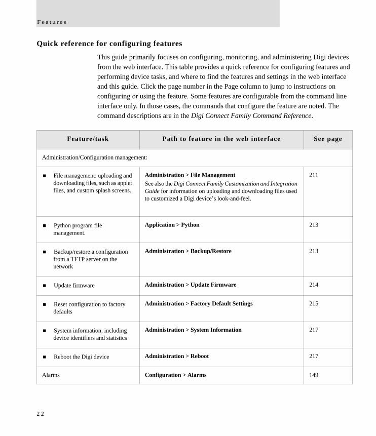
Quick reference for configuring features
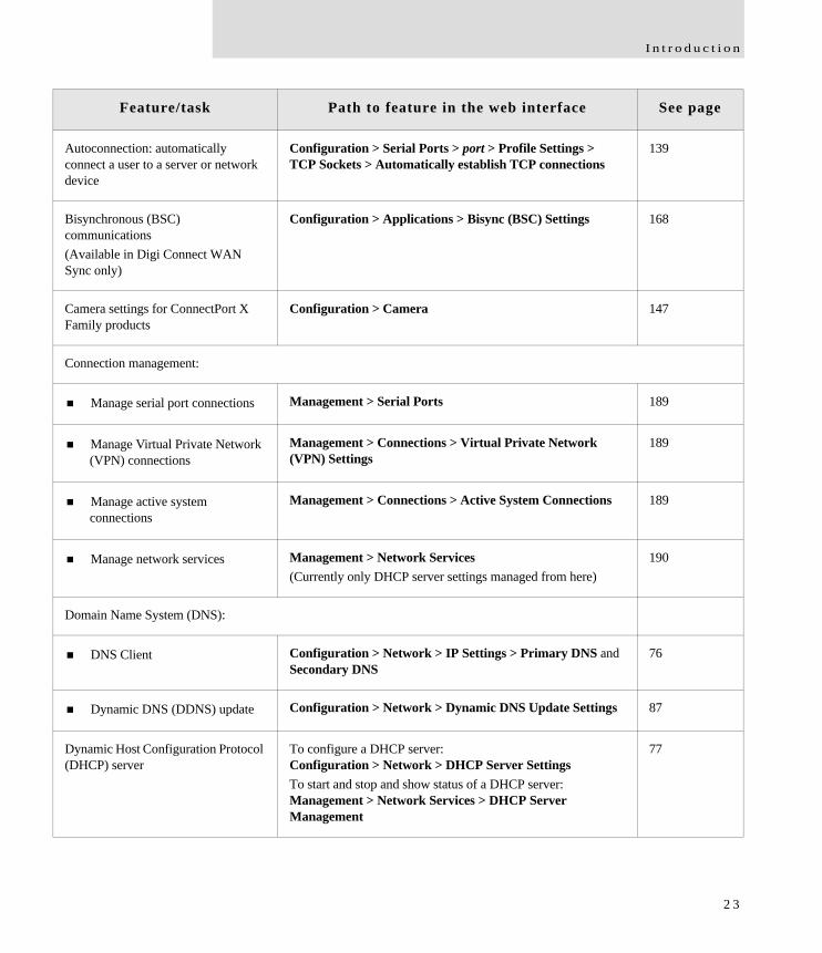
This guide primarily focuses on configuring, monitoring, and administering Digi devices from the web interface. This table provides a quick reference for configuring features and performing device tasks, and where to find the features and settings in the web interface and this guide. Click the page number in the Page column to jump to instructions on configuring or using the feature. Some features are configurable from the command line interface only. In those cases, the commands that configure the feature are noted. The command descriptions are in the Digi Connect Family Command Reference.
Feature/task Path to feature in the web interface See page
Administration/Configuration management:
File management: uploading and downloading files, such as applet files, and custom splash screens.
Administration > File ManagementSee also the Digi Connect Family Customization and Integration Guide for information on uploading and downloading files used to customized a Digi device’s look-and-feel.
211
Python program file management.
Application > Python 213
Backup/restore a configuration from a TFTP server on the network
Administration > Backup/Restore 213
Update firmware Administration > Update Firmware 214
Reset configuration to factory defaults
Administration > Factory Default Settings 215
System information, including device identifiers and statistics
Administration > System Information 217
Reboot the Digi device Administration > Reboot 217
Alarms Configuration > Alarms 149
2 2
I n t r o d u c t i o n
Autoconnection: automatically connect a user to a server or network device
Configuration > Serial Ports > port > Profile Settings > TCP Sockets > Automatically establish TCP connections
139
Bisynchronous (BSC) communications(Available in Digi Connect WAN Sync only)
Configuration > Applications > Bisync (BSC) Settings 168
Camera settings for ConnectPort X Family products
Configuration > Camera 147
Connection management:
Manage serial port connections Management > Serial Ports 189
Manage Virtual Private Network (VPN) connections
Management > Connections > Virtual Private Network (VPN) Settings
189
Manage active system connections
Management > Connections > Active System Connections 189
Manage network services Management > Network Services(Currently only DHCP server settings managed from here)
190
Domain Name System (DNS):
DNS Client Configuration > Network > IP Settings > Primary DNS and Secondary DNS
76
Dynamic DNS (DDNS) update Configuration > Network > Dynamic DNS Update Settings 87
Dynamic Host Configuration Protocol (DHCP) server
To configure a DHCP server: Configuration > Network > DHCP Server SettingsTo start and stop and show status of a DHCP server: Management > Network Services > DHCP Server Management
77
Feature/task Path to feature in the web interface See page
2 3
F e a t u r e s
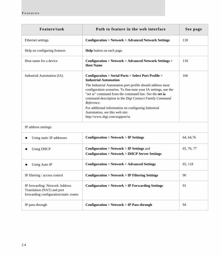
Ethernet settings Configuration > Network > Advanced Network Settings 118
Help on configuring features Help button on each page.
Host name for a device Configuration > Network > Advanced Network Settings > Host Name
118
Industrial Automation (IA) Configuration > Serial Ports > Select Port Profile > Industrial AutomationThe Industrial Automation port profile should address most configuration scenarios. To fine-tune your IA settings, use the “set ia” command from the command line. See the set ia command description in the Digi Connect Family Command Reference.For additional information on configuring Industrial Automation, see this web site:http://www.digi.com/support/ia
166
IP address settings:
Using static IP addresses Configuration > Network > IP Settings 64, 64,76
Using DHCP Configuration > Network > IP Settings andConfiguration > Network > DHCP Server Settings
65, 76, 77
Using Auto IP Configuration > Network > Advanced Settings 65, 118
IP filtering / access control Configuration > Network > IP Filtering Settings 90
IP forwarding: Network Address Translation (NAT) and port forwarding configuration/static routes
Configuration > Network > IP Forwarding Settings 91
IP pass-through Configuration > Network > IP Pass-through 94
Feature/task Path to feature in the web interface See page
2 4
I n t r o d u c t i o n
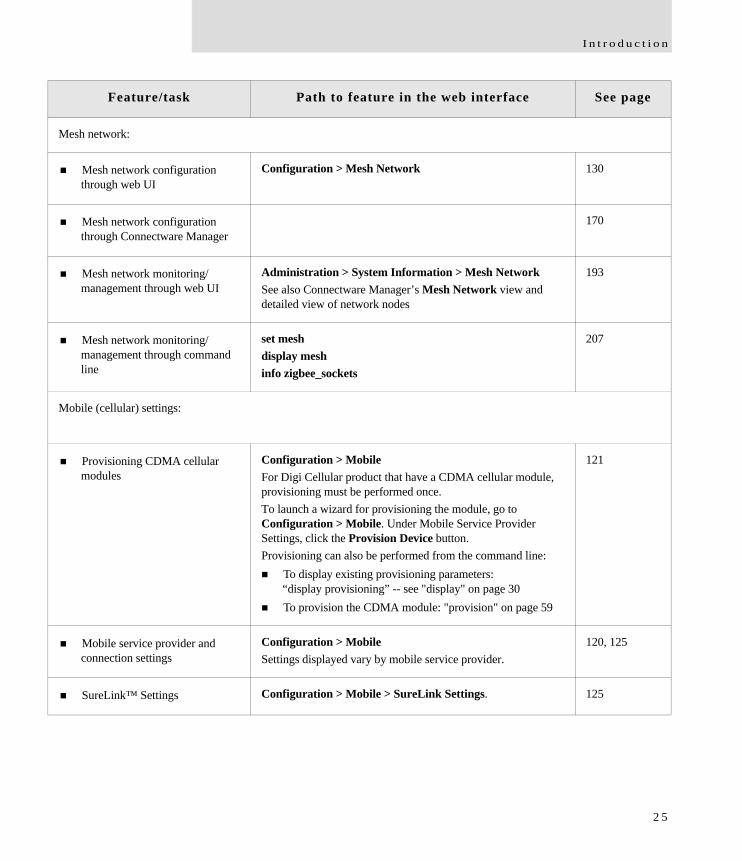
Mesh network:
Mesh network configuration through web UI
Configuration > Mesh Network 130
Mesh network configuration through Connectware Manager
170
Mesh network monitoring/management through web UI
Administration > System Information > Mesh NetworkSee also Connectware Manager’s Mesh Network view and detailed view of network nodes
193
Mesh network monitoring/management through command line
set meshdisplay meshinfo zigbee_sockets
207
Mobile (cellular) settings:
Provisioning CDMA cellular modules
Configuration > MobileFor Digi Cellular product that have a CDMA cellular module, provisioning must be performed once.To launch a wizard for provisioning the module, go to Configuration > Mobile. Under Mobile Service Provider Settings, click the Provision Device button. Provisioning can also be performed from the command line: To display existing provisioning parameters:
“display provisioning” -- see "display" on page 30 To provision the CDMA module: "provision" on page 59
121
Mobile service provider and connection settings
Configuration > MobileSettings displayed vary by mobile service provider.
120, 125
SureLink™ Settings Configuration > Mobile > SureLink Settings. 125
Feature/task Path to feature in the web interface See page
2 5
F e a t u r e s
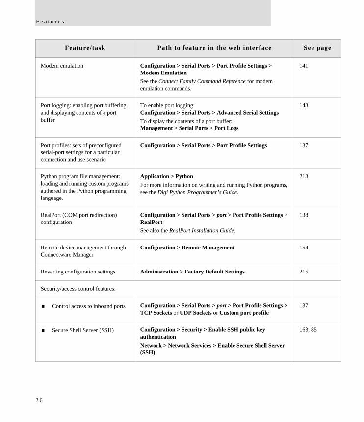
Modem emulation Configuration > Serial Ports > Port Profile Settings > Modem EmulationSee the Connect Family Command Reference for modem emulation commands.
141
Port logging: enabling port buffering and displaying contents of a port buffer
To enable port logging: Configuration > Serial Ports > Advanced Serial SettingsTo display the contents of a port buffer: Management > Serial Ports > Port Logs
143
Port profiles: sets of preconfigured serial-port settings for a particular connection and use scenario
Configuration > Serial Ports > Port Profile Settings 137
Python program file management: loading and running custom programs authored in the Python programming language.
Application > Python For more information on writing and running Python programs, see the Digi Python Programmer’s Guide.
213
RealPort (COM port redirection) configuration
Configuration > Serial Ports > port > Port Profile Settings > RealPortSee also the RealPort Installation Guide.
138
Remote device management through Connectware Manager
Configuration > Remote Management 154
Reverting configuration settings Administration > Factory Default Settings 215
Security/access control features:
Control access to inbound ports Configuration > Serial Ports > port > Port Profile Settings > TCP Sockets or UDP Sockets or Custom port profile
137
Secure Shell Server (SSH) Configuration > Security > Enable SSH public key authenticationNetwork > Network Services > Enable Secure Shell Server (SSH)
163, 85
Feature/task Path to feature in the web interface See page
2 6

I n t r o d u c t i o n
Issue a new/changed password to a user
Configuration > Security 160
Serial port configuration:
Basic serial port settings Configuration > Serial Ports > Basic Serial Settings 142
Advanced serial port settings Configuration > Serial Ports > Advanced Serial Settings 143
Port profiles: associate a serial port with a set of preconfigured port settings for a specific use
Configuration > Serial Ports > Port Profile Settings 137
RCI over serial mode Configuration > Serial Ports > Advanced Serial Settings 143
RTS Toggle Configuration > Serial Ports > Advanced Serial Settings 143
TCP serial connections Configuration > Serial Ports > port > Port Profile Settings > TCP Sockets port profile
139
UDP serial characteristics Configuration > Serial Ports > port > Port Profile Settings > UDP Sockets port profile
140
Simple Network Management Protocol (SNMP):
Configure SNMP through the web interface
Configuration > System > Simple Network Management Protocol (SNMP) Settings
153
Enable/disable SNMP service Configuration > Network > Network Services 82
Enable/disable SNMP alarm traps
Configuration > Alarms > alarm > Send SNMP trap to following destination when alarm occurs
151, 152
Feature/task Path to feature in the web interface See page
2 7
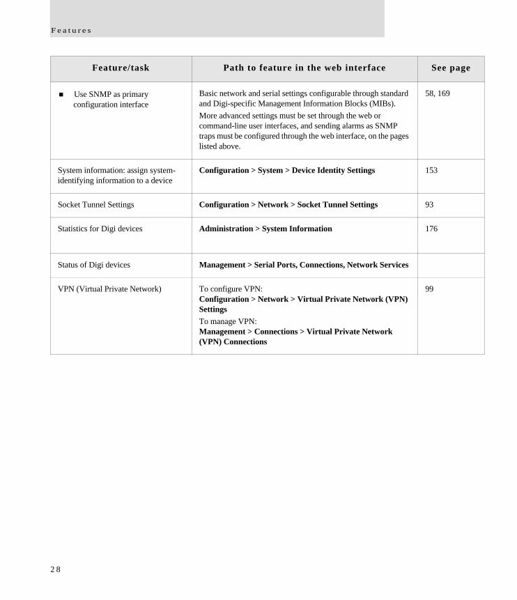
F e a t u r e s
Use SNMP as primary configuration interface
Basic network and serial settings configurable through standard and Digi-specific Management Information Blocks (MIBs).More advanced settings must be set through the web or command-line user interfaces, and sending alarms as SNMP traps must be configured through the web interface, on the pages listed above.
58, 169
System information: assign system-identifying information to a device
Configuration > System > Device Identity Settings 153
Socket Tunnel Settings Configuration > Network > Socket Tunnel Settings 93
Statistics for Digi devices Administration > System Information 176
Status of Digi devices Management > Serial Ports, Connections, Network Services
VPN (Virtual Private Network) To configure VPN: Configuration > Network > Virtual Private Network (VPN) SettingsTo manage VPN: Management > Connections > Virtual Private Network (VPN) Connections
99
Feature/task Path to feature in the web interface See page
2 8
I n t r o d u c t i o n
Hardware features
A summary of hardware features, including power-supply information, is in "Hardware specifications" on page 220.
Network interface features
A detailed list of network interface features is in Chapter 5, "Specifications and certifications". See also the data sheet for your Digi product.
Configurable network services
Access to network services can be enabled and disabled. This means that a device’s use of network services can be restricted to those strictly needed by the device. To improve device security, non-secure services, such as Telnet, can be disabled.
Network services that can be enabled or disabled include:
Advanced Digi Discovery Protocol (ADDP): can enable or disable ADDP, but cannot change its network port number.
RealPort
Encrypted RealPort
HTTP/HTTPS
Line Printer Daemon (LPD)
Remote Login (rlogin)
Remote Shell (rsh)
Simple Network Management Protocol (SNMP)
Telnet
In the web interface, access to network services is enabled and disabled on the Network Services page of Network Configuration. For more information, see "Network services settings" on page 82. In the command-line interface, network services are enabled and disabled through the set service command. See the Digi Connect Family Command Reference for the set service command description.
2 9
F e a t u r e s
IP protocol support
All Digi devices include a Robust on-board TCP/IP stack with a built-in web server. Supported protocols include, unless otherwise noted:
Transmission Control Protocol (TCP)
User Datagram Protocol (UDP)
Dynamic Host Configuration Protocol (DHCP)
Simple Network Management Protocol (SNMP)
Secure Sockets Layer (SSL)/Transport Layer Security (TLS)
Telnet Com Port Control Option (Telnet) including support of RFC 2217 (ability to control serial port through Telnet). See "Serial data communication over TCP and UDP" on page 31 for additional information.
Remote Login (rlogin)
Line Printer Daemon (LPD)
HyperText Transfer Protocol (HTTP)/HyperText Transfer Protocol over Secure Socket Layer (HTTPS)
Simple Mail Transfer Protocol (SMTP)
Internet Control Message Protocol (ICMP)
Internet Group Management Protocol (IGMP)
Address Resolution Protocol (ARP)
Advanced Digi Discovery Protocol (ADDP)
Point to Point Protocol (PPP)
Network Address Translation (NAT)/Port Forwarding
Secure Shell (SSHv2)
Generic Routing Encapsulation (GRE) Passthrough
Encapsulating Security Payload (ESP)
ESP Passthrough
Following is an overview of some of the services provided by these protocols.
3 0
I n t r o d u c t i o n
Serial data communication over TCP and UDP
Digi devices support serial data communication over TCP and UDP. Key features include:
Serial data communication over TCP, also known as autoconnect and tcpserial can automatically perform the following functions: – Establish bidirectional TCP connections, known as autoconnections, between
the serial device and a server or other network device. Autoconnections can be made based on data and or serial hardware signals.
– Control forwarding characteristics based on size, time, and pattern– Allow incoming raw, Telnet, and SSL/TLS (secure-socket) connections– Support RFC 2217, an extension of the Telnet protocol
Serial data communication over UDP, also known as udpserial, can automatically perform the following functions: – Digi Connect products can automatically send serial data to one or more
devices or systems on the network using UDP sockets. Options for sending data include whether specific data is on the serial line, a specific time period has elapsed, or after the specified number of bytes has been received on the serial port.
– Control forwarding characteristics based on size, time, and patterns.– Support incoming datagrams from multiple destinations.– Support outgoing datagrams sent to multiple destinations.
TCP/UDP forwarding characteristics.
Extended communication control on TCP/UDP data paths.– Timeout– Hangup– User-configurable Socket ID string (text string identifier on autoconnect only)
3 1
F e a t u r e s
Dynamic Host Configuration Protocol (DHCP)
Dynamic Host Configuration Protocol (DHCP) can be used to automatically assign IP addresses, deliver TCP/IP stack configuration parameters such as the subnet mask and default router, and provide other configuration information. For further details, see "IP address assignment alternatives" on page 39.
Auto-IP
Auto-IP is a protocol that will automatically assign an IP address from a reserved pool of standard Auto-IP addresses to the computer on which it is installed. Digi devices are set to obtain its IP address automatically from a DHCP server. But if the DHCP server is unavailable or nonexistent, Auto-IP will assign the device an IP address. For further details, see "IP address assignment alternatives" on page 39.
Simple Network Management Protocol (SNMP)
Simple Network Management Protocol (SNMP) is a protocol for managing and monitoring network devices. SNMP architecture enables a network administrator to manage nodes--servers, workstations, routers, switches, hubs, etc.--on an IP network; manage network performance, find and solve network problems, and plan for network growth. Digi devices support SNMP Version 1. For more information on SNMP as a device-management interface, see "Simple Network Management Protocol (SNMP)" on page 58.
Supported RFCs and MIBs
Digi devices support these SNMP-related Request for Comments (RFCs) and Management Information Bases (MIBs):
RFC 1213 - Management Information Base (MIB) II
RFC 1215 - Generic Traps (coldStart, linkUp, authenticationFailure only)
RFC 1316 - Character MIB
RFC 1317 - RS-232 MIB
DIGI-DEVICE-INFO.mib - A Digi enterprise MIB for displaying device information.
DIGI-SERIAL-ALARM-TRAPS.mib - A Digi enterprise MIB for sending alarms as SNMP traps.
3 2
I n t r o d u c t i o n
Supported SNMP traps
SNMP traps can be enabled or disabled. Supported SNMP traps include:
Authentication failure
Login
Cold start
Link up
Alarms can be issued in the form of SNMP traps
Secure Sockets Layer (SSL)/Transport Layer Security (TLS)
Secure Sockets Layer (SSL)/Transport Layer Security (TLS) are used to provide authentication and encryption for Digi Cellular Family products. For more information, see "Security features" on page 42.
Telnet
Digi Cellular Family products support the following types of Telnet connections:
Telnet Client
Telnet Server
Reverse Telnet, often used for console management or device management
Telnet Autoconnect
RFC 2217, Telnet Com Port Control Option, an extension of the Telnet protocol
For more information on these connections, see "Supported connections and data paths in Digi devices" on page 44. Access to Telnet network services can be enabled or disabled.
Remote Login (rlogin)
Users can perform logins to remote systems (rlogin). Remote Login is not supported in Dig Connect WAN. Access to rlogin service can be enabled or disabled.
Line Printer Daemon (LPD)
The Line Printer Daemon (LPD) allows network printing over a serial port. Each serial port has a dedicated LPD server that is independently configurable. Access to LPD service can be enabled or disabled.
3 3
F e a t u r e s
HyperText Transfer Protocol (HTTP)HyperText Transfer Protocol over Secure Socket Layer (HTTPS)
Digi devices provide web pages for configuration that can be secured by requiring a user login.
Internet Control Message Protocol (ICMP)
ICMP statistics can be displayed, including the number of messages received, bad messages received, and destination unreachable messages received.
Point-to-Point Protocol (PPP)
The Point-to-Point Protocol (PPP) transports multi-protocol packets over point-to-point links. PPP encapsulates the data packet, allows the server to inform the dial-up client of its IP address (or client to request the IP address), authenticates the exchange, negotiates multiple protocols, and reassembles the data packet for network communication. Digi Cellular devices support PPP as the connection protocol from the Digi Cellular device to the cellular IP network with NAT (Network Address Technology).
Network Address Translation (NAT)/Port Forwarding
Network Address Translation (NAT) reduces the need for a large amount of publicly known IP addresses by creating a separation between publicly known and privately known IP addresses.
Advanced Digi Discovery Protocol (ADDP)
The Advanced Digi Discovery Protocol (ADDP) runs on any operating system capable of sending multicast IP packets on a network. ADDP allows the system to identify all ADDP-enabled Digi devices attached to a network by sending out a multicast packet. The Digi devices respond to the multicast packet and identify themselves to the client sending the multicast.
ADDP needs to communicate with the TCP/IP stack using UDP. The TCP/IP stack should be able to receive multicast packets and transmit datagrams on a network.
Not all Digi devices support ADDP.
Access to ADDP service can be enabled or disabled, but the network port number for ADDP cannot be changed from its default.
3 4
I n t r o d u c t i o n
Generic Routing Encapsulation (GRE) PassthroughEncapsulating Security Payload (ESP)ESP Passthrough
Generic Routing Encapsulation (GRE) and Encapsulating Security Payload (ESP) are routing protocols that are used to route (tunnel) various types of information between networks.
GRE applies to the encapsulation of IP datagrams tunnelled through the internet. The encapsulation includes security, typically in the form of IPSec (IP security), and is most commonly found in VPN (Virtual Private Network) implementation. RFC (Request For Comment) 1701 and 1702 define these standards.Similarly, ESP is used in conjunction with IPsec as a possible way of carrying IP packets for a Virtual Private Network (VPN) setup. ESP is defined in RFC 2406.
In ESP Passthrough and GRE Passthrough, inbound IPsec ESP or GSP protocol traffic is forwarded from to a VPN device connected to the Digi device’s Ethernet port.
Note: If an Auto-key Internet Key Exchange (IKE)-based VPN is used, UDP port 500 must also be forwarded.
Mobile/Cellular features and protocol support
Provisioning wizard
For Digi devices equipped with a Code-Division Multiple Access (CDMA)-based cellular modem, a wizard is available in the web interface to properly configure the Digi device with the required configuration used to access the mobile network. The wizard allows for both automatic and manual provisioning for a variety of mobile service providers.
Digi SureLink™
All Digi Cellular Family products support the Digi SureLink™ feature. Digi SureLink provides an “always-on” mobile network connection to ensure that a Digi device is in a state where it can connect to the network. It does this through hardware reset thresholds and periodic tests of the connection.
3 5
F e a t u r e s
Mobile/Cellular protocols
Protocols supported in the Digi Cellular Family include, unless otherwise noted:
Global System for Mobile communication (GSM)
Code-Division Multiple Access (CDMA)
General Packet Radio Service (GPRS)
Enhanced Data Rates for GSM Evolution (EDGE)
Universal Mobile Telecommunications Service (UMTS) (ConnectPort WAN VPN only)
Evolution-Data Optimized (EV-DO, EVDO, or 1xEV-DO) (ConnectPort WAN VPN only)
Global System for Mobile communication (GSM)
The GSM protocol is a digital mobile telephone system used in Europe and other parts of the world. There are three major types of digital mobile systems and GSM is the most widely used. GSM compresses and digitizes data and sends it down a channel along with two other streams of user data - each in its own time slot.
Code-Division Multiple Access (CDMA)
CDMA is a form of multiplexing, which allows numerous signals to occupy a single transmission channel, optimizing the use of available bandwidth. The technology is used in ultra-high-frequency (UHF) cellular telephone systems in the 800-MHz and 1.9-GHZ bands and through an analog-to digital conversion enhances privacy and makes cloning difficult.
3 6
I n t r o d u c t i o n
General Packet Radio Service (GPRS)
GPRS is based on Global System for Mobile (GSM) communication. GPRS is a packet-based wireless communication service that transports data rates from 56 up to 114 Kbps and continuous connection to the Internet for mobile phone and computer users. Higher data rates allow users more flexibility in the media they transmit. In theory, GPRS packet-based service costs users less than circuit-switched services since communication channels are being used on a shared-use, as-packets-are-needed basis rather than dedicated only to one user at a time. It should also be easier to make applications available to mobile users because the faster data rate means that middleware currently needed to adapt applications to the slower speed of wireless systems will no longer be needed.
Enhanced Data Rates for GSM Evolution (EDGE)
EDGE is a faster version of the GSM wireless service and designed to deliver data at rates up to 384 Kbps and enable the delivery of multimedia and other broadband applications to mobile phone and computer users. The EDGE standard is built on the existing GSM standard, using the same time-division multiple access frame structure and existing cell arrangements.
Universal Mobile Telecommunications Service (UMTS)
(Supported in ConnectPort WAN VPN only.)
UMTS is a third-generation (3G) broadband, packet-based transmission of text, digitized voice, video, and multimedia at data rates up to 2 megabits per second (Mbps) that offers a consistent set of services to mobile computer and phone users no matter where they are located in the world. Based on the Global System for Mobile (GSM) communication standard, UMTS, endorsed by major standards bodies and manufacturers, is the planned standard for mobile users around the world and is at present still being made available. Once UMTS is fully available geographically, computer and phone users can be constantly attached to the Internet as they travel and, as they roam, have the same set of capabilities no matter where they travel to. Users will have access through a combination of terrestrial wireless and satellite transmissions. Until UMTS is fully implemented, users can have multi-mode devices that switch to the currently available technology (such as GSM 900 and 1800) where UMTS is not yet available.
Today's cellular telephone systems are mainly circuit-switched, with connections always dependent on circuit availability. A packet-switched connection, using the Internet Protocol (IP), means that a virtual connection is always available to any other end point in
3 7
F e a t u r e s
the network. It will also make it possible to provide new services, such as alternative billing methods (pay-per-bit, pay-per-session, flat rate, asymmetric bandwidth, and others). The higher bandwidth of UMTS also promises new services, such as video conferencing. UMTS promises to realize the Virtual Home Environment (VHE) in which a roaming user can have the same services to which the user is accustomed when at home or in the office, through a combination of transparent terrestrial and satellite connections.
The electromagnetic radiation spectrum for UMTS has been identified as frequency bands 1885-2025 MHz for future IMT-2000 systems, and 1980-2010 MHz and 2170-2200 MHz for the satellite portion of UMTS systems.
Evolution-Data Optimized (EV-DO, EVDO, or 1xEV-DO)
EVDO is a wireless radio broadband data standard adopted by many CDMA mobile phone service providers. It is standardized by 3GPP2, as part of the CDMA2000 family of standards. Compared to 1xRTT (CDMA2000 1x) networks, or GPRS and EDGE networks, 1xEV-DO is significantly faster. (Available in ConnectPort WAN VPN only.)
3 8
I n t r o d u c t i o n
IP address assignment alternatives
There are several ways to assign an IP address to a Digi device:
Static IP: Assign a specific IP address to a device, through the Digi Device Setup Wizard, the web interface, or the command-line interface.
Using Dynamic Host Configuration Protocol (DHCP). Dynamic Host Configuration Protocol (DHCP) is an Internet protocol for automating the configuration of computers that use TCP/IP. DHCP can be used to automatically assign IP addresses, to deliver TCP/IP stack configuration parameters such as the subnet mask and default router, and to provide other configuration information. All Digi devices except Digi Connect WAN IA have a DHCP server enabled by default. Digi Connect WAN IA is configured by default to be a DHCP client.
Auto Private IP Addressing (APIPA), also known as Auto-IP: A standard protocol that will automatically assign an IP address from a reserved pool of standard Auto-IP addresses to the computer on which it is installed. The device is set to obtain its IP address automatically from a DHCP server. But if the DHCP server is unavailable or nonexistent, Auto-IP will assign the device an IP address. If DHCP is enabled or responds later ADDP is used, both will override the Auto-IP address previously assigned.
For more details, see "Default IP address" on page 64 and "Alternate methods for assigning an IP address" on page 64.
3 9
F e a t u r e s
RealPort software
Digi devices use the patented RealPort COM/TTY port redirection for Microsoft Windows. RealPort software provides a virtual connection to serial devices, no matter where they reside on the network. The software is installed directly on the host PC and allows applications to talk to devices across a network as though the devices were directly attached to the host. Actually, the devices are connected to a Digi device somewhere on the network.
RealPort is unique among COM port re-directors because it is the only implementation that allows multiple connections to multiple ports over a single TCP/IP connection. Other implementations require a separate TCP/IP connection for each serial port. Unique features also include full hardware and software flow control, as well as tunable latency and throughput.
Access to RealPort services can be enabled or disabled.
Encrypted RealPort
Digi devices also support RealPort software with encryption. Encrypted RealPort offers a secure Ethernet connection between the COM or TTY port and a device server or terminal server. Encryption prevents internal and external snooping of data across the network by encapsulating the TCP/IP packets in a Secure Sockets Layer (SSL) connection and encrypting the data using Advanced Encryption Standard (AES), one of the latest, most efficient security algorithms. Access to Encrypted RealPort services can be enabled or disabled.
Digi’s RealPort with encryption driver has earned Microsoft’s Windows Hardware Quality Lab (WHQL) certification.
Drivers are available for a wide range of operating systems, including Microsoft Windows Server 2003, Windows XP, Windows 2000, Windows NT, Windows 98, Windows ME; SCO Open Server; Linux; AIX; Sun Solaris SPARC; Intel; and HP-UX. It is ideal for financial, retail/point-of-sale, government or any application requiring enhanced security to protect sensitive information.
4 0
I n t r o d u c t i o n
Alarms
Digi devices can be configured to issue alarms, in the form of email message or SNMP traps, when certain device events occur. These events include certain data patterns being detected in the data stream, and cellular alarms for signal strength and amount of cellular traffic for a given period of time. Receiving alarms about these conditions provides the advantage of notifications being issued when events occur, rather than having to monitor the device on an ongoing basis to determine whether these events have occurred. Alarms can also be forwarded to Connectware Manager for display and management in that platform. For more information on configuring alarms, see "Configure alarms" on page 149.
Modem emulation
Digi devices include a configuration profile that allows the device to emulate a modem. Modem emulation sends and receives modem responses to a serial device over TCP/IP (including Ethernet and Cellular) instead of Public Switched Telephone Network (PSTN). The modem emulation profile allows maintaining a current software application but using it over the less expensive Ethernet network. In addition, Telnet processing can be enabled or disabled on the incoming and outgoing modem-emulation connections.The modem-emulation commands supported in Digi devices are documented in the Digi Connect Family Command Reference.
4 1
F e a t u r e s
Security features
Security-related features in Digi devices include:
Secure access and authentication: – One password, one permission level.– Can issue passwords to device users.– Can selectively enable and disable network services such as ADDP, RealPort,
Encrypted RealPort, HTTP/HTTPS, LPD, Remote Login, Remote Shell, SNMP, and Telnet.
– Can control access to inbound ports.– Secure sites for configuration: HTML pages for configuration have appropriate
security.
Encryption:– Strong Secure Sockets Layer (SSL) V3.0/ Transport Layer Security (TLS)
V1.0-based encryption: DES (64-bit), 3DES (192-bit), AES (128-/192-/256-bit), IPsec ESP: DES, 3DES, AES.
– Encrypted RealPort offers encryption for the Ethernet connection between the COM/TTY port and the Digi device.
SNMP security:– Authorization: Changing public and private community names is
recommended to prevent unauthorized access to the device.– SNMP “set” commands can be disabled to make use of SNMP read-only.
4 2
I n t r o d u c t i o n
Configuration management
Once a Digi device is configured and running, configuration-management tasks need to be periodically performed, such as:
Upgrading firmware
Copying configurations to and from a remote host
Software and factory resets
Rebooting the device
Memory management
File management
For more information on these configuration-management tasks, see Chapter 4, "Administration tasks".
Customization capabilities
Several aspects of using Digi devices can be customized. For example:
The look-and-feel of the device interface can be customized, to use a different company logo or screen colors.
Custom factory defaults to which devices can be reverted can be defined.
The Digi Connect Family Customization and Integration Guide (Part Number 90000734; available with the Digi Connect Integration Kit) describes customization and integration tools and processes. Contact Digi International for more information on customization tools and resources and for assistance with customization efforts.
4 3
S u p p o r t e d c o n n e c t i o n s a n d d a t a p a t h s i n D i g i d e v i c e s
Supported connections and data paths in Digi devices
Digi devices allow for several kinds of connections and paths for data flow between the Digi device and other entities. These connections can be grouped into two main categories:
Network services, in which a remote entity initiates a connection to a Digi device.
Network/serial clients, in which a Digi device initiates a network connection or opens a serial port for communication.
This discussion of connections and data paths may be helpful in understanding the effects of enabling certain features and choosing certain settings when configuring Digi products.
Network services
A network service connection is one in which a remote entity initiates a connection to a Digi device. There are several categories of network services:
Network services associated with specific serial ports
Network services associated with serial ports in general
Network services associated with the command-line interface (CLI)
Network services associated with specific serial ports
Network service connections associated with specific serial ports include:
Reverse Telnet: A telnet connection is made to a Digi device, in which data is passed transparently between the telnet connection and a named serial port.
Reverse raw socket: A raw TCP socket connection is made to a Digi device, in which data is passed transparently between the socket and a named serial port.
Reverse TLS socket: An encrypted raw TCP socket is made to a Digi device, in which data is passed transparently to and from a named serial port.
LPD: A TCP connection is made to a named serial port, in which the Digi device interprets the LPD protocol and sends a print job out of the serial port.
Modem emulation, also known as Pseudo-modem (pmodem): A TCP connection is made to a named serial port, and the connection will be “interpreted” as an incoming call to the pseudo-modem.
4 4
I n t r o d u c t i o n
Network services associated with serial ports in general
Network service connections associated with serial ports in general include:
RealPort: A single TCP connection manages (potentially) multiple serial ports.
Modem emulation, also known as pseudo-modem (pool): A TCP connection to the “pool” port is interpreted as an incoming call to an available pseudo-modem in the “pool” of available port numbers.
rsh: Digi devices support a limited implementation of the Remote shell (rsh) protocol, in that a single service listens to connections and allows a command to be executed. Only one class of commands is allowed: a single integer that specifies which serial port to connect to. Otherwise, the resulting connection is somewhat similar to a reverse telnet or reverse socket connection.
Network services associated with the command-line interface
Network service connections associated with the command-line interface include:
Telnet: A user can Telnet directly to a Digi device’s command-line interface.
rlogin: A user can perform a remote login (rlogin) to a Digi device’s command-line interface.
4 5
S u p p o r t e d c o n n e c t i o n s a n d d a t a p a t h s i n D i g i d e v i c e s
Network/serial clients
A network/serial client connection is one in which a Digi device initiates a network connection or opens a serial port for communication. There are several categories of network/serial client connections:
Autoconnect behavior client connections
Command-line interface (CLI)-based clients
Modem emulation (pseudo-modem) client connections
Autoconnect behavior client connections
In client connections that involve autoconnect behaviors, a Digi device initiates a network connection based on timing, serial activity, or serial modem signals. Autoconnect-related client connections include:
Raw TCP connection: The Digi device initiates a raw TCP socket connection to a remote entity.
Telnet connection: The Digi device initiates a TCP connection using the Telnet protocol to a remote entity.
Raw TLS encrypted connection: The Digi device initiates an encrypted raw TCP socket connection to a remote entity.
Rlogin connection: The Digi device initiates a TCP connection using the rlogin protocol to a remote entity.
Command-line interface (CLI)-based client connections
Command-line interface based client connections are available for use once a user has established a session with the Digi device’s CLI. CLI-based client connections include:
telnet: A connection is made to a remote entity using the Telnet protocol.
rlogin: A connection is made to a remote entity using the Rlogin protocol.
connect: Begin communicating with a local serial port.
Modem emulation (pseudo-modem) client connections
When a port is in the modem-emulation or pseudo-modem mode, it can initiate network connections based on AT command strings received on the serial port.The AT commands for modem emulation are documented in the Digi Connect Family Command Reference.
4 6
I n t r o d u c t i o n
Configuration capabilities and interfaces
Following is an overview of the configuration capabilities and interfaces for Digi devices. Chapter 2, "Configure Digi devices" covers these capabilities and interfaces in more detail.
Configuration capabilities
Device configuration involves setting values and enabling features for such areas as:
Network configuration: Specifying the device’s IP address and IP settings, network-service settings, and advanced network settings.
Mobile (cellular) configuration: Specifying the mobile service provider and mobile connection settings for the device.
Serial port configuration: Specifying the serial port characteristics for the device.
Alarms: Defining whether alarms should be issued, the conditions that trigger alarms, and how the alarms should be delivered.
Security/Users configuration: Configuring security features, such as whether password authentication is required for device users.
System configuration: Specifying system-identifying information, such as a device description, contact person, and physical location.
4 7
C o n f i g u r a t i o n c a p a b i l i t i e s a n d i n t e r f a c e s
Configuration interfaces
Several interfaces are available for configuring Digi devices, including:
The Digi Device Setup Wizard, which helps set up an IP address for the device and quickly configure features.
The Digi Device Discovery Utility, which locates Digi devices on a network, and allows opening the web interface for the devices.
A web-based interface embedded with the product, providing device configuration profiles for quick serial-port configuration and other settings.For Digi Cellular Family products, the web interface is the preferred interface for configuration. As all Digi Cellular Family products except Digi Connect WAN IA ship with a default static IP address of 192.168.1.1 for the Ethernet port. Simply connecting a laptop computer to the Ethernet port allows direct access to the web interface for configuration.
A command-line interface (CLI).
Connectware Manager, a configuration interface to fine-tune or monitor Connectware devices. Connectware Manager cannot assign an IP address but it can change one.
Simple Network Management Protocol (SNMP).
4 8
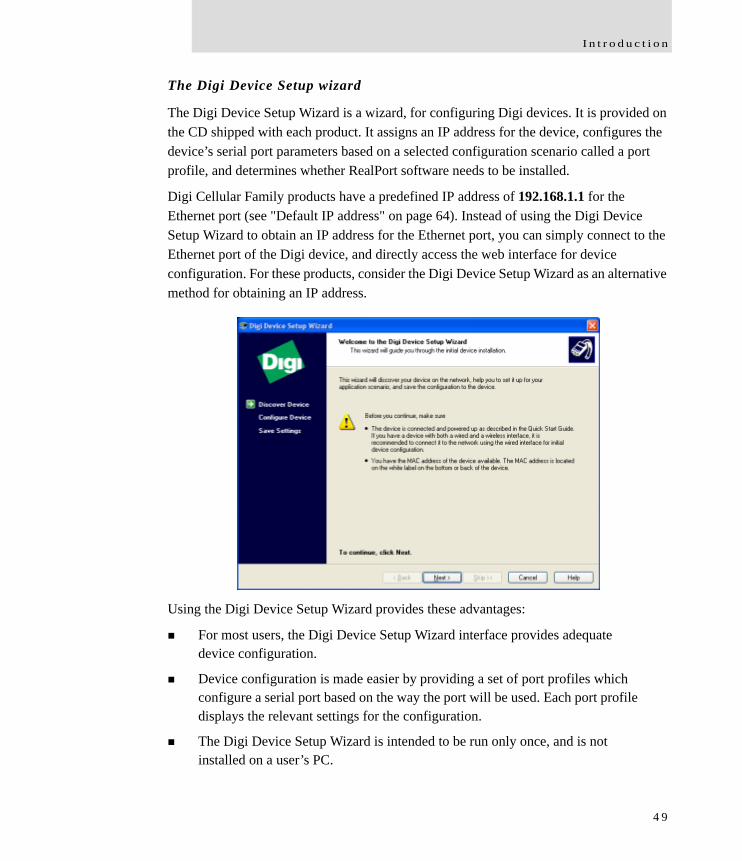
I n t r o d u c t i o n
The Digi Device Setup wizard
The Digi Device Setup Wizard is a wizard, for configuring Digi devices. It is provided on the CD shipped with each product. It assigns an IP address for the device, configures the device’s serial port parameters based on a selected configuration scenario called a port profile, and determines whether RealPort software needs to be installed.
Digi Cellular Family products have a predefined IP address of 192.168.1.1 for the Ethernet port (see "Default IP address" on page 64). Instead of using the Digi Device Setup Wizard to obtain an IP address for the Ethernet port, you can simply connect to the Ethernet port of the Digi device, and directly access the web interface for device configuration. For these products, consider the Digi Device Setup Wizard as an alternative method for obtaining an IP address.
Using the Digi Device Setup Wizard provides these advantages:
For most users, the Digi Device Setup Wizard interface provides adequate device configuration.
Device configuration is made easier by providing a set of port profiles which configure a serial port based on the way the port will be used. Each port profile displays the relevant settings for the configuration.
The Digi Device Setup Wizard is intended to be run only once, and is not installed on a user’s PC.
4 9
C o n f i g u r a t i o n c a p a b i l i t i e s a n d i n t e r f a c e s
Disadvantages of the Digi Device Setup Wizard as an interface include:
While the wizard is available in Microsoft Windows or UNIX platforms, it requires Microsoft Windows for full support, and the PC running Windows usually needs to be on same network segment as the Digi device. The Unix version of the Wizard does not include all the features of the Windows version. The Unix version is limited to network configuration settings, and does not allow configuring or choosing a scenario through port profiles.
Some sites disallow users from running wizards, which would prevent users at such sites from using this interface.
While the configuration capabilities of the Digi Device Setup Wizard are acceptable for most Digi device users, it only provides for the most common configuration scenarios, and is not as flexible as configuring through the web interface or the command line.
The device discovery responses can be blocked by personal firewalls, VPN software, and certain network equipment. Disabling personal firewalls is not always possible.
To access the Digi Device Setup Wizard, insert the Software and Documentation CD that accompanies the Digi device in a PC’s CD drive. The Digi Device Setup Wizard will automatically start.
The Digi Device Setup Wizard has online help, accessed from the Help button on wizard screens.
5 0
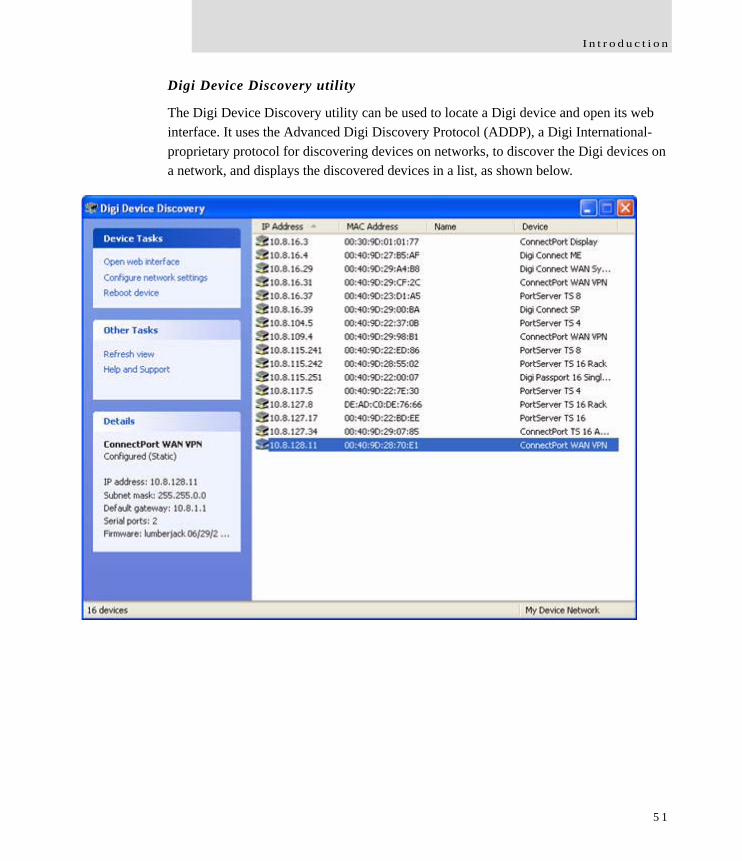
I n t r o d u c t i o n
Digi Device Discovery utility
The Digi Device Discovery utility can be used to locate a Digi device and open its web interface. It uses the Advanced Digi Discovery Protocol (ADDP), a Digi International-proprietary protocol for discovering devices on networks, to discover the Digi devices on a network, and displays the discovered devices in a list, as shown below.
5 1
C o n f i g u r a t i o n c a p a b i l i t i e s a n d i n t e r f a c e s
Advantages of the Digi Device Discovery utility are:
It quickly locates Digi devices and basic device information, such as the device’s address, firmware revision, and whether it has been configured.
ADDP runs on any operating system capable of sending multicast IP packets to a network. ADDP sends out a User Datagram Protocol (UDP) multicast packet to all devices on the network. Devices that support ADDP reply to this UDP multicast with their configuration information. This means that even devices that do not yet have an IP address assigned, or that are misconfigured for the subnet, can reply to the UDP multicast packet, and be displayed in the device discovery results.
Disadvantages include:
Device discovery responses can be blocked by personal firewalls, Virtual Private Network (VPN) software, and certain network equipment in place. Firewalls will block UDP ports 2362 and 2363 that ADDP uses to discover devices.
Not all Digi devices support ADDP.
The Digi Device Discovery utility is available on the Software and Documentation CD that accompanies the Digi device. After installing the utility, it is available from the Start menu.
Access to the ADDP service can be enabled or disabled, but the network port number for ADDP cannot be changed from its default.
For more information on the Digi Device Discovery utility, see page 69.
5 2
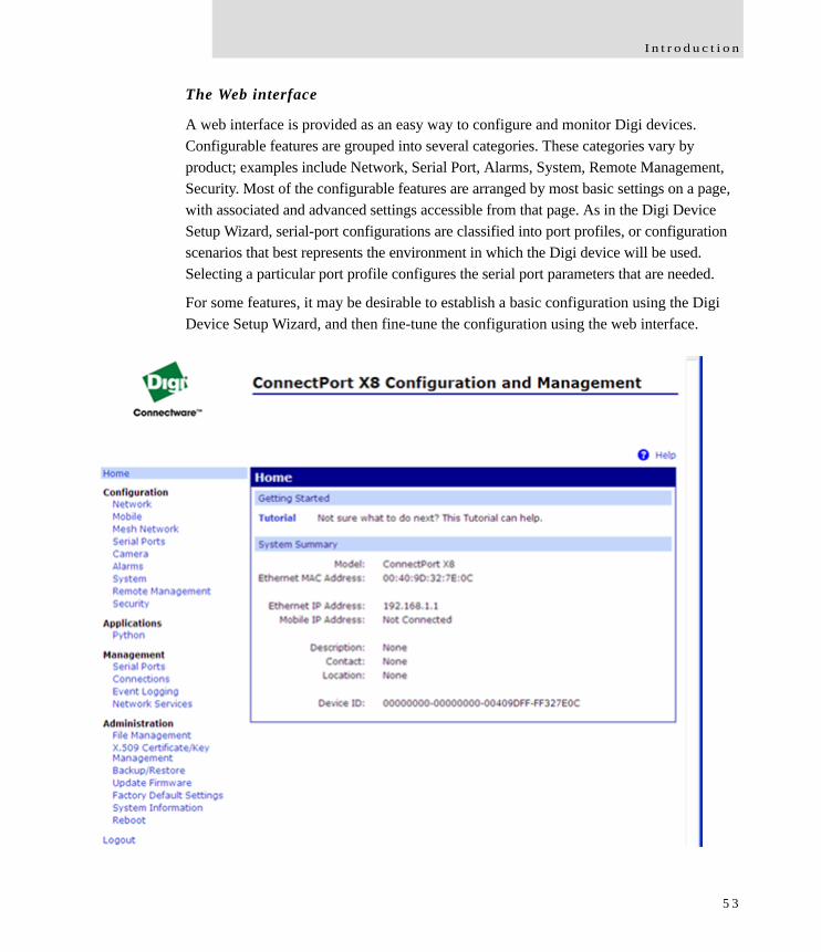
I n t r o d u c t i o n
The Web interface
A web interface is provided as an easy way to configure and monitor Digi devices. Configurable features are grouped into several categories. These categories vary by product; examples include Network, Serial Port, Alarms, System, Remote Management, Security. Most of the configurable features are arranged by most basic settings on a page, with associated and advanced settings accessible from that page. As in the Digi Device Setup Wizard, serial-port configurations are classified into port profiles, or configuration scenarios that best represents the environment in which the Digi device will be used. Selecting a particular port profile configures the serial port parameters that are needed.
For some features, it may be desirable to establish a basic configuration using the Digi Device Setup Wizard, and then fine-tune the configuration using the web interface.
5 3
C o n f i g u r a t i o n c a p a b i l i t i e s a n d i n t e r f a c e s
Advantages of the web interface include
Ease of use, including point-and-click functionality and wizards that make configuration quick and complete.
Secure access to devices.
No need for programming experience.
Port profiles simplify the configuration process.
A potential disadvantage of the web interface is that not all settings provided by the command-line interface are displayed. However, the configuration settings in the web interface should be sufficient for most users. If necessary, settings can be modified later from the command line.
To access the web interface, enter the Digi Cellular Family device’s IP address or host name in a browser’s URL window. The main menu of the web interface is displayed.
For more information, see "Configuration through the web interface" on page 68.
The web interface has a tutorial, accessed from the Home page, and online help, accessed from the Help link on each page.
5 4
I n t r o d u c t i o n
Command-line interface
Digi devices can be configured by issuing commands from the command line. The command-line interface allows communication directly without a graphical interface. For example, the following is a command issued from the command line to assign the IP address to the Ethernet interface:#> set network ip=192.168.1.1
Advantages of the command-line interface include:
Flexibility. Although the command-line Interface is for experienced users and considered complex, it allows flexibility for precise configuration alterations.
Direct communication to device or system.
Disadvantages of the command-line interface include:
Users must have experience issuing commands.
Command documentation is required.
The command line allows the greatest flexibility to configure Digi devices, but is also considered complex.
The command line is available through Telnet or SSH TCP/IP connections, or through serial port using terminal emulation software such as Hyperterminal. Access to the command line from serial ports depends on the port profile in use by the port. By default, serial port command-line access is allowed.
See "Configuration through the command line" on page 166 for more information on this interface. See the Digi Connect Family Command Reference for command descriptions and examples of entering configuration commands from the command-line interface. In addition, online help is available for the commands, through the help and ‘?’ commands.
5 5
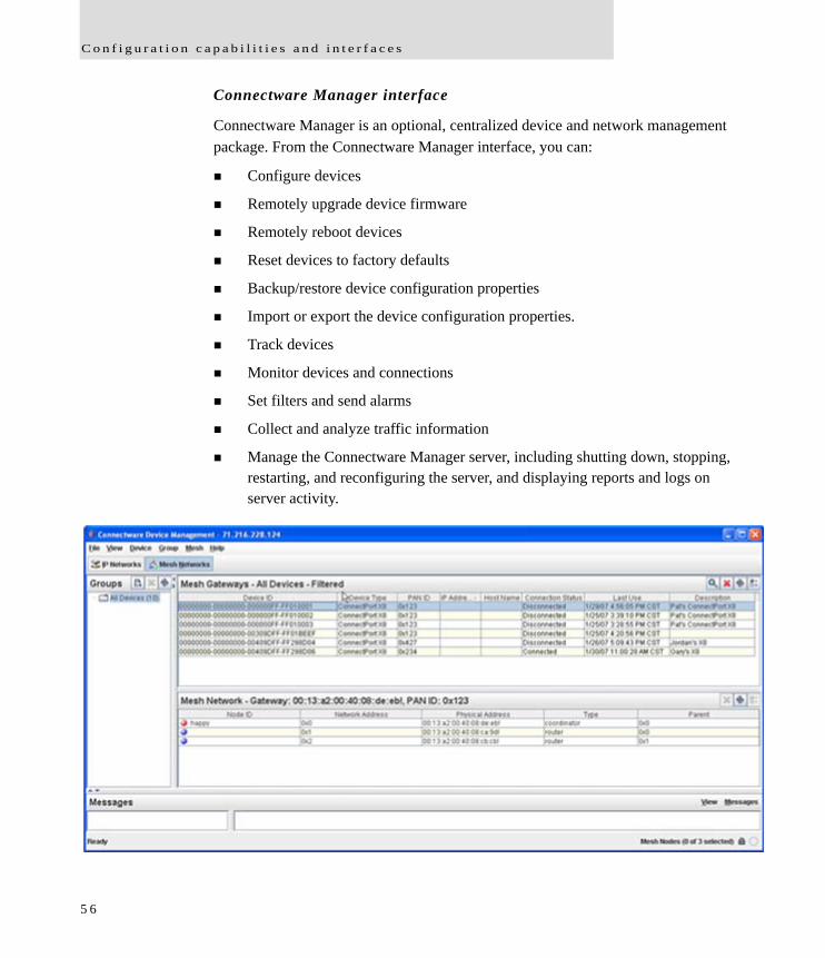
C o n f i g u r a t i o n c a p a b i l i t i e s a n d i n t e r f a c e s
Connectware Manager interface
Connectware Manager is an optional, centralized device and network management package. From the Connectware Manager interface, you can:
Configure devices
Remotely upgrade device firmware
Remotely reboot devices
Reset devices to factory defaults
Backup/restore device configuration properties
Import or export the device configuration properties.
Track devices
Monitor devices and connections
Set filters and send alarms
Collect and analyze traffic information
Manage the Connectware Manager server, including shutting down, stopping, restarting, and reconfiguring the server, and displaying reports and logs on server activity.
5 6

I n t r o d u c t i o n
Advantages of the Connectware Manager interface are:
Allows multiple devices to be managed (configured and monitored) from one source. This multiple-device, network-view capability is particularly useful for Cellular and ConnectPort X products.
The server can also be managed from same location.
Logs and reports can be generated and reviewed. Summaries or totals can be linked back to the original devices for more thorough investigations.
Disadvantages include:
Devices must be provisioned (assigned an IP address) before they can be accessed on Connectware Manager. Use the Digi Device Setup Wizard to provision devices.
If used to manage a device, some of the device configuration options that are available on other device configuration interfaces, such as the web and command-line interfaces, will not be available.
To minimize network traffic, Connectware Manager uses caching. As a result, device settings can be out-of-sync between the device and the settings viewed on the Connectware Manager console.
Connectware Manager requires a dedicated computer to act as a Connectware Manager server.
For more information on Connectware Manager as an remote management interface, see these resources:
"Configure remote management (Connectware Manager) settings" on page 154. This section shows how to configure Connectware Management settings within Digi devices.
"Configuration through Connectware Manager" on page 170.
"Monitoring capabilities from Connectware Manager" on page 206
Connectware Manager Getting Started Guide
5 7
C o n f i g u r a t i o n c a p a b i l i t i e s a n d i n t e r f a c e s
Simple Network Management Protocol (SNMP)
Simple Network Management Protocol (SNMP) is a protocol for managing and monitoring network devices. The SNMP architecture enables a network administrator to manage nodes--servers, workstations, routers, switches, hubs, etc.--on an IP network; manage network performance, find and solve network problems, and plan for network growth. Digi Cellular Family products support SNMP Version 1.
Advantages of SNMP include:
SNMP is easy to implement in extensive networks.
Programming new variables is easy.
SNMP is widely used. SNMP is a standard interface that integrates well with network management stations in an enterprise environment. While its capabilities are limited to device monitoring and display of statistics in Digi Cellular Family devices, read/write capabilities are expected to be added to Digi Cellular Family devices in future releases.
It is easy to ‘drop in’ new devices.
Disadvantages include:
As device communication is UDP-based, the communication is not secure. If more secure communications with a device are required, an alternate interface must be used.
SNMP does not allow for certain task that can be performed from the web interface, such as file management, uploading firmware, or backing up and restoring configurations.
Compared to the web or command-line interfaces, SNMP is limited in its ability to set specific parameters, such as set port profile, is not possible.
Accessing the SNMP interface requires a tool, such as a network management station. The management station relies on an agent at a device to retrieve or update the information at the device, including Device configuration, status, and statistical information. This information is viewed as a logical database, called a Management Information Base (MIB). MIB modules describe MIB variables for a variety of device types and computer hardware and software components.
5 8
I n t r o d u c t i o n
Standard MIBs supported
The standard MIBs supported in Digi Cellular Family devices are:
MIB-II (RFC 1213) This is a MIB for managing a TCP/IP network. It is an update of the original MIB, now called MIB-I. MIB-II contains variable definitions that describe the most basic information needed to manage a TCP/IP network. These variable definitions are organized into several groups, such as groups for managing the system, network interfaces, address translation, transmission media, and various protocols, including IP, ICMP, TCP, UDP, EGP, and SNMP.
CHARACTER-MIB (RFC 1658)
RS-232-MIB (RFC 1659).
Digi enterprise MIBs supported
In addition to the standard MIBs, Digi devices use several Digi enterprise MIBs, including:
DIGI-DEVICE-INFO.mib: for handling device information. This MIB gives access to elements like the firmware revision, device name, IP network information, memory, and CPU statistics.
DIGI-SERIAL-ALARM-TRAPS.mib: for handling alarms sent as SNMP traps.
Additional SNMP resources
A variety of resources about SNMP are available, including reference books, overviews, and other files on the Internet. For an overview of the SNMP interface and the components of MIB-II, go to www.rfceditor.org, and search for MIB-II. From the results, locate the text file describing the SNMP interface, titled Management Information Base for Network Management of TCP/IP-based internets: MIB-II. The text of the Digi enterprise MIBs can also be displayed.
For additional discussion of using SNMP as a device monitoring interface, see "Monitoring Capabilities from SNMP" on page 208.
5 9
M o n i t o r i n g c a p a b i l i t i e s a n d i n t e r f a c e s
Monitoring capabilities and interfaces
There are several capabilities and interfaces for monitoring Digi devices and managing their connections; these are covered in more detail in Chapter 3, "Monitor and manage Digi devices".
Monitoring Digi devices includes such tasks as checking device status, checking runtime state, viewing serial port operations, and reviewing network statistics, and managing their connections.
Monitoring interfaces
As with device configuration, there are several interfaces available for monitoring Digi devices, including:
The web interface embedded with the product
SNMP
The command-line interface
Connectware Manager
Web Interface
The web interface has several screens for monitoring Digi devices:
Network Status
Mobile connection status
Serial Port Management: for each port, the port’s description, current profile, and current serial configuration.
Connections Management: A display of all active system connections.
6 0
I n t r o d u c t i o n
System Information:– General device information– Serial port information: for each port, the port’s description, current profile, and
current serial configuration. This is the same information displayed by choosing Serial Port Management.
– Network statistics: statistics for IP, TCP, UDP, and ICMP
Command-line interface
Several commands can be issued from the command line to monitor devices. For a review of these commands and what they can provide from a device-monitoring perspective, see "Monitoring capabilities from the command line" on page 198.
Connectware Manager
In the Connectware Manager interface, monitoring capabilities can be sorted by the server and the devices managed by the server. The information is available in logs and can be generated into reports. When available, the reports post linked totals that can be drilled back to the original devices that make up the activity of the report.
Connectware Manager is well-suited to managing Cellular and ConnectPort X Family devices and the networks in which the devices reside. Advantages include:
The ability to view an entire network, and multiple networks, at once
Easy to view signal strength, link quality, and alarms
SNMP
Monitoring capabilities of SNMP include managing network performance, gathering device statistics, and finding and solving network problems. For more information on using SNMP for device-monitoring purposes, see "Monitoring Capabilities from SNMP" on page 208.
6 1
A d m i n i s t r a t i o n t a s k s
Administration tasks
Periodically, administrative tasks need to be performed on Digi devices, such as:
Uploading and managing files
Changing the password for logging onto the device
Backing up and restoring the configuration
Updating firmware
Restoring the configuration to factory defaults
Rebooting the module
As with configuration and monitoring tasks, administration can be done from a number of interfaces, including the web interface, command line, and Connectware Manager. See Chapter 4, "Administration tasks" for more information and procedures.
6 2
Configure Digi devicesC H A P T E R 2
This chapter describes how to configure a Digi device. It covers these topics:
"Default IP address" on page 64, identifying the predefined static IP address for your Digi device.
"Alternate methods for assigning an IP address" on page 64
"Configuration through the web interface" on page 68.
"Configuration through the command line" on page 166.
"Configuration through Simple Network Management Protocol (SNMP)" on page 169.
"Batch capabilities for configuring multiple devices" on page 174.
The primary focus of this chapter is on configuring Digi devices through the web interface. To use the Digi Device Setup Wizard for initial configuration, see the online help for the Wizard. For instructions on launching the wizard, see "Configure an IP address using the Digi Device Setup Wizard" on page 64.
6 3
D e f a u l t I P a d d r e s s
Default IP address
ConnectPort X Family products ship with a a default static IP address for the Ethernet port of 192.168.1.1 and a a DHCP server enabled by default. Therefore, simply connecting a laptop computer to the Ethernet port of these products allows direct access to the web interface for configuration.
Alternate methods for assigning an IP address
There are several alternate ways to assign an IP address to a Digi device:
Using the Digi Device Setup Wizard.
Using Dynamic Host Configuration Protocol (DHCP) from the web interface.
Using the command-line interface.
Using Automatic Private IP Addressing (APIPA), also known as Auto-IP.
Configure an IP address using the Digi Device Setup Wizard
The Digi Device Setup Wizard is supplied on the Software and Documentation CD. Using this wizard is the easiest way to assign an IP address and initially configure Digi devices. It discovers Digi devices on a network, configures an IP address, and configures basic serial port parameters according to how the device will be used. After this initial configuration, features can be fine-tuned as needed through the web interface. Setup is specially designed for the Windows environments, and is quick, automated, and complete.
To use the Digi Device Setup Wizard:
1 Connect the Digi deviceto the network and power it on.
2 Locate the MAC address for the Digi device; it is on a label on the bottom of the product. Record it for later use in assigning an IP address.
3 Insert the Digi CD in the CD drive of a computer running Microsoft Window. If the CD does not start automatically, double-click My Computer > CD ROM Drive > setup.exe.
6 4
C o n f i g u r e D i g i d e v i c e s
4 The Digi Device Setup Wizard automatically starts. Select the appropriate platform and click Next.The Digi device discovery utility finds and lists all of the Digi devices on the network.
5 Locate the Digi device by its MAC address.
6 Select the Digi device and click Next.
7 Follow the instructions in the wizard to assign an IP address for the Digi device. Use the online help supplied with the wizard for information about values and selections on the wizard screens.
Configure an IP address using DHCP
A IP address can also be configured using Dynamic Host Configuration Protocol (DHCP).
If desired, set up a permanent entry for the Digi device device on a DHCP server. While this is not necessary to obtain an IP address via DHCP, setting up a permanent entry means the IP address is saved when the device is rebooted. For more information on DHCP server configuration, see "DHCP server settings" on page 77.
Configure an IP address using Auto-IP
The standard protocol Automatic Private IP Addressing (APIPA or Auto-IP) assigns the IP address from the reserved IP addresses in Auto-IP. Use ADDP or DHCP to find the device and assign it a new IP address that compatible with your network. Once the unit is plugged in, Auto-IP automatically assigns the IP address.
6 5
A l t e r n a t e m e t h o d s f o r a s s i g n i n g a n I P a d d r e s s
Configure an IP address from the command-line interface
The set network command configures an IP address from the command line. Include the following parameters:
ip=device ip: The IP address for the device.
gateway=gateway: The network gateway IP address.
submask=device submask: The device subnet mask.
dhcp=off: Turns off use of the Dynamic Host Configuration Protocol (DHCP), so that the IP address assigned is permanent.
static=on: Specifies that the IP address is static, and will remain as the specified IP address, gateway, and submask.
For example:set network ip=10.0.0.100 gateway=10.0.0.1 submask=255.255.255.0 dhcp=off static=on
IP addresses and Connectware Manager
The Connectware Manager interface can only change the Ethernet/LAN address for a Digi device. The mobile/cellular device is typically provided by the mobile service provider; check with your mobile service provider on how they handle addresses. To change the IP address, open the web interface for based on the IP address the device has and navigate to Configuration > Network > IP Settings. On the IP Settings page, enter the new IP address, subnet mask, and gateway.
To use Connectware Manager, first configure the Digi device using the Digi Device Setup Wizard, then install Connectware Manager. For more information, see the Connectware Manager Operator’s Guide.
6 6

C o n f i g u r e D i g i d e v i c e s
Test the IP address configuration
Once the IP address is assigned, test the IP address configuration to be sure it works as configured. This procedure assumes that the Digi device has an IP address.
1 Access the command line of a PC or other networked device.
2 Issue the following command:ping ip-address
where ip-address is the address assigned to the Digi device. For example:ping 192.168.2.2
6 7
C o n f i g u r a t i o n t h r o u g h t h e w e b i n t e r f a c e
Configuration through the web interface
Configuring Digi devices through the web interface involves these tasks:
Change the IP address, as needed. See page 74.
Open the web interface. See page 69.
Configure network communications. See page 75.
Configure mobile (cellular) settings, including provisioning the Digi Cellular Family device, mobile service provider settings, mobile connection settings, and SureLink settings. See page 119.
Configure Mesh network settings. See page 130.
Configure the serial ports. See page 137.
Configure camera settings.
Configure alarms. See page 149.
Configure security/user features such as user names and password authentication. See page 160.
Configure system-identifying information and the settings for Simple Network Management Protocol (SNMP). See page 153.
Configure remote management using a Connectware Manager server. See page 154.
Configure and run applications available for use. Supported applications vary. See page 164.– For ConnectPort X Family products, manage programs authored in the
Python® programming language. See page 164.
6 8
C o n f i g u r e D i g i d e v i c e s
Open the web interface
To open the web interface, either enter the Digi device’s URL in a web browser and log on to the device, if required, or use the Digi Device Discovery utility to locate it and open its web interface.
By entering the Digi device’s IP address in a web browser
1 In the URL address bar of a web browser, enter the IP address of the device.
2 If security has not been enabled for the Digi device, the Home page of the web interface is displayed. If security has been enabled for the Digi device, a login dialog will be displayed. Enter the user name and password for the device. The default username is root and the default password is dbps. If these defaults do not work, contact the system administrator who set up the device. Then the Home page of the web interface is displayed. See "Organization of the web interface" on page 71 for an overview of using the Home page and other linked pages.
Note The idle timeout automatically logs users out of the web interface after 5 minutes of inactivity if password authentication has been enabled for the device.
By using the Digi Device Discovery utility
Alternatively, use the Digi Device Discovery Utility to locate the Digi device and open its web interface.
Install Digi Device Discovery utility
The Digi Device Discovery Utility is available on the Software and Documentation CD. If this utility is not already available on your computer, follow these steps.
1 On the main page Software and Documentation CD, click software - install optional software.
2 Select Device Discovery Utility and click Install.
3 Follow the prompts of the Setup Wizard to install the Digi Device Discovery Utility software.
6 9
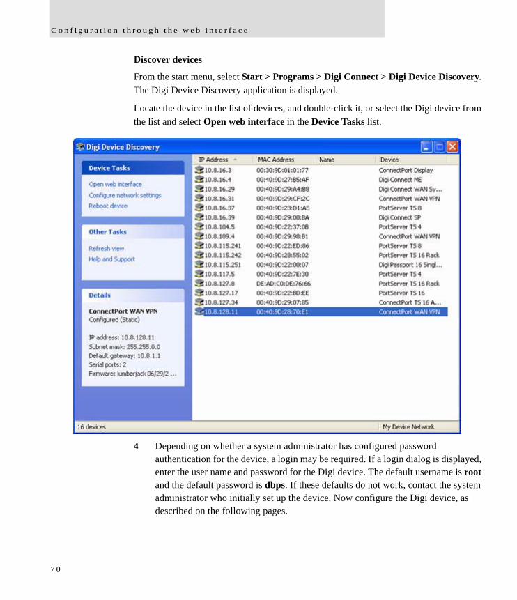
C o n f i g u r a t i o n t h r o u g h t h e w e b i n t e r f a c e
Discover devices
From the start menu, select Start > Programs > Digi Connect > Digi Device Discovery. The Digi Device Discovery application is displayed.
Locate the device in the list of devices, and double-click it, or select the Digi device from the list and select Open web interface in the Device Tasks list.
4 Depending on whether a system administrator has configured password authentication for the device, a login may be required. If a login dialog is displayed, enter the user name and password for the Digi device. The default username is root and the default password is dbps. If these defaults do not work, contact the system administrator who initially set up the device. Now configure the Digi device, as described on the following pages.
7 0
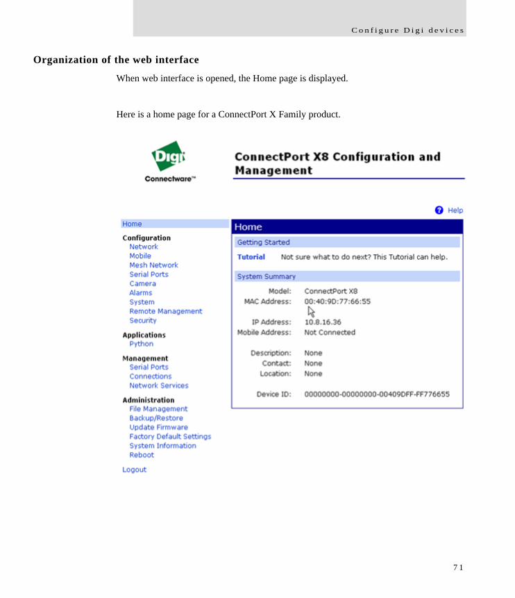
C o n f i g u r e D i g i d e v i c e s
Organization of the web interface
When web interface is opened, the Home page is displayed.
Here is a home page for a ConnectPort X Family product.
7 1
C o n f i g u r a t i o n t h r o u g h t h e w e b i n t e r f a c e
The Home page
The left side of the Home page has a menu of choices that display pages for configuration, management, and administration tasks, and to log out of the web interface. This chapter focuses on the choices under Configuration and Application. For details on monitoring Digi devices and the choices under Management, see Chapter 3, "Monitor and manage Digi devices". For details on the tasks under Administration, see Chapter 4, "Administration tasks".
Clicking Logout logs out of a configuration and management session with a Digi device. It does not close the browser window, but displays a logout window. To finish logging out of the web interface and prevent access by other users, close the browser window. Or, log back on to the device by clicking the link on the screen. After 5 minutes of inactivity, the idle timeout also automatically performs a user logout.
The Getting Started section has a link to a tutorial on configuring and managing Digi device.
The System Summary section notes all available device-description information.
Configuration pages
The choices under Configuration in the menu display pages for configuring settings for various features, such as network settings, mobile settings, and serial port settings.
Some of the configuration settings are organized on sets of linked screens. For example, the Network Configuration screen initially displays the IP Settings, and provides links to Network Services Settings, Advanced Settings, and other network settings appropriate to the Digi device.
7 2
C o n f i g u r e D i g i d e v i c e s
Application pages
Depending on the Digi device, there may be an Application menu item for configuring various applications available for use in the device.
Python: For loading and running custom programs authored in the Python programming language onto ConnectPort X Family devices.
Apply and save changes
The web interface runs locally on the device, which means that the interface always maintains and displays the latest settings in the Digi device.
On each screen, the Apply button is used to save any changes to the configuration settings to the Digi device.
Cancel changes
To cancel changes to configuration settings, click the Refresh or Reload button on the web browser. This causes the browser to reload the page. Any changes made since the last time the Apply button was clicked are reset to their original values.
Restore the Digi device to factory defaults
The device configuration can be reset to factory defaults as needed during the configuration process. See "Restore a device configuration to factory defaults" on page 215.
Online help
Online help is available for all screens of the web interface, and for common configuration and administration tasks. There is also tutorial available on the Home page.
7 3
C o n f i g u r a t i o n t h r o u g h t h e w e b i n t e r f a c e
Change the IP address from the web interface, as needed
Normally, IP addresses are assigned to Digi devices either through DHCP or the Digi Device Setup Wizard.
This procedure assumes that the Digi device already has an IP address and you simply want to change it.
1 Open a web browser and enter the Digi device’s current IP address in the URL address bar.
2 If security is enabled for the Digi device, a login prompt is displayed. Enter the user name and password for the device. The default username is root and the default password is dbps. If these defaults do not work, contact the system administrator who set up the device.
3 Click Network to access the Network Configuration page.
4 On the IP Settings page, select Use the following IP address.
5 Enter an IP address (and other network settings), then click Apply to save the configuration.
7 4
C o n f i g u r e D i g i d e v i c e s
Configure network communications
The Network configuration pages include:
IP Settings: For viewing IP address settings and changing as needed. See page 76.
DHCP Server Settings: For configuring a DHCP server to allow other devices or hosts on this network to be assigned dynamic IP addresses. See page 77.
Network Services Settings: Enable and disables access to various network services, such as ADDP, RealPort and Encrypted RealPort, Telnet, HTTP/HTTPS, and other services. See page 82.
Dynamic DNS Update Settings: For configuring a Dynamic DNS (DDNS) service that allows a user whose IP address is dynamically assigned to be located by a host or domain name. See page 87.
IP Filtering Settings: For configuring the Digi Cellular Family device to only accept connections from specific and known IP addresses or networks. See page 90.
IP Forwarding Settings: For configuring the Digi Cellular Family device to forward certain connections to other devices. This is also known as Network Address Translation (NAT) or Port Forwarding. See page 91.
Socket Tunnel Settings: For configuring a socket tunnel, used to connect two network devices: one on the Digi Cellular Family device’s local network and the other on the remote network. See page 93.
Virtual Private Network (VPN) Settings: For configuring Virtual Private Networks, which are used to securely connect two private networks together so that devices may connect from one network to the other network using secure channels. See page 99.
IP Pass-through Settings: Configures a Digi Cellular Family device to pass its mobile IP address directly through and to the Ethernet device (router or PC) to which it is connected through the Ethernet port. The Digi Cellular Family device becomes transparent (similar to the behavior of a cable or DSL modem) to provide a bridge from the mobile network directly to the end device attached to the Digi Cellular Family device. See page 94.
Advanced Network Settings: Configures the Ethernet Interface speed and mode, TCP/IP settings, TCP keepalive settings, and DHCP settings. See page 118.
7 5
C o n f i g u r a t i o n t h r o u g h t h e w e b i n t e r f a c e
Alternatives for configuring network communications
There are three ways a Digi devicecan be configured on the network.
Using dynamic settings: All network settings will be assigned automatically by the network, using a protocol called DHCP. Contact your network administrator to find out if a DHCP server is available.
Using static settings: All network settings are set manually and will not change. The IP address and Subnet Mask are mandatory. The rest are not mandatory, but may be needed for some functions. Contact your network administrator for the required values.
Using Auto-IP: Auto-IP assigns an IP address to the Digi device immediately after it is plugged in. If running DHCP or ADDP, the Auto-IP address is overridden and a network compatible IP address is assigned, or a static IP address can be assigned.
Digi Cellular Family products have two IP addresses: one for Ethernet and one for cellular. All Digi Cellular Family products except Digi Connect WAN IA have a pre-defined default Ethernet Port IP address of 192.168.1.1.
Even if a DHCP server is available, the device configuration may work better with static settings. Once set, static settings will not change, so you and other network devices can always find the Digi deviceby its IP address. With dynamic settings, the DHCP server can change the IP address. This can happen frequently or infrequently depending on how your network administrator has configured the network.
When the IP address does change, you and other network devices configured to talk to the Digi devicecan no longer access the device. In this case, the Digi device must be located the Digi Device Discovery utility, and other network devices that need to communicate with the Digi device must be reconfigured.
IP settings
The IP Settings page shows how the IP address of the Digi deviceis obtained, either by DHCP or by using a static IP address, subnet mask, default gateway. In addition, this page shows IP addresses of the primary and secondary Domain Name System (DNS) server for the Digi device. Contact your network administrator for more information about these settings, and see the online help.
7 6
C o n f i g u r e D i g i d e v i c e s
DHCP server settings
The DHCP server feature can be enabled in a Digi device to allow other devices or hosts on this network to be assigned dynamic IP addresses. This DHCP server supports a single subnetwork scope.
For the DHCP server to operate, the Digi device must be configured to use a static IP address. For information on how to configure static IP settings, see "IP settings" on page 76.
The Digi Connect WAN IA has different factory defaults for DHCP server. The DHCP server is disabled, and DHCP Client enabled.
For information on how to manage the DHCP server, see "Manage DHCP server operation" on page 190.
DHCP terminology
Some key DHCP terms involved in configuring a DHCP server include:
scopeA scope is the full consecutive range of possible IP addresses for a network. A scope typically defines a single physical subnet on your network, to which DHCP services are offered. A scope is the primary way for the DHCP server to manage distribution and assignment of IP addresses and related configuration parameters to its clients on the network.
exclusion rangeAn exclusion range is a limited sequence of IP addresses within a scope, excluded from DHCP service offerings. Exclusion ranges assure that any addresses in these ranges are not offered by the server to DHCP clients on your network.
address poolAfter the scope is defined and exclusion ranges are applied, the remaining addresses form the available address pool within the scope. The addresses in this pool are available for dynamic assignment by the server to DHCP clients on your network.
7 7
C o n f i g u r a t i o n t h r o u g h t h e w e b i n t e r f a c e
leaseA lease is the length of time that the DHCP server specifies, during which a client host can use an assigned IP address. When the DHCP server grants a lease to a client, the lease is active. Before the lease expires, the client typically needs to renew its address lease assignment with the DHCP server. A lease becomes inactive when it expires or it is deleted at the server, or if the client actively releases the lease. The duration of a lease determines when it will expire and how often the client needs to renew it with the DHCP server in order to retain the lease.
A DHCP server will never grant a lease to its own address. There is no need for its own address to be in the exclusion range; the DHCP server simply protects its address from being offered.
grace periodWhen a DHCP client actively releases a lease, or when the lease expires without being renewed by the client, the DHCP server does not immediately delete the lease record and return the associated IP address to the available address pool. A grace period is the interval of time for which the lease record is retained before the DHCP server automatically deletes the record from its lease list, thereby making the IP address available for lease assignment to another client. The grace period is not a configurable value. See also the discussion of the grace period and what it means when the DHCP server is running in "View and manage current DHCP leases" on page 191.
reservationYou may use a reservation to create a permanent address lease assignment by the DHCP server. Reservations assure that a specified hardware device on the subnet can always use the same IP address. Address lease reservations associate a specific IP address with a specific client's Ethernet MAC address.
optionsOptions are other client configuration parameters that the DHCP server can assign when serving leases to DHCP clients. Most options are defined in RFC 2132. The DHCP server in Digi device supports a limited set of options:
– Option 3: Routers on Subnet – Option 6: DNS Servers
7 8
C o n f i g u r e D i g i d e v i c e s
Addresses in the DHCP server settings
The IP address and subnet mask of the DHCP server's scope are the static IP configuration settings for the Digi device itself.
The default gateway (router) provided to a client with the lease information is the IP address of the Digi device.
The DNS servers provided to a client with the lease information are the DNS server addresses configured in the Digi device. These addresses include any DNS server addresses that the Digi device acquires when it connects to the mobile network.
DHCP server configuration settings
Here are the configuration settings for the DHCP server. Typically, these settings can be modified without having to restart the DHCP server for the changes to become effective in the running server.
Enable Dynamic Host Configuration Protocol (DHCP) Server: Enables the DHCP server feature on this Digi device. Note that for the DHCP server to operate, the Digi device must be configured to use a static IP address. For information on how to configure static IP settings, see "IP settings" on page 76.
IP Addresses: The starting and ending IP addresses for the scope being served by this DHCP server. These addresses must be in the same subnet as the Digi device itself.
Lease Duration: The length of the leases for the scope being served by this DHCP server. The default lease duration is 24 hours. A DHCP client may request a lease duration other than this setting, and the DHCP server will grant that request if possible.
Wait specified delay before sending DHCP offer reply: The interval of time in milliseconds to delay before offering a lease to a new client. The default delay is 500ms, and the range is 0 to 5000ms. Use of this delay permits this Digi device to reside on a network with other DHCP servers, yet not offer leases to new clients unless the other DHCP servers do not make such an offer. This provides a measure of protection against inadvertently connecting a Digi device to a network that is running its own DHCP server(s), and offering leases to clients in a manner inconsistent with that network.
7 9
C o n f i g u r a t i o n t h r o u g h t h e w e b i n t e r f a c e
Check that an IP address is not in use before offering it: When a DHCP client requests a new IP address lease, before offering an IP address to that client, use “ping” to test whether that IP address is already in use by another host on the network but is unknown to the DHCP server. If an IP address is determined to be in use, it is marked as Unavailable for a period of time, and it will not be offered to any client while in this state. Enabling this test adds approximately one second of delay before the IP address is offered to the client, since the “ping” test must not receive a valid reply for that test to successfully determine that the IP address is not already in use. This option is off (disabled) by default. This option does not apply to Static Lease Reservations, since the “ping” test is not used for them.
Static Lease Reservations: A static lease reservation is a specific IP address paired with a client's MAC address, which reserves the IP address for that client's use only. This assures that a client always receives a lease for the same IP address and that no other client obtains a lease for that address. To add a reservation, enter the IP Address and MAC Address values, check or clear the Enable checkbox, and then press the Add button. After adding a reservation, you may click on the IP address or MAC address of that entry in the table, permitting you to specify or modify the lease duration for this reservation. The Enable checkbox for the entry permits a reservation to be disabled without actually removing the entry, then enabled again at a later time. The Remove link is used to permanently remove a reservation from the DHCP server configuration. The Remove All link is used to permanently remove all reservations from the DHCP server configuration.
8 0
C o n f i g u r e D i g i d e v i c e s
Address Exclusions: A specific set of IP addresses to exclude from the scope. The DHCP server will not grant leases to clients for any IP address in the exclusion range. To add an exclusion, enter the starting and ending IP Addresses, check or clear the Enable checkbox, and then press the Add button. The Enable checkbox for the entry permits an exclusion to be disabled without actually removing the entry, then enabled again at a later time. The Remove link is used to permanently remove an exclusion from the DHCP server configuration. The Remove All link is used to permanently remove all exclusions from the DHCP server configuration.
Apply button: You must click the Apply button to save changes you make to the DHCP server settings. If you leave this page without applying the changes, those changes will be discarded.
Manage the DHCP server
For information on managing the DHCP server and viewing and managing lease status, see "Manage DHCP server operation" on page 190.
8 1
C o n f i g u r a t i o n t h r o u g h t h e w e b i n t e r f a c e
Network services settings
The Network Services page shows a set of common network services that are available for Digi devices, and the network port on which the service is running.
Common network services can be enabled and disabled, and the TCP port on which the network service listens can be configured. Disabling services may be done for security purposes. That is, certain services can be disabled so the device runs only those services specifically needed. To improve device security, non-secure services such as Telnet can be disabled.
It is usually best to use the default network port numbers for these services because they are well known by most applications.
Several services have a setting for whether TCP keep-alives will be sent for the network services. TCP keep-alives can be configured in more detail on the Advanced Network Settings page.
Caution Exercise caution in enabling and disabling network services, particularly disabling them. Changing certain settings can render a Digi Connect device inaccessible. For example, disabling Advanced Digi Discovery Protocol (ADDP) prevents the device from being discovered on a network, even if it is actually connected. Disabling HTTP and HTTPS disables access to the web interface. Disabling basic services such as Telnet, Rlogin, etc. can make the Command-Line interface inaccessible.
8 2
C o n f i g u r e D i g i d e v i c e s
Supported network services and their default network port numbers
In Digi devices that have multiple serial ports, the network port number defaults for various services are set based on the following formula: base network port number + serial port number
For example, the Telnet Passthrough service is set to network port 2001 for serial port 1, 2002 for serial port 2, 2003 for serial port 3, etc.
If a network port is changed for a particular service, that is the only network port number that changes. That change does not carry over to the other network ports. For example, if the network port number for Telnet Passthrough is changed from 2001 to 3001, that does not mean that the other network ports will change to 3002, 3003, etc.
There are two types of network services available:
Basic services, which are accessed by connecting to a particular well-known network port.
Passthrough services, in which a particular serial port is set up for a particular type of service. To use the service, users must both use the correct protocol and specify the correct network port. For example, assuming default service ports and using a Linux host, here is how a user would access the SSH and Telnet passthrough services:
#> ssh -l fred digi16 -p 2501
#> telnet digi16 2101
8 3
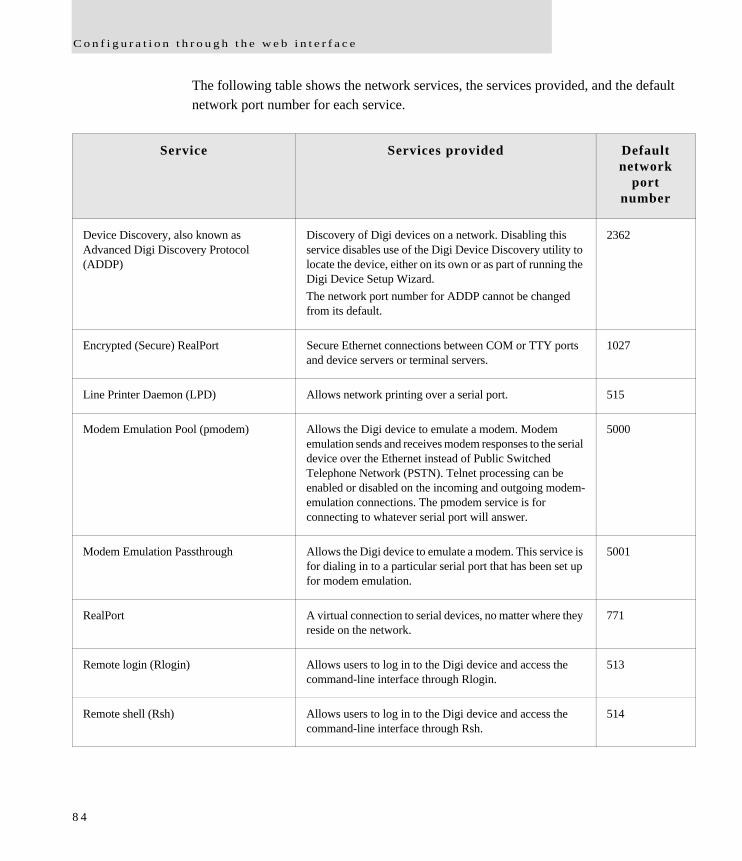
C o n f i g u r a t i o n t h r o u g h t h e w e b i n t e r f a c e
The following table shows the network services, the services provided, and the default network port number for each service.
Service Services provided Default network
port number
Device Discovery, also known as Advanced Digi Discovery Protocol (ADDP)
Discovery of Digi devices on a network. Disabling this service disables use of the Digi Device Discovery utility to locate the device, either on its own or as part of running the Digi Device Setup Wizard.The network port number for ADDP cannot be changed from its default.
2362
Encrypted (Secure) RealPort Secure Ethernet connections between COM or TTY ports and device servers or terminal servers.
1027
Line Printer Daemon (LPD) Allows network printing over a serial port. 515
Modem Emulation Pool (pmodem) Allows the Digi device to emulate a modem. Modem emulation sends and receives modem responses to the serial device over the Ethernet instead of Public Switched Telephone Network (PSTN). Telnet processing can be enabled or disabled on the incoming and outgoing modem-emulation connections. The pmodem service is for connecting to whatever serial port will answer.
5000
Modem Emulation Passthrough Allows the Digi device to emulate a modem. This service is for dialing in to a particular serial port that has been set up for modem emulation.
5001
RealPort A virtual connection to serial devices, no matter where they reside on the network.
771
Remote login (Rlogin) Allows users to log in to the Digi device and access the command-line interface through Rlogin.
513
Remote shell (Rsh) Allows users to log in to the Digi device and access the command-line interface through Rsh.
514
8 4
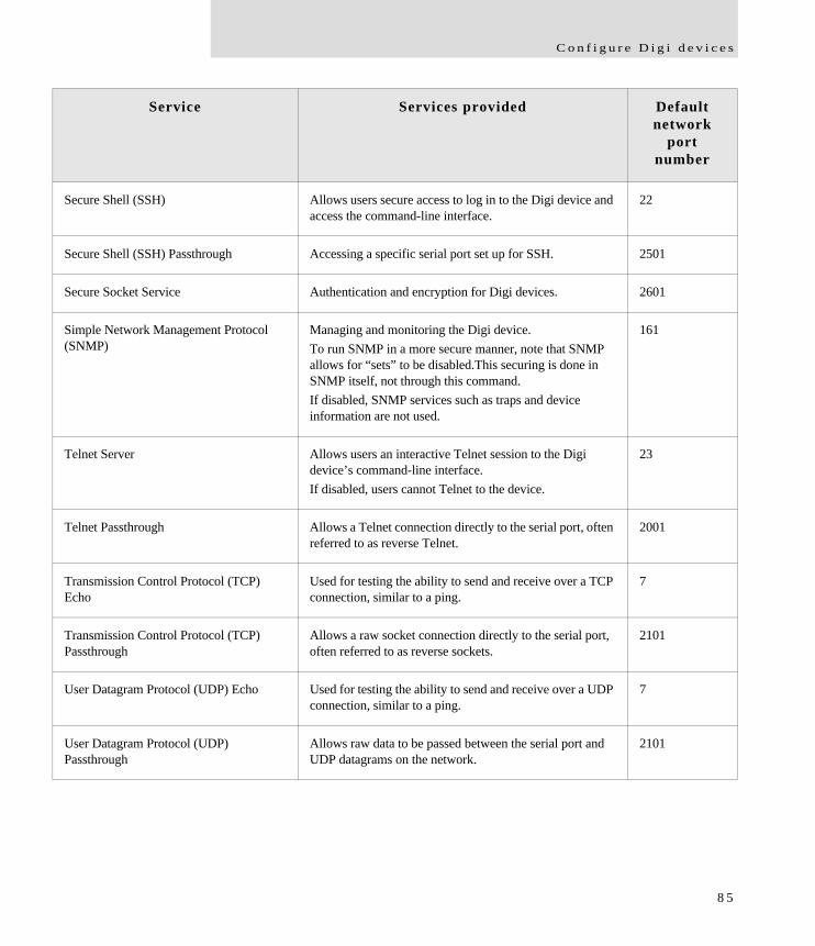
C o n f i g u r e D i g i d e v i c e s
Secure Shell (SSH) Allows users secure access to log in to the Digi device and access the command-line interface.
22
Secure Shell (SSH) Passthrough Accessing a specific serial port set up for SSH. 2501
Secure Socket Service Authentication and encryption for Digi devices. 2601
Simple Network Management Protocol (SNMP)
Managing and monitoring the Digi device. To run SNMP in a more secure manner, note that SNMP allows for “sets” to be disabled.This securing is done in SNMP itself, not through this command.If disabled, SNMP services such as traps and device information are not used.
161
Telnet Server Allows users an interactive Telnet session to the Digi device’s command-line interface. If disabled, users cannot Telnet to the device.
23
Telnet Passthrough Allows a Telnet connection directly to the serial port, often referred to as reverse Telnet.
2001
Transmission Control Protocol (TCP) Echo
Used for testing the ability to send and receive over a TCP connection, similar to a ping.
7
Transmission Control Protocol (TCP) Passthrough
Allows a raw socket connection directly to the serial port, often referred to as reverse sockets.
2101
User Datagram Protocol (UDP) Echo Used for testing the ability to send and receive over a UDP connection, similar to a ping.
7
User Datagram Protocol (UDP) Passthrough
Allows raw data to be passed between the serial port and UDP datagrams on the network.
2101
Service Services provided Default network
port number
8 5
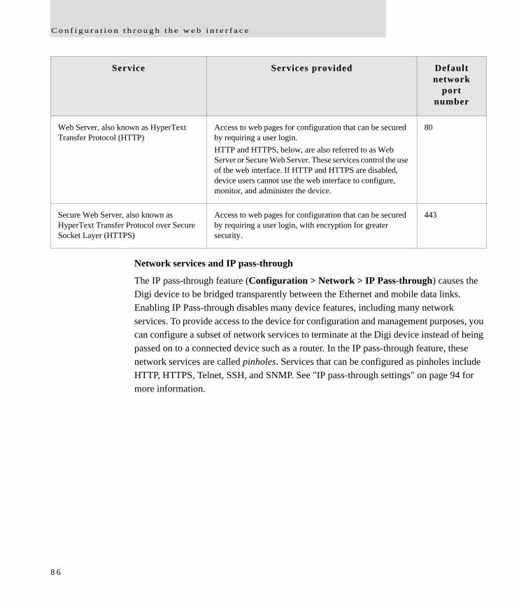
C o n f i g u r a t i o n t h r o u g h t h e w e b i n t e r f a c e
Network services and IP pass-through
The IP pass-through feature (Configuration > Network > IP Pass-through) causes the Digi device to be bridged transparently between the Ethernet and mobile data links. Enabling IP Pass-through disables many device features, including many network services. To provide access to the device for configuration and management purposes, you can configure a subset of network services to terminate at the Digi device instead of being passed on to a connected device such as a router. In the IP pass-through feature, these network services are called pinholes. Services that can be configured as pinholes include HTTP, HTTPS, Telnet, SSH, and SNMP. See "IP pass-through settings" on page 94 for more information.
Web Server, also known as HyperText Transfer Protocol (HTTP)
Access to web pages for configuration that can be secured by requiring a user login.HTTP and HTTPS, below, are also referred to as Web Server or Secure Web Server. These services control the use of the web interface. If HTTP and HTTPS are disabled, device users cannot use the web interface to configure, monitor, and administer the device.
80
Secure Web Server, also known as HyperText Transfer Protocol over Secure Socket Layer (HTTPS)
Access to web pages for configuration that can be secured by requiring a user login, with encryption for greater security.
443
Service Services provided Default network
port number
8 6
C o n f i g u r e D i g i d e v i c e s
Dynamic DNS update settings
A Dynamic DNS (DDNS) service allows a user whose IP address is dynamically assigned to be located by a host or domain name. Before a DDNS service may be used, you must create an account with the DDNS service provider. The provider will give you account information such as username and password. You will use this account information to register your IP address and update it as it changes.
A DDNS service provider typically supports the registration of only public IP addresses. When using such a service provider, if your Digi device has a private IP address (such as 192.168.x.x or 10.x.x.x), your update requests will be rejected.
Your Digi device monitors the IP address it is assigned. It will typically update the DDNS service or server automatically, but only when its IP address has changed from the IP address is previously registered with that service.
DDNS service providers may consider frequent updates to be an abuse of their service. In such a circumstance, the service provider may act by blocking updates from the abusive host for some period of time, or until the customer contacts the provider. Please observe the requirements of the DDNS service provider to ensure compliance with possible abuse guidelines.
The Dynamic DNS Update Settings page includes both settings and status information.
Settings
Use the following dynamic DNS service: Disables DDNS updates, or selects the DDNS service provider to use to register the IP address of this Digi Cellular Family device. When you select a specific DDNS service provider, you must also provide the related account information for that service provider. To force an update request to be sent to a particular DDNS service.
1 Select the “None” radio button to disable DDNS updates, and then click the Apply button to save that change.
2 Select the radio button for the DDNS service you wish to update
3 Click Apply to save that change. If the settings for the selected DDNS service are all specified and valid, an update request will be sent immediately to that service.
8 7
C o n f i g u r a t i o n t h r o u g h t h e w e b i n t e r f a c e
DynDNS.org DDNS Service: You must create your account at DynDNS.org before you can successfully register the IP address of your Digi device with their service. Please familiarize yourself with their service options and requirements, in order to most effectively use this feature of your Digi device. This DDNS service supports only public IP addresses. If you have a private IP address (such as 192.168.x.x or 10.x.x.x), your update requests will be rejected.
Host and Domain Name: The fully qualified host and domain name you have registered with your service provider. An example is: myhost.dyndns.net.
DynDNS User Name: The user name for the account you have created with your service provider.
DynDNS Password: The password for the account you have created with your service provider.
DynDNS DDNS System: The system for the account you have created with your service provider. DynDNS.org supports a number of different services, which vary by the system you select. The available choices are: – Dynamic DNS – Static DNS – Custom DNS
Use Wildcards: Enables/disables wildcards for this host. The available choices for this option are: – Disable wildcards – Enable wildcards – No change to service setting According to wildcard documentation at DynDNS.org: “The wildcard aliases *.yourhost.ourdomain.tld to the same address as yourhost.ourdomain.tld.” Using this option in the settings for your Digi device has the same effect as selecting the wildcard option on the DynDNS.org website. To leave the wildcard option unchanged from the current selection on their web site, use the “no change” option in the device settings. Note that DynDNS.org support for this option may vary according to the DynDNS system you are registered to use.
Connection Method: The connection method to try when connecting to your service provider to register your IP address. DynDNS.org supports three methods to connect. The available choices are:
8 8
C o n f i g u r e D i g i d e v i c e s
– Standard HTTP port 80 – Alternate HTTP port 8245 – Secure HTTPS port 443
Status and history information
Following the settings are status and history information for the DDNS service.
Most Recent DDNS Service Update Status: This section provides the status of the most recent attempt to update a DDNS service or server. The displayed information confirms the success of an update request, or it may offer information as to the reason an update request was rejected by the service or server. A number of status items are shown. Some of them are specific to the DDNS service being updated. Such information will be helpful when trying to resolve update failures with the DDNS service provider. – Service: The name of the DDNS service provider or server being updated. – IP Address Reported: The IP address for your Digi device that is being
registered with the DDNS service provider or server. – Update Status: A simple indication of success or failure for this last update
request. – Result Information: A DDNS service-specific status message, helpful when
consulting technical support. – Raw Result Data: DDNS service-specific update result data returned by the
service provider, helpful when consulting technical support.
Last Logged Action or Result (may be helpful for troubleshooting): The last attempted, logged action or result for the DDNS feature, helpful for troubleshooting possible problems with DDNS updates. This information may help identify problems with settings, network connection failures, and other issues that prevent a DDNS update from being completed successfully. Successful results also are reported here.
8 9
C o n f i g u r a t i o n t h r o u g h t h e w e b i n t e r f a c e
IP filtering settings
You can better restrict your device on the network by only allowing certain devices or networks to connect. This is better known as IP Filtering or Access Control Lists (ACL). By enabling IP filtering, you are telling the device to only accept connections from specific and known IP addresses or networks. Devices can be filtered on a single IP address or can be restricted as a group of devices using a subnet mask that only allows specific networks to access to the device.
Caution It is important to plan and review your IP filtering settings before applying them. Incorrect settings can make the Digi device inaccessible from the network.
On the IP Filtering Settings page, enter the settings as follows:
Only allow access from the following devices and networks: Enables IP filtering so that only the specified devices or networks are allowed to connect to and access the device. Note that if you enable this feature and the system from which you are connecting to the Digi device is not included in the list of allowed devices or networks, then you will instantly no longer be able to communicate or configure the device from this system.
Automatically allow access from all devices on the local subnet: Specifies that all systems and devices on the same local subnet or network of the device should be allowed to connect to the device.
Allow access from the following devices: A list of IP addresses of systems or devices that are allowed to connect to this device.
Allow access from the following networks: A list of networks based on an IP address and matching subnet mask that are allowed to connect to this device. This option allows grouping several devices that exist on a particular subnet or network to connect to the device without having to manually specific each individual IP address.
9 0
C o n f i g u r e D i g i d e v i c e s
IP forwarding settings
When a Digi device acts as a router and communicates on both a private and public network with different interfaces, it is sometimes necessary to forward certain connections to other devices. This is also known as Network Address Translation (NAT) or Port Forwarding. When an incoming connection is made to the device on the private network, the IP port is searched for in the table of port forwarding entries. If the IP port is found, that connection is forwarded to another specific device on the public network.
Port Forwarding/NAT is useful when external devices can not communicate directly to devices on the public network of the Digi device. For example, this may occur because the device is behind a firewall. By using port forwarding, the connections can pass through the networks transparently. Also, Port Forwarding/NAT allows multiple devices on the private network to communicate to devices on the public network by using a shared private IP address that is controlled by Port Forwarding/NAT.
Port forwarding can be used to connect from a Digi device to a RealPort device, such as a Digi Connect SP. For this type of connection to occur, your mobile wireless provider must be mobile-terminated.
IP Forwarding settings include:
Enable IP Routing: Enables or disables IP forwarding.
Apply the following static routes to the IP routing table: The Digi device can be configured with permanent static routes. These routes are added to the IP routing table when this device boots, or afterward when network interfaces become active or changes are made to this list of static routes. The use of static routes provides a means by which IP datagrams can be routed to a network that is not a local network or accessible through the default route.
Enable Network Address Translation (NAT): Enables or disables the use of NAT.
9 1
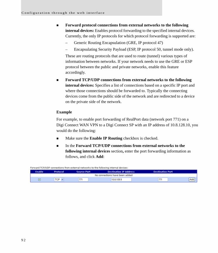
C o n f i g u r a t i o n t h r o u g h t h e w e b i n t e r f a c e
Forward protocol connections from external networks to the following internal devices: Enables protocol forwarding to the specified internal devices. Currently, the only IP protocols for which protocol forwarding is supported are:– Generic Routing Encapsulation (GRE, IP protocol 47)– Encapsulating Security Payload (ESP, IP protocol 50, tunnel mode only).These are routing protocols that are used to route (tunnel) various types of information between networks. If your network needs to use the GRE or ESP protocol between the public and private networks, enable this feature accordingly.
Forward TCP/UDP connections from external networks to the following internal devices: Specifies a list of connections based on a specific IP port and where those connections should be forwarded to. Typically the connecting devices come from the public side of the network and are redirected to a device on the private side of the network.
Example
For example, to enable port forwarding of RealPort data (network port 771) on a Digi Connect WAN VPN to a Digi Connect SP with an IP address of 10.8.128.10, you would do the following:
Make sure the Enable IP Routing checkbox is checked.
In the Forward TCP/UDP connections from external networks to the following internal devices section, enter the port forwarding information as follows, and click Add:
9 2
C o n f i g u r e D i g i d e v i c e s
Socket tunnel settings
A Socket Tunnel can be used to connect two network devices: one on the Digi device’s local network and the other on the remote network. This is especially useful for providing SSL data protection when the local devices do not support the SSL protocol.
One of the endpoint devices is configured to initiate the socket tunnel. The tunnel is initiated when that device opens a TCP socket to the Digi device device on the configured port number. The Digi device then opens a separate connection to the specified destination host. Once the tunnel is established, the Digi device acts as a proxy for the data between the remote network socket and the local network socket, regardless of which end initiated the tunnel.
Socket Tunnel settings include:
Enable: Enables or disables the configured socket tunnel.
Timeout: The timeout (specified in seconds) controls how long the tunnel will remain connected when there is no tunnel traffic. If the timeout value is zero, then no timeout is in effect and the tunnel will stay up until some other event causes it to close.
Initiating Host: The hostname or IP address of the network device which will initiate the tunnel. This field is optional.
Initiating Port: Specify the port number that the Digi device will use to listen for the initial tunnel connection.
Initiating Protocol: The protocol used between the device that initiates the tunnel and the Digi device. Currently, TCP and SSL are the two supported protocols.
Destination Host: The hostname or IP address of the destination network device.
Destination Port: Specify the port number that the Digi device will use to make a connection to the destination device.
Destination Protocol: This is the protocol used between Digi device and the destination device. Currently, TCP and SSL are the two supported protocols. This protocol does not need to be the same for both connections.
9 3
C o n f i g u r a t i o n t h r o u g h t h e w e b i n t e r f a c e
IP pass-through settings
There are many application scenarios where a router is used to decide upon alternative routes using a primary and a secondary (or backup) interface. In many of these configurations, the router is required to use a public IP address as assigned by the network over which it is communicating. This requirement is mostly owing to the router needing to establish a VPN tunnel over that interface and using the public IP address as part of the VPN authentication. (For more on VPN tunnels, see page 99.)
The IP pass-through feature allows a Digi device device to provide bridging functionality similar to that of a cable or DSL modem, where the Digi device becomes “transparent” to the router or connected device. In this case; the router’s WAN interface believes it is connected directly to the mobile network and has no knowledge that the Digi device is the mechanism providing that connectivity.
How IP pass-through works
A Digi device configured for IP pass-through, such as a ConnectPort WAN or Digi Connect WAN, passes its mobile IP address directly through and to the Ethernet device (router or PC) to which it is connected through the Ethernet port. From the perspective of the connected device, the Digi device essentially becomes transparent (similar to the behavior of a cable or DSL modem) to provide a bridge from the mobile network directly to the end device attached to the Digi device.
Since the mobile network address is effectively “passed-through” to the local device connected to the Ethernet port of the Digi device, all network access to it is bypassed, with some specific exceptions.
Here is an example of a Digi device configured for IP pass-through in a network with a third-party router.
9 4
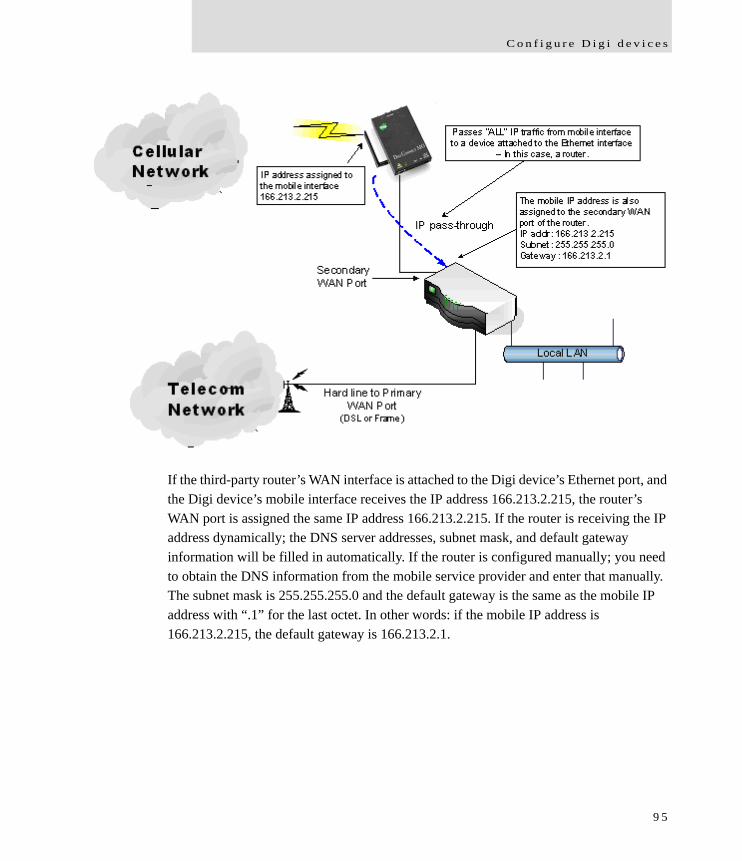
C o n f i g u r e D i g i d e v i c e s
If the third-party router’s WAN interface is attached to the Digi device’s Ethernet port, and the Digi device’s mobile interface receives the IP address 166.213.2.215, the router’s WAN port is assigned the same IP address 166.213.2.215. If the router is receiving the IP address dynamically; the DNS server addresses, subnet mask, and default gateway information will be filled in automatically. If the router is configured manually; you need to obtain the DNS information from the mobile service provider and enter that manually. The subnet mask is 255.255.255.0 and the default gateway is the same as the mobile IP address with “.1” for the last octet. In other words: if the mobile IP address is 166.213.2.215, the default gateway is 166.213.2.1.
9 5
C o n f i g u r a t i o n t h r o u g h t h e w e b i n t e r f a c e
How IP pass-through affects network access to Digi devices
When IP pass-through is enabled, the Digi device effectively disables all router and IP service functionality. Services that are disabled are:
NAT
Port Forwarding
VPN
DDNS updates
Socket Tunnel
Network Services configuration.
The Digi device is effectively transparent to all IP activity and network access by other devices, with these exceptions:
It can be accessed via the serial port for configuration using the command line interface.
It accepts TCP/IP connections for purposes of configuration by means of a “pinhole” on the mobile interface.
It can be accessed by other devices on the local Ethernet segment via the default IP address of 192.168.1.1.
Using pinholes to manage the Digi device
IP pass-through uses a concept called pinholes. The Digi device can be configured to listen on specific TCP ports, and terminate those connections at the Digi device for purposes of managing it. Those ports are called pinholes, and they are not passed on to the device connected to the Ethernet port of the Digi device. Network services and ports that can be configured as pinholes include (see "Network services settings" on page 82 to configure these settings):
Telnet: for accessing the device through a Telnet login and the command-line.
SSH: for accessing to the device through a Secure Shell (SSH) login and the command-line.
HTTP: for accessing the device through HTTP and the web interface.
HTTPS: for accessing to the device through HTTPS and the web interface
SNMP: for monitoring and managing the device through SNMP.
9 6
C o n f i g u r e D i g i d e v i c e s
Connectware Manager and Digi SureLink ports are automatically set up as pinholes so that they continue to work with the Digi device. In addition, the Digi device uses a private address on the Ethernet interface strictly for use in configuration or local access. This allows a user on the local network to gain access to the web interface or a Telnet session in order to make configuration changes.
Remote device management and IP pass-through
As illustrated above, the Digi device allows you to enable pinholes for specific ports to allow remote users to manage the Digi device from the mobile network or open Internet. The Digi device retains its remote management capabilities using Connectware Manager. The necessary pinholes are automatically defined when the Digi device is configured for IP Pass-through.This provides administrators with the same remote-management capabilities that exist in Digi remote devices.
Steps to configure IP pass-through
To configure IP Pass-through from the web interface for your Digi device, follow these steps, or, in the case of the first three steps, make sure they have been performed.
1 Set a static IP address for the Digi device. Go to Configuration > Network > IP Settings.
2 Set up the DHCP server. Go to Configuration > Network > DHCP Server Settings. See page 77 and the online help for DHCP Server Settings.
3 Turn on the DHCP server. Go to Management > Network Services. In DHCP Server Management, click the Start button.
4 Configure IP pass-through settings. Go to Configuration > Network > IP Pass-through. IP pass-through settings include:– Enable IP Pass-through: Enables or disables IP Pass-through.– Pinholes: Specifies whether specific network services/ports are configured as
pinholes for purposes of managing the Digi device.
9 7
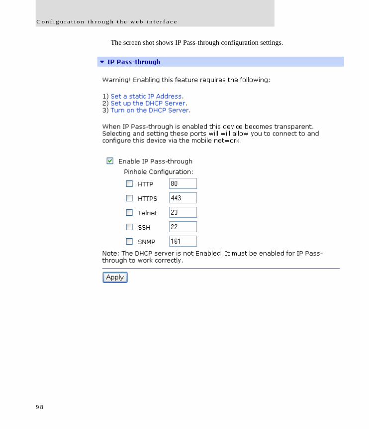
C o n f i g u r a t i o n t h r o u g h t h e w e b i n t e r f a c e
The screen shot shows IP Pass-through configuration settings.
9 8
C o n f i g u r e D i g i d e v i c e s
Virtual Private Network (VPN) settings
Virtual Private Networks (VPNs) are used to securely connect two private networks together so that devices may connect from one network to the other network using secure channels.VPN uses IP Security (IPSec) technology to protect the transferring of data over the Internet Protocol (IP). All Digi Cellular Family products except Digi Connect WAN support VPNs.
The Digi device is responsible for handling the routing between networks. Devices within the private network served by the Digi device can connect directly to devices on the other private network to which the VPN tunnel is established to. The VPN tunnels are configured using various security settings and methods to ensure the networks are secured.
Uses for VPN-enabled Digi devices
VPN-enabled Digi devices, such as Digi Connect WAN VPN, are cellular-enabled routers that securely connect remote subnets using IPsec VPN technology. Devices in the Digi device’s private network can connect directly to devices on the other private network with which the VPN tunnel is established. You configure VPN tunnels using security settings and methods to ensure the networks are secured.
The Digi device is used for primary or backup remote site connectivity. Secured IPsec VPN traffic is typically routed from the Digi device over the cellular IP network and is terminated by a VPN appliance at the host end.
A VPN-enabled Digi device can be used in several scenarios; for example:
As the primary remote site router where no other WAN router is used.
As a backup router where the remote site has a primary WAN connection through DSL, Frame Relay, or other means.
To provide secure access to remote serial and/or Ethernet devices.
This section describes using a Digi device as a primary remote site router using IPsec Encapsulated Security Payload (ESP) and Internet Key Exchange (IKE)/Internet Security Association and Key Management Protocol (ISAKMP) pre-shared key methods.
9 9
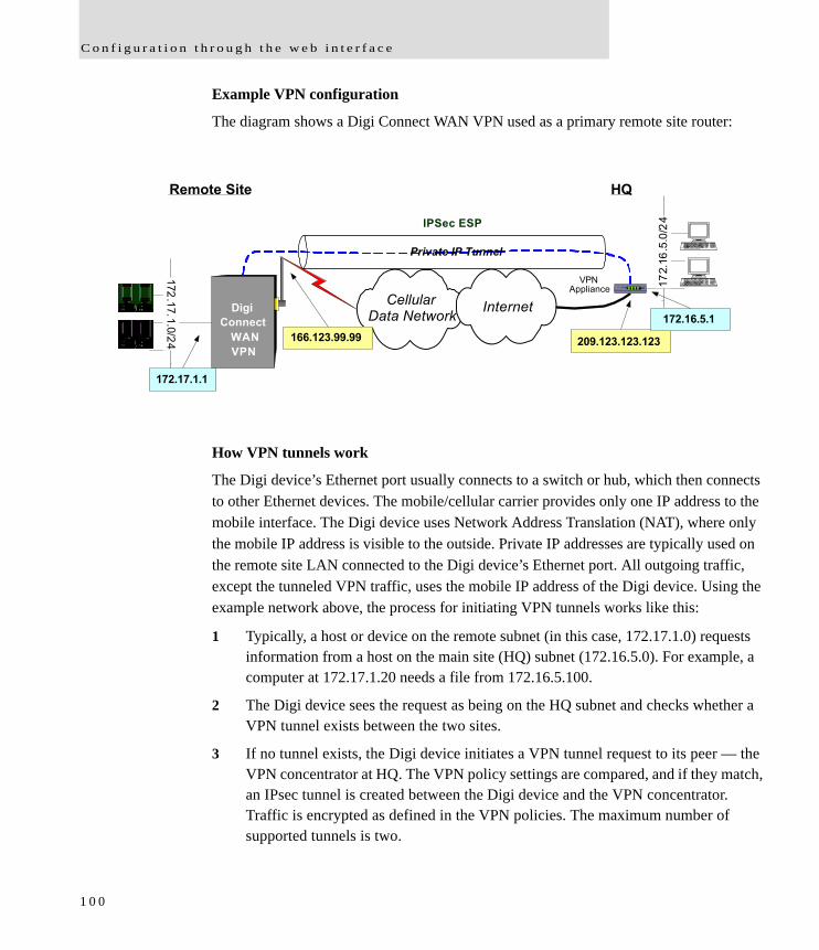
C o n f i g u r a t i o n t h r o u g h t h e w e b i n t e r f a c e
Example VPN configuration
The diagram shows a Digi Connect WAN VPN used as a primary remote site router:
How VPN tunnels work
The Digi device’s Ethernet port usually connects to a switch or hub, which then connects to other Ethernet devices. The mobile/cellular carrier provides only one IP address to the mobile interface. The Digi device uses Network Address Translation (NAT), where only the mobile IP address is visible to the outside. Private IP addresses are typically used on the remote site LAN connected to the Digi device’s Ethernet port. All outgoing traffic, except the tunneled VPN traffic, uses the mobile IP address of the Digi device. Using the example network above, the process for initiating VPN tunnels works like this:
1 Typically, a host or device on the remote subnet (in this case, 172.17.1.0) requests information from a host on the main site (HQ) subnet (172.16.5.0). For example, a computer at 172.17.1.20 needs a file from 172.16.5.100.
2 The Digi device sees the request as being on the HQ subnet and checks whether a VPN tunnel exists between the two sites.
3 If no tunnel exists, the Digi device initiates a VPN tunnel request to its peer — the VPN concentrator at HQ. The VPN policy settings are compared, and if they match, an IPsec tunnel is created between the Digi device and the VPN concentrator. Traffic is encrypted as defined in the VPN policies. The maximum number of supported tunnels is two.
CellularData NetworkDigi
Connect
VPN
Internet
Remote Site HQ
166.123.99.99 209.123.123.123
P WR
O K
WIC 0AC T /C H 0
AC T /C H 1
WIC 0A CT /C H 0
AC T /C H 1
E THA CT
C O L
VPNAppliance 17
2.16
.5.0
/24
172.17.1.0/ 24
172.17.1.1
Private IP Tunnel
172.16.5.1
IPSec ESP
WAN
1 0 0
C o n f i g u r e D i g i d e v i c e s
IP address requirements for VPN tunnels
To establish an IPSec VPN tunnel, the IP address of the mobile interface must be publicly accessible. The IP address can be either static or dynamic depending upon the requirements of your VPN end point. The IP address, however, cannot be within a private range of addresses (for example, 10.0.0.0, 172.16.0.0 or 192.168.0.0). If the mobile IP address is within one of the private IP address ranges, the mobile carrier is using a NAT (Network Address Translation) server between your mobile IP address and the internet. The Digi Connect WAN VPN does not currently support NAT-Traversal.
GSM GPRS/EDGE APN type needed
If the VPN end points require static (persistent) IP addresses, you may need a custom access point name (APN). An Internet APN can work in these cases:
The main site (HQ) VPN appliance can support Dynamic DNS names.
Another form of authentication is used (for example, FQDN).
Be aware that these APNs are based on Cingular Blue; other carrier APNs may have similar requirements.
CDMA carrier requirements
The CDMA (Code-Division Multiple Access) carrier requirements are similar to GSM in that static IP addresses may be required depending on the host site concentrator VPN implementation. In both cases, the Digi device’s mobile IP address will likely need to support mobile terminated data; that is, the ability to accept incoming data connections.
HQ router / VPN appliance configuration
For supported protocols, see the IPsec specifications your Digi device. Security policies on the HQ VPN device must match those on the Digi device. The HQ VPN appliance’s peer address is the Digi device’s mobile IP address.
1 0 1
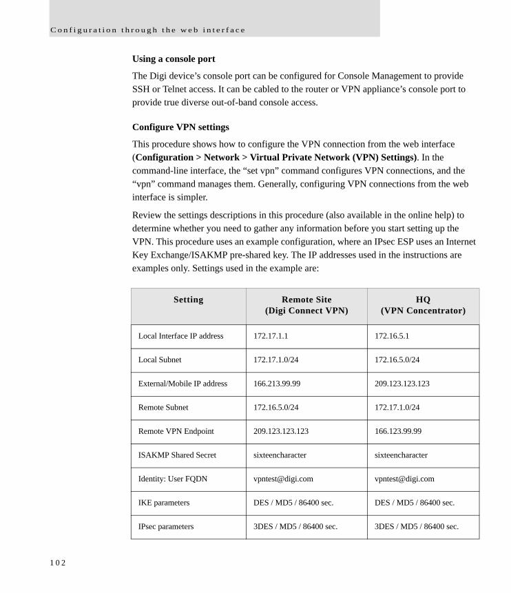
C o n f i g u r a t i o n t h r o u g h t h e w e b i n t e r f a c e
Using a console port
The Digi device’s console port can be configured for Console Management to provide SSH or Telnet access. It can be cabled to the router or VPN appliance’s console port to provide true diverse out-of-band console access.
Configure VPN settings
This procedure shows how to configure the VPN connection from the web interface (Configuration > Network > Virtual Private Network (VPN) Settings). In the command-line interface, the “set vpn” command configures VPN connections, and the “vpn” command manages them. Generally, configuring VPN connections from the web interface is simpler.
Review the settings descriptions in this procedure (also available in the online help) to determine whether you need to gather any information before you start setting up the VPN. This procedure uses an example configuration, where an IPsec ESP uses an Internet Key Exchange/ISAKMP pre-shared key. The IP addresses used in the instructions are examples only. Settings used in the example are:
Setting Remote Site (Digi Connect VPN)
HQ (VPN Concentrator)
Local Interface IP address 172.17.1.1 172.16.5.1
Local Subnet 172.17.1.0/24 172.16.5.0/24
External/Mobile IP address 166.213.99.99 209.123.123.123
Remote Subnet 172.16.5.0/24 172.17.1.0/24
Remote VPN Endpoint 209.123.123.123 166.123.99.99
ISAKMP Shared Secret sixteencharacter sixteencharacter
Identity: User FQDN [email protected] [email protected]
IKE parameters DES / MD5 / 86400 sec. DES / MD5 / 86400 sec.
IPsec parameters 3DES / MD5 / 86400 sec. 3DES / MD5 / 86400 sec.
1 0 2
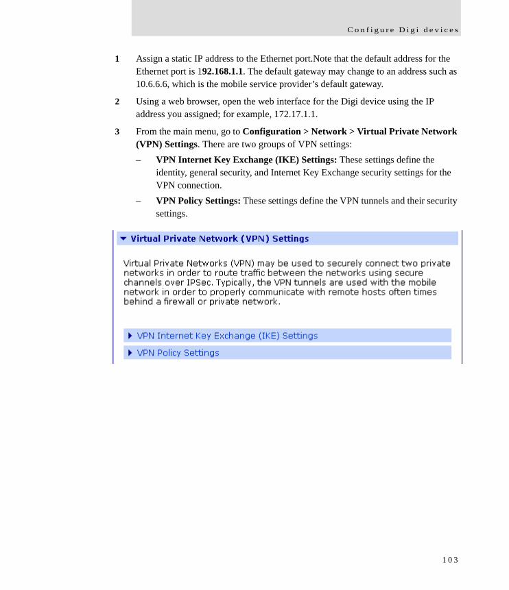
C o n f i g u r e D i g i d e v i c e s
1 Assign a static IP address to the Ethernet port.Note that the default address for the Ethernet port is 192.168.1.1. The default gateway may change to an address such as 10.6.6.6, which is the mobile service provider’s default gateway.
2 Using a web browser, open the web interface for the Digi device using the IP address you assigned; for example, 172.17.1.1.
3 From the main menu, go to Configuration > Network > Virtual Private Network (VPN) Settings. There are two groups of VPN settings:– VPN Internet Key Exchange (IKE) Settings: These settings define the
identity, general security, and Internet Key Exchange security settings for the VPN connection.
– VPN Policy Settings: These settings define the VPN tunnels and their security settings.
1 0 3
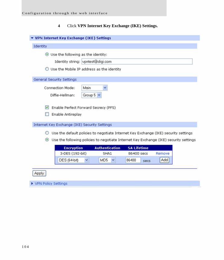
C o n f i g u r a t i o n t h r o u g h t h e w e b i n t e r f a c e
4 Click VPN Internet Key Exchange (IKE) Settings.
1 0 4
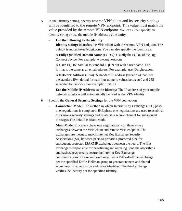
C o n f i g u r e D i g i d e v i c e s
5 In the Identity setting, specify how the VPN client and its security settings will be identified to the remote VPN endpoint. This value must match the value provided by the remote VPN endpoint. You can either specify an identity string or use the mobile IP address as the entity.– Use the following as the identity:
Identity string: Identifies the VPN client with the remote VPN endpoint. The default is [email protected]. You can also specify the identity as:A Fully Qualified Domain Name (FQDN): Usually the FQDN of the Digi Connect device. For example: www.myhost.comA User FQDN: Similar to standard FQDN but with a user name. The format is the same as an email address. For example: [email protected] Network Address (IPv4): A standard IP address (version 4) that uses the standard IPv4 dotted format (four numeric values between 0 and 255 separated by periods). For example: 10.0.0.1
– Use the Mobile IP Address as the identity: The IP address of your mobile network interface will automatically be used as the VPN identity.
6 Specify the General Security Settings for the VPN connection.– Connection Mode: The method in which Internet Key Exchange (IKE) phase
one negotiations is completed. IKE phase one negotiations are used to establish the various security settings and establish a secure channel for subsequent messages.The default is Main Mode.Main Mode: Processes phase one negotiations with three 2-way exchanges between the VPN client and remote VPN endpoint. The exchanges are meant to match Internet Key Exchange Security Associations (SA) between peers to provide a protected pipe for subsequent protected ISAKMP exchanges between the peers. The first exchange is responsible for negotiating and agreeing upon the algorithms and hashes/keys used to secure the Internet Key Exchange communications. The second exchange uses a Diffie-Hellman exchange per the specified Diffie-Hellman group to generate nonces and shared secret keys in order to sign and prove identities. The third exchange verifies the identity per the specified Identity.
1 0 5

C o n f i g u r a t i o n t h r o u g h t h e w e b i n t e r f a c e
Aggressive Mode: Processes phase one negotiations with fewer exchanges than Main Mode. In the first exchange, almost everything is sent in the proposed Internet Key Exchange values including the Diffie-Hellman key, nonce to sign and verify, and the identity. The weakness of using Aggressive Mode compared to Main Mode is that negotiations exchange information before the secure channel is created. However, because less exchanges are used, aggressive mode is faster than main mode.
– Diffie-Hellman: Diffie-Hellman is a public-key cryptography protocol for establishing a shared secret over an insecure communications channel. Diffie-Hellman is used within Internet Key Exchange to establish the session keys that create a secure channel. The method and security factor used to control the exchange is specified by the Diffie-Hellman group. The greater the group, the more secure the transaction. However, because the keys and cryptography calculations are larger, they also require more processing time and performance costs. The default is Group 2. Group 1 (768-bit): Uses a 768-bit Diffie-Hellman prime modulus group to secure the shared secret.Group 2 (1024-bit): Uses a 1024-bit Diffie-Hellman prime modulus group to secure the shared secret.Group 5 (1536-bit): Uses a 1536-bit Diffie-Hellman prime modulus group to secure the shared secret
– Enable Perfect Forward Secrecy (PFS): Perfect Forward Secrecy establishes greater resistance to cryptographic attacks by ensuring that a given key of an Internet Key Exchange SA is not derived from any other secret, and that no other key can be derived from this key. Set this field to match that at the remote VPN gateway. Default is Enabled.
– Enable Antireplay: Antireplay allows the IPsec tunnel receiver to detect and reject packets that have been replayed.Set this field to match that at the remote VPN gateway. The default is Enabled. Important: Disable Antireplay if you use manual keyed tunnels.
1 0 6
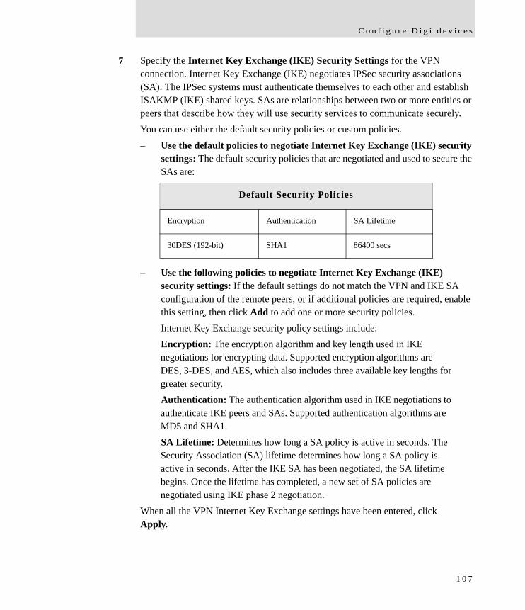
C o n f i g u r e D i g i d e v i c e s
7 Specify the Internet Key Exchange (IKE) Security Settings for the VPN connection. Internet Key Exchange (IKE) negotiates IPSec security associations (SA). The IPSec systems must authenticate themselves to each other and establish ISAKMP (IKE) shared keys. SAs are relationships between two or more entities or peers that describe how they will use security services to communicate securely.You can use either the default security policies or custom policies.– Use the default policies to negotiate Internet Key Exchange (IKE) security
settings: The default security policies that are negotiated and used to secure the SAs are:
– Use the following policies to negotiate Internet Key Exchange (IKE) security settings: If the default settings do not match the VPN and IKE SA configuration of the remote peers, or if additional policies are required, enable this setting, then click Add to add one or more security policies. Internet Key Exchange security policy settings include:Encryption: The encryption algorithm and key length used in IKE negotiations for encrypting data. Supported encryption algorithms are DES, 3-DES, and AES, which also includes three available key lengths for greater security.Authentication: The authentication algorithm used in IKE negotiations to authenticate IKE peers and SAs. Supported authentication algorithms are MD5 and SHA1.SA Lifetime: Determines how long a SA policy is active in seconds. The Security Association (SA) lifetime determines how long a SA policy is active in seconds. After the IKE SA has been negotiated, the SA lifetime begins. Once the lifetime has completed, a new set of SA policies are negotiated using IKE phase 2 negotiation.
When all the VPN Internet Key Exchange settings have been entered, click Apply.
Default Security Policies
Encryption Authentication SA Lifetime
30DES (192-bit) SHA1 86400 secs
1 0 7
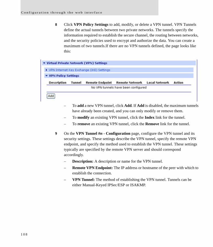
C o n f i g u r a t i o n t h r o u g h t h e w e b i n t e r f a c e
8 Click VPN Policy Settings to add, modify, or delete a VPN tunnel. VPN Tunnels define the actual tunnels between two private networks. The tunnels specify the information required to establish the secure channel, the routing between networks, and the security policies used to encrypt and authorize the data. You can create a maximum of two tunnels.If there are no VPN tunnels defined, the page looks like this:
– To add a new VPN tunnel, click Add. If Add is disabled, the maximum tunnels have already been created, and you can only modify or remove them.
– To modify an existing VPN tunnel, click the Index link for the tunnel. – To remove an existing VPN tunnel, click the Remove link for the tunnel.
9 On the VPN Tunnel #n - Configuration page, configure the VPN tunnel and its security settings. These settings describe the VPN tunnel, specify the remote VPN endpoint, and specify the method used to establish the VPN tunnel. These settings typically are specified by the remote VPN server and should correspond accordingly. – Description: A description or name for the VPN tunnel.– Remote VPN Endpoint: The IP address or hostname of the peer with which to
establish the connection.– VPN Tunnel: The method of establishing the VPN tunnel. Tunnels can be
either Manual-Keyed IPSec/ESP or ISAKMP.
1 0 8
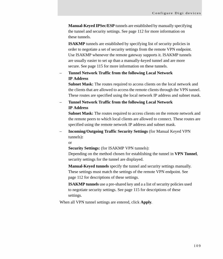
C o n f i g u r e D i g i d e v i c e s
Manual-Keyed IPSec/ESP tunnels are established by manually specifying the tunnel and security settings. See page 112 for more information on these tunnels.ISAKMP tunnels are established by specifying list of security policies in order to negotiate a set of security settings from the remote VPN endpoint. Use ISAKMP whenever the remote gateway supports it. ISAKMP tunnels are usually easier to set up than a manually-keyed tunnel and are more secure. See page 115 for more information on these tunnels.
– Tunnel Network Traffic from the following Local NetworkIP AddressSubnet Mask: The routes required to access clients on the local network and the clients that are allowed to access the remote clients through the VPN tunnel. These routes are specified using the local network IP address and subnet mask.
– Tunnel Network Traffic from the following Local NetworkIP AddressSubnet Mask: The routes required to access clients on the remote network and the remote peers to which local clients are allowed to connect. These routes are specified using the remote network IP address and subnet mask.
– Incoming/Outgoing Traffic Security Settings (for Manual Keyed VPN tunnels):orSecurity Settings: (for ISAKMP VPN tunnels):Depending on the method chosen for establishing the tunnel in VPN Tunnel, security settings for the tunnel are displayed. Manual-Keyed tunnels specify the tunnel and security settings manually. These settings must match the settings of the remote VPN endpoint. See page 112 for descriptions of these settings.ISAKMP tunnels use a pre-shared key and a a list of security policies used to negotiate security settings. See page 115 for descriptions of these settings.
When all VPN tunnel settings are entered, click Apply.
1 0 9
C o n f i g u r a t i o n t h r o u g h t h e w e b i n t e r f a c e
For example, to configure the ISAKMP VPN tunnel in the example configuration, you would choose ISAKMP and enter the pre-shared key (PSK) information and security policy.
1 1 0
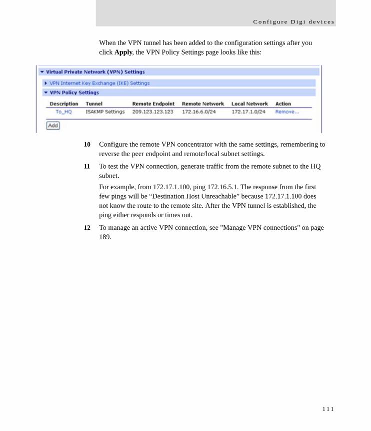
C o n f i g u r e D i g i d e v i c e s
When the VPN tunnel has been added to the configuration settings after you click Apply, the VPN Policy Settings page looks like this:
10 Configure the remote VPN concentrator with the same settings, remembering to reverse the peer endpoint and remote/local subnet settings.
11 To test the VPN connection, generate traffic from the remote subnet to the HQ subnet. For example, from 172.17.1.100, ping 172.16.5.1. The response from the first few pings will be “Destination Host Unreachable” because 172.17.1.100 does not know the route to the remote site. After the VPN tunnel is established, the ping either responds or times out.
12 To manage an active VPN connection, see "Manage VPN connections" on page 189.
1 1 1
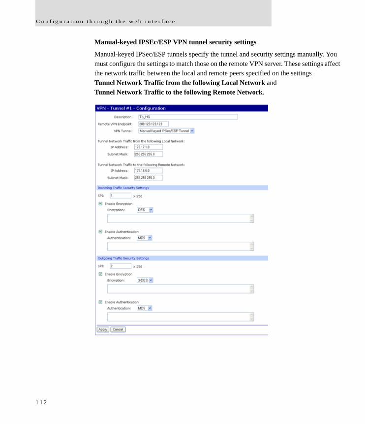
C o n f i g u r a t i o n t h r o u g h t h e w e b i n t e r f a c e
Manual-keyed IPSEc/ESP VPN tunnel security settings
Manual-keyed IPSec/ESP tunnels specify the tunnel and security settings manually. You must configure the settings to match those on the remote VPN server. These settings affect the network traffic between the local and remote peers specified on the settings Tunnel Network Traffic from the following Local Network and Tunnel Network Traffic to the following Remote Network.
1 1 2
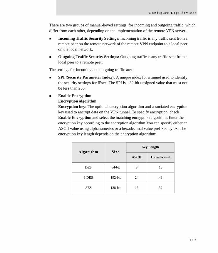
C o n f i g u r e D i g i d e v i c e s
There are two groups of manual-keyed settings, for incoming and outgoing traffic, which differ from each other, depending on the implementation of the remote VPN server.
Incoming Traffic Security Settings: Incoming traffic is any traffic sent from a remote peer on the remote network of the remote VPN endpoint to a local peer on the local network.
Outgoing Traffic Security Settings: Outgoing traffic is any traffic sent from a local peer to a remote peer.
The settings for incoming and outgoing traffic are:
SPI (Security Parameter Index): A unique index for a tunnel used to identify the security settings for IPsec. The SPI is a 32-bit unsigned value that must not be less than 256.
Enable EncryptionEncryption algorithmEncryption key: The optional encryption algorithm and associated encryption key used to encrypt data on the VPN tunnel. To specify encryption, check Enable Encryption and select the matching encryption algorithm. Enter the encryption key according to the encryption algorithm.You can specify either an ASCII value using alphanumerics or a hexadecimal value prefixed by 0x. The encryption key length depends on the encryption algorithm:
Algorithm SizeKey Length
ASCII Hexadecimal
DES 64-bit 8 16
3 DES 192-bit 24 48
AES 128-bit 16 32
1 1 3

C o n f i g u r a t i o n t h r o u g h t h e w e b i n t e r f a c e
Enable AuthenticationAuthentication algorithmAuthentication key: The optional authentication algorithm and associated authentication key used to authorize access on the VPN tunnel. To specify authentication, check Enable Authentication and select the matching authentication algorithm. Enter the authentication key according to the authentication algorithm. You can specify either an ASCII value using alphanumerics or a hexadecimal value prefixed by 0x. The authentication key length depends on the authentication algorithm:
Algorithm SizeKey Length
ASCII Hexadecimal
MD5 128-bit 16 32
SHA1 160-bit 20 40
1 1 4
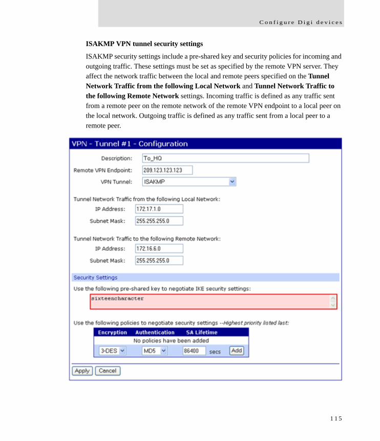
C o n f i g u r e D i g i d e v i c e s
ISAKMP VPN tunnel security settings
ISAKMP security settings include a pre-shared key and security policies for incoming and outgoing traffic. These settings must be set as specified by the remote VPN server. They affect the network traffic between the local and remote peers specified on the Tunnel Network Traffic from the following Local Network and Tunnel Network Traffic to the following Remote Network settings. Incoming traffic is defined as any traffic sent from a remote peer on the remote network of the remote VPN endpoint to a local peer on the local network. Outgoing traffic is defined as any traffic sent from a local peer to a remote peer.
1 1 5
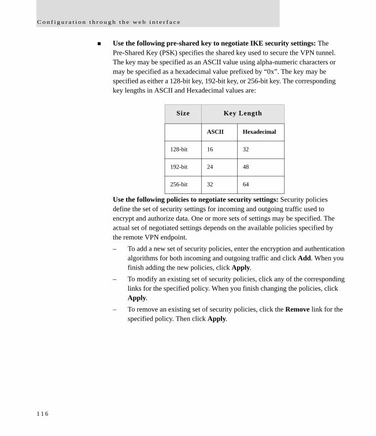
C o n f i g u r a t i o n t h r o u g h t h e w e b i n t e r f a c e
Use the following pre-shared key to negotiate IKE security settings: The Pre-Shared Key (PSK) specifies the shared key used to secure the VPN tunnel. The key may be specified as an ASCII value using alpha-numeric characters or may be specified as a hexadecimal value prefixed by “0x”. The key may be specified as either a 128-bit key, 192-bit key, or 256-bit key. The corresponding key lengths in ASCII and Hexadecimal values are:
Use the following policies to negotiate security settings: Security policies define the set of security settings for incoming and outgoing traffic used to encrypt and authorize data. One or more sets of settings may be specified. The actual set of negotiated settings depends on the available policies specified by the remote VPN endpoint. – To add a new set of security policies, enter the encryption and authentication
algorithms for both incoming and outgoing traffic and click Add. When you finish adding the new policies, click Apply.
– To modify an existing set of security policies, click any of the corresponding links for the specified policy. When you finish changing the policies, click Apply.
– To remove an existing set of security policies, click the Remove link for the specified policy. Then click Apply.
Size Key Length
ASCII Hexadecimal
128-bit 16 32
192-bit 24 48
256-bit 32 64
1 1 6
C o n f i g u r e D i g i d e v i c e s
VPN tunnel proposal configuration for ISAKMP tunnels
The Proposal Configuration settings configure a set of security policies for ISAKMP tunnels. The settings define the set of encryption and authentication algorithms for incoming and outgoing traffic over the VPN tunnel. Proposals let you define multiple types of communications. A security policy can have multiple proposals. For example, a security policy can have two proposals to allow older VPN devices to connect using less-secure methods, while allowing the same policy to have a second (or more) proposal to allow newer, more powerful end-points to use more secure methods. For two devices to communicate with each other, they must have a matching proposal.
VPN tunnel proposal configuration settings include:
Encryption: The encryption algorithm used for encrypting data:– DES: Uses 64-bit keys– 3-DES: Uses 192-bit keys– AES: Uses 128-bit, 192-bit, or 256-bit keys depending on the negotiated
security settings
Authentication: The authentication algorithm used for authenticating clients:– MD5: Uses 128-bit keys.– SHA1: Uses 160-bit keys.
SA Lifetime: The Security Association (SA) lifetime determines how long a SA policy is active in seconds. After the SA has been negotiated, the SA lifetime begins. Once the lifetime has completed, a new set of SA policies are negotiated with the remote VPN endpoint.
1 1 7

C o n f i g u r a t i o n t h r o u g h t h e w e b i n t e r f a c e
Advanced network settings
The Advanced Network Settings are used to further define the network interface, including:
Host name: The Host name to be placed in the DHCP Option 12 field. This is an optional setting which is only used when DHCP is enabled.
Enable Auto IP address assignment: Whether Auto-IP address assignment is enabled or disabled.
Ethernet Interface speed and duplex mode (Auto, Half-Duplex, or Full Duplex).
TCP keep-alive settings: The DHCP server assigns these network settings, unless they are manually set here. To manually set and override these settings, select Ignore TCP Keep-Alive settings from DHCP and specify the values for Idle Timeout, Probe Interval, and whether an extra byte should be stored in TCP keep-alive packets.
1 1 8
C o n f i g u r e D i g i d e v i c e s
Configure mobile (cellular) settings
The Mobile Settings pages configure how to connect to mobile (cellular) networks using the mobile connection, including the service provider, service plan, and connection settings used in connecting to the mobile network. If your Digi device has not already been provisioned for use in the mobile network, you can launch a wizard to provision it from these pages. In addition, you can configure settings for Digi SureLink™, a feature that provides an “always-on” mobile network connection to ensure rapid on-demand communication. The SureLink configuration settings allow you to customize how SureLink detects when a connection has been lost, in order to re-establish the link.
Information required from mobile service provider
To connect to the mobile network, you must get a set of network settings from the mobile service provider including service plan and authentication details. For more information, consult the documentation that came with your mobile service provider's information.
Different processes used for CDMA and GSM provisioning
The process for provisioning your device and the settings displayed on the Mobile Configuration page vary according to whether the mobile service provider network used with your Digi Cellular Family product is based on CDMA (Code-Division Multiple Access) or GSM (Global System for Mobile communication).
CDMA-based mobile service providers
Device provisioning for a CDMA-based mobile service provider consists of selecting the service provider from a list and either automatically or manually entering mobile settings provided by the mobile service provider Examples of CDMA-based mobile service providers include Sprint, Verizon, Alltel, and Midwest.
GSM-based mobile service providers
Device provisioning for a GSM-based mobile service provider involves inserting a Subscriber Identity Module (SIM) card into the Digi device, which makes subscription data available in the cellular network. Examples of GSM-based mobile service providers include Cingular, AT&T, and T-Mobile.
1 1 9
C o n f i g u r a t i o n t h r o u g h t h e w e b i n t e r f a c e
Set mobile configuration settings to factory defaults
The Set to Defaults button on the Mobile Configuration page sets all the mobile settings to factory defaults and sets the Service Provider selection back to deselected.
Mobile service provider settings
The Mobile Service Provider settings part of the screen identifies the service provider to use in connecting to the mobile network. The information displayed varies by Digi Cellular Family product and whether the remote service provider is GSM- or CDMA-based. Settings that may be displayed on this screen include:
Service Provider: For GSM-based mobile service providers, this is the service provider to use in connecting to the mobile network. The service provider must match the provider that supplied the SIM card.This must match the provider that supplied the SIM card. (Not displayed for CDMA products.)
Service Plan: For GSM-based mobile service providers, this is the service plan to use in connecting to the mobile network. This setting must match the plan that the service provider has supplied to you. This is also sometimes known as the APN (Access Point Name).
Username and Password: For GSM-based mobile service providers, these settings are the username and password of the mobile connection needed to access the mobile network.
Device provisioning state: For CDMA-based mobile service providers, the text below the Service Provider selection list states whether the device has already been provisioned. Clicking the Provision Device button launches a wizard for provisioning the device. Mobile device provisioning is described next.
1 2 0
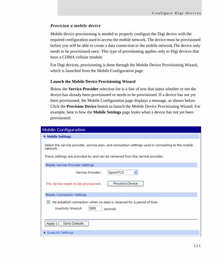
C o n f i g u r e D i g i d e v i c e s
Provision a mobile device
Mobile device provisioning is needed to properly configure the Digi device with the required configuration used to access the mobile network. The device must be provisioned before you will be able to create a data connection to the mobile network.The device only needs to be provisioned once. This type of provisioning applies only to Digi devices that have a CDMA cellular module.
For Digi devices, provisioning is done through the Mobile Device Provisioning Wizard, which is launched from the Mobile Configuration page.
Launch the Mobile Device Provisioning Wizard
Below the Service Provider selection list is a line of text that states whether or not the device has already been provisioned or needs to be provisioned. If a device has not yet been provisioned, the Mobile Configuration page displays a message, as shown below. Click the Provision Device button to launch the Mobile Device Provisioning Wizard. For example, here is how the Mobile Settings page looks when a device has not yet been provisioned.
1 2 1
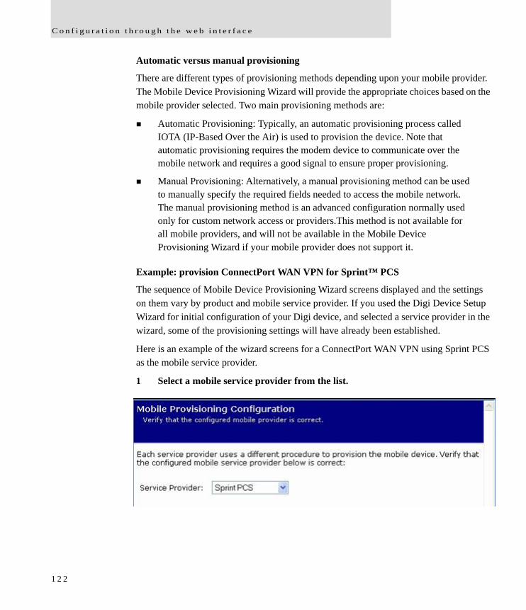
C o n f i g u r a t i o n t h r o u g h t h e w e b i n t e r f a c e
Automatic versus manual provisioning
There are different types of provisioning methods depending upon your mobile provider. The Mobile Device Provisioning Wizard will provide the appropriate choices based on the mobile provider selected. Two main provisioning methods are:
Automatic Provisioning: Typically, an automatic provisioning process called IOTA (IP-Based Over the Air) is used to provision the device. Note that automatic provisioning requires the modem device to communicate over the mobile network and requires a good signal to ensure proper provisioning.
Manual Provisioning: Alternatively, a manual provisioning method can be used to manually specify the required fields needed to access the mobile network. The manual provisioning method is an advanced configuration normally used only for custom network access or providers.This method is not available for all mobile providers, and will not be available in the Mobile Device Provisioning Wizard if your mobile provider does not support it.
Example: provision ConnectPort WAN VPN for Sprint™ PCS
The sequence of Mobile Device Provisioning Wizard screens displayed and the settings on them vary by product and mobile service provider. If you used the Digi Device Setup Wizard for initial configuration of your Digi device, and selected a service provider in the wizard, some of the provisioning settings will have already been established.
Here is an example of the wizard screens for a ConnectPort WAN VPN using Sprint PCS as the mobile service provider.
1 Select a mobile service provider from the list.
1 2 2
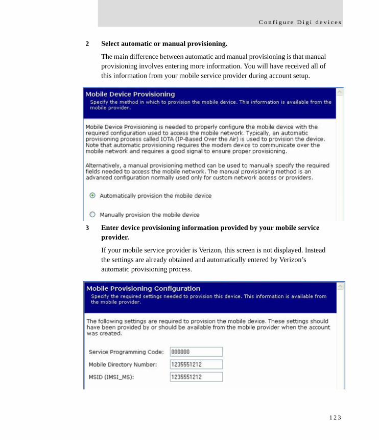
C o n f i g u r e D i g i d e v i c e s
2 Select automatic or manual provisioning.
The main difference between automatic and manual provisioning is that manual provisioning involves entering more information. You will have received all of this information from your mobile service provider during account setup.
3 Enter device provisioning information provided by your mobile service provider.
If your mobile service provider is Verizon, this screen is not displayed. Instead the settings are already obtained and automatically entered by Verizon’s automatic provisioning process.
1 2 3
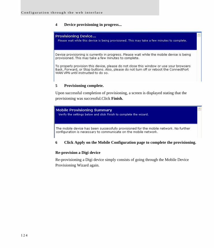
C o n f i g u r a t i o n t h r o u g h t h e w e b i n t e r f a c e
4 Device provisioning in progress...
5 Provisioning complete.
Upon successful completion of provisioning, a screen is displayed stating that the provisioning was successful.Click Finish..
6 Click Apply on the Mobile Configuration page to complete the provisioning.
Re-provision a Digi device
Re-provisioning a Digi device simply consists of going through the Mobile Device Provisioning Wizard again.
1 2 4
C o n f i g u r e D i g i d e v i c e s
Mobile connection settings
Mobile connection settings configure how the mobile connection is established and maintained.
Re-establish connection when no data is received for a period of time:Inactivity timeout: Whether the mobile connection will be disconnected and re-established after no data has been received over the link for the specified amount of time, in seconds.
Digi SureLink™ settings
The Mobile Connection Settings configure Digi SureLink™ settings for a Digi device. SureLink ensures that a Digi device is in a state where it can connect to the mobile network, and they can be used to monitor the integrity of the established mobile connection.
There are two groups of SureLink settings:
Hardware Reset Thresholds: These settings can be configured to clear any error states that were resident in the Digi device’s cellular module, so the device can once again connect to the network, if the connection is lost. It does this by first resetting the cellular module after a default or specified number of consecutive failed connection attempts, and then resetting the Digi device after a default or specified number of failed consecutive connection attempts. Each of these connection-failure settings can be disabled as well.
Link Integrity Monitoring settings: These settings can be configured to perform a selected test to examine the functional integrity of the network connection, and take action to recover the connection in the event that it is lost.
1 2 5
C o n f i g u r a t i o n t h r o u g h t h e w e b i n t e r f a c e
Hardware reset thresholds
Hard reset the modem module after the following number of consecutive failed connections: Enables or disables a hard reset of the cellular modem module after the specified number of failed connection attempts.This value can be a number between 1 and 255. The default is 3.
Power-cycle the device after the following number of consecutive failed connections: Enables or disables a power-cycle of the Digi device after the specified number of failed connection attempts. This value can be a number between 1 and 255. The default is 0, or off.
Link integrity monitoring settings
Enable Link Integrity Monitoring using the test method selected below: Enables or disables the link integrity monitoring tests. If this setting is enabled, the other Link Integrity Monitoring settings may be configured and are used to verify the functional integrity of the mobile connection. The default is off (disabled). There are three tests available: – Ping Test – TCP Connection Test – DNS Lookup Test You can use these tests to demonstrate that two-way communication is working over the mobile connection. Several tests are provided because different mobile networks or firewalls may allow or block Internet packets for various services. Select the appropriate test may be selected according to mobile network constraints and your preferences. The link integrity tests are performed only while the mobile connection is established. If the mobile connection is disconnected, the link integrity tests are suspended until the connection is established again. For the link integrity tests to provide meaningful results, the remote or target hosts must be accessible over the mobile connection and not through the LAN interface of the device (if it has one). That is, the settings should be configured to guarantee that the mobile connection is actually being tested. The link integrity test settings may be modified at any time. The changes are used at the start of the next test interval.
1 2 6
C o n f i g u r e D i g i d e v i c e s
Ping Test: Enables or disables the use of “ping” (ICMP) as a test to verify the integrity of the mobile connection. The test is successful if a valid ping reply is received in response to the ping request sent. The ping test actually sends up to three ping requests, at three second intervals, to test the link. When a valid reply is received, the test completes successfully and immediately. If a reply is received for the first request sent, there is no need to send the other two requests. Two destination hosts may be configured for this test. If the first host fails to reply to all three ping requests, the same test is attempted to the second host. If neither host replies to any of the ping requests sent, the test fails. The primary and secondary addresses may be either IP addresses or fully qualified domain names. – Primary Address: First host to test.– Secondary Address: Second host to test (if the first host fails).
TCP Connection Test: Enables or disables the creation of a new TCP connection as a test to verify the integrity of the mobile connection. The test is successful if a TCP connection is established to a specified remote host and port number. If the remote host actively refuses the connection request, the test is also considered to be successful, since that demonstrates successful two-way communication over the mobile connection. The TCP connection test waits up to 30 seconds for the connection to be established or refused. When the TCP connection is established, the test completes successfully, and the TCP connection is closed immediately. Two destination hosts may be configured for this test. If the first host fails to establish (or refuse) the TCP connection, the same test is attempted to the second host. If neither host successfully establishes (or refuses) the TCP connection, the test fails. The primary and secondary addresses may be either IP addresses or fully qualified domain names. – TCP Port: The TCP port number to connect to on the remote host (default 80).– Primary Address: The address of the first host to test.– Secondary Address: The address of the second host to test (if the first host
fails).
1 2 7
C o n f i g u r a t i o n t h r o u g h t h e w e b i n t e r f a c e
DNS Lookup Test: Enables or disables the use of a Domain Name Server (DNS) lookup as a test to verify the integrity of the mobile connection. The test is successful if a valid reply is received from a DNS server. Typically, this means the hostname is successfully “resolved” to an IP address by a DNS server. But even a reply such as “not found” or “name does not exist” is acceptable as a successful test result, since that demonstrates successful two-way communication over the mobile connection. When a valid reply is received, the test completes successfully and immediately. The DNS servers used in this test for the hostname lookup, are the primary and secondary DNS servers obtained from the mobile network when the mobile PPP connection is first established. These addresses can be viewed by going to Administration > System Information > Mobile. Note that this DNS test is independent of the normal DNS client configuration and lookup cache, which is used for other hostname lookups. This test has been specifically designed to require communication over the mobile connection for each lookup, and to avoid being “short-circuited” by previously cached information. Also, this test does not interfere in any way with the normal DNS client configuration of this device. Two hostnames may be configured for this test. If the first hostname fails to get a reply, the same test is attempted for the second hostname. If no reply is received for either hostname, the test fails. The primary and secondary DNS names should be fully qualified domain names. Note that the reverse lookup of an IP address is possible, but that is usually unlikely to succeed in returning a name. Still, such a reverse lookup can be used to demonstrate the integrity of the mobile connection. – Primary DNS Name: The first hostname to look up.– Secondary DNS Name: The second hostname to look up (if the first hostname
fails).
Repeat the selected link integrity test every N seconds: Specifies the interval, in seconds, at which the selected test is initiated (repeated). A new test will be started every N seconds while the mobile connection is established. This value must be between 10 and 65535. The default is 240. If the configured interval is less time than it takes a test to complete, the next test will not be initiated until the previous (current) test has completed.
1 2 8
C o n f i g u r e D i g i d e v i c e s
Test only when idle: if no data is received for the above period of time: Specifies that the test repeat interval (above) is to be used as an idle period interval. That is, initiate the selected link integrity test only after no data has been received for the specified interval of time. This changes the behavior of the test in that the test interval varies according to the presence of other data received from the mobile connection. Although using this idle option may result in less data being exchanged over the mobile connection, it also prevents the link integrity tests from running as often to verify the true bi-directional state of that connection.
Reset the link after the following number of consecutive link integrity test failures: Specifies that after the configured number of consecutive link integrity test failures, the mobile connection should be disconnected and reestablished. This value must be between 1 and 255. The default is 3. When the mobile connection is reestablished, the “consecutive failures” counter is reset to zero. If the mobile connection is disconnected for any reason (including not as a result of a link integrity test failure), the consecutive failures count is reset to zero when the mobile connection is reestablished.
Status and statistical information for mobile connections
Once the mobile settings have been configured, you can monitor the status of mobile connections by going to Administration > System Information > Mobile. See "Mobile information and statistics" on page 184.
From the command line, this mobile information is displayed by issuing display mobile and display pppstats commands.
1 2 9
C o n f i g u r a t i o n t h r o u g h t h e w e b i n t e r f a c e
Configure Mesh/ZigBee network settings
A Digi ConnectPort X gateway provides a gateway between an Internet Protocol (IP) network and a mesh network of various ZigBee wireless devices. Typically, these mesh devices are small sensors and controllers.
On the Mesh network, the ConnectPort X gateway serves as the coordinator node. As the coordinator, it is responsible for establishing the operation channel and PAN ID for the entire mesh network. The ZigBee wireless devices that are discovered and displayed as routers.
Mesh network terms
ZigBee protocol
Node
ZigBee node typesThere are three types of nodes in a Mesh network that uses the ZigBee protocol:
– Coordinator– Router – End Device
coordinator A coordinator is node that has the unique function of forming a network. The coordinator is responsible for establishing the operating channel and PAN ID for an entire network. Once established, the coordinator can form a network by allowing routers and end devices to join to it. Once the network is formed, the Coordinator functions like a Router (it can participate in routing packets and be a source or destination for data packets). Characteristics of coordinators include:- One coordinator per PAN - Establishes/Organizes PAN - Can route data packets to/from other nodes- Can be a data packet source and destination- Mains-powered In the web interface, a coordinator is also referred to as a gateway device.
1 3 0
C o n f i g u r e D i g i d e v i c e s
routerA router is a node that creates/maintains network information and uses this information to determine the best route for a data packet. A router must join a network before it can allow other routers and end devices to join to it. A router can participate in routing packets and is intended to be a mains-powered node. Characteristics of routers include:- Several routers can operate in one PAN- Routers can route data packets to/from other nodes- Can be a data packet source and destination - Is mains-powered
end device End devices have no routing capacity. They must always interact with their parent node (Router or Coordinator) to transmit or receive data. An end device can be a source or destination for data packets but cannot route packets. End devices can be battery-powered and offer low-power operation. Characteristics of end devices include:- Several end devices can operate in one PAN - Can be a data packet source and destination - All messages are relayed through a coordinator or router - Low power end devices are not supported in this release.
ZigBee protocol terms
Here are definitions of frequently used terms in discussions of and configuration settings for Mesh networks that use the ZigBee protocol.
ZigBee stackZigBee is a published specification set of high-level communication protocols for use with small, low-power modules. The ZigBee stack provides a layer of network functionality on top of the 802.15.4 specification. For example, the mesh and routing capabilities available to ZigBee solutions are absent in the 802.15.4 protocol.
Personal Area Network (PAN)A data communication network that includes a coordinator and one or more routers/end devices. Net-work formation is governed by network maximum depth, maximum child routers and maximum children end devices. All XBee device adapters are shipped with the same factory default PAN ID. This PAN ID can be changed in the Mesh Network configuration settings in the web interface for the ConnectPort X gateway.
1 3 1

C o n f i g u r a t i o n t h r o u g h t h e w e b i n t e r f a c e
joiningThe process of a node becoming part of a ZigBee PAN. A node becomes part of a network by joining to a coordinator or a router (that has previously joined to the network). During the process of joining, the node that allowed joining (the parent) assigns a 16-bit address to the joining node (the child).
network maximum depthThe level of descendents from a coordinator. In a MaxStream PAN, the network maximum depth is 5.
maximum child routersThe maximum number of routers than can join to one node. The maximum number of child routers in a MaxStream PAN is 6.
maximum child end devicesThe maximum number of end devices than can join to one node. The maximum number of child end devices in a MaxStream PAN is 14.
network addressThe 16-bit address assigned to a node after it has joined to another node.
operating channelThe frequency selected for data communications between nodes. The operating channel is selected by the coordinator on power-up.
energy scanA scan of RF channels that detects the amount of energy present on the selected channels. The Coordinator uses the energy scan to determine the operating channel.
route requestBroadcast transmission sent by a coordinator or router throughout the network in attempt to establish a route to a destination node.
route replyUnicast transmission sent back to the originator of the route request. It is initiated by a node when it receives a route request packet and its address matches the Destination Address in the route request packet.
route discoveryThe process of establishing a route to a destination node when one does not exist in the Routing Table. It is based on the AODV (Ad-hoc On-demand Distance Vector routing) protocol.
1 3 2
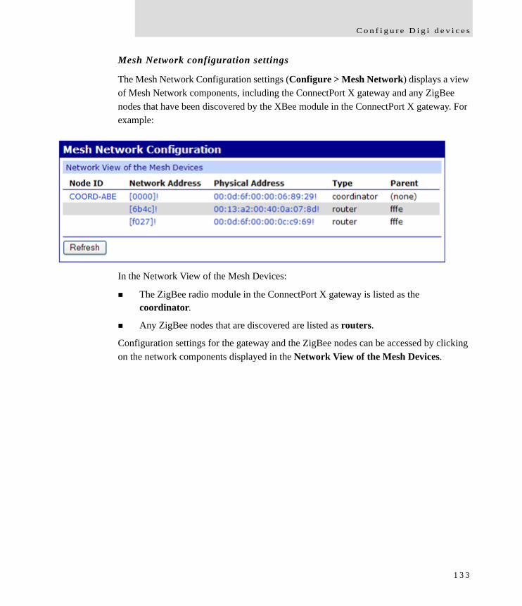
C o n f i g u r e D i g i d e v i c e s
Mesh Network configuration settings
The Mesh Network Configuration settings (Configure > Mesh Network) displays a view of Mesh Network components, including the ConnectPort X gateway and any ZigBee nodes that have been discovered by the XBee module in the ConnectPort X gateway. For example:
In the Network View of the Mesh Devices:
The ZigBee radio module in the ConnectPort X gateway is listed as the coordinator.
Any ZigBee nodes that are discovered are listed as routers.
Configuration settings for the gateway and the ZigBee nodes can be accessed by clicking on the network components displayed in the Network View of the Mesh Devices.
1 3 3
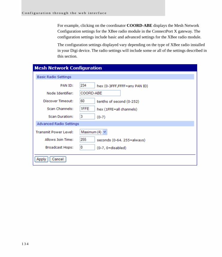
C o n f i g u r a t i o n t h r o u g h t h e w e b i n t e r f a c e
For example, clicking on the coordinator COORD-ABE displays the Mesh Network Configuration settings for the XBee radio module in the ConnectPort X gateway. The configuration settings include basic and advanced settings for the XBee radio module.
The configuration settings displayed vary depending on the type of XBee radio installed in your Digi device. The radio settings will include some or all of the settings described in this section.
1 3 4

C o n f i g u r e D i g i d e v i c e s
Basic radio settings
PAN ID: Sets the PAN (Personal Area Network) ID, in hex. This is the preferred PAN ID for the mesh network. If the configured ID setting is FFFF, the Digi device will select a random PAN ID. Otherwise, the specified ID will be used. When a Router or End device searches for a Coordinator on the mesh network, it joins to a parent that has a matching PAN ID. If that device's configured ID setting is FFFF, the device will join a parent operating on any PAN ID.
Node Identifier: A printable string identifier of this node. This identifier is returned as part of Node Discover command.
Discover Timeout: Sets the amount of time a node will spend discovering other nodes when a Node Join or Node Discover is issued.
Scan Channels: A bit field list of the channels to scan. The Digi device chooses of the channels when starting the network. In a Router or End device, the bit field is a list of channels that will be scanned to find a Coordinator/Router to join.
Scan Duration: Sets the scan duration exponent of the Active and Energy Scans (on each channel) that are used to determine an acceptable channel and Pan ID for startup of the Coordinator.
1 3 5
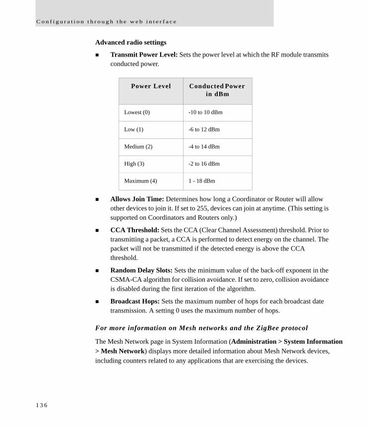
C o n f i g u r a t i o n t h r o u g h t h e w e b i n t e r f a c e
Advanced radio settings
Transmit Power Level: Sets the power level at which the RF module transmits conducted power.
Allows Join Time: Determines how long a Coordinator or Router will allow other devices to join it. If set to 255, devices can join at anytime. (This setting is supported on Coordinators and Routers only.)
CCA Threshold: Sets the CCA (Clear Channel Assessment) threshold. Prior to transmitting a packet, a CCA is performed to detect energy on the channel. The packet will not be transmitted if the detected energy is above the CCA threshold.
Random Delay Slots: Sets the minimum value of the back-off exponent in the CSMA-CA algorithm for collision avoidance. If set to zero, collision avoidance is disabled during the first iteration of the algorithm.
Broadcast Hops: Sets the maximum number of hops for each broadcast date transmission. A setting 0 uses the maximum number of hops.
For more information on Mesh networks and the ZigBee protocol
The Mesh Network page in System Information (Administration > System Information > Mesh Network) displays more detailed information about Mesh Network devices, including counters related to any applications that are exercising the devices.
Power Level Conducted Power in dBm
Lowest (0) -10 to 10 dBm
Low (1) -6 to 12 dBm
Medium (2) -4 to 14 dBm
High (3) -2 to 16 dBm
Maximum (4) 1 - 18 dBm
1 3 6
C o n f i g u r e D i g i d e v i c e s
Configure serial ports
Use the Serial Port Configuration page to establish a port profile for the serial port of the Digi device. The Serial Port Configuration page includes the currently selected port profile for the serial port, detailed configuration settings for the serial port, dependent on the port profile selected, and links to Basic Serial Settings and Advanced Serial Settings.
About port profiles
Port profiles simplify serial port configuration by displaying only those items that are relevant to the currently selected profile. If the Digi Device Setup Wizard was used to initially configure the Digi device, the wizard prompted to select a port profile.
There are several port profile choices, but not all port profiles are supported in all products. Support of port profiles varies by Digi product. If a profile listed in this description is not available on the page, it is not supported in the Digi product.
If a port profile has already been selected, it is shown at the top of the screen. The profile can be changed, or retained but individual settings adjusted.
Everything displayed on the Serial Port Configuration screen between Port Profile Settings and the links to the Basic Serial Settings and Advanced Serial Settings depends on the port profile selected.
Select and configure a port profile
1 To configure any profile select Serial Ports.
2 Click the port to be configured.
3 Click Change Profile.
4 Select the appropriate profile and Click Apply.
5 Enter the appropriate parameters for each profile. Descriptions of each profile follow. See also the online help for the configuration screens for more details about settings and values.
6 Click Apply to save the settings.
1 3 7
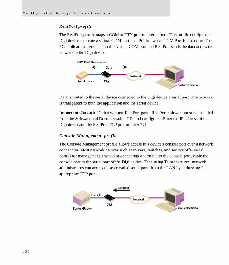
C o n f i g u r a t i o n t h r o u g h t h e w e b i n t e r f a c e
RealPort profile
The RealPort profile maps a COM or TTY port to a serial port. This profile configures a Digi device to create a virtual COM port on a PC, known as COM Port Redirection. The PC applications send data to this virtual COM port and RealPort sends the data across the network to the Digi device.
Data is routed to the serial device connected to the Digi device’s serial port. The network is transparent to both the application and the serial device.
Important: On each PC that will use RealPort ports, RealPort software must be installed from the Software and Documentation CD. and configured. Enter the IP address of the Digi deviceand the RealPort TCP port number 771.
Console Management profile
The Console Management profile allows access to a device's console port over a network connection. Most network devices such as routers, switches, and servers offer serial port(s) for management. Instead of connecting a terminal to the console port, cable the console port to the serial port of the Digi device. Then using Telnet features, network administrators can access these consoled serial ports from the LAN by addressing the appropriate TCP port.
1 3 8
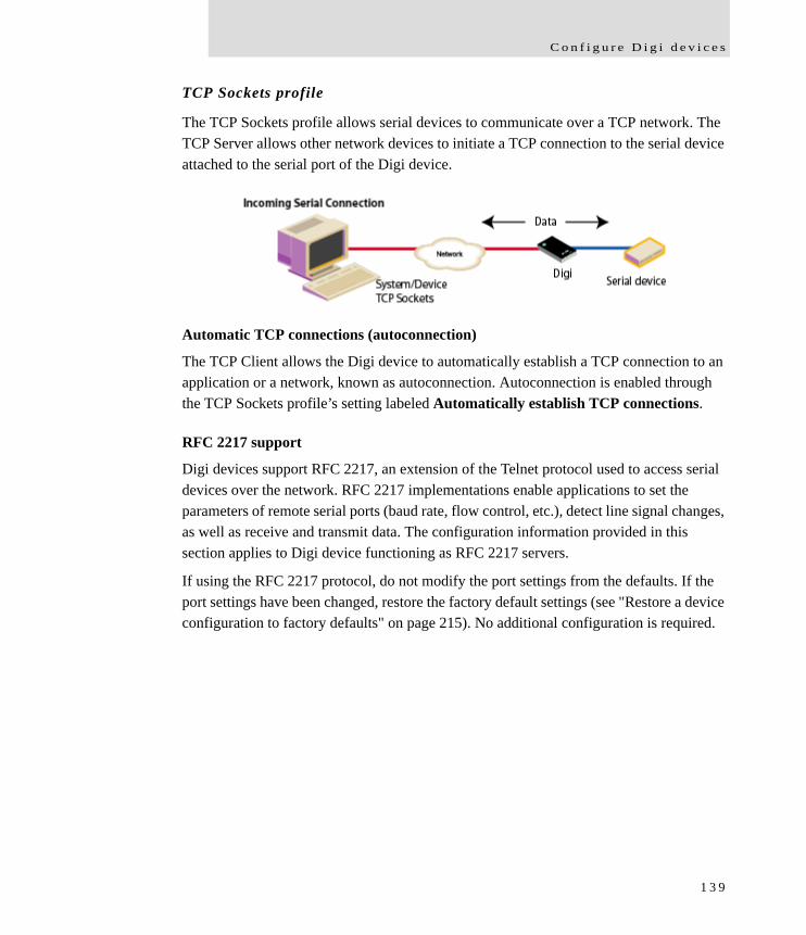
C o n f i g u r e D i g i d e v i c e s
TCP Sockets profile
The TCP Sockets profile allows serial devices to communicate over a TCP network. The TCP Server allows other network devices to initiate a TCP connection to the serial device attached to the serial port of the Digi device.
Automatic TCP connections (autoconnection)
The TCP Client allows the Digi device to automatically establish a TCP connection to an application or a network, known as autoconnection. Autoconnection is enabled through the TCP Sockets profile’s setting labeled Automatically establish TCP connections.
RFC 2217 support
Digi devices support RFC 2217, an extension of the Telnet protocol used to access serial devices over the network. RFC 2217 implementations enable applications to set the parameters of remote serial ports (baud rate, flow control, etc.), detect line signal changes, as well as receive and transmit data. The configuration information provided in this section applies to Digi device functioning as RFC 2217 servers.
If using the RFC 2217 protocol, do not modify the port settings from the defaults. If the port settings have been changed, restore the factory default settings (see "Restore a device configuration to factory defaults" on page 215). No additional configuration is required.
1 3 9
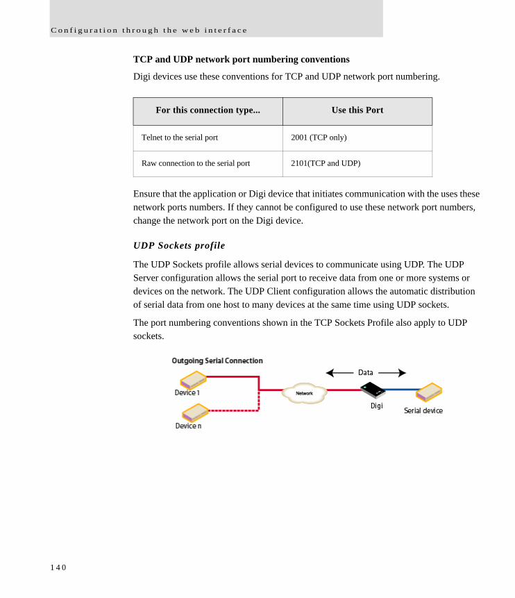
C o n f i g u r a t i o n t h r o u g h t h e w e b i n t e r f a c e
TCP and UDP network port numbering conventions
Digi devices use these conventions for TCP and UDP network port numbering.
Ensure that the application or Digi device that initiates communication with the uses these network ports numbers. If they cannot be configured to use these network port numbers, change the network port on the Digi device.
UDP Sockets profile
The UDP Sockets profile allows serial devices to communicate using UDP. The UDP Server configuration allows the serial port to receive data from one or more systems or devices on the network. The UDP Client configuration allows the automatic distribution of serial data from one host to many devices at the same time using UDP sockets.
The port numbering conventions shown in the TCP Sockets Profile also apply to UDP sockets.
For this connection type... Use this Port
Telnet to the serial port 2001 (TCP only)
Raw connection to the serial port 2101(TCP and UDP)
1 4 0
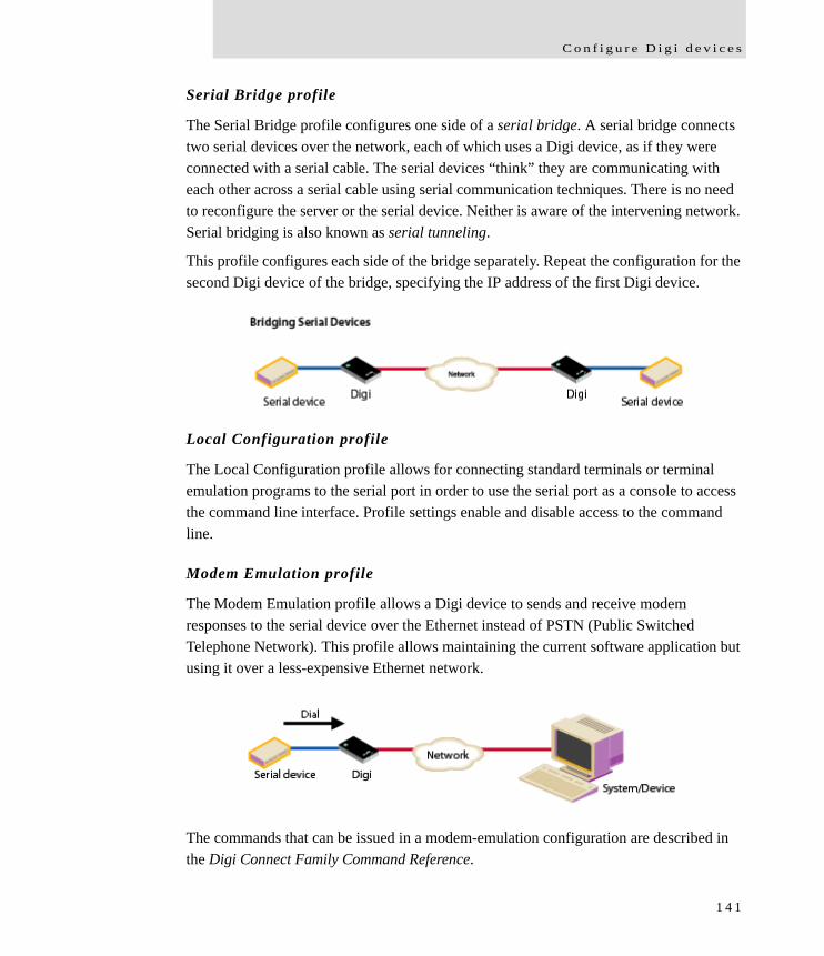
C o n f i g u r e D i g i d e v i c e s
Serial Bridge profile
The Serial Bridge profile configures one side of a serial bridge. A serial bridge connects two serial devices over the network, each of which uses a Digi device, as if they were connected with a serial cable. The serial devices “think” they are communicating with each other across a serial cable using serial communication techniques. There is no need to reconfigure the server or the serial device. Neither is aware of the intervening network. Serial bridging is also known as serial tunneling.
This profile configures each side of the bridge separately. Repeat the configuration for the second Digi device of the bridge, specifying the IP address of the first Digi device.
Local Configuration profile
The Local Configuration profile allows for connecting standard terminals or terminal emulation programs to the serial port in order to use the serial port as a console to access the command line interface. Profile settings enable and disable access to the command line.
Modem Emulation profile
The Modem Emulation profile allows a Digi device to sends and receive modem responses to the serial device over the Ethernet instead of PSTN (Public Switched Telephone Network). This profile allows maintaining the current software application but using it over a less-expensive Ethernet network.
The commands that can be issued in a modem-emulation configuration are described in the Digi Connect Family Command Reference.
1 4 1
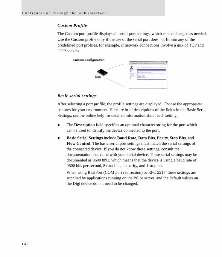
C o n f i g u r a t i o n t h r o u g h t h e w e b i n t e r f a c e
Custom Profile
The Custom port profile displays all serial-port settings, which can be changed as needed. Use the Custom profile only if the use of the serial port does not fit into any of the predefined port profiles, for example, if network connections involve a mix of TCP and UDP sockets.
Basic serial settings
After selecting a port profile, the profile settings are displayed. Choose the appropriate features for your environment. Here are brief descriptions of the fields in the Basic Serial Settings; see the online help for detailed information about each setting.
The Description field specifies an optional character string for the port which can be used to identify the device connected to the port.
Basic Serial Settings include Baud Rate, Data Bits, Parity, Stop Bits, and Flow Control. The basic serial port settings must match the serial settings of the connected device. If you do not know these settings, consult the documentation that came with your serial device. These serial settings may be documented as 9600 8N1, which means that the device is using a baud rate of 9600 bits per second, 8 data bits, no parity, and 1 stop bit. When using RealPort (COM port redirection) or RFC 2217, these settings are supplied by applications running on the PC or server, and the default values on the Digi device do not need to be changed.
1 4 2
C o n f i g u r e D i g i d e v i c e s
Advanced serial settings
The advanced serial settings allow you to further define the serial interface, including whether port buffering (also known as port logging), RTS Toggle, and RCI over Serial are enabled as general serial interface options. You can also define how specific aspects of TCP and UDP serial communications should operate, including timeouts and whether a socket ID is sent.
Serial Settings
The Serial Settings part of the page includes these options:
Enable Port Logging: Enables the port-buffering feature, which allows you to monitor incoming ASCII serial data in log form. The Log Size field specifies the size of the buffer that contains the log of ASCII serial data.
Enable RTS Toggle: When enabled, the RTS (Request To Send) signal is forced high (on) when sending data on the serial port.
Enable RCI over Serial (DSR): This choice allows the Digi Connect device to be configured through the serial port using the RCI protocol. See the RCI specification in the Digi Connect Integration Kit for further details. RCI over Serial uses the DSR (Data Set Ready) serial signal. Verify that the serial port is not configured for autoconnect, modem emulation, or any other application which is dependent on DSR state changes.
1 4 3

C o n f i g u r a t i o n t h r o u g h t h e w e b i n t e r f a c e
TCP settings
The TCP Settings are displayed only when the current serial port is configured with the TCP Sockets or the Custom Profile. The settings are as follows:
Send Socket ID: Include an optional identifier string with the data sent over the network. The Socket ID can be 1 to 256 ASCII characters. To enter non-printable characters, use these key sequences:
Character Key Sequence
backspace \b
formfeed \f
tab \t
new line \n
return \r
backslash \\
hexadecimal values
\xhh
1 4 4
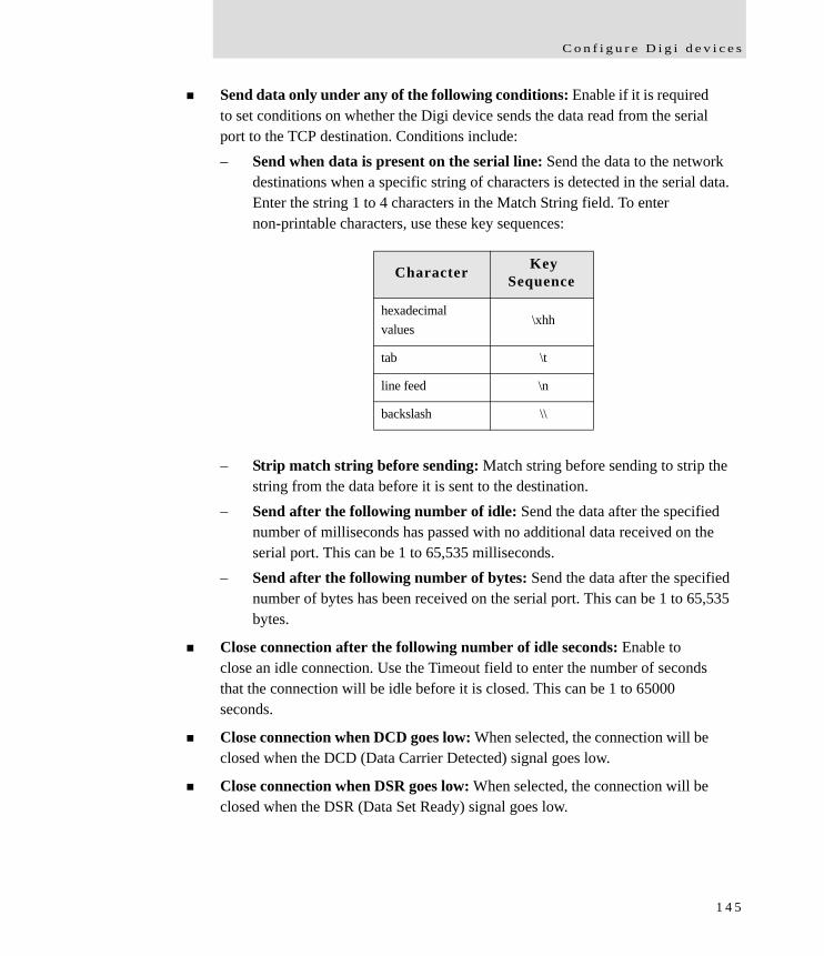
C o n f i g u r e D i g i d e v i c e s
Send data only under any of the following conditions: Enable if it is required to set conditions on whether the Digi device sends the data read from the serial port to the TCP destination. Conditions include:– Send when data is present on the serial line: Send the data to the network
destinations when a specific string of characters is detected in the serial data. Enter the string 1 to 4 characters in the Match String field. To enter non-printable characters, use these key sequences:
– Strip match string before sending: Match string before sending to strip the string from the data before it is sent to the destination.
– Send after the following number of idle: Send the data after the specified number of milliseconds has passed with no additional data received on the serial port. This can be 1 to 65,535 milliseconds.
– Send after the following number of bytes: Send the data after the specified number of bytes has been received on the serial port. This can be 1 to 65,535 bytes.
Close connection after the following number of idle seconds: Enable to close an idle connection. Use the Timeout field to enter the number of seconds that the connection will be idle before it is closed. This can be 1 to 65000 seconds.
Close connection when DCD goes low: When selected, the connection will be closed when the DCD (Data Carrier Detected) signal goes low.
Close connection when DSR goes low: When selected, the connection will be closed when the DSR (Data Set Ready) signal goes low.
Character Key Sequence
hexadecimalvalues
\xhh
tab \t
line feed \n
backslash \\
1 4 5

C o n f i g u r a t i o n t h r o u g h t h e w e b i n t e r f a c e
UDP settings
The UDP Settings are displayed only when the current serial port is configured with the UDP Sockets or the Custom Profile.
Send Socket ID: Include an optional identifier string with the data sent over the network. The Socket ID can be 1 to 256 ASCII characters. To enter non-printable characters, use these key sequences:
Character Key Sequence
backspace \b
formfeed \f
tab \t
new line \n
return \r
backslash \\
hexadecimalvalues
\xhh
1 4 6

C o n f i g u r e D i g i d e v i c e s
Configure camera settings
ConnectPort X Family products support connecting a WatchPort Camera to one of its USB host ports. One Digi WatchPort V2 USB camera is supported.
Camera settings
These settings configure the operation of the camera and handling of images captured by the camera.
Enable Camera: Enables and disables camera. When disabled, all camera activity stops and all memory used will be freed.
Resolution: The resolution level for images.
Frame Delay: Specify the minimum time (in milliseconds) between frames. The actual delay time between frames will be this number or greater. The camera will automatically increase this value as needed, such as in low light conditions. This delay time is the inverse of frames per second. For instance, if you wish to set the camera to process at a maximum of 5 frames per second, the frame delay is set to 200 (1/5 = 0.2 second = 200 ms).
Quality: Choose a quality from 0 to 100. 0 means the lowest quality and smallest image sizes while 100 means the best image quality but largest images. Qualities in the range of 30 to 80 are recommended. Quality above 80 will result in much, much larger images than lower qualities, which will result in lower overall performance and increased memory use.
Send Images to TCP Server: Enables sending camera images to a TCP server. The TCP server application must conform to the protocol sent by this device. The protocol is: On connect, the TCP client sends a protocol id of four bytes: 0x85ce4a71, followed by a protocol version of 4 bytes: 0x00000010 After this, images are sent over and over in the form of 4 bytes containing the length of the JPEG image to follow, followed by the JPEG image. – TCP Server: Name of the server to receive image data. – TCP Port: TCP port. The default port is 22222.
1 4 7
C o n f i g u r a t i o n t h r o u g h t h e w e b i n t e r f a c e
Current Image: Displays a snapshot of the current camera image. Clicking on the image brings up a new window with the full size image (as configured above). If No Camera Available is displayed, either the camera is disabled (see above), no camera is attached to the device, or some other problem is causing the camera to not work correctly. This current snapshot can be accessed by any web browser directly by using the URL:http://device-ip/FS/dev/camera/0
Advanced Settings: All the settings from Automatic Gain Control on are advanced camera settings. It is recommended to leave these camera settings to defaults. They can be modified for specific needs by advanced users, but do not need to be modified by most users.
Camera operation
Once the camera is connected and configured, the current snapshot image from the camera is available directly from the device at the following URL:
http://device-ip/FS/dev/camera/0
Video from the camera is available by streaming the camera data to a TCP server application, a configured by the Send Images to TCP Server configuration settings.
1 4 8
C o n f i g u r e D i g i d e v i c e s
Configure alarms
Use the Alarms page to configure device alarms or display current alarms settings. Device alarms are used to send email messages or SNMP traps when certain device events occur. These events include certain data patterns being detected in the data stream, and, for Digi Cellular Family products, alarms for signal strength and amount of cellular traffic for a given period of time.
Alarm notification settings
On the Alarms page, the Alarm Notification Settings control the following:
Enable alarm notifications: Enables or disables all alarm processing for the Digi Connect device.
Send all alarms to the Remote Management server: enables or disables sending of alarm notifications to the Connectware Manager server. Enabling this setting sends all alarm notifications to the Connectware Manager server. Turn this option on if your Digi device is managed by Connectware Manager. Enabling this option is useful because it allows all alarms to be monitored from one location, the Connectware Manager. Enabling this option also allows Digi devices to send alarms to clients that would otherwise be unreachable from the Digi device, either because the Digi device is behind a firewall or not on the same network as the alarm destination. Disabling this settings disables sending of alarm notifications to the Connectware Manager server. Leave this option off if you do not manage your devices with Connectware Manager or if you wish to have alarms sent from the device, for example, because an SNMP trap destination is local to the device, not the Connectware Manager server.For more information on Connectware Manager, see the Connectware Manager Getting Started Guide, and the Connectware Manager online help.
Mail Server Address (SMTP): Specifies the IP address of the SMTP mail server. Ask your network administrator for this IP address.
From: Specifies the text that will be used in the “From:” field for all alarms that are sent as emails.
1 4 9
C o n f i g u r a t i o n t h r o u g h t h e w e b i n t e r f a c e
Alarm conditions
The Alarm Conditions part of the Alarms page shows a list of all of the alarms. Up to 32 alarms can be configured for a Digi device, and they can be enabled and disabled individually.
Alarm list
The list of alarms displays the current status of each alarm. If there are any alarms already configured for the device, and after configuring any new alarms, this list can be used to list to view alarm status at a glance, then view more details for each alarm as needed.
Enable: Checkbox indicates whether the alarm is currently enabled or disabled.
Alarm: The number of the alarm.
Status: The current status of the alarm, which is either enabled or disabled.
Type: Specifies whether the alarm is based on GPIO pin state changes or serial data pattern matching.
Trigger: The conditions that trigger the alarm.
SNMP Trap: Indicates whether the alarm is sent as an SNMP trap.– If the SNMP Trap field is disabled, and the Send To field has a value, then the
alarm is sent as an email message only. – If the SNMP trap field is enabled and the Send To field is blank, then the alarm
is sent as an SNMP trap only. – If the SNMP Trap field is enabled, and a value is specified in the Send to field,
then that means the alarm is sent both as an email and as an SNMP trap.
Send To: The email address to which the alarm is sent.
Email Subject: The text to be included in the “Subject:” line of any alarms sent as email messages.
1 5 0

C o n f i g u r e D i g i d e v i c e s
Alarm conditions
To configure an alarm, click on it. The configuration page for individual alarms has two sections:
Alarm Conditions: For specifying the conditions on which the alarm is based, serial data pattern matching, signal strength (RSSI), or data usage.
Alarm Destinations: For specifying how the alarm is sent, either as an email message or an SNMP trap, or both, and where the alarm is sent.
Alarm conditions
The Alarm Conditions part of the page is for specifying the conditions on which the alarm is based. Alarm conditions include:
Send alarms based on serial data pattern matching: Click this radio button to specify that this alarm is sent when the specified serial data pattern is detected. Then specify the following: – Serial Port: The serial port to monitor for the data pattern. This field is
displayed for devices where more than one serial port is available.– Pattern: An alarm is sent when the serial port receives this data pattern.
Special characters such as carriage return carriage return (\r) and new line (\n) in the data pattern can be included.
Send alarms based on average RSSI level below threshold for amount of time: Send alarms based on the average signal strength falling below a specified threshold for a specified amount of time.– RSSI: The threshold signal strength, measured in dB (typically -120 dB to -40
dB). – Time: The amount of time, in minutes, that the signal strength falls below the
threshold.
Send alarms based on cellular data exchanged in an amount of time: – Data: The number of bytes of cellular data. – Time: The number of minutes.– Cell Data Type: The type of cellular data exchanged: Receive data, Transmit
data, or Total data.
1 5 1
C o n f i g u r a t i o n t h r o u g h t h e w e b i n t e r f a c e
Alarm destinations
The Alarm Destination part of the page defines how alarm notifications are sent—either as an email message or an SNMP trap, or both—and where the alarm notification is sent.
Send E-mail to the following recipients when alarm occurs: Select the checkbox to specify that the alarm should be sent as an email message. Then specify the following information:– To: The email address to which this alarm notification email message will be
sent. – CC: The email address to which a copy of this alarm notification email
message will be sent (optional). – Priority: The priority of the alarm notification email message. – Subject: The text to be included in the Subject: line of the alarm-notification
email message.
Send SNMP trap to the following destination when alarm occurs: Select the checkbox to specify that the alarm should be sent as an SNMP trap. For alarms to be sent as SNMP traps, the IP address of the destination for the SNMP traps must be specified in the SNMP settings. This is done on the System Configuration pages of the web interface. See "SNMP configuration settings" on page 153. That destination IP address is then displayed below the “Send alarm to SNMP destination” checkbox.
To configure an alarm notification to be sent as both an email message and an SNMP trap, select both Send E-Mail and Send SNMP trap checkboxes.
Click Apply to apply changes for the alarm and return to the Alarms Configuration page.
Enable and Disable Alarms
Once alarm conditions are configured, enable and disable individual alarms by selecting or deselecting the Enable checkbox for each alarm.
1 5 2
C o n f i g u r e D i g i d e v i c e s
Configure system settings
The System Configuration page configures system settings, including device description information, such as the device name, contact, and location, and whether SNMP is enabled or disabled and the SNMP traps that are enabled.
Device description information
A device description is a system description of the Digi device’s name, contact, and location. This device description can be useful for identifying a specific Digi device when working with a large number of devices in multiple locations.
SNMP configuration settings
Simple Network Management Protocol (SNMP) is a protocol that can be used to manage and monitor network devices. Digi devices can be configured to use SNMP features, or SNMP can be disabled entirely for security reasons. To configure SNMP settings, click the Simple Network Management Protocol link at the bottom of the System Configuration page. SNMP settings include:
Enable Simple Network Management Protocol (SNMP): This checkbox enables or disables use of SNMP.
The Public community and Private community fields specify passwords required to get or set SNMP-managed objects. Changing public and private community names from their defaults is recommended to prevent unauthorized access to the device.– Public community: The password required to get SNMP-managed objects. The
default is public.– Private community: The password required to set SNMP-managed objects. The
default is private.
Allow SNMP clients to set device settings through SNMP: This checkbox enables or disables the capability for users to issue SNMP “set” commands uses use of SNMP read-only for the Digi device.
Enable Simple Network Management Protocol (SNMP) traps: Enables or disables the generation of SNMP traps.
1 5 3

C o n f i g u r a t i o n t h r o u g h t h e w e b i n t e r f a c e
Destination IP: The IP address of the system to which traps are sent. In order to enable any of the traps, a non-zero value must be specified. For Digi devices that support alarms, this field is required in order for alarms to be sent in the form of SNMP traps. See "Configure alarms" on page 149.
At the bottom of the page are checkboxes for the SNMP traps that can be used: authentication failure, login, cold start, and link up traps.
Configure remote management (Connectware Manager) settings
The Remote Management configuration page sets up the connection to the Connectware Manager server so the Digi device knows how to connect to the server.
The Connectware Manager server allows devices to be configured and managed from remote locations.
Steps for setting up remote management
Using Connectware Manager as a remote manager of a Digi device requires several steps:
1 Install The Connectware Manager server on a server system. See the Connectware Manager Getting Started Guide for installation instructions
2 Assign a device ID defined for the Digi device. See the Connectware Manager Operator’s Guide’s instructions for adding a device.Important: The device ID for the Digi device must be unique. By default, the device ID is created from the MAC address of the device.
3 From the web interface, configure the Remote Management settings so the device can communicate with the Connectware Manager server. There are two pages of remote management settings: Connections and Advanced settings.
1 5 4
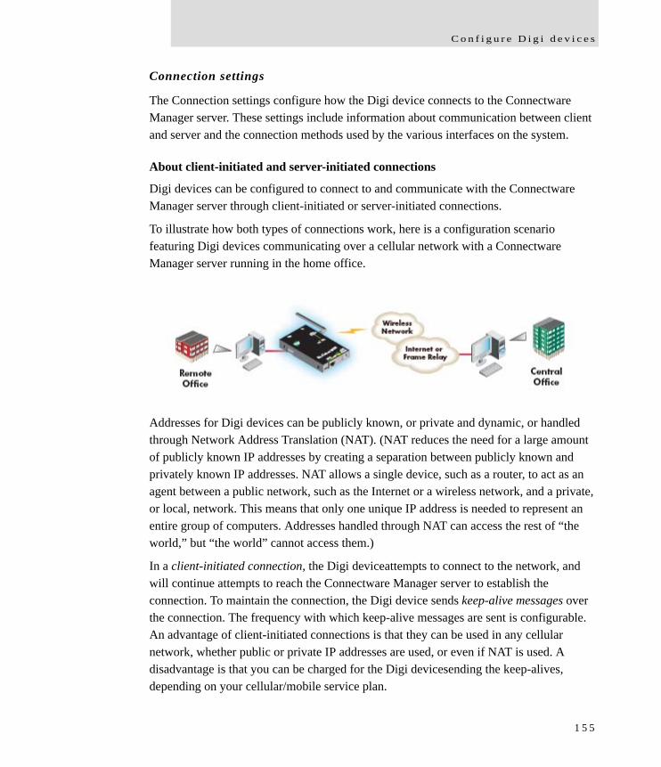
C o n f i g u r e D i g i d e v i c e s
Connection settings
The Connection settings configure how the Digi device connects to the Connectware Manager server. These settings include information about communication between client and server and the connection methods used by the various interfaces on the system.
About client-initiated and server-initiated connections
Digi devices can be configured to connect to and communicate with the Connectware Manager server through client-initiated or server-initiated connections.
To illustrate how both types of connections work, here is a configuration scenario featuring Digi devices communicating over a cellular network with a Connectware Manager server running in the home office.
Addresses for Digi devices can be publicly known, or private and dynamic, or handled through Network Address Translation (NAT). (NAT reduces the need for a large amount of publicly known IP addresses by creating a separation between publicly known and privately known IP addresses. NAT allows a single device, such as a router, to act as an agent between a public network, such as the Internet or a wireless network, and a private, or local, network. This means that only one unique IP address is needed to represent an entire group of computers. Addresses handled through NAT can access the rest of “the world,” but “the world” cannot access them.)
In a client-initiated connection, the Digi deviceattempts to connect to the network, and will continue attempts to reach the Connectware Manager server to establish the connection. To maintain the connection, the Digi device sends keep-alive messages over the connection. The frequency with which keep-alive messages are sent is configurable. An advantage of client-initiated connections is that they can be used in any cellular network, whether public or private IP addresses are used, or even if NAT is used. A disadvantage is that you can be charged for the Digi devicesending the keep-alives, depending on your cellular/mobile service plan.
1 5 5

C o n f i g u r a t i o n t h r o u g h t h e w e b i n t e r f a c e
A server-initiated connection works the opposite way. The Connectware Manager server opens a TCP connection, and the Digi device must be listening for the connection to the Connectware Manager server to occur. An advantage of server-initiated connections is that you are not charged for sending the keep-alive bytes that are used in client-initiated connections. A disadvantage is that there is no way of knowing whether the devices displayed in the device list at the Connectware Manager server are offline or connected. The device list shows all the devices as disconnected until the Connectware Manager server does something to interact with them. In addition, server-initiated connections cannot be used if Digi devices have private IP addresses and are behind a NAT.
Last Known Address (LKA)
Changes to the IP address for a Digi device present a challenge in server-initiated connections, because the Connectware Manager server needs to locate the Digi device by its new IP address. Digi Cellular Family devices handle address changes by sending a Last Known Address (LKA) update to the Connectware Manager server. This permits the Connectware Manager to connect back to the Digi device, or to dynamically update a DNS with the IP address of the device.
1 5 6
C o n f i g u r e D i g i d e v i c e s
Client initiated management connection settings
Enable Remote Management and Configuration using a client initiated connection: Configures the connection to the Connectware Manager server to be initiated by the Connectware Manager client, that is, this Digi device.
Server Hostname: The IP address or hostname of the Connectware Manager server.
Automatically reconnect to the server after being disconnectedWait for: Whether to automatically reconnect to the server after being disconnected and waiting for the specified amount of time.
Server initiated management connection settings
Enable Remote Management and Configuration using a server initiated connection: Configures the connection to the Connectware Manager server to be initiated by the Connectware Manager server. Enable Last Known Address (LKA) updates to the following server: Enables or disables a connection to a Connectware Manager server to inform that server of the IP address of the Digi device, known as a “last known address” (LKA) update. This permits the Connectware Manager to connect back to the Digi Cellular Family device, or to dynamically update a DNS with the IP address of the device.
Server Hostname: The IP address or hostname of the Connectware Manager server.
Retry if the LKA update fails: Retry every: These options specify whether another “last known address” update attempt should be made after a previous attempt failed, and how often the retry attempts should occur.
1 5 7
C o n f i g u r a t i o n t h r o u g h t h e w e b i n t e r f a c e
Advanced remote management settings
The default settings for remote management usually work for most situations. These Advanced settings are used in advanced situations. They are used to configure the idle timeout for the connection between the Digi device and the Connectware Manager server, and the keep-alive settings of the various interfaces (TCP and HTTP for mobile and Ethernet network connections). These settings should only be changed when the defaults do not properly work.
Connection Settings: These settings configure the idle timeout for the connection between the Digi device and the Connectware Manager server.– Disconnect when Connectware Management is idle: Enables or disables the
idle timeout for the connection. If enabled, the connection will be dropped, or ended, after the amount of time specified in the Idle Timeout setting.
– Idle Timeout: The amount of time to wait before timing out the connection.
Mobile Settings: Ethernet Settings: These settings apply to client-initiated management connections over the mobile/cellular and Ethernet networks.– Connectware Management Protocol Keep-Alive Settings: These settings
control how often keep-alive packets are sent over the client-initiated connection to the Connectware Manager server, and whether the device waits before dropping the connection. Receive Interval: The number of seconds to wait for a keep-alive message from the Connectware Manager server before assuming the connection is lost.Transmit Interval: The number of seconds to wait between sending keep-alive messages. (Assume connection is lost after n timeouts: How many timeouts occur before the Digi device assumes the connection to the Connectware Manager server is lost and drops the connection.
1 5 8
C o n f i g u r e D i g i d e v i c e s
– Connection Method: The method for connecting to the Connectware Manager server. TCP: Connect using TCP. This is the default connection method, and is typically good enough for most connections. It is the most efficient method of connecting to the remote server in terms of speed and transmitted data bytes. Automatic: Automatically detect the connection method. This connection method is less efficient than TCP, but it is useful in situations where a firewall or proxy may prevent direct connection via TCP. Automatic will try each combination until a connection is made. This connection method requires the HTTP over Proxy Settings to be specified.None: This value has the same effect as selecting TCP.HTTP: Connect using HTTP.HTTP over Proxy: Connect using HTTP.
– HTTP over Proxy Settings: The settings required to communicate over a proxy network using HTTP. These settings apply when Automatic or HTTP over Proxy connection methods are selected.Hostname: The name of the proxy host.TCP Port: The network port number for the TCP network service on the proxy host. Username:Password: The username and password for logging on to the proxy host.Enable persistent proxy connections: Specifies whether the Digi device should attempt to use HTTP persistent connections. Not all HTTP proxies correctly handle HTTP persistent connections. The use of persistent connections can improve performance of the exchange of messages between the device server and Connectware Manager, when that connection is HTTP/proxy. The reason for this is that the same HTTP connection can be reused for multiple consecutive HTTP requests and replies, eliminating the overhead of establishing a new TCP connection for each individual HTTP request/reply, then closing that connection when the request is complete.
1 5 9
C o n f i g u r a t i o n t h r o u g h t h e w e b i n t e r f a c e
Alarms and the Connectware Manager server
All alarms can be sent to the Connectware Manager server for display and management from that interface. See "Configure alarms" on page 149.
For more information on Connectware Manager
The Connectware Manager Operator’s Guide provides detailed information on Connectware Manager features and tasks performed from the Connectware Manager console.
Configure Security settings
Security settings involve several areas:
User authentication: whether authentication is required for users accessing the Digi device, and the information required to access it. You can choose to have the user authentication be by username and password or by an SSH public key. Depending on the Digi product, multiple users and their authentication information can be defined. User authentication settings are on the Security settings page.
Network Configuration settings to further secure your device: Digi devices with Cellular capability present additional security considerations, mainly involving securing the border between the Digi device and the cellular network. Several settings on the Network Configuration pages are available to further secure the Digi device. For example, on the Network Services page, you can disable unused network services. On the IP Filtering page, you can allow access from a specified devices and networks, and drop all other connection attempts.
1 6 0
C o n f i g u r e D i g i d e v i c e s
About user models and user permissions
In Digi devices that have a one-user model:
By default, there is no login prompt.
The default name for user 1 is root. This user is also known as the administrative user.
User 1 has permissions that enables it to do all commands. Permissions cannot be altered.
Password authentication
By default, there is no password authentication for Digi Cellular Family devices. That means if when accessing the Digi Cellular Family device by opening the web interface or issuing a telnet command, no login prompt is displayed.
Enable password authentication
If desired, enable password authentication for the Cellular Family device.
In the web interface:
1 On the Main menu, click Security.
2 On the Security Configuration page, check the Enable password authentication check box.
3 Enter the new password in the New Password and Confirm Password edit boxes.
4 Click Apply.
5 A prompt is displayed to immediately log back in to the web interface using the new values.
From the command line:
To enable the login prompt for a device that uses the one-user model, issue a newpass command with a password length of one or more characters.
1 6 1
C o n f i g u r a t i o n t h r o u g h t h e w e b i n t e r f a c e
Disable password authentication
Password authentication can be disabled as needed.
In the web interface:
1 On the Main menu, click Security.
2 On the Security Configuration page, check the Enable password authentication check box.
3 Click Apply.
From the command line:
Issue a newpass command with a zero-length password.
Change the password for administrative user
To increase security, change the password for the administrative user from its default. By default, the administrative username is root.
Note Record the new password. If the changed password is lost, the Digi device must be reset to the default firmware settings.
In Digi devices with a single-user model, changing the root password also changes the password for Advanced Digi Discovery Protocol (ADDP). In Digi devices with the multi-user model, changing the root password has no effect on ADDP. To change the ADDP password, use enter newpass name=addp from the command line.
In the web interface:
1 On the Main menu, click Security.
2 On the Security Configuration page, enter the new password in the New Password and Confirm Password edit boxes. The password can be from 4 through 16 characters long and is case-sensitive. Click Apply.
3 A logoff is forced immediately. Log in to the web interface using the new values.
From the command line:
Issue the newpass command.
1 6 2
C o n f i g u r e D i g i d e v i c e s
Upload an SSH public key
SSH can be configured to log into to servers without having to provide a password. This is called “public key authentication” and is more secure than using a normal password. You generate a public/private key using a program called ssh-keygen, and store a copy of the public key on the server(s) that you wish to use for authentication. When you attempt to log in, the server sends you a message encrypted with your public key. Your machine decrypts it and sends back the original message, proving your identity.
To upload an SSH public key:
1 On the Main menu, click Security.
2 On the Security Configuration page, check the Enable SSH public key authentication check box.
3 Type or paste the SSH public key in the edit box.
4 Click Apply.
Disable unused and non-secure network services
Depending on your mobile service provider, other users can access your Digi device device over the Internet, through various network services enabled on your Digi device. To further secure the Digi device, network services not necessary to the device, particularly non-secure or un-encrypted network services such as Telnet, can be disabled. See "Network services settings" on page 82.
Use IP filtering
You can better restrict your device on the network by only allowing certain devices or networks to connect. This is known as IP filtering or Access Control Lists (ACL). IP filtering configures a Digi device to accept connections from specific and known IP addresses or networks only, and silently drop other connections. Digi devices can be filtered on a single IP address or restricted as a group of devices using a subnet mask that only allows specific networks to access to the device. IP Filtering settings are a part of the Network configuration settings. See "IP filtering settings" on page 90.
Important: Plan and review your IP filtering settings before applying them. Incorrect settings can make the Digi device inaccessible from the network.
1 6 3
C o n f i g u r a t i o n t h r o u g h t h e w e b i n t e r f a c e
Configure applications
Several Digi devices support additional configurable applications. For most devices, these applications are accessed from the main menu under Applications. Some devices have an Applications link under Configuration.
Python® program management
ConnectPort X Family products support loading and running programs written in the Python programming language on ConnectPort X devices.
Python is a dynamic, object-oriented language that can be used for developing a wide range of software applications, from simple programs to more complex embedded applications. It includes extensive libraries and works well with other languages. A true open-source language, Python runs on a wide range of operating systems, such as Windows, Linux/Unix, Mac OS X, OS/2, Amiga, Palm Handhelds, and Nokia mobile phones. Python has also been ported to Java and .NET virtual machines.
Recommended distribution of Python interpreter
The current version of the Python interpreter embedded in Digi devices is 2.4.3. Please use modules known to be compatible with this version of the Python language only.
Additional Python programming resources
The Digi Python Programming Handbook introduces the Python programming language and describes Digi’s implementation of Python modules.
For additional information on the Python Programming Language, go to http://www.python.org/ and click the Documentation link.
Python configuration pages
Selecting Applications > Python from the main menu for a ConnectPort X Family device displays the Python Configuration pages. These pages are used to:
Manage Python program files, including uploading them to Digi devices and deleting them as needed.
Configure Python programs to execute when the Digi device boots, also known as auto-start programs.
1 6 4
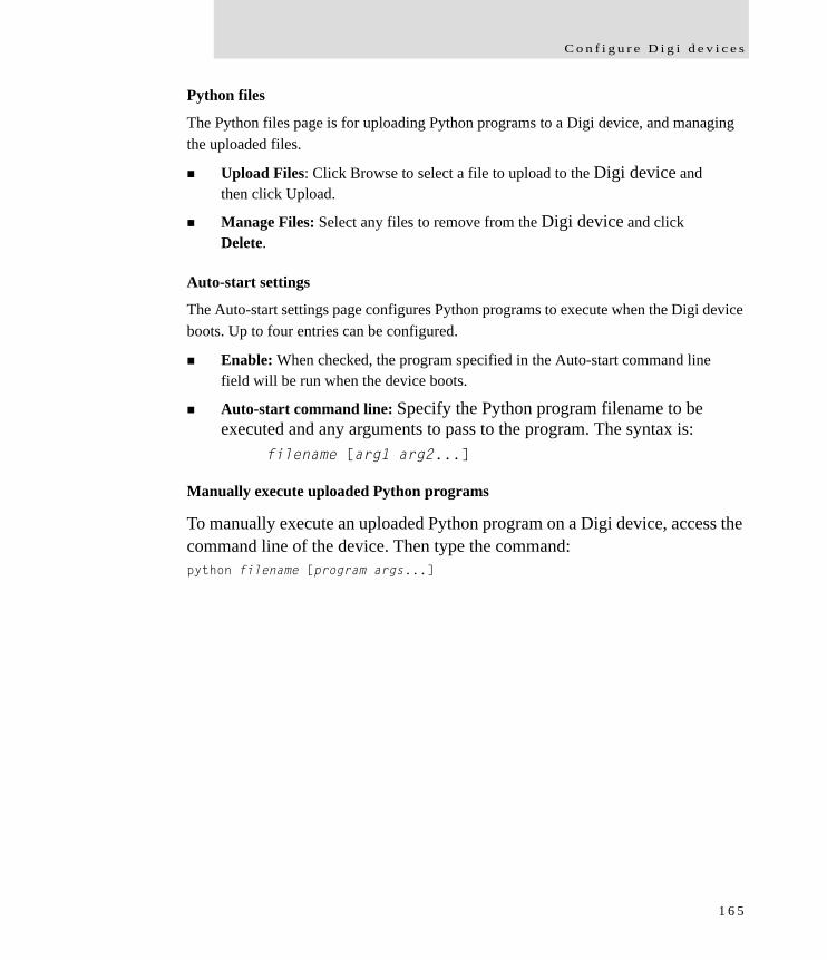
C o n f i g u r e D i g i d e v i c e s
Python files
The Python files page is for uploading Python programs to a Digi device, and managing the uploaded files.
Upload Files: Click Browse to select a file to upload to the Digi device and then click Upload.
Manage Files: Select any files to remove from the Digi device and click Delete.
Auto-start settings
The Auto-start settings page configures Python programs to execute when the Digi device boots. Up to four entries can be configured.
Enable: When checked, the program specified in the Auto-start command line field will be run when the device boots.
Auto-start command line: Specify the Python program filename to be executed and any arguments to pass to the program. The syntax is:
filename [arg1 arg2...]
Manually execute uploaded Python programs
To manually execute an uploaded Python program on a Digi device, access the command line of the device. Then type the command:python filename [program args...]
1 6 5
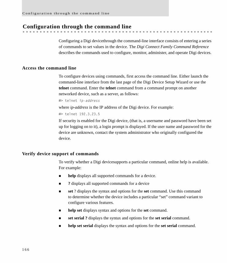
C o n f i g u r a t i o n t h r o u g h t h e c o m m a n d l i n e
Configuration through the command line
Configuring a Digi devicethrough the command-line interface consists of entering a series of commands to set values in the device. The Digi Connect Family Command Reference describes the commands used to configure, monitor, administer, and operate Digi devices.
Access the command line
To configure devices using commands, first access the command line. Either launch the command-line interface from the last page of the Digi Device Setup Wizard or use the telnet command. Enter the telnet command from a command prompt on another networked device, such as a server, as follows:#> telnet ip-address
where ip-address is the IP address of the Digi device. For example:#> telnet 192.3.23.5
If security is enabled for the Digi device, (that is, a username and password have been set up for logging on to it), a login prompt is displayed. If the user name and password for the device are unknown, contact the system administrator who originally configured the device.
Verify device support of commands
To verify whether a Digi devicesupports a particular command, online help is available. For example:
help displays all supported commands for a device.
? displays all supported commands for a device
set ? displays the syntax and options for the set command. Use this command to determine whether the device includes a particular “set” command variant to configure various features.
help set displays syntax and options for the set command.
set serial ? displays the syntax and options for the set serial command.
help set serial displays the syntax and options for the set serial command.
1 6 6
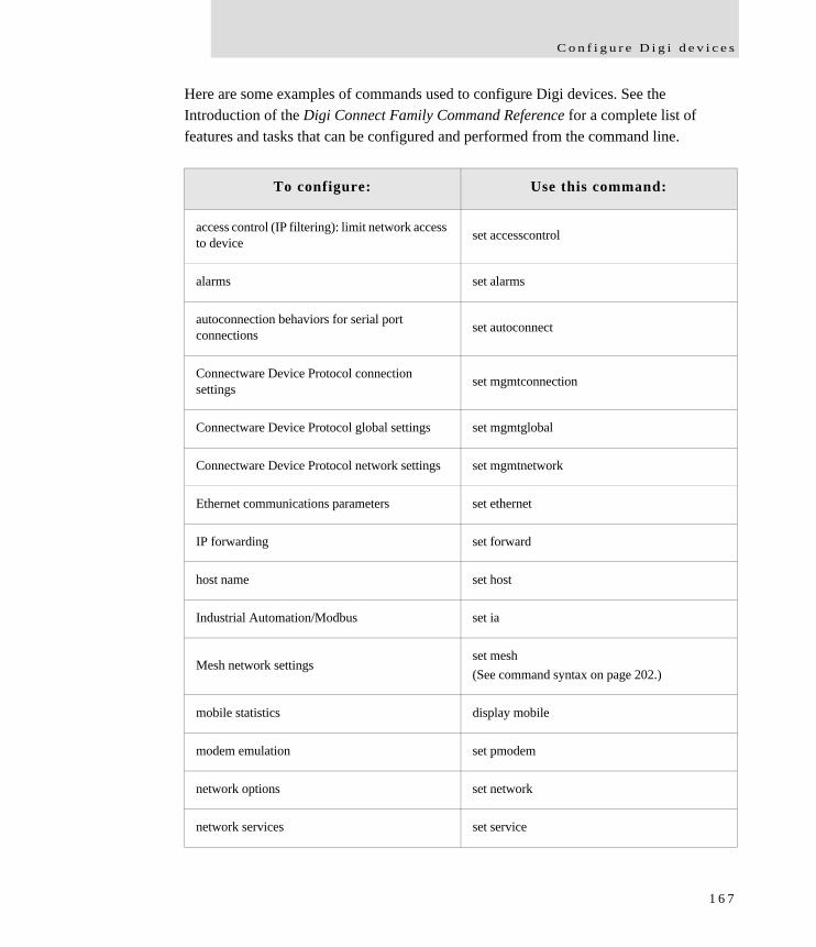
C o n f i g u r e D i g i d e v i c e s
Here are some examples of commands used to configure Digi devices. See the Introduction of the Digi Connect Family Command Reference for a complete list of features and tasks that can be configured and performed from the command line.
To configure: Use this command:
access control (IP filtering): limit network access to device set accesscontrol
alarms set alarms
autoconnection behaviors for serial port connections set autoconnect
Connectware Device Protocol connection settings set mgmtconnection
Connectware Device Protocol global settings set mgmtglobal
Connectware Device Protocol network settings set mgmtnetwork
Ethernet communications parameters set ethernet
IP forwarding set forward
host name set host
Industrial Automation/Modbus set ia
Mesh network settingsset mesh(See command syntax on page 202.)
mobile statistics display mobile
modem emulation set pmodem
network options set network
network services set service
1 6 7
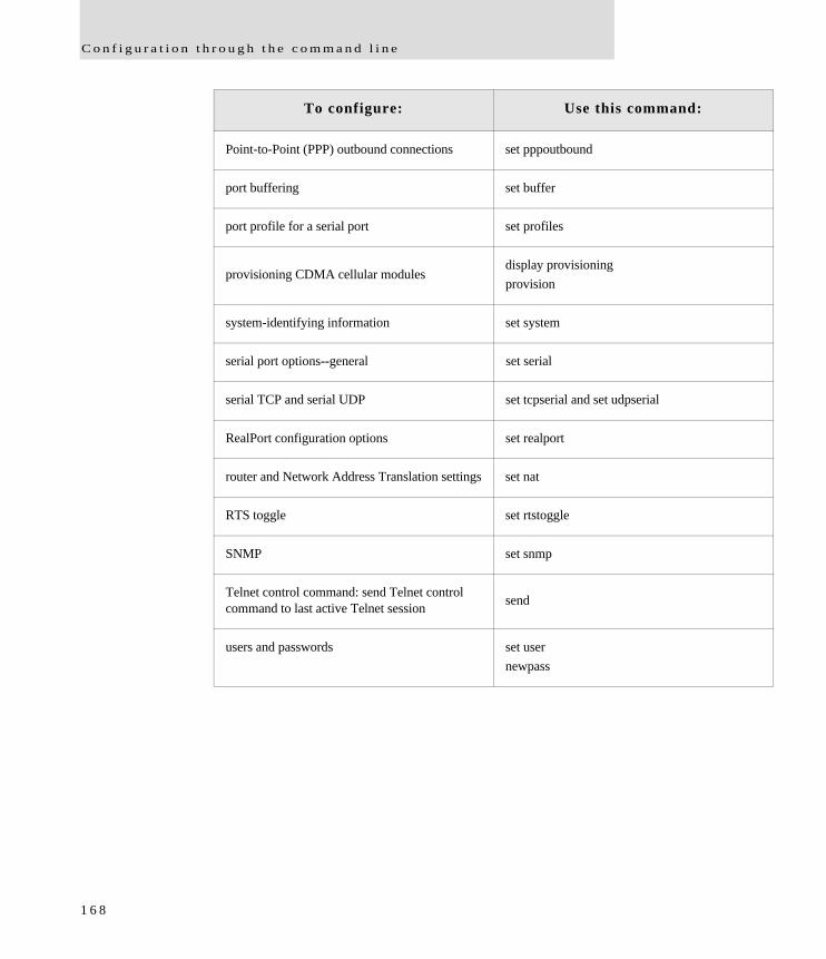
C o n f i g u r a t i o n t h r o u g h t h e c o m m a n d l i n e
Point-to-Point (PPP) outbound connections set pppoutbound
port buffering set buffer
port profile for a serial port set profiles
provisioning CDMA cellular modulesdisplay provisioningprovision
system-identifying information set system
serial port options--general set serial
serial TCP and serial UDP set tcpserial and set udpserial
RealPort configuration options set realport
router and Network Address Translation settings set nat
RTS toggle set rtstoggle
SNMP set snmp
Telnet control command: send Telnet control command to last active Telnet session send
users and passwords set usernewpass
To configure: Use this command:
1 6 8
C o n f i g u r e D i g i d e v i c e s
Configuration through Simple Network Management Protocol (SNMP)
Configuring Digi devices through Simple Network Management protocol uses a subset of standard MIBs for network and serial configuration, plus several Digi enterprise MIBs for device identification and alarm handling. These MIBs are listed and described on page 59, and must be loaded into a network management station (NMS). The standard and Digi Enterprise MIBs allow for very basic network and serial configuration. For more detailed configuration settings, use the command-line interface or web interface instead.
Some elements of SNMP configuration can only be configured from the web interface or command line, such as the setting to send alarms as SNMP traps. In the web interface, this setting is located at Configuration > Alarms > alarm > Alarm Destinations > Send SNMP trap to following destination when alarm occurs. See "Configure alarms" on page 149. In the command-line interface, this setting is configured by the set alarm option type=snmptrap. See the set alarm command description in the Connect Family Command Reference.
For more information on SNMP as a device interface, see pages 32 and 58. For information on SNMP as a monitoring interface, see page 208.
1 6 9
C o n f i g u r a t i o n t h r o u g h C o n n e c t w a r e M a n a g e r
Configuration through Connectware Manager
Configuring Mesh Networks and Nodes through Connectware Manager
Connectware Manager has several views for configuring and managing Mesh networks:
The Mesh Networks view
Node view
Using Connectware Manager to manage devices in Mesh networks provides several advantages:
Can run remotely
Gateway and PAN Management features
Can view more devices and the entire network, rather than one device at a time
Allows for caching of previous sets of device configuration settings
Easier to restructure table
1 7 0
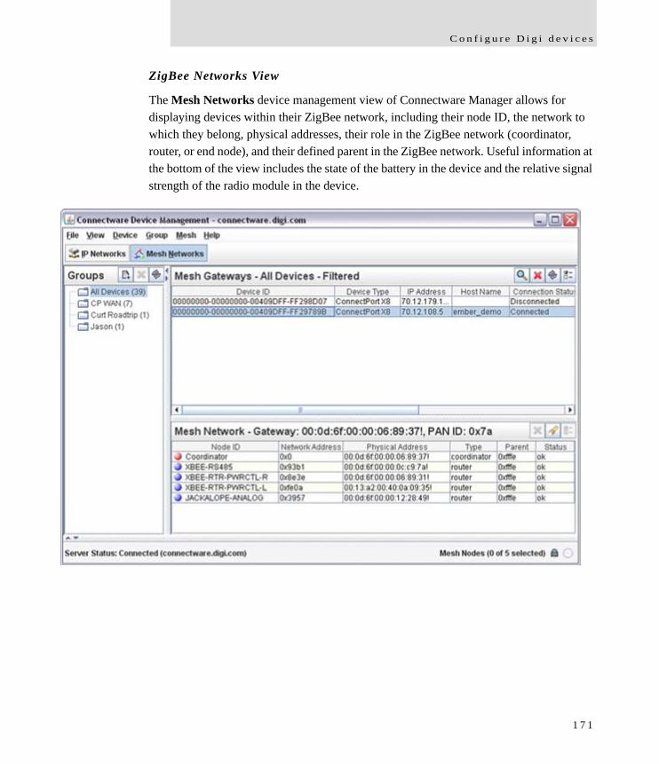
C o n f i g u r e D i g i d e v i c e s
ZigBee Networks View
The Mesh Networks device management view of Connectware Manager allows for displaying devices within their ZigBee network, including their node ID, the network to which they belong, physical addresses, their role in the ZigBee network (coordinator, router, or end node), and their defined parent in the ZigBee network. Useful information at the bottom of the view includes the state of the battery in the device and the relative signal strength of the radio module in the device.
1 7 1
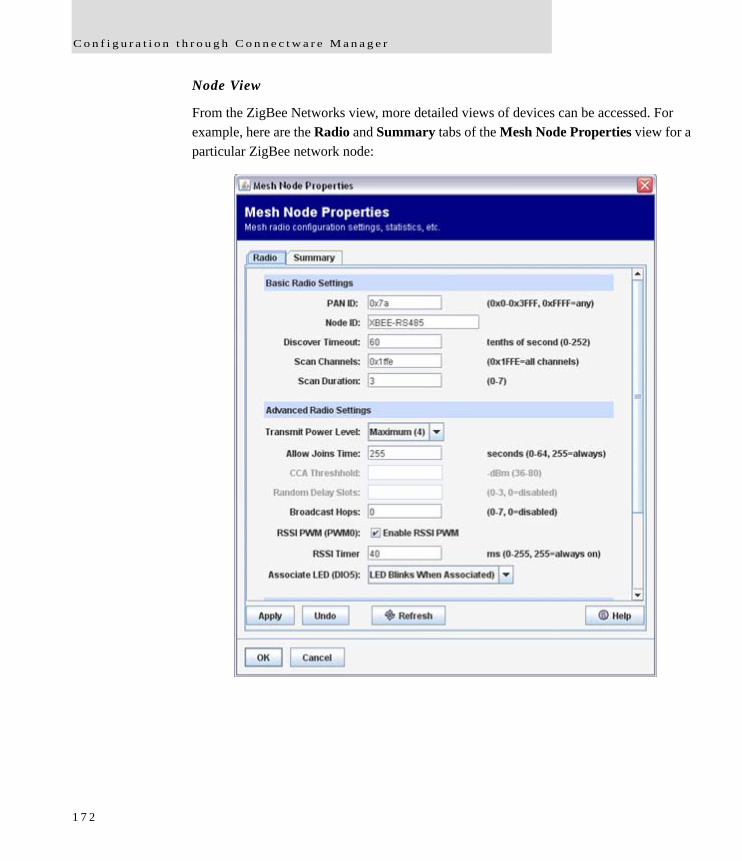
C o n f i g u r a t i o n t h r o u g h C o n n e c t w a r e M a n a g e r
Node View
From the ZigBee Networks view, more detailed views of devices can be accessed. For example, here are the Radio and Summary tabs of the Mesh Node Properties view for a particular ZigBee network node:
1 7 2
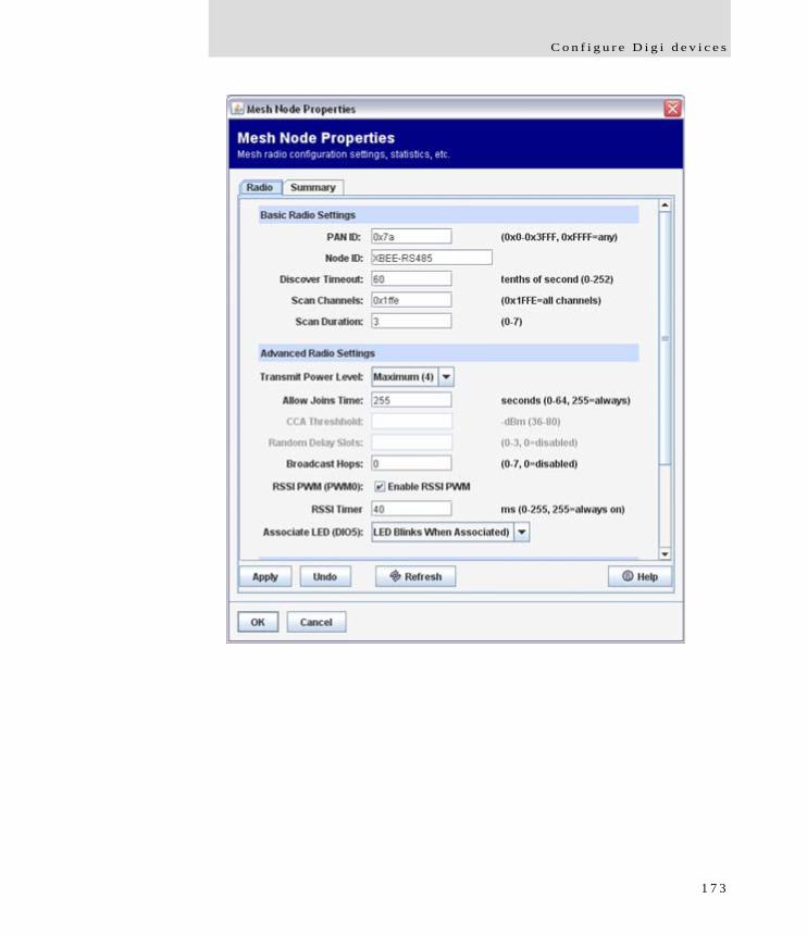
C o n f i g u r e D i g i d e v i c e s
1 7 3
B a t c h c a p a b i l i t i e s f o r c o n f i g u r i n g m u l t i p l e d e v i c e s
Batch capabilities for configuring multiple devices
For configuring many Digi devicesat a time, batch configuration capabilities for uploading configuration files are available through the Digi Connect Programmer. For details and command descriptions, see the Digi Connect Family Customization and Integration Guide.
What’s next?
See Chapter 3, "Monitor and manage Digi devices" for details on viewing system information and device statistics and managing device connections and services. Chapter 4, "Administration tasks" describes common administrative tasks such as file management, updating firmware, and restoring configuration settings to factory defaults.
1 7 4
Monitor and manage Digi devicesC H A P T E R 3
The port, device, system, and network activities of Digi devicescan be monitored for from a variety of interfaces. Changes in data flow may indicate problems or activities that may require immediate attention. In addition, connections and network services can be managed.
This chapter discusses monitoring and connection-management capabilities and tasks in Digi devices. It covers these topics:
Monitoring and Digi devices and manage their connections from the web-based interface on page 176
Monitoring Digi devices from the command line on page 198
Monitoring capabilities from Connectware Manager on page 206
Monitoring capabilities from SNMP on page 208
1 7 5
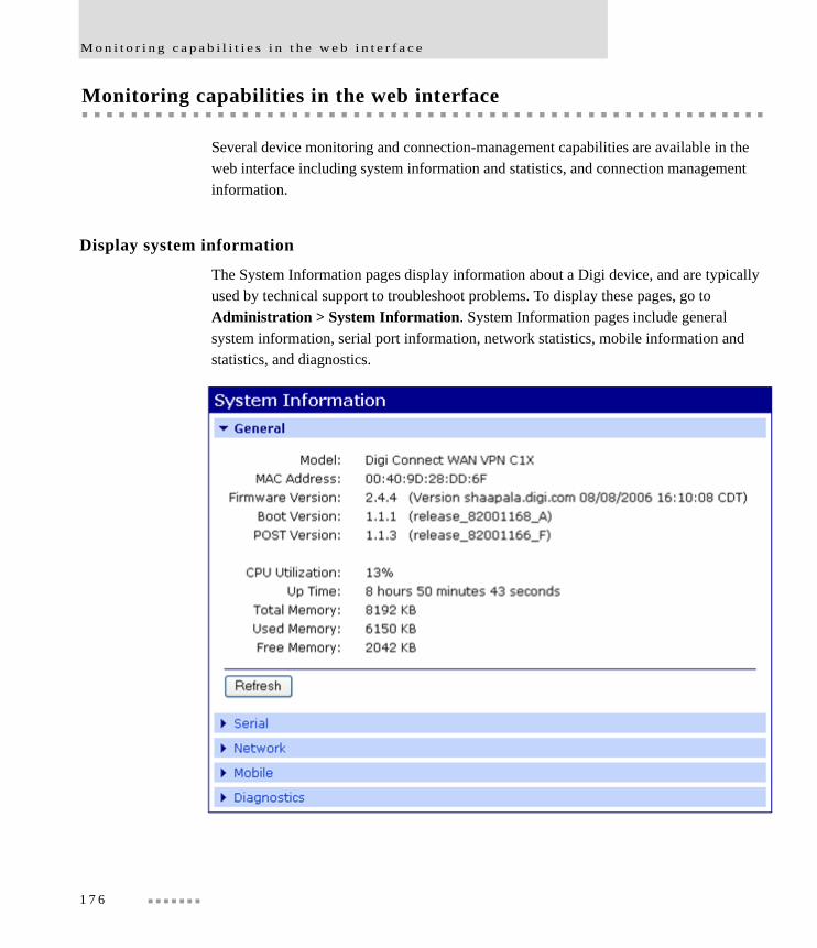
M o n i t o r i n g c a p a b i l i t i e s i n t h e w e b i n t e r f a c e
Monitoring capabilities in the web interface
Several device monitoring and connection-management capabilities are available in the web interface including system information and statistics, and connection management information.
Display system information
The System Information pages display information about a Digi device, and are typically used by technical support to troubleshoot problems. To display these pages, go to Administration > System Information. System Information pages include general system information, serial port information, network statistics, mobile information and statistics, and diagnostics.
1 7 6
M o n i t o r a n d m a n a g e D i g i d e v i c e s
General system information
The General page displays the following general system information about the Digi device, which can be useful in device monitoring and troubleshooting.
Information on the General System Information page includes:
ModelThe model of the Digi device.
MAC AddressA unique network identifier. All network devices are required to have their own unique MAC address. The MAC address is on a sticker on the Digi device. The number is displayed as 12 hexadecimal digits, usually starting with 00:40:9D.
Firmware VersionThe current firmware version running in the Digi device. This information may be used to help locate and download new firmware. Firmware updates can be downloaded from http://support.digi.com/support/firmware.
Boot VersionThe current boot code version running in the Digi device.
POST VersionThe current Power-On Self Test (POST) code version running in the Digi device.
CPU UtilizationThe amount of CPU resources being used by the Digi device.
Important: 100% CPU Utilization may indicate encryption key generation is in-progress. A CPU usage this high may indicate that encryption key generation is in-progress. On initial boot, the Digi device generates some encryption key material: an RSA key for SSL/TLS operations, and a DSA key for SSH operations. This key-generation process can take as long as 40 minutes to complete. Until the corresponding key is generated, the Digi device will be unable to initiate or accept that type of encrypted connection. It will also report itself as 100% busy but, since key generation takes place at a low priority, the device will still function normally. On subsequent reboots, the Digi device will use its existing keys and will not need to generate another unless a reset to factory defaults is done, which will cause a new key to be generated on the next reboot.
1 7 7
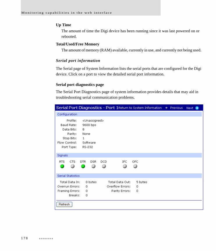
M o n i t o r i n g c a p a b i l i t i e s i n t h e w e b i n t e r f a c e
Up TimeThe amount of time the Digi device has been running since it was last powered on or rebooted.
Total/Used/Free MemoryThe amount of memory (RAM) available, currently in use, and currently not being used.
Serial port information
The Serial page of System Information lists the serial ports that are configured for the Digi device. Click on a port to view the detailed serial port information.
Serial port diagnostics page
The Serial Port Diagnostics page of system information provides details that may aid in troubleshooting serial communication problems.
1 7 8
M o n i t o r a n d m a n a g e D i g i d e v i c e s
Configuration
The Configuration section of serial port information includes the electrical interface (Port Type) and basic serial settings.
Signals
In the Signals section shows the serial port signals are green when asserted (on) and gray when not asserted (off). The meanings of the signals are:
RTSRequest To Send.
CTSClear To Send.
DTRData Terminal Ready.
DSRData Set Ready.
DCDData Carrier Detected.
OFCOutput Flow Control. This signal indicates that flow control is enabled on the remote side of the serial-port connection, and that the Digi device should stop sending data.
IFCInput Flow Control. This signal indicates that the Digi device is operating as if flow control is enabled for incoming data sent from the remote side of the serial-port connection. This signal is more of an indication that flow control is intended or expected rather than true state information. If the remote side has a flow-control mechanism enabled, the Digi device will use it.
1 7 9

M o n i t o r i n g c a p a b i l i t i e s i n t h e w e b i n t e r f a c e
Serial statistics
The Serial statistics section of serial port information includes data counters and error tracking that will help determine the quality of data that is being sent or received. If the error counters are accumulating, there may be a problem in the Digi device.
Total Data InTotal number of data bytes received.
Total Data OutTotal number of data bytes transmitted.
Overrun ErrorsNumber of overrun errors - the next data character arrived before the hardware could move the previous character.
Overflow ErrorsNumber of overflow errors - the receive buffer was full when additional data was received.
Framing ErrorsNumber of framing errors received - the received data did not have a valid stop bit.
Parity ErrorsNumber of parity errors - the received data did not have the correct parity setting.
BreaksNumber of break signals received.
1 8 0

M o n i t o r a n d m a n a g e D i g i d e v i c e s
Network statistics
Network statistics are detailed statistics about network and protocol activity that may aid in troubleshooting network communication problems. Statistics displayed are those gathered since the unit was last rebooted. If an error counter accumulates at an unexpected rate for that type of counter, there may be a problem in the Digi device.
Ethernet Connection Statistics
SpeedEthernet link speed: 10 or 100 Mbps. N/A if link integrity is not detected, for example, if the cable is disconnected.
DuplexEthernet link mode: half or full duplex. N/A if link integrity is not detected, for example, if the cable is disconnected.
Bytes ReceivedBytes Sent
Number of bytes received or sent.
Unicast Packets ReceivedNumber of unicast packets received and delivered to a higher-layer protocol. A unicast packet is one directed to an Ethernet MAC address.
Unicast Packets SentNumber of unicast packets requested to be sent by a higher-layer protocol. A unicast packet is one directed to an Ethernet MAC address.
Non-Unicast Packets ReceivedNumber of non-unicast packets received and delivered to a higher-layer protocol. A non-unicast packet is one directed to either an Ethernet broadcast address or a multicast address.
Non-Unicast Packets SentNumber of non-unicast packets requested to be sent by a higher-layer protocol. A non-unicast packet is one directed to either an Ethernet broadcast address or a multicast address.
Unknown Protocol Packets ReceivedNumber of packets received that were discarded because of an unknown or unsupported protocol.
1 8 1

M o n i t o r i n g c a p a b i l i t i e s i n t h e w e b i n t e r f a c e
IP Statistics
Datagrams ReceivedDatagrams Forwarded
Number of datagrams received or forwarded.
ForwardingDisplays whether forwarding is enabled or disabled.
No RoutesNumber of outgoing datagrams for which no route to the destination IP could be found.
Routing DiscardsNumber of outgoing datagrams which have been discarded.
Default Time-To-LiveNumber of routers an IP packet can pass through before being discarded.
TCP Statistics
Segments ReceivedSegments Sent
Number of segments received or sent.
Active OpensNumber of active opens. In an active open, the Digi device is initiating a connection request with a server.
Passive OpensNumber of passive opens. In a passive open, the Digi device is listening for a connection request from a client.
Bad Segments ReceivedNumber of segments received with errors.
Attempt FailsNumber of failed connection attempts.
Segments RetransmittedNumber of segments retransmitted. Segments are retransmitted when the server doesn't respond to a packet sent by the client. This is to handle packets that might get lost or discarded somewhere in the network.
1 8 2
M o n i t o r a n d m a n a g e D i g i d e v i c e s
Established ResetsNumber of established connections that have been reset.
UDP statistics
Datagrams ReceivedDatagrams Sent
Number of datagrams received or sent.
Bad Datagrams ReceivedNumber of bad datagrams that were received. This number does not include the value contained by No Ports.
No PortsNumber of received datagrams that were discarded because the specified port was invalid.
ICMP statistics
Messages ReceivedNumber of messages received.
Bad Messages ReceivedNumber of received messages with errors.
Destination Unreachable Messages ReceivedNumber of destination unreachable messages received. A destination unreachable message is sent to the originator when a datagram fails to reach its intended destination.
1 8 3
M o n i t o r i n g c a p a b i l i t i e s i n t h e w e b i n t e r f a c e
Mobile information and statistics
The Mobile information and statistics page displays detailed mobile statistics that may aid in troubleshooting network communication problems with your mobile network. The statistics displayed depend on whether your mobile service provider is GSM- or CDMA-based.
Mobile Connection Statistics
Registration StatusThe status of the modem's connection to the cellular network:
– Not Registered: Digi device is not currently searching a new operator to register to.
– Registered: Home Network.– Not Registered: Digi device is currently searching a new operator to register to.– Registration Denied.– Unknown.– Registered - Roaming.
Cell IDThe modem’s identifier in hexadecimal and decimal, for example: “00C3 (195).”
Location Area Code (aka “LAC”)The modem reports this value as a 4-hex-digit string. In the mobile statistics it is displayed both as hex and decimal representations. For example “00C3 (195).”
Signal Strength (RSSI)The relative signal strength, displayed as signal strength LEDs.
– 0 LEDs: Unacceptable; Signal strength is not known or not detectable.– 1 LED: Weak.– 2 LEDs: Moderate.– 3 LEDs: Good.– 4: LEDs: Excellent.
1 8 4
M o n i t o r a n d m a n a g e D i g i d e v i c e s
Mobile Statistics
Mobile statistics include the interface status, bytes received and sent, baud rate, modem resets, and inactivity timer.
IP AddressThe IP address of the PPP connection provided by the mobile service.
Primary DNS AddressSecondary DNS Address
The IP addresses of the DNS nameservers. Name lookups are performed using the nameserver specified on “dns1” first, and if that fails, the nameserver specified on “dns2” is used.
Data ReceivedTotal number of data bytes received.
Data SentTotal number of data bytes sent.
Idle ResetsThe number of times the modem has been reset because no data was received for a period of time.
Inactivity TimerThe time, in seconds, after which if no data has received over the link, the mobile connection will be disconnected and re-established.
1 8 5
M o n i t o r i n g c a p a b i l i t i e s i n t h e w e b i n t e r f a c e
Mobile Information
IMSIInternational Mobile Subscriber Identifier (IMSI), a unique 15-digit number which designates the subscriber. This ID is the subscriber's code to access the cellular network, and is used by the network for provisioning and to admit the device/user to its provisioned services.
Phone NumberThe phone number used to call the modem module. Two numbers are displayed: the Mobile Directory Number (MDN) and the Mobile Identification Number (MIN).
Modem ManufacturerThe manufacturer of the modem module.
ModelThe model name of the modem module.
Modem Serial NumberThe serial number of the modem module.
Modem RevisionThe firmware revision in the modem module.
Other Mobile InformationDepending on your mobile service provider, other mobile information and settings may be provided after the modem revision.
1 8 6
M o n i t o r a n d m a n a g e D i g i d e v i c e s
SureLink statistics
Digi SureLink™ provides an “always-on” mobile network connection to ensure that a Digi device is in a state where it can connect to the network.
The statistics displayed for Digi SureLink pertain to the periodic tests, known as Link Integrity Monitoring tests, that are run over the established PPP connection to ensure that end-to-end communication is possible. There are three Link Integrity Monitoring tests available: Ping Test, TCP Connection Test, and DNS Lookup Test. For descriptions of these tests, see "Link integrity monitoring settings" on page 126.
In these SureLink statistics, a “session” is a PPP session. The session statistics are reset to zero at the start of a new PPP connection. The “total” statistics are the accumulated totals for all sessions since the device booted. The “tests” are the SureLink Link Integrity Monitoring tests that have been configured to be run when the mobile network connection is established.
session successesThe number of times a configured test was attempted and succeeded in the current PPP session.
session failuresThe number of times a configured test was attempted but failed in the current PPP session.
session consecutive failuresThe number of consecutive failures for a test, with no success. When a test is successful, the consecutive failures counter is reset to zero. The consecutive failures counter indicates a device's “progress” toward the configured maximum number of consecutive failures, after which the PPP link is taken down (and restarted).
session bypasses If a configuration parameter is bad, a test is bypassed rather than considered to have succeeded or failed. This means the test was not run. If the PPP connection goes down while a test is in progress, that test may be classified as bypassed, since it could not be run. (Note that the PPP link may come down for many reasons, independent of SureLink testing.)
total successesThe total number of times a configured test was attempted and succeeded since the Digi device was booted.
1 8 7
M o n i t o r i n g c a p a b i l i t i e s i n t h e w e b i n t e r f a c e
total failuresThe total number of times a configured test was attempted but failed since the Digi device was booted.
total link down requestsThe number of times the SureLink feature has failed consecutively the configured number of failures and, as a result, requested that PPP shut down and restart its connection. This statistic counts such occurrences during the current device boot. SureLink itself does do the PPP stop/start; it sends a message to PPP asking it to do so, owing to a Surelink test failure.
total bypasses The total test bypasses (see “session bypasses”) since the Digi device was rebooted.
Diagnostics
The Diagnostics page provides a ping utility to determine whether the Digi device can access remote devices over the network. Enter the hostname of the remote device to attempt to access, and click Ping.
1 8 8

M o n i t o r a n d m a n a g e D i g i d e v i c e s
Manage connections and services
The Management menu is for viewing and managing connections and services for the Digi device.
Manage serial ports
Management > Serial Ports provides an overview of the serial ports and their connections. Clicking Connections displays the active connections for that serial port. The view can be refreshed to see any new serial-port connections list, and connections can be disconnected as needed.
Manage connections
Management > Connections displays active Virtual Private Network (VPN) and system connections.
Manage VPN connections
To monitor a VPN connection from the web interface, select Management > Connections. The VPN settings appear.
Note that the Connect and Disconnect functions do not work for a VPN that uses a Pre-Shared Key (PSK).
Manage active system connections
The Active System Connections list provides an overview of connections associated with various interfaces, such as user connections to the device’s web interface, or to the command line through the local shell; the protocols used for the connections; and the number of active sessions for each connection. One of the uses of this list is to determine whether any connections are no longer needed and can be disconnected.
1 8 9
M o n i t o r i n g c a p a b i l i t i e s i n t h e w e b i n t e r f a c e
Event logging
Information on this feature to be provided in a forthcoming release.
Manage network services
Management > Network Services displays information about active network services. Currently, the only network-service management task possible from this page is managing the DHCP server.
Manage DHCP server operation
DHCP server management operations include:
View DHCP server status.
Start/stop/restart the DHCP server.
View and manage current DHCP leases.
Start, stop, and restart the DHCP server
The DHCP Server Management page shows the current status of the DHCP server. Depending on the current status, there are buttons to start, stop, or restart the DHCP server. Click the appropriate button to perform your request.
Note Stopping, restarting, or rebooting the DHCP server causes all knowledge of the IP address leases to be lost. All leased addresses (except for reservations) will be returned to the available address pool and may be served in a new lease to a DHCP client.
1 9 0
M o n i t o r a n d m a n a g e D i g i d e v i c e s
View and manage current DHCP leases
The DHCP server maintains a current list of its leases, reservations and unavailable addresses. The displayed lease list may contain entries that report a variety of status descriptions. The Lease Status types are identified and described below.
Even after a lease has expired or is released by a DHCP client, the associated IP address is not immediately returned to the available address pool. Rather, there is a non-configurable grace period during which the lease record is retained by the DHCP server. At the end of that grace period, the lease record is automatically deleted and the associated IP address is returned to the available address pool. Where a grace period is observed, this is indicated in the Lease Status descriptions below.
The grace period is incorporated in the DHCP server to increase the consistency of offering the same IP address to a DHCP client, even if that client is rebooted or off the network for a period of time that does not exceed the grace period.
You can explicitly remove leases from the DHCP server while it is running. To remove a lease, select the checkbox to the left of the lease information in the table of leases, then click the Remove button below the lease table. To remove all leases, select the checkbox to the left of the descriptive headings at the top of the table, then click the Remove button below the lease table.
Note Removing a lease will cause the associated IP address to be returned immediately to the available address pool. Any IP address in this available address pool may be served in a new lease to a DHCP client.
Static lease reservations will always show in the lease list. These reservation leases may be removed, but a new lease will be created immediately. To disable or permanently remove a reservation, use the DHCP server Settings page in the Network Configuration area.
1 9 1

M o n i t o r i n g c a p a b i l i t i e s i n t h e w e b i n t e r f a c e
Lease status types
Descriptions of Lease Status values that are displayed in the lease list follow, including how long a lease table entry will remain in each state. Note that after a lease is deleted, the associated IP address is returned to the available address pool.
Assigned (active)A lease is currently assigned and active for the given client. The client may renew the lease, in which case the lease remains in this state.
Assigned (expired)A lease has expired and is no longer active for the given client. A lease in this state will remain for a 4 hour grace period, after which it is deleted. If the same client requests an IP address before the lease is deleted, it will be given the same IP address previously served to it.
Reserved (active)A lease for an address reservation is currently active for the given client. A reservation lease will remain indefinitely, although the status may alternate between active and inactive.
Reserved (inactive)A lease for an address reservation is currently inactive for the given client. A reservation lease will remain indefinitely, although the status may alternate between active and inactive.
Reserved (unavail)A lease for an address reservation was offered to a client, but that client actively declined to use the IP address. Typically this is because the client determined that another host on the same subnetwork is already using that IP address. Upon receiving the client's decline message, the DHCP server will mark the address as unavailable. The lease will remain in this state for 4 hours, after which it is reverts to the Reserved (inactive) status.
Offered (pre-lease)A lease has been offered to the given client, but that client has not yet requested that the lease be acknowledged. It may be that the client also received an offer from another DHCP server, in which case this offer will expire in approximately 2 minutes. If the client requests this lease before that 2 minute interval elapses, this lease will change status to Assigned. If the 2 minute interval expires, the offer record is deleted and the associated IP address is returned immediately to the available address pool.
1 9 2

M o n i t o r a n d m a n a g e D i g i d e v i c e s
ReleasedA lease was previously assigned to the given client, but that client has proactively released it. A lease in this state will remain for a 1 hour grace period, after which it is deleted. If the same client requests an IP address before the lease is deleted, it will be given the same IP address previously served to it.
Unavailable AddressA lease was offered to a client, but that client actively declined to use the IP address. Typically this is because the client determined that another host on the same subnetwork is already using that IP address. Upon receiving the client's decline message, the DHCP server will mark the address as unavailable. The lease will remain in this state for a 4 hour grace period, after which it is deleted. This status may also occur if the DHCP server determines that the IP address is in use before it offers the address to a client (see the DHCP server setting Check that an IP address is not in use before offering it).
Manage Mesh networks
Digi provides several avenues for managing Mesh networks and the ZigBee devices in the Mesh Network:
From a ConnectPort X device’s web interface. This section focuses on this interface.
From a ConnectPort X device’s command-line interface. See"Commands for managing Mesh networks and nodes" on page 202.
From Connectware Manager’s Mesh Networks view. See "Monitor/manage Mesh networks from Connectware Manager" on page 207.
1 9 3
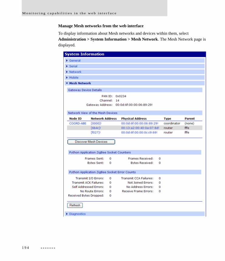
M o n i t o r i n g c a p a b i l i t i e s i n t h e w e b i n t e r f a c e
Manage Mesh networks from the web interface
To display information about Mesh networks and devices within them, select Administration > System Information > Mesh Network. The Mesh Network page is displayed.
1 9 4
M o n i t o r a n d m a n a g e D i g i d e v i c e s
Gateway device details
This part of the display shows information about the ConnectPort X gateway and its role as a gateway device in the Mesh network. It shows the current PAN ID, Channel, and address in use for the Mesh network.
Network view of the Mesh devices
This part of the display shows the ConnectPort X gateway and any devices that have joined the Mesh network.
Click the Discover Mesh Devices button to refresh the list of devices that have joined the mesh network. (The discovery operation may take a few seconds.) Click on a device's table entry to view more detailed information of the state of that device.
Python Application ZigBee Socket Counters
This section includes data counters that are specific to ZigBee Sockets implemented using a Python application.
Frames SentThe total number of transmitted frames.
Frames ReceivedThe total number of received frames.
Bytes SentThe total number of bytes sent.
Bytes ReceivedThe total number of bytes received.
1 9 5
M o n i t o r i n g c a p a b i l i t i e s i n t h e w e b i n t e r f a c e
Python Application ZigBee Socket Error Counts
This section includes error counters that are specific to ZigBee Sockets implemented using a Python application. These values will help determine the quality of data that is being sent or received. Refer to the Troubleshooting information in your User Guide for further help.
Transmit I/O ErrorsThe total number of transmitted frames which could not be transmitted due to an I/O error.
Transmit CCA FailuresThe total number of transmitted frames which could not be transmitted due to a CCA error.
Transmit ACK FailuresThe total number of transmitted frames which could not be transmitted due to an ACK error.
Not Joined ErrorsThe total number of transmitted frames which were attempted to be transmitted to an unjoined node.
Self Addressed ErrorsThe total number of transmitted frames for which a node attempted to transmit to itself.
No Address ErrorsThe total number of transmitted frames for which the destination address could not be found.
No Route ErrorsThe total number of transmitted frames for which a router to the destination could not be found.
Receive Frame ErrorsThe total number of frames where an error occurred on receive.
Received Bytes DroppedThe total number of bytes dropped due to an exhaustion of internal buffers.
1 9 6
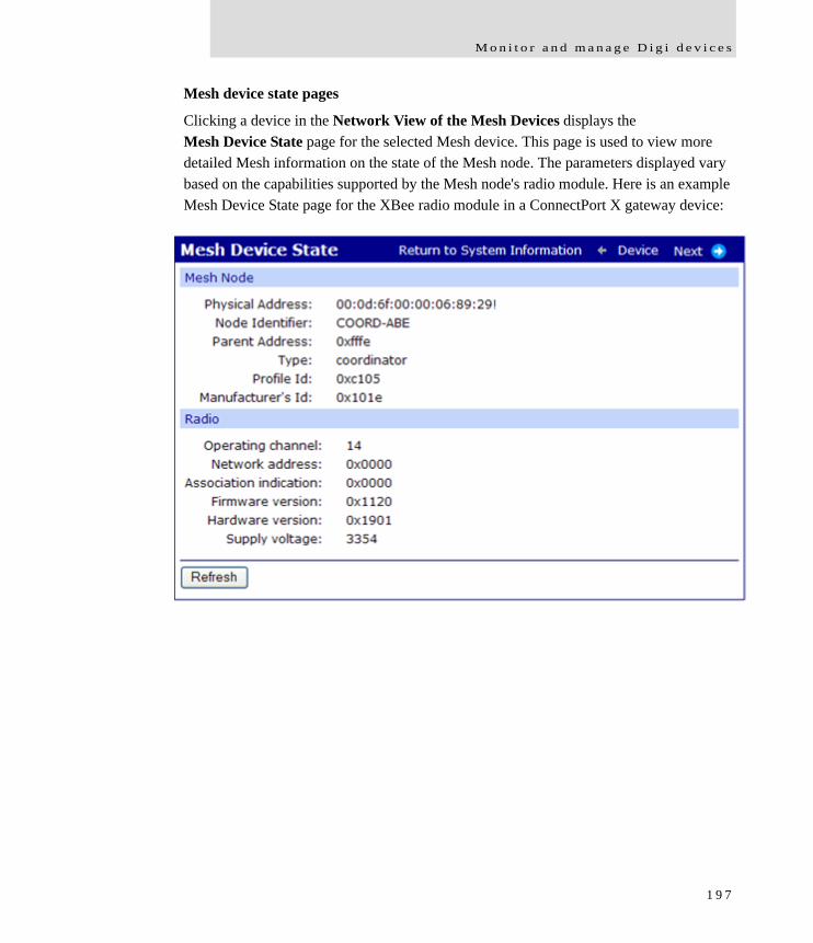
M o n i t o r a n d m a n a g e D i g i d e v i c e s
Mesh device state pages
Clicking a device in the Network View of the Mesh Devices displays the Mesh Device State page for the selected Mesh device. This page is used to view more detailed Mesh information on the state of the Mesh node. The parameters displayed vary based on the capabilities supported by the Mesh node's radio module. Here is an example Mesh Device State page for the XBee radio module in a ConnectPort X gateway device:
1 9 7
M o n i t o r i n g c a p a b i l i t i e s f r o m t h e c o m m a n d l i n e
Monitoring capabilities from the command line
There are several commands for monitoring Digi devices and managing their connections. For complete descriptions of these commands, see the Digi Connect Family Command Reference.
Commands for displaying device information and statistics
display
The display command displays real-time information about a device, such as:
General product information, including the product name, MAC address, boot, post, and firmware versions, memory usage, utilization, and uptime, or the amount of time since the device was booted (display device).
Active interfaces on the system, for example, the web interface, command line interface, Point to Point Protocol (PPP), and Ethernet interface, and their status, such as “Closed” or “Connected.” (display netdevice).
Memory usage information (display memory).
Serial modem signals. (display serial).
Mobile connection information and statistics (display mobile).
Network Address Translation (NAT) information (display nat).
General status of the sockets resource (display sockets).
Active TCP sessions and active TCP listeners (display tcp).
Current UDP listeners (display udp).
Point-to-Point Protocol (PPP) information, including results of Link Integrity Monitoring tests by Digi SureLink “display pppstats”).
Provisioning information currently in the Digi device device’s CDMA module (display provisioning)
Uptime information (display uptime).
Virtual Private Network (VPN) connection information (display vpn).
1 9 8
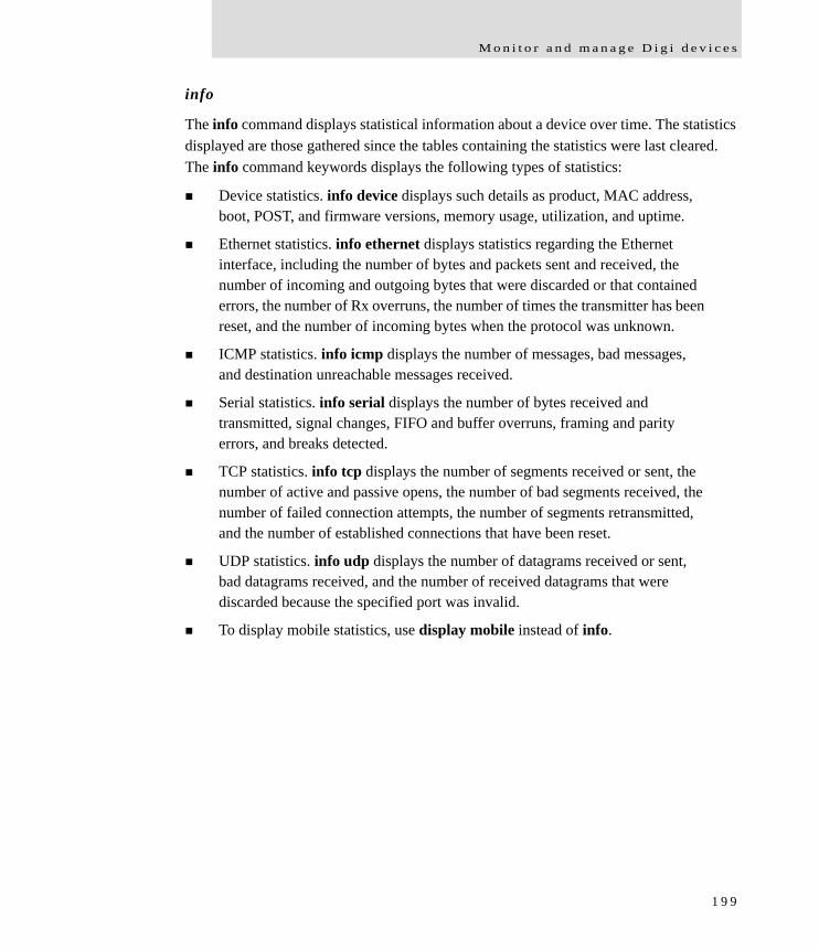
M o n i t o r a n d m a n a g e D i g i d e v i c e s
info
The info command displays statistical information about a device over time. The statistics displayed are those gathered since the tables containing the statistics were last cleared. The info command keywords displays the following types of statistics:
Device statistics. info device displays such details as product, MAC address, boot, POST, and firmware versions, memory usage, utilization, and uptime.
Ethernet statistics. info ethernet displays statistics regarding the Ethernet interface, including the number of bytes and packets sent and received, the number of incoming and outgoing bytes that were discarded or that contained errors, the number of Rx overruns, the number of times the transmitter has been reset, and the number of incoming bytes when the protocol was unknown.
ICMP statistics. info icmp displays the number of messages, bad messages, and destination unreachable messages received.
Serial statistics. info serial displays the number of bytes received and transmitted, signal changes, FIFO and buffer overruns, framing and parity errors, and breaks detected.
TCP statistics. info tcp displays the number of segments received or sent, the number of active and passive opens, the number of bad segments received, the number of failed connection attempts, the number of segments retransmitted, and the number of established connections that have been reset.
UDP statistics. info udp displays the number of datagrams received or sent, bad datagrams received, and the number of received datagrams that were discarded because the specified port was invalid.
To display mobile statistics, use display mobile instead of info.
1 9 9
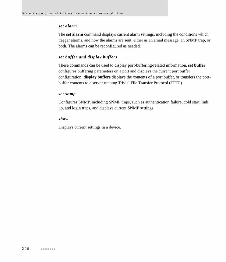
M o n i t o r i n g c a p a b i l i t i e s f r o m t h e c o m m a n d l i n e
set alarm
The set alarm command displays current alarm settings, including the conditions which trigger alarms, and how the alarms are sent, either as an email message, an SNMP trap, or both. The alarms can be reconfigured as needed.
set buffer and display buffers
These commands can be used to display port-buffering-related information. set buffer configures buffering parameters on a port and displays the current port buffer configuration. display buffers displays the contents of a port buffer, or transfers the port-buffer contents to a server running Trivial File Transfer Protocol (TFTP).
set snmp
Configures SNMP, including SNMP traps, such as authentication failure, cold start, link up, and login traps, and displays current SNMP settings.
show
Displays current settings in a device.
2 0 0

M o n i t o r a n d m a n a g e D i g i d e v i c e s
Commands for managing connections and sessions
close: Closes active sessions that were opened by connect, rlogin, and telnet commands.
connect: Makes a connection, or establishes a connection, with a serial port.
dhcp: Manages DHCP server operation.
exit and quit: These commands terminate a currently active session.
vpn: Manages Virtual Private Network (VPN) connections.
who and kill: The who command displays a global list of connections. The list of connections includes those associated with a serial port or the command-line interface. who is particularly useful in conjunction with the kill command, which terminates active connections. Use who to determine any connections that are no longer needed, and end the connections by issuing a kill command.
mode: Changes or displays the operating options for a current Telnet session.
ping: Tests whether a host or other device is active and reachable.
reconnect: Reestablishes a previously established connection; that is, a connection opened by a connect, rlogin, or telnet command; the default operation is to reconnect to the last active session.
rlogin: Performs a login to a remote system.
send: Sends a Telnet control command, such as break, abort output, are you there, escape, or interrupt process, to the last active Telnet session.
status: Displays a list of sessions, or outgoing connections made by connect, rlogin, or telnet commands for a device. Typically, the status command is used to determine which of the current sessions to close.
telnet: Makes an outgoing Telnet connection, also known as a session.
2 0 1

M o n i t o r i n g c a p a b i l i t i e s f r o m t h e c o m m a n d l i n e
Commands for managing Mesh networks and nodes
Several commands are used to configure Mesh networks and display information and statistics about the devices in the Mesh network: set mesh, display mesh, and info zigbee_sockets.
set mesh
The set mesh command configures Mesh network settings for a ConnectPort X gateway. Also displays current configuration parameters on the gateway Mesh node or of remote nodes in the mesh (specified by the address option).
Configure Mesh network settings: command syntaxset mesh [options...] [device_settings...]
options:
state={off|on} {Enable mesh gateway}
address=device address {Specify device to set}
device_settings:
pan_id=0x0-0x3fff {PAN identifier}
dest_addr=address {Destination address}
delay_slots=0-3 {Random delay slots}
broadcast_hops=0-10 {Broadcast radius}
scan_channels=0x1-0xffff {Scan channels, bitfield}
scan_duration=0-7 {Scan duration, exponent}
join_time=0-255 {Node join time, sec}
join_notification=0-2 {Join notification}
node_id=0-20 chars {Node identifier}
discover_timeout=0-252 {Node discovery timeout, x 100 msec}
aggregation=0-255 {Aggregation route notification, x 10 sec}
power_level=0-4 {Transmit power level}
power_mode=0-1 {Power mode}
cca_threshold=36-80 {CCA threshold, -dBm}
sleep_period=32-2800 {Cyclic sleep period, x 10 msec}
device_type=0x0-0xffff {Device type identifier}
serial_rate=0-115200 {Serial interface data rate}
serial_parity=0-4 {Serial interface parity}
2 0 2
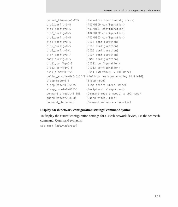
M o n i t o r a n d m a n a g e D i g i d e v i c e s
packet_timeout=0-255 {Packetization timeout, chars}
dio0_config=0-5 {AD0/DIO0 configuration}
dio1_config=0-5 {AD1/DIO1 configuration}
dio2_config=0-5 {AD2/DIO2 configuration}
dio3_config=0-5 {AD3/DIO3 configuration}
dio4_config=0-5 {DIO4 configuration}
dio5_config=0-5 {DIO5 configuration}
dio6_config=0-1 {DIO6 configuration}
dio7_config=0-7 {DIO7 configuration}
pwm0_config=0-5 {PWM0 configuration}
dio11_config=0-5 {DIO11 configuration}
dio12_config=0-5 {DIO12 configuration}
rssi_timer=0-255 {RSSI PWM timer, x 100 msec}
pullup_enable=0x0-0x1fff {Pull-up resistor enable, bitfield}
sleep_mode=0-5 {Sleep mode}
sleep_time=0-65535 {Time before sleep, msec}
sleep_count=0-65535 {Peripheral sleep count}
command_timeout=2-655 {Command mode timeout, x 100 msec}
guard_times=2-3300 {Guard times, msec}
command_char=char {Command sequence character}
Display Mesh network configuration settings: command syntax
To display the current configuration settings for a Mesh network device, use the set mesh command. Command syntax is:set mesh [addr=address]
2 0 3
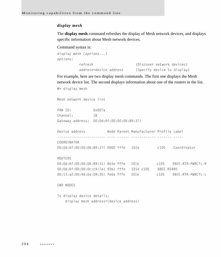
M o n i t o r i n g c a p a b i l i t i e s f r o m t h e c o m m a n d l i n e
display mesh
The display mesh command refreshes the display of Mesh network devices, and displays specific information about Mesh network devices.
Command syntax is:display mesh [options...]
options:
refresh {Discover network devices}
address=device address {Specify device to display}
For example, here are two display mesh commands. The first one displays the Mesh network device list. The second displays information about one of the routers in the list.#> display mesh
Mesh network device list
PAN ID: 0x007a
Channel: 18
Gateway address: 00:0d:6f:00:00:06:89:37!
Device address Node Parent Manufacturer Profile Label
------------------------ ---- ------ ------------ ------- -----
COORDINATOR
00:0d:6f:00:00:06:89:37! 0000 fffe 101e c105 Coordinator
ROUTERS
00:0d:6f:00:00:06:89:31! 8e3e fffe 101e c105 XBEE-RTR-PWRCTL-R
00:0d:6f:00:00:0c:c9:7a! 93b1 fffe 101e c105 XBEE-RS485
00:13:a2:00:40:0a:09:35! fe0a fffe 101e c105 XBEE-RTR-PWRCTL-L
END NODES
To display device details:
display mesh address=(device address)
2 0 4

M o n i t o r a n d m a n a g e D i g i d e v i c e s
#> display mesh address=00:0d:6f:00:00:06:89:31!
Status of device: 00:0d:6f:00:00:06:89:31!
channel : 18
net_addr : 0x8e3e
association : 0x0
firmware_version : 0x1220
hardware_version : 0x1901
supply_voltage : 3289 (mvolts)
info zigbee_sockets
The info zigbee_sockets command displays statistics from the ConnectPort X gateway’s perspective of what is happening on the ZigBee network. This is essentially data from the MaxStream module’s perspective as interpreted by the ZigBee driver in the gateway.
Command syntax is:info zigbee_sockets
2 0 5

M o n i t o r i n g c a p a b i l i t i e s f r o m C o n n e c t w a r e M a n a g e r
Monitoring capabilities from Connectware Manager
Digi devices can be monitored and managed from Connectware Manager. Examples of activities from Connectware Manager include:
Displaying detailed state information and statistics about a device, such as device up time, amount of used and free memory, network settings, Mesh network overview and detailed information on network nodes
Mobile settings
Monitoring the state of the device’s connection and see a connection report and connection history statistics.
Redirecting devices to a to a different destination
Disconnecting devices
Removing devices from the network.
See the Digi Connectware Manager Operator’s Guide’s chapters on managing devices and monitoring device statistics and status.
2 0 6

M o n i t o r a n d m a n a g e D i g i d e v i c e s
Monitor/manage Mesh networks from Connectware Manager
Digi’s Connectware Manager provides remote network management of all connected hardware, including devices on the ZigBee network. In contrast to the one-user-to-one device model of other Digi device interfaces, Connectware Manager deploys a one-user-to-many-devices interface model. From Connectware Manager, you can provision and configure network hardware, track device performance, remotely set filters and alarms, monitor connections, reboot devices and reset defaults, and remotely upgrade firmware. ZigBee extensions to Connectware Manager make it a particularly attractive platform for managing ZigBee devices behind the gateway. It displays all nodes on the ZigBee network with the ability to query for node profiles, node descriptors, connected endpoints, radio configuration settings radio statistics, bindings, and more.
Several views in Connectware Manager are used for viewing and configuring ZigBee networks:
ZigBee Networks View
Node View
See "Configuring Mesh Networks and Nodes through Connectware Manager" on page 170 for examples of these views.
2 0 7
M o n i t o r i n g C a p a b i l i t i e s f r o m S N M P
Monitoring Capabilities from SNMP
Device monitoring capabilities from SNMP include, among other things:
Network statistics, defined in RFC 1213, MIB-II
Port statistics, defined in RFCs 1316 and 1317
Device information, defined in Digi enterprise MIB DIGI-DEVICE-INFO.mib
For more information on the statistics available through the standard RFCs listed above, refer to the RFCs available on the IETF web site (www.ietf.org). For enterprise MIBs, refer to the description fields in the MIB text.
2 0 8
A d m i n i s t r a t i o n t a s k s
Administration tasksC H A P T E R 4
This chapter discusses the administration tasks that need to be performed on Digi devices periodically, such as file management, changing the password used for logging onto the device, backing up and restoring device configurations, updating firmware and Boot/POST code, restoring the device configuration to factory defaults, and rebooting the device. As with device configuration and monitoring, it covers performing administrative tasks through a variety of device interfaces.
It covers these main topics:
Administration from the web interface
Administration from the command-line interface
Administration from Connectware Manager
2 0 9
A d m i n i s t r a t i o n f r o m t h e w e b i n t e r f a c e
Administration from the web interface
The Administration section of the web interface main menu provides the following choices:
File Management: For uploading and managing files, such as custom web pages, applet files, and initialization files. See "File management" on page 211.
Python Program File Management: For uploading custom programs in the Python programming language to Digi devices and configuring the programs to execute automatically at startup. See "Python® program management" on page 164.
X.509 Certificate/Key Management: For loading and managing X.509 certificates and public/private host key pairs that are public key infrastructure (PKI) based security. See page 212.Backup/Restore: For backing up or restoring a device’s configuration settings. See "Backup/restore device configurations" on page 213.
Update Firmware: For updating firmware, including Boot and POST code. See "Update firmware and Boot/POST Code" on page 214.
Factory Default Settings: For restoring a device to factory default settings. See "Restore a device configuration to factory defaults" on page 215.
System Information: For displaying general system information for the device and device statistics. See "Display system information" on page 217.
Reboot: For rebooting the device. See "Reboot the Digi device" on page 217.
These administrative tasks are organized elsewhere in the web interface:
Enable and disable network services. See "Network services settings" on page 82.
Enable password authentication for the Digi device. See "Configure Security settings" on page 160.
2 1 0

A d m i n i s t r a t i o n t a s k s
File management
The File Management page of the web interface uploads custom files to a Digi device, such as the files for a custom applet, or a custom image file of your company logo. Custom applets allow the flexibility to alter the interface either by adding a different company logo, changing colors, or moving information to different locations. If custom applets or the sample Java applet is not used, using this feature is not necessary.
Uploading Files
To upload files to a Digi device, enter the file path and name for the file, or click Browse to locate and select the file, and click Upload.
Delete files
To delete files from a Digi device, select the file from the list under Manage Files and click Delete.
Custom files are not deleted by device reset
Any files uploaded to the file system of a Digi devicefrom the File Management page are not deleted by restoring the device configuration to factory defaults, or by pressing the Reset button on the device (see "Restore a device configuration to factory defaults" on page 215). This deletion is prevented so that customers with custom applets and custom factory defaults can retain them on the device and not have them deleted by a reset. Such files can only be deleted by the Delete operation, described above.
2 1 1
A d m i n i s t r a t i o n f r o m t h e w e b i n t e r f a c e
X.509 Certificate/Key Management
The X.509 Certificate/Key Management pages are for loading and managing X.509 certificates and public/private host key pairs that are public key infrastructure (PKI) based security. There are several pages for managing several certificate databases:
The Certificate Authority (CA) database is used to load certificate authority digital certificates. A certificate authority (CA) is a trusted third party which issues digital certificates for use by other parties. Digital certificates issued by the CA contain a public key. The certificate also contains information about the individual or organization to which the public key belongs. A CA verifies digital certificate applicants' credentials. The CA certificate allows verification of digital certificates, and the information contained therein, issued by that CA.
The Certificate Revocation List (CRL) database is used to load certificate revocation lists for loaded CAs. A certificate revocation list (CRL) is a file that contains the serial numbers of digital certificates issued by a CA which have been revoked, and should no longer be trusted. Like CAs, CRLs are a vital part of a public key infrastructure (PKI). The digital certifiicate of the corresponding CA must be installed before the CRL can be loaded.
The Virtual Private Networking (VPN) Identities database is used to load host certificates and keys. Identity certificates and keys keys allow for IPSec authentication and secure key exchange with ISAKMP/IKE using RSA or DSA signatures. The VPN identity certificate must be issued by a CA trusted by the peer.
The Secure Sockets Layer (SSL) and Transport Layer Security (TLS) databases are used to load host certificates and keys, as well as peer certificates and revocations.
The Secure Shell (SSHv2) Hostkeys database is used to load host private keys. SSHv2 host keys are used for authentication with SSHv2 clients and secure key exchange. A default 1024-bit DSA key is generated automatically if none exists when the device boots.
2 1 2
A d m i n i s t r a t i o n t a s k s
Backup/restore device configurations
Once a Digi device is configured, backing up the configuration settings is recommended in case problems occur later, firmware is upgraded, or hardware is added. If multiple devices need to be configured, the backup/restore feature can be used as a convenience, where the first device’s configuration settings is backed u to a file, then the file is loaded onto the other devices.
This procedure shows how to back up or restore the configuration to a server and download a configuration from a server to a file or TFTP.
If using TFTP, ensure that the TFTP program is running on a server.
In the web interface:
1 From the Main menu, click Administration > Backup/Restore. The Backup/Restore page is displayed.
2 Choose the appropriate option (Backup or Restore) and select the file.
2 1 3
A d m i n i s t r a t i o n f r o m t h e w e b i n t e r f a c e
Update firmware and Boot/POST Code
The firmware and/or boot/POST code for a Digi device can be updated from a file on a PC or through TFTP.The recommended method is to download the firmware to a local hard drive. TFTP is supported for those using UNIX systems. Both the firmware and the boot/POST code are updated using the same set of steps. The Digi device automatically determines the type of image being uploaded. Before uploading the firmware or the boot/POST code, it is very important to read the Release Notes supplied with the firmware to check if the boot/POST code must be updated before updating the firmware.
Prerequisites
These procedures assume that:
A firmware file has already been downloaded the firmware file from the Digi web site.
If using TFTP, that TFTP is running.
Update firmware from a file on a PC
1 From the Main menu, click Administration > Update Firmware. The Update Firmware page is displayed.
2 Enter the name of the firmware or POST file in the Select Firmware edit box, or click Browse to locate and select the firmware or POST file.
3 Click Update. Important: DO NOT close the browser until the update is complete and a reboot prompt has been displayed.
Update Firmware from a TFTP Server
Updating firmware from a TFTP server is done from the command-line interface using the boot command. It cannot be done from the web interface. For details, see "Administration from the command-line interface" on page 218.
2 1 4
A d m i n i s t r a t i o n t a s k s
Restore a device configuration to factory defaults
Restoring a Digi device to its factory default settings clears all current configuration settings except the IP address settings and host key settings. In addition, any files that were loaded into the device through the File Management page such as custom-interface files and applet files are retained. See "File management" on page 211 for information on loading and deleting files.
There are two ways to reset the device configuration of a Digi device to the factory default settings: from the web interface and using the reset button on the Digi device.
Settings cleared and retained during factory reset
The Restore Factory Defaults operation clears all current settings except the IP address settings and host key settings. This is the best way to reset the configuration, because the settings can also be backed up using the Backup/Restore operation, which provides a means for restoring it after the configuration issues have been resolved.
Using the web interface
1 Make a backup copy of the configuration using the Backup/Restore operation, described on page 213.
2 From the Main menu, click Administration > Factory Default Settings. The Factory Default Settings page is displayed.
3 Choose whether to keep the network settings for the device, such as the IP address, and click Restore.
2 1 5
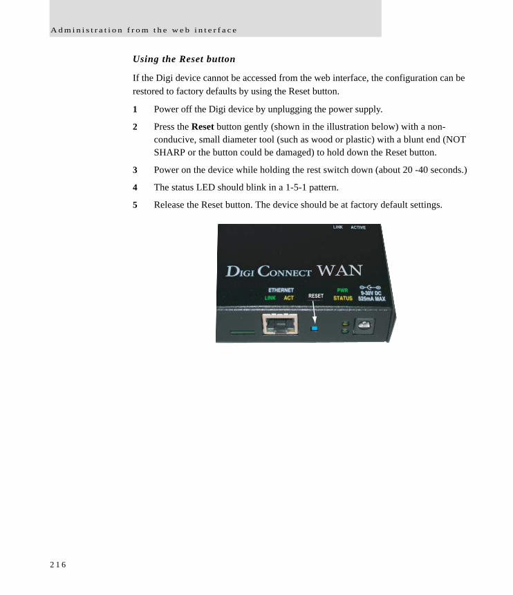
A d m i n i s t r a t i o n f r o m t h e w e b i n t e r f a c e
Using the Reset button
If the Digi device cannot be accessed from the web interface, the configuration can be restored to factory defaults by using the Reset button.
1 Power off the Digi device by unplugging the power supply.
2 Press the Reset button gently (shown in the illustration below) with a non-conducive, small diameter tool (such as wood or plastic) with a blunt end (NOT SHARP or the button could be damaged) to hold down the Reset button.
3 Power on the device while holding the rest switch down (about 20 -40 seconds.)
4 The status LED should blink in a 1-5-1 pattern.
5 Release the Reset button. The device should be at factory default settings.
WAN
RESET
2 1 6
A d m i n i s t r a t i o n t a s k s
Display system information
System information displays the model, MAC address, firmware version, boot version, and POST version of the Digi device. It also displays memory available: total, used, and free, and tracks CPU percent utilization and the uptime.
From the web interface menu, select Administration > System Information. Select General, Serial or Network for the appropriate information. For descriptions of the information displayed on these screens, see page 176.
Reboot the Digi device
Changes to some device settings require saving the changes and rebooting the Digi device. To reboot a Digi device:
1 From the web interface menu, select Administration > Reboot.
2 On the Reboot page, click the Reboot button. Wait approximately 1 minute for the reboot to complete.
Enable/disable access to network services
As needed, enable and disable access to various network services, such as ADDP, RealPort, SNMP, and Telnet. For example, for performance and security reasons, it may be desirable to disable access to all network services not necessary for running or interfacing with the Digi device. In the web interface, enabling and disabling network services is done on the Network Services settings page for a Digi device. See "Network services settings" on page 82.
2 1 7
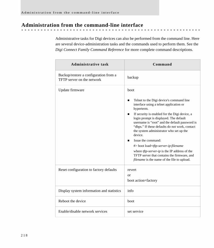
A d m i n i s t r a t i o n f r o m t h e c o m m a n d - l i n e i n t e r f a c e
Administration from the command-line interface
Administrative tasks for Digi devices can also be performed from the command line. Here are several device-administration tasks and the commands used to perform them. See the Digi Connect Family Command Reference for more complete command descriptions.
Administrative task Command
Backup/restore a configuration from a TFTP server on the network backup
Update firmware boot
Telnet to the Digi device's command line interface using a telnet application or hyperterm. If security is enabled for the Digi device, a
login prompt is displayed. The default username is “root” and the default password is “dbps.” If these defaults do not work, contact the system administrator who set up the device. Issue the command:
#> boot load=tftp-server-ip:filenamewhere tftp-server-ip is the IP address of the TFTP server that contains the firmware, and filename is the name of the file to upload.
Reset configuration to factory defaults revert orboot action=factory
Display system information and statistics info
Reboot the device boot
Enable/disable network services set service
2 1 8
S p e c i f i c a t i o n s a n d c e r t i f i c a t i o n s
Specifications and certificationsC H A P T E R 5
This chapter provides hardware specifications, additional feature detail, and regulatory statements and certifications for Digi devices.
Hardware specifications
Regulatory statements and certifications
2 1 9
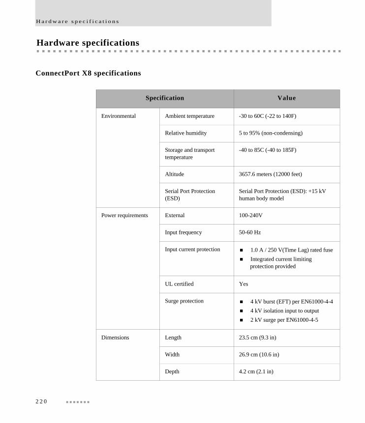
H a r d w a r e s p e c i f i c a t i o n s
Hardware specifications
ConnectPort X8 specifications
Specification Value
Environmental Ambient temperature -30 to 60C (-22 to 140F)
Relative humidity 5 to 95% (non-condensing)
Storage and transport temperature
-40 to 85C (-40 to 185F)
Altitude 3657.6 meters (12000 feet)
Serial Port Protection (ESD)
Serial Port Protection (ESD): +15 kV human body model
Power requirements External 100-240V
Input frequency 50-60 Hz
Input current protection 1.0 A / 250 V(Time Lag) rated fuse Integrated current limiting
protection provided
UL certified Yes
Surge protection 4 kV burst (EFT) per EN61000-4-4 4 kV isolation input to output 2 kV surge per EN61000-4-5
Dimensions Length 23.5 cm (9.3 in)
Width 26.9 cm (10.6 in)
Depth 4.2 cm (2.1 in)
2 2 0

S p e c i f i c a t i o n s a n d c e r t i f i c a t i o n s
Regulatory information and certifications
Safety standards
The ConnectPort X8 gateway device complies with the standards cited in this section.
FCC Part 15 Class B
Radio Frequency Interface (RFI) (FCC 15.105)
The ConnectPort X8 gateway device has been tested and found to comply with the limits for Class B digital devices pursuant to Part 15 Subpart B, of the FCC rules. These limits are designed to provide reasonable protection against harmful interference in a residential environment. This equipment generates, uses, and can radiate radio frequency energy, and if not installed and used in accordance with the instruction manual, may cause harmful interference to radio communications. However, there is no guarantee that interference will not occur in a particular installation. If this equipment does cause harmful interference to radio or television reception, which can be determined by turning the equipment off and on, the user is encouraged to try and correct the interference by one or more of the following measures:
Reorient or relocate the receiving antenna.
Increase the separation between the equipment and receiver.
Connect the equipment into an outlet on a circuit different from that to which the receiver is connected.
Consult the dealer or an experienced radio/TV technician for help.
Labeling Requirements (FCC 15.19)
This device complies with Part 15 of FCC rules. Operation is subject to the following two conditions: (1) this device may not cause harmful interference, and (2) this device must accept any interference received, including interference that may cause undesired operation.
If the FCC ID is not visible when installed inside another device, then the outside of the device into which the module is installed must also display a label referring to the
2 2 1
R e g u l a t o r y i n f o r m a t i o n a n d c e r t i f i c a t i o n s
enclosed module FCC ID. This exterior label can use wording such as the following: “Contains Transmitter Module FCC ID: MCQ-50M1358/ IC: 1846A-50M1358”.
Modifications (FCC 15.21)
Changes or modifications to this equipment not expressly approved by Digi may void the user’s authority to operate this equipment.
Industry Canada
This digital apparatus does not exceed the Class B limits for radio noise emissions from digital apparatus set out in the Radio Interference Regulations of the Canadian Department of Communications.
Le present appareil numerique n’emet pas de bruits radioelectriques depassant les limites applicables aux appareils numeriques de la class B prescrites dans le Reglement sur le brouillage radioelectrique edicte par le ministere des Communications du Canada.
Declaration of Conformity
(In accordance with FCC Dockets 96-208 and 95-19)
Digi International declares, that the product:
to which this declaration relates, meets the requirements specified by the Federal Communications Commission as detailed in the following specifications:
Part 15, Subpart B, for Class B equipment
FCC Docket 96-208 as it applies to Class B personal
Manufacturer’s Name: Digi International
Corporate Headquarters: 11001 Bren Road EastMinnetonka MN 55343
Manufacturing Headquarters: 10000 West 76th StreetEden Prairie MN 55344
Product Name: ConnectPort X8
Model Numbers: 50001358-xx
2 2 2
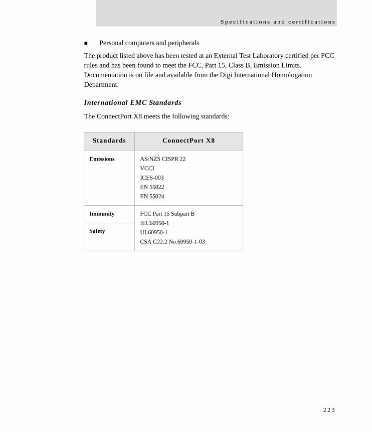
S p e c i f i c a t i o n s a n d c e r t i f i c a t i o n s
Personal computers and peripherals
The product listed above has been tested at an External Test Laboratory certified per FCC rules and has been found to meet the FCC, Part 15, Class B, Emission Limits. Documentation is on file and available from the Digi International Homologation Department.
International EMC Standards
The ConnectPort X8 meets the following standards:
Standards ConnectPort X8
Emissions AS/NZS CISPR 22VCCIICES-003EN 55022EN 55024
FCC Part 15 Subpart BIEC60950-1UL60950-1CSA C22.2 No.60950-1-03
Immunity
Safety
2 2 3

I m p o r t a n t S a f e t y I n f o r m a t i o n
Important Safety Information
To avoid contact with electrical current:
Never install electrical wiring during an electrical storm.
Never install an Ethernet connection in wet locations unless that connector is specifically designed for wet locations.
Use caution when installing or modifying Ethernet lines.
Use a screwdriver and other tools with insulated handles.
Wear safety glasses or goggles.
Do not place Ethernet wiring or connections in any conduit, outlet or junction box containing electrical wiring.
Installation of inside wire may bring you close to electrical wire, conduit, terminals and other electrical facilities. Extreme caution must be used to avoid electrical shock from such facilities. Avoid contact with all such facilities.
Ethernet wiring must be at least 6 feet from bare power wiring or lightning rods and associated wires, and at least 6 inches from other wire (antenna wires, doorbell wires, wires from transformers to neon signs), steam or hot water pipes, and heating ducts.
Do not place an Ethernet connection where it would allow a person to use an Ethernet device while in a bathtub, shower, swimming pool, or similar hazardous location.
Protectors and grounding wire placed by the service provider must not be connected to, removed, or modified by the customer.
Do not touch uninsulated Ethernet wiring if lightning is likely!
External Wiring: Any external communications wiring installed needs to be constructed to all relevant electrical codes. In the United States this is the National Electrical Code Article 800. Contact a licensed electrician for details.
2 2 4
• • • • • • • • • • • • • • • • • • • • • • • • • • • • • • • • • • • • • • • • • • • • • • • • • • • • • • • •
Glossary802.11
The IEEE standard for wireless Local Area Networks. It uses three different physical layers, 802.11a, 802.11b and 802.11g.
access control listSee IP filtering.
ADDPSee Advanced Device Discovery Protocol.
Address Resolution Protocol (ARP)A protocol for mapping an Internet Protocol address (IP address) to a physical machine address that is recognized in the local network.
Advanced Digi Discovery Protocol (ADDP)A protocol that runs on any operating system capable of sending multicast IP packets on a network. ADDP allows the system to identify all ADDP-enabled Digi devices attached to a network by sending out a multicast packet. The Digi devices respond to the multicast packet and identify themselves to the client sending the multicast.
alarmsIn Digi Connect devices, alarms are used to send emails or issue SNMP traps when certain device events occur. These events include certain data patterns being detected in the data stream, and cellular alarms for signal strength and amount of cellular traffic for a given period of time.
ARPSee Address Resolution Protocol.
autoconnectionA network connection initiated from a Digi device that is based on timing, serial activity, or serial modem signals.
Auto-IPA standard protocol that automatically assigns an IP address from a reserved pool of standard Auto-IP addresses to the computer on which it is installed. The device is set to obtain its IP address automatically from a Dynamic Host Configuration Protocol
2 2 5
(DHCP) server. But if the DHCP server is unavailable or nonexistent, Auto-IP will assign the device an IP. If DHCP is enabled or responds later or you use ADDP, both will override the Auto-IP address previously assigned. Also referred to as Auto-IP.
CDMA
CDMA (Code-Division Multiple Access) protocols are used in wireless communications. CDMA is a form of multiplexing, which allows numerous signals to occupy a single transmission channel, optimizing the use of available bandwidth. The technology is used in ultra-high-frequency (UHF) cellular telephone systems in the 800-MHz and 1.9-GHZ bands and through an analog-to digital conversion enhances privacy and makes cloning difficult.
CLICommand-line interface.
COM port redirectionThe process of establishing a connection between the host and networked serial devices by creating a local COM or TTY port on the host. See also RealPort.
configuration managementFor Digi devices, configuration management involves managing the files and settings that contain device configuration information. Configuration management tasks include copying device configuration files to and from a remote host, upgrading device firmware, and resetting the device configuration to factory defaults.
coordinator In Mesh/ZigBee networks, a coordinator is node that has the unique function of forming a network. The coordinator is responsible for establishing the operating channel and PAN ID for an entire network. Once established, the coordinator can form a network by allowing routers and end devices to join to it. Once the network is formed, the coordinator functions like a router (it can participate in routing packets and be a source or destination for data packets). Characteristics of coordinators include:
– One Coordinator per PAN – Establishes/Organizes PAN – Can route data packets to/from other nodes– Can be a data packet source and destination– Mains-powered
In the web interface, a coordinator is also referred to as a gateway device.
2 2 6
CTSClear to Send.
device serverA one- or two-port intelligent network device that converts serial data into network data.
DHCPSee Dynamic Host Configuration Protocol.
Digi Device Setup WizardA wizard for configuring Digi devices that is provided on the CD shipped with each device. The Digi Device Setup Wizard is available in Microsoft Windows or UNIX platforms. It assigns an IP address for the device, configures the device based on your description of the device environment, and determines whether you need to install RealPort. Using the Digi Device Setup Wizard is the recommended and preferred method for configuration.
DSRData Set Ready.
DTRData Terminal Ready.
Dynamic Host Configuration Protocol (DHCP)An Internet protocol for automating the configuration of computers that use TCP/IP. DHCP can be used to automatically assign IP addresses, to deliver TCP/IP stack configuration parameters such as the subnet mask and default router, and to provide other configuration information.
EIASee Electronics Industry Association.
Electronics Industry Association (EIA) and Electronics Industries Alliance (EIA)1) The Electronic Industries Association (EIA) comprises individual organizations that together have agreed on certain data transmission standards such as EIA/TIA-232 (formerly known as RS-232).
2) The Electronics Industries Alliance (EIA) is an alliance of trade organizations that lobby in the interest of companies engaged in the manufacture of electronics-related products.
2 2 7
Encapsulating Security Payload (ESP)A routing protocol used to route (tunnel) various types of information between networks. See also ESP Passthrough.
encryptionThe conversion of data into a form, called a ciphertext, that cannot be easily understood by unauthorized people. Decryption is the process of converting encrypted data back into its original form, so it can be understood. Encryption/decryption is especially important in wireless communications. This is because wireless circuits are easier to tap than their hard-wired counterparts.
end device In Mesh/ZigBee networks, end devices are network devices that have no routing capacity. They must always interact with their parent node (router or coordinator) to transmit or receive data. An end device can be a source or destination for data packets but cannot route packets. End devices can be battery-powered and offer low-power operation. Characteristics of end devices include:
– Several end devices can operate in one PAN – Can be a data packet source and destination – All messages are relayed through a coordinator or router – Low power end devices are not supported in this release.
Enhanced Data Rates for Global Evolution (EDGE)A faster version of the Global System for Mobile (GSM) wireless service, designed to deliver data at rates up to 384 Kbps and enable the delivery of multimedia and other broadband applications to mobile phone and computer users. The EDGE standard is built on the existing GSM standard, using the same time-division multiple access (TDMA) frame structure and existing cell arrangements.
ESP PassthroughA method of carrying IP packets for a Virtual Private Network (VPN) setup. In ESP Passthrough, inbound IPsec ESP protocol traffic is forwarded from to a VPN device connected to the Digi device’s Ethernet port.
Evolution-Data Optimized (EV-DO, EVDO, or 1xEV-DO)A wireless radio broadband data standard adopted by many CDMA mobile phone service providers. It is standardized by 3GPP2, as part of the CDMA2000 family of standards. Compared to 1xRTT (CDMA2000 1x) networks, or GPRS and EDGE networks, 1xEV-DO is significantly faster.
2 2 8
factory defaultsThe default configuration values that are set in a device at the factory.
File Transfer Protocol (FTP)A standard Internet protocol that specifies the simplest way to exchange files between computers on the Internet.
FTPSee File Transfer Protocol.
General Packet Radio Service (GPRS)A packet-based wireless communication service based on Global System for Mobile (GSM) communication that transports data rates from 56 up to 114 Kbps and continuous connection to the Internet for mobile phone and computer users. Higher data rates allow users more flexibility in the media they transmit.
Generic Routing Encapsulation (GRE)A routing protocol used to route (tunnel) various types of information between networks. See also GRE Passthrough.
GRE PassthroughA method of carrying IP packets for a Virtual Private Network (VPN) setup. In GRE Passthrough, inbound IPsec GRE protocol traffic is forwarded from to a VPN device connected to the Digi device’s Ethernet port.
Global System for Mobile communication (GSM)
A digital mobile telephone system that digitizes and compresses data, then sends it down a channel with two other streams of user data, each in its own time slot. It operates at either the 900 MHz or 1800 MHz frequency band.
GSMSee Global System for Mobile communication.
High Speed Downlink Packet Access (HSDPA)High Speed Downlink Packet Access. a packet-based data service with data transmission up to 8-10 Mbit/s (and 20 Mbit/s for MIMO systems) over a 5MHz bandwidth in W-CDMA downlink. HSDPA implementations includes Adaptive Modulation and Coding (AMC), Multiple-Input Multiple-Output (MIMO), Hybrid Automatic Request (HARQ), fast scheduling, fast cell search, and advanced receiver design.
2 2 9

HTTPSee HyperText Transfer Protocol.
HTTPSSee HyperText Transfer Protocol over Secure Socket Layer.
HyperText Transfer Protocol (HTTP)An application protocol in the TCP/IP suite that defines the rules for transferring files (text, graphic images, sound, video, and other multimedia files) on the World Wide web (WWW).
HyperText Transfer Protocol over Secure Socket Layer (HTTPS)A secure message-oriented communications protocol designed for use in conjunction with HTTP. HTTPS encrypts and decrypts user page requests as well as the pages that are returned by the web server. HTTPS uses the Secure Socket Layer (SSL) as a sublayer.
ICMPSee Internet Control Message Protocol.
IGMPSee Internet Group Management Protocol.
Internet Control Message Protocol (ICMP)A message control and error-reporting protocol between a host server and a gateway to the Internet. ICMP uses Internet Protocol (IP) datagrams, but the messages are processed by the IP software and are not directly apparent to the application user.
2 3 0
Internet Group Management Protocol (IGMP)Internet Group Management Protocol (IGMP) provides a way for an Internet computer to report its multicast group membership to adjacent routers. Multicasting allows one computer on the Internet to send content to multiple other computers that have identified themselves as interested in receiving the originating computer's content. Multicasting can be used for such applications as updating the address books of mobile computer users in the field, sending out company newsletters to a distribution list, and “broadcasting” high-bandwidth programs of streaming media to an audience that has “tuned in” by setting up a multicast group membership.
IP filtering
A network configuration that can be enabled to establish rules allowing devices to permit or deny specific IP addresses, networks, or devices from connection access. Also known as access control list.
IPsec (Internet Protocol Security)A framework for a set of protocols for security at the network or packet processing layer of network communication. Earlier security approaches have inserted security at the application layer of the communications model. IPsec is said to be especially useful for implementing virtual private networks and for remote user access through dial-up connection to private networks. An advantage of IPsec is that security arrangements can be handled without requiring changes to individual user computers.
IPsec provides two choices of security service: Authentication Header (AH), which essentially allows authentication of the sender of data, and Encapsulating Security Payload (ESP), which supports both authentication of the sender and encryption of data as well. The specific information associated with each of these services is inserted into the packet in a header that follows the IP packet header. Separate key protocols can be selected, such as the ISAKMP/Oakley protocol.
2 3 1
Internet Security Association and Key Management Protocol (ISAKMP)A protocol that defines procedures and packet formats to establish, negotiate, modify and delete Security Associations (SAs). SAs contain all the information required for execution of various network security services, such as the IP layer services (such as header authentication and payload encapsulation), transport or application layer services, or self-protection of negotiation traffic. ISAKMP defines payloads for exchanging key generation and authentication data. These formats provide a consistent framework for transferring key and authentication data which is independent of the key generation technique, encryption algorithm and authentication mechanism.
ISAKMP is distinct from key exchange protocols in order to cleanly separate the details of security association management (and key management) from the details of key exchange. There may be many different key exchange protocols, each with different security properties. However, a common framework is required for agreeing to the format of SA attributes, and for negotiating, modifying, and deleting SAs. ISAKMP serves as this common framework.
joiningIn Mesh/ZigBee networks, joining is the process of a node becoming part of a ZigBee PAN. A node becomes part of a network by joining to a coordinator or a router (that has previously joined to the network). During the process of joining, the node that allowed joining (the parent) assigns a 16-bit address to the joining node (the child).
MAC addressA unique network identifier. All network devices are required to have their own unique MAC address. The MAC address is on a sticker on your Digi device server. The number is displayed as 12 hexadecimal digits, usually starting with 00:40:9D.
Management Information Base (MIB)A formal description of a set of network objects that can be managed using the Simple Network Management Protocol (SNMP).
MIBSee Management Information Base.
Mobile Device Provisioning Wizard A wizard for provisioning Digi Cellular Family products. Provisioning configures the Digi Cellular Family device with the required configuration used to access the mobile network.
2 3 2

modem emulationA serial port configuration where the port acts as a modem. The Digi device emulates modem responses to a serial device and seamlessly sends and receives data over an Ethernet network instead of a Public Switched Telephone Network (PSTN). The advantage for a user is the ability to retain legacy software applications without modification and use a less expensive Ethernet network in place of public telephone lines. Also known as pseudo-modem or pmodem.
NAT
NAT (Network Address Translation) is the translation of an Internet Protocol address (IP address) used within one network to a different IP address known within another network through a NAT table that does the global-to-local and local-to-global IP address mapping. This increases security since each outgoing or incoming request must go through a translation process that also authenticates the request or matches it to a previous request. NAT can be statically defined or it can be set up to dynamically translate from and to a pool of IP addresses. NAT also conserves on the number of global IP addresses needed and it uses a single IP address in its communication with the world.
Personal Area Network (PAN)In Mesh/ZigBee networks, a PAN is a data communication network that includes a Coordinator and one or more routers/end devices. Network formation is governed by Network Maximum Depth, Maximum Child Routers and Maximum Children End Devices.
port forwardingA serial port configuration that sends data directly to a specific port instead of the path determined by the router based on traffic.
POSTSee Power-On Self Test.
Power-On Self Test (POST)When power is turned on, POST (Power-On Self-Test) is the diagnostic testing sequence that a computer's basic input/output system (or “starting program”) runs to determine if the computer keyboard, random access memory, disk drives, and other hardware are working correctly.
If the necessary hardware is detected and found to be operating properly, the computer begins to boot. If the hardware is not detected or is found not to be operating properly,
2 3 3
the BIOS issues an error message which may be text on the display screen and/or a series of coded beeps, depending on the nature of the problem.
provisioningThe process of configuring a mobile (cellular) device with the required configuration used to access the mobile network.
RealPort
RealPort is patented Digi software for COM port redirection. RealPort makes it possible to establish a connection between the host and networked serial devices by creating a local COM or TTY port on the host. The COM/TTY port appears and behaves as a local port to the PC or server. This process of COM port redirection allows existing software applications like DNP3 and Modbus to work without modification. Unlike other COM port redirectors, RealPort offers full hardware and software flow control, as well as tunable latency and throughput. These features ensure optimum performance, since data transfer is adjusted according to specific application requirements.
remote login (rlogin)A remote login to a Digi device’s command-line interface (CLI). rlogin is a Unix command that allows an authorized user to login to other UNIX machines (hosts) on a network and to interact as if the user were physically at the host computer. Once logged in to the host, the user can do anything that the host has given permission for, such as read, edit, or delete files.
remote shell (rsh)A Berkeley Unix networking command to execute a given command on a remote host, passing it input and receiving its output. Rsh communicates with a daemon on the remote host.
rloginSee remote login.
routerIn Mesh/ZigBee networks, a router is a node that creates/maintains network information and uses this information to determine the best route for a data packet. A router must join a network before it can allow other routers and end devices to join to it. A router can participate in routing packets and is intended to be a mains-powered node. Characteristics of routers include:
– Several routers can operate in one PAN
2 3 4

– Routers can route data packets to/from other nodes– Can be a data packet source and destination – Are mains-powered
RSHSee remote shell.
RSSIRelative Signal Strength Indicator.
RTSReady to Send.
RXD
Receiving Data.
Secure Sockets Layer (SSL)A commonly-used protocol for managing the security of a message transmission on the Internet. SSL has recently been succeeded by Transport Layer Security (TLS), which is based on SSL.
serial bridgeA connection between two serial devices over a network that acts as if they were connected over a serial cable. Also known as serial tunneling.
serial tunnelingSee serial bridge.
Setup WizardSee Digi Device Setup Wizard.
Simple Mail Transfer Protocol (SMTP)A TCP/IP protocol used in sending and receiving e-mail. Since it is limited in its ability to queue messages at the receiving end, it is usually used with one of two other protocols, POP3 or IMAP, that let the user save messages in a server mailbox and download them periodically from the server. SMTP usually is implemented to operate over Internet port 25. An alternative to SMTP that is widely used in Europe is X.400. Many mail servers now support Extended Simple Mail Transfer Protocol (ESMTP), which allows multimedia files to be delivered as e-mail.
Simple Network Management Protocol (SNMP)A protocol for managing and monitoring network devices. The SNMP architecture
2 3 5
enables a network administrator to manage nodes--servers, workstations, routers, switches, hubs, etc.--on an IP network; manage network performance, find and solve network problems, and plan for network growth. Digi devices support SNMP Version 1.
SNMPSee Simple Network Management Protocol.
SMTPSee Simple Mail Transfer Protocol.
SSLSee Secure Sockets Layer.
static IP address assignmentThe process of assigning a specific IP address to a device. Contrast with assigning a device through Dynamic Host Configuration Protocol (DHCP), or Automatic Private IP Addressing (APIPA or Auto-IP).
TCPSee Transmission Control Protocol.
TelnetA user command and an underlying TCP/IP protocol for accessing remote computers. On the web, HTTP and FTP protocols allow you to request specific files from remote computers, but not to actually be logged on as a user of that computer. With Telnet, you log on as a regular user with whatever privileges you may have been granted to the specific application and data on that computer.
TFTPSee Trivial File Transfer Protocol (TFTP).
TLSSee Transport Layer Security.
2 3 6
Transmission Control Protocol (TCP)A set of rules used along with the Internet Protocol (IP) to send data in the form of message units between computers over the Internet. While IP handles the actual delivery of the data, TCP handles keeping track of the individual units of data (called packets) that a message is divided into for efficient routing through the Internet.
For example, when an HTML file is sent to you from a web server, the TCP program layer in that server divides the file into one or more packets, numbers the packets, and then forwards them individually to the IP program layer. Although each packet has the same destination IP address, it may get routed differently through the network. At the other end (the client program in your computer), TCP reassembles the individual packets and waits until they have arrived to forward them to you as a single file.
TCP is known as a connection-oriented protocol, which means that a connection is established and maintained until such time as the message or messages to be exchanged by the application programs at each end have been exchanged. TCP is responsible for ensuring that a message is divided into the packets that IP manages and for reassembling the packets back into the complete message at the other end. In the Open Systems Interconnection (OSI) communication model, TCP is in layer 4, the Transport Layer.
Transport Layer Security (TLS)A protocol that ensures privacy between communicating applications and their users on the Internet. When a server and client communicate, TLS ensures that no third party may eavesdrop or tamper with any message. TLS is the successor to the Secure Sockets Layer (SSL).
Trivial File Transfer Protocol (TFTP)An Internet software utility for transferring files that is simpler to use than the File Transfer Protocol (FTP) but less capable. It is used where user authentication and directory visibility are not required. TFTP uses the User Datagram Protocol (UDP) rather than the Transmission Control Protocol (TCP). TFTP is described formally in Request for Comments (RFC) 1350.
TTY port redirectionThe process of establishing a connection between the host and networked serial devices by creating a local TTY port on the host. The TTY port appears and behaves as a local port to the PC or server. See also RealPort.
2 3 7
TXDTransmit eXchange Data.
UDPSee User Datagram Protocol.
Universal Mobile Telecommunications Service (UMTS)A third-generation (3G) broadband, packet-based transmission of text, digitized voice, video, and multimedia at data rates up to 2 megabits per second (Mbps) that offers a consistent set of services to mobile computer and phone users no matter where they are located in the world. Based on the Global System for Mobile (GSM) communication standard, UMTS, endorsed by major standards bodies and manufacturers, is the planned standard for mobile users around the world and is at present still being made available. Once UMTS is fully available geographically, computer and phone users can be constantly attached to the Internet as they travel and, as they roam, have the same set of capabilities no matter where they travel to. Users will have access through a combination of terrestrial wireless and satellite transmissions. Until UMTS is fully implemented, users can have multi-mode devices that switch to the currently available technology (such as GSM 900 and 1800) where UMTS is not yet available.
Today's cellular telephone systems are mainly circuit-switched, with connections always dependent on circuit availability. A packet-switched connection, using the Internet Protocol (IP), means that a virtual connection is always available to any other end point in the network. It will also make it possible to provide new services, such as alternative billing methods (pay-per-bit, pay-per-session, flat rate, asymmetric bandwidth, and others). The higher bandwidth of UMTS also promises new services, such as video conferencing. UMTS promises to realize the Virtual Home Environment (VHE) in which a roaming user can have the same services to which the user is accustomed when at home or in the office, through a combination of transparent terrestrial and satellite connections.
The electromagnetic radiation spectrum for UMTS has been identified as frequency bands 1885-2025 MHz for future IMT-2000 systems, and 1980-2010 MHz and 2170-2200 MHz for the satellite portion of UMTS systems.
User Datagram Protocol (UDP)A communications protocol that offers a limited amount of service when messages are exchanged between computers in a network that uses the Internet Protocol (IP). UDP is an alternative to the Transmission Control Protocol (TCP) and, together with IP, is
2 3 8
sometimes referred to as UDP/IP. Like the Transmission Control Protocol, UDP uses the Internet Protocol to actually get a data unit (called a datagram) from one computer to another. Unlike TCP, however, UDP does not provide the service of dividing a message into packets (datagrams) and reassembling it at the other end. Specifically, UDP does not provide sequencing of the packets in which the data arrives, nor does it guarantee delivery of data. This means that the application program that uses UDP must be able to make sure that the entire message has arrived and is in the right order. Network applications that want to save processing time because they have very small data units to exchange (and therefore very little message reassembling to do) may prefer UDP to TCP. The Trivial File Transfer Protocol (TFTP) uses UDP instead of TCP.
UDP provides two services not provided by the IP layer. It provides port numbers to help distinguish different user requests and, optionally, a checksum capability to verify that the data arrived intact.
In the Open Systems Interconnection (OSI) communication model, UDP, like TCP, is in layer 4, the Transport Layer.
web interfaceThe web-based interface for configuring, monitoring, and administering Digi devices.
ZigBeeA specification for wireless personal area networks (WPANs) operating at 868 MHz, 902-928 MHz, and 2.4 GHz. A WPAN is a personal area network (a network for interconnecting an individual's devices) in which the device connections are wireless. Using ZigBee, devices in a WPAN can communicate at speeds of up to 250 Kbps while physically separated by distances of up to 50 meters in typical circumstances and greater distances in an ideal environment. ZigBee is based on the 802.15 specification approved by the Institute of Electrical and Electronics Engineers Standards Association (IEEE-SA).
ZigBee provides for high data throughput in applications where the duty cycle is low. This makes ZigBee ideal for home, business, and industrial automation where control devices and sensors are commonly used. Such devices operate at low power levels, and this, in conjunction with their low duty cycle (typically 0.1 percent or less), translates into long battery life. Applications well suited to ZigBee include heating, ventilation, and air conditioning (HVAC), lighting systems, intrusion detection, fire sensing, and the detection and notification of unusual occurrences. ZigBee is compatible with most topologies including peer-to-peer, star network, and mesh networks, and can handle up
2 3 9

to 255 devices in a single WPAN.
2 4 0

I n d e x
• • • • • • • • • • • • • • • • • • • • • • • • • • • •
Index1100% CPU utilization 177
AAccess Control Lists (ACL) 163access permissions for commands 161Active Opens 182ADDP
See Advanced Digi Discovery Protocoladdress requirements for VPN 101administration
from command line 218from web interface 210
administrative user 161Advanced Digi Discovery Protocol (ADDP)
caution on disabling 82changing password for 162default port number 84description 84enabling and disabling access to 84feature description 34
alarmsbased on cellular data 151based on serial data pattern matching 151based on signal strength 151configuring 149, 167number supported per device 150set alarm command 200
Antireplay 106ARP
See Address Resolution ProtocolAttempt Fails 182authentication
configuration settings for 160failure traps 33, 154for VPN Internet Key Exchange (IKE)
negotiations 107for VPN manual-keyed tunnels 114
Auto Private IP Addressing (APIPA) 65autoconnection
configuring 144, 167enabling through TCP Sockets port
profile 139Auto-IP 32, 39, 65, 76, 118automatic provisioning 122
Bbackup command 218backup/restore configurations
from command line 218from web interface 213
Bad Datagrams Received 183Bad Messages Received 183Bad Segments Received 182baud rate 142boot command 218boot version
displaying current 177updating 214
Breaks 180
Ccamera settings 147CDMA
See Code-Division Multiple AccessCell ID 184cellular products
configuring 119information for mobile module 186mobile connection settings 125mobile service provider settings 120provisioning 121See also mobile settingssetting alarms for amount of cellular
traffic 41, 149setting alarms for signal strength 41, 149status and statistics 129, 184
2 4 1

I n d e x
cellular traffic 41, 149certifications 221client-initiated connections 155close command 201Code-Division Multiple Access (CDMA)
carrier requirements for VPN 101description 36mobile service providers 119
cold start traps 33, 154COM port redirection 138, 142command-line interface
accessing 166administering devices from 218as a device configuration interface 55, 166configuring devices from 166monitoring devices from 198overview 55verifying which commands are
supported 166configuration interfaces 48configuring Digi devices 63connect command 201connection management
from command line 201from web interface 189
ConnectPort Displayhardware installation 63
ConnectPort specifications 220ConnectPort WAN VPN
configuring VPN settings 99ConnectPort X8
camera settings 147Connectware Manager
alarm forwarding to 41, 149client- and server-initiated connections 155configuring connections to 154configuring devices from 48, 56connection method 159HTTP over Proxy settings 159idle timeout 158IP addresses 66
keep-alive settings 158Last Known Address (LKA) 156monitoring devices from 61, 206
Console Management port profile 138contact information for a device 153CPU utilization 177CTS 179Custom port profile 146customization
of serial-port settings (Custom port profile) 142
of user interfaces 43overview 43
Ddata bits 142Data Received 185Data Sent 185Datagrams Forwarded 182Datagrams Received 182, 183Datagrams Sent 183DCD 145, 179DDNS (Dynamic DNS) service 87default settings for Digi devices
See factory defaultsdefault static IP address for Ethernet port 64Default Time-To-Live 182default username and password for Digi
devices 69deleting files from file system 211destination IP address for SNMP traps 154Destination Unreachable Messages
Received 183device description 153device information
from command line (info device command) 199
in SNMP 208in web interface 153
device location 153device name 153
2 4 2

I n d e x
DHCPSee Dynamic Host Configuration Protocol
dhcp command 201Diffie-Hellman
groups 106protocol description 106
Digi Connect WAN VPNconfiguring VPN settings 99
Digi Device Setup Wizardconfiguring IP address with 64overview 49
Digi SureLinkSee SureLink
display command 198display mobile command 167display provisioning command 168displaying system information
from command line 218from web interface 217
DNSDNS Lookup Test 126, 128, 187Dynamic DNS Update Settings 87
DSR 143, 145, 179DTR 179Dynamic DNS (DDNS) Update Settings 87Dynamic Host Configuration Protocol (DHCP)
Address Pool 77as an IP address assignment alternative 39changing an IP address with 64, 65description 32Exclusion Range 77Grace Period 78Lease 78lease management 191Lease Status values 192managing DHCP server 190Options for DHCP client configuration 78overview 32Reservation 78scope 77server configuration settings 79
terminology 77
Eemail messages for alarms 149, 151, 152Encapsulating Security Payload (ESP)
definition 35passthrough 35use in port forwarding 92
Encrypted RealPort 40, 84encryption
for Cellular Family products 42for Internet Key Exchange (IKE)
negotiations 107for VPN tunnels 113key generation and 100% CPU
utilization 177Enhanced Data Rates for GSM Evolution
(EDGE) 37environmental specifications 220ESP
See Encapsulating Security PayloadEstablished Resets 183Ethernet
configuring parameters (set ethernet) 167default IP address for Ethernet port 21, 48duplex mode 118for Digi Connect WAN VPN 100speed 118
Evolution-Data Optimized (EV-DO, EVDO, or 1xEV-DO) 38
Ffactory defaults
custom files not deleted by device reset 211for mobile (cellular) configuration
settings 120restoring from command line 218restoring from web interface 215
file management 211firmware
updates from command line 218viewing current version number 177
2 4 3

I n d e x
firmware versionupdating 214, 218
flow control 142, 179Forwarding statistic 182Framing Errors 180Fully Qualified Domain Name (FQDN) 105
GGeneral Packet Radio Service (GPRS) 37General system information page 177Generic Routing Encapsulation (GRE)
as a supported protocol for forwarding 92definition 35passthrough 35
Global System for Mobile communication (GSM)
comparison with Code-Division Multiple Access (CDMA) 119
GPRS/EDGE APN type needed for VPN 101
mobile service providers 119overview 36
GPRSSee General Packet Radio Service
GRESee Generic Routing Encapsulation
GSMSee Global System for Mobile
communication
HHardware Reset Thresholds 125host name 167HTTP over proxy settings 159HyperText Transfer Protocol (HTTP) 34, 86HyperText Transfer Protocol over Secure
Socket Layer (HTTPS) 34, 86
IIdle Resets 185idle timeout
for mobile connections 185
for web interface 69IFC 179IMSI 186Industrial Automation (IA)
configuring from command line 167info command 218Internet Control Message Protocol (ICMP) 30,
34Internet Group Management Protocol
(IGMP) 30Internet Key Exchange (IKE) 35, 107Internet Protocol (IP)
IP protocols supported in Digi devices 30statistics 182
IOTA (IP-Based Over the Air) 122IP address assignment
default static IP address for Ethernet port 64from command line 66from Digi Device Setup Wizard 64testing the configuration 67using Auto-IP 65, 76using Dynamic Host Configuration Protocol
(DHCP) 65, 76, 77using static settings 76
IP filteringas a security measure 90, 163configuring 90
IP forwardingfrom command line (set forward) 167from web interface 91See also port forwarding and NAT
IP Pass-through 94IP Security (IPSec) 99ISAKMP VPN tunnels 109, 115
Kkill command 201
LLAC 184Last Known Address (LKA) 156
2 4 4

I n d e x
Lease Status values 192Line Printer Daemon (LPD) 33, 44, 84Link Integrity Monitoring 125link up traps 33, 154Local Configuration port profile 141Location Area Code 184location information for a device 153login
to a remote system 201login traps 33, 154
MMAC Address 177Management menu 189managing connections and services 189manual provisioning 122manual-keyed VPN tunnel 109, 112Messages Received 183mobile device provisioning 121mobile service providers
CDMA-based 119GSM-based 119information required for provisioning and
configuration 119mobile settings
connection management settings 125factory defaults for 120in Digi Device Setup Wizard 68in web interface 119provisioning state 120Service Plan 120Service Provider 120username and password 120
mobile status and statistics 167, 184mode command 201Model name for Digi device 177modem emulation
configuring 167description 44Modem Emulation Pool (pmodem) network
service 84
network service for (pmodem) 84port profile for 141
Modem Emulation Passthrough 84modem information
International Mobile Subscriber Identifier (IMSI) 186
Mobile Directory Number (MDN) 186Mobile Identification Number (MIN) 186modem manufacturer 186modem model 186modem revision 186modem serial number 186phone number for modem module 186
NNAT
See Network Address TranslationNetwork Address Translation (NAT) 34, 91,
100, 155, 168network options 167network services
ADDP 84available when IP-passthrough enabled
(pinholes) 86, 96description 44enabling and disabling access to 82, 167,
217, 218Encrypted (Secure) RealPort 84HyperText Transfer Protocol (HTTP) 86HyperText Transfer Protocol over Secure
Socket Layer (HTTPS) 86Line Printer Daemon (LPD) 84managing 190Modem Emulation Passthrough 84Modem Emulation Pool (pmodem) 84port numbers for 83RealPort 84Remote login (Rlogin) 84Remote shell (Rsh) 84Secure Shell (SSH) 85Secure Shell (SSH) Passthrough 85
2 4 5

I n d e x
Secure Socket Service 85Secure Web Server (HTTPS) 86Simple Network Management Protocol
(SNMP) 85Telnet 85Telnet Passthrough 85Transmission Control Protocol (TCP)
Echo 85Transmission Control Protocol (TCP)
Passthrough 85User Datagram Protocol (UDP) 85User Datagram Protocol (UDP)
Passthrough 85Web Server (HTTP) 86
Network SettingsIP Filtering Settings 90Virtual Private Network (VPN) Settings 99
network settingsAdvanced Network Settings 118DHCP Server Settings 77Dynamic DNS Update Settings 87IP Forwarding Settings 91IP Pass-through Settings 94IP Settings 76Network Services Settings 82Socket Tunnel Settings 93
newpass commandchanging password for administrative
user 162disabling password authentication 162enabling login prompt 161
No Ports statistic 183No Routes statistic 182
OOFC 179Overflow Errors 180Overrun Errors 180
Pparity 142Parity Errors 180
Passive Opens 182passwords
changing password for administrative user 162
configuring 160default for Digi devices 69enabling and disabling password
authentication 161for accessing mobile network 120for Dynamic DNS (DDNS) service 87, 88for HTTP over Proxy connections 159for SNMP gets and sets 153issuing new passwords to users (newpass
command) 162, 168password authentication 161resetting administrator password by
restoring factory defaults 215Perfect Forward Secrecy (PFS) 106ping command 67, 201Ping Test 126, 187pinholes 96pmodem 44Point-to-Point Protocol (PPP)
description 34set pppoutbound command 168
port bufferingconfiguring from command line (set buffer
command) 168, 200configuring from web interface 143description 143displaying contents of port buffer (display
buffers command) 200port forwarding 91port logging
Enable Port Logging setting 143See also port buffering
port profilesConsole Management 138Custom 142, 146Local Configuration 141Modem Emulation 141
2 4 6

I n d e x
RealPort 138selecting and configuring 137Serial Bridge 141set profiles command 168TCP Sockets 139, 144UDP Sockets 140, 146
POST versiondisplaying current 177updating 214
power requirementsDigi Connect WAN products 220
PPPSee Point to Point Protocol
pre-shared key (PSK) 116Primary DNS Address 185Primary DNS Name 128private community password for SNMP 153proposal 117protocols
Address Resolution Protocol (ARP) 30Advanced Digi Discovery Protocol
(ADDP) 34, 84cellular protocols supported 35Dynamic Host Configuration Protocol
(DHCP) 32Encapsulating Security Payload (ESP) 35,
92ESP Passthrough 30Generic Routing Encapsulation (GRE) 35,
92HyperText Transfer Protocol (HTTP) 34, 86HyperText Transfer Protocol over Secure
Socket Layer (HTTPS) 30, 86Internet Control Message Protocol
(ICMP) 34Internet Group Management Protocol
(IGMP) 30IP protocols supported 30Line Printer Daemon (LPD) 33, 84Network Address Translation (NAT) 34Point to Point Protocol (PPP) 30Remote login (Rlogin) 33, 84
Secure Shell (SSH) 30Secure Sockets Layer (SSL) 33Simple Mail Transfer Protocol (SMTP) 30Simple Network Management Protocol
(SNMP) 32, 85Telnet 33, 85Telnet Com Port Control Option 33Transmission Control Protocol (TCP) 31Transport Layer Security (TLS) 33User Datagram Protocol (UDP) 31
provisioningautomatic 122, 123from command line 168from web interface 121information required from mobile service
provider 119manual 122, 123Mobile Device Provisioning Wizard 121provision command 168re-provisioning 124
Pseudo-modem 44public community password for SNMP 153
Qquit command 201
Rraw TCP connection 46raw TLS encrypted connection 46RCI over Serial 143RealPort
and serial settings 142configuration options 168network service 84port profile for 138software 40
rebooting Digi devicesfrom command line 218from web interface 217
reconnect command 201registration status 184
2 4 7

I n d e x
regulatory information 221Remote Login (Rlogin) 33, 84remote management
and IP Pass-through 97configuration settings 154See also Connectware Manager
Remote shell (Rsh) 45, 84reset device to factory defaults
from command line 218from web interface 218
restore device configuration to factory defaults 215
Reverse raw socket 44Reverse Telnet 33, 44Reverse TLS socket 44revert command 218RFC 1701 35RFC 1702 35RFC 2217 30, 33, 139, 142RFC 2406 35Rlogin 45, 46, 84rlogin command 201root user 161
changing password for 162description and permissions 161
Routing Discards 182RSSI 151, 184RTS 143, 179RTS Toggle 143, 168
SSA Lifetime 107safety information 224Safety Standards 221Secondary DNS Address 185Secondary DNS Name 128Secure Shell (SSH) Passthrough 85Secure Socket Service 85Secure Sockets Layer (SSL) 33Secure Web Server (HTTPS) 86security
Access Control Lists 163changing password for root user 162configuring features 160disabling unused and non-secure network
services 163enabling password authentication 161features overview 42IP filtering 163password for ADDP 162security policies 107, 116SSH public key 163user models and permissions 161
Security Parameter Index (SPI) 113security policies 116Segments Received 182Segments Retransmitted 182Segments Sent 182send command 168, 201Serial Bridge port profile 141serial data communication over TCP 31, 168serial data communication over UDP 31, 168serial interface
configuration profiles for 137configuring 137, 168
serial port diagnostics 178serial port information 178serial port settings
advanced 143basic 142baud rate 142configuring 137, 168data bits 142description for port 142flow control 142parity 142port logging (port buffering) 143port profiles 137RCI over Serial (DSR) 143RTS toggle 143Serial Port Diagnostics page 178Serial system information page 178
2 4 8

I n d e x
stop bits 142TCP settings 144UDP settings 146
serial portsmanaging connections 189
serial statistics 180server-initiated connections 155session bypasses 187session consecutive failures 187session control
from command line 201from web interface 189
session failures 187session information (status command) 201session successes 187set accesscontrol command 167set alarm command 167set autoconnect command 167set buffer command 168set commands for SNMP 153set ethernet command 167set forward command 167set host command 167set ia command 167set mgmtconnection command 167set mgmtglobal command 167set mgmtnetwork command 167set nat command 168set network command 66, 167set pmodem command 167set profiles command 168set realport command 168set rtstoggle command 168set serial command 168set service command 167, 218set snmp command 168set system command 168set tcpserial command 168set udpserial command 168set user command 168show command 200
signal strengthfor Digi Cellular Family products 41, 149,
151, 184setting alarms for 149
Simple Mail Transfer Protocol (SMTP) 30, 149
Simple Network Management Protocol (SN-MP)
configuring 153, 168destination IP address for traps 154enabling and disabling 153enabling and disabling traps 153network service for 85overview 32private community name 153public community name 153sending alarms as SNMP traps 32, 150set commands 153set snmp command 200supported RFCs and MIBs 32supported traps 33
Socket ID 144, 146Socket Tunnel settings 93SSH public key 163SSL
See Secure Sockets Layerstatistics
capabilities available in SNMP 208displaying from command line 199Ethernet 199for mobile (cellular) products 129, 184, 185ICMP 183, 199IP 182network 181network statistics in SNMP 208port statistics in SNMP 208serial 199serial port 180TCP 182, 199UDP 199
status information 60, 129, 175, 201
2 4 9

I n d e x
status LED 216stop bits 142SureLink
configuration settings 125configuring 125description 119statistics 187use 35
system connections 189system information 217, 218System Information page 176system settings 153
TTCP
See Transmission Control ProtocolTelnet
Autoconnect 33client 33command 166, 201connection 46network service 85network service for 85server 33Telnet Com Port Control Option (RFC
2217) 139, 142Telnet Passthrough network service 85
Telnet Com Port Control Option 30TLS 33
See Transport Layer Securitytotal bypasses 188Total Data In 180Total Data Out 180total failures 188total link down requests 188total successes 187total used/free memory 178Transmission Control Protocol (TCP)
configuration settings 144network service for 85overview 31
statistics 182TCP Connection Test 126, 127, 187TCP Echo network service 85TCP keep-alives 118TCP Sockets port profile 139, 144tcpserial communication 31, 144
Transport Layer Security (TLS) 33traps (SNMP) supported in Digi devices 33tunnel 108tunnels
serial tunneling 141socket tunnel 93VPN tunnel 99
UUDP
See User Datagram ProtocolUniversal Mobile Telecommunications Service
(UMTS) 37up time 178uploading files 211User Datagram Protocol (UDP)
configuration settings 146overview 31statistics 183UDP network service 85UDP Passthrough network service 85UDP Sockets port profile 140, 146udpserial communication 31, 146
User FQDN 105users and permissions
default username 69overview 161root user 161set user command 168
VVirtual Private Network (VPN)
CDMA carrier requirements 101configuring 99, 102described 99
2 5 0

I n d e x
IP address requirements 101ISAKMP tunnels 115manual-keyed tunnels 109, 112purpose 99settings 102testing the connection 111tunnel 108Tunnel Proposal Configuration 117
vpn command 201
Wweb interface
accessing 69alarm settings 149application settings 164applying and saving changes 73as a device configuration interface 68canceling changes 73configuration pages 72for configuring devices 68Home page 71, 72idle timeout for 69management menu 189mobile (cellular) settings 119network configuration 75network settings 75online help 73overview 53remote management (Connectware
Manager) settings 154security settings 160serial port settings 137system settings 153user settings 160
who command 201
2 5 1

I n d e x
2 5 2