Embed Size (px)
Citation preview
Considerations for
Rope Rescue in 2009
Kenneth N. Laidlaw
CONSIDERATIONS FOR ROPE RESCUE in 2009
December 2009
by
Kenneth N. Laidlaw
Red Cross Emergency Responder Mountain Rescue Association Operations Leader Qualified
National Cave Rescue Commission Instructor SPRAT Rope Access Technician Qualified
National Association of Search and Rescue SAR Technician Evaluator California Rescue Dog Association Mission Ready Support Member
Mine Safety and Health Administration Qualified Hazardous Materials Operations Certified
Confined Space Operations Certified Type II Wildland Firefighter Qualified
East Bay Regional Park Police Officer retired Signcutter Qualified by Joel Hardin
Amateur Radio Operator – General - N6GFE Alameda County Sheriff’s Department Rescue Member
HSUS Emergency Responder USFW Refuge Volunteer
PO Box 891
Orinda, CA 94563 (510) 843-5253
E-mail: [email protected]
Photographs and Illustrations by John Carnes (NOTE: some need updating, a work in progress)

Table of Contents
Abstract 1 Ropes 2 Webbing 2 Anchoring With Rope 3 Alternative Rope Anchor Idea 3 Anchoring With Webbing 4 Anchor Focal Point 4 Lowering A Load With A Brake Bar Rack 5 Belaying A Load 8 Other Rescue Belay Devices 11 Load Release Hitch 12 Raising A Load 14 Attaching To The Main Line 16 Cross-Lashed Strap 17 Capture The Distance The Load Is Hauled 17 The Commands 18 Connections Using A Soft Interface 18 Use Of A Jigger 18 Litter 21 Rigging Litter 21 Appoint A Safety Officer 24 Personal Skills And Equipment 24 Harness Considerations 26 Some Thoughts In Review 30 Acknowledgements 31 Publications 31 Training 31 Vendors 32 About the Author 32 The Basics – Hardware And Software Needed 33 TAC Rope Kit 34 TAC Rope Kit - lowering 35 TAC Rope Kit - raising 36

2/17/2010 1 Kenneth N. Laidlaw
Abstract Rope rescue presents special challenges, especially in remote areas. With new equipment constantly appearing on the market and techniques continuously being refined, the craft is a very dynamic experience. This presentation will expose new students to safe, basic fundamentals. Advanced students will increase their knowledge of proper techniques. All experiences are based on current testing and review the techniques of application used by different groups, from cave explorers to mountain rescue personnel. OSHA considerations will be addressed. Both hard and soft techniques for attaching to the rope are discussed. At the end of the presentation, a reader should be able to make safe decisions based on their own needs and budget restraints. They will also know the best references for additional information. WARNING: Rope rescue is a very dynamic experience and what may be considered safe today, may be determined inappropriate tomorrow. Check the date in the lower corner of your edition, if you have an earlier version of this paper, destroy it. The most recent version of this paper may available on the Internet. NOTES: An effort has been made to use the historically correct terms and systems international measurements for components to accommodate both North American and European interests. The equipment specifications in this paper describe cordage sizes and hardware that is commonly used in mountain and cave rescue situations. Where larger cordage or stronger hardware is required to meet the Fire Service’s NFPA equipment standards, the specifications for the NFPA compliant equipment is shown in italics.
3/8/08 2 Kenneth N. Laidlaw
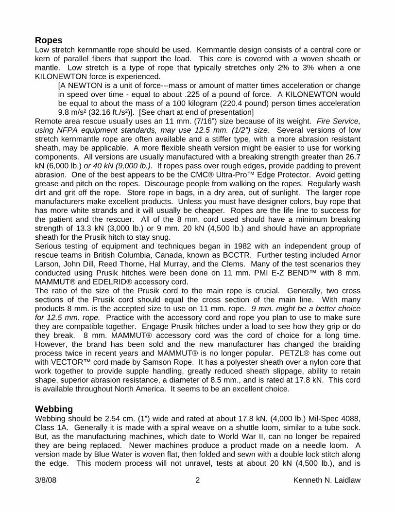
Ropes Low stretch kernmantle rope should be used. Kernmantle design consists of a central core or kern of parallel fibers that support the load. This core is covered with a woven sheath or mantle. Low stretch is a type of rope that typically stretches only 2% to 3% when a one KILONEWTON force is experienced. [A NEWTON is a unit of force---mass or amount of matter times acceleration or change in speed over time - equal to about .225 of a pound of force. A KILONEWTON would be equal to about the mass of a 100 kilogram (220.4 pound) person times acceleration 9.8 m/s² (32.16 ft./s²)]. [See chart at end of presentation] Remote area rescue usually uses an 11 mm. (7/16”) size because of its weight. Fire Service, using NFPA equipment standards, may use 12.5 mm. (1/2”) size. Several versions of low stretch kernmantle rope are often available and a stiffer type, with a more abrasion resistant sheath, may be applicable. A more flexible sheath version might be easier to use for working components. All versions are usually manufactured with a breaking strength greater than 26.7 kN (6,000 lb.) or 40 kN (9,000 lb.). If ropes pass over rough edges, provide padding to prevent abrasion. One of the best appears to be the CMC® Ultra-Pro™ Edge Protector. Avoid getting grease and pitch on the ropes. Discourage people from walking on the ropes. Regularly wash dirt and grit off the rope. Store rope in bags, in a dry area, out of sunlight. The larger rope manufacturers make excellent products. Unless you must have designer colors, buy rope that has more white strands and it will usually be cheaper. Ropes are the life line to success for the patient and the rescuer. All of the 8 mm. cord used should have a minimum breaking strength of 13.3 kN (3,000 lb.) or 9 mm. 20 kN (4,500 lb.) and should have an appropriate sheath for the Prusik hitch to stay snug. Serious testing of equipment and techniques began in 1982 with an independent group of rescue teams in British Columbia, Canada, known as BCCTR. Further testing included Arnor Larson, John Dill, Reed Thorne, Hal Murray, and the Clems. Many of the test scenarios they conducted using Prusik hitches were been done on 11 mm. PMI E-Z BEND™ with 8 mm. MAMMUT® and EDELRID® accessory cord. The ratio of the size of the Prusik cord to the main rope is crucial. Generally, two cross sections of the Prusik cord should equal the cross section of the main line. With many products 8 mm. is the accepted size to use on 11 mm. rope. 9 mm. might be a better choice for 12.5 mm. rope. Practice with the accessory cord and rope you plan to use to make sure they are compatible together. Engage Prusik hitches under a load to see how they grip or do they break. 8 mm. MAMMUT® accessory cord was the cord of choice for a long time. However, the brand has been sold and the new manufacturer has changed the braiding process twice in recent years and MAMMUT® is no longer popular. PETZL® has come out with VECTOR™ cord made by Samson Rope. It has a polyester sheath over a nylon core that work together to provide supple handling, greatly reduced sheath slippage, ability to retain shape, superior abrasion resistance, a diameter of 8.5 mm., and is rated at 17.8 kN. This cord is available throughout North America. It seems to be an excellent choice. Webbing Webbing should be 2.54 cm. (1”) wide and rated at about 17.8 kN. (4,000 lb.) Mil-Spec 4088, Class 1A. Generally it is made with a spiral weave on a shuttle loom, similar to a tube sock. But, as the manufacturing machines, which date to World War II, can no longer be repaired they are being replaced. Newer machines produce a product made on a needle loom. A version made by Blue Water is woven flat, then folded and sewn with a double lock stitch along the edge. This modern process will not unravel, tests at about 20 kN (4,500 lb.), and is
3/8/08 3 Kenneth N. Laidlaw
cheaper to make. Before buying webbing always check the package label for the webbing’s rated strength. Some brands of stitched, folded webbing, with a chain stitch, are made just for general use and should not be used in rope rescue. Webbing should have the ends cut on a bias, a 45 degree angle, to make knot tying easier. Each end of webbing should have the length marked with a Sharpie™. On one side mark the length in feet and on the other the length in meters. Anchoring With Rope Using a piece of rope, take two wraps around an upright. This is defined as a round turn. The objective is to have the rope around the upright absorb the energy of the load with friction so that the running end of the rope will have no tension on it. It is interesting to note that on a smaller diameter upright the rope will exert greater pressure on the upright’s surface. If the surface is very smooth three wraps may be needed. There should be no rope crosses in the turns that might result in the rope rubbing on itself. Secure the running end by placing a clove hitch around the standing part of the rope and finish off using a double overhand back-up knot. Keep the tangent short but do not deflect the standing part. Some groups insist on calling this a high strength tie off. The standing part can be used for a single application or in the standing end place a figure-of-eight on a bight or a bowline. The figure-of-eight knot has an extra loop and does not require any back-up. A bowline should have an overhand knot as a back-up or the Yosemite version of the bowline can be used where the running end passes around and back through the knot and ends up parallel with the standing part. Both of these knots will, however, degrade the strength of the rope by 20 to 30 percent. These knots can be attached to working components or they may be clipped to a rigging plate at a designated anchor focal point, discussed later. With 11 mm. PMI E-Z BEND™ the backed up bowline uses .7 m. of rope. 12.5 mm. uses .8 m. The figure-of-eight knot will require a minimum bight of .45 m. (18”) and uses a total of .9 m. of rope. 12.5 mm. uses 1 m. Good procedure provides bights only as large as are needed by a device. Knots should be dressed and tails should be about two inches long. Tying an overhand backup knot for a figure-eight on a bight is unnecessary and is defined worldwide as the ‘stupid American knot’. Alternative Rope Anchor Idea
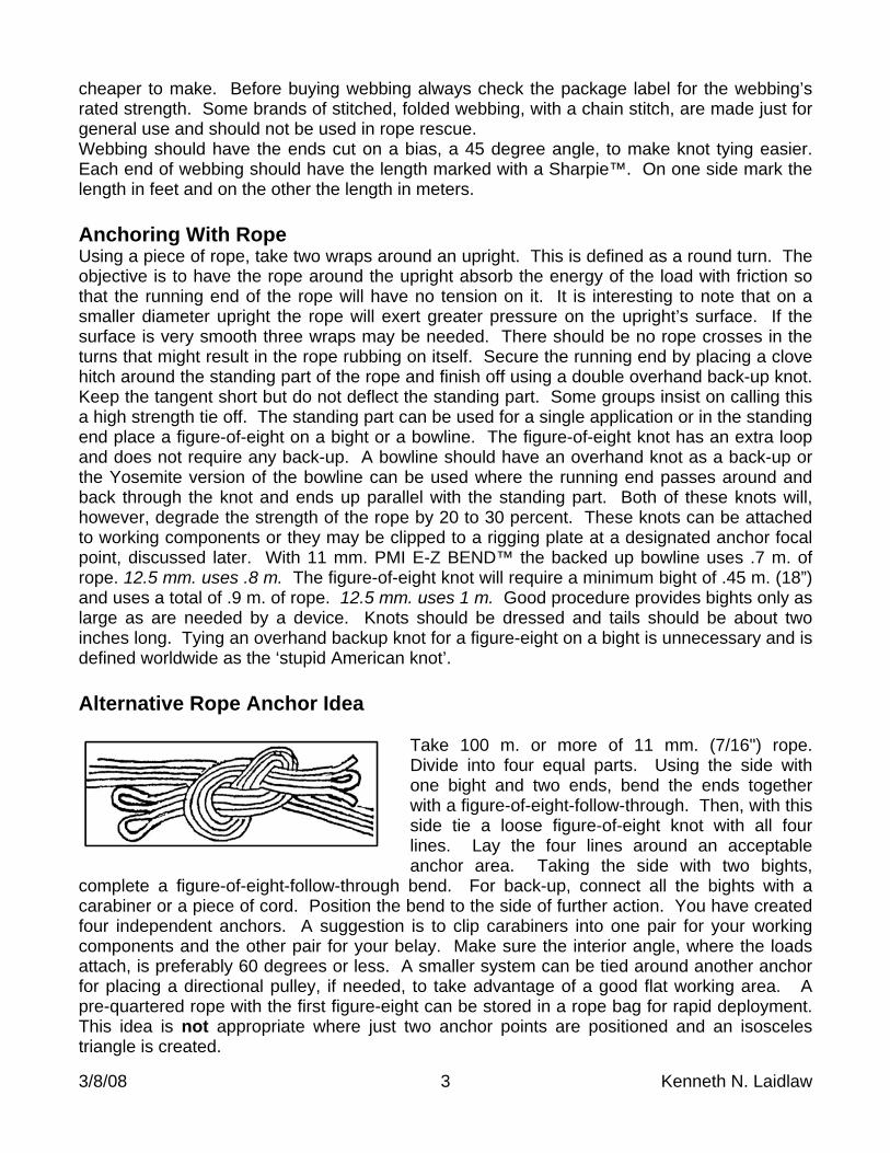
Take 100 m. or more of 11 mm. (7/16") rope. Divide into four equal parts. Using the side with one bight and two ends, bend the ends together with a figure-of-eight-follow-through. Then, with this side tie a loose figure-of-eight knot with all four lines. Lay the four lines around an acceptable anchor area. Taking the side with two bights,
complete a figure-of-eight-follow-through bend. For back-up, connect all the bights with a carabiner or a piece of cord. Position the bend to the side of further action. You have created four independent anchors. A suggestion is to clip carabiners into one pair for your working components and the other pair for your belay. Make sure the interior angle, where the loads attach, is preferably 60 degrees or less. A smaller system can be tied around another anchor for placing a directional pulley, if needed, to take advantage of a good flat working area. A pre-quartered rope with the first figure-eight can be stored in a rope bag for rapid deployment. This idea is not appropriate where just two anchor points are positioned and an isosceles triangle is created.
3/8/08 4 Kenneth N. Laidlaw
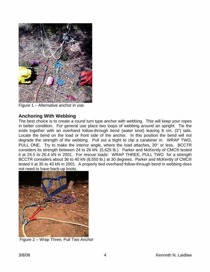
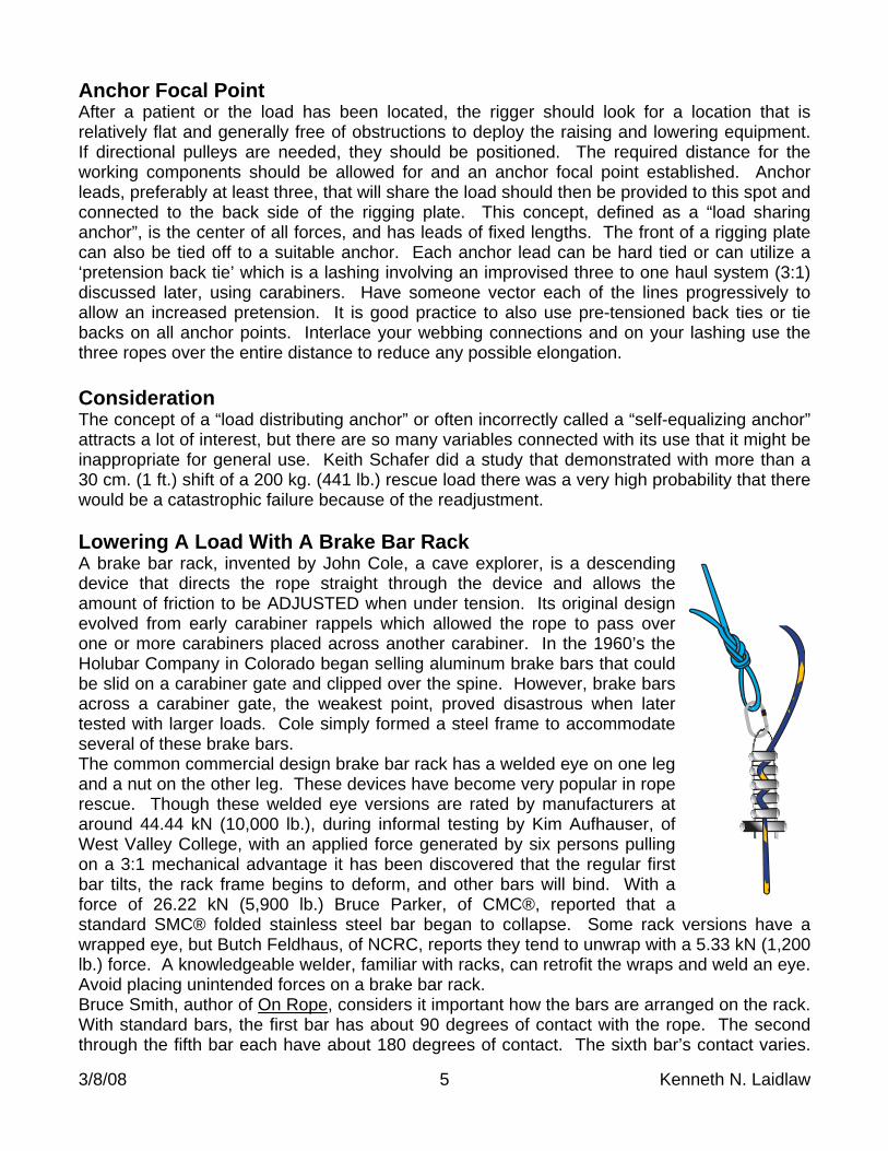
Figure 1 – Alternative anchor in use. Anchoring With Webbing The best choice is to create a round turn type anchor with webbing. This will keep your ropes in better condition. For general use place two loops of webbing around an upright. Tie the ends together with an overhand follow-through bend (water knot) leaving 8 cm. (3”) tails. Locate the bend on the load or front side of the anchor. In this position the bend will not degrade the strength of the webbing. Pull out a bight to clip a carabiner in. WRAP TWO, PULL ONE. Try to make the interior angle, where the load attaches, 30 or less. BCCTR considers its strength between 24 to 26 kN. (5,625 lb.) Parker and McKently of CMC® tested it at 24.5 to 26.4 kN in 2001. For rescue loads: WRAP THREE, PULL TWO for a strength BCCTR considers about 36 to 40 kN (8,550 lb.) at 30 degrees. Parker and McKently of CMC® tested it at 35 to 43 kN in 2001. A properly tied overhand follow-through bend in webbing does not need to have back-up knots.
Figure 2 – Wrap Three, Pull Two Anchor
3/8/08 5 Kenneth N. Laidlaw
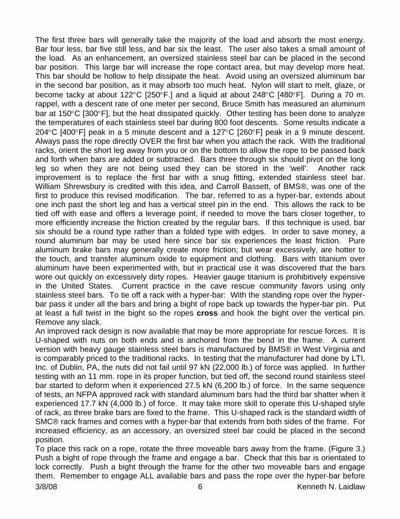
Anchor Focal Point After a patient or the load has been located, the rigger should look for a location that is relatively flat and generally free of obstructions to deploy the raising and lowering equipment. If directional pulleys are needed, they should be positioned. The required distance for the working components should be allowed for and an anchor focal point established. Anchor leads, preferably at least three, that will share the load should then be provided to this spot and connected to the back side of the rigging plate. This concept, defined as a “load sharing anchor”, is the center of all forces, and has leads of fixed lengths. The front of a rigging plate can also be tied off to a suitable anchor. Each anchor lead can be hard tied or can utilize a ‘pretension back tie’ which is a lashing involving an improvised three to one haul system (3:1) discussed later, using carabiners. Have someone vector each of the lines progressively to allow an increased pretension. It is good practice to also use pre-tensioned back ties or tie backs on all anchor points. Interlace your webbing connections and on your lashing use the three ropes over the entire distance to reduce any possible elongation. Consideration The concept of a “load distributing anchor” or often incorrectly called a “self-equalizing anchor” attracts a lot of interest, but there are so many variables connected with its use that it might be inappropriate for general use. Keith Schafer did a study that demonstrated with more than a 30 cm. (1 ft.) shift of a 200 kg. (441 lb.) rescue load there was a very high probability that there would be a catastrophic failure because of the readjustment. Lowering A Load With A Brake Bar Rack A brake bar rack, invented by John Cole, a cave explorer, is a descending device that directs the rope straight through the device and allows the amount of friction to be ADJUSTED when under tension. Its original design evolved from early carabiner rappels which allowed the rope to pass over one or more carabiners placed across another carabiner. In the 1960’s the Holubar Company in Colorado began selling aluminum brake bars that could be slid on a carabiner gate and clipped over the spine. However, brake bars across a carabiner gate, the weakest point, proved disastrous when later tested with larger loads. Cole simply formed a steel frame to accommodate several of these brake bars. The common commercial design brake bar rack has a welded eye on one leg and a nut on the other leg. These devices have become very popular in rope rescue. Though these welded eye versions are rated by manufacturers at around 44.44 kN (10,000 lb.), during informal testing by Kim Aufhauser, of West Valley College, with an applied force generated by six persons pulling on a 3:1 mechanical advantage it has been discovered that the regular first bar tilts, the rack frame begins to deform, and other bars will bind. With a force of 26.22 kN (5,900 lb.) Bruce Parker, of CMC®, reported that a standard SMC® folded stainless steel bar began to collapse. Some rack versions have a wrapped eye, but Butch Feldhaus, of NCRC, reports they tend to unwrap with a 5.33 kN (1,200 lb.) force. A knowledgeable welder, familiar with racks, can retrofit the wraps and weld an eye. Avoid placing unintended forces on a brake bar rack. Bruce Smith, author of On Rope, considers it important how the bars are arranged on the rack. With standard bars, the first bar has about 90 degrees of contact with the rope. The second through the fifth bar each have about 180 degrees of contact. The sixth bar’s contact varies.
3/8/08 6 Kenneth N. Laidlaw
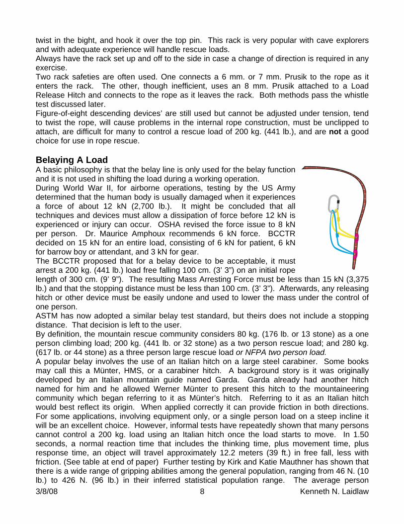
The first three bars will generally take the majority of the load and absorb the most energy. Bar four less, bar five still less, and bar six the least. The user also takes a small amount of the load. As an enhancement, an oversized stainless steel bar can be placed in the second bar position. This large bar will increase the rope contact area, but may develop more heat. This bar should be hollow to help dissipate the heat. Avoid using an oversized aluminum bar in the second bar position, as it may absorb too much heat. Nylon will start to melt, glaze, or become tacky at about 122C [250F.] and a liquid at about 248C [480F]. During a 70 m. rappel, with a descent rate of one meter per second, Bruce Smith has measured an aluminum bar at 150C [300F], but the heat dissipated quickly. Other testing has been done to analyze the temperatures of each stainless steel bar during 800 foot descents. Some results indicate a 204C [400F] peak in a 5 minute descent and a 127C [260F] peak in a 9 minute descent. Always pass the rope directly OVER the first bar when you attach the rack. With the traditional racks, orient the short leg away from you or on the bottom to allow the rope to be passed back and forth when bars are added or subtracted. Bars three through six should pivot on the long leg so when they are not being used they can be stored in the ‘well’. Another rack improvement is to replace the first bar with a snug fitting, extended stainless steel bar. William Shrewsbury is credited with this idea, and Carroll Bassett, of BMS®, was one of the first to produce this revised modification. The bar, referred to as a hyper-bar, extends about one inch past the short leg and has a vertical steel pin in the end. This allows the rack to be tied off with ease and offers a leverage point, if needed to move the bars closer together, to more efficiently increase the friction created by the regular bars. If this technique is used, bar six should be a round type rather than a folded type with edges. In order to save money, a round aluminum bar may be used here since bar six experiences the least friction. Pure aluminum brake bars may generally create more friction; but wear excessively, are hotter to the touch, and transfer aluminum oxide to equipment and clothing. Bars with titanium over aluminum have been experimented with, but in practical use it was discovered that the bars wore out quickly on excessively dirty ropes. Heavier gauge titanium is prohibitively expensive in the United States. Current practice in the cave rescue community favors using only stainless steel bars. To tie off a rack with a hyper-bar: With the standing rope over the hyper-bar pass it under all the bars and bring a bight of rope back up towards the hyper-bar pin. Put at least a full twist in the bight so the ropes cross and hook the bight over the vertical pin. Remove any slack. An improved rack design is now available that may be more appropriate for rescue forces. It is U-shaped with nuts on both ends and is anchored from the bend in the frame. A current version with heavy gauge stainless steel bars is manufactured by BMS® in West Virginia and is comparably priced to the traditional racks. In testing that the manufacturer had done by LTI, Inc. of Dublin, PA, the nuts did not fail until 97 kN (22,000 lb.) of force was applied. In further testing with an 11 mm. rope in its proper function, but tied off, the second round stainless steel bar started to deform when it experienced 27.5 kN (6,200 lb.) of force. In the same sequence of tests, an NFPA approved rack with standard aluminum bars had the third bar shatter when it experienced 17.7 kN (4,000 lb.) of force. It may take more skill to operate this U-shaped style of rack, as three brake bars are fixed to the frame. This U-shaped rack is the standard width of SMC® rack frames and comes with a hyper-bar that extends from both sides of the frame. For increased efficiency, as an accessory, an oversized steel bar could be placed in the second position. To place this rack on a rope, rotate the three moveable bars away from the frame. (Figure 3.) Push a bight of rope through the frame and engage a bar. Check that this bar is orientated to lock correctly. Push a bight through the frame for the other two moveable bars and engage them. Remember to engage ALL available bars and pass the rope over the hyper-bar before
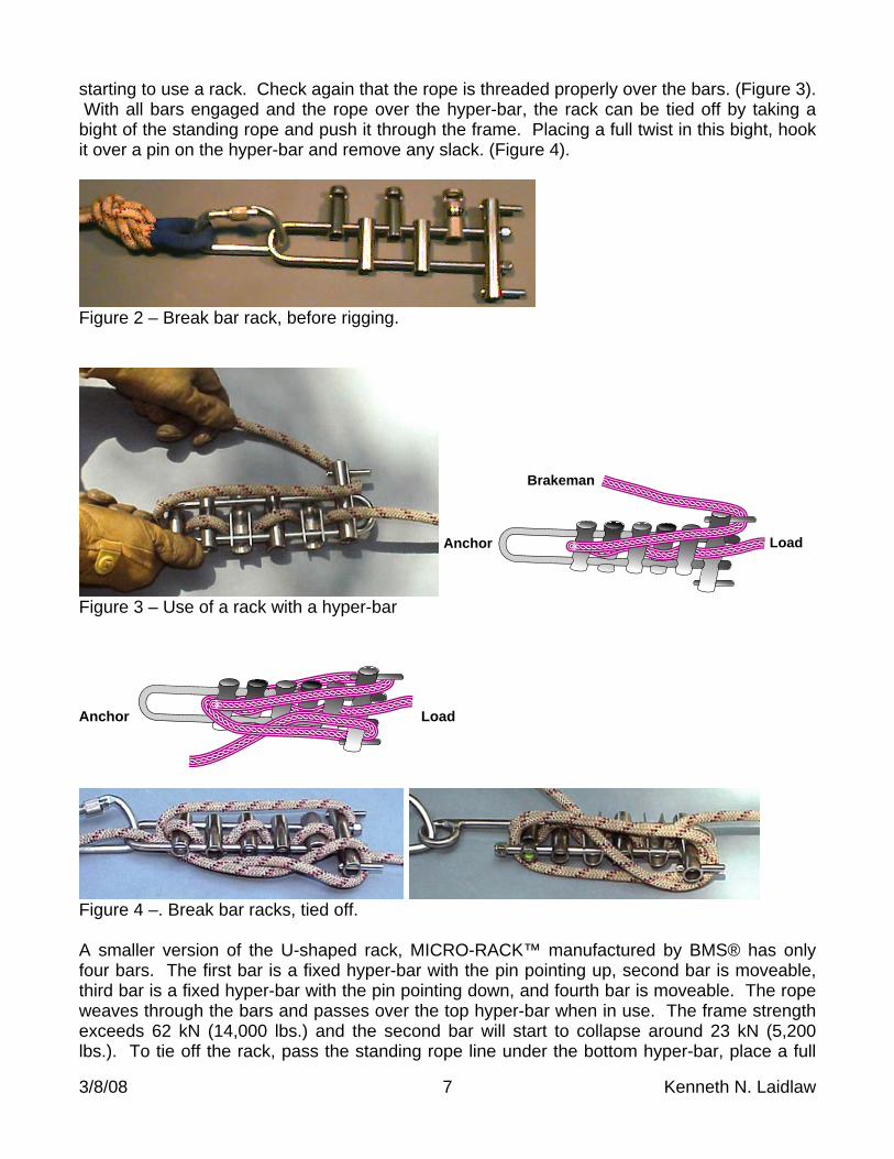
3/8/08 7 Kenneth N. Laidlaw
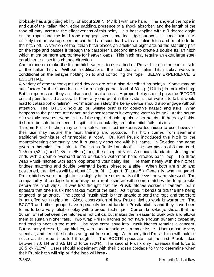
starting to use a rack. Check again that the rope is threaded properly over the bars. (Figure 3). With all bars engaged and the rope over the hyper-bar, the rack can be tied off by taking a bight of the standing rope and push it through the frame. Placing a full twist in this bight, hook it over a pin on the hyper-bar and remove any slack. (Figure 4).
Figure 2 – Break bar rack, before rigging.
Load
Brakeman
Anchor
Figure 3 – Use of a rack with a hyper-bar
LoadAnchor
Figure 4 –. Break bar racks, tied off. A smaller version of the U-shaped rack, MICRO-RACK™ manufactured by BMS® has only four bars. The first bar is a fixed hyper-bar with the pin pointing up, second bar is moveable, third bar is a fixed hyper-bar with the pin pointing down, and fourth bar is moveable. The rope weaves through the bars and passes over the top hyper-bar when in use. The frame strength exceeds 62 kN (14,000 lbs.) and the second bar will start to collapse around 23 kN (5,200 lbs.). To tie off the rack, pass the standing rope line under the bottom hyper-bar, place a full
3/8/08 8 Kenneth N. Laidlaw
twist in the bight, and hook it over the top pin. This rack is very popular with cave explorers and with adequate experience will handle rescue loads. Always have the rack set up and off to the side in case a change of direction is required in any exercise. Two rack safeties are often used. One connects a 6 mm. or 7 mm. Prusik to the rope as it enters the rack. The other, though inefficient, uses an 8 mm. Prusik attached to a Load Release Hitch and connects to the rope as it leaves the rack. Both methods pass the whistle test discussed later. Figure-of-eight descending devices’ are still used but cannot be adjusted under tension, tend to twist the rope, will cause problems in the internal rope construction, must be unclipped to attach, are difficult for many to control a rescue load of 200 kg. (441 lb.), and are not a good choice for use in rope rescue. Belaying A Load A basic philosophy is that the belay line is only used for the belay function and it is not used in shifting the load during a working operation. During World War II, for airborne operations, testing by the US Army determined that the human body is usually damaged when it experiences a force of about 12 kN (2,700 lb.). It might be concluded that all techniques and devices must allow a dissipation of force before 12 kN is experienced or injury can occur. OSHA revised the force issue to 8 kN per person. Dr. Maurice Amphoux recommends 6 kN force. BCCTR decided on 15 kN for an entire load, consisting of 6 kN for patient, 6 kN for barrow boy or attendant, and 3 kN for gear. The BCCTR proposed that for a belay device to be acceptable, it must arrest a 200 kg. (441 lb.) load free falling 100 cm. (3’ 3”) on an initial rope length of 300 cm. (9’ 9”). The resulting Mass Arresting Force must be less than 15 kN (3,375 lb.) and that the stopping distance must be less than 100 cm. (3’ 3”). Afterwards, any releasing hitch or other device must be easily undone and used to lower the mass under the control of one person. ASTM has now adopted a similar belay test standard, but theirs does not include a stopping distance. That decision is left to the user. By definition, the mountain rescue community considers 80 kg. (176 lb. or 13 stone) as a one person climbing load; 200 kg. (441 lb. or 32 stone) as a two person rescue load; and 280 kg. (617 lb. or 44 stone) as a three person large rescue load or NFPA two person load. A popular belay involves the use of an Italian hitch on a large steel carabiner. Some books may call this a Münter, HMS, or a carabiner hitch. A background story is it was originally developed by an Italian mountain guide named Garda. Garda already had another hitch named for him and he allowed Werner Münter to present this hitch to the mountaineering community which began referring to it as Münter’s hitch. Referring to it as an Italian hitch would best reflect its origin. When applied correctly it can provide friction in both directions. For some applications, involving equipment only, or a single person load on a steep incline it will be an excellent choice. However, informal tests have repeatedly shown that many persons cannot control a 200 kg. load using an Italian hitch once the load starts to move. In 1.50 seconds, a normal reaction time that includes the thinking time, plus movement time, plus response time, an object will travel approximately 12.2 meters (39 ft.) in free fall, less with friction. (See table at end of paper) Further testing by Kirk and Katie Mauthner has shown that there is a wide range of gripping abilities among the general population, ranging from 46 N. (10 lb.) to 426 N. (96 lb.) in their inferred statistical population range. The average person
3/8/08 9 Kenneth N. Laidlaw
probably has a gripping ability, of about 209 N. (47 lb.) with one hand. The angle of the rope in and out of the Italian hitch, edge padding, presence of a shock absorber, and the length of the rope all may increase the effectiveness of this belay. It is best applied with a 0 degree angle on the ropes and the load rope dragging over a padded edge surface. In conclusion, it is unlikely that an average person can hold a rescue load with an Italian hitch and be able to tie the hitch off. A version of the Italian hitch places an additional bight around the standing part on the rope and passes it through the carabiner a second time to create a double Italian hitch which might be more appropriate for heaver loads. This hitch may require an extra large steel carabiner to allow it to change direction. Another idea to make the Italian hitch safer is to use a tied off Prusik hitch on the control side of the Italian hitch. Without modifications, the fact that an Italian hitch belay works is conditional on the belayer holding on to and controlling the rope. BELAY EXPERIENCE IS ESSENTIAL. A variety of other techniques and devices are often also described as belays. Some may be satisfactory for their intended use for a single person load of 80 kg. (176 lb.) in rock climbing. But in rope rescue, they are also conditional at best. A proper belay should pass the "BTCCR critical point test", that asks, 'Is there any one point in the system, that were it to fail, it would lead to catastrophic failure?' For maximum safety the belay device should also engage without attention. The "BTCCR hold up [or] whistle test" is for objective hazard and asks, 'What happens to the patient, attendant, and other rescuers if everyone were to let go?' At the sound of a whistle have everyone let go of the rope and hold up his or her hands. If the belay holds, it should be safe to proceed. In spite of its popularity, an Italian hitch fails this test. Tandem Prusik hitches may be the safest and most inexpensive technique to use, however, their use may require the most training and aptitude. This hitch comes from seamen’s traditional techniques of ‘strapping a rope’. Dr. Karl Prusik introduced this hitch to the mountaineering community and it is usually described with his name. In Sweden, the name given to this hitch, translates to English as “triple Larksfoot”. Use two pieces of 8 mm. cord, 1.35 m. (53 in.) and 1.65 m. (65 in.) long, the accepted North American standards. Joining the ends with a double overhand bend or double waterman bend creates each loop. Tie three wrap Prusik hitches with each loop around your belay line. Tie them neatly with the hitches' bridges matching and double overhand bends offset to a side. When both are snug and positioned, the hitches will be about 10 cm. (4 in.) apart. (Figure 5.) Generally, when engaged, Prusik hitches were thought to slip slightly before other parts of the system were stressed. The compatibility of cordage to rope may be a real issue as with some matches the loop breaks before the hitch slips. It was first thought that the Prusik hitches worked in tandem, but it appears that one Prusik hitch takes most of the load. As it grips, it bends or tilts the line being engaged, at an angle. The second Prusik hitch is then unable to bend the rope and therefore is not effective in gripping. Close observation of how Prusik hitches work is warranted. The BCCTR and other groups have repeatedly tested tandem Prusik hitches and they have been found to be a very reliable belay with a proper technique. Current knowledge shows that the 10 cm. offset between the hitches is not critical but makes them easier to work with and allows them to sustain higher falls. Two wrap Prusik hitches do not have enough dynamic capability and tend to heat up too much. The rope entry issue into Prusik hitches remains a concern. But properly dressed, snug hitches, with good technique is a major issue. Users must be very attentive, and keep the hitches snug but free running. A properly tied Prusik hitch will make a noise as the rope is pulled through it. The BCCTR speculate that the first Prusik takes between 7.0 kN and 9.5 kN of force (90%). The second Prusik only increases that force to 10.5 kN (10%). Users should experiment with their chosen cordage to try to determine when their Prusik hitch will slip or if the loop will break.
3/8/08 10 Kenneth N. Laidlaw
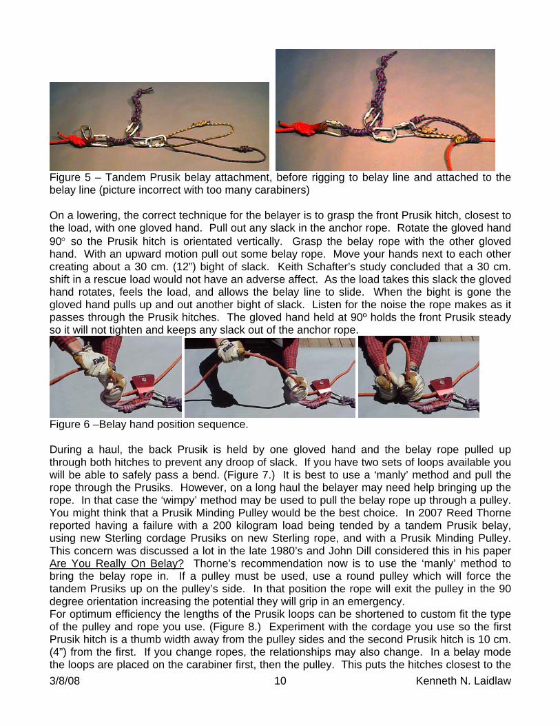
Figure 5 – Tandem Prusik belay attachment, before rigging to belay line and attached to the belay line (picture incorrect with too many carabiners) On a lowering, the correct technique for the belayer is to grasp the front Prusik hitch, closest to the load, with one gloved hand. Pull out any slack in the anchor rope. Rotate the gloved hand 90 so the Prusik hitch is orientated vertically. Grasp the belay rope with the other gloved hand. With an upward motion pull out some belay rope. Move your hands next to each other creating about a 30 cm. (12”) bight of slack. Keith Schafter’s study concluded that a 30 cm. shift in a rescue load would not have an adverse affect. As the load takes this slack the gloved hand rotates, feels the load, and allows the belay line to slide. When the bight is gone the gloved hand pulls up and out another bight of slack. Listen for the noise the rope makes as it passes through the Prusik hitches. The gloved hand held at 90º holds the front Prusik steady so it will not tighten and keeps any slack out of the anchor rope.
Figure 6 –Belay hand position sequence. During a haul, the back Prusik is held by one gloved hand and the belay rope pulled up through both hitches to prevent any droop of slack. If you have two sets of loops available you will be able to safely pass a bend. (Figure 7.) It is best to use a ‘manly’ method and pull the rope through the Prusiks. However, on a long haul the belayer may need help bringing up the rope. In that case the ‘wimpy’ method may be used to pull the belay rope up through a pulley. You might think that a Prusik Minding Pulley would be the best choice. In 2007 Reed Thorne reported having a failure with a 200 kilogram load being tended by a tandem Prusik belay, using new Sterling cordage Prusiks on new Sterling rope, and with a Prusik Minding Pulley. This concern was discussed a lot in the late 1980’s and John Dill considered this in his paper Are You Really On Belay? Thorne’s recommendation now is to use the ‘manly’ method to bring the belay rope in. If a pulley must be used, use a round pulley which will force the tandem Prusiks up on the pulley’s side. In that position the rope will exit the pulley in the 90 degree orientation increasing the potential they will grip in an emergency. For optimum efficiency the lengths of the Prusik loops can be shortened to custom fit the type of the pulley and rope you use. (Figure 8.) Experiment with the cordage you use so the first Prusik hitch is a thumb width away from the pulley sides and the second Prusik hitch is 10 cm. (4”) from the first. If you change ropes, the relationships may also change. In a belay mode the loops are placed on the carabiner first, then the pulley. This puts the hitches closest to the
3/8/08 11 Kenneth N. Laidlaw
carabiner spine so the shock load will be on the strongest part of the carabiner. With a pulley in a system, when you are in a lowering mode, let the rope pass through the pulley. Holding the tandem Prusik hitches at 90º allows them to effectively grip the rope. If a shock load were to be experienced the Prusik hitches just rotate 90 and lock. Your hands will move with the hitches. Whether your thumbs are in or out is not an issue.
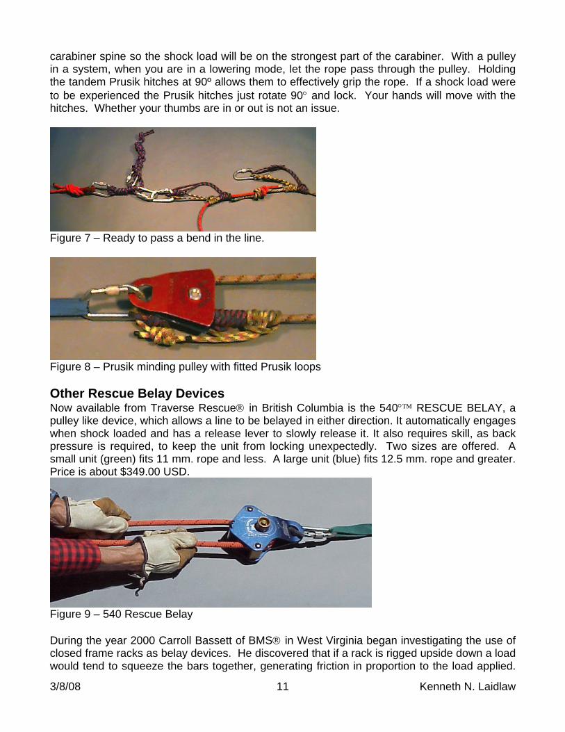
Figure 7 – Ready to pass a bend in the line.
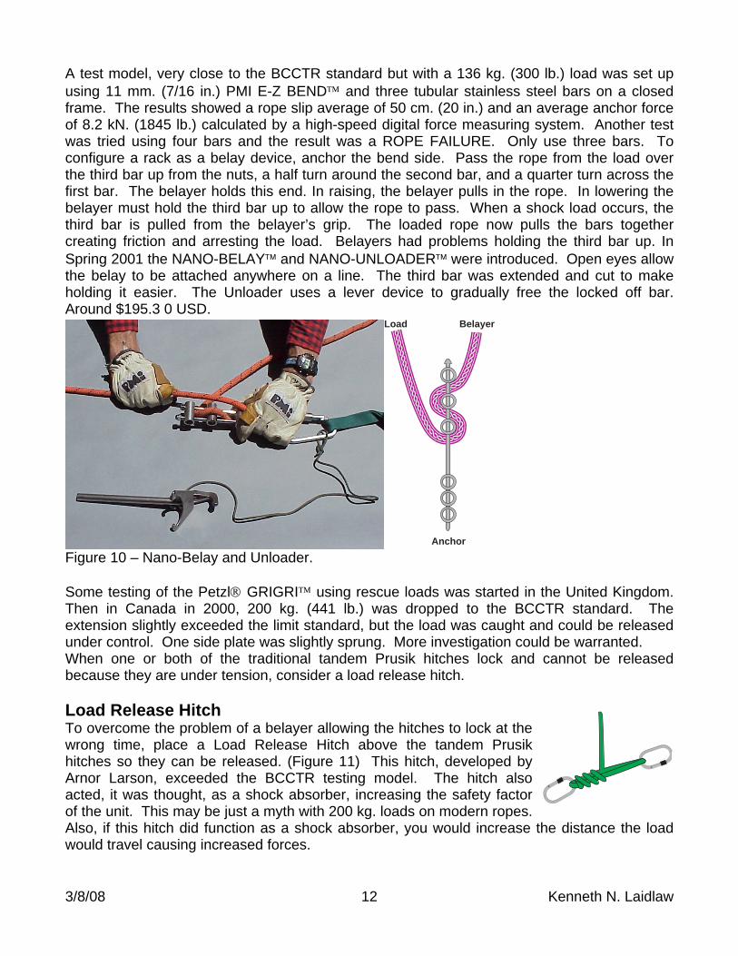
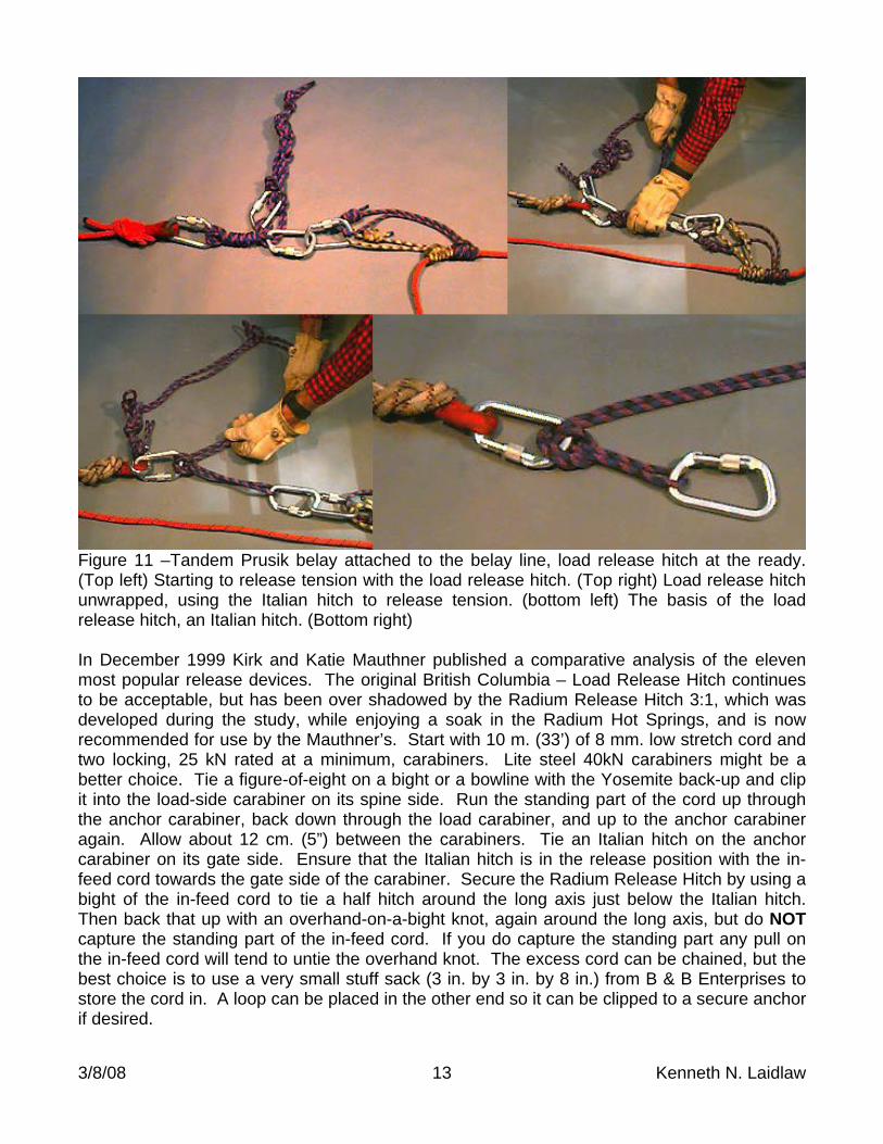
Figure 8 – Prusik minding pulley with fitted Prusik loops Other Rescue Belay Devices Now available from Traverse Rescue in British Columbia is the 540 RESCUE BELAY, a pulley like device, which allows a line to be belayed in either direction. It automatically engages when shock loaded and has a release lever to slowly release it. It also requires skill, as back pressure is required, to keep the unit from locking unexpectedly. Two sizes are offered. A small unit (green) fits 11 mm. rope and less. A large unit (blue) fits 12.5 mm. rope and greater. Price is about $349.00 USD.
Figure 9 – 540 Rescue Belay During the year 2000 Carroll Bassett of BMS in West Virginia began investigating the use of closed frame racks as belay devices. He discovered that if a rack is rigged upside down a load would tend to squeeze the bars together, generating friction in proportion to the load applied.
3/8/08 12 Kenneth N. Laidlaw
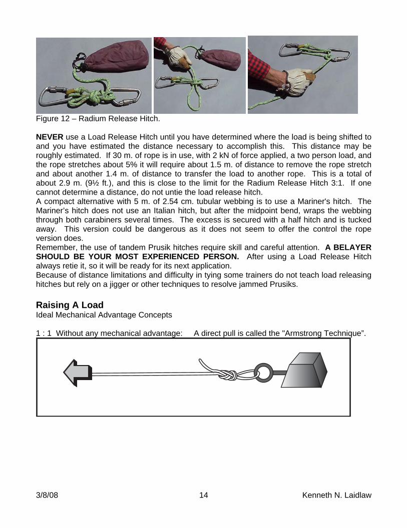
A test model, very close to the BCCTR standard but with a 136 kg. (300 lb.) load was set up using 11 mm. (7/16 in.) PMI E-Z BEND and three tubular stainless steel bars on a closed frame. The results showed a rope slip average of 50 cm. (20 in.) and an average anchor force of 8.2 kN. (1845 lb.) calculated by a high-speed digital force measuring system. Another test was tried using four bars and the result was a ROPE FAILURE. Only use three bars. To configure a rack as a belay device, anchor the bend side. Pass the rope from the load over the third bar up from the nuts, a half turn around the second bar, and a quarter turn across the first bar. The belayer holds this end. In raising, the belayer pulls in the rope. In lowering the belayer must hold the third bar up to allow the rope to pass. When a shock load occurs, the third bar is pulled from the belayer’s grip. The loaded rope now pulls the bars together creating friction and arresting the load. Belayers had problems holding the third bar up. In Spring 2001 the NANO-BELAY and NANO-UNLOADER were introduced. Open eyes allow the belay to be attached anywhere on a line. The third bar was extended and cut to make holding it easier. The Unloader uses a lever device to gradually free the locked off bar. Around $195.3 0 USD.
BelayerLoad
Anchor Figure 10 – Nano-Belay and Unloader. Some testing of the Petzl GRIGRI using rescue loads was started in the United Kingdom. Then in Canada in 2000, 200 kg. (441 lb.) was dropped to the BCCTR standard. The extension slightly exceeded the limit standard, but the load was caught and could be released under control. One side plate was slightly sprung. More investigation could be warranted. When one or both of the traditional tandem Prusik hitches lock and cannot be released because they are under tension, consider a load release hitch. Load Release Hitch To overcome the problem of a belayer allowing the hitches to lock at the wrong time, place a Load Release Hitch above the tandem Prusik hitches so they can be released. (Figure 11) This hitch, developed by Arnor Larson, exceeded the BCCTR testing model. The hitch also acted, it was thought, as a shock absorber, increasing the safety factor of the unit. This may be just a myth with 200 kg. loads on modern ropes. Also, if this hitch did function as a shock absorber, you would increase the distance the load would travel causing increased forces.
3/8/08 13 Kenneth N. Laidlaw
Figure 11 –Tandem Prusik belay attached to the belay line, load release hitch at the ready. (Top left) Starting to release tension with the load release hitch. (Top right) Load release hitch unwrapped, using the Italian hitch to release tension. (bottom left) The basis of the load release hitch, an Italian hitch. (Bottom right) In December 1999 Kirk and Katie Mauthner published a comparative analysis of the eleven most popular release devices. The original British Columbia – Load Release Hitch continues to be acceptable, but has been over shadowed by the Radium Release Hitch 3:1, which was developed during the study, while enjoying a soak in the Radium Hot Springs, and is now recommended for use by the Mauthner’s. Start with 10 m. (33’) of 8 mm. low stretch cord and two locking, 25 kN rated at a minimum, carabiners. Lite steel 40kN carabiners might be a better choice. Tie a figure-of-eight on a bight or a bowline with the Yosemite back-up and clip it into the load-side carabiner on its spine side. Run the standing part of the cord up through the anchor carabiner, back down through the load carabiner, and up to the anchor carabiner again. Allow about 12 cm. (5”) between the carabiners. Tie an Italian hitch on the anchor carabiner on its gate side. Ensure that the Italian hitch is in the release position with the in-feed cord towards the gate side of the carabiner. Secure the Radium Release Hitch by using a bight of the in-feed cord to tie a half hitch around the long axis just below the Italian hitch. Then back that up with an overhand-on-a-bight knot, again around the long axis, but do NOT capture the standing part of the in-feed cord. If you do capture the standing part any pull on the in-feed cord will tend to untie the overhand knot. The excess cord can be chained, but the best choice is to use a very small stuff sack (3 in. by 3 in. by 8 in.) from B & B Enterprises to store the cord in. A loop can be placed in the other end so it can be clipped to a secure anchor if desired.
3/8/08 14 Kenneth N. Laidlaw
Figure 12 – Radium Release Hitch. NEVER use a Load Release Hitch until you have determined where the load is being shifted to and you have estimated the distance necessary to accomplish this. This distance may be roughly estimated. If 30 m. of rope is in use, with 2 kN of force applied, a two person load, and the rope stretches about 5% it will require about 1.5 m. of distance to remove the rope stretch and about another 1.4 m. of distance to transfer the load to another rope. This is a total of about 2.9 m. (9½ ft.), and this is close to the limit for the Radium Release Hitch 3:1. If one cannot determine a distance, do not untie the load release hitch. A compact alternative with 5 m. of 2.54 cm. tubular webbing is to use a Mariner's hitch. The Mariner’s hitch does not use an Italian hitch, but after the midpoint bend, wraps the webbing through both carabiners several times. The excess is secured with a half hitch and is tucked away. This version could be dangerous as it does not seem to offer the control the rope version does. Remember, the use of tandem Prusik hitches require skill and careful attention. A BELAYER SHOULD BE YOUR MOST EXPERIENCED PERSON. After using a Load Release Hitch always retie it, so it will be ready for its next application. Because of distance limitations and difficulty in tying some trainers do not teach load releasing hitches but rely on a jigger or other techniques to resolve jammed Prusiks. Raising A Load Ideal Mechanical Advantage Concepts 1 : 1 Without any mechanical advantage: A direct pull is called the "Armstrong Technique”.
3/8/08 15 Kenneth N. Laidlaw
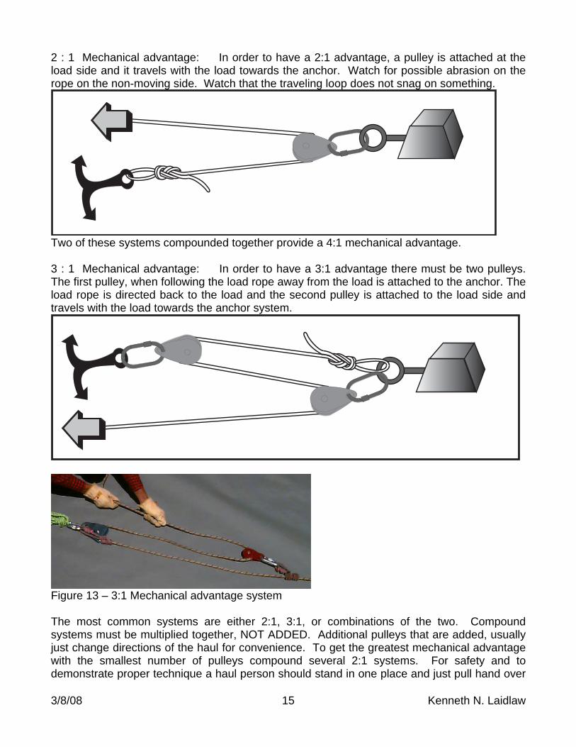
2 : 1 Mechanical advantage: In order to have a 2:1 advantage, a pulley is attached at the load side and it travels with the load towards the anchor. Watch for possible abrasion on the rope on the non-moving side. Watch that the traveling loop does not snag on something.
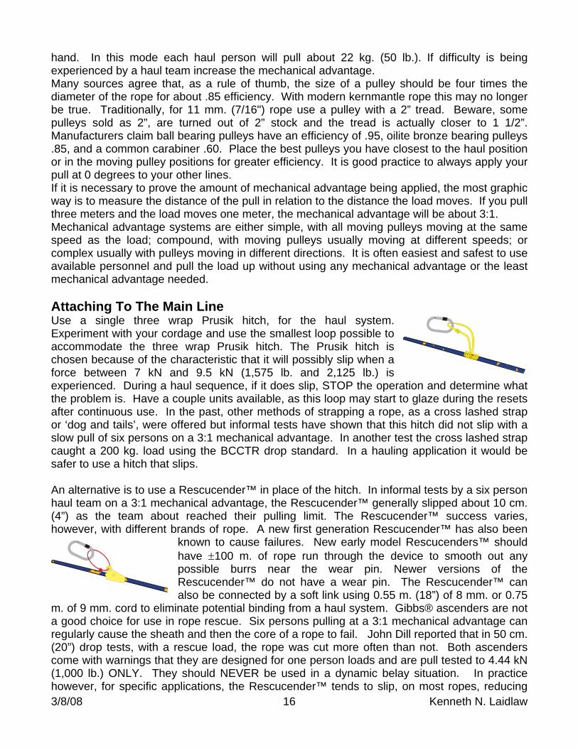
Two of these systems compounded together provide a 4:1 mechanical advantage. 3 : 1 Mechanical advantage: In order to have a 3:1 advantage there must be two pulleys. The first pulley, when following the load rope away from the load is attached to the anchor. The load rope is directed back to the load and the second pulley is attached to the load side and travels with the load towards the anchor system.
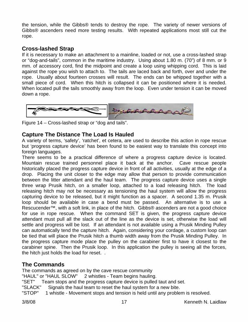
Figure 13 – 3:1 Mechanical advantage system The most common systems are either 2:1, 3:1, or combinations of the two. Compound systems must be multiplied together, NOT ADDED. Additional pulleys that are added, usually just change directions of the haul for convenience. To get the greatest mechanical advantage with the smallest number of pulleys compound several 2:1 systems. For safety and to demonstrate proper technique a haul person should stand in one place and just pull hand over
3/8/08 16 Kenneth N. Laidlaw
hand. In this mode each haul person will pull about 22 kg. (50 lb.). If difficulty is being experienced by a haul team increase the mechanical advantage. Many sources agree that, as a rule of thumb, the size of a pulley should be four times the diameter of the rope for about .85 efficiency. With modern kernmantle rope this may no longer be true. Traditionally, for 11 mm. (7/16") rope use a pulley with a 2” tread. Beware, some pulleys sold as 2”, are turned out of 2” stock and the tread is actually closer to 1 1/2”. Manufacturers claim ball bearing pulleys have an efficiency of .95, oilite bronze bearing pulleys .85, and a common carabiner .60. Place the best pulleys you have closest to the haul position or in the moving pulley positions for greater efficiency. It is good practice to always apply your pull at 0 degrees to your other lines. If it is necessary to prove the amount of mechanical advantage being applied, the most graphic way is to measure the distance of the pull in relation to the distance the load moves. If you pull three meters and the load moves one meter, the mechanical advantage will be about 3:1. Mechanical advantage systems are either simple, with all moving pulleys moving at the same speed as the load; compound, with moving pulleys usually moving at different speeds; or complex usually with pulleys moving in different directions. It is often easiest and safest to use available personnel and pull the load up without using any mechanical advantage or the least mechanical advantage needed. Attaching To The Main Line Use a single three wrap Prusik hitch, for the haul system. Experiment with your cordage and use the smallest loop possible to accommodate the three wrap Prusik hitch. The Prusik hitch is chosen because of the characteristic that it will possibly slip when a force between 7 kN and 9.5 kN (1,575 lb. and 2,125 lb.) is experienced. During a haul sequence, if it does slip, STOP the operation and determine what the problem is. Have a couple units available, as this loop may start to glaze during the resets after continuous use. In the past, other methods of strapping a rope, as a cross lashed strap or ‘dog and tails’, were offered but informal tests have shown that this hitch did not slip with a slow pull of six persons on a 3:1 mechanical advantage. In another test the cross lashed strap caught a 200 kg. load using the BCCTR drop standard. In a hauling application it would be safer to use a hitch that slips. An alternative is to use a Rescucender™ in place of the hitch. In informal tests by a six person haul team on a 3:1 mechanical advantage, the Rescucender™ generally slipped about 10 cm. (4”) as the team about reached their pulling limit. The Rescucender™ success varies, however, with different brands of rope. A new first generation Rescucender™ has also been
known to cause failures. New early model Rescucenders™ should have 100 m. of rope run through the device to smooth out any possible burrs near the wear pin. Newer versions of the Rescucender™ do not have a wear pin. The Rescucender™ can also be connected by a soft link using 0.55 m. (18”) of 8 mm. or 0.75
m. of 9 mm. cord to eliminate potential binding from a haul system. Gibbs® ascenders are not a good choice for use in rope rescue. Six persons pulling at a 3:1 mechanical advantage can regularly cause the sheath and then the core of a rope to fail. John Dill reported that in 50 cm. (20”) drop tests, with a rescue load, the rope was cut more often than not. Both ascenders come with warnings that they are designed for one person loads and are pull tested to 4.44 kN (1,000 lb.) ONLY. They should NEVER be used in a dynamic belay situation. In practice however, for specific applications, the Rescucender™ tends to slip, on most ropes, reducing
3/8/08 17 Kenneth N. Laidlaw
the tension, while the Gibbs® tends to destroy the rope. The variety of newer versions of Gibbs® ascenders need more testing results. With repeated applications most still cut the rope. Cross-lashed Strap If it is necessary to make an attachment to a mainline, loaded or not, use a cross-lashed strap or “dog-and-tails”, common in the maritime industry. Using about 1.80 m. (70”) of 8 mm. or 9 mm. of accessory cord, find the midpoint and create a loop using whipping cord. This is laid against the rope you wish to attach to. The tails are laced back and forth, over and under the rope. Usually about fourteen crosses will result. The ends can be whipped together with a small piece of cord. When this hitch is collapsed it can be positioned where it is needed. When located pull the tails smoothly away from the loop. Even under tension it can be moved down a rope.
Figure 14 – Cross-lashed strap or “dog and tails”. Capture The Distance The Load Is Hauled A variety of terms, ‘safety’, ‘ratchet’, et cetera, are used to describe this action in rope rescue but ‘progress capture device’ has been found to be easiest way to translate this concept into foreign languages. There seems to be a practical difference of where a progress capture device is located. Mountain rescue trained personnel place it back at the anchor. Cave rescue people historically placed the progress capture device in front of all activities, usually at the edge of a drop. Placing the unit closer to the edge may allow that person to provide communication between the litter attendant and the haul team. The progress capture device uses a single three wrap Prusik hitch, on a smaller loop, attached to a load releasing hitch. The load releasing hitch may not be necessary as tensioning the haul system will allow the progress capturing device to be released, but it might function as a spacer. A second 1.35 m. Prusik loop should be available in case a bend must be passed. An alternative is to use a Rescucender™, with a soft link, in place of the hitch. Gibbs® ascenders are not a good choice for use in rope rescue. When the command SET is given, the progress capture device attendant must pull all the slack out of the line as the device is set, otherwise the load will settle and progress will be lost. If an attendant is not available using a Prusik Minding Pulley can automatically tend the capture hitch. Again, considering your cordage, a custom loop can be tied that will place the Prusik hitch a thumb width away from the Prusik Minding Pulley. In the progress capture mode place the pulley on the carabiner first to have it closest to the carabiner spine. Then the Prusik loop. In this application the pulley is seeing all the forces, the hitch just holds the load for reset. . The Commands The commands as agreed on by the cave rescue community "HAUL" or "HAUL SLOW" 2 whistles - Team begins hauling. "SET" Team stops and the progress capture device is pulled taut and set. "SLACK" Signals the haul team to reset the haul system for a new bite. "STOP" 1 whistle - Movement stops and tension is held until any problem is resolved.
3/8/08 18 Kenneth N. Laidlaw
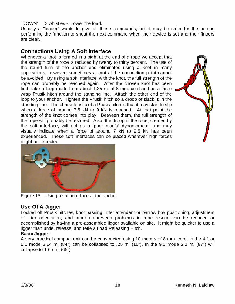
“DOWN” 3 whistles - Lower the load. Usually a "leader" wants to give all these commands, but it may be safer for the person performing the function to shout the next command when their device is set and their fingers are clear. Connections Using A Soft Interface Whenever a knot is formed in a bight at the end of a rope we accept that the strength of the rope is reduced by twenty to thirty percent. The use of the round turn at the anchor end eliminates using a knot in many applications, however, sometimes a knot at the connection point cannot be avoided. By using a soft interface, with the knot, the full strength of the rope can probably be reached again. After the chosen knot has been tied, take a loop made from about 1.35 m. of 8 mm. cord and tie a three wrap Prusik hitch around the standing line. Attach the other end of the loop to your anchor. Tighten the Prusik hitch so a droop of slack is in the standing line. The characteristic of a Prusik hitch is that it may start to slip when a force of around 7.5 kN to 9 kN is reached. At that point the strength of the knot comes into play. Between them, the full strength of the rope will probably be restored. Also, the droop in the rope, created by the soft interface, will act as a ‘poor man’s’ dynamometer and may visually indicate when a force of around 7 kN to 9.5 kN has been experienced. These soft interfaces can be placed wherever high forces might be expected.
Figure 15 – Using a soft interface at the anchor. Use Of A Jigger Locked off Prusik hitches, knot passing, litter attendant or barrow boy positioning, adjustment of litter orientation, and other unforeseen problems in rope rescue can be reduced or accomplished by having a pre-assembled jigger available on site. It might be quicker to use a jigger than untie, release, and retie a Load Releasing Hitch. Basic Jigger: A very practical compact unit can be constructed using 10 meters of 8 mm. cord. In the 4:1 or 5:1 mode 2.14 m. (84”) can be collapsed to .25 m. (10”). In the 9:1 mode 2.2 m. (87”) will collapse to 1.65 m. (65”).
3/8/08 19 Kenneth N. Laidlaw
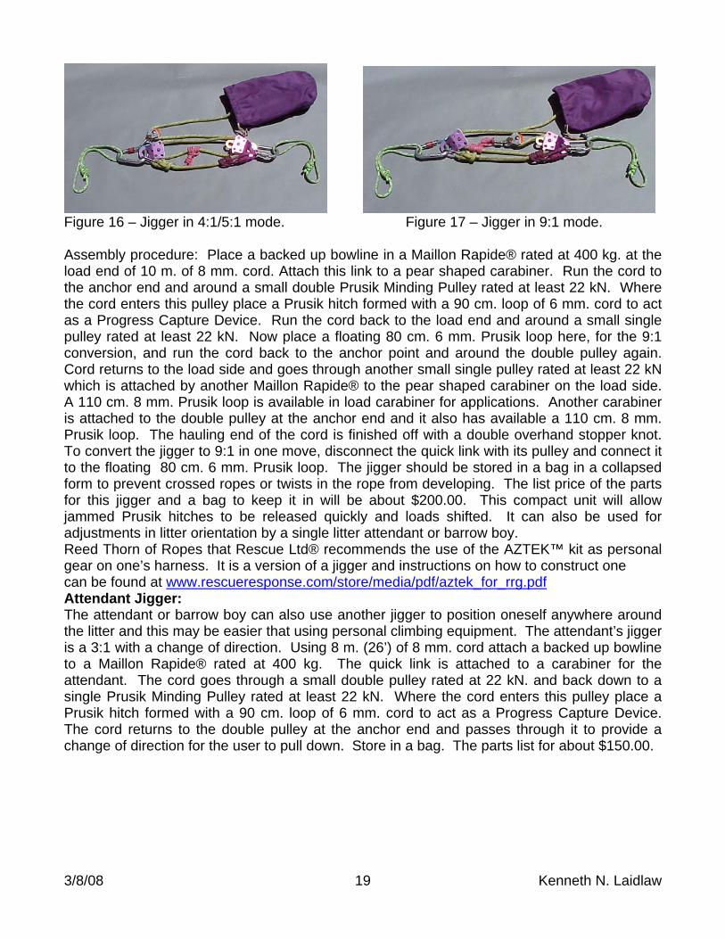
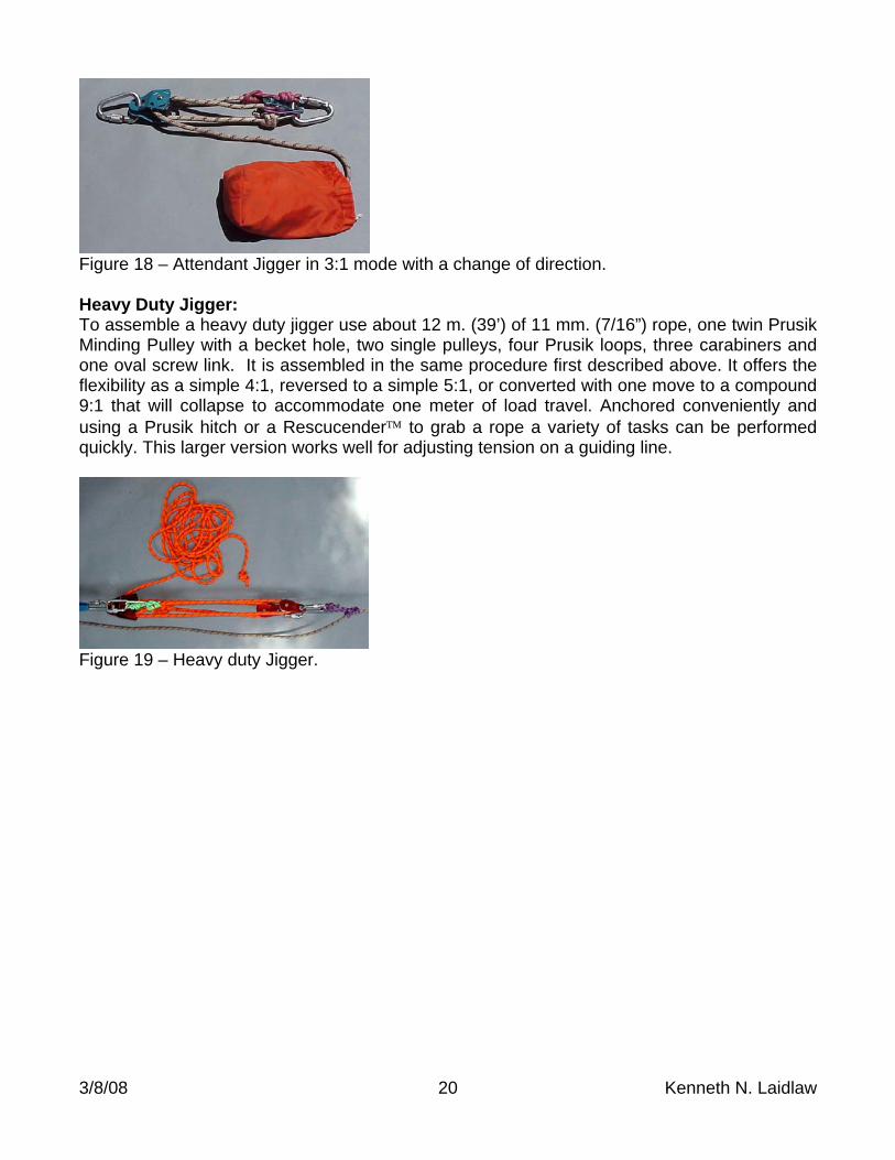
Figure 16 – Jigger in 4:1/5:1 mode. Figure 17 – Jigger in 9:1 mode. Assembly procedure: Place a backed up bowline in a Maillon Rapide® rated at 400 kg. at the load end of 10 m. of 8 mm. cord. Attach this link to a pear shaped carabiner. Run the cord to the anchor end and around a small double Prusik Minding Pulley rated at least 22 kN. Where the cord enters this pulley place a Prusik hitch formed with a 90 cm. loop of 6 mm. cord to act as a Progress Capture Device. Run the cord back to the load end and around a small single pulley rated at least 22 kN. Now place a floating 80 cm. 6 mm. Prusik loop here, for the 9:1 conversion, and run the cord back to the anchor point and around the double pulley again. Cord returns to the load side and goes through another small single pulley rated at least 22 kN which is attached by another Maillon Rapide® to the pear shaped carabiner on the load side. A 110 cm. 8 mm. Prusik loop is available in load carabiner for applications. Another carabiner is attached to the double pulley at the anchor end and it also has available a 110 cm. 8 mm. Prusik loop. The hauling end of the cord is finished off with a double overhand stopper knot. To convert the jigger to 9:1 in one move, disconnect the quick link with its pulley and connect it to the floating 80 cm. 6 mm. Prusik loop. The jigger should be stored in a bag in a collapsed form to prevent crossed ropes or twists in the rope from developing. The list price of the parts for this jigger and a bag to keep it in will be about $200.00. This compact unit will allow jammed Prusik hitches to be released quickly and loads shifted. It can also be used for adjustments in litter orientation by a single litter attendant or barrow boy. Reed Thorn of Ropes that Rescue Ltd® recommends the use of the AZTEK™ kit as personal gear on one’s harness. It is a version of a jigger and instructions on how to construct one can be found at www.rescueresponse.com/store/media/pdf/aztek_for_rrg.pdf Attendant Jigger: The attendant or barrow boy can also use another jigger to position oneself anywhere around the litter and this may be easier that using personal climbing equipment. The attendant’s jigger is a 3:1 with a change of direction. Using 8 m. (26’) of 8 mm. cord attach a backed up bowline to a Maillon Rapide® rated at 400 kg. The quick link is attached to a carabiner for the attendant. The cord goes through a small double pulley rated at 22 kN. and back down to a single Prusik Minding Pulley rated at least 22 kN. Where the cord enters this pulley place a Prusik hitch formed with a 90 cm. loop of 6 mm. cord to act as a Progress Capture Device. The cord returns to the double pulley at the anchor end and passes through it to provide a change of direction for the user to pull down. Store in a bag. The parts list for about $150.00.
3/8/08 20 Kenneth N. Laidlaw
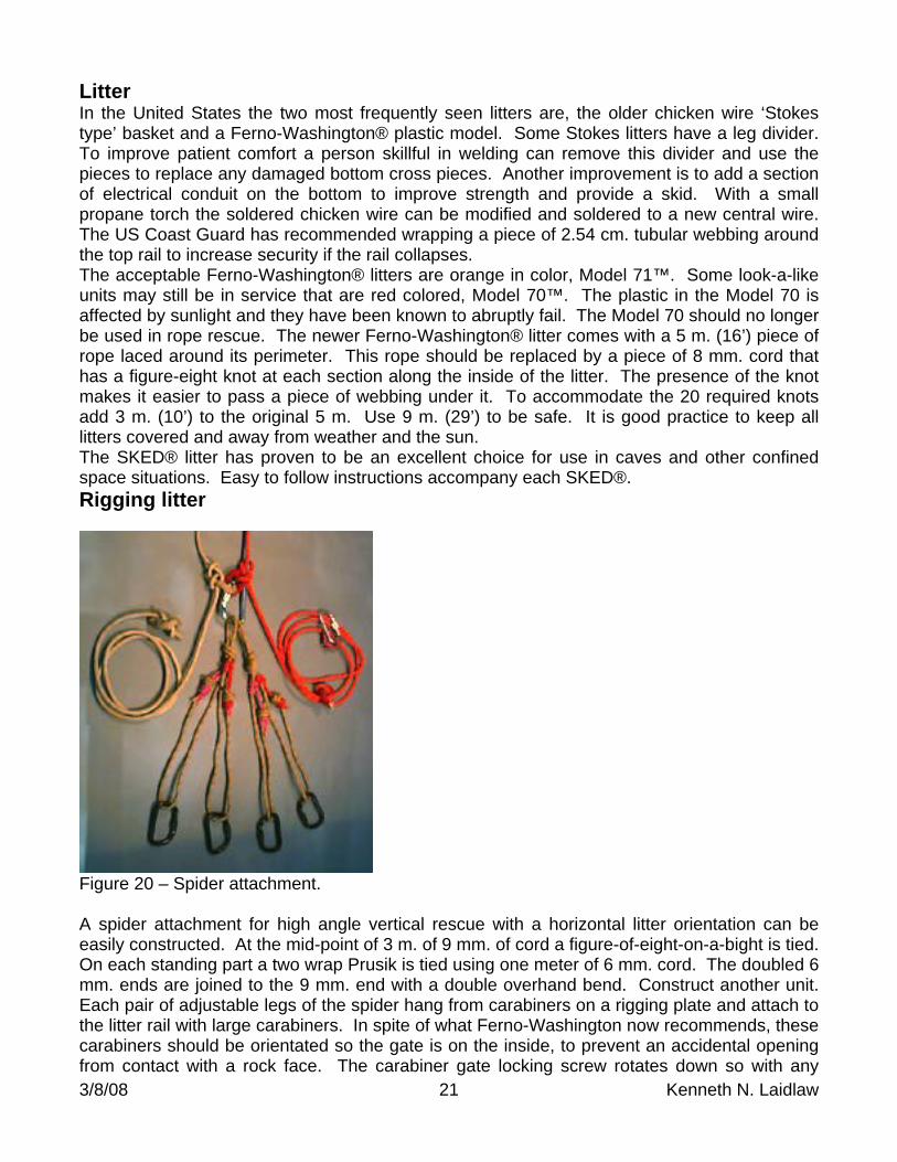
Figure 18 – Attendant Jigger in 3:1 mode with a change of direction. Heavy Duty Jigger: To assemble a heavy duty jigger use about 12 m. (39’) of 11 mm. (7/16”) rope, one twin Prusik Minding Pulley with a becket hole, two single pulleys, four Prusik loops, three carabiners and one oval screw link. It is assembled in the same procedure first described above. It offers the flexibility as a simple 4:1, reversed to a simple 5:1, or converted with one move to a compound 9:1 that will collapse to accommodate one meter of load travel. Anchored conveniently and using a Prusik hitch or a Rescucender to grab a rope a variety of tasks can be performed quickly. This larger version works well for adjusting tension on a guiding line.
Figure 19 – Heavy duty Jigger.
3/8/08 21 Kenneth N. Laidlaw
Litter In the United States the two most frequently seen litters are, the older chicken wire ‘Stokes type’ basket and a Ferno-Washington® plastic model. Some Stokes litters have a leg divider. To improve patient comfort a person skillful in welding can remove this divider and use the pieces to replace any damaged bottom cross pieces. Another improvement is to add a section of electrical conduit on the bottom to improve strength and provide a skid. With a small propane torch the soldered chicken wire can be modified and soldered to a new central wire. The US Coast Guard has recommended wrapping a piece of 2.54 cm. tubular webbing around the top rail to increase security if the rail collapses. The acceptable Ferno-Washington® litters are orange in color, Model 71™. Some look-a-like units may still be in service that are red colored, Model 70™. The plastic in the Model 70 is affected by sunlight and they have been known to abruptly fail. The Model 70 should no longer be used in rope rescue. The newer Ferno-Washington® litter comes with a 5 m. (16’) piece of rope laced around its perimeter. This rope should be replaced by a piece of 8 mm. cord that has a figure-eight knot at each section along the inside of the litter. The presence of the knot makes it easier to pass a piece of webbing under it. To accommodate the 20 required knots add 3 m. (10’) to the original 5 m. Use 9 m. (29’) to be safe. It is good practice to keep all litters covered and away from weather and the sun. The SKED® litter has proven to be an excellent choice for use in caves and other confined space situations. Easy to follow instructions accompany each SKED®. Rigging litter
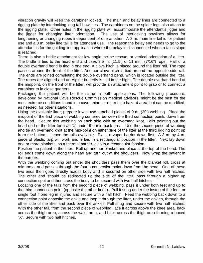
Figure 20 – Spider attachment. A spider attachment for high angle vertical rescue with a horizontal litter orientation can be easily constructed. At the mid-point of 3 m. of 9 mm. of cord a figure-of-eight-on-a-bight is tied. On each standing part a two wrap Prusik is tied using one meter of 6 mm. cord. The doubled 6 mm. ends are joined to the 9 mm. end with a double overhand bend. Construct another unit. Each pair of adjustable legs of the spider hang from carabiners on a rigging plate and attach to the litter rail with large carabiners. In spite of what Ferno-Washington now recommends, these carabiners should be orientated so the gate is on the inside, to prevent an accidental opening from contact with a rock face. The carabiner gate locking screw rotates down so with any
3/8/08 22 Kenneth N. Laidlaw
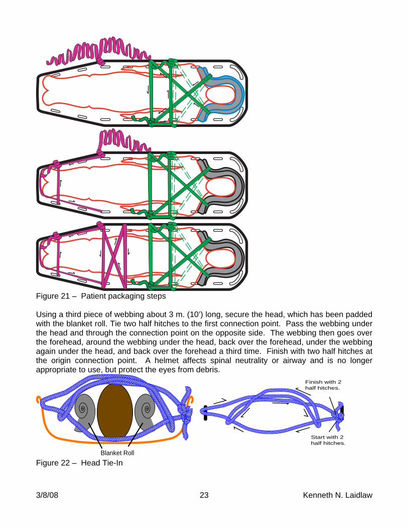
vibration gravity will keep the carabiner locked. The main and belay lines are connected to a rigging plate by interlocking long tail bowlines. The carabiners on the spider legs also attach to the rigging plate. Other holes in the rigging plate will accommodate the attendant’s jigger and the jigger for changing litter orientation. The use of interlocking bowlines allows for lengthening or changing ropes independent of one another. A 2 m. main line tail is for patient use and a 3 m. belay line tail is for attendant use. The reason the belay end needs to go to the attendant is for the guiding line application where the belay is disconnected when a talus slope is reached. There is also a bridle attachment for low angle incline rescue, or vertical orientation of a litter. The bridle is tied to the head end and uses 3.5 m. (11.5’) of 11 mm. (7/16") rope. Half of a double overhand bend is tied in one end. A clove hitch is placed around the litter rail. The rope passes around the front of the litter. Another clove hitch is tied around the opposite side rail. The ends are joined completing the double overhand bend, which is located outside the litter. The ropes are aligned and an Alpine butterfly is tied in the bight. The double overhand bend at the midpoint, on the front of the litter, will provide an attachment point to grab or to connect a carabiner to in close quarters. Packaging the patient will be the same in both applications. The following procedure, developed by National Cave Rescue Commission medical advisors, might be the best for the most extreme conditions found in a cave, mine, or other high hazard area; but can be modified, as needed, for other situations. Using the available litter, prepare it with two attached pieces of 9 m. (30’) webbing. Place the midpoint of the first piece of webbing centered between the third connection points down from the head. Secure this webbing on each side with an overhand knot. Tails pointing out the head end of the litter form an 'X' under the mid-back area. Use the second piece of webbing and tie an overhand knot at the mid-point on either side of the litter at the third rigging point up from the bottom. Leave the tails available. Place a vapor barrier down first. A 3 m. by 4 m. piece of plastic tarp will work and is laid in a rectangular position in the litter. Next lay down one or more blankets, as a thermal barrier, also in a rectangular fashion. Position the patient in the litter. Roll up another blanket and place at the top of the head. The roll ends come down along the head and turn out at the shoulders. Now wrap the patient in the barriers. With the webbing coming out under the shoulders pass them over the blanket roll, cross at mid-torso, and passes through the fourth connection point down from the head. One of these two ends then goes directly across body and is secured on other side with two half hitches. The other end should be redirected up the side of the litter, pass through a higher up connection spot and then cross the body to be secured with two half hitches. Locating one of the tails from the second piece of webbing, pass it under both feet and up to the third connection point (opposite the other knee). Pull it snug under the instep of the feet, or single foot if one leg in injured and secure with a half hitch. Feed the webbing back down to a connection point opposite the ankle and loop it through the litter, under the ankles, through the other side of the litter and back over the ankles. Pull snug and secure with two half hitches. With the other tail, from the second piece of webbing, lace it across above the knee area, back across the thigh area, across the waist area, and back across the thigh area forming a boxed “X”. Secure with two half hitches.
3/8/08 23 Kenneth N. Laidlaw
Figure 21 – Patient packaging steps Using a third piece of webbing about 3 m. (10’) long, secure the head, which has been padded with the blanket roll. Tie two half hitches to the first connection point. Pass the webbing under the head and through the connection point on the opposite side. The webbing then goes over the forehead, around the webbing under the head, back over the forehead, under the webbing again under the head, and back over the forehead a third time. Finish with two half hitches at the origin connection point. A helmet affects spinal neutrality or airway and is no longer appropriate to use, but protect the eyes from debris.
Blanket Roll
Start with 2half hitches.
Finish with 2half hitches.
Figure 22 – Head Tie-In
3/8/08 24 Kenneth N. Laidlaw
Let the patient determine whether or not their arms are secured. Padding in various places, as behind the knees, under neck, may also be appropriate. Under less hazardous conditions, other straps might be more appropriate. Avoid using buckles with a button release or a pull release. Best choices for buckles are the interlocking types with versions offered by Cascade® and Traverse®. The test for a properly secured patient is to stand the litter on each end. If the patient slips down, the packaging was inappropriate. Appoint A Safety Officer Whenever you must perform a raising or a lowering, appoint an experienced person to perform the role of SAFETY OFFICER to check everything that the team does. All carabiners should be squeezed and cordage checked. Rotate this assignment to prevent a person from becoming unpopular. Personal Skills And Equipment A minimum standard for individuals working in the vertical world should be that:
Climbing gear can be put on in less than five minutes. On 5 meters (15 feet) of rope climb past a knot, change over and descend past a knot in
less than 8 minutes. Climb 100 meters (300 feet) in less than 30 minutes.
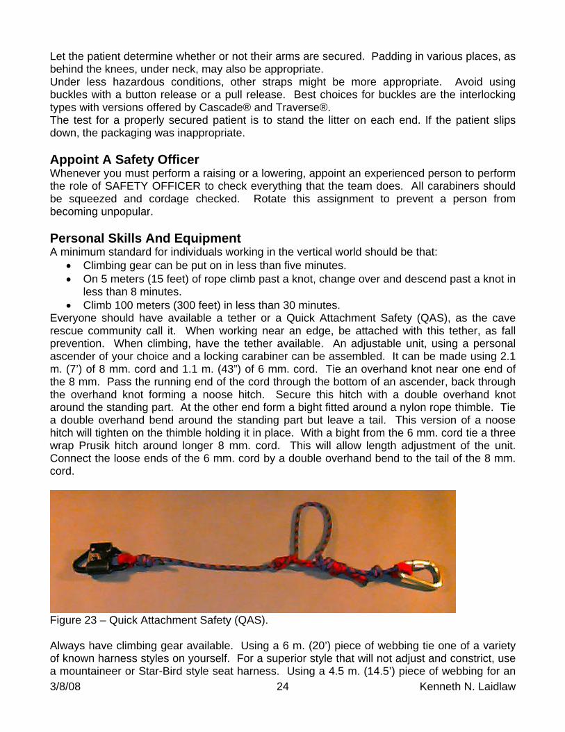
Everyone should have available a tether or a Quick Attachment Safety (QAS), as the cave rescue community call it. When working near an edge, be attached with this tether, as fall prevention. When climbing, have the tether available. An adjustable unit, using a personal ascender of your choice and a locking carabiner can be assembled. It can be made using 2.1 m. (7’) of 8 mm. cord and 1.1 m. (43”) of 6 mm. cord. Tie an overhand knot near one end of the 8 mm. Pass the running end of the cord through the bottom of an ascender, back through the overhand knot forming a noose hitch. Secure this hitch with a double overhand knot around the standing part. At the other end form a bight fitted around a nylon rope thimble. Tie a double overhand bend around the standing part but leave a tail. This version of a noose hitch will tighten on the thimble holding it in place. With a bight from the 6 mm. cord tie a three wrap Prusik hitch around longer 8 mm. cord. This will allow length adjustment of the unit. Connect the loose ends of the 6 mm. cord by a double overhand bend to the tail of the 8 mm. cord.
Figure 23 – Quick Attachment Safety (QAS). Always have climbing gear available. Using a 6 m. (20’) piece of webbing tie one of a variety of known harness styles on yourself. For a superior style that will not adjust and constrict, use a mountaineer or Star-Bird style seat harness. Using a 4.5 m. (14.5’) piece of webbing for an
3/8/08 25 Kenneth N. Laidlaw
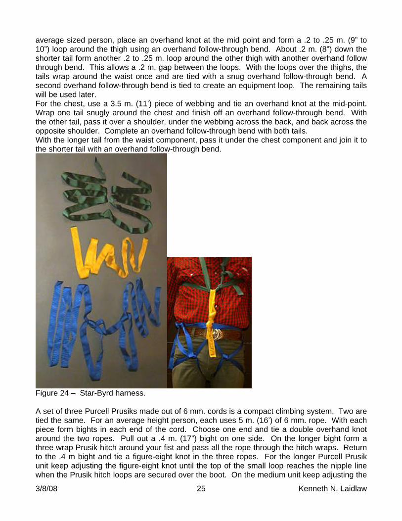
average sized person, place an overhand knot at the mid point and form a .2 to .25 m. (9” to 10”) loop around the thigh using an overhand follow-through bend. About .2 m. (8”) down the shorter tail form another .2 to .25 m. loop around the other thigh with another overhand follow through bend. This allows a .2 m. gap between the loops. With the loops over the thighs, the tails wrap around the waist once and are tied with a snug overhand follow-through bend. A second overhand follow-through bend is tied to create an equipment loop. The remaining tails will be used later. For the chest, use a 3.5 m. (11’) piece of webbing and tie an overhand knot at the mid-point. Wrap one tail snugly around the chest and finish off an overhand follow-through bend. With the other tail, pass it over a shoulder, under the webbing across the back, and back across the opposite shoulder. Complete an overhand follow-through bend with both tails. With the longer tail from the waist component, pass it under the chest component and join it to the shorter tail with an overhand follow-through bend.
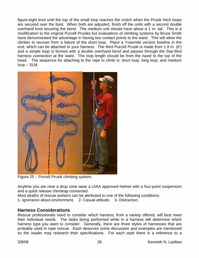
Figure 24 – Star-Byrd harness. A set of three Purcell Prusiks made out of 6 mm. cords is a compact climbing system. Two are tied the same. For an average height person, each uses 5 m. (16’) of 6 mm. rope. With each piece form bights in each end of the cord. Choose one end and tie a double overhand knot around the two ropes. Pull out a .4 m. (17”) bight on one side. On the longer bight form a three wrap Prusik hitch around your fist and pass all the rope through the hitch wraps. Return to the .4 m bight and tie a figure-eight knot in the three ropes. For the longer Purcell Prusik unit keep adjusting the figure-eight knot until the top of the small loop reaches the nipple line when the Prusik hitch loops are secured over the boot. On the medium unit keep adjusting the
3/8/08 26 Kenneth N. Laidlaw
figure-eight knot until the top of the small loop reaches the crotch when the Prusik hitch loops are secured over the boot. When both are adjusted, finish off the units with a second double overhand knot securing the bend. The medium unit should have about a 1 m. tail. This is a modification to the original Purcell Prusiks but evaluations of climbing systems by Bruce Smith have demonstrated the advantage in having two contact points to the waist. This will allow the climber to recover from a failure of the short loop. Place a Yosemite version bowline in the end, which can be attached to your harness. The third Purcell Prusik is made from 1.9 m. (6’) and a simple loop is formed with a double overhand bend and passes through the Star-Bird harness connection at the waist. The loop length should be from the navel to the top of the head. The sequence for attaching to the rope to climb is: short loop, long loop, and medium loop – SLM.
Figure 25 – Purcell Prusik climbing system. Anytime you are near a drop zone wear a UIAA approved helmet with a four-point suspension and a quick release chinstrap connected. Most deaths of rescue workers can be attributed to one of the following conditions: 1- Ignorance about environment, 2- Casual attitude, 3- Distraction. Harness Considerations Rescue professionals need to consider which harness, from a variety offered, will best meet their individual needs. The tasks being performed while in a harness will determine which harness type you want to consider. Generally, there are three styles of harnesses that are probably used in rope rescue. Each deserves some discussion and examples are mentioned so the reader may research their specifications. For each style there is a reference to a
3/8/08 27 Kenneth N. Laidlaw
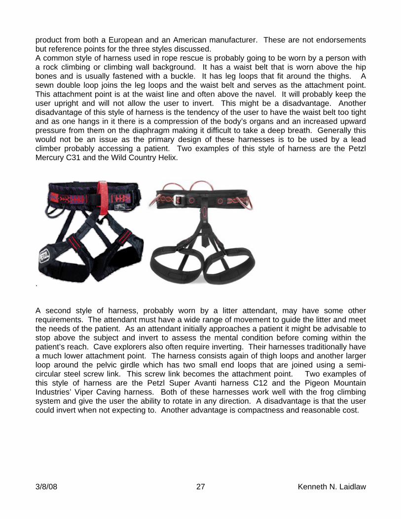
product from both a European and an American manufacturer. These are not endorsements but reference points for the three styles discussed. A common style of harness used in rope rescue is probably going to be worn by a person with a rock climbing or climbing wall background. It has a waist belt that is worn above the hip bones and is usually fastened with a buckle. It has leg loops that fit around the thighs. A sewn double loop joins the leg loops and the waist belt and serves as the attachment point. This attachment point is at the waist line and often above the navel. It will probably keep the user upright and will not allow the user to invert. This might be a disadvantage. Another disadvantage of this style of harness is the tendency of the user to have the waist belt too tight and as one hangs in it there is a compression of the body’s organs and an increased upward pressure from them on the diaphragm making it difficult to take a deep breath. Generally this would not be an issue as the primary design of these harnesses is to be used by a lead climber probably accessing a patient. Two examples of this style of harness are the Petzl Mercury C31 and the Wild Country Helix.
. A second style of harness, probably worn by a litter attendant, may have some other requirements. The attendant must have a wide range of movement to guide the litter and meet the needs of the patient. As an attendant initially approaches a patient it might be advisable to stop above the subject and invert to assess the mental condition before coming within the patient’s reach. Cave explorers also often require inverting. Their harnesses traditionally have a much lower attachment point. The harness consists again of thigh loops and another larger loop around the pelvic girdle which has two small end loops that are joined using a semi-circular steel screw link. This screw link becomes the attachment point. Two examples of this style of harness are the Petzl Super Avanti harness C12 and the Pigeon Mountain Industries’ Viper Caving harness. Both of these harnesses work well with the frog climbing system and give the user the ability to rotate in any direction. A disadvantage is that the user could invert when not expecting to. Another advantage is compactness and reasonable cost.
3/8/08 28 Kenneth N. Laidlaw
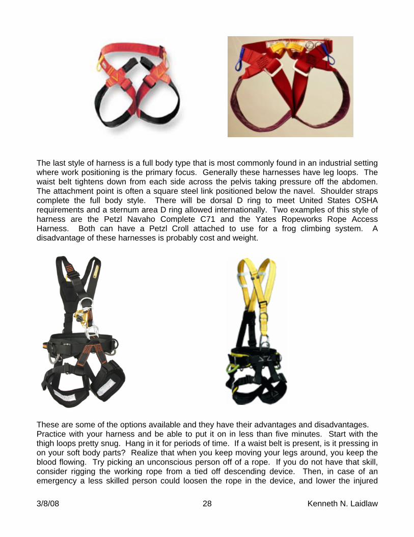
The last style of harness is a full body type that is most commonly found in an industrial setting where work positioning is the primary focus. Generally these harnesses have leg loops. The waist belt tightens down from each side across the pelvis taking pressure off the abdomen. The attachment point is often a square steel link positioned below the navel. Shoulder straps complete the full body style. There will be dorsal D ring to meet United States OSHA requirements and a sternum area D ring allowed internationally. Two examples of this style of harness are the Petzl Navaho Complete C71 and the Yates Ropeworks Rope Access Harness. Both can have a Petzl Croll attached to use for a frog climbing system. A disadvantage of these harnesses is probably cost and weight.
These are some of the options available and they have their advantages and disadvantages. Practice with your harness and be able to put it on in less than five minutes. Start with the thigh loops pretty snug. Hang in it for periods of time. If a waist belt is present, is it pressing in on your soft body parts? Realize that when you keep moving your legs around, you keep the blood flowing. Try picking an unconscious person off of a rope. If you do not have that skill, consider rigging the working rope from a tied off descending device. Then, in case of an emergency a less skilled person could loosen the rope in the device, and lower the injured
3/8/08 29 Kenneth N. Laidlaw
party to the ground. When working on rope it is a best practice to always rig two ropes as OSHA requires. One to climb on and the other for a traveling belay device, i.e. Petzl Shunt. Work restraint systems and their travel restrictions are not a focus of this discussion. However, we need to consider what will happen if a person falls using either of the first two groups of described harnesses. When the attachment point reaches the end of the rope it stops but usually the head and the feet continue to travel with some resultant bone and tissue damage. The shock will probably render the user unable to help oneself. The result will be suspension trauma, also known as Harness Hang Syndrome – HHS. The medical term is called compartmental syndrome, where the blood does not circulate properly and tends to pool in the extremities. This can be a very serious medical situation and the hanging person needs to be removed quickly but in consideration of the pooling complications. To understand the seriousness of this topic the reader should consult a document entitled Harness Suspension prepared by Paul Seddon in 2002. It can be found on the internet at
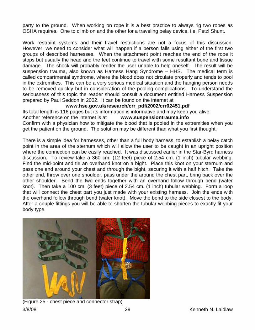
www.hse.gov.uk/research/crr_pdf/2002/crr02451.pdf Its total length is 116 pages but its information is informative and may keep you alive. Another reference on the internet is at www.suspensiontrauma.info Confirm with a physician how to mitigate the blood that is pooled in the extremities when you get the patient on the ground. The solution may be different than what you first thought. There is a simple idea for harnesses, other than a full body harness, to establish a belay catch point in the area of the sternum which will allow the user to be caught in an upright position where the connection can be easily reached. It was discussed earlier in the Star-Byrd harness discussion. To review take a 360 cm. (12 feet) piece of 2.54 cm. (1 inch) tubular webbing. Find the mid-point and tie an overhand knot on a bight. Place this knot on your sternum and pass one end around your chest and through the bight, securing it with a half hitch. Take the other end, throw over one shoulder, pass under the around the chest part, bring back over the other shoulder. Bend the two ends together with an overhand follow through bend (water knot). Then take a 100 cm. (3 feet) piece of 2.54 cm. (1 inch) tubular webbing. Form a loop that will connect the chest part you just made with your existing harness. Join the ends with the overhand follow through bend (water knot). Move the bend to the side closest to the body. After a couple fittings you will be able to shorten the tubular webbing pieces to exactly fit your body type.
(Figure 25 - chest piece and connector strap)
3/8/08 30 Kenneth N. Laidlaw
Connect your belay to this connector strap that goes between the chest piece and your harness. In a fall the belay connection will slide up the connector strap and catch at the sternum area. The impact will catch you in an upright position. You may be slapped in the face but you will be in a position to recover from the incident. Whether or not you use a belay in the United States may depend on your legal status. If you are involved in recreation or serving as a volunteer for rope rescue you are not required to have an independent belay. If you are a paid worker you are required to have an independent belay by OSHA. OSHA says the connection should be in the dorsal area. This will make self recovery difficult. It makes common sense to use a belay whenever possible, and usually it can become a matter of habit. However if the rope dangles more than 90 meters it is probably ill advised to use a belay as the ropes can tangle. Avoid injuries, keep your waist loop loose and use the chest loop as described above. If you want to make marks on a rope, manufacturers say do not use a product that contains phenol. If the ink smells like Pine-Sol™ it should not be used. If the ink smells like alcohol it is safe to use. SANFORD’S Rub-A-Dub™ laundry pen is okay, but SANFORD’S Sharpie™ marker is NOT. However in 2001 Parker and McKently of CMC® conducted testing and could not prove that any type of marking would weaken a rope. In 2004 they reported that contact with both DEET and chewing tobacco spit would not weaken rope. In 2002 they determined that urine would weaken rope strength. In 2002 Jim Kovich an Ohio firefighter sewed rope into a rug and had firefighters wipe their feet daily on it for several months. He also had fire equipment repeatedly drive over rope on the pavement. In both situations the rope tested to original specifications. Some Thoughts In Review Your goal is to get the maximum potential with the minimum of manpower and equipment. A general concept is to use a main line and a belay line of different colors to avoid confusion and keep them in the best condition trying not to tie them to the anchor. Store the two lines in different color bags. Another concept allows for soft and hard methods of attaching to the main line. Extra equipment should be available to pass a bend. The belay line should not be used when the load must be shifted. Use other techniques or a jigger. Avoid situations where a load has a potential of shifting 30 cm. (1’). If you need to make a mid-line connection use a cross-lashed strap or ‘dog and tails’ rather than an in-line knot. Carabiners should be chosen with consideration. Besides locking, the gate design should assure that it will catch when the long axis is stretched. Consider carabiners with the key lock design. Make sure the carabiners are placed with the gates up and the lock screwing down towards the load. Only hand tighten the lock. Interior angles on components should be less than 90 degrees.
With a 100 kg. load: …at 0 degrees each leg has a 50 kg. load …at 30 degrees each leg has a 52 kg. load …at 45 degrees each leg has a 54 kg. load …at 60 degrees each leg has a 58 kg. load …at 90 degrees each leg has a 71 kg. load …at 120 degrees each leg has a 100 kg. load …with an interior angle of 150 degrees each leg has a 193 kg. load The safety factor is described as a ratio between the breaking strength and the force you intend to put on it. A guideline in rope rescue is to try to have around a 10:1 safety factor. If the rope is 11 mm., with minimum rating of 26 kN, then the forces should not exceed 2.6 kN. Through experimentation, the BCCTR developed the twelve people pulling idea, as a safe limit of the force to apply for a system. On 12.5 mm. rope, rated at about 40 kN, then the eighteen

3/8/08 31 Kenneth N. Laidlaw
people pulling idea was a safe limit to apply for a rescue load. Remember, a pulling person is defined as someone just pulling hand over hand, and this effort, in a group setting, approximates only 222 N (50 lbs.) of force for each person. In reality the actual safety factor may be closer to 7:1. The following chart demonstrates how an object is affected by law of gravity in free fall:
Time in seconds Velocity in m/s Displacement in meters 0 0 0 1 9.8 4.9 2 19.6 19.6 3 29.4 44.1 4 39.2 78.4
A final thought… When confronted with the variety of ways of doing something Kirk Mauthner asks, “What difference does a difference make unless it makes a difference?’ Acknowledgements I would like to thank the following individuals for their help in gathering the information presented. Their patience was also appreciated: Arnor Larson, Kirk and Katie Mauthner, Steve Hudson, Bruce Smith, John Dill, Reed Thorne, Bill Cuddington, Carroll Bassett, Jon Olson, William Lane, Kim Aufhauser, William Shrewsbury, Bruce Parker, John McKently, DJ Walker, Gary Storrick, and John Carnes, the illustrator. . Publications These publications currently offer more information on the subject of rope rescue. The Ashley Book of Knots, by Clifford W. Ashley, Doubleday, 1944, (800) 346-7673 On Rope, New Revised Edition, by Bruce Smith and Allen Padgett, National Speleological Society, 1996, (205) 852-1300 Technical Rescue Riggers Guide, by Rick Lipke, Conterra Inc., 2002, (510) 843-5253 Are You REALLY On Belay? by John T. Dill, NASAR RESPONSE®, 1990, (703) 352-1349 Release-Devices: A Comparative Analysis, by Katie and Kirk Mauthner, 1999, (250) 342-6042 The Load Distributing Anchor System, by Keith Schafer, NASAR RESPONSE®, 1991 Gripping Ability on Rope in Motion, by Katie and Kirk Mauthner, 1994, (250) 342-6042 Everything you ever wanted to know about vertical equipment go to:
http://storrick.cnchost.com/VerticalDevicesPage/VerticalHome.shtml Training The author cannot recommend any current training programs. Most instructors and training company employees have learned their rope rescue material by rote, a fixed mechanical way of doing something by memory only without understanding or thought. International Technical Rescue Symposium annually held in early November.

3/8/08 32 Kenneth N. Laidlaw
It is co-sponsored by Mountain Rescue Association, National Cave Rescue Commission, National Association for Search and Rescue, Society of Professional Rope Access Technicians and jointly presented by California Mountain Company and Pigeon Mountain Industries. Three trainers who the author can recommend Arnor Larson, Kirk Mauthner, and Reed Thorne. Venders Contact the dealer listed below, mention this presentation, and request a discount: CAL-PACIFIC RESOURCES at 655 Lewelling Blvd. #149 in San Leandro, CA 94579 Telephone (510) 727-8624 – Fax (510) 383-9192 – [email protected] Offers 5% to 20% off a list price. BMS at HC 68 Box 64B in Friar’s Hill, WV 24938-9774 Telephone (304) 497-4311 http://www.bmsrescue.com manufacturer ABOUT THE AUTHOR Kenneth N. Laidlaw has been a practitioner of Search and Rescue skills with twelve different types of organizations over the last forty years. His background includes Red Cross Emergency First Responder, National Association of Search and Rescue SAR-Technician Evaluator, National Cave Rescue Commission Instructor certification, Society of Professional Rope Access Technician qualification, Joel Hardin Signcutter Tracking certification, Type II Wildland Firefighter qualified, Hazardous Materials Operations certification, Confined Space Operations certification, Mine Safety and Health Administration qualified, Mountain Rescue Association qualified, public safety diver and tender qualified, amateur radio General license N6GFE, California Rescue Dog Association Mission Ready Support Person, Alameda County Sheriff’s Search and Rescue member, Humane Society United States Emergency Responder, United States Fish and Wildlife refuge volunteer, technical skills consultant for the Fire Department for the East Bay Regional Park District, and a retired seasonal Police Officer with the East Bay Regional Park District.

3/8/08 33 Kenneth N. Laidlaw
Basic Application In The Field The following list of minimum equipment can be pre-packaged in two bags and has been demonstrated to probably solve most situations safely with limited personnel. The author now defines this as the T.A.C. Rope Kit, (Tactical, Adaptable, and Compact)
BELAY BAG:
10 m. (33’) 2.54 cm. tubular webbing for wrap 2 pull 1 or wrap 3 pull 2 anchor
60 m. (200’) 11 mm. (7/16”) rope (orange) 1 2” Pulley (not required but makes the haul easier with Prusik hitches) Tandem Prusik set: (Can substitute 540 Rescue Belay)
1.35m (53”) 8 mm. accessory cord loop 1.65 m. (65”) 8 mm. accessory cord loop Load Release Hitch: (Radium 3:1 Load Releasing Hitch) 10 m. (33’) 8 mm. accessory cord 2 lite-steel locking D carabiners 1 pair leather gloves 1 rope bag (orange) WORKING BAG:
10 m. (33’) 2.54 cm. tubular webbing for wrap 2 pull 1 or wrap 3 pull 2 anchor 60 m. (200’) 11 mm. (7/16”) rope (white) 1 brake bar rack (preferably with hyper-bar) 1 aluminum locking D carabiner 1 Prusik minding pulley 1 2” pulley 2 Prusik loops 1.35 m. (53”) accessory cord (may be custom fit) Load Release Hitch: (Radium 3:1 Load Releasing Hitch) 10 m. (33’) 8 mm. accessory cord 2 aluminum locking D carabiners rated over 25 kN 1 rope bag (color other than belay bag)
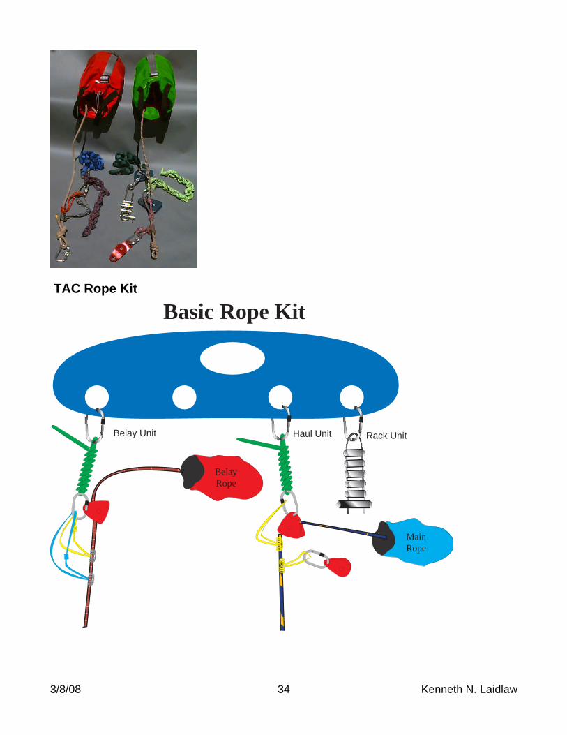
3/8/08 34 Kenneth N. Laidlaw
TAC Rope Kit
Basic Rope Kit
Rack UnitHaul UnitBelay Unit
MainRope
BelayRope
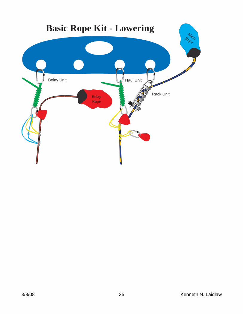
3/8/08 35 Kenneth N. Laidlaw
Basic Rope Kit - Lowering
Rack Unit
Haul UnitBelay Unit
BelayRope
MainRope
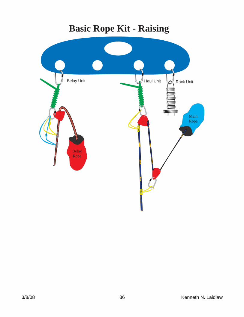
3/8/08 36 Kenneth N. Laidlaw
Basic Rope Kit - Raising
Rack UnitHaul UnitBelay Unit
MainRope
BelayRope