Embed Size (px)
Citation preview
NAVAL
POSTGRADUATE SCHOOL
MONTEREY, CALIFORNIA
THESIS
Approved for public release; distribution is unlimited
CONSOLIDATED TACTICAL NETWORK ANALYSIS FOR OPTIMIZING BANDWIDTH: MARINE CORPS SUPPORT
WIDE AREA NETWORK (SWAN) AND TCP ACCELERATORS
by
Shane Jenson
September 2009
Thesis Co-Advisors: Rex Buddenberg Alex Bordetsky
i
REPORT DOCUMENTATION PAGE Form Approved OMB No. 0704-0188 Public reporting burden for this collection of information is estimated to average 1 hour per response, including the time for reviewing instruction, searching existing data sources, gathering and maintaining the data needed, and completing and reviewing the collection of information. Send comments regarding this burden estimate or any other aspect of this collection of information, including suggestions for reducing this burden, to Washington headquarters Services, Directorate for Information Operations and Reports, 1215 Jefferson Davis Highway, Suite 1204, Arlington, VA 22202-4302, and to the Office of Management and Budget, Paperwork Reduction Project (0704-0188) Washington DC 20503. 1. AGENCY USE ONLY (Leave blank)
2. REPORT DATE September 2009
3. REPORT TYPE AND DATES COVERED Master’s Thesis
4. TITLE AND SUBTITLE: Consolidated Tactical Network Analysis for Optimizing Bandwidth: Marine Corps Support Wide Area Network (SWAN) and TCP Accelerators 6. AUTHOR(S) Shane Jenson
5. FUNDING NUMBERS
7. PERFORMING ORGANIZATION NAME(S) AND ADDRESS(ES) Naval Postgraduate School Monterey, CA 93943-5000
8. PERFORMING ORGANIZATION REPORT NUMBER
9. SPONSORING /MONITORING AGENCY NAME(S) AND ADDRESS(ES) N/A
10. SPONSORING/MONITORING AGENCY REPORT NUMBER
11. SUPPLEMENTARY NOTES The views expressed in this thesis are those of the author and do not reflect the official policy or position of the Department of Defense or the U.S. Government. 12a. DISTRIBUTION / AVAILABILITY STATEMENT Approved for public release; distribution is unlimited
12b. DISTRIBUTION CODE
13. ABSTRACT (maximum 200 words) In 2004, the Support Wide Area Network (SWAN) system added significant capability to the way Marines
communicate on the battlefield. Today, the SWAN system is still a critical segment in Marine communications and the TCP accelerator is being evaluated for a potential upgrade. Due to the rapid nature of the SWAN procurement process, in-depth testing procedures have never been established for this system. As a result, there are no procedures to effectively test and evaluate SWAN components for equipment upgrade.
Currently, MCSC relies on two IT consulting agencies, the U.S. Army Information Systems Engineering Command and the SWAN lab on Camp Pendleton to evaluate components being considered for upgrade. This thesis explores these testing approaches, specifically addressing the TCP accelerator. It also evaluates the testing efforts and combines them into a single, standardized, repeatable and more accurate test that can be applied to the SWAN system or any other tactical Marine Corps network and their components.
15. NUMBER OF PAGES
145
14. SUBJECT TERMS TCP/IP; TCP; IP; Acceleration; Accelerator; SATCOM; Communication; Bandwidth; Optimization; SWAN; Testing; Tactical Network
16. PRICE CODE
17. SECURITY CLASSIFICATION OF REPORT
Unclassified
18. SECURITY CLASSIFICATION OF THIS PAGE
Unclassified
19. SECURITY CLASSIFICATION OF ABSTRACT
Unclassified
20. LIMITATION OF ABSTRACT
UU NSN 7540-01-280-5500 Standard Form 298 (Rev. 8-98) Prescribed by ANSI Std. Z39.18

ii
THIS PAGE INTENTIONALLY LEFT BLANK
iii
Approved for public release; distribution is unlimited
CONSOLIDATED TACTICAL NETWORK ANALYSIS FOR OPTIMIZING BANDWIDTH: MARINE CORPS SUPPORT WIDE AREA NETWORK (SWAN)
AND TCP ACCELERATORS
Shane B. Jenson Captain, United States Marine Corps
B.S., University of Utah, 2001
Submitted in partial fulfillment of the requirements for the degree of
MASTER OF SCIENCE IN INFORMATION TECHNOLOGY MANAGEMENT
from the
NAVAL POSTGRADUATE SCHOOL September 2009
Author: Shane B. Jenson
Approved by: Rex Buddenberg Thesis Co-Advisor
Alex Bordetsky Thesis Co-Advisor
Dan Boger Chairman, Department of Information Sciences

iv
THIS PAGE INTENTIONALLY LEFT BLANK
v
ABSTRACT
In 2004, the Support Wide Area Network (SWAN) system added
significant capability to the way Marines communicate on the battlefield. Today,
the SWAN system is still a critical segment in Marine communications and the
TCP accelerator is being evaluated for a potential upgrade. Due to the rapid
nature of the SWAN procurement process, in-depth testing procedures have
never been established for this system. As a result, there are no procedures to
effectively test and evaluate SWAN components for equipment upgrade.
Currently, MCSC relies on two IT consulting agencies, the U.S. Army
Information Systems Engineering Command and the SWAN lab on Camp
Pendleton to evaluate components being considered for upgrade. This thesis
explores these testing approaches, specifically addressing the TCP accelerator.
It also evaluates the testing efforts and combines them into a single,
standardized, repeatable and more accurate test that can be applied to the
SWAN system or any other tactical Marine Corps network and their components.

vi
THIS PAGE INTENTIONALLY LEFT BLANK
vii
TABLE OF CONTENTS
I. INTRODUCTION............................................................................................. 1 A. THESIS OBJECTIVES......................................................................... 4 B. RELATED WORK ................................................................................ 5
1. Naval Postgraduate Thesis Work ........................................... 5 a. “Optimizing Bandwidth in Tactical
Communications Systems” ......................................... 5 b. “A Conceptual Framework for Tactical Private
Satellite Networks” ....................................................... 7 2. Commercial Information Technology Organizations............ 8
a. MITRE............................................................................. 8 b. Sidereal Solutions Incorporated.................................. 9
3. Marine Corps Tactical Systems Support Activity (MCTSSA) ............................................................................... 10
4. U.S. Army Information Systems Engineering Command ... 11 5. The Problem with Current SWAN Evaluations .................... 12
C. THESIS ORGANIZATION.................................................................. 13
II. TECHNOLOGY BACKGROUND.................................................................. 15 A. NETWORK ARCHITECTURE............................................................ 15
1. Local Area Network (LAN)..................................................... 18 a. Internet Protocol (IP)................................................... 20
2. Wide Area Networks (WAN) .................................................. 21 a. Terrestrial–Wide Area Network (T-WAN)................... 22 b. Radio Frequency–Wide Area Network (RF-WAN)..... 22
3. LANs and WANs .................................................................... 24 B. END-TO-END PROTOCOLS ............................................................. 25
1. User Datagram Protocol (UDP)............................................. 26 2. Transmission Control Protocol (TCP).................................. 27
a. Early Open ................................................................... 32 3. Space Communications Protocol Standard (SPCS) ........... 33 4. Negative-acknowledgement (NACK)–Oriented Reliable
Multicast (NORM).................................................................... 34 C. APPLICATIONS................................................................................. 36
1. File Transfer Protocol (FTP).................................................. 36 2. Hypertext Transfer Protocol (HTTP)..................................... 37 3. Simple Mail Transfer Protocol (SMTP)................................. 39
D. TCP ACCELERATION EXPLAINED ................................................. 40 1. Legacy Performance Enhancing Proxy (PEP)
Functionality .......................................................................... 41 2. Modern PEP functionality ..................................................... 44
E. WEB CACHE COMMUNICATION PROTOCOL (WCCP).................. 46
III. NETWORK TEST DESIGN........................................................................... 47
viii
A. PURPOSE.......................................................................................... 47 B. PHYSICAL LAB DESCRIPTION........................................................ 47
1. Testbed Components ............................................................ 48 2. Testbed Characteristics ........................................................ 50
a. WAN: GSWAN (SWAN-C) ........................................... 50 b. AMC-21 Satellite.......................................................... 51 c. Network Configuration ............................................... 52
3. Software Tools ....................................................................... 53 a. IxChariot ...................................................................... 53 b. Wireshark..................................................................... 55
4. Network Traffic Generating Approach ................................. 56 a. Single Protocol Scripts............................................... 57 b. IxChariot Script Modification ..................................... 58 c. Multi-User/Protocol/Direction Scripts ....................... 60
C. VARIATIONS ..................................................................................... 61 D. LIMITATIONS .................................................................................... 61
1. Traffic Generation.................................................................. 61 2. Multicast ................................................................................. 62
IV. DATA ANALYSIS ......................................................................................... 63 A. EXISTING TCP ACCELERATOR TESTS REVIEW........................... 63 B. TCP ACCELERATOR PLATFORM OVERVIEW............................... 65
1. Comtech–TurboIP.................................................................. 65 2. TurboIP–G2 ............................................................................ 66 3. CISCO–Wide Area Application Service (WAAS) ................. 66 4. CITRIX–WANScaler Defense Edition.................................... 67 5. Riverbed–Steelhead-550 ....................................................... 68
C. NETWORK TRAFFIC VALIDATION: ACTUAL VS. SIMULATED FTP..................................................................................................... 69
D. SINGLE PROTOCOL SCRIPTS ........................................................ 71 E. IXCHARIOT OUTPUT........................................................................ 74 F. MULTIPLE PROTOCOL SCRIPTS.................................................... 79 G. TCP ACCELERATOR INTEROPERABILITY .................................... 82 H. WIRESHARK OUTPUT...................................................................... 84
1. TCP Algorithms...................................................................... 85 2. Network Traffic....................................................................... 86
a. Traffic Reductions....................................................... 86 b. Traffic Organization .................................................... 86
3. IxChariot ................................................................................. 87 I. OTHER TEST RESULTS ................................................................... 87
1. U.S. Army Information Systems Engineering Command ... 87 2. MITRE ..................................................................................... 88 3. MCTSSA.................................................................................. 89
V. CONCLUSION, RECOMMENDATIONS AND FUTURE WORK .................. 91 A. CONCLUSION ................................................................................... 91 B. RECOMMENDATIONS...................................................................... 93
ix
1. TCP Accelerator Testing for the SWAN System ................. 93 a. Network Traffic-Generating Tool ............................... 93 b. Test Procedures.......................................................... 94 c. IT Consultants ............................................................. 95
2. TCP Accelerator Selection.................................................... 95 3. Technology Modifications..................................................... 96
C. FUTURE WORK................................................................................. 96 1. Multicast ................................................................................. 96 2. Traffic Composition............................................................... 98 3. Computing Protocols ............................................................ 99 4. Cost Analysis ....................................................................... 100 5. Open Source Solutions ....................................................... 100
VI. SUMMARY.................................................................................................. 103
APPENDIX ............................................................................................................ 107 A. CANDIDATE DEVICES.................................................................... 107
1. Comtech–TurboIP (Current Device) ................................... 107 2. Comtech–TurboIP-G2.......................................................... 107 3. Cisco–WAAS........................................................................ 108 4. Citrix–WANScaler ................................................................ 109 5. Riverbed–Steelhead ............................................................ 110
B. MULTI-USER/PROTOCOL/DIRECTION TRAFFIC ......................... 112 1. No Acceleration (Unaccelerated)........................................ 112 2. TurboIP ................................................................................. 112 3. TurboIP–G2 .......................................................................... 113 4. Cisco–WAAS........................................................................ 113 5. Citrix–WANScaler ................................................................ 114 6. Riverbed–Steelhead ............................................................ 114
C. INTEROPERABILITY....................................................................... 115 1. TurboIP with TurboIP (reference) ....................................... 115 2. TurboIP with TurboIP-G2..................................................... 115 3. TurboIP with Cisco–WAAS ................................................. 116 4. TurboIP with Citrix–WANScaler.......................................... 116 5. TurboIP with Riverbed–Steelhead...................................... 117
D. WIRESHARK ANALYSIS ................................................................ 118 1. No Acceleration (Unaccelerated)........................................ 118 2. TurboIP ................................................................................. 118 3. TurboIP–G2 .......................................................................... 119 4. Cisco–WAAS........................................................................ 119 5. Citrix–WANScaler ................................................................ 120 6. Riverbed–Steelhead ............................................................ 120
LIST OF REFERENCES........................................................................................ 121
INITIAL DISTRIBUTION LIST ............................................................................... 125

x
THIS PAGE INTENTIONALLY LEFT BLANK
xi
LIST OF FIGURES
Figure 1. OSI Seven-layer Model (From Cote’, 2008, p. 14) ............................. 15 Figure 2. Encapsulation (From Fulp, 2009, p. 11) ............................................. 16 Figure 3. Network without (left) and with NICs................................................... 19 Figure 4. IP Header (From Postel, RFC 791, p. 11) .......................................... 21 Figure 5. UDP Header (From Postel, 1980, p. 1)............................................... 27 Figure 6. TCP Header (Postel, 1981, RFC 793, p. 15) ...................................... 28 Figure 7. TCP 3-Way Handshake (From Fulp, 2009, p. 143) ............................ 29 Figure 8. TCP Window Growth: Exponential vs. Linear (From Low, 2002, pp.
33, 35) ................................................................................................ 31 Figure 9. HTTP Request and Response Header and Body............................... 39 Figure 10. TCP Spoofing (From Inglis, n.d.) ........................................................ 42 Figure 11. TCP Spoofing, Big Picture.................................................................. 43 Figure 12. Testbed Environment for SWAN TCP Accelerators............................ 48 Figure 13. Testbed: WCCP Configured, Used for the Cisco WAAS Device ........ 50 Figure 14. IxChariot Test Process (From Ixia, 2007, p. 2-2)................................ 55 Figure 15. Graph: UDP Traffic Pass Through...................................................... 58 Figure 16. Script Editor Dialogue Box.................................................................. 60 Figure 17. Accelerator Device Form Factor Comparison..................................... 68 Figure 18. Wireshark Packet Capture: Actual FTP Traffic .................................. 70 Figure 19. Wireshark Packet Capture: Simulated FTP Traffic (From IxChariot) .. 70 Figure 20. Throughput: Single Protocol Scripts ................................................... 74 Figure 21. IxChariot GUI: Single-pair, Continuous FTP Session ......................... 77 Figure 22. IxChariot GUI: Two-pair, Continuous FTP Sessions........................... 77 Figure 23. IxChariot GUI: Two-pair, Transaction Delayed FTP Sessions............ 78 Figure 24. IxChariot GUI: 10-pair, Transaction Delayed FTP Sessions............... 78 Figure 25. IxChariot GUI: Multiple Protocol Test, Unaccelerated ........................ 79 Figure 26. Transactions Complete: Multi-user/Protocol/Direction Test................ 80 Figure 27. Time Results: Multi-user/Protocol/Direction Test................................ 81 Figure 28. Throughput Results: Multi-user/Protocol/Direction Test ..................... 81 Figure 29. Throughput Results: Interoperability................................................... 83 Figure 30. Time Results: Interoperability ............................................................. 84 Figure 31. TurboIP, Device and Configuration Interface.................................... 107 Figure 32. TurboIP-G2, Device.......................................................................... 107 Figure 33. Cisco-WAAS, Device and Configuration Interface............................ 108 Figure 34. Cisco-WAAS, Performance Monitor Screen Capture ....................... 108 Figure 35. Citrix-WANScaler, and Configuration Interface ................................ 109 Figure 36. Citrix-WANScaler, Individual Connection Monitor ............................ 109 Figure 37. Riverbed–Steelhead, Device and Configuration Interface................ 110 Figure 38. Riverbed–Steelhead, Individual Connection Monitor ........................ 111 Figure 39. Riverbed–Steelhead, Packet Capture Interface ............................... 111 Figure 40. IxChariot GUI: Multi-user/Protocol/Direction Test, Unaccelerated.... 112 Figure 41. IxChariot GUI: Multi-user/Protocol/Direction, TurboIP ...................... 112
xii
Figure 42. IxChariot GUI: Multi-user/Protocol/Direction, TurboIP-G2 ................ 113 Figure 43. IxChariot GUI: Multi-user/Protocol/Direction, Cisco–WAAS ............. 113 Figure 44. IxChariot GUI: Multi-user/Protocol/Direction, Citrix–WANScaler ...... 114 Figure 45. IxChariot GUI: Multi-user/Protocol/Direction, Riverbed–Steelhead .. 114 Figure 46. IxChariot GUI: Interoperability Test, TurboIP–TurboIP ..................... 115 Figure 47. IxChariot GUI: Interoperability Test, TurboIP–TurboIP-G2 ............... 115 Figure 48. IxChariot GUI: Interoperability Test, TurboIP–Cisco......................... 116 Figure 49. IxChariot GUI: Interoperability Test, TurboIP–Citrix.......................... 116 Figure 50. IxChariot GUI: Interoperability Test, TurboIP–Riverbed ................... 117 Figure 51. Wireshark: Multi-protocol Test, No Acceleration............................... 118 Figure 52. Wireshark: Multi-protocol Test, TurboIP ........................................... 118 Figure 53. Wireshark: Multi-protocol Test, TurboIP–G2 .................................... 119 Figure 54. Wireshark: Multi-protocol Test, Cisco–WAAS .................................. 119 Figure 55. Wireshark: Multi-protocol Test, Citrix–WANScaler ........................... 120 Figure 56. Wireshark: Multi-protocol Test, Riverbed–Steelhead........................ 120
xiii
LIST OF TABLES
Table 1. Summary: WPPL vs. SWAN............................................................... 24 Table 2. Satellite Power Balance Settings........................................................ 52 Table 3. AMC-21 Satellite Capabilities (From Master Transmission Plan,
2009) .................................................................................................. 52 Table 4. Gateway Configuration ....................................................................... 53 Table 5. Summary of Modifications to IxChariot Script Variables ..................... 59 Table 6. Summary of Multi-user/Protocol/Direction Test Script ........................ 61 Table 7. Candidate Device Capability Summary .............................................. 69 Table 8. FTP Throughput Performance, No Acceleration: Actual vs.
Simulated ........................................................................................... 69 Table 9. Throughput: Single Protocol, Various File Size .................................. 72 Table 10. Summary of Multi-user/Protocol/Direction Test Script ........................ 76 Table 11. Multi-user/Protocol/Direction Test, Transaction Completion
Breakdown ......................................................................................... 80 Table 12. Test Recipe for Future Tests ............................................................ 100

xiv
THIS PAGE INTENTIONALLY LEFT BLANK
xv
LIST OF ACRONYMS AND ABBREVIATIONS
ACK Acknowledgement
BER Bit Error Rate
BFT Blue Force Tracker
BLOS Beyond Line-of-sight
C2PC Command and Control Personal Computer
COTS Commercial Off-the-shelf
DISA Defense Information Systems Agency
DoD Department of Defense
DSN Defense Switched Network
FEC Forward Error Correction
FTP File Transfer Protocol
GUI Graphic User Interface
HTTP Hypertext Transfer Protocol
IETF Internet Engineering Task Force
IP Internet Protocol
IT Information Technology
JNN Joint Network Node
LAN Local Area Network
MAC Media Access Control
Mbps Megabits per second
MCSC Marine Corps Systems Command
MCTOG Marine Corps Tactics and Operations Group
MCTSSA Marine Corps Tactical Systems Support Activity
MCO Marine Corps Order
xvi
NACK Negative-Acknowledgement
NIPRNet Nonsecure Internet Protocol Router Network
NORM NACK-Oriented Reliable Multicast
NPS Naval Postgraduate School
NTAS Network Traffic Analysis System (NTAS)
QoS Quality of Service
PEP Protocol Enhancing Proxy
RF Radio Frequency
RTO Retransmission Timeout
RTT Round Trip Time
SCPS Space Communications Protocol Standard
SIPRNet Secret Internet Protocol Router Network
SMTP Simple Mail Transfer Protocol
SNACK Selective Negative Acknowledgement
SWAN Support Wide Area Network
SYN Synchronization
TCP Transmission Control Protocol
UDP User Datagram Protocol
UNP Urgent Needs Process
USMC United States Marine Corps
VSAT Very Small Aperture Terminal
WAN Wide Area Network
WAAS Wide Area Application Service
WWSS World-wide Satellite Systems
WPPL Wireless Point-to-point Link

xvii
ACKNOWLEDGMENTS
There were many individuals who provided input and support for this
research. The following deserve special thanks. Rex Buddenberg, for his
patience, technical expertise and broader look at providing better communication
services to the Marine Corps. James Willard, for his knowledge of the SWAN
system and willingness to provide timely feedback on any topic related to this
research. Ryan Niemes and the SWAN lab personnel at MCTSSA, for their
technical support in acquiring and configuring the SWAN testbed. Major Billy
Cornell, for presenting me with this thesis topic and help coordinating lab time,
equipment and technical expertise. Without him this project would not have been
possible.
To my wife, Sarah, you are my best friend, my pillar of strength and the
love of my life. Thank you for your support as a wonderful mother to our children
and a true friend to me while I was a student, a Marine, and forever. I love you.
To my son, Keanan, and daughters, NaVia and Loraya, I thank you for
understanding my absence and willingness to be flexible during my education at
NPS and my Marine Corps career. Remember:
Education is earned, never given.

xviii
THIS PAGE INTENTIONALLY LEFT BLANK
1
I. INTRODUCTION
During the 2003 invasion of Iraq (Operation Iraqi Freedom, OIF), the
United States Marine Corps (USMC) quickly outgrew the tactical network it was
operating. Ground Combat Elements and embedded Logistic Combat Elements
moved twice a day, resting for one or two days after every three to four days of
movement. The Air Combat Element moved every 7–10 days and subordinate
Command Combat Elements moved every one to two weeks, with similar rest
schedules (B. Cornell, personal communication, July 2, 2009). This type of
movement dispersed combat elements further than anticipated, extending Marine
units beyond the design of their communications equipment. To maintain
mission coordination of this rapidly-advancing force, the USMC required a
network that could be rapidly deployed and provide Beyond Line-of-sight (BLOS)
communication capability; the system acquired was the Support Wide Area
Network (SWAN).
This BLOS capability was so critical that the normal acquisition process
would not be sufficient to fill the need, so the Marine Corps initiated a rapid
acquisition process known as the Urgent Needs Process (UNP). This process
“synchronizes abbreviated requirements, resourcing and acquisition processes in
order to distribute mission-critical warfighting capabilities more rapidly than the
deliberate processes permit” (United States Marine Corps, 2008). Additionally,
since communicating over the horizon was not uncommon to the commercial
sector, a Commercial Off-the-shelf (COTS) solution was chosen to help
accelerate the procurement process.
The SWAN system extends Internet services across a BLOS gap and the
Wireless Point-to-point Link (WPPL) system distributes those Internet services to
forward positions that have line-of-sight radio connectivity1 to the transmission
source. This system was also procured via the same UNP under the same
1 WPPL can also provide non-line-of-sight service by reflecting the signal off of the atmosphere when conditions are right; however, the range is limited.
2
statement of need. While this research focuses on the SWAN system, both
systems share an important characteristic: they are routable networks that
extend Internet capability to Marines operating in remote locations. Being
routable allows these networks to fit into the already established internet (little ‘i’
internet, meaning the Marine Corps network). This routing characteristic has a
layered architecture that allows technology to be easily inserted or upgraded
without changing the entire system.
The SWAN system has added significant capability to Marines Corps
tactical networks. However, through the accelerated procurement process,
several standard procurement phases were bypassed to get this equipment into
the hands of Marine in combat. Specifically, developmental testing was not
required and operational testing was conducted to a limited extent.
Developmental testing was not required, since the system was a collection of
COTS components that had already been proven to work in the commercial
sector; there was no new technology to develop. Since it was a proven
commercial solution, operational testing was limited in the interest of time. This
allowed testing standards to escape documentation.
Any information technology (IT) solution will eventually require an
upgrade. In a March 2009 report, the Defense Science Board Task Force
concluded that the “conventional DoD acquisition process is too long and too
cumbersome to fit the need of the many IT systems that require continuous
changes and upgrades” (Office of the Under Secretary of Defense, 2009, p. iii).
Their primary recommendation is to develop “a new acquisition process for
information technology . . . [that] is agile and geared to delivering meaningful
increments of capability in approximately 18 months or less” (p. iii). Additionally,
Moore’s Law,2 which predicts that IT will double every two years, suggests that
2 Moore has stated that he has been misquoted on this law. He originally predicted that
complexity was doubling every year, referring to the number of components on a microchip. He later changed it to two years; however, Moore’s Law is commonly accepted as 18 months to two years. (Intel 1).
3
there might be better components available for the SWAN system. One reason
IT components can advance so rapidly is that there are hundreds of vendors
competing to create the next technological advancement.
The USMC is exploring a replacement for the Transmission Control
Protocol (TCP) accelerator, a component in the SWAN system. Since so many
companies produce TCP accelerators, how does the Marine Corps choose which
one to purchase? Currently, the Marine Corps has three organizations providing
input on TCP accelerator platform performance, each conducting their own
testing independent of each other. None of these tests accurately represents a
Marine Corps tactical network, producing test results that are inaccurate and
limited in their usefulness. Additionally, these results cannot be compared to
each other, since testbeds and test plans are so vastly different.
The SWAN system is a collection of COTS components that were
designed to optimize network flows in the corporate business environment, and
not around military requirements. While this COTS solution allowed the Marine
Corps to deliver capability to the warfighters quickly and inexpensively, it also
meant that the components might not perform optimally in the warfighter’s
environment since warfighter network traffic patterns are different from
commercial networks.
Consider the TCP accelerator, which was designed to optimize corporate
use of bandwidth. This device was originally developed to help TCP connections
negotiate long delays experienced by large corporations transmitting data over
extended distances, such as a credit card company that backs up its databases
via satellite or, perhaps, needs to send that data across the transatlantic cable.
Both environments have significant delays that degrade the performance of the
TCP, the required Internet protocol for this task. Additionally, corporations
primarily employ these devices during off-peak times, when bandwidth is
cheapest because link congestion is minimal. These connections can be
described as sustained, one-to-many, authenticated links.
4
Compare Blue Force Tracker (BFT) traffic that differs in several ways.
This system consists of multiple users constantly updating their positions,
constantly entering and exiting the network. These networks consist of short,
‘chatty,’ many-to-many links that also require authentication and use both TCP
and the User Datagram Protocol (UDP). Additionally, these links have a greater
probability of being asymmetric and, since they can be located in austere
environments, connections may be intermittent due to troop movement or poor
connectivity. This illustrates how the TCP accelerator, designed for corporate
use and implemented into tactical networks, may not perform optimally for the
warfighters.
Being designated a COTS product means that commercial manufacturers
performed the research and development, reducing unit cost to the Marine Corps
and allowing it to be procured quickly. Each manufacturer individually conducts
tests to gather data and compare their product to other vendor devices. Relying
on commercial vendor-generated data alone will lead to poor product selection
for several reasons. First, vendor reports can bias their own equipment, making
it look more capable than it actually is. Second, testbeds between vendors vary
drastically, which means test data cannot be accurately compared between
vendor claims. Third, vendors do not test how compatible their accelerator may
be with current Marine Corps accelerators. Last, and most important, vendor
testbeds do not accurately portray the environment in which the Marine Corps
will be employing the device. These problems are not surprising since vendors
are competing for a government contract, and they want their product to look the
best. The bottom line is that the Marine Corps needs to verify that these
components will actually fulfill the requirements it has for the devices, under the
conditions in which they will be employed.
A. THESIS OBJECTIVES
This thesis will analyze current SWAN testing procedures, with the primary
objective to create a standard, repeatable test that represents tactical SWAN
5
traffic generated by Marine operating forces. The secondary objective is to test
and evaluate TCP accelerators and generate data that can be used to help
determine the ‘best of breed’ accelerator for the Marine Corps’ need. To
accomplish these objectives, a progressively robust test plan will be produced,
based on previous tactical network research, and then that plan will be executed
over an actual SWAN link. Currently employed TCP accelerators will be base-
lined with the test plan, and that data will be compared to data generated by
accelerators being considered for purchase. The accelerators will be tested at
the Marine Corps Tactical System Support Activity’s (MCTSSA) SWAN lab on
Camp Pendleton. This testbed is a replica of what Marine operating forces are
currently using in Iraq.
B. RELATED WORK
1. Naval Postgraduate Thesis Work
a. “Optimizing Bandwidth in Tactical Communications Systems”
The thesis “Optimizing Bandwidth in Tactical Communications
Systems,” written by Captain Criston Cox, USMC, specifically explored TCP
accelerators (Cox, 2005), in an effort to optimize the use of bandwidth, an
increasingly limited resource in high demand. Cox explained that even if the full
amount of bandwidth in a SATCOM link were available, it would still not be
enough to support the number of users found in a division or higher. For this
reason, he explains the importance of effective bandwidth management.
The problem Cox addresses is extending the usefulness of the
Internet to remote users. While the wired Internet has a high capacity, measured
in gigabytes, SATCOM Internet services are funneled into megabits. These
space links also have a much greater propagation delay than terrestrial links:
respectively, hundreds of milliseconds versus milliseconds. Additionally,
6
these SATCOM services have many customers under a single satellite footprint.
To provide Internet services to many customers through a limited channel
requires bandwidth optimization.
Cox outlines several optimization techniques, including
compression, caching, and quality of service (QoS), all part of the protocol
enhancing proxy (PEP) functionality. All of these techniques are used in today’s
modern PEP devices, which are also known as TCP accelerators. At the time
Cox’s thesis was written, SkyX, ComTech (TurboIP), Expand and Peribit were
the top PEP vendors. The difficult decision then, like now, was in figuring out
which COTS vendor produced the best product for the Marine Corps. To
complicate this matter, the Army was also working on procuring and/or updating
their own PEP devices.
Cox used the Network Traffic Analysis System (NTAS) to monitor
traffic from three different exercises/operations: UFL 04, CG04 and OIF II. He
states “NTAS data confirmed the top four protocols of these networks as HTTP,
SMTP, FTP and UDP” (p. 50). This traffic was then simulated in the lab during
his research using an Application Configuration Utility.
Cox conducted his tests at the MCTSSA SWAN lab on Camp
Pendleton. He simulated traffic through a series of switches, routers,
accelerators and modems, connected to create a network that would facilitate his
accelerator tests. His traffic was then pushed across a simulated satellite link.
The network traffic reflected multiple users, using several protocols
simultaneously in both directions across the link.
Concepts relevant to this research include: 1) interoperability is not
a priority of COTS vendors; 2) caching can save bandwidth when files are being
shared regularly over time, allowing for the accelerator device’s memory to build
up; 3) throughput is a dynamic metric, dependent on many variables; and 4) the
top four protocols observed on tactical networks are HTTP, SMTP, FTP, and
UDP.
7
b. “A Conceptual Framework for Tactical Private Satellite Networks”
Brian Conrad, USMC, and Ioannis Tzanos, Hellenic Navy, outline
the importance of, and high demand on, satellite communications, especially
providing access to lower echelons of command (Conrad & Tzanos, 2008). They
state that SWAN provides broadband connectivity, “allow[ing] smaller units
access to critical information not previously available” (Conrad & Tzanos, 2008,
p. 58). Additionally, SWAN uses commercial bandwidth on COTS equipment,
operated by Marines. This capability has transformed USMC communications;
however, “the limitations on what kind of information can be passed over this
network are constrained by the capacity of the communications link between
terminals” (Conrad & Tzanos, 2008, p. 59). Basically, the authors are saying that
this communication link is critically important to successful operations, and there
is not enough satellite bandwidth to facilitate all the traffic Marines want to push
over this link. Since satellite bandwidth is expensive, the smart use of available
bandwidth is critical. Updated TCP accelerator technology may contribute to the
solution.
Conrad and Tzanos’ thesis focused on the architecture of tactical
satellite networks, of which SWAN is but one. C2 On-the-move Network, Digital
Over-the-horizon Relay (CONDOR) is another system that puts broadband
connectivity in the hands of units on the move, consuming more bandwidth. If
new accelerator technology can more efficiently use the bandwidth consumed by
SWAN traffic, then the saved bandwidth can be used by other users and
systems, or perhaps these devices can be scaled to smaller, more mobile
platforms.
8
2. Commercial Information Technology Organizations
Due to the rapidly changing nature of today’s technology, the Marine
Corps contracts commercial IT consultants to advise on the procurement of IT
systems and devices. The following is a description of two of those organizations
that are involved in the SWAN system.
a. MITRE
MITRE is a “not-for-profit corporation that provide[s] engineering
and technical services to the federal government” (MITRE, 2009). They have
been in business since 1958, and have earned an international reputation for
technical excellence and innovation. MITRE manages four federally-funded
research and development centers. One of those centers is for the Department
of Defense (DoD), known as the DoD Command, Control, Communications and
Intelligence center (“MITRE”). One of the projects being worked on under this
contract is the testing of TCP accelerators for the Marine Corps’ SWAN system.
While this organization has 7,000 employees working on hundreds
of projects, satellite bandwidth is still too expensive for testing purposes.
Therefore, MITRE conducts their testing with a satellite simulator. Additionally,
since this company does not have access to actual SWAN terminals, they must
test accelerators as an independent component on a mock-up terminal.
Over this simulated link, MITRE uses a standard FTP get command
to retrieve various file sizes, a stepped approach to putting a load on
accelerators. File sizes range from 2 KB to 10 MB. To avoid artificial
performance results from TCP accelerator device caching, MITRE adds variation
to their files that are being retrieved, simulating a modification to a shared file.
Other protocols are tested; however, they are tested in isolation, without other
traffic that may be found simultaneously on the tactical network.
MITRE’s objective is to test, validate, and compare throughput
performance on various TCP accelerator devices in order to advise the Marine
Corps on the best product to buy.
9
b. Sidereal Solutions Incorporated
Sidereal Solutions provides network engineering, satellite communications engineering, technical training, and information technology services to government and commercial entities. Sidereal has a proven track record of excellence and superior service, therefore developing long-lasting relationships while providing significant value for the customer (Sidereal, 2009).
Sidereal (sī-dir-ē-əl) is a small company based in Suwanee, GA,
that employs 40 IT professionals, network engineers, and consultants. They
provide general support to the Marine Corps for the SWAN system. They have
developed several SWAN training and technical manuals for all variants of the
SWAN system, and have taught several classes around the world on the
systems, to include both the Marine officer course in Quantico, VA, and the
enlisted Marine course in Twentynine Palms, CA.
Sidereal is built on intellectual capital, focusing on providing the
best service to their customers worldwide. They have a limited testing capability,
none of which is for SWAN; however, they have an exceptionally strong
relationship with many vendors that manufacture devices compatible with SWAN
terminals. Sidereal employees sometimes know more about a vendor’s product
than the engineers that were on site during this thesis research. They obtain this
knowledge by forming and maintaining long-lasting relationships with various
vendors, both large and small, and by keeping up-to-date on the latest
advancements in networking technology.
While Sidereal does not actually test SWAN components, they do
travel to test locations, Marine Communications Schools and remote areas where
Marines are deployed using the SWAN system, to provide support. For this
research, James Willard, general manager and vice president of Sidereal
Solutions, was present during the week of accelerator testing at the Marine
Corps’ request to provide technical expertise on testing methodology and
accuracy.
10
3. Marine Corps Tactical Systems Support Activity (MCTSSA)
MCTSSA is the “Marine Corps’ organization for integration, interoperability
and technical support for tactical C4I systems . . . [They] ensure Marines
continue to win battles by:
Providing technical support in acquiring and sustaining C4ISR products for the operating forces;
Providing technical support to the Operating Forces for fielded command and control system;
Providing technical support for systems engineering and integration; and
Fulfilling the role as the Marine Corps Joint Test Facility for C4I tactical system” (“MCTSSA,” n.d.).
This organization is a West Coast component of Marine Corps Systems
Command (MCSC) based out of Quantico, VA.
While MCTSSA is set up to support Operating Forces with respect to
communication and networking equipment, they also have the capacity to test
and evaluate that equipment and COTS components. The SWAN lab at
MCTSSA is continuously involved in the testing of some communications device.
For the past several years, they have been testing different TCP accelerators.
One of the most significant and recent findings during the SWAN lab
accelerator testing effort in April 2009 was that the TurboIP and the TurboIP G-2
devices were not interoperable with each other. The G-2 is an accelerator that
was designed as an upgrade to the TurboIP device. Logical implementation of
procured devices is that it should be done gradually, naturally requiring device
interoperability. The SWAN lab informed the vendor, who promptly fixed the
problem. Testing for this thesis includes interoperability testing to verify vendor
claims.
The SWAN lab’s current testing procedure is to conduct FTP get
commands of various file sizes (1 mb, 8 mb and 24 mb). The application used to
do this is FileZilla, a free open-source program available online. This is a quick
11
and easy method that can identify which accelerators actually accelerate network
traffic, and whether certain devices are compatible. This approach is not
representative of actual SWAN traffic.
The personnel at the SWAN lab are motivated to test such equipment to
provide data on the best accelerator. They have access to the latest gear the
Marines are using in Iraq and Afghanistan. They also have access to actual
satellite airtime, making this testbed the most representative of the Marines’
operating environment.
4. U.S. Army Information Systems Engineering Command
The SWAN system was rapidly procured using the Army’s World-wide
Satellite Systems (WWSS) contract, “designed to fund existing and projected
bandwidth constraints for DoD transformation programs” (Pike, 2008). At the
time, the Army was testing components for their Joint Network Node (JNN)
system, which is very similar to SWAN. Both systems being COTS systems, and
the DoD’s guidance of system interoperability, made the procurement decision
easy for which brand of accelerator to be purchased. At the time, ComTech’s
TurboIP accelerator was the choice made by the Army.
The U.S. Army continues to test TCP accelerator devices for various
reasons, most recently for Standard Tactical Entry Point (STEP)/Teleport
compatibility. The Army has procured at least three different brands of
accelerators for various systems. Their criteria for choosing a vendor is based
on current literature reviews, that the devices are Space Communication Protocol
Standard (SCPS) compliant and best performer in the Army’s testbed.
Their testbed consists of actual equipment employed by Army
communicators, linked though a satellite simulator. They use IXChariot as a
traffic generator and a stepped approach to testing, which progressively loads
the network to see how the accelerators perform. Additionally, they add
background traffic to simulate other users utilizing the same link simultaneously.
12
5. The Problem with Current SWAN Evaluations
Despite all the effort and money going into testing SWAN components,
current systems in Iraq still have the same TCP accelerator components that
were procured over four years ago. The Army is testing accelerators; the Marine
Corps is testing accelerators; and the Marine Corps has hired IT consultants to
test and evaluate accelerators. None of these agencies have coordinated their
actions, or shared testing procedures or test data. Thus, there are three different
efforts to provide better equipment for Marines operating in austere locations,
with no conclusive or persuasive decisions.
While these efforts are for the same cause, each produces results using a
different method. Some organizations use single protocol tests while others use
multiple protocol tests. Some use a single, one-way connection, while others use
several bi-directional connections. Even the file sizes that are being used are
vastly different. Testbeds are another variable, making these efforts more
complicated than necessary. Some testbeds have simulated pieces while others
are entirely simulated. Every organization is testing a different pool of vendor
components. With so many options producing multiple, incompatible outputs,
there is no consistency of data from which a decision can be made.
Another contributing factor that must be addressed is the growing demand
on satellite bandwidth, and its increasing cost. As smaller systems are being
fielded, making satellite bandwidth more accessible to a greater number of
warfighters, the strain on available bandwidth is exacerbated. Thus, it is
important to aggressively manage the bandwidth that is available and modern
accelerators are designed to do just that. The question remains—which
accelerator should be purchased?
Technological advancements continue to develop more rapidly than the
acquisition process can facilitate. TCP accelerator technology has matured
significantly since the recent TurboIP devices were installed in the SWAN
system, and the Marine Corps has not taken advantage of it. A possible solution
13
to help streamline the procurement of advancing COTS technology, in this case
the TCP accelerator, is to consolidate and standardize testing efforts. This thesis
will attempt to consolidate those efforts and create a test plan that can be shared,
implemented, and repeated across organizations. This will allow test data to be
replicated and verified to ensure requirements are met, facilitating quality
purchase decisions.
C. THESIS ORGANIZATION
This thesis is organized as follows. Chapter II presents information
regarding the architecture, protocols, and technologies used in SWAN networks.
Chapter III discusses how experimentation for this research was designed and
describes the test template. Chapter IV analyzes the data that was captured
during product review and experimentation. Chapter V presents conclusions,
makes recommendations drawn from this research, and provides suggestions for
future research regarding tactical network evaluations and bandwidth
optimization. Chapter VI will summarize the research presented in this thesis.

14
THIS PAGE INTENTIONALLY LEFT BLANK
15
II. TECHNOLOGY BACKGROUND
This chapter outlines the protocols that make the Internet possible, and
how those protocols are used by the SWAN system to extend the Internet onto
the battlefield. Most readers of this thesis will have an understanding of the
protocols mentioned; however, there are a few that are not so well known. The
purpose of this chapter is to clearly define the SWAN link, and illustrate the
several interacting protocols that make this capability possible.
A. NETWORK ARCHITECTURE
The Internet can be illustrated by what is commonly known as the Open
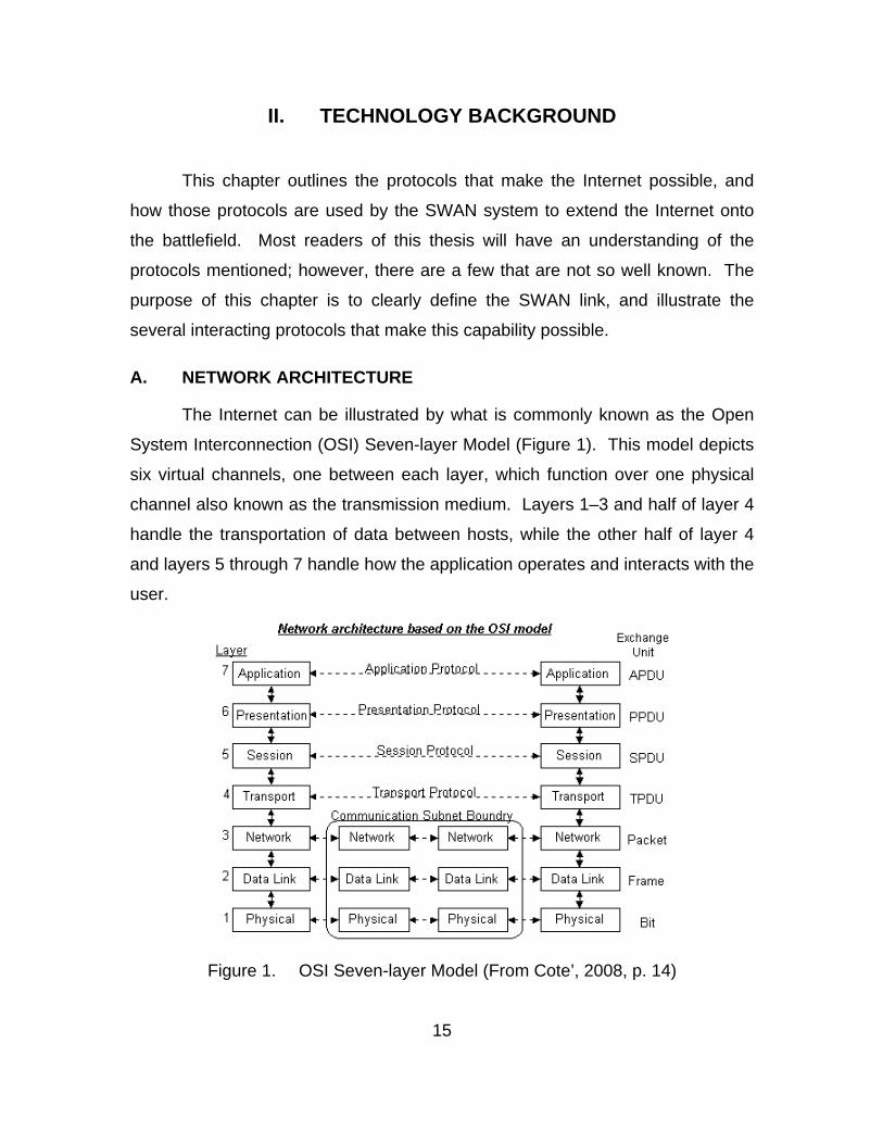
System Interconnection (OSI) Seven-layer Model (Figure 1). This model depicts
six virtual channels, one between each layer, which function over one physical
channel also known as the transmission medium. Layers 1–3 and half of layer 4
handle the transportation of data between hosts, while the other half of layer 4
and layers 5 through 7 handle how the application operates and interacts with the
user.
Figure 1. OSI Seven-layer Model (From Cote’, 2008, p. 14)
16
Layer 1 is required for any two hosts or users to communicate. This
physical layer is what 1s and 0s, or bits, are transmitted on to deliver data
between hosts. This layer can be copper wire, fiber optic cable or even the
atmosphere when referring to wireless radio frequency (RF). It is the medium by
which two devices are connected.
The other six layers are considered virtual channels because they do not
physically connect to each other. They are connected by computer protocols that
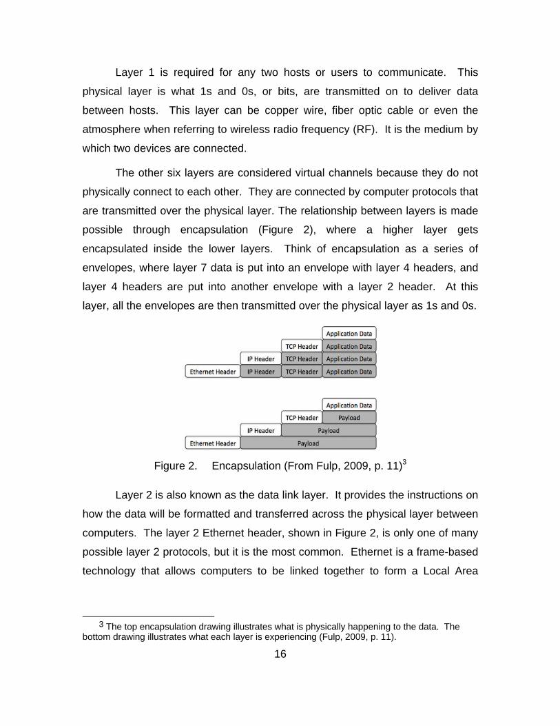
are transmitted over the physical layer. The relationship between layers is made
possible through encapsulation (Figure 2), where a higher layer gets
encapsulated inside the lower layers. Think of encapsulation as a series of
envelopes, where layer 7 data is put into an envelope with layer 4 headers, and
layer 4 headers are put into another envelope with a layer 2 header. At this
layer, all the envelopes are then transmitted over the physical layer as 1s and 0s.
Figure 2. Encapsulation (From Fulp, 2009, p. 11)3
Layer 2 is also known as the data link layer. It provides the instructions on
how the data will be formatted and transferred across the physical layer between
computers. The layer 2 Ethernet header, shown in Figure 2, is only one of many
possible layer 2 protocols, but it is the most common. Ethernet is a frame-based
technology that allows computers to be linked together to form a Local Area
3 The top encapsulation drawing illustrates what is physically happening to the data. The
bottom drawing illustrates what each layer is experiencing (Fulp, 2009, p. 11).
17
Network (LAN). What is most important to note about the Ethernet framing
structure is that it is reusable, which makes the integration of existing and future
components easy as long as the standard is adhered to.
The layer 2 addressing scheme is known as the Media Access Control
(MAC) number or burned in address (bia). This address is unique to a device’s
NIC and it has the following 12-hex digit format: 00:0c:39:72:6a:79. The device
that ‘speaks’ layer 2 language is called a switch. Switches reduce network traffic
by consolidating which hosts see certain network traffic. They do this by
matching a particular host to one of the switch’s port numbers. When traffic from
a host enters through a switch port, the switch associates one of its particular
port numbers with a specific end user’s MAC address and stores that host’s
location on the switch. Then, when any traffic with that particular MAC address
arrives, it only forwards the traffic to those hosts on that port. So, instead of
broadcasting all network traffic to every end user on the network, the switch
sends the traffic to the specific port where the end user resides. Briefly, a switch
provides hop-to-hop data delivery on the same network.
The network layer (layer 3) provides end-to-end (source to destination)
packet delivery for computer communications that occur between different
networks. The layer 3 addressing scheme is known as the Internet Protocol (IP)
address. This address scheme is hierarchical, meaning there is a network
identification part (172.30.XXX.XXX), and a host identification part
(XXX.XXX.193.10). Network size and configuration determine where the network
and host portions of the IP address are defined, but the format
(XXX.XXX.XXX.XXX) is the same for all IP addresses. The IP address is found
in the IP header, which leads the datagram through the Internet.
Layer 4, the transport layer, interacts with layers 3 and 5 to establish and
manage the end-to-end connection or session. Layers 5 through 7 interact with
the user on the user’s terminal. All seven layers are indifferent about the
18
components and transmission mediums that connect the two terminals. Layer
independence creates the ‘virtual connections’ alluded to earlier and are key to
the flexibility of the Internet.
1. Local Area Network (LAN)
At the infancy of the Digital Age, a single dedicated line was used to allow
one computer to communicate with one—and only one—other computer. This
connection was typically done with a wire called twisted pair; today it is done with
category 5 cable (Cat V cable). The purpose of this direct connection was
speed, provided by universal, physical connections inside the computer, called
sockets. Sockets are connected, one to another, and then to other parts in the
computer by wires. These wires carry data and power for various components in
the form of electrical current.
A cable connected the first two computers that were linked together to
transfer data. Each end of the cable was connected to a circuit board, which was
plugged into a socket. Since a socket has the fastest access to a computer’s
memory, this direct connection facilitated ‘wicked’ fast speeds of data transfer
between the two computers. This provided each computer direct access to the
other computer’s memory, making data access no different than accessing a
computers own memory. While this method of communication was fast, there
was one big disadvantage: scalability.
It “required considerable effort to add a new computer to the network”
(Comer, 2007, p. 50), since two computers needed to have the same circuit
boards and a dedicated cable. But, what if computer A needed to be connected
to two or more other computers at the same time? Computer A would need one
circuit board and one wire for each connection, for a total of two circuit boards
and two wires. Computers B and C would each have one circuit board and one
wire connecting to computer A. Additionally, if computers B and C wanted to
19
connect, they would each need another circuit board and wire. Simply put, for
every new computer added to the network, the number of connections doubled.
The development of LANs solved this problem.
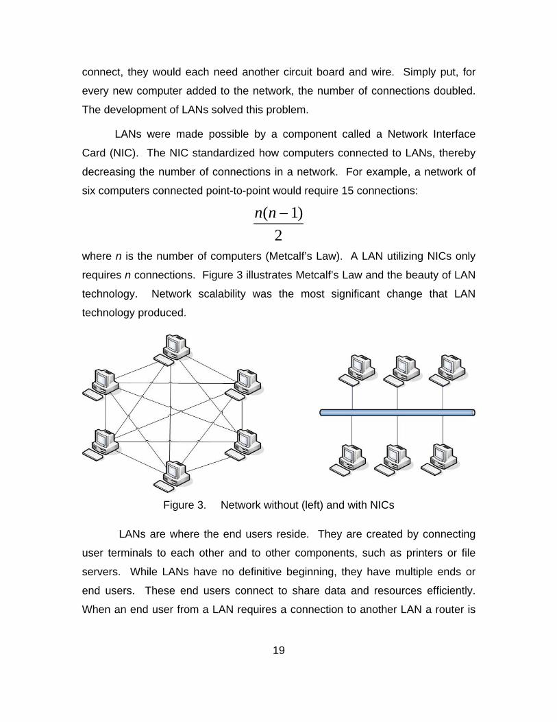
LANs were made possible by a component called a Network Interface
Card (NIC). The NIC standardized how computers connected to LANs, thereby
decreasing the number of connections in a network. For example, a network of
six computers connected point-to-point would require 15 connections:
n(n 1)
2
where n is the number of computers (Metcalf’s Law). A LAN utilizing NICs only
requires n connections. Figure 3 illustrates Metcalf’s Law and the beauty of LAN
technology. Network scalability was the most significant change that LAN
technology produced.
Figure 3. Network without (left) and with NICs
LANs are where the end users reside. They are created by connecting
user terminals to each other and to other components, such as printers or file
servers. While LANs have no definitive beginning, they have multiple ends or
end users. These end users connect to share data and resources efficiently.
When an end user from a LAN requires a connection to another LAN a router is
20
needed. A router is the gateway to other networks. They are layer 3 devices
that make network-to-network connections possible and therefore create
internetworks.
a. Internet Protocol (IP)
The glue that holds LANs and the Internet together is known as the
TCP/IP protocol suite. It is called a suite because it is a collection of many
protocols, TCP/IP being the most fundamental and frequently used.
A protocol is a common language by which computers
communicate. It is a set of rules or standards used by computers to convey,
transfer and share information across a network. These rules can be
implemented at the hardware or software level, or using a combination of the
two. The IP is a software protocol that facilitates basic computer communication.
“The IP provides for transmitting blocks of data called datagrams [or packets]
from source to destination, where the source and destination are hosts identified
by fixed length addresses” (Postel, 1981, RFC 791, p. 1). These addresses are
naturally called IP addresses.
The IP simply specifies how packets must be formed. Its simplicity
provides for the required flexibility that facilitates networking. The protocol is
both stateless and connectionless. Stateless means packets can traverse the
network and arrive in any order. Connectionless means that packet delivery is
unreliable or that there is no acknowledgement or verification of delivery. The IP
standard accommodates a variety of underlying network technologies. WANs
and LANs can connect regardless of network speeds, connection-orientation, or
physical medium (wired, wireless, radio, fiber optics, free space optics, etc.) as
long as the IP is adhered to. This packet formation is understood by all
components in the network, which allow the packets to be routed from its source
to its destination. Additionally, since IP is a published standard specifying exactly
21
how packets need to be formed, multiple vendors can design network
components that are interoperable, making IP the protocol that stitches LANs
and WANs together.
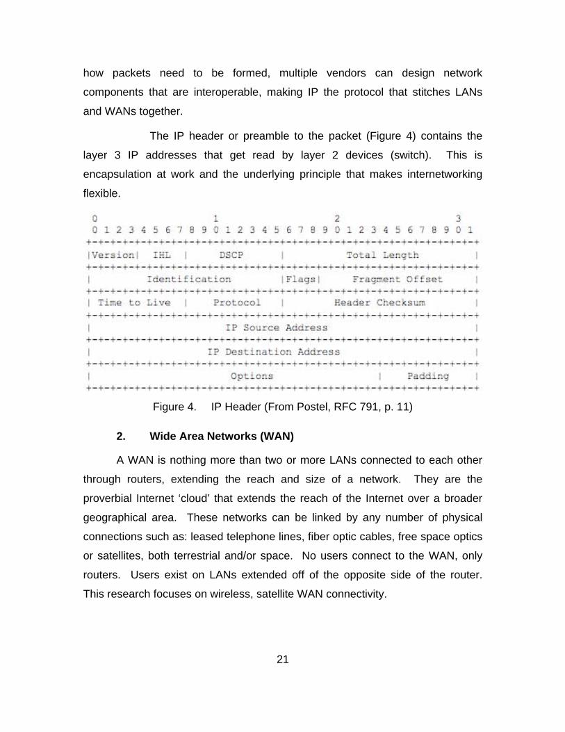
The IP header or preamble to the packet (Figure 4) contains the
layer 3 IP addresses that get read by layer 2 devices (switch). This is
encapsulation at work and the underlying principle that makes internetworking
flexible.
Figure 4. IP Header (From Postel, RFC 791, p. 11)
2. Wide Area Networks (WAN)
A WAN is nothing more than two or more LANs connected to each other
through routers, extending the reach and size of a network. They are the
proverbial Internet ‘cloud’ that extends the reach of the Internet over a broader
geographical area. These networks can be linked by any number of physical
connections such as: leased telephone lines, fiber optic cables, free space optics
or satellites, both terrestrial and/or space. No users connect to the WAN, only
routers. Users exist on LANs extended off of the opposite side of the router.
This research focuses on wireless, satellite WAN connectivity.
22
a. Terrestrial–Wide Area Network (T-WAN)
T-WANs extend communication over distant geographical areas
and are generally connected by cable and fiber optics. An analogy would be how
a home computer connects to the largest network in the world, the Internet, via
an Internet Service Provider (ISP). The home computer is physically connected
to the telephone company’s wires running along the street. For military
applications, T-WANs require a significant military presence since the security of
the cables must be protected for the network to function reliably.
An example of a military T-WAN would be the network on the Al
Asad Airbase, Iraq. This network spans both the north and south sides of the
airfield, integrating ground, aviation and logistic combat elements, which includes
several units and thousands of warfighters.
b. Radio Frequency–Wide Area Network (RF-WAN)
RF-WANs allow networks to span larger geographical areas without
the burden of physical infrastructure and security, though RF signals do require
some protection from jamming. This is accomplished by using the atmosphere
and the wireless transmission of data. These are the networks that are most
desired in remote locations where warfighters have limited to no communication
infrastructure. These WANs are also useful when two T-WANs located in a
combat area are separated by a significant geographical measure and there is a
need for those networks to communicate.
In this case, as with all other WANs, end users do not directly
connect to it. Instead, users connect to the LAN, which in turn gets connected to
a router, and all the router traffic is transmitted via radio signal to the next router.
Thus, any two LANs are simply one router hop away from each other and WANs
allow them to connect over large distances. There are two RF-WAN systems in
the Marine Corps: WPPL and SWAN.
23
(1). Wireless Point-to-Point Link (WPPL). WPPL is a
communication system that provides WAN connectivity over distant geographical
areas with high-powered antennas. It is generally provides a line-of-sight
connection, however, the RF signal can be bounced off the atmosphere for non-
line-of-sight connectivity if the atmospherics conditions permit. Specific to the
Marine Corps, these networks exist in Iraq. One example is the WAN connection
between the router at Camp Fallujah and the router at Al Taqaddum Airbase,
which are separate by 20 miles (32 km).
The advantages of WPPL connectivity are that no wires
need protection between the LANs and it does not require capacity limited
satellite access, as it is a terrestrial system. A limitation to WPPL is that the
antennas require an almost unobstructed, direct line-of-sight view of each other.
This means that terrain, buildings, or weather could potentially reduce this
system’s functionality. It is effective in Iraq because the terrain is relatively flat
and the cultural centers do not build excessively vertical; it is not as flexible in
Afghanistan where the terrain is more rugged.
(2). Support Wide Area network (SWAN). SWAN is a
communication system that provides WAN connectivity over distance
geographical areas via satellite connection. This system was procured as a
BLOS system. It has the same set up as a WPPL; however, these antennas can
access satellites, overcoming the direct ling-of-sight limitation in WPPL. These
systems are deployed in Iraq, Afghanistan and the Horn of Africa.
The advantages of SWAN connectivity are that no wires
need to be protected between the LANs and direct line-of-sight is not required, so
terrain and vertical development are not as limiting to communications. This aids
in extending the Internet into remote locations. The greatest limitation to SWAN
systems is that it provides connectively through space, where the point-to-point
relay is 22,300 miles away, which causes long transmission delays. This is the
primary problem with SWAN links: long delays.
24
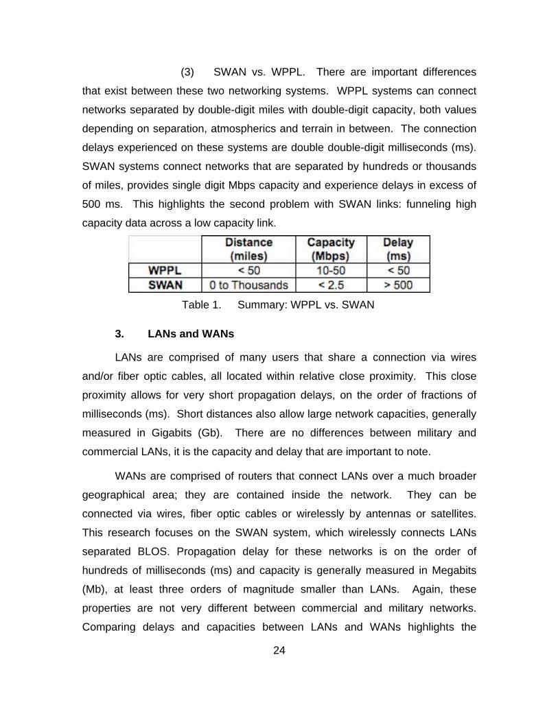
(3) SWAN vs. WPPL. There are important differences
that exist between these two networking systems. WPPL systems can connect
networks separated by double-digit miles with double-digit capacity, both values
depending on separation, atmospherics and terrain in between. The connection
delays experienced on these systems are double double-digit milliseconds (ms).
SWAN systems connect networks that are separated by hundreds or thousands
of miles, provides single digit Mbps capacity and experience delays in excess of
500 ms. This highlights the second problem with SWAN links: funneling high
capacity data across a low capacity link.
Table 1. Summary: WPPL vs. SWAN
3. LANs and WANs
LANs are comprised of many users that share a connection via wires
and/or fiber optic cables, all located within relative close proximity. This close
proximity allows for very short propagation delays, on the order of fractions of
milliseconds (ms). Short distances also allow large network capacities, generally
measured in Gigabits (Gb). There are no differences between military and
commercial LANs, it is the capacity and delay that are important to note.
WANs are comprised of routers that connect LANs over a much broader
geographical area; they are contained inside the network. They can be
connected via wires, fiber optic cables or wirelessly by antennas or satellites.
This research focuses on the SWAN system, which wirelessly connects LANs
separated BLOS. Propagation delay for these networks is on the order of
hundreds of milliseconds (ms) and capacity is generally measured in Megabits
(Mb), at least three orders of magnitude smaller than LANs. Again, these
properties are not very different between commercial and military networks.
Comparing delays and capacities between LANs and WANs highlights the
25
problem being investigated in this research. Many users on a high capacity,
short delay LAN, wanting to use a lower capacity, long delay WAN creates a
restricting bottleneck. The problem can be isolated between the routers that
connect the two LANs, the very definition of a WAN. The TCP accelerator helps
mitigate the problem by making WAN connections behave like LAN connections.
This is accomplished by transparently ensuring that data arrives at its destination
as quickly and reliably as possible, a layer 4 function.
Layers 1, 2 and 3 of the OSI Model (Figure 1) make up the
Communication Subnet Boundary. This boundary of the IP structure is indifferent
about whether or not it is on a LAN or a WAN; an illustration of the value and
flexibility built into the Internet network structure. There is a difference once layer
4, the transport layer, becomes involved. Transport layer protocols, often
referred to as end-to-end protocols, have timing mechanisms that facilitate their
operation, and the transmission environment determines the performance of
those protocols.
B. END-TO-END PROTOCOLS
End-to-end protocols are categorized in the transport layer (layer 4) of the
OSI model. They are instructions on how data is transferred from one end user
to another. Remember that the IP (layer 3) provides a best-effort delivery
infrastructure. It is layer 4’s responsibility to execute that delivery. The transport
layer adds a port number after the IP address to properly route the packets to the
correct port on the end user’s machine. The address scheme now looks
something like this: XXX.XXX.XXX.XXX:21.
There are several layer 4 protocols but the two most frequently used are
UDP and TCP. TCP provides guaranteed or reliable packet delivery at a
bandwidth premium, while UDP provides faster service with no guarantee of
delivery (TCP) at minimal bandwidth cost. This research and SWAN networks
focus on these two end-to-end protocols.
26
1. User Datagram Protocol (UDP)
UDP has been called “TCP’s undisciplined little brother” (Fulp, 2009, p.
133). It provides procedures for data to be transferred between programs with
minimal protocol mechanisms and therefore does not guarantee delivery like
TCP. The protocol is considered connectionless and unreliable and can be
thought of as a fire-and-forget procedure. Connectionless means that this
protocol does not have to establish a connection with the other end terminal
before data is transferred. Unreliable means that data is sent under the
assumption that it will arrive at its destination without follow-up to validate
delivery. If the packet does not make it to its destination, the sender will never
know. The sender will have to make the request again and UDP will attempt to
deliver the packet as if it were the first attempt; or in the case of real-time,
streaming traffic, the data is no longer relevant and not worth retransmitting.
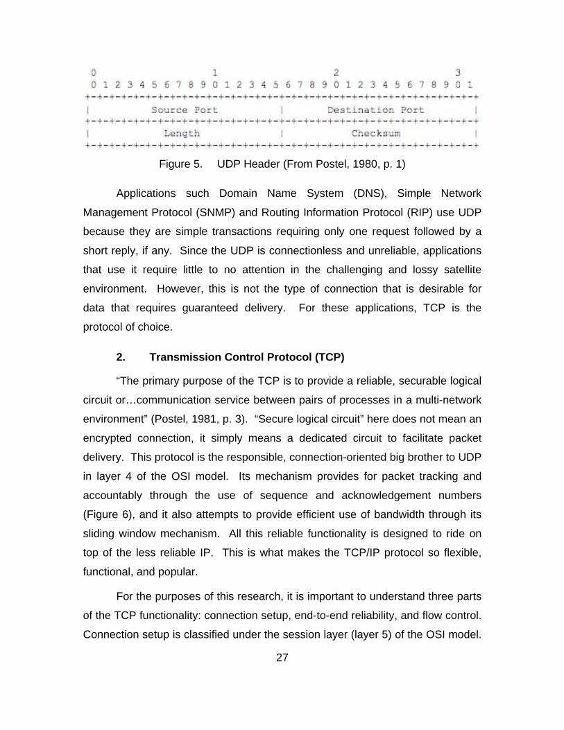
The benefit of the UDP is that is has low overhead. This is obvious when
comparing UDP and TCP headers (Figures 5 & 6). The UDP header is
streamlined because it does not have to establish an initial connection, nor does
it have to account for connection-oriented criteria such as sequence numbers,
acknowledgement numbers, and window sizes. Its unreliable, connectionless
nature means that some packet loss, errors or duplication may occur. This is the
only useful protocol for communications such a Voice over IP (VoIP), Video
Teleconferencing (VTC), and streaming video where real-time information is key
and a few lost packets will not make a difference. Imagine having a cell phone
conversation with another person while drive through a tunnel and you miss
some of the conversation, this is similar to a lost packet. Now, you can still
understand the conversation because the small packets you missed were easy to
fill in. Using UDP means that a few lost packets are acceptable.
27
Figure 5. UDP Header (From Postel, 1980, p. 1)
Applications such Domain Name System (DNS), Simple Network
Management Protocol (SNMP) and Routing Information Protocol (RIP) use UDP
because they are simple transactions requiring only one request followed by a
short reply, if any. Since the UDP is connectionless and unreliable, applications
that use it require little to no attention in the challenging and lossy satellite
environment. However, this is not the type of connection that is desirable for
data that requires guaranteed delivery. For these applications, TCP is the
protocol of choice.
2. Transmission Control Protocol (TCP)
“The primary purpose of the TCP is to provide a reliable, securable logical
circuit or…communication service between pairs of processes in a multi-network
environment” (Postel, 1981, p. 3). “Secure logical circuit” here does not mean an
encrypted connection, it simply means a dedicated circuit to facilitate packet
delivery. This protocol is the responsible, connection-oriented big brother to UDP
in layer 4 of the OSI model. Its mechanism provides for packet tracking and
accountably through the use of sequence and acknowledgement numbers
(Figure 6), and it also attempts to provide efficient use of bandwidth through its
sliding window mechanism. All this reliable functionality is designed to ride on
top of the less reliable IP. This is what makes the TCP/IP protocol so flexible,
functional, and popular.
For the purposes of this research, it is important to understand three parts
of the TCP functionality: connection setup, end-to-end reliability, and flow control.
Connection setup is classified under the session layer (layer 5) of the OSI model.
28
This is the additional overhead that UDP does not have. It creates the reliable
connection between exactly two end terminals. End-to-end reliability and flow
control fall under the transport layer, which facilitates the virtual connections
between higher layers in the OSI model.
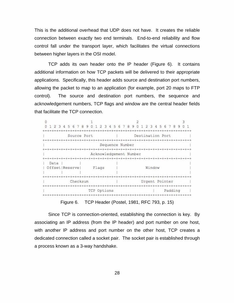
TCP adds its own header onto the IP header (Figure 6). It contains
additional information on how TCP packets will be delivered to their appropriate
applications. Specifically, this header adds source and destination port numbers,
allowing the packet to map to an application (for example, port 20 maps to FTP
control). The source and destination port numbers, the sequence and
acknowledgement numbers, TCP flags and window are the central header fields
that facilitate the TCP connection.
Figure 6. TCP Header (Postel, 1981, RFC 793, p. 15)
Since TCP is connection-oriented, establishing the connection is key. By
associating an IP address (from the IP header) and port number on one host,
with another IP address and port number on the other host, TCP creates a
dedicated connection called a socket pair. The socket pair is established through
a process known as a 3-way handshake.
29
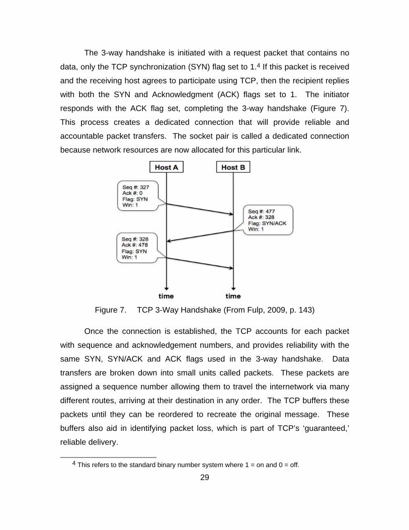
The 3-way handshake is initiated with a request packet that contains no
data, only the TCP synchronization (SYN) flag set to 1.4 If this packet is received
and the receiving host agrees to participate using TCP, then the recipient replies
with both the SYN and Acknowledgment (ACK) flags set to 1. The initiator
responds with the ACK flag set, completing the 3-way handshake (Figure 7).
This process creates a dedicated connection that will provide reliable and
accountable packet transfers. The socket pair is called a dedicated connection
because network resources are now allocated for this particular link.
Figure 7. TCP 3-Way Handshake (From Fulp, 2009, p. 143)
Once the connection is established, the TCP accounts for each packet
with sequence and acknowledgement numbers, and provides reliability with the
same SYN, SYN/ACK and ACK flags used in the 3-way handshake. Data
transfers are broken down into small units called packets. These packets are
assigned a sequence number allowing them to travel the internetwork via many
different routes, arriving at their destination in any order. The TCP buffers these
packets until they can be reordered to recreate the original message. These
buffers also aid in identifying packet loss, which is part of TCP’s ‘guaranteed,’
reliable delivery.
4 This refers to the standard binary number system where 1 = on and 0 = off.
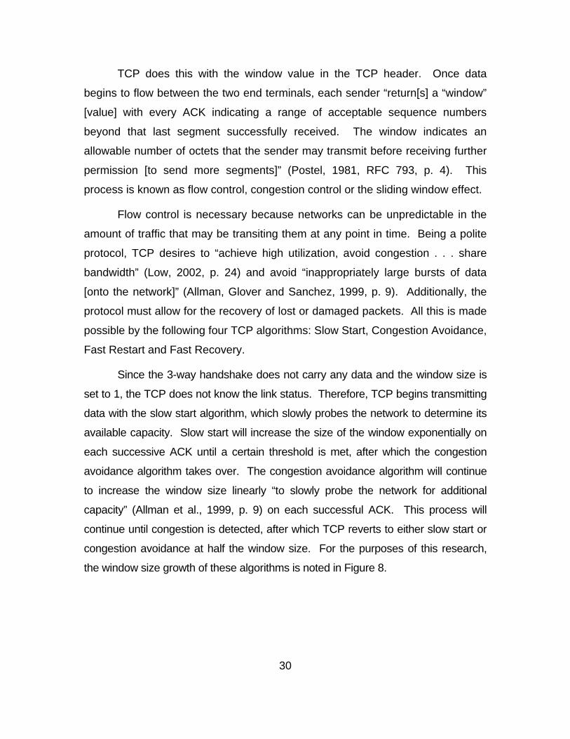
30
TCP does this with the window value in the TCP header. Once data
begins to flow between the two end terminals, each sender “return[s] a “window”
[value] with every ACK indicating a range of acceptable sequence numbers
beyond that last segment successfully received. The window indicates an
allowable number of octets that the sender may transmit before receiving further
permission [to send more segments]” (Postel, 1981, RFC 793, p. 4). This
process is known as flow control, congestion control or the sliding window effect.
Flow control is necessary because networks can be unpredictable in the
amount of traffic that may be transiting them at any point in time. Being a polite
protocol, TCP desires to “achieve high utilization, avoid congestion . . . share
bandwidth” (Low, 2002, p. 24) and avoid “inappropriately large bursts of data
[onto the network]” (Allman, Glover and Sanchez, 1999, p. 9). Additionally, the
protocol must allow for the recovery of lost or damaged packets. All this is made
possible by the following four TCP algorithms: Slow Start, Congestion Avoidance,
Fast Restart and Fast Recovery.
Since the 3-way handshake does not carry any data and the window size is
set to 1, the TCP does not know the link status. Therefore, TCP begins transmitting
data with the slow start algorithm, which slowly probes the network to determine its
available capacity. Slow start will increase the size of the window exponentially on
each successive ACK until a certain threshold is met, after which the congestion
avoidance algorithm takes over. The congestion avoidance algorithm will continue
to increase the window size linearly “to slowly probe the network for additional
capacity” (Allman et al., 1999, p. 9) on each successful ACK. This process will
continue until congestion is detected, after which TCP reverts to either slow start or
congestion avoidance at half the window size. For the purposes of this research,
the window size growth of these algorithms is noted in Figure 8.
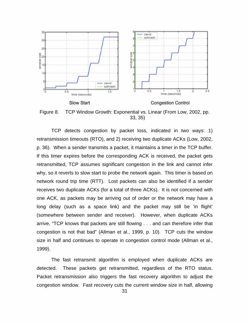
31
Figure 8. TCP Window Growth: Exponential vs. Linear (From Low, 2002, pp. 33, 35)
TCP detects congestion by packet loss, indicated in two ways: 1)
retransmission timeouts (RTO), and 2) receiving two duplicate ACKs (Low, 2002,
p. 36). When a sender transmits a packet, it maintains a timer in the TCP buffer.
If this timer expires before the corresponding ACK is received, the packet gets
retransmitted, TCP assumes significant congestion in the link and cannot infer
why, so it reverts to slow start to probe the network again. This timer is based on
network round trip time (RTT). Lost packets can also be identified if a sender
receives two duplicate ACKs (for a total of three ACKs). It is not concerned with
one ACK, as packets may be arriving out of order or the network may have a
long delay (such as a space link) and the packet may still be ‘in flight’
(somewhere between sender and receiver). However, when duplicate ACKs
arrive, “TCP knows that packets are still flowing . . . and can therefore infer that
congestion is not that bad” (Allman et al., 1999, p. 10). TCP cuts the window
size in half and continues to operate in congestion control mode (Allman et al.,
1999).
The fast retransmit algorithm is employed when duplicate ACKs are
detected. These packets get retransmitted, regardless of the RTO status.
Packet retransmission also triggers the fast recovery algorithm to adjust the
congestion window. Fast recovery cuts the current window size in half, allowing
32
“TCP to keep data flowing through the network at half the rate it was when the
loss was detected” (Allman et al., 1999, p. 10). This keeps TCP in congestion
avoidance mode, and out of slow start.
Lastly, since TCP is the responsible layer 4 protocol, it manages—along
with layer 5—the logical tear down of the connection with an exchange of finish
(FIN) flags. The teardown process releases network resources for allocation to
another connections.
While this explanation seems lengthy, it is necessary to understand this
protocol in order to make sense of the data that will be generated during
experimentation. The TCP is connection intensive and therefore consumes more
network resources than UDP. Three of the top four protocols found transiting
SWAN networks are TCP based: File Transfer Protocol (FTP), Simple Mail
Transfer Protocol (SMTP) and Hypertext Transfer Protocol (HTTP).
Understanding TCP and the other three protocols just mentioned, will help in
understanding SWAN traffic patterns and how to better manage what satellite
bandwidth is available.
a. Early Open
Early open is a not a widely used technique that takes advantage of
the empty packets in the 3-way handshake. Each packet has the capability to
carry 65,535 bytes of data, but according to the TCP algorithm, no data is sent
during the connection establishment. These three transactions are trivial for a
LAN connection with gigabit capacity; however, they are of particular interest in
long delay satellite networks. The problem is highlighted when multiple
subscribers use the TCP to send small packets of data (less than 65,535 bytes)
across the link. If a message is small, the subscriber must wait until the three
other packets establish the connection before the one and only message packet
gets sent. When many users send several short messages via TCP, it is easy to
see how the link can be consumed with 3-way handshake traffic. Early open
uses the request packet in the handshake to deliver data. If the entire message
33
fits into the initial packet and the FIN flag is set to 1, then it only takes one throw
across the WAN to deliver a message that would otherwise require four throws.
3. Space Communications Protocol Standard (SPCS)
The space environment is the medium used by SWAN to extend the
Internet to Marines in remote, BLOS locations. While TCP was designed to be
flexible for various network configurations, the space environment presents some
unique challenges. Allman et al. (1999) state, “There is an inherent delay in the
delivery of a message over a satellite link due to the finite speed of light and the
altitude of communications satellites” (p. 2). These elements of the space
environment degrade the performance of TCP over satellite links (Allman et al.,
1999).
In the 1990s, new protocols were being developed by the armed services
for every new mission being conducted in space to improve TCP performance in
this environment. This uncoordinated effort led to expensive, proprietary,
stovepipe solutions that had no longevity. To reduce cost and allow different
satellite access points to be more interoperable, NASA, the U.S. Space
Command and Jet Propulsion Labs embarked on a joint effort to “develop an
interoperable suite of end-to-end data protocols for satellite networks” (Hooke,
2004). The Space Communications Protocol Standards (SCPS) suite was
developed.
In 2002, the Joint Terminal Engineering Office declared the SCPS-TP the
“most effective and interoperable solution for TCP enhancements” over satellite
communication links. This protocol also “demonstrated both TCP traffic
enhancement capability and interoperability with other TCP devices.” As a result
of the successful testing, SCPS was declared the de facto protocol for future
space links devices involving TCP network traffic (Hooke, 2004). In 2007, SCPS
became an official mandate in the DoD IT Standards Registry.5
5 An IETF RFC does not officially address the SCPS.
34
SCPS is an open-source suite of protocols designed to efficiently facilitate
satellite and wireless communications. The suite is comprised of a file handling
protocol (FP), a transport protocol (TP), a security protocol (SP) and a
networking protocol (NP). Within this suite of protocols, SCPS-TP is the only
required variant, as it facilitates multi-vendor interoperability; other variants are
optional. For the purposes of this research SCPS-TP will be the protocol of
interest, because it is the TCP surrogate in space. The military designation for
this protocol is MIL-STD-2045-44000, which is also ISO standard 15892.
Global Protocols was the first commercial vendor to implement SCPS-TP
into communication hardware. Their implementation is commonly known as
Skipware, and it has become an industry standard.
While SCPS provides support for connectionless multicasting, it does not
support reliable multicasting; more simply, it does not guarantee packet delivery
to a group of subscribers. This is a design problem that exists in all currently
employed transport protocols. As the DoD becomes more network-centric, there
is a growing need for a protocol with this capability.
4. Negative-acknowledgement (NACK)–Oriented Reliable Multicast (NORM)
Net Centric Warfare is characterized by the ability of geographically dispersed forces to create a high level of shared battelspace awareness that can be exploited via self-organized and other network centric operations to achieve commanders’ intent. (Alberts, 1999, p. 88)
This statement summarizes where nearly every aspect of the DoD is
headed in the future. It suggests that warfighters will be dispersed, capable of
accessing and contributing to near a real-time knowledge pool, in order to make
rapid battlefield decisions independently. This concept will require new systems
and new protocols. More importantly, Network Centric Operations will require a
shift from a “point-to-point” to a “many-to-many” mindset.
35
TCP is a point-to-point protocol. It creates dedicated socket pair
connections and is therefore considered a unicast protocol that establishes a
one-to-one relationship between end users. UDP is both a unicast and a
multicast protocol. Since there is no dedicated connection to set up, its
messages can easily be sent from one host to one or many other hosts, making it
a one-to-many protocol. The problem with UDP is that there is no guarantee that
the message will arrive at its destination.
BFT is a dynamic system used to keep commanders updated on the
location of tactical units. As units are on the move, they regularly send short,
bursty UDP updates to refresh their location. However, if without a guarantee of
delivery, there is no way to be sure the position is properly updated. To create a
Network Centric warfighting force, data, information and knowledge need to flow
undisturbed and complete to participating warfighters to give them the best
chance to accomplish their mission. This will require a reliable, connection-
oriented, TCP like protocol.
A hybrid layer 4 protocol that combines the reliability of TCP with the
multicast capability of UDP would be the ideal solution. NORM is an
experimental layer 4 protocol being developed by the Internet Engineering Task
Force (IETF) that integrates the desirable features of both protocols. The idea of
this project is to create an efficient and reliable protocol, capable of distributing
data to a group of participants, using the IP datagram services. When it is
successful, the DoD will be closer to being Network Centric. Some of the issues
that it will have to overcome are caching, retransmission, packet repair and
ordering, all within the contents of group dynamics. Group dynamics consists of
participants joining late, leaving, and rejoining, all while being kept up-to-speed
on the developing situation (Adamson et al., 2004, p. 4).
The research in this thesis began by exploring this important experimental
protocol; however, the more immediate issue of testing and updating SWAN
terminals overtook the focus of this study.
36
C. APPLICATIONS
None of the aforementioned OSI model layers or protocols interact directly
with the user. The application layer (layer 7) is where software and users
generate the functional data to be transferred to another end user. This data
gets packaged inside a lower layer ‘envelopes’ and then transmitted over the
physical medium.
While there is a long list of protocols that fall into the application layer, this
research will focus on the three most common to SWAN networks: FTP, HTTP
and SMTP.
1. File Transfer Protocol (FTP)
The FTP is the most fundamental and efficient type of computer
communication. This protocol allows files to be copied from one computer to
another by simply moving blocks of data (a block of data is a smaller chunk of a
file). Since transferring files is what networking is all about, it is no surprise that
FTP is such a common protocol on the Internet and SWAN networks. RFC 959
states “[t]he objectives of FTP are: 1) to promote sharing of computer programs,
data and/or files, 2) to encourage indirect or implicit use of remote computers, 3)
to shield a user from variation in file storage systems among hosts, and 4) to
transfer data reliably and efficiently” (Postel and Reynolds, 1985, p. 1).
This protocol can be used to easily share mission files for combined arms
coordination; access large, common data stores such as detainee biological
data; and to distribute updates to those databases. FTP is connection-oriented
and therefore uses the TCP.
FTP operates on a client-server architecture, where the client is the
requestor of data and the server is where the requested data is stored. The FTP
uses two TCP connections: a control connection and a data connection. The
control connection is used to establish an FTP session and then to manage it
with basic FTP commands. The control connection does not transfer files, only
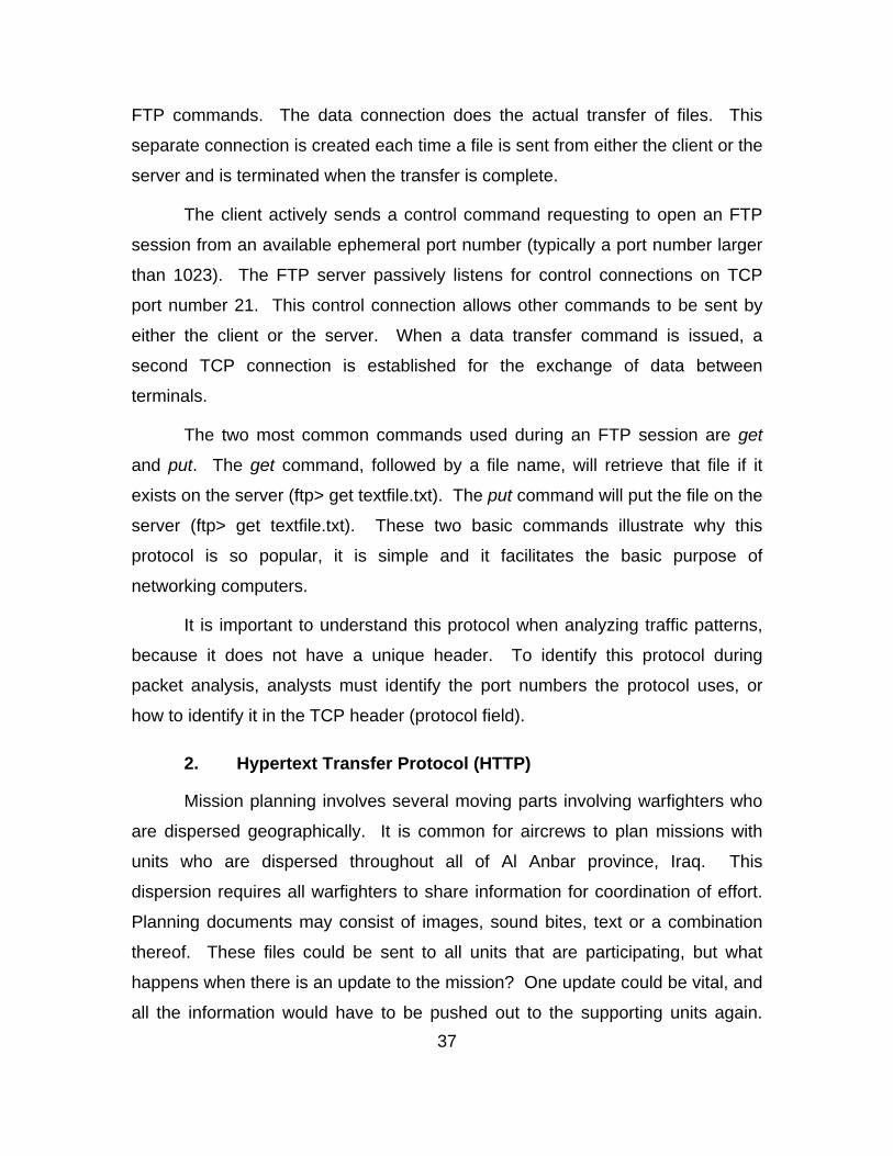
37
FTP commands. The data connection does the actual transfer of files. This
separate connection is created each time a file is sent from either the client or the
server and is terminated when the transfer is complete.
The client actively sends a control command requesting to open an FTP
session from an available ephemeral port number (typically a port number larger
than 1023). The FTP server passively listens for control connections on TCP
port number 21. This control connection allows other commands to be sent by
either the client or the server. When a data transfer command is issued, a
second TCP connection is established for the exchange of data between
terminals.
The two most common commands used during an FTP session are get
and put. The get command, followed by a file name, will retrieve that file if it
exists on the server (ftp> get textfile.txt). The put command will put the file on the
server (ftp> get textfile.txt). These two basic commands illustrate why this
protocol is so popular, it is simple and it facilitates the basic purpose of
networking computers.
It is important to understand this protocol when analyzing traffic patterns,
because it does not have a unique header. To identify this protocol during
packet analysis, analysts must identify the port numbers the protocol uses, or
how to identify it in the TCP header (protocol field).
2. Hypertext Transfer Protocol (HTTP)
Mission planning involves several moving parts involving warfighters who
are dispersed geographically. It is common for aircrews to plan missions with
units who are dispersed throughout all of Al Anbar province, Iraq. This
dispersion requires all warfighters to share information for coordination of effort.
Planning documents may consist of images, sound bites, text or a combination
thereof. These files could be sent to all units that are participating, but what
happens when there is an update to the mission? One update could be vital, and
all the information would have to be pushed out to the supporting units again.
38
This process is not only time-consuming for the lead unit, it also needlessly
consumes network resources. One solution is to pass mission information
through a Webpage that can be accessed by those units participating in the
mission. To make this possible, an HTTP server is setup to facilitate efficient and
reliable information sharing.
The Marine Corps’ objective in the information age is to push information
to decision makers so that the right decision can be acted upon in a timely
manner. The SWAN system has facilitated that through a network solution
where distributed warfighters can collaborate through the use of hypermedia.
RFC 2616 describes HTTP as “an application-level protocol for distributed,
collaborative hypermedia information system” (Fielding et al., 1999, p. 1). This
description fits into the SWAN system’s mission and the concept of Network
Centric Operations.
The HTTP is more complicated both FTP. Basic HTTP communication
consists of a request for information from a resource that exists on the same
server. However, most communications do not take place with this direct
connection. Instead, the HTTP requests often have several intermediary
connections between many requestors and several servers, each of which may
be engaged in multiple, simultaneous communications.
Usually, the client initiates an HTTP request to establish a TCP connection
on server port 80. Once established, a request command is sent to the server.
The server responds with a status (blank) line and a message/response of its
own. The response has a header and a body where the reply message is
located (Figure 9).
39
Figure 9. HTTP Request and Response Header and Body
HTTP allows users to share a variety of file types, facilitating warfighter
collaboration. For this research, it is important to understand what the HTTP
protocol looks like in order to make any sense of, or identify its traffic patterns.
3. Simple Mail Transfer Protocol (SMTP)
Networking was created to make communication and file sharing more
efficient. The most widely used electronic communication application is e-mail.
E-mail is made possible by the SMTP. RFC 821 states that SMTP was designed
to “transfer mail reliably and efficiently” (Postel, 1982, p. 1). FTP and HTTP also
facilitate reliable and efficient communication, but they require both the sender
and receiver to be connected at the same time. To facilitate communication with
a host that is not on the network, SMTP is used.
E-mail traffic is user-oriented, meaning it is sent from one user to another
user, not from one computer to another computer. This means that the standard
IP addressing will not work to deliver an e-mail to a user, simply because the
user is not always receiving their e-mail at the same computer. Instead, a user
accesses their e-mail from a particular server that is always connected to the
Internet. This server serves as a middleman that receives the message when
40
the user is not logged in. When the server identifies that the user is logged in, it
will deliver the message to the user. Kozierok (2005) describes the process in
three steps:
1. Transaction Initiation and Sender identification: The sender
establishes a connection with the SMTP server, informing the
server that it wants to send a message. This message includes the
e-mail address of the sender.
2. Recipient Identification: The sender tells the SMTP server the e-
mail address of the recipient.
3. Mail Transfer: Sender transfers the e-mail message to the SMTP
server (“The TCP/IP Guide”).
The process does not end here. If the e-mail address is not a local SMTP
server address, then the server has to look up the address and forward the
message to the appropriate SMTP server. When the recipient logs onto their e-
mail server, they connect via a SMTP connection to retrieve the message.
SMTP comes in a variety of formats; however, for the purposes of this
research it has two main sections: the message header, which contains
important control and descriptive data; and the body/payload that carries the
data. These connections normally occur on port 25.
The point of this description is to illustrate that SMTP is more complex
than FTP or HTTP. It is a more ‘chatty’ protocol as it frequently sets up and tears
down TCP connections for short-term use. Additionally, since SMTP is a
connection-oriented and user-oriented protocol, it becomes a good surrogate to
represent BFT, an application that is chatty by nature. Understanding the
protocol is essential to identifying its behavior during network device testing.
D. TCP ACCELERATION EXPLAINED
TCP acceleration is used to obtain better throughput for Internet
connections without modifying end applications that require reliable connectivity
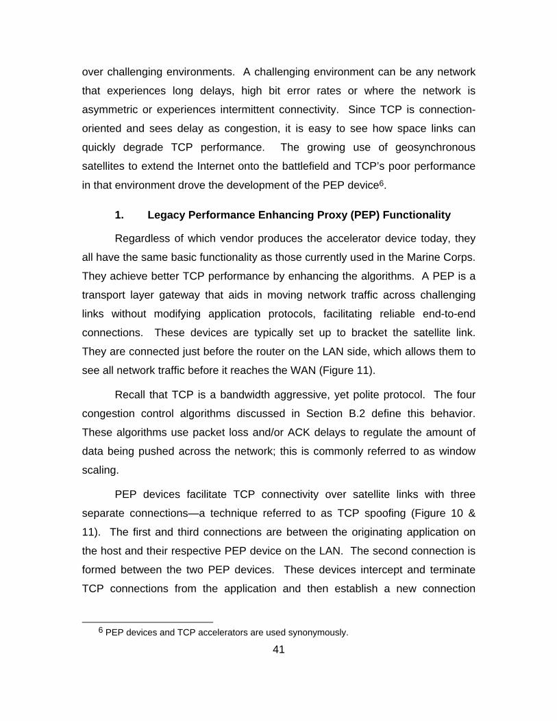
41
over challenging environments. A challenging environment can be any network
that experiences long delays, high bit error rates or where the network is
asymmetric or experiences intermittent connectivity. Since TCP is connection-
oriented and sees delay as congestion, it is easy to see how space links can
quickly degrade TCP performance. The growing use of geosynchronous
satellites to extend the Internet onto the battlefield and TCP’s poor performance
in that environment drove the development of the PEP device6.
1. Legacy Performance Enhancing Proxy (PEP) Functionality
Regardless of which vendor produces the accelerator device today, they
all have the same basic functionality as those currently used in the Marine Corps.
They achieve better TCP performance by enhancing the algorithms. A PEP is a
transport layer gateway that aids in moving network traffic across challenging
links without modifying application protocols, facilitating reliable end-to-end
connections. These devices are typically set up to bracket the satellite link.
They are connected just before the router on the LAN side, which allows them to
see all network traffic before it reaches the WAN (Figure 11).
Recall that TCP is a bandwidth aggressive, yet polite protocol. The four
congestion control algorithms discussed in Section B.2 define this behavior.
These algorithms use packet loss and/or ACK delays to regulate the amount of
data being pushed across the network; this is commonly referred to as window
scaling.
PEP devices facilitate TCP connectivity over satellite links with three
separate connections—a technique referred to as TCP spoofing (Figure 10 &
11). The first and third connections are between the originating application on
the host and their respective PEP device on the LAN. The second connection is
formed between the two PEP devices. These devices intercept and terminate
TCP connections from the application and then establish a new connection
6 PEP devices and TCP accelerators are used synonymously.
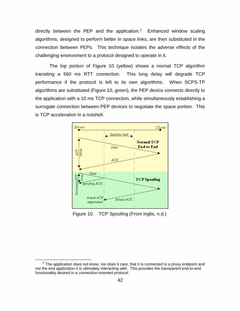
42
directly between the PEP and the application.7 Enhanced window scaling
algorithms, designed to perform better in space links, are then substituted in the
connection between PEPs. This technique isolates the adverse effects of the
challenging environment to a protocol designed to operate in it.
The top portion of Figure 10 (yellow) shows a normal TCP algorithm
transiting a 560 ms RTT connection. This long delay will degrade TCP
performance if the protocol is left to its own algorithms. When SCPS-TP
algorithms are substituted (Figure 10, green), the PEP device connects directly to
the application with a 10 ms TCP connection, while simultaneously establishing a
surrogate connection between PEP devices to negotiate the space portion. This
is TCP acceleration in a nutshell.
Figure 10. TCP Spoofing (From Inglis, n.d.)
7 The application does not know, nor does it care, that it is connected to a proxy endpoint and
not the end application it is ultimately interacting with. This provides the transparent end-to-end functionality desired in a connection-oriented protocol.
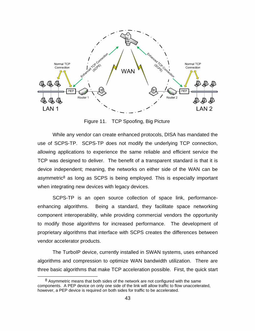
43
Figure 11. TCP Spoofing, Big Picture
While any vendor can create enhanced protocols, DISA has mandated the
use of SCPS-TP. SCPS-TP does not modify the underlying TCP connection,
allowing applications to experience the same reliable and efficient service the
TCP was designed to deliver. The benefit of a transparent standard is that it is
device independent; meaning, the networks on either side of the WAN can be
asymmetric8 as long as SCPS is being employed. This is especially important
when integrating new devices with legacy devices.
SCPS-TP is an open source collection of space link, performance-
enhancing algorithms. Being a standard, they facilitate space networking
component interoperability, while providing commercial vendors the opportunity
to modify those algorithms for increased performance. The development of
proprietary algorithms that interface with SCPS creates the differences between
vendor accelerator products.
The TurboIP device, currently installed in SWAN systems, uses enhanced
algorithms and compression to optimize WAN bandwidth utilization. There are
three basic algorithms that make TCP acceleration possible. First, the quick start
8 Asymmetric means that both sides of the network are not configured with the same components. A PEP device on only one side of the link will allow traffic to flow unaccelerated, however, a PEP device is required on both sides for traffic to be accelerated.
44
algorithm is more aggressive at using available bandwidth than the slow start
algorithm in the standard TCP. This is made possible when the PEP device
terminates the original TCP connection and substitutes the optimal algorithms for
the space link portion of the connection. Second, enhanced congestion control
algorithms are more aggressive and efficient at regulating network traffic through
window scaling. The standard TCP window size is limited to 64 Kbytes, while
enhanced TCP algorithms support window sizes up to 1 Gbyte. Third, PEP
devices use Selective Negative Acknowledgements (SNACKs) algorithms to
identify and retransmit lost packets. Instead of requesting all packets after the
one lost packet, SNACKs simply requests specifically numbered packets that
were lost. This reduces the amount of retransmission traffic on the WAN.
Compression optimizes bandwidth to a lesser extent by encoding files with
fewer bits. Fewer bits equate to less network traffic on the WAN; however, it is
not as effective as protocol enhancement. The encoding scheme must be known
on both sides of the link for compression to even operate. This can cause an
interoperability problem if one side of the link does not understand the
compression scheme. For PEP devices that do compression, they learn ahead
of time which links can and cannot perform compression. On links that cannot
understand the compression scheme, compression is not used, even if it is
turned on. Therefore, it is not as effective at optimizing WAN bandwidth as the
aforementioned algorithms.
2. Modern PEP functionality
Modern PEP devices employ three additional bandwidth optimization
techniques: Application Streamlining, Caching, and Data Deduplication.
Application streamlining refers to algorithms that reduce the amount of
short and frequent (often referred to as ‘chatty’) connection traffic that transits the
WAN. Examples of chatty applications are HTTP and SMTP. These algorithms
consolidate and perform most of the chatty behavior on the LAN before the traffic
transits the WAN. Specifically for TCP connections, application streamlining
45
reduces the number of round trips a particular connection must make. This
reduces the amount of traffic on the WAN by reducing the number of chatty
connections that span the lossy, high latency space link.
Caching is another technique that reduces the amount of network traffic
crossing the WAN. This technique stores a copy of requested files on a hard
drive located on the LAN. When another host on the same LAN requests the
same file that traffic gets delivered locally from the hard drive instead of transiting
the WAN. This keeps WAN resources available for other network traffic.
Since these hard drives do not have infinite memory capacity, there are
two common cache management techniques: First In First Out (FIFO) and Least
Frequently Used (LFU). FIFO overwrites files in sequential order. LFU is the
preferred method of cache management and it simply overwrites files that that
are used less frequently.
Data deduplication is a subset of caching and it is the newest technique in
WAN optimization. Sophisticated traffic pattern recognition algorithms index all
the data that passes through these devices. If indexed data is requested
subsequent times, only a small pointer is sent instead of the entire file. Data
deduplication reduces WAN traffic by sending smaller pointers of previously
requested files. If a file has changed, only the changed portion gets sent across
the WAN in its entirety; the rest is sent via reference pointers. For example, it is
much cheaper in bandwidth cost to send a 4-byte reference pointer and a 5 MB
change to a file, than it is to send an entire 50 MB file. Even though the speed of
a packet across a WAN is almost the speed of light, the fastest packet is the one
that is already there.
All PEP devices contain some combination of legacy and modern
optimization techniques and each vendor implements them differently. These
various implementations are proprietary trade secrets—not SCPS or standards
based and therefore have no solid definition—that are protected by law, and that
make one device perform different from another. Devices that have proprietary
46
internal functionality are often referred to as a ‘black box.’ While it is easy to see
what the data looks like going into and coming out of the device, it is impossible
to know what goes on inside, unless you were involved in its design. Since the
commercial sector produces many different TCP accelerator black boxes, it is
necessary for the Marine Corps to test various products in a realistic environment
to determine which one will best suit the Marine Corps’ needs.
E. WEB CACHE COMMUNICATION PROTOCOL (WCCP)
WCCP is an open standard, Cisco Systems software protocol that
redirects traffic to a cache memory location. This protocol can be enabled in
either the SWAN switch or router (both Cisco products). As traffic passes
through the WCCP enabled component, it is checked against the cache. If the
traffic does not exist in the cache, a copy is placed there and sent to the
accelerator, in its entirety, for transmission over the WAN. If the traffic does exist
in the cache memory, then smaller reference pointers to that specific file on the
other side of the WAN are sent, instead of the whole file. If there are changes to
a file that exist in the cache, then the file transits the WAN in two parts: 1) as
reference pointers to the unchanged portion of that file on the other side of the
link; and 2) as new data in the file from updates or additions. The file gets
reassembled on the other side and also gets updated in the cache for future
reference. Bottom line is if a file exists on both sides of the WAN, then only
smaller reference pointers transit the WAN, and not the entire file. Only new files
and changes to existing files transit the WAN in their entirety.
47
III. NETWORK TEST DESIGN
This chapter describes the reusable test template developed in this
research.
A. PURPOSE
Networks are dynamic in nature. Placing a network in an austere combat
environment makes a tactical network on which lives may depend. These
tactical networks often operate at a high utilization rate, relying on the
guaranteed service of the TCP. Cox noted that I MEF’s GMF links were “91 to
98 percent utilized, between 0200 and 0600, on 09 November 2004” (Cox, 2005,
p. 33). Reliance on information transmitted via satellite links has only increased
since then.
The purpose of this research is two-fold: 1) Consolidate three testing
efforts into one simple, yet realistic and repeatable effort that will reduce cost and
provide faster more accurate results; and 2) evaluate modern TCP accelerators
to replace the original, aging components.
B. PHYSICAL LAB DESCRIPTION
The most important consideration in evaluating tactical networks and their
components is how well the experimental design represents the real world
network. With a real world testbed, accurate results can be obtained indicating
how well a component being evaluated should perform for the Marine who
actually employs it. This research focuses on building a realistic lab environment
and generating network traffic that represents Marine SWAN traffic. The idea is
to combine and outline readily available assets to create a testing environment
that is cost effective, emulates Marine network configurations, and can generate
reliable, repeatable, and useful data that can be used to make procurement or
network configuration decisions.
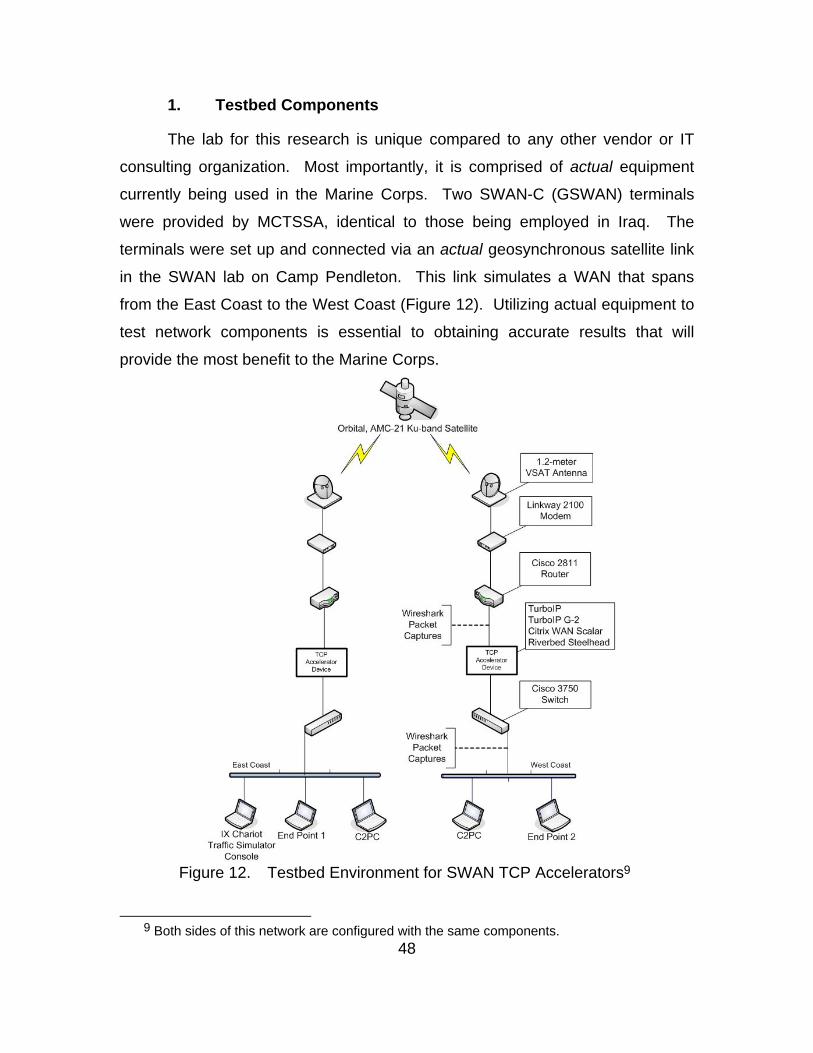
48
1. Testbed Components
The lab for this research is unique compared to any other vendor or IT
consulting organization. Most importantly, it is comprised of actual equipment
currently being used in the Marine Corps. Two SWAN-C (GSWAN) terminals
were provided by MCTSSA, identical to those being employed in Iraq. The
terminals were set up and connected via an actual geosynchronous satellite link
in the SWAN lab on Camp Pendleton. This link simulates a WAN that spans
from the East Coast to the West Coast (Figure 12). Utilizing actual equipment to
test network components is essential to obtaining accurate results that will
provide the most benefit to the Marine Corps.
Figure 12. Testbed Environment for SWAN TCP Accelerators9
9 Both sides of this network are configured with the same components.
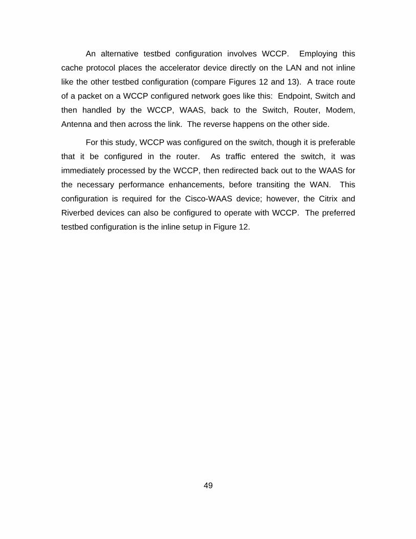
49
An alternative testbed configuration involves WCCP. Employing this
cache protocol places the accelerator device directly on the LAN and not inline
like the other testbed configuration (compare Figures 12 and 13). A trace route
of a packet on a WCCP configured network goes like this: Endpoint, Switch and
then handled by the WCCP, WAAS, back to the Switch, Router, Modem,
Antenna and then across the link. The reverse happens on the other side.
For this study, WCCP was configured on the switch, though it is preferable
that it be configured in the router. As traffic entered the switch, it was
immediately processed by the WCCP, then redirected back out to the WAAS for
the necessary performance enhancements, before transiting the WAN. This
configuration is required for the Cisco-WAAS device; however, the Citrix and
Riverbed devices can also be configured to operate with WCCP. The preferred
testbed configuration is the inline setup in Figure 12.
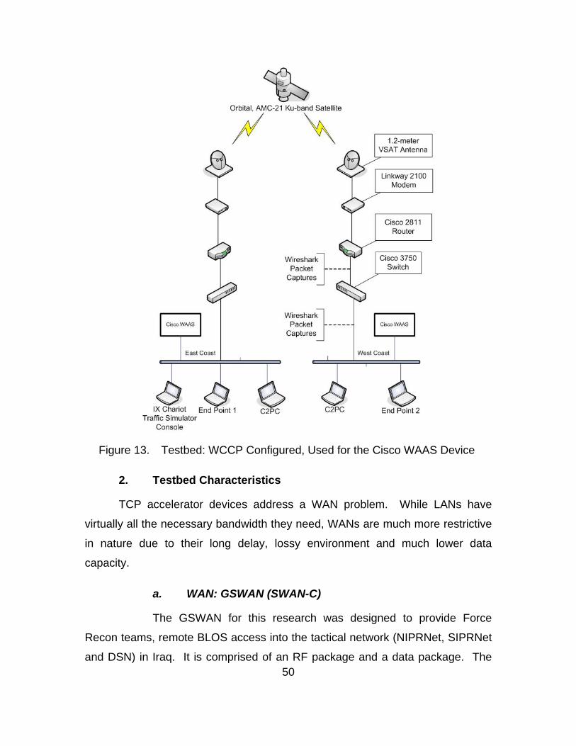
50
Figure 13. Testbed: WCCP Configured, Used for the Cisco WAAS Device
2. Testbed Characteristics
TCP accelerator devices address a WAN problem. While LANs have
virtually all the necessary bandwidth they need, WANs are much more restrictive
in nature due to their long delay, lossy environment and much lower data
capacity.
a. WAN: GSWAN (SWAN-C)
The GSWAN for this research was designed to provide Force
Recon teams, remote BLOS access into the tactical network (NIPRNet, SIPRNet
and DSN) in Iraq. It is comprised of an RF package and a data package. The
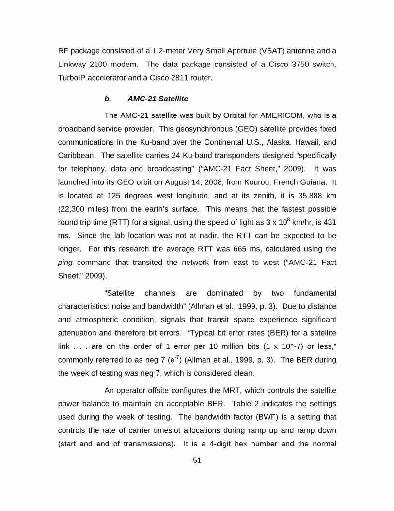
51
RF package consisted of a 1.2-meter Very Small Aperture (VSAT) antenna and a
Linkway 2100 modem. The data package consisted of a Cisco 3750 switch,
TurboIP accelerator and a Cisco 2811 router.
b. AMC-21 Satellite
The AMC-21 satellite was built by Orbital for AMERICOM, who is a
broadband service provider. This geosynchronous (GEO) satellite provides fixed
communications in the Ku-band over the Continental U.S., Alaska, Hawaii, and
Caribbean. The satellite carries 24 Ku-band transponders designed “specifically
for telephony, data and broadcasting” (“AMC-21 Fact Sheet,” 2009). It was
launched into its GEO orbit on August 14, 2008, from Kourou, French Guiana. It
is located at 125 degrees west longitude, and at its zenith, it is 35,888 km
(22,300 miles) from the earth’s surface. This means that the fastest possible
round trip time (RTT) for a signal, using the speed of light as 3 x 10⁸ km/hr, is 431
ms. Since the lab location was not at nadir, the RTT can be expected to be
longer. For this research the average RTT was 665 ms, calculated using the
ping command that transited the network from east to west (“AMC-21 Fact
Sheet,” 2009).
“Satellite channels are dominated by two fundamental
characteristics: noise and bandwidth” (Allman et al., 1999, p. 3). Due to distance
and atmospheric condition, signals that transit space experience significant
attenuation and therefore bit errors. “Typical bit error rates (BER) for a satellite
link . . . are on the order of 1 error per 10 million bits (1 x 10^-7) or less,”
commonly referred to as neg 7 (e-7) (Allman et al., 1999, p. 3). The BER during
the week of testing was neg 7, which is considered clean.
An operator offsite configures the MRT, which controls the satellite
power balance to maintain an acceptable BER. Table 2 indicates the settings
used during the week of testing. The bandwidth factor (BWF) is a setting that
controls the rate of carrier timeslot allocations during ramp up and ramp down
(start and end of transmissions). It is a 4-digit hex number and the normal
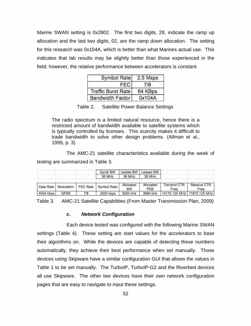
52
Marine SWAN setting is 0x2802. The first two digits, 28, indicate the ramp up
allocation and the last two digits, 02, are the ramp down allocation. The setting
for this research was 0x104A, which is better than what Marines actual use. This
indicates that lab results may be slightly better than those experienced in the
field; however, the relative performance between accelerators is constant.
Table 2. Satellite Power Balance Settings
The radio spectrum is a limited natural resource, hence there is a restricted amount of bandwidth available to satellite systems which is typically controlled by licenses. This scarcity makes it difficult to trade bandwidth to solve other design problems. (Allman et al., 1999, p. 3)
The AMC-21 satellite characteristics available during the week of
testing are summarized in Table 3.
Table 3. AMC-21 Satellite Capabilities (From Master Transmission Plan, 2009)
c. Network Configuration
Each device tested was configured with the following Marine SWAN
settings (Table 4). These setting are start values for the accelerators to base
their algorithms on. While the devices are capable of detecting these numbers
automatically, they achieve their best performance when set manually. Those
devices using Skipware have a similar configuration GUI that allows the values in
Table 1 to be set manually. The TurboIP, TurboIP-G2 and the Riverbed devices
all use Skipware. The other two devices have their own network configuration
pages that are easy to navigate to input these settings.
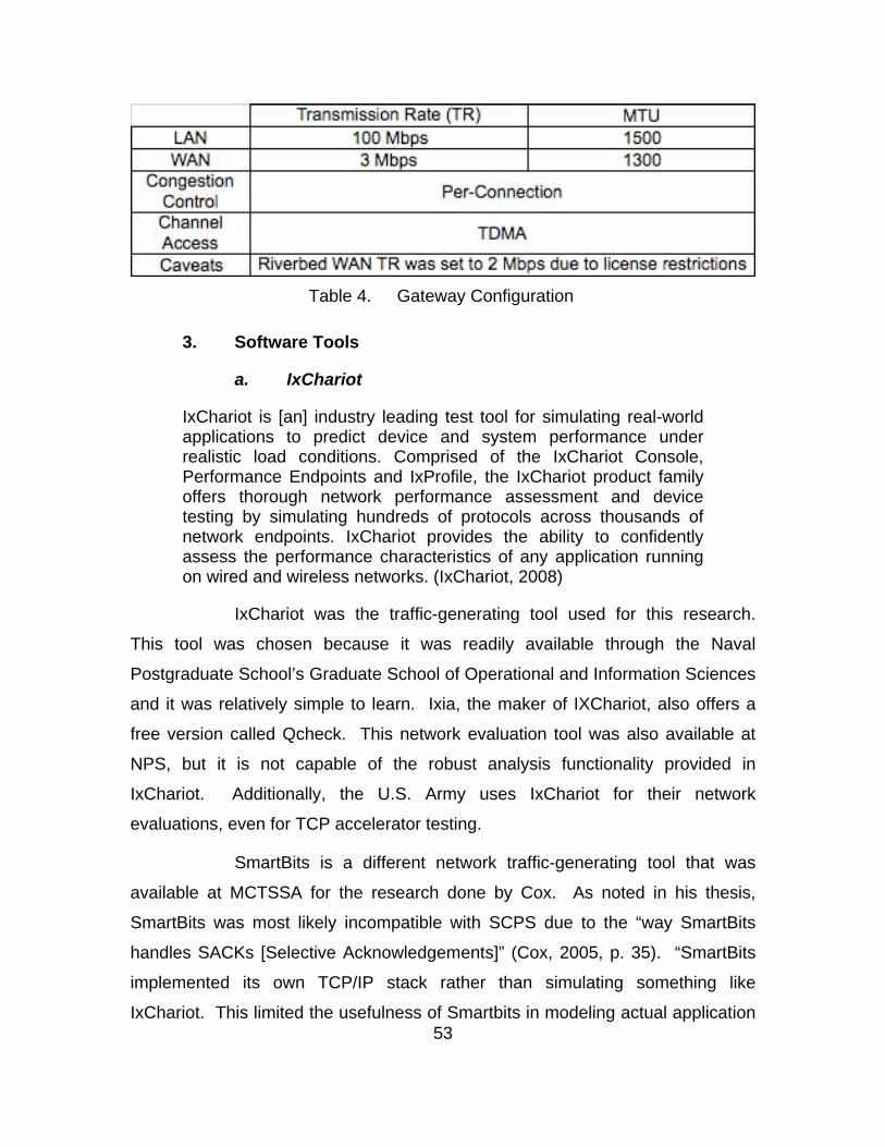
53
Table 4. Gateway Configuration
3. Software Tools
a. IxChariot
IxChariot is [an] industry leading test tool for simulating real-world applications to predict device and system performance under realistic load conditions. Comprised of the IxChariot Console, Performance Endpoints and IxProfile, the IxChariot product family offers thorough network performance assessment and device testing by simulating hundreds of protocols across thousands of network endpoints. IxChariot provides the ability to confidently assess the performance characteristics of any application running on wired and wireless networks. (IxChariot, 2008)
IxChariot was the traffic-generating tool used for this research.
This tool was chosen because it was readily available through the Naval
Postgraduate School’s Graduate School of Operational and Information Sciences
and it was relatively simple to learn. Ixia, the maker of IXChariot, also offers a
free version called Qcheck. This network evaluation tool was also available at
NPS, but it is not capable of the robust analysis functionality provided in
IxChariot. Additionally, the U.S. Army uses IxChariot for their network
evaluations, even for TCP accelerator testing.
SmartBits is a different network traffic-generating tool that was
available at MCTSSA for the research done by Cox. As noted in his thesis,
SmartBits was most likely incompatible with SCPS due to the “way SmartBits
handles SACKs [Selective Acknowledgements]” (Cox, 2005, p. 35). “SmartBits
implemented its own TCP/IP stack rather than simulating something like
IxChariot. This limited the usefulness of Smartbits in modeling actual application
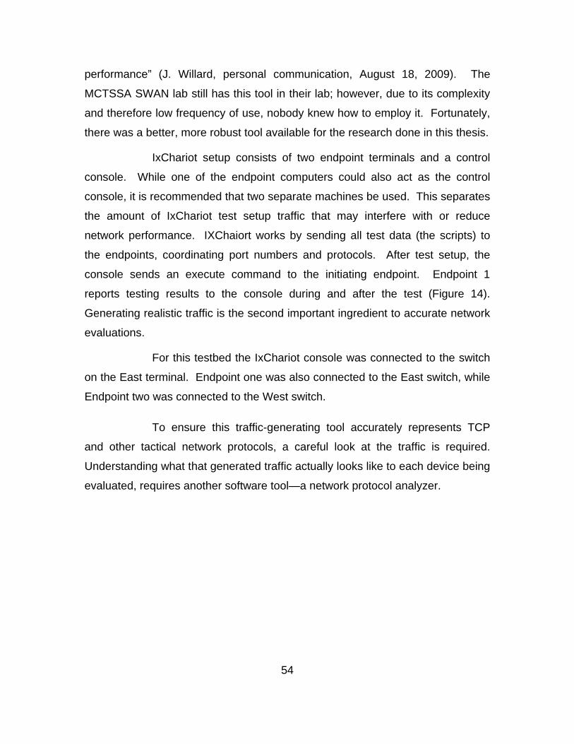
54
performance” (J. Willard, personal communication, August 18, 2009). The
MCTSSA SWAN lab still has this tool in their lab; however, due to its complexity
and therefore low frequency of use, nobody knew how to employ it. Fortunately,
there was a better, more robust tool available for the research done in this thesis.
IxChariot setup consists of two endpoint terminals and a control
console. While one of the endpoint computers could also act as the control
console, it is recommended that two separate machines be used. This separates
the amount of IxChariot test setup traffic that may interfere with or reduce
network performance. IXChaiort works by sending all test data (the scripts) to
the endpoints, coordinating port numbers and protocols. After test setup, the
console sends an execute command to the initiating endpoint. Endpoint 1
reports testing results to the console during and after the test (Figure 14).
Generating realistic traffic is the second important ingredient to accurate network
evaluations.
For this testbed the IxChariot console was connected to the switch
on the East terminal. Endpoint one was also connected to the East switch, while
Endpoint two was connected to the West switch.
To ensure this traffic-generating tool accurately represents TCP
and other tactical network protocols, a careful look at the traffic is required.
Understanding what that generated traffic actually looks like to each device being
evaluated, requires another software tool—a network protocol analyzer.
55
Figure 14. IxChariot Test Process (From Ixia, 2007, p. 2-2)
b. Wireshark
To look deeper into the traffic IxChariot generates and to
understand what is happening to accelerated TCP traffic, Wireshark was used to
capture and analyze packets sent through the SWAN link. “Wireshark is the
world's foremost network protocol analyzer, and is the de facto (and often de
jure) standard across many industries and educational institutions. [Its]
development thrives thanks to the contributions of networking experts across the
globe [and] is the continuation of a project that started in 1998” (Combs, n.d.).
This tool is freeware and is relatively easy to learn.
Since there are two tested configurations, inline and WCCP
(Figures 12 and 13), there are different locations for packet captures. Four
locations are necessary for each testbed: two LAN capture sites and two WAN
capture sites, one on each side of the SWAN connection. The inline
configuration is the easiest, and preferred. Packets were captured just before
the switch on the LAN side, and immediately after the accelerator on the WAN
side. The WCCP configuration is more complex since the packets get redirected
at the switch. For this configuration, packets were captured just before the
switch for LAN traffic and then immediately after the switch, post acceleration, for
WAN traffic. Remember, with the WCCP configuration, packets go to the switch
56
for redirection to the cache and then to the accelerator located on the LAN. After
acceleration, these packets get sent back to the switch, then the router and over
the WAN.
4. Network Traffic Generating Approach
The whole idea behind generating traffic is simply to recreate actual
network traffic in a lab environment without interrupting forward deployed
operations or training exercises. The author was unable to visit a Marine Corps
Tactics and Operations Group (MCTOG) training exercise to capture SWAN
traffic packets due to schedule coordination and data classification. Without
actual traffic to analyze, the author took a stepped approach in building scripts for
the traffic generator that can be characterized as multiple users, simultaneously
using multiple protocols that transfer various file sizes being transmitted in both
directions. This network traffic will be referred to as multi-user/protocol/direction.
Based on Cox’s work, the top four protocols used over a SWAN link are
FTP, HTTP, SMTP and UDP. Included with the IxChariot software package are
base scripts that represent these protocols. These scripts were modified to
progressively load the network with larger file transactions and more users. The
base protocol scripts were first tested individually over the SWAN link to ensure
the simulated protocol accurately represented the actual protocol. This exercise
also served as a baseline to understand how the IxChariot scripts perform in the
satellite network environment. From this data, a multi-user/protocol/direction test
could be built to better represent actual traffic.
The number of connections on a SWAN link is rarely one, nor are those
connections made in only one direction. This is how some testing efforts were
conducted. Running only one script in one direction will not accurately represent
the traffic experienced in tactical networks. Therefore, the scripts run during this
research used 10-pair, five simulating a connection from the East Coast to the
West Coast and five connecting the other direction. This simulates multiple
connections transiting the network in both directions at the same time.
57
a. Single Protocol Scripts
The Throughput script was used to baseline test the link for
maximum throughput. This script sends the specified file size from one endpoint
to the other and waits for an acknowledgement (Ixia, 2007, p. 8-83). File size
was incremented from 100KB to 1 MB to 10 MB. This script, unaccelerated,
provided the baseline to compare accelerated results to.
The FTPget script was used to simulate an FTP get command. File
size was incremented from 100 KB to 1 MB to 10 MB. When this file is run bi-
directionally, it is equivalent to FTP get and put commands being run at the same
time.
The HTTPgif script was used to simulate the transfer of graphic
files from an HTTP server. File size was incremented from 100 KB to 1 MB to 10
MB.
The SMTP script was used to simulate typical e-mail traffic. This
script includes an additional 20-byte header along with the selected file size.
Since e-mail traffic typically consists of smaller files these scripts were modified
as such. File size was incremented from 1 KB to 100KB to 1 MB.
The NetMtgv script was used to simulate streaming video, a UDP
protocol, with factory set defaults. As illustrated in Figure 15, the TCP
accelerator does not touch UDP traffic, referred to as pass through, and therefore
limited testing was done with this script.
A summary of the script configuration for the individual protocol
tests is provided in Table 5.
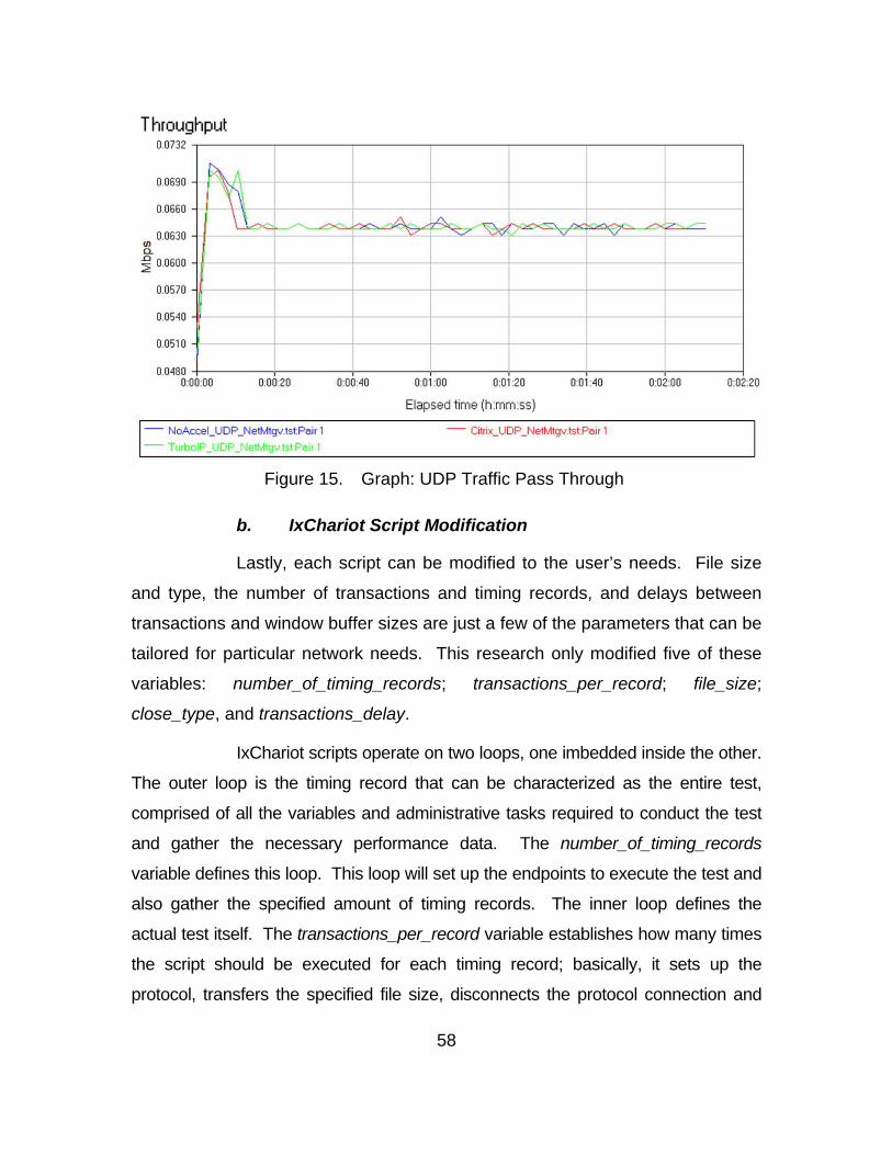
58
Figure 15. Graph: UDP Traffic Pass Through
b. IxChariot Script Modification
Lastly, each script can be modified to the user’s needs. File size
and type, the number of transactions and timing records, and delays between
transactions and window buffer sizes are just a few of the parameters that can be
tailored for particular network needs. This research only modified five of these
variables: number_of_timing_records; transactions_per_record; file_size;
close_type, and transactions_delay.
IxChariot scripts operate on two loops, one imbedded inside the other.
The outer loop is the timing record that can be characterized as the entire test,
comprised of all the variables and administrative tasks required to conduct the test
and gather the necessary performance data. The number_of_timing_records
variable defines this loop. This loop will set up the endpoints to execute the test and
also gather the specified amount of timing records. The inner loop defines the
actual test itself. The transactions_per_record variable establishes how many times
the script should be executed for each timing record; basically, it sets up the
protocol, transfers the specified file size, disconnects the protocol connection and
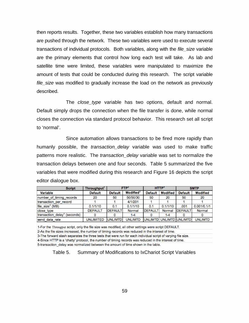
59
then reports results. Together, these two variables establish how many transactions
are pushed through the network. These two variables were used to execute several
transactions of individual protocols. Both variables, along with the file_size variable
are the primary elements that control how long each test will take. As lab and
satellite time were limited, these variables were manipulated to maximize the
amount of tests that could be conducted during this research. The script variable
file_size was modified to gradually increase the load on the network as previously
described.
The close_type variable has two options, default and normal.
Default simply drops the connection when the file transfer is done, while normal
closes the connection via standard protocol behavior. This research set all script
to ‘normal’.
Since automation allows transactions to be fired more rapidly than
humanly possible, the transaction_delay variable was used to make traffic
patterns more realistic. The transaction_delay variable was set to normalize the
transaction delays between one and four seconds. Table 5 summarized the five
variables that were modified during this research and Figure 16 depicts the script
editor dialogue box.
Table 5. Summary of Modifications to IxChariot Script Variables
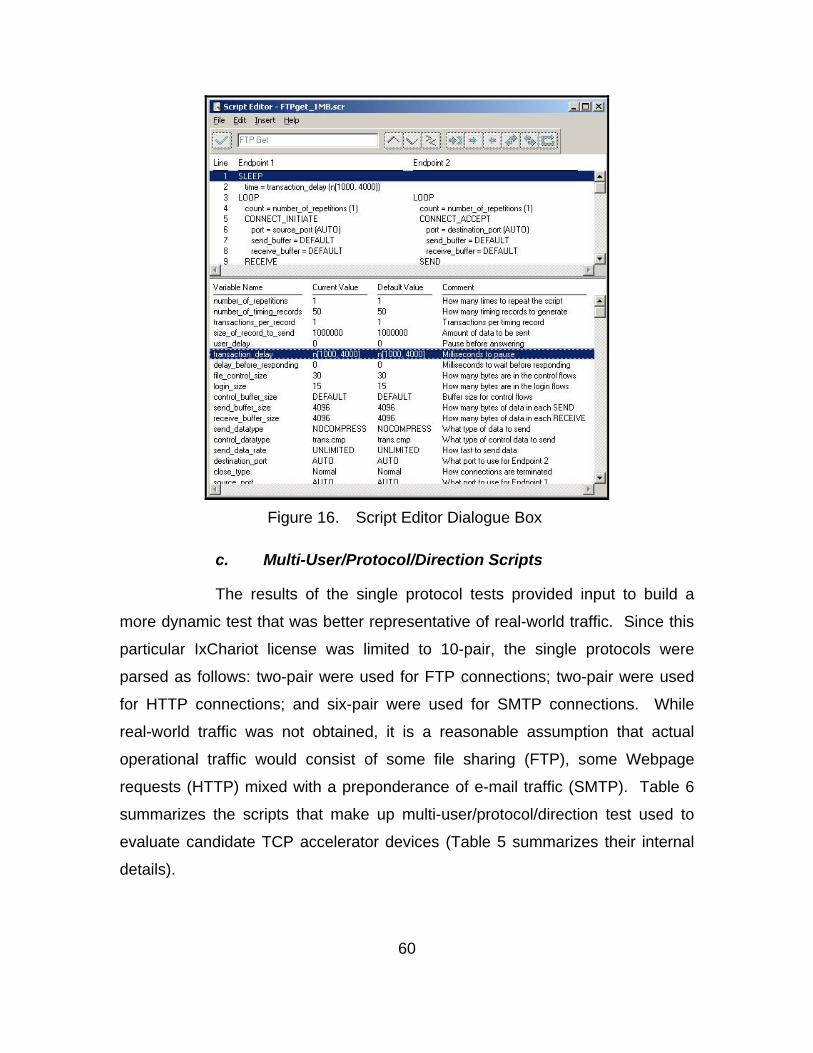
60
Figure 16. Script Editor Dialogue Box
c. Multi-User/Protocol/Direction Scripts
The results of the single protocol tests provided input to build a
more dynamic test that was better representative of real-world traffic. Since this
particular IxChariot license was limited to 10-pair, the single protocols were
parsed as follows: two-pair were used for FTP connections; two-pair were used
for HTTP connections; and six-pair were used for SMTP connections. While
real-world traffic was not obtained, it is a reasonable assumption that actual
operational traffic would consist of some file sharing (FTP), some Webpage
requests (HTTP) mixed with a preponderance of e-mail traffic (SMTP). Table 6
summarizes the scripts that make up multi-user/protocol/direction test used to
evaluate candidate TCP accelerator devices (Table 5 summarizes their internal
details).
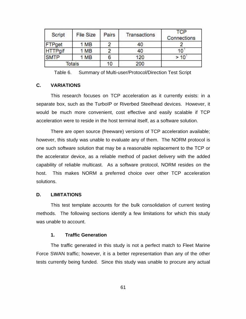
61
Table 6. Summary of Multi-user/Protocol/Direction Test Script
C. VARIATIONS
This research focuses on TCP acceleration as it currently exists: in a
separate box, such as the TurboIP or Riverbed Steelhead devices. However, it
would be much more convenient, cost effective and easily scalable if TCP
acceleration were to reside in the host terminal itself, as a software solution.
There are open source (freeware) versions of TCP acceleration available;
however, this study was unable to evaluate any of them. The NORM protocol is
one such software solution that may be a reasonable replacement to the TCP or
the accelerator device, as a reliable method of packet delivery with the added
capability of reliable multicast. As a software protocol, NORM resides on the
host. This makes NORM a preferred choice over other TCP acceleration
solutions.
D. LIMITATIONS
This test template accounts for the bulk consolidation of current testing
methods. The following sections identify a few limitations for which this study
was unable to account.
1. Traffic Generation
The traffic generated in this study is not a perfect match to Fleet Marine
Force SWAN traffic; however, it is a better representation than any of the other
tests currently being funded. Since this study was unable to procure any actual

62
traffic from actual SWAN links being employed by Marines, several assumption
were made in constructing test scripts (file size, number of users, relative
protocol activity).
Additionally, the traffic-generating tool had a 10-test pair license
restriction. This limited the number of simulated users to 20 (10 users on the
each side of the link).
2. Multicast
The SWAN terminals and the accelerator device are all capable of
multicast traffic. Even the SWAN lab, where these tests were conducted, is
capable of supporting such tests. However, due to lab time and lack of a third
candidate device from each vendor, multicast testing was not conducted. With
this test template and the knowledge that a realistic testbed is available, this
should be the next step in TCP acceleration testing.
63
IV. DATA ANALYSIS
A. EXISTING TCP ACCELERATOR TESTS REVIEW
There are three organizations that are either directly or indirectly testing
TCP accelerators for the Marine Corps: the U.S. Army Information Engineering
Command at Fort Huachuca, AZ; the MITRE Corporation in Bedford, MA; and
MCTSSA on Camp Pendleton, CA. While each testing approach has its
individual strengths and weaknesses, none of them generates accurate
performance data useful for the Marine Corps to base procurement decisions on.
The SWAN system fills a specific capability gap and none of the testing
efforts accurately simulate that environment. The two parts necessary to
accurately simulate the SWAN environment, are the testbed and the network
traffic used to run through the testbed to gather performance data.
Testbed composition varies from the use of actual SWAN terminal
equipment, to full up simulations. The one testbed that uses actual equipment
lacks valid network traffic to load the network with realistic scenarios. The other
two testbeds are in part or all simulation. Even though the SWAN system is built
from common networking components, simulating all or part of that network can
incorporate inaccuracies in data generation. While simulations have advantages,
their individual settings must accurately represent the SWAN environment, and to
compare performance data, their individual settings should be close to identical;
current testing efforts have neither.
The satellite simulation in current SWAN testing efforts is a perfect
example. Those tests that used a simulated satellite only used a propagation
delay of 250ms to 500 ms, when the actual delay experienced by deployed
Marines is between 600 and 700 ms. While this is an easy fix in a simulator,
there is no standard that current SWAN testing efforts are adhering to—a
problem dating back to at least 2005. Another example of tested disparity
64
is that only one incorporates a KG-175B TACLANE mini-encryptor. This device
may or may not have an affect on performance data, but it is a difference that
makes data comparison difficult.
The biggest difference between testing efforts is how network traffic is
modeled. None of the traffic patterns came even close to representing SWAN
traffic. While this research was unable to obtain actual SWAN traffic, some
logical assumptions can be made. First, SWAN terminals connect two or more
LANs; therefore, there is more than one end user using the connection. Second,
all the users do not use the same applications; therefore, there is more than one
protocol transiting the SWAN link at any one time. Third, since there are users
on both sides using the connection, network traffic travels in both directions. Cox
characterized the data similarly. He stated that, “None of the tests reviewed
measured [performance] on a highly saturated, low bandwidth link with multiple
users, simultaneous TCP connections, and multiple protocols” (Cox, 2005, p. 33):
all errors still being repeated today.
Two of the three testing efforts used only one protocol to simulate network
traffic in one direction, and were performed by a single user. The protocol used
was an actual FTP session. This is not nearly enough to saturate a SWAN
connection as experienced by deployed Marines. FTP traffic implies large, multi-
packet files, and real world traffic is small, often single-packet chunks of data.
Another contributing factor to inaccurate network traffic is resource limitations. It
is not reasonably possible for a single lab to generate an accurate amount of
protocol traffic to saturate an actual SWAN link. Nor can a single lab reasonably
produce an accurate number of users interacting on the satellite connection.
Simulators are not to blame for these uncoordinated efforts, nor should
simulators be dismissed from use. Simulators have an essential utility, but they
must represent the real world, otherwise, their output will have very limited use.
Additionally, simulations should be repeatable, allowing for identical data to be
gathered under various lab setups.
65
The raw data generated from these tests can easily be compared (Mbps
vs. Mbps); however, the approach taken to generate that data makes a
difference, which can affect performance results and future procurement
decisions. The three efforts currently employed to evaluate TCP accelerators are
uncoordinated, expensive and not representative of the environment that the
device will be used in. However, there are elements in each organization’s
approach that can easily be combined and tailored specifically for testing SWAN
networks—each at a smaller cost, and producing better results.
This research combined those elements into a standard test that facilitates
real world SWAN network traffic more accurately than current efforts. The data
collected from tests conducted in this testbed are easy to setup, repeatable and
provide more accurate data. This data can be used to compare various vendor
products and predict how well different network configurations may perform in the
real world.
B. TCP ACCELERATOR PLATFORM OVERVIEW
There are several vendors that produce TCP accelerators. The shortlist of
products for this research was derived by MCTSSA. The following is a brief
overview of the test participants: Comtech-TurboIP; Comtech-TurboIP-G2; Citrix-
WANScaler; Cisco-WAAS; and Riverbed-Steelhead. Images of these devices
and their user interfaces can be found in the Appendix (Figures 31–39).
1. Comtech–TurboIP
This is the default accelerator currently used in the SWAN system; it is the
device that all other accelerators will be compared too. This device simply
performs standard PEP functionality, substituting space tolerant algorithms for
native TCP algorithms. This device also has compression functionality; however,
the USMC does not employ this mode. Setup for the TurboIP is quick and easy
and Marines are familiar with it. The form factor for this device is convenient, as
66
it fits into the network package flyaway kit just above the router10. The user
interface (Figure 31) is simple, intuitive and useful, even for the unfamiliar user.
This interface is a Global Protocols, Skipware standard, also used by some
competitors.
2. TurboIP–G2
This device is also produced by Comtech and is being procured by both
the Army and the Marine Corps. The G2 performs legacy PEP functionality with
improved algorithms for greater performance. The manufacturer advertises
caching capabilities; however the device tested did not have this option available.
Tests were conducted on single protocol scripts to compare the G2’s
compression mode on and off. The device performed equally well in both
modes. The remaining tests were done with compression turned off, since this
reduces complexity. Data deduplication will be available in the future as an add-
on for this device. Setting up the TurboIP-G2 is plug and play, especially easy
since this device was designed to replace the original TurboIP and built by the
same manufacturer. This device comes in two form factors: standard size and
½-wide. The standard size easily replaces the current accelerator. The ½ size
version provides the same functionality with a smaller form factor for easier
storage and greater portability. It can be mounted in the same location as the
standard accelerator with the 19” rack mount kit. The user interface is the same
as the TurboIP device (Figure 31).
The remaining devices perform all legacy PEP functionality plus some or
all modern functionality.
3. CISCO–Wide Area Application Service (WAAS)
This device has modern PEP functionality that includes application
streamlining, caching and data deduplication. The form factor for the WAAS is
completely different than that of all other devices. The WAAS is a small
10 Note that the SWAN system and its flyaway kit were designed with the TurboIP device in mind.
67
component that is installed directly into a slot on the front of the router. For this
research, it was installed differently because the particular device that shipped to
MCTSSA was not compatible with the SWAN standard Cisco 2811 router.
Instead, it was installed in a surrogate router (Cisco 3825) that provided power
and a place to connect to the network. WCCP functionality was enabled in the
switch. This caused several problems getting the WAAS device to operate
properly. It took the Cisco representative four days to set up the device, almost
precluding it from testing. Fortunately, due to testing efficiencies designed in this
research, the Cisco-WAAS device was run through most of the tests in less than
a day. An advantage of this form factor is that it eliminates approximately ten
pounds, attributed to other accelerator components like the TurboIP device
(Figure 17, device form factor comparison). The user interface is also simple and
intuitive to use. The software provides visual dashboards and graphing tools that
present network performance real time (Figures 33 and 34).
4. CITRIX–WANScaler Defense Edition
The Citrix WANScaler is being procured by the Army for the Warfighter
Information Network-Tactical (WIN-T) program. This device performs modern
algorithms, compression, caching and to some degree, application streamlining.
The compression functionality acts a lot like data deduplication, checking the
cache site first and compressing only those files that have not transited the WAN.
The application streamlining functionality only works on CIFS files. The
WANScaler is also capable of interfacing with a WCCP; however, for this study
the device was set up inline with the other networking components. Setup for
this device required minimal effort, as it was a plug-and-play replacement for the
original accelerator. The form factor allows the WANScaler to fit inside the
network flyaway kit, in place of the TurboIP device. The user interface (Figure
34) is easy and intuitive to use. The device has some software tools that can be
used for real-time network performance evaluations, such as monitoring the
performance of each connection (Figures 35 and 36).
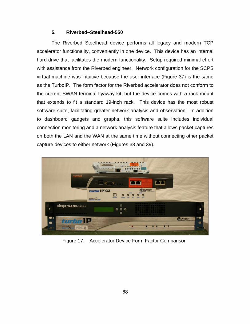
68
5. Riverbed–Steelhead-550
The Riverbed Steelhead device performs all legacy and modern TCP
accelerator functionality, conveniently in one device. This device has an internal
hard drive that facilitates the modern functionality. Setup required minimal effort
with assistance from the Riverbed engineer. Network configuration for the SCPS
virtual machine was intuitive because the user interface (Figure 37) is the same
as the TurboIP. The form factor for the Riverbed accelerator does not conform to
the current SWAN terminal flyaway kit, but the device comes with a rack mount
that extends to fit a standard 19-inch rack. This device has the most robust
software suite, facilitating greater network analysis and observation. In addition
to dashboard gadgets and graphs, this software suite includes individual
connection monitoring and a network analysis feature that allows packet captures
on both the LAN and the WAN at the same time without connecting other packet
capture devices to either network (Figures 38 and 39).
Figure 17. Accelerator Device Form Factor Comparison
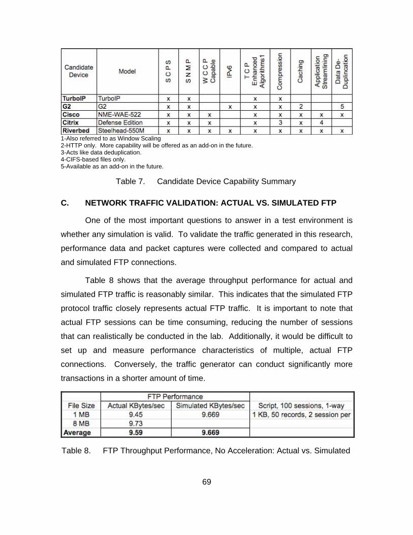
69
1-Also referred to as Window Scaling 2-HTTP only. More capability will be offered as an add-on in the future. 3-Acts like data deduplication. 4-CIFS-based files only. 5-Available as an add-on in the future.
Table 7. Candidate Device Capability Summary
C. NETWORK TRAFFIC VALIDATION: ACTUAL VS. SIMULATED FTP
One of the most important questions to answer in a test environment is
whether any simulation is valid. To validate the traffic generated in this research,
performance data and packet captures were collected and compared to actual
and simulated FTP connections.
Table 8 shows that the average throughput performance for actual and
simulated FTP traffic is reasonably similar. This indicates that the simulated FTP
protocol traffic closely represents actual FTP traffic. It is important to note that
actual FTP sessions can be time consuming, reducing the number of sessions
that can realistically be conducted in the lab. Additionally, it would be difficult to
set up and measure performance characteristics of multiple, actual FTP
connections. Conversely, the traffic generator can conduct significantly more
transactions in a shorter amount of time.
Table 8. FTP Throughput Performance, No Acceleration: Actual vs. Simulated
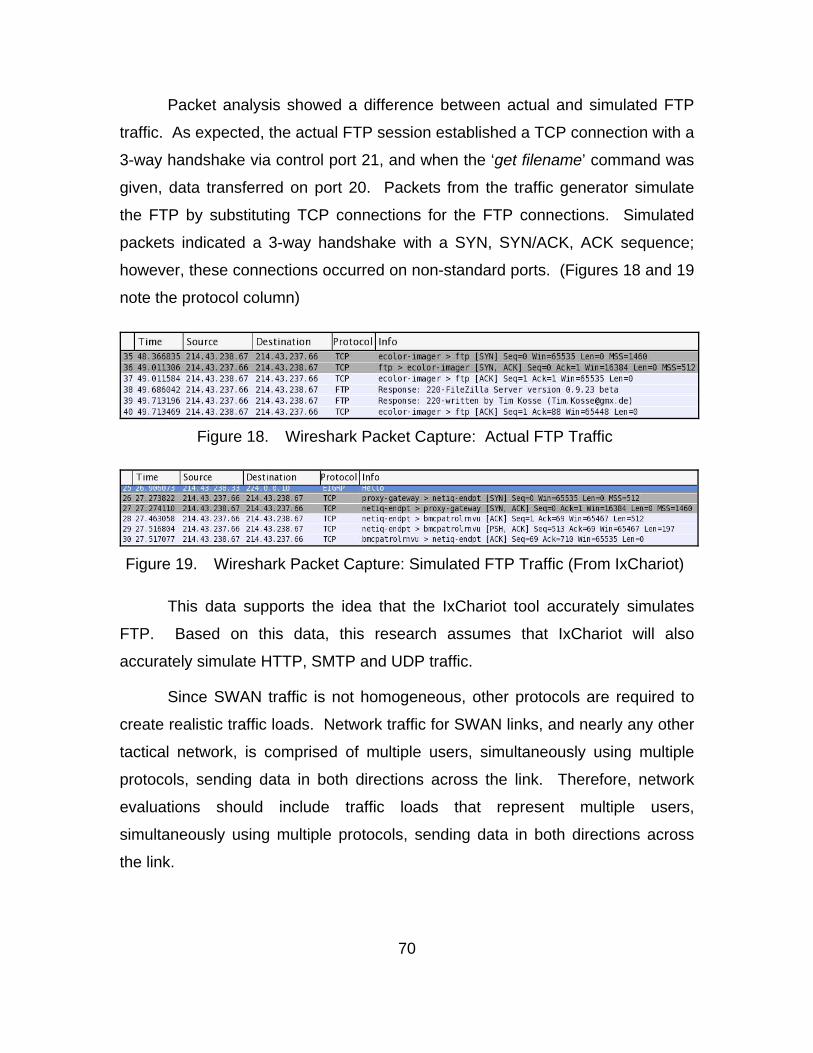
70
Packet analysis showed a difference between actual and simulated FTP
traffic. As expected, the actual FTP session established a TCP connection with a
3-way handshake via control port 21, and when the ‘get filename’ command was
given, data transferred on port 20. Packets from the traffic generator simulate
the FTP by substituting TCP connections for the FTP connections. Simulated
packets indicated a 3-way handshake with a SYN, SYN/ACK, ACK sequence;
however, these connections occurred on non-standard ports. (Figures 18 and 19
note the protocol column)
Figure 18. Wireshark Packet Capture: Actual FTP Traffic
Figure 19. Wireshark Packet Capture: Simulated FTP Traffic (From IxChariot)
This data supports the idea that the IxChariot tool accurately simulates
FTP. Based on this data, this research assumes that IxChariot will also
accurately simulate HTTP, SMTP and UDP traffic.
Since SWAN traffic is not homogeneous, other protocols are required to
create realistic traffic loads. Network traffic for SWAN links, and nearly any other
tactical network, is comprised of multiple users, simultaneously using multiple
protocols, sending data in both directions across the link. Therefore, network
evaluations should include traffic loads that represent multiple users,
simultaneously using multiple protocols, sending data in both directions across
the link.
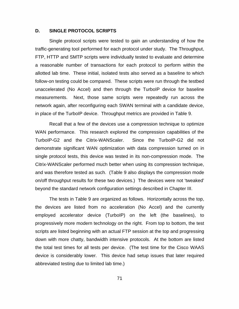
71
D. SINGLE PROTOCOL SCRIPTS
Single protocol scripts were tested to gain an understanding of how the
traffic-generating tool performed for each protocol under study. The Throughput,
FTP, HTTP and SMTP scripts were individually tested to evaluate and determine
a reasonable number of transactions for each protocol to perform within the
allotted lab time. These initial, isolated tests also served as a baseline to which
follow-on testing could be compared. These scripts were run through the testbed
unaccelerated (No Accel) and then through the TurboIP device for baseline
measurements. Next, those same scripts were repeatedly run across the
network again, after reconfiguring each SWAN terminal with a candidate device,
in place of the TurboIP device. Throughput metrics are provided in Table 9.
Recall that a few of the devices use a compression technique to optimize
WAN performance. This research explored the compression capabilities of the
TurboIP-G2 and the Citrix-WANScaler. Since the TurboIP-G2 did not
demonstrate significant WAN optimization with data compression turned on in
single protocol tests, this device was tested in its non-compression mode. The
Citrix-WANScaler performed much better when using its compression technique,
and was therefore tested as such. (Table 9 also displays the compression mode
on/off throughput results for these two devices.) The devices were not ‘tweaked’
beyond the standard network configuration settings described in Chapter III.
The tests in Table 9 are organized as follows. Horizontally across the top,
the devices are listed from no acceleration (No Accel) and the currently
employed accelerator device (TurboIP) on the left (the baselines), to
progressively more modern technology on the right. From top to bottom, the test
scripts are listed beginning with an actual FTP session at the top and progressing
down with more chatty, bandwidth intensive protocols. At the bottom are listed
the total test times for all tests per device. (The test time for the Cisco WAAS
device is considerably lower. This device had setup issues that later required
abbreviated testing due to limited lab time.)
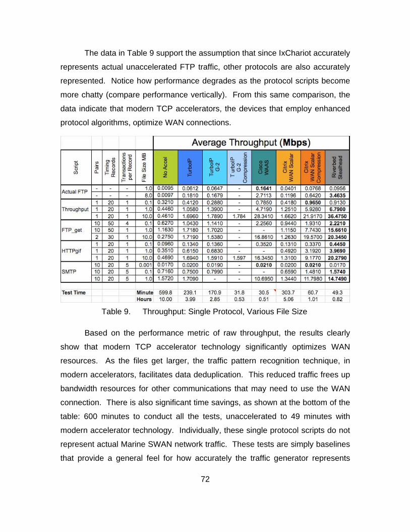
72
The data in Table 9 support the assumption that since IxChariot accurately
represents actual unaccelerated FTP traffic, other protocols are also accurately
represented. Notice how performance degrades as the protocol scripts become
more chatty (compare performance vertically). From this same comparison, the
data indicate that modern TCP accelerators, the devices that employ enhanced
protocol algorithms, optimize WAN connections.
Table 9. Throughput: Single Protocol, Various File Size
Based on the performance metric of raw throughput, the results clearly
show that modern TCP accelerator technology significantly optimizes WAN
resources. As the files get larger, the traffic pattern recognition technique, in
modern accelerators, facilitates data deduplication. This reduced traffic frees up
bandwidth resources for other communications that may need to use the WAN
connection. There is also significant time savings, as shown at the bottom of the
table: 600 minutes to conduct all the tests, unaccelerated to 49 minutes with
modern accelerator technology. Individually, these single protocol scripts do not
represent actual Marine SWAN network traffic. These tests are simply baselines
that provide a general feel for how accurately the traffic generator represents
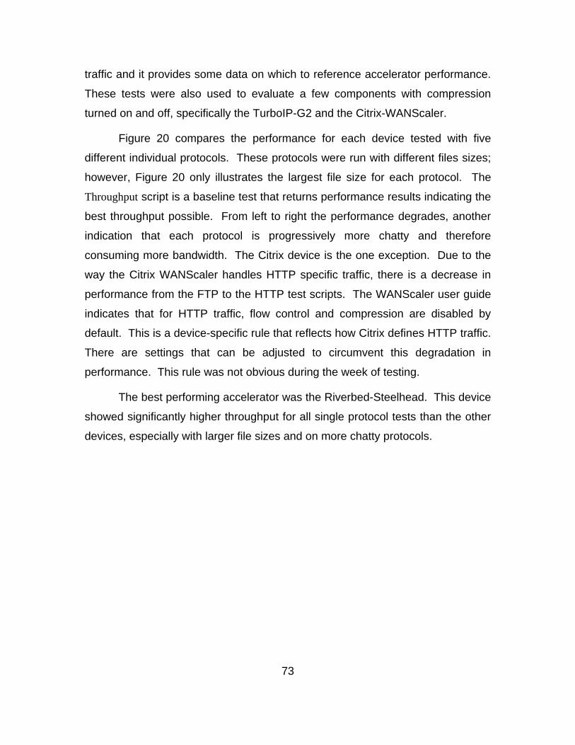
73
traffic and it provides some data on which to reference accelerator performance.
These tests were also used to evaluate a few components with compression
turned on and off, specifically the TurboIP-G2 and the Citrix-WANScaler.
Figure 20 compares the performance for each device tested with five
different individual protocols. These protocols were run with different files sizes;
however, Figure 20 only illustrates the largest file size for each protocol. The
Throughput script is a baseline test that returns performance results indicating the
best throughput possible. From left to right the performance degrades, another
indication that each protocol is progressively more chatty and therefore
consuming more bandwidth. The Citrix device is the one exception. Due to the
way the Citrix WANScaler handles HTTP specific traffic, there is a decrease in
performance from the FTP to the HTTP test scripts. The WANScaler user guide
indicates that for HTTP traffic, flow control and compression are disabled by
default. This is a device-specific rule that reflects how Citrix defines HTTP traffic.
There are settings that can be adjusted to circumvent this degradation in
performance. This rule was not obvious during the week of testing.
The best performing accelerator was the Riverbed-Steelhead. This device
showed significantly higher throughput for all single protocol tests than the other
devices, especially with larger file sizes and on more chatty protocols.
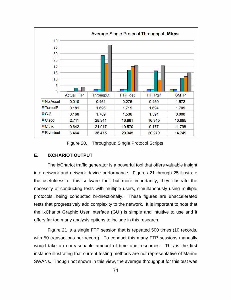
74
Figure 20. Throughput: Single Protocol Scripts
E. IXCHARIOT OUTPUT
The IxChariot traffic generator is a powerful tool that offers valuable insight
into network and network device performance. Figures 21 through 25 illustrate
the usefulness of this software tool; but more importantly, they illustrate the
necessity of conducting tests with multiple users, simultaneously using multiple
protocols, being conducted bi-directionally. These figures are unaccelerated
tests that progressively add complexity to the network. It is important to note that
the IxChariot Graphic User Interface (GUI) is simple and intuitive to use and it
offers far too many analysis options to include in this research.
Figure 21 is a single FTP session that is repeated 500 times (10 records,
with 50 transactions per record). To conduct this many FTP sessions manually
would take an unreasonable amount of time and resources. This is the first
instance illustrating that current testing methods are not representative of Marine
SWANs. Though not shown in this view, the average throughput for this test was
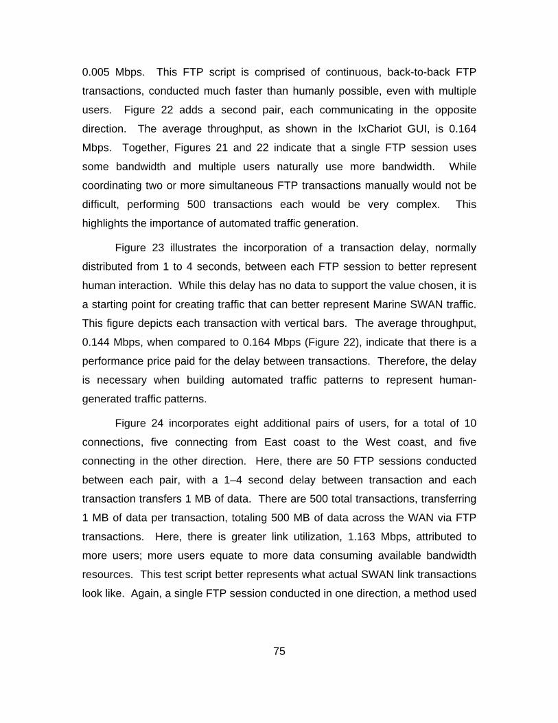
75
0.005 Mbps. This FTP script is comprised of continuous, back-to-back FTP
transactions, conducted much faster than humanly possible, even with multiple
users. Figure 22 adds a second pair, each communicating in the opposite
direction. The average throughput, as shown in the IxChariot GUI, is 0.164
Mbps. Together, Figures 21 and 22 indicate that a single FTP session uses
some bandwidth and multiple users naturally use more bandwidth. While
coordinating two or more simultaneous FTP transactions manually would not be
difficult, performing 500 transactions each would be very complex. This
highlights the importance of automated traffic generation.
Figure 23 illustrates the incorporation of a transaction delay, normally
distributed from 1 to 4 seconds, between each FTP session to better represent
human interaction. While this delay has no data to support the value chosen, it is
a starting point for creating traffic that can better represent Marine SWAN traffic.
This figure depicts each transaction with vertical bars. The average throughput,
0.144 Mbps, when compared to 0.164 Mbps (Figure 22), indicate that there is a
performance price paid for the delay between transactions. Therefore, the delay
is necessary when building automated traffic patterns to represent human-
generated traffic patterns.
Figure 24 incorporates eight additional pairs of users, for a total of 10
connections, five connecting from East coast to the West coast, and five
connecting in the other direction. Here, there are 50 FTP sessions conducted
between each pair, with a 1–4 second delay between transaction and each
transaction transfers 1 MB of data. There are 500 total transactions, transferring
1 MB of data per transaction, totaling 500 MB of data across the WAN via FTP
transactions. Here, there is greater link utilization, 1.163 Mbps, attributed to
more users; more users equate to more data consuming available bandwidth
resources. This test script better represents what actual SWAN link transactions
look like. Again, a single FTP session conducted in one direction, a method used
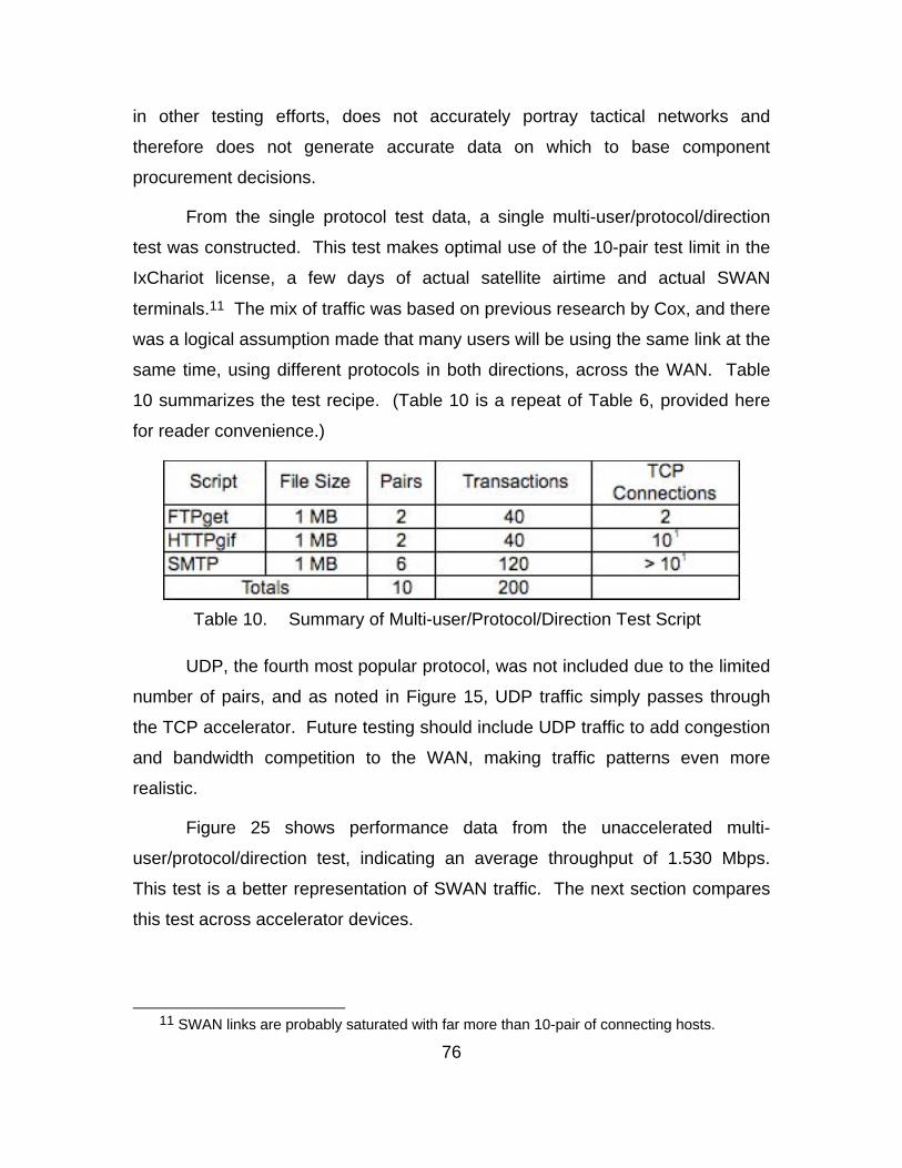
76
in other testing efforts, does not accurately portray tactical networks and
therefore does not generate accurate data on which to base component
procurement decisions.
From the single protocol test data, a single multi-user/protocol/direction
test was constructed. This test makes optimal use of the 10-pair test limit in the
IxChariot license, a few days of actual satellite airtime and actual SWAN
terminals.11 The mix of traffic was based on previous research by Cox, and there
was a logical assumption made that many users will be using the same link at the
same time, using different protocols in both directions, across the WAN. Table
10 summarizes the test recipe. (Table 10 is a repeat of Table 6, provided here
for reader convenience.)
Table 10. Summary of Multi-user/Protocol/Direction Test Script
UDP, the fourth most popular protocol, was not included due to the limited
number of pairs, and as noted in Figure 15, UDP traffic simply passes through
the TCP accelerator. Future testing should include UDP traffic to add congestion
and bandwidth competition to the WAN, making traffic patterns even more
realistic.
Figure 25 shows performance data from the unaccelerated multi-
user/protocol/direction test, indicating an average throughput of 1.530 Mbps.
This test is a better representation of SWAN traffic. The next section compares
this test across accelerator devices.
11 SWAN links are probably saturated with far more than 10-pair of connecting hosts.
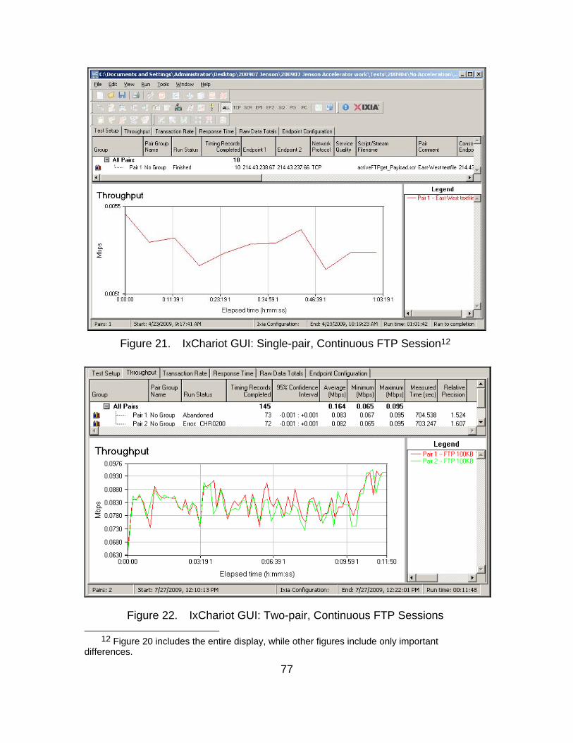
77
Figure 21. IxChariot GUI: Single-pair, Continuous FTP Session12
Figure 22. IxChariot GUI: Two-pair, Continuous FTP Sessions
12 Figure 20 includes the entire display, while other figures include only important differences.
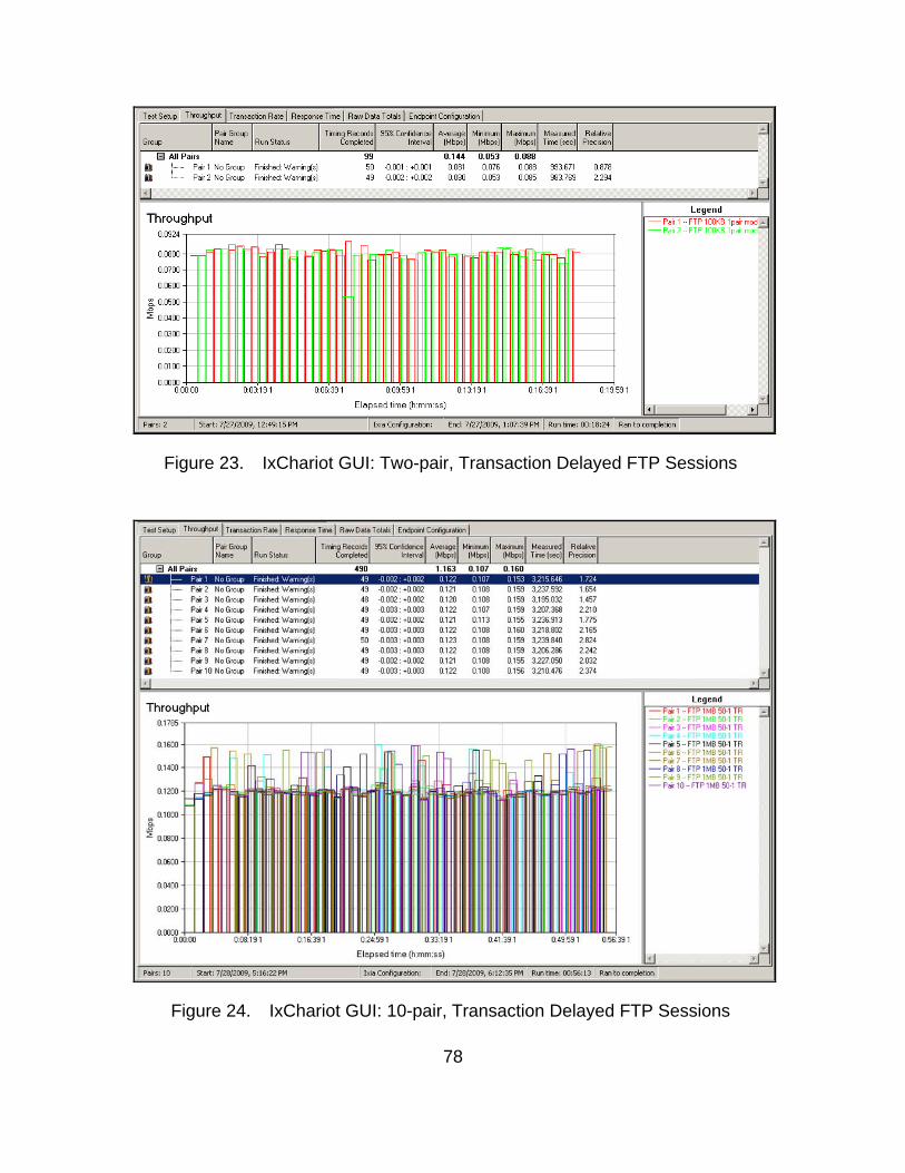
78
Figure 23. IxChariot GUI: Two-pair, Transaction Delayed FTP Sessions
Figure 24. IxChariot GUI: 10-pair, Transaction Delayed FTP Sessions
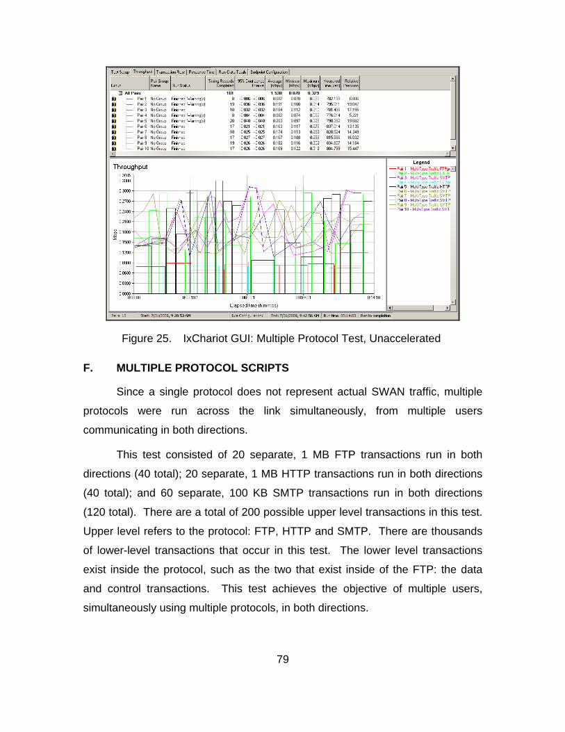
79
Figure 25. IxChariot GUI: Multiple Protocol Test, Unaccelerated
F. MULTIPLE PROTOCOL SCRIPTS
Since a single protocol does not represent actual SWAN traffic, multiple
protocols were run across the link simultaneously, from multiple users
communicating in both directions.
This test consisted of 20 separate, 1 MB FTP transactions run in both
directions (40 total); 20 separate, 1 MB HTTP transactions run in both directions
(40 total); and 60 separate, 100 KB SMTP transactions run in both directions
(120 total). There are a total of 200 possible upper level transactions in this test.
Upper level refers to the protocol: FTP, HTTP and SMTP. There are thousands
of lower-level transactions that occur in this test. The lower level transactions
exist inside the protocol, such as the two that exist inside of the FTP: the data
and control transactions. This test achieves the objective of multiple users,
simultaneously using multiple protocols, in both directions.
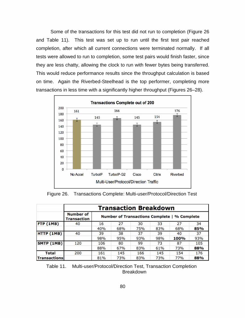
80
Some of the transactions for this test did not run to completion (Figure 26
and Table 11). This test was set up to run until the first test pair reached
completion, after which all current connections were terminated normally. If all
tests were allowed to run to completion, some test pairs would finish faster, since
they are less chatty, allowing the clock to run with fewer bytes being transferred.
This would reduce performance results since the throughput calculation is based
on time. Again the Riverbed-Steelhead is the top performer, completing more
transactions in less time with a significantly higher throughput (Figures 26–28).
Figure 26. Transactions Complete: Multi-user/Protocol/Direction Test
Table 11. Multi-user/Protocol/Direction Test, Transaction Completion Breakdown

81
Figure 27. Time Results: Multi-user/Protocol/Direction Test
Figure 28. Throughput Results: Multi-user/Protocol/Direction Test
The IxChariot GUI provides an excellent illustration of the importance of a
multi-user/protocol/direction traffic load and the value of modern accelerator
technology (Appendix, Figures 40–45). As the graphs are analyzed from no
acceleration, to more modern acceleration technology, the trend shows that
application streamlining is present and beneficial. Both of the TurboIP devices
and unaccelerated traffic have a more random protocol performance than
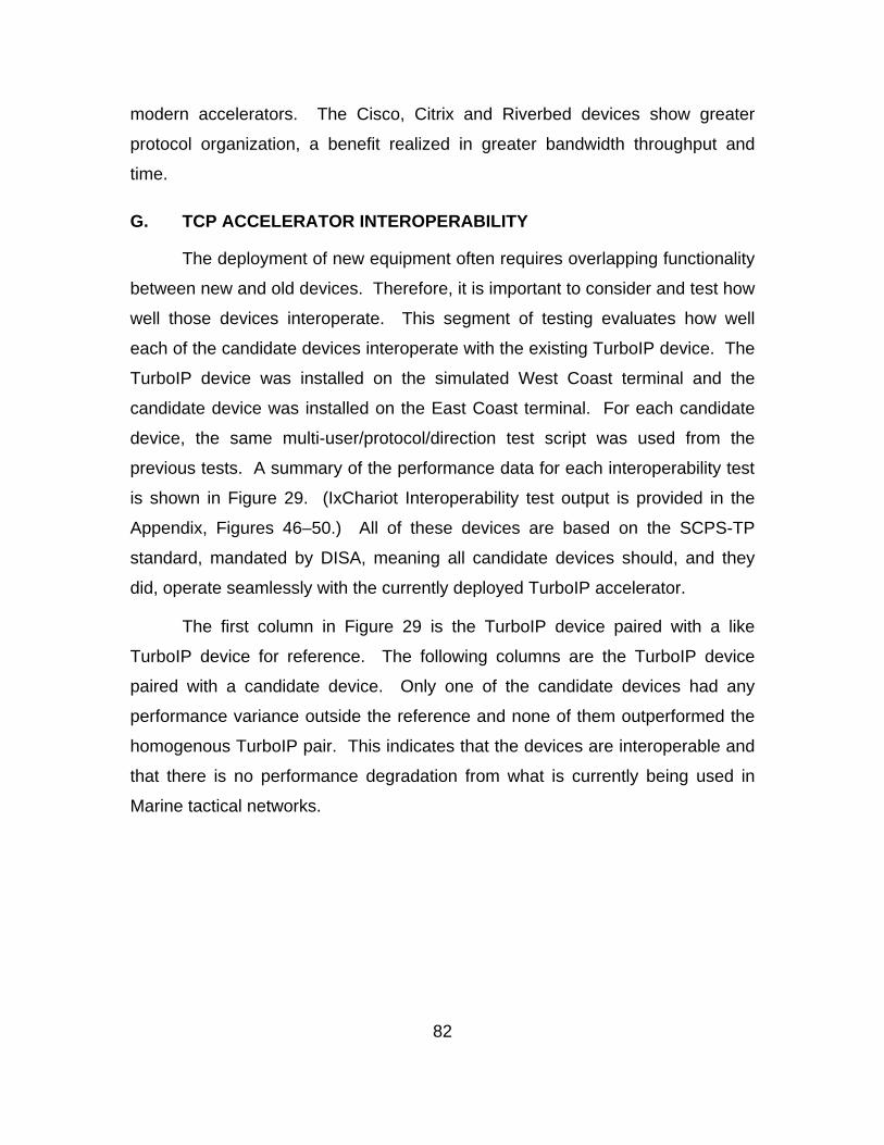
82
modern accelerators. The Cisco, Citrix and Riverbed devices show greater
protocol organization, a benefit realized in greater bandwidth throughput and
time.
G. TCP ACCELERATOR INTEROPERABILITY
The deployment of new equipment often requires overlapping functionality
between new and old devices. Therefore, it is important to consider and test how
well those devices interoperate. This segment of testing evaluates how well
each of the candidate devices interoperate with the existing TurboIP device. The
TurboIP device was installed on the simulated West Coast terminal and the
candidate device was installed on the East Coast terminal. For each candidate
device, the same multi-user/protocol/direction test script was used from the
previous tests. A summary of the performance data for each interoperability test
is shown in Figure 29. (IxChariot Interoperability test output is provided in the
Appendix, Figures 46–50.) All of these devices are based on the SCPS-TP
standard, mandated by DISA, meaning all candidate devices should, and they
did, operate seamlessly with the currently deployed TurboIP accelerator.
The first column in Figure 29 is the TurboIP device paired with a like
TurboIP device for reference. The following columns are the TurboIP device
paired with a candidate device. Only one of the candidate devices had any
performance variance outside the reference and none of them outperformed the
homogenous TurboIP pair. This indicates that the devices are interoperable and
that there is no performance degradation from what is currently being used in
Marine tactical networks.
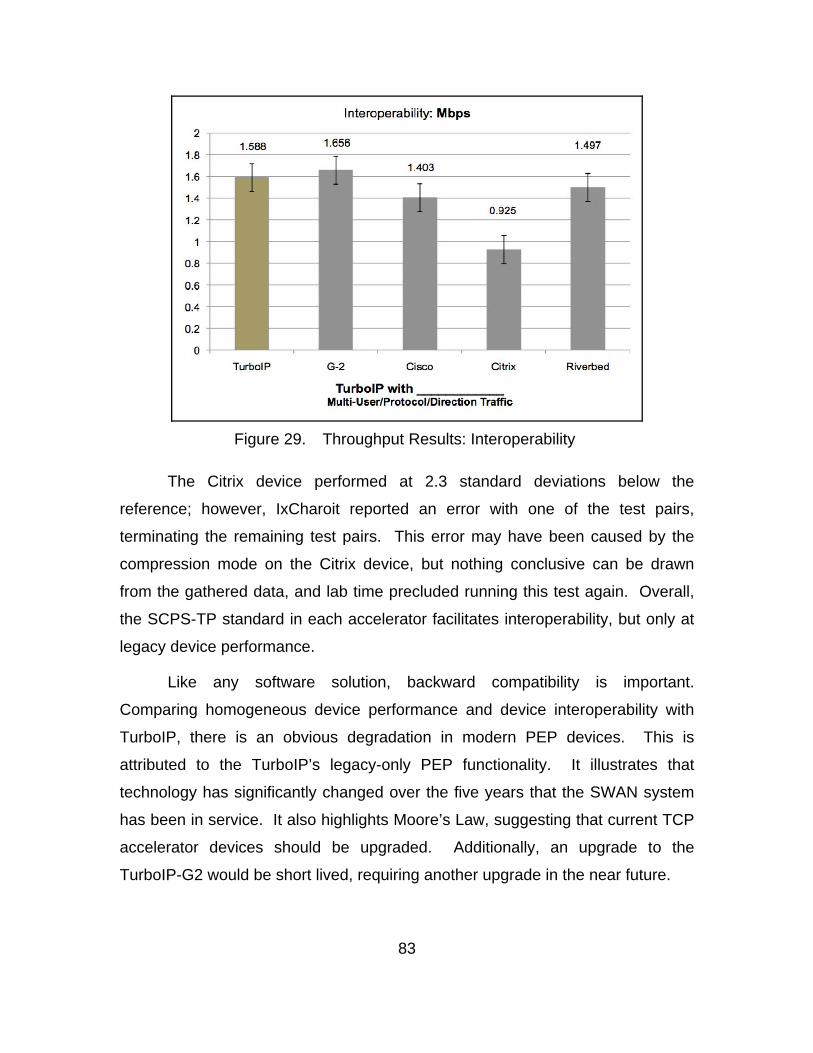
83
Figure 29. Throughput Results: Interoperability
The Citrix device performed at 2.3 standard deviations below the
reference; however, IxCharoit reported an error with one of the test pairs,
terminating the remaining test pairs. This error may have been caused by the
compression mode on the Citrix device, but nothing conclusive can be drawn
from the gathered data, and lab time precluded running this test again. Overall,
the SCPS-TP standard in each accelerator facilitates interoperability, but only at
legacy device performance.
Like any software solution, backward compatibility is important.
Comparing homogeneous device performance and device interoperability with
TurboIP, there is an obvious degradation in modern PEP devices. This is
attributed to the TurboIP’s legacy-only PEP functionality. It illustrates that
technology has significantly changed over the five years that the SWAN system
has been in service. It also highlights Moore’s Law, suggesting that current TCP
accelerator devices should be upgraded. Additionally, an upgrade to the
TurboIP-G2 would be short lived, requiring another upgrade in the near future.
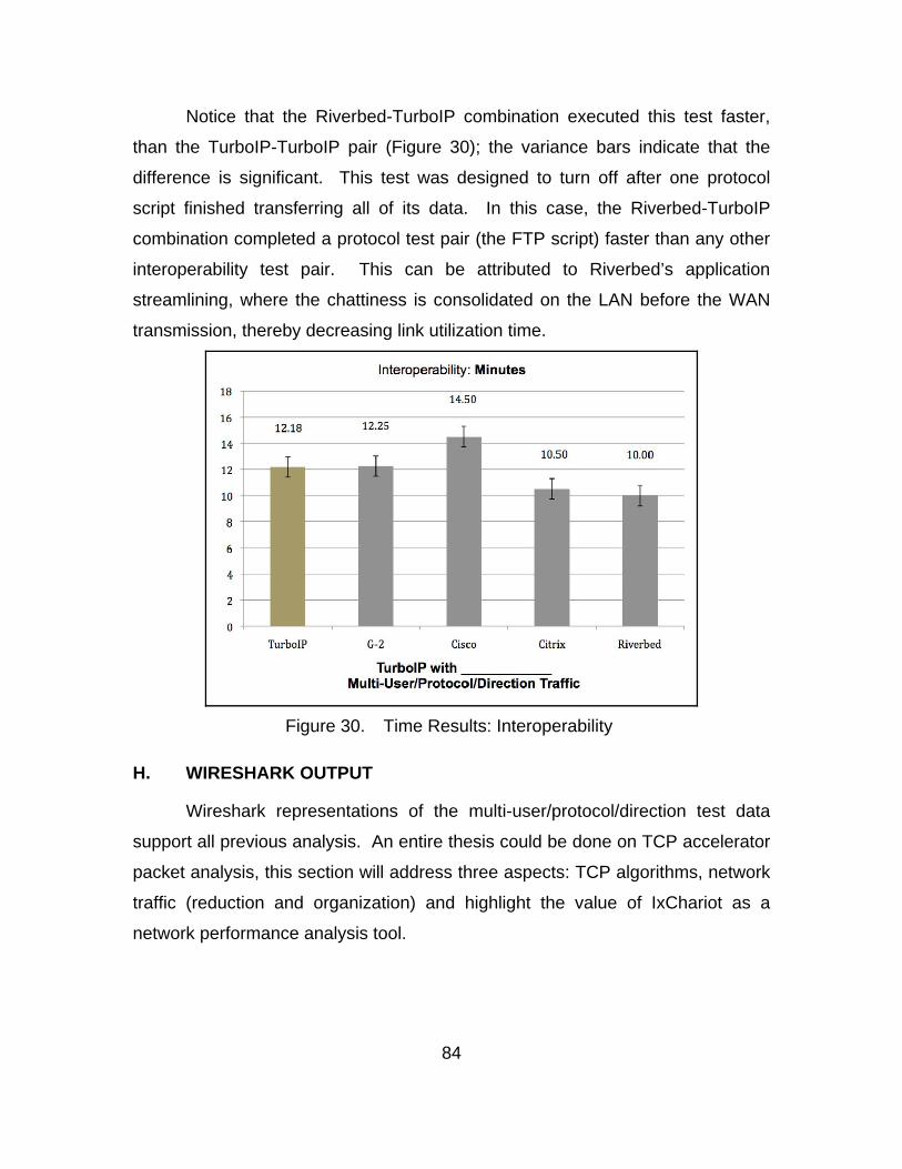
84
Notice that the Riverbed-TurboIP combination executed this test faster,
than the TurboIP-TurboIP pair (Figure 30); the variance bars indicate that the
difference is significant. This test was designed to turn off after one protocol
script finished transferring all of its data. In this case, the Riverbed-TurboIP
combination completed a protocol test pair (the FTP script) faster than any other
interoperability test pair. This can be attributed to Riverbed’s application
streamlining, where the chattiness is consolidated on the LAN before the WAN
transmission, thereby decreasing link utilization time.
Figure 30. Time Results: Interoperability
H. WIRESHARK OUTPUT
Wireshark representations of the multi-user/protocol/direction test data
support all previous analysis. An entire thesis could be done on TCP accelerator
packet analysis, this section will address three aspects: TCP algorithms, network
traffic (reduction and organization) and highlight the value of IxChariot as a
network performance analysis tool.
85
1. TCP Algorithms
Wireshark IO graph analysis (Appendix, Figures 51–56)13 indicates that all
the devices use the slow start algorithm, except the Cisco-WAAS device. They
each take approximately 40 seconds to ramp up to their maximum data rate,
indicated in packets per second (pkts/sec). The Cisco-WAAS device reaches its
maximum rate in 27 seconds. (What the Cicso-WAAS device is actually doing is
beyond the scope of this research.) Packet analysis of the 3-way handshake for
each device, confirm that none of them use early open, as none of the
handshake traffic contains data.
The uniform peaks and troughs for each individual graph indicate the TCP
congestion control algorithm. The TurboIP and TurboIP-G2 are very similar to
each other and to the unaccelerated graph. The difference in performance can
be seen in the average maximum transfer rate (average of the peaks).
Unaccelerated connections ran at 250 pkts/sec and both TurboIP devices
average 500 pkts/sec. The increased data rate is made possible by enhanced
window scaling: 65 Kilobytes (KB) for a normal TCP connection and 14
Gigabytes (GB) and 44 GB, respectively for the TurboIP devices.
Analyzing the three modern devices (Cisco, Citrix, Riverbed) in the same
fashion shows a significant improvement in performance. Data rate: 3500, 500
and 500 pkts/sec respectively. Window size: 65 KB, 8 GB and 14 GB
respectively. The jagged peaks are quite different between the modern devices,
this illustrates the different proprietary implementation of the SCPS. (Again, the
precise internal workings of these devices are beyond the scope of this study.)
13 Notice the red arrow on the No Acceleration, TurboIP and TurboIP-G2 graphs, Figures 51,
52 and 53 respectively. Since the horizontal sizes of these graphs were so large, the center segment was removed to conserve space. The blue arrow highlights the splice.
86
2. Network Traffic
a. Traffic Reductions
Comparing the overall area under the IO graphs generated in
Wireshark, it is clear that modern accelerators (Cisco, Citrix and Riverbed)
achieve better performance by reducing the amount of traffic that transits the
WAN. Modern accelerators also transmit that data faster: 700 and 800 seconds
for legacy accelerators; 140 seconds for modern accelerators, an 81% savings in
bandwidth usage. By reducing traffic through caching, application streamlining
and data deduplication, modern TCP accelerators leave more bandwidth
available for other communications. Additionally, by transferring that data more
efficiently, more bandwidth is available more often; both desirable qualities in
today’s tactical networks.
b. Traffic Organization
Though not included as figures, the packet captures showed
significant traffic organization in modern PEP devices over the legacy PEP
devices during the multi-user/protocol/direction test. The TurboIP packet
captures indicated several ‘TCP Dup Ack’ (duplicate ACKs) and ‘TCP
Retransmission’ packets. These packets were sprinkled throughout the entire
connection. Each duplicate or retransmitted packet equates to one less original
packet beging sent across the network. The TurboIP-G2 also had several
retransmissions due to lost segments. Multiply these by thousands of
connections between multiple users, using different protocols all sending traffic
both directions, and this consumes massive amounts of bandwidth that could
otherwise be used for original traffic.
The modern PEP devices also had some lost, duplicate and
retransmitted packets, but not nearly as many. This can be connected to the fact
that they send less traffic across the WAN, meaning they naturally experience
fewer errors. Fewer errors equates to fewer retransmissions and more available
bandwidth. These devices also demonstrated a more efficient handling of these
87
inevitable packet losses. All three modern PEP devices neatly regrouped lost
packet before they were resent, thus establishing one TCP connection to
retransmit many ‘Dup ACKs’. While all devices have some implementation of
SNACKs, the modern accelerators demonstrated a more organized method.
This traffic organization appears to aid in the efficient handling of errors, leaving
more bandwidth available for other network traffic.
3. IxChariot
While a detailed study of packet captures indicated some traffic
organization, the IxChariot throughput graphs for the multi-user/protocol/direction
tests clearly illustrated it (compare Figures 40–45). Beginning with the
unaccelerated tests, and including the two legacy accelerators, traffic patterns
vacillate significantly, especially the more chatty protocol SMTP. Proceeding
through the modern accelerator IxChariot graphs, there is a significantly
noticeable streamlining of the chatty SMTP traffic. These organized traffic
patterns aid in making modern accelerators efficient bandwidth managers. This
pictorial explanation is not so easy to find in Wireshark packet captures. This
comparison exercise highlights the value IxChariot has in network analysis.
Wireshark and IxChariot together both help illustrate vendor claims of
component capabilities. Through this analysis, modern accelerators reduce
network traffic and organize it more efficiently for better SWAN link utilization.
Even though what happens inside the device is proprietary, this analysis was
able to verify those vendor claims.
I. OTHER TEST RESULTS
1. U.S. Army Information Systems Engineering Command
The U.S. Army Information Systems Engineering Command conducted an
accelerator evaluation in October 2007. Though the specific results are for
official use only, every test they conducted also indicated that the Riverbed
88
device outperformed all other candidates in throughput and time. However, the
Army’s evaluation has two problems that make the results inaccurate for use by
the Marine Corps.
First, the lab environment is not representative of SWAN tactical networks.
The lab was a generic setup with a simulated satellite link that connected two
LANs. The simulated satellite link RTT delay for the Army’s evaluation was 250
milliseconds (ms). The actual average RTT in the SWAN connection for this
thesis work was 665 ms. Second, the traffic generated does not represent
SWAN tactical network traffic. These tests were primarily single protocol. A few
tests contained two protocols, but none contained more than two protocols. As
demonstrated in this analysis, single protocols or tests scripts that do not load the
network with reasonable traffic will produce results that cannot reasonably be
correlated to the real world.
While these tests were conducted on basic networking components on a
simulated WAN, there was one element that future Marine Corps testing should
consider. The Army used a KG-175B TACLANE mini encryptor inline with the
other networking components. While in theory it should not make a difference,
since the encryption occurs before the accelerator, it would be worth testing to
validate that assumption. The Army’s test connects the TACLANE between the
accelerator and the router, similar to SWAN setups.
2. MITRE
MITRE SWAN research is in its infancy. During conversations with
MITRE employees, they agree that actual SWAN traffic must be recreated to
generate accurate results. Their testing consisted of an actual, single protocol
transaction over the WAN link in one direction. Again, this approach is not
representative of Marine SWAN traffic. This approach is also difficult to scale to
the size of tactical networks. These tests, like the Army tests, used simulated
SWAN terminals and a simulated satellite connection. They initially used 500
ms, but have been advised that 665 ms is more realistic.
89
MITRE is a little late to the game on accelerator testing. There are far
better options available to the Marine Corps, than to spend time and money
allowing MITRE to research this system.
3. MCTSSA
MCTSSA’s greatest strength is that they have access to the latest Marine
tactical network equipment and an actual satellite link to conduct testing on. This
is the most important and expensive part of quality testing and it is necessary for
accurate results. The tests that are conducted at MCTSSA are single user,
single protocol, and conducted only in one direction. Again, this does not
accurately represent Marine Corps SWAN traffic.

90
THIS PAGE INTENTIONALLY LEFT BLANK
91
V. CONCLUSION, RECOMMENDATIONS AND FUTURE WORK
The primary objective of this research was to create a standard,
repeatable test that represents SWAN traffic generated by Marine operating
forces. The intent of this test is to provide network decision makers repeatable
procedures that generate accurate data that can be used to effectively evaluate
network and network component performance. This objective was accomplished
in three steps:
1) By developing a repeatable and realistic testbed template (Chapter
III, Figure 12);
2) By employing readily available diagnostic tools to sense, organize
and view performance data (IxChariot and Wireshark); and
3) By developing a network traffic load that better represents Marine
Corps SWAN traffic.
The secondary objective was to use this test template and traffic load to
generate TCP accelerator data to help determine the ‘best of breed’ device for
the Marine Corps’ needs.
A. CONCLUSION
The three testing efforts currently being funded to procure updated TCP
accelerators are inefficient and ineffective. They are disparate and
uncoordinated, each generating data that does not accurately represent Marine
Corps SWAN traffic. These testing efforts had simulated networks and traffic
patterns that were all configured differently, producing results there were difficult
to compare.
This research consolidated elements from the three testing efforts into an
accurate and reliable test plan that is more cost effective than the other testing
methods. This approach uses the same traffic-generating tool the U.S. Army
employs, but with more robust test scripts that represent SWAN traffic. The test
92
scripts built represent multiple users, simultaneously using multiple protocols, in
both directions. These test scripts were combined into one common test that can
easily and repeatedly be run through an actual SWAN link, reconfigured with
multiple candidate TCP accelerators. The test can be applied to other networks
as-is or easily modified to emulate other types of network traffic. The results
show that the test is more dynamic and better represents the assumed chattiness
in actual links. When this test was used to evaluate candidate TCP accelerator
devices, the results clearly show that modern TCP accelerator technology
significantly optimizes bandwidth utilization in the SWAN.
There were four candidate TCP accelerators tested against the current
TurboIP device. The data supports, as Moore’s Law suggests, that the TCP
accelerator component of the SWAN system is in need of an upgrade in
technology. While the legacy accelerator that was procured five years ago still
functions well, modern accelerators optimize WAN bandwidth in two ways. First,
by reducing the amount of traffic that is sent across the WAN and second, by
organizing protocol traffic, which then uses significantly less time to transit the
link, making bandwidth available more of the time. Both functions help better
utilize the available bandwidth more efficiently.
These devices are in fact in need of an upgrade. It is not realistic to
always purchase the latest and greatest technology upgrade; however, in this
case where bandwidth demand is continually increasing and modern accelerator
devices provide significant bandwidth savings, it makes sense to procure the
technology. Additionally, compare the cost of purchasing another satellite or
additional bandwidth, to that of upgrading TCP accelerators that optimize already
purchased bandwidth. The Marine Corps could buy back-to-back increments of
accelerator upgrades for a decade to equal the cost of another satellite.
93
B. RECOMMENDATIONS
1. TCP Accelerator Testing for the SWAN System
Since the three testing efforts evaluated in this research do not generate
accurate data on which to base decisions, it is recommend that MCSC adopt the
testing approach outlined in this thesis. This can be accomplished in the three
steps: a) Purchase a quality network traffic-generating tool; b) Establish testing
procedures for SWAN systems at MCTSSA, most of which is outlined in this
thesis; and c) Incorporate already contracted IT consultants into these decisions.
a. Network Traffic-Generating Tool
The Marine Corps has the ideal SWAN testbed already set up in
the SWAN lab on Camp Pendleton. They have actual SWAN terminals and an
actual satellite link that are configured to perform like those systems that are
forward deployed with our Marines. The only thing missing in this test
environment is a robust traffic-generating tool. IxChariot was the tool used for
this research and it is the same tool employed by the U.S. Army. This software
tool was easy to learn, and it had a robust set of analysis capabilities that would
help Marine network analysts and network decision makers test and evaluate
tactical networks for TCP accelerator performance, and any other network
component or network configuration.
Another option would be to coordinate testing with the Army. Since
actual traffic patterns for the Marine Corps and the Army probably do not differ
drastically and the fact that DoD IT and communication systems are required to
be interoperable, it would make sense to combine these efforts so that test data
can be more valuable to both service. This option would facilitate greater Marine
Corps input into component procurement for Marine specific systems, while at
the same time giving the Army greater insight into the Marine Corps’ needs. This
synergy would aid in the faster procurement of COTS solutions, delivering better,
more capable systems to the warfighter.
94
Either recommendation would require the Marine Corps to
purchase a network traffic generator. The author recommends the IxChariot
software tool with a floating license that includes at least 200-pairs (product
numbers: 920-0034).
b. Test Procedures
TCP accelerator and SWAN testing procedures need to be
standardized and documented, at the very least within in the Marine Corps. A
standardized test would allow the Marine Corps to not only test organically, but
also provide better guidance to IT consulting firms. Currently, test knowledge
resides in the SWAN lab personnel, undocumented, and in IT firms outside the
control of the Marine Corps. A small employee turn over at either location could
result in the loss of some or all previous testing knowledge. Additionally, there is
no historical data currently available to compare today’s TCP accelerators or
network performance to. Standardizing SWAN test procedures will allow the
Marine Corps to track accelerator performance over time, making future
evaluations more valuable and efficient. It could also be used to provide better
guidance for evaluations done by IT consultants. Using IxChariot is one way to
facilitate testing standards and it would also retain testing data for future
comparison.
The Marine Corps has organic assets to facilitate the collection of
information necessary to evaluate modern accelerator technology or any other
segment of the SWAN system. These organic assets exist at MCTSSA. While
MCTSSA’s testing efforts are currently incomplete, some simple, cost effective
and time saving modifications would make this effort more comprehensive,
accurate and valuable to decision makers.
The primary elements of this test are the traffic generating tool and
the accurate and realistic test environment. With these two elements, this test
can be applied to any network configuration to evaluate performance. These
procedures can easily be shared with other organizations to compare network
95
performance. They could even be used to replicate network problems being
experienced by Marines who are forward deployed and call back to MCTSSA for
support. The bottom line is this test is repeatable, accurate, and flexible to
changing networks or different types of networks.
c. IT Consultants
While the MITRE Corporation may provide excellent service on
their DoD contracts, the testing and evaluation of SWAN components is not
optimal. They have several employees working on the SWAN project and have
not produced any solid recommendation for the two years of their research.
Their contract linked to SWAN equipment should be allowed to expire.
Sidereal Solutions has provided valuable input into the SWAN
program, and should remain in the Marine Corps’ budget. James Willard, Vice
President and General Manager of Sidereal, should have a voice in all SWAN
component procurement decisions, as well as in standardizing testing
procedures and purchasing of traffic-generating equipment. Mr. Willard is very
knowledgeable about the SWAN system and the many vendors that build
components for this COTS solution. His contribution to this research and future
SWAN system decisions are invaluable.
2. TCP Accelerator Selection
There were four candidate TCP accelerators tested against the current
TurboIP device: the TurboIP-G2, Cisco-WAAS, Citrix-WANScaler and the
Riverbed-Steelhead. The Riverbed accelerator outperformed all other devices in
single and multiple protocol tests, single and multiple user tests, as well as
interoperability tests. (Of particular note, the Riverbed device, paired with a
TurboIP device, outperformed a homogeneous pair of TurboIP devices.)
Riverbed-Steelhead device also has the most complete and functional network-
performance monitoring software.
96
This thesis is not the only indicator that the Riverbed device is the best
choice. The U.S. Army Information Systems Engineering Command collected
similar results, even thought their tests were not as complete. The Riverbed
Steelhead device will give the SWAN system greater capacity to facilitate
communications, allowing Marines to maintain their tactical edge now and well
into the future.
3. Technology Modifications
Early open is a TCP technique, briefly mentioned Chapter II, which should
become an available feature in the near future. Since wireless and satellite links
are including more individual warfighters who will be generating large amounts of
small network traffic, the early open technique would pay immediate dividends to
reducing volumes of network congestion. Perhaps the SCPS-TP standard could
be refreshed to incorporate this technique for widest dissemination. If not the
SCPS-TP standard, then this technique should be recommended to TCP
accelerator vendors for incorporation into future software upgrades.
C. FUTURE WORK
1. Multicast
Computers were initially designed to speak to each other via protocols that
were designed in the 1960s and 1970s, though they have been updated, are still
in use today. This research began exploring multicast in the tactical
environment; however, the more immediate problem of addressing the testing
procedures for the current SWAN systems in the USMC took precedence. TCP
accelerators are a short-term, intermediate solution to the larger reliable multicast
problem. A reliable multicast software protocol would be the next big step for
extending the Internet into the battlefield.
The trend is to push the Internet deeper into the battlefield and farther
down the chain of command, facilitating the accurate and timely exchange of
information. Blue Force Tracker is an example where the Internet is becoming
97
more available in mobile platforms such as tanks, aircraft, ships and even down
to the individual warfighter. This growth presents several problems such as
reliably sharing individual data with multiple end users, on networks that are
bandwidth challenged and doing it with authentication, where subscribers are
dynamically entering and exiting the network continuously. This growth will
require an increase in systems like RF-WANs, both on the ground (WPPL) and
SATCOM (SWAN). The consequent opportunities are significant.
This solution is not military specific. Reliable multicast capabilities have
many commercial application of which emergency services are but one.
Therefore, this software protocol should eventually reside in the operating system
stack, and be distributed as such.
The Internet Engineering Task Force is working on one such experimental
protocol called Negative Acknowledgement (NACK)-Oriented Reliable Multicast
(NORM). Explored as a thesis topic, this protocol would provide valuable insight
into how this next generation protocol will help solidify network-centric operations
in the DoD. The author would recommend that this research be done by a
minimum of two students working on different aspects of NORM. One student
would focus on understanding, installing, and modifying the NORM source code.
This area of focus would be best suited to a Computer Science student or a
proficient programmer14. The other student would focus on the integration and
testing of this reliable multicast protocol on DoD networks. An accurate test
template is contained in this thesis (Chapter III). In addition to the template, keep
in mind that more than one end terminal will be required. Links between Camp
Pendleton, Camp Roberts and NPS are all within a reasonable distance and all
support DoD networking research. This protocol will become standard in future
network-centric operations and should be explored by NPS students for its
incorporation into the DoD and Marine Corps tactical networks.
14 NORM source code is available at http://downloads.pf.itd.nrl.navy.mil/norm/.
98
2. Traffic Composition
This research built robust test scripts for testing tactical SWANs. Actual
traffic patterns from SWAN networks were not obtained for this research. The
importance of this cannot be over emphasized for future study and analysis. The
following is a list of sources, in order of precedence, from where traffic should be
captured, analyzed and modeled for future research and lab testing:
a. Network traffic that is forward deployed, such as SWAN traffic in
Iraq, Afghanistan or the Horn of Africa.
b. Training exercises where the SWAN terminals are actually
separated by significant, BLOS geography. An excellent place to
start would the monthly training exercises out of Twentynine Palms,
CA, where satellite links are established with SWAN terminals from
around the country, including Camp Lejuene and Hawaii.
c. Training exercises conducted at the Communications Schools in
Twentynine Palms, CA, or Quantico, VA.
The traffic patterns generated from the U.S. Army Information Systems
Engineering Command and the MITRE Corporation do not accurately represent
real world Marine traffic and should be avoided at this time. These traffic
patterns are not robust enough to load the network or accelerator devices with
traffic that would produce valuable information.
This research used network traffic as described by Criston Cox in his 2005
thesis, along with some logical characteristics drawn from the composition of the
Internet. Network traffic is dynamic and SWAN traffic is probably quite different
depending on organizational level and theater employment. For example, traffic
between the MEF and Division is probably different than that between Regiment
and Battalion. Also, traffic in Iraq is probably different than that in Afghanistan or
the Horn of Africa.
99
Characterizations should include what current patterns looks like and what
the future trends will be. Currently, with respect to modern TCP accelerator
technology, caching and data deduplication, it would be useful to know how
much network traffic is new, and how much is repeated, since repeated traffic
does not transit the WAN. Considering the goal of network-centric operations,
future network traffic will consist of a large number of users sending smaller
packets over wireless communication links.
For these reasons, a traffic composition study of Marine Corps networks
would benefit network configuration considerations. Further study should not
focus on SWAN traffic alone, but rather characterize network traffic within the
Marine Corps as a whole. Other networking traffic to consider is administrative
networks and inter-service networks.
3. Computing Protocols
The four protocols tested during this research only represent the four
primary protocols as identified by Criston Cox (Cox, 2005). The multi-
user/protocol/direction test recipe developed in this research is not perfect,
although it is a better representation than current testing efforts. It was
constructed based on data gather in 2005 and the reasonable assumption that
SMTP should be the dominant application protocol that uses a TCP connection.
This assumption did not consider that the SMTP traffic file size would be much
smaller than the other bandwidth competing protocols (FTP and HTTP).
Additionally, this test did not include any UDP traffic in the protocol mix. Based
on this research, future test recipes should look something like Table 12. This
recipe is based on the 10-pair license limit and should be scaled appropriately on
IxChariot chassis with more capabilities. Since the reliable delivery of packets is
desirable, the TCP is the primary connection protocol that should be tested.
UDP is important and even though the accelerator does not touch the traffic, it
should be included to evaluate performance with other non-TCP traffic competing
for bandwidth.
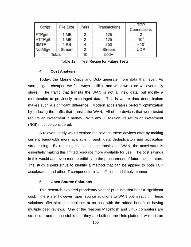
100
Table 12. Test Recipe for Future Tests
4. Cost Analysis
Today, the Marine Corps and DoD generate more data than ever. As
storage gets cheaper, we find ways to fill it, and what we store we eventually
share. The traffic that transits the WAN is not all new data, but mostly a
modification to previously exchanged data. This is where data deduplicaiton
makes such a significant difference. Modern accelerators perform optimization
by reducing the traffic that transits the WAN. All of the devices that were tested
require an investment in money. With any IT solution, its return on investment
(ROI) must be considered.
A relevant study would explore the savings these devices offer by making
current bandwidth more available through data deduplicaiton and application
streamlining. By reducing that data that transits the WAN, the accelerator is
essentially making this limited resource more available for use. The cost savings
in this would add even more credibility to the procurement of future accelerators.
The study should strive to identify a method that can be applied to both TCP
accelerators and other IT components, in an efficient and timely manner.
5. Open Source Solutions
This research explored proprietary vendor products that bear a significant
cost. There are, however, open source solutions to WAN optimization. These
solutions offer similar capabilities at no cost with the added benefit of having
multiple peer reviews. One of the reasons Macintosh and Linux computers are
so secure and successful is that they are built on the Unix platform, which is an
101
open system. This allows the user to study how the system works and make
adjustments to improve it. These are the same reasons that SCPS-TP and other
standards now exist for TCP acceleration.
SCPS-TP is an open source standard, designed so that any developer
can make modification to it for improvement, and yet still be interoperable with
current systems. A performance study including open source solutions such as
NORM could reveal an even more cost effective method to optimizing WAN
performance.

102
THIS PAGE INTENTIONALLY LEFT BLANK
103
VI. SUMMARY
The Support Wide Area Network has been a valuable addition to
communications in the Marine Corps. It has taken the power and flexibility of the
Internet and extended it into remote locations, facilitating mission
accomplishment for Marines on the tip of the spear. This system’s effectiveness
is attributed to two critical factors in network-centric operations: 1) the system
facilitates communication beyond line-of-sight; and 2) it does so as a routable
network segment (Figures 11 and 12).
Central to the SWAN’s effectiveness is its modularity. This modularity
provides for interoperability and maintainability. Its interoperability is manifested
through its routable characteristics. It simply directs an already formatted data
packet to another terminal through the challenging space environment, without
modifying the packet. This means that it does not matter what component is on
the other side of the link, as long as that component can process a standard
Internet packet. The SWAN is maintainable through interoperable components.
These components can be easily replaced if broken, or updated with better
technology. The ability to upgrade components like the TCP accelerator, allows
the entire system—in this case the tactical BLOS network—to operate more
efficiently without making the costly upgrade of replacing the entire system.
The SWAN’s efficiency comes from its ability to squeeze as much
effective capability out of the available bandwidth. As the warfighter’s demand
on bandwidth intensive systems continues to grow, budgeting efforts will have to
be split between equipment like the SWAN system and bandwidth resources.
Since monetary resources are limited and inevitably must be split, it makes
economic sense to procure components that better manage the expensive and
limited bandwidth resource. This is an area that can benefit from both modern
accelerator technology and reliable multicast (NORM).
104
With the exception of the space segment, virtually all of the SWAN
components can be expected to be upgraded, sometimes several times, within
the lifetime of the overall program. This leads to two observations: 1) modularity
is important for maintainability; and 2) some components, like the accelerators,
need to be refreshed on a planned, regular and frequent basis.
The SWAN system was procured through the Urgent Needs Process,
allowing it to forego the time consuming timeline of normal programs of record.
Programs of record have a history of being over budget, behind schedule, and
often deliver aged capabilities. Recently, the SWAN system was declared a
program of record and is already subject to these unintended consequences.
For example, the most recent SWAN-D upgrade will include the TurboIP-G2, a
necessary replacement for the end-of-life TurboIP device. The data in this
research clearly show that this technology is already outdated and that better,
more capable components exist. Yet, the Marine Corps will continue to purchase
this upgrade and deliver it to the Marines who deserve more advanced
equipment that is readily available.
Information Technology systems, by their very nature, age rapidly. The
latest DoD findings have confirmed that the procurement cycle for IT systems is
“too long and cumbersome” (Office of the Under Secretary of Defense, 2009, p.
iii). The SWAN system must not succumb to becoming outdated due to this slow
acquisition process. A contributing factor to the long procurement process can
be attributed to the lack of fast and accurate testing. Since COTS network
components have many vendors, accurate network testing must include two key
elements: 1) an accurate testbed and 2) near real world network traffic. This
research provides recommendations for both, with respect to the SWAN system;
however, this approach can be applied to any tactical or administrative network in
the Marine Corps and the DoD.
The Marine Corps has the means to streamline the process of keeping
SWAN system components, and other networking devices, more up-to-date than
they do presently. The facilities and equipment are available at MCTSSA. The
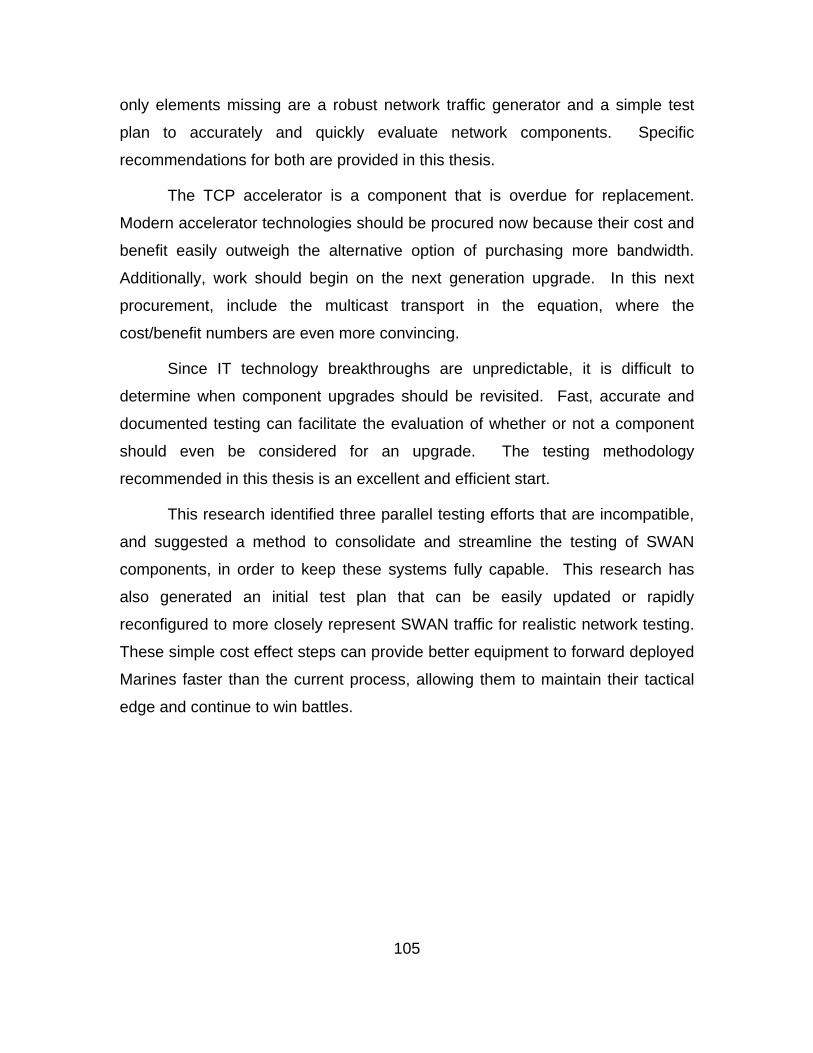
105
only elements missing are a robust network traffic generator and a simple test
plan to accurately and quickly evaluate network components. Specific
recommendations for both are provided in this thesis.
The TCP accelerator is a component that is overdue for replacement.
Modern accelerator technologies should be procured now because their cost and
benefit easily outweigh the alternative option of purchasing more bandwidth.
Additionally, work should begin on the next generation upgrade. In this next
procurement, include the multicast transport in the equation, where the
cost/benefit numbers are even more convincing.
Since IT technology breakthroughs are unpredictable, it is difficult to
determine when component upgrades should be revisited. Fast, accurate and
documented testing can facilitate the evaluation of whether or not a component
should even be considered for an upgrade. The testing methodology
recommended in this thesis is an excellent and efficient start.
This research identified three parallel testing efforts that are incompatible,
and suggested a method to consolidate and streamline the testing of SWAN
components, in order to keep these systems fully capable. This research has
also generated an initial test plan that can be easily updated or rapidly
reconfigured to more closely represent SWAN traffic for realistic network testing.
These simple cost effect steps can provide better equipment to forward deployed
Marines faster than the current process, allowing them to maintain their tactical
edge and continue to win battles.

106
THIS PAGE INTENTIONALLY LEFT BLANK
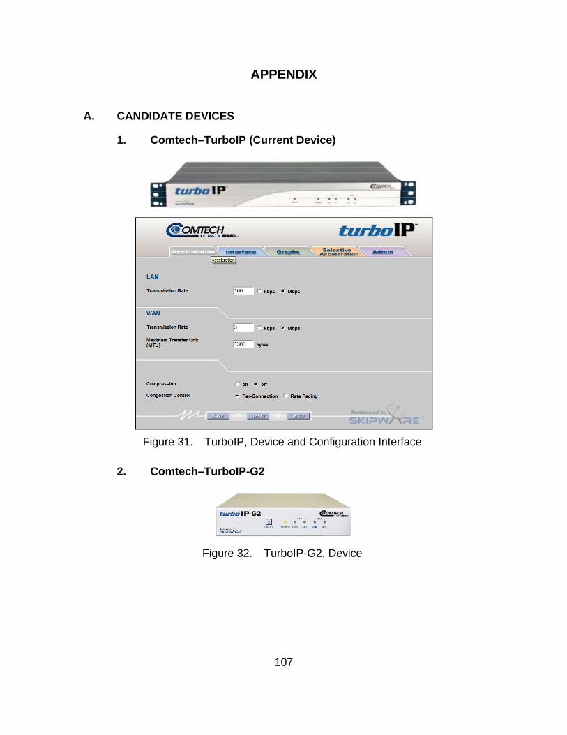
107
APPENDIX
A. CANDIDATE DEVICES
1. Comtech–TurboIP (Current Device)
Figure 31. TurboIP, Device and Configuration Interface
2. Comtech–TurboIP-G2
Figure 32. TurboIP-G2, Device
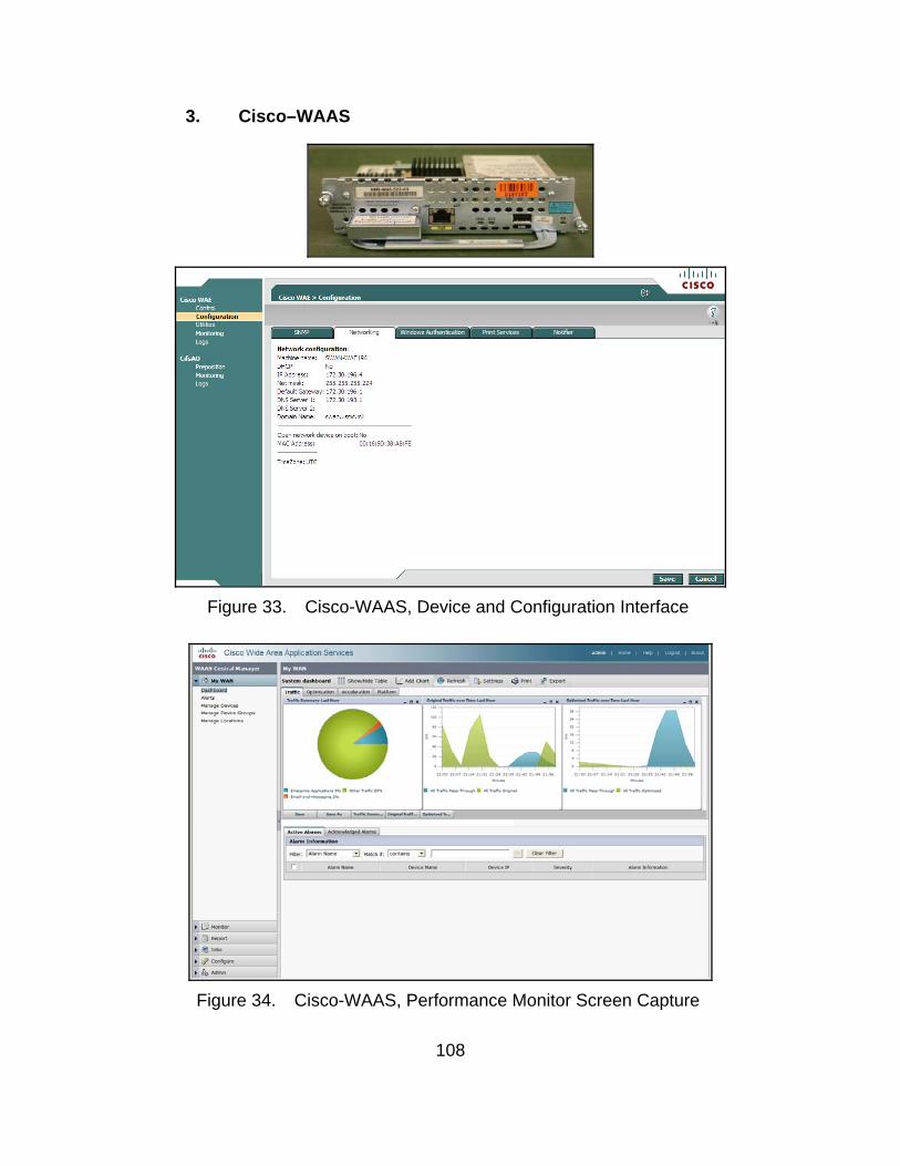
108
3. Cisco–WAAS
Figure 33. Cisco-WAAS, Device and Configuration Interface
Figure 34. Cisco-WAAS, Performance Monitor Screen Capture
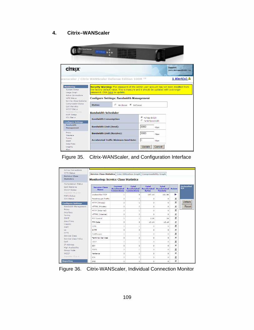
109
4. Citrix–WANScaler
Figure 35. Citrix-WANScaler, and Configuration Interface
Figure 36. Citrix-WANScaler, Individual Connection Monitor

110
5. Riverbed–Steelhead
Figure 37. Riverbed–Steelhead, Device and Configuration Interface
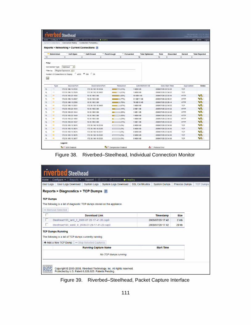
111
Figure 38. Riverbed–Steelhead, Individual Connection Monitor
Figure 39. Riverbed–Steelhead, Packet Capture Interface
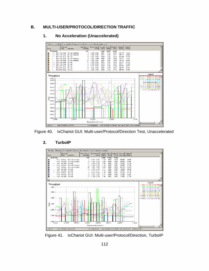
112
B. MULTI-USER/PROTOCOL/DIRECTION TRAFFIC
1. No Acceleration (Unaccelerated)
Figure 40. IxChariot GUI: Multi-user/Protocol/Direction Test, Unaccelerated
2. TurboIP
Figure 41. IxChariot GUI: Multi-user/Protocol/Direction, TurboIP
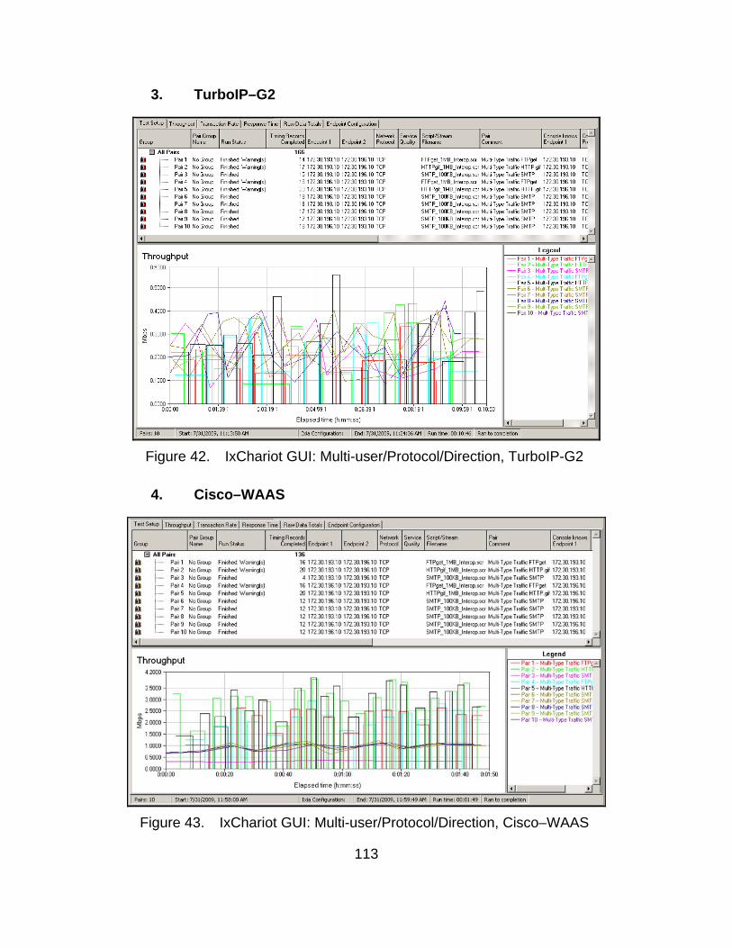
113
3. TurboIP–G2
Figure 42. IxChariot GUI: Multi-user/Protocol/Direction, TurboIP-G2
4. Cisco–WAAS
Figure 43. IxChariot GUI: Multi-user/Protocol/Direction, Cisco–WAAS
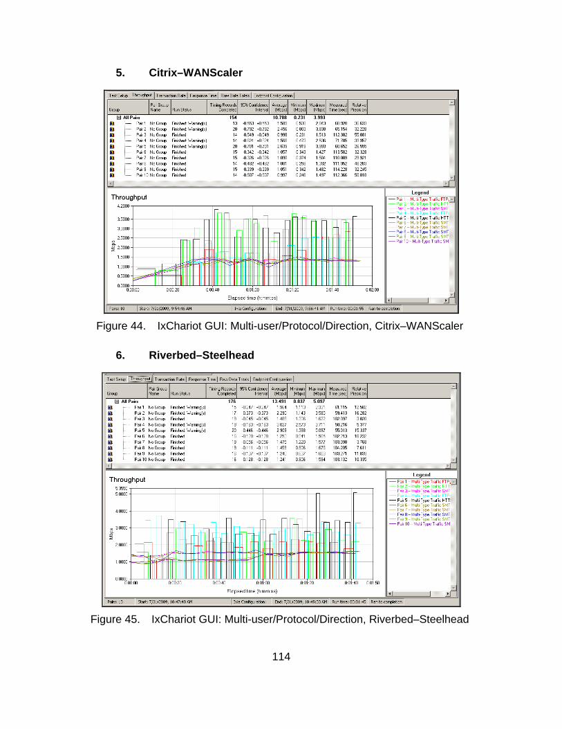
114
5. Citrix–WANScaler
Figure 44. IxChariot GUI: Multi-user/Protocol/Direction, Citrix–WANScaler
6. Riverbed–Steelhead
Figure 45. IxChariot GUI: Multi-user/Protocol/Direction, Riverbed–Steelhead
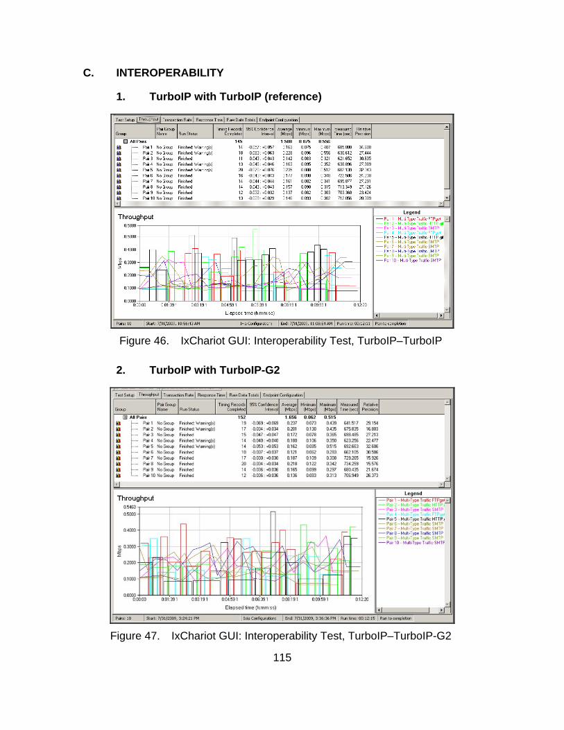
115
C. INTEROPERABILITY
1. TurboIP with TurboIP (reference)
Figure 46. IxChariot GUI: Interoperability Test, TurboIP–TurboIP
2. TurboIP with TurboIP-G2
Figure 47. IxChariot GUI: Interoperability Test, TurboIP–TurboIP-G2
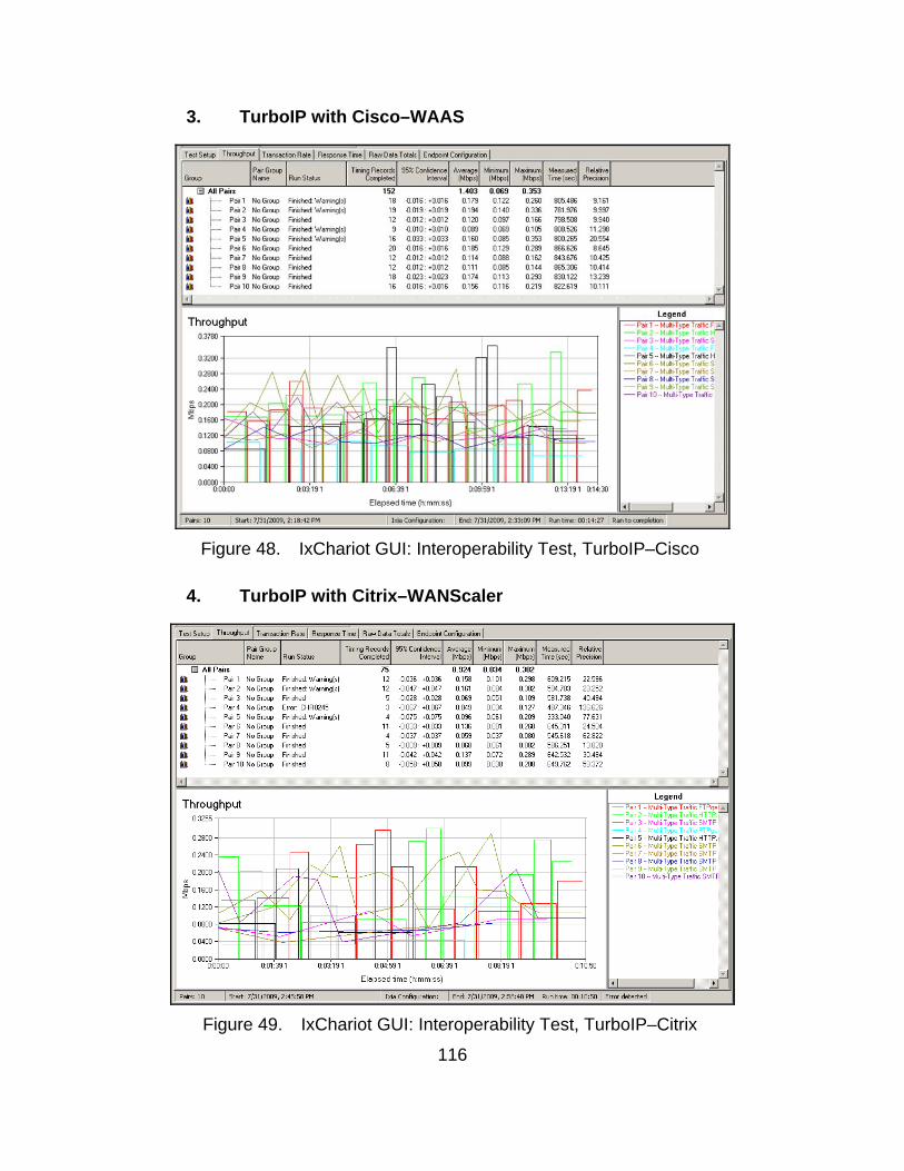
116
3. TurboIP with Cisco–WAAS
Figure 48. IxChariot GUI: Interoperability Test, TurboIP–Cisco
4. TurboIP with Citrix–WANScaler
Figure 49. IxChariot GUI: Interoperability Test, TurboIP–Citrix
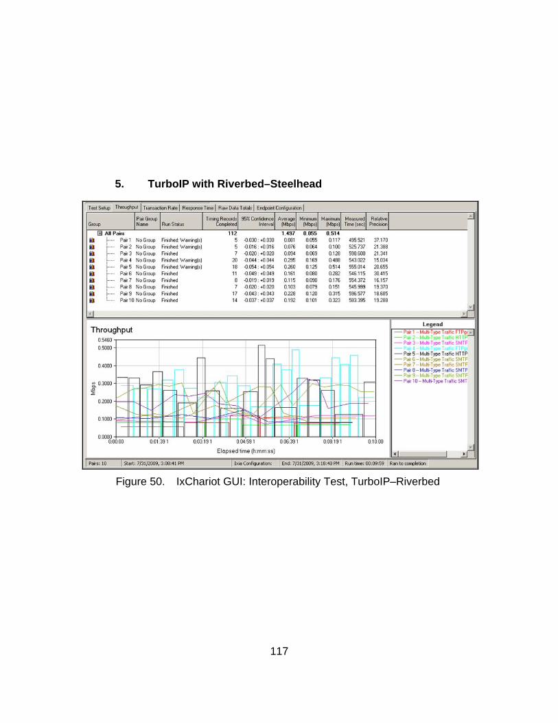
117
5. TurboIP with Riverbed–Steelhead
Figure 50. IxChariot GUI: Interoperability Test, TurboIP–Riverbed
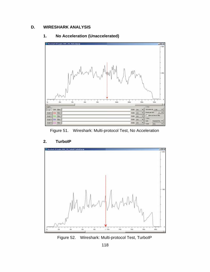
118
D. WIRESHARK ANALYSIS
1. No Acceleration (Unaccelerated)
Figure 51. Wireshark: Multi-protocol Test, No Acceleration
2. TurboIP
Figure 52. Wireshark: Multi-protocol Test, TurboIP
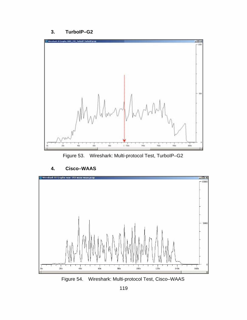
119
3. TurboIP–G2
Figure 53. Wireshark: Multi-protocol Test, TurboIP–G2
4. Cisco–WAAS
Figure 54. Wireshark: Multi-protocol Test, Cisco–WAAS
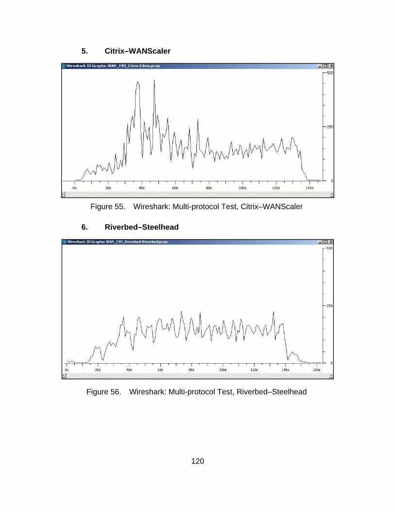
120
5. Citrix–WANScaler
Figure 55. Wireshark: Multi-protocol Test, Citrix–WANScaler
6. Riverbed–Steelhead
Figure 56. Wireshark: Multi-protocol Test, Riverbed–Steelhead

121
LIST OF REFERENCES
Adamson, B., C. Bormann, M. Handley, & J. Macker. (2004). Negative-Acknowledgment (NACK)-Oriented Reliable Multicast (NORM) Building Blocks. RFC 3941.
Alberts, D., Garstka, J., & Stein, F. (1999). Network Centric Warfare. Department of Defense C4ISR Cooperative Research Program. Washington.
Allman, M., Glover, D. & Sanchez, I. (1999, January) Enhancing TCP Over Satellite Channels using Standard Mechanisms. RFC 2488.
AMC-21 Fact Sheet. (2009) Orbital Sciences Corporation: Dulles, VA.
Combs, G. (n.d.). Wireshark: About. http://www.wireshark.org/about.html (accessed May 5, 2009).
Comer, D. (2007) The Internet Book. 4th ed. New Jersey: Pearson Education Inc.
Conrad, B. & Tzanos, I. (2008, September). A Conceptual Framework for Tactical Private Satellite Networks. Master’s thesis, Naval Postgraduate School, Monterey, CA.
Cote’, S. (2008, August 20). Vulnerability Assessment-Network Review. In class lecture [PowerPoint slides]. Presented at the Naval Postgraduate School, Monterey, CA.
Cox, C. (2005, June). Optimizing Bandwidth in Tactical Communications Systems. Master’s thesis, Naval Postgraduate School, Monterey, CA.
Fielding, R., Gettys, J., Mogul, J., Frystyk, H., Masinter, L., Leach, P., & Berners-Lee, T. (1999, June). Hypertext Transfer Protoco–HTTP/1.1. RFC 2616.
Fulp, J. (2009, March 30). Networking Security Crash Course. In class lecture [PowerPoint slides]. Presented at the Naval Postgraduate School, Monterey, CA.
Hooke, A. (2004, April 9). US-DOD Selects CCSDS “SCPS” Transport Protocol for MILSATCOM. Official message posting http://mailman.ccsds.org/pipermail/cmc/2004-April/000094.html (accessed August 9, 2009).
Inglis, D. (n.d.). TCP/IP Performance over Geo-SATCOM Links. EU32 CONEX, DISA-EUROPE STEP Manager. Unpublished White Paper.
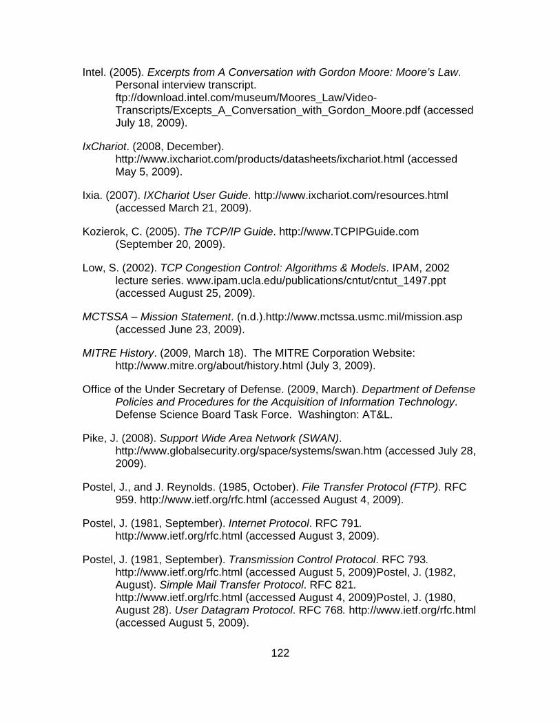
122
Intel. (2005). Excerpts from A Conversation with Gordon Moore: Moore’s Law. Personal interview transcript. ftp://download.intel.com/museum/Moores_Law/Video-Transcripts/Excepts_A_Conversation_with_Gordon_Moore.pdf (accessed July 18, 2009).
IxChariot. (2008, December). http://www.ixchariot.com/products/datasheets/ixchariot.html (accessed May 5, 2009).
Ixia. (2007). IXChariot User Guide. http://www.ixchariot.com/resources.html (accessed March 21, 2009).
Kozierok, C. (2005). The TCP/IP Guide. http://www.TCPIPGuide.com (September 20, 2009).
Low, S. (2002). TCP Congestion Control: Algorithms & Models. IPAM, 2002 lecture series. www.ipam.ucla.edu/publications/cntut/cntut_1497.ppt (accessed August 25, 2009).
MCTSSA – Mission Statement. (n.d.).http://www.mctssa.usmc.mil/mission.asp (accessed June 23, 2009).
MITRE History. (2009, March 18). The MITRE Corporation Website: http://www.mitre.org/about/history.html (July 3, 2009).
Office of the Under Secretary of Defense. (2009, March). Department of Defense Policies and Procedures for the Acquisition of Information Technology. Defense Science Board Task Force. Washington: AT&L.
Pike, J. (2008). Support Wide Area Network (SWAN). http://www.globalsecurity.org/space/systems/swan.htm (accessed July 28, 2009).
Postel, J., and J. Reynolds. (1985, October). File Transfer Protocol (FTP). RFC 959. http://www.ietf.org/rfc.html (accessed August 4, 2009).
Postel, J. (1981, September). Internet Protocol. RFC 791. http://www.ietf.org/rfc.html (accessed August 3, 2009).
Postel, J. (1981, September). Transmission Control Protocol. RFC 793. http://www.ietf.org/rfc.html (accessed August 5, 2009)Postel, J. (1982, August). Simple Mail Transfer Protocol. RFC 821. http://www.ietf.org/rfc.html (accessed August 4, 2009)Postel, J. (1980, August 28). User Datagram Protocol. RFC 768. http://www.ietf.org/rfc.html (accessed August 5, 2009).

123
Sidereal Solutions. (n.d.). Sidereal Solutions – Company Profile on LinkedIn. http://www.linkedin.com/companies/sidereal-solutions (accessed September 21, 2009).
TCP PEPs. (2009, April 7). www.scps.org/index.html (accessed June 20, 2009).
Master Transmission Plan. (2009, July 10). Arrowhead Global Solutions, Inc. Rev. ABC.
United States Marine Corps. (2008, October 17). Marine Corps Order 3900.17. Washington.

124
THIS PAGE INTENTIONALLY LEFT BLANK
125
INITIAL DISTRIBUTION LIST
1. Defense Technical Information Center Ft. Belvoir, Virginia
2. Dudley Knox Library Naval Postgraduate School Monterey, California
3. Marine corps Representative Naval Postgraduate School Monterey, California
4. Director, Training and Education, MCCDC, Code C46 Quantico, Virginia
5. Director, Marine Corps Research Center, MCCDC, Code C40RC Quantico, Virginia
6. Marine Corps Tactical Systems Support Activity (Attn: Operations Officer) Camp Pendleton, California
7. Department of Information Sciences (Attn: Chairman Dan Boger) Naval Postgraduate School Monterey, California