Embed Size (px)
Citation preview
National Aeronautics and Space Administration
CxP 70064BASELINE
RELEASE DATE: SEPTEMBER 5, 2007
CONSTELLATION PROGRAM SUPPORTABILITY PLAN
The electronic version is the official approved document. Verify this is the correct version before use.
Revision: Baseline Document No: CxP 70064Release Date: 09/05/07 Page: 2 of 73Title: Constellation Program Supportability Plan
REVISION AND HISTORY PAGE
Status Revision No.
Change No. Description Release
Date
Baseline - Baseline (Reference CxCBD 000134/1-1, dated 8/16/07)
09/05/07
NOTE: Updates to this document, as released by numbered changes (Change XXX), are identified by a black bar on the right margin.
Revision: Baseline Document No: CxP 70064Release Date: 09/05/07 Page: 3 of 73Title: Constellation Program Supportability Plan
TABLE OF CONTENTS
PARAGRAPH PAGE
1.0 INTRODUCTION.............................................................................................. 5 1.1 PURPOSE........................................................................................................ 5 1.2 SCOPE............................................................................................................. 5 1.3 CHANGE AUTHORITY/RESPONSIBILITY ..................................................... 5
2.0 DOCUMENTS.................................................................................................. 6 2.1 APPLICABLE DOCUMENTS ........................................................................... 6 2.2 REFERENCE DOCUMENTS........................................................................... 6
3.0 INTRODUCTION TO SUPPORTABILITY........................................................ 7 3.1 SUPPORTABILITY IMPLEMENTATION TECHNIQUES................................. 8 3.2 INTEGRATION OF RELIABILITY, MAINTAINABILITY, AND INTEGRATED
LOGISTICS SUPPORT WITHIN THE SYSTEMS ENGINEERING PROCESS................................................................................................... 9
4.0 CONSTELLATION SUPPORTABILITY CONCEPT......................................... 12 4.1 OVERVIEW...................................................................................................... 12 4.2 APPLICATION TO DESIGN REFERENCE MISSIONS................................... 14
4.2.1 Lunar Sortie Mission Supportability Concept .................................... 14 4.2.2 Lunar Outpost Cargo Mission Supportability Concept ...................... 22 4.2.3 Lunar Outpost Crew Mission Supportability Concept........................ 25 4.2.4 Crew to ISS Mission Supportability Concept..................................... 34 4.2.5 Pressurized Cargo to ISS Mission Supportability Concept ............... 37 4.2.6 Mars Mission Supportability Concept................................................ 40
5.0 SUPPORTABILITY PLANNING AND MANAGEMENT.................................... 43 5.1 RELIABILITY AND MAINTAINABILITY (R&M) PLANNING
AND MANAGEMENT .................................................................................. 43 5.2 INTEGRATED LOGISTICS SUPPORT (ILS) PLANNING
AND MANAGEMENT .................................................................................. 43 5.2.1 Integrated Logistics Support Management ....................................... 43 5.2.2 Integrated Logistics Support Plan (ILSP) .......................................... 46
Revision: Baseline Document No: CxP 70064Release Date: 09/05/07 Page: 4 of 73Title: Constellation Program Supportability Plan
TABLE OF CONTENTS
APPENDIX PAGE A ACRONYMS AND ABBREVIATIONS AND GLOSSARY OF TERMS............. 68 B OPEN WORK................................................................................................... 72 C LRU/ORU SELECTION CRITERIA.................................................................. 73
TABLE 5.2.1-1 ILS ROLES AND RESPONSIBILITIES ............................................................ 44 5.2.2.2-1 TRADITIONAL LEVELS OF MAINTENANCE.................................................. 49 B1-1 TO BE DETERMINED ITEMS.......................................................................... 72 B2-1 TO BE RESOLVED ISSUES............................................................................ 72
FIGURE 3.2-1 INTEGRATION OF RELIABILITY, MAINTAINABILITY,
AND INTEGRATED LOGISTICS SUPPORT .............................................. 11
Revision: Baseline Document No: CxP 70064Release Date: 09/05/07 Page: 5 of 73Title: Constellation Program Supportability Plan
1.0 INTRODUCTION
1.1 PURPOSE
The purpose of the Constellation Program Supportability Plan is to convey the vision for supporting Program elements through their life cycle, the methods for implementing this vision through a description of supportability planning, and the definition of roles and responsibilities for implementation by Program participants. Specifically, this plan defines the approach for implementation of the supportability-related elements of CxP 70003-ANX01, Constellation Program Plan Annex 1: Need, Goals, and Objectives and the supportability requirements contained within CxP 70000, Constellation Architecture Requirements Document (CARD), and CxP 70059, Constellation Program Integrated Safety, Reliability, and Quality Assurance (SR&QA) Requirements. The Constellation Program Supportability Plan also addresses the interaction of the Integrated Logistics Support (ILS), Reliability, and Maintainability disciplines to achieve a balanced Supportability solution for the Program. This plan meets, in part, the requirement set forth in NPD 7500.1, Program and Project Logistics Policy, to develop and document an ILS regimen. It is also serves as a means of compliance with selected portions of NPR 7120.5D, NASA Program and Project Management Processes and Requirements.
1.2 SCOPE
The Constellation Supportability Concept applies to all flight components and Ground Support Equipment (GSE) of the Constellation Program (CxP) throughout their life cycle. It applies to all Government Furnished Equipment (GFE) as well as contractor-furnished equipment. Supportability of facilities is also important but is not addressed in this document.
1.3 CHANGE AUTHORITY/RESPONSIBILITY
Proposed changes to this document shall be submitted by a Constellation Program Change Request (CR) to the Constellation Control Board (CxCB) for consideration and disposition.
The CR must include a complete description of the change and the rationale to justify its consideration. All such requests will be processed in accordance with the Constellation Program Configuration Management Plan and comply with CxP 70073-01, Constellation Program Management Systems Requirements, Volume 1: Configuration Management Requirements. The appropriate NASA Office of Primary Responsibility (OPR) identified for this document is Systems Engineering and Integration (SE&I).
Revision: Baseline Document No: CxP 70064Release Date: 09/05/07 Page: 6 of 73Title: Constellation Program Supportability Plan
2.0 DOCUMENTS
2.1 APPLICABLE DOCUMENTS
The documents listed in this paragraph are applicable. Relief from specific portions of the applicable documents may be granted by submitting a Change Request (CR), as described in Section 1.3, and gaining approval from the Control Board with authority to grant the relief.
CxP 70000 Constellation Architecture Requirements Document (CARD)
CxP 70056 Constellation Program Risk Management Plan
CxP 70073-01 Constellation Program Management Systems Requirements, Volume 1: Configuration Management Requirements
2.2 REFERENCE DOCUMENTS
The following documents contain supplemental information to guide the user in the application of this document.
CxP 70003-ANX01 Constellation Program Plan, Annex 1: Need, Goals, and Objectives (NGO)
CxP 70007 Constellation Design Reference Missions and Operational Concepts
CxP 70024 Constellation Program Human-Systems Integration Requirements
CxP 70043 Constellation Program Hardware Failure Modes and Effects Analysis and Critical Items List (FMEA/CIL) Methodology
CxP 70059 Constellation Program Integrated Safety, Reliability and Quality Assurance (SR&QA) Requirements
CxP 70072-ANX01 Constellation Program Management Systems Plan, Annex 1: Common Glossary and Acronyms
CxP 70073-03 Constellation Program Data Management Systems Requirements, Volume 3: Data Architecture Requirements
CxP 70087 Constellation Program Reliability, Availability, and Maintainability Plan
Revision: Baseline Document No: CxP 70064Release Date: 09/05/07 Page: 7 of 73Title: Constellation Program Supportability Plan
CxP 70132 (Baseline Pending)
Constellation Program Commonality Plan
MIL-HDBK-472 Maintainability Prediction
MIL-HDBK-502 Acquisition Logistics
MIL-PRF-49506 Performance Specification, Logistics Management Information
MIL-STD-1390D Level of Repair Analysis
MIL-STD-470B Maintainability Program for Systems and Equipment
MIL-STD-471A Maintainability Verification/Demonstration/Evaluation Maintainability Toolkit, Reliability Analysis Center
NASA-SP-6105 NASA Systems Engineering Handbook
NPD 7500.1 Program and Project Logistics Policy
NPR 7120.5D NASA Program and Project Management Processes and Requirements
NPR 7123.1 NASA Systems Engineering Processes and Requirements
No Number Logistics Engineering and Management, Benjamin S. Blanchard, Prentice Hall, Sixth Edition, 2003.
No Number Systems Engineering and Analysis, Benjamin S. Blanchard, Prentice Hall, Third Edition, 1998.
3.0 INTRODUCTION TO SUPPORTABILITY
Supportability is a Constellation Program wide discipline that will be used to ensure robust availability of Constellation elements while maintaining low Program life cycle cost. Supportability is closely related to the Constellation Program’s Reliability process. Reliability ensures Constellation elements are of high quality and require infrequent maintenance. Supportability ensures that when maintenance is required, the maintenance can be accomplished quickly and in a cost effective way. The Constellation Supportability discipline will influence system design and Constellation’s operations and sustaining engineering processes. During system design, supportability focused analyses will ensure that the systems and components that are most likely to require maintenance can be serviced in a quick and cost efficient way. Constellation operations and sustaining engineering processes will be reviewed from a supportability standpoint to ensure that logistics and maintenance plans are designed to service the
Revision: Baseline Document No: CxP 70064Release Date: 09/05/07 Page: 8 of 73Title: Constellation Program Supportability Plan
systems and components in a cost effective manner. Finally, the Constellation Program’s Supportability plan will be sized and structured to support the unique aspects of the Constellation Program. Figure 3.2-1 illustrates the integrated flow process for implementation.
3.1 SUPPORTABILITY IMPLEMENTATION TECHNIQUES
a. Perform Logistics Support Analysis (LSA) utilizing standard methodologies concurrently with design to identify resources necessary for system support (spares, tools, procedures, training, support equipment) and to influence the design to minimize support requirements. (LSA is closely coupled to Failure Modes and Effects Analysis [FMEA] and Reliability analyses.)
b. Define effective supportability approaches appropriate to the unique needs of a long-term human space flight program. Areas to be defined include placement of strategic resources, inventory management, marking and tagging to facilitate item tracking as well as index numbering, interactive electronic manuals, and Source, Maintenance and Recoverability (SMR) codes.
Supportability functions performed during the operational phase of the life cycle, such as spares acquisition, system maintenance, training of personnel for maintenance, technical documentation, support equipment and training device management and maintenance, and associated planning and administrative activities are a major contributor to life cycle costs. It is essential that system supportability be an integral factor in system design to enable the most cost-effective support. Failure to do so can result in a system that is far more costly to support than would otherwise be necessary. Additionally, in the case of human spaceflight missions and system designs, failure to consider Supportability from the beginning of design can result in system support requirements that cannot be satisfied within performance capabilities. System operational effectiveness is a composite of performance, availability, process efficiency, and life cycle cost. System operational effectiveness can best be achieved through influencing early design and architecture, and through focusing on the supportability outputs. Reliability, reduced logistics footprint, and reduced system life cycle cost are most effectively achieved through inclusion from the very beginning of a project - starting with the definition of required capabilities.
Optimal system operational effectiveness requires balance between system effectiveness, life cycle cost, and consumption of other resources such as mass, volume, and crew time. The emphasis is not only on the reliability and maintainability of the prime mission system or equipment to execute mission capability but also on the cost-effective responsiveness and relevance of the support system and infrastructure. The key is to smoothly integrate the acquisition logistics process with the systems engineering and design maturation processes.
Revision: Baseline Document No: CxP 70064Release Date: 09/05/07 Page: 9 of 73Title: Constellation Program Supportability Plan
Early program activities should include: (1) defining Supportability objectives that are optimally related to system design and to each other and (2) ensuring that Supportability objectives are an integral part of the system requirements and the design. The process of defining end item support requirements must be initiated as the design process begins and continued as the design evolves. The Supportability planning process should encompass all program life cycle phases and address all applicable mission phases including development and test, ground processing including assembly and checkout, prelaunch, launch, in-space and surface destination operations, and post-flight turnaround.
Continuing effort is required through the system life cycle to ensure that changes in system design during the various design and production phases are reviewed and documented for impact on logistics support before they are implemented.
3.2 INTEGRATION OF RELIABILITY, MAINTAINABILITY, AND INTEGRATED LOGISTICS SUPPORT WITHIN THE SYSTEMS ENGINEERING PROCESS
Reliability, maintainability, and logistics engineering analyses establish the basis for a comprehensive Supportability effort designed to ensure meeting mission needs and reducing life-cycle ownership costs. The essential reliability analysis tasks that should be performed are reliability predictions, component-level FMEA, Failure Reporting and Tracking Analysis, Limited Life Item Review and Reliability/Mean Time Between Failures (MTBF) verification. The Supportability manager’s most effective tools for influencing and interacting with the system engineering process are Reliability and Maintainability (R&M) parameters such as MTBF and Mean Time to Repair (MTTR). The MTBF parameter is of prime importance for critical components that are expected to operate successfully throughout certain mission phases without maintenance actions. The rest of the proposed wording is more appropriately included in a reliability document (e.g., the Reliability, Availability, and Maintainability [RAM] Plan). Throughout the development process, measured progress toward achieving R&M values for the system and its components should result in reducing logistics support demand and attaining availability objectives. Methodologies for performing reliability and maintainability analyses and management of these analysis processes are defined in the CxP 70087, Constellation Program Reliability, Availability and Maintainability Plan and in CxP 70043, Constellation Program Hardware Failure Modes and Effects Analysis and Critical Items List (FMEA/CIL) Methodology.
Reliability and maintainability engineering analysis methods, practices, and processes must be integrated throughout the systems engineering process to facilitate the supportability analysis of a design, from conception through operations. As such, the concept of operations must be defined to provide the basis for defining both the top-level system requirements and capabilities, and the initial definition of the system maintenance and support concept. Formulating the system architecture and performing
Revision: Baseline Document No: CxP 70064Release Date: 09/05/07 Page: 10 of 73Title: Constellation Program Supportability Plan
all associated trade studies with attention to system maintenance ensures a balanced and symbiotic relationship between the system and the associated support system.
The FMEA process is used to identify possible failure modes that impact safety or mission success. The process also serves to identify candidates for preventive or corrective maintenance tasks or repair.
The Level of Repair Analysis (LORA), as detailed in MIL-STD-1390D, is performed to determine the least costly support policy for an item and to identify when it is appropriate to make, repair or discard hardware.
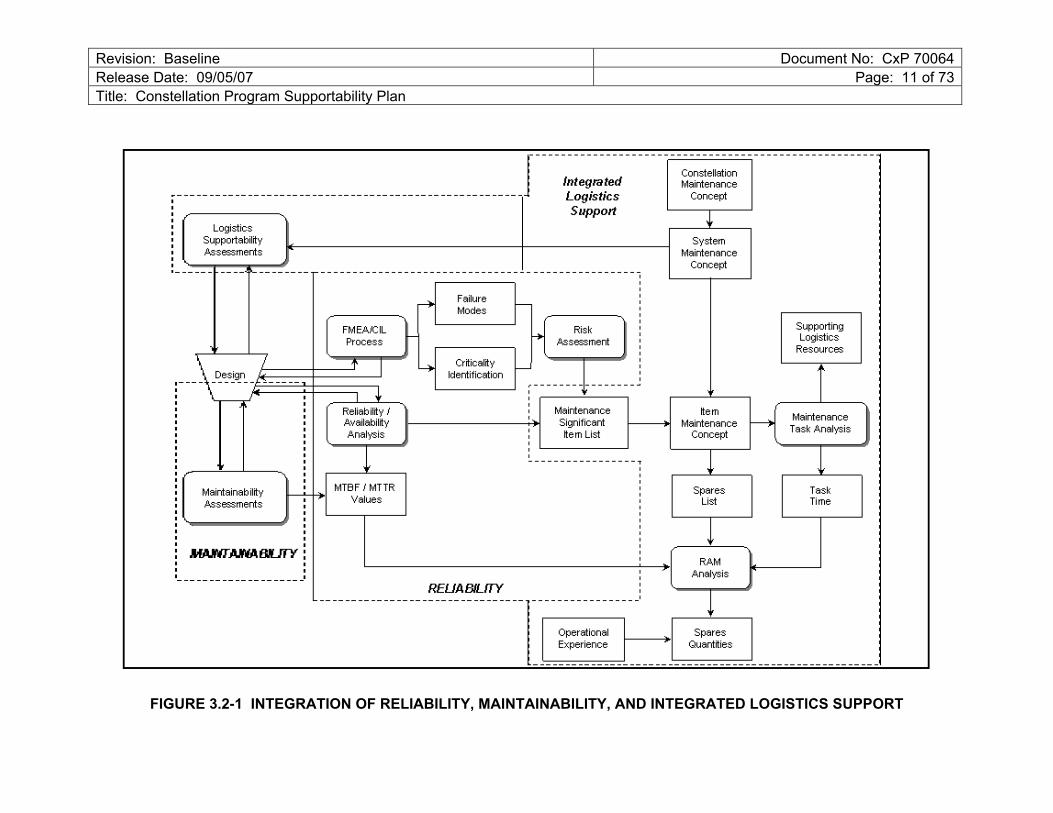
The interaction of Reliability, Maintainability, and Integrated Logistics Support to define resources required for system maintenance is illustrated in Figure 3.2-1. The block labeled “Logistics Supportability Assessments” includes consideration of other ILS functions not uniquely associated with system maintenance (e.g., packaging, handling, storage, and transportation; inventory and tracking, facilities, support equipment, imagery, storage, training and training devices) and manifest themselves in plans for providing “Supporting Logistics Resources.”
The objective of this process is to support the development of a system design that can meet performance requirements, such as Operational Availability (AO) and Functional Availability (AF) by achieving a balance within recognized constraints of Life Cycle Cost (LCC), mass and volume of maintenance resources, and crew time available for maintenance. In addition to affecting flight hardware design, this process highlights aspects of the supporting infrastructure that can be modified to improve efficiency.
Revision: Baseline Document No: CxP 70064Release Date: 09/05/07 Page: 11 of 73Title: Constellation Program Supportability Plan
FIGURE 3.2-1 INTEGRATION OF RELIABILITY, MAINTAINABILITY, AND INTEGRATED LOGISTICS SUPPORT
Revision: Baseline Document No: CxP 70064Release Date: 09/05/07 Page: 12 of 73Title: Constellation Program Supportability Plan
4.0 CONSTELLATION SUPPORTABILITY CONCEPT
4.1 OVERVIEW
The Constellation Supportability Concept represents an evolutionary continuum that ultimately leads to highly autonomous capabilities for support of long-duration human exploration missions. A significant challenge will be accomplishing this objective in a manner that is compatible with anticipated resource constraints. Key resources to be balanced include mass of spares, volume of spares, crew time for maintenance, crew training time, and total cost. The relative weighting, or value, associated with each of these resources may vary - depending on the mission or mission phase. For example, crew time may be more precious during short duration International Space Station (ISS) missions whereas mass or volume available for spares may be more tightly constrained during missions to distant destinations and long duration lunar missions.
This mission-dependant valuation of constrained resources suggests that the supportability concept must be adapted for each type of mission. Furthermore, the approach may differ for each system utilized in a mission and, in fact, be tailored to specific mission phases. In general, as either the distance of the destination from Earth or the duration of the mission increases, greater emphasis will be placed on minimizing the mass and volume of spare items and support equipment necessary to sustain the mission.
There are several ways to approach this. One is to implement commonality, standardization, and interchangeability whenever possible. In this way, any single spare can address the greatest number of potential failures. However, the use of common design components in different applications must be attentive to compatibility of environment use and also especially attentive to common cause failure potential. A second approach is to enable repair at the lowest feasible hardware level thus resulting in the physically smallest possible spares. A third approach is to enable repair of failed items either as an alternative to removal and replacement or as a means of recycling a failed item to subsequently serve as a spare. A fourth approach would be aimed at significantly improving the long-term reliability such that the need for maintenance would be reduced. A fifth approach could focus on the use of self-correcting systems similar to those on long duration robotic spacecraft. Since the systems that will be utilized in Constellation will be used for multiple types of missions, it will be essential that they be designed in such a way that they can be maintained however is appropriate for the particular type of mission or mission phase. The preferred maintenance concept for each item during each mission will be determined by selecting the optimum balance of consumption of the resources defined above.
To plan, perform, and manage supportability activities, it is essential that meaningful performance metrics be defined. Key metrics are defined and discussed below.
Revision: Baseline Document No: CxP 70064Release Date: 09/05/07 Page: 13 of 73Title: Constellation Program Supportability Plan
Inherent Availability, Ai. Inherent Availability is the probability that the system will operate satisfactorily when called upon at any point in time under specified operating conditions and in an ideal logistic support environment. It is calculated as follows:
Ai = MTBF/(MTBF + MTTR)
where, MTBF is the Mean Time Between Failures and MTTR is the Mean Time To Repair.
Operational Availability, AO. Operational Availability is the probability that the system will operate satisfactorily at any point in time under specified operating conditions and in an actual logistic support environment. It is calculated as follows:
AO = MTBM/(MTBM + MDT)
where, MTBM is the Mean Time Between Maintenance and MDT is the Maintenance Down Time.
It is important that this metric be applied selectively. It should only be applied for periods of time when Operational Availability is important. For example, in cases when launches can only occur during specified periods, it is inappropriate to apply Operational Availability to periods when launches cannot occur. To do so would place unnecessary burden on system designs and supporting infrastructure.
Since launches will generally not occur with known flight hardware/software system failures (other than relatively minor failures), prelaunch Operational Availability calculations for flight vehicles will reflect the status of the hardware/software systems -- failure of flight system redundant items will result in availability of less than 100%.
During a mission, Operational Availability is not highly meaningful because a mission will continue with known failures, since redundancy will generally assure that functions are available. As a result, calculation of Operational Availability would result in nearly continuous 100% Operational Availability - not reflecting the actual status of the hardware systems. Once a mission is underway, Functional Availability is more meaningful.
Functional Availability, AF. Functional Availability is the fraction of time that the system is able to perform its functions at a performance level acceptable to users. Functional Availability can reflect operation at levels less than the nominal design level (e.g., reduced power output) and reductions in redundancy.
AF = fraction of total time for which actual performance ≥ minimum required performance without intervention
Mass. Mass of spares and support equipment is a critical parameter during missions. Emphasis should always be placed on minimizing this parameter.
Revision: Baseline Document No: CxP 70064Release Date: 09/05/07 Page: 14 of 73Title: Constellation Program Supportability Plan
Volume. Volume of spares and support equipment is a critical parameter during missions. Emphasis should always be placed on minimizing this parameter.
Crew time. In general, the crew time required for maintenance should be minimized. However, application of crew time can be balanced against mass and volume of spares. That is, if the mass and volume of spares can be minimized by performing maintenance at lower hardware levels - requiring increased crew time - this approach may be selected if the nature of the mission is such that the additional crew time is available.
4.2 APPLICATION TO DESIGN REFERENCE MISSIONS
The Supportability Concept for each Design Reference Mission is provided in the following sections. Design Reference Missions are defined in CxP 70007, Constellation Design Reference Missions and Operational Concepts. All relevant mission phases are covered. Dynamic mission phases such as ascent, descent, entry, and aborts are not included since no supportability-related activities would occur during those phases, although system hardware failures during these phases could result in maintenance actions and other supportability-related activities in subsequent mission phases.
4.2.1 Lunar Sortie Mission Supportability Concept
Ground Operations Mission Phase The Crew Exploration Vehicle (CEV), Crew Launch Vehicle (CLV), Cargo Launch Vehicle (CaLV), Earth Departure Stage (EDS), Lunar Surface Access Module (LSAM), Launch Abort System (LAS), payloads, and cargo are delivered to Kennedy Space Center (KSC) for Ground Processing, Integrated Test, and Launch Services. The elements, payloads, and cargo are received and inspected, and any final standalone assembly, integration, testing and closeouts are completed.
Following integration, all critical interfaces between the CEV and launch vehicle are tested, and final ordnance installation is completed. Once all interfaces are verified, the integrated vehicle is transported from the integration facility to the launch pad for propellant loading, crew ingress to the spacecraft, and launch.
In the event of a launch scrub, several scenarios are possible depending on the reason for the scrub, the duration of the scrub, and the unique requirements of the launch vehicle, spacecraft, payloads, or cargo. Examples of scrub turnaround activities include commodity servicing/top-off, cargo/experiment changeout, troubleshooting, maintenance, or rollback to the integration facility if necessary.
Primary objectives of supportability operations during the ground operations mission phase will be to ensure that rollout schedules are met; that Operational Availability of all launch vehicles, spacecraft, and cargo elements meet values established by the Program; and that these goals are met with the most efficient expenditure of resources.
Revision: Baseline Document No: CxP 70064Release Date: 09/05/07 Page: 15 of 73Title: Constellation Program Supportability Plan
Examples of measures of the cost of supportability include labor, materials, spares, support equipment, facilities, documentation and training.
Prior to “call to stations” in preparation for launch, significant supportability performance metrics will be maintenance task time, administrative time associated with maintenance, and cost associated with maintenance. From “call to stations” to launch or the closing of the final launch window during a launch opportunity, the most significant supportability metric will be Operational Availability. The primary objective will be to meet required Operational Availability within cost constraints. Beginning with cryogenic loading it is unlikely that there will be timely access to do repairs at the launch pad, therefore component reliability will be required to be high enough to meet the intent of the availability requirement assuming no repairs during this period.
Measures of effectiveness. Measures of effectiveness include:
a. Operational Availability, AO, during specified period prior to launch.
b. Cost of normal functions during ground processing and prelaunch activities.
c. Cost of unplanned maintenance functions during ground processing and prelaunch activities.
4.2.1.1 Earth Orbit Operations Mission Phase, Trans-Lunar Coast Mission Phase, Lunar Orbit and Arrival Operations Mission Phase, and Trans-Earth Coast Mission Phase
Corrective maintenance and preventive maintenance. Preventive maintenance will be performed to ensure that systems continue to operate within specified limits. The most typical example of preventive maintenance would be air return filter cleaning or replacement. The need for, and frequency of, preventive maintenance actions will be determined by the systems’ designs and their functional needs and through performance of Logistics Support Analyses.
Corrective maintenance will be performed in response to system hardware failures to restore system function or to restore redundancy prior to commitment to the Trans-Lunar Injection (TLI) burn, the lunar orbit insertion burn, Lunar Surface Access Module (LSAM) undocking, and LSAM descent burn. Preemptive maintenance may be performed if prognostic assessments from an Integrated System Health Management System (ISHM) are available. Although operation to failure will be preferred under most circumstances, preemptive action may be appropriate for critical systems in advance of dynamic mission events. Redundancy required prior to initiation of these critical and dynamic mission events will be determined on the basis of safety and mission success criteria and will be defined by flight rules. If the LSAM has been loitering for an extended period of time prior to arrival of the crew because of a delayed CEV launch, there may be an increased potential for system hardware failures and an associated need for corrective maintenance; however, the design reliability should accommodate
Revision: Baseline Document No: CxP 70064Release Date: 09/05/07 Page: 16 of 73Title: Constellation Program Supportability Plan
delays such that the failure rate remains constant over the mission phase. Even if all hardware is functioning properly at delayed crew arrival, the increased operating time increases the potential for a hardware failure later in the mission.
Hardware or system levels at which maintenance will be performed. To reduce the mass and volume of spares required to support the mission, maintenance should be accomplished at the lowest practical hardware level that is consistent with crew time constraints. Prior to reactivation of hardware that has been repaired, sufficient testing should be performed to ensure that the repaired item will function correctly and not cause additional failures when connected to the system. Standards similar to those used on the ground for post-maintenance acceptance test/check-out should be established to ensure safety. It may be possible to extend orbital loiter times prior to the TLI burn, LSAM undocking, and the lunar descent burn if necessary to accomplish maintenance. Thus, additional crew time may be made available during these periods. Any maintenance action required for the lunar orbit insertion maneuver must be accomplished within the 72-hour Trans-Lunar Coast (TLC) duration and must be accomplished concurrently with other required crew activities during this period. Any maintenance action required to ensure successful reentry of the Earth’s atmosphere must be accomplished within the 96±12-hour Trans-Earth Coast (TEC) duration and must be accomplished concurrently with other required crew activities during this period.
Sparing issues. The initial recommendation for spares to be carried during the mission will be captured in the deliverable Recommended Spare Parts List developed by the Design, Develop, Test and Evaluate (DDT&E) contractors in consultation with NASA. Final determination of the spares manifest will be accomplished through a collaborative assessment with the NASA spacecraft system managers and Program Office personnel. Factors considered in this assessment will include probability of item failure, impact of item failure, mass and volume availability, and task time associated with repair at the item level.
During these mission phases, spares will be carried in both the CEV and the LSAM. To the extent that system components are common, spares carried in one vehicle may be used in either vehicle if necessary.
Maintenance resource availability. Maintenance resources will include spares, tools, data, and documentation necessary to develop required maintenance procedures, and the maintenance procedures themselves. Spares were discussed in the previous section. Tools for each Cx element should consist of a small common set of tools. The composition of this set of tools will be determined in consultation with the DDT&E contractors and will be that which is necessary to perform maintenance tasks associated with the set of spares plus an additional number of tools and materials that will be necessary to support other maintenance.
Revision: Baseline Document No: CxP 70064Release Date: 09/05/07 Page: 17 of 73Title: Constellation Program Supportability Plan
The Cx elements are encouraged to establish a common tool usage with each other. Tool lists will be managed within the frame work of the commonality database. To the extent possible, tools should be capable of both Intravehicular Activity (IVA) and Extravehicular Activity (EVA) use. Data and documentation will include Logistics Support Analysis Records and other engineering data delivered by the DDT&E contractors. Maintenance procedures will be developed from the delivered data by Mission Control personnel.
Operational environment issues. During these mission phases, all maintenance activities will occur in a 0-ge environment. Therefore, captive fasteners should be employed and all activities should avoid creation of debris or manage any that is generated. During nominal missions, all maintenance activities will be conducted IVA and, therefore, occur in a pressurized environment. However, there is a possibility that maintenance tasks may need to be performed IVA in an unpressurized environment. This possibility arises from the CEV requirement that the vehicle be capable of operating unpressurized for up to 120 hours. EVA maintenance of the LSAM and the EVA System will take place only under contingency circumstances. Primary maintenance on rovers or other surface systems will be performed EVA.
Responsibilities for maintenance. Maintenance actions will be performed by the crew. Maintenance procedures will be developed by personnel in Mission Control using supporting data and documentation acquired as deliverable items from the DDT&E contractors. Maintenance procedures for “highly likely” failures or remove/replace maintenance will be developed in advance. Troubleshooting and failure diagnosis will generally be determined by the ISHM System with support by personnel in Mission Control when necessary. However, information and capabilities for troubleshooting and procedure development for critical systems will be available to the crew in the event they need to operate autonomously. In general, the crew will be trained in generic maintenance skills and is needed for a limited set of specific critical tasks. In the event that a complex procedure for which the crew was not specifically trained but which is beyond the scope of the generic skills training, Mission Control personnel may develop and validate the procedure then uplink video files and, possibly, interactive models to provide additional training opportunities for the crew.
Measures of effectiveness. Measures of effectiveness include:
a. Functional Availability, AF
b. Crew time required for preventive and corrective maintenance (minimize)
c. Mass and volume of spares and support equipment required for maintenance activities (minimize)
d. Number of crew interventions required to diagnose hardware failures (minimize)
Revision: Baseline Document No: CxP 70064Release Date: 09/05/07 Page: 18 of 73Title: Constellation Program Supportability Plan
4.2.1.2 Lunar Surface Operations Mission Phase
Corrective maintenance and preventive maintenance. Preventive maintenance will be performed to ensure that systems continue to operate within specified limits. The most typical example of preventive maintenance would be air return filter cleaning or replacement. The need for, and frequency of, preventive maintenance actions will be determined by the systems’ designs and their functional needs and through performance of Logistics Support Analyses.
Corrective maintenance will be performed in response to system hardware failures to restore system function or to restore required levels of redundancy. LSAM maintenance should be performed primarily under IVA conditions. Most rover maintenance, and maintenance of any other surface systems, will be performed EVA. If necessary, an Orbital Replaceable Unit (ORU) removed from a rover, or other surface system, may be transferred to the pressurized volume of the LSAM for repair. During sortie missions, however, this would be an exceptional situation.
Hardware or system levels at which maintenance will be performed. To reduce the mass and volume of spares required to support the mission, maintenance should be accomplished at the lowest practical hardware level that is consistent with crew time constraints. Prior to reactivation of hardware that has been repaired, sufficient testing should be performed to ensure that the repaired item will function correctly and not cause additional failures when connected to the system. Standards similar to those used on the ground for post-maintenance acceptance test/check-out should be established to ensure safety. Somewhat different approaches may be appropriate for maintenance of rovers and other surface systems than for the LSAM because of limitations on EVA time availability.
Sparing issues. The initial recommendation for spares to be carried during the mission will be captured in the deliverable Recommended Spare Parts List developed by the DDT&E contractors in consultation with NASA. Final determination of the spares manifest will be accomplished through a collaborative assessment with the NASA spacecraft system managers and Program Office personnel. Factors in this assessment will include probability of item failure, impact of item failure, mass and volume availability, and task time associated with repair at the item level.
LSAM spares should be stored within the LSAM’s pressurized volume. Whenever possible, spares for rovers or other surface system elements should be stored external to the LSAM’s pressurized environment. This provides ready access without needing to reenter the LSAM.
It is expected that prior to LSAM return a sparing analysis will be performed, and any potentially unnecessary LSAM spares will be removed from the LSAM and left on the lunar surface prior to LSAM ascent. It is also expected that unused common spares from previous missions may be available for loading on to return LSAM for CEV
Revision: Baseline Document No: CxP 70064Release Date: 09/05/07 Page: 19 of 73Title: Constellation Program Supportability Plan
maintenance. This will increase the amount of return cargo capacity. Consequently, the LSAM will be dependent on system reliability and redundancy from lunar surface departure to rendezvous and docking with the CEV in lunar orbit.
Maintenance resource availability. Maintenance resources will include spares, tools, data, and documentation necessary to develop required maintenance procedures. Spares were discussed in the previous section. Tools for each Cx element should consist of a small common set of tools. The composition of this set of tools will be determined in consultation with the DDT&E contractors and will be that which is necessary to perform maintenance tasks associated with the set of spares plus an additional number of tools and materials that will be necessary to support other maintenance. The Cx elements are encouraged to establish a common tool usage with each other. Tool lists will be managed within the framework of the commonality database. To the extent possible, tools should be capable of both IVA and EVA use and should service the EVA System, LSAM, rovers, and other surface systems.
Operational environment issues. Maintenance activities on the lunar surface will take place in a gravity field of approximately 0.16 ge (where 1.0 ge is the magnitude of the gravitational field at the surface of the Earth). Therefore, the potential for overhead maintenance tasks should be minimized and the possibility of needing to manipulate large or massive items overhead should be eliminated. Additionally, reach limitations should be carefully considered for overhead tasks and accessibility in general may be limited. During nominal missions, all maintenance activities will be conducted IVA and, therefore, occur in a pressurized environment. EVA maintenance of the LSAM and the EVA System will take place only under contingency circumstances. Primary maintenance on rovers or other surface systems will be performed EVA.
Responsibilities for maintenance. Maintenance actions will be performed by the crew. Maintenance procedures will be developed by personnel in Mission Control using supporting data and documentation acquired as deliverable items from the DDT&E contractors. Troubleshooting and failure diagnosis will generally be determined by the ISHM System with support by personnel in Mission Control when necessary. However, information and capabilities for troubleshooting and procedure development for critical systems will be available to the crew in the event they need to operate autonomously. In general, the crew will be trained in generic maintenance skills and for a limited set of specific critical tasks. In the event that a complex procedure is needed for which the crew was not specifically trained but which is beyond the scope of the generic skills training, Mission Control personnel may develop and validate the procedure then uplink video files and, possibly, interactive models to provide additional training opportunities for the crew.
During this phase personnel in Mission Control will monitor the condition of the quiescent CEV in lunar orbit. If systems hardware failures occur, they will determine whether corrective maintenance will be required upon return of the crew to the CEV. If
Revision: Baseline Document No: CxP 70064Release Date: 09/05/07 Page: 20 of 73Title: Constellation Program Supportability Plan
it is determined that CEV corrective maintenance will be required, the personnel in Mission Control will develop a plan for its performance.
Measures of effectiveness. Measures of effectiveness include:
a. Functional Availability, AF
b. Crew time required for preventive and corrective maintenance (minimize)
c. Mass and volume of spares and support equipment required for maintenance activities (minimize)
d. Number of crew interventions required to diagnose hardware failures (minimize)
4.2.1.3 Lunar Orbit and Departure Operations Mission Phase
Corrective maintenance and preventive maintenance. Upon return of the crew to the CEV, they will perform preventive maintenance as required by predetermined schedules. Corrective maintenance will be performed if failures have occurred during the crew’s absence and personnel in Mission Control have determined that maintenance is necessary prior to upcoming mission phases. Preemptive maintenance may be performed if prognostic assessments from an Integrated System Health Management System are available. Although operation to failure will be preferred under most circumstances, preemptive action may be appropriate for critical systems in advance of dynamic mission events. If it is determined that a corrective maintenance action is required to prepare the CEV for the Trans-Earth Injection (TEI) burn or Earth reentry, the time in Low Lunar Orbit (LLO) may be extended if necessary to provide sufficient time for completion of the necessary maintenance activities.
Hardware or system levels at which maintenance will be performed. Maintenance should be accomplished at the lowest practical hardware level that is consistent with crew time constraints. Prior to reactivation of hardware that has been repaired, sufficient testing should be performed to ensure that the repaired item will function correctly and not cause additional failures when connected to the system. Standards similar to those used on the ground for post-maintenance acceptance test/check-out should be established to ensure safety.
Sparing issues. Available spares will be those carried onboard the CEV remaining from the Trans-Lunar Coast phase of the mission. Additional spares from the LSAM are no longer available, because they have remained on the lunar surface.
Maintenance resource availability. Maintenance resources will include spares, tools, data, and documentation necessary to develop required maintenance procedures. Spares were discussed in the previous section. Tools for each Cx element should consist of a small common set of tools. The composition of this set of tools will be determined in consultation with the DDT&E contractors and will be that which is
Revision: Baseline Document No: CxP 70064Release Date: 09/05/07 Page: 21 of 73Title: Constellation Program Supportability Plan
necessary to perform maintenance tasks associated with the set of spares plus an additional number of tools and materials that will be necessary to support other maintenance.
Operational environment issues. All maintenance activities will occur in a 0-ge environment. During nominal missions, all maintenance activities will be conducted IVA and, therefore, occur in a pressurized environment. However, there is a possibility that maintenance tasks may need to be performed IVA in an unpressurized environment. This possibility arises from the CEV requirement that the vehicle be capable of operating unpressurized for up to 120 hours. EVA maintenance of the LSAM and the EVA System will take place only under contingency circumstances. Primary maintenance on rovers or other surface systems will be performed EVA.
Responsibilities for maintenance. Maintenance actions will be performed by the crew. Maintenance procedures will be developed by personnel in Mission Control using supporting data and documentation acquired as deliverable items from the DDT&E contractors. Troubleshooting and failure diagnosis will generally be determined by the ISHM System with support by personnel in Mission Control when necessary. However, information and capabilities for troubleshooting and procedure development for critical systems will be available to the crew in the event they need to operate autonomously. In general, the crew will be trained in generic maintenance skills and for a limited set of specific critical tasks. In the event that a complex procedure is needed for which the crew was not specifically trained but which is beyond the scope of the generic skills training, Mission Control personnel may develop and validate the procedure then uplink video files and, possibly, interactive models to provide additional training opportunities for the crew.
Measures of effectiveness. Measures of effectiveness include:
a. Functional Availability, AF
b. Crew time required for preventive and corrective maintenance (minimize)
c. Mass and volume of spares and support equipment required for maintenance activities (minimize)
d. Number of crew interventions required to diagnose hardware failures (minimize)
4.2.1.4 Recovery Mission Phase
After launch, first-stage recovery is accomplished and the first stage is towed back to the launch site for disassembly and inspection, cleaning, and returned to the manufacturer for refurbishment. After a successful Crew Module (CM) landing, recovery forces arrive at the landing site and, after inspection of the spacecraft for safety, configure the spacecraft for crew egress and access to any stowed items, if
Revision: Baseline Document No: CxP 70064Release Date: 09/05/07 Page: 22 of 73Title: Constellation Program Supportability Plan
required. Final spacecraft safing is performed and spacecraft transportation to the launch site is accomplished according to the approved transportation plan.
4.2.2 Lunar Outpost Cargo Mission Supportability Concept
The only mission phases relevant to this section are the Ground Operations Mission Phase and Lunar Surface Operations Mission Phase. This section only addresses supportability activities associated with the cargo delivery operations. If the crew is present for brief periods to unload cargo and to establish surface facilities, it is presumed that they will operate from the LSAM in which they arrived. Supportability functions associated with that crewed LSAM are covered in the Lunar Sortie Crew Design Reference Mission (DRM)/Lunar Surface Operations Mission Phase discussion. Similarly, if the crew is operating from established outpost facilities, supportability operations associated with those facilities are addressed in the Lunar Outpost Crew DRM/Lunar Surface Operations Mission Phase discussion.
4.2.2.1 Ground Operations Mission Phase
The CEV, CLV, CaLV, EDS, LSAM, LAS, payloads, and cargo are delivered to Kennedy Space Center for Ground Processing, Integrated Test, and Launch Services. The elements, payloads, and cargo are received and inspected and any final stand-alone assembly, integration, testing and closeouts are completed.
Following integration, all critical interfaces between the CEV and launch vehicle are tested, and final ordnance installation is completed. Once all interfaces are verified, the integrated vehicle is transported from the integration facility to the launch pad for propellant loading, crew ingress to the spacecraft, and launch.
In the event of a launch scrub, several scenarios are possible depending on the reason for the scrub, the duration of the scrub, and the unique requirements of the launch vehicle, spacecraft, payloads, or cargo. Examples of scrub turnaround activities include commodity servicing/top-off, cargo/experiment changeout, troubleshooting, maintenance, or roll-back to the integration facility if necessary.
Primary objectives of supportability operations during the ground operations mission phase will be to ensure that roll-out schedules are met; that Operational Availability of all launch vehicles, spacecraft, and cargo elements meet values established by the Program in CxP 70000, Constellation Architecture Requirements Document (CARD) and the System Requirements Documents (SRDs); and that these goals are met with the most efficient expenditure of resources. Examples of measures of the cost of supportability include labor, materials, spares, support equipment, facilities, documentation and training.
Corrective maintenance will be performed if hardware failures are identified. Prior to “call to stations” in preparation for launch, significant supportability performance metrics
Revision: Baseline Document No: CxP 70064Release Date: 09/05/07 Page: 23 of 73Title: Constellation Program Supportability Plan
will be maintenance task time, administrative time associated with maintenance, and cost associated with maintenance. From “call to stations” to launch or the closing of the final launch window during a launch opportunity, the most significant supportability metric will be Operational Availability. The primary objective will be to meet required Operational Availability within cost constraints.
Measures of effectiveness. Measures of effectiveness include:
a. Operational Availability, AO, during a specified period prior to launch
b. Cost of supportability functions during ground processing and prelaunch activities
4.2.2.2 Lunar Surface Operations Mission Phase
Corrective maintenance and preventive maintenance. Corrective maintenance will be performed to correct any failures that preclude unloading or deployment of items from the LSAM. Although the crew does not reside in the cargo-delivery LSAM, they will perform various operations within the LSAM such as destowing items for transfer to other surface facilities. If these operations are intended to be performed in a nominal IVA environment, then corrective maintenance may be required to restore the capability of the LSAM to provide the necessary environmental conditions.
Preventive maintenance will be performed to ensure that systems continue to operate within specified limits and to ensure the continued capability of the LSAM to provide the necessary environmental conditions. The most typical example of preventive maintenance would be air return filter cleaning or replacement. The need for, and frequency of, preventive maintenance actions will be determined by the systems’ designs and their functional needs and through performance of Logistics Support Analyses.
Hardware or system levels at which maintenance will be performed. To reduce the mass and volume of spares required to support the mission, maintenance should be accomplished at the lowest practical hardware level that is consistent with crew time constraints. Prior to reactivation of hardware that has been repaired, sufficient testing should be performed to ensure that the repaired item will function correctly and not cause additional failures when connected to the system. Standards similar to those used on the ground for post-maintenance acceptance test/check-out should be established to ensure safety. With the increased time that the crew will be on the surface, it is expected that there will be more opportunity for repair of hardware at lower levels (e.g., repair at the component level). Thus, by taking advantage of an increase in the crew time resource, demand for mass and volume resources may be decreased.
Revision: Baseline Document No: CxP 70064Release Date: 09/05/07 Page: 24 of 73Title: Constellation Program Supportability Plan
Sparing issues. Spares to support the LSAM during the cargo delivery mission can be carried within the LSAM itself or can be pre-positioned at the destination surface facilities. Pre-positioned spares will have been delivered by a previous cargo delivery LSAM or will be residual unused spares from a previous crewed LSAM.
The initial recommendation for spares that should be available to support cargo-delivery LSAMs will be captured in the deliverable Recommended Spare Parts List developed by the DDT&E contractors in consultation with NASA. Final determination will be accomplished through a collaborative assessment with the NASA spacecraft system managers. Factors in this assessment will include probability of item failure, impact of item failure, mass and volume availability, and task time associated with repair at the item level.
Maintenance resource availability. Maintenance resources will include spares, tools, data, and documentation necessary to develop required maintenance procedures. Spares were discussed in the previous section. Tools for each Cx element should consist of a small common set of tools. The composition of this set of tools will be determined in consultation with the DDT&E contractors and will be that which is necessary to perform maintenance tasks associated with the set of spares plus an additional number of tools and materials that will be necessary to support other maintenance. Tools will be stowed in the lunar surface habitat. The Cx elements are encouraged to establish a common tool usage with each other. Tool lists will be managed within the framework of the commonality database. To the extent possible, tools should be capable of both IVA and EVA use and should service the EVA System, LSAM, rovers, and other surface systems.
Operational environment issues. Maintenance activities on the lunar surface will take place in a gravity field of approximately 0.16 ge (where 1.0 ge is the magnitude of the gravitational field at the surface of the Earth). Therefore, the potential for overhead maintenance tasks should be minimized and the possibility of needing to manipulate large or massive items overhead should be eliminated. Additionally, reach limitations should be carefully considered for overhead tasks and accessibility in general may be limited. During nominal missions, all maintenance activities will be conducted IVA and, therefore, occur in a pressurized environment. EVA maintenance of the LSAM will take place only under contingency circumstances.
Responsibilities for maintenance. When crew is not present, maintenance will be limited to that which can be accomplished remotely under the direction and control of Mission Control personnel. When crew is present, maintenance will be accomplished remotely under the direction and control of Mission Control personnel when possible and when this can be accomplished on a schedule that supports other mission requirements. Maintenance actions will be performed by the crew when it is not possible for them to be performed by Mission Control personnel or when other mission requirements make remote performance impractical.
Revision: Baseline Document No: CxP 70064Release Date: 09/05/07 Page: 25 of 73Title: Constellation Program Supportability Plan
Maintenance procedures will be developed by personnel in Mission Control using supporting data and documentation acquired as deliverable items from the DDT&E contractors. Troubleshooting and failure diagnosis will generally be supported by personnel in Mission Control. However, information and capabilities for troubleshooting and procedure development for critical systems should be available to the crew in the event they need to operate autonomously. In general, the crew will be trained in generic maintenance skills and for a limited set of specific critical tasks. In the event that a complex procedure is needed for which the crew was not specifically trained but which is beyond the scope of the generic skills training, Mission Control personnel may develop and validate the procedure then uplink video files and, possibly, interactive models to provide additional training opportunities for the crew.
Measures of effectiveness. Measures of effectiveness include:
a. Functional Availability, AF
b. Crew time required for preventive and corrective maintenance (minimize)
c. Mass and volume of spares and support equipment required for maintenance activities (minimize)
d. Number of crew interventions required to diagnose hardware failures (minimize)
4.2.3 Lunar Outpost Crew Mission Supportability Concept
4.2.3.1 Ground Operations Mission Phase
The CEV, CLV, CaLV, EDS, LSAM, LAS, payloads, and cargo are delivered to Kennedy Space Center for Ground Processing, Integrated Test, and Launch Services. The elements, payloads, and cargo are received and inspected and any final stand-alone assembly, integration, testing and closeouts are completed.
Following integration, all critical interfaces between the CEV and launch vehicle are tested and final ordnance installation is completed. Once all interfaces are verified, the integrated vehicle is transported from the integration facility to the launch pad for propellant loading, crew ingress to the spacecraft, and launch.
In the event of a launch scrub, several scenarios are possible depending on the reason for the scrub, the duration of the scrub, and the unique requirements of the launch vehicle, spacecraft, payloads, or cargo. Examples of scrub turnaround activities include commodity servicing/top-off, cargo/experiment change-out, troubleshooting, maintenance, or roll-back to the integration facility if necessary.
Primary objectives of supportability operations during the ground operations mission phase will be to ensure that roll-out schedules are met; that Operational Availability of all launch vehicles, spacecraft, and cargo elements meet values established by the
Revision: Baseline Document No: CxP 70064Release Date: 09/05/07 Page: 26 of 73Title: Constellation Program Supportability Plan
Program; that these goals are met with the most efficient expenditure of resources. Examples of measures of the cost of supportability include labor, materials, spares, support equipment, facilities, documentation and training.
Corrective maintenance will be performed if hardware failures are identified. Prior to “call to stations” in preparation for launch, significant supportability performance metrics will be maintenance task time, administrative time associated with maintenance, and cost associated with maintenance. From “call to stations” to launch or the closing of the final launch window during a launch opportunity, the most significant supportability metric will be Operational Availability. The primary objective will be to meet required Operational Availability within cost constraints.
This mission phase for the Lunar Outpost Crew DRM is identical to the Lunar Sortie DRM with the addition of integrated testing of the crew LSAM with other lunar surface infrastructure elements.
Measures of effectiveness. Measures of effectiveness include:
a. Operational Availability, AO, during a specified period prior to launch
b. Cost of supportability functions during ground processing and prelaunch activities
4.2.3.2 Earth Orbit Operations Mission Phase, Trans-Lunar Coast Mission Phase, Lunar Orbit and Arrival Operations Mission Phase, and Trans-Earth Coast Mission Phase
Corrective maintenance and preventive maintenance. Preventive maintenance will be performed to ensure that systems continue to operate within specified limits. The most typical example of preventive maintenance would be air return filter cleaning or replacement. The need for, and frequency of, preventive maintenance actions will be determined by the systems’ designs and their functional needs and through performance of Logistics Support Analyses.
Corrective maintenance will be performed in response to system hardware failures to restore system function or to restore redundancy prior to commitment to the TLI burn, the lunar orbit capture burn, LSAM undocking, and LSAM descent burn. Preemptive maintenance may be performed if prognostic assessments from an Integrated System Health Management System are available. Although operation to failure will be preferred under most circumstances, preemptive action may be appropriate for critical systems in advance of dynamic mission events. Redundancy required prior to initiation of these critical and dynamic mission events will be determined on the basis of safety and mission success criteria and will be defined by flight rules. If the LSAM has been loitering for an extended period of time prior to arrival of the crew because of a delayed CEV launch, there will be an increased potential for system hardware failures and an associated need for corrective maintenance. Even if all hardware is functioning properly
Revision: Baseline Document No: CxP 70064Release Date: 09/05/07 Page: 27 of 73Title: Constellation Program Supportability Plan
at delayed crew arrival, the increased operating time increases the potential for a hardware failure later in the mission.
Hardware or system levels at which maintenance will be performed. To reduce the mass and volume of spares required to support the mission, maintenance should be accomplished at the lowest practical hardware level that is consistent with crew time constraints. Prior to reactivation of hardware that has been repaired, sufficient testing should be performed to ensure that the repaired item will function correctly and not cause additional failures when connected to the system. Standards similar to those used on the ground for post-maintenance acceptance test/check-out should be established to ensure safety. It may be possible to extend orbital loiter times prior to the TLI burn, LSAM undocking, and the lunar descent burn if necessary to accomplish maintenance. Thus, additional crew time may be made available during these periods. Any maintenance action required for the lunar orbit insertion maneuver must be accomplished within the 72-hour Trans-Lunar Coast duration and must be accomplished concurrently with other required crew activities during this period. Any maintenance action required to ensure successful reentry of the Earth’s atmosphere must be accomplished within the 96±12-hour Trans-Earth Coast duration and must be accomplished concurrently with other required crew activities during this period.
Sparing issues. The initial recommendation for spares to be carried during the mission will be captured in the deliverable Recommended Spare Parts List developed by the DDT&E contractors in consultation with NASA. Final determination of the spares manifest will be accomplished through a collaborative assessment with the NASA spacecraft system managers and Program Office personnel. Factors considered in this assessment will include probability of item failure, impact of item failure, mass and volume availability, and task time associated with repair at the item level.
During these mission phases, spares will be carried in both the CEV and the LSAM. To the extent that system components are common, spares carried in one vehicle may be used in either vehicle if necessary.
Maintenance resource availability. Maintenance resources will include spares, tools, data and documentation necessary to develop required maintenance procedures, and the maintenance procedures themselves. Spares were discussed in the previous section. Tools for each Cx element should consist of a small common set of tools. The composition of this set of tools will be determined in consultation with the DDT&E contractors and will be that which is necessary to perform maintenance tasks associated with the set of spares plus an additional number of tools and materials that will be necessary to support other maintenance. The Cx elements are encouraged to establish a common tool usage with each other. Tool lists will be managed within the framework of the commonality database. To the extent possible, tools should be capable of both IVA and EVA use. Data and documentation will include Logistics Support Analysis records and other engineering data delivered by the DDT&E
Revision: Baseline Document No: CxP 70064Release Date: 09/05/07 Page: 28 of 73Title: Constellation Program Supportability Plan
contractors. Maintenance procedures will be developed from the delivered data by Mission Control personnel.
Operational environment issues. During these mission phases, all maintenance activities will occur in a 0-ge environment. During nominal missions, all maintenance activities will be conducted IVA and, therefore, occur in a pressurized environment. However, there is a possibility that maintenance tasks may need to be performed IVA in an unpressurized environment. This possibility arises from the CEV requirement that the vehicle be capable of operating unpressurized for up to 120 hours. EVA maintenance of the LSAM and the EVA System will take place only under contingency circumstances. Primary maintenance on rovers or other surface systems will be performed EVA.
Responsibilities for maintenance. Maintenance actions will be performed by the crew. Maintenance procedures will be developed by personnel in Mission Control using supporting data and documentation acquired as deliverable items from the DDT&E contractors. Troubleshooting and failure diagnosis will generally be determined by the ISHM System with support by personnel in Mission Control when necessary. However, information and capabilities for troubleshooting and procedure development for critical systems will be available to the crew in the event they need to operate autonomously. In general, the crew will be trained in generic maintenance skills and for a limited set of specific critical tasks. In the event that a complex procedure is needed for which the crew was not specifically trained but which is beyond the scope of the generic skills training, Mission Control personnel may develop and validate the procedure then uplink video files and, possibly, interactive models to provide additional training opportunities for the crew.
Measures of effectiveness. Measures of effectiveness include:
a. Functional Availability, AF
b. Crew time required for preventive and corrective maintenance (minimize)
c. Mass and volume of spares and support equipment required for maintenance activities (minimize)
d. Number of crew interventions required to diagnose hardware failures (minimize)
4.2.3.3 Lunar Surface Operations Mission Phase
The crew will perform preventive maintenance activities as required by predetermined schedules and will conduct corrective maintenance activities as required. Greater emphasis will be placed on repair of items below the Line Replaceable Unit (LRU)/ORU level. Lower level repair becomes more important for missions of longer duration or at greater distances from Earth. In keeping with the intent for lunar outpost missions to serve as a test bed for technologies and operational concepts that might be utilized in
Revision: Baseline Document No: CxP 70064Release Date: 09/05/07 Page: 29 of 73Title: Constellation Program Supportability Plan
future interplanetary missions, repair technologies and manufacturing technologies should be incorporated to evaluate them for future application.
Capabilities for fabrication of structural and mechanical spares will be implemented on a test and demonstration basis initially; potentially transitioning to a more operational status if early results warrant.
Near the end of this phase, the crew will transfer any unused hardware system spares from the LSAM to the habitat for possible future use. This will increase the capacity for return of samples and increases (or replenishes) the stock of common spares at the habitat.
Corrective maintenance and preventive maintenance. Preventive maintenance of the LSAM, habitat, and surface systems will be performed to ensure that systems continue to operate within specified limits. The need for, and frequency of, preventive maintenance actions will be determined by the systems’ designs and their functional needs and through performance of Logistics Support Analyses.
Corrective maintenance will be performed in response to system hardware failures to restore system function or to restore required levels of redundancy. Pre-emptive maintenance may be conducted if it is determined necessary by the crew or Mission Control that it is necessary to preserve surface habitat critical system functionality and crew safety, LSAM and habitat maintenance should be performed primarily under IVA conditions. Rover maintenance, and maintenance of most other surface systems, may be performed EVA. If necessary, an ORU removed from a rover, or other surface system, may be transferred to the pressurized volume of the habitat for repair. Alternatively, a pressurized facility may be provided if analysis demonstrates sufficient benefit. Repaired items could be reinstalled in their service location or recycled as spares for future use.
Hardware or system levels at which maintenance will be performed. To reduce the mass and volume of spares required to support the mission, maintenance should be accomplished at the lowest practical hardware level that is consistent with crew time constraints. Prior to reactivation of hardware that has been repaired, sufficient testing should be performed to ensure that the repaired item will function correctly and not cause additional failures when connected to the system. Standards similar to those used on the ground for post-maintenance acceptance test/check-out should be established to ensure safety. In general, repair at the lowest possible hardware level will be encouraged over removal and replacement of larger modular assemblies. Although, removal and replacement of larger modular assemblies can be efficient from the perspective of crew time, it results in relatively inefficient use of mass and volume resources. As previously noted, there will be increased emphasis on developing and implementing capabilities for performing maintenance and repair at the lowest practical hardware levels.
Revision: Baseline Document No: CxP 70064Release Date: 09/05/07 Page: 30 of 73Title: Constellation Program Supportability Plan
Sparing issues. Spares to support the LSAM can be carried within the LSAM itself or can be pre-positioned at the destination surface facilities. Pre-positioned spares will have been delivered by a previous cargo delivery LSAM or will be residual unused spares from a previous crewed LSAM. The initial recommendation for spares to be carried during the mission will be captured in the deliverable Recommended Spare Parts List developed by the DDT&E contractors in consultation with NASA. Final determination of the spares manifest will be accomplished through a collaborative assessment with the NASA spacecraft system managers and Program Office personnel. Factors in this assessment will include probability of item failure, impact of item failure, mass and volume availability, and task time associated with repair at the item level.
LSAM spares should be stored within the LSAM’s pressurized volume or within the pressurized habitat. Whenever possible, spares for rovers or surface system elements other than the habitat should be stored external to the habitat’s pressurized environment. This provides ready access without needing to reenter the habitat and relieves internal stowage volume issues. Spares for habitat systems should be stored within the habitat’s pressurized environment.
Manufacturing of structural and mechanical spares is anticipated. This will initially be done on a developmental basis. As the technology matures, and if initial results warrant, manufacturing of structural and mechanical spares may be implemented on an operational basis.
It is expected that any unused LSAM spares will be removed from the LSAM and stowed in the lunar habitat prior to LSAM ascent. This will increase the amount of return cargo capacity. Consequently, the LSAM will be dependent on system reliability and redundancy from lunar surface departure to rendezvous and docking with the CEV in lunar orbit.
Maintenance resource availability. Maintenance resources will include spares, tools, data and documentation necessary to develop required maintenance procedures. Spares were discussed in the previous section. Tools for each Cx element should consist of a small common set of tools. The composition of this set of tools will be determined in consultation with the DDT&E contractors and will be that which is necessary to perform maintenance tasks associated with the set of spares plus an additional number of tools and materials that will be necessary to support other maintenance. The Cx elements are encouraged to establish a common tool usage with each other. Tool lists will be managed within the frame work of the commonality database. To the extent possible, tools should be capable of both IVA and EVA use and should service the EVA System, LSAM, rovers, and other surface systems.
Revision: Baseline Document No: CxP 70064Release Date: 09/05/07 Page: 31 of 73Title: Constellation Program Supportability Plan
Operational environment issues. Maintenance activities on the lunar surface will take place in a gravity field of approximately 0.16 ge (where 1.0 ge is the magnitude of the gravitational field at the surface of the Earth). Therefore, the potential for overhead maintenance tasks should be minimized and the possibility of needing to manipulate massive items overhead should be eliminated. Additionally, reach limitations should be carefully considered for overhead tasks and accessibility in general may be limited. During nominal missions, all maintenance activities will be conducted IVA and, therefore, occur in a pressurized environment. EVA maintenance of the LSAM will take place only under contingency circumstances. Primary maintenance on rovers or other surface systems will be performed EVA.
Responsibilities for maintenance. When crew is not present, maintenance will be limited to that which can be accomplished remotely under the direction and control of Mission Control personnel. When crew is present, maintenance will be accomplished remotely under the direction and control of Mission Control personnel when possible and when this can be accomplished on a schedule that supports other mission requirements. Maintenance actions will be performed by the crew when it is not possible for them to be performed by Mission Control personnel or when other mission requirements make remote performance impractical.
Typically, maintenance procedures will be developed by personnel in Mission Control using supporting data and documentation acquired as deliverable items from the DDT&E contractors. Troubleshooting and failure diagnosis will generally be determined by the ISHM System with support by personnel in Mission Control when necessary. However, information and capabilities for troubleshooting and procedure development for critical systems will be available to the crew in the event they need to operate autonomously. In general, the crew will be trained in generic maintenance skills and for a limited set of specific critical tasks. In the event that a complex procedure is needed for which the crew was not specifically trained but which is beyond the scope of the generic skills training, Mission Control personnel may develop and validate the procedure then uplink video files and, possibly, interactive models to provide additional training opportunities for the crew. Exercising increased autonomy during lunar outpost missions is an important step in developing the ability for the crew to operate independently during future long-duration missions.
During this phase, personnel in Mission Control will monitor the condition of the quiescent CEV in lunar orbit. If systems hardware failures occur, they will determine whether corrective maintenance will be required upon return of the crew to the CEV. If it is determined that CEV corrective maintenance will be required, the personnel in Mission Control will develop a plan for its performance.
Measures of effectiveness. Measures of effectiveness include:
a. Functional Availability, AF
Revision: Baseline Document No: CxP 70064Release Date: 09/05/07 Page: 32 of 73Title: Constellation Program Supportability Plan
b. Crew time required for preventive and corrective maintenance (minimize)
c. Mass and volume of spares and support equipment required for maintenance activities (minimize)
d. Number of crew interventions required to diagnose hardware failures (minimize)
4.2.3.4 Lunar Orbit and Departure Operations Mission Phase
Corrective maintenance and preventive maintenance. Upon return of the crew to the CEV, they will perform preventive maintenance as required by predetermined schedules. Corrective maintenance will be performed if failures have occurred during the crew’s absence and personnel in Mission Control have determined that maintenance is necessary prior to upcoming mission phases. Because of the extended time that the CEV has been in lunar orbit, there is an increased probability of hardware failures that may require corrective maintenance. Preemptive maintenance may be performed if prognostic assessments from an Integrated System Health Management System are available. Although operation to failure will be preferred under most circumstances, preemptive action may be appropriate for critical systems in advance of dynamic mission events. If it is determined that a corrective maintenance action is required to prepare the CEV for the Trans-Earth Injection burn or Earth reentry, the time in LLO may be extended if necessary to provide sufficient time for completion of the necessary maintenance activities.
Hardware or system levels at which maintenance will be performed. Maintenance should be accomplished at the lowest practical hardware level that is consistent with crew time constraints. Prior to reactivation of hardware that has been repaired, sufficient testing should be performed to ensure that the repaired item will function correctly and not cause additional failures when connected to the system. Standards similar to those used on the ground for post-maintenance acceptance test/check-out should be established to ensure safety.
Sparing issues. Available spares will be those carried onboard the CEV remaining from the Trans-Lunar Coast phase of the mission. Additional spares from the LSAM are no longer available because they have been left on the lunar surface to serve as outpost spares.
Maintenance resource availability. Maintenance resources will include spares, tools, data and documentation necessary to develop required maintenance procedures. Spares were discussed in the previous section. Tools for each Cx element should consist of a small common set of tools. The composition of this set of tools will be determined in consultation with the DDT&E contractors and will be that which is necessary to perform maintenance tasks associated with the set of spares plus an additional number of tools and materials that will be necessary to support other maintenance.
Revision: Baseline Document No: CxP 70064Release Date: 09/05/07 Page: 33 of 73Title: Constellation Program Supportability Plan
Operational environment issues. All maintenance activities will occur in a 0-ge environment. During nominal missions, all maintenance activities will be conducted IVA and, therefore, occur in a pressurized environment. However, there is a possibility that maintenance tasks may need to be performed IVA in an unpressurized environment. This possibility arises from the CEV requirement that the vehicle be capable of operating unpressurized for up to 120 hours. EVA maintenance of the LSAM and the EVA System will take place only under contingency circumstances. Primary maintenance on rovers or other surface systems will be performed EVA.
Responsibilities for maintenance. Maintenance actions will be performed by the crew. Maintenance procedures will be developed by personnel in Mission Control using supporting data and documentation acquired as deliverable items from the DDT&E contractors. Troubleshooting and failure diagnosis will generally be determined by the ISHM System with support by personnel in Mission Control when necessary. However, information and capabilities for troubleshooting and procedure development for critical systems will be available to the crew in the event they need to operate autonomously. In general, the crew will be trained in generic maintenance skills and for a limited set of specific critical tasks. In the event that a complex procedure is needed for which the crew was not specifically trained but which is beyond the scope of the generic skills training, Mission Control personnel may develop and validate the procedure then uplink video files and, possibly, interactive models to provide additional training opportunities for the crew.
Measures of effectiveness. Measures of effectiveness include:
a. Functional Availability, AF
b. Crew time required for preventive and corrective maintenance (minimize)
c. Mass and volume of spares and support equipment required for maintenance activities (minimize)
d. Number of crew interventions required to diagnose hardware failures (minimize)
4.2.3.5 Recovery Mission Phase
After launch, first-stage recovery is accomplished and the first stage is towed back to the launch site for disassembly and inspection, cleaning, and returned to the manufacturer for refurbishment. After a successful CM landing on land, recovery forces arrive at the landing site and, after inspection of the spacecraft for safety, configure the spacecraft for crew egress and access to any stowed items, if required. Final spacecraft safing is performed and spacecraft transportation to the launch site is accomplished according to the approved transportation plan.
Revision: Baseline Document No: CxP 70064Release Date: 09/05/07 Page: 34 of 73Title: Constellation Program Supportability Plan
4.2.4 Crew to ISS Mission Supportability Concept
4.2.4.1 Ground Operations Mission Phase
The CEV, CLV, LAS, payloads, and cargo are delivered to Kennedy Space Center for Ground Processing, Integrated Test, and Launch Services. The elements, payloads, and cargo are received and inspected and any final standalone assembly, integration, testing and closeouts are completed.
Following integration, all critical interfaces between the CEV and launch vehicle are tested and final ordnance installation is completed. Once all interfaces are verified, the integrated vehicle is transported from the integration facility to the launch pad for propellant loading, crew ingress to the spacecraft, and launch.
In the event of a launch scrub, several scenarios are possible depending on the reason for the scrub, the duration of the scrub, and the unique requirements of the launch vehicle, spacecraft, payloads, or cargo. Examples of scrub turnaround activities include commodity servicing/top-off, cargo/experiment change-out, troubleshooting, maintenance, or roll-back to the integration facility if necessary.
Corrective maintenance will be performed if hardware failures are identified. Prior to “call to stations” in preparation for launch, significant supportability performance metrics will be maintenance task time, administrative time associated with maintenance, and cost associated with maintenance. From “call to stations” to launch or the closing of the final launch window during a launch opportunity the most significant supportability metric will be Operational Availability. The primary objective will be to meet required Operational Availability within cost constraints. Supportability on ground is integrated with ground operations. Provisioning plans will include support during ground operations. Automated item tracking is expected to be employed to enable determination of provisioned item status throughout the supply chain.
Measures of effectiveness. Measures of effectiveness include:
a. Operational Availability, AO, during a specified period prior to launch
b. Cost of supportability functions during ground processing and prelaunch activities
4.2.4.2 Earth Orbit Operations Mission Phase, Docked Operations Mission Phase, and De-Orbit Preparations Operations Mission Phase
Corrective maintenance and preventive maintenance. Preventive maintenance will be performed to ensure that systems continue to operate within specified limits. The most typical example of preventive maintenance would be air return filter cleaning or replacement. The need for, and frequency of, preventive maintenance actions will be determined by the systems’ designs and their functional needs and through performance of Logistics Support Analyses.
Revision: Baseline Document No: CxP 70064Release Date: 09/05/07 Page: 35 of 73Title: Constellation Program Supportability Plan
Corrective maintenance will be performed in response to system hardware failures to restore system function or to restore redundancy prior to rendezvous and docking with ISS. Preemptive maintenance may be performed if prognostic assessments from an Integrated System Health Management System are available. Although operation to failure will be preferred under most circumstances, preemptive action may be appropriate for critical systems in advance of dynamic mission events. Redundancy required prior to these mission events will be determined on the basis of safety and mission success criteria and will be defined by flight rules.
Hardware or system levels at which maintenance will be performed. To reduce the mass and volume of spares required to support the mission, maintenance should be accomplished at the lowest practical hardware level that is consistent with crew time constraints. Prior to reactivation of hardware that has been repaired, sufficient testing should be performed to ensure that the repaired item will function correctly and not cause additional failures when connected to the system. Standards similar to those used on the ground for post-maintenance acceptance test/check-out should be established to ensure safety. It may be possible to extend orbital loiter times prior to ISS rendezvous and the deorbit burn. Thus, additional crew time may be made available during these periods.
Sparing issues. The initial recommendation for spares to be carried during the mission will be captured in the deliverable Recommended Spare Parts List developed by the DDT&E contractors in consultation with NASA. Final determination of the spares manifest will be accomplished through a collaborative assessment with the NASA spacecraft system managers and Program Office personnel. Factors considered in this assessment will include probability of item failure, impact of item failure, mass and volume availability, and task time associated with repair at the item level. During these mission phases, spares will be carried in the CEV.
Maintenance resource availability. Maintenance resources will include spares, tools, data and documentation necessary to develop required maintenance procedures, and the maintenance procedures themselves. Spares were discussed in the previous section. Tools for each Cx element should consist of a small common set of tools. The composition of this set of tools will be determined in consultation with the DDT&E contractors upon reviewing the need for tools during various mission phases. Only those tools that are not already available on ISS or which may be required during CEV free-flight should be carried on ISS missions. CEV unique tools and repair materials can also be pre-positioned on ISS during initial CEV missions. The Cx elements are encouraged to establish a common tool usage with each other. Tool lists will be managed within the framework of the commonality database. To the extent possible, tools should be capable of both IVA and EVA use. Data and documentation will include Logistics Support Analysis Records and other engineering data delivered by the DDT&E contractors. Maintenance procedures will be developed from the delivered data by Mission Control personnel.
Revision: Baseline Document No: CxP 70064Release Date: 09/05/07 Page: 36 of 73Title: Constellation Program Supportability Plan
Operational environment issues. During these mission phases, all maintenance activities will occur in a 0-ge environment. Therefore, captive fasteners should be employed and all activities should avoid creation of debris or manage any that is generated. During nominal missions, all maintenance activities will be conducted IVA and, therefore, occur in a pressurized environment. EVA maintenance of the LSAM and the EVA System will take place only under contingency circumstances. Primary maintenance on rovers or other surface systems will be performed EVA. During docked periods EVA will be ISS-based utilizing ISS EVA suits.
Responsibilities for maintenance. Maintenance actions will be performed by the crew. Maintenance procedures will be developed by personnel in Mission Control using supporting data and documentation acquired as deliverable items from the DDT&E contractors. Troubleshooting and failure diagnosis will generally be supported by personnel in Mission Control. However, information and capabilities for troubleshooting and procedure development for critical systems should be available to the crew in the event they need to operate autonomously. In general, the crew will be trained in generic maintenance skills and for a limited set of specific critical tasks. In the event that a complex procedure is needed for which the crew was not specifically trained but which is beyond the scope of the generic skills training, Mission Control personnel may develop and validate the procedure then uplink video files and, possibly, interactive models to provide additional training opportunities for the crew.
Measures of effectiveness. Measures of effectiveness include:
a. Functional Availability, AF
b. Crew time required for preventive and corrective maintenance (minimize)
c. Mass and volume of spares and support equipment required for maintenance activities (minimize)
d. Number of crew interventions required to diagnose hardware failures (minimize)
4.2.4.3 CEV-ISS Rendezvous Mission Phase
In general, maintenance operations will not be performed during this mission phase. If system failures occur that degrade necessary functionality or reduce redundancy below levels required by flight rules, the rendezvous may be postponed to provide time for maintenance actions directed at correcting the situation. Rendezvous would be reinitiated following successful completion of required maintenance actions.
4.2.4.4 Recovery Mission Phase
After launch, first-stage recovery is accomplished and the first stage is towed back to the launch site for disassembly and inspection, cleaning, and returned to the manufacturer for refurbishment. After a successful CM landing, recovery forces arrive
Revision: Baseline Document No: CxP 70064Release Date: 09/05/07 Page: 37 of 73Title: Constellation Program Supportability Plan
at the landing site and, after inspection of the spacecraft for safety, configure the spacecraft for crew egress and access to any stowed items, if required. Final spacecraft safing is performed and spacecraft transportation to the launch site is accomplished according to the approved transportation plan.
4.2.5 Pressurized Cargo to ISS Mission Supportability Concept
4.2.5.1 Ground Operations Mission Phase
The CEV, CLV, LAS, payloads, and cargo are delivered to Kennedy Space Center for Ground Processing, Integrated Test, and Launch Services. The elements, payloads, and cargo are received and inspected and any final stand-alone assembly, integration, testing and closeouts are completed.
Following integration, all critical interfaces between the CEV and launch vehicle are tested and final ordnance installation is completed. Once all interfaces are verified, the integrated vehicle is transported from the integration facility to the launch pad for propellant loading and launch.
In the event of a launch scrub, several scenarios are possible depending on the reason for the scrub, the duration of the scrub, and the unique requirements of the launch vehicle, spacecraft, payloads, or cargo. Examples of scrub turnaround activities include commodity servicing/top-off, cargo/experiment change-out, troubleshooting, maintenance, or roll-back to the integration facility if necessary.
Corrective maintenance will be performed if system failures are identified. Prior to “call to stations” in preparation for launch, significant supportability performance metrics will be maintenance task time, administrative time associated with maintenance, and cost associated with maintenance. From “call to stations” to launch or the closing of the final launch window during a launch opportunity the most significant supportability metric will be Operational Availability. The primary objective will be to meet required Operational Availability within cost constraints.
Measures of effectiveness. Measures of effectiveness include:
a. Operational Availability, AO, during a specified period prior to launch
b. Cost of supportability functions during ground processing and prelaunch activities
4.2.5.2 CEV-ISS Docked Operations Mission Phase
During the docked operations, the ground will perform daily health and status checks directly via the Space Network or via hardwired data exchange with the ISS computers. The ISS crew also needs to maintain the capability to perform health and status checks in addition to the vehicle or ISS alerting the crew to system failures or impending failures.
Revision: Baseline Document No: CxP 70064Release Date: 09/05/07 Page: 38 of 73Title: Constellation Program Supportability Plan
Prior to CEV departure, the ground powers up the CEV avionics and flight control systems and performs a checkout to verify readiness to undock. Immediately preceding undocking, the CEV communications system is activated and Radio Frequency (RF) links are verified for both voice and telemetry/command. Final return stowage is transferred to the CEV and positioned for landing.
Corrective maintenance and preventive maintenance. Preventive maintenance will be performed to ensure that systems continue to operate within specified limits. The most typical example of preventive maintenance would be air return filter cleaning or replacement. The need for, and frequency of, preventive maintenance actions will be determined by the systems’ designs and their functional needs and through performance of Logistics Support Analyses.
Corrective maintenance will be performed in response to system hardware failures to restore system function or to restore redundancy during docked operations and in preparation for undocking. Preemptive maintenance may be performed if prognostic assessments from an Integrated System Health Management System are available. Although operation to failure will be preferred under most circumstances, preemptive action may be appropriate for critical systems in advance of dynamic mission events. Redundancy required for these mission events will be determined on the basis of safety and mission success criteria and will be defined by flight rules.
Hardware or system levels at which maintenance will be performed. To reduce the mass and volume of spares required to support the mission, maintenance should be accomplished at the lowest practical hardware level that is consistent with crew time constraints. Prior to reactivation of hardware that has been repaired, sufficient testing should be performed to ensure that the repaired item will function correctly and not cause additional failures when connected to the system. Standards similar to those used on the ground for post-maintenance acceptance test/check-out should be established to ensure safety.
Sparing issues. The initial recommendation for spares to be carried during the mission will be captured in the deliverable Recommended Spare Parts List developed by the DDT&E contractors in consultation with NASA. Final determination will be accomplished through a collaborative assessment with the NASA spacecraft system managers. Factors considered in this assessment will include probability of item failure, impact of item failure, mass and volume availability, and task time associated with repair at the item level. During this mission phase, spares may be pre-positioned on ISS or be carried in the CEV.
Maintenance resource availability. Maintenance resources will include spares, tools, data and documentation necessary to develop required maintenance procedures, and the maintenance procedures themselves. Spares were discussed in the previous section. Tools for each Cx element should consist of a small common set of tools. The
Revision: Baseline Document No: CxP 70064Release Date: 09/05/07 Page: 39 of 73Title: Constellation Program Supportability Plan
composition of this set of tools will be determined in consultation with the DDT&E contractors upon reviewing the need for tools during various mission phases. Only those tools that are not already available on ISS or which may be required during CEV free-flight should be carried on ISS missions. CEV unique tools and repair materials can also be pre-positioned on ISS during initial CEV missions. The Cx elements are encouraged to establish a common tool usage with each other. Tool lists will be managed within the framework of the commonality database. To the extent possible, tools should be capable of both IVA and EVA use. Data and documentation will include Logistics Support Analysis Records and other engineering data delivered by the DDT&E contractors. Maintenance procedures will be developed from the delivered data by Mission Control personnel.
Operational environment issues. All maintenance activities will occur in a 0-ge environment. Therefore, captive fasteners should be employed and all activities should avoid creation of debris or manage any that is generated. During nominal missions, all maintenance activities will be conducted IVA and, therefore, occur in a pressurized environment. EVA maintenance of the LSAM and the EVA System will take place only under contingency circumstances. Primary maintenance on rovers or other surface systems will be performed EVA.
Responsibilities for maintenance. Maintenance actions will be performed by the ISS crew. Maintenance procedures will be developed by personnel in Mission Control using supporting data and documentation acquired as deliverable items from the DDT&E contractors. Troubleshooting and failure diagnosis will generally be supported by personnel in Mission Control. However, information and capabilities for troubleshooting and procedure development for critical systems should be available to the crew in the event they need to operate autonomously. In general, the crew will be trained in generic maintenance skills and for a limited set of specific critical tasks. In the event that a complex procedure is needed for which the crew was not specifically trained but which is beyond the scope of the generic skills training, Mission Control personnel may develop and validate the procedure then uplink video files and, possibly, interactive models to provide additional training opportunities for the crew.
Measures of effectiveness. Measures of effectiveness include:
a. Functional Availability, AF
b. Crew time required for preventive and corrective maintenance (minimize)
c. Mass and volume of spares and support equipment required for maintenance activities (minimize)
d. Number of crew interventions required to diagnose hardware failures (minimize)
Revision: Baseline Document No: CxP 70064Release Date: 09/05/07 Page: 40 of 73Title: Constellation Program Supportability Plan
4.2.5.3 Recovery Mission Phase
After launch, first stage recovery is accomplished, the first stage is towed back to the launch site for disassembly and inspection, cleaned, and returned to the manufacturer for refurbishment. After a successful landing of the CM, the ground performs or verifies post-touchdown safing actions are complete. Recovery forces arrive at the landing site and, after inspection of the spacecraft for safety, configures the spacecraft for access to stowed items, as required. Final spacecraft safing is performed and spacecraft transportation to the launch site is accomplished.
4.2.6 Mars Mission Supportability Concept
Corrective maintenance and preventive maintenance. Preventive maintenance of the Mars Transfer Vehicle (MTV), Descent/Ascent Vehicle (DAV), Surface Habitat (SHAB), and surface systems will be performed to ensure that systems continue to operate within specified limits. The need for, and frequency of, preventive maintenance actions will be determined by the systems’ designs and their functional needs.
Corrective maintenance will be performed in response to system hardware failures to restore system function or to restore required levels of redundancy. Preemptive maintenance may be performed if prognostic assessments from an Integrated System Health Management System are available. Although operation to failure will be preferred under most circumstances, preemptive action may be appropriate for critical systems in advance of dynamic mission events, particularly if the items have an increasing failure rate or limited life designation. MTV, DAV and SHAB maintenance should be performed primarily under IVA conditions. Most rover maintenance, and maintenance of most other surface systems, will be performed EVA. If necessary, an ORU removed from a rover, or other surface system, may be transferred to the pressurized volume of the SHAB for repair. Repaired items could then be reinstalled in their service location or recycled as spares for future use.
Hardware or system levels at which maintenance will be performed. To reduce the mass and volume of spares required to support the mission, maintenance should be accomplished at the lowest practical hardware level that is consistent with crew time constraints. Prior to reactivation of hardware that has been repaired, sufficient testing should be performed to ensure that the repaired item will function correctly and not cause additional failures when connected to the system. Standards similar to those used on the ground for post-maintenance acceptance test/check-out should be established to ensure safety. In general, repair at the lowest possible hardware level will be encouraged over removal and replacement of larger modular assemblies. Although removal and replacement of larger modular assemblies can be efficient from the perspective of crew time, it results in relatively inefficient use of mass and volume resources. As previously noted, there will be increased emphasis on developing and
Revision: Baseline Document No: CxP 70064Release Date: 09/05/07 Page: 41 of 73Title: Constellation Program Supportability Plan
implementing capabilities for performing maintenance and repair at the lowest practical hardware levels.
Sparing issues. Spares to support the MTV will be carried in the MTV. Spares to support the DAV in preparation for descent should be carried within the DAV. Spares to support the DAV in preparation for ascent will be carried in the DAV or can be pre-positioned at the destination surface facilities. Pre-positioned spares will have been delivered by a previous cargo delivery DAV or will be residual unused spares from a previous crewed DAV. The initial recommendation for spares to be carried during the mission will be captured in the deliverable Recommended Spare Parts List developed by the DDT&E contractors in consultation with NASA. Final determination will be accomplished through a collaborative assessment with the NASA spacecraft system managers. Factors in this assessment will include probability of item failure, impact of item failure, mass and volume availability, and task time associated with repair at the item level.
DAV spares should be stored within the DAV’s pressurized volume or within the pressurized SHAB. Whenever possible, spares for rovers or surface system elements other than the SHAB should be stored external to the SHAB’s pressurized environment. This provides ready access without needing to reenter the habitat and relieves internal stowage volume issues. Spares for SHAB systems should be stored within the SHAB’s pressurized environment.
Manufacturing of structural and mechanical spares is anticipated. The need for increased quantities of structural and mechanical spares is expected because of operation of rovers and In-Situ Resource Utilization (ISRU) processing facilities. It is expected that any unused DAV spares will be removed from the DAV and stowed in the Martian habitat prior to DAV ascent. This will increase the amount of return cargo capacity. Consequently, the DAV will be dependent on system reliability and redundancy from Mars surface departure to rendezvous and docking with the MTV in Mars orbit.
Maintenance resource availability. Maintenance resources will include spares, tools, data and documentation necessary to develop required maintenance procedures. Spares were discussed in the previous section. Tools for each Cx element should consist of a small common set of tools. The composition of this set of tools will be determined in consultation with the DDT&E contractors and will be that which is necessary to perform maintenance tasks associated with the set of spares plus an additional number of tools and materials that will be necessary to support other maintenance. The Cx elements are encouraged to establish a common tool usage with each other. Tool lists will be managed within the framework of the commonality database. To the extent possible, tools should be capable of both IVA and EVA use and should service the EVA System, LSAM, rovers, and other surface systems.
Revision: Baseline Document No: CxP 70064Release Date: 09/05/07 Page: 42 of 73Title: Constellation Program Supportability Plan
Operational environment issues. Maintenance activities on the Martian surface will take place in a gravity field of approximately 0.3 ge (where 1.0 ge is the magnitude of the gravitational field at the surface of the Earth). Therefore, the potential for overhead maintenance tasks should be minimized and the possibility of needing to manipulate heavy items overhead should be eliminated. Additionally, reach limitations should be carefully considered for overhead tasks and accessibility in general may be limited. During nominal missions, all maintenance activities for the MTV, DAV, and SHAB will be conducted IVA and, therefore, occur in a pressurized environment. EVA maintenance of the DAV will take place only under contingency circumstances. Primary maintenance on rovers or other surface systems will be performed EVA.
Responsibilities for maintenance. When crew is not present, maintenance will be limited to that which can be accomplished remotely under the direction and control of Mission Control personnel. When crew is present, maintenance will be accomplished remotely under the direction and control of Mission Control personnel when possible and when this can be accomplished on a schedule that supports other mission requirements. Maintenance actions will be performed by the crew when it is not possible for them to be performed by Mission Control personnel or when other mission requirements make remote performance impractical. Typically, maintenance procedures will be developed by personnel in Mission Control using supporting data and documentation acquired as deliverable items from the DDT&E contractors. Also, troubleshooting and failure diagnosis will generally be supported by personnel in Mission Control. However, information and capabilities for troubleshooting and procedure development should be available to the crew to enable them to function more autonomously.
When maintenance actions are performed by the crew, maintenance procedures will be developed by personnel in Mission Control using supporting data and documentation acquired as Logistics Support Analysis deliverable items from the DDT&E contractors. Troubleshooting and failure diagnosis will generally be determined by the ISHM System with support by personnel in Mission Control when necessary. However, information and capabilities for troubleshooting and procedure development for critical systems will be available to the crew in the event they need to operate autonomously.
In general, the crew will be trained in generic maintenance skills and for a limited set of specific critical tasks. In the event that a complex procedure is needed for which the crew was not specifically trained but which is beyond the scope of the generic skills training, Mission Control personnel may develop and validate the procedure then uplink video files and, possibly, interactive models to provide additional training opportunities for the crew.
During this phase, personnel in Mission Control will monitor the condition of the quiescent MTV in Martian orbit. If systems hardware failures occur, they will determine whether corrective maintenance will be required upon return of the crew to the MTV. If
Revision: Baseline Document No: CxP 70064Release Date: 09/05/07 Page: 43 of 73Title: Constellation Program Supportability Plan
it is determined that MTV corrective maintenance will be required, the personnel in Mission Control will develop a plan for its performance.
Ground Operations Measures of effectiveness. Measures of effectiveness include:
a. Operational Availability, AO, during a specified period prior to launch
b. Cost of supportability functions during ground processing and prelaunch activities
Flight Operations Measures of effectiveness. Measures of effectiveness include:
a. Functional Availability, AF
b. Crew time required for preventive and corrective maintenance (minimize)
c. Mass and volume of spares and support equipment required for maintenance activities (minimize)
d. Number of crew interventions required to diagnose hardware failures (minimize)
5.0 SUPPORTABILITY PLANNING AND MANAGEMENT
As noted previously, Supportability is a melding of Reliability, Maintainability, and Integrated Logistics Support (ILS) functions. This section addresses management and planning activities associated with these disciplines. Reliability and Maintainability is addressed only briefly. Integrated Logistics Support is covered in much greater detail.
5.1 RELIABILITY AND MAINTAINABILITY (R&M) PLANNING AND MANAGEMENT
Details of Reliability and Maintainability planning and management are contained in CxP 70087, Constellation Reliability, Availability, and Maintainability Plan.
5.2 INTEGRATED LOGISTICS SUPPORT (ILS) PLANNING AND MANAGEMENT
The purpose of ILS is to (1) integrate support considerations into system and component design; (2) develop support requirements that are consistently related to readiness objectives, to design, and to each other; (3) acquire the required support; and (4) provide the required support during the operational phase at minimum cost.
5.2.1 Integrated Logistics Support Management
Roles and Responsibilities Supportability personnel at each level within the Program have specific, though interrelated, functions as described below.
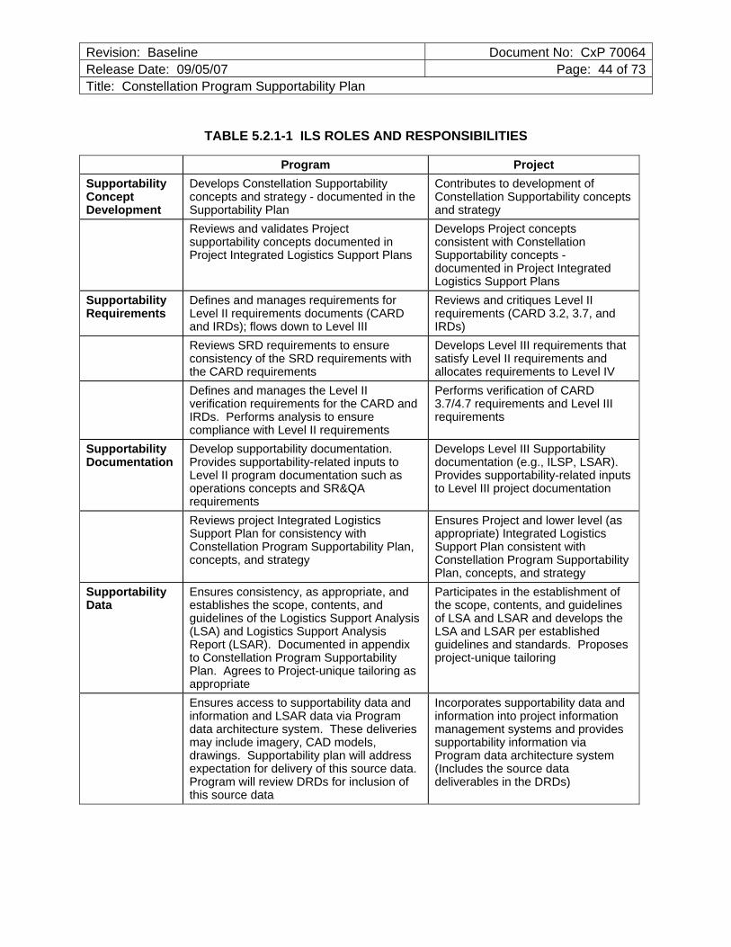
Revision: Baseline Document No: CxP 70064Release Date: 09/05/07 Page: 44 of 73Title: Constellation Program Supportability Plan
TABLE 5.2.1-1 ILS ROLES AND RESPONSIBILITIES
Program Project Supportability Concept Development
Develops Constellation Supportability concepts and strategy - documented in the Supportability Plan
Contributes to development of Constellation Supportability concepts and strategy
Reviews and validates Project supportability concepts documented in Project Integrated Logistics Support Plans
Develops Project concepts consistent with Constellation Supportability concepts - documented in Project Integrated Logistics Support Plans
Supportability Requirements
Defines and manages requirements for Level II requirements documents (CARD and IRDs); flows down to Level III
Reviews and critiques Level II requirements (CARD 3.2, 3.7, and IRDs)
Reviews SRD requirements to ensure consistency of the SRD requirements with the CARD requirements
Develops Level III requirements that satisfy Level II requirements and allocates requirements to Level IV
Defines and manages the Level II verification requirements for the CARD and IRDs. Performs analysis to ensure compliance with Level II requirements
Performs verification of CARD 3.7/4.7 requirements and Level III requirements
Supportability Documentation
Develop supportability documentation. Provides supportability-related inputs to Level II program documentation such as operations concepts and SR&QA requirements
Develops Level III Supportability documentation (e.g., ILSP, LSAR). Provides supportability-related inputs to Level III project documentation
Reviews project Integrated Logistics Support Plan for consistency with Constellation Program Supportability Plan, concepts, and strategy
Ensures Project and lower level (as appropriate) Integrated Logistics Support Plan consistent with Constellation Program Supportability Plan, concepts, and strategy
Supportability Data
Ensures consistency, as appropriate, and establishes the scope, contents, and guidelines of the Logistics Support Analysis (LSA) and Logistics Support Analysis Report (LSAR). Documented in appendix to Constellation Program Supportability Plan. Agrees to Project-unique tailoring as appropriate
Participates in the establishment of the scope, contents, and guidelines of LSA and LSAR and develops the LSA and LSAR per established guidelines and standards. Proposes project-unique tailoring
Ensures access to supportability data and information and LSAR data via Program data architecture system. These deliveries may include imagery, CAD models, drawings. Supportability plan will address expectation for delivery of this source data. Program will review DRDs for inclusion of this source data
Incorporates supportability data and information into project information management systems and provides supportability information via Program data architecture system (Includes the source data deliverables in the DRDs)
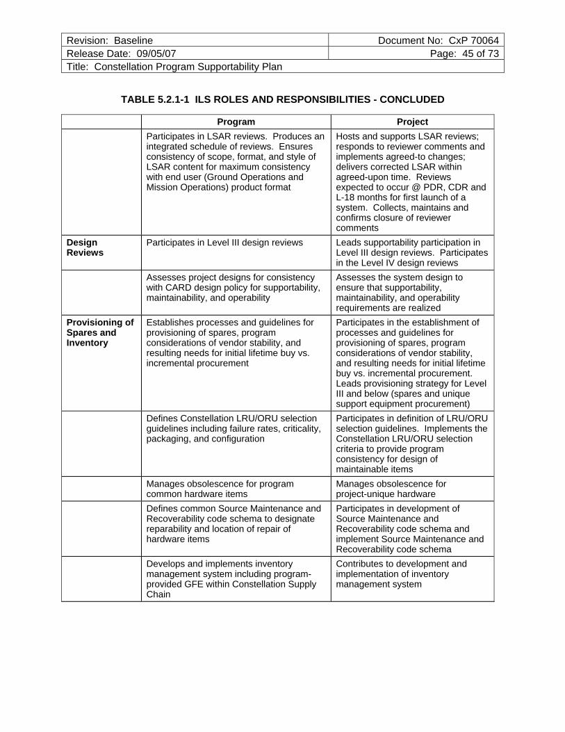
Revision: Baseline Document No: CxP 70064Release Date: 09/05/07 Page: 45 of 73Title: Constellation Program Supportability Plan
TABLE 5.2.1-1 ILS ROLES AND RESPONSIBILITIES - CONCLUDED
Program ProjectParticipates in LSAR reviews. Produces an integrated schedule of reviews. Ensures consistency of scope, format, and style of LSAR content for maximum consistency with end user (Ground Operations and Mission Operations) product format
Hosts and supports LSAR reviews; responds to reviewer comments and implements agreed-to changes; delivers corrected LSAR within agreed-upon time. Reviews expected to occur @ PDR, CDR and L-18 months for first launch of a system. Collects, maintains and confirms closure of reviewer comments
Design Reviews
Participates in Level III design reviews Leads supportability participation in Level III design reviews. Participates in the Level IV design reviews
Assesses project designs for consistency with CARD design policy for supportability, maintainability, and operability
Assesses the system design to ensure that supportability, maintainability, and operability requirements are realized
Provisioning of Spares and Inventory
Establishes processes and guidelines for provisioning of spares, program considerations of vendor stability, and resulting needs for initial lifetime buy vs. incremental procurement
Participates in the establishment of processes and guidelines for provisioning of spares, program considerations of vendor stability, and resulting needs for initial lifetime buy vs. incremental procurement. Leads provisioning strategy for Level III and below (spares and unique support equipment procurement)
Defines Constellation LRU/ORU selection guidelines including failure rates, criticality, packaging, and configuration
Participates in definition of LRU/ORU selection guidelines. Implements the Constellation LRU/ORU selection criteria to provide program consistency for design of maintainable items
Manages obsolescence for program common hardware items
Manages obsolescence for project-unique hardware
Defines common Source Maintenance and Recoverability code schema to designate reparability and location of repair of hardware items
Participates in development of Source Maintenance and Recoverability code schema and implement Source Maintenance and Recoverability code schema
Develops and implements inventory management system including program-provided GFE within Constellation Supply Chain
Contributes to development and implementation of inventory management system
Revision: Baseline Document No: CxP 70064Release Date: 09/05/07 Page: 46 of 73Title: Constellation Program Supportability Plan
5.2.2 Integrated Logistics Support Plan (ILSP)
Each Project (defined as CEV, CLV, etc.) is expected to develop an Integrated Logistics Support Plan (ILSP) that is consistent with this document. The ILSP should address how the contractors will satisfy the ILS deliverable requirements contained within their contract statements of work. In addition, the ILSP should also address how the following disciplines will interrelate with the overall ILS approach for support of the system:
a. Environmental and Health Management
b. Hazardous Materials Management
c. Human-Systems Integration (Human Factors Engineering)
d. Quality Assurance (QA)
e. Safety Engineering
f. Design Engineering
g. Mission Planning, Crew Training, and Flight Operations
h. Ground Operations
i. Configuration Management (CM)
j. Data Management (DM)
k. Design Interface
l. Maintenance Facilities
The ILS planning process should encompass all planned program life cycle phases and address all applicable mission phases including development and test, ground operations including assembly and checkout, prelaunch, launch, first-stage recovery, in-space and surface destination operations, post-flight turnaround, and end of service life of hardware systems.
5.2.2.1 ILSP Planning and Management
ILS Milestone Schedule Each project should establish an ILS milestone schedule that lists the major events and data products that must be developed or accomplished prior to each acquisition milestone. Each Constellation project will identify key controlling events/tasks pertaining to the development, introduction and follow-on support of that project’s primary end-item for inclusion in an ILS master milestone schedule.
Revision: Baseline Document No: CxP 70064Release Date: 09/05/07 Page: 47 of 73Title: Constellation Program Supportability Plan
Integrated Logistics Assessment (ILA) Each Constellation project should conduct an assessment to verify the adequacy of ILS. Typically, an Integrated Logistics Assessment (ILA) is scheduled 60 to 90 days prior to an operational milestone decision, to include Government acceptance of the system and the system’s operational readiness date. The ILA will verify that logistics support is in place in support of the system’s Initial Operational Capability date.
The ILSP should address the following:
a. How the contractor will support these periodic assessments.
b. Provide detailed status on the logistics resources required to support operational milestone (such as spare levels, zero balances, maintenance backlog, etc.).
c. Identify Performance Measurements/Metrics to support ILA.
d. How the ILA may support Certification of Flight Readiness (CoFR).
Risk Management Risk is inherent in any acquisition program and in virtually all functional areas of a program, including the area of logistics. The logistician and other functional experts at all levels must address the areas of risk to ensure that program objectives are met. Risk management is a program management responsibility and is the practice of controlling risk drivers that adversely affect the program. It includes the process of identifying, analyzing, and tracking risk drivers; assessing the likelihood of their occurrence and their consequences; defining risk-handling plans; implementing these plans; and performing continuous assessments to determine how risk changes during the life of the program. This is done by controlling the risks associated with the design, manufacturing, test, and support functions that are part of systems acquisition.
The project ILSP should address the process the ILS program will use to monitor and control identified logistics risks. All such risks will be processed in accordance with CxP 70056, Constellation Program Risk Management Plan.
Logistics Programming and Budgeting The logistics programming and budgeting planning process should encompass all program life cycle phases and address all applicable mission phases including development and test, ground processing including assembly and checkout, prelaunch, launch, in-space and surface destination operations, post-flight turnaround, and end of service life of hardware systems.
The project ILSPs should address the following:
a. How supportability life-cycle cost will be factored into acquisition design and support decisions
Revision: Baseline Document No: CxP 70064Release Date: 09/05/07 Page: 48 of 73Title: Constellation Program Supportability Plan
b. The level of logistics budget traceability
c. Preselect trade studies to be accomplished (if known)
d. Creation of solutions to reduce life cycle costs in DDT&E, Ground Processing, and Flight Operations phases
e. Development and implementation of a plan to insert new technology necessary to ensure availability of spares and prevent against obsolescence
5.2.2.2 Support Concept
Each Project and contractor ILSP must define an overall support concept that is consistent with the Constellation Support Concept defined previously in this document. The support concept forms the framework upon which the support plan and support infrastructure are established.
Maintenance Concept A central component of the Support Concept is the Maintenance Concept. A maintenance concept is a general description of the maintenance tasks required in support of a given system or equipment and the designation of the maintenance level for performing each task. Many of the other supportability functions are emplaced with the purpose of enabling the implementation of the maintenance concept. Project maintenance concepts must be consistent with the Constellation Supportability Concept defined previously in this document.
The ability of the crew to autonomously deal with virtually any system failure and associated maintenance activities will be significantly enhanced by advanced Integrated Systems Health Management (ISHM) capabilities that implement immediate system management actions and also pinpoint the failed items for subsequent maintenance. Another very useful potential feature of ISHM is the ability to forecast impending failures based on current conditions and known or modeled behavior. This will allow the scheduling of maintenance actions before failures occur or, at a minimum, alert the crew that a maintenance action will likely be required at a defined point in the future. ISHM can also significantly contribute to improved ground maintenance activities for the space vehicle by effective location of sensors and designed-in features allowing download of stored failure and other maintenance related data.
It is anticipated that new operational concepts will be applied that include assembly and manufacturing of selected replacement components on an as-needed basis during a mission. Although still in the developmental stage, emerging manufacturing technologies are expected to enable the production of structural and mechanical components from feedstock material. This approach offers the maximum flexibility and optimized use of mass and volume allocations. As these manufacturing capabilities become more fully developed, this should be considered as the primary approach to providing structural and mechanical replacement components.
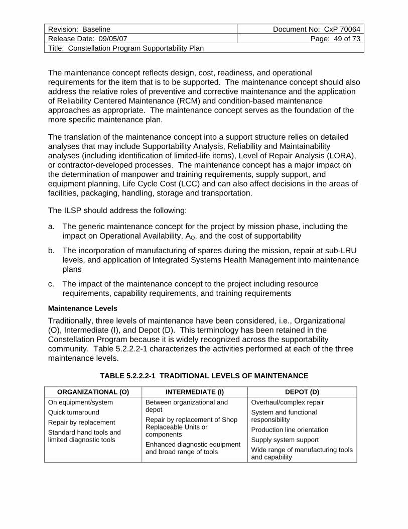
Revision: Baseline Document No: CxP 70064Release Date: 09/05/07 Page: 49 of 73Title: Constellation Program Supportability Plan
The maintenance concept reflects design, cost, readiness, and operational requirements for the item that is to be supported. The maintenance concept should also address the relative roles of preventive and corrective maintenance and the application of Reliability Centered Maintenance (RCM) and condition-based maintenance approaches as appropriate. The maintenance concept serves as the foundation of the more specific maintenance plan.
The translation of the maintenance concept into a support structure relies on detailed analyses that may include Supportability Analysis, Reliability and Maintainability analyses (including identification of limited-life items), Level of Repair Analysis (LORA), or contractor-developed processes. The maintenance concept has a major impact on the determination of manpower and training requirements, supply support, and equipment planning, Life Cycle Cost (LCC) and can also affect decisions in the areas of facilities, packaging, handling, storage and transportation.
The ILSP should address the following:
a. The generic maintenance concept for the project by mission phase, including the impact on Operational Availability, AO, and the cost of supportability
b. The incorporation of manufacturing of spares during the mission, repair at sub-LRU levels, and application of Integrated Systems Health Management into maintenance plans
c. The impact of the maintenance concept to the project including resource requirements, capability requirements, and training requirements
Maintenance Levels Traditionally, three levels of maintenance have been considered, i.e., Organizational (O), Intermediate (I), and Depot (D). This terminology has been retained in the Constellation Program because it is widely recognized across the supportability community. Table 5.2.2.2-1 characterizes the activities performed at each of the three maintenance levels.
TABLE 5.2.2.2-1 TRADITIONAL LEVELS OF MAINTENANCE
ORGANIZATIONAL (O) INTERMEDIATE (I) DEPOT (D) On equipment/system Quick turnaround Repair by replacement Standard hand tools and limited diagnostic tools
Between organizational and depot Repair by replacement of Shop Replaceable Units or components Enhanced diagnostic equipment and broad range of tools
Overhaul/complex repair System and functional responsibility Production line orientation Supply system support Wide range of manufacturing tools and capability
Revision: Baseline Document No: CxP 70064Release Date: 09/05/07 Page: 50 of 73Title: Constellation Program Supportability Plan
The traditional distinction of maintenance levels is most applicable to prelaunch processing and post-flight turnaround operations. During these phases, the option is available to utilize specialized Intermediate-Level or Depot-Level repair facilities (either an “organic” capability or the Original Equipment Manufacturer [OEM]). However, during mission phases occurring in space or on Lunar or planetary surfaces, all critical maintenance must be performed by the flight crew. Therefore, the levels of maintenance employed during flight operations are distinguished primarily by the nature of the tasks to be performed rather than by location or facility and will be identified as mission maintenance, as opposed to ground based maintenance. The maintenance levels for mission maintenance will be designated by the word “Crew” preceding the maintenance level, e.g., Crew-Organizational (C-O), Crew-Intermediate (C-I), and Crew-Depot (C-D). The mission maintenance level designation will be based on the complexity of the specific maintenance task, “C-O” identifying less complex tasks, “C-I” identifying more complex tasks and “C-D” identifying the most complex tasks.
The ILSP should address the following:
a. The levels of maintenance to be implemented and the application of these maintenance levels to the planned program life cycle and mission phases
b. The planned use of contractor and/or Government capabilities and associated infrastructure required for support at each maintenance level
5.2.2.3 Supportability Analyses
Supportability Analysis (SA) is conducted as part of the System Engineering (SE) process to determine how to most effectively support the system over its entire life cycle. It provides the basis for related design requirements that may be included in specifications. The contractor performs many Supportability Analyses; and thus, it is important that requirements for analysis reports be clearly addressed in contractual terms. A performance specification (MIL-PRF-49506, Logistics Management Information [LMI]) has been developed and issued to assist the Government in this regard. It addresses in broad terms each of the following example analyses: maintenance planning, repair analysis, support and test equipment; manpower, personnel, and training; facilities; packaging, handling, storage, and transportation; and post-production support. Further amplification is provided in the performance specification. The consequences of ignoring supportability factors can include delayed delivery, inadequate provisioning, inadequately trained personnel, delayed delivery of support facilities, inadequate support equipment, and excessive down time. The Supportability Analyses should be identified as input to the systems engineering process and should be an integral part of the program's systems engineering strategy.
Project ILSPs should document the Supportability Analysis strategy for the project, starting with the review of given data and specifications of each end item to ensure that credible and sufficient information exists for conducting the analyses. The strategy
Revision: Baseline Document No: CxP 70064Release Date: 09/05/07 Page: 51 of 73Title: Constellation Program Supportability Plan
should address all Supportability Analyses needed to analyze, define, and verify the supportability objectives. The project ILSP should also define the schedule of Logistics Support Analysis Report (LSAR) Reviews and associated needs, goals, and objectives.
The ILSP should address the following:
a. Identify logistics cost drivers and constraints associated with the proposed design
b. Describe the supportability or supportability design constraints as inputs to specifications, requirement documents, or other contractual documents
c. Describe any alternatives and trade-off analyses between different support, design and operational alternatives
d. Identify any support and manpower (crew time) drivers/constraints
e. Describe the proposed maintenance concept. Include other options for the maintenance concept
5.2.2.4 Maintenance Planning
Maintenance planning is the process of applying the maintenance concept to each hardware item and associated processes when making implementation decisions for the lifetime of the system. Maintenance planning applies the maintenance concept and decisional processes to define the level at which each item is maintained, how it is maintained, and the resources required to maintain it. Support and maintenance concepts and resulting plans should reflect the optimum balance between readiness and resource utilization. Maintenance planning is reflected in the content of each item’s Source, Maintenance, and Recoverability (SMR) Code.
A Maintenance Plan will be developed by the contractors as an integral part of the ILSP. The Maintenance Plan and underlying maintenance concept should encompass all program life cycle phases and address all applicable mission phases including development and test, ground operations, launch, in-space and surface destination operations and post-flight turnaround.
Maintenance Plan A maintenance plan is a description of the requirements and tasks to be accomplished for achieving, restoring, or maintaining the operational capability of a system, equipment, or facility. The maintenance plan is normally one part of the ILSP. The maintenance plan documents the results of the maintenance planning effort. It defines what tasks will be performed, how those tasks will be conducted and the resources that are required, and the organization responsible for the various associated activities. Acquisition of support resources must be based on the Maintenance Plan. A Level of Repair Analysis (LORA), as detailed in MIL-STD-1390D, should be used as a part of the supply support concept to determine the best value support policy for an item
Revision: Baseline Document No: CxP 70064Release Date: 09/05/07 Page: 52 of 73Title: Constellation Program Supportability Plan
(considering all resources including cost, mass, volume, and time) and help identify the appropriate time to make, repair or discard the hardware item.
The project ILSPs should address the following:
a. The schedule for maintenance plan development
b. The project’s approach to incorporating the Program’s maintenance and support concepts into an approved Maintenance Plan
c. The assumptions upon which the Maintenance Plan is based
5.2.2.5 Manpower, Personnel and Training
Manpower and personnel analysis is the process conducted to identify and acquire personnel with the skills required to support the system over its planned lifetime. Training includes the students, courses, instructors, equipment, facilities, curricula, and all other materials required to train personnel to support a system including individual and crew training; new equipment training; initial, formal and on-the-job training including any certifications, if required; and logistics support planning for training equipment. Because Manpower, Personnel and Training (MPT) costs are usually a major driver of support costs, planning for this element must begin at program initiation. Acquisition logistics efforts should strive to minimize the quantity and skill levels of manpower and personnel required to support the system over its planned lifetime.
Training of flight crews for In-Flight Maintenance (IFM) is conducted by NASA’s Mission Operations Directorate (MOD). Materials used during this training utilize source material developed during the logistics development process. This training may be performed in NASA training facilities, at other NASA facilities utilizing flight hardware, or at contractor facilities utilizing flight or training hardware.
System-specific training required for ground personnel should be defined by the project in collaboration with the ground processing organizations and documented in the projects’ ILSPs. The contractors’ role in the training of ground personnel should also be defined in the projects’ ILSPs and should address the following specific topics:
a. Safety
b. Skills or knowledge to be trained and any required certifications
c. Recommended necessary duration of training
d. Training facilities required
e. Training equipment or devices required
f. Training program content
Revision: Baseline Document No: CxP 70064Release Date: 09/05/07 Page: 53 of 73Title: Constellation Program Supportability Plan
g. Training program implementation
h. Other resources required Additional details of the implementation of functions by the contractor should be included in the contractors’ ILSPs. Support of Training Equipment and Devices (TE&D) Training Equipment and Devices (TE&D) are model replicas of the end item (system) devoted to the training and instruction of personnel. Because the conduct of training frequently results in increased maintenance requirements (due to constant use from students performing operating and maintenance tasks), the project office may need to adjust the quantity of spare parts and other supply support normally provided.
The ILSP should address the following, as applicable:
a. The procurement of data and documentation necessary to support and maintain TE&D
b. Identify the spare parts and Configuration Management considerations that may impact the TE&D acquisition strategy
c. Identification of spares, repair parts and consumables required for the TE&D
d. Include discussion of tradeoffs and the impact on the acquisition strategy and the overall support structure (e.g., the decision to use [or not use] commercial hardware/software)
Contractor/Factory Training Contractor or factory training encompasses training that is provided by a contractor in the operation, maintenance, or activation of a system, equipment, or training device. It can be conducted at a contractor site or Government facility by contractor or other personnel. Factory training can be either initial or follow-on training, or both.
The project ILSPs should address the following:
a. Whether ground and crew training for system maintenance will be required at the factory
b. Any constraints related to its development and implementation
c. Date, course title, description, developing organization, course developer, and trainee population
d. When identifying the trainee population, indicate if the training is designed for operators, operators/maintainers, (indicate level of training: Organizational, Intermediate, or Depot-Level maintainers), team training, Government and/or contractor personnel
Revision: Baseline Document No: CxP 70064Release Date: 09/05/07 Page: 54 of 73Title: Constellation Program Supportability Plan
e. Whether training is for basic skills, skill progression, or other types of training
f. The rationale for the training of Government personnel (including flight crew) at facilities other than Government facilities
On-Board Maintenance Training On-Board Maintenance Training is provided to flight crews during a mission when necessary to support the performance of specific tasks that may be particularly complex or which require capabilities beyond those acquired by the crewmembers during pre-mission training. On-Board Maintenance Training may include Computer Based Training (CBT), Interactive Courseware (IC), and embedded training. The project ILSPs should address the following:
a. The philosophy, relative scope and benefits of on-board maintenance training capability during a mission
b. The type of training provided, such as:
1. Proficiency training
2. Maintenance training
3. Other on-board maintenance training packages and the location where the identified training will be accomplished
5.2.2.6 Supply Support
Supply Support Concept Supply support includes the identification, procurement, and management of initial and replenishment spare and repair parts based on the approved maintenance concept. Two primary objectives of supply support are to ensure that end items are delivered in a satisfactory state of readiness and to maintain readiness by fulfilling material replenishment requirements throughout the life cycle of the end item. The supportability tasks included in maintenance planning identify the mission criticality of parts, authorized maintenance levels, and estimates of replacement rates and of part failures.
The project ILSPs should address the following:
a. The supply support concept and the strategies used to ensure effective support to the end item
b. The factors, risks and assumptions on which the supply support concept is based
c. How any anticipated commercial item acquisitions will affect the supply support system
d. Any unique supply requirements that are being considered
Revision: Baseline Document No: CxP 70064Release Date: 09/05/07 Page: 55 of 73Title: Constellation Program Supportability Plan
e. The plan to include training, support and test equipment in the supply support system
f. Implementation of space-based inventory management system architecture and element-to-element (CEV to LSAM, etc.) inventory management system compatibility. Compatibility with the Constellation Program Logistics Management System (LMS) should also be addressed
Spares Provisioning and Acquisition Provisioning is the process of determining the range and quantity (depth) of spares and repair parts and support and test equipment required to operate and maintain the end item for an initial period of service. Provisioning methodologies will be determined by the individual projects. Provisioning recommendations will be developed by the contractors and provided to NASA. The projects then evaluate these recommendations, conduct provisioning conferences with the contractors, and develop the provisioning implementation plan. For the Constellation Program, the project’s Government ILS Manager must consider spares for system development and testing, ground processing, prelaunch test and check-out, launch support, and In-Flight Maintenance (including systems on destination surfaces).
Decisions affecting spares must be made very early in the life cycle of a system. As the program evolves, the project’s Government ILS manager must issue provisioning technical documentation guidance, consistent with the system’s maintenance and support concepts, via the contract to ensure that project unique materials are promptly ordered. The project’s Government ILS manager must also ensure that follow-on spare and repair parts are obtained in a cost-effective manner. The project’s Government ILS manager should obtain technical data, drawings, tools, etc. through contractual requirements, to enable competition among contractors for follow-on logistics support. Relying on the original prime contractor for follow-on support material entails risks in the areas of cost and availability of needed spare and repair parts, especially during the post-production support period.
Spares Acquisition Integrated with Production (SAIP) is a process whereby the Government combines spare parts orders with planned production. This approach is particularly effective when applied to limited initial production runs. In such cases, extending a contract for the sole purpose of producing very low quantities of spares may not be cost effective.
The project ILSPs should address the following:
a. Anticipated schedules for provisioning conferences between NASA and contractors
b. Attendance, roles and responsibilities for provisioning conferences
c. Methodology for assessing the contractors’ provisioning recommendations
Revision: Baseline Document No: CxP 70064Release Date: 09/05/07 Page: 56 of 73Title: Constellation Program Supportability Plan
d. Criteria used in the spares determination process
e. Tools or software to be utilized
Constellation Program Logistics Management System (LMS) The Constellation Program Logistics Management System (LMS) provides the capability to integrate program and project logistics related processes, data, and documentation to include inventory management and control. The system will have the capability to identify, track, and manage program and project assets both on the ground and off-Earth. Individual projects’ LMSs will be developed and maintained by the projects. However, all of the projects’ LMSs are required to be compatible with the Constellation LMS. Display screens used by crews should be common for all projects. The LMS will provide a single source for all inventory and equipment management data for both the ground-based and space-stored assets. The LMS will include the capability of monitoring and recording the locations and quantity of logistics items as well as cross references for common component applications, as required in Section 3.1.3.6.7 of CxP 70000, CARD. For inventory activities, the LMS is envisioned as performing three primary functions:
a. Ground-based inventory management
b. Space-based inventory management
c. Equipment/property management
In order for the LMS to be an effective tool, the data residing within the system must be accurate and allow for timely updates. It is also highly desirable that the LMS require minimal hands-on crew interaction to update and maintain the LMS.
The project ILSP should address the following:
a. The types of data to be included in the LMS
b. The functionality of the LMS to provide capabilities, such as reparable item management of critical assets, equipment calibration and early notification of the expiration, material usage, early notification of life limits/shelf life, etc.
c. LMSs information to be displayed to the crew, methods for displaying this information and display formats
d. Application and use of Unique Identification (UID) techniques, such as Radio Frequency tags, dual dimensional matrix symbology, or others
Revision: Baseline Document No: CxP 70064Release Date: 09/05/07 Page: 57 of 73Title: Constellation Program Supportability Plan
5.2.2.7 Support Equipment
Support Equipment Planning Systems or other items of equipment normally require the use of additional equipment to support operations or maintenance. Any item of equipment required to support operation or maintenance is categorized as support equipment. The support equipment can be a special item designed for only one specific use, or it can be items that have multiple uses. The support equipment planning process should encompass all program life-cycle phases and address all applicable mission phases including development and test, ground processing including assembly and checkout, prelaunch, launch, first-stage recovery, in-space and surface destination operations and post-flight turnaround. The following list is a summary of some of the different types of support equipment:
Ground Support Equipment (GSE) GSE is nonflight equipment with a physical and/or functional interface with the flight hardware that is routinely required for the handling, servicing, inspection, testing, maintenance, alignment, adjustment checkout, repair, and overhaul of flight hardware.
Flight Support Equipment (FSE) Flight Support Equipment (FSE) provides the interface between the LRU/ORU or Shop Replaceable Unit (SRU) and the carrier. FSE supports loads during all applicable phases of flight and provides thermal conditioning for launch, landing and in-space operations, as required. For external hardware, FSE is compatible with EVA. For external items that are robotically compatible, the FSE is also robotically compatible such that translation, storage, removal and replacement can be conducted end-to-end without EVA intervention.
Flight Crew Equipment (FCE) FCE consists of all crew-related equipment and includes space suits, extravehicular life support equipment, food, bioinstrumentation, personal communications equipment, photographic equipment, miscellaneous mission operational aids, tools, oxygen, diluent gas for atmospheric pressure maintenance, water, biomedical supplies, and other consumables.
Surface Support Equipment (SSE) SSE is equipment used on destination lunar and planetary surfaces to provide support for setup and sustainment of the surface infrastructure (habitats, production facilities, manufacturing equipment, maintenance facilities, power stations, communications, transportation, and launch and landing sites, etc.). SSE is equipment required for handling, servicing, inspection, testing, maintenance, alignment, adjustment checkout, repair, and overhaul.
Revision: Baseline Document No: CxP 70064Release Date: 09/05/07 Page: 58 of 73Title: Constellation Program Supportability Plan
Test, Measurement, and Diagnostic Equipment (TMDE) TMDE is any system or device used on the ground, in flight, or on a destination surface to evaluate the operational condition of an end item or subsystem thereof to identify and/or isolate any actual or potential malfunction. This TMDE includes diagnostic and prognostic equipment; semiautomatic and Automatic Test Equipment (ATE) to include Test Program Sets (TPSs) (with issued software); and calibration test or measurement equipment.
NOTE: When the term TMDE is used, it refers to both TMDE-GP and TMDE-SP.
Test, Measurement, and Diagnostic Equipment-General Purpose (TMDE-GP) TMDE-GP is any TMDE that can be used to support multiple end items or systems without requiring modification. Addition of external special accessories, plug-in assemblies, logic probes, and attenuators (or TPSs for ATE) are not considered modifications.
Test, Measurement, and Diagnostic Equipment-Special Purpose (TMDE-SP) TMDE-SP is any TMDE designed specifically for support of and functionally restricted to one end item or system. To use this TMDE for support of another end item or system would necessitate modifications to the TMDE. Addition of external special accessories, plug-in assemblies, logic probes, attenuators (or TPS for ATE) are not considered modifications.
Automatic/Automated Test Equipment (ATE) ATE is any TMDE that performs a predetermined program to test functional or static parameters, to evaluate the degree of performance degradation, or to perform fault isolation of unit malfunctions. As a minimum, ATE must be able to sequentially perform testing/measurements, compare the measurements to predetermined values or ranges, and based on the results of this comparison, branch to other tests without manual intervention. ATE is usually external to the prime device.
Test Program Set (TPS) The TPS is the combination of interface devices, software test programs (such as those residing in logic storage media or in permanent digital memory), and documentation that together allows the ATE operator to perform the testing/diagnostic action on the Unit Under Test (UUT).
Built-In Test Equipment (BITE) BITE is any identifiable device that is a part of the supported end item and is used for testing that supported end item.
Revision: Baseline Document No: CxP 70064Release Date: 09/05/07 Page: 59 of 73Title: Constellation Program Supportability Plan
Calibration Equipment Calibration Equipment consists of measurement standards and TMDE used in performance of calibration.
The number of different tools and support equipment required for test, maintenance, assembly, servicing, handling, etc. should be kept to a minimum. Commonality should be stressed and multi-application tools should be used wherever possible. TMDE-GP should be employed versus TMDE-SP, whenever possible.
Support equipment factors may impact commercial item acquisitions (e.g., new calibration standards and procedures for related test equipment may not be available when a commercial end item is fielded). Additionally, rapid fielding of a commercial end item may necessitate the procurement of commercial support equipment or the need for interim contractor support.
The project ILSPs should address the following:
a. Identify support equipment that will be required for each end item for all life cycle phases
b. Identify major items of support equipment requiring development
c. Describe the strategy for providing the required support to the identified support equipment, including existing and new development items
d. Identify risks that may hinder the timely implementation of maintenance and logistics support to the support equipment
5.2.2.8 Facilities
The role of facilities in Supportability activities must be considered. This includes facilities for storage, supportability activities associated with assembly and checkout as well as prelaunch processing, and depot repair.
The ILSPs should address the following:
a. Facilities necessary to enable the performance of supportability functions
b. Specific requirements that facilities must meet to properly enable supportability functions (e.g., lighting, clean room conditions, temperature, humidity, and utilities such as electrical power and pressurized gasses)
c. Need for auxiliary equipment such as fork lifts and cranes
d. Certification processes and requirements (including OEM facilities that are supporting post-production repair activities)
Revision: Baseline Document No: CxP 70064Release Date: 09/05/07 Page: 60 of 73Title: Constellation Program Supportability Plan
5.2.2.9 Packaging, Handling, Storage and Transportation
Packaging, Handling, Storage and Transportation (PHS&T) Planning Packaging, Handling, Storage and Transportation (PHS&T) planning must include all phases of end-item life cycle. This includes:
a. Shipment from the Original Equipment Manufacturer (OEM)
b. Operations at intermediate and final assembly locations
c. Packaging, handling and storage at the launch site and at test facilities
d. Launch (including requirements for Flight Support Equipment [FSE])
e. In-space handling and stowage (with special attention to interfaces for the crew, robotics, and support equipment)
f. Handling on destination Lunar and planetary surfaces
g. Launch from lunar and planetary surfaces
h. Reentry and landing
i. Shipping from landing site to launch site
j. Shipping from landing site to depot facilities for repair and refurbishment
k. Shipping from depots
The ILSP should address:
a. The plan for ensuring that PHS&T aspects of logistics operations are considered and integrated into engineering design and support subsystem design efforts
b. The interaction with the design process is to ensure that end items can be handled with standard equipment and that the need for special handling and support equipment is minimized
c. Specific requirements for responsibilities, surveillance, approvals, facility and equipment and personnel certifications, and procedural aspects of the PHS&T functions for Program Critical Hardware (PCH)
The PHS&T section must address all aspects of PHS&T that are the direct responsibility of the hardware developer and must define information, and the plan for providing that information, needed by other organizations that have responsibility for PHS&T operations during various phases of the life cycle. Examples include but are not limited to:
a. Physical contact constraints
b. Load limits
Revision: Baseline Document No: CxP 70064Release Date: 09/05/07 Page: 61 of 73Title: Constellation Program Supportability Plan
c. Shock and vibration constraints
d. Environmental constraints (i.e., temperature, humidity, etc.)
e. Contamination control
f. Commodity requirements and interfaces (i.e., power, purge gases, etc.)
g. Other safety documentation
The PHS&T planning and budgeting process should encompass all program life cycle phases and address all applicable mission phases including development and test, ground processing including assembly and checkout, prelaunch, launch, recovery, in-space and surface destination operations and post-flight turnaround.
5.2.2.10 Technical Data
Types of Technical Data and Documentation (TD&D) TD&D is recorded information, regardless of form or characteristic, of a scientific or technical nature. There are five categories of technical data:
a. Configuration Documentation (i.e., to include interface requirements and control documents)
b. Technical Procedures
c. Items Identification Data
d. Technical Reports
e. Other (imagery and video of hardware during fabrication and assembly, Problem Reporting, Analysis, and Corrective Action [PRACA]-type data acquired during testing, etc.)
The Supportability Analysis should include a detailed review of TD&D requirements and options for long-term support of Constellation Program requirements.
The project ILSP should address the following:
a. The system to store TD&D and access/transfer plans for NASA
b. Documentation of technical data management planning
c. The acquisition strategy, and associated drivers, for technical manuals and engineering drawings
d. Compatibility of contractor data with existing Government data systems
e. The process to mitigate/minimize proprietary data rights
Revision: Baseline Document No: CxP 70064Release Date: 09/05/07 Page: 62 of 73Title: Constellation Program Supportability Plan
The technical data planning process should encompass all program life cycle phases and address all applicable mission phases including development and test, ground processing including assembly and checkout, prelaunch, launch, recovery, in-space and surface destination operations and post-flight turnaround.
Engineering Drawings Engineering drawings are one of many types of technical data that will have to be purchased during the life cycle of a system. The importance of engineering drawings to the aerospace industrial business processes demands that engineering drawings are adequately and accurately addressed in the contract requirements and are sufficient in detail to meet follow-on procurements, change activities, testing and operations, maintenance and training documentation development. In this context, the term “engineering drawings” includes the electronic data, design files, and solid models from which the final engineering drawings are constructed.
The project ILSPs should describe the management techniques designed to ensure that the engineering drawing program is in synchronization with the maintenance planning process.
Data Rights It is especially important to ensure that the Government has data rights to the delivered system. Data rights are a broad field that includes full data rights, limited data rights, intellectual property rights, proprietary information rights, copyrights, and trade secrets. Without full or limited data rights to drawings and software procured for use in a system, the Government may not have the right to transfer the drawings, software and associated documentation to other Government agencies or other contractors for life-cycle support. If the contractor who developed the system considers the design techniques and algorithms in the software to be trade secrets or proprietary, he will not want the information to be released to competitors. The ILS manager must determine if it will be necessary to release this information to another Government agency or contractor for support purposes during the life cycle of the system. If so, the Government must have either:
a. Full data rights which allow the Government to do anything with the drawings and algorithms, or
b. Limited data rights authorizing release of the drawings and algorithms for support purposes only
Technical Data and Documentation (TD&D) Requirements In most cases, there is no longer a requirement to develop NASA-unique TD&D for commercial equipment. Commercial manuals should be used if feasible and if they satisfy the requirements of the program/project. The alternative is the commitment of spending considerable time and money converting the manuals. In the past, a major
Revision: Baseline Document No: CxP 70064Release Date: 09/05/07 Page: 63 of 73Title: Constellation Program Supportability Plan
data problem has been the incomplete identification of data requirements and the lack of emphasis on procedures that ensure legible, complete and correct TD&D.
The project ILSPs should address the following:
a. Procedures for Technical Data & Documentation (TD&D) procurement including development of Data Requirement Description (DRD) language for application to agreements and contracts
b. Roles and responsibilities of activities/contractors participating in the development of TD&D
c. Risks and mitigations associated with the acquisition, timely delivery, and quality of TD&D
Technical Data and Documentation (TD&D) Changes/Revisions The process for TD&D changes for the program life cycle will be addressed in the ILSP.
Validation/Verification of TD&D The validation process evaluates TD&D for technical accuracy, adequacy, comprehensibility, and usability. The validation is normally conducted at the development/test facility or operational site and involves the performance of operating and maintenance procedures, including test, checkout, calibration, alignment, removal, installation and disassembly. TD&D verification is performed by the Government to ensure that the TD&D is adequate to support the operation and maintenance of the end item. The verification is conducted using personnel with skill levels equivalent to those of the target operators or maintainers.
The project ILSPs should address the following:
a. The plan for TD&D review, validation and verification.
b. The validation process and provisions to ensure the validation method permits the performance of tasks in an environment which closely duplicates (or simulates) operational conditions.
5.2.2.11 Computer Resources Support
The Supportability function will not be responsible for computer resources software support. The Critical Safety Items (CSI) organization is responsible for computer resources software support. Support of computer systems hardware will be treated in the same way as for other hardware (flight and ground) and is covered under the appropriate sections elsewhere in this document.
Revision: Baseline Document No: CxP 70064Release Date: 09/05/07 Page: 64 of 73Title: Constellation Program Supportability Plan
5.2.2.12 Post- Production Support
Interim Contractor Support (ICS) NASA desires that all end items be fully supported at the time of installation with a level of spares and capabilities sufficient to meet operational readiness requirements. If full support is not available prior to system introduction, interim support procedures must be established to bridge the gap between Initial Operating Capability (IOC) and System Support Date (SSD). Interim Contractor Support (ICS) may be used when the design is unstable, when limited quantities of the end item are being procured and when development and production schedules have been compressed so that support cannot be provided through normal provisioning procedures. The project ILSP should identify any items requiring ICS.
Transition to Government Support Transition to Government support is normally scheduled after the system design is stable, when the capability to support the system has been demonstrated, and when the planned ILS resources for the mature system can be delivered. When interim contractor support is used, the support should be provided in such a way that non-standard support procedures are minimized. The need for interim support is often driven by a scarcity of ILS products, such as spare parts. The transition to Government support, if it occurs, will be determined by each individual project in cooperation with the Level II Program. The project ILSP should describe the procedures and schedule for transitioning any identified Interim Contractor Supply Support (ICSS) to NASA.
Depot Requirements Each individual project will determine if it will require depot maintenance capabilities. Factors to be considered in making this determination are system reliability, system maintenance concept, system repair strategy, and availability of existing depot capabilities and capacities (including production sites). In the case where the program/project determines a depot maintenance capability is required and cannot be established prior to system fielding, an interim contractor support strategy may be implemented until the planned depot maintenance capability is established. The depot maintenance planning process should encompass all program life cycle phases and address all applicable mission phases including development and test, ground processing including assembly and test, prelaunch, in-space and surface destination operations and post-flight turnaround.
The ILSP should address the following:
a. Analyses required to identify and define depot requirements
b. How depot resource requirements will be defined and the procedures for fulfilling them, including any plans to utilize existing depots
c. Whether interim contractor or other unique depot support is planned
Revision: Baseline Document No: CxP 70064Release Date: 09/05/07 Page: 65 of 73Title: Constellation Program Supportability Plan
d. The use of existing or common depots, with particular emphasis on any existing depots suitable for use by the Constellation Program
Post Production Support (PPS) Plan The objective of the Post Production Support (PPS) Plan (PPSP) component of the ILSP is to define the resources and capabilities that will be required to support the system from the period beginning at the completion of production through the remainder of the life cycle. This includes all aspects of support including spares and repair parts; acquisition of revised spares, repair parts and software required by post-production design modifications; updates to support data and documentation; repair and refurbishment of failed items; and all related support functions. The PPSP must also define responsibilities for managing PPS activities.
While problems may be encountered in all of the support elements (such as the retention of manpower skills and replacement of support equipment), the loss of production sources for spares and repair parts have presented the greatest difficulties in previous programs. Special attention should be paid to this issue.
The PPSP should be a joint Government-contractor effort. The PPSP should be maintained current, as long as the system is operational and should focus on such issues as:
a. System and subsystem readiness objectives in the post-production time frame
b. Organizational structures and responsibilities in the post-production time frame
c. Resources and management actions required to meet PPSP objectives
d. Assessment of the impact of technological change, system performance improvements and obsolescence
e. Post-production maintenance and repair facility and process certification for support of CxP assets.
f. Transfer and maintenance of sustaining engineering responsibility and control of technical baseline
Additionally, the following should be addressed in the PPSP:
a. Alternative solutions to anticipated support difficulties during the remaining life of the end item
b. Alternative PPS strategy to accommodate production phase out (e.g., second sourcing, standardization with existing hardware, engineering level of effort contracts in the post-production time frame, life-of-type-buys, third party logistics support vs. in-house logistics support, maintenance concept change, suitable substitute, redesign and flexible computer integrated manufacturing)
Revision: Baseline Document No: CxP 70064Release Date: 09/05/07 Page: 66 of 73Title: Constellation Program Supportability Plan
c. Provisions for the use, disposition and storage of Government tools and contractor-developed factory test equipment, tools and dies
d. Support items associated with the end item that may present problems due to inadequate sources of supply after shutdown of production lines
e. Transfer of TD&D and sustaining engineering responsibility along with certification of PPS facilities and processes
The PPS planning process should encompass all program life cycle phases and address all applicable mission phases including development and test, prelaunch, launch, in-space and surface destination operations and post-flight turnaround.
5.2.2.13 Disposal
Disposal Planning Disposal is a complex and evolving process. It is an area in which the NASA Program Manager (PM) has obligations specified in various laws, executive orders, treaties, agreements, and a multitude of NASA and other agency regulations and administrative directives. During disposal, the NASA PM should ensure material determined to require disposal is controlled and should ensure disposal is carried out in a way that minimizes NASA’s liability due to environmental, safety, security, health, and planetary protection issues. The presence of hazardous material contained in the equipment (e.g., lithium and lead acid batteries, components containing mercury, radioactive material, etc.) must be identified and a review of hazardous material procedures conducted prior to disposal. Decisions made during the acquisition process will influence the environmental impact of disposal procedures.
Particular attention may be required for modified equipment where the modifications add hazardous material (e.g., specific paints for service durability) which requires removal prior to disposal. The environmental issues associated with disposal of a system can be more significant than those created during all previous life-cycle phases. Effective planning can minimize hazardous waste generation during ground processing as well as system disposal. If an acquisition program is just being initiated, there will be many opportunities to plan an environmentally acceptable system disposal. If a system is already in service, disposal decision-making options may be limited. Considerations should also be given to making the prime contractor or Original Equipment Manufacturer (OEM) responsible for asset disposal. The ILSP should address the program’s disposal strategy for both the system and the waste stream generated through ground processing activities.
The project ILSPs should address the following:
a. Plans for reuse of flight hardware
Revision: Baseline Document No: CxP 70064Release Date: 09/05/07 Page: 67 of 73Title: Constellation Program Supportability Plan
b. The overall disposal plan, including the use of recycling, reprocessing and disposal in a landfill options
c. In-space disposal (location and methods)
d. Potential environmental impacts of project-specific systems and hardware
e. The process to ensure budget availability to support major disposal efforts
f. Plans for participating in or conducting reviews related to disposal process and interfaces, decommissioning, disposal restrictions, and/or demilitarization
g. Plans for training disposal teams (i.e., reutilization management office personnel) to recognize items with disposal restrictions
h. Termination of Configuration Management (CM) and Data Management (DM) responsibilities and transfer, archiving, or disposal of technical baseline and other project data
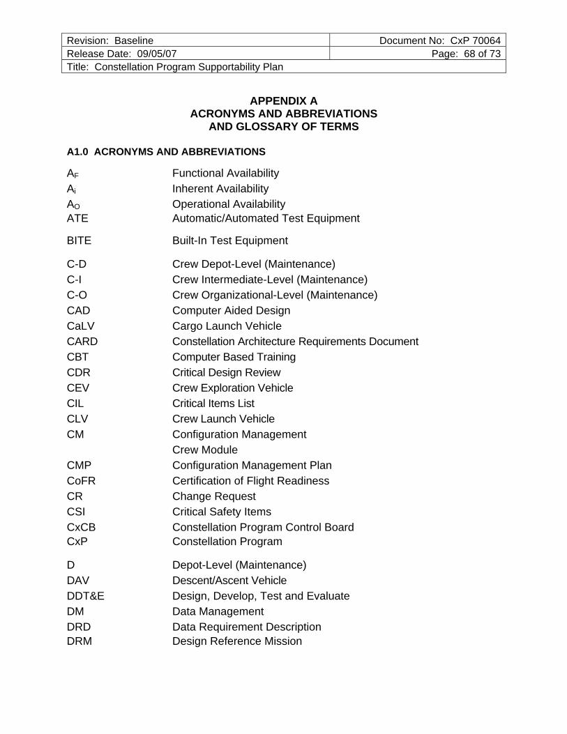
Revision: Baseline Document No: CxP 70064Release Date: 09/05/07 Page: 68 of 73Title: Constellation Program Supportability Plan
APPENDIX A ACRONYMS AND ABBREVIATIONS
AND GLOSSARY OF TERMS
A1.0 ACRONYMS AND ABBREVIATIONS
AF Functional Availability Ai Inherent Availability AO Operational Availability ATE Automatic/Automated Test Equipment
BITE Built-In Test Equipment
C-D Crew Depot-Level (Maintenance) C-I Crew Intermediate-Level (Maintenance) C-O Crew Organizational-Level (Maintenance) CAD Computer Aided Design CaLV Cargo Launch Vehicle CARD Constellation Architecture Requirements Document CBT Computer Based Training CDR Critical Design Review CEV Crew Exploration Vehicle CIL Critical Items List CLV Crew Launch Vehicle CM Configuration Management Crew Module CMP Configuration Management Plan CoFR Certification of Flight Readiness CR Change Request CSI Critical Safety Items CxCB Constellation Program Control Board CxP Constellation Program
D Depot-Level (Maintenance) DAV Descent/Ascent Vehicle DDT&E Design, Develop, Test and Evaluate DM Data Management DRD Data Requirement Description DRM Design Reference Mission
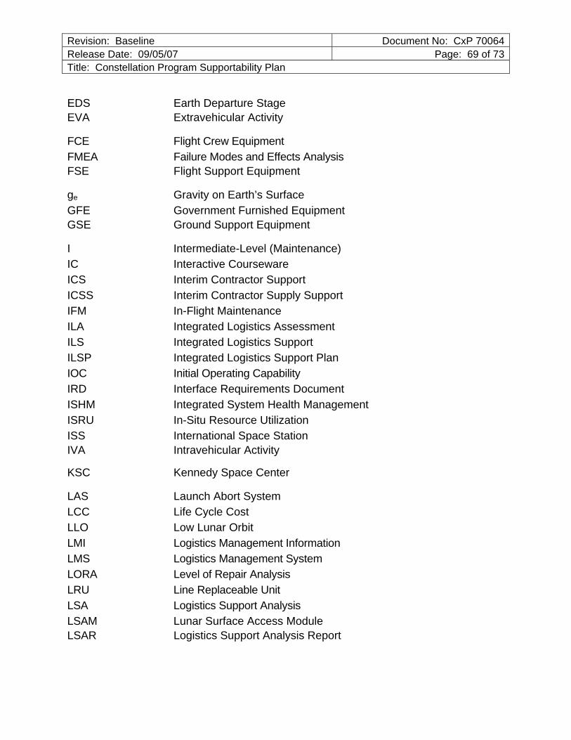
Revision: Baseline Document No: CxP 70064Release Date: 09/05/07 Page: 69 of 73Title: Constellation Program Supportability Plan
EDS Earth Departure Stage EVA Extravehicular Activity
FCE Flight Crew Equipment FMEA Failure Modes and Effects Analysis FSE Flight Support Equipment
ge Gravity on Earth’s Surface GFE Government Furnished Equipment GSE Ground Support Equipment
I Intermediate-Level (Maintenance)IC Interactive Courseware ICS Interim Contractor Support ICSS Interim Contractor Supply Support IFM In-Flight Maintenance ILA Integrated Logistics Assessment ILS Integrated Logistics Support ILSP Integrated Logistics Support Plan IOC Initial Operating Capability IRD Interface Requirements Document ISHM Integrated System Health Management ISRU In-Situ Resource Utilization ISS International Space Station IVA Intravehicular Activity
KSC Kennedy Space Center
LAS Launch Abort System LCC Life Cycle Cost LLO Low Lunar Orbit LMI Logistics Management Information LMS Logistics Management System LORA Level of Repair Analysis LRU Line Replaceable Unit LSA Logistics Support Analysis LSAM Lunar Surface Access Module LSAR Logistics Support Analysis Report

Revision: Baseline Document No: CxP 70064Release Date: 09/05/07 Page: 70 of 73Title: Constellation Program Supportability Plan
MDT Mean Down Time MIL-HDBK Military Handbook MIL-PRF Military Performance (specification) MOD Mission Operations Directorate MPT Manpower, Personnel, and Training MTBF Mean Time Between Failures MTBM Mean Time Between Maintenance MTTR Meant Time To Repair MTV Mars Transfer Vehicle
O Organizational-Level (Maintenance) OEM Original Equipment Manufacturer OPR Office of Primary Responsibility ORU Orbital Replaceable Unit
PCH Program Critical Hardware PDR Preliminary Design Review PHS&T Packaging, Handling, Storage and Transportation PM Program Manager PPS Post Production Support PPSP Post Production Support Plan PRACA Problem Reporting, Analysis, and Corrective Action
QA Quality Assurance
R&M Reliability and Maintainability RAM Reliability, Availability and Maintainability RCM Reliability Centered Maintenance RF Radio Frequency
SA Supportability Analysis SAIP Spares Acquisition Integrated with Production SE System Engineering SE&I Systems Engineering and Integration SHAB Surface Habitat SMR Source, Maintenance, and Recoverability SR&QA Safety, Reliability, and Quality Assurance SRD System Requirements Document SRU Shop Replaceable Unit
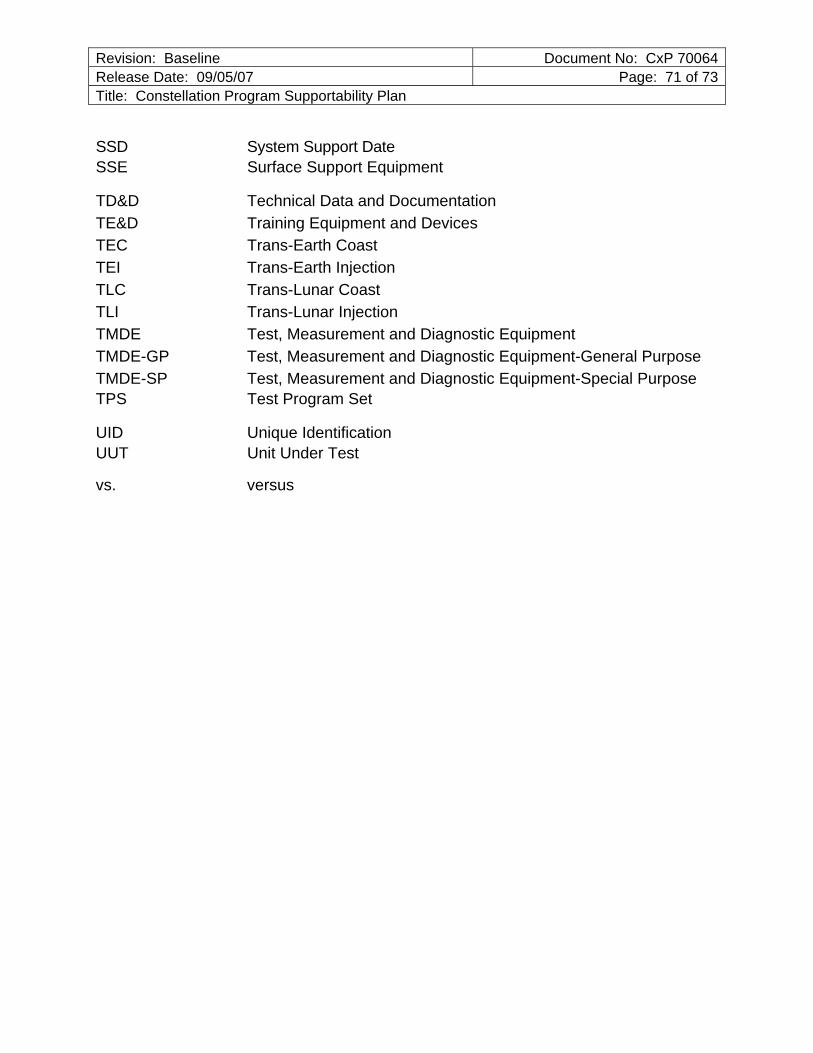
Revision: Baseline Document No: CxP 70064Release Date: 09/05/07 Page: 71 of 73Title: Constellation Program Supportability Plan
SSD System Support Date SSE Surface Support Equipment
TD&D Technical Data and Documentation TE&D Training Equipment and Devices TEC Trans-Earth Coast TEI Trans-Earth Injection TLC Trans-Lunar Coast TLI Trans-Lunar Injection TMDE Test, Measurement and Diagnostic Equipment TMDE-GP Test, Measurement and Diagnostic Equipment-General Purpose TMDE-SP Test, Measurement and Diagnostic Equipment-Special Purpose TPS Test Program Set
UID Unique Identification UUT Unit Under Test
vs. versus
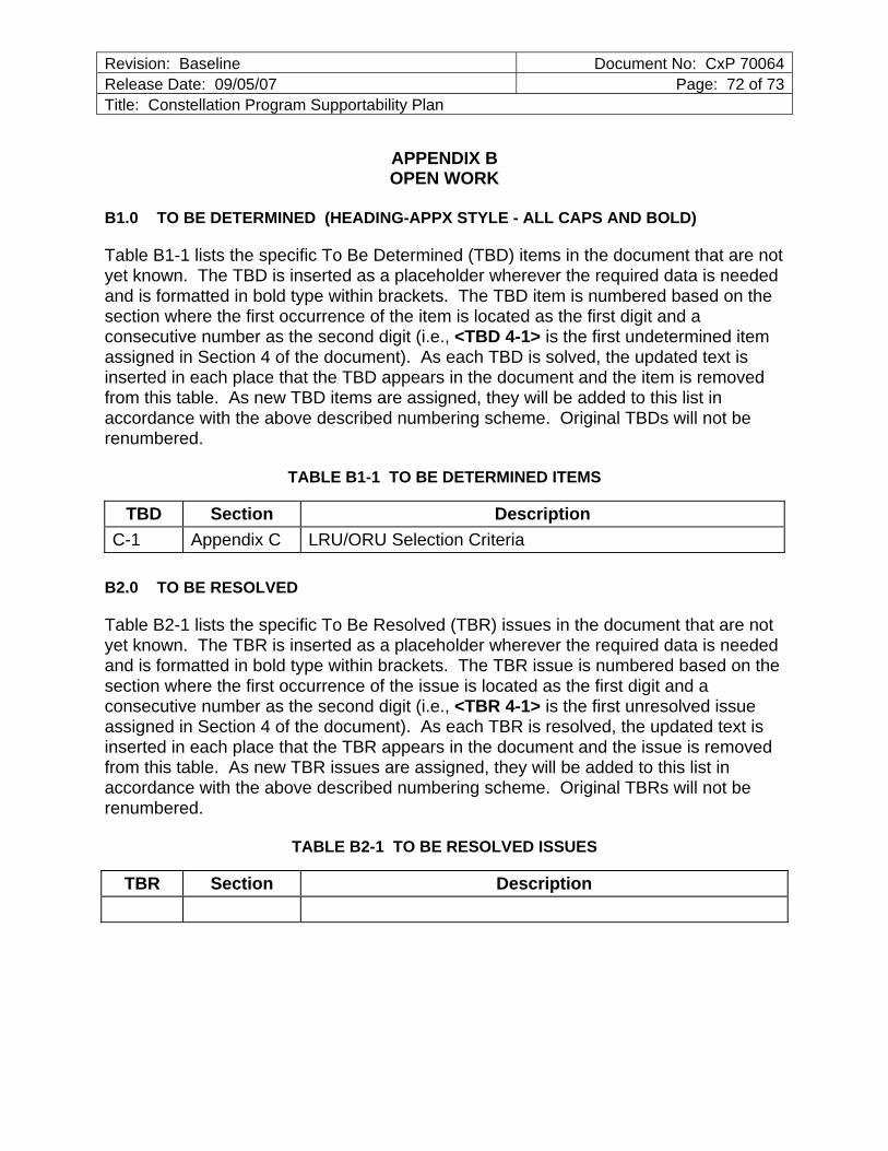
Revision: Baseline Document No: CxP 70064Release Date: 09/05/07 Page: 72 of 73Title: Constellation Program Supportability Plan
APPENDIX B OPEN WORK
B1.0 TO BE DETERMINED (HEADING-APPX STYLE - ALL CAPS AND BOLD)
Table B1-1 lists the specific To Be Determined (TBD) items in the document that are not yet known. The TBD is inserted as a placeholder wherever the required data is needed and is formatted in bold type within brackets. The TBD item is numbered based on the section where the first occurrence of the item is located as the first digit and a consecutive number as the second digit (i.e., <TBD 4-1> is the first undetermined item assigned in Section 4 of the document). As each TBD is solved, the updated text is inserted in each place that the TBD appears in the document and the item is removed from this table. As new TBD items are assigned, they will be added to this list in accordance with the above described numbering scheme. Original TBDs will not be renumbered.
TABLE B1-1 TO BE DETERMINED ITEMS
TBD Section Description C-1 Appendix C LRU/ORU Selection Criteria
B2.0 TO BE RESOLVED
Table B2-1 lists the specific To Be Resolved (TBR) issues in the document that are not yet known. The TBR is inserted as a placeholder wherever the required data is needed and is formatted in bold type within brackets. The TBR issue is numbered based on the section where the first occurrence of the issue is located as the first digit and a consecutive number as the second digit (i.e., <TBR 4-1> is the first unresolved issue assigned in Section 4 of the document). As each TBR is resolved, the updated text is inserted in each place that the TBR appears in the document and the issue is removed from this table. As new TBR issues are assigned, they will be added to this list in accordance with the above described numbering scheme. Original TBRs will not be renumbered.
TABLE B2-1 TO BE RESOLVED ISSUES
TBR Section Description

Revision: Baseline Document No: CxP 70064Release Date: 09/05/07 Page: 73 of 73Title: Constellation Program Supportability Plan
APPENDIX C LRU/ORU SELECTION CRITERIA
<TBD C-1>