Embed Size (px)
Citation preview
Reinhard Müller, Häny AG Phone +41 1 925 42 92 Fax +41 1 923 62 45 E-mail : [email protected]
CONTEMPORARY GROUTING EQUIPMENT
1. SUMMARY
Grouting was for a long time considered to be an art rather than a science. Much of that had to do with little knowledge of the reaction of the grout in the ground and the lack of measuring devices to record the most important parameters and the ability to compare and evaluate the results. With the developments in equipment and materials grouting is now more and more accepted as an efficient method for the treatment of soil and rock formations. In this presentation the view is focussed on equipment for cementicious grouts.
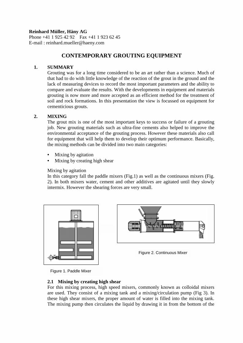
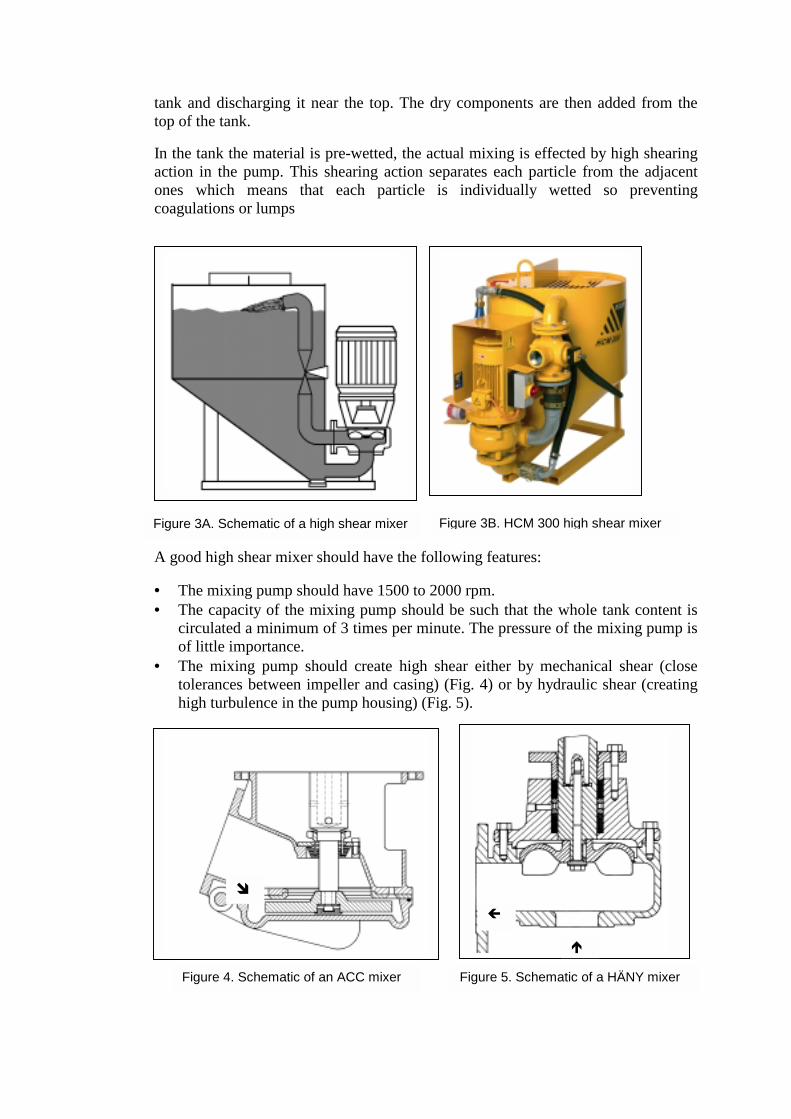
2. MIXING The grout mix is one of the most important keys to success or failure of a grouting job. New grouting materials such as ultra-fine cements also helped to improve the environmental acceptance of the grouting process. However these materials also call for equipment that will help them to develop their optimum performance. Basically, the mixing methods can be divided into two main categories: • Mixing by agitation • Mixing by creating high shear Mixing by agitation In this category fall the paddle mixers (Fig.1) as well as the continuous mixers (Fig. 2). In both mixers water, cement and other additives are agitated until they slowly intermix. However the shearing forces are very small.
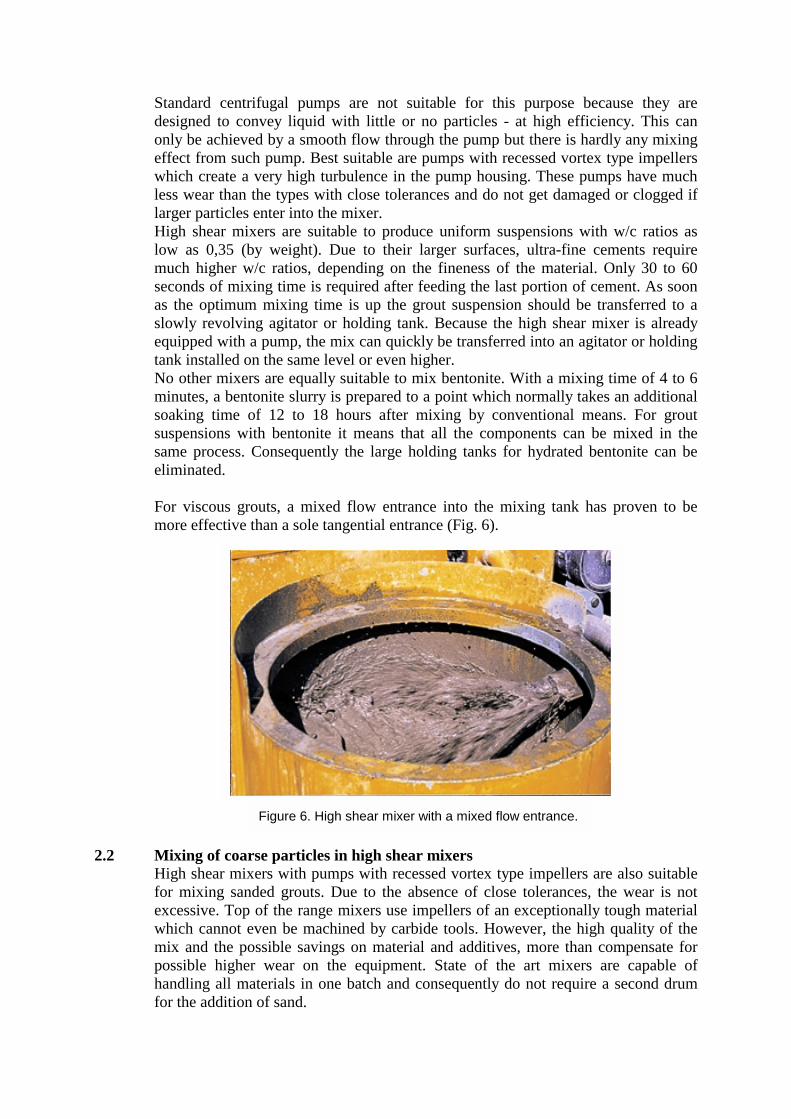
2.1 Mixing by creating high sheaFor this mixing process, high speedare used. They consist of a mixingthese high shear mixers, the properThe mixing pump then circulates thFigure 1. Paddle mixer
Figure 1. Paddle Mixer
r mixers, commonly known as colloidal mixers
tank and a mixing/circulation pump (Fig 3). In amount of water is filled into the mixing tank. e liquid by drawing it in from the bottom of the
Figure 2. Continuous Mixer
Figure 2. Continuous Mixer
tank and discharging it near the top. The dry components are then added from the top of the tank. In the tank the material is pre-wetted, the actual mixing is effected by high shearing action in the pump. This shearing action separates each particle from the adjacent ones which means that each particle is individually wetted so preventing coagulations or lumps A good high shear mixer should have the following features: • The mixing pump should have 1500 to 2000 rpm. • The capacity of the mixing pump should be such that the whole tank content is
circulated a minimum of 3 times per minute. The pressure of the mixing pump is of little importance.
• The mixing pump should create high shear either by mechanical shear (close tolerances between impeller and casing) (Fig. 4) or by hydraulic shear (creating high turbulence in the pump housing) (Fig. 5).
Figure 3A. Schematic of a high shear mixer
Figure 4. Schematic of an ACC mixer F
"
"
igure 5. Schema
#
!
Figure 3B. HCM 300 high shear mixer
tic of a HÄNY mixer
Standard centrifugal pumps are not suitable for this purpose because they are designed to convey liquid with little or no particles - at high efficiency. This can only be achieved by a smooth flow through the pump but there is hardly any mixing effect from such pump. Best suitable are pumps with recessed vortex type impellers which create a very high turbulence in the pump housing. These pumps have much less wear than the types with close tolerances and do not get damaged or clogged if larger particles enter into the mixer. High shear mixers are suitable to produce uniform suspensions with w/c ratios as low as 0,35 (by weight). Due to their larger surfaces, ultra-fine cements require much higher w/c ratios, depending on the fineness of the material. Only 30 to 60 seconds of mixing time is required after feeding the last portion of cement. As soon as the optimum mixing time is up the grout suspension should be transferred to a slowly revolving agitator or holding tank. Because the high shear mixer is already equipped with a pump, the mix can quickly be transferred into an agitator or holding tank installed on the same level or even higher. No other mixers are equally suitable to mix bentonite. With a mixing time of 4 to 6 minutes, a bentonite slurry is prepared to a point which normally takes an additional soaking time of 12 to 18 hours after mixing by conventional means. For grout suspensions with bentonite it means that all the components can be mixed in the same process. Consequently the large holding tanks for hydrated bentonite can be eliminated. For viscous grouts, a mixed flow entrance into the mixing tank has proven to be more effective than a sole tangential entrance (Fig. 6).
2.2 Mixing of coarse particles in high shear mixers
High shear mixers with pumps with recessed vortex type impellers are also suitable for mixing sanded grouts. Due to the absence of close tolerances, the wear is not excessive. Top of the range mixers use impellers of an exceptionally tough material which cannot even be machined by carbide tools. However, the high quality of the mix and the possible savings on material and additives, more than compensate for possible higher wear on the equipment. State of the art mixers are capable of handling all materials in one batch and consequently do not require a second drum for the addition of sand.
Figure 6. High shear mixer with a mixed flow entrance.
3. PUMPING
Almost equally important as the mixer is a careful selection of the grout pump. Today's technology offers to individually limit the grout pressure and flow rate according to the specific requirement of the job.
3.1 Single line grouting The above mentioned features make it possible to eliminate the complicated and unreliable system of return lines. The pressure is automatically controlled by the grout pump and does not require a header with a valve system and an operator to watch the pressure gauge and operate the valves accordingly.
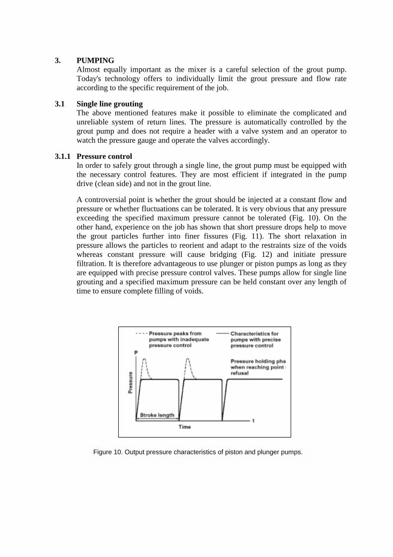
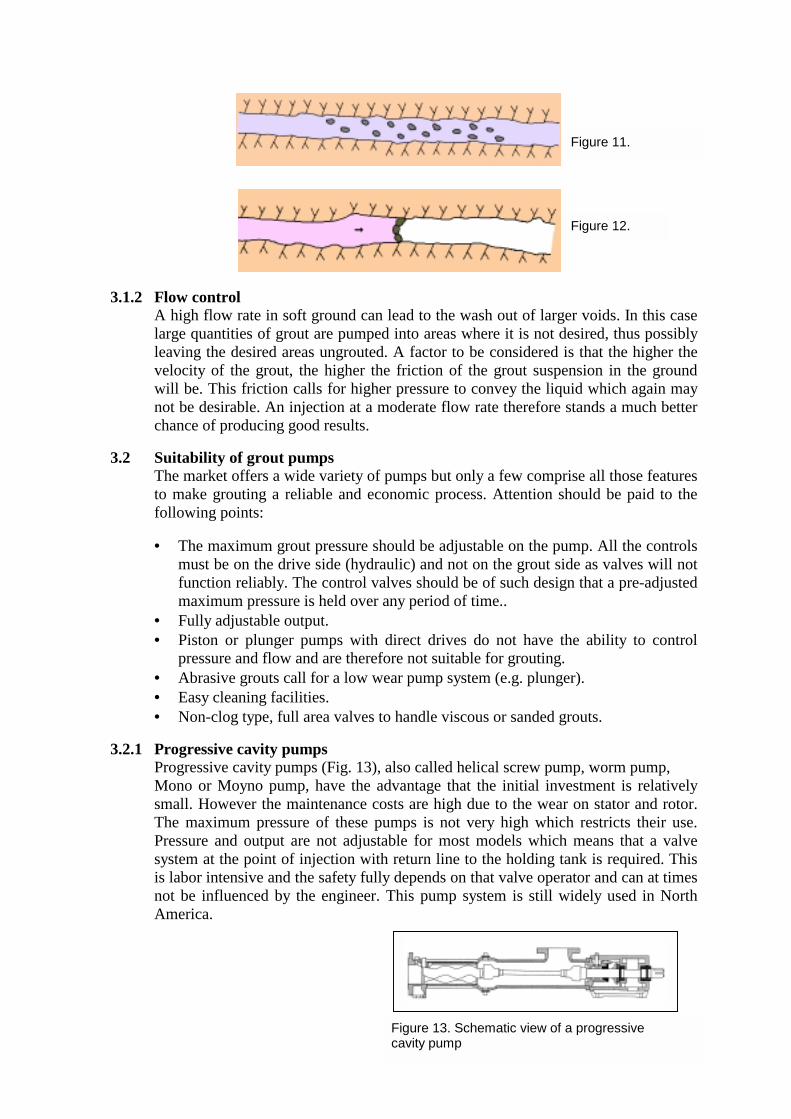
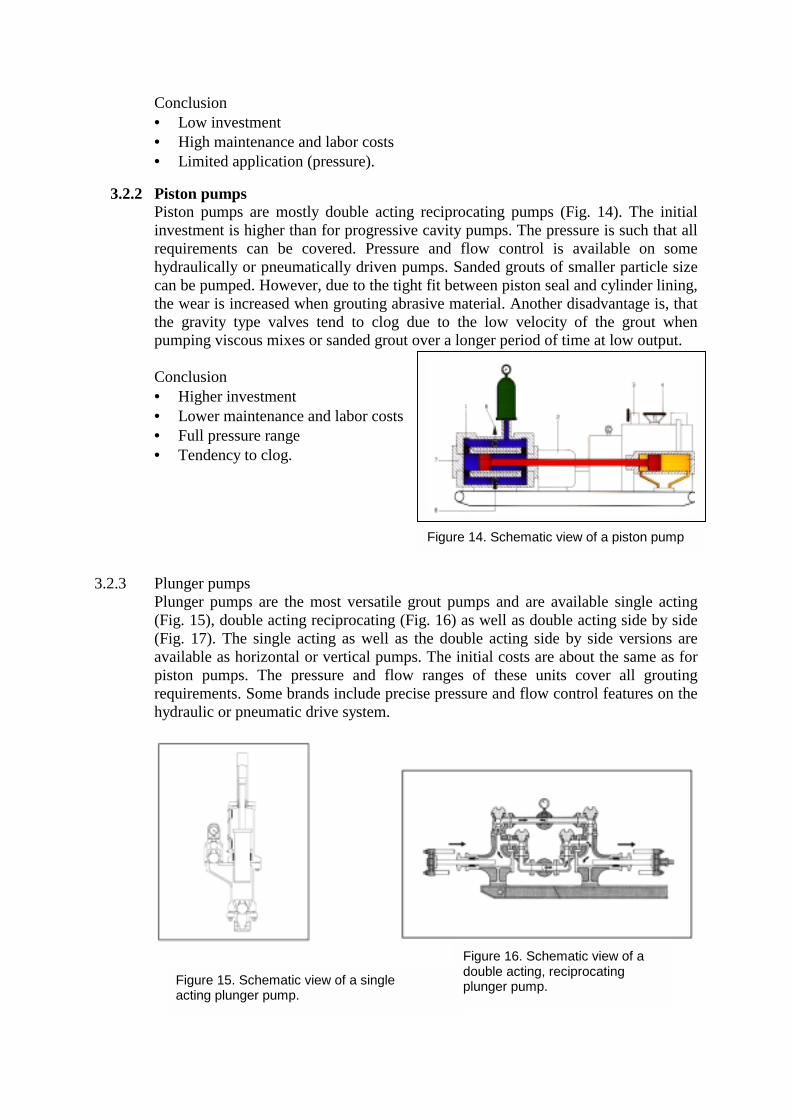
3.1.1 Pressure control In order to safely grout through a single line, the grout pump must be equipped with the necessary control features. They are most efficient if integrated in the pump drive (clean side) and not in the grout line. A controversial point is whether the grout should be injected at a constant flow and pressure or whether fluctuations can be tolerated. It is very obvious that any pressure exceeding the specified maximum pressure cannot be tolerated (Fig. 10). On the other hand, experience on the job has shown that short pressure drops help to move the grout particles further into finer fissures (Fig. 11). The short relaxation in pressure allows the particles to reorient and adapt to the restraints size of the voids whereas constant pressure will cause bridging (Fig. 12) and initiate pressure filtration. It is therefore advantageous to use plunger or piston pumps as long as they are equipped with precise pressure control valves. These pumps allow for single line grouting and a specified maximum pressure can be held constant over any length of time to ensure complete filling of voids.
Figure 10
. Output pressure characteristics of piston and plunger pumps.
3.1.2 Flow control
A high flow rate in soft ground can lead to the wash out of larger voids. In this case large quantities of grout are pumped into areas where it is not desired, thus possibly leaving the desired areas ungrouted. A factor to be considered is that the higher the velocity of the grout, the higher the friction of the grout suspension in the ground will be. This friction calls for higher pressure to convey the liquid which again may not be desirable. An injection at a moderate flow rate therefore stands a much better chance of producing good results.
3.2 Suitability of grout pumps The market offers a wide variety of pumps but only a few comprise all those features to make grouting a reliable and economic process. Attention should be paid to the following points: • The maximum grout pressure should be adjustable on the pump. All the controls
must be on the drive side (hydraulic) and not on the grout side as valves will not function reliably. The control valves should be of such design that a pre-adjusted maximum pressure is held over any period of time..
• Fully adjustable output. • Piston or plunger pumps with direct drives do not have the ability to control
pressure and flow and are therefore not suitable for grouting. • Abrasive grouts call for a low wear pump system (e.g. plunger). • Easy cleaning facilities. • Non-clog type, full area valves to handle viscous or sanded grouts.
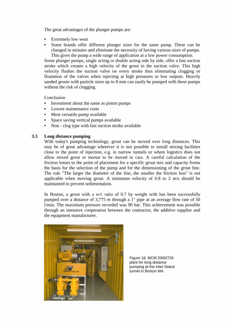
3.2.1 Progressive cavity pumps Progressive cavity pumps (Fig. 13), also called helical screw pump, worm pump, Mono or Moyno pump, have the advantage that the initial investment is relatively small. However the maintenance costs are high due to the wear on stator and rotor. The maximum pressure of these pumps is not very high which restricts their use. Pressure and output are not adjustable for most models which means that a valve system at the point of injection with return line to the holding tank is required. This is labor intensive and the safety fully depends on that valve operator and can at times not be influenced by the engineer. This pump system is still widely used in North America.
Fc
Figure 11.
Figure 12.
igure 13. Schematic view of a progressive avity pump
Conclusion • Low investment • High maintenance and labor costs • Limited application (pressure).
3.2.2 Piston pumps
Piston pumps are mostly double acting reciprocating pumps (Fig. 14). The initial investment is higher than for progressive cavity pumps. The pressure is such that all requirements can be covered. Pressure and flow control is available on some hydraulically or pneumatically driven pumps. Sanded grouts of smaller particle size can be pumped. However, due to the tight fit between piston seal and cylinder lining, the wear is increased when grouting abrasive material. Another disadvantage is, that the gravity type valves tend to clog due to the low velocity of the grout when pumping viscous mixes or sanded grout over a longer period of time at low output. Conclusion • Higher investment • Lower maintenance and labor costs • Full pressure range • Tendency to clog.
3.2.3 Plunger pumps
Plunger pumps are the most versatile gr(Fig. 15), double acting reciprocating (Fig(Fig. 17). The single acting as well as thavailable as horizontal or vertical pumps.piston pumps. The pressure and flow requirements. Some brands include precishydraulic or pneumatic drive system.
Figure 15. Schematic view of a single acting plunger pump.
out pumps and are available single acting . 16) as well as double acting side by side e double acting side by side versions are
The initial costs are about the same as for ranges of these units cover all grouting e pressure and flow control features on the
Figure 14. Schematic view of a piston pump
Figure 16. Schematic view of a double acting, reciprocating plunger pump.
The great advantages of the plunger pumps are: • Extremely low wear • Some brands offer different plunger sizes for the same pump. These can be
changed in minutes and eliminate the necessity of having various sizes of pumps. This gives the pump a wide range of application at a low power consumption.
Some plunger pumps, single acting or double acting side by side, offer a fast suction stroke which creates a high velocity of the grout in the suction valve. This high velocity flushes the suction valve on every stroke thus eliminating clogging or floatation of the valves when injecting at high pressures or low outputs. Heavily sanded grouts with particle sizes up to 8 mm can easily be pumped with these pumps without the risk of clogging. Conclusion • Investment about the same as piston pumps • Lowest maintenance costs • Most versatile pump available • Space saving vertical pumps available • Non - clog type with fast suction stroke available
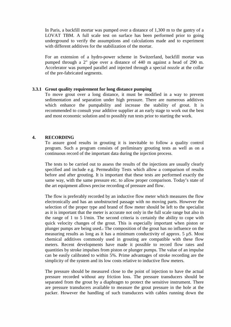
3.3 Long distance pumping With today's pumping technology, grout can be moved over long distances. This may be of great advantage wherever it is not possible to install mixing facilities close to the point of injection, e.g. in narrow tunnels or where logistics does not allow mixed grout or mortar to be moved in cars. A careful calculation of the friction losses to the point of placement for a specific grout mix and capacity forms the basis for the selection of the pump and for the dimensioning of the grout line. The rule "The larger the diameter of the line, the smaller the friction loss" is not applicable when moving grout. A minimum velocity of 0.8 to 2 m/s should be maintained to prevent sedimentation. In Boston, a grout with a w/c ratio of 0.7 by weight with has been successfully pumped over a distance of 3,775 m through a 1" pipe at an average flow rate of 50 l/min. The maximum pressure recorded was 90 bar. This achievement was possible through an intensive cooperation between the contractor, the additive supplier and the equipment manufacturer.
Figure 18. MCM 2000/726 plant for long distance pumping at the Inter-Island tunnel in Boston MA.
In Paris, a backfill mortar was pumped over a distance of 1,300 m to the gantry of a LOVAT TBM. A full scale test on surface has been performed prior to going underground to verify the assumptions and calculations made and to experiment with different additives for the stabilization of the mortar. For an extension of a hydro-power scheme in Switzerland, backfill mortar was pumped through a 2" pipe over a distance of 440 m against a head of 290 m. Accelerator was pumped parallel and injected through a special nozzle at the collar of the pre-fabricated segments.
3.3.1 Grout quality requirement for long distance pumping To move grout over a long distance, it must be modified in a way to prevent sedimentation and separation under high pressure. There are numerous additives which enhance the pumpability and increase the stability of grout. It is recommended to consult your additive supplier at an early stage to work out the best and most economic solution and to possibly run tests prior to starting the work.
4. RECORDING
To assure good results in grouting it is inevitable to follow a quality control program. Such a program consists of preliminary grouting tests as well as on a continuous record of the important data during the injection process. The tests to be carried out to assess the results of the injections are usually clearly specified and include e.g. Permeability Tests which allow a comparison of results before and after grouting. It is important that these tests are performed exactly the same way, with the same pressure etc. to allow proper comparison. Today’s state of the art equipment allows precise recording of pressure and flow. The flow is preferably recorded by an inductive flow meter which measures the flow electronically and has an unobstructed passage with no moving parts. However the selection of the proper type and brand of flow meter should be left to the specialist as it is important that the meter is accurate not only in the full scale range but also in the range of 1 to 5 l/min. The second criteria is certainly the ability to cope with quick velocity changes of the grout. This is especially important when piston or plunger pumps are being used.. The composition of the grout has no influence on the measuring results as long as it has a minimum conductivity of approx. 5 µS. Most chemical additives commonly used in grouting are compatible with these flow meters. Recent developments have made it possible to record flow rates and quantities by stroke impulses from piston or plunger pumps. The value of an impulse can be easily calibrated to within 5%. Prime advantages of stroke recording are the simplicity of the system and its low costs relative to inductive flow meters. The pressure should be measured close to the point of injection to have the actual pressure recorded without any friction loss. The pressure transducers should be separated from the grout by a diaphragm to protect the sensitive instrument. There are pressure transducers available to measure the grout pressure in the hole at the packer. However the handling of such transducers with cables running down the
hole require a lot of experience and care from the grouting crew. For permeability tests, which are usually carried out by an experienced engineer, the “down the hole” pressure recording method is more widely applied.
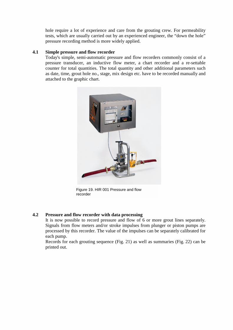
4.1 Simple pressure and flow recorder Today's simple, semi-automatic pressure and flow recorders commonly consist of a pressure transducer, an inductive flow meter, a chart recorder and a re-settable counter for total quantities. The total quantity and other additional parameters such as date, time, grout hole no., stage, mix design etc. have to be recorded manually and attached to the graphic chart.
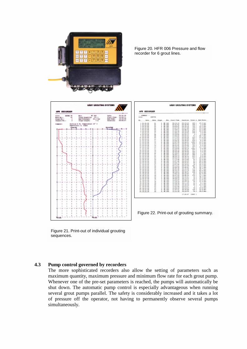
4.2 Pressure and f
It is now possiSignals from flprocessed by theach pump. Records for eacprinted out.
Figure 19. HIR 001 Pressure and flow recorder
low recorder with data processing ble to record pressure and flow of 6 or more grout lines separately. ow meters and/or stroke impulses from plunger or piston pumps are is recorder. The value of the impulses can be separately calibrated for
h grouting sequence (Fig. 21) as well as summaries (Fig. 22) can be
4.3 PuThmWshseofsim
Figure 20. HFR 006 Pressure and flow recorder for 6 grout lines.
Fs
mp control governed by recorders e more sophisticated recorders also al
aximum quantity, maximum pressure and henever one of the pre-set parameters is rut down. The automatic pump control isveral grout pumps parallel. The safety is pressure off the operator, not having
ultaneously.
igure 21. Print-out of individual grouting equences.
low the setting of parameters such as minimum flow rate for each grout pump. eached, the pumps will automatically be especially advantageous when running considerably increased and it takes a lot to permanently observe several pumps
Figure 22. Print-out of grouting summary.
5. AUTOMATED GROUT PLANTS
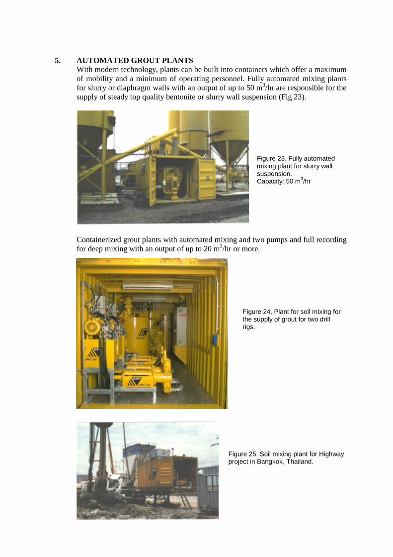
With modern technology, plants can be built into containers which offer a maximum of mobility and a minimum of operating personnel. Fully automated mixing plants for slurry or diaphragm walls with an output of up to 50 m3/hr are responsible for the supply of steady top quality bentonite or slurry wall suspension (Fig 23).
Containerized grout plants with automated mixing and two pumps and full recording for deep mixing with an output of up to 20 m3/hr or more.
Figure 24. Plant for soil mixing for the supply of grout for two drill rigs.
Figure 23. Fully automated mixing plant for slurry wall suspension. Capacity: 50 m3/hr
Figure 25. Soil mixing plant for Highway project in Bangkok, Thailand.
6.
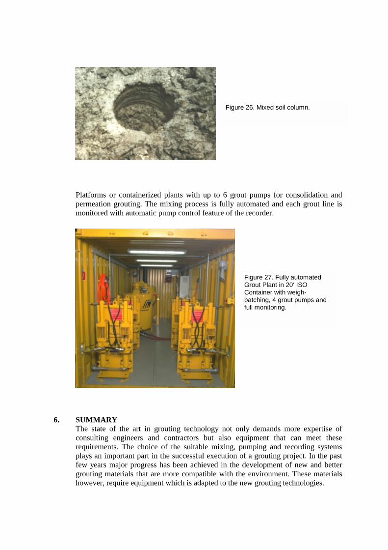
Platforms or containerized plants with up to 6 grout pumps for consolidation and permeation grouting. The mixing process is fully automated and each grout line is monitored with automatic pump control feature of the recorder.
SUMMARY The state of the art in grouting technology not only demands more expertise of consulting engineers and contractors but also equipment that can meet these requirements. The choice of the suitable mixing, pumping and recording systems plays an important part in the successful execution of a grouting project. In the past few years major progress has been achieved in the development of new and better grouting materials that are more compatible with the environment. These materials however, require equipment which is adapted to the new grouting technologies.
Figure 27. Fully automated Grout Plant in 20‘ ISO Container with weigh-batching, 4 grout pumps and full monitoring.
Figure 26. Mixed soil column.
Of significant importance are the mixers which have to prepare the grouting materials in such a way to reach their optimum characteristics. E.g. it does not make sense to mix ultra-fine cement in a paddle or continuous mixer as the resulting hydration of the cement particles in such mixers is insufficient. For these materials as well as for ordinary Portland Cement based grouts, high-shear mixers (colloidal mixers) should be used to assure full hydration of all particles and to prevent lumps of dry cement. In these mixers, homogenous and stable suspensions can be produced which do not tend to settle out of suspension and which displace free water in ground rather than getting diluted by it. Equally important are the grout pumps which must be capable of pumping different grouts, from thin suspensions to fairly viscous and sanded grouts, at exactly predefined maximum pressure and flow rate. There are a variety of pump systems available, each having its advantages and disadvantages. Important however is the choice of a system which complies with the demand for precise pressure and flow control. A further important factor is the recording of data about a grouting project which are essential in the analysis of success or failure of a specific method. The ability to look into records of comparable projects are invaluable. The data collection can be done manually or with equipment which ranges from simple pressure recorders to fully computerized data logging of all important parameters.
References:
Houlsby, A.C. (1990), “Construction and design of Cement Grouting”, New York, John Wiley & Sons. Widmann R., ISRM (1996), “Commission on Rock Grouting”, Elsevier Science Ltd. Kutzner, C. (1991), “Injektionen im Baugrund,” Stuttgart Enke Müller R. (1993), “Geräte für die moderne Injektionstechnik”, Proceedings of the International Conference on Grouting in Rock and Concrete, Salzburg, Austria, October 11-12. Pp. 185-193. Klug D. R., Gause C. and Page T. L. (1999), “An engineered Grouting System developed for the Inter-Island Tunnel Boston, Massachusetts”, Proceedings of theRapid Excavation and Tunneling Conference, Orlando, Florida, June 21-23, pp. 439-454