Embed Size (px)
Citation preview
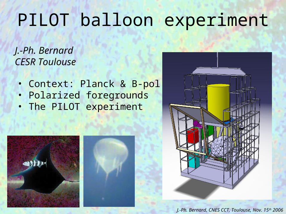
• Context: Planck & B-pol • Polarized foregrounds• The PILOT experiment
J.-Ph. Bernard CESR Toulouse
PILOT balloon experiment
J.-Ph. Bernard, CNES CCT, Toulouse, Nov. 15th 2006
PILOT:Science Objectives
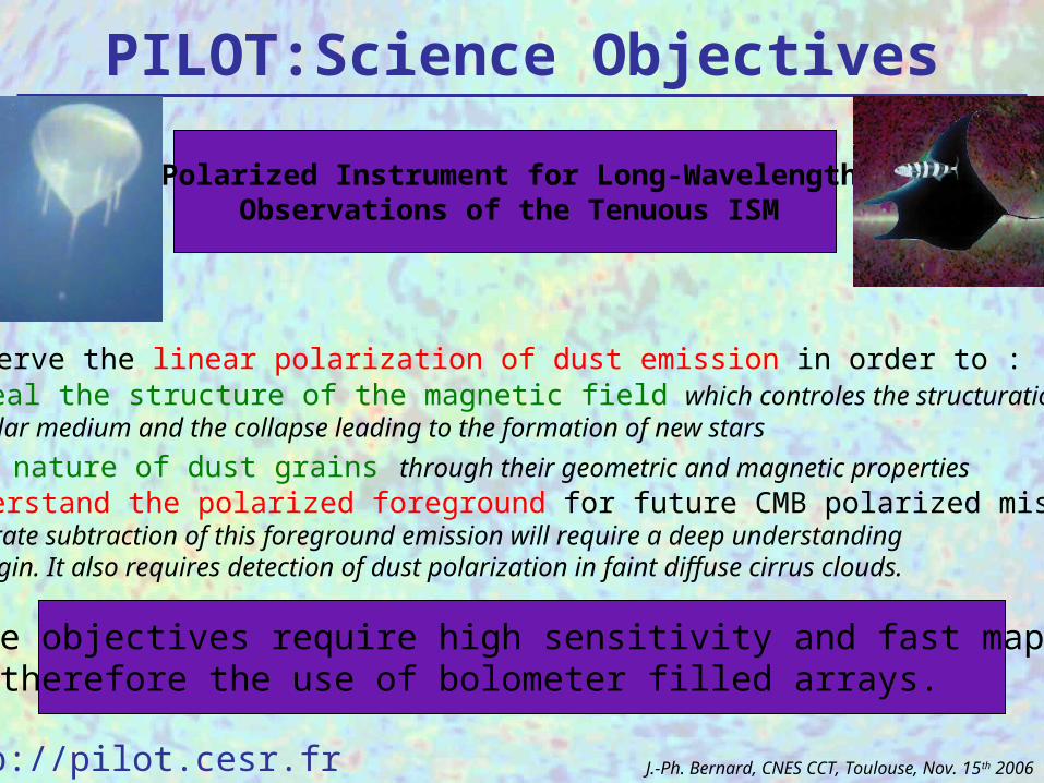
• Observe the linear polarization of dust emission in order to :- Reveal the structure of the magnetic field which controles the structuration of theInterstellar medium and the collapse leading to the formation of new stars
- The nature of dust grains through their geometric and magnetic properties• Understand the polarized foreground for future CMB polarized missionsAn accurate subtraction of this foreground emission will require a deep understandingof its origin. It also requires detection of dust polarization in faint diffuse cirrus clouds.
These objectives require high sensitivity and fast mappingand therefore the use of bolometer filled arrays.
Polarized Instrument for Long-WavelengthObservations of the Tenuous ISM
http://pilot.cesr.fr J.-Ph. Bernard, CNES CCT, Toulouse, Nov. 15th 2006
PILOT:Consortium
France:CESR Toulouse (J.P. Bernard, C. Marty)IAS Orsay (B. Leriche)CEA Saclay (L. Rodriguez)CNES Toulouse (Div ballon)Europe:ESTEC Netherlands: (J. Tauber, G. Pilbrat)Cardiff U. UK (M. Griffin, P. Hargrave)Manchester U. UK (B. Maffei)Roma Italy (S. Masi, P. deBernardis)
J.-Ph. Bernard, CNES CCT, Toulouse, Nov. 15th 2006
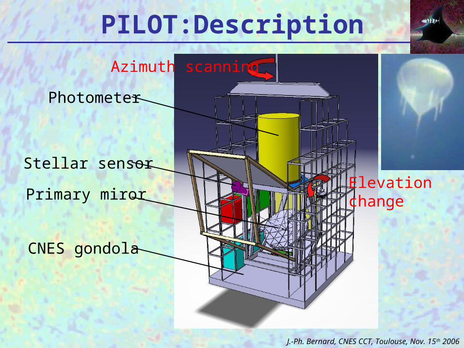
Azimuth scanning
Elevationchange
PILOT:Description
Photometer
Primary miror
Stellar sensor
CNES gondola
J.-Ph. Bernard, CNES CCT, Toulouse, Nov. 15th 2006
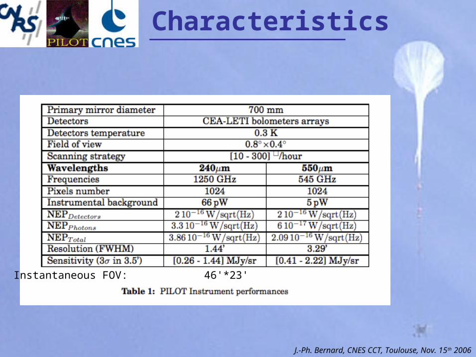
Characteristics
Instantaneous FOV: 46'*23'
J.-Ph. Bernard, CNES CCT, Toulouse, Nov. 15th 2006
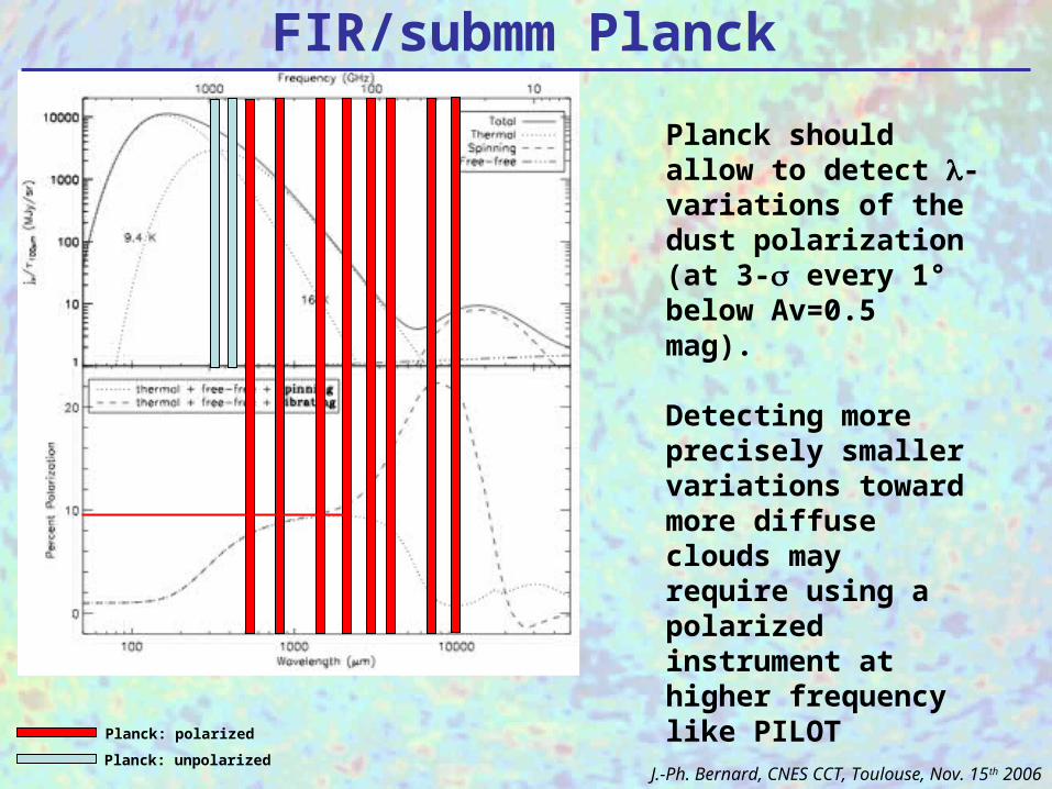
FIR/submm Planck
Planck should allow to detect -variations of the dust polarization(at 3- every 1° below Av=0.5 mag).
Detecting more precisely smaller variations toward more diffuse clouds may require using a polarized instrument at higher frequency like PILOT
Planck: unpolarized
Planck: polarized
J.-Ph. Bernard, CNES CCT, Toulouse, Nov. 15th 2006
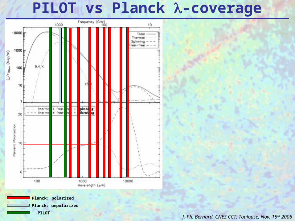
Planck: unpolarized
PILOT
Planck: polarized
PILOT vs Planck -coverage
J.-Ph. Bernard, CNES CCT, Toulouse, Nov. 15th 2006
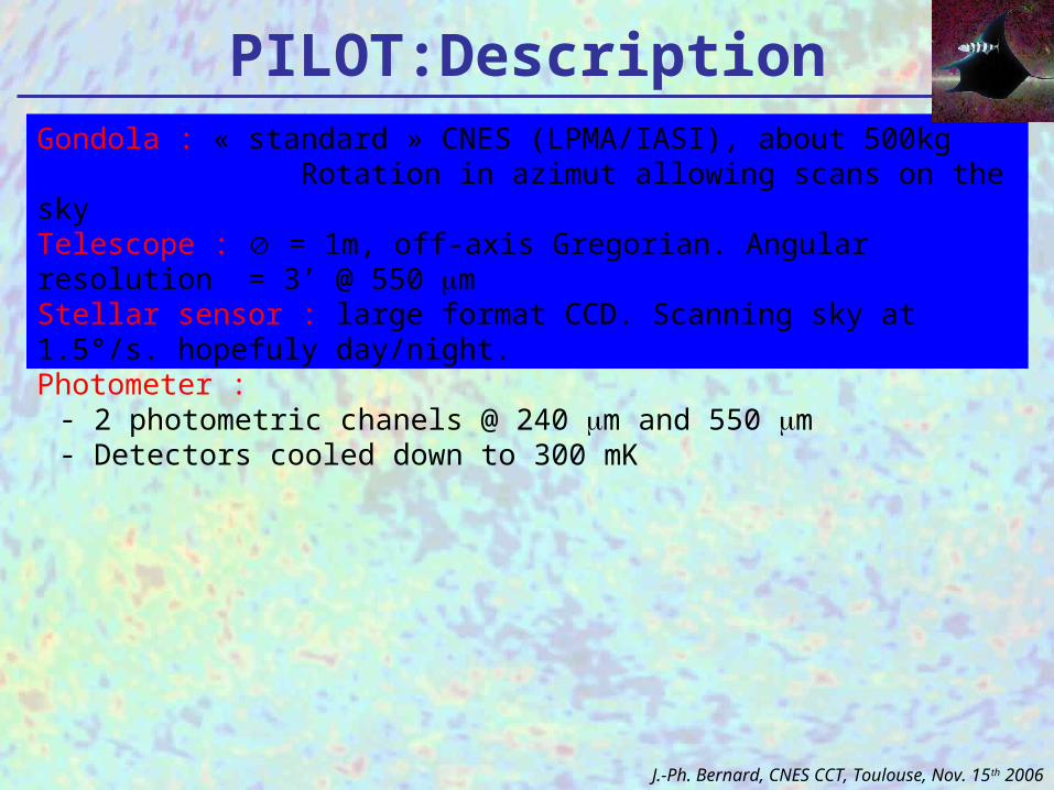
Gondola : « standard » CNES (LPMA/IASI), about 500kg Rotation in azimut allowing scans on the skyTelescope : = 1m, off-axis Gregorian. Angular resolution = 3’ @ 550 mStellar sensor : large format CCD. Scanning sky at 1.5°/s. hopefuly day/night.Photometer :
- 2 photometric chanels @ 240 m and 550 m- Detectors cooled down to 300 mK
PILOT:Description
J.-Ph. Bernard, CNES CCT, Toulouse, Nov. 15th 2006
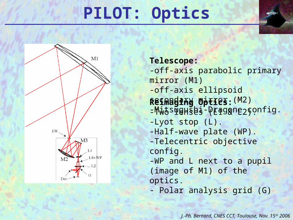
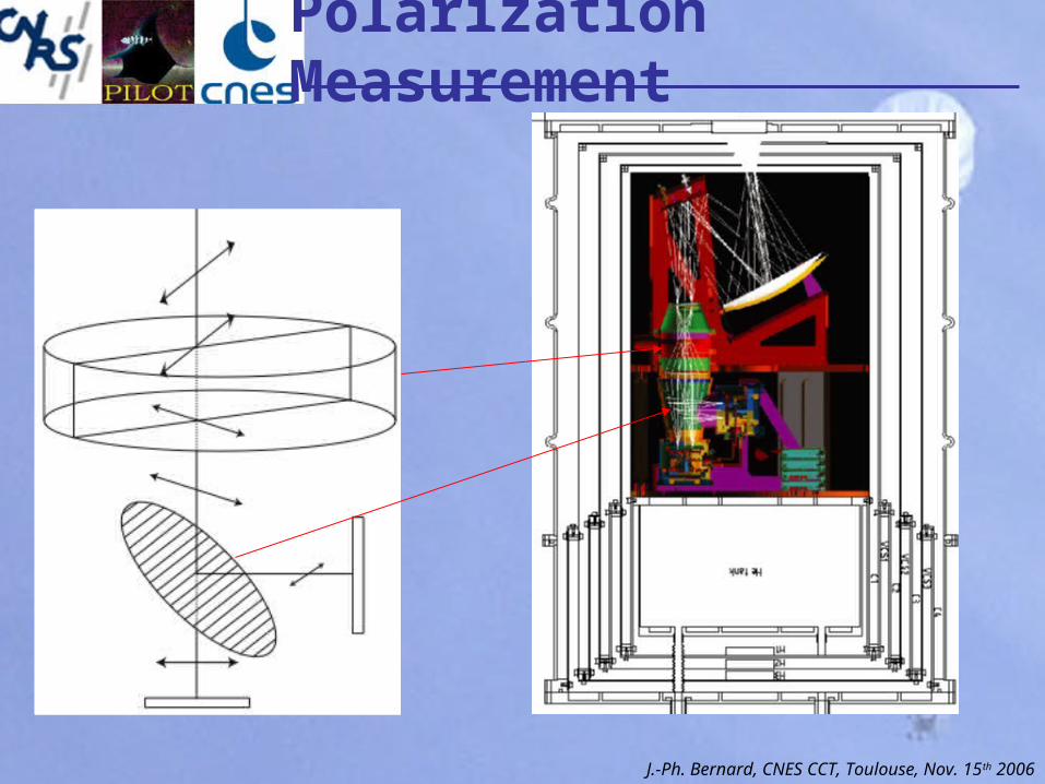
PILOT: Optics
Telescope:-off-axis parabolic primary mirror (M1)-off-axis ellipsoid secondary mirror (M2)-Mitsugushi-Dragone config.
Reimaging Optics:-Two lenses (L1 & L2).-Lyot stop (L).-Half-wave plate (WP).-Telecentric objective config.-WP and L next to a pupil (image of M1) of the optics.- Polar analysis grid (G)
J.-Ph. Bernard, CNES CCT, Toulouse, Nov. 15th 2006
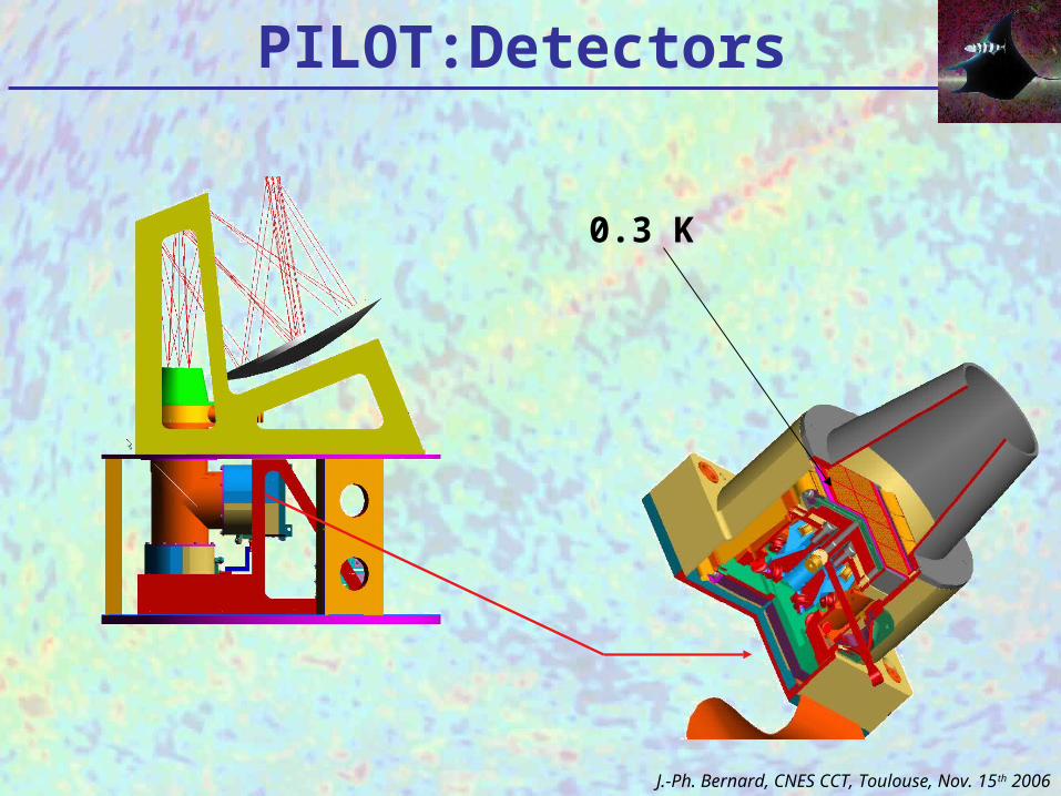
PILOT:Detectors
J.-Ph. Bernard, CNES CCT, Toulouse, Nov. 15th 2006
0.3 K
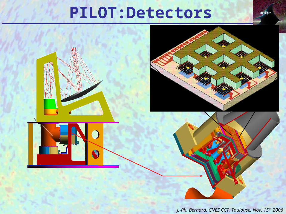
PILOT:Detectors
J.-Ph. Bernard, CNES CCT, Toulouse, Nov. 15th 2006
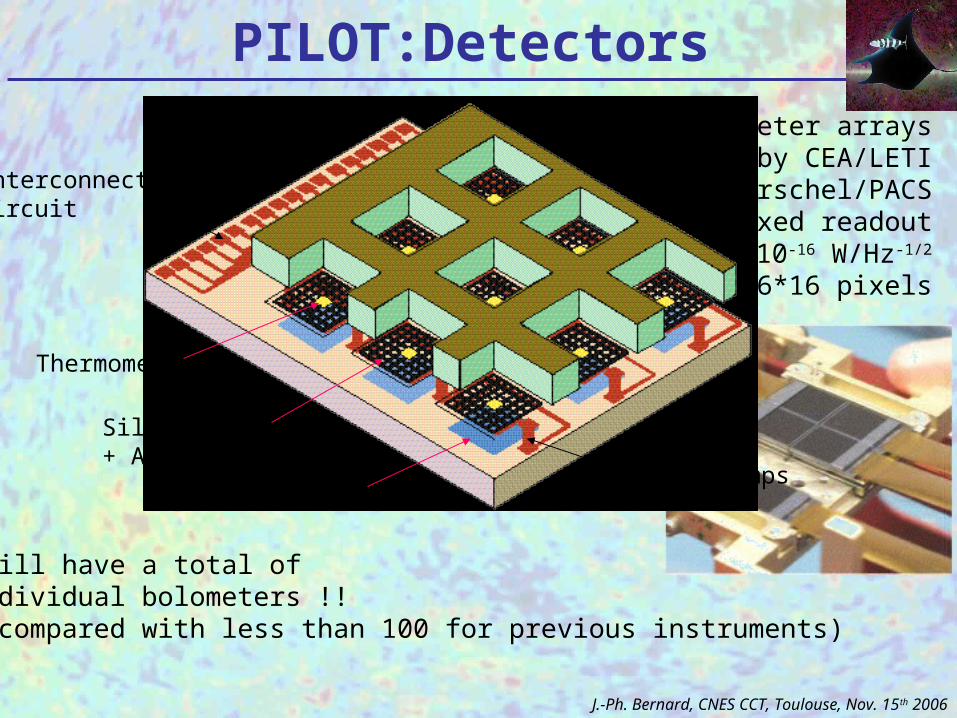
Bolometer arrays developped by CEA/LETI for Herschel/PACS
multiplexed readoutNEP = 2 10-16 W/Hz-1/2
16*16 pixels
PILOT:Detectors
InterconnectionCircuit
Thermometer
Silicon Grid+ Absorber
ReflectorIndium Bumps
J.-Ph. Bernard, CNES CCT, Toulouse, Nov. 15th 2006
PILOT will have a total of2048 individual bolometers !!(to be compared with less than 100 for previous instruments)
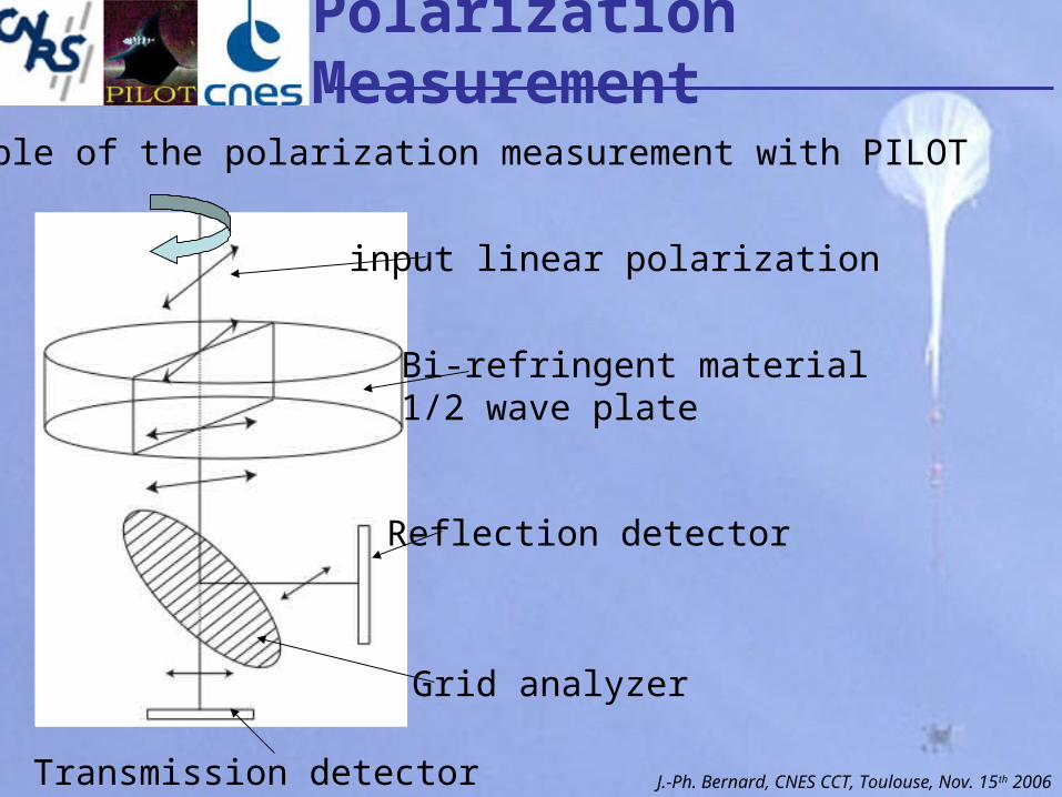
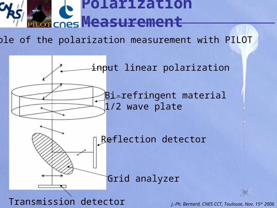
Principle of the polarization measurement with PILOT
Bi-refringent material1/2 wave plate
input linear polarization
Grid analyzer
Transmission detector
Reflection detector
Polarization Measurement
J.-Ph. Bernard, CNES CCT, Toulouse, Nov. 15th 2006
Principle of the polarization measurement with PILOT
input linear polarization
Grid analyzer
Transmission detector
Reflection detector
Polarization Measurement
J.-Ph. Bernard, CNES CCT, Toulouse, Nov. 15th 2006
Bi-refringent material1/2 wave plate
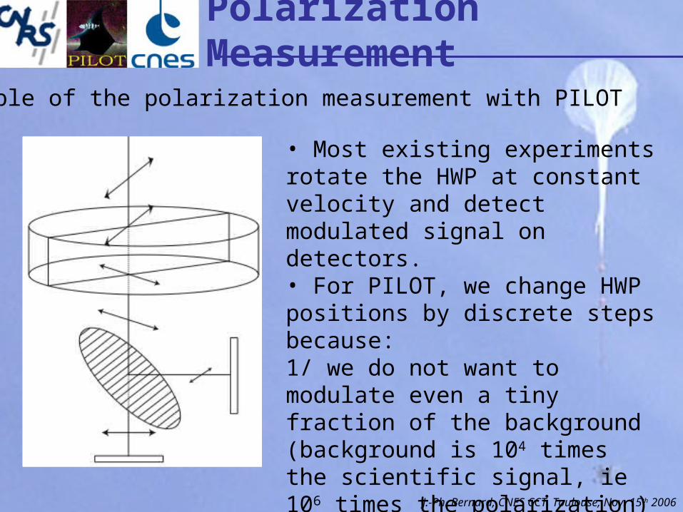
Principle of the polarization measurement with PILOT
• Most existing experiments rotate the HWP at constant velocity and detect modulated signal on detectors.• For PILOT, we change HWP positions by discrete steps because:1/ we do not want to modulate even a tiny fraction of the background(background is 104 times the scientific signal, ie 106 times the polarization)2/ sky mapping while spinning would be too fast for the available detectors.
Polarization Measurement
J.-Ph. Bernard, CNES CCT, Toulouse, Nov. 15th 2006
Polarization Measurement
J.-Ph. Bernard, CNES CCT, Toulouse, Nov. 15th 2006
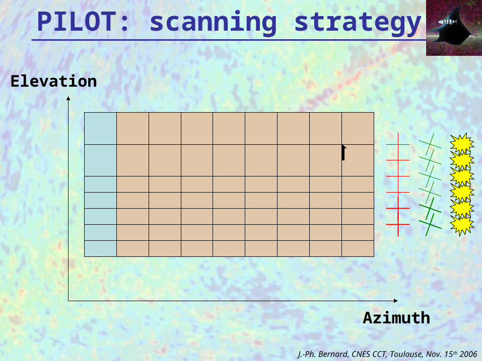
PILOT: scanning strategy
Azimuth
Elevation
550
m
240
mJ.-Ph. Bernard, CNES CCT, Toulouse, Nov. 15th 2006
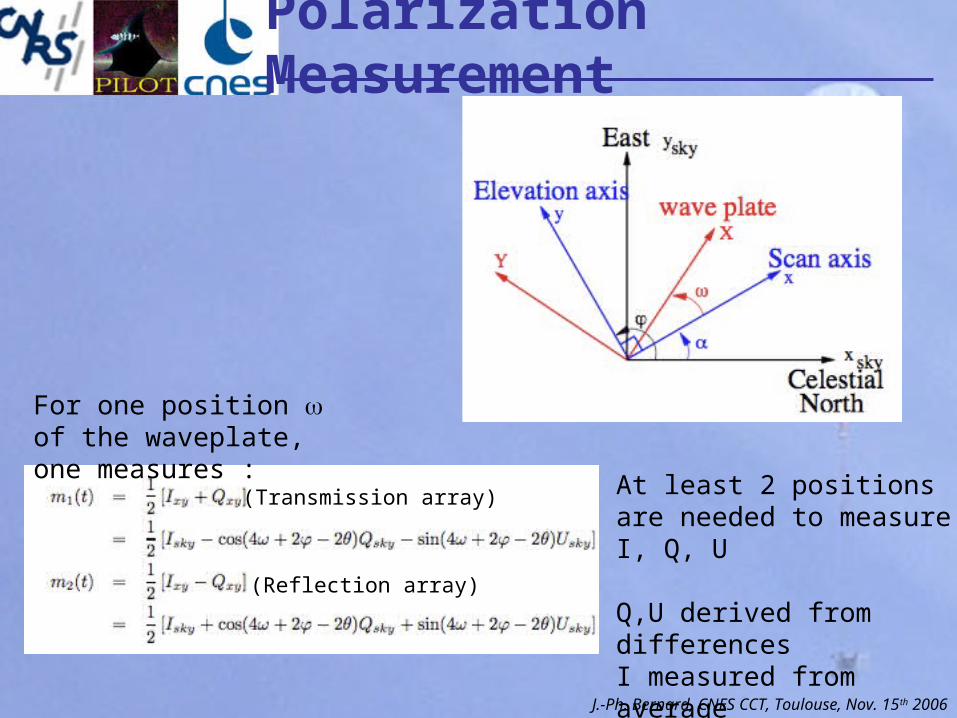
For one position of the waveplate, one measures :
At least 2 positions are needed to measure I, Q, U
Q,U derived from differencesI measured from average
(Transmission array)
(Reflection array)
Polarization Measurement
J.-Ph. Bernard, CNES CCT, Toulouse, Nov. 15th 2006
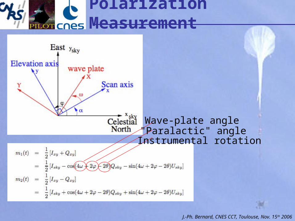
Wave-plate angle"Paralactic" angleInstrumental rotation
Polarization Measurement
J.-Ph. Bernard, CNES CCT, Toulouse, Nov. 15th 2006
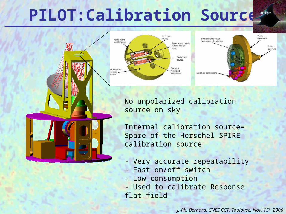
PILOT:Calibration Source
No unpolarized calibration source on sky
Internal calibration source=Spare of the Herschel SPIRE calibration source
- Very accurate repeatability- Fast on/off switch- Low consumption- Used to calibrate Response flat-field
J.-Ph. Bernard, CNES CCT, Toulouse, Nov. 15th 2006
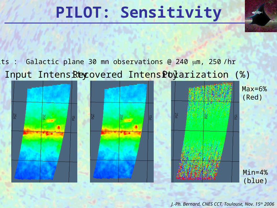
PILOT: Sensitivity
Results : Galactic plane 30 mn observations @ 240 m, 250 �/hr
Input Intensity Recovered Intensity Polarization (%)
Max=6%(Red)
Min=4%(blue)
J.-Ph. Bernard, CNES CCT, Toulouse, Nov. 15th 2006
Simulations
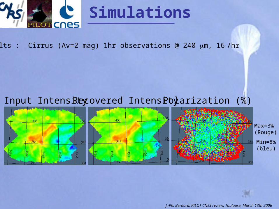
Results : Cirrus (Av=2 mag) 1hr observations @ 240 m, 16 �/hr
Input Intensity Recovered Intensity Polarization (%)
Max=3%(Rouge)
Min=8%(bleu)
J.-Ph. Bernard, PILOT CNES review, Toulouse, March 13th 2006
Mission Planning
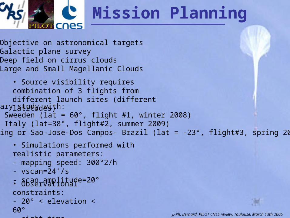
• Objective on astronomical targets- Galactic plane survey- Deep field on cirrus clouds- Large and Small Magellanic Clouds
• Source visibility requires combination of 3 flights from different launch sites (different latitudes)
• Preliminary study with:- Kiruna - Sweeden (lat = 60°, flight #1, winter 2008)-Trapani - Italy (lat=38°, flight#2, summer 2009)-Alice-Spring or Sao-Jose-Dos Campos- Brazil (lat = -23°, flight#3, spring 2010)
• Simulations performed with realistic parameters:- mapping speed: 300°2/h- vscan=24'/s- scan amplitude=20°
• Observational constraints:- 20° < elevation < 60°- night-time observations only
J.-Ph. Bernard, PILOT CNES review, Toulouse, March 13th 2006
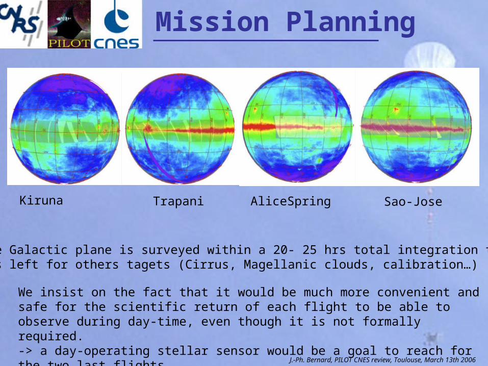
~ 90% of the Galactic plane is surveyed within a 20- 25 hrs total integration time 12 to 16 hrs left for others tagets (Cirrus, Magellanic clouds, calibration…)
We insist on the fact that it would be much more convenient and safe for the scientific return of each flight to be able to observe during day-time, even though it is not formally required. -> a day-operating stellar sensor would be a goal to reach for the two last flights.
Kiruna Trapani AliceSpring Sao-Jose
Mission Planning
J.-Ph. Bernard, PILOT CNES review, Toulouse, March 13th 2006
The END
PILOT
http://pilot.cesr.fr
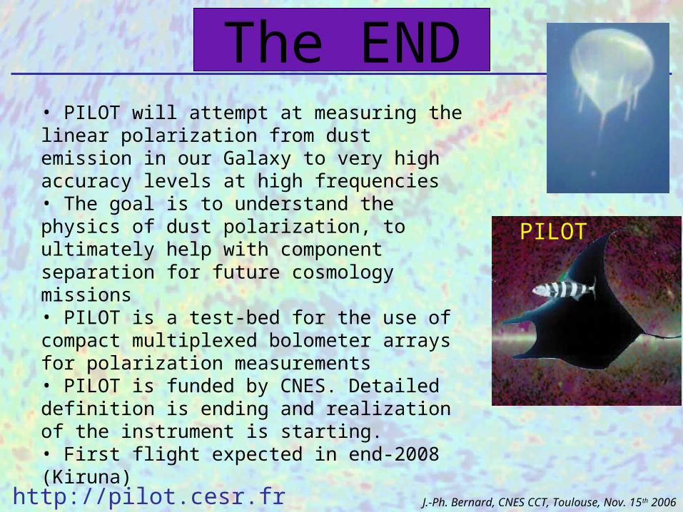
• PILOT will attempt at measuring the linear polarization from dust emission in our Galaxy to very high accuracy levels at high frequencies• The goal is to understand the physics of dust polarization, to ultimately help with component separation for future cosmology missions• PILOT is a test-bed for the use of compact multiplexed bolometer arrays for polarization measurements• PILOT is funded by CNES. Detailed definition is ending and realization of the instrument is starting. • First flight expected in end-2008 (Kiruna)
J.-Ph. Bernard, CNES CCT, Toulouse, Nov. 15th 2006
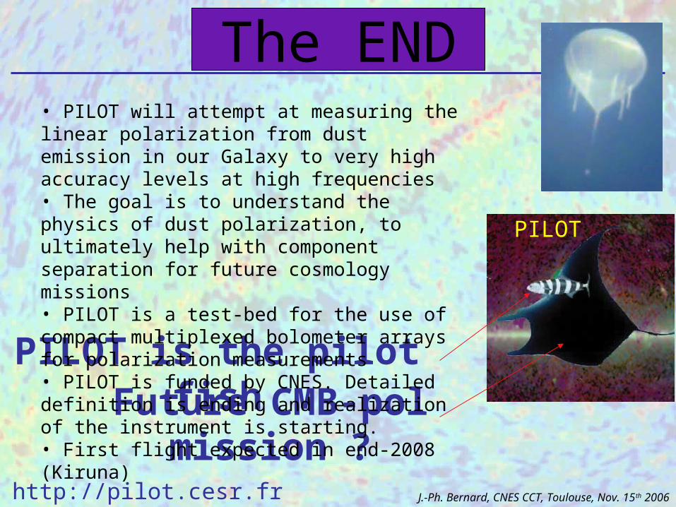
The END
PILOT is the pilot fishFuture CMB-pol mission ?
PILOT
http://pilot.cesr.fr J.-Ph. Bernard, CNES CCT, Toulouse, Nov. 15th 2006
• PILOT will attempt at measuring the linear polarization from dust emission in our Galaxy to very high accuracy levels at high frequencies• The goal is to understand the physics of dust polarization, to ultimately help with component separation for future cosmology missions• PILOT is a test-bed for the use of compact multiplexed bolometer arrays for polarization measurements• PILOT is funded by CNES. Detailed definition is ending and realization of the instrument is starting. • First flight expected in end-2008 (Kiruna)
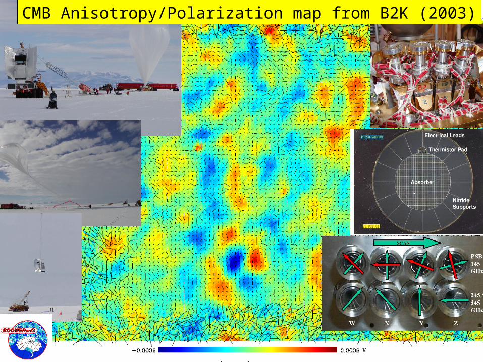
CMB Anisotropy/Polarization map from B2K (2003)
BOOMERanG-FG• We plan to re-fly B03 with an
upgraded forcal plane, to go after foreground cirrus dust polarization.
• This information is essential for all the planned B-modes experiments (e.g. BICEP, Dome-C etc.) and is very difficult to measure from ground.
• The BOOMERanG optics can host an array of >100 PSB at >350 GHz.
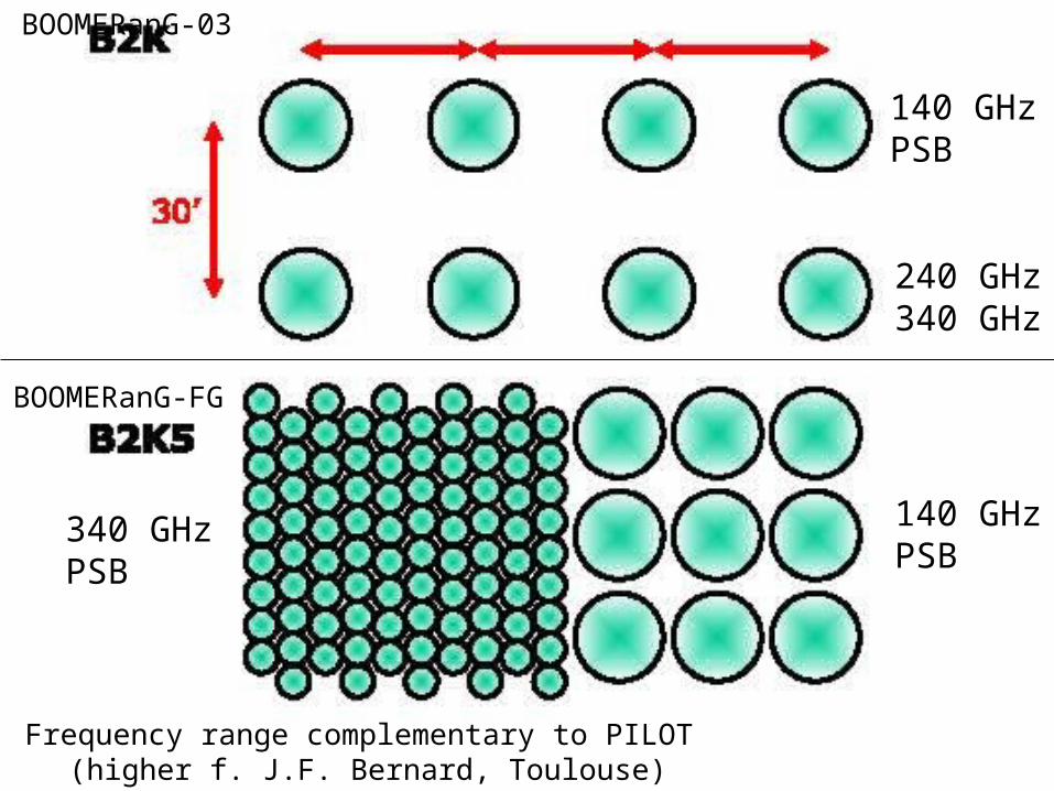
140 GHzPSB
240 GHz340 GHz
340 GHzPSB
140 GHzPSB
BOOMERanG-03
BOOMERanG-FG
Frequency range complementary to PILOT (higher f. J.F. Bernard, Toulouse)
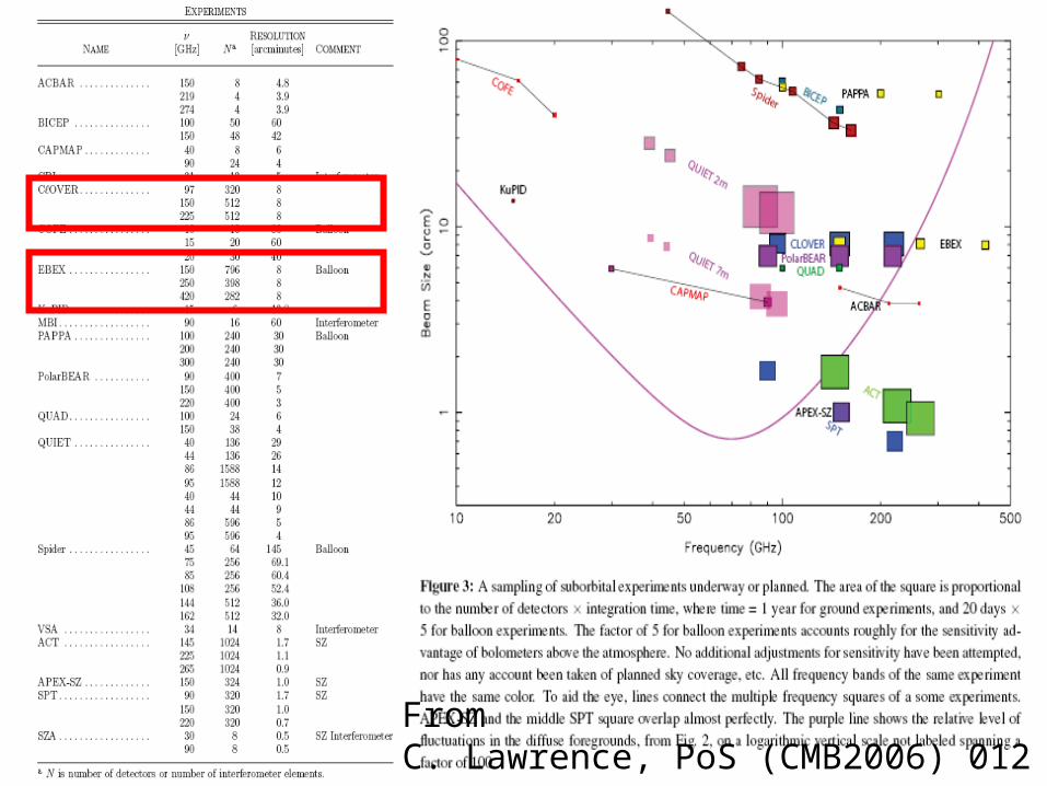
From C. Lawrence, PoS (CMB2006) 012