Embed Size (px)
Citation preview
PRE1382(2)
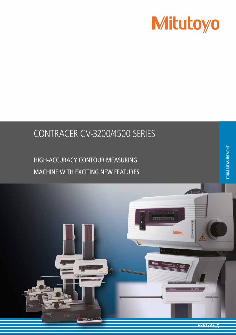
CONTRACER CV-3200/4500 SERIES
FORM
MEA
SURE
MEN
T
HIGH-ACCURACY CONTOUR MEASURING
MACHINE WITH EXCITING NEW FEATURES
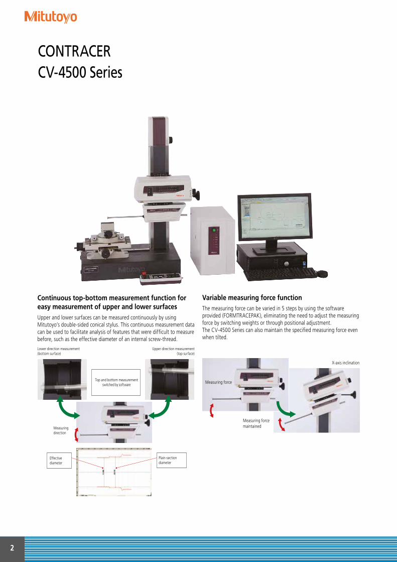
Continuous top-bottom measurement function for easy measurement of upper and lower surfacesUpper and lower surfaces can be measured continuously by using Mitutoyo’s double-sided conical stylus. This continuous measurement data can be used to facilitate analysis of features that were difficult to measure before, such as the effective diameter of an internal screw-thread.
Variable measuring force functionThe measuring force can be varied in 5 steps by using the software provided (FORMTRACEPAK), eliminating the need to adjust the measuring force by switching weights or through positional adjustment. The CV-4500 Series can also maintain the specified measuring force even when tilted.
Lower direction measurement (bottom surface)
Measuring direction
Top and bottom measurement switched by software
Upper direction measurement (top surface)
X-axis inclination
Effective diameter
Plain-section diameter
Measuring force
Measuring force maintained
2
CONTRACER CV-4500 Series
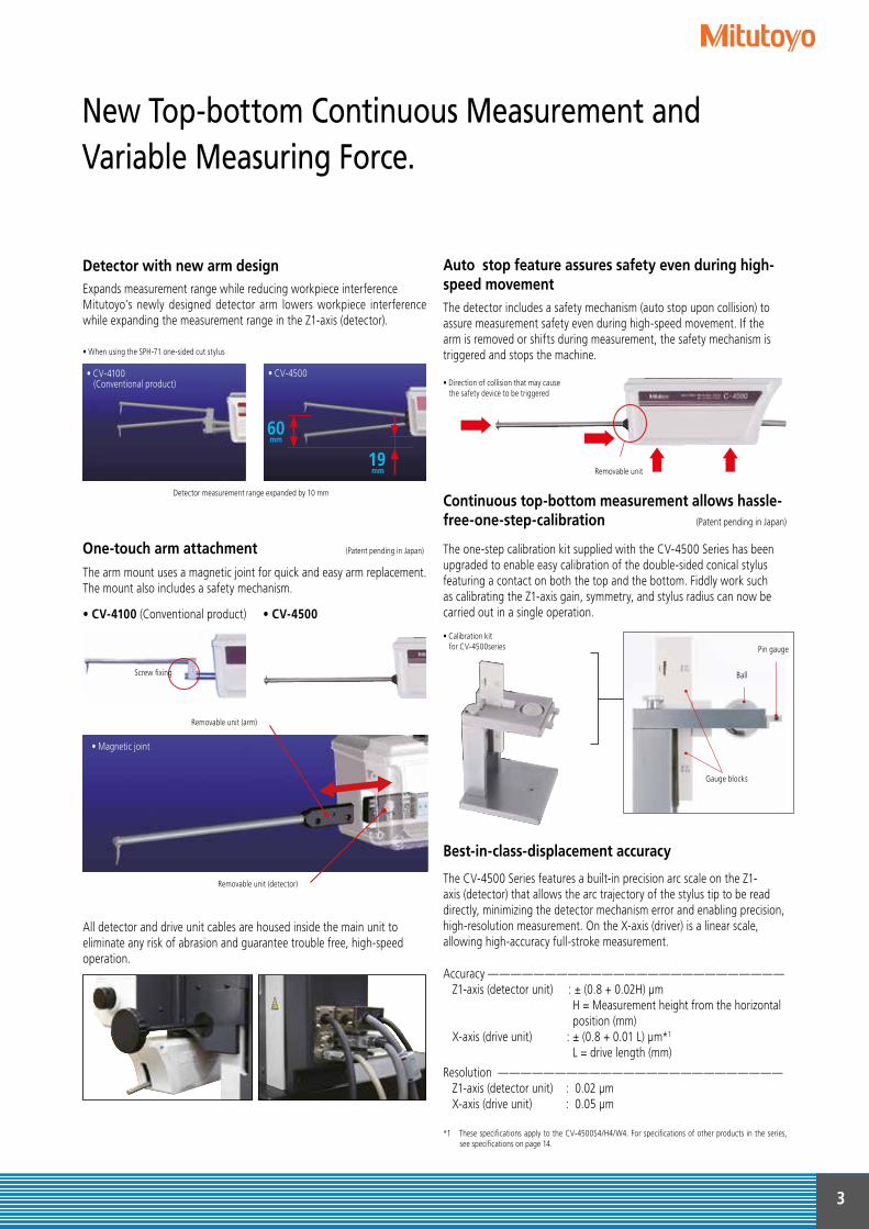
Detector with new arm design Auto stop feature assures safety even during high-speed movement
One-touch arm attachment (Patent pending in Japan)
Expands measurement range while reducing workpiece interferenceMitutoyo’s newly designed detector arm lowers workpiece interference while expanding the measurement range in the Z1-axis (detector).
Detector measurement range expanded by 10 mm
50mm
10 mm
• CV-4100 (Conventional product)
60mm
19 mm
• CV-4500
• When using the SPH-71 one-sided cut stylus
Screw fixing
The arm mount uses a magnetic joint for quick and easy arm replacement. The mount also includes a safety mechanism.
• CV-4100 (Conventional product) • CV-4500
All detector and drive unit cables are housed inside the main unit to eliminate any risk of abrasion and guarantee trouble free, high-speed operation.
Removable unit
• Direction of collision that may cause the safety device to be triggered
The detector includes a safety mechanism (auto stop upon collision) to assure measurement safety even during high-speed movement. If the arm is removed or shifts during measurement, the safety mechanism is triggered and stops the machine.
Continuous top-bottom measurement allows hassle-free-one-step-calibration (Patent pending in Japan)
Best-in-class-displacement accuracy
The CV-4500 Series features a built-in precision arc scale on the Z1-axis (detector) that allows the arc trajectory of the stylus tip to be read directly, minimizing the detector mechanism error and enabling precision, high-resolution measurement. On the X-axis (driver) is a linear scale, allowing high-accuracy full-stroke measurement.
Accuracy —————————————————————————— Z1-axis (detector unit) : ± (0.8 + 0.02H) μm H = Measurement height from the horizontal position (mm) X-axis (drive unit) : ± (0.8 + 0.01 L) μm*1
L = drive length (mm)
Resolution ————————————————————————— Z1-axis (detector unit) : 0.02 μm X-axis (drive unit) : 0.05 μm
*1 These specifications apply to the CV-4500S4/H4/W4. For specifications of other products in the series, see specifications on page 14.
The one-step calibration kit supplied with the CV-4500 Series has been upgraded to enable easy calibration of the double-sided conical stylus featuring a contact on both the top and the bottom. Fiddly work such as calibrating the Z1-axis gain, symmetry, and stylus radius can now be carried out in a single operation.
• Calibration kit for CV-4500series
Ball
Pin gauge
Gauge blocks
• Magnetic joint
Removable unit (arm)
Removable unit (detector)
• CV-4100 (Conventional product)
3
New Top-bottom Continuous Measurement and Variable Measuring Force.
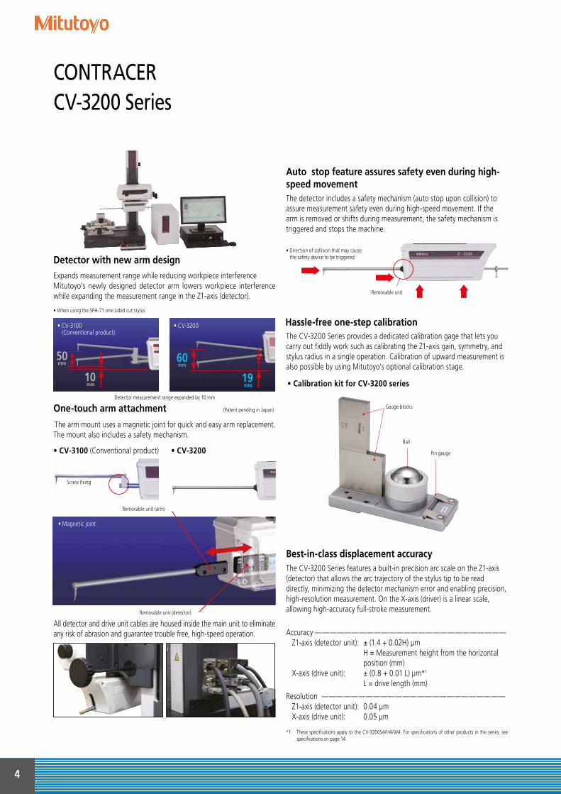
Expands measurement range while reducing workpiece interferenceMitutoyo’s newly designed detector arm lowers workpiece interference while expanding the measurement range in the Z1-axis (detector).
The detector includes a safety mechanism (auto stop upon collision) to assure measurement safety even during high-speed movement. If the arm is removed or shifts during measurement, the safety mechanism is triggered and stops the machine.
The CV-3200 Series features a built-in precision arc scale on the Z1-axis (detector) that allows the arc trajectory of the stylus tip to be read directly, minimizing the detector mechanism error and enabling precision, high-resolution measurement. On the X-axis (driver) is a linear scale, allowing high-accuracy full-stroke measurement.
Detector measurement range expanded by 10 mm
• CV-3100 (Conventional product)
• CV-3200
• When using the SPH-71 one-sided cut stylus
Removable unit
• Direction of collision that may cause the safety device to be triggered
The CV-3200 Series provides a dedicated calibration gage that lets you carry out fiddly work such as calibrating the Z1-axis gain, symmetry, and stylus radius in a single operation. Calibration of upward measurement is also possible by using Mitutoyo’s optional calibration stage.
• Calibration kit for CV-3200 series
50mm
10 mm
60mm
19 mm
All detector and drive unit cables are housed inside the main unit to eliminate any risk of abrasion and guarantee trouble free, high-speed operation.
Ball
Pin gauge
Gauge blocks
• Magnetic joint
Removable unit (arm)
Removable unit (detector)
The arm mount uses a magnetic joint for quick and easy arm replacement. The mount also includes a safety mechanism.
• CV-3100 (Conventional product) • CV-3200
Screw fixing
Accuracy —————————————————————————— Z1-axis (detector unit): ± (1.4 + 0.02H) μm H = Measurement height from the horizontal position (mm) X-axis (drive unit): ± (0.8 + 0.01 L) μm*1
L = drive length (mm)
Resolution ————————————————————————— Z1-axis (detector unit): 0.04 μm X-axis (drive unit): 0.05 μm
*1 These specifications apply to the CV-3200S4/H4/W4. For specifications of other products in the series, see specifications on page 14.
Detector with new arm design
Hassle-free one-step calibration
Best-in-class displacement accuracy
One-touch arm attachment (Patent pending in Japan)
Auto stop feature assures safety even during high-speed movement
4
CONTRACER CV-3200 Series
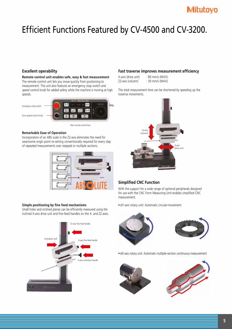
Excellent operability
Simplified CNC FunctionWith the support for a wide range of optional peripherals designed for use with the CNC Form Measuring Unit enables simplified CNC measurement.
• 1-axis rotary unit: Automatic circular-movement
• 2-axis rotary unit: Automatic multiple-section continuous measurement
Remote-control unit enables safe, easy & fast measurement The remote-control unit lets you move quickly from positioning to measurement. The unit also features an emergency stop switch and speed control knob for added safety while the machine is moving at high speeds.
New remote control box
Emergency stop switch
Drive speed control knob
Remarkable Ease of Operation Incorporation of an ABS scale in the Z2-axis eliminates the need for wearisome origin point re-setting conventionally required for every step of repeated measurements over stepped or multiple sections.
Simple positioning by fine feed mechanisms Small holes and inclined planes can be efficiently measured using the inclined X-axis drive unit and fine-feed handles on the X- and Z2-axes.
Inclination unit
Z2-axis fine-feed handle
X-axis fine-feed handle
X-axis inclination handle
Fast traverse improves measurement efficiencyX-axis (drive unit) : 80 mm/s (MAX)Z2-axis (column) : 30 mm/s (MAX)
The total measurement time can be shortened by speeding up the traverse movements.
Z2-axis (column)
X-axis(drive unit)
5
Efficient Functions Featured by CV-4500 and CV-3200.
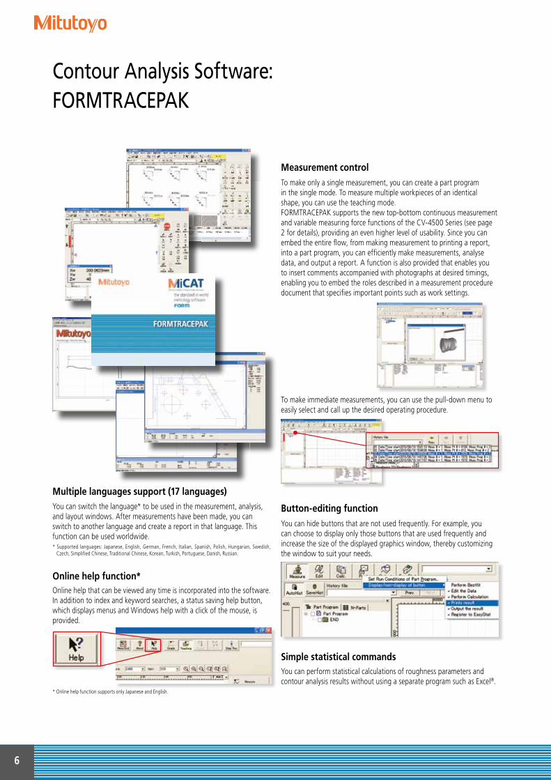
To make only a single measurement, you can create a part programin the single mode. To measure multiple workpieces of an identicalshape, you can use the teaching mode.FORMTRACEPAK supports the new top-bottom continuous measurement and variable measuring force functions of the CV-4500 Series (see page 2 for details), providing an even higher level of usability. Since you can embed the entire flow, from making measurement to printing a report, into a part program, you can efficiently make measurements, analyse data, and output a report. A function is also provided that enables you to insert comments accompanied with photographs at desired timings, enabling you to embed the roles described in a measurement procedure document that specifies important points such as work settings.
To make immediate measurements, you can use the pull-down menu to easily select and call up the desired operating procedure.
Online help that can be viewed any time is incorporated into the software. In addition to index and keyword searches, a status saving help button, which displays menus and Windows help with a click of the mouse, is provided.
You can hide buttons that are not used frequently. For example, you can choose to display only those buttons that are used frequently and increase the size of the displayed graphics window, thereby customizing the window to suit your needs.
* Online help function supports only Japanese and English.
You can perform statistical calculations of roughness parameters and contour analysis results without using a separate program such as Excel®.
You can switch the language* to be used in the measurement, analysis, and layout windows. After measurements have been made, you can switch to another language and create a report in that language. This function can be used worldwide.* Supported languages: Japanese, English, German, French, Italian, Spanish, Polish, Hungarian, Swedish,
Czech, Simplified Chinese, Traditional Chinese, Korean, Turkish, Portuguese, Danish, Russian.
Measurement control
Button-editing function
Simple statistical commands
Multiple languages support (17 languages)
Online help function*
6
Contour Analysis Software:FORMTRACEPAK
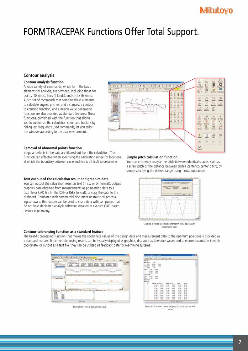
Contour analysis
Removal of abnormal points function Irregular defects in the data are filtered out from the calculation. This function can effective when specifying the calculation range for locations at which the boundary between circle and line is difficult to determine.
Text output of the calculation result and graphics data You can output the calculation result as text (in csv or txt format), output graphics data obtained from measurements as point-string data to a text file or CAD file (in the DXF or IGES format), or copy the data to the clipboard. Combined with commercial document or statistical process-ing software, this feature can be used to share data with computers that do not have dedicated analysis software installed or execute CAD-based reverse engineering.
Contour analysis function A wide variety of commands, which form the basicelements for analysis, are provided, including those forpoints (10 kinds), lines (6 kinds), and circles (6 kinds).A rich set of commands that combine these elementsto calculate angles, pitches, and distances, a contourtolerancing function, and a design value generationfunction are also provided as standard features. Thesefunctions, combined with the function that allowsyou to customize the calculation command buttons byhiding less frequently used commands, let you tailorthe window according to the user environment.
Simple pitch calculation function You can efficiently analyse the pitch between identical shapes, such as a screw pitch or the distance between circles (center-to-center pitch), by simply specifying the desired range using mouse operations.
Example of range specification for screw thread pitch with rectangular tool.
Contour-tolerancing function as a standard feature The best-fit processing function that moves the coordinate values of the design data and measurement data to the optimum positions is provided as a standard feature. Since the tolerancing results can be visually displayed as graphics, displayed as tolerance values and tolerance expansions in each coordinate, or output as a text file, they can be utilized as feedback data for machining systems.
Example of contour-tolerancing result Example of contour tolerancing results output as numeric values
7
FORMTRACEPAK Functions Offer Total Support.
Data combine
Data 2Data 1
Design value generation function
You can generate design data from CAD data (DXF or IGES file) or text data. Furthermore, since you can also convert measurement data into design data, you can save parts data prior to use (testing) as design data and effectively utilize it for checking the wear following use (testing).
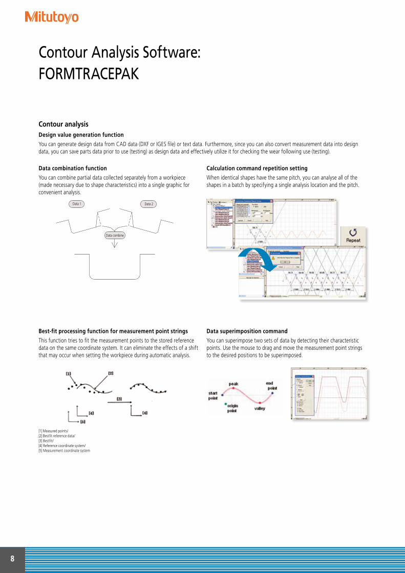
Data combination function
You can combine partial data collected separately from a workpiece (made necessary due to shape characteristics) into a single graphic for convenient analysis.
Calculation command repetition setting
When identical shapes have the same pitch, you can analyse all of the shapes in a batch by specifying a single analysis location and the pitch.
Best-fit processing function for measurement point strings
This function tries to fit the measurement points to the stored reference data on the same coordinate system. It can eliminate the effects of a shift that may occur when setting the workpiece during automatic analysis.
Data superimposition command
You can superimpose two sets of data by detecting their characteristic points. Use the mouse to drag and move the measurement point strings to the desired positions to be superimposed.
Contour analysis
[1] Measured points/ [2] Bestfit reference data/[3] Bestfit/ [4] Reference coordinate system/[5] Measurement coordinate system
8
Contour Analysis Software: FORMTRACEPAK
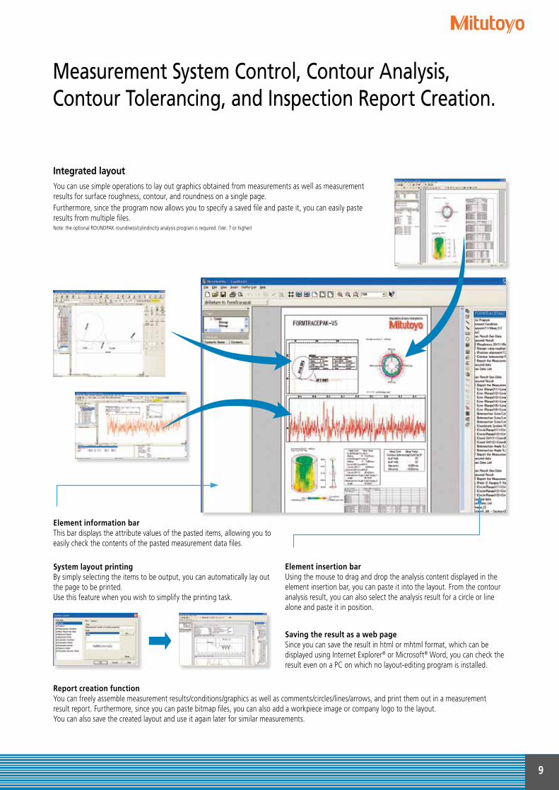
You can use simple operations to lay out graphics obtained from measurements as well as measurement results for surface roughness, contour, and roundness on a single page.Furthermore, since the program now allows you to specify a saved file and paste it, you can easily paste results from multiple files.Note: the optional ROUNDPAK roundness/cylindricity analysis program is required. (Ver. 7 or higher)
Element information bar This bar displays the attribute values of the pasted items, allowing you to easily check the contents of the pasted measurement data files.
System layout printing By simply selecting the items to be output, you can automatically lay out the page to be printed.Use this feature when you wish to simplify the printing task.
Element insertion bar Using the mouse to drag and drop the analysis content displayed in the element insertion bar, you can paste it into the layout. From the contour analysis result, you can also select the analysis result for a circle or line alone and paste it in position.
Saving the result as a web page Since you can save the result in html or mhtml format, which can be displayed using Internet Explorer® or Microsoft® Word, you can check the result even on a PC on which no layout-editing program is installed.
Report creation function You can freely assemble measurement results/conditions/graphics as well as comments/circles/lines/arrows, and print them out in a measurementresult report. Furthermore, since you can paste bitmap files, you can also add a workpiece image or company logo to the layout.You can also save the created layout and use it again later for similar measurements.
Integrated layout
9
Measurement System Control, Contour Analysis, Contour Tolerancing, and Inspection Report Creation.
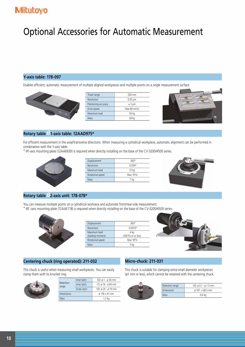
Enables efficient, automatic measurement of multiple aligned workpieces and multiple points on a single measurement surface.
For efficient measurement in the axial/transverse directions. When measuring a cylindrical workpiece, automatic alignment can be performed incombination with the Y-axis table.* 1-axis mounting plate (12AAE630) is required when directly installing on the base of the CV-3200/4500 series.
You can measure multiple points on a cylindrical workiece and automate front/rear-side measurement.* 2 -axis mounting plate (12AAE718) is required when directly installing on the base of the CV-3200/4500 series.
Rotary table 1-axis table: 12AAD975*
Rotary table 2-axis unit: 178-078*
Travel range 200 mm
Resolution 0.05 μm
Positioning accuracy ± 3 μm
Drive speed Max 80 mm/s
Maximum load 50 kg
Mass 28 kg
Displacement 360°
Resolution 0.004°
Maximum load 12 kg
Rotational speed Max 10°/s
Mass 7 kg
Displacement 360°
Resolution 0.0072°Maximum load(loading moment)
4 kg(343 N·cm or less)
Rotational speed Max 18°/s
Mass 5 kg
This chuck is useful when measuring small workpieces. You can easily clamp them with its knurled ring.
This chuck is suitable for clamping extra-small diameter workpieces(ø1 mm or less), which cannot be retained with the centering chuck.
Retentionrange
Inner latch OD: ø 1 - ø 36 mm
Inner latch I D: ø 16 - ø 69 mm
Outer latch OD: ø 25 - ø 79 mm
Dimensions ø 118 × 41 mm
Mass 1.2 kg
Retention range OD: ø 0.1 - ø 1.5 mm
Dimensions ø 107 x 48.5 mm
Mass 0.6 kg
Y-axis table: 178-097
Centering chuck (ring operated): 211-032 Micro-chuck: 211-031
10
Optional Accessories for Automatic Measurement
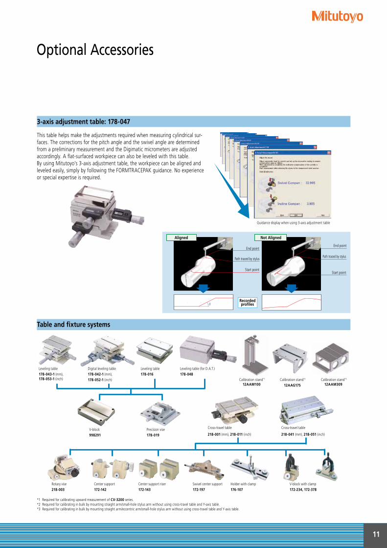
This table helps make the adjustments required when measuring cylindrical sur-faces. The corrections for the pitch angle and the swivel angle are determined from a preliminary measurement and the Digimatic micrometers are adjusted accordingly. A flat-surfaced workpiece can also be leveled with this table. By using Mitutoyo’s 3-axis adjustment table, the workpiece can be aligned and leveled easily, simply by following the FORMTRACEPAK guidance. No experience or special expertise is required.
Aligned Not Aligned
Path traced by stylus
End point
Path traced by stylus
End point
Start pointStart point
Recordedprofiles
Rotary vise218-003
V-block998291
Precision vise178-019
Cross-travel table
218-001 (mm), 218-011 (inch)
Cross-travel table
218-041 (mm), 218-051 (inch)
V-block with clamp172-234, 172-378
Holder with clamp176-107
Swivel center support172-197
Center support riser172-143
Center support172-142
Leveling table178-043-1 (mm), 178-053-1 (inch)
Digital leveling table178-042-1 (mm), 178-052-1 (inch)
Leveling table178-016
Leveling table (for D.A.T.)178-048
Calibration stand*2
12AAG175 Calibration stand*1
12AAM100 Calibration stand*3
12AAM309
Guidance display when using 3-axis adjustment table
*1 Required for calibrating upward measurement of CV-3200 series.*2 Required for calibrating in bulk by mounting straight arm/small-hole stylus arm without using cross-travel table and Y-axis table. *3 Required for calibrating in bulk by mounting straight arm/eccentric arm/small-hole stylus arm without using cross-travel table and Y-axis table.
3-axis adjustment table: 178-047
Table and fixture systems
11
Optional Accessories
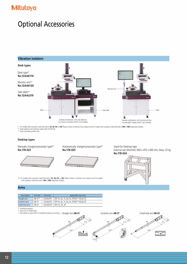
Stand for Desktop typeExternal size (W×D×H): 640 × 470 × 660 mm, Mass: 25 kgNo.178-024
Manually charged pneumatic type*4
No.178-023Automatically charged pneumatic type*4
No.178-025
Desk type*1
No.12AAK110
Monitor arm*2
No.12AAK120
Side table*3
No.12AAL019
*1 For models with a product code that ends in S4, S8, H4, or H8. Please contact us directly if you require units for models with a product code that ends in W4 or W8 (large base models).*2 Used together with vibration isolator (No.12AAK110).*3 User to provide a printer rack.
*4 For models with a product code that ends in S4, S8, H4, or H8. Please contact us directly if you require units for models with a product code that ends in W4 or W8 (large base models).
Example combination: with side table butno monitor arm (tester and PC not included)
Example combination: with monitor arm butno side table*3 (tester and PC not included)
Desktop types
Desk types
Description Arm No. Parts No. Applicable stylus No.Straight arm AB-31*5 12AAM101 SPH-5x, 6x, 7x, 8x, 9x, SPHW*6-56,66,76Eccentric arm AB-37 12AAQ762 SPH-5x, 6x, 7x, 8x, 9x, SPHW*6-56,66,76Small-hole arm AB-33 12AAM103 SPH-41, 42, 43
*5 Standard accessory*6 Stylus for CV-4500 series*7 One-sided cut stylus SPH-71 (standard accessory) mounting •Straight arm AB-31 •Eccentric arm AB-37 •Small-hole arm AB-33
ø8 57.520
218*7
ø8
40
57.520
ø8
218*7
57.520
218*7
Desk
Monitor arm
DeskSide table
Vibration isolators
Arms
12
Optional Accessories
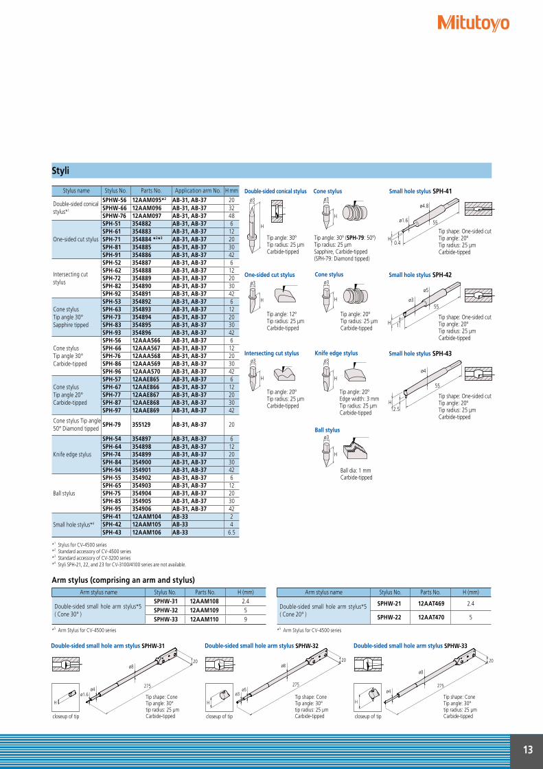
Stylus name Stylus No. Parts No. Application arm No. H mm
Double-sided conical stylus*1
SPHW-56 12AAM095*2 AB-31, AB-37 20SPHW-66 12AAM096 AB-31, AB-37 32SPHW-76 12AAM097 AB-31, AB-37 48
One-sided cut stylus
SPH-51 354882 AB-31, AB-37 6SPH-61 354883 AB-31, AB-37 12SPH-71 354884 *2*3 AB-31, AB-37 20SPH-81 354885 AB-31, AB-37 30SPH-91 354886 AB-31, AB-37 42
Intersecting cut stylus
SPH-52 354887 AB-31, AB-37 6SPH-62 354888 AB-31, AB-37 12SPH-72 354889 AB-31, AB-37 20SPH-82 354890 AB-31, AB-37 30SPH-92 354891 AB-31, AB-37 42
Cone stylusTip angle 30°Sapphire tipped
SPH-53 354892 AB-31, AB-37 6SPH-63 354893 AB-31, AB-37 12SPH-73 354894 AB-31, AB-37 20SPH-83 354895 AB-31, AB-37 30SPH-93 354896 AB-31, AB-37 42
Cone stylusTip angle 30°Carbide-tipped
SPH-56 12AAA566 AB-31, AB-37 6SPH-66 12AAA567 AB-31, AB-37 12SPH-76 12AAA568 AB-31, AB-37 20SPH-86 12AAA569 AB-31, AB-37 30SPH-96 12AAA570 AB-31, AB-37 42
Cone stylusTip angle 20°Carbide-tipped
SPH-57 12AAE865 AB-31, AB-37 6SPH-67 12AAE866 AB-31, AB-37 12SPH-77 12AAE867 AB-31, AB-37 20SPH-87 12AAE868 AB-31, AB-37 30SPH-97 12AAE869 AB-31, AB-37 42
Cone stylus Tip angle 50° Diamond tipped
SPH-79 355129 AB-31, AB-37 20
Knife edge stylus
SPH-54 354897 AB-31, AB-37 6SPH-64 354898 AB-31, AB-37 12SPH-74 354899 AB-31, AB-37 20SPH-84 354900 AB-31, AB-37 30SPH-94 354901 AB-31, AB-37 42
Ball stylus
SPH-55 354902 AB-31, AB-37 6SPH-65 354903 AB-31, AB-37 12SPH-75 354904 AB-31, AB-37 20SPH-85 354905 AB-31, AB-37 30SPH-95 354906 AB-31, AB-37 42
Small hole stylus*4
SPH-41 12AAM104 AB-33 2SPH-42 12AAM105 AB-33 4SPH-43 12AAM106 AB-33 6.5
*1 Stylus for CV-4500 series*2 Standard accessory of CV-4500 series*3 Standard accessory of CV-3200 series *4 Styli SPH-21, 22, and 23 for CV-3100/4100 series are not available.
Tip angle: 20ºEdge width: 3 mmTip radius: 25 µmCarbide-tipped
H
ø3One-sided cut stylus
Tip angle: 12ºTip radius: 25 µmCarbide-tipped
ø3
H
Intersecting cut stylus
Tip angle: 20ºTip radius: 25 µmCarbide-tipped
H
ø3Knife edge stylus
H
ø3Ball stylus
Ball dia: 1 mmCarbide-tipped
ø3
H
Cone stylus
Tip angle: 30º (SPH-79: 50º)Tip radius: 25 µmSapphire, Carbide-tipped (SPH-79: Diamond tipped)
H
ø3Cone stylus
Tip angle: 20ºTip radius: 25 µmCarbide-tipped
55ø1.6
ø4.8
H
Small hole stylus SPH-41
Tip shape: One-sided cutTip angle: 20ºTip radius: 25 µmCarbide-tipped
0.4
ø3
H 1
Small hole stylus SPH-42
Tip shape: One-sided cutTip angle: 20ºTip radius: 25 µmCarbide-tipped
55
ø5
Small hole stylus SPH-43
Tip shape: One-sided cutTip angle: 20ºTip radius: 25 µmCarbide-tipped
ø4
H2.5
55
Double-sided conical stylus
Tip angle: 30ºTip radius: 25 µmCarbide-tipped
H
ø3
Double-sided small hole arm stylus SPHW-31 Double-sided small hole arm stylus SPHW-32 Double-sided small hole arm stylus SPHW-33
Tip shape: ConeTip angle: 30ºtip radius: 25 µmCarbide-tipped
Tip shape: ConeTip angle: 30ºtip radius: 25 µmCarbide-tipped
Tip shape: ConeTip angle: 30ºtip radius: 25 µmCarbide-tipped
ø4ø1.6
ø8
275
20
ø5ø3
ø8
275
20
ø4
ø8
275
20
H
closeup of tip
H
closeup of tip
H
closeup of tip
Arm stylus (comprising an arm and stylus)Arm stylus name Stylus No. Parts No. H (mm)
Double-sided small hole arm stylus*5 ( Cone 30° )
SPHW-31 12AAM108 2.4SPHW-32 12AAM109 5SPHW-33 12AAM110 9
*5 Arm Stylus for CV-4500 series
Arm stylus name Stylus No. Parts No. H (mm)
Double-sided small hole arm stylus*5 ( Cone 20° )
SPHW-21 12AAT469 2.4
SPHW-22 12AAT470 5 *5 Arm Stylus for CV-4500 series
Styli
13
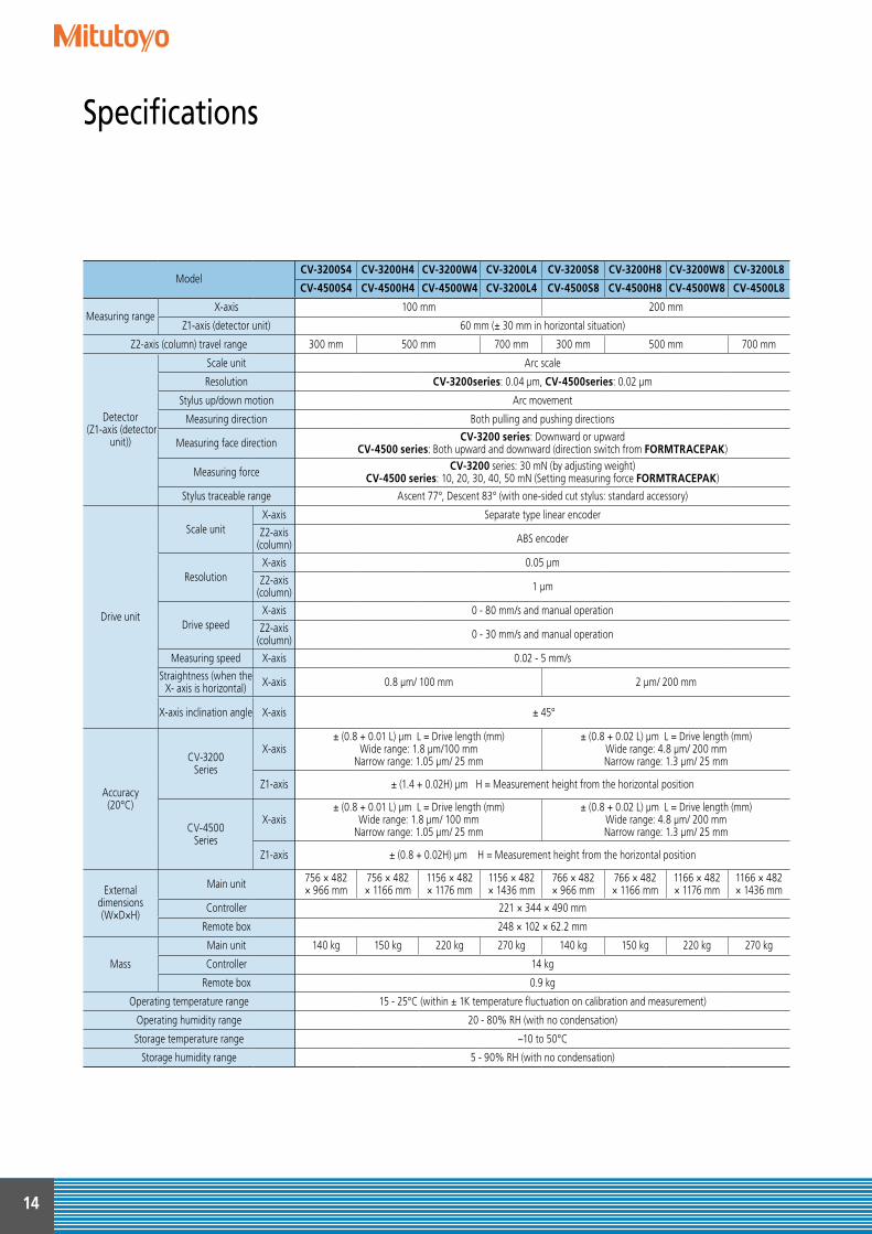
ModelCV-3200S4 CV-3200H4 CV-3200W4 CV-3200L4 CV-3200S8 CV-3200H8 CV-3200W8 CV-3200L8
CV-4500S4 CV-4500H4 CV-4500W4 CV-3200L4 CV-4500S8 CV-4500H8 CV-4500W8 CV-4500L8
Measuring rangeX-axis 100 mm 200 mm
Z1-axis (detector unit) 60 mm (± 30 mm in horizontal situation)
Z2-axis (column) travel range 300 mm 500 mm 700 mm 300 mm 500 mm 700 mm
Detector (Z1-axis (detector
unit))
Scale unit Arc scale
Resolution CV-3200series: 0.04 μm, CV-4500series: 0.02 μm
Stylus up/down motion Arc movement
Measuring direction Both pulling and pushing directions
Measuring face direction CV-3200 series: Downward or upwardCV-4500 series: Both upward and downward (direction switch from FORMTRACEPAK)
Measuring force CV-3200 series: 30 mN (by adjusting weight)CV-4500 series: 10, 20, 30, 40, 50 mN (Setting measuring force FORMTRACEPAK)
Stylus traceable range Ascent 77°, Descent 83° (with one-sided cut stylus: standard accessory)
Drive unit
Scale unitX-axis Separate type linear encoder
Z2-axis (column) ABS encoder
ResolutionX-axis 0.05 μm
Z2-axis (column) 1 μm
Drive speedX-axis 0 - 80 mm/s and manual operation
Z2-axis (column) 0 - 30 mm/s and manual operation
Measuring speed X-axis 0.02 - 5 mm/s
Straightness (when the X- axis is horizontal) X-axis 0.8 μm/ 100 mm 2 μm/ 200 mm
X-axis inclination angle X-axis ± 45°
Accuracy(20°C)
CV-3200Series
X-axis± (0.8 + 0.01 L) μm L = Drive length (mm)
Wide range: 1.8 μm/100 mmNarrow range: 1.05 μm/ 25 mm
± (0.8 + 0.02 L) μm L = Drive length (mm)Wide range: 4.8 μm/ 200 mmNarrow range: 1.3 μm/ 25 mm
Z1-axis ± (1.4 + 0.02H) μm H = Measurement height from the horizontal position
CV-4500Series
X-axis ± (0.8 + 0.01 L) μm L = Drive length (mm)
Wide range: 1.8 μm/ 100 mmNarrow range: 1.05 μm/ 25 mm
± (0.8 + 0.02 L) μm L = Drive length (mm)Wide range: 4.8 μm/ 200 mmNarrow range: 1.3 μm/ 25 mm
Z1-axis ± (0.8 + 0.02H) μm H = Measurement height from the horizontal position
External dimensions(W×D×H)
Main unit 756 × 482× 966 mm
756 × 482× 1166 mm
1156 × 482× 1176 mm
1156 × 482× 1436 mm
766 × 482× 966 mm
766 × 482× 1166 mm
1166 × 482× 1176 mm
1166 × 482× 1436 mm
Controller 221 × 344 × 490 mm
Remote box 248 × 102 × 62.2 mm
Mass
Main unit 140 kg 150 kg 220 kg 270 kg 140 kg 150 kg 220 kg 270 kg
Controller 14 kg
Remote box 0.9 kg
Operating temperature range 15 - 25°C (within ± 1K temperature fluctuation on calibration and measurement)
Operating humidity range 20 - 80% RH (with no condensation)
Storage temperature range −10 to 50°C
Storage humidity range 5 - 90% RH (with no condensation)
14
Specifications
110 [510]
100
600 [1000] 156
100
[110
]12
300
(500
) [50
0] {7
00}
46
228
966
(116
6) [1
176]
{143
6}
854
(105
4) [1
054]
{131
4}
220 386
T-groove
175 130450 32
85
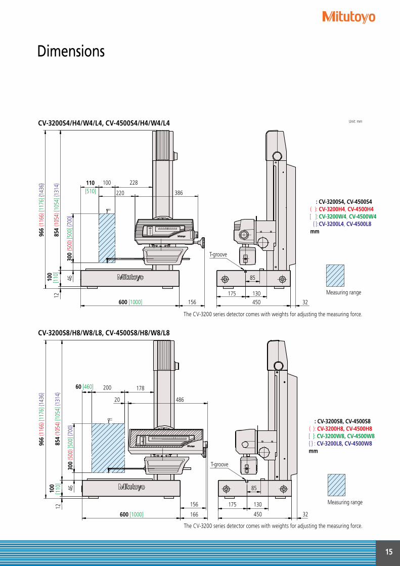
: CV-3200S4, CV-4500S4( ): CV-3200H4, CV-4500H4[ ]: CV-3200W4, CV-4500W4 { }: CV-3200L4, CV-4500L8mm
Measuring range
60 [460] 200
600 [1000]
156
166
300
(500
) [50
0] {7
00}
46
12
178
966
(116
6) [1
176]
{143
6}
854
(105
4) [1
054]
{131
4}
20 486
175
T-groove
130
450 32
85100
[110
]
: CV-3200S8, CV-4500S8( ): CV-3200H8, CV-4500H8[ ]: CV-3200W8, CV-4500W8{ } : CV-3200L8, CV-4500W8mm
Measuring range
CV-3200S4/H4/W4/L4, CV-4500S4/H4/W4/L4
CV-3200S8/H8/W8/L8, CV-4500S8/H8/W8/L8
Unit: mm
The CV-3200 series detector comes with weights for adjusting the measuring force.
The CV-3200 series detector comes with weights for adjusting the measuring force.
15
Dimensions
Find additional product literature and our product catalogue
www.mitutoyo.eu Mitutoyo Europe GmbH
Borsigstraße 8-10 41469 Neuss
Tel. +49 (0) 2137-102-0 Fax +49 (0) 2137-102-351
[email protected] www.mitutoyo.eu
© M
ITUTO
YO/D
031
7 PR
E 13
82(2
)
Whatever your challenges are, Mitutoyo supports you from start to finish.
Mitutoyo is not only a manufacturer of top quality measuring products but one that also offers qualified support for the lifetime of the equipment, backed up by comprehensive services that ensure your staff can make the very best use of the investment.
Apart from the basics of calibration and repair, Mitutoyo offers product and metrology training, as well as IT support for the sophisticated software used in modern measuring technology. We can also design, build, test and deliver bespoke measuring solutions and even, if deemed cost-effective, take your critical measurement challenges in-house on a sub-contract basis.
Note: Product illustrations are without obligation. Product descriptions respectively capability characteristics are only binding when explicitly agreed upon.MITUTOYO, CONTRACER and ABSOLUTE are either registered trademarks or trademarks of Mitutoyo Corp. in Japan and/or other countries/regions. Microsoft and Internet Explorer are either registered trademarks or trademarks of Microsoft Corporation in the United States and/or other countries. Other product, company and brand names mentioned herein are for identification purposes only and may be the trademarks of their respective holders.
Coordinate Measuring Machines
Sensor Systems
Vision Measuring Systems
Test Equipment and Seismometers
Form Measurement
Digital Scale and DRO Systems
Optical Measuring
Small Tool Instruments and Data Management