Embed Size (px)
Citation preview
Inexpensive Laboratory Circulating Pump H. MILTON WOODBURN
University of Buffalo, Buffalo, N. Y.
N MOST laboratories there is occasional need for a means I of circulating water or other liquids at definite temperature through a piece of equipment such as a refractometer, polarim- eter, or condenser. This paper describes a simple pump devised for that purpose which can be constructed in a short time, at very little expense, and with a minimum of glass- blowing and shop technique.
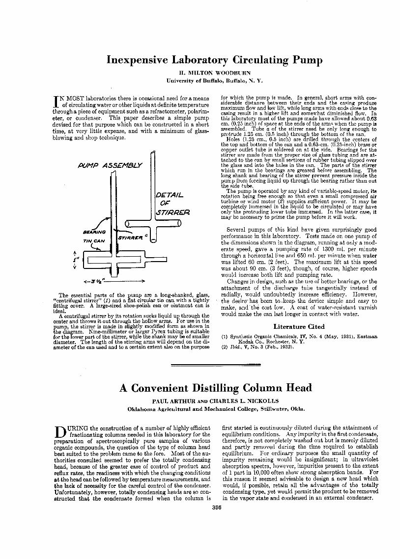
PUMP ASS€MBLY n
The essential parts of the ump are a long-shanked, .glass, “centrifugal stirrer” (1 ) and a Eat circular tin can with a tightly fitting cover. A karge-sized shoe-psbh can or ointment can is ideal.
A centrifugal stirrer by its rotation sucks liquid up through the center and throws it out through the hollow arms. For use in the pump, the stirrer is made in slightly modified form as shown in the dia ram. Kine-millimeter or larger Pyrex tubing is suitable for the fower part of the stirrer, while the shank may be of smaller diameter. The length of the stirring arms will depend on the di- ameter of the can used and to a certain extent also on the purpose
for which the pum i s made. In general, short arms with con- siderable distance getween their ends and the casing produce maximum flow and low lift, while long arms with ends close to the casing result in a higher lift and somewhat diminished flow. In this laboratory most of the pumps made have allowed about 0.63 cm. (0.25 inch) of space at the ends of the armq when the pump ia assembled. Tube a of the stirrer need be only long enough to protrude 1.25 cm. (0.5 inch) through the bottom of the can.
Holes (1.25 cm., 0.5 inch) are drilled through the centers of the top and bottom of the can and a 033-cm. (0.25-inch) brass or copper outlet tube is soldered on at the side. Bearings for the stirrer are made from the proper size of glass tubing and are at- tached to the can by small sections of rubber tubing slipped over the glass and into the holes in the can. The parts of the stirrer which run in the bearings are greased before assembling. The long shank and hearing of the stirrer prevent pressure inside the pump from forcing liquid up through the bearing rather than out the side tube.
The pump is operated by any kind of variable-speed motor, its rotation being free enough so that even a small compressed air turbine or wind motor (2) supplies sufficient power. I t may be completely immersed in the liquid to be circulated or may have only the protruding lower tube immersed. In the latter case, it may be necessary to prime the pump before it will work,
Several pumps of this kind have given surprisingly good performance in this laboratory. Tests made on one pump of the dimensions shown in the diagram, running at only a mod- erate speed, gave a pumping rate of 1300 ml. per minute through a horizontal line and 650 ml. per minute when water was lifted 60 cm. (2 feet). The maximum lift a t this speed was about 90 cm. (3 feet), though, of course, higher speeds would increase both lift and pumping rate.
Changes in design, such as the use of better bearings, or the attachment of the discharge tube tangentially instead of radially, would undoubtedly increase efficiency. However, the desire has been to keep the device simple and easy to make, and the cost low. A coat of water-resistant varnish would make the can last longer in contact with water.
Literature Cited (1) Synthetic Organic Chemicals, IV, No. 4 (May, 1931), Eastman
(2) Zbid., V, No. 3 (Feb., 1932). Kodak Co., RocheRter, N. Y.
A Convenient Distilling Column Head PAUL ARTHUR AND CHARLES L. NICKOLLS
Oklahoma Agricultural and Mechanical College, Stillwater, Okla.
URING the construction of a number of highly efficient D fractionating columns needed in this laboratory for the preparation of spectroscopically pure samples of various organic compounds, the question of the type of column head best suited to the problem came to the fore. Most of the au- thorities consulted seemed to prefer the totally condensing head, because of the greater ease of control of product and reflux rates, the readiness with which the changing conditions at the head can be followed by temperature measurements, and the lack of necessity for the careful control of the condenser. Unfortunately, however, totally condensing head8 are so con- structed that the condensate formed when the column is
first started is continuously diluted during the attainment of equilibrium conditions. Any impurity in the first condensate, therefore, is not completely washed out but is merely diluted and partly removed during the time required to establish equilibrium. For ordinary purposes the small quantity of impurity remaining would be insignificant; in ultraviolet absorption spectra, however, impurities present to the extent of 1 part in 10,000 often show strong absorption bands. For this reason it seemed advisable to design a new head which would, if possible, retain all the advantages of the totally condensing type, yet would permit the product to be removed in the vapor s ta te and condensed in an external condenser.
356
May 15, 1941 A N A L Y T I C A L E D I T I O N 357
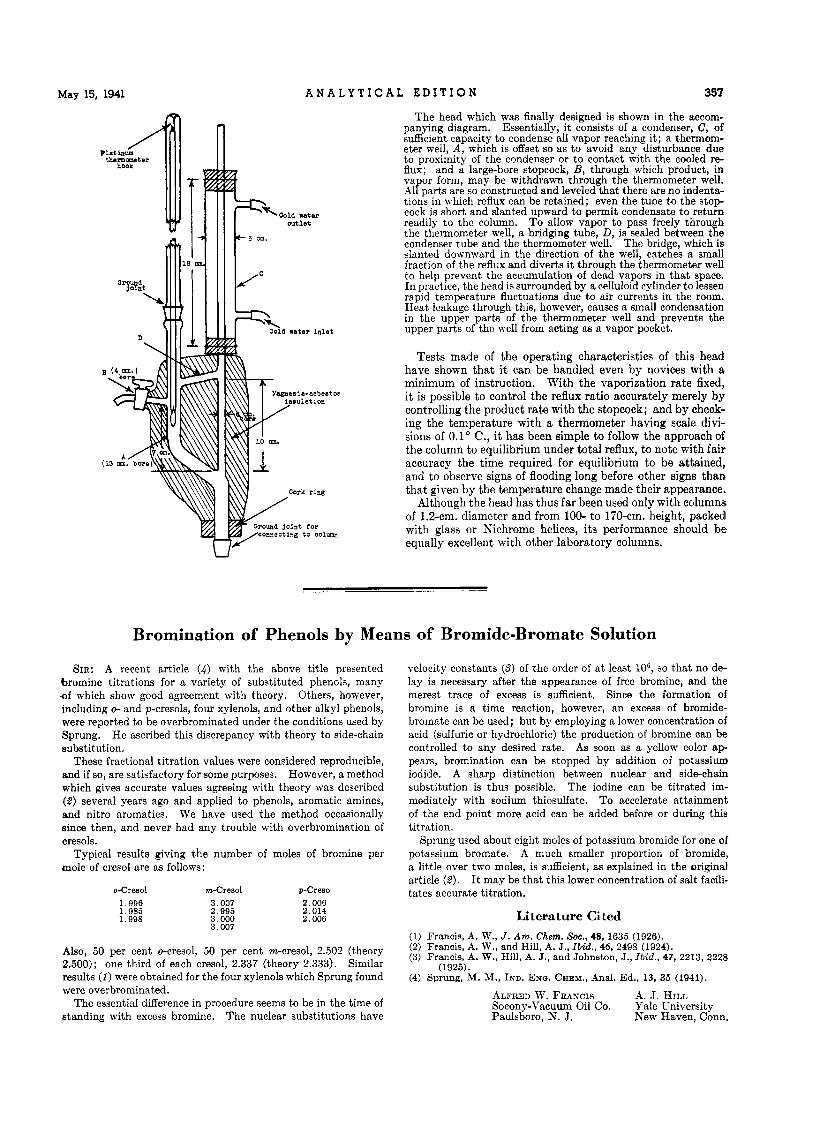
The head which was finally designed is shown in the accom- panying diagram. Essentially, i t consists of a condenser, C, of sufficient capacity to condense all vapor reaching it; a thermom- eter well, A , which is offset so as to avoid any disturbance due to proximity of the condenser or to contact with the cooled re- flux; and a large-bore stopcock, B, through which product, in vapor form, may be withdrawn through the thermometer well. All parts are so constructed and leveled that there are no indenta- tions in which reflux can be retained; even the tube to the stop- cock is short and slanted upward to permit condensate to return readily to the column. To allow vapor to pass freely throu h the thermometer well, a bridging tube, D, is sealed between t%e condenser tube and the thermometer well. The bridge, which is slanted downward in the direction of the well, catches a small fraction of the reflux and diverts it through the thermometer well to help prevent the accumulation of dead vapors in that space. In practice, the head is surrounded by a celluloid cylinder to lessen rapid temperature fluctuations due to air currents in the room. Heat leakage through this, however, causes a small condensation in the upper parts of the thermometer well and prevents the upper parts of the well from acting m a vapor pocket.
Tests made of the operating characteristics of this head have shown tha t it can be handled even by novices with a minimum of instruction. With the vaporization rate fixed, i t is possible to control the reflux ratio accurately merely by controlling the product rate with the stopcock; and by check- ing the temperature with a thermometer having scale divi- sions of 0.1' C., i t has been simple to follow the approach of the column t o equilibrium under total reflux, to note with fair accuracy the time required for equilibrium to be attained, and to observe signs of flooding long before other signs than that given by the temperature change made their appearance.
Although the head has thus far been used only with columns of 1.2-cm. diameter and from 100- to 170-cm. height, packed with glass or h'ichrome helices, its performance should b e equally excellent with other laboratory columns.
U
Bromination of Phenols by Means of Bromide-Bromate Solution
SIR: A recent article (4 ) with the above title presented bromine titrations for a variety of substituted phenols, many .of which show good agreement with theory. Others, however, including 0- and p-cresols, four xylenols, and other alkyl phenols, were reported to be overbrominated under the conditions used by Sprung. He ascribed this discrepancy with theory to side-chain substitution.
These fractional titration values were considered reproducible, and i f so, are satisfactory for some purposes. However, a method which gives accurate values agreeing with theory was described (8) several years ago and applied to phenols, aromatic amines, and nitro aromatics. We have used the method occasionally since then, and never had any trouble with overbromination of cresols.
Typical results giving the number of moles of bromine per mole of cresol are as follows:
0-Cresol m-Cresol p-Creso 1.996 1.985 1.998
3.007 2.996
3.007 3 . no0
2 . on6 2.014 2.006
Also, 50 per cent o-cresol, 50 per cent rn-cresol, 2.502 (theory 2.500); one third of each cresol, 2.337 (theory 2.333). Similar results (1) were obtained for the four xylenols which Sprung found were overbrominated.
The essential difference in procedure seems to be in the time of standing with excess bromine. The nuclear substitutions have
velocity constants (3) of the order of a t least lo6, so that no de- lay is necessary after the appearance of free bromine, and the merest trace of excess is sufficient. Since the formation of bromine is a time reaction, however, an excess of bromide- bromate can be used; but by employing a lower concentration of acid (sulfuric or hydrochloric) the production of bromine can be controlled to any desired rate. As soon as a yellow color a p pears, bromination can be stopped by addition of potassium iodide. A sharp distinction between nuclear and side-chain substitution is thus possible. The iodine can be titrated im- mediately with sodium thiosulfate. To accelerate attainment of the end point more acid can be added before or during this titration.
Sprung used about eight moles of potassium bromide for one of potassium bromate. A much smaller proportion of bromide, a little over two moles, is sufficient, as explained in the original article (2) . I t may be that this lower concentration of salt facili- tates accurate titration.
Literature Cited (1) Francis, A. W., J. Am. Chem. Soc., 48, 1635 (1926). (2) Francis, A. W., and Hill, A. J., I b i d . , 46, 2498 (1924). (3) Francis, A. W., Hill, A. J., and Johnston, J., Ib id . , 47, 2213, 2228
(4) Sprung, M. M., IND. ENG. CHEM., Anal. Ed., 13, 35 (1941). (1925).
ALFRED W. FRANCIS Socony-Vacuum Oil Co. Yale University Paulsboro, N. J.
A. J. HILL
New Haven, Conn.