Embed Size (px)
Citation preview
MB" Conveyors -
2
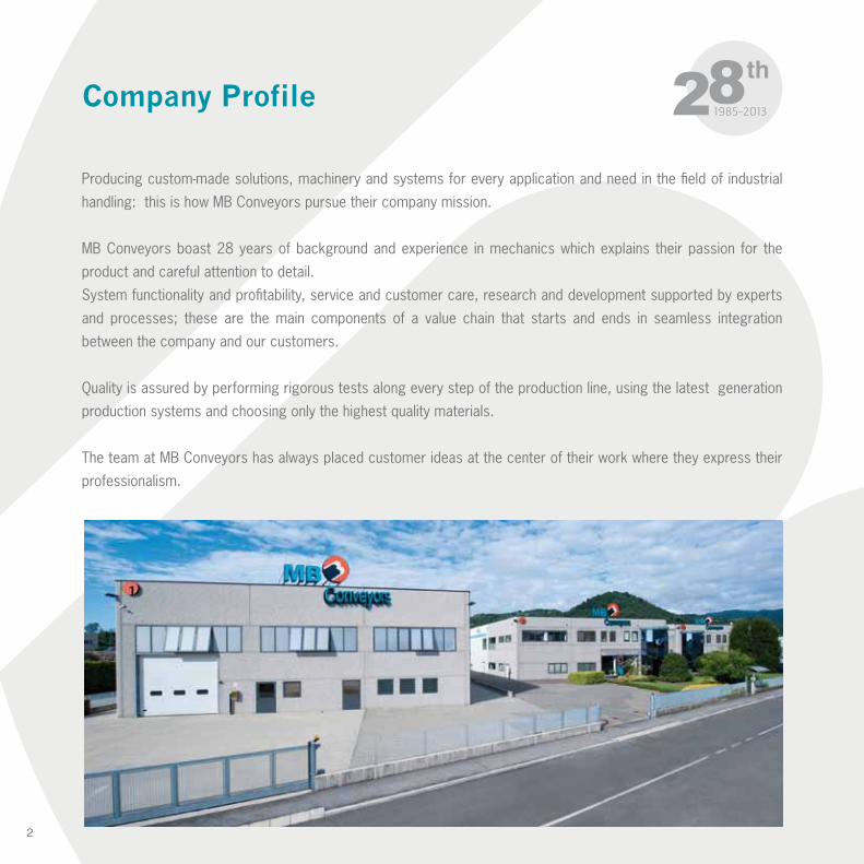
Company Profile
Producing custom-made solutions, machinery and systems for every application and need in the field of industrial
handling: this is how MB Conveyors pursue their company mission.
MB Conveyors boast 28 years of background and experience in mechanics which explains their passion for the
product and careful attention to detail.
System functionality and profitability, service and customer care, research and development supported by experts
and processes; these are the main components of a value chain that starts and ends in seamless integration
between the company and our customers.
Quality is assured by performing rigorous tests along every step of the production line, using the latest generation
production systems and choosing only the highest quality materials.
The team at MB Conveyors has always placed customer ideas at the center of their work where they express their
professionalism.
3
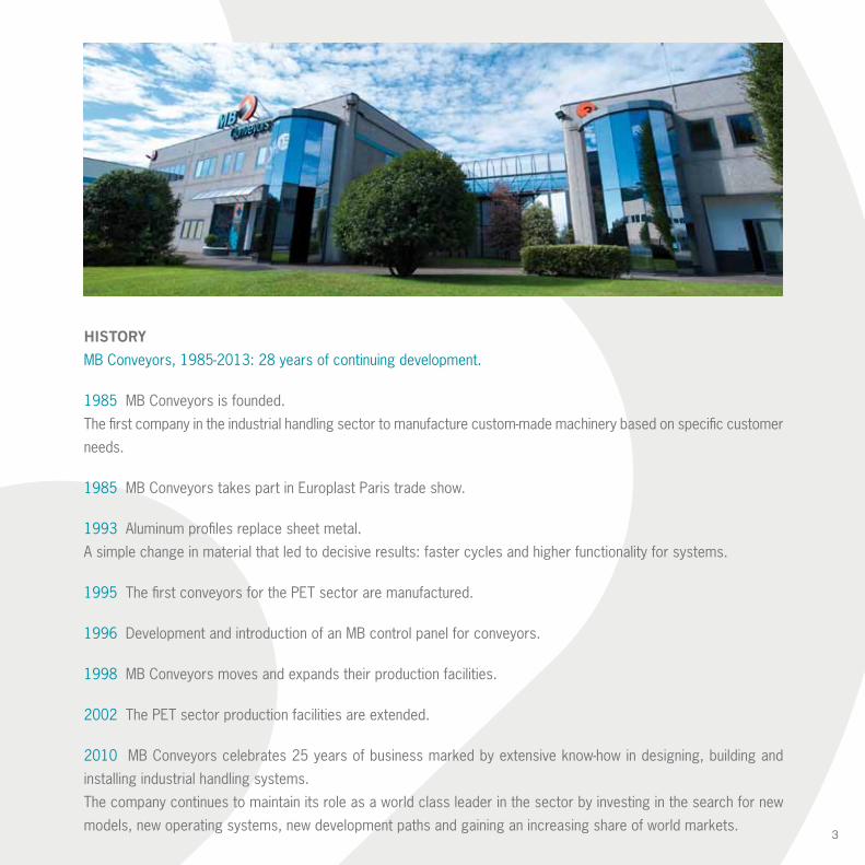
HISTORY
MB Conveyors, 1985-2013: 28 years of continuing development.
1985 MB Conveyors is founded.
The first company in the industrial handling sector to manufacture custom-made machinery based on specific customer
needs.
1985 MB Conveyors takes part in Europlast Paris trade show.
1993 Aluminum profiles replace sheet metal.
A simple change in material that led to decisive results: faster cycles and higher functionality for systems.
1995 The first conveyors for the PET sector are manufactured.
1996 Development and introduction of an MB control panel for conveyors.
1998 MB Conveyors moves and expands their production facilities.
2002 The PET sector production facilities are extended.
2010 MB Conveyors celebrates 25 years of business marked by extensive know-how in designing, building and
installing industrial handling systems.
The company continues to maintain its role as a world class leader in the sector by investing in the search for new
models, new operating systems, new development paths and gaining an increasing share of world markets.
4
CONTENTS
02 COMPANY PROFILE
07 CONVEYORS
08 PA standard flat conveyor
09 PAR conveyor with adjustable flat upper section10 PA conveyor to work with Robot
11 PA applications12 NCPR conveyor13 N-CPTR conveyor14 N-TR conveyor
15 SEPARATORS
16 N-CPST conveyor with paddle separator17 N-SRS and N-FSRV separators installed on conveyor
18 SR - SM separators19 SEPARATORS applications
20 FSRV spiral separator with base
21 FOOD - PHARMA
22 PA F.D.A. customised22 N-CPR F.D.A. customised23 N-CPTR F.D.A. customised23 EV F.D.A. customised24 F.D.A. applications
25 METAL DETECTOR
26 METAL DETECTOR plate27 METAL DETECTOR tunnel28 METAL DETECTOR applications
5
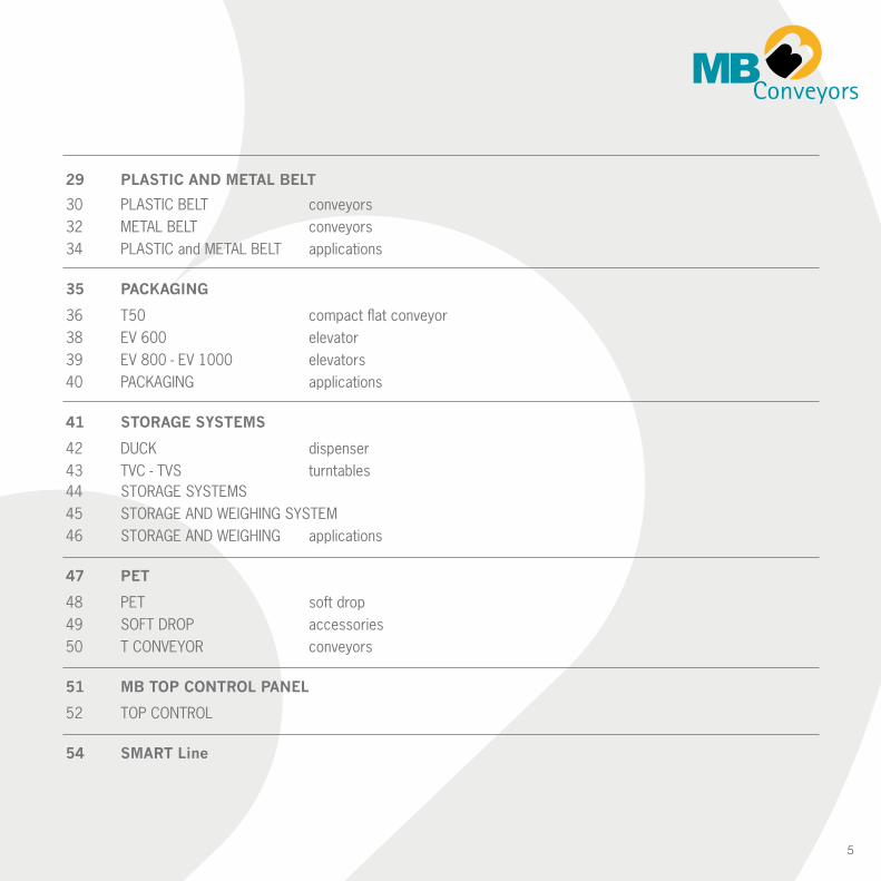
29 PLASTIC AND METAL BELT
30 PLASTIC BELT conveyors32 METAL BELT conveyors34 PLASTIC and METAL BELT applications
35 PACKAGING
36 T50 compact flat conveyor38 EV 600 elevator39 EV 800 - EV 1000 elevators40 PACKAGING applications
41 STORAGE SYSTEMS
42 DUCK dispenser43 TVC - TVS turntables44 STORAGE SYSTEMS45 STORAGE AND WEIGHING SYSTEM46 STORAGE AND WEIGHING applications
47 PET
48 PET soft drop49 SOFT DROP accessories50 T CONVEYOR conveyors
51 MB TOP CONTROL PANEL
52 TOP CONTROL
54 SMART Line


CO
NVEYO
RS
8
Amin 100 mm
max 2000 mm
Bmin 600 mmmax 60 mt
Hmin 200 mm
max 2000 mm
0° -
30°
A +
70
B
340
110
80
A
150
H
0° -
30°
A +
70
B
340
110
80
A
150
H
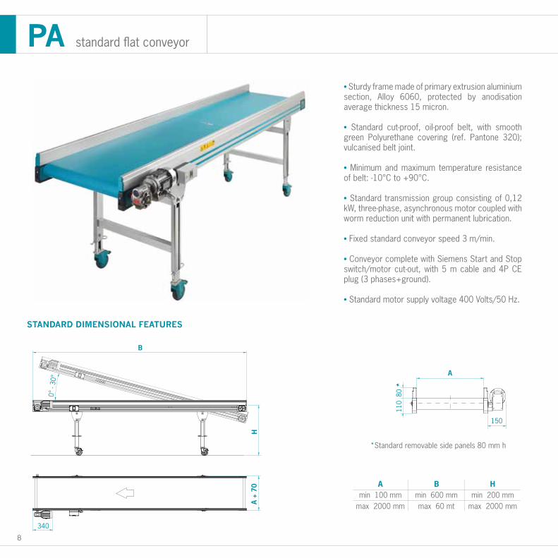
STANDARD DIMENSIONAL FEATURES
• Sturdy frame made of primary extrusion aluminium section, Alloy 6060, protected by anodisation average thickness 15 micron.
• Standard cut-proof, oil-proof belt, with smooth green Polyurethane covering (ref. Pantone 320); vulcanised belt joint.
• Minimum and maximum temperature resistance of belt: -10°C to +90°C. • Standard transmission group consisting of 0,12 kW, three-phase, asynchronous motor coupled with worm reduction unit with permanent lubrication.
• Fixed standard conveyor speed 3 m/min.
• Conveyor complete with Siemens Start and Stop switch/motor cut-out, with 5 m cable and 4P CE plug (3 phases+ground).
• Standard motor supply voltage 400 Volts/50 Hz.
*Standard removable side panels 80 mm h
PA standard flat conveyor
9
Amin 100 mm
max 1200 mm
Bmin 600 mm
max 5000 mm
Cmin 600 mm
max 1000 mm
C
0 - 30°
A
A + 70
110
B = max 5000
150
C
0 - 30°
A
A + 70
110
B = max 5000
150
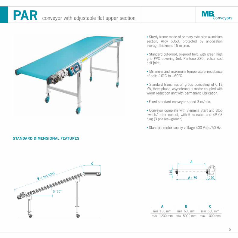
STANDARD DIMENSIONAL FEATURES
• Sturdy frame made of primary extrusion aluminium section, Alloy 6060, protected by anodisation average thickness 15 micron.
• Standard cut-proof, oil-proof belt, with green high grip PVC covering (ref. Pantone 320); vulcanised belt joint.
• Minimum and maximum temperature resistance of belt: -10°C to +60°C.
• Standard transmission group consisting of 0,12 kW, three-phase, asynchronous motor coupled with worm reduction unit with permanent lubrication.
• Fixed standard conveyor speed 3 m/min.
• Conveyor complete with Siemens Start and Stop switch/motor cut-out, with 5 m cable and 4P CE plug (3 phases+ground).
• Standard motor supply voltage 400 Volts/50 Hz.
PAR conveyor with adjustable flat upper section
10
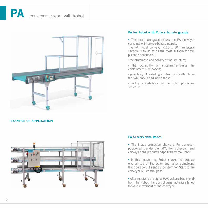
PA for Robot with Polycarbonate guards
• The photo alongside shows the PA conveyor complete with polycarbonate guards.The PA model conveyor (110 x 30 mm lateral section) is found to be the most suitable for this purpose because of:
- the sturdiness and solidity of the structure;
- the possibility of installing/removing the containment side panels;
- possibility of installing control photocells above the side panels and inside these;
- facility of installation of the Robot protection structure.
PA to work with Robot
• The image alongside shows a PA conveyor, positioned beside the IMM, for collecting and conveying the products deposited by the Robot.
• In this image, the Robot stacks the product one on top of the other and, after completing this operation, it sends a consent for Start to the conveyor MB control panel.
• After receiving the signal (A/C voltage-free signal) from the Robot, the control panel activates timed forward movement of the conveyor.
PA conveyor to work with Robot
EXAMPLE OF APPLICATION
11
STANDARD DIMENSIONAL FEATURES
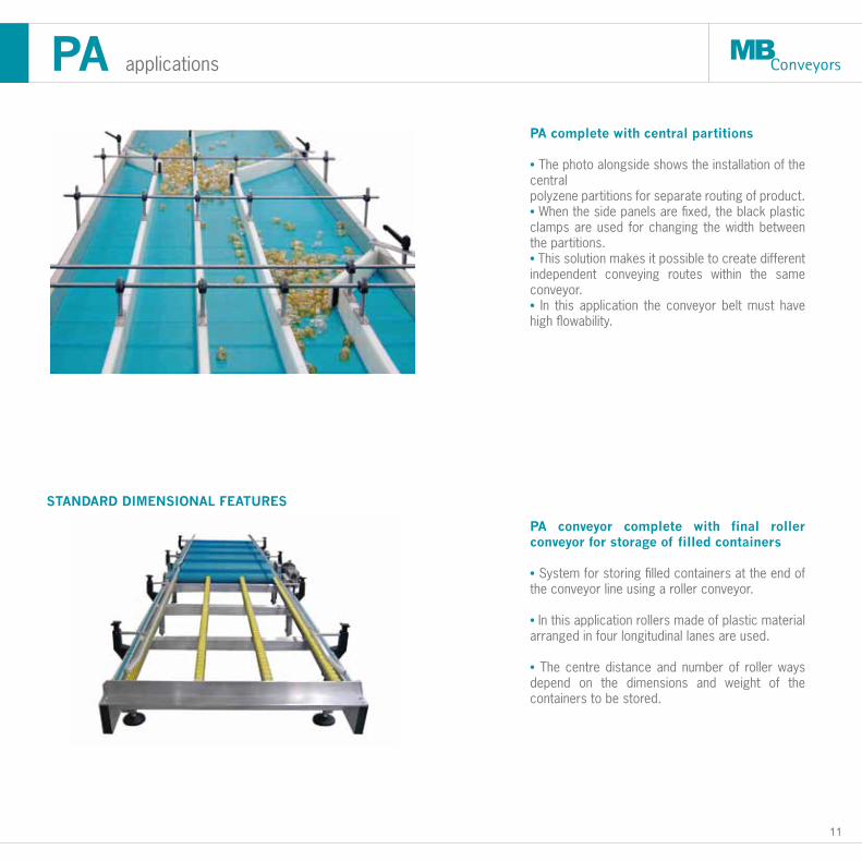
PA complete with central partitions
• The photo alongside shows the installation of the centralpolyzene partitions for separate routing of product.• When the side panels are fixed, the black plastic clamps are used for changing the width between the partitions.• This solution makes it possible to create different independent conveying routes within the same conveyor.• In this application the conveyor belt must have high flowability.
PA conveyor complete with final roller conveyor for storage of filled containers
• System for storing filled containers at the end of the conveyor line using a roller conveyor.
• In this application rollers made of plastic material arranged in four longitudinal lanes are used.
• The centre distance and number of roller ways depend on the dimensions and weight of the containers to be stored.
PA applications
12
25°
- 50°
H m
in
H m
ax
250
(+20
0)
C = 700
B
I = ingombro massimo a 40°
50* A
150
160
A + 70
A
140 mm
240 mm
B
1500 mm
1500 mm
H min
650 mm
650 mm
H max
1150 mm
1150 mm
I - 40°
2000 mm
2000 mm340 mm
N-CPR.0
N-CPR.1N-CPR.2 1800 mm 800 mm 1400 mm 2250 mm
440 mm 2000 mm 850 mm 1550 mm 2400 mm540 mm
N-CPR.3N-CPR.4 2000 mm 850 mm 1550 mm 2400 mm
STANDARD DIMENSIONAL FEATURES
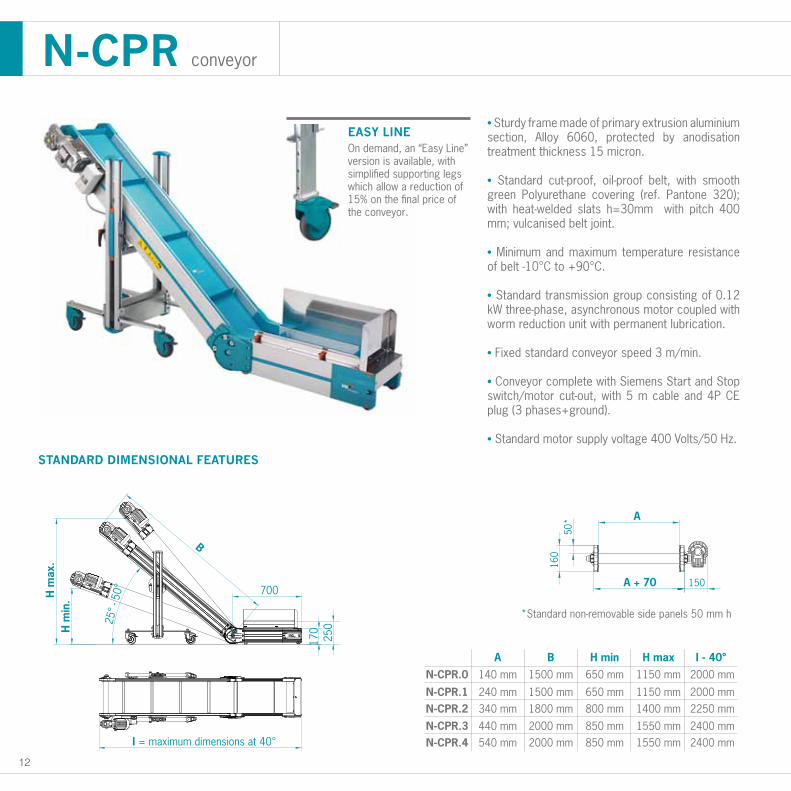
• Sturdy frame made of primary extrusion aluminium section, Alloy 6060, protected by anodisation treatment thickness 15 micron.
• Standard cut-proof, oil-proof belt, with smooth green Polyurethane covering (ref. Pantone 320); with heat-welded slats h=30mm with pitch 400 mm; vulcanised belt joint.
• Minimum and maximum temperature resistance of belt -10°C to +90°C.
• Standard transmission group consisting of 0.12 kW three-phase, asynchronous motor coupled with worm reduction unit with permanent lubrication.
• Fixed standard conveyor speed 3 m/min.
• Conveyor complete with Siemens Start and Stop switch/motor cut-out, with 5 m cable and 4P CE plug (3 phases+ground).
• Standard motor supply voltage 400 Volts/50 Hz.
N-CPR conveyor
*Standard non-removable side panels 50 mm h50
A
150
160
A + 60
25°
- 50°
H m
in.H
max
.
170
700
B
I = maximum dimensions at 40°
250
EASY LINEOn demand, an “Easy Line” version is available, with simplified supporting legs which allow a reduction of 15% on the final price of the conveyor.
13
A
140 mm
240 mm
B
1500 mm
1500 mm
H min
650 mm
650 mm
H max
1150 mm
1150 mm
I - 40°
2500 mm
2500 mm340 mm
N-CPTR.0
N-CPTR.1N-CPTR.2 1800 mm 800 mm 1400 mm 2750 mm
440 mm 2000 mm 850 mm 1550 mm 2900 mm540 mm
N-CPTR.3N-CPTR.4 2000 mm 850 mm 1550 mm 2900 mm
25°
- 50°
H m
in
H m
ax
250
(+20
0)
C = 700
B
I = ingombro massimo a 40°
50* A
150
160
A + 70
STANDARD DIMENSIONAL FEATURES
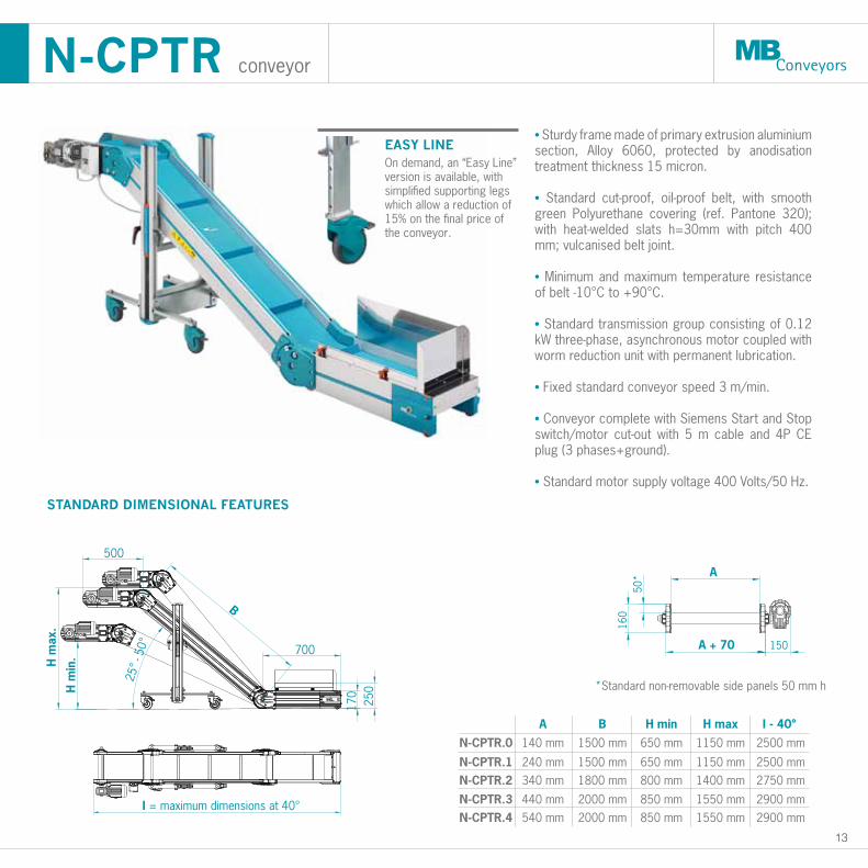
• Sturdy frame made of primary extrusion aluminium section, Alloy 6060, protected by anodisation treatment thickness 15 micron.
• Standard cut-proof, oil-proof belt, with smooth green Polyurethane covering (ref. Pantone 320); with heat-welded slats h=30mm with pitch 400 mm; vulcanised belt joint.
• Minimum and maximum temperature resistance of belt -10°C to +90°C.
• Standard transmission group consisting of 0.12 kW three-phase, asynchronous motor coupled with worm reduction unit with permanent lubrication.
• Fixed standard conveyor speed 3 m/min.
• Conveyor complete with Siemens Start and Stop switch/motor cut-out with 5 m cable and 4P CE plug (3 phases+ground).
• Standard motor supply voltage 400 Volts/50 Hz.
N-CPTR conveyor
A
A + 90
160
I = maximum dimensions at 40°
50
25°
- 50°
B
H m
ax.
H m
in.
500
170
700
250
EASY LINEOn demand, an “Easy Line” version is available, with simplified supporting legs which allow a reduction of 15% on the final price of the conveyor.
*Standard non-removable side panels 50 mm h
14
STANDARD DIMENSIONAL FEATURES
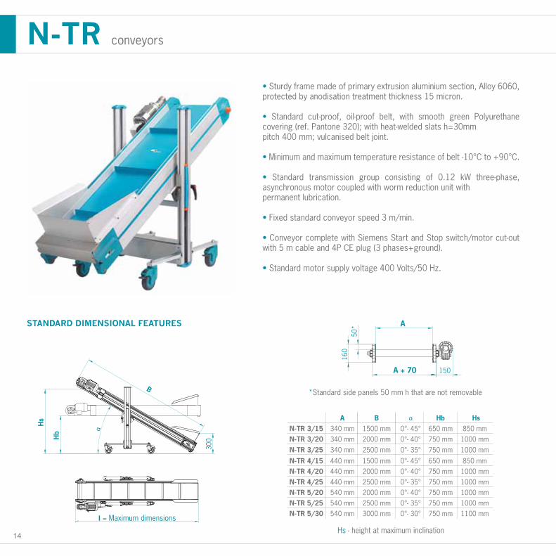
*Standard side panels 50 mm h that are not removable
Hs - height at maximum inclination
• Sturdy frame made of primary extrusion aluminium section, Alloy 6060, protected by anodisation treatment thickness 15 micron.
• Standard cut-proof, oil-proof belt, with smooth green Polyurethane covering (ref. Pantone 320); with heat-welded slats h=30mmpitch 400 mm; vulcanised belt joint.
• Minimum and maximum temperature resistance of belt -10°C to +90°C.
• Standard transmission group consisting of 0.12 kW three-phase, asynchronous motor coupled with worm reduction unit withpermanent lubrication.
• Fixed standard conveyor speed 3 m/min.
• Conveyor complete with Siemens Start and Stop switch/motor cut-out with 5 m cable and 4P CE plug (3 phases+ground).
• Standard motor supply voltage 400 Volts/50 Hz.
N-TR conveyors
SEPARATO
RS
16
25°
- 50°
H m
in
H m
ax
250
(+20
0)
C = 700
B
I = ingombro massimo a 40°
50* A
150
160
A + 70
A
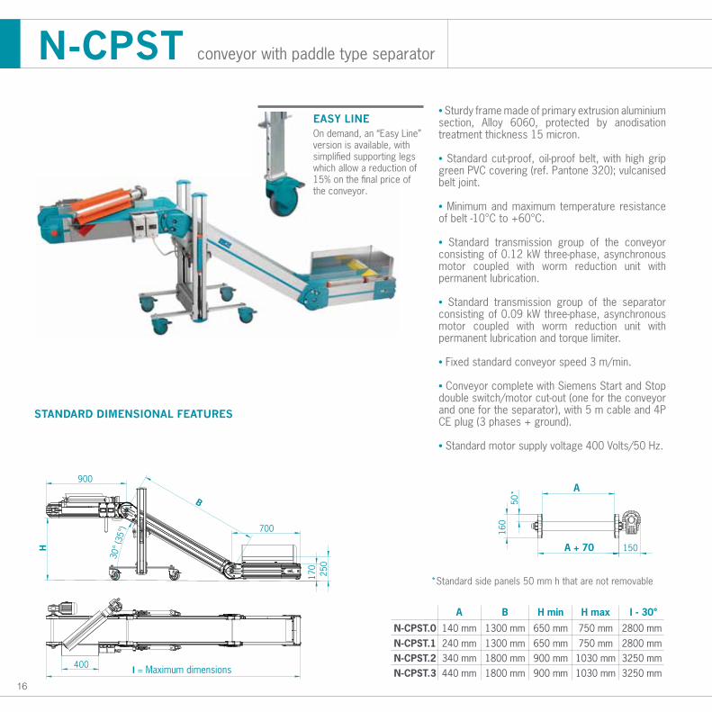
240 mm340 mm
B
1300 mm1800 mm
H min
650 mm900 mm
H max
750 mm1030 mm
I - 30°
2800 mm3250 mm
440 mm
N-CPST.1140 mm 1300 mm 650 mm 750 mm 2800 mmN-CPST.0
N-CPST.2N-CPST.3 1800 mm 900 mm 1030 mm 3250 mm
STANDARD DIMENSIONAL FEATURES
N-CPST conveyor with paddle type separator
• Sturdy frame made of primary extrusion aluminium section, Alloy 6060, protected by anodisation treatment thickness 15 micron.
• Standard cut-proof, oil-proof belt, with high grip green PVC covering (ref. Pantone 320); vulcanised belt joint.
• Minimum and maximum temperature resistance of belt -10°C to +60°C.
• Standard transmission group of the conveyor consisting of 0.12 kW three-phase, asynchronous motor coupled with worm reduction unit with permanent lubrication.
• Standard transmission group of the separator consisting of 0.09 kW three-phase, asynchronous motor coupled with worm reduction unit with permanent lubrication and torque limiter.
• Fixed standard conveyor speed 3 m/min.
• Conveyor complete with Siemens Start and Stop double switch/motor cut-out (one for the conveyor and one for the separator), with 5 m cable and 4P CE plug (3 phases + ground).
• Standard motor supply voltage 400 Volts/50 Hz.
*Standard side panels 50 mm h that are not removable
50
A
150
160
A + 60
900
H
700
170
B
30°
(35°
)
I = Maximum dimensions400
250
EASY LINEOn demand, an “Easy Line” version is available, with simplified supporting legs which allow a reduction of 15% on the final price of the conveyor.
17
L
110
300
200
AA
min 5 - max 100
L
120
250
Section A - A
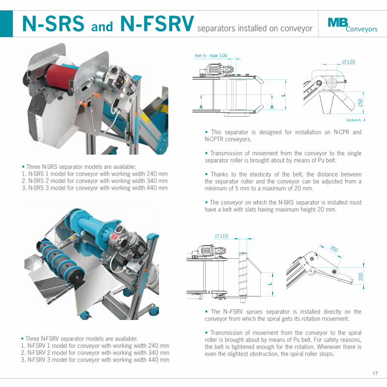
• Three N-SRS separator models are available: 1. N-SRS 1 model for conveyor with working width 240 mm 2. N-SRS 2 model for conveyor with working width 340 mm 3. N-SRS 3 model for conveyor with working width 440 mm
• This separator is designed for installation on N-CPR and N-CPTR conveyors.
• Transmission of movement from the conveyor to the single separator roller is brought about by means of Pu belt.
• Thanks to the elasticity of the belt, the distance between the separator roller and the conveyor can be adjusted from a minimum of 5 mm to a maximum of 20 mm.
• The conveyor on which the N-SRS separator is installed must have a belt with slats having maximum height 20 mm.
• The N–FSRV sprues separator is installed directly on the conveyor from which the spiral gets its rotation movement.
• Transmission of movement from the conveyor to the spiral roller is brought about by means of Pu belt. For safety reasons, the belt is tightened enough for the rotation. Whenever there is even the slightest obstruction, the spiral roller stops.
• Three N-FSRV separator models are available: 1. N-FSRV 1 model for conveyor with working width 240 mm 2. N-FSRV 2 model for conveyor with working width 340 mm 3. N-FSRV 3 model for conveyor with working width 440 mm
N-SRS and N-FSRV separators installed on conveyor
18
STANDARD DIMENSIONAL FEATURES
SR - SM separators
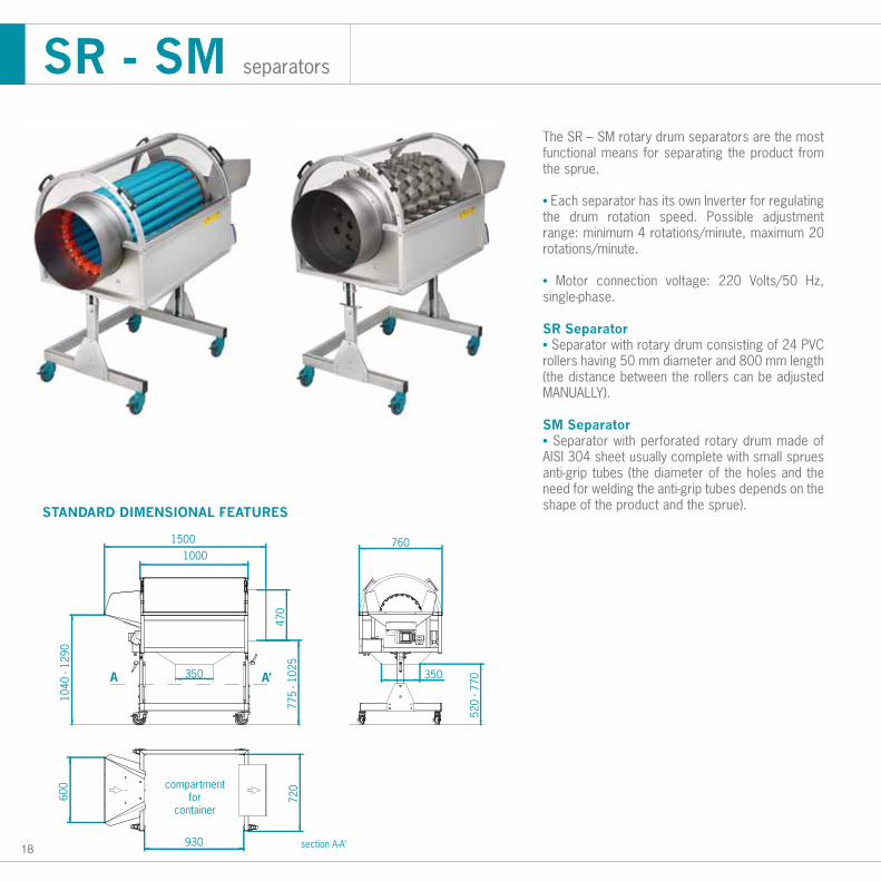
The SR – SM rotary drum separators are the most functional means for separating the product from the sprue.
• Each separator has its own Inverter for regulating the drum rotation speed. Possible adjustment range: minimum 4 rotations/minute, maximum 20 rotations/minute.
• Motor connection voltage: 220 Volts/50 Hz, single-phase.
SR Separator• Separator with rotary drum consisting of 24 PVC rollers having 50 mm diameter and 800 mm length (the distance between the rollers can be adjusted MANUALLY).
SM Separator• Separator with perforated rotary drum made of AISI 304 sheet usually complete with small sprues anti-grip tubes (the diameter of the holes and the need for welding the anti-grip tubes depends on the shape of the product and the sprue).
compartmentfor
container
section A-A’
A A’
1000
775
- 102
5
350
760
350
1040
- 12
9060
0
1500
930
720
520
- 770
470
19
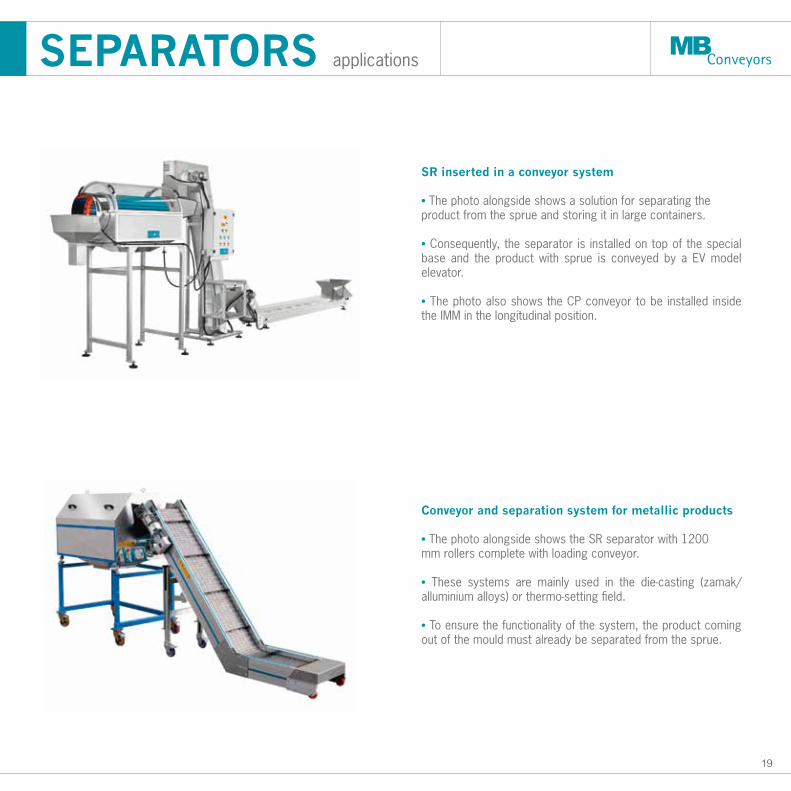
SR inserted in a conveyor system
• The photo alongside shows a solution for separating theproduct from the sprue and storing it in large containers.
• Consequently, the separator is installed on top of the special base and the product with sprue is conveyed by a EV model elevator.
• The photo also shows the CP conveyor to be installed inside the IMM in the longitudinal position.
Conveyor and separation system for metallic products
• The photo alongside shows the SR separator with 1200mm rollers complete with loading conveyor.
• These systems are mainly used in the die-casting (zamak/ alluminium alloys) or thermo-setting field.
• To ensure the functionality of the system, the product coming out of the mould must already be separated from the sprue.
SEPARATORS applications
20
400
760
650
- 850
850
- 105
0
400
STANDARD DIMENSIONAL FEATURES
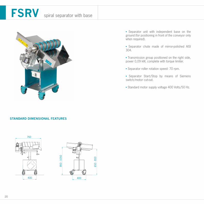
FSRV spiral separator with base
• Separator unit with independent base on the ground (for positioning in front of the conveyor only when required).
• Separator chute made of mirror-polished AISI 304.
• Transmission group positioned on the right side, power 0,09 kW, complete with torque limiter.
• Separator roller rotation speed: 70 rpm.
• Separator Start/Stop by means of Siemens switch/motor cut-out.
• Standard motor supply voltage 400 Volts/50 Hz.
FO
OD
- P
HARM
A
22
F.D.A. food - pharmaceutic
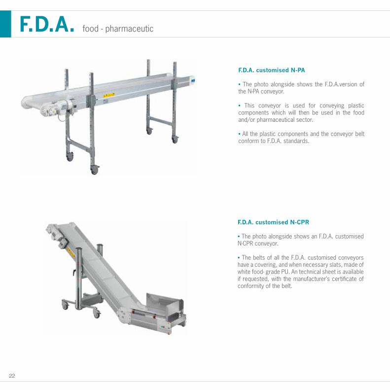
F.D.A. customised N-PA
• The photo alongside shows the F.D.A.version of the N-PA conveyor.
• This conveyor is used for conveying plastic components which will then be used in the food and/or pharmaceutical sector.
• All the plastic components and the conveyor belt conform to F.D.A. standards.
F.D.A. customised N-CPR
• The photo alongside shows an F.D.A. customised N-CPR conveyor.
• The belts of all the F.D.A. customised conveyors have a covering, and when necessary slats, made of white food- grade PU. An technical sheet is available if requested, with the manufacturer’s certificate of conformity of the belt.
23
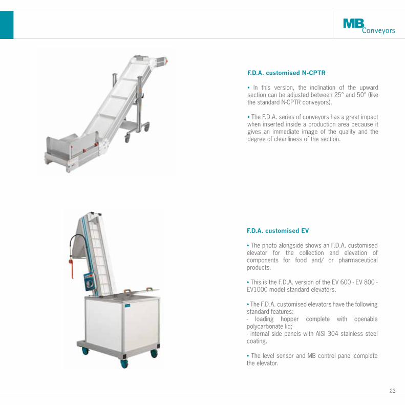
F.D.A. customised N-CPTR
• In this version, the inclination of the upward section can be adjusted between 25° and 50° (like the standard N-CPTR conveyors).
• The F.D.A. series of conveyors has a great impact when inserted inside a production area because it gives an immediate image of the quality and the degree of cleanliness of the section.
F.D.A. customised EV
• The photo alongside shows an F.D.A. customised elevator for the collection and elevation of components for food and/ or pharmaceutical products.
• This is the F.D.A. version of the EV 600 - EV 800 - EV1000 model standard elevators.
• The F.D.A. customised elevators have the following standard features:- loading hopper complete with openable polycarbonate lid; - internal side panels with AISI 304 stainless steel coating.
• The level sensor and MB control panel complete the elevator.
24
F.D.A. applications
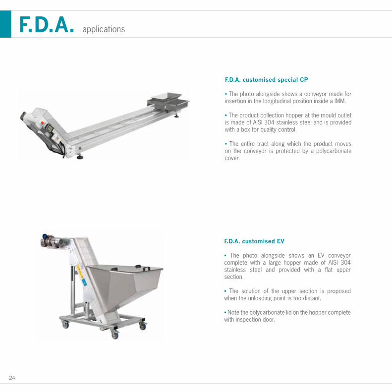
F.D.A. customised special CP
• The photo alongside shows a conveyor made for insertion in the longitudinal position inside a IMM.
• The product collection hopper at the mould outlet is made of AISI 304 stainless steel and is provided with a box for quality control.
• The entire tract along which the product moves on the conveyor is protected by a polycarbonate cover.
F.D.A. customised EV
• The photo alongside shows an EV conveyor complete with a large hopper made of AISI 304 stainless steel and provided with a flat upper section.
• The solution of the upper section is proposed when the unloading point is too distant.
• Note the polycarbonate lid on the hopper complete with inspection door.

METAL D
ETEC
TO
R
26
PLATE METAL DETECTOR
100%
60%
SENSITIVITY RANGE
520
400
150
0 1 2 3 4 5 6 7 8
10
20
30
40
50
60
70
80
90
100
110
120
130
140
150M3 M4 M5 M6 M8 M10M12 M16
IRON NUT
IRON SPHERE (Ø mm)
DETE
CTIO
N H
EIG
HT O
R DI
STAN
CE (m
m)
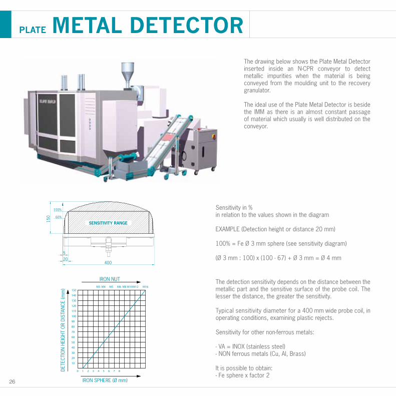
The detection sensitivity depends on the distance between the metallic part and the sensitive surface of the probe coil. The lesser the distance, the greater the sensitivity.
Typical sensitivity diameter for a 400 mm wide probe coil, in operating conditions, examining plastic rejects.
Sensitivity for other non-ferrous metals:
- VA = INOX (stainless steel)- NON ferrous metals (Cu, Al, Brass)
It is possible to obtain:- Fe sphere x factor 2
Sensitivity in %in relation to the values shown in the diagram
EXAMPLE (Detection height or distance 20 mm)
100% = Fe Ø 3 mm sphere (see sensitivity diagram)
(Ø 3 mm : 100) x (100 - 67) + Ø 3 mm = Ø 4 mm
The drawing below shows the Plate Metal Detector inserted inside an N-CPR conveyor to detect metallic impurities when the material is being conveyed from the moulding unit to the recovery granulator.
The ideal use of the Plate Metal Detector is beside the IMM as there is an almost constant passage of material which usually is well distributed on the conveyor.
27
TUNNEL METAL DETECTOR
0 1 2 3 4 5 6 7 8
100
200
300
400
500
M3 M4 M5 M6
IRON NUT
IRON SPHERE (Ø mm)
OPE
NIN
G H
EIG
HT (
mm
)
600
high sensitivity zone
low sensitivity zone
no sensitivity zone
DISTRIBUTION OF SENSITIVITY
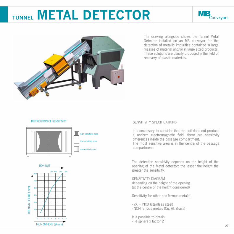
The detection sensitivity depends on the height of the opening of the Metal detector: the lesser the height the greater the sensitivity.
SENSITIVITY DIAGRAM depending on the height of the opening (at the centre of the height considered)
Sensitivity for other non-ferrous metals:
- VA = INOX (stainless steel)- NON ferrous metals (Cu, Al, Brass)
It is possible to obtain:- Fe sphere x factor 2
SENSITIVITY SPECIFICATIONS
It is necessary to consider that the coil does not produce a uniform electromagnetic field: there are sensitivity differences inside the passage compartment.The most sensitive area is in the centre of the passage compartment.
The drawing alongside shows the Tunnel Metal Detector installed on an MB conveyor for the detection of metallic impurities contained in large masses of material and/or in large sized products. These solutions are usually proposed in the field of recovery of plastic materials.
28
METAL DETECTOR applications
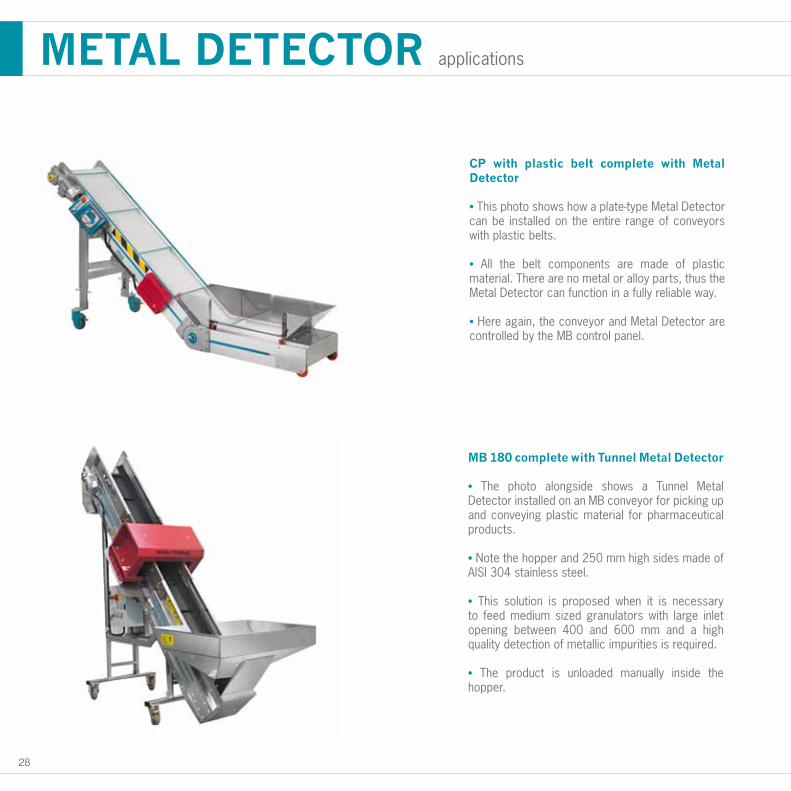
CP with plastic belt complete with Metal Detector
• This photo shows how a plate-type Metal Detector can be installed on the entire range of conveyors with plastic belts.
• All the belt components are made of plastic material. There are no metal or alloy parts, thus the Metal Detector can function in a fully reliable way.
• Here again, the conveyor and Metal Detector are controlled by the MB control panel.
MB 180 complete with Tunnel Metal Detector
• The photo alongside shows a Tunnel Metal Detector installed on an MB conveyor for picking up and conveying plastic material for pharmaceutical products.
• Note the hopper and 250 mm high sides made of AISI 304 stainless steel.
• This solution is proposed when it is necessary to feed medium sized granulators with large inlet opening between 400 and 600 mm and a high quality detection of metallic impurities is required.
• The product is unloaded manually inside the hopper.
PLAS
TIC
AN
D M
ETAL B
ELT
30
16
25
16
50
100
P = 25
P = 25A
16
25
16
50100
P = 25
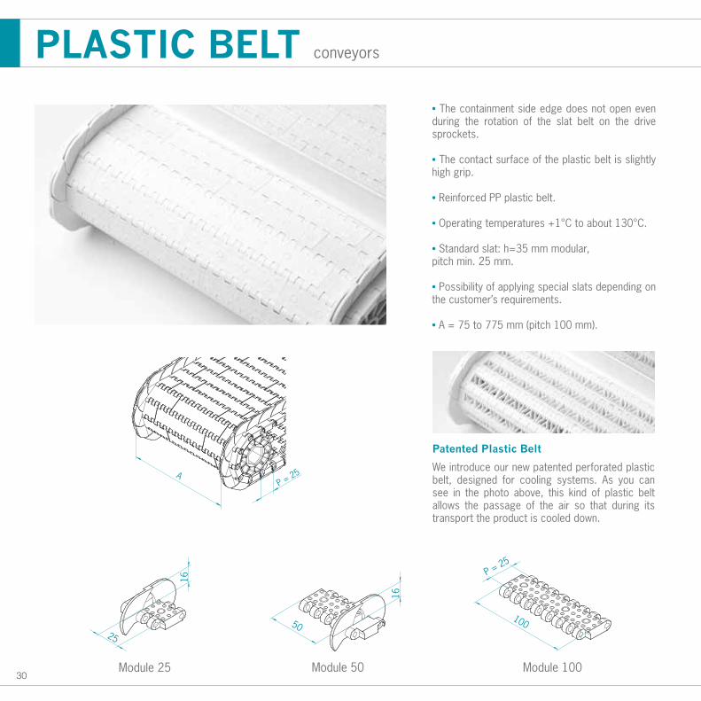
PLASTIC BELT conveyors
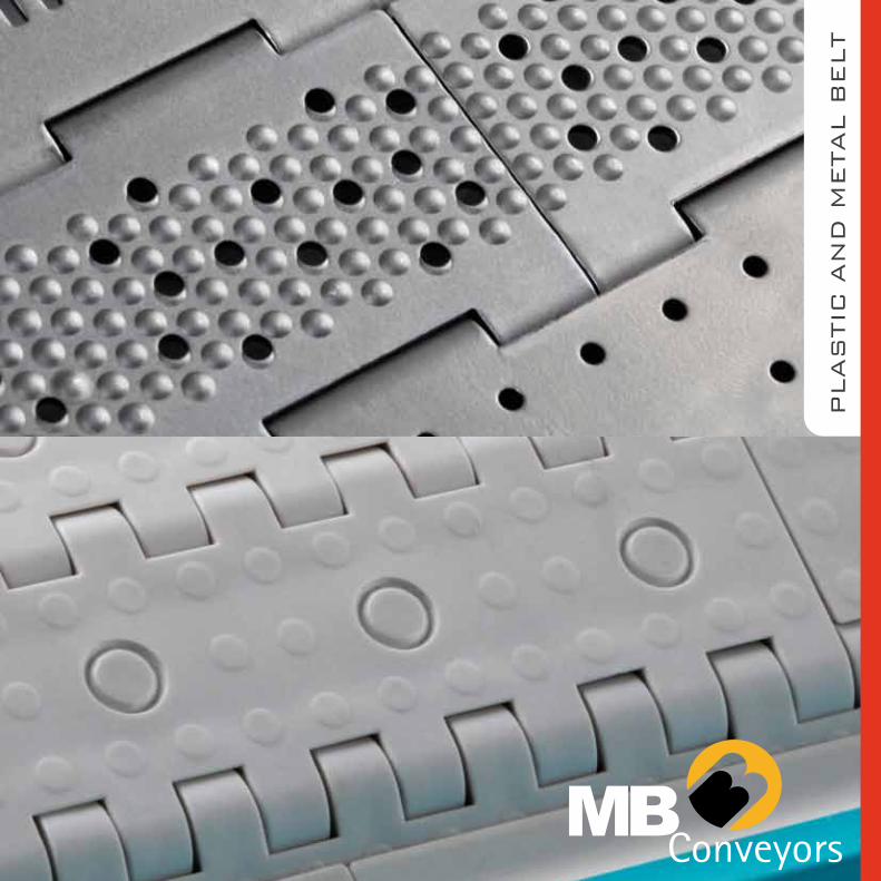
Patented Plastic Belt
We introduce our new patented perforated plastic belt, designed for cooling systems. As you can see in the photo above, this kind of plastic belt allows the passage of the air so that during its transport the product is cooled down.
• The containment side edge does not open even during the rotation of the slat belt on the drive sprockets.
• The contact surface of the plastic belt is slightly high grip.
• Reinforced PP plastic belt.
• Operating temperatures +1°C to about 130°C.
• Standard slat: h=35 mm modular, pitch min. 25 mm.
• Possibility of applying special slats depending on the customer’s requirements.
• A = 75 to 775 mm (pitch 100 mm).
Module 25 Module 50 Module 100
31
PLASTIC BELT applications
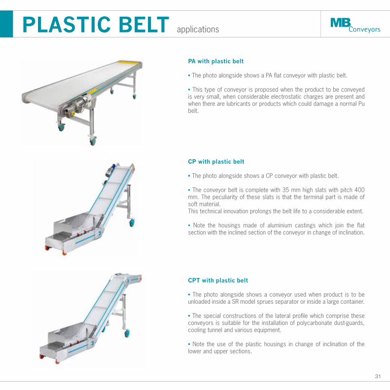
PA with plastic belt • The photo alongside shows a PA flat conveyor with plastic belt.
• This type of conveyor is proposed when the product to be conveyed is very small, when considerable electrostatic charges are present and when there are lubricants or products which could damage a normal Pu belt.
CP with plastic belt • The photo alongside shows a CP conveyor with plastic belt.
• The conveyor belt is complete with 35 mm high slats with pitch 400 mm. The peculiarity of these slats is that the terminal part is made of soft material.This technical innovation prolongs the belt life to a considerable extent.
• Note the housings made of aluminium castings which join the flat section with the inclined section of the conveyor in change of inclination.
CPT with plastic belt
• The photo alongside shows a conveyor used when product is to be unloaded inside a SR model sprues separator or inside a large container.
• The special constructions of the lateral profile which comprise these conveyors is suitable for the installation of polycarbonate dust-guards, cooling tunnel and various equipment.
• Note the use of the plastic housings in change of inclination of the lower and upper sections.
32
Transp
ort direction
A
P = 38.1
50
140.5
100
Ø3
3.5
4
3.5 3.5
22
100
0.5
Ø3Ø3
2.351.8
13
100
1
2
3
4
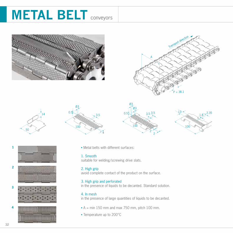
METAL BELT conveyors
• Metal belts with different surfaces:
1. Smoothsuitable for welding/screwing drive slats.
2. High gripavoid complete contact of the product on the surface.
3. High grip and perforatedin the presence of liquids to be decanted. Standard solution.
4. In meshin the presence of large quantities of liquids to be decanted.
• A = min 150 mm and max 750 mm, pitch 100 mm.
• Temperature up to 200°C
33
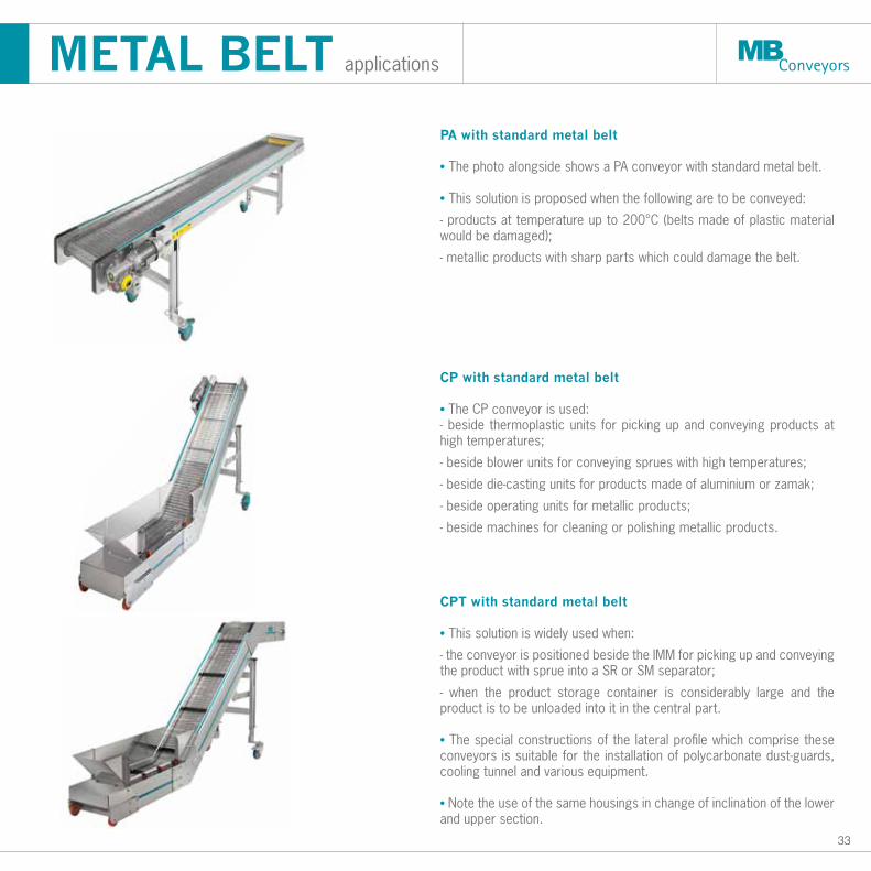
PA with standard metal belt • The photo alongside shows a PA conveyor with standard metal belt.
• This solution is proposed when the following are to be conveyed:
- products at temperature up to 200°C (belts made of plastic material would be damaged);
- metallic products with sharp parts which could damage the belt.
CP with standard metal belt
• The CP conveyor is used:- beside thermoplastic units for picking up and conveying products at high temperatures;
- beside blower units for conveying sprues with high temperatures;
- beside die-casting units for products made of aluminium or zamak;
- beside operating units for metallic products;
- beside machines for cleaning or polishing metallic products.
CPT with standard metal belt • This solution is widely used when:
- the conveyor is positioned beside the IMM for picking up and conveying the product with sprue into a SR or SM separator;
- when the product storage container is considerably large and the product is to be unloaded into it in the central part.
• The special constructions of the lateral profile which comprise these conveyors is suitable for the installation of polycarbonate dust-guards, cooling tunnel and various equipment.
• Note the use of the same housings in change of inclination of the lower and upper section.
METAL BELT applications
34
PLASTIC and METAL BELT applications
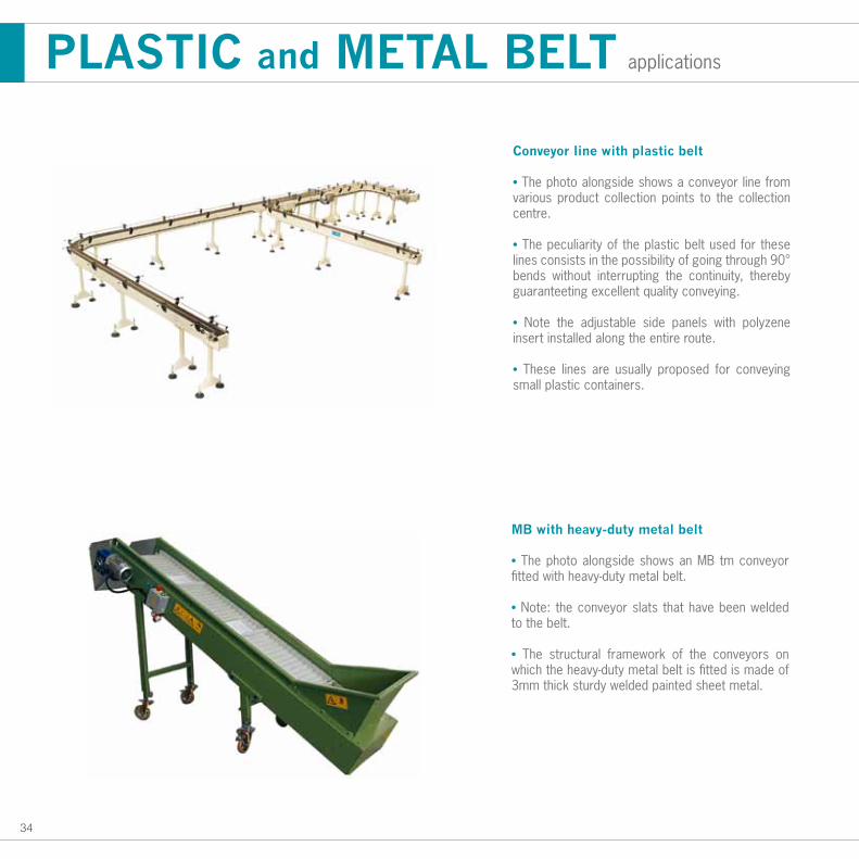
Conveyor line with plastic belt
• The photo alongside shows a conveyor line from various product collection points to the collection centre.
• The peculiarity of the plastic belt used for these lines consists in the possibility of going through 90° bends without interrupting the continuity, thereby guaranteeting excellent quality conveying.
• Note the adjustable side panels with polyzene insert installed along the entire route.
• These lines are usually proposed for conveying small plastic containers.
MB with heavy-duty metal belt
• The photo alongside shows an MB tm conveyor fitted with heavy-duty metal belt.
• Note: the conveyor slats that have been welded to the belt.
• The structural framework of the conveyors on which the heavy-duty metal belt is fitted is made of 3mm thick sturdy welded painted sheet metal.
35PAC
KAG
ING
36
T50 A01
T50 B01
T50 B02
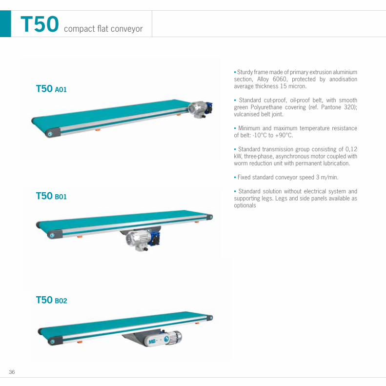
T50 compact flat conveyor
• Sturdy frame made of primary extrusion aluminium section, Alloy 6060, protected by anodisation average thickness 15 micron.
• Standard cut-proof, oil-proof belt, with smooth green Polyurethane covering (ref. Pantone 320); vulcanised belt joint.
• Minimum and maximum temperature resistance of belt: -10°C to +90°C. • Standard transmission group consisting of 0,12 kW, three-phase, asynchronous motor coupled with worm reduction unit with permanent lubrication.
• Fixed standard conveyor speed 3 m/min.
• Standard solution without electrical system and supporting legs. Legs and side panels available as optionals
37
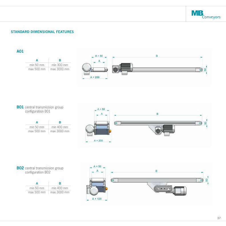
A B
min 50 mm min 300 mmmax 500 mm max 3000 mm
A B
min 50 mm min 400 mmmax 500 mm max 3000 mm
A B
min 50 mm min 400 mmmax 500 mm max 3000 mm
A01
STANDARD DIMENSIONAL FEATURES
B01 central transmission group configuration B01
B02 central transmission group configuration B02
38
H m
in 1
000
H m
ax 1
800
840
B
A
STANDARD DIMENSIONAL FEATURES
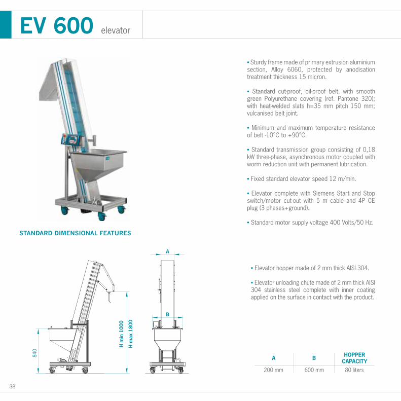
• Sturdy frame made of primary extrusion aluminium section, Alloy 6060, protected by anodisation treatment thickness 15 micron.
• Standard cut-proof, oil-proof belt, with smooth green Polyurethane covering (ref. Pantone 320); with heat-welded slats h=35 mm pitch 150 mm; vulcanised belt joint.
• Minimum and maximum temperature resistance of belt -10°C to +90°C.
• Standard transmission group consisting of 0,18 kW three-phase, asynchronous motor coupled with worm reduction unit with permanent lubrication.
• Fixed standard elevator speed 12 m/min.
• Elevator complete with Siemens Start and Stop switch/motor cut-out with 5 m cable and 4P CE plug (3 phases+ground).
• Standard motor supply voltage 400 Volts/50 Hz.
• Elevator hopper made of 2 mm thick AISI 304.
• Elevator unloading chute made of 2 mm thick AISI 304 stainless steel complete with inner coating applied on the surface in contact with the product.
EV 600 elevator
A
200 mm
B
600 mm
HOPPERCAPACITY
80 liters
39
H m
in 1
250
H m
ax 3
000
B
C
A
STANDARD DIMENSIONAL FEATURES
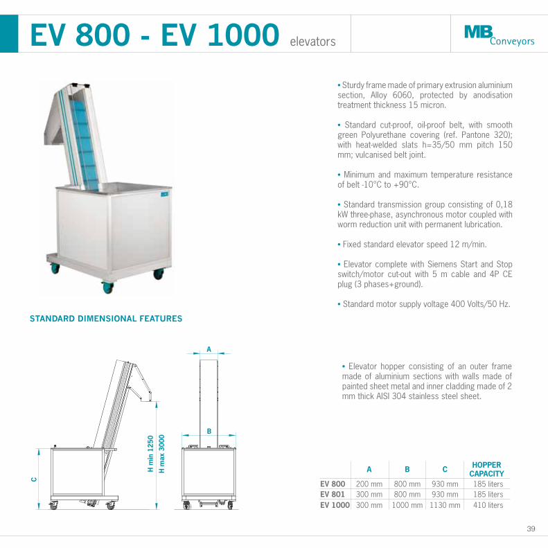
EV 800 - EV 1000 elevators
• Sturdy frame made of primary extrusion aluminium section, Alloy 6060, protected by anodisation treatment thickness 15 micron.
• Standard cut-proof, oil-proof belt, with smooth green Polyurethane covering (ref. Pantone 320); with heat-welded slats h=35/50 mm pitch 150 mm; vulcanised belt joint.
• Minimum and maximum temperature resistance of belt -10°C to +90°C.
• Standard transmission group consisting of 0,18 kW three-phase, asynchronous motor coupled with worm reduction unit with permanent lubrication.
• Fixed standard elevator speed 12 m/min.
• Elevator complete with Siemens Start and Stop switch/motor cut-out with 5 m cable and 4P CE plug (3 phases+ground).
• Standard motor supply voltage 400 Volts/50 Hz.
• Elevator hopper consisting of an outer frame made of aluminium sections with walls made of painted sheet metal and inner cladding made of 2 mm thick AISI 304 stainless steel sheet.
A
800 mm200 mm
B C
930 mm
HOPPERCAPACITY185 liters
800 mm300 mmEV 800EV 801 930 mm 185 liters
1000 mm300 mmEV 1000 1130 mm 410 liters
40
PACKAGING applications
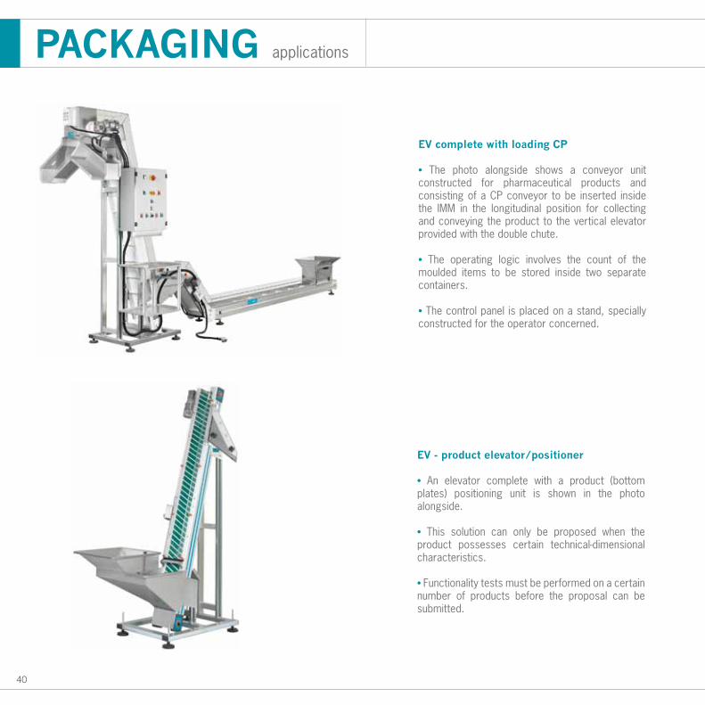
EV complete with loading CP
• The photo alongside shows a conveyor unit constructed for pharmaceutical products and consisting of a CP conveyor to be inserted inside the IMM in the longitudinal position for collecting and conveying the product to the vertical elevator provided with the double chute.
• The operating logic involves the count of the moulded items to be stored inside two separate containers.
• The control panel is placed on a stand, specially constructed for the operator concerned.
EV - product elevator/positioner
• An elevator complete with a product (bottom plates) positioning unit is shown in the photo alongside.
• This solution can only be proposed when the product possesses certain technical-dimensional characteristics.
• Functionality tests must be performed on a certain number of products before the proposal can be submitted.
41STO
RAG
E S
YSTEM
S
42
500
450
200
590
+ 2
00
935
+ 2
00
450
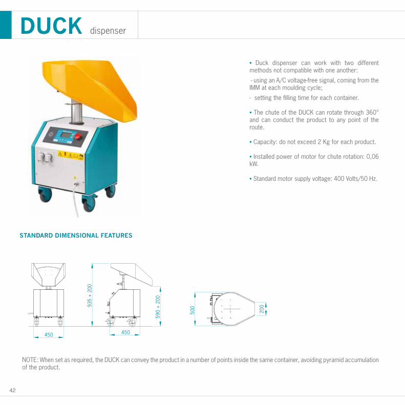
STANDARD DIMENSIONAL FEATURES
• Duck dispenser can work with two different methods not compatible with one another:
- using an A/C voltage-free signal, coming from the IMM at each moulding cycle;
- setting the filling time for each container.
• The chute of the DUCK can rotate through 360° and can conduct the product to any point of the route.
• Capacity: do not exceed 2 Kg for each product. • Installed power of motor for chute rotation: 0,06 kW.
• Standard motor supply voltage: 400 Volts/50 Hz.
DUCK dispenser
NOTE: When set as required, the DUCK can convey the product in a number of points inside the same container, avoiding pyramid accumulation of the product.
43
1010
HD
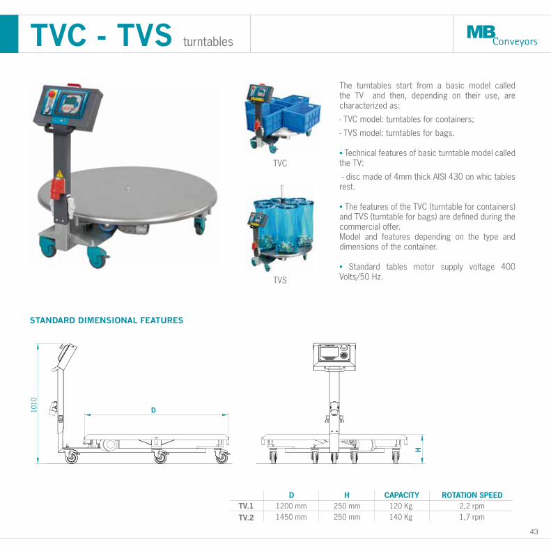
STANDARD DIMENSIONAL FEATURES
The turntables start from a basic model called the TV and then, depending on their use, are characterized as:
- TVC model: turntables for containers;
- TVS model: turntables for bags.
• Technical features of basic turntable model called the TV:
- disc made of 4mm thick AISI 430 on whic tables rest.
• The features of the TVC (turntable for containers) and TVS (turntable for bags) are defined during the commercial offer. Model and features depending on the type and dimensions of the container.
• Standard tables motor supply voltage 400 Volts/50 Hz.
TVC - TVS turntables
TV.1TV.2
D1200 mm1450 mm
H250 mm250 mm
CAPACITY120 Kg140 Kg
ROTATION SPEED2,2 rpm1,7 rpm
TVC
TVS
44
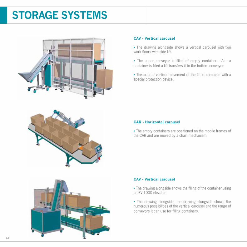
CAV - Vertical carousel
• The drawing alongside shows a vertical carousel with two work floors with side lift.
• The upper conveyor is filled of empty containers. As a container is filled a lift transfers it to the bottom conveyor.
• The area of vertical movement of the lift is complete with a special protection device.
CAR - Horizontal carousel
• The empty containers are positioned on the mobile frames of the CAR and are moved by a chain mechanism.
CAV - Vertical carousel
• The drawing alongside shows the filling of the container using an EV 1000 elevator.
• The drawing alongside, the drawing alongside shows the numerous possibilities of the vertical carousel and the range of conveyors it can use for filling containers.
STORAGE SYSTEMS
45
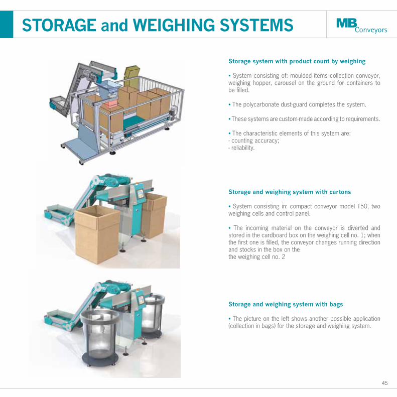
Storage system with product count by weighing
• System consisting of: moulded items collection conveyor, weighing hopper, carousel on the ground for containers to be filled.
• The polycarbonate dust-guard completes the system.
• These systems are custom-made according to requirements.
• The characteristic elements of this system are: - counting accuracy; - reliability.
Storage and weighing system with cartons
• System consisting in: compact conveyor model T50, two weighing cells and control panel.
• The incoming material on the conveyor is diverted and stored in the cardboard box on the weighing cell no. 1; when the first one is filled, the conveyor changes running direction and stocks in the box on thethe weighing cell no. 2
Storage and weighing system with bags
• The picture on the left shows another possible application (collection in bags) for the storage and weighing system.
STORAGE and WEIGHING SYSTEMS
46
STORAGE and WEIGHING SYSTEMS applications
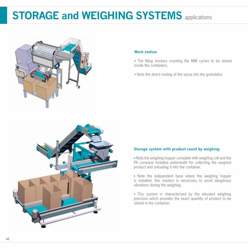
Work station
• The filling involves counting the IMM cycles to be stored inside the containers.
• Note the direct routing of the sprue into the granulator.
Storage system with product count by weighing
• Note the weighing hopper complete with weighing cell and the PA conveyor installed underneath for collecting the weighed product and unloading it into the container.
• Note the independent base where the weighing hopper is installed: this solution is necessary to avoid dangerous vibrations during the weighing.
• This system is characterised by the elevated weighing precision which provides the exact quantity of product to be stored in the container.
PET
48 * dimensioni determinate dalla tipologia pressa
2870
1300 1300
1570
860
1900
3540
1700
55°*
*
* dimensioni determinate dalla tipologia pressa
2870
1300 1300
1570
860
1900
3540
1700
55°*
*
STANDARD DIMENSIONAL FEATURES
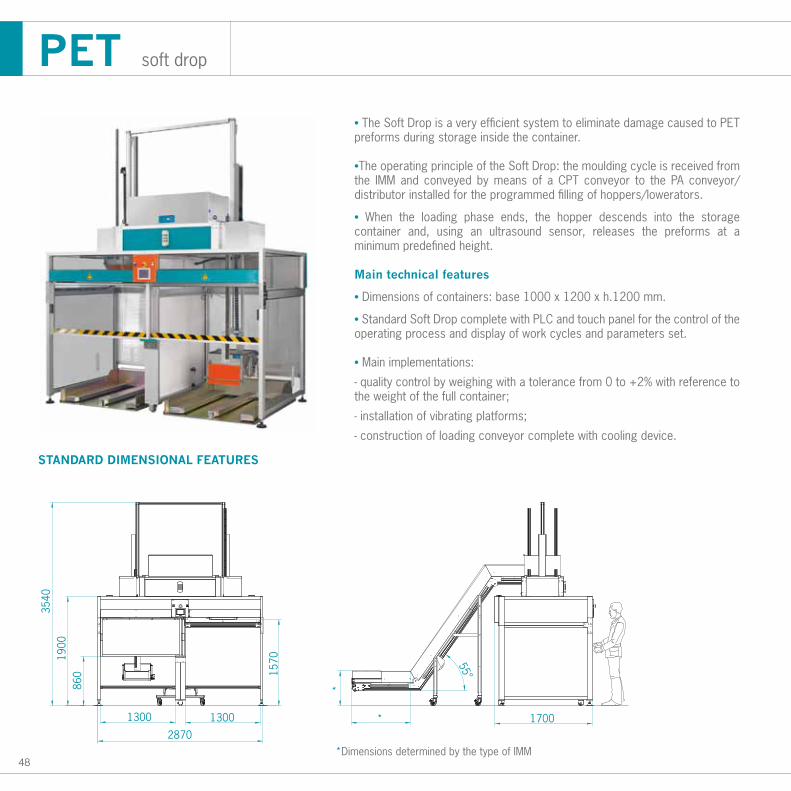
PET soft drop
*Dimensions determined by the type of IMM
• The Soft Drop is a very efficient system to eliminate damage caused to PET preforms during storage inside the container.
•The operating principle of the Soft Drop: the moulding cycle is received from the IMM and conveyed by means of a CPT conveyor to the PA conveyor/distributor installed for the programmed filling of hoppers/lowerators.
• When the loading phase ends, the hopper descends into the storage container and, using an ultrasound sensor, releases the preforms at a minimum predefined height.
Main technical features
• Dimensions of containers: base 1000 x 1200 x h.1200 mm.
• Standard Soft Drop complete with PLC and touch panel for the control of the operating process and display of work cycles and parameters set.
• Main implementations:
- quality control by weighing with a tolerance from 0 to +2% with reference to the weight of the full container;
- installation of vibrating platforms;
- construction of loading conveyor complete with cooling device.
49
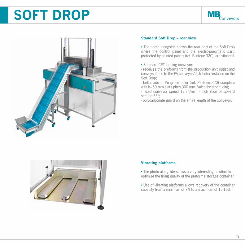
Standard Soft Drop – rear view
• The photo alongside shows the rear part of the Soft Drop where the control panel and the electro-pneumatic part, protected by painted panels (ref. Pantone 320), are situated.
• Standard CPT loading conveyor:- receives the preforms from the production unit outlet and conveys these to the PA conveyor/distributor installed on the Soft Drop;- belt made of Pu green color (ref. Pantone 320) complete with h=50 mm slats pitch 300 mm. Vulcanised belt joint;- Fixed conveyor speed 17 m/min; - inclination of upward section 55°; - polycarbonate guard on the entire length of the conveyor.
Vibrating platforms
• The photo alongside shows a very interesting solution tooptimize the filling quality of the preforms storage container.
• Use of vibrating platforms allows recovery of the container capacity from a minimum of 7% to a maximum of 15-16%.
SOFT DROP
50
1300
55°m
ax
D
C
B
1350
FG
400
STANDARD DIMENSIONAL FEATURES
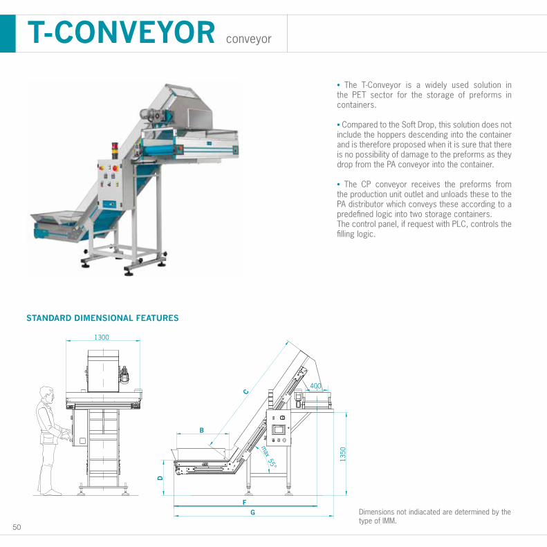
T-CONVEYOR conveyor
• The T-Conveyor is a widely used solution in the PET sector for the storage of preforms in containers.
• Compared to the Soft Drop, this solution does not include the hoppers descending into the container and is therefore proposed when it is sure that there is no possibility of damage to the preforms as they drop from the PA conveyor into the container.
• The CP conveyor receives the preforms from the production unit outlet and unloads these to the PA distributor which conveys these according to a predefined logic into two storage containers.The control panel, if request with PLC, controls the filling logic.
Dimensions not indiacated are determined by the type of IMM.
MB C
ON
TRO
L P
AN
EL
52
340
110
155
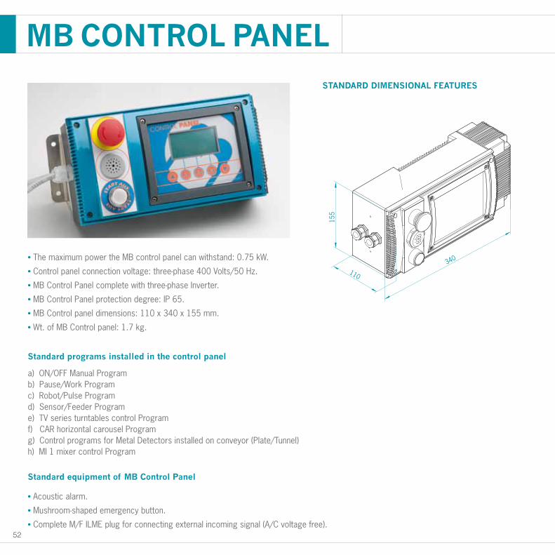
MB CONTROL PANEL
• The maximum power the MB control panel can withstand: 0.75 kW.
• Control panel connection voltage: three-phase 400 Volts/50 Hz.
• MB Control Panel complete with three-phase Inverter.
• MB Control Panel protection degree: IP 65.
• MB Control panel dimensions: 110 x 340 x 155 mm.
• Wt. of MB Control panel: 1.7 kg.
Standard programs installed in the control panel
a) ON/OFF Manual Programb) Pause/Work Programc) Robot/Pulse Programd) Sensor/Feeder Programe) TV series turntables control Programf) CAR horizontal carousel Programg) Control programs for Metal Detectors installed on conveyor (Plate/Tunnel)h) MI 1 mixer control Program
Standard equipment of MB Control Panel
• Acoustic alarm.
• Mushroom-shaped emergency button.
• Complete M/F ILME plug for connecting external incoming signal (A/C voltage free).
STANDARD DIMENSIONAL FEATURES
53
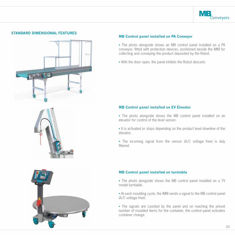
STANDARD DIMENSIONAL FEATURESMB Control panel installed on PA Conveyor • The photo alongside shows an MB control panel installed on a PA conveyor, fitted with protection devices, positioned beside the IMM for collecting and conveying the product deposited by the Robot.
• With the door open, the panel inhibits the Robot descent.
MB Control panel installed on turntable • The photo alongside shows the MB control panel installed on a TV model turntable.
• At each moulding cycle, the IMM sends a signal to the MB control panel (A/C voltage free).
• The signals are counted by the panel and on reaching the preset number of moulded items for the container, the control panel activates container change.
MB Control panel installed on EV Elevator • The photo alongside shows the MB control panel installed on an elevator for control of the level sensor.
• It is activated or stops depending on the product level downline of the elevator.
• The incoming signal from the sensor (A/C voltage free) is duly filtered.
54
NEW!
A
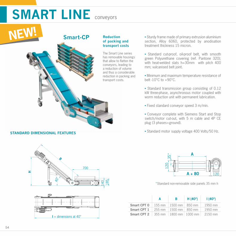
1500 mm155 mm
B H (40°) I (40°)
850 mm 1950 mm1500 mm255 mm
Smart CPT 0Smart CPT 1 850 mm 1950 mm
1800 mm355 mmSmart CPT 2 1000 mm 2150 mm
140
185
700
H
B
40°
I = ingombro massimo a 40°
A
A + 80 120
120
35*
• Sturdy frame made of primary extrusion aluminium section, Alloy 6060, protected by anodisation treatment thickness 15 micron.
• Standard cut-proof, oil-proof belt, with smooth green Polyurethane covering (ref. Pantone 320); with heat-welded slats h=30mm with pitch 400 mm; vulcanised belt joint.
• Minimum and maximum temperature resistance of belt -10°C to +90°C.
• Standard transmission group consisting of 0.12 kW three-phase, asynchronous motor coupled with worm reduction unit with permanent lubrication.
• Fixed standard conveyor speed 3 m/min.
• Conveyor complete with Siemens Start and Stop switch/motor cut-out, with 5 m cable and 4P CE plug (3 phases+ground).
• Standard motor supply voltage 400 Volts/50 Hz. STANDARD DIMENSIONAL FEATURES
Reduction of packing and transport costs
The Smart Line series has removable housings that allow to flatten the conveyors, leading to a reduction of volume and thus a considerable reduction in packing and transport costs.
Smart-CP
SMART LINE conveyors
*Standard non-removable side panels 35 mm h140
185
700
H
B
40°
I = dimensions at 40°
A
A + 80 120
120
35*
A
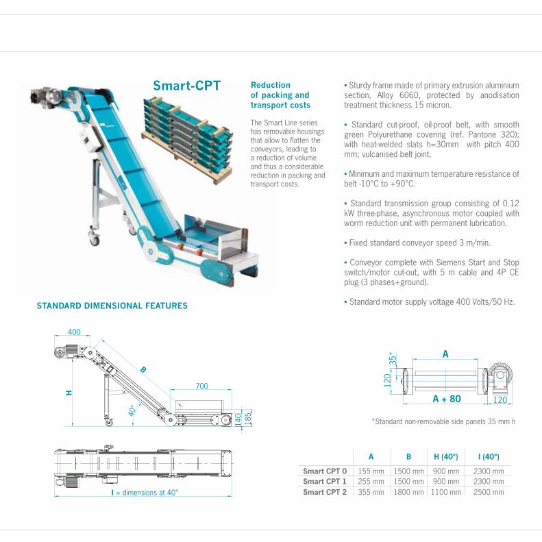
1500 mm155 mm
B H (40°) I (40°)
900 mm 2300 mm1500 mm255 mm
Smart CPT 0Smart CPT 1 900 mm 2300 mm
1800 mm355 mmSmart CPT 2 1100 mm 2500 mm
A
A + 80 120
120
35*
700
400
H
B
40°
I = ingombro massimo a 40°
140
185
• Sturdy frame made of primary extrusion aluminium section, Alloy 6060, protected by anodisation treatment thickness 15 micron.
• Standard cut-proof, oil-proof belt, with smooth green Polyurethane covering (ref. Pantone 320); with heat-welded slats h=30mm with pitch 400 mm; vulcanised belt joint.
• Minimum and maximum temperature resistance of belt -10°C to +90°C.
• Standard transmission group consisting of 0.12 kW three-phase, asynchronous motor coupled with worm reduction unit with permanent lubrication.
• Fixed standard conveyor speed 3 m/min.
• Conveyor complete with Siemens Start and Stop switch/motor cut-out, with 5 m cable and 4P CE plug (3 phases+ground).
• Standard motor supply voltage 400 Volts/50 Hz.
Smart-CPT
STANDARD DIMENSIONAL FEATURES
Reduction of packing and transport costs
The Smart Line series has removable housings that allow to flatten the conveyors, leading to a reduction of volume and thus a considerable reduction in packing and transport costs.
*Standard non-removable side panels 35 mm h
A
A + 80 120
120
35*
700
400
H
B
40°
I = dimensions at 40°
140
185
MB Conveyorsvia della Scienza n.736070 Brogliano - VIItaly
T +39 0445 444555F +39 0445 444599
www.mbconveyors.com MB
Con
veyo
rs s
.r.l.
rese
rves
the
right
to c
hang
e th
eir p
rodu
cts
and
spec
ifica
tions
giv
en in
this
bro
chur
e w
ithou
t prio
r not
ice.