Embed Size (px)
Citation preview
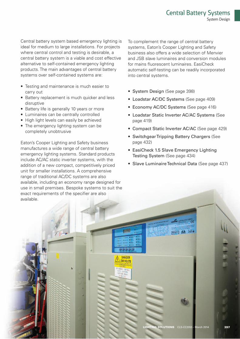
Central battery system based emergency lighting isideal for medium to large installations. For projectswhere central control and testing is desirable, acentral battery system is a viable and cost effectivealternative to self-contained emergency lightingproducts. The main advantages of central batterysystems over self-contained systems are:
• Testing and maintenance is much easier to carry out• Battery replacement is much quicker and less disruptive• Battery life is generally 10 years or more• Luminaires can be centrally controlled• High light levels can easily be achieved• The emergency lighting system can be completely unobtrusive
Eaton’s Cooper Lighting and Safety businessmanufactures a wide range of central batteryemergency lighting systems. Standard productsinclude AC/AC static inverter systems, with theaddition of a new compact, competitively pricedunit for smaller installations. A comprehensiverange of traditional AC/DC systems are alsoavailable, including an economy range designed foruse in small premises. Bespoke systems to suit theexact requirements of the specifier are alsoavailable.
To complement the range of central batterysystems, Eaton’s Cooper Lighting and Safetybusiness also offers a wide selection of Menvierand JSB slave luminaires and conversion modulesfor mains fluorescent luminaires. EasiCheckautomatic self-testing can be readily incorporatedinto central systems.
• System Design (See page 398)
• Loadstar AC/DC Systems (See page 409)
• Economy AC/DC Systems (See page 416)
• Loadstar Static Inverter AC/AC Systems (See page 419)
• Compact Static Inverter AC/AC (See page 429)
• Switchgear Tripping Battery Chargers (See page 432)
• EasiCheck 1.5 Slave Emergency Lighting Testing System (See page 434)
• Slave Luminaire Technical Data (See page 437)
397LIGHTING SOLUTIONS CLS-CC2055 - March 2014
Central Battery SystemsSystem Design
398
Central Battery System Design
When it has been decided that a central battery system is themost suitable system of emergency lighting for a particular site,the designer needs to give consideration to the following:
• Lighting design
• Type of system
• System control and mode of operation
• Battery type
• System sizing
• Battery room ventilation
Lighting Design Considerations
Current legislation and design increases the attraction of usingcentral battery systems to provide emergency lighting in abuilding.In particular, an increase in the use of static inverter systems,which provide an alternative source of power to normal mainsluminaires. These considerations can be summarised as follows:
1. BS 5266 part 7 (EN 1838) specifies increased emergency light levels than previous standards
2. Slave luminaires, operating from AC/DC and AC/AC central systems, offer a higher light output and improved spacing characteristics over comparable self-contained versions of the same luminaire
3. Compact fluorescent lamps make ideal slave luminaires, offering high efficiency and appropriate light output for areas with low ceilings
4. There is an increasing requirement from architects and users to make emergency lighting as unobtrusive as possible, so utilisation of the normal mains luminaires is an ideal solution
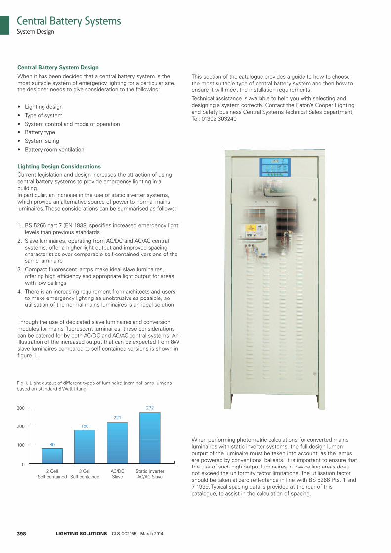
Through the use of dedicated slave luminaires and conversionmodules for mains fluorescent luminaires, these considerationscan be catered for by both AC/DC and AC/AC central systems. Anillustration of the increased output that can be expected from 8Wslave luminaires compared to self-contained versions is shown infigure 1.
This section of the catalogue provides a guide to how to choosethe most suitable type of central battery system and then how toensure it will meet the installation requirements.
Technical assistance is available to help you with selecting anddesigning a system correctly. Contact the Eaton’s Cooper Lightingand Safety business Central Systems Technical Sales department,Tel: 01302 303240
When performing photometric calculations for converted mainsluminaires with static inverter systems, the full design lumenoutput of the luminaire must be taken into account, as the lampsare powered by conventional ballasts. It is important to ensure thatthe use of such high output luminaires in low ceiling areas doesnot exceed the uniformity factor limitations. The utilisation factorshould be taken at zero reflectance in line with BS 5266 Pts. 1 and7 1999. Typical spacing data is provided at the rear of thiscatalogue, to assist in the calculation of spacing.
Central Battery SystemsSystem Design
LIGHTING SOLUTIONS CLS-CC2055 - March 2014
2 CellSelf-contained
80
3 CellSelf-contained
180
AC/DCSlave
221
Static InverterAC/AC Slave
272
0
100
200
300
Fig 1. Light output of different types of luminaire (nominal lamp lumensbased on standard 8 Watt fitting)
399
Central Battery SystemsSystem Design
LIGHTING SOLUTIONS CLS-CC2055 - March 2014
Type of System
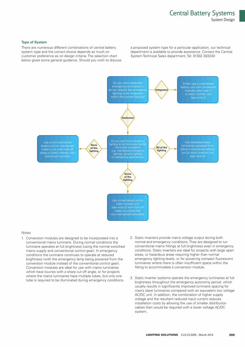
There are numerous different combinations of central batterysystem type and the correct choice depends as much oncustomer preference as on design criteria. The selection chartbelow gives some general guidance. Should you wish to discuss
Notes
1. Conversion modules are designed to be incorporated into a conventional mains luminaire. During normal conditions the luminaire operates at full brightness (using the normal switched mains supply and conventional control gear). In emergency conditions the luminaire continues to operate at reduced brightness (with the emergency lamp being powered from the conversion module instead of the conventional control gear). Conversion modules are ideal for use with mains luminaires which have louvres with a sharp cut off angle, or for projects where the mains luminaires have multiple tubes, but only one tube is required to be illuminated during emergency conditions.
a proposed system type for a particular application, our technicaldepartment is available to provide assistance. Contact the CentralSystem Technical Sales department, Tel: 01302 303240
Do you want dedicatedemergency luminaires or
do you require the emergencylighting to be integrated
within the normal lighting?
Either use a maintainedbattery unit with conversion
modules (see note 1)or static inverter unit
(see note 2)
Use a non-maintainedbattery unit or maintainedbattery unit with hold off
relays or static inverter withsub-circuit monitors
Do you want the emergencylighting to be illuminated whilst
the mains is healthy?e.g. maintained emergency
lighting, security lightingor nighlighting applications?
Use dedicated slaveluminaires powered from
either a maintained batteryunit or static inverter unit
(see note 3)
Use a maintained unit orstatic inverter unit
(see note 3) with hold offrelays to control the
non-maintained luminaires
Integrated
Dedicated
All of thelighting
Noneof the
lighting
Someof the
lighting
2. Static inverters provide mains voltage output during both normal and emergency conditions. They are designed to run conventional mains fittings at full brightness even in emergency conditions. Static inverters are ideal for projects with large open areas, or hazardous areas requiring higher than normal emergency lighting levels, or for powering compact fluorescent luminaires where there is often insufficient space within the fitting to accommodate a conversion module.
3. Static inverter systems operate the emergency luminaires at full brightness throughout the emergency autonomy period, which usually results in significantly improved luminaire spacing for mains slave luminaires compared with an equivalent low voltage AC/DC unit. In addition, the combination of higher supply voltage and the resultant reduced input current reduces installation costs by allowing the use of smaller distribution cables than would be required with a lower voltage AC/DC system.
400
System Control and Mode of Operation
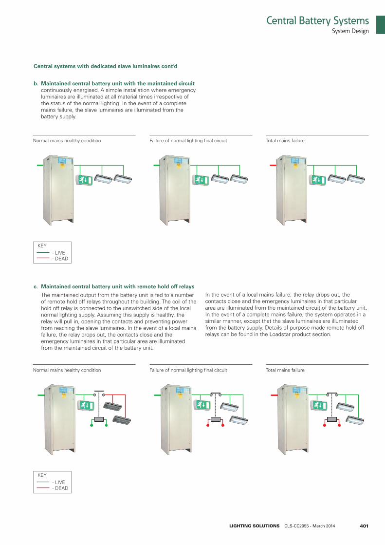
It is a requirement of any correctly designed emergency lightingsystem that the emergency lighting is activated both in the eventof complete mains failure, and also in the event of a local mainsfailure. The emergency lighting system can have luminaires thatare maintained or non-maintained. Similarly, the central batteryunit can also be maintained or non-maintained operation. Thefollowing diagrams explain how activation of the emergencylighting is achieved, using the main types of central batterysystems.
Central systems with dedicated slave luminaires
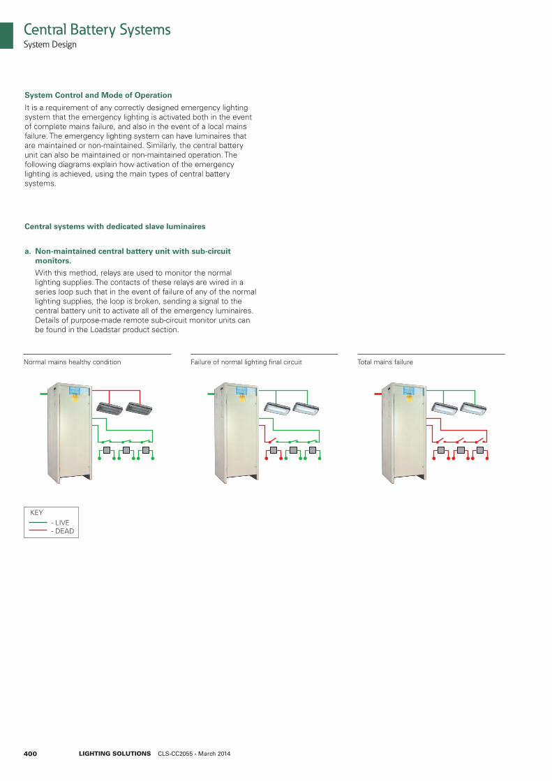
a. Non-maintained central battery unit with sub-circuit monitors.
With this method, relays are used to monitor the normal lighting supplies. The contacts of these relays are wired in a series loop such that in the event of failure of any of the normal lighting supplies, the loop is broken, sending a signal to the central battery unit to activate all of the emergency luminaires. Details of purpose-made remote sub-circuit monitor units can be found in the Loadstar product section.
Central Battery SystemsSystem Design
LIGHTING SOLUTIONS CLS-CC2055 - March 2014
Normal mains healthy condition Failure of normal lighting final circuit Total mains failure
KEY - LIVE - DEAD
401
Central Battery SystemsSystem Design
LIGHTING SOLUTIONS CLS-CC2055 - March 2014
Central systems with dedicated slave luminaires cont’d
b. Maintained central battery unit with the maintained circuit continuously energised. A simple installation where emergency luminaires are illuminated at all material times irrespective of the status of the normal lighting. In the event of a complete mains failure, the slave luminaires are illuminated from the battery supply.
Normal mains healthy condition Failure of normal lighting final circuit Total mains failure
KEY - LIVE - DEAD
c. Maintained central battery unit with remote hold off relays
The maintained output from the battery unit is fed to a number of remote hold off relays throughout the building. The coil of the hold off relay is connected to the unswitched side of the local normal lighting supply. Assuming this supply is healthy, the relay will pull in, opening the contacts and preventing power from reaching the slave luminaires. In the event of a local mains failure, the relay drops out, the contacts close and the emergency luminaires in that particular area are illuminated from the maintained circuit of the battery unit.
In the event of a local mains failure, the relay drops out, thecontacts close and the emergency luminaires in that particulararea are illuminated from the maintained circuit of the battery unit.In the event of a complete mains failure, the system operates in asimilar manner, except that the slave luminaires are illuminatedfrom the battery supply. Details of purpose-made remote hold offrelays can be found in the Loadstar product section.
Normal mains healthy condition Failure of normal lighting final circuit Total mains failure
KEY - LIVE - DEAD
402
Central Battery SystemsSystem Design
LIGHTING SOLUTIONS CLS-CC2055 - March 2014
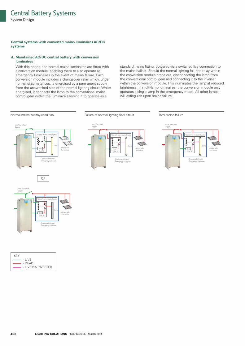
Central systems with converted mains luminaires AC/DCsystems
d. Maintained AC/DC central battery with conversion luminaires
With this option, the normal mains luminaires are fitted with a conversion module, enabling them to also operate as emergency luminaires in the event of mains failure. Each conversion module includes a changeover relay which, under normal circumstances, is energised by a permanent supply from the unswitched side of the normal lighting circuit. Whilst energised, it connects the lamp to the conventional mains control gear within the luminaire allowing it to operate as a
standard mains fitting, powered via a switched live connection tothe mains ballast. Should the normal lighting fail, the relay withinthe conversion module drops out, disconnecting the lamp fromthe conventional control gear and connecting it to the inverterwithin the conversion module. This illuminates the lamp at reducedbrightness. In multi-lamp luminaires, the conversion module onlyoperates a single lamp in the emergency mode. All other lampswill extinguish upon mains failure.
INV
Normal mains control gear
Combined Mains/Emergency Luminaire
Mains onlyLuminaires
Local SwitchedSupply
Lamp
SMCB
INV
Normal mains control gear
Combined Mains/Emergency Luminaire
Mains onlyLuminaires
Local SwitchedSupply
Lamp
SMCB
INV
Normal mains control gear
Combined Mains/Emergency Luminaire
Mains onlyLuminaires
Local SwitchedSupply
Lamp
SMCBINV
Normal mains control gear
Combined Mains/Emergency Luminaire
Mains onlyLuminaires
Local SwitchedSupply
Lamp
SMCB
Normal mains healthy condition Failure of normal lighting final circuit Total mains failure
OR
KEY - LIVE - DEAD - LIVE VIA INVERTER
403
Central Battery SystemsSystem Design
LIGHTING SOLUTIONS CLS-CC2055 - March 2014
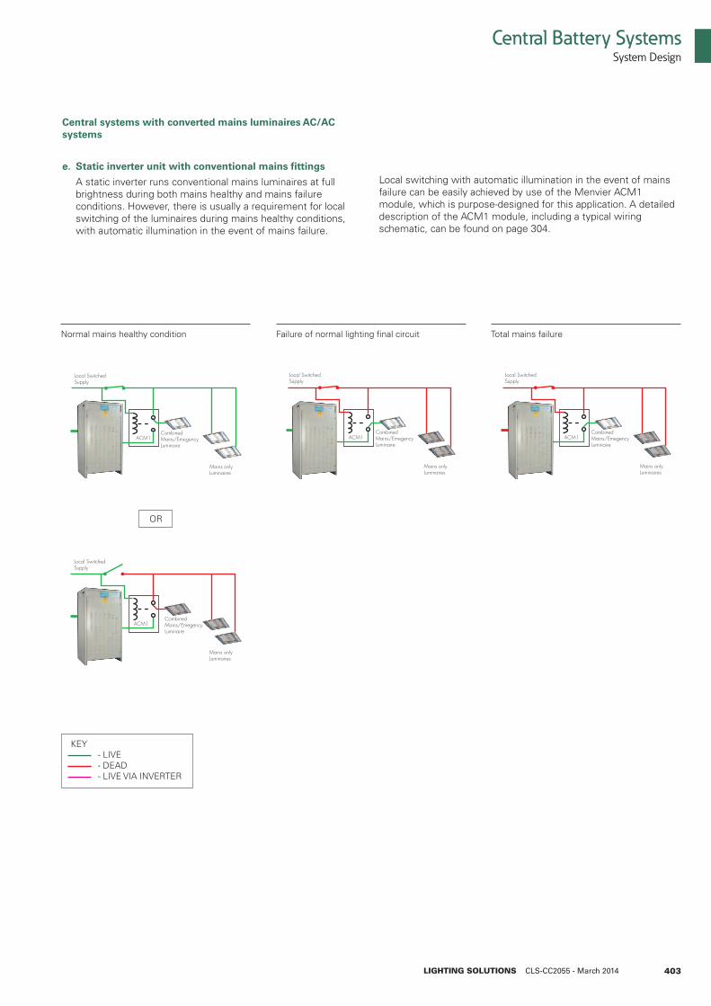
Central systems with converted mains luminaires AC/ACsystems
e. Static inverter unit with conventional mains fittings
A static inverter runs conventional mains luminaires at full brightness during both mains healthy and mains failure conditions. However, there is usually a requirement for local switching of the luminaires during mains healthy conditions, with automatic illumination in the event of mains failure.
Local switching with automatic illumination in the event of mainsfailure can be easily achieved by use of the Menvier ACM1module, which is purpose-designed for this application. A detaileddescription of the ACM1 module, including a typical wiringschematic, can be found on page 304.
Mains onlyLuminaires
CombinedMains/EmegencyLuminaire
Local SwitchedSupply
ACM1
Mains onlyLuminaires
CombinedMains/EmegencyLuminaire
Local SwitchedSupply
ACM1
Mains onlyLuminaires
CombinedMains/EmegencyLuminaire
Local SwitchedSupply
ACM1
Mains onlyLuminaires
CombinedMains/EmegencyLuminaire
Local SwitchedSupply
ACM1
Normal mains healthy condition Failure of normal lighting final circuit Total mains failure
OR
KEY - LIVE - DEAD - LIVE VIA INVERTER
404
Central Battery SystemsSystem Design
LIGHTING SOLUTIONS CLS-CC2055 - March 2014
Battery Type
Eaton’s Cooper Lighting and Safety business offer a choice of fivedifferent battery types:
• Valve regulated lead acid (10 year design life)
• Valve regulated lead acid (3-5 year design life)
• Vented nickel-cadmium
• High performance plante lead acid
• Flat plate lead acid
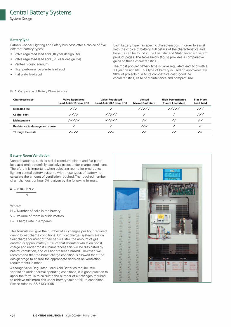
Battery Room Ventilation
Vented batteries, such as nickel cadmium, plante and flat platelead acid emit potentially explosive gases under charge conditions.Therefore it is important when selecting rooms for emergencylighting central battery systems with these types of battery, tocalculate the amount of ventilation required. The required numberof air changes per hour (A) is given by the following formula:
Where:
N = Number of cells in the battery
V = Volume of room in cubic metres
I = Charge rate in Amperes
This formula will give the number of air changes per hour requiredduring boost charge conditions. On float charge (systems are onfloat charge for most of their service life), the amount of gasemitted is approximately 1.5% of that liberated whilst on boostcharge and under most circumstances this will be dissipated bynatural ventilation, and will not present a hazard. However, werecommend that the boost charge condition is allowed for at thedesign stage to ensure the appropriate decision on ventilationrequirements is made.
Although Valve Regulated Lead-Acid Batteries require littleventilation under normal operating conditions, it is good practice toapply the formula to calculate the number of air changes requiredto achieve minimum risk under battery fault or failure conditions.Please refer to: BS 6133:1995
Each battery type has specific characteristics. In order to assistwith the choice of battery, full details of the characteristics andbenefits can be found in the Loadstar and Static Inverter Systemproduct pages. The table below (fig. 2) provides a comparativeguide to these characteristics.
The most popular battery type is valve regulated lead acid with a10 year design life. This type of battery is used on approximately90% of projects due to its competitive cost, good lifecharacteristics, ease of maintenance and compact size.
Fig 2. Comparison of Battery Characteristics
Characteristics Valve Regulated Valve Regulated Vented High Performance Flat Plate Lead Acid (10 year life) Lead Acid (3-5 year life) Nickel Cadmium Plante Lead Acid Lead Acid
Expected life 333 3 33333 33333 333
Capital cost 3333 33333 3 3 333
Maintenance 33333 33333 33 33 33
Resistance to damage and abuse 3 3 333 3 3
Through life costs 3333 333 33 33 33
A = 0.045 x N x I
V
405
Central Battery SystemsSystem Design
LIGHTING SOLUTIONS CLS-CC2055 - March 2014
System Sizing
When sizing the system, it is important to allow for the full inputrequirement of the light fittings rather than the lamp wattages.
AC/DC systems
When using conversion modules fitted to conventional mainsfittings, the lamp will be illuminated directly from the mains ballastduring normal mains healthy operation and via the inverter duringemergency conditions. When being driven from the battery unitvia the conversion module, the emergency lamp will beilluminated at less than full output, and as a result, the fitting willconsume a reduced input power.
AC/AC systems
When utilising a static inverter system, the fitting operates at fulloutput during both mains healthy and mains failure conditions.When sizing a suitable static inverter to power a particular load,it is important to consider the input VA and the input (not lamp)wattage of the emergency luminaires. The total VA requirementdefines the inverter module size, and the total input wattagedefines the battery size.
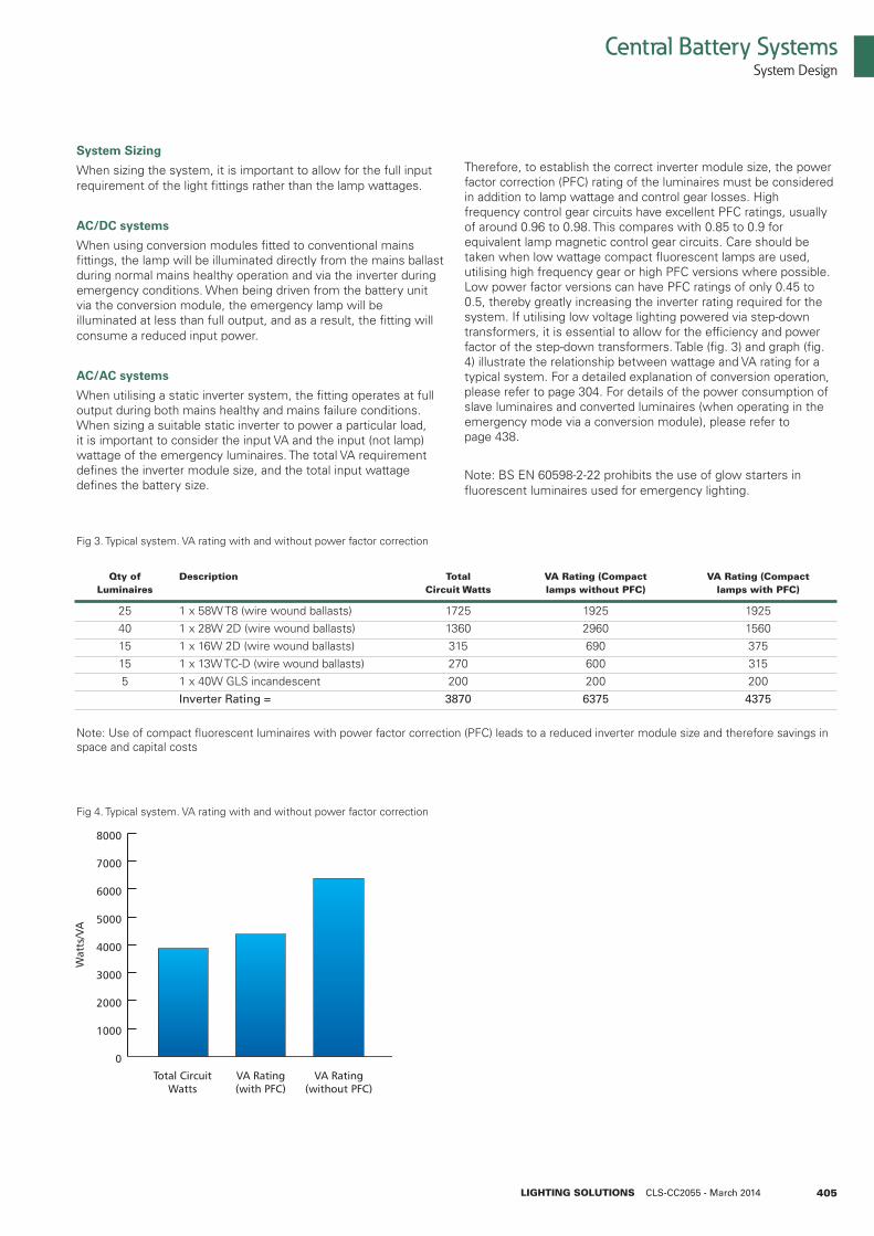
Qty of Description Total VA Rating (Compact VA Rating (Compact Luminaires Circuit Watts lamps without PFC) lamps with PFC)
25 1 x 58W T8 (wire wound ballasts) 1725 1925 1925 40 1 x 28W 2D (wire wound ballasts) 1360 2960 1560 15 1 x 16W 2D (wire wound ballasts) 315 690 375 15 1 x 13W TC-D (wire wound ballasts) 270 600 315 5 1 x 40W GLS incandescent 200 200 200 Inverter Rating = 3870 6375 4375
Therefore, to establish the correct inverter module size, the powerfactor correction (PFC) rating of the luminaires must be consideredin addition to lamp wattage and control gear losses. Highfrequency control gear circuits have excellent PFC ratings, usuallyof around 0.96 to 0.98. This compares with 0.85 to 0.9 forequivalent lamp magnetic control gear circuits. Care should betaken when low wattage compact fluorescent lamps are used,utilising high frequency gear or high PFC versions where possible.Low power factor versions can have PFC ratings of only 0.45 to0.5, thereby greatly increasing the inverter rating required for thesystem. If utilising low voltage lighting powered via step-downtransformers, it is essential to allow for the efficiency and powerfactor of the step-down transformers. Table (fig. 3) and graph (fig.4) illustrate the relationship between wattage and VA rating for atypical system. For a detailed explanation of conversion operation,please refer to page 304. For details of the power consumption ofslave luminaires and converted luminaires (when operating in theemergency mode via a conversion module), please refer topage 438.
Note: BS EN 60598-2-22 prohibits the use of glow starters influorescent luminaires used for emergency lighting.
Fig 4. Typical system. VA rating with and without power factor correction
Note: Use of compact fluorescent luminaires with power factor correction (PFC) leads to a reduced inverter module size and therefore savings inspace and capital costs
Fig 3. Typical system. VA rating with and without power factor correction
406
Additional Considerations
Spare capacity
With any central battery system it is important to bear in mind thatit is difficult to extend the system at a later date unless capacityhas been allowed for at the design stage. For this reason, wewould strongly recommend that some spare capacity is includedwhen selecting the central battery system rating. Our technicaldepartment is available to provide assistance. Contact the CentralSystem team, Tel: 01302 303240 or E-mail:[email protected]
Fire protection of cables
Cables should be routed through areas of low fire risk.The following cables and wiring systems should be used.
a) Cables with inherently high resistance to attack by fire
i) Mineral-insulated copper-sheathed cable in accordance with BS 6207: Part 1
ii) Cable in accordance with BS 6387. The cable should be at least category B
b) Wiring systems requiring additional fire protection.
i) PVC-insulated cables in accordance with BS 6004 in rigid conduits
ii) PVC-insulated cables in accordance with BS 6004 in steel conduit
iii) PVC-insulated and sheathed steel wire armoured cable in accordance with BS 6346 or BS 5467
Systems should be installed in accordance with IEE Regulationsand BS 5266. Additional fire protection may apply. For example, ifcables are buried in the structure of the building.
Central Battery SystemsSystem Design
LIGHTING SOLUTIONS CLS-CC2055 - March 2014
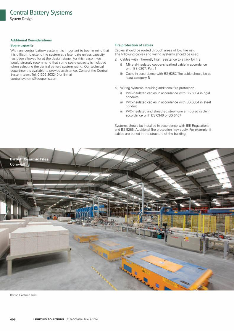
British Ceramic Tiles
British Ceramic TilesCornwall
407
Central Battery SystemsSystem Design
LIGHTING SOLUTIONS CLS-CC2055 - March 2014
Cable sizes
When selecting cable sizes, due regard should be paid tolimitations imposed by voltage drop and physical strength. Eachconductor shall be of copper, having a nominal cross sectional areaof not less than 1mm2. BS 5266 states that the voltage drop incables connecting a central battery to a slave luminaire should notexceed 4% of the system nominal voltage at maximum ratedcurrent.
Using copper conductors, volts drop can be calculated per pairof conductors as shown in table fig. 5. Total volts drop on a circuitcan be calculated according to the formula:
VDT = I x VDM x D
Where:
VDT = volts drop total
I = maximum load current
VDM = volts drop per amp per metre (obtained from fig. 5)
D = cable run in metres
Nominal Cross Maximum Current Volt per Drop Sectional Area Rating per Metre
1.0mm2 14 amps 42mV 1.5mm2 17 amps 28mV 2.5mm2 24 amps 17mV 4.0mm2 32 amps 11mV 6.0mm2 41 amps 7.1mV 10.0mm2 55 amps 4.2mV 16.0mm2 74 amps 2.7mV
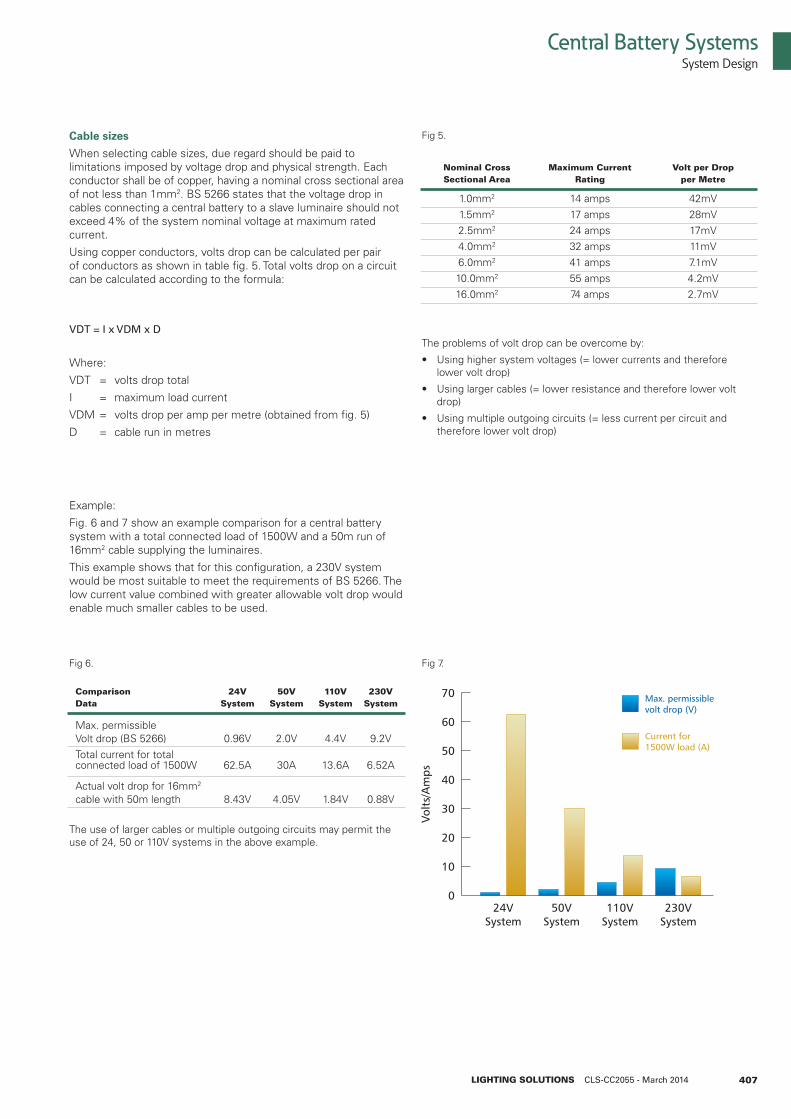
Comparison 24V 50V 110V 230VData System System System System
Max. permissibleVolt drop (BS 5266) 0.96V 2.0V 4.4V 9.2VTotal current for totalconnected load of 1500W 62.5A 30A 13.6A 6.52A
Actual volt drop for 16mm2
cable with 50m length 8.43V 4.05V 1.84V 0.88V
Fig 5.
Fig 6. Fig 7.
The use of larger cables or multiple outgoing circuits may permit theuse of 24, 50 or 110V systems in the above example.
The problems of volt drop can be overcome by:
• Using higher system voltages (= lower currents and therefore lower volt drop)
• Using larger cables (= lower resistance and therefore lower volt drop)
• Using multiple outgoing circuits (= less current per circuit and therefore lower volt drop)
Example:
Fig. 6 and 7 show an example comparison for a central batterysystem with a total connected load of 1500W and a 50m run of16mm2 cable supplying the luminaires.
This example shows that for this configuration, a 230V systemwould be most suitable to meet the requirements of BS 5266. Thelow current value combined with greater allowable volt drop wouldenable much smaller cables to be used.