Embed Size (px)
Citation preview
Correcting the beam centroid motion in an induction acceleratorand reducing the beam breakup instability
J. E. Coleman, C. A. Ekdahl, D. C. Moir, G. W. Sullivan, and M. T. CrawfordLos Alamos National Laboratory, Los Alamos, New Mexico 87545, USA
(Received 9 February 2014; published 15 September 2014)
Axial beam centroid and beam breakup (BBU) measurements were conducted on an 80 ns FWHM,intense relativistic electron bunch with an injected energy of 3.8 MV and current of 2.9 kA. The intenserelativistic electron bunch is accelerated and transported through a nested solenoid and ferrite inductioncore lattice consisting of 64 elements, exiting the accelerator with a nominal energy of 19.8 MeV. Theprincipal objective of these experiments is to quantify the coupling of the beam centroid motion to the BBUinstability and validate the theory of this coupling for the first time. Time resolved centroid measurementsindicate a reduction in the BBU amplitude, hξi, of 19% and a reduction in the BBU growth rate (Γ) of 4%by reducing beam centroid misalignments ∼50% throughout the accelerator. An investigation into thecontribution of the misaligned elements is made. An alignment algorithm is presented in addition to aqualitative comparison of experimental and calculated results which include axial beam centroidoscillations, BBU amplitude, and growth with different dipole steering.
DOI: 10.1103/PhysRevSTAB.17.092802 PACS numbers: 29.27.Bd, 52.59.Sa, 41.75.Ht, 29.20.Ej
I. INTRODUCTION
Relativistic particle accelerators are highly sensitive tocentroid offsets because of the multiple elements used fortransport and acceleration in the accelerator lattice. Thesecentroid offsets can lead to emittance growth and contributeto the beam breakup (BBU) instability or wakefield effects[1–7]. The BBU instability, a transverse magnetic couplingwhich destroys the beam quality, was discovered by theauthors of Refs. [8,9] and has been studied extensively inboth rf and induction accelerators [5,6,10–20]. TheAdvanced Test Accelerator demonstrated the highest inten-sity transport in an induction accelerator to date with a10 kA, 50 MeVelectron beam utilizing phase mix dampingthrough a laser ionized channel to suppress the BBU[12,13,21]. A summary of these previous BBU studiesand recent increased intensity and vacuum transport on aninduction accelerator with 64 cells is described in Ref. [22].Centroid offsets can lead to large emittance growth; this
has been examined analytically for the International LinearCollider (ILC) by several authors over the last decade[1–4]. References [1,2] estimated Δϵ=ϵ ∼ 25% after 50FODO (periodic focusing) cells of quadrupole transport.Reference [1] used a betatron mismatch injection error toinitiate the emittance growth. Reference [2] initiated thegrowth with 100 μm quadrupole misalignments and ran-dom ground motion over long periods of time.References [3,4] analyzed the contribution of centroid
offsets to emittance growth as a function of energy for1 μm quadrupole offset, 15 μrad accelerator cavity tilt, and50 μm correction errors due to beam position monitor(BPM) offsets. Accelerator cavity tilt lead to a linearincrease in emittance with respect to increased energyand the quadrupole offset lead to a much more rapidincrease with respect to increased energy.Beams with intense space charge face a slightly different
challenge. The number of elements in existing inductionlinacs is comparable to a single pass in the ILC. Thetransport magnetic field used in induction linacs is slightlyhigher, but the rigidity ½Bρ� of the beams is > 103 × lowerthan the ILC which contributes to > 1 mm centroid offsetsin the beam distribution. Centroid offsets on DARHTAxesI&II are ∼5 mm throughout the whole accelerator and havebeen estimated to contribute < 4% emittance growth [7].The pulse lengths or bunch lengths of these beams are> 103 × longer. Energy variation from head to tail andmisalignments over these pulses leads to corkscrew, a timedependent centroid motion due to chromaticity [23–25].Estimates of the contribution of displacement and rota-
tional (angular) offsets of the focusing elements to the beamcentroid offsets were made for a nonrelativistic spacecharge dominated Kþ beam in a 4 solenoid lattice[26,27]. Assuming random displacement and rotationaloffsets of 1.5 mm and 5 mrad of each of the 4 solenoids, atotal contribution ∼3 mm and ∼8 mrad was calculated atthe exit of the transport lattice [27]. Reference [26] alsoproposed an alignment algorithm utilizing two dipole pairsin which a 4 × 4matrix is inverted and requires a minimumof five measurements. These dipole correction measure-ments were demonstrated in Refs. [27,28]. Misalignmentsof the emitter and the solenoid lattice contributed to
Published by the American Physical Society under the terms ofthe Creative Commons Attribution 3.0 License. Further distri-bution of this work must maintain attribution to the author(s) andthe published article’s title, journal citation, and DOI.
PHYSICAL REVIEW SPECIAL TOPICS - ACCELERATORS AND BEAMS 17, 092802 (2014)
1098-4402=14=17(9)=092802(12) 092802-1 Published by the American Physical Society
nonlinear focusing effects resulting in a nonuniform Jðx; yÞ[29] and an ensemble of lattice iterations demonstrated thiseffect in Ref. [28].The first axis of the Dual-Axis Radiography for
Hydrodynamic Testing (DARHT) facility [22] is exploringthe limitations of increasing the intensity of the electronbeam for future radiographic capabilities. After increasingthe current by 70% on DARHT Axis-I it was determinedthat the beam centroid was substantially offset and neededto be corrected for transport of the beam to the target. Inorder to effectively increase the intensity of the beam, thecoupling of the beam centroid to BBU must be fullyunderstood and reduced. The results presented belowprovide the first successful demonstration of the reductionof BBU in an induction accelerator through the correctionof the beam centroid and full vacuum transport through 64cells without disruption of the beam quality. These resultsalso provide the first independent validation of the theorywhich explains the coupling of the beam centroid to theBBU instability. The rms centroid was reduced by 50%through the use of a pair of nested dipoles at several zlocations within the accelerator lattice; as a result a 19%reduction in the average BBU amplitude, hξi, and a 4%reduction in the growth rate, Γ, was also observed.
II. BEAM MISALIGNMENTS AND BBUINSTABILITY
As stated in Ref. [22], BBU manifests itself as atransverse magnetic coupling to destroy the beam quality.The BBU growth along the accelerator is characterized bythe equation below [30]:
ξ
ξo¼
�γoγ
�1=2
expðΓmÞ; ð1Þ
where ξ is the measured BBU amplitude at a given locationand ξo is the measured BBU amplitude at the entrance ofthe accelerator. The amplitude decreases with accelerationto 1=2 power and increases exponentially with the maxi-mum growth factor, Γm:
Γm ¼ 1
cIbNgZ⊥
�1
B
�; ð2Þ
where c is the speed of light, Ib (A) is the beam current, Ngis the number of gaps, Z⊥ (Ω=m) is the transverseimpedance of the induction cell cavity, and h1=Bi (1=T)is the average of the inverse magnetic field strength.The impact the beam centroid offset has on the BBU
instability is nested in the transverse coupling impedance,Z⊥ (Ω), of the cells as calculated with the formula, firstderived by Refs. [30,31]
Z⊥Q
¼ ðc R BydzÞ22ωoU
; ð3Þ
where Q is the quality factor of the cell cavity at theresonant frequency, Bydz is the transverse magnetic fieldcomponent which imparts change in the transverse momen-tum to the particles as they traverse the acceleration gap, dz,ωo is the resonant frequency, and U is the stored energy inthe cell. The transverse magnetic field component can alsobe written as a transverse voltage:
Vt ¼ cZ
Bydz: ð4Þ
The coupling of the beam centroid motion to the BBUinstability is rooted in the TM1n0 modes in the inductioncell, which are driven by a displaced current, I, with acentroid offset of hri as shown in the transverse voltageformulation:
Vt ¼ −icωoZ⊥Ihri: ð5Þ
This formulation indicates the importance of minimizingthe beam centroid offset. An estimate of the transversevoltage induced by a 2.9 kA beam with hri ¼ 1 mm in aDARHT Axis-I cell gap with Z⊥ ¼ 1 kΩ and ωo ¼ 4.4 ×10⁹ rad=s is 43 kV. This is 17% of axial voltage providedby the cell to accelerate the beam. The centroid offsetcreates the transverse magnetic field component, Bydz,driving the TM1n0 mode and initiating the BBU, or rfoscillation on the beam envelope. Once initiated, the BBUcentroid oscillation continues to drive the TM1n0 mode inadvancing cavities, which leads to the growth rate of BBUas indicated by Eqs. (1)–(5). As will be shown below inSec. VII reducing the beam centroid motion along theaccelerator by 50% reduced hξi by 19% and Γm by 4%.
III. EXPERIMENTAL SETUP
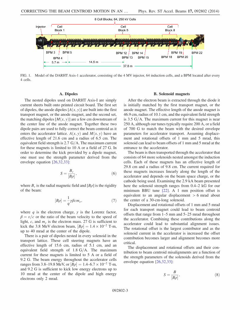
The experimental configuration used to study the cor-rection of the beam centroid and its coupling to the BBUinstability was the DARHT Axis-I linear induction accel-erator (Fig. 1) [22]. The accelerator is composed of a3.8 MV injector and 64, 250 kV induction cells are used toaccelerate the beam to an end point energy of 19.8 MeV.Each induction cell has a nested solenoid and an x and ydipole pair. A minimum number of dipoles were used tocorrect the beam centroid along the length of theaccelerator.Misalignments in induction accelerators are contributed
to nine separate offsets: displacement and rotational offsetsin the diode, beam position monitors, accelerator cells andsolenoids, and finally a rotational offset of the emitter.Including all of the BPMs, cells, and magnets from sourceto target there are 319 individual offsets in this accelerator.Below we will discuss the contributions of the dipoles tobeam alignment and the solenoids and induction cells tobeam misalignment.
COLEMAN et al. Phys. Rev. ST Accel. Beams 17, 092802 (2014)
092802-2
A. Dipoles
The nested dipoles used on DARHT Axis-I are simplycurrent sheets built onto printed circuit board. The first setof dipoles, the anode dipoles [Aðx; yÞ] are built into the firsttransport magnet, or the anode magnet, and the second set,the matching dipoles [Mðx; yÞ] are a few cm downstream ofthe center line of the anode magnet. Together these twodipole pairs are used to fully correct the beam centroid as itenters the accelerator lattice. Aðx; yÞ and Mðx; yÞ have aneffective length of 21.6 cm and a radius of 6.5 cm. Theequivalent field strength is 2.7 G=A. The maximum currentfor these magnets is limited to 10 A or a field of 27 G. Inorder to determine the kick provided by a dipole magnet,one must use the strength parameter derived from theenvelope equation [26,32,33]:
S ¼ Br
½Bρ� ; ð6Þ
where Br is the radial magnetic field and [Bρ] is the rigidityof the beam:
½Bρ� ¼ 1
qγβcme; ð7Þ
where q is the electron charge, γ is the Lorentz factor,β ¼ v=c or the ratio of the beam velocity to the speed oflight, c, and me is the electron mass. 27 G is sufficient tokick the 3.8 MeV electron beam, ½Bρ� ¼ 1.4 × 10⁻² T-m,up to 40 mrad at the center of the dipole.There is a pair of dipoles nested in every solenoid in the
transport lattice. These cell steering magnets have aneffective length of 15.6 cm, radius of 5.1 cm, and anequivalent field strength of 1.8 G=A. The maximumcurrent for these magnets is limited to 5 A or a field of9.2 G. The beam energy throughout the accelerator cellsranges from 3.8–19.8 MeV, or ½Bρ� ¼ 1.4–6.7 × 10⁻² T-m,and 9.2 G is sufficient to kick low energy electrons up to10 mrad at the center of the dipole and high energyelectrons only 2 mrad.
B. Solenoid magnets
After the electron beam is extracted through the diode itis initially matched by the first transport magnet, or theanode magnet. The effective length of the anode magnet is46.9 cm, radius of 10.1 cm, and the equivalent field strengthis 3.5 G=A. The maximum current for this magnet is near250 A, although our tunes typically require 200 A, or a fieldof 700 G to match the beam with the desired envelopeparameters for accelerator transport. Assuming displace-ment and rotational offsets of 1 mm and 5 mrad, thissolenoid can lead to beam offsets of 1 mm and 5 mrad at theentrance to the accelerator.The beam is then transported through the accelerator that
consists of 64 more solenoids nested amongst the inductioncells. Each of these magnets has an effective length of29.8 cm and a radius of 9.8 cm. The current required forthese magnets increases linearly along the length of theaccelerator and depends on the beam space charge, or thecathode being used. Examining the 2.9 kA beam presentedhere the solenoid strength ranges from 0.4–2 kG for ourminimum BBU tune [22]. A 1 mm position offset isequivalent to an angular displacement > 6 mrad aboutthe center of a 30-cm-long solenoid.Displacement and rotational offsets of 1 mm and 5 mrad
for each transport magnet could lead to beam centroidoffsets that range from 1–5 mm and 5–25 mrad throughoutthe accelerator. Combining these contributions along theaccelerator could lead to substantial alignment issues.The rotational offset is the largest contributor and as thesolenoid current in the accelerator is increased the offsetcontribution becomes larger and alignment becomes morecritical.The displacement and rotational offsets and their con-
tribution to beam centroid misalignments are a function ofthe strength parameters of the solenoids derived from theenvelope equation [26,32,33]:
S ¼ B½Bρ� ; ð8Þ
FIG. 1. Model of the DARHTAxis-1 accelerator, consisting of the 4 MV injector, 64 induction cells, and a BPM located after every4 cells.
CORRECTING THE BEAM CENTROID MOTION IN AN … Phys. Rev. ST Accel. Beams 17, 092802 (2014)
092802-3
where B is the magnetic flux density in the solenoid inTesla and ½Bρ� is the rigidity of the beam defined above.The strength parameter indicates the dependence on themagnetic field and beam energy. Moderate energy beamswith γ < 100 and high space charge, like DARHT Axis-I,require large B (> 1 kG) for transport and therefore aremore susceptible to centroid offsets > 1 mm.
C. Induction cells
Once the electron beam is matched by the first transportmagnet and cell magnet it traverses the first induction cellgap. The Axis-I induction cell design is described inRefs. [22,34]. Each cell consists of a ferrite induction corethat is driven with an oil-insulated transmission line. Thedisplacement and rotational offsets and their contribution tobeam centroid misalignments are a function of the strengthparameters of the induction cells derived from the envelopeequation [26,32,33]:
S ¼ Φγβ3c½Bρ�
π
L; ð9Þ
where Φ is the acceleration voltage applied across theinduction cell gap, which is typically 250 kV, and L isthe accelerating gap length, which is 19 mm. Thisformulation indicates a 1 mm cell offset on the first cellkicks the 3.8 MeV beam, ½Bρ� ¼ 1.4 × 10⁻² T-m, about2 mrad. Once γ > 12, after the first cell block, the kick< 1 mrad and becomes negligible with increasing γ. Tiltsdue to the induction cells can be ignored because theacceleration gap is only 19 mm providing a minimaldipole kick. The solenoid magnets and dipoles have alarger contribution to the beam centroid offset, particu-larly at lower energy.
IV. CENTROID MEASUREMENTS
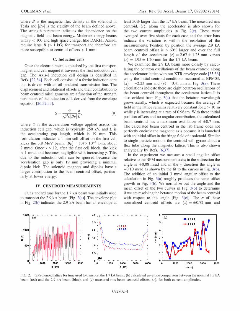
Our standard tune for the 1.7 kA beam was initially usedto transport the 2.9 kA beam [Fig. 2(a)]. The envelope plotin Fig. 2(b) indicates the 2.9 kA beam has an envelope at
least 50% larger than the 1.7 kA beam. The measured rmscentroid, hri, along the accelerator is also shown forthe two current amplitudes in Fig. 2(c). These wereaveraged over five shots for each case and the error barsindicate the variation is within the resolution of themeasurements. Position by position the average 2.9 kAbeam centroid offset is > 60% larger and over the fulllength of the accelerator hri ¼ 2.67� 1.25 mm versushri ¼ 1.95� 1.20 mm for the 1.7 kA beam.We examined the 2.9 kA beam more closely by calcu-
lating the betatron oscillations of the beam centroid alongthe accelerator lattice with our XTR envelope code [35,36]using the initial centroid conditions measured at BPM03,hxi ¼ −2.23 mm and hyi ¼ 0.41 mm in Fig. 3(a). Thesecalculations indicate there are eight betatron oscillations ofthe beam centroid throughout the accelerator lattice. It isalso evident from Fig. 3(a) that the betatron wavelengthgrows axially, which is expected because the average Bfield in the lattice remains relatively constant for z > 10 mwhile γ is increasing at a rate of 0.96=m. With these initialposition offsets and no angular contribution, the calculatedbeam centroid has a maximum oscillation of �0.7 mm.The calculated beam centroid in the lab frame does notperfectly encircle the magnetic axis because it is launchedwith an initial offset in the fringe field of a solenoid. Similarto single particle motion, the centroid will gyrate about aflux tube along the magnetic lattice. This is also shownanalytically by Refs. [6,37].In the experiment we measure a small angular offset
relative to the BPMmeasurement axis; in the x direction theangle is þ0.08 mrad and in the y direction the angle is−0.10 mrad as shown by the fit to the curves in Fig. 3(b).The addition of an initial 3 mrad angular offset to thecalculation in Fig. 3(a) roughly produces the same offsetgrowth in Fig. 3(b). We normalize out the angle and themean offset of the two curves in Fig. 3(b) to determineif we are resolving the betatron motion of the beam centroidwith respect to this angle [Fig. 3(c)]. The σ of thesenormalized centroid offsets are hxi ¼ �0.72 mm and
FIG. 2. (a) Solenoid lattice for tune used to transport the 1.7 kA beam, (b) calculated envelope comparison between the nominal 1.7 kAbeam (red) and the 2.9 kA beam (blue), and (c) measured rms beam centroid offsets, hri, for both current amplitudes.
COLEMAN et al. Phys. Rev. ST Accel. Beams 17, 092802 (2014)
092802-4
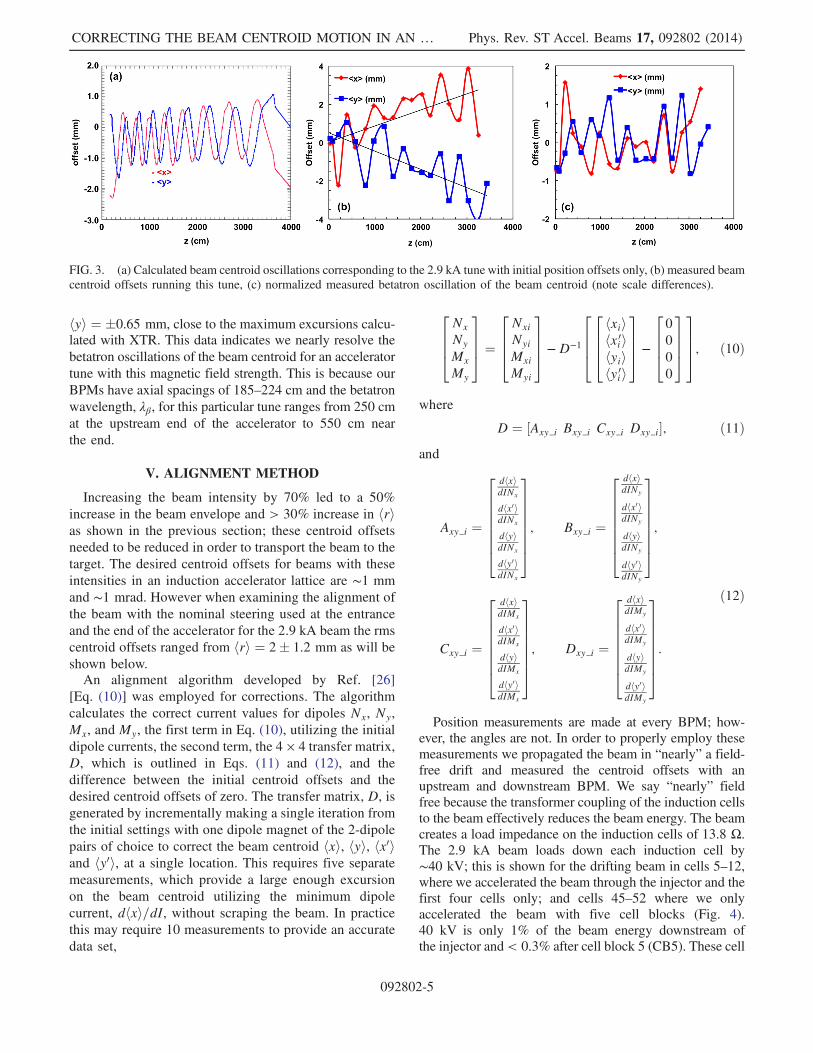
hyi ¼ �0.65 mm, close to the maximum excursions calcu-lated with XTR. This data indicates we nearly resolve thebetatron oscillations of the beam centroid for an acceleratortune with this magnetic field strength. This is because ourBPMs have axial spacings of 185–224 cm and the betatronwavelength, λβ, for this particular tune ranges from 250 cmat the upstream end of the accelerator to 550 cm nearthe end.
V. ALIGNMENT METHOD
Increasing the beam intensity by 70% led to a 50%increase in the beam envelope and > 30% increase in hrias shown in the previous section; these centroid offsetsneeded to be reduced in order to transport the beam to thetarget. The desired centroid offsets for beams with theseintensities in an induction accelerator lattice are ∼1 mmand ∼1 mrad. However when examining the alignment ofthe beam with the nominal steering used at the entranceand the end of the accelerator for the 2.9 kA beam the rmscentroid offsets ranged from hri ¼ 2� 1.2 mm as will beshown below.An alignment algorithm developed by Ref. [26]
[Eq. (10)] was employed for corrections. The algorithmcalculates the correct current values for dipoles Nx, Ny,Mx, and My, the first term in Eq. (10), utilizing the initialdipole currents, the second term, the 4 × 4 transfer matrix,D, which is outlined in Eqs. (11) and (12), and thedifference between the initial centroid offsets and thedesired centroid offsets of zero. The transfer matrix, D, isgenerated by incrementally making a single iteration fromthe initial settings with one dipole magnet of the 2-dipolepairs of choice to correct the beam centroid hxi, hyi, hx0iand hy0i, at a single location. This requires five separatemeasurements, which provide a large enough excursionon the beam centroid utilizing the minimum dipolecurrent, dhxi=dI, without scraping the beam. In practicethis may require 10 measurements to provide an accuratedata set,
2664Nx
Ny
Mx
My
3775 ¼
2664Nxi
Nyi
Mxi
Myi
3775 −D−1
26642664hxiihxi0ihyiihyi0i
3775 −
26640
0
0
0
37753775; ð10Þ
where
D ¼ ½Axy i Bxy i Cxy i Dxy i�; ð11Þand
Axy i ¼
26666664
dhxidINx
dhx0idINx
dhyidINx
dhy0idINx
37777775; Bxy i ¼
26666664
dhxidINy
dhx0idINy
dhyidINy
dhy0idINy
37777775;
Cxy i ¼
26666664
dhxidIMx
dhx0idIMx
dhyidIMx
dhy0idIMx
37777775; Dxy i ¼
26666664
dhxidIMy
dhx0idIMy
dhyidIMy
dhy0idIMy
37777775:
ð12Þ
Position measurements are made at every BPM; how-ever, the angles are not. In order to properly employ thesemeasurements we propagated the beam in “nearly” a field-free drift and measured the centroid offsets with anupstream and downstream BPM. We say “nearly” fieldfree because the transformer coupling of the induction cellsto the beam effectively reduces the beam energy. The beamcreates a load impedance on the induction cells of 13.8 Ω.The 2.9 kA beam loads down each induction cell by∼40 kV; this is shown for the drifting beam in cells 5–12,where we accelerated the beam through the injector and thefirst four cells only; and cells 45–52 where we onlyaccelerated the beam with five cell blocks (Fig. 4).40 kV is only 1% of the beam energy downstream ofthe injector and< 0.3% after cell block 5 (CB5). These cell
FIG. 3. (a) Calculated beam centroid oscillations corresponding to the 2.9 kA tune with initial position offsets only, (b) measured beamcentroid offsets running this tune, (c) normalized measured betatron oscillation of the beam centroid (note scale differences).
CORRECTING THE BEAM CENTROID MOTION IN AN … Phys. Rev. ST Accel. Beams 17, 092802 (2014)
092802-5
voltage monitors provide additional confirmation of thebeam loading and the expansion of the envelope due tospace-charge forces. The beam loading is reduced after cell8 in Fig. 4(a) and after cell 48 in Fig. 4(b) because the beamhas begun to scrape and lose current, indicating therestrictions on using downstream BPMs for the alignmentmeasurements described below.
VI. ALIGNMENT MEASUREMENTS
The alignment method mentioned in the previous sectionwas used to steer the beam for a separate higher field tune,
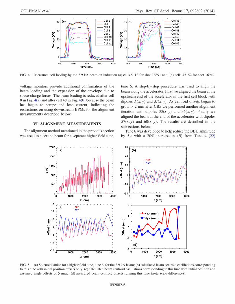
tune 6. A step-by-step procedure was used to align thebeam along the accelerator. First we aligned the beam at theupstream end of the accelerator in the first cell block withdipoles Aðx; yÞ and Mðx; yÞ. As centroid offsets began togrow > 2 mm after CB5 we performed another alignmentiteration with dipoles 33ðx; yÞ and 36ðx; yÞ. Finally wealigned the beam at the end of the accelerator with dipoles57ðx; yÞ and 60ðx; yÞ. The results are described in thesubsections below.Tune 6 was developed to help reduce the BBU amplitude
by 5× with a 20% increase in hBi from Tune 4 [22]
FIG. 4. Measured cell loading by the 2.9 kA beam on induction (a) cells 5–12 for shot 16691 and; (b) cells 45–52 for shot 16949.
FIG. 5. (a) Solenoid lattice for a higher field tune, tune 6, for the 2.9 kA beam; (b) calculated beam centroid oscillations correspondingto this tune with initial position offsets only; (c) calculated beam centroid oscillations corresponding to this tune with initial position andassumed angle offsets of 5 mrad; (d) measured beam centroid offsets running this tune (note scale differences).
COLEMAN et al. Phys. Rev. ST Accel. Beams 17, 092802 (2014)
092802-6
[Figs. 2(a) and 5(a)]. The number of betatron oscillations ofthe beam centroid for this tune is 10 as seen in Fig. 5(b)using the initial centroid offsets measured at BPM03 ofhxi ¼ −1.5 mm and hyi ¼ −1 mm only. The maximumexcursion of the centroid varies �0.7 mm and λβ rangesfrom 250–460 cm. As stated above, the calculated beamcentroid in the lab frame does not perfectly encircle themagnetic axis because it is launched with an initial offset inthe fringe field of a solenoid. The addition of a 5 mradangular offset to the initial beam centroid [Fig. 5(c)]increases the calculated maximum excursion of the centroidthroughout the accelerator > 5× to �4 mm, close to whatis measured in Fig. 5(d), particularly in the downstreamsection. It is also worth noting in the calculation that theaxis of gyration of the beam centroid is> 2 mm away fromthe magnetic axis and is reduced slightly along theaccelerator lattice with ideal magnet alignment. Duringthe experimental setup at this time we were not samplingthe beam centroid on BPMs 7, 9, and 11. The betatronoscillations of the beam centroid increase linearly with themagnetic field; this explains the difficulty of being able toresolve the betatron oscillations with this higher field tune.To resolve the betatron motion of the beam centroid weneed to sample at f > Nyquist, or BPM spacing < λβ=2;for this tune it would require a BPM every 2 cells.
A. Injector steering
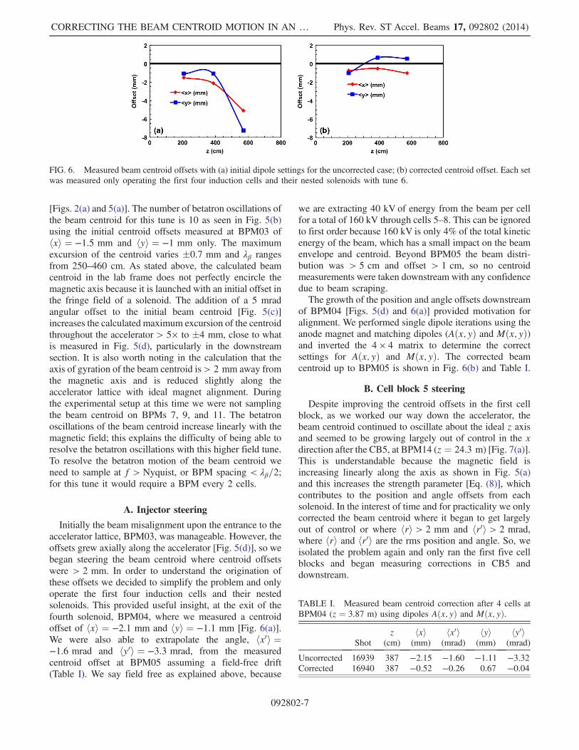
Initially the beam misalignment upon the entrance to theaccelerator lattice, BPM03, was manageable. However, theoffsets grew axially along the accelerator [Fig. 5(d)], so webegan steering the beam centroid where centroid offsetswere > 2 mm. In order to understand the origination ofthese offsets we decided to simplify the problem and onlyoperate the first four induction cells and their nestedsolenoids. This provided useful insight, at the exit of thefourth solenoid, BPM04, where we measured a centroidoffset of hxi ¼ −2.1 mm and hyi ¼ −1.1 mm [Fig. 6(a)].We were also able to extrapolate the angle, hx0i ¼−1.6 mrad and hy0i ¼ −3.3 mrad, from the measuredcentroid offset at BPM05 assuming a field-free drift(Table I). We say field free as explained above, because
we are extracting 40 kV of energy from the beam per cellfor a total of 160 kV through cells 5–8. This can be ignoredto first order because 160 kV is only 4% of the total kineticenergy of the beam, which has a small impact on the beamenvelope and centroid. Beyond BPM05 the beam distri-bution was > 5 cm and offset > 1 cm, so no centroidmeasurements were taken downstream with any confidencedue to beam scraping.The growth of the position and angle offsets downstream
of BPM04 [Figs. 5(d) and 6(a)] provided motivation foralignment. We performed single dipole iterations using theanode magnet and matching dipoles (Aðx; yÞ and Mðx; yÞ)and inverted the 4 × 4 matrix to determine the correctsettings for Aðx; yÞ and Mðx; yÞ. The corrected beamcentroid up to BPM05 is shown in Fig. 6(b) and Table I.
B. Cell block 5 steering
Despite improving the centroid offsets in the first cellblock, as we worked our way down the accelerator, thebeam centroid continued to oscillate about the ideal z axisand seemed to be growing largely out of control in the xdirection after the CB5, at BPM14 (z ¼ 24.3 m) [Fig. 7(a)].This is understandable because the magnetic field isincreasing linearly along the axis as shown in Fig. 5(a)and this increases the strength parameter [Eq. (8)], whichcontributes to the position and angle offsets from eachsolenoid. In the interest of time and for practicality we onlycorrected the beam centroid where it began to get largelyout of control or where hri > 2 mm and hr0i > 2 mrad,where hri and hr0i are the rms position and angle. So, weisolated the problem again and only ran the first five cellblocks and began measuring corrections in CB5 anddownstream.
TABLE I. Measured beam centroid correction after 4 cells atBPM04 (z ¼ 3.87 m) using dipoles Aðx; yÞ and Mðx; yÞ.
Shotz
(cm)hxi(mm)
hx0i(mrad)
hyi(mm)
hy0i(mrad)
Uncorrected 16939 387 −2.15 −1.60 −1.11 −3.32Corrected 16940 387 −0.52 −0.26 0.67 −0.04
FIG. 6. Measured beam centroid offsets with (a) initial dipole settings for the uncorrected case; (b) corrected centroid offset. Each setwas measured only operating the first four induction cells and their nested solenoids with tune 6.
CORRECTING THE BEAM CENTROID MOTION IN AN … Phys. Rev. ST Accel. Beams 17, 092802 (2014)
092802-7
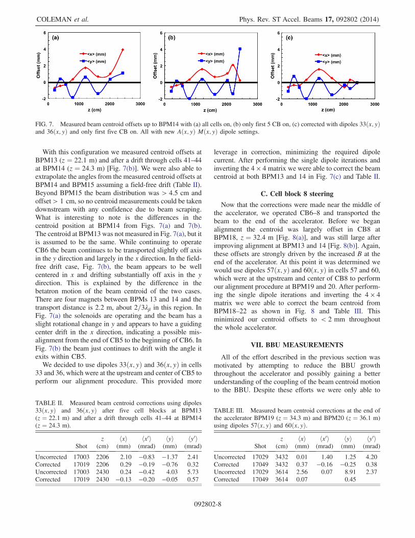
With this configuration we measured centroid offsets atBPM13 (z ¼ 22.1 m) and after a drift through cells 41–44at BPM14 (z ¼ 24.3 m) [Fig. 7(b)]. We were also able toextrapolate the angles from the measured centroid offsets atBPM14 and BPM15 assuming a field-free drift (Table II).Beyond BPM15 the beam distribution was > 4.5 cm andoffset> 1 cm, so no centroid measurements could be takendownstream with any confidence due to beam scraping.What is interesting to note is the differences in thecentroid position at BPM14 from Figs. 7(a) and 7(b).The centroid at BPM13 was not measured in Fig. 7(a), but itis assumed to be the same. While continuing to operateCB6 the beam continues to be transported slightly off axisin the y direction and largely in the x direction. In the field-free drift case, Fig. 7(b), the beam appears to be wellcentered in x and drifting substantially off axis in the ydirection. This is explained by the difference in thebetatron motion of the beam centroid of the two cases.There are four magnets between BPMs 13 and 14 and thetransport distance is 2.2 m, about 2=3λβ in this region. InFig. 7(a) the solenoids are operating and the beam has aslight rotational change in y and appears to have a guidingcenter drift in the x direction, indicating a possible mis-alignment from the end of CB5 to the beginning of CB6. InFig. 7(b) the beam just continues to drift with the angle itexits within CB5.We decided to use dipoles 33ðx; yÞ and 36ðx; yÞ in cells
33 and 36, which were at the upstream and center of CB5 toperform our alignment procedure. This provided more
leverage in correction, minimizing the required dipolecurrent. After performing the single dipole iterations andinverting the 4 × 4 matrix we were able to correct the beamcentroid at both BPM13 and 14 in Fig. 7(c) and Table II.
C. Cell block 8 steering
Now that the corrections were made near the middle ofthe accelerator, we operated CB6–8 and transported thebeam to the end of the accelerator. Before we beganalignment the centroid was largely offset in CB8 atBPM18, z ¼ 32.4 m [Fig. 8(a)], and was still large afterimproving alignment at BPM13 and 14 [Fig. 8(b)]. Again,these offsets are strongly driven by the increased B at theend of the accelerator. At this point it was determined wewould use dipoles 57ðx; yÞ and 60ðx; yÞ in cells 57 and 60,which were at the upstream and center of CB8 to performour alignment procedure at BPM19 and 20. After perform-ing the single dipole iterations and inverting the 4 × 4matrix we were able to correct the beam centroid fromBPM18–22 as shown in Fig. 8 and Table III. Thisminimized our centroid offsets to < 2 mm throughoutthe whole accelerator.
VII. BBU MEASUREMENTS
All of the effort described in the previous section wasmotivated by attempting to reduce the BBU growththroughout the accelerator and possibly gaining a betterunderstanding of the coupling of the beam centroid motionto the BBU. Despite these efforts we were only able to
FIG. 7. Measured beam centroid offsets up to BPM14 with (a) all cells on, (b) only first 5 CB on, (c) corrected with dipoles 33ðx; yÞand 36ðx; yÞ and only first five CB on. All with new Aðx; yÞ Mðx; yÞ dipole settings.
TABLE II. Measured beam centroid corrections using dipoles33ðx; yÞ and 36ðx; yÞ after five cell blocks at BPM13(z ¼ 22.1 m) and after a drift through cells 41–44 at BPM14(z ¼ 24.3 m).
Shotz
(cm)hxi(mm)
hx0i(mrad)
hyi(mm)
hy0i(mrad)
Uncorrected 17003 2206 2.10 −0.83 −1.37 2.41Corrected 17019 2206 0.29 −0.19 −0.76 0.32Uncorrected 17003 2430 0.24 −0.42 4.03 5.73Corrected 17019 2430 −0.13 −0.20 −0.05 0.57
TABLE III. Measured beam centroid corrections at the end ofthe accelerator BPM19 (z ¼ 34.3 m) and BPM20 (z ¼ 36.1 m)using dipoles 57ðx; yÞ and 60ðx; yÞ.
Shotz
(cm)hxi(mm)
hx0i(mrad)
hyi(mm)
hy0i(mrad)
Uncorrected 17029 3432 0.01 1.40 1.25 4.20Corrected 17049 3432 0.37 −0.16 −0.25 0.38Uncorrected 17029 3614 2.56 0.07 8.91 2.37Corrected 17049 3614 0.07 0.45
COLEMAN et al. Phys. Rev. ST Accel. Beams 17, 092802 (2014)
092802-8
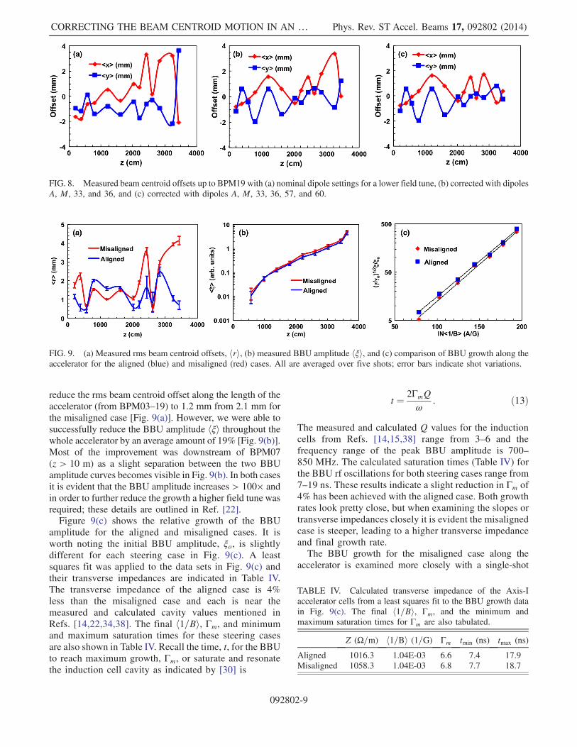
reduce the rms beam centroid offset along the length of theaccelerator (from BPM03–19) to 1.2 mm from 2.1 mm forthe misaligned case [Fig. 9(a)]. However, we were able tosuccessfully reduce the BBU amplitude hξi throughout thewhole accelerator by an average amount of 19% [Fig. 9(b)].Most of the improvement was downstream of BPM07(z > 10 m) as a slight separation between the two BBUamplitude curves becomes visible in Fig. 9(b). In both casesit is evident that the BBU amplitude increases > 100× andin order to further reduce the growth a higher field tune wasrequired; these details are outlined in Ref. [22].Figure 9(c) shows the relative growth of the BBU
amplitude for the aligned and misaligned cases. It isworth noting the initial BBU amplitude, ξo, is slightlydifferent for each steering case in Fig. 9(c). A leastsquares fit was applied to the data sets in Fig. 9(c) andtheir transverse impedances are indicated in Table IV.The transverse impedance of the aligned case is 4%less than the misaligned case and each is near themeasured and calculated cavity values mentioned inRefs. [14,22,34,38]. The final h1=Bi, Γm, and minimumand maximum saturation times for these steering casesare also shown in Table IV. Recall the time, t, for the BBUto reach maximum growth, Γm, or saturate and resonatethe induction cell cavity as indicated by [30] is
t ¼ 2ΓmQω
: ð13Þ
The measured and calculated Q values for the inductioncells from Refs. [14,15,38] range from 3–6 and thefrequency range of the peak BBU amplitude is 700–850 MHz. The calculated saturation times (Table IV) forthe BBU rf oscillations for both steering cases range from7–19 ns. These results indicate a slight reduction in Γm of4% has been achieved with the aligned case. Both growthrates look pretty close, but when examining the slopes ortransverse impedances closely it is evident the misalignedcase is steeper, leading to a higher transverse impedanceand final growth rate.The BBU growth for the misaligned case along the
accelerator is examined more closely with a single-shot
FIG. 8. Measured beam centroid offsets up to BPM19 with (a) nominal dipole settings for a lower field tune, (b) corrected with dipolesA, M, 33, and 36, and (c) corrected with dipoles A, M, 33, 36, 57, and 60.
FIG. 9. (a) Measured rms beam centroid offsets, hri, (b) measured BBU amplitude hξi, and (c) comparison of BBU growth along theaccelerator for the aligned (blue) and misaligned (red) cases. All are averaged over five shots; error bars indicate shot variations.
TABLE IV. Calculated transverse impedance of the Axis-Iaccelerator cells from a least squares fit to the BBU growth datain Fig. 9(c). The final h1=Bi, Γm, and the minimum andmaximum saturation times for Γm are also tabulated.
Z (Ω=m) h1=Bi (1=G) Γm tmin (ns) tmax (ns)
Aligned 1016.3 1.04E-03 6.6 7.4 17.9Misaligned 1058.3 1.04E-03 6.8 7.7 18.7
CORRECTING THE BEAM CENTROID MOTION IN AN … Phys. Rev. ST Accel. Beams 17, 092802 (2014)
092802-9
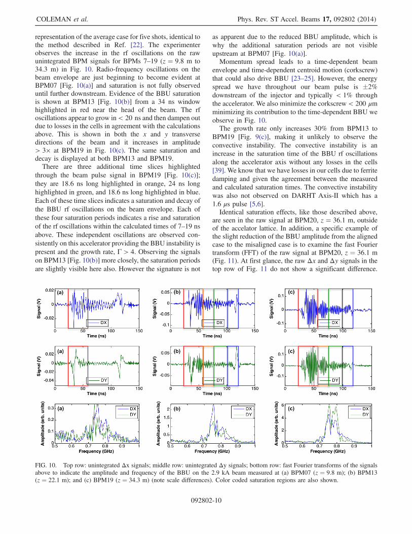
representation of the average case for five shots, identical tothe method described in Ref. [22]. The experimenterobserves the increase in the rf oscillations on the rawunintegrated BPM signals for BPMs 7–19 (z ¼ 9.8 m to34.3 m) in Fig. 10. Radio-frequency oscillations on thebeam envelope are just beginning to become evident atBPM07 [Fig. 10(a)] and saturation is not fully observeduntil further downstream. Evidence of the BBU saturationis shown at BPM13 [Fig. 10(b)] from a 34 ns windowhighlighted in red near the head of the beam. The rfoscillations appear to grow in< 20 ns and then dampen outdue to losses in the cells in agreement with the calculationsabove. This is shown in both the x and y transversedirections of the beam and it increases in amplitude> 3× at BPM19 in Fig. 10(c). The same saturation anddecay is displayed at both BPM13 and BPM19.There are three additional time slices highlighted
through the beam pulse signal in BPM19 [Fig. 10(c)];they are 18.6 ns long highlighted in orange, 24 ns longhighlighted in green, and 18.6 ns long highlighted in blue.Each of these time slices indicates a saturation and decay ofthe BBU rf oscillations on the beam envelope. Each ofthese four saturation periods indicates a rise and saturationof the rf oscillations within the calculated times of 7–19 nsabove. These independent oscillations are observed con-sistently on this accelerator providing the BBU instability ispresent and the growth rate, Γ > 4. Observing the signalson BPM13 [Fig. 10(b)] more closely, the saturation periodsare slightly visible here also. However the signature is not
as apparent due to the reduced BBU amplitude, which iswhy the additional saturation periods are not visibleupstream at BPM07 [Fig. 10(a)].Momentum spread leads to a time-dependent beam
envelope and time-dependent centroid motion (corkscrew)that could also drive BBU [23–25]. However, the energyspread we have throughout our beam pulse is �2%
downstream of the injector and typically < 1% throughthe accelerator. We also minimize the corkscrew < 200 μmminimizing its contribution to the time-dependent BBU weobserve in Fig. 10.The growth rate only increases 30% from BPM13 to
BPM19 [Fig. 9(c)], making it unlikely to observe theconvective instability. The convective instability is anincrease in the saturation time of the BBU rf oscillationsalong the accelerator axis without any losses in the cells[39]. We know that we have losses in our cells due to ferritedamping and given the agreement between the measuredand calculated saturation times. The convective instabilitywas also not observed on DARHT Axis-II which has a1.6 μs pulse [5,6].Identical saturation effects, like those described above,
are seen in the raw signal at BPM20, z ¼ 36.1 m, outsideof the accelator lattice. In addition, a specific example ofthe slight reduction of the BBU amplitude from the alignedcase to the misaligned case is to examine the fast Fouriertransform (FFT) of the raw signal at BPM20, z ¼ 36.1 m(Fig. 11). At first glance, the raw Δx and Δy signals in thetop row of Fig. 11 do not show a significant difference.
FIG. 10. Top row: unintegrated Δx signals; middle row: unintegrated Δy signals; bottom row: fast Fourier transforms of the signalsabove to indicate the amplitude and frequency of the BBU on the 2.9 kA beam measured at (a) BPM07 (z ¼ 9.8 m); (b) BPM13(z ¼ 22.1 m); and (c) BPM19 (z ¼ 34.3 m) (note scale differences). Color coded saturation regions are also shown.
COLEMAN et al. Phys. Rev. ST Accel. Beams 17, 092802 (2014)
092802-10
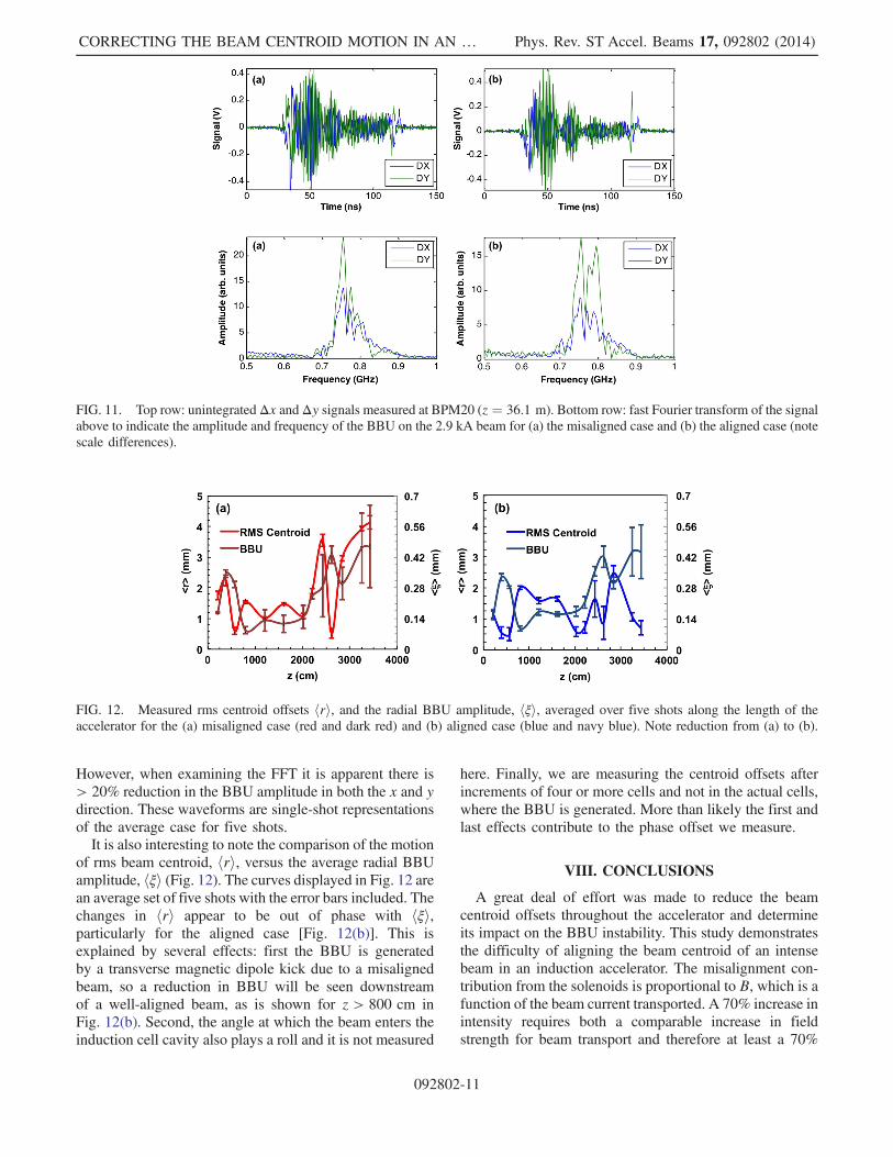
However, when examining the FFT it is apparent there is> 20% reduction in the BBU amplitude in both the x and ydirection. These waveforms are single-shot representationsof the average case for five shots.It is also interesting to note the comparison of the motion
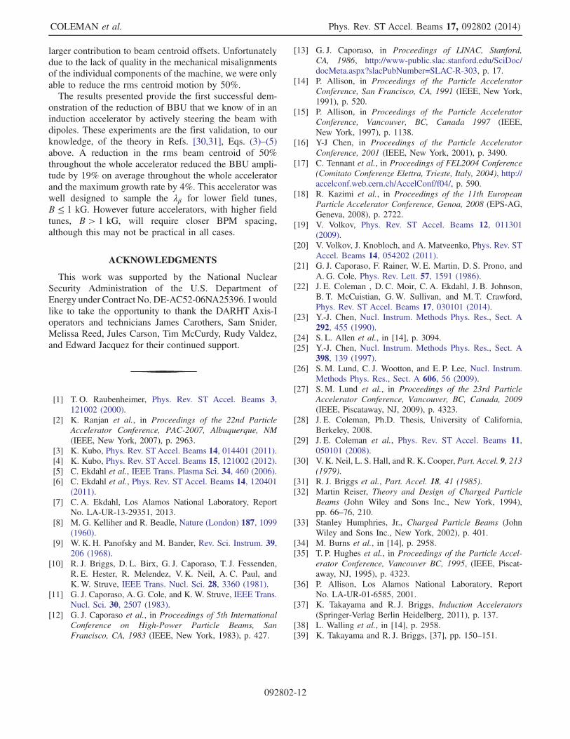
of rms beam centroid, hri, versus the average radial BBUamplitude, hξi (Fig. 12). The curves displayed in Fig. 12 arean average set of five shots with the error bars included. Thechanges in hri appear to be out of phase with hξi,particularly for the aligned case [Fig. 12(b)]. This isexplained by several effects: first the BBU is generatedby a transverse magnetic dipole kick due to a misalignedbeam, so a reduction in BBU will be seen downstreamof a well-aligned beam, as is shown for z > 800 cm inFig. 12(b). Second, the angle at which the beam enters theinduction cell cavity also plays a roll and it is not measured
here. Finally, we are measuring the centroid offsets afterincrements of four or more cells and not in the actual cells,where the BBU is generated. More than likely the first andlast effects contribute to the phase offset we measure.
VIII. CONCLUSIONS
A great deal of effort was made to reduce the beamcentroid offsets throughout the accelerator and determineits impact on the BBU instability. This study demonstratesthe difficulty of aligning the beam centroid of an intensebeam in an induction accelerator. The misalignment con-tribution from the solenoids is proportional to B, which is afunction of the beam current transported. A 70% increase inintensity requires both a comparable increase in fieldstrength for beam transport and therefore at least a 70%
FIG. 11. Top row: unintegratedΔx andΔy signals measured at BPM20 (z ¼ 36.1 m). Bottom row: fast Fourier transform of the signalabove to indicate the amplitude and frequency of the BBU on the 2.9 kA beam for (a) the misaligned case and (b) the aligned case (notescale differences).
FIG. 12. Measured rms centroid offsets hri, and the radial BBU amplitude, hξi, averaged over five shots along the length of theaccelerator for the (a) misaligned case (red and dark red) and (b) aligned case (blue and navy blue). Note reduction from (a) to (b).
CORRECTING THE BEAM CENTROID MOTION IN AN … Phys. Rev. ST Accel. Beams 17, 092802 (2014)
092802-11
larger contribution to beam centroid offsets. Unfortunatelydue to the lack of quality in the mechanical misalignmentsof the individual components of the machine, we were onlyable to reduce the rms centroid motion by 50%.The results presented provide the first successful dem-
onstration of the reduction of BBU that we know of in aninduction accelerator by actively steering the beam withdipoles. These experiments are the first validation, to ourknowledge, of the theory in Refs. [30,31], Eqs. (3)–(5)above. A reduction in the rms beam centroid of 50%throughout the whole accelerator reduced the BBU ampli-tude by 19% on average throughout the whole acceleratorand the maximum growth rate by 4%. This accelerator waswell designed to sample the λβ for lower field tunes,B ≤ 1 kG. However future accelerators, with higher fieldtunes, B > 1 kG, will require closer BPM spacing,although this may not be practical in all cases.
ACKNOWLEDGMENTS
This work was supported by the National NuclearSecurity Administration of the U.S. Department ofEnergy under Contract No. DE-AC52-06NA25396. I wouldlike to take the opportunity to thank the DARHT Axis-Ioperators and technicians James Carothers, Sam Snider,Melissa Reed, Jules Carson, Tim McCurdy, Rudy Valdez,and Edward Jacquez for their continued support.
[1] T. O. Raubenheimer, Phys. Rev. ST Accel. Beams 3,121002 (2000).
[2] K. Ranjan et al., in Proceedings of the 22nd ParticleAccelerator Conference, PAC-2007, Albuquerque, NM(IEEE, New York, 2007), p. 2963.
[3] K. Kubo, Phys. Rev. STAccel. Beams 14, 014401 (2011).[4] K. Kubo, Phys. Rev. STAccel. Beams 15, 121002 (2012).[5] C. Ekdahl et al., IEEE Trans. Plasma Sci. 34, 460 (2006).[6] C. Ekdahl et al., Phys. Rev. ST Accel. Beams 14, 120401
(2011).[7] C. A. Ekdahl, Los Alamos National Laboratory, Report
No. LA-UR-13-29351, 2013.[8] M. G. Kelliher and R. Beadle, Nature (London) 187, 1099
(1960).[9] W. K. H. Panofsky and M. Bander, Rev. Sci. Instrum. 39,
206 (1968).[10] R. J. Briggs, D. L. Birx, G. J. Caporaso, T. J. Fessenden,
R. E. Hester, R. Melendez, V. K. Neil, A. C. Paul, andK.W. Struve, IEEE Trans. Nucl. Sci. 28, 3360 (1981).
[11] G. J. Caporaso, A. G. Cole, and K.W. Struve, IEEE Trans.Nucl. Sci. 30, 2507 (1983).
[12] G. J. Caporaso et al., in Proceedings of 5th InternationalConference on High-Power Particle Beams, SanFrancisco, CA, 1983 (IEEE, New York, 1983), p. 427.
[13] G. J. Caporaso, in Proceedings of LINAC, Stanford,CA, 1986, http://www‑public.slac.stanford.edu/SciDoc/docMeta.aspx?slacPubNumber=SLAC‑R‑303, p. 17.
[14] P. Allison, in Proceedings of the Particle AcceleratorConference, San Francisco, CA, 1991 (IEEE, New York,1991), p. 520.
[15] P. Allison, in Proceedings of the Particle AcceleratorConference, Vancouver, BC, Canada 1997 (IEEE,New York, 1997), p. 1138.
[16] Y-J Chen, in Proceedings of the Particle AcceleratorConference, 2001 (IEEE, New York, 2001), p. 3490.
[17] C. Tennant et al., in Proceedings of FEL2004 Conference(Comitato Conferenze Elettra, Trieste, Italy, 2004), http://accelconf.web.cern.ch/AccelConf/f04/, p. 590.
[18] R. Kazimi et al., in Proceedings of the 11th EuropeanParticle Accelerator Conference, Genoa, 2008 (EPS-AG,Geneva, 2008), p. 2722.
[19] V. Volkov, Phys. Rev. ST Accel. Beams 12, 011301(2009).
[20] V. Volkov, J. Knobloch, and A. Matveenko, Phys. Rev. STAccel. Beams 14, 054202 (2011).
[21] G. J. Caporaso, F. Rainer, W. E. Martin, D. S. Prono, andA. G. Cole, Phys. Rev. Lett. 57, 1591 (1986).
[22] J. E. Coleman , D. C. Moir, C. A. Ekdahl, J. B. Johnson,B. T. McCuistian, G. W. Sullivan, and M. T. Crawford,Phys. Rev. ST Accel. Beams 17, 030101 (2014).
[23] Y.-J. Chen, Nucl. Instrum. Methods Phys. Res., Sect. A292, 455 (1990).
[24] S. L. Allen et al., in [14], p. 3094.[25] Y.-J. Chen, Nucl. Instrum. Methods Phys. Res., Sect. A
398, 139 (1997).[26] S. M. Lund, C. J. Wootton, and E. P. Lee, Nucl. Instrum.
Methods Phys. Res., Sect. A 606, 56 (2009).[27] S. M. Lund et al., in Proceedings of the 23rd Particle
Accelerator Conference, Vancouver, BC, Canada, 2009(IEEE, Piscataway, NJ, 2009), p. 4323.
[28] J. E. Coleman, Ph.D. Thesis, University of California,Berkeley, 2008.
[29] J. E. Coleman et al., Phys. Rev. ST Accel. Beams 11,050101 (2008).
[30] V. K. Neil, L. S. Hall, and R. K. Cooper, Part. Accel. 9, 213(1979).
[31] R. J. Briggs et al., Part. Accel. 18, 41 (1985).[32] Martin Reiser, Theory and Design of Charged Particle
Beams (John Wiley and Sons Inc., New York, 1994),pp. 66–76, 210.
[33] Stanley Humphries, Jr., Charged Particle Beams (JohnWiley and Sons Inc., New York, 2002), p. 401.
[34] M. Burns et al., in [14], p. 2958.[35] T. P. Hughes et al., in Proceedings of the Particle Accel-
erator Conference, Vancouver BC, 1995, (IEEE, Piscat-away, NJ, 1995), p. 4323.
[36] P. Allison, Los Alamos National Laboratory, ReportNo. LA-UR-01-6585, 2001.
[37] K. Takayama and R. J. Briggs, Induction Accelerators(Springer-Verlag Berlin Heidelberg, 2011), p. 137.
[38] L. Walling et al., in [14], p. 2958.[39] K. Takayama and R. J. Briggs, [37], pp. 150–151.
COLEMAN et al. Phys. Rev. ST Accel. Beams 17, 092802 (2014)
092802-12


![ALIGNMENT SCHEMATIC PLAN - New Jersey...centroid n - [(centroid n - grid n)/combine scale factor]=north value modified local project coordinates centroid e - [(centroid e - grid e)/combined](https://img.pdfslide.net/doc/110x75/5ee18361ad6a402d666c5e4d/alignment-schematic-plan-new-jersey-centroid-n-centroid-n-grid-ncombine.jpg)