Embed Size (px)
Citation preview
DOUBLE HDPE CORRUGATED PIPE PRODUCTION PLANT
FOR SEWERAGE WATER
SN4 & SN8
LINE 1-DIA. OD 200 TO 400
LINE 2-DIA. OD 500 TO 800
SEPTEMBER 2006
Page 1
Table of Contents
Table of Contents.......................................................................................1
Introduction ..............................................................................................2
Executive Summary ...................................................................................2
Mission .....................................................................................................3
Vision.......................................................................................................3
CORRUGATED PIPE ....................................................................................4
ADVANTAGES IN CORRUGATED PIPE ............................................................4
APPLICATION OF DOUBLE CORRUGATED PIPE................................................4
Typical Product Specification: ...................................................................5
Diameter and classes..................................................................................5
Double Corrugated Pipe Wall structure.......................................................5
Pipes ends .............................................................................................6
Fittings..................................................................................................6
Manufacturing Process Description: ...........................................................6
Testing..................................................................................................7
Machine for Process: ...............................................................................8
LINE 1- DIAMETER OD 200 TO 400 mm .....................................................9
LINE 2 – DIAMETER 200 TO 800 ............................................................. 13
Productıon capacıty:.............................................................................. 17
Buildings................................................................................................. 17
Operation Manpower ............................................................................. 20
Time Plan and Work Break-Down Structure For Project .............................. 21
PROJECT SCHEDULE ............................................................................. 21
COST :................................................................................................ 21
Conclusion :......................................................................................... 23
Page 2
Introduction
We are an engineering company collecting long-time experiences and references in the construction of plants for the manufacturing of pipes suitable for different fields of application. It operates by managing and coordinating both its inner mechanical, electric and software automation resources and those coming from the external qualified subcontractors, being responsible towards the commitment on the achievement of objectives in compliance with technical, quality and time requirements. The range of services supplied by us covers all phases of an industrial execution, from the system analysis, through the engineering and up to the construction and start-up on site. The granting of theoretical and practical training of the customer's personnel and after-sale skilled assistance, in addition to the above services, make us one of the most complete and competitive companies operating in the field of pipe production plants.
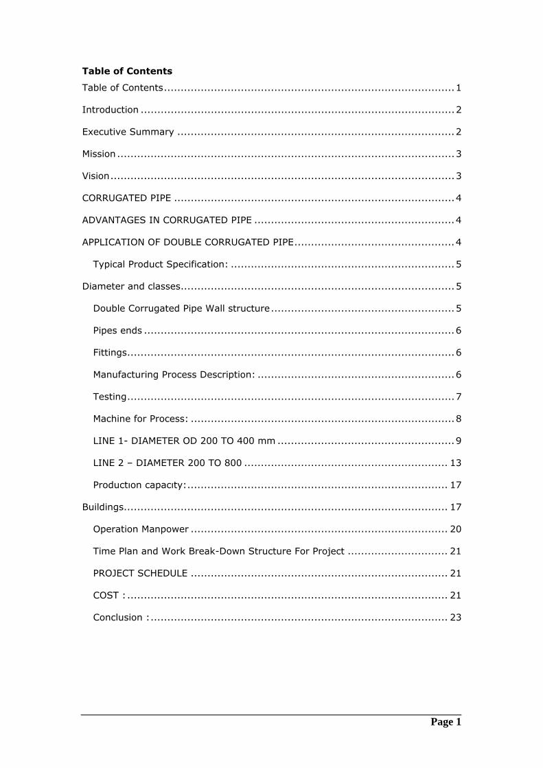
Executive Summary This report describes the initial ideas of the process of identifying, evaluating and designing for the corrugated pipe manufacturing system for Saudi Group. This document is not a status or an evaluation report; this will be a starting document to be updated on every stage of manufacturing of Corrugated Pipe. On this document we want to introduce a system approach to produce corrugated pipe based on current status and our passed experiences. Our recommendation on this report will be reevaluated as we start extensive system analysis on the “Current Business Operations”. It provides a baseline so that top management differentiates between current situation and future requirements.
Corrugated Pipe manufacturing system will be examined in three dimensions; strategic, tactical and operational. As a strategic approach you can find mission, vision and objectives of the Corrugated Pipe manufacturing system; tactical part of this document is to cover requirements, methods and plans; and in the operational dimension tools and components are defined. As a result, this document is a tool of monitoring all Corrugated Pipe manufacturing system. All part of Corrugated Pipe manufacturing system
Page 3
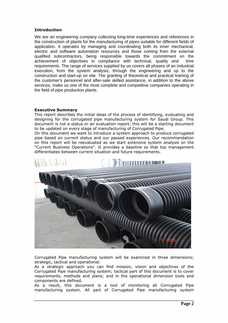
infrastructures will have a place on this document. So this document will be updated to establish the big picture of Corrugated Pipe manufacturing system The final sections contain data to help top management evaluate the cost and benefits of pursuing a new PROJECT for Corrugated Pipe manufacturing. Mission Corrugated Pipe manufacturing system concentrates on providing customers with services and products that consistently meet their needs and expectations. Mission of Corrugated Pipe manufacturing system is to generate a quantified, sustainable business improvement using open ended manufacturing technology. As parallel to all department mission which is; to become a profit center, the reusability and resoluble to this project is our essential target.
Vision As we are dealing with a highly dynamic technology we have to careful about planning dimensions. Planning is the critical part of a Corrugated Pipe manufacturing system to success and save time and money. Provide the vision of the organization to show where it is and where it wants to go. Customer needs to know of its current position before it determines where it wants to go. -Construct a picture of the way key processes are performing with respect to quality, productivity and workforce involvement. -Determine strengths and weaknesses -Set the course for the future -Provide a baseline for measuring progress.
Page 4
CORRUGATED PIPE
Corrugated Pipes are manufactured from HDPE resins. The design philosophy of
Corrugated pipes is to provide products with suitable properties and the required
margin of safety, that will enable the pipe to perform satisfactory after an
extended period of operation (more of 50 years) under typical service conditions.
ADVANTAGES IN CORRUGATED PIPE
Corrugated pipes represent the ideal solution for the abduction of any kind of water, chemicals, affluent and sewers, because they combine the advantage of corrosion resistance. Typical properties that result in advantages in Corrugated Pipe can be summarized as follows: Higher mechanical resistance due to the structure of the pipe.
Corrosion resistance, both of the external wall and internal wall in contact with
the conveyed fluid. No protections such as coating, painting or cathodic are
nedeed. Corrugated pipes are resistant to nearly all chemicals.
Very long life, virtually infinite of the material which does not need
maintaining.
Low weight of pipes lengths that allows for the use of light laying and transport
means.
Easy installation procedures because laying of corrugated pipes is a simple
operation which can be done in short periods of time both above and below
ground, since sleeve joints and socket joints enable fast and reliable assembling.
Workability of the material on sites employing simple equipment.
Possibility of nesting of different diameters of pipe thus allowing additional
saving in transport operations.
APPLICATION OF DOUBLE CORRUGATED PIPE
Sewer systems both urban and industrial
Resident housing construction
Factories
Water Pipes, agriculture pipes, industrial pipes
Page 5
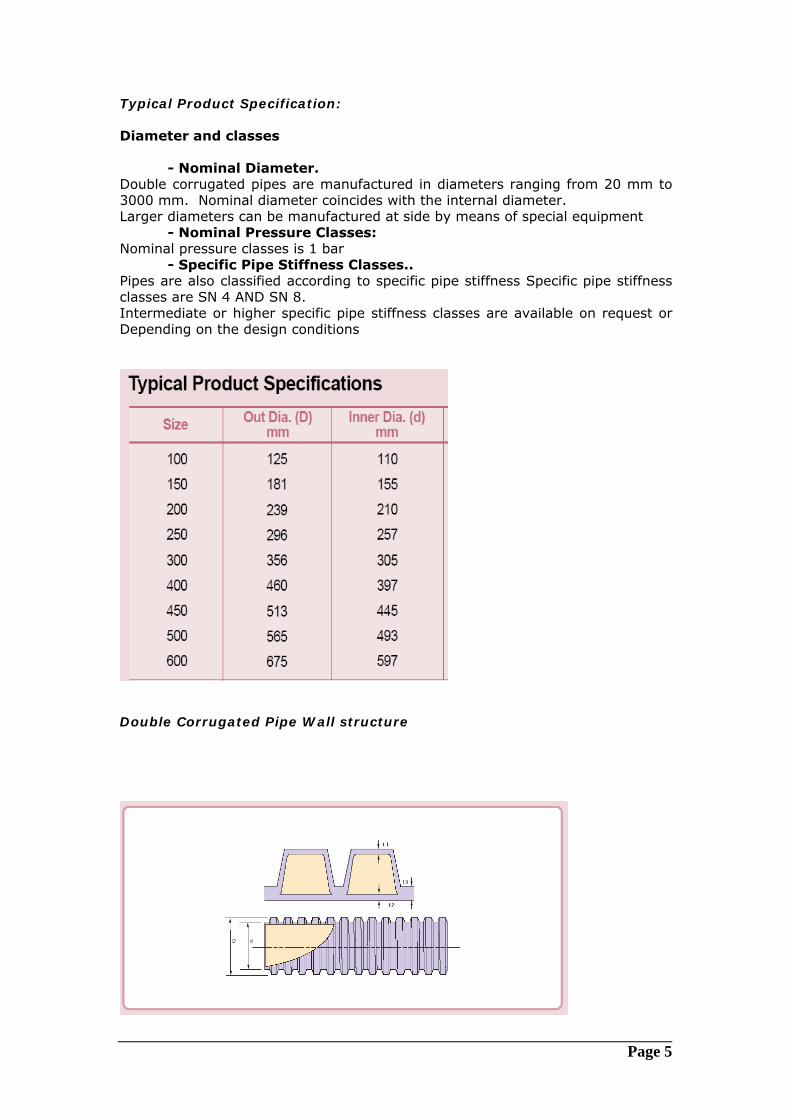
Typical Product Specification: Diameter and classes
- Nominal Diameter. Double corrugated pipes are manufactured in diameters ranging from 20 mm to 3000 mm. Nominal diameter coincides with the internal diameter. Larger diameters can be manufactured at side by means of special equipment
- Nominal Pressure Classes: Nominal pressure classes is 1 bar
- Specific Pipe Stiffness Classes.. Pipes are also classified according to specific pipe stiffness Specific pipe stiffness classes are SN 4 AND SN 8. Intermediate or higher specific pipe stiffness classes are available on request or Depending on the design conditions
Double Corrugated Pipe Wall structure
Page 6
Pipes ends The most common type of CORRUGATED pipes ends coupling is the bell and spigot one that allows ease installation of sections and very good hydraulic sealing by means of rubber gaskets. The supplied pipes manufacturing equipment and moulds are then foreseen in order to produce bell and spigot pipes ends. This kind of joint can be moreover completed with locking device that assures axial continuity to the pipes. Anyway, it is possible to produce also plain ends pipes to be joined by means of COUPLERS. Tolerances in the bell and spigot joint are very limited because the bell is produced by mould Hydraulic sealing The hydraulic sealing for bell and spigot ends pipes is obtained by means of one or two elastomeric toroidal gaskets (O-Ring). The mentioned scheme of bell and spigot report the position of the gaskets on the spigot end. For plain ends pipes, the sealing is assured by COUPLERS.
Fittings
A wide range of fittings and special pieces can be manufactured in DOUBLE corrugated pipe. they present, therefore, the same characteristics, both chemical and mechanical of the pipes. Fittings are manufactured manually employing butt welding machines that pipes pieces to be joined together. Ends of fittings can be bell and spigot type provided with sealing gaskets or plain type to be joined by welding to adjacent pipes or other fittings. The normal production includes: -different degree bends -equal tee or reduced tee -concentric and eccentric reducers -fixed flanges and stub end -blind flanges Moreover, other special pieces such as manholes, flanged pipes equal and reduced tees etc. can be manufactured by welding together fittings and/or pipes sections. Manufacturing Process Description:
The high density PE pipe with inside diameters of 150 mm to 800 mm can be
produced on the offered two production lines.
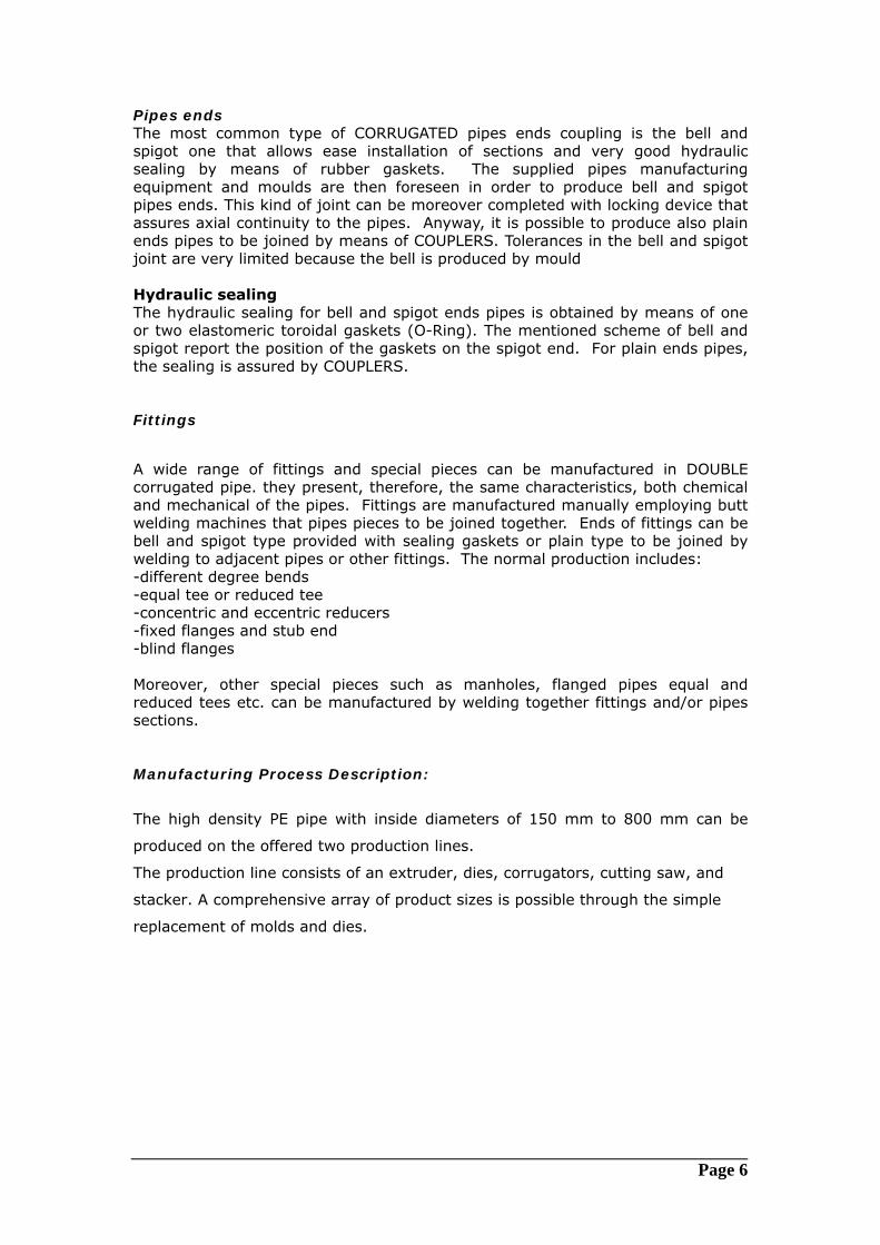
The production line consists of an extruder, dies, corrugators, cutting saw, and
stacker. A comprehensive array of product sizes is possible through the simple
replacement of molds and dies.
Page 7
Operation manpower is reduced by the fully automated procedures.
Raw materials-HDPE resin, fed into the extruder.
This is then placed in corrugated molds. After cooling, an automated sensor cuts
the pipes to desired lengths and stacks them for transportation to the stockyard.
- Easy Operation and Maintenance
- High Productivity
- Minimum Space Requirement for Production Line
- Minimum Friction of Mold -Block Train
- Rapid and Accurate Alignment of Mold-Block
- Wide Array of Raw Materials in Use
Testing
Manufacturing of double corrugated pipes is subjected to constant checking. The checks are carried out on raw materials, at each production phase and, lastly, on the finished product. The mechanical strength of finished products is tested periodically on lengths of pipe chosen at random from standard products. The test consists in reproducing the conditions which the pipe will have to undergo during working and also, in a dimensional check. The inspected pipe, if accepted, is indelibly marked with indications relevant to Manufacturer lot, manufacturing date, diameter, stiffness class and then it is sent to the factory stockyard waiting for shipping. all pipes produced are subjected to a careful quality control by means of systematic non-destructive tests as:
- thickness measurement - Barcol hardness measurement - visual examination
Page 8
In addition to the above, some samples are subjected to the following destructive tests: - parallel plate press test - axial tensile stress test - axial and circumferential bending test. Both destructive and non destructive tests are carried out according to ASTM (American Society for Testing and Materials) standards. The quality control on the final product is preceded by a careful production process and raw materials control. PROCESS EQUIPMENT
Designed and constructed for the continuous production of DOUBLE
CORRUGATED pipes suitable for civil applications (aqueducts, sewerage). The
lines, characterised by a high productivity, can produce pipes having the following
performances and designed for two lines at a started base:
The disadvantaging element is represented by the stand-by time, corresponding
to eight hour working shift, required for the mould replacement when changing
the diameter under production.
Machine for Process:
The present proposal covers the implementation of a new factory for the
manufacture of double corrugated pipes through the establishment of :
- production of pipes with diameters from 200 to 400
- production of pipes with diameters from 500 to 800
The project covers the installation of the production facilities relevant to the
manufacture of pipes with diameters ranging from 200 up to 800 mm with a
three production shifts/day for 330 working days/year.
Line 1:
The extrusion line adopts a co-extrusion technology with double extruders to
produce HDPE double wall corrugated pipe from ID200 mm up to ID400 mm.
Total installed power: 450 KW;
Normal working power: 250 KW;
Cooling water:≤15�, 0.15-0.2 MPa, 0.3 m3/min;
Compressed air: ≥0.5 MPa, 0.3 m3/min;
External dimension (LXWXH): 31,000 mm X 4,500 mm X 3,100 mm.
Lıne 2:
Page 9
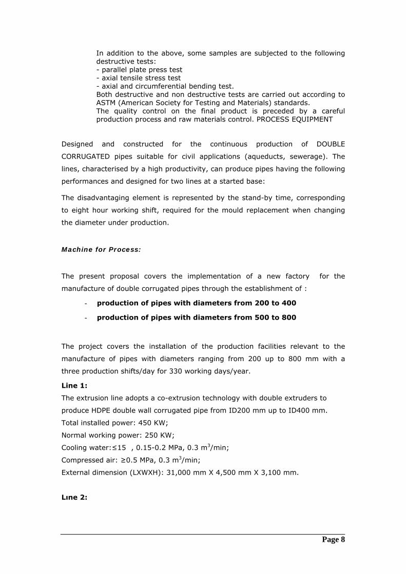
The extrusion line adopts a co-extrusion technology with double extruders to
produce HDPE double wall corrugated pipe from ID200mm up to ID800mm.
Total installed power: 735 KW;
Normal working power: 400 KW;
Cooling water:≤15�, 0.15-0.2 MPa, 0.5 m3/min;
Compressed air: ≥0.5 MPa, 0.3 m3/min;
External dimension (LXWXH): 34,000X4,800X5,320 mm.
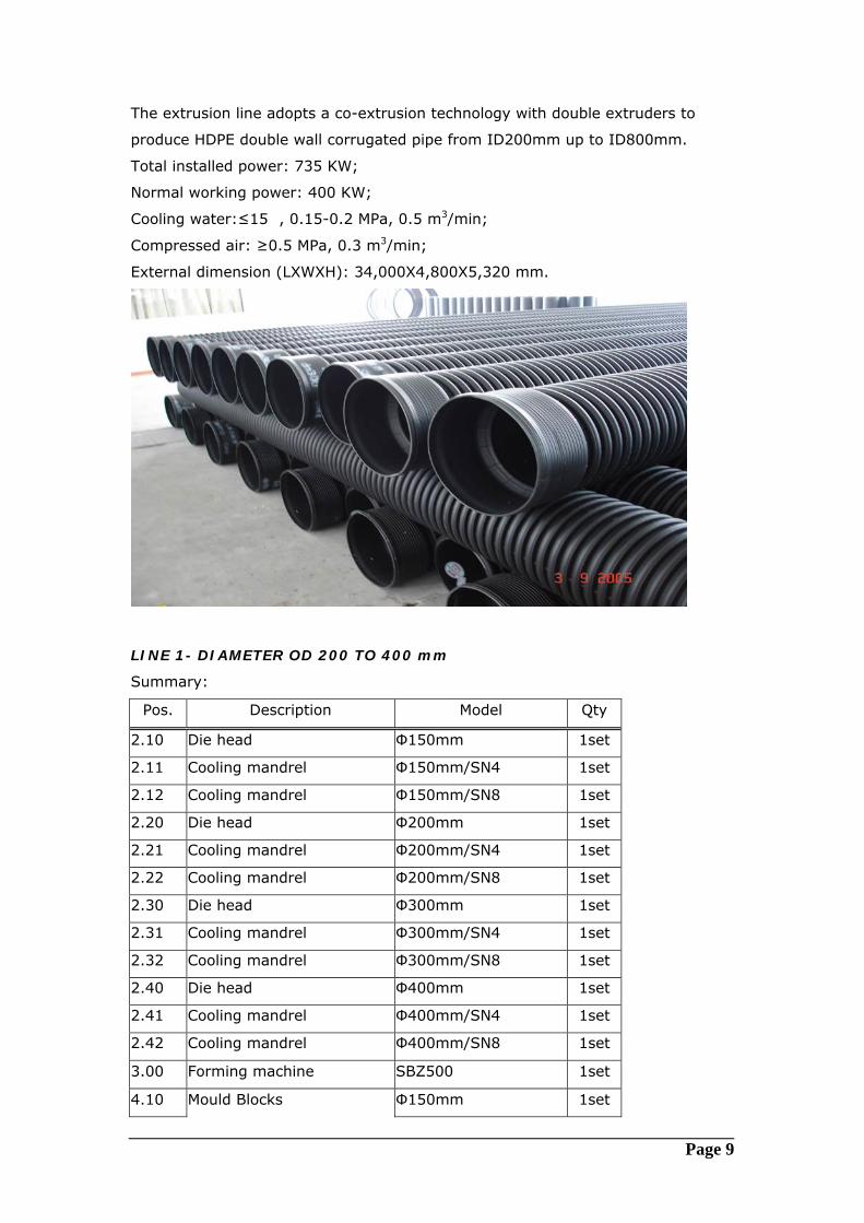
LINE 1- DIAMETER OD 200 TO 400 mm
Summary:
Pos. Description Model Qty
2.10 Die head Φ150mm 1set
2.11 Cooling mandrel Φ150mm/SN4 1set
2.12 Cooling mandrel Φ150mm/SN8 1set
2.20 Die head Φ200mm 1set
2.21 Cooling mandrel Φ200mm/SN4 1set
2.22 Cooling mandrel Φ200mm/SN8 1set
2.30 Die head Φ300mm 1set
2.31 Cooling mandrel Φ300mm/SN4 1set
2.32 Cooling mandrel Φ300mm/SN8 1set
2.40 Die head Φ400mm 1set
2.41 Cooling mandrel Φ400mm/SN4 1set
2.42 Cooling mandrel Φ400mm/SN8 1set
3.00 Forming machine SBZ500 1set
4.10 Mould Blocks Φ150mm 1set
Page 10
4.20 Mould Blocks Φ200mm 1set
4.30 Mould Blocks Φ300mm 1set
4.40 Mould Blocks Φ400mm 1set
5.00 Spray bath DSLQC6330 1set
6.00 Cut-off unit QG5020 1set
7.00 Stacker JGJ5020 1set
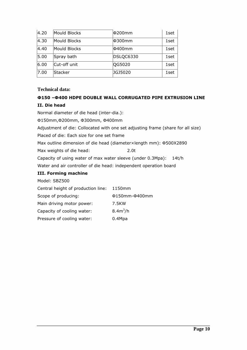
Technical data: Φ150 –Φ400 HDPE DOUBLE WALL CORRUGATED PIPE EXTRUSION LINE
II. Die head
Normal diameter of die head (inter-dia.):
Φ150mm,Φ200mm, Φ300mm, Φ400mm
Adjustment of die: Collocated with one set adjusting frame (share for all size)
Placed of die: Each size for one set frame
Max outline dimension of die head (diameter×length mm): Φ500X2890
Max weights of die head: 2.0t
Capacity of using water of max water sleeve (under 0.3Mpa): 14t/h
Water and air controller of die head: independent operation board
III. Forming machine
Model: SBZ500
Central height of production line: 1150mm
Scope of producing: Φ150mm-Φ400mm
Main driving motor power: 7.5KW
Capacity of cooling water: 8.4m3/h
Pressure of cooling water: 0.4Mpa
Page 11
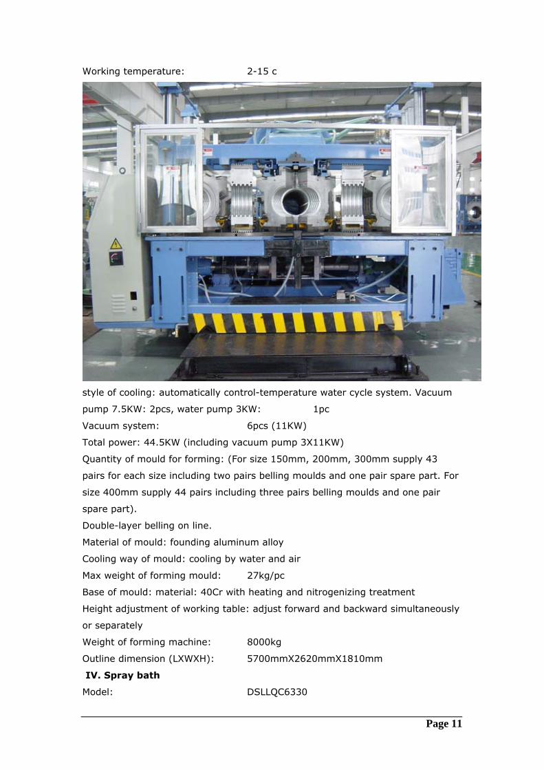
Working temperature: 2-15 c
style of cooling: automatically control-temperature water cycle system. Vacuum
pump 7.5KW: 2pcs, water pump 3KW: 1pc
Vacuum system: 6pcs (11KW)
Total power: 44.5KW (including vacuum pump 3X11KW)
Quantity of mould for forming: (For size 150mm, 200mm, 300mm supply 43
pairs for each size including two pairs belling moulds and one pair spare part. For
size 400mm supply 44 pairs including three pairs belling moulds and one pair
spare part).
Double-layer belling on line.
Material of mould: founding aluminum alloy
Cooling way of mould: cooling by water and air
Max weight of forming mould: 27kg/pc
Base of mould: material: 40Cr with heating and nitrogenizing treatment
Height adjustment of working table: adjust forward and backward simultaneously
or separately
Weight of forming machine: 8000kg
Outline dimension (LXWXH): 5700mmX2620mmX1810mm
IV. Spray bath
Model: DSLLQC6330
Page 12
Scope of spray: Φ150mm –Φ400mm
Power of water pump: 5.5KW
Power of air-blower: 0.75X2 KW
Total power: 7KW
Center height: 1150mm
Outline dimensions (LXWXH): 4500mmX1360mmX2200mm
Weight of machine: 2000KG
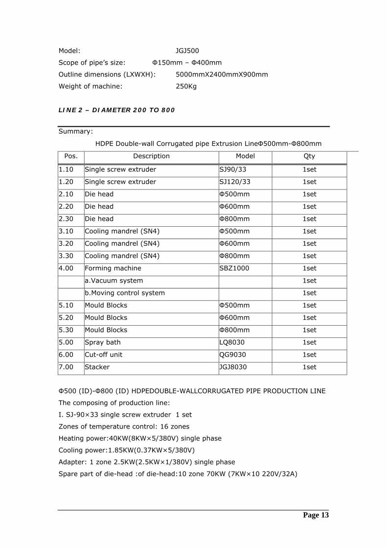
V. Cut-off unit
Model: QG6330
Cutting-off way: double circle knives, no-scraps when cutting
Clamping: “half” clamp by cylinder, casting aluminum clamping
The movement of blade: The connector is drove by the oil cylinder.
Cutting at the fixed length: Forming machine counts the length of pipe and give
the cutting order.
Total power: 2.6KW
Center height: 1250mm
Outline dimensions (LXWXH): 4950mmX1200mmX2200mm
Weight of machine: 1500KG
VI. Stacker
Page 13
Model: JGJ500
Scope of pipe’s size: Φ150mm – Φ400mm
Outline dimensions (LXWXH): 5000mmX2400mmX900mm
Weight of machine: 250Kg
LINE 2 – DIAMETER 200 TO 800
Summary:
HDPE Double-wall Corrugated pipe Extrusion LineΦ500mm-Φ800mm
Pos. Description Model Qty
1.10 Single screw extruder SJ90/33 1set
1.20 Single screw extruder SJ120/33 1set
2.10 Die head Φ500mm 1set
2.20 Die head Φ600mm 1set
2.30 Die head Φ800mm 1set
3.10 Cooling mandrel (SN4) Φ500mm 1set
3.20 Cooling mandrel (SN4) Φ600mm 1set
3.30 Cooling mandrel (SN4) Φ800mm 1set
4.00 Forming machine SBZ1000 1set
a.Vacuum system 1set
b.Moving control system 1set
5.10 Mould Blocks Φ500mm 1set
5.20 Mould Blocks Φ600mm 1set
5.30 Mould Blocks Φ800mm 1set
5.00 Spray bath LQ8030 1set
6.00 Cut-off unit QG9030 1set
7.00 Stacker JGJ8030 1set
Φ500 (ID)-Φ800 (ID) HDPEDOUBLE-WALLCORRUGATED PIPE PRODUCTION LINE
The composing of production line:
I. SJ-90×33 single screw extruder 1 set
Zones of temperature control: 16 zones
Heating power:40KW(8KW×5/380V) single phase
Cooling power:1.85KW(0.37KW×5/380V)
Adapter: 1 zone 2.5KW(2.5KW×1/380V) single phase
Spare part of die-head :of die-head:10 zone 70KW (7KW×10 220V/32A)
Page 14
Feeding mouth temperature control: 1 zone 100W/220V (drive electromagnet
valve cooling)
Pressure of melting substance/temperature of melting substance: collect/inspect
Thermocouple: K style
Each heating zone: autocephaly switch control heating
B: Drag unit of extruder :
Drive motor: ( made in Hangzhou Hengli motor Co.Ltd)
A: Motor style: Z4-250-12 B: Rating power: 160KW
C: Rating current:399A D: Rating speed: 1500r/min
E: Excitation power/voltage:2500W1/80V F: Blower power:3KW/380V
G: Motor of measure speed: 4.4KW/55V
E: mechanical parts
Material of barrel and screw 38CrMolaA with nitrogen treatment Capacity of extruder 500Kg/h (max.)
Main drive motor power: 160Kw
Extrusion Central height: 1000mm
Weight : 6500kg
Outline dimension: 4700mm x 2100mm x 2600mm
SJ-120×33 single screw extruder 1 set
Zones of temperature:10 zones
B: Drag unit of extruder :
A: Device style: SIEMENS 6RA2885-6DS21 B: Rating current:600A
Controlling style: SIEMENS PLC S7-300 control the feeder
SIEMENS OP270C 10inch LCD color screen
Capacity of extruder 800Kg/h (max)
Main drive motor power: 250Kw
Weight: 7000kg
Outline dimension: 5030mm x 1410mm x 2660mm
II. Extrusion die head
Normal diameter of dies head (ID.): Φ500mm, Φ600mm, Φ800mm
Share equipments: Joint body, right-angle elbow
The max heating power of die head: 68KW
Testing-temperature thermocouples of die head: “K” type
Testing-temperature areas of die head: 16pcs
Capacity of using water of max water sleeve (under 0.3Mpa): 14t/h
Water and gas controller of die head: independent operation board
Page 15
Unload tools of die head: standard and self-making, arrangement with machine
III. SBZ1000 Forming machine
The structure of SBZ1000 forming machine is excellent shuttle form. The moving
track is rectangle without curve of entrance and exit. The advantage of it is
moving steadily and fewer moulds needed.
The investment of equipment is cut down greatly so that it is easy for assembling
and changing different size of mould. Numerical control technology is combined
with forming machine so that the level of machine is much higher than before.
The electricity and air is controlled by the PCC and CAN technology, which is
matched with LCD showing screen by touching. All electric elements of it are from
original SIEMENS in Germany, for example, PLC, moving control system and
servomotor etc. The function of stepless timing can supply different speed
according to the sizes of pipes. Due to man-machine insideface system, the
working process and malfunction point are seen from the screen directly so that it
is easy for controlling and repairing. The forming machine is equipped with
special water-cooling system that has good cooling and airproof effect. The
technology fills up the blankness of no water-cooling and water-leakage.
The material of forming mould is special casting aluminum alloy. Due to the
Socket mould, socket is realized on line so that investment of equipments is cut
down. The cooling water cycle system is fitted in forming mould, which can cool
moulds quickly and form pipe easily.
Model of forming machine: SBZ1000 (horizontal type machine)
Height of extruder: 1250mm
Scope of producing: Φ250mm (ID)-Φ800mm (ID)
Moving speed of mould: 0.2-1.5m/min
Main driving motor power: 11KW
Capacity of cooling water: 4.8m3/h
Pressure of cooling water: 0.3Mpa
Working temperature: 15-20�
Mode of cooling: automatically control-temperature water cycle system. Vacuum
system: 6pcs (11KW) 66kw
Total power: 130KW
Quantity of mould for forming: 10 or 12 pairs (for socket on line)
Material of mould: founding aluminum alloy
Base of mould: material: 40Cr; thermal treatment: nitrogen treatment
Height adjustment of working table: 2X2.2KW motor, adjust forward and
backward simultaneously or separately
Page 16
Horizon adjustment of working table: 2X0.25KW motor
Power-off sending back protection: Accumulation imported from USA guarantee
working table automatically sends back when power is off suddenly so that mould
separate from water sleeve.
Weight of forming machine: 20500kg
IV. Spray bath
Type: LQ8030
Scope of spray: Φ250mm (ID)-Φ800mm (ID)
Power of water pump: 5.5KW
Power of air-blower: 4KW
Total power: 9.5KW
Center height: 1250mm
Outline dimensions (LXWXH): 5500mmX1720mmX1930mm
Weight of machine: 2000KG
V. Cut-off Unit
There are two sets clamping systems fixed on front and behind of lathe frame.
Each clamping system is composed of two cylinders and two clamps. Under the
controlling of cylinder, two clamps clamp pipes tightly simultaneously, which
guarantee the synchronization of lathe’s moving speed and pipe’s production
speed. The cutting signal is from the coder fixed on driving servomotor. The
showing windows are on the two sides of lathe. The working process can be
observes through showing windows. Type: QG9030
Cutting-off way: double circle knives, no-scraps when cutting
Clamping: “half” clamp by cylinder, casting aluminum clamping
The movement of blade: The connector is drove by the oil cylinder.
Cutting at the fixed length: Forming machine counts the length of pipe and give
the cutting order.
Total power: 2.6KW
Center height: 1250mm
Outline dimensions (LXWXH): 3500mmX1950mmX1760mm
Weight of machine: 6000KG
VI. Stacker
Type: JGJA8030
Scope of pipe’s size: Φ225mm (inside-dia.)- Φ800mm (outside-dia.)
Transportation motor power: 0.75KW
Outline dimensions (LXWXH): 5700mmX2700mmX1250mm
Page 17
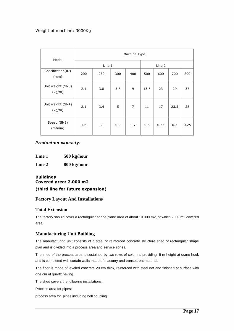
Weight of machine: 3000Kg
Productıon capacıty:
Lıne 1 500 kg/hour
Lıne 2 800 kg/hour Buildings Covered area: 2.000 m2
(third line for future expansion)
Factory Layout And Installations
Total Extension The factory should cover a rectangular shape plane area of about 10.000 m2, of which 2000 m2 covered
area.
Manufacturing Unit Building The manufacturing unit consists of a steel or reinforced concrete structure shed of rectangular shape
plan and is divided into a process area and service zones.
The shed of the process area is sustained by two rows of columns providing 5 m height at crane hook
and is completed with curtain walls made of masonry and transparent material.
The floor is made of leveled concrete 20 cm thick, reinforced with steel net and finished at surface with
one cm of quartz paving.
The shed covers the following installations:
Process area for pipes:
process area for pipes including bell coupling
Machine Type
Model
Line 1 Line 2
Specification(ID)
(mm) 200 250 300 400 500 600 700 800
Unit weight (SN8)
(kg/m)
2.4
3.8
5.8
9
13.5
23
29
37
Unit weight (SN4)
(kg/m)
2.1
3.4
5
7
11
17
23.5
28
Speed (SN8)
(m/min)
1.6
1.1
0.9
0.7
0.5
0.35
0.3
0.25
Page 18
one overhead travelling crane (5 tons capacity)
fittings manufacturing area
Services areas:
Raw material storage area
warehouse (shelves, welding and drilling machine, grinders and tools, spare parts).
quality control laboratory.
dressing rooms, showers and toilets.
Raw materıal Store HDPE Storage AREA should have at least 150 ton capacity.
Utilities And Ancillary Installations The manufacturing shed should be completed with the following utilities and ancillary installations:
• fire fighting network, hydrants and hose reel boxes.
• raw water reservoir.
• potable water network.
• raw water pump (one unit).
• raw water network.
• sewer network.
• shed venting systems.
• Two frontal fork lift 2 ton capacity
• fence and gates.
The positioning of the utilities equipment will be finalized based on the land.
Brief description of some utilities is given here below:
• concrete reservoir:
The concrete reservoir contains the water necessary for the fire fighting system
and raw water consumption. Water to the reservoir is fed by means of a 2" pipe
sectioned, at factory battery limits, by locked open gate valve installed in pit.
The capacity of the reservoir is about 110 m3 whose 10 m3 are relevant to the
raw water consumption, while 100 m3 are assured to the fire fighting system in
order to allow for one hour autonomy.
• fire fighting system:
The fire fighting station is composed of one diesel engine operated pump and
an electric motor jockey one. The diesel engine is provided with its own fuel
daily tanks.
Foreseen head and flow rate of the diesel engine pump are respectively 100
m.c.l. and 100 m3/h, considering the future phase. The jockey pump
continuously pressurizes the 8" network, at head and rate of 60 m.c.l. and 10
m3/hr respectively.
Page 19
When pressure in the fire fighting network reduces below 3 bar, the diesel
pump automatically starts and will be stopped by manual operations. Hydrants
are distributed along the 8" fire fighting ring, each provided with two hose
connections.
The hoses are contained in boxes located nearby the hydrants.
• compressed air system:
Envisaged flow rate is 3 m3/hour at 6 bar. Compressed air piping, inside the
shed, is composed of 2" pipes rings running on steel structures and provided
with 1" shed crossing pipes, installed inside the ducts and wall mounted
connections.
• potable water:
The potable water is fed by a 2" pipe, sectioned at factory battery limit by a gate
valve installed in pit and is directly conveyed in the factory network.
Potable water feeds the office building area, the toilets of the shed and the test
and laboratory rooms.
Electric Installations The total electrical power installed is 1000 KVA and considering a contemporaneity
of 75% the required power is 750 KVA about.
The main electric installations inside the fence of the factory are then the following:
- general electric switch board and control panels.
- power sockets (32 A).
- lighting system inside and outside the shed.
- earthing system.
The diesel generator is located under an own steel shelter and is completed with its
own daily tank.
Service Buildings The following building are envisaged to be installed inside the factory area:
- one prefabricated or masonry building suitable for the accommodation of 10
employees and one manager. The building is provided with office furniture and
toilet.
Moreover, a cover for vehicles is foreseen (40 x 5,5 m).
Open Spaces Not covered spaces extend for about 8.000 m2 and are partially asphalted or
otherwise treated for storage of finished products, internal roads and open air tests.
The factory area is fenced and provided with one main and two services gates.
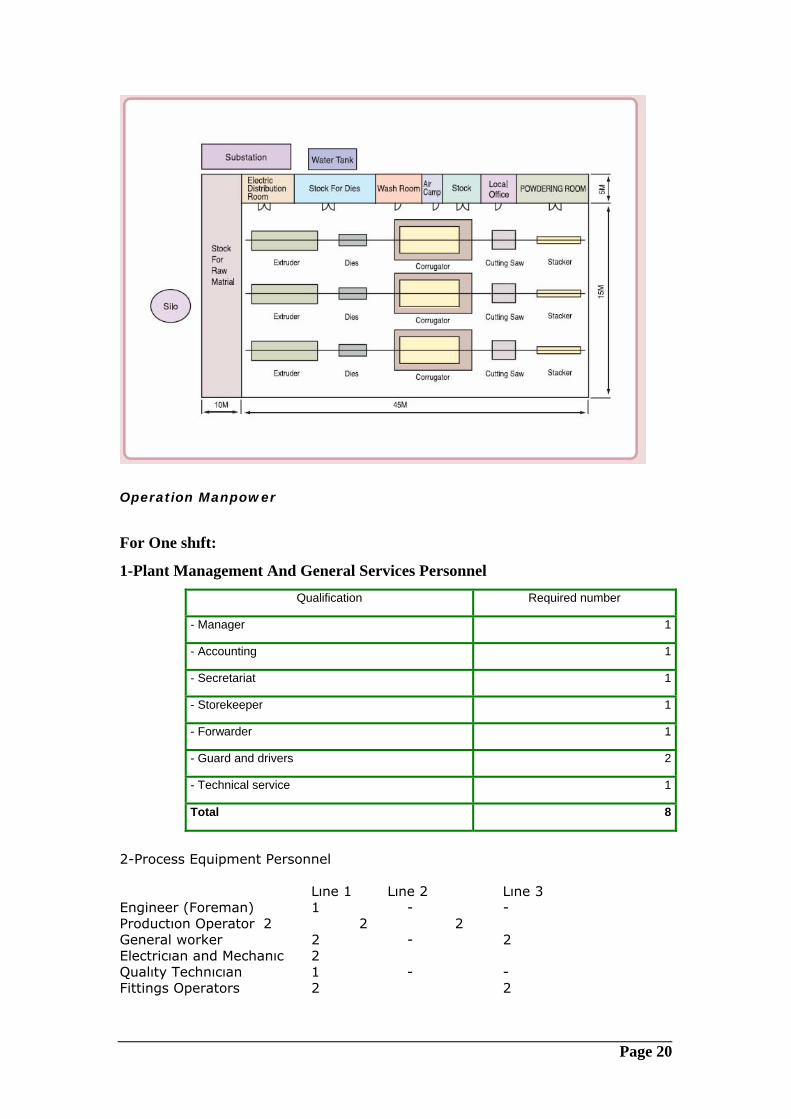
Page 20
Operation Manpower
For One shıft:
1-Plant Management And General Services Personnel Qualification Required number
- Manager 1
- Accounting 1
- Secretariat 1
- Storekeeper 1
- Forwarder 1
- Guard and drivers 2
- Technical service 1
Total 8
2-Process Equipment Personnel Lıne 1 Lıne 2 Lıne 3 Engineer (Foreman) 1 - - Productıon Operator 2 2 2 General worker 2 - 2 Electricıan and Mechanıc 2 Qualıty Technıcıan 1 - - Fittings Operators 2 2
Page 21
Time Plan and Work Break-Down Structure For Project
Project Initiation System Analyses Logical Design Physical Design Approvals Basic Engineering Design Equipment machine selection/order Ocean Transport Custom Clearance Inland Transport up to Site Civil Buildings All site construction Site supervision Commissioning start up under Consultancy Supervision Field Training
PROJECT SCHEDULE
Machine supply 16 weeks Transportation 4 weeks Start up and commissioning 4 weeks Total 24 weeks after order the machine
COST :
MACHINE LINE 1- 600.000 USD FOB CHINA MACHINE LINE 2 – 900.000 USD FOB CHINA BUILDING : 250.000 USD Auxiliary equipment: 250.000 USD Transportation: 100.000 USD Commissioning: 50.000 USD LAND: Laboratory equıpment: 150.000 USD Fittings machines: 100.000 USD TOTAL: 2.400.000 USD KNOW HOW, ENGINEERING DESIGN AND DOCUMENTATION SUPPLIED Preliminary Design: It includes a preliminary layout of plant based on its working flow-sheets, as well as the complete list of machines and tools needed for production and relevant to both process and facilities. This preliminary design will be consolidated into a Technical Report, which will include also all data relevant to production yields, as well as a detailed costs estimate. Know How And Engineering:
Page 22
Based on the above document, the supply of the know-how and engineering shall consist of the following documents referred to the plant as described in the Technical Report. Basic Design Design Of Civil Works Mechanical Design Electrical Design Executive And Detailed Design Work Machines To Be Supplied – Technical Description Plant Erection Supervision: We will supervise the works relevant to the erection of the plant and Start Up, Commissioning and Training: Start up and commissioning of the whole plant will be provided by a team of experts as follows: - 1 plant superintendent. - 1 machine specialist. The above team will also undertake training of operating personnel at site in order to enable them to operate the machine independently and in optimum way. General Assistance: We will supply you with all standards, specifications and shop drawings relevant to pipes of each class, diameter and service pressure series. Moreover our design office will be at your disposal for studies relevant to special applications, as well as technical and organization problems relevant to the applications of the above pipes. Running Assistance: We shall place at your disposal, for the length of time specified above, our experienced personnel as needed for the running operations of the plant. Furthermore we will supply all information relevant to any technological advancement of our operations, so that the plant could benefit of it. Training on Site We will assist the customer in training the latter's specialists, in customer's plant.
Page 23
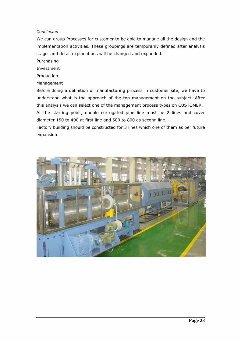
Conclusion :
We can group Processes for customer to be able to manage all the design and the
implementation activities. These groupings are temporarily defined after analysis
stage and detail explanations will be changed and expanded.
Purchasing
Investment
Production
Management
Before doing a definition of manufacturing process in customer site, we have to
understand what is the approach of the top management on the subject. After
this analysis we can select one of the management process types on CUSTOMER.
At the starting point, double corrugated pipe line must be 2 lines and cover
diameter 150 to 400 at first line and 500 to 800 as second line.
Factory building should be constructed for 3 lines which one of them as per future
expansion.