Embed Size (px)
Citation preview
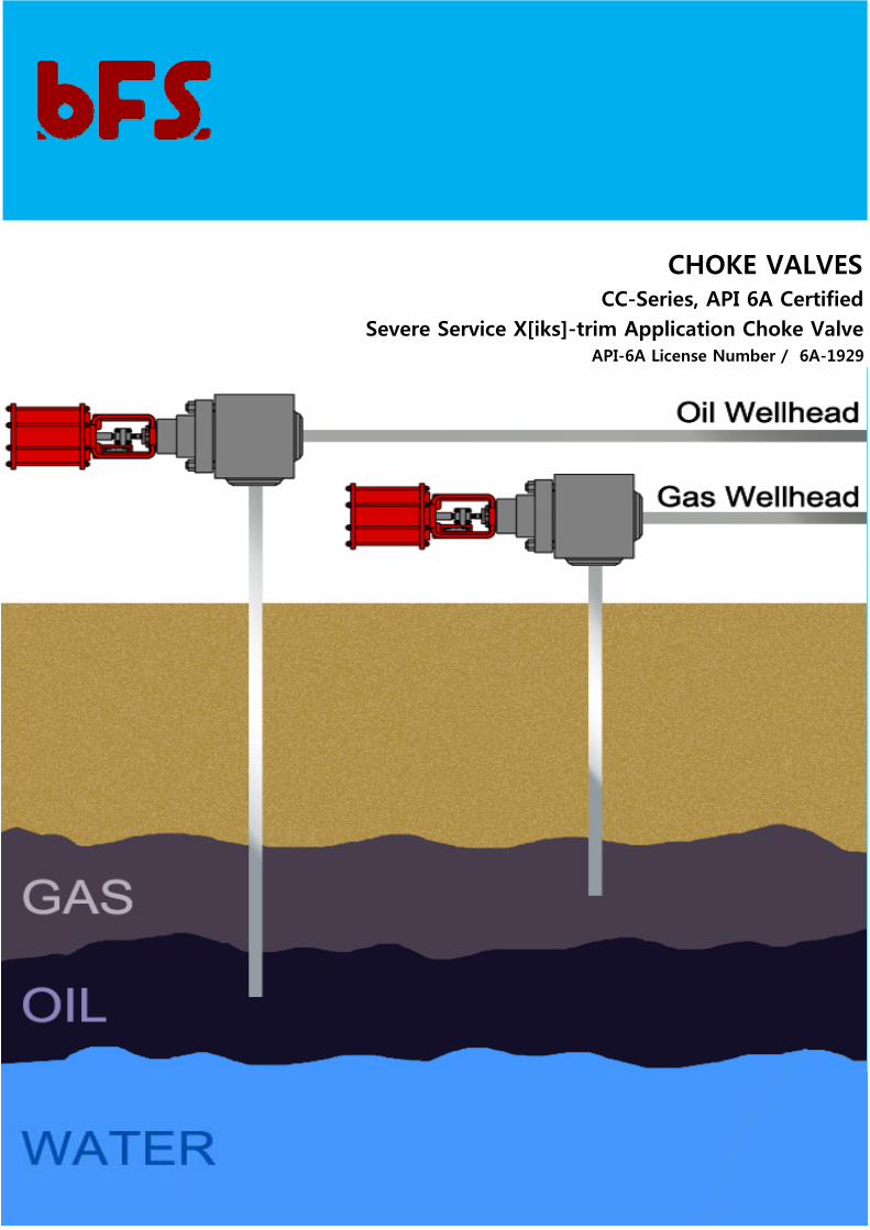
CHOKE VALVESCC-Series, API 6A Certified
Severe Service X[iks]-trim Application Choke ValveAPI-6A License Number / 6A-1929
2
Introduction Control valves for the production and processing of crude oil & natural gas.
3D-Flow-Path Disk Stack X[iks]-trim technology for severe service application. Choke valves are almost always Angle type
valves. Velocity trim control labyrinth technology (water-jet cutting design or investment Casting) provides for trim velocity
of 1/4 or less that of conventional chokes.
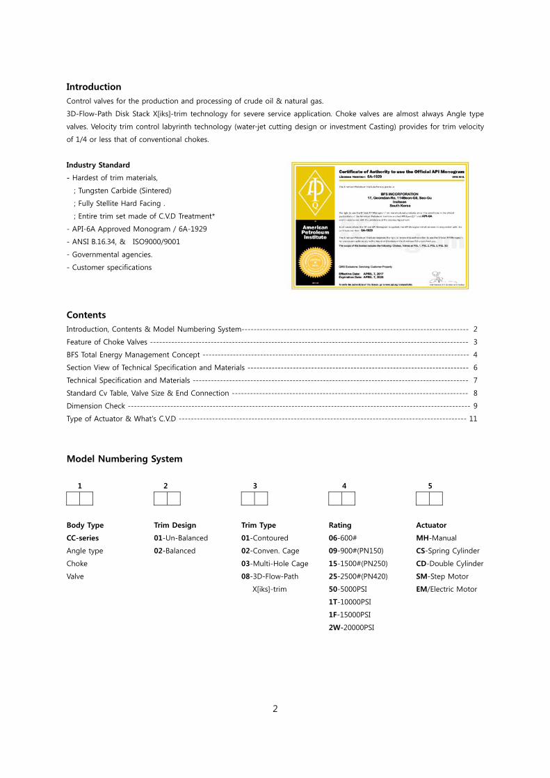
Industry Standard
- Hardest of trim materials,
; Tungsten Carbide (Sintered)
; Fully Stellite Hard Facing .
; Entire trim set made of C.V.D Treatment*
- API-6A Approved Monogram / 6A-1929
- ANSI B.16.34, & ISO9000/9001
- Governmental agencies.
- Customer specifications
Contents Introduction, Contents & Model Numbering System--------------------------------------------------------------------------- 2
Feature of Choke Valves --------------------------------------------------------------------------------------------------------- 3
BFS Total Energy Management Concept ---------------------------------------------------------------------------------------- 4
Section View of Technical Specification and Materials ------------------------------------------------------------------------- 6
Technical Specification and Materials ------------------------------------------------------------------------------------------- 7
Standard Cv Table, Valve Size & End Connection ------------------------------------------------------------------------------ 8
Dimension Check ----------------------------------------------------------------------------------------------------------------- 9
Type of Actuator & What's C.V.D ----------------------------------------------------------------------------------------------- 11
Model Numbering System
1 2 3 4 5
Body Type
CC-series
Angle type
Choke
Valve
Trim Design
01-Un-Balanced
02-Balanced
Trim Type
01-Contoured
02-Conven. Cage
03-Multi-Hole Cage
08-3D-Flow-Path
X[iks]-trim
Rating
06-600#
09-900#(PN150)
15-1500#(PN250)
25-2500#(PN420)
50-5000PSI
1T-10000PSI
1F-15000PSI
2W-20000PSI
Actuator
MH-Manual
CS-Spring Cylinder
CD-Double Cylinder
SM-Step Motor
EM/Electric Motor
3
1. Features of Choke Valves Custom-designed valve, trim and actuator for each unique
choke application. Wide variety of liquid, gas and X[iks]-trim in linear and
EQ-% execution. Sintered Tungsten or Water-jet cutting large hole trim for
dirty well clean-up service and high capacity trim for
minimized pressure loss at well depletion stage. Full range of matching BFS pneumatic, electric and
electro-hydraulic actuators with tailored control
arrangements is available .
1-1. Gas Wellhead Applications
Gas wellhead control/High pressure drop
- Can be > 10,000PSI (690Bar)
High sand content
- Can be rapid erosion failure at pressure drops
as low as 500PSI (34Bar)
High noise levels
- Less than 85dBA is now commonly specified
especially on manned platforms.
Often multi-phase fluid
1-2. Oil Wellhead Applications
Oil wellhead control/High pressure drop
- Can be > 10,000PSI (690Bar)
High sand content
- Can cause rapid erosion failure at pressure
drops as low as 800PSI (55Bar)
Often multi-phase fluid
Fluid with a high "water cut may cause
cavitation damage
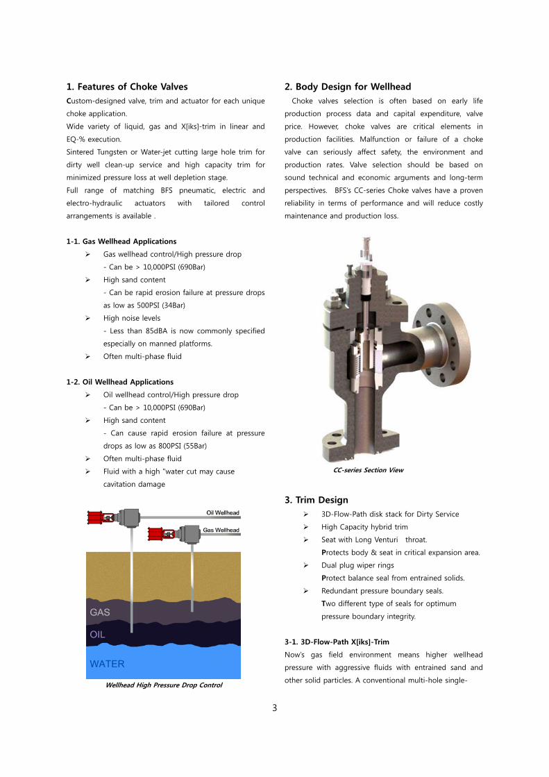
Wellhead High Pressure Drop Control
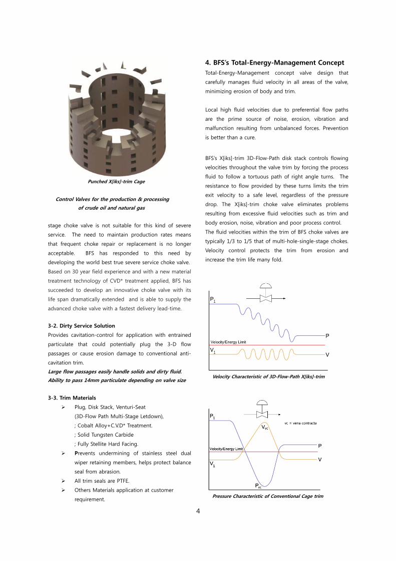
2. Body Design for Wellhead Choke valves selection is often based on early life
production process data and capital expenditure, valve
price. However, choke valves are critical elements in
production facilities. Malfunction or failure of a choke
valve can seriously affect safety, the environment and
production rates. Valve selection should be based on
sound technical and economic arguments and long-term
perspectives. BFS’s CC-series Choke valves have a proven
reliability in terms of performance and will reduce costly
maintenance and production loss.
CC-series Section View
3. Trim Design 3D-Flow-Path disk stack for Dirty Service
High Capacity hybrid trim
Seat with Long Venturi throat.
Protects body & seat in critical expansion area.
Dual plug wiper rings
Protect balance seal from entrained solids.
Redundant pressure boundary seals.
Two different type of seals for optimum
pressure boundary integrity.
3-1. 3D-Flow-Path X[iks]-Trim
Now’s gas field environment means higher wellhead
pressure with aggressive fluids with entrained sand and
other solid particles. A conventional multi-hole single-
4
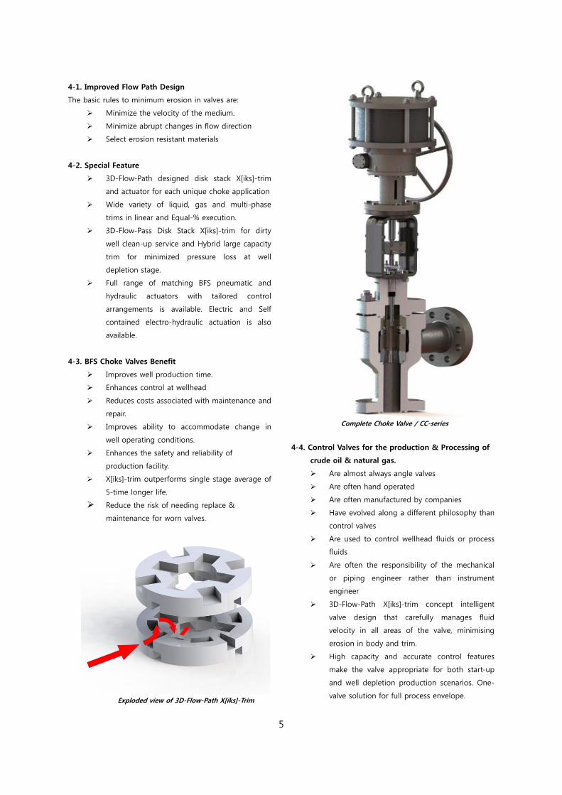
Punched X[iks]-trim Cage
Control Valves for the production & processing
of crude oil and natural gas
stage choke valve is not suitable for this kind of severe
service. The need to maintain production rates means
that frequent choke repair or replacement is no longer
acceptable. BFS has responded to this need by
developing the world best true severe service choke valve. Based on 30 year field experience and with a new material
treatment technology of CVD* treatment applied, BFS has
succeeded to develop an innovative choke valve with its
life span dramatically extended and is able to supply the
advanced choke valve with a fastest delivery lead-time.
3-2. Dirty Service Solution
Provides cavitation-control for application with entrained
particulate that could potentially plug the 3-D flow
passages or cause erosion damage to conventional anti-
cavitation trim.
Large flow passages easily handle solids and dirty fluid.
Ability to pass 14mm particulate depending on valve size
3-3. Trim Materials
Plug, Disk Stack, Venturi-Seat
(3D-Flow Path Multi-Stage Letdown),
; Cobalt Alloy+C.V.D* Treatment.
; Solid Tungsten Carbide
; Fully Stellite Hard Facing.
Prevents undermining of stainless steel dual
wiper retaining members, helps protect balance
seal from abrasion.
All trim seals are PTFE.
Others Materials application at customer
requirement.
4. BFS’s Total-Energy-Management Concept Total-Energy-Management concept valve design that
carefully manages fluid velocity in all areas of the valve,
minimizing erosion of body and trim.
Local high fluid velocities due to preferential flow paths
are the prime source of noise, erosion, vibration and
malfunction resulting from unbalanced forces. Prevention
is better than a cure.
BFS’s X[iks]-trim 3D-Flow-Path disk stack controls flowing
velocities throughout the valve trim by forcing the process
fluid to follow a tortuous path of right angle turns. The
resistance to flow provided by these turns limits the trim
exit velocity to a safe level, regardless of the pressure
drop. The X[iks]-trim choke valve eliminates problems
resulting from excessive fluid velocities such as trim and
body erosion, noise, vibration and poor process control. The fluid velocities within the trim of BFS choke valves are
typically 1/3 to 1/5 that of multi-hole-single-stage chokes.
Velocity control protects the trim from erosion and
increase the trim life many fold.
Velocity Characteristic of 3D-Flow-Path X[iks]-trim
Pressure Characteristic of Conventional Cage trim
5
4-1. Improved Flow Path Design
The basic rules to minimum erosion in valves are:
Minimize the velocity of the medium.
Minimize abrupt changes in flow direction
Select erosion resistant materials
4-2. Special Feature
3D-Flow-Path designed disk stack X[iks]-trim
and actuator for each unique choke application
Wide variety of liquid, gas and multi-phase
trims in linear and Equal-% execution.
3D-Flow-Pass Disk Stack X[iks]-trim for dirty
well clean-up service and Hybrid large capacity
trim for minimized pressure loss at well
depletion stage.
Full range of matching BFS pneumatic and
hydraulic actuators with tailored control
arrangements is available. Electric and Self
contained electro-hydraulic actuation is also
available.
4-3. BFS Choke Valves Benefit
Improves well production time.
Enhances control at wellhead
Reduces costs associated with maintenance and
repair.
Improves ability to accommodate change in
well operating conditions.
Enhances the safety and reliability of
production facility.
X[iks]-trim outperforms single stage average of
5-time longer life.
Reduce the risk of needing replace & maintenance for worn valves.
Exploded view of 3D-Flow-Path X[iks]-Trim
Complete Choke Valve / CC-series
4-4. Control Valves for the production & Processing of
crude oil & natural gas.
Are almost always angle valves
Are often hand operated
Are often manufactured by companies
Have evolved along a different philosophy than
control valves
Are used to control wellhead fluids or process
fluids
Are often the responsibility of the mechanical
or piping engineer rather than instrument
engineer
3D-Flow-Path X[iks]-trim concept intelligent
valve design that carefully manages fluid
velocity in all areas of the valve, minimising
erosion in body and trim.
High capacity and accurate control features
make the valve appropriate for both start-up
and well depletion production scenarios. One-
valve solution for full process envelope.
6
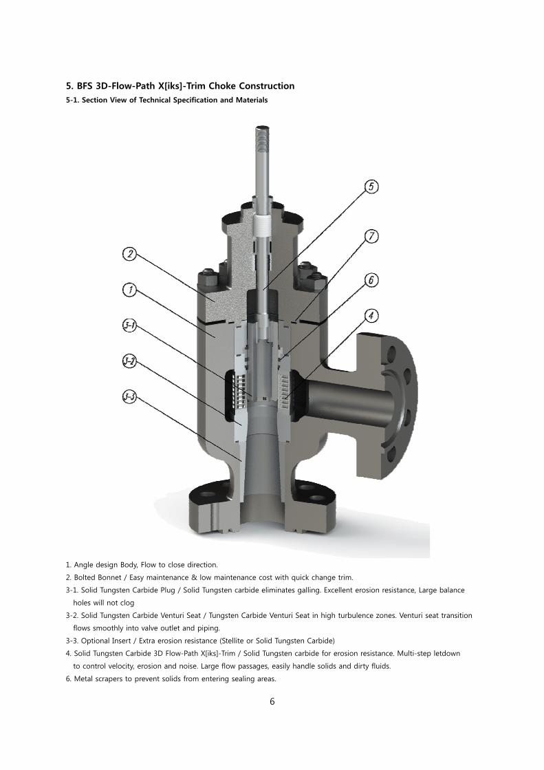
5. BFS 3D-Flow-Path X[iks]-Trim Choke Construction 5-1. Section View of Technical Specification and Materials
1. Angle design Body, Flow to close direction.
2. Bolted Bonnet / Easy maintenance & low maintenance cost with quick change trim.
3-1. Solid Tungsten Carbide Plug / Solid Tungsten carbide eliminates galling. Excellent erosion resistance, Large balance
holes will not clog
3-2. Solid Tungsten Carbide Venturi Seat / Tungsten Carbide Venturi Seat in high turbulence zones. Venturi seat transition
flows smoothly into valve outlet and piping.
3-3. Optional Insert / Extra erosion resistance (Stellite or Solid Tungsten Carbide)
4. Solid Tungsten Carbide 3D Flow-Path X[iks]-Trim / Solid Tungsten carbide for erosion resistance. Multi-step letdown
to control velocity, erosion and noise. Large flow passages, easily handle solids and dirty fluids.
6. Metal scrapers to prevent solids from entering sealing areas.
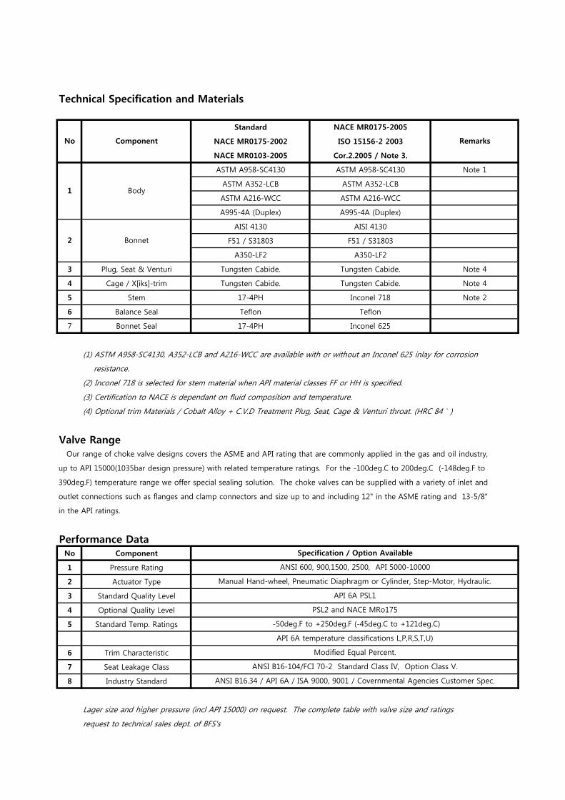
Technical Specification and Materials
Standard NACE MR0175-2005
NACE MR0175-2002 ISO 15156-2 2003
NACE MR0103-2005 Cor.2.2005 / Note 3.
ASTM A958-SC4130 ASTM A958-SC4130 Note 1
ASTM A352-LCB ASTM A352-LCB
ASTM A216-WCC ASTM A216-WCC
A995-4A (Duplex) A995-4A (Duplex)
AISI 4130 AISI 4130
F51 / S31803 F51 / S31803
A350-LF2 A350-LF2
3 Plug, Seat & Venturi Tungsten Cabide. Tungsten Cabide. Note 4
4 Cage / X[iks]-trim Tungsten Cabide. Tungsten Cabide. Note 4
5 Stem 17-4PH Inconel 718 Note 2
6 Balance Seal Teflon Teflon
7 Bonnet Seal 17-4PH Inconel 625
(1) ASTM A958-SC4130, A352-LCB and A216-WCC are available with or without an Inconel 625 inlay for corrosion
resistance.
(2) Inconel 718 is selected for stem material when API material classes FF or HH is specified.
(3) Certification to NACE is dependant on fluid composition and temperature.
(4) Optional trim Materials / Cobalt Alloy + C.V.D Treatment Plug, Seat, Cage & Venturi throat. (HRC 84 )
Valve Range Our range of choke valve designs covers the ASME and API rating that are commonly applied in the gas and oil industry,
up to API 15000(1035bar design pressure) with related temperature ratings. For the -100deg.C to 200deg.C (-148deg.F to
390deg.F) temperature range we offer special sealing solution. The choke valves can be supplied with a variety of inlet and
outlet connections such as flanges and clamp connectors and size up to and including 12" in the ASME rating and 13-5/8"
in the API ratings.
Performance DataNo Component
1 Pressure Rating
2 Actuator Type
3 Standard Quality Level
4 Optional Quality Level
5 Standard Temp. Ratings
6 Trim Characteristic
7 Seat Leakage Class
8 Industry Standard
Lager size and higher pressure (incl API 15000) on request. The complete table with valve size and ratings
request to technical sales dept. of BFS's
No Component Remarks
Body1
ANSI B16.34 / API 6A / ISA 9000, 9001 / Covernmental Agencies Customer Spec.
Bonnet2
Specification / Option Available
ANSI 600, 900,1500, 2500, API 5000-10000
Manual Hand-wheel, Pneumatic Diaphragm or Cylinder, Step-Motor, Hydraulic.
API 6A PSL1
PSL2 and NACE MRo175
-50deg.F to +250deg.F (-45deg.C to +121deg.C)
API 6A temperature classifications L,P,R,S,T,U)
Modified Equal Percent.
ANSI B16-104/FCI 70-2 Standard Class IV, Option Class V.
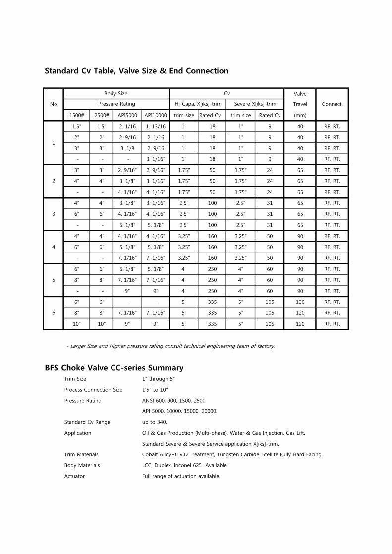
Standard Cv Table, Valve Size & End Connection
Valve
Travel
1500# 2500# API5000 API10000 trim size Rated Cv trim size Rated Cv (mm)
1.5" 1.5" 2. 1/16 1. 13/16 1" 18 1" 9 40 RF. RTJ
2" 2" 2. 9/16 2. 1/16 1" 18 1" 9 40 RF. RTJ
3" 3" 3. 1/8 2. 9/16 1" 18 1" 9 40 RF. RTJ
- - - 3. 1/16" 1" 18 1" 9 40 RF. RTJ
3" 3" 2. 9/16" 2. 9/16" 1.75" 50 1.75" 24 65 RF. RTJ
4" 4" 3. 1/8" 3. 1/16" 1.75" 50 1.75" 24 65 RF. RTJ
- - 4. 1/16" 4. 1/16" 1.75" 50 1.75" 24 65 RF. RTJ
4" 4" 3. 1/8" 3. 1/16" 2.5" 100 2.5" 31 65 RF. RTJ
6" 6" 4. 1/16" 4. 1/16" 2.5" 100 2.5" 31 65 RF. RTJ
- - 5. 1/8" 5. 1/8" 2.5" 100 2.5" 31 65 RF. RTJ
4" 4" 4. 1/16" 4. 1/16" 3.25" 160 3.25" 50 90 RF. RTJ
6" 6" 5. 1/8" 5. 1/8" 3.25" 160 3.25" 50 90 RF. RTJ
- - 7. 1/16" 7. 1/16" 3.25" 160 3.25" 50 90 RF. RTJ
6" 6" 5. 1/8" 5. 1/8" 4" 250 4" 60 90 RF. RTJ
8" 8" 7. 1/16" 7. 1/16" 4" 250 4" 60 90 RF. RTJ
- - 9" 9" 4" 250 4" 60 90 RF. RTJ
6" 6" - - 5" 335 5" 105 120 RF. RTJ
8" 8" 7. 1/16" 7. 1/16" 5" 335 5" 105 120 RF. RTJ
10" 10" 9" 9" 5" 335 5" 105 120 RF. RTJ
- Larger Size and Higher pressure rating consult technical engineering team of factory.
BFS Choke Valve CC-series SummaryTrim Size 1" through 5"
Process Connection Size 1'5" to 10"
Pressure Rating ANSI 600, 900, 1500, 2500,
API 5000, 10000, 15000, 20000.
Standard Cv Range up to 340.
Application Oil & Gas Production (Multi-phase), Water & Gas Injection, Gas Lift.
Standard Severe & Severe Service application X[iks]-trim.
Trim Materials Cobalt Alloy+C.V.D Treatment, Tungsten Carbide. Stellite Fully Hard Facing.
Body Materials LCC, Duplex, Inconel 625 Available.
Actuator Full range of actuation available.
6
Pressure Rating Connect.
2
3
4
5
Body Size Cv
No Severe X[iks]-trimHi-Capa. X[iks]-trim
1
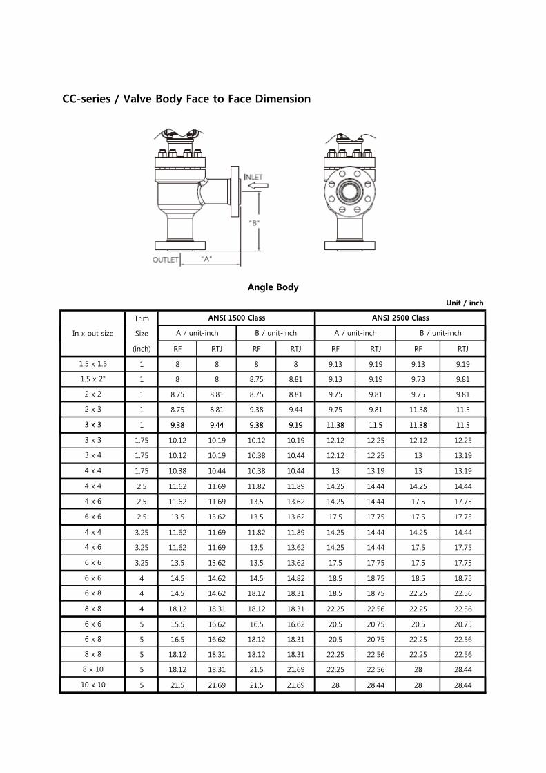
CC-series / Valve Body Face to Face Dimension
Unit / inch
Trim
Size
Angle Body
In x out size
ANSI 1500 Class ANSI 2500 Class
A / unit-inch B / unit-inch A / unit-inch B / unit-inch
(inch) RF RTJ RF RTJ RF RTJ RF RTJ
1 8 8 8 8 9.13 9.19 9.13 9.19
1 8 8 8.75 8.81 9.13 9.19 9.73 9.81
1 8.75 8.81 8.75 8.81 9.75 9.81 9.75 9.81
1 8.75 8.81 9.38 9.44 9.75 9.81 11.38 11.5
1 9 38 9 44 9 38 9 19 11 38 11 5 11 38 11 5
1.5 x 1.5
1.5 x 2"
2 x 2
2 x 3
3 x 3
/ / / /
1 9.38 9.44 9.38 9.19 11.38 11.5 11.38 11.5
1.75 10.12 10.19 10.12 10.19 12.12 12.25 12.12 12.25
1.75 10.12 10.19 10.38 10.44 12.12 12.25 13 13.19
1.75 10.38 10.44 10.38 10.44 13 13.19 13 13.19
2.5 11.62 11.69 11.82 11.89 14.25 14.44 14.25 14.44
2.5 11.62 11.69 13.5 13.62 14.25 14.44 17.5 17.75
3 x 4
4 x 4
3 x 3
3 x 3
4 x 4
4 x 6
2.5 13.5 13.62 13.5 13.62 17.5 17.75 17.5 17.75
3.25 11.62 11.69 11.82 11.89 14.25 14.44 14.25 14.44
3.25 11.62 11.69 13.5 13.62 14.25 14.44 17.5 17.75
3.25 13.5 13.62 13.5 13.62 17.5 17.75 17.5 17.75
4 14.5 14.62 14.5 14.82 18.5 18.75 18.5 18.75
4 14.5 14.62 18.12 18.31 18.5 18.75 22.25 22.56
6 x 6
4 x 4
4 x 6
6 x 6
6 x 6
6 x 8
4 18.12 18.31 18.12 18.31 22.25 22.56 22.25 22.56
5 15.5 16.62 16.5 16.62 20.5 20.75 20.5 20.75
5 16.5 16.62 18.12 18.31 20.5 20.75 22.25 22.56
5 18.12 18.31 18.12 18.31 22.25 22.56 22.25 22.56
5 18.12 18.31 21.5 21.69 22.25 22.56 28 28.44
5 21.5 21.69 21.5 21.69 28 28.44 28 28.44
6 x 8
8 x 8
8 x 10
10 x 10
8 x 8
6 x 6
5 21.5 21.69 21.5 21.69 28 28.44 28 28.4410 x 10
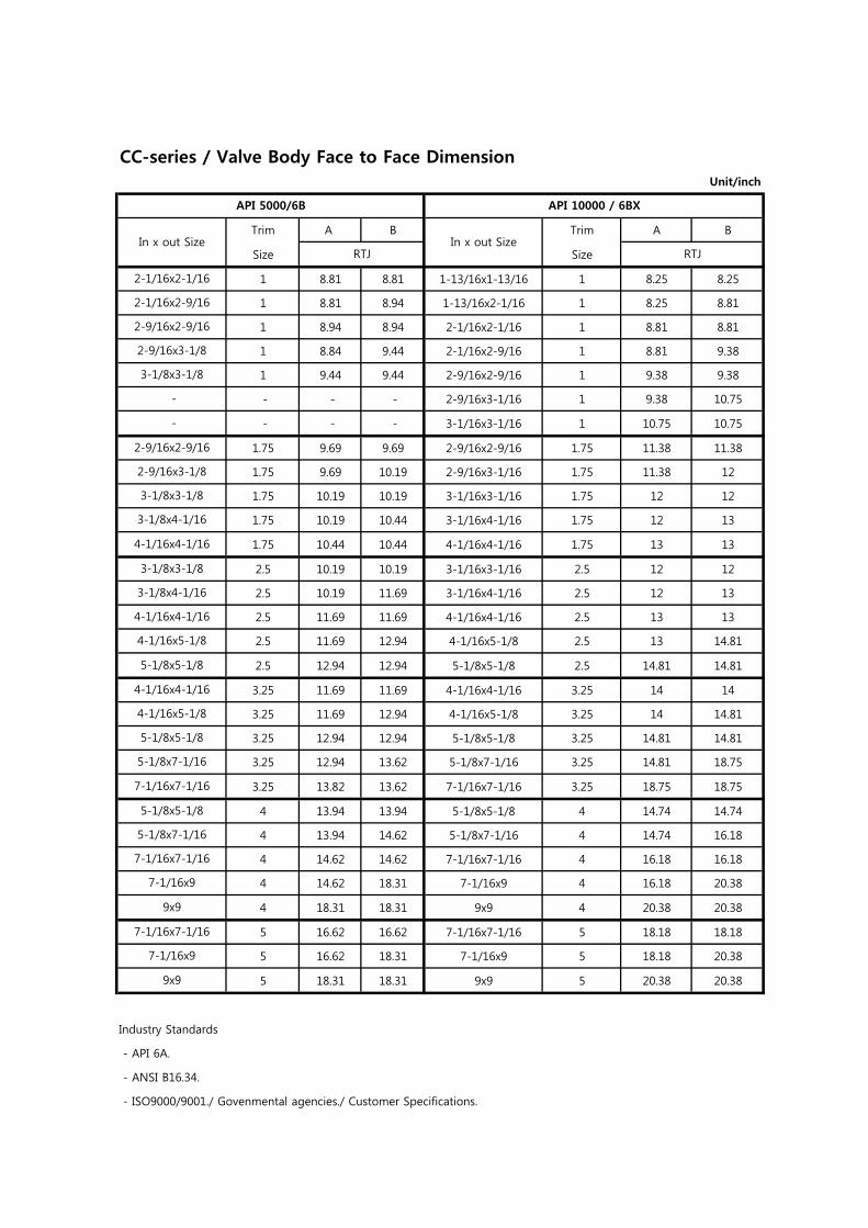
CC-series / Valve Body Face to Face DimensionUnit/inch
Trim A B Trim A B
Size Size
1 8.81 8.81 1-13/16x1-13/16 1 8.25 8.25
1 8.81 8.94 1-13/16x2-1/16 1 8.25 8.81
1 8.94 8.94 2-1/16x2-1/16 1 8.81 8.81
1 8.84 9.44 2-1/16x2-9/16 1 8.81 9.38
1 9.44 9.44 2-9/16x2-9/16 1 9.38 9.38
- - - 2-9/16x3-1/16 1 9.38 10.75
- - - 3-1/16x3-1/16 1 10.75 10.75
1.75 9.69 9.69 2-9/16x2-9/16 1.75 11.38 11.38
1.75 9.69 10.19 2-9/16x3-1/16 1.75 11.38 12
1.75 10.19 10.19 3-1/16x3-1/16 1.75 12 12
1.75 10.19 10.44 3-1/16x4-1/16 1.75 12 13
1.75 10.44 10.44 4-1/16x4-1/16 1.75 13 13
2.5 10.19 10.19 3-1/16x3-1/16 2.5 12 12
2.5 10.19 11.69 3-1/16x4-1/16 2.5 12 13
2.5 11.69 11.69 4-1/16x4-1/16 2.5 13 13
2.5 11.69 12.94 4-1/16x5-1/8 2.5 13 14.81
2.5 12.94 12.94 5-1/8x5-1/8 2.5 14.81 14.81
3.25 11.69 11.69 4-1/16x4-1/16 3.25 14 14
3.25 11.69 12.94 4-1/16x5-1/8 3.25 14 14.81
3.25 12.94 12.94 5-1/8x5-1/8 3.25 14.81 14.81
3.25 12.94 13.62 5-1/8x7-1/16 3.25 14.81 18.75
3.25 13.82 13.62 7-1/16x7-1/16 3.25 18.75 18.75
4 13.94 13.94 5-1/8x5-1/8 4 14.74 14.74
4 13.94 14.62 5-1/8x7-1/16 4 14.74 16.18
4 14.62 14.62 7-1/16x7-1/16 4 16.18 16.18
4 14.62 18.31 7-1/16x9 4 16.18 20.38
4 18.31 18.31 9x9 4 20.38 20.38
5 16.62 16.62 7-1/16x7-1/16 5 18.18 18.18
5 16.62 18.31 7-1/16x9 5 18.18 20.38
5 18.31 18.31 9x9 5 20.38 20.38
Industry Standards
- API 6A.
- ANSI B16.34.
- ISO9000/9001./ Govenmental agencies./ Customer Specifications.
API 10000 / 6BX
In x out SizeRTJRTJ
In x out Size
9x9
4-1/16x5-1/8
5-1/8x5-1/8
5-1/8x7-1/16
7-1/16x7-1/16
5-1/8x5-1/8
5-1/8x7-1/16
7-1/16x7-1/16
7-1/16x9
9x9
7-1/16x7-1/16
7-1/16x9
4-1/16x4-1/16
-
2-9/16x2-9/16
2-9/16x3-1/8
3-1/8x3-1/8
3-1/8x4-1/16
4-1/16x4-1/16
3-1/8x3-1/8
3-1/8x4-1/16
4-1/16x4-1/16
4-1/16x5-1/8
5-1/8x5-1/8
-
API 5000/6B
2-1/16x2-1/16
2-1/16x2-9/16
2-9/16x2-9/16
2-9/16x3-1/8
3-1/8x3-1/8
11
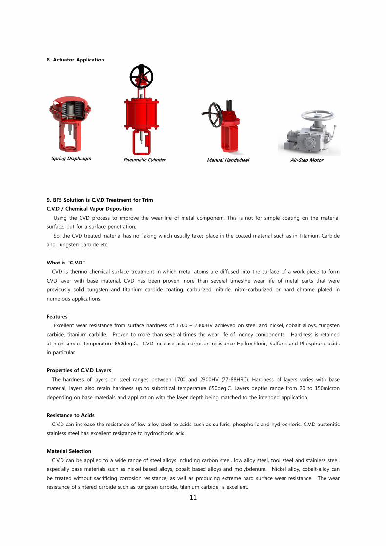
8. Actuator Application
Spring Diaphragm
Pneumatic Cylinder
Manual Handwheel
Air-Step Motor
9. BFS Solution is C.V.D Treatment for Trim
C.V.D / Chemical Vapor Deposition
Using the CVD process to improve the wear life of metal component. This is not for simple coating on the material
surface, but for a surface penetration.
So, the CVD treated material has no flaking which usually takes place in the coated material such as in Titanium Carbide
and Tungsten Carbide etc.
What is “C.V.D”
CVD is thermo-chemical surface treatment in which metal atoms are diffused into the surface of a work piece to form
CVD layer with base material. CVD has been proven more than several timesthe wear life of metal parts that were
previously solid tungsten and titanium carbide coating, carburized, nitride, nitro-carburized or hard chrome plated in
numerous applications.
Features
Excellent wear resistance from surface hardness of 1700 – 2300HV achieved on steel and nickel, cobalt alloys, tungsten
carbide, titanium carbide. Proven to more than several times the wear life of money components. Hardness is retained
at high service temperature 650deg.C. CVD increase acid corrosion resistance Hydrochloric, Sulfuric and Phosphuric acids
in particular.
Properties of C.V.D Layers
The hardness of layers on steel ranges between 1700 and 2300HV (77-88HRC). Hardness of layers varies with base
material, layers also retain hardness up to subcritical temperature 650deg.C. Layers depths range from 20 to 150micron
depending on base materials and application with the layer depth being matched to the intended application.
Resistance to Acids
C.V.D can increase the resistance of low alloy steel to acids such as sulfuric, phosphoric and hydrochloric, C.V.D austenitic
stainless steel has excellent resistance to hydrochloric acid.
Material Selection
C.V.D can be applied to a wide range of steel alloys including carbon steel, low alloy steel, tool steel and stainless steel,
especially base materials such as nickel based alloys, cobalt based alloys and molybdenum. Nickel alloy, cobalt-alloy can
be treated without sacrificing corrosion resistance, as well as producing extreme hard surface wear resistance. The wear
resistance of sintered carbide such as tungsten carbide, titanium carbide, is excellent.
API-6A Choke Valve License Number 6A-1929
Best Flow Solution
BFS Incorporation2 block-3 lot, Geoumdan-Industrial-Complex, 17, Geoumdan-ro, 114 Beon-gil, Seo-gu, Incheon, KoreaT/+82-32-329-9142. F/+82-32-329-9148www.bfsvalve.com