Embed Size (px)
Citation preview
1
COYOTE® 9.5" x 19" (292 mm x 509 mm) Dome Closure
AUGUST 2012
Be sure to read and completely understand this procedure before applying product. Be sure to select the proper PREFORMED product before application.
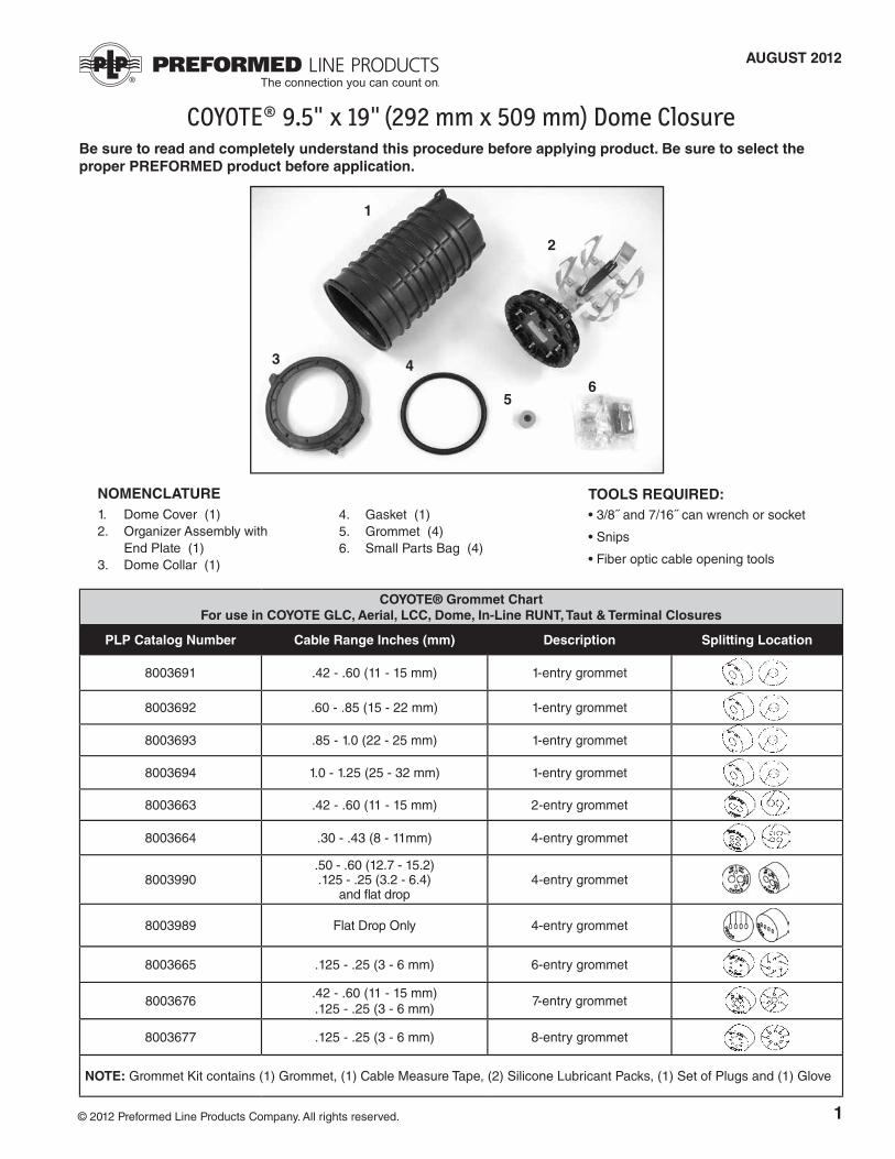
NOMENCLATURE1. Dome Cover (1)2. Organizer Assembly with End Plate (1)3. Dome Collar (1)
4. Gasket (1)5. Grommet (4) 6. Small Parts Bag (4)
2
1
3 4
56
TOOLS REQUIRED:• 3/8˝ and 7/16˝ can wrench or socket
• Snips
• Fiber optic cable opening tools
© 2012 Preformed Line Products Company. All rights reserved.
COYOTE® Grommet ChartFor use in COYOTE GLC, Aerial, LCC, Dome, In-Line RUNT, Taut & Terminal Closures
PLP Catalog Number Cable Range Inches (mm) Description Splitting Location
8003691 .42 - .60 (11 - 15 mm) 1-entry grommet
8003692 .60 - .85 (15 - 22 mm) 1-entry grommet
8003693 .85 - 1.0 (22 - 25 mm) 1-entry grommet
8003694 1.0 - 1.25 (25 - 32 mm) 1-entry grommet
8003663 .42 - .60 (11 - 15 mm) 2-entry grommet
8003664 .30 - .43 (8 - 11mm) 4-entry grommet
8003990.50 - .60 (12.7 - 15.2) .125 - .25 (3.2 - 6.4)
and flat drop4-entry grommet
8003989 Flat Drop Only 4-entry grommet
8003665 .125 - .25 (3 - 6 mm) 6-entry grommet
8003676.42 - .60 (11 - 15 mm) .125 - .25 (3 - 6 mm)
7-entry grommet
8003677 .125 - .25 (3 - 6 mm) 8-entry grommet
NOTE: Grommet Kit contains (1) Grommet, (1) Cable Measure Tape, (2) Silicone Lubricant Packs, (1) Set of Plugs and (1) Glove
2
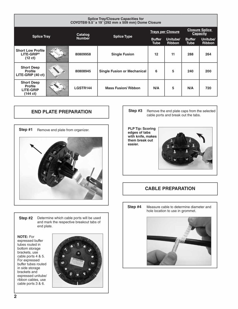
Step #1 Remove end plate from organizer.
Step #3 Remove the end plate caps from the selected cable ports and break out the tabs.
END PLATE PREPARATION
Step #4 Measure cable to determine diameter and hole location to use in grommet.
Step #2
NOTE: For expressed buffer tubes routed in bottom storage brackets, use cable ports 4 & 5. For expressed buffer tubes routed in side storage brackets and expressed unitube/ribbon cables, use cable ports 3 & 6.
Determine which cable ports will be used and mark the respective breakout tabs of end plate.
Splice Tray/Closure Capacities for COYOTE® 9.5˝ x 19˝ (292 mm x 509 mm) Dome Closure
Splice Tray Catalog Number Splice Type
Trays per Closure Closure Splice Capacity
Buffer Tube
Unitube/Ribbon
Buffer Tube
Unitube/Ribbon
Short Low Profile LITE-GRIP®
(12 ct)80809958 Single Fusion 12 11 288 264
Short Deep Profile
LITE-GRIP (40 ct)80808945 Single Fusion or Mechanical 6 5 240 200
Short Deep Profile
LITE-GRIP (144 ct)
LGSTR144 Mass Fusion/ Ribbon N/A 5 N/A 720
PLP Tip: Scoring edges of tabs with knife, makes them break out easier.
CABLE PREPARATION
21
4
3
5
76
3
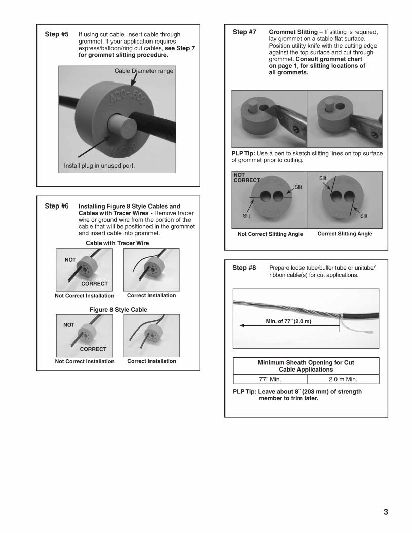
Step #5 If using cut cable, insert cable through grommet. If your application requires express/balloon/ring cut cables, see Step 7 for grommet slitting procedure.
Cable Diameter range
Install plug in unused port.
Step #6 Installing Figure 8 Style Cables and Cables with Tracer Wires - Remove tracer wire or ground wire from the portion of the cable that will be positioned in the grommet and insert cable into grommet.
Cable with Tracer Wire
Figure 8 Style Cable
Not Correct Installation Correct Installation
Not Correct Installation Correct Installation
NOT
CORRECT
NOT
CORRECT
Step #7 Grommet Slitting – If slitting is required, lay grommet on a stable flat surface. Position utility knife with the cutting edge against the top surface and cut through grommet. Consult grommet chart on page 1, for slitting locations of all grommets.
PLP Tip: Use a pen to sketch slitting lines on top surface of grommet prior to cutting.
Not Correct Slitting Angle Correct Slitting Angle
Slit
Slit Slit
Slit
NOT CORRECT
Step #8 Prepare loose tube/buffer tube or unitube/ribbon cable(s) for cut applications.
Min. of 77˝ (2.0 m)
Minimum Sheath Opening for Cut Cable Applications
77˝ Min. 2.0 m Min.
PLP Tip: Leave about 8˝ (203 mm) of strength member to trim later.
4
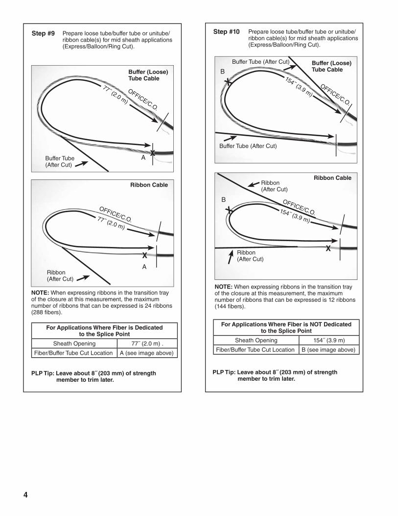
Step #9 Prepare loose tube/buffer tube or unitube/ribbon cable(s) for mid sheath applications (Express/Balloon/Ring Cut).
PLP Tip: Leave about 8˝ (203 mm) of strength member to trim later.
Step #10 Prepare loose tube/buffer tube or unitube/ribbon cable(s) for mid sheath applications (Express/Balloon/Ring Cut).
Buffer (Loose)Tube Cable
NOTE: When expressing ribbons in the transition tray of the closure at this measurement, the maximum number of ribbons that can be expressed is 24 ribbons (288 fibers).
For Applications Where Fiber is Dedicated to the Splice Point
Sheath Opening 77˝ (2.0 m) .
Fiber/Buffer Tube Cut Location A (see image above)
OFFICE/C.O.
77˝ (2.0 m)
X
Ribbon Cable
OFFICE/C.O.77˝ (2.0 m)
XA
A
Buffer (Loose)Tube Cable
OFFICE/C.O.
154˝ (3.9 m)
XB
Ribbon Cable
OFFICE/C.O.154˝ (3.9 m)
X
XB
NOTE: When expressing ribbons in the transition tray of the closure at this measurement, the maximum number of ribbons that can be expressed is 12 ribbons (144 fibers).
PLP Tip: Leave about 8˝ (203 mm) of strength member to trim later.
For Applications Where Fiber is NOT Dedicated to the Splice Point
Sheath Opening 154˝ (3.9 m)
Fiber/Buffer Tube Cut Location B (see image above)
Buffer Tube (After Cut)
Ribbon (After Cut)
Buffer Tube (After Cut)
Buffer Tube (After Cut)
Ribbon (After Cut)
Ribbon (After Cut)
5
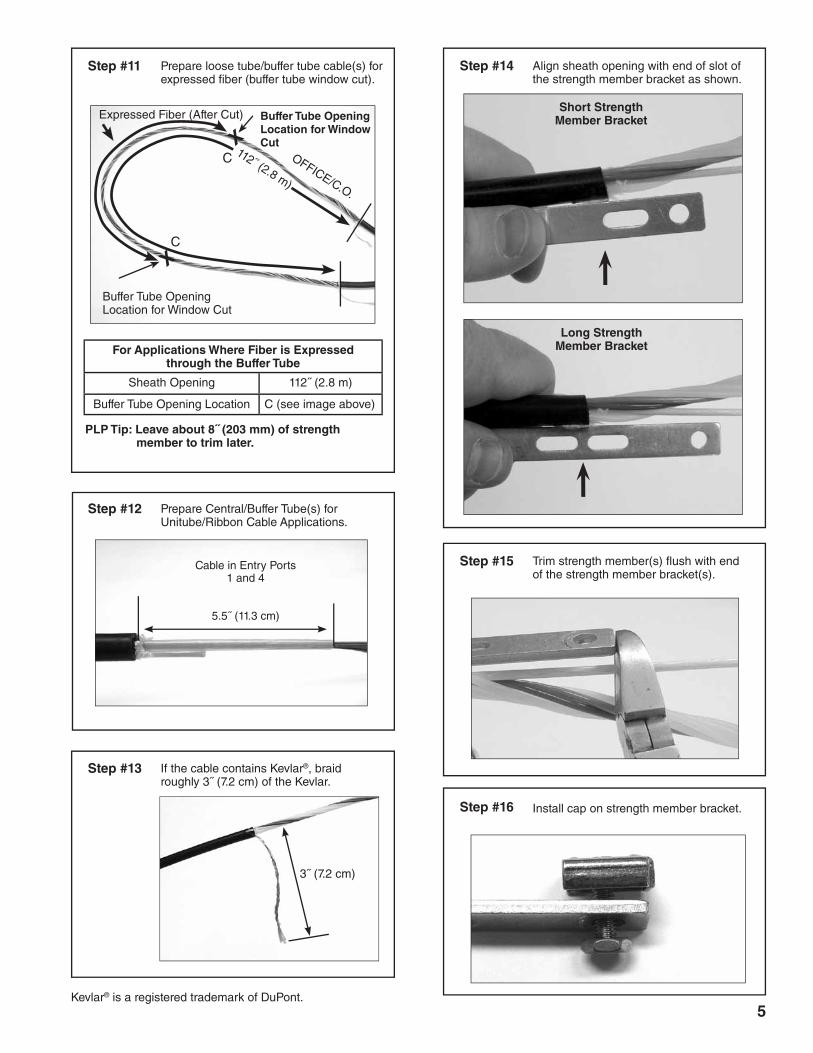
Step #11 Prepare loose tube/buffer tube cable(s) for expressed fiber (buffer tube window cut).
Step #12 Prepare Central/Buffer Tube(s) for Unitube/Ribbon Cable Applications.
Buffer Tube Opening Location for Window Cut
Buffer Tube Opening Location for Window Cut
112˝ (2.8 m)
X
X
OFFICE/C.O.
PLP Tip: Leave about 8˝ (203 mm) of strength member to trim later.
For Applications Where Fiber is Expressed through the Buffer Tube
Sheath Opening 112˝ (2.8 m)
Buffer Tube Opening Location C (see image above)
Cable in Entry Ports 1 and 4
5.5˝ (11.3 cm)
Step #13 If the cable contains Kevlar®, braid roughly 3˝ (7.2 cm) of the Kevlar.
3˝ (7.2 cm)
Kevlar® is a registered trademark of DuPont.
C
C
Expressed Fiber (After Cut)
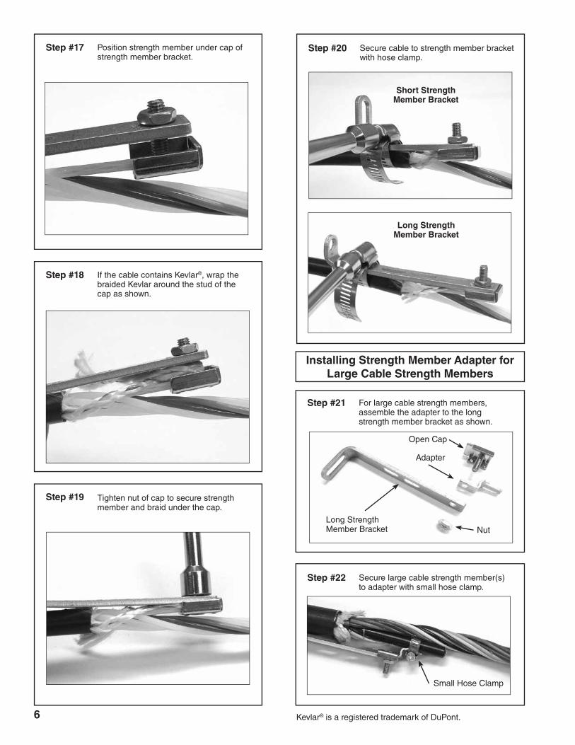
Step #14 Align sheath opening with end of slot of the strength member bracket as shown.
Step #15 Trim strength member(s) flush with end of the strength member bracket(s).
Short Strength Member Bracket
Long Strength Member Bracket
Step #16 Install cap on strength member bracket.
6
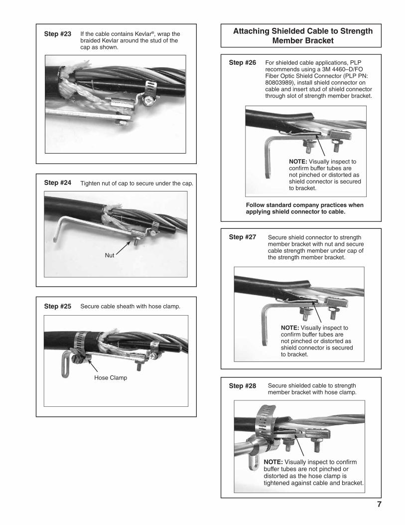
Step #17 Position strength member under cap of strength member bracket.
Step #18 If the cable contains Kevlar®, wrap the braided Kevlar around the stud of the cap as shown.
Installing Strength Member Adapter for Large Cable Strength Members
Small Hose Clamp
Step #22 Secure large cable strength member(s) to adapter with small hose clamp.
Step #21 For large cable strength members, assemble the adapter to the long strength member bracket as shown.
Long Strength Member Bracket
Adapter
Open Cap
Nut
Kevlar® is a registered trademark of DuPont.
Step #20 Secure cable to strength member bracket with hose clamp.
Step #19 Tighten nut of cap to secure strength member and braid under the cap.
Short Strength Member Bracket
Long Strength Member Bracket
7
Step #23 If the cable contains Kevlar®, wrap the braided Kevlar around the stud of the cap as shown.
Step #24 Tighten nut of cap to secure under the cap.
Nut
Step #25 Secure cable sheath with hose clamp.
Step #27
Step #26
Secure shield connector to strength member bracket with nut and secure cable strength member under cap of the strength member bracket.
Follow standard company practices when applying shield connector to cable.
For shielded cable applications, PLP recommends using a 3M 4460–D/FO Fiber Optic Shield Connector (PLP PN: 80803989), install shield connector on cable and insert stud of shield connector through slot of strength member bracket.
Hose ClampStep #28 Secure shielded cable to strength
member bracket with hose clamp.
Attaching Shielded Cable to Strength Member Bracket
NOTE: Visually inspect to confirm buffer tubes are not pinched or distorted as shield connector is secured to bracket.
NOTE: Visually inspect to confirm buffer tubes are not pinched or distorted as shield connector is secured to bracket.
NOTE: Visually inspect to confirm buffer tubes are not pinched or distorted as the hose clamp is tightened against cable and bracket.
8
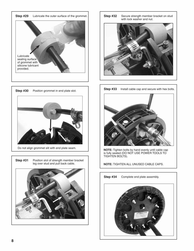
Step #30 Position grommet in end plate slot.
Step #31 Position slot of strength member bracket leg over stud and pull back cable.
Step #32 Secure strength member bracket on stud with lock washer and nut.
NOTE: Tighten bolts by hand evenly until cable cap is fully seated (DO NOT USE POWER TOOLS TO TIGHTEN BOLTS).
NOTE: TIGHTEN ALL UNUSED CABLE CAPS.
Step #29 Lubricate the outer surface of the grommet.
Lubricate sealing surface of grommet with silicone lubricant provided.
Do not align grommet slit with end plate seam.
Step #33 Install cable cap and secure with hex bolts.
Step #34 Complete end plate assembly.
9
Buffer Tube Applications
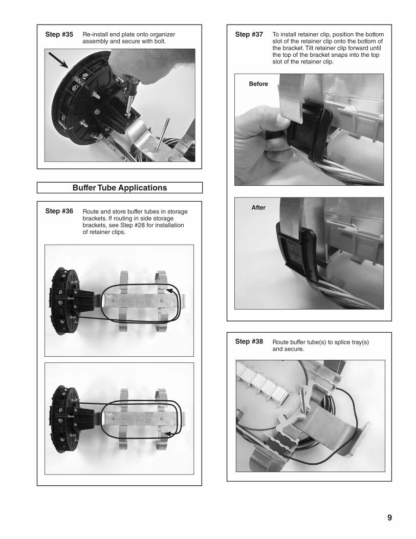
Step #35 Re-install end plate onto organizer assembly and secure with bolt.
Step #36 Route and store buffer tubes in storage brackets. If routing in side storage brackets, see Step #28 for installation of retainer clips.
Step #37 To install retainer clip, position the bottom slot of the retainer clip onto the bottom of the bracket. Tilt retainer clip forward until the top of the bracket snaps into the top slot of the retainer clip.
Step #38 Route buffer tube(s) to splice tray(s) and secure.
Before
After
10
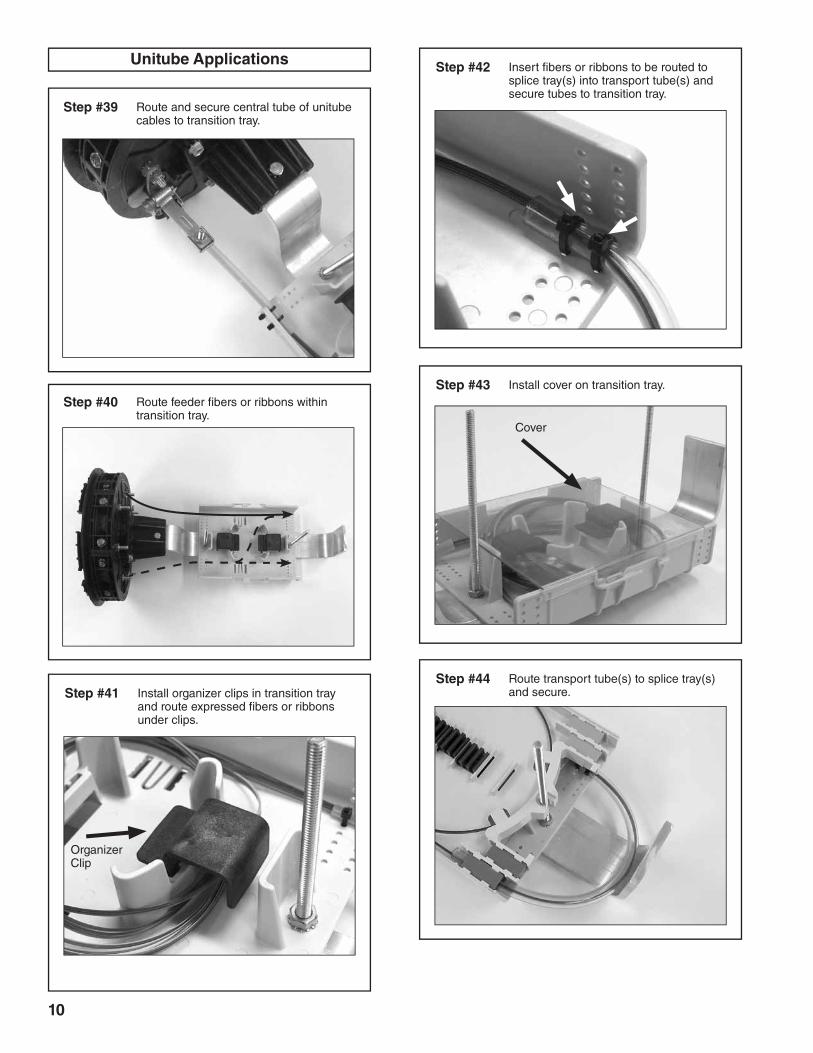
Step #39 Route and secure central tube of unitube cables to transition tray.
Step #40 Route feeder fibers or ribbons within transition tray.
Step #41 Install organizer clips in transition tray and route expressed fibers or ribbons under clips.
Unitube Applications
Organizer Clip
Step #42 Insert fibers or ribbons to be routed to splice tray(s) into transport tube(s) and secure tubes to transition tray.
Step #43 Install cover on transition tray.
Cover
Step #44 Route transport tube(s) to splice tray(s) and secure.
11
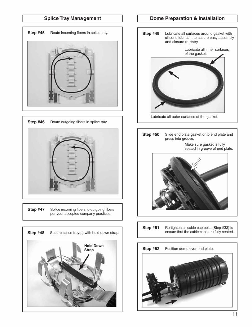
Splice Tray Management
Step #45 Route incoming fibers in splice tray.
Step #46 Route outgoing fibers in splice tray.
Step #47 Splice incoming fibers to outgoing fibers per your accepted company practices.
Step #48 Secure splice tray(s) with hold down strap.
Dome Preparation & Installation
Step #49 Lubricate all surfaces around gasket with silicone lubricant to assure easy assembly and closure re-entry.
Lubricate all outer surfaces of the gasket.
Lubricate all inner surfaces of the gasket.
Step #50 Slide end plate gasket onto end plate and press into groove.
Make sure gasket is fully seated in groove of end plate.
Step #51 Re-tighten all cable cap bolts (Step #33) to ensure that the cable caps are fully seated.
Step #52 Position dome over end plate.Hold Down Strap
12
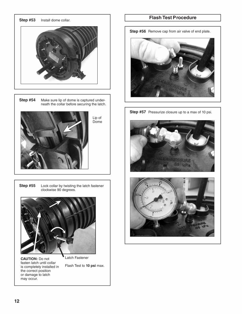
Step #53 Install dome collar.
Step #54 Make sure lip of dome is captured under-neath the collar before securing the latch.
Lip of Dome
Step #55 Lock collar by twisting the latch fastener clockwise 90 degrees.
Latch Fastener
Flash Test to 10 psi max.
CAUTION: Do not fasten latch until collar is completely installed in the correct position or damage to latch may occur.
Step #56 Remove cap from air valve of end plate.
Step #57 Pressurize closure up to a max of 10 psi.
Flash Test Procedure
13
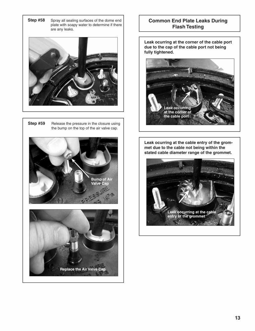
Spray all sealing surfaces of the dome end plate with soapy water to determine if there are any leaks.
Step #58
Step #59 Release the pressure in the closure using the bump on the top of the air valve cap.
Bump of Air Valve Cap
Leak ocurring at the corner of the cable port due to the cap of the cable port not being fully tightened.
Common End Plate Leaks During Flash Testing
Leak ocurring at the cable entry of the grom-met due to the cable not being within the stated cable diameter range of the grommet.
Leak occurring at the corner of the cable port
Leak occurring at the cable entry of the grommet
Replace the Air Valve Cap
14
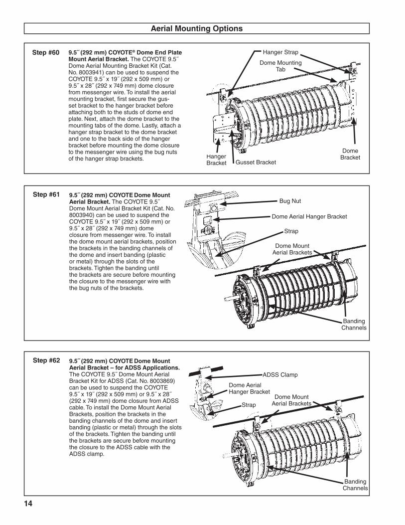
Hanger Strap
Dome Mounting Tab
Step #60 9.5˝ (292 mm) COYOTE® Dome End Plate Mount Aerial Bracket. The COYOTE 9.5˝ Dome Aerial Mounting Bracket Kit (Cat. No. 8003941) can be used to suspend the COYOTE 9.5˝ x 19˝ (292 x 509 mm) or 9.5˝ x 28˝ (292 x 749 mm) dome closure from messenger wire. To install the aerial mounting bracket, first secure the gus-set bracket to the hanger bracket before attaching both to the studs of dome end plate. Next, attach the dome bracket to the mounting tabs of the dome. Lastly, attach a hanger strap bracket to the dome bracket and one to the back side of the hanger bracket before mounting the dome closure to the messenger wire using the bug nuts of the hanger strap brackets.
Aerial Mounting Options
Dome Bracket
Gusset BracketHanger Bracket
Step #61 9.5˝ (292 mm) COYOTE Dome Mount Aerial Bracket. The COYOTE 9.5˝ Dome Mount Aerial Bracket Kit (Cat. No. 8003940) can be used to suspend the COYOTE 9.5˝ x 19˝ (292 x 509 mm) or 9.5˝ x 28˝ (292 x 749 mm) dome closure from messenger wire. To install the dome mount aerial brackets, position the brackets in the banding channels of the dome and insert banding (plastic or metal) through the slots of the brackets. Tighten the banding until the brackets are secure before mounting the closure to the messenger wire with the bug nuts of the brackets.
Banding Channels
Dome Mount Aerial Brackets
Bug Nut
Dome Aerial Hanger Bracket
Strap
Step #62 9.5˝ (292 mm) COYOTE Dome Mount Aerial Bracket – for ADSS Applications. The COYOTE 9.5˝ Dome Mount Aerial Bracket Kit for ADSS (Cat. No. 8003869) can be used to suspend the COYOTE 9.5˝ x 19˝ (292 x 509 mm) or 9.5˝ x 28˝ (292 x 749 mm) dome closure from ADSS cable. To install the Dome Mount Aerial Brackets, position the brackets in the banding channels of the dome and insert banding (plastic or metal) through the slots of the brackets. Tighten the banding until the brackets are secure before mounting the closure to the ADSS cable with the ADSS clamp.
Dome Mount Aerial Brackets
Dome Aerial Hanger Bracket
ADSS Clamp
Strap
Banding Channels
15
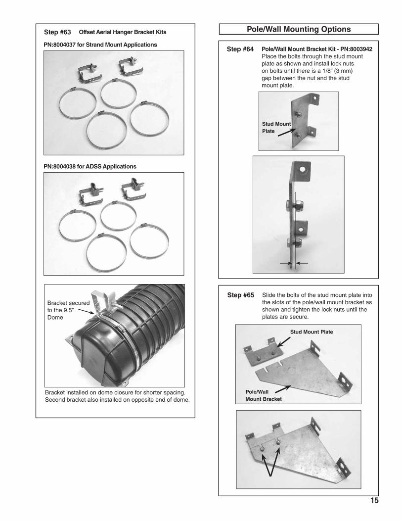
Pole/Wall Mount Bracket Kit - PN:8003942Place the bolts through the stud mount plate as shown and install lock nuts on bolts until there is a 1/8” (3 mm) gap between the nut and the stud mount plate.
Step #64
Stud Mount Plate
Secure Lock Nuts
Pole/Wall Mounting OptionsOffset Aerial Hanger Bracket Kits Step #63
Bracket secured to the 9.5” Dome
Slide the bolts of the stud mount plate into the slots of the pole/wall mount bracket as shown and tighten the lock nuts until the plates are secure.
Step #65
Pole/Wall Mount Bracket
Stud Mount Plate
PN:8004037 for Strand Mount Applications
PN:8004038 for ADSS Applications
Bracket installed on dome closure for shorter spacing. Second bracket also installed on opposite end of dome.
16SP3138-1
P.O. Box 91129, Cleveland, Ohio 44101 • 440.461.5200 • www.preformed.com • e-mail: [email protected]
SAFETY CONSIDERATIONS
This application procedure is not intended to supersede any company construction or safety standards. This procedure is offered only to illustrate safe application for the individual. FAILURE TO FOLLOW THESE PROCEDURES MAY RESULT IN PERSONAL INjURY OR DEATH.
Do not modify this product under any circumstances.
This product is intended for use by trained technicians only. This product should not be used by anyone who is not familiar with, and not trained to use it.
When working in the area of energized lines, extra care should be taken to prevent accidental electrical contact.
For proper performance and personal safety, be sure to select the proper size PREFORMEDTM product before application.
PREFORMED products are precision devices. To insure proper performance, they should be stored in cartons under cover and handled carefully.
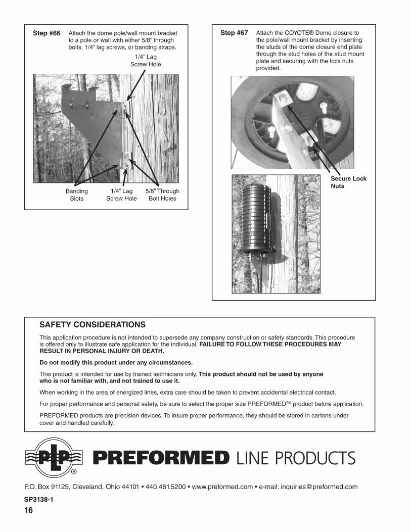
Attach the COYOTE® Dome closure to the pole/wall mount bracket by inserting the studs of the dome closure end plate through the stud holes of the stud mount plate and securing with the lock nuts provided.
Step #67
Secure Lock Nuts
Attach the dome pole/wall mount bracket to a pole or wall with either 5/8” through bolts, 1/4” lag screws, or banding straps.
Step #66
Banding Slots
1/4” Lag Screw Hole
1/4” Lag Screw Hole
5/8” Through Bolt Holes