Embed Size (px)
Citation preview
CPS-i2000(R2) MANUAL
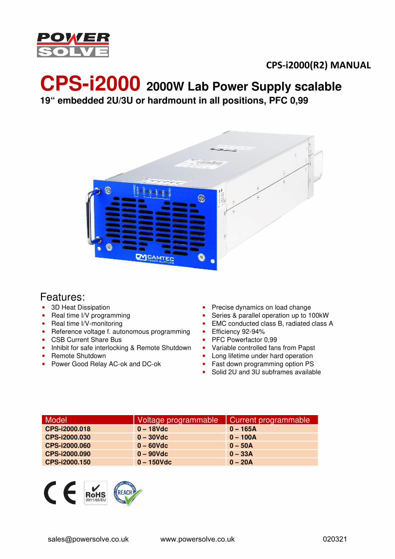
CPS-i2000 2000W Lab Power Supply scalable 19“ embedded 2U/3U or hardmount in all positions, PFC 0,99
Features: • 3D Heat Dissipation
• Real time I/V programming
• Real time I/V-monitoring
• Reference voltage f. autonomous programming
• CSB Current Share Bus
• Inhibit for safe interlocking & Remote Shutdown
• Remote Shutdown
• Power Good Relay AC-ok and DC-ok
• Precise dynamics on load change
• Series & parallel operation up to 100kW
• EMC conducted class B, radiated class A
• Efficiency 92-94%
• PFC Powerfactor 0,99
• Variable controlled fans from Papst
• Long lifetime under hard operation
• Fast down programming option PS
• Solid 2U and 3U subframes available
Model Voltage programmable Current programmable CPS-i2000.018 0 – 18Vdc 0 – 165A
CPS-i2000.030 0 – 30Vdc 0 – 100A
CPS-i2000.060 0 – 60Vdc 0 – 50A
CPS-i2000.090 0 – 90Vdc 0 – 33A
CPS-i2000.150 0 – 150Vdc 0 – 20A
[email protected] www.powersolve.co.uk 020321
CPS-i2000(R2) MANUAL
CPS-POWER - a unique concept of 3D-heat, open mechanics, design to service and open scalability
The Camtec CPS-i models are high-precision lab power supplies „Made in Germany“. These power supplies are designed for scalable power systems in the testing automation.
For more than 25 years the Camtec Power Supplies manufactures high-end switch mode power supplies in Germany. A field breakdown of below 0,004% over a 10-year period under review approves our ambitious quality concept. Each manufactured Camtec product passes several 100% random tests for each detailed function and a full-load Burn-In test.
Although it is not required from the safety norms our production applies a routine safety test to each manufactured device, even if it is an extra low-voltage model. The components in the assembled device pass stress aging to achieve an even level and to prevent from delayed failures. Our internal product engineering guidelines provide a clear target: Camtec product reputation must say „mount and forget“. Quality is never a mere promise for our team.
The CPS-i laboratory power supplies provide low noise and ripple, a very fast programming, and a precise setting at high load changes. With an efficiency of 92-94% and a power factor of 0.99, the devices are highly energy efficient.
Equipped with high-end capacitors of outstanding lifetime our power supplies guarantee a very long and reliable operation time. The circuit design of the CPS-i Series allows cope playing with complex loads. The internal protection circuits protect the power supply and the connected system, even in exceptional situations. The CPS-i series is protected from high transients by strong filters with high energy efficiency. All inputs and outputs and the interface are electrically isolated. The design specifications call for the highest standards of safety and interference suppression. The device was developed in accordance with the requirements of EN61010-1, EN61010-2-201, EN62368-1 and the EMC standards EN55032 conducted Class B, radiated Class A.
The mechanical design of the CPS-i2000 device series is unique. It is the first power supply line in the world market, which can be flexibly adapted to any installation situation. The forced-air-cooling system with monitored and load-dependent variable fan control, allows a detached position in the system. By simple and cost-effective wall brackets the device can be integrated in any position in 90° increments. Unlike comparable power supplies Camtec comes here for the first time to let the system integrator completely free hand. The cooling concepts for supply and exhaust air can be designed to completely remove the heat dissipation from the cabinet. Complex and expensive air-conditionings for switch cabinets can be reduced to a minimum or even eliminate. Brackets for air channels are available as an option. In selecting the fan, as with all our power supplies, in our opinion we use with the German manufacturer EBM Papst the highest quality and most reliable devices in the world market.
The installation of the power supply in a 19" subrack is guaranteed in the simplest way. Again, our engineers have decided to offer a completely open and flexible system. The optional front panels allow the power supplies the use in either a 2U or 3U subrack. In this way we can realized 6kW in 2U-rack and up to 10kW in a 3U-rack with the CPS-i2000 models. With Zero-Stacking the series allows scalable high-power DC source in a comparable small 19-inch rack unit. For power applications with high dynamic range above 10kW we recommend contacting our support team.
As accessories for the CPS-i Camtec provides matched 19 "subframes. Our subracks deserve the name of a carrier, because they really are extremely stable made of stainless steel. The power supplies have nickel-plated steel pins to position the power supplies in the subframes. The so married together systems withstand the toughest conditions. All mechanical connections in the power supplies or on the racks are constructed with A2 or nickel-plated screws, so that they provide maximum protection against corrosion and conductivity.
[email protected] www.powersolve.co.uk 020321
CPS-i2000(R2) MANUAL
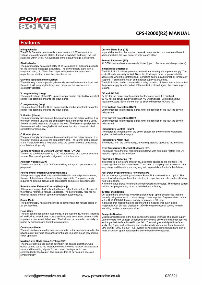
Features
Idling behavior The CPS-i Series is permanently open-circuit proof. When an output voltage is preset it comes stable. If a load is switched suddenly, the unit stabilized within <1ms. An overshoot of the output voltage is irrelevant.
Start behavior The power supply has a start delay of 1s to stabilize all measuring circuits for the interface messages accurately. The power supply starts with a ramp (soft start) of 100ms. The output voltage does not overshoot - regardless of whether a load is connected or not.
Galvanic isolation and insulation The switching power supply is galvanically isolated between the input and the output. All major digital inputs and outputs of the interface are electrically isolated.
V programming (Ureg) The output voltage of the CPS-i power supply can be adjusted by a control signal. The setting is linear to the input signal.
C programming (Ireg) The output current of the CPS-i power supply can be adjusted by a control signal. The setting is linear to the input signal.
V Monitor (Umon) The power supply provides real-time monitoring of the output voltage. It is the exact and real value at the output terminals. If the sense line is used, the real value is measured directly at the load. The latency signal preset to the measured value is negligible since the control circuit is constructed completely analogously.
C Monitor (Imon) The power supply provides real-time monitoring of the output current. It is the exact and real value at the output terminals. The latency signal preset to the measured value is negligible since the control circuit is constructed completely analogously.
Constant Voltage or Constant Current Mode (CV/CC) The device can be operated as a DC voltage source or a constant current source. The operating mode is signaled on the interface.
Auxiliary Voltage (AUX) The devices feature a 12V / 500mA auxiliary voltage to operate external peripheral.
Potentiometer Internal Control (Uadj/Iadj) If the power supply shall only set with the built-in internal potentiometers, the use of the internal reference voltage is possible. The power supply requires no external signals and can operate completely autonomously.
Potentiometer External Control (Uadj/Iadj) If the power supply shall only set with external potentiometers, the use of the internal reference voltage is possible. The power supply requires no external signals and can operate completely autonomously.
Sense Mode The power supply has a sense mode to compensate for voltage drops of 2V per load line.
Fuse Mode The unit can be operated in fuse mode. In the fuse mode, the unit is turned off and locked when it was more than 5 seconds in constant current mode to protect a connected defect load. The lock can be controlled remotely or repeal by disconnection from the mains again.
Continuous Mode The unit can be operated in continuous mode. In the continuous mode, the power supply provides constant current mode in a continuous flow and no ticker-operation.
Master-Slave Mode (Ureg-OUT/Ireg-OUT) The master-slave mode can be defined in the parallel operation. One device can be set as the master, the other involved network units act as a slave and the setting signals follow current / voltage, which are commanded by the Master. This ensures that all devices are operated synchronously.
Current Share Bus (CS) In parallel operation, the involved network components communicate with each other and share the total power evenly to each other.
Remote Shutdown (SD) All CPS-i devices have a remote shutdown (open collector or switching contacts).
Inhibit Mode (Interlock) The inhibit circuit reliably prevents unintentional starting of the power supply. The control loop is internally locked. Since this blocking is done progressively it is active even when the control signal, is missing due to a cable break or temporarily suspend. A premature restart of the power supply is prevented. The inhibit input can be connected to a relay or switch. If the contact is interrupted, the power supply is switched off. If the contact is closed again, the power supply restarts.
DC and AC Fail By DC-fail the power supply reports that the power output is disabled. By AC-fail the power supply reports an AC undervoltage. Both signals have separate outputs. Each of them can be selected between NO and NC.
Over Voltage Protection (OVP) On the interface is a message signal. Until the abolition of the fault the device switches off.
Over Current Protection (OCP) On the interface is a message signal. Until the abolition of the fault the device switches off.
Temperature Control (TEMP) The operating temperature of the power supply can be monitored via a signal applied to the interface output.
Temperature Alarm (TA) If the device is in the critical range, a warning signal is applied to the interface.
Over Temperature Thermal Shutdown (OT)The device has a thermal monitoring: shutdown with automatic restart. The OT signal is applied to the interface.
Fan Failure Monitoring (FF) If it comes to a fan failure or blocking, a signal is applied to the interface. The speed signal of the fan is monitored. Thus, even a creeping fault is detected at an early stage and there is a warning long sold separately in front of a fan failure.
Fast Down Programming & PowerSink (PS) For fast down programming an internal PowerSink is offered as an option. The current sink discharges the output electrolytic capacitors and eleminates skidding inge fed tensions. A further output allows to control external PowerSink modules. The internal current sink for fast programming must be installed at the factory.
3D Heat Dissipation Our aligned and controlled heat dissipation design opens possibilities that are formerly being reserved to custom design power supplies: Steplessly hard mount of the CPS-i2000/3000 power supply modules in a 3D-room. In practice that means that one can mount the modules into every angle imaginable. Our 3D heat dissipation (3D-HD) ensures optimal cooling in each mounting position you may consider.
Design-to-Service: Most recorded failures in the field concern the signal interface of a power supply. Camtec offers new concept of design-to-service that allows the customer easily to exchange the interface himself in the field. The analogue and digital interfaces apply plug & play self calibrating and can be used independent from the model CPS-i/EX/EP 2000 & 3000 Thus, system down cost is being reduced and only a small amount of spare parts need to be stocked by the customer.
[email protected] www.powersolve.co.uk 020321
CPS-i2000(R2) MANUAL
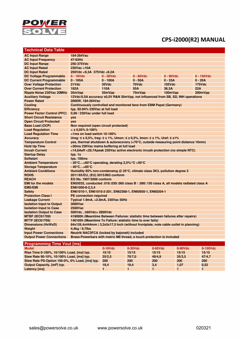
Technical Data Table
AC Input Range 184-264Vac
AC Input Frequency 47-63Hz
DC Input Range 250-375Vdc
AC Input Rated 230Vac <10A
DC Input Rated 250Vdc <9,3A 375Vdc <6.2A
DC Voltage Programmable 0 - 18Vdc 0 - 30Vdc 0 - 60Vdc 0 - 90Vdc 0 - 150Vdc
DC Current Programmable 0 - 165A 0 - 100A 0 - 50A 0 - 33A 0 - 20A
Over Voltage Protection 21Vdc 35Vdc 70Vdc 105Vdc 175Vdc
Over Current Protection 182A 110A 55A 36,3A 22A
Ripple Noise 230Vac 20MHz 35mVpp 35mVpp 75mVpp 100mVpp 200mVpp
Auxiliary Voltage 12Vdc/0,5A accuracy ±0,5V R&N 30mVpp, not influenced from SB, SD, INH operations
Power Rated 2000W, 184-264Vac
Cooling Continuously controlled and monitored fans from EBM Papst (Germany)
Efficiency typ. 92-94% 230Vac at full load
Power Factor Control (PFC) 0,99 / 230Vac under full load
Short Circuit Resistance yes
Open Circuit Protected yes
Base Load (OCP) Non required (open circuit protected)
Load Regulation < ± 0,05% 0-100%
Load Regulation Time <1ms on load switch 10-100%
Accuracy Ureg: ≤ ± 0,5%, Ireg: ≤ ± 1%, Umon: ≤ ± 0,5%, Imon: ≤ ± 1%, Uref: ≤ ±1%
Temperature Control yes, thermal shutdown & autorecovery (+70°C, outside measuring point distance 10mm)
Hold Up Time >30ms 230Vac mains buffering at full load
Inrush Current <14,6Aeff <20,7Apeak 230Vac active electronic inrush protection (no simple NTC)
Startup Delay typ. 1s
Softstart typ. 100ms
Ambient Temperature - 20°C…+60°C operating, derating 2,5%/°C >50°C
Storage Temperature - 40°C…+85°C
Ambient Conditions Humidity 95% non-condensing @ 25°C, climate class 3K3, pollution degree 2
ROHS 2011/65/EU, (EU) 2015/863 conform
REACH EG No. 1907/2006 conform
EMI for the models EN55032, conducted .018/.030/.060 class B / .090/.150 class A, all models radiated class A
EMS/EMI EN61000-6-2,3,4
Safety EN61010-1, EN61010-2-201, EN62368-1, EN60950-1, EN60204-1
Protection Class I PE connection required
Leakage Current Typical 1.9mA, <2.8mA, 230Vac 50Hz
Isolation Input to Output 3000Vac
Isolation Input to Case 2500Vac
Isolation Output to Case 500Vdc , ≥60Vdc= 2800Vdc
MTBF (IEC61709) 419000h (Meantime Between Failures: statistic time between failures after repairs)
MTTF (IEC61709) 146105h (Meantime To Failure: statistic time to ever fails)
Dimensions (HxWxD) 84x126,4x444mm | 3,3x5x17,5 Inch (without frontplate, note cable outlet in planning)
Weight 4,4kg / 9,7lbs
Input Power Connections Neutrik NAC3FCA (locked by bajonett) included
Output Power Connections Brass-Powerbars with metric M8 thread, a touch protection is included
Programming Time Vout [ms] Model 0-18Vdc 0-30Vdc 0-60Vdc 0-90Vdc 0-150Vdc
Rise Time 0-100%, 10/100% Load, [ms] typ. 15/15 15/15 15/15 15/15 15/15
Slew Rate 90-10%, 10/100% Load, [ms] typ. 25/2,5 70/7,0 49/4,9 35/3,5 47/4,7
Slew Rate PS-Option 100-0%, 0% Load, [ms] typ. 200 200 200 200 200
Output Capacity, [mF] typ. 19,4 19,4 3,4 1,07 0,52
Latency [ms] 1 1 1 1 1
[email protected] www.powersolve.co.uk 020321
CPS-i2000(R2) MANUAL
Manual und Technical Details
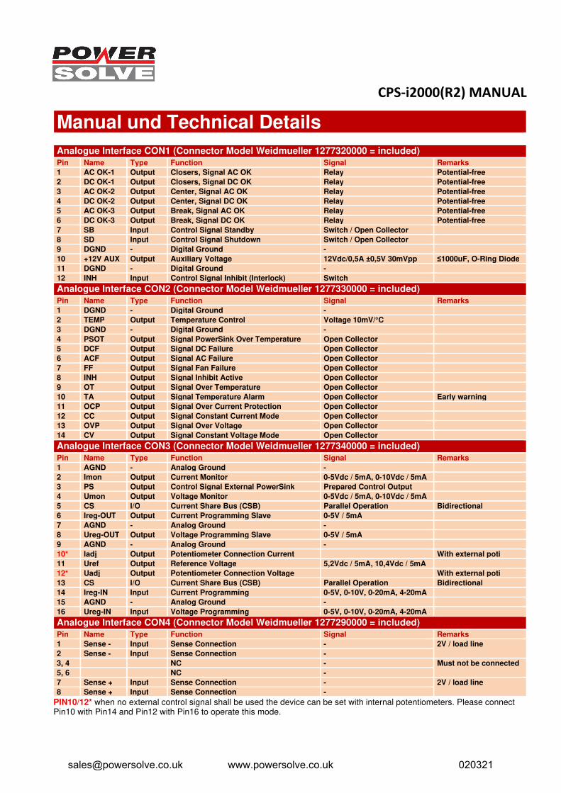
Analogue Interface CON1 (Connector Model Weidmueller 1277320000 = included)
Pin Name Type Function Signal Remarks
1 AC OK-1 Output Closers, Signal AC OK Relay Potential-free
2 DC OK-1 Output Closers, Signal DC OK Relay Potential-free 3 AC OK-2 Output Center, Signal AC OK Relay Potential-free 4 DC OK-2 Output Center, Signal DC OK Relay Potential-free 5 AC OK-3 Output Break, Signal AC OK Relay Potential-free 6 DC OK-3 Output Break, Signal DC OK Relay Potential-free 7 SB Input Control Signal Standby Switch / Open Collector
8 SD Input Control Signal Shutdown Switch / Open Collector
9 DGND - Digital Ground -
10 +12V AUX Output Auxiliary Voltage 12Vdc/0,5A ±0,5V 30mVpp ≤1000uF, O-Ring Diode
11 DGND - Digital Ground -
12 INH Input Control Signal Inhibit (Interlock) Switch
Analogue Interface CON2 (Connector Model Weidmueller 1277330000 = included)
Pin Name Type Function Signal Remarks
1 DGND - Digital Ground -
2 TEMP Output Temperature Control Voltage 10mV/°C
3 DGND - Digital Ground -
4 PSOT Output Signal PowerSink Over Temperature Open Collector
5 DCF Output Signal DC Failure Open Collector
6 ACF Output Signal AC Failure Open Collector
7 FF Output Signal Fan Failure Open Collector
8 INH Output Signal Inhibit Active Open Collector
9 OT Output Signal Over Temperature Open Collector
10 TA Output Signal Temperature Alarm Open Collector Early warning
11 OCP Output Signal Over Current Protection Open Collector 12 CC Output Signal Constant Current Mode Open Collector 13 OVP Output Signal Over Voltage Open Collector 14 CV Output Signal Constant Voltage Mode Open Collector
Analogue Interface CON3 (Connector Model Weidmueller 1277340000 = included)
Pin Name Type Function Signal Remarks
1 AGND - Analog Ground -
2 Imon Output Current Monitor 0-5Vdc / 5mA, 0-10Vdc / 5mA
3 PS Output Control Signal External PowerSink Prepared Control Output
4 Umon Output Voltage Monitor 0-5Vdc / 5mA, 0-10Vdc / 5mA
5 CS I/O Current Share Bus (CSB) Parallel Operation Bidirectional
6 Ireg-OUT Output Current Programming Slave 0-5V / 5mA
7 AGND - Analog Ground -
8 Ureg-OUT Output Voltage Programming Slave 0-5V / 5mA
9 AGND - Analog Ground -
10* Iadj Output Potentiometer Connection Current With external poti
11 Uref Output Reference Voltage 5,2Vdc / 5mA, 10,4Vdc / 5mA
12* Uadj Output Potentiometer Connection Voltage With external poti
13 CS I/O Current Share Bus (CSB) Parallel Operation Bidirectional
14 Ireg-IN Input Current Programming 0-5V, 0-10V, 0-20mA, 4-20mA
15 AGND - Analog Ground -
16 Ureg-IN Input Voltage Programming 0-5V, 0-10V, 0-20mA, 4-20mA
Analogue Interface CON4 (Connector Model Weidmueller 1277290000 = included)
Pin Name Type Function Signal Remarks
1 Sense - Input Sense Connection - 2V / load line
2 Sense - Input Sense Connection - 3, 4 NC - Must not be connected
5, 6 NC -
7 Sense + Input Sense Connection - 2V / load line
8 Sense + Input Sense Connection - PIN10/12* when no external control signal shall be used the device can be set with internal potentiometers. Please connect Pin10 with Pin14 and Pin12 with Pin16 to operate this mode.
[email protected] www.powersolve.co.uk 020321
CPS-i2000(R2) MANUAL
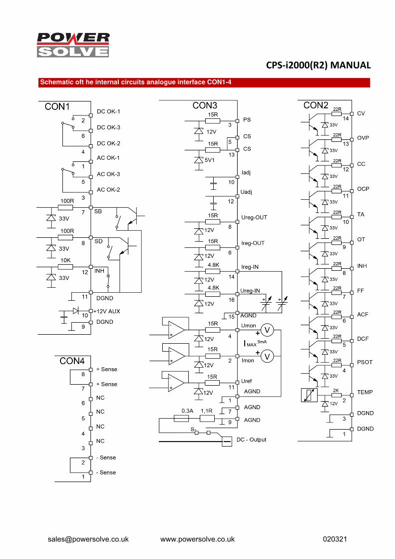
Schematic oft he internal circuits analogue interface CON1-4
[email protected] www.powersolve.co.uk 020321
CPS-i2000(R2) MANUAL
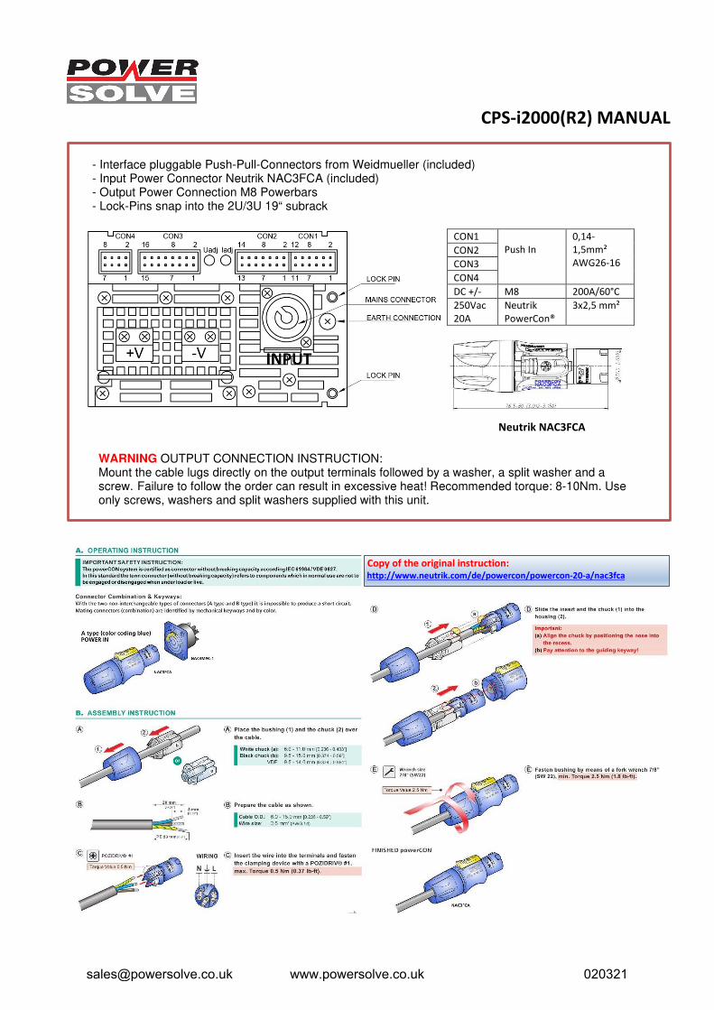
CON1
Push In
0,14-
1,5mm²
AWG26-16
CON2
CON3
CON4
DC +/- M8 200A/60°C
250Vac
20A
Neutrik
PowerCon®
3x2,5 mm²
Neutrik NAC3FCA
Copy of the original instruction: http://www.neutrik.com/de/powercon/powercon-20-a/nac3fca
- Interface pluggable Push-Pull-Connectors from Weidmueller (included)- Input Power Connector Neutrik NAC3FCA (included)- Output Power Connection M8 Powerbars- Lock-Pins snap into the 2U/3U 19“ subrack
WARNING OUTPUT CONNECTION INSTRUCTION: Mount the cable lugs directly on the output terminals followed by a washer, a split washer and a screw. Failure to follow the order can result in excessive heat! Recommended torque: 8-10Nm. Use only screws, washers and split washers supplied with this unit.
[email protected] www.powersolve.co.uk 020321
CPS-i2000(R2) MANUAL
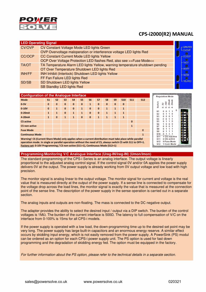
LED Operating Signal
CV/OVP CV Constant Voltage Mode LED lights Green
OVP Overvoltage maloperation or interference voltage LED lights Red
CC/OCP CC Constant Current Mode LED lights Yellow
OCP Over Voltage Protection LED flashes Red, also see >>Fuse Mode<<
TA/OT TA Temperature Alarm LED lights Yellow, warning temperature shutdown pending
OT Over Temperature Shutdown LED lights Red
INH/FF INH Inhibit (Interlock) Shutdown LED lights Yellow
FF Fan Failure LED lights Red
SD/SB SD Shutdown LED lights Yellow
SB Standby LED lights Red
Configuration of the Analogue Interface
Mode S1 S2 S3 S4 S5 S6 S7 S8 S9 S10 S11 S12
0-5V 0 0 0 0 0 1 0 0 0 0
0-10V 0 1 0 0 1 0 0 1 1 1
0-20mA 1 1 0 1 1 0 0 1 1 1
4-20mA 1 0 1 1 0 0 1 1 1 1
CS active 0
CS non-active 1
Fuse Mode 0
Continuous Mode 1
Warning! CS (Current Share Mode) only applies when a current distribution must take place while parallel
operation mode. In single or parallel operation without the need of CS, always switch CS with S11 to OFF=1.
Factory set: 0-10V Programming / CS non-active (S11=1), Continuous Mode (S12=1)
Programming/Monitoring V/C Analogue Interface (Ureg-IN/Ireg-IN) (Umon/Imon)
The standard programming of the CPS-i Series is an analog interface. The output voltage is linearly proportional to the adjusted analog control signal. If the control signal 0V and/or 0A applies the power supply delivers 0V at the output. The power supply is already working from 0V output voltage and low load with high precision.
The monitor signal is analog linear to the output voltage. The monitor signal for current and voltage is the real value that is measured directly at the output of the power supply. If a sense line is connected to compensate for the voltage drop across the load lines, the monitor signal is exactly the value that is measured at the connection point of the sense line. The description of the power supply in the sense operation is carried out in a separate section.
The analog inputs and outputs are non-floating. The mass is connected to the DC negative output.
The adapter provides the ability to select the desired input / output via a DIP switch. The burden of the control voltages is 1MΩ. The burden of the current interface is 500Ω. The latency to full compensation of V/C on the interface from 0-100% is 15ms for all CPS-i models.
If the power supply is operated with a low load, the down-programming time up to the desired set point may be very long. The power supply has large built-in capacitors and an enormous energy reserve. A similar effect occurs by skidding input energy, which is not easily removed from the power supply. A PowerSink (PS) modul can be ordered as an option for each CPS-i power supply unit. The PS option is used for fast down programming and the degradation of skidding energy fed. The option must be equipped in the factory.
For further information about the PS option, please refer to the technical details in a separate section.
[email protected] www.powersolve.co.uk 020321
CPS-i2000(R2) MANUAL
Programming V/C via Potentiometer (Uadj/Iadj) – Stand Alone Operation
The power supply is equipped with 2 potentiometers Uadj and Iadj for setting voltage and current. To enable the setting on the potentiometer, configure the interface via the DIP switch for 0-5V. Connect each Uadj and Iadj of CON3 to the inputs Ureg-IN and Ireg-IN. If one of the two potentiometers is not used, the other value can still be programmed via the interface. In such case, only the control signal 0-5V can be used.
Fuse Mode
The Fuse Mode can be used mode to prevent a major damage to a defective load. Fuse Mode can be activated via the associated switch S12 DIP switch. If the device is in the Fuse Mode (DIP switch S12=0), the device switches off when the constant current operation is taking longer than typ. 5s. The red OCP LED flashes with a period of 0,4s. The PSU is locked. The interlock can be canceled by the power supply is either switched off by the mains input, SB, or SD contact for a moment.
Continuous Mode
If you select Continiuous Mode at DIP switch S12 (DIP switch S12=1), the device provides continuous power. It also applicable in the Constant Current Mode. Factory setup = Continuous Mode
Over Load Behaviour
The CPS-i changes from the standard operation mode into the high current mode when high and fast overload occurs. Thus, it provokes a restart after a 30ms break and delivers continuous current to the output. This special behaviour is a protection for the power supply and for the connected load.
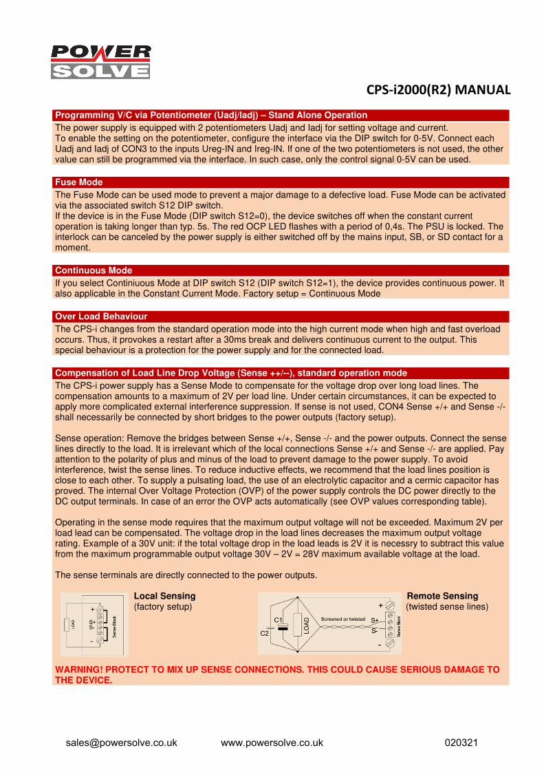
Compensation of Load Line Drop Voltage (Sense ++/--), standard operation mode
The CPS-i power supply has a Sense Mode to compensate for the voltage drop over long load lines. The compensation amounts to a maximum of 2V per load line. Under certain circumstances, it can be expected to apply more complicated external interference suppression. If sense is not used, CON4 Sense +/+ and Sense -/- shall necessarily be connected by short bridges to the power outputs (factory setup).
Sense operation: Remove the bridges between Sense +/+, Sense -/- and the power outputs. Connect the sense lines directly to the load. It is irrelevant which of the local connections Sense +/+ and Sense -/- are applied. Pay attention to the polarity of plus and minus of the load to prevent damage to the power supply. To avoid interference, twist the sense lines. To reduce inductive effects, we recommend that the load lines position is close to each other. To supply a pulsating load, the use of an electrolytic capacitor and a cermic capacitor has proved. The internal Over Voltage Protection (OVP) of the power supply controls the DC power directly to the DC output terminals. In case of an error the OVP acts automatically (see OVP values corresponding table).
Operating in the sense mode requires that the maximum output voltage will not be exceeded. Maximum 2V per load lead can be compensated. The voltage drop in the load lines decreases the maximum output voltage rating. Example of a 30V unit: if the total voltage drop in the load leads is 2V it is necessry to subtract this value from the maximum programmable output voltage 30V – 2V = 28V maximum available voltage at the load.
The sense terminals are directly connected to the power outputs.
Local Sensing Remote Sensing (factory setup) (twisted sense lines)
WARNING! PROTECT TO MIX UP SENSE CONNECTIONS. THIS COULD CAUSE SERIOUS DAMAGE TO THE DEVICE.
[email protected] www.powersolve.co.uk 020321
CPS-i2000(R2) MANUAL
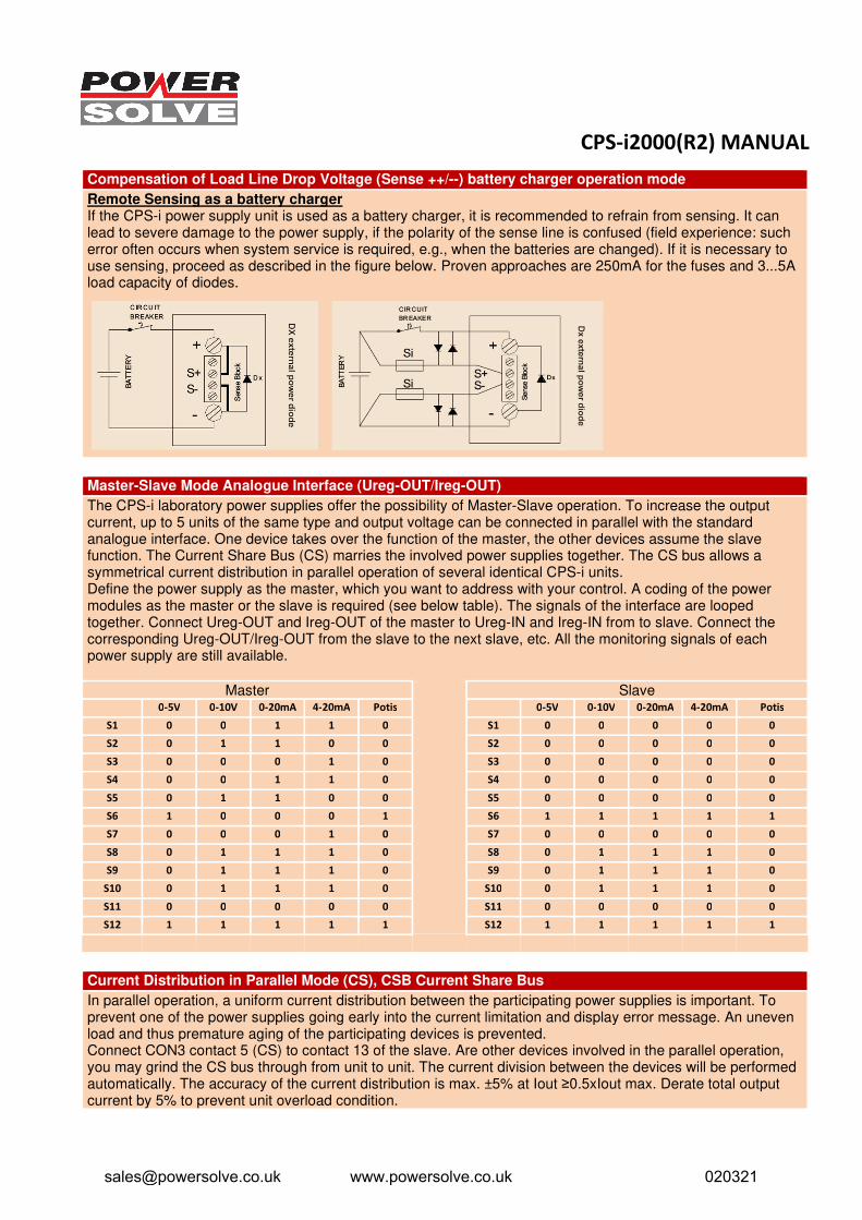
Compensation of Load Line Drop Voltage (Sense ++/--) battery charger operation mode
Remote Sensing as a battery charger If the CPS-i power supply unit is used as a battery charger, it is recommended to refrain from sensing. It can lead to severe damage to the power supply, if the polarity of the sense line is confused (field experience: such error often occurs when system service is required, e.g., when the batteries are changed). If it is necessary to use sensing, proceed as described in the figure below. Proven approaches are 250mA for the fuses and 3...5A load capacity of diodes.
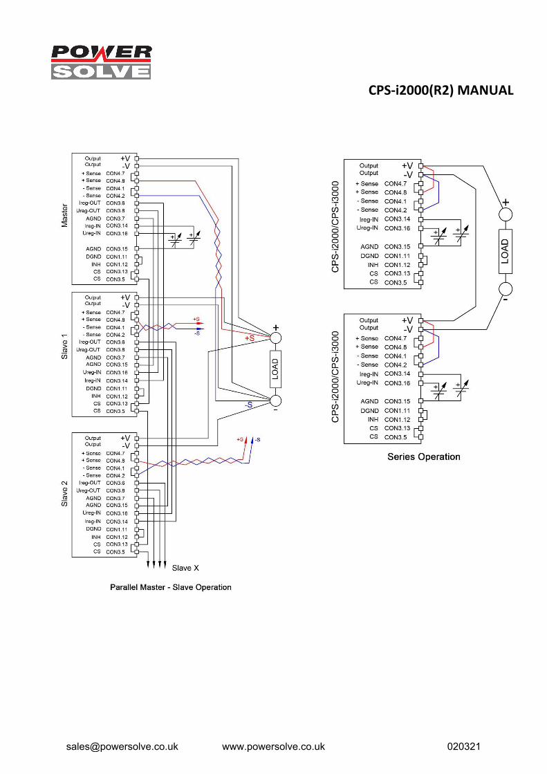
Master-Slave Mode Analogue Interface (Ureg-OUT/Ireg-OUT)
The CPS-i laboratory power supplies offer the possibility of Master-Slave operation. To increase the output current, up to 5 units of the same type and output voltage can be connected in parallel with the standard analogue interface. One device takes over the function of the master, the other devices assume the slave function. The Current Share Bus (CS) marries the involved power supplies together. The CS bus allows a symmetrical current distribution in parallel operation of several identical CPS-i units. Define the power supply as the master, which you want to address with your control. A coding of the power modules as the master or the slave is required (see below table). The signals of the interface are looped together. Connect Ureg-OUT and Ireg-OUT of the master to Ureg-IN and Ireg-IN from to slave. Connect the corresponding Ureg-OUT/Ireg-OUT from the slave to the next slave, etc. All the monitoring signals of each power supply are still available.
Master Slave 0-5V 0-10V 0-20mA 4-20mA Potis 0-5V 0-10V 0-20mA 4-20mA Potis
S1 0 0 1 1 0 S1 0 0 0 0 0
S2 0 1 1 0 0 S2 0 0 0 0 0
S3 0 0 0 1 0 S3 0 0 0 0 0
S4 0 0 1 1 0 S4 0 0 0 0 0
S5 0 1 1 0 0 S5 0 0 0 0 0
S6 1 0 0 0 1 S6 1 1 1 1 1
S7 0 0 0 1 0 S7 0 0 0 0 0
S8 0 1 1 1 0 S8 0 1 1 1 0
S9 0 1 1 1 0 S9 0 1 1 1 0
S10 0 1 1 1 0 S10 0 1 1 1 0
S11 0 0 0 0 0 S11 0 0 0 0 0
S12 1 1 1 1 1 S12 1 1 1 1 1
Current Distribution in Parallel Mode (CS), CSB Current Share Bus
In parallel operation, a uniform current distribution between the participating power supplies is important. To prevent one of the power supplies going early into the current limitation and display error message. An uneven load and thus premature aging of the participating devices is prevented. Connect CON3 contact 5 (CS) to contact 13 of the slave. Are other devices involved in the parallel operation, you may grind the CS bus through from unit to unit. The current division between the devices will be performed automatically. The accuracy of the current distribution is max. ±5% at Iout ≥0.5xIout max. Derate total output current by 5% to prevent unit overload condition.
[email protected] www.powersolve.co.uk 020321
CPS-i2000(R2) MANUAL
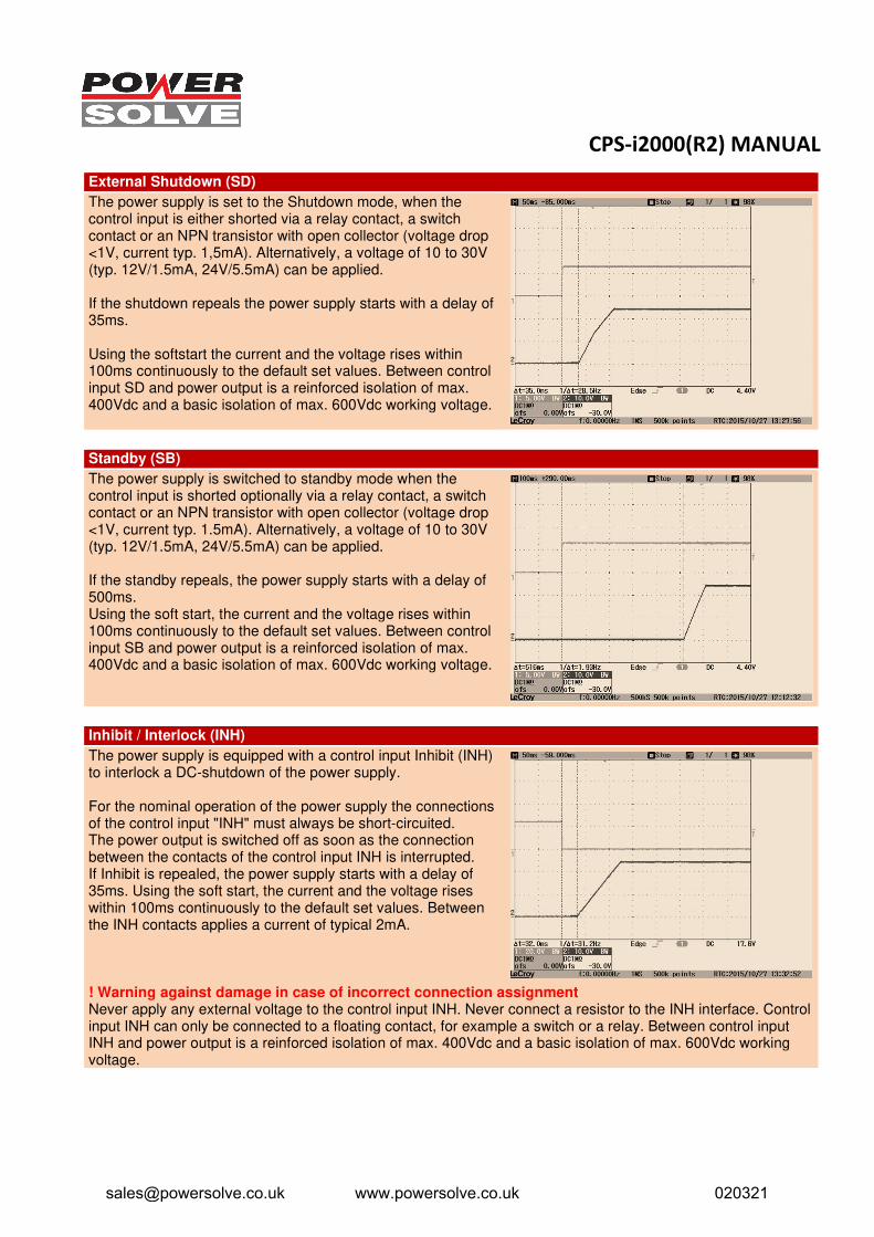
External Shutdown (SD)
The power supply is set to the Shutdown mode, when the control input is either shorted via a relay contact, a switch contact or an NPN transistor with open collector (voltage drop <1V, current typ. 1,5mA). Alternatively, a voltage of 10 to 30V (typ. 12V/1.5mA, 24V/5.5mA) can be applied.
If the shutdown repeals the power supply starts with a delay of 35ms.
Using the softstart the current and the voltage rises within 100ms continuously to the default set values. Between control input SD and power output is a reinforced isolation of max. 400Vdc and a basic isolation of max. 600Vdc working voltage.
Standby (SB)
The power supply is switched to standby mode when the control input is shorted optionally via a relay contact, a switch contact or an NPN transistor with open collector (voltage drop <1V, current typ. 1.5mA). Alternatively, a voltage of 10 to 30V (typ. 12V/1.5mA, 24V/5.5mA) can be applied.
If the standby repeals, the power supply starts with a delay of 500ms. Using the soft start, the current and the voltage rises within 100ms continuously to the default set values. Between control input SB and power output is a reinforced isolation of max. 400Vdc and a basic isolation of max. 600Vdc working voltage.
Inhibit / Interlock (INH)
The power supply is equipped with a control input Inhibit (INH) to interlock a DC-shutdown of the power supply.
For the nominal operation of the power supply the connections of the control input "INH" must always be short-circuited. The power output is switched off as soon as the connection between the contacts of the control input INH is interrupted. If Inhibit is repealed, the power supply starts with a delay of 35ms. Using the soft start, the current and the voltage rises within 100ms continuously to the default set values. Between the INH contacts applies a current of typical 2mA.
! Warning against damage in case of incorrect connection assignmentNever apply any external voltage to the control input INH. Never connect a resistor to the INH interface. Controlinput INH can only be connected to a floating contact, for example a switch or a relay. Between control inputINH and power output is a reinforced isolation of max. 400Vdc and a basic isolation of max. 600Vdc workingvoltage.
[email protected] www.powersolve.co.uk 020321
CPS-i2000(R2) MANUAL
Signal Inhibit (INH) Interlock
INH is high as soon as the connection between the contacts of the control input INH is interrupted. Output Open Collector IMAX=10mA, VLOW≤0,6V, VMAX=30V.
Auxiliary Voltage +12V (AUX)
The power supply offers an auxiliary voltage 12V/500mA. The accuracy is ±500mV. Ripple & Noise 30mVpp. The auxiliary voltage is not affected by the control signals Standby (SB), Shutdown (SD) and Inhibit (INH) and remains always active. Between auxiliary voltage and power output is a reinforced isolation of max. 400Vdc and a basic isolation of max. 600Vdc working voltage.
DC-OK Relay (DC Power Good)
The signal DC OK has potential-free relay contacts (changeover). The contacts of CON1 Pin2 and CON1 Pin4 are closed (relay coil is energized) when the power output is active. The contacts CON1 Pin2 and CON1 Pin4 are open when the power output is inhibited by SB, SD, INH, ACF, OT, FF, OVP or a defective PFC. Contact load (resistive load): 30Vdc/1A, 60Vdc/0.3A, 30Vac/0.5A. Between the relay contacts and power output is a reinforced isolation of max. 400Vdc and a basic isolation of max. 600Vdc working voltage.
DC Fail Signal (DCF)
DCF is high when the power output is disabled by SB, SD, INH, ACF, OT, FF or OVP. Output Open Collector IMAX=10mA, VLOW≤0,6V, VMAX=30V.
AC-OK Relay (AC Power Good)
The Power Good relay reports whether the input voltage is too low or missing. The notification signal AC OK is generated with potential-free relay contacts (changeover). The contacts of CON1 Pin1 and CON1 Pin3 are closed (relay coil is energized) when the input voltage is higher than typ. 175Vac or 210Vdc (switch-on). The contacts of CON1 Pin5 and CON1 Pin3 are closed (relay coil is not energized) when the input voltage is lower than typical 165Vac or 145Vdc (turn-off). Contact load (resistive load): 30Vdc/1A, 60Vdc/0.3A, 30Vac/0.5A. Between the relay contacts and power output is a reinforced isolation of max. 400Vdc and a basic isolation of max. 600Vdc working voltage.
AC Fail Signal (ACF)
The alarm signal ACF is high when the input voltage is lower than typ. 165Vac or 145Vdc. The alarm signal ACF is low when the input voltage is higher than typ. 175Vac or 210Vdc. Output Open Collector IMAX=10mA, VLOW≤0,6V, VMAX=30V.
Over Voltage Protection Signal (OVP)
If an over-voltage occurs to the output (for example, defective components, external feed voltage), it is followed by the shutdown of the power output. A periodic restart attempts (ticker operation period 1s) and a message is triggered: The alarm signal OVP is high. Output Open Collector IMAX=10mA, VLOW≤0,6V, VMAX=30V.
Constant Voltage Mode (CV)
The signal CV is high when the power supply operates as a constant current source. Output Open Collector IMAX=10mA, VLOW≤0,6V, VMAX=30V. When OVP, INH, SB, SD, FF, OCP, OT or a defective PFC occur the mes-sage signal CV is low because the power output is switched off. The change between the CV and the CC mode is automatic. Please pay attention to the DIP switch setting of the Fuse Mode to avoid provoking malfunction.
Constant Current Mode (CC)
The signal CC is high when the power supply operates as a constant voltage source. Output Open Collector IMAX=10mA, VLOW≤0,6V, VMAX=30V. When OVP, INH, SB, SD, FF, OCP, OT or defective PFC occur the mes-sage signal CC is low because the power output is switched off. The change between the CV and the CC mode is automatic. Please pay attention to the DIP switch setting of the Fuse Mode to avoid provoking malfunction.
[email protected] www.powersolve.co.uk 020321
CPS-i2000(R2) MANUAL
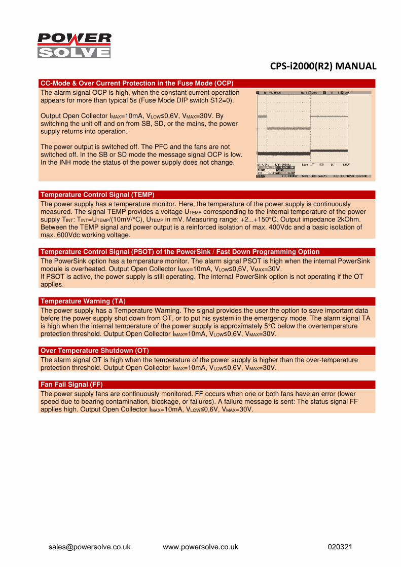
CC-Mode & Over Current Protection in the Fuse Mode (OCP)
The alarm signal OCP is high, when the constant current operation appears for more than typical 5s (Fuse Mode DIP switch S12=0).
Output Open Collector IMAX=10mA, VLOW≤0,6V, VMAX=30V. By switching the unit off and on from SB, SD, or the mains, the power supply returns into operation.
The power output is switched off. The PFC and the fans are not switched off. In the SB or SD mode the message signal OCP is low. In the INH mode the status of the power supply does not change.
Temperature Control Signal (TEMP)
The power supply has a temperature monitor. Here, the temperature of the power supply is continuously measured. The signal TEMP provides a voltage UTEMP corresponding to the internal temperature of the power supply TINT: TINT=UTEMP/(10mV/°C), UTEMP in mV. Measuring range: +2...+150°C. Output impedance 2kOhm. Between the TEMP signal and power output is a reinforced isolation of max. 400Vdc and a basic isolation of max. 600Vdc working voltage.
Temperature Control Signal (PSOT) of the PowerSink / Fast Down Programming Option
The PowerSink option has a temperature monitor. The alarm signal PSOT is high when the internal PowerSink module is overheated. Output Open Collector IMAX=10mA, VLOW≤0,6V, VMAX=30V. If PSOT is active, the power supply is still operating. The internal PowerSink option is not operating if the OT applies.
Temperature Warning (TA)
The power supply has a Temperature Warning. The signal provides the user the option to save important data before the power supply shut down from OT, or to put his system in the emergency mode. The alarm signal TA is high when the internal temperature of the power supply is approximately 5°C below the overtemperature protection threshold. Output Open Collector IMAX=10mA, VLOW≤0,6V, VMAX=30V.
Over Temperature Shutdown (OT)
The alarm signal OT is high when the temperature of the power supply is higher than the over-temperature protection threshold. Output Open Collector IMAX=10mA, VLOW≤0,6V, VMAX=30V.
Fan Fail Signal (FF)
The power supply fans are continuously monitored. FF occurs when one or both fans have an error (lower speed due to bearing contamination, blockage, or failures). A failure message is sent: The status signal FF applies high. Output Open Collector IMAX=10mA, VLOW≤0,6V, VMAX=30V.
[email protected] www.powersolve.co.uk 020321
CPS-i2000(R2) MANUAL
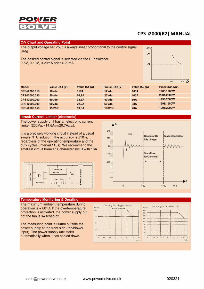
C/V Chart and Operating Point
The output voltage set Vout is always linear proportional to the control signal Ureg.
The desired control signal is selected via the DIP switcher: 0-5V, 0-10V, 0-20mA oder 4-20mA.
Model Value UA1 (V) Value IA1 (A) Value UA2 (V) Value IA2 (A) Pmax (IA1/IA2)
CPS-i2000.018 18Vdc 110A 12Vdc 165A 1980/1980W
CPS-i2000.030 30Vdc 66,7A 20Vdc 100A 2001/2000W
CPS-i2000.060 60Vdc 33,3A 40Vdc 50A 1998/2000W
CPS-i2000.090 90Vdc 22,2A 60Vdc 33A 1998/1980W
CPS-i2000.150 150Vdc 13,3A 100Vdc 20A 1995/2000W
Inrush Current Limiter (electronic)
The power supply unit has an electronic current limiter (230Vac=14,6Arms/20,7Apeak).
It is a precisely working circuit instead of a usual simple NTC solution. The accuracy is ±10%, regardless of the operating temperature and the duty cycles (interval ≥10s). We recommend the smallest circuit breaker a characteristic B with 16A.
Temperature Monitoring & Derating
The maximum ambient temperature during operation is + 60°C. If the overtemperature protection is activated, the power supply but not the fan is switched off.
The measuring point is 50mm outside the power supply at the front side (fan/blower input). The power supply unit starts automatically when it has cooled down.
[email protected] www.powersolve.co.uk 020321
CPS-i2000(R2) MANUAL
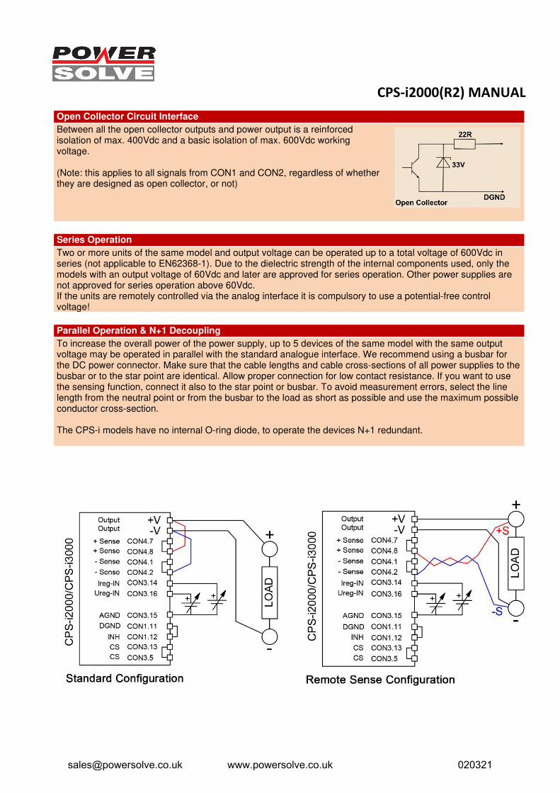
Open Collector Circuit Interface
Between all the open collector outputs and power output is a reinforced isolation of max. 400Vdc and a basic isolation of max. 600Vdc working voltage.
(Note: this applies to all signals from CON1 and CON2, regardless of whether they are designed as open collector, or not)
Series Operation
Two or more units of the same model and output voltage can be operated up to a total voltage of 600Vdc in series (not applicable to EN62368-1). Due to the dielectric strength of the internal components used, only the models with an output voltage of 60Vdc and later are approved for series operation. Other power supplies are not approved for series operation above 60Vdc. If the units are remotely controlled via the analog interface it is compulsory to use a potential-free control voltage!
Parallel Operation & N+1 Decoupling
To increase the overall power of the power supply, up to 5 devices of the same model with the same output voltage may be operated in parallel with the standard analogue interface. We recommend using a busbar for the DC power connector. Make sure that the cable lengths and cable cross-sections of all power supplies to the busbar or to the star point are identical. Allow proper connection for low contact resistance. If you want to use the sensing function, connect it also to the star point or busbar. To avoid measurement errors, select the line length from the neutral point or from the busbar to the load as short as possible and use the maximum possible conductor cross-section.
The CPS-i models have no internal O-ring diode, to operate the devices N+1 redundant.
[email protected] www.powersolve.co.uk 020321
CPS-i2000(R2) MANUAL
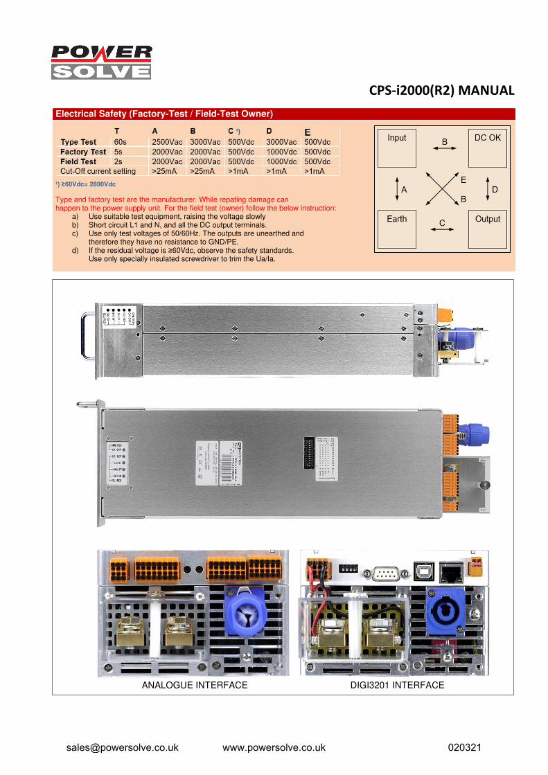
Electrical Safety (Factory-Test / Field-Test Owner)
¹) ≥60Vdc= 2800Vdc
Type and factory test are the manufacturer. While repating damage can happen to the power supply unit. For the field test (owner) follow the below instruction:
a) Use suitable test equipment, raising the voltage slowlyb) Short circuit L1 and N, and all the DC output terminals.c) Use only test voltages of 50/60Hz. The outputs are unearthed and
therefore they have no resistance to GND/PE.d) If the residual voltage is ≥60Vdc, observe the safety standards.
Use only specially insulated screwdriver to trim the Ua/Ia.
ANALOGUE INTERFACE DIGI3201 INTERFACE
[email protected] www.powersolve.co.uk 020321
CPS-i2000(R2) MANUAL
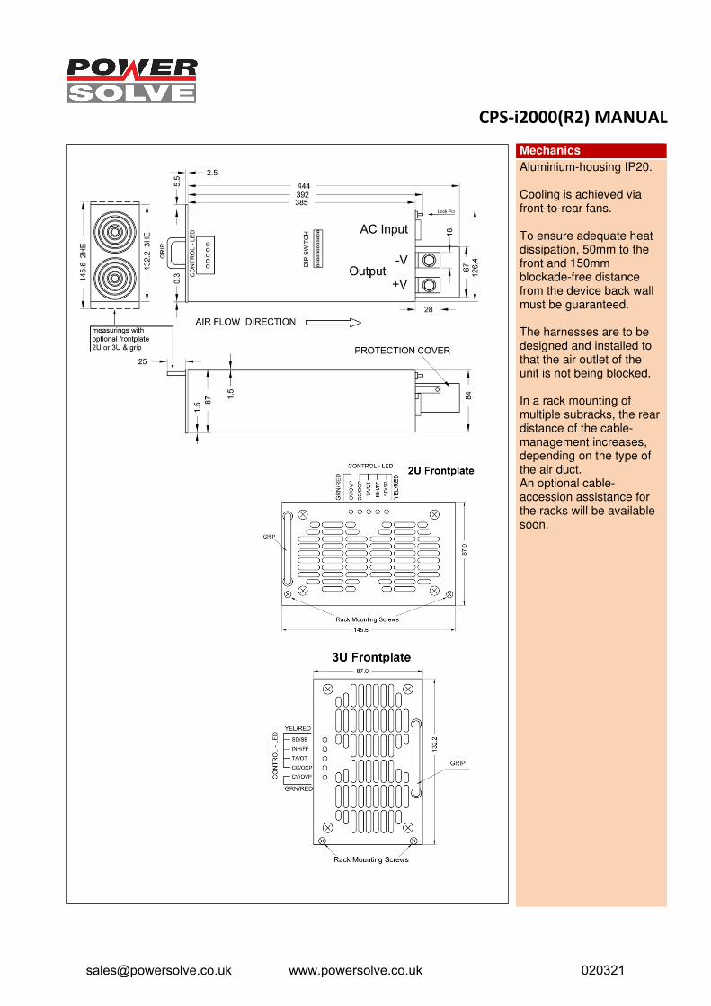
Mechanics
Aluminium-housing IP20.
Cooling is achieved via front-to-rear fans.
To ensure adequate heat dissipation, 50mm to the front and 150mm blockade-free distance from the device back wall must be guaranteed.
The harnesses are to be designed and installed to that the air outlet of the unit is not being blocked.
In a rack mounting of multiple subracks, the rear distance of the cable-management increases, depending on the type of the air duct. An optional cable-accession assistance for the racks will be available soon.
[email protected] www.powersolve.co.uk 020321
CPS-i2000(R2) MANUAL
Available Options
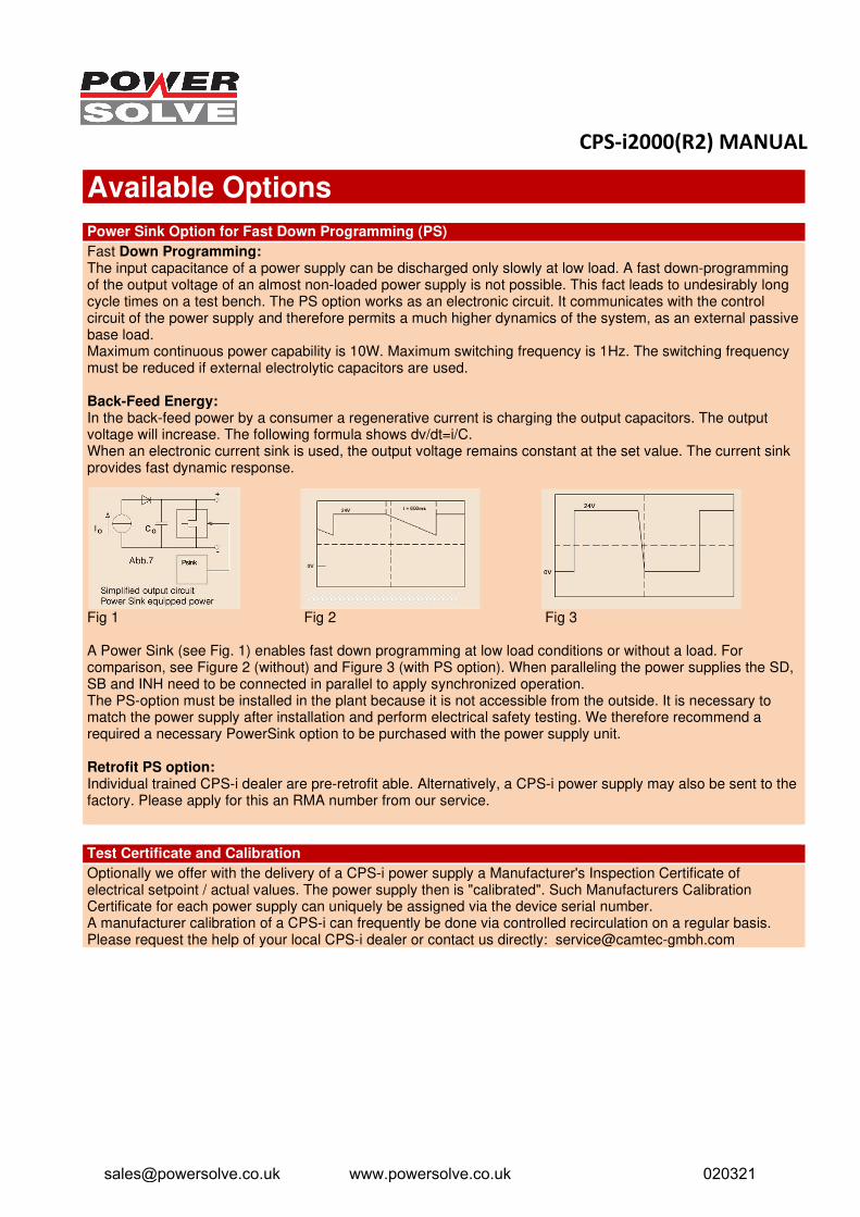
Power Sink Option for Fast Down Programming (PS)
Fast Down Programming: The input capacitance of a power supply can be discharged only slowly at low load. A fast down-programming of the output voltage of an almost non-loaded power supply is not possible. This fact leads to undesirably long cycle times on a test bench. The PS option works as an electronic circuit. It communicates with the control circuit of the power supply and therefore permits a much higher dynamics of the system, as an external passive base load. Maximum continuous power capability is 10W. Maximum switching frequency is 1Hz. The switching frequency must be reduced if external electrolytic capacitors are used.
Back-Feed Energy: In the back-feed power by a consumer a regenerative current is charging the output capacitors. The output voltage will increase. The following formula shows dv/dt=i/C. When an electronic current sink is used, the output voltage remains constant at the set value. The current sink provides fast dynamic response.
Fig 1 Fig 2 Fig 3
A Power Sink (see Fig. 1) enables fast down programming at low load conditions or without a load. For comparison, see Figure 2 (without) and Figure 3 (with PS option). When paralleling the power supplies the SD, SB and INH need to be connected in parallel to apply synchronized operation. The PS-option must be installed in the plant because it is not accessible from the outside. It is necessary to match the power supply after installation and perform electrical safety testing. We therefore recommend a required a necessary PowerSink option to be purchased with the power supply unit.
Retrofit PS option: Individual trained CPS-i dealer are pre-retrofit able. Alternatively, a CPS-i power supply may also be sent to the factory. Please apply for this an RMA number from our service.
Test Certificate and Calibration
Optionally we offer with the delivery of a CPS-i power supply a Manufacturer's Inspection Certificate of electrical setpoint / actual values. The power supply then is "calibrated". Such Manufacturers Calibration Certificate for each power supply can uniquely be assigned via the device serial number. A manufacturer calibration of a CPS-i can frequently be done via controlled recirculation on a regular basis. Please request the help of your local CPS-i dealer or contact us directly: [email protected]
[email protected] www.powersolve.co.uk 020321
CPS-i2000(R2) MANUAL
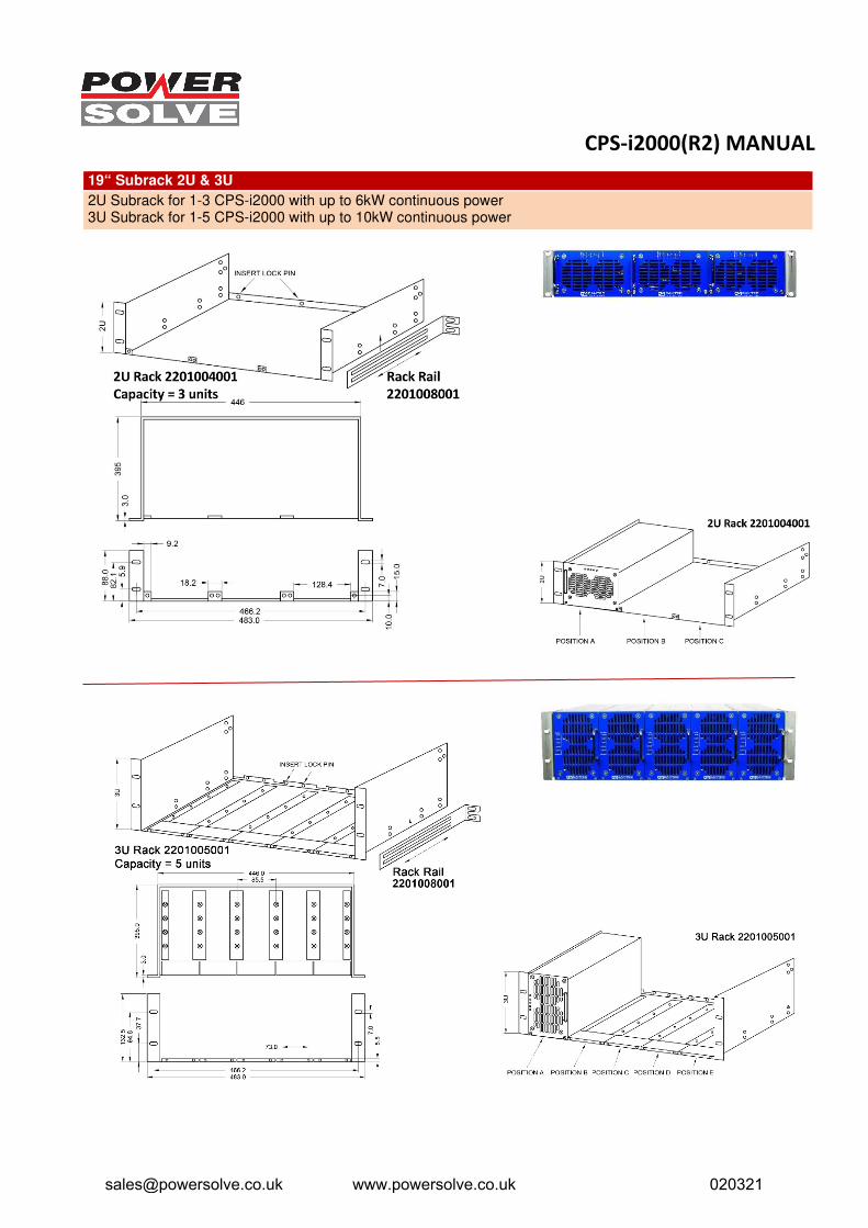
19“ Subrack 2U & 3U
2U Subrack for 1-3 CPS-i2000 with up to 6kW continuous power 3U Subrack for 1-5 CPS-i2000 with up to 10kW continuous power
[email protected] www.powersolve.co.uk 020321

CPS-i2000(R2) MANUAL
Wall Mount Option & 3D Heat Dissipation (3D-HD)
Our aligned and controlled heat dissipation design opens possibilities that are formerly being reserved to custom design power supplies: Steplessly hard mount of the CPS-i2000/3000 power supply modules in a 3D-room.
In practice that means that one can mount the modules into every angle imaginable. Our 3D Heat Dissipation (3D-HD) ensures optimal cooling in each mounting position you may consider.
All you may consider is to make sure, that at least a distance of 5cm (2 Inch) to the front cooling slots and 15cm (6 Inch) to the rear cooling openings are guaranteed to prevent from blocking the airflow. The cabling must also not block the heat dissipation.
When the CPS-i2000/3000 is hard mounted the optional front plates cannot be used. The standard control LEDs allow visualization from any mounting position (see below drawing).
[email protected] www.powersolve.co.uk 020321
CPS-i2000(R2) MANUAL
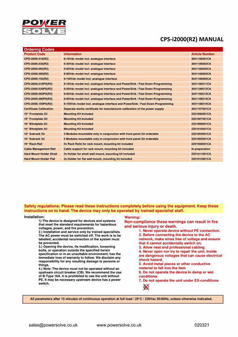
Ordering Codes Product Code Information Article Number
CPS-i2000.018(R2) 0-18Vdc model incl. analogue interface 3041106001CA
CPS-i2000.030(R2) 0-30Vdc model incl. analogue interface 3041106002CA
CPS-i2000.060(R2) 0-60Vdc model incl. analogue interface 3041106003CA
CPS-i2000.090(R2) 0-90Vdc model incl. analogue interface 3041106004CA
CPS-i2000.150(R2) 0-150Vdc model incl. analogue interface 3041106005CA
CPS-i2000.018PS(R2) 0-18Vdc model incl. analogue interface and PowerSink / Fast Down Programming 3041106011CA
CPS-i2000.030PS(R2) 0-30Vdc model incl. analogue interface and PowerSink / Fast Down Programming 3041106012CA
CPS-i2000.060PS(R2) 0-60Vdc model incl. analogue interface and PowerSink / Fast Down Programming 3041106013CA
CPS-i2000.090PS(R2) 0-90Vdc model incl. analogue interface and PowerSink / Fast Down Programming 3041106014CA
CPS-i2000.150PS(R2) 0-150Vdc model incl. analogue interface and PowerSink / Fast Down Programming 3041106015CA
Certificate Calibration Separate works certificate for manufacturer calibration of the power supply 4031107001CA
19“ Frontplate 2U Mounting Kit Included 2201006001CA
19“ Frontplate 3U Mounting Kit Included 2201007001CA
19“ Blindplate 2U Mounting Kit Included 2201009001CA
19“ Blindplate 3U Mounting Kit Included 2201010001CA
19“ Subrack 2U 3 Modules mountable only in conjunction with front panel 2U orderable 2201004001CA
19“ Subrack 3U 5 Modules mountable only in conjunction with front panel 3U orderable 2201005001CA
19“ Rack-Rail 2x Rack Rails for rack mount, mounting kit included 2201008001CA
Cable Management Rail Cable support for rack mount, mounting kit included In preparation
Hard Mount Holder Strait 2x Holder for strait wall mount, mounting kit included 2201011001CA
Hard Mount Holder Flat 2x Holder for flat wall mount, mounting kit included 2201012001CA
Safety regulations: Please read these instructions completely before using the equipment. Keep these instructions on to hand. The device may only be operated by trained specialist staff.
Installation: 1) The device is designed for devices and systemsthat meet the standard requirements for hazardousvoltages, power, and fire prevention.2.) Installation and service only by trained specialists.The AC power must be switched off. The work is to belabelled; accidental reconnection of the system mustbe prevented.3.) Opening the device, its modification, looseningbolts, or operation outside the specified hereinspecification or in an unsuitable environment, has theimmediate loss of warranty to follow. We disclaim anyresponsibility for any resulting damage to persons orthings.4.) Note: The device must not be operated without anupstream circuit breaker (CB). We recommend the useof B-Type 16A. It is prohibited to use the unit withoutPE. It may be necessary upstream device has a powerswitch.
Warning: Non-compliance these warnings can result in fire and serious injury or death.
1. Never operate device without PE connection.2. Before connecting the device to the ACnetwork, make wires free of voltage and ensurethat it cannot accidentally switch on.3. Allow neat and professional cabling.4. Never open nor try to repair the unit. Insideare dangerous voltages that can cause electricalshock hazard.5. Avoid metal pieces or other conductivematerial to fall into the item6. Do not operate the device in damp or wetconditions7. Do not operate the unit under EX-conditions
All parameters after 15 minutes of continuous operation at full load / 25°C / 230Vac 50/60Hz, unless otherwise indicated.
[email protected] www.powersolve.co.uk 020321