Embed Size (px)
Citation preview
c: RESEARCH J INC.
CRAY® COMPUTER SYSTEMS
CRAY X-MP COMPUTER SYSTEMS FUNCTIONAL DESCRIPTION MANUAL
HR-3005
Copyright© 1987 by CRAY RESEARCH, INC. This manual or parts thereof may not be reproduced in any form without permission of CRAY RESEARCH, INC.
c:: 1.=11 "" -..." RECORD OF REVISION RESEARCH. INC. PUBLICATION NUMBER HR-300S
Each time this manual is revised and reprinted, all changes issued against the previous version are incorporated into the new version and the new version is assigned an alphabetic level.
Every page changed by a reprint with revision has the revision level in the lower righthand corner. Changes to part of a page are noted by a change bar in the margin directly opposite the change. A change bar in the margin opposite the page number indicates that the entire page is new. If the manual is rewritten, the revision level changes but the manual does not contain change bars.
Requests for copies of Cray Research, Inc. publications should be directed to the Distribution Center and comments about these publications should be directed to:
CRAY RESEARCH, INC. 1345 Northland Drive Mendota Heights, Minnesota 55120
Revision Description
February 1987 - Original printing.
The UNICOS operating system is derived from the AT&T UNIX System V operating system. UNICOS is also based in part on the Fourth Berkeley Software Distribution under license from The Regents of the University of California.
CRAY, CRAY-1, SSD, and UNICOS are registered trademarks and APML, CFT, CFT??, CFT2, COS, CRAY-2, CRAY X-MP, CSIM, IDS, SEGLDR, SID, and SUPERLINK are trademarks of Cray Research, Inc.
HR-3005 ii
PREFACE
This manual describes the functions of all CRAY X-MP computer systems currently manufactured by Cray Research, Inc. (CRI). For information on earlier models of the CRAY X-MP computer system, contact your local Cray representative.
This manual is written for customers. It describes the overall design of the CRAY X-MP computer systems; provides basic information on the computation section, exchange mechanism, and functional units; and explains the symbolic machine instructions. A fact sheet for each CRAY X-MP model provides specific information pertaining to that model.
This manual contains the following sections:
Section
1
2
3
4
Description
Contains the introduction to this manual
Describes the design of the CRAY X-MP CPU. The registers, functional units, and Exchange Package are described, and a block diagram is provided.
Provides detailed information on the instructions that operate on the CRAY X-MP computer system. Each machine instruction can be represented symbolically in Cray Assembly Language (CAL). The instructions are listed in octal form in a box format that provides the CAL syntax format, an operand if required, a brief description of each instruction, and the machine instruction.
A detailed description of the instruction and an example using the instruction follow the boxed information.
Specific information for each of the current CRAY X-MP models is given, along with a photo and a maximum configuration drawing for each model.
For the reader's convenience, a glossary is also included; it defines many of the commonly used Cray acronymns.
HR-3005 iii

CONTENTS
PREFACE. . • . . . . . . . • . . . . . . . . . . . . • • • • . •• iii
1.
2.
INTRODUCTION . . .
CRAY X-MP COMPUTER SYSTEM COMPONENTS . Central processing units Interfaces . . • . . • • . I/O Subsystem . . • . . . . Disk storage units . . . . Solid-state storage device . . . . . Condensing units ... . . . . . . . Power distribution units ..... . Motor-generator units . . . . . .
CONVENTIONS . . . . Examples
CRAY X-MP DESIGN DETAILS .
CPU COMPUTATION SECTION Programmable clock . . . . . . Registers . . • . • . . . . . . .
Address registers . . . . Scalar registers . . . . . Vector registers . . . . • .
Functional units . . . . . Address functional units . • . . •
Address Add functional unit .. Address Multiply functional unit
Scalar functional units . . . . Scalar Add functional unit Scalar Shift functional unit Scalar Logical functional unit Scalar Population/Parity/Leading Zero functional unit . . . . • . . •
Vector functional units . . . . . Vector Add functional unit
1-1
1-1 1-3 1-3 1-4 1-5 1-6 1-7 1-8 1-9 1-10 1-10
2-1
2-1 2-3 2-3 2-4 2-4 2-4 2-4 2-5 2-5 2-5 2-5 2-6 2-6 2-6
2-6 2-6 2-7
Vector Shift functional unit . . • .• 2-7 Full Vector Logical functional unit . . . • •. 2-7 Second Vector Logical functional unit . • • •• 2-7 Vector Population/Parity functional unit 2-7
HR-3005 v
Functional units (continued) Floating-point functional units .•• . • . • •
Floating-point Add functional unit Floating-point Multiply functional unit •. Reciprocal Approximation functional unit
CPU control section . . . . . . . . • . • Instruction buffers . . . . . . . • • Program Address (P) register • • . • . Next Instruction Parcel (NIP) register Current Instruction Parcel (CIP) and Lower Instruction Parcel (LIP) registers
Exchange sequence . . Exchange Package . . • . . . . . . •
Processor number (PN) Memory error data Program Address (P) register Instruction Base Address (IBA) register .••• Instruction Limit Address (ILA) register. Mode (M) register . . . . . . . . . . . . Vector Not Used (VNU) position . . . . . . Enable Second Vector Logical (ESVL) position • • Flag (F) register . . .... Exchange Address (XA) register . . • . . Vector Length (VL) register . . . . . • . Enhanced Addressing Mode (EAM) position . . • • Data Base Address (DBA) register Program State (PS) register Cluster Number (CLN) register Data Limit Address (DLA) register A registers .. . . . • • • . . . S registers . . . .
CPU intercommunication . . • . Real-time clock . . . . . . . . . Arithmetic operations .• ...•
Integer arithmetic . . . . . . • Floating-point arithmetic Normalized floating-point numbers • • • . Floating-point range errors • • • • .
Floating-point Add functional unit . • • • Floating-point Multiply functional unit •. Floating-point Reciprocal Approximation functional unit • • • . . . • .
Double-precision numbers • . • • . Addition algorithm • . • . Multiplication algorithm . Division algorithm . . .•
Newton's method ••. Derivation of the division algorithm •
LOGICAL OPERATIONS . . . • • • • • . . . . •
HR-3005
Central MemOry Input/output section
vi
2-7 2-7 2-8 2-8 2-8 2-8 2-8 2-9
2-9 2-9 2-9 2-10 2-10 2-10 2-11 2-11 2-11 2-12 2-12 2-12 2-13 2-13 2-14 2-14 2-14 2-14 2-14 2-15 2-15 2-15 2-15 2-15 2-16 2-17 2-18 2-19 2-19 2-20
2-22 2-22 2-23 2-23 2-24 2-25 2-25 2-29 2-30 2-31
3. CRAY X-MP SYMBOLIC MACHINE INSTRUCTIONS
INSTRUCTION SYNTAX Instruction format . . . . . . . • . .
1-parcel instruction format with discrete j and k fields . • . . • • . . . . . . . • . . . . . . 1-parcel instruction format with combined j and k fields . . . . . . . . . . . . . . . . . . 2-parcel instruction format with combined j, k, and m fields . . . . . . . . . . . . . . . . 2-parcel instruction format with combined i, j, k, and m fields . . . . . .
SPECIAL REGISTER VALUES SYMBOLIC NOTATION
General syntax Register designators Location field . Result field . Operand field Comment field
Special syntax forms MONITOR MODE INSTRUCTIONS MACHINE INSTRUCTION DESCRIPTIONS . SYMBOLIC INSTRUCTION SUMMARY . . .
Functional units . . • . . . . . . . CRAY X-MP symbolic machine instructions •
FUNCTIONAL INSTRUCTION SUMMARY . . . . . . . . • . Register entry instructions . . . . . . . . . .
Entries into A registers Entries into S registers . Entries into V registers Entries into Semaphore registers
Inter-register transfer instructions . . . . Transfers to A registers . . . . . Transfers to S registers . . . . . . . • • Transfers to V registers . • . • . . . . . Transfer to Vector Mask register . . . • • Transfer to Vector Length register . Transfer to Semaphore register •
Memory transfers . . . . Bidirectional memory Memory references Stores . . . . . . • Loads • • . • • . .
transfers • .
Integer arithmetic operations . . . • . . . • . . . . . . 24-bit integer arithmetic . . . . . . . . 64-bit integer arithmetic . . . . .
Floating-point arithmetic . . .. ....• Floating-point range errors . • . . Floating-point addition and subtraction • . . . • . Floating-point multiplication • . . . . .
HR-3005 vii
3-1
3-1 3-1
3-2
3-3
3-3
3-5 3-6 3-6 3-6 3-6 3-7 3-7 3-7 3-8 3-8 3-9 3-9 3-98 3-98 3-99 3-102 3-102 3-102 3-102 3-103 3-104 3-104 3-104 3-105 3-106 3-106 3-106 3-106 3-107 3-107 3-107 3-107 3-108 3-109 3-110 3-110 3-111 3-111 3-111 3-112
4.
Floating-point arithmetic (continued) Reciprocal iteration • . Reciprocal approximation
Logical operations . • . . Logical products . . Logical sums . . • . Logical differences Logical equivalence Vector mask Me rge . . . . . . . . . . . . . . • .
Shift instructions Bit count instructions
Scalar population count Vector population count . . • . Scalar population count parity . Scalar leading zero count
Branch instructions . . . . . . . . . Unconditional branch instructions Conditional branch instructions Return jump • . . . . . . • . Normal exit ...•. Error exit • . . • . .
Monitor mode instructions . • . . . Channel control . • • . Set real-time clock Programmable clock interrupt instructions Interprocessor interrupt instructions Cluster number instructions .• . • . . . . Operand range error interrupt instructions . Performance counters . • . . . . . • . . . .
CRAY X-MP SYSTEM CONFIGURATIONS
CRAY X-MP/14se Specification Sheet .....• CRAY X-MP/14 Specification Sheet • CRAY X-MP/18 Specification Sheet . CRAY X-MP/116 Specification Sheet . . • . CRAY X-MP/22 Specification Sheet • CRAY X-MP/24 Specification Sheet • • CRAY X-MP/28 Specification Sheet • . CRAY X-MP/216 Specification Sheet . . . • CRAY X-MP/44 Specification Sheet • . . . . . • . CRAY X-MP/48 Specification Sheet • . . . . . • . CRAY X-MP/416 Specification Sheet . . . .
FIGURES
1-1 CRAY X-MP/4 12-column Mainframe 1-2 Typical Interface Cabinet 1-3 1/0 Subsystem Chassis . . . . .
HR-3005 viii
3-113 3-113 3-114 3-114 3-115 3-115 3-116 3-116 3-117 3-117 3-118 3-119 3-119 3-119 3-119 3-119 3-120 3-120 3-120 3-121 3-121 3-121 3-121 3-122 3-122 3-122 3-123 3-123 3-123
4-1
4-3 4-7 4-11 4-15 4-19 4-23 4-27 4-31 4-35 4-39 4-43
1-2 1-3 1-5
FIGURES (continued)
1-4 1-5 1-6 1-7 2-1 2-2 2-3 2-4 2-5 2-6 2-7 2-8 3-1 3-2 3-3 3-4
3-5
Solid-state Storage Device Chassis . Condensing Unit . . . .. ..... . . Power Distribution Units . . . . . Motor-generator Equipment . . . . CRAY X-MP Block Diagram . . . . Integer Data Formats . .. ....... . Floating-point Data Format . . . . Internal Representation of Floating-point Number (Octal) . Exponent Matrix for Floating-point Multipy Unit Integer Multiply in Floating-point Multiply Functional Unit 49-bit Floating-point Addition . . .. . Newton's Method ...................... . General Form for Instructions ... . . . . . . • . . 1-parcel Instruction Format with Discrete j and k Fields . 1-parcel Instruction Format with Combined j and k Fields 2-parcel Instruction Format with Combined j, k, and m Fields . . . . . . . . . . . . . . . . . . . 2-parcel Instruction Format with Combined i, j, k, and m Fields . . . . . . . . . . . . . . . . . . . .
3-6 2-parcel Instruction Format for a 24-bit Immediate Constant with Combined i, j, k, and m Fields ........ .
4-1 CRAY X-MP/14se Computer System .... . 4-2 CRAY X-MP/14se Configuration (Maximum) 4-3 CRAY X-MP/14 Computer System ....... . 4-4 CRAY X-MP/14 Configuration (Maximum) 4-5 CRAY X-MP/18 Computer System . . . . . 4-6 CRAY X-MP/18 Configuration (Maximum) . 4-7 CRAY X-MP/116 Computer System . . . . . .•. 4-8 CRAY X-MP/116 Configuration (Maximum) 4-9 CRAY X-MP/22 Computer System . . . . . . . . . . . . 4-10 CRAY X-MP/22 Configuration (Maximum) . 4-11 CRAY X-MP/24 Computer System . . . . . . . . . . . . 4-12 CRAY X-MP/24 Configuration (Maximum) . 4-13 CRAY X-MP/28 Computer System . . . . 4-14 CRAY X-MP/28 Configuration (Maximum) . 4-15 CRAY X-MP/216 Computer System . . . . . • . . 4-16 CRAY X-MP/216 Configuration (Maximum) 4-17 CRAY X-MP/44 Computer System •....... 4-18 CRAY X-MP/44 Configuration (Maximum) . 4-19 CRAY CRAY X-MP/48 Computer System . . . . . 4-20 CRAY X-MP/48 Configuration (Maximum) . 4-21 CRAY X-MP/416 Computer System . . . . 4-22 CRAY X-MP/416 Configuration (Maximum)
HR-3005 ix
1-6 1-7 1-8 1-9 2-2 2-16 2-17 2-18 2-20 2-22 2-23 2-25 3-2 3-3 3-3
3-4
3-5
3-5 4-3 4-5 4-7 4-9 4-11 4-13 4-15 4-17 4-19 4-21 4-23 4-25 4-27 4-29 4-31 4-33 4-35 4-37 4-39 4-41 4-43 4-45
TABLES
3-1 Special Register Values · · · · . 3-6 4-1 CRAY X-MP Computer System Overview 4-2 4-2 CRAY X-MP/14se Features · · · · 4-4 4-3 CRAY X-MP/14 Features . · · · · . . 4-8 4-4 CRAY X-MP/18 Features . · · . . . . . . . . . . . . 4-12
GLOSSARY
INDEX
HR-3005 x
CENTRAL PROCESSING UNITS
Each CPU has a computation section consisting of operating registers, functional units, and an instruction control network. The instruction control network makes all decisions related to instruction issue as well as coordinating the three types of processing (vector, scalar, or address). Each of the processing modes has its associated registers and functional units. In multiple-processor mainframes, the interprocessor section, which coordinates processing between CPUs and Central Memory, is shared.
Refer to section 2 for more information on the computation section.
INTERFACES
The Cray mainframe is designed for use with front-end computers in a computer network. A front-end computer system is self contained and executes under the control of its own operating system.
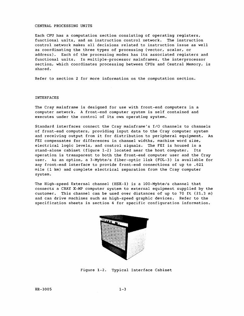
Standard interfaces connect the Cray mainframe's I/O channels to channels of front-end computers, providing input data to the Cray computer system and receiving output from it for distribution to peripheral equipment. An FEI compensates for differences in channel widths, machine word size, electrical logic levels, and control signals. The FEI is housed in a stand-alone cabinet (figure 1-2) located near the host computer. Its operation is transparent to both the front-end computer user and the Cray user. As an option, a 3-Mybte/s fiber-optic link (FOL-3) is available for any front-end interface to provide front-end connections of up to .621 mile (1 km) and complete electrical separation from the Cray computer system.
The High-speed External channel (HSX-1) is a 100-Mybte/s channel that connects a CRAY X-MP computer system to external equipment supplied by the customer. This channel can be used over distances of up to 70 ft (21.3 m) and can drive machines such as high-speed graphic devices. Refer to the specification sheets in section 4 for specific configuration information.
Figure 1-2. Typical Interface Cabinet
HR-3005 1-3
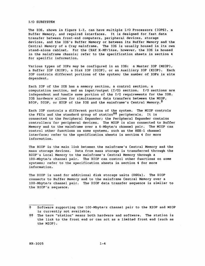
IIO SUBSYSTEM
The lOS, shown in figure 1-3, can have multiple IIO Processors (lOPS), a Buffer Memory, and required interfaces. It is designed for fast data transfer between front-end computers, peripheral devices, storage devices, and the lOS's Buffer Memory or between its Buffer Memory and the Central Memory of a Cray mainframe. The lOS is usually housed in its own stand-alone cabinet. For the CRAY X-MP/14se, however, the lOS is housed in the mainframe chassis; refer to the specification sheets in section 4 for specific information.
Various types of lOPs may be configured in an lOS: a Master lOP (MIOP), a Buffer lOP (BIOP), a Disk lOP (DIOP), or an Auxiliary lOP (XIOP). Each lOP controls different portions of the system; the number of lOPs is site dependent.
Each lOP of the lOS has a memory section, a control section, a computation section, and an inputloutput (I/O) section. IIO sections are independent and handle some portion of the IIO requirements for the lOS. lOS hardware allows for simultaneous data transfers between the MIOP, BIOP, DIOP, or XIOP of the lOS and the mainframe's Central Memory.t
Each lOP controls a different portion of the system. The MIOP controls the FEls and the standard group of stationtt peripherals. It is connected to the Peripheral Expander; the Peripheral Expander contains controllers 'for peripheral devices. The MIOP is also connected to Buffer Memory and to the mainframe over a 6-Mbyte/s channel pair. The MIOP can control other functions on some systems, such as the HSX-1 channel interface; refer to the specification sheets in section 4 for more information.
The BIOP is the main link between the mainframe's Central Memory and the mass storage devices. Data from mass storage is transferred through the BIOP's Local Memory to the mainframe's Central Memory through a 100-Mbyte/s channel pair. The BIOP can control other functions on some systems; refer to the specification sheets in section 4 for more information.
The DIOP is used for additional disk storage units (DSUs). The DIOP connects to Buffer Memory and to the mainframe Central Memory over a 100-Mbyte/s channel pair. The DIOP data transfer sequence is similar to the BIOP's sequence.
t Software supporting the 100-Mbyte/s channel pair to the XIOP and MIOP is currently not available.
tt The term "station" means both hardware and software. The station is the link to the front end or can act as a limited front end (such as the MIOP).
HR-3005 1-4
The XIOP is used for block multiplexer channels and interfaces to the block multiplexer controllers (BMCs). In most CRAY X-MP computer systems, the XIOP also interfaces with the HSX channel; refer to the specification sheets in section 4 for more information.
Figure 1-3. 1/0 Subsystem Chassis
DISK STORAGE UNITS
For mass storage, the system uses CRI disk storage units (DSUs). A disk controller unit (DCU) interfaces the DSUs to an lOP within the lOS.
The lOP and the disk controller unit can transfer data between the direct memory access (DMA) port of the lOP and multiple DSUs, without missing data or skipping revolutions, even when all DSUs are operating at full speed.
HR-3005 1-5
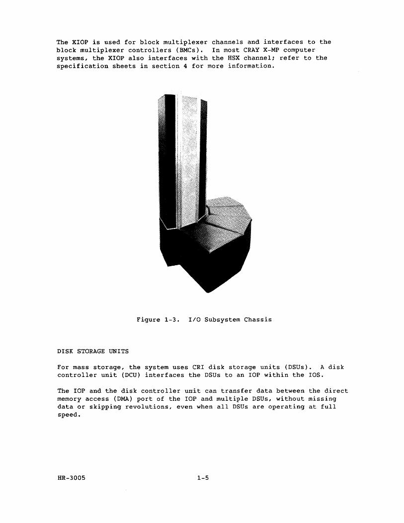
SOLID-STATE STORAGE DEVICE
The SSD shown in figure 1-4 is an optional, high-performance device used for temporary data storage. It transfers data between the mainframe's Central Memory and the SSD through one or two special Cray interface cables with a maximum speed of 1000-Mbyte/s each. The actual speed of these transfers depends on the SSD and CRAY X-MP memory size and system configuration. The SSD can also be connected directly to an lOP over a 100-Mbyte/s channel pair.
The SSD-31 is a special version of the SSD; it is housed within the IDS chassis. Refer to section 4 for all the current SSD configurations available.
Figure 1-4. Solid-state Storage Device Chassis
HR-3005 1-6
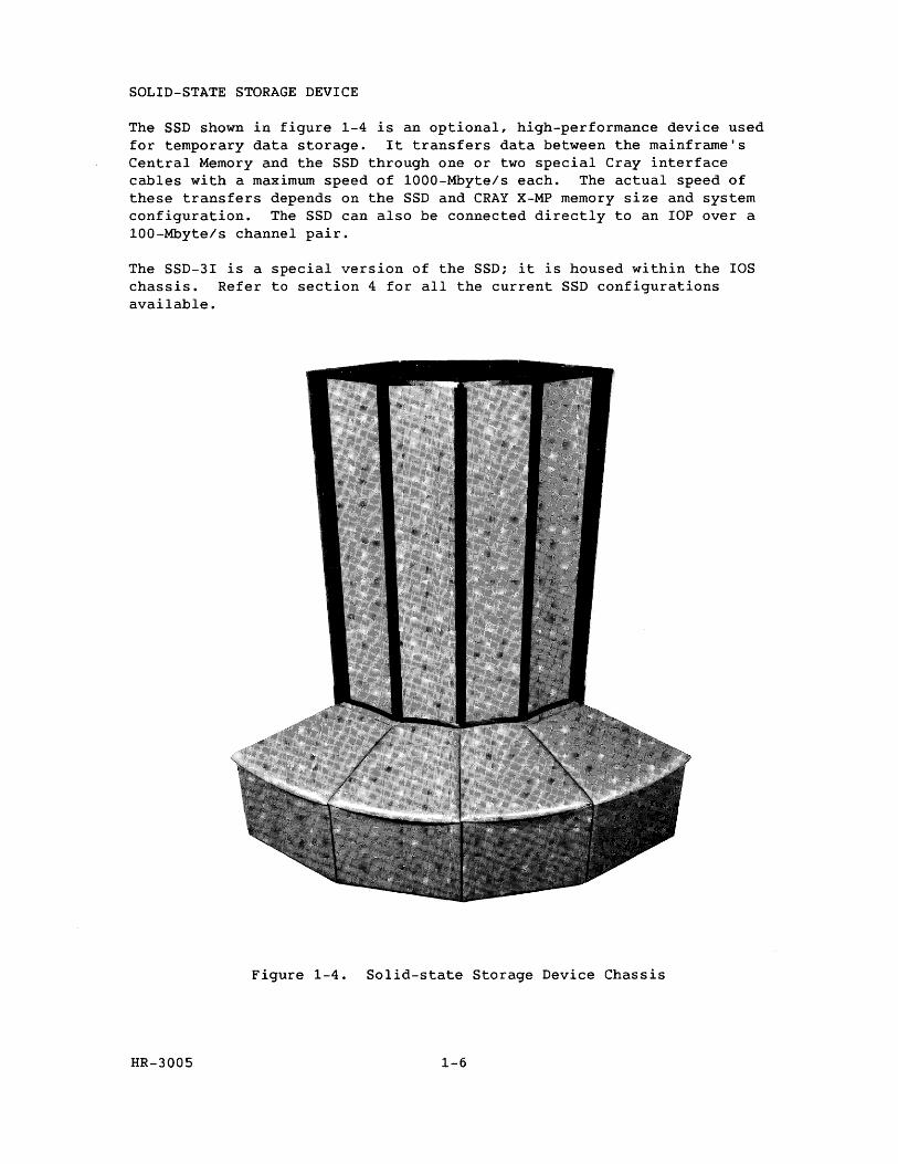
CONDENSING UNITS
A condensing unit (figure 1-5) contains the major components of the refrigeration system used to cool the computer chassis. Heat is removed from the condensing unit by a second-level cooling system that is not part of the computer system.
Figure 1-5. Condensing Unit
HR-3005 1-7
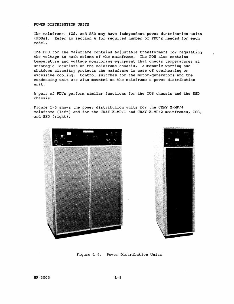
POWER DISTRIBUTION UNITS
The mainframe, lOS, and SSD may have independent power distribution units (PDlls). Refer to section 4 for required number of PDU's needed for each model.
The PDU for the mainframe contains adjustable transformers for regulating the voltage to each column of the mainframe. The PDU also contains temperature and voltage monitoring equipment that checks temperatures at strategic locations on the mainframe chassis. Automatic warning and shutdown circuitry protects the mainframe in case of overheating or excessive cooling. Control switches for the motor-generators and the condensing unit are also mounted on the mainframe's power distribution unit.
A pair of PDlls perform similar functions for the IDS chassis and the SSD chassis.
Figure 1-6 shows the power distribution units for the CRAY X-MP/4 mainframe (left) and for the CRAY X-MP/l and CRAY X-MP/2 mainframes, lOS, and SSD (right).
• *' 'l ,,~
:.£... " .,." -:: - -",-
Figure 1-6. Power Distribution Units
HR-3005 1-8
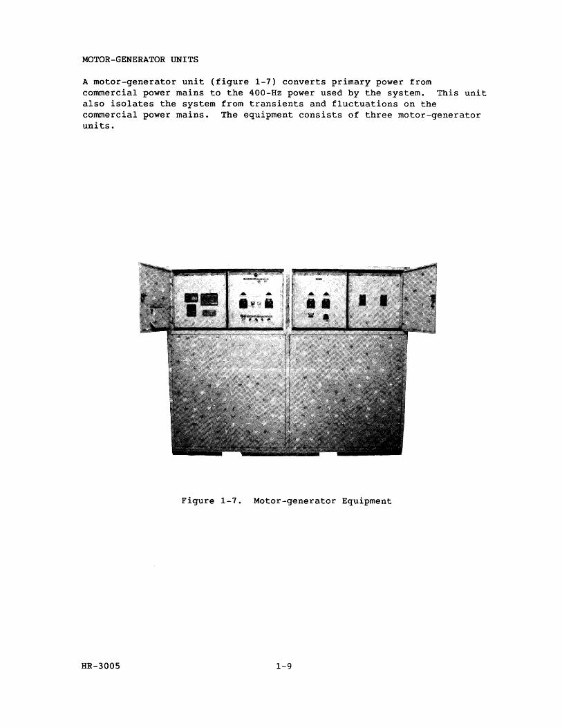
MOTOR-GENERATOR UNITS
A motor-generator unit (figure 1-7) converts primary power from commercial power mains to the 400-Hz power used by the system. This unit also isolates the system from transients and fluctuations on the commercial power mains. The equipment consists of three motor-generator units.
Figure 1-7. Motor-generator Equipment
HR-3005 1-9
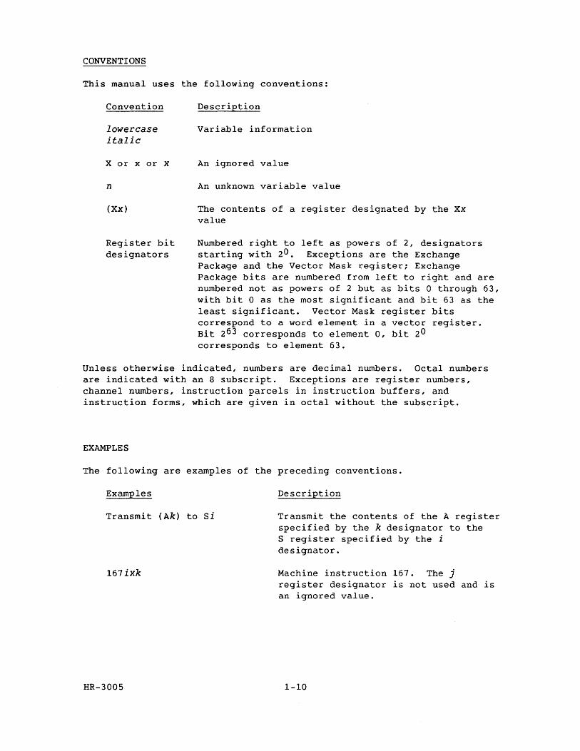
CONVENTIONS
This manual uses the following conventions:
Convention
lowercase italic
X or x or x
n
(xx)
Register bit designators
Description
Variable information
An ignored value
An unknown variable value
The contents of a register designated by the Xx value
Numbered right to left as powers of 2, designators starting with 20. Exceptions are the Exchange Package and the Vector Mask register; Exchange Package bits are numbered from left to right and are numbered not as powers of 2 but as bits 0 through 63, with bit ° as the most significant and bit 63 as the least significant. Vector Mask register bits correspond to a word element in a vector register. Bit 263 corresponds to element 0, bit 20 corresponds to element 63.
Unless otherwise indicated, numbers are decimal numbers. Octal numbers are indicated with an 8 subscript. Exceptions are register numbers, channel numbers, instruction parcels in instruction buffers, and instruction forms, which are given in octal without the subscript.
EXAMPLES
The following are examples of the preceding conventions.
Examples
Transmit (Ak) to Si
167ixk
HR-3005
Description
Transmit the contents of the A register specified by the k designator to the S register specified by the i designator.
Machine instruction 167. The j register designator is not used and is an ignored value.
1-10
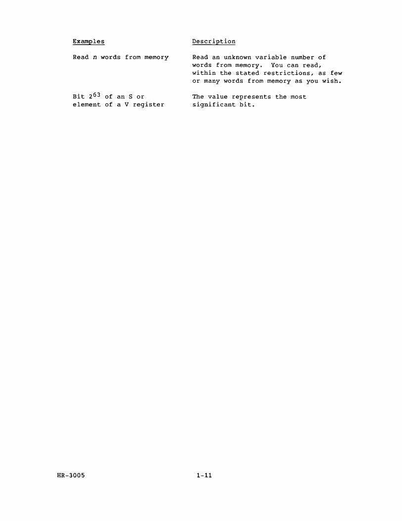
Examples
Read n words from memory
Bit 2 63 of an S or element of a V register
HR-3005
Description
Read an unknown variable number of words from memory. You can read, within the stated restrictions, as few or many words from memory as you wish.
The value represents the most significant bit.
1-11

eRA Y X-MP DESIGN DETAILS
The following subsections describe the major components of a CRAY X-MP central processing unit (CPU).
CPU COMPUTATION SECTION
2
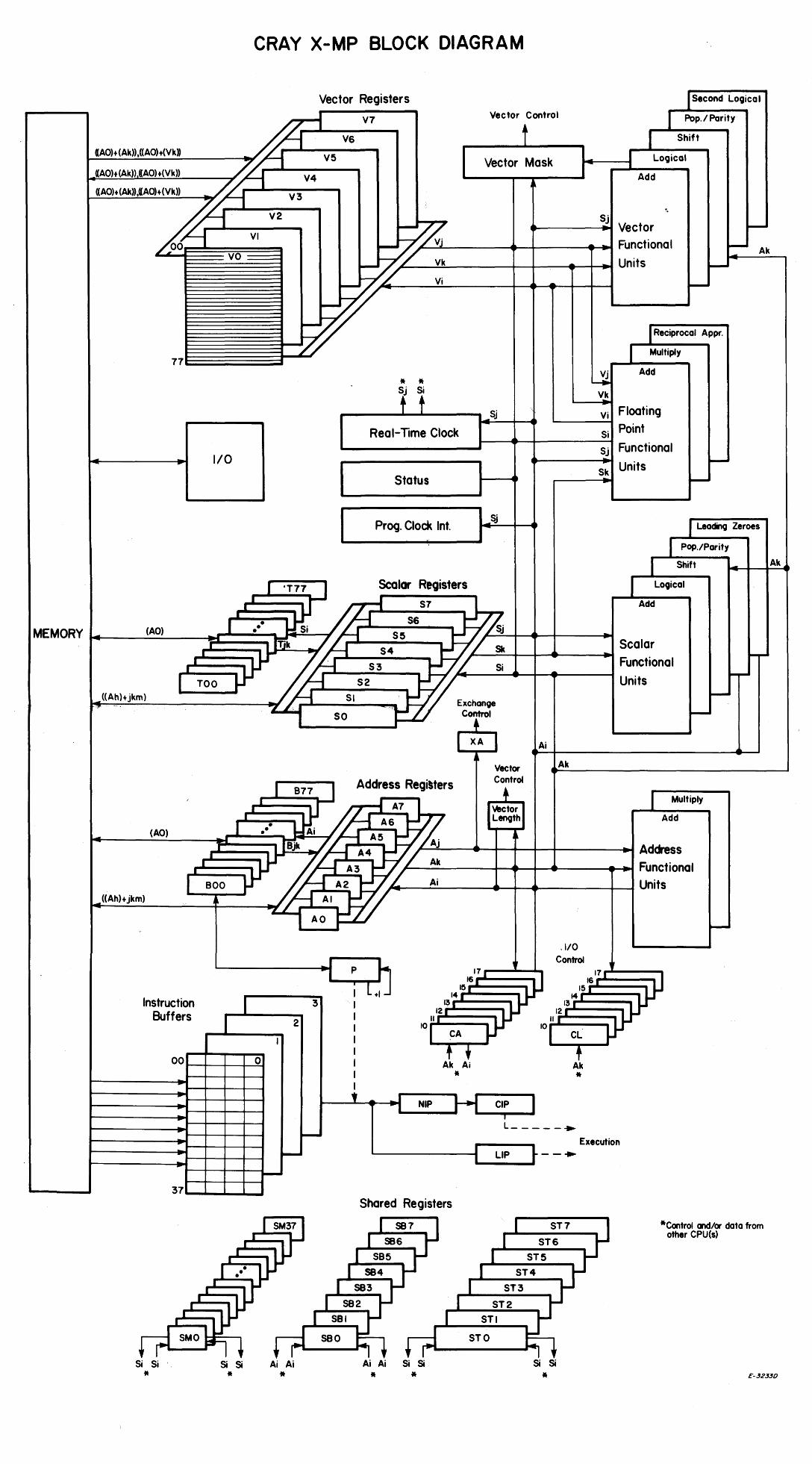
Each CPU is an identical, independent computation section consisting of operating registers, functional units, and an instruction control network (refer to figure 2-1, a fold-out block diagram of a typical CRAY X-MP computation section). The computation section performs three types of processing: address, scalar, and vector. Address processing operates on internal control information, such as addresses and indexes, while scalar and vector processing are performed on data. The instruction control network makes all decisions related to instruction issue as well as coordinating the three types of processing. Each of the processing modes has its associated registers and functional units.
Address information flows from Central Memory, instruction values or from control registers to address registers. Information in the address registers is distributed to various parts of the control network for use in controlling the scalar, vector, and IIO operations. The address registers can also supply operands to two integer functional units. The units generate address and index information and return the result to the address registers. Address information can also be transmitted to Central Memory from the address registers.
Data flow in a computation section is from Central Memory to registers and from registers to functional units. Results flow from functional units to registers and from registers to Central Memory or back to functional units. Data flows along either the scalar or vector path, depending on the processing mode. An exception is that scalar registers can provide one required operand for some vector operations performed in the vector functional units.
The computation section performs integer or floating-point arithmetic operations. Integer arithmetic is performed in twos complement mode. Floating-point quantities have signed magnitude representation.
Floating-point instructions provide for addition, subtraction, multiplication, and reciprocal approximation. The reciprocal approximation instructions provide for a floating-point divide operation that uses a multiple instruction sequence.
HR-3005 2-1

Figure 2-1. CRAY X-MP Block Diagram
HR-3005 2-2
CRAY X-MP BLOCK DIAGRAM
Vector Registers , I V7 Vector Control
t
Second Logical
I Pop.! Parity
(AO)+ (Ak»,«AO) +(Vk» V5
«AO)+(Ak» «AO)+(Vk» h «AO) + (Ak».«AO)+(Vk» h V3
~ V2
- ...... --V-I---
100
VO
V4
-77
1/0
V6 I Shift
Vector Mask 14-__ -11 Logical - , Add
\
S' ~ / / ...... ___ --I.: ...
J Vector
~ / /~/:-.....:...VVjjt....· -------4~+---______ Functional _/ Vk Units -
_ ~ Vi -
I Reciprocal Appr.
* * t t Real-Time Clock
Status
Multiply
V· Add ~
Vk
Sj Vi Floating I.....------f
Si Point ~-~---f-----~
Sj Functional ...... ------t ...
Sk Units -
-- Ak
Prog. Clock Int. Sj
Leading Zeroes
I Pop./Parity
I Shift
Scalar Registers Logical I 'T77 I
MEMORY ~ __ ~(A~O) __ -,;J=,=I=·::::~.=.:1Tillf~s:':"'i 7 S5 1- ,... ____ .mk / S4
• -. 56
S7 Add
Sj
'/ SIc Scalar
«Ahl+jkm) t"" '>.
(AO)
,,«Ah)+jkm)
.,. ~'~ ~S3~ I TOO ~ S2
SI 'I '. I
SO
I 877 I Address Regi'ters
· :::;,r { A7
I I I ••• 1.J{ I A5A6
'L,-.--Si--tr--t-..... ----.... Functional
Exchange corl
[ XA
Vector Control
+ Vector Length
Units
Ai
Ak
-
I Multiply
Add
.... I0000-__ • lijk - ~ A4
... ·_'_~ ... o_o _ _'r ~ AI A2
A3
Aj ~..l:!....--...... _+~_~+----.... Address
~'/--A......;k.....-..---I__+_-+~~-_~t-I-... Functional 'L Ai Units
7'
AO • .1/0
• L~
, Control ~ -'1 P 17, 17,
16. 16
I Ie ( Ie.
Instruction Buffers 2
3 I I
14 ( 1314~ 13.- • 12( 12. 11.- II I
I lor CA 10 I CL I I
I At A~ l 0 I 00 t---+---+-+-~
I * * .. I t I
NIP CIP ' . .. t---+---+-+---1 .. I L _____ .. - Execution
~
.. t--+---+-+--I .. I--
I LIP -- .. L -
Shared Registers
-"" -,...
-
-
*Control andlor data from other CPU(s)
Si Si Ai Ai Si Si
Ak
Si Si
* * Ai Ai
* * * Si Si
* £-32.$30
Integer or fixed-point operations are integer addition, integer subtraction, and integer multiplication. An integer multiply operation is done through a software algorithm using the floating-point multiply functional unit to generate multiple partial products. These partial products are then shifted and merged to form the full product. No integer divide instruction is provided; the operation is accomplished through a software algorithm using floating-point hardware.
The instruction set includes Boolean operations for OR, AND, equivalence, and exclusive OR, and for a mask-controlled merge operation. Shift operations allow the manipulation of either 64-bit or 128-bit operands to produce 64-bit results. With the exception of 24-bit integer arithmetic, most operations are implemented in vector and scalar instructions. The integer product is a scalar instruction designed for index calculation. Full indexing capability lets you index throughout memory in either scalar or vector modes. The index can be positive or negative in either mode. Indexing allows matrix operations in vector mode to be performed on rows or on the diagonal as well as allowing conventional column-oriented operations.
Population and parity counts are provided for both vector and scalar operations. An additional scalar operation is the leading zero count.
PROGRAMMABLE CLOCK
A programmable clock is a standard feature of the CRAY X-MP computer systems. This clock allows the operating system to force interrupts to occur at a particular time or frequency. The clock frequency/intervals vary for different models of the CRAY X-MP computer systems.
REGISTERS
A CPU has three primary and two intermediate sets of registers. The primary sets of registers are the address (A), scalar (S), and vector (V) registers. These registers are considered primary because functional units can access them directly.
For the A and S registers, an intermediate level of registers exists. These registers are not accessible to the functional units but act as a buffer for the primary registers. Block transfers of consecutive locations are possible between these registers and Central Memory so that the number of memory reference instructions required for scalar and address operands is greatly reduced. The intermediate registers that support the A registers are referred to as intermediate address (B) registers. The intermediate registers that support S registers are referred to as scalar-save (T) registers.
HR-3005 2-3
Address registers
The A registers serve a variety of applications but are primarily used as address registers for memory references and as index registers. They provide values for shift counts, loop control, and channel I/O operations and receive values of population count and leading zeros count. In address applications, A registers index the base address for scalar memory references and provide both a base address and an address increment for vector memory references.
The B registers are used as intermediate storage for the A registers. Typically, B registers contain data to be referenced repeatedly over a long span, making it unnecessary to retain the data in either A registers or Central Memory. Examples of uses are loop counts, variable array base addresses, and dimensions.
Scalar registers
The S registers are the principal scalar registers for a CPU serving as the source and destination for operands executing scalar arithmetic and logical instructions. Scalar functional units perform both integer and floating-point arithmetic operations.
The T registers are used as intermediate storage for the S registers. Data is transferred between T and S registers and between T registers and Central Memory.
Vector registers
The V registers are used for vector operations. Successive elements from a V register enter a functional unit in successive clock periods (CPs). The effective length of a vector register for any operation is controlled by the program-selectable Vector Length (VL) register. The Vector Mask (VM) register allows for the logical selection of particular elements of a vector.
FUNCTIONAL UNITS
Instructions other than simple transmits or control operations are performed by specialized hardware known as functional units. Each unit implements an algorithm or a portion of the instruction set. Most functional units can operate simultaneously. Functional units have independent logic except for the following:
• The Reciprocal Approximation and Vector Population Count units share some logic.
HR-3005 2-4
• The Floating-point Multiply and Second Vector Logical units share input and output paths.
• The Scalar Add and Scalar Shift units share output paths.
The preceding cases of shared logic can cause a hold issue condition.
All functional units perform algorithms in a fixed amount of time; delays are impossible once the operands have been delivered to the unit. Functional units are fully segmented. This means that a new set of operands for unrelated computation can enter a functional unit each CP, even though the functional unit time can be more than 1 CPo
The functional units identified are arbitrarily described in four groups: address, scalar, vector, and floating-point. Each of the first three groups function with one of the primary register types (A, S, and V) to support the address, scalar, and vector modes of processing available in the mainframe. The fourth group, floating-point, supports either scalar or vector operations and accepts operands from or delivers results to S or V registers. In addition, Central Memory can also act as a functional unit for vector operations.
A functional unit engaged in a vector operation remains busy until it is finished. In this state, the functional unit is reserved. Other instructions requiring the same functional unit are not issued until the previous operation is complete. Only one functional unit of each type is available to the vector instruction hardware (with the exception of the Second Vector Logical unit). When the vector operation completes, the reservation is dropped and the functional unit is then available for another operation.
Address functional units
Address functional units perform integer arithmetic on operands obtained from A registers and deliver the results to an A register (refer to section 2 for an explanation of integer arithmetic). The arithmetic is twos complement.
Address Add functional unit - The Address Add functional unit performs integer addition and subtraction; addition and subtraction are performed in a similar manner. The unit detects no overflow.
Address Multiply functional unit - The Address Multiply functional unit forms an integer product from two operands. No rounding is performed.
Scalar functional units
Scalar functional units perform operations on operands obtained from S registers and usually deliver the results to an S register (refer to section 2 for an explanation of integer arithmetic). The exception is
HR-3005 2-5
the Population/Parity/Leading Zero Count functional unit, which delivers its result to an A register.
The Scalar Add, Scalar Shift, Scalar Logical, and Scalar Population/Parity/Leading Zero functional units are exclusively associated with scalar operations and are described here. Three additional functional units are used for both scalar and vector operations. They are described in the subsection on Floating-point Functional Units.
Scalar Add functional unit - The Scalar Add functional unit performs integer addition and subtraction; addition and subtraction are performed in a similar manner. The unit detects no overflow.
Scalar Shift functional unit - The Scalar Shift functional unit shifts the entire contents of an S register or shifts the contents of two concatenated S registers into a single resultant S register.
Scalar Loqical functional unit - The Scalar Logical functional unit performs bit-by-bit manipulation of quantities obtained from S registers.
Scalar Population/Parity/Leading Zero functional unit - This functional unit can count the number of bits in an S register having a value of 1 in the operand and returns a i-bit population parity count (even parity). It also can count the number of bits of 0 preceding a 1 bit in the operand from left to right; the operand is obtained from an S register and the result is delivered to an A register.
Vector functional units
Most vector functional units perform operations on operands obtained from one or two V registers or from a V register and an S register. The Reciprocal, Shift, and Population/Parity functional units, which require only one operand, are exceptions. Results from a vector functional unit are delivered to a V register.
Successive operand pairs are transmitted each CP to a functional unit. The corresponding result emerges from the functional unit n CPs later, where n is the functional unit time and is constant for a given functional unit. The VL register determines the number of operands or operand pairs to be processed by a functional unit.
The functional units described in this subsection are exclusively associated with vector operations. Three functional units are associated with both vector operations and scalar operations and are described in the Floating-point Functional Units subsection. When a floating-point functional unit is used for a vector operation, the general description of vector functional units given in the subsection applies.
HR-300S 2-6
Vector Add functional unit - The Vector Add functional unit performs integer addition and subtraction for a vector operation and delivers the results to elements of a V register. Addition and subtraction are performed in a similar manner. The unit detects no overflow.
Vector Shift functional unit - The Vector Shift functional unit shifts the entire contents of a V register element or the value formed from two consecutive elements of a V register. Shift counts are obtained from an A register and are end off with zero fill.
Full Vector Logical functional unit - The Full Vector Logical functional unit performs a bit-by-bit manipulation of specified quantities for specific instructions. The Full Vector Logical functional unit also performs vector register merge, compressed index, and logical operations associated with the vector mask instruction.
Second Vector Logical functional unit - The Second Vector Logical functional unit performs a bit-by-bit manipulation of the specified quantities for specific instructions. A selection is made as to which of the two vector logical functional units to use: the Full Vector Logical functional unit or the Second Vector Logical functional unit. If the Second Vector Logical unit is enabled (through the Exchange Package), instructions are issued there first if possible. If the unit is busy, issue is then attempted to the Full Vector Logical unit. When both units are busy, the first unit to clear is selected for issue. Instructions are issued to the Full Vector Logical unit first, even though the Second Vector Logical unit is not busy, if another conflict is present for the Second Vector Logical unit (for example, a Floating-point Multiply functional unit reservation).
Vector Population/Parity functional unit - The Vector Population/Parity functional unit counts the 1 bits in each element of the source V register. The total number of 1 bits is the population count. This population count can be an odd or an even number, as shown by its low-order bit. The vector population count instruction delivers the total population count to elements of the destination V register while the vector population count parity instruction delivers the low-order bit of the count to the destination V register for even parity.
Floating-point functional units
Three floating-point functional units perform floating-point arithmetic for scalar and vector operations. When a scalar instruction is executed, operands are obtained from S register(s) and results are delivered to an S register. For most vector instructions, operands are obtained from pairs of V registers, or from an S register and a V register. Results are delivered to a V register. An exception is the Reciprocal Approximation unit, which requires only one input operand.
Floating-point Add functional unit - The Floating-point Add functional unit performs addition or subtraction of operands in floating-point
HR-3005 2-7
format. The final result is normalized even when operands are unnormalized. Normalized numbers are explained later in this section.
Floating-point Multiply functional unit - The Floating-point Multiply functional unit executes instructions that provide for full- and half-precision multiplication of operands in floating-point format and for computing two minus a floating-point product for reciprocal iterations.
The half-precision product is rounded; the full-precision product can be rounded or not rounded.
Input operands qre assumed to be normalized. The Floating-point Multiply functional unit delivers a normalized result only if both input operands are normalized. Normalized numbers are explained later in this section.
Out-of-range exponents are detected. If both operands have zero exponents, however, the result is considered as an integer product, is not normalized, and is not considered out of range.
Reciprocal Approximation functional unit - The Reciprocal Approximation functional unit finds the approximate reciprocal of an operand in floating-point format. The input operand is assumed to be normalized and, if so, the result is correct. The high-order bit of the coefficient is not tested but is assumed to be a 1. Out-of-range exponents are detected. Normalized numbers are explained later in this section.
CPU CONTROL SECTION
The CPU's control section contains instruction buffers and registers for instruction issue and control. The following subsections describe the registers and buffers.
Instruction buffers
Each CPU has four instruction buffers; each holds 128 consecutive instruction parcels. Instruction parcels are held in the buffers before being delivered to the NIP or LIP registers.
Program Address (P) register
The P register indicates the next parcel of program code to enter the Next Instruction Parcel (NIP) register. New data enters the P register on an instruction branch or on an exchange sequence. The contents of P are then advanced sequentially until the next branch or exchange sequence.
HR-3005 2-8
Next Instruction Parcel (NIP) register
The NIP register holds a parcel of program code before it enters the Current Instruction Parcel (ClP) register.
Current Instruction Parcel (CIP) and Lower Instruction Parcel (LIP) registers
The CIP register holds the instruction waiting to be issued. If the instruction is a 2-parcel instruction, the CIP register holds the first parcel of the instruction and the LIP register holds the second parcel. Instruction formats are explained in section 3.
EXCHANGE SEQUENCE
A CPU uses an exchange mechanism for switching instruction execution from program to program. This exchange mechanism involves the use of blocks of program parameters known as Exchange Packages and a CPU operation referred to as an exchange sequence.
Instruction issue is terminated by the hardware upon detection of an interrupt condition. All memory bank and functional unit activity is allowed to finish. To switch execution in order to handle the interrupt, the CPU executes the exchange sequence. This causes program parameters for the next program to be exchanged with current information in the operating registers. Each program in the system has its associated 16-word Exchange Package, which contains the parameters used in its execution sequence. Only the A and S registers are saved in a program's Exchange Package; the contents of the B, T, V, VM, Shared Address (SB), Shared Scalar (ST), and Semaphore (SM) registers must be saved by software.
Exchange sequences may be initiated by a deadstart sequence or program exit, voluntarily by the software, or automatically upon occurrence of an interrupt condition.
EXCHANGE PACKAGE
The Exchange Package is a block of sixteen 64-bit words in memory associated with a particular program. The Exchange Package contains the basic parameters necessary to provide continuity from one execution interval for the program to the next. The exchange sequence swaps data from memory to the operating registers and back to memory. This sequence exchanges data in an active Exchange Package residing in the operating registers with an inactive Exchange Package in memory. The Exchange Address (XA) register address of the active Exchange Package specifies
HR-3005 2-9
the memory address to be used for the swap. Data is exchanged and a new program execution interval is initiated by the exchange sequence.
The following subsections define the contents of the Exchange Package.
Processor number (PN)
The state of the PN in the Exchange Package indicates in which CPU the Exchange Package executed. This value is not read into the CPU; it is a constant inserted only into a package being stored. In single-processor models, this value is always O.
Memory error data
Error data, consisting of four fields of information, appears in the Exchange Package if the interrupt on correctable memory error bit is set and a correctable memory error is encountered or if the interrupt on uncorrectable memory error bit is set and an uncorrectable memory error is detected.t
Memory error data fields are described below.
Field
Error type (E)
Syndrome (S)
Read mode (R)
Description
The type of memory error encountered, correctable or uncorrectable, is indicated in this word of the Exchange Package.
The S bits used in defining a memory data error are returned in this word of the Exchange Package.
The type of read mode in progress when a memory data error occurred is indicated in these bits of the Exchange Package.
Read address (CSB) The chip select, bank, and section bits where a memory data error occurred are defined in this word.
Program Address (P) register
The P register contents (address of first program instruction not yet issued) are stored in this word of the Exchange Package. The instruction at this location is the first instruction to be issued when this program begins again.
t For multiple-bit memory errors, the hardware always sets the Correctable Memory Error flag in the interrupted Exchange Package.
HR-3005 2-10
Instruction Base Address (IBA) register
The IBA register holds the base address of the user's instruction field. A user instruction can be executed only by the CPU if the absolute address at which the instruction is located is greater than or equal to the contents of the current Exchange Package IBA register of the program executing. This determination is made at instruction buffer fetch time by the CPU.
Instruction Limit Address (ILA) register
The ILA register holds the limit address of the user's instruction field. A user instruction can be executed only by the CPU if the absolute address at which the instruction is located is less than the contents of the current Exchange Package ILA register of the program executing. This determination is made at instruction buffer fetch time by the CPU.
Mode (M) register
The M register contains part of the Exchange Package for a currently active program. The bits of the M register that are set selectively during an exchange sequence are defined as follows:
•
•
•
•
•
•
•
Waiting for Semaphore (WS) flag; when set, the CPU exchanged when a test and set instruction was holding in the CIP register.
Floating-point Error Status (FPS) flag; when set, a floating-point error has occurred regardless of the state of the Floating-point Error Mode flag.
Bidirectional Memory Mode (BOM) flag; when set, block reads and writes can operate concurrently.
Selected for External Interrupts (SEI) flag; when set, this CPU is preferred for 1/0 interrupts.t
Interrupt Monitor Mode (IMM) flag; when set, it enables all interrupts in monitor mode except PC, MCU, 1/0, NEX, and ICP.
Operand Range Error Mode (lOR) flag; when set, it enables interrupts on operand address range errors.
Correctable Memory Error Mode (ICM) flag; when set, it enables interrupts on correctable memory data errors.
t Not available on single-processor systems
HR-3005 2-11
• Floating-point Error Mode (IFP) flag; when set, it enables interrupts on floating-point errors.
• Uncorrectable Memory Error Mode (IUM) flag; when set, it enables interrupts on uncorrectable memory data errors.
• Monitor Mode (MM) flag; when set, it inhibits all interrupts except memory errors, normal exit, and error exit.
Vector Not Used (VNU) position
The state of the VNU position in the Exchange Package indicates whether several specific vector instructions were issued during the execution intervals. If none of the instructions were issued, the bit is set. If one or more of the instructions were issued, the bit is not set.
Enable Second Vector Logical (ESVL) position
The contents of the ESVL position in the Exchange Package indicate whether or not the Second Vector Logical unit can be used. If set, the Second Vector Logical unit may be used. If clear, the Second Vector Logical unit cannot be used; only the Full Vector Logical unit may be used.
Flag (F) register
The F register contains part of the Exchange Package for the currently active program. This register contains flags individually identified within the Exchange Package. Setting any of these flags interrupts program execution. When one or more flags are set, a Request Interrupt signal is sent to initiate an exchange sequence. The F register contents are stored along with the rest of the Exchange Package. The monitor program can analyze the flags for the cause of the interruption. Before the monitor program exchanges back to the package, it must clear the flags in the F register area of the package. If any bit remains set, another exchange occurs immediately.
The F register contains the following flags:
• Interrupt from Internal CPU (ICP) flag; set when the other CPU issues instruction 0014j1.t
• Deadlock (DL) flag; set when all CPU(s) in a cluster are holding issue on a test and set instruction.
t Not available on single-processor systems
HR-3005 2-12
• Programmable Clock Interrupt (PCI) flag; set when the interrupt countdown counter in the programmable clock equals O.
• MCU Interrupt (MCU) flag; set when the MIOP sends this signal.
• Floating-point Error (FPE) flag; set when a floating-point range error occurs in any of the floating-point functional units and the Enable Floating-point Interrupt flag is set.
• Operand Range Error (ORE) flag; set when a data reference is made outside the boundaries of the DBA and DLA registers and the Enable Operand Range Interrupt flag is set.
• Program Range Error (PRE) flag; set when an instruction fetch is made outside the boundaries of the Instruction Base Address (IBA) and Instruction Limit Address (ILA) registers.
• Memory Error (ME) flag; set when a correctable or uncorrectable memory error occurs and the corresponding enable memory error mode bit is set in the M register.
• I/O Interrupt (101) flag; set when a 6-Mbyte/s channel or the 1000-Mbyte/s (100 Mbyte/s channel in single-procession models) channel completes a transfer.
• Error Exit (EEX) flag; if not in MM, set by an error exit instruction.
• Normal Exit (NEX) flag; if not in MM and IMM, set by a normal exit instruction.
Exchange Address (XA) register
The XA register specifies the first word address (FWA) of a 16-word Exchange Package loaded by an exchange operation. The register contains the high-order 8 bits of a 12-bit field specifying the address. The low-order bits of the field are always 0; an Exchange Package must begin on a 16-word boundary. The 12-bit limit requires that the absolute address be in the lower 4096 (10,0008) words of memory. When an execution interval terminates, the exchange sequence exchanges the contents of the registers with the contents of the Exchange Package at the beginning address (XA) in memory.
Vector Length (VL) register
The VL register specifies the length of all vector operations performed by vector instructions and the length of the vectors held by the V registers.
HR-3005 2-13
Enhanced Addressing Mode (EAM) positiont
The contents of the EAM position in the Exchange Package indicates whether or not address extension occurs for address calculations.
Data Base Address (DBA) register
The DBA register holds the base address of the user's data field. An operand can be fetched or stored only by the CPU if the absolute address at which the operand is located is greater than or equal to the contents of the current Exchange Package DBA register of the program executing. This determination is made each time an operand is fetched or stored by the CPU.
Program State (PS) register
The state of the PS register is manipulated by the operating system to represent different program states in the CPUs concurrently processing a single program.
Cluster Number (CLN) register
The CLN register determines the CPU's cluster. The CLN register contents are used to determine which set of SB, ST, and SM registers the CPU can access. If the CLN register is 0, the CPU does not have access to any SB, ST, or SM register. The CLN register's contents in all CPUs are also used to determine the condition necessary for a deadlock interrupt.
Data Limit Address (DLA) register
The DLA register holds the upper limit address of the user's data field. An operand can be fetched or stored only by the CPU if the absolute address at which the operand is located is less than the contents of the current Exchange Package DLA register of the program executing. This determination is made each time an operand is fetched or stored by the CPU.
If the final absolute address of the operand as computed by the CPU does not fall between the range of addresses contained within the currently executing Exchange Package DBA and DLA registers, the CPU generates an operand (address) iange error interrupt.
t Not available on all systems
HR-3005 2-14
A registers
The current contents of all A registers are stored in a portion of the Exchange Package.
S registers
The current contents of all S registers are stored in a portion of the Exchange Package.
CPU INTERCOMMUNICATION
The inter-CPU communication section of the mainframe contains clusters of shared registers for interprocessor communication and synchronization. Each cluster consists of Shared Address (SB), Shared Scalar (ST), and Semaphore (SM) registers.
In multiprocessor systems, the SB and ST registers are used for passing address and scalar information from one CPU to another, while the SM registers are used for control between CPUs. In single-processor systems, the CPU can use the SB and ST registers, while the SM registers can be used by the CPU for storage and control.
Each CPU's Cluster Number (CLN) register determines which set of shared registers is accessed by a CPU (clustering). The cluster may be accessed by any processor to which it is allocated in either user or system (monitor) mode. Any processor in monitor mode can interrupt any other and cause it to switch from user to monitor mode. Additionally, each processor in a cluster can asynchronously perform scalar or vector operations dictated by user programs. The hardware also provides built-in detection of system deadlock within the cluster.
REAL-TIME CLOCK
In multiprocessor systems, the mainframe contains one real-time clock (RTC), which is shared by all the CPUs. This counter is 64-bits and advances one count each CP. Because the clock advances synchronously with program execution, it can be used to time the program to an exact number of CPs. In single-processor systems, the RTC is not shared but works the same way.
ARITHMETIC OPERATIONS
Functional units in a CPU perform either twos complement integer arithmetic or floating-point arithmetic.
HR-3005 2-15
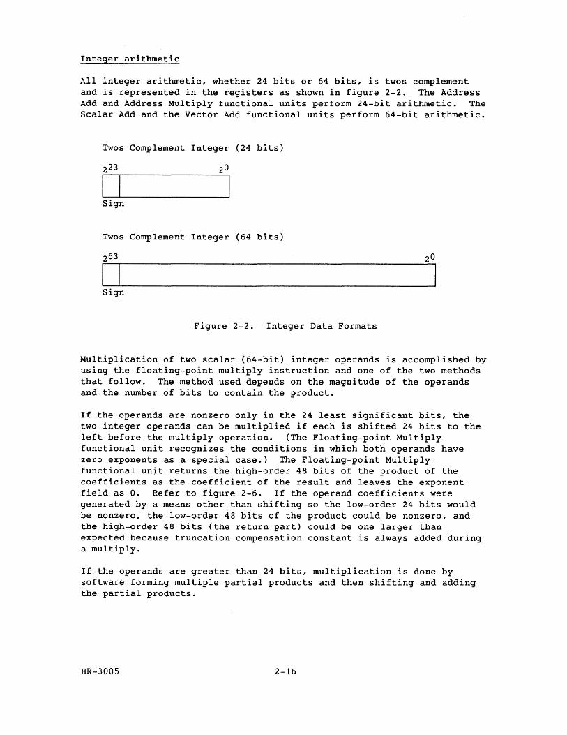
Integer arithmetic
All integer arithmetic, whether 24 bits or 64 bits, is twos complement and is represented in the registers as shown in figure 2-2. The Address Add and Address Multiply functional units perform 24-bit arithmetic. The Scalar Add and the Vector Add functional units perform 64-bit arithmetic.
Twos Complement Integer (24 bits)
I I Sign
Twos Complement Integer (64 bits)
I I Sign
Figure 2-2. Integer Data Formats
Multiplication of two scalar (64-bit) integer operands is accomplished by using the floating-point multiply instruction and one of the two methods that follow. The method used depends on the magnitude of the operands and the number of bits to contain the product.
If the operands are nonzero only in the 24 least significant bits, the two integer operands can be multiplied if each is shifted 24 bits to the left before the multiply operation. (The Floating-point Multiply functional unit recognizes the conditions in which both operands have zero exponents as a special case.) The Floating-point Multiply functional unit returns the high-order 48 bits of the product of the coefficients as the coefficient of the result and leaves the exponent field as O. Refer to figure 2-6. If the operand coefficients were generated by a means other than shifting so the low-order 24 bits would be nonzero, the low-order 48 bits of the product could be nonzero, and the high-order 48 bits (the return part) could be one larger than expected because truncation compensation constant is always added during a multiply.
If the operands are greater than 24 bits, multiplication is done by software forming multiple partial products and then shifting and adding the partial products.
HR-3005 2-16
Division is done by algorithm; the particular algorithm used depends on the number of bits in the quotient. The quickest and most frequently used method is to convert the numbers to floating-point format and then use the floating-point functional units.
Floating-point arithmetic
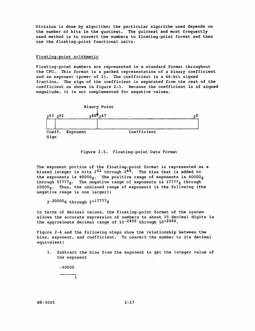
Floating-point numbers are represented in a standard format throughout the CPU. This format is a packed representation of a binary coefficient and an exponent (power of 2). The coefficient is a 4S-bit signed fraction. The sign of the coefficient is separated from the rest of the coefficient as shown in figure 2-3. Because the coefficient is of signed magnitude, it is not complemented for negative values.
I I Coeff. Sign
Binary Point
24S~247
Exponent Coefficient
Figure 2-3. Floating-point Data Format
The exponent portion of the floating-point format is represented as a biased integer in bits 262 through 24S • The bias that is added to the exponents is 40000 S. The positive range of exponents is 400008 through 57777S. The negative range of exponents is 37777 S through 20000 8 • Thus, the unbiased range of exponents is the following (the negative range is one larger):
2-20000S through 2+177778
In terms of decimal values, the floating-point format of the system allows the accurate expression of numbers to about 15 decimal digits in the approximate decimal range of 10-2466 through 10+2466 .
Figure 2-4 and the following steps show the relationship between the bias, exponent, and coefficient. To convert the number to its decimal equivalent:
1. Subtract the bias from the exponent to get the integer value of the exponent
-40000
1
HR-3005 2-17
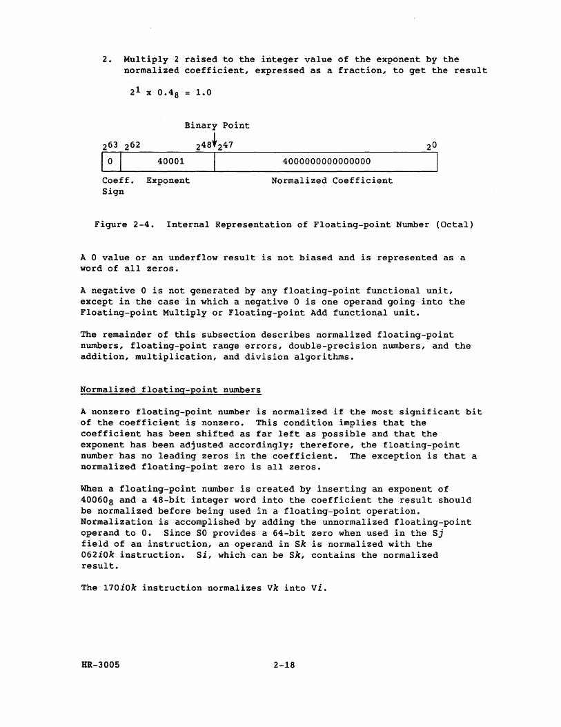
2. Multiply 2 raised to the integer value of the exponent by the normalized coefficient, expressed as a fraction, to get the result
21 x 0.48 = 1.0
Binary Point
248.247
40001 I Coeff. Exponent Sign
4000000000000000
Normalized Coefficient
Figure 2-4. Internal Representation of Floating-point Number (Octal)
A 0 value or an underflow result is not biased and is represented as a word of all zeros.
A negative 0 is not generated by any floating-point functional unit, except in the case in which a negative 0 is one operand going into the Floating-point Multiply or Floating-point Add functional unit.
The remainder of this subsection describes normalized floating-point numbers, floating-point range errors, double-precision numbers, and the addition, multiplication, and division algorithms.
Normalized floating-point numbers
A nonzero floating-point number is normalized if the most significant bit of the coefficient is nonzero. This condition implies that the coefficient has been shifted as far left as possible and that the exponent has been adjusted accordingly; therefore, the floating-point number has no leading zeros in the coefficient. The exception is that a normalized floating-point zero is all zeros.
When a floating-point number is created by inserting an exponent of 400608 and a 48-bit integer word into the coefficient the result should be normalized before being used in a floating-point operation. Normalization is accomplished by adding the unnormalized floating-point operand to o. Since SO provides a 64-bit zero when used in the Sj field of an instruction, an operand in Sk is normalized with the 062iOk instruction. Si, which can be Sk, contains the normalized result.
The 170iOk instruction normalizes vk into vi.
HR-3005 2-18
Floating-point range errors
Overflow of the floating-point range is indicated by an exponent value of 600008 for Floating-point Add or Multiply and 600028 for Floating-point Reciprocal or greater in packed format. Detection of the overflow condition initiates an interrupt if the Floating-point Mode flag is set in the Mode register and monitor mode is not in effect. The Floating-point Mode flag can be set or cleared by a user mode program.
Cray operating system COS keeps a bit in a table to indicate the condition of the mode bit. System software manipulates the mode bit and uses the table bit to indicate how the mode should be left for the user. Therefore, the user usually needs to put the appropriate bit in the table if the user changes the mode.
Floating-point range error conditions are detected by the floating-point functional units, as described in the following paragraphs.
Floating-point Add functional unit - A floating-point add range error condition is generated for scalar operands when the larger incoming exponent is greater than or equal to 600008. This condition sets the Floating-point Error flag, with an exponent of 600008 being sent to the result register along with the computed coefficient, as in the following example:
60000.4xxxxxxxxxxxxxxx +57777.4xxxxxxxxxxxxxxx
60000.6xxxxxxxxxxxxxxx
Range Error
Result Register
HR-3005
NOTE
If a floating-point add or subtract generates an exponent of less than 20000 8 or a coefficient of 0, the condition is considered an underflow; no fault is generated, and the word returned from the functional unit is all 0 bits. If either operand is out of bounds (exponent of 600008 or greater) or if the final sum or difference is out of bounds (exponent of 600008 or greater), the exponent is set to 600008' and a floating-point error is flagged. If floating-point faults are enabled, an interrupt occurs. Refer to the Floating-point Range Errors subsection for more information.
2-19
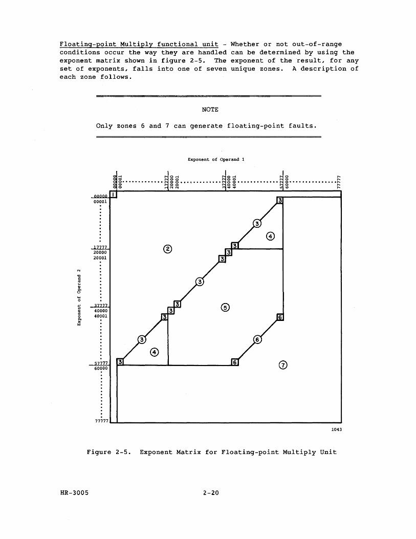
Floating-point Multiply functional unit - Whether or not out-of-range conditions occur the way they are handled can be determined by using the exponent matrix shown in figure 2-5. The exponent of the result, for any set of exponents, falls into one of seven unique zones. A description of each zone follows.
'0 s:: 111 \.< GI
8 ~ 0 ., g GI Q 0 Il< M rzl
NOTE
Only zones 6 and 7 can generate floating-point faults.
00001
20000 20001
40000 40001
7777 60000
.
..-I o 0- •••••••••••• o o
Exponent of Operand 1
0..-1 00 o 0 ••• ~ ••••••••• 00 NN
®
0..-1 00 o 0 ••••••••••••• 00 ..,...,.
@
@
o " o " o· •••••••••••• •• ,.... o " ID "
77777~~ ____________________________________________________________ -,
1043
Figure 2-5. Exponent Matrix for Floating-point Multiply Unit
HR-3005 2-20
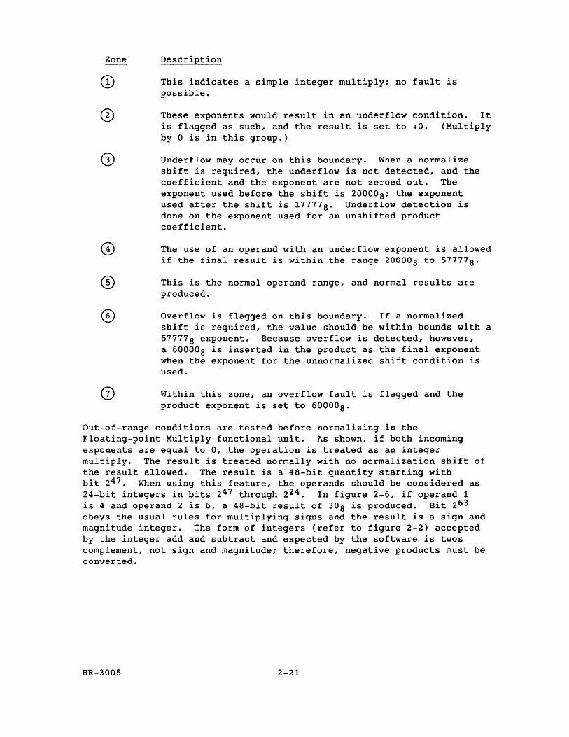
Zone
®
Description
This indicates a simple integer multiply; no fault is possible.
These exponents would result in an underflow condition. It is flagged as such, and the result is set to +0. (Multiply by 0 is in this group.)
Underflow may occur on this boundary. When a normalize shift is required, the underflow is not detected, and the coefficient and the exponent are not zeroed out. The exponent used before the shift is 20000a; the exponent used after the shift is 17777 a • Underflow detection is done on the exponent used for an unshifted product coefficient.
The use of an operand with an underflow exponent is allowed if the final result is within the range 20000a to 57777 a •
This is the normal operand range, and normal results are produced.
Overflow is flagged on this boundary. If a normalized shift is required, the value should be within bounds with a 57777 a exponent. Because overflow is detected, however, a 60000a is inserted in the product as the final exponent when the exponent for the unnormalized shift condition is used.
Within this zone, an overflow fault is flagged and the product exponent is set to 60000a.
Out-of-range conditions are tested before normalizing in the Floating-point Multiply functional unit. As shown, if both incoming exponents are equal to 0, the operation is treated as an integer mUltiply. The result is treated normally with no normalization shift of the result allowed. The result is a 48-bit quantity starting with bit 247. When using this feature, the operands should be considered as 24-bit integers in bits 247 through 224. In figure 2-6, if operand 1 is 4 and operand 2 is 6, a 4a-bit result of 30a is produced. Bit 263
obeys the usual rules for multiplying signs and the result is a sign and magnitude integer. The form of integers (refer to figure 2-2) accepted by the integer add and subtract and expected by the software is twos complement, not sign and magnitude; therefore, negative products must be converted.
HR-3005 2-21
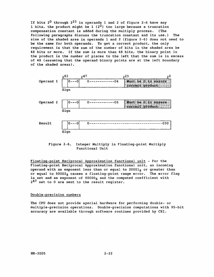
If bits 20 through 223 in operands 1 and 2 of figure 2-6 have any 1 bits, the product might be 1 (20) too large because a truncation compensation constant is added during the multiply process. (The following paragraphs discuss the truncation constant and its use.) The size of the shaded area in operands 1 and 2 (figure 2-6) does not need to be the same for both operands. To get a correct product, the only requirement is that the sum of the number of bits in the shaded area be 48 bits or more. If the sum is more than 48 bits, the binary point in the product is the number of places to the left that the sum is in excess of 48 (assuming that the operand binary points are at the left boundary of the shaded areas).
247 223 Operand 1 0------------04
Operand 2 0------------06
Sign
Result 0-----------------------------------030
Sign
Figure 2-6. Integer Multiply in Floating-point Multiply Functional Unit
Floating-point Reciprocal Approximation functional unit - For the Floating-point Reciprocal Approximation functional unit, an incoming operand with an exponent less than or equal to 200018 or greater than or equal to 600028 causes a floating-point range error. The error flag is set and an exponent of 600008 and the computed coefficient with 247 set to 0 are sent to the result register.
Double-precision numbers
The CPU does not provide special hardware for performing double- or multiple-precision operations. Double-precision computations with 95-bit accuracy are available through software routines provided by CRI.
HR-3005 2-22
Addition algorithm
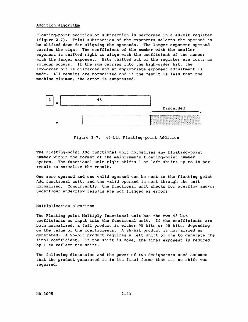
Floating-point addition or subtraction is performed in a 49-bit register (figure 2-7). Trial subtraction of the exponents selects the operand to be shifted down for aligning the operands. The larger exponent operand carries the sign. The coefficient of the number with the smaller exponent is shifted right to align with the coefficient of the number with the larger exponent. Bits shifted out of the register are lost; no roundup occurs. If the sum carries into the high-order bit, the low-order bit is discarded and an appropriate exponent adjustment is made. All results are normalized and if the result is less than the machine minimum, the error is suppressed.
~.I~ ___ 48 ____ ~ Discarded
•
Figure 2-7. 49-bit Floating-point Addition
The Floating-point Add functional unit normalizes any floating-point number within the format of the mainframe's floating-point number system. The functional unit right shifts 1 or left shifts up to 48 per result to normalize the result.
One zero operand and one valid operand can be sent to the Floating-point Add functional unit, and the valid operand is sent through the unit normalized. Concurrently, the functional unit checks for overflow and/or underflow; underflow results are not flagged as errors.
Multiplication algorithm
The Floating-point Multiply functional unit has the two 48-bit coefficients as input into the functional unit. If the coefficients are both normalized, a full product is either 95 bits or 96 bits, depending on the value of the coefficients. A 96-bit product is normalized as generated. A 95-bit product requires a left shift of one to generate the final coefficient. If the shift is done, the final exponent is reduced by 1 to reflect the shift.
The following discussion and the power of two designators used assumes that the product generated is in its final form; that is, no shift was required.
HR-3005 2-23
On the system, the functional unit truncates part of the low-order bits of the 96-bit product. To adjust for this truncation, a constant is unconditionally added above the truncation. The average value of this truncation is 9.25 x 2- 56 , which was determined by adding all carries produced by all possible combinations that could be truncated and dividing the sum by the number of possible combinations. Nine carries are injected at, tne 2-56 position to compensate for the truncated bits.
The effect of the truncation without compensation is at most a result coefficient 1 smaller than expected. With compensation, the results range from 1 too large to 1 too small in the 2-48 bit position, with approximately 99 percent of the values having zero deviation from what would have been generated had a full 96-bit product been present. The multiplication is commutative; that is, A times B equals B times A.
Rounding is optional where truncation compensation is not used. The rounding method used adds a constant so that it is 50 percent high (0.25 x 2-48 ; high) 38 percent of the time and 25 percent low (0.125 x 2-48 ; low) 62 percent of the time, resulting in a near-zero average rounding error. In a full-precision rounded multiply, 2 round bits are entered into the functional unit at bit positions 2-50 and 2- 51 and allowed to propagate.
For a half-precision multiply, round bits are entered into the functional unit at bit positions 2- 32 and 2- 31 • A carry resulting from this entry is allowed to propagate up and the 29 most significant bits of the normalized result are transmitted back.
The variations due to this truncation and rounding are in the following range:
-0.23 x 2-48 to +0.57 x 2-48
or
-8.17 x 10⁻¹⁶ to +20.25 x 10⁻¹⁶
With a full 96-bit product and rounding equal to one-half the least significant bit, the following variation would be expected:
-0.5 x 2-48 to +0.5 x 2-48
Division algorithm
The system performs floating-point division through reciprocal approximation, facilitating hardware implementation of a fully segmented functional unit. Because of this segmentation, operands enter the reciprocal unit during each CPo In vector mode, results are produced at a 1-CP rate and are used in other vector operations during chaining because all functional units in the system have the same result rate. The reciprocal approximation is based on Newton's method.
HR-3005 2-24
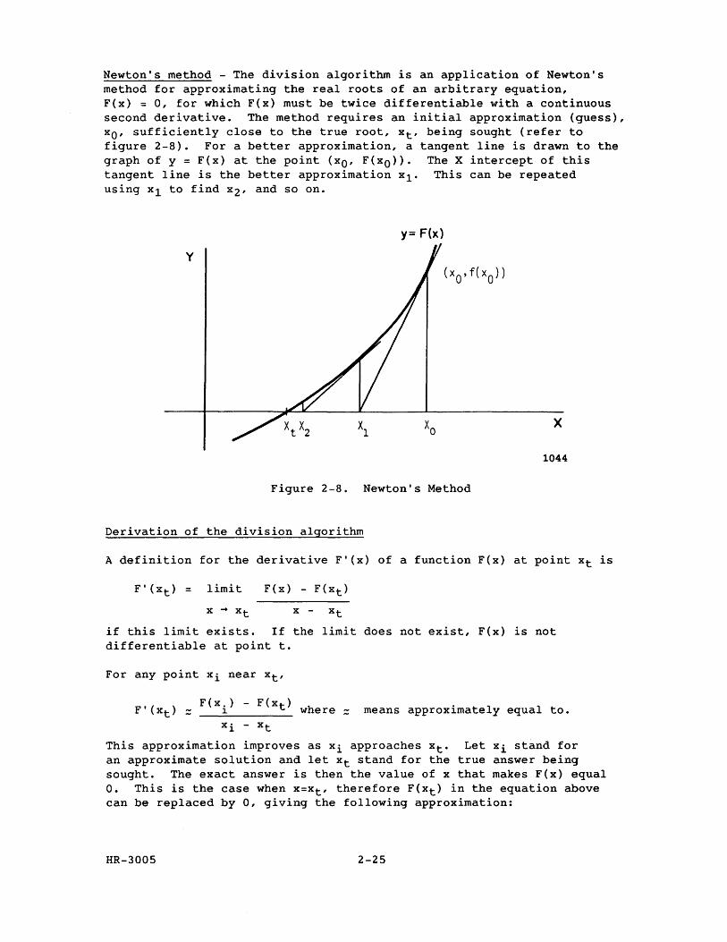
Newton's method - The division algorithm is an application of Newton's method for approximating the real roots of an arbitrary equation, F(x) = 0, for which F(x) must be twice differentiable with a continuous second derivative. The method requires an initial approximation (guess), xo' sufficiently close to the true root, Xt' being sought (refer to figure 2-8). For a better approximation, a tangent line is drawn to the graph of y = F(x) at the point (xO' F(xO». The X intercept of this tangent line is the better approximation xl. This can be repeated using xl to find x2' and so on.
y= F(x)
y
x
1044
Figure 2-8. Newton's Method
Derivation of the division algorithm
A definition for the derivative F'(x) of a function F(x) at point Xt is
F' (Xt) = 1 imi t F(x) - F(xt)
if this limit exists. If the limit does not exist, F(x) is not differentiable at point t.
For any point xi near Xt'
F(x.) - F(xt) F'(xt) = 1 where = means approximately equal to.
xi - Xt
This approximation improves as xi approaches Xt. Let xi stand for an approximate solution and let Xt stand for the true answer being sought. The exact answer is then the value of x that makes F(x) equal O. This is the case when x=Xt' therefore F(xt) in the equation above can be replaced by 0, giving the following approximation:
HR-3005 2-25
F' (Xt):: F ( xi) xi- Xt
Approximation (1)
Xt - xi is the correction applied to an approximate answer, xi' to give the right answer because xi + (Xt - xi) equals Xt. Solving approximation (1) for (Xt - Xi) gives the following:
Xt - Xi = correction:: - F(xi) ,
F' (Xt)
that is, - F(xi) is the approximate correction.
F' (Xt)
If this quantity is substituted into the approximation, then:
Xt:: (xi + approximate correction) = xi+l.
This gives the following equation:
= x. [(x )i 1.
F' (xi)
Equation (1)
where xi+l is a better approximation than Xi to the true value, Xt' being sought. The exact answer is generally not obtained at once because the correction term is not generally exact. The operation is repeated until the answer becomes sufficiently close for practical use.
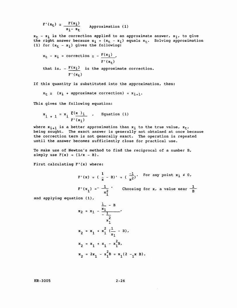
To make use of Newton's method to find the reciprocal of a number B, simply use F(x) = (l/x - B).
First calculating F'(x) where:
F'(x) = 1 -1 x - B)' = ( x2)·
For any point Xl ~ 0,
1 Choosing for x, a value near
and applying equation (1),
1 - B Xl
x2 = Xl - -=~1-----
2 Xl
2 (~ B) , x2 = Xl + Xl -
Xl
2 x
2 = Xl + Xl - xlB,
2xl
2 x
l(2 B). x
2 = - xlB = -lx
HR-3005 2-26
1 B
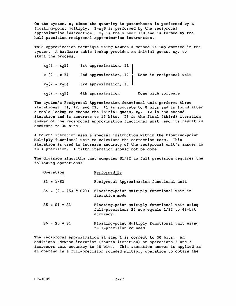
On the system, xl times the quantity in parentheses is performed by a floating-point multiply. 2-x1B is performed by the reciprocal approximation instruction. xl is the x near liB and is formed by the half-precision reciprocal approximation instruction.
This approximation technique using Newton's method is implemented in the system. A hardware table lookup provides an initial guess, xo' to start the process.
xO(2 - xOB) 1st approximation, I1
I x1(2 x1B) 2nd approximation, I2 Done in reciprocal unit
x2(2 - x2 B) 3rd approximation, I3
x3(2 - x3 B) 4th approximation Done with software
The system's Reciprocal Approximation functional unit performs three iterations: I1, I2, and I3. I1 is accurate to 8 bits and is found after a table lookup to choose the initial guess, xO. I2 is the second iteration and is accurate to 16 bits. 13 is the final (third) iteration answer of the Reciprocal Approximation functional unit, and its result is accurate to 30 bits.
A fourth iteration uses a special instruction within the Floating-point Multiply functional unit to calculate the correction term. This iteration is used to increase accuracy of the reciprocal unit's answer to full precision. A fifth iteration should not be done.
The division algorithm that computes 81/82 to full precision requires the following operations:
Operation Performed By
83 = 1182 Reciprocal Approximation functional unit
84 = (2 - (83 * 82» Floating-point Multiply functional unit in iteration mode
85 = 84 * 83
86 = 85 * 81
Floating-point Multiply functional unit using full-precision; 85 now equals 1/82 to 48-bit accuracy.
Floating-point Multiply functional unit using full-precision rounded
The reciprocal approximation at step 1 is correct to 30 bits. An additional Newton iteration (fourth iteration) at operations 2 and 3 increases this accuracy to 48 bits. This iteration answer is applied as an operand in a full-precision rounded multiply operation to obtain the
HR-3005 2-27
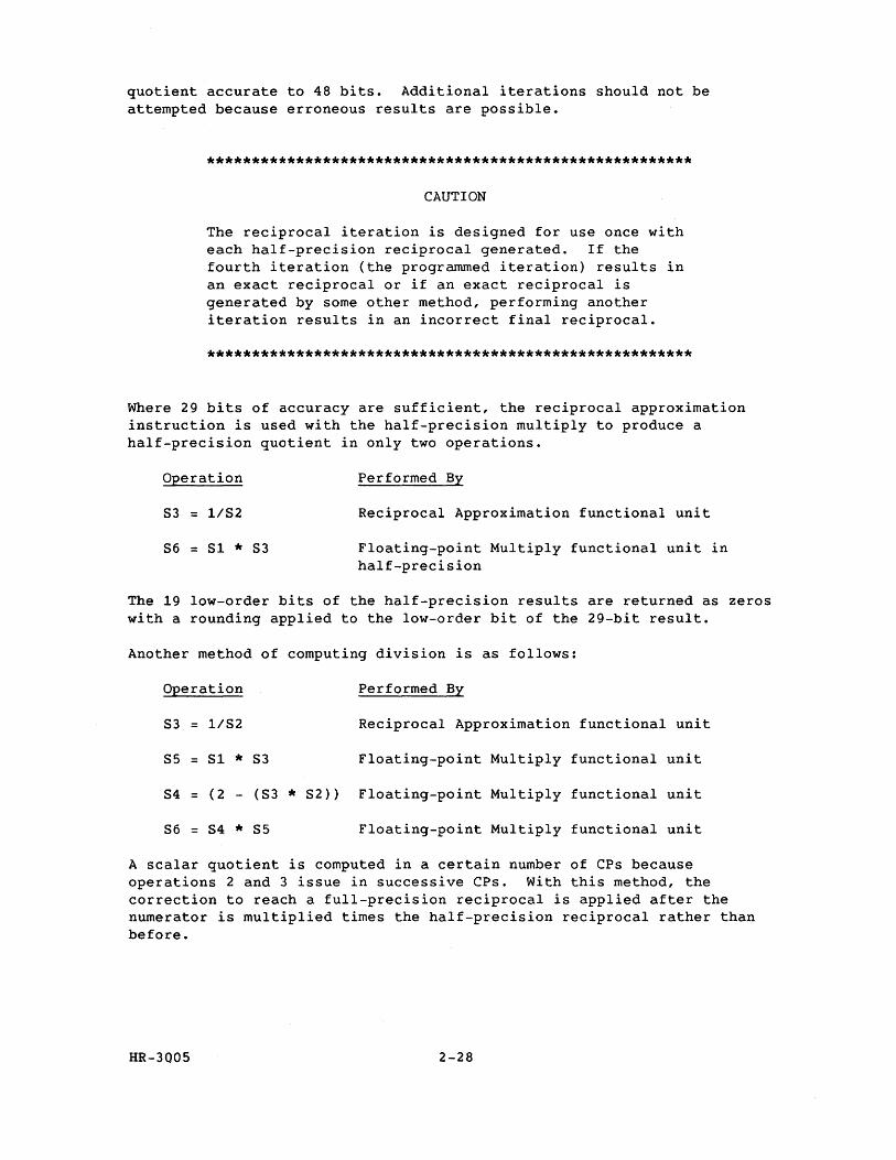
quotient accurate to 48 bits. Additional iterations should not be attempted because erroneous results are possible.
*******************************************************
CAUTION
The reciprocal iteration is designed for use once with each half-precision reciprocal generated. If the fourth iteration (the programmed iteration) results in an exact reciprocal or if an exact reciprocal is generated by some other method, performing another iteration results in an incorrect final reciprocal.
*******************************************************
Where 29 bits of accuracy are sufficient, the reciprocal approximation instruction is used with the half-precision multiply to produce a half-precision quotient in only two operations.
Operation
83 = 1/82
86 = 81 * 83
Performed By
Reciprocal Approximation functional unit
Floating-point Multiply functional unit in half-precision
The 19 low-order bits of the half-precision results are returned as zeros with a rounding applied to the low-order bit of the 29-bit result.
Another method of computing division is as follows:
Operation Performed By
83 = 1/82 Reciprocal Approximation functional unit
85 = 81 * 83 Floating-point Multiply functional unit
84 = (2 - (83 * 82)) Floating-point Multiply functional unit
86 = 84 * 85 Floating-point Multiply functional unit
A scalar quotient is computed in a certain number of CPs because operations 2 and 3 issue in successive CPs. With this method, the correction to reach a full-precision reciprocal is applied after the numerator is multiplied times the half-precision reciprocal rather than before.
HR-3005 2-28
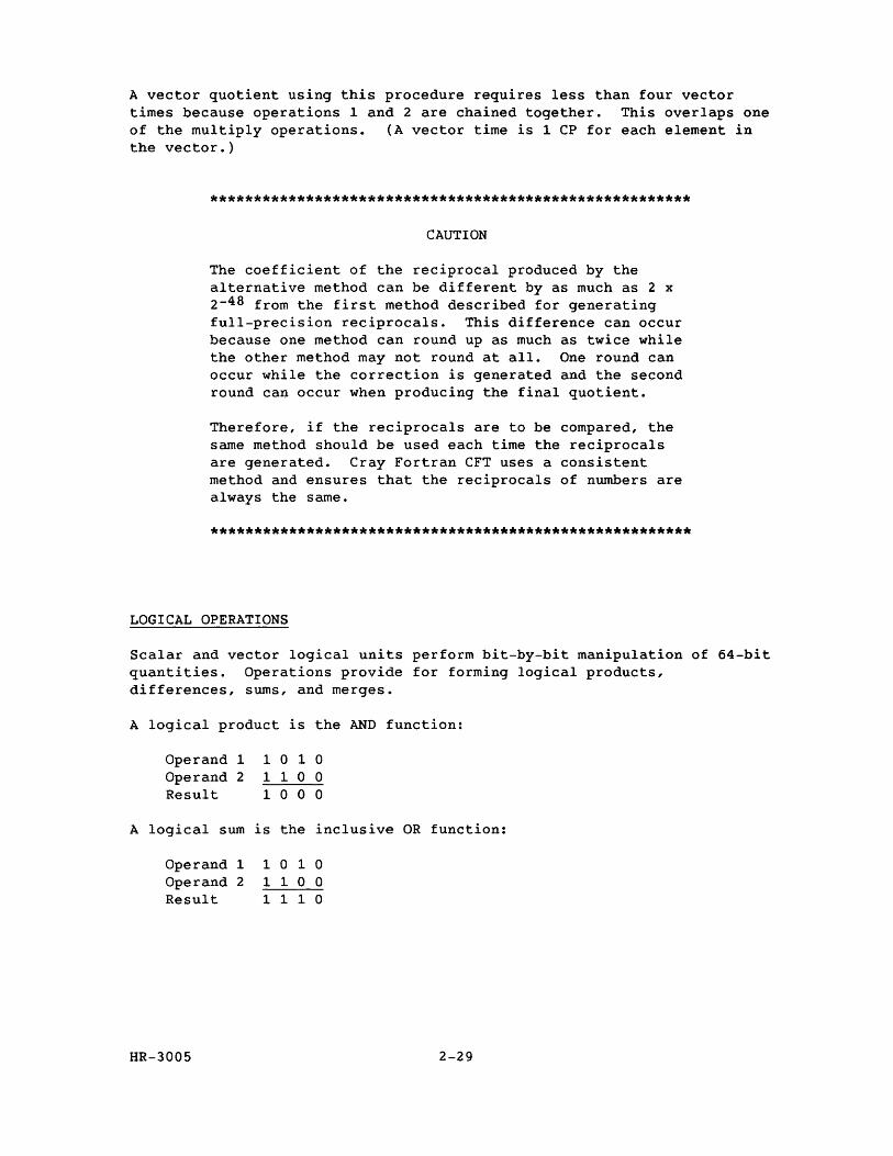
A vector quotient using this procedure requires less than four vector times because operations 1 and 2 are chained together. This overlaps one of the multiply operations. (A vector time is 1 CP for each element in the vector.)
*******************************************************
CAUTION
The coefficient of the reciprocal produced by the alternative method can be different by as much as 2 x 2-48 from the first method described for generating full-precision reciprocals. This difference can occur because one method can round up as much as twice while the other method may not round at all. One round can occur while the correction is generated and the second round can occur when producing the final quotient.
Therefore, if the reciprocals are to be compared, the same method should be used each time the reciprocals are generated. Cray Fortran CFT uses a consistent method and ensures that the reciprocals of numbers are always the same.
*******************************************************
LOGICAL OPERATIONS
Scalar and vector logical units perform bit-by-bit manipulation of 64-bit quantities. Operations provide for forming logical products, differences, sums, and merges.
A logical product is the AND function:
Operand 1 Operand 2 Result
1 0 1 0 110 0 100 0
A logical sum is the inclusive OR function:
Operand 1 Operand 2 Result
HR-3005
1 0 1 0 110 0 1 1 1 0
2-29
A logical difference is the exclusive OR function:
Operand 1 1 0 1 0 Operand 2 1 1 0 0 Result 0 1 1 0
A logical equivalence is the exclusive NOR function:
Operand 1 1 0 1 0 Operand 2 1 1 0 0 Result 1 0 0 1
The merge uses two operands and a mask to produce results as follows:
Operand 1 1 0 1 0 1 0 1 0 Operand 2 1 1 0 0 1 1 0 0 Mask 1 1 1 1 0 0 0 0 Result 1 0 1 0 1 1 0 0
The bits of operand 1 pass where the mask bit is 1. The bits of operand 2 pass where the mask bit is O.
CENTRAL MEMORY
The CRAY X-MP Central Memory is shared by the CPUs on multiprocessor systems and is arranged in interleaved banks. The interleaved memory banks enable extremely high transfer rates through the I/O section and provide low read/write times for vector processing. All banks can be accessed independently and in parallel during each machine clock period.
Each CRAY X-MP processor has four parallel memory ports: three for vector and scalar operations and one for I/O. The multiport memory has built-in conflict resolution hardware to minimize delays and maintain the integrity of all memory references to the same bank at the same time.
All CRAY X-MP models provide a flexible hardware chaining mechanism for vector processing. This feature enables a result vector to be used at any time as an operand in a succeeding operation. Also, vector chaining to and from memory is possible.
In addition, the CRAY X-MP computer system provides hardware support for vector conditionals. Gather/scatter operations (chainable from other vector memory fetches and stores) and compressed-index generation facilitate and speed execution of various conditional vector operations realized from ordinary user programs. All models allow execution of two vector logical operations of the same type at the same time.
Central Memory comes in various sizes; refer to section 4 for the different memory configurations.
HR-3005 2-30
INPUT/OUTPUT SECTION
The I/O section is shared by the CPUs in multiprocessor systems and may be equipped with a variety of high-performance channels for communicating with the mainframe, the lOS, and the SSD. The latter two devices are high-speed data transfer devices designed to support CRAY X-MP processing speeds. Refer to section 4 for information on channel types and transfer rates for your specific CRAY X-MP computer system.
HR-3005 2-31

CRAY X-MP SYMBOLIC MACHINE INSTRUCTIONS
3
Each CRAY X-MP mainframe machine instruction can be represented symbolically in Cray Assembly Language (CAL). This section provides information on the symbolic machine instructions used with the CRAY X-MP computer systems.
This section provides information on symbolic machine instruction format for a 1-parcel (16-bit) instruction or a 2-parcel (32-bit) instruction. It also describes special register values that may be referenced by the instructions and the symbolic notation used for coding the machine instructions.
Detailed information on the CAL instructions that operate on the CRAY X-MP computer systems is provided in the Machine Instruction Description subsection. Each machine instruction begins with boxed information consisting of the CAL syntax format, an operand if required, a brief description of each instruction, and the machine instruction.
Following the boxed information is a detailed description of the instruction and an example.
The Symbolic Instruction Summary section provides a summary of functional units and the symbolic machine instructions; the Functional Instruction Summary section lists the instructions by function.
INSTRUCTION SYNTAX
The assembler identifies a symbolic instruction according to its syntax and generates a corresponding binary machine code. An instruction is generated in the assembly section in use when the instruction is interpreted.
This section describes the format of symbolic machine instructions, special register values, and notation used for coding symbolic machine instructions for CAL Assembler Version 2 on a CRAY X-MP computer system.
INSTRUCTION FORMAT
Each instruction is either a 1-parcel (16-bit) instruction or a 2-parcel (32-bit) instruction. Instructions are packed 4 parcels per word.
HR-3005 3-1
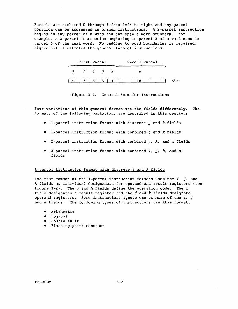
Parcels are numbered 0 through 3 from left to right and any parcel position can be addressed in branch instructions. A 2-parcel instruction begins in any parcel of a word and can span a word boundary. For example, a 2-parcel instruction beginning in parcel 3 of a word ends in parcel 0 of the next word. No padding to word boundaries is required. Figure 3-1 illustrates the general form of instructions.
First Parcel Second Parcel ~--------~----------~----------~--------~
g h i j k m
4 3 3 3 3 16 Bits
Figure 3-1. General Form for Instructions
Four variations of this general format use the fields differently. The formats of the following variations are described in this section:
• 1-parcel instruction format with discrete j and k fields
• 1-parcel instruction format with combined j and k fields
• 2-parcel instruction format with combined j, k, and m fields
• 2-parcel instruction format with combined i, j, k, and m fields
1-Earcel instruction format with discrete i and k fields
The most common of the 1-parcel instruction formats uses the i, j, and k fields as individual designators for operand and result registers (see figure 3-2). The g and h fields define the operation code. The i field designates a result register and the j and k fields designate operand registers. Some instructions ignore one or more of the i, j, and k fields. The following types of instructions use this format:
• Arithmetic • Logical • Double shift • Floating-point constant
HR-3005 3-2
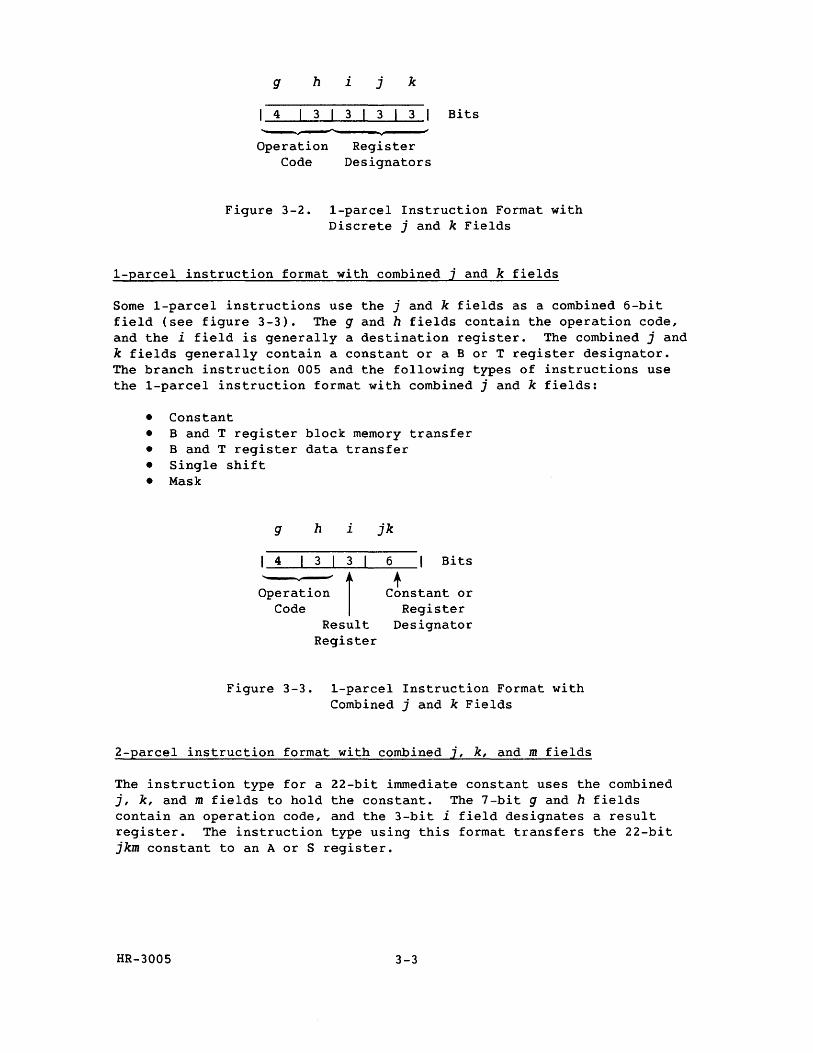
g h
4 3
Operation Code
Figure 3-2.
i j k
3 3 3
Register Designators
Bits
I-parcel Instruction Format with Discrete j and k Fields
I-parcel instruction format with combined j and k fields
Some 1-parcel instructions use the j and k fields as a combined 6-bit field (see figure 3-3). The g and h fields contain the operation code, and the i field is generally a destination register. The combined j and k fields generally contain a constant or a B or T register designator. The branch instruction 005 and the following types of instructions use the 1-parcel instruction format with combined j and k fields:
• Constant • Band T register block memory transfer • Band T register data transfer • Single shift
• Mask
g h i jk
4 3 3 6 Bits
I + Operation Constant or Code Register
Result Designator Register
Figure 3-3. 1-parcel Instruction Format with Combined j and k Fields
2-parcel instruction format with combined j, k, and m fields
The instruction type for a 22-bit immediate constant uses the combined j, k, and m fields to hold the constant. The 7-bit g and h fields contain an operation code, and the 3-bit i field designates a result register. The instruction type using this format transfers the 22-bit jkm constant to an A or S register.
HR-3005 3-3
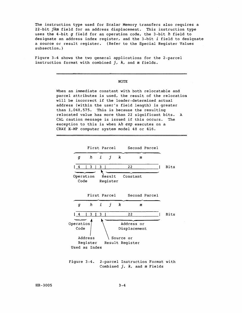
The instruction type used for Scalar Memory transfers also requires a 22-bit jkm field for an address displacement. This instruction type uses the 4-bit g field for an operation code, the 3-bit h field to designate an address index register, and the 3-bit i field to designate a source or result register. (Refer to the Special Register Values subsection.)
Figure 3-4 shows the two general applications for the 2-parcel instruction format with combined j, k, and m fields.
NOTE
When an immediate constant with both relocatable and parcel attributes is used, the result of the relocation will be incorrect if the loader-determined actual address (within the user's field length) is greater than 1,048,575. This is because the resulting relocated value has more than 22 significant bits. A CAL caution message is issued if this occurs. The exception to this is when Ah exp executes on a CRAY X-MP computer system model 48 or 416.
First Parcel Second Parcel
g h
4 3
Operat1on Code
i j k m
3 I 22
~-------Result Constant Register
First Parcel Second Parcel
g h i j k m
4 3 3 22
op~nl Code
Address '\
Address or Displacement
Source or Result Register Register
Used as Index
Bits
Bits
Figure 3-4. 2-parcel Instruction Format with Combined j, k, and m Fields
HR-3005 3-4
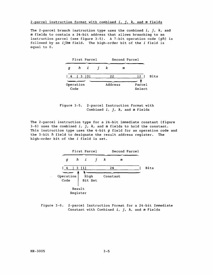
2-parcel instruction format with combined i, j, k, and m fields
The 2-parcel branch instruction type uses the combined i, j, k, and m fields to contain a 24-bit address that allows branching to an instruction parcel (see figure 3-5). A 7-bit operation code (gh) is followed by an ijkm field. The high-order bit of the i field is equal to O.
First Parcel Second Parcel
g h i j k m
I 4 I 3 10 1 22 12 I Bits
~ t . Operation Address Parcel
Code Select
Figure 3-5. 2-parcel Instruction Format with Combined i, j, k, and m Fields
The 2-parcel instruction type for a 24-bit immediate constant (figure 3-6) uses the combined i, j, k, and m fields to hold the constant. This instruction type uses the 4-bit g field for an operation code and the 3-bit h field to designate the result address register. The high-order bit of the i field is set.
First Parcel
g h i j
4 3 111
op~nl ~i9h Code Bit Set
Result Register
Second Parcel
k m
24 Bits
Constant
Figure 3-6. 2-parcel Instruction Format for a 24-bit Immediate Constant with Combined i, j, k, and m Fields
HR-3005 3-5
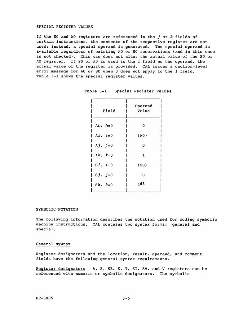
SPECIAL REGISTER VALUES
If the SO and AO registers are referenced in the j or k fields of certain instructions, the contents of the respective register are not used; instead, a special operand is generated. The special operand is available regardless of existing AO or SO reservations (and in this case is not checked). This use does not alter the actual value of the SO or AO register. If SO or AO is used in the i field as the operand, the actual value of the register is provided. CAL issues a caution-level error message for AO or SO when 0 does not apply to the i field. Table 3-1 shows the special register values.
Table 3-1. Special Register Values
Operand Field Value
Ah, h=O 0
Ai, i=O (AO)
Aj, j=O 0
Ak, k=O 1
Si, i=O (SO)
Sj, j=O 0
Sk, k=O 263
SYMBOLIC NOTATION
The following information describes the notation used for coding symbolic machine instructions. CAL contains two syntax forms: general and special.
General syntax
Register designators and the location, result, operand, and comment fields have the following general syntax requirements.
Register designators - A, B, SB, S, T, ST, SM, and V registers can be referenced with numeric or symbolic designators. The symbolic
HR-3005 3-6
designators can be entered in uppercase, lowercase, or any mixture of upper and lowercase.
In symbolic notation, the h, i, j, and k designators indicate the field of the machine instruction into which the register designator constant or symbol value is placed. An expression (exp) occupies the jk, ijk, jkm, or ijkm field depending on the operation code and magnitude of the expression value. Supporting registers have the following designators:
Designator Register
CA Current Address CL Channel Limit CI Channel Interrupt flag CE Channel Error flag RT Real-time Clock MC Master Clear SB Sign Bit (Sk, with k=O) SM Semaphore VL Vector Length VM Vector Mask XA Exchange Address
Location field - The location field of a symbolic instruction optionally contains a symbol. When a symbol is present, it is assigned a parcel address as indicated by the current value of the location counter after any required force to parcel boundary occurs.
Result field - The result field of a symbolic machine instruction can consist of one, two, or three subfields separated by commas. A subfield can be null or it can contain a register designator or an expression. The expression specifies a memory address that indicates the register or memory location to receive the results of the operation. The result field may contain a mnemonic indicating the function being performed (for example, J for jump or ex for exit). The mnemonics are case sensitive and must be entered in either all uppercase or all lowercase letters; they cannot be mixed. For example, EX is a valid mnemonic for exit, while Ex is not.
Operand field - The operand field of a symbolic machine instruction consists of no subfield or one, two, or three subfields separated by commas. A subfield can be null, contain an expression (with no register designators), or consist of register designators and operators.
HR-3005 3-7
The following special characters can appear in the operand field of symbolic machine instructions and are used by the assembler in determining the operation to be performed.
Character
+
* /
# > < &
\
Operation
Arithmetic sum of specified registers Arithmetic difference of specified registers Arithmetic product of specified registers Reciprocal of approximation Use ones complement Shift value or form mask from left to right Shift value or form mask from right to left Logical product of specified registers Logical sum of specified registers Logical difference of specified registers
In some instructions, register designators are prefixed by the following letters which have special meaning to the assembler. These letters can be entered in either uppercase or lowercase (case insensitive).
F Floating-point operation H Half-precision floating-point operation R Rounded floating-point operation I Reciprocal iteration P Population count Q Parity count Z Leading-zero count
Comment field - The comment field of the symbolic machine instructions begins in column 35. By convention, the comment should be preceded by a semicolon (;) in column 35, and a space.
Special syntax forms
The CAL instruction repertoire has been expanded for the convenience of programmers and to allow for special forms of symbolic instructions. Because of this expansion, certain Cray machine instructions can be generated from two or more different CAL instructions. For example, both of the following instructions generate instruction 002000, which causes a 1 to be entered into the VL register:
VL AO VL 1
The first instruction is the basic form of the Enter VL instruction, which takes advantage of the special case in which (Ak}=l if k=O; the second instruction is a special syntax form providing the programmer with a more convenient notation for the special case.
HR-3005 3-8
Any of the operations performed by special instructions can be performed by instructions in the basic set. Instructions having a special syntax form are identified as such in the instruction description found later in this section.
In several cases, a single syntax form of an instruction can result in any of several different machine instructions being generated. These cases provide for entering the value of an expression into an A register or into an S register or for shifting S register contents, the assembler determines which instruction to generate from characteristics of the expression.
MONITOR MODE INSTRUCTIONS
The monitor mode instructions (channel control, set real-time clock, and programmable clock interrupts) perform specialized functions that are useful to the operating system. These instructions execute only when the CPU is operating in monitor mode. If an instruction is executed while the CPU is not in the monitor mode, it is treated as a no-ope
MACHINE INSTRUCTION DESCRIPTIONS
This section contains detailed information about individual instructions or groups of related instructions. Each instruction begins with boxed information consisting of the CAL syntax format. It consists of a result field description, an operand field description, a brief description of each instruction, and the machine instruction (octal code sequence defined by the gh fields). The appearance of an m in a format description designates an instruction consisting of two parcels. An x in the format description signifies that the field containing the x is ignored during a CRAY X-MP computer system instruction execution. CAL inserts a 0 for each occurrence of x.
Following the boxed information is a detailed description of the instruction or instructions and an example using the instruction.
HR-3005
*******************************************************
CAUTION
Instructions with g, h, i, j, k, and m fields not explicitly described in the following instructions may produce indeterminate results.
*******************************************************
3-9
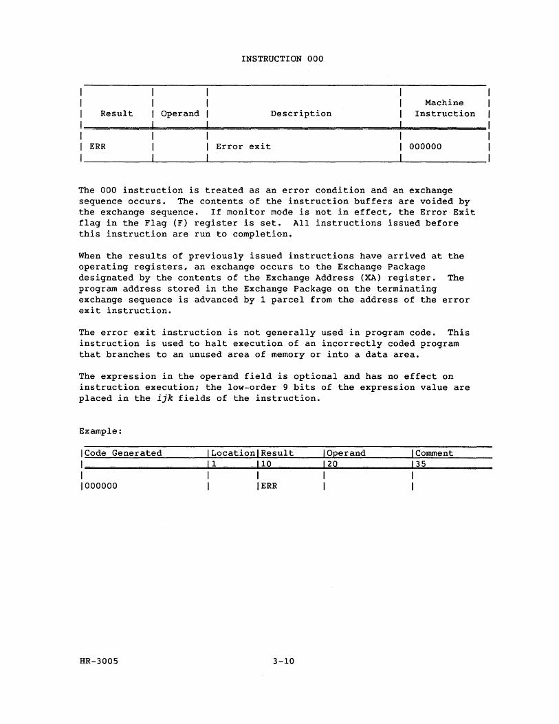
Result Operand
INSTRUCTION 000
Description Machine
Instruction
ERR Error exit 000000
The 000 instruction is treated as an error condition and an exchange sequence occurs. The contents of the instruction buffers are voided by the exchange sequence. If monitor mode is not in effect, the Error Exit flag in the Flag (F) register is set. All instructions issued before this instruction are run to completion.
When the results of previously issued instructions have arrived at the operating registers, an exchange occurs to the Exchange Package designated by the contents of the Exchange Address (XA) register. The program address stored in the Exchange Package on the terminating exchange sequence is advanced by 1 parcel from the address of the error exit instruction.
The error exit instruction is not generally used in program code. This instruction is used to halt execution of an incorrectly coded program that branches to an unused area of memory or into a data area.
The expression in the operand field is optional and has no effect on instruction execution; the low-order 9 bits of the expression value are placed in the ijk fields of the instruction.
Example:
ICode Generated I Locationl Result I Operand I Comment
1=========================11=========1=1=Q~=========1=2~Q~==============13~5============= I I I I I 1000000 I I ERR I I
HR-3005 3-10
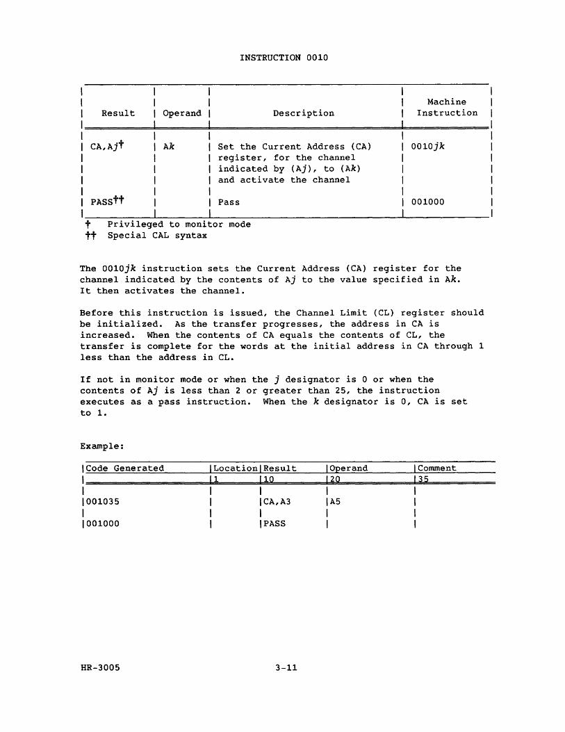
Result Operand
INSTRUCTION 0010
Description Machine
Instruction
CA,Ajt Ak Set the Current Address (CA) register, for the channel indicated by (Aj), to (Ak) and activate the channel
0010jk
PASStt Pass
t Privileged to monitor mode tt Special CAL syntax
001000
The 0010jk instruction sets the Current Address (CA) register for the channel indicated by the contents of Aj to the value specified in Ak. It then activates the channel.
Before this instruction is issued, the Channel Limit (CL) register should be initialized. As the transfer progresses, the address in CA is increased. When the contents of CA equals the contents of CL, the transfer is complete for the words at the initial address in CA through 1 less than the address in CL.
If not in monitor mode or when the j designator is 0 or when the contents of Aj is less than 2 or greater than 25, the instruction executes as a pass instruction. When the k designator is 0, CA is set to 1.
Example:
ICode Generated ILocationlResult I Operand I Comment
1========================1~1========1~1~Q==========~12~0~============~1=3~5============= 1 1 1 I I 1001035 1 ICA,A3 IA5 I 1 I I I I 1001000 I I PASS I I
HR-3005 3-11
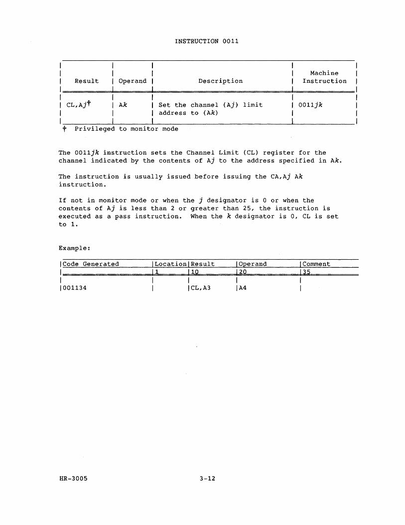
I I I Result Operand
I I
INSTRUCTION 0011
Description Machine
Instruction
I CL,Ajt Ak Set the channel (Aj) limit 0011jk
I address to (Ak)
I t Privileged to monitor mode
The 0011jk instruction sets the Channel Limit (CL) register for the channel indicated by the contents of Aj to the address specified in Ak.
The instruction is usually issued before issuing the CA,Aj Ak instruction.
If not in monitor mode or when the j designator is 0 or when the contents of Aj is less than 2 or greater than 25, the instruction is executed as a pass instruction. When the k designator is 0, CL is set to 1.
Example:
ICode Generated ILocationlResult I Operand I Comment
1=====================1=1========1~10~========1~2=0=============1=35~========== I I I I I 1001134 I ICL,A3 IA4 I
HR-3005 3-12
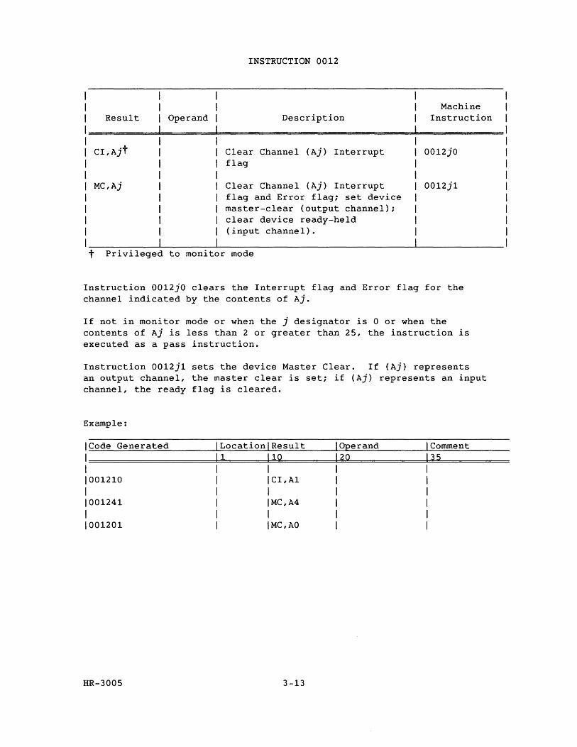
Result Operand
CI,Ajt
MC,Aj
INSTRUCTION 0012
Description
Clear Channel (Aj) Interrupt flag
Clear Channel (Aj) Interrupt flag and Error flag; set device master-clear (output channel); clear device ready-held (input channel).
t Privileged to monitor mode
Machine Instruction
0012jO
0012jl
Instruction 0012jO clears the Interrupt flag and Error flag for the channel indicated by the contents of Aj.
If not in monitor mode or when the j designator is 0 or when the contents of Aj is less than 2 or greater than 25, the instruction is executed as a pass instruction.
Instruction 0012jl sets the device Master Clear. If (Aj) represents an output channel, the master clear is set; if (Aj) represents an input channel, the ready flag is cleared.
Example:
ICode Generated ILocationlResult I Operand I Comment
1 11 110 120 135
1 I 1 I I 1001210 I ICI,Al I I 1 1 I 1 I 1001241 I IMC,A4 1 I 1 1 I 1 I 1001201 1 IMC,AO I I
HR-3005 3-13

I I
INSTRUCTION 0013
I Result Operand Description Machine
Instruction
I==========~===================================d============= I I XAt Aj Enter XA register with (Aj) 0013jO
I __________ ~--------~------------------------------~--------------t Privileged to monitor mode
The 0013jO instruction transmits bits 12 through 19 of register Aj to the Exchange Address (XA) register.
If the j designator is 0, the XA register is cleared.
A monitor program activates a user job by initializing the XA register to point to the user job's Exchange Package and then executing a normal exit (EX).
Example:
ICode Generated ILocationlResult I Operand I Comment
1=======================1=1========1=1=0~========~12~0~=============13~5~=========== I I I I I 1001350 I IXA lAS I
HR-3005
NOTE
Instruction 0013 is privileged to monitor mode and is treated as a pass instruction if the monitor mode bit is not set.
3-14
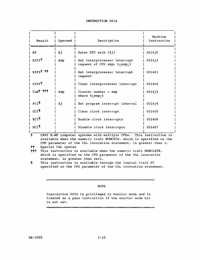
Result Operand
RT Sj
SIPIt exp
SIPIt tt
CIPIt
CLNt ttt exp
Sj
INSTRUCTION 0014
Description
Enter RTC with (Sj)
Set interprocessor interrupt request of CPU exp; 0~exp~3
Set interprocessor interrupt request
Clear interprocessor interrupt
Cluster number = exp where 0~exp~5
Set program interrupt interval
Clear clock interrupt
Enable clock interrupts
Disable clock interrupts
Machine Instruction
0014jO
0014j1
001401
001402
0014j3
0014j4
001405
001406
001407
t CRAY X-MP compute systems with multiple CPUs. This instruction is available when the numeric trait NUMCPUS, which is specified on the CPU parameter of the CAL invocation statement, is greater than 1.
tt Special CAL syntax ttt This instruction is available when the numeric trait NUMCLSTR,
which is specified on the CPU parameter of the CAL invocation statement, is greater than zero.
~r This instruction is available through the logical trait PC specified on the CPU parameter of the CAL invocation statement.
HR-3005
NOTE
Instruction 0014 is privileged to monitor mode and is treated as a pass instruction if the monitor mode bit is not set.
3-15
INSTRUCTION 0014 (continued)
The 0014jO instruction transmits the contents of register Sj to the Real-time Clock register. When the j designator is 0, the Real-time Clock register is set to O.
The 001401 and 001402 instructions handle interprocessor interrupt requests. When the k designator is 1, the instruction sets the internal CPU interrupt request in another CPU. If the other CPU is not in monitor mode, the ICP (Interrupt from Internal CPU) flag sets in the F register, causing an interrupt. The request remains until cleared by the receiving CPU.
When the k designator is 2, the instruction clears the internal CPU interrupt request set by another CPU.
The 0014j3 instruction sets the cluster number to j to make the following cluster selections:
CLN = 0 No cluster; all shared register and semaphore operations are no-ops, (except SB, ST, or SM register reads, which return a o value to Ai or Si).
CLN = 1 Cluster 1
CLN = 2 Cluster 2
CLN = 3 Cluster 3
CLN = 4 Cluster 4
CLN = 5 Cluster 5
Each of clusters 1, 2, 3, 4, and 5 has a separate set of SM, SB, and ST registers.
The 0014j4 instruction loads the low-order 32 bits from the Sj register into the Interrupt Interval register (II) and the Interrupt Countdown counter (ICD). The Interrupt Countdown counter is a 32-bit counter that is decreased by 1 each clock period until the contents of the counter is equal to O. At this time, the real-time clock (RTC) interrupt request is set. The counter is then set to the interval value held in the Interrupt Interval register and repeats the countdown to 0 cycle. When an RTC interrupt request is set, it remains set until a clear clock interrupt (CCI) instruction is executed.
The 001405 instruction clears an RTC interrupt.
HR-3005 3-16
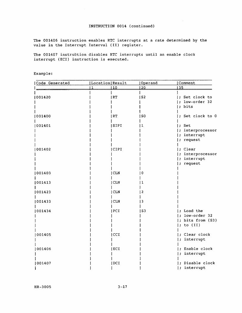
INSTRUCTION 0014 (continued)
The 001406 instruction enables RTC interrupts at a rate determined by the value in the Interrupt Interval (II) register.
The 001407 instruction disables RTC interrupts until an enable clock interrupt (ECI) instruction is executed.
Example:
ICode Generated LocationlResult Operand Comment
1====================~1~====~11~0~========~20~==========~3~5~========== 1 1 1001420 RT
1
1 1
001400 RT
001401 SIPI
001402 CIPI
001403 CLN
001413 CLN
001423 CLN
001433 CLN
001434 PCI
001405 CCI
001406 ECI
001407 DCI
HR-3005 3-17
S2
SO
1
o
1
2
3
S3
Set clock to low-order 32 bits
Set clock to 0
Set interprocessor interrupt request
Clear interprocessor interrupt request
Load the low-order 32 bits from (S3) to (II)
Clear clock interrupt
Enable clock interrupt
Disable clock interrupt
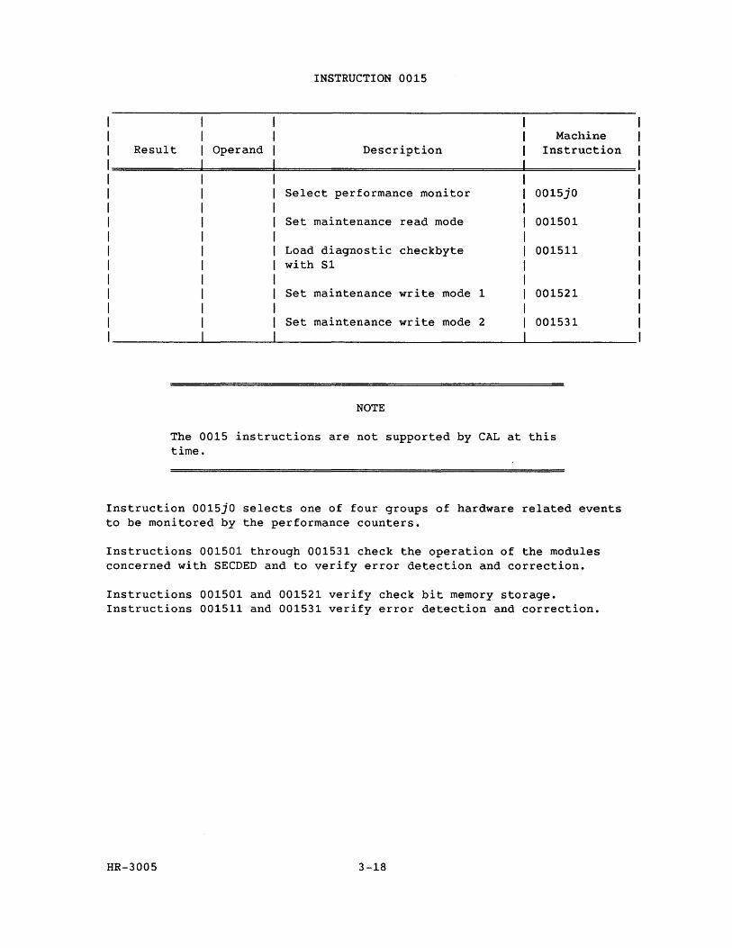
INSTRUCTION 0015
Result Operand Description Machine
Instruction
Select performance monitor 0015jO
Set maintenance read mode 001501
Load diagnostic checkbyte 001511 with Sl
Set maintenance write mode 1 001521
Set maintenance write mode 2 001531
NOTE
The 0015 instructions are not supported by CAL at this time.
Instruction 0015jO selects one of four groups of hardware related events to be monitored by the performance counters.
Instructions 001501 through 001531 check the operation of the modules concerned with SECDED and to verify error detection and correction.
Instructions 001501 and 001521 verify check bit memory storage. Instructions 001511 and 001531 verify error detection and correction.
HR-3005 3-18
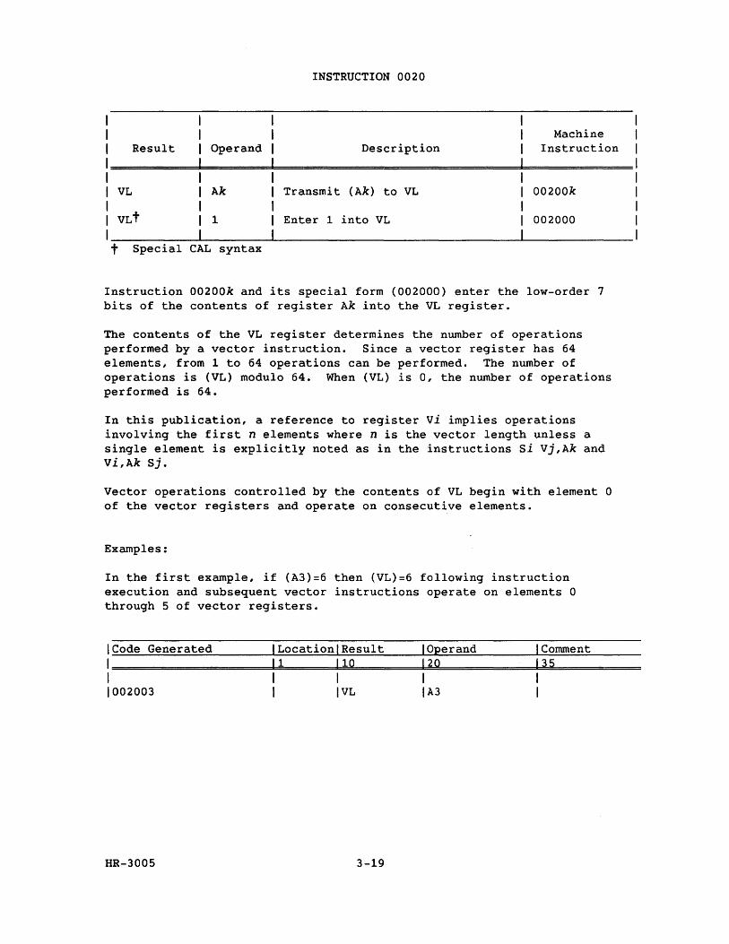
1 1 1 Result Operand
INSTRUCTION 0020
Description Machine
Instruction
1=========================================================== 1 1 VL Ak Transmit (Ak) to VL 00200k
1 1 VLt 1 Enter 1 into VL 002000
I __________ ~--------~------------------------------~--------------t Special CAL syntax
Instruction 00200k and its special form (002000) enter the low-order 7 bits of the contents of register Ak into the VL register.
The contents of the VL register determines the number of operations performed by a vector instruction. Since a vector register has 64 elements, from 1 to 64 operations can be performed. The number of operations is (VL) modulo 64. When (VL) is 0, the number of operations performed is 64.
In this publication, a reference to register vi implies operations involving the first n elements where n is the vector length unless a single element is explicitly noted as in the instructions Si Vj,Ak and Vi,Ak Sj.
Vector operations controlled by the contents of VL begin with element 0 of the vector registers and operate on consecutive elements.
Examples:
In the first example, if (A3)=6 then (VL)=6 following instruction execution and subsequent vector instructions operate on elements 0 through 5 of vector registers.
ICode Generated I Locationl Result I Operand I Comment
1======================1~1=======1~1~0========~1~20~============1~3~5============ 1 1 1 1 1 1002003 1 IVL IA3 I
HR-3005 3-19
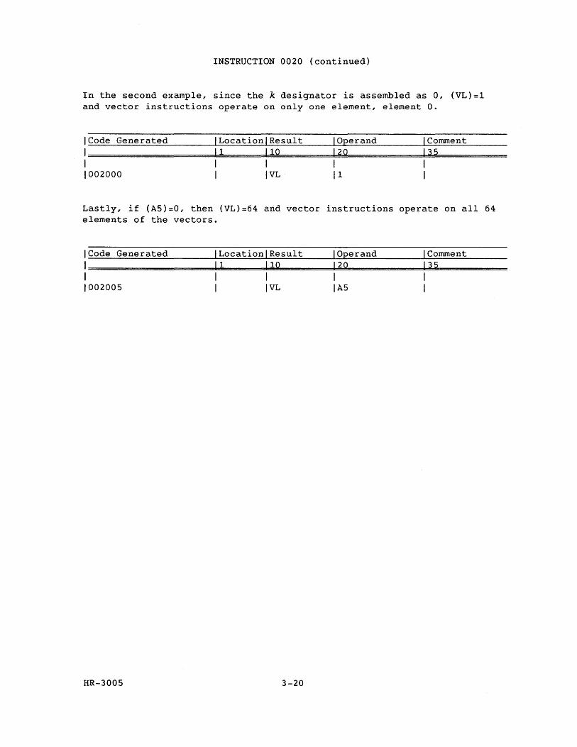
INSTRUCTION 0020 (continued)
In the second example, since the k designator is assembled as 0, (VL}=l and vector instructions operate on only one element, element O.
ICode Generated ILocationlResult I Operand I Comment
1=====================1=1========11=0==========12=0=============1~3~5============ I I I I I 1002000 I IVL 11 I
Lastly, if (A5}=0, then (VL}=64 and vector instructions operate on all 64 elements of the vectors.
ICode Generated ILocationlResult I Operand I Comment
1======================1=1=======1=1=0==========1~2~0=============1~3~5============ I I I I I 1002005 I IVL IA5 I
HR-3005 3-20
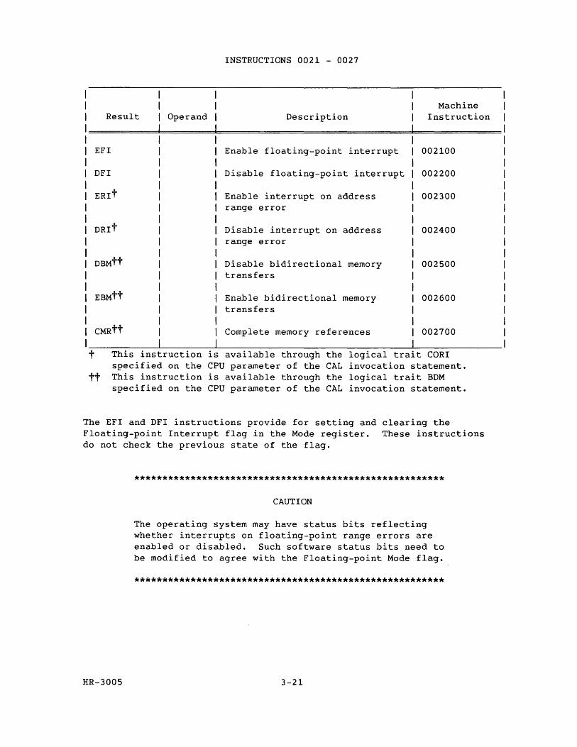
Result Operand
EFI
DFI
ERlt
DRlt
t This instruction specified on the
is
INSTRUCTIONS 0021 - 0027
Description
Enable floating-point interrupt
Disable floating-point interrupt
Enable interrupt on address range error
Disable interrupt on address range error
Disable bidirectional memory transfers
Enable bidirectional memory transfers
Complete memory references
Machine Instruction
002100
002200
002300
002400
002500
002600
002700
available through the logical tra1t CORI CPU parameter of the CAL invocation statement.
tt This instruction is available through the logical trait BDM specified on the CPU parameter of the CAL invocation statement.
The EFI and DFI instructions provide for setting and clearing the Floating-point Interrupt flag in the Mode register. These instructions do not check the previous state of the flag.
HR-3005
*******************************************************
CAUTION
The operating system may have status bits reflecting whether interrupts on floating-point range errors are enabled or disabled. Such software status bits need to be modified to agree with the Floating-point Mode flag.
*******************************************************
3-21
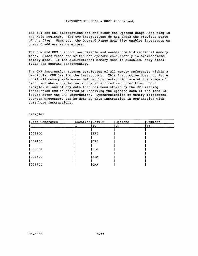
INSTRUCTIONS 0021 - 0027 (continued)
The ERI and DRI instructions set and clear the Operand Range Mode flag in the Mode register. The two instructions do not check the previous state of the flag. When set, the Operand Range Mode flag enables interrupts on operand address range errors.
The DBM and EBM instructions disable and enable the bidirectional memory mode. Block reads and writes can operate concurrently in bidirectional memory mode. If the bidirectional memory mode is disabled, only block reads can operate concurrently.
The CMR instruction assures completion of all memory references within a particular CPU issuing the instruction. This instruction does not issue until all memory references before this instruction are at the stage of execution where completion occurs in a fixed amount of time. For example, a load of any data that has been stored by the CPU issuing instruction CMR is assured of receiving the updated data if the load is issued after the CMR instruction. Synchronization of memory references between processors can be done by this instruction in conjunction with semaphore instructions.
Example:
Code Generated Location Result Operand Comment 1 10 20 35
002300 ERI
002400 DRI
002500 DBM
002600 EBM
002700 CMR
HR-3005 3-22
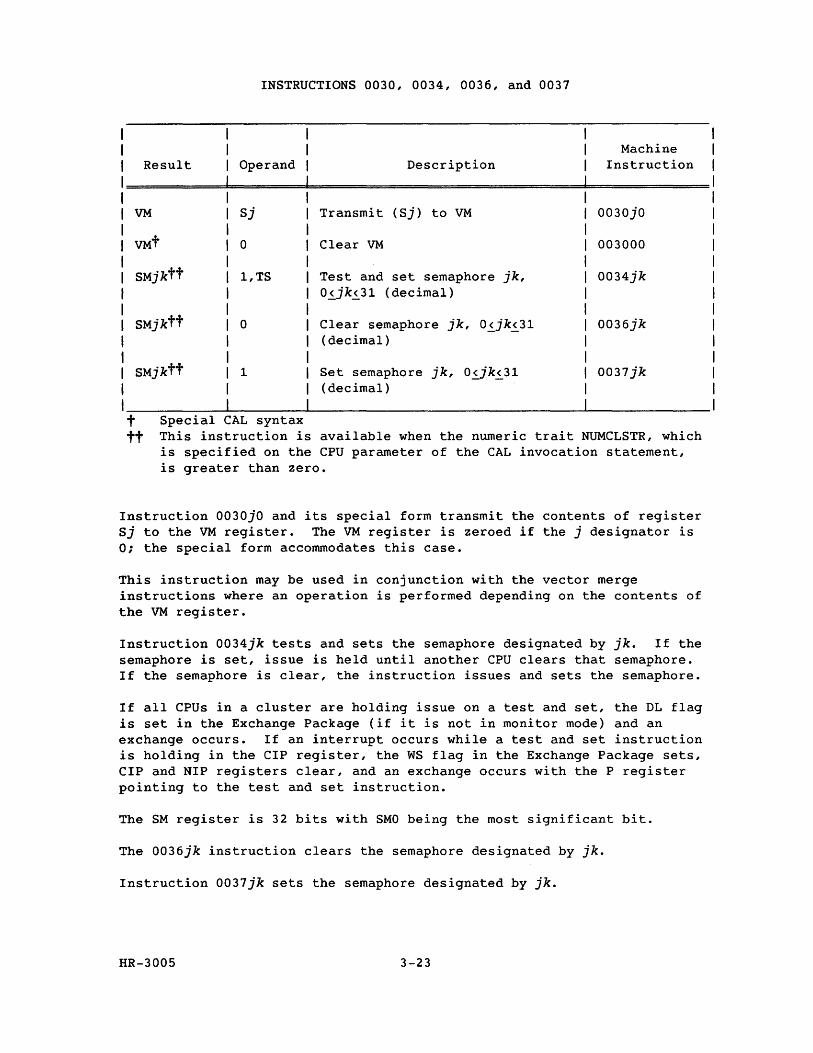
INSTRUCTIONS 0030, 0034, 0036, and 0037
Machine Result Operand Description Instruction
VM Sj Transmit (Sj) to VM 0030jO
VMt 0 Clear VM 003000
SMjktt 1,TS Test and set semaphore jk, 0034jk 0~jk~31 (decimal)
SMjktt 0 Clear semaphore jk, 0~jk~31 0036jk (decimal)
SMjktt 1 Set semaphore jk, 0~jk~31 0037jk (decimal)
t Special CAL syntax tt This instruction is available when the numeric trait NUMCLSTR, which
is specified on the CPU parameter of the CAL invocation statement, is greater than zero.
Instruction 0030jO and its special form transmit the contents of register Sj to the VM register. The VM register is zeroed if the j designator is 0; the special form accommodates this case.
This instruction may be used in conjunction with the vector merge instructions where an operation is performed depending on the contents of the VM register.
Instruction 0034jk tests and sets the semaphore designated by jk. If the semaphore is set, issue is held until another CPU clears that semaphore. If the semaphore is clear, the instruction issues and sets the semaphore.
If all CPUs in a cluster are holding issue on a test and set, the DL flag is set in the Exchange Package (if it is not in monitor mode) and an exchange occurs. If an interrupt occurs while a test and set instruction is holding in the CIP register, the WS flag in the Exchange Package sets, CIP and NIP registers clear, and an exchange occurs with the P register pointing to the test and set instruction.
The SM register is 32 bits with SMO being the most significant bit.
The 0036jk instruction clears the semaphore designated by jk.
Instruction 0037jk sets the semaphore designated by jk.
HR-3005 3-23
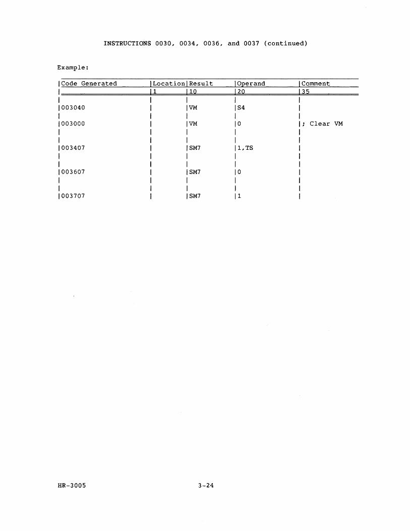
INSTRUCTIONS 0030, 0034, 0036, and 0037 (continued)
Example:
Code Generated Location Result Operand Comment 1 10 20 35
003040 VM S4
003000 VM 0 Clear VM
003407 SM7 1,TS
003607 SM7 0
003707 SM7 1
HR-3005 3-24
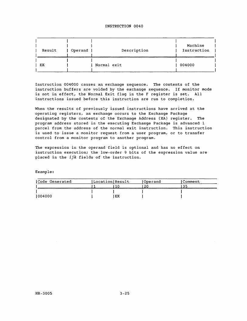
Result Operand
INSTRUCTION 0040
Description Machine
Instruction
EX Normal exit 004000
Instruction 004000 causes an exchange sequence. The contents of the instruction buffers are voided by the exchange sequence. If monitor mode is not in effect, the Normal Exit flag in the F register is set. All instructions issued before this instruction are run to completion.
When the results of previously issued instructions have arrived at the operating registers, an exchange occurs to the Exchange Package designated by the contents of the Exchange Address (XA) register. The program address stored in the executing Exchange Package is advanced 1 parcel from the address of the normal exit instruction. This instruction is used to issue a monitor request from a user program, or to transfer control from a monitor program to another program.
The expression in the operand field is optional and has no effect on instruction execution; the low-order 9 bits of the expression value are placed in the ijk fields of the instruction.
Example:
ICode Generated ILocationlResult I Operand I Comment
1====================~1~1=======1~1~0==========12~0=============1~3~5============ I I I I I 1004000 I lEX I I
HR-3005 3-25
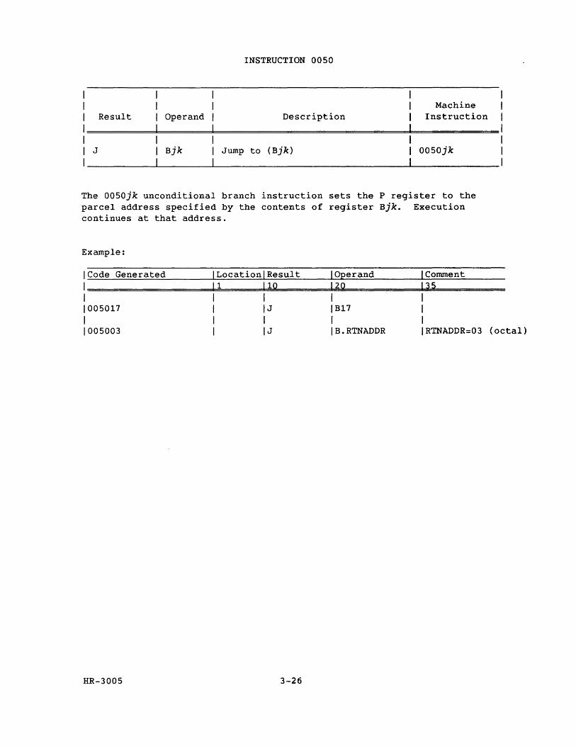
Result Operand
INSTRUCTION 0050
Description Machine
Instruction
J Bjk Jump to (Bjk) 0050jk
The 0050jk unconditional branch instruction sets the P register to the parcel address specified by the contents of register Bjk. Execution continues at that address.
Example:
ICode Generated ILocationlResult I Operand I Comment
1====================~1~1=======1~1~0=========1~2~0============d1~3~5============= 1 1 1 1 1 1005017 1 IJ IB17 1 1 1 1 1 1 1005003 1 IJ IB.RTNADDR IRTNADDR=03 (octal)
HR-3005 3-26
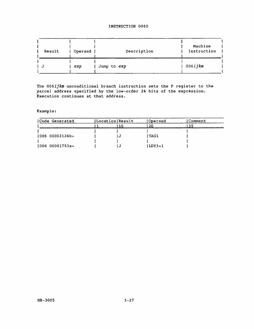
Result
J
INSTRUCTION 0060
Operand Description
exp Jump to exp
Machine Instruction
006ijkm
The 006ijkm unconditional branch instruction sets the P register to the parcel address specified by the low-order 24 bits of the expression. Execution continues at that address.
Example:
1 Code Generated ILocationlResult I Operand I Comment 1 11 110 120 135 1 I 1 1 1 1006 00002124b+ I IJ ITAG1 1 1 I 1 1 I 1006 00001753a+ 1 IJ ILDY3+1 1
HR-3005 3-27
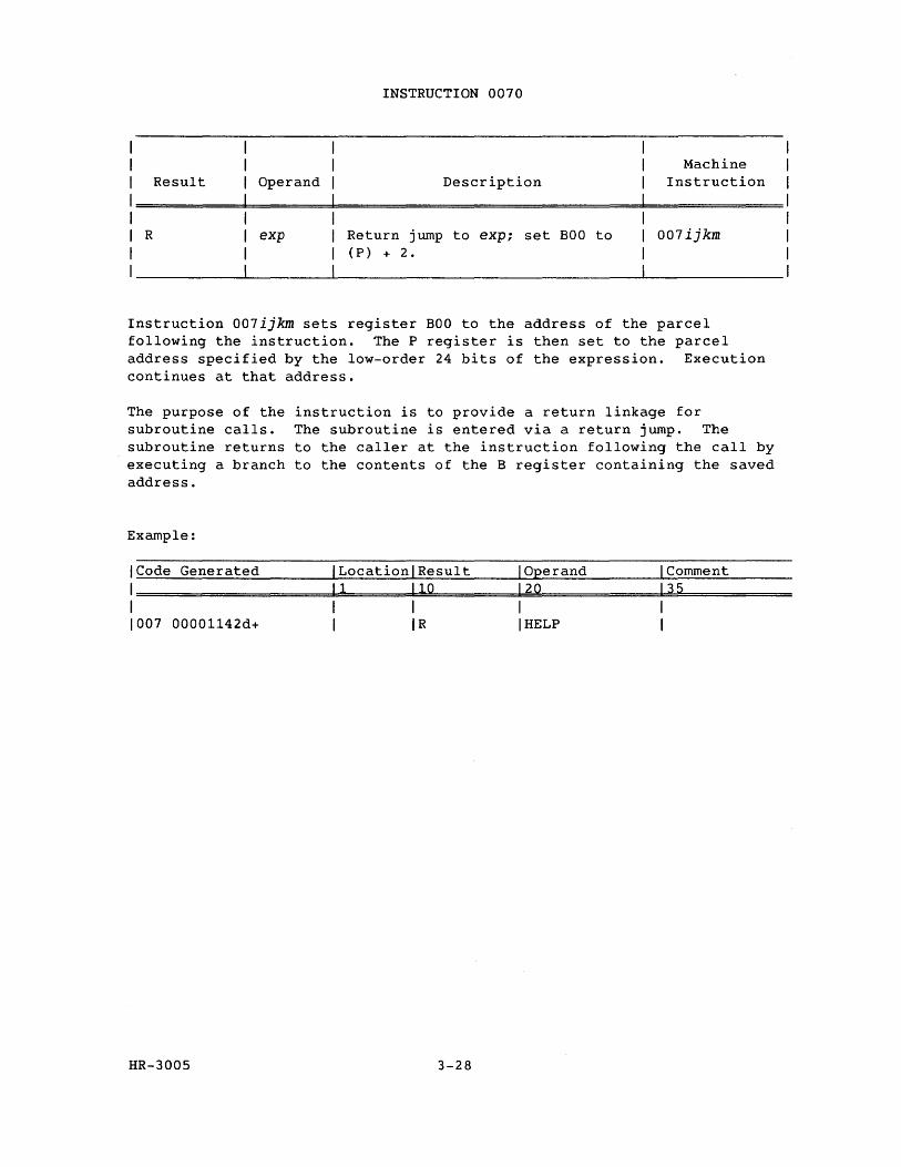
Result Operand
INSTRUCTION 0070
Description Machine
Instruction
R exp Return jump to exp; set BOO to (P) + 2.
007ijkm
Instruction 007ijkm sets register BOO to the address of the parcel following the instruction. The P register is then set to the parcel address specified by the low-order 24 bits of the expression. Execution continues at that address.
The purpose of the instruction is to provide a return linkage for subroutine calls. The subroutine is entered via a return jump. The subroutine returns to the caller at the instruction following the call by executing a branch to the contents of the B register containing the saved address.
Example:
ICode Generated ILocationlResult I Operand I Comment
1=====================1=1=======1=1=0==========12=0=============1~3~5============ I I I I I 1007 00001142d+ I IR I HELP I
HR-3005 3-28
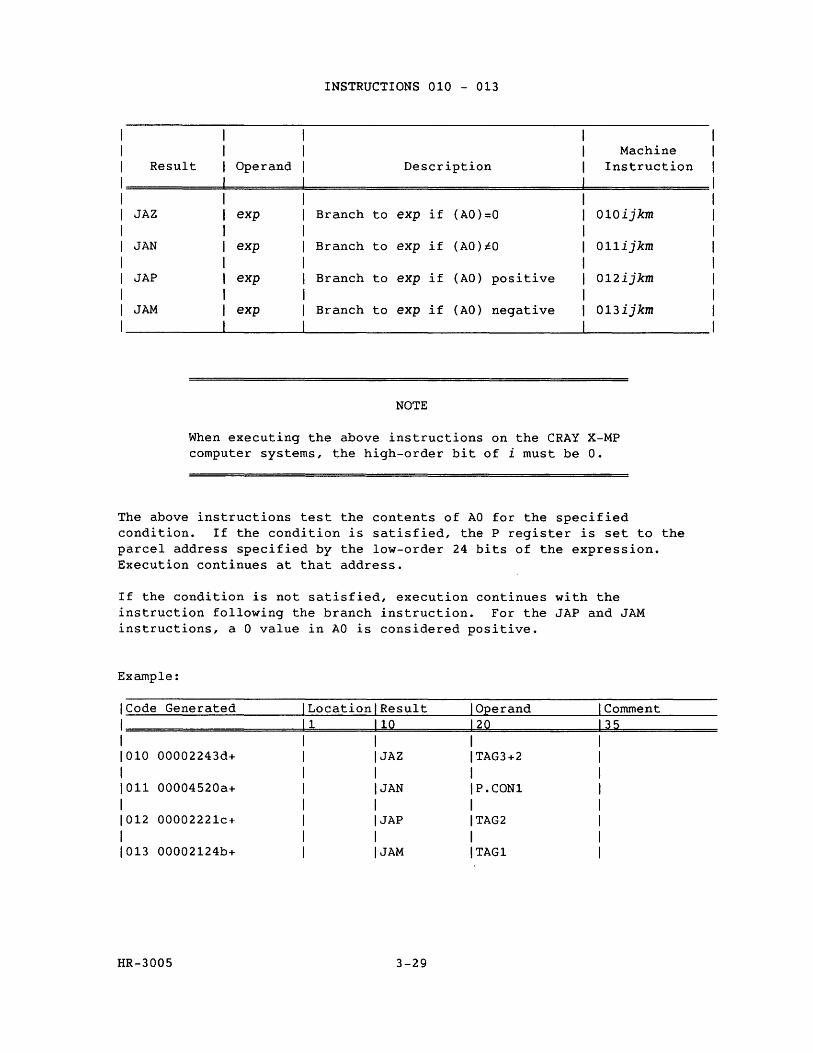
INSTRUCTIONS 010 - 013
Machine Result Operand Description Instruction
JAZ exp Branch to exp if (AO)=O 010ijkm
JAN exp Branch to exp if (AO)~O 011ijkm
JAP exp Branch to exp if (AO) positive 012ijkm
JAM exp Branch to exp if (AO) negative 013ijkm
NOTE
When executing the above instructions on the CRAY X-MP computer systems, the high-order bit of i must be O.
The above instructions test the contents of AO for the specified condition. If the condition is satisfied, the P register is set to the parcel address specified by the low-order 24 bits of the expression. Execution continues at that address.
If the condition is not satisfied, execution continues with the instruction following the branch instruction. For the JAP and JAM instructions, a 0 value in AO is considered positive.
Example:
ICode Generated Location Result I Operand Comment
I 1 10 120 35 I I 1010 00002243d+ JAZ ITAG3+2 I I 1011 00004520a+ JAN IP.CONl I I 1012 00002221c+ JAP ITAG2 I I 1013 00002124b+ JAM ITAG1
HR-3005 3-29
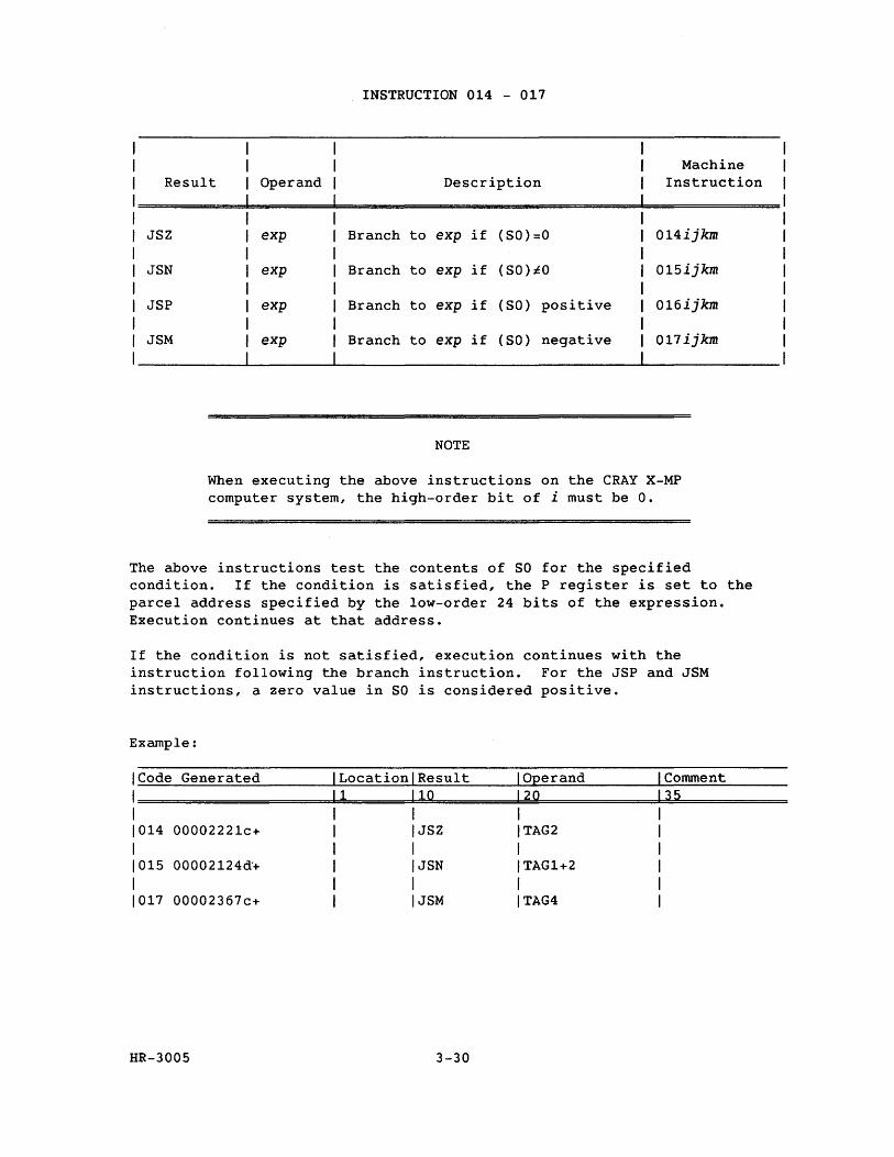
INSTRUCTION 014 - 017
Machine Result Operand Description Instruction
JSZ exp Branch to exp if (SO)=O 014ijkm
JSN exp Branch to exp if (SO)~O 015ijkm
JSP exp Branch to exp if (SO) positive 016ijkm
JSM exp Branch to exp if (SO) negative 017ijkm
NOTE
When executing the above instructions on the CRAY X-MP computer system, the high-order bit of i must be O.
The above instructions test the contents of SO for the specified condition. If the condition is satisfied, the P register is set to the parcel address specified by the low-order 24 bits of the expression. Execution continues at that address.
If the condition is not satisfied, execution continues with the instruction following the branch instruction. For the JSP and JSM instructions, a zero value in SO is considered positive.
Example:
ICode Generated ILocationlResult I Operand I Comment I 11 110 120 135 I I I I I 1014 00002221c+ I IJSZ ITAG2 I I I I I I 1015 00002124d'+ I IJSN ITAG1+2 I I I I I I 1017 00002367c+ I IJSM ITAG4 I
HR-3005 3-30
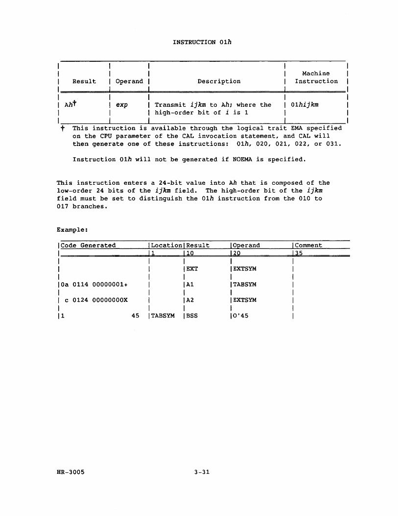
I I I Result Operand
INSTRUCTION 01h
Description Machine
Instruction
1=========================================================== I I Aht I
exp Transmit ijkm to Ah; where the high-order bit of i is 1
01hijkm
I __________ ~--------~------------------------------~--------------t This instruction is available through the logical trait EMA specified
on the CPU parameter of the CAL invocation statement, and CAL will then generate one of these instructions: 01h, 020, 021, 022, or 031.
Instruction 01h will not be generated if NOEMA is specified.
This instruction enters a 24-bit value into Ah that is composed of the low-order 24 bits of the ijkm field. The high-order bit of the ijkm field must be set to distinguish the 01h instruction from the 010 to 017 branches.
Example:
I Code Generated Location Result Operand Comment I 1 10 20 35 I I EXT EXTSYM I lOa 0114 00000001+ Al TABSYM I I c 0124 OOOOOOOOX A2 EXTSYM I 11 45 TABSYM BSS 0'45
HR-3005 3-31
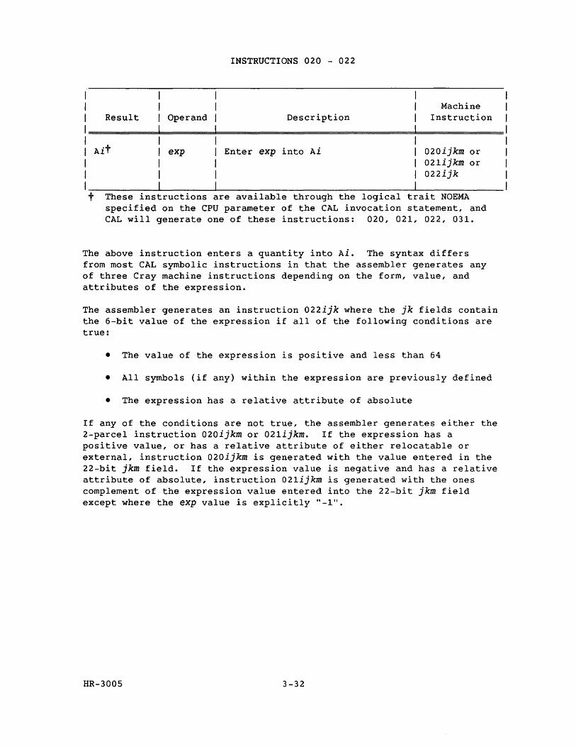
1 1 1 Result Operand
INSTRUCTIONS 020 - 022
Description Machine
Instruction
1============================================================= 1 1 Ait exp Enter exp into Ai 020ijkm or
021ijkm or 022ijk
1
1
I __________ ~--------~------------------------------~--------------t These instructions are available through the logical t ait NOEMA
specified on the CPU parameter of the CAL invocation statement, and CAL will generate one of these instructions: 020, 021, 022, 031.
The above instruction enters a quantity into Ai. The syntax differs from most CAL symbolic instructions in that the assembler generates any of three Cray machine instructions depending on the form, value, and attributes of the expression.
The assembler generates an instruction 022ijk where the jk fields contain the 6-bit value of the expression if all of the following conditions are true:
• The value of the expression is positive and less than 64
• All symbols (if any) within the expression are previously defined
• The expression has a relative attribute of absolute
If any of the conditions are not true, the assembler generates either the 2-parcel instruction 020ijkm or 021ijkm. If the expression has a positive value, or has a relative attribute of either relocatable or external, instruction 020ijkm is generated with the value entered in the 22-bit jkm field. If the expression value is negative and has a relative attribute of absolute, instruction 021ijkm is generated with the ones complement of the expression value entered into the 22-bit jkm field except where the exp value is explicitly "-1".
HR-3005 3-32
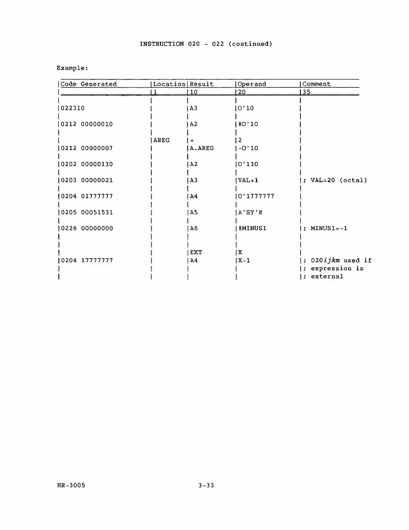
INSTRUCTION 020 - 022 (continued)
Example:
Code Generated Location Result °Eerand Comment 1 10 20 35
022310 A3 0'10
0212 00000010 A2 #0'10
AREG = 2 0212 00000007 A.AREG -0' 10
0202 00000130 A2 0'130
0203 00000021 A3 VAL+1 VAL=20 (octal)
0204 01777777 A4 0'1777777
0205 00051531 A5 A'SY'R
0226 00000000 A6 #MINUS1 MINUS1=-1
EXT X 0204 17777777 A4 X-1 020ijkm used if
expression is ; external
HR-3005 3-33
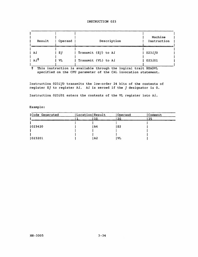
1 1 1 Result Operand
INSTRUCTION 023
Machine Description Instruction
I========~==================================~============ 1
1
1 1
Ai
Ait
Sj Transmit
VL Transmit
(Sj) to Ai 023ijO
(VL) to Ai 023iOl
I __________ ~--------~------------------------------~--------------t This inst uction is available through the logical trait READVL specified on the CPU parameter of the CAL invocation statement.
Instruction 023ijO transmits the low-order 24 bits of the contents of register Sj to register Ai. Ai is zeroed if the j designator is O.
Instruction 023iOl enters the contents of the VL register into Ai.
Example:
ICode Generated I Locationl Result I Operand I Comment
1=====================1~1=======1~1~0=========1~20~==========dl~3~5=========== 1 1 1 1 1 1023420 1 IA4 IS2 1 1 1 1 1 1 1 1 1 1 1 1 02 3201 1 1 A 2 1 VL 1
HR-3005 3-34
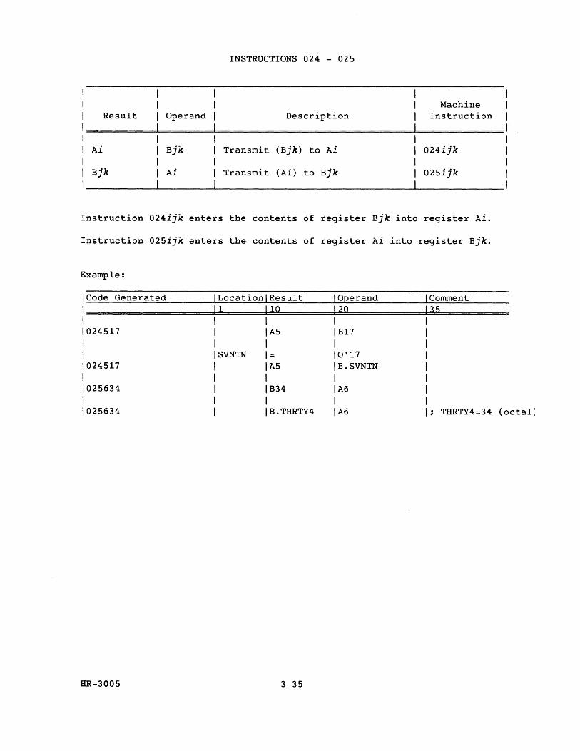
Result
Ai
Bjk
INSTRUCTIONS 024 - 025
Operand Description
Bjk Transmit (Bjk) to Ai
Ai Transmit (Ai) to Bjk
Machine Instruction
024ijk
025ijk
Instruction 024ijk enters the contents of register Bjk into register Ai.
Instruction 025ijk enters the contents of register Ai into register Bjk.
Example:
ICode Generated Location Result Operand Comment 1 1 10 20 35 1 1024517 A5 B17 1 1 SVNTN = 0' 17 1024517 A5 B.SVNTN 1 1025634 B34 A6
1 1025634 B.THRTY4 A6 THRTY4=34 (octal:
HR-3005 3-35
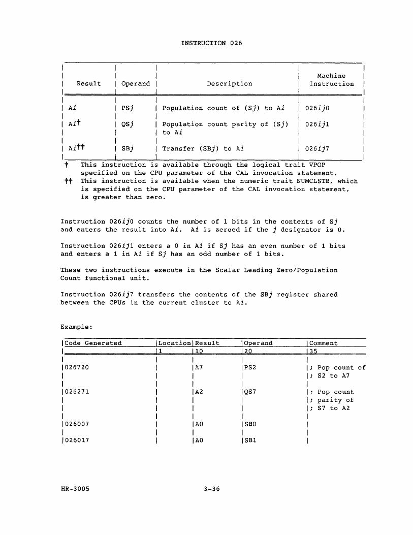
INSTRUCTION 026
Machine Result Operand Description Instruction
Ai PSj Population count of (Sj) to Ai 026ijO
Ait QSj Population count parity of (Sj) 026ij1 to Ai
Aitt SBj Transfer (SBj) to Ai 026ij7
t This instruction is available through the logical tra1t VPOP specified on the CPU parameter of the CAL invocation statement.
tt This instruction is available when the numeric trait NUMCLSTR, which is specified on the CPU parameter of the CAL invocation statement, is greater than zero.
Instruction 026ijO counts the number of 1 bits in the contents of Sj and enters the result into Ai. Ai is zeroed if the j designator is O.
Instruction 026ij1 enters a 0 in Ai if Sj has an even number of 1 bits and enters a 1 in Ai if Sj has an odd number of 1 bits.
These two instructions execute in the Scalar Leading Zero/Population Count functional unit.
Instruction 026ij7 transfers the contents of the SBj register shared between the CPUs in the current cluster to Ai.
Example:
Code Generated Location Result O:eerand Comment 1 10 20 35
026720 A7 PS2 Pop count S2 to A7
026271 A2 QS7 Pop count parity of S7 to A2
026007 AO SBO
026017 AO SB1
HR-3005 3-36
of
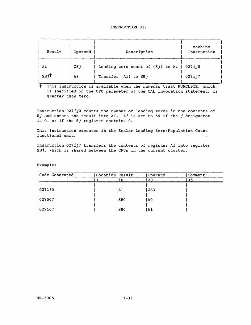
I I I Result Operand
INSTRUCTION 027
Description Machine
Instruction
I=========d=======d==========================~============ I I Ai ZSj Leading zero count of (Sj) to Ai 027ijO I I Ai Transfer (Ai) to SBj 027ij7
I __________ ~------~------------------------------~-------------t This instruction is available when the numeric trait NUMCLSTR, which
is specified on the CPU parameter of the CAL invocation statement, is greater than zero.
Instruction 027ijO counts the number of leading zeros in the contents of Sj and enters the result into Ai. Ai is set to 64 if the j designator is 0, or if the Sj register contains O.
This instruction executes in the Scalar Leading Zero/Population Count functional unit.
Instruction 027ij7 transfers the contents of register Ai into register SBj, which is shared between the CPUs in the current cluster.
Example:
ICode Generated ILocationlResult I Operand I Comment
1====================~11~====~1~10~======~12~0~==========dl~3~5=========== I I I I I 1027130 I IA1 IZS3 I I I I I I 1027007 I I SBO I AO I I I I I I 1027107 I ISBO IA1 I
HR-3005 3-37
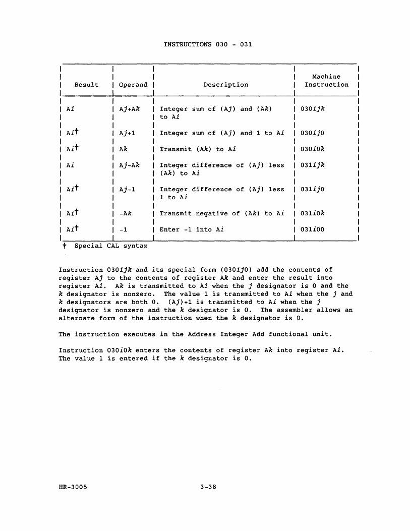
INSTRUCTIONS 030 - 031
Machine Result Operand Description Instruction
Ai Aj+Ak Integer sum of (Aj) and (Ak) 030ijk to Ai
Ait Aj+1 Integer sum of (Aj) and 1 to Ai 030ijO
Ait Ak Transmit (Ak) to Ai 030iOk
Ai Aj-Ak Integer difference of (Aj) less 031ijk (Ak) to Ai
Ait Aj-l Integer difference of (Aj) less 031ijO 1 to Ai
Ait -Ak Transmit negative of (Ak) to Ai 031iOk
Ait -1 Enter -1 into Ai 031iOO
t Special CAL syntax
Instruction 030ijk and its special form (030ijO) add the contents of register Aj to the contents of register Ak and enter the result into register Ai. Ak is transmitted to Ai when the j designator is 0 and the k designator is nonzero. The value 1 is transmitted to Ai when the j and k designators are both o. (Aj)+1 is transmitted to Ai when the j designator is nonzero and the k designator is O. The assembler allows an alternate form of the instruction when the k designator is o.
The instruction executes in the Address Integer Add functional unit.
Instruction o30iok enters the contents of register Ak into register Ai. The value 1 is entered if the k designator is o.
HR-300S 3-38
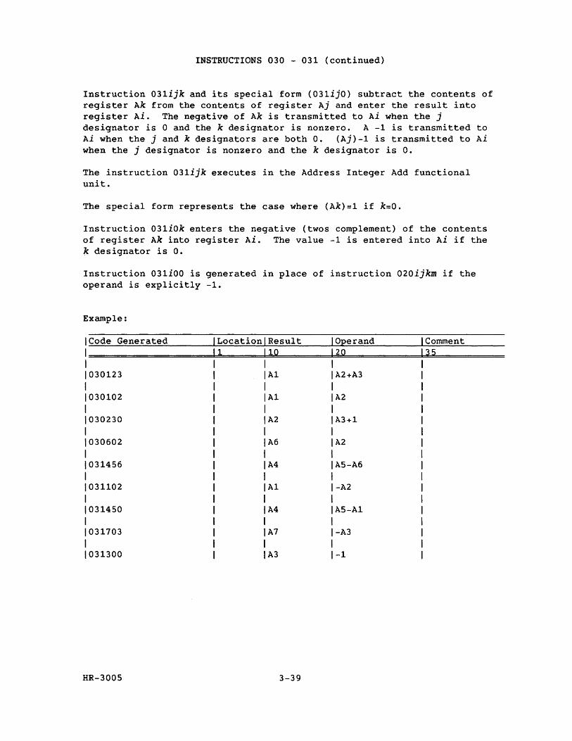
INSTRUCTIONS 030 - 031 (continued)
Instruction 031ijk and its special form (031ijO) subtract the contents of register Ak from the contents of register Aj and enter the result into register Ai. The negative of Ak is transmitted to Ai when the j designator is 0 and the k designator is nonzero. A -1 is transmitted to Ai when the j and k designators are both O. (Aj)-l is transmitted to Ai when the j designator is nonzero and the k designator is o.
The instruction 031ijk executes in the Address Integer Add functional unit.
The special form represents the case where (Ak)=l if k=O.
Instruction 031iOk enters the negative (twos complement) of the contents of register Ak into register Ai. The value -1 is entered into Ai if the k designator is o.
Instruction 031iOO is generated in place of instruction 020ijkm if the operand is explicitly -1.
Example:
Code Generated Location Result Operand Comment 1 10 20 35
030123 A1 A2+A3
030102 A1 A2
030230 A2 A3+1
030602 A6 A2
031456 A4 AS-A6
031102 A1 -A2
031450 A4 AS-A1
031703 A7 -A3
031300 A3 -1
HR-300S 3-39
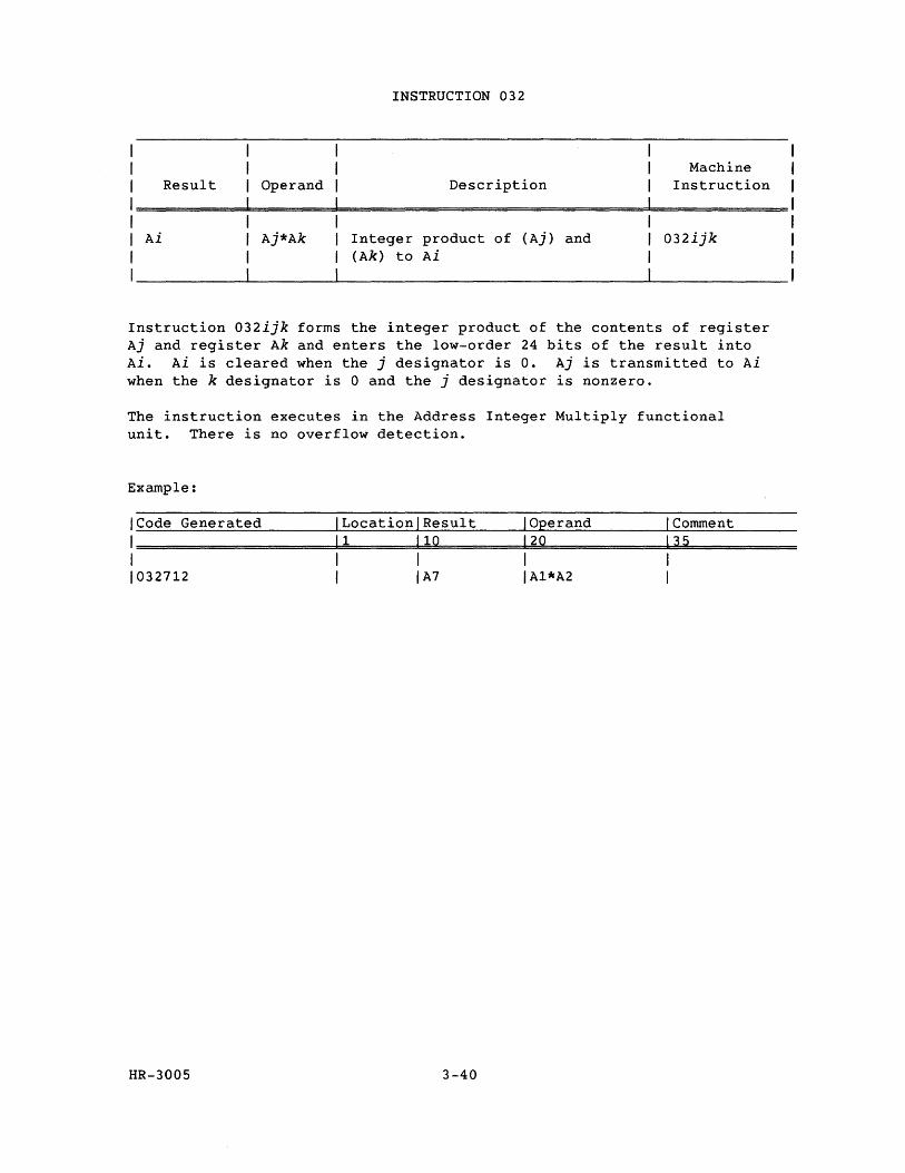
Result Operand
INSTRUCTION 032
Description Machine
Instruction
Ai Aj*Ak Integer product of (Aj) and (Ak) to Ai
032ijk
Instruction 032ijk forms the integer product of the contents of register Aj and register Ak and enters the low-order 24 bits of the result into Ai. Ai is cleared when the j designator is o. Aj is transmitted to Ai when the k designator is 0 and the j designator is nonzero.
The instruction executes in the Address Integer Multiply functional unit. There is no overflow detection.
Example:
ICode Generated ILocationlResult I Operand I Comment
1=====================1~1~======1~10~========1~2~0=============1~3~5=========== 1 1 1 1 1 1032712 1 IA7 IA1*A2 1
HR-3005 3-40
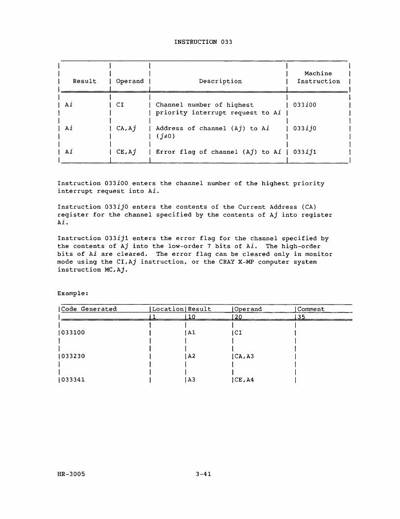
INSTRUCTION 033
Machine Result Operand Description Instruction
Ai CI Channel number of highest 033iOO priority interrupt request to Ai
Ai CA,Aj Address of channel (Aj) to Ai 033ijO (jiO)
Ai CE,Aj Error flag of channel (Aj) to Ai 033ij1
Instruction 033iOO enters the channel number of the highest priority interrupt request into Ai.
Instruction 033ijO enters the contents of the Current Address (CA) register for the channel specified by the contents of Aj into register Ai.
Instruction 033ij1 enters the error flag for the channel specified by the contents of Aj into the low-order 7 bits of Ai. The high-order bits of Ai are cleared. The error flag can be cleared only in monitor mode using the CI,Aj instruction, or the CRAY X-MP computer system instruction MC,Aj.
Example:
ICode Generated Location Result Operand Comment
1======================1========1=0~=========20~============3~5~========== 1
1033100 1
1
1033230 1
1
1033341
HR-3005
A1
A2
A3
CI
CA,A3
CE,A4
3-41
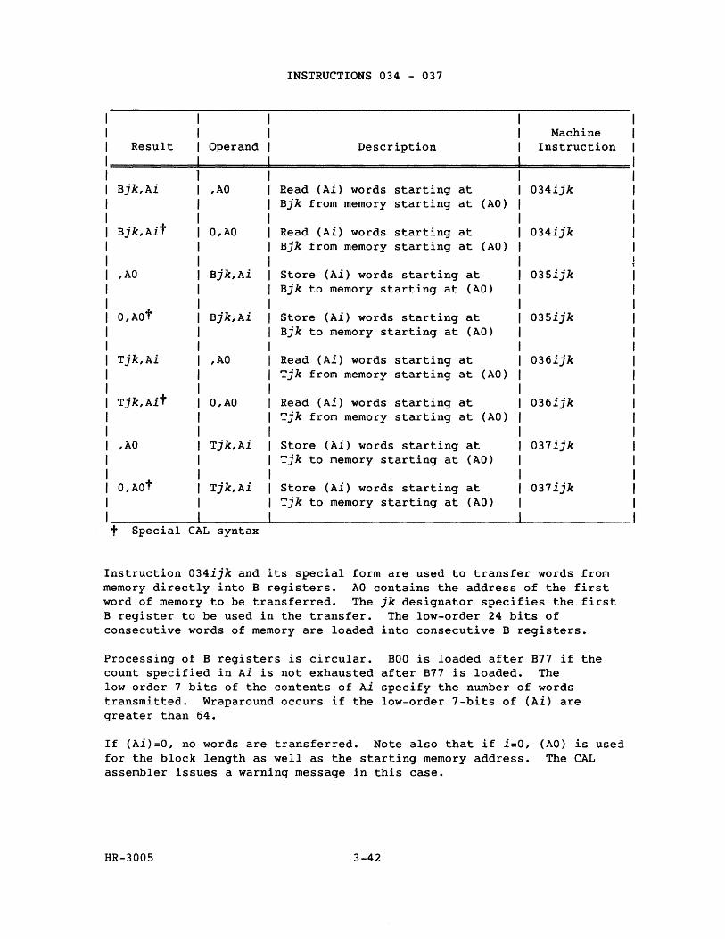
INSTRUCTIONS 034 - 037
Machine Result Operand Description Instruction
Bjk,Ai ,AO Read (Ai) words starting at 034ijk Bjk from memory starting at (AO)
Bjk,Ait O,AO Read (Ai) words starting at 034ijk Bjk from memory starting at (AO)
,AO Bjk,Ai Store (Ai) words starting at 035ijk Bjk to memory starting at (AO)
O,AOt Bjk,Ai Store (Ai) words starting at 035ijk Bjk to memory starting at (AO)
Tjk,Ai ,AO Read (Ai) words starting at 036ijk Tjk from memory starting at (AO)
Tjk,Ait O,AO Read (Ai) words starting at 036ijk Tjk from memory starting at (AO)
,AO Tjk,Ai Store (Ai) words starting at 037ijk Tjk to memory starting at (AO)
O,AOt Tjk,Ai Store (Ai) words starting at 037ijk Tjk to memory starting at (AO)
t Special CAL syntax
Instruction 034ijk and its special form are used to transfer words from memory directly into B registers. AO contains the address of the first word of memory to be transferred. The jk designator specifies the first B register to be used in the transfer. The low-order 24 bits of consecutive words of memory are loaded into consecutive B registers.
Processing of B registers is circular. BOO is loaded after B77 if the count specified in Ai is not exhausted after B77 is loaded. The low-order 7 bits of the contents of Ai specify the number of words transmitted. Wraparound occurs if the low-order 7-bits of (Ai) are greater than 64.
If (Ai)=o, no words are transferred. Note also that if i=O, (AO) is used for the block length as well as the starting memory address. The CAL assembler issues a warning message in this case.
HR-3005 3-42
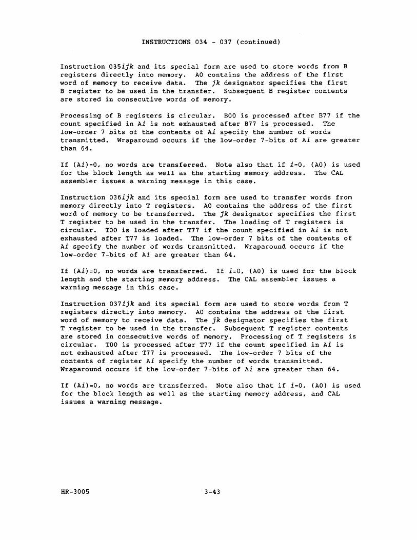
INSTRUCTIONS 034 - 037 (continued)
Instruction 035ijk and its special form are used to store words from B registers directly into memory. AO contains the address of the first word of memory to receive data. The jk designator specifies the first B register to be used in the transfer. Subsequent B register contents are stored in consecutive words of memory.
Processing of B registers is circular. count specified in Ai is not exhausted low-order 7 bits of the contents of Ai transmitted. Wraparound occurs if the than 64.
BOO is processed after B77 if the after B77 is processed. The specify the number of words low-order 7-bits of Ai are greater
If (Ai)=O, no words are transferred. Note also that if i=O, (AO) is used for the block length as well as the starting memory address. The CAL assembler issues a warning message in this case.
Instruction 036ijk and its special form are used to transfer words from memory directly into T registers. AO contains the address of the first word of memory to be transferred. The jk designator specifies the first T register to be used in the transfer. The loading of T registers is circular. TOO is loaded after T77 if the count specified in Ai is not exhausted after T77 is loaded. The low-order 7 bits of the contents of Ai specify the number of words transmitted. Wraparound occurs if the low-order 7-bits of Ai are greater than 64.
If (Ai)=O, no words are transferred. If i=O, (AO) is used for the block length and the starting memory address. The CAL assembler issues a warning message in this case.
Instruction 037ijk and its special form are used to store words from T registers directly into memory. AO contains the address of the first word of memory to receive data. The jk designator specifies the first T register to be used in the transfer. Subsequent T register contents are stored in consecutive words of memory. Processing of T registers is circular. TOO is processed after T77 if the count specified in Ai is not exhausted after T77 is processed. The low-order 7 bits of the contents of register Ai specify the number of words transmitted. Wraparound occurs if the low-order 7-bits of Ai are greater than 64.
If (Ai)=O, no words are transferred. Note also that if i=O, (AO) is used for the block length as well as the starting memory address, and CAL issues a warning message.
HR-3005 3-43
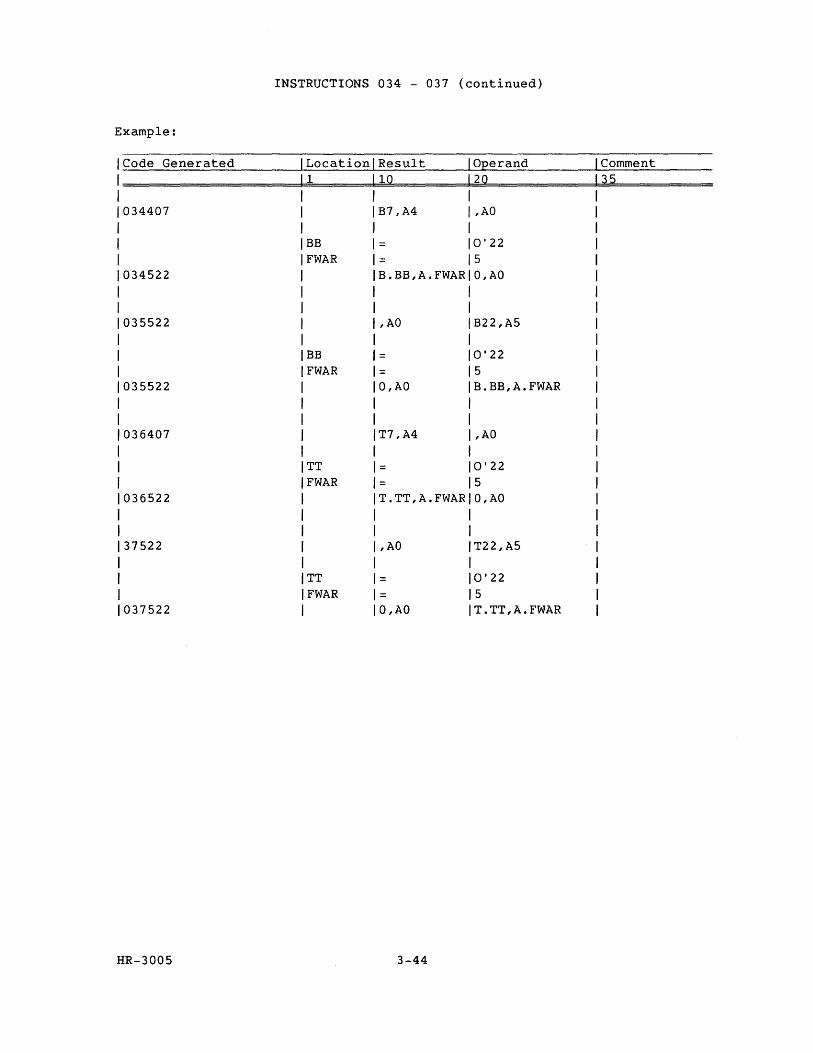
INSTRUCTIONS 034 - 037 (continued)
Example:
Code Generated Location Result Operand Comment 1 10 20 35
034407 B7,A4 ,AD
BB 0' 22 FWAR = 5
034522 B.BB,A..FWAR O,AO
035522 ,AD B22,A5
BB 0' 22 FWAR 5
035522 O,AO B.BB,A.FWAR
036407 T7,A4 ,AD
TT = 0' 22 FWAR = 5
036522 T.TT,A.FWAR O,AO
37522 ,AD T22,A5
TT = 0' 22 FWAR 5
037522 O,AO T.TT,A.FWAR
HR-3005 3-44
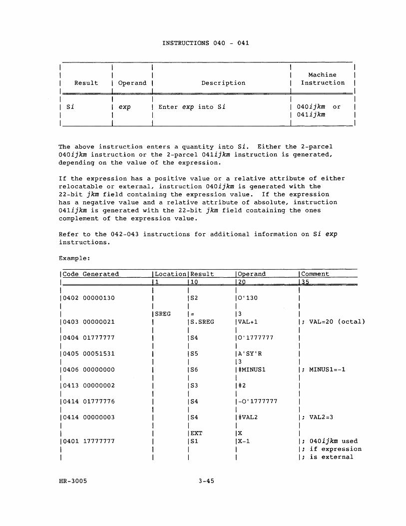
Result Operand
Si exp
INSTRUCTIONS 040 - 041
Description
Enter exp into Si
Machine Instruction
040ijkm or 041ijkm
The above instruction enters a quantity into si. Either the 2-parcel 040ijkm instruction or the 2-parcel 041ijkm instruction is generated, depending on the value of the expression.
If the expression has a positive value or a relative attribute of either relocatable or external, instruction 040ijkm is generated with the 22-bit jkm field containing the expression value. If the expression has a negative value and a relative attribute of absolute, instruction 041ijkm is generated with the 22-bit jkm field containing the ones complement of the expression value.
Refer to the 042-043 instructions for additional information on Si exp instructions.
Example:
Code Generated Location Result 1 10
0402 00000130 S2
SREG = 0403 00000021 S.SREG
0404 01777777 S4
0405 00051531 S5
0406 00000000 S6
0413 00000002 S3
0414 01777776 S4
0414 00000003 S4
EXT 0401 17777777 S1
HR-3005 3-45
Operand 20
0'130
3 VAL+1
0'1777777
A'SY'R 3 #MINUS1
#2
-0'1777777
#VAL2
X X-1
Comment 35
VAL=20 (octal)
MINUS1=-1
VAL2=3
040ijkm used ; if expression
is external
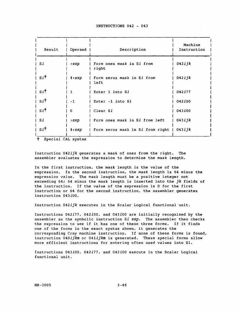
INSTRUCTIONS 042 - 043
Machine Result Operand Description Instruction
Si <exp Form ones mask in Si from 042ijk right
Sit #>exp Form zeros mask in Si from 042ijk left
Sit 1 Enter 1 into Si 042i77
Sit -1 Enter -1 into Si 042iOO
Sit 0 Clear si 043iOO
Si >exp Form ones mask in si from left 043ijk
Sit #<exp Form zeros mask in Si from right 043ijk
t Special CAL syntax
Instruction 042ijk generates a mask of ones from the right. The assembler evaluates the expression to determine the mask length.
In the first instruction, the mask length is the value of the expression. In the second instruction, the mask length is 64 minus the expression value. The mask length must be a positive integer not exceeding 64; 64 minus the mask length is inserted into the jk fields of the instruction. If the value of the expression is 0 for the first instruction or 64 for the second instruction, the assembler generates instruction 043iOO.
Instruction 042ijk executes in the Scalar Logical functional unit.
Instructions 042i77, 042iOO, and 043iOO are initially recognized by the assembler as the symbolic instruction Si expo The assembler then checks the expression to see if it has one of these three forms. If it finds one of the forms in the exact syntax shown, it generates the corresponding Cray machine instruction. If none of these forms is found, instruction 040ijkm or 041ijkm is generated. These special forms allow more efficient instructions for entering often used values into S1.
Instructions 043iOO, 042i77, and 042iOO execute in the Scalar Logical functional unit.
HR-3005 3-46
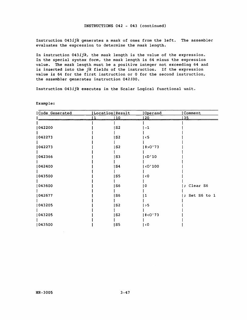
INSTRUCTIONS 042 - 043 (continued)
Instruction 043ijk generates a mask of ones from the left. The assembler evaluates the expression to determine the mask length.
In instruction 043ijk, the mask length is the value of the expression. In the special syntax form, the mask length is 64 minus the expression value. The mask length must be a positive integer not exceeding 64 and is inserted into the jk fields of the instruction. If the expression value is 64 for the first instruction or 0 for the second instruction, the assembler generates instruction 042iOO.
Instruction 043ijk executes in the Scalar Logical functional unit.
Example:
Code Generated Location Result Operand Comment 1 10 20 35
042200 S2 -1
042273 S2 <5
042273 S2 #>0'73
042366 S3 <0'10
042400 S4 <0'100
043500 S5 <0
043600 S6 0 ; Clear 86
042677 S6 1 Set S6 to 1
043205 82 >5
043205 S2 # <0' 73
043500 S5 <0
HR-3005 3-47
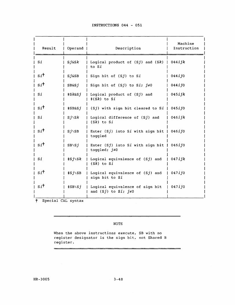
t
INSTRUCTIONS 044 - 051
Result Operand Description
Si Sj&Sk Logical product of (Sj) and (Sk) to Si
Sit Sj&SB Sign bit of (Sj) to Si
Sit SB&Sj Sign bit of (Sj) to Si; ji:O
si #Sk&Sj Logical product of (Sj) and #(Sk) to Si
Sit #SB&Sj (Sj) with sign bit cleared to si
Si Sj\Sk Logical difference of (Sj) and (Sk) to Si
Sit Sj\SB Enter (Sj) into Si with sign bit toggled
Sit SB\Sj Enter (Sj) into Si with sign bit toggled; jl:O
Si #Sj\Sk Logical equivalence of (Sj) and (Sk) to Si
Sit #Sj\SB Logical equivalence of (Sj) and sign bit to si
Sit #SB\Sj Logical equivalence of sign bit and (Sj) to Si; jl:O
Special CAL syntax
NOTE
When the above instructions execute, SB with no register designator is the sign bit, not Shared B register.
HR-3005 3-48
Machine Instruction
044ijk
044ijO
044ijO
045ijk
045ijO
046ijk
046ijO
046ijO
047ijk
047ijO
047ijO
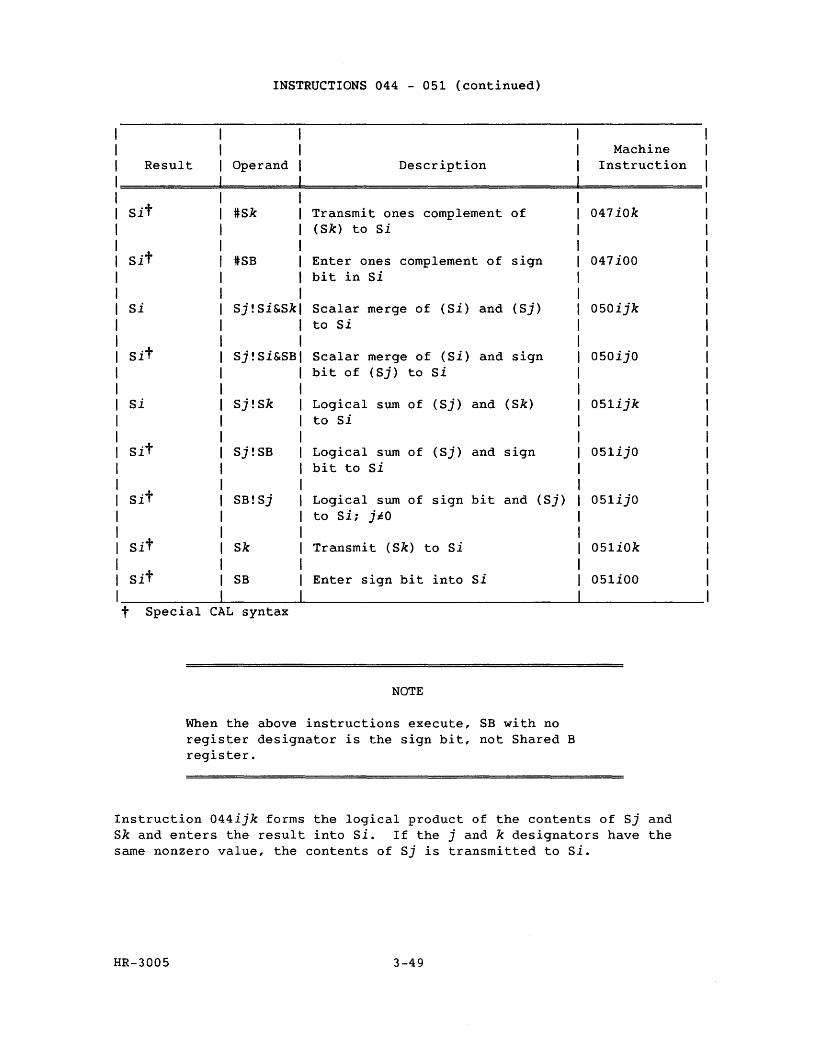
t
INSTRUCTIONS 044 - 051 (continued)
Result Operand Description
Sit #Sk Transmit ones complement of (Sk) to si
Sit #SB Enter ones complement of sign bit in Si
Si Sj!Si&Sk Scalar merge of (Si) and (Sj) to Si
Sit Sj!Si&SB Scalar merge of (Si) and sign bit of (Sj) to Si
Si Sj!Sk Logical sum of (Sj) and (Sk) to Si
Sit Sj!SB Logical sum of (Sj) and sign bit to Si
Sit SB!Sj Logical sum of sign bit and (Sj) to Si; j~O
Sit Sk Transmit ( Sk) to Si
Sit SB Enter sign bit into Si
Special CAL syntax
NOTE
When the above instructions execute, SB with no register designator is the sign bit, not Shared B register.
Machine Instruction
047iOk
047iOO
050ijk
050ijO
051ijk
051ijO
051ijO
051iOk
051iOO
Instruction 044ijk forms the logical product of the contents of Sj and Sk and enters the result into Si. If the j and k designators have the same nonzero value, the contents of Sj is transmitted to Si.
HR-3005 3-49
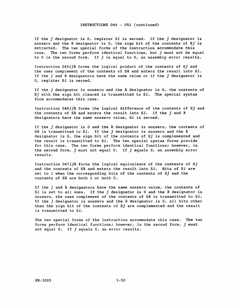
INSTRUCTIONS 044 - 051 (continued)
If the j designator is 0, register Si is zeroed. If the j designator is nonzero and the k designator is 0, the sign bit of the contents of Sj is extracted. The two special forms of the instruction accommodate this case. The two forms perform identical functions, but j must not be equal to 0 in the second form. If j is equal to 0, an assembly error results.
Instruction 045ijk forms the logical product of the contents of Sj and the ones complement of the contents of Sk and enters the result into Si. If the j and k designators have the same value or if the j designator is 0, register Si is zeroed.
If the j designator is nonzero and the k designator is 0, the contents of Sj with the sign bit cleared is transmitted to Si. The special syntax form accommodates this case.
Instruction 046ijk forms the logical difference of the contents of Sj and the contents of Sk and enters the result into Si. If the j and k designators have the same nonzero value, Si is zeroed.
If the j designator is 0 and the k designator is nonzero, the contents of Sk is transmitted to Si. If the j designator is nonzero and the k designator is 0, the sign bit of the contents of Sj is complemented and the result is transmitted to Si. The two special syntax forms provide for this case. The two forms perform identical functions; however, in the second form, j must not equal O. If j equals 0, an assembly error results.
Instruction 047ijk forms the logical equivalence of the contents of Sj and the contents of Sk and enters the result into si. Bits of Si are set to 1 when the corresponding bits of the contents of Sj and the contents of Sk are both 1 or both O.
If the j and k designators have the same nonzero value, the contents of Si is set to all ones. If the j designator is 0 and the k designator is nonzero, the ones complement of the contents of Sk is transmitted to Si. If the j designator is nonzero and the k designator is 0, all bits other than the sign bit of the contents of Sj are complemented and the result is transmitted to Si.
The two special forms of the instruction accommodate this case. The two forms perform identical functions; however, in the second form, j must not equal O. If j equals 0, an error results.
HR-3005 3-50
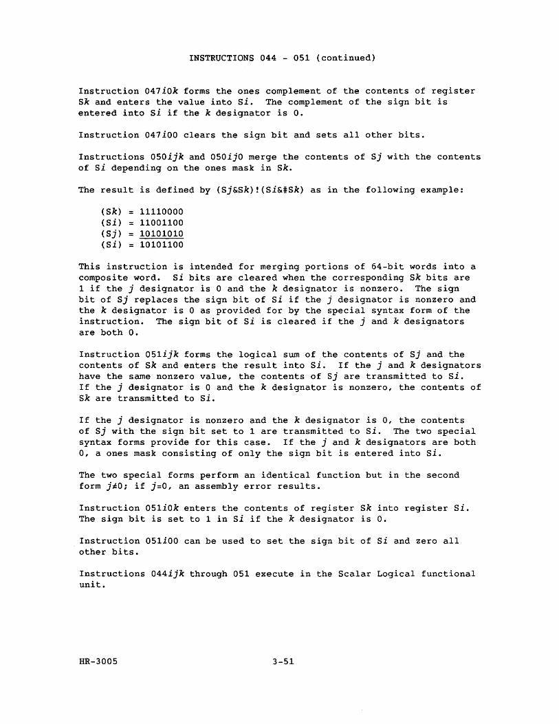
INSTRUCTIONS 044 - OSl (continued)
Instruction 047iOk forms the ones complement of the contents of register Sk and enters the value into Si. The complement of the sign bit is entered into Si if the k designator is o.
Instruction 047iOO clears the sign bit and sets all other bits.
Instructions OSOijk and OSOijO merge the contents of Sj with the contents of Si depending on the ones mask in Sk.
The result is defined by (Sj&Sk)!(Si&#Sk) as in the following example:
(Sk) = 11110000 (Si) = 11001100 (Sj) = 10101010 (Si) = 10101100
This instruction is intended for merging portions of 64-bit words into a composite word. Si bits are cleared when the corresponding Sk bits are 1 if the j designator is 0 and the k designator is nonzero. The sign bit of Sj replaces the sign bit of Si if the j designator is nonzero and the k designator is 0 as provided for by the special syntax form of the instruction. The sign bit of Si is cleared if the j and k designators are both O.
Instruction OSlijk forms the logical sum of the contents of Sj and the contents of Sk and enters the result into Si. If the j and k designators have the same nonzero value, the contents of Sj are transmitted to Si. If the j designator is 0 and the k designator is nonzero, the contents of Sk are transmitted to Si.
If the j designator is nonzero and the k designator is 0, the contents of Sj with the sign bit set to 1 are transmitted to Si. The two special. syntax forms provide for this case. If the j and k designators are both 0, a ones mask consisting of only the sign bit is entered into Si.
The two special forms perform an identical function but in the second form j~O; if j=O, an assembly error results.
Instruction OSliOk enters the contents of register Sk into register Si. The sign bit is set to 1 in Si if the k designator is O.
Instruction OSliOO can be used to set the sign bit of Si and zero all other bits.
Instructions 044ijk through OSl execute in the Scalar Logical functional unit.
HR-300S 3-S1
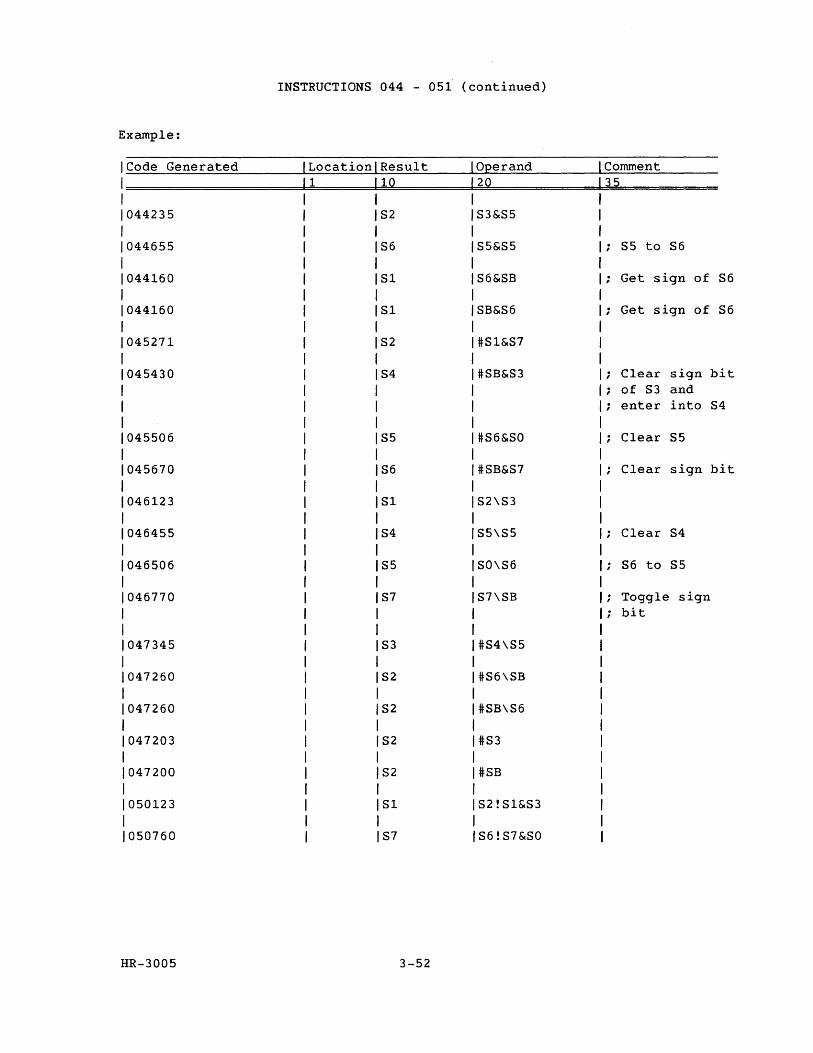
INSTRUCTIONS 044 - 05f (continued)
Example:
Code Generated ILocation Result IOEerand Comment
11 lQ 12Q 35 1 1
044235 1 S2 IS3&S5 1 1
044655 1 S6 IS5&S5 S5 to S6
1 1 044160 1 SI IS6&SB Get sign of S6
1 1 044160 SI SB&S6 Get sign of S6
045271 S2 #SI&S7
045430 S4 #SB&S3 ; Clear sign bit of S3 and
; enter into S4
045506 S5 #S6&SO Clear S5
045670 S6 #SB&S7 Clear sign bit
046123 SI S2\S3
046455 S4 S5\S5 Clear S4
046506 S5 SO\S6 S6 to S5
046770 S7 S7\SB Toggle sign bit
047345 S3 #S4\S5
047260 S2 #S6\SB
047260 S2 #SB\S6
047203 S2 #S3
047200 S2 #SB
050123 SI S2!SI&S3
050760 S7 S6!S7&SO
HR-3005 3-52
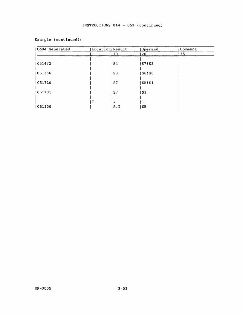
INSTRUCTIONS 044 - 051 (continued)
Example (continued):
Code Generated Location Result Operand Comment 1 10 20 35
051472 S4 S7!S2
051366 S3 S6!S6
051710 S7 SB!Sl
051701 S7 Sl
I = 1 051100 S.I SB
HR-3005 3-53
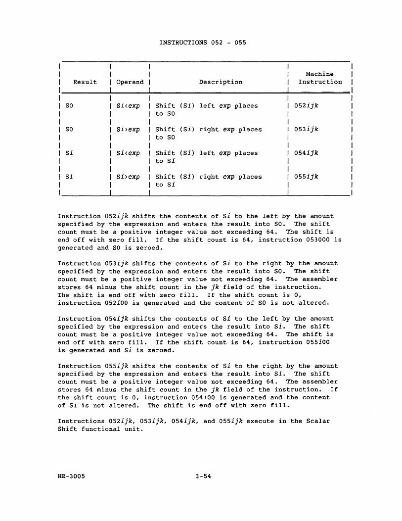
INSTRUCTIONS 052 - 055
Machine Result Operand Description Instruction
SO Si<exp Shift (Si) left exp places 052ijk to SO
SO si>exp Shift (Si) right exp places 053ijk to SO
Si Si<exp Shift (Si) left exp places 054ijk to Si
si Si>exp Shift (Si) right exp places 055ijk to Si
Instruction 052ijk shifts the contents of Si to the left by the amount specified by the expression and enters the result into SO. The shift count must be a positive integer value not exceeding 64. The shift is end off with zero fill. If the shift count is 64, instruction 053000 is generated and SO is zeroed.
Instruction 053ijk shifts the contents of Si to the right by the amount specified by the expression and enters the result into SO. The shift count must be a positive integer value not exceeding 64. The assembler stores 64 minus the shift count in the jk field of the instruction. The shift is end off with zero fill. If the shift count is 0, instruction 052iOO is generated and the content of SO is not altered.
Instruction 054ijk shifts the contents of si to the left by the amount specified by the expression and enters the result into Si. The shift count must be a positive integer value not exceeding 64. The shift is end off with zero fill. If the shift count is 64, instruction 055iOO is generated and Si is zeroed.
Instruction 055ijk shifts the contents of Si to the right by the amount specified by the expression and enters the result into Si. The shift count must be a positive integer value not exceeding 64. The assembler stores 64 minus the shift count in the jk field of the instruction. If the shift count is 0, instruction 054iOO is generated and the content of si is not altered. The shift is end off with zero fill.
Instructions 052ijk, 053ijk, 054ijk, and 055ijk execute in the Scalar Shift functional unit.
HR-3005 3-54
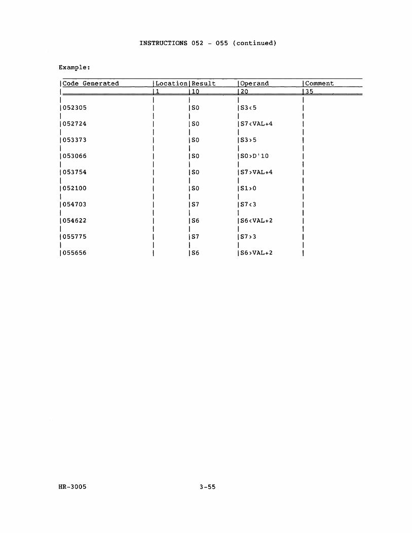
INSTRUCTIONS 052 - 055 (continued)
Example:
Code Generated Location Result Operand Comment 1 10 20 35
052305 SO S3<5
052724 SO S7<VAL+4
053373 SO S3>5
053066 SO SO>D'10
053754 SO S7>VAL+4
052100 SO Sl>O
054703 S7 S7<3
054622 S6 S6<VAL+2
055775 S7 S7>3
055656 S6 S6>VAL+2
HR-3005 3-55
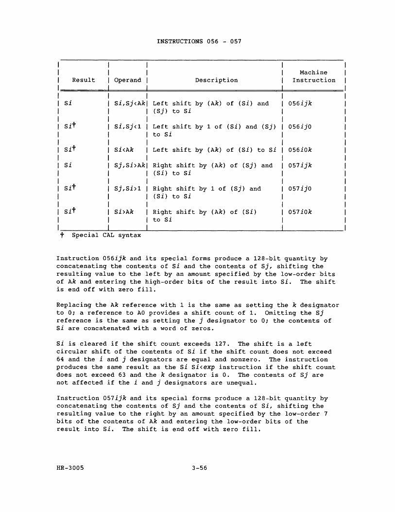
INSTRUCTIONS 056 - 057
Machine Result Operand Description Instruction
Si Si,Sj<Ak Left shift by (Ak) of (Si) and 056ijk (Sj) to si
Sit Si,Sj<1 Left shift by 1 of (Si) and (Sj) 056ijO to Si
Sit Si<Ak Left shift by (Ak) of (Si) to si 056iOk
Si Sj,Si>Ak Right shift by (Ak) of (Sj) and 057ijk (Si) to Si
Sit sj,Si>1 Right shift by 1 of (Sj) and 057ijO (Si) to si
Sit Si>Ak Right shift by (Ak) of (Si) 057iOk to Si
t Special CAL syntax
Instruction 056ijk and its special forms produce a 128-bit quantity by concatenating the contents of Si and the contents of Sj, shifting the resulting value to the left by an amount specified by the low-order bits of Ak and entering the high-order bits of the result into si. The shift is end off with zero fill.
Replacing the Ak reference with 1 is the same as setting the k designator to 0; a reference to AO provides a shift count of 1. Omitting the Sj reference is the sarne as setting the j designator to 0; the contents of Si are concatenated with a word of zeros.
Si is cleared if the shift count exceeds 127. The shift is a left circular shift of the contents of Si if the shift count does not exceed 64 and the i and j designators are equal and nonzero. The instruction produces the same result as the Si Si<exp instruction if the shift count does not exceed 63 and the k designator is O. The contents of Sj are not affected if the i and j designators are unequal.
Instruction 057ijk and its special forms produce a 128-bit quantity by concatenating the contents of Sj and the contents of Si, shifting the resulting value to the right by an amount specified by the low-order 7 bits of the contents of Ak and entering the low-order bits of the result into Si. The shift is end off with zero fill.
HR-3005 3-56
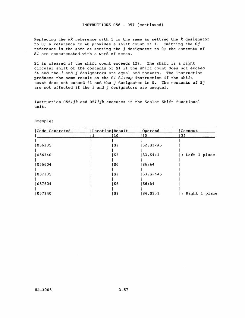
INSTRUCTIONS 056 - 057 (continued)
Replacing the Ak reference with 1 is the same as setting the k designator to 0; a reference to AO provides a shift count of 1. Omitting the Sj reference is the same as setting the j designator to 0; the contents of si are concatenated with a word of zeros.
si is cleared if the shift count exceeds 127. The shift is a right circular shift of the contents of si if the shift count does not exceed 64 and the i and j designators are equal and nonzero. The instruction produces the same result as the Si Si>exp instruction if the shift count does not exceed 63 and the j designator is O. The contents of Sj are not affected if the i and j designators are unequal.
Instruction 056ijk and 057ijk executes in the Scalar Shift functional unit.
Example:
Code Generated Location Result Operand Comment 1 10 20 35
056235 S2 S2,S3<A5
056340 S3 S3,S4<1 Left 1 place
056604 S6 S6<A4
057235 S2 S3,S2>A5
057604 S6 S6>A4
057340 S3 S4,S3>1 Right 1 place
HR-3005 3-57
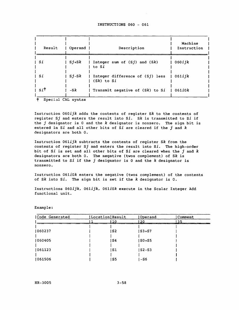
INSTRUCTIONS 060 - 061
Machine Result Operand Description Instruction
Si Sj+Sk Integer sum o£ (Sj) and (Sk) 060ijk to si
Si Sj-Sk Integer difference of (Sj) less 061ijk (Sk) to Si
Sit -Sk Transmit negative of (Sk) to si 061iOk
t Speci~l CAL syntax
Instruction 060ijk adds the contents of register Sk to the contents of register Sj and enters the result into Si. Sk is transmitted to Si if the j designator is 0 and the k designator is nonzero. The sign bit is entered in si and all other bits of Si are cleared if the j and k designators are both o.
Instruction 061ijk subtracts the contents of register Sk from the contents of register Sj and enters the result into si. The high-order bit of Si is set and all other bits of Si are cleared when the j and k designators are both O. The negative (twos complement) of Sk is transmitted to Si if the j designator is 0 and the k designator is nonzero.
Instruction 061iok enters the negative (twos complement) of the contents of Sk into Si. The sign bit is set if the k designator is o.
Instructions 060ijk, 061ijk, 061iOk execute in the Scalar Integer Add functional unit.
Example:
ICode Generated Location Result Operand Comment 1 1 10 20 35 1 1060237 S2 S3+S7 1 1060405 S4 SO+S5 1 1061123 S1 S2-S3 1 1061506 S5 -S6
HR-3005 3-58
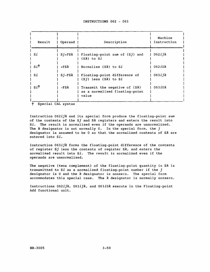
INSTRUCTIONS 062 - 063
Machine Result Operand Description Instruction
Si Sj+FSk Floating-point sum of (Sj) and 062ijk (Sk) to si
Sit +FSk Normalize (Sk) to Si 062iOk
Si Sj-FSk Floating-point difference of 063ijk (Sj) less (Sk) to Si
Sit -FSk Transmit the negative of (Sk) 063iOk as a normalized floating-point value
t Special CAL syntax
Instruction 062ijk and its special form produce the floating-point sum of the contents of the Sj and Sk registers and enters the result into Si. The result is normalized even if the operands are unnormalized. The k designator is not normally O. In the special form, the j designator is assumed to be 0 so that the normalized contents of Sk are entered into Si.
Instruction 063ijk forms the floating-point difference of the contents of register Sj less the contents of register Sk, and enters the normalized result into Si. The result is normalized even if the operands are unnormalized.
The negative (twos complement) of the floating-point quantity in Sk is transmitted to Si as a normalized floating-point number if the j designator is 0 and the k designator is nonzero. The special form accommodates this special case. The k designator is normally nonzero.
Instructions 062ijk, 063ijk, and 063iOk execute in the Floating-point Add functional unit.
HR-3005 3-59

INSTRUCTIONS 062 - 063 (continued)
Example:
ICode Generated Comment Location Result Operand
1===================d=======d==========~============~3=5========== 1 10 20 1
1062345 1
1062404 1
1063302 1
1063761
HR-3005
S3
S4
S3
S7
S4+FS5
+FS4
-FS2
S6-FS1
3-60
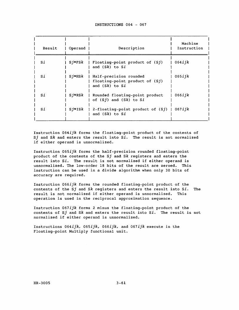
INSTRUCTIONS 064 - 067
Machine Result Operand Description Instruction
Si Sj*FSk Floating-point product of (Sj) 064ijk and (Sk) to Si
Si Sj*HSk Half-precision rounded 065ijk floating-point product of (Sj) and (Sk) to si
Si Sj*RSk Rounded floating-point product 066ijk of (Sj) and (Sk) to Si
Si Sj*ISk 2-floating-point product of (Sj) 067ijk and (Sk) to Si
Instruction 064ijk forms the floating-point product of the contents of Sj and Sk and enters the result into Si. The result is not normalized if either operand is unnormalized.
Instruction 065ijk forms the half-precision rounded floating-point product of the contents of the Sj and Sk registers and enters the result into Si. The result is not normalized if either operand is unnormalized. The low-order 18 bits of the result are zeroed. This instruction can be used in a divide algorithm when only 30 bits of accuracy are required.
Instruction 066ijk forms the rounded floating-point product of the contents of the Sj and Sk registers and enters the result into Si. The result is not normalized if either operand is unnormalized. This operation is used in the reciprocal approximation sequence.
Instruction 067ijk forms 2 minus the floating-point product of the contents of Sj and sk and enters the result into Si. The result is not normalized if either operand is unnormalized.
Instructions 064ijk, 065ijk, 066ijk, and 067ijk execute in the Floating-point Multiply functional unit.
HR-3005 3-61
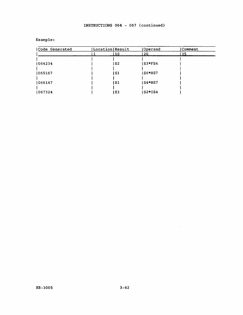
INSTRUCTIONS 064 - 067 (continued)
Example:
ICode Generated Comment Location Result Operand 1 10 20 1====================~======~========~=============3~5===========
1
1064234 1
1065167 1
1066147 1
1067324
HR-3005
S2
Sl
Sl
S3
S3*FS4
S6*HS7
S4*RS7
S2*IS4
3-62
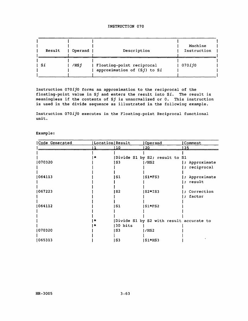
Result Operand
Si IHSj
INSTRUCTION 070
Description
Floating-point reciprocal approximation of (Sj) to Si
Machine Instruction
070ijO
Instruction 070ijO forms an approximation to the reciprocal of the floating-point value in Sj and enters the result into Si. The result is meaningless if the contents of Sj is unnormalized or O. This instruction is used in the divide sequence as illustrated in the following example.
Instruction 070ijO executes in the Floating-point Reciprocal functional unit.
Example:
Code Generated Location Result I Operand I Comment 1 10 120 135
I I * Divide Sl by S2; result to Sl
070320 S3 IHS2 Approximate reciprocal
064113 Sl Sl*FS3 ; Approximate result
067223 S2 S2*IS3 Correction . factor ,
064112 Sl Sl*FS2
* Divide Sl by S2 with result accurate to * 30 bits I
070320 S3 I/HS2 I
065313 S3 IS1*HS3
HR-3005 3-63
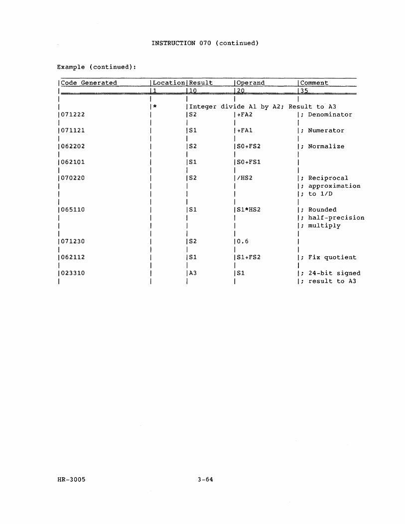
INSTRUCTION 070 (continued)
Example (continued) :
Code Generated Location Result IOEerand 1 Comment 1 1Q 12Q 135
I I * Integer divide A1 by A2; Result to A3
071222 S2 +FA2 Denominator
071121 Sl +FA1 Numerator
062202 S2 SO+FS2 Normalize
062101 Sl SO+FS1
070220 S2 IHS2 Reciprocal approximation to liD
065110 Sl Sl*HS2 Rounded half-precision multiply
071230 S2 0.6
062112 Sl Sl+FS2 Fix quotient
023310 A3 Sl 24-bit signed result to A3
HR-3005 3-64
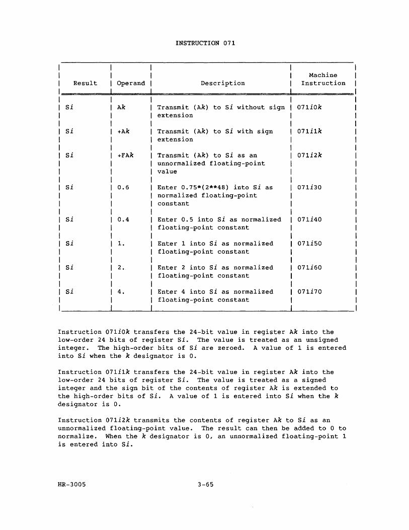
Result Operand
Si Ak
Si +Ak
Si +FAk
Si 0.6
Si 0.4
Si 1.
Si 2.
Si 4.
INSTRUCTION 071
Description
Transmit (Ak) to Si without sign extension
Transmit (Ak) to Si with sign extension
Transmit (Ak) to Si as an unnormalized floating-point value
Enter 0.75*(2**48) into Si as normalized floating-point constant
Enter 0.5 into Si as normalized floating-point constant
Enter 1 into Si as normalized floating-point constant
Enter 2 into Si as normalized floating-point constant
Enter 4 into Si as normalized floating-point constant
Machine Instruction
071iOk
071i1k
071i2k
071i30
071i40
071i50
071i60
071i70
Instruction 071iOk transfers the 24-bit value in register Ak into the low-order 24 bits of register Si. The value is treated as an unsigned integer. The high-order bits of Si are zeroed. A value of 1 is entered into Si when the k designator is o.
Instruction 071i1k transfers the 24-bit value in register Ak into the low-order 24 bits of register Si. The value is treated as a signed integer and the sign bit of the contents of register Ak is extended to the high-order bits of Si. A value of 1 is entered into Si when the k designator is o.
Instruction 071i2k transmits the contents of register Ak to Si as an unnormalized floating-point value. The result can then be added to 0 to normalize. When the k designator is 0, an unnormalized floating-point 1 is entered into Si.
HR-3005 3-65
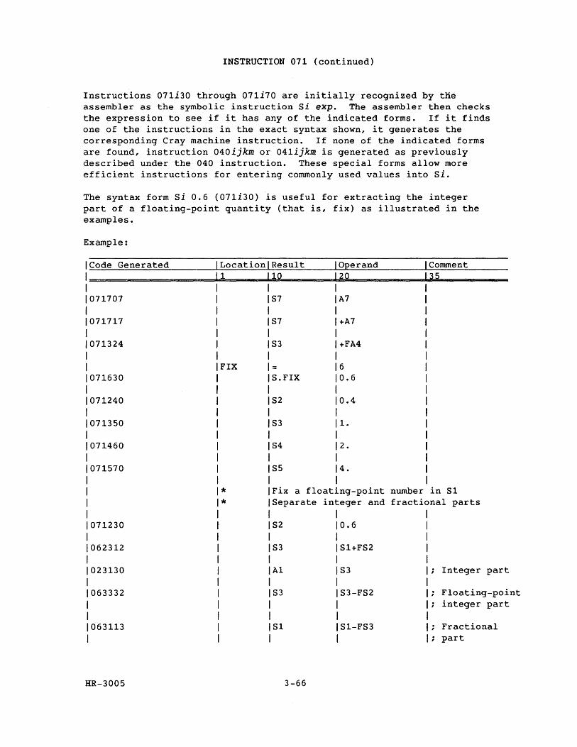
INSTRUCTION 071 (continued)
Instructions 071i30 through 071i70 are initially recognized by tne assembler as the symbolic instruction Si expo The assembler then checks the expression to see if it has any of the indicated forms. If it finds one of the instructions in the exact syntax shown, it generates the corresponding Cray machine instruction. If none of the indicated forms are found, instruction 040ijkm or 041ijkm is generated as previously described under the 040 instruction. These special forms allow more efficient instructions for entering commonly used values into Si.
The syntax form si 0.6 (071i30) is useful for extracting the integer part of a floating-point quantity (that is, fix) as illustrated in the examples.
Example:
Code Generated I Location Result IOEerand Comment 11 lQ 12Q 35 I I
071707 I S7 A7
I 071717 I S7 +A7
I 071324 I S3 +FA4
I FIX = 6
071630 S.FIX 0.6
071240 S2 0.4
071350 S3 1.
071460 S4 2.
071570 S5 4.
* Fix a float1ng-point number in SI
* Separate integer and fractional parts
071230 S2 0.6
062312 S3 SI+FS2
023130 Al S3 Integer part
063332 S3 S3-FS2 Floating-point integer part
063113 SI SI-FS3 Fractional part
HR-3005 3-66
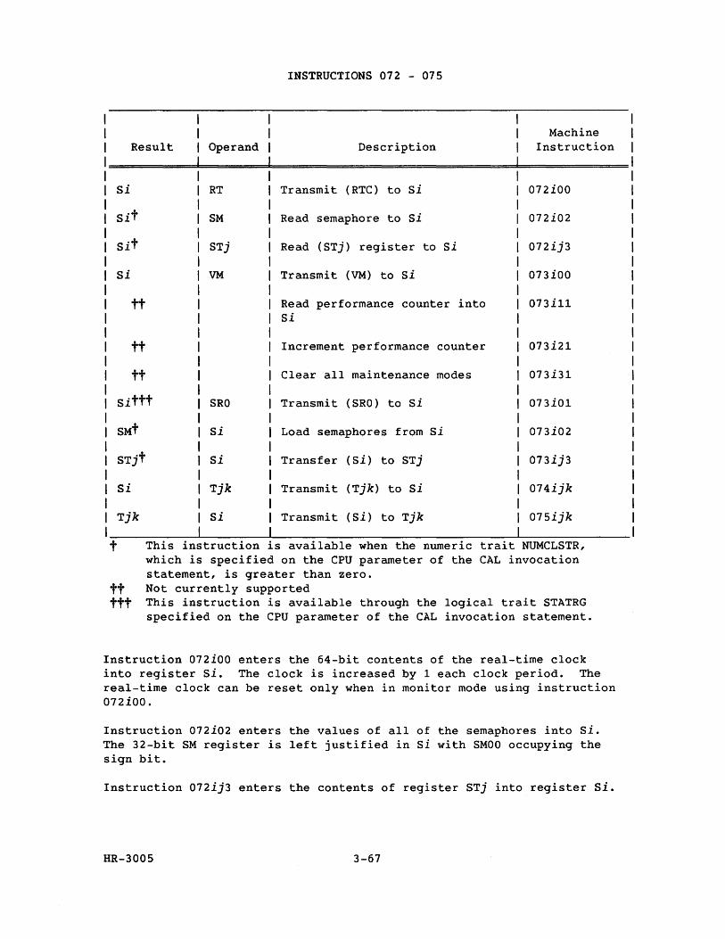
Result
Si
Si
tt
tt
tt
Sittt
SMt
STjt
Si
Tjk
Operand
RT
SM
STj
VM
SRO
Si
Si
Tjk
Si
INSTRUCTIONS 072 - 075
Description
Transmit (RTC) to Si
Read semaphore to Si
Read (STj) register to Si
Transmit (VM) to Si
Read performance counter into Si
Increment performance counter
Clear all maintenance modes
Transmit (SRO) to Si
Load semaphores from Si
Transfer (Si) to STj
Transmit (Tjk) to Si
Transmit (Si) to Tjk
Machine Instruction
072iOO
072i02
072ij3
073ioo
073ill
073i21
073i31
073iOl
073i02
073ij3
074ijk
075ijk
t This in truction 1S available when the numeric trait NUMCLSTR, which is specified on the CPU parameter of the CAL invocation statement, is greater than zero.
tt Not currently supported ttt This instruction is available through the logical trait STATRG
specified on the CPU parameter of the CAL invocation statement.
Instruction 072iOO enters the 64-bit contents of the real-time clock into register Si. The clock is increased by 1 each clock period. The real-time clock can be reset only when in monitor mode using instruction 072iOO.
Instruction 072i02 enters the values of all of the semaphores into si. The 32-bit SM register is left justified in Si with SMOO occupying the sign bit.
Instruction 072ij3 enters the contents of register STj into register Si.
HR-3005 3-67
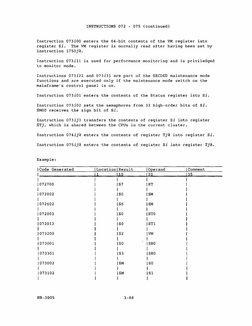
INSTRUCTIONS 072 - 075 (continued)
Instruction 073iOO enters the 64-bit contents of the VM register into register si. The VM register is normally read after having been set by instruction 1750jk.
Instruction 073il1 is used for performance monitoring and is priviledged to monitor mode.
Instructions 073i21 and 073i31 are part of the SECDED maintenance mode functions and are executed only if the maintenance mode switch on the mainframe's control panel is on.
Instruction 073iOl enters the contents of the Status register into Si.
Instruction 073i02 sets the semaphores from 32 high-order bits of Si. SMOO receives the sign bit of Si.
Instruction 073ij3 transfers the contents of register Si into register STj, which is shared between the CPUs in the current cluster.
Instruction 074ijk enters the contents of register Tjk into register Si.
Instruction 075ijk enters the contents of register Si into register Tjk.
Example:
Code Generated Location Result Operand Comment 1 10 20 35
072700 S7 RT
072002 SO SM
072602 S6 SM
072003 SO STO
072013 SO STl
073200 S2 IVM
I 073001 SO ISRO
I 073301 S3 ISRO
I 073002 SM ISO
I 073102 SM lSi
I
HR-3005 3-68
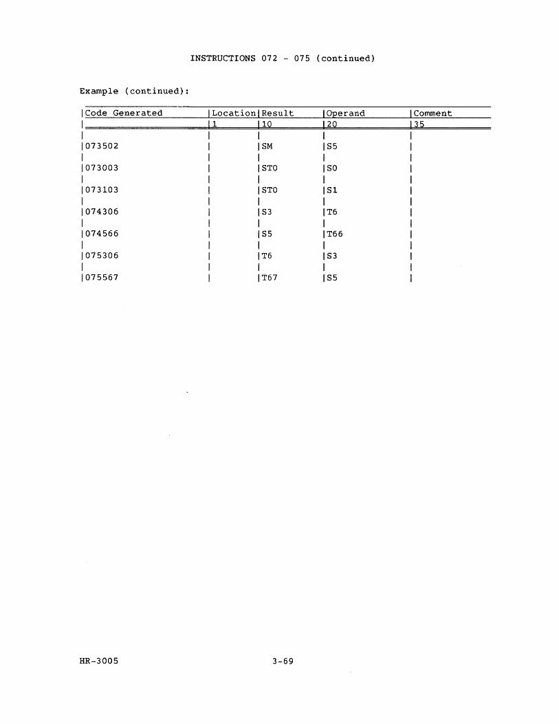
INSTRUCTIONS 072 - 075 (continued)
Example (continued):
ICode Generated Location Result Operand Comment I 1 10 20 35
073502 SM S5
073003 STO SO
073103 STO Sl
074306 S3 T6
074566 S5 T66
075306 T6 S3
075567 T67 S5
HR-3005 3-69
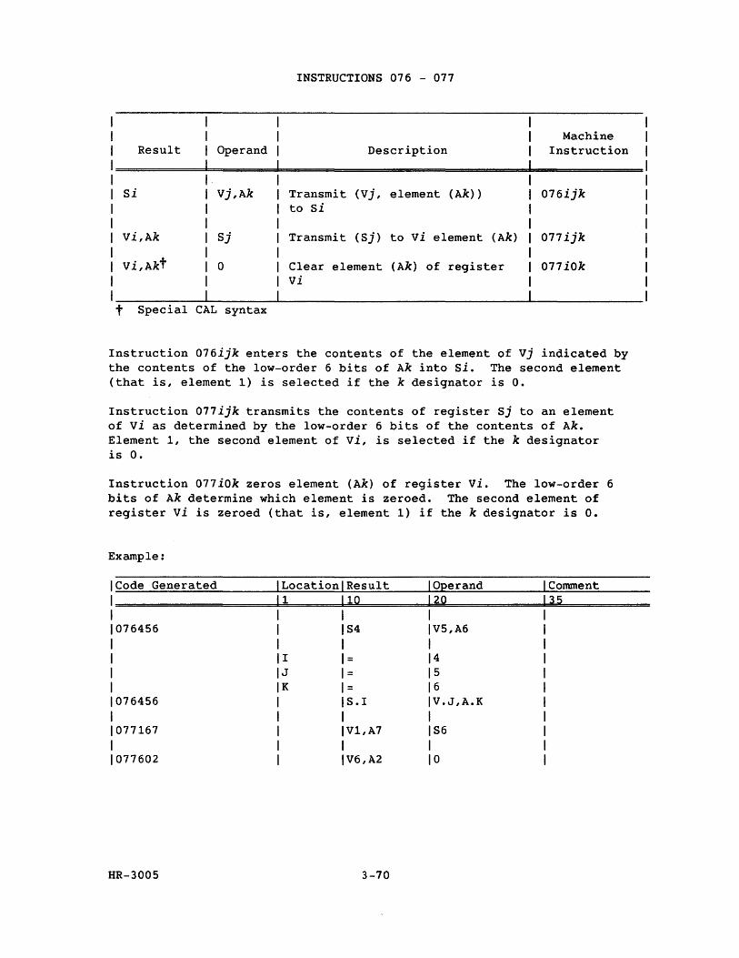
Result Operand
Si Vj,Ak
Vi,Ak Sj
o
t Special CAL syntax
INSTRUCTIONS 076 - 077
Description
Transmit (Vj, element (Ak» to Si
Transmit (Sj) to vi element (Ak)
Clear element (Ak) of register vi
Machine Instruction
076ijk
077ijk
077iOk
Instruction 076ijk enters the contents of the element of Vj indicated by the contents of the low-order 6 bits of Ak into Si. The second element (that is, element 1) is selected if the k designator is o.
Instruction 077ijk transmits the contents of register Sj to an element of vi as determined by the low-order 6 bits of the contents of Ak. Element 1, the second element of Vi, is selected if the k designator is o.
Instruction 077iOk zeros element (Ak) of register vi. The low-order 6 bits of Ak determine which element is zeroed. The second element of register vi is zeroed (that is, element 1) if the k designator is o.
Example:
Code Generated Location Result Operand Comment 1 10 20 35
076456 S4 V5,A6
I = 4 J = 5 K = 6
076456 S.l V.J,A.K
077167 V1,A7 S6
077602 V6,A2 0
HR-3005 3-70
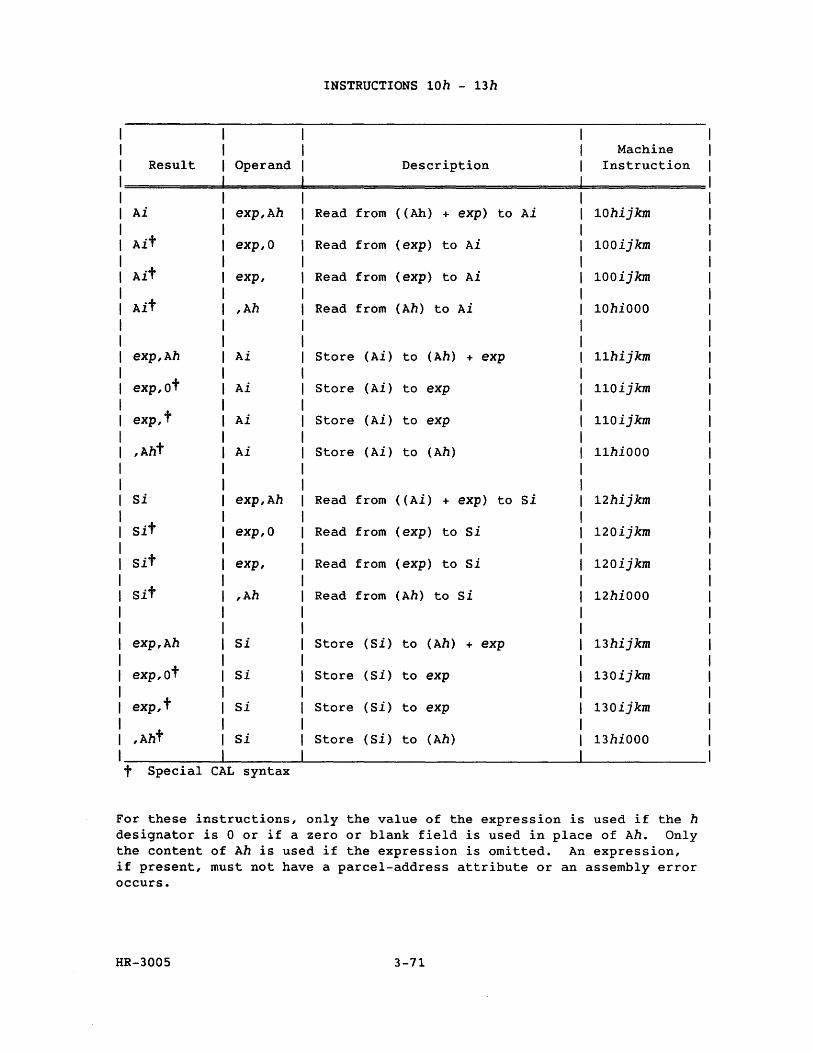
INSTRUCTIONS 10h - 13h
Machine Result Operand Description Instruction
Ai exp,Ah Read from ( (Ah) + exp) to Ai 10hijkm
Ait exp,O Read from (exp) to Ai 100ijkm
Ait exp, Read from (exp) to Ai 100ijkm
Ait ,Ah Read from (Ah) to Ai 10hiOOO
exp,Ah Ai Store (Ai) to (Ah) + exp 11hijkm
exp,ot Ai Store (Ai) to exp 110ijkm
exp,t Ai Store (Ai) to exp 110ijkm
,Aht Ai Store (Ai) to (Ah) llhiOOO
Si exp,Ah Read from ( (Ai) + exp) to Si 12hijkm
Sit exp,O Read from (exp) to Si 120ijkm
Sit exp, Read from (exp) to Si 120ijkm
Sit ,Ah Read from (Ah) to Si 12hiOOO
exp,Ah Si Store (Si) to (Ah) + exp 13hijkm
exp,ot Si Store (Si) to exp 130ijkm
exp,t Si Store (Si) to exp 130ijkm
,Aht Si Store (Si) to (Ah) 13hiOOO
t Special CAL syntax
For these instructions, only the value of the expression is used if the h designator is 0 or if a zero or blank field is used in place of Ah. Only the content of Ah is used if the expression is omitted. An expression, if present, must not have a parcel-address attribute or an assembly error occurs.
HR-3005 3-71
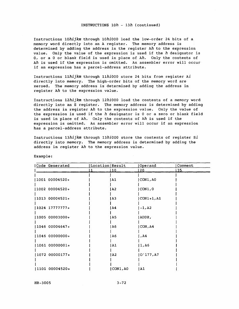
INSTRUCTIONS 10h - 13h (continued)
Instructions 10hijkm through 10hiOOO load the low-order 24 bits of a memory word directly into an A register. The memory address is determined by adding the address in the register Ah to the expression value. Only the value of the expression is used if the h designator is 0, or a 0 or blank field is used in place of Ah. Only the contents of Ah is used if the expression is omitted. An assembler error will occur if an expression has a parcel-address attribute.
Instructions 11hijkm through 11hiOOO store 24 bits from register Ai directly into memory. The high-order bits of the memory word are zeroed. The memory address is determined by adding the address in register Ah to the expression value.
Instructions 12hijkm through 12hiOOO load the contents of a memory word directly into an S register. The memory address is determined by adding the address in register Ah to the expression value. Only the value of the expression is used if the h designator is 0 or a zero or blank field is used in place of Ah. Only the contents of Ah is used if the expression is omitted. An assembler error will occur if an expression has a parcel-address attribute.
Instructions 13hijkm through 13hiOOO store the contents of register Si directly into memory. The memory address is determined by adding the address in register Ah to the expression value.
Example:
Code Generated LocationlResult Operand Comment 1 \10 20 35
I 1001 00004520+ A1 CON1,AO
1002 00004520+ A2 CON1,0
1013 00004521+ A3 CON1+1,A1
1024 17777777+ A4 -1,A2
1005 00003000+ A5 ADDR,
1046 00004647+ A6 CON,A4
1046 00000000+ A6 ,A4
1061 00000001+ A1 1,A6
1072 00000177+ A2 O'177,A7
1101 00004520+ CON1,AO A1
HR-3005 3-72
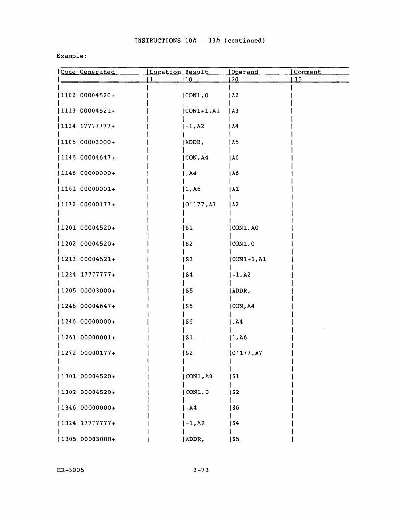
INSTRUCTIONS 10h - 13h (continued)
Example:
Code Generated Location Result Operand Comment 1 10 20 35
1102 00004520+ CON1,0 A2
1113 00004521+ CON1+1,A1 A3
1124 17777777+ -1,A2 A4
1105 00003000+ ADDR, A5
1146 00004647+ CON,A4 A6
1146 00000000+ ,A4 A6
1161 00000001+ 1,A6 A1
1172 00000177+ O'177,A7 A2
1201 00004520+ S1 CON1,AO
1202 00004520+ S2 CON1,0
1213 00004521+ S3 CON1+1,A1
1224 17777777+ S4 -1,A2
1205 00003000+ S5 ADDR,
1246 00004647+ S6 CON,A4
1246 00000000+ S6 ,A4
1261 00000001+ S1 1,A6
1272 00000177+ S2 O'177,A7
1301 00004520+ CON1,AO S1
1302 00004520+ CON1,0 S2
1346 00000000+ ,A4 S6
1324 17777777+ -1,A2 S4
1305 00003000+ ADDR, S5
HR-3005 3-73
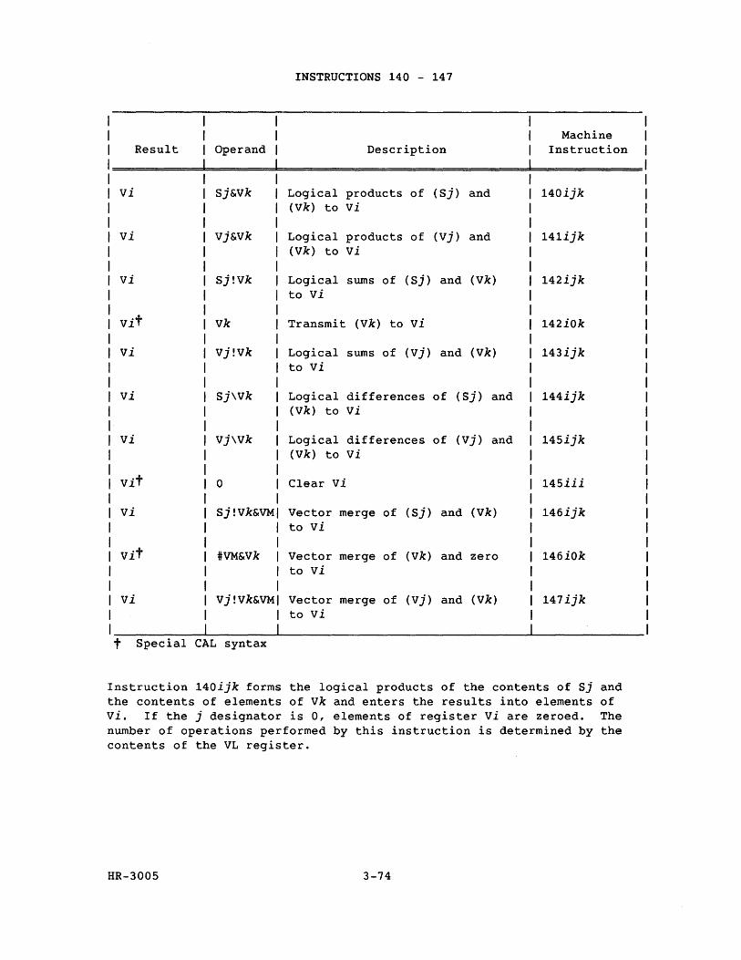
INSTRUCTIONS 140 - 147
Machine Result Operand Description Instruction
vi Sj&Vk Logical products of (Sj) and 140ijk (Vk) to vi
vi vj&Vk Logical products of (vj) and 141ijk (Vk) to vi
vi Sj!Vk Logical sums of (Sj) and (Vk) 142ijk to vi
Vit vk Transmit (Vk) to vi 142iOk
vi vj!Vk Logical sums of (Vj) and (Vk) 143ijk to vi
vi Sj\Vk Logical differences of (Sj) and 144ijk (Vk) to vi
vi Vj\Vk Logical differences of (vj) and 145ijk (Vk) to vi
Vit 0 Clear vi 145iii
vi Sj!Vk&VM Vector merge of (Sj) and (Vk) 146ijk to vi
Vit #VM&Vk Vector merge of (Vk) and zero 146iOk to vi
vi Vj!Vk&VM Vector merge of (vj) and (Vk) 147ijk to vi
t Special CAL syntax
Instruction 140ijk forms the logical products of the contents of Sj and the contents of elements of vk and enters the results into elements of vi. If the j designator is 0, elements of register vi are zeroed. The number of operations performed by this instruction is determined by the contents of the VL register.
HR-3005 3-74
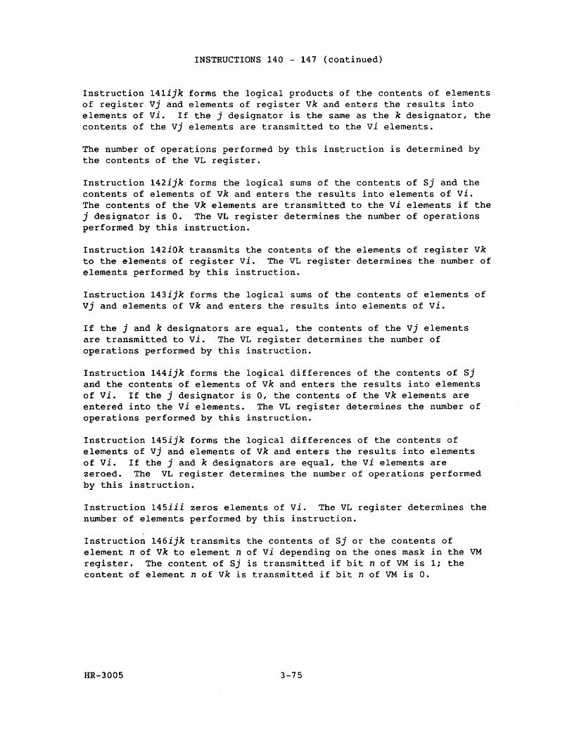
INSTRUCTIONS 140 - 147 (continued)
Instruction 141ijk forms the logical products of the contents of elements of register vj and elements of register vk and enters the results into elements of vi. If the j designator is the same as the k designator, the contents of the vj elements are transmitted to the vi elements.
The number of operations performed by this instruction is determined by the contents of the VL register.
Instruction 142ijk forms the logical sums of the contents of Sj and the contents of elements of vk and enters the results into elements of vi. The contents of the vk elements are transmitted to the vi elements if the j designator is o. The VL register determines the number of operations performed by this instruction.
Instruction 142iOk transmits the contents of the elements of register vk to the elements of register vi. The VL register determines the number of elements performed by this instruction.
Instruction 143ijk forms the logical sums of the contents of elements of vj and elements of vk and enters the results into elements of vi.
If the j and k designators are equal, the contents of the Vj elements are transmitted to vi. The VL register determines the number of operations performed by this instruction.
Instruction 144ijk forms the logical differences of the contents of Sj and the contents of elements of vk and enters the results into elements of Vi. If the j designator is 0, the contents of the vk elements are entered into the vi elements. The VL register determines the number of operations performed by this instruction.
Instruction 145ijk forms the logical differences of the contents of elements of Vj and elements of vk and enters the results into elements of Vi. If the j and k designators are equal, the vi elements are zeroed. The VL register determines the number of operations performed by this instruction.
Instruction 145iii zeros elements of vi. The VL register determines the number of elements performed by this instruction.
Instruction 146ijk transmits the contents of Sj or the contents of element n of vk to element n of vi depending on the ones mask in the VM register. The content of Sj is transmitted if bit n of VM is 1; the content of element n of vk is transmitted if bit n of VM is o.
HR-3005 3-75
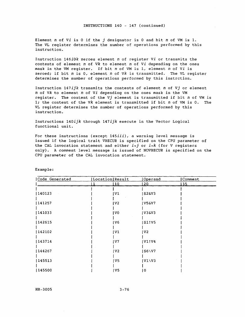
INSTRUCTIONS 140 - 147 (continued)
Element n of vi is 0 if the j designator is 0 and bit n of VM is 1. The VL register determines the number of operations performed by this instruction.
Instruction 146iOk zeroes element n of register vi or transmits the contents of element n of vk to element n of vi depending on the ones mask in the VM register. If bit n of VM is 1, element n of vi is zeroed; if bit n is 0, element n of vk is transmitted. The VL register determines the number of operations performed by this instrction.
Instruction 147ijk transmits the contents of element n of Vj or element n of vk to element n of vi depending on the ones mask in the VM register. The content of the Vj element is transmitted if bit n of VM is 1; the content of the vk element is transmitted if bit n of VM is O. The VL register determines the number of operations performed by this instruction.
Instructions 140ijk through 147ijk execute in the Vector Logical functional unit.
For these instructions (except 145iii), a warning level message is issued if the logical trait VRECUR is specified on the CPU parameter of the CAL invocation statement and either i=j or i=k (for V registers only). A comment level message is issued of NOVRECUR is specified on the CPU parameter of the CAL invocation statement.
Example:
Code Generated Location Result Operand Comment 1 10 20 35
140123 V1 S2&V3
141257 V2 V5&V7
141033 VO V3&V3
142615 V6 Sl!V5
142102 V1 V2
143714 V7 V1!V4
144267 V2 S6\V7
145513 V5 V1\V3
145500 V5 0
HR-3005 3-76
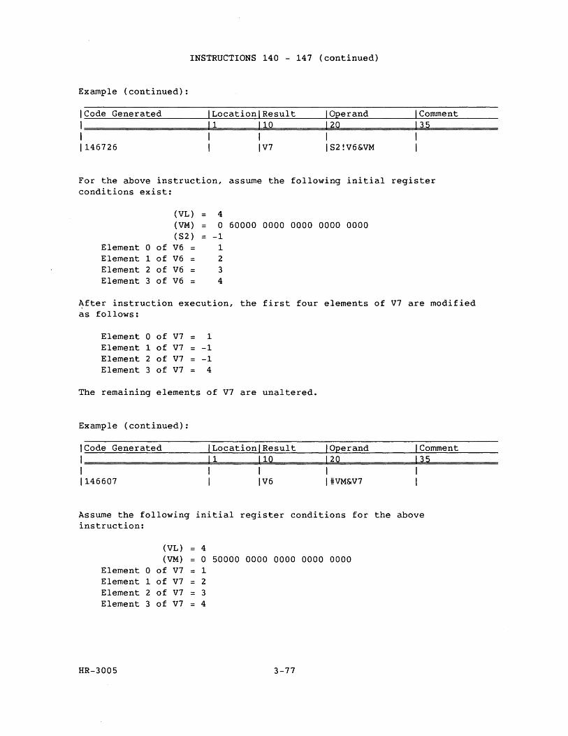
INSTRUCTIONS 140 - 147 (continued)
Example (continued):
ICode Generated ILocationlResult I Operand I Comment
1=====================1~1=======b11~0~========1~20~============13~5~========== I I I I I 1146726 I IV7 152!V6&VM I
For the above instruction, assume the following initial register conditions exist:
(VL) = 4 (VM) = a 60000 0000 0000 0000 0000 (52) = -1
Element a of V6 = 1 Element 1 of V6 2 Element 2 of V6 = 3 Element 3 of V6 4
After instruction execution, the first four elements of V7 are modified as follows:
Element a of V7 = 1 Element 1 of V7 = -1 Element 2 of V7 = -1 Element 3 of V7 4
The remaining elements of V7 are unaltered.
Example (continued):
ICode Generated I Location/Result /Operand /Comment
1=====================1~1=======1~1~0========~12~0~==========~13~5~========== I I I I I 1146607 I I V6 I :!tVM&V7 I
Assume the following initial register conditions for the above instruction:
(VL) = 4 (VM) a 50000 0000 0000 0000 0000
Element a of V7 = 1 Element 1 of V7 = 2 Element 2 of V7 3 Element 3 of V7 = 4
HR-3005 3-77
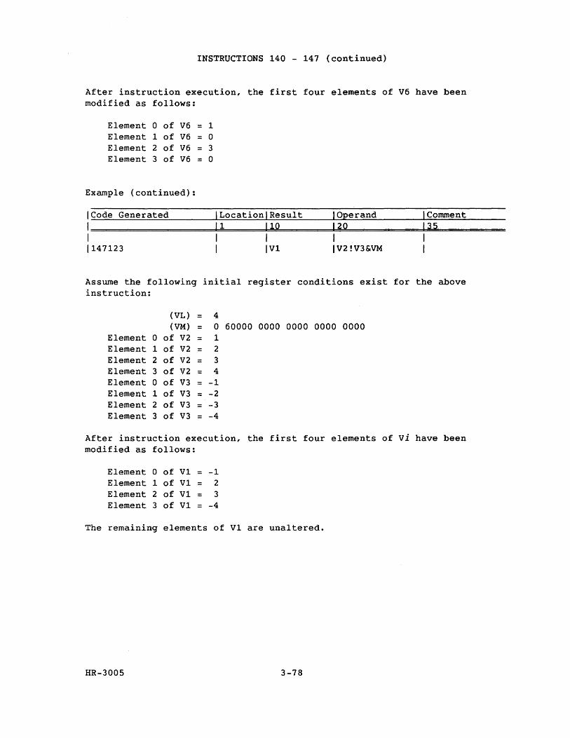
INSTRUCTIONS 140 - 147 (continued)
After instruction execution, the first four elements of V6 have been modified as follows:
Element 0 of V6 = 1 Element 1 of V6 = 0 Element 2 of V6 = 3 Element 3 of V6 = 0
Example (continued):
ICode Generated ILocationlResult I Operand I Comment
1========================la1========1~1~0===========12~Q~=============1~3~5~=========== I I 1 1 1 1147123 I IV1 IV2!V3&VM I
Assume the following initial register conditions exist for the above instruction:
(VL) 4 (VM) = 0 60000 0000 0000 0000 0000
Element 0 of V2 = 1 Element 1 of V2 = 2 Element 2 of V2 = 3 Element 3 of V2 = 4 Element 0 of V3 = -1 Element 1 of V3 = -2 Element 2 of V3 = -3 Element 3 of V3 = -4
After instruction execution, the first four elements of vi have been modified as follows:
Element 0 of V1 -1 Element 1 of V1 = 2 Element 2 of V1 = 3 Element 3 of V1 = -4
The remaining elements of V1 are unaltered.
HR-3005 3-78
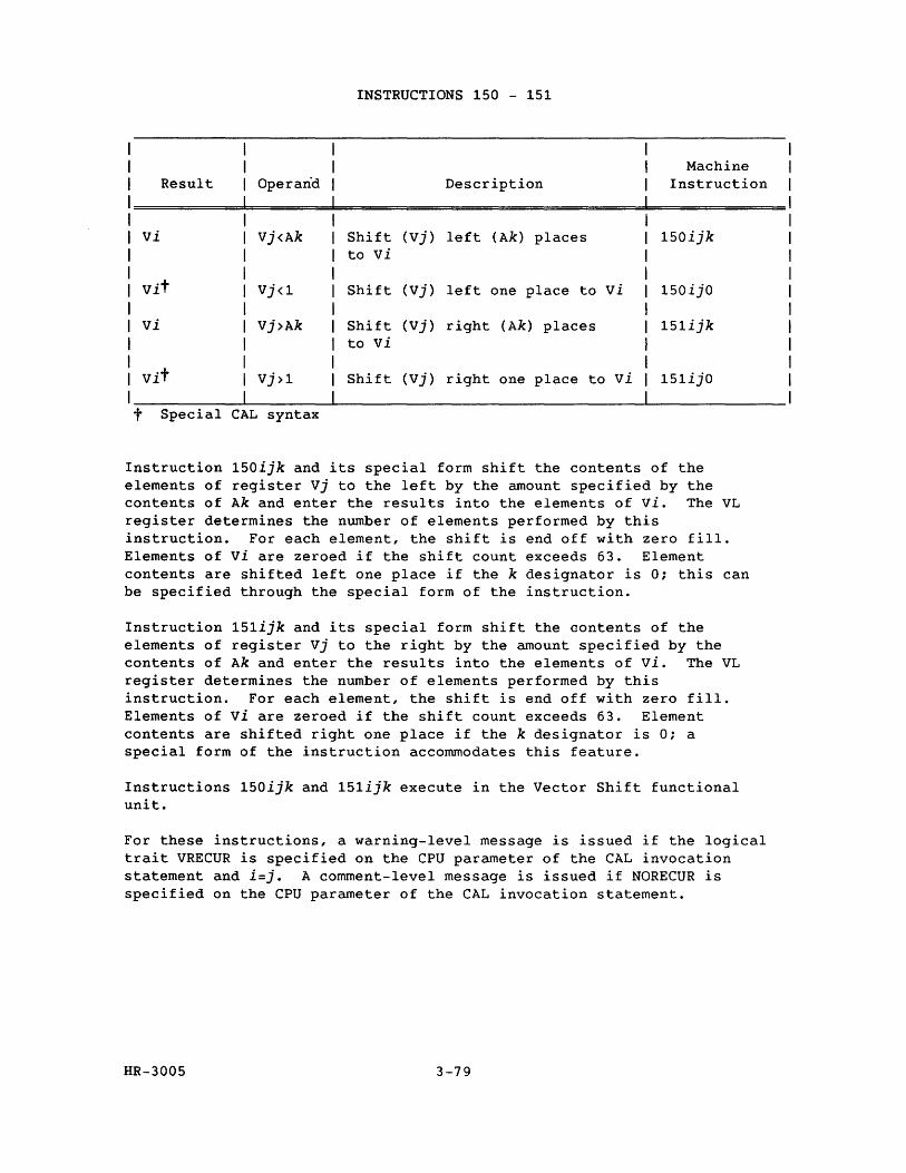
INSTRUCTIONS 150 - 151
Machine Result Operand Description Instruction
vi Vj<Ak Shift (vj) left (Ak) places 150ijk to vi
vit Vj<l Shift (vj) left one place to vi 150ijO
vi Vj>Ak Shift (Vj) right (Ak) places 151ijk to vi
vit Vj>l Shift (Vj) right one place to vi 151ijO
t Special CAL syntax
Instruction 150ijk and its special form shift the contents of the elements of register Vj to the left by the amount specified by the contents of Ak and enter the results into the elements of vi. The VL register determines the number of elements performed by this instruction. For each element, the shift is end off with zero fill. Elements of vi are zeroed if the shift count exceeds 63. Element contents are shifted left one place if the k designator is 0; this can be specified through the special form of the instruction.
Instruction 151ijk and its special form shift the contents of the elements of register Vj to the right by the amount specified by the contents of Ak and enter the results into the elements of vi. The VL register determines the number of elements performed by this instruction. For each element, the shift is end off with zero fill. Elements of vi are zeroed if the shift count exceeds 63. Element contents are shifted right one place if the k designator is 0; a special form of the instruction accommodates this feature.
Instructions 150ijk and 151ijk execute in the Vector Shift functional unit.
For these instructions, a warning-level message is issued if the logical trait VRECUR is specified on the CPU parameter of the CAL invocation statement and i=j. A comment-level message is issued if NORECUR is specified on the CPU parameter of the CAL invocation statement.
HR-3005 3-79
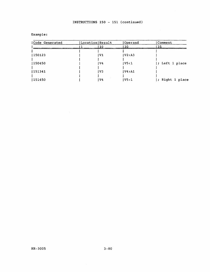
INSTRUCTIONS 150 - 151 (continued)
Example:
ICode Generated Comment Location Result Operand 1 10 20 1===================d~======~========~~============35~=========
1 1150123 1 1150450 1
1151341 1
1151450
HR-3005
V1
V4
V3
V4
V2<A3
V5<1 Left 1 place
V4>A1
V5>1 ; Right 1 place
3-80
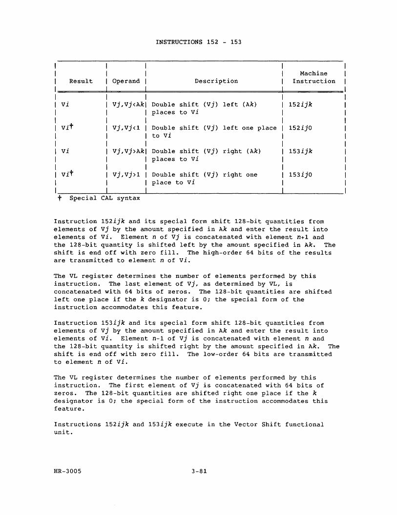
INSTRUCTIONS 152 - 153
Machine Result Operand Description Instruction
vi Vj,Vj<Ak Double shift (vj) left (Ak) 152ijk places to vi
vit Vj,Vj<1 Double shift (vj) left one place 152ijO to vi
vi Vj,Vj>Ak Double shift (vj) right (Ak) 153ijk places to vi
vit Vj,Vj>1 Double shift (Vj) right one 153ijO place to vi
t Special CAL syntax
Instruction 152ijk and its special form shift 128-bit quantities from elements of Vj by the amount specified in Ak and enter the result into elements of vi. Element n of Vj is concatenated with element n+1 and the 128-bit quantity is shifted left by the amount specified in Ak. The shift is end off with zero fill. The high-order 64 bits of the results are transmitted to element n of vi.
The VL register determines the number of elements performed by this instruction. The last element of vj, as determined by VL, is concatenated with 64 bits of zeros. The 128-bit quantities are shifted left one place if the k designator is 0; the special form of the instruction accommodates this feature.
Instruction 153ijk and its special form shift 128-bit quantities from elements of vj by the amount specified in Ak and enter the result into elements of vi. Element n-1 of vj is concatenated with element nand the 128-bit quantity is shifted right by the amount specified in Ak. The shift is end off with zero fill. The low-order 64 bits are transmitted to element n of vi.
The VL register determines the number of elements performed by this instruction. The first element of Vj is concatenated with 64 bits of zeros. The 128-bit quantities are shifted right one place if the k designator is 0; the special form of the instruction accommodates this feature.
Instructions 152ijk and 153ijk execute in the Vector Shift functional unit.
HR-3005 3-81
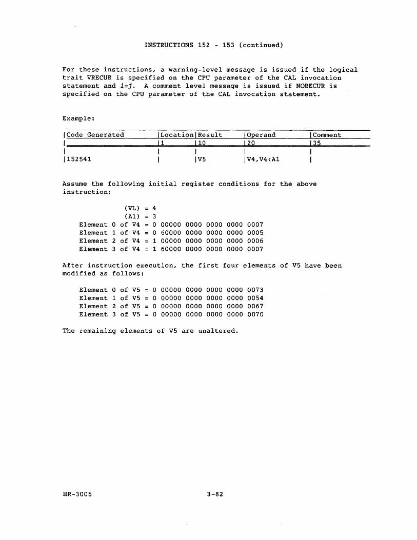
INSTRUCTIONS 152 - 153 (continued)
For these instructions, a warning-level message is issued if the logical trait VRECUR is specified on the CPU parameter of the CAL invocation statement and i=j. A comment level message is issued if NORECUR is specified on the CPU parameter of the CAL invocation statement.
Example:
ICode Generated I LocationlResult I Operand I Comment
1=======================1~1========1~1~O==========1~2~0~============~13~5~=========== 1 1 1 I I 1152541 I IV5 IV4,V4<A1 1
Assume the following initial register conditions for the above instruction:
(VL) = 4 (A1) = 3
Element a of V4 = a 00000 0000 0000 0000 0007 Element 1 of V4 = a 60000 0000 0000 0000 0005 Element 2 of V4 = 1 00000 0000 0000 0000 0006 Element 3 of V4 = 1 60000 0000 0000 0000 0007
After instruction execution, the first four elements of V5have been modified as follows:
Element a of V5 = a 00000 0000 0000 0000 0073 Element 1 of V5 = a 00000 0000 0000 0000 0054 Element 2 of V5 = a 00000 0000 0000 0000 0067 Element 3 of V5 = a 00000 0000 0000 0000 0070
The remaining elements of V5 are unaltered.
HR-3005 3-82
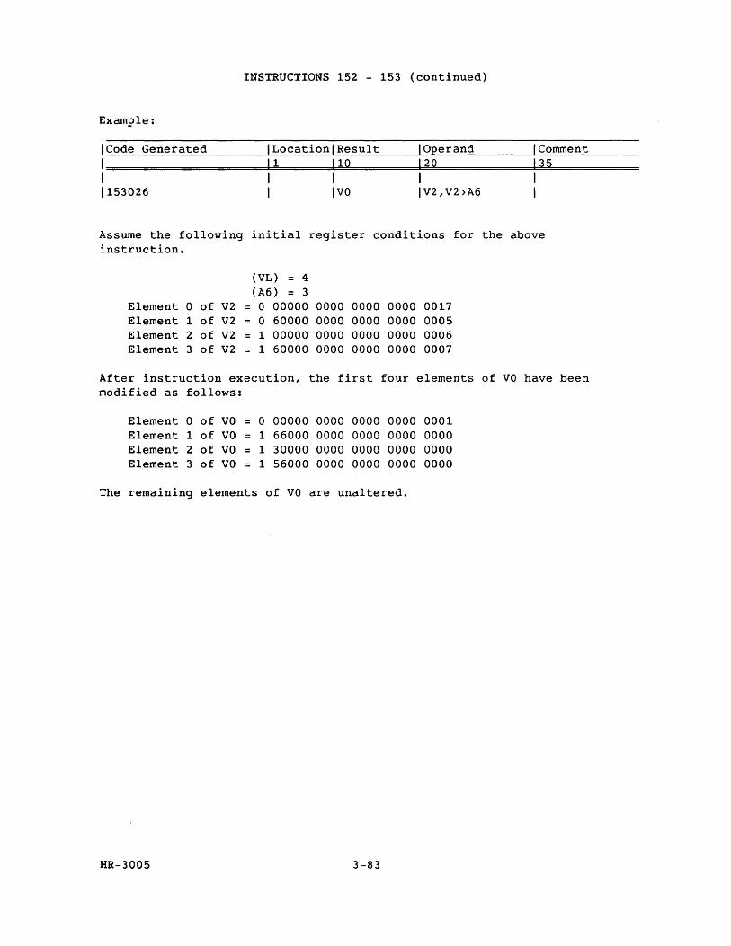
INSTRUCTIONS 152 - 153 (continued)
Example:
ICode Generated ILocationlResult I Operand I Comment
1=====================1=1======~ll=0==========1=2Q==============13=5============ I I I I I 1153026 I IVa IV2,V2>A6 I
Assume the following initial register conditions for the above instruction.
(VL) = 4 (A6) = 3
Element a of V2 = a 00000 0000 0000 0000 0017 Element 1 of V2 = a 60000 0000 0000 0000 0005 Element 2 of V2 = 1 00000 0000 0000 0000 0006 Element 3 of V2 = 1 60000 0000 0000 0000 0007
After instruction execution, the first four elements of va have been modified as follows:
Element a of va = a 00000 0000 0000 0000 0001 Element 1 of va = 1 66000 0000 0000 0000 0000 Element 2 of va = 1 30000 0000 0000 0000 0000 Element 3 of va = 1 56000 0000 0000 0000 0000
The remaining elements of va are unaltered.
HR-3005 3-83
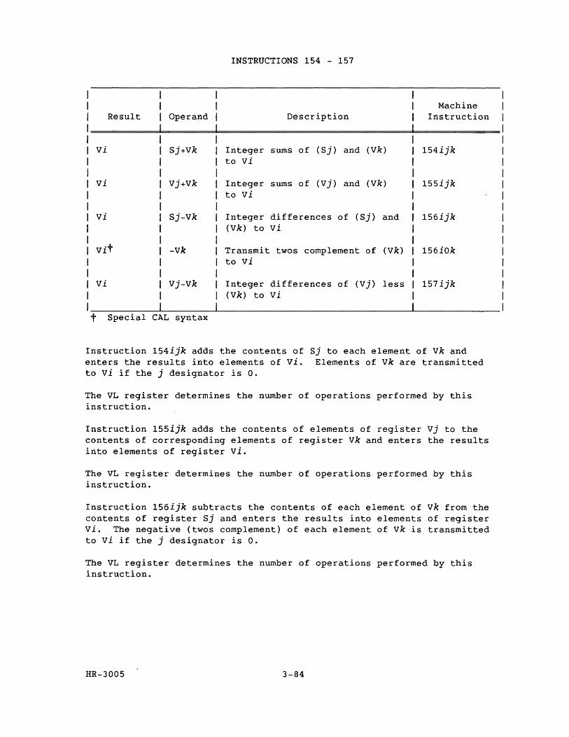
INSTRUCTIONS 154 - 157
Machine Result Operand Description Instruction
vi Sj+Vk Integer sums of (Sj) and (Vk) 154ijk to vi
vi Vj+Vk Integer sums of (Vj) and (Vk) 155ijk to vi
vi Sj-Vk Integer differences of (Sj) and 156ijk (Vk) to vi
Vit -vk Transmit twos complement of (Vk) 156iOk to vi
vi Vj-Vk Integer differences of (Vj) less 157ijk (Vk) to vi
t Special CAL syntax
Instruction 154ijk adds the contents of Sj to each element of vk and enters the results into elements of vi. Elements of vk are transmitted to vi if the j designator is O.
The VL register determines the number of operations performed by this instruction.
Instruction 155ijk adds the contents of elements of register Vj to the contents of corresponding elements of register vk and enters the results into elements of register vi.
The VL register determines the number of operations performed by this instruction.
Instruction 156ijk subtracts the contents of each element of vk from the contents of register Sj and enters the results into elements of register vi. The negative (twos complement) of each element of vk is transmitted to vi if the j designator is O.
The VL register determines the number of operations performed by this instruction.
HR-3005 3-84
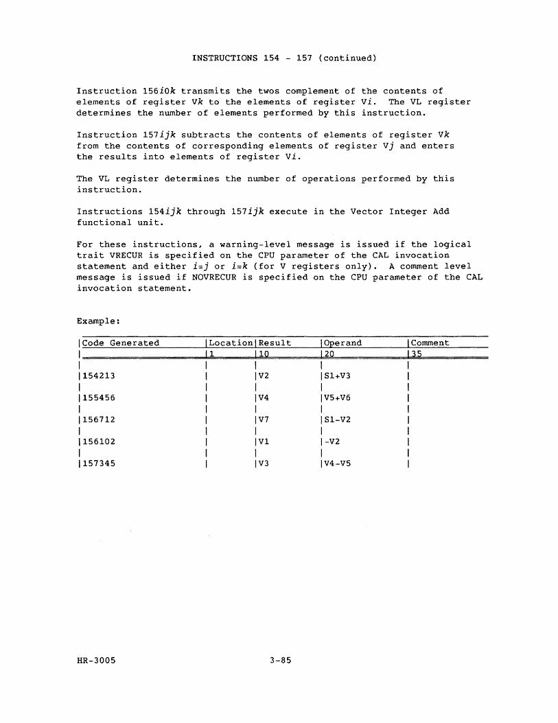
INSTRUCTIONS 154 - 157 (continued)
Instruction 156iOk transmits the twos complement of the contents of elements of register vk to the elements of register vi. The VL register determines the number of elements performed by this instruction.
Instruction 157ijk subtracts the contents of elements of register vk from the contents of corresponding elements of register Vj and enters the results into elements of register vi.
The VL register determines the number of operations performed by this instruction.
Instructions 154ijk through 157ijk execute in the Vector Integer Add functional unit.
For these instructions, a warning-level message is issued if the logical trait VRECUR is specified on the CPU parameter of the CAL invocation statement and either i=j or i=k (for V registers only). A comment level message is issued if NOVRECUR is specified on the CPU parameter of the CAL invocation statement.
Example:
Code Generated Location Result Operand Comment 1 10 20 35
154213 V2 Sl+V3
155456 V4 V5+V6
156712 V7 Sl-V2
156102 V1 -V2
157345 V3 V4-V5
HR-3005 3-85
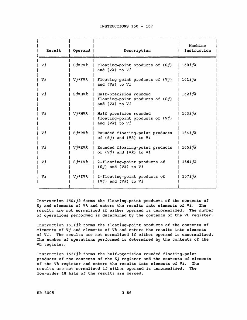
INSTRUCTIONS 160 - 167
Machine Result Operand Description Instruction
vi Sj*FVk Floating-point products of (Sj) 160ijk and (Vk) to vi
vi Vj*FVk Floating-point products of (Vj) 161ijk and (Vk) to vi
vi Sj*HVk Half-precision rounded 162ijk floating-point products of (Sj) and (Vk) to vi
vi Vj*HVk Half-precision rounded 163ijk floating-point products of (Vj) and (Vk) to vi
vi Sj*RVk Rounded floating-point products 164ijk of (Sj) and (Vk) to vi
vi Vj*RVk Rounded floating-point products 165ijk of (Vj) and (Vk) to vi
vi Sj*IVk 2-floating-point products of 166ijk (Sj) and (Vk) to vi
vi Vj*IVk 2-floating-point products of 167ijk (Vj) and (Vk) to vi
Instruction 160ijk forms the floating-point products of the contents of Sj and elements of vk and enters the results into elements of vi. The results are not normalized if either operand is unnormalized. The number of operations performed is determined by the contents of the VL register.
Instruction 161ijk forms the floating-point products of the contents of elements of Vj and elements of vk and enters the results into elements of vi. The results are not normalized if either operand is unnormalized. The number of operations performed is determined by the contents of the VL register.
Instruction 162ijk forms the half-p~ecision rounded floating-point products of the contents of the Sj register and the contents of elements of the vk register and enters the results into elements of vi. The results are not normalized if either operand is unnormalized. The low-order 18 bits of the results are zeroed.
HR-3005 3-86
INSTRUCTIONS 160 - 167 (continued)
The number of operations performed by this instruction is determined by the contents of the VL register. This instruction can be used in a divide algorithm when only 30 bits of accuracy are required.
Instruction 163ijk forms the half-precision rounded floating-point products of the contents of elements of the Vj register and elements of the Vk register and enters the results into elements of vi. The results are not normalized if either operand is unnormalized. The low-order 18 bits of the results are zeroed.
The VL register determines the number of operations performed by this instruction. This instruction can be used in a divide algorithm when only 30 bits of accuracy are required.
Instruction 164ijk forms the rounded floating-point products of the contents of the Sj register and the contents of elements of vk and enters the results into elements of vi. The results will not be normalized if either operand is unnormalized. The VL register determines the number of operations performed by this instruction.
Instruction 165ijk forms the rounded floating-point products of the contents of elements of Vj and elements of vk and enters the results into elements of vi. The results will not be normalized if either operand is unnormalized. The VL register determines the number of operations performed by this instruction.
Instruction 166ijk forms 2 minus the floating-point products of the contents of Sj and the contents of elements of vk and enters the results into elements of vi. The results are not normalized if either operand is unnormalized. The VL register determines the number of operations performed by this instruction.
Instruction 167ijk forms 2 minus the floating-point products of contents of elements of Vj and elements of vk and enters the results into elements of vi. The results are not normalized if either operand is unnormalized. This instruction is used in the divide sequence. The VL register determines the number of operations performed by this instruction.
Instructions 160ijk through 167ijk execute in the Floating-point Multiply functional unit. For these instructions, a warning-level message is issued if the logical trait VRECUR is specified on the CPU parameter of the CAL invocation statement and either i=j or i=k (for V registers only). A comment-level message is issued if NORECUR is specified on the CPU parameter of t~e CAL invocation statement.
HR-3005 3-87
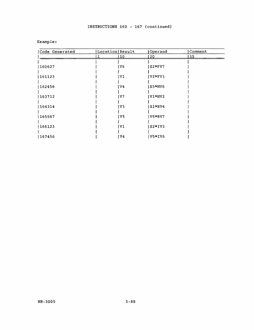
INSTRUCTIONS 160 - 167 (continued)
Example:
Code Generated Location Result Operand Comment 1 10 20 35
160627 V6 S2*FV7
161123 V1 V2*FV3
162456 V4 S5*HV6
163712 V7 V1*HV2
164314 V3 Sl*RV4
165567 V5 V6*RV7
166123 V1 S2*IV3
167456 V4 V5*IV6
HR-3005 3-88
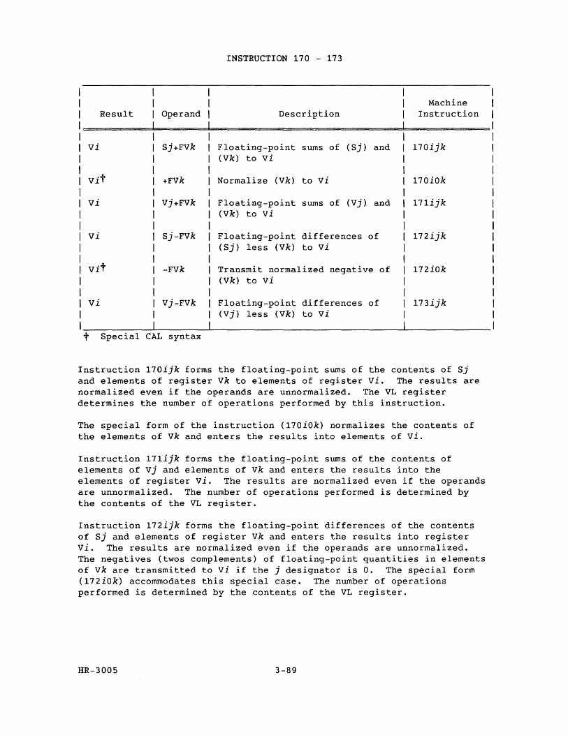
INSTRUCTION 170 - 173
Machine Result Operand Description Instruction
vi Sj+FVk Floating-point sums of (Sj) and 170ijk (Vk) to vi
vit +Fvk Normalize (Vk) to vi 170iok
vi Vj+FVk Floating-point sums of (vj) and 171ijk (Vk) to vi
vi Sj-FVk Floating-point differences of 172ijk (Sj) less (Vk) to vi
vit -Fvk Transmit normalized negative of 172iok (Vk) to vi
vi Vj-FVk Floating-point differences of 173ijk (Vj) less (Vk) to vi
t Special CAL syntax
Instruction 170ijk forms the floating-point sums of the contents of Sj and elements of register Vk to elements of register vi. The results are normalized even if the operands are unnormalized. The VL register determines the number of operations performed by this instruction.
The special form of the instruction (170iOk) normalizes the contents of the elements of vk and enters the results into elements of vi.
Instruction 171ijk forms the floating-point sums of the contents of elements of vj and elements of Vk and enters the results into the elements of register vi. The results are normalized even if the operands are unnormalized. The number of operations performed is determined by the contents of the VL register.
Instruction 172ijk forms the floating-point differences of the contents of Sj and elements of register Vk and enters the results into register vi. The results are normalized even if the operands are unnormalized. The negatives (twos complements) of floating-point quantities in elements of vk are transmitted to vi if the j designator is O. The special form (172iOk) accommodates this special case. The number of operations performed is determined by the contents of the VL register.
HR-3005 3-89
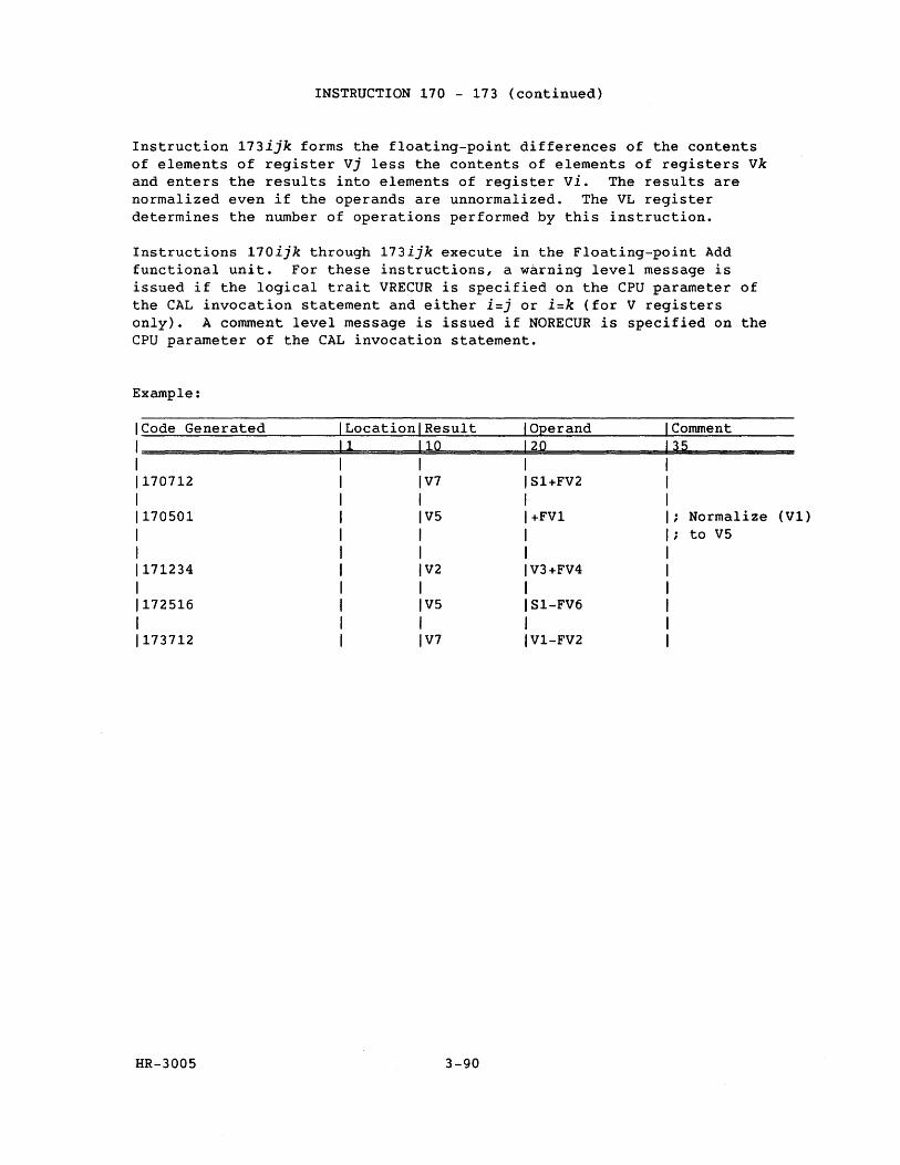
INSTRUCTION 170 - 173 (continued)
Instruction 173ijk forms the floating-point differences of the contents of elements of register Vj less the contents of elements of registers vk and enters the results into elements of register vi. The results are normalized even if the operands are unnormalized. The VL register determines the number of operations performed by this instruction.
Instructions 170ijk through 173ijk execute in the Floating-point Add functional unit. For these instructions, a warning level message is issued if the logical trait VRECUR is specified on the CPU parameter of the CAL invocation statement and either i=j or i=k (for V registers only). A comment level message is issued if NORECUR is specified on the CPU parameter of the CAL invocation statement.
Example:
Code Generated Location Result 1 10
170712 V7
170501 V5
171234 V2
172516 V5
173712 V7
HR-3005 3-90
Operand 20
SI+FV2
+FVl
V3+FV4
SI-FV6
VI-FV2
Comment 35
Normalize (VI) to V5
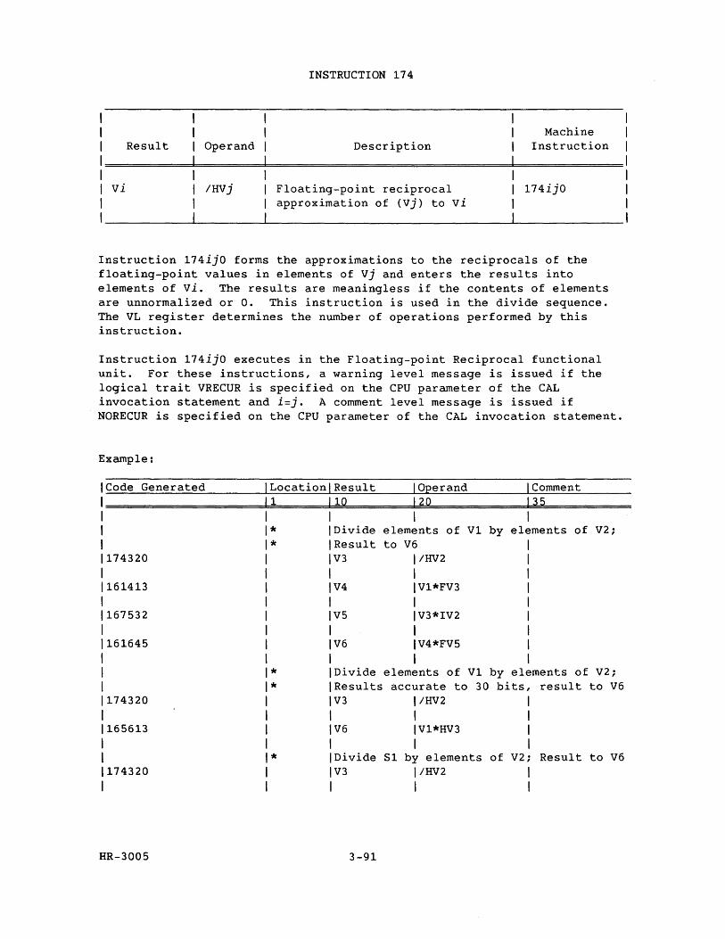
Result Operand
vi IHvj
INSTRUCTION 174
Description
Floating-point reciprocal approximation of (Vj) to vi
Machine Instruction
174ijO
Instruction 174ijO forms the approximations to the reciprocals of the floating-point values in elements of Vj and enters the results into elements of vi. The results are meaningless if the contents of elements are unnormalized or O. This instruction is used in the divide sequence. The VL register determines the number of operations performed by this instruction.
Instruction 174ijO executes in the Floating-point Reciprocal functional unit. For these instructions, a warning level message is issued if the logical trait VRECUR is specified on the CPU parameter of the CAL invocation statement and i=j. A comment level message is issued if NORECUR is specified on the CPU parameter of the CAL invocation statement.
Example:
Code Generated LocationlResult I Operand I Comment 1 110 120 135
* I Divide elements of V1 by elements of V2; * IResult to V6
174320 IV3 I/HV2 I I
161413 IV4 IV1*FV3
I I 167532 V5 IV3*IV2
I 161645 V6 IV4*FV5
I * Divide elements of V1 by elements of V2; * Results accurate to 30 bits, result to V6
174320 V3 I/HV2 I
165613 V6 IV1*HV3
I * Divide 81 by elements of V2; Result to V6
174320 V3 I/HV2 I
HR-3005 3-91
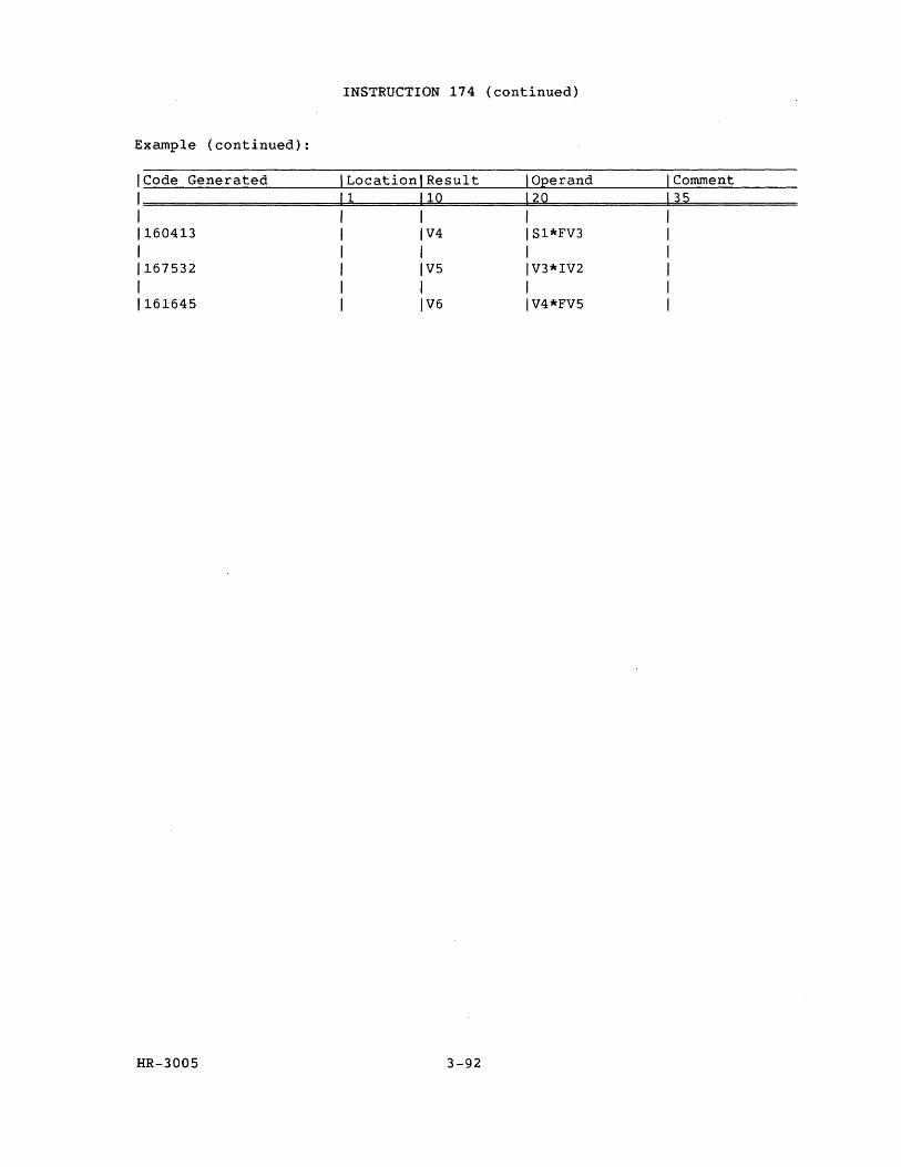
INSTRUCTION 174 (continued)
Example (continued):
'Code Generated ILocationlResult I Operand I Comment
'=====================1=1========11=Q==========12~Q=============1~3~5============ 1 "I 1 1160413 1 IV4 IS1*FV3 1 1 1 1 I I 1167532 I IV5 IV3*IV2 1 , 1 I I I 1161645 I IV6 IV4*FV5 1
HR-3005 3-92
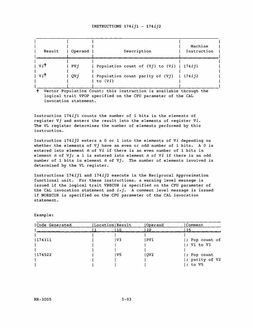
I 1
I Result Operand
INSTRUCTIONS 174ij1 - 174ij2
Description Machine
Instruction
1============================================================= I 1 Vit pvj
I I Vit Qvj
I
Population count of (Vj) to (Vi)
Population count parity of (Vj) to (Vi)
174ij1
174ij2
I ______________ ~------------~---------------------------------------------~--------------------t Vector Population Count; this instruction is available through the
logical trait VPOP specified on the CPU parameter of the CAL invocation statement.
Instruction 174ij1 counts the number of 1 bits in the elements of register Vj and enters the result into the elements of register vi. The VL register determines the number of elements performed by this instruction.
Instruction 174ij2 enters a 0 or 1 into the elements of vi depending on whether the elements of Vj have an even or odd number of 1 bits. A 0 is entered into element n of vi if there is an even number of 1 bits in element n of Vj; a 1 is entered into element n of vi if there is an odd number of 1 bits in element n of vj. The number of elements involved is determined by the VL register.
Instructions 174ij1 and 174ij2 execute in the Reciprocal Approximation functional unit. For these instructions, a warning level message is issued if the logical trait VRECUR is specified on the CPU parameter of the CAL invocation statement and i=j. A comment level message is issued if NORECUR is specified on the CPU parameter of the CAL invocation statement.
Example:
ICode Generated ILocationlResult I Operand 1 Comment
1====================~11~====~I~lQ~·========~1~2~O=============13~5~========== I I I I I 1174311 I IV3 IPV1 I; Pop count of I I I I I; V1 to V3 I I I I I 1174522 1 1 V5 1 QV2 I; Pop count I I I I I; par i ty of V2 I I I I I; to V5
HR-3005 3-93
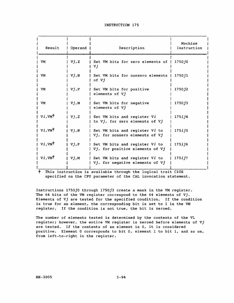
INSTRUCTION 175
Machine Result Operand Description Instruction
VM vj,z Set VM bits for zero elements of 1750jO Vj
VM Vj,N Set VM bits for nonzero elements 1750j1 of vj
VM vj,p Set VM bits for positive 1750j2 elements of Vj
VM Vj,M Set VM bits for negative 1750j3 elements of Vj
Vi,VMt vj ,Z Set VM bits and register vi 175ij4 to vj, for zero elements of Vj
Vi,VMt Vj,N Set VM bits and register vi to 175ij5 Vj, for nonzero elements of vj
Vi,VMt Vj,p Set VM bits and register vi to 175ij6 Vj, for positive elements of vj
Vi,VMt Vj,M Set VM bits and register vi to 175ij7 Vj, for negative elements of Vj
t This inst uction is available through the logical trait CIGS specified on the CPU parameter of the CAL invocation statement.
Instructions 1750jO through 1750j3 create a mask in the VM register. The 64 bits of the VM register correspond to the 64 elements of vj. Elements of Vj are tested for the specified condition. If the condition is true for an element, the corresponding bit is set to 1 in the VM register. If the condition is not true, the bit is zeroed.
The number of elements tested is determined by the contents of the VL register; however, the entire VM register is zeroed before elements of Vj are tested. Lf the contents of an element is 0, it is considered positive. Element 0 corresponds to bit 0, element 1 to bit 1, and so on, from left-to-right in the register.
HR-3005 3-94
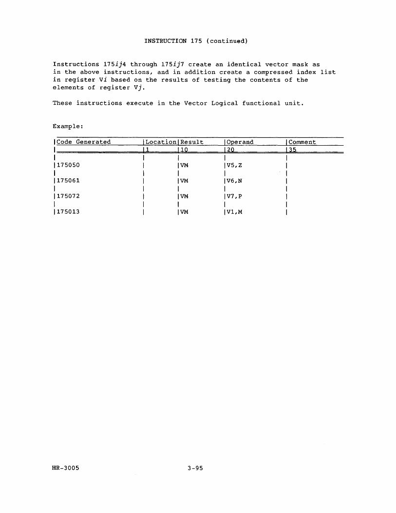
INSTRUCTION 175 (continued)
Instructions 175ij4 through 175ij7 create an identical vector mask as in the above instructions, and in addition create a compressed index list in register vi based on the results of testing the contents of the elements of register Vj.
These instructions execute in the Vector Logical functional unit.
Example:
ICode Generated Location Result Operand Comment 1 1 10 20 35
1 1175050 VM V5,Z
1 1175061 VM V6,N
1 1175072 VM V7,P
1 1175013 VM V1,M
HR-3005 3-95
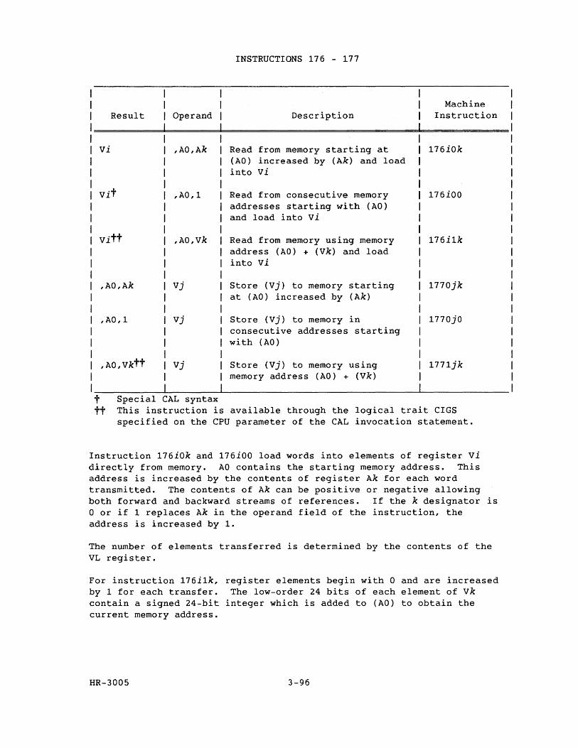
Result Operand
vi ,AO,Ak
,AO,1
,AO,vk
,AO,Ak Vj
,AO,1 Vj
,AO,Vktt Vj
t Special CAL syntax
INSTRUCTIONS 176 - 177
Description
Read from memory starting at (AO) increased by (Ak) and load into vi
Read from consecutive memory addresses starting with (AO) and load into vi
Read from memory using memory address (AO) + (Vk) and load into vi
Store (Vj) to memory starting at (AO) increased by (Ak)
Store (Vj) to memory in consecutive addresses starting with (AO)
Store (Vj) to memory using memory address (AO) + (Vk)
Machine Instruction
176iOk
176iOO
176i1k
1770jk
1770jO
1771jk
tt This instruction is available through the logical trait CIGS specified on the CPU parameter of the CAL invocation statement.
Instruction 176iOk and 176iOO load words into elements of register vi directly from memory. AO contains the starting memory address. This address is increased by the contents of register Ak for each word transmitted. The contents of Ak can be positive or negative allowing both forward and backward streams of references. If the k designator is o or if 1 replaces Ak in the operand field of the instruction, the address is increased by 1.
The number of elements transferred is determined by the contents of the VL register.
For instruction 176i1k, register elements begin with 0 and are increased by 1 for each transfer. The low-order 24 bits of each element of vk contain a signed 24-bit integer which is added to (AO) to obtain the current memory address.
HR-3005 3-96
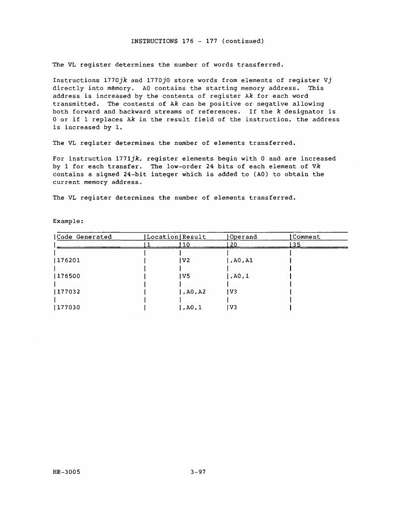
INSTRUCTIONS 176 - 177 (continued)
The VL register determines the number of words transferred.
Instructions 1770jk and 1770jO store words from elements of register Vj directly into m~mory. AO contains the starting memory address. This address is increased by the contents of register Ak for each word transmitted. The contents of Ak can be positive or negative allowing both forward and backward streams of references. If the k designator is o or if 1 replaces Ak in the result field of the instruction, the address is increased by 1.
The VL register determines the number of elements transferred.
For instruction 1771jk, register elements begin with 0 and are increased by 1 for each transfer. The low-order 24 bits of each element of vk contains a signed 24-bit integer which is added to (AO) to obtain the current memory address.
The VL register determines the number of elements transferred.
Example:
ICode Generated Comment Location Result Operand 1 10 20 1====================~======~~========~============~3~5===========
1
1176201 1
1176500 1
1177032
1
1177030
HR-3005
V2
V5
,AO,A2
,AO,1
3-97
,AO,Al
,AO,1
V3
V3
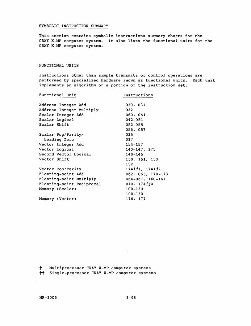
SYMBOLIC INSTRUCTION SUMMARY
This section contains symbolic instructions summary charts for the CRAY X-MP computer system. It also lists the functional units for the CRAY X-MP computer system.
FUNCTIONAL UNITS
Instructions other than simple transmits or control operations are performed by specialized hardware known as functional units. Each unit implements an algorithm or a portion of the instruction set.
Functional Unit
Address Integer Add Address Integer Multiply Scalar Integer Add Scalar Logical Scalar Shift
Scalar Pop/Parity/ Leading Zero
Vector Integer Add Vector Logical Second Vector Logical Vector Shift
Vector Pop/Parity Floating-point Add Floating-point Multiply Floating-point Reciprocal Memory (Scalar)
Memory (Vector)
Instructions
030, 031 032 060, 061 042-051 052-055 056, 057 026 027 154-157 140-147, 175 140-145 150, 151, 153 152 174ij1, 174ij2 062, 063, 170-173 064-067, 160-167 070, 174ijO 100-130 100-130 176, 177
t Multiprocessor CRAY X-MP computer systems tt Single-processor CRAY X-MP computer systems
HR-3005 3-98
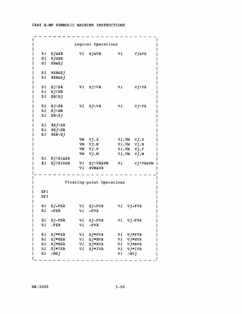
CRAY X-MP SYMBOLIC MACHINE INSTRUCTIONS
--------------------------
Logical Operations
Si Sj&Sk vi Sj&Vk vi Vj&Vk si Sj&SB Si SB&Sj
si #Sk&Sj si #SB&Sj
Si Sj!Sk vi Sj!Vk vi vj!Vk Si Sj!SB Si SB!Sj
Si Sj\Sk vi Sj\Vk vi vj\Vk si Sj\SB si SB\Sj
si #Sj\Sk Si #Sj\SB Si #SB\Sj
VM vj,Z Vi,VM vj,z VM Vj,N Vi,VM vj,N VM vj,p Vi,VM vj,p VM Vj,M Vi,VM Vj,M
Si Sj!Si&Sk Si Sj!Si&SB vi Sj!Vk&VM vi Vj!Vk&VM
vi #VM&Vk
-------------- ------------
Floating-point Operations
EFI DFI
Si Sj+FSk vi Sj+FVk vi Vj+FVk Si +FSk vi +Fvk
si Sj-FSk vi Sj-FVk vi vj-FVk si -FSk vi -Fvk
Si Sj*FSk vi Sj*FVk vi Vj*FVk si Sj*HSk vi Sj*HVk vi vj*HVk Si Sj*RSk vi Sj*RVk vi vj*RVk Si Sj*ISk vi Sj*IVk vi Vj*IVk Si IHSj vi IHVj
--------------------------
HR-3005 3-99
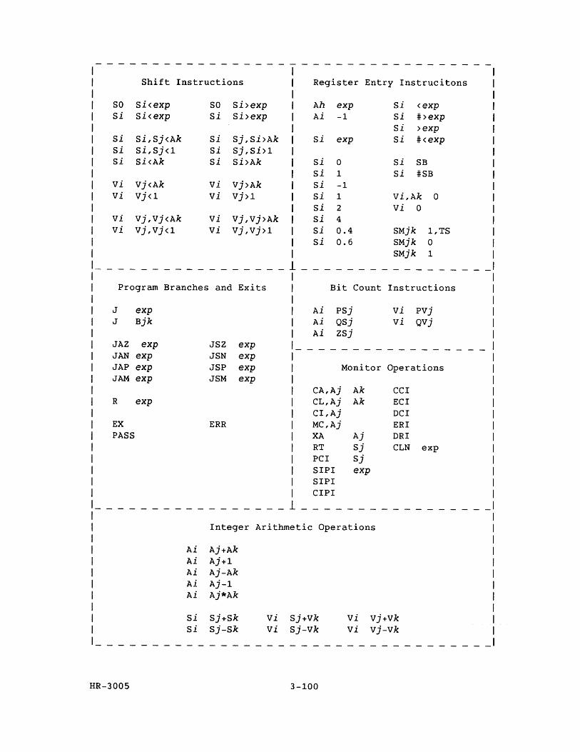
Shift Instructions Register Entry Instrucitons
SO si<exp Si Si<exp
Si Si,Sj<Ak Si Si,Sj<l Si Si<Ak
vi vi
vi vi
Vj<Ak Vj<1
Vj,Vj<Ak Vj,Vj<1
SO Si>exp Si Si>exp
si Sj,Si>Ak Si Sj,Si>1 si Si>Ak
vi vi
vi vi
Vj>Ak Vj>1
Vj,Vj>Ak Vj,Vj>1
Ah exp Ai -1
Si exp
Si 0 Si 1 Si Si Si Si Si Si
-1 1 2 4 0.4 0.6
si <exp si #>exp Si >exp Si #<exp
Si SB Si #SB
Vi,Ak vi 0
SMjk SMjk SMjk
o
1,TS o 1
Program Branches and Exits Bit Count Instructions
J J
JAZ JAN JAP JAM
R
EX PASS
HR-300S
exp Bjk
exp exp exp exp
exp
JSZ exp JSN exp JSP exp JSM exp
ERR
Ai PSj Ai QSj Ai zsj
vi PVj vi QVj
Monitor Operations
CA,Aj Ak CCI CL,Aj Ak ECI CI,Aj DCI MC,Aj ERI XA Aj DRI RT Sj CLN exp PCI Sj SIPI exp SIPI CIPI
- - -- ---------
Integer Arithmetic Operations
Ai Aj+Ak Ai Aj+l Ai Aj-Ak Ai Aj-l Ai Aj*Ak
Si Sj+Sk Si Sj-Sk
vi Sj+Vk vi Sj-Vk
3-100
vi vj+Vk vi vj-Vk
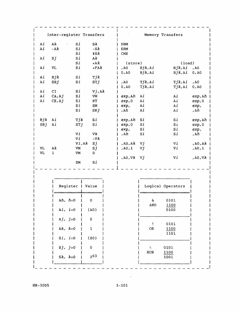
-------------------------------------
Inter-register Transfers Memory Transfers
Ai Ak Si Sk DBM Ai -Ak Si -Sk EBM
Si #Sk CMR Ai Sj Si Ak
Si +Ak (store) (load) Ai VL Si +FAk ,AD Bjk,Ai Bjk,Ai ,AD
O,AO Bjk,Ai Bjk,Ai O,AO Ai Bjk Si Tjk Ai SBj Si STj ,AD Tjk,Ai Tjk,Ai ,AD
O,AO Tjk,Ai Tjk,Ai O,AO Ai CI Si Vj,Ak Ai CA,Aj Si VM exp,Ah Ai Ai exp,Ah Ai CE,Aj Si RT exp,O Ai Ai exp,O
Si SM exp, Ai Ai exp, Si SRj ,Ah Ai Ai ,Ah
Bjk Ai Tjk Si exp,Ah Si Si exp,Ah SBj Ai STj Si exp,O Si Si exp,O
exp, Si Si exp, vi Vk ,Ah si si ,Ah vi -vk Vi,Ak Sj ,AO,Ak vj vi ,AO,Ak
VL Ak VM Sj ,AO,l Vj vi ,AO,l VL 1 VM 0
,AO,Vk vj vi ,AO,vk SM Si
-----------______ 1 _______
----------
Register Value Logical Operators
Ah, h=O 0 & 0101 AND 1100
Ai, i=O (AD) 0100
Aj, j=O 0 0101
Ak, k=O 1 OR 1100 1101
Si, i=O (SO)
Sj, j=O 0 \ 0101 XOR 1100
Sk, k=O 263 1001
HR-3005 3-101
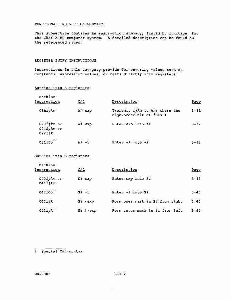
FUNCTIONAL INSTRUCTION SUMMARY
This subsection contains an instruction summary, listed by function, for the CRAY X-MP computer system. A detailed description can be found on the referenced pages.
REGISTER ENTRY INSTRUCTIONS
Instructions in this category provide for entering values such as constants, expression values, or masks directly into registers.
Entries into A registers
Machine Instruction
01hijkm
020ijkm or 021ijkm or 022ijk
031iOOt
CAL
Ah exp
Ai exp
Ai -1
Entries into S registers
Machine Instruction
040ijkm or 041ijkm
042ioot
042ijk
042ijkt
CAL
Si exp
Si -1
Si <exp
Si #>exp
t Special CAL syntax
HR-3005
Description
Transmit ijkm to Ah; where the high-order bit of i is 1
Enter exp into Ai
Enter -1 into Ai
Description
Enter exp into Si
Enter -1 into si
Form ones mask in si from right
Form zeros mask in si from left
3-102
3-31
3-32
3-38
3-45
3-46
3-46
3-46
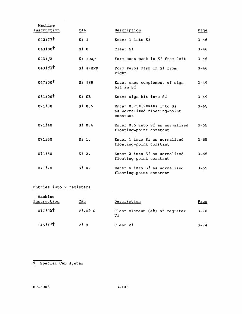
Machine Instruction
042i77t
043iOot
043ijk
043ijkt
047ioot
051ioot
071i30
071i40
071i50
071i60
071i70
CAL
Si 1
Si 0
Si >exp
Si #<exp
Si #SB
Si SB
Si 0.6
Si 0.4
Si 1.
Si 2.
Si 4.
Entries into V registers
Machine Instruction
077iOkt
145iiit
CAL
Vi,Ak 0
vi 0
t Special CAL syntax
HR-3005
Description
Enter 1 into si
Clear Si
Form ones mask in si from left
Form zeros mask in Si from right
Enter ones complement of sign bit in Si
Enter sign bit into Si
Enter 0.75*(2**48) into Si as normalized floating-point constant
Enter 0.5 into si as normalized floating-point constant
Enter 1 into Si as normalized floating-point constant
Enter 2 into Si as normalized floating-point constant
Enter 4 into Si as normalized floating-point constant
Description
Clear element (Ak) of register vi
Clear vi
3-103
3-46
3-46
3-46
3-46
3-49
3-49
3-65
3-65
3-65
3-65
3-65
3-70
3-74
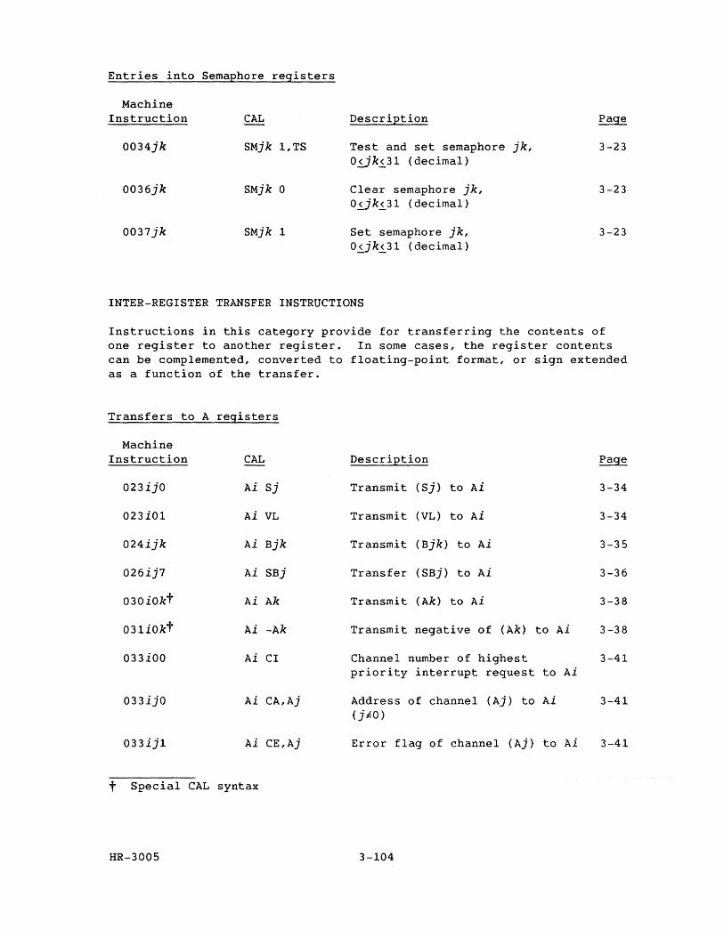
Entries into Semaphore registers
Machine Instruction CAL Description Page
0034jk SMjk 1,TS Test and set semaphore jk, 3-23 05..jk5..31 (decimal)
0036jk SMjk 0 Clear semaphore jk, 3-23 0~jk5..31 (decimal)
0037jk SMjk 1 Set semaphore jk, 3-23 05..jk5..31 (decimal)
INTER-REGISTER TRANSFER INSTRUCTIONS
Instructions in this category provide for transferring the contents of one register to another register. In some cases, the register contents can be complemented, converted to floating-point format, or sign extended as a function of the transfer.
Transfers to A registers
Machine Instruction CAL Description Page
023ijO Ai Sj Transmit (Sj) to Ai 3-34
023i01 Ai VL Transmit (VL) to Ai 3-34
024ijk Ai Bjk Transmit (Bjk) to Ai 3-35
026ij7 Ai SBj Transfer (SBj) to Ai 3-36
030iOkt Ai Ak Transmit (Ak) to Ai 3-38
031iOkt Ai -Ak Transmit negative of (Ak) to Ai 3-38
033iOO Ai CI Channel number of highest 3-41 priority interrupt request to Ai
033ijO Ai CA,Aj Address of channel (Aj) to Ai 3-41 (jiO)
033ij1 Ai CE,Aj Error flag of channel (Aj) to Ai 3-41
t Special CAL syntax
HR-3005 3-104
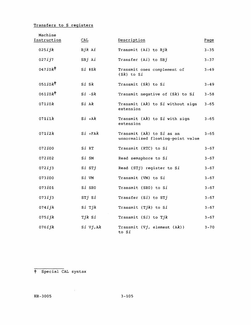
Transfers to S registers
Machine Instruction CAL Description Page
025ijk Bjk Ai Transmit (Ai) to Bjk 3-35
027ij7 SBj Ai Transfer (Ai) to SBj 3-37
047iOkt si #Sk Transmit ones complement of 3-49 (Sk) to Si
051iokt Si Sk Transmit (Sk) to Si 3-49
061iOkt Si -Sk Transmit negative of (Sk) to Si 3-58
071iOk Si Ak Transmit (Ak) to Si without sign 3-65 extension
071i1k Si +Ak Transmit (Ak) to si with sign 3-65 extension
071i2k Si +FAk Transmit (Ak) to Si as an 3-65 unnormalized floating-point value
072iOO Si RT Transmit (RTC) to Si 3-67
072i02 Si SM Read semaphore to Si 3-67
072ij3 Si STj Read (STj) register to Si 3-67
073iOO Si VM Transmit (VM) to si 3-67
073i01 Si SRO Transmit (SRO) to Si 3-67
073ij3 STj Si Transfer (Si) to STj 3-67
074ijk Si Tjk Transmit (Tjk) to si 3-67
075ijk Tjk Si Transmit (Si) to Tjk 3-67
076ijk Si Vj,Ak Transmit (vj, element (Ak» 3-70 to Si
t Special CAL syntax
HR-3005 3-105
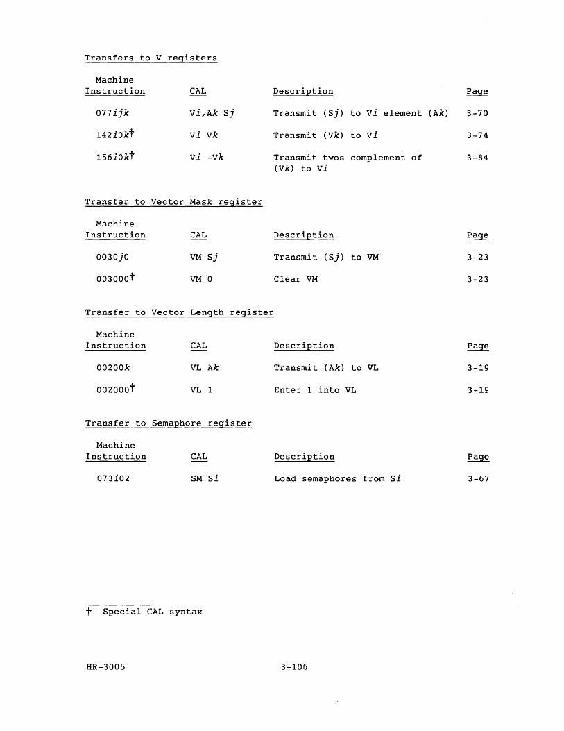
Transfers to V registers
Machine Instruction
077ijk
142iOkt
156iOkt
CAL
Vi,Ak
vi vk
vi -vk
Sj
Transfer to Vector Mask register
Machine Instruction
0030jO
003000t
CAL
VM Sj
VM 0
Transfer to Vector Length register
Machine Instruction
00200k
002000t
Transfer to
Machine Instruction
073i02
CAL
VL Ak
VL 1
Semaphore register
CAL
SM Si
t Special CAL syntax
HR-3005
Description Page
Transmit (Sj) to vi element (Ak) 3-70
Transmit (Vk) to vi 3-74
Transmit twos complement of 3-84 (Vk) to vi
Description
Transmit (Sj) to VM 3-23
Clear VM 3-23
Description
Transmit (Ak) to VL 3-19
Enter 1 into VL 3-19
Description
Load semaphores from si 3-67
3-106
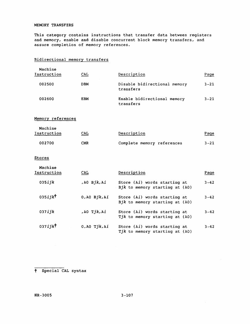
MEMORY TRANSFERS
This category contains instructions that transfer data between registers and memory, enable and disable concurrent block memory transfers, and assure completion of memory references.
Bidirectional memory transfers
Machine Instruction
002500
002600
Memory references
Machine Instruction
002700
Stores
Machine Instruction
035ijk
035ijkt
037ijk
037ijkt
CAL
DBM
EBM
CAL
CMR
CAL
,AO Bjk,Ai
O,AO Bjk,Ai
,AO Tjk,Ai
O,AO Tjk,Ai
t Special CAL syntax
HR-3005
Description
Disable bidirectional memory transfers
Enable bidirectional memory transfers
Description
Complete memory references
Description
Store (Ai) words starting at Bjk to memory starting at (AO)
Store (Ai) words starting at Bjk to memory starting at (AO)
Store (Ai) words starting at Tjk to memory starting at (AO)
Store (Ai) words starting at Tjk to memory starting at (AO)
3-107
3-21
3-21
Page
3-21
Page
3-42
3-42
3-42
3-42
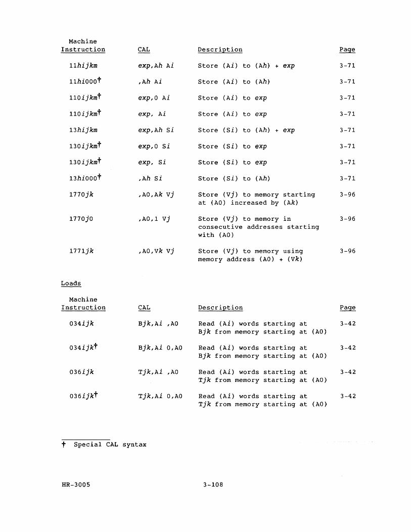
Machine Instruction CAL Description Page
11hijkm exp,Ah Ai Store (Ai) to (Ah) + exp 3-71
11hiOOot ,Ah Ai Store (Ai) to (Ah) 3-71
110ijkmt exp,O Ai Store (Ai) to exp 3-71
110ijkmt exp, Ai Store (Ai) to exp 3-71
13hijkm exp,Ah Si Store (Si) to (Ah) + exp 3-71
130ijkmt exp,O Si Store (Si) to exp 3-71
130ijkmt exp, Si Store (Si) to exp 3-71
13hiOOOt ,Ah Si Store (Si) to (Ah) 3-71
1770jk ,AO,Ak vj Store (vj) to memory starting 3-96 at (AO) increased by (Ak)
1770jO ,AO,1 Vj Store (vj) to memory in 3-96 consecutive addresses starting with (AD)
1771jk ,AD,vk Vj Store (Vj) to memory using 3-96 memory address (AD) + (Vk)
Loads
Machine Instruction CAL Description Page
D34ijk Bjk,Ai ,AD Read (Ai) words starting at 3-42 Bjk from memory starting at (AO)
D34ijkt Bjk,Ai D,AD Read (Ai) words starting at 3-42 Bjk from memory starting at (AD)
D36ijk Tjk,Ai ,AD Read (Ai) words starting at 3-42 Tjk from memory starting at (AD)
D36ijkt Tjk,Ai D,AD Read (Ai) words starting at 3-42 Tjk from memory starting at (AO)
t Special CAL syntax
HR-300S 3-108
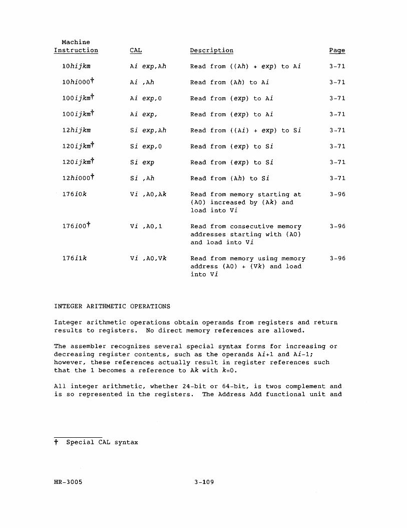
Machine Instruction CAL Description Page
10hijkm Ai exp,Ah Read from ( (Ah) + exp) to Ai 3-71
10hiOOOt Ai ,Ah Read from (Ah) to Ai 3-71
100ijkmt Ai exp,O Read from (exp) to Ai 3-71
100ijkmt Ai exp, Read from (exp) to Ai 3-71
12hijkm Si exp,Ah Read from ( (Ai) + exp) to Si 3-71
120ijkmt si exp,O Read from (exp) to Si 3-71
120ijkmt Si exp Read from (exp) to Si 3-71
12hiOOOt Si ,Ah Read from (Ah) to Si 3-71
176iOk vi ,AO,Ak Read from memory starting at 3-96 (AO) increased by (Ak) and load into vi
176iOOt Vi ,AO,1 Read from consecutive memory 3-96 addresses starting with (AO) and load into vi
176i1k vi ,AO,Vk Read from memory using memory 3-96 address (AO) + (Vk) and load into vi
INTEGER ARITHMETIC OPERATIONS
Integer arithmetic operations obtain operands from registers and return results to registers. No direct memory references are allowed.
The assembler recognizes several special syntax forms for increasing or decreasing register contents, such as the operands Ai+1 and Ai-1; however, these references actually result in register references such that the 1 becomes a reference to Ak with k=O.
All integer arithmetic, whether 24-bit or 64-bit, is twos complement and is so represented in the registers. The Address Add functional unit and
t Special CAL syntax
HR-3005 3-109
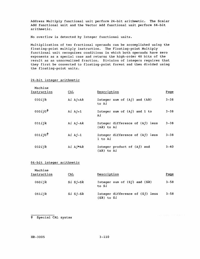
Address Multiply functional unit perform 24-bit arithmetic. The Scalar Add functional unit and the Vector Add functional unit perform 64-bit arithmetic.
No overflow is detected by Integer functional units.
Multiplication of two fractional operands can be accomplished using the floating-point multiply instruction. The Floating-point Multiply functional unit recognizes conditions in which both operands have zero exponents as a special case and returns the high-order 48 bits of the result as an unnormalized fraction. Division of integers requires that they first be converted to floating-point format and then divided using the floating-point units.
24-bit integer arithmetic
Machine Instruction CAL Description Page
030ijk Ai Aj+Ak Integer sum of (Aj) and (Ak) 3-38 to Ai
030ijOt Ai Aj+1 Integer sum of (Aj) and 1 to 3-38 Ai
031ijk Ai Aj-Ak Integer difference of (Aj) less 3-38 (Ak) to Ai
031ijOt Ai Aj-1 Integer difference of (Aj) less 3-38 1 to Ai
032ijk Ai Aj*Ak Integer product of (Aj) and 3-40 (Ak) to Ai
64-bit integer arithmetic
Machine Instruction CAL Description Page
060ijk Si Sj+Sk Integer sum of (Sj) and (Sk) 3-58 to Si
061ijk si Sj-Sk Integer difference of (Sj) less 3-58 (Sk) to Si
t Special CAL syntax
HR-3005 3-110
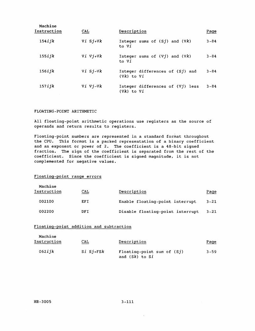
Machine Instruction CAL Description Page
154ijk vi Sj+Vk Integer sums of (Sj) and (Vk) 3-84 to vi
155ijk vi Vj+Vk Integer sums of (Vj) and (Vk) 3-84 to vi
156ijk vi Sj-Vk Integer differences of (Sj) and 3-84 (Vk) to vi
157ijk vi Vj-Vk Integer differences of (Vj) less 3-84 (Vk) to vi
FLOATING-POINT ARITHMETIC
All floating-point arithmetic operations use registers as the source of operands and return results to registers.
Floating-point numbers are represented in a standard format throughout the cpu. This format is a packed representation of a binary coefficient and an exponent or power of 2. The coefficient is a 48-bit signed fraction. The sign of the coefficient is separated from the rest of the coefficient. Since the coefficient is signed magnitude, it is not complemented for negative values.
Floating-point range errors
Machine Instruction
002100
002200
CAL
EFI
DFI
Description
Enable floating-point interrupt
Disable floating-point interrupt
Floating-point addition and subtraction
Machine Instruction
062ijk
HR-3005
CAL
Si Sj+FSk
Description
Floating-point sum of (Sj) and (Sk) to Si
3-111
3-21
3-21
3-59
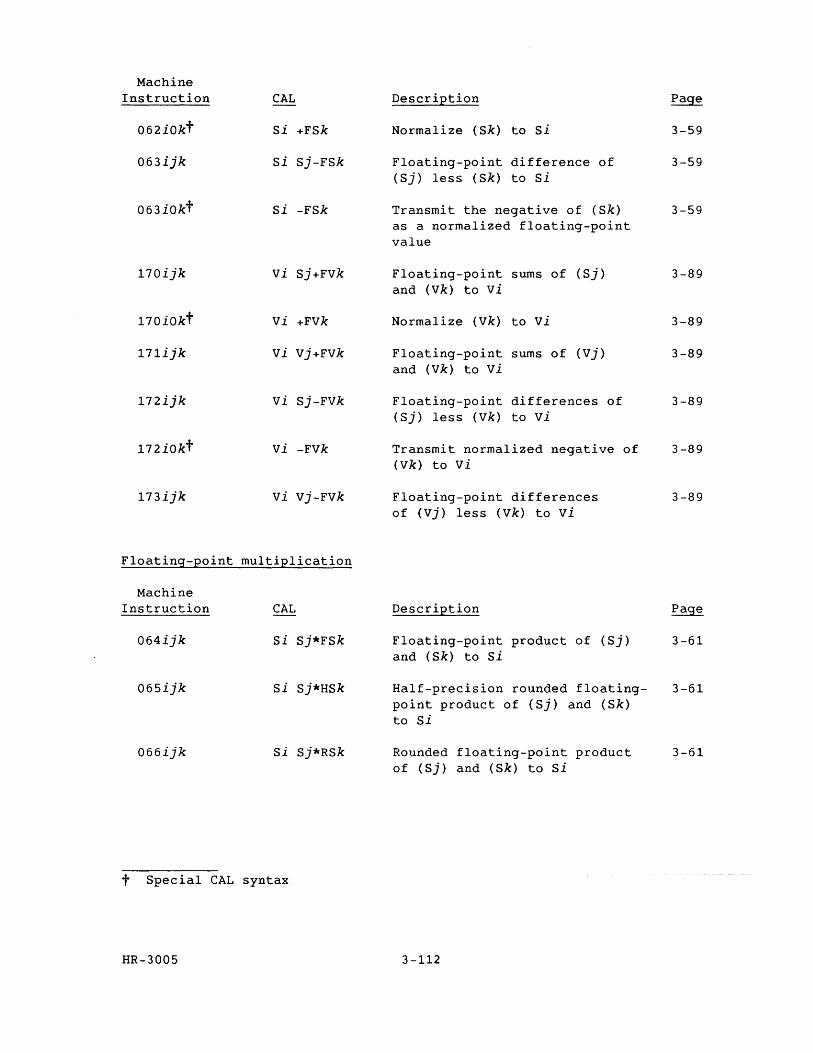
Machine Instruction CAL
062iOkt Si +FSk
063ijk si Sj-FSk
063iOkt Si -FSk
170ijk vi Sj+FVk
170iOkt vi +Fvk
171ijk vi vj+FVk
172ijk vi Sj-FVk
172iOkt vi -Fvk
173ijk vi vj-Fvk
Floating-point multiplication
Machine Instruction
064ijk
065ijk
066ijk
CAL
Si Sj*FSk
si Sj*HSk
Si Sj*RSk
t Special CAL syntax
HR-3005
Description
Normalize (Sk) to si
Floating-point difference of (Sj) less (Sk) to Si
Transmit the negative of (Sk) as a normalized floating-point value
Floating-point sums of (Sj) and (Vk) to vi
Normalize (Vk) to vi
Floating-point sums of (Vj) and (Vk) to vi
Floating-point differences of (Sj) less (Vk) to vi
Transmit normalized negative of (Vk) to vi
Floating-point differences of (vj) less (Vk) to vi
Description
Floating-point product of (Sj) and (Sk) to Si
Half-precision rounded floatingpoint product of (Sj) and (Sk) to Si
Rounded floating-point product of (Sj) and (Sk) to Si
3-112
3-59
3-59
3-59
3-89
3-89
3-89
3-89
3-89
3-89
3-61
3-61
3-61
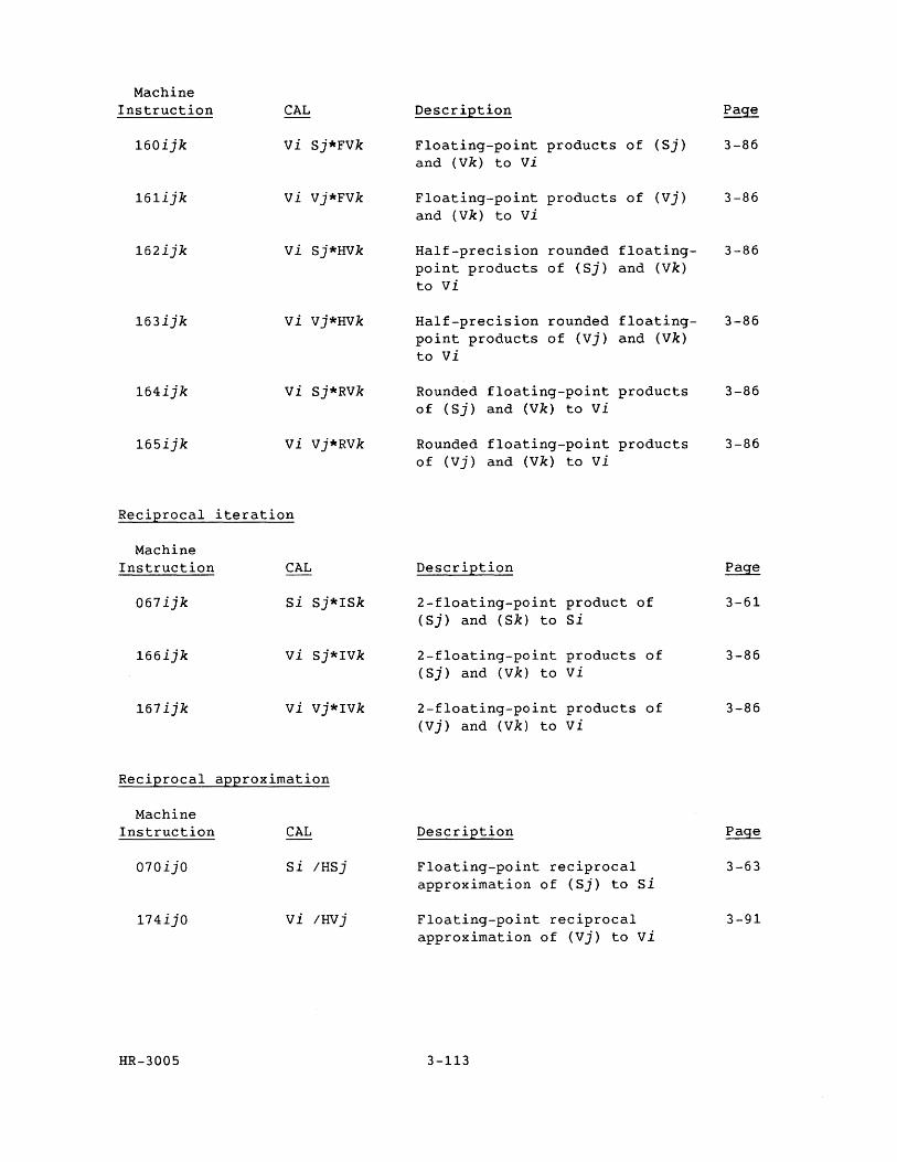
Machine Instruction
160ijk
161ijk
162ijk
163ijk
164ijk
165ijk
Reciprocal
Machine Instruction
067ijk
166ijk
167ijk
CAL
vi Sj*FVk
vi Vj*FVk
vi Sj*HVk
vi vj*HVk
vi Sj*RVk
vi Vj*RVk
iteration
CAL
Si Sj*ISk
vi Sj*IVk
vi vj*IVk
Reciprocal approximation
Machine Instruction
070ijO
174ijO
HR-3005
CAL
Si IHSj
vi IHVj
Description
Floating-point products of (Sj) and (Vk) to vi
Floating-point products of (Vj) and (Vk) to vi
Half-precision rounded floating-point products of (Sj) and (Vk) to vi
Half-precision rounded floating-point products of (Vj) and (Vk) to vi
Rounded floating-point products of (Sj) and (Vk) to vi
Rounded floating-point products of (vj) and (Vk) to vi
Description
2-floating-point product of (Sj) and (Sk) to Si
2-floating-point products of (Sj) and (Vk) to vi
2-floating-point products of (vj) and (Vk) to vi
Description
Floating-point reciprocal approximation of (Sj) to Si
Floating-point reciprocal approximation of (Vj) to vi
3-113
Page
3-86
3-86
3-86
3-86
3-86
3-86
Page
3-61
3-86
3-86
3-63
3-91
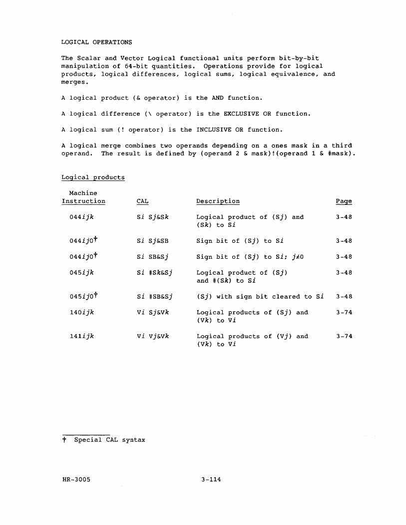
LOGICAL OPERATIONS
The Scalar and Vector Logical functional units perform bit-by-bit manipulation of 64-bit quantities. Operations provide for logical products, logical differences, logical sums, logical equivalence, and merges.
A logical product (& operator) is the AND function.
A logical difference (\ operator) is the, EXCLUSIVE OR function.
A logical sum (! operator) is the INCLUSIVE OR function.
A logical merge combines two operands depending on a ones mask in a third operand. The result is defined by (operand 2 & mask)! (operand 1 & #mask).
Logical products
Machine Instruction CAL Description Page
044ijk Si Sj&Sk Logical product of (Sj) and 3-48 (Sk) to Si
044ijOt Si Sj&SB Sign bit of (Sj) to Si 3-48
044ijOt Si SB&Sj Sign bit of (Sj) to Si; jiO 3-48
045ijk Si #Sk&Sj Logical product of (Sj) 3-48 and #(Sk) to Si
045ijOt Si #SB&Sj (Sj) with sign bit cleared to Si 3-48
140ijk vi Sj&Vk Logical products of (Sj) and 3-74 (Vk) to vi
141ijk vi vj&Vk Logical products of (Vj) and 3-74 (Vk) to vi
t Special CAL syntax
HR-3005 3-114
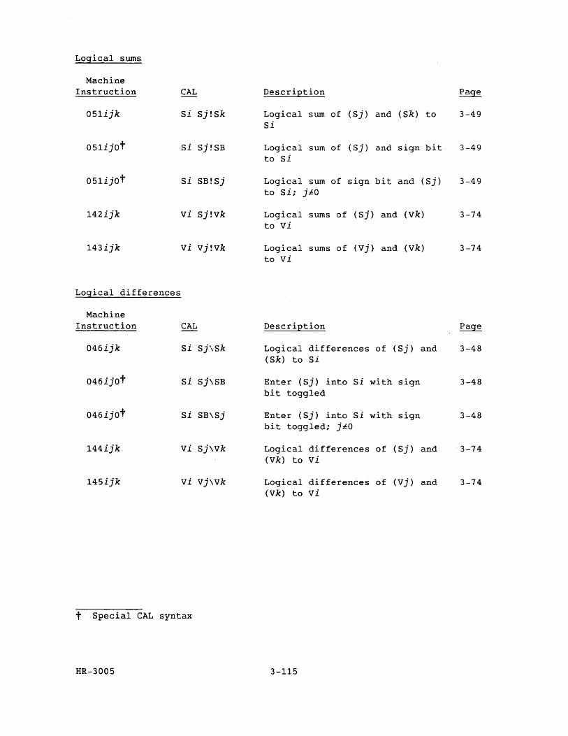
Logical sums
Machine Instruction CAL Description Page
051ijk Si Sj!Sk Logical sum of (Sj) and ( Sk) to 3-49 Si
051ijOt Si Sj!SB Logical sum of (Sj) and sign bit 3-49 to si
051ijOt Si SB!Sj Logical sum of sign bit and (Sj) 3-49 to Si; j~O
142ijk vi Sj!Vk Logical sums of (Sj) and (Vk) 3-74 to vi
143ijk vi Vj!Vk Logical sums of (vj) and (Vk) 3-74 to vi
Logical differences
Machine Instruction CAL Description Page
046ijk Si Sj\Sk Logical differences of (Sj) and 3-48 (Sk) to Si
046ijOt Si Sj\SB Enter (Sj) into Si with sign 3-48 bit toggled
046ijot Si SB\Sj Enter (Sj) into si with sign 3-48 bit toggled; j~O
144ijk vi Sj\Vk Logical differences of (Sj) and 3-74 (Vk) to vi
145ijk vi Vj\Vk Logical differences of (Vj) and 3-74 (Vk) to vi
t Special CAL syntax
HR-3005 3-115
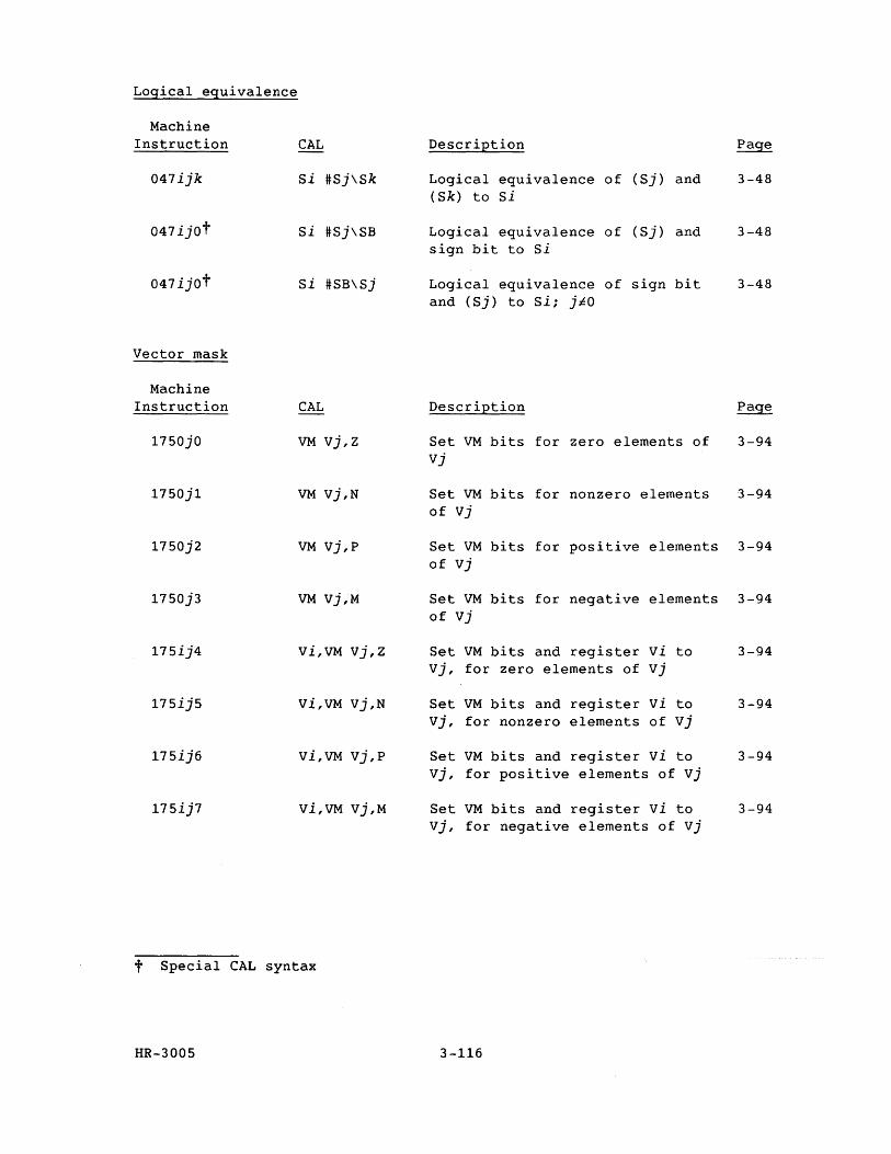
Logical equivalence
Machine Instruction
047ijk
047ijot
047ijot
Vector mask
Machine Instruction
17S0jO
17S0j1
17S0j2
17S0j3
17Sij4
17SijS
17Sij6
17Sij7
CAL
Si #Sj\Sk
Si #Sj\SB
Si #SB\Sj
CAL
VM vj,z
VM Vj,N
VM vj,p
VM Vj,M
Vi,VM vj,z
Vi,VM Vj,N
Vi,VM vj,p
Vi,VM Vj,M
t Special CAL syntax
HR-300S
Description
Logical equivalence of (Sj) and (Sk) to Si
Logical equivalence of (Sj) and sign bit to Si
Logical equivalence of sign bit and (Sj) to si; jiO
3-48
3-48
3-48
Description Page
Set VM bits for zero elements of 3-94 Vj
Set VM bits for nonzero elements 3-94 of vj
Set VM bits for positive elements 3-94 of Vj
Set VM bits for negative elements 3-94 of vj
Set VM bits and register vi to Vj, for zero elements of Vj
Set VM bits and register vi to Vj, for nonzero elements of Vj
Set VM bits and register vi to Vj, for positive elements of Vj
Set VM bits and register vi to Vj, for negative elements of Vj
3-116
3-94
3-94
3-94
3-94
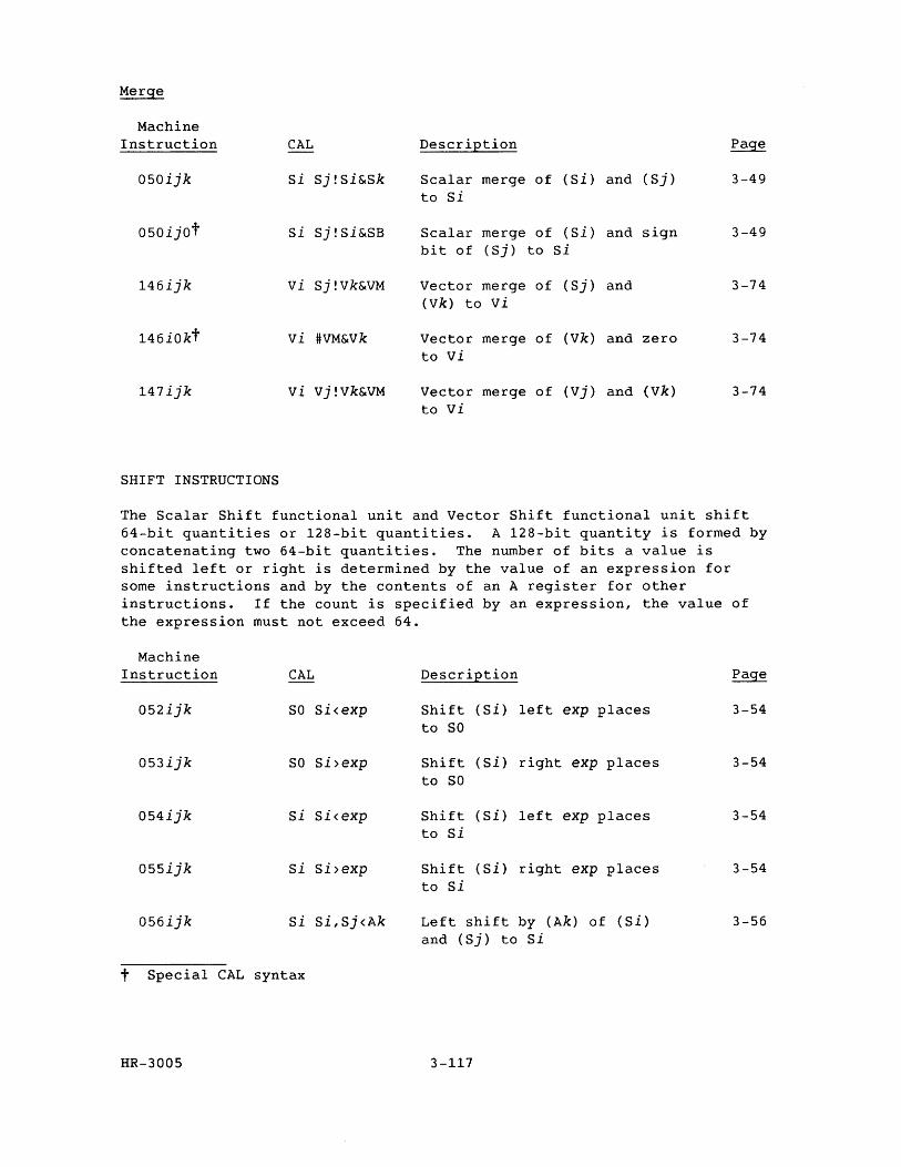
Machine Instruction
050ijk
050ijot
146ijk
146iOkt
147ijk
SHIFT INSTRUCTIONS
CAL
Si Sj!Si&Sk
si Sj!Si&SB
vi Sj!Vk&VM
vi #VM&Vk
vi Vj!Vk&VM
Description
Scalar merge of (Si) and (Sj) to Si
Scalar merge of (Si) and sign bit of (Sj) to Si
Vector merge of (Sj) and (Vk) to vi
Vector merge of (Vk) and zero to vi
Vector merge of (vj) and (Vk) to vi
3-49
3-49
3-74
3-74
3-74
The Scalar Shift functional unit and Vector Shift functional unit shift 64-bit quantities or 128-bit quantities. A 128-bit quantity is formed by concatenating two 64-bit quantities. The number of bits a value is shifted left or right is determined by the value of an expression for some instructions and by the contents of an A register for other instructions. If the count is specified by an expression, the value of the expression must not exceed 64.
Machine Instruction CAL Description Page
052ijk SO Si<exp Shift (Si) left exp places 3-54 to SO
053ijk SO Si>exp Shift (Si) right exp places 3-54 to SO
054ijk Si Si<exp Shift (Si) left exp places 3-54 to Si
055ijk Si Si>exp Shift (Si) right exp places 3-54 to Si
056ijk Si Si,Sj<Ak Left shift by (Ak) of (Si) 3-56 and (Sj) to Si
t Special CAL syntax
HR-3005 3-117
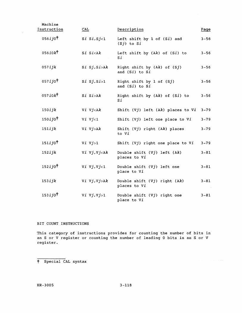
Machine Instruction CAL DescriEtion Page
056ijOt Si Si,Sj<l Left shift by 1 of (Si) and 3-56 (Sj) to Si
056iOkt Si Si<Ak Left shift by (Ak) of (Si) to 3-56 Si
057ijk Si Sj,Si>Ak Right shift by (Ak) of (Sj) 3-56 and (Si) to si
057ijOt Si Sj,Si>l Right shift by 1 of (Sj) 3-56 and (Si) to Si
057iOkt Si Si>Ak Right shift by (Ak) of (Si) to 3-56 Si
150ijk vi Vj<Ak Shift (Vj) left (Ak) places to vi 3-79
150ijOt vi Vj<l Shift (vj) left one place to vi 3-79
151ijk vi Vj>Ak Shift (vj) right (Ak) places 3-79 to vi
151ijOt vi Vj>l Shift (Vj) right one place to vi 3-79
152ijk vi Vj,Vj<Ak Double shift (Vj) left (Ak) 3-81 places to vi
152ijOt vi Vj,Vj<l Double shift (Vj) left one 3-81 place to vi
153ijk vi vj,Vj>Ak Double shift (Vj) right (Ak) 3-81 places to vi
153ijOt vi Vj,Vj>l Double shift (Vj) right one 3-81 place to vi
BIT COUNT INSTRUCTIONS
This category of instructions provides for counting the number of bits in an S or V register or counting the number of leading 0 bits in an S or V register.
t Special CAL syntax
HR-3005 3-118
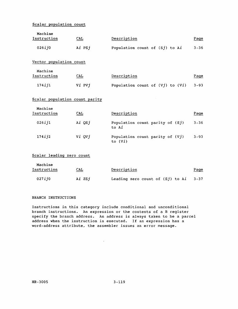
Scalar population count
Machine Instruction CAL
026ijO Ai PSj
Vector population count
Machine Instruction CAL
174ij1 vi PVj
Scalar population count parity
Machine Instruction
026ij1
174ij2
CAL
Ai QSj
vi QVj
Scalar leading zero count
Machine Instruction
027ijO
BRANCH INSTRUCTIONS
CAL
Ai ZSj
Description
Population count of (Sj) to Ai
Description
Population count of (vj) to (Vi)
Description
Population count parity of (Sj) to Ai
Population count parity of (vj) to (Vi)
Description
Leading zero count of (Sj) to Ai
3-36
3-93
3-36
3-93
3-37
Instructions in this category include conditional and unconditional branch instructions. An expression or the contents of a B register specify the branch address. An address is always taken to be a parcel address when the instruction is executed. If an expression has a word-address attribute, the assembler issues an error message.
HR-3005 3-119
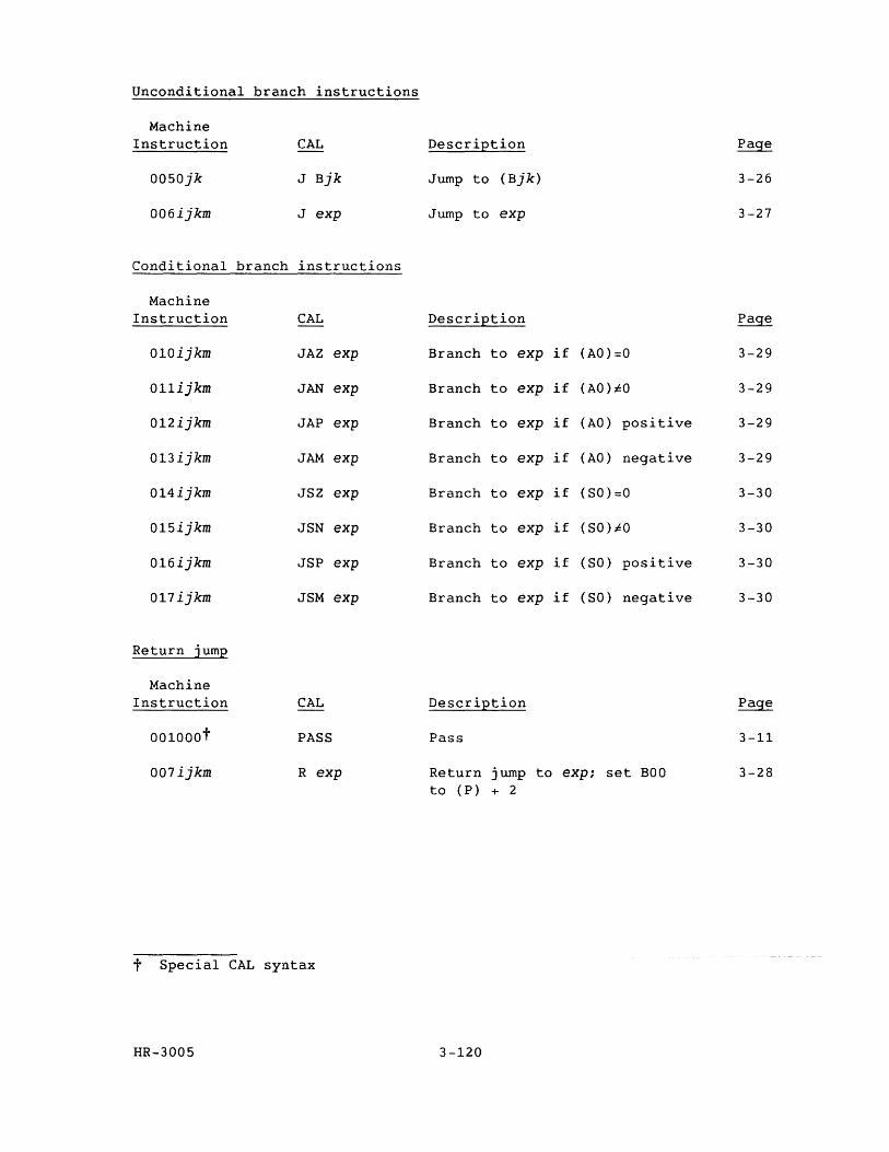
Unconditional branch instructions
Machine Instruction CAL Description Page
0050jk J Bjk Jump to (Bjk) 3-26
006ijkm J exp Jump to exp 3-27
Conditional branch instructions
Machine Instruction CAL Description Page
010ijkm JAZ exp Branch to exp if (AO)=O 3-29
011ijkm JAN exp Branch to exp if (AO)iO 3-29
012ijkm JAP exp Branch to exp if (AO) positive 3-29
013ijkm JAM exp Branch to exp if (AO) negative 3-29
014ijkm JSZ exp Branch to exp if (SO)=O 3-30
015ijkm JSN exp Branch to exp if (SO)iO 3-30
016ijkm JSP exp Branch to exp if (SO) positive 3-30
017ijkm JSM exp Branch to exp if (SO) negative 3-30
Return jump
Machine Instruction CAL Description Page
001000t PASS Pass 3-11
007ijkm R exp Return jump to exp; set BOO 3-28 to (P) + 2
t Special CAL syntax
HR-3005 3-120
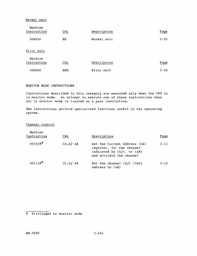
Normal exit
Machine Instruction CAL Description Page
004000 EX Normal exit 3-25
Error exit
Machine Instruction CAL Description Page
000000 ERR Error exit 3-10
MONITOR MODE INSTRUCTIONS
Instructions described in this category are executed only when the CPU is in monitor mode. An attempt to execute one of these instructions when not in monitor mode is treated as a pass instruction.
The instructions perform specialized functions useful to the operating system.
Channel control
Machine Instruction
0010jkt
0011jkt
CAL
CA,Aj Ak
CL,Aj Ak
t Privileged to monitor mode
HR-3005
Description
Set the Current Address (CA) register, for the channel indicated by (Aj), to (Ak) and activate the channel
Set the channel (Aj) limit address to (Ak)
3-121
3-11
3-12
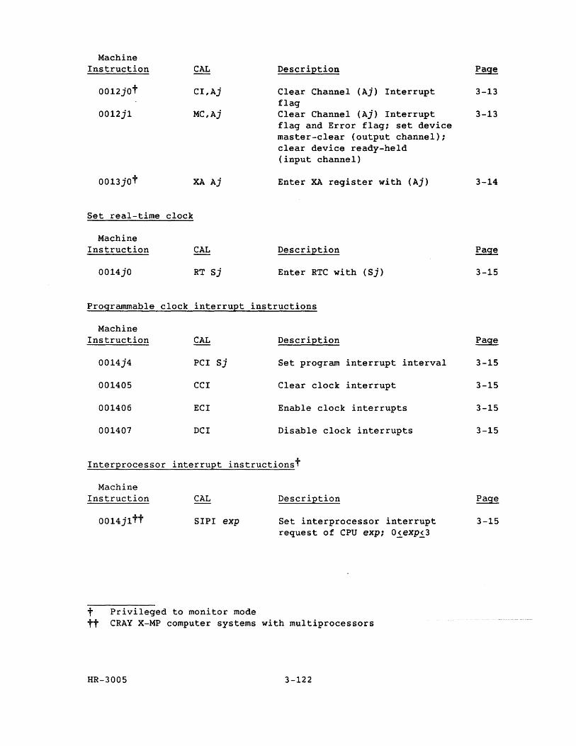
Machine Instruction
0012jOt
0012j1
0013jOt
Set real-time
Machine Instruction
0014jO
Programmable
Machine Instruction
0014j4
001405
001406
001407
CAL
CI,Aj
MC,Aj
XA Aj
clock
CAL
RT Sj
clock interrupt
CAL
PCI Sj
CCI
ECI
DCI
Description
Clear Channel (Aj) Interrupt flag Clear Channel (Aj) Interrupt flag and Error flag; set device master-clear (output channel); clear device ready-held (input channel)
Enter XA register with (Aj)
Description
Enter RTC with (Sj)
instructions
Description
Set program interrupt interval
Clear clock interrupt
Enable clock interrupts
Disable clock interrupts
Interprocessor interrupt instructionst
Machine Instruction
0014j1tt
CAL
SIPI exp
t Privileged to monitor mode
Description
Set interprocessor interrupt request of CPU exp; 0~exp~3
tt CRAY X-MP computer systems with multiprocessors
HR-3005 3-122
3-13
3-13
3-14
3-15
Page
3-15
3-15
3-15
3-15
3-15
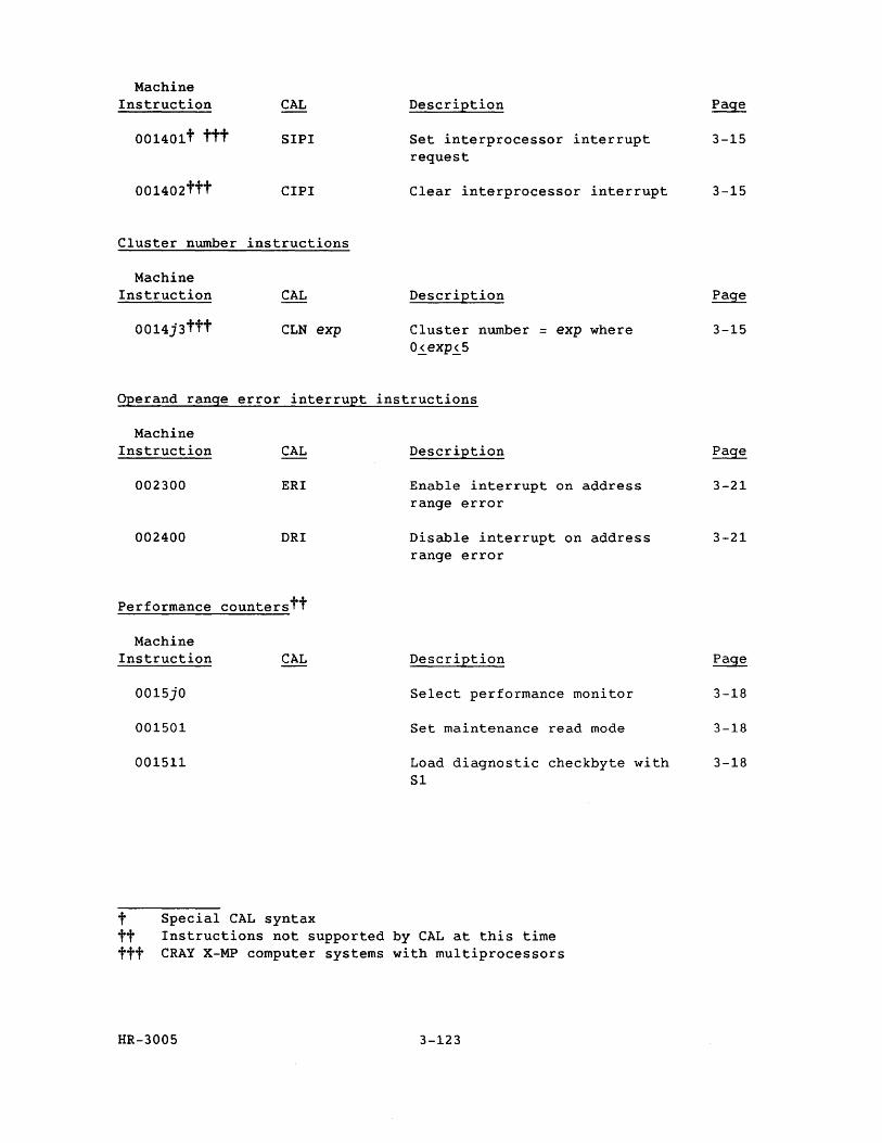
Machine Instruction
001401t ttt
001402ttt
CAL
SIPI
CIPI
Cluster number instructions
Machine Instruction
0014j3ttt
CAL
CLN exp
Description
Set interprocessor interrupt request
Clear interprocessor interrupt
Description
Cluster number = exp where 0~exp~5
Operand range error interrupt instructions
Machine Instruction CAL
002300 ERI
002400 DRI
Performance counterstt
Machine Instruction
0015jO
001501
001511
CAL
t Special CAL syntax
Description
Enable interrupt on address range error
Disable interrupt on address range error
Description
Select performance monitor
Set maintenance read mode
Load diagnostic checkbyte with Sl
tt Instructions not supported by CAL at this time ttt CRAY X-MP computer systems with multiprocessors
HR-3005 3-123
3-15
3-15
3-15
Page
3-21
3-21
3-18
3-18
3-18
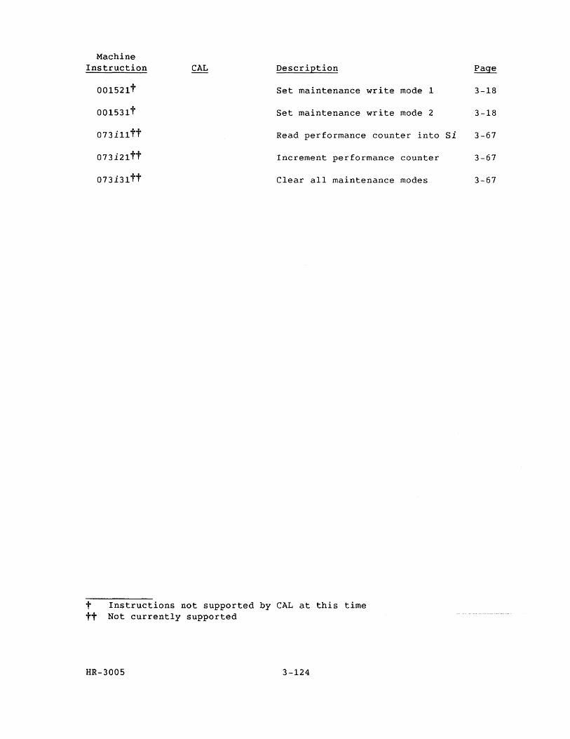
Machine Instruction CAL DescriEtion
001521t Set maintenance write mode 1
001531t Set maintenance write mode 2
073i11tt Read performance counter into
073i21tt Increment performance
073i31tt Clear all maintenance
t Instructions not supported by CAL at this time tt Not currently supported
HR-3005 3-124
counter
modes
Page
3-18
3-18
Si 3-67
3-67
3-67
CRAY X-MP SYSTEM CONFIGURATIONS
The CRAY X-MP mainframe, 1/0 Subsystem (lOS), and associated equipment units are available with a number of options in a variety of system configurations. The options, such as the number of central processing units (CPUs), 1/0 Processors (lOPs), and channel connections, and a variety of memory sizes, banking arrangements, and peripheral devices, are used to produce several unique models. Table 4-1 shows an overview of all CRAY X-MP models currently available. A specification sheet is provided for each model later in this section; each specification sheet contains specific information for each of the CRAY X-MP models.
HR-3005 4-1
4

HR-300S 4-2
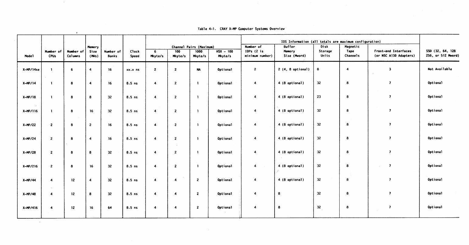
Table 4-1. CRAY X-HP Computer Systems Overview
lOS Information (all totals are maximum configuration) MellOry Channel Pairs (Maximum) Number of Buffer Disk Magnetic
NUliber of NUliber of Size Number of Clock 6 100 1000 HSX - 100 lOPs (2 is MeIIory Storage Tape Front-end Interfaces SSD (32, 64, 128 Model CPUs Columns (ttis) Banks Speed Hbyte/s Hbyte/s "byte/s "byte/s minimum number) Size (f1word) Units Channels (or NSC A130 Adapters) 256, or 512 f1word)
(
X-MP/14se 1 6 4 16 xx.x ns 2 2 NA Optional 2 2 (4, 8 optional) 8 4 3 Not Available
X-HP114 1 8 4 16 8.5 ns 4 2 1 Optional 4 4 (8 optional) 32 8 7 Optional
X-"P/18 1 8 8 32 8.5 ns 4 2 1 Optional 4 4 (8 optional) 23 8 7 Opt ional
X-MP1116 1 8 16 32 8.5 ns 4 2 1 Optional 4 4 (8 optional) 32 8 7 Opt ional
X-"P/22 2 8 2 16 8.5 ns 4 2 1 Optional 4 4 (8 optional) 32 8 7 Optional
X-MP/24 2 8 4 16 8.5 ns 4 2 1 Optional 4 4 (8 optional) 32 8 7 Optional
X-MP/28 2 8 8 32 8.5 ns 4 2 1 Optional 4 4 (8 optional) 32 8 7 Optional
X-MP/216 2 8 16 32 8.5 ns 4 2 1 Optional 4 4 (8 optional) 32 8 7 Optional
/
X-MP/44 4 12 4 32 8.5 ns 4 4 2 Optional 4 4 (8 optional) 32 8 7 Optional
X-MP/48 4 12 8 32 8.5 ns 4 4 2 Optional 4 8 32 8 7 Optional
X-MP/416 4 12 16 64 8.5 ns 4 4 2 Optional 4 8 32 8 7 Optional
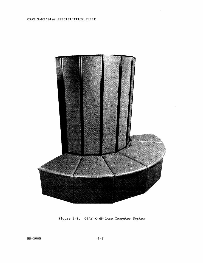
CRAY X-MP/14se SPECIFICATION SHEET
Figure 4-1. CRAY X-MP/14se Computer System
HR-3005 4-3
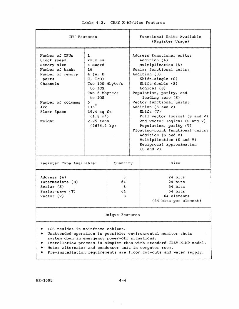
Table 4-2. CRAY X-MP/14se Features
CPU Features Functional Units Available
Number of CPUs Clock speed Memory size Number of banks Number of memory ports
Channels
Number of columns Arc Floor Space
Weight
1 xx.x ns 4 Mword 16 4 (A, B C, liD) Two 100 Mbyte/s
to IDS Two 6 Mbyte/s to IDS
6 135
0
19.4 sq ft (1.8 m2 )
2.95 tons (2676.2 kg)
Register Type Available: Quantity
Address (A) Intermediate (B) Scalar (S) Scalar-save (T) Vector (V)
8 64
8 64
8
(Register Usage)
Address functional units: Addition (A) Multiplication (A)
Scalar functional units: Addition (S)
Shift-single (S) Shift-double (S) Logical (S)
Population, parity, and leading zero (S)
Vector functional units: Addition (S and V)
Shift (V) Full vector logical (S and V) 2nd vector logical (S and V) Population, parity (V)
Floating-point functional units: Addition (S and V) Multiplication (S and V) Reciprocal approximation (S and V)
Size
24 bits 24 bits 64 bits 64 bits
64 elements (64 bits per element)
Unique Features
• IDS resides in mainframe cabinet. • Unattended operation is possible; environmental monitor shuts
system down in emergency power-off situations. • Installation process is simpler than with standard CRAY X-MP model. • Motor alternator and condenser unit in computer room. • Pre-installation requirements are floor cut-outs and water supply.
HR-3005 4-4
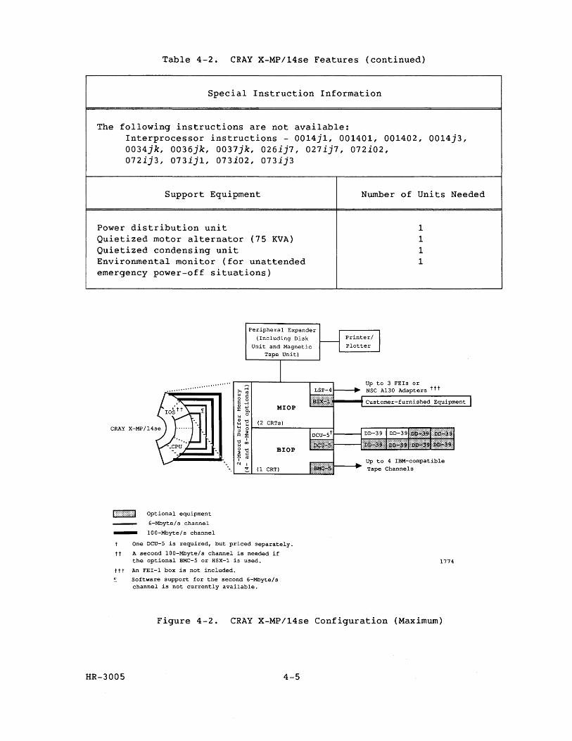
Table 4-2. CRAY X-MP/14se Features (continued)
Special Instruction Information
The following instructions are not available: Interprocessor instructions - 0014jl, 001401, 001402, 0014j3, 0034jk, 0036jk, 0037jk, 026ij7, 027ij7, 072i02, 072ij3, 073ij1, 073i02, 073ij3
Support Equipment
Power distribution unit Quietized motor alternator (75 KVA) Quietized condensing unit Environmental monitor (for unattended emergency power-off situations)
I: ()Wrt] Optional equipment
6-Mbyte/s channel
- 100-Mbyte/s channel
--
Peripheral Expander (Including Disk
Unit and Magnetic Tape Unit)
>,::l k co o § ~ j MIOP ~ 0.. k 0
Q) '0 (2 CRTs) 4-1 ~ 4-1 0 ;l :J III l: '0 I k <X)
o '0 BIOP ~ I:: ~ co N I
:::. (1 CRT)
One DCU-5 is required, but priced separately.
tt A second 100-Mbyte/s channel is needed if the optional BMC-5 or HSX-1 is used.
ttt An FEI-1 box is not included.
~ Software support for the second 6-Mbyte/s channel is not currently available.
Number of Units Needed
1 1 1 1
Up to 3 FEIs or NSC A130 Adapters ttt
Up to 4 IBM-compatible Tape Channels
1774
Figure 4-2. CRAY X-MP/14se Configuration (Maximum)
HR-3005 4-5

RESEARCH, INC. Copyright@1987 by CRAY RESEARCH, INC.

CRAY X-MP/14 SPECIFICATION SHEET
Figure 4-3. CRAY X-MP/14 Computer System
HR-3005 4-7
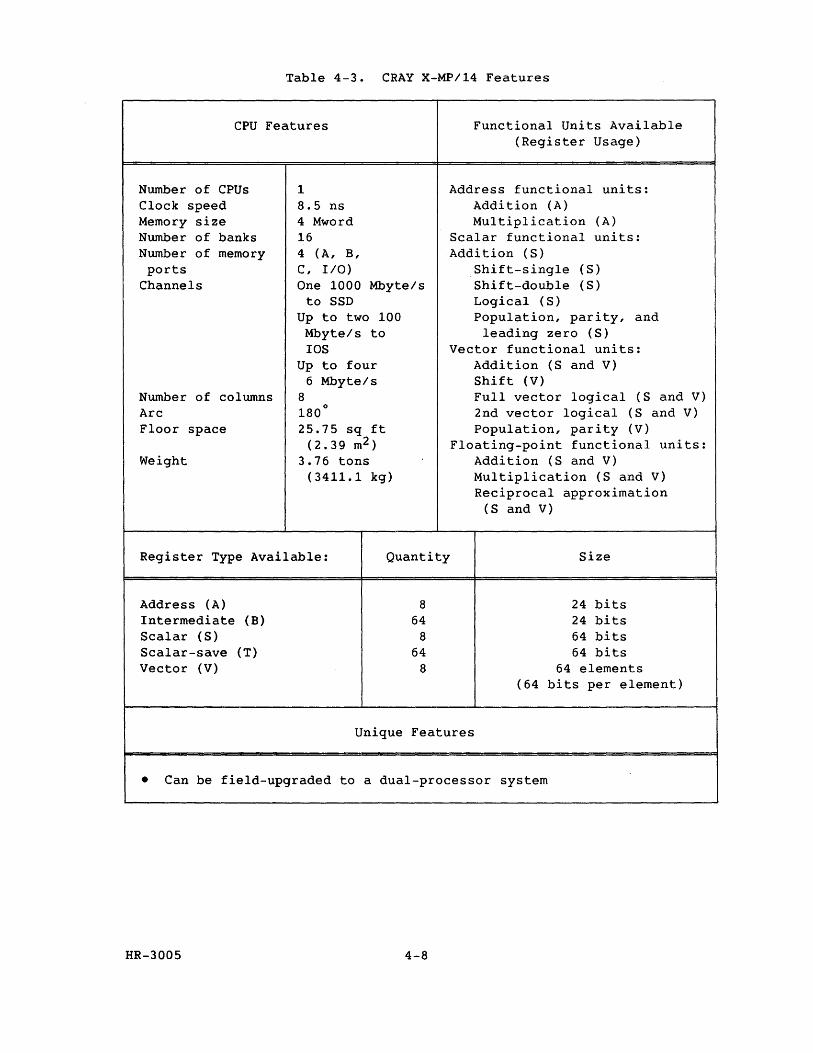
Table 4-3. CRAY X-MP/14 Features
CPU Features Functional Units Available
Number of CPUs Clock speed Memory size Number of banks Number of memory ports
Channels
Number of columns Arc Floor space
Weight
1 8.5 ns 4 Mword 16 4 (A, B, C, I/O) One 1000 Mbyte/s
to SSD Up to two 100
Mbyte/s to IDS
Up to four 6 Mbyte/s
8 180
0
25.75 sq ft (2.39 m2 )
3.76 tons (3411.1 kg)
(Register Usage)
Address functional units: Addition (A) Multiplication (A)
Scalar functional units: Addition (S)
Shift-single (S) Shift-double (S) Logical (S) Population, parity, and
leading zero (S) Vector functional units:
Addition (S and V) Shift (V) Full vector logical (S and V) 2nd vector logical (S and V) Population, parity (V)
Floating-point functional units: Addition (S and V) Multiplication (S and V) Reciprocal approximation
(S and V)
Register Type Available: Quantity Size
Address (A) Intermediate (B) Scalar (S) Scalar-save (T) Vector (V)
8 64
8 64
8
Unique Features
24 bits 24 bits 64 bits 64 bits
64 elements (64 bits per element)
• Can be field-upgraded to a dual-processor system
HR-3005 4-8

Table 4-3. CRAY X-MP/14 Features (continued)
Special Instruction Information
The following instructions are not available: Interprocessor instructions - 0014j1, 001401, 001402, 0014j3, 0034jk, 0036jk, 0037jk, 026ij7, 027ij7, 072i02, 072ij3, 073ij1, 073i02, 073ij3
Support Equipment
Mainframe power distribution unit IDS power distribution unit Refrigeration condensing unit Motor-generator sets SSD power distribution unit (optional) Maintenance micro computer unit
-
SSD (64,128,256
or 512 Mword)
lOS
6-Mbyte/s channel
100 -Mbyte / schanne 1
1"1
- 1000-Mbyte/s channel
Optional equipment
",
"'" '"
'" 1,_,
-'-1 "
Peripheral Expander
(Including Disk Unit and Magnetic
Tape Unit)
MIOP
(3 CRTs)
BIOP
Number of Units Needed
1 1 1 2 1 1
To 3 FEIs or NSC A130 Adapters
To 4 FEIs or NSC A130 Adapters
1772-01
Figure 4-4. CRAY X-MP/14 Configuration (Maximum)
HR-3005 4-9

RESEARCH, INC. Copyright© 1987 by CRAY RESEARCH, INC.
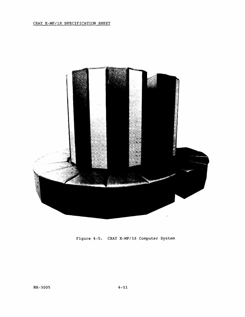
CRAY X-MP/18 SPECIFICATION SHEET
Figure 4-5. CRAY X-MP/18 Computer System
HR-3005 4-11
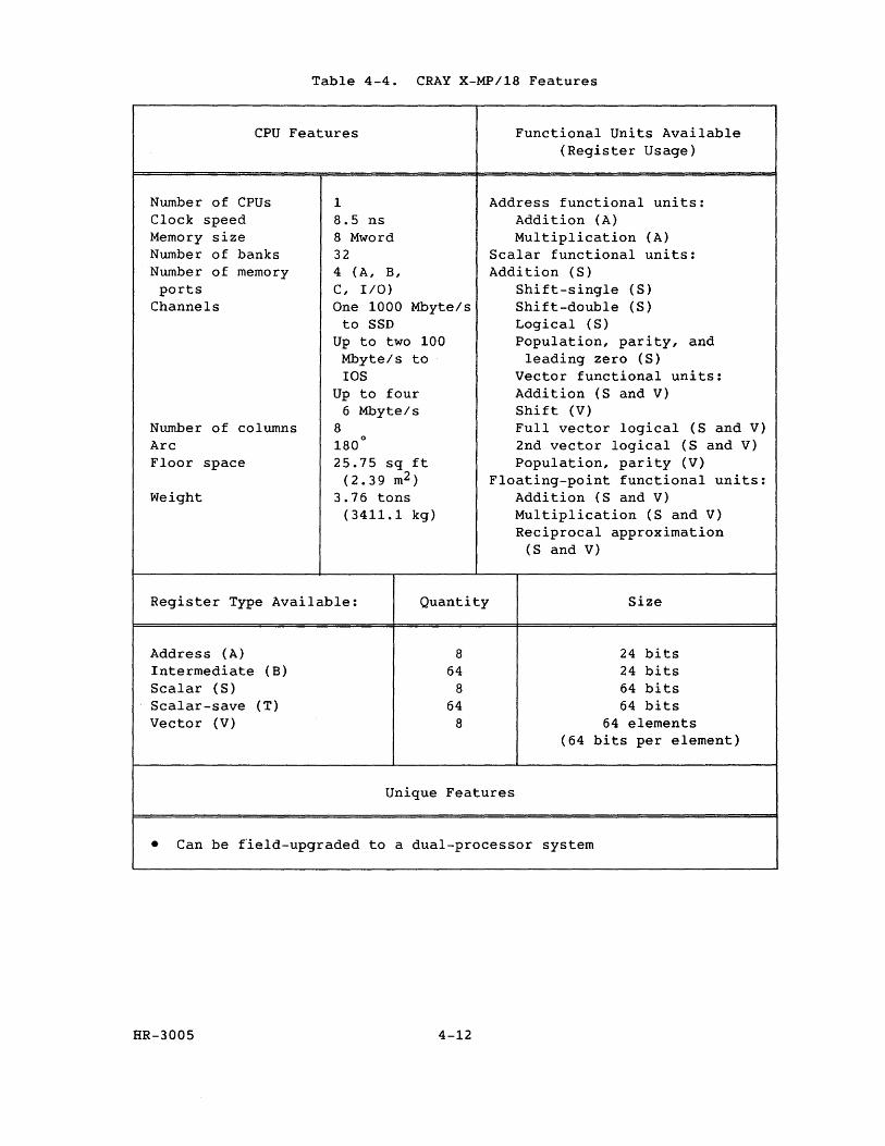
Table 4-4. CRAY X-MP/18 Features
CPU Features Functional Units Available
Number of CPUs Clock speed Memory size Number of banks Number of memory ports
Channels
Number of columns Arc Floor space
Weight
1 8.5 ns 8 Mword 32 4 (A, B, C, I/O) One 1000 Mbyte/s
to SSD Up to two 100
Mbyte/s to lOS
Up to four 6 Mbyte/s
8 180
0
25.75 sq ft (2.39 m2 )
3.76 tons (3411.1 kg)
Register Type Available: Quantity
Address (A) Intermediate (B)
Scalar (S) Scalar-save (T) Vector (V)
8 64
8 64
8
(Register Usage)
Address functional units: Addition (A) Multiplication (A)
Scalar functional units: Addition (S)
Shift-single (S) Shift-double (S) Logical (S) Population, parity, and
leading zero (S) Vector functional units: Addition (S and V) Shift (V) Full vector logical (S and V) 2nd vector logical (S and V) Population, parity (V)
Floating-point functional units: Addition (S and V) Multiplication (S and V) Reciprocal approximation
(S and V)
Size
24 bits 24 bits 64 bits 64 bits
64 elements (64 bits per element)
Unique Features
• Can be field-upgraded to a dual-processor system
HR-3005 4-12
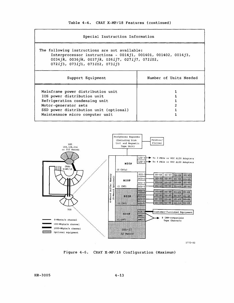
Table 4-4. CRAY X-MP/18 Features (continued)
Special Instruction Information
The following instructions are not available: Interprocessor instructions - 0014j1, 001401, 001402, 0014j3, 0034jk, 0036jk, 0037jk, 026ij7, 027ij7, 072i02, 072ij3, 073ij1, 073i02, 073ij3
Support Equipment
Mainframe power distribution unit lOS power distribution unit Refrigeration condensing unit Motor-generator sets SSD power distribution unit (optional) Maintenance micro computer unit
SSD (64,128,256
or 512 Mword)
Peripheral Expander
(Including Disk Unit and Magnetic
Tape Unit)
Number of Units Needed
1 1 1 2 1 1
MlOP
LSP-4 .... ~ To 3 FEls or NSC A130 Adapters
L:;I'-'1r-__ To 4 FEIs or NSC A130 Adapters
lOS """ '"
'"
6-Mbyte/s channel - 100-Mbyte/ s channel
- 1000-Mbyte/s channel
Optional equipment
I",
I",
""" "
(3 CRTs)
BlOP
""""
8 IBM-compatible Tape Channels
Figure 4-6. CRAY X-MP/18 Configuration (Maximum)
HR-3005 4-13
1772-02

RESEARCH, INC. Copyright@ 1987 by CRAY RESEARCH, INC.

CRAY X-MP/116 SPECIFICATION SHEET
Figure 4-7. CRAY X-MP/116 Computer System
HR-3005 4-15
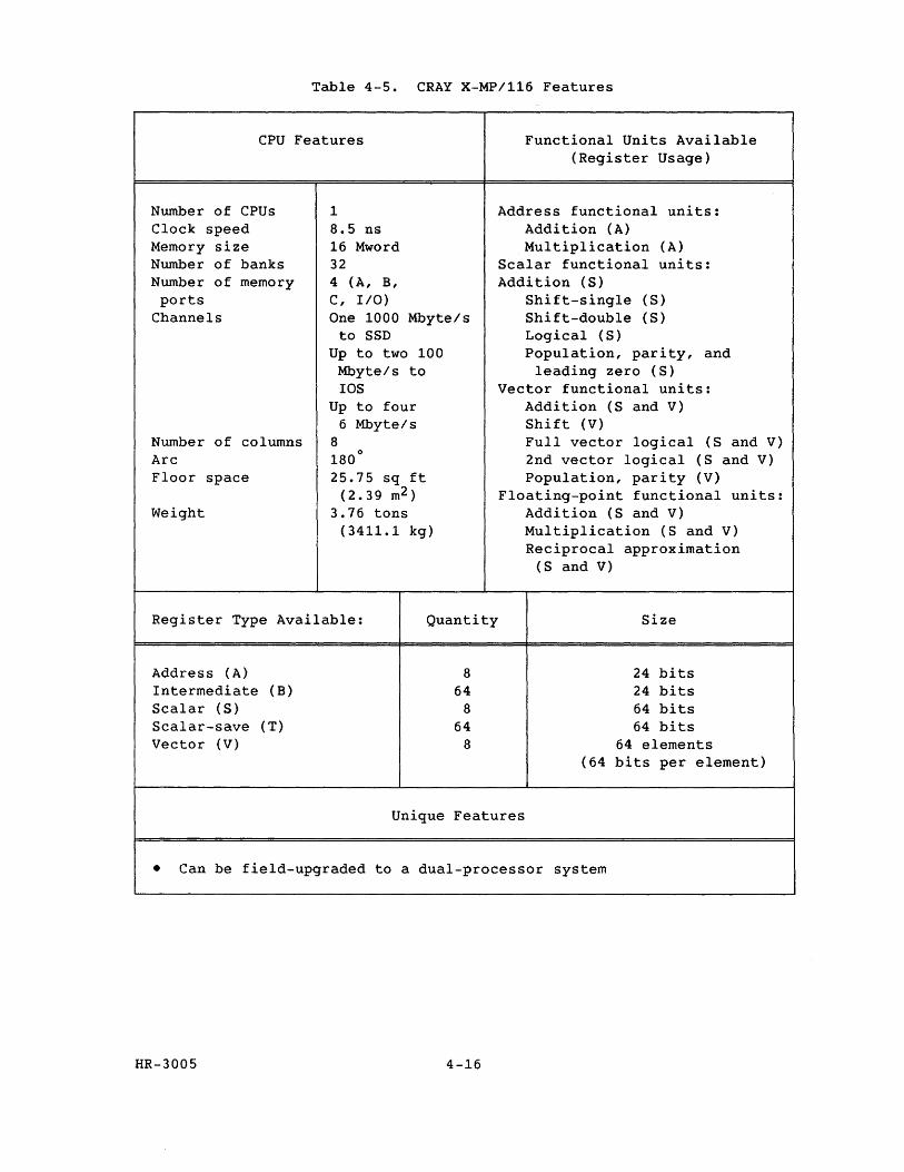
Table 4-5. CRAY X-MP/116 Features
CPU Features Functional Units Available
Number of CPUs Clock speed Memory size Number of banks Number of memory ports
Channels
Number of columns Arc Floor space
Weight
1 8.5 ns 16 Mword 32 4 (A, B, C, I/O) One 1000 Mbyte/s
to SSD Up to two 100
Mbyte/s to lOS
Up to four 6 Mbyte/s
8 180
0
25.75 sq ft (2.39 m2 )
3.76 tons (3411.1 kg)
(Register Usage)
Address functional units: Addition (A) Multiplication (A)
Scalar functional units: Addition (S)
Shift-single (S) Shift-double (S) Logical (S) Population, parity, and
leading zero (S) Vector functional units:
Addition (S and V) Shift (V) Full vector logical (S and V) 2nd vector logical (S and V) Population, parity (V)
Floating-point functional units: Addition (S and V) Multiplication (S and V) Reciprocal approximation
(S and V)
Register Type Available: Quantity Size
Address (A) Intermediate (B) Scalar (S) Scalar-save (T) Vector (V)
8 64
8 64
8
Unique Features
24 bits 24 bits 64 bits 64 bits
64 elements (64 bits per element)
• Can be field-upgraded to a dual-processor system
HR-3005 4-16
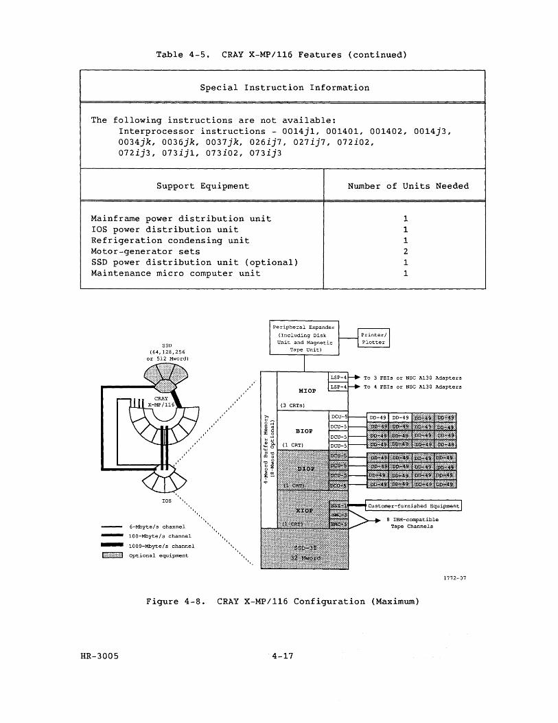
Table 4-5. CRAY X-MP/116 Features (continued)
Special Instruction Information
The following instructions are not available: Interprocessor instructions - 0014j1, 001401, 001402, 0014j3, 0034jk, 0036jk, 0037jk, 026ij7, 027ij7, 072i02, 072ij3, 073ij1, 073i02., 073ij3
Support Equipment
Mainframe power distribution unit lOS power distribution unit Refrigeration condensing unit Motor-generator sets SSD power distribution unit (optional) Maintenance micro computer unit
SSD (64,128,256
or 512 Mword)
Peripheral Expander
(Including Disk Unit and Magnetic
Tape Unit)
Number of Units Needed
1 1 1 2 1 1
LSP-4t--p To 3 FEIs or NSC A130 Adapters
LSP-4t--p To 4 FEIs or NSC A130 Adapters
-lOS
' . .........
6-Mbyte/s channel
100-Mbyte/s channel
- 1000-Mbyte/s channel
Optional equipment
". 'I"
'. '. 1'1,
'.
(3 CRTs)
1""
".
Figure 4-8. CRAY X-MP/116 Configuration (Maximum)
HR-3005 4-17
1772-07

RESEARCH, INC. Copyright@ 1987 by CRA Y RESEARCH, INC.
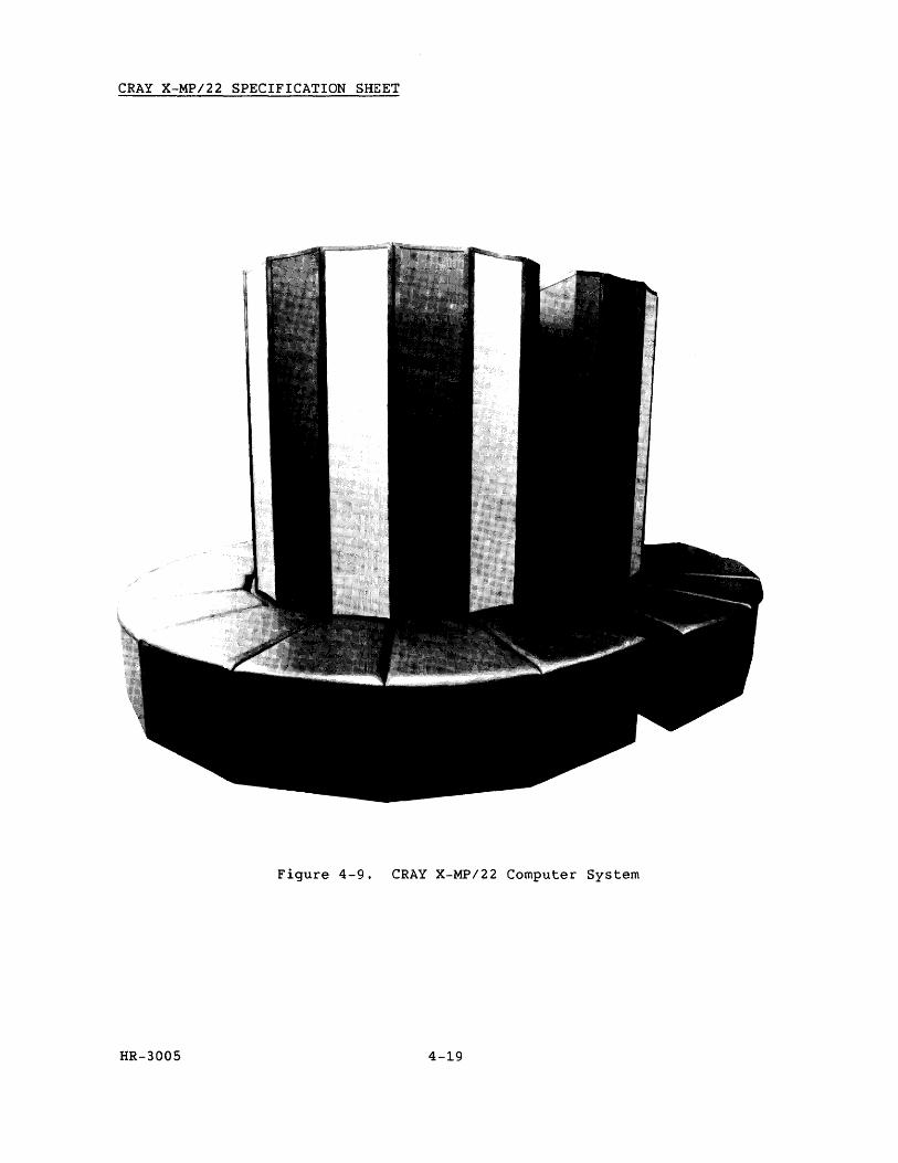
CRAY X-MP/22 SPECIFICATION SHEET
Figure 4-9. CRAY X-MP/22 Computer System
HR-3005 4-19
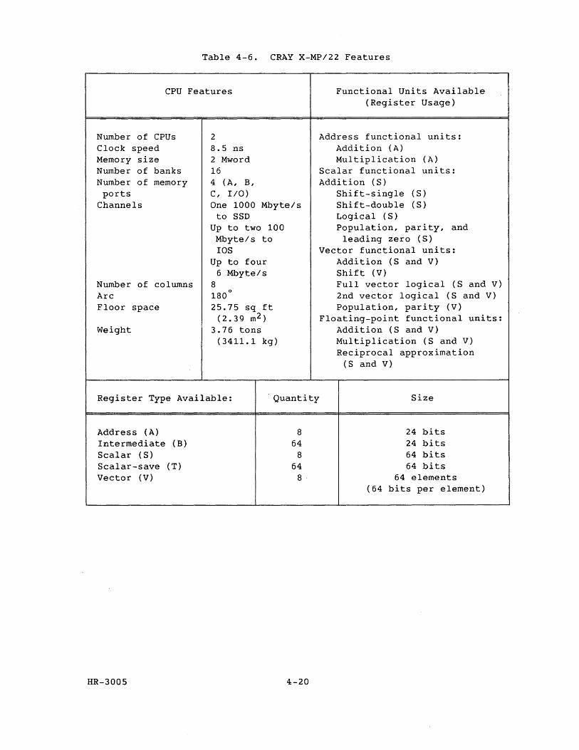
Table 4-6. CRAY X-MP/22 Features
CPU Features Functional Units Available
Number of CPUs Clock speed Memory size Number of banks Number of memory ports
Channels
Number of columns Arc Floor space
Weight
2 8.5 ns 2 Mword 16 4 (A, B, C, I/O) One 1000 Mbyte/s
to SSD Up to two 100 Mbyte/s to lOS
Up to four 6 Mbyte/s
8 o
180 25.75 sq ft
(2.39 m2 ) 3.76 tons
(3411.1 kg)
(Register Usage)
Address functional units: Addition (A) Multiplication (A)
Scalar functional units: Addition (S)
Shift-single (S) Shift-double (S) Logical (S) Population, parity, and
leading zero (S) Vector functional units:
Addition (S and V) Shift (V) Full vector logical (S and V) 2nd vector logical (S and V) Population, parity (V)
Floating-point functional units: Addition (S and V) Multiplication (S and V) Reciprocal approximation
(S and V)
Register Type Available: Quantity Size
Address (A) Intermediate (B) Scalar (S) Scalar-save (T) Vector (V)
HR-3005
8 64
8 64 8·
4-20
24 bits 24 bits 64 bits 64 bits
64 elements (64 bits per element)
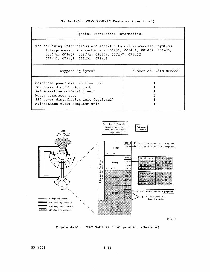
Table 4-6. CRAY X-MP/22 Features (continued)
Special Instruction Information
The following instructions are specific to multi-processor systems: Interprocessor instructions - 0014j1, 001401, 001402, 0014j3, 0034jk, 0036jk, 0037jk, 026ij7, 027ij7, 072i02, 072ij3, 073ij1, 073i02, 073ij3
Support Equipment
Mainframe power distribution unit lOS power distribution unit Refrigeration condensing unit Motor-generator sets SSD power distribution unit (optional) Maintenance micro computer unit
-
SSD (64,128,256
or 512 Mword)
lOS
6-Mbyte/ s channel
100-Mbyte/s channel
- 1000-Mbyte/s channel
I::,:}}:}}}:! Optional equipment .......
Peripheral Expander
(Including Disk Unit and Magnetic
Tape Unit)
MlOP
(3 CRTs)
BlOP
Number of Units Needed
1 1 1 2 1 1
To 3 FEIs or NSC A130 Adapters
To 4 FEIs or NSC A130 Adapters
Tape Channels
1772-03
Figure 4-10. CRAY X-MP/22 Configuration (Maximum)
HR-3005 4-21

~--I=:I ~~ ~ .~ __ . 144' RESEARCH, INC. Copyright© 1987 by CRAY RESEARCH, INC.

CRAY X-MP/24 SPECIFICATION SHEET
Figure 4-11. CRAY X-MP/24 Computer System
HR-3005 4-23

Table 4-7. CRAY X-MP/24 Features
CPU Features Functional Units Available
Number of CPUs Clock speed Memory size Number of banks Number of memory ports
Channels
Number of columns Arc Floor space
Weight
2 8.5 ns 4 Mword 16 4 (A, B, C, I/O) One 1000 Mbyte/s
to SSD Up to two 100
Mbyte/s to IDS
Up to four 6 Mbyte/s
8 o
180 25.75 sq ft
(2.39 m2 ) 3.76 tons
(3411.1 kg)
Register Type Available: Quantity
Address (A) Intermediate (B) Scalar (S) Scalar-save (T) Vector (V)
HR-3005
8 64
8 64
8
4-24
(Register Usage)
Address functional units: Addition (A) Multiplication (A)
Scalar functional units: Addition (S)
Shift-single (S) Shift-double (S) Logical (S) Population, parity, and
leading zero (S) Vector functional units:
Addition (S and V) Shift (V) Full vector logical (S and V) 2nd vector logical (S and V) Population, parity (V)
Floating-point functional units: Addition (S and V) Multiplication (S and V) Reciprocal approximation
(S and V)
Size
24 bits 24 bits 64 bits 64 bits
64 elements (64 bits per element)
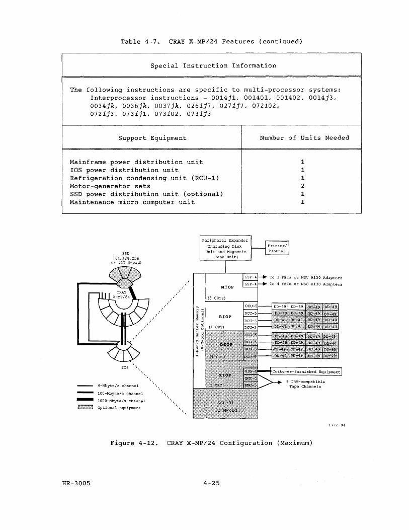
Table 4-7. CRAY X-MP/24 Features (continued)
Special Instruction Information
The following instructions are specific to multi-processor systems: Interprocessor instructions - 0014j1, 001401, 001402, 0014j3, 0034jk, 0036jk, 0037jk, 026ij7, 027ij7, 072i02, 072ij3, 073ijl, 073i02, 073ij3
Support Equipment
Mainframe power distribution unit lOS power distribution unit Refrigeration condensing unit (RCU-l) Motor-generator sets SSD power distribution unit (optional) Maintenance micro computer unit
-
SSD (64,128,256
or 512 Mword)
ros II"
6-Mbyte/ s channel
100-Mbyte/ s channel
- 1000-Mbyte/s channel
I::",,::{{>">d Optional equipment
...............
...........
'" IIII
"~'I 1 1'1
", '"
"
peripheral Expander
(Including Disk Unit and Magnetic
Tape Unit)
MIOP
(3 CRTs)
Number of Units Needed
1 1 1 2
1 1
To 3 FEIs or NSC A130 Adapters
To 4 FEIs or NSC A130 Adapters
1772-04
Figure 4-12. CRAY X-MP/24 Configuration (Maximum)
HR-3005 4-25

RESEARCH, INC. Copyright@ 1987 by CRA Y RESEARCH, INC.
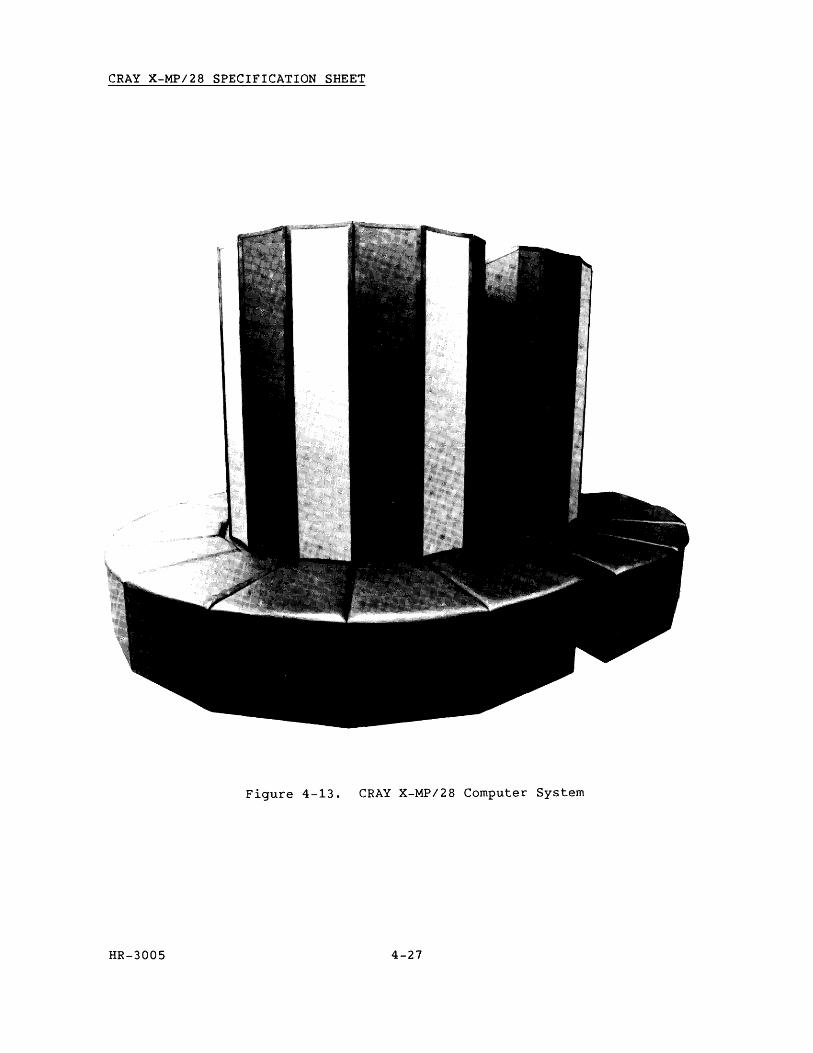
CRAY X-MP/28 SPECIFICATION SHEET
Figure 4-13. CRAY X-MP/28 Computer System
HR-3005 4-27
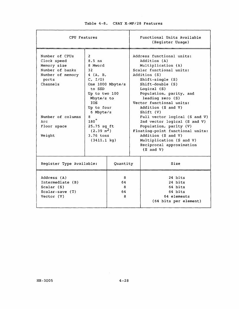
Table 4-8. CRAY X-MP/28 Features
CPU Features Functional Units Available
Number of CPUs Clock speed Memory size Number of banks Number of memory ports
Channels
Number of columns Arc Floor space
Weight
2 8.5 ns 8 Mword 32 4 (A, B, C, I/O) One 1000 Mbyte/s
to SSD Up to two 100
Mbyte/s to IDS
Up to four 6 Mbyte/s
8 o
180 25.75 sq ft
(2.39 m2 ) 3.76 tons
(3411.1 kg)
(Register Usage)
Address functional units: Addition (A) Multiplication (A)
Scalar functional units: Addition (S)
Shift-single (S) Shift-double (S) Logical (S) Population, parity, and
leading zero (S) Vector functional units:
Addition (S and V) Shift (V) Full vector logical (S and V) 2nd vector logical (S and V) Population, parity (V)
Floating-point functional units: Addition (S and V) Multiplication (S and V) Reciprocal approximation
(S and V)
Register Type Available: Quantity Size
Address (A) Intermediate (B) Scalar (S) Scalar-save (T) Vector (V)
HR-3005
8 64
8 64
8
4-28
24 bits 24 bits 64 bits 64 bits
64 elements (64 bits per element)
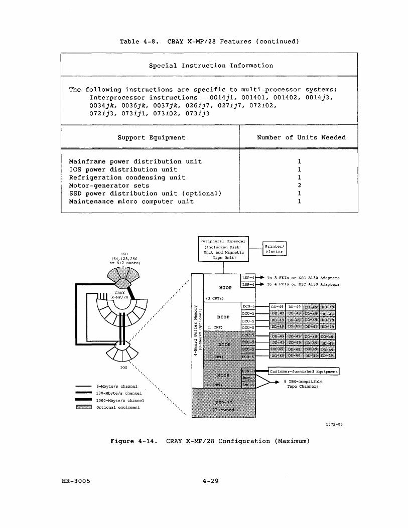
Table 4-8. CRAY X-MP/28 Features (continued)
Special Instruction Information
The following instructions are specific to multi-processor systems: Interprocessor instructions - 0014j1, 001401, 001402, 0014j3, 0034jk, 0036jk, 0037jk, 026ij7, 027ij7, 072i02, 072ij3, 073ij1, 073i02, 073ij3
Support Equipment
Mainframe power distribution unit IDS power distribution unit Refrigeration condensing unit Motor-generator sets SSD power distribution unit (optional) Maintenance micro computer unit
-
SSD (64,128,256
or 512 Mword)
lOS
........ 6-Mbyte/s channel
100-Mbyte/ s channel
....... 1000-Mbyte/s channel
Optional equipment
11
'1
'. I'll
"'"
"'I ".
Peripheral Expander
(Including Disk Unit and Magnetic
Tape Unit)
MlOP
(3 CRTs)
BlOP
Number of Units Needed
1 1 1 2 1 1
To 3 FEls or NSC A130 Adapters
To 4 FEls or NSC Al30 Adapters
Tape Channels
1772-05
Figure 4-14. CRAY X-MP/28 Configuration (Maximum)
HR-3005 4-29

RESEARCH, INC. Copyright@ 1987 by CRAY RESEARCH, INC.
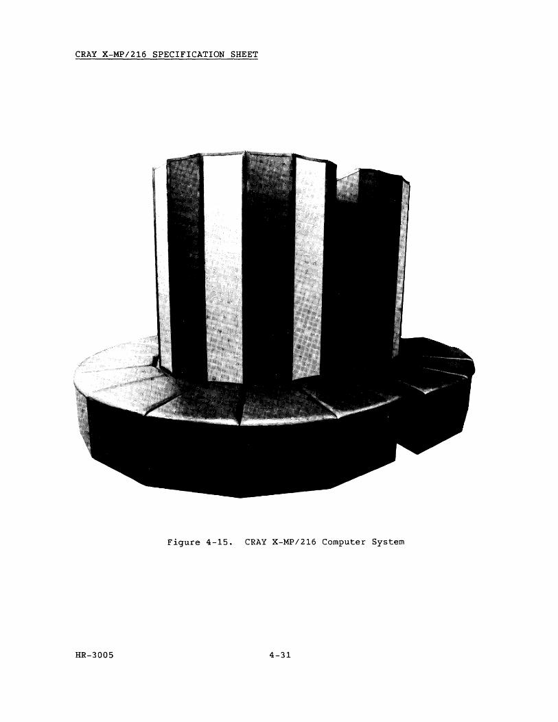
CRAY X-MP/216 SPECIFICATION SHEET
Figure 4-15. CRAY X-MP/216 Computer System
HR-3005 4-31

Table 4-9. CRAY X-MP/216 Features
CPU Features Functional Units Available
Number of CPUs Clock speed Memory size Number of banks Number of memory ports
Channels
Number of columns Arc Floor space
Weight
2 8.5 ns 16 Mword 32 4 (A, B,
C, liD)
One 1000 Mbytels to SSD
Up to two 100 Mbyte/s to IDS
Up to four 6 Mbytels
8 180
0
25.75 sq ft (2.39 m2 )
3.76 tons (3411.1 kg)
(Register Usage)
Address functional units: Addition (A) Multiplication (A)
Scalar functional units: Addition (S)
Shift-single (S) Shift-double (S) Logical (S) Population, parity, and
leading zero (S) Vector functional units:
Addition (S and V) Shift (V) Full vector logical (S and V) 2nd vector logical (S and V) Population, parity (V)
Floating-point functional units: Addition (S and V) Multiplication (S and V) Reciprocal approximation
(S and V)
Register Type Available: Quantity Size
Address (A) Intermediate (B) Scalar (S) Scalar-save (T) Vector (V)
HR-3005
8 64
8 64
8
4-32
(64
24 bits 24 bits 64 bits 64 bits
64 elements bits per element)

Table 4-9. CRAY X-MP/216 Features (continued)
Special Instruction Information
The following instructions are specific to multi-processor systems: Interprocessor instructions - 0014j1, 001401, 001402, 0014j3, 0034jk, 0036jk, 0037jk, 026ij7, 027ij7, 072i02, 072ij3, 073ij1, 073i02, 073ij3
Support Equipment
Mainframe power distribution unit lOS power distribution unit Refrigeration condensing unit Motor-generator sets SSD power distribution unit (optional) Maintenance micro computer unit
SSD (64,128,256
or 512 Mword)
peripheral Expander
(Including Disk Unit and Magnetic
Tape Unit)
Number of Units Needed
1 1 1 2 1 1
.......... MIOP
To 3 FEIs or NSC A130 Adapters
LSP-4 t--P To 4 FEIs or NSC A130 Adapters
-
lOS 1"1
1'1"
6-Mbyte/s channel
100-Mbyte/s channel
- 1000-Mbyte/s channel
optional equipment
'II,
'1 1 '1
" "
""""
(3 CRTs)
"""
8 IBM-compatible Tape Channels
Figure 4-16. CRAY X-MP/216 Configuration (Maximum)
HR-3005 4-33
1772-06

RESEARCH, INC. Copyright© 1987 by CRAY RESEARCH, INC.
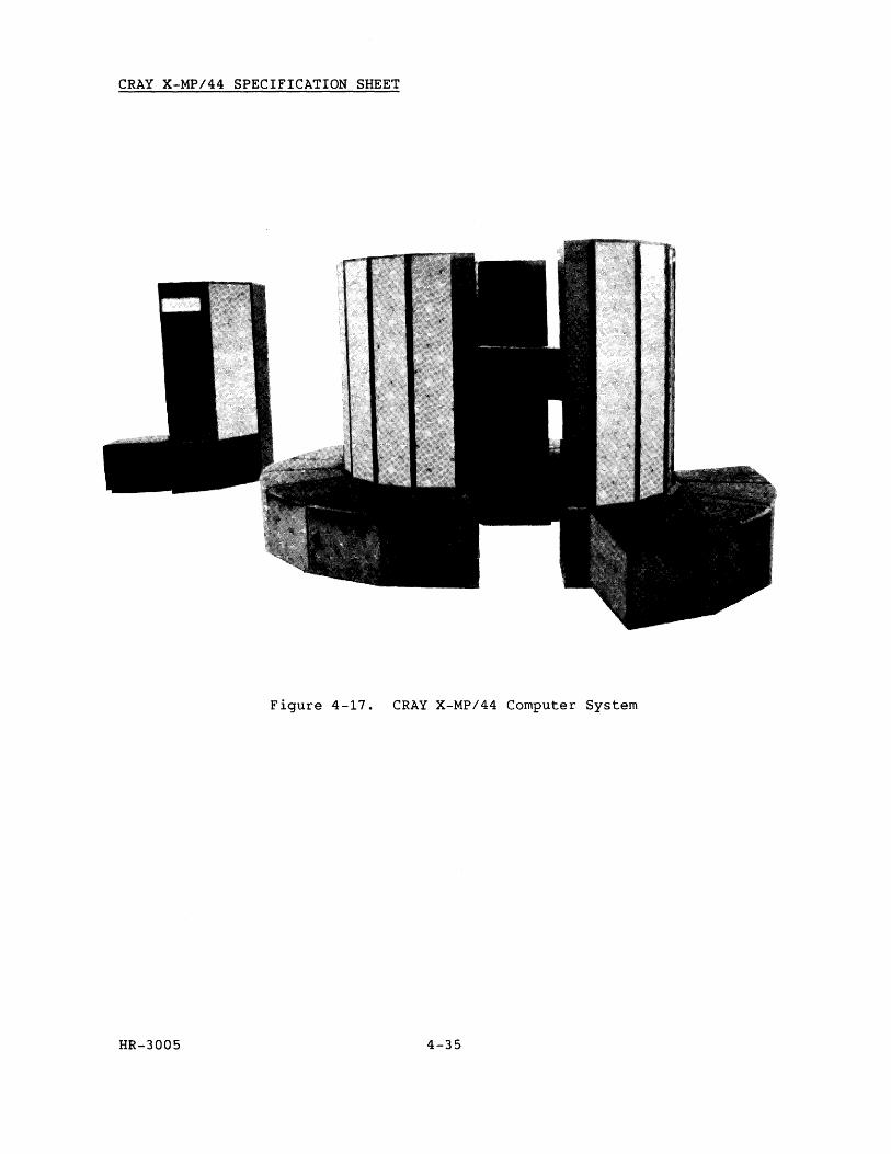
CRAY X-MP/44 SPECIFICATION SHEET
Figure 4-17. CRAY X-MP/44 Computer System
HR-3005 4-35
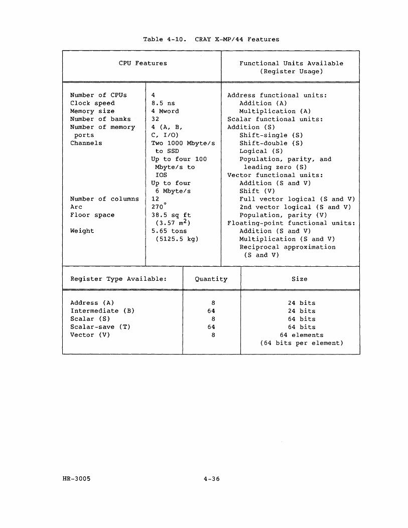
Table 4-10. CRAY X-MP/44 Features
CPU Features Functional Units Available
Number of CPUs Clock speed Memory size Number of banks Number of memory ports
Channels
Number of columns Arc Floor space
Weight
4 8.5 ns 4 Mword 32 4 (A, B, C, I/O) Two 1000 Mbyte/s
to SSD Up to four 100
Mbyte/s to IDS
Up to four 6 Mbyte/s
12 270
0
38.5 sq ft (3.57 m2 )
5.65 tons (5125.5 kg)
Register Type Available: Quantity
Address (A) Intermediate (B) Scalar (S) Scalar-save (T) Vector (V)
HR-3005
8 64
8 64
8
4-36
(Register Usage)
Address functional units: Addition (A) Multiplication (A)
Scalar functional units: Addition (S)
Shift-single (S) Shift-double (S) Logical (S) Population, parity, and
leading zero (S) Vector functional units:
Addition (S and V) Shift (V) Full vector logical (S and V) 2nd vector logical (S and V) Population, parity (V)
Floating-point functional units: Addition (S and V) Multiplication (S and V) Reciprocal approximation
(S and V)
Size
24 bits 24 bits 64 bits 64 bits
64 elements (64 bits per element)
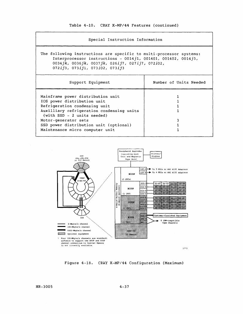
Table 4-10. CRAY X-MP/44 Features (continued)
Special Instruction Information
The following instructions are specific to multi-processor systems: Interprocessor instructions - 0014j1, 001401, 001402, 0014j3, 0034jk, 0036jk, 0037jk, 026ij7, 027ij7, 072i02, 072ij3, 073ijl, 073i02, 073ij3
Support Equipment
Mainframe power distribution unit lOS power distribution unit Refrigeration condensing unit Auxilliary refrigeration condensing units
(with SSD - 2 units needed) Motor-generator sets SSD power distribution unit (optional) Maintenance micro computer unit
SSD (64,128,256
or 512 Mword)
lOS
6-Mbyte/s channel
100-Mbyte/s channel
- 1000-Mbyte/s channel
1#""""",)/;;;1 Optional equipment
11111,
............. ".
t Four 100-Mbyte/s channels are standard; software to support the MIOP and DIOP channel connection to Central Memory is not currently available.
'. ".
Peripheral Expander
(Including Disk Unit and Magnetic
Tape Unit)
Number of Units Needed
1 1 1 1
3 1 1
To 3 FEls or NSC A130 Adapters
To 4 FEls or NSC Al30 Adapters
1773
Figure 4-18. CRAY X-MP/44 Configuration (Maximum)
HR-3005 4-37

RESEARCH, INC. Copyright© 1987 by CRAY RESEARCH, INC.
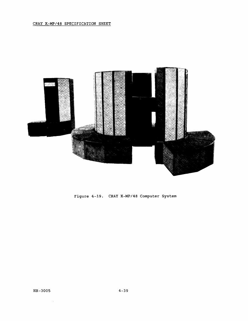
CRAY X-MP/48 SPECIFICATION SHEET
Figure 4-19. CRAY X-MP/48 Computer System
HR-3005 4-39
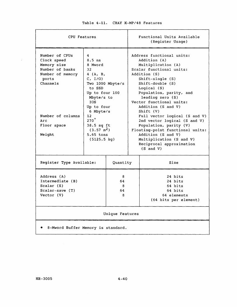
Table 4-11. CRAY X-MP/48 Features
CPU Features Functional Units Available
Number of CPUs Clock speed Memory size Number of banks Number of memory ports
Channels
Number of columns Arc Floor space
Weight
4 8.5 ns 8 Mword 32 4 (A, B, c, I/O)
Two 1000 Mbyte/s to SSD
Up to four 100 Mbyte/s to lOS
Up to four 6 Mbyte/s
12 270
0
38.5 sq ft (3.57 m2 )
5.65 tons (5125.5 kg)
Register Type Available: Quantity
Address (A) Intermediate (B) Scalar (S) Scalar-save (T) Vector (V)
8 64
8 64
8
(Register Usage)
Address functional units: Addition (A) Multiplication (A)
Scalar functional units: Addition (S)
Shift-single (S) Shift-double (S) Logical (S) Popul~tion, parity, and
leading zero (S) Vector functional units:
Addition (S and V) Shift (V) Full vector logical (S and V) 2nd vector logical (S and V) Population, parity (V)
Floating-point funct~onal units: Addition (S and V) Multiplication (S and V) Reciprocal approximation
(S and V)
Size
24 bits 24 bits 64 bits 64 bits
64 elements (64 bits per element)
Unique Features
• 8-Mword Buffer Memory is standard.
HR-3005 4-40
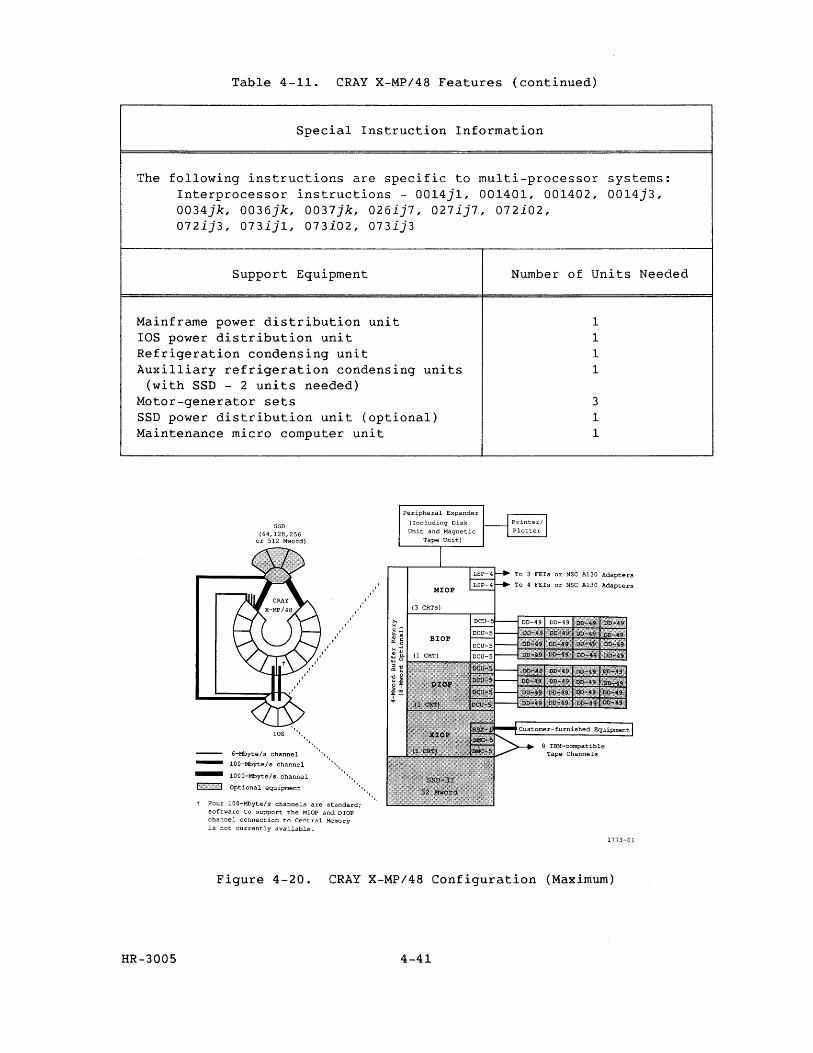
Table 4-11. CRAY X-MP/48 Features (continued)
Special Instruction Information
The following instructions are specific to multi-processor Interprocessor instructions - 0014j1, 001401, 001402, 0034jk, 0036jk, 0037jk, 026ij7, 027ij7, 072i02, 072ij3, 073ij1, 073i02, 073ij3
systems: 0014j3,
Support Equipment Number of Units Needed
Mainframe power distribution unit lOS power distribution unit Refrigeration condensing unit Auxilliary refrigeration condensing units
(with SSD - 2 units needed) Motor-generator sets SSD power distribution unit (optional) Maintenance micro computer unit
SSD (64,128,256
or 512 Mword)
lOS ••••••••••
6-Mbyte/s channel ".
lOO-Mbyte/s channel 1111
'1
- 1000-Mbyte/s channel ••••••
F:,:,}":'",,,,,,,,! Optional equipment •••••••• ,
t Four 100-Mbyte/s channels are standard; software to support the MIOP and DIOP channel connection to Central Memory is not currently available.
Peripheral Expander
(Including Disk Unit and Magnetic
Tape Unit)
1 1 1 1
3 1 1
To 3 FEIs or NSC A130 Adapters
To 4 FEls or NSC A130 Adapters
1773-01
Figure 4-20. CRAY X-MP/48 Configuration (Maximum)
HR-3005 4-41

RESEARCH, INC. Copyright© 1987 by CRA Y RESEARCH, INC.
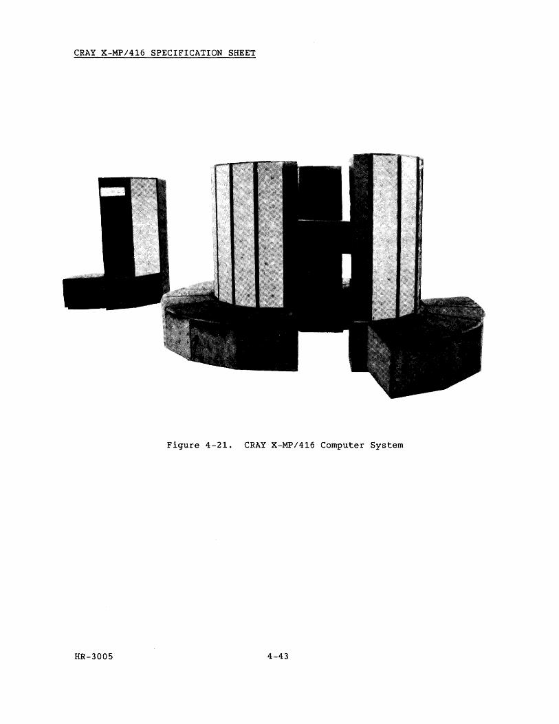
CRAY X-MP/416 SPECIFICATION SHEET
Figure 4-21. CRAY X-MP/416 Computer System
HR-3005 4-43
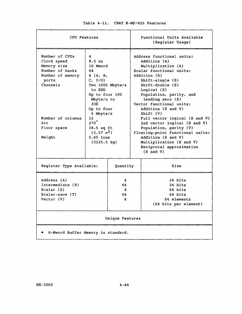
Table 4-11. CRAY X-MP/416 Features
CPU Features Functional Units Available
Number of CPUs Clock speed Memory size Number of banks Number of memory ports
Channels
Number of columns Arc Floor space
Weight
4 8.5 ns 16 Mword 64 4 (A, B, C, I/O) Two 1000 Mbyte/s
to SSD Up to four 100 Mbyte/s to lOS
Up to four 6 Mbyte/s
12 270
0
38.5 sq ft (3.57 m2 )
5.65 tons (5125.5 kg)
Register Type Available: Quantity
Address (A) Intermediate (B) Scalar (S) Scalar-save (T) Vector (V)
8 64
8 64
8
(Register Usage)
Address functional units: Addition (A) Multiplication (A)
Scalar functional units: Addition (S)
Shift-single (S) Shift-double (S) Logical (S) Population, parity, and
leading zero (S) Vector functional units:
Addition (S and V) Shift (V) Full vector logical (S and V) 2nd vector logical (S and V) Population, parity (V)
Floating-point functional units: Addition (8 and V) Multiplication (S and V) Reciprocal approximation
(S and V)
Size
24 bits 24 bits 64 bits 64 bits
64 elements (64 bits per element)
Unique Features
• 8-Mword Buffer Memory is standard.
HR-3005 4-44
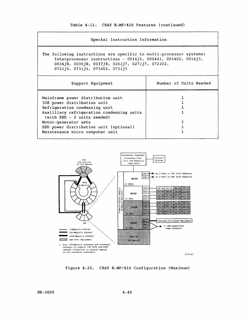
Table 4-11. CRAY X-MP/416 Features (continued)
Special Instruction Information
The following instructions are specific to multi-processor systems: Interprocessor instructions - 0014j1, 001401, 001402, 0014j3, 0034jk, 0036jk, 0037jk, 026ij7, 027ij7, 072i02, 072ij3, 073ij1, 073i02, 073ij3
Support Equipment
Mainframe power distribution unit lOS power distribution unit Refrigeration condensing unit Auxilliary refrigeration condensing units
(with SSD - 2 units needed) Motor-generator sets SSD power distribution unit (optional) Maintenance micro computer unit
SSD (64,128,256
or 512 Mword)
lOS " •
............. 6-Mbyte/s channel
100-Mbyte/s channel '. = :::::'::,:,:::;.' """""'", t Four 100-Mbyte/s channels are standard;
software to support the MIOP and DIOP channel connection to Central Memory is not currently available.
Peripheral Expander
(Including Disk Uni t and Magnet ic
Tape Unit)
Number of Units Needed
1 1 1 1
3 1 1
TO 3 FEIs or NSC A130 Adapters
To 4 FEls or NSC A130 Adapters
1773-02
Figure 4-22. CRAY X-MP/416 Configuration (Maximum)
HR-3005 4-45

~--I=:I ~ ........ ~ ,.' __ 1 I.-=-, RESEARCH, INC. Copyright© 1987 by CRAY RESEARCH, INC.

GLOSSARY

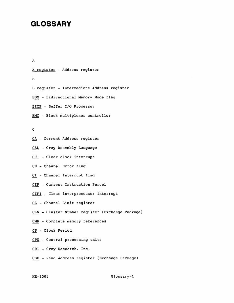
GLOSSARY
A
A register - Address register
B
B register - Intermediate Address register
BDM - Bidirectional Memory Mode flag
BIOP - Buffer lID Processor
BMC - Block multiplexer controller
C
CA - Current Address register
CAL - Cray Assembly Language
CCI - Clear clock interrupt
CE - Channel Error flag
CI - Channel Interrupt flag
CIP - Current Instruction Parcel
ClPl - Clear interprocessor interrupt
CL - Channel Limit register
CLN - Cluster Number register (Exchange Package)
CMR - Complete memory references
CP - Clock Period
CPU - Central processing units
CRI - Cray Research, Inc.
CSB - Read Address register (Exchange Package)
HR-3005 Glossary-l
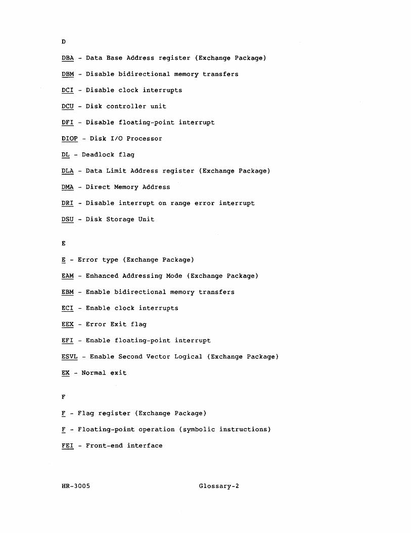
D
DBA - Data Base Address register (Exchange Package)
DBM - Disable bidirectional memory transfers
DCI - Disable clock interrupts
DCU - Disk controller unit
DFI - Disable floating-point interrupt
DIOP - Disk IIO Processor
DL - Deadlock flag
DLA - Data Limit Address register (Exchange Package)
DMA - Direct Memory Address
DRI - Disable interrupt on range error interrupt
DSU - Disk Storage Unit
E
E - Error type (Exchange Package)
EAM - Enhanced Addressing Mode (Exchange Package)
EBM - Enable bidirectional memory transfers
ECI - Enable clock interrupts
EEX - Error Exit flag
EFI - Enable floating-point interrupt
ESVL - Enable Second Vector Logical (Exchange Package)
EX - Normal exit
F
F - Flag register (Exchange Package)
F - Floating-point operation (symbolic instructions)
FEI - Front-end interface
HR-3005 Glossary-2
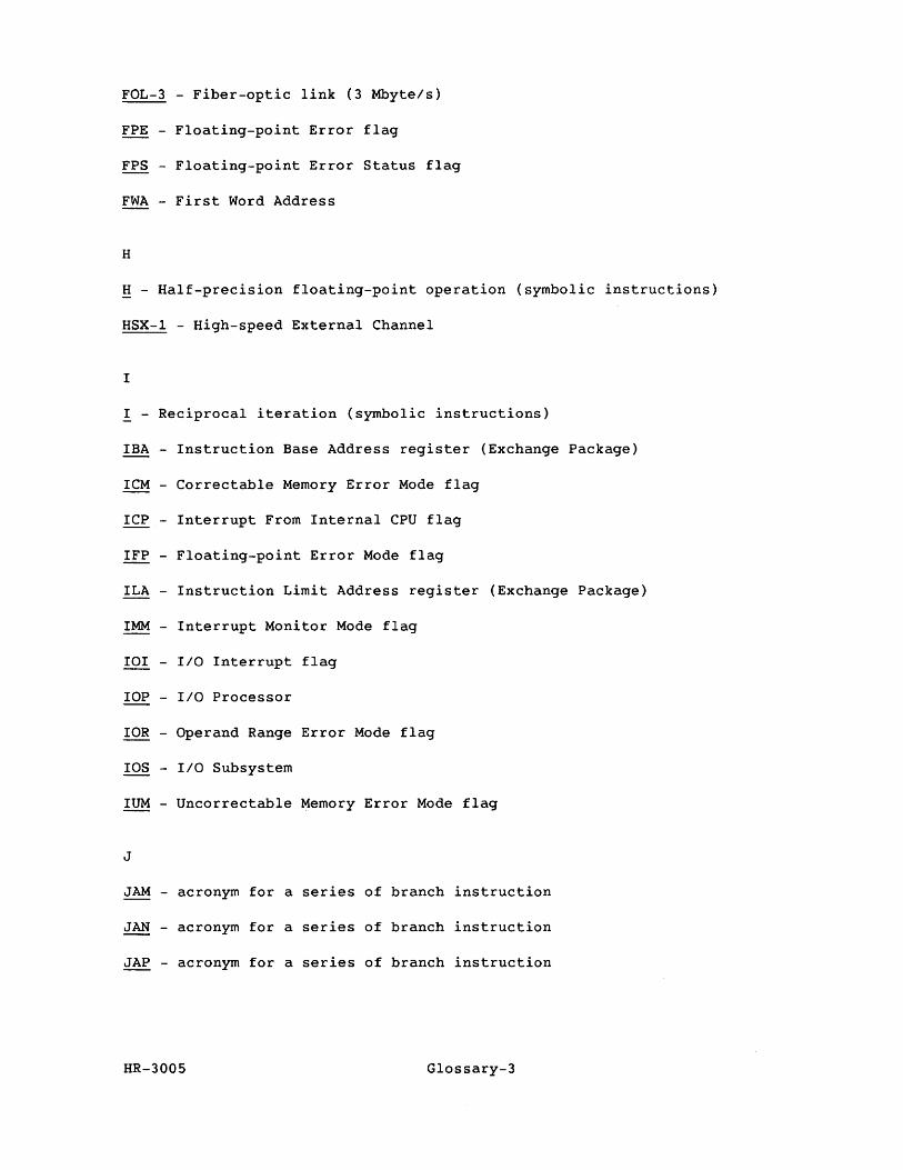
FOL-3 - Fiber-optic link (3 Mbyte/s)
FPE - Floating-point Error flag
FPS - Floating-point Error Status flag
FWA - First Word Address
H
H - Half-precision floating-point operation (symbolic instructions)
HSX-l - High-speed External Channel
I
I - Reciprocal iteration (symbolic instructions)
IBA - Instruction Base Address register (Exchange Package)
ICM - Correctable Memory Error Mode flag
ICP - Interrupt From Internal CPU flag
IFP - Floating-point Error Mode flag
ILA - Instruction Limit Address register (Exchange Package)
IMM - Interrupt Monitor Mode flag
101 - lID Interrupt flag
lOP - lID Processor
lOR - Operand Range Error Mode flag
IDS - lID Subsystem
IUM - Uncorrectable Memory Error Mode flag
J
JAM - acronym for a series of branch instruction
JAN - acronym for a series of branch instruction
JAP - acronym for a series of branch instruction
HR-3005 Glossary-3
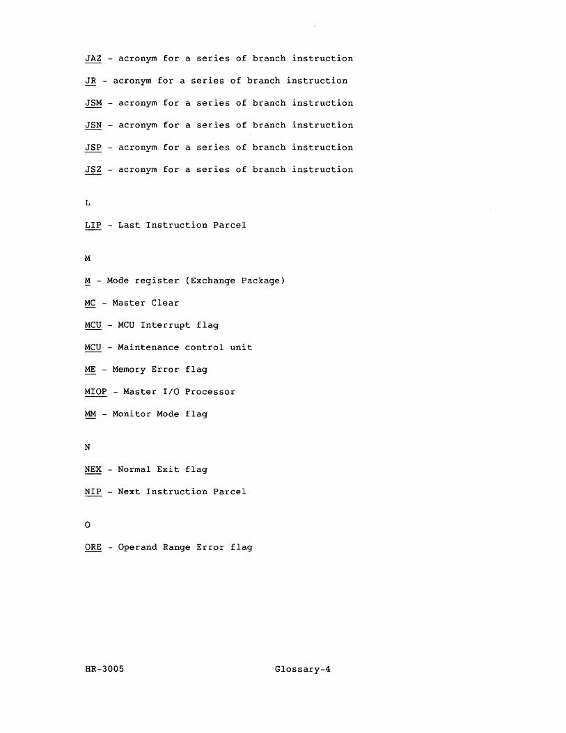
JAZ - acronym for a series of branch
JR - acronym for a series of branch
JSM - acronym for a series of branch
JSN - acronym for a series of branch
JSP - acronym for a series of branch
JSZ - acronym for a series of branch
L
LIP - Last Instruction Parcel
M
M - Mode register (Exchange Package)
MC - Master Clear
MCU - MCU Interrupt flag
MCU - Maintenance control unit
ME - Memory Error flag
MIOP - Master IIO Processor
MM - Monitor Mode flag
N
NEX - Normal Exit flag
NIP - Next Instruction Parcel
o
ORE - Operand Range Error flag
instruction
instruction
instruction
instruction
instruction
instruction
HR-3005 Glossary-4
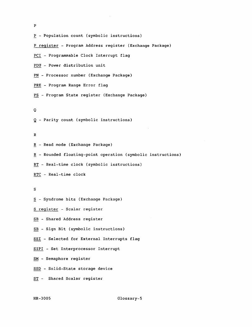
P
P - Population count (symbolic instructions)
P register - Program Address register (Exchange Package)
PCI - Programmable Clock Interrupt flag
PDU - Power distribution unit
PN - Processor number (Exchange Package)
PRE - Program Range Error flag
PS - Program State register (Exchange Package)
Q
Q - Parity count (symbolic instructions)
R
R - Read mode (Exchange Package)
R - Rounded floating-point operation (symbolic instructions)
RT - Real-time clock (symbolic instructions)
RTC - Real-time clock
S
S - Syndrome bits (Exchange Package)
S register - Scalar register
SB - Shared Address register
SB - Sign Bit (symbolic instructions)
SEI - Selected for External Interrupts flag
SIPI - Set Interprocessor Interrupt
SM - Semaphore register
SSD - Solid-State storage device
ST - Shared Scalar register
HR-3005 Glossary-5
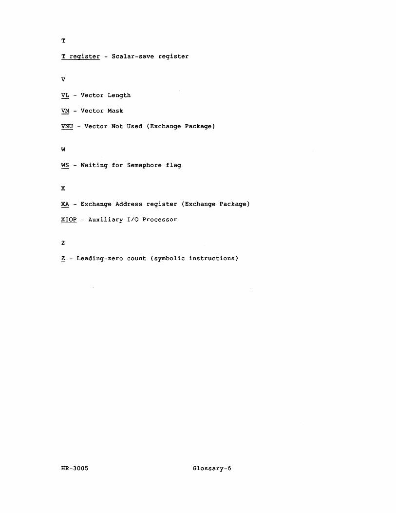
T
T register - Scalar-save register
V
VL - Vector Length
VM - Vector Mask
VNU - Vector Not Used (Exchange Package)
W
WS - Waiting for Semaphore flag
x
XA - Exchange Address register (Exchange Package)
XIOP - Auxiliary I/O Processor
z
Z - Leading-zero count (symbolic instructions)
HR-3005 Glossary-6

INDEX

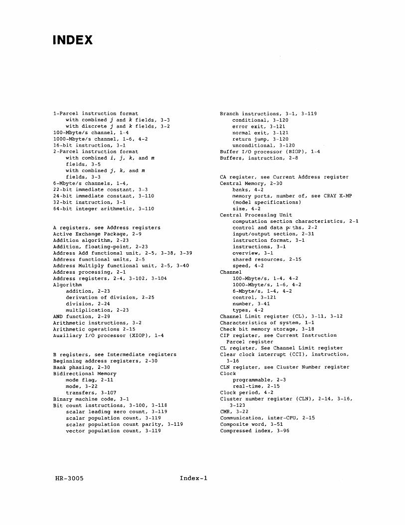
INDEX
1-Parcel instruction format with combined j and k fields, 3-3 with discrete j and k fields, 3-2
100-Mbyte/s channel, 1-4 1000-Mbyte/s channel, 1-5, 4-2 15-bit instruction, 3-1 2-Parcel instruction format
with combined i, j, k, and m fields, 3-5 with combined j, k, and m fields, 3-3
5-Mbyte/s channels, 1-4, 22-bit immediate constant, 3-3 24-bit immediate constant, 3-110 32-bit instruction, 3-1 54-bit integer arithmetic, 3-110
A registers, see Address registers Active Exchange Package, 2-9 Addition algorithm, 2-23 Addition, floating-point, 2-23 Address Add functional unit, 2-5, 3-38, 3-39 Address functional units, 2-5 Address Multiply functional unit, 2-5, 3-40 Address processing, 2-1 Address registers, 2-4, 3-102, 3-104 Algorithm
addition, 2-23 derivation of division, 2-25 division, 2-24 multiplication, 2-23
AND function, 2-29 Arithmetic instructions, 3-2 Arithmetic operations 2-15 Auxiliary I/O processor (XIOP), 1-4
B registers, see Intermediate registers Beginning address registers, 2-30 Bank phasing, 2-30 Bidirectional Memory
mode flag, 2-11 mode, 3-22 transfers, 3-107
Binary machine code, 3-1 Bit count instructions, 3-100, 3-118
scalar leading zero count, 3-119 scalar population count, 3-119 scalar population count parity, 3-119 vector population count, 3-119
HR-3005 Index-l
Branch instructions, 3-1, 3-119 conditional, 3-120 error exit, 3-121 normal exit, 3-121 return jump, 3-120 unconditional, 3-120
Buffer I/O processor (BIOP), 1-4 Buffers, instruction, 2-8
CA register, see Current Address register Central Memory, 2-30
banks, 4-2 memory ports, number of, see CRAY X-MP (model specifications) size, 4-2
Central Processing Unit computation section characteristics, 2-1 control and data p.ths, 2-2 input/output section, 2-31 instruction format, 3-1 instructions, 3-1 overview, 3-1 shared resources, 2-15 speed, 4-2
Channel 100-Mbyte/s, 1-4, 4-2 1000-Mbyte/s, 1-5, 4-2 6-Mbyte/s, 1-4, 4-2 control, 3-121 number, 3-41 types, 4-2
Channel Limit register (CL), 3-11, 3-12 Characteristics of system, 1~1
Check bit memory storage, 3-18 CIP register, see Current Instruction
Parcel register CL register, See Channel Limit register Clear clock interrupt (CCI), instruction,
3-15 CLN register, see Cluster Number register Clock
programmable, 2-3 real-time, 2-15
Clock period, 4-2 Cluster number register (CLN), 2-14, 3-16,
3-123 CMR, 3-22 Communication, inter-CPU, 2-15 Composite word, 3-51 Compressed index, 3-96
computation section, 2-1 Condensing units, 1-7 Conditional branch instructions, 3-120 Configurations of system, see CRAY X-MP
(model specifications) Control and data paths of CPU, 2-2 Control, inter-CPU, 2-15 Conventions, notatio~~i, 1-10 Correctable Memory Error Mode flag, 2-11 CP, see clock period CPU, see Central Processing Unit CPU operating registers
A registers, 2-4 address registers, 2-4 B registers, 2-4 S registers, 2-4 scalar registers, 2-4 T registers, 2-4 V registers, 2-4 Vector registers, 2-4
CRAY X-MP (model specifications), 4-1 114se computer system, 4-3
CPU features, 4-4 Functional units, 4-4 Maximum configuration, 4-5 Register types, 4-4 Special instructions, 4-5 Support equipment, 4-5 Unique features, 4-5
114 computer system, 4-7 CPU features, 4-8 Functional units, 4-8 Maximum configuration, 4-9 Register types, 4-8 Special instructions, 4-9 Support equipment, 4-9 Unique features, 4-8
118 computer system, 4-11 CPU features, 4-12 Functional units, 4-12 Maximum configuration, 4-13 Register types, 4-12 Special instructions, 4-13 Support equipment, 4-13 Unique features, 4-12
1116 computer system, 4-15 CPU features, 4-16 Functional units, 4-16 Maximum configuration, 4-17 Register types, 4-16 Special instructions, 4-17 Support equipment, 4-17 Unique features, 4-16
122 computer system, 4-19 CPU features, 4-20 Functional units, 4-20 Maximum configuration, 4-21 Register types, 4-20 Special instructions, 4-21 Support equipment, 4-21
124 computer system, 4-23 CPU features, 4-24 Functional units, 4-24
HR-3005 Index-2
CRAY X-MP (model specifications) (continued) Maximum configuration, 4-25 Register types, 4-24 Special instructions, 4-25 Support equipment, 4-25
128 computer system, 4-27 CPU features, 4-28 Functional units, 4-28 Maximum configuration, 4-29
. Register types, 4-28 Special instructions, 4-29 Support equipment, 4-29
1216 computer system, 4-31 CPU features, 4-32 Functional units, 4-32 Maximum configuration, 4-33 Register types, 4-32 Special instructions 4-33 Support equipment, 4-33
144 computer system, 4-35 CPU features, 4-36 Functional units, 4-36 Maximum configuration, 4-37 Register types, 4-36 Special instructions, 4-37 Support equipment, 4-37
148 computer system, 4-39 CPU features, 4-40 Functional units, 4-40 Maximum configuration, 4-41 Register types, 4-40 Special instructions, 4-41 Support equipment, 4-41 Unique feature, 4-40
1416 computer system, 4-43 CPU features, 4-44 Functional units, 4-44 Maximum configuration, 4-45 Register types, 4-44 Special instructions, 4-45 Support equipment, 4-45 Unique feature, 4-44
CSB - read address, 2-10 Current Address register (CA), 3-11, 3-41 Current Instruction Parcel register (CIP),
2-9, 3-23
Data Base Address register (DBA), 2-14 Data formats
integer, 2-16 floating-point, 2-17
Data Limit Address register (DLA), 2-14 DBA register, see Data Base Address register DBM, 3-22 Decimal equvialents, 2-17 Derivation of the division algorithm, 2-25 DFI, 3-21 Disable floating-point interrupt, 3-21 Disk control unit, 1-5 Disk 1/0 processor (DIOP), 1-4 Disk storage units, 1-5 Division algorithm, 2-24
DL flag, 3-23 DLA register, see Data Limit Address
register Double-precision numbers, 2-22 Double-shift instructions, 3-2 DRI, 3-21
E - error type, 2-10 EBM, 3-22 EFI, 3-21 Enable floating-point interrupt, 3-21 ERI, 3-21 Error condition, 3-10 Error detection and correction, 3-18 Error Exit flag, 3-10 Error exit, 3-121 Error flag, 3-13, 3-41 Exchange Address (XA) register, 2-13, 3-10,
3-25 Exchange mechanism, 2-9 Exchange Package, 2-9, 3-10, 3-23
active, 2-9 contents, 2-10 enable Second Vector Logical, 2-12 management, 2-12 memory error data, 2-10 processor number, 2-10 vector not used (VNU), 2-12
Exchange Package registers A registers, 2-15 Cluster Number register, 2-14 Exchange Address register, 2-13 Flag register, 2-12 Mode register, 2-11 Program Address register, 2-10 Program State register, 2-14 S registers, 2-15
Exchange sequence, 2-9, 3-10, 3-25 Exclusive NOR function, 2-30 Exclusive OR function, 2-30 Exponent matrix for floating-point multiply
unit, 2-20 External Interrupts flag, 2-11
F register, see Flag register Flag register, Exchange Package, 2-12, 3-10
3-16, 3-25 Flags
Bidirectional Memory Mode, 2-11 Correctable Memory Error Mode, 2-11 External Interrupts, 2-11 Floating-point Error Mode, 2-13 Monitor Mode, 2-12 Operand Range Error Mode, 2-11 Operand Range Error, 2-11 Program Range Error, 2-13 Uncorrectable Memory Error Mode, 2-12
Floating-point Add functional unit, 2-7, 3-59, 3-90 add functional unit range error, 2-19 addition, 2-23, 3-111
HR-3005 Index-3
Floating-point (continued) arithmetic, 2-17, 3-111, 3-112, 3-113 constant instructions, 3-2 data format, 2-17 difference, 3-59, 3-89 Error Mode flag, 2-12 exponent matrix, 2-20 functional units, 2-7 Interrupt flag, 3-21 multiplication, 3-112 Multiply functional unit, 2-8, 3-61,
3-87 multiply functional unit out-of-range
conditions, 2-19 normalized numbers, 2-18 operations, 3-98 product half-precision rounded of, 3-61 products half-precision rounded, 3-87 products, 3-87 quantity, 3-59 range errors, 2-19 range overflow, 2-19 reciprocal approximation functional
unit range error, 2-22 subtraction, 2-23
Floating-point arithmetic, 2-17 exponent range, 2-17 underflow, 2-17
Functional units, 2-4 address, 2-5 Address Add, 2-5 Address Multiply, 2-5 Floating-point, 2-7 Floating-point Add, 2-7 Floating-point Multiply, 2-8 Full Vector Logical, 2-7 Reciprocal Approximation, 2-8 scalar, 2-5 Scalar Add, 2-6 Scalar Logical, 2-6 Scalar Population/Parity/Leading Zero,
2-6 Scalar Shift, 2-6 Second Vector Logical, 2-7 vector, 2-6 Vector Add, 2-7 Vector Population/Parity, 2-7 Vector Shift, 2-7 vector reservation, 2-5
Functions AND, 3-114 EXCLUSIVE OR, 3-114 INCLUSIVE OR, 3-114
Functional instruction summary, 3-102 Functional units, 3-98
g field, 3-1 General instruction form, 3-1
h field, 3-1
i field, 3-1 ICP flag, 3 -16 IIO channels, 4-2 IIO processors, types of, 1-4 IBA register, see Instruction Base Address register Inclusive OR function, 2-29 Instruction
32-bit, 3-1 arithmetic, 3-2 bit count, 3-100, 3-118
scalar leading zero count, 3-119 scalar population count, 3-119 scalar population count parity, 3-119 vector population count, 3-119
branch, 3-1, 3-119 conditional, 3-120 error exit, 3-121 normal exit, 3-121 return jump, 3-120 unconditional, 3-120
buffers, 2-8, 3-10, 3-25 clear clock interrupt, 3-16 cluster number, 3-120 conditional branch, 3-120 descriptions, 3-9 double shift, 3-2 functional summary, 3-102 general form, 3-1 JAM, 3-29 JAP, 3-30 JSM, 3-30 JSP, 3-30 monitor, 3-121
channel control, 3-121 cluster number, 3-123 interprocessor interrupt, 3-122 operand range error interrupt, 3-123 performance counters, 3-123 programmable clock interrupt, 3-122 set real-time clock, 3-122
shift, 3-100, 3-117 summary, 3-98 syntax, 3-1
format, 3-1 monitor mode, 3-9 special register values, 3-6 symbolic notation, 3-6
types, 3-1 vector, 3-19
merge, 3-23 Instruction Base Address register, 2-11 Instruction buffers, 2-8, 3-10, 3-25 Instruction format
I-Parcel with combined j and k fields, 3-3
I-Parcel with discrete j and k fields, 3-2
2-Parcel with combined i, j, k, and m fields, 3-5
2-Parcel with combined j, k, and m fields, 3-3
HR-3005 Index-4
Instruction Limit Address register (ILA), 2-11
Instruction issue, 2-8 Instruction parcel, 2-8 Instructions, general form for, 3-1 Integer arithmetic, 2-16, 3-100, 3-109,
3-110 Integer data formats, 2-16 Inter-CPU communication and control, 2-15 Interfaces, 1-3 Inter-register transfers, 3-101, 3-104
A registers, 3-104 S registers, 3-105 semaphore registers, 3-106 V registers, 3-106 Vector Length register, 3-106 Vector Mask register, 3-106
Intermediate registers, 2-3, 3-42, 3-43 Internal CPU interrupt request, 3-15, 3-16 Interprocessor interrupt
instructions, 3-122 requests, 3-15
Interrupt Countdown counter (ICD), 3-16 Interrupt flag, 3-13 Interrupt Interval register (II), 3-16 Issue, 3-8
j field, 3-1 JAM instructions, 3-29 JAP instructions, 3-29 JSM instructions, 3-30 JSP instructions, 3-30
k field, 3-1
Loads, 3-108 Logical
AND function, 2-29 differences, 3-50, 3-115 exclusive NOR function, 2-30 exclusive OR function, 2-29 inclusive OR function, 2-30 operations, 3-2, 3-99, 3-101, 3-114
differences, 3-115 equivalence, 3-116 merge, 3-117 products, 3-49, 3-50, 3-114 sums, 3-51, 3-115 vector mask, 3-116
Lower Instruction Parcel register (LIP), 2-9
m field, 3-1 M register, see Mode register Mask length, 3-46, 3-47 Mass storage, 1-5 Master Clear, 3-13 Master IIO processor (MIOP), 1-4 Memory, see Central Memory
Memory error data fields, 2-10 Memory
references, 3-107 completion, 3-22
transfers, 3-107 bidirectional, 3-101, 3-107 loads, 3-108 references, 3-107 stores, 3-107
Merge, 3-11 Mode register (M), 2-11, 3-21 Monitor instructions, 3-121
channel control, 3-121 cluster number, 3-121 interprocessor interrupt, 3-122 operand range error interrupt, 3-123 performance counters, 3-123 programmable clock interrupt, 3-122 set real-time clock, 3-122
Monitor mode, 3-10, 3-25 flag, 2-12 instructions, 3-9 operations, 3-100
Monitor program, 3-14 Motor-generator units, 1-9 Multiplication algorithm, 2-,3
Newton's method, 2-24 Next Instruction Parcel register (NIP),
2-9, 3-23 Normal Exit flag, 3-25 Normal exit, 3-121 Normalized floating-point numbers, 2-18 Notation conventions, 1-10
Operand range error interrupt instructions,
3-122 Range Error flag, 2-13, 3-21 Range Error Mode flag, 2-11
Operating registers, see CPU operating registers
Organization of system, 2-1
P register, see Program Address register Parcel address, 3-26, 3-27, 3-28 Parcel-address attribute, 3-72 Parcels, 3-1 Performance counters, 3-18, 3-123 Physical dimensions of system, see CRAY X-MP
(model specifications) PN, see Processor number Population count
scalar, 3-119 scalar parity, 3-119 vector, 3-119
Power distribution units, 1-8 Processor Number (PN), 2-10
HR-3005 Index-5
Program Address register (P), 2-10
instructions, 3-23, 3-26, 3-27, 3-28, 3-29
branches and exits, 3-100 range error, 3-13 Range Error flag, 2-13 State register (PS), 2-14
Programmable clock, 2-3 Programmable clock interrupt instructions,
3-122
R - read mode, 2-10 Read address, 2-10 Read mode, 2-10 Ready flag, 3-13 Real-time clock, 2-15, 3-15, Real-time clock interrupt request, 3-16
Real-time Clock register (RTC), 2-15, 3-67 Reciprocal Approximation functional unit,
2-8, 3-113 Reciprocal Approximation functional unit
iterations, 2-27, 3-113 Register entry instructions
A registers, 3-100, 3-102 S registers, 3-102 V registers, 3-103 semaphore registers, 3-104
Registers Address (A), 2-4, 2-15 Cluster Number (CLN), 2-14 Current Instruction Parcel (CIP), 2-9 Data Base Address, 2-14 Data Limit Address, 2-14 Exchange Address (XA), 2-13 Exchange, see Exchange registers Flag (F), 2-12 Instruction Base Address, 2-11 Instruction Limit Address, 2-11 Intermediate, 2-4 Lower Instruction Parcel (LIP), 2-9 Mode (M), 2-11 Next Instruction Parcel (NIP), 2-9 operating, see CPU operating registers Program Address, 2-8 Program State (PS), 2-14 Real-time Clock register, 2-15 Scalar registers (S), 2-4, 2-15 Semaphore, 2-15 shared, 2-15 Shared Address, 2-15 Shared Scalar, 2-15 Vector Length, 2-13
Register values, 3-101 Return jump, 3-120 Return linkage, 3-28 RTC register, see Real-time Clock register
S - syndrome, 2-10 S registers, see Scalar registers
SB registers, see Shared Address registers Scalar
Add functional unit, 2-6, 3-58 functional units, 2-5 Logical functional unit, 2-6, 3-46, 3-51 memory transfers, 3-4 registers (S), 2-4 Population/Parity/Leading Zero
functional unit, 2-16, 3-37 Shift functional unit, 2-6, 3-54, 3-57
SECDED, 3-18 Second Vector Logical unit enable/disable,
2-12 Second Vector Logical/Floating-point
Multiply input, output data paths, 2-2 Semaphore flag, 2-11 Semaphore registers, 2-15, 3-23, 3-67,
3-104, 3-106 Shared
address registers, 2-15 registers, 2-15 resources of CPU, 2-15 scalar registers, 2-15
Shift instructions, 3-100, 3-117 Sign bit, 3-51, 3-58 SM registers, see Semaphore registers Solid-state Storage Device, 1-6 Special register values, 3-6 ST registers, see Shared Scalar registers Status register, 3-68 Stores, 3-107 Symbolic instruction summary, 3-98, 3-99 Symbolic notation, 3-6
general syntax, 3-6 special syntax form, 3-8
Syntax, 3-6 comment field, 3-8 location field, 3-7 operand field, 3-7 register designators, 3-7 result field, 3-7
System basic organization, 1-1 characteristics, 1-1 configurations, see CRAY X-MP
(model specifications) physical dimensions of, see CRAY X-MP
(model specifications)
T registers, see Intermediate scalar registers Twos complement, 3-58, 3-84 Twos complement integer arithmetic, 2-16
Unconditional branch instruction, 3-26, 3-27, 3-120
Uncorrectable Memory Error Mode flag, 2-12 Unnormalized floating-point value, 3-65
V registers, see Vector registers
HR-3005 Index-6
Vector Add functional unit, 2-7, 3-85 instructions, 3-19, 3-103, 3-106 Length register, 2-13, 3-17, 3-34,
3-73, 3-77, 3-84, 3-85, 3-87, 3-89, 3-106
logical functional units, 2-16, 3-76 Mask, 3-95, 3-116
register, 3-23, 3-68, 3-70, 3-94, 3-106
merge instruction, 3-23 population, 3-119 Population/Parity functional unit, 2-7 processing, 2-1 Shift functional unit, 2-7
VL register, see Vector Length register VM register, see Vector Mask register VNU - vector not used, 2-12
Word boundary, 3-1 WS flag, 3-23
XA register, see Exchange Adc -ess register XIOP, see Auxiliary I/O processor
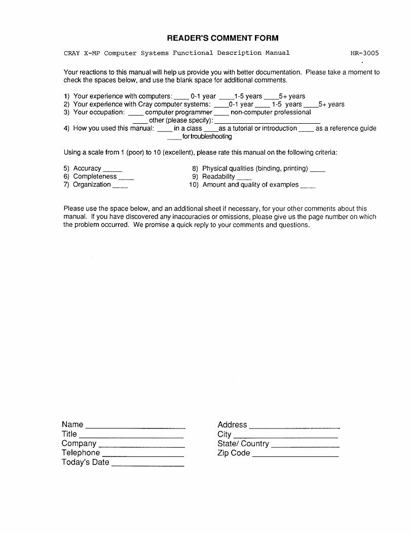
READER'S COMMENT FORM
CRAY X-MP computer Systems Functional Description Manual HR-3005
Your reactions to this manual will help us provide you with better documentation. Please take a moment to check the spaces below, and use the blank space for additional comments.
1) Your experience with computers: __ 0-1 year __ 1-5 years __ 5+ years 2) Your experience with Cray computer systems: __ 0-1 year __ 1-5 years __ 5+ years 3) Your occupation: __ computer programmer __ non-computer professional
__ other (please specify): ___________ _ 4) How you used this manual: __ in a class __ as a tutorial or introduction __ as a reference guide
__ for troubleshooting
Using a scale from 1 (poor) to 10 (excellent), please rate this manual on the following criteria:
5) Accuracy __ 8) Physical qualities (binding, printing) __ 6) Completeness __ 9) Readability __ 7) Organization __ 10) Amount and quality of examples __
Please use the space below, and an additional sheet if necessary, for your other comments about this manual. If you have discovered any inaccuracies or omissions, please give us the page number on which the problem occurred. We promise a quick reply to your comments and questions.
Name Address ----------------- ----------------------Title --------------------- City __________ _ Company ________ _ State/ Country ______ _ Telephone _______ _ Zip Code ________ _ Today's Date ______ _
-------------------------------------------~
IIIIII BUSINESS REPLY CARD FIRST CLASS PERMIT NO 6184 ST PAUL MN
POSTAGE Will BE PAID BY ADDRESSEE
RESEARCH. INC.
Attention: PUBLICATIONS 1345 Northland Drive Mendota Heights, MN 55120
NO POSTAGE NECESSARY IF MAILED
IN THE UNITED STATES
-------------------------------------------~
STAPLE
(") C -i l> r o Z G)
-i I U5 r Z m