Embed Size (px)
Citation preview
CRCTechnical Reference Manual
P/N 3100132 • Rev 1.0 • 01NOV01
Technical Manuals Online! - http://www.tech-man.com

DEVELOPED BY Edwards Systems Technology6411 Parkland DriveSarasota, FL 34243(941) 739-4300
COPYRIGHT NOTICE Copyright © 2001 Edwards Systems Technology, Inc.
This manual and the products it describes are copyrighted byEdwards Systems Technology, Inc. (EST). You may notreproduce, translate, transcribe, or transmit any part of thismanual without express, written permission from EST.
This manual contains proprietary information intended fordistribution to authorized persons or companies for the solepurpose of conducting business with EST. If you distribute anyinformation contained in this manual to unauthorized persons,you have violated all distributor agreements and we may takelegal action.
CREDITS This manual was designed and written by the EST TechnicalServices - Documentation Department, Sarasota.
DOCUMENT HISTORY
Date Revision Reason for change
01NOV01 1.0 Initial publication.
Technical Manuals Online! - http://www.tech-man.com
CRC Technical Reference Manual i
Content
Chapter 1 Introduction • 1.1About this manual • 1.2Introduction to the CRC • 1.3Physical description • 1.4Overview of operation • 1.5
Chapter 2 Features and functions • 2.1CRC features • 2.2CRC functions • 2.8Mounting • 2.11Supervision • 2.12
Chapter 3 Hardware and equipment • 3.1Basic equipment • 3.2Control panel modules • 3.3SAC bus and wiring • 3.4CRC connections and options • 3.5Card readers and access cards • 3.9Software packages • 3.11
Chapter 4 Access control applications • 4.1Other factors • 4.2Anti-passback • 4.4Central monitoring station • 4.7Common door access • 4.9Delayed egress • 4.11Elevator control • 4.14Emergency exit door • 4.17Handicap access door • 4.19Maglock peripherals • 4.21Multiple card readers • 4.23Muster • 4.25Power for continuous locks • 4.28Power for intermittent locks • 4.30Power from an ac source • 4.32Power from a remote source • 4.35Remote controls • 4.38Two-person rule • 4.40
Chapter 5 Installation • 5.1Installation guidelines • 5.2Wiring the CRC • 5.5Installing and wiring the card reader • 5.8Installing the door locks • 5.9Checking operation with a construction card • 5.12NFPA 72 • 5.13
Technical Manuals Online! - http://www.tech-man.com
Content
ii CRC Technical Reference Manual
Chapter 6 Programming • 6.1SDU • 6.2ACDB • 6.10
Chapter 7 Operation • 7.1CRC processing • 7.2Sounder Output • 7.7Card reader LED outputs • 7.8Card reader power • 7.10Lock power • 7.11
Chapter 8 Maintenance and troubleshooting • 8.1Maintenance • 8.2CRC troubleshooting • 8.3Card reader troubleshooting • 8.4Access control cards troubleshooting • 8.6
Y Glossary • Y.1
Z Index • Z.1
Technical Manuals Online! - http://www.tech-man.com
Content
CRC Technical Reference Manual iii
Important information
Limitation of liabilityThe content of this manual is proprietary in nature and isintended solely for distribution to authorized persons,companies, distributors and/or others for the sole purpose ofconducting business associated with EST. The distribution ofinformation contained within this manual to unauthorizedpersons shall constitute a violation of any distributor agreementsand may result in implementation of legal proceedings.
Installation in accordance with this manual, applicable codes,and the instructions of the Authority Having Jurisdiction ismandatory. EST shall not under any circumstances be liable forany incidental or consequential damages arising from loss ofproperty or other damages or losses owing to the failure of ESTproducts beyond the cost of repair or replacement of anydefective products. EST reserves the right to make productimprovements and change product specifications at any time.
While every precaution has been taken during the preparation ofthis manual to ensure the accuracy of its contents, EST assumesno responsibility for errors or omissions.
FCC warningThis equipment can generate and radiate radio frequency energy.If this equipment is not installed in accordance with this manual,it may cause interference to radio communications. Thisequipment has been tested and found to comply within the limitsfor Class A computing devices pursuant to Subpart B of Part 15of the FCC Rules. These rules are designed to providereasonable protection against such interference when thisequipment is operated in a commercial environment. Operationof this equipment is likely to cause interference, in which casethe user at his own expense, is required to take whatevermeasures may be required to correct the interference.
Technical Manuals Online! - http://www.tech-man.com

Content
iv CRC Technical Reference Manual
ApprovalsThe Card Reader Controller (CRC) has been submitted to thefollowing approval agencies for listing:
• Federal Communications Commission (FCC)• Underwriters Laboratories Inc. (UL)• Underwriters Laboratories of Canada (ULC)
The CRC is compatible with the EST3 System.
Technical Manuals Online! - http://www.tech-man.com
CRC Technical Reference Manual 1.1
Chapter 1 Introduction
Summary
This chapter introduces you to the Card Reader Controller(CRC). We describe the CRC and present an overview of itsoperation.
ContentAbout this manual • 1.2Introduction to the CRC • 1.3Physical description • 1.4Overview of operation • 1.5
Technical Manuals Online! - http://www.tech-man.com

Introduction
1.2 CRC Technical Reference Manual
About this manualPurpose of the manual
This manual shows you how to design and develop an accesscontrol system based on the capabilities of the Card ReaderController (CRC). It also provides information on how to install,wire, configure, and maintain the CRC and related components.
Intended audience
This manual and the information it contains are intended forpeople who have experience with fire alarm systems, and a basicknowledge of security and access control applications.
Organization
This manual is organized into chapters. Here are briefdescriptions of the chapters.
Chapter 1: Introduction. Provides information on how thismanual is structured and gives a basic overview of the CRC.
Chapter 2: Features and functions. Provides a detailed look atthe CRC’s primary features and functions.
Chapter 3: Hardware and equipment. Provides a detailed list ofcompatible equipment that can be used with a CRC and anaccess control system.
Chapter 4: Access control applications. Provides information ondesigning an access control system using the CRC and relatedcomponents.
Chapter 5: Installation. Provides details on how to install a CRCand associated devices.
Chapter 6: Programming. Breaks configuration down into SDUand ACDB options. This chapter gives a definition andexplanation of each configuration option or setting.
Chapter 7: Operation. This chapter explains the operations ofthe CRC and some of its related components.
Chapter 8: Maintenance and troubleshooting. Explains differentproblems that may arise while using the CRC, card readers, oraccess control system and gives suggested solutions.
The manual includes a glossary and an index.
Related documents
ACDB User Manual (P/N 270961)
CRC CRCXM Card Reader Controller (P/N 387625)
Technical Manuals Online! - http://www.tech-man.com
Introduction
CRC Technical Reference Manual 1.3
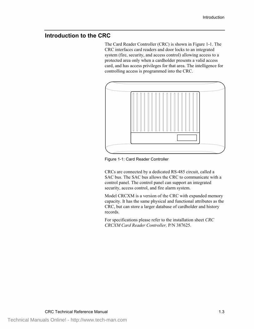
Introduction to the CRCThe Card Reader Controller (CRC) is shown in Figure 1-1. TheCRC interfaces card readers and door locks to an integratedsystem (fire, security, and access control) allowing access to aprotected area only when a cardholder presents a valid accesscard, and has access privileges for that area. The intelligence forcontrolling access is programmed into the CRC.
Figure 1-1: Card Reader Controller
CRCs are connected by a dedicated RS-485 circuit, called aSAC bus. The SAC bus allows the CRC to communicate with acontrol panel. The control panel can support an integratedsecurity, access control, and fire alarm system.
Model CRCXM is a version of the CRC with expanded memorycapacity. It has the same physical and functional attributes as theCRC, but can store a larger database of cardholder and historyrecords.
For specifications please refer to the installation sheet CRCCRCXM Card Reader Controller, P/N 387625.
Technical Manuals Online! - http://www.tech-man.com
Introduction
1.4 CRC Technical Reference Manual
Physical descriptionThe CRC has a streamlined white housing, designed to blend inwith most surroundings. This lets you install the CRC in plainsight, which typically requires much less time and effort.
The CRC has terminals for connection to the SAC bus, power,card reading devices, and door locking mechanism. Space isprovided for a standby battery. The CRC battery continues tooperate the CRC in case of a power failure. Jumpers areprovided for configuring the CRC to use ac or dc power, and tooperate continuous or intermittent operation door locks.
Technical Manuals Online! - http://www.tech-man.com

Introduction
CRC Technical Reference Manual 1.5
Overview of operationEach door being used for access control requires a CRC, a cardreading device, and an electric door lock. Both the card readerand door lock are wired to the CRC.
An access card is assigned to each person that requires access.The access card is equipped with a unique code that must beentered into the database of the CRC. The unique code allowsthe CRC to recognize a valid cardholder.
Each cardholder is assigned a set of access privileges thatdetermine the times and conditions under which access isgranted. The set of privileges is called an access level
When a card is read at the card reader, the following sequence ofevents occurs before the person is granted access:
1. The reader interprets the code on the card and forwards thisdata to the CRC.
2. The CRC determines whether to grant access. Some of thequestions that must be satisfied to make this decision are:
• Does the card code exist in the CRC database?
• Does the cardholder have disarm privileges for thesecurity partition assigned to the CRC?
• Is the security partition armed in the area beingaccessed?
• Is the time of day within the access level schedule?
• Does the person have an irregular access privilege?
3. If the CRC determines that the person has the correct accessprivileges, it releases the door lock, thereby allowing theperson to open the door.
4. The CRC automatically shares entry and exit eventinformation when there are multiple CRCs within apartition.
5. Entry and exit event information required by externalintegrated gateway connections (such as FireWorks) isautomatically sent to the control panel.
Technical Manuals Online! - http://www.tech-man.com

Introduction
1.6 CRC Technical Reference Manual
Technical Manuals Online! - http://www.tech-man.com
CRC Technical Reference Manual 2.1
Chapter 2 Features and functions
Summary
This chapter provides detailed definitions of the CRC’s featuresand functions.
ContentCRC features • 2.2
System integration • 2.2Enhanced survivability • 2.2System CRC capacity • 2.2Controls for readers and locks • 2.3LED and CRC sounder drivers • 2.3CRC dry contact relay connections • 2.3CRC input circuits • 2.4Access cards • 2.4Card readers • 2.4Database storage • 2.4Access levels and schedules • 2.5Schedules and holidays • 2.5Database capacities • 2.6User-defined logged attempts • 2.6User-defined PIN schedule • 2.6User-defined unlock and open times • 2.7
CRC functions • 2.8Construction mode • 2.8Security partition disarming • 2.8Alarm point bypass • 2.8Cardholder disability • 2.8Multiple tenants • 2.9Elevator floor access control • 2.9Visitor and escort function • 2.9Anti-passback options • 2.9Muster function • 2.9Two-person rule • 2.10
Mounting • 2.11Physical design • 2.11Distance from panel • 2.11
Supervision • 2.12CRC ac power • 2.12CRC cover • 2.12CRC low battery • 2.12CRC to card reader connection • 2.12CRC to lock connection • 2.12
Technical Manuals Online! - http://www.tech-man.com
Features and functions
2.2 CRC Technical Reference Manual
CRC features
System integrationThe CRC integrates seamlessly with the EST3 fire alarm system.If a fire alarm occurs, a simple program rule can unlock exitdoors. With fire and security devices installed on the samenetwork, no degradation in system performance occurs.
Because each CRC makes its own access decisions, very littlenetwork traffic is generated by the access control function. This,along with the integrated design of the network operatingsystem, ensures that fire signals always receive the highestpriority. To reduce traffic even further, the SDU optimizeswhich event messages the system receives.
Enhanced survivabilityIn performing its task, the CRC maintains a database of up to8,000 users with all options and schedules. It also stores the5,000 most recent access denied (and optionally, access granted)events.
The CRCXM stores up to 36,000 users and 20,000 events.
If the control panel 3-CPU1 or 3-SAC fails, or if the CRC losescommunication with the 3-SAC, the CRC continues to functionwithout any degradation.
If power is lost to the CRC, it can continue to operate on its owninternal battery power. The CRC will continue to grant and denyaccess for a limited amount of time (refer to battery calculationsin Appendix A), thereby eliminating the need for granting freeaccess during a degraded period.
When battery power is exhausted the control panel generates acommunication fault event message for the CRC.
System CRC capacityIn an integrated system, security and access control devices areconnected by a dedicated RS-485 circuit, called a SAC bus. TheSAC bus originates at the Security Access Control module(3-SAC).
Each 3-SAC can support up to 62 CRC or KPDISP (KeypadDisplay) devices for Class B wiring (30 CRCs or KPDISPs forClass A). This is a multiple-drop circuit and does not require adedicated run for each device.
Technical Manuals Online! - http://www.tech-man.com
Features and functions
CRC Technical Reference Manual 2.3
Should network communication be lost, the CRC will continueto grant access based on the database stored in its memory,without loss of any security feature.
(Applications that rely on communication between CRCs are theexception. For example, anti-passback and two-person ruleapplications, requiring more than one door, may not work indegraded mode.)
Controls for readers and locksEach CRC provides the power and electronics required tocontrol and monitor a single door. The CRC can accommodatetwo card readers (entry and exit) plus an associated electric doorlock. The CRC can use an external 24 Vdc power supply or aCRCXF CRC Transformer (a 16.5 Vac transformer) to powercontinuous-duty locks.
If desired, all entry and exit events can be reported to theFireWorks Guard Workstation. It is also possible to determinethe current location of an individual and obtain a list of allpeople who are in the premises.
The CRC can monitor the door contact and activate an optionalsounder if the door is opened without first badging out. This canact as a reminder to badge out, and ensure that managementknows who is in the building. It can also act as a simple form ofexit control in the event of an unauthorized exit.
LED and CRC sounder driversThe CRC provides LED driver terminals for the card readers.Thus, the readers can visually indicate whether access is grantedor denied.
The CRC provides different LED flash rates for applications thatrequire a PIN number or a second card. Examples: two-personrule or escorted visitor.
A driver for an audible sounder is also provided by the CRC.Refer to the installation sheet for the CRCSND CRC Sounder,P/N 3100033 for additional information.
CRC dry contact relay connectionsThe CRC includes common, N.O., and N.C. outputs from aForm C relay. These can be used to control auxiliary fire alarmdevices such as fans and dampers, as well as devices thatsupport handicap functions
Technical Manuals Online! - http://www.tech-man.com

Features and functions
2.4 CRC Technical Reference Manual
CRC input circuitsEach CRC has two input circuits for use with access control andsecurity devices. These are typically used for a door positionsensor and a request to exit device. The input circuits can beconfigured for use with a switch, controlled by a receptionist,that manually unlocks the door. Finally, the input circuits can beused as security input points.
Access cardsThe CRC is compatible with a large variety of access cards.These cards do not require a specially-ordered facility code. ESToffers access cards that are prenumbered and ready for use. TheEST cards have nonrepeating, unique numbers. This makes iteasy for administrators to add new cards to the access controlsystem.
When a site has an existing access control system, the CRC isflexible enough to integrate with most cards and card readersalready in use. To determine which cards and card readers arecompatible with the CRC see Chapter 3, Hardware andEquipment.
Card readersThe CRC is compatible with a variety of card readers thatcommunicate using the Security Industry Association (SIA)Wiegand output format. These include:
• Proximity• Wiegand pin• Magnetic stripe• Smart card• Keypad
To determine which cards and card readers are compatible withthe CRC, see the CRC installation sheet.
Database storageEach CRC stores a complete database within its memory. Itretains all the data necessary for complete operation of thedevices it controls. This distribution of intelligence maximizesthe speed at which access decisions are made and providessurvivability in the event that the CRC is disconnected from thenetwork.
Cardholder data is created and maintained by the Access ControlDatabase (ACDB) program, which runs on the end user’s PC.
Technical Manuals Online! - http://www.tech-man.com
Features and functions
CRC Technical Reference Manual 2.5
This information is encrypted and sent to the CRCs, via eitherdirect connection or modem (dial-up) connection.
With modem connection, the ACDB program can dial up thesystem and send the encrypted database information toindividual CRCs. This allows a single access control database toserve multiple sites.
Modem connection also permits multiple tenants to share acommon access control system without sharing a commondatabase.
Access levels and schedulesAn access level is a predefined collection of access and securityprivileges. One or more cardholders can be assigned the sameaccess level, and thus would have the same set of privileges.
Access levels consist of a list of doors, each with a specifiedschedule. Any combination of doors and schedules can beassigned to an access level. The access level determines whetheror not a cardholder can access a given door at a given time.
Each cardholder can be assigned two access levels. This helpsthe administrator quickly assign multiple access rights to asingle person. For example, a female manger could be assignedtwo access levels, one access level for mangers and one accesslevel for females. This grants the employee access privileges forthe manger-level doors and for all women’s restrooms.
Each access level can have an active date and an expiration date.This means the two access levels can be used to control rotatingshifts, parking lots, or temporary schedules.
When used for rotating time shifts, the first access level is thecurrent schedule and the second access level the future schedule.The first expire date and the second active date reflect the dateof the change of shift.
In parking lots, dual access levels allows for canceling parkingprivileges without canceling building access.
In temporary schedule use, the second schedule overrides thefirst schedule when active and returns control to the firstschedule when it expires.
Schedules and holidaysThe CRC stores the schedules and holidays created in the ACDBprogram. Each schedule identifies specific times (in 15-minuteincrements) and days when access is granted.
Technical Manuals Online! - http://www.tech-man.com
Features and functions
2.6 CRC Technical Reference Manual
Holidays are exceptions to normal Monday through Sundayschedules, when different access requirements are desired. Manyholidays can be programmed using rules rather than fixed dates.This minimizes year-to-year programming required to updateholidays.
For example, schedules for fixed holidays such as January 1,which can fall on a Saturday or Sunday, are assigned to takeplace on the previous Friday or next Monday respectively.
Database capacitiesAll access decisions are made locally in the CRC. The CRC’snon-volatile memory holds the cardholder, schedule, and holidayinformation required.
A total of 8,000 cardholders can be stored in each CRC. TheCRCXM has additional memory, and supports 36,000cardholders.
The CRC or CRCXM can store 1,200 access levels (255 percompany). Each cardholder can be assigned two access levels.
The CRC or CRCXM can store 1,200 schedules (255 percompany) and 1,200 holidays (255 per company).
The CRC stores up to 5,000 events per door, ensuring no loss ofhistory. The CRCXM has additional memory and stores up to20,000 events. This history information can be uploaded to theACDB program on demand, for use in a variety of reports.
User-defined logged attemptsBy using a suppression schedule in the ACDB, you candetermine when normal access events are to be logged. Loggedevents always include irregular events and unsuccessfulattempts. Determining what you want to be logged helpseliminate unnecessary events from entering the history buffer.
User-defined PIN scheduleA schedule can be used to define when a PIN must be entered toverify each card swipe. To use this option, a combination cardreader and keypad must be installed. The use of a PIN decreasesthe possibility that a recently lost or stolen card can be used togain entry. A schedule defines when a PIN must be used. Thiscan be during business hours, outside business hours, or at alltimes.
The card is always presented first. If the schedule determinesthat a PIN is required, the red LED on the card reader will flash
Technical Manuals Online! - http://www.tech-man.com

Features and functions
CRC Technical Reference Manual 2.7
at 1 Hz. This is an indication that the user must enter a PIN. Theuser then enters the PIN to gain access.
This option is selectable per door. If no schedule is defined for adoor, that door will not require a PIN. For this application thekeypad used must provide output in standard Dorado 8-bitWiegand data format.
User-defined unlock and open timesUsing the ACDB program, the administrator can control howmuch time a person has to enter or exit through a door. The CRCcontrols both the unlock time and door open time, and these canbe set in the ACDB program.
Unlock timers control the number of seconds that the door staysunlocked when a user badges in. When the unlock timer expiresthe door lock locks. The ACDB has three unlock timers:
• Standard unlock• Handicap unlock• Manual unlock
The CRC relay can be used to control a door opener. Door opentimers control the number of seconds that the relay stays active.The ACDB has two door open timers:
• Manual open time• Relay open time
Refer to Chapter 6: Programming for more information on thesefields.
Technical Manuals Online! - http://www.tech-man.com
Features and functions
2.8 CRC Technical Reference Manual
CRC functions
Construction modeThe CRC can operate in a construction mode. In this mode, thebuilding contractors use specially coded cards for gaining accessbefore the system is fully operational.
This mode is in effect before the CRC is programmed by theACDB. As soon as a card record is downloaded into the CRC,the construction card stops working.
Remember that temporary cards can be included in the accesscontrol database and downloaded into the CRC. This allowsworkmen to continue installation and testing, even after theACDB database has been downloaded. The ACDB user candefine an automatic deactivation date for such cards.
The ACDB cannot be used to restore a CRC to its originalcondition. This can only be done with the SDU, using theRemove from 3-SAC download action (found in theCommunication Functions dialog box).
Security partition disarmingA partition is an area of an alarm system that can operate and becontrolled independently. A CRC can be used to disarm one of255 security partitions.
Alarm point bypassCRCs can be programmed to automatically bypass alarm pointswhen a cardholder is granted access. For example, an employeeentrance door may need to be armed at all times. Bypassing thisdoor contact allows free entry and exit as authorized employeescome and go. If an unauthorized entry is made an annunciationalarm sounds.
Cardholder disabilityA special disability option allows an individual additional accesstime. A disability option can be selected for any cardholder.When such a cardholder presents his card to the reader, the CRCrecognizes the option and provides additional, user-definedaccess time and operates a relay that can activate an automaticdoor opener.
Technical Manuals Online! - http://www.tech-man.com
Features and functions
CRC Technical Reference Manual 2.9
Multiple tenantsMultiple tenants are supported by the CRC. During systeminstallation, the available schedules and holidays are allocated tothe tenants, up to 255 per tenant.
Tenants can then control their own access control database,using a dial-up modem connection or direct RS-232 connection.
Elevator floor access controlElevator floor access control is possible if you use CRCs in anintegrated system. Because the fire portion of the system isalready interconnected with the elevator controller for elevatorcapture functions, floor access control is a simple extension ofan existing function.
Visitor and escort functionThe CRC can be used to allow a visitor to gain access only whenwith an escort. Both the escort and visitor must badge in at acard reader to gain access. First the visitor badges in, followedby the escort. The CRC will only allow access after the escorthas badged in.
Anti-passback optionsAnti-passback is a feature of the access control system thatprevents successive use of one card to pass through a controlleddoor (in the same direction). The CRC supports three differentversions of anti–passback: strict, timed, and logged.
Muster functionIn the event of an evacuation of a building, the musterapplication can be used to verify that everyone has exited thebuilding.
During an evacuation, everyone exits the building immediatelyand goes to one of the predetermined muster stations. At themuster station, personnel use their access cards to badge out at acard reader that is attached to a CRC designated as a musterstation.
After everyone has badged out at the muster station, securitystaff use the ACDB program to run a muster report. The ACDBreport will indicate personnel that have badged into the buildingbut have not badged out.
Technical Manuals Online! - http://www.tech-man.com

Features and functions
2.10 CRC Technical Reference Manual
Two-person ruleA two-person rule ensures that no staff member can be in thecontrolled area alone. When two people are present in the area,one cannot exit without the other.
This feature is typically used in high security areas, where policyrequires a minimum of two persons in a secured area.(Examples: top-secret areas, vaults, high value stockrooms.)
Technical Manuals Online! - http://www.tech-man.com
Features and functions
CRC Technical Reference Manual 2.11
Mounting
Physical designThe unit is housed in an off-white case. The attractive designallows for surface mounting in exposed areas.
Distance from panelIn an integrated access control system the CRC is connected tothe 3-SAC via the SAC bus. The CRC can be up to 4,000 feet(1,220 m) from the 3-SAC. Power requirements must bedetermined for extended distances. (Refer to the CRCinstallation sheet for further details).
Technical Manuals Online! - http://www.tech-man.com
Features and functions
2.12 CRC Technical Reference Manual
Supervision
CRC ac powerThe power for operating the CRC can come from any one ofthree sources:
• The control panel power supply• An external 24 Vdc power supply• A CRCXF CRC Transformer
If the CRC loses any primary power source, a primary powertrouble signal is sent to the panel for annunciation.
CRC coverIf the cover of the CRC is removed, the built-in tamper switch isactivated and a tamper signal is sent to the panel forannunciation.
CRC low batteryThe power for operating the door releasing mechanism can befurnished by a 1.2 AH, 12 V battery in the CRC. The battery ischarged from either an ac or a dc power source.
The battery is monitored for a low voltage condition. If a lowvoltage condition exists, a CRC trouble condition is sent to thepanel for annunciation.
CRC to card reader connectionIf the wiring from the CRC to the card reader breaks, a cardreader trouble signal is sent to the panel for annunciation.
CRC to lock connectionIf the wiring from the CRC to the electric door lock breaks, alock trouble signal is sent to the panel for annunciation.
Technical Manuals Online! - http://www.tech-man.com
CRC Technical Reference Manual 3.1
Chapter 3 Hardware and equipment
Summary
This chapter provides information about hardware andequipment that can be used with the CRC.
ContentBasic equipment • 3.2Control panel modules • 3.3
3-SAC Security Access Control module • 3.33-MODCOM Modem Communicator module • 3.3
SAC bus and wiring • 3.4SAC bus • 3.4Card reader wire • 3.4
CRC connections and options • 3.5CRC Card Reader Controller • 3.5Input circuits 1 and 2 • 3.6Output circuit • 3.6Lock • 3.6CRC options • 3.6
Card readers and access cards • 3.9Card readers • 3.9Access cards • 3.10
Software packages • 3.11Resource Profile Manager (RPM) tool • 3.11Access Control Database (ACDB) program • 3.11ACDB8 • 3.11ACDB8+ • 3.12ACDB-SVR • 3.12ACDB-CLNT • 3.12
Technical Manuals Online! - http://www.tech-man.com
Hardware and equipment
3.2 CRC Technical Reference Manual
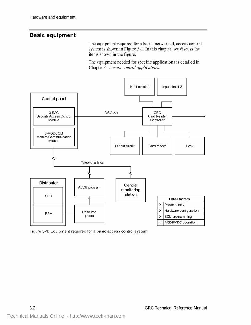
Basic equipmentThe equipment required for a basic, networked, access controlsystem is shown in Figure 3-1. In this chapter, we discuss theitems shown in the figure.
The equipment needed for specific applications is detailed inChapter 4: Access control applications.
Central monitoring
station
Telephone lines
Control panel
SAC bus
ACDB program
3-SACSecurity Access Control
Module
3-MODCOMModem Communication
Module
CRCCard Reader
Controller
Distributor
SDU
Resource profile
LockCard reader
Input circuit 1 Input circuit 2
Power supply
Other factors
Hardware configuration
SDU programming
ACDB/KDC operation
X
X
X
X
RPM
Output circuit
Figure 3-1: Equipment required for a basic access control system
Technical Manuals Online! - http://www.tech-man.com
Hardware and equipment
CRC Technical Reference Manual 3.3
Control panel modules
3-SAC Security Access Control moduleThe 3-SAC Security Access Control rail module controls a high-speed RS-485 circuit called the Security Access Control (SAC)bus. The SAC bus supports fire, security, and access controldevices.
The 3-SAC handles message traffic for these devices. Events arepassed from the devices to the 3-SAC module, then to the3-CPU1 for processing.
The 3-SAC has two sets of bus circuit terminals, and is capableof Class A or Class B configuration. Each Class B circuit caninclude 31 devices, for a total of 62 devices per module. Class Acircuits can include 30 devices total. In Figure 3-1, we show aClass B bus with a CRC Card Reader Controller module.
3-MODCOM Modem Communicator moduleThe 3-MODCOM Modem Communicator module has bothmodem and dialer functions. It can transmit and receiveinformation.
The 3-MODCOM can transmit alarm, supervisory, or troublemessages to a remote central monitoring station using one or twotelephone lines. A variation of the module (3-MODCOMP) cantransmit pager messages to a paging company using the TAPprotocol.
The module can also receive information sent over telephonelines by the Access Control Database (ACDB) program.
Technical Manuals Online! - http://www.tech-man.com
Hardware and equipment
3.4 CRC Technical Reference Manual
SAC bus and wiring
SAC busSince our security and access control devices require 24 Vdc, wesuggest that you always use a four-wire cable for the SAC busand a 24 Vdc power supply.
For the data wires, use unshielded, twisted pair, with greaterthan 6 twists per foot, in 14 to 22 AWG (1.50 to 0.25 sq mm).For the power wires, use 14 or 16 AWG.
You can use a four-conductor cable with an overall jacketcontaining solid 2-19 AWG and 2-16 AWG for the SAC bus.
The maximum run from a CRC to the 3-SAC is 4,000 ft(1,220 m) at 25 pF/ft. The maximum total capacitance of the runis 0.1 µF, and the maximum total resistance is 52 Ω.
Card reader wireEight-conductor stranded 22 AWG cable with overall shield isrecommended for the cable from the CRC to the card reader.
Technical Manuals Online! - http://www.tech-man.com
Hardware and equipment
CRC Technical Reference Manual 3.5
CRC connections and options
CRC Card Reader ControllerThe Card Reader Controller (CRC) is used for interfacing a cardreader into an integrated security and fire alarm system. OneCRC is required for each door you want to control. The CRC hasa terminal strip for connections to the following:
• 24 Vdc power• Strike (or other lock type)• Relay contacts• Card reader power• Card reader data• Card reader LEDs (two)• Optional sounder• SAC bus• Input loops 1 and 2
Each CRC supports:
• 8,000 cardholders• 5,000 events• 1,200 access levels (255 per company)• 1,200 schedules (255 per company)• 1,200 holidays (255 per company)
Each CRCXM supports:
• 36,000 cardholders• 20,000 events• 1,200 access levels (255 per company)• 1,200 schedules (255 per company)• 1,200 holidays (255 per company)
The CRC module performs all access decision processing. EachCRC stores an access database and is capable of granting ordenying entry without external communication.
When entry is granted, the CRC applies or removes power to thestrike or maglock to unlock the door. The CRC is also capable ofunlocking a door on activation of a manual push button.
Each CRC stores access control information and records of theevents for the door it controls. The CRCXM model featuresenhanced storage capacity.
Using its internal battery, the CRC can continue processingaccess events even if there is a loss of communication orprimary power.
Technical Manuals Online! - http://www.tech-man.com
Hardware and equipment
3.6 CRC Technical Reference Manual
Input circuits 1 and 2Each CRC supports two input circuits for such devices as:
• Door contacts• Motion detectors• Request to exit buttons• Security devices
A door contact device monitors the door position (open orclosed) for various applications.
A motion detector detects a person’s approach and can be usedto unlock the door.
A request to exit (REX) push button (or bar) can be used tomanually unlock the door.
Security devices, such as glass-break detectors can be associatedwith the door to enhance its security, or to monitor a nearbywindow.
Output circuitEach CRC supports one output circuit in the form of N.O. andN.C. dry contact connections. The output circuit can be used forsuch devices as:
• Automatic door openers• Fan and damper control• Door holder control
LockThe CRC supports any type of door locking device. Commonlock devices are strikes and maglocks. A strike opens the doorwhen power is supplied, while a maglock secures the door whilepower is supplied.
CRC options
CRCSND CRC Sounder
The CRC Sounder is a small horn that mounts inside the cardreader controller module. The sounder operates if an emergencyexit door is opened without an exit request and can also indicatethat a door has been left open. The sounder clips to the inside ofthe CRC cover.
The CRC Sounder can be programmed, using rules written in theSDU. Further, the ACDB program can control several operatingparameters of the sounder.
Technical Manuals Online! - http://www.tech-man.com
Hardware and equipment
CRC Technical Reference Manual 3.7
CRCRL CRC Accessory Relay
The CRCRL is an accessory relay for the CRC(XM) CardReader Controller. Use the CRCRL in conjunction with anexternal power supply to control a lock which requires voltageor current outside the CRC's operating range.
CRC battery
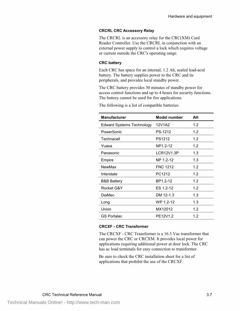
Each CRC has space for an internal, 1.2 Ah, sealed lead-acidbattery. The battery supplies power to the CRC and itsperipherals, and provides local standby power.
The CRC battery provides 30 minutes of standby power foraccess control functions and up to 4 hours for security functions.The battery cannot be used for fire applications.
The following is a list of compatible batteries:
Manufacturer Model number AH
Edward Systems Technology 12V1A2 1.2
PowerSonic PS-1212 1.2
Technacell PS1212 1.2
Yuasa NP1.2-12 1.2
Panasonic LCR12V1.3P 1.3
Empire NP 1.2-12 1.3
NewMax FNC 1212 1.2
Interstate PC1212 1.2
B&B Battery BP1.2-12 1.2
Rocket G&Y ES 1.2-12 1.2
DiaMec DM 12-1.3 1.3
Long WP 1.2-12 1.3
Union MX12012 1.2
GS Portalac PE12V1.2 1.2
CRCXF - CRC Transformer
The CRCXF - CRC Transformer is a 16.5 Vac transformer thatcan power the CRC or CRCXM. It provides local power forapplications requiring additional power at door lock. The CRChas ac load terminals for easy connection to transformer.
Be sure to check the CRC installation sheet for a list ofapplications that prohibit the use of the CRCXF.
Technical Manuals Online! - http://www.tech-man.com

Hardware and equipment
3.8 CRC Technical Reference Manual
Cypress CVT-2110
The Cypress CVT-2110 converts Wiegand data to RS-232ASCII hexadecimal.
You can use the CVT2110 to connect a card reader to a serialport on the ACDB computer. This means you can read a cardnumber directly into the ACDB program by swiping the card,rather than by typing.
The CVT-2110 requires an external source of voltage between 8and 24 Vdc at 150 mA. It is available from Cypress ComputerSystems, Inc. (www.cypresscom.com).
Technical Manuals Online! - http://www.tech-man.com
Hardware and equipment
CRC Technical Reference Manual 3.9
Card readers and access cards
Card readersBy card reader, we mean any of the different types of credentialreader supported by the CRC. A card reader scans a card todetermine the card number and passes the card number to theCRC.
All the required electronics are assembled in the card readerhousing. The card reader connects directly to the CRC, whichprocesses the card number and grants or denies access.
Each CRC can support several card readers. Typically, a CRCwill control an entry and exit card reader for the doorway. It canalso support multiple readers for such applications as two-personrule or anti-passback.
Note that the CRC supports any type of reader that uses theindustry standard Wiegand output format. These include:
• Proximity• Wiegand pin• Magnetic stripe• Keypad• Smart card
Some applications work best with card readers that support dualLED control. The CRC uses two LEDs, or two LED states, toindicate that further actions are required after the initial badgingoperation, before access is granted. These applications are:
• Two-person rule• Visitor and escort• PIN schedule
If you plan one of these applications, contact the card readermanufacturer to confirm that the reader supports dual LEDcontrol.
Card readers are additionally categorized by the way the cardmust be presented to the card reader for reading:
• Card swipe: The card swipe reader does its reading as a cardis swiped through a slot in the reader.
• Insert: The insert reader requires that the card be insertedfully into a narrow slot, with the reading typically beingdone as the card is withdrawn.
• Proximity: The proximity reader requires the user to pass thecoded card in close proximity to the reader, with the readerusing RF energy to determine the code on the card.
Technical Manuals Online! - http://www.tech-man.com
Hardware and equipment
3.10 CRC Technical Reference Manual
Some card readers are also equipped with a keypad. The keypadallows for entry of a PIN number in addition to the card code.The CRC can accommodate any PIN number of 1-4 digits alongwith the associated card code. The need to enter a PIN iscontrolled by two factors: whether or not the access schedulecalls for use of a PIN, and whether or not the partition to whichthe CRC belongs is armed.
Card readers may come with an LED arrangement to visuallyinform the user of the card reading and access control status.Typically, an LED arrangement uses red and green LEDlighting. Some readers use a bicolor LED and others use twoseparate LEDs. On most card readers the red LED is normallylit; this serves as an indication that the reader is receiving power.When a card is read, the LED temporarily turns from red togreen.
The CRC can provide 12 Vdc at 0.5A for operating its cardreaders.
Note: For a list of compatible card readers, see the CRCinstallation sheet.
Access cardsWith the correct card reader, the CRC can process the followingtypes of access cards:
• Wiegand• Magnetic stripe• Proximity
Note: For a list of compatible access cards, see the CRCinstallation sheet.
Technical Manuals Online! - http://www.tech-man.com
Hardware and equipment
CRC Technical Reference Manual 3.11
Software packages
Resource Profile Manager (RPM) toolThe Resource Profile Manager (RPM) tool is part of the SDU. Ituses the project database to create a separate resource profile foreach company that will be using the access control system.
The resource profile defines the access control system for theACDB program. It includes detailed information about eachCRC used by a given company. For example:
• Communication method• Primary or secondary control• Number of cardholders• Number of schedules• Number of holidays• Number of access levels• Command lists used
Access Control Database (ACDB) programThe Access Control Database (ACDB) program lets the userdefine and maintain a database of information about CRCs,cardholders, schedules, and access levels.
The ACDB program runs on the user’s PC. Additions or updatesto the access control database can be transmitted to the CRCunits in two ways.
The first method is via modem and dial-up telephone line to the3-MODCOM. The information is then routed to the 3-CPU1,through the correct 3-SACs, and finally to the CRC units.
The second method is by connecting the user’s PC directly to the3-CPU1 using an RS-232 cable. The connection is madebetween the PC’s COM1 port and any of the RS-232 terminalson the 3-CPU1. As in the first method, after reaching the3-CPU1 additions and changes are routed through the correct3-SACs to the CRCs.
Note: Changes to the access control database have no impact onthe parameters or operations of listed fire system equipment.
Different versions of the ACDB software are availableaccording to your system configuration and the number of doorsyou need to control. These are described below.
ACDB8ACDB8 is a software package that lets you enroll 50,000cardholders in an EST3 network system with eight or less doors.
Technical Manuals Online! - http://www.tech-man.com
Hardware and equipment
3.12 CRC Technical Reference Manual
ACDB8+ACDB8+ is a software package that lets you enroll 50,000cardholders in a networked EST3 system with over 4,000 doors.
ACDB-SVRACDB-SVR is the Access Control Database Server ApplicationSoftware. This is installed on the server PC for connection ofadditional Access Control Database client machines. Thisversion provides the same graphical user interface for cardholderenrollment and database configuration.
ACDB-CLNTACDB-CLNT is the Access Control Database ClientApplication Software. This allows client machines tocommunicate with the ACDB-SVR database for use withadditional workstations.
Technical Manuals Online! - http://www.tech-man.com
CRC Technical Reference Manual 4.1
Chapter 4 Access control applications
Summary
The CRC is a powerful and flexible component of access controlsystems. While it is a central component of such systems, itcannot work in isolation. This chapter shows how the CRCinteracts with other components and modules.
This chapter also illustrates and describes several access controlapplications. Each application is presented as a separate topicthat includes a block diagram and description. These give you anoverview of the application, and show the components requiredand their interconnection.
Refer to the EST3 Installation Sheets for specific componentsettings and terminal connections.
ContentOther factors • 4.2Anti-passback • 4.4Central monitoring station • 4.7Common door access • 4.9Delayed egress • 4.11Elevator control • 4.14Emergency exit door • 4.17Handicap access door • 4.19Maglock peripherals • 4.21Multiple card readers • 4.23Muster • 4.25Power for continuous locks • 4.28Power for intermittent locks • 4.30Power from an ac source • 4.32Power from a remote source • 4.35Remote controls • 4.38Two-person rule • 4.40
Technical Manuals Online! - http://www.tech-man.com
Access control applications
4.2 CRC Technical Reference Manual
Other factorsEach of the application drawings in this chapter includes acallout box for other factors that should be considered. Theseare:
• Power supply• Hardware configuration• SDU programming• ACDB/KDC operation
Power supplyThe CRC is designed to operate on 24 Vdc. For this reason, werecommend that you include power from the panel with the SACbus cable. You can use the panel 3-PPS/M or 3-BPS/M powersupplies.
When using a transformer power supply you must provide acircuit common path between all devices, using the –24 Vdcterminals.
If you use an additional power supply other than the CRCXF,that power supply must be listed for fire alarm applications, musthave ground fault detection disabled, and must have a circuitground (circuit common) that is isolated from earth ground.
Hardware configurationThe CRC has two jumpers that configure the power source andusage for the module. See the CRC installation sheet for detailson the jumper settings.
No other configuration settings are made at the device itself. Allother configuration is done via SDU or ACDB programming.
The SDU determines site-level configuration and parameters.The ACDB program controls end-user settings.
SDU programmingWhile the ACDB program defines the access control database,all other definition, configuration, and programming for theaccess control system happens in the SDU.
The SDU controls the general configuration of the 3-SACmodules, plus the configuration of all CRC devices on the SACbusses.
CRC modules can be configured to execute a specific,predefined command list when a specific access control eventoccurs. You write the command lists in the SDU, and assignthem to CRC events when you configure the CRC module.
Technical Manuals Online! - http://www.tech-man.com
Access control applications
CRC Technical Reference Manual 4.3
Partitions are fundamental groups used with access controlsystems. To use such access control features as two-person rule,muster, or anti-passback, CRCs must belong to the samepartition. All partitions are created and defined in the SDU, andeach CRC can be assigned to a partition.
For the 3-MODCOM module, the SDU determines the dialer andmodem parameters, defines the receivers and accounts, andassigns each account to the correct receiver. These settingscontrol CMS reporting and ACDB download operation.
Finally, the SDU includes the RPM tool, described in Chapter 3.
ACDB operationThe ACDB program lets the end user create and revise his accesscontrol database. Parameters stored in the database identifycardholders, schedules, and holidays, and assign accessprivileges.
The SDU includes a tool called the Resource Profile Manager(RPM). The RPM lets you create a resource profile for eachcompany using the system for access control purposes. Duringsetup of the ACDB program, the user imports the resourceprofile created by the RPM. This defines the system devices forthe ACDB program.
The ACDB runs on the end user’s computer. You can connectthe computer to the access control system in two ways:
• From an RS-232 port on the computer to an RS-232 port onthe 3-CPU1
• From the computer modem to a 3-MODCOM via telephonelines
The end result is that the ACDB database can be downloadedfrom the user’s computer to the system. Each CRC stores thatportion of the database pertinent to its operation.
Access control applicationsThe remaining topics in this chapter discuss specific accesscontrol applications. Each topic gives you an overview of theapplication, showing the components required and theirinterconnection.
Each topic includes a block diagram and general description ofthe application. Other factors (as called out on the drawings) arediscussed under separate headings in the topic.
Technical Manuals Online! - http://www.tech-man.com

Access control applications
4.4 CRC Technical Reference Manual
Anti-passback
Description of the applicationAnti-passback is a feature of the access control system thatprevents successive use of one card to pass through any door inthe same direction. Anti-passback prevents a card from beingpassed back to another person for the purpose of gainingunauthorized access.
The CRC supports three forms of anti-passback:
• Strict• Logged• Timed
Strict anti-passback is the most restrictive form of anti-passback.It requires all personnel to badge in and out, denying them accessto an area when they fail to do so.
Logged anti-passback is less restrictive than strict anti-passback.It still requires personnel to badge in and out but does not denyaccess when anti-passback rules are violated. Rather, such accessis logged as an access granted anti-passback event. With loggedanti-passback, security staff can work to correct violations, butpersonnel are not locked out.
Timed anti-passback prevents reuse of a card for a specificperiod, but does not require personnel to badge out. A timedanti-passback system automatically badges a cardholder out ofthe controlled partition after a specified time period, allowing thecard to be used again.
Note: Timed anti-passback cannot be used with a musterapplication, since the system automatically logs cardholders outof the partition, defeating muster accounting.
To implement anti-passback, a separate CRC is required at eachdoorway in the controlled partition. Each doorway requires anoutside card reader. Strict and logged anti-passback applicationsalso require an inside reader at every doorway. Timed anti-passback does not require the use of an inside card reader.
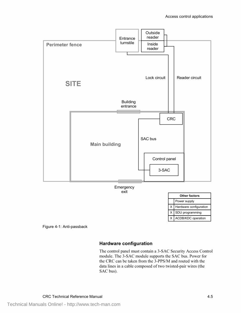
A typical anti-passback application is shown in Figure 4-1,below.
The figure shows a building with a perimeter fence. It would beeasy for an employee to pass his access card to an unauthorizedindividual through the fence, thereby allowing access.Configuring the access control system for anti-passbackoperation can help prevent this from happening.
Technical Manuals Online! - http://www.tech-man.com
Access control applications
CRC Technical Reference Manual 4.5
Power supply
Other factors
Hardware configuration
SDU programming
ACDB/KDC operation
X
X
X
Control panel
CRC
3-SAC
SITE
Entrance turnstile
SAC bus
Perimeter fence
Main building
Emergency exit
Building entrance
Inside reader
Outside reader
Lock circuit Reader circuit
Figure 4-1: Anti-passback
Hardware configurationThe control panel must contain a 3-SAC Security Access Controlmodule. The 3-SAC module supports the SAC bus. Power forthe CRC can be taken from the 3-PPS/M and routed with thedata lines in a cable composed of two twisted-pair wires (theSAC bus).
Technical Manuals Online! - http://www.tech-man.com

Access control applications
4.6 CRC Technical Reference Manual
SDU programmingIf the CRC is to be used for anti-passback this must beconfigured using the SDU. The CRC configuration dialogs letyou select the type of anti-passback you want to use:
• None• Logged• Timed• Strict
You can also assign a predefined command list to various accessgranted or access denied events, including the anti-passbackevents:
• Access granted anti-passback• Access denied anti-passback
The 3-CPU1 runs the command list you specify when either ofthese events occurs.
ACDB programmingWith timed anti-passback, the cardholder is automaticallymarked out after a specified period of time. This period isdefined by the ACDB. The period can be set from 0 through 255minutes (4 hours and 15 minutes).
Technical Manuals Online! - http://www.tech-man.com
Access control applications
CRC Technical Reference Manual 4.7
Central monitoring station
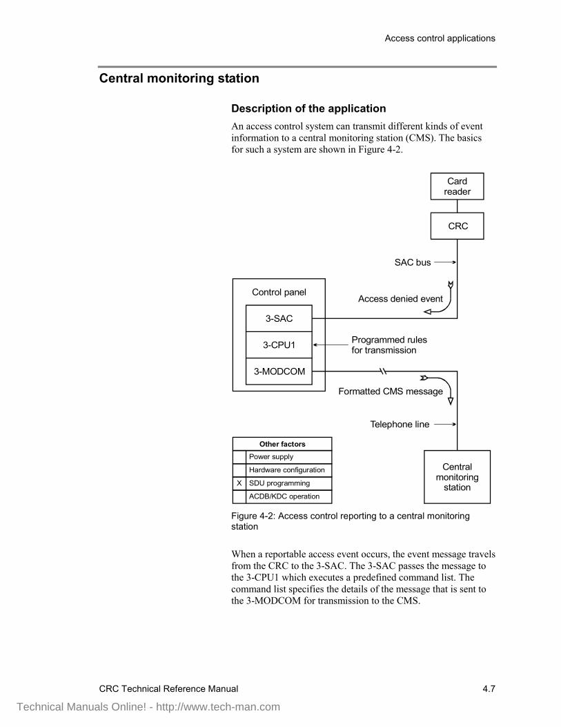
Description of the applicationAn access control system can transmit different kinds of eventinformation to a central monitoring station (CMS). The basicsfor such a system are shown in Figure 4-2.
Control panel
3-SAC
3-MODCOM
3-CPU1
Power supply
Hardware configuration
SDU programming
ACDB/KDC operation
Other factors
X
CRC
Cardreader
Central monitoring
station
Programmed rules for transmission
Telephone line
SAC bus
Access denied event
Formatted CMS message
Figure 4-2: Access control reporting to a central monitoringstation
When a reportable access event occurs, the event message travelsfrom the CRC to the 3-SAC. The 3-SAC passes the message tothe 3-CPU1 which executes a predefined command list. Thecommand list specifies the details of the message that is sent tothe 3-MODCOM for transmission to the CMS.
Technical Manuals Online! - http://www.tech-man.com

Access control applications
4.8 CRC Technical Reference Manual
SDU programmingReporting access control events to a CMS depends entirely onprogramming and the creation of command lists. In essence, youmust assign a command list to each CRC event you want toreport. The command list contains the details of the message tobe transmitted.
The following CRC events can be assigned command lists:
• Access granted• Access granted irregular• Access granted anti-passback• Access granted muster• Access denied unknown• Access denied reader disabled• Access denied access level not active• Access denied outside schedule 1• Access denied outside schedule 2• Access denied partition armed• Access denied PIN not entered• Access denied PIN not valid• Access denied two-person timeout• Access denied anti-passback• Access denied escort
Technical Manuals Online! - http://www.tech-man.com
Access control applications
CRC Technical Reference Manual 4.9
Common door access
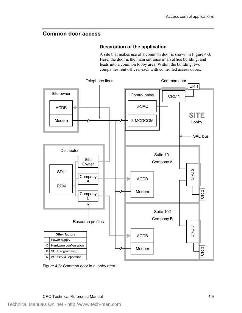
Description of the applicationA site that makes use of a common door is shown in Figure 4-3.Here, the door is the main entrance of an office building, andleads into a common lobby area. Within the building, twocompanies rent offices, each with controlled access doors.
Power supply
Other factors
Hardware configuration
SDU programming
ACDB/KDC operation
X
X
X
CR 1
Control panel CRC 1
CR
3
CR
C 3
CR
2
ACDB CR
C 2
Modem
ACDB
Modem
3-SAC
3-MODCOM
ACDB
Modem
SDU
RPM
Site Owner
Company A
Company B
Distributor
Site owner
SITE
Company A
Company B
Lobby
Common door
SAC bus
Resource profiles
Telephone lines
Suite 101
Suite 102
Figure 4-3: Common door in a lobby area
Technical Manuals Online! - http://www.tech-man.com

Access control applications
4.10 CRC Technical Reference Manual
Hardware configurationThe site has an EST3 control panel that includes a 3-SAC and a3-MODCOM module. The 3-SAC supports the SAC bus. The3-MODCOM module supports modem communication with thecontrol panel over telephone lines.
SDU programmingAs the distributor, you use the SDU to program the EST panelfor this application. Part of the programming job is to use theResource Profile Manager (RPM) to create resource profiles forthe site owner and for each tenant company.
Resource profiles are imported into the Access Control Database(ACDB) program. They determine which devices the user cansee and program. Resource profiles also establish transmissionroutes that permit modem communication with the EST3 panel.
When a device is shared, the RPM lets you specify how much ofthe device is allocated to each company. You can allocateresources either by percentages or by actual numbers.
It’s a good idea to hold some allocation in reserve, giving eachcompany only what it needs. It is much easier to allocateadditional resources as needed than to reclaim resources that arealready allocated.
In our example, the resource profile for company A wouldcontain CRC 1 (the lobby door) and CRC 2 (the suite 101 door).For Company A, you might choose to allocate 80% of CRC 2,and 20% of CRC 1.
Similarly, the resource profile for company B would allocate80% of CRC 3 and another 20% of CRC 1.
The site owner will need access to the CRC2 and CRC3 doorsfor cleaning or inspection purposes. The site owner resourceprofile could allocate 20% of CRC 1, 10 % of CRC 2, and 10%of CRC 3.
This leaves 40% of CRC1 unallocated, and 10% of CRC2 andCRC3 unallocated. The unallocated resources are reserved forfuture expansion or changes.
ACDB operationThe site owner, the owner of company A, and the owner ofcompany B, can all use telephone lines to communicate with theEST3 control panel via the 3-MODCOM module. They candownload additions and changes to the CRCs, and upload usagedata for various ACDB reports.
Technical Manuals Online! - http://www.tech-man.com
Access control applications
CRC Technical Reference Manual 4.11
Delayed egress
Description of the applicationDelayed egress doors help to control shoplifting at retail sites. Adelayed egress door has card readers and a request to exit (REX)switch. Employees can badge in and out as they would at anyother door. In an emergency, customers must press the REXswitch to unlock the door.
When the REX switch is activated, the CRC sounds theCRCSND horn and sends a security alarm event to the panel. Itdoes not unlock the door immediately, thus allowing site stafftime to investigate.
The CRC waits for a specific interval of time before unlockingthe door. The typical delay time is 15 seconds; however, youmay be able to use a delay of up to 30 seconds with the approvalof the AHJ. The horn continues to sound for a specific period oftime, or until the CRC is reset.
After the delay time passes, the CRC unlocks the door, andlatches it in the unlocked state. The CRC must be reset in orderto relock the door and silence the horn. To reset the CRC, sitestaff must use a valid badge at the card reader.
The CRC also activates the CRCSND horn if the door is openedwithout badging. For example, if the door is forced open fromthe outside, the CRCSND activates, even though the REX hasnot been pressed.
Many codes require that delayed egress doors unlock during afire alarm, or when the panel is in trouble. This requirementallows occupants to evacuate the site immediately when a fire isdetected, or when the panel loses its ability to detect a fire orsound the alarm.
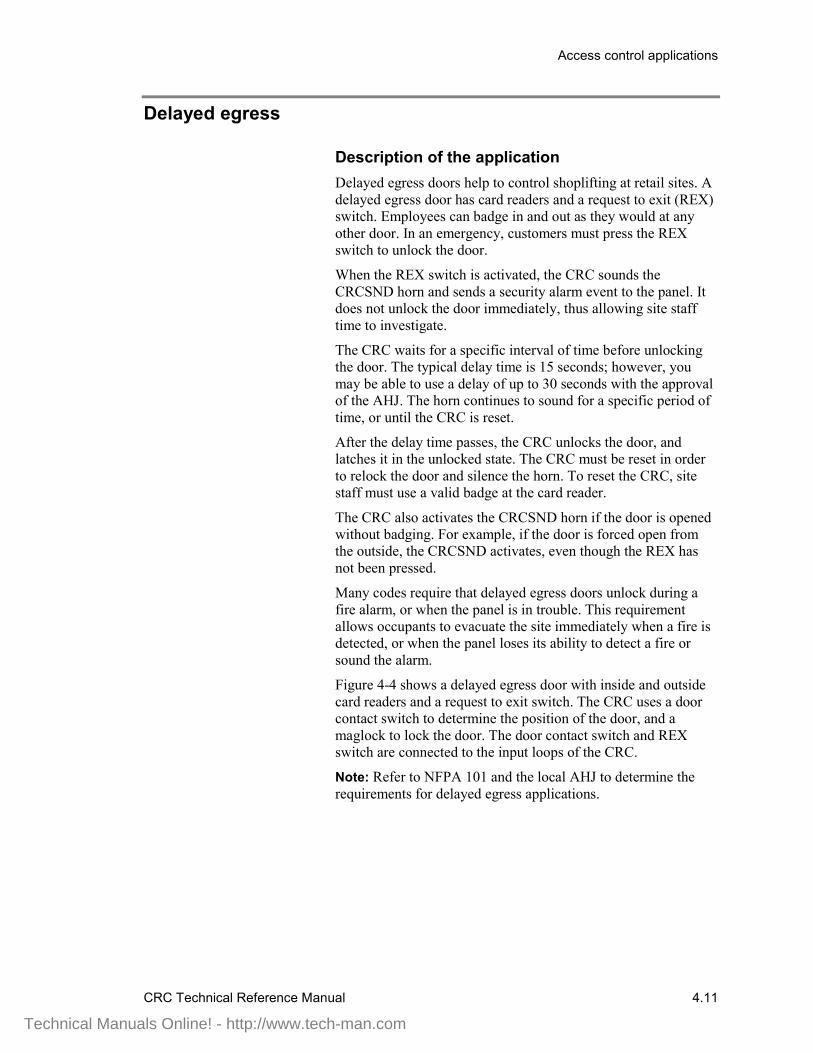
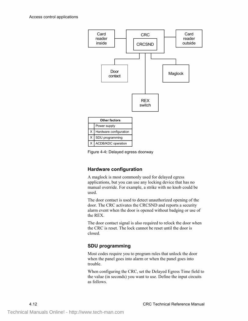
Figure 4-4 shows a delayed egress door with inside and outsidecard readers and a request to exit switch. The CRC uses a doorcontact switch to determine the position of the door, and amaglock to lock the door. The door contact switch and REXswitch are connected to the input loops of the CRC.
Note: Refer to NFPA 101 and the local AHJ to determine therequirements for delayed egress applications.
Technical Manuals Online! - http://www.tech-man.com
Access control applications
4.12 CRC Technical Reference Manual
CRCCard reader inside
Power supply
Other factors
Hardware configuration
SDU programming
ACDB/KDC operation
X
X
X
CRCSND
Door contact
Card reader outside
Maglock
REX switch
Figure 4-4: Delayed egress doorway
Hardware configurationA maglock is most commonly used for delayed egressapplications, but you can use any locking device that has nomanual override. For example, a strike with no knob could beused.
The door contact is used to detect unauthorized opening of thedoor. The CRC activates the CRCSND and reports a securityalarm event when the door is opened without badging or use ofthe REX.
The door contact signal is also required to relock the door whenthe CRC is reset. The lock cannot be reset until the door isclosed.
SDU programmingMost codes require you to program rules that unlock the doorwhen the panel goes into alarm or when the panel goes intotrouble.
When configuring the CRC, set the Delayed Egress Time field tothe value (in seconds) you want to use. Define the input circuitsas follows.
Technical Manuals Online! - http://www.tech-man.com
Access control applications
CRC Technical Reference Manual 4.13
For the door contact input loop:
• Device Type = Security P Monitor• Input Circuit Partition = as determined by project• Max Delta Count = as determined by project• Delays = None• Application = Emergency Exit Door Contact• Personality = Basic
For the request to exit switch:
• Device Type = Monitor• Input Circuit Partition = None• Max Delta Count = not applicable• Delays = None• Application = Request to Exit with Delayed Egress• Personality = N.O. with Trouble
ACDB operationWhen an employee badges in or out at the door, the CRCbypasses the door contact for a specified period of time. This iscalled the Bypass Time, and is specified in the ACDB.
The duration of the CRCSND horn is also specified in theACDB, as the Emergency Exit Sounder Time. This can be set toany value between 0 and 255 seconds.
Setting the value to 0 seconds effectively inhibits the CRCSND.Setting the value to 255 seconds programs the CRC to operatethe CRCSND until the CRC is manually reset by badging at theCRC card reader.
Technical Manuals Online! - http://www.tech-man.com
Access control applications
4.14 CRC Technical Reference Manual
Elevator control
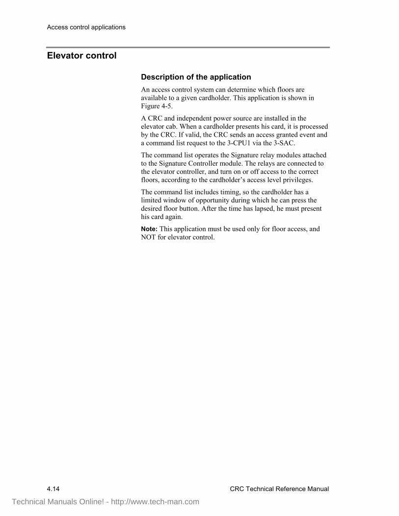
Description of the applicationAn access control system can determine which floors areavailable to a given cardholder. This application is shown inFigure 4-5.
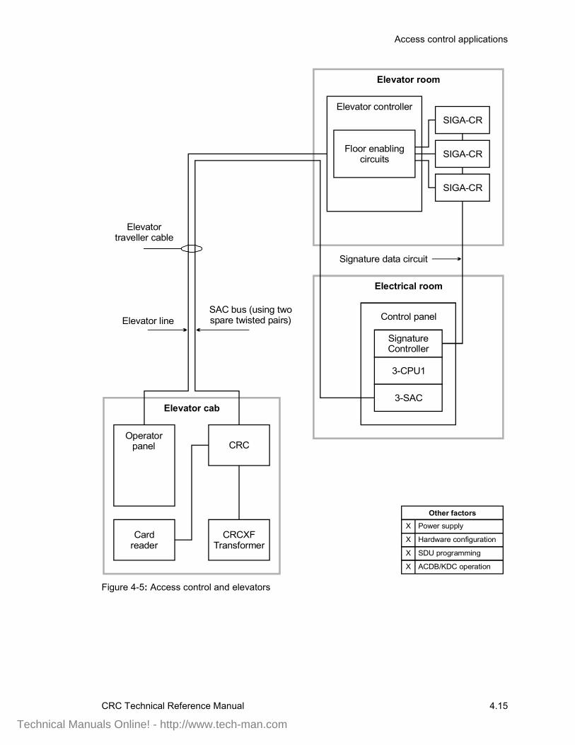
A CRC and independent power source are installed in theelevator cab. When a cardholder presents his card, it is processedby the CRC. If valid, the CRC sends an access granted event anda command list request to the 3-CPU1 via the 3-SAC.
The command list operates the Signature relay modules attachedto the Signature Controller module. The relays are connected tothe elevator controller, and turn on or off access to the correctfloors, according to the cardholder’s access level privileges.
The command list includes timing, so the cardholder has alimited window of opportunity during which he can press thedesired floor button. After the time has lapsed, he must presenthis card again.
Note: This application must be used only for floor access, andNOT for elevator control.
Technical Manuals Online! - http://www.tech-man.com
Access control applications
CRC Technical Reference Manual 4.15
Control panel
3-SAC
Signature Controller
3-CPU1
CRC
Card reader
CRCXFTransformer
Elevator cab
Operatorpanel
Elevator controller
Electrical room
Elevator room
Floor enabling circuits
SIGA-CR
SIGA-CR
SIGA-CR
Power supply
Hardware configuration
SDU programming
ACDB/KDC operation
Other factors
X
X
X
X
Elevator traveller cable
Signature data circuit
SAC bus (using two spare twisted pairs)Elevator line
Figure 4-5: Access control and elevators
Technical Manuals Online! - http://www.tech-man.com

Access control applications
4.16 CRC Technical Reference Manual
Power supplyThe figure shows an independent power source for the CRC.This is suggested due to the length of cable from the cab to theelectrical room.
Two pairs of wires are used to connect the CRC to the controlpanel. The SAC bus requires one pair for data communication.One wire of the second pair is required to maintain a commonground between the control panel and the CRC. For details, referto the topic Power from an ac source, later in this chapter.
If you use an additional power supply other than the CRCXF,that power supply must be listed for fire alarm applications, musthave ground fault detection disabled, and must have a circuitground (circuit common) that is isolated from earth ground.
Hardware configurationIn this application, none of the CRC input circuits or relaycontacts are used. The CRC simply reads the card and passes thecommand list request to the 3-SAC and 3-CPU1 for processing.
Since the CRC lock and input circuits are not used, you mustprovide dummy loads to maintain correct supervision currents.See the installation sheet for the correct load values.
SDU programmingThe SDU programmer must create a command list for eachcombination of floors desired.
ACDB operationThe site security officer determines which floors should beaccessible for an access level, and assigns the correct commandlist to the access granted event for that level. The site securityofficer also determines which cardholders belong to each accesslevel.
Technical Manuals Online! - http://www.tech-man.com
Access control applications
CRC Technical Reference Manual 4.17
Emergency exit door
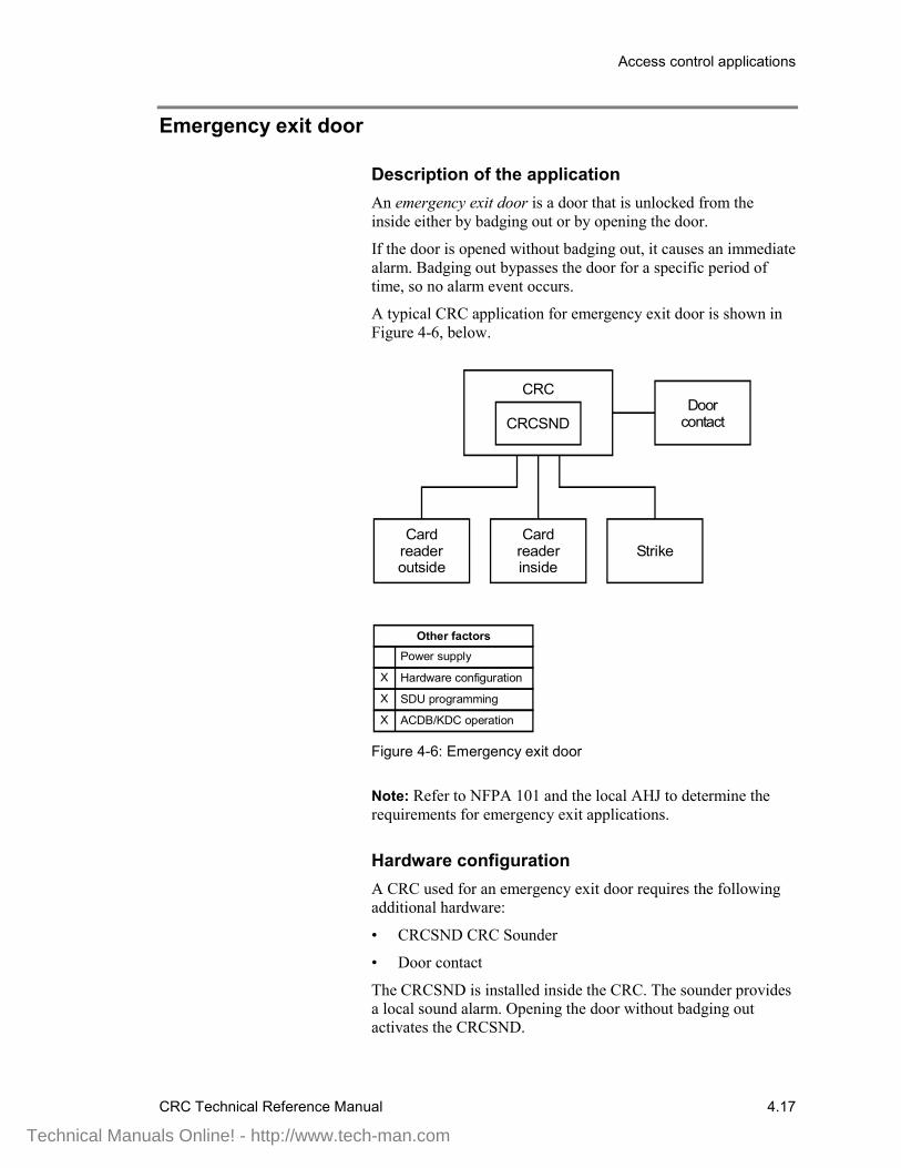
Description of the applicationAn emergency exit door is a door that is unlocked from theinside either by badging out or by opening the door.
If the door is opened without badging out, it causes an immediatealarm. Badging out bypasses the door for a specific period oftime, so no alarm event occurs.
A typical CRC application for emergency exit door is shown inFigure 4-6, below.
CRC
Card reader inside
Power supply
Other factors
Hardware configuration
SDU programming
ACDB/KDC operation
X
X
X
CRCSNDDoor
contact
Card reader outside
Strike
Figure 4-6: Emergency exit door
Note: Refer to NFPA 101 and the local AHJ to determine therequirements for emergency exit applications.
Hardware configurationA CRC used for an emergency exit door requires the followingadditional hardware:
• CRCSND CRC Sounder
• Door contact
The CRCSND is installed inside the CRC. The sounder providesa local sound alarm. Opening the door without badging outactivates the CRCSND.
Technical Manuals Online! - http://www.tech-man.com
Access control applications
4.18 CRC Technical Reference Manual
The door contact is connected to the CRC via the input circuit.
SDU programmingIn the SDU, you’ll need to define the input circuit for the doorcontact as follows:
• Device type: Security P Monitor• Delays: None• Application: Door Contact• Personality: Basic
ACDB operationTwo time periods are defined in the ACDB: Emergency ExitSounder Time, and Bypass Time.
Emergency Exit Sounder Time is the number of seconds (0through 255) the CRC Sounder sounds when an emergency exitdoor is opened without badging out.
When set to zero, the sounder is disabled. When set to 255, thesounder sounds until manually reset. The sounder is reset when acardholder badges in at the door.
In all cases badging in on the affected CRC can silence thesounder.
Bypass Time is the number of seconds (0 through 255) that thedoor is bypassed after a cardholder badges out.
Technical Manuals Online! - http://www.tech-man.com
Access control applications
CRC Technical Reference Manual 4.19
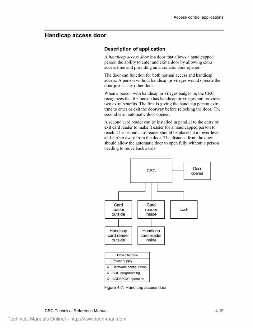
Handicap access door
Description of applicationA handicap access door is a door that allows a handicappedperson the ability to enter and exit a door by allowing extraaccess time and providing an automatic door opener.
The door can function for both normal access and handicapaccess. A person without handicap privileges would operate thedoor just as any other door.
When a person with handicap privileges badges in, the CRCrecognizes that the person has handicap privileges and providestwo extra benefits. The first is giving the handicap person extratime to enter or exit the doorway before relocking the door. Thesecond is an automatic door opener.
A second card reader can be installed in parallel to the entry orexit card reader to make it easier for a handicapped person toreach. The second card reader should be placed at a lower leveland farther away from the door. The distance from the doorshould allow the automatic door to open fully without a personneeding to move backwards.
CRC
Card reader inside
Power supply
Other factors
Hardware configuration
SDU programming
ACDB/KDC operation
X
X
X
Door opener
Card reader outside
Lock
Handicap card reader
inside
Handicap card reader
outside
Figure 4-7: Handicap access door
Technical Manuals Online! - http://www.tech-man.com
Access control applications
4.20 CRC Technical Reference Manual
Note: Refer to the appropriate ADA codes and the local AHJ todetermine the requirements for handicap access doorapplications.
Hardware configurationA CRC used for a handicap access door may require thefollowing additional hardware:
• Automatic door opener• Additional card readers
The automatic door opener is installed directly to the accessdoor. The CRC controls the opening of the door with its internalrelay.
Caution: The CRC relay is for low-voltage only. Do not exceedthe relay limits stated on the installation sheet.
The additional card readers are wired to the standard card readersin parallel.
SDU programmingIn the SDU, you’ll need to define the CRC relay device type asAccess Door Motor Control. This will activate the door openerfor the time specified by the ACDB.
ACDB operationThe Relay Open Time is defined in the ACDB. This is thenumber of seconds (0 through 255) that the CRC activates therelay that automatically opens the door. The default is 30seconds.
The Handicap Unlock time is also defined in the ACDB. This isthe number of seconds (0 through 255) that the lock staysunlocked. The default is 20 seconds The door relocks when theunlock time has expired and the door has closed.
Both of these times can be set to allow a longer access time for ahandicapped person.
Technical Manuals Online! - http://www.tech-man.com
Access control applications
CRC Technical Reference Manual 4.21
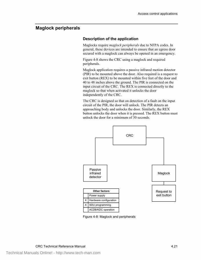
Maglock peripherals
Description of the applicationMaglocks require maglock peripherals due to NFPA codes. Ingeneral, these devices are intended to ensure that an egress doorsecured with a maglock can always be opened in an emergency.
Figure 4-8 shows the CRC using a maglock and requiredperipherals.
Maglock application requires a passive infrared motion detector(PIR) to be mounted above the door. Also required is a request toexit button (REX) to be mounted within five feet of the door and40 to 48 inches above the ground. The PIR is connected on theinput circuit of the CRC. The REX is connected directly to themaglock so that when activated it unlocks the doorindependently of the CRC.
The CRC is designed so that on detection of a fault on the inputcircuit of the PIR, the door will unlock. The PIR detects anapproaching body and unlocks the door. Similarly, the REXbutton unlocks the door when it is pressed. The REX button mustunlock the door for a minimum of 30 seconds.
CRC
Passive infrared detector
Request to exit button
Maglock
Power supply
Other factors
Hardware configuration
SDU programming
ACDB/KDC operation
X
X
Figure 4-8: Maglock and peripherals
Technical Manuals Online! - http://www.tech-man.com
Access control applications
4.22 CRC Technical Reference Manual
Hardware configurationThe maglock peripherals consist of the following:
• Passive infrared motion detector (PIR)• Request to exit button (REX)
The PIR is connected via the CRC input circuit. The REX isconnected directly to the maglock instead of the CRC inputcircuit to meet NFPA requirements.
SDU programmingWhen programming the system for this application you’ll needto configure the CRC, defining the device types. You’ll alsoneed to define the input circuits. For this application define theinput circuit for the PIR as follows:
• Device type = Security interior• Application = Request to exit motion detector.
Technical Manuals Online! - http://www.tech-man.com
Access control applications
CRC Technical Reference Manual 4.23
Multiple card readers
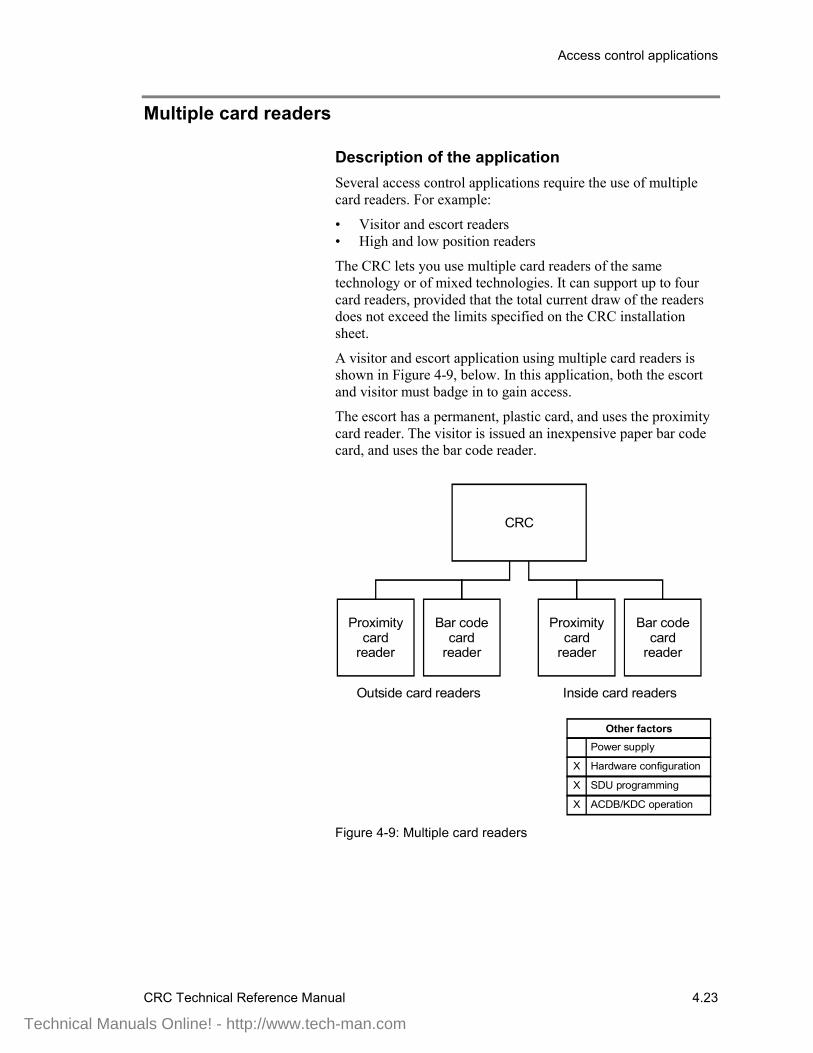
Description of the applicationSeveral access control applications require the use of multiplecard readers. For example:
• Visitor and escort readers• High and low position readers
The CRC lets you use multiple card readers of the sametechnology or of mixed technologies. It can support up to fourcard readers, provided that the total current draw of the readersdoes not exceed the limits specified on the CRC installationsheet.
A visitor and escort application using multiple card readers isshown in Figure 4-9, below. In this application, both the escortand visitor must badge in to gain access.
The escort has a permanent, plastic card, and uses the proximitycard reader. The visitor is issued an inexpensive paper bar codecard, and uses the bar code reader.
CRC
Bar code card
reader
Proximity card
reader
Power supply
Other factors
Hardware configuration
SDU programming
ACDB/KDC operation
X
X
Outside card readers
Bar code card
reader
Proximity card
reader
Inside card readers
X
Figure 4-9: Multiple card readers
Technical Manuals Online! - http://www.tech-man.com
Access control applications
4.24 CRC Technical Reference Manual
Card readerThis application works best with card readers that support dualLED control. The CRC uses the second LED (or LED state) tosignal the visitor that the escort must badge in before access isgranted.
Hardware configurationThe proximity card reader and barcode card reader are connectedto the same terminals of the CRC.
SDU programmingWhen an escorted visitor tries to enter a controlled area withoutan employee, the CRC generates an access denied escort event.You can select a predefined command list that the 3-CPU1executes in response to this event.
ACDB operationLike employees, visitors must be assigned an access level usingthe ACDB. The site security officer can elect to assign the sameaccess level to all visitor cards, or assign different access levelsto ranges of visitor cards.
Technical Manuals Online! - http://www.tech-man.com
Access control applications
CRC Technical Reference Manual 4.25
Muster
Description of the applicationThe muster application can be used to determine who has exitedthe building in the event of an evacuation.
During normal operations, staff badge in and out using the insideand outside readers. Note that muster reporting will only work ifall employees badge in and out.
During an evacuation, everyone exits the building immediatelyand goes to one of the predetermined muster stations. At themuster station personnel badge in using a reader that is attachedto a CRC designated as a muster station.
After everyone has badged in at the muster station security staffuse the ACDB program to create a muster report. The report listsstaff who badged into the building but did not badge out at amuster station.
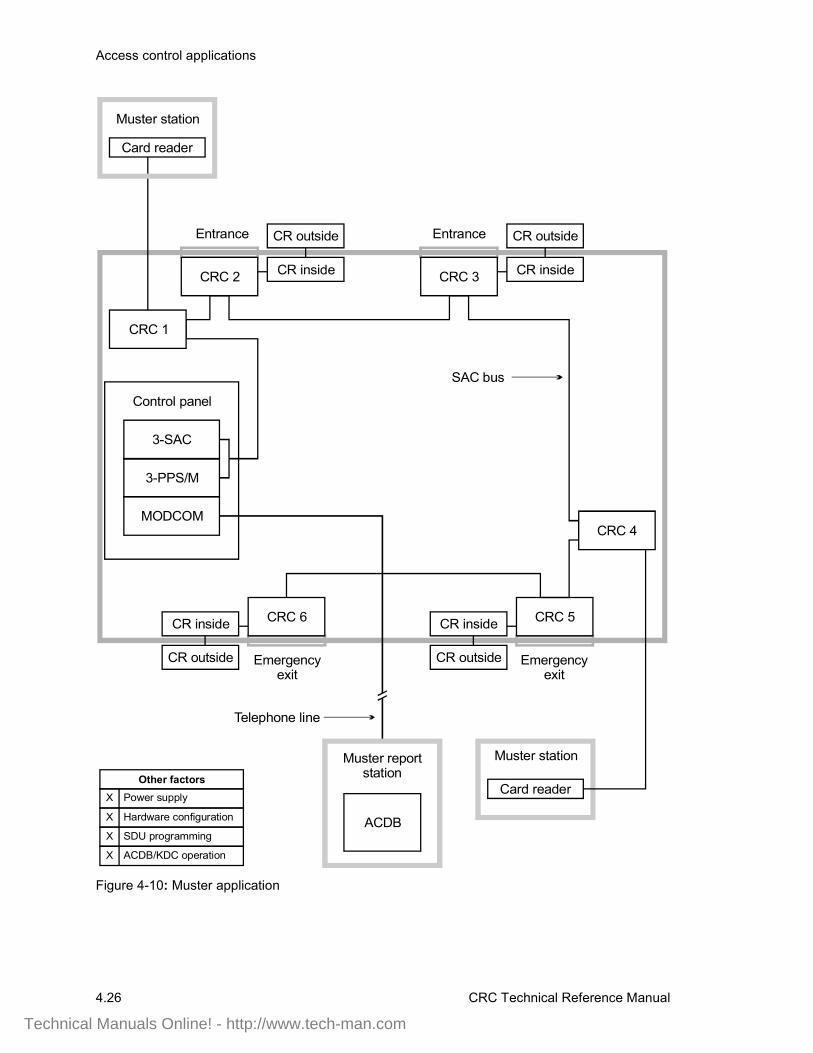
Figure 4-10 shows a typical muster application. CRCs 2, 3, 5,and 6 are normal access control CRCs. CRCs 1 and 4 are musterstation CRCs.
The ACDB computer must be located in a safe area so securitystaff can create the muster report after the evacuation. Thiscomputer can connect to the access control system either viatelephone lines and a 3-MODCOM, or by direct connection tothe EST3 control panel.
Note: Links between the ACDB computer and the control panelshould be tested regularly to ensure correct operation.
Staff must be made aware of the importance of badging in andout at all times. Failure to do so can result in a false musterreport, indicating that someone is still in the building. This inturn can result in rescue personnel risking danger to search forsomeone who is not actually in the building.
Technical Manuals Online! - http://www.tech-man.com
Access control applications
4.26 CRC Technical Reference Manual
Card reader
Muster station
Power supplyOther factors
Hardware configuration
SDU programming
ACDB/KDC operation
X
X
X
X
CRC 6
Control panel
3-PPS/M
SAC bus
CR outside
CRC 2
Entrance
CR inside
CR outside
CRC 3
Entrance
CR inside
CRC 5
CR outside
CR inside
Emergencyexit
CRC 4
CRC 1
MODCOM
ACDB
Muster report station
3-SAC
Card reader
Muster station
Emergencyexit
CR outside
CR inside
Telephone line
Figure 4-10: Muster application
Technical Manuals Online! - http://www.tech-man.com
Access control applications
CRC Technical Reference Manual 4.27
Hardware configurationThe control panel must contain the following rail modules:
• 3-SAC Security Access Control module• 3-PPS/M Primary Power Supply module
• 3-MODCOM Modem Communication module— or —3-RS232 Card option installed in the 3-CPU1
The 3-SAC module supports the SAC bus. Power for the CRC isnormally taken from the 3-PPS/M and is routed with the datalines in a cable composed of two twisted-pair wires.
The 3-MODCOM module supports modem communicationbetween the control panel and the ACDB program via telephonelines. Alternately, the 3-RS232 Card supports RS-232communications on a cable connected directly to the 3-CPU1.
All CRCs controlled by a muster station must be on the same3-SAC card as the muster station. Badging out at a muster stationbadges the person out of all partitions for that 3-SAC card.Therefore, a single muster station can serve multiple partitions,provided that they are on the same 3-SAC card.
The system must have at least one muster CRC per 3-SACmodule. The system cannot exchange muster informationbetween 3-SAC modules, so each must be handled separately formuster purposes.
A CRC used for a muster station requires the specified dummyload on the lock terminals to maintain supervision. (Refer to theCRC installation sheet for correct resistor values.)
The card reader used for the muster station must be wired as anoutside reader.
SDU programmingEach CRC used in a muster application requires specificconfiguration settings. These are made in the SDU program, onthe CRC Configuration tab.
If the CRC is used in a partition that has muster control, checkthe Muster Support box.
For the CRC designated as the muster station, check the MusterStation box, but leave the Muster Support box clear.
In the SDU, you can also assign a predefined command list tothe Access Granted Muster event.
Technical Manuals Online! - http://www.tech-man.com
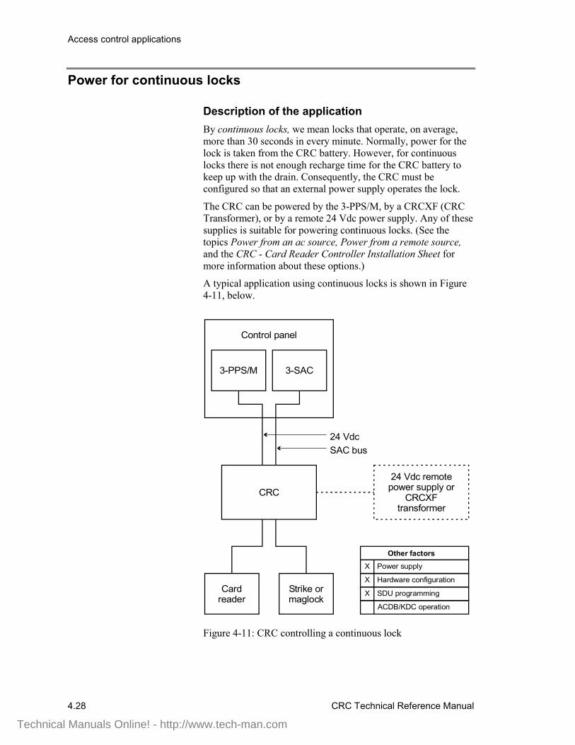
Access control applications
4.28 CRC Technical Reference Manual
Power for continuous locks
Description of the applicationBy continuous locks, we mean locks that operate, on average,more than 30 seconds in every minute. Normally, power for thelock is taken from the CRC battery. However, for continuouslocks there is not enough recharge time for the CRC battery tokeep up with the drain. Consequently, the CRC must beconfigured so that an external power supply operates the lock.
The CRC can be powered by the 3-PPS/M, by a CRCXF (CRCTransformer), or by a remote 24 Vdc power supply. Any of thesesupplies is suitable for powering continuous locks. (See thetopics Power from an ac source, Power from a remote source,and the CRC - Card Reader Controller Installation Sheet formore information about these options.)
A typical application using continuous locks is shown in Figure4-11, below.
3-SAC3-PPS/M
CRC
Strike or maglock
Card reader
24 VdcSAC bus
Control panel
Power supply
Other factors
Hardware configuration
SDU programming
ACDB/KDC operation
X
X
X
24 Vdc remote power supply or
CRCXF transformer
Figure 4-11: CRC controlling a continuous lock
Technical Manuals Online! - http://www.tech-man.com

Access control applications
CRC Technical Reference Manual 4.29
The figure shows the power coming from the 3-PPS/M in thecontrol panel. This power supply could be used to operate thelock, but use of a CRCXF or remote 24 Vdc supply isrecommended to minimize the load on the panel power supply.
During open schedules, or when an authorized card is read at acard reader, the CRC provides power from the 3-PPS/M to thedoor strike to unlock the door. For maglocks, the CRC providespower from the 3-PPS/M (or CRCXF or 24 Vdc power supply)to activate the lock during closed schedules, or betweenauthorized card accesses.
Power supplyUse power and load calculations to determine the need forremote power supplies or transformers. Refer to Appendix A:Calculations for calculation guidelines.
Jumper settings determine the power source and usage for theCRC. Refer to the installation sheet for correct jumper settings.Configure the input power as dc when using power from thecontrol panel or a remote supply. Configure input power as acwhen using a transformer.
For this application, configure the output power as continuous.
Hardware configurationThe control panel must contain the following rail modules:
• 3-SAC Security Access Control module• 3-PPS/M Primary Power Supply module
The 3-SAC module supports the SAC bus. Power for the CRC istaken from the 3-PPS/M and is routed with the data lines in acable composed of two twisted-pair wires.
SDU programmingWhen configuring the system for this application, you’ll need toconfigure the CRC and define the appropriate lock type in theSDU. For this application the Lock Type can be either Strike orMaglock as required to match the lock actually used.
Technical Manuals Online! - http://www.tech-man.com
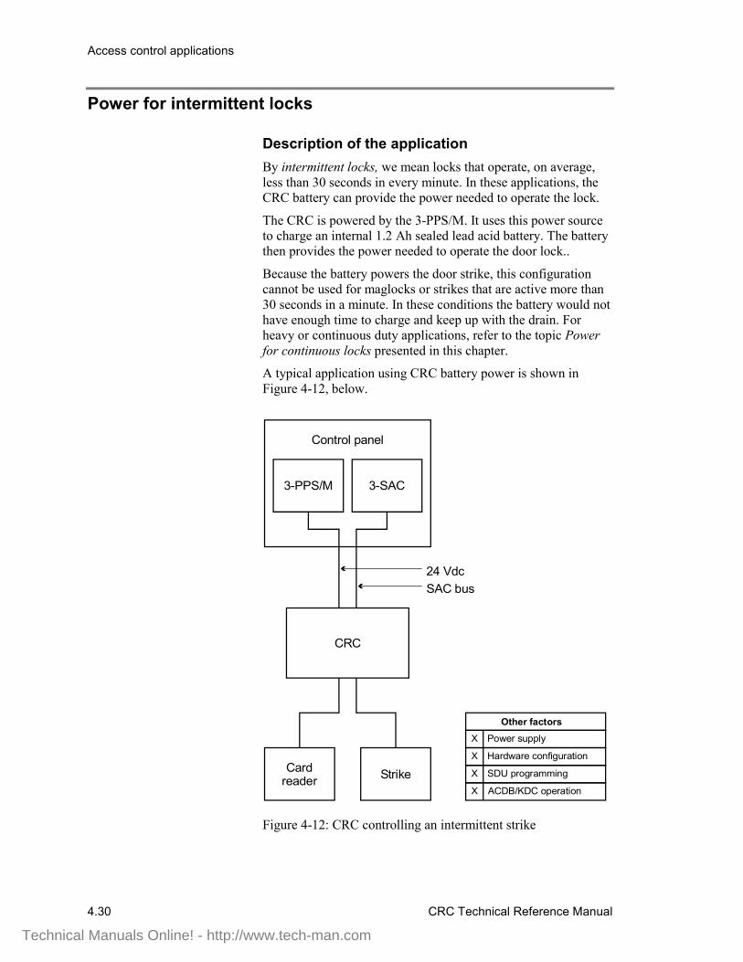
Access control applications
4.30 CRC Technical Reference Manual
Power for intermittent locks
Description of the applicationBy intermittent locks, we mean locks that operate, on average,less than 30 seconds in every minute. In these applications, theCRC battery can provide the power needed to operate the lock.
The CRC is powered by the 3-PPS/M. It uses this power sourceto charge an internal 1.2 Ah sealed lead acid battery. The batterythen provides the power needed to operate the door lock..
Because the battery powers the door strike, this configurationcannot be used for maglocks or strikes that are active more than30 seconds in a minute. In these conditions the battery would nothave enough time to charge and keep up with the drain. Forheavy or continuous duty applications, refer to the topic Powerfor continuous locks presented in this chapter.
A typical application using CRC battery power is shown inFigure 4-12, below.
3-SAC3-PPS/M
CRC
StrikeCard reader
24 VdcSAC bus
Control panel
Power supply
Other factors
Hardware configuration
SDU programming
ACDB/KDC operation
X
X
X
X
Figure 4-12: CRC controlling an intermittent strike
Technical Manuals Online! - http://www.tech-man.com

Access control applications
CRC Technical Reference Manual 4.31
The figure shows the charging power coming from the 3-PPS/Min the control panel. The access control system requires a 24 Vdcpower supply to power the CRC and to charge its battery. The3-SAC connects to the CRC through the SAC bus.
When an authorized card is read at a card reader, the CRCprovides power from its internal battery to the door strike andunlocks the door.
Power supplyJumper settings determine the power source and usage for theCRC. Refer to the installation sheet for correct jumper settings.Configure the input power as dc. Configure the output power asintermittent.
Hardware configurationThe control panel must contain the following rail modules:
• 3-SAC Security Access Control module• 3-PPS/M Primary Power Supply module
The 3-SAC module supports the SAC bus. Power for the CRC istaken from the 3-PPS/M and is routed with the data lines in acable composed of two twisted-pair wires.
SDU programmingWhen configuring the system for this application, you’ll need toconfigure the CRC and define the appropriate lock type in theSDU. For this application set the Lock Type to Strike.
ACDB operationNote that a CRC configured and programmed for intermittentlock use cannot support an open schedule (a period when thelock is kept open). Such a schedule would quickly drain the CRCbattery and the lock would close.
You should document the CRC configuration and include this inyour project plans. Make a copy of this documentation availableto the site security staff who will use the ACDB to create andassign schedules.
Technical Manuals Online! - http://www.tech-man.com

Access control applications
4.32 CRC Technical Reference Manual
Power from an ac source
Description of the applicationBy ac power, we mean that the CRC provides the power tooperate the electric door strike or maglock by using a 16.5 Vactransformer (model CRCXF). This supply can providecontinuous power to the door strike or maglock, and also powerthe CRC.
Using an ac source:
• Limits power drawn from the control panel• Supports continuous duty locks• Supports schedules with unlock periods
Note: Be sure to check the installation sheet for the CRC andCRCXM Card Reader Controller (P/N: 387625) for a list ofapplications that prohibit the use of the CRCXF.
A typical CRC using ac power is shown in Figure 4-13.
Technical Manuals Online! - http://www.tech-man.com
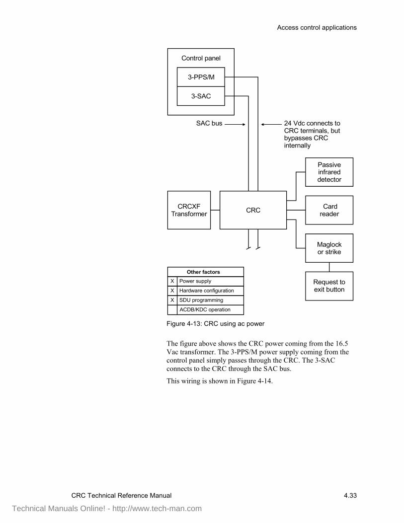
Access control applications
CRC Technical Reference Manual 4.33
Control panel
3-SAC
3-PPS/M
Maglock or strike
Card reader
Power supply
Other factors
Hardware configuration
SDU programming
ACDB/KDC operation
X
X
X
CRCXFTransformer
Passive infrared detector
SAC bus 24 Vdc connects to CRC terminals, but bypasses CRC internally
Request to exit button
CRC
Figure 4-13: CRC using ac power
The figure above shows the CRC power coming from the 16.5Vac transformer. The 3-PPS/M power supply coming from thecontrol panel simply passes through the CRC. The 3-SACconnects to the CRC through the SAC bus.
This wiring is shown in Figure 4-14.
Technical Manuals Online! - http://www.tech-man.com

Access control applications
4.34 CRC Technical Reference Manual
Control panel
Power supply
24 Vdc
CRCXFTransformer(16.5 Vac)
CRC24 Vdc
CRC24 Vdc
CRC24 Vdc
Figure 4-14: Wiring details for transformer supply
Power supplyJumper settings determine the power source and usage for theCRC. Configure the input power as ac. Configure the outputpower as continuous.
If you use an additional power supply other than the CRCXF,that power supply must be listed for fire alarm applications, musthave ground fault detection disabled, and must have a circuitground (circuit common) that is isolated from earth ground.
Hardware configurationThe control panel must contain the following rail modules:
• 3-SAC Security Access Control module• 3-PPS/M Primary Power Supply module
The 3-SAC module supports the SAC bus. Power for the CRC isnormally taken from the 3-PPS/M and is routed with the datalines in a cable composed of two twisted-pair wires. In this casethe power from the 3-PPS/M is connected to the CRC terminals,but internally bypassed.
When using a transformer power supply you must provide acircuit common path between all devices, using the -24 Vdcterminals. As shown in the wiring diagram, the 24 Vdc lines canbe connected to all devices to accomplish this.
The 16.5 Vac transformer must be plugged into a continuouslyenergized ac socket, not one controlled by a switch.
SDU programmingWhen programming the system for this application, you’ll needto configure the CRC and define the appropriate lock type in theSDU. This can be either a strike or maglock.
Technical Manuals Online! - http://www.tech-man.com

Access control applications
CRC Technical Reference Manual 4.35
Power from a remote source
Description of the applicationBy remote power, we mean that the CRC provides the power tooperate the electronic door strike or maglock by using a remotedc power supply. This additional power can provide continuouspower to the door strike or maglock.
A typical CRC using remote power is shown in Figure 4-15. Theadditional power is needed because the CRC battery can notkeep up with the power needs of maglocks or strikes with anactive duty cycle greater than 30 seconds in a minute. In theseconditions the battery does not have enough time to charge andkeep up with the drain.
The figure shows power coming from the additional remotepower supply to power the CRC and maglock. The supply issupervised by the Signature data circuit derived from the3-SSDC module. The 3-SAC connects to the CRC through theSAC bus.
Technical Manuals Online! - http://www.tech-man.com
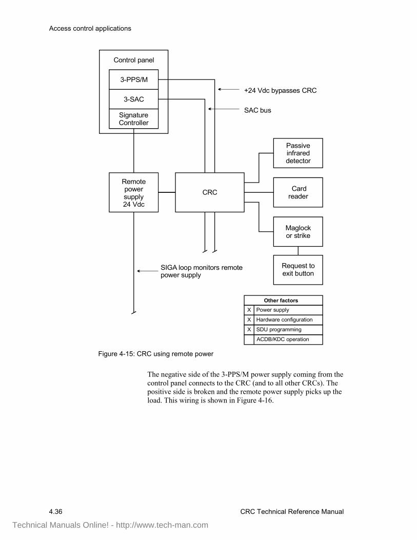
Access control applications
4.36 CRC Technical Reference Manual
Control panel
Signature Controller
3-PPS/M
3-SAC
CRC
Maglock or strike
Card reader
Power supply
Other factors
Hardware configuration
SDU programming
ACDB/KDC operation
X
X
X
Remote power supply24 Vdc
Passive infrared detector
SAC bus
+24 Vdc bypasses CRC
SIGA loop monitors remote power supply
Request to exit button
Figure 4-15: CRC using remote power
The negative side of the 3-PPS/M power supply coming from thecontrol panel connects to the CRC (and to all other CRCs). Thepositive side is broken and the remote power supply picks up theload. This wiring is shown in Figure 4-16.
Technical Manuals Online! - http://www.tech-man.com
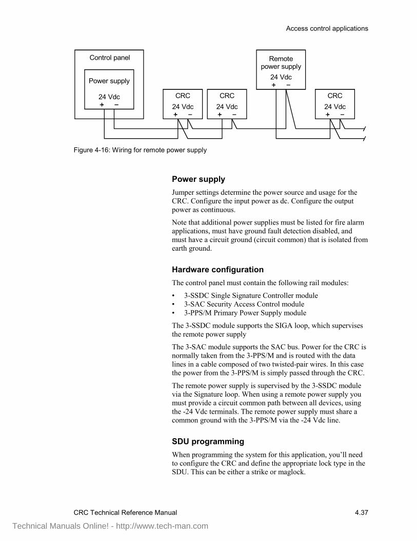
Access control applications
CRC Technical Reference Manual 4.37
Control panel
Power supply
24 Vdc
Remote power supply
CRC24 Vdc
CRC24 Vdc
CRC24 Vdc
24 Vdc
Figure 4-16: Wiring for remote power supply
Power supplyJumper settings determine the power source and usage for theCRC. Configure the input power as dc. Configure the outputpower as continuous.
Note that additional power supplies must be listed for fire alarmapplications, must have ground fault detection disabled, andmust have a circuit ground (circuit common) that is isolated fromearth ground.
Hardware configurationThe control panel must contain the following rail modules:
• 3-SSDC Single Signature Controller module• 3-SAC Security Access Control module• 3-PPS/M Primary Power Supply module
The 3-SSDC module supports the SIGA loop, which supervisesthe remote power supply
The 3-SAC module supports the SAC bus. Power for the CRC isnormally taken from the 3-PPS/M and is routed with the datalines in a cable composed of two twisted-pair wires. In this casethe power from the 3-PPS/M is simply passed through the CRC.
The remote power supply is supervised by the 3-SSDC modulevia the Signature loop. When using a remote power supply youmust provide a circuit common path between all devices, usingthe -24 Vdc terminals. The remote power supply must share acommon ground with the 3-PPS/M via the -24 Vdc line.
SDU programmingWhen programming the system for this application, you’ll needto configure the CRC and define the appropriate lock type in theSDU. This can be either a strike or maglock.
Technical Manuals Online! - http://www.tech-man.com
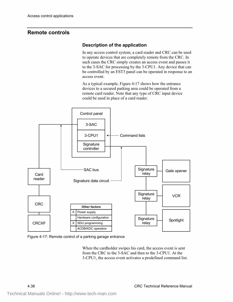
Access control applications
4.38 CRC Technical Reference Manual
Remote controls
Description of the applicationIn any access control system, a card reader and CRC can be usedto operate devices that are completely remote from the CRC. Insuch cases the CRC simply creates an access event and passes itto the 3-SAC for processing by the 3-CPU1. Any device that canbe controlled by an EST3 panel can be operated in response to anaccess event.
As a typical example, Figure 4-17 shows how the entrancedevices to a secured parking area could be operated from aremote card reader. Note that any type of CRC input devicecould be used in place of a card reader.
Control panel
3-SAC
Signature controller
3-CPU1
Signaturerelay
Command lists
Gate opener
VCR
Spotlight
CRC
Card reader
CRCXF
SAC bus
Signature data circuit
Power supply
Hardware configuration
SDU programming
ACDB/KDC operation
Other factors
X
X
Signaturerelay
Signaturerelay
Figure 4-17: Remote control of a parking garage entrance
When the cardholder swipes his card, the access event is sentfrom the CRC to the 3-SAC and then to the 3-CPU1. At the3-CPU1, the access event activates a predefined command list.
Technical Manuals Online! - http://www.tech-man.com

Access control applications
CRC Technical Reference Manual 4.39
The command list operates the Signature relays on the Signaturedata circuit supported by the Signature controller module. Theserelays activate the gate opener, a spotlight, and a VCR imagerecording system.
An inside card reader and could be used to control exits from thearea, but it would be more appropriate to use a motion detector,since egress from the area is not controlled.
Power supplyA CRCXF - CRC Transformer power supply is shown, assumingthat the CRC is be located at some distance from the electricalroom and control panel.
If you use an additional power supply other than the CRCXF,that power supply must be listed for fire alarm applications, musthave ground fault detection disabled, and must have a circuitground (circuit common) that is isolated from earth ground.
SDU programmingThe SDU programmer must create a command list that specifiesactivation of the correct relays and devices, the delays required,and the deactivation of the devices.
Since there is no restoration phase of access events, thecommand list should include commands that turn off the devices.
Technical Manuals Online! - http://www.tech-man.com

Access control applications
4.40 CRC Technical Reference Manual
Two-person rule
Description of the applicationA two-person rule ensures that no staff member can be in acontrolled area alone. A CRC operating under two-person ruleprevents the entrance of a single person into the controlled area.When two people are present in the area, one cannot exit withoutthe other.
The controlled area can have a single entrance or multipleentrances. The network coordinates user information between theCRCs that serve a common area.
A typical two-person rule application is shown in Figure 4-18,below.
Technical Manuals Online! - http://www.tech-man.com
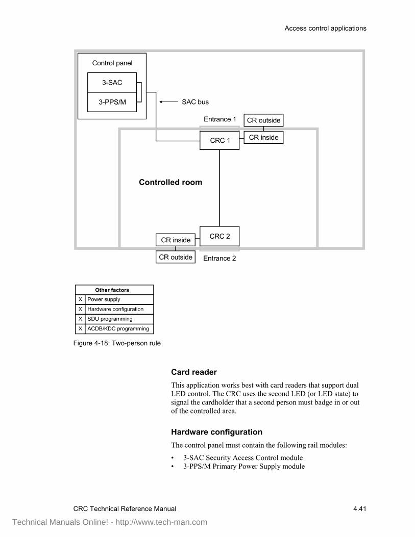
Access control applications
CRC Technical Reference Manual 4.41
Power supply
Other factors
Hardware configuration
SDU programming
ACDB/KDC programming
X
X
X
X
Control panel
CRC 2
3-SAC
3-PPS/M SAC bus
CR outside
CRC 1
Entrance 2
Entrance 1
Controlled room
CR inside
CR outside
CR inside
Figure 4-18: Two-person rule
Card readerThis application works best with card readers that support dualLED control. The CRC uses the second LED (or LED state) tosignal the cardholder that a second person must badge in or outof the controlled area.
Hardware configurationThe control panel must contain the following rail modules:
• 3-SAC Security Access Control module• 3-PPS/M Primary Power Supply module
Technical Manuals Online! - http://www.tech-man.com

Access control applications
4.42 CRC Technical Reference Manual
The 3-SAC module supports the SAC bus. Power for the CRC isnormally taken from the 3-PPS/M and is routed with the datalines in a cable composed of two twisted-pair wires.
SDU programmingIf the CRC is to be used for two-person rule it must beconfigured in the SDU. On the CRC Configuration tab, the 2Person Rule box must be checked.
You can also assign a predefined command list to the AccessDenied 2 Person Timeout event. This setting is found on theCRC Command Lists tab.
Technical Manuals Online! - http://www.tech-man.com
CRC Technical Reference Manual 5.1
Chapter 5 Installation
Summary
This chapter covers mechanical and wiring installationinstructions for the CRC.
ContentInstallation guidelines • 5.2
Planning an installation • 5.2Lobbies • 5.2CRC installation guidelines • 5.2System requirements • 5.3Installing the CRC • 5.4
Wiring the CRC • 5.5SAC bus wiring • 5.5Recommended cabling • 5.5Powering the CRC • 5.5
Installing and wiring the card reader • 5.8Installing the door locks • 5.9
Installing and wiring electric door strikes • 5.9Installing and wiring an electrified lockset • 5.9Installing maglocks • 5.10
Checking operation with a construction card • 5.12NFPA 72 • 5.13
Technical Manuals Online! - http://www.tech-man.com
Installation
5.2 CRC Technical Reference Manual
Installation guidelines
Planning an installationHere are some general guidelines to remember when planningyour installation:
• All access control applications require a separate CRC foreach door
• An inside card reader and outside card reader can be used onopposite sides of a door and share the same CRC
• When using the CRC for access control, make sure that thereis always a mechanical mechanism for gaining access
If there is a problem with the door release mechanism or theCRC, the mechanical door lock will be the only method forgaining access.
LobbiesWhere general access to an unprotected lobby is required, andthere is no concern for scheduling, a card reader can be usedwith a CRC that does not have any associated security partition.
This arrangement will allow access to the lobby for all personswith valid cards, while requiring all others (visitors, etc.) to bebuzzed in.
If access to the lobby is to be limited to certain working hoursthe CRC can be programmed with an open schedule. While theopen schedule is active, the lobby door will be unlocked.
CRC installation guidelinesFor specific CRC installation instructions refer to the installationsheet, P/N 387625, CRC / CRCXM Card Reader Controller. TheCRC installation sheet provides pertinent wiring informationconcerning the various card readers, including instructions forthe CRC jumper settings.
Here are some additional points to remember:
• Do not use a magnetic stripe card with a Wiegand reader.Doing so may corrupt the code on the magnetic stripe card.
• Each CRC must receive a minimum of 18.5 V from thecontrol panel power supply, otherwise the CRC battery willnot charge. If 18.5 V can not be supplied to the CRC fromthe panel, add an additional power supply.
• Maximum current for the electric door lock is 500 mA
Technical Manuals Online! - http://www.tech-man.com
Installation
CRC Technical Reference Manual 5.3
• Maximum current for card readers is 500 mA
• Make certain that the length of wire between the CRC andits associated card reader(s) does not exceed card readermanufacturer's recommendations
• The CRC must be installed indoors, inside the protectedarea, and must not be subjected to temperatures below 32° F(0° C) or above 120° F (49° C)
• Include each CRC in your project layout diagram, indicatingthe partition that will be accessed using the CRC and theCRC serial number
• Each CRC and each card reader presents a current drain.These current drains affect the overall system powerrequirements and they must be incorporated into the powercalculations. (See Appendix A, Calculations.)
System requirementsWhen designing an integrated system based on an EST3control panel, the following upgrade levels and componentsare required for proper operation:• 3-CPU1 with version 3.1 firmware or higher• SDU version 3.1 or higher• 3-SAC Security Access Control module• 3-MODCOM Modem Communicator module with version
3.1 firmware or higher (or 3-RS232 communication card in3-CPU1)
• CRC Card Reader Controller modules• Access Control Database (ACDB) program
Technical Manuals Online! - http://www.tech-man.com
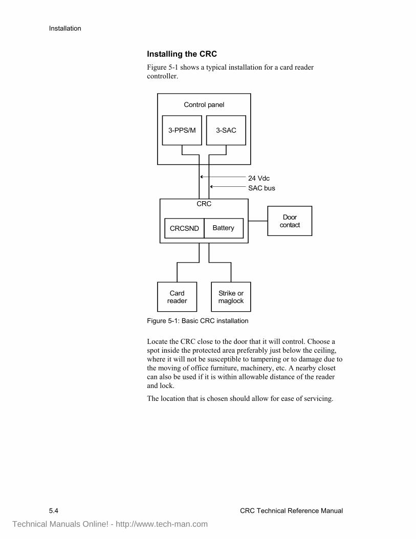
Installation
5.4 CRC Technical Reference Manual
Installing the CRCFigure 5-1 shows a typical installation for a card readercontroller.
3-SAC3-PPS/M
CRC
Strike or maglock
Card reader
24 VdcSAC bus
Control panel
Door contactCRCSND Battery
Figure 5-1: Basic CRC installation
Locate the CRC close to the door that it will control. Choose aspot inside the protected area preferably just below the ceiling,where it will not be susceptible to tampering or to damage due tothe moving of office furniture, machinery, etc. A nearby closetcan also be used if it is within allowable distance of the readerand lock.
The location that is chosen should allow for ease of servicing.
Technical Manuals Online! - http://www.tech-man.com
Installation
CRC Technical Reference Manual 5.5
Wiring the CRC
SAC bus wiringIf the CRC is going to be used in an integrated system with acontrol panel, the CRC must be wired to the 3-SAC SecurityAccess Control module. The 3-SAC supports the SAC bus, anRS-485 communication line.
The 3-SAC module can support Class A or Class B wiring. IfClass A, the 3-SAC can support 30 CRCs or KPDISPs. If ClassB, the 3-SAC can support 62 CRCs or KPDISPs (31 per loop).
Recommended cablingSince our security and access control devices require 24 Vdc, wesuggest that you always use a four-wire cable for the SAC busand a 24 Vdc power supply.
For the data wires, use unshielded, twisted pair, with greaterthan 6 twists per foot, in 14 to 22 AWG (1.50 to 0.25 sq mm).For the power wires, use 14 or 16 AWG.
You can use a four-conductor cable with an overall jacketcontaining solid 2-19 AWG and 2-16 AWG for the SAC bus.
The maximum run from a CRC to the 3-SAC is 4,000 ft(1,220 m) at 25 pF/ft. The maximum total capacitance of the runis 0.1 µF, and the maximum total resistance is 52 Ω.
Powering the CRCThe CRC can be powered in several ways, as described inChapter 4, Access Control Applications. Each method requiresspecific jumper settings and wiring to allow the CRC to operateand communicate properly.
Note: Be sure to make the correct jumper settings for the CRC,as described on the CRC - Card Reader Controller InstallationSheet (P/N 387625).
24 Vdc wiring
The CRC can receive 24 Vdc power from the control panelpower supply. Simply use the 24 Vdc terminals on the CRC andcontrol panel power supply.
Transformer wiring
The CRC can be powered from an external transformer, theCRCXF. Connect the transformer to the 16.5 Vac terminals inthe CRC. Note that all connected CRCs or KPDISPs must have a
Technical Manuals Online! - http://www.tech-man.com
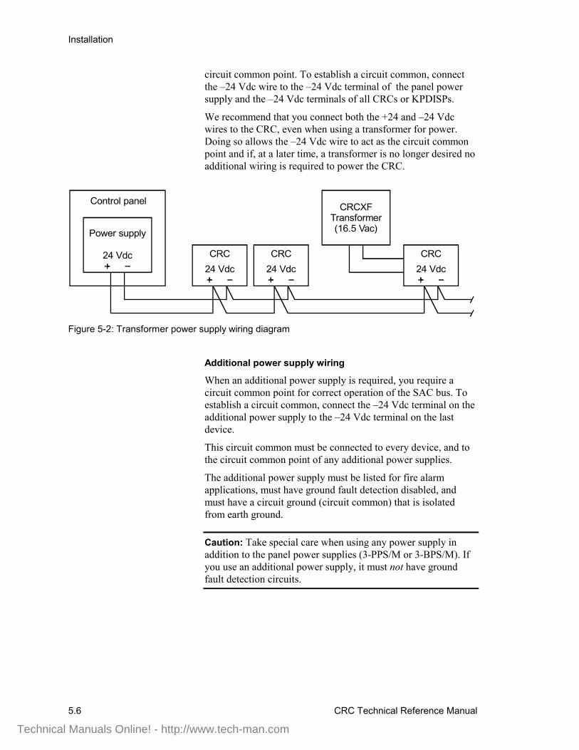
Installation
5.6 CRC Technical Reference Manual
circuit common point. To establish a circuit common, connectthe –24 Vdc wire to the –24 Vdc terminal of the panel powersupply and the –24 Vdc terminals of all CRCs or KPDISPs.
We recommend that you connect both the +24 and –24 Vdcwires to the CRC, even when using a transformer for power.Doing so allows the –24 Vdc wire to act as the circuit commonpoint and if, at a later time, a transformer is no longer desired noadditional wiring is required to power the CRC.
Control panel
Power supply
24 Vdc
CRCXFTransformer(16.5 Vac)
CRC24 Vdc
CRC24 Vdc
CRC24 Vdc
Figure 5-2: Transformer power supply wiring diagram
Additional power supply wiring
When an additional power supply is required, you require acircuit common point for correct operation of the SAC bus. Toestablish a circuit common, connect the –24 Vdc terminal on theadditional power supply to the –24 Vdc terminal on the lastdevice.
This circuit common must be connected to every device, and tothe circuit common point of any additional power supplies.
The additional power supply must be listed for fire alarmapplications, must have ground fault detection disabled, andmust have a circuit ground (circuit common) that is isolatedfrom earth ground.
Caution: Take special care when using any power supply inaddition to the panel power supplies (3-PPS/M or 3-BPS/M). Ifyou use an additional power supply, it must not have groundfault detection circuits.
Technical Manuals Online! - http://www.tech-man.com
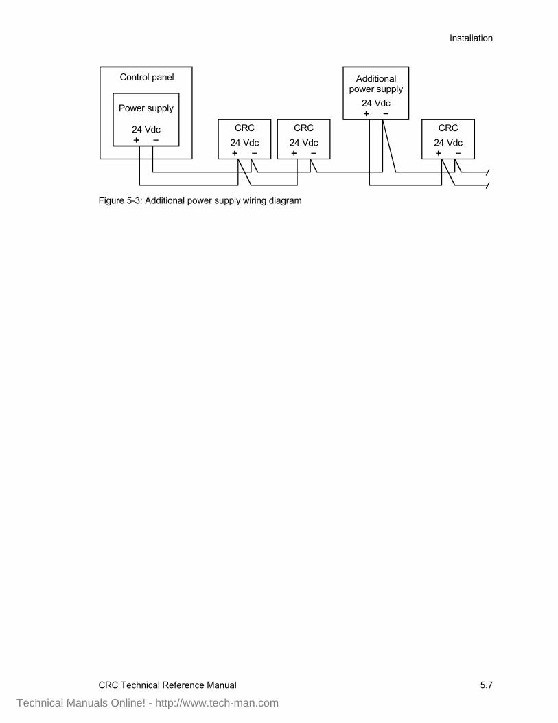
Installation
CRC Technical Reference Manual 5.7
Control panel
Power supply
24 Vdc
Additional power supply
CRC24 Vdc
CRC24 Vdc
CRC24 Vdc
24 Vdc
Figure 5-3: Additional power supply wiring diagram
Technical Manuals Online! - http://www.tech-man.com
Installation
5.8 CRC Technical Reference Manual
Installing and wiring the card readerInstall card readers in accordance with the manufacturer'sinstructions, making connections as shown on the CRCinstallation sheet. Make sure that extension cables from thereader do not exceed the manufacturer's recommendations.Typically 8-conductor shielded wire is recommended.
Note that both inside and outside card readers use the same CRCterminals. However, for the inside reader, the connection isreversed. This is how the CRC distinguishes between the insideand outside readers.
When installing the inside readers make sure that the card readerData 0 wire (typically green) is connected to terminal 13 and theData 1 wire (typically white) is connected to terminal 12.
Some proximity readers interfere with each other, even onopposite sides of a wall, and should be kept some distance awayfrom each other. Check with the manufacturer for recommendeddistances between units. Mount the inside unit temporarily untilyou can verify proper operation.
Where required, make DIP switch settings for the card reader asshown in the installation sheets supplied by the readermanufacturer. Make settings that will select the followingoptions:
• Dual-LED control• Pull up resistors• Standard Wiegand output
The CRC installation sheet contains information for connectingthe readers to the CRC. Where vendor extension cables are notavailable for these connections, use 22/8 shielded wire for theextension.
Technical Manuals Online! - http://www.tech-man.com
Installation
CRC Technical Reference Manual 5.9
Installing the door locksThe CRC supports the three basic types of door lock: strikes,maglocks, and electrified locksets. Each lock type has a distinctmethod of operation and installation. Always follow themanufacturer’s instructions while installing locks.
Installing and wiring electric door strikesInstall the electric door strike in accordance with themanufacturer's instructions, and make connections as shown onthe CRC installation sheet.
Many installation companies subcontract the actual lockinstallation. The process of cutting metal or chiseling wood islearned over time and errors may permanently damage adoorframe.
Check with the door and lock manufacturers to ensure thatadding the strike does not effect any fire rating of the door.
Check that the strike is compatible with the lockset installed inthe door. The lockset should be a commercial grade lock with adead latch to prevent someone from shimming the door open.
Make sure that strike cable does not exceed the maximumallowable voltage drop.
Make sure the door is properly aligned, has a good fit to theframe, and has an operating closer. The door should worksmoothly and close fully after being opened. Insist that defectivedoors be fixed or replaced before proceeding with the lockinstallation.
Note: If you are not using the CRC to control a lock, a standard4.7 KΩ EOL resistor must be connected across TB1-5 andTB1-6 to simulate the lock load for the CRC supervisory circuit.
Installing and wiring an electrified locksetInstall the electrified lockset in accordance with themanufacturer's instructions, making connections as shown on theCRC installation sheet for a strike.
Remove the latch and drill straight through the hole into the coreof the door. Unscrew the center hinge from the door and drillanother hole (in the area where the hinge was) into the core ofthe door. Snake the wire through the door to the knob.
Connect the wires to the lockset and run the wires to the frameusing an electrified hinge or a door cord. Many installationcompanies subcontract the actual lock installation. The process
Technical Manuals Online! - http://www.tech-man.com
Installation
5.10 CRC Technical Reference Manual
of drilling holes in metal or wood is learned over time and errorsmay permanently damage a door.
Check with the door and lock manufacturers to ensure thatadding the new lockset does not effect any fire ratings. Also,check that the door can be opened from the inside without a keyor card.
Check that the lockset is compatible with the striker plateinstalled in the frame.
Flexible armored door cord
When installing an electrified lockset, a flexible armored doorcord must be used to interconnect wiring to CRC. This is usedon the hinged side of door to pass the wires from the door to theframe. It comes with two plastic end caps to secure the ends tothe door and frame.
Installing maglocksMaglock and electrified bolt installations raise safety concerns.These types of lock do not have a built-in mechanical override,as do strikes and electrified locksets. This creates the potentialfor trapping occupants in a fire if such locks are not properlyinstalled.
For this reason the NFPA and local building codes includeregulations for the proper installation of maglock and electrifiedbolts. Maglocks and electrified bolts must meet ALL of thefollowing requirements:
• Include a request to exit motion detector. The detector mustbe an approved exit device and fail safe upon loss of power.
• Unlock on loss of primary power to the access controlsystem that locks the door.
• Include an independent, manual, request to exit device (abutton or bar) mounted 40 to 48 inches above the floor,within 5 feet of the door with sign that reads "Push to Exit".On activation, the door must remain unlocked for aminimum of 30 seconds.
• Unlock on ANY of the following: activation of a buildingfire alarm, loss of primary power, activation of a fire alarmtrouble, or disabling of a fire alarm device. The doors mustremain unlocked until the fire alarm is manually reset or thetrouble or disable condition is cleared.
• Unlock on activation of building automatic sprinkler s. Thedoors must remain unlocked until the sprinkler alarm ismanually reset.
Technical Manuals Online! - http://www.tech-man.com

Installation
CRC Technical Reference Manual 5.11
Note: Please refer to the latest editions of NFPA to determinethe most current code requirements.
Please read the topic NFPA 72, later in this chapter. It discussesadditional material that applies to maglocks and electrified bolts.
Technical Manuals Online! - http://www.tech-man.com

Installation
5.12 CRC Technical Reference Manual
Checking operation with a construction cardCRCs come from the factory preprogrammed to recognize aconstruction card with a special card code. The CRC will onlyaccept the construction code when no user data has beendownloaded to it.
Once the CRC battery has been charged, the construction cardcan be used to check the operation of the electric door lock, orother releasing mechanism, in order to make adjustments wherenecessary. Remember, to use the construction card the CRCmust be factory fresh, with no card information downloaded.
After making all required adjustments and powering up thesystem, temporary cards can be created for the construction staffto use as required. When the installation of the system iscomplete these temporary cards can be deleted or allowed toexpire.
Technical Manuals Online! - http://www.tech-man.com
Installation
CRC Technical Reference Manual 5.13
NFPA 72Section 3-9.5
NFPA 72 3-9.5 pertains to door unlocking devices. It states thatall emergency exits shall unlock upon loss of primary power tothe fire alarm system.
This is expanded to include the requirement that anydisablement of the fire alarm system must cause the emergencyexits to unlock. This requirement includes wiring faults betweenthe lock controller and the request to exit devices. When arequest cannot be detected, the door must unlock.
Remember that these requirements only apply to a door that islocked by a device that cannot be manually overridden. Thougha strike holds a latch, a knob can be turned or a paddle depressedto retract the latch and allow the door to open. Maglocks orbolts, on the other hand, hold the door shut and no amount ofknob turning or pushing will open the door.
Technical Manuals Online! - http://www.tech-man.com

Installation
5.14 CRC Technical Reference Manual
Technical Manuals Online! - http://www.tech-man.com

CRC Technical Reference Manual 6.1
Chapter 6 Programming
Summary
This chapter covers the programming options available for theCRC. Program settings can be made in the Access ControlDatabase (ACDB) program and in the System Definition Utility(SDU) program.
We discuss which options are configured in each program, anddefine the fields used to program the CRC.
ContentSDU • 6.2
Configuring the CRC • 6.2CRC configuration • 6.2CRC command lists • 6.3CRC input circuits • 6.5Resource Profile Manager (RPM) • 6.9
ACDB • 6.10ACDB user-defined options • 6.10Summary • 6.10Inputs • 6.10Options • 6.10Door timers • 6.11Miscellaneous • 6.12Assignment of cardholder data • 6.12
Technical Manuals Online! - http://www.tech-man.com
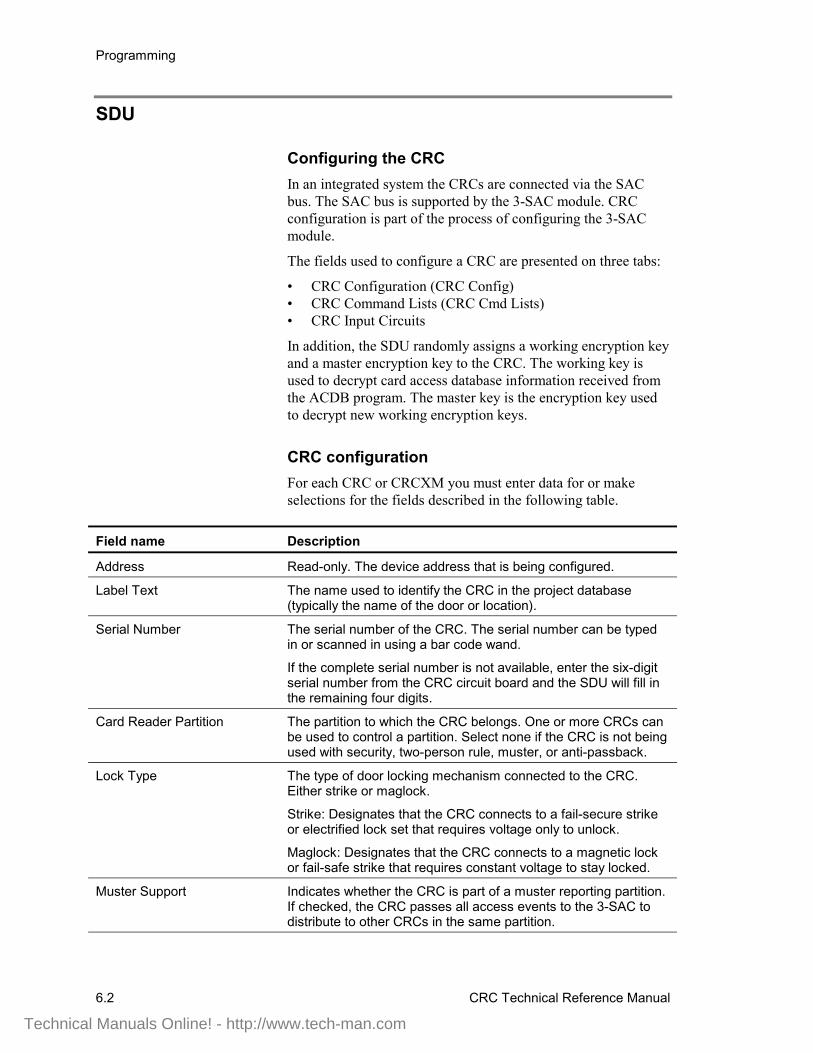
Programming
6.2 CRC Technical Reference Manual
SDU
Configuring the CRCIn an integrated system the CRCs are connected via the SACbus. The SAC bus is supported by the 3-SAC module. CRCconfiguration is part of the process of configuring the 3-SACmodule.
The fields used to configure a CRC are presented on three tabs:
• CRC Configuration (CRC Config)• CRC Command Lists (CRC Cmd Lists)• CRC Input Circuits
In addition, the SDU randomly assigns a working encryption keyand a master encryption key to the CRC. The working key isused to decrypt card access database information received fromthe ACDB program. The master key is the encryption key usedto decrypt new working encryption keys.
CRC configurationFor each CRC or CRCXM you must enter data for or makeselections for the fields described in the following table.
Field name Description
Address Read-only. The device address that is being configured.
Label Text The name used to identify the CRC in the project database(typically the name of the door or location).
Serial Number The serial number of the CRC. The serial number can be typedin or scanned in using a bar code wand.
If the complete serial number is not available, enter the six-digitserial number from the CRC circuit board and the SDU will fill inthe remaining four digits.
Card Reader Partition The partition to which the CRC belongs. One or more CRCs canbe used to control a partition. Select none if the CRC is not beingused with security, two-person rule, muster, or anti-passback.
Lock Type The type of door locking mechanism connected to the CRC.Either strike or maglock.
Strike: Designates that the CRC connects to a fail-secure strikeor electrified lock set that requires voltage only to unlock.
Maglock: Designates that the CRC connects to a magnetic lockor fail-safe strike that requires constant voltage to stay locked.
Muster Support Indicates whether the CRC is part of a muster reporting partition.If checked, the CRC passes all access events to the 3-SAC todistribute to other CRCs in the same partition.
Technical Manuals Online! - http://www.tech-man.com
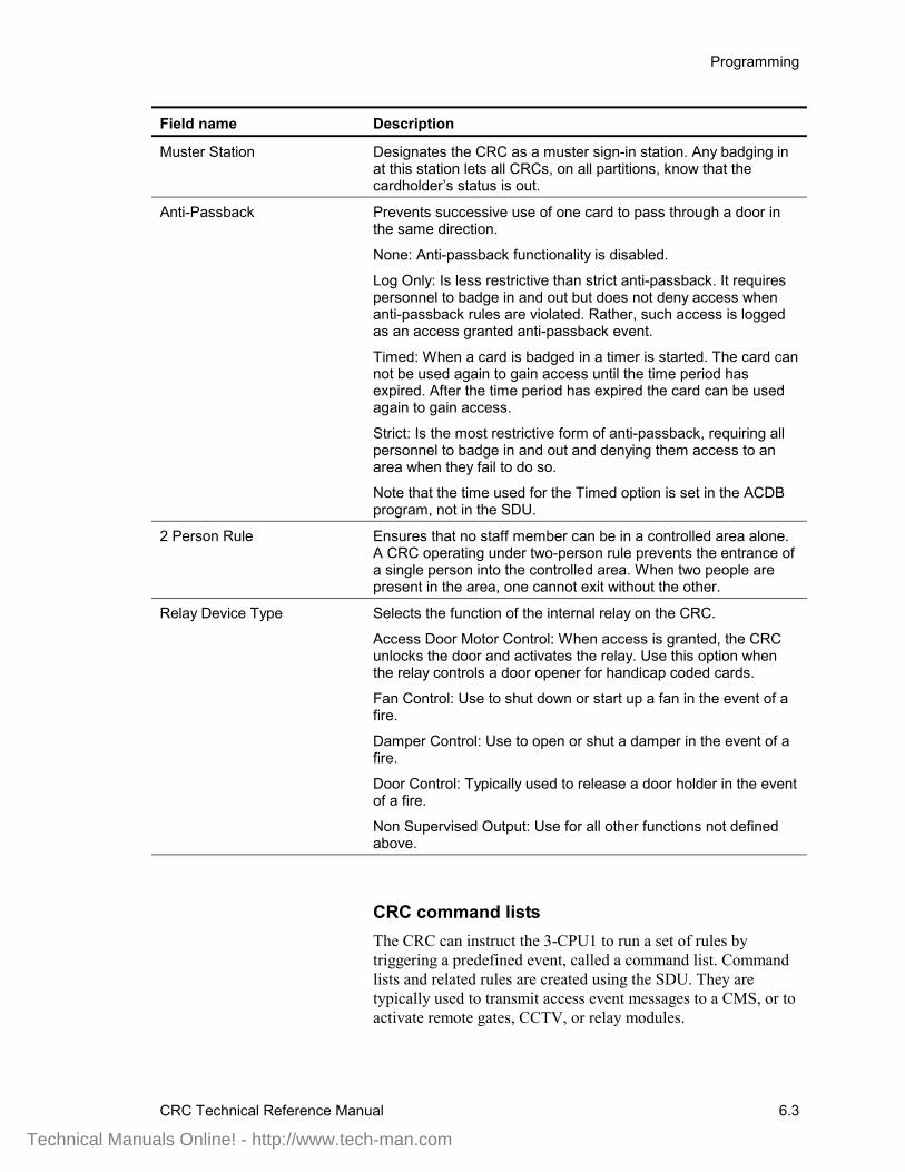
Programming
CRC Technical Reference Manual 6.3
Field name Description
Muster Station Designates the CRC as a muster sign-in station. Any badging inat this station lets all CRCs, on all partitions, know that thecardholder’s status is out.
Anti-Passback Prevents successive use of one card to pass through a door inthe same direction.
None: Anti-passback functionality is disabled.
Log Only: Is less restrictive than strict anti-passback. It requirespersonnel to badge in and out but does not deny access whenanti-passback rules are violated. Rather, such access is loggedas an access granted anti-passback event.
Timed: When a card is badged in a timer is started. The card cannot be used again to gain access until the time period hasexpired. After the time period has expired the card can be usedagain to gain access.
Strict: Is the most restrictive form of anti-passback, requiring allpersonnel to badge in and out and denying them access to anarea when they fail to do so.
Note that the time used for the Timed option is set in the ACDBprogram, not in the SDU.
2 Person Rule Ensures that no staff member can be in a controlled area alone.A CRC operating under two-person rule prevents the entrance ofa single person into the controlled area. When two people arepresent in the area, one cannot exit without the other.
Relay Device Type Selects the function of the internal relay on the CRC.
Access Door Motor Control: When access is granted, the CRCunlocks the door and activates the relay. Use this option whenthe relay controls a door opener for handicap coded cards.
Fan Control: Use to shut down or start up a fan in the event of afire.
Damper Control: Use to open or shut a damper in the event of afire.
Door Control: Typically used to release a door holder in the eventof a fire.
Non Supervised Output: Use for all other functions not definedabove.
CRC command listsThe CRC can instruct the 3-CPU1 to run a set of rules bytriggering a predefined event, called a command list. Commandlists and related rules are created using the SDU. They aretypically used to transmit access event messages to a CMS, or toactivate remote gates, CCTV, or relay modules.
Technical Manuals Online! - http://www.tech-man.com
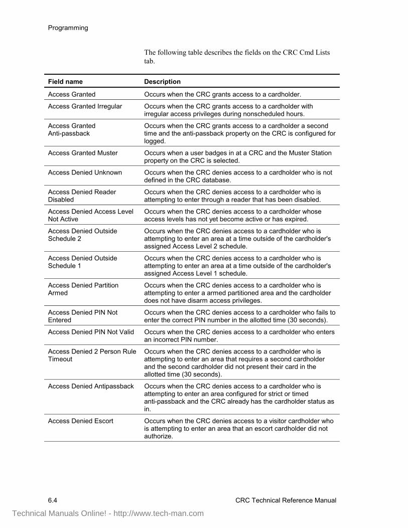
Programming
6.4 CRC Technical Reference Manual
The following table describes the fields on the CRC Cmd Liststab.
Field name Description
Access Granted Occurs when the CRC grants access to a cardholder.
Access Granted Irregular Occurs when the CRC grants access to a cardholder withirregular access privileges during nonscheduled hours.
Access GrantedAnti-passback
Occurs when the CRC grants access to a cardholder a secondtime and the anti-passback property on the CRC is configured forlogged.
Access Granted Muster Occurs when a user badges in at a CRC and the Muster Stationproperty on the CRC is selected.
Access Denied Unknown Occurs when the CRC denies access to a cardholder who is notdefined in the CRC database.
Access Denied ReaderDisabled
Occurs when the CRC denies access to a cardholder who isattempting to enter through a reader that has been disabled.
Access Denied Access LevelNot Active
Occurs when the CRC denies access to a cardholder whoseaccess levels has not yet become active or has expired.
Access Denied OutsideSchedule 2
Occurs when the CRC denies access to a cardholder who isattempting to enter an area at a time outside of the cardholder'sassigned Access Level 2 schedule.
Access Denied OutsideSchedule 1
Occurs when the CRC denies access to a cardholder who isattempting to enter an area at a time outside of the cardholder'sassigned Access Level 1 schedule.
Access Denied PartitionArmed
Occurs when the CRC denies access to a cardholder who isattempting to enter a armed partitioned area and the cardholderdoes not have disarm access privileges.
Access Denied PIN NotEntered
Occurs when the CRC denies access to a cardholder who fails toenter the correct PIN number in the allotted time (30 seconds).
Access Denied PIN Not Valid Occurs when the CRC denies access to a cardholder who entersan incorrect PIN number.
Access Denied 2 Person RuleTimeout
Occurs when the CRC denies access to a cardholder who isattempting to enter an area that requires a second cardholderand the second cardholder did not present their card in theallotted time (30 seconds).
Access Denied Antipassback Occurs when the CRC denies access to a cardholder who isattempting to enter an area configured for strict or timedanti-passback and the CRC already has the cardholder status asin.
Access Denied Escort Occurs when the CRC denies access to a visitor cardholder whois attempting to enter an area that an escort cardholder did notauthorize.
Technical Manuals Online! - http://www.tech-man.com
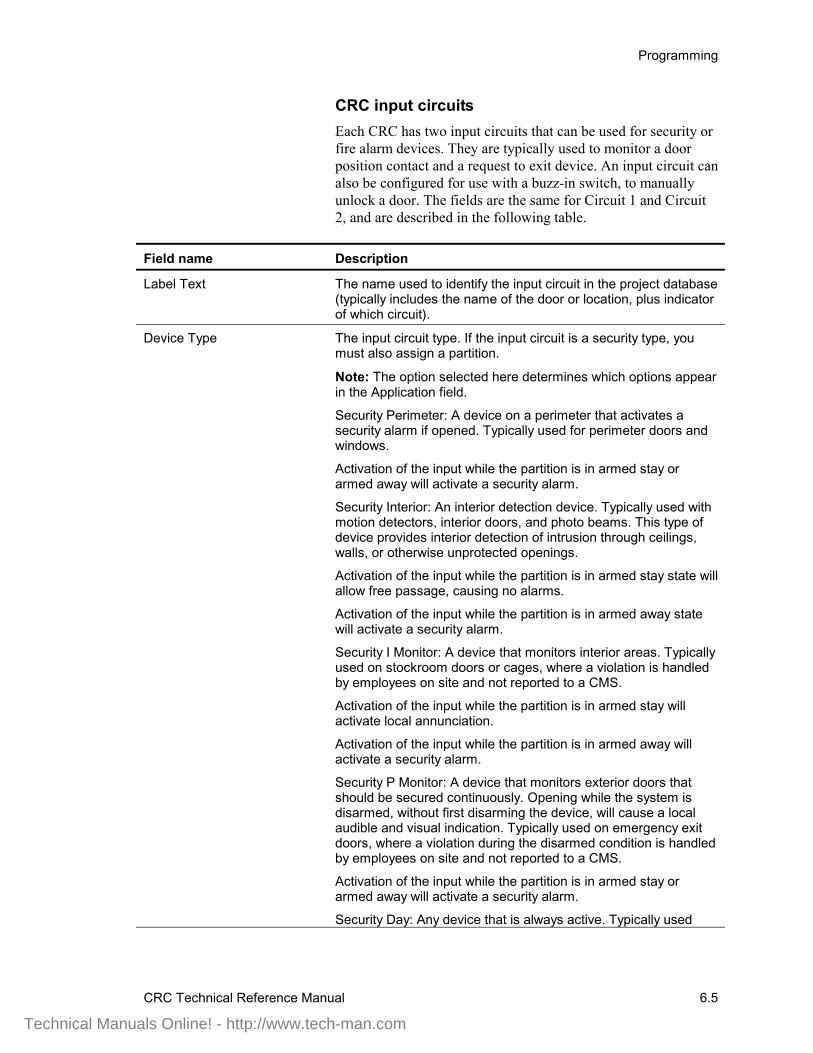
Programming
CRC Technical Reference Manual 6.5
CRC input circuitsEach CRC has two input circuits that can be used for security orfire alarm devices. They are typically used to monitor a doorposition contact and a request to exit device. An input circuit canalso be configured for use with a buzz-in switch, to manuallyunlock a door. The fields are the same for Circuit 1 and Circuit2, and are described in the following table.
Field name Description
Label Text The name used to identify the input circuit in the project database(typically includes the name of the door or location, plus indicatorof which circuit).
Device Type The input circuit type. If the input circuit is a security type, youmust also assign a partition.
Note: The option selected here determines which options appearin the Application field.
Security Perimeter: A device on a perimeter that activates asecurity alarm if opened. Typically used for perimeter doors andwindows.
Activation of the input while the partition is in armed stay orarmed away will activate a security alarm.
Security Interior: An interior detection device. Typically used withmotion detectors, interior doors, and photo beams. This type ofdevice provides interior detection of intrusion through ceilings,walls, or otherwise unprotected openings.
Activation of the input while the partition is in armed stay state willallow free passage, causing no alarms.
Activation of the input while the partition is in armed away statewill activate a security alarm.
Security I Monitor: A device that monitors interior areas. Typicallyused on stockroom doors or cages, where a violation is handledby employees on site and not reported to a CMS.
Activation of the input while the partition is in armed stay willactivate local annunciation.
Activation of the input while the partition is in armed away willactivate a security alarm.
Security P Monitor: A device that monitors exterior doors thatshould be secured continuously. Opening while the system isdisarmed, without first disarming the device, will cause a localaudible and visual indication. Typically used on emergency exitdoors, where a violation during the disarmed condition is handledby employees on site and not reported to a CMS.
Activation of the input while the partition is in armed stay orarmed away will activate a security alarm.
Security Day: Any device that is always active. Typically used
Technical Manuals Online! - http://www.tech-man.com
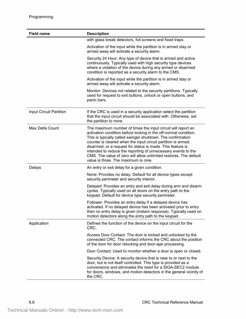
Programming
6.6 CRC Technical Reference Manual
Field name Descriptionwith glass break detectors, foil screens and fixed traps.
Activation of the input while the partition is in armed stay orarmed away will activate a security alarm.
Security 24 Hour: Any type of device that is armed and activecontinuously. Typically used with high security type deviceswhere a violation of the device during any armed or disarmedcondition is reported as a security alarm to the CMS.
Activation of the input while the partition is in armed stay orarmed away will activate a security alarm.
Monitor: Devices not related to the security partitions. Typicallyused for request to exit buttons, unlock or open buttons, andpanic bars.
Input Circuit Partition If the CRC is used in a security application select the partitionthat the input circuit should be associated with. Otherwise, setthe partition to none.
Max Delta Count The maximum number of times the input circuit will report anactivation condition before locking in the off-normal condition.This is typically called swinger shutdown. The confirmationcounter is cleared when the input circuit partition is armed,disarmed, or a request for status is made. This feature isintended to reduce the reporting of unnecessary events to theCMS. The value of zero will allow unlimited restores. The defaultvalue is three. The maximum is nine.
Delays An entry or exit delay for a given condition.
None: Provides no delay. Default for all device types exceptsecurity perimeter and security interior.
Delayed: Provides an entry and exit delay during arm and disarmcycles. Typically used on all doors on the entry path to thekeypad. Default for device type security perimeter.
Follower: Provides an entry delay if a delayed device hasactivated. If no delayed device has been activated prior to entrythen no entry delay is given (instant response). Typically used onmotion detectors along the entry path to the keypad.
Application Defines the function of the device on the input circuit for theCRC.
Access Door Contact: The door is locked and unlocked by theconnected CRC. The contact informs the CRC about the positionof the door for door relocking and door-ajar processing.
Door Contact: Used to monitor whether a door is open or closed.
Security Device: A security device that is near to or next to thedoor, but is not itself controlled. This type is provided as aconvenience and eliminates the need for a SIGA-SEC2 modulefor doors, windows, and motion detectors in the general vicinity ofthe CRC.
Technical Manuals Online! - http://www.tech-man.com

Programming
CRC Technical Reference Manual 6.7
Field name Description
Emergency Exit Door Contact: The door is locked and unlockedby the connected CRC but is monitored continuously for an openstate. The contact informs the CRC about the position of the doorfor door relocking. If the door is opened without badging in or out,it causes a local annunciation (if disarmed) or a security alarm (ifarmed stay or armed away). Badging in or out temporarilybypasses (for the time specified in Delayed Egress Time) thedoor, allowing access without creating an alarm or causing alocal annunciation. Refer to NFPA 101 and AHJ.
Request To Exit Motion Detector: Causes the CRC toautomatically unlock an access door by detecting motion assomeone approaches. The request to exit motion detector andthis circuit type are required by NFPA for use with a maglock.
Exiting the door without badging out will cause an alarm. Selectthis input circuit type if badging out is required or the other inputcircuit is not an emergency exit access door.
Request To Exit Motion Detector with Bypass: Causes the CRCto automatically unlock an access door and activate a bypasstimer by detecting motion as someone approaches. The requestto exit motion detector and this circuit type are required by NFPAfor use with a maglock.
The bypass feature of this application allows egress withoutbadging out. Select this input circuit type if badging out is notrequired and the other input circuit is an emergency exit accessdoor.
Request To Exit Button (REX): A REX button or panic bar allowsa person to manually activate the CRC to unlock the accessdoor. The REX is required by NFPA for use with a maglock.
Exiting the door without badging out will cause an alarm. Selectthis input circuit type if badging out is required or the other inputcircuit is not an emergency exit access door.
Request To Exit Button with Bypass: Allows a person to manuallyactivate the CRC to unlock the access door. The REX is requiredby NFPA for use with a maglock.
The bypass feature of this application allows egress withoutbadging out. Select this input circuit type if badging out is notrequired and the other input circuit is an emergency exit accessdoor.
Request to Unlock: A pushbutton used to manually buzz aperson in. Often called a visitor button and used by areceptionist, this input circuit type can be used with strikes andmaglocks.
The activation is not logged.
Request to Unlock with Log: A pushbutton used to manually buzza person in. Often called a visitor button and used by areceptionist, this input circuit type can be used with strikes andmaglocks.
Technical Manuals Online! - http://www.tech-man.com
Programming
6.8 CRC Technical Reference Manual
Field name Description
The activation is logged.
Request to Open: Connects to an ADA-approved request to exitpushbutton. As a person approaches an access door, theymanually activate the pushbutton. This causes the CRC to unlockthe door and activate the door open relay. The ADA button andthis input circuit type may be required by ADA for use with doorsto public areas.
Exiting the door without badging out will cause an alarm. Selectthis type if badging out is required or if the other input is not anemergency exit access door.
Request to Open with Bypass: Connects to an ADA-approvedrequest to exit pushbutton. As a person approaches an accessdoor, they manually activate the pushbutton. This causes theCRC to unlock the door and activate the door open relay. TheADA button and this input circuit type may be required by ADA foruse with doors to public areas.
The bypass feature of this application allows egress withoutbadging out. Select this input circuit type if badging out is notrequired and the door is an emergency exit access door.
Request to Exit with Delayed Egress: Connects to a request toexit pushbutton or panic bar. The request to exit push buttonactivates the CRC sounder and a timer. After a maximum of 30seconds, the CRC will unlock the door. The delayed REX buttonand this input circuit type are allowed by NFPA for use with amaglock.
This type of exit device is typically used in retail stores todiscourage shoplifting.
Refer to NFPA 101 and AHJ.
Personality Basic: The device contact can be an N.C, N.O. or SPDT(transfer) type. Any off-normal state of the device causes asecurity alarm.
N.C. with Trouble: Connected to an N.C. switch. A short on thisswitch causes a trouble and an open causes a activation.
Typically, this personality is used to annunciate a short in thewiring to the device during the disarmed state.
N.O. with Trouble: Connected to an N.O. or SPDT (transfer)switch. An open on this switch causes a trouble and a shortcauses a activation.
Typically, this personality is used to annunciate an open in thewiring to the device during the disarmed state.
Delayed Egress Time The number of seconds to delay egress when a delayed requestto exit push button or bar is pressed. The field is only availablewhen the Application field is set to Request to Exit with DelayedEgress. When set to zero (default) the delayed egress feature isdisabled. Normally set to 15 seconds (16 to 30 seconds requiresapproval from AHJ). Refer to NFPA 101 and AHJ.
Technical Manuals Online! - http://www.tech-man.com
Programming
CRC Technical Reference Manual 6.9
Resource Profile Manager (RPM)The SDU includes a tool called the Resource Profile Manager(RPM). The RPM is used to divide each CRCs resources amongthe companies that will be using the CRC.
The RPM creates a separate resource profile for each company.The resource profile is imported into the company’s ACDBprogram and defines the devices and devices resources availableto the company.
The RPM lets you create a tree view of all the companies,buildings, floors, and devices in the project. Refer to the SDUonline help system for more information on using the RPM. Thetable below gives definitions of the fields that apply to CRCs inthis tool.
Field name Description
Company The name of a company as previously defined in the SDU. Read-only.
Building A name created in the RPM to identify the building in which thedevice is located. Example: Manufacturing Building. Buildings arecreated in the RPM.
Partition The name of a partition previously defined and assigned to theCRC in the SDU. Read-only.
Device Type The RPM handles all types of security and access controldevices. The Device type is as assigned in the SDU, and forCRCs can be either CRC or CRCXM. Read-only.
Device The Device Label as defined in the SDU. Read-only.
Primary Designates a company as the primary company for the CRC.The primary company sets and controls some key parameters forthe CRC. Some examples: Unlock Schedule, Bypass Time,Unlock Time, PIN Required For Disarm.
User Set Locks the values you manually enter for Cardholders, Schedules,Holidays and Access Levels, so that these values are notchanged by the automatic Mass Assign function of the RPM.
Cardholders The number of cardholders allocated to the company for thisCRC.
Schedules The number of schedules allocated to the company for this CRC.
Holidays The number of holidays allocated to the company for this CRC.
Access Level The number of access levels allocated to the company for thisCRC.
Technical Manuals Online! - http://www.tech-man.com
Programming
6.10 CRC Technical Reference Manual
ACDB
ACDB user-defined optionsThe following options are programmable by the companydesignated as the primary company for the CRC. The ACDB isused to program these CRC options and to download the data tothe CRCs.
These options appear on various tabs of the Door dialog box.
SummaryFields displayed on the Summary tab are read-only with theexception of the Comm Route.
Field name Description
Comm Route The configuration used by the ACDB to communicate with thesystem control panel. All CRCs start with the initial value of<3-CPU Default> for the comm route. Additional comm routescan be defined in the ACDB and assigned here.
InputsAll fields on the Inputs tab are read-only, and display the valuesset in the SDU.
OptionsFields on the options tab can be set only by the primary owner ofthe CRC. The tab does not appear for other users of the CRC.The fields are as described in the following table.
Field name Description
Schedules
Unlock This schedule defines the times when the door connected to thisCRC is automatically unlocked. This is typically used toautomatically unlock lobby doors when a receptionist is on duty.A selection of No Schedule disables this feature. Before the dooris unlocked, the associated partition may be automaticallydisarmed. (Refer to Use Unlock Schedule.) The default is alwayslocked.
Doors used with an unlock schedule must be configured forcontinuous operation.
Technical Manuals Online! - http://www.tech-man.com
Programming
CRC Technical Reference Manual 6.11
Field name Description
Use Unlock Schedule If checked, the door unlocks on time following the UnlockSchedule and automatically disarms the CRC partition.
If cleared, the Unlock Schedule will not take effect until thepartition associated with the CRC has been manually disarmed.This feature is useful in case of severe weather, where it is notdesirable to open a building if people are unable to get to work.
PIN This schedule defines the times during which a PIN must beentered to verify each card swipe. To use this option, acombination reader and keypad must be installed. The use of aPIN decreases the possibility that a recently lost or stolen cardcan be used to gain entry.
The schedule may define PIN use at all times or at times outsidenormal business hours. The card is always presented first. If aPIN is required, the red LED flashes at 1 Hz. This indicates thatthe user must enter a PIN. The user then enters the PIN to gainaccess. This option is selectable on a door-by-door basis. Thedefault is No Schedule; that is, a PIN is never needed.
Suppression This schedule defines the times during which the CRC does notlog normal events. This option is provided to reduce the numberof normal access events stored as history during business hours.It is normally used on perimeter and bathroom doors where anaudit trail is not needed for normal business hours. All abnormalevents are always logged to history. The default is No Schedule,which means the CRC will always log events.
Door timersThe ACDB allows various lock, relay, and sounder timers to bedefined for each CRC.
Field name Description
Unlock timers
Standard Unlock The number of seconds that the door stays unlocked when auser badges in. The time can range from 0 to 255 seconds. Thedefault value is 10 seconds. If an access door contact isconnected to the CRC, then opening of the door relocks the doorand allows the door to immediately lock when the door closes.
Handicap Unlock The number of seconds the door lock stays unlocked when auser designated as handicapped badges in. The time can rangefrom 0 to 255 seconds. Default value is 20 seconds. If an accessdoor contact is connected to the CRC, the opening of the doorrelocks the door and allows the door to immediately lock whenthe door closes.
Technical Manuals Online! - http://www.tech-man.com

Programming
6.12 CRC Technical Reference Manual
Manual Unlock The number of seconds the door lock stays unlocked when anunlock command is received from the 3-CPU1, FireWorks, or arequest to exit device. The time can range from 0 to 255seconds. If an access door contact is connected to the CRC, theopening of the door relocks the door and allow the door toimmediately lock when the door closes. Default value is 30seconds.
Open timers
Manual Open Time The number of seconds that the auxiliary relay stays active whenan open command is received from the 3-CPU1, FireWorks, orfrom an ADA request to open device. The time can range from 0to 255 seconds. Default value is 20 seconds.
Relay Open Time The number of seconds the auxiliary relay stays active when ahandicapped user badges in. The time can range from 0 to 255seconds. Default value is 30 seconds. The relay output istypically connected to a door opener.
Door Ajar Time The number of seconds the access door may be left open. If thetime is exceeded a signal is sent to the 3-CPU1 and the CRCsounder (if installed) sounds for one second every minute. Thishelps to maintain security for the building by not allowing doors tobe propped open. The default is 0 seconds, which disables thefeature. This option requires a door contact sensor.
Exit timers
Emergency Exit Sounder The number of seconds (0 to 255) that the CRC sounder willsound when an emergency exit door is opened without badgingout or using a request to exit device. When set to zero, thisfeature is disabled. When set to 255, the sounder will sound untilmanually reset. In all cases, the sounder can be silenced bybadging in on the affected CRC.
Delayed Egress Read-only. This value is set in the SDU.
Control timers
Bypass The number of seconds (0 to 255) that a door contact, connectedto a CRC, is bypassed. The access door must have an exitdevice with bypass option. If the door is opened when the bypasstimer is zero a security alarm event will be created. If the door isopen when the timer expires, a security maintenance event willbe created. A value of 0 (default) disables this feature.
MiscellaneousAll fields on the Miscellaneous tab are read-only. See the ACDBUser Manual for definitions of these fields.
Assignment of cardholder dataUp to 8,000 CRC or 36,000 CRCXM cardholders can beassigned to each door. Each cardholder is represented by a
Technical Manuals Online! - http://www.tech-man.com

Programming
CRC Technical Reference Manual 6.13
unique User ID number that identifies that person to the systemand to FireWorks. For information on how to program user data,please refer to the ACDB User Manual.
Technical Manuals Online! - http://www.tech-man.com

Programming
6.14 CRC Technical Reference Manual
Technical Manuals Online! - http://www.tech-man.com
CRC Technical Reference Manual 7.1
Chapter 7 Operation
Summary
This chapter explains the operation of the CRC and some of itsfeatures.
ContentCRC processing • 7.2Sounder Output • 7.7Card reader LED outputs • 7.8
Dual-line LED control • 7.8Red LED • 7.8Green LED • 7.8
Card reader power • 7.10CRC card reader power control • 7.103-CPU card reader power control • 7.10
Lock power • 7.11CRC lock power control • 7.113-CPU lock power control • 7.11
Technical Manuals Online! - http://www.tech-man.com
Operation
7.2 CRC Technical Reference Manual
CRC processing1. Badging in
A cardholder badges in at a card reader. The card reader readsthe card number, which consists of 26 to 38 bits of data. Thecard reader transmits the data to the CRC via the Data 0 andData 1 lines. The CRC receives the data. When data stops, theCRC begins processing the number.
2. Multiple access attempts
If the CRC detects ten access denied events in a two-minuteinterval it ignores any further badging attempts. The cardholdermust wait two minutes for the CRC to reset its attempt counter.This feature slows any brute force attempt to gain access bytrying various cards and PINs.
3. Construction card
If the CRC database is empty, the CRC determines whether thecard number is a (factory set) construction card number. If theconstruction card is verified, the CRC activates the lock for thedefault unlock time.
4. Data base search
If the CRC database is not empty, the CRC searches for the cardnumber. The card number is checked in both normal andinverted form, in case the data is from an inside card reader. Ifno match is found the CRC logs an access denied unknownevent, increments the attempt counter, and denies access.
5. Card reader disabled
If the CRC finds the card number, it next determines whethereither card reader (inside or outside) has been disabled. If thecard data is coming from a disabled reader, the CRC logs anaccess denied reader disabled event, increments the attemptcounter, and denies access.
6. Time and date
If the card reader is enabled, the CRC checks that it has thecorrect time and date. If the CRC has not received a time anddate update since powering up, it assumes an irregular accessevent and continues processing without checking schedules. In anetworked system, the CRC’s time and date is updated every fewminutes.
7. Access level two
If the CRC has the correct time and date, it checks whetheraccess level two is active for the cardholder. If access level two
Technical Manuals Online! - http://www.tech-man.com
Operation
CRC Technical Reference Manual 7.3
is active, the CRC checks to see if the present time is within thecardholder’s second access level schedule.
A schedule is a collection of 15-minute segments in a week.These segments tell the system whether a cardholder is permittedaccess at a door at a particular day and time.
An access level has a start and end date, and a start and end time.These define when the schedule is in effect, or active. An accesslevel is considered active when the current date falls between thestart and end dates, and start and end times.
8. Access level one
If the current time is outside access level two for the cardholder,the CRC checks the access level two schedule override option. Ifthis option is not set, the CRC checks the access level oneschedule. If the override option is set, then access level one is notchecked.
If the first access level is inactive or the current time is outsidethe cardholder’s access schedule one and the cardholder does nothave irregular privilege, the CRC denies access.
The CRC logs an access denied outside schedule two event,increments the attempt counter, and denies access.
9. Irregular access privilege
If the current time is outside an active schedule and thecardholder has irregular privilege, the CRC sets an irregularaccess flag and continues processing. If access is subsequentlygranted, the CRC logs an access granted irregular event.
10. Disarm partition
Assuming that the cardholder has passed the schedule testsdescribed above, the CRC next tests whether or not its partitionis armed. If the CRC partition is armed, a check is made of thecardholder’s disarm privilege. If the cardholder does not havedisarm privilege for the partition, the CRC logs an access deniedpartition armed event, increments the attempt counter, and deniesaccess. If the CRC partition is disarmed, processing continues.
11. PIN entry schedule
Next, the CRC checks the PIN schedule to determine if thecardholder is required to enter a PIN. A PIN schedule is usuallyactive outside of normal business hours in the event an accesscard is lost or stolen.
If the schedule is not active, processing continues. If theschedule is active (a PIN is required), the red LED on the readerflashes slowly to inform the cardholder to enter the PIN. If thePIN is successfully entered, processing continues. If the PIN is
Technical Manuals Online! - http://www.tech-man.com
Operation
7.4 CRC Technical Reference Manual
not entered correctly within 30 seconds, the CRC log an accessdenied PIN not entered event, increments the attempt counter,and denies access.
12. PIN required for disarm
If the CRC partition is armed, the CRC checks the PIN requiredfor disarm option. If this option is set, the red LED on the readerwill flash slowly to inform the cardholder to enter the PIN. If thePIN is successfully entered, processing continues. If the PIN isnot entered correctly within 30 seconds, the CRC logs an accessdenied PIN not entered event, increments the attempt counter,and denies access.
13. Two-person rule
The CRC now checks for the two-person rule option. Thisfeature is typically used in a high security application, wherepolicy requires a minimum of two persons to be in a securedarea. (Examples: top secret areas, vaults, high value stockrooms).
If the option is not selected or if the partition is already occupiedby two or more people, processing continues. If the option isselected, the CRC flashes the red LED twice per second. If asecond different cardholder badges in, processing continues. If asecond cardholder does not badge in within 30 seconds the CRClogs an access denied two person rule timeout event, incrementsthe attempt counter, and denies access.
To gain access, both cards must have access privileges for thepartition and must comply with any schedule restrictions.
14. Anti-passback
CRC processing continues with a check for the anti-passbackoption. If the anti-passback option is not selected, processingcontinues. If it is selected, the location of the cardholder isdetermined.
If the cardholder is entering a partition and is currently markedas outside that partition, processing continues. If the cardholderis entering a partition and is currently marked as already insidethat partition, the CRC looks to see which type of anti-passbackis currently set.
If the log only option is selected, an anti-passback violation flagis set and processing continues. If the log option is not selected,the CRC logs an access denied anti-passback event, incrementsthe attempt counter, and denies access.
If the timed anti-passback option is selected and the card readwas from an outside card reader, the cardholder is marked asbeing in and the anti-passback timer is set. If the card read was
Technical Manuals Online! - http://www.tech-man.com
Operation
CRC Technical Reference Manual 7.5
from an inside reader, the cardholder is marked as being out andthe anti-passback timer is cleared.
If the anti-passback violation flag is set, the CRC logs an accessgranted anti-passback event and continues processing.
15. Visitor and escort
The CRC checks whether the cardholder is an employee orvisitor. If the cardholder is an escorted visitor, the CRC flashesthe red LED twice per second. If an employee cardholder badgesin within 30 seconds, processing continues. If no employeebadges in, the CRC logs an access denied escort event,increments the attempt counter, and denies access.
16. Partition disarm
At this point the card has passed all validation tests. Next theCRC determines whether or not its partition is armed. If it isalready disarmed, processing continues. If it is armed, the CRCchecks the card disarm option.
If this option is not in effect, processing continues. If it the carddisarm option is set, the CRC sends a request to the 3-CPU1 todisarm the CRC partition.
When the 3-CPU1 confirms the request by disarming thepartition, the CRC logs either an access granted event or anaccess granted irregular event, depending on the irregular accessflag.
If the 3-CPU1 does not disarm the partition within 30 seconds,for whatever reason, the CRC logs an access denied partitionarmed event, increments the attempt counter, and denies access.
If the timed anti-passback option is in effect, if the card read wasfrom an outside reader then the cardholder is marked as being inand the anti-passback timer is set. If the card read was from aninside reader, the cardholder is marked as being out and the anti-passback timer is cleared.
If the anti-passback violation flag is set, the CRC logs an accessgranted anti-passback event, and continues processing.
If the irregular access flag is set, the CRC logs an access grantedirregular event and continues processing.
17. Muster station
If a cardholder badges in to a muster station card reader, theCRC logs an access granted muster event, and the cardholder islogged out of all partitions.
Technical Manuals Online! - http://www.tech-man.com
Operation
7.6 CRC Technical Reference Manual
18. Suppression schedule
If a cardholder badges in and the current time is not within thesuppression schedule, the CRC logs an access granted event andcontinues processing. If the within the suppression scheduleprocessing continues without logging the access event.
19. Handicap
If the cardholder has not been designated as handicapped thedoor is unlocked for the number of seconds specified by thestandard unlock time and processing continues. If the cardholderhas been designated as handicapped, the door is unlocked for thenumber of seconds specified by the handicap unlock time. Inaddition, the relay to open the door will active for the number ofseconds specified by the relay open time and processingcontinues.
20. Bypass time
If a door is opened and there is a value in bypass time, the CRCbypasses the door contact for the specified time. (The door mustbe configured with an open or exit device with a bypass option.)If the door is opened when this timer is zero a security event iscreated. If the door is open when the timer expires, a securitymaintenance event is created. A value of zero (default) disablesthis feature.
21. Emergency exit sounder
The CRC sounder activates when an emergency exit door isopened without badging out or using a request to exit device.The sounder remains active for the time specified the emergencyexit sounder time field. When set to zero, this feature is disabled.When set to 255, the sounder remains active until manually reset.In all cases, the sounder can be silenced by badging in at theaffected CRC.
Technical Manuals Online! - http://www.tech-man.com
Operation
CRC Technical Reference Manual 7.7
Sounder outputThe CRC has a built-in sounder output that can drive the buzzerin the card reader (if present). Alternately, this output can beused to drive a CRC Sounder (CRCSND) module mounted in theCRC enclosure.
Normally, the sounder in the card reader is off. In most cardreaders, when a card is presented the sounder beeps to indicatethat the card presented has been badged in. This is a function ofthe reader itself and not a function of the CRC.
If a 3-CPU sounder on command is sent to the CRC from a ruleor command, the sounder output is turned on.
If the emergency exit sounder timer is running, caused by anemergency exit door opening, the sounder output is turned on.
If the delayed egress timer is running, caused by the activation ofa delayed egress request to exit button, the sounder output isturned on.
If a cardholder has incorrectly entered a PIN the sounder beepsfour times. Each beep is 1/4 second in duration. This indicates tothe cardholder that the PIN was not accepted and that he needs tobadge in again and re-enter the PIN.
Lastly if the access door connected to the CRC has been leftopen for greater than the door ajar time, the sounder output isturned on for one second every minute.
If none of the timers or conditions exist, the sounder output willbe off.
Technical Manuals Online! - http://www.tech-man.com
Operation
7.8 CRC Technical Reference Manual
Card reader LED outputs
Dual-line LED controlIt is important to put the card reader in the dual-line LED controlmode. This is can be done by ordering the correct model reader,setting the correct option switch, or using a mode control card.Refer to the manufacturer’s installation sheet for details. If thecard reader is left in the single-line LED control mode, the greenand red LED functions may appear reversed.
Red LEDThe CRC drives two LED outputs, one designated for the redLED wire to the reader and the other for the green LED wire tothe reader.
Normally, the red LED on the reader is on as an indication thatthe reader is receiving power and ready to read cards. In mostreaders, when a card is presented to the card reader the red LEDflashes indicating that the card presented has been read. This is afunction of the reader itself and not a function of the CRC.
If a 3-CPU unlock command is sent to the CRC from a rule orcommand the red LED output turns off.
If a card was read in and the unlock timer has the door unlocked,the red LED output turns off.
If a REX device, unlock button, or 3-CPU command for a timedunlock is received and the manual unlock timer has the doorunlocked, the red LED output turns off.
If a card was read and a PIN is required, the red LED outputflashes slowly off and on at a rate of one cycle per second. Thismode lasts for 30 seconds.
The two-person rule and escort and visitor applications requirethat two cards be read to badge in. After the initial card hasbadged in, the red LED output flashes quickly off and on at arate of two cycles per second, for 30 seconds.
Green LEDNormally, the green LED on the reader is off. In some readers,when a card is presented, the green LED flashes on as indicationthat the card has been read. This is a function of the reader itselfand not a function of the CRC.
If a 3-CPU unlock command is sent to the CRC from a rule orcommand, the green LED output turns on.
Technical Manuals Online! - http://www.tech-man.com

Operation
CRC Technical Reference Manual 7.9
If a cardholder has badged in and the unlock timer has the doorunlocked, the green LED output turns on.
If a REX device, unlock button, or 3-CPU command for a timedunlock is received and the manual unlock timer has the doorunlocked, the green LED output turns on.
Note: The green LED output does not turn on or flash for PINentry, two-person rule, or escorted visitor. Only the red LEDoutput goes off, resulting in the reader LEDs going from red tooff, not red to green.
Technical Manuals Online! - http://www.tech-man.com

Operation
7.10 CRC Technical Reference Manual
Card reader power
CRC card reader power controlCard reader power is controlled by the CRC. It is turned offautomatically when the CRC detects a low battery condition onits internal 1.2 Ah battery.
3-CPU card reader power controlPower for the card readers are also controlled by the 3-CPU. The3-CPU1 can disable both the inside and outside card readers.Doing so helps conserve the panel battery power if the panelpowering the CRC loses ac power.
This technique is called load shedding. Load shedding isimplemented via rules you create in the SDU.
Technical Manuals Online! - http://www.tech-man.com
Operation
CRC Technical Reference Manual 7.11
Lock power
CRC lock power controlLock power output is controlled by the CRC. It is turned offautomatically when the CRC detects a low battery condition onits internal 1.2 Ah battery.
3-CPU lock power controlLock power is also controlled by the 3-CPU1. Doing so helpsconserve the panel battery power if the panel powering the CRCloses ac power.
This technique is called load shedding. Load shedding isimplemented via SDU rules that unlock the door. Load sheddingshould be programmed for any continuous duty locks, but is notnecessary for intermittent duty locks.
Technical Manuals Online! - http://www.tech-man.com

Operation
7.12 CRC Technical Reference Manual
Technical Manuals Online! - http://www.tech-man.com
CRC Technical Reference Manual 8.1
Chapter 8 Maintenance and troubleshooting
Summary
This chapter explains different problems that may arise whileusing the access control system and gives recommendations fortheir solutions.
ContentMaintenance • 8.2
Magnetic stripe readers and cards • 8.2Supervision of the CRC • 8.2
CRC troubleshooting • 8.3Card reader troubleshooting • 8.4Access control cards troubleshooting • 8.6
Technical Manuals Online! - http://www.tech-man.com

Maintenance and troubleshooting
8.2 CRC Technical Reference Manual
Maintenance
Magnetic stripe readers and cardsMagnetic stripe readers and cards may experience wear overtime. This wear necessitates periodic reader maintenance andeventual card replacement. Consult the manufacturer's orvendor's literature for recommended service and replacementintervals.
Supervision of the CRCThe following CRC items are supervised by the CRC unit itselfto ensure functional integrity:
• Battery voltage• Wiring between CRC and lock• RAM stack• Program space• Database space• Continue task operation• Task watchdog
When primary power to the CRC is lost, the battery is monitoredfor low voltage. If the voltage measurement falls below 11.2volts, a low voltage condition exists. This condition produces atrouble event and a message is displayed at the control panel.
When using a strike lock, the wiring between the lock and theCRC is supervised for an open circuit. If an open circuit occurs,the control panel displays a trouble message.
Technical Manuals Online! - http://www.tech-man.com
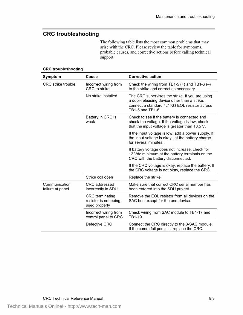
Maintenance and troubleshooting
CRC Technical Reference Manual 8.3
CRC troubleshootingThe following table lists the most common problems that mayarise with the CRC. Please review the table for symptoms,probable causes, and corrective actions before calling technicalsupport.
CRC troubleshooting
Symptom Cause Corrective action
Incorrect wiring fromCRC to strike
Check the wiring from TB1-5 (+) and TB1-6 (–)to the strike and correct as necessary
No strike installed The CRC supervises the strike. If you are usinga door-releasing device other than a strike,connect a standard 4.7 KΩ EOL resistor acrossTB1-5 and TB1-6.
Battery in CRC isweak
Check to see if the battery is connected andcheck the voltage. If the voltage is low, checkthat the input voltage is greater than 18.5 V.
If the input voltage is low, add a power supply. Ifthe input voltage is okay, let the battery chargefor several minutes.
If battery voltage does not increase, check for12 Vdc minimum at the battery terminals on theCRC with the battery disconnected.
If the CRC voltage is okay, replace the battery. Ifthe CRC voltage is not okay, replace the CRC.
CRC strike trouble
Strike coil open Replace the strike
CRC addressedincorrectly in SDU
Make sure that correct CRC serial number hasbeen entered into the SDU project.
CRC terminatingresistor is not beingused properly
Remove the EOL resistor from all devices on theSAC bus except for the end device.
Incorrect wiring fromcontrol panel to CRC
Check wiring from SAC module to TB1-17 andTB1-19
Communicationfailure at panel
Defective CRC Connect the CRC directly to the 3-SAC module.If the comm fail persists, replace the CRC.
Technical Manuals Online! - http://www.tech-man.com
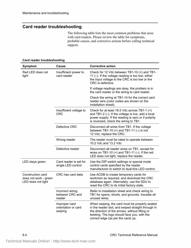
Maintenance and troubleshooting
8.4 CRC Technical Reference Manual
Card reader troubleshootingThe following table lists the most common problems that arisewith card readers. Please review the table for symptoms,probable causes, and corrective actions before calling technicalsupport.
Card reader troubleshooting
Symptom Cause Corrective action
Insufficient power tocard reader
Check for 12 Vdc between TB1-10 (+) and TB1-11 (–). If the voltage reading is too low, eitherthe input voltage to the CRC is too low or theCRC is defective.
If voltage readings are okay, the problem is inthe card reader or the wiring to card reader.
Check the wiring at TB1-14 for the correct cardreader wire (color codes are shown on theinstallation sheet).
Insufficient voltage toCRC
Check for at least 18.5 Vdc across TB1-1 (+)and TB1-2 (–). If the voltage is low, add a localpower supply. If the reading is zero or if polarityis reversed, check the wiring to TB1.
Defective CRC Disconnect all wires from TB1. If the voltagebetween TB1-10 (+) and TB1-11 (–) is not12 Vdc, replace the CRC.
Wrong reader The reader must be rated to operate between10.2 Vdc and 13.2 Vdc
Red LED does notlight
Defective reader Disconnect all reader wires on TB1, except forwires on TB1-10 (+) and TB1-11 (–). If the redLED does not light, replace the reader.
LED stays green Card reader is set forsingle LED control
Use the DIP switch settings or special modecontrol cards specified by the readermanufacturer to switch to dual-line LED control.
CRC has card data Use ACDB to create temporary cards forworkmen as required, and download the CRCdatabase again. Alternately, use the SDU toreset the CRC to its initial factory state.
Incorrect wiringbetween CRC andreader
Refer to installation sheet and check wiring toTB1 for opens, shorts, and grounds. Insulate allunused wires.
Construction carddoes not work - greenLED does not light
Improper cardorientation or cardswiping
When swiping, the card must be properly seatedin the reader slot, and swiped straight through inthe direction of the arrows, without lifting ortwisting. The logo should face you, with thecorrect edge (as per the card) up.
Technical Manuals Online! - http://www.tech-man.com
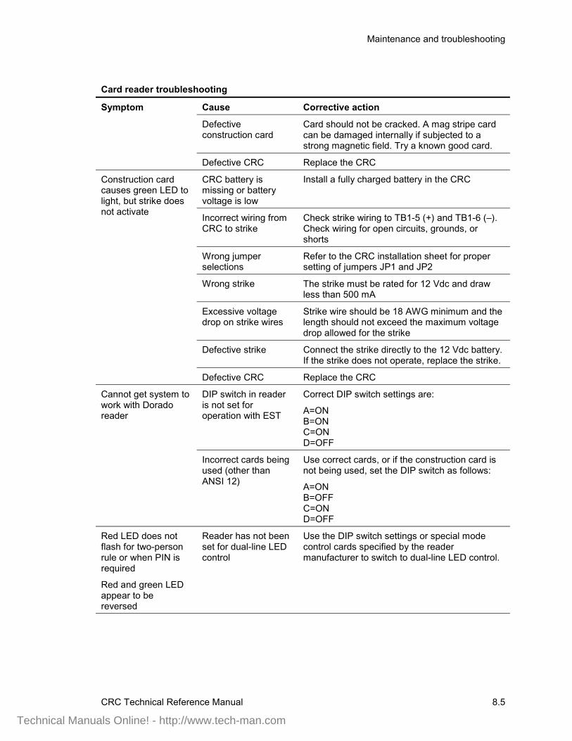
Maintenance and troubleshooting
CRC Technical Reference Manual 8.5
Card reader troubleshooting
Symptom Cause Corrective action
Defectiveconstruction card
Card should not be cracked. A mag stripe cardcan be damaged internally if subjected to astrong magnetic field. Try a known good card.
Defective CRC Replace the CRC
CRC battery ismissing or batteryvoltage is low
Install a fully charged battery in the CRC
Incorrect wiring fromCRC to strike
Check strike wiring to TB1-5 (+) and TB1-6 (–).Check wiring for open circuits, grounds, orshorts
Wrong jumperselections
Refer to the CRC installation sheet for propersetting of jumpers JP1 and JP2
Wrong strike The strike must be rated for 12 Vdc and drawless than 500 mA
Excessive voltagedrop on strike wires
Strike wire should be 18 AWG minimum and thelength should not exceed the maximum voltagedrop allowed for the strike
Defective strike Connect the strike directly to the 12 Vdc battery.If the strike does not operate, replace the strike.
Construction cardcauses green LED tolight, but strike doesnot activate
Defective CRC Replace the CRC
DIP switch in readeris not set foroperation with EST
Correct DIP switch settings are:
A=ONB=ONC=OND=OFF
Cannot get system towork with Doradoreader
Incorrect cards beingused (other thanANSI 12)
Use correct cards, or if the construction card isnot being used, set the DIP switch as follows:
A=ONB=OFFC=OND=OFF
Red LED does notflash for two-personrule or when PIN isrequired
Red and green LEDappear to bereversed
Reader has not beenset for dual-line LEDcontrol
Use the DIP switch settings or special modecontrol cards specified by the readermanufacturer to switch to dual-line LED control.
Technical Manuals Online! - http://www.tech-man.com
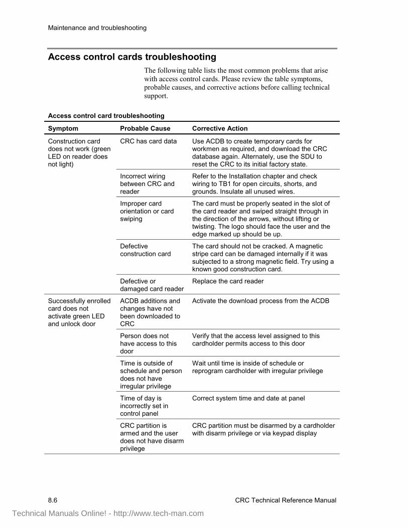
Maintenance and troubleshooting
8.6 CRC Technical Reference Manual
Access control cards troubleshootingThe following table lists the most common problems that arisewith access control cards. Please review the table symptoms,probable causes, and corrective actions before calling technicalsupport.
Access control card troubleshooting
Symptom Probable Cause Corrective Action
CRC has card data Use ACDB to create temporary cards forworkmen as required, and download the CRCdatabase again. Alternately, use the SDU toreset the CRC to its initial factory state.
Incorrect wiringbetween CRC andreader
Refer to the Installation chapter and checkwiring to TB1 for open circuits, shorts, andgrounds. Insulate all unused wires.
Improper cardorientation or cardswiping
The card must be properly seated in the slot ofthe card reader and swiped straight through inthe direction of the arrows, without lifting ortwisting. The logo should face the user and theedge marked up should be up.
Defectiveconstruction card
The card should not be cracked. A magneticstripe card can be damaged internally if it wassubjected to a strong magnetic field. Try using aknown good construction card.
Construction carddoes not work (greenLED on reader doesnot light)
Defective ordamaged card reader
Replace the card reader
ACDB additions andchanges have notbeen downloaded toCRC
Activate the download process from the ACDB
Person does nothave access to thisdoor
Verify that the access level assigned to thiscardholder permits access to this door
Time is outside ofschedule and persondoes not haveirregular privilege
Wait until time is inside of schedule orreprogram cardholder with irregular privilege
Time of day isincorrectly set incontrol panel
Correct system time and date at panel
Successfully enrolledcard does notactivate green LEDand unlock door
CRC partition isarmed and the userdoes not have disarmprivilege
CRC partition must be disarmed by a cardholderwith disarm privilege or via keypad display
Technical Manuals Online! - http://www.tech-man.com
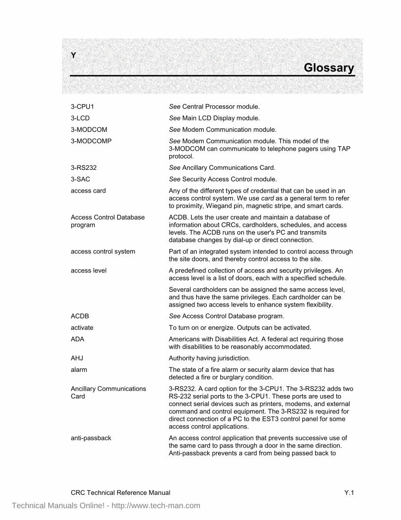
CRC Technical Reference Manual Y.1
Y Glossary
3-CPU1 See Central Processor module.
3-LCD See Main LCD Display module.
3-MODCOM See Modem Communication module.
3-MODCOMP See Modem Communication module. This model of the3-MODCOM can communicate to telephone pagers using TAPprotocol.
3-RS232 See Ancillary Communications Card.
3-SAC See Security Access Control module.
access card Any of the different types of credential that can be used in anaccess control system. We use card as a general term to referto proximity, Wiegand pin, magnetic stripe, and smart cards.
Access Control Databaseprogram
ACDB. Lets the user create and maintain a database ofinformation about CRCs, cardholders, schedules, and accesslevels. The ACDB runs on the user's PC and transmitsdatabase changes by dial-up or direct connection.
access control system Part of an integrated system intended to control access throughthe site doors, and thereby control access to the site.
access level A predefined collection of access and security privileges. Anaccess level is a list of doors, each with a specified schedule.
Several cardholders can be assigned the same access level,and thus have the same privileges. Each cardholder can beassigned two access levels to enhance system flexibility.
ACDB See Access Control Database program.
activate To turn on or energize. Outputs can be activated.
ADA Americans with Disabilities Act. A federal act requiring thosewith disabilities to be reasonably accommodated.
AHJ Authority having jurisdiction.
alarm The state of a fire alarm or security alarm device that hasdetected a fire or burglary condition.
Ancillary CommunicationsCard
3-RS232. A card option for the 3-CPU1. The 3-RS232 adds twoRS-232 serial ports to the 3-CPU1. These ports are used toconnect serial devices such as printers, modems, and externalcommand and control equipment. The 3-RS232 is required fordirect connection of a PC to the EST3 control panel for someaccess control applications.
anti-passback An access control application that prevents successive use ofthe same card to pass through a door in the same direction.Anti-passback prevents a card from being passed back to
Technical Manuals Online! - http://www.tech-man.com
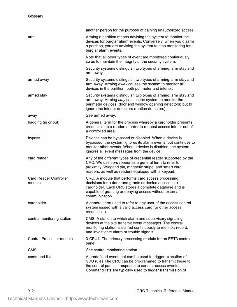
Glossary
Y.2 CRC Technical Reference Manual
another person for the purpose of gaining unauthorized access.
arm Arming a partition means advising the system to monitor thedevices for burglar alarm events. Conversely, when you disarma partition, you are advising the system to stop monitoring forburglar alarm events.
Note that all other types of event are monitored continuously,so as to maintain the integrity of the security system.
Security systems distinguish two types of arming: arm stay andarm away.
armed away Security systems distinguish two types of arming: arm stay andarm away. Arming away causes the system to monitor alldevices in the partition, both perimeter and interior.
armed stay Security systems distinguish two types of arming: arm stay andarm away. Arming stay causes the system to monitor theperimeter devices (door and window opening detectors) but toignore the interior detectors (motion detectors).
away See armed away.
badging (in or out) A general term for the process whereby a cardholder presentscredentials to a reader in order to request access into or out ofa controlled area.
bypass Devices can be bypassed or disabled. When a device isbypassed, the system ignores its alarm events, but continues tomonitor other events. When a device is disabled, the systemignores all event messages from the device.
card reader Any of the different types of credential reader supported by theCRC. We use card reader as a general term to refer toproximity, Wiegand pin, magnetic stripe, and smart cardreaders, as well as readers equipped with a keypad.
Card Reader Controllermodule
CRC. A module that performs card access processingdecisions for a door, and grants or denies access to acardholder. Each CRC stores a complete database and iscapable of granting or denying access without externalcommunication.
cardholder A general term used to refer to any user of the access controlsystem issued with a valid access card (or other accesscredentials).
central monitoring station CMS. A station to which alarm and supervisory signalingdevices at the site transmit event messages. The centralmonitoring station is staffed continuously to monitor, record,and investigate alarm or trouble signals.
Central Processor module 3-CPU1. The primary processing module for an EST3 controlpanel.
CMS See central monitoring station.
command list A predefined event that can be used to trigger execution ofSDU rules The CRC can be programmed to transmit these tothe control panel in response to certain access events.Command lists are typically used to trigger transmission of
Technical Manuals Online! - http://www.tech-man.com
Glossary
CRC Technical Reference Manual Y.3
access event messages to a CMS, or to trigger activation ofremote gates, CCTV, or relay modules.
common door An access control application where a given door is used byseveral different companies, as in the main entrance of anoffice building.
company General term for a group of end-users who use the accesscontrol system at the project site. Projects can include one ormore companies. Generally, the resources of dedicatedsecurity and access control devices are controlled by a singlecompany. Several companies may share the resources ofcommon devices.
construction card Special access cards that will work with any CRC prior to adatabase being downloaded.
construction mode Before a database is downloaded to a CRC it is in constructionmode. Building contractors can use specially codedconstruction cards for access and for testing.
continuous lock Locks that operate, on average, more than 30 seconds in everyminute. In these applications, the CRC battery alone can notprovide the power needed to operate the lock.
control panel An electronics cabinet housing the 3-CPU1, 3-LCD, and relatedmodules, acting as the central controlling point for an integratedsystem, or as one control node of a networked, integratedsystem.
Control Relay module SIGA-CR. A component of the Signature Series. A device thatprovides one Form C dry relay contact to control externalappliances (door closers, fans, dampers, etc.) or equipmentshutdown.
CR Card reader.
CRC See Card Reader Controller module.
CRC Accessory Relay CRCRL. An accessory relay for the CRC, used in conjunctionwith an external power supply, to control a lock with voltage orcurrent requirements that exceed the CRC operating range.
CRC Sounder CRCSND. A small horn that mounts inside the CRC module.The sounder is controlled by the internal firmware of the CRC,by settings in the ACDB program, and by SDU programmingrules.
CRCRL See CRC Accessory Relay.
CRCSND See CRC Sounder.
CRCXM See Card Reader Controller module. This option of the CRChas extended memory and holds a larger database.
database A file composed of records, each containing fields, togetherwith a set of operations for searching, sorting, recombining, andother functions. In this manual, database most often refers tothe access control database that is created by the ACDB anddownloaded through the control panel to individual CRCs.
degraded mode A mode of operation used when a module has lost
Technical Manuals Online! - http://www.tech-man.com
Glossary
Y.4 CRC Technical Reference Manual
communication with its supporting system. The CRC canoperate when communication with the control panel isdisrupted, providing enhanced survivability.
delayed egress An access control application intended to control shoplifting atretail sites. A delayed egress door is fitted with card readersand a request to exit (REX) button. Employees can badge inand out as at any other door. In an emergency, customers canpress the REX to unlock the door. Pressing the REX generatesa security alarm but does not unlock the door immediately.
device Any detector or module. Devices are electronic sensing unitsthat monitor an area for unwanted conditions and report thoseconditions to the system control panel. Devices are alsoreferred to as points.
Typical fire alarm devices are heat detectors, smoke detectors,and pull stations. Security devices include door status sensors,motion detectors, and broken glass detectors.
device address A number which uniquely identifies a detector or module in anintegrated system.
disable Devices can be bypassed or disabled. When a device isbypassed, the system ignores its alarm events, but continues tomonitor other events. When a device is disabled, the systemignores all event messages from the device.
disarm Arming a partition means advising the system to monitor thedevices for burglar alarm events. Conversely, when you disarma partition, you are advising the system to stop monitoring forburglar alarm events.
Note that all other types of event are monitored continuously,so as to maintain the integrity of the security system.
door contact A switch that monitors the position (open or closed) of the door.
download Sending a compiled project database from a PC to the firealarm control panel. Also, sending an access control databasefrom a PC to the CRC devices via the control panel.
dry contacts Electrical connection points on a device provided for switchingexternal circuits or devices, but electrically isolated from thecontrolling circuit. The external circuit must have its own powersource, which is routed through the dry contacts.
elevator control An access control application that determines which floors areavailable to a given cardholder.
emergency exit door An access control application where an exit door can beunlocked from the inside by badging out or by mechanicalmeans. If the door is opened without badging out, it causes animmediate security alarm.
enable Permit an input, output, or system feature to function. Also, toinstruct the system to monitor event messages from a device.See also disable.
FireWorks A computerized display and control system used with EST2,EST3, FCC, and IRC-3 fire networks. FireWorks uses one or
Technical Manuals Online! - http://www.tech-man.com

Glossary
CRC Technical Reference Manual Y.5
more display computers to monitor and control severalnetworks of multiplex signaling systems, card access systems,and CCTV systems.
handicap access door An access control application for a door that providesmechanical assistance and extended access time for ahandicapped cardholder.
holiday schedule Exceptions to normal schedules, when different access timesare desired.
input circuit Each CRC has two input circuits for use with access controland security devices. These are typically used for a doorposition sensor and a request to exit device. The input circuitscan also be used as security input points.
integrated system A panel-based system that can integrate fire alarm, security,and access control functions.
intermittent lock Locks that operate, on average, less than 30 seconds in everyminute. In these applications, the CRC battery provides thepower needed to operate the lock.
keypad Some card readers are equipped with a keypad to allow entryof a PIN number in addition to the access card. We do not usethe term keypad to refer to the KPDISP Keypad Displaymodule.
Keypad Display module KPDISP. A control and display module used in security and lifesafety applications. The KPDISP includes an LCD display, atelephone-style keypad, a variable-tone sounder, and aninternal processor. It is most typically used to arm and disarmsecurity partitions.
KPDISP See Keypad Display module.
LED Light emitting diode.
load shedding When ac power fails, the CRC can disable its peripheraldevices in a controlled fashion so as to preserve access controland audit functions for as long as possible. This process isreferred to as load shedding.
lock Any type of door securing device. We use lock as a generalterm to refer to both strikes and maglocks.
maglock Magnetic lock. A type of lock that secures the door (holds itshut) when power is applied.
magnetic stripe card A type of access card having a data encoded magnetic tape orstripe on one side.
Main LCD Display module 3-LCD. An EST3 control and display module. The 3-LCD isattached to the 3-CPU1 and displays event messages andsystem status. It can be used to control the operation of thesystem from the control panel.
Modem Communicationmodule
3-MODCOM. An EST3 communication module with modemand dialer capabilities. The 3-MODCOM can be used todownload information from remote sites or to report events to acentral monitoring station. The 3-MODCOMP can communicateto telephone pagers using TAP protocol.
Technical Manuals Online! - http://www.tech-man.com

Glossary
Y.6 CRC Technical Reference Manual
muster An access control application that lets users determine who hasexited a controlled area in the event of an emergencyevacuation.
muster report station A PC located in a secure area, outside the controlled area,equipped with the ACDB program. Security staff use this PC tocreate a muster report after an emergency evacuation.
muster station A CRC located outside the controlled area at which cardholdersbadge out after an emergency evacuation.
NFPA 72 National Fire Alarm Code.
normal Devices can be in different states. States are classified asnormal or off-normal.
When a smoke detector is operating perfectly and there is nosmoke in the area, the device is said to be in a normal state.
If smoke is detected the device goes into an alarm state. If thedevice is damaged, it goes into a trouble state. Both alarm andtrouble are off-normal states.
off-normal See normal.
open schedule A type of access control schedule, defined with the ACDB, thatspecifies times when a door is unlocked. For example, accessto a building lobby may be determined with an open schedule.When the open schedule is active, the lobby door is unlocked.
output circuit The CRC includes common, NO, and NC outputs from a FormC relay. These can be used to control auxiliary devices such asfans and dampers, as well as devices that support handicapfunctions.
partition A physical area that a security system protects with a group ofrelated devices. A site may consist of a single partition or ofmultiple partitions. Partitions can be armed and disarmedindependently.
PIN schedule A type of access control schedule that defines when a PIN mustbe entered to verify the badging-in operation and grant access
proximity card A type of access card containing a microcircuit. When placed inclose proximity to a card reader, the card activates the reader'scircuitry and registers a unique code.
remote controls An access control application that allows the CRC to operatedevices located remotely from the CRC. The CRC passesevents to the control panel, which in turn operates the remotedevices.
remote power source A dc power source located remotely from the control panel, butclose to a CRC. The CRC operates an electronic door lockusing power from this power supply.
resource profile A file that defines the system security and access controldevices for the ACDB program.
Resource Profile Manager tool RPM. Part of the SDU that uses the project database to createa separate resource profile for each company that uses theaccess control system.
Technical Manuals Online! - http://www.tech-man.com
Glossary
CRC Technical Reference Manual Y.7
REX Request to exit button.
RPM See Resource Profile Manager tool.
RS-232 An asynchronous communication format used to communicatebetween a PC and a control panel.
RS-485 A serial differential communications format used tocommunicate between panels, and between the 3-SAC moduleand security or access control devices.
rule Defines the system response to given input events. Ruleformat: [rule label] (input state) (input device type) ‘input label’ :output command (output device type) (priority) ‘output label’comments;
Rules are written with the SDU and downloaded to the controlpanel and its modules. Rules program the behavior of thesystem.
SAC bus An RS-485 communication line supported by a 3-SAC modulethat connects access control and security devices. We suggestrunning the RS-485 data lines and a 24 Vdc power supply inthe same cable, and sometimes refer to the combined data andpower lines as the SAC bus.
schedule Identifies specific times (in 15 minute increments) and dayswhen access is granted.
SDU See System Definition Utility.
Security Access Controlmodule
3-SAC. An EST3 module that supports an RS-485 line forsecurity and access control devices.
security alarm When a security device goes into alarm it generates a securityalarm event. This triggers programmed responses from thesystem control panel, and may result in a message being sentto a central monitoring station or a telephone pager. The endresult will be the dispatch of a police or security officer toinvestigate the problem.
security partition See partition.
security system Part of an integrated system intended to monitor and reportunauthorized access to specific areas of the site, therebypreventing vandalism and burglary.
security trouble When a security device goes into trouble it generates a securitytrouble event. This triggers programmed responses from thesystem control panel, and may result in a message being sentto a central monitoring station or a telephone pager. The endresult will be the dispatch of maintenance personnel toinvestigate and resolve the problem.
SIGA An abbreviation for Signature Series.
SIGA-CR See Control Relay module.
Signature Controller An EST3 module used to support a Signature Data Circuit andthe devices on the circuit. Several different models areavailable.
Technical Manuals Online! - http://www.tech-man.com

Glossary
Y.8 CRC Technical Reference Manual
Signature Data Circuit The wiring which connects Signature Series devices to the firealarm panel.
smart card A type of access card with an embedded integrated circuit chip.The card has both a coded memory and microprocessorintelligence. It can record card transactions and store data.
sounder See CRC Sounder.
stay See armed stay.
strike A type of lock. A strike unlocks the door when power is applied.
suppression schedule A type of access control schedule that defines times when theCRC does not log normal events. This reduces the number ofevents that would otherwise be stored in the CRC duringnormal business hours.
survivability Property of a system, module, or device that lets it continue toperform its intended functions despite system or componentfailures.
System Definition Utility A Windows based program used to enter and modifyinformation contained in the EST3 system.
TAP protocol Telocator Alphanumeric Protocol. A communication protocolthat lets the EST3 system transmit text messages to suitablyequipped and supported alphanumeric pagers, via the3-MODCOMP.
two-person rule An access control application that ensures that no staff membercan be in the controlled area alone. A CRC operating undertwo-person rule prevents the entrance of a single person intothe controlled area. When two people are present in the area,one cannot exit without the other.
visitor and escort An access control application where a visitor is issued atemporary access card. Access to specific doors is granted onlywhen an employee (escort) with a permanent access cardbadges in with the visitor. This application may make use ofmultiple card readers to handle different types of visitor andemployee access card.
Wiegand pin card A type of access card embedded with encoded ferromagneticwires.
zone A physical area that a fire alarm system protects with a group ofrelated devices. A site usually consists of two or more zones.
Technical Manuals Online! - http://www.tech-man.com
CRC Technical Reference Manual Z.1
Z Index
224 Vdc wiring • 5.52-person rule • See two-person rule
33-CPU1 requirements • 5.33-MODCOM • 3.3, 4.25, 4.273-PPS/M • 5.43-RS232 card • 4.273-SAC
capacity • 5.5Class A or B wiring • 2.2configuration in SDU • 6.2description • 3.3device capacity • 2.2, 3.3diagram of basic CRC installation • 5.4wiring distance • 2.11
Aac power source application • 4.32ac power supply
elevator control application • 4.16remote controls application • 4.39
access cardscompatibility list • 3.10definition • 1.5description • 2.4, 3.9, 3.10troubleshooting • 8.6
access control applications • 4.1Access Control Database • See ACDBaccess control system diagram • 3.2access denied command lists • 6.3access door contact application • 6.6access events
command lists in SDU • 4.8, 6.3CRC capacities • 3.5sharing between CRCs • 1.5storage in CRC database • 2.2
access granted command lists • 6.3access level field in RPM • 6.9access level two • 7.2access levels
active and expire dates • 2.5CRC capacities • 3.5CRC processing • 7.2definition • 1.5, 2.5override option • 7.3start and end date and time • 7.2temporary schedules • 2.5visitors • 4.24
ACDB3-MODCOM receiving function • 3.3card input converter • 3.8computer location in muster • 4.25configuring CRC • 4.2connection methods • 2.4CRC configuration • 6.10CRCSND configuration • 3.6
ACDB (continued)description • 2.4, 3.11door timers • 2.7event log • 2.6role in a security system • 4.3setting options with • 6.1suppression schedule • 2.6transmission methods • 3.11versions • 3.11
ACDB operationcommon door access • 4.10delayed egress • 4.13emergency exit door • 4.18handicap access door • 4.20intermittent locks • 4.31multiple card readers • 4.24power for intermittent locks • 4.31
ACDB programming • See application descriptions forspecific application
active date • 2.5ADA • 2.8additional card readers • 4.20additional power supplies • 3.7, 4.2, 5.6address field in SDU • 6.2anti-passback
CRC functions • 2.9CRC processing • 7.4muster application • 4.4network comm loss • 2.2SDU configuration • 6.3
anti-passback application • 4.4application descriptions
ac power source • 4.32anti-passback • 4.4central monitoring station • 4.7common door access • 4.9continuous locks • 4.28dc power supply • 4.35delayed egress • 4.11elevator control • 4.14emergency exit door • 4.17handicap access door • 4.19intermittent locks • 4.30maglock peripherals • 4.21multiple card readers • 4.23muster • 4.25power for continuous locks • 4.28power for intermittent locks • 4.30power from a remote source • 4.35power from an ac source • 4.32remote controls • 4.38remote power source • 4.35remote power source application • 4.35two-person rule • 4.40
application field in SDU • 6.6application field values • 6.6armored door cord • 5.10assignment of user data • 6.12audit trails • 2.2automatic door openers • 2.8, 3.6, 4.19
Technical Manuals Online! - http://www.tech-man.com

Index
Z.2 CRC Technical Reference Manual
Bbadging in • 4.25, 7.2, 7.7bar code card • 4.23basic personality • 6.8batteries
description • 1.4diagram of basic CRC installation • 5.4failure • 2.2limitations of CRC battery • 4.34load shedding • 7.10, 7.11standby power feature • 2.2supervision • 2.12, 8.2
building field in RPM • 6.9bypass alarm point • 2.8bypass field in ACDB • 6.12bypass time
CRC processing • 7.6delayed egress application • 4.13emergency exit door application • 4.18
Ccables • See also wiring
card reader • 3.4recommended • 5.5SAC bus • 3.4
capacitance of SAC bus • 3.4capacities
3-SAC card • 2.2CRC database • 2.6
card access equipment • 3.2card input device • 3.8card numbers • 7.2Card Reader Controller • See CRCcard reader partition field in SDU • 6.2card readers
additional • 4.20anti-passback application • 4.4CRC capacity • 2.3CRC processing • 7.2definition • 3.9description • 2.4, 3.9diagram of basic CRC installation • 5.4dual LED control • 4.24, 4.41, 7.8handicap access door application • 4.19inside vs. outside • 5.8installation • 5.8LEDs • 2.3, 3.10, 7.8list of compatible readers • 3.10load shedding • 7.10maintenance • 8.2power • 3.10, 7.10sounder • 7.7supervision • 2.12terminals • 1.4troubleshooting • 8.4two-person rule application • 4.41types supported • 2.4wiring • 5.8
cardholders • 2.6, 3.5cardholders field in RPM • 6.9central monitoring station application • 4.7central monitoring stations • 3.3circuit common • 4.2, 4.16, 4.39, 5.5Class A or B wiring • 2.2comm route field in ACDB • 6.10
command listselevator control application • 4.16events with • 4.8multiple card readers application • 4.24muster application • 4.27programming • 6.3remote controls application • 4.39two-person rule application • 4.42
common door access application • 4.9common ground • See circuit commoncompany field in RPM • 6.9compatible devices • 3.10configuring CRC • 4.2construction cards • 5.12, 7.2construction mode • 2.8continue task supervision • 8.2continuous locks • 4.28continuous locks application • 4.28contractor access • 2.8control panel failure • 2.2cover supervision • 2.12CRC
3-SAC capacity • 2.2ACDB configuration • 6.10battery • 1.4, 2.2capacities • 3.5card reader power • 3.10connections • 3.5description • 1.3, 1.4, 3.5diagram of basic CRC installation • 5.4dry contact relay • 2.4features • 2.2functions • 2.8housing • 2.11input circuits • 3.6, 6.5installation guidelines • 5.2jumpers • 1.4, 4.2, 5.5location • 5.4lock output • 3.6operation • 1.5, 7.2options • 3.5, 3.6output circuits • 3.6power sources • 2.12power supply from cabinet • 4.2processing • 3.5, 7.2resetting • 4.11, 4.12, 4.13SDU command lists • 6.3SDU configuration • 6.2sounder driver • 2.3terminal strip • 3.5troubleshooting • 8.3
CRC Accessory Relay • See CRCRLCRC Expanded Memory • See CRCXMCRC installation sheet • 1.3CRC Sounder • See CRCSNDCRC Transformer • See CRCXFCRCRL • 3.7CRCSND
delayed egress application • 4.11description • 3.6, 7.7diagram of basic CRC installation • 5.4emergency exit door application • 4.17emergency exits • 7.7installation • 3.6operation • 2.3, 7.7
CRCXF • 3.7CRCXM • 1.3, 3.5Cypress CVT 2110 • 3.8
Technical Manuals Online! - http://www.tech-man.com
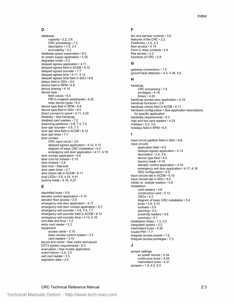
Index
CRC Technical Reference Manual Z.3
Ddatabase
capacity • 2.2, 2.6CRC processing • 7.2description • 1.5, 2.4survivability • 2.2
database space supervision • 8.2dc power supply application • 4.35degraded mode • 2.2delayed egress application • 4.11delayed egress field in ACDB • 6.12delayed egress sounder • 7.7delayed egress time • 4.11, 4.12delayed egress time field in SDU • 6.8delays field in SDU • 6.6device field in RPM • 6.9device sharing • 4.10device type
field values • 6.5PIR in maglock peripherals • 4.22relay device types • 6.3
device type field in RPM • 6.9device type field in SDU • 6.5direct connect to panel • 3.11, 4.25disability • See handicapdisabled card readers • 7.2disarming partitions • 2.8, 7.3, 7.5door ajar sounder • 3.6, 7.7door ajar time field in ACDB • 6.12door ajar timer • 7.7door contact
CRC input circuit • 3.6delayed egress application • 4.12, 4.13diagram of basic CRC installation • 5.4emergency exit door application • 4.17, 4.18
door contact application • 6.6door cord for lockset • 5.10door holders • 3.6door lock • See lockdoor open timer • 2.7door timers tab in ACDB • 6.11dual LEDs • 3.9, 4.24, 4.41dummy loads • 4.16, 4.27
Eelectrified locks • 5.9elevator control application • 4.14elevator floor access • 2.9emergency exit door application • 4.17emergency exit door contact application • 6.7emergency exit sounder • 3.6, 7.6, 7.7emergency exit sounder field in ACDB • 6.12emergency exit sounder time • 4.13, 4.18end date and time • 7.2entry card reader • 2.3equipment
access cards • 3.10basic access control system • 3.2card readers • 3.10
escort and visitor • See visitor and escortEST3 system requirements • 5.3evacuation • See muster applicationevent history • 2.6, 3.5exit card reader • 2.3expiration date • 2.5
Ffan and damper controls • 3.6features of the CRC • 2.2FireWorks • 1.5, 2.3floor access • 4.14Form C relay contacts • 2.4free access • 2.2functions of CRC • 2.8
Ggateway connections • 1.5ground fault detection • 4.2, 4.39, 5.6
Hhandicap
CRC processing • 7.6privileges • 4.19timers • 4.20
handicap access door application • 4.19handicap functions • 2.8handicap unlock field in ACDB • 6.11hardware configuration • See application descriptions
for specific applicationhardware requirements • 5.3high and low card readers • 4.23holidays • 2.5, 3.5holidays field in RPM • 6.9
Iinput circuit partition field in SDU • 6.6input circuits
application field • 6.6delayed egress application • 4.13description • 2.4, 3.6device type field • 6.5dummy loads • 4.16elevator control application • 4.16emergency exit door application • 4.17, 4.18SDU configuration • 6.5
input circuits tab in ACDB • 6.10input circuits tab in SDU • 6.5inside vs. outside readers • 5.8installation
card readers • 5.8construction card • 5.12CRCs • 5.2diagram of basic CRC installation • 5.4locks • 5.9, 5.10locksets • 5.9planning • 5.2proximity readers • 5.8summary • 5.1
installation sheet • 1.3, 5.2integrated system • 2.2intermittent locks • 4.30invalid PIN • 7.7irregular access events • 7.2irregular access privileges • 7.3
Jjumper settings
ac power source • 4.34continuous locks • 4.29intermittent locks • 4.31
jumpers • 1.4, 4.2, 5.5
Technical Manuals Online! - http://www.tech-man.com
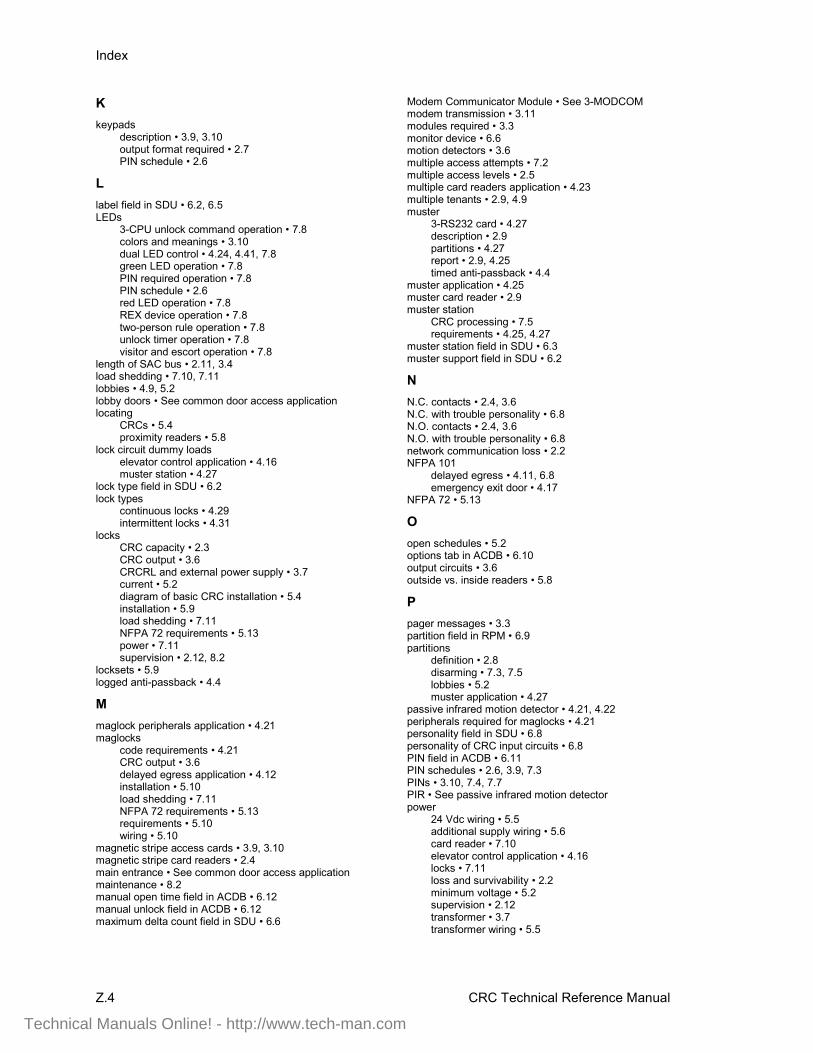
Index
Z.4 CRC Technical Reference Manual
Kkeypads
description • 3.9, 3.10output format required • 2.7PIN schedule • 2.6
Llabel field in SDU • 6.2, 6.5LEDs
3-CPU unlock command operation • 7.8colors and meanings • 3.10dual LED control • 4.24, 4.41, 7.8green LED operation • 7.8PIN required operation • 7.8PIN schedule • 2.6red LED operation • 7.8REX device operation • 7.8two-person rule operation • 7.8unlock timer operation • 7.8visitor and escort operation • 7.8
length of SAC bus • 2.11, 3.4load shedding • 7.10, 7.11lobbies • 4.9, 5.2lobby doors • See common door access applicationlocating
CRCs • 5.4proximity readers • 5.8
lock circuit dummy loadselevator control application • 4.16muster station • 4.27
lock type field in SDU • 6.2lock types
continuous locks • 4.29intermittent locks • 4.31
locksCRC capacity • 2.3CRC output • 3.6CRCRL and external power supply • 3.7current • 5.2diagram of basic CRC installation • 5.4installation • 5.9load shedding • 7.11NFPA 72 requirements • 5.13power • 7.11supervision • 2.12, 8.2
locksets • 5.9logged anti-passback • 4.4
Mmaglock peripherals application • 4.21maglocks
code requirements • 4.21CRC output • 3.6delayed egress application • 4.12installation • 5.10load shedding • 7.11NFPA 72 requirements • 5.13requirements • 5.10wiring • 5.10
magnetic stripe access cards • 3.9, 3.10magnetic stripe card readers • 2.4main entrance • See common door access applicationmaintenance • 8.2manual open time field in ACDB • 6.12manual unlock field in ACDB • 6.12maximum delta count field in SDU • 6.6
Modem Communicator Module • See 3-MODCOMmodem transmission • 3.11modules required • 3.3monitor device • 6.6motion detectors • 3.6multiple access attempts • 7.2multiple access levels • 2.5multiple card readers application • 4.23multiple tenants • 2.9, 4.9muster
3-RS232 card • 4.27description • 2.9partitions • 4.27report • 2.9, 4.25timed anti-passback • 4.4
muster application • 4.25muster card reader • 2.9muster station
CRC processing • 7.5requirements • 4.25, 4.27
muster station field in SDU • 6.3muster support field in SDU • 6.2
NN.C. contacts • 2.4, 3.6N.C. with trouble personality • 6.8N.O. contacts • 2.4, 3.6N.O. with trouble personality • 6.8network communication loss • 2.2NFPA 101
delayed egress • 4.11, 6.8emergency exit door • 4.17
NFPA 72 • 5.13
Oopen schedules • 5.2options tab in ACDB • 6.10output circuits • 3.6outside vs. inside readers • 5.8
Ppager messages • 3.3partition field in RPM • 6.9partitions
definition • 2.8disarming • 7.3, 7.5lobbies • 5.2muster application • 4.27
passive infrared motion detector • 4.21, 4.22peripherals required for maglocks • 4.21personality field in SDU • 6.8personality of CRC input circuits • 6.8PIN field in ACDB • 6.11PIN schedules • 2.6, 3.9, 7.3PINs • 3.10, 7.4, 7.7PIR • See passive infrared motion detectorpower
24 Vdc wiring • 5.5additional supply wiring • 5.6card reader • 7.10elevator control application • 4.16locks • 7.11loss and survivability • 2.2minimum voltage • 5.2supervision • 2.12transformer • 3.7transformer wiring • 5.5
Technical Manuals Online! - http://www.tech-man.com
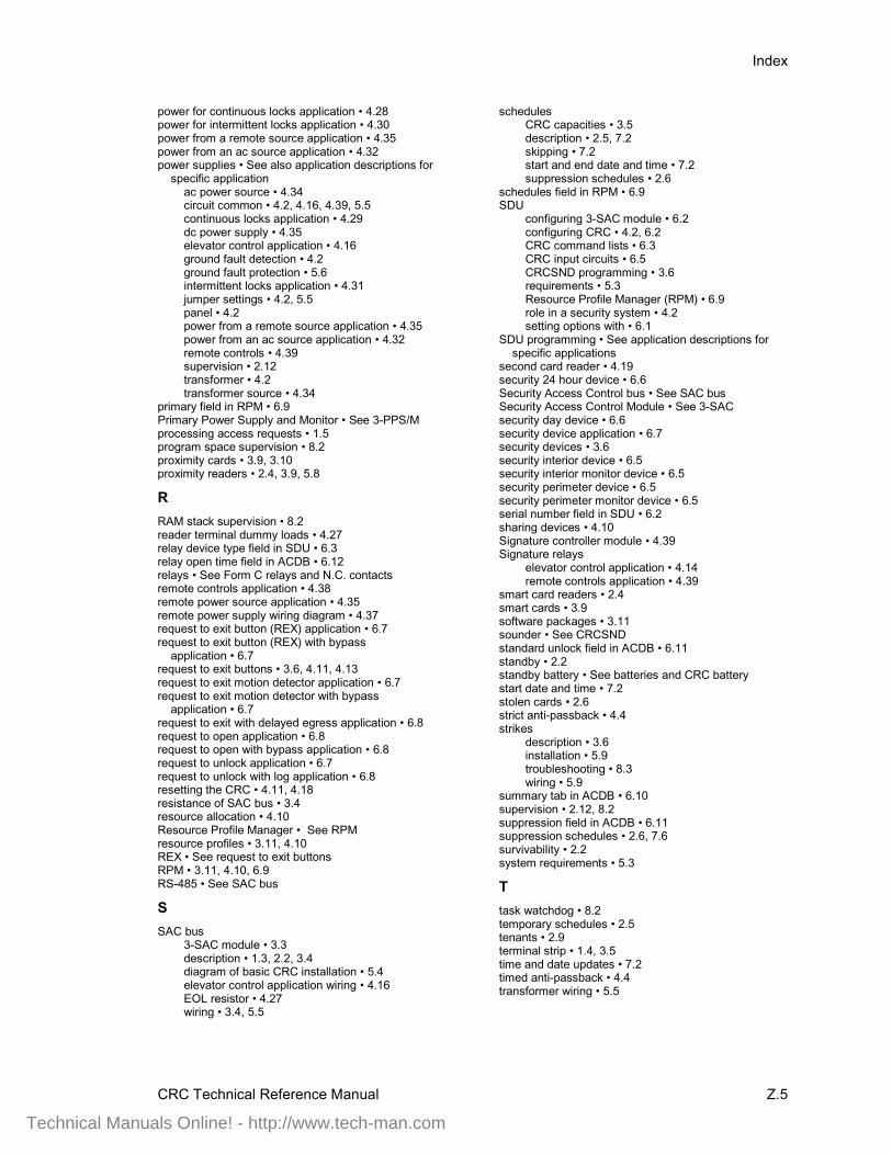
Index
CRC Technical Reference Manual Z.5
power for continuous locks application • 4.28power for intermittent locks application • 4.30power from a remote source application • 4.35power from an ac source application • 4.32power supplies • See also application descriptions for
specific applicationac power source • 4.34circuit common • 4.2, 4.16, 4.39, 5.5continuous locks application • 4.29dc power supply • 4.35elevator control application • 4.16ground fault detection • 4.2ground fault protection • 5.6intermittent locks application • 4.31jumper settings • 4.2, 5.5panel • 4.2power from a remote source application • 4.35power from an ac source application • 4.32remote controls • 4.39supervision • 2.12transformer • 4.2transformer source • 4.34
primary field in RPM • 6.9Primary Power Supply and Monitor • See 3-PPS/Mprocessing access requests • 1.5program space supervision • 8.2proximity cards • 3.9, 3.10proximity readers • 2.4, 3.9, 5.8
RRAM stack supervision • 8.2reader terminal dummy loads • 4.27relay device type field in SDU • 6.3relay open time field in ACDB • 6.12relays • See Form C relays and N.C. contactsremote controls application • 4.38remote power source application • 4.35remote power supply wiring diagram • 4.37request to exit button (REX) application • 6.7request to exit button (REX) with bypass
application • 6.7request to exit buttons • 3.6, 4.11, 4.13request to exit motion detector application • 6.7request to exit motion detector with bypass
application • 6.7request to exit with delayed egress application • 6.8request to open application • 6.8request to open with bypass application • 6.8request to unlock application • 6.7request to unlock with log application • 6.8resetting the CRC • 4.11, 4.18resistance of SAC bus • 3.4resource allocation • 4.10Resource Profile Manager • See RPMresource profiles • 3.11, 4.10REX • See request to exit buttonsRPM • 3.11, 4.10, 6.9RS-485 • See SAC bus
SSAC bus
3-SAC module • 3.3description • 1.3, 2.2, 3.4diagram of basic CRC installation • 5.4elevator control application wiring • 4.16EOL resistor • 4.27wiring • 3.4, 5.5
schedulesCRC capacities • 3.5description • 2.5, 7.2skipping • 7.2start and end date and time • 7.2suppression schedules • 2.6
schedules field in RPM • 6.9SDU
configuring 3-SAC module • 6.2configuring CRC • 4.2, 6.2CRC command lists • 6.3CRC input circuits • 6.5CRCSND programming • 3.6requirements • 5.3Resource Profile Manager (RPM) • 6.9role in a security system • 4.2setting options with • 6.1
SDU programming • See application descriptions forspecific applications
second card reader • 4.19security 24 hour device • 6.6Security Access Control bus • See SAC busSecurity Access Control Module • See 3-SACsecurity day device • 6.6security device application • 6.7security devices • 3.6security interior device • 6.5security interior monitor device • 6.5security perimeter device • 6.5security perimeter monitor device • 6.5serial number field in SDU • 6.2sharing devices • 4.10Signature controller module • 4.39Signature relays
elevator control application • 4.14remote controls application • 4.39
smart card readers • 2.4smart cards • 3.9software packages • 3.11sounder • See CRCSNDstandard unlock field in ACDB • 6.11standby • 2.2standby battery • See batteries and CRC batterystart date and time • 7.2stolen cards • 2.6strict anti-passback • 4.4strikes
description • 3.6installation • 5.9troubleshooting • 8.3wiring • 5.9
summary tab in ACDB • 6.10supervision • 2.12, 8.2suppression field in ACDB • 6.11suppression schedules • 2.6, 7.6survivability • 2.2system requirements • 5.3
Ttask watchdog • 8.2temporary schedules • 2.5tenants • 2.9terminal strip • 1.4, 3.5time and date updates • 7.2timed anti-passback • 4.4transformer wiring • 5.5
Technical Manuals Online! - http://www.tech-man.com
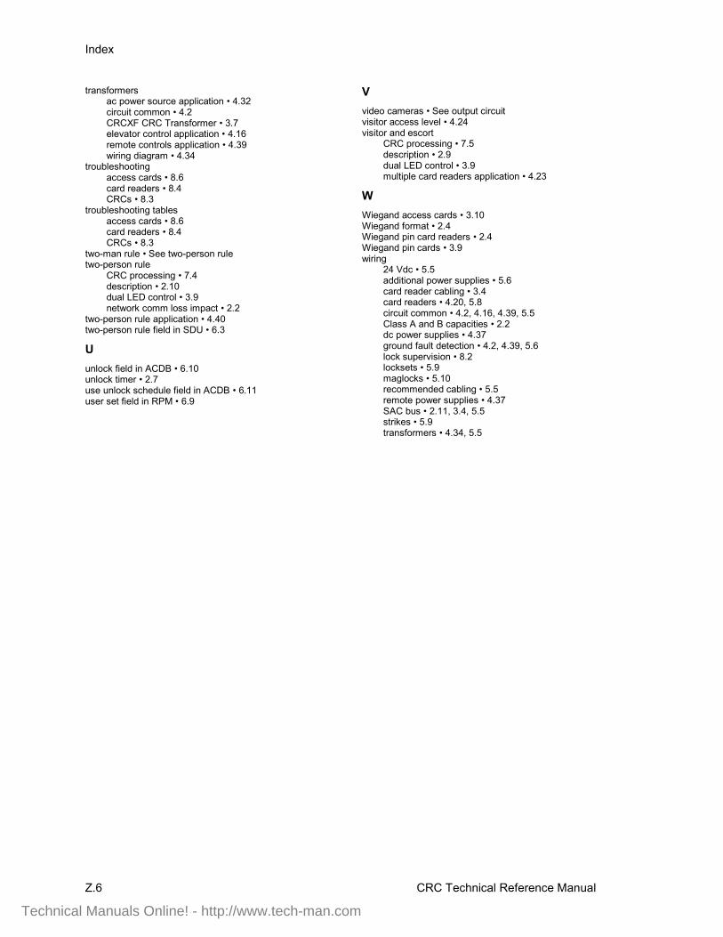
Index
Z.6 CRC Technical Reference Manual
transformersac power source application • 4.32circuit common • 4.2CRCXF CRC Transformer • 3.7elevator control application • 4.16remote controls application • 4.39wiring diagram • 4.34
troubleshootingaccess cards • 8.6card readers • 8.4CRCs • 8.3
troubleshooting tablesaccess cards • 8.6card readers • 8.4CRCs • 8.3
two-man rule • See two-person ruletwo-person rule
CRC processing • 7.4description • 2.10dual LED control • 3.9network comm loss impact • 2.2
two-person rule application • 4.40two-person rule field in SDU • 6.3
Uunlock field in ACDB • 6.10unlock timer • 2.7use unlock schedule field in ACDB • 6.11user set field in RPM • 6.9
Vvideo cameras • See output circuitvisitor access level • 4.24visitor and escort
CRC processing • 7.5description • 2.9dual LED control • 3.9multiple card readers application • 4.23
WWiegand access cards • 3.10Wiegand format • 2.4Wiegand pin card readers • 2.4Wiegand pin cards • 3.9wiring
24 Vdc • 5.5additional power supplies • 5.6card reader cabling • 3.4card readers • 4.20, 5.8circuit common • 4.2, 4.16, 4.39, 5.5Class A and B capacities • 2.2dc power supplies • 4.37ground fault detection • 4.2, 4.39, 5.6lock supervision • 8.2locksets • 5.9maglocks • 5.10recommended cabling • 5.5remote power supplies • 4.37SAC bus • 2.11, 3.4, 5.5strikes • 5.9transformers • 4.34, 5.5
Technical Manuals Online! - http://www.tech-man.com