Embed Size (px)
Citation preview
Creating a High-Tech Totem Pole
An Interactive Qualifying Project
submitted to the Faculty of
WORCESTER POLYTECHNIC INSTITUTE
in partial fulfilment of the requirements for the
degree of Bachelor of Science
by
Daniel Sanderson
Brian Baggaley
Max Kinney
David Rubenstien
Date:
March 5, 2016
Report Submitted to:
Professors Brigitte Servatius and Tahar El-Korchi
Worcester Polytechnic Institute
This report represents work of WPI undergraduate students submitted to the faculty as evidence
of a degree requirement. WPI routinely publishes these reports on its web site without editorial
or peer review. For more information about the projects program at WPI, see
http://www.wpi.edu/Academics/Projects.
1
Table of Contents Table of Figures ................................................................................................................................................................ 3
Abstract ............................................................................................................................................................................. 5
Chapter 1: Totem Poles.................................................................................................................................................... 6
Inspiration for the High-Tech Totem ................................................................................................................. 6
Northwest Coast Native American Culture ........................................................................................................ 6
Traditional Totem Pole Design ............................................................................................................................ 7
Chapter 2: Art and its Impact ......................................................................................................................................... 9
Defining Art in Public Spaces .............................................................................................................................. 9
Visual Art in Worcester ..................................................................................................................................... 10
The Influence of Technology on Art ................................................................................................................. 16
Impact on Totem ................................................................................................................................................ 18
Chapter 3: High-Tech Totem Materials ....................................................................................................................... 19
What is Concrete? .............................................................................................................................................. 19
History of Concrete ............................................................................................................................................ 19
Light transmitting materials.............................................................................................................................. 22
3D Printed Sculpture .......................................................................................................................................... 23
Glass in the Prototype ........................................................................................................................................ 24
Chapter 4: Construction of the Totem .......................................................................................................................... 25
Testing with Prototypes ..................................................................................................................................... 25
Totem Parameters .............................................................................................................................................. 28
Mold Preparation ............................................................................................................................................... 29
Concrete Mixture Calculations ......................................................................................................................... 32
Concrete Pouring and Curing ........................................................................................................................... 35
Polishing Totem Sections ................................................................................................................................... 37
Light Source System ........................................................................................................................................... 38
Creating the 3D Models ..................................................................................................................................... 39
Transporting the Totem ..................................................................................................................................... 41
Erecting the Totem ............................................................................................................................................. 41
Chapter 5: RED: Material. Symbol. Emotion. Temperature. .................................................................................... 43
Presentation of the Totem .................................................................................................................................. 43
Art Show Feedback ............................................................................................................................................ 51
Chapter 6: Project Analysis ........................................................................................................................................... 54
Cost analysis ....................................................................................................................................................... 54
Recommendations on how to Improve ............................................................................................................. 54
Difficulties Encountered .................................................................................................................................... 56
Chapter 7: Personal Reflections .................................................................................................................................... 59
Daniel Sanderson ................................................................................................................................................ 59
2
David Rubenstein ............................................................................................................................................... 60
Max Kinney ......................................................................................................................................................... 60
Brian Baggaley.................................................................................................................................................... 61
Chapter 8: Future of the High-tech Totem .................................................................................................................. 62
Vision for the High-Tech Totem ........................................................................................................................ 62
Campus Installation ........................................................................................................................................... 63
Future Project Work .......................................................................................................................................... 65
Closing Remarks ................................................................................................................................................ 66
References ....................................................................................................................................................................... 67
Appendix A ....................................................................................................................................................................... 1
A.1 .......................................................................................................................................................................... 1
A.2 .......................................................................................................................................................................... 3
A.3 .......................................................................................................................................................................... 6
Appendix B ....................................................................................................................................................................... 9
Appendix C ..................................................................................................................................................................... 10
Appendix D ..................................................................................................................................................................... 13
Acknowledgments ........................................................................................................................................................... 15
3
Table of Figures Figure 1: Haida Totem Pole. From Lions Lookout Park, White Rock, British Columbia, Canada (Mabel, 2013).
Retrieved from http://commons.wikimedia.org/wiki/File:White_Rock,_BC_-_Haida_totem_pole_01.jpg ________ 7
Figure 2: Replica Totem Pole. From The University of British Columbia, Museum of Anthropology in Vancouver,
Canada (Leoboudv, 2012). Retrieved from
http://commons.wikimedia.org/wiki/File:Haida_replica_totem_pole_(UBC_Museum).jpg ____________________ 9
Figure 3: Public Art Catalogue around Worcester Polytechnic Institute. From Public Art Working Group
(Worcestermass.org, 2015). Retrieved from http://www.worcestermass.org/arts-culture-entertainment/public-art
____________________________________________________________________________________________ 11
Figure 4: The Carved Column (~850 AD). From Worcester Art Museum, Worcester, Massachusetts (Worcester Art
Museum, 2014). Photo by Dan Sanderson. _________________________________________________________ 12
Figure 5: Lightpainting: Night. From Gordon C. Library, Worcester Polytechnic Institute (The Daily Herd, 2014).
Retrieved from http://wp.wpi.edu/dailyherd/2014/05/05/lightpainting/ _________________________________ 13
Figure 6: Lightpainting: Day. From Gordon C. Library, Worcester Polytechnic Institute (2/18/2015). Photo taken by
Dave Hazel. __________________________________________________________________________________ 14
Figure 7: Proud Goat. Quadrangle, Worcester Polytechnic Institute (3/22/2015). __________________________ 15
Figure 8: Charging Goat. Parking Circle, Worcester Polytechnic Institute (3/22/2015). Photo by Dan Sanderson. _ 15
Figure 9: MemorySpace by Deborah Aschheim Fuller Laboratories, Worcester Polytechnic Institute (3/22/2015).
Photo by Dan Sanderson. _______________________________________________________________________ 16
Figure 10: A Strandbeest created by Theo Jansen. From Hannover, Germany in 2007 (Wikimedia Commons).
http://de.wikipedia.org/wiki/Strandbeest __________________________________________________________ 17
Figure 11: Acrylic Rod Test (9//12/2014). Photo by Dan Sanderson. _____________________________________ 23
Figure 12: Fishing Line Embedded Concrete. From Worcester Polytechnic Institute (9//12/2014). Photo by Dan
Sanderson. ___________________________________________________________________________________ 27
Figure 13: Fishing Line and Acrylic Embedded Concrete Tube with Pink Tissue Paper Filter. From Worcester
Polytechnic Institute (11/28/2014). Photo by Dan Sanderson. __________________________________________ 28
Figure 14: Raised Wooden Platform with Measured Sonotube Placement. (3/8/15)_________________________ 30
4
Figure 15: Acrylic Rod between Inner and Outer Sonotubes. (3/10/15) ___________________________________ 31
Figure 16: Water Cementitious Relationships. From Design and Control of Concrete Mixtures, Portland Cement
Association. (2014) ____________________________________________________________________________ 33
Figure 17: Concrete Mixing. From Kaven Hall, Worcester Polytechnic Institute (3/11/2015). Photo by Dan
Sanderson. ___________________________________________________________________________________ 35
Figure 18: Plastic Covering Mold. From Kaven Hall, Worcester Polytechnic Institute (3/11/2015). Photo by Dan
Sanderson. ___________________________________________________________________________________ 36
Figure 19: Four Concrete Sections. From Kaven Hall, Worcester Polytechnic Institute (3/11/2015). Photo by Dan
Sanderson. ___________________________________________________________________________________ 36
Figure 20: Internal Lighting Fixture. (3/12/15) Photo by Brian Baggaley __________________________________ 39
Figure 21: Postcard invitation for the opening of RED _________________________________________________ 43
Figure 22: Motorized Pen, Sprinkler Factory (4/11/2015). Photo by Dan Sanderson. ________________________ 44
Figure 23: Surface of Mars, Sprinkler Factory (4/11/2015). Photo by Dan Sanderson. _______________________ 45
Figure 24: Visual Force Sensor Mats and Projections, Sprinkler Factory (4/11/015). _________________________ 45
Figure 25: 3D RED Animation, Sprinkler Factory (4/11/2015). __________________________________________ 46
Figure 26: Animation of realistic, Sprinkler Factory (4/11/2015). ________________________________________ 47
Figure 27: High-Tech Totem Pole, Sprinkler Factory (4/11/2015). _______________________________________ 48
Figure 28: High-Tech Totem Pole in Darkness, Sprinkler Factory (4/11/2015). _____________________________ 49
Figure 29: Totem Pole with Fourth Section Attached, Sprinkler Factory (4/11/2015). Modified photo by Dan
Sanderson. ___________________________________________________________________________________ 50
Figure 30: President Leshin & the Totem Team, Sprinkler Factory (4/18/2015) _____________________________ 53
Figure 31: Ein Haus fuers Leben 01. From LiTraCon (LiTraCon, 2014). ____________________________________ 56
Figure 32: High-Tech Totem at Gateway Park. From image of 50 Prescott and Totem at RED art Exhibit. Original
retrieved from http://www.kelleher-sadowsky.com/wp-content/uploads/2014/12/50-Prescott-Street-Worcester-
MA.jpg ______________________________________________________________________________________ 64
5
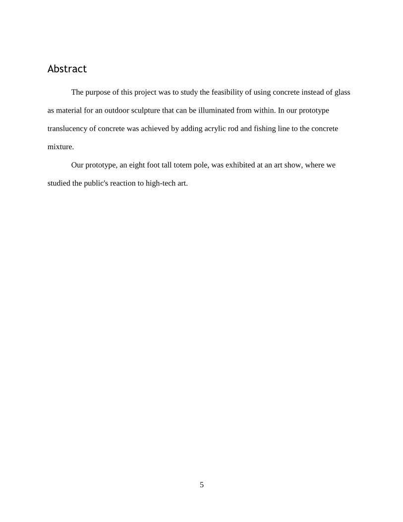
Abstract
The purpose of this project was to study the feasibility of using concrete instead of glass
as material for an outdoor sculpture that can be illuminated from within. In our prototype
translucency of concrete was achieved by adding acrylic rod and fishing line to the concrete
mixture.
Our prototype, an eight foot tall totem pole, was exhibited at an art show, where we
studied the public's reaction to high-tech art.
6
Chapter 1: Totem Poles
Inspiration for the High-Tech Totem
Wendy Wacko, a landscape artist in the Canadian Rockies (Wacko, n.d.), dreams of
creating a totem pole as large as the famous Haida Totems (Bedford, 1998). Wacko envisions
this totem being made of a material not only durable enough to withstand the environment of the
Canadian Rockies, but also translucent and lit from within so that the totem can be transformed
as day changes to night. Wacko proposes using glass as a material. The team was inspired by her
ideas. Different possibilities were investigated and the findings are presented in this paper.
Northwest Coast Native American Culture
There were 30 Native American tribes in northwestern North America, each with an
average of 8000 members, before European Colonization occurred in 1774 (Miller, 2014). Off
the coast of British Columbia, Canada, is a set of islands called Haida Gwaii, home to the Haida
tribe. Mythology was an essential part of the Haida culture. Family history was preserved
through oral tradition and the carving of totem poles (Halpin, 1981).
Mythology was expressed on totem poles in the form of crests and symbols, which
represented the power that the family held within the tribe (Halpin, 1981). In Figure 1, an eagle
is represented on the top of a Haida totem pole. As stated by Ruth Schiffmann, every animal and
person carved on a totem had a specific meaning.
“An eagle was used to portray power, courage, and wisdom. The raven showed curiosity,
deception, and trickery. A fox symbolized cunning, agility, and wildness, while a frog
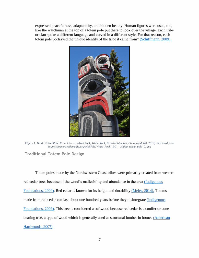
7
expressed peacefulness, adaptability, and hidden beauty. Human figures were used, too,
like the watchman at the top of a totem pole put there to look over the village. Each tribe
or clan spoke a different language and carved in a different style. For that reason, each
totem pole portrayed the unique identity of the tribe it came from” (Schiffmann, 2009).
Figure 1: Haida Totem Pole. From Lions Lookout Park, White Rock, British Columbia, Canada (Mabel, 2013). Retrieved from
http://commons.wikimedia.org/wiki/File:White_Rock,_BC_-_Haida_totem_pole_01.jpg
Traditional Totem Pole Design
Totem poles made by the Northwestern Coast tribes were primarily created from western
red cedar trees because of the wood’s malleability and abundance in the area (Indigenous
Foundations, 2009). Red cedar is known for its height and durability (Meier, 2014). Totems
made from red cedar can last about one hundred years before they disintegrate (Indigenous
Foundations, 2009). This tree is considered a softwood because red cedar is a conifer or cone
bearing tree, a type of wood which is generally used as structural lumber in homes (American
Hardwoods, 2007).
8
To create the totem poles, red cedar trees were cut down and stripped of their bark
(Dearborn, 2002). Tribe members applied their skills to work on various sections of the totem
pole. The wood was carved using chisels, stone blades, adzes (a hand tool for shaping wood),
bones, antlers, shells, and wooden tools (Adz, 2015). Colors used to paint totem poles came from
earth pigments. The most common colors were black and red, as they were most available to the
tribes of the Northwest Coast. To create black, salmon eggs were mixed with charred wood or
bone. Red was created by mixing salmon eggs with crushed rocks that contained iron. However,
colors such as blue, blue-green, white, and yellow were also used. The pigments were bound by
mixing salmon eggs with various materials, then applied using porcupine-hair brushes
(Schiffmann, 2009).
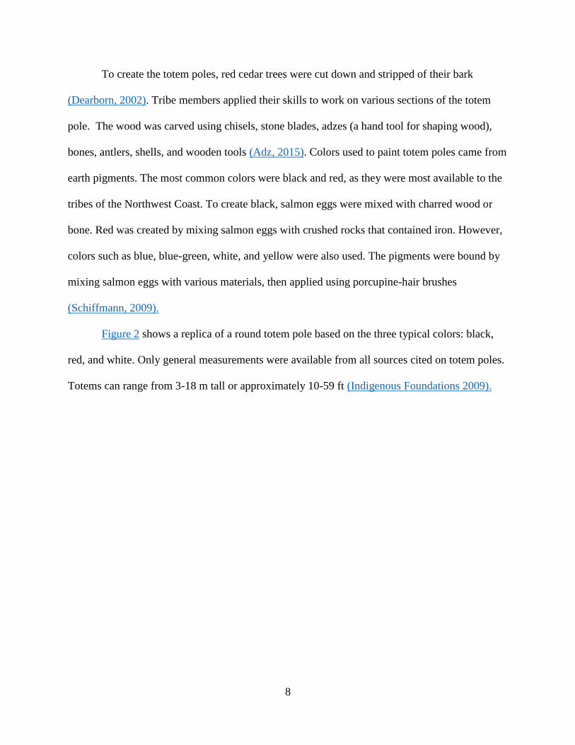
Figure 2 shows a replica of a round totem pole based on the three typical colors: black,
red, and white. Only general measurements were available from all sources cited on totem poles.
Totems can range from 3-18 m tall or approximately 10-59 ft (Indigenous Foundations 2009).
9
Figure 2: Replica Totem Pole. From The University of British Columbia, Museum of Anthropology in Vancouver, Canada
(Leoboudv, 2012). Retrieved from http://commons.wikimedia.org/wiki/File:Haida_replica_totem_pole_(UBC_Museum).jpg
Chapter 2: Art and its Impact
Defining Art in Public Spaces
Public art is not restricted to any specific medium, form, style, or subject matter. It can be
large or small, realistic or abstract, contrasting to the environment or similar to the surroundings.
It can be in the form of a mural, sculpture, or structure (Encyclopedia of Art, n.d.). Public art is
defined as follows by Encyclopedia of Art:
Public art is an umbrella term which includes any work of art purchased with public
funds, or which comes into the public domain (by donation, or by public display, etc.)
irrespective of where it is situated in the community, or who sees it (Encyclopedia of Art,
n.d.).
10
There are two categories of public art, transient and permanent. Transient art is
temporary; it only lasts as long as the environment for it persists (Coutts, 2008), such as ice
sculptures which will melt when seasons change. Haida totem poles, as well as the one proposed
by Wendy Wacko (6), are considered permanent art because totems remain in the same location
for an extended period of time.
Outdoor venues with public art have experienced decreased crime rates. This was the
case in New York City, where government representative Henry Stern redesigned Bryant Park
with the addition of sculptures. Before the redesign, drug dealers and violent criminals
frequented the park. Afterward, the park became a cultural destination for New Yorkers and
tourists alike (Sussman, 2013). Elizabeth Strong-Cuevas said the following about this topic,
“Art in public spaces has a civilizing affect on a community; it promotes good behavior,
whereas dilapidated and deteriorated public areas tend to invite vandalism and become
havens for illegal activities.” (Sussman, 2013)
The installation of public art serves the community. Artists can represent the culture of
the area and reaffirm what the public is feeling (Sussman, 2013). According to Sussman, public
art should neither discourage any group, nor insult the cultures of the local people. Ultimately,
public art can bring a community together, while passing down culture and ideals to future
generations (Sussman, 2013).
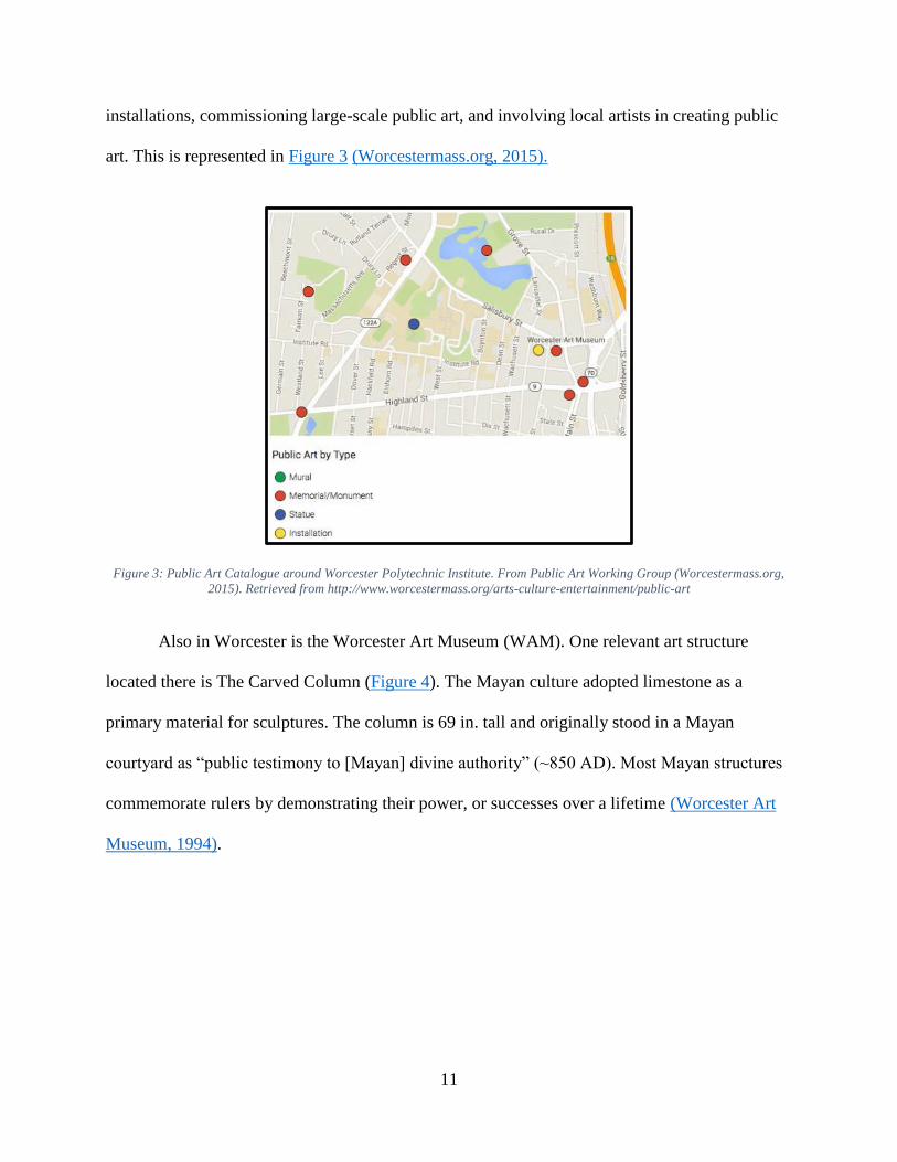
Visual Art in Worcester
In Worcester, Massachusetts, the mission of the Public Art Working Group (PAWG) is to
enrich the culture and aesthetics of the city by installing public art. Current projects undertaken
by the PAWG include mapping out public art in Worcester, finding new locations for public art
11
installations, commissioning large-scale public art, and involving local artists in creating public
art. This is represented in Figure 3 (Worcestermass.org, 2015).
Figure 3: Public Art Catalogue around Worcester Polytechnic Institute. From Public Art Working Group (Worcestermass.org,
2015). Retrieved from http://www.worcestermass.org/arts-culture-entertainment/public-art
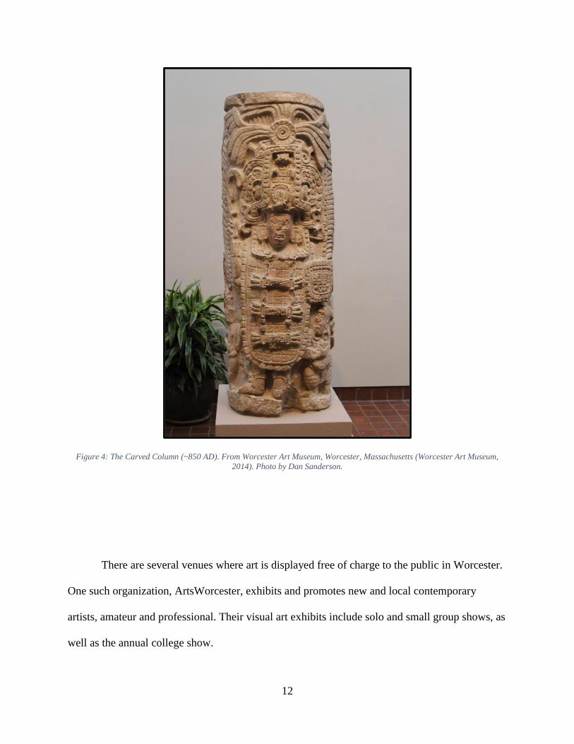
Also in Worcester is the Worcester Art Museum (WAM). One relevant art structure
located there is The Carved Column (Figure 4). The Mayan culture adopted limestone as a
primary material for sculptures. The column is 69 in. tall and originally stood in a Mayan
courtyard as “public testimony to [Mayan] divine authority” (~850 AD). Most Mayan structures
commemorate rulers by demonstrating their power, or successes over a lifetime (Worcester Art
Museum, 1994).
12
Figure 4: The Carved Column (~850 AD). From Worcester Art Museum, Worcester, Massachusetts (Worcester Art Museum,
2014). Photo by Dan Sanderson.
There are several venues where art is displayed free of charge to the public in Worcester.
One such organization, ArtsWorcester, exhibits and promotes new and local contemporary
artists, amateur and professional. Their visual art exhibits include solo and small group shows, as
well as the annual college show.
13
Another organization, the Sprinkler Factory, is a subdivision of the Worcester Art
Museum. This converted warehouse is now used for functions such as art exhibits, classes, and
work spaces for local artists of Worcester. The project advisor, Professor Servaitus, arranged to
have the totem displayed at an art exhibit at the Sprinkler Factory with Luis Fraire, the curator of
the art show.
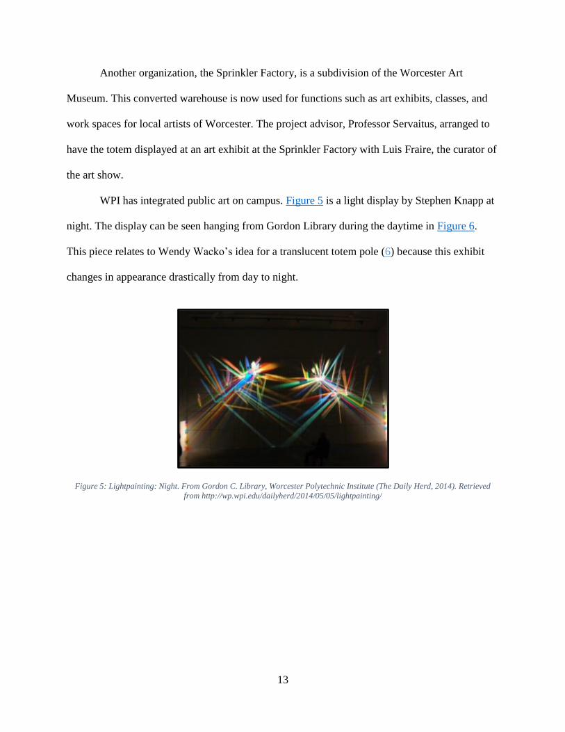
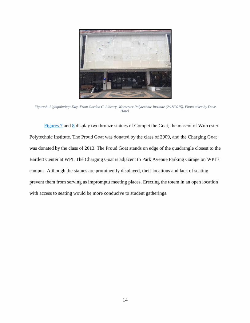
WPI has integrated public art on campus. Figure 5 is a light display by Stephen Knapp at
night. The display can be seen hanging from Gordon Library during the daytime in Figure 6.
This piece relates to Wendy Wacko’s idea for a translucent totem pole (6) because this exhibit
changes in appearance drastically from day to night.
Figure 5: Lightpainting: Night. From Gordon C. Library, Worcester Polytechnic Institute (The Daily Herd, 2014). Retrieved
from http://wp.wpi.edu/dailyherd/2014/05/05/lightpainting/
14
Figure 6: Lightpainting: Day. From Gordon C. Library, Worcester Polytechnic Institute (2/18/2015). Photo taken by Dave
Hazel.
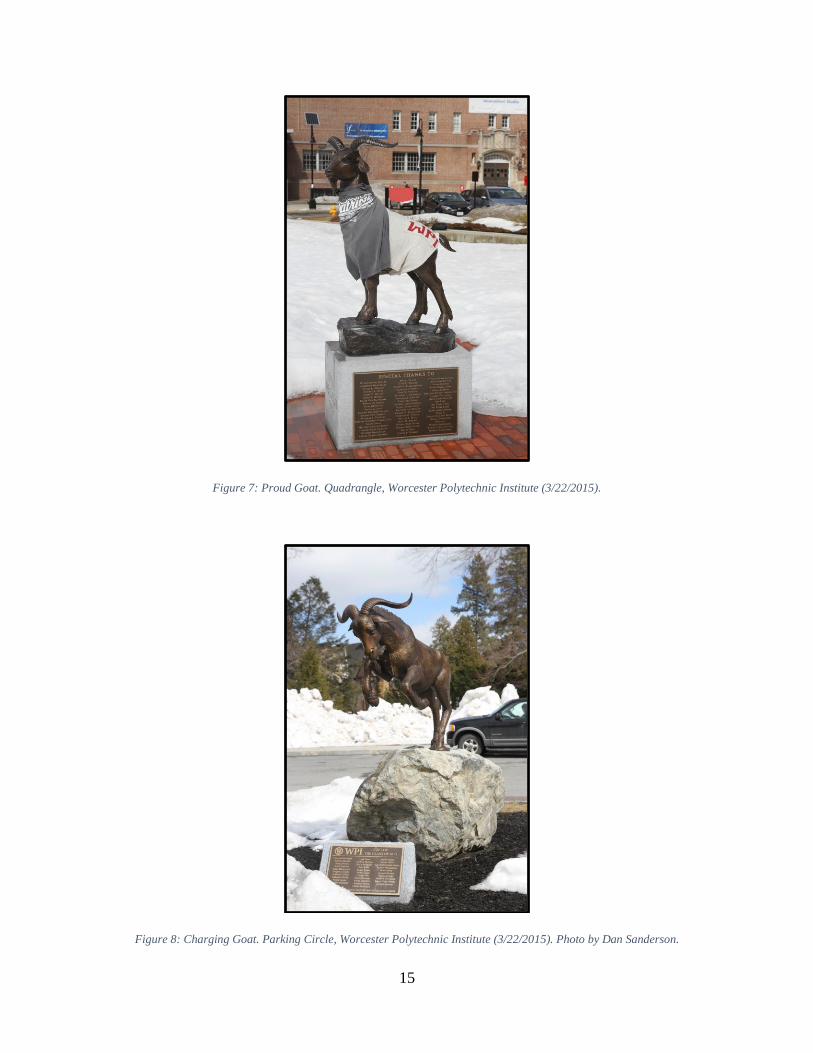
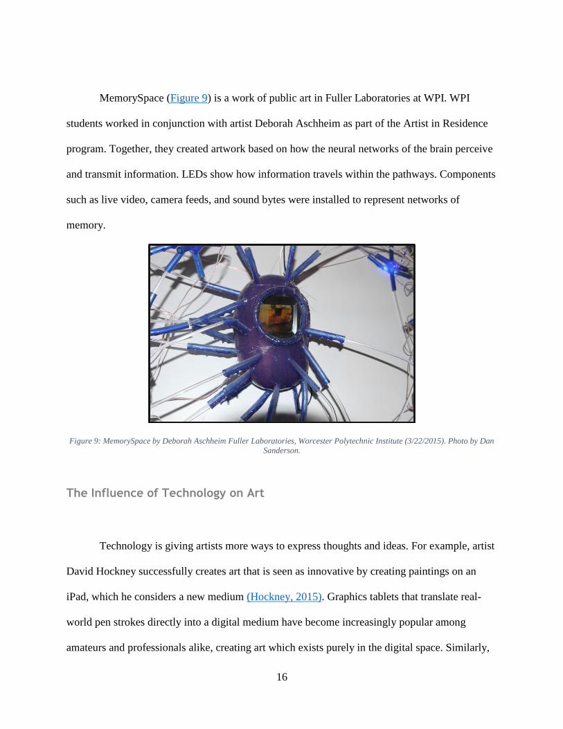
Figures 7 and 8 display two bronze statues of Gompei the Goat, the mascot of Worcester
Polytechnic Institute. The Proud Goat was donated by the class of 2009, and the Charging Goat
was donated by the class of 2013. The Proud Goat stands on edge of the quadrangle closest to the
Bartlett Center at WPI. The Charging Goat is adjacent to Park Avenue Parking Garage on WPI’s
campus. Although the statues are prominently displayed, their locations and lack of seating
prevent them from serving as impromptu meeting places. Erecting the totem in an open location
with access to seating would be more conducive to student gatherings.
15
Figure 7: Proud Goat. Quadrangle, Worcester Polytechnic Institute (3/22/2015).
Figure 8: Charging Goat. Parking Circle, Worcester Polytechnic Institute (3/22/2015). Photo by Dan Sanderson.
16
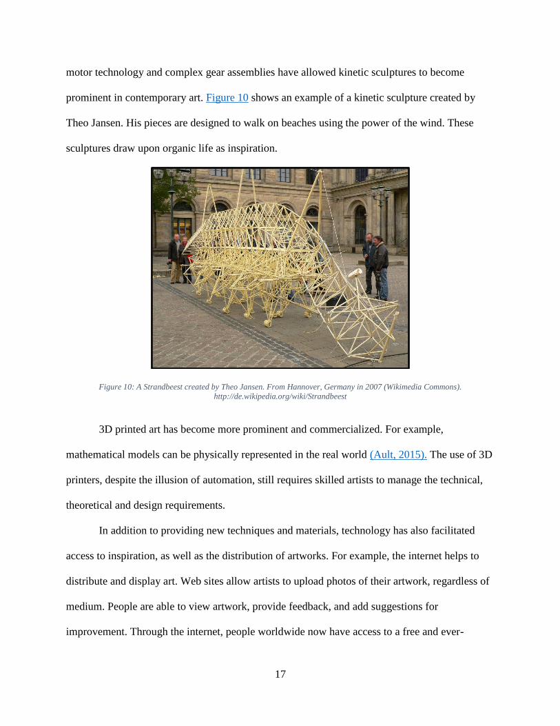
MemorySpace (Figure 9) is a work of public art in Fuller Laboratories at WPI. WPI
students worked in conjunction with artist Deborah Aschheim as part of the Artist in Residence
program. Together, they created artwork based on how the neural networks of the brain perceive
and transmit information. LEDs show how information travels within the pathways. Components
such as live video, camera feeds, and sound bytes were installed to represent networks of
memory.
Figure 9: MemorySpace by Deborah Aschheim Fuller Laboratories, Worcester Polytechnic Institute (3/22/2015). Photo by Dan
Sanderson.
The Influence of Technology on Art
Technology is giving artists more ways to express thoughts and ideas. For example, artist
David Hockney successfully creates art that is seen as innovative by creating paintings on an
iPad, which he considers a new medium (Hockney, 2015). Graphics tablets that translate real-
world pen strokes directly into a digital medium have become increasingly popular among
amateurs and professionals alike, creating art which exists purely in the digital space. Similarly,
17
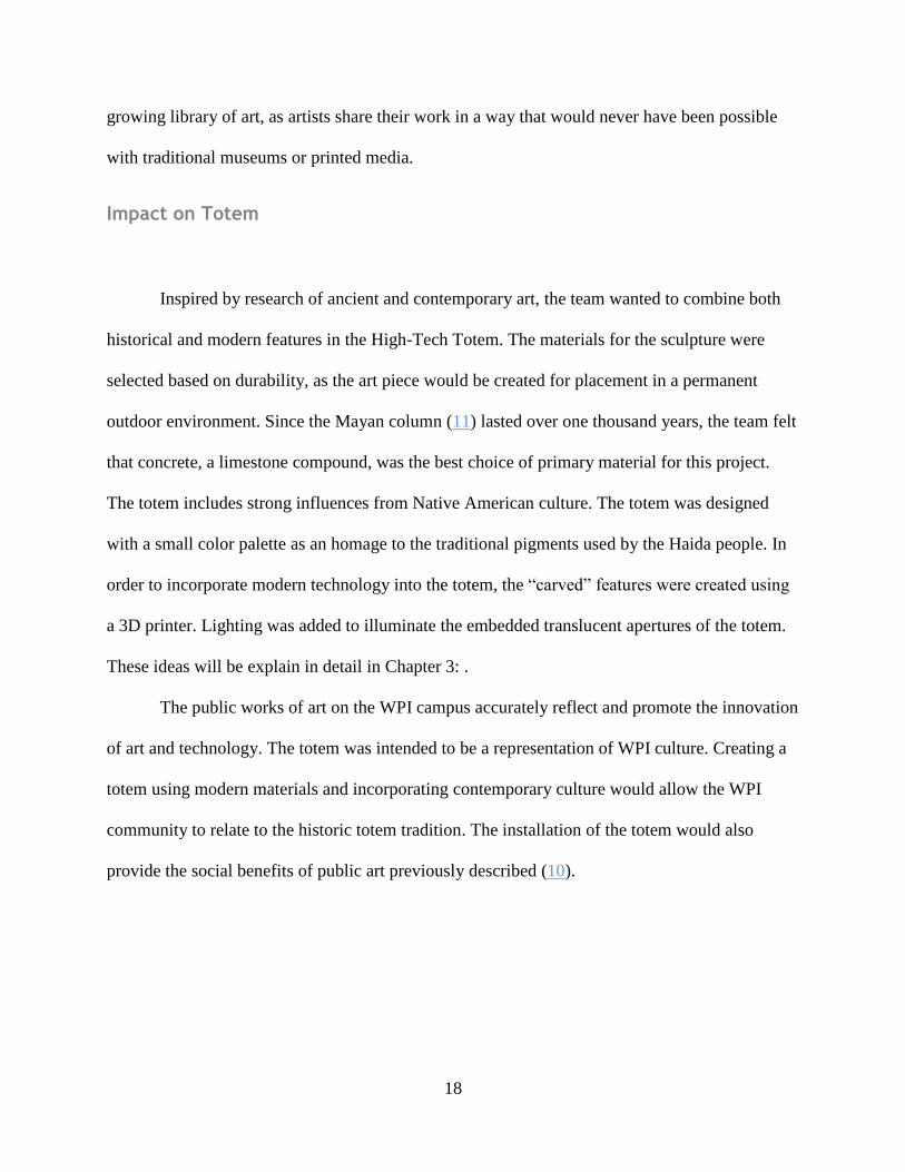
motor technology and complex gear assemblies have allowed kinetic sculptures to become
prominent in contemporary art. Figure 10 shows an example of a kinetic sculpture created by
Theo Jansen. His pieces are designed to walk on beaches using the power of the wind. These
sculptures draw upon organic life as inspiration.
Figure 10: A Strandbeest created by Theo Jansen. From Hannover, Germany in 2007 (Wikimedia Commons).
http://de.wikipedia.org/wiki/Strandbeest
3D printed art has become more prominent and commercialized. For example,
mathematical models can be physically represented in the real world (Ault, 2015). The use of 3D
printers, despite the illusion of automation, still requires skilled artists to manage the technical,
theoretical and design requirements.
In addition to providing new techniques and materials, technology has also facilitated
access to inspiration, as well as the distribution of artworks. For example, the internet helps to
distribute and display art. Web sites allow artists to upload photos of their artwork, regardless of
medium. People are able to view artwork, provide feedback, and add suggestions for
improvement. Through the internet, people worldwide now have access to a free and ever-
18
growing library of art, as artists share their work in a way that would never have been possible
with traditional museums or printed media.
Impact on Totem
Inspired by research of ancient and contemporary art, the team wanted to combine both
historical and modern features in the High-Tech Totem. The materials for the sculpture were
selected based on durability, as the art piece would be created for placement in a permanent
outdoor environment. Since the Mayan column (11) lasted over one thousand years, the team felt
that concrete, a limestone compound, was the best choice of primary material for this project.
The totem includes strong influences from Native American culture. The totem was designed
with a small color palette as an homage to the traditional pigments used by the Haida people. In
order to incorporate modern technology into the totem, the “carved” features were created using
a 3D printer. Lighting was added to illuminate the embedded translucent apertures of the totem.
These ideas will be explain in detail in Chapter 3: .
The public works of art on the WPI campus accurately reflect and promote the innovation
of art and technology. The totem was intended to be a representation of WPI culture. Creating a
totem using modern materials and incorporating contemporary culture would allow the WPI
community to relate to the historic totem tradition. The installation of the totem would also
provide the social benefits of public art previously described (10).
19
Chapter 3: High-Tech Totem Materials
What is Concrete?
Concrete is made with three primary ingredients: cement, water, and aggregate. Cement
is a dust composed of hydraulic calcium silicate, created when limestone is fired in a kiln and
then crushed. Aggregate is used to fill space and add structural support to concrete. Aggregate is
divided into two categories, coarse and fine. Coarse aggregate is made of crushed stone and
gravel that is larger than .2 in. Coarse aggregate is primarily in the size range of .375 in. to 1.5
in. Fine aggregate is made with sand or crushed stone that is smaller than .2 in. The size of the
aggregate is based on the average dimensions of the aggregate particles (Kerkhoff, 2002). Water
reacts with cement and hardens it. During this hydration process, cement particles begin to bind
to other particles or surfaces. This process, known as curing, lasts until there are no longer any
dehydrated particles of cement. Concrete is at its optimal strength to curing ratio after
approxiametly 28 days. (Kerkhoff, 2002).
History of Concrete
The origin of concrete dates back to 6500 BC, with Nabataean or Bedouin traders in parts
of Syria and Jordan. In 3000 BC, the Egyptians also used concrete for building the Pyramids. By
200 BC, the Romans built their famous structures such as the Pantheon, the Colosseum, the
Roman Baths and aqueducts using concrete made with volcanic sand, lime, and water. In 1793,
John Smeaton, a renowned English Civil Engineer, used concrete to rebuild the Eddystone
20
Lighthouse in Cornwall, England. In 1824, Joseph Aspdin, a mason who became a cement
manufacturer, developed a process using chalk and clay to create Portland Cement. He later
refined his method using limestone and clay (Gromicko, 2015).
Concrete was fundamental in creating modern architecture. Examples of concrete
structures include the Hoover Dam, which was created using 3,250,000 cu yds of concrete. The
Burj Khalifa in Dubai, U.A.E., as of 2011, was the tallest building in the world. It was created
using reinforced concrete. The building was made with 431,600 cu yds of concrete and 61,000
tons of steel reinforcements. The structure stands 2,717 ft tall. Both of these structures are
monuments to the diversity and strength of concrete (Gromicko, 2015).
Today concrete is inexpensive, accessible and customizable, making it the most widely
used building material all over the world. The most common cement used for concrete is
Portland Cement (Kerkhoff, 2002). When mixed, cured, and used correctly, concrete can sustain
compressive forces of up to 7000 PSI (pounds of force per square inch). With air entrainment, or
air pockets collected in the concrete, it can last through many freezing and thawing cycles as
well. (Kerkhoff, 2002).
Concrete has the advantages of costing .0181-.0272 USD / lb (Appendix A.1). It has a
density of .0506-.0723 lb / cu in. It also has a moldability rating of 3-4 according to Granta. This
means that it has an average to good moldability on a scale of one being impractical and five
being excellent. Its durability to fresh water, UV radiation, and sunlight is excellent. Concrete
also has an excellent resistance to industrial and rural atmosphere. Its resistance to wear is
normal. Concrete has an average resistance to frost. To avoid deterioration, a coating can be put
on the concrete after it has cured that would diminish these lapses in resistance (Granta, 2014).
21
For reference, hardwood, specifically oak, is comparable to the western red cedar that
was used for totems by the Haida tribes. Hardwood is .299-.331 USD / lb (Appendix A.2). Its
frost resistance is average. Its moldability is 2-3. Its durability is limited in its resistance to fresh
water. Its resistance to UV radiation is good. Wear is inevitable. It has a density of .0238-.0253
lb / cu in. It is seen that hardwood has wear properties similar to concrete (Granta, 2014).
Professor Tahar El-Korchi, department head of the Civil and Environmental Engineering
program at WPI, recommended using concrete as a material for creating the totem due to its
suitable pourability, inexpensive cost, and ability to withstand environmental conditions.
Professor El-Korchi also granted the team access to the concrete lab on WPI’s campus, located in
Kaven Hall. Therefore, concrete the most viable option for this project.
Autoclaved aerated concrete was considered for creating the totem pole. Autoclaved
aerated concrete is less dense than standard concrete. It has a cost of .0272-.0363 USD / lb
(Appendix A.3). It has a density of .0145-.0325 lb / cu in. It has equal moldability, frost
resistance, and UV radiation as standard concrete. It has the same acceptable fresh water
resistance, but less wear resistance than standard concrete. Autoclaved aerated concrete is
created by using a foaming mixing agent during the creation of the concrete. It can be sculpted
using woodworking tools. This allows for greater possibilities in sculpting the concrete, but it
also makes a protective coating a necessity because it is more prone to wear than standard
concrete. (Granta, 2014). For the aforementioned reasons, as well as its lack of availability,
autoclaved aerated concrete was rejected.
The concrete used for the totem pole was a standard mix consisting of Quikrete Portland
Cement. This concrete was chosen largely due to availability. Quikrete Portland Cement is a pre-
22
fabricated material consisting of hydraulic compounds, calcium silicates and magnesium oxide.
Quickrete only requires the addition of water and aggregate followed by curing time before
taking on the form of concrete.
Light transmitting materials
Acrylic is a clear translucent material, a derivative of plexiglass known for its light
weight and resistance to high impact stress (Acrylic Rod, 2014). Typical industrial diameter sizes
of acrylic rod range from .19 in. to 7.87 in. (Perspex & Acrylic Index, 2015). In order to balance
the amount of light transmitted and integrity of the concrete structure, diameter sizes one in., .5
in., .375 in., and .25 in. were chosen. These rods were purchased in lengths of four ft., four ft.,
10 in., and 10 in., respectively, from various sources through the Amazon Corporation. This
material was chosen for the totem pole in order to transmit light from within the concrete
structure. Varying sizes were chosen to add to the aesthetic of the totem pole.
Along with acrylic, fishing line was used to help transmit light from the light source
within the structure. Fishing line is a nylon based material that has high resistance to shear and
strain forces. Fishing line is categorized by gauge, which represents the thickness of the fishing
line. The highest gauge and thus thickest clear nylon monofilament fishing line was chosen to
best transmit light. For use in the totem, 200 yds. of 80 gauge fishing line was purchased from a
local Dick’s Sporting Goods®.
23
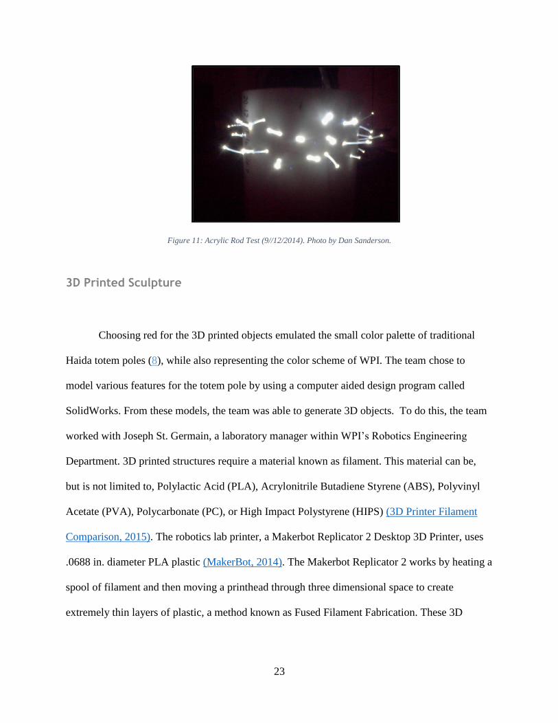
Figure 11: Acrylic Rod Test (9//12/2014). Photo by Dan Sanderson.
3D Printed Sculpture
Choosing red for the 3D printed objects emulated the small color palette of traditional
Haida totem poles (8), while also representing the color scheme of WPI. The team chose to
model various features for the totem pole by using a computer aided design program called
SolidWorks. From these models, the team was able to generate 3D objects. To do this, the team
worked with Joseph St. Germain, a laboratory manager within WPI’s Robotics Engineering
Department. 3D printed structures require a material known as filament. This material can be,
but is not limited to, Polylactic Acid (PLA), Acrylonitrile Butadiene Styrene (ABS), Polyvinyl
Acetate (PVA), Polycarbonate (PC), or High Impact Polystyrene (HIPS) (3D Printer Filament
Comparison, 2015). The robotics lab printer, a Makerbot Replicator 2 Desktop 3D Printer, uses
.0688 in. diameter PLA plastic (MakerBot, 2014). The Makerbot Replicator 2 works by heating a
spool of filament and then moving a printhead through three dimensional space to create
extremely thin layers of plastic, a method known as Fused Filament Fabrication. These 3D
24
printed objects were mounted onto the totem pole with an epoxy to further enhance the high-tech
medium of art.
Glass in the Prototype
The IQP team initially chose crushed glass as an aggregate for concrete because it is
more resistant to environmental conditions such as rain, ultraviolet rays, heat, and cold. In order
to ensure the structural integrity of the concrete, the glass must have relatively uniform-sized
shards and irregular shape and must be greater in size or equivalent to .125” conventional
aggregate. The type of glass that best matches these qualities is a variant of soda-lime glass. The
variant is obtained when soda-lime glass is tempered. The definition of tempering is heating and
cooling the glass so that its outer surface is in compression and inner surface is in tension. This
strengthens the glass to a level above untempered glass, producing predictable breaking patterns
of pieces with blunt edges when enough force is applied. (Pfaender, 1996).
Tempered soda-lime glass is commonly used in windows, glass bottles, containers, lamp
bulbs, and mirrors. This is an accessible type of glass; it can easily be found at recycling
facilities. (Granta, 2014).
25
Chapter 4: Construction of the Totem
Testing with Prototypes
After seeing embedded glass in the surface of stone counter tops and in concrete floors,
the IQP team was inspired to use glass as an aggregate to transform concrete from an opaque to
translucent material. A 60 lb bag of Quikrete Portland Cement (21) was purchased from
Lowe’s©. The cement was mixed with crushed glass from recycled bottles collected for use in
small-scale prototype testing.
Stone course aggregate was replaced in the mix design with a proportional amount of
glass aggregate. To accomplish this, sieves of size .375 in. were used to separate the glasses into
two concentrations, greater than .375 in. and less than .375 in. The amounts of water and cement
used were unchanged. The coarse aggregate weight was altered due to the different weight of
tempered glass. The absolute volume method for determining the fine aggregate proportions was
altered due to the change in the coarse aggregate absolute volume.
● Density of tempered glass was determined by dividing the mass of tempered glass by its
volume as measured in a laboratory setting. The result was 155 lb / cu ft
Course Aggregate (CA) = 155 lb / cu ft * 27 cu ft * .55 = 2287 lb
● Absolute volume method
Water: 5.37 cu ft
Cement: 3.103 cu ft
26
Course Aggregate (CA): 2287 lb / (2.21 (Specific gravity of silica glass) * 62.4 lb / cu ft) = 16.58
cu ft
27 cu ft - (16.58 + 3.103 + 5.37) cu ft = 2.03 cu ft
Fine Aggregate (FA): 2 cu ft * 2.68 (specific gravity of fine aggregate) * 62.4 lb / cu ft = 335 lb
Water: 10%
Cement: 17%
Course Aggregate (CA): 64%
Fine Aggregate (FA) : 10%
(Kerkhoff, 2002)
The glass-concrete mixture was mixed and set in three 2x2x1 in., solid cubes and three
3x6 in. solid cylinders. The amount of glass aggregate was increased in the last of the 3x6 in.
cylinders so that it had a significantly larger proportion of volumetric glass than the first two
cylinders. After allowing the mix to settle in the casts, the sides were tapped with a rubber mallet
to remove as many air bubbles from the concrete as possible. The vibrations from the mallet
dissipated the air that was trapped when the concrete was poured. This ensured that the concrete
would be non-air-entrained: it would have few to no air pockets left in the concrete mixture once
it had dried in its mold. The concrete was left to dry for 24 hours before being moved into a
curing room with 200% relative humidity. The concrete did not need to be fully cured for the
standard 28 days because the strength of the concrete had no impact on the translucency testing.
The glass embedded into the concrete mixture would hypothetically allow light to pass
through the concrete by refracting the light through the individual pieces of glass, and through
the thin layer of concrete between the glass pieces. Although light intensity would be reduced
27
due to the concrete in between the glass, enough light would be transmitted to classify the
material as translucent.
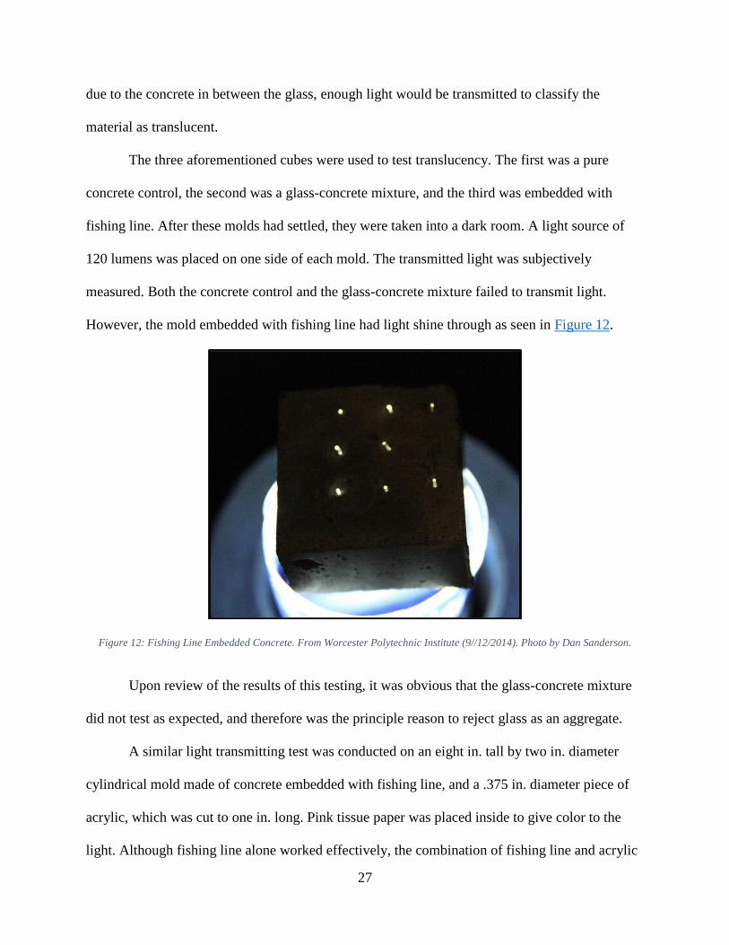
The three aforementioned cubes were used to test translucency. The first was a pure
concrete control, the second was a glass-concrete mixture, and the third was embedded with
fishing line. After these molds had settled, they were taken into a dark room. A light source of
120 lumens was placed on one side of each mold. The transmitted light was subjectively
measured. Both the concrete control and the glass-concrete mixture failed to transmit light.
However, the mold embedded with fishing line had light shine through as seen in Figure 12.
Figure 12: Fishing Line Embedded Concrete. From Worcester Polytechnic Institute (9//12/2014). Photo by Dan Sanderson.
Upon review of the results of this testing, it was obvious that the glass-concrete mixture
did not test as expected, and therefore was the principle reason to reject glass as an aggregate.
A similar light transmitting test was conducted on an eight in. tall by two in. diameter
cylindrical mold made of concrete embedded with fishing line, and a .375 in. diameter piece of
acrylic, which was cut to one in. long. Pink tissue paper was placed inside to give color to the
light. Although fishing line alone worked effectively, the combination of fishing line and acrylic
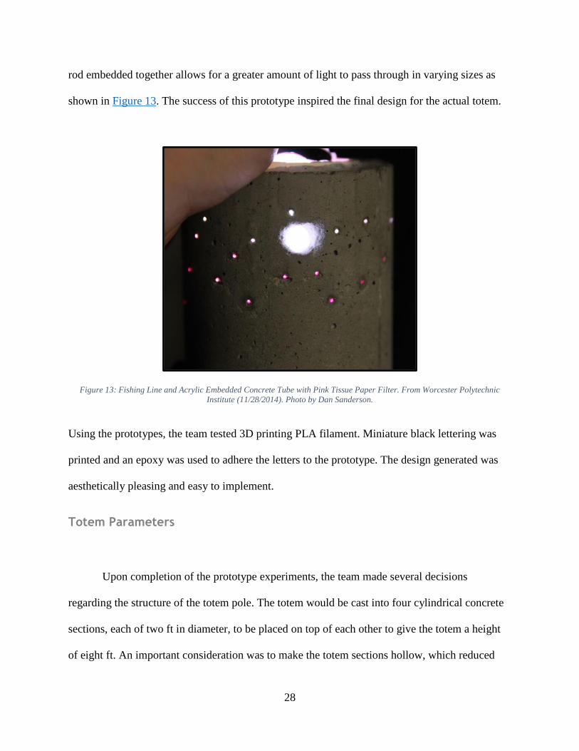
28
rod embedded together allows for a greater amount of light to pass through in varying sizes as
shown in Figure 13. The success of this prototype inspired the final design for the actual totem.
Figure 13: Fishing Line and Acrylic Embedded Concrete Tube with Pink Tissue Paper Filter. From Worcester Polytechnic
Institute (11/28/2014). Photo by Dan Sanderson.
Using the prototypes, the team tested 3D printing PLA filament. Miniature black lettering was
printed and an epoxy was used to adhere the letters to the prototype. The design generated was
aesthetically pleasing and easy to implement.
Totem Parameters
Upon completion of the prototype experiments, the team made several decisions
regarding the structure of the totem pole. The totem would be cast into four cylindrical concrete
sections, each of two ft in diameter, to be placed on top of each other to give the totem a height
of eight ft. An important consideration was to make the totem sections hollow, which reduced
29
the amount of concrete necessary for a full-size totem and thereby reduced the weight of the
structure. This also created an opportunity to use an internal light source to shine through the
acrylic rod and fishing line embedded into the concrete.
Mold Preparation
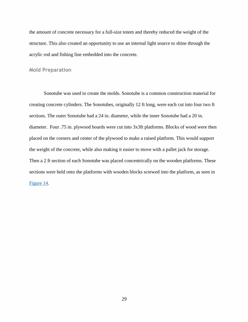
Sonotube was used to create the molds. Sonotube is a common construction material for
creating concrete cylinders. The Sonotubes, originally 12 ft long, were each cut into four two ft
sections. The outer Sonotube had a 24 in. diameter, while the inner Sonotube had a 20 in.
diameter. Four .75 in. plywood boards were cut into 3x3ft platforms. Blocks of wood were then
placed on the corners and center of the plywood to make a raised platform. This would support
the weight of the concrete, while also making it easier to move with a pallet jack for storage.
Then a 2 ft section of each Sonotube was placed concentrically on the wooden platforms. These
sections were held onto the platforms with wooden blocks screwed into the platform, as seen in
Figure 14.
30
Figure 14: Raised Wooden Platform with Measured Sonotube Placement. (3/8/15)
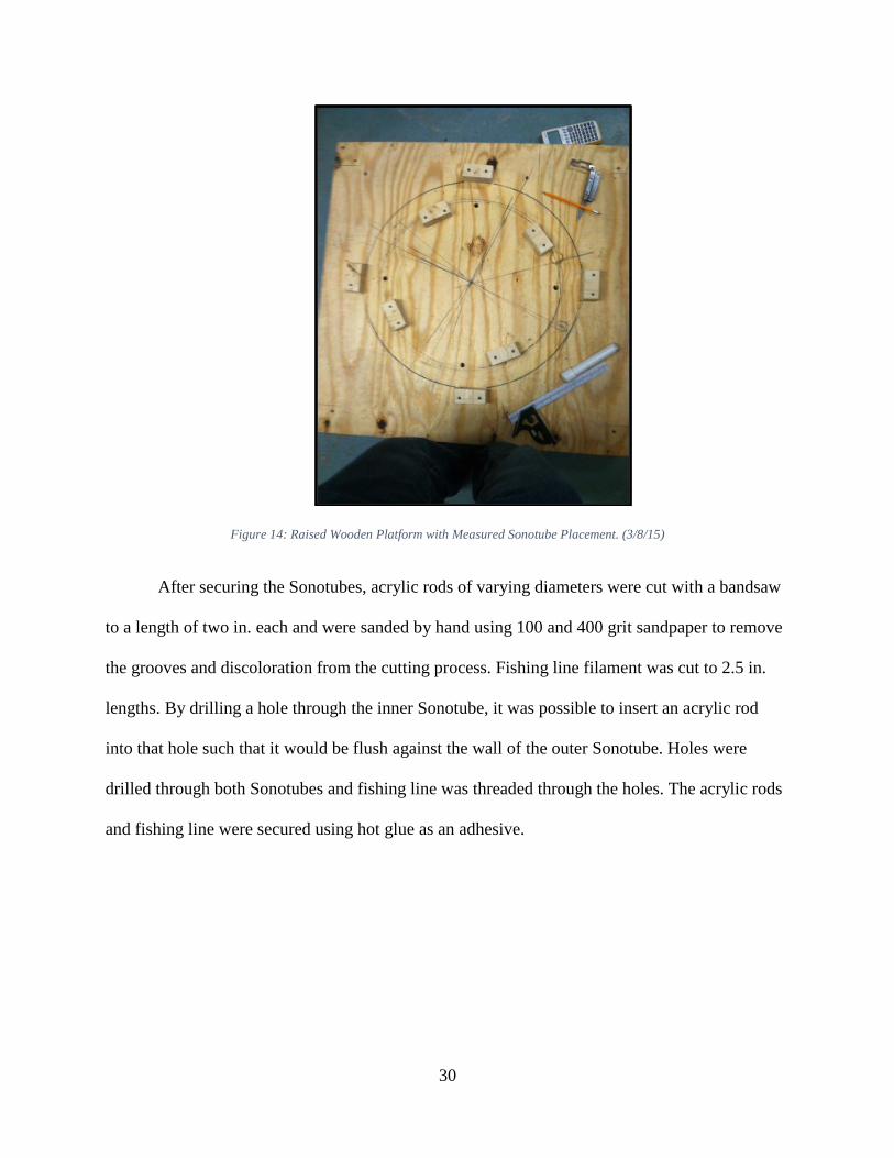
After securing the Sonotubes, acrylic rods of varying diameters were cut with a bandsaw
to a length of two in. each and were sanded by hand using 100 and 400 grit sandpaper to remove
the grooves and discoloration from the cutting process. Fishing line filament was cut to 2.5 in.
lengths. By drilling a hole through the inner Sonotube, it was possible to insert an acrylic rod
into that hole such that it would be flush against the wall of the outer Sonotube. Holes were
drilled through both Sonotubes and fishing line was threaded through the holes. The acrylic rods
and fishing line were secured using hot glue as an adhesive.
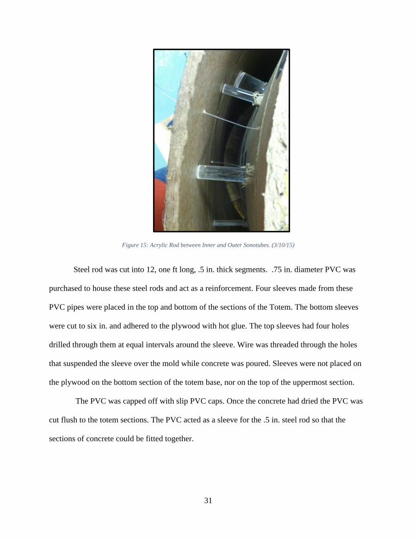
31
Figure 15: Acrylic Rod between Inner and Outer Sonotubes. (3/10/15)
Steel rod was cut into 12, one ft long, .5 in. thick segments. .75 in. diameter PVC was
purchased to house these steel rods and act as a reinforcement. Four sleeves made from these
PVC pipes were placed in the top and bottom of the sections of the Totem. The bottom sleeves
were cut to six in. and adhered to the plywood with hot glue. The top sleeves had four holes
drilled through them at equal intervals around the sleeve. Wire was threaded through the holes
that suspended the sleeve over the mold while concrete was poured. Sleeves were not placed on
the plywood on the bottom section of the totem base, nor on the top of the uppermost section.
The PVC was capped off with slip PVC caps. Once the concrete had dried the PVC was
cut flush to the totem sections. The PVC acted as a sleeve for the .5 in. steel rod so that the
sections of concrete could be fitted together.
32
Concrete Mixture Calculations
The proportions of the cement, water, and aggregate in a batch of concrete is based on the
exposure to rain, wind, hot and cold temperatures, chemicals, the desired strength of the
concrete, and the concrete’s effective workability (its relative viscosity and ability to fill a
volume). The Totem was designed to withstand the climate of Worcester, MA. In the past five
years, Worcester’s average temperatures have ranged from 17.8°F to 77.5°F (U.S. Climate Data,
2015).
The concrete mixture for the totem was non-air-entrained. The water-cementitious ratio
(mass of water divided by mass of concrete) was chosen to be .48. With a water-cementitious
ratio of .48, the compressive strength of the resulting concrete would be 5000 PSI. The ratio was
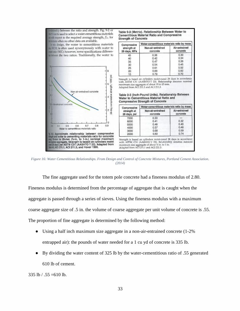
then readjusted to .55 to increase the workability of the concrete (Figure 16).
The standard concrete mix that was chosen for the final mold would yield a theoretical
compressive strength of approximately 4800 PSI. The sections of the totem would produce a
maximum of approximately 22 PSI at the very base of the structure (Figure 16, Table 9-3).
33
Figure 16: Water Cementitious Relationships. From Design and Control of Concrete Mixtures, Portland Cement Association.
(2014)
The fine aggregate used for the totem pole concrete had a fineness modulus of 2.80.
Fineness modulus is determined from the percentage of aggregate that is caught when the
aggregate is passed through a series of sieves. Using the fineness modulus with a maximum
coarse aggregate size of .5 in. the volume of coarse aggregate per unit volume of concrete is .55.
The proportion of fine aggregate is determined by the following method:
● Using a half inch maximum size aggregate in a non-air-entrained concrete (1-2%
entrapped air): the pounds of water needed for a 1 cu yd of concrete is 335 lb.
● By dividing the water content of 325 lb by the water-cementitious ratio of .55 generated
610 lb of cement.
335 lb / .55 =610 lb.
34
● Using the 2.8 fineness modulus of fine aggregate and translating that to .55 coarse
aggregate per unit volume of concrete with a 100 lb / cu ft weight for the average coarse
aggregate a value of 1485 lb of coarse aggregate (CA) was obtained.
100 lb / cu ft * 27 cu ft / cu yd * .55 = 1485 lb of concrete
● Calculating the absolute volume of the ingredients per 1 cu yd of concrete by dividing the
weight per cu yd of the ingredients by the density of water and then summing the
volumes and subtracting from 1 cu yd. The remaining volume in the mixture can be
converted into a poundage of fine aggregate.
water: 335 lb / 62.4 lb / cu ft = 5.37 cu ft
cement: 610 lb / (3.15(specific gravity of cement) *62.4 lb / cu ft) = 3.103
Coarse Aggregate: 1486 lb / (2.68 (specific gravity of coarse aggregate) * 62.4 lb / cu ft) = 8.88
27 cu ft - (5.37 + 3.103 + 8.88) cu ft = 9.65 cu ft
Fine Aggregate = 9.65 cu ft * 2.68 (specific gravity of fine aggregate) *62.4 lb / cu ft = 1589 lb
● Adding the weights of the ingredients and dividing them by the individual ingredient a
percent proportion of each ingredients in 1 lb was obtained.
Water: 8%
Cement: 15%
Coarse Aggregate: 37%
Fine Aggregate (FA): 40%
(Kerkhoff, 2002)
The above proportions were determined using the absolute volume method for a concrete
mixture design. The design used stone as the coarse aggregate (Kerkhoff, 2002).
Additional mix info in Appendix B.
35
Concrete Pouring and Curing
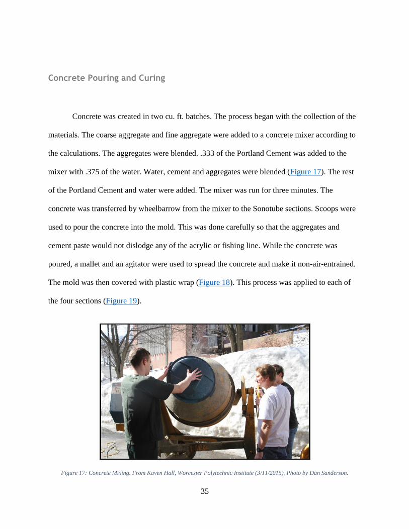
Concrete was created in two cu. ft. batches. The process began with the collection of the
materials. The coarse aggregate and fine aggregate were added to a concrete mixer according to
the calculations. The aggregates were blended. .333 of the Portland Cement was added to the
mixer with .375 of the water. Water, cement and aggregates were blended (Figure 17). The rest
of the Portland Cement and water were added. The mixer was run for three minutes. The
concrete was transferred by wheelbarrow from the mixer to the Sonotube sections. Scoops were
used to pour the concrete into the mold. This was done carefully so that the aggregates and
cement paste would not dislodge any of the acrylic or fishing line. While the concrete was
poured, a mallet and an agitator were used to spread the concrete and make it non-air-entrained.
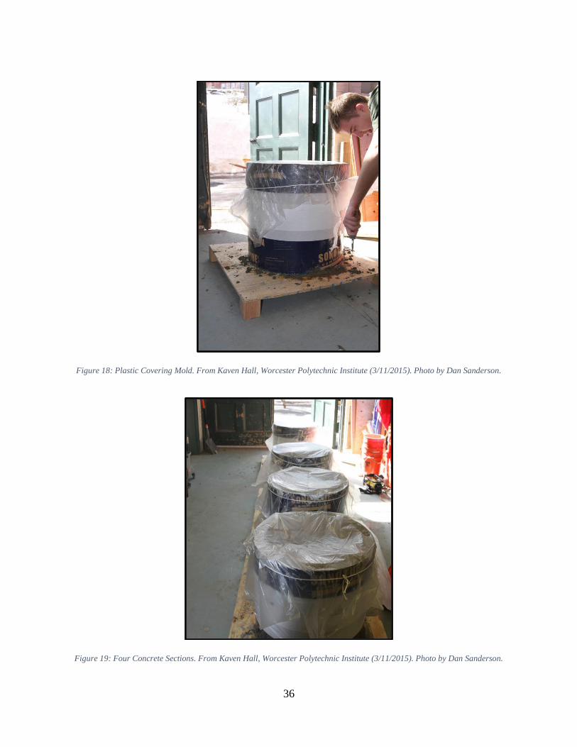
The mold was then covered with plastic wrap (Figure 18). This process was applied to each of
the four sections (Figure 19).
Figure 17: Concrete Mixing. From Kaven Hall, Worcester Polytechnic Institute (3/11/2015). Photo by Dan Sanderson.
36
Figure 18: Plastic Covering Mold. From Kaven Hall, Worcester Polytechnic Institute (3/11/2015). Photo by Dan Sanderson.
Figure 19: Four Concrete Sections. From Kaven Hall, Worcester Polytechnic Institute (3/11/2015). Photo by Dan Sanderson.
37
Unfortunately, there was not enough space in the curing room to store the four sections,
so the totem pieces were left in open air with the plastic covering. After one week, the plastic
was removed and the team began to peel off the Sonotube mold from both the inside and outside.
Polishing Totem Sections
After all the Sonotube had been peeled from the concrete, the team began the process of
polishing the surface of the concrete to make a smooth and aesthetically appealing surface. First,
the team used files, chisels and a dremel with a diamond file attachment to remove concrete that
had seeped in-between the Sonotube casing and the acrylic rods. The removal of this concrete
was necessary to get the light transmission that was desired. The process was time consuming
and unfortunately marred the surface of some of the acrylic rods. The Dermal was the most
efficient tool and would chip away the concrete but would then quickly gouge the surface of the
acrylic. Very fine control of the tool was need by the team to successfully clean the surface of
the acrylic.
After cleaning the acrylic rod surfaces so that light could pass through, the team cut the
excess fishing line that stuck out form the surface of the concrete. Then the team sanded the
surface of the totem. This made the totem smooth and removed several sharp surfaces that
otherwise could have harmed viewers if they were to interact with the Totem.
38
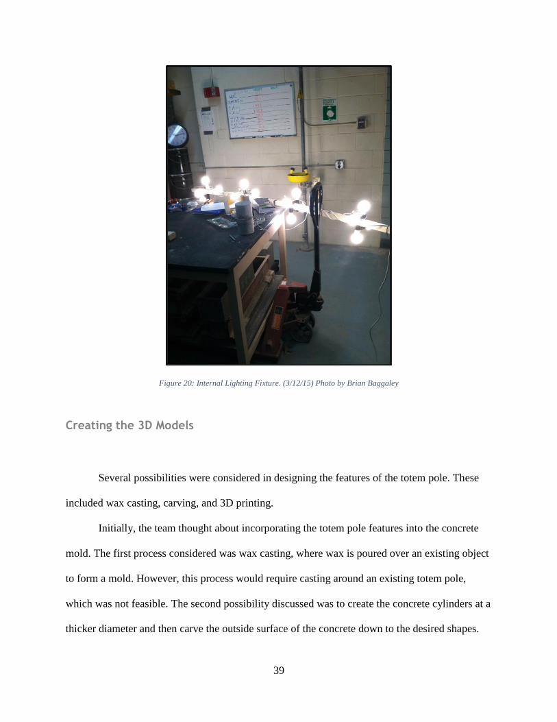
Light Source System
The team created a light source consisting of 16 LED light bulbs with corresponding
sockets mounted on an eight foot piece of square wood approximately 2x2 in. The bulbs were
60W equivalent (8.5W) LEDs that had a rating of 800 lumen. LED bulbs give off less heat, draw
less power, and are more environmentally friendly than incandescent bulbs. The mounts were
secured in crisscross patterns of four at a starting height of one foot and then consecutive rings of
mounts every two ft. This layout established uniform lighting, as lights point in four different
directions of the totem from the middle of every section. The mounts were wired in parallel so
that the voltage would be the same across all light bulbs. The wiring was connected to a standard
American 120V three prong outlet connector.
39
Figure 20: Internal Lighting Fixture. (3/12/15) Photo by Brian Baggaley
Creating the 3D Models
Several possibilities were considered in designing the features of the totem pole. These
included wax casting, carving, and 3D printing.
Initially, the team thought about incorporating the totem pole features into the concrete
mold. The first process considered was wax casting, where wax is poured over an existing object
to form a mold. However, this process would require casting around an existing totem pole,
which was not feasible. The second possibility discussed was to create the concrete cylinders at a
thicker diameter and then carve the outside surface of the concrete down to the desired shapes.
40
Although these are more traditional and artistic methods, none of the team members had any
experience in either wax casting or sculpting. Without the expertise of a skilled artisan, these
methods had higher risk of damage and cracks in the concrete walls, as well as concerns for
structural stability. Therefore, the team decided against these techniques and opted for a more
attainable high-tech choice for the totem features.
The chosen method of adding dimension and shape to the totem pole was to 3D print
parts, then attach them to the concrete pole. This option was feasible, since the materials were
readily available at WPI. Additionally, Joseph St. Germain (23) is a subject-matter expert with
respect to 3D printing.
The original 3D printed designs included the WPI logo, the school’s mascot, Gompei the
Goat, the WPI Two Towers icon, and small symbols representing a collection of WPI majors.
After discussion with Luis Fraire, the Sprinkler Factory Gallery Manager, the WPI logo was
replaced to further fit the theme of the gallery exhibit, “Red”. Instead of the WPI logo the word
for the color red, written in the language of the Haida people was created. Translated, “red” is
“Sgíidang” in the Haida language (Haida Language, 2014). The team had limited access to the
3D printer due to time-sharing constraints from multiple departments. Therefore, it was decided
that only the goat head, the two towers, and Sgíidang would be featured on the totem pole at the
Sprinkler Factory exhibit.
The models for the 3D printed features of the totem were created in computer aided
design software. The parts were designed to be able to fit on the print bed of the 3D printer. The
dimensions were to be no larger than 5.9x5.9in. The letters for Sgíidang were made with the font
creator in the Creo parametric software. The models were scaled proportionally to have the same
height. The Two Towers were created by using a reference image in the Solidworks program and
41
tracing the shape of the towers into simplified logos. The Goat model was created in two
separate parts so that its total size could be larger than the 5.9 in. restriction allowed with one
print. The parts were then saved as STL files so that they could be read by the 3D printer
software and created.
Transporting the Totem
The Mungovan Movers Company transported the four sections of the totem to the
Sprinkler Factory, where it would be assembled for display at the spring art exhibition. The
construction of the totem pole was done in sections, which were each two ft. tall with an outer
diameter of 24 in. and an inner diameter of 20 in. (29). The weight of these sections was
approximately 300 pounds each. By building the totem in sections, it was easier to transport than
an eight foot tall, 1200 pound solid object.
Erecting the Totem
The Totem team began assembling the sections by hand with the assistance of four other
individuals (Acknowledgments). The totem sections were aligned with the ones below using the
steel rod in the PVC sleeves (31). This was done to secure the sections. This way the sections
could only be separated by moving the top section up and off of the metal rods. While stacking
the third section, one of the PVC sleeves did not properly align with one of the sleeves in the
section below. For this reason, there were only three steel rods between the second and third
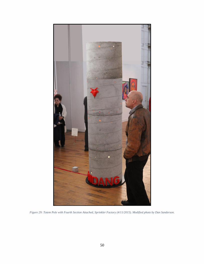
section. It was decided that the last section of the totem would be omitted for the art show at the
Sprinkler Factory, since it was too difficult to lift overhead by hand. If the assemblers had
42
attempted to lift the fourth section they would be putting themselves in a dangerous position that
was deemed unnecessary and irresponsible by the team members. The fourth section would have
also added to the likelihood of the totem toppling do to the higher center of gravity, creating a
further unsafe situation that the public would be exposed to.
Next, the lighting source was installed inside the totem (38). Then the outer surface of the
totem was sanded further as the surface became marked in the transportation. The 3D printed
models were added to the surface of the totem using a two part epoxy. Red gift wrap tissue paper
was placed around the inside of the totem so that viewing through the acrylic would create a red
color, similar to the prototype (Figure 13).
43
Chapter 5: RED: Material. Symbol. Emotion. Temperature.
Presentation of the Totem
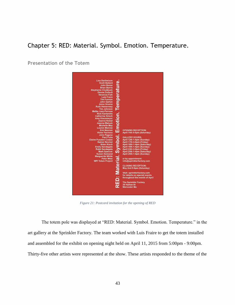
Figure 21: Postcard invitation for the opening of RED
The totem pole was displayed at “RED: Material. Symbol. Emotion. Temperature.” in the
art gallery at the Sprinkler Factory. The team worked with Luis Fraire to get the totem installed
and assembled for the exhibit on opening night held on April 11, 2015 from 5:00pm - 9:00pm.
Thirty-five other artists were represented at the show. These artists responded to the theme of the
44
color red for this show. In addition, lectures were given on the subject matter at an event called
Art after Dark. See Appendix C for press release and advertisement.
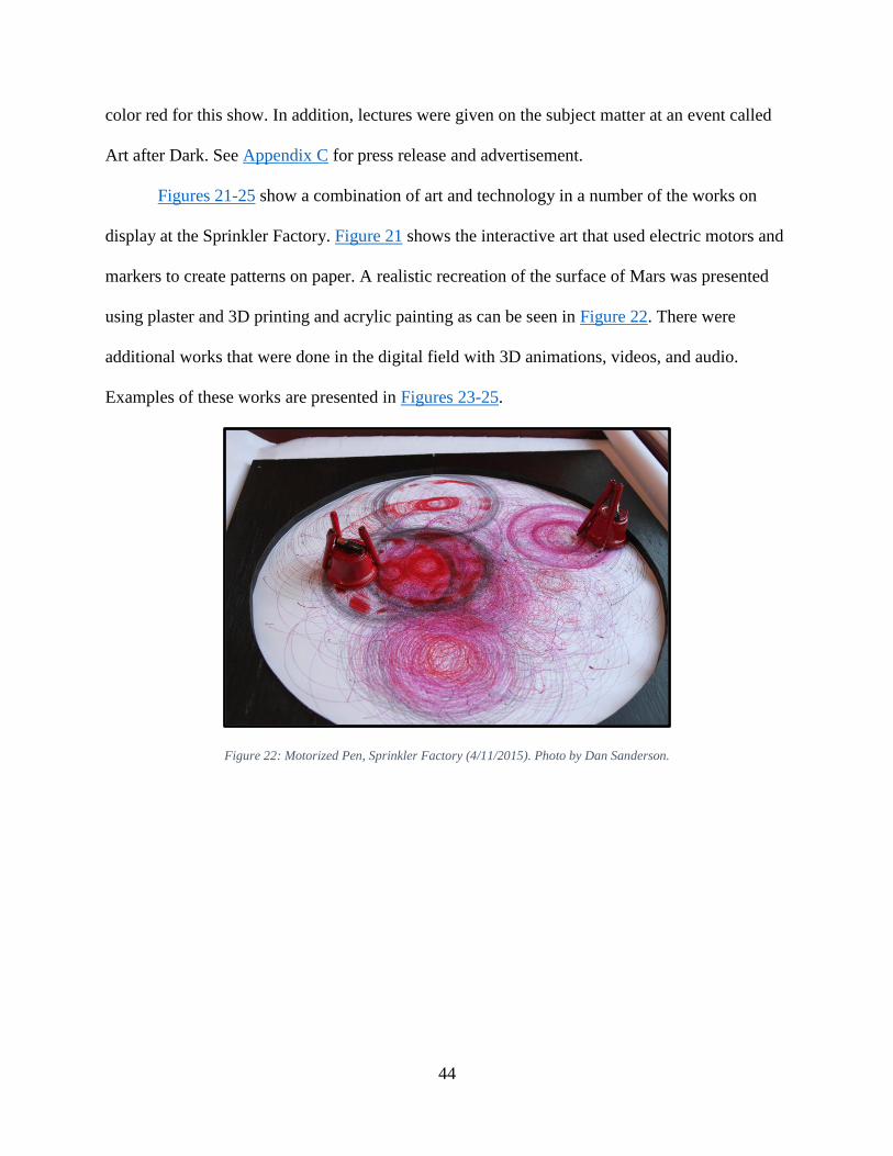
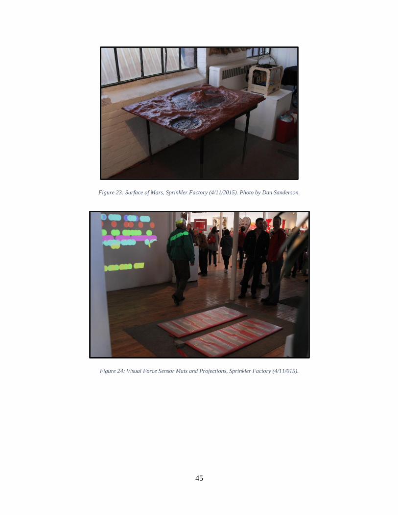
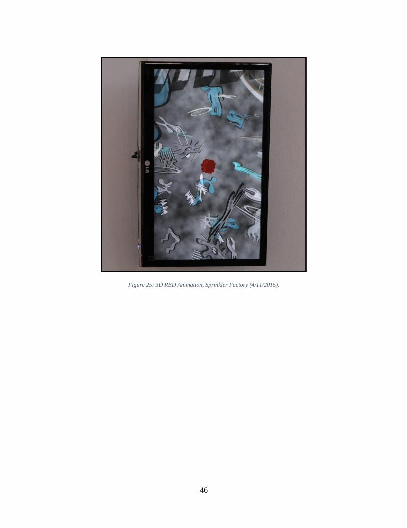
Figures 21-25 show a combination of art and technology in a number of the works on
display at the Sprinkler Factory. Figure 21 shows the interactive art that used electric motors and
markers to create patterns on paper. A realistic recreation of the surface of Mars was presented
using plaster and 3D printing and acrylic painting as can be seen in Figure 22. There were
additional works that were done in the digital field with 3D animations, videos, and audio.
Examples of these works are presented in Figures 23-25.
Figure 22: Motorized Pen, Sprinkler Factory (4/11/2015). Photo by Dan Sanderson.
45
Figure 23: Surface of Mars, Sprinkler Factory (4/11/2015). Photo by Dan Sanderson.
Figure 24: Visual Force Sensor Mats and Projections, Sprinkler Factory (4/11/015).
46
Figure 25: 3D RED Animation, Sprinkler Factory (4/11/2015).
47
Figure 26: Animation of realistic, Sprinkler Factory (4/11/2015).
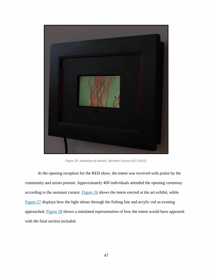
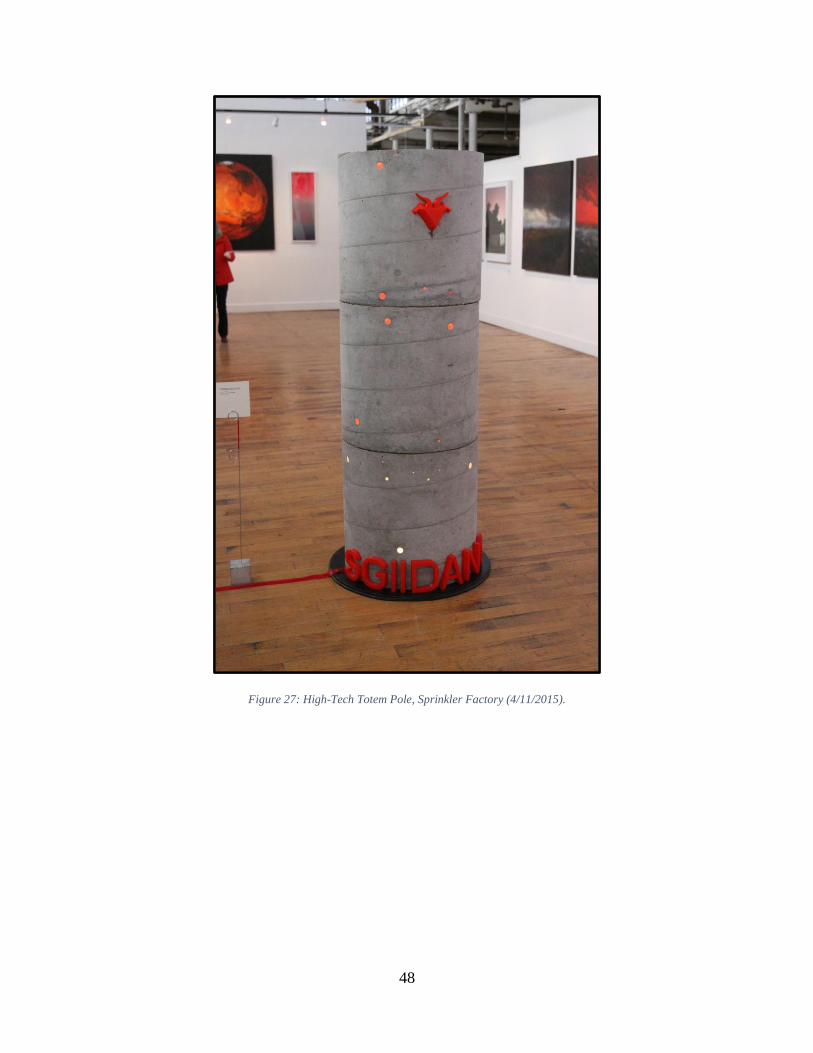
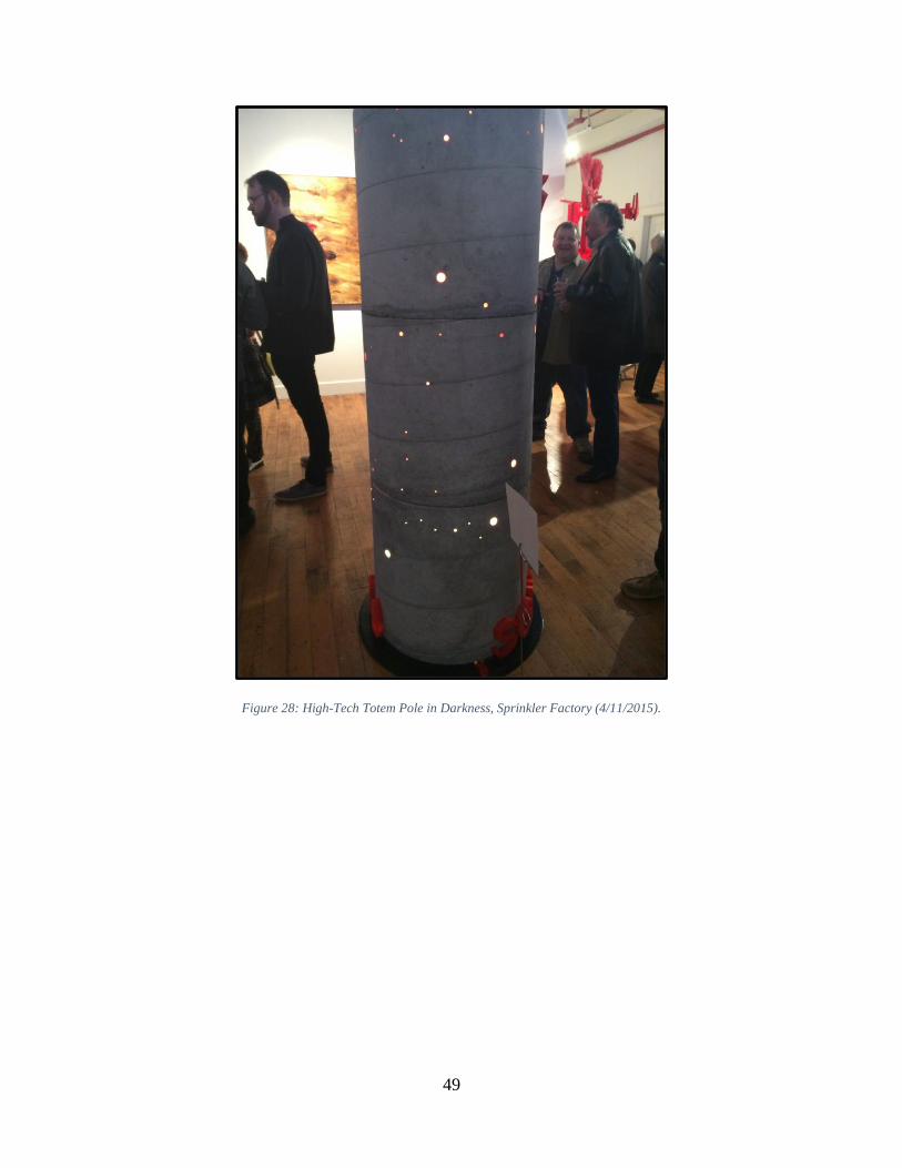
At the opening reception for the RED show, the totem was received with praise by the
community and artists present. Approximately 400 individuals attended the opening ceremony
according to the assistant curator. Figure 26 shows the totem erected at the art exhibit, while
Figure 27 displays how the light shines through the fishing line and acrylic rod as evening
approached. Figure 28 shows a simulated representation of how the totem would have appeared
with the final section included.
48
Figure 27: High-Tech Totem Pole, Sprinkler Factory (4/11/2015).
49
Figure 28: High-Tech Totem Pole in Darkness, Sprinkler Factory (4/11/2015).
50
Figure 29: Totem Pole with Fourth Section Attached, Sprinkler Factory (4/11/2015). Modified photo by Dan Sanderson.
51
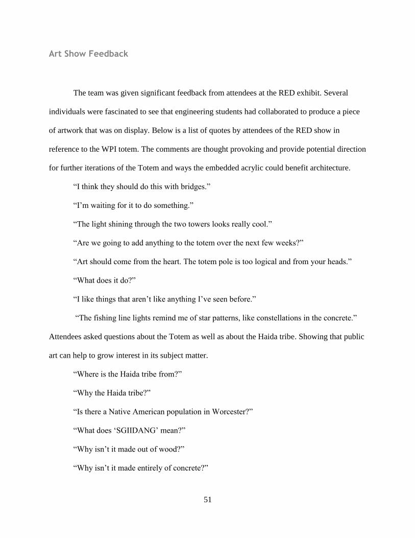
Art Show Feedback
The team was given significant feedback from attendees at the RED exhibit. Several
individuals were fascinated to see that engineering students had collaborated to produce a piece
of artwork that was on display. Below is a list of quotes by attendees of the RED show in
reference to the WPI totem. The comments are thought provoking and provide potential direction
for further iterations of the Totem and ways the embedded acrylic could benefit architecture.
“I think they should do this with bridges.”
“I’m waiting for it to do something.”
“The light shining through the two towers looks really cool.”
“Are we going to add anything to the totem over the next few weeks?”
“Art should come from the heart. The totem pole is too logical and from your heads.”
“What does it do?”
“I like things that aren’t like anything I’ve seen before.”
“The fishing line lights remind me of star patterns, like constellations in the concrete.”
Attendees asked questions about the Totem as well as about the Haida tribe. Showing that public
art can help to grow interest in its subject matter.
“Where is the Haida tribe from?”
“Why the Haida tribe?”
“Is there a Native American population in Worcester?”
“What does ‘SGIIDANG’ mean?”
“Why isn’t it made out of wood?”
“Why isn’t it made entirely of concrete?”
52
Some of the questions asked were related to the creation and technology of the totem. These
questions could help to express WPI’s connection to art as well as its connection to the Sprinkler
Factory.
“Is it one piece?”
“How did you get it to line up?”
“What materials were used?”
“How did you drill it?”
“How much concrete did it take?”
“Was this Sonotube filled with concrete?”
“How did you get it here?”
“Why is the cord coming out of the bottom and not the top?”
“What font did you print in?”
“How did you get those acrylic rods in? How can you buy acrylic rod?”
“Is the top sealed?”
“Can the 3D printing be customized in future renditions?”
Some people asked questions not about the totem pole, but of the team members’ feelings.
Allowing for the community to learn about the members of WPI in a more intimate way.
What year are you? What engineering are you studying?
What does this mean to you? Are you here for other reasons?
“What did you learn from the project?”
“Do you have an emotional attachment to the art?
53
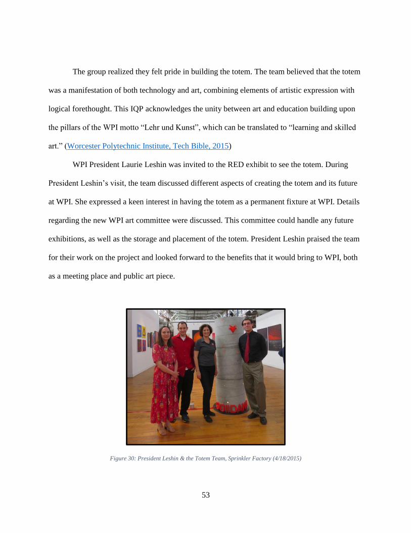
The group realized they felt pride in building the totem. The team believed that the totem
was a manifestation of both technology and art, combining elements of artistic expression with
logical forethought. This IQP acknowledges the unity between art and education building upon
the pillars of the WPI motto “Lehr und Kunst”, which can be translated to “learning and skilled
art.” (Worcester Polytechnic Institute, Tech Bible, 2015)
WPI President Laurie Leshin was invited to the RED exhibit to see the totem. During
President Leshin’s visit, the team discussed different aspects of creating the totem and its future
at WPI. She expressed a keen interest in having the totem as a permanent fixture at WPI. Details
regarding the new WPI art committee were discussed. This committee could handle any future
exhibitions, as well as the storage and placement of the totem. President Leshin praised the team
for their work on the project and looked forward to the benefits that it would bring to WPI, both
as a meeting place and public art piece.
Figure 30: President Leshin & the Totem Team, Sprinkler Factory (4/18/2015)
54
Chapter 6: Project Analysis
Cost analysis
The cost of materials for the Totem pole totaled $694.34, as detailed in Appendix D. The
two most expensive individual costs were for the lighting and the Sonotubes. The lighting cost
totaled $147.36. The positioning of lights could have been altered to three LEDs instead of four
per section which would have reduced the cost by approximately $37. However, this small
savings may have potentially had a negative impact on illumination. If the Sonotubes had been
obtained from a construction site, rather than ordered through the WPI CEE department, the cost
would have been reduced by as much as $269, a significant savings of 39%
Recommendations on how to Improve
Artistic recommendations include planning the positioning of the acrylic and fishing line
in order to depict an image in the concrete. The viewers at the art show felt that an artistic design
formed by a pattern in the lights would be interesting. The team’s recommendation for Wendy
Wacko would be to incorporate a human or animal pattern to represent the theme of the Haida
people and their culture. A similar idea could be applied to the WPI-centric totem. For example,
the motto “Lehr und Kunst” would make an excellent design choice to represent the WPI
community. Any such pattern would likely require additional fishing line to enhance the image
with more light points, thereby reducing blank space. An additional benefit of the fishing line is
that it creates a transition from day to night lighting as the small light from the fibers is not
55
noticeable in daylight, but becomes more obvious as ambient lighting fades. Adding too much
additional acrylic could harm the integrity of the structure, as well as detract from the other
symbolic features of the totem. It is important to maintain a balance between acrylic rods,
symbolic features, and concrete so no component overwhelms any other.
Possible considerations for the symbolic features on the surface of the totem include
making larger 3D printed carvings, created in the same way that the goat head was designed and
assembled. Other ideas mentioned include an expansion of the 3D color palette or using color
dyes on the concrete to complement the 3D printed design.
Some viewers at the art show felt that the 3D features of the totem were incongruent.
Alternatively, machined cast molds for concrete could be poured into and attached to the surface
of the totem using concrete anchors. This method would allow for larger features than the 3D
printing, which was limited by bed size. The molds would allow for less material to be used than
a solid version using the same material. While the concrete features would be more uniform and
traditional, they would not exemplify the high-tech component of 3D printed features.
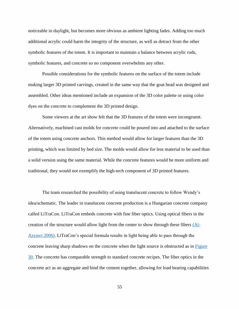
The team researched the possibility of using translucent concrete to follow Wendy’s
idea/schematic. The leader in translucent concrete production is a Hungarian concrete company
called LiTraCon. LiTraCon embeds concrete with fine fiber optics. Using optical fibers in the
creation of the structure would allow light from the center to show through these fibers (Al-
Azzawi 2006). LiTraCon’s special formula results in light being able to pass through the
concrete leaving sharp shadows on the concrete when the light source is obstructed as in Figure
30. The concrete has comparable strength to standard concrete recipes. The fiber optics in the
concrete act as an aggregate and bind the cement together, allowing for load bearing capabilities
56
(LiTraCon, 2015). However, the prohibitive costs of light transmitting concrete ruled out this
option as impractical and extremely expensive. In a future rendition, WPI could possibly fund a
new totem made from this translucent concrete. Alternatively, an MQP could be created that
researches the creation of translucent concrete from a more technical aspect.
Figure 31: Ein Haus fuers Leben 01. From LiTraCon (LiTraCon, 2014).
Difficulties Encountered
The creation of the High Tech Totem, similar to many other projects, encountered
challenges to the completion of the project. Technical issues, lack of budget, and team dynamics
were among some of the issues that were overcome.
During the process to create acrylic-embedded concrete, the team placed the acrylic flush
to the mold and then poured concrete inside, causing some faces of the acrylic to be covered with
57
concrete. This meant that the concrete had to be scoured away from the acrylic surfaces for light
to pass through, which could potentially damage the concrete. The recommendations provided in
the report would be an alternate method for this process. Holes could be drilled on both inner and
outer Sonotubes. Acrylic rods would be inserted to protrude from both sides of the mold, and
then concrete would be poured. Once the concrete hardened, the acrylic rods would be cut down
and sanded flush to the surface resulting in a more precise finish against the concrete. This
oversight was due to the lack of artistic experience and forethought and due to time constraints
that prevented testing. The time spent correcting this mistake, however, was more detrimental to
the project than was worth the gains it as an upwards of six hours was spent uncovering acrylic
from the concrete.
Transportation of the totem was another issue that was encountered by the team due to a
lack of foresight. Although the totem was separated into sections so that it would be easier to
transport and the raised platforms for use with pallet jacks helped, long distance transportation
was the crux of the process. Lack of proper equipment prevented the team from being able to
move the sections of the totem. A moving company was needed to transport the totem sections to
the Sprinkler Factory. At the Sprinkler Factory another issue was encountered. The service
elevator that would have allowed for ease of access to the studio area was out of operation. This
required the moving company to pull the concrete sections on dollies up a long ramp. Having
experience with moving and project planning could have prevented this tedious and expensive
process.
Assembly of the totem was another hurdle that the team encountered. Miscommunication
between Fraire and the team resulted in a loss of time after it was discovered that there was no
support beams capable of acting as a fixed point for a pulley system. Without the ability to hoist
58
the section and a lack of elevator or time to move lifting equipment, the totem needed to be
assembled by hand. This resulted in the inability of the team to attach the final section of the
totem. Better communication skills and fail-safe plans would have saved time and allowed for
the completion of the full sculpture.
Communication was an issue between the team and Wacko. This lack of communication
was present on both sides as many of the original emails from the team went without response.
The team also began to send messages less frequently to Wacko. Had a better line of
communication been established the totem team could have received more artistic insight form
Wacko. In return the team could have provided their scientific and problem solving abilities to
Wacko. This exchange of knowledge would have allowed for a more complete answer to the
original proposal.
Team dynamics also prevented the project from being completed in an efficient manner.
A lack of leadership prevented tasks from being completed on time. This issue resulted in
separation in the team that prevented cohesion. Attendance to events was an issue for all
members of the team. This furthered the separation in the team so that work was not spread
equally. Work was also not communicated well, preventing members of the group from learning
and contributing to problems that arose.
A lack of experience was another large detriment to the team. Sufficient background in
construction was lacking. The large focus on concrete and construction for this project led to a
significant amount of research alongside trial and error. Lack of time management experience
made the project run against last minute deadlines that could have otherwise been avoided. With
background in project work the team could have functioned more coherently and produced a
better final product.
59
Chapter 7: Personal Reflections
Daniel Sanderson
The High-Tech Totem IQP was an experience that requires a lot of self-reflection. As a
contributor to the project, I served a pivotal role in producing the final product. With technical
skills and experience with building and constructing, I had the best grasp on how to create a
concrete mixture and how to make the totem a reality. I took charge in emailing the team and
setting up meetings which put me in the role of leader by the other members of the team. As a
leader, I was not able to motivate others into completing tasks and did not communicate
necessary tasks well. This meant that deadlines were missed and the project suffered. I also
began doing work individually and did not communicate my procedures or findings well to the
group. I believe this resulted in a separation that made the group require information only I was
familiar with. This slowed work by the other members which meant I was picking up the slack of
individual work resulting in a cyclic pattern as the result of my inability to communicate
information. This failure cost time and hurt the quality of the IQP.
From this project I gained a breath of knowledge in the civil engineering field and
learned about the importance of team cohesion. In the future I will take the knowledge gained
from this experience to modify my behavior in teams to be more inclusive. I believe this will
allow for more growth by all members of the team.
60
David Rubenstein
This IQP was a significant experience. Who comes out of their IQP as a gallery published
artist? I learned a lot about how to work with concrete during this project. I also learned more
about how organize writing an extremely long paper, something that before IQP I hadn’t had to
do before. With all the upsides of this project, there were also significant problems as well. First
among these is the team did not communicate nearly as well as we should have. We had weekly
meetings, when we should have had at least two meetings a week if not more. Also, not every
team member was at every meeting. There were some team members who I barely saw at any
point during the project. When we had major deadlines, we should have been much harder on
ourselves to enforce them and get them done. I also think that we allowed the delegation of work
to become uneven as the project wore on, with much more being asked of some of the team
members than others. As a robotics major with a significant focus in computer science, my
talents did not lend themselves well to physically constructing a structure.
Max Kinney
When I first saw this IQP, it was explained to me that the project would consist of
researching materials with which a totem pole of the given specifications could be created. We
were then to forward our findings to artist Wendy Wacko so that she could construct her
art. Unfortunately, whenever we contacted Wendy, her responses were very delayed, and soon
the concept of helping to create a work of art had become detached from the project. With
advising Wendy no longer the goal of the project, the new goal became to work as a group to
create a proof of concept with our findings.
61
There were many difficulties that came with this project in addition to Wendy’s absence. The
project was not completed in the time frame we had hoped for, leading to several
difficulties. The additional workload that new terms provided lead to a significant decrease in
teamwork. For me personally, I had heavy course work and could not dedicate time to a project
that had completely removed itself from the aspects that had my interest. I stopped
communication for longer than was reasonable. However it also proved rather difficult to get
involved again when it became clear that I was still obligated to contribute to this project. I had
to follow up several times on my messages to get involved again, and then once solid
communication had happened there was another issue. The team had been making significant
progress on the project without sharing the progress. This made it initially difficult to resume
contributing to the project.
Brian Baggaley
The High-Tech Totem IQP has taught me many lessons. The first is that no project truly
turns out exactly as expected. I feel as though this was particularly true for constructing the
totem pole. Originally, the goal for this project was to research totem poles made by the Haida
Native American tribe to assist Wendy Wacko in creating an artistic totem pole as an homage to
existing totem poles. The piece was originally to be displayed in the Canadian Rockies.
However, we were not able to establish stable communication with Wendy Wacko, which is the
first instance of communication problems that would continue to hinder this project. Near the
end of the first term, the team began to speculate on crafting an ice sculpture to display in winter
for the Worcester Art Museum. This idea had potential, but we took action too late, as the art
museum needed matters like this at least two months in advance. Thus, at the start of C term, our
62
team was focused on establishing some proof of concept that a translucent effect could be
produced in a concrete totem pole. It was at this point that it became clear the team was
distanced from one another. Information was lost, attendance to meetings was inconsistent. I feel
as though the information recorded in my meeting minutes also suffered, along with the delayed
time it took to send the minutes out to everyone.
That being said, I also know that I have learned from this project. Planning is a crucial
part of accomplishing goals, Moreover, I did not know anything about concrete or art in
Worcester prior to this project. Although I am an electrical engineer, I have always had a
tremendous appreciation for art. The Sprinkler Factory, to me, was an experience I won’t soon
forget. Not only was I exposed to unique styles and creative ideas, I was part of it. And I believe
that working on this totem was a step in the right direction towards appreciating all that
Worcester has to offer.
Chapter 8: Future of the High-tech Totem
Vision for the High-Tech Totem
The team has additional recommendations for the WPI art committee designated for
future teams to oversee further development and display of this project. One suggestion is to add
a solar panel to the top of the totem. This would allow the totem to be a fixture of new-age
energy, as well as its own self-sustaining light source. Another suggestion would be to request
that WPI department heads and their students submit 3D collaborations for the totem
representing each respective major. This way, each major could choose a design to accurately
represent their field of study. Another proposal would be for WPI to hold a school-wide contest
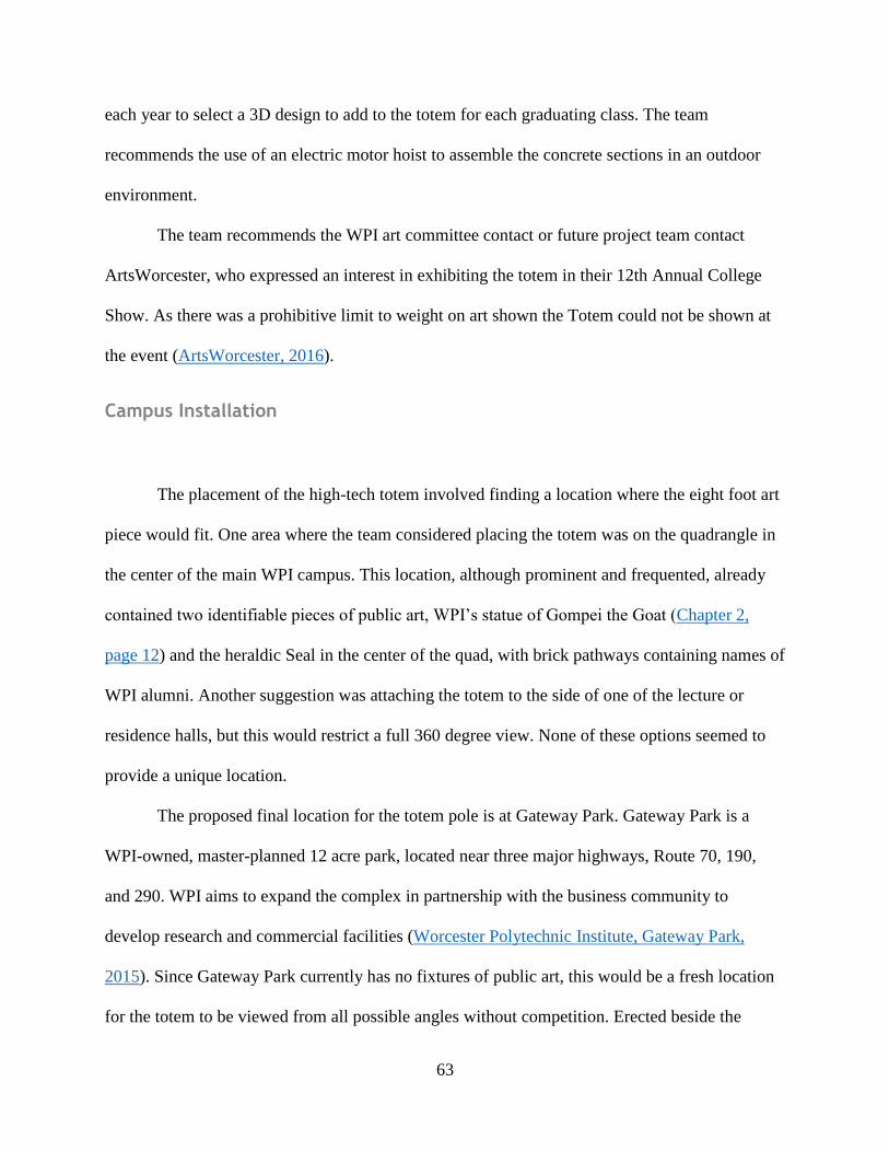
63
each year to select a 3D design to add to the totem for each graduating class. The team
recommends the use of an electric motor hoist to assemble the concrete sections in an outdoor
environment.
The team recommends the WPI art committee contact or future project team contact
ArtsWorcester, who expressed an interest in exhibiting the totem in their 12th Annual College
Show. As there was a prohibitive limit to weight on art shown the Totem could not be shown at
the event (ArtsWorcester, 2016).
Campus Installation
The placement of the high-tech totem involved finding a location where the eight foot art
piece would fit. One area where the team considered placing the totem was on the quadrangle in
the center of the main WPI campus. This location, although prominent and frequented, already
contained two identifiable pieces of public art, WPI’s statue of Gompei the Goat (Chapter 2,
page 12) and the heraldic Seal in the center of the quad, with brick pathways containing names of
WPI alumni. Another suggestion was attaching the totem to the side of one of the lecture or
residence halls, but this would restrict a full 360 degree view. None of these options seemed to
provide a unique location.
The proposed final location for the totem pole is at Gateway Park. Gateway Park is a
WPI-owned, master-planned 12 acre park, located near three major highways, Route 70, 190,
and 290. WPI aims to expand the complex in partnership with the business community to
develop research and commercial facilities (Worcester Polytechnic Institute, Gateway Park,
2015). Since Gateway Park currently has no fixtures of public art, this would be a fresh location
for the totem to be viewed from all possible angles without competition. Erected beside the
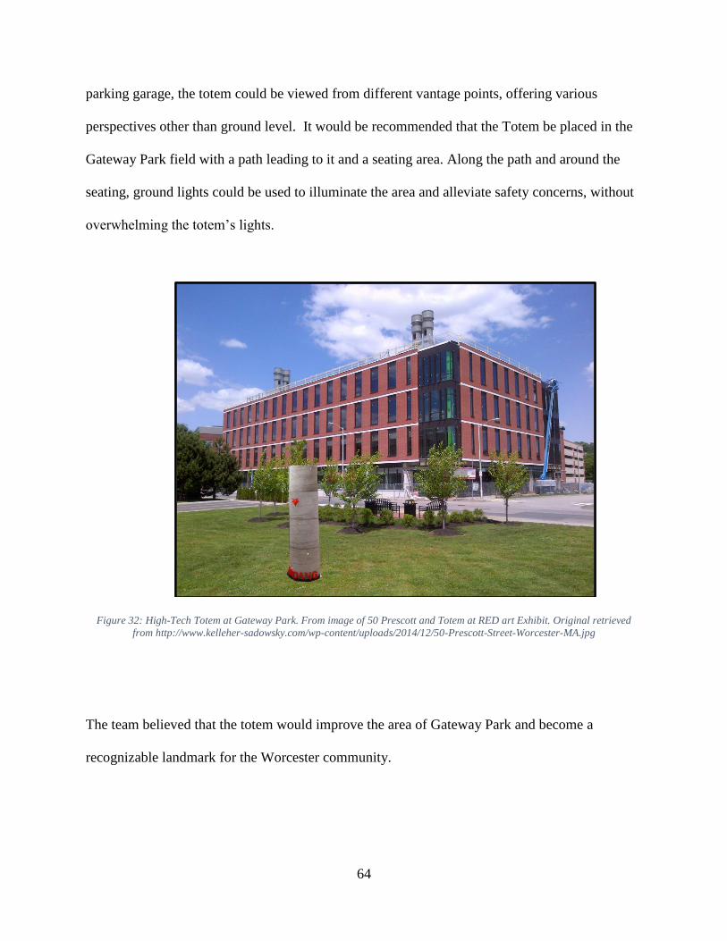
64
parking garage, the totem could be viewed from different vantage points, offering various
perspectives other than ground level. It would be recommended that the Totem be placed in the
Gateway Park field with a path leading to it and a seating area. Along the path and around the
seating, ground lights could be used to illuminate the area and alleviate safety concerns, without
overwhelming the totem’s lights.
Figure 32: High-Tech Totem at Gateway Park. From image of 50 Prescott and Totem at RED art Exhibit. Original retrieved
from http://www.kelleher-sadowsky.com/wp-content/uploads/2014/12/50-Prescott-Street-Worcester-MA.jpg
The team believed that the totem would improve the area of Gateway Park and become a
recognizable landmark for the Worcester community.
65
Future Project Work
The art director at the Sprinkler Factory, Luis Fraire, proposed the following idea to the
team: assemble a pathway of several totems spanning the distance from the WPI campus, past
the Worcester Art Museum to Gateway Park. Effectively, these totems could act as artistic
streetlights, keeping the area safe while adding more culture and beauty to the surroundings.
Each totem could have a separate theme submitted by a local artist in the community. Each artist
could create their own totem, representing the culture of Worcester. This would require both
communication and collaboration between the WPI art committee, ArtsWorcester, the Sprinkler
Factory, PAWG, and the City of Worcester for approval to undergo such a large scale project of
this nature. In doing so, WPI would become an epicenter of artistic and cultural activity, while
integrating the lives of students with local artists and other members of the community.
A new Major Qualifying Project (MQP) or succession of MQP’s would be the most
feasible way to have a future iteration of the High Tech Totem become a known part of the
community. By having this project be an MQP the teams will have more experience, more
budget, and more technical skills needed to incorporate a highly functional totem into the area
around campus. Fraire’s idea could become a reality. Totems that provide light like a street lamp,
are a meeting place with seating and a good atmosphere, and tell the story of WPI’s culture and
history or the culture and history of all of Worcester could become a fixture for the area and a
mark of pride for WPI.
66
Closing Remarks
The High-Tech Totem team believe that further refinement of the totem pole design will
allow for its successful construction and its installation will result in the first piece of public art
to serve as a gathering and meeting point for students at WPI. By incorporating elements of
WPI’s culture, while also implementing technology into its design, the totem will connect and
stimulate the WPI community. This installation would also improve the aesthetics of Gateway
Park. The team would like the totem to attain the same notoriety as the Proud Goat statue. In 50
years, the hope is that the totem will be well-known by everyone and still standing on the WPI
campus with improvements that future project groups have added to the structure.
67
References
About LiTraCon. LiTraCon. 2015, March 6. About LiTraCon. Retrieved from
http://litracon.hu/
Acrylic Rod. (2014, January 1). Retrieved February 26th, 2015, from
http://www.estreetplastics.com/Acrylic_Rod_s/46.htm
Adz. (2015). In Encyclopædia Britannica online. Retrieved from
http://www.britannica.com/EBchecked/topic/6883/adz
Al-Azzawi, A. (2006, December 26). Fiber Optics: Principles and Practices (Optical Science
and Engineering Series). Print.
American Hardwoods. (2007). The Guide to American Hardwood `Species. Retrieved from
http://www.hardwoodinfo.com/articles/view/pro/24/267
ArtsWorcester: Gallery Exhibits. (2016, February). The Aurora. Retrieved from
http://artsworcester.org/exhibits/the-aurora/
Ault, H. (Director) (2015, February 13). Rapid Prototype technology. Advanced Computer
Aided Design. Lecture conducted from Professor Ault, Worcester.
Bedford, J. (1998). Haida art in the Pitt Rivers Museum, Oxford, and the Rev. Charles
Harrison. European Review of Native American Studies, Vol. XII, no. 2, pg. 1-10.
Concrete: Scientific Principles, University of Illinois. (n.d.). (2015, February 14). Retrieved
from http://matse1.matse.illinois.edu/concrete/prin.html
G. Coutts, Jokela, Timo 2008 Art, Community and Environment : Educational Perspectives
Bristol, GBR Intellect Ltd. Art, Community and Environment : Educational Perspectives
Community arts projects.
Dearborn, K. (2002). Totem Poles. Faces: People, Places, and Cultures. Print.
Encyclopedia of Art. (n.d.) Public Art: Definition, History, Types. Retrieved from
http://www.visual-arts-cork.com/public-art.htm
Granta, Material Science (2014). CES EduPack [computer software]. United Kingdom:
Cambridge.
Gromicko, N., & Shepard, K. (2015). The History of Concrete. Retrieved from
http://www.nachi.org/history-of-concrete.htm
Halpin, M. M. (1981). Totem Poles: An Illustrated Guide. University of British Columbia Press
68
in association with the U.B.C. Museum of Anthropology. Print.
Hockney, D. (2015). Cultivating Culture. Retrieved from
http://www.cultivatingculture.com/profiles/david-hockney/
Indigenous Foundations (2009). Totem Poles: What are totem poles? The University of British
Colombia. Retrieved from http://indigenousfoundations.arts.ubc.ca/home/culture/totem-
poles.html
Kerkhoff, B., Kosmatka, S., & Panarese, W. (2002). Design and Control of Concrete Mixtures.
Skokie, Illinois: Portland Cement Association, 1988. Print.
MakerBot (2014, January). Replicator 2: Desktop 3D Printer. Retrieved from
https://mindtouch.makerbot.com/@api/deki/files/108/MB1036_REP2_UserManual_V4.pdf
Meier, E. (2014). The Wood Database: Western Red Cedar. Retrieved from http://www.wood-
database.com/lumber-identification/softwoods/western-red-cedar
Miller, H., & Reese, M. (2014). Indians and Europeans on the Northwest Coast, 1774-1812.
Retrieved from
http://www.washington.edu/uwired/outreach/cspn/Website/Classroom%20Materials/Curriculu
m%20Packets/Indians%20&%20Europeans/Indians%20&%20Europeans.html
Perspex & Acrylic Index. (2015, January 1). Retrieved February 20th, 2015, from
http://www.theplasticshop.co.uk/perspex-acrylic-index.html
Pfaender, H.G. Schott Guide to Glass. Springer, 1995. Colchester Essex. Print.
R. Schiffmann. (200)9 Totem poles: an ancient Alaskan art Faces: People, Places, and Cultures.
Article. Totem poles: an ancient Alaskan art. Ancient art. Print
Sussman, J. (2013). Art in Public Spaces. National Civic Review, July 23, 2013. Article.
U.S. Climate Data, Worcester, MA. (2015, January 1). Retrieved February 26, 2015, from
http://www.usclimatedata.com/climate/worcester/massachusetts/united-states/usma0502
Vocabulary in Native American Languages: Haida Words. Haida Indian Language. 2014.
Retrieved from http://www.native-languages.org/haida_words.htm.
Wacko, W. (n.d.). Wendy Wacko: Artist Statement. Retrieved from
http://www.mountaingalleries.com/#!wacko-bio/c1xxh
Weather Warehouse. (2014). Weather History for Worcester, MA.
Retrieved from https://weather-warehouse.com/index.html
Worcestermass.org (2015). City of Worcester, Massachusetts: Public Art. Retrieved from
69
http://www.worcestermass.org/arts-culture-entertainment/public-art
Worcester Art Museum (1994). Selected Works. Worcester, MA: Worcester Art Museum.
Worcester Polytechnic Institute (2014). Lightpainting Illuminates
WPI’s Gordon Library Facade. Retrieved from
http://www.wpi.edu/news/20134/sknapp.html
Worcester Polytechnic Institute (2015). Division of
Finance and Operations Retrieved from
http://www.gatewayparkworcester.com/
Worcester Polytechnic Institute (2015). Office of Alumni Relations.
Retrieved from http://www.wpi.edu/academics/library/history/techbible/seal.html
3D Printer Filament Comparison (2015, January 1).
MatterHackers. (2015, January 18) Retrieved from
http://www.matterhackers.com/3d-printer-filament-compare
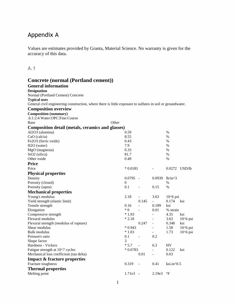
1
Appendix A
Values are estimates provided by Granta, Material Science. No warranty is given for the
accuracy of this data.
A.1
Concrete (normal (Portland cement))
General information Designation Normal (Portland Cement) Concrete Typical uses General civil engineering construction, where there is little exposure to sulfates in soil or groundwater. Composition overview Composition (summary) .6:1:2:4 Water:OPC:Fine:Coarse Base Other Composition detail (metals, ceramics and glasses) Al2O3 (alumina) 0.59 % CaO (calcia) 8.55 % Fe2O3 (ferric oxide) 0.43 % H2O (water) 7.9 % MgO (magnesia) 0.33 % SiO2 (silica) 81.7 % Other oxide 0.49 % Price Price * 0.0181 - 0.0272 USD/lb Physical properties Density 0.0795 - 0.0939 lb/in^3 Porosity (closed) 0 % Porosity (open) 0.1 - 0.15 % Mechanical properties Young's modulus 2.18 - 3.63 10^6 psi Yield strength (elastic limit) 0.145 - 0.174 ksi Tensile strength 0.16 - 0.189 ksi Elongation * 0 - 0.01 % strain Compressive strength * 1.93 - 4.35 ksi Flexural modulus * 2.18 - 3.63 10^6 psi Flexural strength (modulus of rupture) 0.247 - 0.348 ksi Shear modulus * 0.943 - 1.58 10^6 psi Bulk modulus * 1.03 - 1.73 10^6 psi Poisson's ratio 0.1 - 0.2 Shape factor 3 Hardness - Vickers * 5.7 - 6.3 HV Fatigue strength at 10^7 cycles * 0.0783 - 0.122 ksi Mechanical loss coefficient (tan delta) 0.01 - 0.03 Impact & fracture properties Fracture toughness 0.319 - 0.41 ksi.in^0.5 Thermal properties Melting point 1.71e3 - 2.19e3 °F
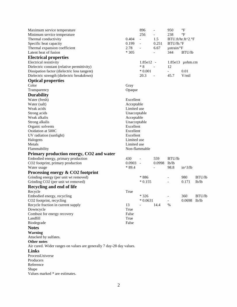
2
Maximum service temperature 896 - 950 °F Minimum service temperature 256 - 238 °F Thermal conductivity 0.404 - 1.5 BTU.ft/hr.ft^2.°F Specific heat capacity 0.199 - 0.251 BTU/lb.°F Thermal expansion coefficient 2.78 - 6.67 µstrain/°F Latent heat of fusion * 305 - 344 BTU/lb Electrical properties Electrical resistivity 1.85e12 - 1.85e13 µohm.cm Dielectric constant (relative permittivity) * 8 - 12 Dissipation factor (dielectric loss tangent) * 0.001 - 0.01 Dielectric strength (dielectric breakdown) 20.3 - 45.7 V/mil Optical properties Color Gray Transparency Opaque Durability Water (fresh) Excellent Water (salt) Acceptable Weak acids Limited use Strong acids Unacceptable Weak alkalis Acceptable Strong alkalis Unacceptable Organic solvents Excellent Oxidation at 500C Excellent UV radiation (sunlight) Excellent Halogens Limited use Metals Limited use Flammability Non-flammable Primary production energy, CO2 and water Embodied energy, primary production 430 - 559 BTU/lb CO2 footprint, primary production 0.0903 - 0.0998 lb/lb Water usage * 89.4 - 98.8 in^3/lb Processing energy & CO2 footprint Grinding energy (per unit wt removed) * 886 - 980 BTU/lb Grinding CO2 (per unit wt removed) * 0.155 - 0.171 lb/lb Recycling and end of life Recycle True Embodied energy, recycling * 326 - 360 BTU/lb CO2 footprint, recycling * 0.0631 - 0.0698 lb/lb Recycle fraction in current supply 13 - 14.4 % Downcycle True Combust for energy recovery False Landfill True Biodegrade False Notes Warning Attacked by sulfates. Other notes Air cured. Wider ranges on values are generally 7 day-28 day values. Links ProcessUniverse Producers Reference Shape Values marked * are estimates.
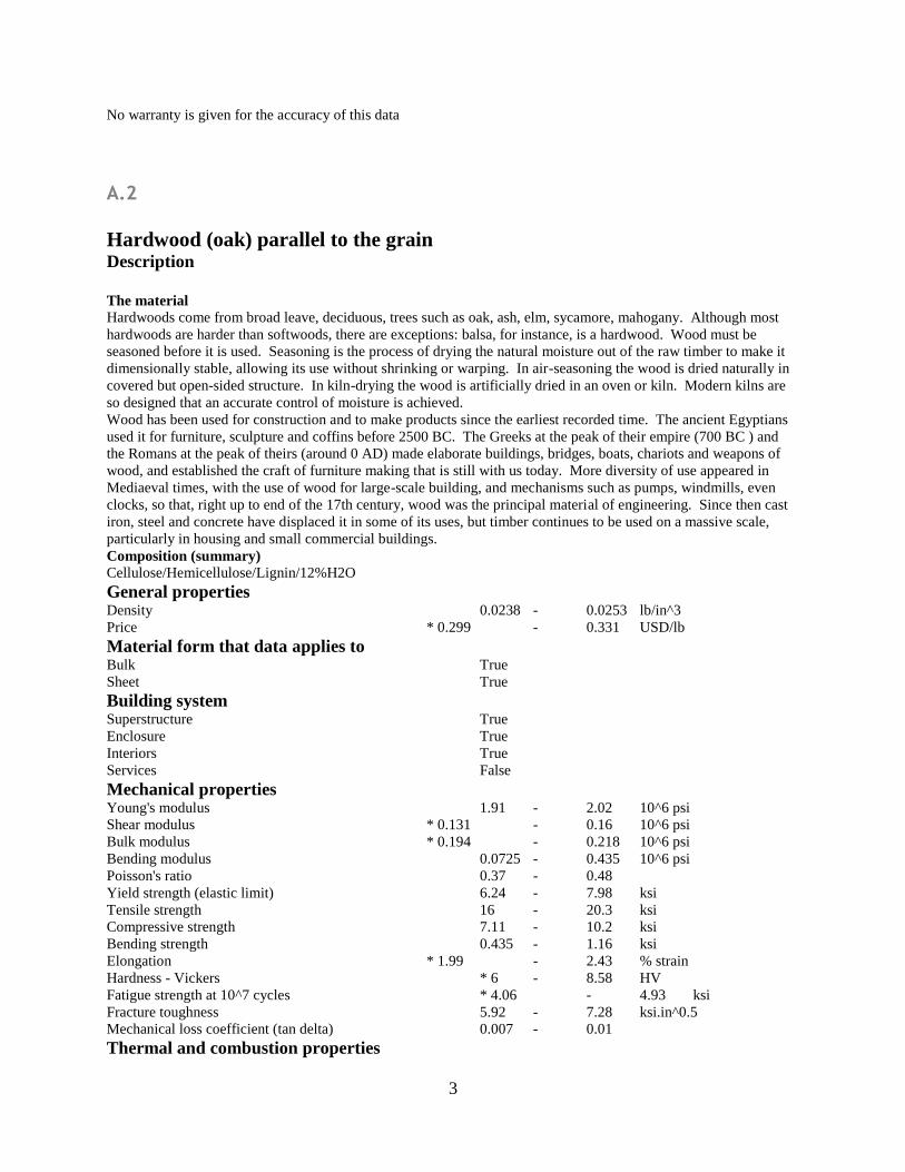
3
No warranty is given for the accuracy of this data
A.2
Hardwood (oak) parallel to the grain
Description The material Hardwoods come from broad leave, deciduous, trees such as oak, ash, elm, sycamore, mahogany. Although most
hardwoods are harder than softwoods, there are exceptions: balsa, for instance, is a hardwood. Wood must be
seasoned before it is used. Seasoning is the process of drying the natural moisture out of the raw timber to make it
dimensionally stable, allowing its use without shrinking or warping. In air-seasoning the wood is dried naturally in
covered but open-sided structure. In kiln-drying the wood is artificially dried in an oven or kiln. Modern kilns are
so designed that an accurate control of moisture is achieved. Wood has been used for construction and to make products since the earliest recorded time. The ancient Egyptians
used it for furniture, sculpture and coffins before 2500 BC. The Greeks at the peak of their empire (700 BC ) and
the Romans at the peak of theirs (around 0 AD) made elaborate buildings, bridges, boats, chariots and weapons of
wood, and established the craft of furniture making that is still with us today. More diversity of use appeared in
Mediaeval times, with the use of wood for large-scale building, and mechanisms such as pumps, windmills, even
clocks, so that, right up to end of the 17th century, wood was the principal material of engineering. Since then cast
iron, steel and concrete have displaced it in some of its uses, but timber continues to be used on a massive scale,
particularly in housing and small commercial buildings. Composition (summary) Cellulose/Hemicellulose/Lignin/12%H2O General properties Density 0.0238 - 0.0253 lb/in^3 Price * 0.299 - 0.331 USD/lb Material form that data applies to Bulk True Sheet True Building system Superstructure True Enclosure True Interiors True Services False Mechanical properties Young's modulus 1.91 - 2.02 10^6 psi Shear modulus * 0.131 - 0.16 10^6 psi Bulk modulus * 0.194 - 0.218 10^6 psi Bending modulus 0.0725 - 0.435 10^6 psi Poisson's ratio 0.37 - 0.48 Yield strength (elastic limit) 6.24 - 7.98 ksi Tensile strength 16 - 20.3 ksi Compressive strength 7.11 - 10.2 ksi Bending strength 0.435 - 1.16 ksi Elongation * 1.99 - 2.43 % strain Hardness - Vickers * 6 - 8.58 HV Fatigue strength at 10^7 cycles * 4.06 - 4.93 ksi Fracture toughness 5.92 - 7.28 ksi.in^0.5 Mechanical loss coefficient (tan delta) 0.007 - 0.01 Thermal and combustion properties
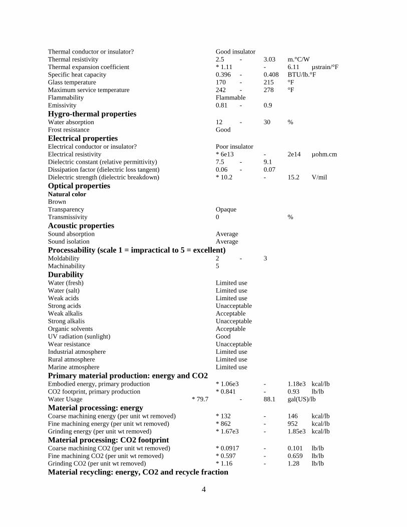
4
Thermal conductor or insulator? Good insulator Thermal resistivity 2.5 - 3.03 m.°C/W Thermal expansion coefficient * 1.11 - 6.11 µstrain/°F Specific heat capacity 0.396 - 0.408 BTU/lb.°F Glass temperature 170 - 215 °F Maximum service temperature 242 - 278 °F Flammability Flammable Emissivity 0.81 - 0.9 Hygro-thermal properties Water absorption 12 - 30 % Frost resistance Good Electrical properties Electrical conductor or insulator? Poor insulator Electrical resistivity * 6e13 - 2e14 µohm.cm Dielectric constant (relative permittivity) 7.5 - 9.1 Dissipation factor (dielectric loss tangent) 0.06 - 0.07 Dielectric strength (dielectric breakdown) * 10.2 - 15.2 V/mil Optical properties Natural color Brown Transparency Opaque Transmissivity 0 % Acoustic properties Sound absorption Average Sound isolation Average Processability (scale 1 = impractical to 5 = excellent) Moldability 2 - 3 Machinability 5 Durability Water (fresh) Limited use Water (salt) Limited use Weak acids Limited use Strong acids Unacceptable Weak alkalis Acceptable Strong alkalis Unacceptable Organic solvents Acceptable UV radiation (sunlight) Good Wear resistance Unacceptable Industrial atmosphere Limited use Rural atmosphere Limited use Marine atmosphere Limited use Primary material production: energy and CO2 Embodied energy, primary production * 1.06e3 - 1.18e3 kcal/lb CO2 footprint, primary production * 0.841 - 0.93 lb/lb Water Usage * 79.7 - 88.1 gal(US)/lb Material processing: energy Coarse machining energy (per unit wt removed) * 132 - 146 kcal/lb Fine machining energy (per unit wt removed) * 862 - 952 kcal/lb Grinding energy (per unit wt removed) * 1.67e3 - 1.85e3 kcal/lb Material processing: CO2 footprint Coarse machining CO2 (per unit wt removed) * 0.0917 - 0.101 lb/lb Fine machining CO2 (per unit wt removed) * 0.597 - 0.659 lb/lb Grinding CO2 (per unit wt removed) * 1.16 - 1.28 lb/lb Material recycling: energy, CO2 and recycle fraction
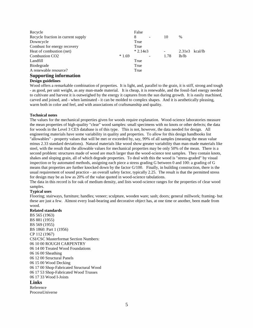
5
Recycle False Recycle fraction in current supply 8 - 10 % Downcycle True Combust for energy recovery True Heat of combustion (net) * 2.14e3 - 2.31e3 kcal/lb Combustion CO2 * 1.69 - 1.78 lb/lb Landfill True Biodegrade True A renewable resource? True Supporting information Design guidelines Wood offers a remarkable combination of properties. It is light, and, parallel to the grain, it is stiff, strong and tough
- as good, per unit weight, as any man-made material. It is cheap, it is renewable, and the fossil-fuel energy needed
to cultivate and harvest it is outweighed by the energy it captures from the sun during growth. It is easily machined,
carved and joined, and - when laminated - it can be molded to complex shapes. And it is aesthetically pleasing,
warm both in color and feel, and with associations of craftsmanship and quality. Technical notes The values for the mechanical properties given for woods require explanation. Wood-science laboratories measure
the mean properties of high-quality "clear" wood samples: small specimens with no knots or other defects; the data
for woods in the Level 3 CES database is of this type. This is not, however, the data needed for design. All
engineering materials have some variability in quality and properties. To allow for this design handbooks list
"allowables" - property values that will be met or exceeded by, say, 99% of all samples (meaning the mean value
minus 2.33 standard deviations). Natural materials like wood show greater variability than man-made materials like
steel, with the result that the allowable values for mechanical properties may be only 50% of the mean. There is a
second problem: structures made of wood are much larger than the wood-science test samples. They contain knots,
shakes and sloping grain, all of which degrade properties. To deal with this the wood is "stress-graded" by visual
inspection or by automated methods, assigning each piece a stress grading G between 0 and 100: a grading of G
means that properties are further knocked down by the factor G/100. Finally, in building construction, there is the
usual requirement of sound practice - an overall safety factor, typically 2.25. The result is that the permitted stress
for design may be as low as 20% of the value quoted in wood-science tabulations. The data in this record is for oak of medium density, and lists wood-science ranges for the properties of clear wood
samples. Typical uses Flooring; stairways, furniture; handles; veneer; sculpture, wooden ware; sash; doors; general millwork; framing- but
these are just a few. Almost every load-bearing and decorative object has, at one time or another, been made from
wood. Related standards BS 565 (1963) BS 881 (1955) BS 569 (1955) BS 1860: Part 1 (1956) CP 112 (1967) CSI/CSC Masterformat Section Numbers: 06 10 00 ROUGH CARPENTRY 06 14 00 Treated Wood Foundations 06 16 00 Sheathing 06 12 00 Structural Panels 06 15 00 Wood Decking 06 17 00 Shop-Fabricated Structural Wood 06 17 53 Shop-Fabricated Wood Trusses 06 17 33 Wood I-Joists Links Reference ProcessUniverse
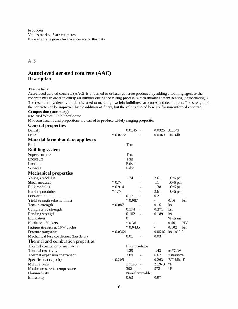
6
Producers Values marked * are estimates. No warranty is given for the accuracy of this data
A.3
Autoclaved aerated concrete (AAC)
Description The material Autoclaved aerated concrete (AAC) is a foamed or cellular concrete produced by adding a foaming agent to the
concrete mix in order to entrap air bubbles during the curing process, which involves steam heating ("autoclaving").
The resultant low density product is used to make lightweight buildings, structures and decorations. The strength of
the concrete can be improved by the addition of fibers, but the values quoted here are for unreinforced concrete. Composition (summary) 0.6:1:0:4 Water:OPC:Fine:Coarse Mix constituents and proportions are varied to produce widely ranging properties. General properties Density 0.0145 - 0.0325 lb/in^3 Price * 0.0272 - 0.0363 USD/lb Material form that data applies to Bulk True Building system Superstructure True Enclosure True Interiors False Services False Mechanical properties Young's modulus 1.74 - 2.61 10^6 psi Shear modulus * 0.74 - 1.1 10^6 psi Bulk modulus * 0.914 - 1.38 10^6 psi Bending modulus * 1.74 - 2.61 10^6 psi Poisson's ratio 0.17 - 0.2 Yield strength (elastic limit) * 0.087 - 0.16 ksi Tensile strength * 0.087 - 0.16 ksi Compressive strength 0.174 - 0.271 ksi Bending strength 0.102 - 0.189 ksi Elongation 0 % strain Hardness - Vickers * 0.36 - 0.56 HV Fatigue strength at 10^7 cycles * 0.0435 - 0.102 ksi Fracture toughness * 0.0364 - 0.0546 ksi.in^0.5 Mechanical loss coefficient (tan delta) 0.01 - 0.03 Thermal and combustion properties Thermal conductor or insulator? Poor insulator Thermal resistivity 1.25 - 1.43 m.°C/W Thermal expansion coefficient 3.89 - 6.67 µstrain/°F Specific heat capacity * 0.205 - 0.263 BTU/lb.°F Melting point 1.71e3 - 2.19e3 °F Maximum service temperature 392 - 572 °F Flammability Non-flammable Emissivity 0.63 - 0.97
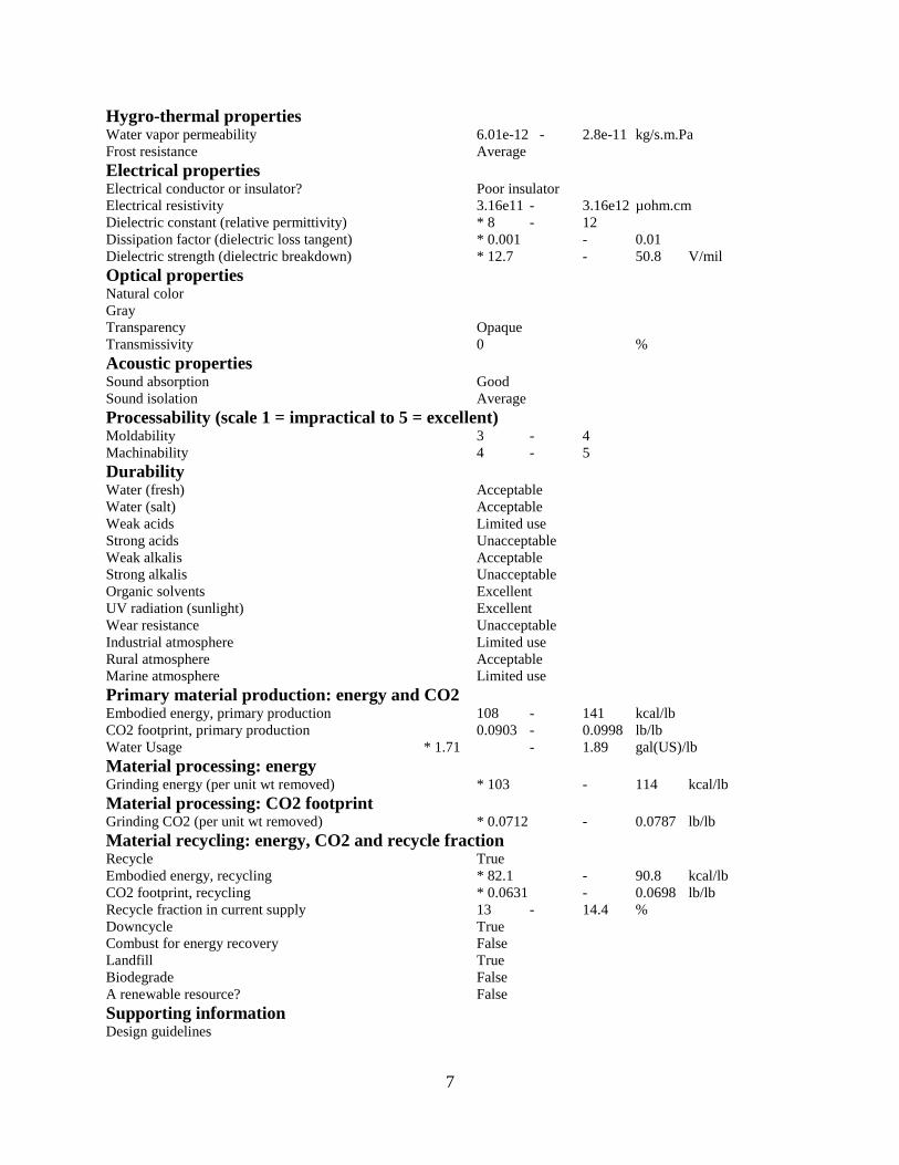
7
Hygro-thermal properties Water vapor permeability 6.01e-12 - 2.8e-11 kg/s.m.Pa Frost resistance Average Electrical properties Electrical conductor or insulator? Poor insulator Electrical resistivity 3.16e11 - 3.16e12 µohm.cm Dielectric constant (relative permittivity) * 8 - 12 Dissipation factor (dielectric loss tangent) * 0.001 - 0.01 Dielectric strength (dielectric breakdown) * 12.7 - 50.8 V/mil Optical properties Natural color Gray Transparency Opaque Transmissivity 0 % Acoustic properties Sound absorption Good Sound isolation Average Processability (scale 1 = impractical to 5 = excellent) Moldability 3 - 4 Machinability 4 - 5 Durability Water (fresh) Acceptable Water (salt) Acceptable Weak acids Limited use Strong acids Unacceptable Weak alkalis Acceptable Strong alkalis Unacceptable Organic solvents Excellent UV radiation (sunlight) Excellent Wear resistance Unacceptable Industrial atmosphere Limited use Rural atmosphere Acceptable Marine atmosphere Limited use Primary material production: energy and CO2 Embodied energy, primary production 108 - 141 kcal/lb CO2 footprint, primary production 0.0903 - 0.0998 lb/lb Water Usage * 1.71 - 1.89 gal(US)/lb Material processing: energy Grinding energy (per unit wt removed) * 103 - 114 kcal/lb Material processing: CO2 footprint Grinding CO2 (per unit wt removed) * 0.0712 - 0.0787 lb/lb Material recycling: energy, CO2 and recycle fraction Recycle True Embodied energy, recycling * 82.1 - 90.8 kcal/lb CO2 footprint, recycling * 0.0631 - 0.0698 lb/lb Recycle fraction in current supply 13 - 14.4 % Downcycle True Combust for energy recovery False Landfill True Biodegrade False A renewable resource? False Supporting information Design guidelines
8
Autoclaved Aerated Concrete (AAC) is light colored and contains many small air bubbles that contribute to the
material's insulating properties. AAC can be sculpted with wood working tools but, being soft, it is rarely used in
an exposed condition, but requires surface protection. AAC is load-bearing, insulating and capable of being
'sculpted', giving it potential as an environmentally responsible building material. Technical notes AAC has good compressive strength, allowing its use as a load-bearing material in structures up to 3 storeys high.
Entire buildings can be made in AAC including walls, floors and roofing. Lintels, floor slabs and roofing panels
require steel reinforcement to give structural adequacy. AAC has reasonably good insulation qualities and its low
thermal mass gives energy efficiency. It provides good sound insulation, is suited for fire-rated applications but its
porosity allows it to take up water if exposed. There are a number of proprietary finishes based on acrylic polymers,
which, when mixed with sand and cement, provide a durable and water resistant coating. The quoted properties are for unreinforced concrete. However, in practice, they are significantly improved by the
addition of fibers. Typical uses Concrete blocks, lightweight tilt-up panels, foamed concrete floor screeds, sound and thermal insulation,
geotechnical and ornamental concrete applications - e.g. column heads Tradenames LiteBuilt, Hebel, Ytong Related standards CSI/CSC Masterformat Section Numbers: 03 00 00 CONCRETE Further reading The Australian Government web site www.greenhouse.gov.au carries useful information on AAC. Links Reference ProcessUniverse Producers Values marked * are estimates. No warranty is given for the accuracy of this data
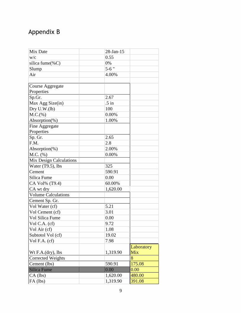
9
Appendix B
Mix Date 28-Jan-15
w/c 0.55
silica fume(%C) 0%
Slump 5-6 "
Air 4.00%
Course Aggregate
Properties
Sp.Gr. 2.67
Max Agg Size(in) .5 in
Dry U.W.(lb) 100
M.C.(%) 0.00%
Absorption(%) 1.00%
Fine Aggregate
Properties
Sp. Gr. 2.65
F.M. 2.8
Absorption(%) 2.00%
M.C. (%) 0.00%
Mix Design Calculations
Water (T9.5), lbs 325
Cement 590.91
Silica Fume 0.00
CA Vol% (T9.4) 60.00%
CA wt dry 1,620.00
Volume Calculations
Cement Sp. Gr.
Vol Water (cf) 5.21
Vol Cement (cf) 3.01
Vol Silica Fume 0.00
Vol C.A. (cf) 9.72
Vol Air (cf) 1.08
Subtotol Vol (cf) 19.02
Vol F.A. (cf) 7.98
Wt F.A.(dry), lbs 1,319.90
Laboratory
Mix
Corrected Weights 8
Cement (lbs) 590.91 175.08
Silica Fume 0.00 0.00
CA (lbs) 1,620.00 480.00
FA (lbs) 1,319.90 391.08
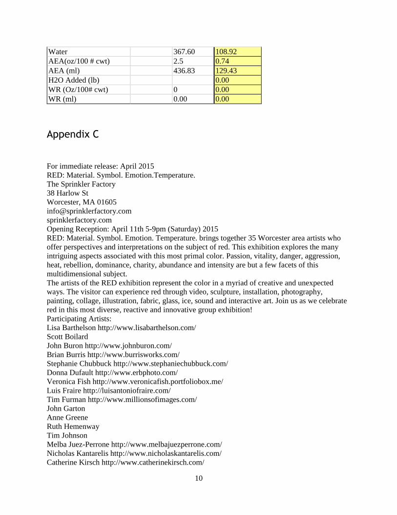
10
Water 367.60 108.92
AEA(oz/100 # cwt) 2.5 0.74
AEA (ml) 436.83 129.43
H2O Added (lb) 0.00
WR (Oz/100# cwt) 0 0.00
WR (ml) 0.00 0.00
Appendix C
For immediate release: April 2015
RED: Material. Symbol. Emotion.Temperature.
The Sprinkler Factory
38 Harlow St
Worcester, MA 01605
sprinklerfactory.com
Opening Reception: April 11th 5-9pm (Saturday) 2015
RED: Material. Symbol. Emotion. Temperature. brings together 35 Worcester area artists who
offer perspectives and interpretations on the subject of red. This exhibition explores the many
intriguing aspects associated with this most primal color. Passion, vitality, danger, aggression,
heat, rebellion, dominance, charity, abundance and intensity are but a few facets of this
multidimensional subject.
The artists of the RED exhibition represent the color in a myriad of creative and unexpected
ways. The visitor can experience red through video, sculpture, installation, photography,
painting, collage, illustration, fabric, glass, ice, sound and interactive art. Join us as we celebrate
red in this most diverse, reactive and innovative group exhibition!
Participating Artists:
Lisa Barthelson http://www.lisabarthelson.com/
Scott Boilard
John Buron http://www.johnburon.com/
Brian Burris http://www.burrisworks.com/
Stephanie Chubbuck http://www.stephaniechubbuck.com/
Donna Dufault http://www.erbphoto.com/
Veronica Fish http://www.veronicafish.portfoliobox.me/
Luis Fraire http://luisantoniofraire.com/
Tim Furman http://www.millionsofimages.com/
John Garton
Anne Greene
Ruth Hemenway
Tim Johnson
Melba Juez-Perrone http://www.melbajuezperrone.com/
Nicholas Kantarelis http://www.nicholaskantarelis.com/
Catherine Kirsch http://www.catherinekirsch.com/
11
Amy Klausmeyer https://moonlightconfetti.wordpress.com/
Jeanne Kowal
Joanna Matuck http://www.joannamatuckstudios.com/
Michelle May
Lauren Monroe http://www.worcesterthinktank.com/
Kim Noonan
Victor Pacheco http://www.vicpacheco.com/
John Pagano http://johnpagano.info/
Paul Puiia http://www.paulpuiia.com/
Elaine Pusateri Cowan
Rainer Reichel
Brian Riach
Emily Sandagata http://emilysandagata.viewbook.com/
Robb Sandagata http://www.rsandagata.com/
Mark Spencer http://www.markspencerstudio.com/
Susan Swinand http://www.swinand.com/
Marguerite White http://margueritetwhite.com/
Peter Wise http://www.peterwiseart.com/
WPI Totem Project
GALLERY HOURS:
April 12th 1-4pm (Sunday)
April 17th 4-8pm (Friday)
April 18th 1-4pm (Saturday)
April 19th 1-4pm (Sunday)
April 24th 4-8pm (Friday)
April 25th 1-4pm (Saturday)
April 26th 1-4pm (Sunday)
CLOSING RECEPTION:
May 2nd 5-9pm (Saturday)
SPECIAL EVENTS:
Slow Art Day
April 11th (Saturday Morning)
10:00-10:30am Meet in the gallery
10:30-11:30am Look at art slowly
11:30-12:00pm Discuss the experience
Slow Art Day is the global all-volunteer event with a simple mission: help more people discover
for themselves the joy of looking
at and loving art. More info: http://www.slowartday.com/
ART AFTER DARK (talk & discussion series with Birgit Strähle)
April 17th 8-9pm (Friday) Sources of Red – Facts, Legends, and Secret Recipes
*guests are invited for a pre-talk reception at 7:30pm
April 24th 8-9pm (Friday) A Journey Through Cultural History – The Many Meanings of Red
*guests are invited for a pre-talk reception at 7:30pm
All events are FREE and OPEN to the PUBLIC
12
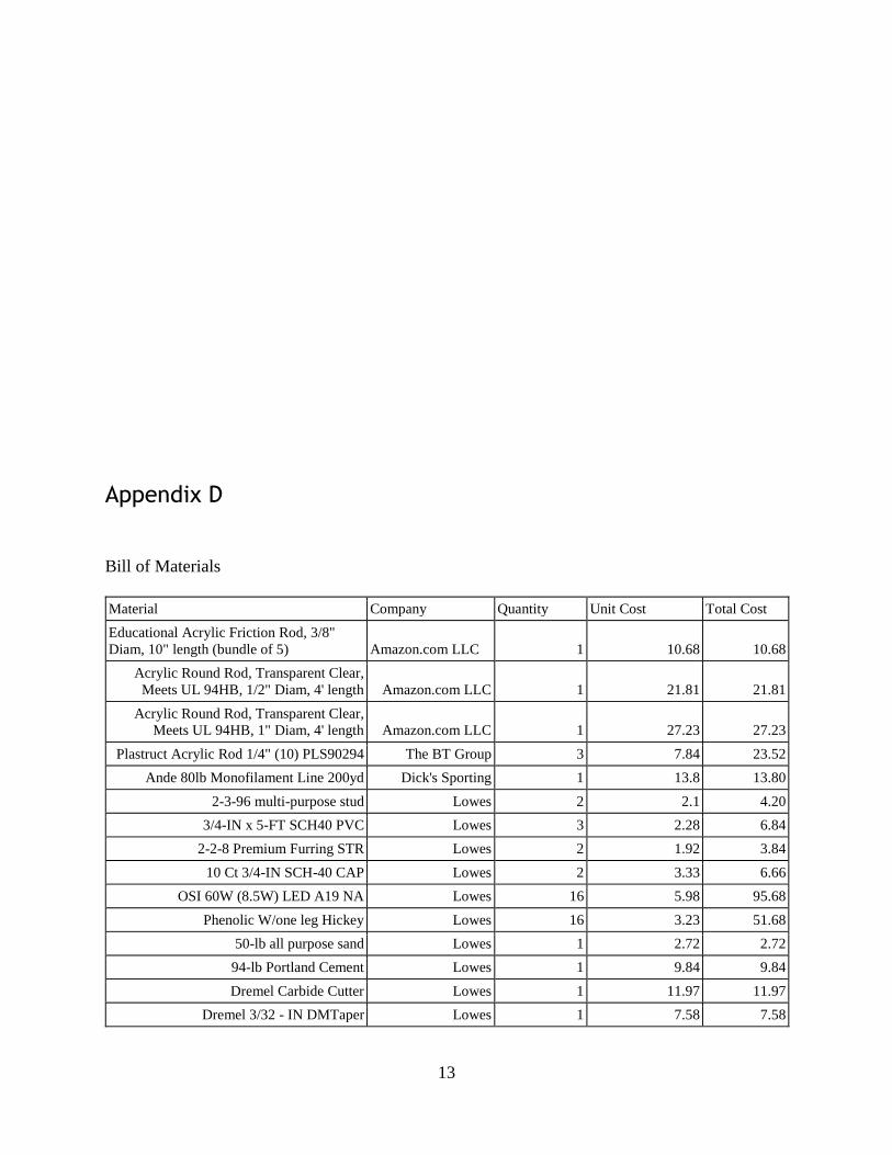
13
Appendix D
Bill of Materials
Material Company Quantity Unit Cost Total Cost
Educational Acrylic Friction Rod, 3/8"
Diam, 10" length (bundle of 5) Amazon.com LLC 1 10.68 10.68
Acrylic Round Rod, Transparent Clear,
Meets UL 94HB, 1/2" Diam, 4' length Amazon.com LLC 1 21.81 21.81
Acrylic Round Rod, Transparent Clear,
Meets UL 94HB, 1" Diam, 4' length Amazon.com LLC 1 27.23 27.23
Plastruct Acrylic Rod 1/4" (10) PLS90294 The BT Group 3 7.84 23.52
Ande 80lb Monofilament Line 200yd Dick's Sporting 1 13.8 13.80
2-3-96 multi-purpose stud Lowes 2 2.1 4.20
3/4-IN x 5-FT SCH40 PVC Lowes 3 2.28 6.84
2-2-8 Premium Furring STR Lowes 2 1.92 3.84
10 Ct 3/4-IN SCH-40 CAP Lowes 2 3.33 6.66
OSI 60W (8.5W) LED A19 NA Lowes 16 5.98 95.68
Phenolic W/one leg Hickey Lowes 16 3.23 51.68
50-lb all purpose sand Lowes 1 2.72 2.72
94-lb Portland Cement Lowes 1 9.84 9.84
Dremel Carbide Cutter Lowes 1 11.97 11.97
Dremel 3/32 - IN DMTaper Lowes 1 7.58 7.58
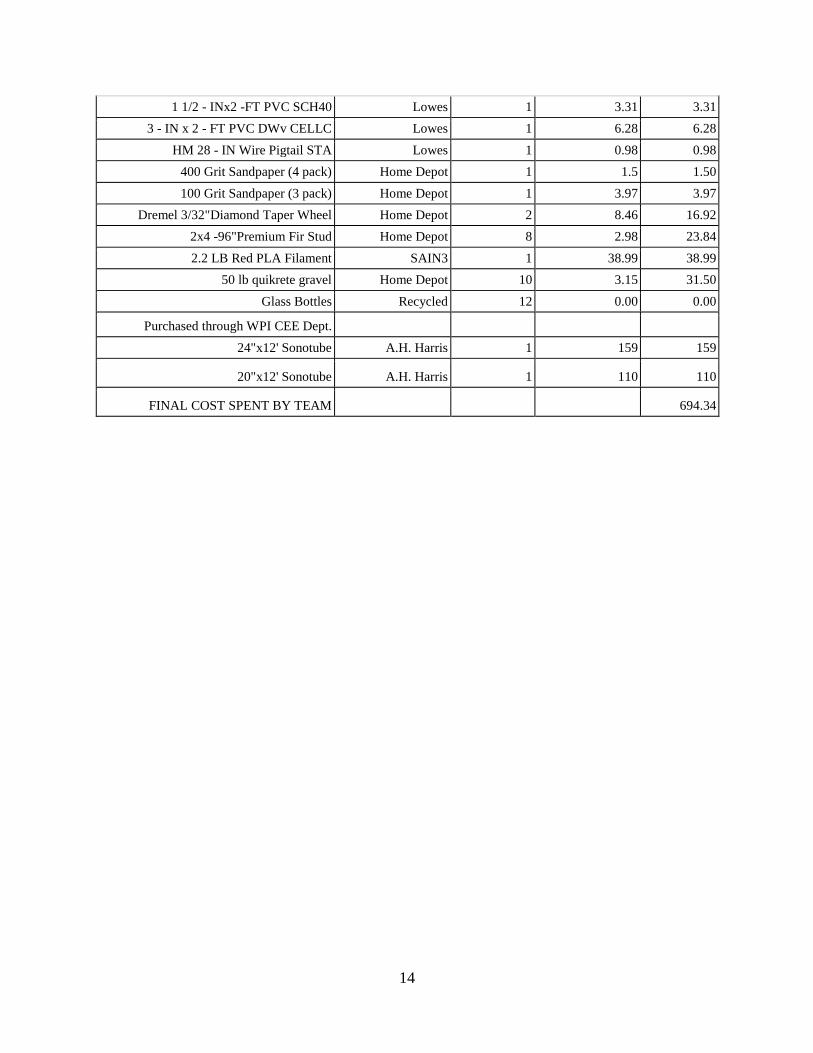
14
1 1/2 - INx2 -FT PVC SCH40 Lowes 1 3.31 3.31
3 - IN x 2 - FT PVC DWv CELLC Lowes 1 6.28 6.28
HM 28 - IN Wire Pigtail STA Lowes 1 0.98 0.98
400 Grit Sandpaper (4 pack) Home Depot 1 1.5 1.50
100 Grit Sandpaper (3 pack) Home Depot 1 3.97 3.97
Dremel 3/32"Diamond Taper Wheel Home Depot 2 8.46 16.92
2x4 -96"Premium Fir Stud Home Depot 8 2.98 23.84
2.2 LB Red PLA Filament SAIN3 1 38.99 38.99
50 lb quikrete gravel Home Depot 10 3.15 31.50
Glass Bottles Recycled 12 0.00 0.00
Purchased through WPI CEE Dept.
24"x12' Sonotube A.H. Harris 1 159 159
20"x12' Sonotube A.H. Harris 1 110 110
FINAL COST SPENT BY TEAM 694.34
15
Acknowledgments
The High-Tech Totem team would like to thank the following for their help with the High-Tech
Totem Pole project.
Professor Brigitte Servatius
Professor Tahar El-Korchi
Wendy Wacko
Russ Lang and the CEE department
Luis Fraire and the Sprinkler Factory Group
A.H. Harris
All others who assisted with the creation of the Totem and its assembly including Nick
McMahon, Jake Zagorsky, and Kevin Lee.