Embed Size (px)
Citation preview
Creating an immersive virtual reality application for ski jumping
Emil Moltu Staurset
Master of Science in Computer Science
Supervisor: Monica Divitini, IDICo-supervisor: Ekaterina Prasolova-Førland, SVT
Department of Computer and Information Science
Submission date: June 2015
Norwegian University of Science and Technology

Creating an immersive virtual reality
application for ski jumping
COMPUTER SCIENCE MASTERS THESIS
Department of Computer and Information Science
Norwegian University of Science and Technology
Emil Moltu Staurset
SPRING 2015
Supervisor: Dr. Ekaterina Prasolova-Førland
Sammendrag
Virtuell virkelighet (VR) har i løpet av de siste ti årene blitt anvendt i ett stort spekter av domener.
VR gir muligheten til å utføre oppgaver i ett kontrollert og trygt miljø. I denne rapporten presen-
terer jeg en virtuell skihoppapplikasjon. Applikasjonen ble implementert i Unity3D. Et LIDAR-
system ble brukt til å skape en nøyaktig punksky av hoppbakken i Granåsen. Punktskyen ble
omgjort til en mesh ved å utføre Poisson Surface Reconstruction. Applikasjonen har en foren-
klet fysisk modell basert på Marasovic [2003]. Applikasjonen bruker akselerometer i en Wiimote
til å måle vinkelen på overkroppen til spilleren under hoppet. Vi utforsket også muligheten for å
bruke Kinect og Wii Balance Board til å detektere hoppet. Applikasjonen ble testet av det norske
hopplandslaget, og av elever på videregående skole. Det viste seg at applikasjonen har poten-
siale til å bli brukt til å trene på timingen på hoppkanten. Den kan også være ett verktøy for å
inspirere unge skihoppere.
i
Abstract
Virtual reality(VR) has been successfully applied to a broad range of training domains. VR pro-
vides an opportunity to train in a safe and controlled environment, with support for accurate
performance measurement. In this report I present a prototype of a VR application for ski jump-
ing. The goal for this project is to explore if such an application can be used to teach the basics
of ski jumping, and if it can be used as a training tool for athletes. The development process is
thoroughly described in the report. Through user testing and an expert evaluation it was con-
cluded that the application has potential to be used as a tool for practicing the timing of the
jump. Improvements for the prototype is proposed, which should enable the prototype to also
evaluate the jumping technique.

ii
Acknowledgments
I would like to thank my supervisor Ekaterina Praslova-Førland for her useful comments and
engagement throughout the whole year. Furthermore I would like to thank Håvard Aas from
Blinken Nord, who helped me by creating the point cloud of Granåsen. The project would not
have been the same without you. Also I have to express my gratitude to Christian Meyer, Steinar
Bråten and the Norwegian national ski jumping team, who have willingly shared their precious
time during the evaluation, and have given me valuable feedback on the system.
Contents
Abstract . . . . . . . . . . . . . . . . . . . . . . . . . . . . . . . . . . . . . . . . . . . . . . . . i
Acknowledgments . . . . . . . . . . . . . . . . . . . . . . . . . . . . . . . . . . . . . . . . . ii
1 Introduction 2
1.1 Motivation . . . . . . . . . . . . . . . . . . . . . . . . . . . . . . . . . . . . . . . . . . . 2
1.2 Research questions . . . . . . . . . . . . . . . . . . . . . . . . . . . . . . . . . . . . . . 4
1.3 Research Method . . . . . . . . . . . . . . . . . . . . . . . . . . . . . . . . . . . . . . . 4
2 Background 6
2.1 Virtual Reality . . . . . . . . . . . . . . . . . . . . . . . . . . . . . . . . . . . . . . . . . 6
2.2 Areas of applications for virtual reality . . . . . . . . . . . . . . . . . . . . . . . . . . . 7
2.2.1 Military training . . . . . . . . . . . . . . . . . . . . . . . . . . . . . . . . . . . . 7
2.2.2 Entertainment . . . . . . . . . . . . . . . . . . . . . . . . . . . . . . . . . . . . . 9
2.2.3 Education . . . . . . . . . . . . . . . . . . . . . . . . . . . . . . . . . . . . . . . 9
2.2.4 Sports training . . . . . . . . . . . . . . . . . . . . . . . . . . . . . . . . . . . . 10
2.3 Ski jumping applications . . . . . . . . . . . . . . . . . . . . . . . . . . . . . . . . . . . 11
2.4 Serious games . . . . . . . . . . . . . . . . . . . . . . . . . . . . . . . . . . . . . . . . . 12
2.5 Natural User interface . . . . . . . . . . . . . . . . . . . . . . . . . . . . . . . . . . . . 13
2.6 Ski jumping . . . . . . . . . . . . . . . . . . . . . . . . . . . . . . . . . . . . . . . . . . 14
2.7 Requirements . . . . . . . . . . . . . . . . . . . . . . . . . . . . . . . . . . . . . . . . . 14
3 The first prototype 16
3.1 Modeling . . . . . . . . . . . . . . . . . . . . . . . . . . . . . . . . . . . . . . . . . . . . 16
3.2 Physical Model . . . . . . . . . . . . . . . . . . . . . . . . . . . . . . . . . . . . . . . . 19
iii
CONTENTS 1
3.3 Implementing in Unity . . . . . . . . . . . . . . . . . . . . . . . . . . . . . . . . . . . . 21
4 Modeling 24
4.1 Surface Reconstruction . . . . . . . . . . . . . . . . . . . . . . . . . . . . . . . . . . . 25
4.2 Marching Cubes(RIMLS) . . . . . . . . . . . . . . . . . . . . . . . . . . . . . . . . . . . 26
4.3 Poisson Surface Reconstruction . . . . . . . . . . . . . . . . . . . . . . . . . . . . . . 28
4.4 Ball Pivot Algorithm . . . . . . . . . . . . . . . . . . . . . . . . . . . . . . . . . . . . . 29
4.5 Which reconstruction method? . . . . . . . . . . . . . . . . . . . . . . . . . . . . . . . 35
4.6 Post processing the mesh . . . . . . . . . . . . . . . . . . . . . . . . . . . . . . . . . . 36
5 Implementation in Unity 44
5.1 The player object . . . . . . . . . . . . . . . . . . . . . . . . . . . . . . . . . . . . . . . 44
5.1.1 Head rotation . . . . . . . . . . . . . . . . . . . . . . . . . . . . . . . . . . . . . 44
5.1.2 Body orientation . . . . . . . . . . . . . . . . . . . . . . . . . . . . . . . . . . . 45
5.2 Jumping . . . . . . . . . . . . . . . . . . . . . . . . . . . . . . . . . . . . . . . . . . . . 51
5.3 Measuring length . . . . . . . . . . . . . . . . . . . . . . . . . . . . . . . . . . . . . . . 54
5.4 Falling . . . . . . . . . . . . . . . . . . . . . . . . . . . . . . . . . . . . . . . . . . . . . . 57
5.5 Ski . . . . . . . . . . . . . . . . . . . . . . . . . . . . . . . . . . . . . . . . . . . . . . . . 58
5.6 Kinect . . . . . . . . . . . . . . . . . . . . . . . . . . . . . . . . . . . . . . . . . . . . . . 60
5.7 Wii Remote . . . . . . . . . . . . . . . . . . . . . . . . . . . . . . . . . . . . . . . . . . . 61
5.8 Wii Balance Board . . . . . . . . . . . . . . . . . . . . . . . . . . . . . . . . . . . . . . . 62
6 Conclusion 64
6.1 Purpose of the tests . . . . . . . . . . . . . . . . . . . . . . . . . . . . . . . . . . . . . . 64
6.2 Expert evaluation . . . . . . . . . . . . . . . . . . . . . . . . . . . . . . . . . . . . . . . 64
6.3 General public . . . . . . . . . . . . . . . . . . . . . . . . . . . . . . . . . . . . . . . . . 69
6.3.1 limitations . . . . . . . . . . . . . . . . . . . . . . . . . . . . . . . . . . . . . . . 76
6.4 Discussion . . . . . . . . . . . . . . . . . . . . . . . . . . . . . . . . . . . . . . . . . . . 77
6.5 Conclusion . . . . . . . . . . . . . . . . . . . . . . . . . . . . . . . . . . . . . . . . . . . 79
6.6 Future Work . . . . . . . . . . . . . . . . . . . . . . . . . . . . . . . . . . . . . . . . . . 80
Bibliography 87
Chapter 1
Introduction
1.1 Motivation
Virtual reality has been pursued for some time, and it has been successfully implemented in sev-
eral domains such as military training [Bowman and McMahan, 2007], sports training [Komura
et al., 2002] and education [Seymour et al., 2002]. It is believed that the first attempts at vir-
tual reality started back in the 1860s when artists started to paint three dimensional panoramic
murals. However the modern virtual reality did not really start before 1957 when Morten Hel-
lig invented the Sensorama, a simulator that projected 3D images combined with smell, wind
and sound to create an illusion of reality. Traditionally the technology used in virtual reality ap-
plications has been expensive, which is one of the explanations for why virtual reality has not
become mainstream yet. With the release of the Oculus Rift in 2012, for the first time there was
a reasonably priced head mounted display accessible for the general public. This has opened
up for building VR applications for a reasonable amount of money.
Jonathan Steuer defines VR as "a real or simulated environment in which a perceiver expe-
riences telepresence" Steuer [1992]. Where telepresence is defined as "a mediated perception
of an environment". Today there are a wide variety of VR technologies with varying degree of
immersion, spanning from regular computer screens, to head mounted displays such as the
Oculus Rift, and the more advanced CAVE systems. Other VR technologies such as haptic, and
gesture recognition are contributing to increase immersiveness in virtual reality applications.
Educators and researchers have also been drawn to virtual environments after they appeared.
2
CHAPTER 1. INTRODUCTION 3
The VR technology has several traits that makes it interesting to be used for educational pur-
poses such as low cost, and high safety, and it can provide interaction in simulated context with
high immersion [Cram et al., 2011]. Today there are many different educational environments
that define themselves as "Virtual Campuses" or "Virtual universities". These environments
started out as applications for distance learning in the early 90’s of the 20th century [Carswell,
1998] Modern virtual campuses have adopted several different technologies which ranges from
simple web-based systems to immersive 3D Virtual environments. Many of the virtual cam-
puses attempts to create a familiar atmosphere for the students, and acts as a framework around
the educational content, and learning activities at the educational institution they represent
[Fominykh et al., 2008]
Virtual cities has also become increasingly popular. The virtual cities often has higher re-
quirements for the design quality of the environments and the level of detail are often of high
importance [Dokonal et al., 2004]. The virtual cities can have different purposes such as geo-
graphical navigation(Google Earth), heritage perservation (Rome Reborn, Forbidden City), so-
cializing(Cybertown) and tourism (VirtualNYCTour). Virtual reality also has the possibility to
offer tourism useful applications within several areas such as planning and management, mar-
keting, entertainment and education accessability and heritage preservation. Virtual reality can
create virtual experiences that tourists may accept as substitutes for real visitations to threat-
ened sites Guttentag [2010] .
In Norway ski jumping is popular, and many tourists come to visit the ski jumping hills.
This project is done in cooperation with Visit Trondheim. Visit Trondheim is interested in using
virtual reality to promote Trondheim to tourists. In earlier projects parts of Trondheim has been
modeled and implemented in the virtual 3d-world Second Life. The goal for this project is to
create a prototype for a real time 3D ski jumping simulator, based on the hill in Trondheim,
Granåsen. Furthermore we want to see how emerging technologies such as the Oculus Rift,
Kinect and Wii Balance board can be used to improve the user experience in an application like
this.
The simulator may have several applications: Teaching the basics of ski jumping to the
general public, be a tool for recruiting aspiring young ski jumpers, promote Trondheim and
Granåsen as a tourist destination, and be used by ski jumpers in a training situation. A simu-
CHAPTER 1. INTRODUCTION 4
lator like this gives the possibility for everyone to experience a ski jump without the risk that is
involved with real ski jumping.
1.2 Research questions
Much of the research in this project will be about developing the prototype and exploring the
possibilities of building a reasonably priced immersive virtual reality ski jumping simulator.
Moreover I will explore how the system can be used. The research question is as follows
R 1: To what extent can an immersive virtual reality application support the understanding of
ski jumping for amateurs?
In order for the application to be able to achieve this goal, the application has to be a re-
alistic simulation of a ski jump, and let the user emulate the different techniques involved
in a ski jump. This will be evaluated by letting representatives from the general public test
the application
R 2: Is it possible to use an immersive virtual reality application as a training tool for ski jumpers?
This puts higher requirements on the system, as the athletes demand a higher level of
realism to be able to use it in a training situation.
R 3: How would such an application be developed
Which tools, methods, and algorithms are required for developing such an application
1.3 Research Method
Literature research
This project required research on virtual reality, 3D-modeling, Computer Graphics,Blender, Unity,
and ski jumping. It proved helpful too read about how virtual reality has been applied earlier,
and specifically how it has been implemented in sports. Literature and web materials on 3D-
modeling, Blender and Unity was necessary to enable me to develop the prototype. The litera-
ture on ski jumping gave insight in how the physical model could be implemented.
CHAPTER 1. INTRODUCTION 5
Questionnaire
The prototype was tested by the general public at NTNU and Vitensenteret. After the test the
users answered a questionnaire. We had to limit the number of questions, as we did not want
it to take the average user more than 5 minutes to complete the survey. The questions is is de-
signed using the proven Likert scale, focusing on the realism, presence, and learning. Measuring
the presence is based on [Usoh et al., 2000].
Expert evaluation
The expert evaluation was done with professional ski jumpers from the Norwegian national
team. The evaluation was conducted as a semi structured interview where the prototype was
presented, tested, and discussed. The interview focused on the realism of the prototype, the
physical model, and how it could be used as a tool in training.
Chapter 2
Background
2.1 Virtual Reality
The goal in Virtual Reality is to create an immersive experience for the user. The reality it
presents is a synthetic 3D-world which is often presented to the user on a stereoscopic head
mounted display, and some applications also offers haptics, or tactile feedback to enhance the
reality. Users often show a strong reaction when experiencing immersive virtual reality for the
first time. It is a different experience than interacting with regular 3D applications on a desktop
PC or a gaming console. This is supported by Meehan et al. [2002] , which confirms that users
behave and feel differently in immersive Virtual Environments. The terms immersion and pres-
ence are often interchangeably used in Virtual Reality community. In Slater [2003] it is claimed
that they are distinct concepts and defines the terms this way:
• Immersion refers to the objective level of sensory fidelity a VR systems provides.
• Presence is the user’s subjective pshycological response to a VR System.
Slater uses an analogy to colour science where immersion is analogous to wave distribution
as it can be objectively assessed and presence is analogous to the perception of colour. In other
words presence is a humans reaction to immersion, and given the same immersive system dif-
ferent people may experience different levels of presence. This means that a VR systems level
of immersion is only dependent on the systems rendering software, display technology, audio,
6
CHAPTER 2. BACKGROUND 7
and tactile feedback technology. In Usoh et al. [2000] the following list of factors that impacts
the level of visual immersion was proposed:
• Field of view - The size of the visual field(in degrees) that can be viewed instaneously.
• Field of regard - the total size of visual fields (in degrees) surrounding the user.
• Display size
• Display resolution
• Stereoscopy - The display of different images to each eye to provide an additional depth
cue
• Head-based rendering - The display of images based on the physical position and orien-
tation of the user’s head (head tracking)
• Realism of lighting,
• Frame rate
• Refresh rate
2.2 Areas of applications for virtual reality
2.2.1 Military training
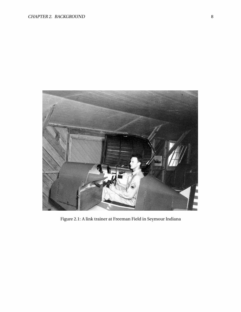
Virtual reality has several applications in military training. The US Military has been a primary
supporter of real time simulation ever since the Link Flight Instrument trainer in late 1930s,
which is shown in figure 2.1. Flight simulation was first invented to support carrier landing
training, in-flight emergency training and air-to air combat [Rolfe and Staples, 1988]. The de-
velopment of these simulators was originally motivated by safety and cost, and lack of suitable
training areas. Virtual reality applications also ranges from flight simulators used in pilot train-
ing to urban combat simulators training infantry in combat tactics. Virtual reality training can
provide the user with an accurate simulation of real events in a safe, controlled environment.
And in many cases it has reduced cost in comparison with real-world exercises.
CHAPTER 2. BACKGROUND 8
Figure 2.1: A link trainer at Freeman Field in Seymour Indiana
CHAPTER 2. BACKGROUND 9
2.2.2 Entertainment
Entertainment or games has a big potential in Virtual reality. However up until now it has been
more limited than some predicted, most probably due to the system’s high cost. It is likely that
the release of Oculus Rift will lead to a resurgence for virtual reality games as it is a reasonably
priced head mounted display, targeted at the video game market. Even though it has not yet
officially been released we are starting to see commercial games with support for Oculus Rift
such as Half Life 2, and Team Fortress 2.
2.2.3 Education
As mentioned earlier the virtual campuses acts as a framework around the educational content,
and learning activities at the educational institution. In addition to the virtual campuses we are
also seeing potential for custom applications for specific educations. For instance in education
of surgeons. Haluck and Krummel [2000] explores how virtual reality can be applied in educa-
tion of surgeons: Technological advancements have drastically changed how doctors diagnose
and treat disease. But surgeons are still being trained using the 100 year old Halstedian appren-
ticeship model. This means that in today’s surgical programs most education is surgical skill
takes place in the operating room. Some have argued that the Operating Room(OR) is the best
environment for surgical education. However there are several possible weaknesses with using
the OR as the classroom. There are numerous distractions, the learner may arrive exhausted or
unprepared, or the mentor may not be a good instructor. Furthermore the specific case may not
be suited for the learner. One must also take into the consideration patient safety. A virtual envi-
ronment for surgical training could be a useful supplement in the education. The trainee could
participate in real-life events without significant risk, as there are no patient who might suffer.
The tasks could be repeated as many times as necessary, and the operation could be abandoned
at any time.
In [Seymour et al., 2002] a randomized double blinded study was peformed on VR and op-
erating room performance. Sixteen surgical residents had baseline pshychomotor abilities as-
sessed, and where randomized to either VR training or control non-VR Training. They then
performed a laparoscopic cholecystectomy with an attending surgeon blind to training status.
CHAPTER 2. BACKGROUND 10
There was no difference in the baseline assessment between the groups. The gallbladder was 29
% faster for VR-trained residents and the non-VR-trained residents was nine times more likely
to transiently fail to make progress, and five times more likely to injure the gallbladder or burn
non-target tissue.
2.2.4 Sports training
There are several potential advantages to a sports training Virtual Environment. [Miles et al.,
2012] lists the following:
• A VE allows standardised scenarios to be created by coaches
• Extra information can be given to players to enrich the environment and guide their per-
formance
• It is possible to quickly and randomly change the environment to match any competative
situations.
In sports athletes has to react to their environment that provides them with information.
Especially for duels between two players the opponents react with anticipation by using this
information. Traditionally these situations was analyzed by showing a film on a wide-screen,
and stopping at strategic time events, and the subjects would than guess the remainder of the
sequence. In Bideau et al. [2004] it is suggested that virtual reality could be an alternative for
this. The environment is under control and enables fine tuning of parameters, and measure
the parameters effect on the subject’s behaviour. They develop a system where they are testing
how handball goalkeepers acts in a virtual scenery. The study shows that the proposed model
enables to carry-out virtual experiments without modifying the natural gestures of the subject.
An other example of virtual reality is shown in Chong and Croft [2009], where the rugby
player sees a full-sized projected video of a player jumping, and the goal is to throw the rugby
ball to that player. A device called TAM (Throw accuracy measurement) was created, compro-
mising of 28 lasers forming two grids. As the lasers is intersected the data is sent to an MATLAB
application, which calculates the parabolic flight of the ball. Tests with players with different
CHAPTER 2. BACKGROUND 11
experience-levels showed that inexperienced players made more than twice as many errors as
experienced players.
Virtual reality has also been applied successfully in other sports, for instance Komura et al.
[2002] introduce a prototype for a virtual batting cage, which enables batters to face a variety
of baseball pitchers. There are no real baseball thrown, but a virtual ball is rendered over the
screen in different trajectories depending on which pitcher the player is facing. The player is
swinging a bat with reflectors attached to the sweet spot. Photoelectric sensors are analyzing
the trajectory of the bat when the player swings, and calculate the balls movement accordingly.
In Park and Moon [2013], it is presented how virtual reality can be used in order to teach be-
ginners the basic of snowboarding. The system is able to teach 5 basic snowboarding exercises.
It is detecting the players movement and center of gravity, and giving instant feedback on the
players performance. Both these papers are good examples on how virtual reality can be imple-
mented as tools for sports training. In Stinson and Bowman [2014] it is shown that a VR sport-
oriented system can induce increased anxiety compared to a baseline condition. Which indi-
cates that there are potential for useful VR sports psychology training systems. And ski jumping
is a sport where mental fortitude plays an important role in an athletes performance.
2.3 Ski jumping applications
Over the years there has been several ski jumping games. Deluxe Ski Jump 4 is by many consid-
ered to be the best ski jumping game on the market in 2015, mainly because there are not any
real competitors. Deluxe Ski Jump has 24 accurately modeled ski hills, and the game is based on
real physics. There has not been published any papers about how the physics in Deluxe ski jump
is implemented. The game controller on the other hand is quite simple, as it uses a computer
mouse for all the phases of the jump. The player can choose between 12 different camera angles
when jumping, and one of them is a first person camera angle. However from that viewpoint
it is really hard to get good results, because it is hard for the player to judge the how the skiers
body is positioned.
Wii fit ski jumping is also an interesting ski jumping game. The game uses the Wii Balance
Board, so the user is using his body to control the jump. Simulating body movement in this
CHAPTER 2. BACKGROUND 12
fashion can improve the users perception of the game, and will probably result in a more real-
istic experience than if you are only pushing a button on a controller. Although game has nice
controllers, the game itself is simple and does not seem to have any real physics.
In 19 November 2014 the Alf Engen Ski Museum in Park City, Utah opened a new virtual ski
jump exhibition called "Take Flight". It seems like the game is displayed on a TV-monitor, and it
also looks like it using some kind of a force scale for the jumping, similar to the Wii fit jumping
game. At the moment there is not much information about the system, but based on Engen-
Museum [2014] this may be one of the better virtual ski jumping simulator at the moment. And
in March 2015 the Slovenian insurance company Triglav created the "Planica 2015 Virtual ski
flying" Sporto [2015] which is a virtual reality ski jumping application based the real ski jumping
hill Planica, which is one of the largest ski jumping hills in the world with a hill record of 248.5
meters. The application is using the Oculus Rift Devolopent Kit 2, and it seems like it only uses
the head tracker of the Oculus for controlling the ski jump. This is probably the best virtual
reality ski jumping application using a head mounted display.
2.4 Serious games
There are several definitions of video games and serious games. [Zyda, 2005] offers the following
definitions video game: "A mental contest, played with a computer according to certain rules
for amusement, recreation of winning a stake". Serious game: "A mental contest, played with
a computer in accordance with specific rules that uses entertainment to further government or
corporate training, education, health, public policy, and strategic communication objectives."
In other words a serious game is a game where the main objective is to educate users, and not
to entertain them. The games need to be engaging but not necessarily fun. Serious games can
be many different game genres and like virtual reality it can have a broad area of applications.
Americas Army US-Army is a round based team tactical shooter game where the player can ex-
perience how it is to be a soldier in the US army. It was first deemed to be a good recruiting tool
but there "was insufficient fidelity in the game for it to be any use in training". Later it turned
out that the game also had been incorporated in the training for soldiers who e.g. struggled in
the rifle range Zyda [2005]. The earlier mentioned experiment in [Haluck and Krummel, 2000]
CHAPTER 2. BACKGROUND 13
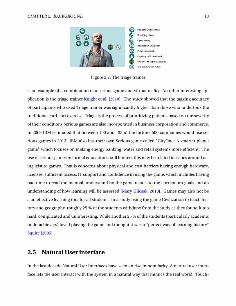
Figure 2.2: The triage trainer
is an example of a combination of a serious game and virtual reality. An other interesting ap-
plication is the triage trainer Knight et al. [2010]. The study showed that the tagging accuracy
of participants who used Triage trainer was significantly higher than those who undertook the
traditional card-sort exercise. Triage is the process of prioritizing patients based on the severity
of their conditions.Serious games are also incorporated in business corporation and commerce.
In 2009 IBM estimated that between 100 and 135 of the fortune 500 companies would use se-
rious games in 2012. IBM also has their own Serious game called "CityOne: A smarter planet
game" which focuses on making energy banking, water and retail systems more efficient. The
use of serious games in formal education is still limited, this may be related to issues around us-
ing leisure games. That is concerns about physical and cost barriers having enough hardware,
licenses, sufficient access, IT support and confidence in using the game, which includes having
had time to read the manual, understand ho the game relates to the curriculum goals and an
understanding of how learning will be assessed [Mary Ulicsak, 2010]. Games may also not be
a an effective learning tool for all students. In a study using the game Civilization to teach his-
tory and geography, roughly 25 % of the students withdrew from the study as they found it too
hard, complicated and uninteresting. While another 25 % of the students (particularly academic
underachievers) loved playing the game and thought it was a "perfect way of learning history"
Squire [2005]
2.5 Natural User interface
In the last decade Natural User Interfaces have seen an rise in popularity. A natural user inter-
face lets the user interact with the system in a natural way that mimics the real world. Touch-
CHAPTER 2. BACKGROUND 14
screens(Microsoft Surface), and gestural interactions(Kinect) lets the user interact with systems
in new ways. Natural user interfaces is of particular interests for virtual reality. In virtual reality
applications the user often has a head mounted display (HMD), which prevents the user from
seeing the keyboard and mouse. Natural user interface is considered as an requirement for a
sport-themed virtual reality application in [Miles et al., 2012]
2.6 Ski jumping
Ski jumping is a form of Nordic skiing in which athletes descend a take-off ramp, called the in-
run, jump and fly as far as possible. During the in-run the athlete tries to gather as much speed
as possible by having favorable aerodynamic body position. While in flight the athlete attempts
to hold a favorable body position and avoid landing as long as possible. In competitions points
are awarded both for style and length. The skis are 11 cm wide and can be up to 146% of the
total body height of the skier.
The ski jumping hill consists of two main parts: the in-run, and the landing slope. The in-run
typically starts with an angle of 38-36 degrees which then curves into an transition often called
the take-off radius or the R1. The transition is then followed by the take-off ramp, which typically
has an angle of 7 and 12 degrees downhill. The landing slope has a smooth curve that follows
the profile of the jump, because of this the skier is never more than 6 meters above the ground.
The steepest point of the hill is called the K-point or the critical point. The K-point is used in the
calculation of distance points in competitions, as a jump to the critical point grants 60 points.
Further down the slope lies the hill size point, which is calculated based on the technical data
of a hill based on radius, angle of inclination and record distance. Since 2004 this has been the
official measurement for the size of hills.
2.7 Requirements
In this section we will describe the requirements for the prototype. The requirements was set
through reviewing the literature.
• The hill should be similar to the ski jumping hill in Trondheim, Granåsen. This means
CHAPTER 2. BACKGROUND 15
that the hill have recognizable visual elements from the hill. It should also have the same
structural dimenensions as the real hill.
• The prototype should be physical correct. The prototype should model the physical prop-
erties of a ski jump correctly, including speed, jumping, and flying.
• The application should be able to run in real time on a mid-range computer.
• The system should provide a realistic ski jumping experience for amateurs.
• The prototype should have a natural user interface
Chapter 3
The first prototype
This project is a continuation of the prototype made in Staurset [2014]. In this chapter I will de-
scribe the design and implementation of the original prototype. I will only describe the most im-
portant part of the development process. For a more detailed explanation please see [Staurset,
2014].
3.1 Modeling
A 3D model consists of vertices, edges and faces in 3D-space. It is usual to start up with a simple
mesh(e.g a cube) and shape it by doing operations on said mesh. I used the the graphics software
Blender to create the models. A model consists of vertices, edges and faces in 3D-space. It is
usual to start up with simple mesh(e.g. a cube) and shape it by doing operations on the mesh. In
Blender you have many different operations that can be applied to the model such as translate,
rotate, scale, mirror,extrude and duplicate. These operations can be applied at mesh ,face, and
vertex level.
I used the official FIS hill certificate(Appendix A) as a reference when I created the hill. The
hill certificate provides the basic measurement and metrics of the hill. The in-run was divided
into 3 parts: the straight, the transition (or radius) and the take-off ramp. The straight part of
the in-run was created by shaping a cube. At first it was scaled and rotated so the cube had
correct dimensions and orientation. Then the cube was subdivided into a finer mesh. Next the
ski tracks was made by extruding down two of the rows on the cube. The radius was created by
16
CHAPTER 3. THE FIRST PROTOTYPE 17
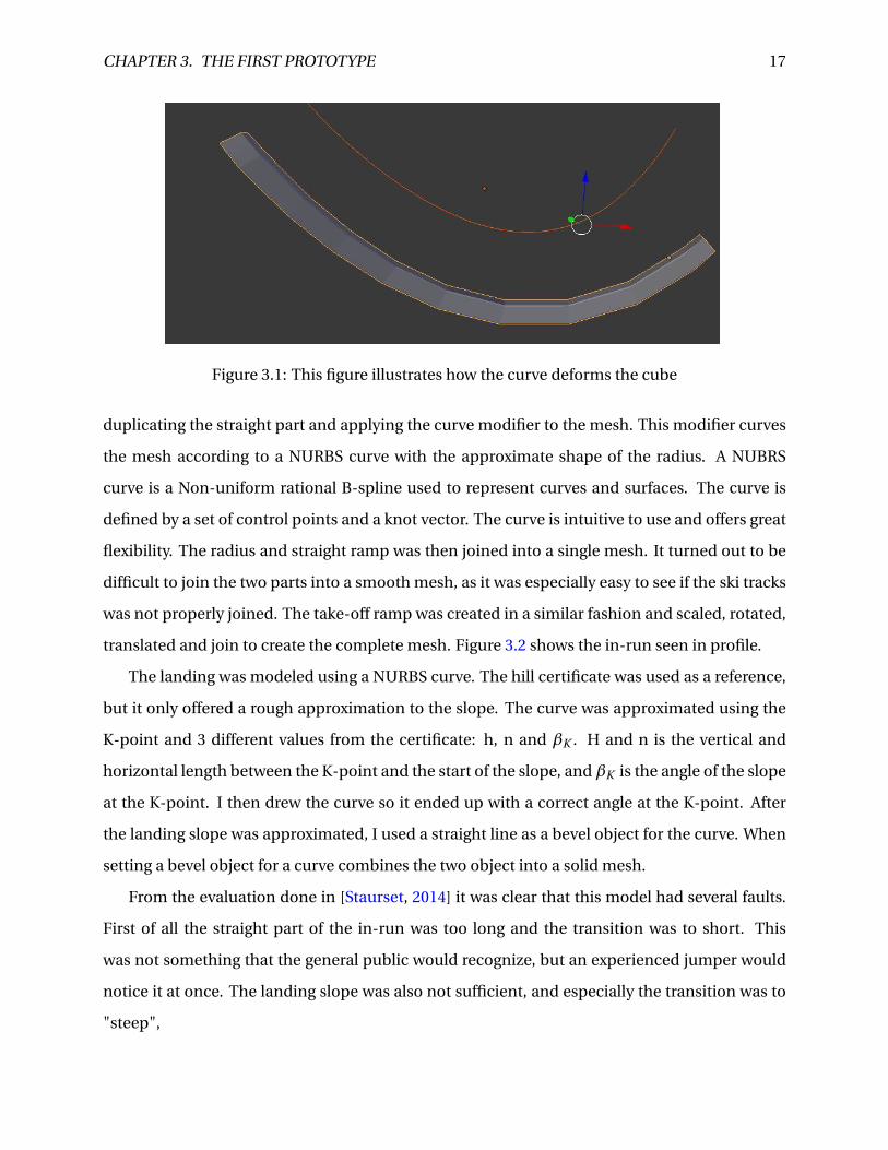
Figure 3.1: This figure illustrates how the curve deforms the cube
duplicating the straight part and applying the curve modifier to the mesh. This modifier curves
the mesh according to a NURBS curve with the approximate shape of the radius. A NUBRS
curve is a Non-uniform rational B-spline used to represent curves and surfaces. The curve is
defined by a set of control points and a knot vector. The curve is intuitive to use and offers great
flexibility. The radius and straight ramp was then joined into a single mesh. It turned out to be
difficult to join the two parts into a smooth mesh, as it was especially easy to see if the ski tracks
was not properly joined. The take-off ramp was created in a similar fashion and scaled, rotated,
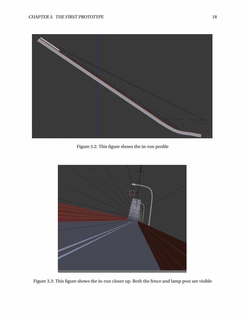
translated and join to create the complete mesh. Figure 3.2 shows the in-run seen in profile.
The landing was modeled using a NURBS curve. The hill certificate was used as a reference,
but it only offered a rough approximation to the slope. The curve was approximated using the
K-point and 3 different values from the certificate: h, n and βK . H and n is the vertical and
horizontal length between the K-point and the start of the slope, and βK is the angle of the slope
at the K-point. I then drew the curve so it ended up with a correct angle at the K-point. After
the landing slope was approximated, I used a straight line as a bevel object for the curve. When
setting a bevel object for a curve combines the two object into a solid mesh.
From the evaluation done in [Staurset, 2014] it was clear that this model had several faults.
First of all the straight part of the in-run was too long and the transition was to short. This
was not something that the general public would recognize, but an experienced jumper would
notice it at once. The landing slope was also not sufficient, and especially the transition was to
"steep",
CHAPTER 3. THE FIRST PROTOTYPE 18
Figure 3.2: This figure shows the in-run profile
Figure 3.3: This figure shows the in-run closer up. Both the fence and lamp post are visible
CHAPTER 3. THE FIRST PROTOTYPE 19
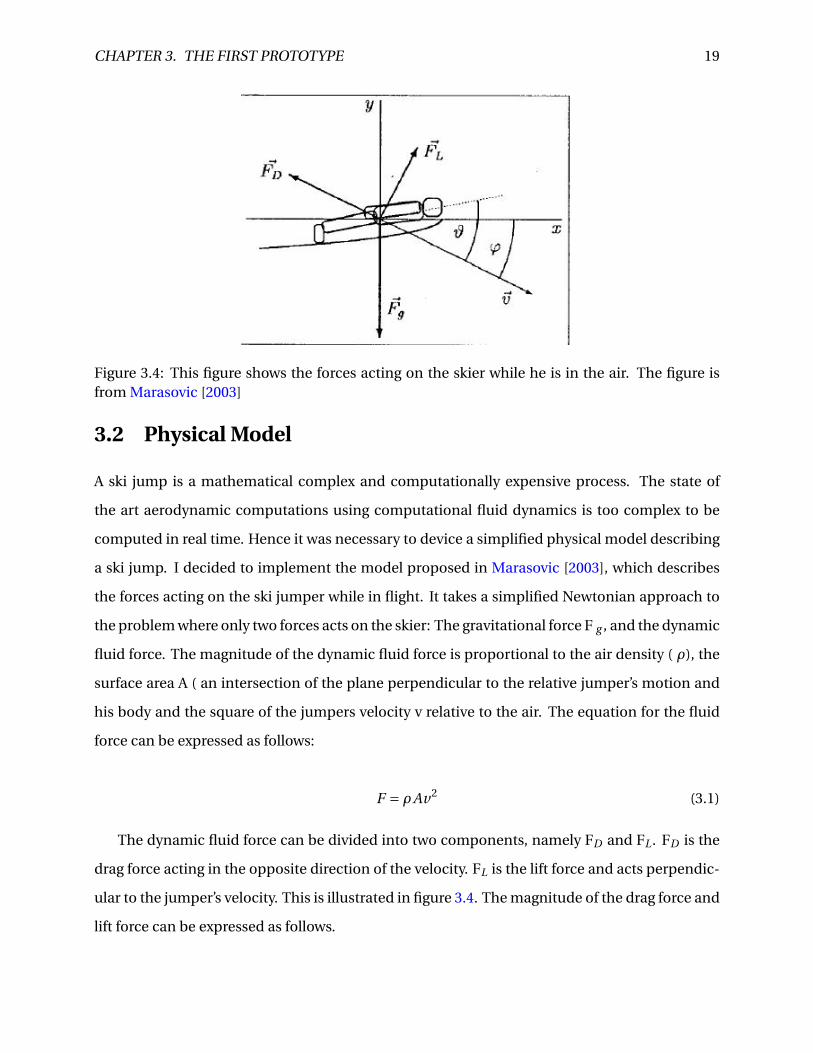
Figure 3.4: This figure shows the forces acting on the skier while he is in the air. The figure isfrom Marasovic [2003]
3.2 Physical Model
A ski jump is a mathematical complex and computationally expensive process. The state of
the art aerodynamic computations using computational fluid dynamics is too complex to be
computed in real time. Hence it was necessary to device a simplified physical model describing
a ski jump. I decided to implement the model proposed in Marasovic [2003], which describes
the forces acting on the ski jumper while in flight. It takes a simplified Newtonian approach to
the problem where only two forces acts on the skier: The gravitational force F g , and the dynamic
fluid force. The magnitude of the dynamic fluid force is proportional to the air density ( ρ), the
surface area A ( an intersection of the plane perpendicular to the relative jumper’s motion and
his body and the square of the jumpers velocity v relative to the air. The equation for the fluid
force can be expressed as follows:
F = ρAv2 (3.1)
The dynamic fluid force can be divided into two components, namely FD and FL . FD is the
drag force acting in the opposite direction of the velocity. FL is the lift force and acts perpendic-
ular to the jumper’s velocity. This is illustrated in figure 3.4. The magnitude of the drag force and
lift force can be expressed as follows.
CHAPTER 3. THE FIRST PROTOTYPE 20
FD = 1
2CDρv2
(A⊥+ A∥ sin2(ϑ)sin(ϑ)
)(3.2)
FL = 1
2CLρv2 A∥si n2(ϑ)cos(ϑ) (3.3)
Where A⊥ is the area of the frontal surface of the skier, A∥ is the area of bottom surface of
the skier. For simplicity these are assumed to be constant during the jump. CD and CL is the
drag and lift coefficient. And ϑ is the angle between the body of the skier and the velocity v,
also known as the angle of attack. By decomposing the drag and lift force I can derive the forces
Fx and Fy which is the sum of forces acting on the skier in the horizontal and vertical direction
respectively.
Fx = 1
2CLρA∥ sin2(ϑ)cos(ϑ)sin(φ)− 1
2CDρv2
[A⊥+ A∥ sin2(ϑ)sin(ϑ)
]cos(φ) (3.4)
Fy =−mg + 1
2CLρv2 A∥ sin2(ϑ)cos(ϑ)cos(φ)+ 1
2CDρv2
[A⊥+ A∥ sin2(ϑ)sin(ϑ)
]sin(φ) (3.5)
here φ is the instantaneous angle between the velocity and the x-axis, m is the mass of the
ski jumper and g is the acceleration of gravity. By using Newton’s laws of motion I were able to
express the acceleration and instantaneous velocity in both vertical and horizontal direction by
the following equations
d vx
d t= Fx
m(3.6)
d vy
d t= Fy
m(3.7)
d x
d t= vx (3.8)
d y
d t= vy (3.9)
CHAPTER 3. THE FIRST PROTOTYPE 21
According this model the parameters that changes during a ski jump is FX , FY , the skiers
velocity, position and angle of attack. And the only thing the jumper can impact while he is in
the air is the angle of attack. The prototype used the following values for the constants: A⊥ =
0.15 m2, A∥=1.2 m2, m = 58, g = 9.81 m/s2, ρ =1.0 kg/m3, and CD = CL = 1.
3.3 Implementing in Unity
The application was developed in Unity 3D. Unity is a cross-platform game creation system, in-
cluding a game engine and an IDE. Unity also has its own integration package for Oculus Rift,
which makes it relatively easy to create a VR-application compatible with Oculus rift. When cre-
ating an application in Unity the game is organized in scenes. Each unique scene can be thought
of as an unique level. The scenes can contain numerous GameObjects. GameObjects is the ba-
sic building block in Unity. Everything you see in the game is a game object. The GameObjects
themselves does not do anything, but it is a container for components that can be attached to
the object. The components can be several different things such as a mesh renderer, a collider, a
rigid body, and a script among others. Scripting in Unity is also an important part in developing
in Unity. The scripts can be created in JavaScript, C# and BOO. Through a well documented API
you can access and manipulate the Gameobjects and other components via the code.
The first thing I did was importing the 3D-models from Blender, and place them in the scene.
In this context the imported model will be the GameObject and by default it has two compo-
nents attached to it: the transform, and the animator. The transform keeps track of the position,
rotation and scale of the GameObject, while the Animator lets you manipulate the behaviour
of the object by providing setup for state machines and blend trees. The terrain was created by
using the built in terrain creator in Unity. This gives you three different tools for manipulating
the height map of the terrain: raise/lower terrain, paint height, and the smooth height. The ter-
rain creator also has a tree creator, which lets you place trees in a chosen radius with a chosen
density. These tools make it quite easy to to create a varied scene.
After importing the models into Unity, colliders was added to them. Unity provides 4 differ-
ent colliders: box, sphere, capsule, and mesh collider. The first 3 are often called primitive col-
liders as they are less computational expensive than the mesh collider. The colliders can both
CHAPTER 3. THE FIRST PROTOTYPE 22
be used to prevent the player from falling through the objects and as an action trigger. However
a collider cannot be used for both at the same time. Due to the complex shape of the in-run
and out-run both had to use the mesh collider. The in-run also has a trigger box collider which
to keep track of when the player is in the in-run. The out-run also needed a collider to trigger
when the player landed. A box collider was not accurate enough, and the existing collider could
not be used. Therefore the out-run was duplicated, where the duplicated out-run has a trigger
mesh collider that triggers when the player landed. This trigger mesh was translated 0.3 meter
in the Y-direction to make sure that the collider got triggered when the player landed.
The player behaviour used the standard Unity First Person Controller as a starting point.
This is a out of the box controller which make you able to walk around in a unity scene. It has a
sphere collider which prevents the player from falling through the terrain, and it has a standard
camera that can be rotated with the mouse, and several parameters that enables you to fine
tune the behaviour of the character. The player object has a capsule collider which prevents
the player from falling through the terrain and other colliders. It also has 3 scripts attached:
MouseLook, CharacterMotor and FPSInput Controller.
The FPSInputController handles the input from the keyboard/mouse and passes it on to the
CharacterMotor and the MouseLook scripts. The MouseLook Scripts handles the mouse input
and rotates the camera based on it. While the CharacterMotor is responsible for calculating
the movement of the player based on the input. By default the motor has implemented walking,
jumping, gravity and sliding. This was the script where much of the work was done. The script is
quite complex but I will give a brief explanation on how it works. The update function is called
every frame and have two different modus operandi: fixed or "when available". When doing
fixed update the function is called at a fixed interval of 0.02 seconds, while the "when available"
is called immediately after the last frame was done calculated. The fixed update tends to per-
form better in physical simulations, so that is what we chose. The Algorithm 1 shows the main
steps in the update function. ApplyInputVelocityChange updates the velocity according to in-
put from the keyboard and the current velocity. ApplyGravityAndJumping handles the jumping
and also implements gravity(without air resistance) . In MoveCharacterAndUpdatevelocity the
position of the player is updated, taking collisions into consideration, and updates the velocity
based on the distance the player actually moves.
CHAPTER 3. THE FIRST PROTOTYPE 23
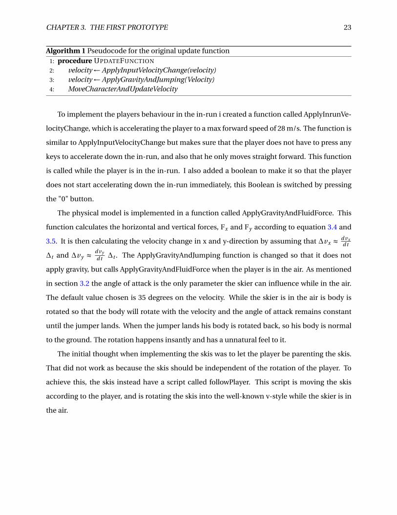
Algorithm 1 Pseudocode for the original update function1: procedure UPDATEFUNCTION
2: velocity ← ApplyInputVelocityChange(velocity)3: velocity ← ApplyGravityAndJumping(Velocity)4: MoveCharacterAndUpdateVelocity
To implement the players behaviour in the in-run i created a function called ApplyInrunVe-
locityChange, which is accelerating the player to a max forward speed of 28 m/s. The function is
similar to ApplyInputVelocityChange but makes sure that the player does not have to press any
keys to accelerate down the in-run, and also that he only moves straight forward. This function
is called while the player is in the in-run. I also added a boolean to make it so that the player
does not start accelerating down the in-run immediately, this Boolean is switched by pressing
the "0" button.
The physical model is implemented in a function called ApplyGravityAndFluidForce. This
function calculates the horizontal and vertical forces, Fx and Fy according to equation 3.4 and
3.5. It is then calculating the velocity change in x and y-direction by assuming that ∆vx ≈ d vxd t
∆t and ∆vy ≈ d vy
d t ∆t . The ApplyGravityAndJumping function is changed so that it does not
apply gravity, but calls ApplyGravityAndFluidForce when the player is in the air. As mentioned
in section 3.2 the angle of attack is the only parameter the skier can influence while in the air.
The default value chosen is 35 degrees on the velocity. While the skier is in the air is body is
rotated so that the body will rotate with the velocity and the angle of attack remains constant
until the jumper lands. When the jumper lands his body is rotated back, so his body is normal
to the ground. The rotation happens insantly and has a unnatural feel to it.
The initial thought when implementing the skis was to let the player be parenting the skis.
That did not work as because the skis should be independent of the rotation of the player. To
achieve this, the skis instead have a script called followPlayer. This script is moving the skis
according to the player, and is rotating the skis into the well-known v-style while the skier is in
the air.
Chapter 4
Modeling
In the second iteration we used a Lidar system to create an accurate model of the hill. LIDAR
is a remote sensing technology that accurately measures distances to a target by illuminating it
with a laser and analyzing the reflected lightSANGAM [2012]. The LIDAR system was attached
to a drone that flew over a large area around Granåsen. The output from the Lidar system is a
point cloud in the form of a LAS-file. A point cloud is a set of data points in 3D space. With the
system it is possible to choose the granularity of the point cloud down to one point every 5 cm.
After some initial testing I found that I got the best results 10 cm granularity, this is of course
a trade off between file size and accuracy of the point cloud. As mentioned in section 3.1 a 3D
model consist of vertices, edges and faces in 3D-space. The point cloud is only raw data points
and has to be converted into a triangulated mesh before it can be used in Unity.
I did not have software that could read the LAS-file, so the first step was to convert the LAS-
file into the more manageable XYZ format. In this format each point is written in ASCII sepa-
rated by comma. This conversion was done by using the LAStools las2txt program, which pro-
vides an easy and intuitive way to convert LAS files.
With the new XYZ file I was able to edit the point cloud using Meshlab. Meshlab is an open
source 3D mesh processing software with many useful tools for processing point clouds. The
file size of the original point cloud was ∼ 75 MB, which seems a little excessive for our use.
24
CHAPTER 4. MODELING 25
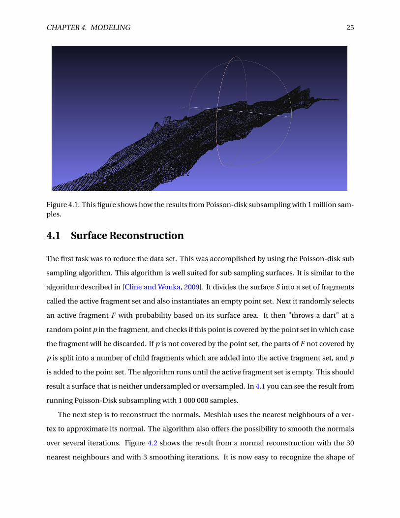
Figure 4.1: This figure shows how the results from Poisson-disk subsampling with 1 million sam-ples.
4.1 Surface Reconstruction
The first task was to reduce the data set. This was accomplished by using the Poisson-disk sub
sampling algorithm. This algorithm is well suited for sub sampling surfaces. It is similar to the
algorithm described in [Cline and Wonka, 2009]. It divides the surface S into a set of fragments
called the active fragment set and also instantiates an empty point set. Next it randomly selects
an active fragment F with probability based on its surface area. It then "throws a dart" at a
random point p in the fragment, and checks if this point is covered by the point set in which case
the fragment will be discarded. If p is not covered by the point set, the parts of F not covered by
p is split into a number of child fragments which are added into the active fragment set, and p
is added to the point set. The algorithm runs until the active fragment set is empty. This should
result a surface that is neither undersampled or oversampled. In 4.1 you can see the result from
running Poisson-Disk subsampling with 1 000 000 samples.
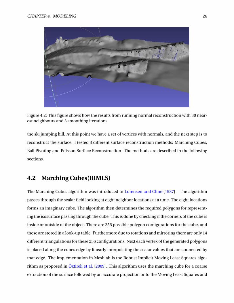
The next step is to reconstruct the normals. Meshlab uses the nearest neighbours of a ver-
tex to approximate its normal. The algorithm also offers the possibility to smooth the normals
over several iterations. Figure 4.2 shows the result from a normal reconstruction with the 30
nearest neighbours and with 3 smoothing iterations. It is now easy to recognize the shape of
CHAPTER 4. MODELING 26
Figure 4.2: This figure shows how the results from running normal reconstruction with 30 near-est neighbours and 3 smoothing iterations.
the ski jumping hill. At this point we have a set of vertices with normals, and the next step is to
reconstruct the surface. I tested 3 different surface reconstruction methods: Marching Cubes,
Ball Pivoting and Poisson Surface Reconstruction. The methods are described in the following
sections.
4.2 Marching Cubes(RIMLS)
The Marching Cubes algorithm was introduced in Lorensen and Cline [1987] . The algorithm
passes through the scalar field looking at eight neighbor locations at a time. The eight locations
forms an imaginary cube. The algorithm then determines the required polygons for represent-
ing the isosurface passing through the cube. This is done by checking if the corners of the cube is
inside or outside of the object. There are 256 possible polygon configurations for the cube, and
these are stored in a look-up table. Furthermore due to rotations and mirroring there are only 14
different triangulations for these 256 configurations. Next each vertex of the generated polygons
is placed along the cubes edge by linearly interpolating the scalar values that are connected by
that edge. The implementation in Meshlab is the Robust Implicit Moving Least Squares algo-
rithm as proposed in Öztireli et al. [2009]. This algorithm uses the marching cube for a coarse
extraction of the surface followed by an accurate projection onto the Moving Least Squares and
CHAPTER 4. MODELING 27
an extra zero removal procedure. Meshlab offers the following parameters for tweaking the out-
put:
• MLS - Filter scale: The scale of the spatial low pass filter relative to the local point spacing
of the vertices
• Projection - Accuracy: Threshold value for stopping the projection step.
• Projection - Max iterations: Specifies the number of iterations of the projection step.
• MLS -Sharpness: Width of the filter used by the normal refitting weight. Typical values
are ranging between 0.75(sharp) and 2.0 (smooth)
• MLS - Max fitting iterations: Max number of fitting iterations.
• Grid resolution Resolution of the grid that marching cubes are ran on.
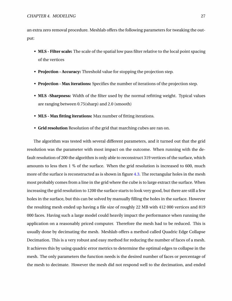
The algorithm was tested with several different parameters, and it turned out that the grid
resolution was the parameter with most impact on the outcome. When running with the de-
fault resolution of 200 the algorithm is only able to reconstruct 319 vertices of the surface, which
amounts to less then 1 % of the surface. When the grid resolution is increased to 600, much
more of the surface is reconstructed as is shown in figure 4.3. The rectangular holes in the mesh
most probably comes from a line in the grid where the cube is to large extract the surface. When
increasing the grid resolution to 1200 the surface starts to look very good, but there are still a few
holes in the surface, but this can be solved by manually filling the holes in the surface. However
the resulting mesh ended up having a file size of roughly 22 MB with 412 000 vertices and 819
000 faces. Having such a large model could heavily impact the performance when running the
application on a reasonably priced computer. Therefore the mesh had to be reduced. This is
usually done by decimating the mesh. Meshlab offers a method called Quadric Edge Collapse
Decimation. This is a very robust and easy method for reducing the number of faces of a mesh.
It achieves this by using quadric error metrics to determine the optimal edges to collapse in the
mesh. The only parameters the function needs is the desired number of faces or percentage of
the mesh to decimate. However the mesh did not respond well to the decimation, and ended
CHAPTER 4. MODELING 28
Figure 4.3: This figure shows the in-run reconstructed with the Marching Cube algorithm withgrid resolution of 600
up looking very noisy when decimating only 10 % of the faces as can be seen in figure 4.4. Fur-
thermore it is worth mentioning that although the method is able to reconstruct the shape of
the in-run it is not detailed enough to be used directly in the application.
4.3 Poisson Surface Reconstruction
This approach was introduced by Mikael Kazhdan in Kazhdan et al. [2006]. It requires a point
set with oriented normals. The indicator function is used in the reconstruction of the surface.
It is a function that is zero everywhere except near the surface. The gradient of this function is
first approximated using the normal field, and then the function itself is derived from this gradi-
ent. Next the Marching Cubes algorithm is used to build an octree representing the surface. An
octree is an tree data structure where each node has exactly 8 children are used for partitioning
the 3 dimensional space. Meshlab offers several parameters that can impact the reconstruction:
• Octree Depth: This is the depth of the octree created in the reconstruction. The default
value is a depth of 8.
• Solver divide: This specifies at which depth a Gauss-Seidel is used to solve the Laplacian
equation. This parameter can impact the memory usage during reconstruction.
CHAPTER 4. MODELING 29
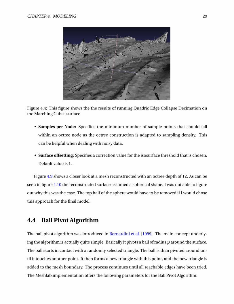
Figure 4.4: This figure shows the the results of running Quadric Edge Collapse Decimation onthe Marching Cubes surface
• Samples per Node: Specifies the minimum number of sample points that should fall
within an octree node as the octree construction is adapted to sampling density. This
can be helpful when dealing with noisy data.
• Surface offsetting: Specifies a correction value for the isosurface threshold that is chosen.
Default value is 1.
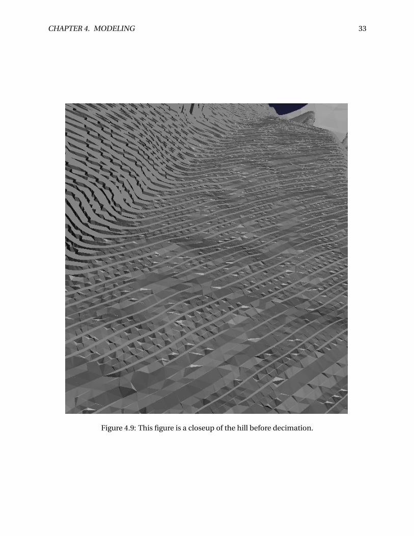
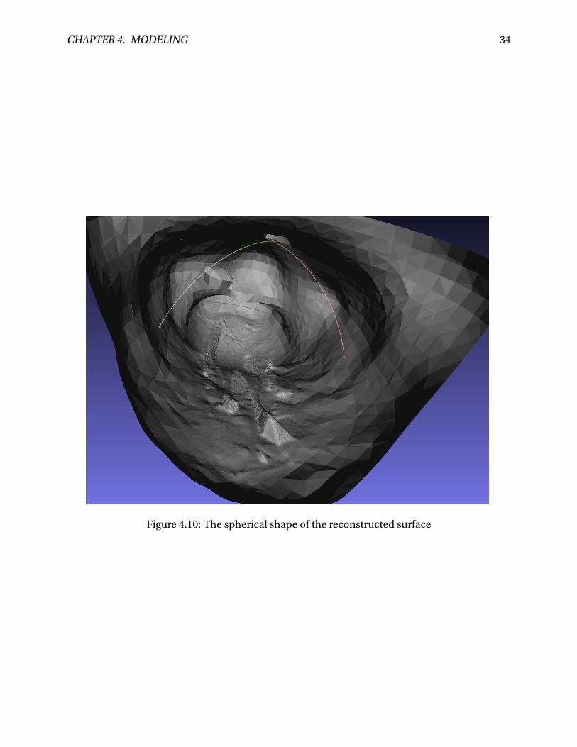
Figure 4.9 shows a closer look at a mesh reconstructed with an octree depth of 12. As can be
seen in figure 4.10 the reconstructed surface assumed a spherical shape. I was not able to figure
out why this was the case. The top half of the sphere would have to be removed if I would chose
this approach for the final model.
4.4 Ball Pivot Algorithm
The ball pivot algorithm was introduced in Bernardini et al. [1999]. The main concept underly-
ing the algorithm is actually quite simple. Basically it pivots a ball of radius p around the surface.
The ball starts in contact with a randomly selected triangle. The ball is than pivoted around un-
til it touches another point. It then forms a new triangle with this point, and the new triangle is
added to the mesh boundary. The process continues until all reachable edges have been tried.
The Meshlab implementation offers the following parameters for the Ball Pivot Algorithm:
CHAPTER 4. MODELING 30
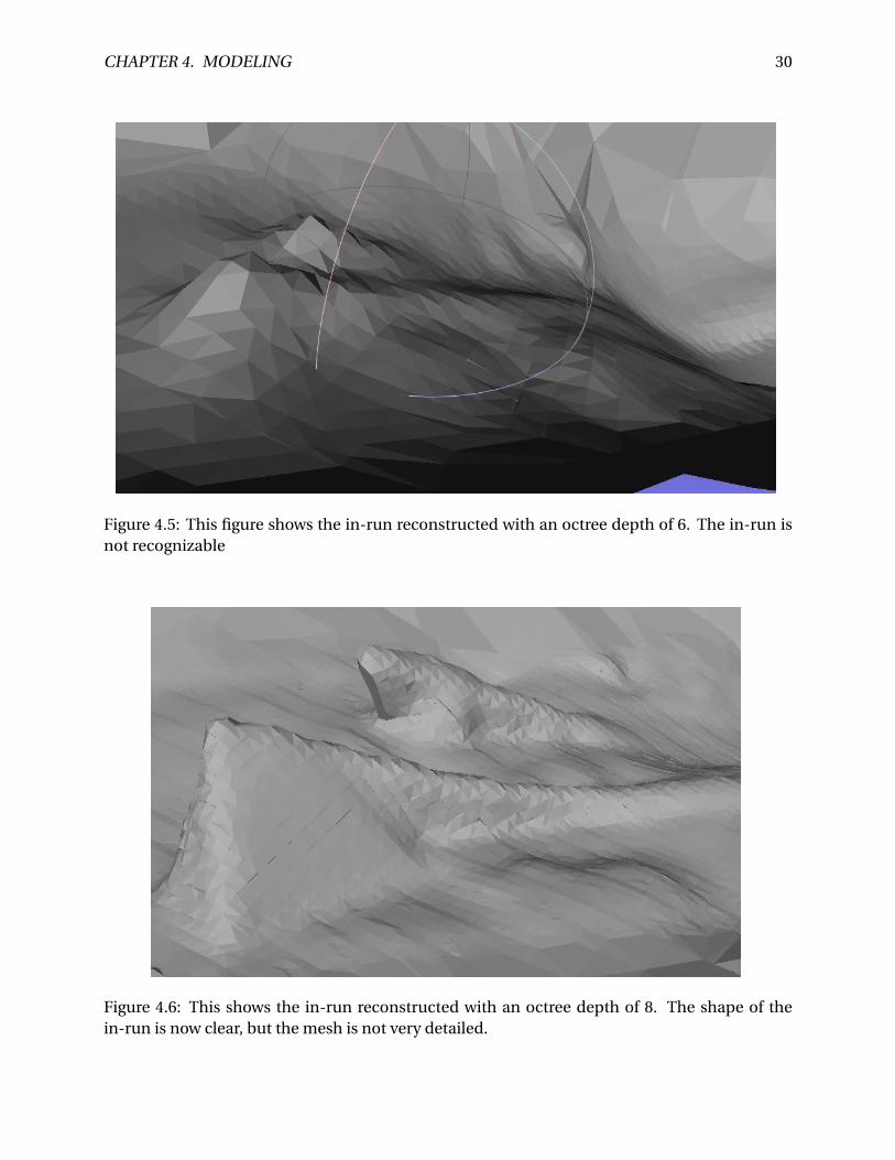
Figure 4.5: This figure shows the in-run reconstructed with an octree depth of 6. The in-run isnot recognizable
Figure 4.6: This shows the in-run reconstructed with an octree depth of 8. The shape of thein-run is now clear, but the mesh is not very detailed.
CHAPTER 4. MODELING 31
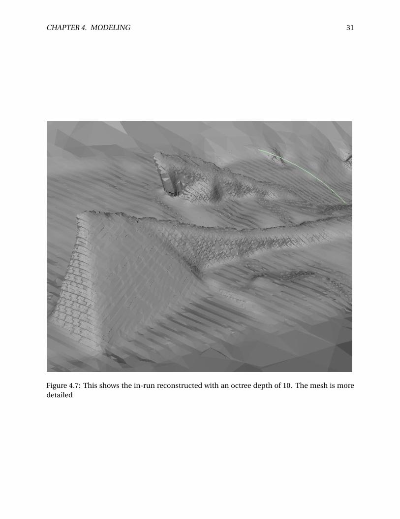
Figure 4.7: This shows the in-run reconstructed with an octree depth of 10. The mesh is moredetailed
CHAPTER 4. MODELING 32
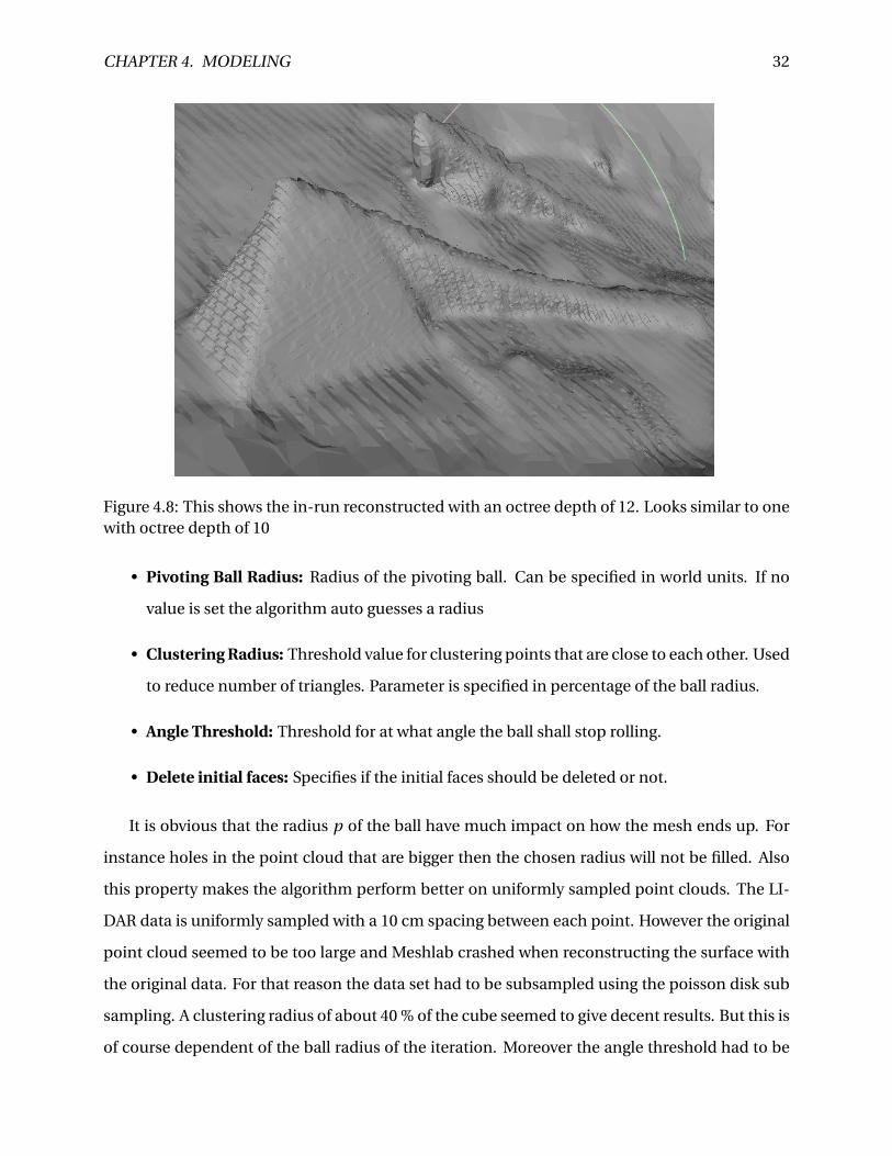
Figure 4.8: This shows the in-run reconstructed with an octree depth of 12. Looks similar to onewith octree depth of 10
• Pivoting Ball Radius: Radius of the pivoting ball. Can be specified in world units. If no
value is set the algorithm auto guesses a radius
• Clustering Radius: Threshold value for clustering points that are close to each other. Used
to reduce number of triangles. Parameter is specified in percentage of the ball radius.
• Angle Threshold: Threshold for at what angle the ball shall stop rolling.
• Delete initial faces: Specifies if the initial faces should be deleted or not.
It is obvious that the radius p of the ball have much impact on how the mesh ends up. For
instance holes in the point cloud that are bigger then the chosen radius will not be filled. Also
this property makes the algorithm perform better on uniformly sampled point clouds. The LI-
DAR data is uniformly sampled with a 10 cm spacing between each point. However the original
point cloud seemed to be too large and Meshlab crashed when reconstructing the surface with
the original data. For that reason the data set had to be subsampled using the poisson disk sub
sampling. A clustering radius of about 40 % of the cube seemed to give decent results. But this is
of course dependent of the ball radius of the iteration. Moreover the angle threshold had to be
CHAPTER 4. MODELING 33
Figure 4.9: This figure is a closeup of the hill before decimation.
CHAPTER 4. MODELING 34
Figure 4.10: The spherical shape of the reconstructed surface
CHAPTER 4. MODELING 35
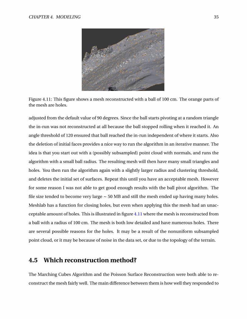
Figure 4.11: This figure shows a mesh reconstructed with a ball of 100 cm. The orange parts ofthe mesh are holes.
adjusted from the default value of 90 degrees. Since the ball starts pivoting at a random triangle
the in-run was not reconstructed at all because the ball stopped rolling when it reached it. An
angle threshold of 120 ensured that ball reached the in-run independent of where it starts. Also
the deletion of initial faces provides a nice way to run the algorithm in an iterative manner. The
idea is that you start out with a (possibly subsampled) point cloud with normals, and runs the
algorithm with a small ball radius. The resulting mesh will then have many small triangles and
holes. You then run the algorithm again with a slightly larger radius and clustering threshold,
and deletes the initial set of surfaces. Repeat this until you have an acceptable mesh. However
for some reason I was not able to get good enough results with the ball pivot algorithm. The
file size tended to become very large ∼ 50 MB and still the mesh ended up having many holes.
Meshlab has a function for closing holes, but even when applying this the mesh had an unac-
ceptable amount of holes. This is illustrated in figure 4.11 where the mesh is reconstructed from
a ball with a radius of 100 cm. The mesh is both low detailed and have numerous holes. There
are several possible reasons for the holes. It may be a result of the nonuniform subsampled
point cloud, or it may be because of noise in the data set, or due to the topology of the terrain.
4.5 Which reconstruction method?
The Marching Cubes Algorithm and the Poisson Surface Reconstruction were both able to re-
construct the mesh fairly well. The main difference between them is how well they responded to
CHAPTER 4. MODELING 36
decimation. And that is an important factor because a too detailed mesh will impact the perfor-
mance of the application. For this reason the Poisson Surface Reconstruction mesh was chosen
for this application. It is also worth noting that none of the algorithms was able to reconstruct
the in-run in such a detail that it could be used directly in the application.
4.6 Post processing the mesh
The next step is to process the mesh to make it ready to be imported into Unity. I started out
with a mesh from Poisson Surface Reconstruction. When the mesh is imported into the Blender
scene it is located far away from the origin of the scene, actually it is placed at the point (-2397,-
22316,-37). I believe this position comes from the LIDAR data. To move the geometry to the
center of the scene I first snap the 3D-cursor to the origin, than the Origin of the mesh is moved
to the 3D-cursor and then the geometry is moved to its origin. As shown in 4.10 the mesh has
a spherical shape, where the top half of the sphere is basically noise. The noise was removed
manually by using the Circle Select tool to select the noise and then delete the vertices. Figure
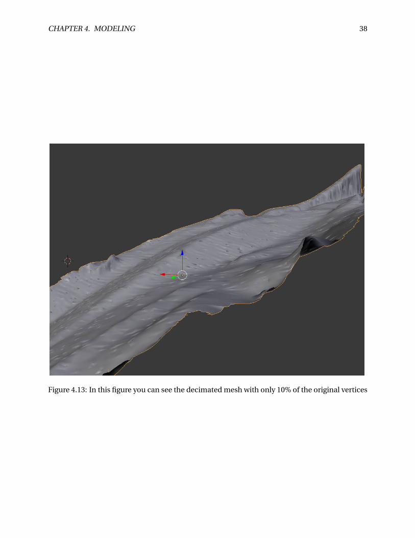
4.12 show the mesh after the removal of the noise. Still the mesh is quite dense and has ∼ 620k
faces. So I applied the decimate modifier to the mesh. This modifier is very similar to the quadric
edge collapse decimation in Meshlab. The mesh was reduced to 10 % of its original face count,
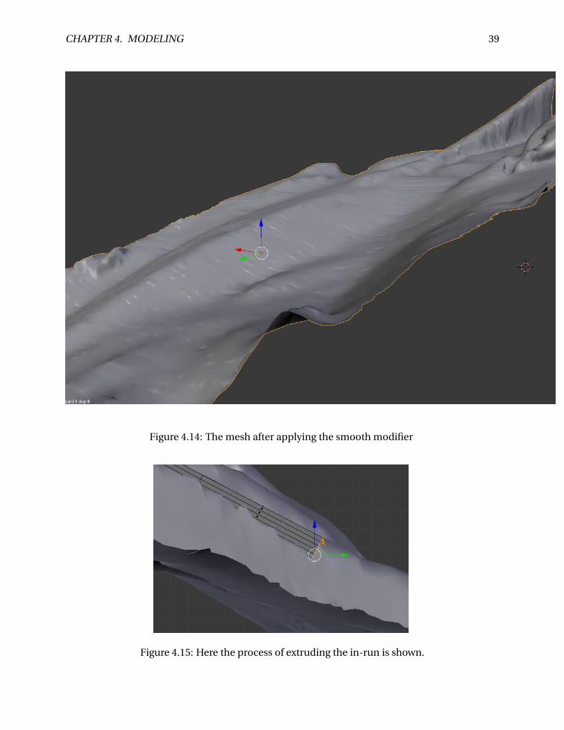
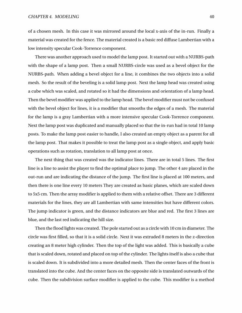
and visibly it was not much of a difference as can bee seen in figure 4.13. However the surface
still look kind of rough and unsmooth. This was solved by applying the smooth modifier with
factor 1 on the mesh. The modifier smooths the angle between adjacent faces in the mesh. In
other words it smooths the mesh without subdividing it, and the number of vertices stays the
same. The result from the smoothing can be seen in figure 4.14. By now the hill itself is ready
to be exported to Unity. However there still is work to do on the in-run, as it is not detailed
enough. Nevertheless the mesh has the profile and dimensions of the in-run and can be used
as a reference for building a new in-run. Which is ultimately what I decided to do. I started
out with a simple cube. The cube was subdivided so it had a more detailed mesh. Next the ski
tracks was created by simply extruding two rows of the cube down in the z-direction. Then the
cube was translated to the top of the in-run and rotated so it had the same orientation as the
in-run mesh. Next I selected the front of the cube and switched into right orthographic view.
CHAPTER 4. MODELING 37
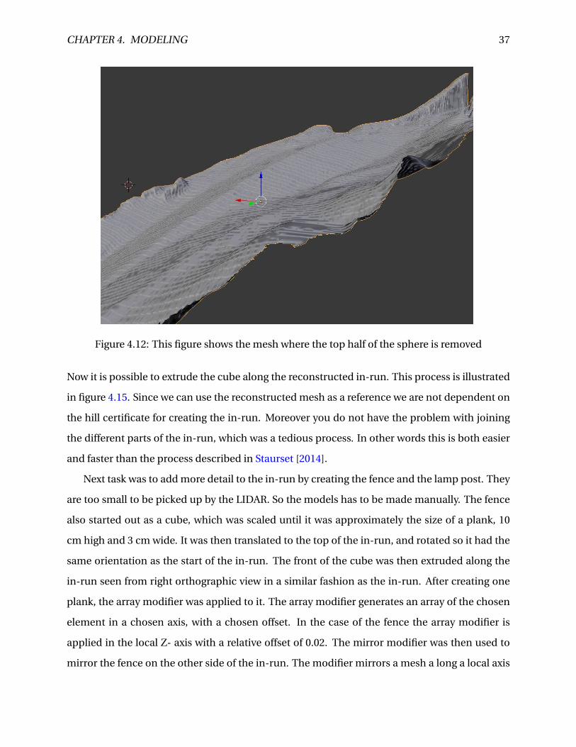
Figure 4.12: This figure shows the mesh where the top half of the sphere is removed
Now it is possible to extrude the cube along the reconstructed in-run. This process is illustrated
in figure 4.15. Since we can use the reconstructed mesh as a reference we are not dependent on
the hill certificate for creating the in-run. Moreover you do not have the problem with joining
the different parts of the in-run, which was a tedious process. In other words this is both easier
and faster than the process described in Staurset [2014].
Next task was to add more detail to the in-run by creating the fence and the lamp post. They
are too small to be picked up by the LIDAR. So the models has to be made manually. The fence
also started out as a cube, which was scaled until it was approximately the size of a plank, 10
cm high and 3 cm wide. It was then translated to the top of the in-run, and rotated so it had the
same orientation as the start of the in-run. The front of the cube was then extruded along the
in-run seen from right orthographic view in a similar fashion as the in-run. After creating one
plank, the array modifier was applied to it. The array modifier generates an array of the chosen
element in a chosen axis, with a chosen offset. In the case of the fence the array modifier is
applied in the local Z- axis with a relative offset of 0.02. The mirror modifier was then used to
mirror the fence on the other side of the in-run. The modifier mirrors a mesh a long a local axis
CHAPTER 4. MODELING 38
Figure 4.13: In this figure you can see the decimated mesh with only 10% of the original vertices
CHAPTER 4. MODELING 39
Figure 4.14: The mesh after applying the smooth modifier
Figure 4.15: Here the process of extruding the in-run is shown.
CHAPTER 4. MODELING 40
of a chosen mesh. In this case it was mirrored around the local x-axis of the in-run. Finally a
material was created for the fence. The material created is a basic red diffuse Lambertian with a
low intensity specular Cook-Torrence component.
There was another approach used to model the lamp post. It started out with a NURBS-path
with the shape of a lamp post. Then a small NURBS-circle was used as a bevel object for the
NURBS-path. When adding a bevel object for a line, it combines the two objects into a solid
mesh. So the result of the beveling is a solid lamp post. Next the lamp head was created using
a cube which was scaled, and rotated so it had the dimensions and orientation of a lamp head.
Then the bevel modifier was applied to the lamp head. The bevel modifier must not be confused
with the bevel object for lines, it is a modifier that smooths the edges of a mesh. The material
for the lamp is a gray Lambertian with a more intensive specular Cook-Torrence component.
Next the lamp post was duplicated and manually placed so that the in-run had in total 10 lamp
posts. To make the lamp post easier to handle, I also created an empty object as a parent for all
the lamp post. That makes it possible to treat the lamp post as a single object, and apply basic
operations such as rotation, translation to all lamp post at once.
The next thing that was created was the indicator lines. There are in total 5 lines. The first
line is a line to assist the player to find the optimal place to jump. The other 4 are placed in the
out-run and are indicating the distance of the jump. The first line is placed at 100 meters, and
then there is one line every 10 meters They are created as basic planes, which are scaled down
to 5x5 cm. Then the array modifier is applied to them with a relative offset. There are 3 different
materials for the lines, they are all Lambertian with same intensities but have different colors.
The jump indicator is green, and the distance indicators are blue and red. The first 3 lines are
blue, and the last red indicating the hill size.
Then the flood lights was created. The pole started out as a circle with 10 cm in diameter. The
circle was first filled, so that it is a solid circle. Next it was extruded 8 meters in the z-direction
creating an 8 meter high cylinder. Then the top of the light was added. This is basically a cube
that is scaled down, rotated and placed on top of the cylinder. The lights itself is also a cube that
is scaled down. It is subdivided into a more detailed mesh. Then the center faces of the front is
translated into the cube. And the center faces on the opposite side is translated outwards of the
cube. Then the subdivision surface modifier is applied to the cube. This modifier is a method
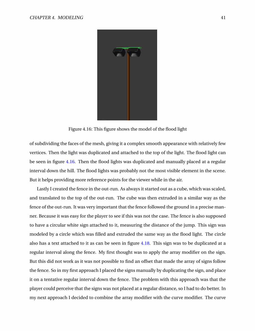
CHAPTER 4. MODELING 41
Figure 4.16: This figure shows the model of the flood light
of subdividing the faces of the mesh, giving it a complex smooth appearance with relatively few
vertices. Then the light was duplicated and attached to the top of the light. The flood light can
be seen in figure 4.16. Then the flood lights was duplicated and manually placed at a regular
interval down the hill. The flood lights was probably not the most visible element in the scene.
But it helps providing more reference points for the viewer while in the air.
Lastly I created the fence in the out-run. As always it started out as a cube, which was scaled,
and translated to the top of the out-run. The cube was then extruded in a similar way as the
fence of the out-run. It was very important that the fence followed the ground in a precise man-
ner. Because it was easy for the player to see if this was not the case. The fence is also supposed
to have a circular white sign attached to it, measuring the distance of the jump. This sign was
modeled by a circle which was filled and extruded the same way as the flood light. The circle
also has a text attached to it as can be seen in figure 4.18. This sign was to be duplicated at a
regular interval along the fence. My first thought was to apply the array modifier on the sign.
But this did not work as it was not possible to find an offset that made the array of signs follow
the fence. So in my first approach I placed the signs manually by duplicating the sign, and place
it on a tentative regular interval down the fence. The problem with this approach was that the
player could perceive that the signs was not placed at a regular distance, so I had to do better. In
my next approach I decided to combine the array modifier with the curve modifier. The curve
CHAPTER 4. MODELING 42
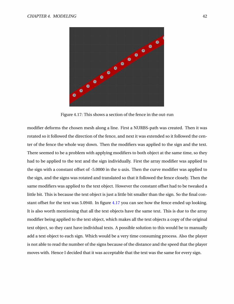
Figure 4.17: This shows a section of the fence in the out-run
modifier deforms the chosen mesh along a line. First a NURBS-path was created. Then it was
rotated so it followed the direction of the fence, and next it was extended so it followed the cen-
ter of the fence the whole way down. Then the modifiers was applied to the sign and the text.
There seemed to be a problem with applying modifiers to both object at the same time, so they
had to be applied to the text and the sign individually. First the array modifier was applied to
the sign with a constant offset of -5.0000 in the x-axis. Then the curve modifier was applied to
the sign, and the signs was rotated and translated so that it followed the fence closely. Then the
same modifiers was applied to the text object. However the constant offset had to be tweaked a
little bit. This is because the text object is just a little bit smaller than the sign. So the final con-
stant offset for the text was 5.0940. In figure 4.17 you can see how the fence ended up looking.
It is also worth mentioning that all the text objects have the same text. This is due to the array
modifier being applied to the text object, which makes all the text objects a copy of the original
text object, so they cant have individual texts. A possible solution to this would be to manually
add a text object to each sign. Which would be a very time consuming process. Also the player
is not able to read the number of the signs because of the distance and the speed that the player
moves with. Hence I decided that it was acceptable that the text was the same for every sign.

CHAPTER 4. MODELING 43
Figure 4.18: This figure shows the sign for measuring distance attached to the out-run fence.
Chapter 5
Implementation in Unity
In this chapter the implementation in Unity will be described thoroughly.
5.1 The player object
The project is a continuation of the project in Staurset [2014], so I used the same Player GameOb-
ject as a starting point. This is an extension of the standard Unity First Person Controller. There
has been done several improvements and extensions to the original object. In the following
section these changes will be explained.
5.1.1 Head rotation
In the original version there was a problem that the camera was rotated around the x-axis when
the player was in the air. This made it so that the player had to look upward when flying down
the hill. This is because the camera is a child of the player object, and in Unity every transform
applied to the parent is also applied to every children of that object. E.g if the player object
moves 10 units along the x-axis the camera will also move 10 units in the same direction. In the
same way when the player is rotated along the x-axis when flying the camera would rotate the
same amount. This is undesirable, hence we need to find a way decouple the rotation of the
players body, and the camera. One possible solution would be remove the parent relationship
between the camera and the player. But then the camera has to have another way of following
the player. This would could be done with a script which updates the cameras position for every
44
CHAPTER 5. IMPLEMENTATION IN UNITY 45
frame. One problem with this approach is that the camera no longer has access to broadcasted
messages within the player object. Another possible solution is to add a new object as parent of
the camera and child of the Player object. This new objects only task is to decouple the rotation
of the player object with the camera. It has a script attached to it called headManager. This
script only has one function: Update. Update is called for every frame, and in this function it
resets the heads orientation. By doing this the camera can now rotate independent on player
rotation, and it is still a child of the player, so it can receive broadcasts within the player object.
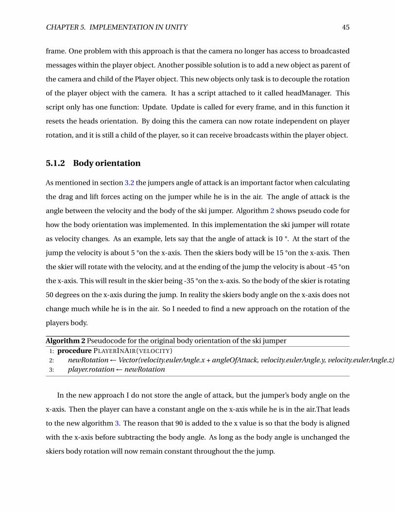
5.1.2 Body orientation
As mentioned in section 3.2 the jumpers angle of attack is an important factor when calculating
the drag and lift forces acting on the jumper while he is in the air. The angle of attack is the
angle between the velocity and the body of the ski jumper. Algorithm 2 shows pseudo code for
how the body orientation was implemented. In this implementation the ski jumper will rotate
as velocity changes. As an example, lets say that the angle of attack is 10 °. At the start of the
jump the velocity is about 5 °on the x-axis. Then the skiers body will be 15 °on the x-axis. Then
the skier will rotate with the velocity, and at the ending of the jump the velocity is about -45 °on
the x-axis. This will result in the skier being -35 °on the x-axis. So the body of the skier is rotating
50 degrees on the x-axis during the jump. In reality the skiers body angle on the x-axis does not
change much while he is in the air. So I needed to find a new approach on the rotation of the
players body.
Algorithm 2 Pseudocode for the original body orientation of the ski jumper1: procedure PLAYERINAIR( VELOCITY )2: newRotation ← Vector(velocity.eulerAngle.x + angleOfAttack, velocity.eulerAngle.y, velocity.eulerAngle.z)3: player.rotation ← newRotation
In the new approach I do not store the angle of attack, but the jumper’s body angle on the
x-axis. Then the player can have a constant angle on the x-axis while he is in the air.That leads
to the new algorithm 3. The reason that 90 is added to the x value is so that the body is aligned
with the x-axis before subtracting the body angle. As long as the body angle is unchanged the
skiers body rotation will now remain constant throughout the the jump.
CHAPTER 5. IMPLEMENTATION IN UNITY 46
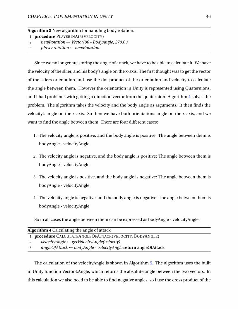
Algorithm 3 New algorithm for handling body rotation.1: procedure PLAYERINAIR( VELOCITY )2: newRotation ← Vector(90 - BodyAngle, 270,0 )3: player.rotation ← newRotation
Since we no longer are storing the angle of attack, we have to be able to calculate it. We have
the velocity of the skier, and his body’s angle on the x-axis. The first thought was to get the vector
of the skiers orientation and use the dot product of the orientation and velocity to calculate
the angle between them. However the orientation in Unity is represented using Quaternions,
and I had problems with getting a direction vector from the quaternion. Algorithm 4 solves the
problem. The algorithm takes the velocity and the body angle as arguments. It then finds the
velocity’s angle on the x-axis. So then we have both orientations angle on the x-axis, and we
want to find the angle between them. There are four different cases:
1. The velocity angle is positive, and the body angle is positive: The angle between them is
bodyAngle - velocityAngle
2. The velocity angle is negative, and the body angle is positive: The angle between them is
bodyAngle - velocityAngle
3. The velocity angle is positive, and the body angle is negative: The angle between them is
bodyAngle - velocityAngle
4. The velocity angle is negative, and the body angle is negative: The angle between them is
bodyAngle - velocityAngle
So in all cases the angle between them can be expressed as bodyAngle - velocityAngle.
Algorithm 4 Calculating the angle of attack1: procedure CALCULATEANGLEOFATTACK( VELOCITY, BODYANGLE)2: velocityAngle ← getVelocityAngle(velocity)3: angleOfAttack ← bodyAngle - velocityAngle return angleOfAttack
The calculation of the velocityAngle is shown in Algorithm 5. The algorithm uses the built
in Unity function Vector3.Angle, which returns the absolute angle between the two vectors. In
this calculation we also need to be able to find negative angles, so I use the cross product of the
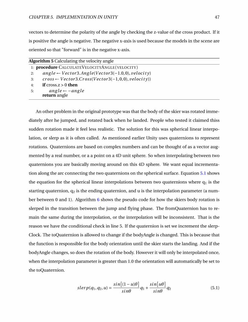
CHAPTER 5. IMPLEMENTATION IN UNITY 47
vectors to determine the polarity of the angle by checking the z-value of the cross product. If it
is positive the angle is negative. The negative x-axis is used because the models in the scene are
oriented so that "forward" is in the negative x-axis.
Algorithm 5 Calculating the velocity angle1: procedure CALCULATEVELOCITYANGLE( VELOCITY )2: ang l e ←V ector 3.Ang le(V ector 3(−1.0,0), veloci t y)3: cr oss ←V ector 3.Cr oss(V ector 3(−1,0,0), veloci t y))4: if cross.z > 0 then5: ang l e ←−ang l e
return angle
An other problem in the original prototype was that the body of the skier was rotated imme-
diately after he jumped, and rotated back when he landed. People who tested it claimed thiss
sudden rotation made it feel less realistic. The solution for this was spherical linear interpo-
lation, or slerp as it is often called. As mentioned earlier Unity uses quaternions to represent
rotations. Quaternions are based on complex numbers and can be thought of as a vector aug-
mented by a real number, or a a point on a 4D unit sphere. So when interpolating between two
quaternions you are basically moving around on this 4D sphere. We want equal incrementa-
tion along the arc connecting the two quaternions on the spherical surface. Equation 5.1 shows
the equation for the spherical linear interpolations between two quaternions where q1 is the
starting quaternion, q2 is the ending quaternion, and u is the interpolation parameter (a num-
ber between 0 and 1). Algorithm 6 shows the pseudo code for how the skiers body rotation is
slerped in the transition between the jump and flying phase. The fromQuaternion has to re-
main the same during the interpolation, or the interpolation will be inconsistent. That is the
reason we have the conditional check in line 5. If the quaternion is set we increment the slerp-
Clock. The toQuaternion is allowed to change if the bodyAngle is changed. This is because that
the function is responsible for the body orientation until the skier starts the landing. And if the
bodyAngle changes, so does the rotation of the body. However it will only be interpolated once,
when the interpolation parameter is greater than 1.0 the orientation will automatically be set to
the toQuaternion.
sl er p(q1, q2,u) = si n[(1−u)θ
]si nθ
q1 +si n
[uθ
]si nθ
q2 (5.1)
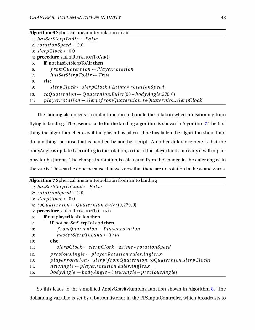
CHAPTER 5. IMPLEMENTATION IN UNITY 48
Algorithm 6 Spherical linear interpolation to air1: hasSetSler pTo Ai r ← F al se2: r ot ati onSpeed ← 2.63: sl er pC lock ← 0.04: procedure SLERPROTATIONTOAIR()5: if not hasSetSlerpToAir then6: f r omQuater ni on ← Pl ayer.r ot ati on7: hasSetSler pTo Ai r ← Tr ue8: else9: sl er pC lock ← sl er pC lock +∆t i me ∗ r ot ati onSpeed
10: toQuater ni on ←Quater ni on.Euler (90−bod y Ang l e,270,0)11: pl ayer.r ot ati on ← sl er p( f r omQuater ni on, toQuater ni on, sl er pC lock)
The landing also needs a similar function to handle the rotation when transitioning from
flying to landing. The pseudo code for the landing algorithm is shown in Algorithm 7.The first
thing the algorithm checks is if the player has fallen. If he has fallen the algorithm should not
do any thing, because that is handled by another script. An other difference here is that the
bodyAngle is updated according to the rotation, so that if the player lands too early it will impact
how far he jumps. The change in rotation is calculated from the change in the euler angles in
the x-axis. This can be done because that we know that there are no rotation in the y- and z-axis.
Algorithm 7 Spherical linear interpolation from air to landing1: hasSetSler pToLand ← F al se2: r ot ati onSpeed ← 2.03: sl er pC lock ← 0.04: toQuater ni on ←Quater ni on.Euler (0,270,0)5: procedure SLERPROTATIONTOLAND
6: if not playerHasFallen then7: if not hasSetSlerpToLand then8: f r omQuater ni on ← Pl ayer.r ot ati on9: hasSetSler pToLand ← Tr ue
10: else11: sl er pC lock ← sl er pC lock +∆t i me ∗ r ot ati onSpeed
12: pr evi ous Ang le ← pl ayer.Rot ati on.euler Ang les.x13: pl ayer.r ot ati on ← sl er p( f r omQuater ni on, toQuater ni on, sl er pC lock)14: new Ang l e ← pl ayer.r ot ati on.euler Ang les.x15: bod y Ang l e ← bod y Ang l e + (new Ang l e −pr evi ous Ang le)
So this leads to the simplified ApplyGravityJumping function shown in Algorithm 8. The
doLanding variable is set by a button listener in the FPSInputController, which broadcasts to
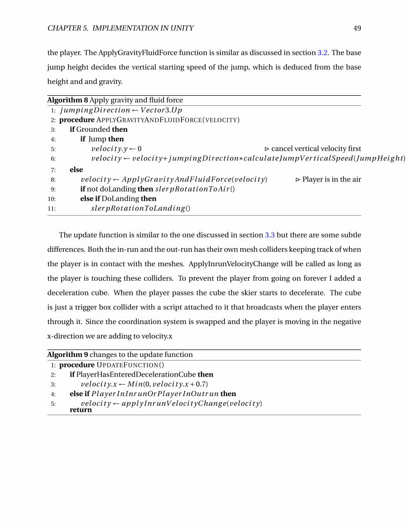
CHAPTER 5. IMPLEMENTATION IN UNITY 49
the player. The ApplyGravityFluidForce function is similar as discussed in section 3.2. The base
jump height decides the vertical starting speed of the jump, which is deduced from the base
height and and gravity.
Algorithm 8 Apply gravity and fluid force1: j umpi ng Di r ect i on ←V ector 3.Up2: procedure APPLYGRAVITYANDFLUIDFORCE( VELOCITY )3: if Grounded then4: if Jump then5: veloci t y.y ← 0 . cancel vertical velocity first6: veloci t y ← veloci t y+ j umpi ng Di r ect i on∗calcul ate JumpV er ti calSpeed(JumpHei g ht )
7: else8: veloci t y ← Appl yGr avi t y AndF lui dFor ce(veloci t y) . Player is in the air9: if not doLanding then sl er pRot ati onTo Ai r ()
10: else if DoLanding then11: sl er pRot ati onToLandi ng ()
The update function is similar to the one discussed in section 3.3 but there are some subtle
differences. Both the in-run and the out-run has their own mesh colliders keeping track of when
the player is in contact with the meshes. ApplyInrunVelocityChange will be called as long as
the player is touching these colliders. To prevent the player from going on forever I added a
deceleration cube. When the player passes the cube the skier starts to decelerate. The cube
is just a trigger box collider with a script attached to it that broadcasts when the player enters
through it. Since the coordination system is swapped and the player is moving in the negative
x-direction we are adding to velocity.x
Algorithm 9 changes to the update function1: procedure UPDATEFUNCTION()2: if PlayerHasEnteredDecelerationCube then3: veloci t y.x ← Mi n(0, veloci t y.x +0.7)4: else if Pl ayer InInr unOr Pl ayer InOutr un then5: veloci t y ← appl y Inr unV eloci t yC hang e(veloci t y)
return
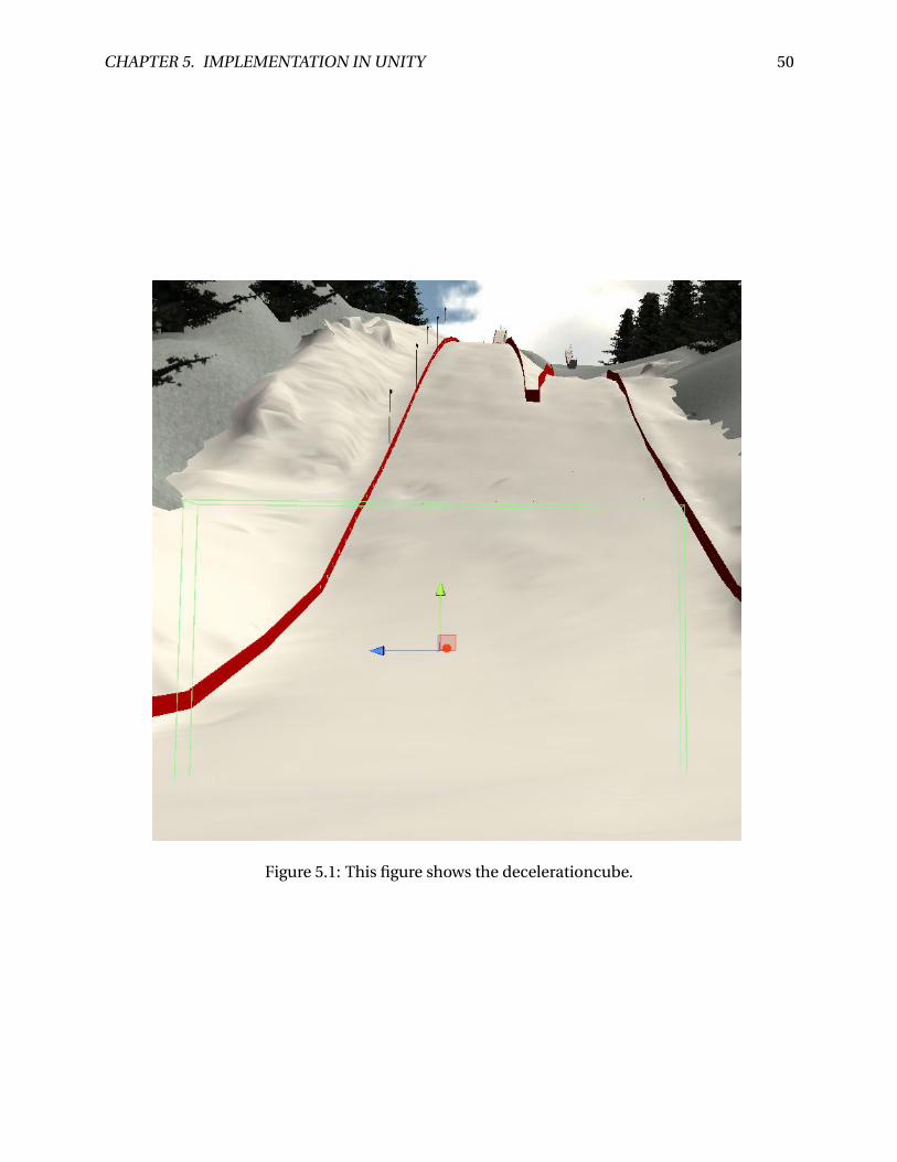
CHAPTER 5. IMPLEMENTATION IN UNITY 50
Figure 5.1: This figure shows the decelerationcube.
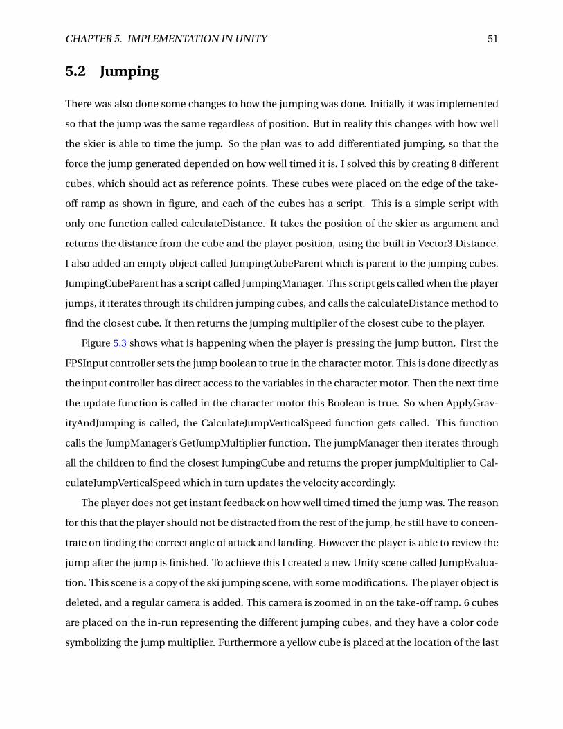
CHAPTER 5. IMPLEMENTATION IN UNITY 51
5.2 Jumping
There was also done some changes to how the jumping was done. Initially it was implemented
so that the jump was the same regardless of position. But in reality this changes with how well
the skier is able to time the jump. So the plan was to add differentiated jumping, so that the
force the jump generated depended on how well timed it is. I solved this by creating 8 different
cubes, which should act as reference points. These cubes were placed on the edge of the take-
off ramp as shown in figure, and each of the cubes has a script. This is a simple script with
only one function called calculateDistance. It takes the position of the skier as argument and
returns the distance from the cube and the player position, using the built in Vector3.Distance.
I also added an empty object called JumpingCubeParent which is parent to the jumping cubes.
JumpingCubeParent has a script called JumpingManager. This script gets called when the player
jumps, it iterates through its children jumping cubes, and calls the calculateDistance method to
find the closest cube. It then returns the jumping multiplier of the closest cube to the player.
Figure 5.3 shows what is happening when the player is pressing the jump button. First the
FPSInput controller sets the jump boolean to true in the character motor. This is done directly as
the input controller has direct access to the variables in the character motor. Then the next time
the update function is called in the character motor this Boolean is true. So when ApplyGrav-
ityAndJumping is called, the CalculateJumpVerticalSpeed function gets called. This function
calls the JumpManager’s GetJumpMultiplier function. The jumpManager then iterates through
all the children to find the closest JumpingCube and returns the proper jumpMultiplier to Cal-
culateJumpVerticalSpeed which in turn updates the velocity accordingly.
The player does not get instant feedback on how well timed timed the jump was. The reason
for this that the player should not be distracted from the rest of the jump, he still have to concen-
trate on finding the correct angle of attack and landing. However the player is able to review the
jump after the jump is finished. To achieve this I created a new Unity scene called JumpEvalua-
tion. This scene is a copy of the ski jumping scene, with some modifications. The player object is
deleted, and a regular camera is added. This camera is zoomed in on the take-off ramp. 6 cubes
are placed on the in-run representing the different jumping cubes, and they have a color code
symbolizing the jump multiplier. Furthermore a yellow cube is placed at the location of the last
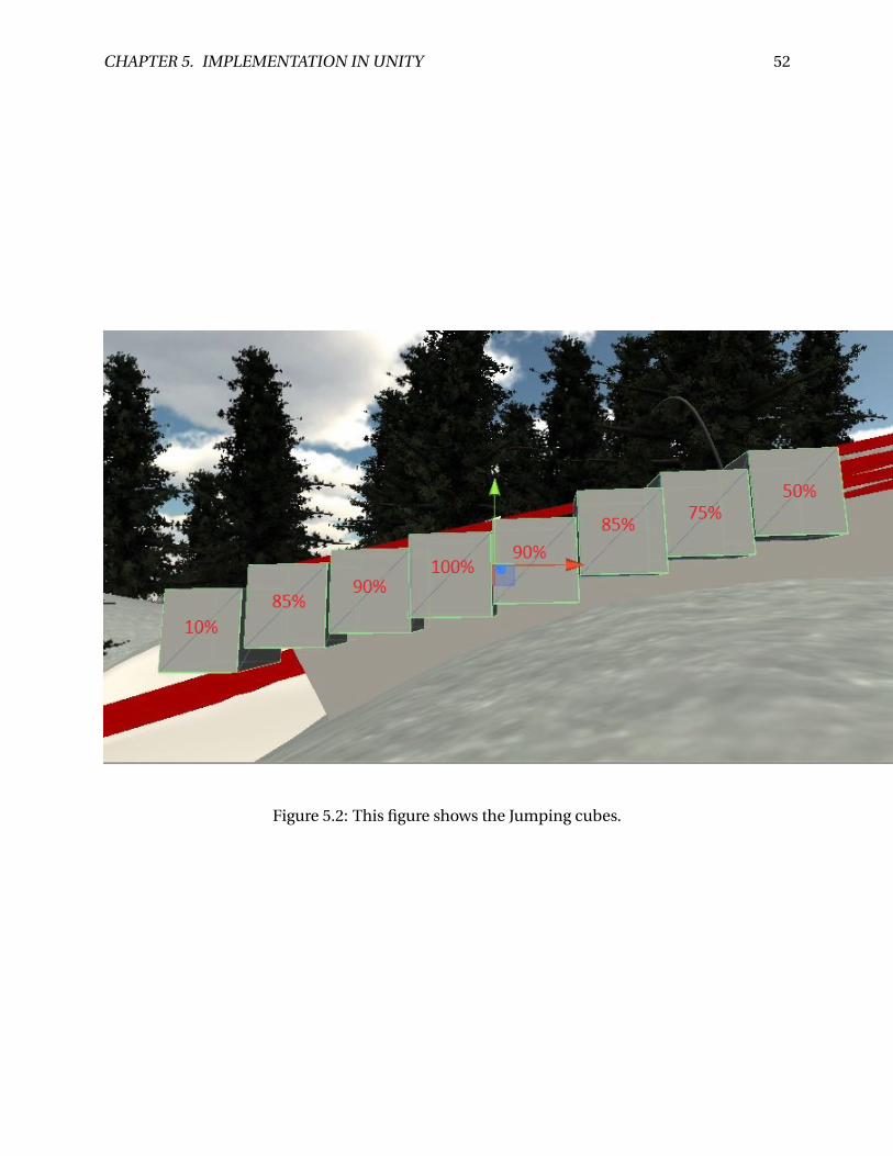
CHAPTER 5. IMPLEMENTATION IN UNITY 52
Figure 5.2: This figure shows the Jumping cubes.
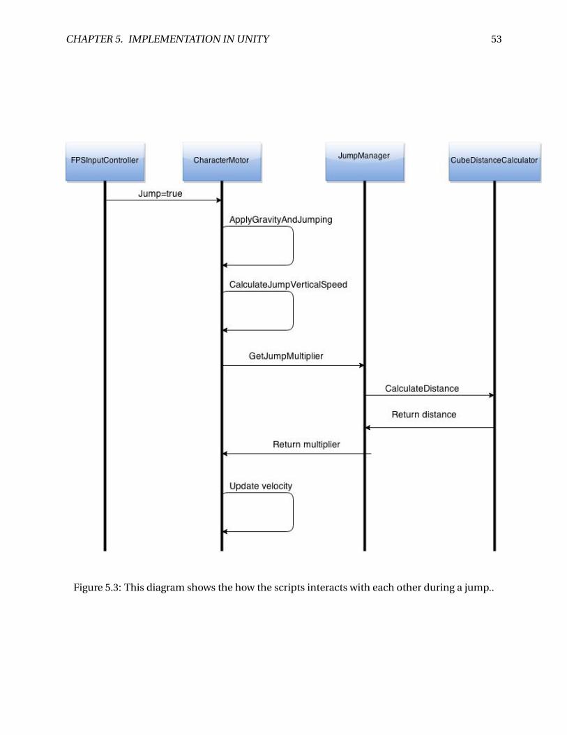
CHAPTER 5. IMPLEMENTATION IN UNITY 53
Figure 5.3: This diagram shows the how the scripts interacts with each other during a jump..
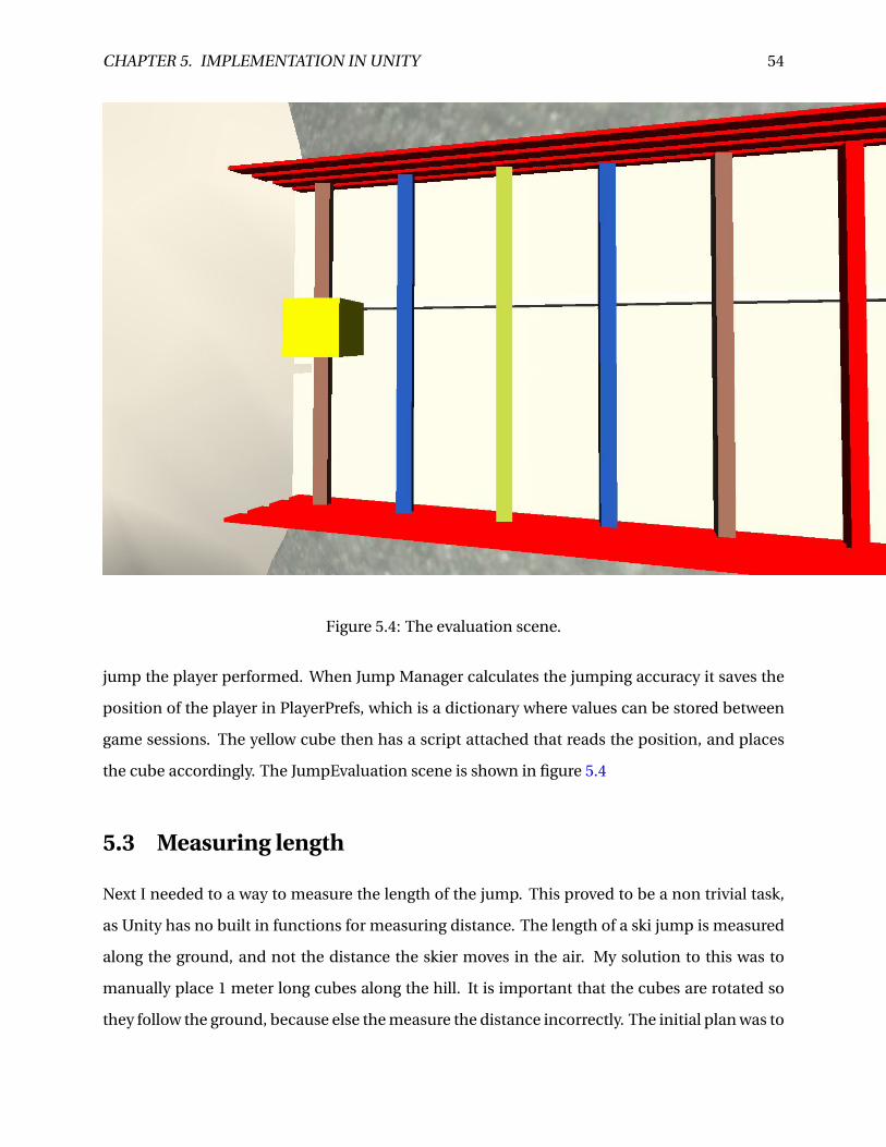
CHAPTER 5. IMPLEMENTATION IN UNITY 54
Figure 5.4: The evaluation scene.
jump the player performed. When Jump Manager calculates the jumping accuracy it saves the
position of the player in PlayerPrefs, which is a dictionary where values can be stored between
game sessions. The yellow cube then has a script attached that reads the position, and places
the cube accordingly. The JumpEvaluation scene is shown in figure 5.4
5.3 Measuring length
Next I needed to a way to measure the length of the jump. This proved to be a non trivial task,
as Unity has no built in functions for measuring distance. The length of a ski jump is measured
along the ground, and not the distance the skier moves in the air. My solution to this was to
manually place 1 meter long cubes along the hill. It is important that the cubes are rotated so
they follow the ground, because else the measure the distance incorrectly. The initial plan was to
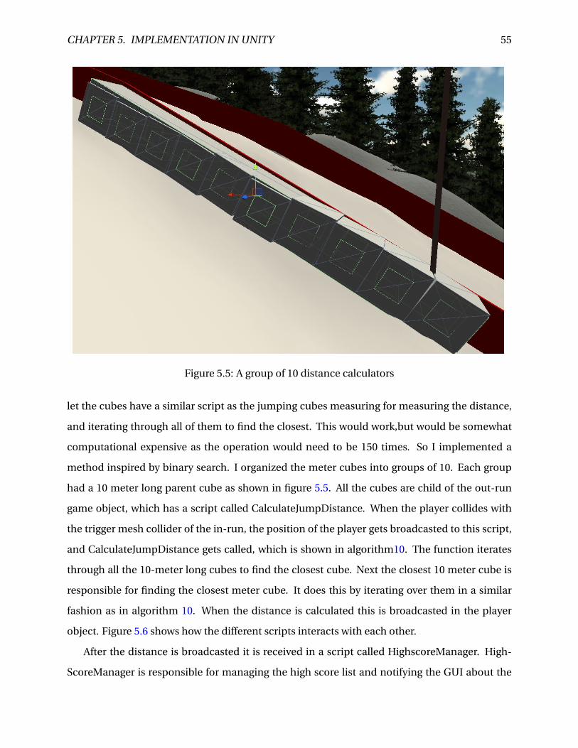
CHAPTER 5. IMPLEMENTATION IN UNITY 55
Figure 5.5: A group of 10 distance calculators
let the cubes have a similar script as the jumping cubes measuring for measuring the distance,
and iterating through all of them to find the closest. This would work,but would be somewhat
computational expensive as the operation would need to be 150 times. So I implemented a
method inspired by binary search. I organized the meter cubes into groups of 10. Each group
had a 10 meter long parent cube as shown in figure 5.5. All the cubes are child of the out-run
game object, which has a script called CalculateJumpDistance. When the player collides with
the trigger mesh collider of the in-run, the position of the player gets broadcasted to this script,
and CalculateJumpDistance gets called, which is shown in algorithm10. The function iterates
through all the 10-meter long cubes to find the closest cube. Next the closest 10 meter cube is
responsible for finding the closest meter cube. It does this by iterating over them in a similar
fashion as in algorithm 10. When the distance is calculated this is broadcasted in the player
object. Figure 5.6 shows how the different scripts interacts with each other.
After the distance is broadcasted it is received in a script called HighscoreManager. High-
ScoreManager is responsible for managing the high score list and notifying the GUI about the
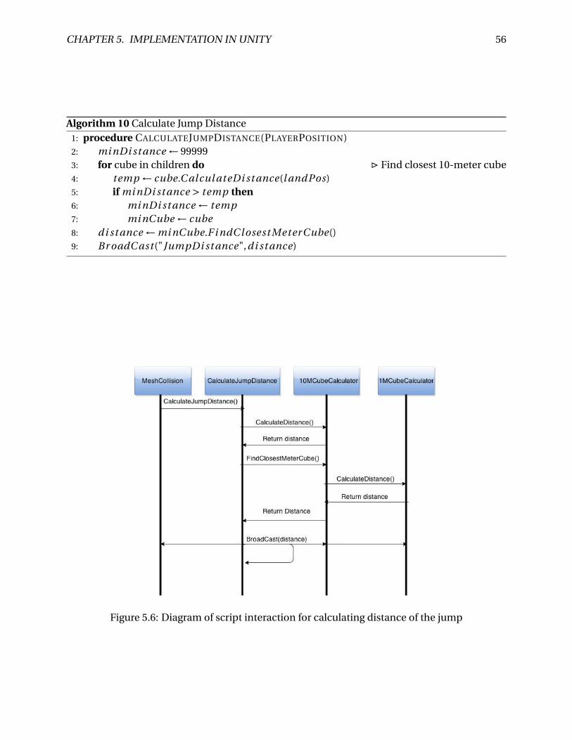
CHAPTER 5. IMPLEMENTATION IN UNITY 56
Algorithm 10 Calculate Jump Distance1: procedure CALCULATEJUMPDISTANCE(PLAYERPOSITION)2: mi nDi st ance ← 999993: for cube in children do . Find closest 10-meter cube4: temp ← cube.C alcul ateDi st ance(l andPos)5: if mi nDi st ance > temp then6: mi nDi st ance ← temp7: mi nCube ← cube8: di st ance ← mi nCube.F i ndC losest MeterCube()9: Br oadC ast ("JumpDi st ance",di st ance)
Figure 5.6: Diagram of script interaction for calculating distance of the jump
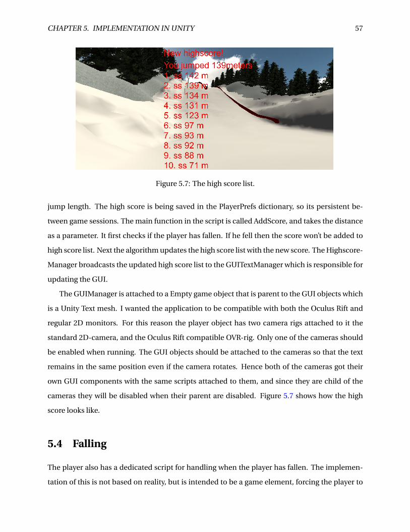
CHAPTER 5. IMPLEMENTATION IN UNITY 57
Figure 5.7: The high score list.
jump length. The high score is being saved in the PlayerPrefs dictionary, so its persistent be-
tween game sessions. The main function in the script is called AddScore, and takes the distance
as a parameter. It first checks if the player has fallen. If he fell then the score won’t be added to
high score list. Next the algorithm updates the high score list with the new score. The Highscore-
Manager broadcasts the updated high score list to the GUITextManager which is responsible for
updating the GUI.
The GUIManager is attached to a Empty game object that is parent to the GUI objects which
is a Unity Text mesh. I wanted the application to be compatible with both the Oculus Rift and
regular 2D monitors. For this reason the player object has two camera rigs attached to it the
standard 2D-camera, and the Oculus Rift compatible OVR-rig. Only one of the cameras should
be enabled when running. The GUI objects should be attached to the cameras so that the text
remains in the same position even if the camera rotates. Hence both of the cameras got their
own GUI components with the same scripts attached to them, and since they are child of the
cameras they will be disabled when their parent are disabled. Figure 5.7 shows how the high
score looks like.
5.4 Falling
The player also has a dedicated script for handling when the player has fallen. The implemen-
tation of this is not based on reality, but is intended to be a game element, forcing the player to
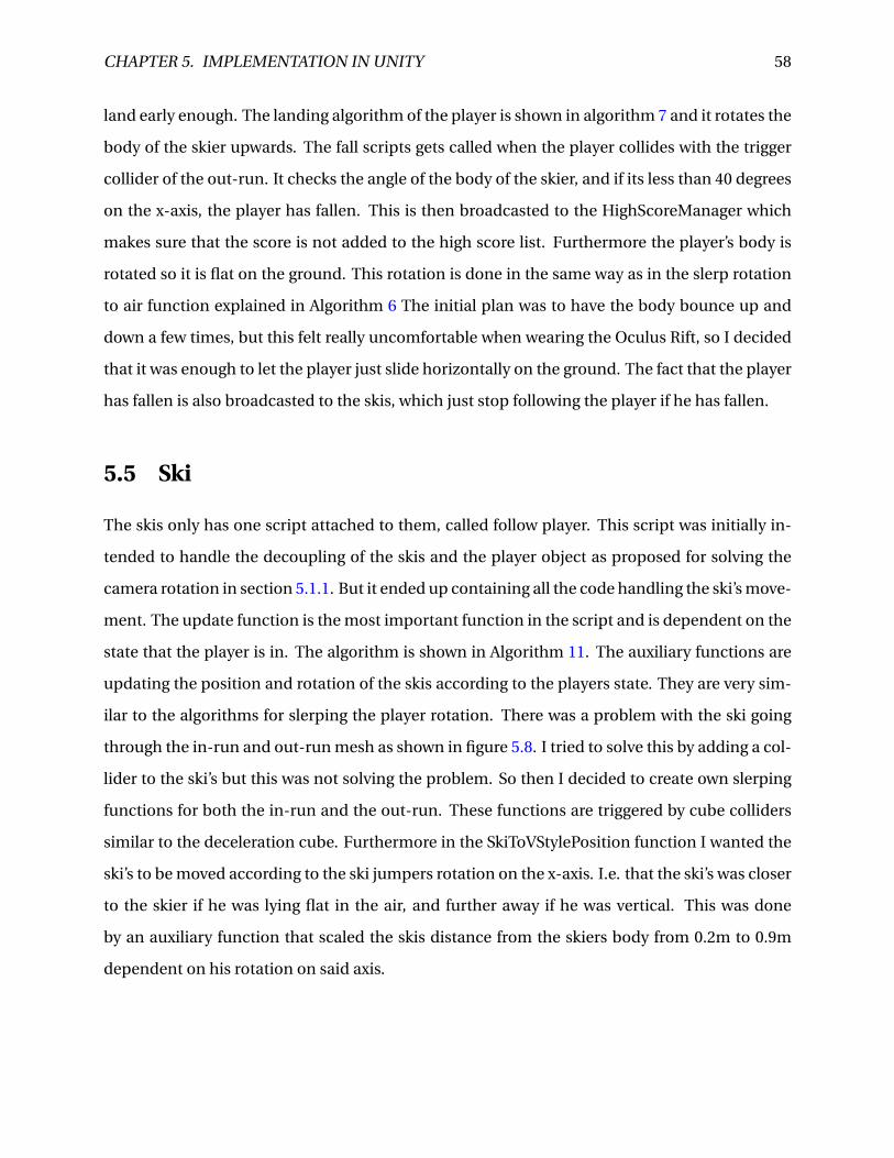
CHAPTER 5. IMPLEMENTATION IN UNITY 58
land early enough. The landing algorithm of the player is shown in algorithm 7 and it rotates the
body of the skier upwards. The fall scripts gets called when the player collides with the trigger
collider of the out-run. It checks the angle of the body of the skier, and if its less than 40 degrees
on the x-axis, the player has fallen. This is then broadcasted to the HighScoreManager which
makes sure that the score is not added to the high score list. Furthermore the player’s body is
rotated so it is flat on the ground. This rotation is done in the same way as in the slerp rotation
to air function explained in Algorithm 6 The initial plan was to have the body bounce up and
down a few times, but this felt really uncomfortable when wearing the Oculus Rift, so I decided
that it was enough to let the player just slide horizontally on the ground. The fact that the player
has fallen is also broadcasted to the skis, which just stop following the player if he has fallen.
5.5 Ski
The skis only has one script attached to them, called follow player. This script was initially in-
tended to handle the decoupling of the skis and the player object as proposed for solving the
camera rotation in section 5.1.1. But it ended up containing all the code handling the ski’s move-
ment. The update function is the most important function in the script and is dependent on the
state that the player is in. The algorithm is shown in Algorithm 11. The auxiliary functions are
updating the position and rotation of the skis according to the players state. They are very sim-
ilar to the algorithms for slerping the player rotation. There was a problem with the ski going
through the in-run and out-run mesh as shown in figure 5.8. I tried to solve this by adding a col-
lider to the ski’s but this was not solving the problem. So then I decided to create own slerping
functions for both the in-run and the out-run. These functions are triggered by cube colliders
similar to the deceleration cube. Furthermore in the SkiToVStylePosition function I wanted the
ski’s to be moved according to the ski jumpers rotation on the x-axis. I.e. that the ski’s was closer
to the skier if he was lying flat in the air, and further away if he was vertical. This was done
by an auxiliary function that scaled the skis distance from the skiers body from 0.2m to 0.9m
dependent on his rotation on said axis.
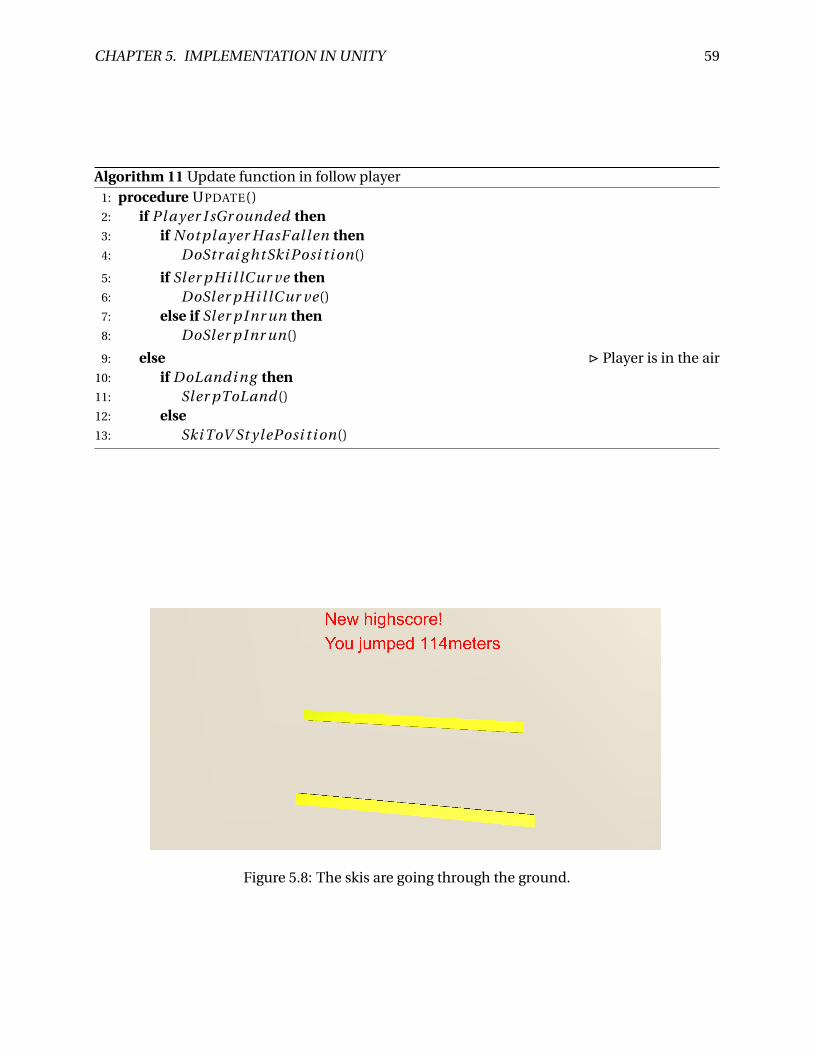
CHAPTER 5. IMPLEMENTATION IN UNITY 59
Algorithm 11 Update function in follow player1: procedure UPDATE()2: if Pl ayer I sGr ounded then3: if Not pl ayer H asF al l en then4: DoStr ai g htSki Posi t i on()
5: if Sl er pHi l lCur ve then6: DoSler pHi l lCur ve()7: else if Sl er pInr un then8: DoSler pInr un()
9: else . Player is in the air10: if DoLandi ng then11: Sl er pToLand()12: else13: Ski ToV St ylePosi t i on()
Figure 5.8: The skis are going through the ground.
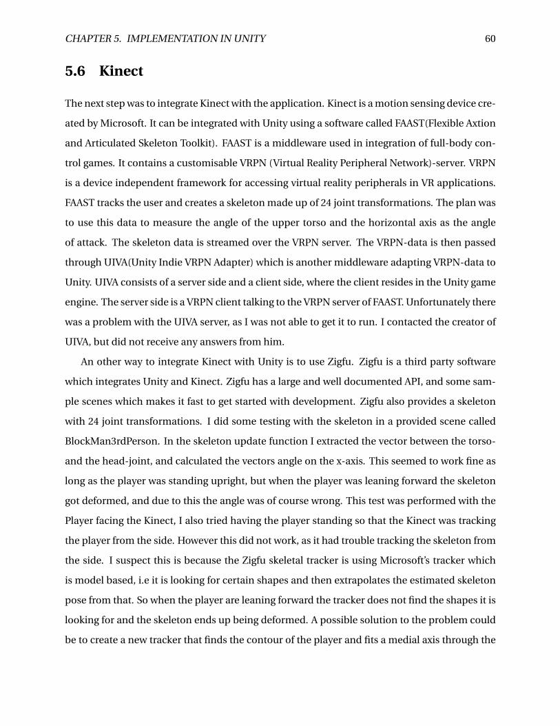
CHAPTER 5. IMPLEMENTATION IN UNITY 60
5.6 Kinect
The next step was to integrate Kinect with the application. Kinect is a motion sensing device cre-
ated by Microsoft. It can be integrated with Unity using a software called FAAST(Flexible Axtion
and Articulated Skeleton Toolkit). FAAST is a middleware used in integration of full-body con-
trol games. It contains a customisable VRPN (Virtual Reality Peripheral Network)-server. VRPN
is a device independent framework for accessing virtual reality peripherals in VR applications.
FAAST tracks the user and creates a skeleton made up of 24 joint transformations. The plan was
to use this data to measure the angle of the upper torso and the horizontal axis as the angle
of attack. The skeleton data is streamed over the VRPN server. The VRPN-data is then passed
through UIVA(Unity Indie VRPN Adapter) which is another middleware adapting VRPN-data to
Unity. UIVA consists of a server side and a client side, where the client resides in the Unity game
engine. The server side is a VRPN client talking to the VRPN server of FAAST. Unfortunately there
was a problem with the UIVA server, as I was not able to get it to run. I contacted the creator of
UIVA, but did not receive any answers from him.
An other way to integrate Kinect with Unity is to use Zigfu. Zigfu is a third party software
which integrates Unity and Kinect. Zigfu has a large and well documented API, and some sam-
ple scenes which makes it fast to get started with development. Zigfu also provides a skeleton
with 24 joint transformations. I did some testing with the skeleton in a provided scene called
BlockMan3rdPerson. In the skeleton update function I extracted the vector between the torso-
and the head-joint, and calculated the vectors angle on the x-axis. This seemed to work fine as
long as the player was standing upright, but when the player was leaning forward the skeleton
got deformed, and due to this the angle was of course wrong. This test was performed with the
Player facing the Kinect, I also tried having the player standing so that the Kinect was tracking
the player from the side. However this did not work, as it had trouble tracking the skeleton from
the side. I suspect this is because the Zigfu skeletal tracker is using Microsoft’s tracker which
is model based, i.e it is looking for certain shapes and then extrapolates the estimated skeleton
pose from that. So when the player are leaning forward the tracker does not find the shapes it is
looking for and the skeleton ends up being deformed. A possible solution to the problem could
be to create a new tracker that finds the contour of the player and fits a medial axis through the
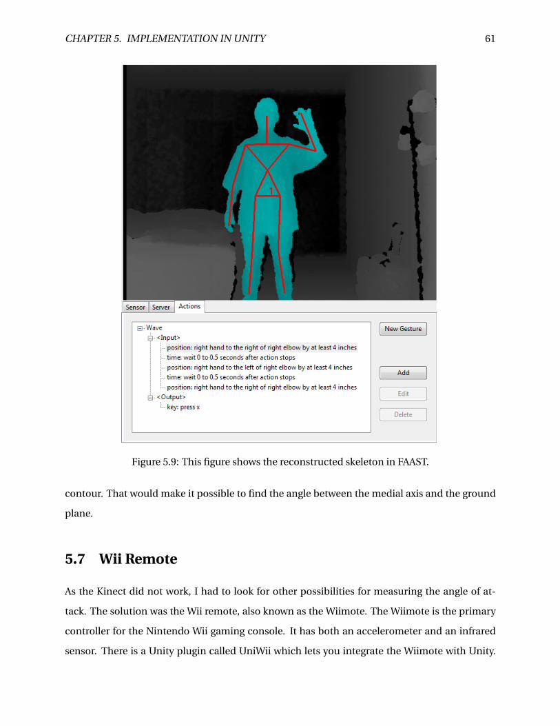
CHAPTER 5. IMPLEMENTATION IN UNITY 61
Figure 5.9: This figure shows the reconstructed skeleton in FAAST.
contour. That would make it possible to find the angle between the medial axis and the ground
plane.
5.7 Wii Remote
As the Kinect did not work, I had to look for other possibilities for measuring the angle of at-
tack. The solution was the Wii remote, also known as the Wiimote. The Wiimote is the primary
controller for the Nintendo Wii gaming console. It has both an accelerometer and an infrared
sensor. There is a Unity plugin called UniWii which lets you integrate the Wiimote with Unity.
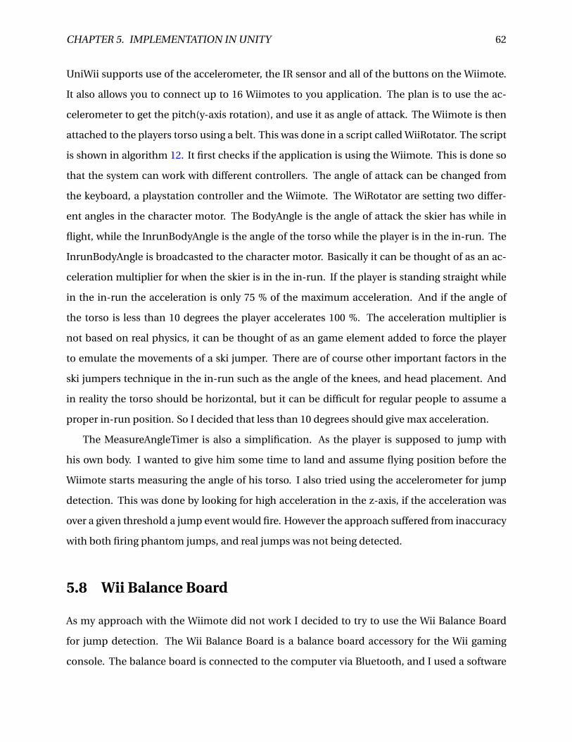
CHAPTER 5. IMPLEMENTATION IN UNITY 62
UniWii supports use of the accelerometer, the IR sensor and all of the buttons on the Wiimote.
It also allows you to connect up to 16 Wiimotes to you application. The plan is to use the ac-
celerometer to get the pitch(y-axis rotation), and use it as angle of attack. The Wiimote is then
attached to the players torso using a belt. This was done in a script called WiiRotator. The script
is shown in algorithm 12. It first checks if the application is using the Wiimote. This is done so
that the system can work with different controllers. The angle of attack can be changed from
the keyboard, a playstation controller and the Wiimote. The WiRotator are setting two differ-
ent angles in the character motor. The BodyAngle is the angle of attack the skier has while in
flight, while the InrunBodyAngle is the angle of the torso while the player is in the in-run. The
InrunBodyAngle is broadcasted to the character motor. Basically it can be thought of as an ac-
celeration multiplier for when the skier is in the in-run. If the player is standing straight while
in the in-run the acceleration is only 75 % of the maximum acceleration. And if the angle of
the torso is less than 10 degrees the player accelerates 100 %. The acceleration multiplier is
not based on real physics, it can be thought of as an game element added to force the player
to emulate the movements of a ski jumper. There are of course other important factors in the
ski jumpers technique in the in-run such as the angle of the knees, and head placement. And
in reality the torso should be horizontal, but it can be difficult for regular people to assume a
proper in-run position. So I decided that less than 10 degrees should give max acceleration.
The MeasureAngleTimer is also a simplification. As the player is supposed to jump with
his own body. I wanted to give him some time to land and assume flying position before the
Wiimote starts measuring the angle of his torso. I also tried using the accelerometer for jump
detection. This was done by looking for high acceleration in the z-axis, if the acceleration was
over a given threshold a jump event would fire. However the approach suffered from inaccuracy
with both firing phantom jumps, and real jumps was not being detected.
5.8 Wii Balance Board
As my approach with the Wiimote did not work I decided to try to use the Wii Balance Board
for jump detection. The Wii Balance Board is a balance board accessory for the Wii gaming
console. The balance board is connected to the computer via Bluetooth, and I used a software
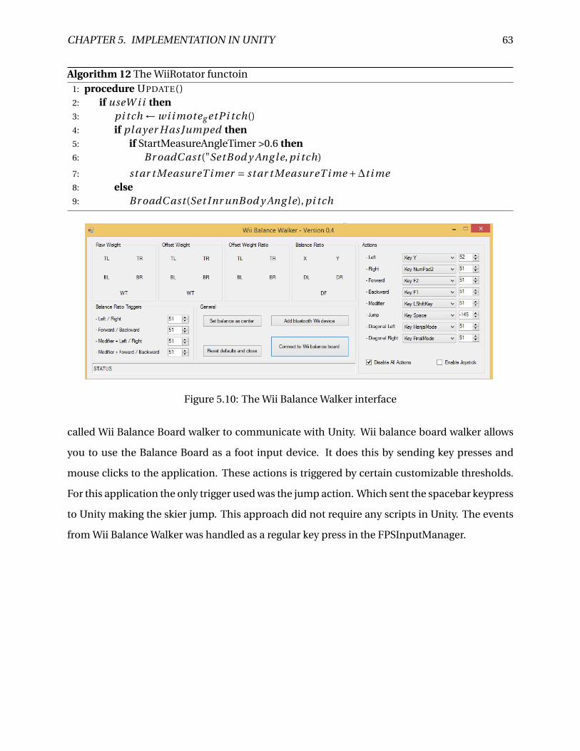
CHAPTER 5. IMPLEMENTATION IN UNITY 63
Algorithm 12 The WiiRotator functoin1: procedure UPDATE()2: if useW i i then3: pi tch ← wi i moteg etPi tch()4: if pl ayer H as Jumped then5: if StartMeasureAngleTimer >0.6 then6: Br oadC ast ("SetBod y Ang l e, pi tch)
7: st ar t Measur eT i mer = st ar t Measur eT i me +∆t i me8: else9: Br oadC ast (Set Inr unBod y Ang le), pi tch
Figure 5.10: The Wii Balance Walker interface
called Wii Balance Board walker to communicate with Unity. Wii balance board walker allows
you to use the Balance Board as a foot input device. It does this by sending key presses and
mouse clicks to the application. These actions is triggered by certain customizable thresholds.
For this application the only trigger used was the jump action. Which sent the spacebar keypress
to Unity making the skier jump. This approach did not require any scripts in Unity. The events
from Wii Balance Walker was handled as a regular key press in the FPSInputManager.
Chapter 6
Conclusion
6.1 Purpose of the tests
After the implementation it was time to evaluate the prototype. In user testing it normal to
focus on both the weak and strong sides of the prototype, where the goal is to continuously
improve the prototype. This was the second iteration of evaluating where the first iteration was
conducted in november and is described in Staurset [2014]. For this prototype there are two
well defined user groups: Ski jumpers and non-ski jumpers (the general public). The plan was
to let representatives from both groups test the system, and give feedback on it. In the following
chapter we will explain how the tests was conducted, and the results from the evaluation.
6.2 Expert evaluation
The evaluation with ski jumpers was conducted with athletes and trainers from the Norwegian
national ski jumping team. The evaluation was in the form of a semi structured interview. The
interview gave valuable insight in the strengths and weaknesses of the prototype. The visual im-
pression they got was that the in-run was to short, mainly the straight part of the in-run should
be 20 meters longer. They also thought that the radius seemed a little flat. However the out-run
looked very similar to the out-run in Granåsen.
64
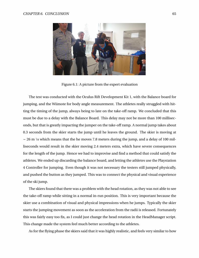
CHAPTER 6. CONCLUSION 65
Figure 6.1: A picture from the expert evaluation
The test was conducted with the Oculus Rift Development Kit 1, with the Balance board for
jumping, and the Wiimote for body angle measurement. The athletes really struggled with hit-
ting the timing of the jump, always being to late on the take-off ramp. We concluded that this
must be due to a delay with the Balance Board. This delay may not be more than 100 millisec-
onds, but that is greatly impacting the jumper on the take-off ramp. A normal jump takes about
0.3 seconds from the skier starts the jump until he leaves the ground. The skier is moving at
∼ 26 m \s which means that the he moves 7.8 meters during the jump, and a delay of 100 mil-
liseconds would result in the skier moving 2.4 meters extra, which have severe consequences
for the length of the jump. Hence we had to improvise and find a method that could satisfy the
athletes. We ended up discarding the balance board, and letting the athletes use the Playstation
4 Controller for jumping. Even though it was not necessary the testers still jumped physically,
and pushed the button as they jumped. This was to connect the physical and visual experience
of the ski jump.
The skiers found that there was a problem with the head rotation, as they was not able to see
the take-off ramp while sitting in a normal in-run position. This is very important because the
skier use a combination of visual and physical impressions when he jumps. Typically the skier
starts the jumping movement as soon as the acceleration from the radii is released. Fortunately
this was fairly easy too fix, as I could just change the head rotation in the HeadManager script.
This change made the system feel much better according to the athletes.
As for the flying phase the skiers said that it was highly realistic, and feels very similar to how
CHAPTER 6. CONCLUSION 66
it is to jump in real life. "The feeling of "take-off" in a long jump feels very good, and reminds
me much about how it is in real life" a jumper said. However one jumper said that it felt like
profile of the jump felt a little off. By this he meant that you was too high above ground after
take-off, and a little low above ground at the end of a jump. But this is individual for every ski
jumper, and is dependent on many factors such as jump timing, how much force the jumpers
generate, and flying technique of the jumper among others. However they pointed out that there
was a problem with the physical model. The way it is implemented now the lift increases as the
angle of attack decreases. I.e the lower the angle of attack the longer the jump. In real life the
skiers body and the ski’s acts like a wing and to minimize the drag and maximize the lift forces
acting on the skier. Ideally the skier should have an angle of attack of about 11 degrees. An other
aspect that the model does not catch is how important the rotation is in a ski jump. A ski jumper
should have a small rotation forward during a jump. However if he adjust the rotation forward
to fast he may get an over rotation, and if the rotation is to small the skier will be pushed back
and thus generating more drag resulting in a shorter jump. They suggested that there should be
implemented sort of a breaking point in the physical model where the lift is reduced if the angle
is below 11 degrees. Besides of this they where pleased with the physical model.
All the jumpers agreed on that the in-run seemed to short, and especially the problem was
that the straight part of the in-run should be at least 15 meters longer. They also said that the
straight part felt a little to flat. After the evaluation I checked the steepness of the straight part
of the in-run and the take-off ramp, and they are correct according to the hill certificate. I also
checked the length of the in-run, and it really seem to be shorter then it is supposed to be. First
I checked the manually created in-run that was imported into unity, and it was about 73 meters
long, which is 20 meter less then the real in-run. My first theory was that there was a weakness
in the surface reconstruction algorithm so it omitted the top part of the in-run. This theory was
dismissed after I checked the raw data from the drone. I imported the drone data into Meshlab
and converted it into a PLY file, so it could be opened in Blender. And from measuring there this
was also about 73 meters long. So it appears that the LIDAR-system has failed to recreate the top
part of the in-run. The consequences of the short in-run is not very severe, as it has successfully
recreated the radius and the take-off ramp. Fixing the in-run requires only that you extrude
the straight part of the in-run 20 meters in the local x-direction. The same has to be done for
CHAPTER 6. CONCLUSION 67
the fence, and the lamp posts as well. But when this is done, the in-run should be satisfactory
according to the skiers.
One of the jumpers suggested that the in-run may feel flatter because they are standing on
the flat ground. And they are used to feel the steepness of the in-run in their feet, this discon-
nect between what they are seeing and what they are feeling may lead to the skiers feeling the
in-run is less steep. Another factor is that they do not feel the acceleration forces act on the
body as it does in a real ski jump. This may contribute to the skiers feeling that the simulator
is less extreme. It is impossible to recreate the acceleration forces that acts on a skier while he
is jumping, but it is possible to build an apparatus that the skier stands on, which rotates the
ground according to the movement of the skier. However this would both be quite complex and
expensive.
The jump is now implemented so that the player jumps immediately when the jump button
is pushed. As mentioned earlier the average jump takes 0.3 seconds, and for the skiers it would
be much more natural to have a 0.3 second delay on the jump button so they can push it when
they would start the jump movement. The trainers also gave valuable input on the jump mul-
tipliers shown in figure 5.2. In reality the skier want to jump as close to the end of the take-off
ramp as possible, and a difference of 3 meters on the take-off ramp could result in a 40 meter
difference on a ski jump. So the jump multipliers should be changed, scaled accordingly.
Other possible improvements was also discussed. One suggestion was to use infrared lights
attached to the shoulder, hip, knee and ankle as shown in figure 6.2. These IR- lights could be
read by the Wiimote which looks at the person from the side. The Wiimote has an IR-camera
which is supported by the UniWii plugin for Unity. So the IR-lights could be used to reconstruct
a 2D- skeleton of the skier. This skeleton could possibly be used for jump detection, by checking
when angle between the knee, hips and ankle start to change. Alternatively the jump could be
triggered when the light at the ankle starts to move in the y-direction.This would also allow to
create a replay system where you could watch the skiers 2D skeleton as they jump. Furthermore
you could also use the angle between the horizontal axis and the torso to measure the angle of
attack, replacing the Wiimote attached to the jumpers body.
It was also suggested to use force scale which could be used to detect the jump. With a force
scale the application can use the force generated by the skier as input for the jump. And you
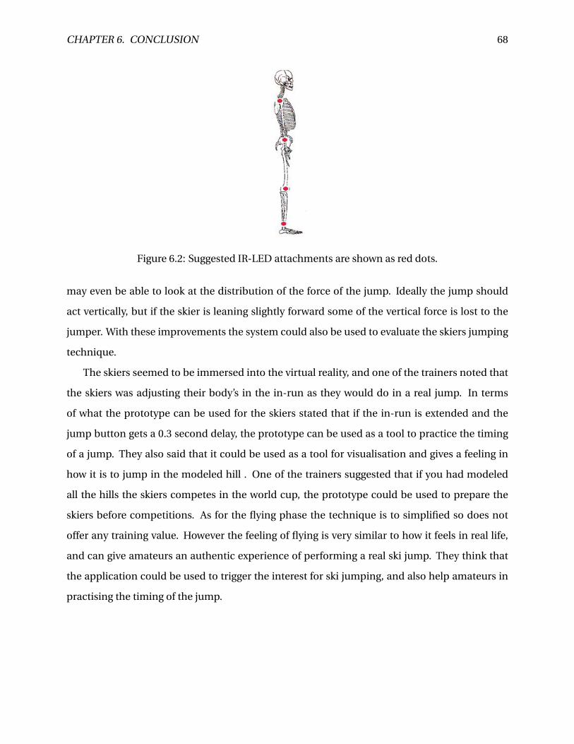
CHAPTER 6. CONCLUSION 68
Figure 6.2: Suggested IR-LED attachments are shown as red dots.
may even be able to look at the distribution of the force of the jump. Ideally the jump should
act vertically, but if the skier is leaning slightly forward some of the vertical force is lost to the
jumper. With these improvements the system could also be used to evaluate the skiers jumping
technique.
The skiers seemed to be immersed into the virtual reality, and one of the trainers noted that
the skiers was adjusting their body’s in the in-run as they would do in a real jump. In terms
of what the prototype can be used for the skiers stated that if the in-run is extended and the
jump button gets a 0.3 second delay, the prototype can be used as a tool to practice the timing
of a jump. They also said that it could be used as a tool for visualisation and gives a feeling in
how it is to jump in the modeled hill . One of the trainers suggested that if you had modeled
all the hills the skiers competes in the world cup, the prototype could be used to prepare the
skiers before competitions. As for the flying phase the technique is to simplified so does not
offer any training value. However the feeling of flying is very similar to how it feels in real life,
and can give amateurs an authentic experience of performing a real ski jump. They think that
the application could be used to trigger the interest for ski jumping, and also help amateurs in
practising the timing of the jump.
CHAPTER 6. CONCLUSION 69
6.3 General public
The prototype was also tested by the general public. The test was conducted at Vitensenteret
and at an event called Open Day at NTNU. Open day is an event where high school students
visit the university, and Vitensenteret is a scientific "hands-on" experience center in Trondheim.
The plan was to have the participants answer a questionnaire afterwards, but the participants at
Vitensenteret was mainly children less than 10 years old, so the questionnaire was not suitable.
But we made a simplified questionnaire where the testers could give a rating to the system from
1 to 5, and answer if they wanted the prototype to be part of the exhibition at Vitensenteret. The
system was tested by 62 children and 58 of them gave it a rating of 5 out of 5. The remaining 4
gave it a rating of 4 out of 5. Furthermore all of the testers wanted the system to be part of the
exhibition at Vitensenteret. From this we can conclude that the children enjoyed the applica-
tion. Initially the test was conducted with the Wii Balance Board for jump detection, and the
Wiimote measuring angle of attack. However this setup proved to be difficult for the chlidren,
and 3 out of 5 of the first testers fell on the ground after jumping off the Balance Board. So I de-
cided to let the rest of the children test the system using the Playstation controller for jumping,
and adjusting the angle of attack.
On the Open Day at NTNU the test was conducted with Oculus Rift, and using the Balance
Board for jumping and Wiimote to measure the angle of attack. After testing the prototype they
answered a questionnaire. The questionnaire was designed to focus on user experience, realism
and presence. In total 32 people answered the questionnaire, and of these 28 was male and 4
female. Of these participants 24 had no experience with ski jumping, 7 had little experience,
and 1 had much experience with ski jumping. Most of the participants was experienced with
computer games.
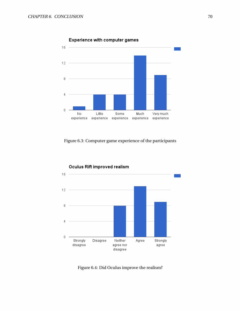
CHAPTER 6. CONCLUSION 70
Figure 6.3: Computer game experience of the participants
Figure 6.4: Did Oculus improve the realism?

CHAPTER 6. CONCLUSION 71
Figure 6.5: Would more body movement improve the system?
Figure 6.6: How the participants perceived the experience

CHAPTER 6. CONCLUSION 72
Figure 6.7: Did it feel like the participants jumped themself
Figure 6.8: How realistic was the experience?
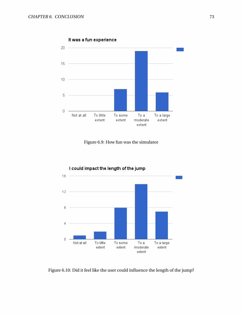
CHAPTER 6. CONCLUSION 73
Figure 6.9: How fun was the simulator
Figure 6.10: Did it feel like the user could influence the length of the jump?

CHAPTER 6. CONCLUSION 74
Figure 6.11: Did the participants learn something about ski jumping technique?
Figure 6.12: Did the participants learn something about ski jumping technique?
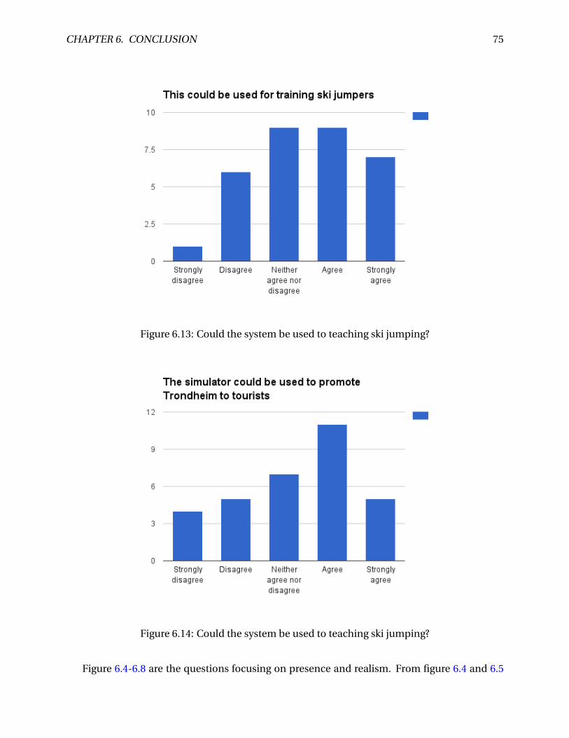
CHAPTER 6. CONCLUSION 75
Figure 6.13: Could the system be used to teaching ski jumping?
Figure 6.14: Could the system be used to teaching ski jumping?
Figure 6.4-6.8 are the questions focusing on presence and realism. From figure 6.4 and 6.5
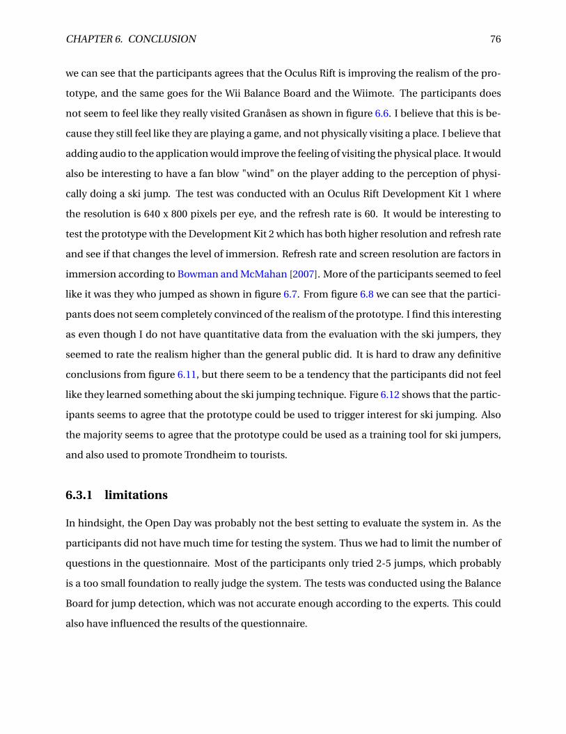
CHAPTER 6. CONCLUSION 76
we can see that the participants agrees that the Oculus Rift is improving the realism of the pro-
totype, and the same goes for the Wii Balance Board and the Wiimote. The participants does
not seem to feel like they really visited Granåsen as shown in figure 6.6. I believe that this is be-
cause they still feel like they are playing a game, and not physically visiting a place. I believe that
adding audio to the application would improve the feeling of visiting the physical place. It would
also be interesting to have a fan blow "wind" on the player adding to the perception of physi-
cally doing a ski jump. The test was conducted with an Oculus Rift Development Kit 1 where
the resolution is 640 x 800 pixels per eye, and the refresh rate is 60. It would be interesting to
test the prototype with the Development Kit 2 which has both higher resolution and refresh rate
and see if that changes the level of immersion. Refresh rate and screen resolution are factors in
immersion according to Bowman and McMahan [2007]. More of the participants seemed to feel
like it was they who jumped as shown in figure 6.7. From figure 6.8 we can see that the partici-
pants does not seem completely convinced of the realism of the prototype. I find this interesting
as even though I do not have quantitative data from the evaluation with the ski jumpers, they
seemed to rate the realism higher than the general public did. It is hard to draw any definitive
conclusions from figure 6.11, but there seem to be a tendency that the participants did not feel
like they learned something about the ski jumping technique. Figure 6.12 shows that the partic-
ipants seems to agree that the prototype could be used to trigger interest for ski jumping. Also
the majority seems to agree that the prototype could be used as a training tool for ski jumpers,
and also used to promote Trondheim to tourists.
6.3.1 limitations
In hindsight, the Open Day was probably not the best setting to evaluate the system in. As the
participants did not have much time for testing the system. Thus we had to limit the number of
questions in the questionnaire. Most of the participants only tried 2-5 jumps, which probably
is a too small foundation to really judge the system. The tests was conducted using the Balance
Board for jump detection, which was not accurate enough according to the experts. This could
also have influenced the results of the questionnaire.
CHAPTER 6. CONCLUSION 77
6.4 Discussion
In section 2.7 the requirements for the system was proposed. All of the requirements has been
met to some extent:
The hill should visually look like Granåsen:
This was achieved by performing surface reconstruction on data collected by a LIDAR system.
Several other visual elements was modeled using images as references, e.g. the fence, the lamp
posts). Based on the expert evaluation the scene looks similar to the real hill. Unfortunately the
LIDAR data was not able to capture the whole in-run, and this resulted in a too short in-run. This
is not something the untrained eye will notice, but for athletes it is important that the in-run is
accurate.
The prototype should be physical correct:
The physical model is a simplification of the real physics of the ski jump. The experts that tested
the system found the physical model satisfactory, and the flying phase was realistically modeled.
The only complaint of the physical model is that there should be a breaking point in the angle of
attack, so that you get less lift if the angle of attack is less than 11 degrees. This could for instance
be achieved by implementing a multiplier in the same way as the acceleration modifier when
the skier is in the in-run. That would also add more skill to the game. To perform a long jump
in the current physical model you have to have as low angle of attack as possible, but with the
breaking point implemented the goal will be to find the "correct" angle of attack.
The system should provide a realistic ski jumping experience for amateurs:
The results from the question about realism is shown in figure 6.8, and from those results the
participants found the experience to be realistic to some extent. The test was performed with
the Wii Balance Board, which was proved too inaccurate in the expert evaluation due to the
delay. This may have impacted the results from the questionnaire.
The system should be able to run in real-time on a mid-range computer:
The system has been extensively tested on a Samsung ATIV Book 4 Samsung [2015], which is a
low- to mid-range lap top, and there has not been any performance issues with the application.
The system should have a natural user interface
There still are some work to do with the user interface. The angle of attack is being measured
CHAPTER 6. CONCLUSION 78
by the Wiimote, and this works fine. However the Wii Balance Board did not work well enough
for jump detection. I would recommend to explore the IR-LED solution proposed in section 6.2.
It may also be possible do more test with using the accelerometer for jump detection. There
still are some functions that rely on traditional user interface (buttons/keys), such as landing,
restarting the jump, and jump evaluation. These functions could possibly be activated with
gesture recognition using the Kinect. However I did not have time to investigate this further.
As for development Unity proved to be a very well suited platform for development of virtual
reality applications. The Oculus Rift SDK for Unity made it easy to integrate with Oculus Rift.
Furthermore Unity has a well-documented API Unity [2015] and I found the software intuitive
and easy to use. Furthermore Unity has plugins who supports input-devices such as the Wi-
imote and the Kinect. The use of LIDAR for reconstructing the hill also worked reasonably well.
The only problem with it was that the system was not able to detect the whole in-run. Through
surface reconstruction and post-processing we ended up with a scene where the experts could
clearly recognize Granåsen.
Compared to the other ski jumping applications described in section 2.3 the application has
some features that none of the other applications has. It is hard to compare with Alf Engen’s
Take Flight because there are not much information about it. But by using JDHGroup [2015] as
a reference we are able to do some comparisons. Take Flight only has a regular TV-monitor for
displaying the graphics. This should lead to a less immersive experience than by using the Ocu-
lus Rift. The application seems to be using some sort of a balance board for input, which seems
to be the only way the player are interacting with the system. It does not require the player to
mimic the technique of a real ski jump. It seems fair to claim that even without the Balance
board for jump detection, my application has a user interface that mimics the ski jumping tech-
nique more accurate, and thus should be more useful for training ski jumpers.
There is also limited information on the "Planica 2015 Virtual ski flying" application, but the
comparisons are based on Sporto [2015] and Triglav [2015]. This is the only other ski jump appli-
cation I have found that also uses a head mounted display. It uses the Oculus Rift Development
Kit 2, and it seems like it only uses the head tracker of the Oculus as input. It seems like the head
tracker is only used to determine the timing of the jump. In terms of user interface I would still
claim that my prototype has a more intuitive and realistic user interface, which makes it more
CHAPTER 6. CONCLUSION 79
suitable to use by athletes in a training situation.
As mentioned earlier Deluxe Ski Jump 4 (DSJ) is considered the best ski jump game in the
market. I have tested the game extensively, and in my opinion the physics is the most impressive
aspect of the game. It seems to have a more sophisticated physical model that is able to capture
the rotation of the skiers body, and the ski’s behaviour while they are in the air. However as I
mentioned earlier it is primarily a game and not a virtual reality application. The game supports
first person camera, but it is difficult to use as you cant assess how the skiers body is positioned.
Both applications uses the timing of the jump, and the angle of attack in the air to determine the
length of the jump. One of the trainers that tested my game is an experienced DSJ-player, and
he said that the dream would be to have an application with DSJ’s physics and my user interface.
6.5 Conclusion
In this report I have described how a virtual reality simulator for ski jumping can be developed. A
LIDAR system was used to create a point cloud of the ski jumping hill in Trondheim, Granåsen.
This point cloud was converted to a mesh by using the Poisson surface reconstruction algo-
rithm. The application was implemented in Unity, and has a simplified physical model based
on Marasovic [2003]. The application uses the Wiimote to measure the body angle when the
player is in the in-run, and in the air. We tried using the Wii Balance Board for jump detection,
but due to delay this did not work well enough.
Even though the prototype is not perfect, and has areas of improvement such as jump-
detection, I would claim that this best known ski jumping application for ski jumpers in training.
As mentioned in section 6.2 with some minor improvements (delay on jump, extension of in-
run), the application can be used by professional ski jumpers to practice the timing of the jump.
The flying phase is too simplified and does not offer any training value for the skiers. But the
flying phase is extremely difficult to recreate in a way that could be transferable to the real tech-
nique. Furthermore the application can give a realistic experience of how it feels to perform a
real ski jump. And it can be used as a tool to trigger interest for ski jumping, and inspire aspiring
ski jumpers.
CHAPTER 6. CONCLUSION 80
6.6 Future Work
For future works it would be interesting to continue the work on jump detection. The next
step would be to find a way to accurately detect the moment of a jump. It is important that
the method has low latency. In section 6.2 I proposed a possible solution using the Wiimote
as an IR-camera, and attaching IR-lights to the jumpers body. This could be used to create a
2-dimensional skeleton of the jumpers body as shown in figure 6.2. A jump event could be
fired when the IR-light attached to the ankle starts moving in the y-direction. Furthermore this
method could enable the creation of a replay system, where you can see the jumper’s skeleton
during the jump. Still the application would be mostly effective for practicing timing, but the
user interface would be more natural. To further improve this, one could use a force scale to de-
tect the jump. Then the force the skier generates could be used as input for the jump. Also then
you could look at the force distribution of the jump. Then the application would have potential
to be used as a tool for practicing the technique of the jump as well.
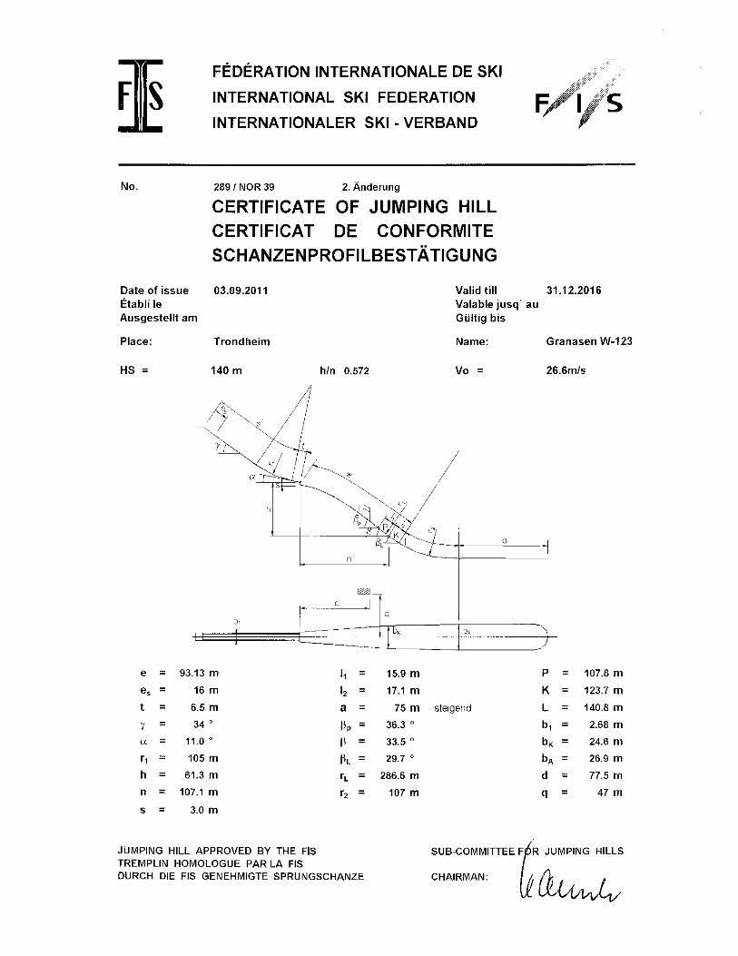

APPENDIX B
Questionnaire
Sex?
Male
Female
Oculus Rift increases the realism?
Strongly disagree
Disagree
Neither disagrees or agrees
Agree
Strongly agree
How much experience do you have with ski jumping?
No experience
Some experience
Much experience
How much experience do you have with Computer games?
No experience
Little experience
Some experience
Much experience
Very much experience

It was a fun experience?
Not at all
To little extent
To some extent
To a moderate extent
To a large extent
It felt like I actually visited Granåsen?
Not at all
To little extent
To some extent
To a moderate extent
To a large extent
It felt like it was I who jumped
Not at all
To little extent
To some extent
To a moderate extent
To a large extent
The ski jump felt realistic?
Not at all
To little extent
To some extent
To a moderate extent
To a large extent

I learned something about ski jumping technique?
Not at all
To little extent
To some extent
To a moderate extent
To a large extent
It would have been a better experience if the hill looked more like the real Granåsen?
Strongly disagree
Disagree
Neither disagrees or agrees
Agree
Strongly agree
The use of Wii Balance Board and Wiimote improves the realism
Not at all
To little extent
To some extent
To a moderate extent
To a large extent
The simulator could be used to trigger the interest for ski jumping
Strongly disagree
Disagree
Neither disagrees or agrees
Agree
Strongly agree

This simulator could be a useful tool to teach ski jumping?
Strongly disagree
Disagree
Neither disagrees or agrees
Agree
Strongly agree
This simulator could be used to promote Trondheim to tourists
Strongly disagree
Disagree
Neither disagrees or agrees
Agree
Strongly agree

CHAPTER 6. CONCLUSION 86
Appendix C
The project is available here: https://goo.gl/Mz4yzp. The URL is a reference to a Dropbox
folder. The folder contains a copy of the Unity project, Unity builds with different target plat-
forms, and the audio file from the expert evaluation.
Bibliography
F. Bernardini, J. Mittleman, H. Rushmeier, C. Silva, and G. Taubin. The ball-pivoting algorithm
for surface reconstruction. Visualization and Computer Graphics, IEEE Transactions on, 5(4):
349–359, Oct 1999. ISSN 1077-2626. doi: 10.1109/2945.817351.
Benoît Bideau, Franck Multon, Richard Kulpa, Laetitia Fradet, and Bruno Arnaldi. Virtual re-
ality applied to sports: Do handball goalkeepers react realistically to simulated synthetic
opponents? In Proceedings of the 2004 ACM SIGGRAPH International Conference on Vir-
tual Reality Continuum and Its Applications in Industry, VRCAI ’04, pages 210–216, New
York, NY, USA, 2004. ACM. ISBN 1-58113-884-9. doi: 10.1145/1044588.1044632. URL
http://doi.acm.org/10.1145/1044588.1044632.
D.A. Bowman and R.P. McMahan. Virtual reality: How much immersion is enough? Computer,
40(7):36–43, July 2007. ISSN 0018-9162. doi: 10.1109/MC.2007.257.
Linda Carswell. The “virtual university”: toward an internet paradigm? In ACM SIGCSE Bulletin,
volume 30, pages 46–50. ACM, 1998.
Albert K. Chong and Hayden G. Croft. A photogrammetric application in virtual sport training.
The Photogrammetric Record, 24(125):51–65, 2009. ISSN 1477-9730. doi: 10.1111/j.1477-9730.
2009.00517.x. URL http://dx.doi.org/10.1111/j.1477-9730.2009.00517.x.
Jeschke S Razdan A White K Cline, D and P Wonka. Dart throwing on surfaces. In Computer
Graphics Forum (Proceedings of Eurographics Symposium on Rendering), 2009.
Andrew Cram, John Hedberg, and Maree Gosper. Beyond immersion–meaningful involvement
in virtual worlds. In Global Learn, volume 2011, pages 1548–1557, 2011.
87
BIBLIOGRAPHY 88
Wolfgang Dokonal, Bob Martens, and Reinhard Plösch. Creating and using virtual cities. na,
2004.
Engen-Museum. New virtual ski jumping exhibit, 2014. URL https://www.engenmuseum.org/
news/new-virtual-ski-jumping-exhibit.
M Fominykh, E Prasolova-Førland, M Morozov, and A Gerasimov. Virtual campus as a frame-
work for educational and social activities. In IASTED International Conference on Computers
and Advanced Technology in Education, 2008.
Daniel A. Guttentag. Virtual reality: Applications and implications for tourism. Tourism
Management, 31(5):637 – 651, 2010. ISSN 0261-5177. doi: http://dx.doi.org/10.1016/
j.tourman.2009.07.003. URL http://www.sciencedirect.com/science/article/pii/
S0261517709001332.
Randy S Haluck and Thomas M Krummel. Computers and virtual reality for surgical education
in the 21st century. Archives of surgery, 135(7):786–792, 2000.
JDHGroup. Alf engen’s take flight, 2015. URL http://jdhgroup.com/projects/
alf-engens-take-flight-virtual-ski-jump.
Michael Kazhdan, Matthew Bolitho, and Hugues Hoppe. Poisson surface reconstruction. In Pro-
ceedings of the Fourth Eurographics Symposium on Geometry Processing, SGP ’06, pages 61–70,
Aire-la-Ville, Switzerland, Switzerland, 2006. Eurographics Association. ISBN 3-905673-36-3.
URL http://dl.acm.org/citation.cfm?id=1281957.1281965.
James F Knight, Simon Carley, Bryan Tregunna, Steve Jarvis, Richard Smithies, Sara de Freitas,
Ian Dunwell, and Kevin Mackway-Jones. Serious gaming technology in major incident triage
training: a pragmatic controlled trial. Resuscitation, 81(9):1175–1179, 2010.
Taku Komura, Atsushi Kuroda, and Yoshihisa Shinagawa. Nicemeetvr: Facing professional base-
ball pitchers in the virtual batting cage. In Proceedings of the 2002 ACM Symposium on Applied
Computing, SAC ’02, pages 1060–1065, New York, NY, USA, 2002. ACM. ISBN 1-58113-445-2.
doi: 10.1145/508791.509000. URL http://doi.acm.org/10.1145/508791.509000.
BIBLIOGRAPHY 89
William E. Lorensen and Harvey E. Cline. Marching cubes: A high resolution 3d surface con-
struction algorithm. In Proceedings of the 14th Annual Conference on Computer Graphics and
Interactive Techniques, SIGGRAPH ’87, pages 163–169, New York, NY, USA, 1987. ACM. ISBN 0-
89791-227-6. doi: 10.1145/37401.37422. URL http://doi.acm.org/10.1145/37401.37422.
K. Marasovic. Visualised interactive computer simulation of ski-jumping. In Information Tech-
nology Interfaces, 2003. ITI 2003. Proceedings of the 25th International Conference on, pages
613–618, June 2003. doi: 10.1109/ITI.2003.1225411.
Marta Wright Mary Ulicsak. Games in education: Serious games. a futurelab literature review. A
Futurelab literature review, 2010.
Michael Meehan, Brent Insko, Mary Whitton, and Frederick P Brooks Jr. Physiological measures
of presence in stressful virtual environments. In ACM Transactions on Graphics (TOG), vol-
ume 21, pages 645–652. ACM, 2002.
Helen C Miles, Serban R Pop, Simon J Watt, Gavin P Lawrence, and Nigel W John. A review of
virtual environments for training in ball sports. Computers & Graphics, 36(6):714–726, 2012.
Changhoon Park and Junsuk Moon. Using game technology to develop snowboard training
simulator. In Constantine Stephanidis, editor, HCI International 2013 - Posters’ Extended Ab-
stracts, volume 374 of Communications in Computer and Information Science, pages 723–726.
Springer Berlin Heidelberg, 2013. ISBN 978-3-642-39475-1. doi: 10.1007/978-3-642-39476-8_
145. URL http://dx.doi.org/10.1007/978-3-642-39476-8_145.
John M Rolfe and Ken J Staples. Flight simulation, volume 1. Cambridge University Press, 1988.
Samsung. Specification of samsung ativ book 4, 2015. URL http://www.samsung.com/us/
support/owners/product/NP470R5E-K01UB.
SONU SANGAM. Light detection and ranging, 2012.
Neal E Seymour, Anthony G Gallagher, Sanziana A Roman, Michael K O’Brien, Vipin K Bansal,
Dana K Andersen, and Richard M Satava. Virtual reality training improves operating room
performance: results of a randomized, double-blinded study. Annals of surgery, 236(4):458,
2002.
BIBLIOGRAPHY 90
Mel Slater. A note on presence terminology. Presence connect, 3(3):1–5, 2003.
Sporto. Zavarovalnica triglav offering virtual reality in planica, 2015. URL http://sporto.si/
en-us/novica/87/zavarovalnica-triglav-offering-virtual-reality-in-planica.
Kurt Squire. Changing the game: What happens when video games enter the classroom. Inno-
vate: Journal of online education, 1(6), 2005.
Emil Moltu Staurset. Creating an immersive virtual reality application for ski jumping. na, 2014.
Jonathan Steuer. Defining virtual reality: Dimensions determining telepresence. Journal of
Communication, 42(4):73–93, 1992. ISSN 1460-2466. doi: 10.1111/j.1460-2466.1992.tb00812.
x. URL http://dx.doi.org/10.1111/j.1460-2466.1992.tb00812.x.
C. Stinson and D.A. Bowman. Feasibility of training athletes for high-pressure situations using
virtual reality. IEEE Transactions on Visualization and Computer Graphics, 20(4):606–615,
2014. doi: 10.1109/TVCG.2014.23. URL http://www.scopus.com/inward/record.url?
eid=2-s2.0-84897459573&partnerID=40&md5=6b28ba2482642c787de2e73ec517b831.
cited By 0.
Triglav. Virtualni poleti planica 2015, 2015. URL https://www.youtube.com/watch?v=
8HHfafKyZ8Y.
Unity. Unity game enigne, 2015. URL https://unity3d.com/.
US-Army. Americas army. URL http://www.americasarmy.com/.
M Usoh, E Catena, S Arman, and M Slater. Using presence questionnaires in reality. Presence, 9
(5):497–503, Oct 2000. ISSN 1054-7460. doi: 10.1162/105474600566989.
M. Zyda. From visual simulation to virtual reality to games. Computer, 38(9):25–32, Sept 2005.
ISSN 0018-9162. doi: 10.1109/MC.2005.297.
A. C. Öztireli, G. Guennebaud, and M. Gross. Feature preserving point set surfaces based on non-
linear kernel regression. Computer Graphics Forum, 28(2):493–501, 2009. ISSN 1467-8659.
doi: 10.1111/j.1467-8659.2009.01388.x. URL http://dx.doi.org/10.1111/j.1467-8659.
2009.01388.x.


![Madame Bovary on the Holodeck: Immersive Interactive ... · Immersive Interactive ... [Multimedia Information Systems] Artificial, Augmented and Virtual Reality - Virtual Reality](https://img.pdfslide.net/doc/110x75/5b0dbe807f8b9a2f788e329e/madame-bovary-on-the-holodeck-immersive-interactive-interactive-multimedia.jpg)