Embed Size (px)
Citation preview
CS3350B Computer Architecture
Winter 2015
Lecture 6.2: Instructional Level Parallelism:Hazards and Resolutions
Marc Moreno Maza
www.csd.uwo.ca/Courses/CS3350b
[Adapted from lectures on Computer Organization and Design, Patterson & Hennessy, 5th edition, 2011]
2
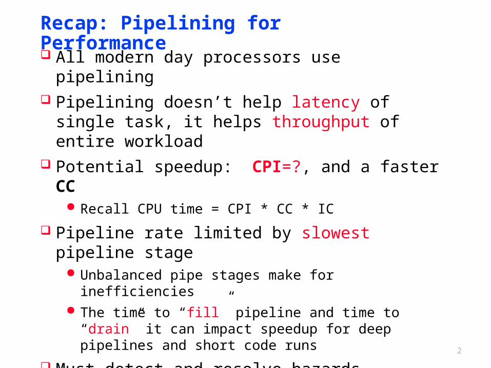
Recap: Pipelining for Performance
All modern day processors use pipelining Pipelining doesn’t help latency of single task, it helps
throughput of entire workload Potential speedup: CPI=?, and a faster CC
Recall CPU time = CPI * CC * IC
Pipeline rate limited by slowest pipeline stage Unbalanced pipe stages make for inefficiencies The time to “fill” pipeline and time to “drain” it can impact
speedup for deep pipelines and short code runs
Must detect and resolve hazards Can always resolve hazards by waiting (Stalling) Stalling negatively affects CPI (makes CPI more than the
ideal of 1)
3
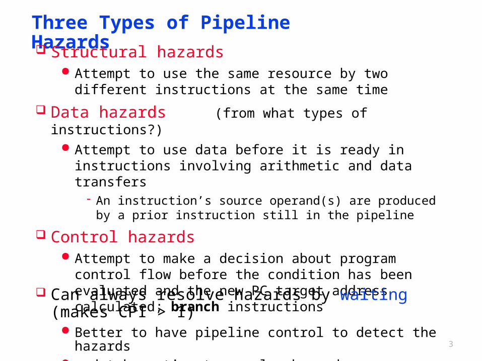
Three Types of Pipeline Hazards Structural hazards
Attempt to use the same resource by two different instructions at the same time
Data hazards (from what types of instructions?) Attempt to use data before it is ready in instructions involving
arithmetic and data transfers- An instruction’s source operand(s) are produced by a prior
instruction still in the pipeline
Control hazards Attempt to make a decision about program control flow before
the condition has been evaluated and the new PC target address calculated; branch instructions
Can always resolve hazards by waiting (makes CPI > 1) Better to have pipeline control to detect the hazards and take action to resolve hazards more efficiently
4
Instr.
Order
Time (clock cycles)
lw
Inst 1
Inst 2
Inst 4
Inst 3
AL
UMem Reg Mem Reg
AL
UMem Reg Mem Reg
AL
UMem Reg Mem RegA
LUMem Reg Mem Reg
AL
UMem Reg Mem Reg
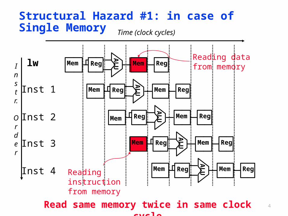
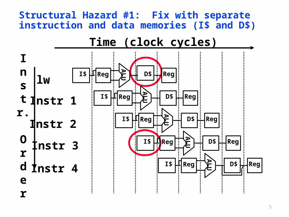
Structural Hazard #1: in case of Single Memory
Reading data from memory
Reading instruction from memory
Read same memory twice in same clock cycle
5
I$
lw
Instr 1
Instr 2
Instr 3
Instr 4A
LU I$ Reg D$ Reg
AL
U I$ Reg D$ Reg
AL
U I$ Reg D$ Reg
AL
UReg D$ Reg
AL
U I$ Reg D$ Reg
Instr.
Order
Time (clock cycles)
Structural Hazard #1: Fix with separate instruction and data memories (I$ and D$)
6
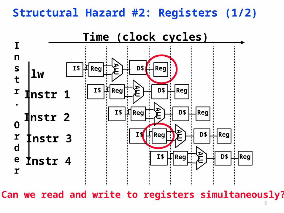
Structural Hazard #2: Registers (1/2)
Can we read and write to registers simultaneously?
I$
lw
Instr 1
Instr 2
Instr 3
Instr 4A
LU I$ Reg D$ Reg
AL
U I$ Reg D$ Reg
AL
U I$ Reg D$ RegA
LUReg D$ Reg
AL
U I$ Reg D$ Reg
Instr.
Order
Time (clock cycles)
7
Structural Hazard #2: Registers (2/2)
Two different solutions have been used:(1) RegFile access is very fast: takes less than half the time of
ALU stage- Write to Registers during first half of each clock cycle- Read from Registers during second half of each clock cycle
(2) Build RegFile with independent read and write ports
Result: can perform register Read and Write during same clock cycle
8
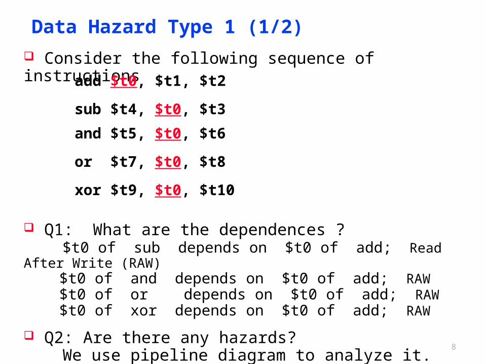
Data Hazard Type 1 (1/2)
Consider the following sequence of instructions
Q1: What are the dependences ? $t0 of sub depends on $t0 of add; Read After Write (RAW) $t0 of and depends on $t0 of add; RAW $t0 of or depends on $t0 of add; RAW $t0 of xor depends on $t0 of add; RAW
Q2: Are there any hazards? We use pipeline diagram to analyze it.
add $t0, $t1, $t2
sub $t4, $t0, $t3
and $t5, $t0, $t6
or $t7, $t0, $t8
xor $t9, $t0, $t10
9
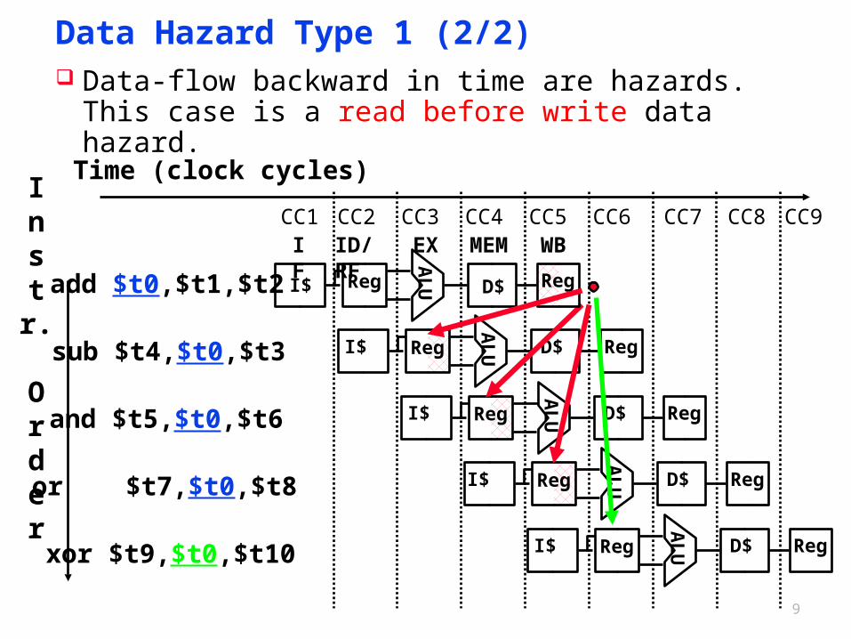
Data Hazard Type 1 (2/2) Data-flow backward in time are hazards.
This case is a read before write data hazard.
sub $t4,$t0,$t3A
LUI$ Reg D$ Reg
and $t5,$t0,$t6
AL
UI$ Reg D$ Reg
or $t7,$t0,$t8 I$
AL
UReg D$ Reg
xor $t9,$t0,$t10
AL
UI$ Reg D$ Reg
add $t0,$t1,$t2
IF ID/RF EX MEM WB
AL
UI$ Reg D$ Reg
Instr.
Order
Time (clock cycles)
CC1 CC2 CC3 CC4 CC5 CC6 CC7 CC8 CC9
10
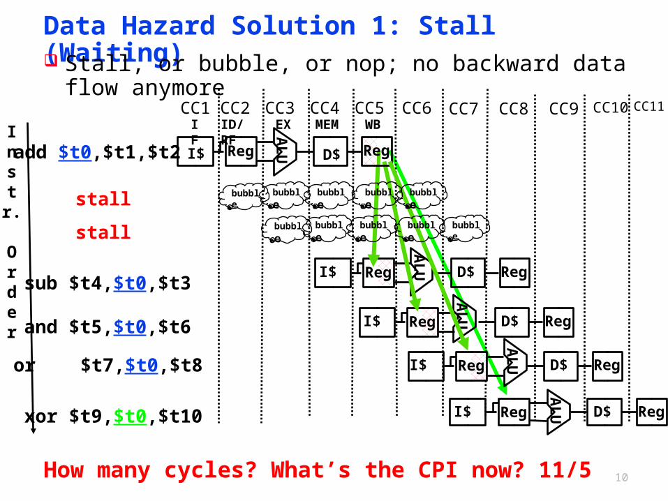
Data Hazard Solution 1: Stall (Waiting) Stall, or bubble, or nop; no backward data flow anymore
xor $t9,$t0,$t10
AL
UI$ Reg D$ Reg
sub $t4,$t0,$t3
AL
UI$ Reg D$ Reg
and $t5,$t0,$t6
AL
UI$ Reg D$ Reg
or $t7,$t0,$t8 I$
AL
UReg D$ Reg
add $t0,$t1,$t2
IF ID/RF EX MEM WBAL
UI$ Reg D$ RegInstr.
Order
CC1 CC2 CC3 CC4 CC5 CC6
bubble bubble bubble bubble bubble
bubble bubble bubble bubble bubble
stall
stall
How many cycles? What’s the CPI now? 11/5
CC7 CC8 CC9 CC10 CC11
11
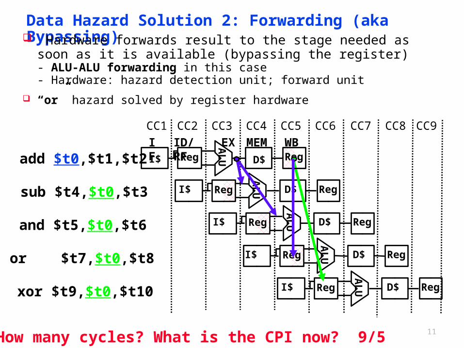
Data Hazard Solution 2: Forwarding (aka Bypassing) Hardware forwards result to the stage needed as soon as it is
available (bypassing the register) - ALU-ALU forwarding in this case- Hardware: hazard detection unit; forward unit
“or” hazard solved by register hardware
sub $t4,$t0,$t3A
LUI$ Reg D$ Reg
and $t5,$t0,$t6
AL
UI$ Reg D$ Reg
or $t7,$t0,$t8 I$
AL
UReg D$ Reg
xor $t9,$t0,$t10
AL
UI$ Reg D$ Reg
add $t0,$t1,$t2IF ID/RF EX MEM WBA
LUI$ Reg D$ Reg
CC1 CC2 CC3 CC4 CC5 CC6
How many cycles? What is the CPI now? 9/5
CC7 CC8 CC9
Yet Another Complication!
Instr.
Order
add $1,$1,$2
AL
UIM Reg DM Reg
add $1,$1,$3
add $1,$1,$4
AL
UIM Reg DM Reg
AL
UIM Reg DM Reg
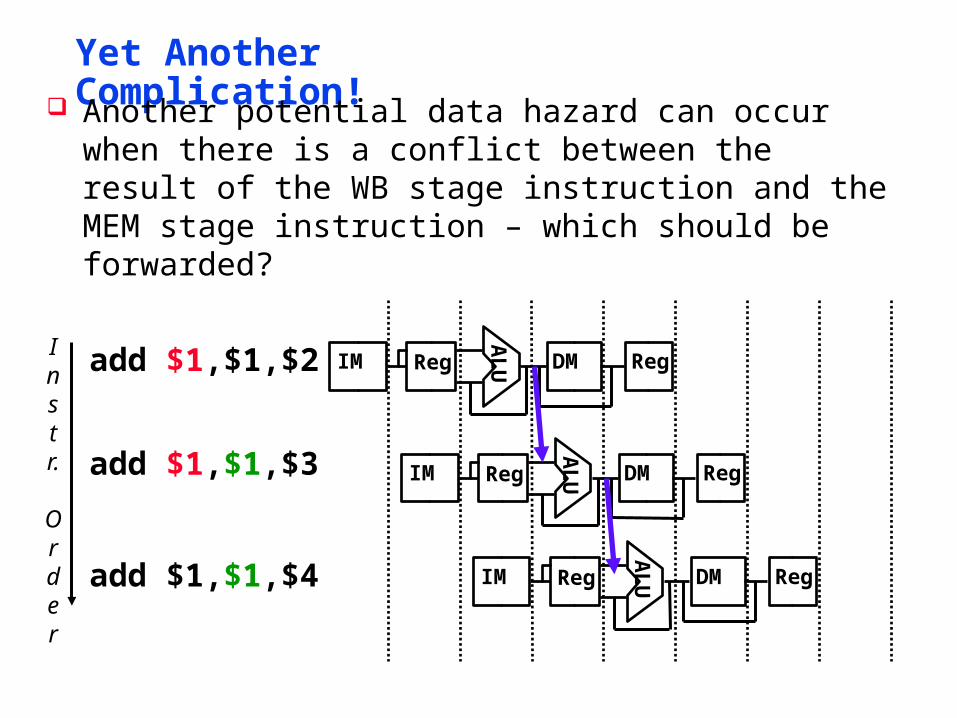
Another potential data hazard can occur when there is a conflict between the result of the WB stage instruction and the MEM stage instruction – which should be forwarded?
13
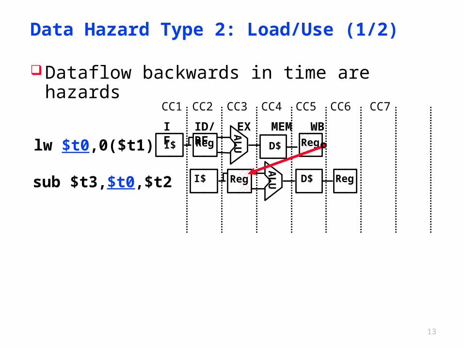
Data Hazard Type 2: Load/Use (1/2)
Dataflow backwards in time are hazards
sub $t3,$t0,$t2A
LUI$ Reg D$ Reg
lw $t0,0($t1)IF ID/RF EX MEM WBA
LUI$ Reg D$ Reg
CC1 CC2 CC3 CC4 CC5 CC6 CC7
14
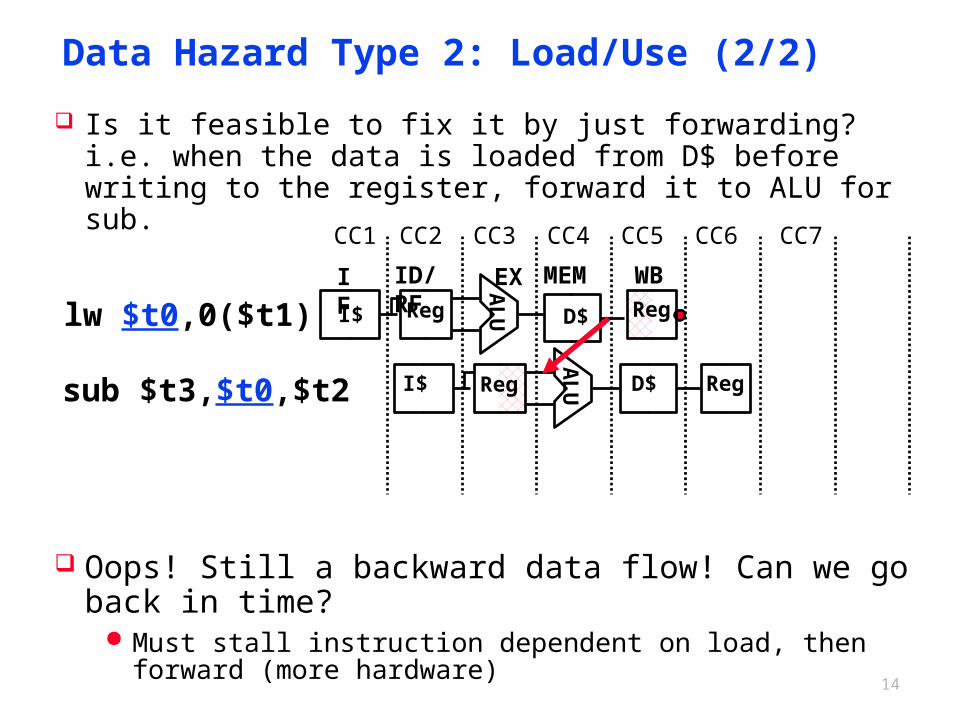
Data Hazard Type 2: Load/Use (2/2)
Is it feasible to fix it by just forwarding? i.e. when the data is loaded from D$ before writing to the register, forward it to ALU for sub.
Oops! Still a backward data flow! Can we go back in time? Must stall instruction dependent on load, then forward (more
hardware)
sub $t3,$t0,$t2A
LUI$ Reg D$ Reg
lw $t0,0($t1)IF ID/RF EX MEM WBA
LUI$ Reg D$ Reg
CC1 CC2 CC3 CC4 CC5 CC6 CC7
15
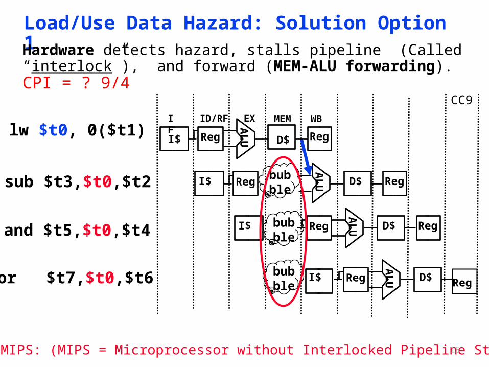
Load/Use Data Hazard: Solution Option 1Hardware detects hazard, stalls pipeline (Called “interlock”), and forward (MEM-ALU forwarding). CPI = ? 9/4
sub $t3,$t0,$t2A
LUI$ Reg D$ Regbub
ble
and $t5,$t0,$t4
AL
UI$ Reg D$ Regbubble
or $t7,$t0,$t6 I$
AL
UReg D$bubble
lw $t0, 0($t1)IF ID/RF EX MEM WBA
LUI$ Reg D$ Reg
Not in MIPS: (MIPS = Microprocessor without Interlocked Pipeline Stages)
Reg
CC9
16
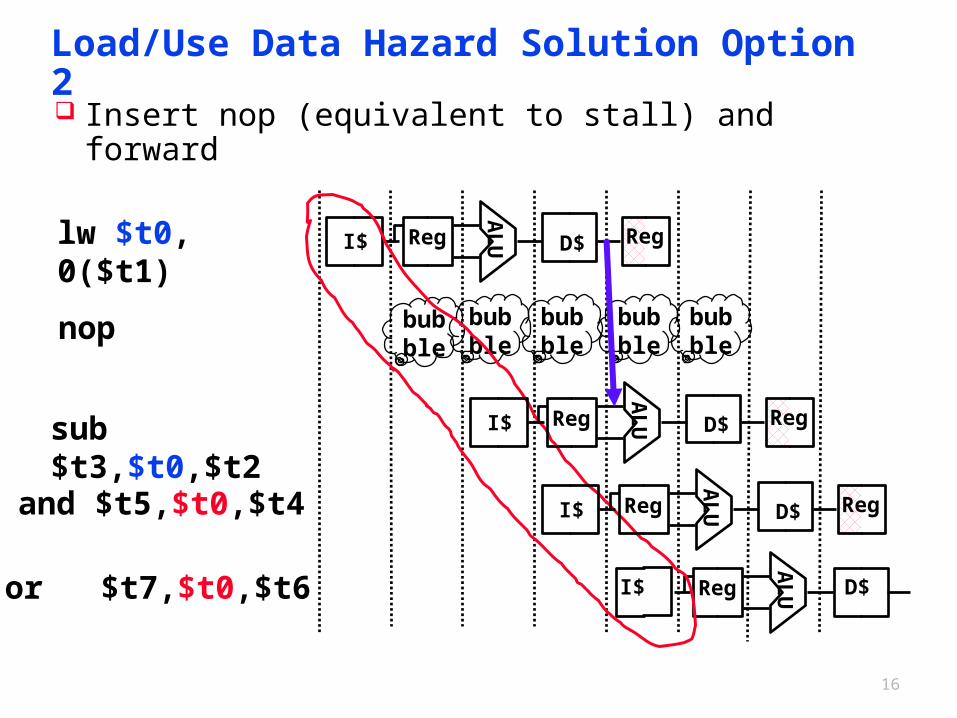
Load/Use Data Hazard Solution Option 2
Insert nop (equivalent to stall) and forward
sub $t3,$t0,$t2
and $t5,$t0,$t4
or $t7,$t0,$t6 I$
AL
UReg D$
lw $t0, 0($t1)
AL
UI$ Reg D$ Reg
bubble
bubble
bubble
bubble
bubble
AL
UI$ Reg D$ Reg
AL
UI$ Reg D$ Reg
nop
17
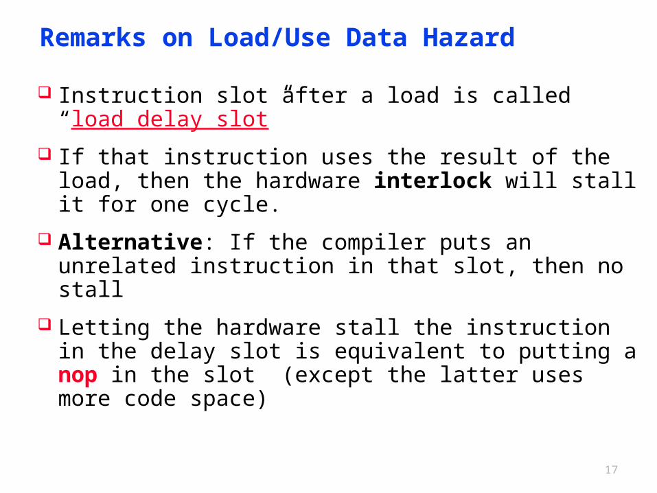
Remarks on Load/Use Data Hazard
Instruction slot after a load is called “load delay slot”
If that instruction uses the result of the load, then the hardware interlock will stall it for one cycle.
Alternative: If the compiler puts an unrelated instruction in that slot, then no stall
Letting the hardware stall the instruction in the delay slot is equivalent to putting a nop in the slot (except the latter uses more code space)
18
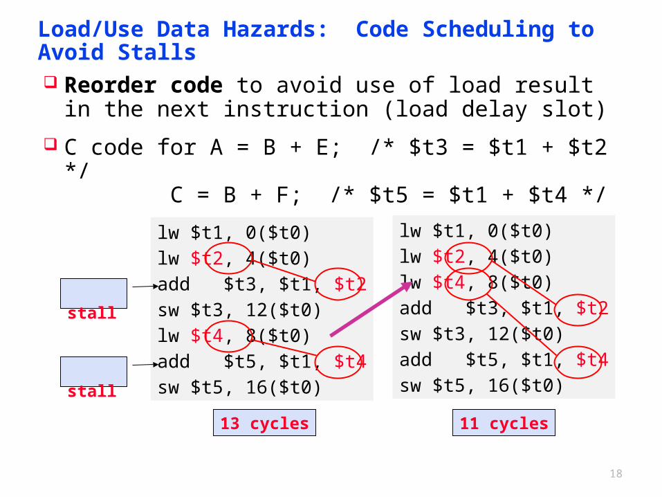
Load/Use Data Hazards: Code Scheduling to Avoid Stalls
Reorder code to avoid use of load result in the next instruction (load delay slot)
C code for A = B + E; /* $t3 = $t1 + $t2 */ C = B + F; /* $t5 = $t1 + $t4 */
lw $t1, 0($t0)lw $t2, 4($t0)add $t3, $t1, $t2sw $t3, 12($t0)lw $t4, 8($t0)add $t5, $t1, $t4sw $t5, 16($t0)
stall
stall
lw $t1, 0($t0)lw $t2, 4($t0)lw $t4, 8($t0)add $t3, $t1, $t2sw $t3, 12($t0)add $t5, $t1, $t4sw $t5, 16($t0)
11 cycles13 cycles
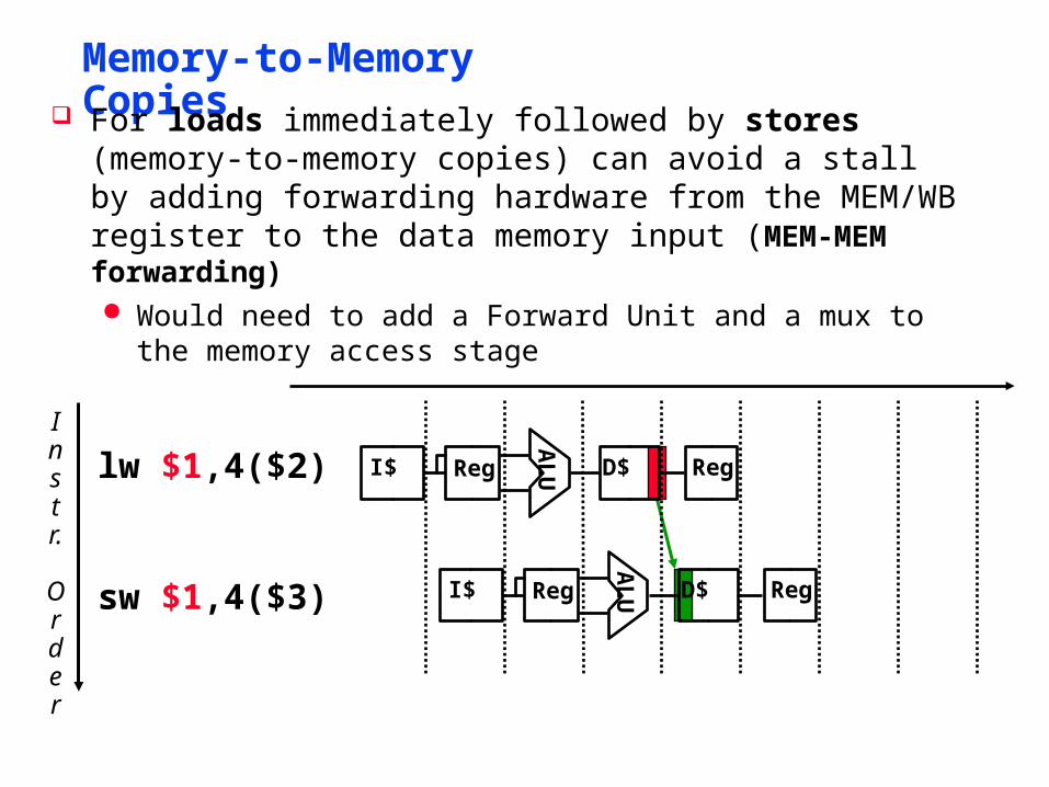
Memory-to-Memory Copies
Instr.
Order
lw $1,4($2)A
LUI$ Reg D$ Reg
sw $1,4($3)
AL
UI$ Reg D$ Reg
For loads immediately followed by stores (memory-to-memory copies) can avoid a stall by adding forwarding hardware from the MEM/WB register to the data memory input (MEM-MEM forwarding) Would need to add a Forward Unit and a mux to the memory
access stage
20
Control Hazards
Branch determines flow of control Fetching next instruction depends on branch outcome The delay in determining the proper instruction to fetch is called a
control hazard or branch hazard. Pipeline can’t always fetch correct instruction
- Still working on ID stage of branch
beq, bne in MIPS pipeline
21
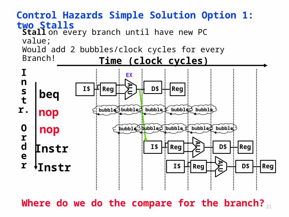
Control Hazards Simple Solution Option 1: two Stalls
Where do we do the compare for the branch?
I$
beq
nop
nop
Instr
InstrA
LU I$ Reg D$ Reg
AL
UReg D$ Reg
AL
U I$ Reg D$ Reg
Instr.
Order
Time (clock cycles)
bubble bubble bubble bubble bubble
bubble bubble bubble bubble bubble
Stall on every branch until have new PC value;Would add 2 bubbles/clock cycles for every Branch!
EX
22
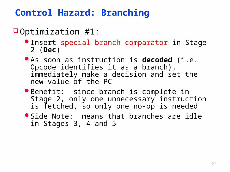
Control Hazard: Branching
Optimization #1: Insert special branch comparator in Stage 2 (Dec) As soon as instruction is decoded (i.e. Opcode
identifies it as a branch), immediately make a decision and set the new value of the PC
Benefit: since branch is complete in Stage 2, only one unnecessary instruction is fetched, so only one no-op is needed
Side Note: means that branches are idle in Stages 3, 4 and 5
23
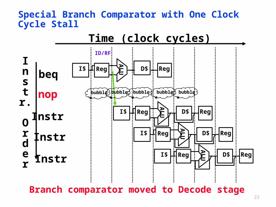
Special Branch Comparator with One Clock Cycle Stall
Branch comparator moved to Decode stage
I$
beq
nop
Instr
Instr
InstrA
LU I$ Reg D$ Reg
AL
U I$ Reg D$ Reg
AL
UReg D$ Reg
AL
U I$ Reg D$ Reg
Instr.
Order
Time (clock cycles)
bubble bubble bubble bubble bubble
ID/RF
24
Performance of Stall on Branch Assume branches are 17% of the instructions executed in
SPECint2006. Since the other instructions run have a CPI of 1, and branches took one extra clock cycle for the stall, then we would see a CPI of 1.17 and hence a slowdown of 1.17 versus the ideal case.
25
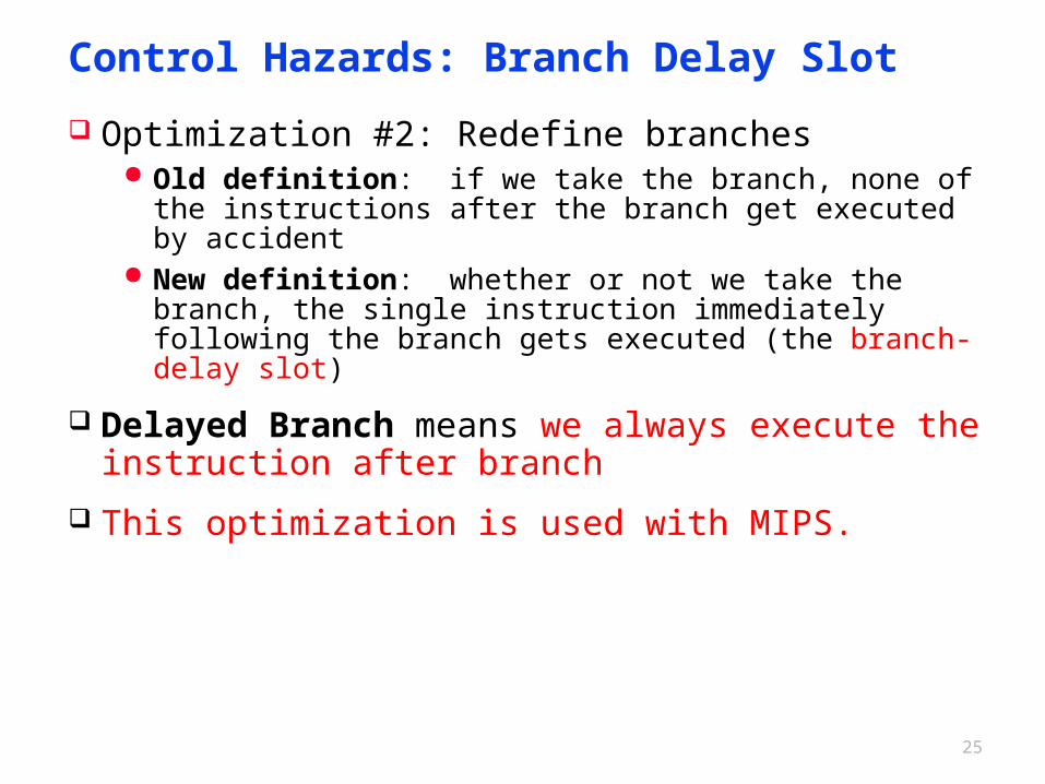
Control Hazards: Branch Delay Slot
Optimization #2: Redefine branches Old definition: if we take the branch, none of the instructions
after the branch get executed by accident New definition: whether or not we take the branch, the single
instruction immediately following the branch gets executed (the branch-delay slot)
Delayed Branch means we always execute the instruction after branch
This optimization is used with MIPS.
26
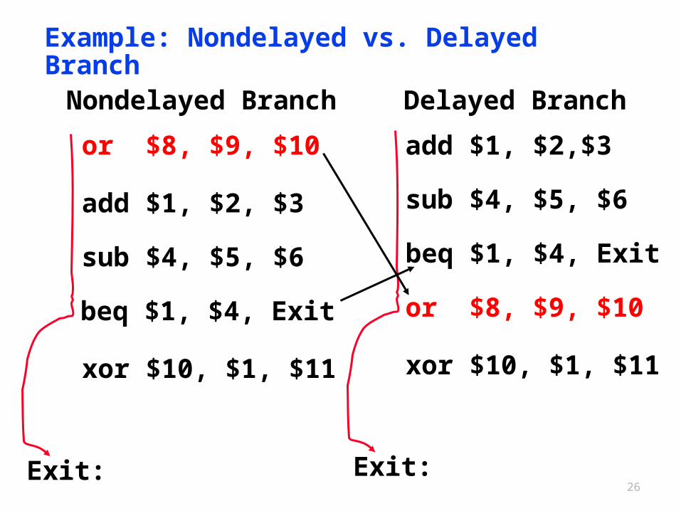
Example: Nondelayed vs. Delayed Branch
add $1, $2, $3
sub $4, $5, $6
beq $1, $4, Exit
or $8, $9, $10
xor $10, $1, $11
Nondelayed Branch
add $1, $2,$3
sub $4, $5, $6
beq $1, $4, Exit
or $8, $9, $10
xor $10, $1, $11
Delayed Branch
Exit: Exit:
27
Notes on Branch-Delay Slot
Worst-Case Scenario: put a no-op in the branch-delay slot Better Case: place some instruction preceding the branch in the
branch-delay slot—as long as the changed doesn’t affect the logic of program
- Re-ordering instructions is common way to speed up programs- Compiler usually finds such an instruction 50% of time- Jumps also have a delay slot …
Since delayed branches are useful when the branches are short, no processor uses a delayed branch of more than one cycle. For longer branch delays, hardware-based branch prediction is usually used.
The delayed branch always executes the next sequential instruction, with the branch taking place after that one instruction delay. It is hidden from the MIPS assembly language programmer because the assembler can automatically arrange the instructions to get the branch behavior desired by the programmer. MIPS software will place an instruction immediately after the delayed branch instruction that is not affected by the branch, and a taken branch changes the address of the instruction that follows this safe instruction.
28
Control Hazards: Branch Prediction
Opt #3: Predict outcome of a branch, fix up if guess wrong
Must cancel all instructions in pipeline that depended on wrong-guess
This is called “flushing” the pipeline
Opt 3.1: Assume branches are NOT taken,continue execution down the sequential instruction stream. If the branch is taken, the instructions that are being fetched and decoded must be discarded. Execution continues at the branch target.
If branches are untaken half the time, and if it costs little to discard the instructions, this optimization halves the cost of control hazards.
Opt3.2: Dynamic branch prediction: Prediction of branches at runtime using runtime information.
branch prediction buffer or branch history table
29
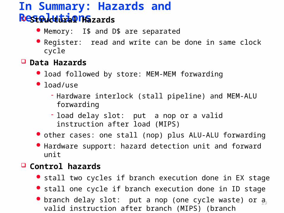
In Summary: Hazards and Resolutions Structural Hazards
Memory: I$ and D$ are separated Register: read and write can be done in same clock cycle
Data Hazards load followed by store: MEM-MEM forwarding load/use
- Hardware interlock (stall pipeline) and MEM-ALU forwarding- load delay slot: put a nop or a valid instruction after load (MIPS)
other cases: one stall (nop) plus ALU-ALU forwarding Hardware support: hazard detection unit and forward unit
Control hazards stall two cycles if branch execution done in EX stage stall one cycle if branch execution done in ID stage branch delay slot: put a nop (one cycle waste) or a valid instruction
after branch (MIPS) (branch execution in ID) branch predication: branch not taken or dynamic predication
How does a hazard solution impact the pipeline performance?
30
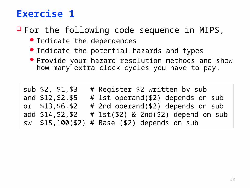
Exercise 1
For the following code sequence in MIPS, Indicate the dependences Indicate the potential hazards and types Provide your hazard resolution methods and show how many
extra clock cycles you have to pay.
sub $2, $1,$3 # Register $2 written by suband $12,$2,$5 # 1st operand($2) depends on subor $13,$6,$2 # 2nd operand($2) depends on subadd $14,$2,$2 # 1st($2) & 2nd($2) depend on subsw $15,100($2) # Base ($2) depends on sub
31
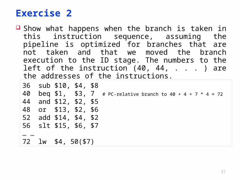
Exercise 2 Show what happens when the branch is taken in this
instruction sequence, assuming the pipeline is optimized for branches that are not taken and that we moved the branch execution to the ID stage. The numbers to the left of the instruction (40, 44, . . . ) are the addresses of the instructions.
36 sub $10, $4, $840 beq $1, $3, 7 # PC-relative branch to 40 + 4 + 7 * 4 = 7244 and $12, $2, $548 or $13, $2, $652 add $14, $4, $256 slt $15, $6, $7… … 72 lw $4, 50($7)