Embed Size (px)
Citation preview
CSA8000 & TDS8000 Programmer Guide 1
CSA8000 and TDS8000 Programmer Guide
PHP013904
Version 4.00
This document duplicates the information found in the CSA8000 and TDS8000
Programmer Guide, which is part of the Online Help system of 8000 Series instruments. This document is provided so that you have a version that can
easily be printed.
This document is not orderable and is not available in printed format.
PLEASE READ. This document contains revisions for the latest version of product software, Version 1.4. You will find these revisions in Appendix A: Additions for Version 1.4 Software Only, located after the Index, at the end of this document.
All other material in this document applies to both version 1.3 and version 1.4 of the product software. You can determine the version of software installed in your instrument by selecting About TDS/CSA8000 from the application Help menu.
2 CSA8000 & TDS8000 Programmer Guide
Table of Contents
Preface 11
Copyright and Version Information................................................................ 11
Getting Started 12
Introduction.................................................................................................... 12
Remote Communications .............................................................................. 12
Documentation .............................................................................................. 15
Command Syntax 16
Syntax Overview............................................................................................ 16
Command and Query Structure .................................................................... 16
Clearing the Instrument ................................................................................. 18
Command Entry............................................................................................. 18
Constructed Mnemonics................................................................................ 20
Argument Types ............................................................................................ 22
Command Groups 25
Acquisition Command Group ........................................................................ 25
Calibration Command Group......................................................................... 26
Compensation Command Group................................................................... 27
Cursor Command Group ............................................................................... 28
Display Control Command Group ................................................................. 29
Hard Copy Command Group......................................................................... 31
Histogram Command Group ......................................................................... 32
Horizontal Command Group.......................................................................... 33
Mask Command Group ................................................................................. 37
Math Command Group.................................................................................. 39
Measurement Command Group.................................................................... 40
Miscellaneous Command Group ................................................................... 44
Save and Recall Command Group................................................................ 44
Status and Error Command Group................................................................ 45
System Command Group.............................................................................. 46
TDR Command Group .................................................................................. 47
Trigger Command Group .............................................................................. 48
Vertical Command Group.............................................................................. 49
Waveform Database Command Group......................................................... 51
Waveform Transfer Command Group........................................................... 53
Commands 57
*CLS .............................................................................................................. 57
*ESE .............................................................................................................. 57
*ESR?............................................................................................................ 58
*IDN? ............................................................................................................. 58
*LRN? ............................................................................................................ 59
*OPC ............................................................................................................. 59
*PSC.............................................................................................................. 60
*RST .............................................................................................................. 61
*SRE.............................................................................................................. 62
*STB? ............................................................................................................ 62
*WAI .............................................................................................................. 63
ACQuire:CURRentcount:ACQWfms? ........................................................... 63
ACQuire:CURRentcount:HISTHits? .............................................................. 63
ACQuire:CURRentcount:HISTWfms?........................................................... 64
CSA8000 & TDS8000 Programmer Guide 3
ACQuire:CURRentcount:MASKHits<n>?...................................................... 64
ACQuire:CURRentcount:MASKSamples? .................................................... 65
ACQuire:CURRentcount:MASKTHits?.......................................................... 66
ACQuire:CURRentcount:MASKWfms?......................................................... 66
ACQuire:DATA:CLEAR ................................................................................. 67
ACQuire:MODe ............................................................................................. 67
ACQuire:NUMAVg......................................................................................... 69
ACQuire:SAVEFile:SAVEScreen .................................................................. 69
ACQuire:SAVEFile:SAVEWfm ...................................................................... 70
ACQuire:STATE ............................................................................................ 71
ACQuire:STOPAfter:ACTion ......................................................................... 72
ACQuire:STOPAfter:BELL ............................................................................ 73
ACQuire:STOPAfter:CONDition .................................................................... 74
ACQuire:STOPAfter:COUNt.......................................................................... 76
ACQuire:STOPAfter:MODE .......................................................................... 77
ACQuire:STOPAfter? .................................................................................... 77
ACQuire?....................................................................................................... 78
ALLEv? .......................................................................................................... 78
AUTOSet ....................................................................................................... 79
AUTOSet:STOP ............................................................................................ 79
AUTOSet:TYPE............................................................................................. 80
Group............................................................................................................. 80
AUTOSet:UNDO............................................................................................ 81
BUSY?........................................................................................................... 81
CALibrate:DATE:CH<x>?.............................................................................. 82
CALibrate:DATE:MAInframe? ....................................................................... 82
CALibrate:DCCALibrator ............................................................................... 83
CALibrate:HOSTInfo:CH<x>? ....................................................................... 83
CALibrate:LOCK:STATus?............................................................................ 83
CALibrate:STATus:CH<x>? .......................................................................... 84
CALibrate:STATus:MAInframe?.................................................................... 84
CALibrate:TEMPerature:CH<x>?.................................................................. 85
CALibrate:TEMPerature:MAInframe? ........................................................... 85
CALibrate:UPDATEinfo:ALL.......................................................................... 85
CALibrate:UPDATEinfo:CH<x>..................................................................... 86
CALibrate:UPDATEinfo:MAInframe .............................................................. 86
CH<x>:BANdwidth:LIST?.............................................................................. 86
CH<x>:BANdwidth:VALue............................................................................. 87
CH<x>:DESkew............................................................................................. 88
CH<x>:EXTAtten:MODE ............................................................................... 89
CH<x>:EXTAtten:VALue ............................................................................... 89
CH<x>:FILTer:LIST? ..................................................................................... 90
CH<x>:FILTer:VALue.................................................................................... 91
CH<x>:OFFSet.............................................................................................. 93
CH<x>:POSition ............................................................................................ 94
CH<x>:SCAle ................................................................................................ 95
CH<x>:UNIts ................................................................................................. 96
CH<x>:WFMLabel ......................................................................................... 97
CH<x>:WLENgth:LIST? ................................................................................ 97
CH<x>:WLENgth:VALue ............................................................................... 98
CH<x>? ......................................................................................................... 98
COMPensate:ALL.......................................................................................... 99
COMPensate:CH<x>..................................................................................... 99
COMPensate:DARKLev:CH<x>.................................................................. 100
COMPensate:DATE:CH<x>? ...................................................................... 100
COMPensate:DATE:MAInframe?................................................................ 100
COMPensate:MAInframe ............................................................................ 101
4 CSA8000 & TDS8000 Programmer Guide
COMPensate:OPTGAIN:CH<x> ................................................................. 101
COMPensate:RECAll:FACTory:ALL ........................................................... 102
COMPensate:RECAll:FACTory:CH<x>....................................................... 102
COMPensate:RECAll:FACTory:MAInframe ................................................ 102
COMPensate:RECAll:USER:ALL................................................................ 102
COMPensate:RECAll:USER:CH<x> ........................................................... 103
COMPensate:RECAll:USER:MAInframe..................................................... 103
COMPensate:RESults:VERBose? .............................................................. 103
COMPensate:RESults?............................................................................... 104
COMPensate:SAVe:USER:ALL .................................................................. 104
COMPensate:SAVe:USER:CH<x> ............................................................. 104
COMPensate:SAVe:USER:MAInframe....................................................... 105
COMPensate:STATus:CH<x>?................................................................... 105
COMPensate:STATus:MAInframe? ............................................................ 105
COMPensate:TEMPerature:CH<x>? .......................................................... 106
COMPensate:TEMPerature:MAInframe?.................................................... 106
CURSor:CURSor<x>:COLOR..................................................................... 106
CURSor:CURSor<x>:SOUrce..................................................................... 108
CURSor:FUNCtion ...................................................................................... 109
CURSor:HBArs:DELTa? ............................................................................. 110
CURSor:HBArs:POSition<x> ...................................................................... 110
CURSor:HBArs?.......................................................................................... 111
CURSor:SELect........................................................................................... 111
CURSor:VBArs? .......................................................................................... 112
CURSor:VBArs:DELTa?.............................................................................. 112
CURSor:VBArs:POSition<x>....................................................................... 113
CURSor:WAVeform:HDELTa?.................................................................... 113
CURSor:WAVeform:HPOS<x>? ................................................................. 114
CURSor:WAVeform:POSition<x> ............................................................... 114
CURSor:WAVeform:VDELTa? .................................................................... 115
CURSor:WAVeform?................................................................................... 115
CURSor? ..................................................................................................... 115
CURVe ........................................................................................................ 116
DATa ........................................................................................................... 117
DATa:DESTination ...................................................................................... 118
DATa:ENCdg............................................................................................... 118
DATa:SOUrce.............................................................................................. 120
DATa:STARt................................................................................................ 121
DATa:STOP................................................................................................. 121
DATa:TIMebase .......................................................................................... 122
DATE ........................................................................................................... 123
DELEte:WAVEform ..................................................................................... 124
DESE........................................................................................................... 124
DISplay:COLor:BACKground ...................................................................... 125
DISplay:COLor:CURSOR<x>...................................................................... 126
DISplay:COLor:FOREground ...................................................................... 128
DISplay:COLor:HIStogram .......................................................................... 129
DISplay:COLor:MASK ................................................................................. 130
DISplay:COLor? .......................................................................................... 131
DISplay:CURSReadout ............................................................................... 132
DISplay:GRAticule:HDIVS?......................................................................... 133
DISplay:GRAticule:STYLE .......................................................................... 133
DISplay:GRAticule:VDIVS?......................................................................... 134
DISplay:GRAticule?..................................................................................... 134
DISplay:HISTReadout ................................................................................. 135
DISplay:INTERPolat .................................................................................... 135
DISplay:MASKReadout ............................................................................... 137
CSA8000 & TDS8000 Programmer Guide 5
DISplay:MEASBar ....................................................................................... 137
DISplay:MEASReadout ............................................................................... 138
DISplay:PERSistence.................................................................................. 139
DISplay:SHOWVector ................................................................................. 139
DISplay:STYLE............................................................................................ 140
DISpLay:WFMReadout ............................................................................... 141
DISplay? ...................................................................................................... 142
EVENT?....................................................................................................... 142
EVMsg? ....................................................................................................... 142
EVQty? ........................................................................................................ 143
EXPort ......................................................................................................... 143
FACTory ...................................................................................................... 144
FILESystem:READFile? <file path> ............................................................ 145
HARDCopy .................................................................................................. 146
HARDCopy:FILEName................................................................................ 146
HARDCopy:FORMat ................................................................................... 147
HARDCopy:INKSaver.................................................................................. 148
HEADer ....................................................................................................... 149
HIStogram:BOX........................................................................................... 150
HIStogram:BOXPcnt.................................................................................... 151
HIStogram:COLOR...................................................................................... 152
HIStogram:COUNt....................................................................................... 153
HIStogram:DISplay...................................................................................... 153
HIStogram:ENABle...................................................................................... 154
HIStogram:MODe........................................................................................ 154
HIStogram:SIZe........................................................................................... 155
HIStogram:SOUrce...................................................................................... 156
HIStogram:STATistics:HITS?...................................................................... 157
HIStogram:STATistics:MEAN?.................................................................... 157
HIStogram:STATistics:MEDIAN? ................................................................ 157
HIStogram:STATistics:PEAKHits? .............................................................. 158
HIStogram:STATistics:PKTOPK? ............................................................... 158
HIStogram:STATistics:SIGMA<x>? ............................................................ 158
HIStogram:STATistics:WAVeforms?........................................................... 159
HIStogram:STATistics? ............................................................................... 159
HIStogram:STATistics:STDdev? ................................................................. 160
HIStogram:TYPE......................................................................................... 160
HIStogram:WFMDB:STATE ........................................................................ 161
HIStogram? ................................................................................................. 162
HORizontal:BITS:BITRate........................................................................... 162
HORizontal:BITS:STANdard ....................................................................... 163
HORizontal:DISTance:DIELectric ............................................................... 166
HORizontal:DISTance:PVELocity ............................................................... 166
HORizontal:EXT10MHZref:FREQ............................................................... 167
HORizontal:FRAMescan:AUTOPosition ..................................................... 167
HORizontal:FRAMescan:RESET ................................................................ 168
HORizontal:FRAMescan:SCANBits ............................................................ 169
HORizontal:FRAMescan:STARTBit ............................................................ 169
HORizontal:FRAMescan:STATE................................................................. 170
HORizontal:MAG<x>:POSition.................................................................... 171
HORizontal:MAG<x>:RECORDLength ....................................................... 173
HORizontal:MAG<x>:REFPoint .................................................................. 174
HORizontal:MAG<x>:RESolution?.............................................................. 175
HORizontal:MAG<x>:SCAle........................................................................ 175
HORizontal:MAG<x>:TOFPoint? ................................................................ 176
HORizontal:MAG<x>:TOLPoint?................................................................. 177
HORizontal:MAG<x>:VIEW......................................................................... 178
6 CSA8000 & TDS8000 Programmer Guide
HORizontal:MAG<x>?................................................................................. 179
HORizontal:MAIn:POSition ......................................................................... 179
HORizontal:MAIn:RECordlength ................................................................. 181
HORizontal:MAIn:REFPoint ........................................................................ 182
HORizontal:MAIn:RESolution?.................................................................... 184
HORizontal:MAIn:SCAle ............................................................................. 184
HORizontal:MAIn:TOFPoint? ...................................................................... 185
HORizontal:MAIn:TOLPoint? ...................................................................... 186
HORizontal:MAIn?....................................................................................... 186
HORizontal:MATH<x>:MAG<x>:POSition? ................................................ 187
HORizontal:MATH<x>:MAG<x>:RECORDLength?.................................... 187
HORizontal:MATH<x>:MAG<x>:RESolution? ............................................ 188
HORizontal:MATH<x>:MAG<x>:SCAle? .................................................... 188
HORizontal:MATH<x>:MAG<x>:TOFPoint? ............................................... 189
HORizontal:MATH<x>:MAG<x>:TOLPoint ................................................. 189
HORizontal:MATH<x>:MAIn:POSition? ...................................................... 190
HORizontal:MATH<x>:MAIn:RECORDLength?.......................................... 190
HORizontal:MATH<x>:MAIn:REFPoint? ..................................................... 191
HORizontal:MATH<x>:MAIn:RESolution? .................................................. 191
HORizontal:MATH<x>:MAIn:SCAle? .......................................................... 191
HORizontal:MATH<x>:MAIn:TOFPoint? ..................................................... 192
HORizontal:MATH<x>:MAIn:TOLPoint? ..................................................... 192
HORizontal:REF<x>:MAG<x>:POSition? ................................................... 193
HORizontal:REF<x>:MAG<x>:RECORDLength?....................................... 193
HORizontal:REF<x>:MAG<x>:RESolution? ............................................... 194
HORizontal:REF<x>:MAG<x>:SCAle? ....................................................... 194
HORizontal:REF<x>:MAG<x>:TOFPoint? .................................................. 195
HORizontal:REF<x>:MAG<x>:TOLPoint? .................................................. 195
HORizontal:REF<x>:MAIn:POSition? ......................................................... 196
HORizontal:REF<x>:MAIn:RECORDLength?............................................. 196
HORizontal:REF<x>:MAIn:REFPoint? ........................................................ 197
HORizontal:REF<x>:MAIn:RESolution? ..................................................... 197
HORizontal:REF<x>:MAIn:SCAle? ............................................................. 197
HORizontal:REF<x>:MAIn:TOFPoint? ........................................................ 198
HORizontal:REF<x>:MAIn:TOLPoint? ........................................................ 198
HORizontal:TBMode.................................................................................... 199
HORizontal:UNIts ........................................................................................ 200
HORizontal? ................................................................................................ 201
ID? ............................................................................................................... 201
LOCk ........................................................................................................... 202
MASK:AUTOSet:MODE .............................................................................. 203
MASK:COLOr .............................................................................................. 203
MASK:COUNt.............................................................................................. 204
MASK:COUNt:SAMPles?............................................................................ 205
MASK:COUNt:STATE ................................................................................. 205
MASK:COUNt:TOTal?................................................................................. 206
MASK:COUNt:WAVeforms? ....................................................................... 206
MASK:DISplay............................................................................................. 207
MASK:MARgin:PERCent ............................................................................ 207
MASK:MARgin:STATE................................................................................ 208
MASK:MASK<x> ......................................................................................... 209
MASK:MASK<x>:COUNt? .......................................................................... 210
MASK:MASK<x>:NR_Pt? ........................................................................... 210
MASK:MASK<x>:POInts ............................................................................. 211
MASK:MASK<x>:POINTSPcnt ................................................................... 211
MASK:SOUrce............................................................................................. 212
MASK:STANdard......................................................................................... 213
CSA8000 & TDS8000 Programmer Guide 7
MASK:WFMDB:STATE ............................................................................... 217
MASK? ........................................................................................................ 217
MATH<x>:DEFine ....................................................................................... 218
MATH<x>:FILTer:MODe ............................................................................. 219
MATH<x>:FILTer:RISetime......................................................................... 220
MATH<x>:NUMavg ..................................................................................... 220
MATH<x>:POSition ..................................................................................... 221
MATH<x>:POSition ..................................................................................... 222
MATH<x>:SCAle ......................................................................................... 222
MATH<x>:SCAle ......................................................................................... 223
MATH<x>:UNITs? ....................................................................................... 224
MATH<x>:WFMLabel .................................................................................. 225
MATH<x>? .................................................................................................. 225
MEASUrement:ALL:VALue? ....................................................................... 226
MEASUrement:ANNOtations:STATE.......................................................... 226
MEASUrement:LIST.................................................................................... 227
MEASUrement:LISTValue?......................................................................... 228
MEASUrement:MEAS<x>:ALL?.................................................................. 228
MEASUrement:MEAS<x>:EYEWindow ...................................................... 229
MEASUrement:MEAS<x>:GATing:STATE ................................................. 230
MEASUrement:MEAS<x>:JITter ................................................................. 231
MEASUrement:MEAS<x>:MAXimum?........................................................ 232
MEASUrement:MEAS<x>:MEAN?.............................................................. 232
MEASUrement:MEAS<x>:MINImum?......................................................... 233
MEASUrement:MEAS<x>:NOISe ............................................................... 233
MEASUrement:MEAS<x>:REFLevel<x>:ABSolute:HIGH .......................... 234
MEASUrement:MEAS<x>:REFLevel<x>:ABSolute:LOW........................... 235
MEASUrement:MEAS<x>:REFLevel<x>:ABSolute:MID............................. 235
MEASUrement:MEAS<x>:REFLevel<x>:METHod ..................................... 236
MEASUrement:MEAS<x>:REFLevel<x>:RELative:HIGH........................... 238
MEASUrement:MEAS<x>:REFLevel<x>:RELative:LOW ........................... 239
MEASUrement:MEAS<x>:REFLevel<x>:RELative:MID............................. 240
MEASUrement:MEAS<x>:REFLevel<x>? .................................................. 241
MEASUrement:MEAS<x>:SETDefault........................................................ 241
MEASUrement:MEAS<x>:SOURCE<x>:EDGE:DIRection......................... 241
MEASUrement:MEAS<x>:SOURCE<x>:EDGE:SLOPe............................. 243
MEASUrement:MEAS<x>:SOURCE<x>:EDGE? ....................................... 244
MEASUrement:MEAS<x>:SOURCE<x>:GATE<x>:PCTPos ..................... 244
MEASUrement:MEAS<x>:SOURCE<x>:GATE<x>:POS ........................... 245
MEASUrement:MEAS<x>:SOURCE<x>:GATE<x>?.................................. 246
MEASUrement:MEAS<x>:SOURCE<x>:HILow:METHod .......................... 246
MEASUrement:MEAS<x>:SOURCE<x>:HILow:TRACK:HIGH: ENABle ... 248
MEASUrement:MEAS<x>:SOURCE<x>:HILow:TRACK :HIGH:VALue ..... 250
MEASUrement:MEAS<x>:SOURCE<x>:HILow:TRACK:LOW :ENABle .... 251
MEASUrement:MEAS<x>:SOURCE<x>:HILow:TRACK :LOW:VALue ...... 252
MEASUrement:MEAS<x>:SOURCE<x>:HILow? ....................................... 253
MEASUrement:MEAS<x>:SOURCE<x>:WFM ........................................... 253
MEASUrement:MEAS<x>:SOURCE<x>:WFMDB:SIGType....................... 254
MEASUrement:MEAS<x>:SOURCE<x>:WFMDB:STATE ......................... 255
MEASUrement:MEAS<x>:STATE............................................................... 256
MEASUrement:MEAS<x>:STATIstics:CLEAr ............................................. 257
MEASUrement:MEAS<x>:STDdev? ........................................................... 258
MEASUrement:MEAS<x>:TYPE................................................................. 258
MEASUrement:MEAS<x>:UNITS? ............................................................. 263
MEASUrement:MEAS<x>:VALue? ............................................................. 264
MEASUrement:STATIstics:ENABle ............................................................ 265
MEASUrement:STATIstics:WEIGHTing...................................................... 266
8 CSA8000 & TDS8000 Programmer Guide
MEASUrement?........................................................................................... 266
RECAll:SETUp ............................................................................................ 267
RECAll:WAVEform ...................................................................................... 268
REF<x>:POSition ........................................................................................ 268
REF<x>:SCAle ............................................................................................ 269
REF<x>:WFMLabel ..................................................................................... 270
SAVe:SETUp............................................................................................... 270
SAVe:WAVEform......................................................................................... 271
SELect:CH<x>............................................................................................. 272
SELect:CONTROl........................................................................................ 273
SELect:MATH<x>........................................................................................ 274
SELect:REF<x>........................................................................................... 275
SELect? ....................................................................................................... 276
SET?............................................................................................................ 276
SOURCE<x> ............................................................................................... 277
SYNC:TIMEOUT ......................................................................................... 277
SYSTem:PROPerties:ACQHWver? ............................................................ 279
SYStem:PROPerties:CH<x>:BANDwidth? ................................................. 279
SYStem:PROPerties:CH<x>:CAPacitance? ............................................... 280
SYStem:PROPerties:CH<x>:CLKRec? ...................................................... 280
SYStem:PROPerties:CH<x>:DYNamic?..................................................... 280
SYStem:PROPerties:CH<x>:EXTender?.................................................... 281
SYStem:PROPerties:CH<x>:FILTer? ......................................................... 281
SYStem:PROPerties:CH<x>:IMPedance?.................................................. 281
SYSTem:PROPerties:CH<X>:MODElnum? ............................................... 282
SYStem:PROPerties:CH<x>:NONDestruct? .............................................. 282
SYStem:PROPerties:CH<x>:OPERating?.................................................. 282
SYStem:PROPerties:CH<x>:PRObe:DYNamic?........................................ 283
SYStem:PROPerties:CH<x>:PRObe:IMPedance?..................................... 283
SYStem:PROPerties:CH<x>:PRObe:MODElnum? .................................... 284
SYStem:PROPerties:CH<x>:PRObe:SCAle?............................................. 284
SYSTem:PROPerties:CH<x>:PRObe:SERialnum?.................................... 284
SYStem:PROPerties:CH<x>:RISetime? ..................................................... 285
SYSTem:PROPerties:CH<x>:SERialnum?................................................. 285
SYSTem:PROPerties:CH<x>:TEKPDriver?................................................ 285
SYSTem:PROPerties:CH<x>:TEKPVersion? ............................................. 286
SYSTem:PROPerties:CH<x>:WLENgth? ................................................... 286
SYSTem:PROPerties:GROup<x>:TEKPVersion? ...................................... 286
SYSTem:PROPerties:MAInframe:MODElnum?.......................................... 287
SYSTem:PROPerties:MAInframe:SERialnum? .......................................... 287
SYSTem:PROPerties:MAInframe:SWVersion? .......................................... 287
SYSTem:PROPerties:ONTime?.................................................................. 288
SYSTem:PROPerties:POWerups? ............................................................. 288
SYSTem:PROPerties:PROCHWver?.......................................................... 288
SYSTem:PROPerties:TOTalontime? .......................................................... 289
TDR:CH<x>:PRESET.................................................................................. 289
TDR:CH<x>:STEP:DESkew........................................................................ 290
TDR:CH<x>:STEP:POLarity ....................................................................... 290
TDR:CH<x>:STEP:STATE.......................................................................... 291
TDR:CH<x>:UNIts ....................................................................................... 292
TDR:INTRate............................................................................................... 293
TDR? ........................................................................................................... 293
TIME ............................................................................................................ 294
TRIGger:CH<x>:CLKRec:LIST? ................................................................. 295
TRIGger:CH<x>:CLKRec:VALue ................................................................ 295
TRIGger:CLKRec:SOUrce .......................................................................... 297
TRIGger:GATEd.......................................................................................... 298
CSA8000 & TDS8000 Programmer Guide 9
TRIGger:HIFreq........................................................................................... 299
TRIGger:HOLDoff........................................................................................ 300
TRIGger:INTRate ........................................................................................ 301
TRIGger:LEVel ............................................................................................ 302
TRIGger:METAReject.................................................................................. 303
TRIGger:MODe ........................................................................................... 304
TRIGger:SETLevel ...................................................................................... 304
TRIGger:SLOpe........................................................................................... 305
TRIGger:SOURce........................................................................................ 306
TRIGger:STATE? ........................................................................................ 307
TRIGger?..................................................................................................... 307
UNLock........................................................................................................ 308
VERBose ..................................................................................................... 308
WAVFrm?.................................................................................................... 309
WFMDB:DISPlay:EMPHasis ....................................................................... 310
WFMDB:DISPlay:GRADing......................................................................... 311
WFMDB:DISPlay:INVert.............................................................................. 311
WFMDB:DISPlay? ....................................................................................... 312
WFMDB:WFMDB<x>:CLEAR ..................................................................... 312
WFMDB:WFMDB<x>:DISPlay .................................................................... 313
WFMDB:WFMDB<x>:ENABle..................................................................... 314
WFMDB:WFMDB<x>:SOURce ................................................................... 314
WFMDB:WFMDB<x>? ................................................................................ 315
WFMDB? ..................................................................................................... 316
WFMInpre:BIT_Nr? ..................................................................................... 316
WFMInpre:BN_Fmt...................................................................................... 316
WFMInpre:BYT_Nr?.................................................................................... 317
WFMInpre:BYT_Or...................................................................................... 318
WFMInpre:ENCdg ....................................................................................... 318
WFMInpre:NR_Pt ........................................................................................ 319
WFMInpre:PT_Fmt...................................................................................... 320
WFMInpre:WFMLabel ................................................................................. 320
WFMInpre:XINcr.......................................................................................... 321
WFMInpre:XMULT....................................................................................... 322
WFMInpre:XOFf .......................................................................................... 322
WFMInpre:XUNit ......................................................................................... 323
WFMInpre:XZEro......................................................................................... 323
WFMInpre:YMUlt ......................................................................................... 324
WFMInpre:YOFf .......................................................................................... 325
WFMInpre:YSCALE..................................................................................... 325
WFMInpre:YUNit ......................................................................................... 326
WFMInpre:YZEro......................................................................................... 326
WFMInpre?.................................................................................................. 327
WFMOutpre:BIT_Nr?................................................................................... 327
WFMOutpre:BN_FMT.................................................................................. 328
WFMOutpre:BYT_Nr? ................................................................................. 328
WFMOutpre:BYT_Or................................................................................... 329
WFMOutpre:ENCdg .................................................................................... 329
WFMOutpre:NR_Pt? ................................................................................... 330
WFMOutpre:PT_Fmt? ................................................................................. 331
WFMOutpre:WFId? ..................................................................................... 331
WFMOutpre:WFMLabel? ............................................................................ 331
WFMOutpre:XINcr?..................................................................................... 332
WFMOutpre:XMUlt? .................................................................................... 332
WFMOutpre:XOFf?...................................................................................... 332
WFMOutpre:XUNit?..................................................................................... 333
WFMOutpre:XZEro?.................................................................................... 333
10 CSA8000 & TDS8000 Programmer Guide
WFMOutpre:YMUlt? .................................................................................... 334
WFMOutpre:YOFf?...................................................................................... 334
WFMOutpre:YSCALE?................................................................................ 334
WFMOutpre:YUNit?..................................................................................... 335
WFMOutpre:YZEro?.................................................................................... 335
WFMOutpre? ............................................................................................... 336
Status and Events 337
Registers ..................................................................................................... 337
Queues ........................................................................................................ 340
Event Handling Sequence........................................................................... 341
Synchronization Methods ............................................................................ 342
Messages .................................................................................................... 347
Miscellaneous 355
Reserved Words.......................................................................................... 355
Factory Default Setup Values...................................................................... 358
GPIB Interface Specifications 365
GPIB Functions ........................................................................................... 365
Interface Messages ..................................................................................... 367
Programming Examples 368
Descriptions of the Sample Programs......................................................... 368
To Run the Sample Programs..................................................................... 368
To Copy the Sample-Program Code to Your Programs.............................. 369
Index 370
CSA8000 & TDS8000 Programmer Guide 11
Preface
Copyright and Version Information
Copyright © Tektronix, Inc. All rights reserved. Licensed software
products are owned by Tektronix or its suppliers and are protected by
United States copyright laws and international treaty provisions.
Use, duplication or disclosure by the Government is subject to
restrictions as set forth in subparagraph (c)(1)(ii) of the Rights in
Technical Data and Computer Software clause at DFARS 252.227-7013,
or subparagraphs (c)(1) and (2) of the Commercial Computer Software –
Restricted Rights clause at FAR 52.227-19, as applicable.
Tektronix products are covered by U.S. and foreign patents, issued and
pending. Information in this documentation supercedes that in all
previously published material. Specifications and price change privileges
reserved.
Tektronix, Inc. P.O. Box 500, Beaverton, OR 97077
TEKTRONIX, TEK, TEKPROBE, and FrameScan are registered
trademarks of Tektronix, Inc.
12 CSA8000 & TDS8000 Programmer Guide
Getting Started
Introduction
This online programmer guide provides you with the information you
need to use GPIB commands to remotely control your instrument. With
this information, you can write computer programs that will perform
functions such as setting the front-panel controls, taking measurements,
performing statistical calculations, and exporting data for use in other
programs, such as spreadsheets.
The programmer guide is divided into the following major topics
(books):
• Getting Started. This topic introduces you to the online programmer
guide and provides basic information about setting up your
instrument for remote control.
• Command Syntax. This topic provides an overview of the
command syntax that you will use to communicate with the
instrument and other general information about commands, such as
how commands and queries are constructed, and how to enter
commands, constructed mnemonics, and argument types.
• Command Groups. This topic contains all the commands listed in
functional groups. Each group consists of an overview of the
commands in that group and a table that lists all the commands and
queries for that group. You can click a command in the listing and a
detailed description of the command will be displayed.
• Status and Events. This topic discusses the status and event
reporting system for the GPIB interface. This system informs you of
certain significant events that occur within the instrument. Topics
that are discussed include registers, queues, event-handling
sequences, synchronization methods, and messages that the
instrument may return, including error messages.
• Miscellaneous. This topic contains miscellaneous information, such
as a list of reserved words, a table of the factory initialization
(default) settings, and the GPIB interface specifications, that may be
helpful when using GPIB commands to remotely control the
instrument.
Remote Communications
Before setting up your instrument for remote communications, you
should familiarize yourself with the following GPIB requirements:
• A unique device address must be assigned to each device on the bus.
No two devices can share the same device address.
• No more than 15 devices can be connected to any one line.
CSA8000 & TDS8000 Programmer Guide 13
• One device should be connected for every 6 feet (2 meters) of cable
used.
• No more than 65 feet (20 meters) of cable should be used to connect
devices to a bus.
• At least two-thirds of the devices on the network should be powered
on while using the network.
• Connect the devices on the network in a star or linear configuration.
Do not use loop or parallel configurations.
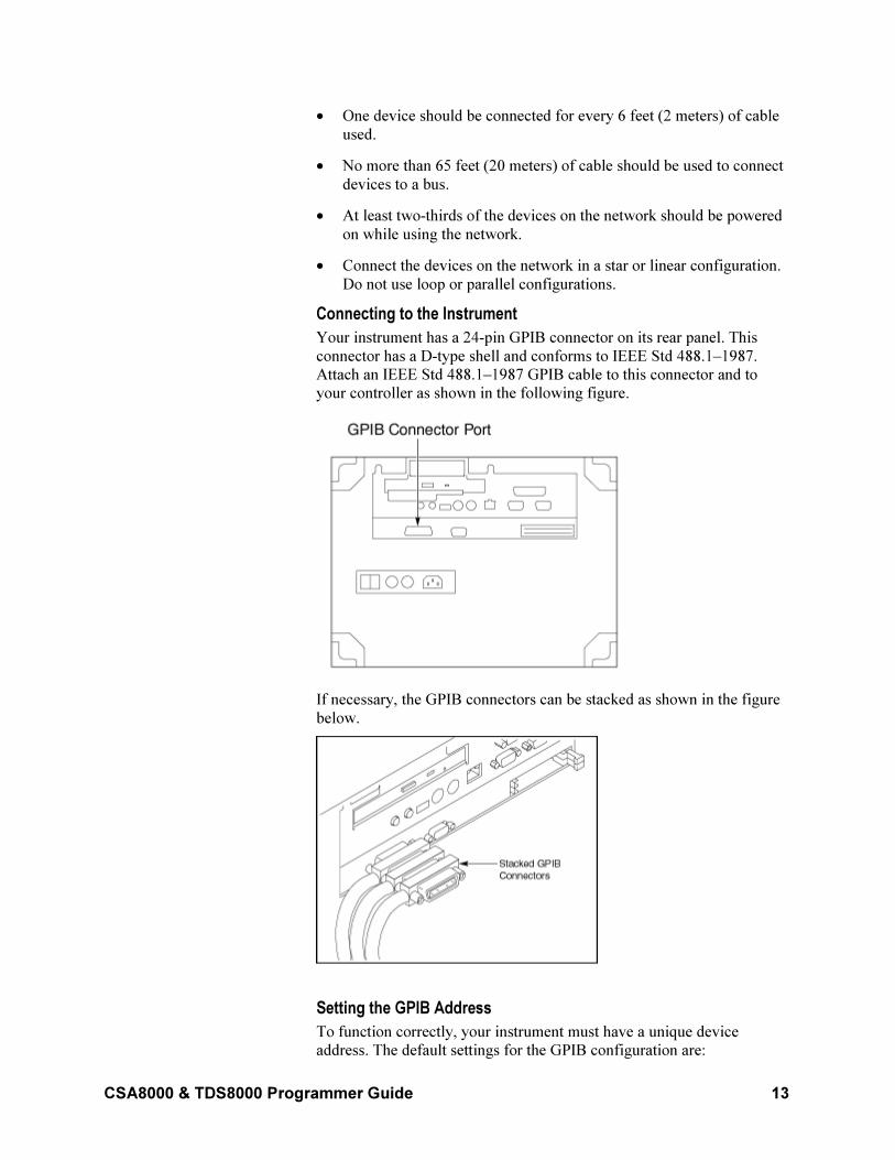
Connecting to the Instrument
Your instrument has a 24-pin GPIB connector on its rear panel. This
connector has a D-type shell and conforms to IEEE Std 488.1–1987.
Attach an IEEE Std 488.1–1987 GPIB cable to this connector and to
your controller as shown in the following figure.
If necessary, the GPIB connectors can be stacked as shown in the figure
below.
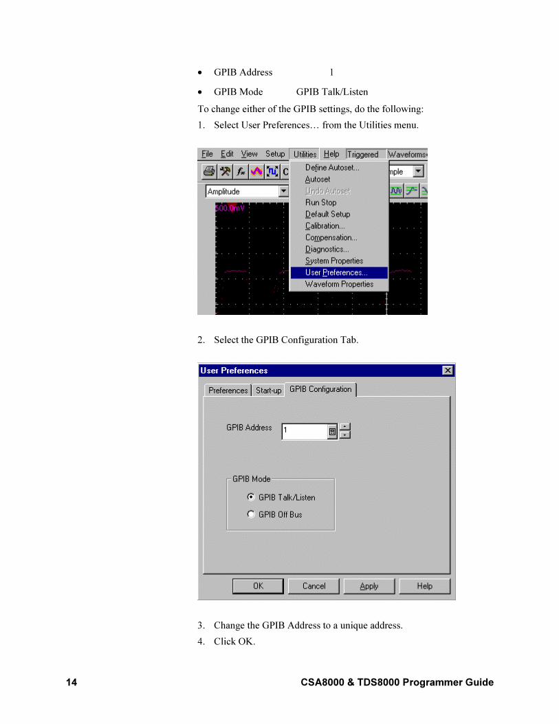
Setting the GPIB Address
To function correctly, your instrument must have a unique device
address. The default settings for the GPIB configuration are:
14 CSA8000 & TDS8000 Programmer Guide
• GPIB Address 1
• GPIB Mode GPIB Talk/Listen
To change either of the GPIB settings, do the following:
1. Select User Preferences… from the Utilities menu.
2. Select the GPIB Configuration Tab.
3. Change the GPIB Address to a unique address.
4. Click OK.
CSA8000 & TDS8000 Programmer Guide 15
The instrument is set up for bi-directional communication with your
controller.
Documentation
In addition to this CSA8000 & TDS8000 Programmer Online Guide, the
following documentation is included with this instrument.
CSA8000 & TDS8000 Online Help. This online help system is integrated with the User Interface application that ships with this product.
CSA8000B & TDS8000B User Manual or CSA8000 & TDS8000 User Manual. This is the user manual for the instrument and is included with it.
CSA8000B & TDS8000B Reference or CSA8000 & TDS8000 Reference. This is a quick reference to the major features of the instrument and how they operate. The reference is included with the instrument.
80E00 Series Electrical Sampling Module User Manual. This user manual is included as a standard accessory with electrical sampling modules ordered for use with this instrument.
80C00 Series Optical Sampling Module User Manual. This user manual is included as a standard accessory with optical sampling modules ordered for use with this instrument.
Oscilloscope Analysis and Connectivity Made Easy. This book explores some options for getting data from your instrument into any one of several available analysis tools. See the CSA8000 & TDS8000 Online Help described above for more information.
Note: Occasionally, Tektronix publishes user information on its web site, such as updated drivers, application notes, and programming examples. See Contacting Tektronix in your user manual for access information on this site.
16 CSA8000 & TDS8000 Programmer Guide
Command Syntax
Syntax Overview
You can control the operations and functions of the instrument through
the GPIB interface using commands and queries. The related topics listed
below describe the syntax of these commands and queries. The topics
also describe the conventions that the instrument uses to process them.
See the Command Groups topic in the table of contents to locate lists of
the commands by command group. The table of contents also lists the
commands alphabetically, or you can use the index to locate a specific
command.
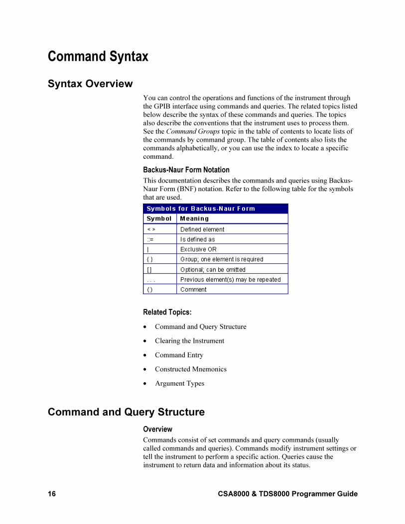
Backus-Naur Form Notation
This documentation describes the commands and queries using Backus-
Naur Form (BNF) notation. Refer to the following table for the symbols
that are used.
Related Topics:
• Command and Query Structure
• Clearing the Instrument
• Command Entry
• Constructed Mnemonics
• Argument Types
Command and Query Structure
Overview
Commands consist of set commands and query commands (usually
called commands and queries). Commands modify instrument settings or
tell the instrument to perform a specific action. Queries cause the
instrument to return data and information about its status.
CSA8000 & TDS8000 Programmer Guide 17
Most commands have both a set form and a query form. The query form
of the command differs from the set form by its question mark on the
end. For example, the set command ACQuire:MODe has a query form
ACQuire:MODe?. Not all commands have both a set and a query form.
Some commands have set only and some have query only.
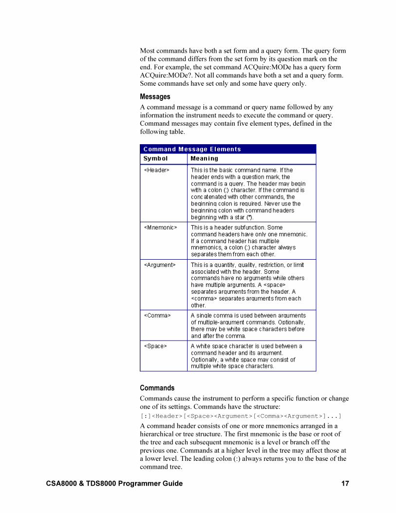
Messages
A command message is a command or query name followed by any
information the instrument needs to execute the command or query.
Command messages may contain five element types, defined in the
following table.
Commands
Commands cause the instrument to perform a specific function or change
one of its settings. Commands have the structure:
[:]<Header>[<Space><Argument>[<Comma><Argument>]...]
A command header consists of one or more mnemonics arranged in a
hierarchical or tree structure. The first mnemonic is the base or root of
the tree and each subsequent mnemonic is a level or branch off the
previous one. Commands at a higher level in the tree may affect those at
a lower level. The leading colon (:) always returns you to the base of the
command tree.
18 CSA8000 & TDS8000 Programmer Guide
Queries
Queries cause the instrument to return information about its status or
settings. Queries have the structure:
• [:]<Header>?
• [:]<Header>?[<Space><Argument>[<Comma>
<Argument>]
...]
You can specify a query command at any level within the command tree
unless otherwise noted. These branch queries return information about all
the mnemonics below the specified branch or level. For example,
HIStogram:STATistics:STDdev? returns the standard deviation of the
histogram, while HIStogram:STATistics? returns all the histogram
statistics, and HIStogram? returns all the histogram parameters.
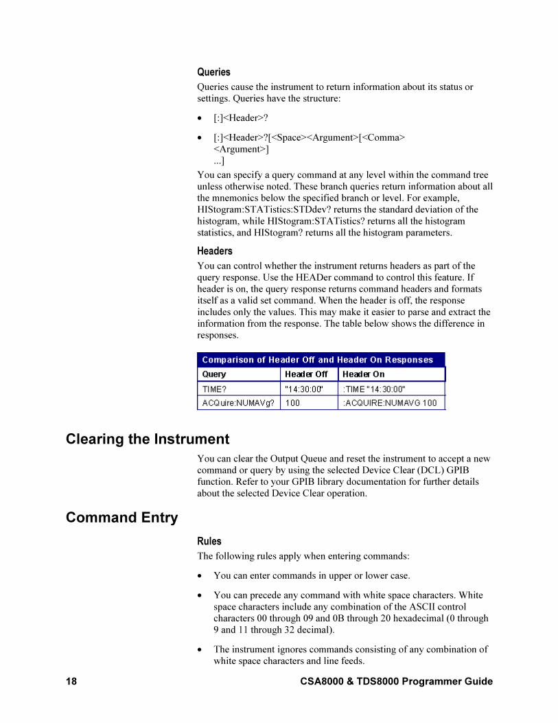
Headers
You can control whether the instrument returns headers as part of the
query response. Use the HEADer command to control this feature. If
header is on, the query response returns command headers and formats
itself as a valid set command. When the header is off, the response
includes only the values. This may make it easier to parse and extract the
information from the response. The table below shows the difference in
responses.
Clearing the Instrument
You can clear the Output Queue and reset the instrument to accept a new
command or query by using the selected Device Clear (DCL) GPIB
function. Refer to your GPIB library documentation for further details
about the selected Device Clear operation.
Command Entry
Rules
The following rules apply when entering commands:
• You can enter commands in upper or lower case.
• You can precede any command with white space characters. White
space characters include any combination of the ASCII control
characters 00 through 09 and 0B through 20 hexadecimal (0 through
9 and 11 through 32 decimal).
• The instrument ignores commands consisting of any combination of
white space characters and line feeds.
CSA8000 & TDS8000 Programmer Guide 19
Abbreviating
You can abbreviate many instrument commands. Each command in this
documentation shows the abbreviations in capitals. For example, you can
enter the command ACQuire:NUMAvg simply as ACQ:NUMA or
acq:numa.
Abbreviation rules may change over time as new instrument models are
introduced. Thus, for the most robust code, use the full spelling.
If you use the HEADer command to have command headers included as
part of query responses, you can further control whether the returned
headers are abbreviated or are full-length with the VERBose command.
Concatenating
You can concatenate any combination of set commands and queries
using a semicolon (;). The instrument executes concatenated commands
in the order received.
When concatenating commands and queries, you must follow these rules:
• Separate completely different headers by a semicolon and by the
beginning colon on all commands except the first one. For example,
the commands, TRIGger:MODe NORMal and ACQuire:NUMAVg
10, can be concatenated into the following single command:
TRIGger:MODe NORMal;:ACQuire:NUMAVg 10
• If concatenated commands have headers that differ by only the last
mnemonic, you can abbreviate the second command and eliminate
the beginning colon. For example, you can concatenate the
commands ACQuire:MODe ENVelope and ACQuire:NUMAVg 10
into a single command:
ACQuire:MODe ENVElope; NUMAVg 10
The longer version works equally well:
ACQuire:MODe ENVElope;:ACQuire:NUMAVg 10
• Never precede a star (*) command with a colon:
ACQuire:MODe ENVElope;*OPC
Any commands that follow will be processed as if the star command
was not there. For example, the ACQuire:MODe
ENVElope;*OPC;NUMAVg 10 commands will set the acquisition
mode to envelope and set the number of acquisitions for averaging to
10.
• When you concatenate queries, the responses to all the queries are
concatenated into a single response message. For example, if the
display background color is white and the display foreground color is
black, the concatenated query
DISplay:COLor:BACKGround?;FOREGround? will return the
following:
If the header is on:
:DISPLAY:COLOR:BACKGROUND 7;
:DISPLAY:COLOR:FOREGROUND 0
If the header is off:
20 CSA8000 & TDS8000 Programmer Guide
7;0
• Set commands and queries may be concatenated in the same
message. For example,
ACQuire:MODe SAMple;NUMAVg?;STATE?
is a valid message that sets the acquisition mode to sample. The
message then queries the number of acquisitions for averaging and
the acquisition state. Concatenated commands and queries are
executed in the order received.
Here are some invalid concatenations:
• DISPlay:STYle:NORMal;ACQuire:NUMAVg 10
(no colon before ACQuire)
• DISPlay:COLor:CURSor1 1;:CURSor2 5
(extra colon before CURSor2; use DISPlay:COLor:CURSor1
1;CURSor2 5 instead)
• DISPlay:STYle:NORMal;:*OPC
(colon before a star (*) command)
• DISPlay:COLor:CURSor1 1;COLor:CURSor2 5
(levels of the mnemonics are different; either remove the second use
of COLor or place :DISPlay: in front of COLor:CURSor2 5)
Terminating
This documentation uses <EOM> (End of message) to represent a
message terminator.
The end-of-message terminator may be the END message (EOI asserted
concurrently with the last data byte), the ASCII code for line feed (LF)
sent as the last data byte, or both. The instrument always terminates
messages with LF and EOI. It allows white space before the terminator.
For example, it allows CR LF.
Constructed Mnemonics
Some header mnemonics specify one of a range of mnemonics. For
example, a channel mnemonic can be CH1, CH2, CH3, … through CH8.
You use these mnemonics in the command just as you do any other
mnemonic. For example, there is a CH1:POSition command, and there is
also a CH2:POSition command. In the command descriptions, this list of
choices is abbreviated as CH<x>.
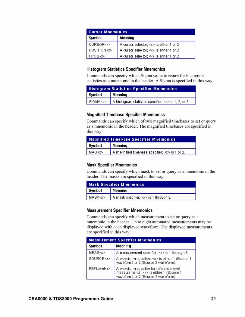
Cursor Position Mnemonics
When cursors are displayed, commands may specify which cursor of the
pair to use.
CSA8000 & TDS8000 Programmer Guide 21
Histogram Statistics Specifier Mnemonics
Commands can specify which Sigma value to return for histogram
statistics as a mnemonic in the header. A Sigma is specified in this way:
Magnified Timebase Specifier Mnemonics
Commands can specify which of two magnified timebases to set or query
as a mnemonic in the header. The magnified timebases are specified in
this way:
Mask Specifier Mnemonics
Commands can specify which mask to set or query as a mnemonic in the
header. The masks are specified in this way:
Measurement Specifier Mnemonics
Commands can specify which measurement to set or query as a
mnemonic in the header. Up to eight automated measurements may be
displayed with each displayed waveform. The displayed measurements
are specified in this way:
22 CSA8000 & TDS8000 Programmer Guide
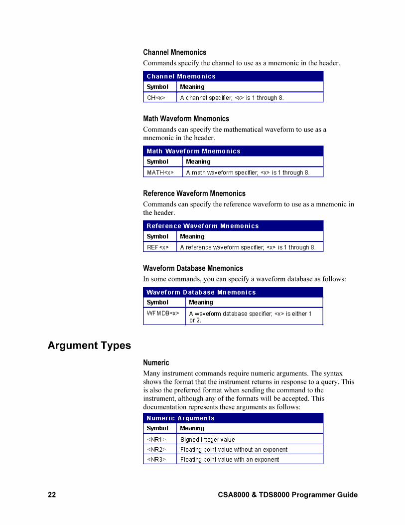
Channel Mnemonics
Commands specify the channel to use as a mnemonic in the header.
Math Waveform Mnemonics
Commands can specify the mathematical waveform to use as a
mnemonic in the header.
Reference Waveform Mnemonics
Commands can specify the reference waveform to use as a mnemonic in
the header.
Waveform Database Mnemonics
In some commands, you can specify a waveform database as follows:
Argument Types
Numeric
Many instrument commands require numeric arguments. The syntax
shows the format that the instrument returns in response to a query. This
is also the preferred format when sending the command to the
instrument, although any of the formats will be accepted. This
documentation represents these arguments as follows:
CSA8000 & TDS8000 Programmer Guide 23
Most numeric arguments will be automatically forced to a valid setting,
by either rounding or truncating, when an invalid number is input (unless
otherwise noted in the command description).
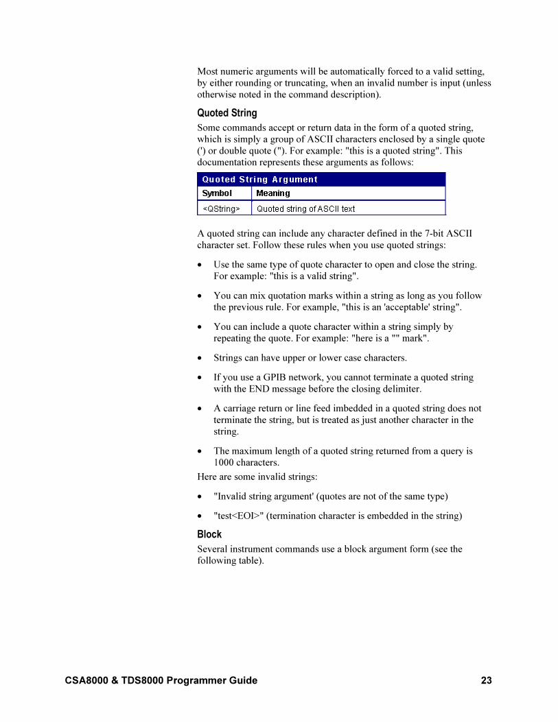
Quoted String
Some commands accept or return data in the form of a quoted string,
which is simply a group of ASCII characters enclosed by a single quote
(') or double quote ("). For example: "this is a quoted string". This
documentation represents these arguments as follows:
A quoted string can include any character defined in the 7-bit ASCII
character set. Follow these rules when you use quoted strings:
• Use the same type of quote character to open and close the string.
For example: "this is a valid string".
• You can mix quotation marks within a string as long as you follow
the previous rule. For example, "this is an 'acceptable' string".
• You can include a quote character within a string simply by
repeating the quote. For example: "here is a "" mark".
• Strings can have upper or lower case characters.
• If you use a GPIB network, you cannot terminate a quoted string
with the END message before the closing delimiter.
• A carriage return or line feed imbedded in a quoted string does not
terminate the string, but is treated as just another character in the
string.
• The maximum length of a quoted string returned from a query is
1000 characters.
Here are some invalid strings:
• "Invalid string argument' (quotes are not of the same type)
• "test<EOI>" (termination character is embedded in the string)
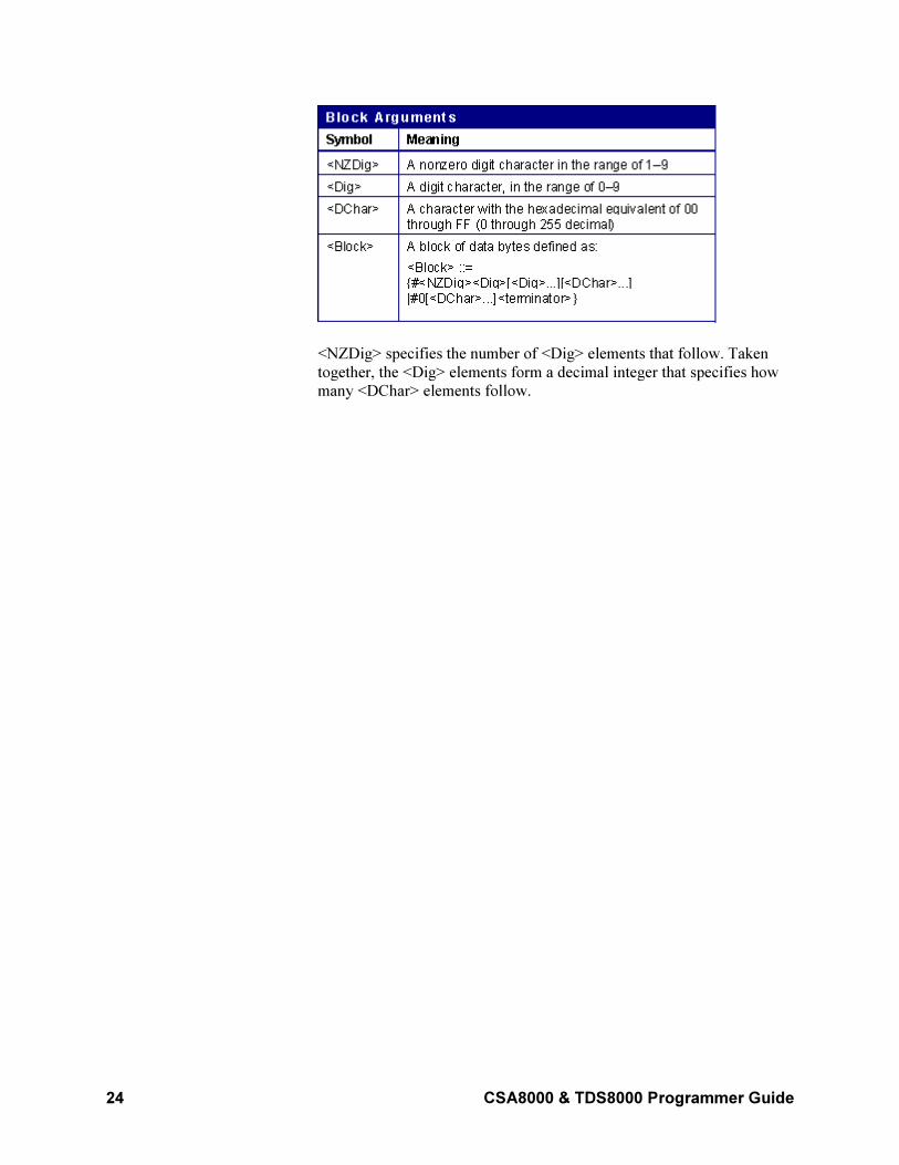
Block
Several instrument commands use a block argument form (see the
following table).
24 CSA8000 & TDS8000 Programmer Guide
<NZDig> specifies the number of <Dig> elements that follow. Taken
together, the <Dig> elements form a decimal integer that specifies how
many <DChar> elements follow.
CSA8000 & TDS8000 Programmer Guide 25
Command Groups
Acquisition Command Group
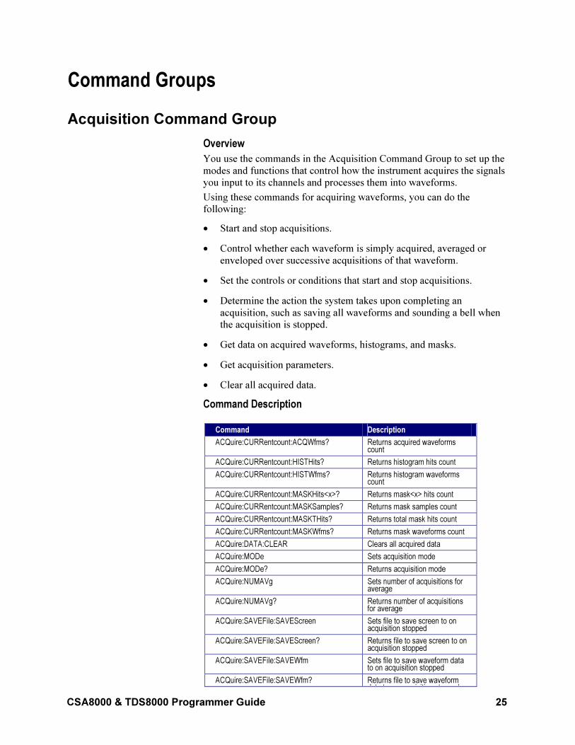
Overview
You use the commands in the Acquisition Command Group to set up the
modes and functions that control how the instrument acquires the signals
you input to its channels and processes them into waveforms.
Using these commands for acquiring waveforms, you can do the
following:
• Start and stop acquisitions.
• Control whether each waveform is simply acquired, averaged or
enveloped over successive acquisitions of that waveform.
• Set the controls or conditions that start and stop acquisitions.
• Determine the action the system takes upon completing an
acquisition, such as saving all waveforms and sounding a bell when
the acquisition is stopped.
• Get data on acquired waveforms, histograms, and masks.
• Get acquisition parameters.
• Clear all acquired data.
Command Description
Command Description
ACQuire:CURRentcount:ACQWfms? Returns acquired waveforms count
ACQuire:CURRentcount:HISTHits? Returns histogram hits count
ACQuire:CURRentcount:HISTWfms? Returns histogram waveforms count
ACQuire:CURRentcount:MASKHits<x>? Returns mask<x> hits count
ACQuire:CURRentcount:MASKSamples? Returns mask samples count
ACQuire:CURRentcount:MASKTHits? Returns total mask hits count
ACQuire:CURRentcount:MASKWfms? Returns mask waveforms count
ACQuire:DATA:CLEAR Clears all acquired data
ACQuire:MODe Sets acquisition mode
ACQuire:MODe? Returns acquisition mode
ACQuire:NUMAVg Sets number of acquisitions for average
ACQuire:NUMAVg? Returns number of acquisitions for average
ACQuire:SAVEFile:SAVEScreen Sets file to save screen to on acquisition stopped
ACQuire:SAVEFile:SAVEScreen? Returns file to save screen to on acquisition stopped
ACQuire:SAVEFile:SAVEWfm Sets file to save waveform data to on acquisition stopped
ACQuire:SAVEFile:SAVEWfm? Returns file to save waveform data to on acquisition stopped
26 CSA8000 & TDS8000 Programmer Guide
data to on acquisition stopped
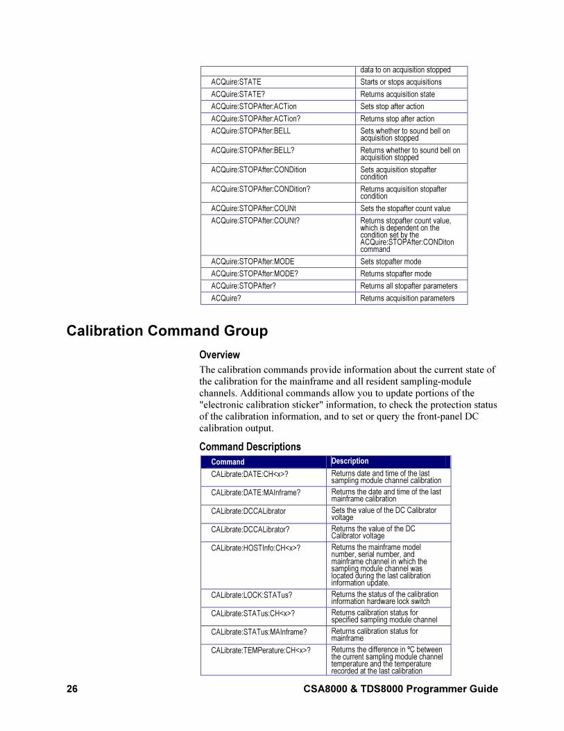
ACQuire:STATE Starts or stops acquisitions
ACQuire:STATE? Returns acquisition state
ACQuire:STOPAfter:ACTion Sets stop after action
ACQuire:STOPAfter:ACTion? Returns stop after action
ACQuire:STOPAfter:BELL Sets whether to sound bell on acquisition stopped
ACQuire:STOPAfter:BELL? Returns whether to sound bell on acquisition stopped
ACQuire:STOPAfter:CONDition Sets acquisition stopafter condition
ACQuire:STOPAfter:CONDition? Returns acquisition stopafter condition
ACQuire:STOPAfter:COUNt Sets the stopafter count value
ACQuire:STOPAfter:COUNt? Returns stopafter count value, which is dependent on the condition set by the ACQuire:STOPAfter:CONDiton command
ACQuire:STOPAfter:MODE Sets stopafter mode
ACQuire:STOPAfter:MODE? Returns stopafter mode
ACQuire:STOPAfter? Returns all stopafter parameters
ACQuire? Returns acquisition parameters
Calibration Command Group
Overview
The calibration commands provide information about the current state of
the calibration for the mainframe and all resident sampling-module
channels. Additional commands allow you to update portions of the
"electronic calibration sticker" information, to check the protection status
of the calibration information, and to set or query the front-panel DC
calibration output.
Command Descriptions
Command Description
CALibrate:DATE:CH<x>? Returns date and time of the last sampling module channel calibration
CALibrate:DATE:MAInframe? Returns the date and time of the last mainframe calibration
CALibrate:DCCALibrator Sets the value of the DC Calibrator voltage
CALibrate:DCCALibrator? Returns the value of the DC Calibrator voltage
CALibrate:HOSTInfo:CH<x>? Returns the mainframe model number, serial number, and mainframe channel in which the sampling module channel was located during the last calibration information update.
CALibrate:LOCK:STATus? Returns the status of the calibration information hardware lock switch
CALibrate:STATus:CH<x>? Returns calibration status for specified sampling module channel
CALibrate:STATus:MAInframe? Returns calibration status for mainframe
CALibrate:TEMPerature:CH<x>? Returns the difference in ºC between the current sampling module channel temperature and the temperature recorded at the last calibration
CSA8000 & TDS8000 Programmer Guide 27
information update
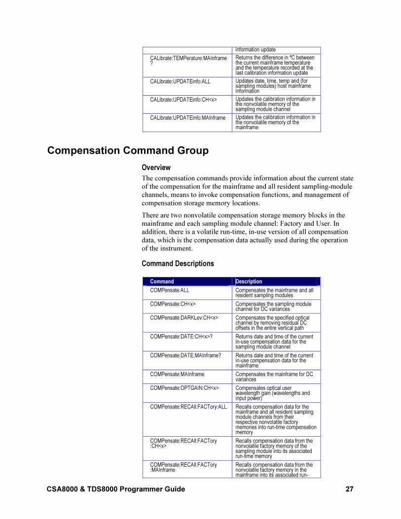
CALibrate:TEMPerature:MAInframe?
Returns the difference in ºC between the current mainframe temperature and the temperature recorded at the last calibration information update
CALibrate:UPDATEinfo:ALL Updates date, time, temp and (for sampling modules) host mainframe information
CALibrate:UPDATEinfo:CH<x> Updates the calibration information in the nonvolatile memory of the sampling module channel
CALibrate:UPDATEinfo:MAInframe Updates the calibration information in the nonvolatile memory of the mainframe
Compensation Command Group
Overview
The compensation commands provide information about the current state
of the compensation for the mainframe and all resident sampling-module
channels, means to invoke compensation functions, and management of
compensation storage memory locations.
There are two nonvolatile compensation storage memory blocks in the
mainframe and each sampling module channel: Factory and User. In
addition, there is a volatile run-time, in-use version of all compensation
data, which is the compensation data actually used during the operation
of the instrument.
Command Descriptions
Command Description
COMPensate:ALL Compensates the mainframe and all resident sampling modules
COMPensate:CH<x> Compensates the sampling module channel for DC variances
COMPensate:DARKLev:CH<x> Compensates the specified optical channel by removing residual DC offsets in the entire vertical path
COMPensate:DATE:CH<x>? Returns date and time of the current in-use compensation data for the sampling module channel
COMPensate:DATE:MAInframe? Returns date and time of the current in-use compensation data for the mainframe
COMPensate:MAInframe Compensates the mainframe for DC variances
COMPensate:OPTGAIN:CH<x> Compensates optical user wavelength gain (wavelengths and input power)
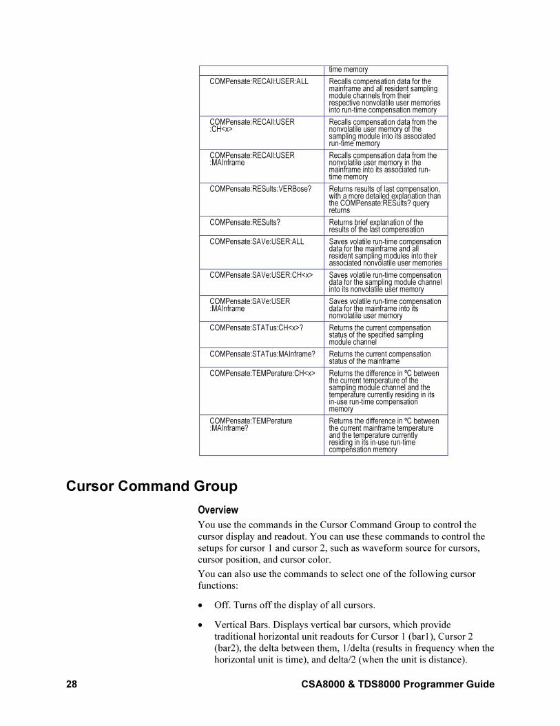
COMPensate:RECAll:FACTory:ALL Recalls compensation data for the mainframe and all resident sampling module channels from their respective nonvolatile factory memories into run-time compensation memory
COMPensate:RECAll:FACTory :CH<x>
Recalls compensation data from the nonvolatile factory memory of the sampling module into its associated run-time memory
COMPensate:RECAll:FACTory :MAInframe
Recalls compensation data from the nonvolatile factory memory in the mainframe into its associated run-
28 CSA8000 & TDS8000 Programmer Guide
time memory
COMPensate:RECAll:USER:ALL Recalls compensation data for the mainframe and all resident sampling module channels from their respective nonvolatile user memories into run-time compensation memory
COMPensate:RECAll:USER :CH<x>
Recalls compensation data from the nonvolatile user memory of the sampling module into its associated run-time memory
COMPensate:RECAll:USER :MAInframe
Recalls compensation data from the nonvolatile user memory in the mainframe into its associated run-time memory
COMPensate:RESults:VERBose? Returns results of last compensation, with a more detailed explanation than the COMPensate:RESults? query returns
COMPensate:RESults? Returns brief explanation of the results of the last compensation
COMPensate:SAVe:USER:ALL Saves volatile run-time compensation data for the mainframe and all resident sampling modules into their associated nonvolatile user memories
COMPensate:SAVe:USER:CH<x> Saves volatile run-time compensation data for the sampling module channel into its nonvolatile user memory
COMPensate:SAVe:USER :MAInframe
Saves volatile run-time compensation data for the mainframe into its nonvolatile user memory
COMPensate:STATus:CH<x>? Returns the current compensation status of the specified sampling module channel
COMPensate:STATus:MAInframe? Returns the current compensation status of the mainframe
COMPensate:TEMPerature:CH<x> Returns the difference in ºC between the current temperature of the sampling module channel and the temperature currently residing in its in-use run-time compensation memory
COMPensate:TEMPerature :MAInframe?
Returns the difference in ºC between the current mainframe temperature and the temperature currently residing in its in-use run-time compensation memory
Cursor Command Group
Overview
You use the commands in the Cursor Command Group to control the
cursor display and readout. You can use these commands to control the
setups for cursor 1 and cursor 2, such as waveform source for cursors,
cursor position, and cursor color.
You can also use the commands to select one of the following cursor
functions:
• Off. Turns off the display of all cursors.
• Vertical Bars. Displays vertical bar cursors, which provide
traditional horizontal unit readouts for Cursor 1 (bar1), Cursor 2
(bar2), the delta between them, 1/delta (results in frequency when the
horizontal unit is time), and delta/2 (when the unit is distance).
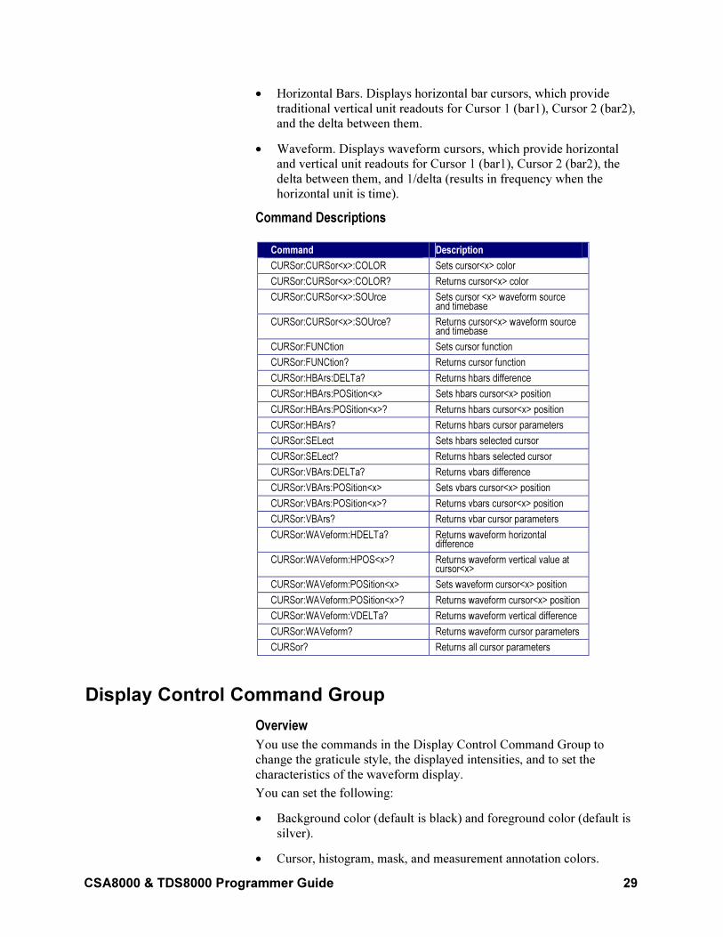
CSA8000 & TDS8000 Programmer Guide 29
• Horizontal Bars. Displays horizontal bar cursors, which provide
traditional vertical unit readouts for Cursor 1 (bar1), Cursor 2 (bar2),
and the delta between them.
• Waveform. Displays waveform cursors, which provide horizontal
and vertical unit readouts for Cursor 1 (bar1), Cursor 2 (bar2), the
delta between them, and 1/delta (results in frequency when the
horizontal unit is time).
Command Descriptions
Command Description
CURSor:CURSor<x>:COLOR Sets cursor<x> color
CURSor:CURSor<x>:COLOR? Returns cursor<x> color
CURSor:CURSor<x>:SOUrce Sets cursor <x> waveform source and timebase
CURSor:CURSor<x>:SOUrce? Returns cursor<x> waveform source and timebase
CURSor:FUNCtion Sets cursor function
CURSor:FUNCtion? Returns cursor function
CURSor:HBArs:DELTa? Returns hbars difference
CURSor:HBArs:POSition<x> Sets hbars cursor<x> position
CURSor:HBArs:POSition<x>? Returns hbars cursor<x> position
CURSor:HBArs? Returns hbars cursor parameters
CURSor:SELect Sets hbars selected cursor
CURSor:SELect? Returns hbars selected cursor
CURSor:VBArs:DELTa? Returns vbars difference
CURSor:VBArs:POSition<x> Sets vbars cursor<x> position
CURSor:VBArs:POSition<x>? Returns vbars cursor<x> position
CURSor:VBArs? Returns vbar cursor parameters
CURSor:WAVeform:HDELTa? Returns waveform horizontal difference
CURSor:WAVeform:HPOS<x>? Returns waveform vertical value at cursor<x>
CURSor:WAVeform:POSition<x> Sets waveform cursor<x> position
CURSor:WAVeform:POSition<x>? Returns waveform cursor<x> position
CURSor:WAVeform:VDELTa? Returns waveform vertical difference
CURSor:WAVeform? Returns waveform cursor parameters
CURSor? Returns all cursor parameters
Display Control Command Group
Overview
You use the commands in the Display Control Command Group to
change the graticule style, the displayed intensities, and to set the
characteristics of the waveform display.
You can set the following:
• Background color (default is black) and foreground color (default is
silver).
• Cursor, histogram, mask, and measurement annotation colors.
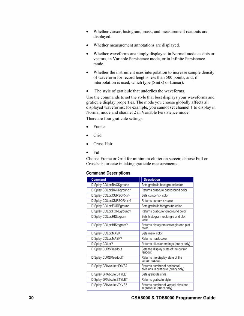
30 CSA8000 & TDS8000 Programmer Guide
• Whether cursor, histogram, mask, and measurement readouts are
displayed.
• Whether measurement annotations are displayed.
• Whether waveforms are simply displayed in Normal mode as dots or
vectors, in Variable Persistence mode, or in Infinite Persistence
mode.
• Whether the instrument uses interpolation to increase sample density
of waveform for record lengths less than 500 points, and, if
interpolation is used, which type (Sin(x) or Linear).
• The style of graticule that underlies the waveforms.
Use the commands to set the style that best displays your waveforms and
graticule display properties. The mode you choose globally affects all
displayed waveforms; for example, you cannot set channel 1 to display in
Normal mode and channel 2 in Variable Persistence mode.
There are four graticule settings:
• Frame
• Grid
• Cross Hair
• Full
Choose Frame or Grid for minimum clutter on screen; choose Full or
Crosshair for ease in taking graticule measurements.
Command Descriptions
Command Description
DISplay:COLor:BACKground Sets graticule background color
DISplay:COLor:BACKground? Returns graticule background color
DISplay:COLor:CURSOR<x> Sets cursor<x> color
DISplay:COLor:CURSOR<x>? Returns cursor<x> color
DISplay:COLor:FOREground Sets graticule foreground color
DISplay:COLor:FOREground? Returns graticule foreground color
DISplay:COLor:HIStogram Sets histogram rectangle and plot color
DISplay:COLor:HIStogram? Returns histogram rectangle and plot color
DISplay:COLor:MASK Sets mask color
DISplay:COLor:MASK? Returns mask color
DISplay:COLor? Returns all color settings (query only)
DISplay:CURSReadout Sets the display state of the cursor readout
DISplay:CURSReadout? Returns the display state of the cursor readout
DISplay:GRAticule:HDIVS? Returns number of horizontal divisions in graticule (query only)
DISplay:GRAticule:STYLE Sets graticule style
DISplay:GRAticule:STYLE? Returns graticule style
DISplay:GRAticule:VDIVS? Returns number of vertical divisions in graticule (query only)
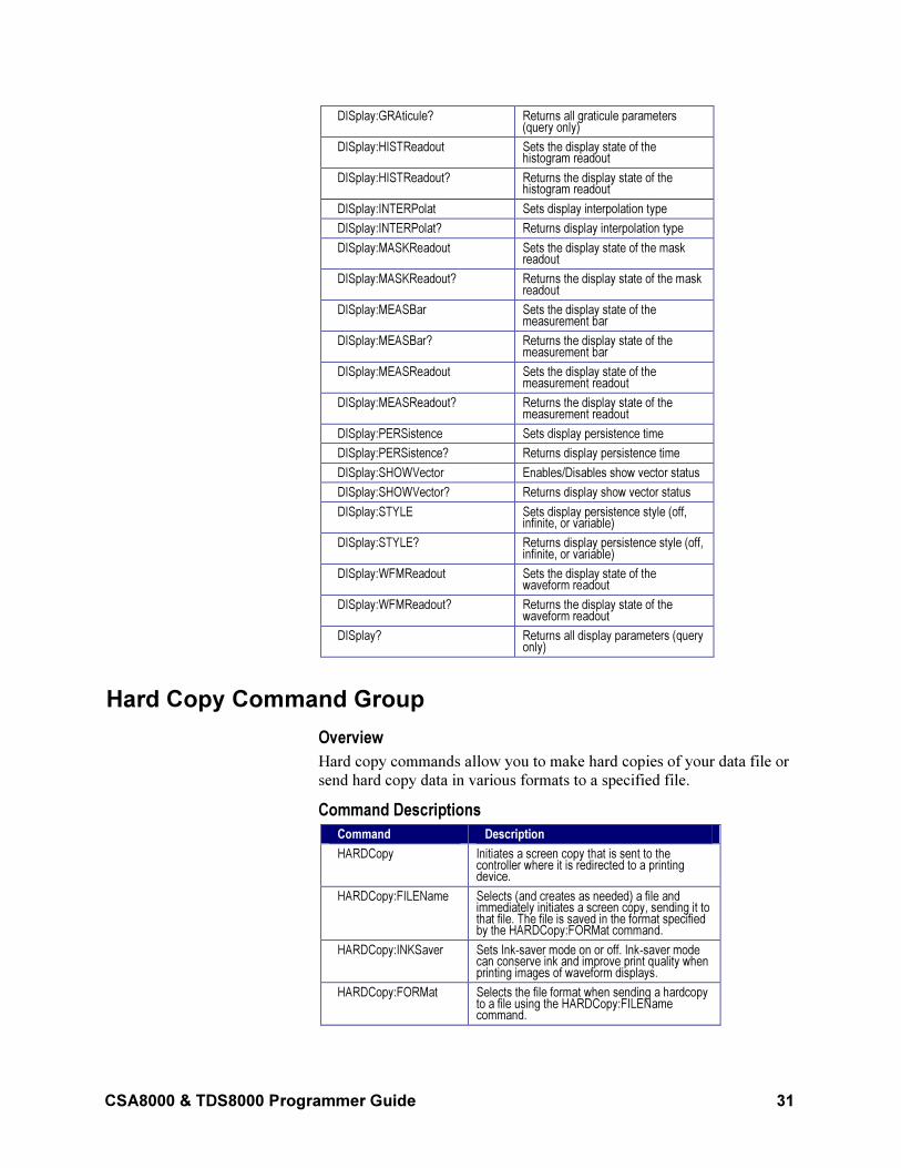
CSA8000 & TDS8000 Programmer Guide 31
DISplay:GRAticule? Returns all graticule parameters (query only)
DISplay:HISTReadout Sets the display state of the histogram readout
DISplay:HISTReadout? Returns the display state of the histogram readout
DISplay:INTERPolat Sets display interpolation type
DISplay:INTERPolat? Returns display interpolation type
DISplay:MASKReadout Sets the display state of the mask readout
DISplay:MASKReadout? Returns the display state of the mask readout
DISplay:MEASBar Sets the display state of the measurement bar
DISplay:MEASBar? Returns the display state of the measurement bar
DISplay:MEASReadout Sets the display state of the measurement readout
DISplay:MEASReadout? Returns the display state of the measurement readout
DISplay:PERSistence Sets display persistence time
DISplay:PERSistence? Returns display persistence time
DISplay:SHOWVector Enables/Disables show vector status
DISplay:SHOWVector? Returns display show vector status
DISplay:STYLE Sets display persistence style (off, infinite, or variable)
DISplay:STYLE? Returns display persistence style (off, infinite, or variable)
DISplay:WFMReadout Sets the display state of the waveform readout
DISplay:WFMReadout? Returns the display state of the waveform readout
DISplay? Returns all display parameters (query only)
Hard Copy Command Group
Overview
Hard copy commands allow you to make hard copies of your data file or
send hard copy data in various formats to a specified file.
Command Descriptions
Command Description
HARDCopy Initiates a screen copy that is sent to the controller where it is redirected to a printing device.
HARDCopy:FILEName Selects (and creates as needed) a file and immediately initiates a screen copy, sending it to that file. The file is saved in the format specified by the HARDCopy:FORMat command.
HARDCopy:INKSaver Sets Ink-saver mode on or off. Ink-saver mode can conserve ink and improve print quality when printing images of waveform displays.
HARDCopy:FORMat Selects the file format when sending a hardcopy to a file using the HARDCopy:FILEName command.
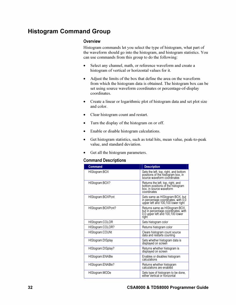
32 CSA8000 & TDS8000 Programmer Guide
Histogram Command Group
Overview
Histogram commands let you select the type of histogram, what part of
the waveform should go into the histogram, and histogram statistics. You
can use commands from this group to do the following:
• Select any channel, math, or reference waveform and create a
histogram of vertical or horizontal values for it.
• Adjust the limits of the box that define the area on the waveform
from which the histogram data is obtained. The histogram box can be
set using source waveform coordinates or percentage-of-display
coordinates.
• Create a linear or logarithmic plot of histogram data and set plot size
and color.
• Clear histogram count and restart.
• Turn the display of the histogram on or off.
• Enable or disable histogram calculations.
• Get histogram statistics, such as total hits, mean value, peak-to-peak
value, and standard deviation.
• Get all the histogram parameters.
Command Descriptions
Command Description
HIStogram:BOX Sets the left, top, right, and bottom positions of the histogram box, in source waveform coordinates
HIStogram:BOX? Returns the left, top, right, and bottom positions of the histogram box, in source waveform coordinates
HIStogram:BOXPcnt Sets same as HIStogram:BOX, but in percentage coordinates, with 0,0 upper left and 100,100 lower right
HIStogram:BOXPcnt? Returns same as HIStogram:BOX, but in percentage coordinates, with 0,0 upper left and 100,100 lower right
HIStogram:COLOR Sets histogram color
HIStogram:COLOR? Returns histogram color
HIStogram:COUNt Clears histogram count source data and restarts counting
HIStogram:DISplay Sets whether histogram data is displayed on screen
HIStogram:DISplay? Returns whether histogram is displayed on screen
HIStogram:ENABle Enables or disables histogram calculations
HIStogram:ENABle? Returns whether histogram calculations are enabled
HIStogram:MODe Sets type of histogram to be done, either vertical or horizontal
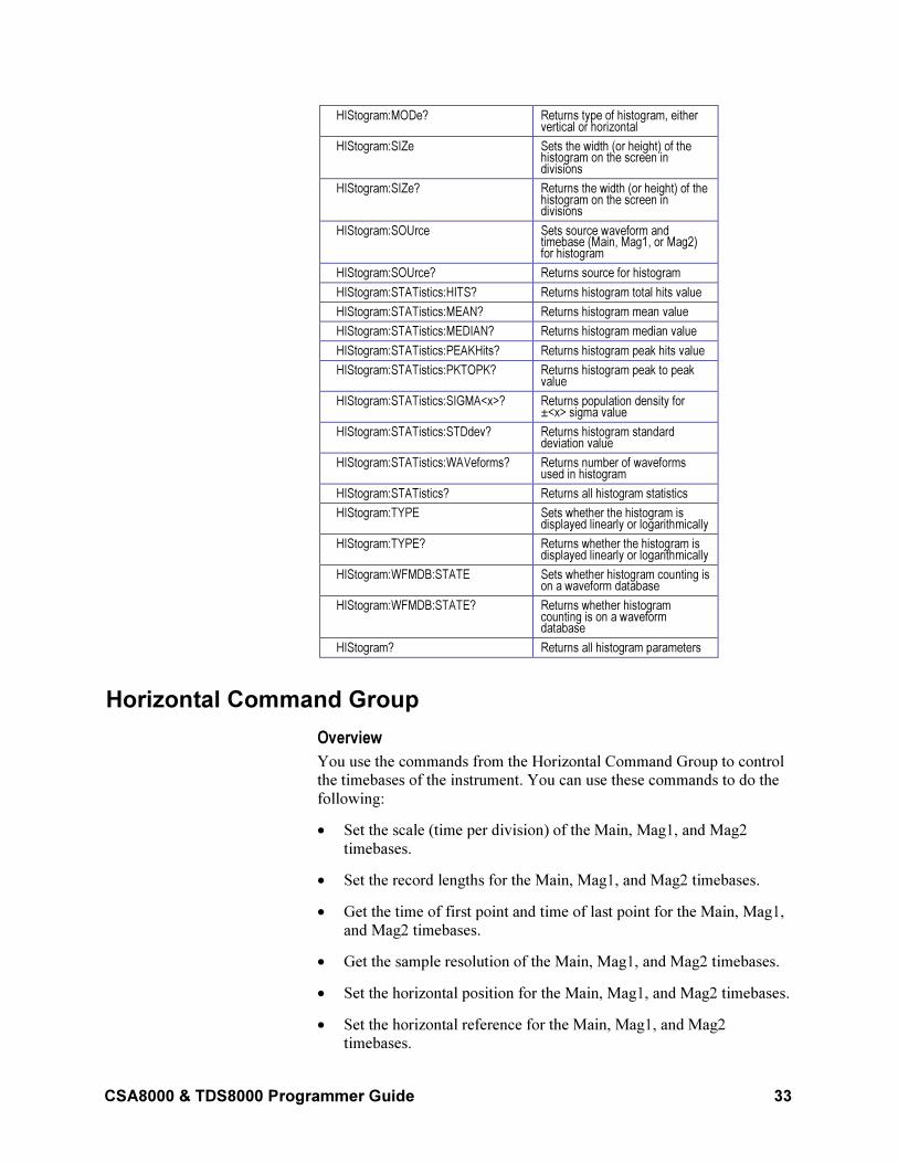
CSA8000 & TDS8000 Programmer Guide 33
HIStogram:MODe? Returns type of histogram, either vertical or horizontal
HIStogram:SIZe Sets the width (or height) of the histogram on the screen in divisions
HIStogram:SIZe? Returns the width (or height) of the histogram on the screen in divisions
HIStogram:SOUrce Sets source waveform and timebase (Main, Mag1, or Mag2) for histogram
HIStogram:SOUrce? Returns source for histogram
HIStogram:STATistics:HITS? Returns histogram total hits value
HIStogram:STATistics:MEAN? Returns histogram mean value
HIStogram:STATistics:MEDIAN? Returns histogram median value
HIStogram:STATistics:PEAKHits? Returns histogram peak hits value
HIStogram:STATistics:PKTOPK? Returns histogram peak to peak value
HIStogram:STATistics:SIGMA<x>? Returns population density for ±<x> sigma value
HIStogram:STATistics:STDdev? Returns histogram standard deviation value
HIStogram:STATistics:WAVeforms? Returns number of waveforms used in histogram
HIStogram:STATistics? Returns all histogram statistics
HIStogram:TYPE Sets whether the histogram is displayed linearly or logarithmically
HIStogram:TYPE? Returns whether the histogram is displayed linearly or logarithmically
HIStogram:WFMDB:STATE Sets whether histogram counting is on a waveform database
HIStogram:WFMDB:STATE? Returns whether histogram counting is on a waveform database
HIStogram? Returns all histogram parameters
Horizontal Command Group
Overview
You use the commands from the Horizontal Command Group to control
the timebases of the instrument. You can use these commands to do the
following:
• Set the scale (time per division) of the Main, Mag1, and Mag2
timebases.
• Set the record lengths for the Main, Mag1, and Mag2 timebases.
• Get the time of first point and time of last point for the Main, Mag1,
and Mag2 timebases.
• Get the sample resolution of the Main, Mag1, and Mag2 timebases.
• Set the horizontal position for the Main, Mag1, and Mag2 timebases.
• Set the horizontal reference for the Main, Mag1, and Mag2
timebases.
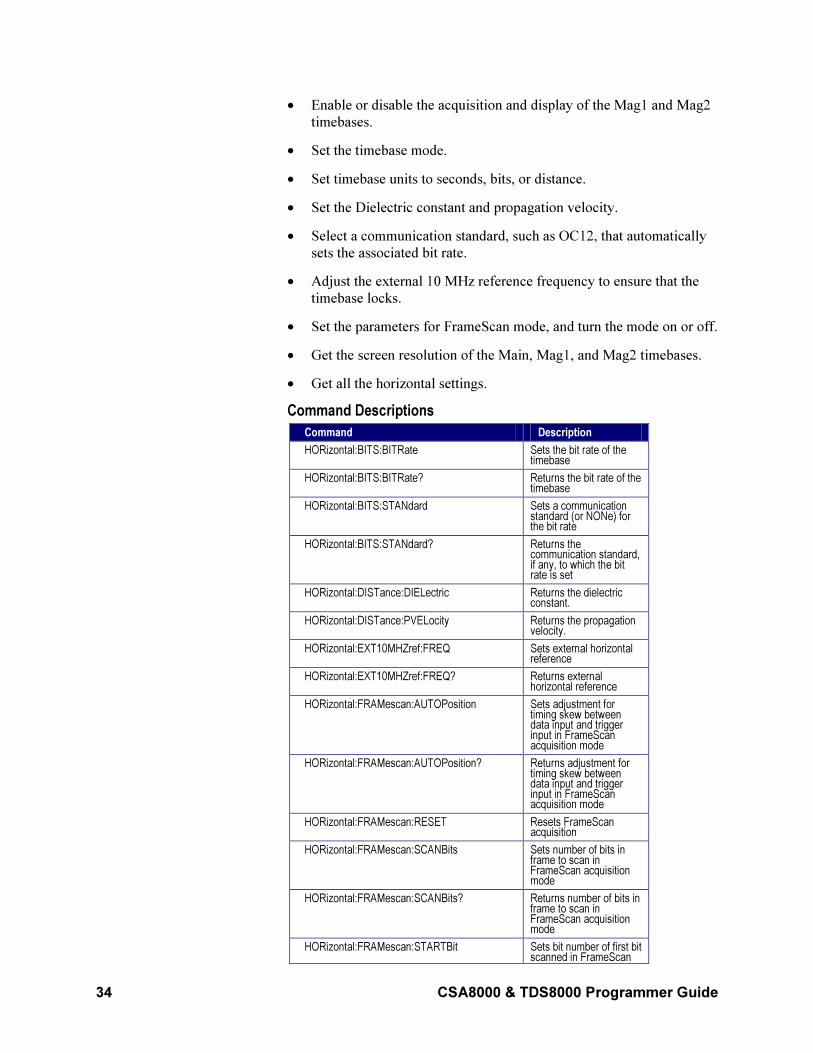
34 CSA8000 & TDS8000 Programmer Guide
• Enable or disable the acquisition and display of the Mag1 and Mag2
timebases.
• Set the timebase mode.
• Set timebase units to seconds, bits, or distance.
• Set the Dielectric constant and propagation velocity.
• Select a communication standard, such as OC12, that automatically
sets the associated bit rate.
• Adjust the external 10 MHz reference frequency to ensure that the
timebase locks.
• Set the parameters for FrameScan mode, and turn the mode on or off.
• Get the screen resolution of the Main, Mag1, and Mag2 timebases.
• Get all the horizontal settings.
Command Descriptions
Command Description
HORizontal:BITS:BITRate Sets the bit rate of the timebase
HORizontal:BITS:BITRate? Returns the bit rate of the timebase
HORizontal:BITS:STANdard Sets a communication standard (or NONe) for the bit rate
HORizontal:BITS:STANdard? Returns the communication standard, if any, to which the bit rate is set
HORizontal:DISTance:DIELectric Returns the dielectric constant.
HORizontal:DISTance:PVELocity Returns the propagation velocity.
HORizontal:EXT10MHZref:FREQ Sets external horizontal reference
HORizontal:EXT10MHZref:FREQ? Returns external horizontal reference
HORizontal:FRAMescan:AUTOPosition Sets adjustment for timing skew between data input and trigger input in FrameScan acquisition mode
HORizontal:FRAMescan:AUTOPosition? Returns adjustment for timing skew between data input and trigger input in FrameScan acquisition mode
HORizontal:FRAMescan:RESET Resets FrameScan acquisition
HORizontal:FRAMescan:SCANBits Sets number of bits in frame to scan in FrameScan acquisition mode
HORizontal:FRAMescan:SCANBits? Returns number of bits in frame to scan in FrameScan acquisition mode
HORizontal:FRAMescan:STARTBit Sets bit number of first bit scanned in FrameScan
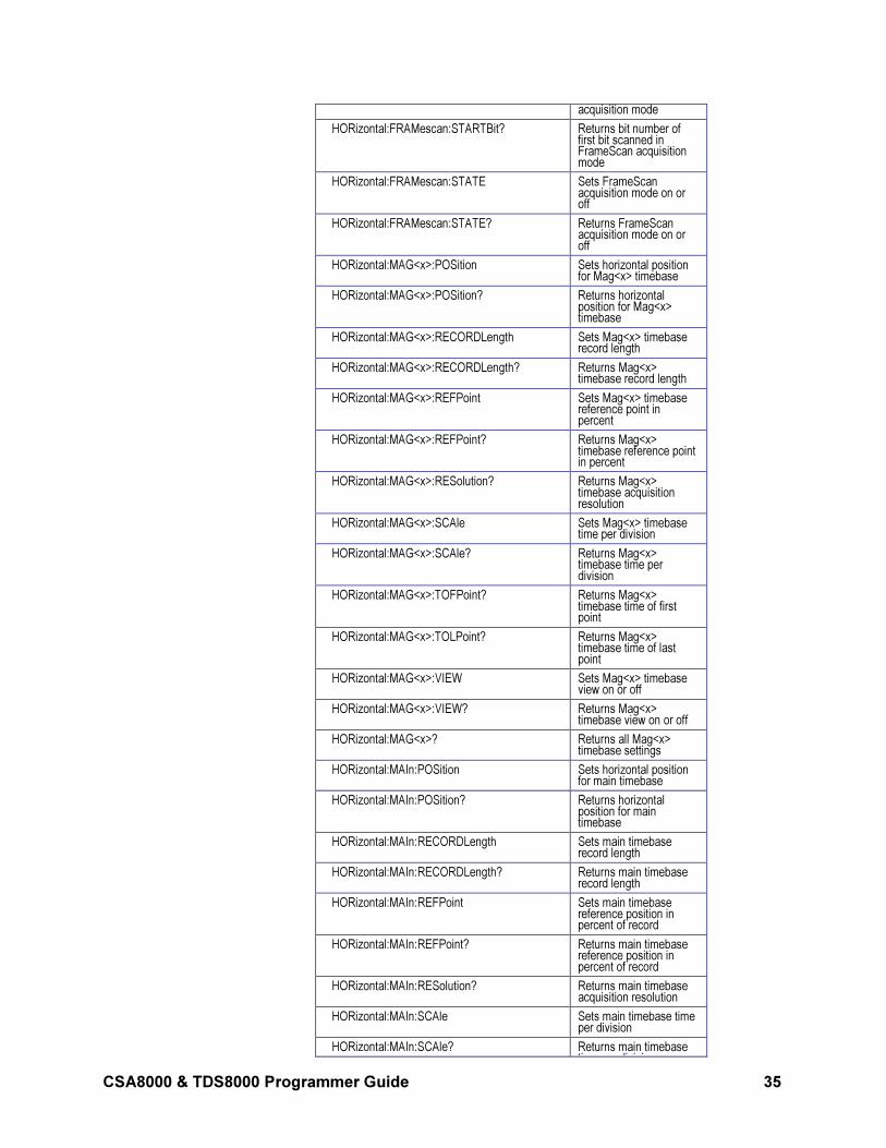
CSA8000 & TDS8000 Programmer Guide 35
acquisition mode
HORizontal:FRAMescan:STARTBit? Returns bit number of first bit scanned in FrameScan acquisition mode
HORizontal:FRAMescan:STATE Sets FrameScan acquisition mode on or off
HORizontal:FRAMescan:STATE? Returns FrameScan acquisition mode on or off
HORizontal:MAG<x>:POSition Sets horizontal position for Mag<x> timebase
HORizontal:MAG<x>:POSition? Returns horizontal position for Mag<x> timebase
HORizontal:MAG<x>:RECORDLength Sets Mag<x> timebase record length
HORizontal:MAG<x>:RECORDLength? Returns Mag<x> timebase record length
HORizontal:MAG<x>:REFPoint Sets Mag<x> timebase reference point in percent
HORizontal:MAG<x>:REFPoint? Returns Mag<x> timebase reference point in percent
HORizontal:MAG<x>:RESolution? Returns Mag<x> timebase acquisition resolution
HORizontal:MAG<x>:SCAle Sets Mag<x> timebase time per division
HORizontal:MAG<x>:SCAle? Returns Mag<x> timebase time per division
HORizontal:MAG<x>:TOFPoint? Returns Mag<x> timebase time of first point
HORizontal:MAG<x>:TOLPoint? Returns Mag<x> timebase time of last point
HORizontal:MAG<x>:VIEW Sets Mag<x> timebase view on or off
HORizontal:MAG<x>:VIEW? Returns Mag<x> timebase view on or off
HORizontal:MAG<x>? Returns all Mag<x> timebase settings
HORizontal:MAIn:POSition Sets horizontal position for main timebase
HORizontal:MAIn:POSition? Returns horizontal position for main timebase
HORizontal:MAIn:RECORDLength Sets main timebase record length
HORizontal:MAIn:RECORDLength? Returns main timebase record length
HORizontal:MAIn:REFPoint Sets main timebase reference position in percent of record
HORizontal:MAIn:REFPoint? Returns main timebase reference position in percent of record
HORizontal:MAIn:RESolution? Returns main timebase acquisition resolution
HORizontal:MAIn:SCAle Sets main timebase time per division
HORizontal:MAIn:SCAle? Returns main timebase ti di i i

36 CSA8000 & TDS8000 Programmer Guide
time per division
HORizontal:MAIn:TOFPoint? Returns main timebase time of first point
HORizontal:MAIn:TOLPoint? Returns main timebase time of last point
HORizontal:MAIn? Return all main timebase settings
HORizontal:MATH<x>:MAG<x>:POSition? Returns Math<x> "Acquisition" horizontal position for Mag<x> timebase
HORizontal:MATH<x>:MAG<x> :RECORDLength?
Returns Math<x> Mag<x> timebase record length
HORizontal:MATH<x>:MAG<x>:RESolution? Returns Math<x> Mag<x> timebase acquisition resolution
HORizontal:MATH<x>:MAG<x>:SCAle? Returns math <x> Mag<x> timebase time per division
HORizontal:MATH<x>:MAG<x>:TOFPoint? Returns Math<x> Mag<x> timebase time of first point
HORizontal:MATH<x>:MAG<x>:TOLPoint? Returns Math<x> Mag<x> timebase time of last point
HORizontal:MATH<x>:MAIn:POSition? Returns math <x> horizontal position for main timebase
HORizontal:MATH<x>:MAIn:RECORDLength? Returns math <x> main timebase record length
HORizontal:MATH<x>:MAIn:REFPoint? Returns math <x> main timebase reference position in percent of record
HORizontal:MATH<x>:MAIn:RESolution? Returns math <x> main timebase acquisition resolution
HORizontal:MATH<x>:MAIn:SCAle? Returns math <x> main timebase time per division
HORizontal:MATH<x>:MAIn:TOFPoint? Returns math <x> main timebase time of first point
HORizontal:MATH<x>:MAIn:TOLPoint? Returns math <x> main timebase time of last point
HORizontal:REF<x>:MAG<x>:POSition? Returns reference<x> "Acquisition" horizontal position for Mag<x> timebase
HORizontal:REF<x>:MAG<x>:RECORDLength? Returns reference<x> Mag<x> timebase record length
HORizontal:REF<x>:MAG<x>:RESolution? Returns reference<x> Mag<x> timebase screen resolution
HORizontal:REF<x>:MAG<x>:SCAle? Returns reference<x> Mag<x> timebase time per division
HORizontal:REF<x>:MAG<x>:TOFPoint? Returns ref<x> mag<x> timebase time of first point
HORizontal:REF<x>:MAG<x>:TOLPoint? Returns ref<x> mag<x> timebase time of last point
HORizontal:REF<x>:MAIn:POSition? Returns reference<x> "Acquisition" horizontal position for main
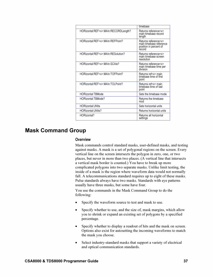
CSA8000 & TDS8000 Programmer Guide 37
timebase
HORizontal:REF<x>:MAIn:RECORDLength? Returns reference<x> main timebase record length
HORizontal:REF<x>:MAIn:REFPoint? Returns reference<x> main timebase reference position in percent of record
HORizontal:REF<x>:MAIn:RESolution? Returns reference<x> main timebase screen resolution
HORizontal:REF<x>:MAIn:SCAle? Returns reference<x> main timebase time per division
HORizontal:REF<x>:MAIn:TOFPoint? Returns ref<x> main timebase time of first point
HORizontal:REF<x>:MAIn:TOLPoint? Returns ref<x> main timebase time of last point
HORizontal:TBMode Sets the timebase mode
HORizontal:TBMode? Returns the timebase mod
HORizontal:UNIts Sets horizontal units
HORizontal:UNIts? Returns horizontal units
HORizontal? Returns all horizontal settings
Mask Command Group
Overview
Mask commands control standard masks, user-defined masks, and testing
against masks. A mask is a set of polygonal regions on the screen. Every
vertical line on the screen intersects the polygon in zero, one, or two
places, but never in more than two places. (A vertical line that intersects
a vertical mask border is counted.) You have to break up more
complicated polygons into two separate masks. Unlike limit testing, the
inside of a mask is the region where waveform data would not normally
fall. A telecommunications standard requires up to eight of these masks.
Pulse standards always have two masks. Standards with eye patterns
usually have three masks, but some have four.
You use the commands in the Mask Command Group to do the
following:
• Specify the waveform source to test and mask to use.
• Specify whether to use, and the size of, mask margins, which allow
you to shrink or expand an existing set of polygons by a specified
percentage.
• Specify whether to display a readout of hits and the mask on screen.
Options also exist for autosetting the incoming waveforms to match
the mask you choose.
• Select industry-standard masks that support a variety of electrical
and optical communication standards.
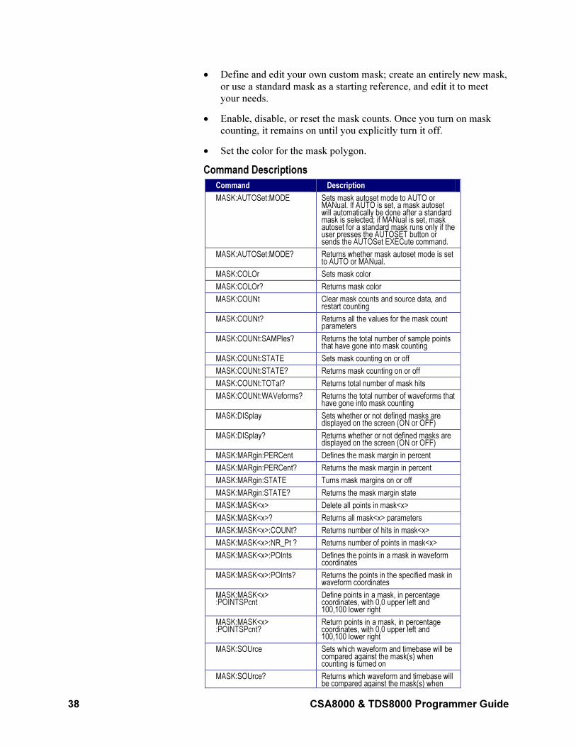
38 CSA8000 & TDS8000 Programmer Guide
• Define and edit your own custom mask; create an entirely new mask,
or use a standard mask as a starting reference, and edit it to meet
your needs.
• Enable, disable, or reset the mask counts. Once you turn on mask
counting, it remains on until you explicitly turn it off.
• Set the color for the mask polygon.
Command Descriptions
Command Description
MASK:AUTOSet:MODE Sets mask autoset mode to AUTO or MANual. If AUTO is set, a mask autoset will automatically be done after a standard mask is selected; if MANual is set, mask autoset for a standard mask runs only if the user presses the AUTOSET button or sends the AUTOSet EXECute command.
MASK:AUTOSet:MODE? Returns whether mask autoset mode is set to AUTO or MANual.
MASK:COLOr Sets mask color
MASK:COLOr? Returns mask color
MASK:COUNt Clear mask counts and source data, and restart counting
MASK:COUNt? Returns all the values for the mask count parameters
MASK:COUNt:SAMPles? Returns the total number of sample points that have gone into mask counting
MASK:COUNt:STATE Sets mask counting on or off
MASK:COUNt:STATE? Returns mask counting on or off
MASK:COUNt:TOTal? Returns total number of mask hits
MASK:COUNt:WAVeforms? Returns the total number of waveforms that have gone into mask counting
MASK:DISplay Sets whether or not defined masks are displayed on the screen (ON or OFF)
MASK:DISplay? Returns whether or not defined masks are displayed on the screen (ON or OFF)
MASK:MARgin:PERCent Defines the mask margin in percent
MASK:MARgin:PERCent? Returns the mask margin in percent
MASK:MARgin:STATE Turns mask margins on or off
MASK:MARgin:STATE? Returns the mask margin state
MASK:MASK<x> Delete all points in mask<x>
MASK:MASK<x>? Returns all mask<x> parameters
MASK:MASK<x>:COUNt? Returns number of hits in mask<x>
MASK:MASK<x>:NR_Pt ? Returns number of points in mask<x>
MASK:MASK<x>:POInts Defines the points in a mask in waveform coordinates
MASK:MASK<x>:POInts? Returns the points in the specified mask in waveform coordinates
MASK:MASK<x> :POINTSPcnt
Define points in a mask, in percentage coordinates, with 0,0 upper left and 100,100 lower right
MASK:MASK<x> :POINTSPcnt?
Return points in a mask, in percentage coordinates, with 0,0 upper left and 100,100 lower right
MASK:SOUrce Sets which waveform and timebase will be compared against the mask(s) when counting is turned on
MASK:SOUrce? Returns which waveform and timebase will be compared against the mask(s) when
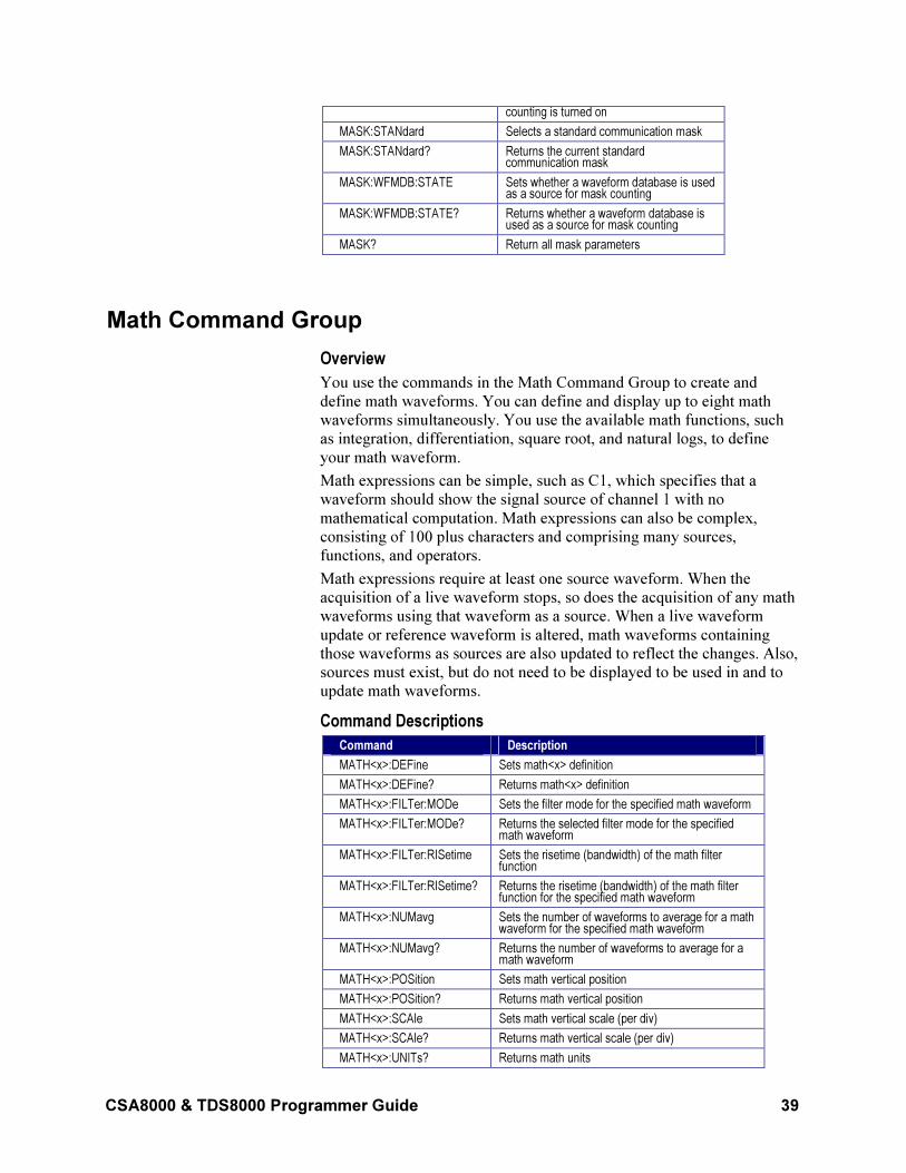
CSA8000 & TDS8000 Programmer Guide 39
counting is turned on
MASK:STANdard Selects a standard communication mask
MASK:STANdard? Returns the current standard communication mask
MASK:WFMDB:STATE Sets whether a waveform database is used as a source for mask counting
MASK:WFMDB:STATE? Returns whether a waveform database is used as a source for mask counting
MASK? Return all mask parameters
Math Command Group
Overview
You use the commands in the Math Command Group to create and
define math waveforms. You can define and display up to eight math
waveforms simultaneously. You use the available math functions, such
as integration, differentiation, square root, and natural logs, to define
your math waveform.
Math expressions can be simple, such as C1, which specifies that a
waveform should show the signal source of channel 1 with no
mathematical computation. Math expressions can also be complex,
consisting of 100 plus characters and comprising many sources,
functions, and operators.
Math expressions require at least one source waveform. When the
acquisition of a live waveform stops, so does the acquisition of any math
waveforms using that waveform as a source. When a live waveform
update or reference waveform is altered, math waveforms containing
those waveforms as sources are also updated to reflect the changes. Also,
sources must exist, but do not need to be displayed to be used in and to
update math waveforms.
Command Descriptions
Command Description
MATH<x>:DEFine Sets math<x> definition
MATH<x>:DEFine? Returns math<x> definition
MATH<x>:FILTer:MODe Sets the filter mode for the specified math waveform
MATH<x>:FILTer:MODe? Returns the selected filter mode for the specified math waveform
MATH<x>:FILTer:RISetime Sets the risetime (bandwidth) of the math filter function
MATH<x>:FILTer:RISetime? Returns the risetime (bandwidth) of the math filter function for the specified math waveform
MATH<x>:NUMavg Sets the number of waveforms to average for a math waveform for the specified math waveform
MATH<x>:NUMavg? Returns the number of waveforms to average for a math waveform
MATH<x>:POSition Sets math vertical position
MATH<x>:POSition? Returns math vertical position
MATH<x>:SCAle Sets math vertical scale (per div)
MATH<x>:SCAle? Returns math vertical scale (per div)
MATH<x>:UNITs? Returns math units
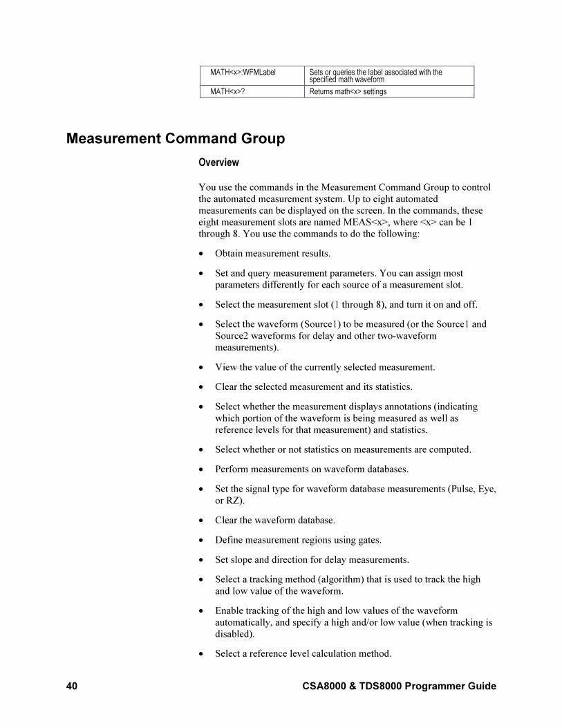
40 CSA8000 & TDS8000 Programmer Guide
MATH<x>:WFMLabel Sets or queries the label associated with the specified math waveform
MATH<x>? Returns math<x> settings
Measurement Command Group
Overview
You use the commands in the Measurement Command Group to control
the automated measurement system. Up to eight automated
measurements can be displayed on the screen. In the commands, these
eight measurement slots are named MEAS<x>, where <x> can be 1
through 8. You use the commands to do the following:
• Obtain measurement results.
• Set and query measurement parameters. You can assign most
parameters differently for each source of a measurement slot.
• Select the measurement slot (1 through 8), and turn it on and off.
• Select the waveform (Source1) to be measured (or the Source1 and
Source2 waveforms for delay and other two-waveform
measurements).
• View the value of the currently selected measurement.
• Clear the selected measurement and its statistics.
• Select whether the measurement displays annotations (indicating
which portion of the waveform is being measured as well as
reference levels for that measurement) and statistics.
• Select whether or not statistics on measurements are computed.
• Perform measurements on waveform databases.
• Set the signal type for waveform database measurements (Pulse, Eye,
or RZ).
• Clear the waveform database.
• Define measurement regions using gates.
• Set slope and direction for delay measurements.
• Select a tracking method (algorithm) that is used to track the high
and low value of the waveform.
• Enable tracking of the high and low values of the waveform
automatically, and specify a high and/or low value (when tracking is
disabled).
• Select a reference level calculation method.
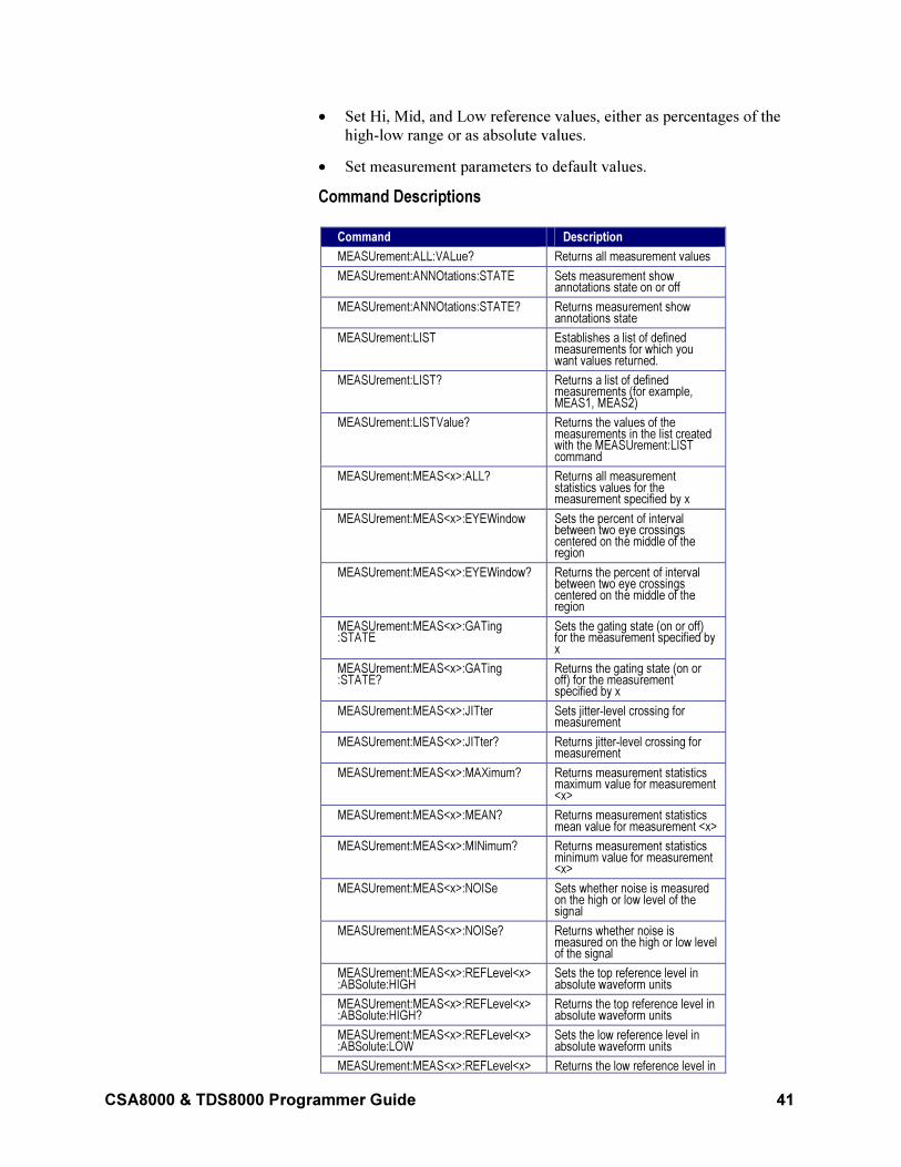
CSA8000 & TDS8000 Programmer Guide 41
• Set Hi, Mid, and Low reference values, either as percentages of the
high-low range or as absolute values.
• Set measurement parameters to default values.
Command Descriptions
Command Description
MEASUrement:ALL:VALue? Returns all measurement values
MEASUrement:ANNOtations:STATE Sets measurement show annotations state on or off
MEASUrement:ANNOtations:STATE? Returns measurement show annotations state
MEASUrement:LIST Establishes a list of defined measurements for which you want values returned.
MEASUrement:LIST? Returns a list of defined measurements (for example, MEAS1, MEAS2)
MEASUrement:LISTValue? Returns the values of the measurements in the list created with the MEASUrement:LIST command
MEASUrement:MEAS<x>:ALL? Returns all measurement statistics values for the measurement specified by x
MEASUrement:MEAS<x>:EYEWindow Sets the percent of interval between two eye crossings centered on the middle of the region
MEASUrement:MEAS<x>:EYEWindow? Returns the percent of interval between two eye crossings centered on the middle of the region
MEASUrement:MEAS<x>:GATing :STATE
Sets the gating state (on or off) for the measurement specified by x
MEASUrement:MEAS<x>:GATing :STATE?
Returns the gating state (on or off) for the measurement specified by x
MEASUrement:MEAS<x>:JITter Sets jitter-level crossing for measurement
MEASUrement:MEAS<x>:JITter? Returns jitter-level crossing for measurement
MEASUrement:MEAS<x>:MAXimum? Returns measurement statistics maximum value for measurement <x>
MEASUrement:MEAS<x>:MEAN? Returns measurement statistics mean value for measurement <x>
MEASUrement:MEAS<x>:MINimum? Returns measurement statistics minimum value for measurement <x>
MEASUrement:MEAS<x>:NOISe Sets whether noise is measured on the high or low level of the signal
MEASUrement:MEAS<x>:NOISe? Returns whether noise is measured on the high or low level of the signal
MEASUrement:MEAS<x>:REFLevel<x> :ABSolute:HIGH
Sets the top reference level in absolute waveform units
MEASUrement:MEAS<x>:REFLevel<x> :ABSolute:HIGH?
Returns the top reference level in absolute waveform units
MEASUrement:MEAS<x>:REFLevel<x> :ABSolute:LOW
Sets the low reference level in absolute waveform units
MEASUrement:MEAS<x>:REFLevel<x> Returns the low reference level in
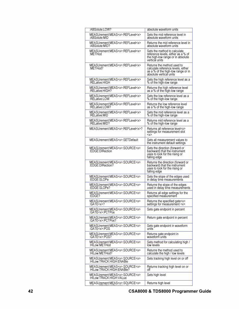
42 CSA8000 & TDS8000 Programmer Guide
:ABSolute:LOW? absolute waveform units
MEASUrement:MEAS<x>:REFLevel<x> :ABSolute:MID
Sets the mid reference level in absolute waveform units
MEASUrement:MEAS<x>:REFLevel<x> :ABSolute:MID?
Returns the mid reference level in absolute waveform units
MEASUrement:MEAS<x>:REFLevel<x> :METHod
Sets the method to calculate reference levels, either as a % of the high-low range or in absolute vertical units
MEASUrement:MEAS<x>:REFLevel<x> :METHod?
Returns the method used to calculate reference levels, either as a % of the high-low range or in absolute vertical units
MEASUrement:MEAS<x>:REFLevel<x> :RELative:HIGH
Sets the high reference level as a % of the high-low range
MEASUrement:MEAS<x>:REFLevel<x> :RELative:HIGH?
Returns the high reference level as a % of the high-low range
MEASUrement:MEAS<x>:REFLevel<x> :RELative:LOW
Sets the low reference level as a % of the high-low range
MEASUrement:MEAS<x>:REFLevel<x> :RELative:LOW?
Returns the low reference level as a % of the high-low range
MEASUrement:MEAS<x>:REFLevel<x> :RELative:MID
Sets the mid reference level as a % of the high-low range
MEASUrement:MEAS<x>:REFLevel<x> :RELative:MID?
Returns mid reference level as a % of the high-low range
MEASUrement:MEAS<x>:REFLevel<x>? Returns all reference level<x> settings for measurement slot <x>
MEASUrement:MEAS<x>:SETDefault Sets all measurement values to the instrument default settings
MEASUrement:MEAS<x>:SOURCE<x> :EDGE:DIRection
Sets the direction (forward or backward) that the instrument uses to look for the rising or falling edge
MEASUrement:MEAS<x>:SOURCE<x> :EDGE:DIRection?
Returns the direction (forward or backward) that the instrument uses to look for the rising or falling edge
MEASUrement:MEAS<x>:SOURCE<x> :EDGE:SLOPe
Sets the slope of the edges used in delay time measurements
MEASUrement:MEAS<x>:SOURCE<x> :EDGE:SLOPe?
Returns the slope of the edges used in delay time measurements
MEASUrement:MEAS<x>:SOURCE<x> :EDGE?
Returns all edge settings for the specified measurement
MEASUrement:MEAS<x>:SOURCE<x> :GATE<x>?
Returns the specified gate<x> settings for measurement <x>
MEASUrement:MEAS<x>:SOURCE<x> :GATE<x>:PCTPos
Sets gate endpoint in percent
MEASUrement:MEAS<x>:SOURCE<x> :GATE<x>:PCTPos?
Return gate endpoint in percent
MEASUrement:MEAS<x>:SOURCE<x> :GATE<x>:POS
Sets gate endpoint in waveform units
MEASUrement:MEAS<x>:SOURCE<x> :GATE<x>:POS?
Returns gate endpoint in waveform units
MEASUrement:MEAS<x>:SOURCE<x> :HILow:METHod
Sets method for calculating high / low levels
MEASUrement:MEAS<x>:SOURCE<x> :HILow:METHod?
Returns the method used to calculate the high / low levels
MEASUrement:MEAS<x>:SOURCE<x> :HILow:TRACK:HIGH:ENABle
Sets tracking high level on or off
MEASUrement:MEAS<x>:SOURCE<x> :HILow:TRACK:HIGH:ENABle?
Returns tracking high level on or off
MEASUrement:MEAS<x>:SOURCE<x> :HILow:TRACK:HIGH:VALue
Sets high level
MEASUrement:MEAS<x>:SOURCE<x> HIL TRACK HIGH VAL ?
Returns high level
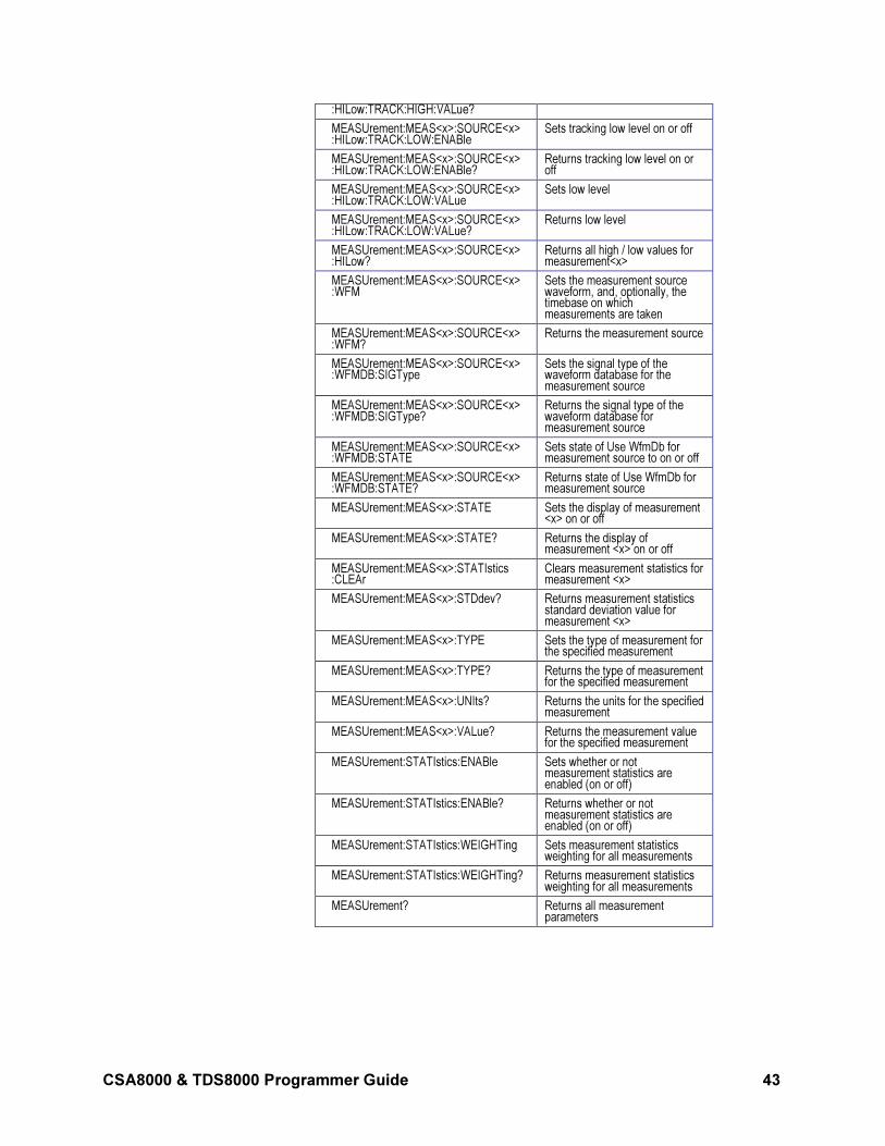
CSA8000 & TDS8000 Programmer Guide 43
:HILow:TRACK:HIGH:VALue?
MEASUrement:MEAS<x>:SOURCE<x> :HILow:TRACK:LOW:ENABle
Sets tracking low level on or off
MEASUrement:MEAS<x>:SOURCE<x> :HILow:TRACK:LOW:ENABle?
Returns tracking low level on or off
MEASUrement:MEAS<x>:SOURCE<x> :HILow:TRACK:LOW:VALue
Sets low level
MEASUrement:MEAS<x>:SOURCE<x> :HILow:TRACK:LOW:VALue?
Returns low level
MEASUrement:MEAS<x>:SOURCE<x> :HILow?
Returns all high / low values for measurement<x>
MEASUrement:MEAS<x>:SOURCE<x> :WFM
Sets the measurement source waveform, and, optionally, the timebase on which measurements are taken
MEASUrement:MEAS<x>:SOURCE<x> :WFM?
Returns the measurement source
MEASUrement:MEAS<x>:SOURCE<x> :WFMDB:SIGType
Sets the signal type of the waveform database for the measurement source
MEASUrement:MEAS<x>:SOURCE<x> :WFMDB:SIGType?
Returns the signal type of the waveform database for measurement source
MEASUrement:MEAS<x>:SOURCE<x> :WFMDB:STATE
Sets state of Use WfmDb for measurement source to on or off
MEASUrement:MEAS<x>:SOURCE<x> :WFMDB:STATE?
Returns state of Use WfmDb for measurement source
MEASUrement:MEAS<x>:STATE Sets the display of measurement <x> on or off
MEASUrement:MEAS<x>:STATE? Returns the display of measurement <x> on or off
MEASUrement:MEAS<x>:STATIstics :CLEAr
Clears measurement statistics for measurement <x>
MEASUrement:MEAS<x>:STDdev? Returns measurement statistics standard deviation value for measurement <x>
MEASUrement:MEAS<x>:TYPE Sets the type of measurement for the specified measurement
MEASUrement:MEAS<x>:TYPE? Returns the type of measurement for the specified measurement
MEASUrement:MEAS<x>:UNIts? Returns the units for the specified measurement
MEASUrement:MEAS<x>:VALue? Returns the measurement value for the specified measurement
MEASUrement:STATIstics:ENABle Sets whether or not measurement statistics are enabled (on or off)
MEASUrement:STATIstics:ENABle? Returns whether or not measurement statistics are enabled (on or off)
MEASUrement:STATIstics:WEIGHTing Sets measurement statistics weighting for all measurements
MEASUrement:STATIstics:WEIGHTing? Returns measurement statistics weighting for all measurements
MEASUrement? Returns all measurement parameters
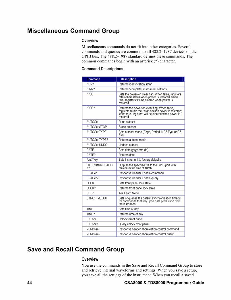
44 CSA8000 & TDS8000 Programmer Guide
Miscellaneous Command Group
Overview
Miscellaneous commands do not fit into other categories. Several
commands and queries are common to all 488.2–1987 devices on the
GPIB bus. The 488.2–1987 standard defines these commands. The
common commands begin with an asterisk (*) character.
Command Descriptions
Command Description
*IDN? Returns identification string
*LRN? Returns "complete" instrument settings
*PSC Sets the power-on clear flag. When false, registers retain their status when power is restored; when true, registers will be cleared when power is restored
*PSC? Returns the power-on clear flag. When false, registers retain their status when power is restored; when true, registers will be cleared when power is restored
AUTOSet Runs autoset
AUTOSet:STOP Stops autoset
AUTOSet:TYPE Sets autoset mode (Edge, Period, NRZ Eye, or RZ Eye)
AUTOSet:TYPE? Returns autoset mode
AUTOSet:UNDO Undoes autoset
DATE Sets date (yyyy-mm-dd)
DATE? Returns date
FACTory Sets instrument to factory defaults.
FILESystem:READFile?
Outputs the specified file to the GPIB port with maximum file size of 10Mb
HEADer Response Header Enable command
HEADer? Response Header Enable query
LOCK Sets front panel lock state
LOCK? Returns front panel lock state
SET? Tek Learn Mode
SYNC:TIMEOUT Sets or queries the default synchronization timeout for commands that rely upon data production from the instrument
TIME Sets time of day
TIME? Returns rime of day
UNLock Unlocks front panel
UNLock? Query unlock front panel
VERBose Response header abbreviation control command
VERBose? Response header abbreviation control query
Save and Recall Command Group
Overview
You use the commands in the Save and Recall Command Group to store
and retrieve internal waveforms and settings. When you save a setup,
you save all the settings of the instrument. When you recall a saved
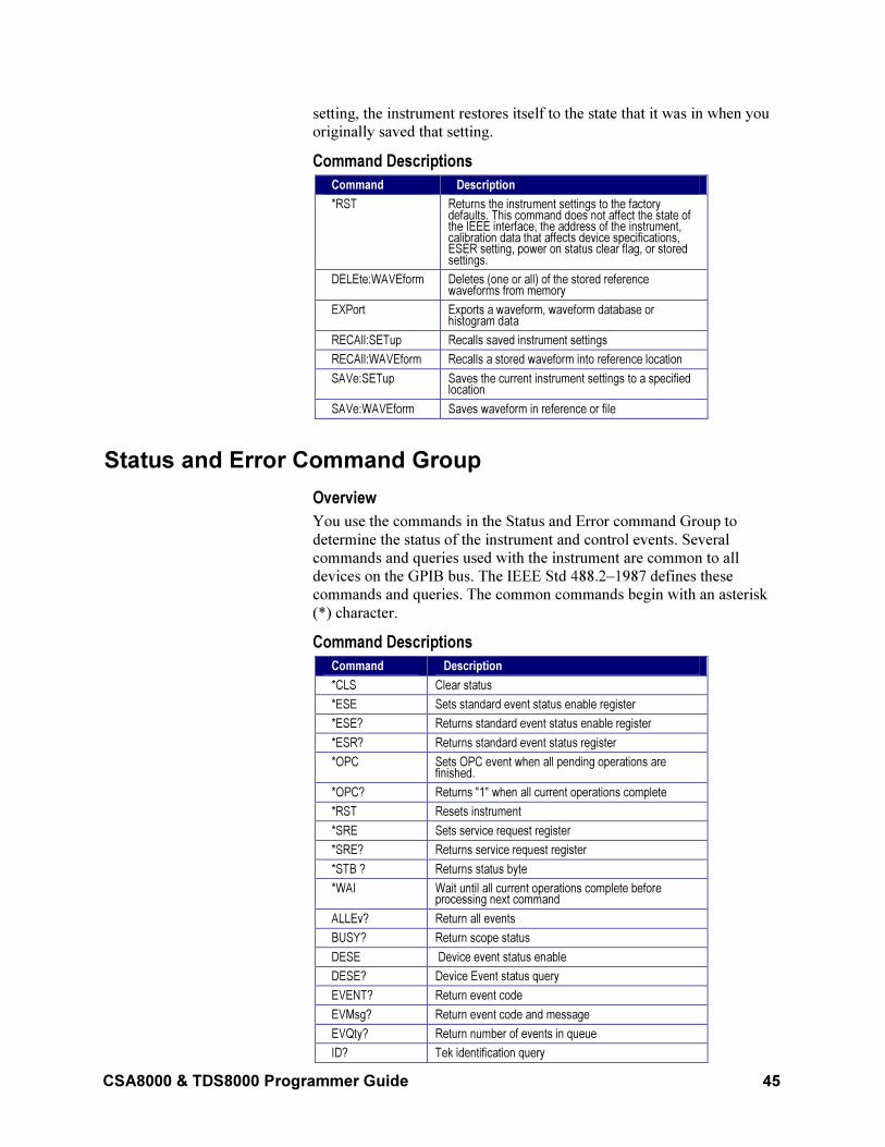
CSA8000 & TDS8000 Programmer Guide 45
setting, the instrument restores itself to the state that it was in when you
originally saved that setting.
Command Descriptions
Command Description
*RST Returns the instrument settings to the factory defaults. This command does not affect the state of the IEEE interface, the address of the instrument, calibration data that affects device specifications, ESER setting, power on status clear flag, or stored settings.
DELEte:WAVEform Deletes (one or all) of the stored reference waveforms from memory
EXPort Exports a waveform, waveform database or histogram data
RECAll:SETup Recalls saved instrument settings
RECAll:WAVEform Recalls a stored waveform into reference location
SAVe:SETup Saves the current instrument settings to a specified location
SAVe:WAVEform Saves waveform in reference or file
Status and Error Command Group
Overview
You use the commands in the Status and Error command Group to
determine the status of the instrument and control events. Several
commands and queries used with the instrument are common to all
devices on the GPIB bus. The IEEE Std 488.2–1987 defines these
commands and queries. The common commands begin with an asterisk
(*) character.
Command Descriptions
Command Description
*CLS Clear status
*ESE Sets standard event status enable register
*ESE? Returns standard event status enable register
*ESR? Returns standard event status register
*OPC Sets OPC event when all pending operations are finished.
*OPC? Returns "1" when all current operations complete
*RST Resets instrument
*SRE Sets service request register
*SRE? Returns service request register
*STB ? Returns status byte
*WAI Wait until all current operations complete before processing next command
ALLEv? Return all events
BUSY? Return scope status
DESE Device event status enable
DESE? Device Event status query
EVENT? Return event code
EVMsg? Return event code and message
EVQty? Return number of events in queue
ID? Tek identification query
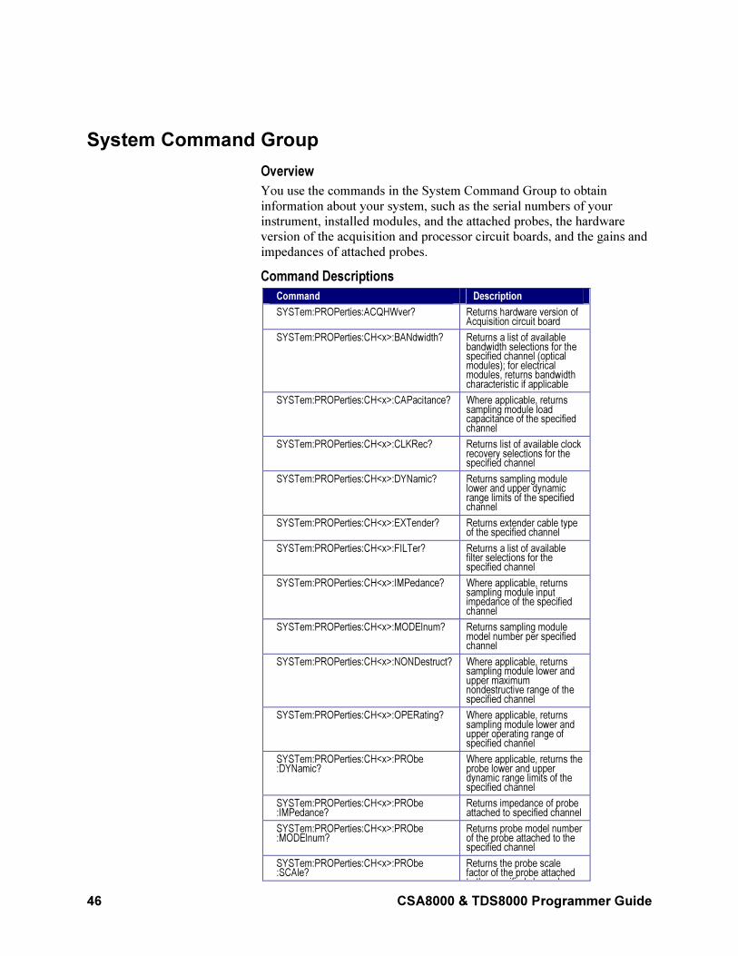
46 CSA8000 & TDS8000 Programmer Guide
System Command Group
Overview
You use the commands in the System Command Group to obtain
information about your system, such as the serial numbers of your
instrument, installed modules, and the attached probes, the hardware
version of the acquisition and processor circuit boards, and the gains and
impedances of attached probes.
Command Descriptions
Command Description
SYSTem:PROPerties:ACQHWver? Returns hardware version of Acquisition circuit board
SYSTem:PROPerties:CH<x>:BANdwidth? Returns a list of available bandwidth selections for the specified channel (optical modules); for electrical modules, returns bandwidth characteristic if applicable
SYSTem:PROPerties:CH<x>:CAPacitance? Where applicable, returns sampling module load capacitance of the specified channel
SYSTem:PROPerties:CH<x>:CLKRec? Returns list of available clock recovery selections for the specified channel
SYSTem:PROPerties:CH<x>:DYNamic? Returns sampling module lower and upper dynamic range limits of the specified channel
SYSTem:PROPerties:CH<x>:EXTender? Returns extender cable type of the specified channel
SYSTem:PROPerties:CH<x>:FILTer? Returns a list of available filter selections for the specified channel
SYSTem:PROPerties:CH<x>:IMPedance? Where applicable, returns sampling module input impedance of the specified channel
SYSTem:PROPerties:CH<x>:MODElnum? Returns sampling module model number per specified channel
SYSTem:PROPerties:CH<x>:NONDestruct? Where applicable, returns sampling module lower and upper maximum nondestructive range of the specified channel
SYSTem:PROPerties:CH<x>:OPERating? Where applicable, returns sampling module lower and upper operating range of specified channel
SYSTem:PROPerties:CH<x>:PRObe :DYNamic?
Where applicable, returns the probe lower and upper dynamic range limits of the specified channel
SYSTem:PROPerties:CH<x>:PRObe :IMPedance?
Returns impedance of probe attached to specified channel
SYSTem:PROPerties:CH<x>:PRObe :MODElnum?
Returns probe model number of the probe attached to the specified channel
SYSTem:PROPerties:CH<x>:PRObe :SCAle?
Returns the probe scale factor of the probe attached to the specified channel
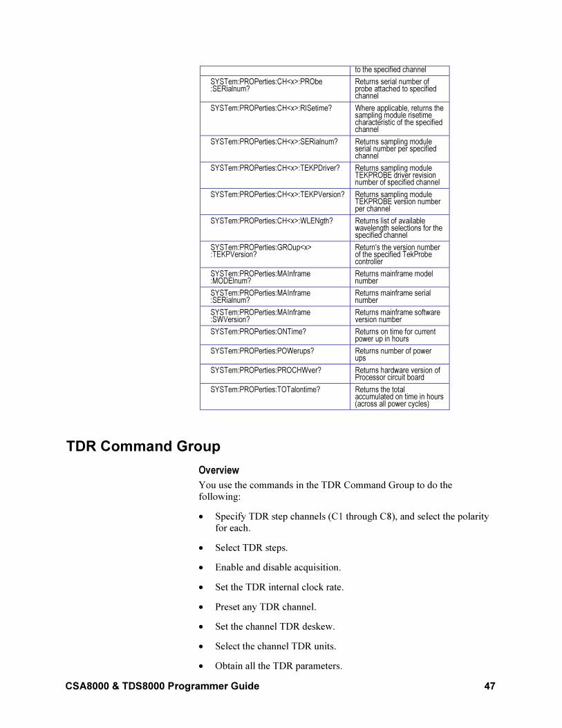
CSA8000 & TDS8000 Programmer Guide 47
to the specified channel
SYSTem:PROPerties:CH<x>:PRObe :SERialnum?
Returns serial number of probe attached to specified channel
SYSTem:PROPerties:CH<x>:RISetime? Where applicable, returns the sampling module risetime characteristic of the specified channel
SYSTem:PROPerties:CH<x>:SERialnum? Returns sampling module serial number per specified channel
SYSTem:PROPerties:CH<x>:TEKPDriver? Returns sampling module TEKPROBE driver revision number of specified channel
SYSTem:PROPerties:CH<x>:TEKPVersion? Returns sampling module TEKPROBE version number per channel
SYSTem:PROPerties:CH<x>:WLENgth? Returns list of available wavelength selections for the specified channel
SYSTem:PROPerties:GROup<x> :TEKPVersion?
Return's the version number of the specified TekProbe controller
SYSTem:PROPerties:MAInframe :MODElnum?
Returns mainframe model number
SYSTem:PROPerties:MAInframe :SERialnum?
Returns mainframe serial number
SYSTem:PROPerties:MAInframe :SWVersion?
Returns mainframe software version number
SYSTem:PROPerties:ONTime? Returns on time for current power up in hours
SYSTem:PROPerties:POWerups? Returns number of power ups
SYSTem:PROPerties:PROCHWver? Returns hardware version of Processor circuit board
SYSTem:PROPerties:TOTalontime? Returns the total accumulated on time in hours (across all power cycles)
TDR Command Group
Overview
You use the commands in the TDR Command Group to do the
following:
• Specify TDR step channels (C1 through C8), and select the polarity
for each.
• Select TDR steps.
• Enable and disable acquisition.
• Set the TDR internal clock rate.
• Preset any TDR channel.
• Set the channel TDR deskew.
• Select the channel TDR units.
• Obtain all the TDR parameters.
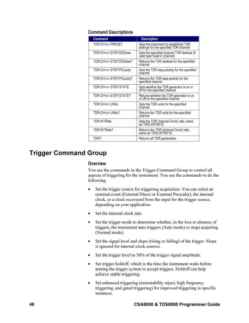
48 CSA8000 & TDS8000 Programmer Guide
Command Descriptions
Command Description
TDR:CH<x>:PRESET Sets the instrument to predefined TDR settings for the specified TDR channel
TDR:CH<x>:STEP:DESkew Sets the specified channel TDR deskew (if valid type head in channel)
TDR:CH<x>:STEP:DESkew? Returns the TDR deskew for the specified channel
TDR:CH<x>:STEP:POLarity Sets the TDR step polarity for the specified channel
TDR:CH<x>:STEP:POLarity? Returns the TDR step polarity for the specified channel
TDR:CH<x>:STEP:STATE Sets whether the TDR generator is on or off for the specified channel
TDR:CH<x>:STEP:STATE? Returns whether the TDR generator is on or off for the specified channel
TDR:CH<x>:UNIts Sets the TDR units for the specified channel
TDR:CH<x>:UNIts? Returns the TDR units for the specified channel
TDR:INTRate Sets the TDR (Internal Clock) rate; same as TRIG:INTRATE
TDR:INTRate? Returns the TDR (Internal Clock) rate; same as TRIG:INTRATE
TDR? Returns all TDR parameters
Trigger Command Group
Overview
You use the commands in the Trigger Command Group to control all
aspects of triggering for the instrument. You use the commands to do the
following:
• Set the trigger source for triggering acquisition. You can select an
external event (External Direct or External Prescaler), the internal
clock, or a clock recovered from the input for the trigger source,
depending on your application.
• Set the internal clock rate.
• Set the trigger mode to determine whether, in the loss or absence of
triggers, the instrument auto triggers (Auto mode) or stops acquiring
(Normal mode).
• Set the signal level and slope (rising or falling) of the trigger. Slope
is ignored for internal clock sources.
• Set the trigger level to 50% of the trigger signal amplitude.
• Set trigger holdoff, which is the time the instrument waits before
arming the trigger system to accept triggers. Holdoff can help
achieve stable triggering.
• Set enhanced triggering (metastability reject, high frequency
triggering, and gated triggering) for improved triggering in specific
instances.
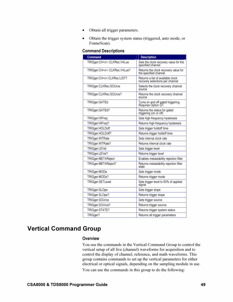
CSA8000 & TDS8000 Programmer Guide 49
• Obtain all trigger parameters.
• Obtain the trigger system status (triggered, auto mode, or
FrameScan).
Command Descriptions
Command Description
TRIGger:CH<x>::CLKRec:VALue Sets the clock recovery value for the specified channel
TRIGger:CH<x>::CLKRec:VALue? Returns the clock recovery value for the specified channel
TRIGger:CH<x>:CLKRec:LIST? Returns a list of available clock recovery selections per channel
TRIGger:CLKRec:SOUrce Selects the clock recovery channel source
TRIGger:CLKRec:SOUrce? Returns the clock recovery channel source
TRIGger:GATEd Turns on and off gated triggering. Requires Option GT.
TRIGger:GATEd? Returns the status for gated triggering (on or off)
TRIGger:HIFreq Sets high-frequency hysteresis
TRIGger:HIFreq? Returns high-frequency hysteresis
TRIGger:HOLDoff Sets trigger holdoff time
TRIGger:HOLDoff? Returns trigger holdoff time
TRIGger:INTRate Sets internal clock rate
TRIGger:INTRate? Returns internal clock rate
TRIGger:LEVel Sets trigger level
TRIGger:LEVel? Returns trigger level
TRIGger:METAReject Enables metastability rejection filter
TRIGger:METAReject? Returns metastability rejection filter state
TRIGger:MODe Sets trigger mode
TRIGger:MODe? Returns trigger mode
TRIGger:SETLevel Sets trigger level to 50% of applied signal
TRIGger:SLOpe Sets trigger slope
TRIGger:SLOpe? Returns trigger slope
TRIGger:SOUrce Sets trigger source
TRIGger:SOUrce? Returns trigger source
TRIGger:STATE? Returns trigger system status
TRIGger? Returns all trigger parameters
Vertical Command Group
Overview
You use the commands in the Vertical Command Group to control the
vertical setup of all live (channel) waveforms for acquisition and to
control the display of channel, reference, and math waveforms. This
group contains commands to set up the vertical parameters for either
electrical or optical signals, depending on the sampling module in use.
You can use the commands in this group to do the following:
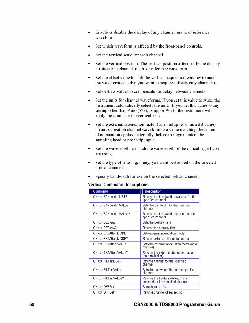
50 CSA8000 & TDS8000 Programmer Guide
• Enable or disable the display of any channel, math, or reference
waveform.
• Set which waveform is affected by the front-panel controls.
• Set the vertical scale for each channel.
• Set the vertical position. The vertical position affects only the display
position of a channel, math, or reference waveform.
• Set the offset value to shift the vertical acquisition window to match
the waveform data that you want to acquire (affects only channels).
• Set deskew values to compensate for delay between channels.
• Set the units for channel waveforms. If you set this value to Auto, the
instrument automatically selects the units. If you set this value to any
setting other than Auto (Volt, Amp, or Watt), the instrument will
apply these units to the vertical axis.
• Set the external attenuation factor (as a multiplier or as a dB value)
on an acquisition channel waveform to a value matching the amount
of attenuation applied externally, before the signal enters the
sampling head or probe tip input.
• Set the wavelength to match the wavelength of the optical signal you
are using.
• Set the type of filtering, if any, you want performed on the selected
optical channel.
• Specify bandwidth for use on the selected optical channel.
Vertical Command Descriptions
Command Description
CH<x>:BANdwidth:LIST? Returns the bandwidths available for the specified channel
CH<x>:BANdwidth:VALue Sets the bandwidth for the specified channel
CH<x>:BANdwidth:VALue? Returns the bandwidth selection for the specified channel
CH<x>:DESkew Sets the deskew time
CH<x>:DESkew? Returns the deskew time
CH<x>:EXTAtten:MODE Sets external attenuation mode
CH<x>:EXTAtten:MODE? Returns external attenuation mode
CH<x>:EXTAtten:VALue Sets the external attenuation factor (as a multiple)
CH<x>:EXTAtten:VALue? Returns the external attenuation factor (as a multiplier)
CH<x>:FILTer:LIST? Returns filter list for the specified channel
CH<x>:FILTer:VALue Sets the hardware filter for the specified channel
CH<x>:FILTer:VALue? Returns the hardware filter, if any, selected for the specified channel
CH<x>:OFFSet Sets channel offset
CH<x>:OFFSet? Returns channel offset setting
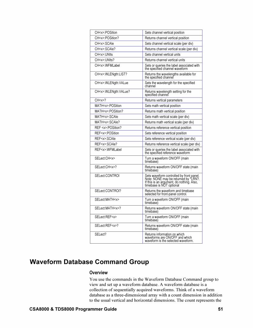
CSA8000 & TDS8000 Programmer Guide 51
CH<x>:POSition Sets channel vertical position
CH<x>:POSition? Returns channel vertical position
CH<x>:SCAle Sets channel vertical scale (per div)
CH<x>:SCAle? Returns channel vertical scale (per div)
CH<x>:UNIts Sets channel vertical units
CH<x>:UNIts? Returns channel vertical units
CH<x>:WFMLabel Sets or queries the label associated with the specified channel waveform
CH<x>:WLENgth:LIST? Returns the wavelengths available for the specified channel
CH<x>:WLENgth:VALue Sets the wavelength for the specified channel
CH<x>:WLENgth:VALue? Returns wavelength setting for the specified channel
CH<x>? Returns vertical parameters
MATH<x>:POSition Sets math vertical position
MATH<x>:POSition? Returns math vertical position
MATH<x>:SCAle Sets math vertical scale (per div)
MATH<x>:SCAle? Returns math vertical scale (per div)
REF <x>:POSition? Returns reference vertical position
REF<x>:POSition Sets reference vertical position
REF<x>:SCAle Sets reference vertical scale (per div)
REF<x>:SCAle? Returns reference vertical scale (per div)
REF<x>:WFMLabel Sets or queries the label associated with the specified reference waveform
SELect:CH<x> Turn a waveform ON/OFF (main timebase)
SELect:CH<x>? Returns waveform ON/OFF state (main timebase)
SELect:CONTROl Sets waveform controlled by front panel. Note: NONE may be returned by *LRN?. If this is an argument, do nothing. Also, timebase is NOT optional
SELect:CONTROl? Returns the waveform and timebase selected for front-panel control.
SELect:MATH<x> Turn a waveform ON/OFF (main timebase)
SELect:MATH<x>? Returns waveform ON/OFF state (main timebase)
SELect:REF<x> Turn a waveform ON/OFF (main timebase)
SELect:REF<x>? Returns waveform ON/OFF state (main timebase)
SELect? Returns information on which waveforms are ON/OFF and which waveform is the selected waveform.
Waveform Database Command Group
Overview
You use the commands in the Waveform Database Command group to
view and set up a waveform database. A waveform database is a
collection of sequentially acquired waveforms. Think of a waveform
database as a three-dimensional array with a count dimension in addition
to the usual vertical and horizontal dimensions. The count represents the
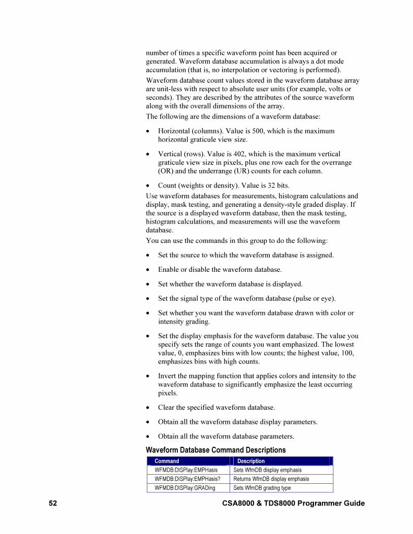
52 CSA8000 & TDS8000 Programmer Guide
number of times a specific waveform point has been acquired or
generated. Waveform database accumulation is always a dot mode
accumulation (that is, no interpolation or vectoring is performed).
Waveform database count values stored in the waveform database array
are unit-less with respect to absolute user units (for example, volts or
seconds). They are described by the attributes of the source waveform
along with the overall dimensions of the array.
The following are the dimensions of a waveform database:
• Horizontal (columns). Value is 500, which is the maximum
horizontal graticule view size.
• Vertical (rows). Value is 402, which is the maximum vertical
graticule view size in pixels, plus one row each for the overrange
(OR) and the underrange (UR) counts for each column.
• Count (weights or density). Value is 32 bits.
Use waveform databases for measurements, histogram calculations and
display, mask testing, and generating a density-style graded display. If
the source is a displayed waveform database, then the mask testing,
histogram calculations, and measurements will use the waveform
database.
You can use the commands in this group to do the following:
• Set the source to which the waveform database is assigned.
• Enable or disable the waveform database.
• Set whether the waveform database is displayed.
• Set the signal type of the waveform database (pulse or eye).
• Set whether you want the waveform database drawn with color or
intensity grading.
• Set the display emphasis for the waveform database. The value you
specify sets the range of counts you want emphasized. The lowest
value, 0, emphasizes bins with low counts; the highest value, 100,
emphasizes bins with high counts.
• Invert the mapping function that applies colors and intensity to the
waveform database to significantly emphasize the least occurring
pixels.
• Clear the specified waveform database.
• Obtain all the waveform database display parameters.
• Obtain all the waveform database parameters.
Waveform Database Command Descriptions
Command Description
WFMDB:DISPlay:EMPHasis Sets WfmDB display emphasis
WFMDB:DISPlay:EMPHasis? Returns WfmDB display emphasis
WFMDB:DISPlay:GRADing Sets WfmDB grading type
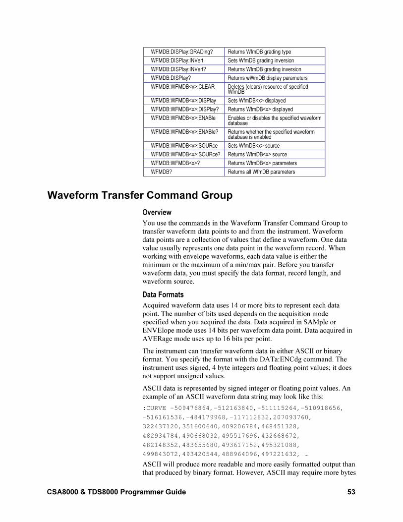
CSA8000 & TDS8000 Programmer Guide 53
WFMDB:DISPlay:GRADing? Returns WfmDB grading type
WFMDB:DISPlay:INVert Sets WfmDB grading inversion
WFMDB:DISPlay:INVert? Returns WfmDB grading inversion
WFMDB:DISPlay? Returns wWmDB display parameters
WFMDB:WFMDB<x>:CLEAR Deletes (clears) resource of specified WfmDB
WFMDB:WFMDB<x>:DISPlay Sets WfmDB<x> displayed
WFMDB:WFMDB<x>:DISPlay? Returns WfmDB<x> displayed
WFMDB:WFMDB<x>:ENABle Enables or disables the specified waveform database
WFMDB:WFMDB<x>:ENABle? Returns whether the specified waveform database is enabled
WFMDB:WFMDB<x>:SOURce Sets WfmDB<x> source
WFMDB:WFMDB<x>:SOURce? Returns WfmDB<x> source
WFMDB:WFMDB<x>? Returns WfmDB<x> parameters
WFMDB? Returns all WfmDB parameters
Waveform Transfer Command Group
Overview
You use the commands in the Waveform Transfer Command Group to
transfer waveform data points to and from the instrument. Waveform
data points are a collection of values that define a waveform. One data
value usually represents one data point in the waveform record. When
working with envelope waveforms, each data value is either the
minimum or the maximum of a min/max pair. Before you transfer
waveform data, you must specify the data format, record length, and
waveform source.
Data Formats
Acquired waveform data uses 14 or more bits to represent each data
point. The number of bits used depends on the acquisition mode
specified when you acquired the data. Data acquired in SAMple or
ENVElope mode uses 14 bits per waveform data point. Data acquired in
AVERage mode uses up to 16 bits per point.
The instrument can transfer waveform data in either ASCII or binary
format. You specify the format with the DATa:ENCdg command. The
instrument uses signed, 4 byte integers and floating point values; it does
not support unsigned values.
ASCII data is represented by signed integer or floating point values. An
example of an ASCII waveform data string may look like this:
:CURVE -509476864,-512163840,-511115264,-510918656,
-516161536,-484179968,-117112832,207093760,
322437120,351600640,409206784,468451328,
482934784,490668032,495517696,432668672,
482148352,483655680,493617152,495321088,
499843072,493420544,488964096,497221632, …
ASCII will produce more readable and more easily formatted output than
that produced by binary format. However, ASCII may require more bytes
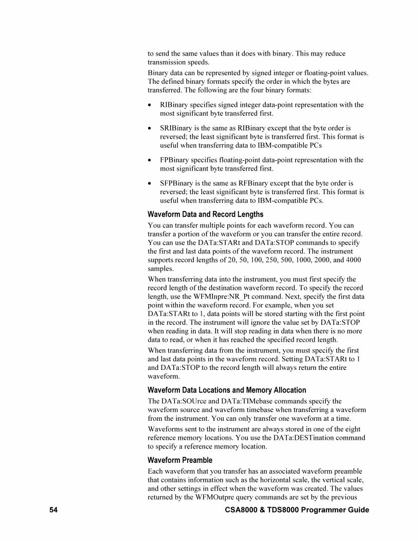
54 CSA8000 & TDS8000 Programmer Guide
to send the same values than it does with binary. This may reduce
transmission speeds.
Binary data can be represented by signed integer or floating-point values.
The defined binary formats specify the order in which the bytes are
transferred. The following are the four binary formats:
• RIBinary specifies signed integer data-point representation with the
most significant byte transferred first.
• SRIBinary is the same as RIBinary except that the byte order is
reversed; the least significant byte is transferred first. This format is
useful when transferring data to IBM-compatible PCs
• FPBinary specifies floating-point data-point representation with the
most significant byte transferred first.
• SFPBinary is the same as RFBinary except that the byte order is
reversed; the least significant byte is transferred first. This format is
useful when transferring data to IBM-compatible PCs.
Waveform Data and Record Lengths
You can transfer multiple points for each waveform record. You can
transfer a portion of the waveform or you can transfer the entire record.
You can use the DATa:STARt and DATa:STOP commands to specify
the first and last data points of the waveform record. The instrument
supports record lengths of 20, 50, 100, 250, 500, 1000, 2000, and 4000
samples.
When transferring data into the instrument, you must first specify the
record length of the destination waveform record. To specify the record
length, use the WFMInpre:NR_Pt command. Next, specify the first data
point within the waveform record. For example, when you set
DATa:STARt to 1, data points will be stored starting with the first point
in the record. The instrument will ignore the value set by DATa:STOP
when reading in data. It will stop reading in data when there is no more
data to read, or when it has reached the specified record length.
When transferring data from the instrument, you must specify the first
and last data points in the waveform record. Setting DATa:STARt to 1
and DATa:STOP to the record length will always return the entire
waveform.
Waveform Data Locations and Memory Allocation
The DATa:SOUrce and DATa:TIMebase commands specify the
waveform source and waveform timebase when transferring a waveform
from the instrument. You can only transfer one waveform at a time.
Waveforms sent to the instrument are always stored in one of the eight
reference memory locations. You use the DATa:DESTination command
to specify a reference memory location.
Waveform Preamble
Each waveform that you transfer has an associated waveform preamble
that contains information such as the horizontal scale, the vertical scale,
and other settings in effect when the waveform was created. The values
returned by the WFMOutpre query commands are set by the previous
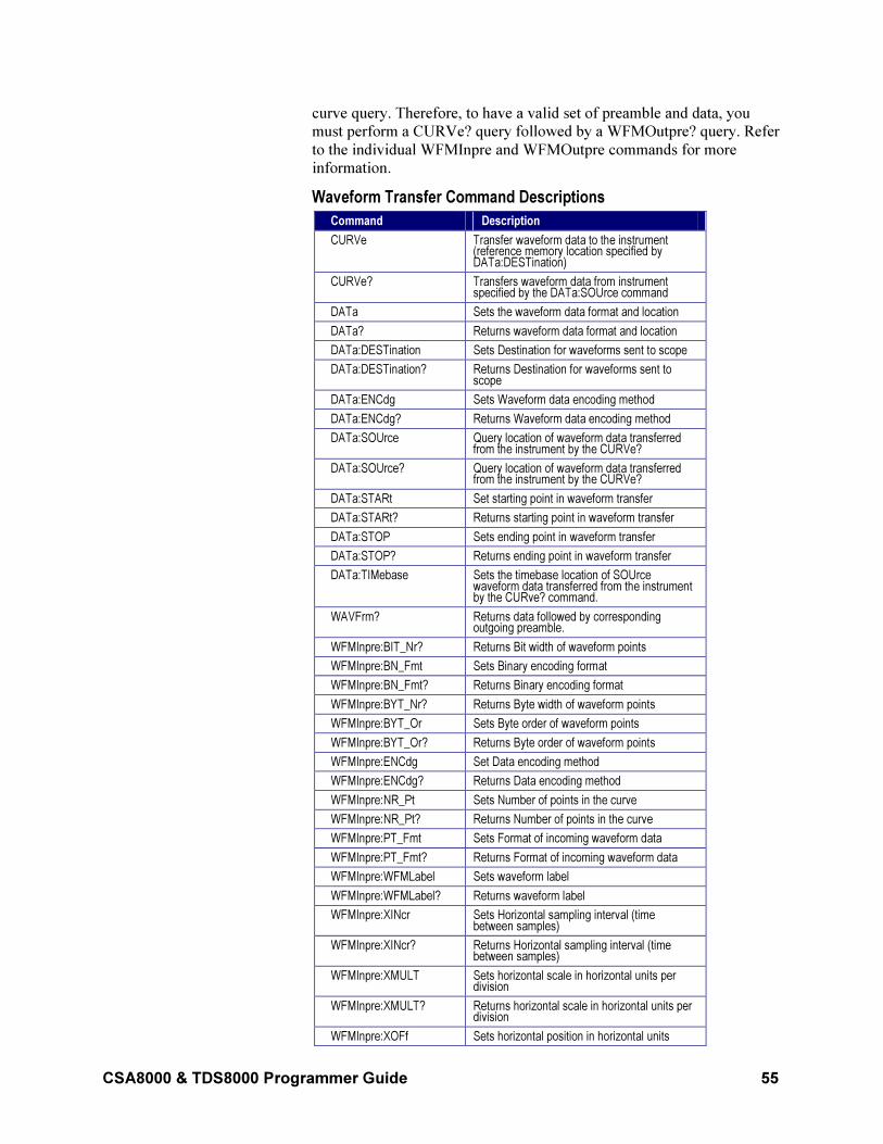
CSA8000 & TDS8000 Programmer Guide 55
curve query. Therefore, to have a valid set of preamble and data, you
must perform a CURVe? query followed by a WFMOutpre? query. Refer
to the individual WFMInpre and WFMOutpre commands for more
information.
Waveform Transfer Command Descriptions
Command Description
CURVe Transfer waveform data to the instrument (reference memory location specified by DATa:DESTination)
CURVe? Transfers waveform data from instrument specified by the DATa:SOUrce command
DATa Sets the waveform data format and location
DATa? Returns waveform data format and location
DATa:DESTination Sets Destination for waveforms sent to scope
DATa:DESTination? Returns Destination for waveforms sent to scope
DATa:ENCdg Sets Waveform data encoding method
DATa:ENCdg? Returns Waveform data encoding method
DATa:SOUrce Query location of waveform data transferred from the instrument by the CURVe?
DATa:SOUrce? Query location of waveform data transferred from the instrument by the CURVe?
DATa:STARt Set starting point in waveform transfer
DATa:STARt? Returns starting point in waveform transfer
DATa:STOP Sets ending point in waveform transfer
DATa:STOP? Returns ending point in waveform transfer
DATa:TIMebase Sets the timebase location of SOUrce waveform data transferred from the instrument by the CURve? command.
WAVFrm? Returns data followed by corresponding outgoing preamble.
WFMInpre:BIT_Nr? Returns Bit width of waveform points
WFMInpre:BN_Fmt Sets Binary encoding format
WFMInpre:BN_Fmt? Returns Binary encoding format
WFMInpre:BYT_Nr? Returns Byte width of waveform points
WFMInpre:BYT_Or Sets Byte order of waveform points
WFMInpre:BYT_Or? Returns Byte order of waveform points
WFMInpre:ENCdg Set Data encoding method
WFMInpre:ENCdg? Returns Data encoding method
WFMInpre:NR_Pt Sets Number of points in the curve
WFMInpre:NR_Pt? Returns Number of points in the curve
WFMInpre:PT_Fmt Sets Format of incoming waveform data
WFMInpre:PT_Fmt? Returns Format of incoming waveform data
WFMInpre:WFMLabel Sets waveform label
WFMInpre:WFMLabel? Returns waveform label
WFMInpre:XINcr Sets Horizontal sampling interval (time between samples)
WFMInpre:XINcr? Returns Horizontal sampling interval (time between samples)
WFMInpre:XMULT Sets horizontal scale in horizontal units per division
WFMInpre:XMULT? Returns horizontal scale in horizontal units per division
WFMInpre:XOFf Sets horizontal position in horizontal units
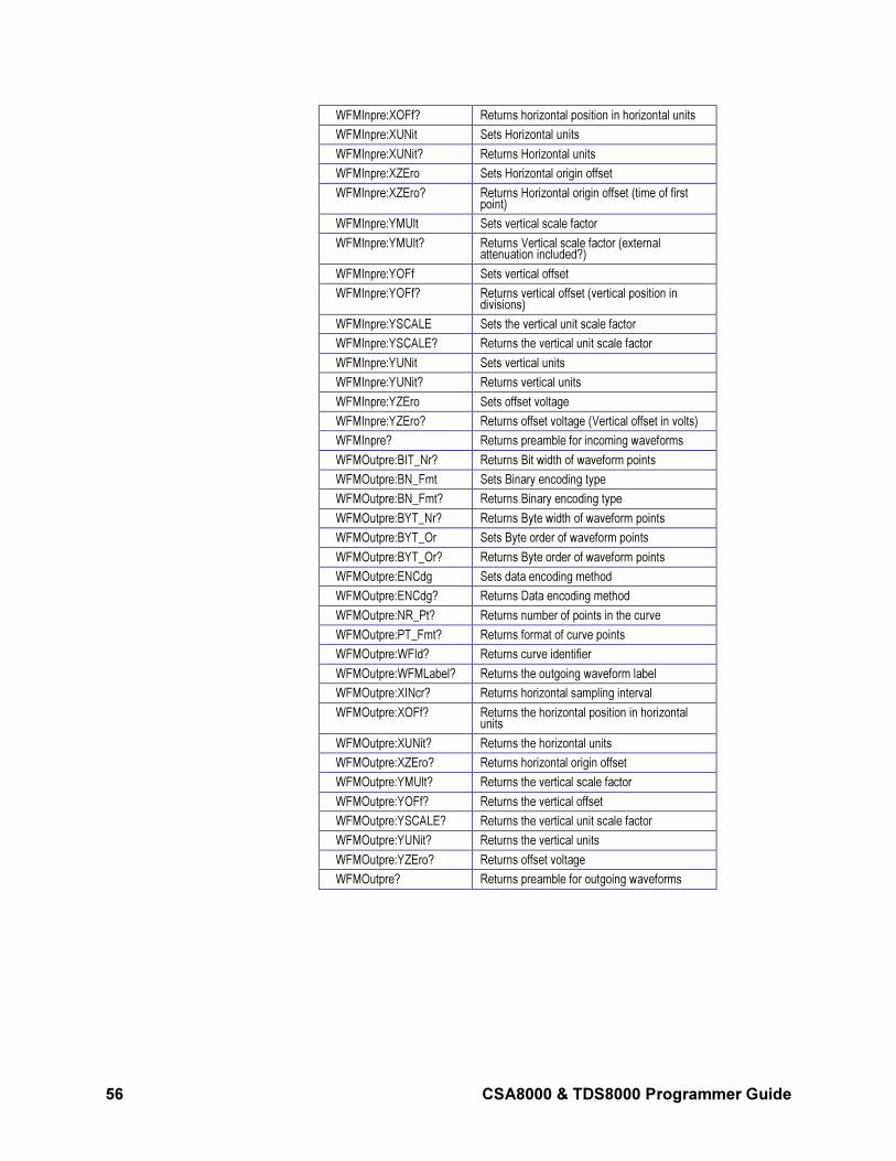
56 CSA8000 & TDS8000 Programmer Guide
WFMInpre:XOFf? Returns horizontal position in horizontal units
WFMInpre:XUNit Sets Horizontal units
WFMInpre:XUNit? Returns Horizontal units
WFMInpre:XZEro Sets Horizontal origin offset
WFMInpre:XZEro? Returns Horizontal origin offset (time of first point)
WFMInpre:YMUlt Sets vertical scale factor
WFMInpre:YMUlt? Returns Vertical scale factor (external attenuation included?)
WFMInpre:YOFf Sets vertical offset
WFMInpre:YOFf? Returns vertical offset (vertical position in divisions)
WFMInpre:YSCALE Sets the vertical unit scale factor
WFMInpre:YSCALE? Returns the vertical unit scale factor
WFMInpre:YUNit Sets vertical units
WFMInpre:YUNit? Returns vertical units
WFMInpre:YZEro Sets offset voltage
WFMInpre:YZEro? Returns offset voltage (Vertical offset in volts)
WFMInpre? Returns preamble for incoming waveforms
WFMOutpre:BIT_Nr? Returns Bit width of waveform points
WFMOutpre:BN_Fmt Sets Binary encoding type
WFMOutpre:BN_Fmt? Returns Binary encoding type
WFMOutpre:BYT_Nr? Returns Byte width of waveform points
WFMOutpre:BYT_Or Sets Byte order of waveform points
WFMOutpre:BYT_Or? Returns Byte order of waveform points
WFMOutpre:ENCdg Sets data encoding method
WFMOutpre:ENCdg? Returns Data encoding method
WFMOutpre:NR_Pt? Returns number of points in the curve
WFMOutpre:PT_Fmt? Returns format of curve points
WFMOutpre:WFId? Returns curve identifier
WFMOutpre:WFMLabel? Returns the outgoing waveform label
WFMOutpre:XINcr? Returns horizontal sampling interval
WFMOutpre:XOFf? Returns the horizontal position in horizontal units
WFMOutpre:XUNit? Returns the horizontal units
WFMOutpre:XZEro? Returns horizontal origin offset
WFMOutpre:YMUlt? Returns the vertical scale factor
WFMOutpre:YOFf? Returns the vertical offset
WFMOutpre:YSCALE? Returns the vertical unit scale factor
WFMOutpre:YUNit? Returns the vertical units
WFMOutpre:YZEro? Returns offset voltage
WFMOutpre? Returns preamble for outgoing waveforms
CSA8000 & TDS8000 Programmer Guide 57
Commands
This section lists commands and queries alphabetically and describes
them and their arguments.
*CLS
This command (no query form) clears the following status data structures
of the instrument:
• Event Queue
• Standard Event Status Register (SESR)
• Status Byte Register (except the MAV bit; see below)
If the *CLS command immediately follows an <EOI>, the Output Queue
and MAV bit (Status Byte Register bit 4) are also cleared. MAV
indicates information is in the output queue. The device clear (DCL)
GPIB control message will clear the output queue and thus MAV. *CLS
does not clear the output queue or MAV. (For more information about
these registers and bits, and of event handling in general, see the Status
and Events Overview, on page 337, and its subtopics.)
*CLS can suppress a service request that is to be generated by an *OPC.
This will happen if a hardcopy output or single sequence acquisition
operation is still being processed when the *CLS command is executed.
Group
Status and Error
Related Commands
DESE, *ESE, *ESR?, EVENT?, EVMsg?, *SRE, *STB?
Syntax *CLS
*ESE
This command sets or queries the bits in the Event Status Enable
Register (ESER). The ESER prevents events from being reported to the
Status Byte Register (SBR). For a more detailed discussion of the use of
these registers, see Registers on page 337.
Group
Status and Error
Related Commands
*CLS, DESE, *ESR?, EVENT?, EVMsg?, *SRE, *STB?
Syntax 1 *ESE <NR1>
Syntax 2 *ESE?
58 CSA8000 & TDS8000 Programmer Guide
Argument NR1
This is a value in the range from 0 through 255. The binary bits of the
ESER are set according to this value.
The power-on default for ESER is 0 if *PSC is 1. If *PSC is 0, the ESER
maintains its value through a power cycle.
Note: Setting the DESER and the ESER to the same value allows only
those codes to be entered into the Event Queue and summarized on the
ESB bit (bit 5) of the Status Byte Register. Use the DESE command to set
the DESER. See Event Handling Sequence on page 341 for a discussion
of event handling.
Example 1 *ESE 209
Sets the ESER to binary 11010001, which enables the PON, URQ, EXE,
and OPC bits.
Example 2 *ESE?
This query might return the string *ESE 186, indicating that the ESER
contains the binary value 10111010.
*ESR?
This is a query only command that returns the contents of the Standard
Event Status Register (SESR). This query also clears the SESR, since
reading the SESR clears it. For a more detailed discussion of the use of
these registers, see Registers on page 337.
Group
Status and Error
Related Commands
ALLEv?, *CLS, DESE, *ESE, EVENT?, EVMsg?, *SRE, *STB?
Syntax *ESR?
Example *ESR?
This query might return the value 213, showing that the SESR contains
binary 11010101.
*IDN?
This is a query only command that returns the instrument identification
code.
Group
Miscellaneous
CSA8000 & TDS8000 Programmer Guide 59
Related Commands
ID?
Syntax *IDN?
Returns
The instrument ID in the following format:
TEKTRONIX,<model number>,0,CF:92.1CT FV:<firmware version number>
Example
*IDN?
This query might return the response TEKTRONIX,TDS8000,0,CF:91.1CT FV:1.0.444.
*LRN?
This query only command returns a string listing the instrument settings,
except for configuration information for the calibration values. You can
use this string to return the instrument to the state it was in when you
made the *LRN? query. This command is identical to the SET? query.
Group
Miscellaneous
Related Commands
HEADer, SET?, VERBose
Syntax *LRN?
Note: The *LRN? query always returns a string including command
headers, regardless of the setting of the HEADer command. This is
because the returned string is intended to be sent back to the instrument
as a command string. The VERBose command can still be used normally
to specify whether the returned headers should be abbreviated.
Example *LRN?
A partial response to this query might be the following:
:ACQUIRE:STATE 1;MODE SAMPLE;NUMENV 10;NUMAVG 16;REPET 1;STOPAFTER RUNSTOP;:DIAG:LOOP:OPTION ONCE;COUNT 1;:DIAG:STATE HALT;:HEADER 1;:VERBOSE 1;:CURSOR:FUNCTION OFF;VBARS:UNITS SECONDS;POSITION1 1.00E-6;POSITION2 9.00E-6;SELECT CURSOR1;
*OPC
This command generates the operation complete message in the Standard
Event Status Register (SESR) when all pending operations finish. The
*OPC? query places the ASCII character "1" into the output queue when
all pending operations are finished. The *OPC? response is not available
to read until all pending operations finish. For a complete discussion of
60 CSA8000 & TDS8000 Programmer Guide
the use of these registers and the output queue, see Registers, on page
337, and Queue on page 340.
The *OPC command allows you to synchronize the operation of the
instrument with your application program. For more information, see Synchronization Methods on page 342.
Commands that Generate an OPC Message
Operat ion Command
Automatic instrumentadjustment
AUTOSet EXECute
Internal self compensation COMPensate:ALLCOMPensate:CH<x>COMPensate:DARKLev:CH<x>COMPensate:MAInframeCOMPensate:OPTGAIN:CH<x>
Conditional ACQuire:STATE ON orACQuire:STATE RUN (whenACQuire:STOPAfter is set toCONDition)
Hardcopy output HARDCopy STARt
Group
Status and Error
Related Commands
BUSY?, *WAI
Syntax 1 *OPC
Syntax 2 *OPC?
This query returns 1 when all pending operations are finished.
*PSC
This command sets or queries the power-on status flag that controls the
automatic power-on handling of the DESER, SRER, and ESER registers.
When *PSC is true, the DESER register is set to 255 and the SRER and
ESER registers are set to 0 at power on. When *PSC is false, the current
values in the DESER, SRER, and ESER registers are retained in
nonvolatile memory when the instrument is powered off and are restored
when the instrument is powered on.
Group
Miscellaneous
Syntax 1 *PSC <NR1>
Syntax 2 *PSC?
CSA8000 & TDS8000 Programmer Guide 61
Argument NR1
When this argument is 0, the power-on status clear flag is set to false.
When the argument is not equal to 0, the power-on status clear flag is set
to true.
Example 1 *PSC 0
This command sets the power-on status flag to false, causing the values
in the DESER, SRER, and ESER registers to be retained in nonvolatile
memory when the instrument is powered off and restored when it is
powered on.
Example 2 *PSC?
This query might return the value 1, indicating that the power-on status
clear flag is set to true.
*RST
This command resets the instrument to the factory default settings. There
is no query form of this command.
The *RST command does not alter the following:
• The state of the IEEE Std 488.1-1987 interface
• The selected IEEE Std 488.1-1987 address of the instrument
• Calibration data that affect device specifications
• The Output Queue
• The Service Request Enable Register setting
• The Standard Event Status Enable Register setting
• The Power-on status clear flag setting
• Alias definitions
• Stored settings
• The *PUD? response
Group
Status and Error, Save and Recall
Related Commands
FACtory, RECAll:SETUp, SAVe:SETUp
Syntax *RST
This command returns the instrument settings to the factory defaults.
62 CSA8000 & TDS8000 Programmer Guide
*SRE
The *SRE (Service Request Enable) command sets and queries the bits
in the Service Request Enable Register (SRER). For more information,
refer to Registers.
Group
Status and Error
Related Commands
*CLS, DESE, *ESE, *ESR?, EVENT?, EVMSg?, FACtory, *STB?
Syntax 1 *SRE <NR1>
Syntax 2 *SRE?
Argument NR1
This is a value in the range from 0 to 255. The binary bits of the SRER
are set according to this value. Using an out-of-range value causes an
execution error. The power-on default for SRER is 0 if *PSC is 1. If
*PSC is 0, the SRER maintains its value throughout a power cycle.
Example 1 *SRE 48
Sets the bits in the SRER to 00110000 binary.
Example 2 *SRE?
This query might return a value of 32, showing that the bits in the SRER
have the binary value 00100000.
*STB?
The *STB? (Read Status Byte) query returns the contents of the Status
Byte Register (SBR) using the Master Summary Status (MSS) bit. For
more information, refer to Registers.
Group
Status and Error
Related Commands
*CLS, DESE, *ESE, *ESR?, EVENT?, EVMSg?, FACtory, *SRE
Syntax *STB?
Return Value
<NR1>
Example *STB?
CSA8000 & TDS8000 Programmer Guide 63
This query might return the value 96, showing that the SBR contains the
binary value 01100000.
*WAI
The *WAI (Wait) command (no query form) prevents the instrument
from executing further commands or queries until all pending operations
finish. This command allows you to synchronize the operation of the
instrument with your application program. For more information, refer to
Synchronization Methods.
Group
Status and Error
Related Commands
BUSY?, *OPC
Syntax *WAI
ACQuire:CURRentcount:ACQWfms?
This query only command returns the current count value of acquired
waveforms. The target value of this count is set by the
ACQuire:STOPAfter:COUNt command (in conjunction with the
ACQuire:STOPAfter:CONDition command). The instrument then counts
up to this value. When the count reaches (or exceeds) the value,
acquisition stops, and the specified StopAfter action is enabled.
Group
Acquisition
Related Commands
ACQuire:STOPAfter:COUNt, ACQuire:STOPAfter:CONDition
Syntax ACQuire:CURRentcount:ACQWfms?
Returns NR1
This is the current count value of acquired waveforms.
Example ACQuire:CURRentcount:ACQWfms?
This query might return :ACQUIRE:CURRENTCOUNT:ACQWFMS 20,
indicating that currently 20 waveforms have been acquired.
ACQuire:CURRentcount:HISTHits?
This query only command returns the current count value of histogram
hits. The target value of this count is set by the
ACQuire:STOPAfter:COUNt command (in conjunction with the
ACQuire:STOPAfter:CONDition command). The instrument then counts
64 CSA8000 & TDS8000 Programmer Guide
up to this value. When the count reaches (or exceeds) this value,
acquisition stops, and the specified StopAfter action is enabled.
Group
Acquisition
Related Commands
ACQuire:STOPAfter:COUNt, ACQuire:STOPAfter:CONDition
Syntax ACQuire:CURRentcount:HISTHits?
Returns NR1
This is the current count value of histogram hits.
Example ACQuire:CURRentcount:HISTHits?
This query might return :ACQUIRE:CURRENTCOUNT:HISTHITS
100, indicating that currently 100 histogram hits have been acquired.
ACQuire:CURRentcount:HISTWfms?
This query only command returns the current count value of waveforms
accumulated for histograms. The target value of this count is set by the
ACQuire:STOPAfter:COUNt command (in conjunction with the
ACQuire:STOPAfter:CONDition command). The instrument then counts
up to this value. When the count reaches (or exceeds) this value,
acquisition stops, and the specified StopAfter action is performed.
Group
Acquisition
Related Commands
ACQuire:STOPAfter:COUNt, ACQuire:STOPAfter:CONDition
Syntax ACQuire:CURRentcount:HISTWfms?
Returns NR1
This is the current count value of histogram waveforms.
Example ACQuire:CURRentcount:HISTWfms?
This query might return :ACQUIRE:CURRENTCOUNT:HISTWFMS
25, indicating that currently 25 waveforms have been acquired in the
histogram.
ACQuire:CURRentcount:MASKHits<n>?
This query only command returns the current count value of hits in the
specified mask polygon, which can be 1 through 8. The target value of
CSA8000 & TDS8000 Programmer Guide 65
this count is set by the ACQuire:STOPAfter:COUNt command (in
conjunction with the ACQuire:STOPAfter:CONDition command). The
instrument then counts up to this value. When the count reaches (or
exceeds) this value, acquisition stops, and the specified StopAfter action
is enabled.
Group
Acquisition
Related Commands
ACQuire:STOPAfter:COUNt, ACQuire:STOPAfter:CONDition
Syntax ACQuire:CURRentcount:MASKHits<n>?
Returns NR1
This is the current count value of hits for the specified mask polygon,
which can be 1 through 8.
Example ACQuire:CURRentcount:MASKHits4?
This query might return :ACQUIRE:CURRENTCOUNT:MASKHITS4
300, indicating that currently 300 mask hits have been acquired in mask
4.
ACQuire:CURRentcount:MASKSamples?
This query only command returns the current count value of mask
samples. The target value of this count is set by the
ACQuire:STOPAfter:COUNt command (in conjunction with the
ACQuire:STOPAfter:CONDition command). The instrument then counts
up to this value. When the count reaches (or exceeds) this value,
acquisition stops, and the specified StopAfter action is performed.
Group
Acquisition
Related Commands
ACQuire:STOPAfter:COUNt, ACQuire:STOPAfter:CONDition
Syntax ACQuire:CURRentcount:MASKSamples?
Returns NR1
This is the current count value of mask samples accumulated for mask
testing.
Example ACQuire:CURRentcount:MASKSamples?
66 CSA8000 & TDS8000 Programmer Guide
This query might return
:ACQUIRE:CURRENTCOUNT:MASKSAMPLES 75, indicating that
currently 75 mask samples have been acquired for mask testing.
ACQuire:CURRentcount:MASKTHits?
This query only command returns the current total count value of mask
hits. The target value of this count is set by the
ACQuire:STOPAfter:COUNt command (in conjunction with the
ACQuire:STOPAfter:CONDition command). The instrument then counts
up to this value. When the count reaches (or exceeds) this value,
acquisition stops, and the specified StopAfter action is performed.
Group
Acquisition
Related Commands
ACQuire:STOPAfter:COUNt, ACQuire:STOPAfter:CONDition
Syntax ACQuire:CURRentcount:MASKTHits?
Returns NR1
This is the current count value of mask hits.
Example ACQuire:CURRentcount:MASKTHits?
This query might return :ACQUIRE:CURRENTCOUNT:MASKTHITS
300, indicating that currently 300 mask hits have been acquired.
ACQuire:CURRentcount:MASKWfms?
This query only command returns the current count value of mask
waveforms. The target value of this count is set by the
ACQuire:STOPAfter:COUNt command (in conjunction with the
ACQuire:STOPAfter:CONDition command). The instrument then counts
up to this value. When the count reaches (or exceeds) this value,
acquisition stops, and the specified StopAfter action is performed.
Group
Acquisition
Related Commands
ACQuire:STOPAfter:COUNt, ACQuire:STOPAfter:CONDition
Syntax ACQuire:CURRentcount:MASKWfms?
Returns NR1
This is the current count value of waveforms accumulated for mask
testing.
CSA8000 & TDS8000 Programmer Guide 67
Example ACQuire:CURRentcount:MASKWfms?
This query might return :ACQUIRE:CURRENTCOUNT:MASKWFMS
25, indicating that currently 25 waveforms have been acquired for mask
testing.
ACQuire:DATA:CLEAR
This command (no query form) causes an acquisition reset and clears all
acquired data, clears the display, and, if active, resets FrameScan. When
a clear data occurs, it has the following effects:
• Sample-mode waveform. The current waveform data is replaced by
the waveform data of the next acquisition cycle when it is available.
• Average-mode waveform. The average algorithm mode resets such
that the next acquisition will be a straight-through copy.
• Envelope-mode waveform. The envelope algorithm mode resets such
that the next acquisition will be a straight -through copy.
• Waveform database. The contents of the database will be cleared
(reset to zero) at the start of the next acquisition cycle before adding
the next acquisition.
• Histogram data and statistics. The data and all statistics will be
cleared immediately.
• Mask counts and statistics. Mask counts and all statistics will be
cleared immediately.
• Acquisition status. The acquisition waveform count or StopAfter
condition is reset and target counts are reloaded.
• Counts. Resets all counts, including number of acquired waveforms,
acquisition and math average counts, conditional stop counts, and
FrameScan counts (if any of these are active).
• Measurement statistics. Measurement statistics are reset.
Group
Acquisition
Syntax ACQuire:DATA:CLEAR
Example ACQuire:DATA:CLEAR
This command causes an acquisition reset and clears all acquired data.
ACQuire:MODe
This command sets or queries the acquisition mode of the instrument,
which determines how the final value of the acquisition interval is
generated from the many data samples. The instrument applies the
68 CSA8000 & TDS8000 Programmer Guide
specified mode globally to all channel waveforms that it acquires.
Sending this command is equivalent to selecting the Acquisition Mode in
the Acquisition Setup dialog box.
Normally, the instrument takes one sample per trigger and builds a
channel waveform over many successive triggers. If acquiring continues,
the instrument writes over the acquired waveform with each newly
acquired waveform from the same channel. You can modify this
behavior by setting the instrument to use one of the three, mutually
exclusive acquisition modes:
• Sample. Use Sample mode to see the signal in its purest form with
no post processing. This is the default mode.
• Average. Use Average mode to reduce the apparent noise in the
signal to reveal fundamental waveform behavior.
• Envelope. Use Envelope mode when it's important to see the
variation of extremes in a waveform over time.
Group
Acquisition
Related Commands
ACQuire:NUMAVg
Syntax 1 ACQuire:MODe SAMple|AVERage|ENVElope
Syntax 2 ACQuire:MODe?
Arguments
• SAMple
Specifies sample mode, in which the displayed data point value is
simply the first sampled value that was taken during the acquisition
interval. There is no post processing of acquired samples; the
instrument overwrites waveforms at each new acquisition cycle. SAMple is the default acquisition mode.
• AVERage
Specifies averaging mode, in which the resulting waveform shows an
average of SAMple data points from several consecutive waveform
acquisitions. The instrument processes the number of waveforms you
specify into the acquired waveform, creating a running back-
weighted exponential average of the input signal. The number of
waveform acquisitions that go into making up the average waveform is set or queried using the ACQuire:NUMAVg command.
• ENVElope
Specifies envelope mode, in which the instrument continuously, as
subsequent waveforms are acquired, retains the running minimum
(Min) and maximum (Max) values in adjacent sample intervals, creating an envelope of all waveforms acquired for that channel.
CSA8000 & TDS8000 Programmer Guide 69
Example 1 ACQuire:MODe ENVElope
Sets the acquisition mode to display a waveform that is an envelope of
many individual waveform acquisitions.
Example 2 ACQuire:MODe?
This command might return :ACQUIRE:MODE AVERAGE, indicating
that the displayed waveform is the average of the specified number of
waveform acquisitions.
ACQuire:NUMAVg
This command sets or queries the number of waveform acquisitions that
make up an averaged waveform. Sending this command is equivalent to
setting the number of samples in the Acquisition Mode section of the
Acquisition Setup dialog box when Average is checked for the
Acquisition Mode. Use the ACQuire:MODe command to enable the
Average mode.
Group
Acquisition
Related Commands
ACQuire:MODe
Syntax 1 ACQuire:NUMAVg <NR1>
Syntax 2 ACQuire:NUMAVg?
Arguments NR1
This is the number of consecutive waveform acquisitions (from 2 to
4,096) used for averaging.
Example 1 ACQuire:NUMAVg 10
This command specifies that an averaged waveform will show the result
of combining 10 separately acquired waveforms.
Example 2 ACQuire:NUMAVg?
This command might return :ACQUIRE:NUMAVG 75, indicating that
there are 75 acquisitions specified for averaging.
ACQuire:SAVEFile:SAVEScreen
This command sets or queries the file to which a screen is saved at the
completion of a StopAfter condition (when the StopAfter action is set to
SAVEScreen). See the ACQuire:STOPAfter:ACTion command. The
screen is saved in the specified file in .BMP format. This is equivalent to
70 CSA8000 & TDS8000 Programmer Guide
selecting Print Screen to File in the Stop Action section of the
Acquisition Setup dialog box and entering a file name.
Group
Acquisition
Related Commands
ACQuire:STOPAfter:ACTion, ACQuire:STOPAfter:CONDition,
ACQuire:STOPAfter:MODE
Syntax 1 ACQuire:SAVEFile:SAVEScreen <Qstring>
Syntax 2 ACQuire:SAVEFile:SAVEScreen?
Argument <Qstring>
This quoted string defines the file name and path. Input the file path
using the form <drive>/<dir>/<filename>. The <drive> and one or more
<dir> arguments are optional. If you do not specify them, the instrument
will copy the file into the current directory. The <filename> can be a
Windows 95/Windows 98 long file name. Do not use wild card
characters.
Example 1 ACQuire:SAVEFile:SAVEScreen "Wavetest.bmp"
This command specifies the file Wavetest.bmp (in the current directory)
to which the screen will be saved after a StopAfter SAVEScreen
condition is met.
Example 2 ACQuire:SAVEFile:SAVEScreen?
This query might return :ACQUIRE:SAVEFILE:SAVESCREEN
"TESTFILE.BMP", indicating that the screen will be saved in
TESTFILE.BMP in the current directory when the StopAfter action is
enabled.
ACQuire:SAVEFile:SAVEWfm
This command sets or queries the file to which waveform data is saved at
the completion of a StopAfter condition (when the StopAfter action is set
to SAVEWaveform). See the ACQuire:STOPAfter:ACTion command.
This is equivalent to selecting Save All Waveforms in the Stop Action
section of the Acquisition Setup dialog box and entering a file name.
This command sets the base file name and path used when multiple
waveforms are saved. Each saved waveform has the base file name with
a unique index number appended to it to prevent overwriting of the files.
Group
Acquisition
CSA8000 & TDS8000 Programmer Guide 71
Related Commands
ACQuire:STOPAfter:ACTion, ACQuire:STOPAfter:CONDition,
ACQuire:STOPAfter:MODE
Syntax 1 ACQuire:SAVEFile:SAVEWfm <Qstring>
Syntax 2 ACQuire:SAVEFile:SAVEWfm?
Argument <Qstring>
This quoted string defines the base file name and path. Input the file path
using the form <drive>/<dir>/<filename>. The <drive> and one or more
<dir> arguments are optional. If you do not specify them, the instrument
will copy the file into the current directory. The <filename> can be a
Windows 95/Windows 98 long file name. Do not use wild card
characters. An index number is attached to the base filename each time
this command is sent so that the file is not overwritten. For example, a
file with the base name Wave.doc will be saved as Wave1.doc the first
time, Wave2.doc the second time, and so on.
Example 1 ACQuire:SAVEFile:SAVEWfm "Wave.doc"
This command specifies the file Wave1.doc (in the current directory) to
which the screen will be saved after a StopAfter SAVEWfm condition is
met.
Example 2 ACQuire:SAVEFile:SAVEWfm?
This query might return :ACQUIRE:SAVEFILE:SAVEWFM
"WAVETST.DOC", indicating that the waveform data will be saved in
WAVETST.DOC in the current directory when the StopAfter action is
enabled.
ACQuire:STATE
This command starts or stops acquisitions or queries whether the
acquisition is running or stopped. Sending this command is equivalent to
pressing the front-panel RUN/STOP button. The
ACQuire:STOPAfter:MODe and ACQuire:STOPAfter:CONDition
commands may cause other signal events to also stop acquisition.
Group
Acquisition
Related Commands
ACQuire:STOPAfter:MODe, ACQuire:STOPAfter:CONDition
Syntax 1 ACQuire:STATE OFF|ON|RUN|STOP|<NR1>
72 CSA8000 & TDS8000 Programmer Guide
Syntax 2 ACQuire:STATE?
Arguments
• OFF
Stops acquisitions.
• STOP
Stops acquisitions.
• ON
Starts acquisitions.
• RUN
Starts acquisitions.
• NR1
0 stops acquisitions; any other value starts acquisitions.
Example 1 ACQUIRE:STATE RUN
Starts acquisition of waveform data.
Example 2 ACQUIRE:STATE?
This query might return :ACQUIRE:STATE 1, indicating that the
acquisition system is running.
NOTE: A query always returns a 0 or 1.
ACQuire:STOPAfter:ACTion
This command sets or queries the action that the instrument performs
after the acquisition is stopped when reading a conditional state. This is
equivalent to making a Stop Action selection in the Acquisition Setup
dialog box.
Group
Acquisition
Related Commands
ACQuire:SAVEFile:SAVEScreen, ACQuire:SAVEFile:SAVEWfm
Syntax 1 ACQuire:STOPAfter:ACTion NONE|SAVEScreen|PRINTScreen|SAVEWaveform
Syntax 2 ACQuire:STOPAfter:ACTion?
Arguments
• NONE
Specifies to take no action when the stop after condition is met. This is the default.
CSA8000 & TDS8000 Programmer Guide 73
• SAVEScreen
Specifies that on acquisition stop the file named by the
ACQuire:SAVEFile:SAVEScreen command will be created if it does
not exist or overwritten if does. The resultant file will contain a bitmap image of the display.
• PRINTScreen
Specifies that on acquisition stop a bitmap image of the application is
sent to the default printer.
• SAVEWaveform
Specifies that on acquisition stop all waveforms are saved in the files specified by the ACQuire:SAVEFile:SAVEWfm command.
Example 1 ACQuire:STOPAfter:ACTion PRINTSCREEN
Sets the instrument to send a bitmap image of the application to the
printer when the stop after condition is met.
Example 2 ACQuire:STOPAfter:ACTion?
This query might return :ACQUIRE:STOPAFTER:ACTION NONE,
indicating that no action is taken when the stop after condition is met.
ACQuire:STOPAfter:BELL
This command sets or queries whether to sound the bell after the
acquisition is complete. This is equivalent to checking Ring Bell in the
Stop Action section of the Acquisition Setup dialog box.
Group
Acquisition
Syntax 1 ACQuire:STOPAfter:BELL ON|OFF|NR1
Syntax 2 ACQuire:STOPAfter:BELL?
Arguments
• ON
Turns on the bell.
• 0FF
Turns off the bell.
• NR1
0 turns off the bell; any other value turns on the bell.
Example 1 ACQuire:STOPAfter:BELL ON
This would turn on the Stop After Bell feature.
74 CSA8000 & TDS8000 Programmer Guide
Example 2 ACQuire:STOPAfter:BELL?
This query might return :ACQUIRE:STOPAFTER:BELL 1, indicating
that the Stop After Bell feature is on.
NOTE: A query always returns a 0 or 1.
ACQuire:STOPAfter:CONDition
This command sets or queries the StopAfter condition. The StopAfter
condition qualifies a stop condition for the acquisition system. Only one
StopAfter condition can be active at a given time. Each StopAfter
condition identifies, directly or indirectly, a specific data element or
operation such that all mutually exclusive conditions are unique and
unambiguous. This command allows you to specify the condition on
which to stop acquiring. The condition is valid when the
ACQuire:STOPAfter:MODE is set to CONDition. This is equivalent to
checking the Condition control in the Stop After section of the
Acquisition Setup dialog box and selecting a condition.
Note: You must have the associated feature enabled before you can set
the StopAfter condition. For example, you must turn on histograms
(HIStogram:ENABle) before you can set the HISTHits StopAfter
condition.
Group
Acquisition
Related Commands
ACQuire:STOPAfter:COUNt, ACQuire:STOPAfter:MODE
Syntax 1 ACQuire:STOPAfter:CONDition ACQWfms|HISTWaveform|HISTHits|MASKWaveform|MASKSample|MASK<x>Hits|MASKTOTalhit|FRAMecycle|AVGComp
Syntax 2 ACQuire:STOPAfter:CONDition?
Arguments
• ACQWfms
Sets the instrument to stop acquiring after some specified number of
raw acquisition cycles. This setting tells the instrument to count the
number of Main Timebase sweeps (Mag sweeps are not counted
independently) and stop acquisition after the specified number of
acquisitions has been reached. Use the ACQuire:STOPAfter:COUNt command to set the target number of waveforms.
• HISTWaveform
Sets the instrument to stop acquisition after a specified number of
Histogram source waveforms is acquired. Use the
ACQuire:STOPAfter:COUNt command to set the specified number of waveforms.
• HISTHits
CSA8000 & TDS8000 Programmer Guide 75
Sets the instrument to stop acquisition after it acquires a specified
number of valid hits (that is, non-null samples) in the histogram
region. This is a greater than or equal to condition because only
complete records are processed. Therefore, the number of actual hits
will not necessarily match your requested number of hits; the
acquisition will stop when the number of hits is greater than or equal
to the number of specified hits. Use the
ACQuire:STOPAfter:COUNt command to set the specified number
of hits.
• MASKWaveform
Sets the instrument to stop acquisition after a specified number of
waveforms is acquired of the Mask source waveform. Use the
ACQuire:STOPAfter:COUNt command to set the specified number
of waveforms.
• MASKSample
Sets the instrument to stop acquisition after a greater than or equal to
number of valid (that is, non-null) waveform samples are acquired of
the Mask source waveform. Use the ACQuire:STOPAfter:COUNt
command to set the specified number of waveform samples.
• MASK<x>Hits
Sets the instrument to stop acquisition after a specified number of
mask hits occur in mask number <x>, which can be 1 through 8. For
the same reasons as HISTHits argument, this is also a greater than or
equal to condition. Use the ACQuire:STOPAfter:COUNt command to set the specified number of hits.
• MASKTOTalhit
Sets the instrument to stop acquisition after a specified number of
total mask hits occurs in all masks combined. For the same reasons
as the HISTHits argument, this is also a greater than or equal to
condition. Use the ACQuire:STOPAfter:COUNt command to set the specified total number of hits.
• FRAMecycle
Sets the instrument to stop acquisition after it has acquired the
number of bits specified in the Scan Bits field in the Frame Scan
section of the Horizontal Setup dialog box (for example, stop after
one frame scan cycle). You can set the number of scan bits with the
HORizontal:FRAMescan:SCANBits command.
• AVGComp
Sets the instrument to stop acquisition after the number of
waveforms specified by the ACQuire:NUMAVg command have been acquired and averaged.
Example 1 ACQuire:STOPAfter:CONDition HISTHits
This command sets the instrument to stop acquisition after it acquires the
specified number of valid hits in the histogram region.
76 CSA8000 & TDS8000 Programmer Guide
Example 2 ACQuire:STOPAfter:CONDition?
This query might return :ACQUIRE:STOPAFTER:CONDITION
MASK3HITS, indicating that the acquisition will be stopped after the hits
in mask 3 are equal to or greater than the specified number of hits.
ACQuire:STOPAfter:COUNt
This command sets or queries the target StopAfter count for the
condition specified by the ACQuire:STOPAfter:CONDition command.
The current count for the condition must be equal to or greater than this
value before acquisitions are stopped and a StopAfter action is enabled.
The state of the numeric StopAfter count for each condition is kept
individually so that you do not need to re-enter a count when switching
between conditions. Use the appropriate ACQuire:CURRentcount
command to get the current count for a condition (see Related
Commands below).
Group
Acquisition
Related Commands
ACQuire:STOPAfter:Mode, ACQuire:STOPAfter:CONDition,
ACQuire:CURrentcount:ACQWfms?,
ACQuire:CURrentcount:HISTWfms?,
ACQuire:CURrentcount:HISTHits?,
ACQuire:CURrentcount:MASKWfms?,
ACQuire:CURrentcount:MASKHits?,
ACQuire:CURrentcount:MASKHits<x>?,
ACQuire:CURrentcount:MASKSamples?
Syntax 1 ACQuire:STOPAfter:COUNt <NR1>
Syntax 2 ACQuire:STOPAfter:COUNt?
Argument NR1
This is the count value that must be reached (or exceeded) before the
acquisitions stop and StopAfter action can occur.
Example 1 ACQuire:STOPAfter:COUNt 12
This command sets the StopAfter count for the specified condition to 12.
Example 2 ACQuire:STOPAfter:COUNt?
This query might return :ACQUIRE:STOPAFTER:COUNT 5,
indicating that the total count for the specified condition is 5.
CSA8000 & TDS8000 Programmer Guide 77
ACQuire:STOPAfter:MODE
This command tells the instrument when to stop taking acquisitions. The
query form of this command returns the StopAfter mode. This command
is the equivalent of checking Run/Stop or Condition in the Stop After
section of the Acquisition Setup dialog box. (The ACQuire:STATE
command can also be used to start or stop acquisitions.)
Group
Acquisition
Related Commands
ACQuire:STOPAfter:CONDition, ACQuire:STATE
Syntax 1 ACQuire:STOPAfter:MODE RUNSTop|CONDition
Syntax 2 ACQuire:STOPAfter:MODE?
Arguments
• RUNSTop
Specifies that the run and stop state is determined by the one of the
front-panel RUN/STOP controls.
• CONDition
Specifies that the run and stop state of the system is determined by a
set a qualifiers specified by the StopAfter Condition. These sub-
states are further described in the ACQuire:STOPAfter:CONDition
section. (The instrument can still be stopped unconditionally by
pressing the front-panel Run/Stop button or by sending the ACQuire:STATE command.)
Example 1 ACQuire:STOPAfter:MODE RUNSTOP
This command sets the instrument to run or stop acquisitions when the
user presses the front-panel RUN/STOP button.
Example 2 ACQuire:STOPAfter:MODE?
This query might return :ACQUIRE:STOPAFTER:MODE
CONDITION, indicating that the run and stop state of the system is
determined by a set of qualifiers specified by the StopAfter condition.
ACQuire:STOPAfter?
This query only command returns all StopAfter parameters.
Group
Acquisition
Syntax ACQuire:STOPAfter?

78 CSA8000 & TDS8000 Programmer Guide
Example ACQuire:STOPAfter?
This query might return :ACQUIRE:STOPAFTER:MODE RUNSTOP;BELL 0;ACTION NONE;CONDITION
ACQWFMS;COUNT 1.
ACQuire?
This is a query only command that returns all the current acquisition
parameters.
Group
Acquisition
Syntax ACQuire?
Example ACQuire?
This query might return the following string for the current acquisition
parameters: :ACQUIRE:CURRENTCOUNT:ACQWFMS 0;HISTWFMS 0;HISTHITS 0;MASKWFMS 0;MASKSAMPLES 0;MASKTHITS 0;MASKHITS1 0;MASKHITS2 0;MASKHITS3 0;MASKHITS4 0;MASKHITS5 0;MASKHITS6 0;MASKHITS7 0;MASKHITS8 0;:ACQUIRE:MODE SAMPLE;NUMAVG 16;SAVEFILE:SAVESCREEN "";SAVEWFM "";:ACQUIRE:STATE 1;STOPAFTER:MODE RUNSTOP;BELL 0;ACTION NONE;CONDITION ACQWFMS;COUNT 1
ALLEv?
This query only command causes the instrument to return all events and
their messages and removes the returned events from the Event Queue.
The messages are separated by commas. Use the *ESR? query to enable
the events to be returned. For a complete discussion of the use of these
registers, see the topics in Status and Events on page 337. This command
is similar to repeatedly sending *EVMsg? queries to the instrument.
Group
Status and Error
Related Commands
*CLS, DESE, *ESE, ESR?, EVENT?, EVMsg?, EVQty, *SRE, *STB?
Syntax ALLEve?
Returns
The event code and message in the following format:
<Event Code>,<QString>[,<Event Code>,<QString>…]
<QString>::=<Message>;[<Command>]
CSA8000 & TDS8000 Programmer Guide 79
<Command> is the command that caused the error and may be returned
when a command error is detected by the instrument. As much of the
command will be returned as possible without exceeding the 60-
character limit of the <Message> and <Command> strings combined.
The command string is right justified.
Example ALLev?
This query might return the string :ALLEV 2225,"Measurement Error, No waveform to measure;",420,"Query
UNTERMINATED;".
AUTOSet
This command (no query form) causes the instrument to adjust its
vertical, horizontal, and trigger controls to provide a stable display of the
selected waveform. Sending this command is equivalent to pressing the
front-panel AUTOSET button.
Note: If the currently selected waveform is a mask source, a mask
autoset will be performed.
Group
Miscellaneous
Related Commands
AUTOSet:TYPE
Syntax AUTOSet EXECute
Argument EXEcute
This argument autosets the currently selected waveform.
Example AUTOSet EXECute
Autosets the currently selected waveform.
AUTOSet:STOP
This command (no query form) aborts an autoset that was initiated with
the AUTOSet command.
Group
Miscellaneous
Syntax AUTOSet:STOP
Example AUTOSet:STOP
80 CSA8000 & TDS8000 Programmer Guide
AUTOSet:TYPE
This command sets or queries the default mode used by the AUTOSet
command to perform nonmask AUTOSet operations. Using the :TYPE
argument, you can bias the autoset operation for display of either a
waveform edge, period, or eye, centered in the graticule. Sending this
command is equivalent to selecting a mode in the Autoset properties
dialog box that is displayed when you select Define Autoset from the
Utilities menu.
Note. When performing MASK:AUTOSet operations, the currently
defined predefined mask standard (selected with the MASK:STANDARD
command) drives Autoset execution, not the AUTOSET:TYPE command
setting. However, when using a user-defined mask, you still might want
to use the AUTOSet and AUTOSet:TYPE command, since the
MASK:AUTOSET command is unable to obtain autoset parameters from
a user-defined mask standard.
Group
Miscellaneous
Related Commands
AUTOSet
Syntax 1 AUTOSet:TYPE EDGe|PERIod|EYE|RZ
Syntax 2 AUTOSet:TYPE?
Arguments
• EDGE
Sets subsequent autoset commands to configure the instrument to
display a rising edge of the signal connected to the currently selected channel in the center 20% of the graticule.
• PERIod
Sets subsequent autoset commands to configure the instrument to
display 2 to 3 periods of the signal connected to the currently
selected channel centered in the graticule.
• EYE
Sets subsequent autoset commands to configure the instrument to
display one bit (two eye crossings) horizontally centered across
approximately 70% of the graticule (7 divisions) and vertically
centered across approximately 60% of the graticule (6 divisions). Use the Eye argument for NRZ waveforms.
• RZ
Sets subsequent autoset commands to configure the instrument to
display one bit (two rising edges) horizontally centered across
approximately 60% of the graticule (6 divisions) and vertically centered across approximately 50% of the graticule (5 divisions).
CSA8000 & TDS8000 Programmer Guide 81
Example 1 AUTOSet:TYPE EDGE
This command sets the default Autoset mode to EDGE.
Example 2 AUTOSet:TYPE?
This query might return :AUTOSET:TYPE RZ, indicating that the
default Autoset mode is RZ.
AUTOSet:UNDO
This command (no query form) returns the parameters changed by an
AUTOSet command to their previous states. This command is
invalidated the first time you modify any instrument state parameter.
Group
Miscellaneous
Related Commands
AUTOSet
Syntax AUTOSet:UNDO
Example 1 AUTOSet:UNDO
BUSY?
This is a query only command that returns the status of the instrument.
This command allows you to synchronize the operation of the instrument
with your application program. See Synchronization Methods on page
342 for more detailed information.
Group
Status and error
Related Commands
*OPC, *WAI
Syntax BUSY?
Returns <NR1>
If 0 is returned, it means that the instrument is not busy processing a
command whose execution time is extensive. These commands are listed
in the table below.
If 1 is returned, it means that the instrument is busy processing one of the commands listed in the table below.
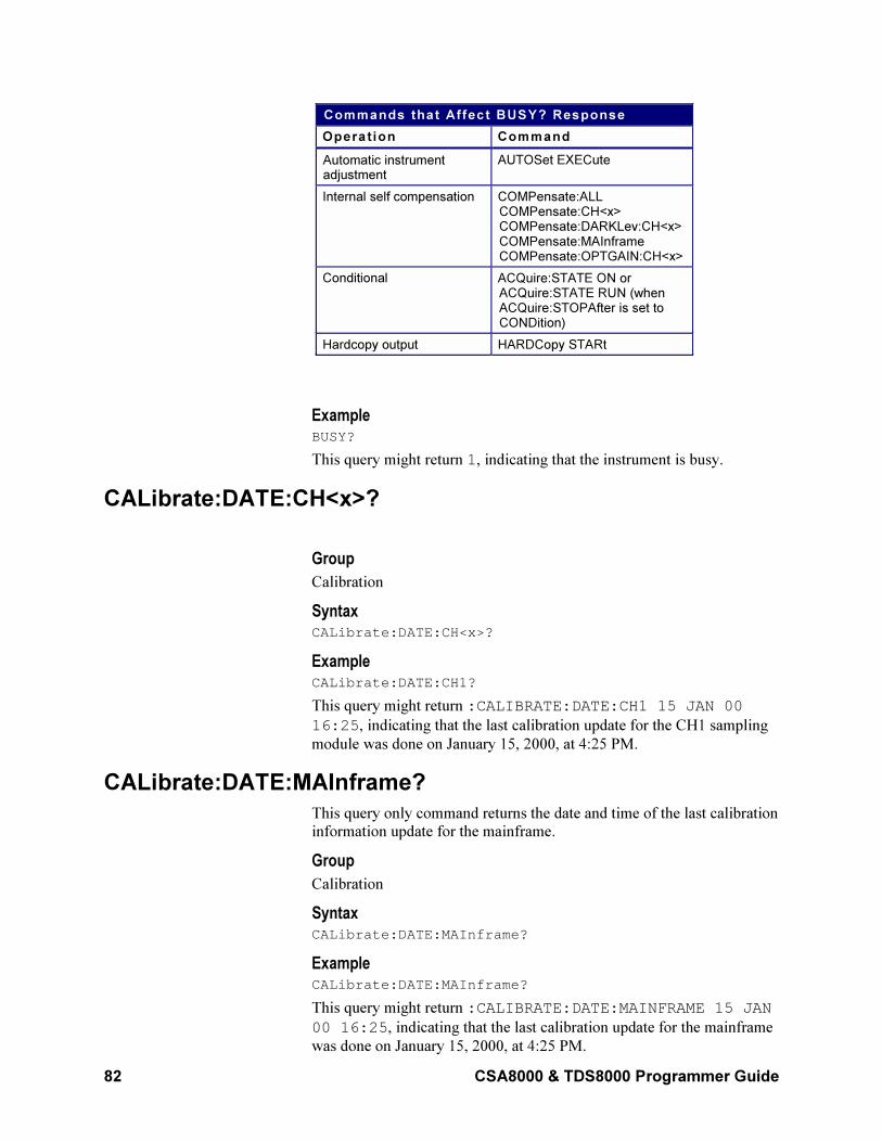
82 CSA8000 & TDS8000 Programmer Guide
Commands that Affect BUSY? Response
Operat ion Command
Automatic instrumentadjustment
AUTOSet EXECute
Internal self compensation COMPensate:ALLCOMPensate:CH<x>COMPensate:DARKLev:CH<x>COMPensate:MAInframeCOMPensate:OPTGAIN:CH<x>
Conditional ACQuire:STATE ON orACQuire:STATE RUN (whenACQuire:STOPAfter is set toCONDition)
Hardcopy output HARDCopy STARt
Example BUSY?
This query might return 1, indicating that the instrument is busy.
CALibrate:DATE:CH<x>?
Group
Calibration
Syntax CALibrate:DATE:CH<x>?
Example CALibrate:DATE:CH1?
This query might return :CALIBRATE:DATE:CH1 15 JAN 00
16:25, indicating that the last calibration update for the CH1 sampling
module was done on January 15, 2000, at 4:25 PM.
CALibrate:DATE:MAInframe?
This query only command returns the date and time of the last calibration
information update for the mainframe.
Group
Calibration
Syntax CALibrate:DATE:MAInframe?
Example CALibrate:DATE:MAInframe?
This query might return :CALIBRATE:DATE:MAINFRAME 15 JAN
00 16:25, indicating that the last calibration update for the mainframe
was done on January 15, 2000, at 4:25 PM.
CSA8000 & TDS8000 Programmer Guide 83
CALibrate:DCCALibrator
This command sets or queries the value of the DC Calibrator voltage.
Group
Calibration
Syntax 1 CALibrate:DCCALibrator <NR2>
Syntax 2 CALibrate:DCCALibrator?
Argument NR2
This is the value to which you want to set the DC Calibrator voltage. The
range for this value is from –1.25 VDC through +1.25 VDC.
Example 1 CALibrate:DCCALibrator 0.5
This command sets the DC Calibrator voltage to 0.5 V.
Example 2 CALibrate:DCCALibrator?
This query might return :CALIBRATE:DCCALIBRATOR
5.00000000000E–001, indicating that the DC Calibrator voltage is
set to 0.5 V.
CALibrate:HOSTInfo:CH<x>?
This query only command returns the mainframe channel, model
number, and serial number in which the sampling module channel was
located during the last calibration information update.
Group
Calibration
Syntax CALibrate:HOSTInfo:CH<x>?
Example CALibrate:HOSTInfo:CH2?
This query might return :CALIBRATE:HOSTINFO:CH2
"TDS8000,B010235,CH4", indicating that the sampling module
currently in channel 2 was installed in channel 4 of the TDS8000
mainframe, serial number B010235 during the last calibration
information update.
CALibrate:LOCK:STATus?
This is a query only command that returns the status of the calibration
information hardware lock switch.
84 CSA8000 & TDS8000 Programmer Guide
Group
Calibration
Syntax CALibrate:LOCK:STATus?
Example CALibrate:LOCK:STATus?
This query might return :CALibrate:LOCK:STATus 1, indicating
that the calibration information is protected and cannot be updated.
CALibrate:STATus:CH<x>?
This is a query only command that returns the current calibration status
for the sampling module channel.
Group
Calibration
Syntax CALibrate:STATus:CH<x>?
Returns
May return PASS, DEFAULTS, or WARMUP.
Example CALibrate:STATus:CH1?
This query might return :CALIBRATE:STATUS:CH1 PASS,
indicating that the calibration status of the sampling module in channel 1
is PASS.
CALibrate:STATus:MAInframe?
This is a query only command that returns the current calibration status
for the mainframe.
Group
Calibration
Syntax CALibrate:STATus:MAInframe?
Returns
May return PASS, DEFAULTS, or WARMUP.
Example CALibrate:STATus:MAInframe?
This query might return :CALIBRATE:STATUS:MAINFRAME PASS,
indicating that the calibration status of the mainframe is PASS.
CSA8000 & TDS8000 Programmer Guide 85
CALibrate:TEMPerature:CH<x>?
This is a query only command that returns the difference (in ºC) between
the current sampling module channel temperature and the temperature
recorded at the last calibration information update.
Group
Calibration
Syntax CALibrate:TEMPerature:CH<x>?
Example CALibrate:TEMPerature:CH2?
This query might return :CALIBRATE:TEMPERATURE:CH2 1.5,
indicating that the temperature difference between the current sampling
module channel temperature and the temperature recorded at the last
calibration information update is 1.5 ºC.
CALibrate:TEMPerature:MAInframe?
This is a query only command that returns the difference (in ºC) between
the current mainframe temperature and the temperature recorded at the
last calibration information update.
Group
Calibration
Syntax CALibrate:TEMPerature:MAInframe?
Example CALibrate:TEMPerature:MAInframe?
This query might return :CALIBRATE:TEMPERATURE:MAINFRAME
–2.7, indicating that the difference in temperature between the current
mainframe temperature and the temperature recorded at the last
calibration information update is –2.7 ºC
CALibrate:UPDATEinfo:ALL
This command (no query form) updates the calibration information for
the mainframe and all resident sampling module channels into
nonvolatile memories.
Note: The calibration lock switch must be set to Unprotected (that is, a
query status of 0) for the calibration information to be updated.
Group
Calibration
Syntax CALibrate:UPDATEinfo:ALL
86 CSA8000 & TDS8000 Programmer Guide
Example CALibrate:UPDATEinfo:ALL
CALibrate:UPDATEinfo:CH<x>
This command (no query form) updates the calibration information in the
nonvolatile memory of the sampling module. This includes the current
date and time, temperature, and host information (such as current
channel, location, model number, and serial number).
Note: The calibration lock switch must be set to Unprotected (that is, a
query status of 0) for the calibration information to be updated.
Group
Calibration
Syntax CALibrate:UPDATEinfo:CH<x>
Example CALibrate:UPDATEinfo:CH1
CALibrate:UPDATEinfo:MAInframe
This command (no query form) updates the calibration information in the
nonvolatile memory of the mainframe. This includes the current date,
time, and temperature.
Note: The calibration lock switch must be set to Unprotected for the
calibration information to be updated.
Group
Calibration
Syntax CALibrate:UPDATEinfo:MAInframe
Example CALibrate:UPDATEinfo:MAInframe
CH<x>:BANdwidth:LIST?
This query-only command returns a list of the available bandwidths for
the specified channel. The channel is specified by x, which can be 1
through 8. (Generally, bandwidth selections are available only to optical
sampling modules in CH 1 or CH 2.) The returned list contains the actual
bandwidths available for the channel. The available bandwidths are
dependent on the optical sampling module.
The optical modules have differing valid settings. Use the <>:LIST?
query to determine the valid Clock Recovery | Filter | Bandwidth |
Wavelength settings for your optical module. Features of optical
modules are listed in the 80C0X Optical Module User Manual. Features
of currently installed optical modules can be viewed using the System
Properties dialog.
CSA8000 & TDS8000 Programmer Guide 87
To set the bandwidth for a channel, use the CH<x>:BANdwidth:VALue
command.
Group
Vertical
Related Commands
CH<x>:BANdwidth:VALue
Syntax CH<x>:BANdwidth:LIST?
Example CH1:BANdwidth:LIST?
This query might return :CH1:BANDWIDTH:LIST
20.0000000000E+009,12.49999974400E+009, which
indicates the bandwidths that are available for Channel 1 (80C01 Optical
Sampling Module).
CH<x>:BANdwidth:VALue
This command sets or queries the bandwidth for the channel specified by
x, which can be 1 through 8. (Generally, bandwidth selections are
available only to optical sampling modules in CH 1 or CH 2.) Sending
the command is the equivalent to selecting a bandwidth from the
Bandwidth pulldown menu in the Signal Conditioning section of the
Vertical Setup dialog box for Optical. The available bandwidths are
determined by the optical sampling module.
The optical modules have differing valid settings. Use the <>:LIST?
query to determine the valid Clock Recovery | Filter | Bandwidth |
Wavelength settings for your optical module. Features of optical
modules are listed in the 80C0X Optical Module User Manual. Features
of currently installed optical modules can be viewed using the System
Properties dialog.
Available bandwidths include the following: 2 GHz, 12.5 GHz, 20 GHz,
30 GHz, 40 GHz, and 50 GHz.
You can use the CH<x>:BANdwidth:LIST? query to determine the
available bandwidths for the specified channel.
Group
Vertical
Syntax 1 CH<x>:BANdwidth:VALue <NR3>
Syntax 2 CH<x>:BANdwidth:VALue?
Arguments NR3
This argument is the value of the bandwidth you want to set. Use the
CH<x>:BANdwidth:LIST? command to query the bandwidths available
88 CSA8000 & TDS8000 Programmer Guide
for the specified channel. The instrument automatically selects the
bandwidth nearest to the input value.
Example 1 CH1:BANdwidth:VALue 2.0E+10
This argument sets the Channel 1 bandwidth to 20 GHz.
Example 2 CH2:BANdwidth:VALue?
This query might return :CH2:BANDWIDTH:VALUE
12.49999974400E+009, indicating that the bandwidth for Channel 1
is set to 12.5 GHz.
CH<x>:DESkew
This command sets or queries the deskew time for the channel specified
by x, which can be 1 through 8. Sending this command is the equivalent
to setting Deskew in the Vertical Setup dialog box for the selected
channel.
You can adjust deskew to add or subtract an independent, channel-based
acquisition time delay to the delay from the trigger point (the horizontal
position) that is inherently common to the acquisition of all channels.
This allows you to compensate for delay differences introduced between
channels by external cabling with unequal delays.
Note: Setting different deskew values on dual-channel sampling modules
that use a single sampling strobe (for example, the 80E02, 80E03, 80E04
sampling modules) reduces overall acquisition performance. In these
instances, the acquisition must digitize each channel on a separate
acquisition pass to obtain each of the signals with the desired time
alignment. This multiple pass acquisition process applies to the
acquisition of the channels within each active timebase.
Group
Vertical
Syntax 1 CH<x>:DESkew <NR3>
Syntax 2 CH<x>:DESkew?
Argument NR3
This is the deskew time for this channel. The range is -0.5 ns to +100 ns
with a resolution of 1 ps. Out of range values are clipped.
Example 1 CH7:DESkew 5.0E–9
This command sets the deskew time for Channel 7 to 5 ns.
Example 2 CH3:DESkew?
CSA8000 & TDS8000 Programmer Guide 89
This query might return :CH3:DESKEW 10.00000000008E-009,
indicating that the deskew time for Channel 3 is set to 10 ns.
CH<x>:EXTAtten:MODE
This command sets or queries the external attenuation mode for the
channel specified by x, which can be 1 through 8.
Group
Vertical
Syntax 1 CH<x>:EXTAtten:Mode LINear|DB
Syntax 2 CH<x>:EXTAtten:MODE?
Arguments
• LINear
This argument sets the mode so that the attenuation value is a linear numeric multiplier, such as 15X.
• DB
This argument sets the mode so that the attenuation value is in dB.
Example 1 CH7:EXTAtten:MODE LIN
This command sets the external attenuation mode to linear for the
Channel 7.
Example 2 CH3:EXTAtten:MODE?
This query might return :CH3:EXTATTEN:MODE DB, indicating that
the external attenuation is set to the DB mode for Channel 3.
CH<x>:EXTAtten:VALue
This command sets a value matching the amount of attenuation applied
externally, before the signal enters the specified input channel. The
channel is specified by x, which can be 1 through 8. The query form
returns the amount of attenuation that is set for the instrument. The
instrument takes into account this external attenuation when displaying
vertical readouts, measurements, and so on for this channel. This
command is the equivalent to entering a value in the External
Attenuation control in the External Attenuation section of the Vertical
Setup dialog box.
Use the CH<x>:EXTAtten:MODE command to select whether the
attenuation value is set or returned as a linear attenuation (such as 15X)
or as dB attenuation (such as 10 dB).
Note: External Attenuation (dB) = 20 * log10 (Linear)) for External
Attenuation (linear) > 0.
For example, 0 dB=1X, 20 dB=10X, 40 dB=100X, and so on.
90 CSA8000 & TDS8000 Programmer Guide
The external attenuation is set to 1 (linear) or 0 dB for all TDR sources
and for all channels released as TDR sources. External attenuation is set
to 1 (linear) or 0 dB when you attach an external real-time accessory,
such as a probe, to the selected channel.
Group
Vertical
Related Command
CH<x>:EXTAtten:MODE
Syntax 1 CH<x>:EXTAtten:VALue <NR3>
Argument NR3
This is the attenuation value specified as a multiplier in the range of
1.0E–6 to 1.0E+6. The default is 1.00.
Syntax 2 CH<x>:EXTAtten:VALue?
Example 1 CH7:EXTAtten:VALue 1.5E+1
This command sets the external attenuation for Channel 7 to 15X when
linear is set as the external attenuation mode.
Example 2 CH3:EXTAtten:VALue?
This query might return :CH3:EXTATTEN:VALUE
10.000000000000, indicating that the external attenuation is set to
10X for Channel 3 when linear is set as the external attenuation mode.
CH<x>:FILTer:LIST?
This query only command returns a list of the filters available for the
channel specified by x, which can be 1 through 8. (Generally, only
optical modules in CH1 or CH2 have filter selections.) The filters
available depend on the optical sampling module (see the 80C0X Optical
Sampling Module User Manual). Sending this command is the equivalent
using the Filter pulldown in the Signal Conditioning section of the
Optical portion of the Vertical Setup dialog box.
Use the CH<x>:FILTer:VALue command to set a filter.
Group
Vertical
Related Commands
CH<x>:FILTer:VALue
Syntax CH<x>:FILTer:LIST?
CSA8000 & TDS8000 Programmer Guide 91
Example CH1:FILTer:LIST?
This query might return :CH1:FILTER:LIST
NONE,OC12,OC48,OC192, indicating the filters available for Channel
1 when using an 80C01 Optical Sampling Module.
CH<x>:FILTer:VALue
This command sets or queries the reference-receiver filter that is applied to the channel specified by x, which can be 1 through 8. The reference-receiver filter selections require hardware support that may not be provided by your sampling module; see your 8000-series sampling module user manual to determine which filters your module supports. You can also use the CH<x>:FILTer:LIST? query to return a list of the filters available for the specified channel.
If you select a filter that your sampling module does not support, you
will receive Execution Error code 2508, with error message "Selected
filter is not available". (See Messages, on page 347, for general
information on programming interface messages.)
Group
Vertical
Related Commands
CH<x>:FILTer:LIST?
Syntax 1 CH<x>:FILTer:VALue NONe|OC1|OC3|OC9|OC12|OC18|OC24|OC36|OC48|FEC2666|OC96|OC192|FEC10664|FEC10709|FC1063|FC2125|FC4250|ENET1250|ENET3125|ENET9953|ENET10313|INFIniband
Syntax 2 CH<x>:FILTer:VALue?
Arguments
• NONe
Disables reference- receiver filtering.
• OC1
Selects a reference-receiver filter for the 51.84 Mb/s bit rate, in
accordance with the Sonet/SDHOC-1/STM-0 standard.
• OC3
Selects a reference-receiver filter for the 155.52 Mb/s bit rate, in accordance with the Sonet/SDHOC-3/STM-1 standard.
• OC9
Selects a reference-receiver filter for the 466.56 Mb/s bit rate, in accordance with the Sonet/SDHOC-9/STM-3 standard.
• OC12
Selects a reference-receiver filter for the 622.08 Mb/s bit rate, in
92 CSA8000 & TDS8000 Programmer Guide
accordance with the Sonet/SDHOC-12/STM-4 standard.
• OC18
Selects a reference-receiver filter for the 933.12 Mb/s bit rate, in accordance with the Sonet/SDHOC-18/STM-6 standard.
• OC24
Selects a reference-receiver filter for the 1.24416 Gb/s bit rate, in
accordance with the Sonet/SDHOC-24/STM-8 standard.
• OC36
Selects a reference-receiver filter for the 1.86624 Gb/s bit rate, in accordance with the Sonet/SDHOC-36/STM-12 standard.
• OC48
Selects a reference-receiver filter for the 2.48832 Gb/s bit rate, in accordance with the Sonet/SDHOC-48/STM-16 standard.
• FEC2666
Selects a reference-receiver filter for the 2.6660571 Gb/s bit rate, in
accordance with the ITU-T G.975 Recommendation
• OC96
Selects a reference-receiver filter for the 4.97664 Gb/s bit rate, in accordance with the Sonet/SDHOC96/STM-32 standard.
• OC192
Selects a reference-receiver filter for the 9.95328 Gb/s bit rate, in accordance with the Sonet/SDHOC192/STM-64 standard.
• FEC10664
Selects a reference-receiver filter for the 10.6642 Gb/s bit rate, in
accordance with the ITU-T G.975 recommendation.
• FEC10709
Selects a reference-receiver filter for the 10.709225 Gb/s bit rate, in accordance with the ITU-T G.709 draft recommendation.
• FC1063
Selects a reference-receiver filter for the 1.0625 Gb/s bit rate, in accordance with the ANSI X3.230-1994 standard.
• FC2125
Selects a reference-receiver filter for the 2.125 Gb/s bit rate, in
accordance with the ANSI Fibre Channel Physical Interface (FC-PI) Rev 11 draft standard.
• FC4250
Selects a reference-receiver filter for the 4.250 Gb/s bit rate, in
accordance with the ANSI Fibre Channel Physical Interface (FC-PI)
Rev 11 draft standard.
• ENET1250
Selects a reference-receiver filter for the 1.250 Gb/s bit rate, in
CSA8000 & TDS8000 Programmer Guide 93
accordance with the IEEE 802.3 standard.
• ENET3125
Selects a reference-receiver filter for the 3.125 Gb/s bit rate, in accordance with the IEEE P802.ae draft standard.
• ENET9953
Selects a reference-receiver filter for the 9.9533 Gb/s bit rate, in
accordance with the IEEE P802.ae draft standard.
• ENET10313
Selects a reference-receiver filter for the 10.313 Gb/s bit rate, in accordance with the IEEE P802.ae draft standard.
• INFIniband
Selects a reference-receiver filter for the 2.500 Gb/s bit rate, in accordance with the InfiniBand standard.
Example 1 CH1:FILTer:VALue NONe
This command disables the filtering for Channel 1.
Example 2 CH2:FILTer:VALue?
This query might return :CH2:FILTER:VALUE OC12, indicating that
the OC12 filter is enabled for Channel 2.
CH<x>:OFFSet
This command sets or queries the vertical offset for the specified
channel. The channel is specified by x, which can be 1 through 8. Setting
an offset with this command is the equivalent to entering a value in the
Offset control in the Channel section of the Vertical Setup dialog box or
adjusting the front-panel Vertical OFFSET knob.
Channel offset adjusts the vertical acquisition window (moves the DC
level around which the signal is sampled) for the selected channel.
Visualize offset as scrolling the acquisition window towards the top of a
large signal (or one with a positive DC bias) for increased offset values
and scrolling towards the bottom for decreased offset values. Optimal
vertical accuracy (of the entire signal) is obtained when the offset is set
to the average DC bias of the input signal (that is, when it centers the
signal around the input dynamic range of the sampling module).
The range and resolution of offset values for a given channel is
dependent on multiple factors: the sampling module type (specifically, its
input dynamic range), the probe type (if attached), the external
attenuation factor, the selected units (if TDR is active), and the scale.
For more information on how offset ranges are determined, refer to the
topic Vertical Offset in the online help for your instrument.
Group
Vertical
94 CSA8000 & TDS8000 Programmer Guide
Related Commands
CH<x>:POSition
Syntax 1 CH<x>:OFFSet <NR3>
Syntax 2 CH<x>:OFFSet?
Argument NR3
This is the offset value for the specified channel; the range is ±1.6 V.
Example 1 CH4:OFFSet 2.0E–3
This sets the offset for Channel 4 to 2 mV.
Example 2 CH3:OFFSet?
This query might return :CH3:OFFSET 0.100000000000,
indicating that the offset for Channel 3 is set to 100 mV.
CH<x>:POSition
This command sets or queries the vertical position of the specified
channel. The channel is specified by x, which can be 1 through 8.
Sending this command is the equivalent to setting Position in the Setup
section of the Vertical Setup dialog box or adjusting the front-panel
Vertical POSITION knob.
Increasing the position value of a waveform causes the waveform to
move up, and decreasing the position value causes the waveform to move
down. Position adjusts only the display position of a channel, math, or
reference waveform.
Group
Vertical
Related Commands
CH<x>:OFFSet
Syntax 1 CH<x>:POSition <NR3>
Syntax 2 CH<x>:POSition?
Argument <NR3>
This is the position value in divisions from the center graticule. The
range is ±5 divisions for channels and ±1000 divisions for math and
reference waveforms.
CSA8000 & TDS8000 Programmer Guide 95
Example 1 CH2:POSITION 1.3E+00
Positions the Channel 2 input signal 1.3 divisions above the center
graticule.
Example 2 CH1:POSITION?
This command might return :CH1:POSITION -2.000000000000,
indicating that the current position of Channel 1 is 2 divisions below the
center graticule.
CH<x>:SCAle
This command sets or queries the vertical scale of the channel specified
by x, which can be 1 through 8. Sending this command is the equivalent
to setting a value in the Scale control in the Setup section of the Vertical
Setup dialog box or adjusting the front-panel Vertical SCALE knob.
Channel scale, expressed as the per division setting, adjusts the display
size for the selected channel. Similar to the scale control for reference
and math waveforms, this control provides graphical scaling only; the
control has no effect on the input vertical acquisition hardware.
Increasing the scale causes the waveform to be displayed smaller.
Decreasing the scale causes the waveform to be displayed larger.
The range and resolution of scale values for a given channel is dependent
on multiple factors: the sampling module type (specifically, its input
dynamic range), the probe type (if attached), the external attenuation
factor, and the selected units (if TDR is active).
For more information on how scale ranges are determined, refer to the
topic Vertical Scale in the online help for your instrument.
Channel scale changes have an effect on the allowable offset range for
the channel. In general, as the vertical scale value is reduced, the amount
of allowable offset increases.
For more information on how scale affects offset range, refer to the topic
Vertical Offset in the online help for your instrument.
Group
Vertical
Related Commands
CH<x>:OFFSet, CH<x>:POSition
Syntax 1 CH<x>:SCAle <NR3>
Syntax 2 CH<x>:SCAle?
Argument NR3
This is the vertical channel scale in units per division.
96 CSA8000 & TDS8000 Programmer Guide
Example 1 CH4:SCAle 5.0E-01
This command sets the scale for Channel 4 to 500 mV per division.
Example 2 CH2:SCAle?
This query might return :CH2:SCALE 0.02000000000, indicating
that the current scale setting of Channel 2 is 20 mV per division.
CH<x>:UNIts
This command sets or queries the units for the specified channel. The
channel is specified by x, which can be 1 through 8. Sending this
command is the equivalent to setting the Units control in the Channel
section of the Vertical Setup dialog box. You can use this control to
override the automatic selection of units for the selected channel. If you
set this value to AUto, the instrument automatically selects the units. If
you set this value to Volt, Watt, or Amp, the instrument will apply these
units to the vertical axis.
• The selections in this control are Auto, Volt, Amp, and Watt. When you change the units setting, all
vertical units are reported as specified and no data transformations take place.
• For TDR waveforms, the Units control in the Vertical Setup dialog box is not active. Use the
TDR:CH<x>:UNIts command to set and query units in TDR. The units available are Rho, Ohm, and
Volt. When you change units of TDR waveforms, data transformations take place. The default is Rho.
Group
Vertical
Syntax 1 CH<x>:UNIts AUto|Volt|Watt|Amp
Syntax 2 CH<x>:UNIts?
Arguments
• AUTO
This sets the units for the specified channel so that they are
automatically determined by the instrument (depends on the probe attached to the specified channel).
• Volt
This sets the vertical-axis units for the specified channel to volts.
• Watt
This sets the vertical-axis units for the specified channel to watts.
• Amp
This sets the vertical-axis units for the specified channel to amperes.
Example 1 CH4:UNIts AUTO
CSA8000 & TDS8000 Programmer Guide 97
This command sets the vertical axis units for Channel 4 so that they are
determined automatically by the instrument.
Example 2 CH1:UNIts?
This query might return :CH1:UNITS VOLT, indicating that the
vertical-axis units for Channel 1 are set to volts.
CH<x>:WFMLabel
This command sets or queries the label associated with the channel
waveform specified.
Group
Vertical
Related Commands
Math<x>:WFMLabel, REF<x>:WFMLabel
Syntax 1
CH<x>:WFMLabel
Syntax 2
CH<x>:WFMLabel?
Argument Qstring
This argument sets the label for the waveform.
Example 1 CH1:WFMLabel "My CH1 waveform"
This command sets the label for CH1 to be "My CH1 waveform," which
is the label displayed with the waveform when it is displayed on screen.
Example 2 CH1:WFMLabel?
This query might return :CH1:WFMLABEL "My CH1 waveform"
indicating that the label for channel 1 is set to "My CH1 waveform.".
CH<x>:WLENgth:LIST?
This query only command returns a list of the available wavelengths for
the channel specified by x, which can be 1 through 8. (Generally, only
optical modules in CH1 or CH2 have wavelength selections.) The
returned list contains the actual wavelengths available for the channel.
Use the CH<x>:WLENgth:VALue command to set a value from the list.
Group
Vertical
Related Commands
CH<x>:WLENgth:VALue
98 CSA8000 & TDS8000 Programmer Guide
Syntax CH<x>:WLENgth:LIST?
Example CH2:WLENgth:LIST?
This query might return :CH2:WLENLIST
FACTORY,1550,1310,USER,1330, indicating the available
wavelengths for Channel 2.
CH<x>:WLENgth:VALue
This command sets or queries the wavelength for the channel specified
by x, which can be 1 through 8. (Generally, only optical modules in CH1
or CH2 have filter selections.) You can use the CH<x>:WLENgth:LIST?
query to determine the available wavelengths.
Group
Vertical
Related Commands
CH<x>:WLENgth:LIST?
Syntax 1 CH<x>:WLENgth:VALue <NR3> [,USER|FACTory]
Syntax 2 CH<x>:WLENgth:VALue?
Arguments
• NR3
This argument specifies the wavelength.
• USER
This keyword must follow a user-calibrated value.
• FACTory
This argument must follow a factory-calibrated value.
Example 1 CH1:WLENgth:VALue 1310
This argument sets the Channel 1 wavelength to 1310.
Example 2 CH2:WLENgth:VALue?
This query might return :CH2:WLENGTH:VALUE 1550, indicating
that the wavelength for Channel 2 is set to 1550.
CH<x>?
This is a query only command that returns the vertical parameters for the
specified channel. The channel is specified by x, which can be 1
through 8.
CSA8000 & TDS8000 Programmer Guide 99
Group
Vertical
Syntax CH<x>?
Example CH3?
This query might return the following:
:CH3:DESKEW 0.000000000000;OFFSET0.000000000000;UNITS AUTO;FILTER:VALUE NONE;:CH3:EXTATTEN:MODE LINEAR;VALUE 1.000000000000;:CH3:POSITION 0.000000000000;PTPEAK 0.700000000000;SCALE 0.700000000000
COMPensate:ALL
This command (no query form) compensates the mainframe and all
resident sampling module channels for DC variances. Before sending this
command, disconnect or terminate all sampling module inputs, and
disconnect all probes.
Note: Data from a successful compensation is not automatically saved
into nonvolatile user storage. Use the COMPensate:SAVe commands if
you want to retain the data in nonvolatile storage.
Group
Compensation
Related Commands
COMPensate:SAVe:USER:ALL
Syntax COMPensate:ALL
Example COMPensate:ALL
COMPensate:CH<x>
This command (no query form) compensates the sampling module
channel for DC variances. Before sending this command, disconnect or
terminate all sampling module inputs, and disconnect all probes.
Note: Data from a successful compensation is not automatically saved
into nonvolatile user storage. Use the COMPensate:SAVe commands if
you want to retain the data in nonvolatile storage.
Group
Compensation
Related Commands
COMPensate:SAVe:USER:CH<x>
100 CSA8000 & TDS8000 Programmer Guide
Syntax COMPensate:CH<x>
Example COMPensate:CH1
COMPensate:DARKLev:CH<x>
This command (no query form) compensates an optical channel by
removing residual DC offsets in the entire vertical path. This provides
better DC offset compensation at the current vertical settings. Before
sending this command, disconnect the input to the optical channel (or
turn off the optical source) so there is no optical signal (that is, it is
"dark").
Group
Compensation
Syntax COMPensate:DARKLev:CH<x>
Example COMPensate:DARKLev:CH1
COMPensate:DATE:CH<x>?
This is a query only command that returns the date and the time of the
current in-use (that is, run-time) compensation data for the sampling
module channel.
Group
Compensation
Syntax COMPensate:DATE:CH<x>?
Example COMPensate:DATE:CH2?
This query might return :COMPENSATE:DATE:CH2 15 JAN 00
16:25.
COMPensate:DATE:MAInframe?
This is a query only command that returns the date and the time of the
current in-use (that is, run-time) compensation data for the mainframe.
Group
Compensation
Syntax COMPensate:DATE:MAInframe?
Example COMPensate:DATE:MAInframe?
CSA8000 & TDS8000 Programmer Guide 101
This query might return :COMPENSATE:DATE:MAINFRAME 15
JAN 00 16:25.
COMPensate:MAInframe
This command (no query form) compensates the mainframe for DC
variances. Before sending this command, disconnect or terminate all
sampling module inputs, and disconnect all probes.
Note: Data from a successful compensation is not automatically saved
into nonvolatile user storage. Use the COMPensate:SAVe commands if
you want to retain the data in nonvolatile storage.
Group
Compensation
Related Commands
COMPensate:SAVe:USER:MAInframe
Syntax COMPensate:MAInframe
Example COMPensate:MAInframe
COMPensate:OPTGAIN:CH<x>
This command (no query form) compensates the gain of the optical
channel by comparing the given input power to an average optical power
measurement. The gain correction factor and the given input wavelength
are automatically stored in the nonvolatile memory of the sampling
module channel. The optical signal source must be connected and
configured appropriately before sending this command. You should use a
signal of known optical power at the wavelength for which you are
compensating.
Group
Compensation
Syntax COMPensate:OPTGAIN:CH<x> <NR1>, <NR3>
Arguments
• NR1
This argument is the wavelength (in nm) of the input optical signal.
• NR3
This argument is the average optical power of the input optical
signal.
Example COMPensate:OPTGAIN:CH1 1000,1.0E–3
102 CSA8000 & TDS8000 Programmer Guide
COMPensate:RECAll:FACTory:ALL
This command (no query form) recalls compensation data for the
mainframe and all resident sampling module channels from their
respective nonvolatile factory memories into the current, in-use (that is,
run-time) compensation memory.
Group
Compensation
Syntax COMPensate:RECAll:FACTory:ALL
Example COMPensate:RECAll:FACTory:ALL
COMPensate:RECAll:FACTory:CH<x>
This command (no query form) recalls compensation data from the
nonvolatile factory memory of the sampling module channel into its
associated in-use (that is, run-time) compensation memory.
Group
Compensation
Syntax COMPensate:RECAll:FACTory:CH<x>
Example COMPensate:RECAll:FACTory:CH2
COMPensate:RECAll:FACTory:MAInframe
This command (no query form) recalls compensation data from the
nonvolatile factory memory of the mainframe into its associated in-use
(that is, run-time) compensation memory.
Group
Compensation
Syntax COMPensate:RECAll:FACTory:MAInframe
Example COMPensate:RECAll:FACTory:MAInframe
COMPensate:RECAll:USER:ALL
This command (no query form) recalls compensation data for the
mainframe and all resident sampling module channels from their
respective nonvolatile user memories into the current, in-use (that is, run-
time) compensation memory.
Group
Compensation
CSA8000 & TDS8000 Programmer Guide 103
Syntax COMPensate:RECAll:USER:ALL
Example COMPensate:RECAll:USER:ALL
COMPensate:RECAll:USER:CH<x>
This command (no query form) recalls compensation data from the
nonvolatile user memory of the sampling module channel into its
associated in-use (that is, run-time) compensation memory.
Group
Compensation
Syntax COMPensate:RECAll:USER:CH<x>
Example COMPensate:RECAll:USER:CH1
COMPensate:RECAll:USER:MAInframe
This command (no query form) recalls compensation data from the
nonvolatile user memory of the mainframe into its associated in-use (that
is, run-time) compensation memory.
Group
Compensation
Syntax COMPensate:RECAll:USER:MAInframe
Example COMPensate:RECAll:USER:MAInframe
COMPensate:RESults:VERBose?
This is a query only command that returns a more explanatory message
than the COMPensate:ReSults query returns about the results of the last
compensation execution.
Group
Compensation
Related Commands
COMPensate:RESults?
Syntax COMPensate:RESults:VERBose?
Example COMPensate:RESults:VERBose?
104 CSA8000 & TDS8000 Programmer Guide
This query might return :COMPENSATE:RESULTS:VERBOSE
COMP COMPLETED, NO FAILURES.
COMPensate:RESults?
This is a query only command that returns an abbreviated status about
the results of the last compensation execution. Any result other than
PASS generally indicates a failure. For a more detailed message about
the results of the last compensation execution, use the
COMPensate:RESults:VERBose? query.
Group
Compensation
Syntax COMPensate:RESults?
Example COMPensate:RESults?
This query might return :COMPENSATE:RESULTS PASS, indicating
that the compensation was successful.
COMPensate:SAVe:USER:ALL
This command (no query form) saves the volatile run-time compensation
data for the mainframe and all resident sampling module channels into
their respective nonvolatile user memories.
Group
Compensation
Syntax COMPensate:SAVe:USER:ALL
Example COMPensate:SAVe:USER:ALL
COMPensate:SAVe:USER:CH<x>
This command (no query form) saves the volatile run-time compensation
data for the sampling module channel into the nonvolatile user memory
of the sampling module channel. The channel is specified by x, which
can be 1 through 8.
Group
Compensation
Syntax COMPensate:SAVe:USER:CH<x>
Example COMPensate:SAVe:USER:CH2
CSA8000 & TDS8000 Programmer Guide 105
COMPensate:SAVe:USER:MAInframe
This command (no query form) saves the volatile run-time compensation
data for the mainframe into the nonvolatile user memory of the
mainframe.
Group
Compensation
Syntax COMPensate:SAVe:USER:MAInframe
Example COMPensate:SAVe:USER:MAInframe
COMPensate:STATus:CH<x>?
This is a query only command that returns the current compensation
status for the sampling module channel. Possible responses are
DEFAULTS, WARMUP, FAIL, PASS, and COMPREQ.
Group
Compensation
Syntax COMPensate:STATus:CH<x>?
Example COMPensate:STATus:CH1?
This query might return :COMPENSATE:STATUS:CH1 COMPREQ,
indicating that the warm-up period for the instrument has elapsed, but the
current compensation temperature delta is greater than desired, and the
instrument should be compensated again.
COMPensate:STATus:MAInframe?
This is a query only command that returns the current compensation
status for the mainframe. Possible responses are DEFAULTS, WARMUP,
FAIL, PASS, and COMPREQ.
Group
Compensation
Syntax COMPensate:STATus:MAInframe?
Example COMPensate:STATus:MAInframe?
This query might return :COMPENSATE:STATUS:MAINFRAME
PASS, indicating that the current compensation data should allow the
instrument to meet operating specifications.
106 CSA8000 & TDS8000 Programmer Guide
COMPensate:TEMPerature:CH<x>?
This query only command returns the difference (in ºC) between the
current temperature of the sampling module channel and the associated
temperature currently residing in the in-use run-time compensation
memory.
Group
Compensation
Syntax COMPensate:TEMPerature:CH<x>?
Example COMPensate:TEMPerature:CH1?
This query might return :COMPENSATE:TEMPERATURE:CH1 1.5
COMPensate:TEMPerature:MAInframe?
This query only command returns the difference (in ºC) between the
current temperature of the mainframe and the associated temperature
currently residing in the in-use run-time compensation memory.
Group
Compensation
Syntax COMPensate:TEMPerature:MAInframe?
Example COMPensate:TEMPerature:MAInframe?
This query might return
:COMPENSATE:TEMPERATURE:MAINFRAME 2.7.
CURSor:CURSor<x>:COLOR
This command sets or queries the color of the cursor specified by x,
which can be 1 or 2. (This command is the same as the
DISPlay:COLor:CURSOR command.) This is equivalent to setting Color
in the Cursor 1 or Cursor 2 section of the Cursor Setup dialog box. The
available colors are listed in the following table.
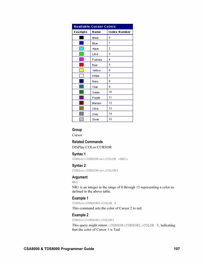
CSA8000 & TDS8000 Programmer Guide 107
Group
Cursor
Related Commands
DISPlay:COLor:CURSOR
Syntax 1 CURSor:CURSOR<x>:COLOR <NR1>
Syntax 2 CURSor:CURSOR<x>:COLOR?
Argument NR1
NR1 is an integer in the range of 0 through 15 representing a color as
defined in the above table.
Example 1 CURSor:CURSOR2:COLOR 5
This command sets the color of Cursor 2 to red.
Example 2 CURSor:CURSOR1:COLOR?
This query might return :CURSOR:CURSOR1:COLOR 9, indicating
that the color of Cursor 1 is Teal
108 CSA8000 & TDS8000 Programmer Guide
CURSor:CURSor<x>:SOUrce
This command sets or queries which waveform is associated with the
specified cursor. The cursor is specified by x, which can be 1 or 2. This
command can optionally set the target timebase. This is equivalent to
selecting a waveform (and timebase) in the Source control for the Cursor
1 or Cursor 2 section of the Cursor Setup dialog box. If you do not set
the timebase, the default is Main for both cursors.
Group
Cursor
Syntax 1 CURSor:CURSOR<x>:SOUrce CH<x>|MATH<x>|REF<x>[,MAIN|MAG1|MAG2]
Syntax 2 CURSor:CURSOR<x>:SOUrce?
Arguments
• CH<x>
This argument selects a channel waveform as the source for the specified cursor. The range for x is 1 through 8.
• MATH<x>
This argument selects a math waveform as the source for the specified cursor. The range for x is 1 through 8.
• REF<x>
This argument selects a reference waveform as the source for the
specified cursor. The range for x is 1 through 8.
• MAIn
This optional argument selects Main as the timebase for the specified cursor display.
• MAG1
This optional argument selects MAG1 as the timebase for the specified cursor display.
• MAG2
This optional argument selects MAG2 as the timebase for the
specified cursor display.
Example 1 CURSor:CURSOR2:SOUrce CH8,MAG1
This command associates Cursor 2 with the channel 8 waveform and the
MAG1 timebase.
Example 2 CURSor:CURSOR1:SOUrce?
CSA8000 & TDS8000 Programmer Guide 109
This query might return :CURSOR:CURSOR1:SOURCE REF2,MAIN
indicating that Cursor 1 is associated with the REF2 waveform and the
Main timebase.
CURSor:FUNCtion
This command sets or queries cursor type. Cursors are attached to the
selected waveform. Sending this command is equivalent to setting
Function in the Cursor Setup dialog box.
Group
Cursor
Related Command
SELect:CONTROl
Syntax 1 CURSor:FUNCtion HBArs|OFF|VBArs|WAVEforms
Syntax 2 CURSor:FUNCtion?
Arguments
• HBArs
Enables horizontal bar cursors, which provide traditional vertical unit
readouts for Cursor 1 (bar1), Cursor 2 (bar2), and the ∆ between
them.
• OFF
Removes the cursors from the display.
• VBArs
Enables vertical bar cursors, which provide traditional horizontal unit
readouts for Cursor 1 (bar1), Cursor 2 (bar2), the ∆ between them,
and 1/∆t (frequency when the horizontal unit is time).
• WAVEforms
Enables the waveform cursors, which provide both horizontal unit
readouts and vertical unit readouts for Cursor 1 and Cursor 2, which are constrained to valid data points of the selected waveform.
Example 1 CURSOR:FUNCtion VBARS
This command enables the vertical bar type cursors.
Example 2 CURSOR:FUNCtion?
This query might return :CURSOR:FUNCTION HBARS, indicating that
the horizontal bar cursors are enabled.
110 CSA8000 & TDS8000 Programmer Guide
CURSor:HBArs:DELTa?
This query only command returns the difference between the two
horizontal bar cursors.
Group
Cursor
Related Commands
CURSor:FUNCtion
Syntax CURSor:HBArs:DELTa?
Returns
NR3
Example CURSOR:HBARS:DELTA?
This command might return :CURSOR:HBARS:DELTA -
3.00813008130E-003 for the difference between the two horizontal
bar cursors.
CURSor:HBArs:POSition<x>
This command sets or queries the position of a horizontal bar cursor,
which is constrained to be visible in the selected timebase. (Use the
CURSor:FUNCtion command to set the cursor function to horizontal
bars.) The cursor is specified by x, which can be 1 or 2. This is
equivalent to setting a value in the Position control in the Cursor 1 or
Cursor 2 sections of the Cursor Setup dialog box (when Horizontal Bars
is selected in the Function section).
Group
Cursor
Related Commands
CURSor:FUNCtion
Syntax 1 CURSor:HBArs:POSition<x> <NR3>
Syntax 2 CURSor:HBArs:POSition<x>?
Argument NR3
This argument specifies the cursor position relative to zero for the source
waveform.
Example 1 CURSor:HBArs:POSition1 3.0E-3
CSA8000 & TDS8000 Programmer Guide 111
Positions Cursor 1 at 3 mV units above the zero level of the source
waveform.
Example 2 CURSor:HBArs:POSition2?
This command might return :CURSOR:HBARS:POSITION2 -
1.96476964770E-003, indicating that Cursor 2 is approximately
1.965 mV below the zero level of the source waveform.
CURSor:HBArs?
This query only command returns the current settings for the horizontal
bar cursors.
Group
Cursor
Syntax CURSor:HBArs?
Example CURSor:HBArs?
This command might return
:CURSOR:HBARS:DELTA -4.01084010840E-003; POSITION1 2.01897018970E-003;
POSITION2 -1.99186991870E-003.
CURSor:SELect
This command sets or queries which cursor is active for front-panel
control. The active cursor is displayed as a solid line and can be moved
using the front-panel general-purpose knob. The unselected cursor is
displayed as a dashed line. This command is equivalent to clicking in the
Position control box in the Cursor 1 or Cursor 2 section of the Cursor
Setup dialog box.
Group
Cursor
Syntax 1 CURSor:SELect CURSOR1|CURSOR2|NONe
Syntax 2 CURSor:SELect?
Arguments
• CURSOR1
Makes cursor 1 the active cursor.
• CURSOR2
Makes cursor 2 the active cursor.
• NONe
112 CSA8000 & TDS8000 Programmer Guide
Disables cursor 1 and cursor 2 so that they cannot be moved by the front-panel general-purpose knob.
Example 1 CURSor:SELect CURSOR1
Sets cursor 1 as the active cursor, which is controllable by the front-panel
general-purpose knob.
Example 2 CURSor:SELect?
This query might return :CURSOR:SELECT CURSOR1, indicating that
cursor 1 is the active cursor and can be controlled by the front-panel
general-purpose knob.
CURSor:VBArs?
This query only command returns the current settings of the vertical bar
cursors.
Group
Cursor
Syntax CURSor:VBArs?
Example CURSOR:VBARS?
This query might return :CURSOR:VBARS:DELTA 1.00601202405E-009;POSITION1 20.9968917836E-009; POSITION2 22.0029038076E-009
CURSor:VBArs:DELTa?
This query only command returns the difference between the two vertical
bar cursors. This corresponds to the ∆t value in the Cursors readout.
Group
Cursor
Syntax CURSor:VBArs:DELTa?
Returns
NR3
Example CURSOR:VBARS:DELTa?
This command might return :CURSOR:VBARS:DELTA
1.65330661323E-009, indicating the delta between the vertical bar
cursors in absolute horizontal units.
CSA8000 & TDS8000 Programmer Guide 113
CURSor:VBArs:POSition<x>
This command sets or queries the position of the specified vertical bar
cursor, which is constrained to be within the displayed range. The cursor
is specified by x, which can be 1 or 2. (Use the CURSor FUNCtion
command to set the cursor function to vertical bars.) This is equivalent to
entering a value in the Cursor 1 or Cursor 2 Position control in the
Cursor Setup dialog box.
Group
Cursor
Related Commands
HORizontal:MAIn:TOFPoint?, HORizontal:MAG<x>:TOFPoint?,
HORizontal:MATH<x>:MAIn:TOFPoint?,,
HORizontal:MATH<x>MAG<x>:TOFPoint?,
HORizontal:REF<x>:MAIn:TOFPoint?,
HORizontal:REF<x>MAG<x>:TOFPoint?
Syntax 1 CURSor:VBArs:POSition<x> <NR3>
Syntax 2 CURSor:VBArs:POSition<x>?
Argument
NR3
This argument specifies the cursor position measured from the trigger
point of the source waveform.
Example 1: CURSor:VBArs:POSition2 9.0E-6
This command positions the cursor 2 vertical bar cursor at 9 µs from the
trigger point of the source waveform.
Example 2: CURSor:VBArs:POSition1?
This query might return :CURSOR:VBARS:POSITION1
17.4929859719E-009, indicating that the cursor 1 vertical bar is at
17.49 ns from the trigger point of the source waveform.
CURSor:WAVeform:HDELTa?
This query-only command returns the horizontal difference between the
waveform cursors. This is the absolute value of the horizontal position of
the first cursor minus the horizontal position of the second cursor. This is
equivalent to the waveform ∆t readout value.
Group
Cursor
Syntax CURSor:WAVeform:HDELTa?
114 CSA8000 & TDS8000 Programmer Guide
Example CURSor:WAVeform:HDELTa?
This query might return :CURSOR:WAVEFORM:HDELTA 1.03E–9,
indicating that the time between the waveform cursors is 1.03 ns.
CURSor:WAVeform:HPOS<x>?
This query only command returns the position of the specified waveform
cursor. The cursor is specified by x, which can be 1 or 2. This
corresponds to the v1 or v2 (cursor 1 or cursor 2) cursor readout.
Group
Cursor
Syntax CURSor:WAVeform:HPOS<x>?
Example CURSor:WAVeform:HPOS1?
This query might return :CURSOR:WAVEFORM:HPOS2
0.247344970703, indicating that cursor 2 is at 247.3 mV with respect
to ground on the source waveform.
CURSor:WAVeform:POSition<x>
This command sets or queries the position of a waveform cursor, which
is constrained to be visible in the selected timebase. (Use the CURSor
FUNCtion command to set the cursor function to Waveform.) The cursor
is specified by x, which can be 1 or 2. This is equivalent to setting a
value in the Position control in the Cursor 1 or Cursor 2 sections of the
Cursor Setup dialog box (when Waveform is selected in the Function
section).
Group
Cursor
Related Commands
CURSor FUNCtion
Syntax 1 CURSor:WAVeform:POSition<x> <NR3>
Syntax 2 CURSor:WAVeform:POSition<x>?
Argument NR3
This argument specifies the cursor position measured relative to the time
of the trigger point of the source waveform.
Example 1 CURSor:WAVeform:POSition2 9.00E-6
This command positions the cursor 2 waveform cursor at 9 µs.
CSA8000 & TDS8000 Programmer Guide 115
Example 2 CURSor:WAVeform:POSition2?
This query might return :CURSOR:WAVEFORM:POSITION2
51.0701402806E-009, indicating waveform cursor 1 is at 51.1 ns.
CURSor:WAVeform:VDELTa?
This query only command returns the vertical difference between the
waveform cursors. This is the absolute value of the vertical position of
the first cursor minus the vertical position of the second cursor. This is
equivalent to the waveform ∆v readout value.
Group
Cursor
Syntax CURSor:WAVeform:VDELTa?
Example CURSor:WAVeform:VDELTa?
This command might return CURSOR:WAVEFORM:VDELTA 1.06E–
3, indicating that the voltage between the waveform cursors is 1.06 mV.
CURSor:WAVeform?
This query only command returns all of the waveform cursor parameters.
Group
Cursor
Syntax CURSor:WAVeform?
Example CURSor:WAVeform?
This query might return :CURSOR:WAVEFORM:HDELTA 0.487243652344;VDELTA –19.9398797595E-009; HPOS1 0.241729736328;HPOS2 –0.245513916016; POSITION1 31.1302605210E-009; POSITION2 51.0701402806E-009
CURSor?
This is a query only command that returns all of the current cursor
settings.
Group
Cursor
Syntax
CURSor?
116 CSA8000 & TDS8000 Programmer Guide
Example: CURSOR?
This command might return the following as the current cursor settings:
:CURSOR:CURSOR1:COLOR 5;SOURCE CH3,MAIN;:CURSOR:CURSOR2:COLOR 5;SOURCE CH3,MAIN;:CURSOR:DIV2 0;FUNCTION WAVEFORMS;SELECT CURSOR1;HBARS:DELTA –0.401084010840;POSITION10.201897018970;POSITION2 –0.199186991870;:CURSOR:VBARS:DELTA 19.9398797595E-009;POSITION131.1302605210E-009;POSITION2 51.0701402806E-009;:CURSOR:WAVEFORM:HDELTA 0.485961914062;VDELTA -19.9398797595E-009;HPOS1 0.240936279297;HPOS2 –0.245025634766;POSITION1 31.1302605210E-009;POSITION2 51.0701402806E-009
CURVe
This query form of this command transfers waveform data from the
instrument in binary or ASCII format. Use the DATa:SOUrce and
DATa:TIMebase commands to specify the location (source) of the
waveform data that is transferred from the instrument. Each waveform
that is transferred has an associated waveform preamble that contains
information such as data format and scale. Refer to the WFMOutpre?
query for information about the waveform preamble after the curve query
command is completed. The data format is specified by the
DATa:ENCdg command.
The first and last data points that are transferred are specified by the
DATa:STARt and DATa:STOP commands.
The CURVe command transfers waveform data to the instrument. The
data is stored in the reference memory location specified by
DATa:DESTination, starting with the data point specified by the
DATa:STARt command. Only one waveform can be transferred at a
time. If the destination reference is not empty, the reference slot will be
cleared, and the instrument will attempt to create a waveform using the
provided data points. The waveform will only be displayed if the
reference is displayed.
Group
Waveform Transfer
Related Commands
DATa:SOUrce, DATa:TIMebase, WFMOutpre?, DATa:ENCdg,
DATa:STARt, DATa:STOP, DATa:DESTination
Syntax 1 CURVe <block>|<ascii>
Syntax 2 CURVe?
Arguments
• block
This is the waveform data in binary format. The waveform is
CSA8000 & TDS8000 Programmer Guide 117
formatted as: #<x><yyy><data><newline> where <x> is the number
of y bytes. For example, if <yyy> = 500, then <x> = 3. <yyy> is the
number of bytes to transfer including checksum.
• ascii
This is the waveform data in ASCII format. The format for ASCII
data is <NR1>[,<NR1>...] where each <NR1> represents a data point.
Example CURVe?
This command might return the following for ASCII data (partial):
:CURVE -509476864,-512163840,-511115264,-510918656,-516161536,-484179968,-117112832,207093760,322437120,351600640,409206784,468451328,482934784,490668032,495517696,432668672,482148352,483655680,493617152,495321088,499843072,493420544,488964096,497221632,503250944,501088256,501743616,503447552,498139136,502857728,507248640,507117568,503054336,506200064,505413632,502988800,506658816,506920960,498008064,501415936,504299520,498991104,496304128,499056640,501612544,505806848,498794496,494206976,414449664,-11141120,-274071552,-394330112,-432865280,-450756608,-488439808,-500826112,…
DATa
This command sets or queries the format and location of the waveform
data that is transferred with the CURVe command.
Group
Waveform Transfer
Related Commands
CURVE, WAVFrm?, DATa:STARt, DATa:STOP
Syntax 1 DATa INIT|SNAp
Syntax 2 DATa?
Arguments
• INIT
This argument initializes the waveform data parameters to their factory defaults.
• SNAp
This argument sets DATa:STARt and DATa:STOP to match the current vertical bar cursor positions.
Example 1 DATA SNAp
118 CSA8000 & TDS8000 Programmer Guide
This command assigns the current position of the vertical bar cursors to
DATA:START and DATA:STOP.
Example 2 DATA?
This query might return :DATA:DESTINATION REF1;SOURCE
CH3;ENCDG ASCII;START 1;STOP 500.
DATa:DESTination
This command sets or queries the destination reference memory location
for storing waveform data that is transferred into the instrument by the
CURVe command.
Group
Waveform Transfer
Syntax 1 DATa:DESTination REF<x>
Syntax 2 DATa:DESTination?
Arguments REF<x>
REF1 through REF8 are the reference memory locations where the
waveform will be stored. You cannot have a channel as a destination.
Example 1 DATA:DESTination REF3
This command stores the incoming waveform data in Reference 3.
Example 2 DATA:DESTINATION?
This command might return :DATA:DESTINATION REF8 as the
reference memory location that is currently selected.
DATa:ENCdg
This command sets or queries the format of the waveform data. This
command is equivalent to setting WFMOutpre:ENCdg,
WFMOutpre:BN_Fmt, and WFMOutpre:BYT_Or, as shown in the table
below. Only signed, 4-byte integers and floating point values are
supported. Changing the DATa:ENCdg parameter will coerce
WFMOutpre formatter commands accordingly. If ASCIi is selected, the
output will be formatted to floating point or signed integer, based on how
the data is stored in the instrument.
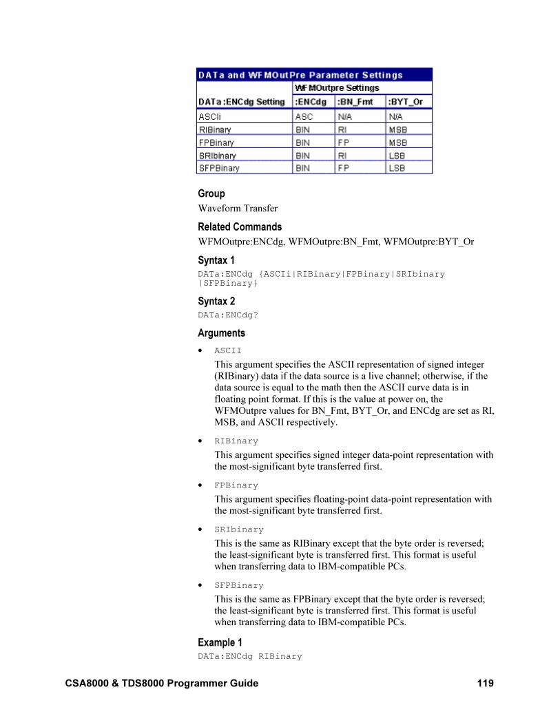
CSA8000 & TDS8000 Programmer Guide 119
Group
Waveform Transfer
Related Commands
WFMOutpre:ENCdg, WFMOutpre:BN_Fmt, WFMOutpre:BYT_Or
Syntax 1 DATa:ENCdg ASCIi|RIBinary|FPBinary|SRIbinary|SFPBinary
Syntax 2 DATa:ENCdg?
Arguments
• ASCII
This argument specifies the ASCII representation of signed integer
(RIBinary) data if the data source is a live channel; otherwise, if the
data source is equal to the math then the ASCII curve data is in
floating point format. If this is the value at power on, the
WFMOutpre values for BN_Fmt, BYT_Or, and ENCdg are set as RI, MSB, and ASCII respectively.
• RIBinary
This argument specifies signed integer data-point representation with
the most-significant byte transferred first.
• FPBinary
This argument specifies floating-point data-point representation with the most-significant byte transferred first.
• SRIbinary
This is the same as RIBinary except that the byte order is reversed;
the least-significant byte is transferred first. This format is useful
when transferring data to IBM-compatible PCs.
• SFPBinary
This is the same as FPBinary except that the byte order is reversed;
the least-significant byte is transferred first. This format is useful when transferring data to IBM-compatible PCs.
Example 1 DATa:ENCdg RIBinary
120 CSA8000 & TDS8000 Programmer Guide
This command sets the data-encoding format to signed integer, with the
most-significant byte transferred first.
Example 2 DATa:ENCdg?
This query might return DATA:ENCDG SFPBINARY, indicating that
the format of the data is floating point, with the least-significant bit
transferred first.
DATa:SOUrce
This command sets or queries the location of the waveform data that is
transferred from the instrument by the CURVe? query. Only one source
can be set at a time. Changing the source waveform does not cause the
WFMOutpre interpretation commands to update. To update these
commands, you must send the CURVe? command. You may also set or
query the timebase associated with the waveform data transferred from
the instrument using the DATa:TIMebase command.
Group
Waveform Transfer
Related Commands
DATa:TIMebase
Syntax 1 DATa:SOUrce CH<x>|MATH<x>|REF<x>
Syntax 2 DATa:SOUrce?
Arguments
• CH<x>
This argument selects the specified channel (1 through 8) acquisition waveform as the waveform source.
• MATH<x>
This argument selects the specified Math (1 through 8) waveform as the waveform source.
• REF<x>
This argument selects the specified Reference (1 through 8)
waveform as the waveform source.
Example 1 DATA:SOUrce REF2
This command specifies that the Reference 2 waveform will be
transferred in the next CURVE? query.
Example 2 DATA:SOUrce?
CSA8000 & TDS8000 Programmer Guide 121
This command might return :DATA:SOURCE REF3, indicating that
Reference 3 waveform is the source for the waveform data that is
transferred using a CURVE? query.
DATa:STARt
Sets or queries the starting data point for waveform transfer. This
command allows for the transfer of partial waveforms to and from the
instrument.
Group
Waveform Transfer
Related Commands
CURVe?, DATa:STOP
Syntax 1 DATa:STARt <NR1>
Syntax 2 DATa:STARt?
Argument NR1
This value ranges from 1 to the record length and is the first data point
that will be transferred. Data will be transferred from this point to
DATa:STOP or the record length, whichever is less. If this value is
greater than the record length, then no data will be transferred.
When DATa:STOP is less than DATa:STARt, the stop value will equal
DATa:STARt + (DATa:STARt - DATa:STOP). For example, if
DATa:STARt = 30 and DATa:STOP = 20, then the range of data points
for the waveform transfer will equal 30 through 40.
Example 1 DATA:STARt 10
This command specifies that the waveform transfer will begin with data
point 10.
Example 2 DATA:START?
This query might return :DATA:START 214 , indicating that 214 is the
first waveform data point that will be transferred.
DATa:STOP
Sets or queries the last data point that will be transferred when using the
CURVe? query. This allows the transfer of partial waveforms to the
controller.
When using the CURVe command, the instrument will stop reading data
when there is no more data to read or when the specified record length is
reached. When the specified record length is reached, this command will
be ignored.
122 CSA8000 & TDS8000 Programmer Guide
Group
Waveform Transfer
Related Commands
CURVe?, DATa:STARt
Syntax 1 DATa:STOP <NR1>
Syntax 2 DATa:STOP?
Argument NR1
This value ranges from 1 to the record length and is the last data point
that will be transferred. If this value is greater than the record length,
then data will be transferred up to the record length. If both
DATa:STARt and DATa:STOP are greater than the record length, an
execution error will be generated.
If you always want to transfer complete waveforms, just set
DATa:STARt to 1 and DATa:STOP to the maximum record length.
When DATa:STOP is less than DATa:STARt, the stop value will equal
DATa:STARt + (DATa:STARt - DATa:STOP). For example, if
DATa:STARt = 30 and DATa:STOP = 20, then the range of data points
for the waveform transfer will equal 30 through 40.
Example 1 DATA:STOP 4000
This command specifies that the waveform transfer will stop at data
point 4000.
Example 2 DATA:STOP?
This query might return :DATA:STOP 500, indicating that 500 is the
last data point that will be transferred.
DATa:TIMebase
Sets or queries the DATa:SOUrce associated timebase used to specify
the location of the waveform data to be transferred from the instrument
when using the CURVe? command. The specified timebase must be
active and displayed in order to receive data.
Group
Waveform Transfer
Related Commands
CURVe?, DATa:SOUrce
Syntax 1 DATa:TIMebase MAIn|MAG1|MAG2
CSA8000 & TDS8000 Programmer Guide 123
Syntax 2 DATa:TIMebase?
Arguments
MAIn: This argument selects MAIn as the timebase for the waveform
data to be transferred out by the next CURVe? command.
MAG1: This argument selects MAG1 as the timebase for the waveform
data to be transferred out by the next CURVe? Command.
MAG2: This argument selects MAG2 as the timebase for the waveform
data to be transferred out by the next CURVe? command.
Example DATa:TIMebase MAG1
This command sets the timebase for the waveform data to be transferred
out to MAG1.
DATa:TIMebase?
This command might return :DATa:TIMebase MAIN, indicating that the
timebase for the source waveform data is set to main.
DATE
This command sets or queries the date that the instrument can display.
Group
Miscellaneous
Related Commands
TIMe
Syntax 1 DATE <QString>
Syntax 2 DATE?
Arguments <QString>
This is a date in the form "yyyy-mm-dd".
• yyyy
This is a four-digit year number.
• mm
This is a two-digit month number from 01 to 12.
• dd
This is a two-digit day number in the month.
Note: There must a dash (-) after the yyyy and after the mm.
Example 1 DATE "2000-01-24"
This command sets the date to January 24, 2000.
124 CSA8000 & TDS8000 Programmer Guide
Example 2 DATE?
This query might return :DATE 1999-06-01, indicating that the date
is June 1, 1999.
DELEte:WAVEform
This command (no query form) deletes one or all of the stored reference
waveforms from memory. The memory allocated for the reference
location is then available for reallocation.
Note: A reference waveform cannot be deleted if it is a source client for
some other operation, such as a histogram source, math source,
measurement, or waveform database.
Group
Save and Recall
Related Commands
RECAll:WAVEform, SAVe:WAVEform
Syntax DELEte:WAVEform REF<x>|ALL
Arguments
• REF<x>
Specifies one of the reference memory locations (REF1 through
REF8).
• ALL
Specifies all the stored reference waveforms.
Example 1 DELEte:WAVEform ALL
Removes all the waveforms stored in reference memory.
Example 2 DELEte:WAVEform REF2
Removes the waveform stored at REF2.
DESE
This command sets or queries the bits in the Device Event Status Enable
Register (DESER). The DESER is the mask that determines whether
events are reported to the Standard Event Status Register (SESR) and
entered into the Event Queue. For a more detailed discussion of the use
of these registers, see Registers on page 337.
Group
Status and Error
Related Commands
*CLS, *ESE, *ESR?, EVENT?, EVMsg?, *SRE, *STB?
CSA8000 & TDS8000 Programmer Guide 125
Syntax 1 DESE <NR1>
Syntax 2 DESE?
Argument <NR1>
This is a value in the range from 0 through 255. The binary bits of the
DESER are set according to this value. For example, DESE 209 sets the
DESER to the binary value 11010001 (that is, the most significant bit in
the register is set to 1, the next most significant bit to 1, the next bit to 0,
and so on).
The power-on default for DESER is all bits set if *PSC is 1. If *PSC is 0,
the DESER maintains its value through a power cycle.
Note: Setting the DESER and the ESER to the same value allows only
those codes to be entered into the Event Queue and summarized on the
ESB bit (bit 5) of the Status Byte Register. Use the *ESE command to set
the ESER.
Example 1 DESE 209
Sets the DESER to binary 11010001, which enables the PON, URQ,
EXE, and OPC bits.
Example 2 DESE?
This query might return :DESE 186, indicating that the DESER
contains the binary value 10111010.
DISplay:COLor:BACKground
This command sets or queries the color of the graticule background. This
is equivalent to setting the Background color in the Graticule section of
the Display Setup dialog box. The default background color is black. The
available background colors are listed in the following table.
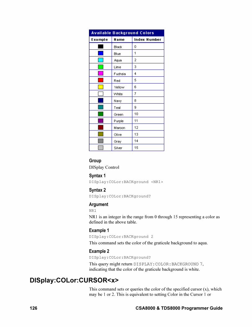
126 CSA8000 & TDS8000 Programmer Guide
Group
DISplay Control
Syntax 1 DISplay:COLor:BACKground <NR1>
Syntax 2 DISplay:COLor:BACKground?
Argument NR1
NR1 is an integer in the range from 0 through 15 representing a color as
defined in the above table.
Example 1 DISplay:COLor:BACKground 2
This command sets the color of the graticule background to aqua.
Example 2 DISplay:COLor:BACKground?
This query might return DISPLAY:COLOR:BACKGROUND 7,
indicating that the color of the graticule background is white.
DISplay:COLor:CURSOR<x>
This command sets or queries the color of the specified cursor (x), which
may be 1 or 2. This is equivalent to setting Color in the Cursor 1 or
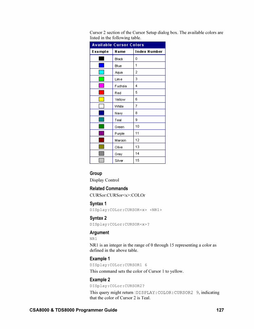
CSA8000 & TDS8000 Programmer Guide 127
Cursor 2 section of the Cursor Setup dialog box. The available colors are
listed in the following table.
Group
Display Control
Related Commands
CURSor:CURSor<x>:COLOr
Syntax 1 DISplay:COLor:CURSOR<x> <NR1>
Syntax 2 DISplay:COLor:CURSOR<x>?
Argument NR1
NR1 is an integer in the range of 0 through 15 representing a color as
defined in the above table.
Example 1 DISplay:COLor:CURSOR1 6
This command sets the color of Cursor 1 to yellow.
Example 2 DISplay:COLor:CURSOR2?
This query might return :DISPLAY:COLOR:CURSOR2 9, indicating
that the color of Cursor 2 is Teal.
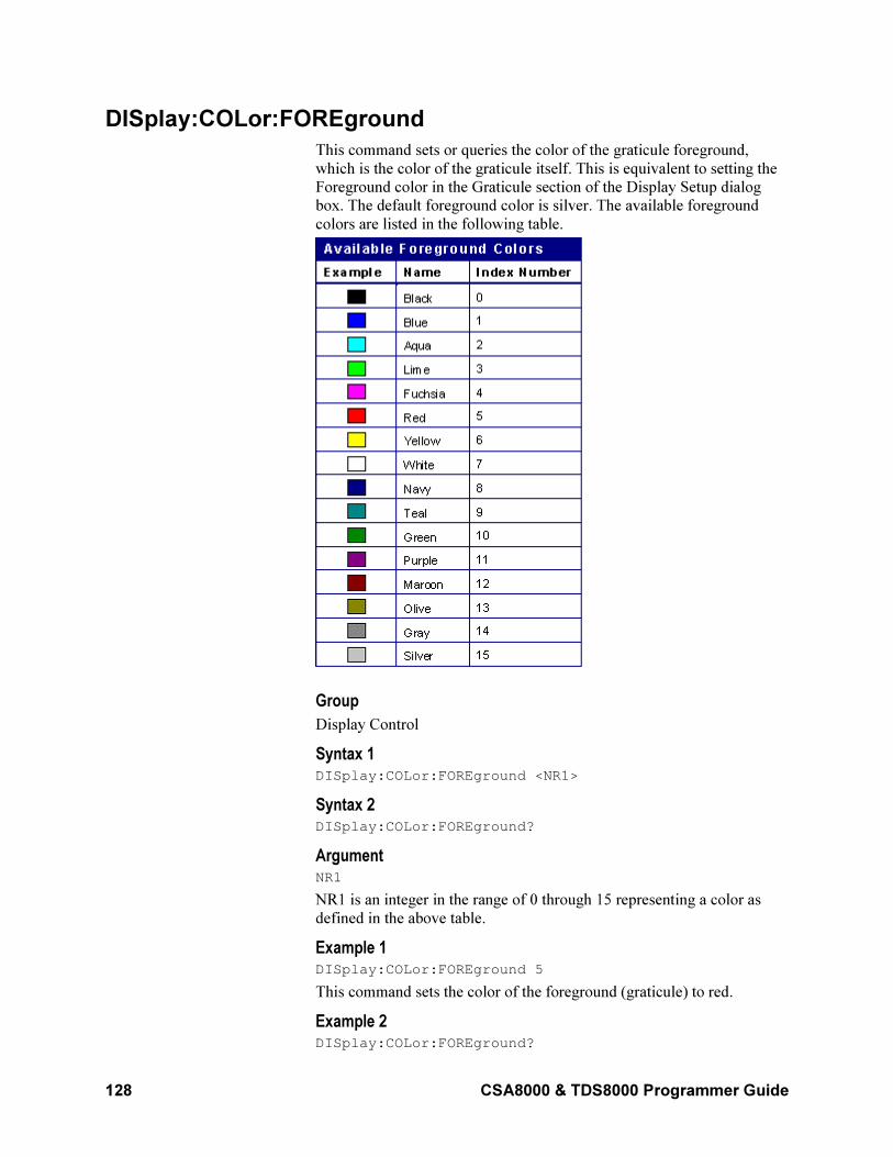
128 CSA8000 & TDS8000 Programmer Guide
DISplay:COLor:FOREground
This command sets or queries the color of the graticule foreground,
which is the color of the graticule itself. This is equivalent to setting the
Foreground color in the Graticule section of the Display Setup dialog
box. The default foreground color is silver. The available foreground
colors are listed in the following table.
Group
Display Control
Syntax 1 DISplay:COLor:FOREground <NR1>
Syntax 2 DISplay:COLor:FOREground?
Argument NR1
NR1 is an integer in the range of 0 through 15 representing a color as
defined in the above table.
Example 1 DISplay:COLor:FOREground 5
This command sets the color of the foreground (graticule) to red.
Example 2 DISplay:COLor:FOREground?
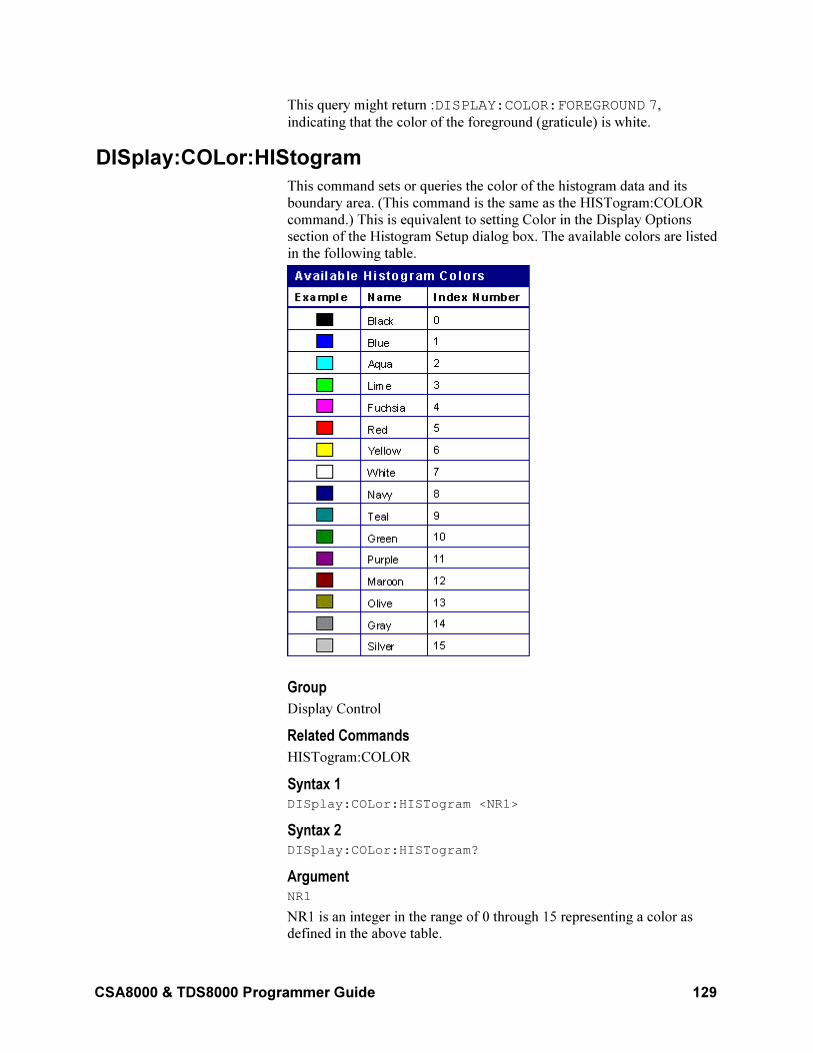
CSA8000 & TDS8000 Programmer Guide 129
This query might return :DISPLAY:COLOR:FOREGROUND 7,
indicating that the color of the foreground (graticule) is white.
DISplay:COLor:HIStogram
This command sets or queries the color of the histogram data and its
boundary area. (This command is the same as the HISTogram:COLOR
command.) This is equivalent to setting Color in the Display Options
section of the Histogram Setup dialog box. The available colors are listed
in the following table.
Group
Display Control
Related Commands
HISTogram:COLOR
Syntax 1 DISplay:COLor:HISTogram <NR1>
Syntax 2 DISplay:COLor:HISTogram?
Argument NR1
NR1 is an integer in the range of 0 through 15 representing a color as
defined in the above table.
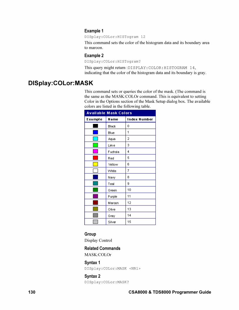
130 CSA8000 & TDS8000 Programmer Guide
Example 1 DISplay:COLor:HISTogram 12
This command sets the color of the histogram data and its boundary area
to maroon.
Example 2 DISplay:COLor:HISTogram?
This query might return :DISPLAY:COLOR:HISTOGRAM 14,
indicating that the color of the histogram data and its boundary is gray.
DISplay:COLor:MASK
This command sets or queries the color of the mask. (The command is
the same as the MASK:COLOr command. This is equivalent to setting
Color in the Options section of the Mask Setup dialog box. The available
colors are listed in the following table.
Group
Display Control
Related Commands
MASK:COLOr
Syntax 1 DISplay:COLor:MASK <NR1>
Syntax 2 DISplay:COLor:MASK?
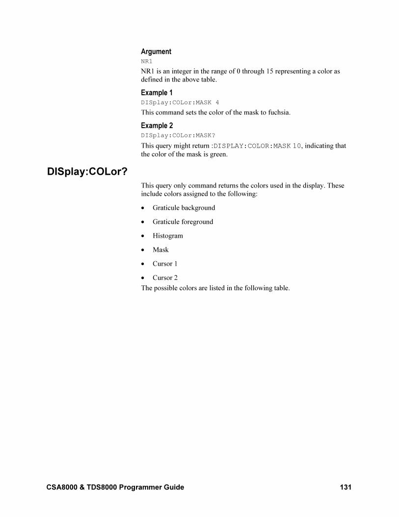
CSA8000 & TDS8000 Programmer Guide 131
Argument NR1
NR1 is an integer in the range of 0 through 15 representing a color as
defined in the above table.
Example 1 DISplay:COLor:MASK 4
This command sets the color of the mask to fuchsia.
Example 2 DISplay:COLor:MASK?
This query might return :DISPLAY:COLOR:MASK 10, indicating that
the color of the mask is green.
DISplay:COLor?
This query only command returns the colors used in the display. These
include colors assigned to the following:
• Graticule background
• Graticule foreground
• Histogram
• Mask
• Cursor 1
• Cursor 2
The possible colors are listed in the following table.
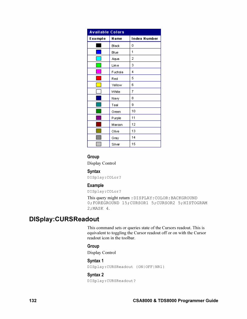
132 CSA8000 & TDS8000 Programmer Guide
Group
Display Control
Syntax DISplay:COLor?
Example DISplay:COLor?
This query might return :DISPLAY:COLOR:BACKGROUND 0;FOREGROUND 15;CURSOR1 5;CURSOR2 5;HISTOGRAM
2;MASK 4.
DISplay:CURSReadout
This command sets or queries state of the Cursors readout. This is
equivalent to toggling the Cursor readout off or on with the Cursor
readout icon in the toolbar.
Group
Display Control
Syntax 1 DISplay:CURSReadout ON|OFF|NR1
Syntax 2 DISplay:CURSReadout?
CSA8000 & TDS8000 Programmer Guide 133
Arguments
• ON
Enables the readout display for the Cursor function.
• OFF
Disables the readout display for the Cursor function.
• NR1
A 0 disables the Cursor readout display; any other integer enables the Cursor readout display.
Example 1 DISplay:CURSReadout 1
This command enables the Cursor readout display.
Example 2 DISplay:CURSReadout?
This query might return :DISPLAY:CURSREADOUT 0, indicating that
the Cursor readout display is off.
NOTE: A query always returns a 0 or 1.
DISplay:GRAticule:HDIVS?
This query only command returns the number of horizontal divisions in
the graticule.
Group
Display Control
Syntax DISplay:GRAticule:HDIVS?
Example DISplay:GRAticule:HDIVS?
This query might return :DISPLAY:GRATICULE:HDIVS 10,
indicating that the graticule display is 10 horizontal divisions wide.
DISplay:GRAticule:STYLE
This command selects the style of graticule that is displayed. Sending the
command is equivalent to setting Style in the Graticule section of the
Display Setup dialog box. The following are the available graticule
styles:
• Full (default)
• Crosshair
• Grid
• Frame
134 CSA8000 & TDS8000 Programmer Guide
Group
Display Control
Syntax 1 DISplay:GRAticule:STYLE FULl|CROSSHair|GRId|FRAme
Syntax 2 DISplay:GRAticule:STYLE?
Arguments
• FULl
Specifies a frame, a grid, and cross hairs.
• CROSSHair
Specifies a frame and cross hairs.
• GRId
Specifies a frame and a grid.
• FRAme
Specifies just a frame.
Example 1 DISpLAY:GRATICULE:STYLE GRID
Sets the graticule style to display a frame and a grid.
Example 2 DISpLAY:GRATICULE:STYLE?
This query might return :DISPLAY:GRATICULE:STYLE FULL when
all graticule elements (grid, frame, and cross hairs) are displayed.
DISplay:GRAticule:VDIVS?
This query only command returns the number of vertical divisions in the
graticule.
Group
Display Control
Syntax DISplay:GRAticule:VDIVS?
Example DISplay:GRAticule:VDIVS?
This query might return :DISPLAY:GRATICULE:VDIVS 10,
indicating that the graticule display is 10 vertical divisions high.
DISplay:GRAticule?
This query only command returns all the graticule parameters.
Group
Display Control
CSA8000 & TDS8000 Programmer Guide 135
Syntax DISplay:GRAticule?
Example DISplay:GRAticule?
This query might return :DISPLAY:GRATICULE:STYLE FULL; HDIVS 0.100000000000;VDIVS 0.10000000000.
DISplay:HISTReadout
This command sets or queries state of the Histogram readout. This is
equivalent to toggling the Histogram readout off or on with the
Histogram readout icon in the toolbar.
Group
Display Control
Syntax 1 DISplay:HISTReadout ON|OFF|NR1
Syntax 2 DISplay:HISTReadout?
Arguments
• ON
Enables the readout display for the Histogram function.
• OFF
Disables the readout display for the Histogram function.
• NR1
A 0 disables the Histogram readout display; any other integer enables the Histogram readout display.
Example 1 DISplay:HISTReadout 1
This command enables the Histogram readout display.
Example 2 DISplay:HISTReadout?
This query might return :DISPLAY:HISTREADOUT 0, indicating that
the Histogram readout display is off.
NOTE: A query always returns a 0 or 1.
DISplay:INTERPolat
This command sets or queries the interpolation algorithm used to display
any waveforms in the Main or Mag views when the record length is less
than 500 points. This is equivalent to setting Interpolation in the Style
section of the Display Setup dialog box.
Note: Interpolation is a display function only; the instrument does not do
acquisition interpolation.
136 CSA8000 & TDS8000 Programmer Guide
With interpolation and for high acquisition rates, the instrument increases
the sample density on the waveforms it displays by calculating
intermediate points for those sampled. You can set one of the following
Interpolation display algorithms:
• None (default). Turns interpolation off.
• Sin (X)/X. This algorithm computes points using a curve fit between
the actual values acquired. It assumes all interpolated points fall
along the curve. This is useful when displaying more rounded
waveforms such as sine waves. This algorithm can be used for
general use, but it may introduce some overshoot or undershoot in
signals with fast rise times.
• Linear. This algorithm computes points between actual acquired
samples by using a straight line fit. The algorithm assumes all
interpolated points fall along the straight line. Linear interpolation is
useful for many waveforms such as pulse trains.
Group
Display Control
Related Commands
DISplay:STYle
Syntax 1 DISplay:INTERPolat LINear|NONe|SINX
Syntax 2 DISplay:INTERPolat?
Arguments
• LINear
Specifies linear interpolation.
• NONe
Turns off the interpolation function.
• SINX
Specifies Sin (x)/x interpolation.
Example 1 DISplay:INTERPolat LINear
This command selects the linear interpolation algorithm.
Example 2 DISplay:INTERPolat?
This query might return :DISPLAY:INTERPOLAT NONE, indicating
that no interpolation algorithm is selected.
CSA8000 & TDS8000 Programmer Guide 137
DISplay:MASKReadout
This command sets or queries state of the Mask readout. This is
equivalent to toggling the Mask readout off or on with the Mask readout
icon in the toolbar.
Group
Display Control
Syntax 1 DISplay:MASKReadout ON|OFF|NR1
Syntax 2 DISplay:MASKReadout?
Arguments
• ON
Enables the readout display for the Mask function.
• OFF
Disables the readout display for the Mask function.
• NR1
A 0 disables the Mask readout display; any other integer enables the
Mask readout display.
Example 1 DISplay:MASKReadout 1
This command enables the Mask readout display.
Example 2 DISplay:MASKReadout?
This query might return :DISPLAY:MASKREADOUT 0, indicating that
the Mask readout display is off.
NOTE: A query always returns a 0 or 1.
DISplay:MEASBar
This command sets or queries whether or not the Measurement Bar is
displayed. This is equivalent to checking or clearing the Measurement
Bar menu item in the View menu.
Group
Display Control
Syntax 1 DISplay:MEASBar ON|OFF|NR1
Syntax 2 DISplay:MEASBar?
Arguments
• ON
138 CSA8000 & TDS8000 Programmer Guide
Enables the Measurement Bar display.
• OFF
Disables the Measurement Bar display.
• NR1
A 0 disables the Measurement Bar display; any other integer enables the Measurement Bar display.
Example 1 DISplay:MEASBar 1
This command enables the Measurement Bar display.
Example 2 DISplay:MEASBar?
This query might return :DISPLAY:MEASBAR 0, indicating that the
Measurement Bar display is off.
NOTE: A query always returns a 0 or 1.
DISplay:MEASReadout
This command sets or queries state of the measurement readout. This is
equivalent to toggling the Measurement readout off or on with the
Measurement readout icon in the toolbar.
Group
Display Control
Syntax 1 DISplay:MEASReadout ON|OFF|NR1
Syntax 2 DISplay:MEASReadout?
Arguments
• ON
Enables the readout display for the Measurement function.
• OFF
Disables the readout display for the Measurement function.
• NR1
A 0 disables the Measurement readout display; any other integer enables the Measurement readout display.
Example 1 DISplay:MEASReadout 1
This command enables the Measurement readout display.
Example 2 DISplay:MEASReadout?
CSA8000 & TDS8000 Programmer Guide 139
This query might return :DISPLAY:MEASREADOUT 0, indicating that
the Measurement readout display is off.
NOTE: A query always returns a 0 or 1.
DISplay:PERSistence
This command sets or queries the length of time that data points are
displayed when variable persistence is active. This affects the display
only and is equivalent to setting Time in the Style section of the Display
Setup dialog box.
Group
DISplay Control
Related Commands
DISplay:STYle
Syntax 1 DISplay:PERSistence <NR3>
Syntax 2 DISplay:PERSistence?
Argument NR3
Specifies the length, in seconds, that the waveform points are displayed
on the screen. The range is 500 ms to 100 s (in increments of 100 ms
from 500 ms to 1s and in 0.5 s increments from 1 s to 100 s).
Example 1 DISplay:PERSistence 3
Specifies that the waveform points are displayed on the screen for 3
seconds before they fade.
Example 2 DISplay:PERSistence?
This query might return :DISPLAY:PERSISTENCE
0.200000000000 indicating that the persistence is set to 200 ms.
DISplay:SHOWVector
This command sets or queries the Show Vectors mode. For the Normal
display style only, you can set the instrument to draw vectors between
displayed waveform points. This is equivalent to selecting or clearing the
Show Vectors check box in the Style section of the Display Setup dialog
box.
Group
Display Control
Related Commands
DISplay:STYle
140 CSA8000 & TDS8000 Programmer Guide
Syntax 1 DISplay:SHOWVector ON|OFF|NR1
Syntax 2 DISplay:SHOWVector?
Arguments
• ON
Enables the vector display.
• OFF
Disables the vector display.
• NR1
0 disables the vector display; any other integer enables the vector
display.
Example 1 DISplay:SHOWVector ON
This enables the Show Vectors mode, which displays lines between the
sampled (or interpolated) points.
Example 2 DISplay:SHOWVector?
This query might return :DISPLAY:SHOWVECTOR 0, indicating that the
vector display is disabled, and the waveform is displayed as dots.
NOTE: A query always returns a 0 or 1.
DISplay:STYLE
This command sets or queries whether or not the data is displayed using
persistence. Sending this command is equivalent to selecting Variable
Persistence or Infinite Persistence (or neither) in the Style section of the
Display Setup dialog box.
Group
Display Control
Related Commands
DISplay:PERSistence
Syntax 1 DISplay:STYLE NORMal|INFPersist|VARPersist
Syntax 2 DISplay:STYLE?
Arguments
• NORMal
Disables the persistence mode.
• INFPersist
CSA8000 & TDS8000 Programmer Guide 141
Accumulates data points on the display indefinitely. The display is reset when the style or acquisition is reset.
• VARPersist
Leaves acquired data points on the display for a period of time
specified by the DISplay:PERSistence command.
Example 1 DISplay:STYLE INFPersist
Sets the display to indefinitely accumulate data points on the screen.
Example 2 DISplay:STYLE?
This command might return :DISPLAY:STYLE VARPERSIST,
indicating that the display style is set to variable persistence.
DISpLay:WFMReadout
This command sets or queries state of the Waveform readout. This is
equivalent to toggling the Waveform readout off or on with the
Waveform readout icon in the toolbar.
Group
Display Control
Syntax 1 DISplay:WFMReadout ON|OFF|NR1
Syntax 2 DISplay:WFMReadout?
Arguments
• ON
Enables the readout display for the Waveform function.
• OFF
Disables the readout display for the Waveform function.
• NR1
A 0 disables the Waveform readout display; any other integer enables the Waveform readout display.
Example 1 DISplay:WFMReadout 1
This command enables the Waveform readout display.
Example 2 DISplay:WFMReadout?
This query might return :DISPLAY:WFMREADOUT 0, indicating that
the Waveform readout display is off.
NOTE: A query always returns a 0 or 1.
142 CSA8000 & TDS8000 Programmer Guide
DISplay?
This is a query only command that returns the current display settings.
Group
Display Control
Syntax DISplay?
Example DISplay?
This command might return the following:
:DISPLAY:PERSISTENCE 0.200000000000;STYLENORMAL;INTERPOLAT SINX;SHOWVECTOR 1;GRATICULE:STYLEFULL;HDIVS 1.00000000000;VDIVS1.00000000000;:DISPLAY:COLOR:BACKGROUND 0;FOREGROUND7;CURSOR1 5;CURSOR2 5;HISTOGRAM 2;MASK4;:DISPLAY:MEASREADOUT 0;CURSREADOUT 0;HISTREADOUT0;WFMREADOUT 1;MASKREADOUT 0;MEASBAR 1
EVENT?
This is a query only command that returns an event code from the Event
Queue that provides information about the results of the last *ESR? read.
EVENT? also removes the returned value from the Event Queue. For
more information, see Event Handling Sequence on page 341.
Group
Status and Error
Related Commands
ALLev?, *CLS, DESE, *ESE, *ESR?, EVMsg?, *SRE, *STB?
Syntax EVENT?
Example EVENT?
This query might return the response :EVENT 110, indicating that
there was an error in a command header.
EVMsg?
This is a query only command that removes a single event code from the
Event Queue that is associated with the results of the last *ESR? read
and returns the event code along with an explanatory message. For more
information, see Event Handling Sequence on page 341.
Group
Status and Error
Related Commands
ALLEv?, *CLS, DESE, *ESE, *ESR?, EVENT?, *SRE, *STB
CSA8000 & TDS8000 Programmer Guide 143
Syntax EVMsg?
Returns
The event code and message in the following format:
<Event Code><Comma><QString>[<Event Code><Comma><QString>...]<QString>::= <Message>;[<Command>]
where <Command> is the command that caused the error and may be
returned when a command error is detected by the instrument. As much
of the command will be returned as possible without exceeding the 60-
character limit of the <Message> and <Command> strings combined.
The command string is right justified.
Example EVMSG?
This query might return :EVMSG 110,"Command header
error".
EVQty?
This query only command returns the number of event codes that are in
the Event Queue. This is useful when using the ALLEv? query, since it
lets you know exactly how many events will be returned.
Group
Status and Error
Related Commands
ALLEv?, EVENT?, EVMsg?
Syntax EVQty?
Example EVQTY?
This query might return :EVQTY 3, indicating that there are three event
codes in the Event Queue.
EXPort
This command (no query form) exports waveform data to a file as a
series of comma-separated values (CSV) in ASCII text. Exporting data in
this format allows you to use it with other analysis tools, such as
spreadsheets or math analysis applications. Exported waveforms cannot
be imported. If you intend to recall a waveform later, you should save it
instead of exporting it.
Group
Save and Recall
144 CSA8000 & TDS8000 Programmer Guide
Related Commands
Syntax EXPort CH<x>|MATH<x>|REF<x>|HIST[,MAIn|MAG1|MAG2], <filepath>
Arguments
• CH<x>
This argument selects a channel waveform to export. The range for x is 1 through 8.
• MATH<x>
This argument selects a math waveform to export. The range for x is
1 through 8.
• REF<x>
This argument selects a reference waveform to export. The range for x is 1 through 8.
• HIST
This argument selects histogram data to export.
• MAIn
This optional argument selects Main as the timebase for the exported waveform. This is the default timebase.
• MAG1
This optional argument selects MAG1 as the timebase for the
exported waveform.
• MAG2
This optional argument selects MAG2 as the timebase for the exported waveform.
• <file path>
This is the location to which the waveform will be exported.
The <file path> is a quoted string that defines the file name and path.
Input the file path using the form <drive>/<dir>/<filename>. The
<filename> can be a Windows 95/Windows 98 long file name. Do not use wild card characters.
Example
EXPort REF2 "C:My Documents\TDS8000\MainR2.txt"
FACTory
This command (no query form) resets the instrument to its factory
default settings. Sending this command is equivalent to pressing the
front-panel DEFAULT SETUP button or selecting Default Setup in the
Utilities menu.
Executing the FACtory command does the following actions:
CSA8000 & TDS8000 Programmer Guide 145
• Clears the Event Status Enable Register
• Clears the Service Request Enable Register
• Sets the Device Event Status Enable Register to 255
• Sets the Power On Status Clear Flag to TRUE
• Enables all Command Headers (HEADer ON)
• Clears the pending operation flag and associated operations
• Clears all references from the reference slots
• The FACtory command does not change the following:
• The state of the GPIB (IEEE Std 488.1-1987) interface
• The selected GPIB address
• Data transfer settings
• Calibration data that affects device specifications
• Protected user data
• Stored settings
Group
Miscellaneous
Related Commands
RECAll:SETUp, *RST, SAVe:SETUp
Syntax FACTory
Example FACTory
FILESystem:READFile? <file path>
Outputs the specified file to the GPIB port with maximum file size of
10Mb
Argument
• file path
<file path> is a quoted string that defines the file name and path.
Input the file path using the form "<drive>\dir\filename". The
<filename> can be a Windows95/Windows 98 long file name. Do
not use wild card characters.
Example FILESYSTEM:READFILE? "c:\My Documents\Pi\test.txt"
146 CSA8000 & TDS8000 Programmer Guide
HARDCopy
This command (no query form) sends a copy of the screen display
followed by an EOI to the hard copy port. Sending this command is
equivalent to pressing the front-panel PRINT button.
Note: This command is NOT IEEE STD 488.2-1987 compatible.
Group
Hardcopy
Related Commands
HARDCopy:FORMat
HARDCopy:FILEName
HARDCopy:INKSaver
Syntax HARDCopy STARt
Arguments STARt
Initiates a screen copy that is sent to the controller where it is redirected
to a printing device.
Note: Use the *WAI command between HARDCopy STARt commands to
ensure that the first hardcopy task is sent to the printer before starting
another.
Example HARDCOPY STARt
Starts a hardcopy.
HARDCopy:FILEName
This command immediately sends a copy of the screen display to the file
specified by the command argument. The filename may include a
relative path, or a fully qualified path, to any location supported by
Microsoft Windows, including the local hard disk, floppy drive, and
network folders.
Note. If the file you specify doesn't exist, sending this command creates
it. If the file does exist, sending this command overwrites its contents.
The image-file format that your hardcopy will have depends on whether
you include a file extension when you specify the file path:
• If your :FILEName argument does not include a file extension, the
file extension associated with the format set by the
HARDCopy:FORMat command is automatically appended and that
image-file format is used. You can change the file format using the
HARDCopy:FORMat command, sending it before you send the
HARDCopy:FILEName command.
• If your :FILEName argument does include a file extension, the
image-file associated with it is used instead. The file extension must
CSA8000 & TDS8000 Programmer Guide 147
be one associated with one of the formats listed for the
HARDCopy:FORMat command.
Group
Hardcopy
Related Commands
HARDCopy
HARDCopy:FORMat
HARDCopy:INKSaver
Syntax HARDCopy:FILEName <file path>
Argument file path
This argument specifies the file to which the hardcopy is sent. This
argument is a quoted string that defines the file name, path, and,
optionally, the file format if you include a file extension (see the
description above).
Note. The specified filename must be enclosed with quotation marks and
wild card characters are illegal.
Example 1 HARDCOPY:FILENAME "C:\My Documents\tek"
Immediately outputs a hardcopy to the file TEK.<format>, where
<format> is the image-file format set by the HARDCopy:FORMat
command, or by the optional file-name extension (see the description
above).
Example 2 HARDCOPY:FILENAME "C:\My Documents\tek.png"
Immediately outputs a hardcopy to the file TEK.PNG, where PNG is
image-file format set by the file-name extension included in the
command argument (see the description above).
HARDCopy:FORMat
This command selects the image-file format used with the hardcopy commands. Several image file formats are provided to support compatibility with image-processing applications and efficient utilization of disk capacity.
Syntax HARDCopy:FORMat PNG|JPEG|BMP|TIFF|TARGA
Arguments
• PNG
Sets the hardcopy format to PNG. This setting produces compressed
image files between 20KB and 100KB. This format uses a lossless
image compression algorithm and will always produce the smallest
file size of the available formats.
148 CSA8000 & TDS8000 Programmer Guide
• JPEG
Sets the hardcopy format to JPEG. This setting produces compressed
image files between 60KB and 100KB. This format uses a lossy image compression algorithm.
• BMP
Sets the hardcopy format to BMP. This setting produces minimally
compressed (RLE) image files around 1MB. This is the default
image file format and is commonly supported by Microsoft Windows compatible applications.
• TIFF
Sets the hardcopy format to TIFF. This setting produces uncompressed image files that are typically larger than 1MB.
• TARGA
Sets the hardcopy format to TARGA. This setting produces
minimally compressed (RLE) image files around 1MB.
Related Commands HARDCopy:FILEName
HARDCopy
Example HARDCOPY:FORMAT PNG
Selects PNG as the file format to which hardcopy data is sent.
HARDCopy:INKSaver
This command turns Ink-saver mode on and off. When Ink-saver mode is
on, hardcopies are produced with a white background to conserve ink.
Ink-saver mode can be used when sending hardcopy images to a printer,
or when sending hardcopy images to a file using the
HARDCopy:FILEName command.
Group
Hardcopy
Related Commands
HARDCopy
HARDCopy:FORMat
HARDCopy:FILEName
Syntax HARDCopy:INKSaver ON | OFF | 0 | 1
Argument
ON | OFF | 0 | 1
This argument turns Ink-saver mode on and off
Example 1
HARDCOPY:INKSAVER ON
CSA8000 & TDS8000 Programmer Guide 149
Turns Ink-saver mode on for subsequent hardcopy commands.
Example 2
HARDCOPY:INKSAVER?
This query will return : HARDCOPY:INKSAVER 1 if Ink-saver mode is
currently on.
HEADer
This command sets and queries the Response Header Enable State that
causes the instrument to either include or omit headers on query
responses. This command does not affect IEEE Std 488.2-1987 Common
Commands (those starting with an asterisk); these commands never
return headers.
Group
Miscellaneous
Related Commands
VERBose
Syntax 1
HEADer ON|OFF|NR1
Syntax 2
HEADer?
Arguments
• ON
Sets the Response Header Enable State to true. This causes the
instrument to include headers on applicable query responses. You
can then use the query response as a command.
• OFF
Sets the Response Header Enable State to false. This causes the
instrument to omit headers on query responses so that only the argument is returned.
• NR1
0 sets the Response Header Enable State to false, which disables the
headers; any other integer sets the Response Header Enable State to true, which enables the headers. (A query always returns a 0 or 1.)
Example 1 HEADER OFF
This command causes the instrument to omit headers from query
responses.
Example 2 HEADER?
This query might return :HEADER 1, indicating that the Response
Header Enable State is on.
150 CSA8000 & TDS8000 Programmer Guide
NOTE: A query always returns a 0 or 1.
HIStogram:BOX
Defines the left, top, right, and bottom boundaries of the histogram box
in source waveform coordinates. This is equivalent to setting the Limit
Controls for Left, Top, Right, and Bottom in the Histogram Setup dialog
box. This command is similar to the HIStogram:BOXPcnt command,
which uses percentage coordinates to define the boundaries of the
histogram box.
Group
Histogram
Related Commands
HIStogram:BOXPcnt
Syntax 1 HIStogram:BOX <NR3>,<NR3>,<NR3>,<NR3>
Syntax 2 HIStogram:BOX?
Arguments
• NR3
The left position of the histogram box in source waveform coordinates.
• NR3
The top position of the histogram box in source waveform coordinates.
• NR3
The right position of the histogram box in source waveform
coordinates.
• NR3
The bottom position of the histogram box in source waveform coordinates.
Example 1 HISTOGRAM:BOX 1.518E-006,-2.46E-1,3.518E-6,-7.47E-1
This command defines the coordinates of the histogram box in source
waveform coordinates.
Example 2 HISTOGRAM:BOX?
This query might return :HISTOGRAM:BOX 1.51800000000E-006,-0.246000000000,
3.51800000000E-006,-0.747000000000.
CSA8000 & TDS8000 Programmer Guide 151
HIStogram:BOXPcnt
Defines the left, top, right, and bottom positions of the histogram box, in
percentage of screen coordinates. The upper left has the value 0, 0 and
the lower right has the value 100, 100. Any value outside the range of 0
to 100 is clipped and generates an error. This command is similar to the
HIStogram:BOX command, which uses waveform coordinates to define
the boundaries of the histogram box.
Group
Histogram
Related Commands
HIStogram:BOX
Syntax 1 HIStogram:BOXPcnt <NR3>,<NR3>,<NR3>,<NR3>
Syntax 2 HIStogram:BOXPcnt?
Arguments
• NR3
The left position of the histogram box in percentage coordinates. The default value is 30.
• NR3
The top position of the histogram box in percentage coordinates. The default value is 25.
• NR3
The right position of the histogram box in percentage coordinates.
The default value is 70.
• NR3
The bottom position of the histogram box in percentage coordinates. The default value is 75.
Example 1 HIStogram:BOXPcnt 35,21,72,76
This command defines the coordinates of a histogram box in percentage
coordinates.
Example 2 HIStogram:BOXPcnt?
This query might return :HISTOGRAM:BOXPCNT 30.0000000000, 25.0000000000,70.0000000000,
75.0000000000.
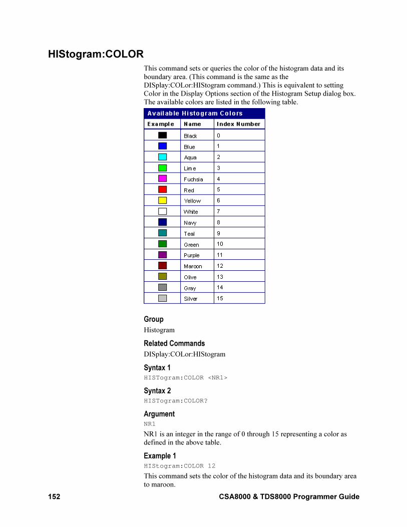
152 CSA8000 & TDS8000 Programmer Guide
HIStogram:COLOR
This command sets or queries the color of the histogram data and its
boundary area. (This command is the same as the
DISplay:COLor:HIStogram command.) This is equivalent to setting
Color in the Display Options section of the Histogram Setup dialog box.
The available colors are listed in the following table.
Group
Histogram
Related Commands
DISplay:COLor:HIStogram
Syntax 1 HISTogram:COLOR <NR1>
Syntax 2 HISTogram:COLOR?
Argument NR1
NR1 is an integer in the range of 0 through 15 representing a color as
defined in the above table.
Example 1 HIStogram:COLOR 12
This command sets the color of the histogram data and its boundary area
to maroon.
CSA8000 & TDS8000 Programmer Guide 153
Example 2 HISTogram:COLor?
This query might return :HISTOGRAM:COLOR:14, indicating that the
color of the histogram data and its boundary is gray.
HIStogram:COUNt
This command clears the count and statistics for the histogram and the
histogram source data. If the histogram is on, then counting restarts. This
is equivalent to clicking Clear in the Source section of the Histogram
Setup dialog box. There is no query form of this command.
Group
Histogram
Syntax HIStogram:COUNt RESET
Example HISTOGRAM:COUNT RESET
Clears the count and statistics for the histogram and the histogram source
data.
HIStogram:DISplay
This command sets or queries whether the histogram is displayed. This is
equivalent to selecting Histogram in the Display Options section of the
Histogram Setup dialog box.
Group
Histogram
Syntax 1 HIStogram:DISplay ON|OFF|NR1
Syntax 2 HIStogram:DISplay?
Arguments
• ON
This argument displays the histogram.
• OFF
This argument disables the histogram display.
• NR1
A 0 disables the histogram display; any other value displays the histogram.
Example 1 HISTogram:DISplay ON
This command displays the histogram.
154 CSA8000 & TDS8000 Programmer Guide
Example 2 HIStogram:DISplay?
This query might return :HISTOGRAM:DISPLAY 0, indicating that
the histogram display is disabled.
NOTE: A query always returns a 0 or 1.
HIStogram:ENABle
This command sets or queries whether the histogram calculations are
enabled. This is equivalent to selecting Enable Histogram in the Source
section of the Histogram Setup dialog box. Sending this command will
cause the histogram statistics to be displayed (but not the histogram). Use
the HIStogram:DISplay command to control whether the histogram is
displayed on screen.
Group
Histogram
Syntax 1 HIStogram:ENABle ON|OFF|NR1
Syntax 2 HIStogram:ENABle?
Arguments
• ON
This argument enables histogram calculations.
• OFF
This argument disables histogram calculations.
• NR1
A 0 disables the histogram calculations; any other value enables histogram calculations.
Example 1 HISTogram:ENABle ON
This command enables histogram calculations.
Example 2 HIStogram:ENABle?
This query might return :HISTOGRAM:ENABLE 0, indicating that the
histogram calculations are disabled.
NOTE: A query always returns a 0 or 1.
HIStogram:MODe
Selects the type of histogram to create. This is equivalent to selecting
either Vertical or Horizontal in the Source section of the Histogram
Setup dialog box.
CSA8000 & TDS8000 Programmer Guide 155
Group
Histogram
Syntax 1 HIStogram:MODe HORizontal|VERTical
Syntax 2 HIStogram:MODe?
Arguments
• HORizontal
Displays a horizontally positioned histogram that shows time distribution.
• VERTical
Displays a vertically positioned histogram that shows a voltage distribution (or other vertical distribution, such as amperes).
Example 1 HIStogram:MODe HORizontal
Sets the histogram mode to the horizontal display mode.
Example 2 HIStogram:MODe?
This query might return :HISTOGRAM:MODE VERTICAL, indicating
that the vertical display mode is selected for the histogram.
HIStogram:SIZe
This command sets or queries the width or height in divisions of the
histogram plot on the screen. This is equivalent to setting Size in the
Display Options section of the Histogram Setup dialog box.
Group
Histogram
Syntax 1 HIStogram:SIZe <NR3>
Syntax 2 HIStogram:SIZe?
Argument NR3
The value can vary from 1.0 to 10.0 in Horizontal mode and from 1.0 to
10.0 in Vertical mode. Resolution is to the nearest pixel.
Example 1 HIStogram:SIZe 2
This command sets the size of the histogram to 2 divisions.
Example 2 HIStogram:SIZe?
156 CSA8000 & TDS8000 Programmer Guide
This command might return:HISTOGRAM:SIZE 4.00000000000,
indicating the histogram size is set to 4 divisions.
HIStogram:SOUrce
This command sets or queries which source will be compared against the
histogram box when the histogram testing is enabled. You can also select
the timebase on which to perform testing. If you do not specify a
timebase, Main is the default. This is equivalent to selecting the source
from the pulldown list in the Source section of the Histogram Setup
dialog box. The waveform need not be displayed for histograms to run.
You might want the channel displays disabled so you can see a full-
screen histogram and not have waveform data confuse the display.
Group
Histogram
Syntax 1 HIStogram:SOUrce CH<x>|MATH<x>|REF<x>[,MAIn|MAG1|MAG2]
Syntax 2 HIStogram:SOUrce?
Argument
• CH<x>
This argument selects a channel waveform as the source for the
histogram. The range for x is 1 through 8.
• MATH<x>
This argument selects a math waveform as the source for the histogram. The range for x is 1 through 8.
• REF<x>
This argument selects a reference waveform as the source for the histogram. The range for x is 1 through 8.
• MAIn
This optional argument selects Main as the timebase for the
histogram display.
• MAG1
This optional argument selects MAG1 as the timebase for the histogram display.
• MAG2
This optional argument selects MAG2 as the timebase for the histogram display.
Example 1 HIStogram:SOUrce CH1
Enables the Channel 1 waveform to be compared against the histogram
box. The default timebase, Main, is used for the histogram display.
CSA8000 & TDS8000 Programmer Guide 157
Example 2 HIStogram:SOUrce?
This query might return :HISTOGRAM:SOURCE CH1,MAG1,
indicating that the waveform for Channel 1 is the source for the
histogram and that it is displayed using MAG1 as the timebase.
HIStogram:STATistics:HITS?
This query only command returns the total hits calculated for the
histogram. This is the value that is displayed for Hits in the Histogram
readout.
Group
Histogram
Syntax HISTogram:STATistics:HITS?
Example HISTogram:STATistics:HITS?
This query might return :HISTOGRAM:STATISTICS:HITS
6.83400000000E+003, indicating that the total hits for the histogram
is 6,834.
HIStogram:STATistics:MEAN?
This query only command returns the mean value calculated for the
histogram. This is the value that is displayed for Mean in the Histogram
readout.
Group
Histogram
Syntax HISTogram:STATistics:MEAN?
Example HISTogram:STATistics:MEAN?
This query might return :HISTOGRAM:STATISTICS:MEAN
43.0000000000E-009, indicating that the mean value for the
horizontal histogram is 43 ns.
HIStogram:STATistics:MEDIAN?
This query only command returns the median value calculated for the
histogram. This is the value that is displayed for Median in the
Histogram readout.
Group
Histogram
Syntax HISTogram:STATistics:MEDIAN?
158 CSA8000 & TDS8000 Programmer Guide
Example HISTogram:STATistics:MEDIAN?
This query might return :HISTOGRAM:STATISTICS:MEDIAN
43.0000000000E-009, indicating that the median value for the
horizontal histogram is 43 ns.
HIStogram:STATistics:PEAKHits?
This query only command returns the peak hits calculated for the
histogram. This is the value that is displayed for Peak in the Histogram
readout.
Group
Histogram
Syntax HISTogram:STATistics:PEAKHits?
Example HISTogram:STATistics:PEAKHits?
This query might return :HISTOGRAM:STATISTICS:PEAKHITS
370.000000000, indicating that the peak hits value calculated for the
waveform is 370.
HIStogram:STATistics:PKTOPK?
This query only command returns the peak-to-peak value calculated for
the histogram. This is the value that is displayed for Pk-Pk in the
Histogram readout.
Group
Histogram
Syntax HISTogram:STATistics:PK2PK?
Example HISTogram:STATistics:PK2PK?
This query might return :HISTOGRAM:STATISTICS:PKTOPK
200000000000.009, indicating that the peak-to-peak value for the
horizontal histogram is 20 ns
HIStogram:STATistics:SIGMA<x>?
This query only command returns the population densities for ±1σ, ±2σ,
or ±3σ value (standard deviation from the mean value) calculated for the
histogram. This is the value that is displayed for µ±1σ, µ±2σ, or µ±3σ in
the Histogram readout.
Group
Histogram
CSA8000 & TDS8000 Programmer Guide 159
Syntax HISTogram:STATistics:SIGMA<x>?
The value for x can be 1, 2, or 3, indicating a query for the sigma1,
sigma2, or sigma3 value.
Example HISTogram:STATistics:SIGMA1?
This query might return :HISTOGRAM:STATISTICS:SIGMA1
58.0060, indicating that 58% of the hits fall within one standard
deviation (µ±1σ) from the mean calculated for the histogram.
HIStogram:STATistics:WAVeforms?
This query only command returns the number of waveforms used in the
histogram. This is the value that is displayed for Waveforms in the
Histogram readout.
Group
Histogram
Syntax HISTogram:STATistics:WAVeforms?
Example HISTogram:STATistics:WAVeforms?
This query might return :HISTOGRAM:STATISTICS:WAVEFORMS
2.08100000000E+003, indicating that 2081 waveforms were used to
create the histogram.
HIStogram:STATistics?
This query only command returns all histogram statistics. These are the
Histogram statistics that are displayed in the Histogram readout:
• Mean
• Median
• Std Dev
• Pk-Pk
• µ±1?
• µ±2?
• µ±3?
• Peak
• Hits
• Waveforms
The histogram statistics (and count) can be reset with the
HIStogram:COUNt command.
160 CSA8000 & TDS8000 Programmer Guide
Group
Histogram
Related Commands
HIStogram:COUNt
Syntax HISTogram:STATistics?
Example HISTogram:STATistics?
This query might return the following:
:HISTOGRAM:STATISTICS:MEAN 43.0000000000E-009;MEDIAN 43.0000000000E-009;STDDEV 5.80230431544E-009;PKTOPK 20.0000000000E-009;SIGMA1 58.7064;SIGMA2 58.7064;SIGMA3 100.0000; PEAKHITS 2.43800000000E+003;HITS 490.038000000E+003; WAVEFORMS 2.43800000000E+003
HIStogram:STATistics:STDdev?
This query only command returns the standard deviation value calculated
for the histogram. This is the value that is displayed for Std Dev in the
Histogram readout.
Group
Histogram
Syntax HISTogram:STATistics:STDdev?
Example HISTogram:STATistics:STDdev?
This query might return :HISTOGRAM:STATISTICS:STDDEV
5.80230767128E-009, indicating that the standard deviation value
for the horizontal histogram is 5.80 ns.
HIStogram:TYPE
This command sets or queries whether the histogram is displayed linearly
or logarithmically. This is equivalent to selecting Linear or Logarithmic
in the Display Options section of the Histogram Setup dialog box.
Group
Histogram
Syntax 1 HIStogram:TYPE LINEAr|LOG
Syntax 2 HIStogram:TYPE?
CSA8000 & TDS8000 Programmer Guide 161
Arguments
• LINEAr
This argument specifies that bin counts smaller than the maximum
should be scaled linearly by dividing the bin count by the maximum bin count.
• LOG
This argument specifies that bin counts smaller than the maximum
should be scaled logarithmically (log (bin-count)) with log(0) staying
at 0 (baseline). The base of the log does not matter since logs to
different bases differ only by a constant multiplier. Logarithmic
scaling provides better visual detail for bins with low counts.
Example 1 HISTogram:TYPE LINEAr
This command displays the count in each bin scaled linearly.
Example 2 HIStogram:TYPE?
This query might return :HISTOGRAM:TYPE LINEAR, indicating that
the histogram display is scaled linearly.
HIStogram:WFMDB:STATE
This command sets or queries whether the histogram counting is made
on a waveform database created on the source of the histogram. This is
equivalent to selecting or clearing the Use Wfm Database check box in
the Source section of the Histogram Setup dialog box.
Group
Histogram
Syntax 1 HIStogram:WFMDB:STATE ON|OFF|NR1
Syntax 2 HIStogram:WFMDB:STATE?
Arguments
• ON
This argument enables histogram counting on a waveform database created on the source of the histogram.
• OFF
This argument disables histogram counting on a waveform database;
testing is done "on the fly."
• NR1
A 0 disables the histogram counting on a waveform database; any other value enables histogram counting on a waveform database.
162 CSA8000 & TDS8000 Programmer Guide
Example 1 HISTogram:WFMDB:STATE ON
This command enables histogram counting on a waveform database.
Example 2 HIStogram:WFMDB:STATE?
This query might return :HISTOGRAM:WFMDB:STATE 0, indicating
that the histogram counting on a waveform database is disabled.
Note: A query always returns 0 or 1.
HIStogram?
This is a query only command that returns histogram parameters; it
queries the state of all settable histogram parameters.
Group
Histogram
Syntax HIStogram?
Example HISTOGRAM?
This command might return :HISTOGRAM:BOX 1.51800000000E-006,-24.4980000000, 3.51800000000E-006,-74.4980000000;BOXPCNT 30.0000000000,25.0000000000, 7.00000000000,7.50000000000;COLOR 6; ENABLE 1;DISPLAY 1;TYPE LINEAR;MODE VERTICAL; SIZE 4.00000000000;SOURCE CH3,MAIN; STATISTICS:MEAN 46.9321597622E-003; MEDIAN 224.000000000E-003;STDDEV 227.027807252E-003; PKTOPK 500.000000000E-003;SIGMA1 636.054733146E-003; SIGMA2 636.054733146E-003;SIGMA3 1.00000000000; PEAKHITS 39.4280000000E+003;HITS 185.701000000E+003; WAVEFORMS 924.000000000;:HISTOGRAM:WFMDB:STATE 1
HORizontal:BITS:BITRate
This command sets or queries the bit rate of the timebase. Sending this
command is equivalent to setting a value in the Bit Rate control in the
All Timebases section of the Horizontal Setup dialog box. This value is
used to convert horizontal scales from seconds to bits.
If a communications standard is set by the HORizontal:BITS:STANdard
command, the bit rate is coerced to the bit rate for the specified standard.
Group
Horizontal
CSA8000 & TDS8000 Programmer Guide 163
Related Commands
HORizontal:BITS:STANdard, HORizontal:UNIts
Syntax 1 HORizontal:BITS:BITRate <NR3>
Syntax 2 HORizontal:BITS:BITRate?
Argument NR3
This argument is the bit rate.
Example 1 HORizontal:BITS:BITRate 5.0E6
This command sets the bit rate to 5 Mbits per second.
Example 2 HORizontal:BITS:BITRate?
This query might return :HORIZONTAL:BITS:BITRATE
2.48832000000E+009, indicating that the bit rate is set to 2.488
Gbits per second.
HORizontal:BITS:STANdard
This command sets or queries the communication standard, which
determines the bit rate that is used to calculate parameters, such as
horizontal position, when HORizontal:UNIts are set to the BITS
selection. The seconds-to-bits conversion factors of all timebases are set
in accordance with the bit rate associated with the selected
communication standard. Sending this command is equivalent to
selecting a communication standard for the Com Standard control in the
All Timebases section of the Horizontal Setup dialog box.
Note: Setting the HORizontal:BITS:STANdard with this command sets
the MASK:STANdard setting to the same argument. Also, setting the
horizontal bit rate with the HORizontal:BITS:BITRate command coerces
the HORizontal:BITS:STANdard setting to USERMask.
Group
Horizontal
Syntax 1 HORizontal:BITS:STANdard NONe|OC1|OC3|OC9|OC12|OC18|OC24|OC36|OC48|FEC2666|OC192|FEC10664|FEC10709|OC768|FEC42657|FC133|FC266|FC531|FC1063 |FC2125|FC4250|FC133E|FC266E|FC531E|FC1063E|ENET1250|ENET3125|ENET9953|ENET10313|INFIniband|USERMask
Syntax 2 HORizontal:BITS:STANdard?
Arguments
• NONe
164 CSA8000 & TDS8000 Programmer Guide
Disables the communications standards.
• OC1
Selects the 51.84 Mb/s bit rate, in accordance with the Sonet/SDHOC-1/STM-0 standard.
• OC3
Selects the 155.52 Mb/s bit rate, in accordance with the
Sonet/SDHOC-3/STM-1 standard.
• OC9
Selects the 466.56 Mb/s bit rate, in accordance with the Sonet/SDHOC-9/STM-3 standard.
• OC12
Selects the 622.08 Mb/s bit rate, in accordance with the Sonet/SDHOC-12/STM-4 standard.
• OC18
Selects the 933.12 Mb/s bit rate, in accordance with the
Sonet/SDHOC-18/STM-6 standard.
• OC24
Selects the 1.24416 Gb/s bit rate, in accordance with the Sonet/SDHOC-24/STM-8 standard.
• OC36
Selects the 1.86624 Gb/s bit rate, in accordance with the Sonet/SDHOC-36/STM-12 standard.
• OC48
Selects the 2.48832 Gb/s bit rate, in accordance with the
Sonet/SDHOC-48/STM-16 standard.
• FEC2666
Selects the 2.6660571 Gb/s bit rate, in accordance with the ITU-T G.975 Recommendation
• OC192
Selects the 9.95328 Gb/s bit rate, in accordance with the Sonet/SDHOC192/STM-64 standard.
• FEC10664
Selects the 10.6642 Gb/s bit rate, in accordance with the ITU-T
G.975 Recommendation
• FEC10709
Selects the 10.709225 Gb/s bit rate, in accordance with the ITU-T G.709 Draft Recommendation
• OC768
Selects the 39.8131 bit rate, in accordance with the Sonet/SDHOC768/STM-256 standard.
• FEC42657
CSA8000 & TDS8000 Programmer Guide 165
Selects the 42.6569 Gb/s bit rate, in accordance with the ITU-T G.975 Recommendation
• FC133
Selects the 132.81 Mb/s bit rate, in accordance with the ANSI
X3.230-1994 standard.
• FC266
Selects the 265.6 Mb/s bit rate, in accordance with the ANSI X3.230-1994 standard.
• FC531
Selects the 531.2 Mb/s bit rate, in accordance with the ANSI X3.230-1994 standard.
• FC1063
Selects the 1062.5 Gb/s bit rate, in accordance with the ANSI
X3.230-1994 standard.
• FC2125
Selects the 2125 Gb/s bit rate, in accordance with the ANSI Fibre Channel Physical Interface (FC-PI) Rev 11 draft standard.
• FC4250
Selects the 4250 Gb/s bit rate, in accordance with the ANSI Fibre Channel Physical Interface (FC-PI) Rev 11 draft standard.
• FC133E
Selects the 132.81 Mb/s bit rate, in accordance with the ANSI
X3.230-1994 standard.
• FC266E
Selects the 265.6 Mb/s bit rate, in accordance with the ANSI X3.230-1994 standard.
• FC531E
Selects the 531.2 Mb/s bit rate, in accordance with the ANSI X3.230-1994 standard.
• FC1063E
Selects the 1.0625 Gb/s bit rate, in accordance with the ANSI
X3.230-1994 standard.
• ENET1250
Selects the 1.250 Gb/s bit rate, in accordance with the IEEE 802.3 standard.
• ENET3125
Selects the 3.125 Gb/s bit rate, in accordance with the IEEE P802.ae draft standard.
• ENET9953
Selects the 9.95328 Gb/s bit rate, in accordance with the IEEE
P802.ae draft standard.
166 CSA8000 & TDS8000 Programmer Guide
• ENET10313
Selects the 10.3125 Gb/s bit rate, in accordance with the IEEE
P802.ae draft standard.
• INFIniband
Selects the 2.500 Gb/s bit rate, in accordance with the InfiniBand standard.
• USERMask
Sets the bit rate in accordance with a user-defined standard.
Example 1 HORizontal:BITS:STANdard OC192
This command sets the bit rate to the Sonet/SDH OC-192/STM-64
standard of 9953 Mb/s.
Example 2 HORizontal:BITS:STANdard?
This query might return :HORIZONTAL:BITS:STANDARD OC12,
indicating that the bit rate is set to the Sonet/SDH OC-12/STM-4
standard of 622.1 Mb/s.
HORizontal:DISTance:DIELectric
This command sets or queries the dielectric constant. This is equivalent
to setting the Dielectric constant in the Distance section of the Horizontal
Setup dialog box.
Group
Horizontal
Related Commands
HORizontal:UNIts, HORizontal:DISTance:PVELocity,
Syntax 1 HORizontal:DISTance:DIELectric <NR3>
Syntax 2 HORizontal:DISTance:DIELectric?
Argument NR3
This argument is the dielectric constant of the material being tested.
HORizontal:DISTance:PVELocity
This command sets or queries the Propagation Velocity. This is
equivalent to setting the Propagation Velocity in the Distance section of
the Horizontal Setup dialog box.
Group
Horizontal
CSA8000 & TDS8000 Programmer Guide 167
Related Commands
HORizontal:UNIts, HORizontal:DISTance:DIELectric
Syntax 1 HORizontal:DISTance:PVELocity <NR3>
Syntax 2 HORizontal:DISTance:PVELocity?
Argument NR3
This argument is the propagation velocity of the material being tested.
HORizontal:EXT10MHZref:FREQ
This command sets or queries the external 10 MHz reference frequency.
The command allows you to adjust the external 10 MHz reference
frequency to ensure that the timebase locks when the Lock to Ext. 10
MHz mode is set using the HORizontal:TBMode command.
Group
Horizontal
Related Commands
HORizontal:TBMode
Syntax 1 HORizontal:EXT10MHZref <NR3>
Syntax 2 HORizontal:EXT10MHZref?
Argument NR3
This is the external 10 MHz frequency setting. The range for this
argument is 1.0E7 ±0.1% (9.99 MHz through 10.01 MHz). The
resolution is 0.1 Hz. The default is 10 MHz.
Example 1 HORizontal:EXT10MHZref 9.999E6
This command sets the horizontal external 10 MHz frequency to 9.999
MHz.
Example 2 HORizontal:EXT10MHZref?
This query might return :HORIZONTAL:EXT10MHZREF:FREQ
10.0000000000E+006, indicating that the horizontal external 10
MHz frequency is set to the default value.
HORizontal:FRAMescan:AUTOPosition
This command sets or queries whether or not Auto Position is enabled
when in FrameScan mode. When Auto Position is enabled, the
168 CSA8000 & TDS8000 Programmer Guide
FrameScan mode starts scanning with an initial horizontal position
specified by the start bit set by the HORizontal:FRAMescan:STARTBit
command. Otherwise, scanning starts at the current horizontal bit
location. Sending this command is equivalent to checking the Auto
Position box in the FrameScan section of the Horizontal Setup dialog
box.
Group
Horizontal
Related Commands
HORizontal:FRAMescan:STARTBit
Syntax 1 HORizontal:FRAMescan:AUTOPosition ON|OFF|NR1
Syntax 2 HORizontal:FRAMescan:AUTOPosition?
Argument
• ON
This argument enables Auto Position mode, which starts the scan at
the start bit specified by the HORizontal:FRAMescan:STARTBit command.
• OFF
This argument disables Auto Position. Scanning will start at the current horizontal bit location.
• NR1
A 0 disables Auto Position; any other value enables Auto Position.
Example 1 HORizontal:FRAMescan:AUTOPosition 1
This command enables Auto Position.
Example 2 HORizontal:FRAMescan:AUTOPosition?
This query might return
:HORIZONTAL:FRAMESCAN:AUTOPOSITION 0, indicating that
Auto Position is disabled.
NOTE: A query always returns a 0 or 1.
HORizontal:FRAMescan:RESET
This command (no query form) resets and restarts the FrameScan
acquisition at the specified start bit. Sending this command is equivalent
to clicking the Reset button in the FrameScan section of the Horizontal
Setup dialog box. You can set the start bit with the
HORizontal:FRAMescan:STARTBit command.
Group
Horizontal
CSA8000 & TDS8000 Programmer Guide 169
Syntax HORizontal:FRAMescan:RESET
Example HORizontal:FRAMescan:RESET
This command resets and restarts the FrameScan acquisition at the
specified start bit.
HORizontal:FRAMescan:SCANBits
This command sets or queries the number of bits or subframes to scan in
the FrameScan mode. Sending this command is equivalent to setting a
value in the Scan Bits control in the FrameScan section of the Horizontal
Setup dialog box.
Scanning will begin at either the start bit specified with the
HORizontal:FRAMescan:STARTBit command or the current horizontal
bit location. The minimum value of bits to scan is 1 and the maximum
value is 220
–1.
Group
Horizontal
Related Commands
HORizontal:FRAMescan:STARTBit
Syntax 1 HORizontal:FRAMescan:SCANBits <NR1>
Syntax 2 HORizontal:FRAMescan:SCANBits?
Argument NR1
This argument sets the number of bits to be scanned in FrameScan mode.
The range is 1 through 1,048,575 bits.
Example 1 HORizontal:FRAMescan:SCANBits 4000
This command sets the number of bits scanned in the FrameScan mode
to 4000.
Example 2 HORizontal:FRAMescan:SCANBits?
This query might return :HORIZONTAL:FRAMESCAN:SCANBITS
700, indicating the number of scan bits is set to 700.
HORizontal:FRAMescan:STARTBit
This command sets or queries the bit number of the first bit scanned in
the FrameScan Acquisition mode when Auto Position mode is enabled.
The Start Bit value is used to help determine the Horizontal Position
when FrameScan starts. The start bit setting may be a noninteger number
and has a minimum value determined by the minimum hardware
170 CSA8000 & TDS8000 Programmer Guide
insertion delay multiplied by the selected bit rate. There is no interaction
with Scan Bits. Sending this command is equivalent to setting a value in
the Start Bit control in the FrameScan section of the Horizontal Setup
dialog box.
Group
Horizontal
Related Commands
HORizontal:FRAMescan:AUTOPosition
Syntax 1 HORizontal:FRAMescan:STARTBit <NR3>
Syntax 2 HORizontal:FRAMescan:STARTBit?
Argument NR3
This argument specifies the starting bit location for the scan.
Example 1 HORizontal:FRAMescan:STARTBit 200
This command sets the first bit scanned to 200.
Example 2 HORizontal:FRAMescan:STARTBit?
This query might return :HORIZONTAL:FRAMESCAN:STARTBIT
45.0000000000E+003, indicating that the first bit scanned in
FrameScan mode when Auto Position is enabled is bit 450.
HORizontal:FRAMescan:STATE
This command sets or queries the FrameScan mode. Scanning starts as
soon as you enable FrameScan. Sending this command is equivalent to
checking Enabled in the FrameScan section of the Horizontal Setup
dialog box.
FrameScan acquisitions allow detailed display and analysis of individual,
complete waveforms or of the bit sequences leading up to a failure. This
ability to identify the specific patterns that cause the failures makes using
FrameScan mode superior to traditional methods of analyzing pattern-
dependent failures in high bit rate communications signals.
Refer to the online help and the user manual for this instrument for
additional information about FrameScan.
Group
Horizontal
Syntax 1 HORizontal:FRAMescan:STATE ON|OFF|NR1
Syntax 2 HORizontal:FRAMescan:STATE?
CSA8000 & TDS8000 Programmer Guide 171
Arguments
• ON
This argument enables the FrameScan mode.
• OFF
This argument disables the FrameScan mode.
• NR1
A 0 disables the FrameScan mode; any other value enables the FrameScan mode.
Example 1 HORizontal:FRAMescan:STATE ON
This command enables the FameScan mode.
Example 2 HORizontal:FRAMescan:STATE?
This query might return :HORIZONTAL:FRAMESCAN:STATE 0,
indicating that the FrameScan mode is currently disabled.
NOTE: A query always returns a 0 or 1.
HORizontal:MAG<x>:POSition
This command sets or queries the horizontal position for the specified
Mag timebase. The Mag timebase is specified by x, which can be 1 or 2.
Sending this command is equivalent to selecting a Mag timebase and
entering a value in the Position control in the Timebase section of the
Horizontal Setup dialog box or adjusting the front-panel Horizontal
POSITION control.
This command sets a delay time (or distance) for the specified Mag
channel waveforms between the trigger event and the horizontal
reference point for the Mag timebase, which is set with the
HORizontal:MAG<x>:REFPoint command. The minimum position you
can set is limited to one of the following settings, depending on the
current hardware configuration:
• If there are no sampling modules on extender cables, the minimum
horizontal position is set to 19 ns. This is the typical value, not the
actual hardware minimum value (insertion delay, or the minimum
time from an external trigger event to the first acquired sample).·
• If there are one or more sampling modules on extender cables, then
the minimum horizontal position is set to 19 ns plus the maximum
delay of the extender cables. The minimum horizontal position
governs the smallest horizontal position you can set. Changing the
main timebase position can affect the position of each Mag timebase;
however, Mag timebase positions cannot affect the main timebase
position.
• Mag acquisitions are contained within the Main timebase
acquisitions.
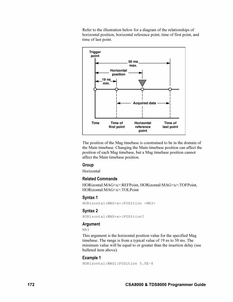
172 CSA8000 & TDS8000 Programmer Guide
Refer to the illustration below for a diagram of the relationships of
horizontal position, horizontal reference point, time of first point, and
time of last point.
The position of the Mag timebase is constrained to be in the domain of
the Main timebase. Changing the Main timebase position can affect the
position of each Mag timebase, but a Mag timebase position cannot
affect the Main timebase position.
Group
Horizontal
Related Commands
HORizontal:MAG<x>:REFPoint, HORizontal:MAG<x>:TOFPoint,
HORizontal:MAG<x>:TOLPoint
Syntax 1 HORizontal:MAG<x>:POSition <NR3>
Syntax 2 HORizontal:MAG<x>:POSition?
Argument NR3
This argument is the horizontal position value for the specified Mag
timebase. The range is from a typical value of 19 ns to 50 ms. The
minimum value will be equal to or greater than the insertion delay (see
bulleted item above).
Example 1 HORizontal:MAG1:POSition 5.0E–8
CSA8000 & TDS8000 Programmer Guide 173
This command attempts to set the horizontal position for the Mag1
timebase to 50 ns. (If the Main timebase does not cover the time window,
the Mag horizontal position will be coerced.)
Example 2 HORizontal:MAG2:POSition?
This query might return :HORIZONTAL:MAGNIFY2:POSITION
84.0000000000E-009, indicating that the horizontal position for the
MAG2 timebase is set to a time of 84 ns relative to the trigger.
HORizontal:MAG<x>:RECORDLength
This command sets or queries the record length for the specified Mag
timebase. The Mag timebase is specified by x, which can be 1 or 2.
Sending this command is equivalent to selecting a Mag timebase and
then setting a value for the Record Length control in the Timebase
section of the Horizontal Setup dialog box.
The instrument displays the waveform within the 10 horizontal divisions
on screen. The values you can set for record length are 20, 50, 100, 250,
500, 1000, 2000, and 4000 samples.
Record length can be constrained by the horizontal scale. The minimum
sample interval is 10 fs. Therefore, (10 X Horizontal Scale)÷Record
Length must be greater than or equal to 10 fs. For example, if the
horizontal scale is equal to 1 ps/div, the maximum record length is 1000
points.
Group
Horizontal
Related Commands
HORizontal:MAG<x>:SCAle, HORizontal:MAG<x>:RESolution?
Syntax 1 HORizontal:MAG<x>:RECORDLength <NR1>
Syntax 2 HORizontal:MAG<x>:RECORDLength?
Argument NR1
This argument is the record length; valid record lengths are 20, 50, 100,
250, 500, 1000, 2000, and 4000 samples.
Example 1 HORizontal:MAG2:RECORDLength 1000
This command sets the Mag 2 timebase record length to 1000 samples.
Example 2 HORizontal:MAG<x>:RECORDLength?
This query might return
:HORIZONTAL:MAGNIFY1:RECORDLENGTH 4000, indicating that
the record length for the Mag 1 timebase is set to 4000 samples.
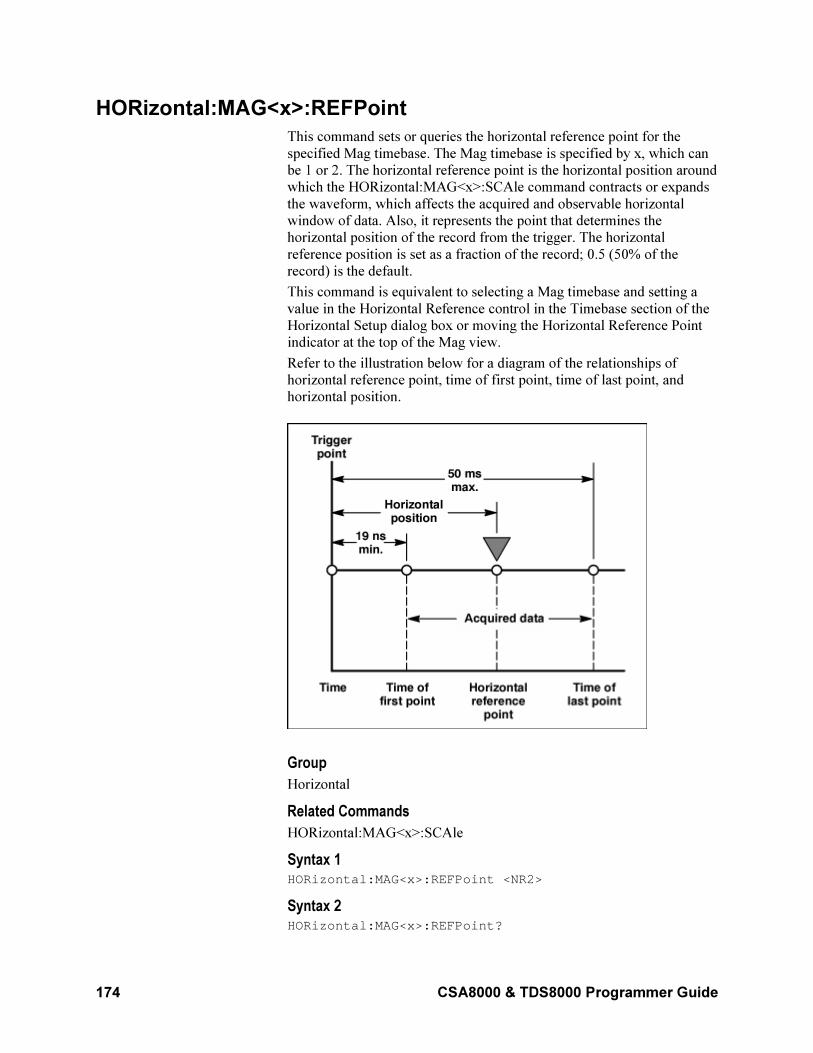
174 CSA8000 & TDS8000 Programmer Guide
HORizontal:MAG<x>:REFPoint
This command sets or queries the horizontal reference point for the
specified Mag timebase. The Mag timebase is specified by x, which can
be 1 or 2. The horizontal reference point is the horizontal position around
which the HORizontal:MAG<x>:SCAle command contracts or expands
the waveform, which affects the acquired and observable horizontal
window of data. Also, it represents the point that determines the
horizontal position of the record from the trigger. The horizontal
reference position is set as a fraction of the record; 0.5 (50% of the
record) is the default.
This command is equivalent to selecting a Mag timebase and setting a
value in the Horizontal Reference control in the Timebase section of the
Horizontal Setup dialog box or moving the Horizontal Reference Point
indicator at the top of the Mag view.
Refer to the illustration below for a diagram of the relationships of
horizontal reference point, time of first point, time of last point, and
horizontal position.
Group
Horizontal
Related Commands
HORizontal:MAG<x>:SCAle
Syntax 1 HORizontal:MAG<x>:REFPoint <NR2>
Syntax 2 HORizontal:MAG<x>:REFPoint?
CSA8000 & TDS8000 Programmer Guide 175
Argument NR2
This is the fraction of the record at which the horizontal reference point
is set. The range is 0 through 1 (corresponding to 0% through 100% of
record); the default is 0.5. The resolution is 0.01.
Example 1 HORizontal:MAG1:REFPoint 2.5E–1
This sets the horizontal reference point for the Mag1 timebase to 0.25
(25%). This is the point around which the HORizontal:MAG:SCAle
command contracts or expands the waveform.
Example 2 HORizontal:MAG2:REFPoint?
This query might return :HORIZONTAL:MAGNIFY2:REFPOINT
.500000000000, indicating that the horizontal reference point for the
Mag2 timebase is set to 0.5 (50%), which is the default.
HORizontal:MAG<x>:RESolution?
This query only command returns the current resolution per sample of
the specified Mag timebase. The Mag timebase is specified by x, which
can be 1 or 2. The resolution for the selected timebase is displayed in the
Resolution field in the Timebase section of the Horizontal Setup dialog
box. You cannot directly set the resolution. Instead, use the
HORizontal:MAG<x>:SCAle command to set the horizontal scale and
the HORizontal:MAG<x>:RECORDLength command to set the record
length. Resolution is displayed in horizontal units, typically time.
Group
Horizontal
Related Commands
HORizontal:MAG<x>:SCAle, HORizontal:MAG<x>:RECORDLength
Syntax HORizontal:MAG<x>:RESolution?
Example HORizontal:MAG1:RESolution?
This query might return :HORIZONTAL:MAGNIFY1:RESOLUTION
6.31000000000E-012, indicating that the resolution is 6.31 ps.
HORizontal:MAG<x>:SCAle
This command sets or queries the scale (time per division) for the
specified Mag timebase. The Mag timebase is specified by x, which can
be 1 or 2. Sending this command is equivalent to selecting a Mag
timebase and adjusting the Scale control in the Timebase section of the
Horizontal Setup dialog box (or adjusting the Horizontal SCALE front-
panel knob).
176 CSA8000 & TDS8000 Programmer Guide
Channel waveforms display in the Mag timebases with the horizontal
scale set for the timebase. Each channel timebase, Main, Mag1, and
Mag2, uses its own horizontal scale. All channel waveforms in an
individual timebase share the timebase scale. The horizontal scale,
together with the record length setting, determines the sample interval.
Main, Mag1, and Mag2 timebase scales, positions, and record lengths
(resolution) are independent of one another; however, acquisitions on
Mag timebases must be totally contained within the Main timebase.
Scale can be constrained by the record length. The minimum sample
interval is 10 fs. Therefore, (10 X Horizontal Scale)÷Record Length must
be greater than or equal to 10 fs. For example, if the record length is
equal to 4000 samples, the horizontal scale must be greater than or equal
to 4 ps/div.
Group
Horizontal
Related Commands
HORizontal:MAG<x>:RECORDLength,
HORizontal:MAG<x>:RESolution, HORizontal:MAG<x>:REFPoint,
HORizontal:MAG<x>:POSition
Syntax 1 HORizontal:MAG<x>:SCAle <NR3>
Syntax 2 HORizontal:MAG<x>:SCAle?
Argument NR3
This argument is the horizontal time per division for the specified Mag
timebase. The range is 1 ps per division to 5 ms per division.
Example 1 HORIZONTAL:MAG1:SCALE 2E-6
Sets the MAG1 scale to 2 µs per division.
Example 2 HORIZONTAL:MAG2:SCALE?
This query might return :HORIZONTAL:MAGNIFY2:SCALE
2.00000000000E-009, indicating that the Mag2 timebase is
currently set to 2 ns per division.
HORizontal:MAG<x>:TOFPoint?
This query only command returns time of first point for the specified
Mag timebase, which is the time interval between the trigger point and
the first point in the specified Mag timebase record (waveform). The
Mag timebase is specified by x, which can be 1 or 2.
Refer to the illustration below for a diagram of the relationships of time
of first point, time of last point, horizontal position, and horizontal
reference point.
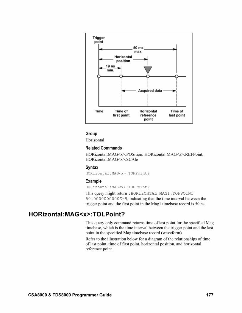
CSA8000 & TDS8000 Programmer Guide 177
Group
Horizontal
Related Commands
HORizontal:MAG<x>:POSition, HORizontal:MAG<x>:REFPoint,
HORizontal:MAG<x>:SCAle
Syntax HORizontal:MAG<x>:TOFPoint?
Example HORizontal:MAG<x>:TOFPoint?
This query might return :HORIZONTAL:MAG1:TOFPOINT
50.0000000000E-9, indicating that the time interval between the
trigger point and the first point in the Mag1 timebase record is 50 ns.
HORizontal:MAG<x>:TOLPoint?
This query only command returns time of last point for the specified Mag
timebase, which is the time interval between the trigger point and the last
point in the specified Mag timebase record (waveform).
Refer to the illustration below for a diagram of the relationships of time
of last point, time of first point, horizontal position, and horizontal
reference point.
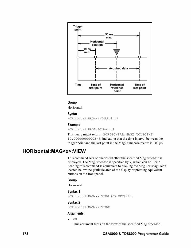
178 CSA8000 & TDS8000 Programmer Guide
Group
Horizontal
Syntax HORizontal:MAG<x>:TOLPoint?
Example HORizontal:MAG2:TOLPoint?
This query might return :HORIZONTAL:MAG2:TOLPOINT
10.0000000000E-3, indicating that the time interval between the
trigger point and the last point in the Mag2 timebase record is 100 µs.
HORizontal:MAG<x>:VIEW
This command sets or queries whether the specified Mag timebase is
displayed. The Mag timebase is specified by x, which can be 1 or 2.
Sending this command is equivalent to clicking the Mag1 or Mag2 icon
located below the graticule area of the display or pressing equivalent
buttons on the front panel.
Group
Horizontal
Syntax 1 HORizontal:MAG<x>:VIEW ON|OFF|NR1
Syntax 2 HORizontal:MAG<x>:VIEW?
Arguments
• ON
This argument turns on the view of the specified Mag timebase.
CSA8000 & TDS8000 Programmer Guide 179
• OFF
This argument turns off the view of the specified Mag timebase.
• NR1
A 0 disables the specified Mag timebase view; any other integer
enables the specified Mag timebase view.
Example 1 HORizontal:MAG2:VIEW ON
This command displays the Mag2 timebase.
Example 2 HORizontal:MAG1:VIEW?
This query might return :HORIZONTAL:MAGNIFY1:VIEW 0,
indicating that the display of the Mag1 timebase is disabled.
NOTE: A query always returns a 0 or 1.
HORizontal:MAG<x>?
This query only command returns the timebase settings for the specified
Mag timebase. The Mag timebase is specified by x, which can be 1 or 2.
Group
Horizontal
Syntax HORizontal:MAG<x>?
Example HORizontal:MAG1?
This query might return :HORIZONTAL:MAGNIFY1:SCALE 1.05200000000E-009; POSITION 64.0380000000E-009;RESOLUTION 5.26000000000E-012;RECORDLENGTH 2000;REFPOINT 0.00000000000;VIEW 1; TOLPOINT 74.5580000000E-009;
TOFPOINT 64.0380000000E-009.
HORizontal:MAIn:POSition
This command sets or queries the horizontal position for the Main
timebase. Sending this command is equivalent to selecting MainTB and
entering a value in the Position control in the Timebase section of the
Horizontal Setup dialog box or adjusting the front-panel Horizontal
POSITION control.
This command sets a global delay time (or distance) for all channel
waveforms between the trigger event and the horizontal reference point
for the Main timebase, which is set with the
HORizontal:MAIn:REFPoint command. The minimum position you can
set is limited to one of two settings, depending on the current hardware
configuration:
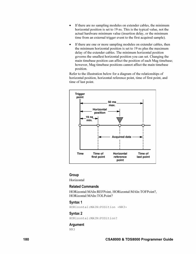
180 CSA8000 & TDS8000 Programmer Guide
• If there are no sampling modules on extender cables, the minimum
horizontal position is set to 19 ns. This is the typical value, not the
actual hardware minimum value (insertion delay, or the minimum
time from an external trigger event to the first acquired sample).
• If there are one or more sampling modules on extender cables, then
the minimum horizontal position is set to 19 ns plus the maximum
delay of the extender cables. The minimum horizontal position
governs the smallest horizontal position you can set. Changing the
main timebase position can affect the position of each Mag timebase;
however, Mag timebase positions cannot affect the main timebase
position.
Refer to the illustration below for a diagram of the relationships of
horizontal position, horizontal reference point, time of first point, and
time of last point.
Group
Horizontal
Related Commands
HORizontal:MAIn:REFPoint, HORizontal:MAIn:TOFPoint?,
HORizontal:MAIn:TOLPoint?
Syntax 1 HORizontal:MAIN:POSition <NR3>
Syntax 2 HORizontal:MAIN:POSition?
Argument NR3
CSA8000 & TDS8000 Programmer Guide 181
This argument is the horizontal position value for the Main timebase.
The range is from a typical value of 19 ns to 50 ms. The minimum value
will be equal to or greater than the insertion delay (see bulleted item
above).
Example 1 HORizontal:MAIN:POSition 1.0E–7
This command sets the horizontal position for the Main timebase to 100
ns.
Example 2 HORizontal:MAIN:POSition?
This query might return :HORIZONTAL:MAIN:POSITION
95.0000000000E-009, indicating that the horizontal position for the
Main timebase is set to 95 ns.
HORizontal:MAIn:RECordlength
This command sets or queries the record length for the Main timebase.
This is equivalent to selecting MainTB and then setting a value for the
Record Length control in the Timebase section of the Horizontal Setup
dialog box.
The instrument displays the waveform within the 10 horizontal divisions
on screen. The values you can set for record length are 20, 50, 100, 250,
500, 1000, 2000, and 4000 samples. The default is 500 samples.
Because the waveform must display within 10 horizontal divisions, not
all record length settings are valid at all horizontal scales. More
specifically:
• SI (sample interval) = TD (Time Duration) / RL (Record Length in
samples)
• TD = 10 divs (window) x Horizontal scale (Time/div)
• If RL or TD vary, SI varies to accommodate up to highest sample
rate.
SI is limited to its lowest value (10 fs). Record length cannot increase for
certain scale values, so that SI does not decrease below the 10 fs limit.
The equation becomes:
Max RL = (10 x Horizontal scale) / SI, with div x sec/div x
samples/sec, which yields samples (10 divs x sec/div) / Min SI
(sec/sample).
For example, at 1 ps/div and 10 divisions, the record length must be
≤1000.
Group
Horizontal
Related Commands
HORizontal:MAIn:SCAle, HORizontal:MAIn:RESolution
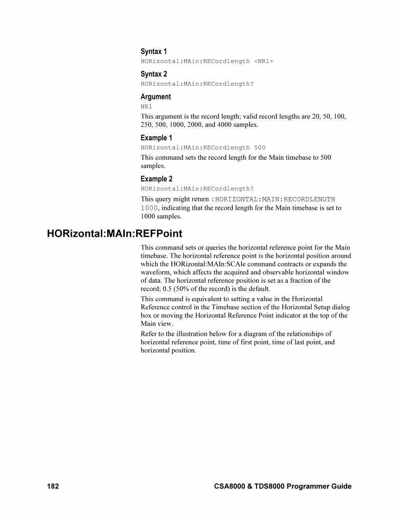
182 CSA8000 & TDS8000 Programmer Guide
Syntax 1 HORizontal:MAin:RECordlength <NR1>
Syntax 2 HORizontal:MAin:RECordlength?
Argument NR1
This argument is the record length; valid record lengths are 20, 50, 100,
250, 500, 1000, 2000, and 4000 samples.
Example 1 HORizontal:MAin:RECordlength 500
This command sets the record length for the Main timebase to 500
samples.
Example 2 HORizontal:MAin:RECordlength?
This query might return :HORIZONTAL:MAIN:RECORDLENGTH
1000, indicating that the record length for the Main timebase is set to
1000 samples.
HORizontal:MAIn:REFPoint
This command sets or queries the horizontal reference point for the Main
timebase. The horizontal reference point is the horizontal position around
which the HORizontal:MAIn:SCAle command contracts or expands the
waveform, which affects the acquired and observable horizontal window
of data. The horizontal reference position is set as a fraction of the
record; 0.5 (50% of the record) is the default.
This command is equivalent to setting a value in the Horizontal
Reference control in the Timebase section of the Horizontal Setup dialog
box or moving the Horizontal Reference Point indicator at the top of the
Main view.
Refer to the illustration below for a diagram of the relationships of
horizontal reference point, time of first point, time of last point, and
horizontal position.
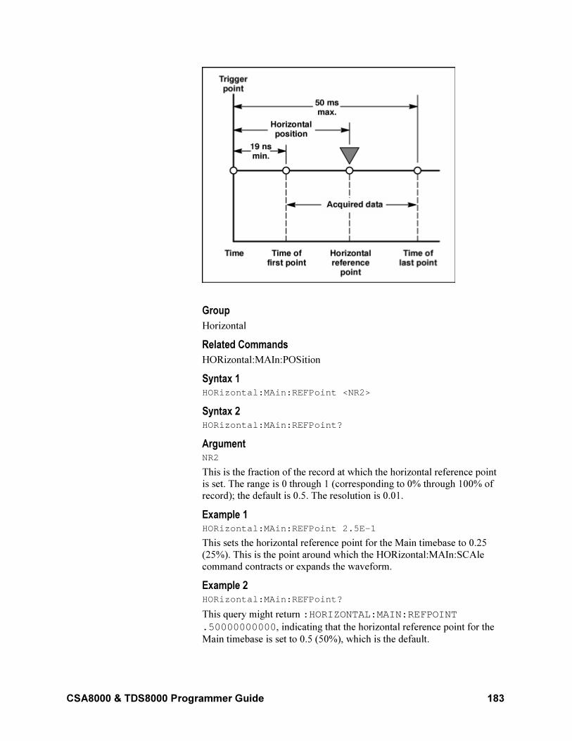
CSA8000 & TDS8000 Programmer Guide 183
Group
Horizontal
Related Commands
HORizontal:MAIn:POSition
Syntax 1 HORizontal:MAin:REFPoint <NR2>
Syntax 2 HORizontal:MAin:REFPoint?
Argument NR2
This is the fraction of the record at which the horizontal reference point
is set. The range is 0 through 1 (corresponding to 0% through 100% of
record); the default is 0.5. The resolution is 0.01.
Example 1 HORizontal:MAin:REFPoint 2.5E–1
This sets the horizontal reference point for the Main timebase to 0.25
(25%). This is the point around which the HORizontal:MAIn:SCAle
command contracts or expands the waveform.
Example 2 HORizontal:MAin:REFPoint?
This query might return :HORIZONTAL:MAIN:REFPOINT
.50000000000, indicating that the horizontal reference point for the
Main timebase is set to 0.5 (50%), which is the default.
184 CSA8000 & TDS8000 Programmer Guide
HORizontal:MAIn:RESolution?
This query only command returns the current resolution per sample of
the Main timebase. This value is the same as the value displayed in the
Resolution field in the Timebase section of the Horizontal Setup dialog
box. You cannot directly set the resolution. Instead, the use the
HORizontal:MAIn:SCAle command to set the horizontal scale and the
HORizontal:MAIn:RECORDLength command to set the record length.
Resolution is displayed in horizontal units, typically time.
Group
Horizontal
Related Commands
HORizontal:MAIn:SCAle, HORizontal:MAIn:RECORDLength,
Syntax HORizontal:MAin:RESolution?
Example HORizontal:MAin:RESolution?
This query might return :HORIZONTAL:MAIN:RESOLUTION
25.0000000000E-012, indicating that the horizontal resolution for
the Main timebase is 25 ps.
HORizontal:MAIn:SCAle
This command sets or queries the scale (time per division) for the Main
timebase. Sending this command is equivalent to selecting MainTB and
adjusting the Scale control in the Timebase section of the Horizontal
Setup dialog box.
The horizontal scale that you set with this command is common to all
channel waveforms using the Main timebase. The horizontal scale,
together with the record length setting, determines the sample interval.
Group
Horizontal
Related Commands
HORizontal:MAIn:RECordlength, HORizontal:MAIn:RESolution
Syntax 1 HORizontal:MAIn:SCAle <NR3>
Syntax 2 HORizontal:MAIn:SCAle?
Argument NR3
This argument is the horizontal time per division for the Main timebase.
The range is 1 ps per division to 5 ms per division.
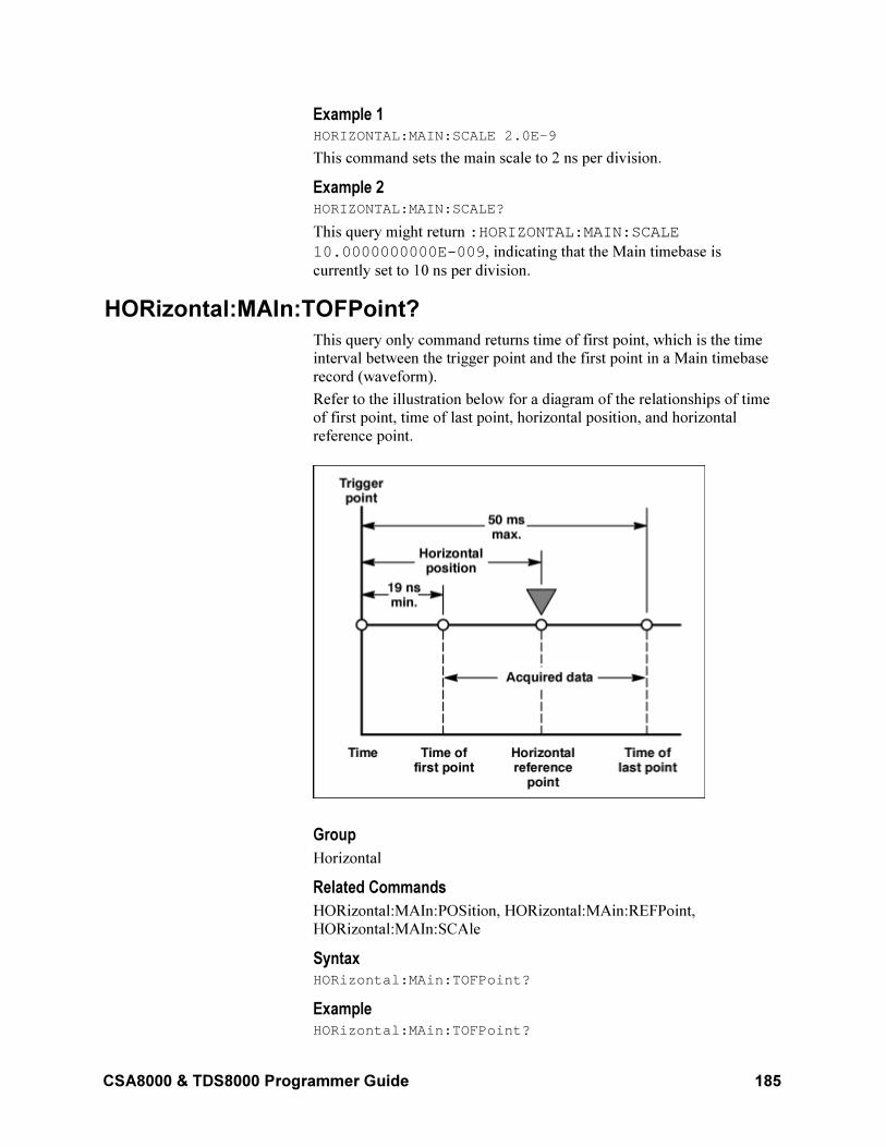
CSA8000 & TDS8000 Programmer Guide 185
Example 1 HORIZONTAL:MAIN:SCALE 2.0E-9
This command sets the main scale to 2 ns per division.
Example 2 HORIZONTAL:MAIN:SCALE?
This query might return :HORIZONTAL:MAIN:SCALE
10.0000000000E-009, indicating that the Main timebase is
currently set to 10 ns per division.
HORizontal:MAIn:TOFPoint?
This query only command returns time of first point, which is the time
interval between the trigger point and the first point in a Main timebase
record (waveform).
Refer to the illustration below for a diagram of the relationships of time
of first point, time of last point, horizontal position, and horizontal
reference point.
Group
Horizontal
Related Commands
HORizontal:MAIn:POSition, HORizontal:MAin:REFPoint,
HORizontal:MAIn:SCAle
Syntax HORizontal:MAin:TOFPoint?
Example HORizontal:MAin:TOFPoint?
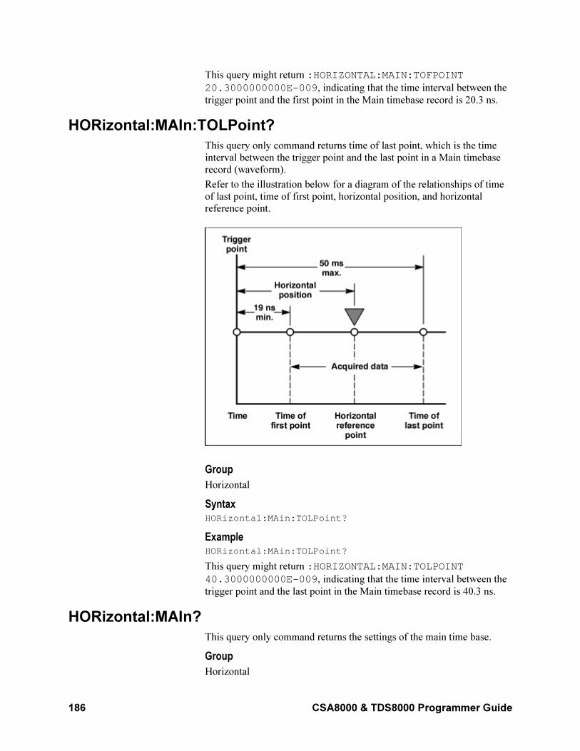
186 CSA8000 & TDS8000 Programmer Guide
This query might return :HORIZONTAL:MAIN:TOFPOINT
20.3000000000E-009, indicating that the time interval between the
trigger point and the first point in the Main timebase record is 20.3 ns.
HORizontal:MAIn:TOLPoint?
This query only command returns time of last point, which is the time
interval between the trigger point and the last point in a Main timebase
record (waveform).
Refer to the illustration below for a diagram of the relationships of time
of last point, time of first point, horizontal position, and horizontal
reference point.
Group
Horizontal
Syntax HORizontal:MAin:TOLPoint?
Example HORizontal:MAin:TOLPoint?
This query might return :HORIZONTAL:MAIN:TOLPOINT
40.3000000000E-009, indicating that the time interval between the
trigger point and the last point in the Main timebase record is 40.3 ns.
HORizontal:MAIn?
This query only command returns the settings of the main time base.
Group
Horizontal
CSA8000 & TDS8000 Programmer Guide 187
Syntax HORizontal:MAIn?
Example HORIZONTAL:MAIN?
This command might return :HORIZONTAL:MAIN:SCALE 2.00000000000E-009; POSITION 20.3000000000E-009; RESOLUTION 5.00000000000E-012;RECORDLENGTH 4000; REFPOINT 0.00000000000; TOLPOINT 40.3000000000E-009; TOFPOINT 20.3000000000E-009.
HORizontal:MATH<x>:MAG<x>:POSition?
This query only command returns the horizontal position of the specified
math waveform using the specified Mag timebase. The math waveform
is specified by x, which can be 1 through 8; the Mag timebase is
specified by x, which can be 1 or 2.
Group
Horizontal
Syntax HORizontal:MATH<x>:MAG<x>:POSition?
Example HORizontal:MATH1:MAG2:POSition?
This query might return :HORIZONTAL:MATH1:MAGNIFY2:POSITION
19.0000000000E-009, indicating that the horizontal position of the
Math 2 waveform using the MAG2 timebase is set to the minimum time
of 19 ns.
HORizontal:MATH<x>:MAG<x>:RECORDLength?
This query only command returns the record length of the specified Mag
timebase for the specified math waveform. The value of the record length
can be 20, 50, 100, 250, 500, 1000, 2000, and 4000 samples. It results
from normalizing the sources of a math waveform.
Group
Horizontal
Related Commands
HORizontal:MATH<x>:MAG<x>:SCAle?,
HORizontal:MATH<x>:MAG<x>:RESolution?
Syntax HORizontal:MATH<x>:MAG<x>:RECORDLength?
Example HORizontal:MATH5:MAG2:RECORDLength?
188 CSA8000 & TDS8000 Programmer Guide
This query might return
:HORIZONTAL:MATH5:MAGNIFY2:RECORDLENGTH 1000,
indicating that the record length of the Mag 2 timebase is set to 1000
samples for the Math 5 waveform.
HORizontal:MATH<x>:MAG<x>:RESolution?
This query only command returns the resolution per sample of the
specified Mag timebase for the specified math waveform. The math
waveform is specified by x, which can be 1 through 8; the Mag timebase
is specified by x, which can be 1 or 2. Resolution is displayed in
horizontal units, typically time.
Group
Horizontal
Related Commands
HORizontal:MATH<x>:MAG<x>:SCAle,
HORizontal:MATH<x>:MAG<x>:RECORDLength?
Syntax HORizontal:MATH<x>:MAG<x>:RESolution?
Example HORizontal:MATH1:MAG1:RESolution?
This query might return :HORIZONTAL:MATH1:MAGNIFY1:RESOLUTION
1.00000000000E–009, indicating that the resolution of the Mag1
timebase for the Math1 waveform is 1 ns.
HORizontal:MATH<x>:MAG<x>:SCAle?
This query only command returns the scale (time per division) of the
specified Mag timebase for the specified math waveform. The math
waveform is specified by x, which can be 1 through 8; the Mag timebase
is specified by x, which can be 1 or 2.
Math waveforms derive their timebase settings from the waveform
sources that define them. Math scale is inherited from the live channel
source of the math waveform or the saved reference waveforms, if there
are no live channel waveforms in the math expression.
Group
Horizontal
Related Commands
HORizontal:MAG<x>:RECordlength,
HORizontal:MAG<x>:RESolution
Syntax HORizontal:MATH<x>:MAG<x>:SCAle?
Example HORIZONTAL:MATH2:MAG2:SCALE?
CSA8000 & TDS8000 Programmer Guide 189
This query might return :HORIZONTAL:MATH1:MAGNIFY1:SCALE
30.00000000000E-009, indicating that the Mag1 timebase is
currently set to 30 ns per division for the Math 1 waveform.
HORizontal:MATH<x>:MAG<x>:TOFPoint?
This query only command returns the time of first point of the specified
math waveform using the specified Mag timebase. The math waveform
is specified by x, which can be 1 through 8; the Mag timebase is
specified by x, which can be 1 or 2. The time of first point is the time
interval between the trigger point and the first point in the specified Mag
timebase record (waveform).
Group
Horizontal
Related Commands
HORizontal:MATH<x>:MAG<x>:POSition?,
HORizontal:MATH<x>:MAG<x>:SCAle?
Syntax HORizontal:MATH<x>MAG<x>:TOFPoint?
Example HORizontal:MATH4:MAG1:TOFPoint?
This query might return :HORIZONTAL:MATH4:MAGNIFY1:TOFPOINT
50.00000000000E-009, indicating that the time interval between
the trigger point and the first point in the Math 4 waveform record using
the Mag1 timebase is 50 ns.
HORizontal:MATH<x>:MAG<x>:TOLPoint
This query only command returns time of last point of the specified math
waveform using the specified Mag timebase. The math waveform is
specified by x, which can be 1 through 8; the Mag timebase is specified
by x, which can be 1 or 2. The time of last point is the time interval
between the trigger point and the last point in the specified Mag timebase
record (waveform).
Group
Horizontal
Related Commands
HORizontal:MATH<x>:MAG<x>:POSition?,
HORizontal:MATH<x>:MAG<x>:SCAle?
Syntax HORizontal:MATH<x>:MAG<x>:TOLPoint?
Example HORizontal:MATH2:MAG2:TOLPoint?
190 CSA8000 & TDS8000 Programmer Guide
This query might return :HORIZONTAL:MAGNIFY2:TOLPOINT
1.00000000000E-9, indicating that the time interval between the
trigger point and the last point in the Math 2 waveform record using the
Mag2 timebase is 1 ns.
HORizontal:MATH<x>:MAIn:POSition?
This query only command returns the horizontal position of the specified
math waveform using the Main timebase. The math waveform is
specified by x, which can be 1 through 8.
Group
Horizontal
Related Commands
HORizontal:MATH<x>:MAIn:REFPoint?,
HORizontal:MATH<x>:MAIn:TOFPoint?,
HORizontal:MATH<x>:MAIn:TOLPoint?
Syntax HORizontal:MATH<x>:MAIN:POSition?
Example HORizontal:MATH8:MAIN:POSition?
This query might return :HORIZONTAL:MATH8:MAIN:POSITION
19.00000000000E-009, indicating that the horizontal position of
the Math 8 waveform using the Main timebase is set to the minimum
time of 19 ns.
HORizontal:MATH<x>:MAIn:RECORDLength?
This query only command returns the record length of the Main timebase
for the specified math waveform. The math waveform is specified by x,
which can be 1 through 8.
Record lengths can be 20, 50, 100, 250, 500, 1000, 2000, and 4000
samples. It results from normalizing the sources of a math waveform.
Group
Horizontal
Related Commands
HORizontal:MATH<x>:MAIn:SCAle?,
HORizontal:MATH<x>:MAIn:RESolution
Syntax HORizontal:MATH<x>:MAin:RECORDLength?
Example HORizontal:MATH4:MAin:RECORDLength?
This query might return
:HORIZONTAL:MATH4:MAIN:RECORDLENGTH 1000, indicating
that the record length for the Main timebase is set to 1000 samples for
the Math 4 waveform.
CSA8000 & TDS8000 Programmer Guide 191
HORizontal:MATH<x>:MAIn:REFPoint?
This query only command returns the horizontal reference point of the
specified math waveform using the Main timebase. The math waveform
is specified by x, which can be 1 through 8. The horizontal reference
point is the horizontal position around which the
HORizontal:MAIn:SCAle command contracts or expands the waveform,
which affects the acquired and observable horizontal window of data.
The horizontal reference position is set as a fraction of the record; 0.5
(50% of the record) is the default.
Group
Horizontal
Related Commands
HORizontal:MATH<x>:MAIn:SCAle
Example HORizontal:MATH3:MAin:REFPoint?
This query might return :HORIZONTAL:MATH3:MAIN:REFPOINT
.50000000000, indicating that the horizontal reference point for the
Math 3 waveform using the Main timebase is set to 0.5 (50%).
HORizontal:MATH<x>:MAIn:RESolution?
This query only command returns the current resolution per sample of
the Main timebase for the specified math waveform. The math waveform
is specified by x, which can be 1 through 8. Resolution is displayed in
horizontal units, typically time.
Group
Horizontal
Related Commands
HORizontal:MATH<x>:MAIn:SCAle?,
HORizontal:MATH<x>:MAIn:RECORDLength?,
Syntax HORizontal:MATH<x>:MAin:RESolution?
Example HORizontal:MATH2:MAin:RESolution?
This query might return :HORIZONTAL:MATH1:MAIN:RESOLUTION 1.00000000000E-
009, indicating that the Main timebase resolution is at 1 ns for the
Math2 waveform.
HORizontal:MATH<x>:MAIn:SCAle?
This query only command returns the scale (time per division) of the
Main timebase for the specified math waveform. The math waveform is
specified by x, which can be 1 through 8.
192 CSA8000 & TDS8000 Programmer Guide
Group
Horizontal
Related Commands
HORizontal:MATH<x>:MAIn:RECordlength?,
HORizontal:MATH<x>:MAIn:RESolution?
Syntax HORizontal:MATH<x>:MAIn:SCAle?
Example HORizontal:MATH4:MAIn:SCAle?
This query might return :HORIZONTAL:MATH1:MAIN:SCALE
1.00000000000E-009, indicating that the Main timebase for the
Math4 waveform is set to 1 ns per division.
HORizontal:MATH<x>:MAIn:TOFPoint?
This query only command returns the time of first point of the Main
timebase record, which is the time interval between the trigger point and
the first point in the record, for the specified math waveform. The math
waveform is specified by x, which can be 1 through 8.
Group
Horizontal
Related Commands
HORizontal:MATH<x>:MAIN:POSition?,
HORizontal:MATH<x>:MAIn:REFPoint?,
HORizontal:MATH<x>:MAIn:SCAle?
Syntax HORizontal:MATH<x>:MAin:TOFPoint?
Example HORizontal:MATH3:MAin:TOFPoint?
This query might return :HORIZONTAL:MATH3:MAIN:TOFPOINT
1.00000000000E-12, indicating that the time of first point for the
Main timebase record for the Math3 waveform is 100 ps.
HORizontal:MATH<x>:MAIn:TOLPoint?
This query only command returns the time of last point of the Main
timebase record, which is the time interval between the trigger point and
the last point in the record, for the specified math waveform. The math
waveform is specified by x, which can be 1 through 8.
Group
Horizontal
CSA8000 & TDS8000 Programmer Guide 193
Related Commands
HORizontal:MATH<x>:MAIN:POSition?,
HORizontal:MATH<x>:MAIn:REFPoint?,
HORizontal:MATH<x>:MAIn:SCAle?
Syntax HORizontal:MATH<x>:MAin:TOLPoint?
Example HORizontal:MATH3:MAin:TOLPoint?
This query might return :HORIZONTAL:MATH3:MAIN:TOLPOINT
36.0000000000E-009, indicating that the time of last point for the
Main timebase record for the Math3 waveform is 36 ns.
HORizontal:REF<x>:MAG<x>:POSition?
This query only command returns the horizontal position of the specified
Mag timebase for the specified Reference waveform. The Reference
waveform is specified by x, which can be 1 through 8; the Mag timebase
is specified by x, which can be 1 or 2.
Group
Horizontal
Related Commands
HORizontal:REF<x>:MAG<x>:TOFPoint?,
HORizontal:REF<x>:MAG<x>:TOLPoint?
Syntax HORizontal:REF<x>:MAG<x>:POSition?
Example HORizontal:REF1:MAG2:POSition?
This query might return :HORIZONTAL:REF1:MAGNIFY2:POSITION
19.00000000000E-009, indicating that the horizontal position for
the Ref 1 waveform using the MAG2 timebase is the minimum time of
19 ns.
HORizontal:REF<x>:MAG<x>:RECORDLength?
This query only command returns the record length of the Reference
waveform specified by x, which can be 1 through 8, using the specified
Mag timebase (1 or 2). The value of the record length can be 20, 50, 100,
250, 500, 1000, 2000, and 4000 samples.
Group
Horizontal
Related Commands
HORizontal:REF<x>:MAG<x>:SCAle?,
HORizontal:REF<x>:MAG<x>:RESolution?
194 CSA8000 & TDS8000 Programmer Guide
Syntax HORizontal:REF<x>:MAG<x>:RECORDLength?
Example HORizontal:REF5:MAG2:RECORDLength?
This query might return
:HORIZONTAL:REF5:MAG2:RECORDLENGTH 1000, indicating
that the record length of the Ref 5 waveform using the Mag 2 timebase is
1000 samples.
HORizontal:REF<x>:MAG<x>:RESolution?
This query only command returns the current resolution per sample of
the Reference waveform. The Reference waveform is specified by x,
which can be 1 through 8; the Mag timebase is specified by x, which can
be 1 or 2. Resolution is displayed in horizontal units, typically time.
Group
Horizontal
Related Commands
HORizontal:REF<x>:MAG<x>:SCAle?,
HORizontal:REF<x>:MAG<x>:RECORDLength?
Syntax HORizontal:REF<x>:MAG<x>:RESolution?
Example HORizontal:REF1:MAG1:RESolution?
This query might return :HORIZONTAL:REF1:MAGNIFY1:RESOLUTION
12.50000000000E-012, indicating that the resolution of the Ref 1
waveform using the Mag1 timebase is 12.5 ps.
HORizontal:REF<x>:MAG<x>:SCAle?
This query only command returns the scale (time per division) of the
specified Reference waveform using the specified Mag timebase. The
Reference waveform is specified by x, which can be 1 through 8; the
Mag timebase is specified by x, which can be 1 or 2.
Group
Horizontal
Related Commands
HORizontal:REF<x>:MAG<x>:RECORDLength?,
HORizontal:REF<x>:MAG<x>:RESolution?
Syntax HORizontal:REF<x>:MAG<x>:SCAle?
Example HORIZONTAL:REF3:MAG2:SCALE?
CSA8000 & TDS8000 Programmer Guide 195
This query might return :HORIZONTAL:REF3:MAGNIFY2:SCALE
1.00000000000E-012, indicating that the Mag2 timebase is 100 ps
per division for the Ref 3 waveform.
HORizontal:REF<x>:MAG<x>:TOFPoint?
This query only command returns time of first point of the specified
Reference waveform using the specified Mag timebase. The Reference
waveform is specified by x, which can be 1 through 8; the Mag timebase
is specified by x, which can be 1 or 2. The time of first point is the time
interval between the trigger point and the first point in the specified Mag
timebase record (waveform).
Group
Horizontal
Related Commands
HORizontal:REF<x>:MAG<x>:POSition?,
HORizontal:REF<x>:MAG<x>:SCAle?
Syntax HORizontal:REF<x>:MAG<x>:TOFPoint?
Example HORizontal:REF1:MAG1:TOFPoint?
This query might return :HORIZONTAL:REF1:MAGNIFY1:TOFPOINT
50.0000000000E-009, indicating that the time interval between the
trigger point and the first point in the Ref 1 waveform record using the
Mag1 timebase is 50 ns.
HORizontal:REF<x>:MAG<x>:TOLPoint?
This query only command returns time of last point of the specified
Reference waveform using the specified Mag timebase. The Reference
waveform is specified by x, which can be 1 through 8; the Mag timebase
is specified by x, which can be 1 or 2. The time of last point is the time
interval between the trigger point and the last point in the specified Mag
timebase record (waveform).
Group
Horizontal
Related Commands
HORizontal:REF<x>:MAG<x>:POSition?,
HORizontal:REF<x>:MAG<x>:SCAle?
Syntax HORizontal:REF<x>:MAG<x>:TOLPoint?
Example HORizontal:REF1:MAG1:TOLPoint?
196 CSA8000 & TDS8000 Programmer Guide
This query might return :HORIZONTAL:REF1:MAGNIFY1:TOLPOINT
500.00000000000E-12, indicating that the time of last point of the
Ref 1 waveform record using the Mag 1 timebase is 500 ps.
HORizontal:REF<x>:MAIn:POSition?
This query only command returns the horizontal position of the specified
reference waveform using the Main timebase. The reference waveform is
specified by x, which can be 1 through 8.
Group
Horizontal
Related Commands
HORizontal:REF<x>:MAIn:REFPoint?,
HORizontal:REF<x>:MAIn:TOFPoint?,
HORizontal:REF<x>:MAIn:TOLPoint?
Syntax HORizontal:REF<x>MAIN:POSition?
Example HORizontal:REF5:MAIN:POSition?
This query might return :HORIZONTAL:REF5:MAIN:POSITION
51.3630000000E-009, indicating that the horizontal position of the
Reference 5 waveform using the Main timebase is 51.36 ns.
HORizontal:REF<x>:MAIn:RECORDLength?
This query only command returns the record length of the specified
reference waveform using the Main timebase. The reference waveform is
specified by x, which can be 1 through 8.
Group
Horizontal
Related Commands
HORizontal:REF<x>:MAIn:RESolution?,
HORizontal:REF<x>:MAIn:SCAle?
Syntax HORizontal:REF<x>:MAin:RECORDLength?
Example HORizontal:REF7:MAin:RECORDLength?
This query might return
:HORIZONTAL:REF7:MAIN:RECORDLENGTH 1000, indicating
that the record length of the Reference 7 waveform using the Main
timebase is 1000 samples.
CSA8000 & TDS8000 Programmer Guide 197
HORizontal:REF<x>:MAIn:REFPoint?
This query only command returns the horizontal reference point of the
specified reference waveform using the Main timebase. The reference
waveform is specified by x, which can be 1 through 8.
Group
Horizontal
Related Commands
HORizontal:REF<x>:MAIn:SCAle?
Syntax HORizontal:REF<x>:MAin:REFPoint?
Example HORizontal:REF1:MAin:REFPoint?
This query might return :HORIZONTAL:REF1:MAIN:REFPOINT
5.00000000000E–001, indicating that the horizontal reference point
of Reference 1 waveform using the Main timebase is set to 0.5 (50%),
which is the default.
HORizontal:REF<x>:MAIn:RESolution?
This query only command returns the current resolution per sample of
the specified reference waveform using the Main timebase. The reference
waveform is specified by x, which can be 1 through 8. The resolution
value is the same as the value displayed in the Resolution field in the
Timebase section of the Horizontal Setup dialog box. The resolution is
determined by the scale and record length values of the reference
waveform. Resolution is displayed in horizontal units, typically time.
Group
Horizontal
Related Commands
HORizontal:REF<x>:MAIn:SCAle?,
HORizontal:REF<x>:MAIn:RECORDLength?
Syntax HORizontal:REF<x>:MAin:RESolution?
Example HORizontal:REF7:MAin:RESolution?
This query might return :HORIZONTAL:REF1:MAIN:RESOLUTION
10.00000000000E-012, indicating that the Reference 1 waveform
resolution using the Main timebase is 10 ps.
HORizontal:REF<x>:MAIn:SCAle?
This query only command returns the scale (time per division) of the
Main timebase for the specified reference waveform. The reference
waveform is specified by x, which can be 1 through 8.
198 CSA8000 & TDS8000 Programmer Guide
The horizontal scale that is returned with this command is unique to the
specified reference waveform. The horizontal scale, together with the
record length value, determines the sample interval.
Group
Horizontal
Related Commands
HORizontal:REF<x>MAIn:RECordlength?,
HORizontal:REF<x>:MAIn:RESolution?
Syntax HORizontal:REF<x>:MAIn:SCAle?
Example HORizontal:REF3:MAIn:SCAle?
This query might return :HORIZONTAL:REF3:MAIN:SCALE
2.00000000000E-009, indicating that the Main timebase is 2 ns per
division for the Reference 3 waveform.
HORizontal:REF<x>:MAIn:TOFPoint?
This query only command returns time of first point of the specified
reference waveform record using the Main timebase. The time of first
point is the time interval between the trigger point and the first point in
the specified Reference Main timebase record.
Group
Horizontal
Related Commands
HORizontal:REF<x>MAIN:POSition?,
HORizontal:REF<x>:MAin:REFPoint?,
HORizontal:REF<x>:MAIn:SCAle?
Syntax HORizontal:REF<x>:MAin:TOFPoint?
Example HORizontal:REF1:MAin:TOFPoint?
This query might return :HORIZONTAL:REF1:MAIN:TOFPOINT
41.36300000000E-009, indicating that the time interval between
the trigger point and the first point in the record for the Reference 1 Main
timebase record is 41.36 ns.
HORizontal:REF<x>:MAIn:TOLPoint?
This query only command returns time of last point of the specified
reference record (waveform) using the Main timebase. The time of last
point is the time interval between the trigger point and the last point in
the specified Reference Main timebase record.
CSA8000 & TDS8000 Programmer Guide 199
Group
Horizontal
Related Commands
HORizontal:REF<x>MAIN:POSition?,
HORizontal:REF<x>:MAin:REFPoint?,
HORizontal:REF<x>:MAIn:SCAle?
Syntax HORizontal:REF<x>:MAin:TOLPoint?
Example HORizontal:REF3:MAin:TOLPoint?
This query might return :HORIZONTAL:REF3:MAIN:TOLPOINT
51.30000000000E-009, indicating that the time interval between
the trigger point and the last point in the Reference 3 Main timebase
record is 51.3 ns.
HORizontal:TBMode
This command sets or queries the timebase mode. Sending this command
is equivalent to making a selection in the Mode control in the All
Timebases section of the Horizontal Setup dialog box.
Group
Horizontal
Syntax 1 HORizontal:TBMode SHORTTerm|LOCKExt|LOCKInt
Syntax 2 HORizontal:TBMode?
Arguments
• SHORTTerm
This argument enables the horizontal timebase mode, which gives
the best short-term jitter.
• LOCKExt
This argument enables the Lock to Ext. 10 MHz mode, which locks the timebase to an external 10 MHz reference signal.
• LOCKInt
This argument enables the Lock to Int. 10 MHz mode, which locks
the timebase to the internal 10 MHz reference signal. This mode
yields exceptional long-term horizontal stability.
Example 1 HORizontal:TBMode LOCKInt
This command locks the timebase to the internal 10 MHz reference
signal.
200 CSA8000 & TDS8000 Programmer Guide
Example 2 HORizontal:TBMode?
This query might return :HORIZONTAL:TBMODE LOCKEXT,
indicating that the timebase is locked to an external 10 MHz reference
signal.
HORizontal:UNIts
This command sets or queries the horizontal units used for all timebases.
The available units are seconds, bits, meters, feet, and inches. This is
equivalent to selecting Seconds Bits, or Distance for Units in the All
Timebases section of the Horizontal Setup dialog box. When selecting
Distance for horizontal units, further options are meters, feet and inches.
Group
Horizontal
Related Commands
HORizontal:DISTance:DIELectric HORizontal:DISTance:PVELocity
Syntax 1 HORizontal:UNIts S|BITS|FT|IN|M
Syntax 2 HORizontal:UNIts?
Arguments
• S
This argument sets the horizontal units for all timebases to seconds.
• BITS
This argument sets the horizontal units for all timebases to bits.
• FT
This argument sets the horizontal units for all timebases to feet.
• IN
This argument sets the horizontal units for all timebases to inches.
• M
This argument sets the horizontal units for all timebases to meters.
Example 1 HORizontal:UNIts S
This command sets the horizontal units for all timebases to seconds.
Example 2 HORizontal:UNIts?
This query might return :HORIZONTAL:UNITS BITS, indicating that
horizontal units for all timebases is set to bits.
CSA8000 & TDS8000 Programmer Guide 201
HORizontal?
This query only command returns all settings for the horizontal
commands.
Group
Horizontal
Syntax HORizontal?
Example HORizontal?
This command might return the following string (partial):
:HORIZONTAL:TBMODE LOCKINT;UNITS S;:BITS:STANDARD OC192;BITRATE 9.95328000000E+009;:HORIZONTAL:EXT10MHZREF:FREQ 10.0000000000E+006;:HORIZONTAL:MAIN:SCALE 5.00000000000E-009;POSITION 8116300000000.009;RESOLUTION 12.50000000000E-012;RECORDLENGTH 4000;REFPOINT 1.00000000000;TOLPOINT 81.16300000000E-009;TOFPOINT 31.16300000000E-009;:HORIZONTAL:MAGNIFY1:SCALE 2.00000000000E-009;POSITION 51.16300000000E-009;RESOLUTION 10.00000000000E-012;RECORDLENGTH 2000;REFPOINT 1.00000000000;VIEW 1;TOLPOINT 51.16300000000E-009;TOFPOINT 31.16300000000E-009;:HORIZONTAL:MAGNIFY2:SCALE 3.30000000000E-011;POSITION 31.21300000000E-009;RESOLUTION 220.00000000000E-015;RECORDLENGTH 1000;REFPOINT 150.00000000000E-003;VIEW 0;TOLPOINT 31.49300000000E-009;TOFPOINT 31.16300000000E-009;…
ID?
This is a query only command that returns identifying information about
the instrument and its firmware.
Group
Status and Error
Related Commands
*IDN?
Syntax
ID?
Returns
The instrument id in the following format:
TEK/<model number>,CF:92.1CT,FV:<firmware versionnumber>
202 CSA8000 & TDS8000 Programmer Guide
Example ID?
This query might return ID
TEK/TDS8000,CF:91.1CT,FV:1.0.444.
LOCk
This command sets and queries the lock state of the touchscreen and the
front-panel controls. There is no front-panel equivalent.
Group
Miscellaneous
Related Commands
UNLock
Syntax 1 LOCk ALL|NONe|TOUCH|FPAnel
Syntax 2 LOCk?
Arguments
• •ALL
Disables all front-panel controls and the touchscreen.
• NONe
Enables all front-panel controls and the touchscreen. This is equivalent to the UNLock ALL command.
Note: If the instrument is in the Remote With Lockout State (RWLS),
the LOCk NONe command has no effect. For more information, see
ANSI/IEEE Std. 488.1-1987 Standard Digital Interface for
Programmable Instrumentation, section 2.8.3 on RL State Descriptions.
• TOUCH
Disables the touchscreen.
• FPAnel
Disables the front-panel controls.
Example 1 LOCK ALL
Locks the front-panel controls and the touchscreen.
Example 2 LOCK?
This query returns :LOCK NONE when the front-panel controls and
touchscreen are enabled by this command.
CSA8000 & TDS8000 Programmer Guide 203
MASK:AUTOSet:MODE
This command sets or queries whether or not a mask autoset will
automatically be done after a standard mask is selected. This is
equivalent to selecting Automatic or Manual in the Autoset section of the
Mask Setup dialog box.
Group
Mask
Syntax 1 MASK:AUTOSet:MODE AUTO|MANual
Syntax 2 MASK:AUTOSet:MODE?
Arguments
• AUTO
Sets the instrument to automatically run the mask autoset when a
standard mask (or a user-defined mask that is derived from a
standard mask) is selected from the Comm Standard section of the
Mask Setup dialog box. Autoset will not run continuously; it will run
once when a standard is selected.
• MANual
With this argument, the mask autoset algorithm for a standard mask
runs only if the user presses the AUTOSET button or sends the
AUTOSet EXECute command. If a standard mask (or a user-defined
mask that is derived from a standard mask) is not currently selected,
the mask autoset algorithm will not run, and the normal autoset will
run when the user presses the AUTOSET button. Manual is the
default value.
Example 1 MASK:AUTOset:MODE AUTO
Sets the instrument to automatically run autoset when a standard mask is
selected from the Comm Standard section of the Mask Setup dialog box.
Example 2 MASK:AUTOSET:MODE?
This query might return :MASK:AUTOSET:MODE AUTO, indicating
that mask autoset will run automatically when the user selects a standard
mask from the front panel.
MASK:COLOr
This command sets or queries the color of the mask. (The command is
the same as the DISplay:COLor:MASK command.) This is equivalent to
setting Color in the Options section of the Mask Setup dialog box. The
available colors are listed in the following table.
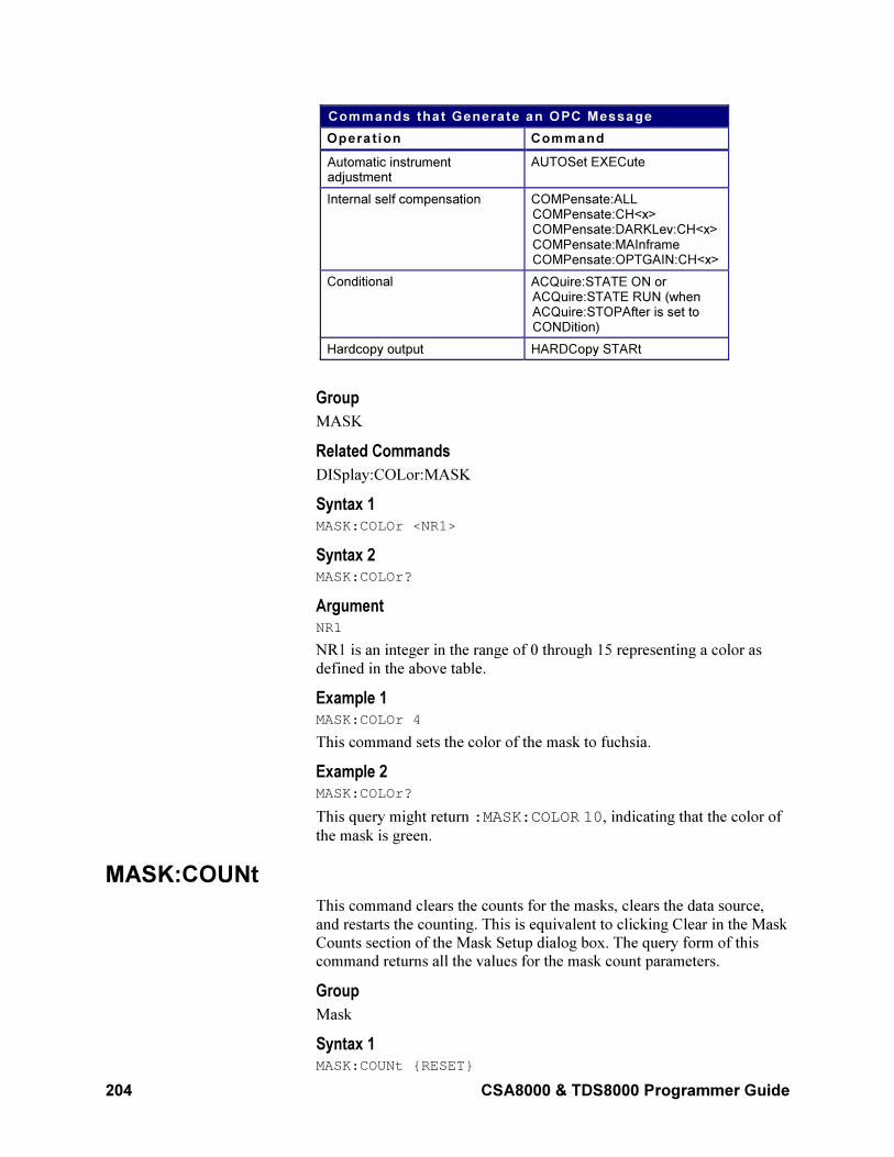
204 CSA8000 & TDS8000 Programmer Guide
Commands that Generate an OPC Message
Operat ion Command
Automatic instrumentadjustment
AUTOSet EXECute
Internal self compensation COMPensate:ALLCOMPensate:CH<x>COMPensate:DARKLev:CH<x>COMPensate:MAInframeCOMPensate:OPTGAIN:CH<x>
Conditional ACQuire:STATE ON orACQuire:STATE RUN (whenACQuire:STOPAfter is set toCONDition)
Hardcopy output HARDCopy STARt
Group
MASK
Related Commands
DISplay:COLor:MASK
Syntax 1 MASK:COLOr <NR1>
Syntax 2 MASK:COLOr?
Argument NR1
NR1 is an integer in the range of 0 through 15 representing a color as
defined in the above table.
Example 1 MASK:COLOr 4
This command sets the color of the mask to fuchsia.
Example 2 MASK:COLOr?
This query might return :MASK:COLOR 10, indicating that the color of
the mask is green.
MASK:COUNt
This command clears the counts for the masks, clears the data source,
and restarts the counting. This is equivalent to clicking Clear in the Mask
Counts section of the Mask Setup dialog box. The query form of this
command returns all the values for the mask count parameters.
Group
Mask
Syntax 1 MASK:COUNt RESET
CSA8000 & TDS8000 Programmer Guide 205
Syntax 2 MASK:COUN?
Example 1 MASK:COUNt RESET
This command clears the counts for the masks, clears the data source,
and restarts the counting.
Example 2 MASK:COUNt?
This query might return :MASK:COUNT:STATE 1;TOTAL
487641;WAVEFORMS 2887;SAMPLES 1443500.
MASK:COUNt:SAMPles?
This query only command returns the total number of sample points used
in the count of the total number of mask hits (returned by the
MASK:COUNt:TOTal? query).
Group
Mask
Syntax MASK:COUNt:SAMPles?
Example MASK:COUNt:SAMPles?
This query might return :MASK:COUNT:SAMPLES 500, indicating
that the count of mask hits is based on 500 samples.
MASK:COUNt:STATE
This command sets or queries whether or not mask counting is being
done. Sending this command is equivalent to checking or clearing the
Enable Mask Counts check box in the Source section of the Mask Setup
dialog box.
Group
Mask
Syntax 1 MASK:COUNt:STATE ON|OFF|<NR1>
Syntax 2 MASK:COUNt:STATE?
Arguments
• OFF
This argument turns off mask counting. This is the default state.
• ON
This argument turns on mask counting.
206 CSA8000 & TDS8000 Programmer Guide
• NR1
0 turns off mask counting; any other integer turns on mask counting.
Example 1 MASK:COUNt:STATE ON
This command turns on mask counting.
Example 2 MASK:COUNt:STATE?
This command might return :MASK:COUNT:STATE 0, indicating that
mask counting is turned off.
NOTE: A query always returns a 0 or 1.
MASK:COUNt:TOTal?
Description
This query only command returns the sum of all the hits in all the defined
masks. If masks overlap (no standard masks overlap) and a hit occurs in
the overlap region, the total hits will count that hit multiple times. The
query returns the current value, which may be displayed in the Mask
readout as Total.
Group
Mask
Syntax MASK:COUNt:TOTal?
Returns
NR1
Example MASK:COUNT:TOTAL?
This query might return: MASK:COUNT:TOTAL 20057, indicating
that the total hits in all masks is 20,057.
MASK:COUNt:WAVeforms?
Description
This query only command returns the number of waveforms that have
contributed to mask counting. This value may be displayed in the Mask
readout as Waveforms.
Group
Mask
Syntax MASK:COUNt:WAVeforms?
Returns
NR1
CSA8000 & TDS8000 Programmer Guide 207
Example MASK:COUNt:WAVeforms
This query might return: MASK:COUNT:WAVEFORMS 6568
MASK:DISplay
This command sets or queries whether or not defined masks are
displayed on the screen. This is useful for temporarily turning off user-
defined masks without deleting them. This is equivalent to checking or
clearing the Display Mask control in the Options section of the Mask
Setup dialog box.
Group
Mask
Syntax 1 MASK:DISplay OFF|ON|<NR1>
Syntax 2 MASK:DISplay?
Arguments
• OFF
Removes the masks from the display; this does not turn mask counting off. This is the default value.
• ON
This argument displays the masks. Turning mask counting on turns
this on. Selecting any standard mask turns this on.
MASK:MASK<x>:POINTSPCNT or MASK:MASK<x>:POINTS turns this on.
• NR1
0 turns off the mask display; any other integer turns on the mask
display.
Example 1 MASK:DISPLAY ON
This command sets the display to show the defined masks.
Example 2 MASK:DISPLAY?
This command might return 1, indicating that the display shows masks.
NOTE: A query always returns a 0 or 1.
MASK:MARgin:PERCent
This command sets or queries the mask-margin percentage. (This is
equivalent to setting a value in the Margin control in the Mask Margins
section of the Mask Setup dialog box.) If the margin percentage would
cause the masks to either go off screen or cross one another, the margin
is not allowed, and the last valid margin is restored. If you set a positive
208 CSA8000 & TDS8000 Programmer Guide
mask margin percentage, the polygon expands and the mask test will be
more difficult to pass due to the expanded test area. If you set a negative
mask margin percentage, the polygon shrinks and the mask test will be
easier to pass due to the smaller area.
Group
Mask
Syntax 1 MASK:MARgin:PERCent <NR3>
Syntax 2 MASK:MARgin:PERCent?
Argument NR3
This value is –90.0 to +100.0. The default is 5.
Example 1 MASK:MARgin:PERCent 25
Sets the mask margin percentage to 25.
Example 2 MASK:MARgin:PERCent?
This query might return :MASK:MARGIN:PERCENT
1.00000000000E+001, indicating that the mask margin is set to
10%.
MASK:MARgin:STATE
This command sets or queries the state of the mask margins. This is
equivalent to checking or clearing the On check box in the Mask Margins
section of the Mask Setup dialog box.
Group
Mask
Syntax 1 MASK:MARgin:STATE ON|OFF|<NR1>
Syntax 2 MASK:MARgin:STATE?
Arguments
• OFF
Turns off mask margins. The default is OFF. The currently displayed
margined mask is erased and the original mask is displayed.
• ON
Turns on mask margins.
• NR1
0 turns off mask margins; any other integer turns on the selected
CSA8000 & TDS8000 Programmer Guide 209
mask margins.
Example 1 MASK:MARgin:STATE ON
This command turns on mask margins.
Example 2 MASK:MARGIN:STATE?
This query might return :MASK:MARGIN:STATE 1, indicating that
mask margins are on.
NOTE: A query always returns a 0 or 1.
MASK:MASK<x>
This command deletes all points in the mask specified by x, which can be
1 through 8. The query form of this command returns all the parameters
for the specified mask.
Group
Mask
Syntax 1 MASK:MASK<x> DELEte
Syntax 2 MASK:MASK<x>?
Argument DELEte
Deletes all points in the specified mask.
Example 1 MASK:MASK3 DELETE
Deletes the points in Mask 3.
Example 2 MASK:MASK2?
This query might return :MASK:MASK2:COUNT 973938; NR_PT 6;POINTS 2.41362680953E-008,1.25313281387E-005, 2.80024003985E-008,-1.59147870727E-003, 3.37463674782E-008,-1.59147870727E-003, 3.76125015578E-008,1.25313281387E-005, 3.37463674782E-008,1.61654129624E-003, 2.80024003985E-008,1.61654129624E-003; POINTSPCNT 25.4000,49.7500,39.4000,65.7500, 60.2000,65.7500,74.2000,49.7500,60.2000, 33.7500,39.4000,33.7500.
210 CSA8000 & TDS8000 Programmer Guide
MASK:MASK<x>:COUNt?
This query only command returns the number of hits in the specified
mask. The mask is specified by <x>, which can be 1 through 8. The
count will be zero unless the MASK:COUNt:STATE is ON (or was ON).
Group
Mask
Related Commands
MASK:COUNt:STATE
Syntax MASK:MASK<x>:COUNt?
Returns NR1
This is the number of hits in the specified mask.
Example MASK:MASK3:COUNT?
This query might return :MASK:MASK3:COUNT 1478, indicating that
the number of hits in Mask 3 is 1478.
MASK:MASK<x>:NR_Pt?
This query only command returns the number of points (vertices) in the
specified mask. The mask is specified by <x>, which can be 1 through 8.
One use of this query is to see how many pairs a
MASK:MASK<x>:POINTSPcnt or MASK:MASK<x>POInts command
will return.
Group
Mask
Related Commands
MASK:MASK<x>POInts, MASK:MASK<x>:POINTSPcnt
Syntax MASK:MASK<x>:NR_Pt?
Returns <NR1>
This is the number of points in the specified mask.
Example MASK:MASK3:NR_PT?
This query might return :MASK:MASK3:NR_PT 6, indicating that
Mask 3 has 6 points.
CSA8000 & TDS8000 Programmer Guide 211
MASK:MASK<x>:POInts
This command sets or queries the points (vertices) in the specified mask
in waveform coordinates. The mask is specified by <x>, which can be 1
through 8. When you send this command, any currently existing points in
the mask are deleted. Each point or vertex is an xy coordinate that
represents a horizontal/vertical pair in source waveform (user) units. The
order of the pairs has no effect on the mask created.
If the vertical or horizontal scale or position changes after this command
is executed, a query will return different values for the vertices. This is
because the mask polygons remain stationary on the display, but the
relationship of the internal coordinate system to the absolute user values
changes.
Note: If the specified mask is undefined, a query will return 0,0.
Group
Mask
Syntax 1 MASK:MASK<x>POInts <NR3>,<NR3>,<NR3>,<NR3>,[…,…]
Syntax 2 MASK:MASK<x>POInts?
Argument NR3
This is the pair of xy coordinates for a point (vertex) in the mask. Each
mask polygon can have a maximum of 50 points or vertices. You must
specify more than two pair of points, otherwise the mask is marked as
undefined, and the points are ignored. The default is no points in the
mask.
Example 1 MASK:MASK7:POInts –2.3e–9,44e–3,–2.5e–9,47e–3,1.2e–9,40e–3
This command defines the points in mask 7.
Example 2 MASK:MASK3:POInts?
This query might return :MASK:MASK3:POINTS 1.97664729029E-008,-5.00000000000E-001, 2.13889173040E-008,-5.00000000000E-001, 2.13843094343E-008,-3.74686717987E-001,
1.97710825489E-008,-3.74686717987E-001,
indicating the points in Mask 3.
MASK:MASK<x>:POINTSPcnt
This command sets or queries the points (vertices) in the specified mask
in percentage coordinates. The mask is specified by <x>, which can be 1
through 8. Any currently existing points in the mask are deleted. The
upper leftmost point is 0,0, and the lower rightmost point is 100,100.
212 CSA8000 & TDS8000 Programmer Guide
Each mask polygon can have a maximum of 50 points or vertices. If
more than 50 points are specified, an error is generated and the extra
points are ignored. If any point is outside of 0…100, an error is
generated, and the point is clipped to the nearest boundary. The order of
the pairs has no effect on the mask created.
Note: If the specified mask is undefined, a query will return 0,0.
Group
Mask
Syntax 1 MASK:MASK<x>:POINTSPcnt <NR3>,<NR3>[,<NR3>,<NR3>,…]
Syntax 2 MASK:MASK<x>:POINTSPcnt?
Argument NR3
This is the pair of xy coordinates for a point (vertex) in the mask. You
must specify more than two pair of points, otherwise the mask is marked
as undefined, and the points are ignored. Resolution of the NR3 value is
to the nearest pixel. 500 pixels horizontally implies 0.2% resolution; 400
pixels vertically implies 0.25% resolution. The default is no points in the
mask.
Example 1 MASK:MASK7:POINTSPcnt 20.4,10.5,90,10.5,50,80
Defines the points in Mask 7.
Example 2 MASK:MASK7:POINTSPcnt?
This query might return :MASK:MASK7:POINTSPCNT
20.4000,10.5000,90.000,10.500,50.000,80.000 as the
percentage coordinates for Mask 7.
MASK:SOUrce
This command sets or queries which source will be compared against the
mask(s) when counting is turned on. This command can optionally set
the timebase of the source. This is equivalent to selecting a waveform
(and timebase) in the Source section of the Mask Setup dialog box. If
you do not specify the timebase, the default is Main.
Group
Mask
Syntax 1 MASK:SOUrce CH(x)|MATH(X)|REF(X)[,MAIn|MAG1|MAG2]
Syntax 2 MASK:SOUrce?
CSA8000 & TDS8000 Programmer Guide 213
Arguments
• CH<x>
This argument selects a channel waveform to be compared against the specified mask. The range for x is 1 through 8.
• MATH<x>
This argument selects a math waveform to be compared against the specified mask. The range for x is 1 through 8.
• REF<x>
This argument selects a reference waveform to be compared against
the specified mask. The range for x is 1 through 8.
• MAIn
This optional argument selects Main as the timebase for the specified
waveform to be compared against the mask. This is the default timebase.
• MAG1
This optional argument selects MAG1 as the timebase for the
specified waveform to be compared against the mask.
• MAG2
This optional argument selects MAG2 as the timebase for the specified waveform to be compared against the mask.
Example 1 MASK:SOURCE CH1
Enables CH1 to be compared against the mask. Since a timebase is not
specified, the default, Main, is used.
Example 2 MASK:SOURCE?
This query might return :MASK:SOURCE CH1,MAIN, indicating that
the Channel 1 waveform will be compared against the mask using the
Main timebase.
MASK:STANdard
This command selects a set of predefined mask polygons (hereafter
referred to as a "mask") to be used for mask testing in accordance with
the communications standard specified by the command argument. The
query form of this command returns the current mask selected. Note the
following usage rules:
• Setting the MASK:STANdard sets the HORizontal:BITS:STANdard
to the same argument, thereby setting the horizontal bit rate to the bit
rate associated with the selected standard.
• Do not use the USERMask to select a user-defined mask, rather use
the MASK:MASK<X>:POInts and/or the
MASK:MASK<X>:POINTSPcnt commands to define the mask.
This action coerces the MASK:STANdard and
214 CSA8000 & TDS8000 Programmer Guide
HORizontal:BITS:STANdard settings to USERMask. (The
USERMask setting cannot be selected directly with the
MASK:STANdard command, but MASK:STANdard queries will
return USERMask when user-defined masks are selected.)
• When you use user-defined masks, you should set the horizontal bit
rate explicitly with the HORizontal:BITS:BITRate command.
• You can use the MASK:MASK<X> commands to access the current
masks, whether predefined or user defined, and their associated
counters.
• If you specify user-defined masks, note that selecting one of the
predefined mask standards will overwrite your user-defined masks. If
your test is related to one of the predefined mask standards, you
might want to first select the related predefined standard, and then
only modify the masks and/or bit rate as required.
• Selecting NONE will delete all currently defined masks.
• If MASK:COUNt:STATE is ON, then mask counting starts.
Group
Mask
Syntax 1 MASK:STANdard NONe|OC1|OC3|OC9|OC12|OC18|OC24|OC36|OC48|FEC2666|OC192|FEC10664|FEC10709|OC768|FEC42657|FC133|FC266|FC531|FC1063|FC2125|FC4250|FC133E|FC266E|FC531E|FC1063E|ENET1250|ENET3125|ENET9953|ENET10313|INFIniband|USERMask
Syntax 2 MASK:STANdard?
Arguments
• NONe
Disables the communications standards.
• OC1
Selects the 51.84 Mb/s bit rate, in accordance with the Sonet/SDHOC-1/STM-0 standard.
• OC3
Selects the 155.52 Mb/s bit rate, in accordance with the
Sonet/SDHOC-3/STM-1 standard.
• OC9
Selects the 466.56 Mb/s bit rate, in accordance with the Sonet/SDHOC-9/STM-3 standard.
• OC12
Selects the 622.08 Mb/s bit rate, in accordance with the Sonet/SDHOC-12/STM-4 standard.
• OC18
CSA8000 & TDS8000 Programmer Guide 215
Selects the 933.12 Mb/s bit rate, in accordance with the Sonet/SDHOC-18/STM-6 standard.
• OC24
Selects the 1.24416 Gb/s bit rate, in accordance with the
Sonet/SDHOC-24/STM-8 standard.
• OC36
Selects the 1.86624 Gb/s bit rate, in accordance with the Sonet/SDHOC-36/STM-12 standard.
• OC48
Selects the 2.488.32 Gb/s bit rate, in accordance with the Sonet/SDHOC-48/STM-16 standard.
• FEC2666
Selects the 2.6660571 Gb/s bit rate, in accordance with the ITU-T
G.975 Recommendation
• OC192
Selects the 9.95328 Gb/s bit rate, in accordance with the Sonet/SDHOC192/STM-64 standard.
• FEC10664
Selects the 10.6642 Gb/s bit rate, in accordance with the ITU-T G.975 Recommendation
• FEC10709
Selects the 10.709225 Gb/s bit rate, in accordance with the ITU-T
G.709 Draft Recommendation
• OC768
Selects the 39.8131 Gb/s bit rate, in accordance with the Sonet/SDHOC768/STM-256 standard.
• FEC42657
Selects the 42.6569 Gb/s bit rate, in accordance with the ITU-T G.975 Recommendation
• FC133
Selects the 132.81 Mb/s bit rate, in accordance with the ANSI
X3.230-1994 standard.
• FC266
Selects the 265.6 Mb/s bit rate, in accordance with the ANSI X3.230-1994 standard.
• FC531
Selects the 531.2 Mb/s bit rate, in accordance with the ANSI X3.230-1994 standard.
• FC1063
Selects the 1.0625 Gb/s bit rate, in accordance with the ANSI
X3.230-1994 standard.
216 CSA8000 & TDS8000 Programmer Guide
• FC2125
Selects the 2.125 Gb/s bit rate, in accordance with the ANSI Fibre
Channel Physical Interface (FC-PI) Rev 11 draft standard.
• FC4250
Selects the 4.250 Gb/s bit rate, in accordance with the ANSI Fibre Channel Physical Interface (FC-PI) Rev 11 draft standard.
• FC133E
Selects the 132.81 Mb/s bit rate, in accordance with the ANSI X3.230-1994 standard.
• FC266E
Selects the 265.6 Mb/s bit rate, in accordance with the ANSI
X3.230-1994 standard.
• FC531E
Selects the 531.2 Mb/s bit rate, in accordance with the ANSI X3.230-1994 standard.
• FC1063E
Selects the 10.625 Gb/s bit rate, in accordance with the ANSI X3.230-1994 standard.
• ENET1250
Selects the 1.250 Gb/s bit rate, in accordance with the IEEE 802.3
standard.
• ENET3125
Selects the 3.125 Gb/s bit rate, in accordance with the IEEE P802.ae draft standard.
• ENET9953
Selects the 9.9533 Gb/s bit rate, in accordance with the IEEE P802.ae draft standard.
• ENET10313
Selects the 10.3125 Gb/s bit rate, in accordance with the IEEE
P802.ae draft standard.
• INFIniband
Selects the 2.500 Gb/s bit rate, in accordance with the InfiniBand standard.
• USERMask
Sets the bit rate in accordance with a user-defined standard.
Example 1 MASK:STANdard OC3
This command selects the OC3 standard Sonet/SDH optical mask with a
data rate of 155.52 Mb/s.
Example 2 MASK:STANdard?
CSA8000 & TDS8000 Programmer Guide 217
This query might return :MASK:STANDARD OC12, indicating that the
Sonet (SDH) OC12/STM-4 optical mask with a data rate of 622.08 Mb/s
is selected as the current mask standard.
MASK:WFMDB:STATE
This command sets or queries whether the MASK counting is made on a
waveform database. This is equivalent to selecting or clearing the Use
Wfm Database check box in the Source section of the Mask Setup dialog
box.
Group
MASK
Syntax 1 MASK:WFMDB:STATE ON|OFF|NR1
Syntax 2 MASK:WFMDB:STATE?
Arguments
• ON
This argument enables mask counting on a waveform database.
• OFF
This argument disables mask counting on a waveform database
(mask counting is then performed on directly on the acquired
waveform).
• NR1
A 0 disables the mask counting on a waveform database; any other value enables mask counting on a waveform database.
Example 1 MASK:WFMDB:STATE ON
This command enables mask counting on a waveform database.
Example 2 MASK:WFMDB:STATE?
This query might return :MASK:WFMDB:STATE 0, indicating that the
mask counting on a waveform database is disabled.
NOTE: A query always returns a 0 or 1.
MASK?
This query only command returns the status of all settable mask
parameters.
Group
Mask
Syntax MASK?
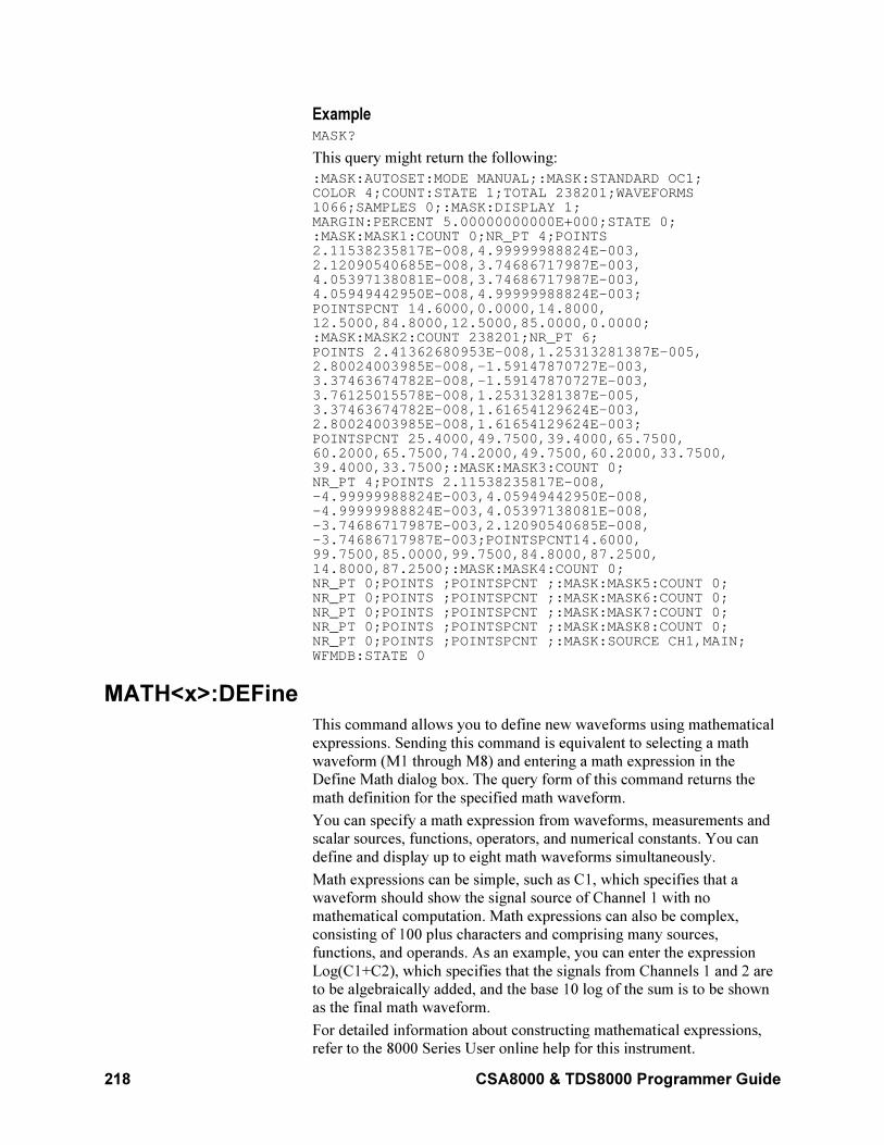
218 CSA8000 & TDS8000 Programmer Guide
Example MASK?
This query might return the following:
:MASK:AUTOSET:MODE MANUAL;:MASK:STANDARD OC1;COLOR 4;COUNT:STATE 1;TOTAL 238201;WAVEFORMS1066;SAMPLES 0;:MASK:DISPLAY 1;MARGIN:PERCENT 5.00000000000E+000;STATE 0;:MASK:MASK1:COUNT 0;NR_PT 4;POINTS2.11538235817E-008,4.99999988824E-003,2.12090540685E-008,3.74686717987E-003,4.05397138081E-008,3.74686717987E-003,4.05949442950E-008,4.99999988824E-003;POINTSPCNT 14.6000,0.0000,14.8000,12.5000,84.8000,12.5000,85.0000,0.0000;:MASK:MASK2:COUNT 238201;NR_PT 6;POINTS 2.41362680953E-008,1.25313281387E-005,2.80024003985E-008,-1.59147870727E-003,3.37463674782E-008,-1.59147870727E-003,3.76125015578E-008,1.25313281387E-005,3.37463674782E-008,1.61654129624E-003,2.80024003985E-008,1.61654129624E-003;POINTSPCNT 25.4000,49.7500,39.4000,65.7500,60.2000,65.7500,74.2000,49.7500,60.2000,33.7500,39.4000,33.7500;:MASK:MASK3:COUNT 0;NR_PT 4;POINTS 2.11538235817E-008,-4.99999988824E-003,4.05949442950E-008,-4.99999988824E-003,4.05397138081E-008,-3.74686717987E-003,2.12090540685E-008,-3.74686717987E-003;POINTSPCNT14.6000,99.7500,85.0000,99.7500,84.8000,87.2500,14.8000,87.2500;:MASK:MASK4:COUNT 0;NR_PT 0;POINTS ;POINTSPCNT ;:MASK:MASK5:COUNT 0;NR_PT 0;POINTS ;POINTSPCNT ;:MASK:MASK6:COUNT 0;NR_PT 0;POINTS ;POINTSPCNT ;:MASK:MASK7:COUNT 0;NR_PT 0;POINTS ;POINTSPCNT ;:MASK:MASK8:COUNT 0;NR_PT 0;POINTS ;POINTSPCNT ;:MASK:SOURCE CH1,MAIN;WFMDB:STATE 0
MATH<x>:DEFine
This command allows you to define new waveforms using mathematical
expressions. Sending this command is equivalent to selecting a math
waveform (M1 through M8) and entering a math expression in the
Define Math dialog box. The query form of this command returns the
math definition for the specified math waveform.
You can specify a math expression from waveforms, measurements and
scalar sources, functions, operators, and numerical constants. You can
define and display up to eight math waveforms simultaneously.
Math expressions can be simple, such as C1, which specifies that a
waveform should show the signal source of Channel 1 with no
mathematical computation. Math expressions can also be complex,
consisting of 100 plus characters and comprising many sources,
functions, and operands. As an example, you can enter the expression
Log(C1+C2), which specifies that the signals from Channels 1 and 2 are
to be algebraically added, and the base 10 log of the sum is to be shown
as the final math waveform.
For detailed information about constructing mathematical expressions,
refer to the 8000 Series User online help for this instrument.
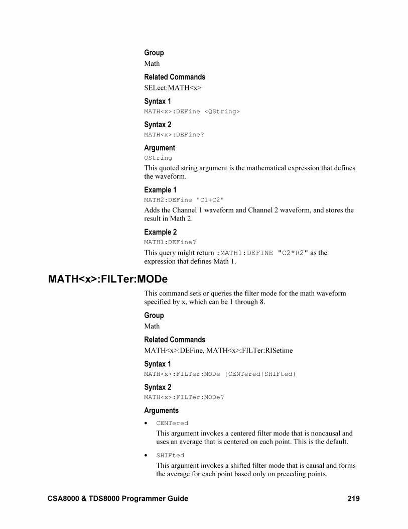
CSA8000 & TDS8000 Programmer Guide 219
Group
Math
Related Commands
SELect:MATH<x>
Syntax 1 MATH<x>:DEFine <QString>
Syntax 2 MATH<x>:DEFine?
Argument QString
This quoted string argument is the mathematical expression that defines
the waveform.
Example 1 MATH2:DEFine "C1+C2"
Adds the Channel 1 waveform and Channel 2 waveform, and stores the
result in Math 2.
Example 2 MATH1:DEFine?
This query might return :MATH1:DEFINE "C2*R2" as the
expression that defines Math 1.
MATH<x>:FILTer:MODe
This command sets or queries the filter mode for the math waveform
specified by x, which can be 1 through 8.
Group
Math
Related Commands
MATH<x>:DEFine, MATH<x>:FILTer:RISetime
Syntax 1 MATH<x>:FILTer:MODe CENTered|SHIFted
Syntax 2 MATH<x>:FILTer:MODe?
Arguments
• CENTered
This argument invokes a centered filter mode that is noncausal and uses an average that is centered on each point. This is the default.
• SHIFted
This argument invokes a shifted filter mode that is causal and forms
the average for each point based only on preceding points.
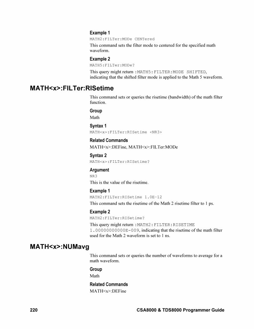
220 CSA8000 & TDS8000 Programmer Guide
Example 1 MATH2:FILTer:MODe CENTered
This command sets the filter mode to centered for the specified math
waveform.
Example 2 MATH5:FILTer:MODe?
This query might return :MATH5:FILTER:MODE SHIFTED,
indicating that the shifted filter mode is applied to the Math 5 waveform.
MATH<x>:FILTer:RISetime
This command sets or queries the risetime (bandwidth) of the math filter
function.
Group
Math
Syntax 1 MATH<x>:FILTer:RISetime <NR3>
Related Commands
MATH<x>:DEFine, MATH<x>:FILTer:MODe
Syntax 2 MATH<x>:FILTer:RISetime?
Argument NR3
This is the value of the risetime.
Example 1 MATH2:FILTer:RISetime 1.0E–12
This command sets the risetime of the Math 2 risetime filter to 1 ps.
Example 2 MATH2:FILTer:RISetime?
This query might return :MATH2:FILTER:RISETIME
1.00000000000E-009, indicating that the risetime of the math filter
used for the Math 2 waveform is set to 1 ns.
MATH<x>:NUMavg
This command sets or queries the number of waveforms to average for a
math waveform.
Group
Math
Related Commands
MATH<x>:DEFine
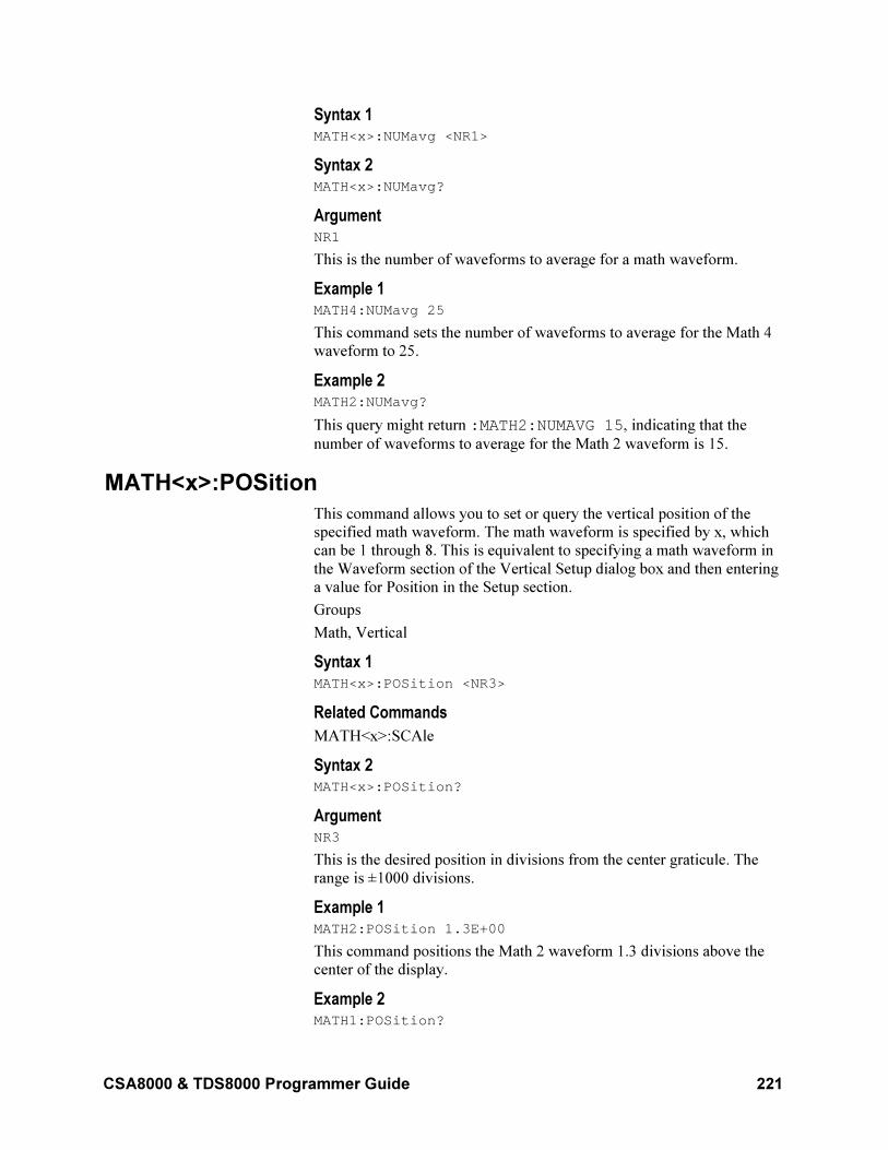
CSA8000 & TDS8000 Programmer Guide 221
Syntax 1 MATH<x>:NUMavg <NR1>
Syntax 2 MATH<x>:NUMavg?
Argument NR1
This is the number of waveforms to average for a math waveform.
Example 1 MATH4:NUMavg 25
This command sets the number of waveforms to average for the Math 4
waveform to 25.
Example 2 MATH2:NUMavg?
This query might return :MATH2:NUMAVG 15, indicating that the
number of waveforms to average for the Math 2 waveform is 15.
MATH<x>:POSition
This command allows you to set or query the vertical position of the
specified math waveform. The math waveform is specified by x, which
can be 1 through 8. This is equivalent to specifying a math waveform in
the Waveform section of the Vertical Setup dialog box and then entering
a value for Position in the Setup section.
Groups
Math, Vertical
Syntax 1 MATH<x>:POSition <NR3>
Related Commands
MATH<x>:SCAle
Syntax 2 MATH<x>:POSition?
Argument NR3
This is the desired position in divisions from the center graticule. The
range is ±1000 divisions.
Example 1 MATH2:POSition 1.3E+00
This command positions the Math 2 waveform 1.3 divisions above the
center of the display.
Example 2 MATH1:POSition?
222 CSA8000 & TDS8000 Programmer Guide
This query might return :MATH1:POSITION -
1.50000000000E+000 as the position setting for the Math 1
waveform, indicating that the waveform is positioned 1.5 divisions
below the center of the display.
MATH<x>:POSition
This command allows you to set or query the vertical position of the
specified math waveform. The math waveform is specified by x, which
can be 1 through 8. This is equivalent to specifying a math waveform in
the Waveform section of the Vertical Setup dialog box and then entering
a value for Position in the Setup section.
Groups
Math, Vertical
Syntax 1 MATH<x>:POSition <NR3>
Related Commands
MATH<x>:SCAle
Syntax 2 MATH<x>:POSition?
Argument NR3
This is the desired position in divisions from the center graticule. The
range is ±1000 divisions.
Example 1 MATH2:POSition 1.3E+00
This command positions the Math 2 waveform 1.3 divisions above the
center of the display.
Example 2 MATH1:POSition?
This query might return :MATH1:POSITION -1.500000000000
as the position setting for the Math 1 waveform, indicating that the
waveform is positioned 1.5 divisions below the center of the display.
MATH<x>:SCAle
This command allows you to set or query the vertical scale of the math
waveform specified by x, which can be 1 through 8. This is equivalent to
specifying a math waveform in the Waveform section of the Vertical
Setup dialog box and then entering a value for Scale in the Setup section.
Each waveform has its own vertical scale parameter. For a signal with
constant amplitude, increasing the scale causes the waveform to be
displayed smaller. Decreasing the scale causes the waveform to be
displayed larger. For math waveforms, this setting controls the display
only, graphically scaling these waveforms and having no effect on the
acquisition hardware.
CSA8000 & TDS8000 Programmer Guide 223
Groups
Math, Vertical
Related Commands
MATH<x>:POSition
Syntax 1 MATH<x>:SCAle <NR3>
Syntax 2 MATH<x>:SCAle?
Argument NR3
This is the scale in vertical units per division. The range is 1.0E–30 to
1.0E+30.
Example 1 MATH4:SCAle 100E–03
This command sets the Math 4 waveform scale to 100 mV per division.
Example 2 MATH1:SCAle?
This query might return :MATH1:SCALE 1.00000000000E-001
as the scale setting for the Math 1 waveform, indicating that the current
volts per division setting of the Math 1 waveform is 100 mV per
division.
MATH<x>:SCAle
This command allows you to set or query the vertical scale of the math
waveform specified by x, which can be 1 through 8. This is equivalent to
specifying a math waveform in the Waveform section of the Vertical
Setup dialog box and then entering a value for Scale in the Setup section.
Each waveform has its own vertical scale parameter. For a signal with
constant amplitude, increasing the scale causes the waveform to be
displayed smaller. Decreasing the scale causes the waveform to be
displayed larger. For math waveforms, this setting controls the display
only, graphically scaling these waveforms and having no effect on the
acquisition hardware.
Groups
Math, Vertical
Related Commands
MATH<x>:POSition
Syntax 1 MATH<x>:SCAle <NR3>
Syntax 2 MATH<x>:SCAle?
224 CSA8000 & TDS8000 Programmer Guide
Argument NR3
This is the scale in vertical units per division. The range is 1.0E–30 to
1.0E+30.
Example 1 MATH4:SCAle 100E–03
This command sets the Math 4 waveform scale to 100 mV per division.
Example 2 MATH1:SCAle?
This query might return :MATH1:SCALE 0.100000000000 as the
scale setting for the Math 1 waveform, indicating that the current volts
per division setting of the Math 1 waveform is 100 mV per division.
MATH<x>:UNITs?
This query only command returns the math units for the specified math
waveform. The x argument can be 1 through 8, specifying math
waveforms M1 through M8. The instrument will attempt to determine
the appropriate units for the result of the math expression that generates
the math waveform. The default is UNDEFINED unless one of the
following rules can be applied:
• If the resultant waveform is unitless, a "U" is displayed for the unit
label.
• Plus (+), Minus (–), Average, Envelope, and Filter functions use the
unit label of the source operands for the vertical axis readout and the
horizontal axis unit label of the source operands for the horizontal
axis readout. If the units for the sources are not the same, then the
result is unitless.
• An integration function concatenates the vertical axis unit label and
the horizontal axis label of its source operand for the vertical axis
readout (for example, Vs) and the horizontal axis unit label of the
source operands for the horizontal axis readout.
• A differential function concatenates the vertical axis unit label and
the horizontal axis label of its source operand with a slash (/) inserted
between labels (for example, V/s) and the horizontal axis unit label
of the source operands for the horizontal axis readout.
• The multiply function (*) concatenates the vertical axis unit labels of
its source operands for the vertical axis readout (for example, VV)
and the horizontal axis unit label of the source operands for the
horizontal axis readout.
• The divide function concatenates the unit labels of its source
operands with a slash (/) inserted between the labels (for example,
V/V) and the horizontal axis unit label of the source operands for the
horizontal axis readout.
CSA8000 & TDS8000 Programmer Guide 225
• The log, ln, sqrt, and ex
function results are unitless.
Group
Math
Syntax MATH<x>:UNITs?
Example MATH3:UNITs?
This query might return :MATH3:UNITs "V", indicating that the units
for Math 3 waveform are volts.
MATH<x>:WFMLabel
This command sets or queries the label associated with the math
waveform specified.
Group
Math
Related Commands
CH<x>:WFMLabel, REF<x>:WFMLabel
Syntax 1 MATH<x>:WFMLabel
Syntax2 MATH<x>:WFMLabel?
Argument Qstring
This argument sets the label for the math waveform.
Example 1 MATH1:WFMLabel "My MATH1 waveform"
This command sets the label for MATH1 to be "My MATH1 waveform,"
which is the label displayed with the waveform when it is displayed on
screen.
Example 2 MATH1:WFMLabel?
This query might return :MATH1:WFMLABEL "My MATH1
waveform," indicating that the label for the MATH1 waveform is set to
"My MATH1 waveform."
MATH<x>?
This is a query only command that returns the settings for the math
waveform specified by <x>, which can be 1 through 8.
Group
Math
226 CSA8000 & TDS8000 Programmer Guide
Syntax MATH<x>?
Example MATH3?
This query might return :MATH3:POSITION 1.59400000000+001; SCALE 1.00000000000–001;DEFINE "C3+C3/C3";UNITS "V"; FILTER:RISETIME 1.00000000000–OO9;MODE CENTERED;
MATH3NUMAVG 2.
MEASUrement:ALL:VALue?
This query only command returns all the measurement values.
Group
Measurement
Related Commands
MEASUrement:LISTValue?,
MEASUrement:MEAS<x>:VALue?
Syntax MEASUrement:ALL:VALue?
Example MEASUrement:ALL:VALue?
This query might return :MEASUREMENT:ALL:VALUE 5.18798842266E-004, 1.08967389191E-010,99.10000000000E+36, 1.57041666667E-009,6.367736800021E+008, 99.10000000000E+36,4.11368599818E-001",
99.10000000000E+36 as the listing of the eight possible
measurement values.
Note: The value 99.10000000000E+36 in the returned list of values
is the numeric equivalent to NAN (not a number); this value indicates
that the measurement slot does not have a valid measurement defined for
it.
MEASUrement:ANNOtations:STATE
This command sets or queries whether annotations are displayed. This is
equivalent to toggling the Annotations check box in the Measurement
Setup dialog box. To display gates used in gated measurements, Gates
must be enabled with the MEASUrement:MEAS<x>:GATing:STATE
command.
Group
Measurement
CSA8000 & TDS8000 Programmer Guide 227
Related Commands
MEASUrement:MEAS<x>:GATing:STATE
Syntax 1 MEASUrement:ANNOtations:STATE ON|OFF|NR1
Syntax 2 MEASUrement:ANNOtations:STATE?
Arguments
• ON
Enables the display of annotations.
• OFF
Disables the display of annotations.
• NR1
A 0 disables the display of annotations; any other integer enables the display of annotations.
Example 1 MEASUrement:ANNOtations:STATE ON
This command enables the display of annotations.
Example 2 MEASUrement:ANNOtations:STATE?
This query might return :MEASUREMENT:ANNOTATIONS:STATE 0,
indicating that the display of annotations is disabled.
NOTE: A query always returns a 0 or 1.
MEASUrement:LIST
You use this command to establish a list of defined measurements for
which you want values returned. The query form of this command
returns the list of the defined measurements (for example, MEAS1,
MEAS2). You can use the MEASUrement:LISTValue? query to get the
value for each of the defined measurements in the list. There is no
equivalent front-panel or user-interface application control for this
feature.
Group
Measurement
Related Commands
MEASUrement:LISTValue?
Syntax 1 MEASUrement:LIST <NR1>[,<NR1>]
Syntax 2: MEASUrement:LIST?
228 CSA8000 & TDS8000 Programmer Guide
Argument NR1
This argument is one of the defined measurement slots. You can create a
list of up to 8 measurements (1 through 8) that correspond to Meas 1
through Meas 8.
Example 1 MEASUrement:LIST 1,4,5
This command establishes a list of 3 defined measurements (Meas 1,
Meas 4, and Meas 5) for which values can be returned.
Example 2 MEASUrement:LIST?
This query might return :MEASUREMENT:LIST 1,2, indicating that
the list consists of two measurements.
MEASUrement:LISTValue?
This query only command returns the values of the measurements in the
list created with the MEASUrement:LIST command.
Group
Measurement
Related Commands
MEASUrement:LIST
Syntax MEASUrement:LISTVALue?
Example MEASUrement:LISTVALue?
This query might return :MEASUREMENT:LISTVALUE
1.52587894784E-004,2.49499996255E-010, which are the
measurement values for the measurement slots defined as part of the list.
MEASUrement:MEAS<x>:ALL?
This query only command returns all the statistics for the measurement
specified by x, which can be 1 through 8. Before you send this command,
send the MEASUrement:STATIstics:ENABle ON command to ensure
accurate measurement statistics. The following measurement values are
returned:
• Maximum (see MEASUrement:MEAS<x>:MAXimum?)
• Minimum (see MEASUrement:MEAS<x>:MINImum?)
• Mean (see MEASUrement:MEAS<x>:MEAN?)
• Standard deviation (see MEASUrement:MEAS<x>:STDdev?)
• Measurement value (see MEASUrement:MEAS<x>:VALue?)
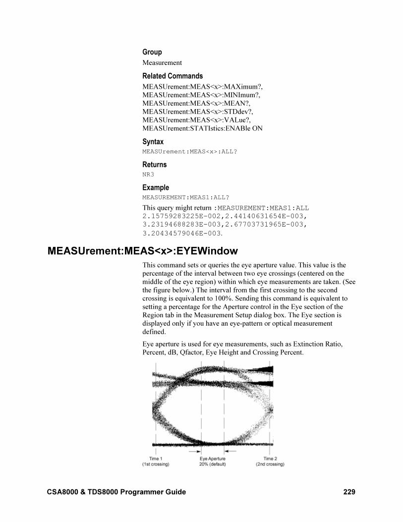
CSA8000 & TDS8000 Programmer Guide 229
Group
Measurement
Related Commands
MEASUrement:MEAS<x>:MAXimum?,
MEASUrement:MEAS<x>:MINImum?,
MEASUrement:MEAS<x>:MEAN?,
MEASUrement:MEAS<x>:STDdev?,
MEASUrement:MEAS<x>:VALue?,
MEASUrement:STATIstics:ENABle ON
Syntax MEASUrement:MEAS<x>:ALL?
Returns NR3
Example MEASUREMENT:MEAS1:ALL?
This query might return :MEASUREMENT:MEAS1:ALL 2.15759283225E-002,2.44140631654E-003, 3.23194688283E-003,2.67703731965E-003,
3.20434579046E-003.
MEASUrement:MEAS<x>:EYEWindow
This command sets or queries the eye aperture value. This value is the
percentage of the interval between two eye crossings (centered on the
middle of the eye region) within which eye measurements are taken. (See
the figure below.) The interval from the first crossing to the second
crossing is equivalent to 100%. Sending this command is equivalent to
setting a percentage for the Aperture control in the Eye section of the
Region tab in the Measurement Setup dialog box. The Eye section is
displayed only if you have an eye-pattern or optical measurement
defined.
Eye aperture is used for eye measurements, such as Extinction Ratio,
Percent, dB, Qfactor, Eye Height and Crossing Percent.
230 CSA8000 & TDS8000 Programmer Guide
Group
Measurement
Syntax 1 MEASUrement:MEAS<x>:EYEWindow <NR2>
Syntax 2: MEASUrement:MEAS<x>:EYEWindow?
Arguments NR2
This argument is the percent of interval between two eye crossings
centered on the middle of the region. The range is 0 to 100. The default
is 20.
Example 1 MEASUrement:MEAS1:EYEWindow 25
This command sets the eye aperture (window) to 25% for Measurement
1.
Example 2 MEASUrement:MEAS1:EYEWindow?
This query might return MEASUREMENT:MEAS1:EYEWINDOW 10,
indicating that the eye aperture is set to 10%. Measurement 1 will be
taken within this region.
MEASUrement:MEAS<x>:GATing:STATE
This command sets or queries the gating state for the measurement slot
specified by x, which can be 1 through 8. Sending this command is
equivalent to toggling the On check box in the Gates section of the
Region portion of the Measurement Setup dialog box.
A gate defines a segment of waveform data over which the measurement
is performed. You can define the specified measurement using the
MEASUrement:MEAS<x>:TYPe command. You can use the
MEASUrement:ANNOtations:STATE command to display the gating in
the graticule area.
Group
Measurement
Related Commands
MEASUrement:MEAS<x>:TYPe,
MEASUrement:ANNOtations:STATE
MEASUrement:MEAS:SOURCE:GATE:POS
MEASUrement:MEAS:SOURCE:GATE:PCTPos
Syntax 1 MEASUrement:MEAS<x>:GATing:STATE ON|OFF|NR1
Syntax 2: MEASUrement:MEAS<x>:GATing:STATE?
CSA8000 & TDS8000 Programmer Guide 231
Arguments
• ON
This argument enables the gating for the specified measurement.
• OFF
This argument disables the gating for the specified measurement.
• NR1
A 0 disables the gating for the specified measurement; any other value enables the gating for the specified measurement.
Example 1 MEASUrement:MEAS2:GATing:STATE ON
Enables the gating for Measurement 2.
Example 2 MEASUrement:MEAS1:GATing:STATE?
This query might return MEASUREMENT:MEAS1:GATING:STATE 1,
indicating that gating is enabled for Measurement 1.
NOTE: A query always returns a 0 or 1.
MEASUrement:MEAS<x>:JITter
This command sets or queries whether the jitter measurement should be
made at the eye crossing of an eye pattern or at the mid reference level.
Sending this command is equivalent to selecting Eye Cross or Mid Ref
for the Jitter At field in the Eye section of the Region tab in the
Measurement Setup dialog box. The Eye section is displayed only if you
have an eye-pattern or optical measurement defined.
Group
Measurement
Syntax 1 MEASUrement:MEAS<x>:JITter EYECross|MIDref
Syntax 2: MEASUrement:MEAS<x>:JITter?
Arguments
• EYECross
This argument causes the measurement for jitter to be taken at the eye crossing.
• MIDref
This argument causes the measurement for jitter to be taken at the mid reference level.
Example 1 MEASUrement:MEAS1:JITter EYECross
This command causes the jitter measurement to be made at the eye
crossing.
232 CSA8000 & TDS8000 Programmer Guide
Example 2 MEASUrement:MEAS2:JITter?
This query might return :MEASUREMENT:MEAS2:JITTER MIDREF,
indicating that Measurement 2 will measure jitter at the mid reference
level.
MEASUrement:MEAS<x>:MAXimum?
Description
This query only command returns the maximum value found for the
measurement slot specified by x, which can be 1 through 8, since the last
statistical reset.
Group
Measurement
Related Commands
MEASUrement:MEAS<x>:ALL?
Syntax MEASUrement:MEAS<x>:MAXimum?
Returns
NR3
Example MEASUREMENT:MEAS3:MAXIMUM?
This query might return :MEASUREMENT:MEAS3:MAXIMUM
4.27246105395E-003, indicating that the maximum value for Meas
3 is 4.272 mV.
MEASUrement:MEAS<x>:MEAN?
This query only command returns the mean value accumulated for the
measurement slot specified by x, which can be 1 through 8, since the last
statistical reset.
Group
Measurement
Related Commands
MEASUrement:MEAS<x>:ALL?
Syntax MEASUrement:MEAS<x>:MEAN?
Returns NR3
Example MEASUREMENT:MEAS1:MEAN?

CSA8000 & TDS8000 Programmer Guide 233
This query might return :MEASUREMENT:MEAS1:MEAN
2.85516357276E-003, indicating that the mean value for Meas 1 is
2.855 mV.
MEASUrement:MEAS<x>:MINImum?
This query only command returns the minimum value found for the
measurement slot specified by x, which can be 1 through 8, since the last
statistical reset.
Group
Measurement
Related Commands
MEASUrement:MEAS<x>:ALL?
Syntax MEASUrement:MEAS<x>:MINImum?
Returns NR3
Example MEASUREMENT:MEAS1:MINIMUM?
This query might return :MEASUREMENT:MEAS1:MINIMUM
1.92260747428E-003, indicating that the minimum value for Meas
1 is 1.923 mV.
MEASUrement:MEAS<x>:NOISe
This command sets or queries whether the noise measurement is made on
the high or low level of the waveform. Sending this command is
equivalent to selecting High or Low for the Noise At field in the Eye
section of the Region tab in the Measurement Setup dialog box. The Eye
section is displayed only if you have an eye-pattern or optical
measurement defined.
Group
Measurement
Syntax 1 MEASUrement:MEAS<x>:NOIse HIGH|LOW
Syntax 2: MEASUrement:MEAS<x>:NOISe?
Arguments
• HIGH
This argument causes the measurement for noise to be taken at the high level of the waveform.
• LOW
This argument causes the measurement for noise to be taken at the
234 CSA8000 & TDS8000 Programmer Guide
low level of the waveform.
Example 1 MEASUrement:MEAS1:NOISe HIGH
This command causes the noise measurement to be made at the high
level of the waveform for Measurement 1.
Example 2 MEASUrement:MEAS2:NOISe?
This query might return :MEASUREMENT:MEAS2:NOISE LOW,
indicating that Measurement 2 will measure noise at the low level of the
waveform.
MEASUrement:MEAS<x>:REFLevel<x>:ABSolute:HIGH
This command sets or queries the high reference level in absolute user
units for the specified measurement. The measurement slot is specified
by x, which can be 1 through 8. The reference level source is specified
by x, which can only be 1 for this measurement (or defaults to 1 if not
specified).
This absolute value is used as the high reference level when
MEASUrement:MEAS<x>:REFLevel<x>:METHod is set to ABSolute.
Sending this command is equivalent to selecting the RefLevel tab in the
Measurement Setup dialog box, selecting Absolute in the Reference
Level Calc Method section, and then entering an absolute value for Hi in
the Reference section.
Group
Measurement
Related Commands
MEASUrement:MEAS<x>:REFLevel<x>:METHod
Syntax 1 MEASUrement:MEAS<x>:REFLevel<x>:ABSolute:HIGH <NR3>
Syntax 2 MEASUrement:MEAS<x>:REFLevel<x>:ABSolute:HIGH?
Argument NR3
This argument is the high reference level in absolute user units. The
default is 0 V.
Example 1 MEASUrement:MEAS3:REFLevel1:ABSolute:HIGH 2.0E–1
This command sets the high reference level for Measurement 3 to 200
mV.
Example 2 MEASUrement:MEAS2:REFLevel1:ABSolute:HIGH?
CSA8000 & TDS8000 Programmer Guide 235
This query might return :MEASUREMENT:MEAS2:REFLEVEL1:ABSOLUTE:HIGH
9.00000000000E–2, indicating that the high reference level for
Measurement 2 to is set to 90 mV.
MEASUrement:MEAS<x>:REFLevel<x>:ABSolute:LOW
This command sets or queries the low reference level in absolute user
units for the specified measurement. The measurement slot is specified
by x, which can be 1 through 8. The reference level source is specified x,
which can only be 1 for this measurement (or defaults to 1 if not
specified).
This absolute value is used as the low reference level when
MEASUrement:MEAS<x>:REFLevel<x>:METHod is set to ABSolute.
Sending this command is equivalent to selecting Absolute in the
Reference Level Calc Method section of the RefLevel dialog and then
entering an absolute value for Low in the Reference section of the
Measurement Setup dialog box.
Group
Measurement
Related Commands
MEASUrement:MEAS<x>:REFLevel<x>:METHod
Syntax 1 MEASUrement:MEAS<x>:REFLevel<x>:ABSolute:LOW <NR3>
Syntax 2 MEASUrement:MEAS<x>:REFLevel<x>:ABSolute:LOW?
Argument NR3
This argument is the low reference level in absolute user units. The
default is 0 V.
Example 1 MEASUrement:MEAS3:REFLevel1:ABSolute:LOW 2.0E–2
This command sets the low reference level for Measurement 3 to 20 mV.
Example 2 MEASUrement:MEAS2:REFLevel1:ABSolute:LOW?
This query might return :MEASUREMENT:MEAS2:REFLEVEL1:ABSOLUTE:LOW
3.00000000000E-003, indicating that the low reference level for
Measurement 2 to is set to 3 mV.
MEASUrement:MEAS<x>:REFLevel<x>:ABSolute:MID
This command sets or queries the mid reference level in absolute user
units for the specified measurement. The measurement slot is specified
by x, which can be 1 through 8. The reference level is specified by x
(which corresponds to the Source1 or Source2 waveform) and can be 1
236 CSA8000 & TDS8000 Programmer Guide
or 2. (You can set two different mid reference levels when taking
measurements, such as phase or delay, between two source waveforms.)
This absolute value is used as the mid reference level when
MEASUrement:MEAS<x>:REFLevel<x>:METHod is set to ABSolute.
Sending this command is equivalent to selecting ABSolute in the
Reference Level Calc Method section of the RefLevel dialog and then
entering an absolute value for Mid in the Reference section of the
Measurement Setup dialog box.
Group
Measurement
Related Commands
MEASUrement:MEAS<x>:REFLevel<x>:METHod
Syntax 1 MEASUrement:MEAS<x>:REFLevel<x>:ABSolute:MID <NR3>
Syntax 2 MEASUrement:MEAS<x>:REFLevel<x>:ABSolute:MID?
Argument NR3
This argument is the mid reference level in absolute user units. The
default is 0 V.
Example 1 MEASUrement:MEAS3:REFLevel2:ABSolute:MID 4.0E–2
This command sets the mid reference level for Measurement 3 on Source
2 to 40 mV.
Example 2 MEASUrement:MEAS2:REFLevel1:ABSolute:MID?
This query might return :MEASUREMENT:MEAS2:REFLEVEL1:ABSOLUTE:MID
5.0000000000E–2, indicating that the mid reference level for
Measurement 2 on Source 1 is set to 50 mV.
MEASUrement:MEAS<x>:REFLevel<x>:METHod
This command sets or queries the method the instrument uses to
calculate the reference levels for a specified measurement taken on a
specified source waveform. The measurement slot is specified by x,
which can be 1 through 8. The reference level is specified by x (which
corresponds to the Source1 or Source2 waveform) and can be 1 or 2.
Sending this command is equivalent to selecting the option button for the
type of calculation in the Reference Level Calc Method section of the
RefLevel dialog in the Measurement Setup dialog box.
The following diagram shows how each method calculates the High and
Low reference levels.
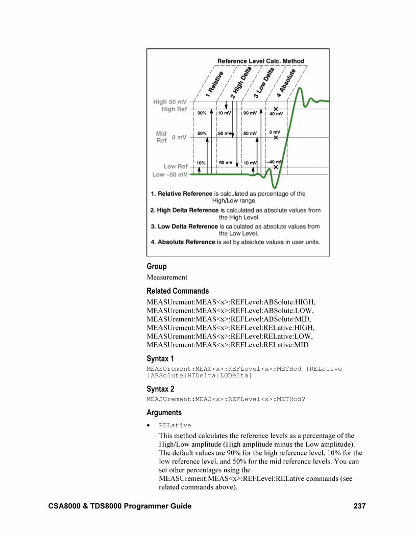
CSA8000 & TDS8000 Programmer Guide 237
Group
Measurement
Related Commands
MEASUrement:MEAS<x>:REFLevel:ABSolute:HIGH,
MEASUrement:MEAS<x>:REFLevel:ABSolute:LOW,
MEASUrement:MEAS<x>:REFLevel:ABSolute:MID,
MEASUrement:MEAS<x>:REFLevel:RELative:HIGH,
MEASUrement:MEAS<x>:REFLevel:RELative:LOW,
MEASUrement:MEAS<x>:REFLevel:RELative:MID
Syntax 1 MEASUrement:MEAS<x>:REFLevel<x>:METHod RELative|ABSolute|HIDelta|LODelta
Syntax 2 MEASUrement:MEAS<x>:REFLevel<x>:METHod?
Arguments
• RELative
This method calculates the reference levels as a percentage of the
High/Low amplitude (High amplitude minus the Low amplitude).
The default values are 90% for the high reference level, 10% for the
low reference level, and 50% for the mid reference levels. You can
set other percentages using the
MEASUrement:MEAS<x>:REFLevel:RELative commands (see related commands above).
238 CSA8000 & TDS8000 Programmer Guide
• ABSolute
This method uses reference levels set explicitly in absolute user units
with the MEASUrement:MEAS<x>:REFLevel:ABSolute commands
(see related commands above). This method is useful when precise
values are required (for example, when you are designing to
published interface specifications such as RS-232-C). The default
values are 0 V for the high reference level, the low reference level, and the mid reference levels.
• HIDelta
This method sets the reference levels as absolute amplitude delta
values from the High level.
• LODelta
This method sets the reference levels as absolute amplitude delta values from the Low level.
Example 1 MEASUrement:MEAS1:REFLevel1:METHod RELative
This command sets the method of calculating the reference levels to
relative for Measurement 1; the default values are 90% for the high
reference level, 50% for the mid reference level, and 10% for the low
reference level.
Example 2 MEASUrement:MEAS8:REFLevel1:METHod?
This query might return
:MEASUREMENT:MEAS8:REFLEVEL1:METHOD ABSOLUTE,
indicating the reference levels used are set to absolute values in user
units.
MEASUrement:MEAS<x>:REFLevel<x>:RELative:HIGH
This command sets or queries the percent of the High/Low range that the
instrument uses to calculate the high reference level for the specified
measurement, where 100% is equal to the High/Low range. The
measurement slot is specified by x, which can be 1 through 8. The
reference level source is specified x, which can only be 1 for this
measurement (or defaults to 1 if not specified).
This percentage is used to calculate the high reference level when
MEASUrement:MEAS<x>:REFLevel<x>:METHod is set to RELative.
Sending this command is equivalent to selecting Relative in the
Reference Level Calc Method section of the RefLevel dialog and then
entering a percentage for Hi in the Reference section of the Measurement
Setup dialog box.
Group
Measurement
Related Commands
MEASUrement:MEAS<x>:REFLevel<x>:METHod
CSA8000 & TDS8000 Programmer Guide 239
Syntax 1 MEASUrement:MEAS<x>:REFLevel<x>:RELative:HIGH <NR2>
Syntax 2 MEASUrement:MEAS<x>:REFLevel<x>:RELative:HIGH?
Argument NR2
This argument can be from 0 to 100 (percent) and is the high reference
level. The default is 90 (percent).
Example 1 MEASUrement:MEAS3:REFLevel1:RELative:HIGH 95
This command sets the high reference level for Measurement 3 to 95% of
the High/Low range.
Example 2 MEASUrement:MEAS2:REFLevel1:RELative:HIGH?
This query might return :MEASUREMENT:MEAS2:REFLEVEL1:PERCENT:HIGH
9.00000000000E+001, indicating that the high reference level for
Measurement 2 to is set to 90% (the default value) of the High/Low
range.
MEASUrement:MEAS<x>:REFLevel<x>:RELative:LOW
This command sets or queries the percent of the High/Low range that the
instrument uses to calculate the low reference level for the specified
measurement, where 100% is equal to the High/Low range. The
measurement slot is specified by x, which can be 1 through 8. The
reference level source is specified x, which can only be 1 for this
measurement (or defaults to 1 if not specified).
This percentage is used to calculate the low reference level when
MEASUrement:MEAS<x>:REFLevel<x>:METHod is set to RELative.
Sending this command is equivalent to selecting Relative in the
Reference Level Calc Method section of the RefLevel dialog and then
entering a percentage for Low in the Reference section of the
Measurement Setup dialog box.
Group
Measurement
Related Commands
MEASUrement:MEAS<x>:REFLevel<x>:METHod
Syntax 1 MEASUrement:MEAS<x>:REFLevel<x>:RELative:LOW <NR2>
Syntax 2 MEASUrement:MEAS<x>:REFLevel<x>:RELative:LOW?
Argument NR2
240 CSA8000 & TDS8000 Programmer Guide
This argument can be from 0 to 100 (percent) and is the low reference
level. The default is 10 (percent).
Example 1 MEASUrement:MEAS3:REFLevel1:RELative:Low 20
This command sets the low reference level for Measurement 3 to 20% of
the High/Low range.
Example 2 MEASUrement:MEAS2:REFLevel1:RELative:LOW?
This query might return
:MEASUREMENT:MEAS2:REFLEVEL1:RELATIVE:LOW 10,
indicating that the low reference level for Measurement 2 is set to 10%
(the default value) of the High/Low range.
MEASUrement:MEAS<x>:REFLevel<x>:RELative:MID
This command sets or queries the percent of the High/Low range that the
instrument uses to calculate the mid reference level for the specified
measurement, where 100% is equal to the High/Low range. The
measurement slot is specified by x, which can be 1 through 8. The
reference level is specified by x (which corresponds to the Source1 or
Source2 waveform) and can be 1 or 2. (You can set two different mid
reference levels when taking measurements, such as phase or delay,
between two source waveforms.)
This percentage is used to calculate the mid reference level when
MEASUrement:MEAS<x>:REFLevel<x>:METHod is set to RELative.
Sending this command is equivalent to selecting Relative in the
Reference Level Calc Method section of the RefLevel dialog and then
entering a percentage for Mid in the Reference section of the
Measurement Setup dialog box.
Group
Measurement
Related Commands
MEASUrement:MEAS<x>:REFLevel<x>:METHod
Syntax 1 MEASUrement:MEAS<x>:REFLevel<x>:RELative:MID <NR2>
Syntax 2 MEASUrement:MEAS<x>:REFLevel<x>:RELative:MID?
Argument NR2
This argument can be from 0 to 100 (percent) and is the mid reference
level. The default is 50 (percent).
Example 1 MEASUrement:MEAS3:REFLevel2:RELative:MID 40
This command sets the mid reference level for Measurement 3 on Source
2 to 40% of the High/Low range.
CSA8000 & TDS8000 Programmer Guide 241
Example 2 MEASUrement:MEAS2:REFLevel1:RELative:MID?
This query might return :MEASUREMENT:MEAS2:REFLEVEL1:PERCENT:LOW
5.00000000000E+001, indicating that the mid reference level for
Measurement 2 on Source 1 is set to 50% (the default value) of the
High/Low range.
MEASUrement:MEAS<x>:REFLevel<x>?
This is a query only command that returns all reference level <x>
settings for measurement slot <x> (slot one through slot eight).
Group
Measurement
Syntax MEASUrement:MEAS<x>:REFLevel?
Example MEASUrement:MEAS1:REFLevel?
This query might return :MEASUREMENT:MEAS1:REFLEVEL1:METHOD RELATIVE; ABSOLUTE:HIGH 0.00000000000E+000; LOW 0.00000000000E+000;MID 0.00000000000E+000; :MEASUREMENT:MEAS1:REFLEVEL1:RELATIVE: HIGH 9.00000000000E+001;LOW 1.00000000000E+001; MID 5.00000000000E+001
MEASUrement:MEAS<x>:SETDefault
This command (no query form) sets all the parameters for the
measurement specified by x, which can be 1 through 8, to the factory
default settings. This command affects only measurement parameters.
Group
Measurement
Syntax MEASUrement:MEAS<x>:SETDefault
Example MEASUrement:MEAS3:SETDefault
This command sets the parameters for Measurement 3 to their factory
default settings.
MEASUrement:MEAS<x>:SOURCE<x>:EDGE:DIRection
This command sets or queries the direction that the instrument uses to
look for the rising or falling edge of the specified waveform when taking
the specified measurement. This command affects only Delay, Ncross
and Pcross measurements. The measurement slot is specified by x, which
242 CSA8000 & TDS8000 Programmer Guide
can be 1 through 8; the source waveform is specified by x, which can be
1 or 2.
Sending this command is equivalent to selecting an option button ( or
) for Direction in the Edges section of the Region dialog in the
Measurement Setup dialog box.
Group
Measurement
Related Commands
MEASUremenr:MEAS<x>:GATing:STATE,
MEASUrement:MEAS<x>:SOURCE<x>:EDGE:SLOPe
Syntax 1 MEASUrement:MEAS<x>:SOURCE<x>:EDGE:DIRectionFORward|BACkward
Syntax 2 MEASUrement:MEAS<x>:SOURCE<x>:EDGE:DIRection?
Arguments
• FORward
This argument causes the instrument to search forward from the
beginning of the waveform (or gated region) and find the first edge
with the slope set by the
MEASUrement:MEAS<x>:SOURCE<x>:EDGE:SLOPe command
(delay measurements) or for the edge implicitly determined by the defined measurement.
• BACkward
This argument causes the instrument to search backward from the
end of the waveform (or gated region) and find the last edge with the
slope set by the
MEASUrement:MEAS<x>:SOURCE<x>:EDGE:SLOPe command
(delay measurements) or for the edge implicitly determined by the defined measurement.
Example 1 MEASUrement:MEAS2:SOURCE1:EDGE:DIRection FORward
This command causes the instrument to search forward from the
beginning of the Source 1 waveform (or the beginning of the gated
region, if gates are enabled) for the first specified edge (rising or falling)
Example 2 MEASUrement:MEAS8:SOURCE1:EDGE:DIRection?
This query might return :MEASUREMENT:MEAS8:SOURCE1:EDGE:DIRECTION
FORWARD, indicating that the instrument will search forward from the
beginning of the Source 1 waveform (or the beginning of the gated
region, if gates are enabled) for the specified edge (rising or falling)
when taking Measurement 8.
CSA8000 & TDS8000 Programmer Guide 243
MEASUrement:MEAS<x>:SOURCE<x>:EDGE:SLOPe
This command sets or queries the slope (or polarity) of the edges used in
delay time measurements. The measurement slot is specified by x, which
can be 1 through 8; the source is specified by x, which can be 1 (source
waveform) or 2 (destination waveform). For edge measurements other
than delay, the slope is determined implicitly (for example, rise time
measurements use positive slopes). If gates are enabled (see the
MEASUremenr:MEAS<x>:GATing:STATE command), the instrument
finds the edge within the measurement zone; otherwise, the instrument
finds the edge within the entire waveform record.
Sending this command is equivalent to selecting an option button (±, +,
or –) for Slope in the Edges section of the Region dialog in the
Measurement Setup dialog box. (A delay measurement must be selected
before these buttons are active.)
Use the MEASUrement:MEAS<x>:SOURCE:EDGE:DIRection
command to set the direction that the instrument uses to look for the
rising or falling edge of the waveforms.
Group
Measurement
Syntax 1 MEASUrement:MEAS<x>:SOURCE<x>:EDGE:SLOPe RISE|FALL|EITHer
Syntax 2 MEASUrement:MEAS<x>:SOURCE<x>:EDGE:SLOPe?
Arguments
• RISE
This argument causes the instrument to take the specified
measurement on a rising (positive-going) edge of the specified source waveform.
• FALL
This argument causes the instrument to take the specified
measurement on a falling (negative-going) edge of the specified source waveform.
• EITHer
This argument causes the instrument to take the specified
measurement on either a rising (positive-going) or falling (negative-going) edge of the specified source waveform.
Example 1 MEASUrement:MEAS4:SOURCE1:EDGE:SLOPe RISE
This command causes the instrument to take the delay for Measurement
4 from a rising edge of the Source 1 waveform.
Example 2 MEASUrement:MEAS4:SOURCE2:EDGE:SLOPe?
244 CSA8000 & TDS8000 Programmer Guide
This query might return
:MEASUREMENT:MEAS4:SOURCE2:EDGE:SLOPE FALL,
indicating that the delay for Measurement 4 is taken to a falling edge of
the Source 2 (destination) waveform.
MEASUrement:MEAS<x>:SOURCE<x>:EDGE?
This query only command returns edge parameters (slope and direction)
for the specified measurement slot using the specified source. The
measurement slot is specified by x, which can be 1 through 8. The
Source is specified by x, which can be 1 or 2.
Measurement
Syntax MEASUrement:MEAS<x>:SOURCE<x>:EDGE?
Example MEASUrement:MEAS<x>:SOURCE<x>:EDGE?
This query might return :MEASUREMENT:MEAS4:SOURCE1:EDGE:SLOPE
FALL;DIRECTION FORWARD.
MEASUrement:MEAS<x>:SOURCE<x>:GATE<x>:PCTPos
This command sets or queries the position (in percentage of the waveform) of the source gates for the measurement. The measurement, source, and gate are defined as follows:
• MEAS<x> where x can be 1 through 8 (a maximum of 8 measurement slots)
• SOURCE<x> where x can be 1 or 2 (a maximum of 2 source waveforms)
• GATE<x> where x can be 1 or 2 (one pair of gates per source waveform)
Gates are generic, nondirectional markers that segment the area of
waveform data over which measurements are performed. There is no
distinction in gates of stop or start, so they can cross.
You use this command to set the position of a gate as a percentage of the
waveform. This is equivalent to selecting the Region dialog in the
Measurement Setup dialog box and entering the position as a percentage
of the waveform in the G1 or G2 control in the Gates section.
Note that a user cannot directly set the position of a gate in the
Measurement Setup dialog box using waveform units. Instead, the user
sets the percentage of the waveform at which the gate is positioned, and
then the position in waveform units is displayed in the readout boxes
adjacent to the G1 and G2 controls. However, you can directly set the
gate position in waveform units with the GPIB command,
MEASUrement:MEAS<x>:SOURCE<x>:GATE<x>:POS.
Group
Measurement
Related Commands
MEASUrement:MEAS<x>:SOURCE<x>:GATE<x>:POS
CSA8000 & TDS8000 Programmer Guide 245
MEASUrement:MEAS<x>:GATing:STATE
Syntax 1 MEASUrement:MEAS<x>:SOURCE<x>:GATE<x>:PCTPos <NR2>
Syntax 2 MEASUrement:MEAS<x>:SOURCE<x>:GATE<x>:PCTPos?
Arguments NR2
This argument is the position of the specified gate in percentage.
Example 1 MEASUrement:MEAS4:SOURCE1:GATE1:PCTPos 25
This command sets Gate 1 to 25% on the Source 1 waveform used for
Measurement 4.
Example 2 MEASUrement:MEAS2:SOURCE1:GATE2:PCTPos?
This query might return :MEASUREMENT:MEAS2:SOURCE1:GATE2:PCTPOS
8.00000000000E+001, indicating that Gate 2 is set at 80% on the
Source 1 waveform used for Measurement 2.
MEASUrement:MEAS<x>:SOURCE<x>:GATE<x>:POS
This command sets or queries the position (in waveform units) of the
source gates for the measurement. The measurement, source, and gate
are defined as follows:
• MEAS<x>, where x can be 1 through 8 (a maximum of 8
measurement slots)
• SOURCE<x>, where x can be 1 or 2 (a maximum of 2 source
waveforms)
• GATE<x>, where x can be 1 or 2 (one pair of gates per source
waveform)
Gates are generic, nondirectional markers that segment the area of
waveform data over which measurements are performed. There is no
distinction in gates of stop or start, so they can cross.
Although you can use this command to set the position of a gate in
waveform units, a user cannot directly set the position of a gate in the
Measurement Setup dialog box using waveform units. Instead, the user
selects the Region dialog, enters the position as a percentage of the
waveform, and then reads the position in waveform units in the readouts
adjacent to the percentage controls for G1 and G2. This is equivalent to
setting the position with the
MEASUrement:MEAS<x>:SOURCE<x>:GATE<x>:PCTPOS
command.
Group
Measurement
246 CSA8000 & TDS8000 Programmer Guide
Related Commands
MEASUrement:MEAS<x>:SOURCE<x>:GATE<x>:PCTPOS
MEASUrement:MEAS<x>:GATing:STATE
Syntax 1 MEASUrement:MEAS<x>:SOURCE<x>:GATE<x>:POS <NR3>
Syntax 2 MEASUrement:MEAS<x>:SOURCE<x>:GATE<x>:POS?
Arguments NR3
This argument is the position of the specified gate in waveform units.
The position is constrained to be ≥TOFP (time of first point) and ≤TOLP
(time of last point).
Example 1 MEASUrement:MEAS4:SOURCE1:GATE1:POS 1.9E–8
This command sets Gate 1 to 19 ns on the Source 1 waveform used for
Measurement 4 relative to the trigger.
Example 2 MEASUrement:MEAS2:SOURCE1:GATE2:POS?
This query might return :MEASUREMENT:MEAS2:SOURCE1:GATE2:POS
2.29100000000E-008, indicating that Gate 2 is set at 22.91 ns on
the Source 1 waveform used for Measurement 2.
MEASUrement:MEAS<x>:SOURCE<x>:GATE<x>?
This query-only command returns all gate settings of the specified gate
for the specified measurement on the specified source waveform. The
measurement slot is specified by x, which can be 1 through 8; the source
is specified by x, which can be 1 or 2; and the gate is specified by x,
which can be 1 or 2.
Group
Measurement
Syntax MEASUrement:MEAS<x>:SOURCE<x>:GATE<x>?
Example MEASUrement:MEAS1:SOURCE1:GATE1?
This query might return :MEASUREMENT:MEAS1:SOURCE1:GATE1 :POS 20.25000000000E-9;PCTPOS 25.00000000000
MEASUrement:MEAS<x>:SOURCE<x>:HILow:METHod
This command sets or queries the method of calculating the high/low
levels for a specified measurement on a specified source waveform. The
measurement slot is specified by x, which can be 1 through 8; the source
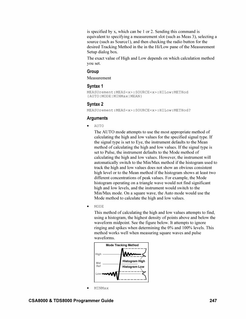
CSA8000 & TDS8000 Programmer Guide 247
is specified by x, which can be 1 or 2. Sending this command is
equivalent to specifying a measurement slot (such as Meas 3), selecting a
source (such as Source1), and then checking the radio button for the
desired Tracking Method in the in the Hi/Low pane of the Measurement
Setup dialog box.
The exact value of High and Low depends on which calculation method
you set.
Group
Measurement
Syntax 1 MEASUrement:MEAS<x>:SOURCE<x>:HILow:METHodAUTO|MODE|MINMax|MEAN
Syntax 2 MEASUrement:MEAS<x>:SOURCE<x>:HILow:METHod?
Arguments
• AUTO
The AUTO mode attempts to use the most appropriate method of
calculating the high and low values for the specified signal type. If
the signal type is set to Eye, the instrument defaults to the Mean
method of calculating the high and low values. If the signal type is
set to Pulse, the instrument defaults to the Mode method of
calculating the high and low values. However, the instrument will
automatically switch to the Min/Max method if the histogram used to
track the high and low values does not show an obvious consistent
high level or to the Mean method if the histogram shows at least two
different concentrations of peak values. For example, the Mode
histogram operating on a triangle wave would not find significant
high and low levels, and the instrument would switch to the
Min/Max mode. On a square wave, the Auto mode would use the Mode method to calculate the high and low values.
• MODE
This method of calculating the high and low values attempts to find,
using a histogram, the highest density of points above and below the
waveform midpoint. See the figure below. It attempts to ignore
ringing and spikes when determining the 0% and 100% levels. This
method works well when measuring square waves and pulse waveforms.
• MINMax
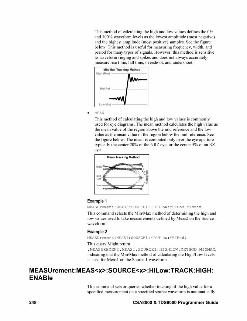
248 CSA8000 & TDS8000 Programmer Guide
This method of calculating the high and low values defines the 0%
and 100% waveform levels as the lowest amplitude (most negative)
and the highest amplitude (most positive) samples. See the figure
below. This method is useful for measuring frequency, width, and
period for many types of signals. However, this method is sensitive
to waveform ringing and spikes and does not always accurately measure rise time, fall time, overshoot, and undershoot.
• MEAN
This method of calculating the high and low values is commonly
used for eye diagrams. The mean method calculates the high value as
the mean value of the region above the mid reference and the low
value as the mean value of the region below the mid reference. See
the figure below. The mean is computed only over the eye aperture -
typically the center 20% of the NRZ eye, or the center 5% of an RZ
eye.
Example 1 MEASUrement:MEAS2:SOURCE1:HIGHLow:METHod MINMax
This command selects the Min/Max method of determining the high and
low values used to take measurements defined by Meas2 on the Source 1
waveform.
Example 2 MEASUrement:MEAS1:SOURCE1:HIGHLow:METHod?
This query Might return
:MEASUREMENT:MEAS1:SOURCE1:HIGHLOW:METHOD MINMAX,
indicating that the Min/Max method of calculating the High/Low levels
is used for Meas1 on the Source 1 waveform.
MEASUrement:MEAS<x>:SOURCE<x>:HILow:TRACK:HIGH: ENABle
This command sets or queries whether tracking of the high value for a
specified measurement on a specified source waveform is automatically
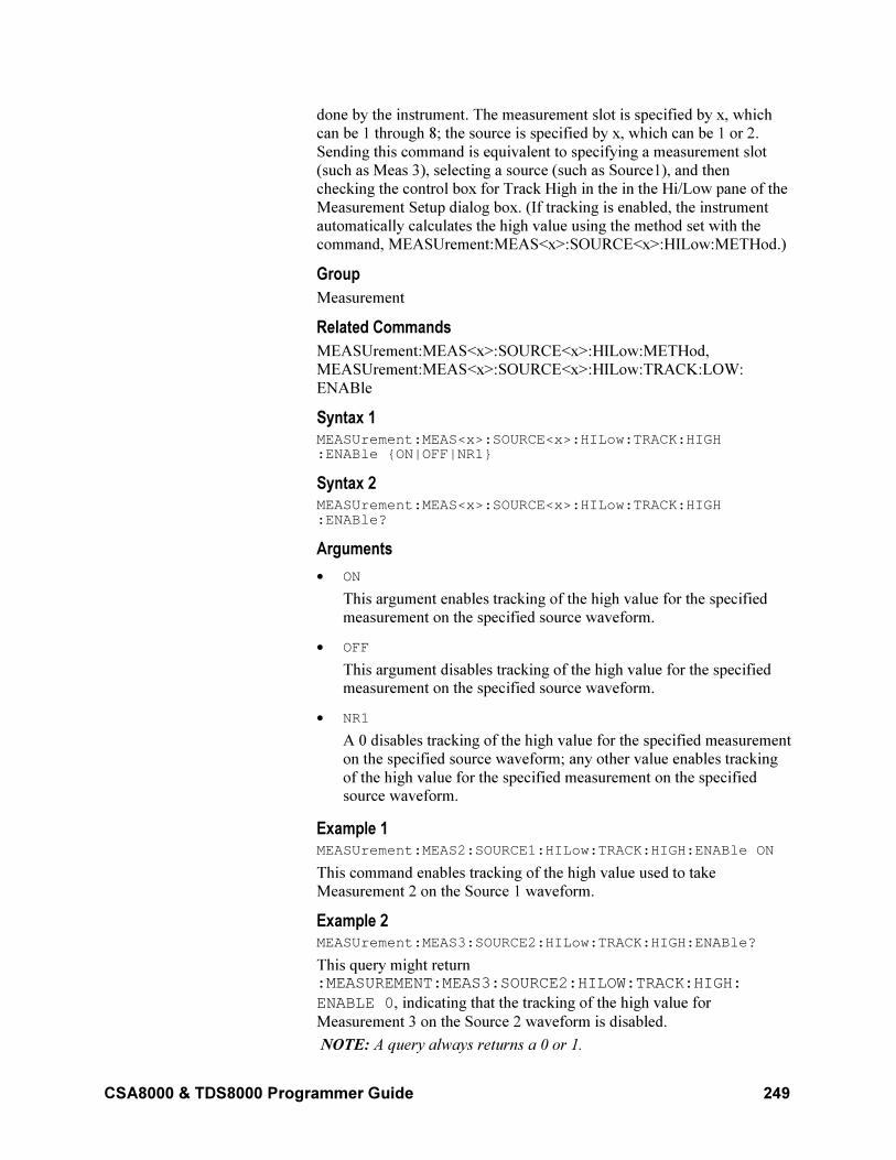
CSA8000 & TDS8000 Programmer Guide 249
done by the instrument. The measurement slot is specified by x, which
can be 1 through 8; the source is specified by x, which can be 1 or 2.
Sending this command is equivalent to specifying a measurement slot
(such as Meas 3), selecting a source (such as Source1), and then
checking the control box for Track High in the in the Hi/Low pane of the
Measurement Setup dialog box. (If tracking is enabled, the instrument
automatically calculates the high value using the method set with the
command, MEASUrement:MEAS<x>:SOURCE<x>:HILow:METHod.)
Group
Measurement
Related Commands
MEASUrement:MEAS<x>:SOURCE<x>:HILow:METHod,
MEASUrement:MEAS<x>:SOURCE<x>:HILow:TRACK:LOW:
ENABle
Syntax 1 MEASUrement:MEAS<x>:SOURCE<x>:HILow:TRACK:HIGH:ENABle ON|OFF|NR1
Syntax 2 MEASUrement:MEAS<x>:SOURCE<x>:HILow:TRACK:HIGH:ENABle?
Arguments
• ON
This argument enables tracking of the high value for the specified
measurement on the specified source waveform.
• OFF
This argument disables tracking of the high value for the specified measurement on the specified source waveform.
• NR1
A 0 disables tracking of the high value for the specified measurement
on the specified source waveform; any other value enables tracking
of the high value for the specified measurement on the specified source waveform.
Example 1 MEASUrement:MEAS2:SOURCE1:HILow:TRACK:HIGH:ENABle ON
This command enables tracking of the high value used to take
Measurement 2 on the Source 1 waveform.
Example 2 MEASUrement:MEAS3:SOURCE2:HILow:TRACK:HIGH:ENABle?
This query might return :MEASUREMENT:MEAS3:SOURCE2:HILOW:TRACK:HIGH:
ENABLE 0, indicating that the tracking of the high value for
Measurement 3 on the Source 2 waveform is disabled.
NOTE: A query always returns a 0 or 1.
250 CSA8000 & TDS8000 Programmer Guide
MEASUrement:MEAS<x>:SOURCE<x>:HILow:TRACK :HIGH:VALue
This command sets or queries the high value used to calculate a specified
measurement on a specified source waveform. The measurement slot is
specified by x, which can be 1 through 8; the source is specified by x,
which can be 1 or 2. Sending this command is equivalent to selecting a
measurement slot (such as Meas 3), selecting a source (such as Source1),
turning tracking High off, and then entering an absolute value in the
High control box in the in the Hi/Low pane of the Measurement Setup
dialog box. (If tracking is enabled for High, the instrument automatically
calculates the high value using the method set with the command,
MEASUrement:MEAS<x>:SOURCE<x>:HILow:METHod.)
Group
Measurement
Related Commands
MEASUrement:MEAS<x>:SOURCE<x>:HILow:METHod,
MEASUrement:MEAS<x>:SOURCE<x>:HILow:TRACK:HIGH:
ENABle
Syntax 1 MEASUrement:MEAS1:SOURCE1:HILow:TRACK:HIGH:VALue<NR3>
Syntax 2 MEASUrement:MEAS1:SOURCE1:HILow:TRACK:HIGH:VALue?
Argument NR3
This argument is the absolute value of the high level for the HiLow
settings.
Example 1 MEASUrement:MEAS2:SOURCE1:HILow:TRACK:HIGH:VALue5.0E–1
This command sets the high value used to take Measurement 2 on the
Source 1 waveform to 500 mV.
Example 2 MEASUrement:MEAS1:SOURCE1:HILow:TRACK:HIGH:VALue?
This query might return :MEASUREMENT:MEAS1:SOURCE1:HILOW:TRACK:HIGH
:VALUE 2.00000000000E-001, indicating that the high value used
to take Measurement 3 on the Source 1 waveform is 200 mV.
CSA8000 & TDS8000 Programmer Guide 251
MEASUrement:MEAS<x>:SOURCE<x>:HILow:TRACK:LOW :ENABle
This command sets or queries whether tracking of the low value for a
specified measurement on a specified source waveform is automatically
done by the instrument. The measurement slot is specified by x, which
can be 1 through 8; the source is specified by x, which can be 1 or 2.
Sending this command is equivalent to specifying a measurement slot
(such as Meas 3), selecting a source (such as Source1), and then
checking the control box for Track Low in the in the HiLow dialog of the
Measurement Setup dialog box. (If tracking is enabled, the instrument
automatically calculates the low value using the method set with the
command, MEASUrement:MEAS<x>:SOURCE<x>:HILow:METHod.)
Group
Measurement
Related Commands
MEASUrement:MEAS<x>:SOURCE<x>:HILow:METHod,
MEASUrement:MEAS<x>:SOURCE<x>:HILow:TRACK:HIGH:
ENABle
Syntax 1 MEASUrement:MEAS<x>:SOURCE<x>:HILow:TRACK:LOW:ENABle ON|OFF|NR1
Syntax 2 MEASUrement:MEAS<x>:SOURCE<x>:HILow:TRACK:LOW:ENABle?
Arguments
• ON
This argument enables tracking of the low value for the specified measurement on the specified source waveform.
• OFF
This argument disables tracking of the low value for the specified measurement on the specified source waveform.
• NR1
A 0 disables tracking of the low value for the specified measurement
on the specified source waveform; any other value enables tracking
of the low value for the specified measurement on the specified source waveform.
Example 1 MEASUrement:MEAS2:SOURCE1:HILow:TRACK:LOW:ENABle ON
This command enables tracking of the low value used to take
Measurement 2 on the Source 1 waveform.
Example 2 MEASUrement:MEAS3:SOURCE2:HILow:TRACK:LOW:ENABle?
252 CSA8000 & TDS8000 Programmer Guide
This query might return :MEASUREMENT:MEAS3:SOURCE2:HILOW:TRACK:LOW:
ENABLE 0, indicating that the tracking of the low value for
Measurement 3 on the Source 2 waveform is disabled.
NOTE: A query always returns a 0 or 1.
MEASUrement:MEAS<x>:SOURCE<x>:HILow:TRACK :LOW:VALue
This command sets or queries the low value used to calculate a specified
measurement on a specified source waveform. The measurement slot is
specified by x, which can be 1 through 8; the source is specified by x,
which can be 1 or 2. Sending this command is equivalent to selecting a
measurement slot (such as Meas 3), selecting a source (such as Source1),
setting tracking Low to off, and then entering an absolute value in the
Low control box in the in the Hi/Low pane of the Measurement Setup
dialog box. (If tracking is enabled for Low, the instrument automatically
calculates the low value using the method set with the command,
MEASUrement:MEAS<x>:SOURCE<x>:HILow:METHod.)
Group
Measurement
Related Commands
MEASUrement:MEAS<x>:SOURCE<x>:HILow:METHod,
MEASUrement:MEAS<x>:SOURCE<x>:HILow:TRACK:LOW:
ENABle
Syntax 1 MEASUrement:MEAS2:SOURCE1:HILow:TRACK:LOW:VALue <NR3>
Syntax 2 MEASUrement:MEAS2:SOURCE1:HILow:TRACK:LOW:VALue?
Argument NR3
This argument is the absolute value of the low level for the HiLow
settings.
Example 1 MEASUrement:MEAS2:SOURCE1:HILow:TRACK:LOW:VALue 5.0E–3
This command sets the low value used to take Measurement 2 on the
Source 1 waveform to 5 mV.
Example 2 MEASUrement:MEAS3:SOURCE1:HILow:TRACK:LOW:VALue?
This query might return :MEASUREMENT:MEAS3:SOURCE1
:HILOW:TRACK:LOW:VALUE 1.00000000000E-002, indicating
that the low value used to take Measurement 3 on the Source 1 waveform
is 10 mV.
CSA8000 & TDS8000 Programmer Guide 253
MEASUrement:MEAS<x>:SOURCE<x>:HILow?
This query only command returns all the High/Low settings for the
specified measurement taken on the specified source waveform. The
measurement slot is specified by x, which can be 1 through 8; the source
is specified by x, which can be 1 or 2.
Group
Measurement
Syntax MEASUrement:MEAS<x>:SOURCE<x>:HIGHLow?
Example MEASUrement:MEAS1:SOURCE1:HIGHLow?
This query might return :MEASUREMENT:MEAS1:SOURCE1:HILOW:METHOD AUTO; TRACK:HIGH:ENABLE 1;VALUE 2.00000000000E-001; :MEASUREMENT:MEAS1:SOURCE1:HILOW:TRACK:LOW:ENABLE 1;
VALUE 1.00000000000E-002.
MEASUrement:MEAS<x>:SOURCE<x>:WFM
This command sets or queries the source waveform (SOURCE1) on
which the specified single-channel measurements are taken and from
which two-channel measurements, such as delay or phase are taken. The
measurement slot is specified by x, and can be 1 through 8. This
command also sets or queries the destination waveform (SOURCE2) to
which two-channel measurements are taken. If the source is not specified
(either 1 or 2), the default is SOURCE1. Optionally, this command can
specify the timebase for the specified source or destination waveform. If
the timebase is not specified, the default is the Main timebase.
Group
Measurement
Syntax 1 MEASUrement:MEAS<x>:SOURCE<x>:WFM CH<x>)|MATH<x>|REF<x>[,MAIn|MAG1|MAG2]
Syntax 2 MEASUrement:MEAS<x>:SOURCE<x>:WFM?
Arguments
• CH<x>
This argument selects a channel waveform as the source or destination waveform. The range for x is 1 through 8.
• MATH<x>
This argument selects a math waveform as the source or destination waveform. The range for x is 1 through 8.
• REF<x>
254 CSA8000 & TDS8000 Programmer Guide
This argument selects a reference waveform as the source or destination waveform. The range for x is 1 through 8.
• MAIn
This optional argument selects Main as the timebase for the specified
source or destination waveform. This is the default timebase.
• MAG1
This optional argument selects MAG1 as the timebase for the specified source or destination waveform (for channels and math).
• MAG2
This optional argument selects MAG2 as the timebase for the specified source or destination waveform for channels and math).
Example 1 MEASUrement:MEAS2:SOURCE1:WFM MATH1
This command sets MATH1 as the source waveform for Measurement 2
Example 2 MEASUrement:MEAS2:SOURCE1:WFM?
This query might return :MEASUREMENT:MEAS1:SOURCE1:WFM
CH3,MAIN, indicating that the source waveform for Measurement 1 is
Channel 3 using the Main timebase.
MEASUrement:MEAS<x>:SOURCE<x>:WFMDB:SIGType
This command sets or queries the type of input signal used to populate
the waveform database associated with the specified measurement slot,
MEAS<x>, where x can be 1 through 8, and the specified measurement
source, SOURCE<x>, where x can be 1 or 2. To ensure accurate
measurement results, always use this command to specify the input-
signal type of the measurement source if your measurement is taken on a
waveform database. Sending this command is equivalent to selecting
Pulse, NRZ (Non-Return to Zero), or RZ (Return to Zero) as the Signal
Type in the Source pane of the Measurement Setup dialog box.
Group
Measurement
Related Commands
MEASUrement:MEAS<X>:SOURCE<x>:WFMDB:STATE
CSA8000 & TDS8000 Programmer Guide 255
Syntax 1 MEASUrement:MEAS<x>:SOURCE<x>:WFMDB:SIGTypePULSE|EYE|RZ
Syntax 2 MEASUrement:MEAS<x>:SOURCE<x>:WFMDB:SIGType?
Arguments
• PULSE
Use this signal type for generic signals that are not associated with synchronous communications standards
• EYE
Use this signal type for synchronous-communication signals with
NRZ (non-return to zero) characteristics.
• RZ
Use this signal type for synchronous communication signals with RZ (return to zero) characteristics.
Example 1 MEASUrement:MEAS5:SOURCE1:WFMDB:SIGType PULSE
This command selects Pulse as the signal type associated with source 1 for measurement slot 5.
Example 2 MEASUrement:MEAS2:SOURCE1:WFMDB:SIGType?
This query might return :MEASUREMENT:MEAS2:SOURCE1
:WFMDB:SIGTYPE RZ, indicating that the signal type associated with
source 1 of measurement slot 2 is RZ.
MEASUrement:MEAS<x>:SOURCE<x>:WFMDB:STATE
This command sets or queries whether the specified measurement is
taken on the specified waveform or a waveform database built from the
targeted source. The measurement slot is specified by x, which can be 1
through 8; the source waveform is specified by x, which can be 1 or 2.
Sending this command is equivalent to selecting a measurement and a
source in the Measurement Setup dialog box, and then selecting or
clearing the Use Wfm Database check box in the Source dialog of the
Measurement Setup dialog box.
Group
Measurement
Related Commands
MEASUrement:MEAS<x>:SOURCE<x>:WFMDB:SIGType
Syntax 1 MEASUrement:MEAS<x>:SOURCE<x>:WFMDB:STATEON|OFF|NR1
256 CSA8000 & TDS8000 Programmer Guide
Syntax 2 MEASUrement:MEAS<x>:SOURCE<x>:WFMDB:STATE?
Arguments
• ON
This argument enables the database measurement for the specified source waveform so that the measurement is made on the database.
• OFF
This argument disables the database measurement so that the measurement is taken directly on the acquired waveform.
• NR1
A 0 disables the database measurement; any other value enables the
database measurement.
Example 1 MEASUrement:MEAS5:SOURCE1:WFMDB:STATE ON
This command causes Measurement 5 to be taken on the Source 1
waveform database.
Example 2 MEASUrement:MEAS<x>:SOURCE<x>:WFMDB:STATE?
This query might return :MEASUREMENT:MEAS2:SOURCE1
:WFMDB:STATE 0, indicating that Measurement 2 will be taken on the
Source 1 waveform.
NOTE: A query always returns a 0 or 1.
MEASUrement:MEAS<x>:STATE
This command sets or queries whether the specified measurement slot is
computed and displayed. The measurement slot is specified by x, which
can be 1 through 8. Sending this command is equivalent to selecting a
measurement slot (such as Meas 3) and checking the On box in the
Measurement Setup dialog box.
For a measurement to display, you must have selected a source
waveform and defined the measurement you want take and display. You
select the measurement source with the
MEASUrement:MEAS<x>:SOURCE<x>:WFM command. You define
the measurement type with the MEASUrement:MEAS<x>:TYPe
command.
Group
Measurement
Related Commands
MEASUrement:MEAS<x>:SOURCE<x>:WFM,
MEASUrement:MEAS<x>:TYPe
Syntax 1 MEASUrement:MEAS<x>:STATE OFF|ON|<NR1>
CSA8000 & TDS8000 Programmer Guide 257
Syntax 2 MEASUrement:MEAS<x>:STATE?
Arguments
• OFF
This argument disables the calculation and display of the measurement defined in the specified measurement slot.
• ON
This argument enables the calculation and display of the measurement defined in the specified measurement slot.
• NR1
A 0 disables the calculation and display of the specified
measurement slot; any other value enables the calculation and display of the specified measurement slot.
Example 1 MEASUREMENT:MEAS1:STATE ON
This command displays the measurement defined in measurement slot 1.
Example 2 MEASUREMENT:MEAS4:STATE?
This query might return :MEASUREMENT:MEAS4:STATE 1,
indicating that the measurement defined for measurement slot 4 is
displayed.
NOTE: A query always returns a 0 or 1.
MEASUrement:MEAS<x>:STATIstics:CLEAr
This command (no query form) clears and restarts the calculation of the
statistics for the measurement slot specified by x, which can be 1 through
8.
Group
Measurement
Related Commands
MEASUrement:STATistics:ENABle
Syntax 1 MEASUrement:MEAS<x>:STATIstics:CLEAr
Example MEASUrement:MEAS3:STATIstics:CLEAr
This command clears and restarts calculating the statistics for
Measurement 3.
258 CSA8000 & TDS8000 Programmer Guide
MEASUrement:MEAS<x>:STDdev?
This query only command returns the standard deviation of values
accumulated for the measurement slot specified by x, which can be 1
through 8, since the last statistical reset.
Group
Measurement
Related Commands
MEASUrement:MEAS<x>:ALL
Syntax MEASUrement:MEAS<x>:STDdev?
Returns NR3
Example MEASUREMENT:MEAS1:STDDEV?
This query might return :MEASUREMENT:MEAS1:STDDEV
1.16796169259E-011, indicating that the standard deviation for
Measurement 1 is 11.8 ps.
MEASUrement:MEAS<x>:TYPE
This command sets or queries the measurement type assigned to the
specified measurement slot, where x is one of the available measurement
slots from 1 through 8. If the specified measurement slot is already
assigned, selecting a new measurement type will re-assign the specified
slot to the requested measurement type. Sending this command is
equivalent to using the pulldown list to select the type of measurement
you want to take, after first selecting the measurement slot (such as Meas
1) and a source-signal type (such a NRZ), in the Meas Setup dialog box.
Note. All of the measurement types require at least one source waveform
to be specified with the MEASUrement:MEAS<x>:SOURCE1:WFM
command.
You can set numerous measurement parameters that can enhance your
measurement results and increase measurement repeatability, please refer
to the Measurement Command Group for more information.
Group
Measurement
Syntax 1 MEASUrement:MEAS<x>:TYPE UNDEFined|HIGH|LOW|AMPLitude|MEAN|MAXimum|MINImum|PK2Pk|MID|POVershoot|NOVershoot|RMSNoise|PKPKNoise|AOPTPWRDBM|RMS|ACRMs|CRMs|CMEan|SNRatio|AOPTpwr|GAIN|RISe|FALL|PERIod|FREQuency|PCROss|NCROss|PWIdth|NWIdth|PDUty|NDUty|BURst|RMSJitter|PKPKJitter|DELay|PHAse|AREa|CARea|EXTINCTDB|EXTINCTPCT|EXTINCTRATIO|EYEHeight|PCTCROss|LEVCROss|QFACtor|EYEWIdth|DISTDUty|BITTime|BITRate|TIMCROss|EYEOfactor|SUPRSDB|SUPRSPCT|SUPRSRATIO|PULSESym
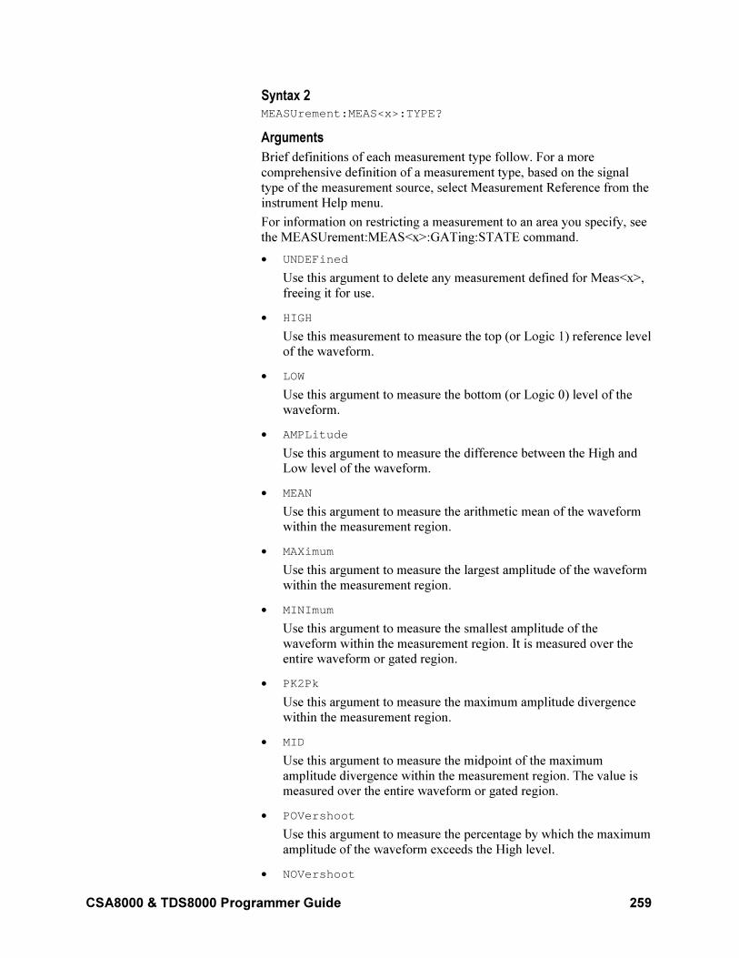
CSA8000 & TDS8000 Programmer Guide 259
Syntax 2 MEASUrement:MEAS<x>:TYPE?
Arguments
Brief definitions of each measurement type follow. For a more
comprehensive definition of a measurement type, based on the signal
type of the measurement source, select Measurement Reference from the
instrument Help menu.
For information on restricting a measurement to an area you specify, see
the MEASUrement:MEAS<x>:GATing:STATE command.
• UNDEFined
Use this argument to delete any measurement defined for Meas<x>,
freeing it for use.
• HIGH
Use this measurement to measure the top (or Logic 1) reference level of the waveform.
• LOW
Use this argument to measure the bottom (or Logic 0) level of the waveform.
• AMPLitude
Use this argument to measure the difference between the High and Low level of the waveform.
• MEAN
Use this argument to measure the arithmetic mean of the waveform within the measurement region.
• MAXimum
Use this argument to measure the largest amplitude of the waveform
within the measurement region.
• MINImum
Use this argument to measure the smallest amplitude of the
waveform within the measurement region. It is measured over the entire waveform or gated region.
• PK2Pk
Use this argument to measure the maximum amplitude divergence
within the measurement region.
• MID
Use this argument to measure the midpoint of the maximum
amplitude divergence within the measurement region. The value is measured over the entire waveform or gated region.
• POVershoot
Use this argument to measure the percentage by which the maximum
amplitude of the waveform exceeds the High level.
• NOVershoot
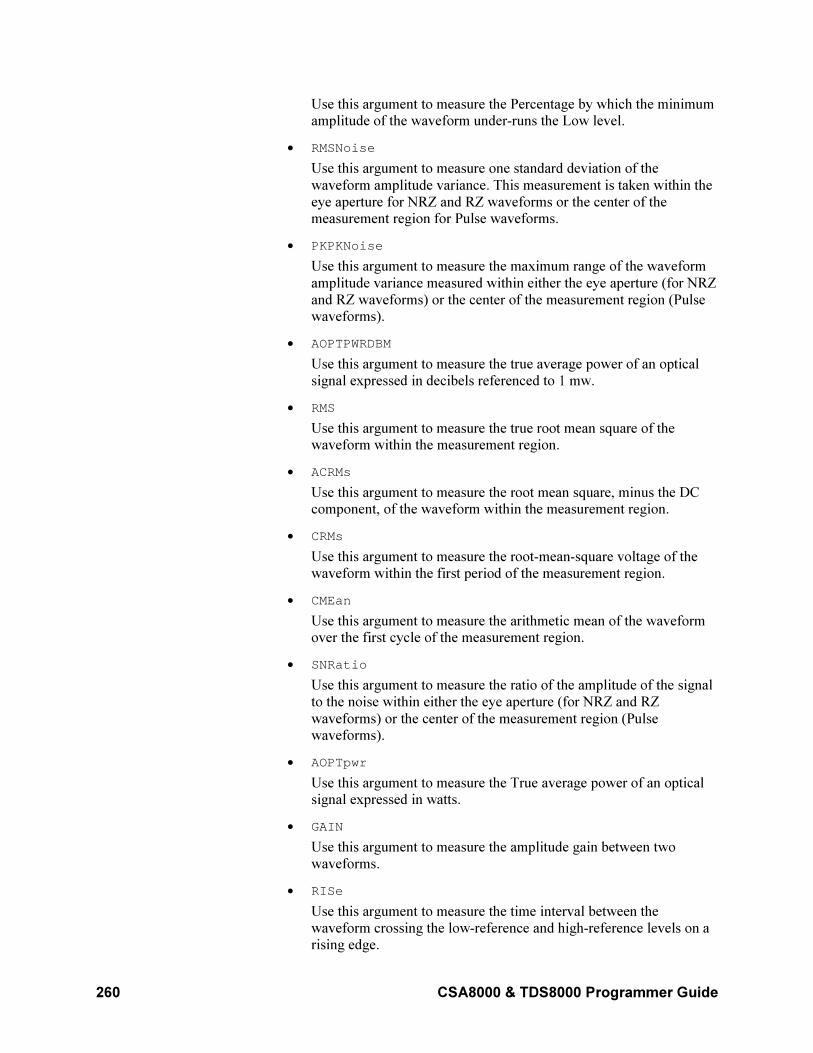
260 CSA8000 & TDS8000 Programmer Guide
Use this argument to measure the Percentage by which the minimum amplitude of the waveform under-runs the Low level.
• RMSNoise
Use this argument to measure one standard deviation of the
waveform amplitude variance. This measurement is taken within the
eye aperture for NRZ and RZ waveforms or the center of the measurement region for Pulse waveforms.
• PKPKNoise
Use this argument to measure the maximum range of the waveform
amplitude variance measured within either the eye aperture (for NRZ
and RZ waveforms) or the center of the measurement region (Pulse waveforms).
• AOPTPWRDBM
Use this argument to measure the true average power of an optical
signal expressed in decibels referenced to 1 mw.
• RMS
Use this argument to measure the true root mean square of the waveform within the measurement region.
• ACRMs
Use this argument to measure the root mean square, minus the DC component, of the waveform within the measurement region.
• CRMs
Use this argument to measure the root-mean-square voltage of the
waveform within the first period of the measurement region.
• CMEan
Use this argument to measure the arithmetic mean of the waveform over the first cycle of the measurement region.
• SNRatio
Use this argument to measure the ratio of the amplitude of the signal
to the noise within either the eye aperture (for NRZ and RZ
waveforms) or the center of the measurement region (Pulse waveforms).
• AOPTpwr
Use this argument to measure the True average power of an optical signal expressed in watts.
• GAIN
Use this argument to measure the amplitude gain between two
waveforms.
• RISe
Use this argument to measure the time interval between the
waveform crossing the low-reference and high-reference levels on a rising edge.
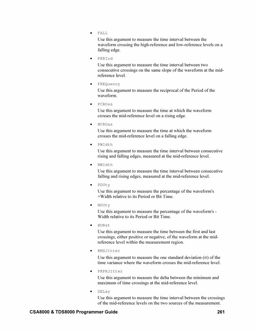
CSA8000 & TDS8000 Programmer Guide 261
• FALL
Use this argument to measure the time interval between the
waveform crossing the high-reference and low-reference levels on a falling edge.
• PERIod
Use this argument to measure the time interval between two
consecutive crossings on the same slope of the waveform at the mid-
reference level.
• FREQuency
Use this argument to measure the reciprocal of the Period of the waveform.
• PCROss
Use this argument to measure the time at which the waveform crosses the mid-reference level on a rising edge.
• NCROss
Use this argument to measure the time at which the waveform
crosses the mid-reference level on a falling edge.
• PWIdth
Use this argument to measure the time interval between consecutive rising and falling edges, measured at the mid-reference level.
• NWIdth
Use this argument to measure the time interval between consecutive falling and rising edges, measured at the mid-reference level.
• PDUty
Use this argument to measure the percentage of the waveform's
+Width relative to its Period or Bit Time.
• NDUty
Use this argument to measure the percentage of the waveform's -Width relative to its Period or Bit Time.
• BURst
Use this argument to measure the time between the first and last
crossings, either positive or negative, of the waveform at the mid-
reference level within the measurement region.
• RMSJitter
Use this argument to measure the one standard deviation (σ) of the time variance where the waveform crosses the mid-reference level.
• PKPKJitter
Use this argument to measure the delta between the minimum and maximum of time crossings at the mid-reference level.
• DELay
Use this argument to measure the time interval between the crossings
of the mid-reference levels on the two sources of the measurement.
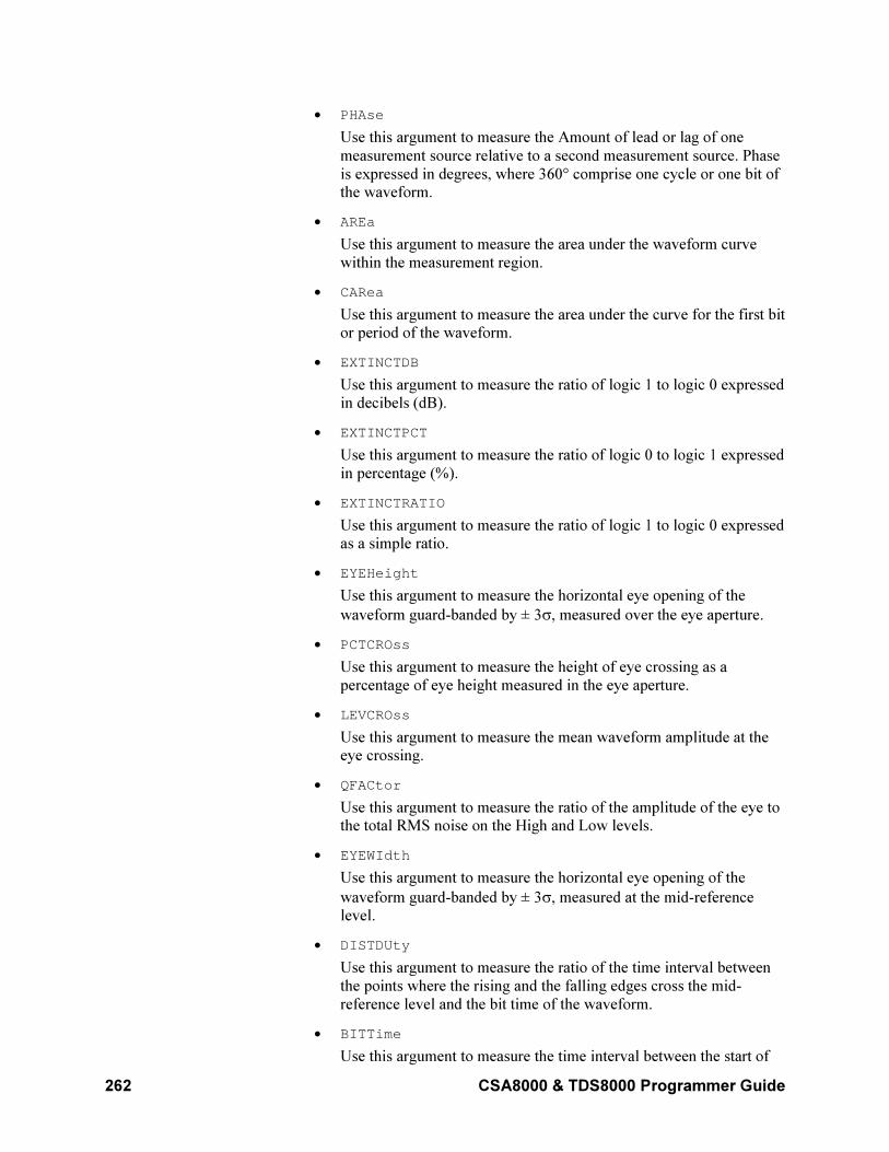
262 CSA8000 & TDS8000 Programmer Guide
• PHAse
Use this argument to measure the Amount of lead or lag of one
measurement source relative to a second measurement source. Phase
is expressed in degrees, where 360° comprise one cycle or one bit of the waveform.
• AREa
Use this argument to measure the area under the waveform curve
within the measurement region.
• CARea
Use this argument to measure the area under the curve for the first bit or period of the waveform.
• EXTINCTDB
Use this argument to measure the ratio of logic 1 to logic 0 expressed in decibels (dB).
• EXTINCTPCT
Use this argument to measure the ratio of logic 0 to logic 1 expressed
in percentage (%).
• EXTINCTRATIO
Use this argument to measure the ratio of logic 1 to logic 0 expressed as a simple ratio.
• EYEHeight
Use this argument to measure the horizontal eye opening of the
waveform guard-banded by ± 3σ, measured over the eye aperture.
• PCTCROss
Use this argument to measure the height of eye crossing as a
percentage of eye height measured in the eye aperture.
• LEVCROss
Use this argument to measure the mean waveform amplitude at the eye crossing.
• QFACtor
Use this argument to measure the ratio of the amplitude of the eye to the total RMS noise on the High and Low levels.
• EYEWIdth
Use this argument to measure the horizontal eye opening of the
waveform guard-banded by ± 3σ, measured at the mid-reference level.
• DISTDUty
Use this argument to measure the ratio of the time interval between
the points where the rising and the falling edges cross the mid-
reference level and the bit time of the waveform.
• BITTime
Use this argument to measure the time interval between the start of
CSA8000 & TDS8000 Programmer Guide 263
two successive data bits of the waveform.
• BITRate
Use this argument to measure the inverse of the time interval between the start of two successive data bits of the waveform.
• TIMCROss
Use this argument to measure the horizontal position (measured from
the trigger point) of the eye crossing.
• EYEOfactor
Use this argument to measure the horizontal eye opening of the
waveform guard-banded by ± 1σ, measured over the eye aperture.
• SUPRSDB
Use this argument to measure the ratio of the average High level to
the suppressed level measured between two consecutive RZ pulses
expressed in decibels (dB).
• SUPRSPCT
Click this button to measure the Ratio of the average High level to
the Suppressed level measured between two consecutive RZ pulses expressed in percentage (%).
• SUPRSRATIO
Use this argument to measure the Ratio of the average High level to
the Suppressed level measured between two consecutive RZ pulses expressed as a simple ratio.
• PULSESym
Use this argument to measure the extent to which the RZ pulse is
symmetrical around the peak at the mid-reference level. The pulse
peak is the center of the interval, sized to Eye Aperture, which yields the maximum mean vertical value.
Example 1 MEASUrement:MEAS3:TYPE FREQuency
This command defines Measurement 3 as a measurement of the
frequency of a waveform.
Example 2 MEASUrement:MEAS3:TYPE?
This query might return :MEASUREMENT:MEAS3:TYPE RMS,
indicating that Measurement 3 is defined to measure the RMS value of a
waveform.
MEASUrement:MEAS<x>:UNITS?
This query only command returns the units for the measurement slot
specified by x, which can be 1 through 8. You first must have defined the
measurement slot using the MEASUrement:MEAS<x>:TYPe command
before the units can be returned.
264 CSA8000 & TDS8000 Programmer Guide
Group
Measurement
Related Commands
MEASUrement:MEAS<x>:VALue?, MEASUrement:MEAS<x>:TYPE
Syntax MEASUrement:MEAS<x>:UNITS?
Return Values
<QString>
• "dB" for extinction ratio dB
• "Hz" for hertz
• "s" for seconds
• "unitless" for Q-factor
• "V" for volts
• "VV" for volts2
• "volt-seconds" for cycle area
• "W" for watts (used with optical modules)
• "watt-seconds" for cycle area
• "%" for percent
• "Ω" for ohms (used with TDR)
• "Ω-seconds" for cycle area
• "ρ" for rho (used with TDR)
• "ρ-seconds" for cycle area
Example MEASUREMENT:MEAS3:UNITS?
This query might return :MEASUREMENT:MEAS3:UNITS "%",
indicating the units for Measurement 3 are percent.
MEASUrement:MEAS<x>:VALue?
This query only command returns the value that has been calculated for
the measurement slot specified by x.
Group
Measurement
Related Commands
MEASUrement:MEAS<x>:TYPE, MEASUrement:MEAS<x>:UNIts?
CSA8000 & TDS8000 Programmer Guide 265
Syntax MEASUrement:MEAS<x>:VALue?
Returns
NR3
This is the calculated value for the specified measurement.
Example MEASUrement:MEAS1:VALue?
This query might return :MEASUREMENT:MEAS1:VALUE
1.24896277383E+008 as the calculated value for Measurement 1.
MEASUrement:STATIstics:ENABle
This command sets or queries whether the instrument calculates the
measurement statistics. Sending this command is equivalent to selecting
the Statistics check box in the Measurement Setup dialog box.
Use the MEASUrement:STATIstics:WEIGHTing command to set
statistics weighting. Weighting is the number of measurements over
which you want the statistics calculated.
Use the MEASUrement:MEAS<x>:ALL? Command to query all the
measurement statistical values at one time.
Group
Measurement
Related Commands
MEASUrement:STATIstics:WEIGHTing
MEASUrement:MEAS<x>:ALL?
Syntax 1 MEASUrement:STATIstics:ENABle ON|OFF|NR1
Syntax 2 MEASUrement:STATIstics:ENABle?
Arguments
• ON
This argument causes the instrument to compute the statistics on
measurement values. If a measurement is using a waveform
database, it will not compute statistics.
• OFF
This argument turns off the calculation of the measurement statistics.
• NR1
A 0 disables the calculation of statistics; any other value enables the calculation of statistics.
Example 1 MEASUrement:STATIstics:ENABle ON
This command enables the calculation of the measurement statistics.
266 CSA8000 & TDS8000 Programmer Guide
Example 2 MEASUrement:STATIstics:ENABle?
This query might return :MEASUREMENT:STATISTICS:ENABLE 0,
indicating that the calculation of statistics is disabled.
NOTE: A query always returns a 0 or 1.
MEASUrement:STATIstics:WEIGHTing
This command sets or queries the weighting the instrument uses to
calculate the measurement statistics. Weighting is the number of
measurements over which you want the statistics calculated. Sending this
command is equivalent to entering a value in the Weighting control in
the Measurements Setup dialog box. The Statistics check box must be
selected before the Weighting control is active.
Use the MEASUrement:STATistics:ENABle command to enable the
statistics weighting function.
Group
Measurement
Related Commands
MEASUrement:STATistics:ENABle
Syntax 1 MEASUrement:STATIstics:WEIGHTing <NR1>
Syntax 2 MEASUrement:STATIstics:WEIGHTing?
Argument NR1
This argument is the number of measurements over which the statistics
are calculated. The range is from 2 through 1,000,000 with a resolution
of 1. The default value is 32.
Example 1 MEASUrement:STATIstics:WEIGHTing 10
This command sets the weighting to 10, which means the statistics are
calculated over 10 measurements.
Example 2 MEASUrement:STATIstics:WEIGHTing?
This query might return
:MEASUREMENT:STATISTICS:WEIGHTING 50, indicating that the
statistics are calculated over 50 measurements.
MEASUrement?
This is a query only command that returns all measurement parameters.
Group
Measurement
CSA8000 & TDS8000 Programmer Guide 267
Syntax MEASUrement?
Example MEASUrement?
This query might return the following (partial list):
:MEASUREMENT:ALL:VALUE 9.91000000000E+037,9.91000000000E+037,9.91000000000E+037,9.91000000000E+037,9.91000000000E+037,9.91000000000E+037,9.91000000000E+037,9.91000000000E+037;:MEASUREMENT:LIST 1;LISTVALUE 9.91000000000E+037;ANNOTATIONS:STATE 0;:MEASUREMENT:STATISTICS:ENABLE 0;WEIGHTING 32;:MEASUREMENT:MEAS1:NOISE HIGH;JITTER EYECROSS;EYEWINDOW 20;MAXIMUM 9.91000000000E+037;MINIMUM 9.91000000000E+037;MEAN 9.91000000000E+037;STDDEV 9.91000000000E+037;VALUE 9.91000000000E+037;ALL 9.91000000000E+037,9.91000000000E+037,9.91000000000E+037,9.91000000000E+037,9.91000000000E+037;UNITS "";TYPE UNDEFINED;STATE 0;GATING:STATE 0;:MEASUREMENT:MEAS1:SOURCE1:WFM CH3,MAIN;WFMDB:STATE 0;SIGTYPE PULSE;:MEASUREMENT:MEAS1:SOURCE1:GATE1:POS 1.80000000000E-008;…
RECAll:SETUp
This command (no query form) restores a stored or factory default setup
from a Windows file. Sending this command is equivalent to selecting
Recall Saved Setup or Recall Factory Setup in the Save/Recall Setup
menu.
Group
Save and Recall
Related Commands
FACtory, *RST, SAVe:SETUp
Syntax RECAll:SETUp FACtory|<file path>
Arguments
• FACtory
Selects the factory setup.
• <file path>
This is the location from which the setup will be recalled.
The <file path> is a quoted string that defines the file name and path.
Input the file path using the form <drive>\<dir>\<filename>. <drive>
and one or more <dir>s are optional. If you do not specify them, the
instrument will read the file from the default directory. The
<filename> can be a Windows 95/Windows 98 long file name. Do not use wild card characters.
Example 1 RECALL:SETUP FACTORY
268 CSA8000 & TDS8000 Programmer Guide
Recalls (and makes current) the instrument setup to its factory defaults.
Example 2 RECALL:SETUP "TEK00000.STP"
Recalls the instrument setup from the file TEK00000.STP in the default
directory and on the default drive.
RECAll:WAVEform
This command (no query form) recalls a stored waveform into a
reference location. Sending this command is equivalent to selecting
Recall Waveform from the File Menu, and then selecting a waveform file
source and reference destination in the Recall Waveform dialog box.
Group
Save and Recall
Syntax RECAll:WAVEform <file path>,REF<x>
Arguments
• <filepath>
This is a quoted string that defines the file name and path. Input the
file path using the form <drive>/<dir>/<filename>. <drive> and one
or more <dir>s are optional. If you do not specify them, the
instrument will recall the waveform from the default directory. The
<filename> can be a Windows 95/Windows 98 long file name. Do not use wild card characters.
• REF<x>
This is the location in internal reference memory to which the waveform is recalled.
Example RECALL:WAVEFORM "TEK00000.WFM",REF1
Recalls the waveform stored in the file named TEK00000.WFM in the
default directory and on the default drive to Reference waveform 1.
REF<x>:POSition
This command allows you to set or query the vertical position of the
specified reference waveform. The reference waveform is specified by x,
which can be 1 through 8. This is the equivalent to specifying a reference
waveform in the Waveform section of the Vertical Setup dialog box and
then entering a value for Position in the Setup section.
Group
Vertical
Syntax 1 REF<x>:POSition <NR3>
CSA8000 & TDS8000 Programmer Guide 269
Syntax 2 REF<x>:POSition?
Argument NR3
This is the desired position, in divisions from the center graticule. The
range is ±1000 divisions.
Example 1 REF2:POSition 1.3E+000
This command positions the Reference 2 waveform 1.3 divisions above
the center of the display.
Example 2 REF1:POSition?
This query might return :REF1:POSITION 2.000000000000 as
the position setting for the Reference 1 waveform, indicating that the
waveform is positioned 2 divisions above the center of the display.
REF<x>:SCAle
This command allows you to set or query the vertical scale of the
specified reference waveform. The waveform is specified by x, which
can be 1 through 8. This is the equivalent to specifying a reference
waveform in the Waveform section of the Vertical Setup dialog box and
then entering a value for Scale in the Setup section.
Increasing the Scale causes the waveform to be displayed smaller.
Decreasing the scale causes the waveform to be displayed larger. For
reference waveforms, this setting controls the display only, graphically
scaling these waveforms and having no effect on the acquisition
hardware.
Group
Vertical
Syntax 1 REF<x>:SCAle <NR3>
Syntax 2 REF<x>:SCAle?
Argument NR3
This is the vertical reference scale in units per division.
Example 1 REF4:SCAle 1.0E–02
This command sets the Reference 4 waveform scale to 10 mV per
division.
Example 2 REF1:SCAle?
270 CSA8000 & TDS8000 Programmer Guide
This query might return :REF1:SCALE 0.100000000000 as the
scale setting for the Reference 1 waveform, indicating that the current
volts per division setting of the Reference 1 waveform is 100 mV per
division.
REF<x>:WFMLabel
This command sets or queries the label associated with the reference
waveform specified.
Group
Vertical
Related Commands
CH<x>:WFMLabel, MATH<x>:WFMLabel
Syntax 1 REF<x>:WFMLabel
Syntax2 REF<x>:WFMLabel?
Argument Qstring
This argument sets the label for the reference waveform.
Example 1 REF1:WFMLabel "My REF1 waveform"
This command sets the label for REF1 to be "My REF1 waveform,"
which is the label displayed with the waveform when it is displayed on
screen.
Example 2 REF1:WFMLabel?
This query might return :REF1:WFMLABEL "My REF1 waveform,"
indicating that the label for the REF1 waveform is set to "My REF1
waveform."
SAVe:SETUp
This command (no query form) saves the current instrument setup into
the specified memory location. Sending this is equivalent to selecting
Save Setup in the File menu.
Group
Save and Recall
Related Commands
FACtory, RECAll:SETUp
Syntax SAVe:SETUp <file path>
CSA8000 & TDS8000 Programmer Guide 271
Arguments file path
This argument is a quoted string that defines the file name and path.
Input the file path using the form <drive>/<dir>/<filename>. <drive> and
one or more <dir>s are optional. If you do not specify them, the
instrument will write the file to the current directory. The <filename>
can be a Windows 95/Windows 98 long file name. Do not use wild card
characters. It is recommended that you use "STP" for the extension to
identify files that store setup data.
Settings saved in one instrument may or may not work on a different
instrument with a different version of firmware.
Example SAVE:SETUP "C:\MYDocuments\Tests\Ui\Data\Setuptest.STP"
This command saves the current instrument setup to the file
Setuptest.STP in the Data subdirectory on the C drive.
SAVe:WAVEform
This command (no query form) stores a waveform in one of eight
reference memory locations or to a file. You must specify a waveform, a
timebase, and a destination (either a file path or a waveform reference
slot). Sending this command is equivalent to selecting Save Waveform…
from the File menu and then selecting a waveform and destination in the
Save Waveform(s) dialog box.
Group
Save and Recall
Related Command
DELEte:WAVEform
Syntax SAVe:WAVEform CH<x>|MATH<x>|REF<x>,MAIn|MAG1|MAG2,REF<x>|<filepath>
Arguments
• CH<x>
This argument selects a channel waveform to save. The range for x is
1 through 8.
• MATH<x>
This argument selects a math waveform to save. The range for x is 1 through 8.
• REF<x>
This argument selects a reference waveform to save. The range for x
is 1 through 8. You can also use this argument as a destination into
which a waveform (including a reference waveform) can be saved.
• MAIn
This argument selects Main as the timebase for the saved waveform.
272 CSA8000 & TDS8000 Programmer Guide
This is the default timebase.
• MAG1
This argument selects MAG1 as the timebase for the saved waveform.
• MAG2
This argument selects MAG2 as the timebase for the saved
waveform.
• <file path>
This is the location to which the waveform will be saved.
The <file path> is a quoted string that defines the file name and path.
Input the file path using the form <drive>/<dir>/<filename>. The
<filename> can be a Windows 95/Windows 98 long file name. Do
not use wild card characters.
Example 1 SAVE:WAVEFORM MATH2,MAIn,REF1
Saves the Math 2 waveform displayed by the Main timebase in
Reference memory location 2.
Example 2 SAVE:WAVEFORM MATH1,MAG1,"TEK00000.WFM"
Saves the Math1 waveform and timebase to the file TEK00000.WFM in
the default directory and on the default drive.
SELect:CH<x>
This command sets or queries whether the specified acquisition
waveform is displayed. The waveform is specified by x, which can be 1
through 8. This command is the equivalent to selecting an acquisition
waveform and checking the On control in the Waveform section of the
Vertical Setup dialog box.
Group
Vertical
Related Commands
SELect:CONTROl
Syntax 1 SELect:CH<x> ON|OFF|NR1
Syntax 2 SELect:CH<x>?
Argument
• ON
This argument displays the specified acquisition waveform.
• OFF
This argument turns off the display of the specified acquisition
CSA8000 & TDS8000 Programmer Guide 273
waveform.
• NR1
A 0 turns off the display of the specified acquisition waveform; any other value displays the specified acquisition waveform.
Example 1 SELect:CH4 1
This command displays the acquisition waveform for Channel 4.
Example 2 SELect:CH2?
This query might return :SELECT:CH2 0, indicating that the display
of the Channel 2 acquisition waveform is disabled.
NOTE: A query always returns a 0 or 1.
SELect:CONTROl
This command sets or queries the waveform that is currently affected by
the front-panel controls. This is the equivalent to pressing the Vertical
CH, MATH, or REF button on the front panel and then pressing a button
(1 through 8) to specify a waveform.
When sending this command, you must specify a timebase (MAIn,
MAG1, or MAG2). Also, the waveform must be displayed for the
command to enable control of it.
Note: You should define a math waveform before turning the waveform
on.
Group
Vertical
Related Commands
SELect:CH<x>
Syntax 1 SELect:CONTROl CH<x>|MATH<x>|REF<x>|NONE,MAIn|MAG1|MAG2
Syntax 2 SELect:CONTROl?
Arguments
• CH<x>
This argument selects the specified channel waveform as the
waveform that is affected by the front-panel controls. The range for x is 1 through 8.
• MATH<x>
This argument selects the specified math waveform as the waveform
that is affected by the front-panel controls. The range for x is 1 through 8.
• REF<x>
274 CSA8000 & TDS8000 Programmer Guide
This argument selects the specified reference waveform as the
waveform that is affected by the front-panel controls. The range for x
is 1 through 8.
• NONE
This argument causes the instrument to do nothing. When returned in
a query, NONE indicates that no waveforms are associated with the front-panel controls.
• MAIn
This argument selects Main as the timebase for the specified
waveform.
• MAG1
This argument selects MAG1 as the timebase for the specified waveform.
• MAG2
This argument selects MAG2 as the timebase for the specified waveform.
Example 1 SELect:CONTROl CH1,MAIn
This command selects the Channel 1 acquisition waveform as the
waveform affected by the front-panel controls. This waveform is
displayed using the main timebase.
Example 2 SELect:CONTROl?
This query might return :SELECT:CONTROL MATH5,MAIN,
indicating that the Math 5 waveform is currently affected by the front-
panel controls and is displayed using the main timebase.
Example 3 SELect:CONTROl?
This query might return :SELECT:CONTROL NONE,MAIN, indicating
that no waveform using the Main timebase is controlled by front-panel
controls.
SELect:MATH<x>
This command sets or queries whether the specified math waveform is
displayed. The waveform is specified by x, which can be 1 through 8.
This command is the equivalent to selecting a math waveform and
checking the On control in the Waveform section of the Vertical Setup
dialog box.
Group
Vertical
Related Commands
SELect:CONTROl
CSA8000 & TDS8000 Programmer Guide 275
Syntax 1 SELect:Math<x> ON|OFF|NR1
Syntax 2 SELect:Math<x>?
Argument
• ON
This argument displays the specified math waveform.
• OFF
This argument turns off the display of the specified math waveform.
• NR1
A 0 turns off the display of the specified math waveform; any other
value displays the specified math waveform.
Example 1 SELect:MATH4 1
This command displays the Math 4 waveform.
Example 2 SELect:MATH2?
This query might return :SELECT:MATH2 0, indicating that the
display of the Math 2 waveform is disabled.
NOTE: A query always returns a 0 or 1.
SELect:REF<x>
This command sets or queries whether the specified reference waveform
is displayed. The waveform is specified by x, which can be 1 through 8.
This command is the equivalent to selecting a reference waveform and
checking the On control in the Waveform section of the Vertical Setup
dialog box.
Note: You should define a reference waveform before turning the
waveform on.
Group
Vertical
Related Commands
SELect:CONTROl
Syntax 1 SELect:REF<x> ON|OFF|NR1
Syntax 2 SELect:REF<x>?
Argument
• ON
This argument displays the specified reference waveform.
276 CSA8000 & TDS8000 Programmer Guide
• OFF
This argument turns off the display of the specified reference
waveform.
• NR1
A 0 turns off the display of the specified reference waveform; any other value displays the specified reference waveform.
Example 1 SELect:REF4 1
This command displays the Reference 4 waveform.
Example 2 SELect:REF5?
This query might return :SELECT:REF5 0, indicating that the display
of the Reference 5 waveform is disabled.
NOTE: A query always returns a 0 or 1.
SELect?
This is a query only command that returns the selected waveform that is
affected by the front-panel controls and the display status (on or off) of
all waveforms.
Group
Vertical
Syntax SELect?
Example SELECT?
This command might return the following:
:SELECT:CH1 0;CH2 0;CH3 1;CH4 0;CH5 0;CH6 0;CH7 0;CH80;MATH1 1;MATH2 0;MATH3 0;MATH4 0;MATH5 0;MATH60;MATH7 0;MATH8 0;REF1 1;REF2 0;REF3 0;REF4 0;REF50;REF6 0;REF7 0;REF8 0;CONTROL REF1,MAIN
SET?
This query only command returns a string listing the instrument settings,
except for configuration information for the calibration values. You can
use this string to return the instrument to the state it was in when you
made the SET? query. This command is identical to the *LRN?
command.
Group
Miscellaneous
Related Commands
HEADer, *LRN?, VERBose
CSA8000 & TDS8000 Programmer Guide 277
Syntax SET?
Note: The SET? query always returns a string with command headers,
regardless of the setting of the HEADer command. This is because the
returned string is intended to be sent back to the instrument as a
command string. The VERBose command can still be used to specify
whether the returned headers should be abbreviated or full length.
Example SET?
This query may return a string (partial) that looks like this:
:ACQUIRE:MODE SAMPLE;NUMAVG 16;SAVEFILE:SAVESCREEN"";SAVEWFM "";:ACQUIRE:STATE 1;STOPAFTER:MODERUNSTOP;BELL 0;ACTION NONE;CONDITION ACQWFMS;COUNT1;:CALIBRATE:DCCALIBRATOR 0.0000;:DIAG:LOOP1;CONTROL:LOOP 0;HALT 0;:CURSOR:CURSOR1:COLOR 5;SOURCECH1,MAIN;:CURSOR:CURSOR2:COLOR 5;SOURCECH1,MAIN;:CURSOR:DIV2 0;FUNCTION OFF;SELECTCURSOR1;HBARS:POSITION1 -0.00162162000;POSITION20.00170271000;:CURSOR:VBARS:POSITION1 1.67800000000E-6;POSITION2 3.32800000000E-6;:CURSOR:WAVEFORM:POSITION1 1.67800000000E-6;POSITION2 3.32800000000E-6;:DATA:DESTINATIONREF1;SOURCE CH1;ENCDG ASCII;START 1;STOP500;:WFMINPRE:ENCDG ASCII;BN_FMT RI;BYT_OR LSB;NR_PT500;PT_FMT Y;XINCR 0.0000;XZERO 16.00000000000E-9;XUNIT "";YMULT 0.10000000000;XMULT 100.00000000000E-12;XOFF 16.00000000000E-9;YZERO 0.0000;YSCALE0.0000;YOFF 0;…
SOURCE<x>
Note that this argument specifies the source, which can be source 1 or
source 2. To set the actual waveform (channel, reference, or math) that is
assigned to source, you must use the
MEASUrement:MEAS<x>:SOURCE<x>:WFM command. Two sources
are provided because some measurements (gain, phase) require two
sources.
SYNC:TIMEOUT
This command sets or queries the default synchronization timeout for
commands that rely upon data production by the instrument. The default
timeout value of 2 seconds is appropriate for most applications, but you
might need to adjust this timeout under the following circumstances:
• Slow waveform acquisition rate. The combination of record-length,
averaging, frame-scan, trigger hold-off and trigger-source repetitive-
rate settings can result in a waveform acquisition time that exceeds
the synchronization timeout. If this is the case, sending a query to the
instrument results in a synchronization timeout before the instrument
can produce results.
278 CSA8000 & TDS8000 Programmer Guide
• Custom user configurations. Any configuration that significantly
influences the rate at which the instrument produces results can
result in a synchronization timeout. Such configurations can include
any third-party software that you install if it consumes a significant
amount of CPU cycles or system resources.
Group
Miscellaneous
Related Commands
:MEASUrement:ALL:VALue?, :MEASUrement:LIST?,
:MEASUrement:LISTValue?, :MEASUrement:MEAS<X>:MAXimum?,
:MEASUrement:MEAS<X>:MINimum?,
:MEASUrement:MEAS<X>:MEAN?,
:MEASUrement:MEAS<X>:STDdev?,
:MEASUrement:MEAS<X>:VALue?,
:MEASUrement:MEAS<X>:ALL?,
:MEASUrement:MEAS<X>:UNIts?,
:MEASUrement:MEAS<X>:TYPe?,
:ACQuire:CURRentcount:ACQWfms?,
:ACQuire:CURRentcount:HISTWfms?,
:ACQuire:CURRentcount:HISTHits?,
:ACQuire:CURRentcount:MASKWfms?,
:ACQuire:CURRentcount:MASKSamples?,
:ACQuire:CURRentcount:MASKTHits?,
:ACQuire:CURRentcount:MASKHits<X>?,
:MASK:COUNt:TOTal?,, :MASK:COUNt:WAVeforms?,
:MASK:COUNt:SAMPles?, :MASK:MASK<X>:COUNt?,
:HIStogram:STATistics?, :HIStogram:MEAN?, :HIStogram:MEDIAN?,
:HIStogram:STDdev?, :HIStogram:PKTOPK?,
:HIStogram:SIGMA<Y>?, :HIStogram:PEAKHits?, :HIStogram:HITS?,
:HIStogram:WAVeforms?
Syntax 1 SYNC:TIMEOUT <NR1>
Syntax 2 SYNC:TIMEOUT?
Arguments NR1
The desired timeout duration specified in seconds. When any of the
related commands are issued to the instrument, if query results are not
produced before the timeout expires, a timeout condition will occur.
Typically, this will result in error event being posted to the Event Queue
and will be reflected in the Standard Event Status Register (SESR). For a
more detailed discussion of error reporting, please refer to the Status and
Events section.
CSA8000 & TDS8000 Programmer Guide 279
Example 1 SYNC:TIMEOUT 10
This command adjusts the synchronization timeout to a duration of 10
seconds.
Example 2 SYNC:TIMEOUT?
This query might return 2, indicating the default timeout is 2 seconds.
SYSTem:PROPerties:ACQHWver?
This query only command returns the hardware version of the
Acquisition circuit board in the instrument.
Group
System
Syntax SYSTem:PROPerties:ACQHWver?
Example SYSTem:PROPerties:ACQHWver?
This query might return :SYSTEM:PROPERTIES:ACQHWVER 1.
SYStem:PROPerties:CH<x>:BANDwidth?
This query only command returns a list of available bandwidth selections
or, if applicable to the sampling module channel, its characteristic
bandwidth.
Group
System
Related Commands
CH<x>:BANdwidth:LIST?, CH<x>:BANDwidth:VALue
Syntax SYSTem:PROPerties:CH<x>:BANDwidth?
Example 1 SYSTem:PROPerties:CH1:BANDwidth?
This query might return :SYSTEM:PROPERTIES:CH1:BANDWIDTH
2.00000000000E+010,1.24999997440E+010, indicating that
the available bandwidths for Channel 1 are 20 GHz and 12.5 GHz.
Example 2 SYSTem:PROPerties:CH5:BANdwidth?
This query might return :SYSTEM:PROPERTIES:CH5:BANDWIDTH
5.00000000000E+010,indicating that the characteristic bandwidth of
the sampling module is 50 GHz.
280 CSA8000 & TDS8000 Programmer Guide
SYStem:PROPerties:CH<x>:CAPacitance?
This query only command returns the characteristic load capacitance (if
applicable) of the channel specified by x, which can be 1 through 8.
Group
System
Syntax SYStem:PROPerties:CH<x>:CAPacitance?
Example SYStem:PROPerties:CH3:CAPacitance?
This query might return :SYSTEM:PROPERTIES:CH3:CAPACITANCE
4.75000000000E–013, indicating that the characteristic load
capacitance for Channel 3 is 0.475 pF.
SYStem:PROPerties:CH<x>:CLKRec?
This query only command returns a list of the available clock recovery
selections available to the trigger system from the channel specified by x,
which can be 1 through 8.
Group
System
Related Commands
TRIGger:CH<x>:CLKRec:LIST?, TRIGger:CH<x>:CLKRec:VALue,
TRIGger:CLKRec:SOUrce
Syntax SYStem:PROPerties:CH<x>:CLKRec?
Example SYStem:PROPerties:CH1:CLKRec?
This query might return :SYSTEM:PROPERTIES:CH1:CLKREC
NONE,OC12,OC48.
SYStem:PROPerties:CH<x>:DYNamic?
This query only command returns the lower (minimum) and upper
(maximum) input signal dynamic limits of the specified channel of the
sampling module. The channel is specified by x, which can be 1 through
8.
Group
System
Syntax SYSTem:PROPerties:CH<x>:DYNamic?
Example SYSTem:PROPerties:CH5:DYNamic?
CSA8000 & TDS8000 Programmer Guide 281
This query might return :SYSTEM:PROPERTIES:CH5:DYNAMIC
–5.00000000000E–001,5.00000000000E–001, indicating that
the input dynamic range of Channel 5 is between –0.5 to +0.5, for a total
dynamic range of 1.0 (with the applicable unit of measurement
determined by the type of sampling module for the channel).
SYStem:PROPerties:CH<x>:EXTender?
This query only command returns the extender cable type that is attached
to the channel specified by x, which can be 1 through 8. The extender
attaches between the sampling module and the mainframe.
Group
System
Syntax SYStem:PROPerties:CH<x>:EXTender?
Example SYStem:PROPerties:CH8:EXTender?
This query might return :SYSTEM:PROPERTIES:CH8:EXTENDER
ONEMETER, indicating that a 1-meter extender cable is present on
Channel 8.
SYStem:PROPerties:CH<x>:FILTer?
This query only command returns a list of the available filter selections
for the channel specified by x, which can be 1 through 8.
Group
System
Related Commands
CH<x>:FILTer:LIST?, CH<x>:FILTer:VALue
Syntax SYStem:PROPerties:CH<x>:FILTer?
Example SYStem:PROPerties:CH1:FILTer?
This query might return :SYSTEM:PROPERTIES:CH1:FILTER
NONE,OC12,OC48,OC192.
SYStem:PROPerties:CH<x>:IMPedance?
This query only command returns the characteristic input impedance of
the sampling module (if applicable) for the channel specified by x, which
can be 1 through 8.
Group
System
282 CSA8000 & TDS8000 Programmer Guide
Syntax SYSTem:PROPerties:CH<x>:IMPedance?
Example SYSTem:PROPerties:CH3:IMPedance?
This query might return :SYSTEM:PROPERTIES:CH3:IMPEDANCE
5.00000000000E+001, indicating that the characteristic input
impedance is 50 Ω for Channel 3.
SYSTem:PROPerties:CH<X>:MODElnum?
This query only command returns the sampling module model number of
the specified channel.
Group
System
Syntax SYSTem:PROPerties:CH<x>:MODElnum?
Returns
Example SYSTem:PROPerties:CH4:MODElnum?
This query might return :SYSTEM:PROPERTIES:CH4:MODELNUM
"80E04".
SYStem:PROPerties:CH<x>:NONDestruct?
This query only command returns the lower (minimum) and upper
(maximum) absolute input signal nondestructive limits of the channel
specified by x, which can be 1 through 8.
Group
System
Syntax SYSTem:PROPerties:CH<x>:NONDestruct?
Example SYSTem:PROPerties:CH3:NONDestruct?
This query might return :SYSTEM:PROPERTIES:CH3 :NONDESTRUCT –
3.00000000000E+000,3.00000000000E+000, indicating that
the absolute input nondestruct range for Channel 3 is from –3.0 to +3.0
(with the applicable unit of measure determined by the type of sampling
module for the channel).
SYStem:PROPerties:CH<x>:OPERating?
This query only command returns the lower (minimum) and upper
(maximum) absolute input signal operating limits of the sampling
module channel specified by x, which can be 1 through 8.
CSA8000 & TDS8000 Programmer Guide 283
Group
System
Syntax SYSTem:PROPerties:CH<x>:OPERating?
Example SYSTem:PROPerties:CH5:OPERating?
This query might return :SYSTEM:PROPERTIES:CH3:OPERATING
–1.600000000000E+000,1.600000000000E+000, indicating
that the absolute input operating range for CH5 is from –1.6 to +1.6
(with the applicable unit of measure determined by the type of sampling
module for the channel).
SYStem:PROPerties:CH<x>:PRObe:DYNamic?
This query only command returns the lower (minimum) and upper
(maximum) output signal dynamic limits of a probe attached to the
channel specified by x, which can be 1 through 8. The actual input
dynamic range of the probe (and channel) can be calculated by dividing
the dynamic range limits of the probe by the scale factor of the probe.
Group
System
Related Commands
SYStem:PROPerties:CH<x>:PRObe:SCAle?
Syntax SYStem:PROPerties:CH6:PRObe:DYNamic?
Example SYStem:PROPerties:CH3:PRObe:DYNamic?
This query might return :SYSTEM:PROPERTIES:CH3:PROBE
:DYNAMIC –4.00000000000E-001,4.00000000000E-001,
indicating that the output dynamic range of the probe attached to
Channel 3 is –4.0 to +4.0 (with the applicable unit of measure
determined by the type of probe and sampling module for the channel).
SYStem:PROPerties:CH<x>:PRObe:IMPedance?
This query only command returns the characteristic input impedance of a
probe attached to the channel specified by x, which can be 1 through 8.
Group
System
Syntax SYStem:PROPerties:CH<x>:PRObe:IMPedance?
Example SYStem:PROPerties:CH1:PRObe:IMPedance?
284 CSA8000 & TDS8000 Programmer Guide
This query might return :SYSTEM:PROPERTIES:CH1:PROBE
:IMPEDANCE 1.00000000000E+005, indicating that the
characteristic input impedance of the probe attached to Channel 1 is 100
kΩ.
SYStem:PROPerties:CH<x>:PRObe:MODElnum?
This query only command returns the model number of the probe
attached to the channel specified by x, which can be 1 through 8.
Group
System
Syntax SYStem:PROPerties:CH<x>:PRObe:MODElnum?
Example SYStem:PROPerties:CH3:PRObe:MODElnum?
This query might return :SYSTEM:PROPERTIES:CH3:PROBE
:MODELNUM "P6209", indicating that a Tektronix P6209 FET probe
is attached to Channel 3.
SYStem:PROPerties:CH<x>:PRObe:SCAle?
This query only command returns the scale factor of a probe attached to
the channel specified by x, which can be 1 through 8.
Group
System
Syntax SYStem:PROPerties:CH<x>:PRObe:SCAle?
Example SYStem:PROPerties:CH3:PRObe:SCAle?
This query might return :SYSTEM:PROPERTIES:CH3:PROBE
:SCALE 1.00000000000E-001, indicating that the probe attached
to Channel 3 has a probe characteristic scale factor of 0.1 (that is, a 10X
attenuation from input to output).
SYSTem:PROPerties:CH<x>:PRObe:SERialnum?
This query only command returns the serial number of the probe attached
to the specified channel.
Group
System
Syntax SYSTem:PROPerties:CH<x>:PRObe:SERialnum?
CSA8000 & TDS8000 Programmer Guide 285
Returns
Example SYSTem:PROPerties:CH3:PRObe:SERialnum?
This query might return
:SYSTEM:PROPERTIES:CH3:PROBE:SERIALNUM "B012288".
SYStem:PROPerties:CH<x>:RISetime?
This query only command returns the characteristic risetime of the
sampling module (if applicable) for the channel specified by x, which
can be 1 through 8.
Group
System
Syntax SYStem:PROPerties:CH<x>:RISetime?
Example SYStem:PROPerties:CH4:RISetime?
This query might return :SYSTEM:PROPERTIES:CH4:RISETIME
1.74999997132E-011, indicating that the characteristic risetime for
Channel 4 is 17.5 ps.
SYSTem:PROPerties:CH<x>:SERialnum?
This query only command returns the sampling module serial number of
the channel specified by x, which can be 1 through 8.
Group
System
Syntax SYSTem:PROPerties:CH<X>:SERialnum?
Returns
Example SYSTem:PROPerties:CH4:SERialnum?
This query might return :SYSTEM:PROPERTIES:CH4:SERIALNUM "B013456".
SYSTem:PROPerties:CH<x>:TEKPDriver?
This query only command returns the TEKPROBE driver revision
number for the channel specified by x, which can be 1 through 8.
Group
System
Syntax SYSTem:PROPerties:CH<x>:TEKPDriver?
286 CSA8000 & TDS8000 Programmer Guide
Example SYSTem:PROPerties:CH4:TEKPDriver?
This query might return
:SYSTEM:PROPERTIES:CH4:TEKPDRIVER "1.00", indicating
the TEKPROBE driver revision number for Channel 4.
SYSTem:PROPerties:CH<x>:TEKPVersion?
This query only command returns the TEKPROBE version number for
the channel specified by x, which can be 1 through 8.
Group
System
Syntax SYSTem:PROPerties:CH<x>:TEKPVersion?
Example SYSTem:PROPerties:CH4:TEKPVersion?
This query might return
:SYSTEM:PROPERTIES:CH4:TEKPVERSION "3.00", indicating
the TEKPROBE version number for Channel 4.
SYSTem:PROPerties:CH<x>:WLENgth?
This query only command returns a list of the available factory and user
wavelength selections for the channel specified by x, which can be 1
through 8.
Group
System
Related Commands
CH<x>:WLENgth:LIST?, CH<x>:WLENgth:VALue
Syntax SYSTem:PROPerties:CH<x>:WLENgth?
Example SYSTem:PROPerties:CH2:WLENgth?
This query might return :SYSTEM:PROPERTIES:CH2:WLENGTH
FACTORY,1550,1310,USER,1000.
SYSTem:PROPerties:GROup<x>:TEKPVersion?
This query only command returns the version number of the
TEKPROBE controller hardware specified by x, which can be 1 or 2.
Group
System
Syntax SYSTem:PROPerties:GROup<x>:TEKPVersion?
CSA8000 & TDS8000 Programmer Guide 287
Example SYSTem:PROPerties:GROup1:TEKPVersion?
This query might return :SYSTEM:PROPERTIES:GROUP1
:TEKPVERSION "1331–00", indicating the version of the
TEKPROBE controller for Group 1.
SYSTem:PROPerties:MAInframe:MODElnum?
This query only command returns the model number of the mainframe
instrument.
Group
System
Syntax SYSTem:PROPerties:MAInframe:MODElnum?
Example SYSTem:PROPerties:MAInframe:MODElnum?
This query might return :SYSTEM:PROPERTIES:MAINFRAME
:MODELNUM "CSA8000". Other model numbers that might be
returned include "CSA8000B",."TDS8000", and "TDS8000B".
SYSTem:PROPerties:MAInframe:SERialnum?
This query only command returns the serial number of the mainframe
instrument.
Group
System
Syntax SYSTem:PROPerties:MAInframe:SERialnum?
Example SYSTem:PROPerties:MAInframe:SERialnum?
This query might return :SYSTEM:PROPERTIES:MAINFRAME
:SERIALNUM "B010247".
SYSTem:PROPerties:MAInframe:SWVersion?
This query only command returns the software version number of the
mainframe instrument.
Group
System
Syntax SYSTem:PROPerties:MAInframe:SWVersion?
Example SYSTem:PROPerties:MAInframe:SWVersion?
288 CSA8000 & TDS8000 Programmer Guide
This query might return
:SYSTEM:PROPERTIES:MAINFRAME:SWVERSION "1.0.0".
SYSTem:PROPerties:ONTime?
This query only command returns the on time (in hours) for the current
power-on cycle of the instrument.
Group
System
Syntax SYSTem:PROPerties:ONTime?
Example SYSTem:PROPerties:ONTime?
This query might return :SYSTEM:PROPERTIES:ONTIME 1.50,
indicating the on time for the instrument for the current power-on cycle
is 1.5 hours.
SYSTem:PROPerties:POWerups?
This query only command returns the total number of times that the
instrument has been powered on.
Group
System
Syntax SYSTem:PROPerties:POWerups?
Example SYSTem:PROPerties:POWerups?
This query might return :SYSTEM:PROPERTIES:POWERUPS 8,
indicating that the instrument has been powered on a total of eight times.
SYSTem:PROPerties:PROCHWver?
This query only command returns the hardware version of the Processor
circuit board in the instrument.
Group
System
Syntax SYSTem:PROPerties:PROCHWver?
Example SYSTem:PROPerties:PROCHWver?
This query might return :SYSTEM:PROPERTIES:PROCHWVER 1.
CSA8000 & TDS8000 Programmer Guide 289
SYSTem:PROPerties:TOTalontime?
This query only command returns the total accumulated power-on time
(in hours) across all power cycles.
Group
System
Syntax SYSTem:PROPerties:TOTalontime?
Example SYSTem:PROPerties:TOTalontime?
This query might return :SYSTEM:PROPERTIES:TOTALONTIME
533.47, indicating the total power-on time for the instrument is 533.47
hours.
TDR:CH<x>:PRESET
This command (no query form) sets the instrument to predefined TDR
settings for the channel specified by x, which can be 1 through 8.
A TDR preset on any channel makes the following changes:
• Turns on the acquisition and display for the selected channel.
• Turns on the TDR step for the selected channel (of the selected step
polarity).
• Sets the vertical scale, offset, and position for the selected channel
such that the vertical region corresponding to the front-panel
connector is placed approximately at center screen (vertically).
• Sets the horizontal scale and position such that the incident TDR step
is on screen.
• Sets the horizontal timebase mode to Lock to Internal 10MHz.
• Sets the trigger source to Internal Clock. The Internal Clock Rate is
not changed.
Note: You cannot preset channels that are not TDR capable or that have
external accessories attached, such as probes.
If you are using a sampling module extender cable (or multiple extender
cables of differing lengths), it is not possible to view incident TDR steps
on those channels not attached to the longest cable due to the effect of
extender cables on the minimum horizontal position.
Group
TDR
290 CSA8000 & TDS8000 Programmer Guide
Related Commands
TDR:CH<x>:UNIts, TDR:CH<x>:STEP:POLarity,
TDR:CH<x>:STEP:STATE
Syntax 1 TDR:CH<x>:PRESET
Example 1 TDR:CH3:PRESET
TDR:CH<x>:STEP:DESkew
This command sets or queries the time (deskew) at which the step
generator for the even-numbered channel asserts the TDR step relative to
the odd-numbered channel of the TDR sampling module. Normally, you
do not use deskew with single channels; it is a two-channel adjustment.
Channels are selected as pairs to set deskew (for example, Channel 1 and
Channel 2, Channel 3 and Channel 4, and so on). You can set the deskew
on either channel of the channel pair, and both channels are coerced. The
deskew is set as a percentage.
Group
TDR
Syntax 1 TDR:CH<x>:STEP:DESkew <NR3>
Syntax 2 TDR:CH<x>:STEP:DESkew?
Argument NR3
This argument is the percentage of time at which the step generator for
the right channel asserts the TDR step relative to the left channel. The
range is –100 to +100% with a resolution of 0.1%.
Example 1 TDR:CH3:STEP:DESkew 1.05+001
This command sets the deskew between Channel 3 and Channel 4 to
10.5%.
Example 2 TDR:CH3:STEP:DESkew?
This query might return :TDR:CH3:STEP:DESKEW
30.00000000000, indicating that the deskew for Channel 3 is set to
30%.
TDR:CH<x>:STEP:POLarity
This command sets or queries the polarity (positive- or negative-going)
of the TDR output pulses for the specified channel. The channel is
specified by x, which can be 1 through 8. This is equivalent to toggling
CSA8000 & TDS8000 Programmer Guide 291
the polarity icon between a rising edge and a falling edge in the TDR
Step section of the TDR Setup dialog box for the specified channel.
Group
TDR
Syntax 1 TDR:CH<x>:STEP:POLarity PLUS|MINUS
Syntax 2 TDR:CH<x>:STEP:POLarity?
Arguments
• PLUS
This argument sets positive-going TDR output pulses.
• MINUS
This argument sets negative-going TDR output pulses.
Example 1 TDR:CH2:STEP:POLarity PLUS
This command sets positive-going TDR output pulses for Channel 2.
Example 2 TDR:CH3:STEP:POLarity?
This query might return :TDR:CH3:STEP:POLARITY MINUS,
indicating that negative-going TDR output pulses are set for Channel 3.
TDR:CH<x>:STEP:STATE
This command sets or queries whether the TDR step generator is on or
off for the specified channel. The channel is specified by x, which can be
1 through 8. This is equivalent to checking the ON control for the
specified channel in the TDR Step section of the TDR Setup dialog box.
Note: You cannot turn on the step generator for a channel that has a
probe attached. If the step generator is on and you then attach a probe to
the channel, the instrument will turn the step generator off.
Group
TDR
Syntax 1 TDR:CH<x>:STEP:STATE ON|OFF|NR1
Syntax 2 TDR:CH[n]:STEP:STATE?
Arguments
• ON
This enables the TDR generator for the specified channel.
• OFF
This disables the TDR generator for the specified channel.
292 CSA8000 & TDS8000 Programmer Guide
• NR1
A 0 disables the TDR step generator for the specified channel; any
other value enables the step generator for the specified channel.
Example 1 TDR:CH6:STEP:STATE OFF
This command turns off the TDR generator for Channel 6.
Example 2 TDR:CH5:STEP:STATE?
This query might return :TDR:CH5:STEP:STATE 1, indicating that
the TDR generator for Channel 5 is on.
NOTE: A query always returns a 0 or 1.
TDR:CH<x>:UNIts
This command sets or queries the TDR units for the channel specified by
x, which can be 1 through 8. This is equivalent to checking the ON
control for the specified channel in the TDR Step section of the TDR
Setup dialog box and then selecting the units from the pulldown list for
the specified channel. The units of measure commonly used in TDR are
units of rho (ρ) measured on the vertical axis.
Note: These units apply only when the TDR step is on for the specified
channel; when the TDR step is on, the vertical units setting for the
specified channel is overwritten.
Group
TDR
Related Commands
TDR:CH<x>:PRESET, CH<x>:UNIts
Syntax 1 TDR:CH<x>:UNIts Volt|Rho|Ohm
Syntax 2 TDR:CH<x>:UNIts?
Arguments
• Volt
This argument sets the units for the specified channel to volts.
• Rho
This argument sets the units for the specified channel to rho.
• Ohm
This argument sets the units for the specified channel to ohms.
Example 1 TDR:CH3:UNIts Volt
This command sets the units for Channel 3 to volts.
CSA8000 & TDS8000 Programmer Guide 293
Example 2 TDR:CH3:UNIts?
This query might return :TDR:CH3:UNITS OHM, indicating that the
units for Channel 3 are ohms.
TDR:INTRate
This command sets or queries the TDR (internal clock) rate. The
command sets the same parameter as the TRIGger:INTRate command.
The internal clock in the instrument generates a continuous signal with
selectable repetition rates of 200 kHz (default), 100 kHz, 50 kHz, and 25
kHz. Sending this command is equivalent to selecting a value for Internal
Clock in the TDR (or Trigger) Setup dialog box. The internal clock rate
is used to synchronize the generation of TDR step pulses with the
subsequent acquisition.
Group
TDR
Related Commands
TRIGger:INTRate
Syntax 1 TDR:INTRate <NR3>
Syntax 2 TDR:INTRate?
Argument NR3
This argument sets the internal clock rate to one of the following: 25
kHz, 50 kHz, 100 kHz, or 200 kHz. You can input any NR3 value; the
instrument will set the internal clock rate to the closest available setting.
Example 1 TDR:INTRate 100E3
This command sets the internal clock rate to 100 kHz.
Example 2 TDR:INTRate?
This query might return :TDR:INTRATE 0.200000000000E+006,
indicating that the internal clock rate is set to the default, which is 200
kHz.
TDR?
This query only command returns all of the TDR parameters.
Group
TDR
Syntax TDR?
294 CSA8000 & TDS8000 Programmer Guide
Example TDR?
This query might return :TDR:CH1:UNITS RHO;STEP:STATE 0;DESKEW 0.00000000000;POLARITY PLUS;:TDR:CH2:UNITS RHO;STEP:STATE 0;DESKEW 0.00000000000;POLARITY PLUS;:TDR:CH3:UNITS RHO;STEP:STATE 0;DESKEW 10.50000000000;POLARITY MINUS;:TDR:CH4:UNITS OHM;STEP:STATE 1;DESKEW -11.00000000000;POLARITY MINUS;:TDR:CH5:UNITS RHO;STEP:STATE 0;DESKEW 0.00000000000;POLARITY PLUS;:TDR:CH6:UNITS RHO;STEP:STATE 0;DESKEW 0.00000000000;POLARITY PLUS;:TDR:CH7:UNITS RHO;STEP:STATE 0;DESKEW 0.00000000000;POLARITY PLUS;:TDR:CH8:UNITS RHO;STEP:STATE 0;DESKEW
0.00000000000;POLARITY PLUS;:TDR:INTRATE 100.
TIME
This command sets or queries the time that the instrument can display.
Group
Miscellaneous
Related Commands
DATE
Syntax 1 TIME <QString>
Syntax 2 TIME?
Argument QString
This is time in the form "hh:mm:ss".
• hh is the hour number from 1 to 24.
• mm is the minute number in the hour from 0 to 59.
• ss is the seconds number in the minute from 0 to 59.
Note: There must be a colon after the hh and after the mm.
Example 1 TIME "01:24:00"
This command sets the time to 01:24 AM.
Example 2 TIME?
This query might return :TIME 14:30:00, indicating that the time is
2:30 PM.
CSA8000 & TDS8000 Programmer Guide 295
TRIGger:CH<x>:CLKRec:LIST?
This query returns a list of the clock recovery selections that are
available for the channel specified by x, which can be 1 or 2. The
available choices are dependent on the optical sampling module that is
installed.
The optical modules have differing valid settings. Use the <>:LIST?
query to determine the valid Clock Recovery | Filter | Bandwidth |
Wavelength settings for your optical module. Features of optical
modules are listed in the 80C0X Optical Module User Manual. Features
of currently installed optical modules can be viewed using the System
Properties dialog.
Group
Trigger
Syntax TRIGger:CH<x>:CLKRec:LIST?
Example TRIGger:CH1:CLKRec:LIST?
This query might return :TRIGGER:CH1:CLKREC:LIST
NONE,OC12,OC48.
TRIGger:CH<x>:CLKRec:VALue
This command sets or queries the clock recovery value that is applied to
the channel specified by x, which can be 1 or 2. The clock-recovery
selections require hardware support that may not be provided by your
sampling module; see your 8000-series sampling-module user manual to
determine which clock-recovery selections your module supports. You
can also use the SYStem:PROPerties:CH<x>:CLKRec? query to
determine clock recovery options available for the specified channel.
If you select a clock recovery setting that your sampling module does not
support, you will receive Execution Error code 220 with error message
"Parameter Error." (See Messages on page 347 for general information
on programming interface messages.)
Group
Trigger
Syntax 1 TRIGger:CH<x>:CLKRec:VALue NONe|OC1|OC3|OC9|OC12|OC18|OC24|OC36|OC48|FEC2666|OC96|OC192|FEC10664|FEC10709|FC1063|FC2125|FC4250|ENET1250|ENET3125|ENET9953|ENET10313|INFIniband
Syntax 2 TRIGger:CH<x>:CLKRec:VALue?
Arguments
• NONe
296 CSA8000 & TDS8000 Programmer Guide
Disables reference-receiver filtering.
• OC1
Selects a reference-receiver filter for the 51.84 Mb/s bit rate, in accordance with the Sonet/SDHOC-1/STM-0 standard.
• OC3
Selects a reference-receiver filter for the 155.52 Mb/s bit rate, in
accordance with the Sonet/SDHOC-3/STM-1 standard.
• OC9
Selects a reference-receiver filter for the 466.56 Mb/s bit rate, in accordance with the Sonet/SDHOC-9/STM-3 standard.
• OC12
Selects a reference-receiver filter for the 622.08 Mb/s bit rate, in accordance with the Sonet/SDHOC-12/STM-4 standard.
• OC18
Selects a reference-receiver filter for the 933.12 Mb/s bit rate, in
accordance with the Sonet/SDHOC-18/STM-6 standard.
• OC24
Selects a reference-receiver filter for the 1.24416 Gb/s bit rate, in accordance with the Sonet/SDHOC-24/STM-8 standard.
• OC36
Selects a reference-receiver filter for the 1.86624 Gb/s bit rate, in accordance with the Sonet/SDHOC-36/STM-12 standard.
• OC48
Selects a reference-receiver filter for the 2.48832 Gb/s bit rate, in
accordance with the Sonet/SDHOC-48/STM-16 standard.
• FEC2666
Selects a reference-receiver filter for the 2.6660571 Gb/s bit rate, in accordance with the ITU-T G.975 Recommendation
• OC96
Selects a reference-receiver filter for the 4.97664 Gb/s bit rate, in accordance with the Sonet/SDHOC96/STM-32 standard.
• OC192
Selects a reference-receiver filter for the 9.95328 Gb/s bit rate, in
accordance with the Sonet/SDHOC192/STM-64 standard.
• FEC10664
Selects a reference-receiver filter for the 10.6642 Gb/s bit rate, in accordance with the ITU-T G.975 Recommendation
• FEC10709
Selects a reference-receiver filter for the 10.709225 Gb/s bit rate, in accordance with the ITU-T G.709 Draft Recommendation
• FC1063
CSA8000 & TDS8000 Programmer Guide 297
Selects a reference-receiver filter for the 1.0625 Gb/s bit rate, in accordance with the ANSI X3.230-1994 standard.
• FC2125
Selects a reference-receiver filter for the 2.125 Gb/s bit rate, in
accordance with the ANSI Fibre Channel Physical Interface (FC-PI) Rev 11 draft standard.
• FC4250
Selects a reference-receiver filter for the 4.250 Gb/s bit rate, in
accordance with the ANSI Fibre Channel Physical Interface (FC-PI)
Rev 11 draft standard.
• ENET1250
Selects a reference-receiver filter for the 1.250 Gb/s bit rate, in accordance with the IEEE 802.3 standard.
• ENET3125
Selects a reference-receiver filter for the 3.125 Gb/s bit rate, in accordance with the IEEE P802.ae draft standard.
• ENET9953
Selects a reference-receiver filter for the 9.9533 Gb/s bit rate, in
accordance with the IEEE P802.ae draft standard.
• ENET10313
Selects a reference-receiver filter for the 10.3125 Gb/s bit rate, in accordance with the IEEE P802.ae draft standard.
• INFIniband
Selects a reference-receiver filter for the 2.500 Gb/s bit rate, in accordance with the InfiniBand standard.
Example 1 TRIGger:CH<x>:CLKRec:VALue OC12
This command sets the clock-recovery value for Channel 1 to the OC12
standard.
Example 2 TRIGger:CH1:CLKRec:VALue?
This query might return :TRIGGER:CH1:CLKREC:VALUE OC48,
indicating that the clock-recovery value selected for Channel 1 is the
OC48 standard (data rate of 2488.3 Mb/s).
TRIGger:CLKRec:SOUrce
This command sets or queries the clock recovery trigger source. The
clock recovery trigger source is derived from the optical input of an
80C0x optical module with an installed clock recovery option. This clock
is synchronous with the incoming data signal. Use of this trigger source
requires an optical sampling module that supports clock recovery. The
sampling module picks the clock off internally and outputs it to the
instrument for triggering.
298 CSA8000 & TDS8000 Programmer Guide
Group
Trigger
Syntax 1 TRIGger:CLKRec:SOUrce CH<x>|NONe
Syntax 2 TRIGger:CLKRec:SOUrce?
Arguments
• CH<x>
This argument is the channel for which you want to set the clock recovery source. The value for x can be 1 or 2.
• NONe
Setting or querying this argument indicates that the specified channel
has no available clock recovery options. You cannot set a specified
channel to NONe if there are available clock recovery options.
Example 1 TRIGger:CLKRec:SOUrce CH2
This command sets the source for clock recovery to Channel 2.
Example 2
TRIGger:CLKRec:SOUrce?
This query might return :TRIGGER:CLKREC:SOURCE CH1,
indicating that Channel 1 is the source for clock recovery.
TRIGger:GATEd
This command sets or queries the gated triggering setting, on (enabled)
or off (disabled). When enabled, the Trigger Gate (TTL) input at the
instrument rear panel qualifies trigger events such that the trigger system
ignores trigger events (including auto triggers and external trigger inputs)
while the Trigger Gate input remains asserted. See the following table.
Trigger Gate input TRIGger:GATEd setting Trigger behavior
LOW (< 0.8 volts) ON or 1 Trigger events are ignored
HIGH (> 2.0 volts) ON or 1 Trigger events are handled
LOW (< 0.8 volts) OFF or 0 Trigger events are handled
HIGH (> 2.0 volts) OFF or 0 Trigger events are handled
Option GT
Note that this command is only available for CSA8000B or TDS8000B
instruments that come with Option GT installed. CSA8000 or TDS8000
instruments cannot use Option GT, even if their product software is
upgraded. An instrument not equipped with the GT option returns an
error message if sent this command.
Group
Trigger
CSA8000 & TDS8000 Programmer Guide 299
Related Commands
TRIGger:SOUrce
Syntax 1 TRIGger:GATEd ON|OFF|NR1
Syntax 2 TRIGger:GATEd?
Arguments
• ON
Enables gating of the trigger system.
• OFF
Disables gating of the trigger system.
• NR1
A 0 disables gated triggering; any other value enables it.
Example 1 TRIGger:GATEd OFF
This command disables the gated triggering feature.
Example 2 TRIGger:GATEd?
This query might return :TRIGGER:GATED 1, indicating that the
gated triggering feature is enabled. If Option GT is not installed, this
query always returns 0 and generates the Execution Error code 2509 with
error message Gated Trigger is not Available.
NOTE: A query always returns a 0 or 1.
TRIGger:HIFreq
This command sets or queries whether the high-frequency triggering
function is enabled. The enhanced triggering control increases the trigger
sensitivity of the trigger circuit by decreasing hysterisis. This allows
triggering on higher frequency signals. This command is equivalent to
selecting High Frequency Triggering in the Enhanced Triggering section
of the Trigger Setup dialog box. High Frequency Triggering is enabled
only when the trigger source is External Direct (see the TRIGger:SOUrce
command).
Group
Trigger
Related Commands
TRIGger:SOUrce
Syntax 1 TRIGger:HIFreq ON|OFF|NR1
Syntax 2 TRIGger:HIFreq?
300 CSA8000 & TDS8000 Programmer Guide
Arguments
• ON
Enables high-frequency triggering.
• OFF
Disables high-frequency triggering.
• NR1
A 0 disables the high-frequency triggering; any other value enables the high-frequency triggering.
Example 1 TRIGger:HIFreq OFF
This command disables the high-frequency triggering.
Example 2 TRIGger:HIFreq?
This query might return :TRIGGER:HIFREQ 1, indicating that the
high-frequency triggering is enabled.
NOTE: A query always returns a 0 or 1.
TRIGger:HOLDoff
This command sets or queries the trigger holdoff, which is the time the
instrument waits before arming the trigger system to accept triggers.
Holdoff can help achieve stable triggering. Sending this command is
equivalent to entering a value in the Holdoff control in the Trigger Setup
dialog box.
Two primary factors determine what the minimum acceptable holdoff
value may be at any given time.
• Hardware restrictions. There is a minimum time required from the
acceptance of one trigger event until the next due to both trigger re-
arm time and maximum sample rate requirements. These
requirements result in an absolute minimum holdoff setting of 5µs
(given appropriate instrument settings).
• Time of last sample. The instrument must use a holdoff setting that is
at least greater than the time from the trigger event to the farthest
sample in any waveform acquisition. For example, if you have the
time/div set to 1µs/div with the horizontal timebase position set to
minimum (about 18 ns), the operational (that is, actual) holdoff must
be greater than: 19 ns + 1 µs/div*10 div = 10.018 µs (the hardware
restrictions cause the instrument to increase this value).
The following are many of the parameters, which affect the
determination by the instrument of the minimum actual holdoff:
• Horizontal scale (that is, time/div)
• Horizontal position
• Horizontal timebase mode
CSA8000 & TDS8000 Programmer Guide 301
• Horizontal FrameScan settings (when FrameScan is enabled)
• User (Channel) deskew
The query form of this command returns the actual holdoff value in use
by the instrument.
Group
Trigger
Related Commands
HORizontal:MAin:Scale, HORizontal:Main:POSition,
TRIGger:INTRate, CH<x>:DESKew
Syntax 1 TRIGger:HOLDoff <NR3>
Syntax 2 TRIGger:HOLDoff?
Argument NR3
This is the value of the holdoff time.
Example 1 TRIGger:HOLDoff 5.0E–6
This command sets the requested trigger holdoff to 5 µs.
Example 2 TRIGger:HOLDoff?
This query might return :TRIGGER:HOLDOFF 6.00000000000E-
006, indicating that the actual holdoff is set to 6 µs.
TRIGger:INTRate
This command sets or queries the internal clock rate. The command sets
the same parameter as the TDR:INTRate command. The internal clock in
the instrument generates a continuous signal with selectable repetition
rates of 200 kHz (default), 100 kHz, 50 kHz, and 25 kHz. Sending this
command is equivalent to selecting a value for Internal Clock in the
Trigger or TDR Setup dialog box. Use the TRIGger:SOUrce command
to select the internal clock. This internal clock rate can be used to
synchronize the generation of TDR step pulses with the subsequent
acquisition.
Group
Trigger
Related Commands
TDR:INTRate
Syntax 1 TRIGger:INTRate <NR3>
302 CSA8000 & TDS8000 Programmer Guide
Syntax 2 TRIGger:INTRate?
Arguments NR3
This argument sets the internal clock rate to one of the following: 25
kHz, 50 kHz, 100 kHz, or 200 kHz. You can input any NR3 value; the
instrument will set the internal clock rate to the closest available setting.
Example 1 TRIGger:INTRate 100E3
This command sets the internal clock rate to 100 kHz.
Example 2 TRIGger:INTRate?
This query might return :TRIGGER:INTRATE
200.00000000000E+003, indicating that the internal clock rate is
set to the default, 200 kHz.
TRIGger:LEVel
This command queries or sets the trigger level, which is applied only
when the trigger source is set to External Direct (see the
TRIGger:SOUrce command). The trigger level is the voltage threshold
through which the trigger source signal must pass to generate a trigger
event. This command is equivalent to setting a value for the level in the
Level section of the Trigger Setup dialog box or adjusting the Trigger
LEVEL control on the front panel.
Group
Trigger
Related Commands
TRIGger:SOUrce, TRIGger:SETLevel
Syntax 1 TRIGger:LEVel <NR3>
Syntax 2 TRIGger:LEVel?
Argument NR3
This is the value of the trigger level in volts.
Example 1 TRIGger:LEVel 1.0E–1
This command sets the trigger level to 100 mV.
Example 2 TRIGger:LEVel?
CSA8000 & TDS8000 Programmer Guide 303
This query might return :TRIGGER:LEVEL 0.24100000000,
indicating that the trigger level is set to 241 mV.
TRIGger:METAReject
This command sets or queries the metastability rejection filter.
Metastability is a phenomenon that occurs when both the trigger input
signal and the holdoff generated re-enable signal arrive at the trigger
recognizer at the same time (or within close proximity). Statistically, the
occurrence of this phenomenon is extremely low. However, a trigger
event generated under these conditions may result in incorrect
acquisition of the sample. The metastability reject control enables or
disables the detection of these metastable conditions. When you enable
this control and a metastable condition is detected, the instrument
replaces the potentially bad sample with a Null sample value. This
command is equivalent to checking or clearing the Metastability Reject
control in the Enhanced Triggering section of the Trigger Setup dialog
box.
Group
Trigger
Syntax 1 TRIGger:METAReject ON|OFF|NR1
Syntax 2 TRIGger:METAReject?
Arguments
• ON
This turns on the metastability rejection filter.
• OFF
This turns off the metastability rejection filter.
• NR1
A 0 disables the metastability rejection filter; any other value enables the metastability rejection filter.
Example 1 TRIGger:METAReject 1
This command enables the metastability rejection filter.
Example 2 TRIGger:METAReject?
This query might return :TRIGGER:METAREJECT 0, indicating that
the metastability rejection filter is disabled.
NOTE: A query always returns a 0 or 1.
304 CSA8000 & TDS8000 Programmer Guide
TRIGger:MODe
This command sets or queries the trigger mode. This is equivalent to
selecting Auto or Normal in the Mode section of the Trigger Setup dialog
box. Auto or Normal mode applies only if the trigger source is set to
External Direct or External Prescaler (see the TRIGger:SOUrce
command).
In Normal mode, the instrument acquires data only if a valid trigger
event occurs. Otherwise, the instrument stops acquiring data, freezing the
display and halting trace calculation and measurement.
In Auto (Autotrigger) mode, if a trigger does not occur within 50 ms
during any portion of an acquisition cycle, the instrument switches to the
internal clock and provides enough triggers to finish the current
acquisition cycle. As long as the instrument is in the running state, the
next acquisition begins and the process is repeated (that is, another 50 ms
must elapse before the instrument autotriggers again).
Group
Trigger
Related Commands
TRIGger:SOUrce
Syntax 1 TRIGger:MODe NORMal|AUTO
Syntax 2 TRIGger:MODe?
Arguments
• NORMal
This sets the trigger mode to Normal (see the command description
above).
• AUTO
This sets the trigger mode to Auto (see the command description above).
Example 1 TRIGger:MODe NORMal
This sets the trigger mode to Normal.
Example 2 TRIGger:MODe?
This query might return :TRIGGER:MODE AUTO, indicating that the
triggering mode is set to autotrigger.
TRIGger:SETLevel
This command (no query form) sets the trigger level automatically to
50% of the minimum/maximum value of the trigger input signal. This
trigger level is effective only when the trigger source is set to External
CSA8000 & TDS8000 Programmer Guide 305
Direct (see the TRIGger:SOUrce command). The trigger level is the
voltage threshold through which the trigger source signal must pass to
generate a trigger event. This command is equivalent to clicking Set to
50% in the Level section of the Trigger Setup dialog box or pressing the
Trigger SET TO 50% button on the front panel.
Group
Trigger
Related Commands
TRIGger:SOUrce, TRIGger:LEVel
Syntax TRIGger:SETLevel
Example TRIGger:SETLevel
This command sets the trigger level to 50% of the applied signal.
TRIGger:SLOpe
This command sets or queries the trigger slope. The slope is applied only
when trigger source is set to External Direct. See the TRIGger:SOUrce
command. (For External Prescaler, Internal Clock, and Clock Recovery
trigger sources, the slope is set internally to rising.) Sending this
command is equivalent to selecting the rising or falling icon in the Slope
section of the Trigger Setup dialog box.
Group
Trigger
Related Commands
TRIGger:SOUrce
Syntax 1 TRIGger:SLOpe RISe|FALL
Syntax 2 TRIGger:SLOpe?
Arguments
• RISe
This argument causes the instrument to trigger on the rising slope of the trigger source signal.
• FALL
This argument causes the instrument to trigger on the falling slope of the trigger source signal.
Example 1 TRIGger:SLOpe FALL
This command causes the instrument to trigger on the falling slope of the
trigger source signal when the trigger source is set to External Direct.
306 CSA8000 & TDS8000 Programmer Guide
Example 2 TRIGger:SLOpe?
This query might return :TRIGGER:SLOPE RISE, indicating that the
instrument is set to trigger on the rising slope of the trigger source signal.
TRIGger:SOURce
This command sets or queries the trigger source, which provides the
signal that triggers acquisition. This is equivalent to selecting one of the
radio buttons in the Trigger Source section of the Trigger Setup dialog
box.
There are four trigger sources from which you can choose: two derived
from external inputs and two derived internally.
• External Direct. Select this trigger source to trigger on an external
signal that you couple to the External Direct trigger input connectors
on the instrument front panel. The input coupling mode is DC and
triggering is usable with signals up to at least 3.0 GHz.
• External Prescaler. Select this trigger source to trigger on an external
signal that you couple to the External Prescaler trigger input
connector on the instrument front panel. The input coupling mode is
DC. Triggering is usable with signals up to at least 12.5 GHz. The
external signal you input is divided down (prescaled) before being
applied to the trigger system. Use this type of trigger source for
higher frequency signals that cannot be triggered on with External
Direct.
• Internal Clock. Select this trigger source to trigger on an internal
clock signal. Use the TRIGger:INTRate command to select a clock
rate of 200 kHz (default), 100 kHz, 50 kHz, or 25 kHz. Use this type
of trigger source with TDR to synchronize the generation of TDR
step pulses with the subsequent acquisition. The Internal Clock Out
connector supplies a sample of the internal clock at the instrument
front panel.
• Clock Recovery. Select this trigger source to trigger on an external
clock recovery trigger coupled to the clock recovery trigger input.
This trigger source requires an optical sampling head that supports
clock recovery. The sampling head picks the clock off internally and
outputs it to the instrument for triggering. Use the
TRIGger:CLKRec:SOUrce command to select either Channel 1 or
Channel 2 as the clock recovery channel source if more that one
optical sampling module with clock recovery capability is installed
in the instrument. Use the TRIGger:CLKRec:SOUrce? query to
determine which channel is currently selected as the clock recovery
channel source.
Group
Trigger
Related Commands
TRIGger:INTRate, TRIGger:CLKRec:SOUrce
CSA8000 & TDS8000 Programmer Guide 307
Syntax 1 TRIGger:SOURce EXTDirect|EXTPrescaler|INTClk|CLKRECovery
Syntax 2 TRIGger:SOURce?
Argument
• EXTDirect
Sets the trigger source to External Direct (see the command description above).
• EXTPrescaler
Sets the trigger source to External Prescaler (see the command description above).
• INTClk
Sets the trigger source to Internal Clock (see the command
description above).
• CLKRECovery
Sets the trigger source to Clock Recovery (see the command description above).
Example 1 TRIGger:SOURce EXTDirect
This command sets the trigger source to External Direct.
Example 2 TRIGger:SOURce?
This query might return :TRIGGER:SOURCE INTCLK, indicating that
the trigger source is currently set to the internal clock.
TRIGger:STATE?
This query returns the status of the trigger system. The possible returns
are TRIGGERED, NOTTRIGGERED, STOPPED, and AUTOING.
Group
Trigger
Syntax TRIGger:STATE?
Example TRIGger:STATE?
This query might return :TRIGGER:STATE TRIGGERED, indicating
that the instrument is triggered.
TRIGger?
This query only command returns all the trigger parameters for the
instrument.
308 CSA8000 & TDS8000 Programmer Guide
Group
Trigger
Syntax TRIGger?
Example TRIGger?
This query might return :TRIGGER:HIFREQ 0;METAREJECT 0;HOLDOFF 6.00000000000E-006;INTRATE 200;LEVEL 0.190000000000;MODE NORMAL;SLOPE RISE;SOURCE EXTDIRECT;STATE TRIGGERED;CLKREC:SOURCE
CH1;:TRIGGER:CH1:CLKREC:LIST.
UNLock
This command unlocks the front panel and touchscreen. This command
is equivalent to LOCk NONe. There is no query form for this command.
Note: If the instrument is in the Remote With Lockout State (RWLS), the
UNLOCk command has no effect. For more information, see ANSI-IEEE
Std. 488.1-1987 Standard Digital Interface for Programmable
Instrumentation, section 2.8.3 on RL State Descriptions.
Group
Miscellaneous
Related Commands
LOCk
Syntax UNLock ALL
Argument ALL
This unlocks all front-panel buttons, knobs and the touchscreen.
Example UNLock ALL
VERBose
Description
Sets and queries the verbose state that controls the length of keywords on
query responses. Keywords can be both headers and arguments. This
command does not affect IEEE Std 488.2-1987 Common Commands
(those starting with an asterisk).
Group
Miscellaneous
Related Commands
HEADer, *LRN, SET?
CSA8000 & TDS8000 Programmer Guide 309
Syntax 1
VERBose OFF|ON|<NR1>
Syntax 2
VERBose?
Arguments
• ON
Sets the verbose state true, which returns full-length keywords for applicable setting queries.
• OFF
Sets the verbose state false, which returns minimum-length keywords for applicable setting queries.
• NR1
0 sets the verbose state false, which returns minimum-length
keywords for applicable setting queries; any other integer sets the
verbose state true, which returns full-length keywords for applicable setting queries. A query always returns a 0 or 1.
Example 1 VERBose ON
Sets the verbose state true, which returns full-length keywords for
queries.
Example 2 VERBose?
This query might return :VERBOSE 1, indicating that the verbose state
is true.
NOTE: A query always returns a 0 or 1.
WAVFrm?
This is a query only command that returns CURVe? and WFMOutpre?
data (data and outgoing waveform preamble) for the waveform as
specified by the DATa:SOUrce command. This command is equivalent
to sending the CURVe? and WFMOutpre? commands.
Group
Waveform Transfer
Related Commands
CURVe?, DATa:SOUrce, DATa:TIMebase, WFMOutpre?
Syntax WAVFrm?
Example WAVFrm?
This query might return the following (partial):
310 CSA8000 & TDS8000 Programmer Guide
:WAVFRM -447610880,-467206144,-501547008, -499187712,-513605632,-510001152,-511508480, -519241728,-504365056,-504365056,-507576320, -509214720,-509476864,-509476864,-509476864, -505348096,-508559360,-511639552,-509739008, -510984192,-513015808,-509214720,-510001152, -508362752,-512688128,-512950272,-509083648, -510328832,-511705088,-510197760,-508166144,
-506265600,-514588672,…,:WFMOUTPRE:ENCDG ASCII; BN_FMT RI;BYT_OR LSB;BYT_NR 4;BIT_NR 32; NR_PT 500;PT_FMT Y;XINCR 500.00000000000E-012; XZERO 18.00000000008E-009;XUNIT ""; YMULT 0.1000000000000;XMULT 500.00000000000E-012; XOFF 20.50000000008E-009;YZERO 0.00000000000; YSCALE 232.83064365443E-012;YOFF 0;YUNIT ""; WFID "Pulse Test, 100.0mV/div, 500.0ps/div, 500 points, Sample mode";WFMLABEL "Pulse Test"
WFMDB:DISPlay:EMPHasis
This command sets or queries the display emphasis for the WfmDB
(waveform database). The value you specify sets the range of counts that
you want to emphasize. The lowest value, 0, emphasizes bins with low
counts; the highest value, 100, emphasizes bins with high counts. You
can set the emphasis from 0% to 100%. This command is the equivalent
to using the slide bar to set the Emphasize Counts percentage in the
Display Options section of the WfmDB Setup dialog box.
Group
Waveform Database
Related Commands
WFMDB:DISPlay:GRADing, WFMDB:DISPlay:INVert
Syntax 1 WFMDB:DISPlay:EMPHasis <NR3>
Syntax 2 WFMDB:DISPlay:EMPHasis?
Argument NR3
This is the percentage to which Emphasize Counts is set. The range is
from 0 through 100.
Example 1 WFMDB:DISPlay:EMPHasis 0
This command sets the instrument to emphasize in the display bins with
low counts.
Example 2 WFMDB:DISPlay:EMPHasis?
CSA8000 & TDS8000 Programmer Guide 311
This query might return :WFMDB:DISPLAY:EMPHASIS 50,
indicating that the Emphasize Counts is set to 50%.
WFMDB:DISPlay:GRADing
This command sets or queries which grading type (color or intensity) the
instrument uses to draw the WfmDB. This is equivalent to selecting
Color or Intensity for Grading in the Display Options section of the
WfmDB Setup dialog box.
Group
Waveform Database
Related Commands
WFMDB:DISPlay:EMPHasis, WFMDB:DISPlay:INVert
Syntax 1 WFMDB:DISPlay:GRADing COLor|INTensity
Syntax 2 WFMDB:DISPlay:GRADing?
Argument
• COLor
This argument maps the WfmDB display to colors. This is the default setting.
• INTensity
This argument maps the WfmDB display to intensity.
Example 1 WFMDB:DISPlay:GRADing COLor
This command sets the grading type for the WfmDB to color.
Example 2 WFMDB:DISPlay:GRADing?
This query might return :WFMDB:DISPLAY:GRADING INTENSITY,
indicating that the grading type for the WfmDB display is set to
intensity.
WFMDB:DISPlay:INVert
This command sets or queries whether the Color or Intensity grading is
displayed inverted. When Invert is enabled, the mapping function that
applies colors and intensity to the WfmDB significantly emphasizes the
least occurring pixels. This is the equivalent to selecting or deselecting
Invert Color/Intensity in the Display Options section of the WfmDB
Setup dialog box.
Group
Waveform Database
312 CSA8000 & TDS8000 Programmer Guide
Related Commands
WFMDB:DISPlay:EMPHasis, WFMDB:DISPlay:GRADing
Syntax 1 WFMDB:DISPlay:INVert ON|OFF|NR1
Syntax 2 WFMDB:DISPlay:INVert?
Argument
• ON
This argument enables the invert function.
• OFF
This argument disables the invert function.
• NR1
A 0 disables on the invert function; any other integer enables the invert function.
Example 1 WFMDB:DISPlay:INVert ON
This command enables the invert function.
Example 2 WFMDB:DISPlay:INVert?
This query might return :WFMDB:DISPLAY:INVERT 0, indicating
that the invert function is disabled.
Note: This query always returns 0 or 1.
WFMDB:DISPlay?
This query only command returns all the WfmDB display parameters.
Group
Waveform Database
Related Commands
WFMDB?
Syntax 1 WFMDB:DISPlay?
Example WFMDB:DISPlay?
This query might return :WFMDB:DISPLAY:EMPHASIS
50;GRADING COLOR;INVERT 0.
WFMDB:WFMDB<x>:CLEAR
This command (no query form) resets to zero (clears) the counts in the
specified WfmDB. The WfmDB is specified by x, which can be 1 or 2.
CSA8000 & TDS8000 Programmer Guide 313
(Sending the ACQuire:DATA:CLEAR command has the same effect on
the WfmDB.)
Group
Waveform Database
Related Commands
ACQuire:DATA:CLEAR
Syntax WFMDB:WFMDB<x>:CLEAR
Example WFMDB:WFMDB1:CLEAR
This command clears the counts in WfmDB 1 (Waveform Database1).
WFMDB:WFMDB<x>:DISPlay
This command displays the specified WfmDB waveform. The query
form of this command returns whether or not the specified WfmDB
waveform is displayed. The WfmDB is specified by x, which can be 1 or
2. This command is the equivalent to checking the Display Database
control in the Database1 or Database2 sections of the WfmDB Setup
dialog box.
Group
Waveform Database
Syntax 1 WFMDB:WFMDB<x>:DISPlay ON|OFF|NR1
Syntax 2 WFMDB:WFMDB<x>:DISPlay?
Argument
• ON
This enables the display of the specified WfmDB waveform.
• OFF
This disables the display of the specified WfmDB waveform. This is
the default setting.
• NR1
A 0 disables the display of the specified WfmDB waveform; any
other integer value enables the display of the specified WfmDB waveform.
Example 1 WFMDB:WFMDB1:DISPlay ON
This command enables the waveform display for Database 1.
Example 2 WFMDB:WFMDB2:DISPlay?
314 CSA8000 & TDS8000 Programmer Guide
This query might return :WFMDB:WFMDB2:DISPLAY 0, indicating
that the Database 2 waveform display is disabled.
Note: This query always returns a 0 or 1.
WFMDB:WFMDB<x>:ENABle
This command sets or queries whether the specified waveform database
(WfmDB) is enabled. The WfmDB is specified by x, which can be 1 or
2. This command is the equivalent to selecting or deselecting the On
check in the Database1 or Database2 sections of the Wfm Database
Setup dialog box. Use the WFMDB:WFMDB<x>:DISplay command to
control whether or not the waveform database is displayed.
Group
Waveform Database
Related Commands
WFMDB:WFMDB<x>:DISplay
Syntax 1 WFMDB:WFMDB<x>:EBABle ON|OFF|NR1
Syntax 2 WFMDB:WFMDB<x>:ENABle?
Argument
• ON
This enables the display of the specified WfmDB waveform.
• OFF
This disables the display of the specified WfmDB waveform. This is the default setting.
• NR1
A 0 disables the display of the specified WfmDB waveform; any
other integer value enables the display of the specified WfmDB waveform.
Example 1 WFMDB:WFMDB1:ENABle ON
This command enables the waveform display for Database 1.
Example 2 WFMDB:WFMDB2:ENABle?
This query might return :WFMDB:WFMDB2:ENABLE 0, indicating that
the Database 2 waveform display is disabled.
Note: This query always returns a 0 or 1.
WFMDB:WFMDB<x>:SOURce
This command sets or queries the source of the WfmDB specified by x,
which can be 1 or 2. This command can optionally set the timebase. This
CSA8000 & TDS8000 Programmer Guide 315
is the equivalent to selecting a source (and timebase) in the Source
control for the Database1 or the Database2 sections of the WfmDB Setup
dialog box. If you do not set the timebase, the default is Main.
Group
Waveform Database
Syntax 1 WFMDB:WFMDB<x>:SOURce CH<x>|MATH<x>[,MAIN|MAG1|MAG2]
Syntax 2 WFMDB:WFMDB<x>:SOURce?
Argument
• CH<x>
This argument selects a channel waveform as the source for the
specified WfmDB. The range for x is 1 through 8.
• MATH<x>
This argument selects a math waveform as the source for the specified WfmDB. The range for x is 1 through 8.
• MAIN
This optional argument selects Main as the timebase for the specified WfmDB display. This is the default timebase.
• MAG1
This optional argument selects MAG1 as the timebase for the
specified WfmDB display.
• MAG2
This optional argument selects MAG2 as the timebase for the specified WfmDB display.
Example 1 WFMDB:WFMDB1:SOURce CH4
This command sets Channel 4 as the source for WfmDb1.
Example 2 WFMDB:WFMDB<x>:SOURce?
This query might return :WFMDB:WFMDB2:SOURCE MATH2,MAIN,
indicating that the Math 1 waveform is set as the source for WfmDB2
and is displayed with the Main timebase.
WFMDB:WFMDB<x>?
This query only command returns the waveform database parameters for
the WfmDB specified by x, which can be 1 or 2.
Group
Waveform Database
316 CSA8000 & TDS8000 Programmer Guide
Syntax WFMDB:WFMDB<x>?
Example WFMDB:WFMDB2?
This query might return :WFMDB:WFMDB2:SOURCE
REF1,MAIN;DISPLAY 1;ENABLE 1.
WFMDB?
This query only command returns all the waveform database parameters.
Group
Waveform Database
Related Commands
WFMDB:DISPlay?
Syntax 1 WFMDB?
Example WFMDB?
This query might return :WFMDB:DISPLAY:EMPHASIS 32;GRADING COLOR;INVERT 1;:WFMDB:WFMDB1:SOURCE CH1,MAIN;DISPLAY 1;ENABLE 1;:WFMDB:WFMDB2:SOURCE CH1,MAIN;DISPLAY 0;ENABLE 0.
WFMInpre:BIT_Nr?
This query only command returns the number of bits (width) per
waveform point for the waveform to be transferred to the instrument.
Note: This instrument supports only the 32-bit format.
Group
Waveform Transfer
Related Commands
WFMInpre:BYT_Nr?
Syntax WFMInpre:BIT_Nr?
Example WFMInpre:BIT_Nr?
This query might return :WFMINPRE:BIT_NR 32, indicating that
there are 32 bits per waveform point.
WFMInpre:BN_Fmt
This command sets or queries the format of the binary or ascii data
encoding of the waveform to be transferred to the instrument.
CSA8000 & TDS8000 Programmer Guide 317
Group
Waveform Transfer
Related Commands
DATa:ENCdg, WFMInpre:BYT_Or, WFMInpre:ENCdg
Syntax 1 WFMInpre:BN_Fmt RI|FP
Syntax 2 WFMInpre:BN_Fmt?
Arguments
• RI
This argument specifies signed integer data-point representation.
• FP
This argument specifies floating-point data-point representation.
Example 1 WFMInpre:BN_FMT RI
This command specifies that the binary or ascii waveform data values are
signed integer data points.
Example 2 WFMInpre:BN_FMT?
This query might return :WFMPRE:BN_FMT FP, indicating that the
waveform data format for transferring a waveform is floating point.
WFMInpre:BYT_Nr?
This query only command returns the byte width of the waveform to be
transferred to the instrument.
Note: This instrument supports only a 4-byte width format.
Group
Waveform Transfer
Related Commands
WFMInpre:BIT_Nr?
Syntax WFMInpre:BYT_Nr?
Example WFMInpre:BYT_Nr?
This query might return :WFMINPRE:BYT_NR 4, indicating that the
byte width for waveform data is four bits.
318 CSA8000 & TDS8000 Programmer Guide
WFMInpre:BYT_Or
Selects which byte of binary waveform data is transmitted first during a
waveform data transfer to the instrument.
Group
Waveform Transfer
Related Commands
DATa:ENCdg, WFMInpre:BN_Fmt, WFMInpre:ENCdg
Syntax 1 WFMInpre:BYT_Or LSB|MSB
Syntax 2 WFMInpre:BYT_Or?
Arguments
• LSB
This argument selects the least-significant byte to be transmitted
first.
• MSB
This argument selects the most-significant byte to be transmitted first.
Example 1 WFMInpre:BYT_OR MSB
This command specifies that the most-significant byte in the waveform
data will be transferred first.
Example 2 WFMInpre:BYT_OR?
This query might return :WFMINPRE:BYT_O MSB, indicating that the
most-significant byte in the waveform data will be transmitted first.
WFMInpre:ENCdg
This command sets or queries the type of encoding used for waveform
data transferred with the CURVe command.
Group
Waveform Transfer
Related Commands
DATa:ENCdg, WFMIpre:BYT_Or , WFMInpre:BN_Fmt
Syntax 1: WFMInpre:ENCdg ASCIi|BINary
Syntax 2 WFMInpre:ENCdg?
CSA8000 & TDS8000 Programmer Guide 319
Arguments
• ASCIi
This argument sets the encoding for waveform data transfer to ASCIi format.
• BINary
This argument sets the encoding for the waveform data transfer to binary format.
Example 1 WFMInpre:ENCdg ASCIi
This command specifies that the input waveform data is in ASCII format.
Example 2 WFMInpre:ENCdg?
This query might return :WFMINPRE:ENCDG BIN, indicating that the
waveform data is in binary format.
WFMInpre:NR_Pt
This command sets or queries the record length of the input waveform.
The query returns the allocated record length of the input waveform. This
is the number of points in the curve plus any additional NULL values to
fill the record. Any additional input points will be discarded. Valid
record lengths are 20, 50, 100, 250, 500, 1000, 2000, and 4000. When
using this command to set the record length of the input waveform and
the input value is different from one of the valid record lengths, the value
will be coerced to the next higher valid record length. An event will then
be generated.
Group
Waveform Transfer
Related Commands
CURVe, DATa:STOP, DATa:STARt, DATa:DESTination
Syntax 1 WFMInpre:NR_Pt <NR1>
Syntax 2 WFMInpre:NR_Pt?
Argument NR1
This argument is a valid record length. It can be 20, 50, 100, 250, 500,
1000, 2000, and 4000.
Example 1 WFMInpre:NR_Pt 2000
This command sets the record length to 2000.
320 CSA8000 & TDS8000 Programmer Guide
Example 2 WFMInpre:NR_Pt?
This query might return :WFMINPRE:NR_PT 4000, indicating that the
record length for the input waveform is set to 4000.
WFMInpre:PT_Fmt
This command sets or queries the data point format of the incoming
waveform.
Group
ACQuire:MODe
Related Commands
DATa:DESTination
Syntax WFMInpre:PT_Fmt Y|ENV
Arguments
• Y
This argument specifies a standard waveform where one ASCII or
binary point is transmitted for each point in the waveform record.
Only y values are explicitly transmitted. Absolute coordinates are given by:
X(n) = 0 + (XINcr * n) + XZEro
Y(n) = (YSCALE * y(n)) + YZEro
where n = 0,1,…
• ENV
This argument specifies that the waveform is transmitted as min and max pairs. Absolute coordinates are given by:
X(n) = XINcr (INT(n/2) + XZEro
Y(n(max) = YSCALE * y(n(max)) +YZEro)
Y(n(min)) = YSCALE * y(n(min)) +YZEro)
Example 1 WFMInpre:PT_Fmt ENV
This command sets the waveform data point format to enveloped.
Example 1 WFMInpre:PT_Fmt?
This query might return :WFMINPRE:PT_FMT Y, which indicates that
the data is transmitted as a standard waveform.
WFMInpre:WFMLabel
This command sets or queries the label for the incoming waveform.
Sending this command is equivalent to selecting Waveform Properties
from the Utilities menu and entering a label in the Waveform Label field.
CSA8000 & TDS8000 Programmer Guide 321
Group
Waveform Transfer
Syntax 1 WFMInpre:WFMLabel <Qstring>
Syntax 2 WFMInpre:WFMLabel?
Arguments Qstring
This argument sets the label for the incoming waveform.
Example 1 WFMInpre:WFMLabel "Pulse Test"
This command sets the label for the incoming waveform to Pulse Test.
Example 2 WFMInpre:WFMLabel?
This query might return :WFMINPRE:WFMLABEL "Test 4",
indicating that the label for the incoming waveform is set to Test 4.
WFMInpre:XINcr
This command sets or queries the interval between samples of the
incoming waveform
Group
Waveform Transfer
Related Commands
HORizontal:MAIn:RESolution?
Syntax 1 WFMInpre:XINcr <NR3>
Syntax 2 WFMInpre:XINcr?
Argument NR3
This argument is the sampling interval in seconds per point.
Example 1 WFMInpre:XINcr 1.0E–9
This command sets the horizontal sampling interval to 1 ns.
Example 2 WFMInpre:XINcr?
This query might return :WFMINPRE:XINCR 5.00000000000E-
009, indicating that the interval between samples is 5 ns.
322 CSA8000 & TDS8000 Programmer Guide
WFMInpre:XMULT
This command sets or queries the horizontal scale factor (horizontal units
per division) of the incoming waveform.
Group
Waveform Transfer
Related Commands
HORizontal:MAIn:SCAle
Syntax 1 WFMInpre:XMUlt <NR3>
Syntax WFMInpre:XMUlt?
Argument NR3
This argument is the horizontal scale factor of the incoming waveform.
Example 1 WFMInpre:XMUlt 1.0E–5
This command sets the horizontal scale factor to 10 µs per division.
Example 2 WFMInpre:XMUlt?
This query might return :WFMINPRE:XMULT 1.00000000000E-
009, indicating that the horizontal scale factor of the waveform to be
transferred is set to 1 ns per division.
WFMInpre:XOFf
This command sets or queries the horizontal position in horizontal units
of the incoming waveform.
Group
Waveform Transfer
Related Commands
HORizontal:MAIn:POSition
Syntax 1 WFMInpre:XOFf <NR3>
Syntax 2 WFMInpre:XOFf?
Argument NR3
This argument is the horizontal position in horizontal units.
Example 1 WFMInpre:XOFF 6.5E–8
CSA8000 & TDS8000 Programmer Guide 323
This command sets the horizontal position for the incoming waveform to
65 ns.
Example 2 WFMInpre:XOFF?
This query might return :WFMINPRE:XOFF 2.0E–8, indicating that
the horizontal position for the waveform to be transferred is set to 20 ns.
WFMInpre:XUNit
This command sets or queries the horizontal (x-axis) units of the
incoming waveform.
Group
Waveform Transfer
Related Commands
HORizontal:UNIts
Syntax 1 WFMInpre:XUNit <QString>
Syntax 2 WFMInpre:XUNit?
Argument QString
This argument is a quoted string.
Example 1 WFMInpre:XUNit "s"
This command sets the horizontal units to seconds.
Example 2 WFMInpre:XUNit?
This query might return :WFMINPRE:XUNIT "s", indicating that the
horizontal units of the incoming waveform are seconds.
WFMInpre:XZEro
This command sets or queries the horizontal (x-axis) origin offset (time
of first point in this instrument) of the incoming waveform. The time of
first point is the time interval between the trigger point and the first point
in the record (waveform).
Group
Waveform Transfer
Related Commands
HORizontal:MAIn:TOFPoint?
Syntax 1 WFMInpre:XZEro <NR3>
324 CSA8000 & TDS8000 Programmer Guide
Syntax 2 WFMInpre:XZEro?
Argument NR3
This argument is the time interval between the trigger point and the first
point in the waveform record.
Example 1 WFMInpre:XZEro 20E–9
This command sets the horizontal origin offset (time of first point) to 20
ns for the incoming waveform. This is the time interval between the
trigger point and the first point in the waveform record.
Example 2 WFMInpre:XZEro?
This query might return :WFMINPRE:XZERO 5.000000000000E–
8, indicating that the time interval between the trigger point and the first
point in the incoming waveform record is 50 ns.
WFMInpre:YMUlt
This command sets or queries the vertical scale in vertical units per
division of the incoming waveform returned by the previous CURve?
command.
Group
Waveform Transfer
Related Commands
CH<x>:SCAle
Syntax 1 WFMInpre:YMUlt <NR3>
Syntax 2 WFMInpre:YMUlt?
Argument NR3
This argument is the vertical scale factor in YUNits (usually volts) per
division of the incoming waveform.
Example 1 WFMInpre:YMUlt 5.0E–3
This command sets the vertical scale factor of the incoming waveform to
5 mV per division.
Example 2 WFMInpre:YMUlt?
CSA8000 & TDS8000 Programmer Guide 325
This query might return :WFMINPRE:YMULT 0.100000000000,
indicating that the vertical scale of the incoming waveform is set to 100
mV per division.
WFMInpre:YOFf
This command sets or queries the vertical position of the incoming
waveform in divisions.
Group
Waveform Transfer
Related Commands
CH<x>:POSition
Syntax 1 WFMInpre:YOFf <NR3>
Syntax 2 WFMInpre:YOFf?
Argument NR3
This argument is the vertical position in divisions of the incoming
waveform.
Example 1 WFMInpre:YOFf 1.0E+0
This command sets the vertical position to 1 division.
Example 2 WFMInpre:YOFf?
This query might return :WFMINPRE:YOFF -2, indicating that the
vertical position of the incoming waveform is –2 divisions.
WFMInpre:YSCALE
This command sets or queries the vertical unit scale factor of the
incoming waveform. The value in vertical units is calculated by the
following formula: Vertical Units = (Raw Data) * YSCALE + YZERO.
Group
Waveform Transfer
Syntax 1 WFMInpre:YSCALE <NR3>
Syntax 2 WFMInpre:YSCALE?
Argument NR3
This argument is the value of the vertical scale factor. NOTE that the
argument is always 1 when DATA:SOURCE is set to a math waveform.
326 CSA8000 & TDS8000 Programmer Guide
Example 1 WFMInpre:YSCALE 9.20e-10
This command sets the vertical unit scale factor of the incoming
waveform to 920E-12.
Example 2 WFMInpre:YSCALE?
This query might return :WFMINPRE:YSCALE 9.20E10, indicating
that the vertical unit scale factor of the incoming waveform is 920 pV.
WFMInpre:YUNit
This command sets or queries the vertical (y-axis) units of the incoming
waveform.
Group
Waveform Transfer
Related Commands
CH<x>:UNIts
Syntax 1 WFMInpre:YUNit <QString>
Syntax 2 WFMInpre:YUNit?
Argument QString
This argument sets the vertical units of the incoming waveform.
Example 1 WFMInpre:YUNit "W"
This command sets the vertical units of the incoming waveform to watts.
Example 2 WFMInpre:YUNit?
This query might return :WFMINPRE:YUNIT "V", indicating that the
vertical units of the incoming waveform are volts.
WFMInpre:YZEro
This command sets or queries the vertical offset voltage of the incoming
waveform.
Group
Waveform Transfer
Related Commands
CH<x>:OFFSet
Syntax 1 WFMInpre:YZEro <NR3>
CSA8000 & TDS8000 Programmer Guide 327
Syntax 2 WFMInpre:YZEro?
Argument NR3
This is the vertical offset in volts of the incoming waveform.
Example 1 WFMInpre:YZEro 5.0E–6
This command sets the vertical offset of the incoming waveform to 5 µV
Example 2 WFMInpre:YZEro?
This query might return :WFMINPRE:YZERO 1.00000000000E-
006, indicating that the vertical offset of the incoming waveform is 1
µV.
WFMInpre?
This is a query only that returns the waveform formatting data
(preamble) for the incoming waveform.
Group
Waveform Transfer
Syntax WFMINPre?
Example WFMINPre?
This query might return the following:
:WFMINPRE:ENCDG ASCII;BN_FMT RI;BYT_OR LSB;BYT_NR4;BIT_NR 32;NR_PT 500;PT_FMT Y;XINCR 1.00000000000E-006;XZERO 16.00000000008E-009;XUNIT "nuts";YMULT0.100000000000;XMULT 100.00000000000E-012;XOFF65.00000000008E-009;YZERO 1.00000000000E-006;YSCALE5.00000000000E-003;YOFF -2;YUNIT "";WFMLABEL ""
WFMOutpre:BIT_Nr?
This query only command returns the number of bits (width) per
waveform point of the waveform to be transferred from the instrument.
Note: This instrument supports only a 32-bit format.
Group
Waveform Transfer
Related Commands
WFMOutpre:BYT_Nr?
Syntax 2 WFMOutpre:BIT_Nr?
328 CSA8000 & TDS8000 Programmer Guide
Example WFMOutpre:BIT_Nr?
This query might return :WFMOUTPRE:BIT_NR 32, indicating that
there are 32 bits per waveform point.
WFMOutpre:BN_FMT
This command sets or queries the format of the binary data encoding of
the waveform to be transferred from the instrument. Sending this
command will coerce DATa:ENCdg to a corresponding setting based on
binary format and order.
Group
Waveform Transfer
Related Commands
DATa:ENCdg, WFMOutpre:BYT_Or, WFMOutpre:ENCdg
Syntax 1 WFMOutpre:BN_Fmt RI|FP
Syntax 2 WFMOutpre:BN_Fmt?
Arguments
• RI
This argument specifies signed integer data-point representation.
• FP
This argument specifies floating-point data-point representation.
Example 1 WFMOutpre:BN_FMT RI
This command specifies that the binary waveform data are signed integer
data points.
Example 2 WFMOutpre:BN_FMT?
This query might return :WFMPRE:BN_FMT FP, indicating that the
current waveform data format is floating point binary.
WFMOutpre:BYT_Nr?
This query only command returns the byte width for the waveform to be
transferred from the instrument.
Note: This instrument supports only 4-byte data widths.
Group
Waveform Transfer
Related Commands
WFMOutpre:BIT_Nr?
CSA8000 & TDS8000 Programmer Guide 329
Syntax WFMOutpre:BYT_Nr?
Example WFMOutpre:BYT_Nr?
This query might return :WFMOUTPRE:BYT_NR 4, indicating that the
byte width for waveform data is 4.
WFMOutpre:BYT_Or
Selects which byte of binary waveform data is transmitted first during a
waveform data transfer. If binary encoding is selected, this command
will coerce DATa:ENCdg to corresponding settings based on the binary
format and order.
Group
Waveform Transfer
Related Commands
DATa:ENCdg, WFMOutpre:BN_Fmt, WFMOutpre:ENCdg
Syntax 1 WFMOutpre:BYT_Or LSB|MSB
Syntax 2 WFMOutpre:BYT_Or?
Arguments
• LSB
This argument selects the least-significant byte to be transmitted
first.
• MSB
This argument selects the most-significant byte to be transmitted first.
Example 1 WFMOutpre:BYT_OR MSB
This command specifies that the most-significant byte in the waveform
data will be transferred first.
Example 2 WFMOutpre:BYT_OR?
This query might return :WFMOUTPRE:BYT_O MSB, indicating that
the most-significant byte in the waveform data will be transmitted first.
WFMOutpre:ENCdg
This command sets or queries the type of encoding used for waveform
data transferred with the CURVe? command. Using this command to
change the type of encoding also changes the encoding set by the
DATA:ENCdg command.
330 CSA8000 & TDS8000 Programmer Guide
Group
Waveform Transfer
Related Commands
DATa:ENCdg, WFMOutpre:BYT_Or, WFMOutpre:BN_Fmt
Syntax 1: WFMOutpre:ENCdg ASCIi|BINary
Syntax 2 WFMOutpre:ENCdg?
Arguments
• ASCIi
This argument sets the encoding for waveform data transfer to ASCIi
curve data. The output will be formatted to floating point or integer,
based on how the data is stored in the instrument.
• BINary
This argument sets the encoding for the waveform data transfer to
binary format. This will coerce DATA:ENCdg to a corresponding setting based on binary format and order.
Example 1 WFMOutpre:ENCdg ASCIi
This command specifies that the waveform data is in ASCII format.
Example 2 WFMOutpre:ENCdg?
This query might return :WFMOUTPRE:ENCDG BINARY, indicating
that the waveform data is in binary format.
WFMOutpre:NR_Pt?
This is a query only command that returns the number of points that were
returned by the previous CURVe? command. The number of points is the
greater of the absolute value of (DATa:STOP – DATa:STARt) +1, or the
record length of the source waveform specified by the DATa:SOUrce
command.
Group
Waveform Transfer
Related Commands
CURVe?, DATa:STOP, DATa:STARt, DATa:SOUrce,
DATa:TIMEbase
Syntax WFMOutpre:NR_Pt?
Example WFMOutpre:NR_Pt?
CSA8000 & TDS8000 Programmer Guide 331
This query might return :WFMOUTPRE:NR_PT 500.
WFMOutpre:PT_Fmt?
This is a query only command that returns the data point format of the
waveform returned by the previous CURve? command.
Group
Waveform Transfer
Related Commands
ACQuire:MODe?
Syntax WFMOutpre:PT_Fmt?
Returns
This query returns either Y, which specifies a standard waveform where
one ASCII or binary point is transmitted for each point in the waveform
record, or ENV, which specifies that the waveform is transmitted as min
and max pairs.
Example WFMOutpre:PT_Fmt?
This query might return :WFMOUTPRE:PT_FMT Y, which indicates that
the data is transmitted as a standard waveform.
WFMOutpre:WFId?
This is a query only command that returns a descriptive string of the
waveform returned by the previous CURve? command.
Group
Waveform Transfer
Syntax WFMOutpre:WFId?
Example WFMOutpre:WFId?
This query might return :WFMOUTPRE:WFID "C3, 100.0mV/div,
5.000ns, 500 points, Sample mode".
WFMOutpre:WFMLabel?
This is query only command that returns the label for the previous
waveform transferred by the CURve? command.
Group
Waveform Transfer
Syntax WFMOutpre:WFMLabel?
332 CSA8000 & TDS8000 Programmer Guide
Example WFMOutpre:WFMLabel?
This query might return :WFMOutpre:WFMLabel "Pulse Test".
WFMOutpre:XINcr?
This is a query only command that returns the interval between samples
of the waveform transferred by the CURve? command.
Group
Waveform Transfer
Related Commands
HORizontal:MAIn:RESolution?
Syntax WFMOutpre:XINcr?
Example WFMOutpre:XINcr?
This query might return :WFMOUTPRE:XINCR 5.00000000000E-
009, indicating that the interval between samples of the previously
transferred waveform was 5 ns.
WFMOutpre:XMUlt?
This is a query only command that returns the horizontal scale factor of
the waveform returned by the previous CURve? command.
Group
Waveform Transfer
Related Commands
HORizontal:MAIn:SCAle?
Syntax WFMOutpre:XMUlt?
Example WFMOutpre:XMUlt?
This query might return :WFMOUTPRE:XMULT 5.00000000000E-
006, indicating that the horizontal scale factor of the previously
transferred waveform was set to 5 µs per division.
WFMOutpre:XOFf?
This is a query only command that returns the horizontal position in
horizontal units of the returned waveform.
Group
Waveform Transfer
CSA8000 & TDS8000 Programmer Guide 333
Related Commands
HORizontal:MAIn:POSition?
Syntax WFMOutpre:XOFf?
Example WFMOutpre:XOFf?
This query might return :WFMOUTPRE:XOFF 20.50000000008E-
009, indicating that the horizontal position for the previously transferred
waveform was set to 20.5 ns.
WFMOutpre:XUNit?
This is a query only command that returns the horizontal units of the
waveform returned by the previous CURve? command.
Group
Waveform Transfer
Related Commands
HORizontal:UNIts?
Syntax WFMOutpre:XUNit?
Example WFMOutpre:XUNit?
This query might return :WFMOUTPRE:XUNIT "s", indicating that the
horizontal units of the previously acquired waveform were seconds.
WFMOutpre:XZEro?
This is a query only command that returns the time of first point (sample)
of the waveform returned by the previous CURve? command.
Group
Waveform Transfer
Related Commands
HORizontal:MAIn:TOFPoint?
Syntax WFMOutpre:XZEro?
Example WFMOutpre:XZEro?
This query might return :WFMOUTPRE:XZERO
19.00000000008E-009, indicating that the time interval between
the trigger point and the first point in the previous waveform record was
19 ns.
334 CSA8000 & TDS8000 Programmer Guide
WFMOutpre:YMUlt?
This is a query only command that returns the vertical scale factor in
vertical units per division of the waveform returned by the previous
CURve? command.
Group
Waveform Transfer
Related Commands
CH<x>:SCAle?
Syntax WFMOutpre:YMUlt?
Example WFMOutpre:YMUlt?
This query might return :WFMOUTPRE:YMULT 0.100000000000,
indicating that the vertical scale of the previously transferred waveform
was set to 100 mV per division.
WFMOutpre:YOFf?
This is a query only command that returns the vertical position of the
waveform returned by the previous CURve? command.
Group
Waveform Transfer
Related Commands
CH<x>:POSition?
Syntax WFMOutpre:YOFf?
Example WFMOutpre:YOFf?
This query might return :WFMOUTPRE:YOFF 0, indicating that the
vertical position of the previously transferred waveform was at the
centerline.
WFMOutpre:YSCALE?
This query only command returns vertical unit scale factor of the
incoming waveform by the previous CURve? command. The value in
vertical units is calculated by the following formula: Vertical Units =
(Raw Data) x YSCALE + YZERO.
Note. If the DATA:SOURCE is a math waveform, the
WFMOUTPRE:YSCALE value is always 1. If the data source is a
reference waveform, then the WFMOUTPRE:YSCALE value depends on
the original source data.
CSA8000 & TDS8000 Programmer Guide 335
Group
Waveform Transfer
Syntax WFMOutpre:YSCALE?
Example WFMOutpre:YSCALE?
This query might return :WFMOUTPRE:YSCALE
9.200000000000E10, indicating that the vertical unit scale factor of
the incoming waveform is 920p
WFMOutpre:YUNit?
This is a query only command that returns the vertical units of the
waveform returned by the previous CURve? command.
Group
Waveform Transfer
Related Commands
CH<x>:UNIts
Syntax WFMOutpre:YUNit?
Example WFMOutpre:YUNit?
This query might return :WFMOUTPRE:YUNIT "V", indicating that
the vertical units of the previously transferred waveform were volts.
WFMOutpre:YZEro?
This is a query only command that returns the vertical offset of the
waveform returned by the previous CURve? command.
Group
Waveform Transfer
Related Commands
CH<x>:OFFSet?
Syntax WFMOutpre:YZEro?
Example WFMOutpre:YZEro?
This query might return :WFMOUTPRE:YZERO 1.00000000000E–
001, indicating that the vertical offset of the previously transferred
waveform was 100 mV.
336 CSA8000 & TDS8000 Programmer Guide
WFMOutpre?
This is a query only command that returns the preamble for the outgoing
waveform. This data always corresponds to the previous CURVe?
command (the returned parameters do not necessarily correspond to the
current waveform settings made by the DATa:SOUrce command). A
CURVe? command must precede the WFMOutpre? query to get
corresponding header/data information.
Group
Waveform Transfer
Related Commands
CURVe? , WAVFrm?
Syntax WFMOutpre?
Example WFMOutpre?
This query might return :WFMOUTPRE:ENCDG ASCII;BN_FMT RI;BYT_OR LSB;BYT_NR 4;BIT_NR 32;NR_PT 500;PT_FMT Y;XINCR 500.00000000000E-012;XZERO 18.00000000008E-009;XUNIT "";YMULT 0.100000000000;XMULT 500.00000000000E-012;XOFF 20.50000000008E-009;YZERO 0.000000000000;YSCALE 232.83064365432E-012;YOFF 0;YUNIT "";WFID "Pulse Test, 100.0mV/div, 500.0ps/div, 500 points, Sample mode";WFMLABEL "Pulse Test"
CSA8000 & TDS8000 Programmer Guide 337
Status and Events
The instrument provides a status and event reporting system for the
GPIB interface. This system informs you of certain significant events
that occur within the instrument.
The instrument status handling system consists of five 8-bit registers and
two queues. The remaining Status subtopics describe these registers and
components. They also explain how the event handling system operates.
Related Topics
• Registers
• Queues
• Event Handling Sequence
• Synchronizations Methods
• Messages
Registers
Overview
The registers in the event handling system divide into two functional
groups:
• Status Registers contain information about the status of the
instrument. These registers include the Standard Event Status
Register (SESR) and the Status Byte Register (SBR).
• Enable Registers determine whether selected types of events are
reported to the Status Registers and the Event Queue. They include
the Device Event Status Enable Register (DESER), the Event Status
Enable Register (ESER), and the Service Request Enable Register
(SRER).
Status Registers
The Standard Event Status Register (SESR) and the Status Byte Register
(SBR) record certain types of events that may occur while the instrument
is in use. IEEE Std 488.2-1987 defines these registers.
Each bit in a Status Register records a particular type of event, such as an
execution error or message available. When an event of a given type
occurs, the instrument sets the bit that represents that type of event to a
value of one. (You can disable bits so that they ignore events and remain
at zero. See Enable Registers on page 339.) Reading the status registers
tells you what types of events have occurred.
The Standard Event Status Register (SESR). The SESR records eight
types of events that can occur within the instrument. Use the *ESR?
query to read the SESR register. Reading the register clears the bits of
the register so that the register can accumulate information about new
events.
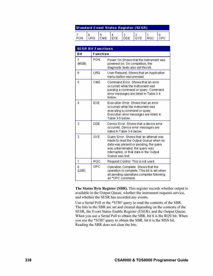
338 CSA8000 & TDS8000 Programmer Guide
The Status Byte Register (SBR). This register records whether output is
available in the Output Queue, whether the instrument requests service,
and whether the SESR has recorded any events.
Use a Serial Poll or the *STB? query to read the contents of the SBR.
The bits in the SBR are set and cleared depending on the contents of the
SESR, the Event Status Enable Register (ESER), and the Output Queue.
When you use a Serial Poll to obtain the SBR, bit 6 is the RQS bit. When
you use the *STB? query to obtain the SBR, bit 6 is the MSS bit.
Reading the SBR does not clear the bits.
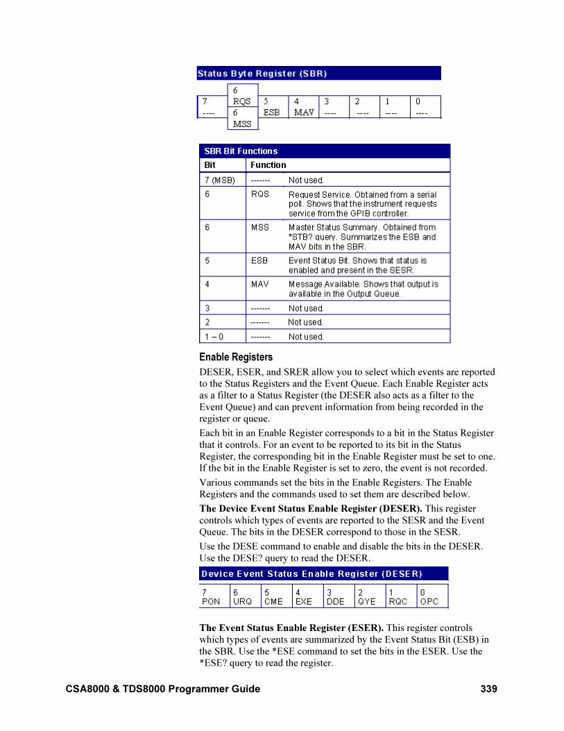
CSA8000 & TDS8000 Programmer Guide 339
Enable Registers
DESER, ESER, and SRER allow you to select which events are reported
to the Status Registers and the Event Queue. Each Enable Register acts
as a filter to a Status Register (the DESER also acts as a filter to the
Event Queue) and can prevent information from being recorded in the
register or queue.
Each bit in an Enable Register corresponds to a bit in the Status Register
that it controls. For an event to be reported to its bit in the Status
Register, the corresponding bit in the Enable Register must be set to one.
If the bit in the Enable Register is set to zero, the event is not recorded.
Various commands set the bits in the Enable Registers. The Enable
Registers and the commands used to set them are described below.
The Device Event Status Enable Register (DESER). This register
controls which types of events are reported to the SESR and the Event
Queue. The bits in the DESER correspond to those in the SESR.
Use the DESE command to enable and disable the bits in the DESER.
Use the DESE? query to read the DESER.
The Event Status Enable Register (ESER). This register controls
which types of events are summarized by the Event Status Bit (ESB) in
the SBR. Use the *ESE command to set the bits in the ESER. Use the
*ESE? query to read the register.
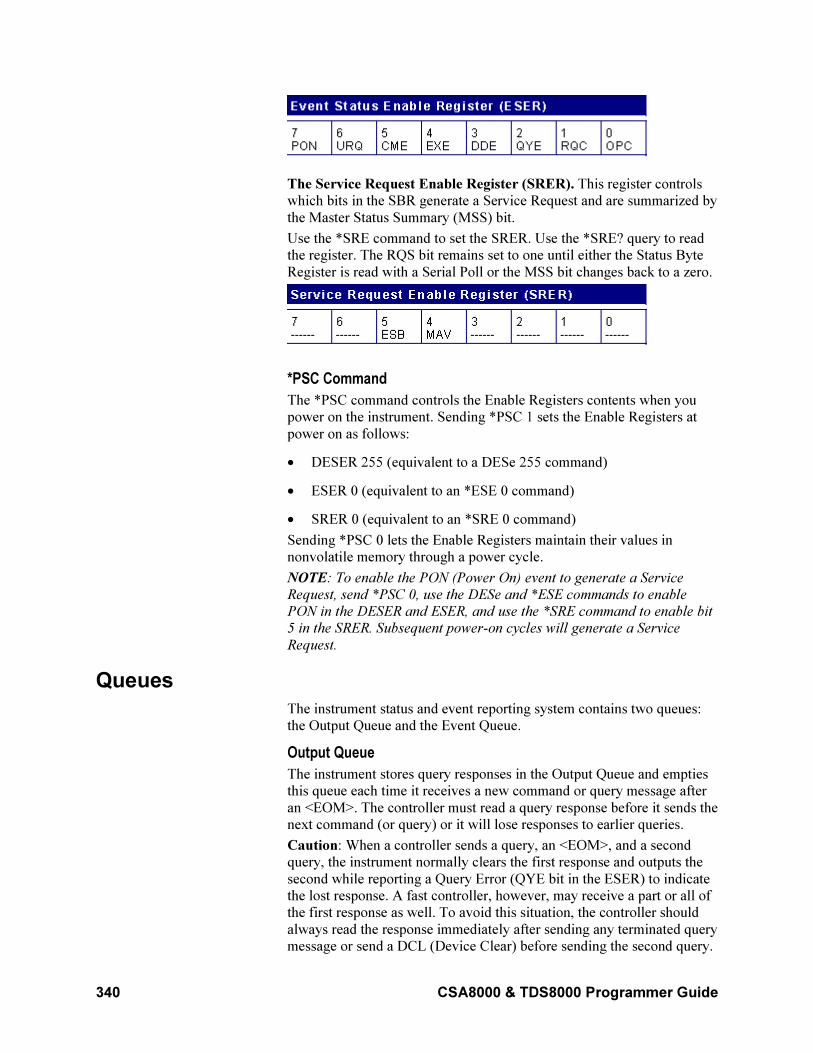
340 CSA8000 & TDS8000 Programmer Guide
The Service Request Enable Register (SRER). This register controls
which bits in the SBR generate a Service Request and are summarized by
the Master Status Summary (MSS) bit.
Use the *SRE command to set the SRER. Use the *SRE? query to read
the register. The RQS bit remains set to one until either the Status Byte
Register is read with a Serial Poll or the MSS bit changes back to a zero.
*PSC Command
The *PSC command controls the Enable Registers contents when you
power on the instrument. Sending *PSC 1 sets the Enable Registers at
power on as follows:
• DESER 255 (equivalent to a DESe 255 command)
• ESER 0 (equivalent to an *ESE 0 command)
• SRER 0 (equivalent to an *SRE 0 command)
Sending *PSC 0 lets the Enable Registers maintain their values in
nonvolatile memory through a power cycle.
NOTE: To enable the PON (Power On) event to generate a Service
Request, send *PSC 0, use the DESe and *ESE commands to enable
PON in the DESER and ESER, and use the *SRE command to enable bit
5 in the SRER. Subsequent power-on cycles will generate a Service
Request.
Queues
The instrument status and event reporting system contains two queues:
the Output Queue and the Event Queue.
Output Queue
The instrument stores query responses in the Output Queue and empties
this queue each time it receives a new command or query message after
an <EOM>. The controller must read a query response before it sends the
next command (or query) or it will lose responses to earlier queries.
Caution: When a controller sends a query, an <EOM>, and a second
query, the instrument normally clears the first response and outputs the
second while reporting a Query Error (QYE bit in the ESER) to indicate
the lost response. A fast controller, however, may receive a part or all of
the first response as well. To avoid this situation, the controller should
always read the response immediately after sending any terminated query
message or send a DCL (Device Clear) before sending the second query.
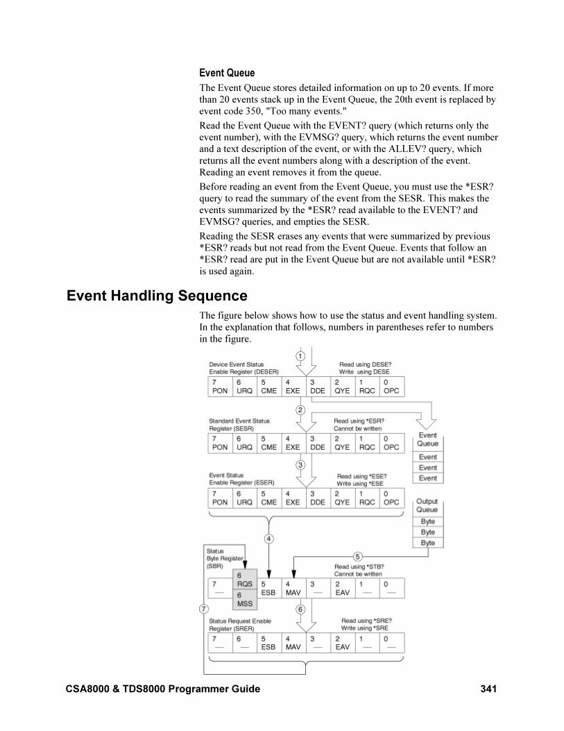
CSA8000 & TDS8000 Programmer Guide 341
Event Queue
The Event Queue stores detailed information on up to 20 events. If more
than 20 events stack up in the Event Queue, the 20th event is replaced by
event code 350, "Too many events."
Read the Event Queue with the EVENT? query (which returns only the
event number), with the EVMSG? query, which returns the event number
and a text description of the event, or with the ALLEV? query, which
returns all the event numbers along with a description of the event.
Reading an event removes it from the queue.
Before reading an event from the Event Queue, you must use the *ESR?
query to read the summary of the event from the SESR. This makes the
events summarized by the *ESR? read available to the EVENT? and
EVMSG? queries, and empties the SESR.
Reading the SESR erases any events that were summarized by previous
*ESR? reads but not read from the Event Queue. Events that follow an
*ESR? read are put in the Event Queue but are not available until *ESR?
is used again.
Event Handling Sequence
The figure below shows how to use the status and event handling system.
In the explanation that follows, numbers in parentheses refer to numbers
in the figure.
342 CSA8000 & TDS8000 Programmer Guide
When an event occurs, a signal is sent to the DESER (1). If that type of
event is enabled in the DESER (that is, if the bit for that event type is set
to one), the appropriate bit in the SESR is set to one, and the event is
recorded in the Event Queue (2). If the corresponding bit in the ESER is
also enabled (3), then the ESB bit in the SBR is set to one (4).
When output is sent to the Output Queue, the MAV bit in the SBR is set
to one (5).
When a bit in the SBR is set to one and the corresponding bit in the
SRER is enabled (6), the MSS bit in the SBR is set to one and a service
request is generated (7). Bit 2 of the SBR (EAV) flags the presence of
events in the queue.
Synchronization Methods
Although most GPIB commands are completed almost immediately after
being received by the instrument, some commands start a process that
requires more time. For example, once a HARDcopy STARt command is
executed it may be a few seconds before the hardcopy operation is
complete. Rather than remain idle while the operation is in process, the
instrument will continue processing other commands. This means that
some operations will not be completed in the order that they were sent.
Sometimes the result of an operation depends on the result of an earlier
operation. The first operation must be completed before the next
operation can be processed. The instrument status and event reporting
system provides ways to do this.
For example, synchronization may be used to ensure that the curve?
query command returns waveform data that is consistent with the current
instrument settings. You could use the following sequence to do this:
/** Sets up conditional acquisition **/
ACQUIRE:STATE OFF
SELECT:CH1 ON
HORIZONTAL:RECORDLENGTH 500
ACQUIRE:MODE SAMPLE
ACQUIRE:STOPAFTER:COUNT 1
ACQUIRE:STOPAFTER:MODE CONDITION
/** Sets up the data preamble **/
DATA:START 1
DATA:STOP 500
DATA:ENCDG RIBINARY
/** Clear data and acquire waveforms until conditionalstop occurs**/
ACQUIRE:DATA:CLEAR
ACQUIRE:STATE ON
/** Synchronize the operations by using *WAI, Busy?,*OPC, or *OPC?/
<Synchronization command>
/** Get the curve data **/
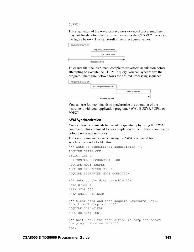
CSA8000 & TDS8000 Programmer Guide 343
CURVE?
The acquisition of the waveform requires extended processing time. It
may not finish before the instrument executes the CURVE? query (see
the figure below). This can result in incorrect curve values.
To ensure that the instrument completes waveform acquisition before
attempting to execute the CURVE? query, you can synchronize the
program. The figure below shows the desired processing sequence.
You can use four commands to synchronize the operation of the
instrument with your application program: *WAI, BUSY?, *OPC, or
*OPC?
*WAI Synchronization
You can force commands to execute sequentially by using the *WAI
command. This command forces completion of the previous commands
before processing new ones.
The same command sequence using the *WAI command for
synchronization looks like this:
/** Sets up conditional acquisition **/
ACQUIRE:STATE OFF
SELECT:CH1 ON
HORIZONTAL:RECORDLENGTH 500
ACQUIRE:MODE SAMPLE
ACQUIRE:STOPAFTER:COUNT 1
ACQUIRE:STOPAFTER:MODE CONDITION
/** Sets up the data preamble **/
DATA:START 1
DATA:STOP 500
DATA:ENCDG RIBINARY
/** Clear data and then acquire waveforms untilconditional stop occurs**/
ACQUIRE:DATA:CLEAR
ACQUIRE:STATE ON
/** Wait until the acquisition is complete beforequerying the curve data**/
*WAI
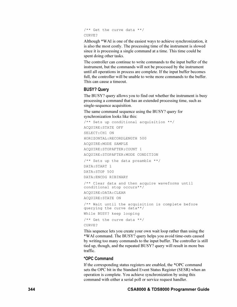
344 CSA8000 & TDS8000 Programmer Guide
/** Get the curve data **/
CURVE?
Although *WAI is one of the easiest ways to achieve synchronization, it
is also the most costly. The processing time of the instrument is slowed
since it is processing a single command at a time. This time could be
spent doing other tasks.
The controller can continue to write commands to the input buffer of the
instrument, but the commands will not be processed by the instrument
until all operations in process are complete. If the input buffer becomes
full, the controller will be unable to write more commands to the buffer.
This can cause a timeout.
BUSY? Query
The BUSY? query allows you to find out whether the instrument is busy
processing a command that has an extended processing time, such as
single-sequence acquisition.
The same command sequence using the BUSY? query for
synchronization looks like this:
/** Sets up conditional acquisition **/
ACQUIRE:STATE OFF
SELECT:CH1 ON
HORIZONTAL:RECORDLENGTH 500
ACQUIRE:MODE SAMPLE
ACQUIRE:STOPAFTER:COUNT 1
ACQUIRE:STOPAFTER:MODE CONDITION
/** Sets up the data preamble **/
DATA:START 1
DATA:STOP 500
DATA:ENCDG RIBINARY
/** Clear data and then acquire waveforms untilconditional stop occurs**/
ACQUIRE:DATA:CLEAR
ACQUIRE:STATE ON
/** Wait until the acquisition is complete beforequerying the curve data**/
While BUSY? keep looping
/** Get the curve data **/
CURVE?
This sequence lets you create your own wait loop rather than using the
*WAI command. The BUSY? query helps you avoid time-outs caused
by writing too many commands to the input buffer. The controller is still
tied up, though, and the repeated BUSY? query will result in more bus
traffic.
*OPC Command
If the corresponding status registers are enabled, the *OPC command
sets the OPC bit in the Standard Event Status Register (SESR) when an
operation is complete. You achieve synchronization by using this
command with either a serial poll or service request handler.
CSA8000 & TDS8000 Programmer Guide 345
Serial Poll Method: Enable the OPC bit in the Device Event Status
Enable Register (DESER) and the Event Status Enable Register (ESER)
using the DESE and *ESE commands.
When the operation is complete, the OPC bit in the Standard Event
Status Register (SESR) will be enabled and the Event Status Bit (ESB) in
the Status Byte Register will be enabled.
The same command sequence using the *OPC command for
synchronization with serial polling looks like this:
/** Sets up conditional acquisition **/
ACQUIRE:STATE OFF
SELECT:CH1 ON
HORIZONTAL:RECORDLENGTH 500
ACQUIRE:MODE SAMPLE
ACQUIRE:STOPAFTER:COUNT 1
ACQUIRE:STOPAFTER:MODE CONDITION
/** Enable the status registers **/
DESE 1
*ESE 1
*SRE 0
/** Sets up the data preamble **/
DATA:START 1
DATA:STOP 500
DATA:ENCDG RIBINARY
/** Clear data, and then acquire waveforms untilconditional stop occurs**/
ACQUIRE:DATA:CLEAR
ACQUIRE:STATE ON
/** Wait until the acquisition is complete beforequerying the curve data.**/
*OPC
While serial poll = 0, keep looping
/** Get the curve data **/
CURVE?
This technique requires less bus traffic than did looping on BUSY?.
Service Request Method: Enable the OPC bit in the Device Event
Status Enable Register (DESER) and the Event Status Enable Register
(ESER) using the DESE and *ESE commands.
You can also enable service requests by setting the ESB bit in the
Service Request Enable Register (SRER) using the *SRE command.
When the operation is complete, a Service Request will be generated.
The same command sequence using the *OPC command for
synchronization looks like this:
/** Sets up conditional acquisition **/
ACQUIRE:STATE OFF
SELECT:CH1 ON
HORIZONTAL:RECORDLENGTH 500
346 CSA8000 & TDS8000 Programmer Guide
ACQUIRE:MODE SAMPLE
ACQUIRE:STOPAFTER:CONDITION ACQWFMS
ACQUIRE:STOPAFTER:COUNT 100
ACQUIRE:STOPAFTER:MODE CONDITION
/** Enable the status registers **/
DESE 1
*ESE 1
*SRE 32
/** Set up measurement parameters **/
MEASUREMENT:MEAS1:TYPE AMPLITUDE
MEASUREMENT:MEAS1:SOURCE CH1
/** Acquire waveforms until conditional stop occurs**/
ACQUIRE:DATA:CLEAR
ACQUIRE:STATE ON
/**Wait until the acquisition is complete beforetaking the measurement**/
*OPC
/**The program can now do different tasks such as talkto other devices. The SRQ, when it comes, interruptsthose tasks and returns control to this task.**/
/** Take amplitude measurement **/
MEASUREMENT:MEAS1:VALUE?
This technique is more efficient but requires more sophisticated
programming.
*OPC? Query
The *OPC? query places a 1 in the Output Queue once an operation is
complete. A timeout could occur if you try to read the output queue
before there is any data in it.
The same command sequence using the *OPC? query for
synchronization looks like this:
/** Sets up conditional acquisition **/
ACQUIRE:STATE OFF
SELECT:CH1 ON
HORIZONTAL:RECORDLENGTH 500
ACQUIRE:MODE SAMPLE
ACQUIRE:STOPAFTER:COUNT 1
ACQUIRE:STOPAFTER:MODE CONDITION
/** Set up measurement parameters **/
MEASUREMENT:MEAS1:TYPE AMPLITUDE
MEASUREMENT:MEAS1:SOURCE CH1
/** Clear data, and then acquire waveforms untilconditional stop occurs**/
ACQUIRE:DATA:CLEAR
ACQUIRE:STATE ON
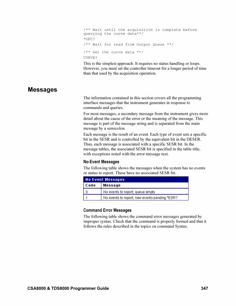
CSA8000 & TDS8000 Programmer Guide 347
/** Wait until the acquisition is complete beforequerying the curve data**/
*OPC?
/** Wait for read from Output Queue **/
/** Get the curve data **/
CURVE?
This is the simplest approach. It requires no status handling or loops.
However, you must set the controller timeout for a longer period of time
than that used by the acquisition operation.
Messages
The information contained in this section covers all the programming
interface messages that the instrument generates in response to
commands and queries.
For most messages, a secondary message from the instrument gives more
detail about the cause of the error or the meaning of the message. This
message is part of the message string and is separated from the main
message by a semicolon.
Each message is the result of an event. Each type of event sets a specific
bit in the SESR and is controlled by the equivalent bit in the DESER.
Thus, each message is associated with a specific SESR bit. In the
message tables, the associated SESR bit is specified in the table title,
with exceptions noted with the error message text.
No-Event Messages
The following table shows the messages when the system has no events
or status to report. These have no associated SESR bit.
Command Error Messages
The following table shows the command error messages generated by
improper syntax. Check that the command is properly formed and that it
follows the rules described in the topics on command Syntax.
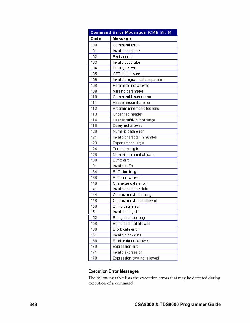
348 CSA8000 & TDS8000 Programmer Guide
Execution Error Messages
The following table lists the execution errors that may be detected during
execution of a command.
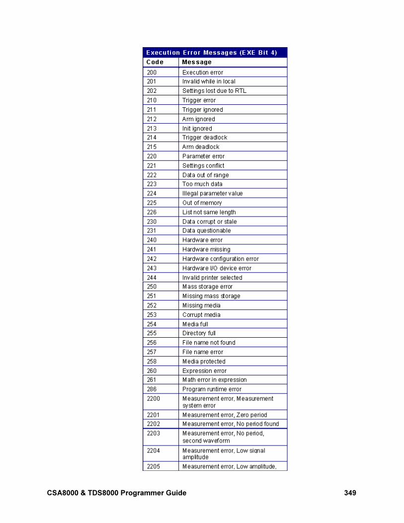
CSA8000 & TDS8000 Programmer Guide 349
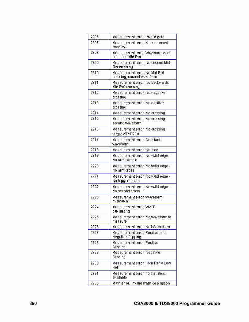
350 CSA8000 & TDS8000 Programmer Guide
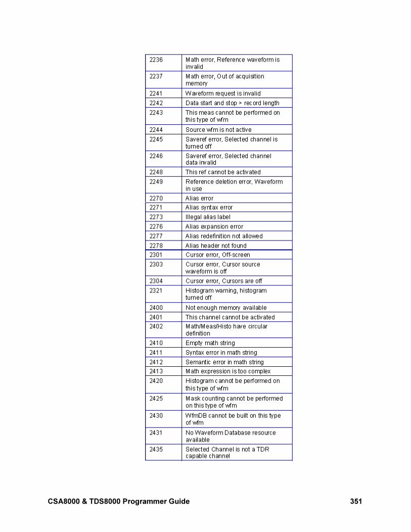
CSA8000 & TDS8000 Programmer Guide 351
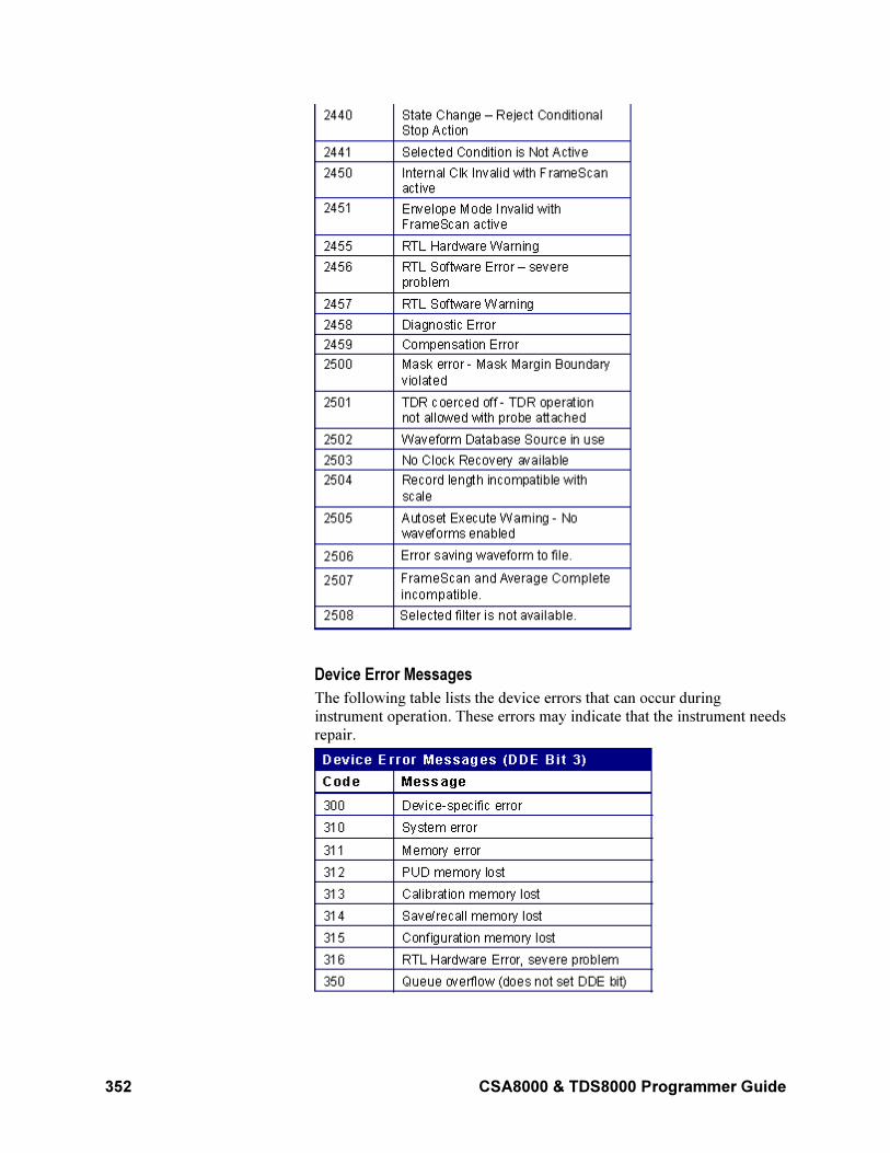
352 CSA8000 & TDS8000 Programmer Guide
Device Error Messages
The following table lists the device errors that can occur during
instrument operation. These errors may indicate that the instrument needs
repair.
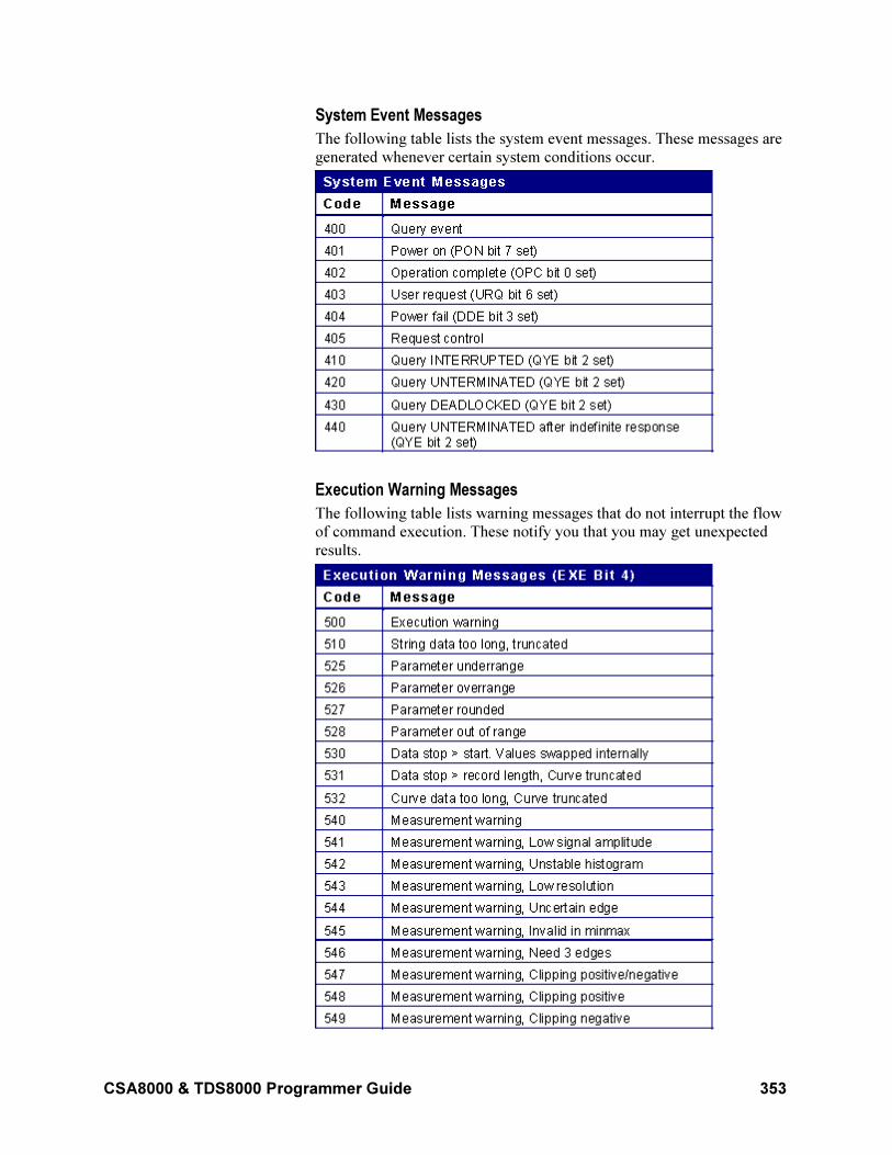
CSA8000 & TDS8000 Programmer Guide 353
System Event Messages
The following table lists the system event messages. These messages are
generated whenever certain system conditions occur.
Execution Warning Messages
The following table lists warning messages that do not interrupt the flow
of command execution. These notify you that you may get unexpected
results.
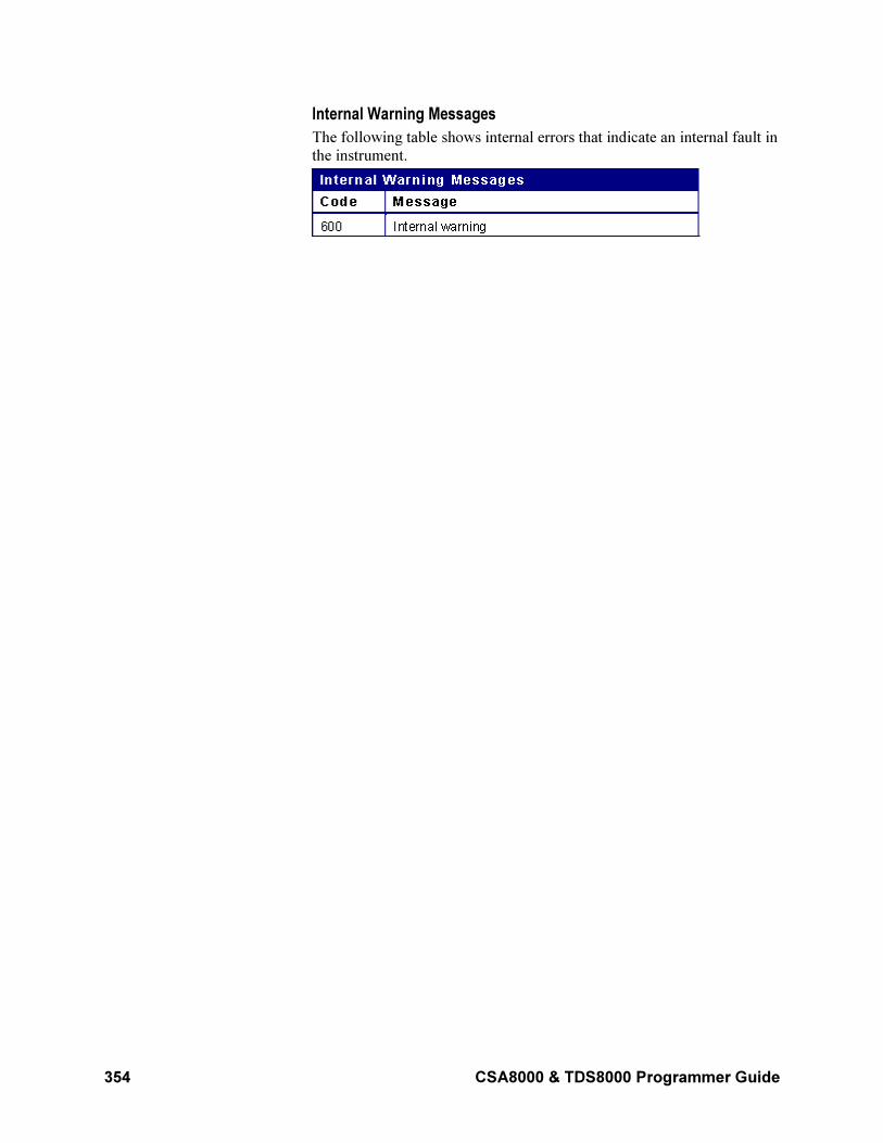
354 CSA8000 & TDS8000 Programmer Guide
Internal Warning Messages
The following table shows internal errors that indicate an internal fault in
the instrument.

CSA8000 & TDS8000 Programmer Guide 355
Miscellaneous
Reserved Words
This topic is a list of reserved words for the CSA8000 and TDS8000
instruments. Capital letters identify the required minimum spelling. For
the most robust code use the full spelling, since spelling rules may
change over time and from instrument model to instrument model.
*CLS – DARKLev
*CLS AOPTPWRDBM BELL CLEAR
*ESE ALL BINary CLKRec
*ESR ALLEv BIT_Nr CLKRECovery
*IDN Amp BITTime CMEan
*LRN AMPLitude BITRate COLOR
*OPC ANNOtations BITS COMPensate
*PSC AOPTpwr BN_Fm CONDition
*RST AREa BOX CONTROl
*SRE ASCIi BOXPcnt COUNt
*STB AUTO BURst CRMs
*TST AUTOPosition BUSY CROSSHair
*WAI AUTOSet BYT_Nr CURRentcount
ABSolute AVERage BYT_Or CURSor
ACQHWver AVG CALibrate CURSReadout
ACQuire AVGComp CAPacitance CURVe
ACQWfms BACKground CARea DARKLev
ACRMs BACkward CENTered
ACTion BANDwidth CH
DATA-GRid
DATA ENCdg EYEHeight FILTer
DATE ENET10313 EYEOfactor FOREground
DB ENET1250 EYEWIdth FORward
DCCALibrator ENET3125 EYEWindow FP
DEFine ENET9953 FACTory FPAnel
DELay ENV FALL FPANversion
DELTa EVENT FC1063 FPBinary
DESE EVMsg FC1063e FRAme
DESkew EVQty FC133 FRAMescan
DESTination EXECute FC133E FREQuency
DIAg EXPort FC2125 FULl
DIEL EXT10MHZref FC266 FUNCtion
DIRection EXTAtten FC266E GAIN
DISPlay EXTDirect FC4250 GATE
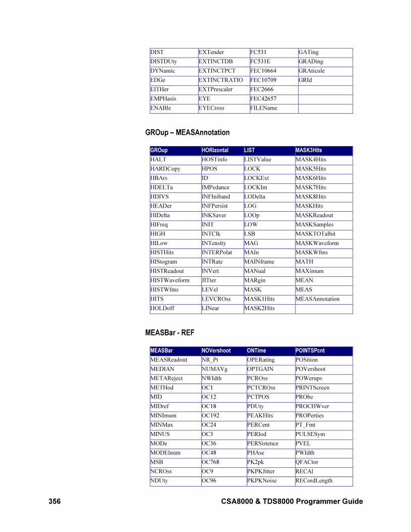
356 CSA8000 & TDS8000 Programmer Guide
DIST EXTender FC531 GATing
DISTDUty EXTINCTDB FC531E GRADing
DYNamic EXTINCTPCT FEC10664 GRAticule
EDGe EXTINCTRATIO FEC10709 GRId
EITHer EXTPrescaler FEC2666
EMPHasis EYE FEC42657
ENABle EYECross FILEName
GROup – MEASAnnotation
GROup HORizontal LIST MASK3Hits
HALT HOSTinfo LISTValue MASK4Hits
HARDCopy HPOS LOCK MASK5Hits
HBArs ID LOCKExt MASK6Hits
HDELTa IMPedance LOCKInt MASK7Hits
HDIVS INFIniband LODelta MASK8Hits
HEADer INFPersist LOG MASKHits
HIDelta INKSaver LOOp MASKReadout
HIFreq INIT LOW MASKSamples
HIGH INTClk LSB MASKTOTalhit
HILow INTensity MAG MASKWaveform
HISTHits INTERPolat MAIn MASKWfms
HIStogram INTRate MAINframe MATH
HISTReadout INVert MANual MAXimum
HISTWaveform JITter MARgin MEAN
HISTWfms LEVel MASK MEAS
HITS LEVCROss MASK1Hits MEASAnnotation
HOLDoff LINear MASK2Hits
MEASBar - REF
MEASBar NOVershoot ONTime POINTSPcnt
MEASReadout NR_Pt OPERating POSition
MEDIAN NUMAVg OPTGAIN POVershoot
METAReject NWIdth PCROss POWerups
METHod OC1 PCTCROss PRINTScreen
MID OC12 PCTPOS PRObe
MIDref OC18 PDUty PROCHWver
MINImum OC192 PEAKHits PROPerties
MINMax OC24 PERCent PT_Fmt
MINUS OC3 PERIod PULSESym
MODe OC36 PERSistence PVEL
MODElnum OC48 PHAse PWIdth
MSB OC768 PK2pk QFACtor
NCROss OC9 PKPKJitter RECAl
NDUty OC96 PKPKNoise RECordLength
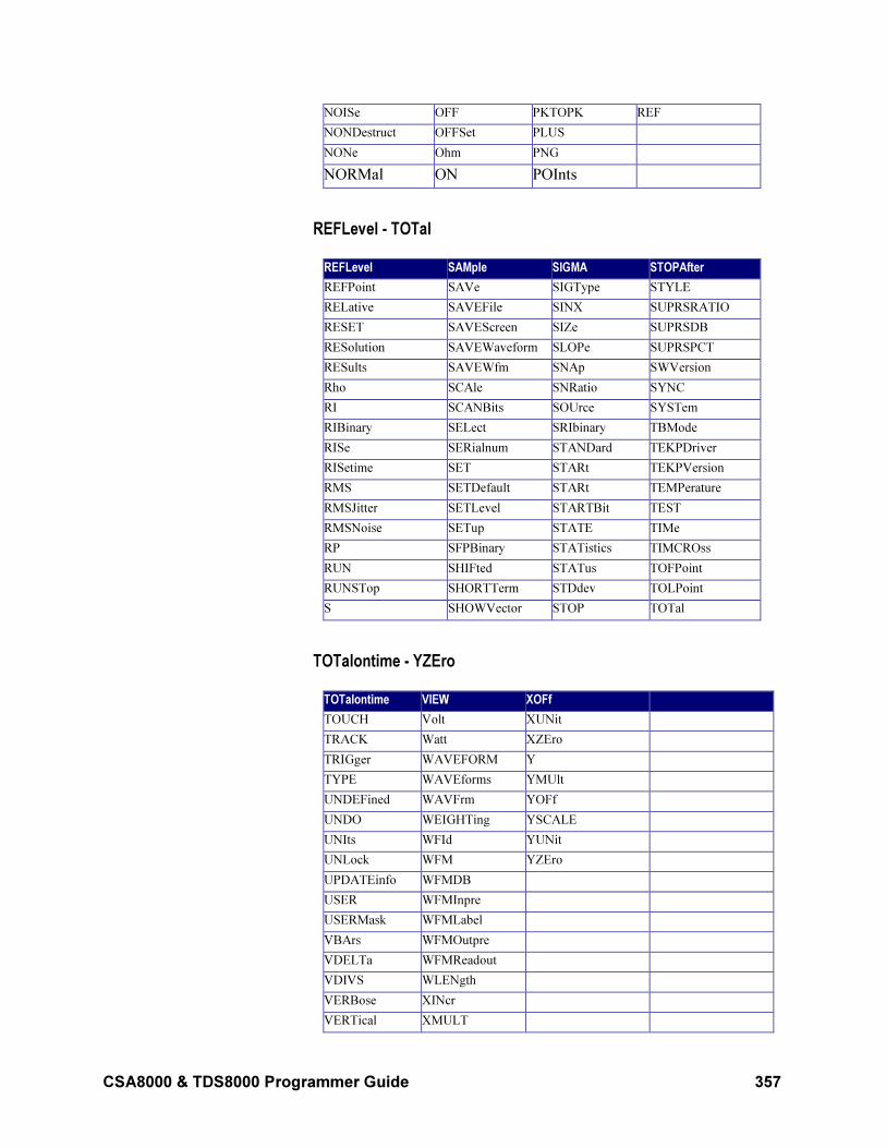
CSA8000 & TDS8000 Programmer Guide 357
NOISe OFF PKTOPK REF
NONDestruct OFFSet PLUS
NONe Ohm PNG
NORMal ON POInts
REFLevel - TOTal
REFLevel SAMple SIGMA STOPAfter
REFPoint SAVe SIGType STYLE
RELative SAVEFile SINX SUPRSRATIO
RESET SAVEScreen SIZe SUPRSDB
RESolution SAVEWaveform SLOPe SUPRSPCT
RESults SAVEWfm SNAp SWVersion
Rho SCAle SNRatio SYNC
RI SCANBits SOUrce SYSTem
RIBinary SELect SRIbinary TBMode
RISe SERialnum STANDard TEKPDriver
RISetime SET STARt TEKPVersion
RMS SETDefault STARt TEMPerature
RMSJitter SETLevel STARTBit TEST
RMSNoise SETup STATE TIMe
RP SFPBinary STATistics TIMCROss
RUN SHIFted STATus TOFPoint
RUNSTop SHORTTerm STDdev TOLPoint
S SHOWVector STOP TOTal
TOTalontime - YZEro
TOTalontime VIEW XOFf
TOUCH Volt XUNit
TRACK Watt XZEro
TRIGger WAVEFORM Y
TYPE WAVEforms YMUlt
UNDEFined WAVFrm YOFf
UNDO WEIGHTing YSCALE
UNIts WFId YUNit
UNLock WFM YZEro
UPDATEinfo WFMDB
USER WFMInpre
USERMask WFMLabel
VBArs WFMOutpre
VDELTa WFMReadout
VDIVS WLENgth
VERBose XINcr
VERTical XMULT
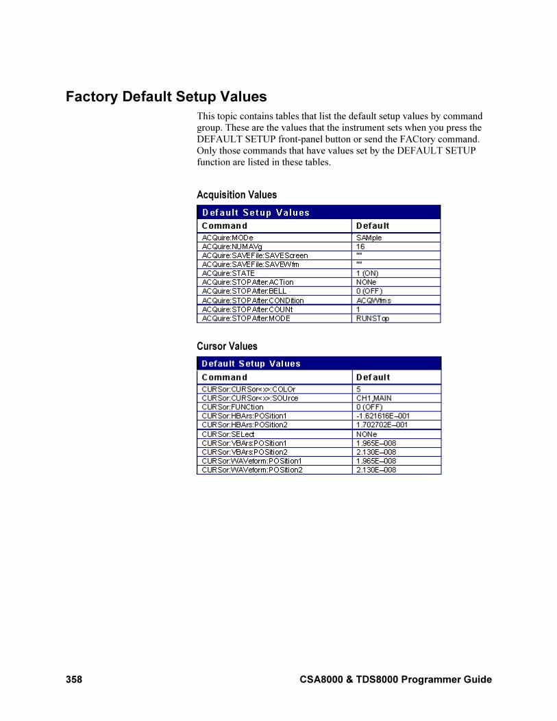
358 CSA8000 & TDS8000 Programmer Guide
Factory Default Setup Values
This topic contains tables that list the default setup values by command
group. These are the values that the instrument sets when you press the
DEFAULT SETUP front-panel button or send the FACtory command.
Only those commands that have values set by the DEFAULT SETUP
function are listed in these tables.
Acquisition Values
Cursor Values
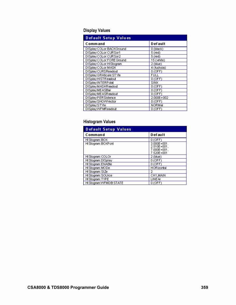
CSA8000 & TDS8000 Programmer Guide 359
Display Values
Histogram Values
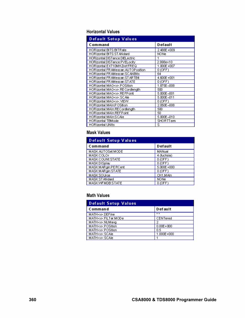
360 CSA8000 & TDS8000 Programmer Guide
Horizontal Values
Mask Values
Math Values
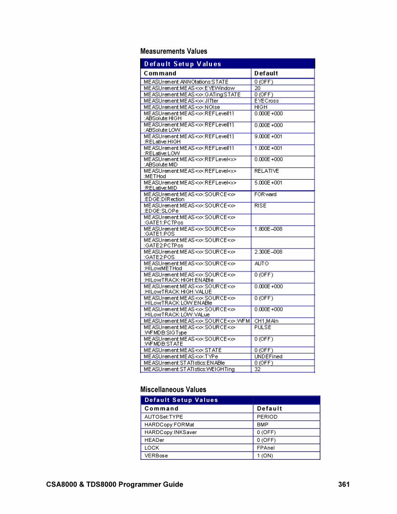
CSA8000 & TDS8000 Programmer Guide 361
Measurements Values
Miscellaneous Values
Def au l t Se tup Va lues
Com m and Def au l t
AUTOSet:TYPE PERIOD
HARDCopy:FORMat BMP
HARDCopy:INKSaver 0 (OFF)
HEADer 0 (OFF)
LOCK FPAnel
VERBose 1 (ON)
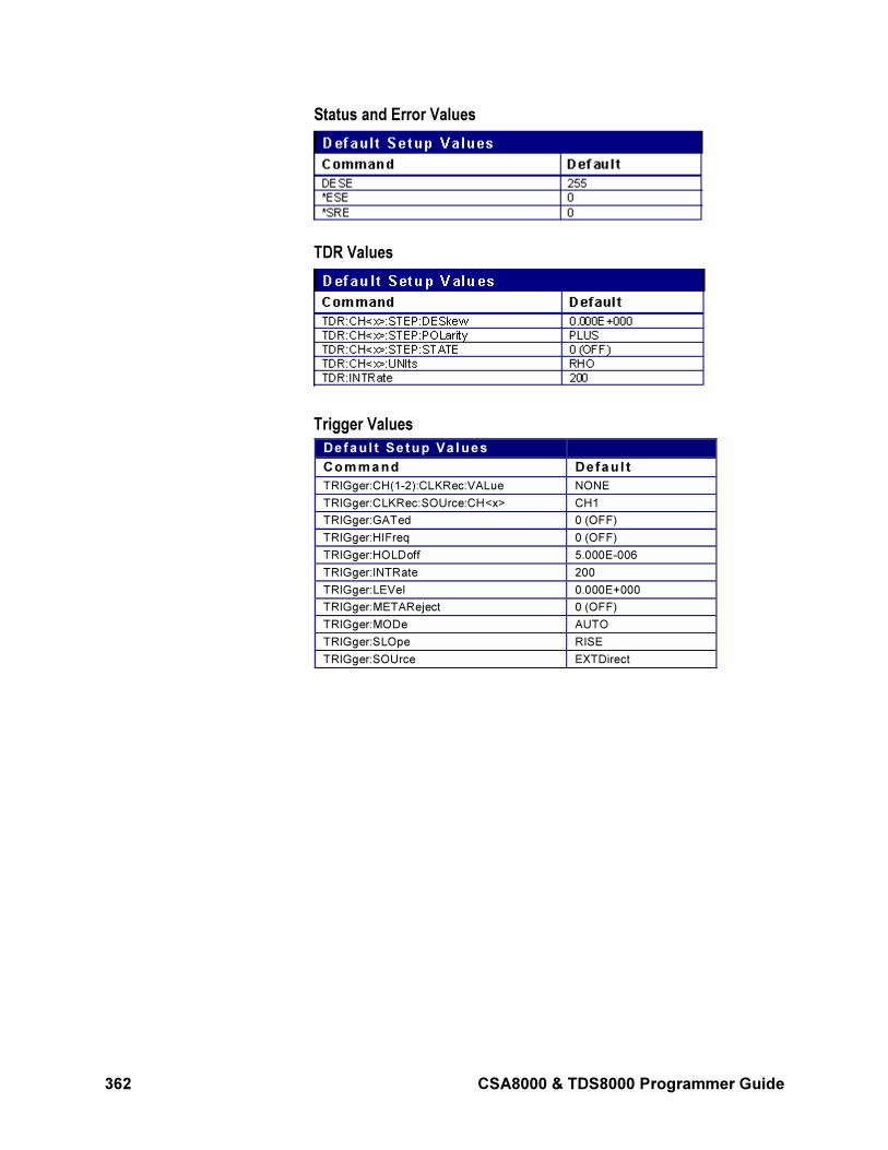
362 CSA8000 & TDS8000 Programmer Guide
Status and Error Values
TDR Values
Trigger Values
Def au l t Se t up Va l ues
Co m m and Defau l t
TRIGger:CH(1-2):CLKRec:VALue NONE
TRIGger:CLKRec:SOUrce:CH<x> CH1
TRIGger:GATed 0 (OFF)
TRIGger:HIFreq 0 (OFF)
TRIGger:HOLDoff 5.000E-006
TRIGger:INTRate 200
TRIGger:LEVel 0.000E+000
TRIGger:METAReject 0 (OFF)
TRIGger:MODe AUTO
TRIGger:SLOpe RISE
TRIGger:SOUrce EXTDirect
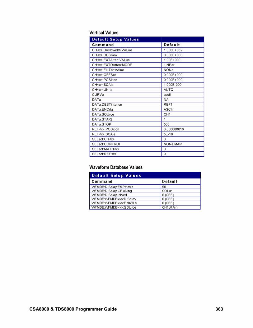
CSA8000 & TDS8000 Programmer Guide 363
Vertical Values
Def au l t Se tup Va lues
Com m and Def au l t
CH<x>:BANdwidth:VALue 1.000E+032
CH<x>:DESKew 0.000E+000
CH<x>:EXTAtten:VALue 1.00E+000
CH<x>:EXTDAtten:MODE LINEar
CH<x>:FILTer:VAlue NONe
CH<x>:OFFSet 0.000E+000
CH<x>:POSition 0.000E+000
CH<x>:SCAle 1.000E-000
CH<x>:UNIts AUTO
CURVe ascii
DATa NA
DATa:DESTintation REF1
DATa:ENCdg ASCIi
DATa:SOUrce CH1
DATa:STARt 1
DATa:STOP 500
REF<x>:POSition 0.000000016
REF<x>:SCAle 5E-10
SELect:CH<x> 0
SELect:CONTROI NONe,MAIn
SELect:MATH<x> 0
SELect:REF<x> 0
Waveform Database Values
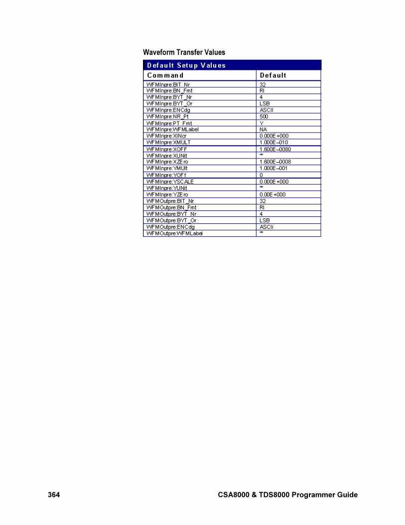
364 CSA8000 & TDS8000 Programmer Guide
Waveform Transfer Values
CSA8000 & TDS8000 Programmer Guide 365
GPIB Interface Specifications
This topic describes details of the GPIB remote interface of the
instrument. Normally, you will not need this information to use the
instrument, but this information may be useful if you are connecting to
controllers with unusual configurations.
GPIB Functions
The following table lists the GPIB interface functions and electrical
functions subsets supported by this instrument with a brief descriptions
of each.
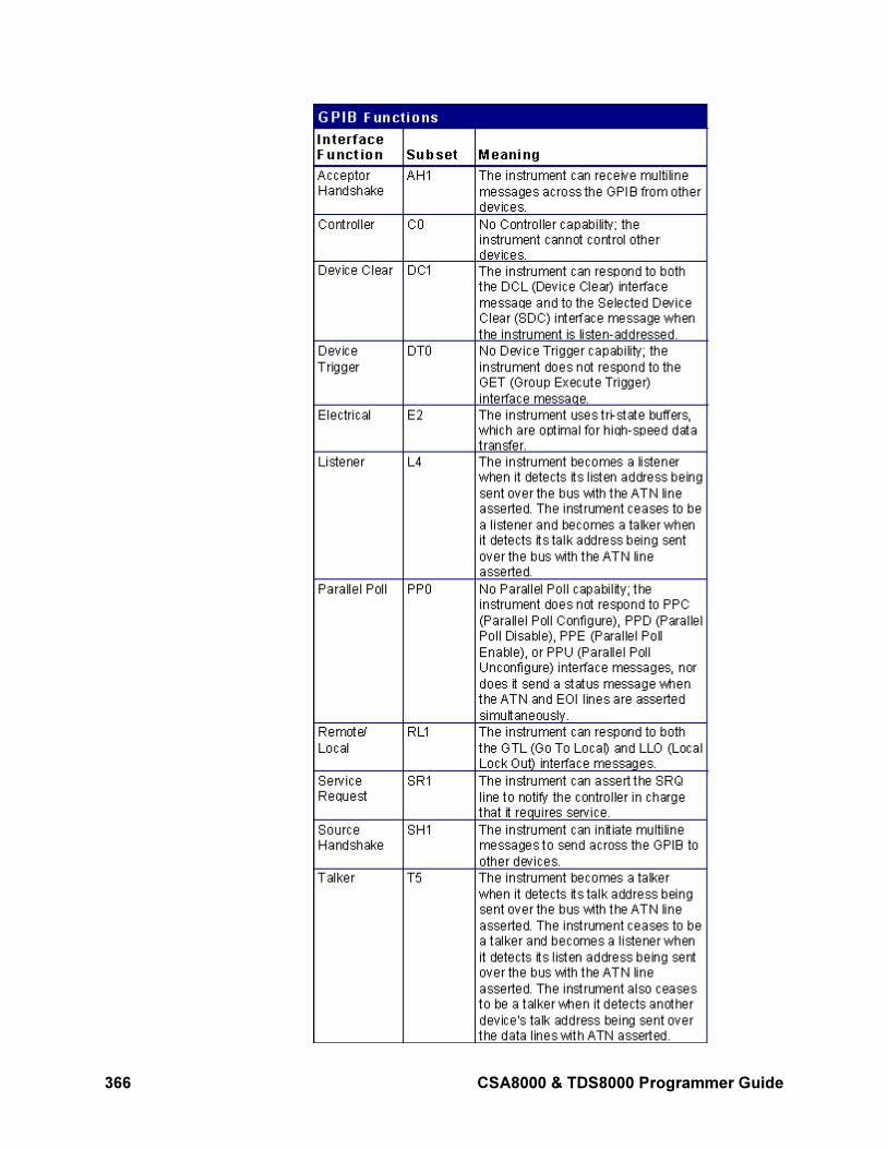
366 CSA8000 & TDS8000 Programmer Guide
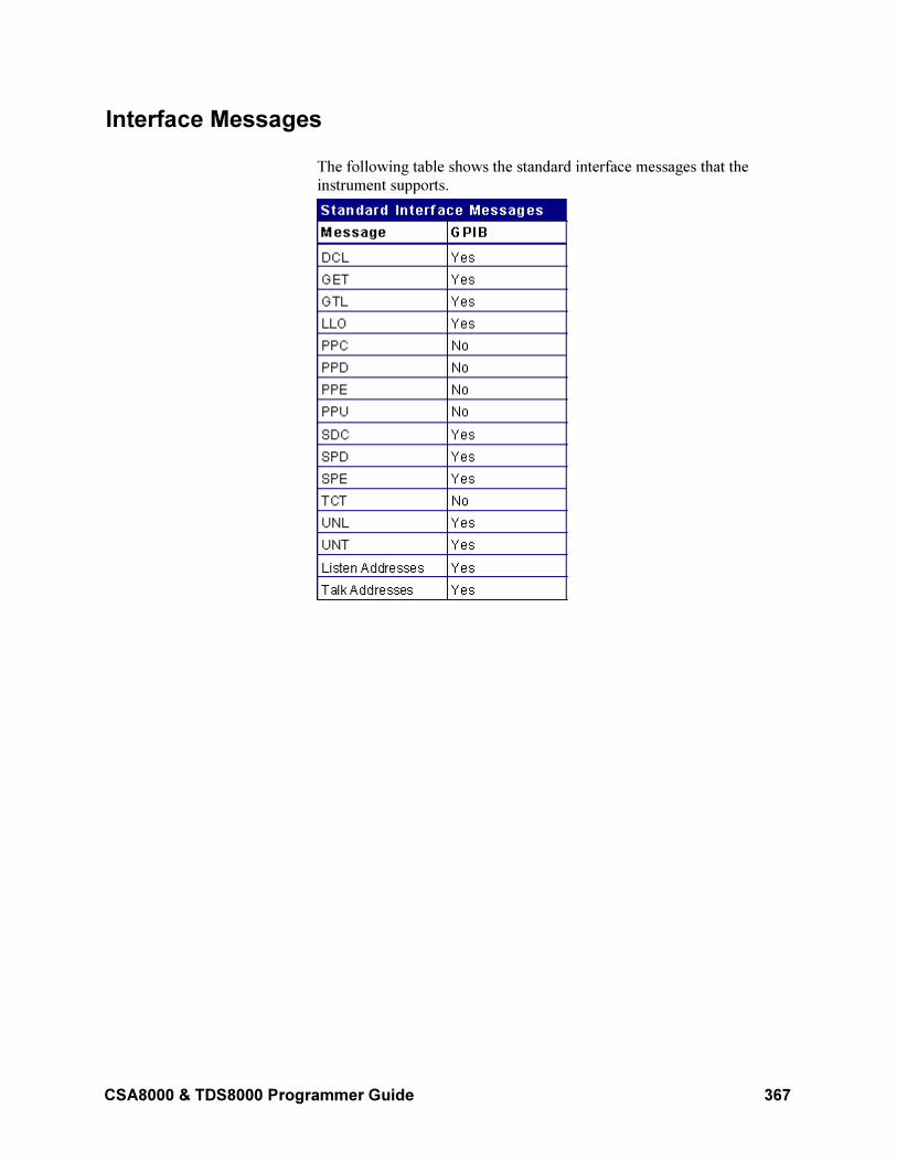
CSA8000 & TDS8000 Programmer Guide 367
Interface Messages
The following table shows the standard interface messages that the
instrument supports.
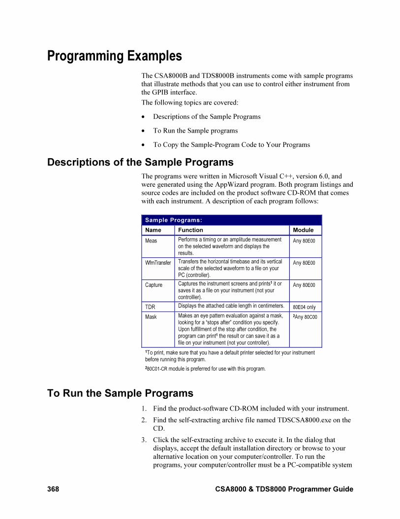
368 CSA8000 & TDS8000 Programmer Guide
Programming Examples
The CSA8000B and TDS8000B instruments come with sample programs
that illustrate methods that you can use to control either instrument from
the GPIB interface.
The following topics are covered:
• Descriptions of the Sample Programs
• To Run the Sample programs
• To Copy the Sample-Program Code to Your Programs
Descriptions of the Sample Programs
The programs were written in Microsoft Visual C++, version 6.0, and
were generated using the AppWizard program. Both program listings and
source codes are included on the product software CD-ROM that comes
with each instrument. A description of each program follows:
Sample Programs:
Name Function Module
Meas Performs a timing or an amplitude measurementon the selected waveform and displays theresults.
Any 80E00
WfmTransfer Transfers the horizontal timebase and its verticalscale of the selected waveform to a file on yourPC (controller).
Any 80E00
Capture Captures the instrument screens and prints1 it orsaves it as a file on your instrument (not yourcontrolller).
Any 80E00
TDR Displays the attached cable length in centimeters. 80E04 only
Mask Makes an eye pattern evaluation against a mask,looking for a “stops after” condition you specify.Upon fulfillment of the stop after condition, theprogram can print1 the result or can save it as afile on your instrument (not your controller).
2Any 80C00
1To print, make sure that you have a default printer selected for your instrumentbefore running this program.
280C01-CR module is preferred for use with this program.
To Run the Sample Programs
1. Find the product-software CD-ROM included with your instrument.
2. Find the self-extracting archive file named TDSCSA8000.exe on the
CD.
3. Click the self-extracting archive to execute it. In the dialog that
displays, accept the default installation directory or browse to your
alternative location on your computer/controller. To run the
programs, your computer/controller must be a PC-compatible system
CSA8000 & TDS8000 Programmer Guide 369
equipped with a National Instruments GPIB board and associated
drivers.
4. Ensure that:
• the instrument is set as DEV1 with address of 1, and that the PC
(controller) is set as GPIB0
• a valid signal is connected to the instrument
Navigate to the Sources directory contained in the TDSCSA8000
directory that you extracted.
Click to execute the program that you wish to run. The program will
display a dialog box from which you can set up and run the program.
Note. To reassign the name of your instrument, you can, enter your
current device name into the appropriate edit box within each program
(except the Mask program, where the board address is hard-coded to
zero). You can also use IBCONF.EXE to reassign the name.
To Copy the Sample-Program Code to Your Programs
1. Do steps 1 through 3 of the procedure To Run the Sample Programs
if you have not yet installed the TDSCSA8000 directory containing
the programs.
2. Navigate to the Programs directory contained in the TDSCSA8000
directory.
3. Open the program file in your favorite editor or IDE, and copy the
code you want into your programs.
370 CSA8000 & TDS8000 Programmer Guide
Index
*CLS ..............................................................................................................................57
*ESE .......................................................................................................................57, 58
*ESR? ...........................................................................................................................58
*IDN? ............................................................................................................................59
*LRN? ...........................................................................................................................59
*OPC........................................................................................................................59, 60
*PSC ........................................................................................................................60, 61
*RST ..............................................................................................................................61
*SRE ..............................................................................................................................62
*STB? ............................................................................................................................62
*WAI ..............................................................................................................................63
ACQuire
MODe ............................................................................................................. 67, 68, 69
SAVEFile
SAVEScreen.............................................................................................................70
SAVEWfm ................................................................................................................71
STOPAfter
ACTion...............................................................................................................72, 73
BELL .................................................................................................................73, 74
CONDition ..........................................................................................................74, 75
COUNt .....................................................................................................................76
MODE?...................................................................................................................77
STOPAfter?................................................................................................................77
ACQuire? ......................................................................................................................78
ALLEv? .........................................................................................................................79
Argument Type
block ...........................................................................................................................23
numeric .................................................................................................................22, 23
quoted string ................................................................................................................23
AUTOSet ........................................................................................................................79
Backus-Naur Form (BNF) notation .....................................................................................16
BUSY? ....................................................................................................................81, 82
CALibrate
UPDATEinfo
ALL..........................................................................................................................85
MAInframe................................................................................................................86
CH<x>
BANdwidth
VALue................................................................................................................87, 88
DESkew ................................................................................................................88, 89
CSA8000 & TDS8000 Programmer Guide 371
EXTAtten
MODE......................................................................................................................89
VALue................................................................................................................89, 90
OFFSet .................................................................................................................93, 94
POSition ................................................................................................................94, 95
SCAle ...................................................................................................................95, 96
UNIts.....................................................................................................................96, 97
WLENgth
VALue......................................................................................................................98
CH<x>?.........................................................................................................................99
Command and Query Structure
colon
leading .....................................................................................................................17
header.........................................................................................................................17
messages ....................................................................................................................17
set form .......................................................................................................................17
Command Entry
concatenating...............................................................................................................19
Command Error Messages .............................................................................................348
Command Group
Acquisition .............................................................................................................25, 26
Calibration .............................................................................................................26, 27
Compensation ........................................................................................................27, 28
Cursor .........................................................................................................................29
Hardcopy .....................................................................................................................31
Histogram ..............................................................................................................32, 33
Horizontal .................................................................................................. 34, 35, 36, 37
Mask .....................................................................................................................38, 39
Math .....................................................................................................................39, 40
Measurement ................................................................................................... 41, 42, 43
TDR ............................................................................................................................48
Trigger ........................................................................................................................49
Vertical ........................................................................................................................51
Waveform Database .....................................................................................................53
Waveform Transfer .......................................................................................................55
COMPensate
ALL .............................................................................................................................99
MAInframe .................................................................................................................101
RECAll
FACTory
ALL ....................................................................................................................102
MAInframe ..........................................................................................................102
USER
372 CSA8000 & TDS8000 Programmer Guide
ALL ....................................................................................................................102
MAInframe ..........................................................................................................103
SAVe
USER
ALL ....................................................................................................................104
MAInframe ..........................................................................................................105
Concatenating commands and queries ...............................................................................19
Copyright ........................................................................................................................11
CURSor ................................................................................................ 106, 107, 110, 111
CURSor<x>
COLOR .......................................................................................................... 106, 107
SOUrce ..................................................................................................................108
FUNCtion ..................................................................................................................109
HBArs
POSition.................................................................................................................110
CURSor? ......................................................................................................................115
CURVe ................................................................................................................. 116, 117
DATa.................................................................................................................... 117, 118
DESTination...............................................................................................................118
ENCdg ......................................................................................................................119
SOUrce ............................................................................................................. 120, 121
STOP ................................................................................................................ 121, 122
DATE ................................................................................................................... 123, 124
DELEte
WAVEform.................................................................................................................124
DESE ..........................................................................................................................125
DISplay
COLor
BACKground................................................................................................... 125, 126
FOREground .................................................................................................. 128, 129
HIStogram ...................................................................................................... 129, 130
MASK ............................................................................................................ 130, 131
GRAticule
STYLE ........................................................................................................... 133, 134
PERSistence..............................................................................................................139
STYLE .............................................................................................................. 140, 141
DISplay? .....................................................................................................................142
Documentation ................................................................................................................15
Enable Registers ...........................................................................................................340
End-of-message terminator ...............................................................................................20
Event Queue .................................................................................................................342
EVENT? .......................................................................................................................142
EVMsg? ......................................................................................................................143
CSA8000 & TDS8000 Programmer Guide 373
EVQty?........................................................................................................................143
EXPort......................................................................................................................... 144
FACTory ............................................................................................................... 144, 145
GPIB
Functions...................................................................................................................366
HARDCopy
FILEName ......................................................................................................... 146, 147
FORMat ........................................................................................................... 147, 148
STARt ......................................................................................................................146
HEADer ........................................................................................................................149
command ....................................................................................................................17
HIStogram
BOX..........................................................................................................................150
COLOR ............................................................................................................. 152, 153
COUNt ......................................................................................................................153
DISplay ............................................................................................................. 153, 154
MODe .......................................................................................................................155
SIZe .................................................................................................................. 155, 156
SOUrce ............................................................................................................. 156, 157
HIStogram?.................................................................................................................162
HORizontal
BITS
STANdard..................................................................................... 163, 164, 165, 166
MAG<x>
POSition................................................................................................. 171, 172, 173
SCAle ............................................................................................................ 176, 177
VIEW ............................................................................................................. 179, 180
MAIn
POSition................................................................................................. 180, 181, 182
SCAle ............................................................................................................ 185, 186
UNIts.........................................................................................................................201
HORizontal?................................................................................................................202
ID?....................................................................................................................... 202, 203
Ink-saver............................................................................................................... 148, 149
Interface messages................................................................................................ 348, 368
LOCk............................................................................................................................203
MASK
COLOR ............................................................................................................. 204, 205
COUNt
STATE ...................................................................................................................206
DISplay .....................................................................................................................208
MARgin
STATE ...................................................................................................................209
374 CSA8000 & TDS8000 Programmer Guide
MASK<x>
POInts....................................................................................................................212
SOUrce .....................................................................................................................213
STANdard ................................................................................ 214, 215, 216, 217, 218
MASK?................................................................................................................ 218, 219
MATH<x>
DEFine ......................................................................................................................219
FILTer
MODe ............................................................................................................ 220, 221
RISetime ................................................................................................................221
POSition ............................................................................................................ 222, 223
SCAle ....................................................................................................... 223, 224, 225
MATH<x>?..................................................................................................................227
MEASUrement
LIST.................................................................................................................. 228, 229
MEAS<x>
GATing
STATE................................................................................................................231
JITter ............................................................................................................. 232, 233
NOISe............................................................................................................ 234, 235
REFLevel<x>
ABSolute
HIGH ....................................................................................................... 235, 236
LOW................................................................................................................236
MID ......................................................................................................... 236, 237
METHod ............................................................................................. 237, 238, 239
RELative
HIGH ....................................................................................................... 239, 240
LOW........................................................................................................ 240, 241
MID ......................................................................................................... 241, 242
SOURCE<x>
EDGE
DIRection ................................................................................................. 242, 243
SLOPe.............................................................................................................244
HILow
METHod .......................................................................................... 248, 249, 250
TRACK
HIGH
VALue ............................................................................................... 251, 252
LOW
VALue ............................................................................................... 253, 254
TYPE ............................................................................................................. 259, 260
STATIstics
CSA8000 & TDS8000 Programmer Guide 375
WEIGHTing ............................................................................................................267
MEASUrement? ..........................................................................................................268
Messages
Command Error..........................................................................................................348
System Event .............................................................................................................354
Mnemonics ......................................................................................................... 20, 21, 22
channel .................................................................................................................20, 22
cursor position..............................................................................................................20
histogram statistics specifier ..........................................................................................21
magnified timebase specifier ..........................................................................................21
mask specifier ..............................................................................................................21
math waveform.............................................................................................................22
measurement specifier ..................................................................................................21
reference waveform ......................................................................................................22
waveform database.......................................................................................................22
Numeric arguments....................................................................................................22, 23
Output Queue................................................................................................................341
Queries...........................................................................................................................18
Queues
Event ................................................................................................................ 341, 342
Output .......................................................................................................................341
RECAll
SETUp .............................................................................................................. 268, 269
WAVEform.................................................................................................................269
REF<x>
POSition ............................................................................................................ 269, 270
SCAle ............................................................................................................... 270, 271
Registers
Enable...................................................................................................... 338, 340, 341
Event Status Enable Register (ESER) ...........................................................................340
Events......................................................................................................................338
Service Request Enable Register (SRER) .....................................................................341
Status............................................................................................................... 338, 339
Status Byte Register (SBR).................................................................................. 338, 339
Remote Communications..................................................................................................12
Rules..............................................................................................................................18
Sample Programs .................................................................................................. 369, 370
SAVe
SETUp .............................................................................................................. 271, 272
WAVEform......................................................................................................... 272, 273
SELect
CONTROl ..................................................................................................................274
376 CSA8000 & TDS8000 Programmer Guide
SELect? ......................................................................................................................277
Sequence
event handling............................................................................................................342
SET?........................................................................................................................... 278
Standard Event Status Register (SESR) ...........................................................................338
Status and Events
Messages ..................................................................................................................348
Registers ...................................................................................................................338
Status Registers ............................................................................................................338
symbols
Backus-Naur ................................................................................................................16
SYNC
TIMEOUT .................................................................................................. 278, 279, 280
Synchronization Methods
using the *OPC command............................................................................................346
using the *OPC? query ................................................................................................347
using the *WAI command ............................................................................................344
using the BUSY? query ...............................................................................................345
Syntax ............................................................................................................................16
System Event Messages ................................................................................................354
TDR
CH<x>
PRESET.................................................................................................................290
STEP
DESkew ..............................................................................................................291
POLarity...................................................................................................... 291, 292
UNIts ............................................................................................................. 293, 294
TDR?................................................................................................................... 294, 295
TIME ............................................................................................................................295
TRIGger ............................................................................................................... 299, 300
CH<x>
CLKRec
VALue......................................................................................................... 296, 298
CLKRec
SOUrce .......................................................................................................... 298, 299
GATEd............................................................................................................. 299, 300
HOLDoff ............................................................................................................ 301, 302
LEVel ................................................................................................................ 303, 304
MODe .......................................................................................................................305
SLOpe............................................................................................................... 306, 307
SOURce ............................................................................................................ 307, 308
TRIGger? ....................................................................................................................309
UNLock ........................................................................................................................309
CSA8000 & TDS8000 Programmer Guide 377
VERBose .............................................................................................................. 309, 310
Version of the online Programmers Guide.......................................................................1
WAVFrm? ...................................................................................................................310
WFMDB........................................................................................................................313
DISPlay
EMPHasis ..............................................................................................................311
GRADing ................................................................................................................312
INVert ....................................................................................................................313
WFMDB<x>
DISPlay .......................................................................................................... 314, 315
SOURce......................................................................................................... 315, 316
WFMDB? ....................................................................................................................317
WFMInpre
XINcr.........................................................................................................................323
YSCALE ....................................................................................................................326
WFMInpre? .................................................................................................................328
WFMOutpre?.................................................................................................................337

378 CSA8000 & TDS8000 Programmer Guide
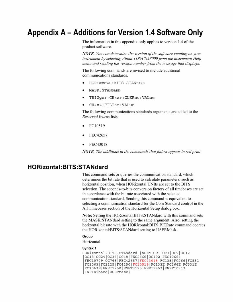
Appendix A – Additions for Version 1.4 Software Only The information in this appendix only applies to version 1.4 of the
product software.
NOTE. You can determine the version of the software running on your
instrument by selecting About TDS/CSA8000 from the instrument Help
menu and reading the version number from the message that displays.
The following commands are revised to include additional
communications standards.
• HORIZONTAL:BITS:STANDARD
• MASK:STANDARD
• TRIGger:CH<x>:CLKRec:VALue
• CH<x>:FILTer:VALue
The following communications standards arguments are added to the
Reserved Words lists:
• FC10519
• FEC42657
• FEC43018
NOTE. The additions in the commands that follow appear in red print.
HORizontal:BITS:STANdard This command sets or queries the communication standard, which
determines the bit rate that is used to calculate parameters, such as
horizontal position, when HORizontal:UNIts are set to the BITS
selection. The seconds-to-bits conversion factors of all timebases are set
in accordance with the bit rate associated with the selected
communication standard. Sending this command is equivalent to
selecting a communication standard for the Com Standard control in the
All Timebases section of the Horizontal Setup dialog box.
Note: Setting the HORizontal:BITS:STANdard with this command sets
the MASK:STANdard setting to the same argument. Also, setting the
horizontal bit rate with the HORizontal:BITS:BITRate command coerces
the HORizontal:BITS:STANdard setting to USERMask.
Group
Horizontal
Syntax 1
HORizontal:BITS:STANdard NONe|OC1|OC3|OC9|OC12|OC18|OC24|OC36|OC48|FEC2666|OC192|FEC10664|FEC10709|OC768|FEC42657|FEC43018|FC133|FC266|FC531|FC1063|FC2125|FC4250|FC10519|FC133E|FC266E|FC531E|FC1063E|ENET1250|ENET3125|ENET9953|ENET10313|INFIniband|USERMask
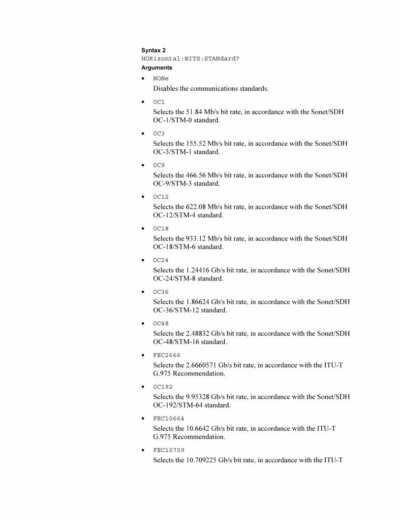
Syntax 2
HORizontal:BITS:STANdard?
Arguments
• NONe
Disables the communications standards.
• OC1
Selects the 51.84 Mb/s bit rate, in accordance with the Sonet/SDH
OC-1/STM-0 standard.
• OC3
Selects the 155.52 Mb/s bit rate, in accordance with the Sonet/SDH
OC-3/STM-1 standard.
• OC9
Selects the 466.56 Mb/s bit rate, in accordance with the Sonet/SDH
OC-9/STM-3 standard.
• OC12
Selects the 622.08 Mb/s bit rate, in accordance with the Sonet/SDH
OC-12/STM-4 standard.
• OC18
Selects the 933.12 Mb/s bit rate, in accordance with the Sonet/SDH
OC-18/STM-6 standard.
• OC24
Selects the 1.24416 Gb/s bit rate, in accordance with the Sonet/SDH
OC-24/STM-8 standard.
• OC36
Selects the 1.86624 Gb/s bit rate, in accordance with the Sonet/SDH
OC-36/STM-12 standard.
• OC48
Selects the 2.48832 Gb/s bit rate, in accordance with the Sonet/SDH
OC-48/STM-16 standard.
• FEC2666
Selects the 2.6660571 Gb/s bit rate, in accordance with the ITU-T
G.975 Recommendation.
• OC192
Selects the 9.95328 Gb/s bit rate, in accordance with the Sonet/SDH
OC-192/STM-64 standard.
• FEC10664
Selects the 10.6642 Gb/s bit rate, in accordance with the ITU-T
G.975 Recommendation.
• FEC10709
Selects the 10.709225 Gb/s bit rate, in accordance with the ITU-T
G.709 Draft Recommendation.
• OC768
Selects the 39.8131 Gb/s bit rate, in accordance with the Sonet/SDH
OC-768/STM-256 standard.
• FEC42657
Selects the 42.6569 Gb/s bit rate, in accordance with the ITU-T
G.975 Recommendation.
• FEC43018
Selects the 43.018414 Gb/s bit rate, in accordance with the ITU-T
G.709 Draft Recommendation G.709.
• FC133
Selects the 132.81 Mb/s bit rate, in accordance with the ANSI
X3.230-1994 standard.
• FC266
Selects the 265.6 Mb/s bit rate, in accordance with the ANSI
X3.230-1994 standard.
• FC531
Selects the 531.2 Mb/s bit rate, in accordance with the ANSI
X3.230-1994 standard.
• FC1063
Selects the 1062.5 Gb/s bit rate, in accordance with the ANSI
X3.230-1994 standard.
• FC2125
Selects the 2125 Gb/s bit rate, in accordance with the ANSI Fibre
Channel Physical Interface (FC-PI) Rev 11 draft standard.
• FC4250
Selects the 4250 Gb/s bit rate, in accordance with the ANSI Fibre
Channel Physical Interface (FC-PI) Rev 11 draft standard.
• FC10519
Selects the 10.518750 Gb/s bit rate, in accordance with the proposed
10 Gigabit Fibre Channel (10GFC) standard.
• FC133E
Selects the 132.81 Mb/s bit rate, in accordance with the ANSI
X3.230-1994 standard.
• FC266E
Selects the 265.6 Mb/s bit rate, in accordance with the ANSI
X3.230-1994 standard.
• FC531E
Selects the 531.2 Mb/s bit rate, in accordance with the ANSI
X3.230-1994 standard.
• FC1063E
Selects the 1.0625 Gb/s bit rate, in accordance with the ANSI
X3.230-1994 standard.
• ENET1250
Selects the 1.250 Gb/s bit rate, in accordance with the IEEE 802.3
standard.
• ENET3125
Selects the 3.125 Gb/s bit rate, in accordance with the IEEE
P802.3ae draft standard.
• ENET9953
Selects the 9.95328 Gb/s bit rate, in accordance with the IEEE
P802.3ae draft standard.
• ENET10313
Selects the 10.3125 Gb/s bit rate, in accordance with the IEEE
P802.3ae draft standard.
• INFIniband
Selects the 2.500 Gb/s bit rate, in accordance with the InfiniBand
standard.
• USERMask
Sets the bit rate in accordance with a user-defined standard.
Example 1
HORizontal:BITS:STANdard OC192
This command sets the bit rate to the Sonet/SDH OC-192/STM-64
standard of 9953 Mb/s.
Example 2
HORizontal:BITS:STANdard?
This query might return :HORIZONTAL:BITS:STANDARD OC12,
indicating that the bit rate is set to the Sonet/SDH OC-12/STM-4
standard of 622.1 Mb/s.
MASK:STANdard This command selects a set of predefined mask polygons (hereafter
referred to as a "mask") to be used for mask testing in accordance with
the communications standard specified by the command argument. The
query form of this command returns the current mask selected. Note the
following usage rules:
• Setting the MASK:STANdard sets the HORizontal:BITS:STANdard
to the same argument, thereby setting the horizontal bit rate to the bit
rate associated with the selected standard.
• Do not use the USERMask to select a user-defined mask, rather use
the MASK:MASK<X>:POInts and/or the
MASK:MASK<X>:POINTSPcnt commands to define the mask.
This action coerces the MASK:STANdard and
HORizontal:BITS:STANdard settings to USERMask. (The
USERMask setting cannot be selected directly with the
MASK:STANdard command, but MASK:STANdard queries will
return USERMask when user-defined masks are selected.)
• When you use user-defined masks, you should set the horizontal bit
rate explicitly with the HORizontal:BITS:BITRate command.
• You can use the MASK:MASK<X> commands to access the current
masks, whether predefined or user defined, and their associated
counters.
• If you specify user-defined masks, note that selecting one of the
predefined mask standards will overwrite your user-defined masks. If
your test is related to one of the predefined mask standards, you
might want to first select the related predefined standard, and then
only modify the masks and/or bit rate as required.
• Selecting NONE will delete all currently defined masks.
• If MASK:COUNt:STATE is ON, then mask counting starts.
Group
Mask
Syntax 1
MASK:STANdard NONe|OC1|OC3|OC9|OC12|OC18|OC24|OC36|OC48|FEC2666|OC192|FEC10664|FEC10709|OC768|FEC42657|FEC43018|FC133|FC266|FC531|FC1063|FC2125|FC4250|FC133E|FC266E|FC531E|FC1063E|FC10519|ENET1250|ENET3125|ENET9953|ENET10313|INFIniband|USERMask
Syntax 2
MASK:STANdard?
Arguments
• NONe
Disables the communications standards.
• OC1
Selects the 51.84 Mb/s bit rate and mask, in accordance with the
Sonet/SDH OC-1/STM-0 standard.
• OC3
Selects the 155.52 Mb/s bit rate and mask, in accordance with the
Sonet/SDH OC-3/STM-1 standard.
• OC9
Selects the 466.56 Mb/s bit rate and mask, in accordance with the
Sonet/SDH OC-9/STM-3 standard.
• OC12
Selects the 622.08 Mb/s bit rate and mask, in accordance with the
Sonet/SDH OC-12/STM-4 standard.
• OC18
Selects the 933.12 Mb/s bit rate and mask, in accordance with the
Sonet/SDH OC-18/STM-6 standard.
• OC24
Selects the 1.24416 Gb/s bit rate and mask, in accordance with the
Sonet/SDH OC-24/STM-8 standard.
• OC36
Selects the 1.86624 Gb/s bit rate and mask, in accordance with the
Sonet/SDH OC-36/STM-12 standard.
• OC48
Selects the 2.488.32 Gb/s bit rate and mask, in accordance with the
Sonet/SDH OC-48/STM-16 standard.
• FEC2666
Selects the 2.6660571 Gb/s bit rate and mask, in accordance with the
ITU-T G.975 Recommendation.
• OC192
Selects the 9.95328 Gb/s bit rate and mask, in accordance with the
Sonet/SDH OC192/STM-64 standard.
• FEC10664
Selects the 10.6642 Gb/s bit rate and mask, in accordance with the
ITU-T G.975 Recommendation.
• FEC10709
Selects the 10.709225 Gb/s bit rate and mask, in accordance with the
ITU-T G.709 Draft Recommendation.
• OC768
Selects the 39.8131 Gb/s bit rate and mask, in accordance with the
Sonet/SDH OC-768/STM-256 standard.
• FEC42657
Selects the 42.6569 Gb/s bit rate and mask, in accordance with the
ITU-T G.975 Recommendation.
• FEC43018
Selects the 43.018414 Gb/s bit rate and mask, in accordance with the
ITU-T G.709 Draft Recommendation.
• FC133
Selects the 132.81 Mb/s bit rate and mask, in accordance with the
ANSI X3.230-1994 standard.
• FC266
Selects the 265.6 Mb/s bit rate and mask, in accordance with the
ANSI X3.230-1994 standard.
• FC531
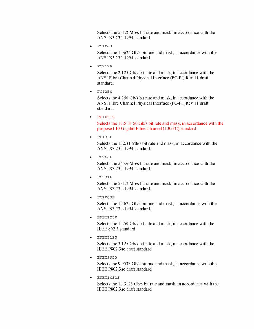
Selects the 531.2 Mb/s bit rate and mask, in accordance with the
ANSI X3.230-1994 standard.
• FC1063
Selects the 1.0625 Gb/s bit rate and mask, in accordance with the
ANSI X3.230-1994 standard.
• FC2125
Selects the 2.125 Gb/s bit rate and mask, in accordance with the
ANSI Fibre Channel Physical Interface (FC-PI) Rev 11 draft
standard.
• FC4250
Selects the 4.250 Gb/s bit rate and mask, in accordance with the
ANSI Fibre Channel Physical Interface (FC-PI) Rev 11 draft
standard.
• FC10519
Selects the 10.518750 Gb/s bit rate and mask, in accordance with the
proposed 10 Gigabit Fibre Channel (10GFC) standard.
• FC133E
Selects the 132.81 Mb/s bit rate and mask, in accordance with the
ANSI X3.230-1994 standard.
• FC266E
Selects the 265.6 Mb/s bit rate and mask, in accordance with the
ANSI X3.230-1994 standard.
• FC531E
Selects the 531.2 Mb/s bit rate and mask, in accordance with the
ANSI X3.230-1994 standard.
• FC1063E
Selects the 10.625 Gb/s bit rate and mask, in accordance with the
ANSI X3.230-1994 standard.
• ENET1250
Selects the 1.250 Gb/s bit rate and mask, in accordance with the
IEEE 802.3 standard.
• ENET3125
Selects the 3.125 Gb/s bit rate and mask, in accordance with the
IEEE P802.3ae draft standard.
• ENET9953
Selects the 9.9533 Gb/s bit rate and mask, in accordance with the
IEEE P802.3ae draft standard.
• ENET10313
Selects the 10.3125 Gb/s bit rate and mask, in accordance with the
IEEE P802.3ae draft standard.
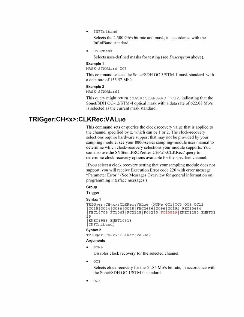
• INFIniband
Selects the 2.500 Gb/s bit rate and mask, in accordance with the
InfiniBand standard.
• USERMask
Selects user-defined masks for testing (see Description above).
Example 1
MASK:STANdard OC3
This command selects the Sonet/SDH OC-3/STM-1 mask standard with
a data rate of 155.52 Mb/s.
Example 2
MASK:STANdard?
This query might return :MASK:STANDARD OC12, indicating that the
Sonet/SDH OC-12/STM-4 optical mask with a data rate of 622.08 Mb/s
is selected as the current mask standard.
TRIGger:CH<x>:CLKRec:VALue This command sets or queries the clock recovery value that is applied to
the channel specified by x, which can be 1 or 2. The clock-recovery
selections require hardware support that may not be provided by your
sampling module; see your 8000-series sampling-module user manual to
determine which clock-recovery selections your module supports. You
can also use the SYStem:PROPerties:CH<x>:CLKRec? query to
determine clock recovery options available for the specified channel.
If you select a clock recovery setting that your sampling module does not
support, you will receive Execution Error code 220 with error message
“Parameter Error." (See Messages Overview for general information on
programming interface messages.)
Group
Trigger
Syntax 1
TRIGger:CH<x>:CLKRec:VALue NONe|OC1|OC3|OC9|OC12|OC18|OC24|OC36|OC48|FEC2666|OC96|OC192|FEC10664|FEC10709|FC1063|FC2125|FC4250|FC10519|ENET1250|ENET3125|ENET9953|ENET10313|INFIniband
Syntax 2
TRIGger:CH<x>:CLKRec:VALue?
Arguments
• NONe
Disables clock recovery for the selected channel.
• OC1
Selects clock recovery for the 51.84 Mb/s bit rate, in accordance with
the Sonet/SDH OC-1/STM-0 standard.
• OC3
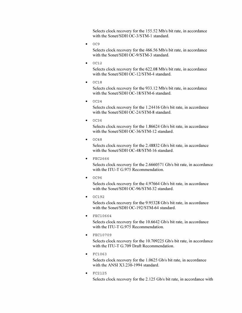
Selects clock recovery for the 155.52 Mb/s bit rate, in accordance
with the Sonet/SDH OC-3/STM-1 standard.
• OC9
Selects clock recovery for the 466.56 Mb/s bit rate, in accordance
with the Sonet/SDH OC-9/STM-3 standard.
• OC12
Selects clock recovery for the 622.08 Mb/s bit rate, in accordance
with the Sonet/SDH OC-12/STM-4 standard.
• OC18
Selects clock recovery for the 933.12 Mb/s bit rate, in accordance
with the Sonet/SDH OC-18/STM-6 standard.
• OC24
Selects clock recovery for the 1.24416 Gb/s bit rate, in accordance
with the Sonet/SDH OC-24/STM-8 standard.
• OC36
Selects clock recovery for the 1.86624 Gb/s bit rate, in accordance
with the Sonet/SDH OC-36/STM-12 standard.
• OC48
Selects clock recovery for the 2.48832 Gb/s bit rate, in accordance
with the Sonet/SDH OC-48/STM-16 standard.
• FEC2666
Selects clock recovery for the 2.6660571 Gb/s bit rate, in accordance
with the ITU-T G.975 Recommendation.
• OC96
Selects clock recovery for the 4.97664 Gb/s bit rate, in accordance
with the Sonet/SDH OC-96/STM-32 standard.
• OC192
Selects clock recovery for the 9.95328 Gb/s bit rate, in accordance
with the Sonet/SDH OC-192/STM-64 standard.
• FEC10664
Selects clock recovery for the 10.6642 Gb/s bit rate, in accordance
with the ITU-T G.975 Recommendation.
• FEC10709
Selects clock recovery for the 10.709225 Gb/s bit rate, in accordance
with the ITU-T G.709 Draft Recommendation.
• FC1063
Selects clock recovery for the 1.0625 Gb/s bit rate, in accordance
with the ANSI X3.230-1994 standard.
• FC2125
Selects clock recovery for the 2.125 Gb/s bit rate, in accordance with
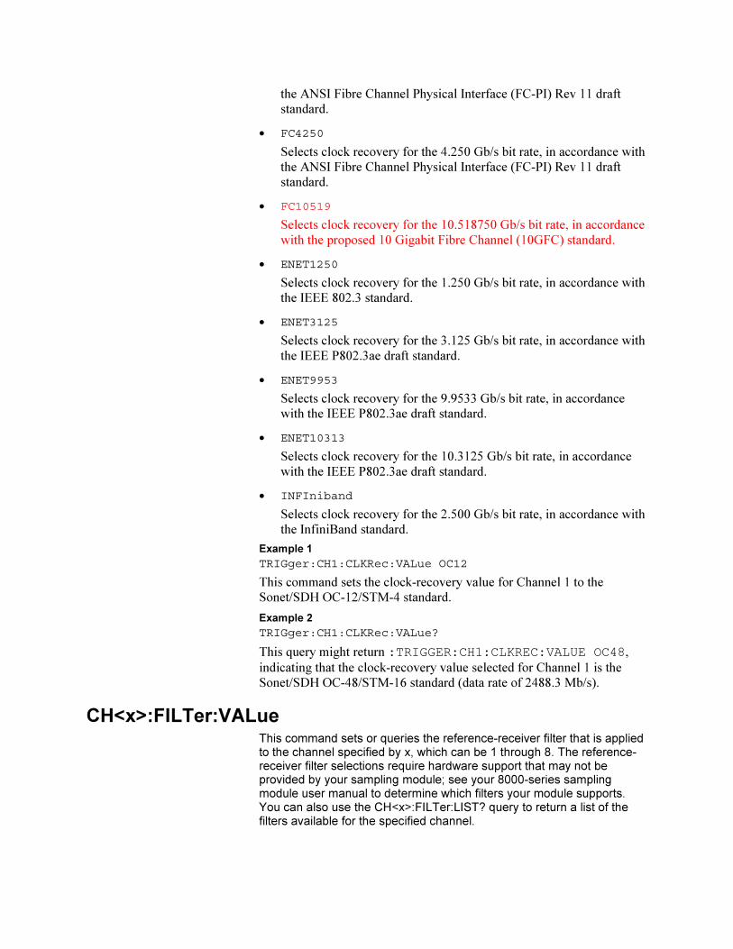
the ANSI Fibre Channel Physical Interface (FC-PI) Rev 11 draft
standard.
• FC4250
Selects clock recovery for the 4.250 Gb/s bit rate, in accordance with
the ANSI Fibre Channel Physical Interface (FC-PI) Rev 11 draft
standard.
• FC10519
Selects clock recovery for the 10.518750 Gb/s bit rate, in accordance
with the proposed 10 Gigabit Fibre Channel (10GFC) standard.
• ENET1250
Selects clock recovery for the 1.250 Gb/s bit rate, in accordance with
the IEEE 802.3 standard.
• ENET3125
Selects clock recovery for the 3.125 Gb/s bit rate, in accordance with
the IEEE P802.3ae draft standard.
• ENET9953
Selects clock recovery for the 9.9533 Gb/s bit rate, in accordance
with the IEEE P802.3ae draft standard.
• ENET10313
Selects clock recovery for the 10.3125 Gb/s bit rate, in accordance
with the IEEE P802.3ae draft standard.
• INFIniband
Selects clock recovery for the 2.500 Gb/s bit rate, in accordance with
the InfiniBand standard.
Example 1
TRIGger:CH1:CLKRec:VALue OC12
This command sets the clock-recovery value for Channel 1 to the
Sonet/SDH OC-12/STM-4 standard.
Example 2
TRIGger:CH1:CLKRec:VALue?
This query might return :TRIGGER:CH1:CLKREC:VALUE OC48,
indicating that the clock-recovery value selected for Channel 1 is the
Sonet/SDH OC-48/STM-16 standard (data rate of 2488.3 Mb/s).
CH<x>:FILTer:VALue This command sets or queries the reference-receiver filter that is applied to the channel specified by x, which can be 1 through 8. The reference-receiver filter selections require hardware support that may not be provided by your sampling module; see your 8000-series sampling module user manual to determine which filters your module supports. You can also use the CH<x>:FILTer:LIST? query to return a list of the filters available for the specified channel.
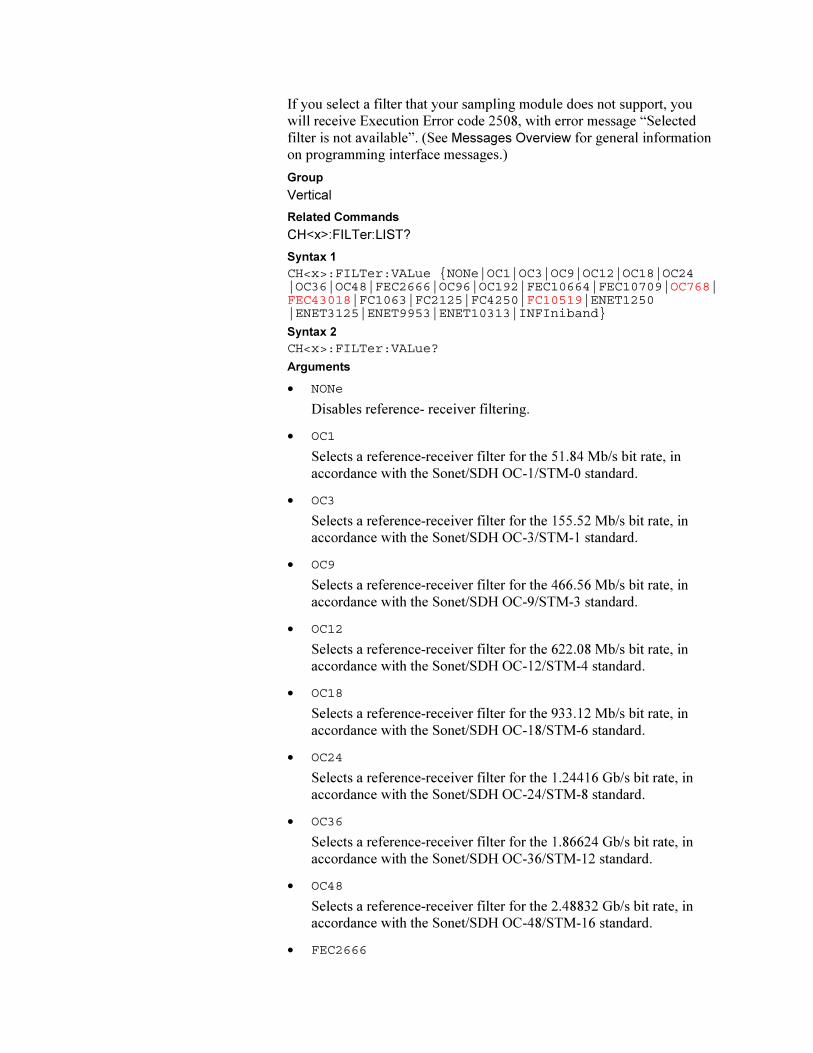
If you select a filter that your sampling module does not support, you
will receive Execution Error code 2508, with error message “Selected
filter is not available”. (See Messages Overview for general information
on programming interface messages.)
Group
Vertical
Related Commands
CH<x>:FILTer:LIST?
Syntax 1
CH<x>:FILTer:VALue NONe|OC1|OC3|OC9|OC12|OC18|OC24|OC36|OC48|FEC2666|OC96|OC192|FEC10664|FEC10709|OC768|FEC43018|FC1063|FC2125|FC4250|FC10519|ENET1250|ENET3125|ENET9953|ENET10313|INFIniband
Syntax 2
CH<x>:FILTer:VALue?
Arguments
• NONe
Disables reference- receiver filtering.
• OC1
Selects a reference-receiver filter for the 51.84 Mb/s bit rate, in
accordance with the Sonet/SDH OC-1/STM-0 standard.
• OC3
Selects a reference-receiver filter for the 155.52 Mb/s bit rate, in
accordance with the Sonet/SDH OC-3/STM-1 standard.
• OC9
Selects a reference-receiver filter for the 466.56 Mb/s bit rate, in
accordance with the Sonet/SDH OC-9/STM-3 standard.
• OC12
Selects a reference-receiver filter for the 622.08 Mb/s bit rate, in
accordance with the Sonet/SDH OC-12/STM-4 standard.
• OC18
Selects a reference-receiver filter for the 933.12 Mb/s bit rate, in
accordance with the Sonet/SDH OC-18/STM-6 standard.
• OC24
Selects a reference-receiver filter for the 1.24416 Gb/s bit rate, in
accordance with the Sonet/SDH OC-24/STM-8 standard.
• OC36
Selects a reference-receiver filter for the 1.86624 Gb/s bit rate, in
accordance with the Sonet/SDH OC-36/STM-12 standard.
• OC48
Selects a reference-receiver filter for the 2.48832 Gb/s bit rate, in
accordance with the Sonet/SDH OC-48/STM-16 standard.
• FEC2666
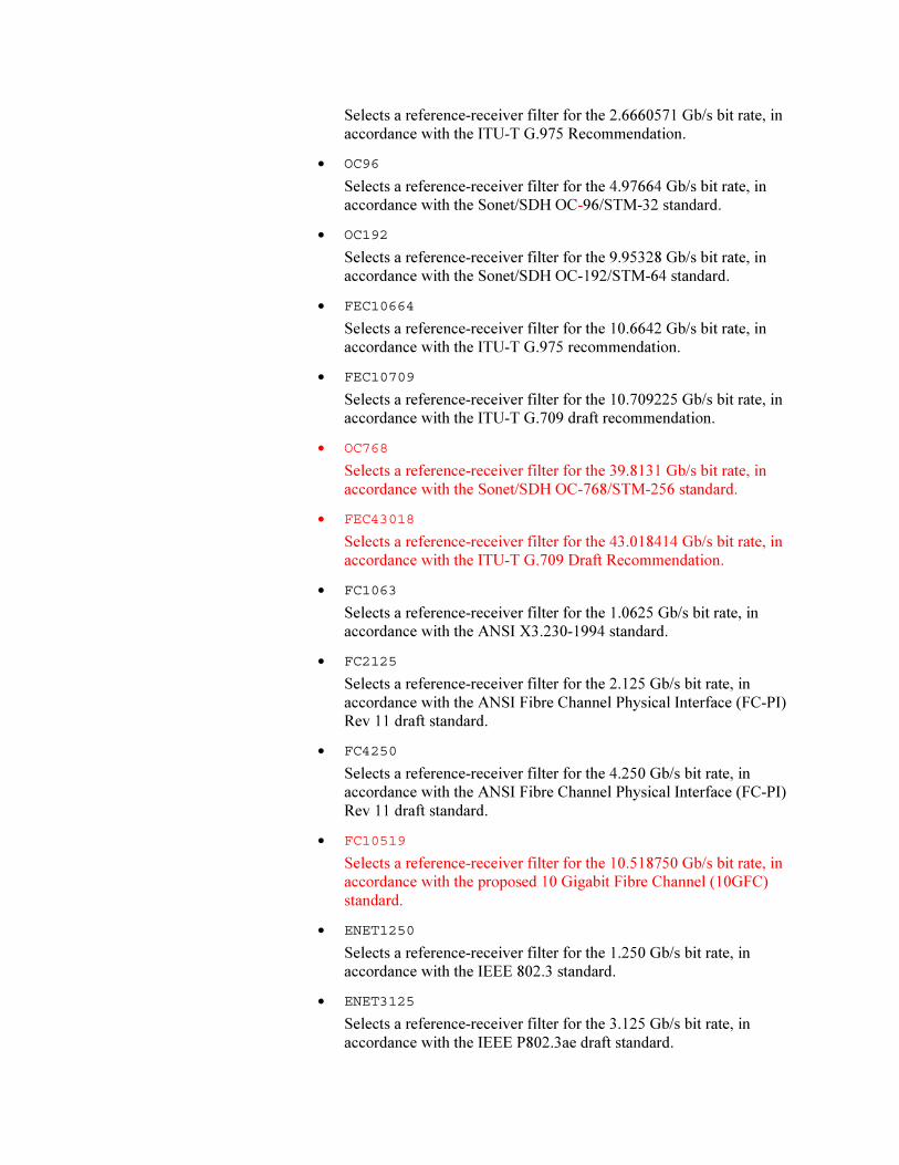
Selects a reference-receiver filter for the 2.6660571 Gb/s bit rate, in
accordance with the ITU-T G.975 Recommendation.
• OC96
Selects a reference-receiver filter for the 4.97664 Gb/s bit rate, in
accordance with the Sonet/SDH OC-96/STM-32 standard.
• OC192
Selects a reference-receiver filter for the 9.95328 Gb/s bit rate, in
accordance with the Sonet/SDH OC-192/STM-64 standard.
• FEC10664
Selects a reference-receiver filter for the 10.6642 Gb/s bit rate, in
accordance with the ITU-T G.975 recommendation.
• FEC10709
Selects a reference-receiver filter for the 10.709225 Gb/s bit rate, in
accordance with the ITU-T G.709 draft recommendation.
• OC768
Selects a reference-receiver filter for the 39.8131 Gb/s bit rate, in
accordance with the Sonet/SDH OC-768/STM-256 standard.
• FEC43018
Selects a reference-receiver filter for the 43.018414 Gb/s bit rate, in
accordance with the ITU-T G.709 Draft Recommendation.
• FC1063
Selects a reference-receiver filter for the 1.0625 Gb/s bit rate, in
accordance with the ANSI X3.230-1994 standard.
• FC2125
Selects a reference-receiver filter for the 2.125 Gb/s bit rate, in
accordance with the ANSI Fibre Channel Physical Interface (FC-PI)
Rev 11 draft standard.
• FC4250
Selects a reference-receiver filter for the 4.250 Gb/s bit rate, in
accordance with the ANSI Fibre Channel Physical Interface (FC-PI)
Rev 11 draft standard.
• FC10519
Selects a reference-receiver filter for the 10.518750 Gb/s bit rate, in
accordance with the proposed 10 Gigabit Fibre Channel (10GFC)
standard.
• ENET1250
Selects a reference-receiver filter for the 1.250 Gb/s bit rate, in
accordance with the IEEE 802.3 standard.
• ENET3125
Selects a reference-receiver filter for the 3.125 Gb/s bit rate, in
accordance with the IEEE P802.3ae draft standard.
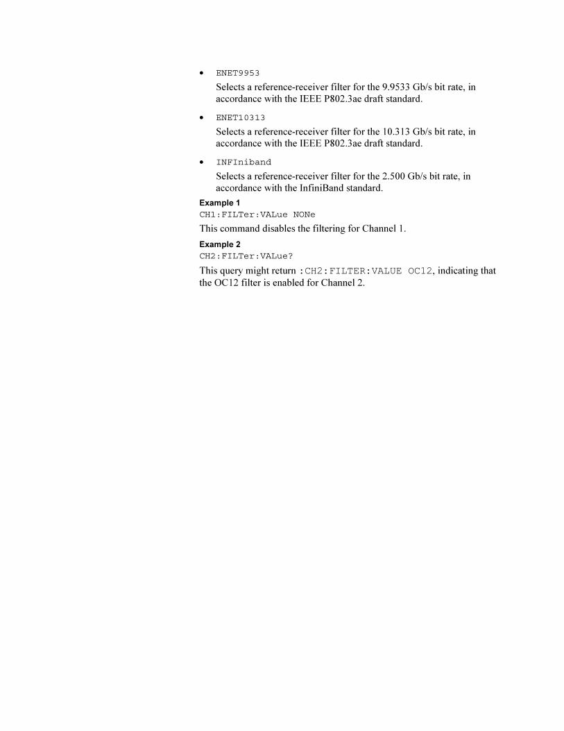
• ENET9953
Selects a reference-receiver filter for the 9.9533 Gb/s bit rate, in
accordance with the IEEE P802.3ae draft standard.
• ENET10313
Selects a reference-receiver filter for the 10.313 Gb/s bit rate, in
accordance with the IEEE P802.3ae draft standard.
• INFIniband
Selects a reference-receiver filter for the 2.500 Gb/s bit rate, in
accordance with the InfiniBand standard.
Example 1
CH1:FILTer:VALue NONe
This command disables the filtering for Channel 1.
Example 2
CH2:FILTer:VALue?
This query might return :CH2:FILTER:VALUE OC12, indicating that
the OC12 filter is enabled for Channel 2.