Embed Size (px)
Citation preview
CSCI2510 Computer Organization
Lecture 11: Pipelining
Ming-Chang YANG
Reading: Chap. 8 (5th Ed.)
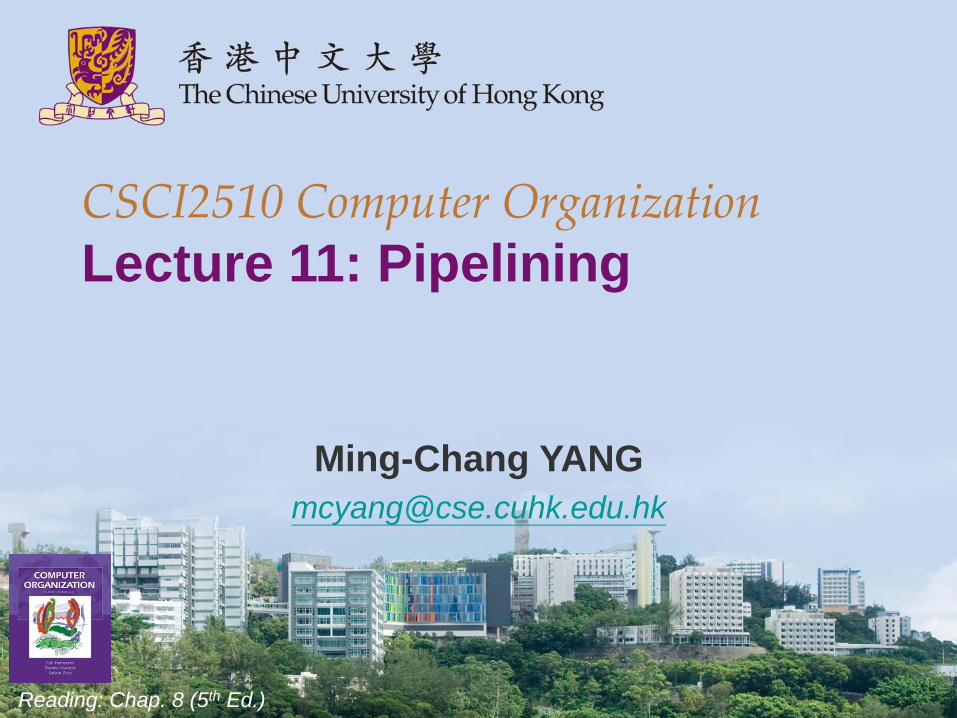
Why We Need Pipelining?
• Real-life example:
Four loads of
laundry that need
to be washed,
dried, and folded.
– Washing: 30 min
– Drying: 40 min
– Folding: 20 min
• Without pipeline:
– 360 min in total
• With pipeline:
– 210 min in total!
CSCI2510 Lec11: Pipelining 2
https://cs.stanford.edu/people/eroberts/courses/soco/projects/risc/pipelining/index.html

Outline
• Sequential Execution vs Pipelining
• Pipeline Stall: Hazard
– Data Hazard
– Instruction Hazard
– Structural Hazard
• Superscalar Operation
CSCI2510 Lec11: Pipelining 3
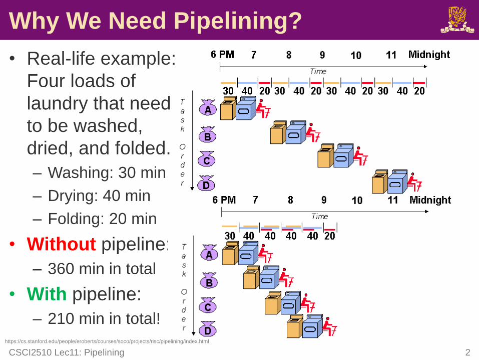
Sequential Execution
• The processor fetches and executes instructions, one
after the other.
– Fi: Fetch steps for instruction Ii
– Ei: Execute steps for instruction Ii
• Execution of a program consists of a sequential
sequence of fetch and execute steps:
• How to improve the speed of execution?
– Use faster technologies to build CPU and memory ($$$).
– Arrange hardware to do multiple operations at a time ($).
CSCI2510 Lec11: Pipelining 4
F1 E1 F2 E2 F3 E3
I1 I2 I3
Time
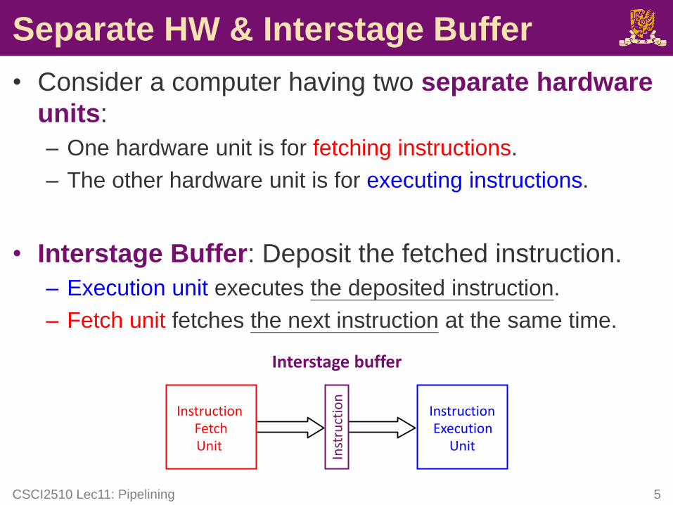
Separate HW & Interstage Buffer
• Consider a computer having two separate hardware
units:
– One hardware unit is for fetching instructions.
– The other hardware unit is for executing instructions.
• Interstage Buffer: Deposit the fetched instruction.
– Execution unit executes the deposited instruction.
– Fetch unit fetches the next instruction at the same time.
CSCI2510 Lec11: Pipelining 5
InstructionFetchUnit
ExecutionUnit
Interstage buffer
Instruction
Inst
ruct
ion
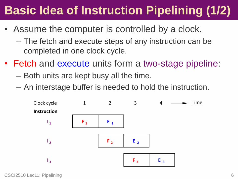
• Assume the computer is controlled by a clock.
– The fetch and execute steps of any instruction can be
completed in one clock cycle.
• Fetch and execute units form a two-stage pipeline:
– Both units are kept busy all the time.
– An interstage buffer is needed to hold the instruction.
CSCI2510 Lec11: Pipelining 6
Basic Idea of Instruction Pipelining (1/2)
F 1 E 1
F 2 E 2
F 3 E 3
I 1
I 2
I 3
Instruction
Clock cycle 1 2 3 4 Time
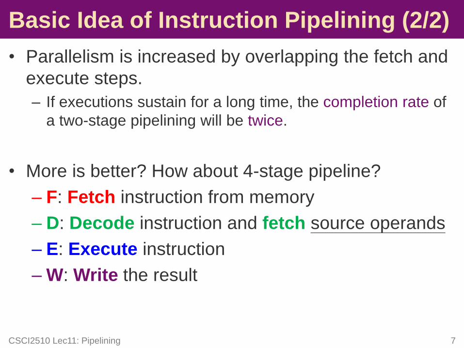
• Parallelism is increased by overlapping the fetch and
execute steps.
– If executions sustain for a long time, the completion rate of
a two-stage pipelining will be twice.
• More is better? How about 4-stage pipeline?
– F: Fetch instruction from memory
– D: Decode instruction and fetch source operands
– E: Execute instruction
– W: Write the result
CSCI2510 Lec11: Pipelining 7
Basic Idea of Instruction Pipelining (2/2)
FFetch
instruction
DDecode
instruction
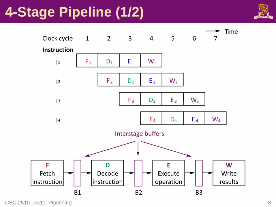
4-Stage Pipeline (1/2)
CSCI2510 Lec11: Pipelining 8
F 4I4
F 1
F 2
F 3
I1
I2
I3
D1
D2
D3
D4
E 1
E 2
E 3
E 4
W1
W2
W3
W4
Instruction
Clock cycle 1 2 3 4 5 6 7
EExecute
operation
WWriteresults
Interstage buffers
B1 B2 B3
Time
4-Stage Pipeline (2/2)
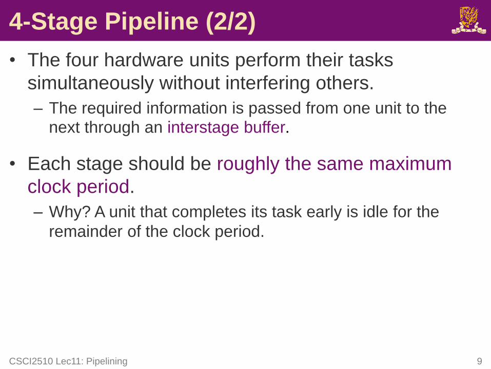
• The four hardware units perform their tasks
simultaneously without interfering others.
– The required information is passed from one unit to the next through an interstage buffer.
• Each stage should be roughly the same maximum
clock period.
– Why? A unit that completes its task early is idle for the
remainder of the clock period.
CSCI2510 Lec11: Pipelining 9
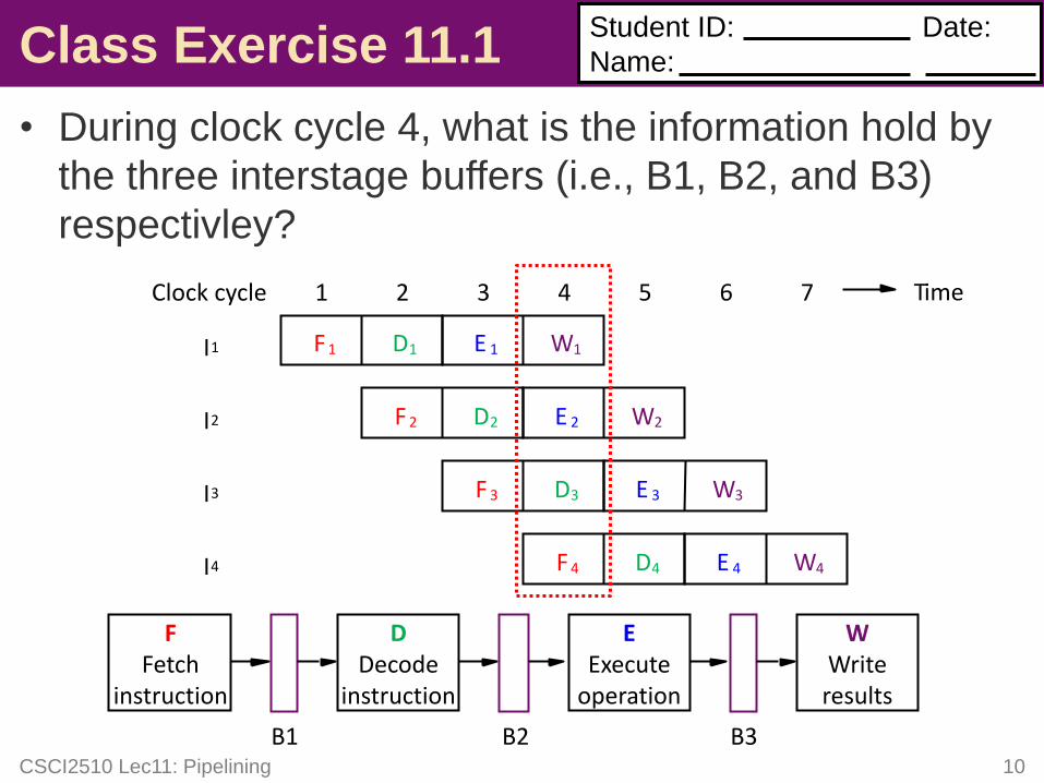
Class Exercise 11.1
• During clock cycle 4, what is the information hold by
the three interstage buffers (i.e., B1, B2, and B3)
respectivley?
CSCI2510 Lec11: Pipelining 10
Student ID:
Name:
Date:
FFetch
instruction
DDecode
instruction
F 4I4
F 1
F 2
F 3
I1
I2
I3
D1
D2
D3
D4
E 1
E 2
E 3
E 4
W1
W2
W3
W4
Clock cycle 1 2 3 4 5 6 7
EExecute
operation
WWriteresults
B1 B2 B3
Time
Outline
• Sequential Execution vs Pipelining
• Pipeline Stall: Hazard
– Data Hazard
– Instruction Hazard
– Structural Hazard
• Superscalar Operation
CSCI2510 Lec11: Pipelining 12
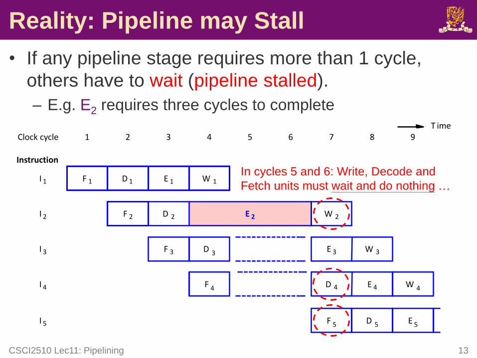
Reality: Pipeline may Stall
• If any pipeline stage requires more than 1 cycle,
others have to wait (pipeline stalled).
– E.g. E2 requires three cycles to complete
CSCI2510 Lec11: Pipelining 13
F 1
F 2
F 3
I 1
I 2
I 3
E 1
E 2
E 3
D 1
D 2
D 3
W 1
W 2
W 3
Instruction
F 4 D 4I 4
Clock cycle 1 2 3 4 5 6 7 8 9
E 4
F 5I 5 D 5
T ime
E 5
W 4
In cycles 5 and 6: Write, Decode and
Fetch units must wait and do nothing …
Stall & Hazard
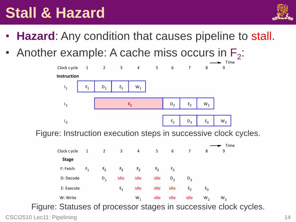
• Hazard: Any condition that causes pipeline to stall.
• Another example: A cache miss occurs in F2:
Figure: Instruction execution steps in successive clock cycles.
Figure: Statuses of processor stages in successive clock cycles.
CSCI2510 Lec11: Pipelining 14
F1
F2
F3
I1
I2
I3
D1
D2
D3
E1
E2
E3
W1
W2
W3
Instruction
1 2 3 4 5 6 7 8 9Clock c ycleTime
1 2 3 4 5 6 7 8Clock c ycle
Stage
F: Fetch
D: Decode
E: Execute
W: Write
F1 F2 F3
D1 D2 D3idle idle idle
E1 E2 E3idle idle idle
W1 W2idle idle idle
9
W3
F2 F2 F2
Time
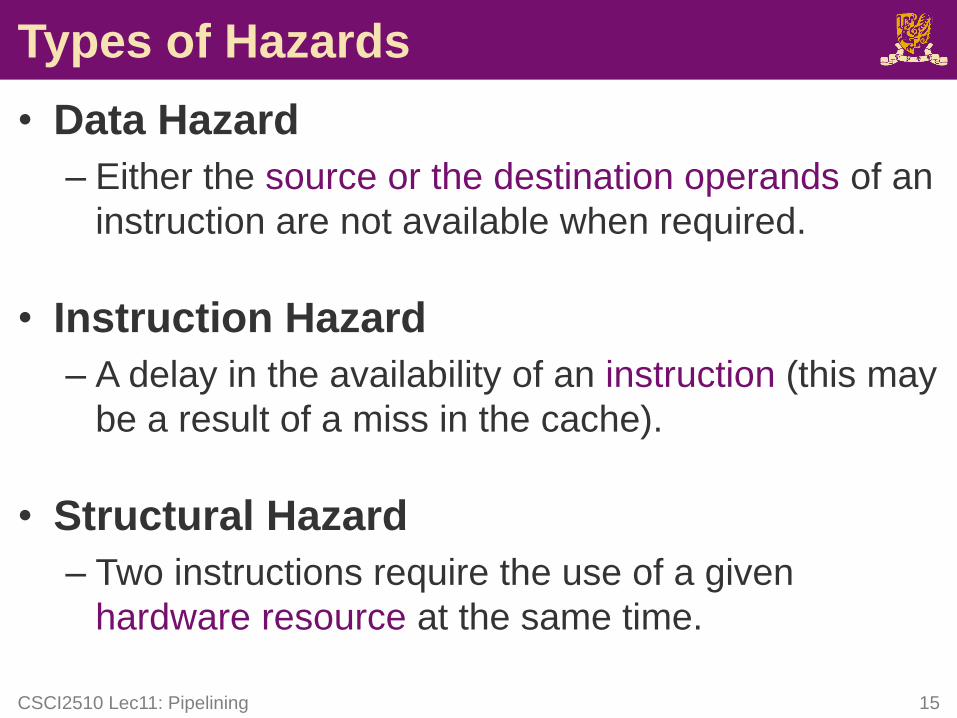
Types of Hazards
• Data Hazard
– Either the source or the destination operands of an
instruction are not available when required.
• Instruction Hazard
– A delay in the availability of an instruction (this may
be a result of a miss in the cache).
• Structural Hazard
– Two instructions require the use of a given
hardware resource at the same time.
CSCI2510 Lec11: Pipelining 15
Outline
• Sequential Execution vs Pipelining
• Pipeline Stall: Hazard
– Data Hazard
– Instruction Hazard
– Structural Hazard
• Superscalar Operation
CSCI2510 Lec11: Pipelining 16
Data Hazard
CSCI2510 Lec11: Pipelining 17
I1 (Mul)
I2 (Add)
I3
Instruction
1 2 3 4 5 6 7 8 9Clock c ycle
I4
F 1
F 2
F 3
D 1
D 3
E 1
E 3
E2
W3
W1
D2-A W2
F 4 D4 E 4 W 4
D 2
Time
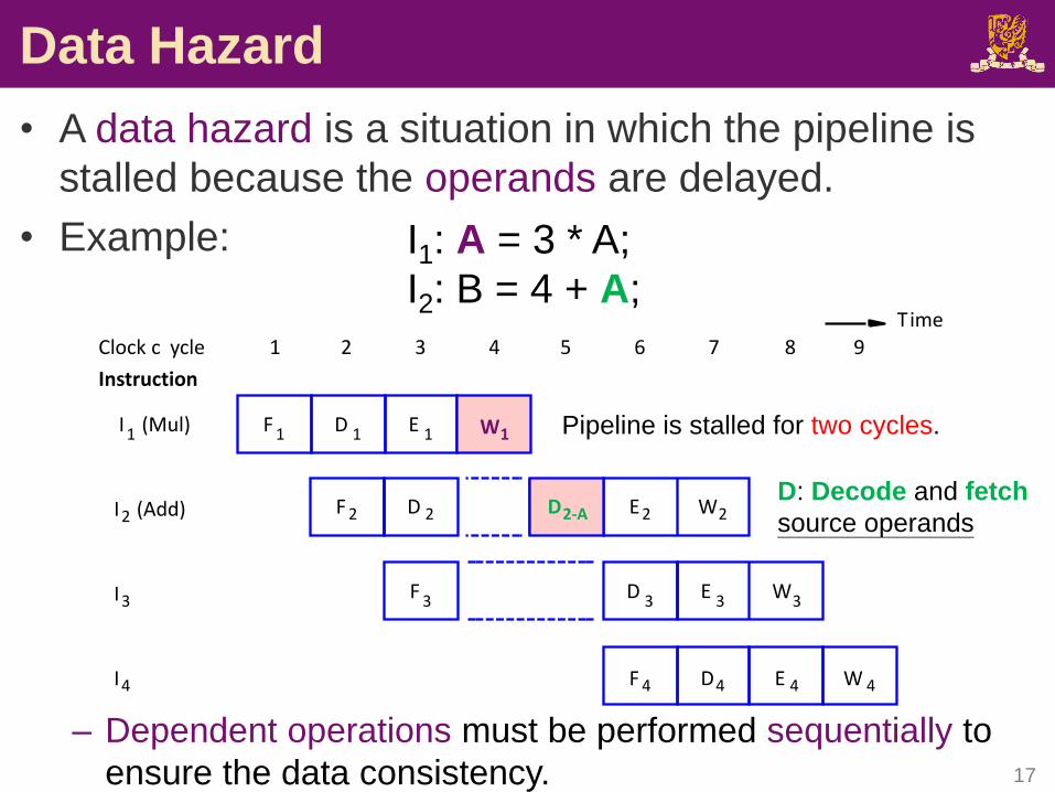
Pipeline is stalled for two cycles.
I1: A = 3 * A;
I2: B = 4 + A;
D: Decode and fetch
source operands
• A data hazard is a situation in which the pipeline is
stalled because the operands are delayed.
• Example:
– Dependent operations must be performed sequentially to
ensure the data consistency.

Class Exercise 11.2
• Please specify whether we will encounter data
hazards for the following instructions.
CSCI2510 Lec11: Pipelining 18
I1: A = 5 * C;
I2: B = 20 + C;
I1: C = A * B;
I2: E = C + D;
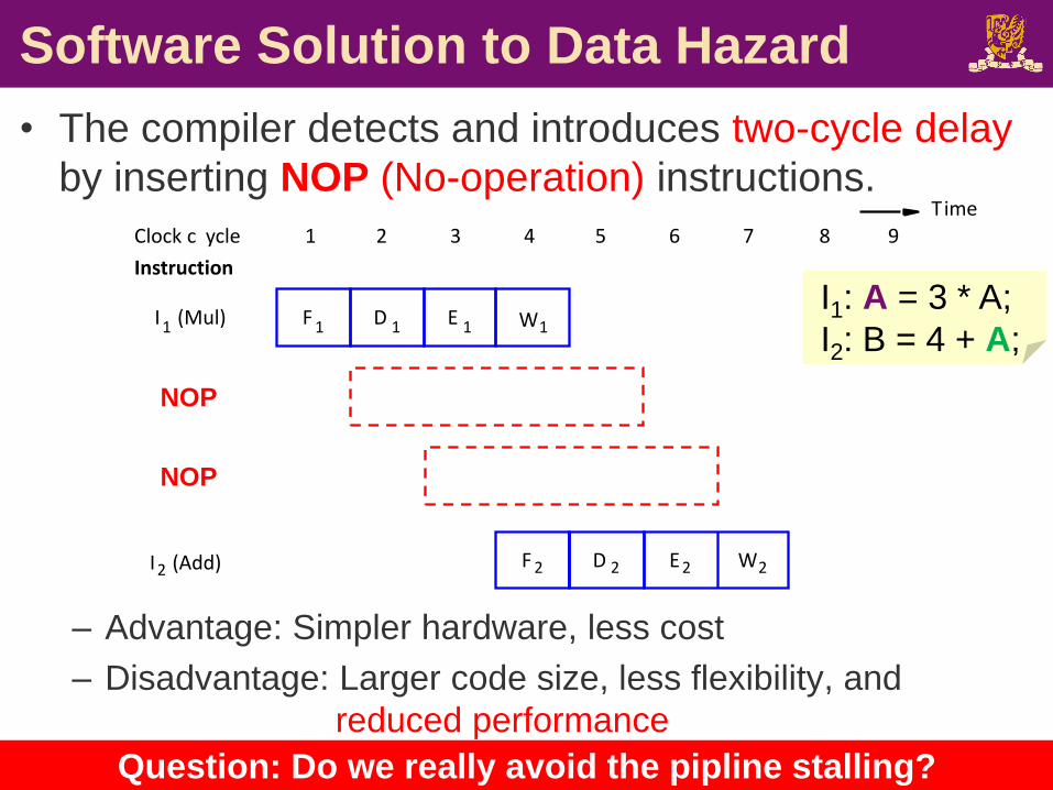
Software Solution to Data Hazard
• The compiler detects and introduces two-cycle delay
by inserting NOP (No-operation) instructions.
– Advantage: Simpler hardware, less cost
– Disadvantage: Larger code size, less flexibility, and
reduced performance
CSCI2510 Lec11: Pipelining 20
F 1
F 2
I1 (Mul)
I2 (Add)
D 1 E 1
E2
Instruction
1 2 3 4 5 6 7 8 9Clock c ycle
W1
W2D 2
Time
NOP
NOP
I1: A = 3 * A;
I2: B = 4 + A;
Question: Do we really avoid the pipline stalling?
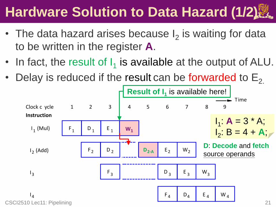
Hardware Solution to Data Hazard (1/2)
• The data hazard arises because I2 is waiting for data
to be written in the register A.
• In fact, the result of I1 is available at the output of ALU.
• Delay is reduced if the result can be forwarded to E2.
CSCI2510 Lec11: Pipelining 21
F 1
F 2
F 3
I1 (Mul)
I2 (Add)
I3
D 1
D 3
E 1
E 3
E2
W3
Instruction
1 2 3 4 5 6 7 8 9Clock c ycle
W1
D2-A W2
F 4 D4 E 4 W 4I4
D 2
Time
D: Decode and fetch
source operands
I1: A = 3 * A;
I2: B = 4 + A;
Result of I1 is available here!
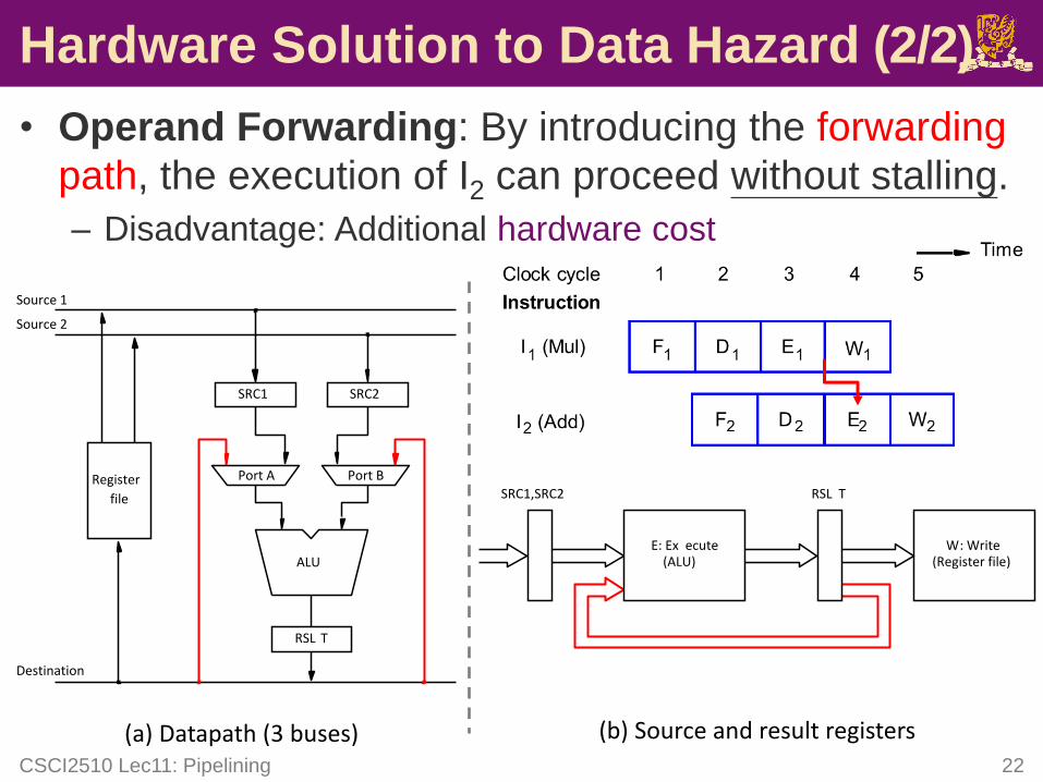
Hardware Solution to Data Hazard (2/2)
• Operand Forwarding: By introducing the forwarding
path, the execution of I2 can proceed without stalling.
– Disadvantage: Additional hardware cost
CSCI2510 Lec11: Pipelining 22
E: Ex ecute(ALU)
W: Write(Register file)
SRC1,SRC2 RSL T
(b) Source and result registers
Register
file
SRC1 SRC2
RSL T
Destination
Source 1
Source 2
(a) Datapath (3 buses)
ALU
Port A Port B
Outline
• Sequential Execution vs Pipelining
• Pipeline Stall: Hazard
– Data Hazard
– Instruction Hazard
– Structural Hazard
• Superscalar Operation
CSCI2510 Lec11: Pipelining 23
Instruction Hazard
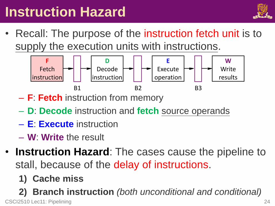
• Recall: The purpose of the instruction fetch unit is to
supply the execution units with instructions.
– F: Fetch instruction from memory
– D: Decode instruction and fetch source operands
– E: Execute instruction
– W: Write the result
• Instruction Hazard: The cases cause the pipeline to
stall, because of the delay of instructions.
1) Cache miss
2) Branch instruction (both unconditional and conditional)CSCI2510 Lec11: Pipelining 24
FFetch
instruction
DDecode
instruction
EExecute
operation
WWriteresults
B1 B2 B3
Instruction Hazard: Cache Miss
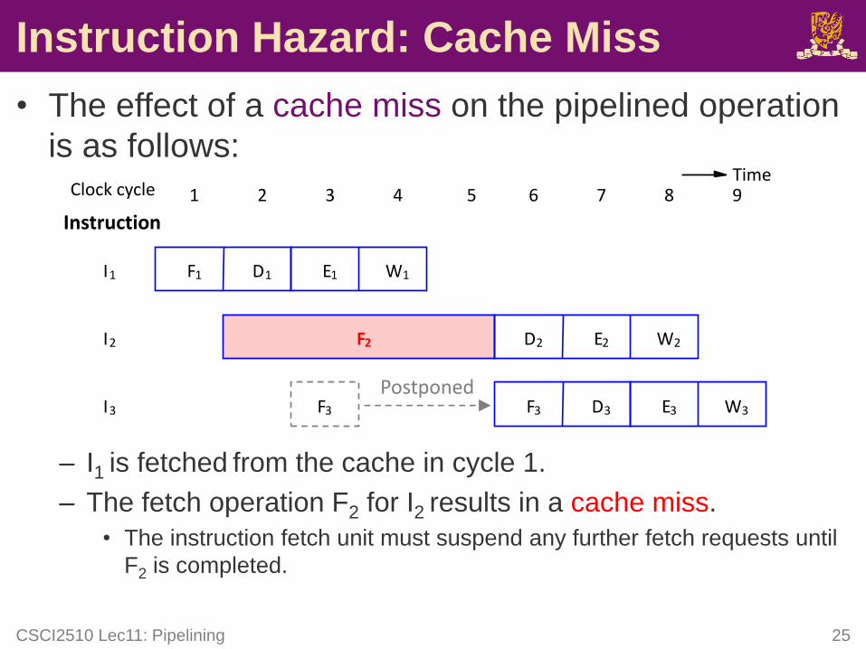
• The effect of a cache miss on the pipelined operation
is as follows:
– I1 is fetched from the cache in cycle 1.
– The fetch operation F2 for I2 results in a cache miss.
• The instruction fetch unit must suspend any further fetch requests until
F2 is completed.
CSCI2510 Lec11: Pipelining 25
F1
F2
I1
I2
I3
D1
D2
E1
E2
W1
W2
F3 D3 E3 W3
Instruction
1 2 3 4 5 6 7 8 9Clock cycleTime
F3
Postponed
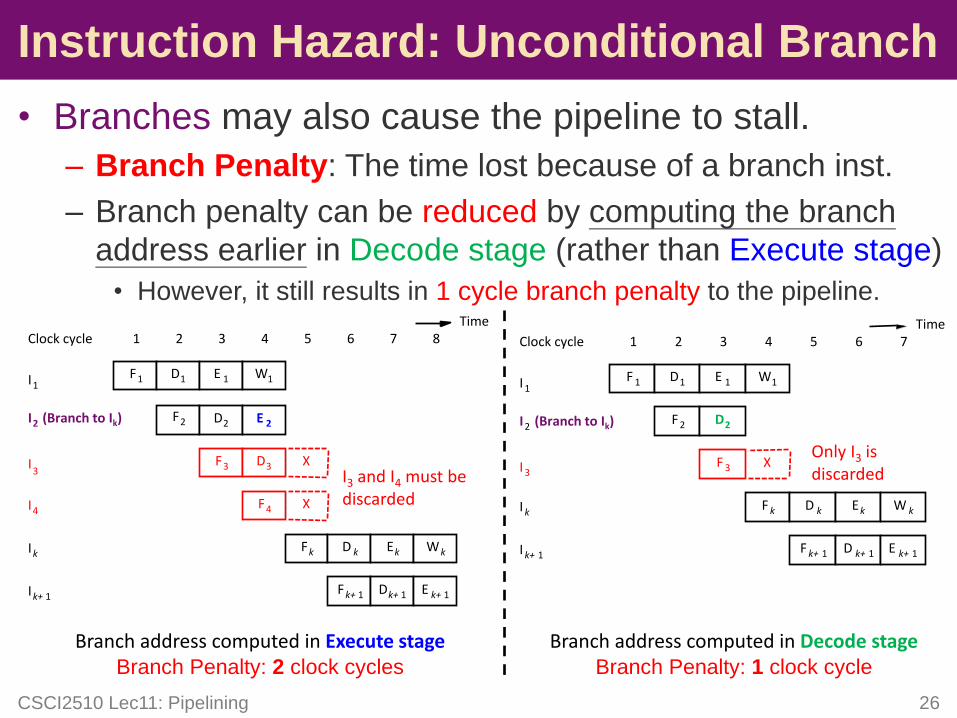
• Branches may also cause the pipeline to stall.
– Branch Penalty: The time lost because of a branch inst.
– Branch penalty can be reduced by computing the branch
address earlier in Decode stage (rather than Execute stage)
• However, it still results in 1 cycle branch penalty to the pipeline.
CSCI2510 Lec11: Pipelining 26
F1 D1 E 1 W1
I2 (Branch to Ik)
I1
1 2 3 4 5 6 7Clock cycle
F2 D2
Branch address computed in Execute stageBranch Penalty: 2 clock cycles
E 2
8Time
F 1 D1 E 1 W1
I2 (Branch to Ik)
I 1
1 2 3 4 5 6 7Clock cycle
F 2 D2
Branch address computed in Decode stageBranch Penalty: 1 clock cycle
Time
Fk D k Ek
Fk+ 1 Dk+ 1
Ik
Ik+ 1
Wk
E k+ 1
XF3I3
D3
F4 XI4
I3 and I4 must be discarded
F 3 X
F k D k Ek
F k+ 1 D k+ 1
I 3
I k
I k+ 1
W k
E k+ 1
Only I3 is discarded
Instruction Hazard: Unconditional Branch
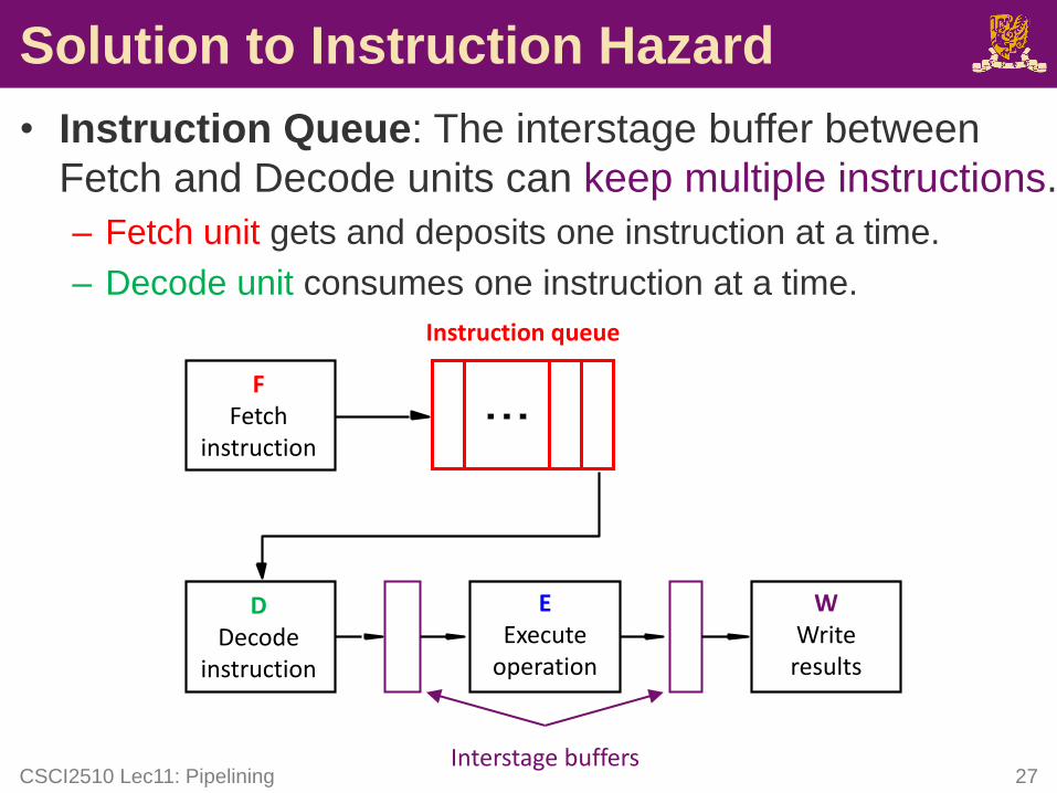
Solution to Instruction Hazard
• Instruction Queue: The interstage buffer between
Fetch and Decode units can keep multiple instructions.
– Fetch unit gets and deposits one instruction at a time.
– Decode unit consumes one instruction at a time.
CSCI2510 Lec11: Pipelining 27
Instruction queue
EExecute
operation
WWriteresults
DDecode
instruction
FFetch
instruction
Interstage buffers
F4
W3E 3
F2 D2 E 2 W2
F3 D3
E 4D4 W4F4
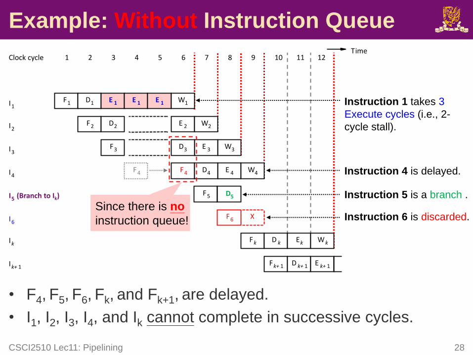
• F4, F5, F6, Fk, and Fk+1, are delayed.
• I1, I2, I3, I4, and Ik cannot complete in successive cycles.
CSCI2510 Lec11: Pipelining 28
Example: Without Instruction Queue
F1 D1 E 1 E 1 E 1 W1
I5 (Branch to Ik)
I1
1 2 3 4 5 6 7 8 9Clock cycle
I2
I3
I4
I6
Ik
Ik+ 1
10Time
XF6
Fk D k Ek
Fk+ 1 D k+ 1
Wk
E k+ 1
11 12
Instruction 1 takes 3
Execute cycles (i.e., 2-
cycle stall).
Instruction 4 is delayed.
Instruction 5 is a branch .
Instruction 6 is discarded.
F5 D5
Since there is no
instruction queue!
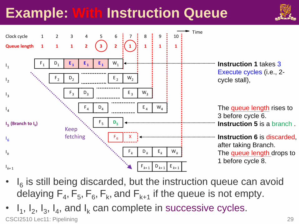
• I6 is still being discarded, but the instruction queue can avoid
delaying F4, F5, F6, Fk, and Fk+1 if the queue is not empty.
• I1, I2, I3, I4, and Ik can complete in successive cycles.CSCI2510 Lec11: Pipelining 29
Example: With Instruction Queue
F1 D1 E 1 E 1 E 1 W1
I5 (Branch to Ik)
I1
1 2 3 4 5 6 7 8 9Clock cycle
I2
I3
I4
I6
Ik
Ik+ 1
10
1Queue length 1 1 12 3 2 1 1 1
Time
X
F4
W3E 3
F2 D2 E 2 W2
F3 D3
E 4D4 W4
F5
F6
Fk D k Ek
Fk+ 1 D k+ 1
Wk
E k+ 1
Keep fetching
D5
Instruction 1 takes 3
Execute cycles (i.e., 2-
cycle stall),
The queue length rises to
3 before cycle 6.
Instruction 5 is a branch .
Instruction 6 is discarded,
after taking Branch.
The queue length drops to
1 before cycle 8.
Without vs With Instruction Queue
• With instruction queue, the branch instruction does
not increase the overall execution time (if the queue
is not empty).
– Since instructions can complete in successive clock cycles.
• Branch address is computed in parallel with other
instructions, so no cycles lost due to branch.
– This is called branch folding.
• Instruction queue is also possible to hide the effect of
cache miss (if the queue is not empty).
CSCI2510 Lec11: Pipelining 30
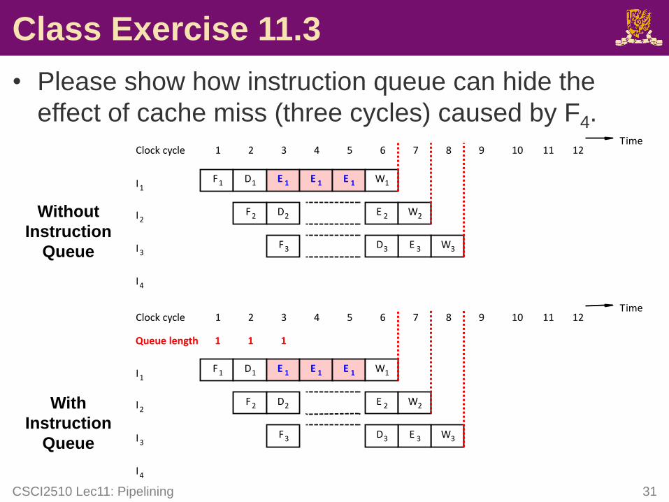
Class Exercise 11.3
• Please show how instruction queue can hide the
effect of cache miss (three cycles) caused by F4.
CSCI2510 Lec11: Pipelining 31
F1 D1 E 1 E 1 E 1 W1
W3E 3
I1
F2 D2
1 2 3 4 5 6 7 8 9Clock cycle
E 2 W2
F3 D3
I2
I3
I4
10Time
11 12
F1 D1 E 1 E 1 E 1 W1
W3E 3
I1
F2 D2 E 2 W2
F3 D3
I2
I3
I4
1 2 3 4 5 6 7 8 9Clock cycle 10Time
11 12
1 1 1Queue length
Without
Instruction
Queue
With
Instruction
Queue
All intermediate instructionsmust be discarded …
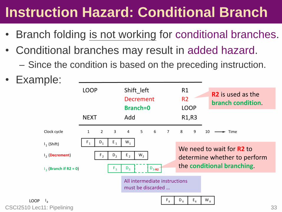
• Branch folding is not working for conditional branches.
• Conditional branches may result in added hazard.
– Since the condition is based on the preceding instruction.
• Example:
CSCI2510 Lec11: Pipelining 33
Instruction Hazard: Conditional Branch
Add
LOOP Shift_left R1
Decrement
Branch=0
R2
LOOP
NEXT R1,R3
R2 is used as the branch condition.
We need to wait for R2 to determine whether to perform the conditional branching.
F 1 D1 E 1 W1
I 2 (Decrement)
I 1
1 2 3 4 5 6 7Clock cycle
F3 D3I 3
Time
F 2 D2 E 2 W2
(Shift)
(Branch if R2 = 0) D3-R2
F k D k EkI k W k
8 9 10
LOOP
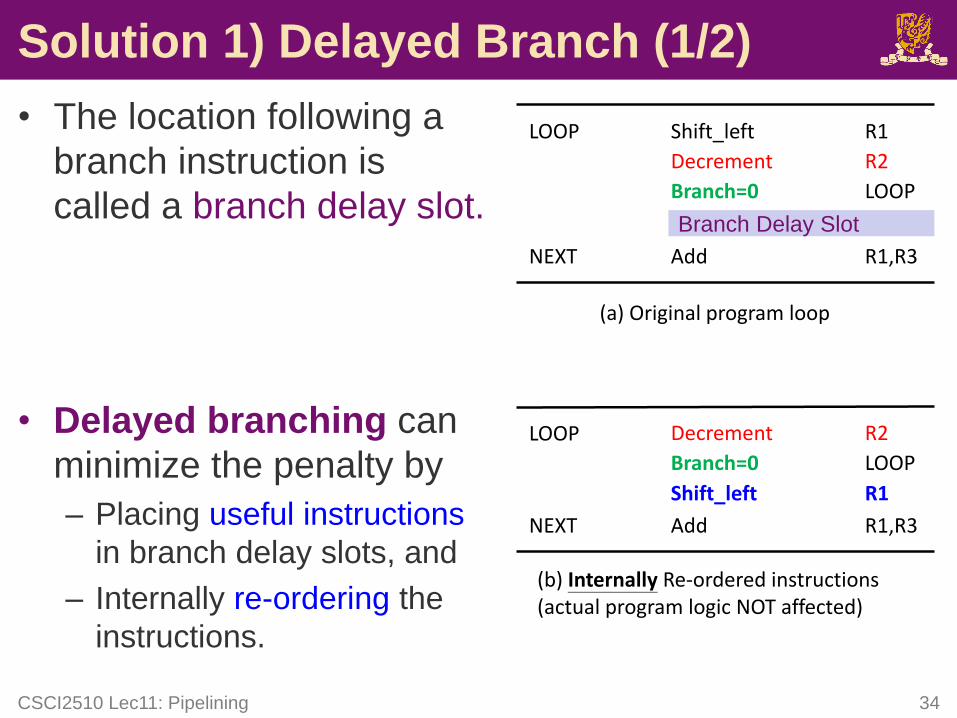
Solution 1) Delayed Branch (1/2)
• The location following a
branch instruction is
called a branch delay slot.
• Delayed branching can
minimize the penalty by
– Placing useful instructions
in branch delay slots, and
– Internally re-ordering the
instructions.
CSCI2510 Lec11: Pipelining 34
Add
LOOP Shift_left R1
Decrement
Branch=0
R2
LOOP
NEXT R1,R3
(a) Original program loop
Add
LOOP
Shift_left R1
Decrement
Branch=0
R2
LOOP
NEXT R1,R3
(b) Internally Re-ordered instructions(actual program logic NOT affected)
Branch Delay Slot
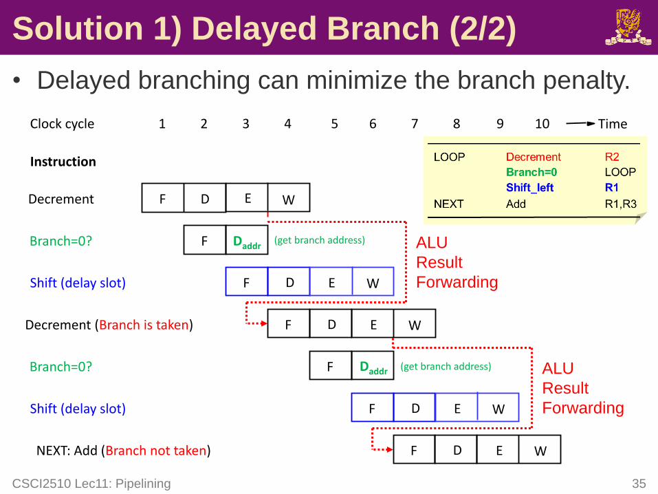
Solution 1) Delayed Branch (2/2)
• Delayed branching can minimize the branch penalty.
CSCI2510 Lec11: Pipelining 35
Instruction
1 2 3 4 5 6 7 8Clock cycle Time
F ENEXT: Add (Branch not taken) WD
9 10
ALU
Result
Forwarding
ALU
Result
Forwarding
F D
F Daddr
F E
Decrement
Branch=0?
Shift (delay slot)
E
W
W
D
(get branch address)
F E
F
F E
Decrement (Branch is taken)
Branch=0?
Shift (delay slot)
W
W
D
Daddr
D
(get branch address)
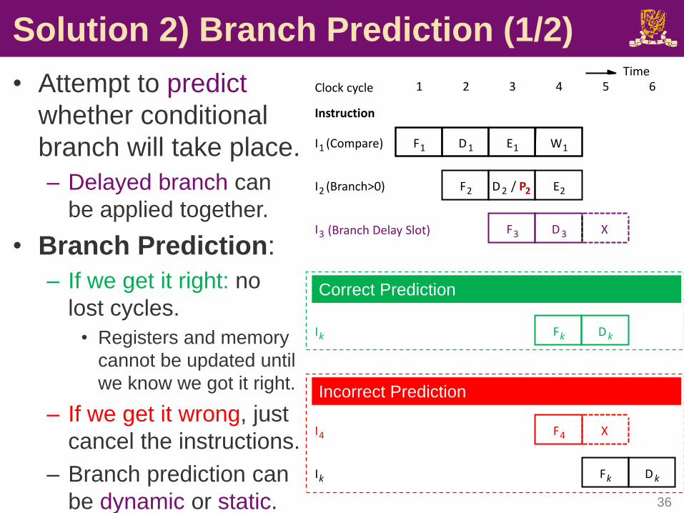
Solution 2) Branch Prediction (1/2)
CSCI2510 Lec11: Pipelining 36
F1
F2
I1 (Compare)
I2 (Branch>0)
D1 E1 W1
Instruction
E2
Clock cycle 1 2 3 4 5 6
D 2 / P2
Time
I3 F3 D 3 X(Branch Delay Slot)
F4
Fk D k
XI4
Ik
Incorrect Prediction
Fk D kIk
Correct Prediction
• Attempt to predict
whether conditional
branch will take place.
– Delayed branch can
be applied together.
• Branch Prediction:
– If we get it right: no
lost cycles.
• Registers and memory
cannot be updated until
we know we got it right.
– If we get it wrong, just
cancel the instructions.
– Branch prediction can
be dynamic or static.
Solution 2) Branch Prediction (2/2)
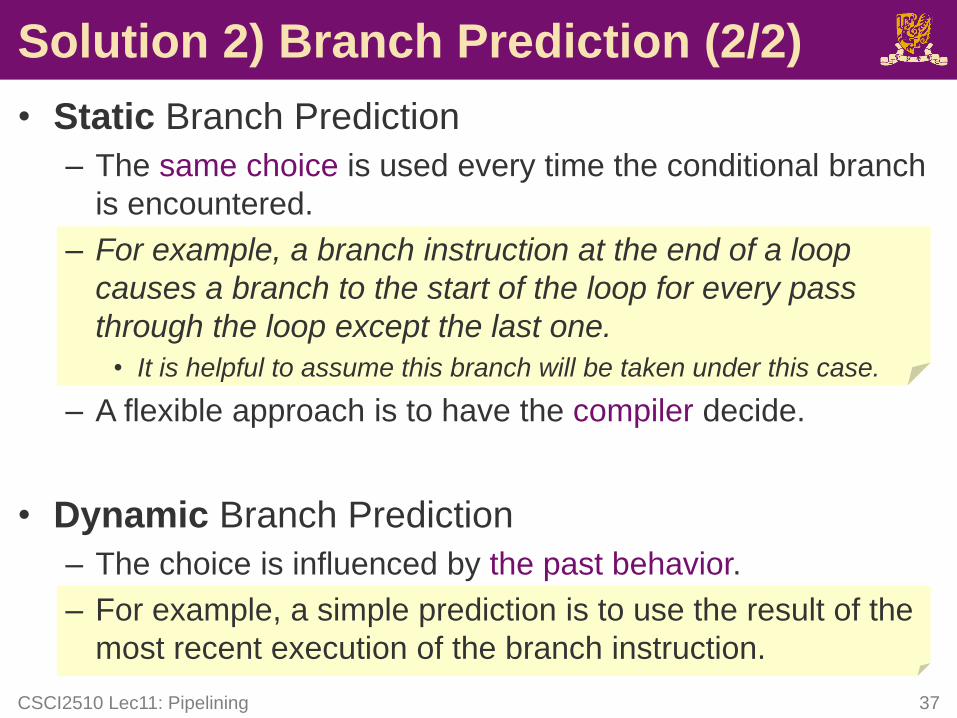
• Static Branch Prediction
– The same choice is used every time the conditional branch
is encountered.
– For example, a branch instruction at the end of a loop
causes a branch to the start of the loop for every pass
through the loop except the last one.
• It is helpful to assume this branch will be taken under this case.
– A flexible approach is to have the compiler decide.
• Dynamic Branch Prediction
– The choice is influenced by the past behavior.
– For example, a simple prediction is to use the result of the
most recent execution of the branch instruction.
CSCI2510 Lec11: Pipelining 37
Outline
• Sequential Execution vs Pipelining
• Pipeline Stall: Hazard
– Data Hazard
– Instruction Hazard
– Structural Hazard
• Superscalar Operation
CSCI2510 Lec11: Pipelining 38
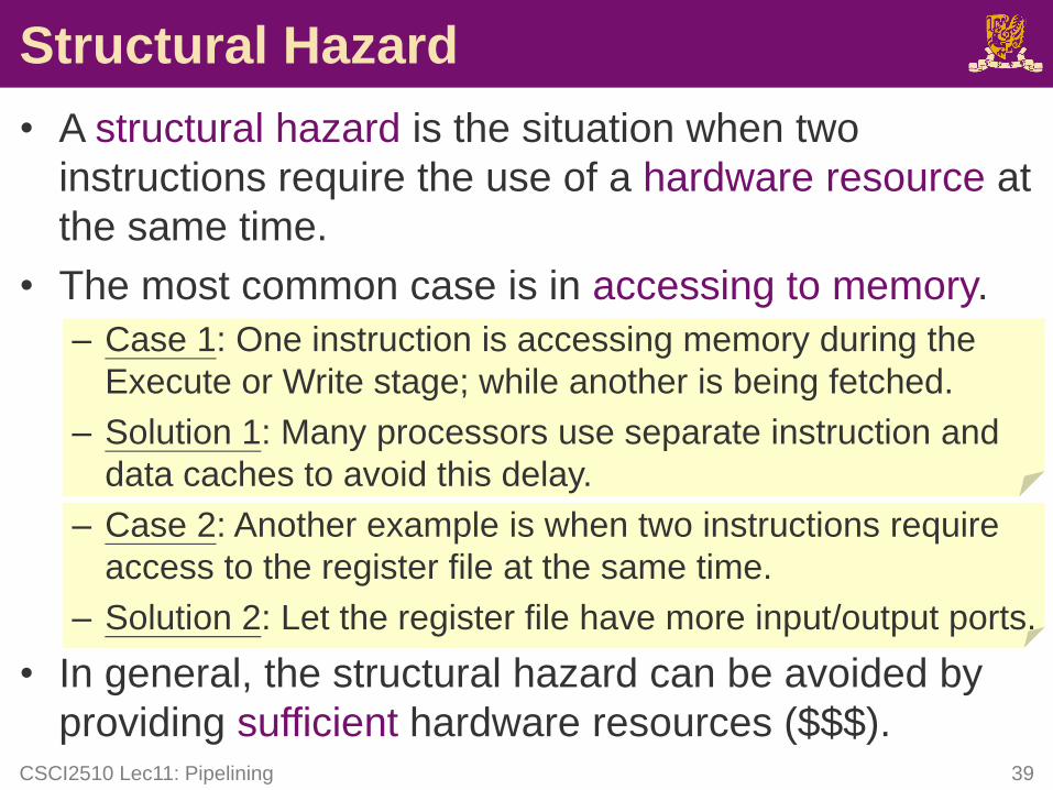
Structural Hazard
• A structural hazard is the situation when two
instructions require the use of a hardware resource at
the same time.
• The most common case is in accessing to memory.
– Case 1: One instruction is accessing memory during the
Execute or Write stage; while another is being fetched.
– Solution 1: Many processors use separate instruction and
data caches to avoid this delay.
– Case 2: Another example is when two instructions require
access to the register file at the same time.
– Solution 2: Let the register file have more input/output ports.
• In general, the structural hazard can be avoided by
providing sufficient hardware resources ($$$).CSCI2510 Lec11: Pipelining 39
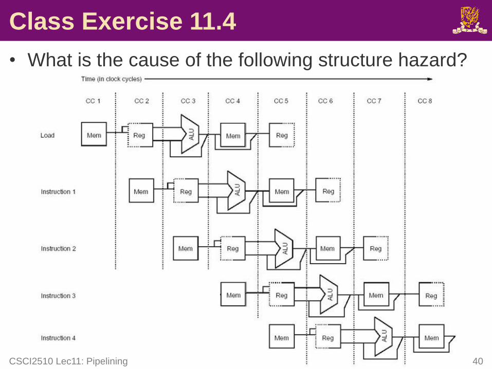
Class Exercise 11.4
• What is the cause of the following structure hazard?
CSCI2510 Lec11: Pipelining 40
Outline
• Sequential Execution vs Pipelining
• Pipeline Stall: Hazard
– Data Hazard
– Instruction Hazard
– Structural Hazard
• Superscalar Operation
CSCI2510 Lec11: Pipelining 42
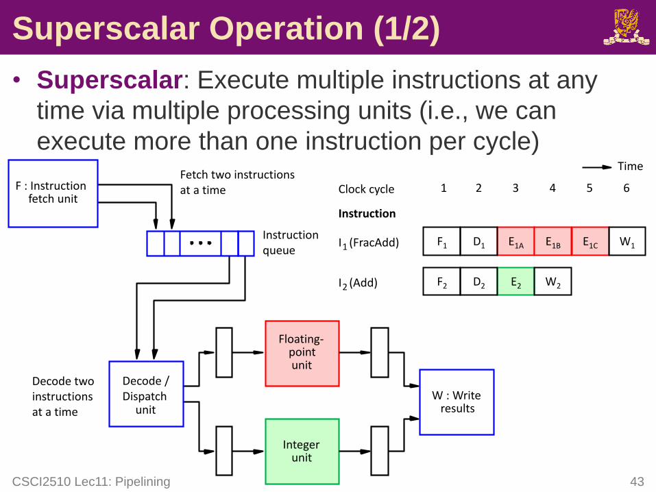
Superscalar Operation (1/2)
• Superscalar: Execute multiple instructions at any
time via multiple processing units (i.e., we can
execute more than one instruction per cycle)
CSCI2510 Lec11: Pipelining 43
W : Writeresults
Decode /Dispatch
unit
Instruction queue
Floating-pointunit
Integerunit
F : Instructionfetch unit
Fetch two instructionsat a time
Decode two instructionsat a time
I1 (FracAdd)
Instruction
Clock cycle 1 2 3 4 5 6
Time
F1 D1 E1A E1B E1C W1
I2 (Add) F2 D2 E2 W2
Superscalar Operation (2/2)
• Superscalar operation may result in out-of-order
execution, and cause data consistency issue.
– In our previous example, I1 and I2 are dispatched in the
same order as they appear.
– However, their execution is completed out of order.
– To guarantee a consistent state when out-of-order
execution occur, the results of the execution of instructions
must be written in program order strictly .
• The out-of-order execution is also a common
technique to make use of instruction cycles by re-
ordering instructions.
– E.g., Delayed branching reorders the instructions to
minimize the branch penalty.CSCI2510 Lec11: Pipelining 44
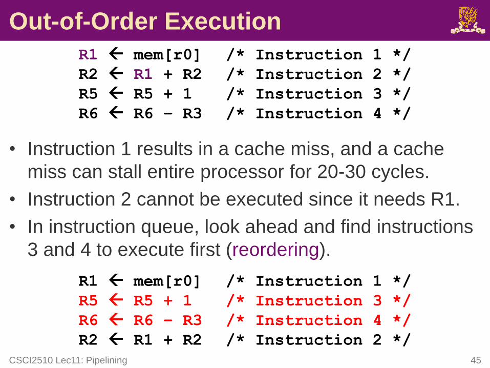
Out-of-Order Execution
R1 mem[r0] /* Instruction 1 */
R2 R1 + R2 /* Instruction 2 */
R5 R5 + 1 /* Instruction 3 */
R6 R6 – R3 /* Instruction 4 */
• Instruction 1 results in a cache miss, and a cache
miss can stall entire processor for 20-30 cycles.
• Instruction 2 cannot be executed since it needs R1.
• In instruction queue, look ahead and find instructions
3 and 4 to execute first (reordering).
R1 mem[r0] /* Instruction 1 */
R5 R5 + 1 /* Instruction 3 */
R6 R6 – R3 /* Instruction 4 */
R2 R1 + R2 /* Instruction 2 */
CSCI2510 Lec11: Pipelining 45
Summary
• Sequential Execution vs Pipelining
• Pipeline Stall: Hazard
– Data Hazard
– Instruction Hazard
– Structural Hazard
• Superscalar Operation
CSCI2510 Lec11: Pipelining 46