Embed Size (px)
Citation preview
40.00 113.30 113.30 113.30 30.00
Filters Air.
Turbochargers
Ø In:6 ¨Ø.out:11 ¨
2[X]
TOP VIEW
SIDE VIEW
18.34
12.49
(8X) holes Ø 1¨ 52.0
0 70.0
0
Ret
urn Inle
t
20.00
Generator
Box Connection
3.00 3.00
FRONT VIEW
210.00
RADIATOR:ENGINE:
# SPRING AVMS:
DESCRIPTION
AIR: FILTER BASE FRAME:
OV-25-4HQST30G1/G2/G3AH1135BP-QSTG3-STF
8 PZS
FO 023-0
MODELSCNE740CNE805
JAN 05th 2005
CUMMINS ENGINE QST30G1/G2/G3 - STAMFORD ALTERNATOR
Rev.
Customer:
DateDescription
ReviewsCertificated
Date:
Draw:
Title:
Revised:
Scale:
Code:
Dept.: Engineering
Of:
Marks: Draw:
Certificated:
S/O:
s/e
cms
R.G.C. CNE/Y-13F.H.M. F.H.M.
Ottomotores keeps the right to change the information with out prior notice
Date: Date: JAN 05th 2005 JAN 05th 2005
-THE GENSET DIMENSIONS ARE THE SAME BY FAMILY MODEL, THERE COULD BE ONLY DIFFERENCES ON THE ALTERNATORLENGHT SEE SPECIFIC GENERAL ARRAGEMENT DRAWING OF CERTEIN MODEL
-TOTAL WEIGHT COULD VARY CHECK RATING CHART FOR EACH MODEL
CNY750CNE850CNY800
CNE1040CNY900
G-DRIVE
QSK1
0
5
10
15
20
25
30
35
0 1000 2000 3000 4000 5000 6000
Altitude (meters)
% D
erat
e o
f R
ated
Po
wer
0
5
10
15
20
25
30
35
0 1000 2000 3000 4000 5000 6000
Altitude (meters)
% D
erat
e o
f R
ated
Po
wer
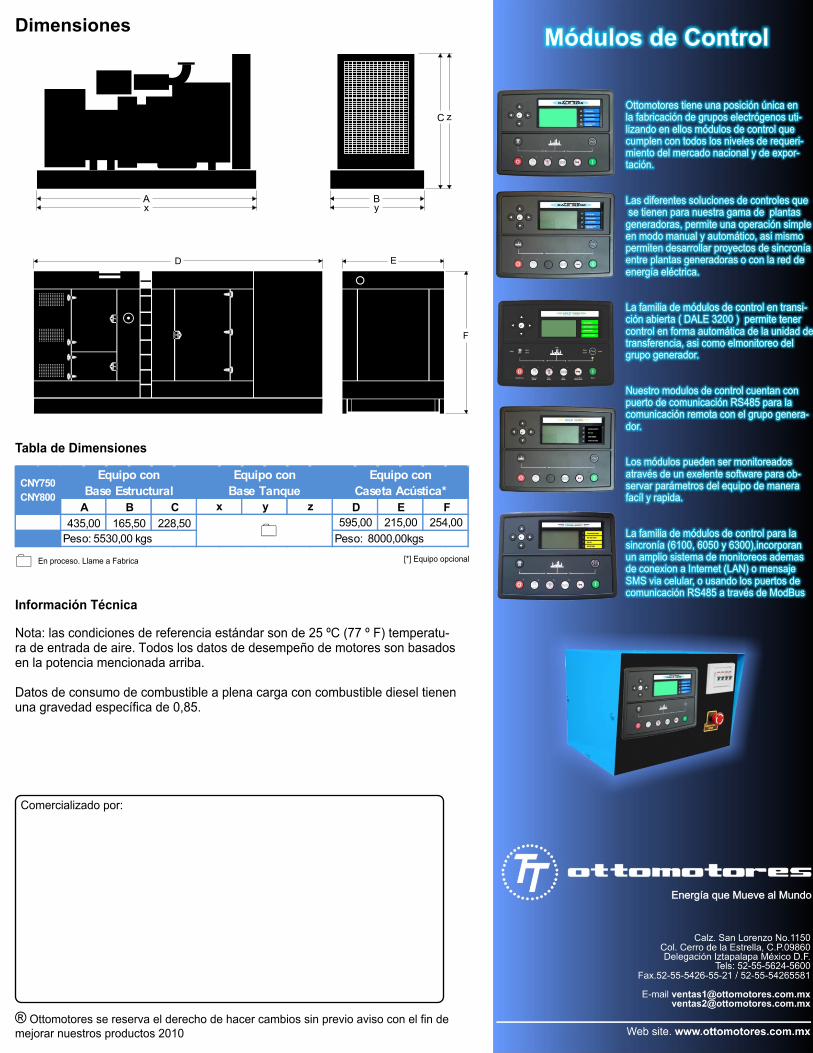
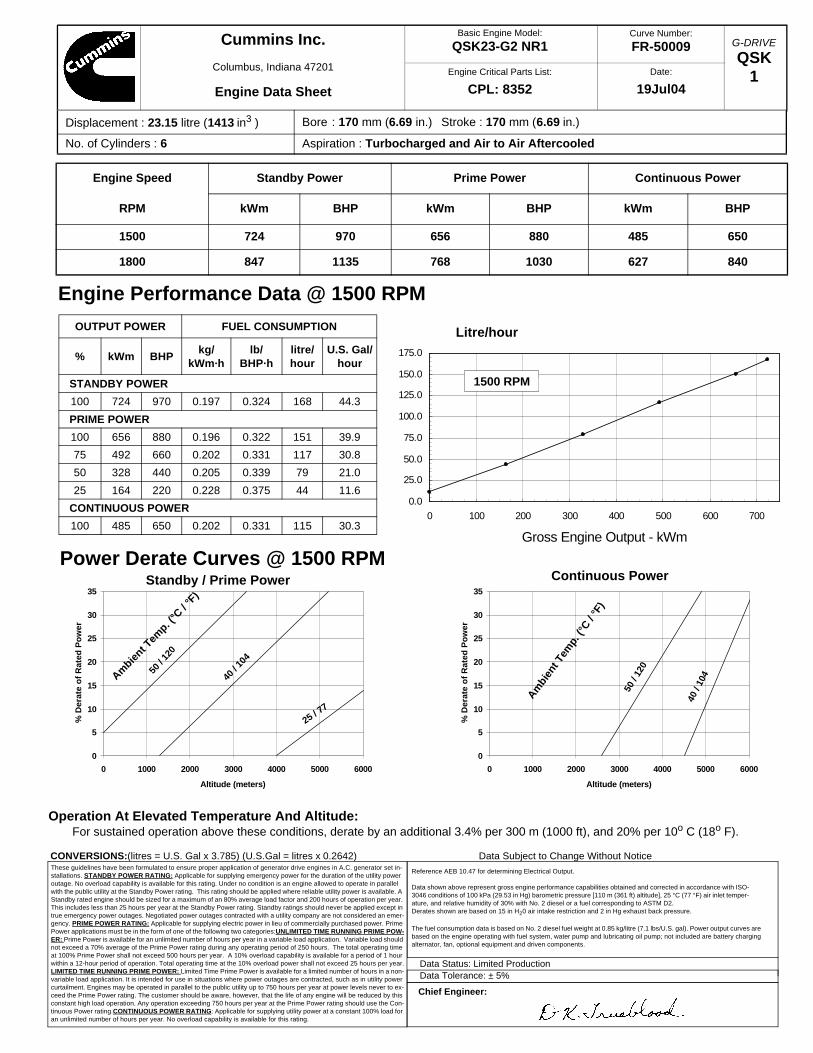
Engine Speed Standby Power Prime Power Continuous Power
RPM kWm BHP kWm BHP kWm BHP
1500 724 970 656 880 485 650
1800 847 1135 768 1030 627 840
OUTPUT POWER FUEL CONSUMPTION
% kWm BHPkg/
kWm·hlb/
BHP·hlitre/hour
U.S. Gal/hour
STANDBY POWER
100 724 970 0.197 0.324 168 44.3
PRIME POWER
100 656 880 0.196 0.322 151 39.9
75 492 660 0.202 0.331 117 30.8
50 328 440 0.205 0.339 79 21.0
25 164 220 0.228 0.375 44 11.6
CONTINUOUS POWER
100 485 650 0.202 0.331 115 30.3
0.0
25.0
50.0
75.0
100.0
125.0
150.0
175.0
0 100 200 300 400 500 600 700
Gross Engine Output - kWm
1500 RPM
Litre/hour
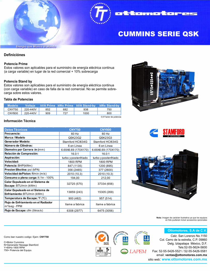
These guidelines have been formulated to ensure proper application of generator drive engines in A.C. generator set in-stallations. STANDBY POWER RATING: Applicable for supplying emergency power for the duration of the utility power outage. No overload capability is available for this rating. Under no condition is an engine allowed to operate in parallel with the public utility at the Standby Power rating. This rating should be applied where reliable utility power is available. A Standby rated engine should be sized for a maximum of an 80% average load factor and 200 hours of operation per year. This includes less than 25 hours per year at the Standby Power rating. Standby ratings should never be applied except in true emergency power outages. Negotiated power outages contracted with a utility company are not considered an emer-gency. PRIME POWER RATING: Applicable for supplying electric power in lieu of commercially purchased power. Prime Power applications must be in the form of one of the following two categories:UNLIMITED TIME RUNNING PRIME POW-ER: Prime Power is available for an unlimited number of hours per year in a variable load application. Variable load should not exceed a 70% average of the Prime Power rating during any operating period of 250 hours. The total operating time at 100% Prime Power shall not exceed 500 hours per year. A 10% overload capability is available for a period of 1 hour within a 12-hour period of operation. Total operating time at the 10% overload power shall not exceed 25 hours per year.LIMITED TIME RUNNING PRIME POWER: Limited Time Prime Power is available for a limited number of hours in a non-variable load application. It is intended for use in situations where power outages are contracted, such as in utility power curtailment. Engines may be operated in parallel to the public utility up to 750 hours per year at power levels never to ex-ceed the Prime Power rating. The customer should be aware, however, that the life of any engine will be reduced by this constant high load operation. Any operation exceeding 750 hours per year at the Prime Power rating should use the Con-tinuous Power rating.CONTINUOUS POWER RATING: Applicable for supplying utility power at a constant 100% load for an unlimited number of hours per year. No overload capability is available for this rating.
Reference AEB 10.47 for determining Electrical Output.
Data shown above represent gross engine performance capabilities obtained and corrected in accordance with ISO-3046 conditions of 100 kPa (29.53 in Hg) barometric pressure [110 m (361 ft) altitude], 25 °C (77 °F) air inlet temper-ature, and relative humidity of 30% with No. 2 diesel or a fuel corresponding to ASTM D2. Derates shown are based on 15 in H20 air intake restriction and 2 in Hg exhaust back pressure.
The fuel consumption data is based on No. 2 diesel fuel weight at 0.85 kg/litre (7.1 lbs/U.S. gal). Power output curves arebased on the engine operating with fuel system, water pump and lubricating oil pump; not included are battery chargingalternator, fan, optional equipment and driven components.
Data Status: Limited ProductionData Tolerance: ± 5%
Chief Engineer:
CONVERSIONS:(litres = U.S. Gal x 3.785) (U.S.Gal = litres x 0.2642) Data Subject to Change Without Notice
Power Derate Curves @ 1500 RPM Standby / Prime Power
Operation At Elevated Temperature And Altitude:For sustained operation above these conditions, derate by an additional 3.4% per 300 m (1000 ft), and 20% per 10o C (18o F).
Engine Performance Data @ 1500 RPM
Continuous Power
Displacement : 23.15 litre (1413 in3 ) Bore : 170 mm (6.69 in.) Stroke : 170 mm (6.69 in.)
No. of Cylinders : 6 Aspiration : Turbocharged and Air to Air Aftercooled
Cummins Inc.
Columbus, Indiana 47201
Engine Data Sheet
Curve Number:
FR-50009Basic Engine Model:
QSK23-G2 NR1
Engine Critical Parts List:
CPL: 8352Date:
19Jul04
Ambie
nt Tem
p. (°C
/ °F
)
40 / 1
04
25 / 77
50 /
120
Ambi
ent T
emp.
(°C /
°F)
50 /
120
40 /
104

G-DRIVE
QSK2
0
5
10
15
20
25
30
35
0 2000 4000 6000 8000 10000 12000
Altitude (feet)
% D
erat
e o
f ra
ted
po
wer
0
5
10
15
20
25
30
35
0 2000 4000 6000 8000 10000 12000
Altitude (feet)
% D
erat
e o
f ra
ted
po
wer
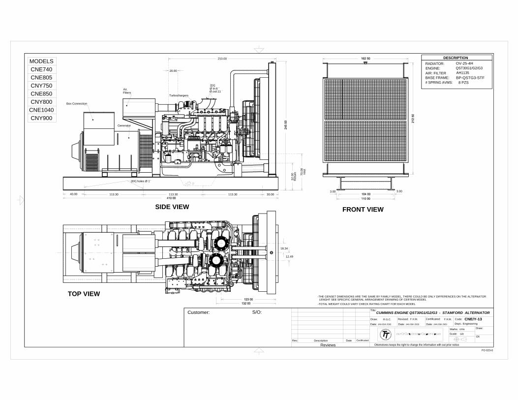
Engine Speed Standby Power Prime Power Continuous Power
RPM kWm BHP kWm BHP kWm BHP
1500 724 970 656 880 515 650
1800 847 1135 768 1030 627 840
Displacement : 23.15 litre (1413 in3 ) Bore : 170 mm (6.69 in.) Stroke : 170 mm (6.69 in.)
No. of Cylinders : 6 Aspiration : Turbocharged and Air to Air Aftercooled
Cummins Inc.
Columbus, Indiana 47201
Engine Data Sheet
Curve Number:
FR-50009Basic Engine Model:
QSK23-G2 NR1
Engine Critical Parts List:
CPL: 8352Date:
19Jul04
OUTPUT POWER FUEL CONSUMPTION
% kWm BHPkg/
kWm·hlb/
BHP·hlitre/hour
U.S. Gal/hour
STANDBY POWER
100 847 1135 0.195 0.321 194 51.3
PRIME POWER
100 768 1030 0.195 0.320 176 46.4
75 576 773 0.196 0.322 133 35.1
50 384 515 0.206 0.338 93 24.5
25 192 258 0.243 0.400 55 14.5
CONTINUOUS POWER
100 627 840 0.194 0.319 143 37.7
Engine Performance Data @ 1800 RPM
Continuous Power
U.S. Gallons/hour
These guidelines have been formulated to ensure proper application of generator drive engines in A.C. generator set in-stallations. STANDBY POWER RATING: Applicable for supplying emergency power for the duration of the utility power outage. No overload capability is available for this rating. Under no condition is an engine allowed to operate in parallel with the public utility at the Standby Power rating. This rating should be applied where reliable utility power is available. A Standby rated engine should be sized for a maximum of an 80% average load factor and 200 hours of operation per year. This includes less than 25 hours per year at the Standby Power rating. Standby ratings should never be applied except in true emergency power outages. Negotiated power outages contracted with a utility company are not considered an emer-gency. PRIME POWER RATING: Applicable for supplying electric power in lieu of commercially purchased power. Prime Power applications must be in the form of one of the following two categories:UNLIMITED TIME RUNNING PRIME POW-ER: Prime Power is available for an unlimited number of hours per year in a variable load application. Variable load should not exceed a 70% average of the Prime Power rating during any operating period of 250 hours. The total operating time at 100% Prime Power shall not exceed 500 hours per year. A 10% overload capability is available for a period of 1 hour within a 12-hour period of operation. Total operating time at the 10% overload power shall not exceed 25 hours per year.LIMITED TIME RUNNING PRIME POWER: Limited Time Prime Power is available for a limited number of hours in a non-variable load application. It is intended for use in situations where power outages are contracted, such as in utility power curtailment. Engines may be operated in parallel to the public utility up to 750 hours per year at power levels never to ex-ceed the Prime Power rating. The customer should be aware, however, that the life of any engine will be reduced by this constant high load operation. Any operation exceeding 750 hours per year at the Prime Power rating should use the Con-tinuous Power rating.CONTINUOUS POWER RATING: Applicable for supplying utility power at a constant 100% load for an unlimited number of hours per year. No overload capability is available for this rating.
Reference AEB 10.47 for determining Electrical Output.
Data shown above represent gross engine performance capabilities obtained and corrected in accordance with ISO-3046 conditions of 100 kPa (29.53 in Hg) barometric pressure [110 m (361 ft) altitude], 25 °C (77 °F) air inlet temper-ature, and relative humidity of 30% with No. 2 diesel or a fuel corresponding to ASTM D2. Derates shown are based on 15 in H20 air intake restriction and 2 in Hg exhaust back pressure.
The fuel consumption data is based on No. 2 diesel fuel weight at 0.85 kg/litre (7.1 lbs/U.S. gal). Power output curves arebased on the engine operating with fuel system, water pump and lubricating oil pump; not included are battery chargingalternator, fan, optional equipment and driven components.
Data Status: Limited ProductionData Tolerance: ± 5%
Chief Engineer:
CONVERSIONS:(litres = U.S. Gal x 3.785) (U.S.Gal = litres x 0.2642) Data Subject to Change Without Notice
0.0
10.0
20.0
30.0
40.0
50.0
60.0
0 250 500 750 1000 1250
Gross Engine Output - BHP
1800 RPM
U.S. Gallons / hour
Standby / Prime Power
Operation At Elevated Temperature And Altitude:For sustained operation above these conditions, derate by an additional 5.0% per 300 m (1000 ft), and 7% per 10o C (18o F).
Ambie
nt Tem
p. (°C
/ °F
)
40 / 104
25 / 7
750
/ 120
Ambient Tem
p. (°C / °
F)
50 / 1
20
40 / 1
04
25 / 77
Power Derate Curves @ 1800 RPM
G-DRIVE
QSK3Cummins Inc.
Engine Data Sheet
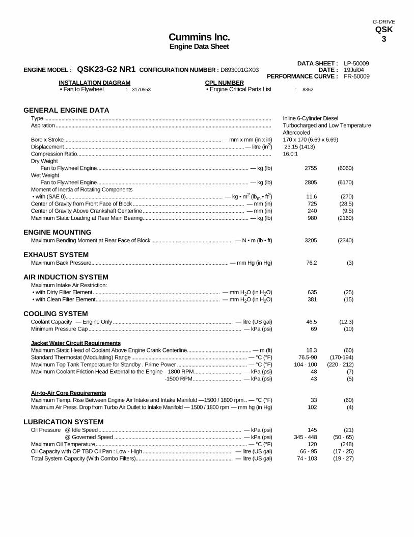
DATA SHEET : LP-50009ENGINE MODEL : QSK23-G2 NR1 CONFIGURATION NUMBER : D893001GX03 DATE : 19Jul04
PERFORMANCE CURVE : FR-50009INSTALLATION DIAGRAM CPL NUMBER • Fan to Flywheel : 3170553 • Engine Critical Parts List : 8352
GENERAL ENGINE DATAType ............................................................................................................................................................... Inline 6-Cylinder DieselAspiration ....................................................................................................................................................... Turbocharged and Low Temperature
Aftercooled Bore x Stroke.............................................................................................................. — mm x mm (in x in) 170 x 170 (6.69 x 6.69)Displacement.............................................................................................................................. — litre (in3) 23.15 (1413)Compression Ratio........................................................................................................................................ 16.0:1Dry Weight
Fan to Flywheel Engine.......................................................................................................... — kg (lb) 2755 (6060)Wet Weight
Fan to Flywheel Engine.......................................................................................................... — kg (lb) 2805 (6170)Moment of Inertia of Rotating Components • with (SAE 0).............................................................................................................. — kg • m2 (lbm • ft2) 11.6 (270)Center of Gravity from Front Face of Block .............................................................................. — mm (in) 725 (28.5)Center of Gravity Above Crankshaft Centerline....................................................................... — mm (in) 240 (9.5)Maximum Static Loading at Rear Main Bearing.......................................................................... — kg (lb) 980 (2160)
ENGINE MOUNTINGMaximum Bending Moment at Rear Face of Block ......................................................... — N • m (lb • ft) 3205 (2340)
EXHAUST SYSTEMMaximum Back Pressure................................................................................................ — mm Hg (in Hg) 76.2 (3)
AIR INDUCTION SYSTEMMaximum Intake Air Restriction: • with Dirty Filter Element......................................................................................... — mm H2O (in H2O) 635 (25) • with Clean Filter Element....................................................................................... — mm H2O (in H2O) 381 (15)
COOLING SYSTEM Coolant Capacity — Engine Only .................................................................................... — litre (US gal) 46.5 (12.3)Minimum Pressure Cap ........................................................................................................... — kPa (psi) 69 (10)
Jacket Water Circuit RequirementsMaximum Static Head of Coolant Above Engine Crank Centerline............................................. — m (ft) 18.3 (60)Standard Thermostat (Modulating) Range................................................................................. — °C (°F) 76.5-90 (170-194)Maximum Top Tank Temperature for Standby . Prime Power ................................................. — °C (°F) 104 - 100 (220 - 212)Maximum Coolant Friction Head External to the Engine - 1800 RPM................................. — kPa (psi) 48 (7)
-1500 RPM.................................. — kPa (psi) 43 (5)
Air-to-Air Core RequirementsMaximum Temp. Rise Between Engine Air Intake and Intake Manifold —1500 / 1800 rpm.. — °C (°F) 33 (60)Maximum Air Press. Drop from Turbo Air Outlet to Intake Manifold — 1500 / 1800 rpm — mm hg (in Hg) 102 (4)
LUBRICATION SYSTEMOil Pressure @ Idle Speed.................................................................................................... — kPa (psi) 145 (21)
@ Governed Speed ......................................................................................... — kPa (psi) 345 - 448 (50 - 65)Maximum Oil Temperature.......................................................................................................... — °C (°F) 120 (248)Oil Capacity with OP TBD Oil Pan : Low - High............................................................... — litre (US gal) 66 - 95 (17 - 25)Total System Capacity (With Combo Filters).................................................................... — litre (US gal) 74 - 103 (19 - 27)
G-DRIVE
QSK4
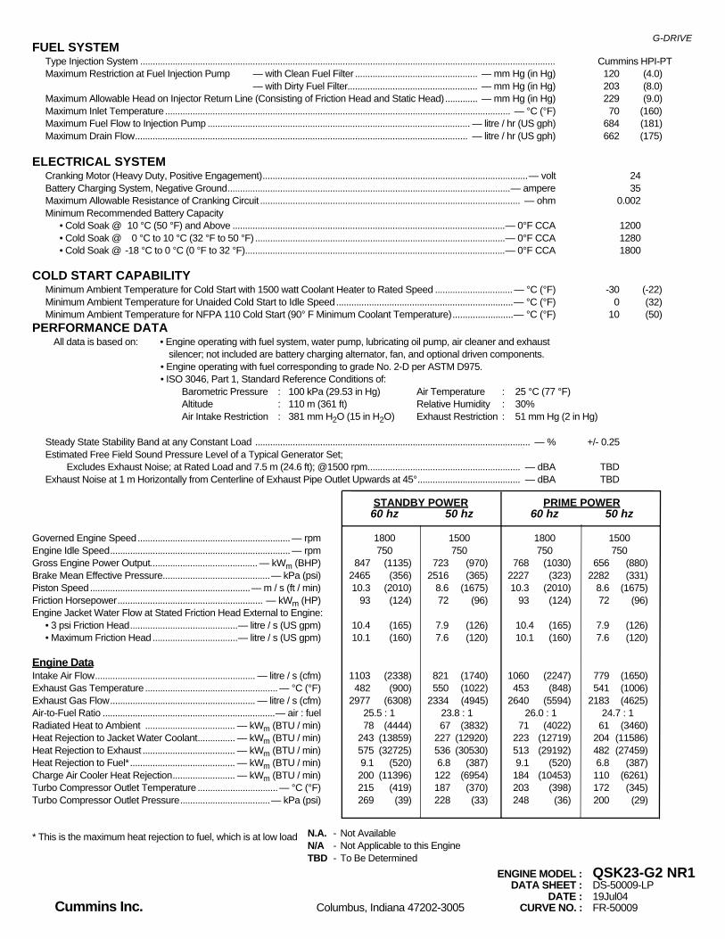
FUEL SYSTEMType Injection System ...................................................................................................................................................................... Cummins HPI-PTMaximum Restriction at Fuel Injection Pump — with Clean Fuel Filter ................................................. — mm Hg (in Hg) 120 (4.0)
— with Dirty Fuel Filter.................................................... — mm Hg (in Hg) 203 (8.0)Maximum Allowable Head on Injector Return Line (Consisting of Friction Head and Static Head)............. — mm Hg (in Hg) 229 (9.0)Maximum Inlet Temperature.......................................................................................................................................... — °C (°F) 70 (160)Maximum Fuel Flow to Injection Pump ......................................................................................................... — litre / hr (US gph) 684 (181)Maximum Drain Flow..................................................................................................................................... — litre / hr (US gph) 662 (175)
ELECTRICAL SYSTEMCranking Motor (Heavy Duty, Positive Engagement)..........................................................................................................— volt 24Battery Charging System, Negative Ground.................................................................................................................— ampere 35Maximum Allowable Resistance of Cranking Circuit ........................................................................................................ — ohm 0.002Minimum Recommended Battery Capacity
• Cold Soak @ 10 °C (50 °F) and Above .............................................................................................................— 0°F CCA 1200• Cold Soak @ 0 °C to 10 °C (32 °F to 50 °F) ....................................................................................................— 0°F CCA 1280• Cold Soak @ -18 °C to 0 °C (0 °F to 32 °F)........................................................................................................— 0°F CCA 1800
COLD START CAPABILITYMinimum Ambient Temperature for Cold Start with 1500 watt Coolant Heater to Rated Speed ............................... — °C (°F) -30 (-22)Minimum Ambient Temperature for Unaided Cold Start to Idle Speed......................................................................— °C (°F) 0 (32) Minimum Ambient Temperature for NFPA 110 Cold Start (90° F Minimum Coolant Temperature)........................— °C (°F) 10 (50)
PERFORMANCE DATAAll data is based on: • Engine operating with fuel system, water pump, lubricating oil pump, air cleaner and exhaust
silencer; not included are battery charging alternator, fan, and optional driven components.• Engine operating with fuel corresponding to grade No. 2-D per ASTM D975.• ISO 3046, Part 1, Standard Reference Conditions of:
Barometric Pressure : 100 kPa (29.53 in Hg) Air Temperature : 25 °C (77 °F)Altitude : 110 m (361 ft) Relative Humidity : 30%Air Intake Restriction : 381 mm H2O (15 in H2O) Exhaust Restriction : 51 mm Hg (2 in Hg)
Steady State Stability Band at any Constant Load .............................................................................................................. — % +/- 0.25Estimated Free Field Sound Pressure Level of a Typical Generator Set;
Excludes Exhaust Noise; at Rated Load and 7.5 m (24.6 ft); @1500 rpm............................................................. — dBA TBDExhaust Noise at 1 m Horizontally from Centerline of Exhaust Pipe Outlet Upwards at 45°......................................... — dBA TBD
STANDBY POWER PRIME POWER60 hz 50 hz 60 hz 50 hz
Governed Engine Speed............................................................. — rpm 1800 1500 1800 1500Engine Idle Speed........................................................................ — rpm 750 750 750 750Gross Engine Power Output........................................... — kWm (BHP) 847 (1135) 723 (970) 768 (1030) 656 (880)Brake Mean Effective Pressure...........................................— kPa (psi) 2465 (356) 2516 (365) 2227 (323) 2282 (331)Piston Speed................................................................— m / s (ft / min) 10.3 (2010) 8.6 (1675) 10.3 (2010) 8.6 (1675)Friction Horsepower.......................................................... — kWm (HP) 93 (124) 72 (96) 93 (124) 72 (96)Engine Jacket Water Flow at Stated Friction Head External to Engine:
• 3 psi Friction Head...........................................— litre / s (US gpm) 10.4 (165) 7.9 (126) 10.4 (165) 7.9 (126)• Maximum Friction Head..................................— litre / s (US gpm) 10.1 (160) 7.6 (120) 10.1 (160) 7.6 (120)
Engine DataIntake Air Flow................................................................ — litre / s (cfm) 1103 (2338) 821 (1740) 1060 (2247) 779 (1650)Exhaust Gas Temperature ..................................................... — °C (°F) 482 (900) 550 (1022) 453 (848) 541 (1006)Exhaust Gas Flow.......................................................... — litre / s (cfm) 2977 (6308) 2334 (4945) 2640 (5594) 2183 (4625)Air-to-Fuel Ratio .....................................................................— air : fuel 25.5 : 1 23.8 : 1 26.0 : 1 24.7 : 1Radiated Heat to Ambient .................................... — kWm (BTU / min) 78 (4444) 67 (3832) 71 (4022) 61 (3460)Heat Rejection to Jacket Water Coolant............... — kWm (BTU / min) 243 (13859) 227 (12920) 223 (12719) 204 (11586)Heat Rejection to Exhaust ..................................... — kWm (BTU / min) 575 (32725) 536 (30530) 513 (29192) 482 (27459)Heat Rejection to Fuel*.......................................... — kWm (BTU / min) 9.1 (520) 6.8 (387) 9.1 (520) 6.8 (387)Charge Air Cooler Heat Rejection......................... — kWm (BTU / min) 200 (11396) 122 (6954) 184 (10453) 110 (6261)Turbo Compressor Outlet Temperature ................................— °C (°F) 215 (419) 187 (370) 203 (398) 172 (345)Turbo Compressor Outlet Pressure....................................— kPa (psi) 269 (39) 228 (33) 248 (36) 200 (29)
* This is the maximum heat rejection to fuel, which is at low load
ENGINE MODEL : QSK23-G2 NR1DATA SHEET : DS-50009-LP
DATE : 19Jul04Cummins Inc. Columbus, Indiana 47202-3005 CURVE NO. : FR-50009
N.A. - Not AvailableN/A - Not Applicable to this EngineTBD - To Be Determined
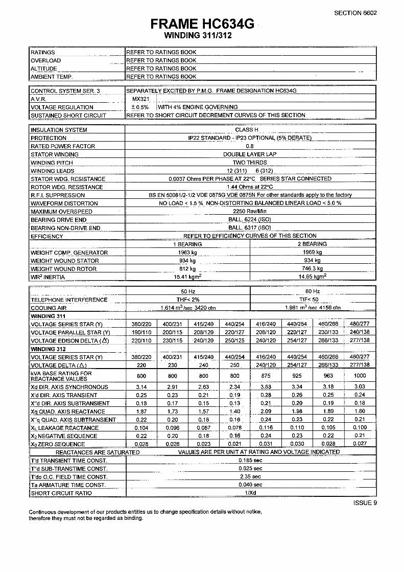

NEWAGE INTERNATIONAL LIMITEDPO BOX 17, Barnack Road, Stamford, Lincolnshire PE9 2NB, England.
Telephone 44 (0) 1780 484000Telex 32268 Cables Newage Stamford Fax 44 (0) 1780 484100