Embed Size (px)
Citation preview
Current status of electricity generation at nuclear power plants
Professor Igor Pioro1 and Professor Pavel Kirillov2 1Faculty of Energy Systems & Nuclear Science, University of Ontario Institute of Technology, 2000 Simcoe Str. N.,
Oshawa ON L1H 7K4 Canada. E-mail: [email protected] 2State Scientific Centre of the Russian Federation - Institute of Physics and Power Engineering (IPPE) named after A.I.
Leipunsky, Obninsk, Russia. E-mail: [email protected]
Keywords: Electricity generation; nuclear power plant; nuclear reactor.
1. Introduction
It is well known that the electrical-power generation is the key factor for advances in any other industries, agriculture and level of living (see Chapter 1) [1]. In general, electrical energy can be generated by: 1) non-renewable-energy sources such as coal, natural gas, oil, and nuclear; and 2) renewable-energy sources such as hydro, wind, solar, biomass, geothermal and marine. However, the main sources for electrical-energy generation are: 1) thermal - primary coal and secondary natural gas; 2) “large” hydro and 3) nuclear. The rest of the energy sources might have visible impact just in some countries. In addition, the renewable-energy sources such as wind and solar are not really reliable sources for industrial power generation, because they depend on Mother nature and relative costs of electrical energy generated by these and some other renewable-energy sources with exception of large hydro-electric power plants can be significantly higher than those generated by non-renewable-energy sources. Therefore, nuclear-based electrical-energy generation will be considered in this chapter for Generation II, III and III+ Nuclear Power Plants (NPPs) and in Chapter 4 - for Generation IV NPPs (renewable-energy power plants are considered in Chapter 1 and thermal power plants – in Chapter 2).
2. Modern nuclear power plants
Nuclear power is also a non-renewable-energy source as the fossil fuels, but nuclear resources can be used for significantly longer time than some fossil fuels and nuclear power does not emit carbon dioxide into atmosphere. However, NPPs create radioactive wastes, and the problem with reprocessing and ultimate safe storage of nuclear wastes should be resolved. Currently, this source of energy is considered as the most viable one for electrical generation for the next 50 – 100 years. First success of using nuclear power for electrical generation [1] was achieved in several countries within 50-s, and currently, Generations II and III nuclear-power reactors are operating around the world (see Tables 1 and 2 and Figs. 1-10). In general, definitions of nuclear-reactors generations [1] are as the following: 1) Generation I (1950 – 1965) – early prototypes of nuclear reactors; 2) Generation II (1965 – 1995) – commercial power reactors; 3) Generation III (1995 – 2010) – modern reactors (water-cooled NPPs with thermal efficiencies within 30 – 36%; carbon-dioxide-cooled NPPs with thermal efficiencies up to 42% and liquid sodium-cooled NPP with the thermal efficiency up to 40%) and Generation III+ (2010 – 2025) – reactors with improved parameters (evolutionary design improvements) (water-cooled NPPs with thermal efficiencies up to 38%) (see Table 3); and 4) Generation IV (2025 - …) (see Chapter 4) – reactors in principle with new parameters (NPPs with thermal efficiencies within 43 – 50% and even higher for all types of reactors). (Several classifications of NPPs are listed in [1].) Table 1. Operating and forthcoming nuclear-power reactors as per April of 2013 [2] (in total - 433 (444) (net 371 (378) GWel); (in Italic mode - number of power reactors before the Japan earthquake and tsunami disaster in spring of 2011) [3].
1. Pressurized Water Reactors (PWRs) (see Fig. 1 and Table 4) – 271 (268) (251 (247) GWel); forthcoming – 85 (89 GWel).
2. Boiling Water Reactors (BWRs) or Advanced BWRs (ABWRs) (see Fig. 2 and Table 5) – 83 (92) (78 (78) GWel); forthcoming – 6 (8 GWel).
3. Pressurized Heavy Water Reactors (PHWRs) (see Figs. 3 and 4) – 48 (50) (24 (25) GWel), Argentina 2, Canada 19, China 2, India 18, Pakistan 1, Romania 2, S. Korea 4; forthcoming – 7 (4 GWel).
4. Gas Cooled Reactors (GCRs) – 15 (18) (8 GWel), UK (Advanced Gas Reactors (AGRs) (see Fig. 5) – 14 and Magnox (see Fig. 6) – 1); forthcoming – 0.
5. Light-water, Graphite-moderated Reactors (LGRs) (see Table 4) – 15 (10 GWel), Russia, 11 RBMKs (see Fig. 7) and 4 EGPs1 (earlier prototype of RBMK) (see Fig. 8); forthcoming – 0.
1 EGP – Power Heterogeneous Loop reactor (in Russian abbreviations), channel-type, graphite moderated, light-water coolant,
boiling reactor with natural circulation.
Materials and processes for energy: communicating current research and technological developments (A. Méndez-Vilas, Ed.)____________________________________________________________________________________________________
©FORMATEX 2013806
6. Liquid-Metal Fast-Breeder Reactors (LMFBRs) (see Fig. 9 and Table 4) – 1 (0.6 GWel), Sodium-cooled Fast Reactor (SFR) – BN-600, Russia; forthcoming – 4 (1.5 GWel).
Table 2. Current nuclear-power reactors by nation (11 first nations) as per April of 2013 [2]; (in Italic mode - number of power reactors before the Japan earthquake and tsunami disaster in spring of 2011) [3].
No. Nation # Units Net GWel Changes in # of reactors from 20111. USA 103 (104) 103 (103) ↓ Decreased by1 reactor 2. France 58 63 - No changes 3. Japan2 50 (54) 44 (47) ↓ Decreased by 4 reactors 4. Russia 33 (32) 24 (23) ↑ Increased by 1 reactor 5. S. Korea 23 (20) 21 (18) ↑ Increased by 3 reactors 6. Canada 19 (22) 13 (15) ↓ Decreased by 3 reactors 7. Ukraine 15 13 - No changes 8. Germany 9 (17) 12 (20) ↓ Decreased by 8 reactors 9. China 15 (13) 12 (10) ↑ Increased by 2 reactors 10. Sweden 10 9 - No changes 11. UK 16 (19) 9 (10) ↓ Decreased by 3 reactors
Table 3. Selected Generation III+ reactors (deployment in 5–10 years).
ABWR – Toshiba, Mitsubishi Heavy Industries and Hitachi-GE (Japan-USA) (the only one Generation III+ reactor design already implemented in the power industry). Advanced CANDU Reactor (ACR-1000) - AECL, Canada. Advanced Plant (AP-1000) – Toshiba-Westinghouse (Japan-USA) (6 under construction in China and 6 planned to be built in China and 6 – in USA). Advanced PWR (APR-1400) – South Korea (4 under construction in S. Korea and 4 planned to be built in United Arab Emirates). European Pressurized-water Reactor (EPR) - AREVA, France (1 should be put into operation in Finland, 1 under construction in France and 2 - in China and 2 planned to be built in USA). ESBWR (Economic Simplified Boiling Water Reactor) - GE-Hitachi (USA-Japan). VVER3 (design AES4-2006 or VVER-1200 with ~1200 MWel) – GIDROPRESS, Russia (2 under construction in Russia and several more planned to be built in various countries). Reference parameters of Generation III+ VVER [4] are listed below:
Parameter Value Thermal power, MWth 3200 Electric power, MWel 1160 NPP thermal efficiency, % 36 Primary coolant pressure, MPa 16.2 Steam-generator pressure, MPa 7.0 Coolant temperature at reactor inlet, oC 298 Coolant temperature at reactor outlet, oC 329 NPP service life, years 50 Main equipment service life, years 60 Replaced equipment service life, years, not less than 30 Capacity factor, % up to 90 Load factor, % up to 92 Equipment availability factor 99 Length of fuel cycle, years 4 – 5 Frequency of re-fuelling, months 12 – 18 Fuel assembly maximum burn-up, MW day/kgU up to 60 – 70 Inter-repair period length, years 4 – 8 Annual average length of scheduled shut-downs (for re-fuelling, scheduled maintenance work), days per year
16 – 40
Refueling length, days per year ≤16
2 Currently, i.e., in April of 2013, only several reactors in operation. However, more reactors are planned to put into operation. 3 VVER or WWER – Water Water Power Reactor (in Russian abbreviations). 4 AES – Atomic Electrical Station (Nuclear Power Plant) (in Russian abbreviations).
Materials and processes for energy: communicating current research and technological developments (A. Méndez-Vilas, Ed.)____________________________________________________________________________________________________
©FORMATEX 2013 807
Parameter Value Number of not scheduled reactor shutdowns per year ≤1 Frequency of severe core damage, 1/year <10-6 Frequency of limiting emergency release, 1/year <10-7 Efficient time of passive safety and emergency control system operation without operator’s action and power supply, hour
≥24
OBE/SSE, magnitude of MSK-64 scale 6 and 7* Compliance with EUR requirements, yes/no Yes *RP main stationary equipment is designed for SSE of magnitude 8.
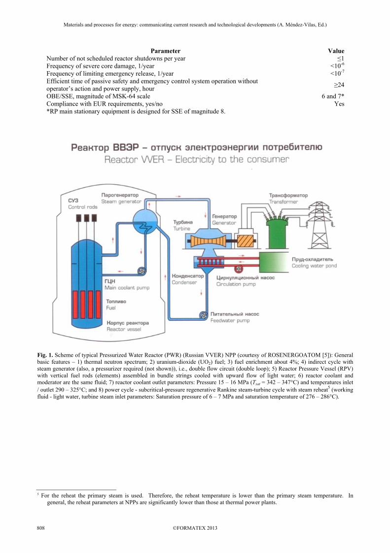
Fig. 1. Scheme of typical Pressurized Water Reactor (PWR) (Russian VVER) NPP (courtesy of ROSENERGOATOM [5]): General basic features – 1) thermal neutron spectrum; 2) uranium-dioxide (UO2) fuel; 3) fuel enrichment about 4%; 4) indirect cycle with steam generator (also, a pressurizer required (not shown)), i.e., double flow circuit (double loop); 5) Reactor Pressure Vessel (RPV) with vertical fuel rods (elements) assembled in bundle strings cooled with upward flow of light water; 6) reactor coolant and moderator are the same fluid; 7) reactor coolant outlet parameters: Pressure 15 – 16 MPa (Tsat = 342 – 347°C) and temperatures inlet / outlet 290 – 325°C; and 8) power cycle - subcritical-pressure regenerative Rankine steam-turbine cycle with steam reheat5 (working fluid - light water, turbine steam inlet parameters: Saturation pressure of 6 – 7 MPa and saturation temperature of 276 – 286°C).
5 For the reheat the primary steam is used. Therefore, the reheat temperature is lower than the primary steam temperature. In
general, the reheat parameters at NPPs are significantly lower than those at thermal power plants.
Materials and processes for energy: communicating current research and technological developments (A. Méndez-Vilas, Ed.)____________________________________________________________________________________________________
©FORMATEX 2013808
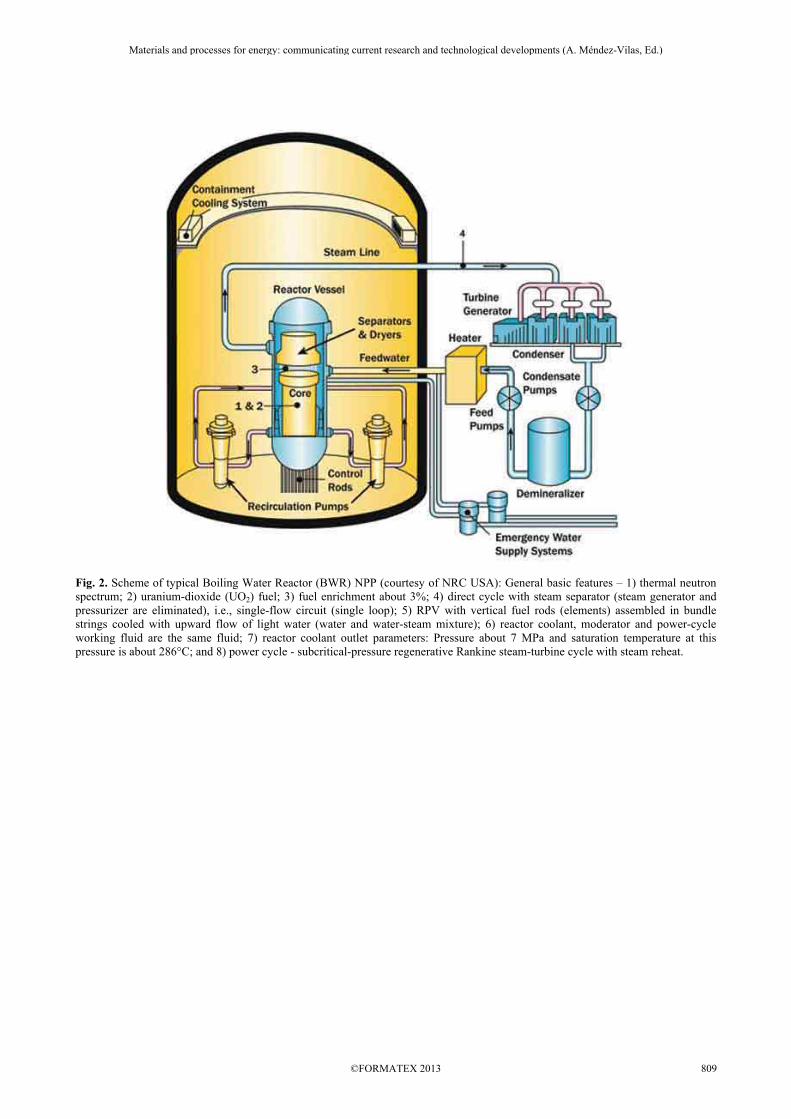
Fig. 2. Scheme of typical Boiling Water Reactor (BWR) NPP (courtesy of NRC USA): General basic features – 1) thermal neutron spectrum; 2) uranium-dioxide (UO2) fuel; 3) fuel enrichment about 3%; 4) direct cycle with steam separator (steam generator and pressurizer are eliminated), i.e., single-flow circuit (single loop); 5) RPV with vertical fuel rods (elements) assembled in bundle strings cooled with upward flow of light water (water and water-steam mixture); 6) reactor coolant, moderator and power-cycle working fluid are the same fluid; 7) reactor coolant outlet parameters: Pressure about 7 MPa and saturation temperature at this pressure is about 286°C; and 8) power cycle - subcritical-pressure regenerative Rankine steam-turbine cycle with steam reheat.
Materials and processes for energy: communicating current research and technological developments (A. Méndez-Vilas, Ed.)____________________________________________________________________________________________________
©FORMATEX 2013 809
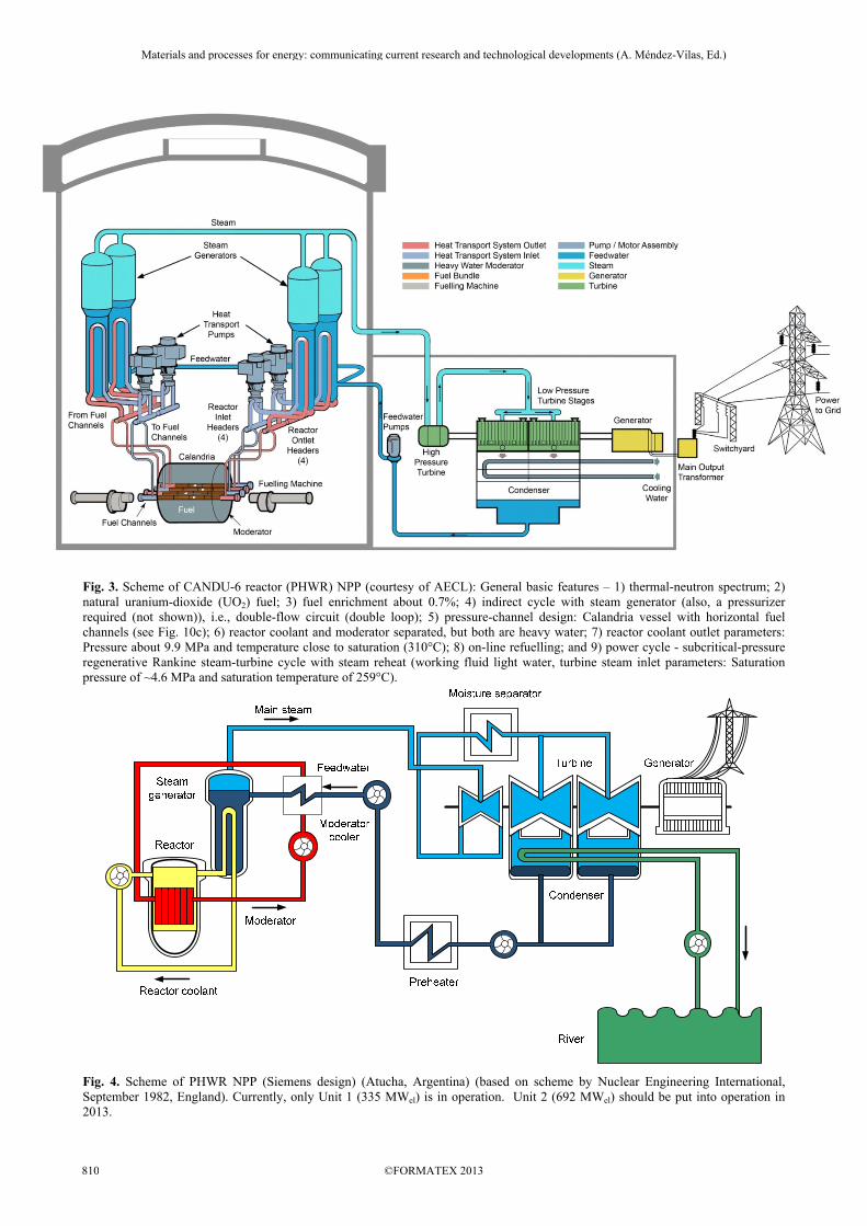
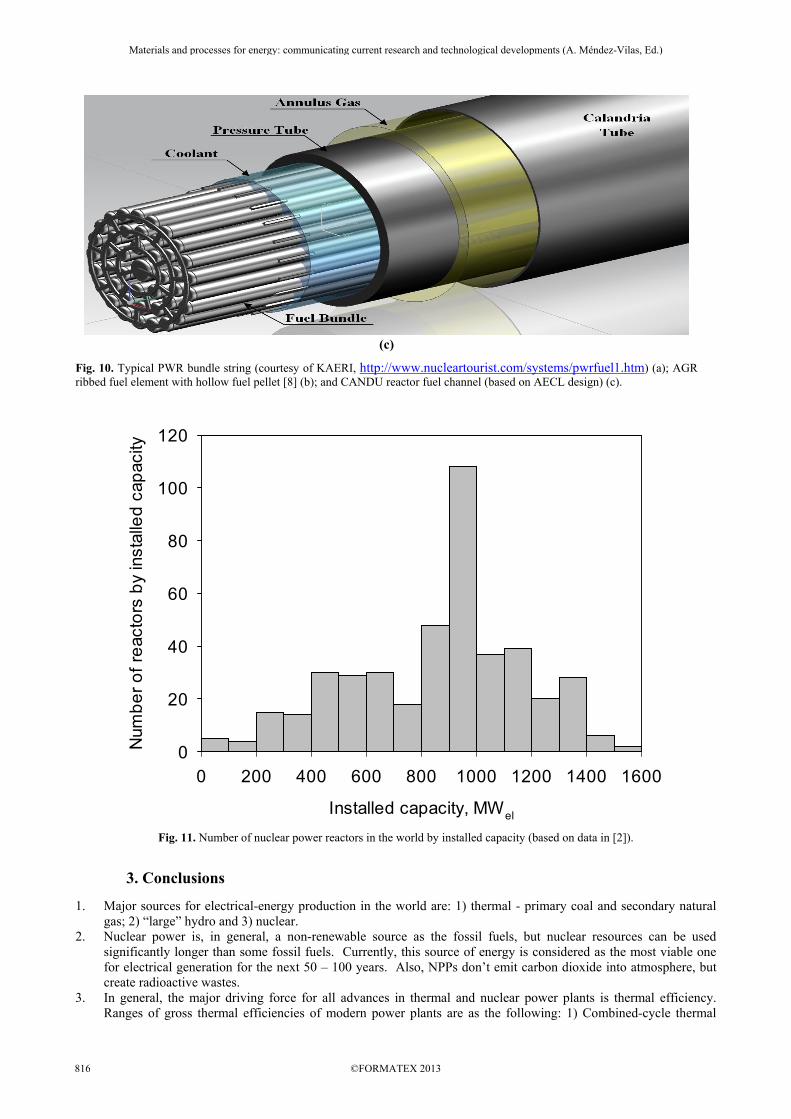
Fig. 3. Scheme of CANDU-6 reactor (PHWR) NPP (courtesy of AECL): General basic features – 1) thermal-neutron spectrum; 2) natural uranium-dioxide (UO2) fuel; 3) fuel enrichment about 0.7%; 4) indirect cycle with steam generator (also, a pressurizer required (not shown)), i.e., double-flow circuit (double loop); 5) pressure-channel design: Calandria vessel with horizontal fuel channels (see Fig. 10c); 6) reactor coolant and moderator separated, but both are heavy water; 7) reactor coolant outlet parameters: Pressure about 9.9 MPa and temperature close to saturation (310°C); 8) on-line refuelling; and 9) power cycle - subcritical-pressure regenerative Rankine steam-turbine cycle with steam reheat (working fluid light water, turbine steam inlet parameters: Saturation pressure of ~4.6 MPa and saturation temperature of 259°C).
Fig. 4. Scheme of PHWR NPP (Siemens design) (Atucha, Argentina) (based on scheme by Nuclear Engineering International, September 1982, England). Currently, only Unit 1 (335 MWel) is in operation. Unit 2 (692 MWel) should be put into operation in 2013.
Materials and processes for energy: communicating current research and technological developments (A. Méndez-Vilas, Ed.)____________________________________________________________________________________________________
©FORMATEX 2013810
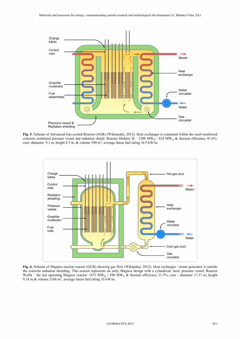
Fig. 5. Scheme of Advanced Gas-cooled Reactor (AGR) (Wikimedia, 2012). Heat exchanger is contained within the steel-reinforced concrete combined pressure vessel and radiation shield. Reactor Hinkley B – 1500 MWth / 624 MWel & thermal efficiency 41.6%; core: diameter 9.1 m, height 8.3 m, & volume 540 m3; average linear fuel rating 16.9 kW/m.
Fig. 6. Scheme of Magnox nuclear reactor (GCR) showing gas flow (Wikipidea, 2012). Heat exchanger / steam generator is outside the concrete radiation shielding. This reactor represents an early Magnox design with a cylindrical, steel, pressure vessel. Reactor Wylfa – the last operating Magnox reactor: 1875 MWth / 590 MWel & thermal efficiency 31.5%; core - diameter 17.37 m, height 9.14 m & volume 2166 m3; average linear fuel rating 33 kW/m.
Materials and processes for energy: communicating current research and technological developments (A. Méndez-Vilas, Ed.)____________________________________________________________________________________________________
©FORMATEX 2013 811
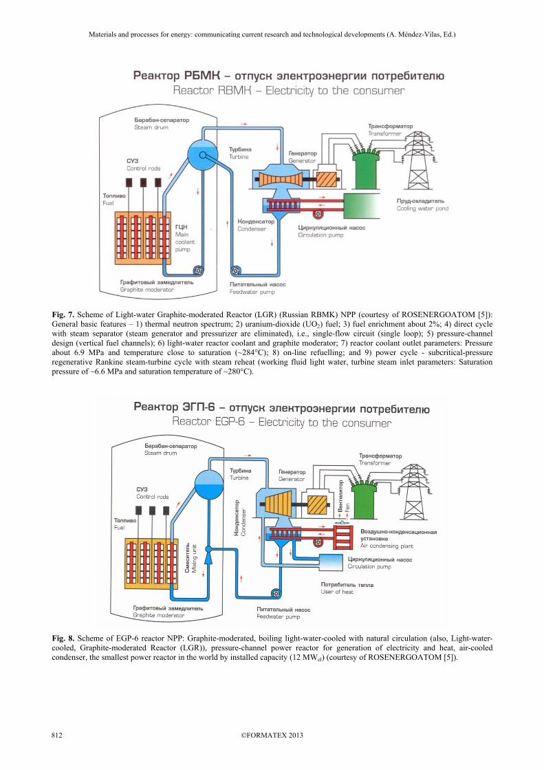
Fig. 7. Scheme of Light-water Graphite-moderated Reactor (LGR) (Russian RBMK) NPP (courtesy of ROSENERGOATOM [5]): General basic features – 1) thermal neutron spectrum; 2) uranium-dioxide (UO2) fuel; 3) fuel enrichment about 2%; 4) direct cycle with steam separator (steam generator and pressurizer are eliminated), i.e., single-flow circuit (single loop); 5) pressure-channel design (vertical fuel channels); 6) light-water reactor coolant and graphite moderator; 7) reactor coolant outlet parameters: Pressure about 6.9 MPa and temperature close to saturation (~284°C); 8) on-line refuelling; and 9) power cycle - subcritical-pressure regenerative Rankine steam-turbine cycle with steam reheat (working fluid light water, turbine steam inlet parameters: Saturation pressure of ~6.6 MPa and saturation temperature of ~280°C).
Fig. 8. Scheme of EGP-6 reactor NPP: Graphite-moderated, boiling light-water-cooled with natural circulation (also, Light-water-cooled, Graphite-moderated Reactor (LGR)), pressure-channel power reactor for generation of electricity and heat, air-cooled condenser, the smallest power reactor in the world by installed capacity (12 MWel) (courtesy of ROSENERGOATOM [5]).
Materials and processes for energy: communicating current research and technological developments (A. Méndez-Vilas, Ed.)____________________________________________________________________________________________________
©FORMATEX 2013812
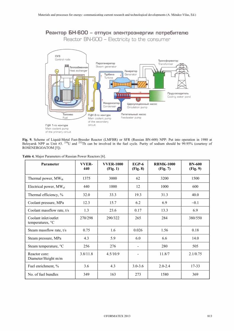
Fig. 9. Scheme of Liquid-Metal Fast-Breeder Reactor (LMFBR) or SFR (Russian BN-600) NPP: Put into operation in 1980 at Beloyarsk NPP as Unit #3. 238U and 232Th can be involved in the fuel cycle. Purity of sodium should be 99.95% (courtesy of ROSENERGOATOM [5]). Table 4. Major Parameters of Russian Power Reactors [6].
Parameter VVER-440
VVER-1000 (Fig. 1)
EGP-6 (Fig. 8)
RBMK-1000 (Fig. 7)
BN-600 (Fig. 9)
Thermal power, MWth 1375 3000 62 3200 1500
Electrical power, MWel 440 1000 12 1000 600
Thermal efficiency, % 32.0 33.3 19.3 31.3 40.0
Coolant pressure, MPa 12.3 15.7 6.2 6.9 ~0.1
Coolant massflow rate, t/s 1.3 23.6 0.17 13.3 6.9
Coolant inlet/outlet temperatures, °C
270/298 290/322 265 284 380/550
Steam massflow rate, t/s 0.75 1.6 0.026 1.56 0.18
Steam pressure, MPa 4.3 5.9 6.0 6.6 14.0
Steam temperature, °C 256 276 - 280 505
Reactor core: Diameter/Height m/m
3.8/11.8 4.5/10.9 - 11.8/7 2.1/0.75
Fuel enrichment, % 3.6 4.3 3.0-3.6 2.0-2.4 17-33
No. of fuel bundles 349 163 273 1580 369
Materials and processes for energy: communicating current research and technological developments (A. Méndez-Vilas, Ed.)____________________________________________________________________________________________________
©FORMATEX 2013 813
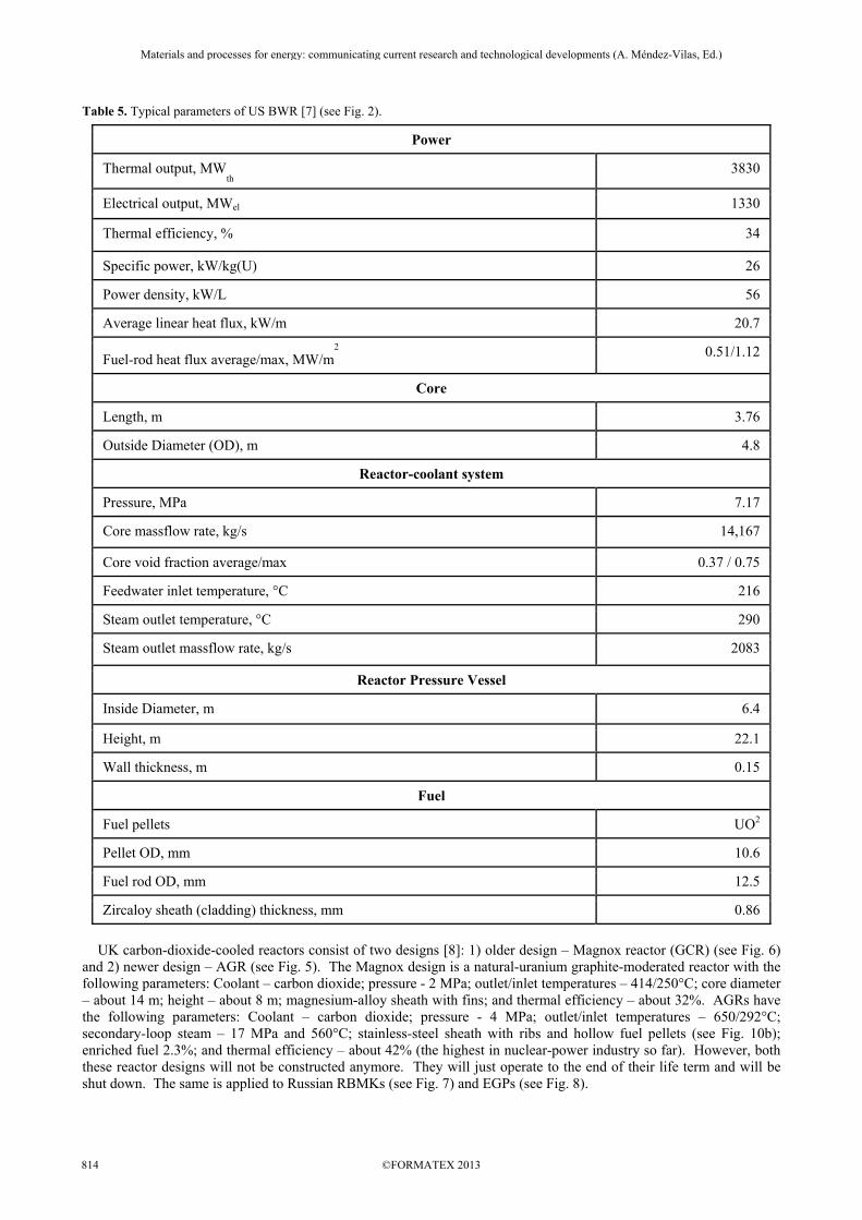
Table 5. Typical parameters of US BWR [7] (see Fig. 2).
Power
Thermal output, MWth 3830
Electrical output, MWel 1330
Thermal efficiency, % 34
Specific power, kW/kg(U) 26
Power density, kW/L 56
Average linear heat flux, kW/m 20.7
Fuel-rod heat flux average/max, MW/m2
0.51/1.12
Core
Length, m 3.76
Outside Diameter (OD), m 4.8
Reactor-coolant system
Pressure, MPa 7.17
Core massflow rate, kg/s 14,167
Core void fraction average/max 0.37 / 0.75
Feedwater inlet temperature, °C 216
Steam outlet temperature, °C 290
Steam outlet massflow rate, kg/s 2083
Reactor Pressure Vessel
Inside Diameter, m 6.4
Height, m 22.1
Wall thickness, m 0.15
Fuel
Fuel pellets UO2
Pellet OD, mm 10.6
Fuel rod OD, mm 12.5
Zircaloy sheath (cladding) thickness, mm 0.86
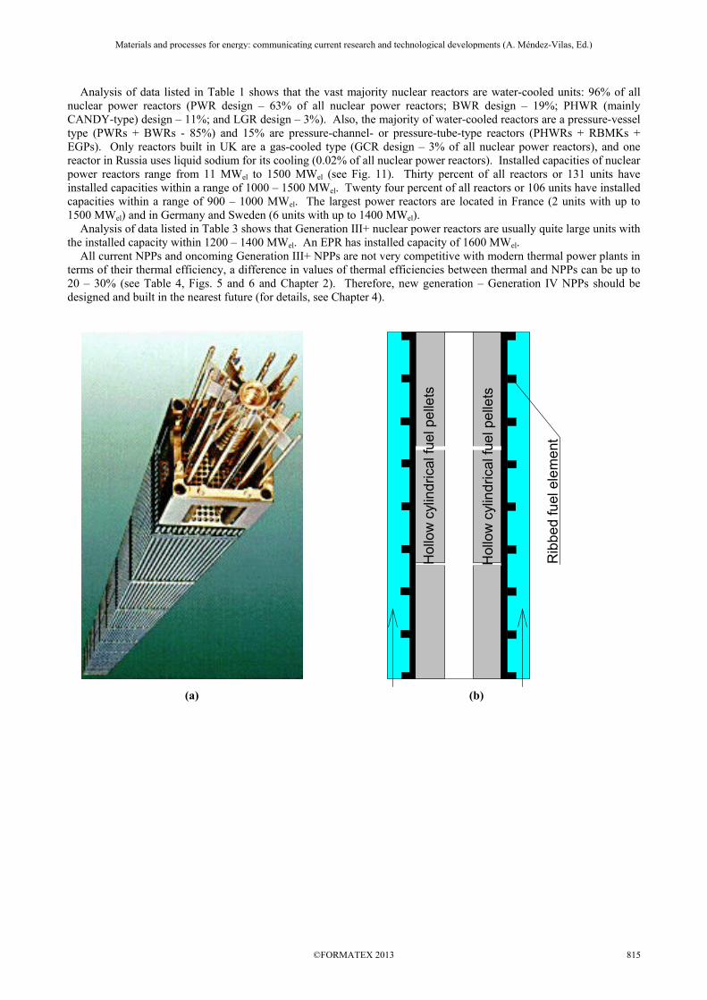
UK carbon-dioxide-cooled reactors consist of two designs [8]: 1) older design – Magnox reactor (GCR) (see Fig. 6) and 2) newer design – AGR (see Fig. 5). The Magnox design is a natural-uranium graphite-moderated reactor with the following parameters: Coolant – carbon dioxide; pressure - 2 MPa; outlet/inlet temperatures – 414/250°C; core diameter – about 14 m; height – about 8 m; magnesium-alloy sheath with fins; and thermal efficiency – about 32%. AGRs have the following parameters: Coolant – carbon dioxide; pressure - 4 MPa; outlet/inlet temperatures – 650/292°C; secondary-loop steam – 17 MPa and 560°C; stainless-steel sheath with ribs and hollow fuel pellets (see Fig. 10b); enriched fuel 2.3%; and thermal efficiency – about 42% (the highest in nuclear-power industry so far). However, both these reactor designs will not be constructed anymore. They will just operate to the end of their life term and will be shut down. The same is applied to Russian RBMKs (see Fig. 7) and EGPs (see Fig. 8).
Materials and processes for energy: communicating current research and technological developments (A. Méndez-Vilas, Ed.)____________________________________________________________________________________________________
©FORMATEX 2013814
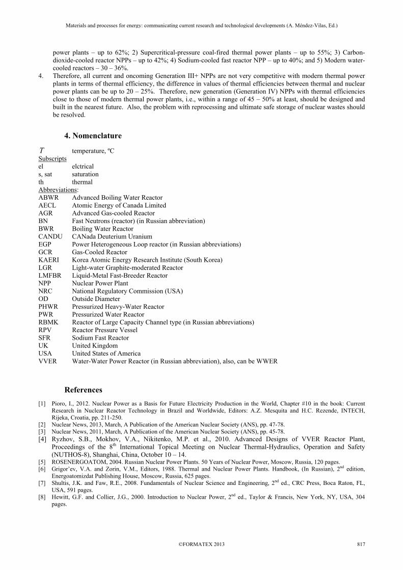
Analysis of data listed in Table 1 shows that the vast majority nuclear reactors are water-cooled units: 96% of all nuclear power reactors (PWR design – 63% of all nuclear power reactors; BWR design – 19%; PHWR (mainly CANDY-type) design – 11%; and LGR design – 3%). Also, the majority of water-cooled reactors are a pressure-vessel type (PWRs + BWRs - 85%) and 15% are pressure-channel- or pressure-tube-type reactors (PHWRs + RBMKs + EGPs). Only reactors built in UK are a gas-cooled type (GCR design – 3% of all nuclear power reactors), and one reactor in Russia uses liquid sodium for its cooling (0.02% of all nuclear power reactors). Installed capacities of nuclear power reactors range from 11 MWel to 1500 MWel (see Fig. 11). Thirty percent of all reactors or 131 units have installed capacities within a range of 1000 – 1500 MWel. Twenty four percent of all reactors or 106 units have installed capacities within a range of 900 – 1000 MWel. The largest power reactors are located in France (2 units with up to 1500 MWel) and in Germany and Sweden (6 units with up to 1400 MWel). Analysis of data listed in Table 3 shows that Generation III+ nuclear power reactors are usually quite large units with the installed capacity within 1200 – 1400 MWel. An EPR has installed capacity of 1600 MWel. All current NPPs and oncoming Generation III+ NPPs are not very competitive with modern thermal power plants in terms of their thermal efficiency, a difference in values of thermal efficiencies between thermal and NPPs can be up to 20 – 30% (see Table 4, Figs. 5 and 6 and Chapter 2). Therefore, new generation – Generation IV NPPs should be designed and built in the nearest future (for details, see Chapter 4).
Hol
low
cyl
indr
ical
fuel
pel
lets
Hol
low
cyl
indr
ical
fuel
pel
lets
Rib
bed
fuel
ele
men
t
(a) (b)
Materials and processes for energy: communicating current research and technological developments (A. Méndez-Vilas, Ed.)____________________________________________________________________________________________________
©FORMATEX 2013 815
(c)
Fig. 10. Typical PWR bundle string (courtesy of KAERI, http://www.nucleartourist.com/systems/pwrfuel1.htm) (a); AGR ribbed fuel element with hollow fuel pellet [8] (b); and CANDU reactor fuel channel (based on AECL design) (c).
Installed capacity, MWel
0 200 400 600 800 1000 1200 1400 1600
Num
ber o
f rea
ctor
s by
inst
alle
d ca
paci
ty
0
20
40
60
80
100
120
Fig. 11. Number of nuclear power reactors in the world by installed capacity (based on data in [2]).
3. Conclusions
1. Major sources for electrical-energy production in the world are: 1) thermal - primary coal and secondary natural gas; 2) “large” hydro and 3) nuclear.
2. Nuclear power is, in general, a non-renewable source as the fossil fuels, but nuclear resources can be used significantly longer than some fossil fuels. Currently, this source of energy is considered as the most viable one for electrical generation for the next 50 – 100 years. Also, NPPs don’t emit carbon dioxide into atmosphere, but create radioactive wastes.
3. In general, the major driving force for all advances in thermal and nuclear power plants is thermal efficiency. Ranges of gross thermal efficiencies of modern power plants are as the following: 1) Combined-cycle thermal
Materials and processes for energy: communicating current research and technological developments (A. Méndez-Vilas, Ed.)____________________________________________________________________________________________________
©FORMATEX 2013816
power plants – up to 62%; 2) Supercritical-pressure coal-fired thermal power plants – up to 55%; 3) Carbon-dioxide-cooled reactor NPPs – up to 42%; 4) Sodium-cooled fast reactor NPP – up to 40%; and 5) Modern water-cooled reactors – 30 – 36%.
4. Therefore, all current and oncoming Generation III+ NPPs are not very competitive with modern thermal power plants in terms of thermal efficiency, the difference in values of thermal efficiencies between thermal and nuclear power plants can be up to 20 – 25%. Therefore, new generation (Generation IV) NPPs with thermal efficiencies close to those of modern thermal power plants, i.e., within a range of 45 – 50% at least, should be designed and built in the nearest future. Also, the problem with reprocessing and ultimate safe storage of nuclear wastes should be resolved.
4. Nomenclature
T temperature, ºC Subscripts el elctrical s, sat saturation th thermal Abbreviations: ABWR Advanced Boiling Water Reactor AECL Atomic Energy of Canada Limited AGR Advanced Gas-cooled Reactor BN Fast Neutrons (reactor) (in Russian abbreviation) BWR Boiling Water Reactor CANDU CANada Deuterium Uranium EGP Power Heterogeneous Loop reactor (in Russian abbreviations) GCR Gas-Cooled Reactor KAERI Korea Atomic Energy Research Institute (South Korea) LGR Light-water Graphite-moderated Reactor LMFBR Liquid-Metal Fast-Breeder Reactor NPP Nuclear Power Plant NRC National Regulatory Commission (USA) OD Outside Diameter PHWR Pressurized Heavy-Water Reactor PWR Pressurized Water Reactor RBMK Reactor of Large Capacity Channel type (in Russian abbreviations) RPV Reactor Pressure Vessel SFR Sodium Fast Reactor UK United Kingdom USA United States of America VVER Water-Water Power Reactor (in Russian abbreviation), also, can be WWER
References [1] Pioro, I., 2012. Nuclear Power as a Basis for Future Electricity Production in the World, Chapter #10 in the book: Current
Research in Nuclear Reactor Technology in Brazil and Worldwide, Editors: A.Z. Mesquita and H.C. Rezende, INTECH, Rijeka, Croatia, pp. 211-250.
[2] Nuclear News, 2013, March, A Publication of the American Nuclear Society (ANS), pp. 47-78. [3] Nuclear News, 2011, March, A Publication of the American Nuclear Society (ANS), pp. 45-78. [4] Ryzhov, S.B., Mokhov, V.A., Nikitenko, M.P. et al., 2010. Advanced Designs of VVER Reactor Plant,
Proceedings of the 8th International Topical Meeting on Nuclear Thermal-Hydraulics, Operation and Safety (NUTHOS-8), Shanghai, China, October 10 – 14.
[5] ROSENERGOATOM, 2004. Russian Nuclear Power Plants. 50 Years of Nuclear Power, Moscow, Russia, 120 pages. [6] Grigor’ev, V.A. and Zorin, V.M., Editors, 1988. Thermal and Nuclear Power Plants. Handbook, (In Russian), 2nd edition,
Energoatomizdat Publishing House, Moscow, Russia, 625 pages. [7] Shultis, J.K. and Faw, R.E., 2008. Fundamentals of Nuclear Science and Engineering, 2nd ed., CRC Press, Boca Raton, FL,
USA, 591 pages. [8] Hewitt, G.F. and Collier, J.G., 2000. Introduction to Nuclear Power, 2nd ed., Taylor & Francis, New York, NY, USA, 304
pages.
Materials and processes for energy: communicating current research and technological developments (A. Méndez-Vilas, Ed.)____________________________________________________________________________________________________
©FORMATEX 2013 817