Embed Size (px)
Citation preview

STACK RACK INSTALLATION
Customer Service800.783.7257
sarisinfrastructure.com

Tell Us What You Think
sarisinfrastructure.com/feedback
Register your product for updatessarisinfrastructure.com/registration
3
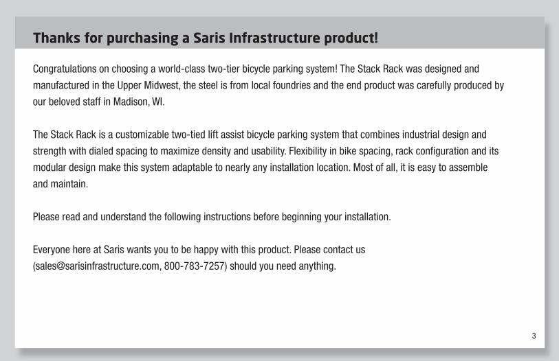
Thanks for purchasing a Saris Infrastructure product!
Congratulations on choosing a world-class two-tier bicycle parking system! The Stack Rack was designed and
manufactured in the Upper Midwest, the steel is from local foundries and the end product was carefully produced by
our beloved staff in Madison, WI.
The Stack Rack is a customizable two-tied lift assist bicycle parking system that combines industrial design and
strength with dialed spacing to maximize density and usability. Flexibility in bike spacing, rack confi guration and its
modular design make this system adaptable to nearly any installation location. Most of all, it is easy to assemble
and maintain.
Please read and understand the following instructions before beginning your installation.
Everyone here at Saris wants you to be happy with this product. Please contact us
([email protected], 800-783-7257) should you need anything.
4
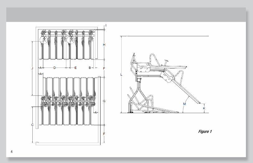
Figure 1
Figure 1
5
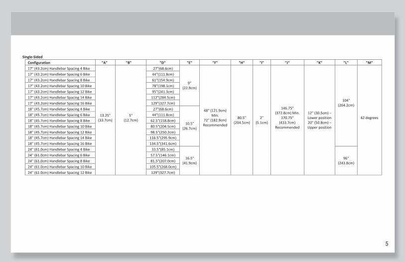
Single-Sided Configuration "A" "B" "D" "E" "F" "H" "I" "J" "K" "L" "M" 17" (43.2cm) Handlebar Spacing 4 Bike
13.25" (33.7cm)
5" (12.7cm)
27"(68.6cm)
9” (22.9cm)
48" (121.9cm) Min.
72" (182.9cm) Recommended
80.5" (204.5cm)
2" (5.1cm)
146.75" (372.8cm) Min.
170.75" (433.7cm)
Recommended
12" (30.5cm) – Lower position 20" (50.8cm) – Upper position
104" (264.2cm)
42 degrees
17" (43.2cm) Handlebar Spacing 6 Bike 44"(111.8cm) 17" (43.2cm) Handlebar Spacing 8 Bike 61"(154.9cm) 17" (43.2cm) Handlebar Spacing 10 Bike 78"(198.1cm) 17" (43.2cm) Handlebar Spacing 12 Bike 95"(241.3cm) 17" (43.2cm) Handlebar Spacing 14 Bike 112"(284.5cm) 17" (43.2cm) Handlebar Spacing 16 Bike 129"(327.7cm) 18" (45.7cm) Handlebar Spacing 4 Bike 27"(68.6cm)
10.5" (26.7cm)
18" (45.7cm) Handlebar Spacing 6 Bike 44"(111.8cm) 18" (45.7cm) Handlebar Spacing 8 Bike 62.5"(158.8cm) 18" (45.7cm) Handlebar Spacing 10 Bike 80.5"(204.5cm) 18" (45.7cm) Handlebar Spacing 12 Bike 98.5"(250.2cm) 18" (45.7cm) Handlebar Spacing 14 Bike 116.5"(295.9cm) 18" (45.7cm) Handlebar Spacing 16 Bike 134.5"(341.6cm) 24" (61.0cm) Handlebar Spacing 4 Bike 33.5"(85.1cm)
16.5" (41.9cm)
96" (243.8cm)
24" (61.0cm) Handlebar Spacing 6 Bike 57.5"(146.1cm) 24" (61.0cm) Handlebar Spacing 8 Bike 81.5"(207.0cm) 24" (61.0cm) Handlebar Spacing 10 Bike 105.5"(268.0cm) 24" (61.0cm) Handlebar Spacing 12 Bike 129"(327.7cm)
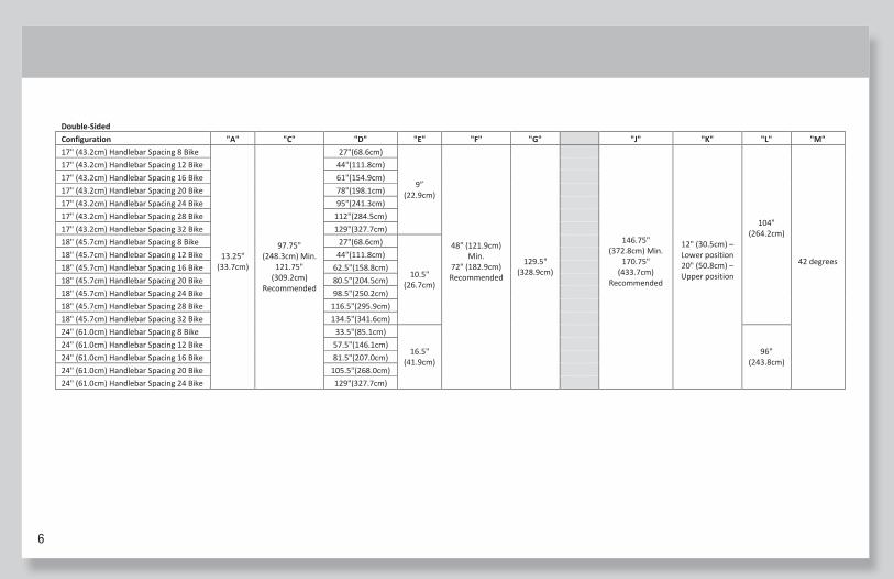
Double-Sided Configuration "A" "C" "D" "E" "F" "G" "J" "K" "L" "M" 17" (43.2cm) Handlebar Spacing 8 Bike
13.25" (33.7cm)
97.75" (248.3cm) Min.
121.75" (309.2cm)
Recommended
27"(68.6cm)
9” (22.9cm)
48" (121.9cm) Min.
72" (182.9cm) Recommended
129.5" (328.9cm)
146.75" (372.8cm) Min.
170.75" (433.7cm)
Recommended
12" (30.5cm) – Lower position 20" (50.8cm) – Upper position
104" (264.2cm)
42 degrees
17" (43.2cm) Handlebar Spacing 12 Bike 44"(111.8cm) 17" (43.2cm) Handlebar Spacing 16 Bike 61"(154.9cm) 17" (43.2cm) Handlebar Spacing 20 Bike 78"(198.1cm) 17" (43.2cm) Handlebar Spacing 24 Bike 95"(241.3cm) 17" (43.2cm) Handlebar Spacing 28 Bike 112"(284.5cm) 17" (43.2cm) Handlebar Spacing 32 Bike 129"(327.7cm) 18" (45.7cm) Handlebar Spacing 8 Bike 27"(68.6cm)
10.5" (26.7cm)
18" (45.7cm) Handlebar Spacing 12 Bike 44"(111.8cm) 18" (45.7cm) Handlebar Spacing 16 Bike 62.5"(158.8cm) 18" (45.7cm) Handlebar Spacing 20 Bike 80.5"(204.5cm) 18" (45.7cm) Handlebar Spacing 24 Bike 98.5"(250.2cm) 18" (45.7cm) Handlebar Spacing 28 Bike 116.5"(295.9cm) 18" (45.7cm) Handlebar Spacing 32 Bike 134.5"(341.6cm) 24" (61.0cm) Handlebar Spacing 8 Bike 33.5"(85.1cm)
16.5" (41.9cm)
96" (243.8cm)
24" (61.0cm) Handlebar Spacing 12 Bike 57.5"(146.1cm) 24" (61.0cm) Handlebar Spacing 16 Bike 81.5"(207.0cm) 24" (61.0cm) Handlebar Spacing 20 Bike 105.5"(268.0cm) 24" (61.0cm) Handlebar Spacing 24 Bike 129"(327.7cm)
6
Single-Sided Configuration "A" "B" "D" "E" "F" "H" "I" "J" "K" "L" "M" 17" (43.2cm) Handlebar Spacing 4 Bike
13.25" (33.7cm)
5" (12.7cm)
27"(68.6cm)
9” (22.9cm)
48" (121.9cm) Min.
72" (182.9cm) Recommended
80.5" (204.5cm)
2" (5.1cm)
146.75" (372.8cm) Min.
170.75" (433.7cm)
Recommended
12" (30.5cm) – Lower position 20" (50.8cm) – Upper position
104" (264.2cm)
42 degrees
17" (43.2cm) Handlebar Spacing 6 Bike 44"(111.8cm) 17" (43.2cm) Handlebar Spacing 8 Bike 61"(154.9cm) 17" (43.2cm) Handlebar Spacing 10 Bike 78"(198.1cm) 17" (43.2cm) Handlebar Spacing 12 Bike 95"(241.3cm) 17" (43.2cm) Handlebar Spacing 14 Bike 112"(284.5cm) 17" (43.2cm) Handlebar Spacing 16 Bike 129"(327.7cm) 18" (45.7cm) Handlebar Spacing 4 Bike 27"(68.6cm)
10.5" (26.7cm)
18" (45.7cm) Handlebar Spacing 6 Bike 44"(111.8cm) 18" (45.7cm) Handlebar Spacing 8 Bike 62.5"(158.8cm) 18" (45.7cm) Handlebar Spacing 10 Bike 80.5"(204.5cm) 18" (45.7cm) Handlebar Spacing 12 Bike 98.5"(250.2cm) 18" (45.7cm) Handlebar Spacing 14 Bike 116.5"(295.9cm) 18" (45.7cm) Handlebar Spacing 16 Bike 134.5"(341.6cm) 24" (61.0cm) Handlebar Spacing 4 Bike 33.5"(85.1cm)
16.5" (41.9cm)
96" (243.8cm)
24" (61.0cm) Handlebar Spacing 6 Bike 57.5"(146.1cm) 24" (61.0cm) Handlebar Spacing 8 Bike 81.5"(207.0cm) 24" (61.0cm) Handlebar Spacing 10 Bike 105.5"(268.0cm) 24" (61.0cm) Handlebar Spacing 12 Bike 129"(327.7cm)
Double-Sided Configuration "A" "C" "D" "E" "F" "G" "J" "K" "L" "M" 17" (43.2cm) Handlebar Spacing 8 Bike
13.25" (33.7cm)
97.75" (248.3cm) Min.
121.75" (309.2cm)
Recommended
27"(68.6cm)
9” (22.9cm)
48" (121.9cm) Min.
72" (182.9cm) Recommended
129.5" (328.9cm)
146.75" (372.8cm) Min.
170.75" (433.7cm)
Recommended
12" (30.5cm) – Lower position 20" (50.8cm) – Upper position
104" (264.2cm)
42 degrees
17" (43.2cm) Handlebar Spacing 12 Bike 44"(111.8cm) 17" (43.2cm) Handlebar Spacing 16 Bike 61"(154.9cm) 17" (43.2cm) Handlebar Spacing 20 Bike 78"(198.1cm) 17" (43.2cm) Handlebar Spacing 24 Bike 95"(241.3cm) 17" (43.2cm) Handlebar Spacing 28 Bike 112"(284.5cm) 17" (43.2cm) Handlebar Spacing 32 Bike 129"(327.7cm) 18" (45.7cm) Handlebar Spacing 8 Bike 27"(68.6cm)
10.5" (26.7cm)
18" (45.7cm) Handlebar Spacing 12 Bike 44"(111.8cm) 18" (45.7cm) Handlebar Spacing 16 Bike 62.5"(158.8cm) 18" (45.7cm) Handlebar Spacing 20 Bike 80.5"(204.5cm) 18" (45.7cm) Handlebar Spacing 24 Bike 98.5"(250.2cm) 18" (45.7cm) Handlebar Spacing 28 Bike 116.5"(295.9cm) 18" (45.7cm) Handlebar Spacing 32 Bike 134.5"(341.6cm) 24" (61.0cm) Handlebar Spacing 8 Bike 33.5"(85.1cm)
16.5" (41.9cm)
96" (243.8cm)
24" (61.0cm) Handlebar Spacing 12 Bike 57.5"(146.1cm) 24" (61.0cm) Handlebar Spacing 16 Bike 81.5"(207.0cm) 24" (61.0cm) Handlebar Spacing 20 Bike 105.5"(268.0cm) 24" (61.0cm) Handlebar Spacing 24 Bike 129"(327.7cm)
7
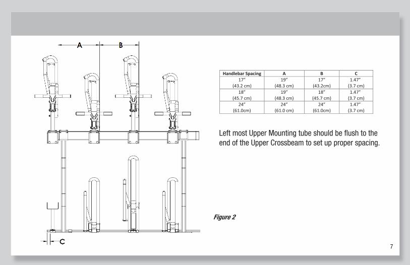
Figure 2
Handlebar Spacing A B C 17”
(43.2 cm) 19”
(48.3 cm) 17”
(43.2cm) 1.47”
(3.7 cm) 18”
(45.7 cm) 19”
(48.3 cm) 18”
(45.7 cm) 1.47”
(3.7 cm) 24”
(61.0cm) 24”
(61.0 cm) 24”
(61.0cm) 1.47”
(3.7 cm)
Left most Upper Mounting tube should be flush to the end of the Upper Crossbeam to set up proper spacing.
Figure 2
Left most Upper Mounting tube should be fl ush to the end of the Upper Crossbeam to set up proper spacing.
Figure 2
Handlebar Spacing A B C 17”
(43.2 cm) 19”
(48.3 cm) 17”
(43.2cm) 1.47”
(3.7 cm) 18”
(45.7 cm) 19”
(48.3 cm) 18”
(45.7 cm) 1.47”
(3.7 cm) 24”
(61.0cm) 24”
(61.0 cm) 24”
(61.0cm) 1.47”
(3.7 cm)
Left most Upper Mounting tube should be flush to the end of the Upper Crossbeam to set up proper spacing.
8
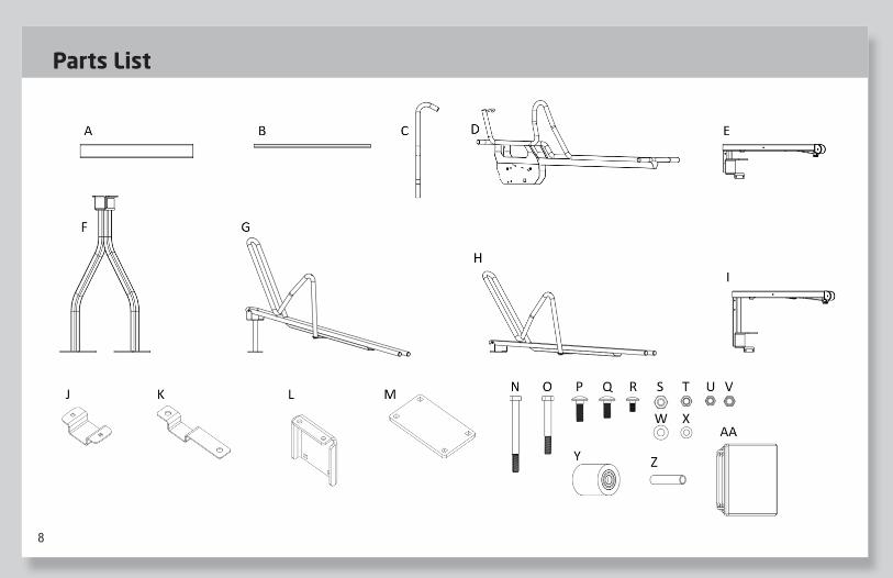
Parts List
9
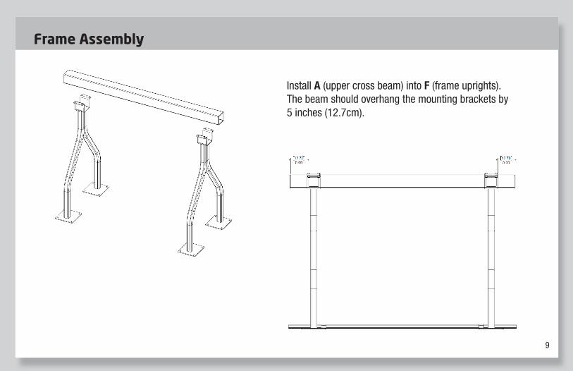
Install A (upper cross beam) into F (frame uprights). The beam should overhang the mounting brackets by 5 inches (12.7cm).
Install A (upper cross beam) into F (frame uprights). The beam should overhang the mounting brackets by 5 inches (12.7cm).
Install A (upper cross beam) into F (frame uprights). The beam should overhang the mounting brackets by 5 inches (12.7cm).
Frame Assembly
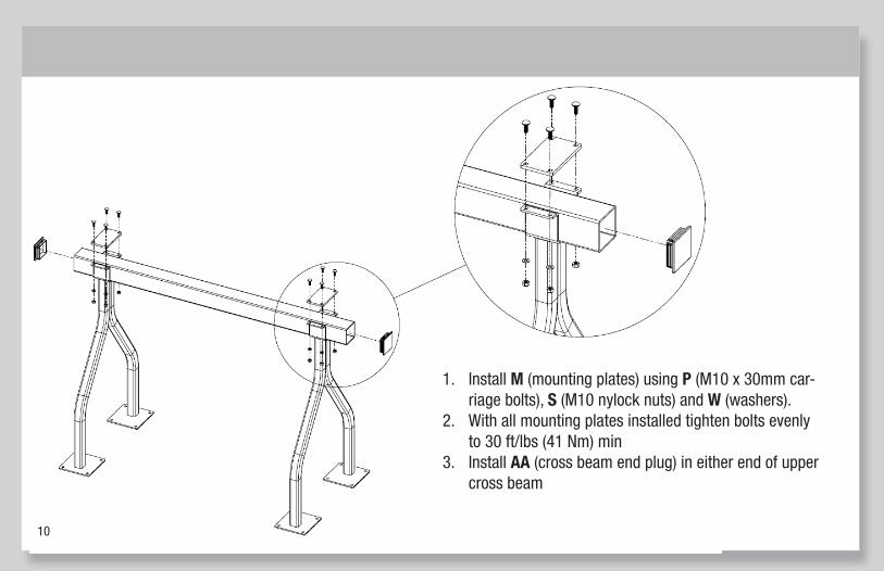
1. Install M (mounting plates) using P (M10 x 30mm carriage bolts), S (M10 nylock nuts) and W (washers).
2. With all mounting plates installed tighten bolts evenly to 30 ft/lbs (41 Nm) min
3. Install AA (cross beam end plug) in either end of upper cross beam
1. Install M (mounting plates) using P (M10 x 30mm car-riage bolts), S (M10 nylock nuts) and W (washers).
2. With all mounting plates installed tighten bolts evenly to 30 ft/lbs (41 Nm) min
3. Install AA (cross beam end plug) in either end of upper cross beam
10
11
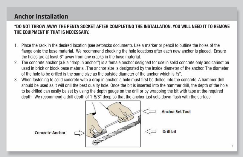
*DO NOT THROW AWAY THE PENTA SOCKET AFTER COMPLETING THE INSTALLATION. YOU WILL NEED IT TO REMOVE THE EQUIPMENT IF THAT IS NECESSARY.
1. Place the rack in the desired location (see setbacks document). Use a marker or pencil to outline the holes of the fl ange onto the base material. We recommend checking the hole locations after each new anchor is placed. Ensure the holes are at least 6” away from any cracks in the base material.
2. The concrete anchor (a.k.a “drop in anchor”) is a female anchor designed for use in solid concrete only and cannot be used in brick or block base material. The anchor size is designated by the inside diameter of the anchor. The diameter of the hole to be drilled is the same size as the outside diameter of the anchor which is ½”.
3. When fastening to solid concrete with a drop in anchor, a hole must fi rst be drilled into the concrete. A hammer drill should be used as it will drill the best quality hole. Once the bit is inserted into the hammer drill, the depth of the hole to be drilled can easily be set by using the depth gauge on the drill or by wrapping the bit with tape at the required depth. We recommend a drill depth of 1-5/8” deep so that the anchor just sets down fl ush with the surface.
A. Temporary Mount (P/N 28879) & Temporary Secure Mount (P/N 26270)-Sold Separately
Circle dock Temporary Mount (P/N 29164) & Temporary Secure Mount (P/N 29163)-sold separately
Tools Needed for Installation (Sold by Saris)
• Anchor Set Tool P/N 25683
• Penta Security Socket P/N 25680 (only needed for temporary secure installation)
Tools Needed for Installation (Installer Provides)
• Tape Measure • ½” Masonry Drill Bit Drill (Hammer drill recommended) • Hammer • 3/8” drive ratchet • Marker or Pencil • 7/32” hex key • Level
*DO NOT THROW AWAY THE PENTA SOCKET AFTER COMPLETING THE INSTALLATION. YOU WILL NEED IT TO REMOVE THE EQUIPMENT IF THAT IS NECESSARY.
1. Place the rack in the desired location (see setbacks document). Use a marker or pencil to outline the holes of the flange onto the base material. We recommend checking the hole locations after each new anchor is placed. Ensure the holes are at least 6” away from any cracks in the base material.
2. The concrete anchor (a.k.a “drop in anchor”) is a female anchor designed for use in solid concrete only and cannot be used in brick or block base material. The anchor size is designated by the inside diameter of the anchor. The diameter of the hole to be drilled is the same size as the outside diameter of the anchor which is ½”.
3. When fastening to solid concrete with a drop in anchor, a hole must first be drilled into the concrete. A hammer drill should be used as it will drill the best quality hole. Once the bit is inserted into the hammer drill, the depth of the hole to be drilled can easily be set by using the depth gauge on the drill or by wrapping the bit with tape at the required depth. We recommend a drill depth of 1-5/8” deep so that the anchor just sets down flush with the surface.
4. Before starting to drill the hole, it is important that eye and ear protection are used. Make sure the hammer drill is in the
hammer mode and start drilling your hole. Continue drilling until the tape on the bit or the drill gauge meets the base material- this means that the required depth has been reached.
Anchor Installation
12
5. Before proceeding with installation, the hole must be cleaned of all concrete dust to ensure proper fastening. Use a wire brush,
a vacuum or compressed air to clean out the hole completely.
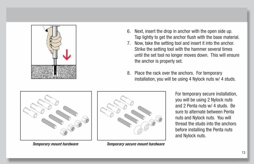
6. Next, insert the drop in anchor with the open side up. Tap lightly to get the anchor flush with the base material. 7. Now, take the setting tool and insert it into the anchor. Strike the setting tool with the hammer several times until the set tool
no longer moves down. This will ensure the anchor is properly set.
8. Place the rack over the anchors. For temporary installation, you will be using 4 button head hex bolts. Use the 7/32” hex wrench to tighten the button head hex bolts.
Temporary mount hardware
For temporary secure installation, you will be using 2 studs w/ 2 Penta nuts and 2 button head hex bolts. Be sure to alternate between Penta nuts and button head bolts. You will thread the stud into the anchor prior to installing the Penta nuts using the Penta socket. Use the 7/32” hex wrench to tighten the button head hex bolts.
5. Before proceeding with installation, the hole must be cleaned of all concrete dust to ensure proper fastening. Use a wire brush,
a vacuum or compressed air to clean out the hole completely.
6. Next, insert the drop in anchor with the open side up. Tap lightly to get the anchor flush with the base material. 7. Now, take the setting tool and insert it into the anchor. Strike the setting tool with the hammer several times until the set tool
no longer moves down. This will ensure the anchor is properly set.
8. Place the rack over the anchors. For temporary installation, you will be using 4 button head hex bolts. Use the 7/32” hex wrench to tighten the button head hex bolts.
Temporary mount hardware
For temporary secure installation, you will be using 2 studs w/ 2 Penta nuts and 2 button head hex bolts. Be sure to alternate between Penta nuts and button head bolts. You will thread the stud into the anchor prior to installing the Penta nuts using the Penta socket. Use the 7/32” hex wrench to tighten the button head hex bolts.
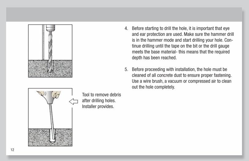
Tool to remove debris after drilling holes. Installer provides.
5. Before proceeding with installation, the hole must be cleaned of all concrete dust to ensure proper fastening. Use a wire brush,
a vacuum or compressed air to clean out the hole completely.
6. Next, insert the drop in anchor with the open side up. Tap lightly to get the anchor flush with the base material. 7. Now, take the setting tool and insert it into the anchor. Strike the setting tool with the hammer several times until the set tool
no longer moves down. This will ensure the anchor is properly set.
8. Place the rack over the anchors. For temporary installation, you will be using 4 button head hex bolts. Use the 7/32” hex wrench to tighten the button head hex bolts.
Temporary mount hardware
For temporary secure installation, you will be using 2 studs w/ 2 Penta nuts and 2 button head hex bolts. Be sure to alternate between Penta nuts and button head bolts. You will thread the stud into the anchor prior to installing the Penta nuts using the Penta socket. Use the 7/32” hex wrench to tighten the button head hex bolts.
4. Before starting to drill the hole, it is important that eye and ear protection are used. Make sure the hammer drill is in the hammer mode and start drilling your hole. Con-tinue drilling until the tape on the bit or the drill gauge meets the base material- this means that the required depth has been reached.
5. Before proceeding with installation, the hole must be cleaned of all concrete dust to ensure proper fastening. Use a wire brush, a vacuum or compressed air to clean out the hole completely.
6. Next, insert the drop in anchor with the open side up. Tap lightly to get the anchor fl ush with the base material.
7. Now, take the setting tool and insert it into the anchor. Strike the setting tool with the hammer several times until the set tool no longer moves down. This will ensure the anchor is properly set.
8. Place the rack over the anchors. For temporary installation, you will be using 4 Nylock nuts w/ 4 studs.
5. Before proceeding with installation, the hole must be cleaned of all concrete dust to ensure proper fastening. Use a wire brush,
a vacuum or compressed air to clean out the hole completely.
6. Next, insert the drop in anchor with the open side up. Tap lightly to get the anchor flush with the base material. 7. Now, take the setting tool and insert it into the anchor. Strike the setting tool with the hammer several times until the set tool
no longer moves down. This will ensure the anchor is properly set.
8. Place the rack over the anchors. For temporary installation, you will be using 4 button head hex bolts. Use the 7/32” hex wrench to tighten the button head hex bolts.
Temporary mount hardware
For temporary secure installation, you will be using 2 studs w/ 2 Penta nuts and 2 button head hex bolts. Be sure to alternate between Penta nuts and button head bolts. You will thread the stud into the anchor prior to installing the Penta nuts using the Penta socket. Use the 7/32” hex wrench to tighten the button head hex bolts.
Temporary mount hardware Temporary secure mount hardware
For temporary secure installation, you will be using 2 Nylock nuts and 2 Penta nuts w/ 4 studs. Be sure to alternate between Penta nuts and Nylock nuts. You will thread the studs into the anchors before installing the Penta nuts and Nylock nuts.
13
14
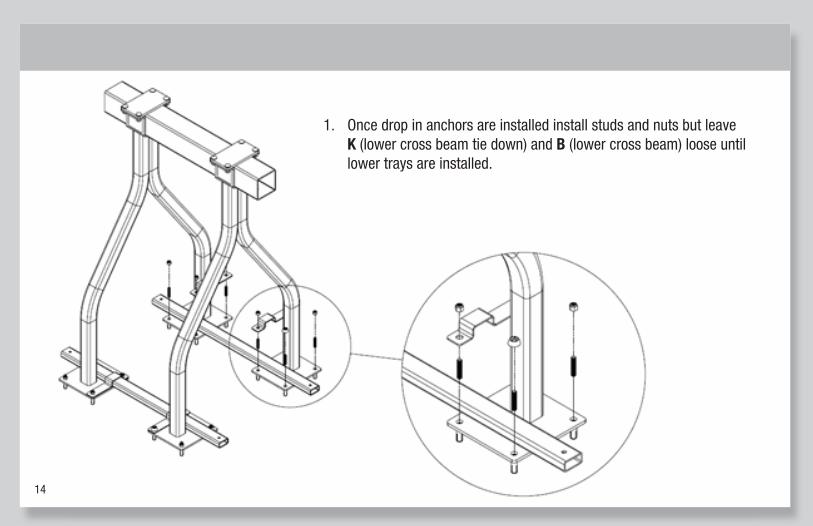
1. Once drop in anchors are installed install studs and nuts but leave K (lower cross beam tie down) and B (lower cross beam) loose until lower trays are installed.
15
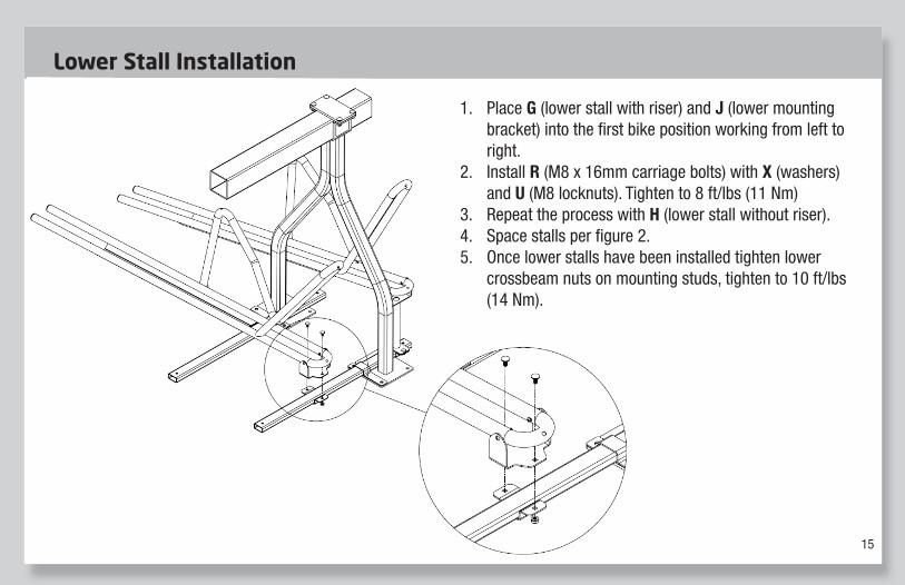
1. Place G (lower stall with riser) and J (lower mounting bracket) into the first bike position working from left to right.
2. Install R (M8 x 16mm carriage bolts) with X (washers) and U (M8 locknuts). Tighten to 8 ft/lbs (11 Nm)
3. Repeat the process with H (lower stall without riser). 4. Space stalls per figure 2. 5. Once lower stalls have been installed tighten lower
crossbeam nuts on mounting studs, tighten to 10 ft/lbs (14 Nm).
1. Place G (lower stall with riser) and J (lower mounting bracket) into the fi rst bike position working from left to right.
2. Install R (M8 x 16mm carriage bolts) with X (washers) and U (M8 locknuts). Tighten to 8 ft/lbs (11 Nm)
3. Repeat the process with H (lower stall without riser).4. Space stalls per fi gure 2.5. Once lower stalls have been installed tighten lower
crossbeam nuts on mounting studs, tighten to 10 ft/lbs (14 Nm).
Lower Stall Installation
16
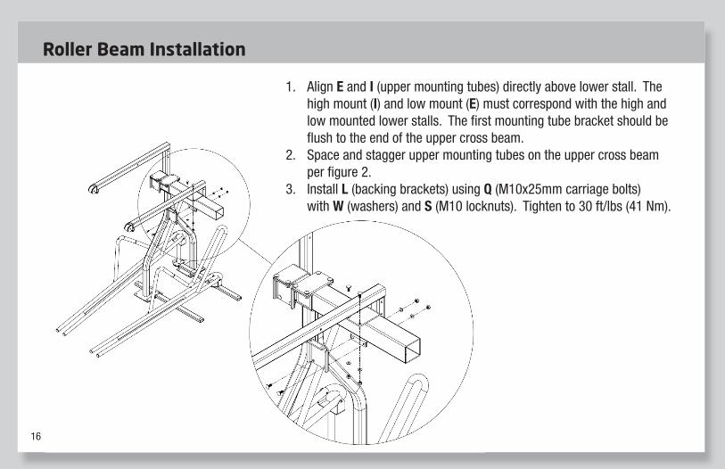
1. Align E and I (upper mounting tubes) directly above lower stall. The high mount (I) and low mount (E) must correspond with the high and low mounted lower stalls. The first mounting tube bracket should be flush to the end of the upper cross beam.
2. Space and stagger upper mounting tubes on the upper cross beam per figure 2.
3. Install L (backing brackets) using Q (M10x25mm carriage bolts) with W (washers) and S (M10 locknuts). Tighten to 30 ft/lbs (41 Nm).
1. Align E and I (upper mounting tubes) directly above lower stall. The high mount (I) and low mount (E) must correspond with the high and low mounted lower stalls. The fi rst mounting tube bracket should be fl ush to the end of the upper cross beam.
2. Space and stagger upper mounting tubes on the upper cross beam per fi gure 2.
3. Install L (backing brackets) using Q (M10x25mm carriage bolts) with W (washers) and S (M10 locknuts). Tighten to 30 ft/lbs (41 Nm).
Roller Beam Installation
17
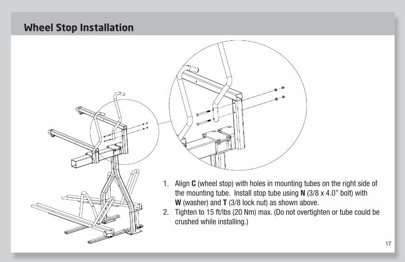
1. Align C (wheel stop) with holes in mounting tubes on the right side of the mounting tube. Install stop tube using N (3/8 x 4.0” bolt) with W (washer) and T (3/8 lock nut) as shown above.
2. Tighten to 15 ft/lbs (20 Nm) max. (Do not overtighten or tube could be crushed while installing.)
1. Align C (wheel stop) with holes in mounting tubes on the right side of the mounting tube. Install stop tube using N (3/8 x 4.0” bolt) with W (washer) and T (3/8 lock nut) as shown above.
2. Tighten to 15 ft/lbs (20 Nm) max. (Do not overtighten or tube could be crushed while installing.)
Wheel Stop Installation
18
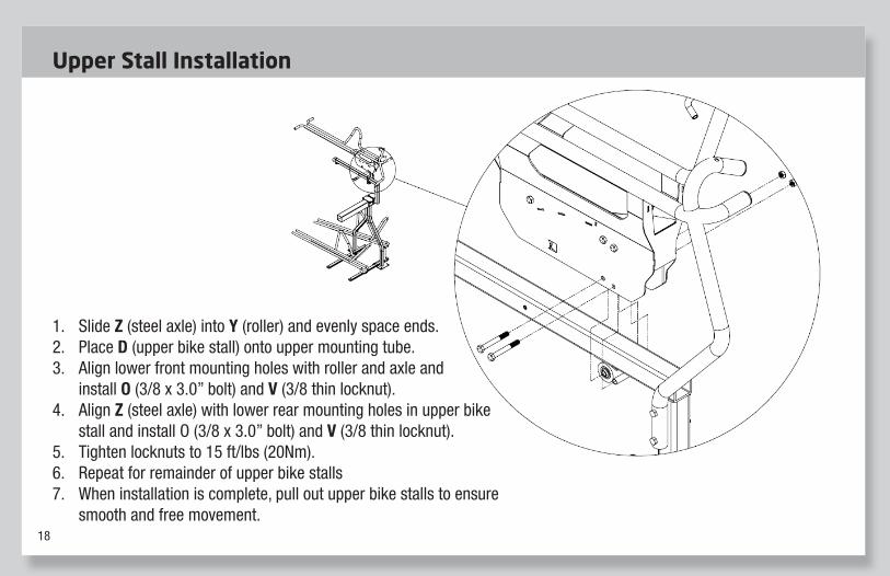
1. Slide Z (steel axle) into Y (roller) and evenly space ends.
2. Place D (upper bike stall) onto upper mounting tube. 3. Align lower front mounting holes with roller and
axle and install O (3/8 x 3.0” bolt) and V (3/8 thin locknut).
4. Align Z (steel axle) with lower rear mounting holes in upper bike stall and install O (3/8 x 3.0” bolt) and V (3/8 thin locknut).
5. Tighten locknuts to 15 ft/lbs (20Nm). 6. Repeat for remainder of upper bike stalls 7. When installation is complete, pull out upper bike
stalls to ensure smooth and free movement.
1. Slide Z (steel axle) into Y (roller) and evenly space ends.2. Place D (upper bike stall) onto upper mounting tube.3. Align lower front mounting holes with roller and axle and
install O (3/8 x 3.0” bolt) and V (3/8 thin locknut).4. Align Z (steel axle) with lower rear mounting holes in upper bike
stall and install O (3/8 x 3.0” bolt) and V (3/8 thin locknut). 5. Tighten locknuts to 15 ft/lbs (20Nm).6. Repeat for remainder of upper bike stalls7. When installation is complete, pull out upper bike stalls to ensure
smooth and free movement.
Upper Stall Installation
19
WARNING: Manufacturer and seller expressly disclaim any and all liability for personal injury, property damage or loss, whether direct, indirect, or incidental, resulting from the incorrect attachment or inappropriate placement, improper use,
inadequate maintenance, or neglect of this product. Placement of this product is beyond control of the manufacturer. It is the end users reasonability to place this product so as to avoid potential pedestrian or playground accidents.
WARRANTY: We warrant this product to the fi rst consumer to be free from defect in material and workmanship for a period of one year from date of purchase. Please retain your sales slip for your records. Any product or part thereof found to be defective within that period will be replaced without charge provided that: (1) the product was not misused; (2) no alterations or modifi cations were made; (3) its failure resulted from a defect in material or workmanship and not from normal wear expected in the use of the product; (4) the product or part is delivered, freight prepaid, to Saris Products.
Manufacturer’s only obligation shall be to replace such products or parts proved to be defective.
Saris Cycling Group 5253 Verona Road Madison, WI 53711 (800) 783-7257 www.sarisinfrastructure.com
12/19