Embed Size (px)
Citation preview
Cat. No. W366-E1-10
CX-Simulator Ver. 1.9
SYSMACWS02-SIMC1-E
OPERATION MANUAL

SYSMAC WS02-SIMC1-E CX-Simulator Ver. 1.9 Operation Manual Revised December 2009
v
Notice: OMRON products are manufactured for use according to proper procedures by a qualified operator and only for the purposes described in this manual. The following conventions are used to indicate and classify precautions in this manual. Always heed the information provided with them. Failure to heed precautions can result in injury to people or damage to property.
DANGER Indicates an imminently hazardous situation which, if not avoided, will result in death or
serious injury. Additionally, there may be severe property damage.
WARNING Indicates a potentially hazardous situation which, if not avoided, could result in death or serious injury. Additionally, there may be severe property damage.
Caution Indicates a potentially hazardous situation which, if not avoided, may result in minor or moderate injury, or property damage.
OMRON Product References All OMRON products are capitalized in this manual. The word "Unit" is also capitalized when it refers to an OMRON product, regardless of whether or not it appears in the proper name of the product.
The abbreviation "Ch," which appears in some displays and on some OMRON products, often means "word" and is abbreviated "Wd" in documentation in this sense.
In this manual, "PLC" is used as the abbreviation for Programmable Controller.
Visual Aids The following headings appear in the left column of the manual to help you locate different types of information.
Note Indicates information of particular interest for efficient and convenient opera-
tion of the product.
1, 2, 3... 1. Indicates lists of one sort or another, such as procedures, checklists, etc. OMRON, 2008
All rights reserved. No part of this publication may be reproduced, stored in a retrieval system, or transmitted, in any form, or by any means, mechanical, electronic, photocopying, recording, or otherwise, without the prior written permission of OMRON. No patent liability is assumed with respect to the use of the information contained herein. Moreover, because OMRON is constantly striving to improve its high-quality products, the information contained in this manual is subject to change without notice. Every precaution has been taken in the preparation of this manual. Nevertheless, OMRON assumes no responsibility for errors or omissions. Neither is any liability assumed for damages resulting from the use of the information contained in this publication.
vi
About Upgrades: Version 1.1
The following functions have been added to the CX-Simulator with the upgrade from Version 1.0 to Version 1.1.
Actual Serial Communications Possible In Ver.1.0, the contents of messages sent by serial communications instruc-tions are displayed on the computer screen. In Ver.1.1, actual serial com-munications to an external serial communications device connected to a COM port on the computer are also possible.
NT Link (1:N Mode) Possible In Ver.1.1, communications with OMRON’s Programmable Terminal (PT) connected to a COM port on the computer via NT Link are possible.
Multipoint Data Collection Tool Added Time-series I/O memory data acquired from the actual PLC can be saved as a Data Replay File (CSV format). Unlike Data Trace, data can not be acquired every cycle. However, data of more than 50 words can be acquired.
WindowsMe/2000 Supported
Serial Number Entry on Installing Added
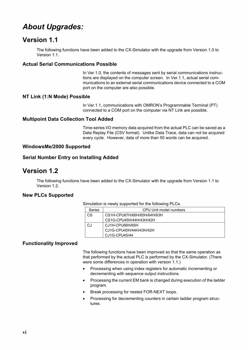
Version 1.2 The following functions have been added to the CX-Simulator with the upgrade from Version 1.1 to Version 1.2.
New PLCs Supported Simulation is newly supported for the following PLCs.
Series CPU Unit model numbers CS CS1H-CPU67H/66H/65H/64H/63H
CS1G-CPU45H/44H/43H/42H CJ CJ1H-CPU66H/65H
CJ1G-CPU45H/44H/43H/42H CJ1G-CPU45/44
Functionality Improved The following functions have been improved so that the same operation as that performed by the actual PLC is performed by the CX-Simulator. (There were some differences in operation with version 1.1.) • Processing when using index registers for automatic incrementing or
decrementing with sequence output instructions. • Processing the current EM bank is changed during execution of the ladder
program. • Break processing for nested FOR-NEXT loops. • Processing for decrementing counters in certain ladder program struc-
tures.
vii
Simplified System Exit Processing When the system is exited while the CX-Simulator is connected, a confirma-tion dialog box will appear and, upon confirmation, the CX-Simulator will be disconnected and the system shut down.
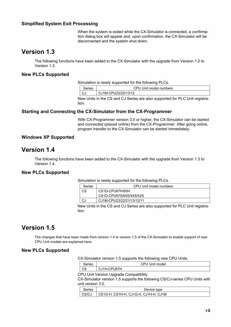
Version 1.3 The following functions have been added to the CX-Simulator with the upgrade from Version 1.2 to Version 1.3.
New PLCs Supported Simulation is newly supported for the following PLCs.
Series CPU Unit model numbers CJ CJ1M-CPU23/22/13/12
New Units in the CS and CJ Series are also supported for PLC Unit registra-tion.
Starting and Connecting the CX-Simulator from the CX-Programmer With CX-Programmer version 3.0 or higher, the CX-Simulator can be started and connected (placed online) from the CX-Programmer. After going online, program transfer to the CX-Simulator can be started immediately.
Windows XP Supported
Version 1.4 The following functions have been added to the CX-Simulator with the upgrade from Version 1.3 to Version 1.4.
New PLCs Supported Simulation is newly supported for the following PLCs.
Series CPU Unit model numbers CS CS1D-CPU67H/65H
CS1D-CPU67S/65S/44S/42S CJ CJ1M-CPU23/22/21/13/12/11
New Units in the CS and CJ Series are also supported for PLC Unit registra-tion.
Version 1.5 The changes that have been made from version 1.4 to version 1.5 of the CX-Simulator to enable support of new CPU Unit models are explained here.
New PLCs Supported CX-Simulator version 1.5 supports the following new CPU Units.
Series CPU Unit model CS CJ1H-CPU67H
CPU Unit Version Upgrade Compatibility CX-Simulator version 1.5 supports the following CS/CJ-series CPU Units with unit version 3.0.
Series Device type CS/CJ CS1G-H, CS1H-H, CJ1G-H, CJ1H-H, CJ1M
viii
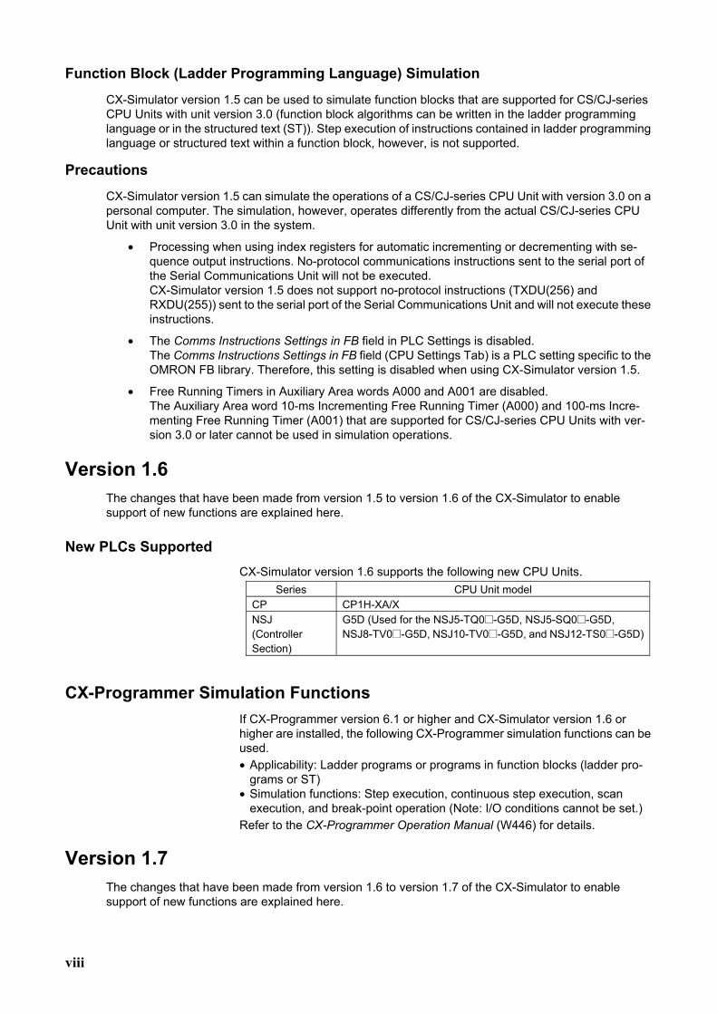
Function Block (Ladder Programming Language) Simulation
CX-Simulator version 1.5 can be used to simulate function blocks that are supported for CS/CJ-series CPU Units with unit version 3.0 (function block algorithms can be written in the ladder programming language or in the structured text (ST)). Step execution of instructions contained in ladder programming language or structured text within a function block, however, is not supported.
Precautions
CX-Simulator version 1.5 can simulate the operations of a CS/CJ-series CPU Unit with version 3.0 on a personal computer. The simulation, however, operates differently from the actual CS/CJ-series CPU Unit with unit version 3.0 in the system.
• Processing when using index registers for automatic incrementing or decrementing with se-quence output instructions. No-protocol communications instructions sent to the serial port of the Serial Communications Unit will not be executed. CX-Simulator version 1.5 does not support no-protocol instructions (TXDU(256) and RXDU(255)) sent to the serial port of the Serial Communications Unit and will not execute these instructions.
• The Comms Instructions Settings in FB field in PLC Settings is disabled. The Comms Instructions Settings in FB field (CPU Settings Tab) is a PLC setting specific to the OMRON FB library. Therefore, this setting is disabled when using CX-Simulator version 1.5.
• Free Running Timers in Auxiliary Area words A000 and A001 are disabled. The Auxiliary Area word 10-ms Incrementing Free Running Timer (A000) and 100-ms Incre-menting Free Running Timer (A001) that are supported for CS/CJ-series CPU Units with ver-sion 3.0 or later cannot be used in simulation operations.
Version 1.6 The changes that have been made from version 1.5 to version 1.6 of the CX-Simulator to enable support of new functions are explained here.
New PLCs Supported CX-Simulator version 1.6 supports the following new CPU Units.
Series CPU Unit model CP CP1H-XA/X NSJ (Controller Section)
G5D (Used for the NSJ5-TQ0@-G5D, NSJ5-SQ0@-G5D, NSJ8-TV0@-G5D, NSJ10-TV0@-G5D, and NSJ12-TS0@-G5D)
CX-Programmer Simulation Functions If CX-Programmer version 6.1 or higher and CX-Simulator version 1.6 or higher are installed, the following CX-Programmer simulation functions can be used. • Applicability: Ladder programs or programs in function blocks (ladder pro-
grams or ST) • Simulation functions: Step execution, continuous step execution, scan
execution, and break-point operation (Note: I/O conditions cannot be set.) Refer to the CX-Programmer Operation Manual (W446) for details.
Version 1.7 The changes that have been made from version 1.6 to version 1.7 of the CX-Simulator to enable support of new functions are explained here.
ix
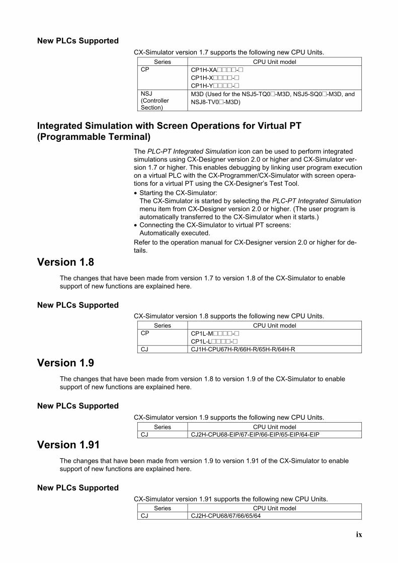
New PLCs Supported CX-Simulator version 1.7 supports the following new CPU Units.
Series CPU Unit model CP CP1H-XA@@@@-@
CP1H-X@@@@-@ CP1H-Y@@@@-@
NSJ (Controller Section)
M3D (Used for the NSJ5-TQ0@-M3D, NSJ5-SQ0@-M3D, and NSJ8-TV0@-M3D)
Integrated Simulation with Screen Operations for Virtual PT (Programmable Terminal)
The PLC-PT Integrated Simulation icon can be used to perform integrated simulations using CX-Designer version 2.0 or higher and CX-Simulator ver-sion 1.7 or higher. This enables debugging by linking user program execution on a virtual PLC with the CX-Programmer/CX-Simulator with screen opera-tions for a virtual PT using the CX-Designer’s Test Tool. • Starting the CX-Simulator:
The CX-Simulator is started by selecting the PLC-PT Integrated Simulation menu item from CX-Designer version 2.0 or higher. (The user program is automatically transferred to the CX-Simulator when it starts.)
• Connecting the CX-Simulator to virtual PT screens: Automatically executed.
Refer to the operation manual for CX-Designer version 2.0 or higher for de-tails.
Version 1.8 The changes that have been made from version 1.7 to version 1.8 of the CX-Simulator to enable support of new functions are explained here.
New PLCs Supported CX-Simulator version 1.8 supports the following new CPU Units.
Series CPU Unit model CP CP1L-M@@@@-@
CP1L-L@@@@-@ CJ CJ1H-CPU67H-R/66H-R/65H-R/64H-R
Version 1.9 The changes that have been made from version 1.8 to version 1.9 of the CX-Simulator to enable support of new functions are explained here.
New PLCs Supported CX-Simulator version 1.9 supports the following new CPU Units.
Series CPU Unit model CJ CJ2H-CPU68-EIP/67-EIP/66-EIP/65-EIP/64-EIP
Version 1.91 The changes that have been made from version 1.9 to version 1.91 of the CX-Simulator to enable support of new functions are explained here.
New PLCs Supported CX-Simulator version 1.91 supports the following new CPU Units.
Series CPU Unit model CJ CJ2H-CPU68/67/66/65/64
x
Version 1.94 The changes that have been made from version 1.9 to version 1.94 of the CX-Simulator to enable support of new functions are explained here.
Support for Windows 7
Note This upgrade accompanies the upgrade of CX-One version 3.2 to CX-One version 4.03.
xi
Unit Versions of CS/CJ/CP/NSJ-series CPU Units
Unit Versions A “unit version” has been introduced to manage CPU Units in the CS/CJ/CP/NSJ Series according to differences in functionality accompanying Unit upgrades. This applies to the CJ2H, CS1-H, CJ1-H, CJ1M, CS1D, and CP1H CPU Units.
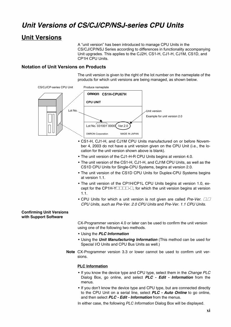
Notation of Unit Versions on Products The unit version is given to the right of the lot number on the nameplate of the products for which unit versions are being managed, as shown below.
Unit version
Example for unit version 2.0
CS1H-CPU67H
CPU UNIT
Lot No. 031001 0000 Ver.2.0
OMRON Corporation MADE IN JAPAN
Produce nameplate CS/CJ/CP-series CPU Unit
Lot No.
• CS1-H, CJ1-H, and CJ1M CPU Units manufactured on or before Novem-
ber 4, 2003 do not have a unit version given on the CPU Unit (i.e., the lo-cation for the unit version shown above is blank).
• The unit version of the CJ1-H-R CPU Units begins at version 4.0.
• The unit version of the CS1-H, CJ1-H, and CJ1M CPU Units, as well as the CS1D CPU Units for Single-CPU Systems, begins at version 2.0.
• The unit version of the CS1D CPU Units for Duplex-CPU Systems begins at version 1.1.
• The unit version of the CP1H/CP1L CPU Units begins at version 1.0, ex-cept for the CP1H-Y@@@@-@, for which the unit version begins at version 1.1.
• CPU Units for which a unit version is not given are called Pre-Ver. @.@ CPU Units, such as Pre-Ver. 2.0 CPU Units and Pre-Ver. 1.1 CPU Units.
Confirming Unit Versions with Support Software
CX-Programmer version 4.0 or later can be used to confirm the unit version using one of the following two methods. • Using the PLC Information
• Using the Unit Manufacturing Information (This method can be used for Special I/O Units and CPU Bus Units as well.)
Note CX-Programmer version 3.3 or lower cannot be used to confirm unit ver-sions.
PLC Information
• If you know the device type and CPU type, select them in the Change PLC Dialog Box, go online, and select PLC - Edit - Information from the menus.
• If you don’t know the device type and CPU type, but are connected directly to the CPU Unit on a serial line, select PLC - Auto Online to go online, and then select PLC - Edit - Information from the menus.
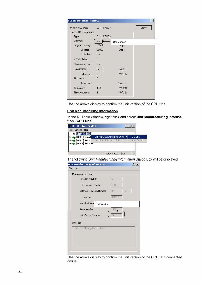
In either case, the following PLC Information Dialog Box will be displayed.
xii
Unit version
Use the above display to confirm the unit version of the CPU Unit.
Unit Manufacturing Information
In the IO Table Window, right-click and select Unit Manufacturing informa-tion - CPU Unit.
The following Unit Manufacturing information Dialog Box will be displayed
Unit version
Use the above display to confirm the unit version of the CPU Unit connected online.
xiii
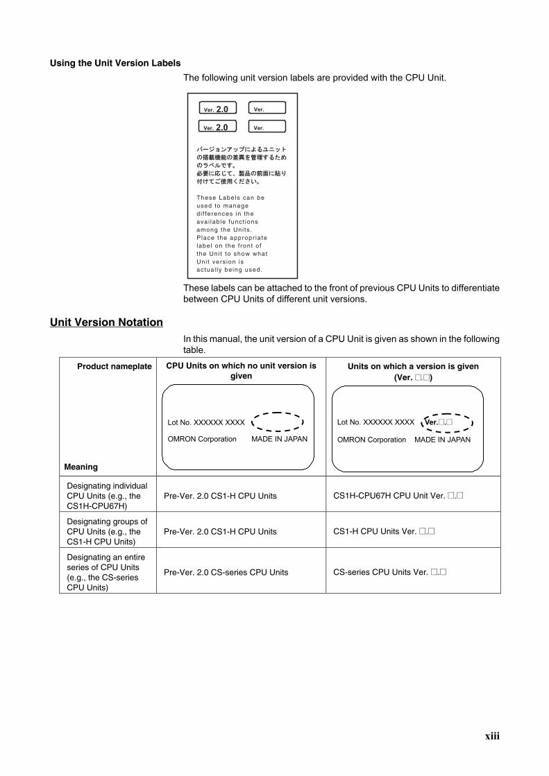
Using the Unit Version Labels
The following unit version labels are provided with the CPU Unit.
These labels can be attached to the front of previous CPU Units to differentiate between CPU Units of different unit versions.
Unit Version Notation In this manual, the unit version of a CPU Unit is given as shown in the following table.
Product nameplate Meaning
CPU Units on which no unit version is given
Lot No. XXXXXX XXXX
OMRON Corporation MADE IN JAPAN
Units on which a version is given (Ver. @.@)
Lot No. XXXXXX XXXX Ver.@.@
OMRON Corporation MADE IN JAPAN
Designating individual CPU Units (e.g., the CS1H-CPU67H)
Pre-Ver. 2.0 CS1-H CPU Units CS1H-CPU67H CPU Unit Ver. @.@
Designating groups of CPU Units (e.g., the CS1-H CPU Units)
Pre-Ver. 2.0 CS1-H CPU Units CS1-H CPU Units Ver. @.@
Designating an entire series of CPU Units (e.g., the CS-series CPU Units)
Pre-Ver. 2.0 CS-series CPU Units CS-series CPU Units Ver. @.@
xiv
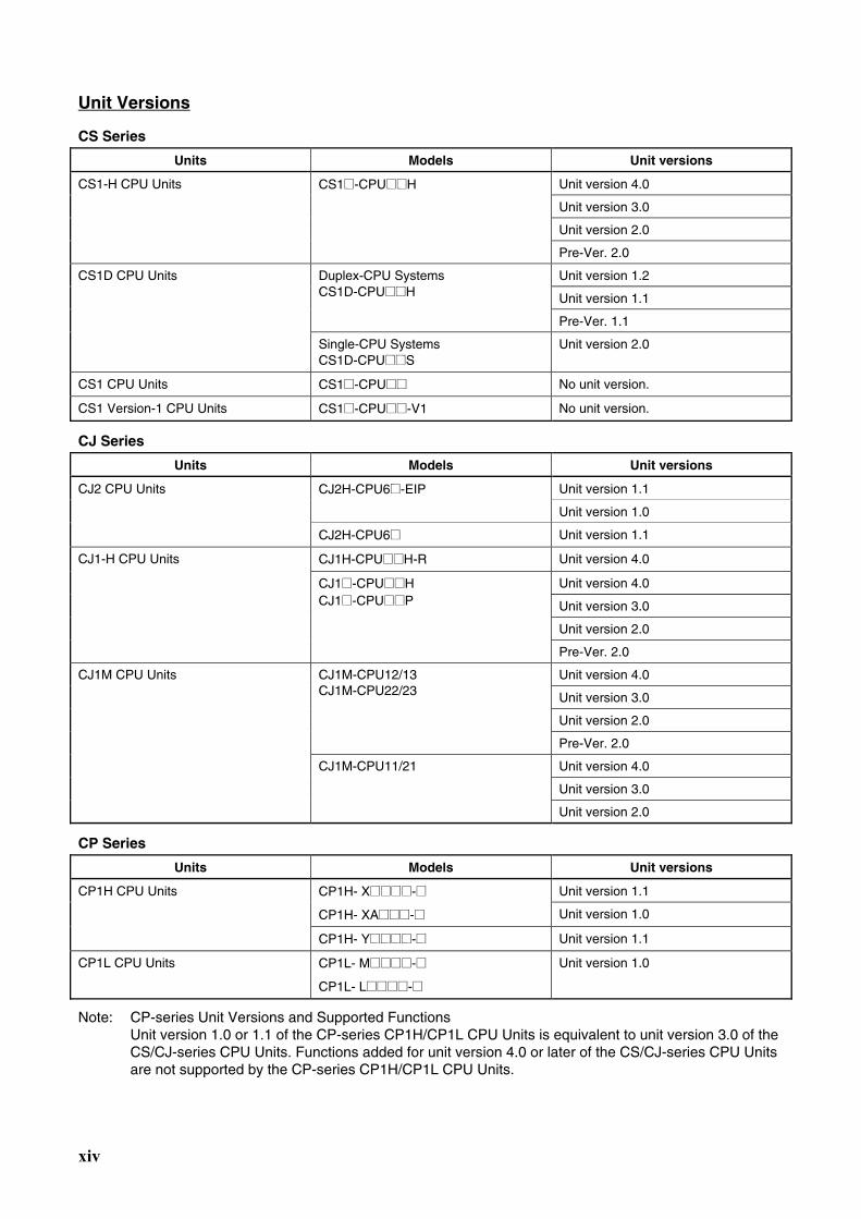
Unit Versions
CS Series
Units Models Unit versions
Unit version 4.0
Unit version 3.0
Unit version 2.0
CS1-H CPU Units CS1@-CPU@@H
Pre-Ver. 2.0
Unit version 1.2
Unit version 1.1
Duplex-CPU Systems CS1D-CPU@@H
Pre-Ver. 1.1
CS1D CPU Units
Single-CPU Systems CS1D-CPU@@S
Unit version 2.0
CS1 CPU Units CS1@-CPU@@ No unit version.
CS1 Version-1 CPU Units CS1@-CPU@@-V1 No unit version.
CJ Series
Units Models Unit versions
Unit version 1.1 CJ2H-CPU6@-EIP
Unit version 1.0
CJ2 CPU Units
CJ2H-CPU6@ Unit version 1.1
CJ1H-CPU@@H-R Unit version 4.0
Unit version 4.0
Unit version 3.0
Unit version 2.0
CJ1-H CPU Units
CJ1@-CPU@@H CJ1@-CPU@@P
Pre-Ver. 2.0
Unit version 4.0
Unit version 3.0
Unit version 2.0
CJ1M-CPU12/13 CJ1M-CPU22/23
Pre-Ver. 2.0
Unit version 4.0
Unit version 3.0
CJ1M CPU Units
CJ1M-CPU11/21
Unit version 2.0
CP Series
Units Models Unit versions
Unit version 1.1 CP1H- X@@@@-@
CP1H- XA@@@-@ Unit version 1.0
CP1H CPU Units
CP1H- Y@@@@-@ Unit version 1.1
CP1L CPU Units CP1L- M@@@@-@
CP1L- L@@@@-@
Unit version 1.0
Note: CP-series Unit Versions and Supported Functions Unit version 1.0 or 1.1 of the CP-series CP1H/CP1L CPU Units is equivalent to unit version 3.0 of the CS/CJ-series CPU Units. Functions added for unit version 4.0 or later of the CS/CJ-series CPU Units are not supported by the CP-series CP1H/CP1L CPU Units.
xv
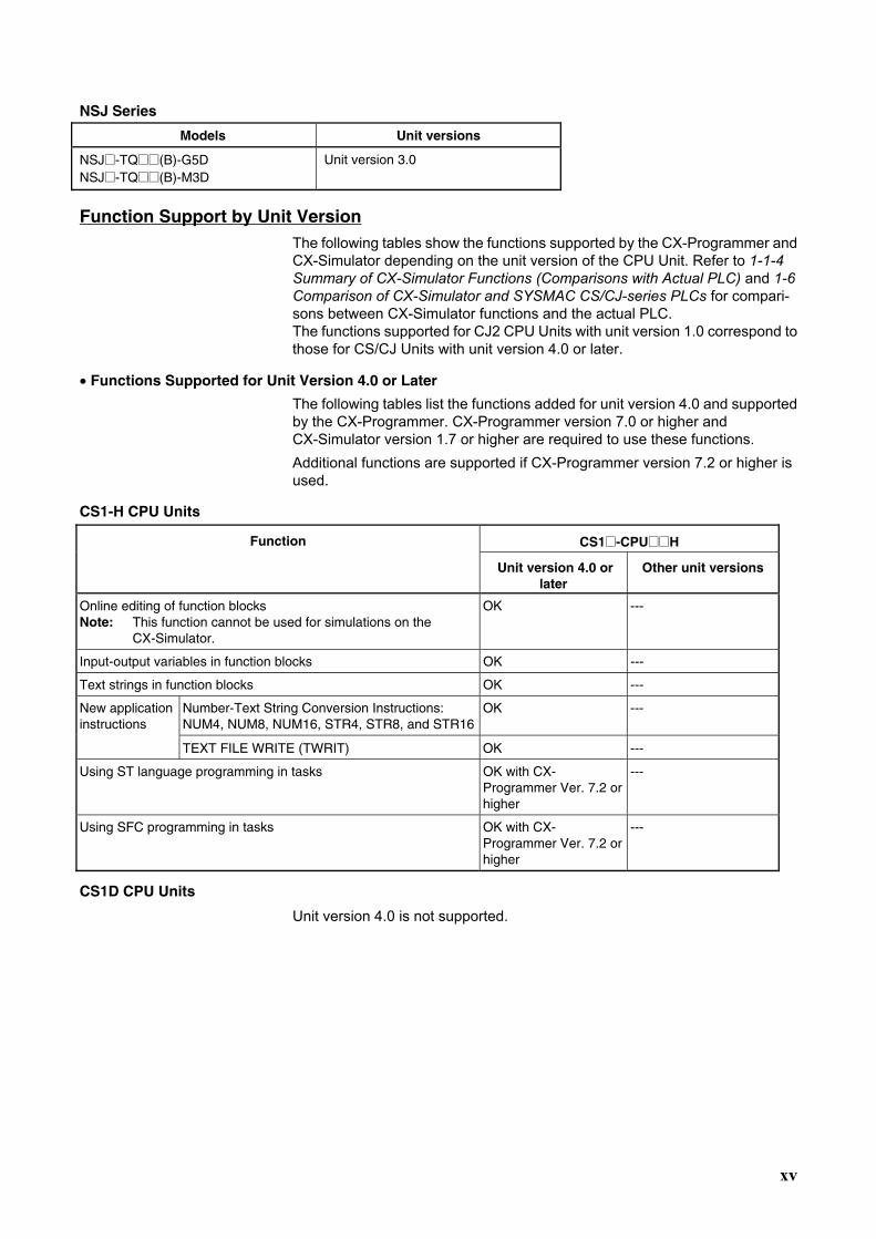
NSJ Series
Models Unit versions
NSJ@-TQ@@(B)-G5D NSJ@-TQ@@(B)-M3D
Unit version 3.0
Function Support by Unit Version The following tables show the functions supported by the CX-Programmer and CX-Simulator depending on the unit version of the CPU Unit. Refer to 1-1-4 Summary of CX-Simulator Functions (Comparisons with Actual PLC) and 1-6 Comparison of CX-Simulator and SYSMAC CS/CJ-series PLCs for compari-sons between CX-Simulator functions and the actual PLC. The functions supported for CJ2 CPU Units with unit version 1.0 correspond to those for CS/CJ Units with unit version 4.0 or later.
• Functions Supported for Unit Version 4.0 or Later
The following tables list the functions added for unit version 4.0 and supported by the CX-Programmer. CX-Programmer version 7.0 or higher and CX-Simulator version 1.7 or higher are required to use these functions. Additional functions are supported if CX-Programmer version 7.2 or higher is used.
CS1-H CPU Units
CS1@-CPU@@H Function
Unit version 4.0 or later
Other unit versions
Online editing of function blocks Note: This function cannot be used for simulations on the CX-Simulator.
OK ---
Input-output variables in function blocks OK ---
Text strings in function blocks OK ---
Number-Text String Conversion Instructions: NUM4, NUM8, NUM16, STR4, STR8, and STR16
OK --- New application instructions
TEXT FILE WRITE (TWRIT) OK ---
Using ST language programming in tasks OK with CX- Programmer Ver. 7.2 or higher
---
Using SFC programming in tasks OK with CX- Programmer Ver. 7.2 or higher
---
CS1D CPU Units
Unit version 4.0 is not supported.
xvi
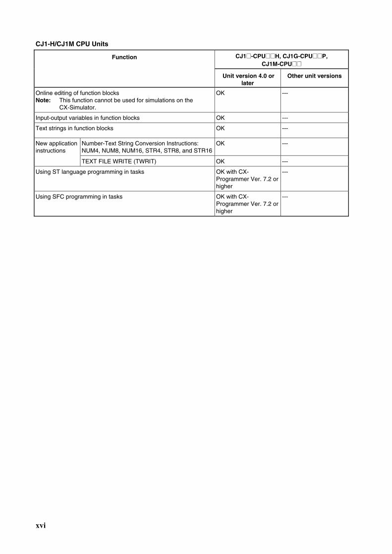
CJ1-H/CJ1M CPU Units
CJ1@-CPU@@H, CJ1G-CPU@@P, CJ1M-CPU@@
Function
Unit version 4.0 or later
Other unit versions
Online editing of function blocks Note: This function cannot be used for simulations on the CX-Simulator.
OK ---
Input-output variables in function blocks OK ---
Text strings in function blocks OK ---
Number-Text String Conversion Instructions: NUM4, NUM8, NUM16, STR4, STR8, and STR16
OK --- New application instructions
TEXT FILE WRITE (TWRIT) OK ---
Using ST language programming in tasks OK with CX- Programmer Ver. 7.2 or higher
---
Using SFC programming in tasks OK with CX- Programmer Ver. 7.2 or higher
---
xvii
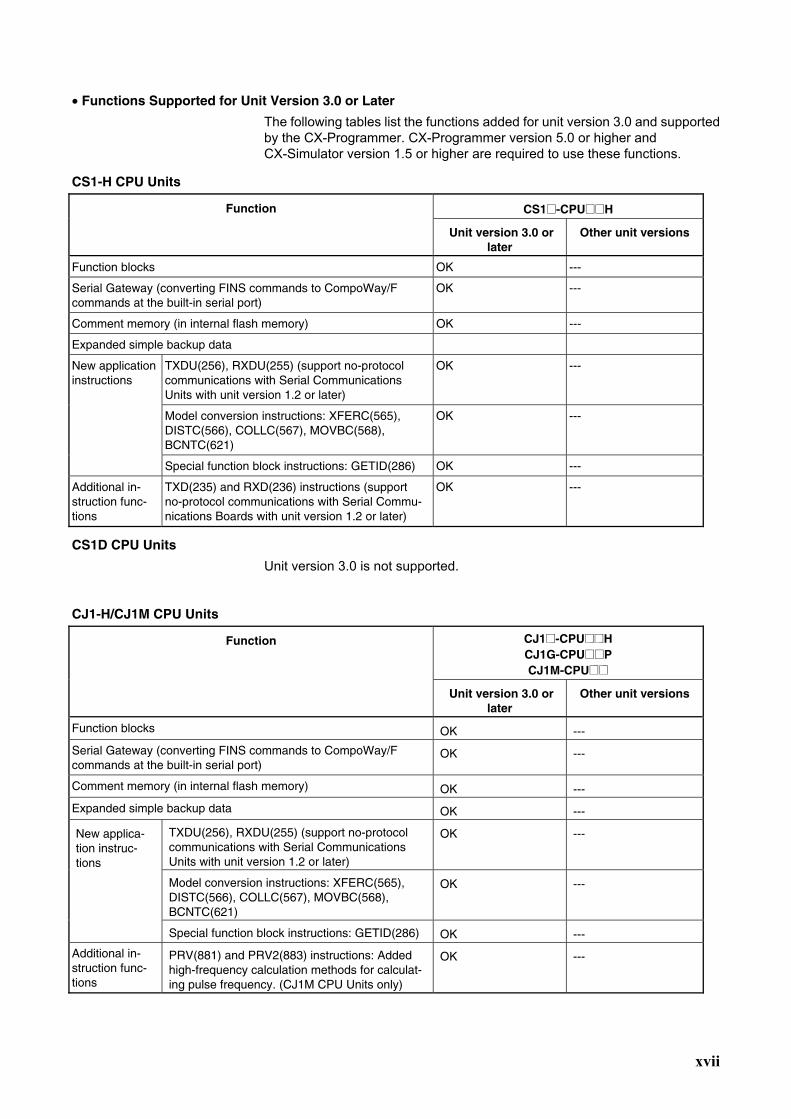
• Functions Supported for Unit Version 3.0 or Later
The following tables list the functions added for unit version 3.0 and supported by the CX-Programmer. CX-Programmer version 5.0 or higher and CX-Simulator version 1.5 or higher are required to use these functions.
CS1-H CPU Units
CS1@-CPU@@H Function
Unit version 3.0 or later
Other unit versions
Function blocks OK ---
Serial Gateway (converting FINS commands to CompoWay/F commands at the built-in serial port)
OK ---
Comment memory (in internal flash memory) OK ---
Expanded simple backup data
TXDU(256), RXDU(255) (support no-protocol communications with Serial Communications Units with unit version 1.2 or later)
OK ---
Model conversion instructions: XFERC(565), DISTC(566), COLLC(567), MOVBC(568), BCNTC(621)
OK ---
New application instructions
Special function block instructions: GETID(286) OK ---
Additional in-struction func-tions
TXD(235) and RXD(236) instructions (support no-protocol communications with Serial Commu-nications Boards with unit version 1.2 or later)
OK ---
CS1D CPU Units
Unit version 3.0 is not supported.
CJ1-H/CJ1M CPU Units
CJ1@-CPU@@H CJ1G-CPU@@P CJ1M-CPU@@
Function
Unit version 3.0 or later
Other unit versions
Function blocks OK ---
Serial Gateway (converting FINS commands to CompoWay/F commands at the built-in serial port)
OK ---
Comment memory (in internal flash memory) OK ---
Expanded simple backup data OK ---
TXDU(256), RXDU(255) (support no-protocol communications with Serial Communications Units with unit version 1.2 or later)
OK ---
Model conversion instructions: XFERC(565), DISTC(566), COLLC(567), MOVBC(568), BCNTC(621)
OK ---
New applica-tion instruc-tions
Special function block instructions: GETID(286) OK ---
Additional in-struction func-tions
PRV(881) and PRV2(883) instructions: Added high-frequency calculation methods for calculat-ing pulse frequency. (CJ1M CPU Units only)
OK ---
xviii
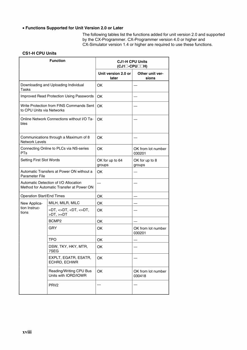
• Functions Supported for Unit Version 2.0 or Later
The following tables list the functions added for unit version 2.0 and supported by the CX-Programmer. CX-Programmer version 4.0 or higher and CX-Simulator version 1.4 or higher are required to use these functions.
CS1-H CPU Units
CJ1-H CPU Units (CJ1@-CPU@@H)
Function
Unit version 2.0 or later
Other unit ver-sions
Downloading and Uploading Individual Tasks
OK ---
Improved Read Protection Using Passwords OK ---
Write Protection from FINS Commands Sent to CPU Units via Networks
OK ---
Online Network Connections without I/O Ta-bles
OK ---
Communications through a Maximum of 8 Network Levels
OK ---
Connecting Online to PLCs via NS-series PTs
OK OK from lot number 030201
Setting First Slot Words OK for up to 64 groups
OK for up to 8 groups
Automatic Transfers at Power ON without a Parameter File
OK ---
Automatic Detection of I/O Allocation Method for Automatic Transfer at Power ON
--- ---
Operation Start/End Times OK ---
MILH, MILR, MILC OK ---
=DT, <>DT, <DT, <=DT, >DT, >=DT
OK ---
BCMP2 OK ---
GRY OK OK from lot number 030201
TPO OK ---
DSW, TKY, HKY, MTR, 7SEG
OK ---
EXPLT, EGATR, ESATR, ECHRD, ECHWR
OK ---
Reading/Writing CPU Bus Units with IORD/IOWR
OK OK from lot number 030418
New Applica-tion Instruc-tions
PRV2 --- ---
xix
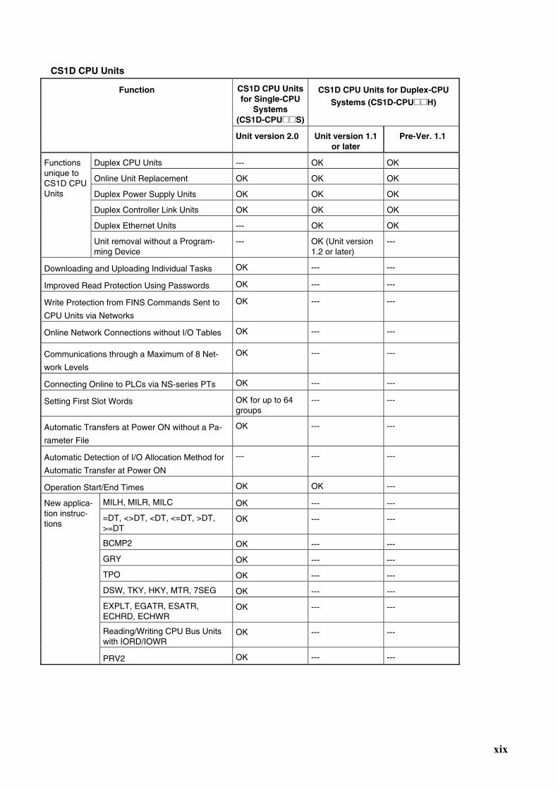
CS1D CPU Units
CS1D CPU Units for Single-CPU
Systems (CS1D-CPU@@S)
CS1D CPU Units for Duplex-CPU Systems (CS1D-CPU@@H)
Function
Unit version 2.0 Unit version 1.1or later
Pre-Ver. 1.1
Duplex CPU Units --- OK OK
Online Unit Replacement OK OK OK
Duplex Power Supply Units OK OK OK
Duplex Controller Link Units OK OK OK
Duplex Ethernet Units --- OK OK
Functions unique to CS1D CPU Units
Unit removal without a Program-ming Device
--- OK (Unit version 1.2 or later)
---
Downloading and Uploading Individual Tasks OK --- ---
Improved Read Protection Using Passwords OK --- ---
Write Protection from FINS Commands Sent to
CPU Units via Networks
OK --- ---
Online Network Connections without I/O Tables OK --- ---
Communications through a Maximum of 8 Net-
work Levels
OK --- ---
Connecting Online to PLCs via NS-series PTs OK --- ---
Setting First Slot Words OK for up to 64 groups
--- ---
Automatic Transfers at Power ON without a Pa-
rameter File
OK --- ---
Automatic Detection of I/O Allocation Method for
Automatic Transfer at Power ON
--- --- ---
Operation Start/End Times OK OK ---
MILH, MILR, MILC OK --- ---
=DT, <>DT, <DT, <=DT, >DT, >=DT
OK --- ---
BCMP2 OK --- ---
GRY OK --- ---
TPO OK --- ---
DSW, TKY, HKY, MTR, 7SEG OK --- ---
EXPLT, EGATR, ESATR, ECHRD, ECHWR
OK --- ---
Reading/Writing CPU Bus Units with IORD/IOWR
OK --- ---
New applica-tion instruc-tions
PRV2 OK --- ---
xx
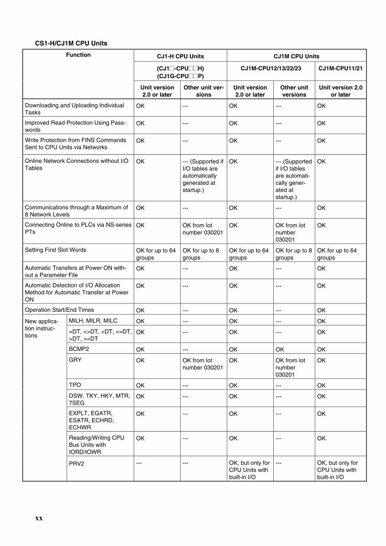
CS1-H/CJ1M CPU Units
CJ1-H CPU Units CJ1M CPU Units
(CJ1@-CPU@@H) (CJ1G-CPU@@P)
CJ1M-CPU12/13/22/23 CJ1M-CPU11/21
Function
Unit version 2.0 or later
Other unit ver-sions
Unit version 2.0 or later
Other unit versions
Unit version 2.0 or later
Downloading and Uploading Individual Tasks
OK --- OK --- OK
Improved Read Protection Using Pass-words
OK --- OK --- OK
Write Protection from FINS Commands Sent to CPU Units via Networks
OK --- OK --- OK
Online Network Connections without I/O Tables
OK --- (Supported if I/O tables are automatically generated at startup.)
OK --- (Supported if I/O tables are automati-cally gener-ated at startup.)
OK
Communications through a Maximum of 8 Network Levels
OK --- OK --- OK
Connecting Online to PLCs via NS-series PTs
OK OK from lot number 030201
OK OK from lot number 030201
OK
Setting First Slot Words OK for up to 64 groups
OK for up to 8 groups
OK for up to 64 groups
OK for up to 8 groups
OK for up to 64 groups
Automatic Transfers at Power ON with-out a Parameter File
OK --- OK --- OK
Automatic Detection of I/O Allocation Method for Automatic Transfer at Power ON
OK --- OK --- OK
Operation Start/End Times OK --- OK --- OK
MILH, MILR, MILC OK --- OK --- OK
=DT, <>DT, <DT, <=DT, >DT, >=DT
OK --- OK --- OK
BCMP2 OK --- OK OK OK
GRY OK OK from lot number 030201
OK OK from lot number 030201
OK
TPO OK --- OK --- OK
DSW, TKY, HKY, MTR, 7SEG
OK --- OK --- OK
EXPLT, EGATR, ESATR, ECHRD, ECHWR
OK --- OK --- OK
Reading/Writing CPU Bus Units with IORD/IOWR
OK --- OK --- OK
New applica-tion instruc-tions
PRV2 --- --- OK, but only for CPU Units with built-in I/O
--- OK, but only for CPU Units with built-in I/O
xxi
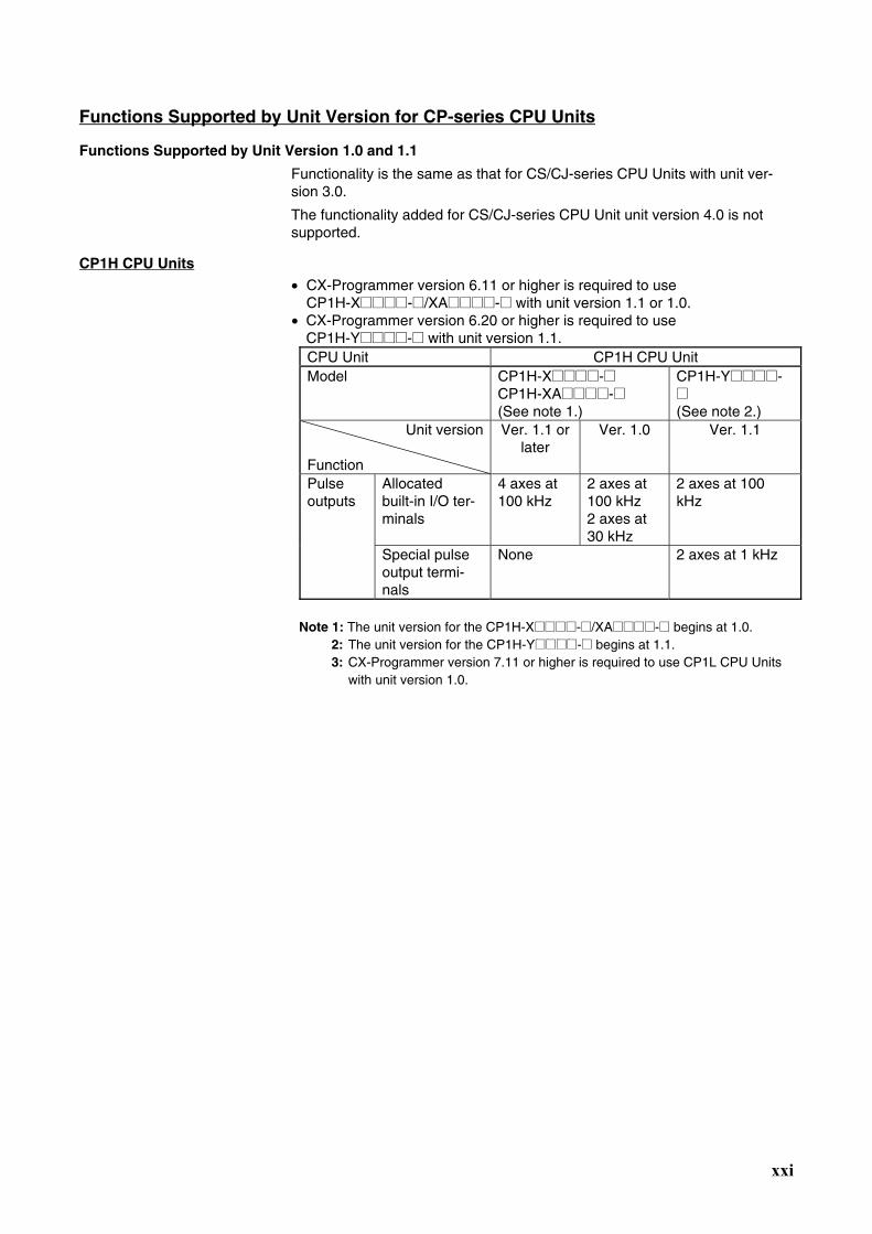
Functions Supported by Unit Version for CP-series CPU Units
Functions Supported by Unit Version 1.0 and 1.1
Functionality is the same as that for CS/CJ-series CPU Units with unit ver-sion 3.0.
The functionality added for CS/CJ-series CPU Unit unit version 4.0 is not supported.
CP1H CPU Units • CX-Programmer version 6.11 or higher is required to use
CP1H-X@@@@-@/XA@@@@-@ with unit version 1.1 or 1.0. • CX-Programmer version 6.20 or higher is required to use
CP1H-Y@@@@-@ with unit version 1.1. CPU Unit CP1H CPU Unit Model CP1H-X@@@@-@
CP1H-XA@@@@-@ (See note 1.)
CP1H-Y@@@@-@ (See note 2.)
Unit version
Function
Ver. 1.1 or later
Ver. 1.0 Ver. 1.1
Allocated built-in I/O ter-minals
4 axes at 100 kHz
2 axes at 100 kHz 2 axes at 30 kHz
2 axes at 100 kHz
Pulse outputs
Special pulse output termi-nals
None 2 axes at 1 kHz
Note 1: The unit version for the CP1H-X@@@@-@/XA@@@@-@ begins at 1.0.
2: The unit version for the CP1H-Y@@@@-@ begins at 1.1. 3: CX-Programmer version 7.11 or higher is required to use CP1L CPU Units
with unit version 1.0.
xxii
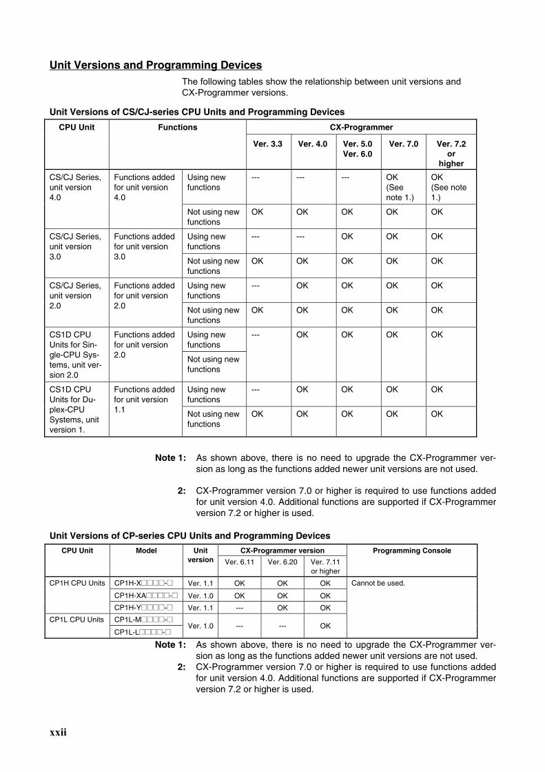
Unit Versions and Programming Devices The following tables show the relationship between unit versions and CX-Programmer versions.
Unit Versions of CS/CJ-series CPU Units and Programming Devices
CX-Programmer CPU Unit Functions
Ver. 3.3 Ver. 4.0 Ver. 5.0 Ver. 6.0
Ver. 7.0 Ver. 7.2 or
higher Using new functions
--- --- --- OK (See note 1.)
OK (See note 1.)
CS/CJ Series, unit version 4.0
Functions added for unit version 4.0
Not using new functions
OK OK OK OK OK
Using new functions
--- --- OK OK OK CS/CJ Series, unit version 3.0
Functions added for unit version 3.0 Not using new
functions OK OK OK OK OK
Using new functions
--- OK OK OK OK CS/CJ Series, unit version 2.0
Functions added for unit version 2.0 Not using new
functions OK OK OK OK OK
Using new functions
CS1D CPU Units for Sin-gle-CPU Sys-tems, unit ver-sion 2.0
Functions added for unit version 2.0 Not using new
functions
--- OK OK OK OK
Using new functions
--- OK OK OK OK CS1D CPU Units for Du-plex-CPU Systems, unit version 1.
Functions added for unit version 1.1 Not using new
functions OK OK OK OK OK
Note 1: As shown above, there is no need to upgrade the CX-Programmer ver-
sion as long as the functions added newer unit versions are not used.
2: CX-Programmer version 7.0 or higher is required to use functions added for unit version 4.0. Additional functions are supported if CX-Programmer version 7.2 or higher is used.
Unit Versions of CP-series CPU Units and Programming Devices
CX-Programmer version CPU Unit Model Unit version Ver. 6.11 Ver. 6.20 Ver. 7.11
or higher
Programming Console
CP1H-X@@@@-@ Ver. 1.1 OK OK OK
CP1H-XA@@@@-@ Ver. 1.0 OK OK OK
CP1H CPU Units
CP1H-Y@@@@-@ Ver. 1.1 --- OK OK
CP1L-M@@@@-@ CP1L CPU Units
CP1L-L@@@@-@ Ver. 1.0 --- --- OK
Cannot be used.
Note 1: As shown above, there is no need to upgrade the CX-Programmer ver-sion as long as the functions added newer unit versions are not used.
2: CX-Programmer version 7.0 or higher is required to use functions added for unit version 4.0. Additional functions are supported if CX-Programmer version 7.2 or higher is used.
xxiii
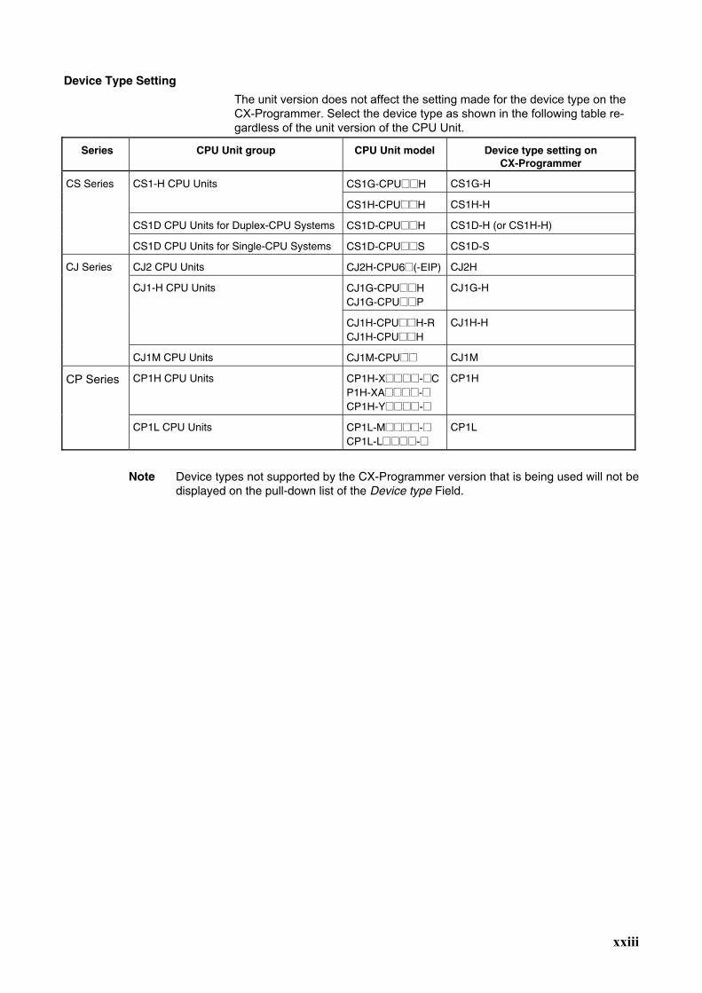
Device Type Setting
The unit version does not affect the setting made for the device type on the CX-Programmer. Select the device type as shown in the following table re-gardless of the unit version of the CPU Unit.
Series CPU Unit group CPU Unit model Device type setting on CX-Programmer
CS1G-CPU@@H CS1G-H CS1-H CPU Units
CS1H-CPU@@H CS1H-H
CS1D CPU Units for Duplex-CPU Systems CS1D-CPU@@H CS1D-H (or CS1H-H)
CS Series
CS1D CPU Units for Single-CPU Systems CS1D-CPU@@S CS1D-S
CJ2 CPU Units CJ2H-CPU6@(-EIP) CJ2H
CJ1G-CPU@@H CJ1G-CPU@@P
CJ1G-H CJ1-H CPU Units
CJ1H-CPU@@H-R CJ1H-CPU@@H
CJ1H-H
CJ Series
CJ1M CPU Units CJ1M-CPU@@ CJ1M
CP Series CP1H CPU Units CP1H-X@@@@-@CP1H-XA@@@@-@ CP1H-Y@@@@-@
CP1H
CP1L CPU Units CP1L-M@@@@-@ CP1L-L@@@@-@
CP1L
Note Device types not supported by the CX-Programmer version that is being used will not be
displayed on the pull-down list of the Device type Field.
xxiv
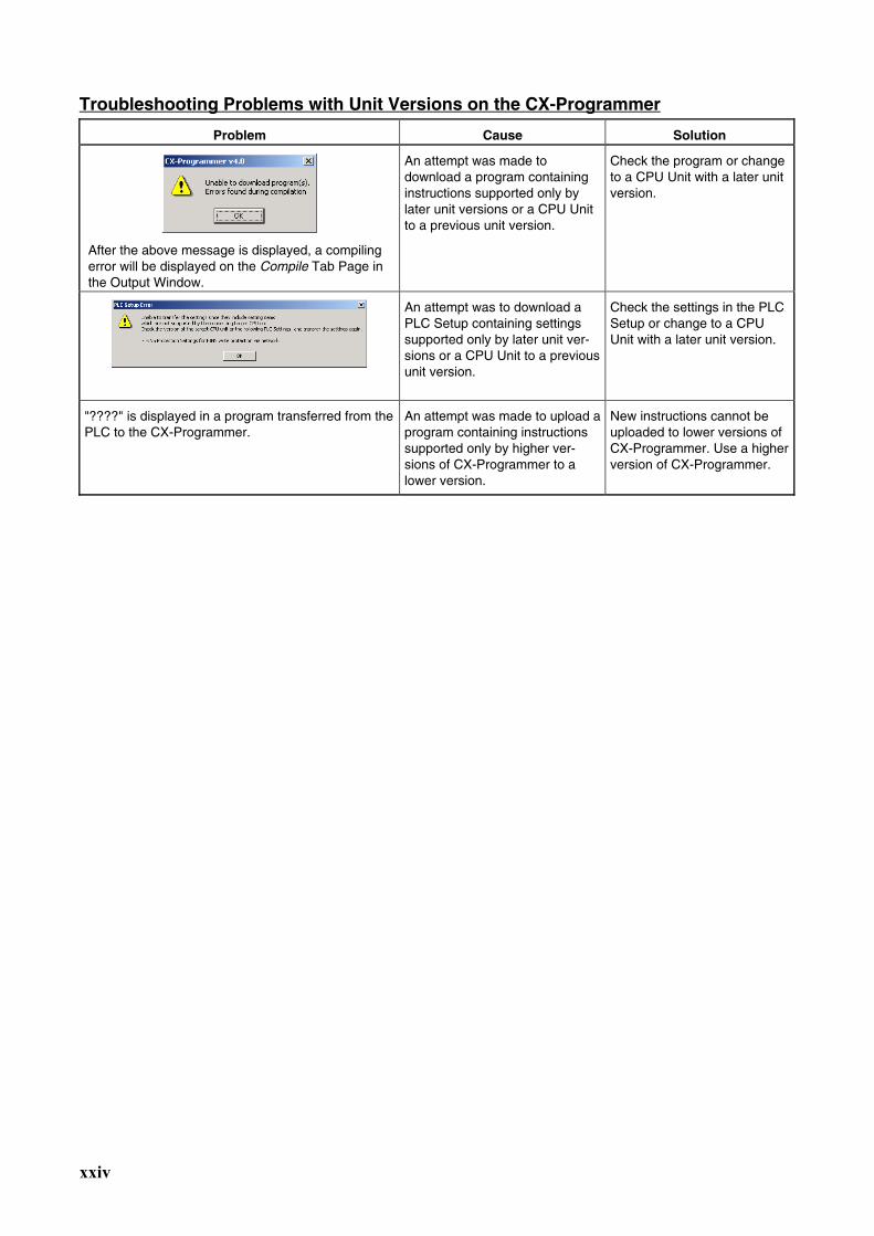
Troubleshooting Problems with Unit Versions on the CX-Programmer Problem Cause Solution
After the above message is displayed, a compiling error will be displayed on the Compile Tab Page in the Output Window.
An attempt was made to download a program containing instructions supported only by later unit versions or a CPU Unit to a previous unit version.
Check the program or change to a CPU Unit with a later unit version.
An attempt was to download a PLC Setup containing settings supported only by later unit ver-sions or a CPU Unit to a previous unit version.
Check the settings in the PLC Setup or change to a CPU Unit with a later unit version.
"????" is displayed in a program transferred from the PLC to the CX-Programmer.
An attempt was made to upload a program containing instructions supported only by higher ver-sions of CX-Programmer to a lower version.
New instructions cannot be uploaded to lower versions of CX-Programmer. Use a higher version of CX-Programmer.

xxv
xxvi
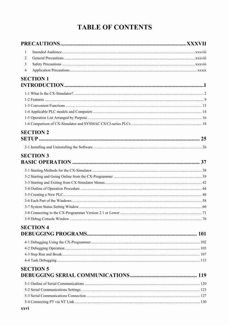
TABLE OF CONTENTS
PRECAUTIONS..............................................................................................XXXVII
1 Intended Audience .........................................................................................................................................xxxviii 2 General Precautions .......................................................................................................................................xxxviii 3 Safety Precautions .........................................................................................................................................xxxviii 4 Application Precautions................................................................................................................................... xxxix
SECTION 1 INTRODUCTION........................................................................................................1
1-1 What Is the CX-Simulator? ...................................................................................................................................... 2 1-2 Features .................................................................................................................................................................... 9 1-3 Convenient Functions............................................................................................................................................. 13 1-4 Applicable PLC models and Computers ................................................................................................................ 14 1-5 Operation List Arranged by Purpose...................................................................................................................... 16 1-6 Comparison of CX-Simulator and SYSMAC CS/CJ-series PLCs ......................................................................... 18
SECTION 2 SETUP ........................................................................................................................ 25
2-1 Installing and Uninstalling the Software ................................................................................................................ 26
SECTION 3 BASIC OPERATION ............................................................................................... 37
3-1 Starting Methods for the CX-Simulator ................................................................................................................. 38 3-2 Starting and Going Online from the CX-Programmer ........................................................................................... 39 3-3 Starting and Exiting from CX-Simulator Menus.................................................................................................... 42 3-4 Outline of Operation Procedure ............................................................................................................................. 44 3-5 Creating a New PLC............................................................................................................................................... 48 3-6 Each Part of the Windows ...................................................................................................................................... 58 3-7 System Status Setting Window .............................................................................................................................. 60 3-8 Connecting to the CX-Programmer Version 2.1 or Lower .................................................................................... 71 3-9 Debug Console Window ........................................................................................................................................ 76
SECTION 4 DEBUGGING PROGRAMS.................................................................................. 101
4-1 Debugging Using the CX-Programmer ................................................................................................................ 102 4-2 Debugging Operation ........................................................................................................................................... 103 4-3 Step Run and Break.............................................................................................................................................. 107 4-4 Task Debugging ................................................................................................................................................... 115
SECTION 5 DEBUGGING SERIAL COMMUNICATIONS.................................................. 119
5-1 Outline of Serial Communications ....................................................................................................................... 120 5-2 Serial Communications Settings........................................................................................................................... 123 5-3 Serial Communications Connection ..................................................................................................................... 127 5-4 Connecting PT via NT Link ................................................................................................................................. 130
xxvii
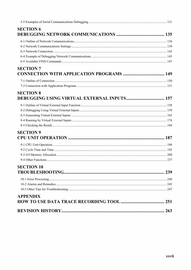
5-5 Examples of Serial Communications Debugging................................................................................................. 131
SECTION 6 DEBUGGING NETWORK COMMUNICATIONS ........................................... 135
6-1 Outline of Network Communications................................................................................................................... 136 6-2 Network Communications Settings ...................................................................................................................... 139 6-3 Network Connection............................................................................................................................................. 142 6-4 Example of Debugging Network Communications.............................................................................................. 143 6-5 Available FINS Commands.................................................................................................................................. 147
SECTION 7 CONNECTION WITH APPLICATION PROGRAMS ..................................... 149
7-1 Outline of Connection .......................................................................................................................................... 150 7-2 Connection with Application Programs ............................................................................................................... 151
SECTION 8 DEBUGGING USING VIRTUAL EXTERNAL INPUTS.................................. 157
8-1 Outline of Virtual External Input Function .......................................................................................................... 158 8-2 Debugging Using Virtual External Inputs............................................................................................................ 159 8-3 Generating Virtual External Inputs ...................................................................................................................... 162 8-4 Running by Virtual External Inputs ..................................................................................................................... 176 8-5 Checking the Result.............................................................................................................................................. 184
SECTION 9 CPU UNIT OPERATION ...................................................................................... 187
9-1 CPU Unit Operation ............................................................................................................................................. 188 9-2 Cycle Time and Time ........................................................................................................................................... 192 9-3 I/O Memory Allocation ........................................................................................................................................ 200 9-4 Other Functions .................................................................................................................................................... 237
SECTION 10 TROUBLESHOOTING.......................................................................................... 239
10-1 Error Processing ................................................................................................................................................. 240 10-2 Alarms and Remedies......................................................................................................................................... 245 10-3 Other Tips for Troubleshooting.......................................................................................................................... 247
APPENDIX HOW TO USE DATA TRACE RECORDING TOOL ....................................... 251
REVISION HISTORY............................................................................................ 263
xxviii
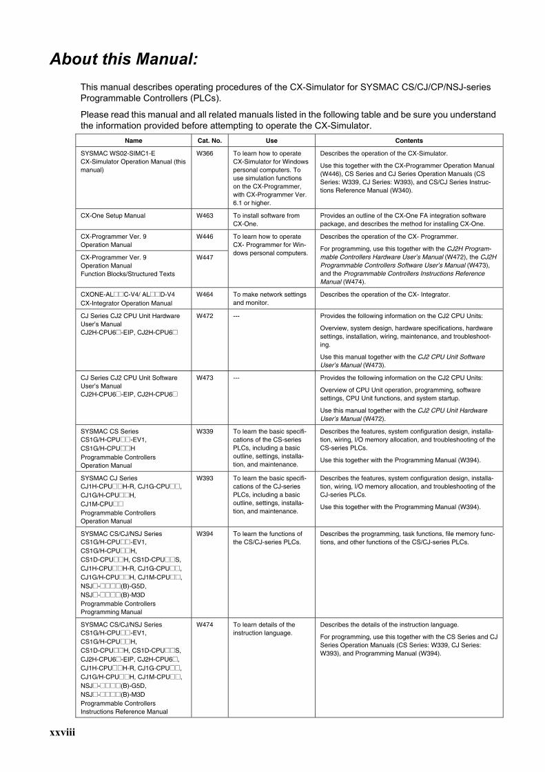
About this Manual:
This manual describes operating procedures of the CX-Simulator for SYSMAC CS/CJ/CP/NSJ-series Programmable Controllers (PLCs).
Please read this manual and all related manuals listed in the following table and be sure you understand the information provided before attempting to operate the CX-Simulator.
Name Cat. No. Use Contents
SYSMAC WS02-SIMC1-E CX-Simulator Operation Manual (this manual)
W366 To learn how to operate CX-Simulator for Windows personal computers. To use simulation functions on the CX-Programmer, with CX-Programmer Ver. 6.1 or higher.
Describes the operation of the CX-Simulator.
Use this together with the CX-Programmer Operation Manual (W446), CS Series and CJ Series Operation Manuals (CS Series: W339, CJ Series: W393), and CS/CJ Series Instruc-tions Reference Manual (W340).
CX-One Setup Manual W463 To install software from CX-One.
Provides an outline of the CX-One FA integration software package, and describes the method for installing CX-One.
CX-Programmer Ver. 9 Operation Manual
W446
CX-Programmer Ver. 9 Operation Manual Function Blocks/Structured Texts
W447
To learn how to operate CX- Programmer for Win-dows personal computers.
Describes the operation of the CX- Programmer.
For programming, use this together with the CJ2H Program-mable Controllers Hardware User’s Manual (W472), the CJ2H Programmable Controllers Software User’s Manual (W473), and the Programmable Controllers Instructions Reference Manual (W474).
CXONE-AL@@C-V4/ AL@@D-V4 CX-Integrator Operation Manual
W464 To make network settings and monitor.
Describes the operation of the CX- Integrator.
CJ Series CJ2 CPU Unit Hardware User’s Manual CJ2H-CPU6@-EIP, CJ2H-CPU6@
W472 --- Provides the following information on the CJ2 CPU Units:
Overview, system design, hardware specifications, hardware settings, installation, wiring, maintenance, and troubleshoot-ing.
Use this manual together with the CJ2 CPU Unit Software User’s Manual (W473).
CJ Series CJ2 CPU Unit Software User’s Manual CJ2H-CPU6@-EIP, CJ2H-CPU6@
W473 --- Provides the following information on the CJ2 CPU Units:
Overview of CPU Unit operation, programming, software settings, CPU Unit functions, and system startup.
Use this manual together with the CJ2 CPU Unit Hardware User’s Manual (W472).
SYSMAC CS Series CS1G/H-CPU@@-EV1, CS1G/H-CPU@@H Programmable Controllers Operation Manual
W339 To learn the basic specifi-cations of the CS-series PLCs, including a basic outline, settings, installa-tion, and maintenance.
Describes the features, system configuration design, installa-tion, wiring, I/O memory allocation, and troubleshooting of the CS-series PLCs.
Use this together with the Programming Manual (W394).
SYSMAC CJ Series CJ1H-CPU@@H-R, CJ1G-CPU@@, CJ1G/H-CPU@@H, CJ1M-CPU@@ Programmable Controllers Operation Manual
W393 To learn the basic specifi-cations of the CJ-series PLCs, including a basic outline, settings, installa-tion, and maintenance.
Describes the features, system configuration design, installa-tion, wiring, I/O memory allocation, and troubleshooting of the CJ-series PLCs.
Use this together with the Programming Manual (W394).
SYSMAC CS/CJ/NSJ Series CS1G/H-CPU@@-EV1, CS1G/H-CPU@@H, CS1D-CPU@@H, CS1D-CPU@@S, CJ1H-CPU@@H-R, CJ1G-CPU@@, CJ1G/H-CPU@@H, CJ1M-CPU@@, NSJ@-@@@@(B)-G5D, NSJ@-@@@@(B)-M3D Programmable Controllers Programming Manual
W394 To learn the functions of the CS/CJ-series PLCs.
Describes the programming, task functions, file memory func-tions, and other functions of the CS/CJ-series PLCs.
SYSMAC CS/CJ/NSJ Series CS1G/H-CPU@@-EV1, CS1G/H-CPU@@H, CS1D-CPU@@H, CS1D-CPU@@S, CJ2H-CPU6@-EIP, CJ2H-CPU6@, CJ1H-CPU@@H-R, CJ1G-CPU@@, CJ1G/H-CPU@@H, CJ1M-CPU@@, NSJ@-@@@@(B)-G5D, NSJ@-@@@@(B)-M3D Programmable Controllers Instructions Reference Manual
W474 To learn details of the instruction language.
Describes the details of the instruction language.
For programming, use this together with the CS Series and CJ Series Operation Manuals (CS Series: W339, CJ Series: W393), and Programming Manual (W394).
xxix
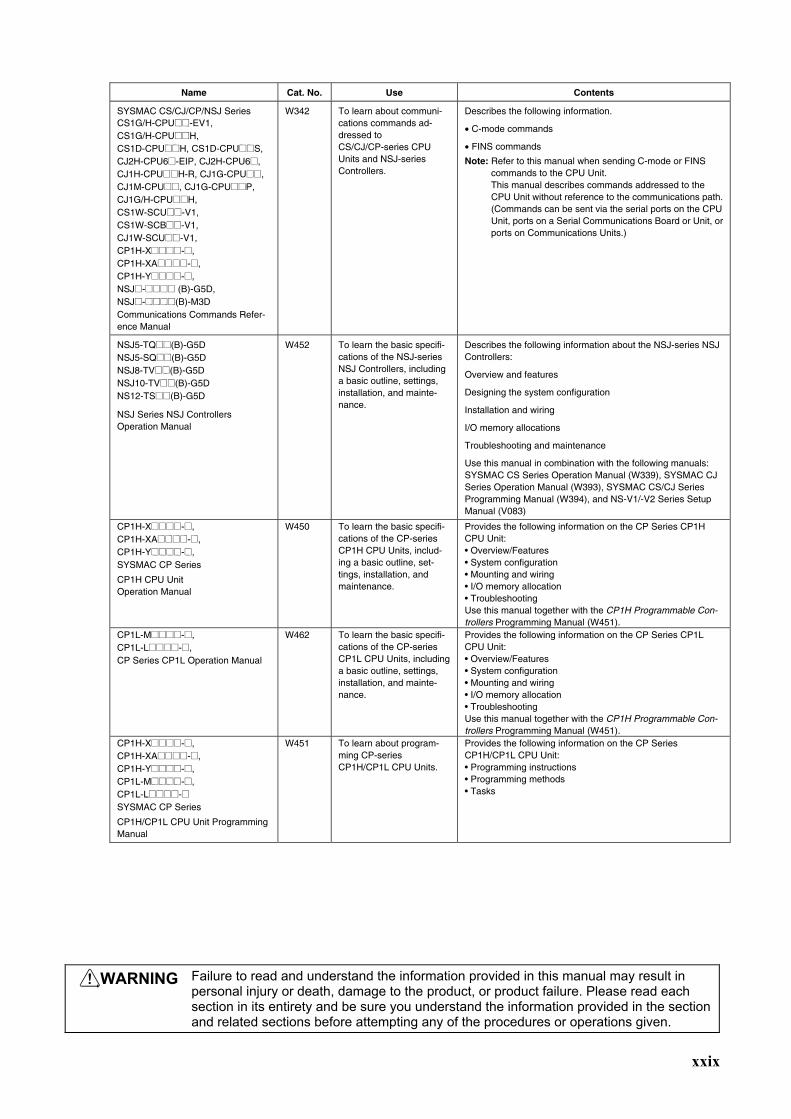
Name Cat. No. Use Contents
SYSMAC CS/CJ/CP/NSJ Series CS1G/H-CPU@@-EV1, CS1G/H-CPU@@H, CS1D-CPU@@H, CS1D-CPU@@S, CJ2H-CPU6@-EIP, CJ2H-CPU6@, CJ1H-CPU@@H-R, CJ1G-CPU@@, CJ1M-CPU@@, CJ1G-CPU@@P, CJ1G/H-CPU@@H, CS1W-SCU@@-V1, CS1W-SCB@@-V1, CJ1W-SCU@@-V1, CP1H-X@@@@-@, CP1H-XA@@@@-@, CP1H-Y@@@@-@, NSJ@-@@@@ (B)-G5D, NSJ@-@@@@(B)-M3D Communications Commands Refer-ence Manual
W342 To learn about communi-cations commands ad-dressed to CS/CJ/CP-series CPU Units and NSJ-series Controllers.
Describes the following information.
• C-mode commands
• FINS commands
Note: Refer to this manual when sending C-mode or FINS commands to the CPU Unit. This manual describes commands addressed to the CPU Unit without reference to the communications path. (Commands can be sent via the serial ports on the CPU Unit, ports on a Serial Communications Board or Unit, or ports on Communications Units.)
NSJ5-TQ@@(B)-G5D NSJ5-SQ@@(B)-G5D NSJ8-TV@@(B)-G5D NSJ10-TV@@(B)-G5D NS12-TS@@(B)-G5D
NSJ Series NSJ Controllers Operation Manual
W452 To learn the basic specifi-cations of the NSJ-series NSJ Controllers, including a basic outline, settings, installation, and mainte-nance.
Describes the following information about the NSJ-series NSJ Controllers:
Overview and features
Designing the system configuration
Installation and wiring
I/O memory allocations
Troubleshooting and maintenance
Use this manual in combination with the following manuals: SYSMAC CS Series Operation Manual (W339), SYSMAC CJ Series Operation Manual (W393), SYSMAC CS/CJ Series Programming Manual (W394), and NS-V1/-V2 Series Setup Manual (V083)
CP1H-X@@@@-@, CP1H-XA@@@@-@, CP1H-Y@@@@-@, SYSMAC CP Series
CP1H CPU Unit Operation Manual
W450 To learn the basic specifi-cations of the CP-series CP1H CPU Units, includ-ing a basic outline, set-tings, installation, and maintenance.
Provides the following information on the CP Series CP1H CPU Unit: • Overview/Features • System configuration • Mounting and wiring • I/O memory allocation • Troubleshooting Use this manual together with the CP1H Programmable Con-trollers Programming Manual (W451).
CP1L-M@@@@-@, CP1L-L@@@@-@, CP Series CP1L Operation Manual
W462 To learn the basic specifi-cations of the CP-series CP1L CPU Units, including a basic outline, settings, installation, and mainte-nance.
Provides the following information on the CP Series CP1L CPU Unit: • Overview/Features • System configuration • Mounting and wiring • I/O memory allocation • Troubleshooting Use this manual together with the CP1H Programmable Con-trollers Programming Manual (W451).
CP1H-X@@@@-@, CP1H-XA@@@@-@, CP1H-Y@@@@-@, CP1L-M@@@@-@, CP1L-L@@@@-@ SYSMAC CP Series
CP1H/CP1L CPU Unit Programming Manual
W451
To learn about program-ming CP-series CP1H/CP1L CPU Units.
Provides the following information on the CP Series CP1H/CP1L CPU Unit: • Programming instructions • Programming methods • Tasks
WARNING Failure to read and understand the information provided in this manual may result in personal injury or death, damage to the product, or product failure. Please read each section in its entirety and be sure you understand the information provided in the section and related sections before attempting any of the procedures or operations given.
xxx
About this Manual, Continued This manual contains the following sections.
Section 1 introduces the special features and functions of the CX-Simulator and a comparison between SYSMAC CS/CJ/CP/NSJ-series PLCs
Section 2 provides the information on how to setup the CX-Simulator.
Section 3 describes the basic operation of the CX-Simulator.
Section 4 describes how to debug user programs.
Section 5 describes how to debug Serial Communications functions.
Section 6 describes how to debug Network Communications functions.
Section 7 describes how to connect with application programs.
Section 8 provides information on how to debug using virtual external inputs.
Section 9 describes operations of the CPU Unit including cycle times and I/O Memory allocation.
Section 10 provides information on errors and alarms that occur during the operation along with the remedies.
Appendix provides information on how to use the Data Trace Recording Tool.

xxxi
xxxii
Read and Understand This Manual
Please read and understand this manual before using the product. Please consult your OMRON representa-tive if you have any questions or comments.
Warranty and Limitations of Liability WARRANTY
(1) The warranty period for the Software is one year from either the date of purchase or the date on which the Software is delivered to the specified location.
(2) If the User discovers a defect in the Software (i.e., substantial non-conformity with the manual), and returns it to OMRON within the above warranty period, OMRON will replace the Software without charge by offering media or downloading services from the Internet. And if the User discovers a defect in the media which is at-tributable to OMRON and returns the Software to OMRON within the above warranty period, OMRON will re-place the defective media without charge. If OMRON is unable to replace the defective media or correct the Software, the liability of OMRON and the User’s remedy shall be limited to a refund of the license fee paid to OMRON for the Software.
LIMITATIONS OF LIABILITY (1) THE ABOVE WARRANTY SHALL CONSTITUTE THE USER’S SOLE AND EXCLUSIVE REMEDIES
AGAINST OMRON AND THERE ARE NO OTHER WARRANTIES, EXPRESSED OR IMPLIED, INCLUDING BUT NOT LIMITED TO, WARRANTY OF MERCHANTABILITY OR FITNESS FOR A PARTICULAR PURPOSE. IN NO EVENT WILL OMRON BE LIABLE FOR ANY LOST PROFITS OR OTHER INDIRECT, INCIDENTAL, SPECIAL, OR CONSEQUENTIAL DAMAGES ARISING OUT OF USE OF THE SOFTWARE.
(2) OMRON SHALL ASSUME NO LIABILITY FOR DEFECTS IN THE SOFTWARE BASED ON MODIFICATION OR ALTERATION OF THE SOFTWARE BY THE USER OR ANY THIRD PARTY.
(3) OMRON SHALL ASSUME NO LIABILITY FOR SOFTWARE DEVELOPED BY THE USER OR ANY THIRD PARTY BASED ON THE SOFTWARE OR ANY CONSEQUENCE THEREOF.

xxxiii
Application Considerations SUITABILITY FOR USE
THE USER SHALL NOT USE THE SOFTWARE FOR A PURPOSE THAT IS NOT DESCRIBED IN THE ATTACHED USER MANUAL.
xxxiv
Disclaimers CHANGE IN SPECIFICATIONS
The software specifications and accessories may be changed at any time based on improvements or for other reasons.
EXTENT OF SERVICE
The license fee of the Software does not include service costs, such as dispatching technical staff.
ERRORS AND OMISSIONS
The information in this manual has been carefully checked and is believed to be accurate; however, no responsi-bility is assumed for clerical, typographical, or proofreading errors, or omissions.
xxxv
Notation This manual describes operation items as follows:
Notation Examples "[ ]" indicates a menu name, key, dialog box name, or button name. However, in some cases where it is obviously a menu name, [ ] is not attached.
Example: [File] menu, [Tab] key, [Search] dialog box, [OK] button
"|" indicates the hierarchy for a menu or display.
Example:
• "Select [File] | [Create]" indicates "select [Create] from the [File] menu."
• "Select [PLC] | [Operation Mode] | [Monitor]" indicates "select [Operation Mode] from the [PLC] menu and then select [Monitor]."
• "Select [System Status] | [Settings] | [UM Setting]" indicates "select the [Settings] button from the [System Status] window and then select [UM Setting] from the pop-up menu."
"[ ] + [ ]" indicates pressing multiple keys simultaneously.
Example:
• "[Ctrl] + [S]" indicates "press [S] key with the [Ctrl] key held down." • "[Ctrl] + [Shift] + [L]" indicates "press the [L] key with the [Ctrl] and [Shift] keys held down."
About Operation Examples
This manual describes operation and settings assuming that the target PLC is a CS/CJ-series PLC and the Programming Device is the CX-Programmer.

xxxvi
xxxvii
PRECAUTIONS This section provides general precautions for using the Programmable Controller (PLC) and related devices. The information contained in this section is important for the safe and reliable application of the Programmable Controller. You must read this section and understand the information contained before attempting to set up or operate a PLC system.
1 Intended Audience .................................................................................................................. xxxviii 2 General Precautions ................................................................................................................ xxxviii 3 Safety Precautions................................................................................................................... xxxviii 4 Application Precautions ............................................................................................................ xxxix
Safety Precautions 3
xxxviii
1 Intended Audience This manual is intended for the following personnel, who must also have knowledge of electrical systems (an electrical engineer or the equivalent). Personnel in charge of installing FA systems. Personnel in charge of designing FA systems. Personnel in charge of managing FA systems and facilities.
2 General Precautions The user must operate the product according to the performance specifica-tions described in the operation manuals. Before using the product under conditions which are not described in the manual or applying the product to nuclear control systems, railroad systems, aviation systems, vehicles, combustion systems, medical equipment, amusement machines, safety equipment, and other systems, machines, and equipment that may have a serious influence on lives and property if used improperly, consult your OMRON representative. Make sure that the ratings and performance characteristics of the product are sufficient for the systems, machines, and equipment, and be sure to provide the systems, machines, and equipment with double safety mechanisms. This manual provides information for programming and operating the Unit. Be sure to read this manual before attempting to use the Unit and keep this manual close at hand for reference during operation.
WARNING It is extremely important that a PLC and all PLC Units be used for the speci-
fied purpose and under the specified conditions, especially in applications that can directly or indirectly affect human life. You must consult with your OMRON representative before applying a PLC System to the above-mentioned applications.
3 Safety Precautions WARNING The CX-Simulator simulates PLC operation. However, there are some dif-
ferences in operation and timings between those of the CX-Simulator and the actual PLC system. Be sure to confirm operation on the actual system as well as debugging the programs on the CX-Simulator before running the actual system. Unexpected operation may cause an accident.
Caution Enabling serial communications function of the CX-Simulator may affect the
operation of devices connected to the computer. When external devices are not being used, do not enable the serial communications function. Unex-pected operation of the external devices may cause an accident.
Caution When the CX-Simulator is used together with the Data Link function, the
Memory Mapping function of the FinsGateway, or the Cyclic Server of the FinsServer Series, the operation of external devices connected to the per-sonal computer may be affected. Do not activate these functions if they do not need to be used simultaneously. Unexpected operation of the external devices may cause an accident.
Application Precautions 4
xxxix
4 Application Precautions Observe the following precautions when using the CX-Simulator.
• Confirm the destination is the CX-Simulator when the CX-Simulator is con-
nected online with the CX-Programmer or other applications. When the CX-Simulator is disabled or not connected to the Simulator, the actual sys-tem may be activated.
• Confirm the destination is the PLC when another application connects online with the actual system while the CX-Simulator is activated. Connection may be made not with the actual system but with the CX-Simulator.

1
SECTION 1 Introduction
1-1 What Is the CX-Simulator? .......................................................................................................... 2 1-1-1 Summary .......................................................................................................................... 2 1-1-2 Software Configuration of CX-Simulator ........................................................................ 3 1-1-3 Basic Block Diagram........................................................................................................ 5 1-1-4 Summary of CX-Simulator Functions (Comparisons with Actual PLC) ......................... 6
1-2 Features......................................................................................................................................... 9 1-2-1 Features ............................................................................................................................ 9
1-3 Convenient Functions ................................................................................................................. 13 1-4 Applicable PLC models and Computers..................................................................................... 14
1-4-1 Applicable PLC models.................................................................................................. 14 1-4-2 Computer ........................................................................................................................ 15
1-5 Operation List Arranged by Purpose .......................................................................................... 16 1-5-1 Setting Operation Environment...................................................................................... 16 1-5-2 Program Execution ......................................................................................................... 16 1-5-3 Program Debugging ....................................................................................................... 16 1-5-4 Monitor the Status .......................................................................................................... 17 1-5-5 Set Serial Communications Settings............................................................................... 17 1-5-6 Set Network Communications Parameters ..................................................................... 17 1-5-7 Execute Virtual External Input....................................................................................... 17
1-6 Comparison of CX-Simulator and SYSMAC CS/CJ-series PLCs ............................................. 18
What Is the CX-Simulator? Section 1-1
2
1-1 What Is the CX-Simulator?
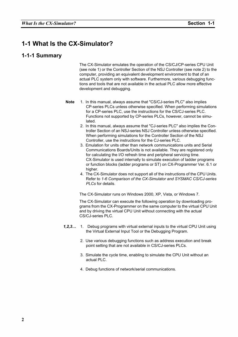
1-1-1 Summary The CX-Simulator emulates the operation of the CS/CJ/CP-series CPU Unit (see note 1) or the Controller Section of the NSJ Controller (see note 2) to the computer, providing an equivalent development environment to that of an actual PLC system only with software. Furthermore, various debugging func-tions and tools that are not available in the actual PLC allow more effective development and debugging.
Note 1. In this manual, always assume that "CS/CJ-series PLC" also implies
CP-series PLCs unless otherwise specified. When performing simulations for a CP-series PLC, use the instructions for the CS/CJ-series PLC. Functions not supported by CP-series PLCs, however, cannot be simu-lated.
2. In this manual, always assume that "CJ-series PLC" also implies the Con-troller Section of an NSJ-series NSJ Controller unless otherwise specified. When performing simulations for the Controller Section of the NSJ Controller, use the instructions for the CJ-series PLC.
3. Emulation for units other than network communications units and Serial Communications Boards/Units is not available. They are registered only for calculating the I/O refresh time and peripheral servicing time. CX-Simulator is used internally to simulate execution of ladder programs or function blocks (ladder programs or ST) on CX-Programmer Ver. 6.1 or higher.
4. The CX-Simulator does not support all of the instructions of the CPU Units. Refer to 1-6 Comparison of the CX-Simulator and SYSMAC CS/CJ-series PLCs for details.
The CX-Simulator runs on Windows 2000, XP, Vista, or Windows 7.
The CX-Simulator can execute the following operation by downloading pro-grams from the CX-Programmer on the same computer to the virtual CPU Unit and by driving the virtual CPU Unit without connecting with the actual CS/CJ-series PLC.
1,2,3… 1. Debug programs with virtual external inputs to the virtual CPU Unit using
the Virtual External Input Tool or the Debugging Program.
2. Use various debugging functions such as address execution and break point setting that are not available in CS/CJ-series PLCs.
3. Simulate the cycle time, enabling to simulate the CPU Unit without an
actual PLC.
4. Debug functions of network/serial communications.
What Is the CX-Simulator? Section 1-1
3
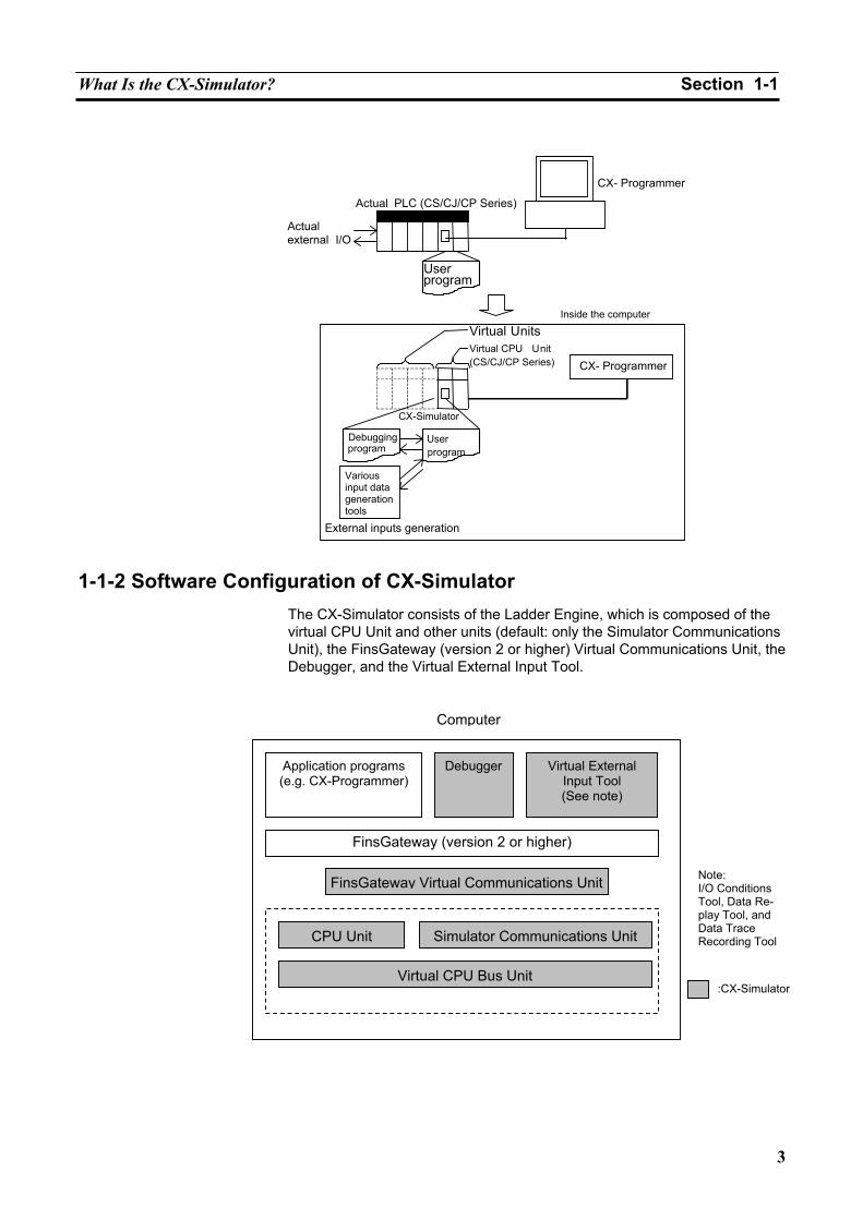
1-1-2 Software Configuration of CX-Simulator The CX-Simulator consists of the Ladder Engine, which is composed of the virtual CPU Unit and other units (default: only the Simulator Communications Unit), the FinsGateway (version 2 or higher) Virtual Communications Unit, the Debugger, and the Virtual External Input Tool.
Actual PLC (CS/CJ/CP Series)
Actual external I/O
CX- Programmer
Userprogram
CX-Simulator
CX- Programmer
Userprogram
Debuggingprogram
Various input data generation tools
External inputs generation
Virtual UnitsVirtual CPU Unit(CS/CJ/CP Series)
Inside the computer
Note:I/O Conditions Tool, Data Re-play Tool, and Data Trace Recording Tool
Computer
Application programs (e.g. CX-Programmer)
Debugger
Virtual External Input Tool (See note)
FinsGateway (version 2 or higher)
FinsGateway Virtual Communications Unit
CPU Unit Simulator Communications Unit
Virtual CPU Bus Unit:CX-Simulator
What Is the CX-Simulator? Section 1-1
4
Item Contents
A platform for CS/CJ/CP-series PLC Emulation Consists of multiple units. Default: Consists of the CPU Unit and the Simulator Communications Unit. CPU Unit A virtual unit corresponding to the actual CPU Unit, in-
cluding application programs (UM1), debugging pro-grams (UM2), and I/O memory areas.
Ladder Engine
Simulator Communications Unit
The CX-Simulator's own virtual and general-purpose communications unit, corresponding to PLC's network communications unit. Possible to communicate with the CX-Programmer.
FinsGateway (ver-sion 2 or higher)
Virtual Communi-cations Unit (See note.)
Connect Simulator Communications Unit in the Ladder Engine with FinsGateway ver-sion 2 or higher. Two types are available: Virtual Controller Link Unit and Virtual Ethernet Unit. The CX-Programmer also performs FINS communications with the Lad-der Engine via the Virtual Communications Unit.
Debugger Controls the Ladder Engine and executes various CX-Simulator's own debugging functions. Debugging program (UM2) Possible to simulate I/O operation with a program in the
program area for debugging other than the area for ap-plications (UM1).
For virtual external I/O functions
Command log The log for CX-Programmer's operations (e.g. I/O mem-ory change, Force set/reset) is saved in a file (Command log file). Possible to replay operation for the Ladder Engine using the Data Replay Tool.
Note The FinsGateway Virtual Communications Unit is different from the FinsGateway
itself. CX-Simulator does not include the FinsGateway itself.
What Is the CX-Simulator? Section 1-1
5
Item Contents
Data Replay Tool
Read data in sequence from Command log file, Data Trace file, and Data Replay file, and issue FINS com-mands to the Ladder Engine to regenerate input data.
I/O Condi-tions Tool
Change contents of designated I/O memory areas when the contents satisfy certain conditions.
Data Trace Recording Tool
Possible to input trace data (Data trace file) actually obtained from PLC to the Ladder Engine using the Data Replay Tool. Possible to generate long-term data.
For virtual external I/O functions
Virtual Ex-ternal Input Tool
Multipoint Data Collec-tion Tool
Possible to acquire trace data of more than 50 words from an actual PLC and to input to the Ladder Engine using the Data Replay Tool.
For network com-munications
FinsGate-way Virtual comm. Unit/ Simulator Communi-cations Unit
FINS commands send/receive to/from application programs on the Computers and the CPU Unit of FinsGateway are possible. Screen dis-play of send messages is also possible. FINS commands send is not possible (receive is possible).
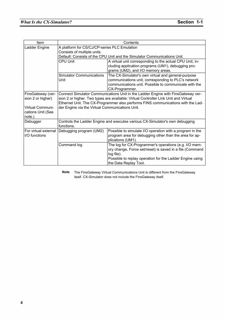
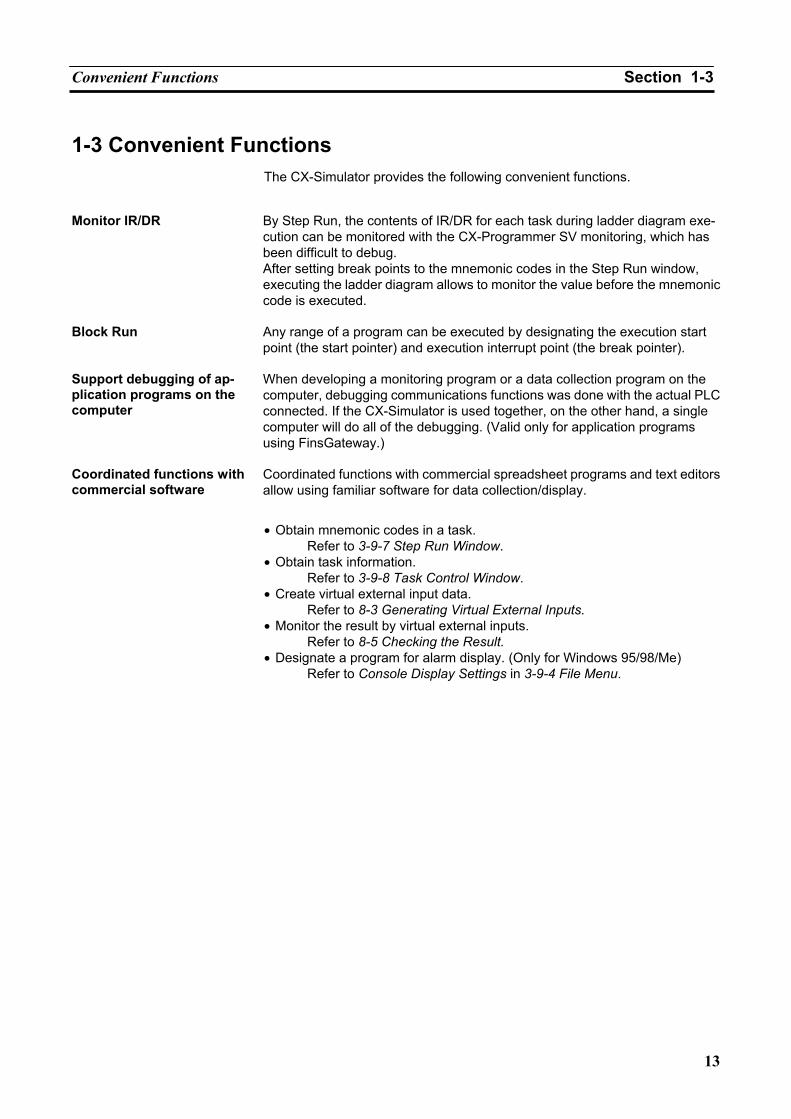
1-1-3 Basic Block Diagram
Computer
Application programs (e.g. CX-Programmer)
FinsGatewayFinsGateway Virtual
Communications unit
Simulator Communica-tions unit
CPU UnitApplication program
Debugging program
Virtual External Input Tool
Virtual exter-nal input
What Is the CX-Simulator? Section 1-1
6
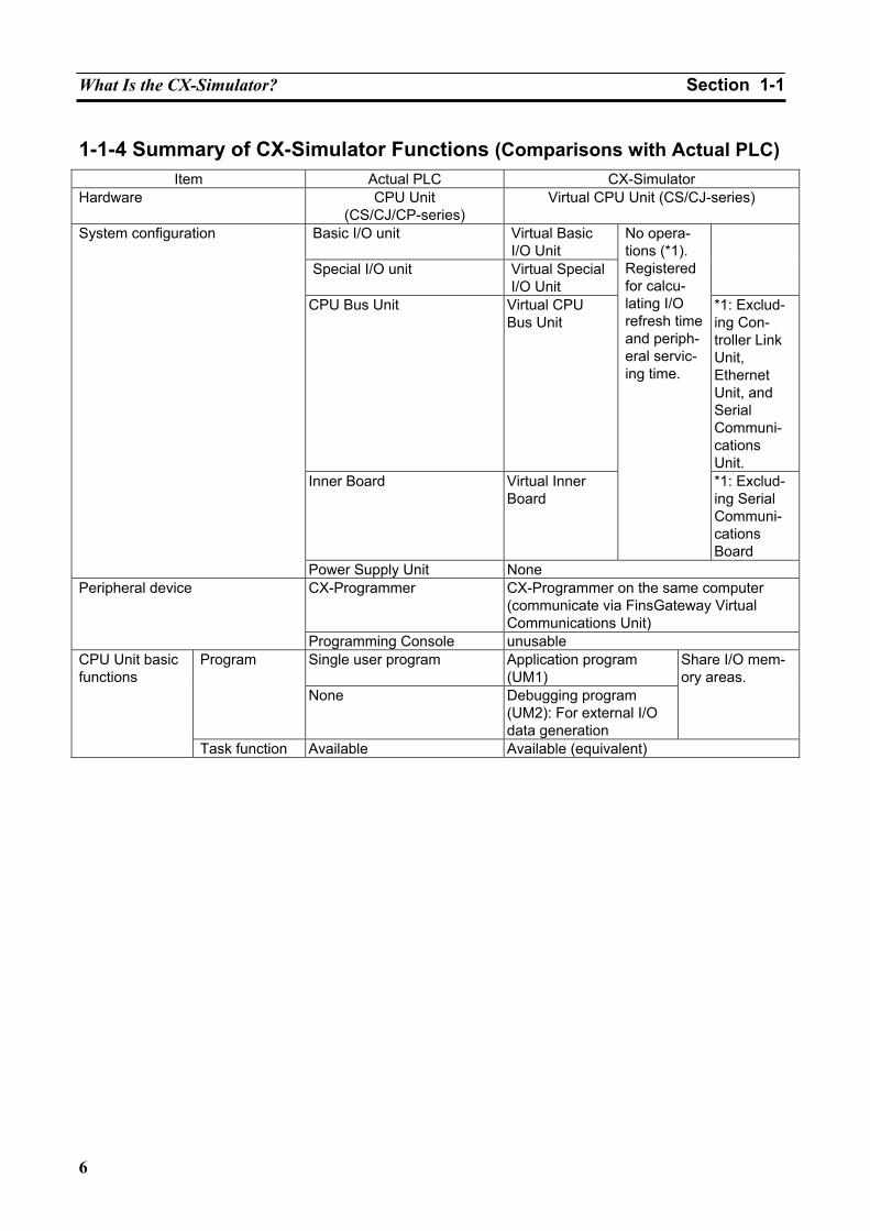
1-1-4 Summary of CX-Simulator Functions (Comparisons with Actual PLC) Item Actual PLC CX-Simulator
Hardware CPU Unit (CS/CJ/CP-series)
Virtual CPU Unit (CS/CJ-series)
Basic I/O unit Virtual Basic I/O Unit
Special I/O unit Virtual Special I/O Unit
CPU Bus Unit Virtual CPU Bus Unit
*1: Exclud-ing Con-troller Link Unit, Ethernet Unit, and Serial Communi-cations Unit.
Inner Board Virtual Inner Board
No opera-tions (*1). Registered for calcu-lating I/O refresh time and periph-eral servic-ing time.
*1: Exclud-ing Serial Communi-cations Board
System configuration
Power Supply Unit None CX-Programmer CX-Programmer on the same computer
(communicate via FinsGateway Virtual Communications Unit)
Peripheral device
Programming Console unusable Single user program Application program
(UM1) Program
None Debugging program (UM2): For external I/O data generation
Share I/O mem-ory areas.
CPU Unit basic functions
Task function Available Available (equivalent)
What Is the CX-Simulator? Section 1-1
7
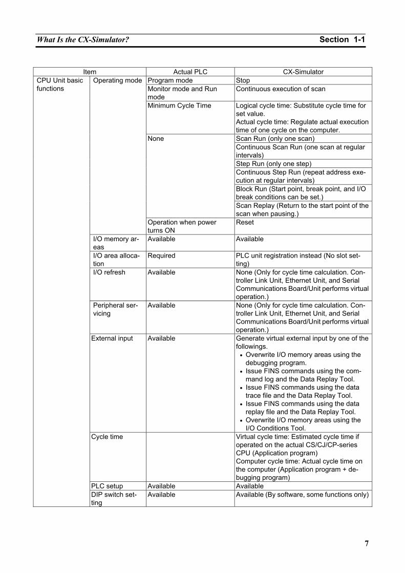
Item Actual PLC CX-Simulator
Program mode Stop Monitor mode and Run mode
Continuous execution of scan
Minimum Cycle Time Logical cycle time: Substitute cycle time for set value. Actual cycle time: Regulate actual execution time of one cycle on the computer. Scan Run (only one scan) Continuous Scan Run (one scan at regular intervals) Step Run (only one step) Continuous Step Run (repeat address exe-cution at regular intervals) Block Run (Start point, break point, and I/O break conditions can be set.)
None
Scan Replay (Return to the start point of the scan when pausing.)
Operating mode
Operation when power turns ON
Reset
I/O memory ar-eas
Available Available
I/O area alloca-tion
Required PLC unit registration instead (No slot set-ting)
I/O refresh Available None (Only for cycle time calculation. Con-troller Link Unit, Ethernet Unit, and Serial Communications Board/Unit performs virtual operation.)
Peripheral ser-vicing
Available None (Only for cycle time calculation. Con-troller Link Unit, Ethernet Unit, and Serial Communications Board/Unit performs virtual operation.)
External input Available Generate virtual external input by one of the followings.
• Overwrite I/O memory areas using the debugging program.
• Issue FINS commands using the com-mand log and the Data Replay Tool.
• Issue FINS commands using the data trace file and the Data Replay Tool.
• Issue FINS commands using the data replay file and the Data Replay Tool.
• Overwrite I/O memory areas using the I/O Conditions Tool.
Cycle time Virtual cycle time: Estimated cycle time if operated on the actual CS/CJ/CP-series CPU (Application program) Computer cycle time: Actual cycle time on the computer (Application program + de-bugging program)
PLC setup Available Available
CPU Unit basic functions
DIP switch set-ting
Available Available (By software, some functions only)
What Is the CX-Simulator? Section 1-1
8
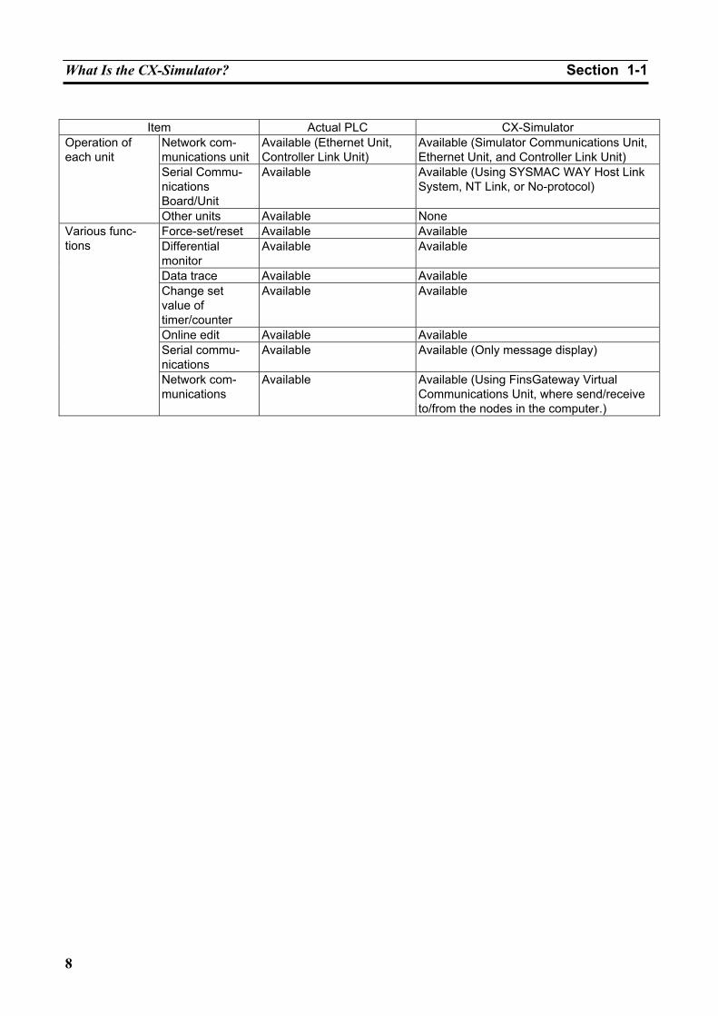
Item Actual PLC CX-Simulator
Network com-munications unit
Available (Ethernet Unit, Controller Link Unit)
Available (Simulator Communications Unit, Ethernet Unit, and Controller Link Unit)
Serial Commu-nications Board/Unit
Available Available (Using SYSMAC WAY Host Link System, NT Link, or No-protocol)
Operation of each unit
Other units Available None Force-set/reset Available Available Differential monitor
Available Available
Data trace Available Available Change set value of timer/counter
Available Available
Online edit Available Available Serial commu-nications
Available Available (Only message display)
Various func-tions
Network com-munications
Available Available (Using FinsGateway Virtual Communications Unit, where send/receive to/from the nodes in the computer.)
Features Section 1-2
9
1-2 Features Using the CX-Simulator with the following features can reduce man-days for program debugging.
1-2-1 Features Possible to simulate operation of the Virtual CPU Unit on the computer.
The CX-Simulator simulates operation of the SYSMAC CS/CJ/CP-series CPU Unit. The operation of programs can be easily checked without an actual PLC being connected. Using the CX-Simulator combined with the CX-Programmer allows to develop/debug programs on a single computer.
Easily use the CX-Programmer on the same computer
Programs for the Virtual CPU Unit on the CX-Simulator can be seamlessly debugged with the CX-Programmer that has been used. The powerful monitoring functions (including those for a ladder diagram window and pre-sent values) can be used as they used to be. Furthermore, when CX-Programmer version 3.0 or higher is used with CX-Simulator version 1.3, the CX-Simulator can be started and placed online from the CX-Programmer.
Calculate the virtual cycle time
An estimated cycle time for operation on the actual PLC can be obtained as a virtual cycle time, which is different from an elapsed time on the computer. Use it as a tentative time for operation on the actual PLC.
Dedicated debugging function Adding dedicated debugging functions to the CX-Simulator enables more detailed debugging than that of CX-Programmer + actual CS/CJ/CP-series PLC.
Step Run A program can be executed in the unit of instruction. Peripheral servicing
during a stoppage by the address execution enables monitoring of program being executed.
Start point, break point, and I/O break conditions
A program can be executed from any mnemonic code by designating a start point. Setting multiple break points and break conditions depending on the I/O memory status enables to pause a program at any point and on any conditions.
Scan Replay Scan Replay returns the program conditions to those just prior to the scan
started. The program can be replayed on the same conditions any times. Check the number and the time of executions of each task
Displaying the number and the time of executions of each task will help solve the bottleneck in executions, reducing the cycle time by re-division of the tasks.
Simulated startup of inter-rupt tasks
Simulated startup of interrupt tasks at any timing enables to debug interrupt processes.
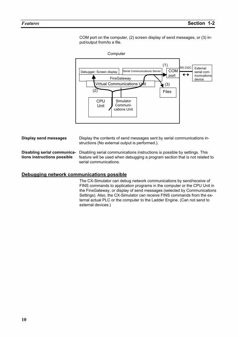
Serial communications In the CX-Simulator, debugging serial communications is possible by: (1) ac-tual communications to an external serial communications device using a
Features Section 1-2
10
COM port on the computer, (2) screen display of send messages, or (3) in-put/output from/to a file.
Display send messages Display the contents of send messages sent by serial communications in-
structions (No external output is performed.). Disabling serial communica-tions instructions possible
Disabling serial communications instructions is possible by settings. This feature will be used when debugging a program section that is not related to serial communications.
Debugging network communications possible The CX-Simulator can debug network communications by send/receive of FINS commands to application programs in the computer or the CPU Unit in the FinsGateway, or display of send messages (selected by Communications Settings). Also, the CX-Simulator can receive FINS commands from the ex-ternal actual PLC or the computer to the Ladder Engine. (Can not send to external devices.)
Computer
Debugger: Screen display
FinsGateway
Simulator Communi-
cations Unit
CPU Unit
External serial com-munications device
RS-232C (1)
(3)
COM port
Files (2) Virtual Communications Unit
Serial Communications Server
Features Section 1-2
11
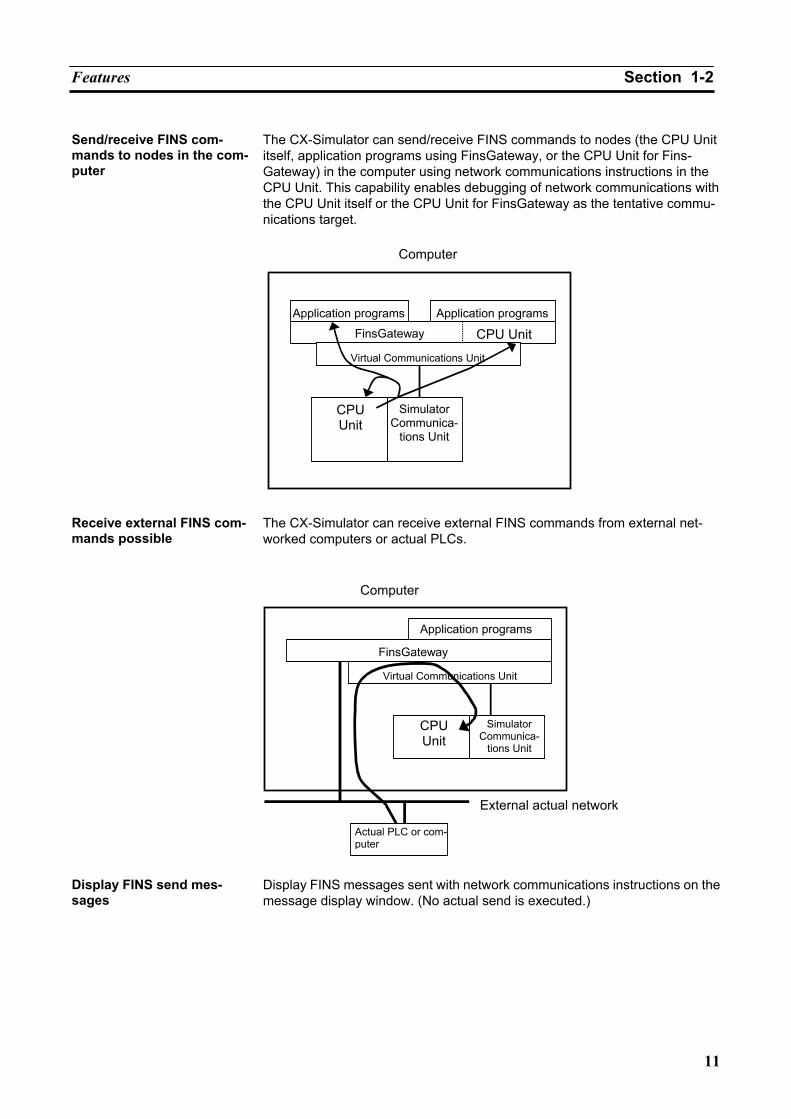
Send/receive FINS com-mands to nodes in the com-puter
The CX-Simulator can send/receive FINS commands to nodes (the CPU Unit itself, application programs using FinsGateway, or the CPU Unit for Fins-Gateway) in the computer using network communications instructions in the CPU Unit. This capability enables debugging of network communications with the CPU Unit itself or the CPU Unit for FinsGateway as the tentative commu-nications target.
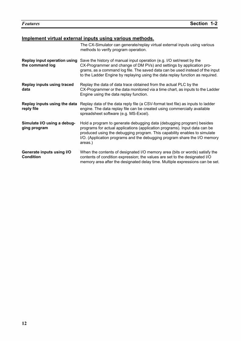
Receive external FINS com-mands possible
The CX-Simulator can receive external FINS commands from external net-worked computers or actual PLCs.
Display FINS send mes-sages
Display FINS messages sent with network communications instructions on the message display window. (No actual send is executed.)
Computer
Application programs Application programs
FinsGateway CPU Unit
Simulator Communica-
tions Unit
CPU Unit
Virtual Communications Unit
Computer
Application programs
FinsGateway
Simulator Communica-
tions Unit
CPU Unit
Virtual Communications Unit
Actual PLC or com-puter
External actual network
Features Section 1-2
12
Implement virtual external inputs using various methods. The CX-Simulator can generate/replay virtual external inputs using various methods to verify program operation.
Replay input operation using the command log
Save the history of manual input operation (e.g. I/O set/reset by the CX-Programmer and change of DM PVs) and settings by application pro-grams, as a command log file. The saved data can be used instead of the input to the Ladder Engine by replaying using the data replay function as required.
Replay inputs using traced data
Replay the data of data trace obtained from the actual PLC by the CX-Programmer or the data monitored via a time chart, as inputs to the Ladder Engine using the data replay function.
Replay inputs using the data reply file
Replay data of the data reply file (a CSV-format text file) as inputs to ladder engine. The data replay file can be created using commercially available spreadsheet software (e.g. MS-Excel).
Simulate I/O using a debug-ging program
Hold a program to generate debugging data (debugging program) besides programs for actual applications (application programs). Input data can be produced using the debugging program. This capability enables to simulate I/O. (Application programs and the debugging program share the I/O memory areas.)
Generate inputs using I/O Condition
When the contents of designated I/O memory area (bits or words) satisfy the contents of condition expression; the values are set to the designated I/O memory area after the designated delay time. Multiple expressions can be set.
Convenient Functions Section 1-3
13
1-3 Convenient Functions The CX-Simulator provides the following convenient functions.
Monitor IR/DR By Step Run, the contents of IR/DR for each task during ladder diagram exe-
cution can be monitored with the CX-Programmer SV monitoring, which has been difficult to debug. After setting break points to the mnemonic codes in the Step Run window, executing the ladder diagram allows to monitor the value before the mnemonic code is executed.
Block Run Any range of a program can be executed by designating the execution start
point (the start pointer) and execution interrupt point (the break pointer). Support debugging of ap-plication programs on the computer
When developing a monitoring program or a data collection program on the computer, debugging communications functions was done with the actual PLC connected. If the CX-Simulator is used together, on the other hand, a single computer will do all of the debugging. (Valid only for application programs using FinsGateway.)
Coordinated functions with commercial software
Coordinated functions with commercial spreadsheet programs and text editors allow using familiar software for data collection/display. • Obtain mnemonic codes in a task.
Refer to 3-9-7 Step Run Window. • Obtain task information.
Refer to 3-9-8 Task Control Window. • Create virtual external input data.
Refer to 8-3 Generating Virtual External Inputs. • Monitor the result by virtual external inputs.
Refer to 8-5 Checking the Result. • Designate a program for alarm display. (Only for Windows 95/98/Me)
Refer to Console Display Settings in 3-9-4 File Menu.
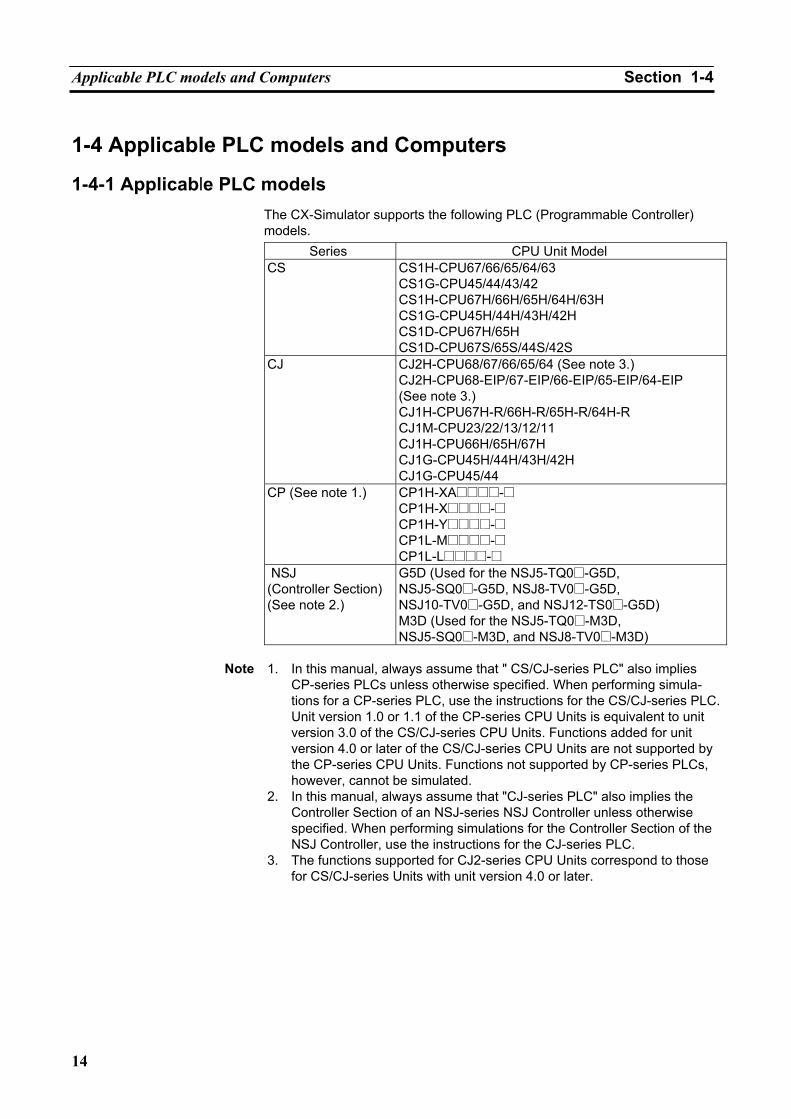
Applicable PLC models and Computers Section 1-4
14
1-4 Applicable PLC models and Computers
1-4-1 Applicable PLC models The CX-Simulator supports the following PLC (Programmable Controller) models.
Series CPU Unit Model CS CS1H-CPU67/66/65/64/63
CS1G-CPU45/44/43/42 CS1H-CPU67H/66H/65H/64H/63H CS1G-CPU45H/44H/43H/42H CS1D-CPU67H/65H CS1D-CPU67S/65S/44S/42S
CJ CJ2H-CPU68/67/66/65/64 (See note 3.) CJ2H-CPU68-EIP/67-EIP/66-EIP/65-EIP/64-EIP (See note 3.) CJ1H-CPU67H-R/66H-R/65H-R/64H-R CJ1M-CPU23/22/13/12/11 CJ1H-CPU66H/65H/67H CJ1G-CPU45H/44H/43H/42H CJ1G-CPU45/44
CP (See note 1.) CP1H-XA@@@@-@ CP1H-X@@@@-@ CP1H-Y@@@@-@ CP1L-M@@@@-@ CP1L-L@@@@-@
NSJ (Controller Section) (See note 2.)
G5D (Used for the NSJ5-TQ0@-G5D, NSJ5-SQ0@-G5D, NSJ8-TV0@-G5D, NSJ10-TV0@-G5D, and NSJ12-TS0@-G5D) M3D (Used for the NSJ5-TQ0@-M3D, NSJ5-SQ0@-M3D, and NSJ8-TV0@-M3D)
Note 1. In this manual, always assume that " CS/CJ-series PLC" also implies
CP-series PLCs unless otherwise specified. When performing simula-tions for a CP-series PLC, use the instructions for the CS/CJ-series PLC. Unit version 1.0 or 1.1 of the CP-series CPU Units is equivalent to unit version 3.0 of the CS/CJ-series CPU Units. Functions added for unit version 4.0 or later of the CS/CJ-series CPU Units are not supported by the CP-series CPU Units. Functions not supported by CP-series PLCs, however, cannot be simulated.
2. In this manual, always assume that "CJ-series PLC" also implies the Controller Section of an NSJ-series NSJ Controller unless otherwise specified. When performing simulations for the Controller Section of the NSJ Controller, use the instructions for the CJ-series PLC.
3. The functions supported for CJ2-series CPU Units correspond to those for CS/CJ-series Units with unit version 4.0 or later.
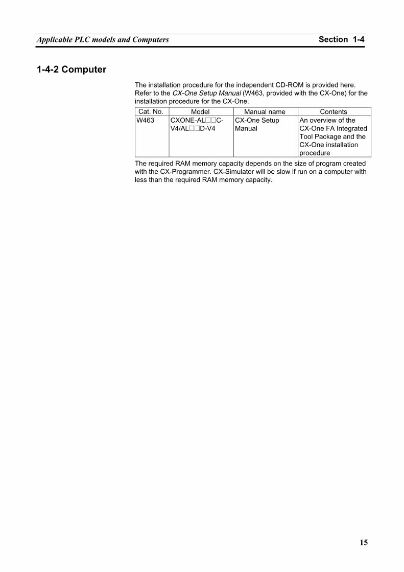
Applicable PLC models and Computers Section 1-4
15
1-4-2 Computer The installation procedure for the independent CD-ROM is provided here. Refer to the CX-One Setup Manual (W463, provided with the CX-One) for the installation procedure for the CX-One. Cat. No. Model Manual name Contents
W463 CXONE-AL@@C- V4/AL@@D-V4
CX-One Setup Manual
An overview of the CX-One FA Integrated Tool Package and the CX-One installation procedure
The required RAM memory capacity depends on the size of program created with the CX-Programmer. CX-Simulator will be slow if run on a computer with less than the required RAM memory capacity.
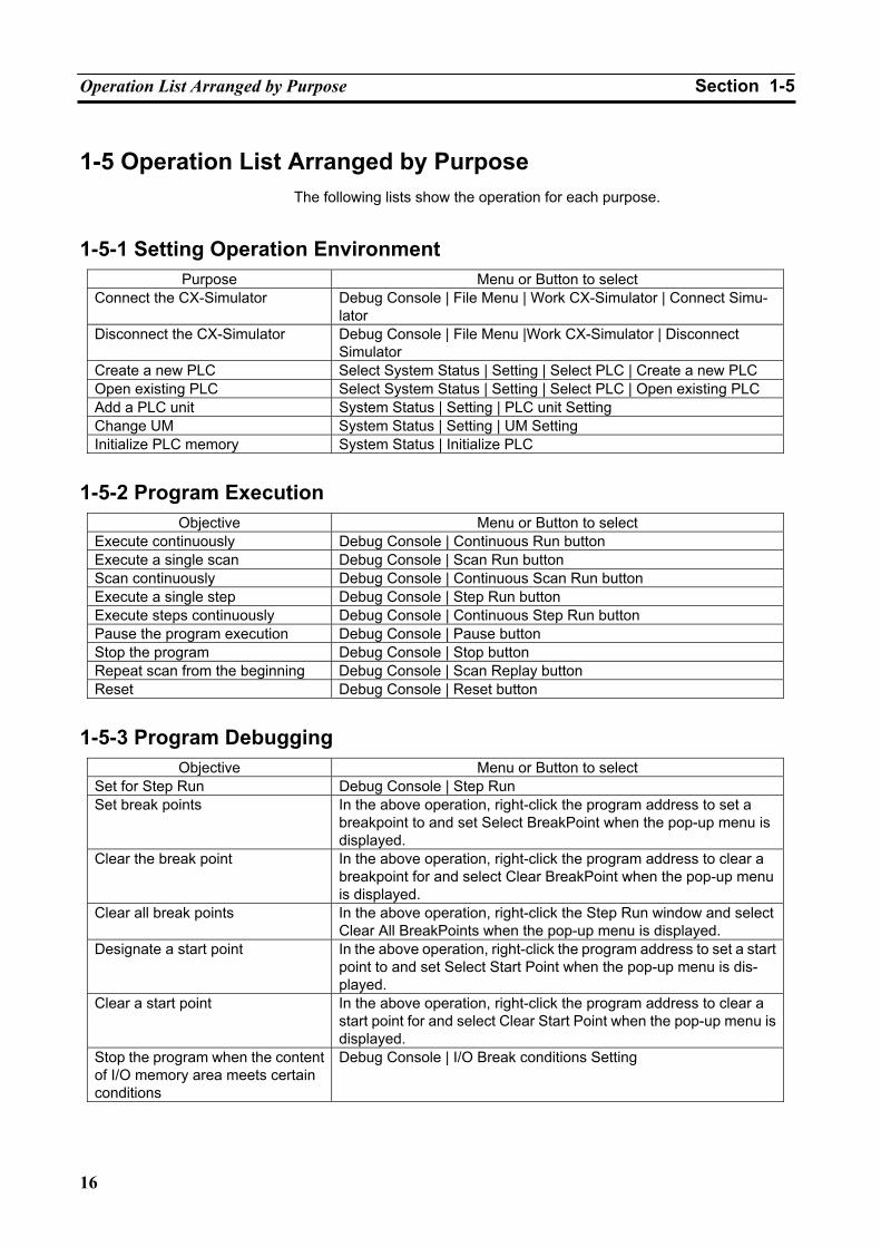
Operation List Arranged by Purpose Section 1-5
16
1-5 Operation List Arranged by Purpose The following lists show the operation for each purpose.
1-5-1 Setting Operation Environment Purpose Menu or Button to select
Connect the CX-Simulator Debug Console | File Menu | Work CX-Simulator | Connect Simu-lator
Disconnect the CX-Simulator Debug Console | File Menu |Work CX-Simulator | Disconnect Simulator
Create a new PLC Select System Status | Setting | Select PLC | Create a new PLC Open existing PLC Select System Status | Setting | Select PLC | Open existing PLC Add a PLC unit System Status | Setting | PLC unit Setting Change UM System Status | Setting | UM Setting Initialize PLC memory System Status | Initialize PLC
1-5-2 Program Execution Objective Menu or Button to select
Execute continuously Debug Console | Continuous Run button Execute a single scan Debug Console | Scan Run button Scan continuously Debug Console | Continuous Scan Run button Execute a single step Debug Console | Step Run button Execute steps continuously Debug Console | Continuous Step Run button Pause the program execution Debug Console | Pause button Stop the program Debug Console | Stop button Repeat scan from the beginning Debug Console | Scan Replay button Reset Debug Console | Reset button
1-5-3 Program Debugging Objective Menu or Button to select
Set for Step Run Debug Console | Step Run Set break points In the above operation, right-click the program address to set a
breakpoint to and set Select BreakPoint when the pop-up menu is displayed.
Clear the break point In the above operation, right-click the program address to clear a breakpoint for and select Clear BreakPoint when the pop-up menu is displayed.
Clear all break points In the above operation, right-click the Step Run window and select Clear All BreakPoints when the pop-up menu is displayed.
Designate a start point In the above operation, right-click the program address to set a start point to and set Select Start Point when the pop-up menu is dis-played.
Clear a start point In the above operation, right-click the program address to clear a start point for and select Clear Start Point when the pop-up menu is displayed.
Stop the program when the content of I/O memory area meets certain conditions
Debug Console | I/O Break conditions Setting
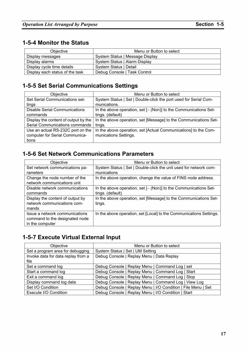
Operation List Arranged by Purpose Section 1-5
17
1-5-4 Monitor the Status Objective Menu or Button to select
Display messages System Status | Message Display Display alarms System Status | Alarm Display Display cycle time details System Status | Detail Display each status of the task Debug Console | Task Control
1-5-5 Set Serial Communications Settings Objective Menu or Button to select
Set Serial Communications set-tings
System Status | Set | Double-click the port used for Serial Com-munications.
Disable Serial Communications commands
In the above operation, set [− (Non)] to the Communications Set-tings. (default)
Display the content of output by the Serial Communications commands
In the above operation, set [Message] to the Communications Set-tings.
Use an actual RS-232C port on the computer for Serial Communica-tions
In the above operation, set [Actual Communications] to the Com-munications Settings.
1-5-6 Set Network Communications Parameters Objective Menu or Button to select
Set network communications pa-rameters
System Status | Set | Double-click the unit used for network com-munications
Change the node number of the network communications unit
In the above operation, change the value of FINS node address.
Disable network communications commands
In the above operation, set [− (Non)] to the Communications Set-tings. (default)
Display the content of output by network communications com-mands
In the above operation, set [Message] to the Communications Set-tings.
Issue a network communications command to the designated node in the computer
In the above operation, set [Local] to the Communications Settings.
1-5-7 Execute Virtual External Input Objective Menu or Button to select
Set a program area for debugging System Status | Set | UM Setting Invoke data for data replay from a file
Debug Console | Replay Menu | Data Replay
Set a command log Debug Console | Replay Menu | Command Log | set Start a command log Debug Console | Replay Menu | Command Log | Start Exit a command log Debug Console | Replay Menu | Command Log | Stop Display command log data Debug Console | Replay Menu | Command Log | View Log Set I/O Condition Debug Console | Replay Menu | I/O Condition | File Menu | Set Execute I/O Condition Debug Console | Replay Menu | I/O Condition | Start
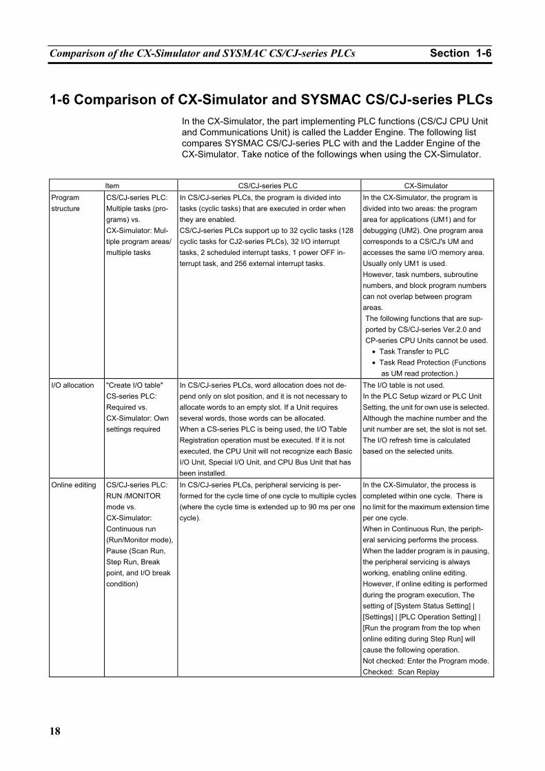
Comparison of the CX-Simulator and SYSMAC CS/CJ-series PLCs Section 1-6
18
1-6 Comparison of CX-Simulator and SYSMAC CS/CJ-series PLCs In the CX-Simulator, the part implementing PLC functions (CS/CJ CPU Unit and Communications Unit) is called the Ladder Engine. The following list compares SYSMAC CS/CJ-series PLC with and the Ladder Engine of the CX-Simulator. Take notice of the followings when using the CX-Simulator.
Item CS/CJ-series PLC CX-Simulator
Program structure
CS/CJ-series PLC: Multiple tasks (pro-grams) vs. CX-Simulator: Mul-tiple program areas/ multiple tasks
In CS/CJ-series PLCs, the program is divided into tasks (cyclic tasks) that are executed in order when they are enabled. CS/CJ-series PLCs support up to 32 cyclic tasks (128 cyclic tasks for CJ2-series PLCs), 32 I/O interrupt tasks, 2 scheduled interrupt tasks, 1 power OFF in-terrupt task, and 256 external interrupt tasks.
In the CX-Simulator, the program is divided into two areas: the program area for applications (UM1) and for debugging (UM2). One program area corresponds to a CS/CJ's UM and accesses the same I/O memory area. Usually only UM1 is used. However, task numbers, subroutine numbers, and block program numbers can not overlap between program areas. The following functions that are sup-ported by CS/CJ-series Ver.2.0 and CP-series CPU Units cannot be used.
• Task Transfer to PLC • Task Read Protection (Functions
as UM read protection.) I/O allocation "Create I/O table"
CS-series PLC: Required vs. CX-Simulator: Own settings required
In CS/CJ-series PLCs, word allocation does not de-pend only on slot position, and it is not necessary to allocate words to an empty slot. If a Unit requires several words, those words can be allocated. When a CS-series PLC is being used, the I/O Table Registration operation must be executed. If it is not executed, the CPU Unit will not recognize each Basic I/O Unit, Special I/O Unit, and CPU Bus Unit that has been installed.
The I/O table is not used. In the PLC Setup wizard or PLC Unit Setting, the unit for own use is selected. Although the machine number and the unit number are set, the slot is not set.The I/O refresh time is calculated based on the selected units.
Online editing CS/CJ-series PLC: RUN /MONITOR mode vs. CX-Simulator: Continuous run (Run/Monitor mode), Pause (Scan Run, Step Run, Break point, and I/O break condition)
In CS/CJ-series PLCs, peripheral servicing is per-formed for the cycle time of one cycle to multiple cycles (where the cycle time is extended up to 90 ms per one cycle).
In the CX-Simulator, the process is completed within one cycle. There is no limit for the maximum extension time per one cycle. When in Continuous Run, the periph-eral servicing performs the process. When the ladder program is in pausing, the peripheral servicing is always working, enabling online editing. However, if online editing is performed during the program execution, The setting of [System Status Setting] | [Settings] | [PLC Operation Setting] | [Run the program from the top when online editing during Step Run] will cause the following operation. Not checked: Enter the Program mode.Checked: Scan Replay
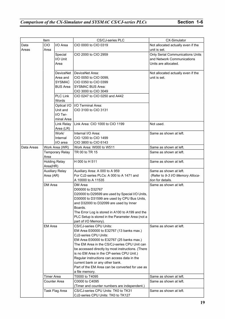
Comparison of the CX-Simulator and SYSMAC CS/CJ-series PLCs Section 1-6
19
Item CS/CJ-series PLC CX-Simulator
I/O Area CIO 0000 to CIO 0319 Not allocated actually even if the unit is set.
Special I/O Unit Area
CIO 2000 to CIO 2959 Only Serial Communications Units and Network Communications Units are allocated.
DeviceNet Area and SYSMAC BUS Area
DeviceNet Area: CIO 0050 to CIO 0099, CIO 0350 to CIO 0399 SYSMAC BUS Area: CIO 3000 to CIO 3049
PLC Link Words
CIO 0247 to CIO 0250 and A442
Optical I/O Unit and I/O Ter-minal Area
I/O Terminal Area: CIO 3100 to CIO 3131
Not allocated actually even if the unit is set.
Link Relay Area (LR)
Link Area: CIO 1000 to CIO 1199 Not used.
Data Areas
CIO Area
Work/ Internal I/O area
Internal I/O Area: CIO 1200 to CIO 1499 CIO 3800 to CIO 6143
Same as shown at left.
Work Area (WR) Work Area: W000 to W511 Same as shown at left. Temporary Relay Area
TR 00 to TR 15 Same as shown at left.
Holding Relay Area(HR)
H 000 to H 511 Same as shown at left.
Auxiliary Relay Area (AR)
Auxiliary Area: A 000 to A 959 For CJ2-series PLCs: A 000 to A 1471 and A 10000 to A 11535
Same as shown at left. (Refer to 9-3 I/O Memory Alloca-tion for details.
DM Area DM Area D00000 to D32767 D20000 to D29599 are used by Special I/O Units, D30000 to D31599 are used by CPU Bus Units, and D32000 to D32099 are used by Inner Boards. The Error Log is stored in A100 to A199 and the PLC Setup is stored in the Parameter Area (not a part of I/O Memory).
Same as shown at left.
EM Area CS/CJ-series CPU Units: EM Area E00000 to E32767 (13 banks max.) CJ2-series CPU Units: EM Area E00000 to E32767 (25 banks max.) The EM Area in the CS/CJ-series CPU Unit can be accessed directly by most instructions. (There is no EM Area in the CP-series CPU Unit.) Regular instructions can access data in the current bank or any other bank. Part of the EM Area can be converted for use as a file memory.
Same as shown at left.
Timer Area T0000 to T4095 Same as shown at left. Counter Area C0000 to C4095
(Timer and counter numbers are independent.) Same as shown at left.
Data Areas
Task Flag Area CS/CJ-series CPU Units: TK0 to TK31 CJ2-series CPU Units: TK0 to TK127
Same as shown at left.
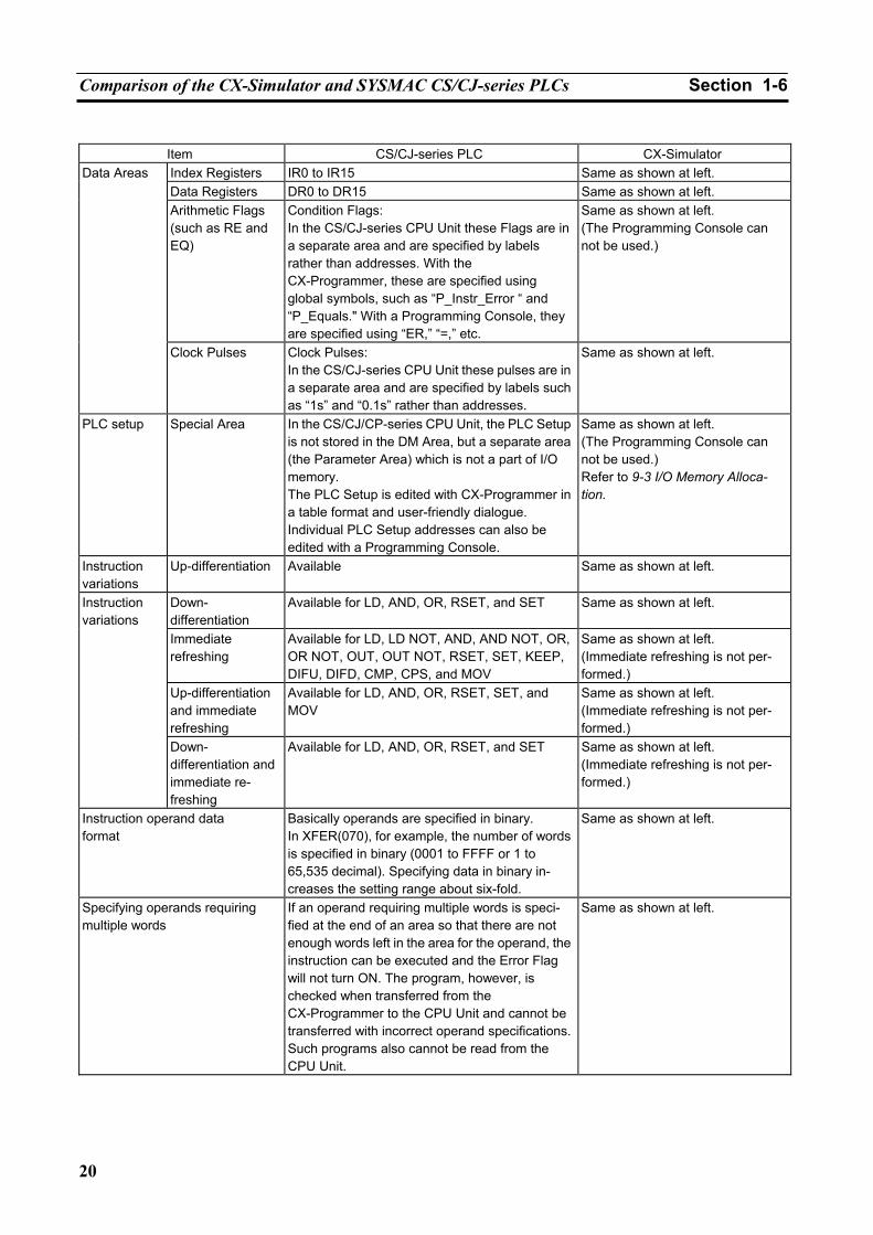
Comparison of the CX-Simulator and SYSMAC CS/CJ-series PLCs Section 1-6
20
Item CS/CJ-series PLC CX-Simulator
Data Areas Index Registers IR0 to IR15 Same as shown at left. Data Registers DR0 to DR15 Same as shown at left. Arithmetic Flags (such as RE and EQ)
Condition Flags: In the CS/CJ-series CPU Unit these Flags are in a separate area and are specified by labels rather than addresses. With the CX-Programmer, these are specified using global symbols, such as “P_Instr_Error “ and “P_Equals." With a Programming Console, they are specified using “ER,” “=,” etc.
Same as shown at left. (The Programming Console can not be used.)
Clock Pulses Clock Pulses: In the CS/CJ-series CPU Unit these pulses are in a separate area and are specified by labels such as “1s” and “0.1s” rather than addresses.
Same as shown at left.
PLC setup Special Area In the CS/CJ/CP-series CPU Unit, the PLC Setup is not stored in the DM Area, but a separate area (the Parameter Area) which is not a part of I/O memory. The PLC Setup is edited with CX-Programmer in a table format and user-friendly dialogue. Individual PLC Setup addresses can also be edited with a Programming Console.
Same as shown at left. (The Programming Console can not be used.) Refer to 9-3 I/O Memory Alloca-tion.
Instruction variations
Up-differentiation Available Same as shown at left.
Down- differentiation
Available for LD, AND, OR, RSET, and SET Same as shown at left.
Immediate refreshing
Available for LD, LD NOT, AND, AND NOT, OR, OR NOT, OUT, OUT NOT, RSET, SET, KEEP, DIFU, DIFD, CMP, CPS, and MOV
Same as shown at left. (Immediate refreshing is not per-formed.)
Up-differentiation and immediate refreshing
Available for LD, AND, OR, RSET, SET, and MOV
Same as shown at left. (Immediate refreshing is not per-formed.)
Instruction variations
Down- differentiation and immediate re-freshing
Available for LD, AND, OR, RSET, and SET Same as shown at left. (Immediate refreshing is not per-formed.)
Instruction operand data format
Basically operands are specified in binary. In XFER(070), for example, the number of words is specified in binary (0001 to FFFF or 1 to 65,535 decimal). Specifying data in binary in-creases the setting range about six-fold.
Same as shown at left.
Specifying operands requiring multiple words
If an operand requiring multiple words is speci-fied at the end of an area so that there are not enough words left in the area for the operand, the instruction can be executed and the Error Flag will not turn ON. The program, however, is checked when transferred from the CX-Programmer to the CPU Unit and cannot be transferred with incorrect operand specifications. Such programs also cannot be read from the CPU Unit.
Same as shown at left.
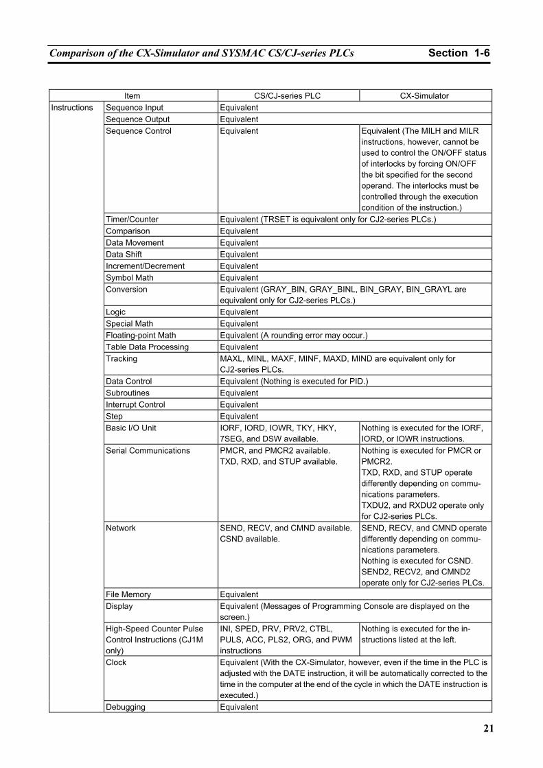
Comparison of the CX-Simulator and SYSMAC CS/CJ-series PLCs Section 1-6
21
Item CS/CJ-series PLC CX-Simulator
Sequence Input Equivalent Sequence Output Equivalent Sequence Control Equivalent Equivalent (The MILH and MILR
instructions, however, cannot be used to control the ON/OFF status of interlocks by forcing ON/OFF the bit specified for the second operand. The interlocks must be controlled through the execution condition of the instruction.)
Timer/Counter Equivalent (TRSET is equivalent only for CJ2-series PLCs.) Comparison Equivalent Data Movement Equivalent Data Shift Equivalent Increment/Decrement Equivalent Symbol Math Equivalent Conversion Equivalent (GRAY_BIN, GRAY_BINL, BIN_GRAY, BIN_GRAYL are
equivalent only for CJ2-series PLCs.) Logic Equivalent Special Math Equivalent Floating-point Math Equivalent (A rounding error may occur.) Table Data Processing Equivalent Tracking MAXL, MINL, MAXF, MINF, MAXD, MIND are equivalent only for
CJ2-series PLCs. Data Control Equivalent (Nothing is executed for PID.) Subroutines Equivalent Interrupt Control Equivalent Step Equivalent Basic I/O Unit IORF, IORD, IOWR, TKY, HKY,
7SEG, and DSW available. Nothing is executed for the IORF, IORD, or IOWR instructions.
Serial Communications PMCR, and PMCR2 available. TXD, RXD, and STUP available.
Nothing is executed for PMCR or PMCR2. TXD, RXD, and STUP operate differently depending on commu-nications parameters. TXDU2, and RXDU2 operate only for CJ2-series PLCs.
Network SEND, RECV, and CMND available.CSND available.
SEND, RECV, and CMND operate differently depending on commu-nications parameters. Nothing is executed for CSND. SEND2, RECV2, and CMND2 operate only for CJ2-series PLCs.
File Memory Equivalent Display Equivalent (Messages of Programming Console are displayed on the
screen.) High-Speed Counter Pulse Control Instructions (CJ1M only)
INI, SPED, PRV, PRV2, CTBL, PULS, ACC, PLS2, ORG, and PWM instructions
Nothing is executed for the in-structions listed at the left.
Clock Equivalent (With the CX-Simulator, however, even if the time in the PLC is adjusted with the DATE instruction, it will be automatically corrected to the time in the computer at the end of the cycle in which the DATE instruction is executed.)
Instructions
Debugging Equivalent
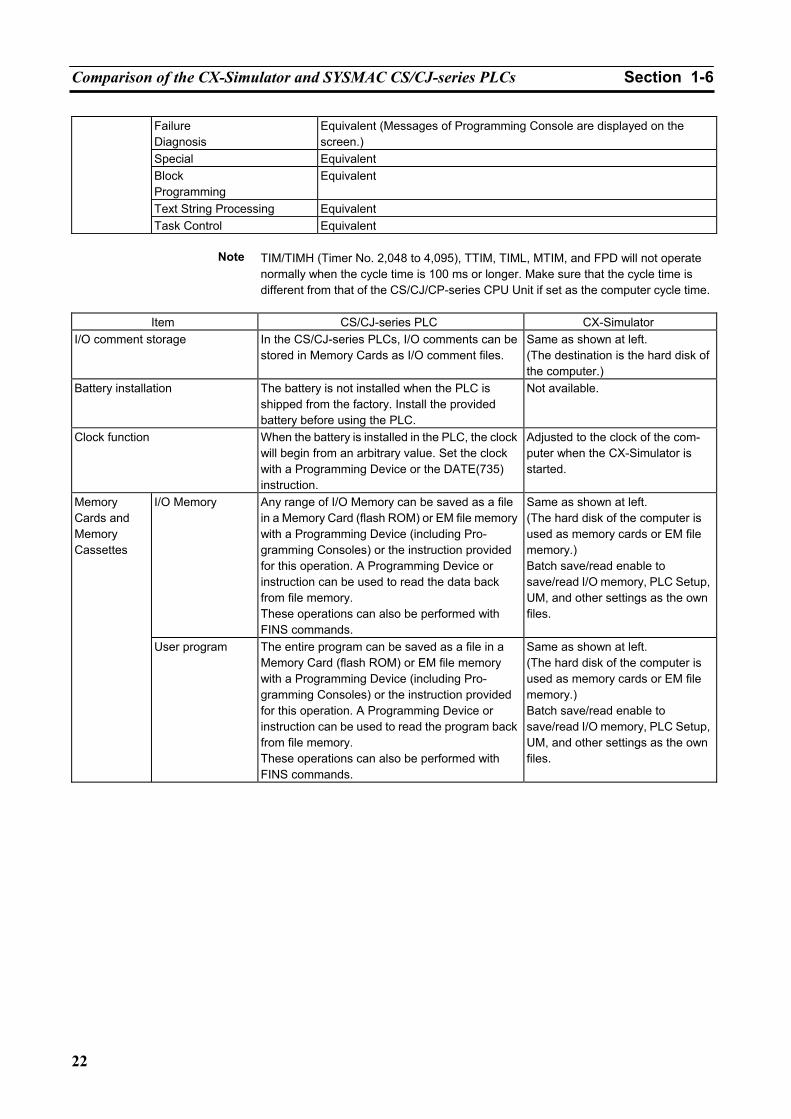
Comparison of the CX-Simulator and SYSMAC CS/CJ-series PLCs Section 1-6
22
Failure Diagnosis
Equivalent (Messages of Programming Console are displayed on the screen.)
Special Equivalent Block Programming
Equivalent
Text String Processing Equivalent
Task Control Equivalent
Note TIM/TIMH (Timer No. 2,048 to 4,095), TTIM, TIML, MTIM, and FPD will not operate normally when the cycle time is 100 ms or longer. Make sure that the cycle time is different from that of the CS/CJ/CP-series CPU Unit if set as the computer cycle time.
Item CS/CJ-series PLC CX-Simulator
I/O comment storage In the CS/CJ-series PLCs, I/O comments can be stored in Memory Cards as I/O comment files.
Same as shown at left. (The destination is the hard disk of the computer.)
Battery installation The battery is not installed when the PLC is shipped from the factory. Install the provided battery before using the PLC.
Not available.
Clock function When the battery is installed in the PLC, the clock will begin from an arbitrary value. Set the clock with a Programming Device or the DATE(735) instruction.
Adjusted to the clock of the com-puter when the CX-Simulator is started.
I/O Memory Any range of I/O Memory can be saved as a file in a Memory Card (flash ROM) or EM file memory with a Programming Device (including Pro-gramming Consoles) or the instruction provided for this operation. A Programming Device or instruction can be used to read the data back from file memory. These operations can also be performed with FINS commands.
Same as shown at left. (The hard disk of the computer is used as memory cards or EM file memory.) Batch save/read enable to save/read I/O memory, PLC Setup, UM, and other settings as the own files.
Memory Cards and Memory Cassettes
User program The entire program can be saved as a file in a Memory Card (flash ROM) or EM file memory with a Programming Device (including Pro-gramming Consoles) or the instruction provided for this operation. A Programming Device or instruction can be used to read the program back from file memory. These operations can also be performed with FINS commands.
Same as shown at left. (The hard disk of the computer is used as memory cards or EM file memory.) Batch save/read enable to save/read I/O memory, PLC Setup, UM, and other settings as the own files.
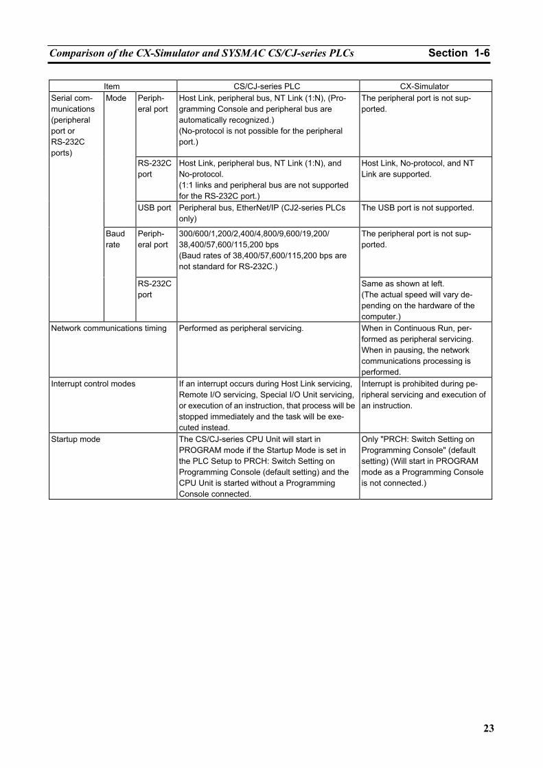
Comparison of the CX-Simulator and SYSMAC CS/CJ-series PLCs Section 1-6
23
Item CS/CJ-series PLC CX-Simulator Periph-eral port
Host Link, peripheral bus, NT Link (1:N), (Pro-gramming Console and peripheral bus are automatically recognized.) (No-protocol is not possible for the peripheral port.)
The peripheral port is not sup-ported.
RS-232C port
Host Link, peripheral bus, NT Link (1:N), and No-protocol. (1:1 links and peripheral bus are not supported for the RS-232C port.)
Host Link, No-protocol, and NT Link are supported.
Mode
USB port Peripheral bus, EtherNet/IP (CJ2-series PLCs only)
The USB port is not supported.
Periph-eral port
The peripheral port is not sup-ported.
Serial com-munications (peripheral port or RS-232C ports)
Baud rate
RS-232C port
300/600/1,200/2,400/4,800/9,600/19,200/ 38,400/57,600/115,200 bps (Baud rates of 38,400/57,600/115,200 bps are not standard for RS-232C.)
Same as shown at left. (The actual speed will vary de-pending on the hardware of the computer.)
Network communications timing Performed as peripheral servicing. When in Continuous Run, per-formed as peripheral servicing. When in pausing, the network communications processing is performed.
Interrupt control modes If an interrupt occurs during Host Link servicing, Remote I/O servicing, Special I/O Unit servicing, or execution of an instruction, that process will be stopped immediately and the task will be exe-cuted instead.
Interrupt is prohibited during pe-ripheral servicing and execution of an instruction.
Startup mode The CS/CJ-series CPU Unit will start in PROGRAM mode if the Startup Mode is set in the PLC Setup to PRCH: Switch Setting on Programming Console (default setting) and the CPU Unit is started without a Programming Console connected.
Only "PRCH: Switch Setting on Programming Console" (default setting) (Will start in PROGRAM mode as a Programming Console is not connected.)
Comparison of the CX-Simulator and SYSMAC CS/CJ-series PLCs Section 1-6
24
25
SECTION 2 Setup
2-1 Installing and Uninstalling the Software .................................................................................... 26 2-1-1 Required Software.......................................................................................................... 26 2-1-2 Preparations .................................................................................................................... 26 2-1-3 Precautions ..................................................................................................................... 27 2-1-4 Installing the CX-Simulator ........................................................................................... 28 2-1-5 Uninstalling the CX-Simulator....................................................................................... 34
Installing and Uninstalling the Software Section 2-1
26
2-1 Installing and Uninstalling the Software 2-1-1 Required Software
The following software must be installed on the same computer to use the CX-Simulator.
1,2,3… 1. CX-Simulator 2. CX-Server (communications driver)
Forms of the CX-Simulator
The CX-Simulator is available both on an independent CD-ROM and on the CX-One FA Integrated Tool Package CD-ROM. The CX-Simulator is the same in either case.
The installation procedure for the independent CD-ROM is provided here. Refer to the CX-One Setup Manual (W463, provided with the CX-One) for the installation procedure for the CX-One.
Cat. No. Model Manual name Contents W463 CXONE-AL@@C-
V4/AL@@D-V4
CX-One Setup Manual
An overview of the CX-One FA Integrated Tool Package and the CX-One installation pro-cedure
2-1-2 Preparations
Note If the CX-Simulator was previously installed from the CX-One and it is nec-
essary to install it from the individual CX-Simulator CD-ROM, always uninstall the CX-Simulator using the following procedure before installing it from its individual CD-ROM. The CX-Simulator will not operate properly if it is installed without first uninstalling it.
1,2,3… 1. Insert the CX-One installation disk 1 into the CD-ROM drive.
2. Select the Modify Option to enable modifying the Support Software that is installed.
3. In the Select Features Dialog Box, clear the selection of only the CX-Simulator. Do not change any other selections.
4. Continue by following the instructions in the dialog boxes to modify the installation and uninstall CX-Simulator.
5. Once the CX-Simulator uninstallation process has been completed, place the individual CD-ROM disk for the CX-Simulator into the CD-ROM drive and install the CX-Simulator. (See note.)
Note If the version of the CX-Server bundled on the individual CX-Simulator
CD-ROM is lower than the version of the CX-Server bundled with the CX-One, install only the CX-Simulator and NOT the CX-Server. (A message will be displayed if the version is lower.) If a version of CX-Server that is lower than the version with the CX-One is installed, the CX-One will not op-erate properly.
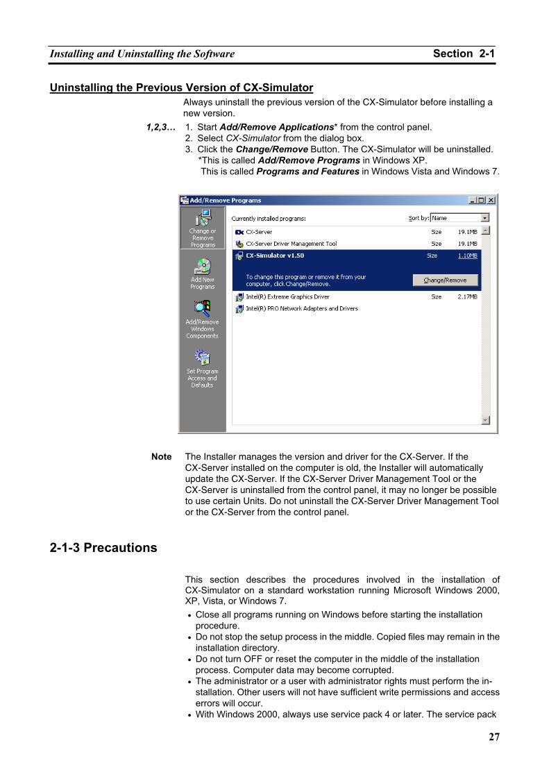
Installing and Uninstalling the Software Section 2-1
27
Uninstalling the Previous Version of CX-Simulator Always uninstall the previous version of the CX-Simulator before installing a new version.
1,2,3… 1. Start Add/Remove Applications* from the control panel. 2. Select CX-Simulator from the dialog box. 3. Click the Change/Remove Button. The CX-Simulator will be uninstalled.
*This is called Add/Remove Programs in Windows XP. This is called Programs and Features in Windows Vista and Windows 7.
Note The Installer manages the version and driver for the CX-Server. If the
CX-Server installed on the computer is old, the Installer will automatically update the CX-Server. If the CX-Server Driver Management Tool or the CX-Server is uninstalled from the control panel, it may no longer be possible to use certain Units. Do not uninstall the CX-Server Driver Management Tool or the CX-Server from the control panel.
2-1-3 Precautions
This section describes the procedures involved in the installation of CX-Simulator on a standard workstation running Microsoft Windows 2000, XP, Vista, or Windows 7. • Close all programs running on Windows before starting the installation
procedure. • Do not stop the setup process in the middle. Copied files may remain in the
installation directory. • Do not turn OFF or reset the computer in the middle of the installation
process. Computer data may become corrupted. • The administrator or a user with administrator rights must perform the in-
stallation. Other users will not have sufficient write permissions and access errors will occur.
• With Windows 2000, always use service pack 4 or later. The service pack
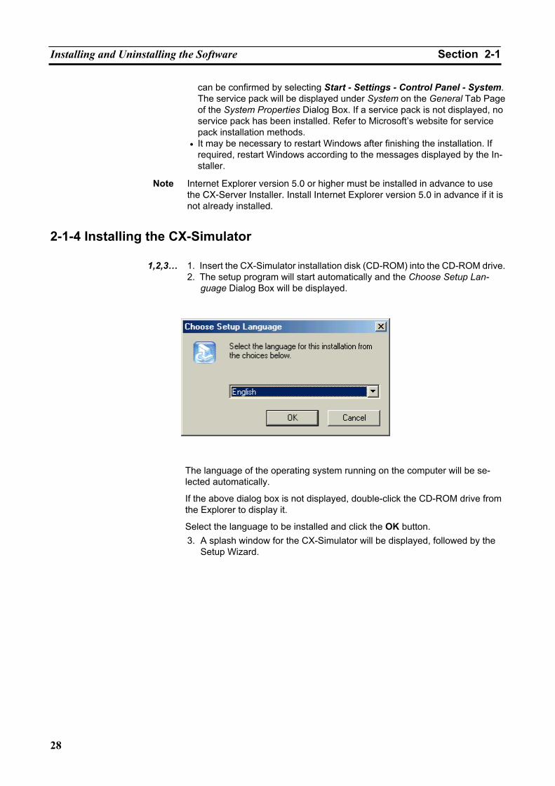
Installing and Uninstalling the Software Section 2-1
28
can be confirmed by selecting Start - Settings - Control Panel - System. The service pack will be displayed under System on the General Tab Page of the System Properties Dialog Box. If a service pack is not displayed, no service pack has been installed. Refer to Microsoft’s website for service pack installation methods.
• It may be necessary to restart Windows after finishing the installation. If required, restart Windows according to the messages displayed by the In-staller.
Note Internet Explorer version 5.0 or higher must be installed in advance to use the CX-Server Installer. Install Internet Explorer version 5.0 in advance if it is not already installed.
2-1-4 Installing the CX-Simulator
1,2,3… 1. Insert the CX-Simulator installation disk (CD-ROM) into the CD-ROM drive.2. The setup program will start automatically and the Choose Setup Lan-
guage Dialog Box will be displayed.
The language of the operating system running on the computer will be se-lected automatically.
If the above dialog box is not displayed, double-click the CD-ROM drive from the Explorer to display it.
Select the language to be installed and click the OK button. 3. A splash window for the CX-Simulator will be displayed, followed by the
Setup Wizard.
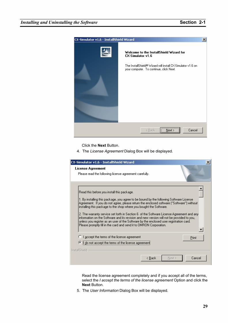
Installing and Uninstalling the Software Section 2-1
29
Click the Next Button.
4. The License Agreement Dialog Box will be displayed.
Read the license agreement completely and if you accept all of the terms,
select the I accept the terms of the license agreement Option and click the Next Button.
5. The User Information Dialog Box will be displayed.
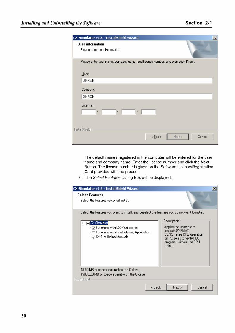
Installing and Uninstalling the Software Section 2-1
30
The default names registered in the computer will be entered for the user
name and company name. Enter the license number and click the Next Button. The license number is given on the Software License/Registration Card provided with the product.
6. The Select Features Dialog Box will be displayed.
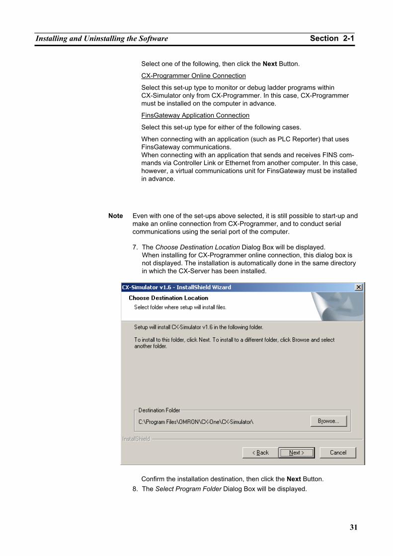
Installing and Uninstalling the Software Section 2-1
31
Select one of the following, then click the Next Button.
CX-Programmer Online Connection
Select this set-up type to monitor or debug ladder programs within CX-Simulator only from CX-Programmer. In this case, CX-Programmer must be installed on the computer in advance.
FinsGateway Application Connection
Select this set-up type for either of the following cases.
When connecting with an application (such as PLC Reporter) that uses FinsGateway communications. When connecting with an application that sends and receives FINS com-mands via Controller Link or Ethernet from another computer. In this case, however, a virtual communications unit for FinsGateway must be installed in advance.
Note Even with one of the set-ups above selected, it is still possible to start-up and make an online connection from CX-Programmer, and to conduct serial communications using the serial port of the computer.
7. The Choose Destination Location Dialog Box will be displayed.
When installing for CX-Programmer online connection, this dialog box is not displayed. The installation is automatically done in the same directory in which the CX-Server has been installed.
Confirm the installation destination, then click the Next Button. 8. The Select Program Folder Dialog Box will be displayed.
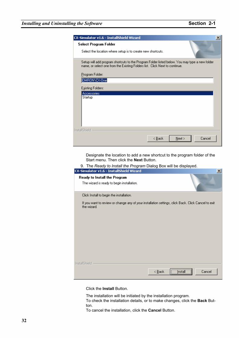
Installing and Uninstalling the Software Section 2-1
32
Designate the location to add a new shortcut to the program folder of the Start menu. Then click the Next Button.
9. The Ready to Install the Program Dialog Box will be displayed.
Click the Install Button.
The installation will be initiated by the installation program. To check the installation details, or to make changes, click the Back But-ton. To cancel the installation, click the Cancel Button.
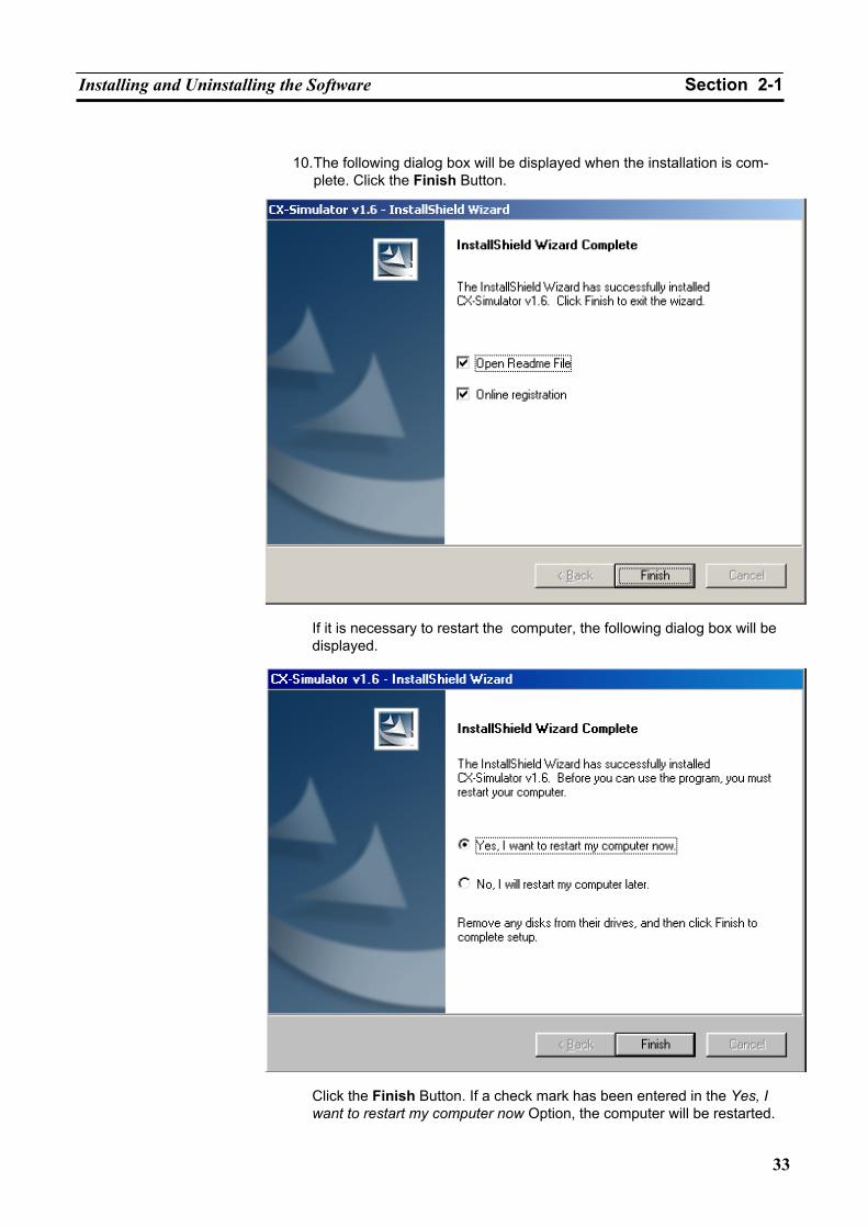
Installing and Uninstalling the Software Section 2-1
33
10. The following dialog box will be displayed when the installation is com-
plete. Click the Finish Button.
If it is necessary to restart the computer, the following dialog box will be displayed.
Click the Finish Button. If a check mark has been entered in the Yes, I want to restart my computer now Option, the computer will be restarted.
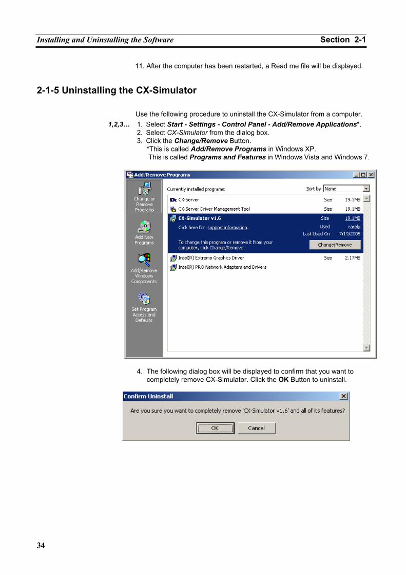
Installing and Uninstalling the Software Section 2-1
34
11. After the computer has been restarted, a Read me file will be displayed.
2-1-5 Uninstalling the CX-Simulator
Use the following procedure to uninstall the CX-Simulator from a computer. 1,2,3… 1. Select Start - Settings - Control Panel - Add/Remove Applications*.
2. Select CX-Simulator from the dialog box. 3. Click the Change/Remove Button.
*This is called Add/Remove Programs in Windows XP. This is called Programs and Features in Windows Vista and Windows 7.
4. The following dialog box will be displayed to confirm that you want to completely remove CX-Simulator. Click the OK Button to uninstall.
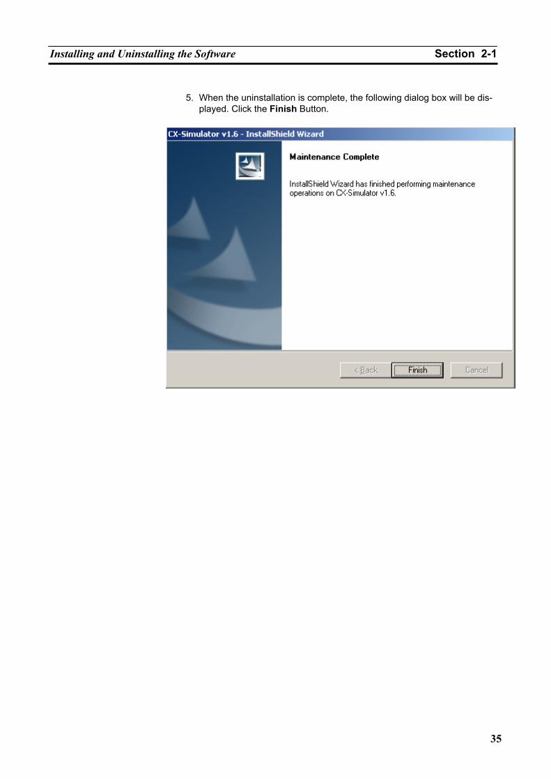
Installing and Uninstalling the Software Section 2-1
35
5. When the uninstallation is complete, the following dialog box will be dis-played. Click the Finish Button.

Installing and Uninstalling the Software Section 2-1
36
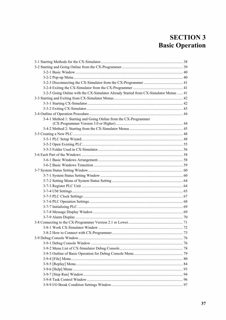
37
SECTION 3 Basic Operation
3-1 Starting Methods for the CX-Simulator...................................................................................... 38 3-2 Starting and Going Online from the CX-Programmer................................................................ 39
3-2-1 Basic Window ................................................................................................................ 40 3-2-2 Pop-up Menu .................................................................................................................. 40 3-2-3 Disconnecting the CX-Simulator from the CX-Programmer ......................................... 41 3-2-4 Exiting the CX-Simulator from the CX-Programmer .................................................... 41 3-2-5 Going Online with the CX-Simulator Already Started from CX-Simulator Menus ...... 41
3-3 Starting and Exiting from CX-Simulator Menus ........................................................................ 42 3-3-1 Starting CX-Simulator.................................................................................................... 42 3-3-2 Exiting CX-Simulator..................................................................................................... 43
3-4 Outline of Operation Procedure.................................................................................................. 44 3-4-1 Method 1: Starting and Going Online from the CX-Programmer
(CX-Programmer Version 3.0 or Higher) ...................................................................... 44 3-4-2 Method 2: Starting from the CX-Simulator Menus........................................................ 45
3-5 Creating a New PLC................................................................................................................... 48 3-5-1 PLC Setup Wizard.......................................................................................................... 48 3-5-2 Open Existing PLC......................................................................................................... 55 3-5-3 Folder Used in CX-Simulator......................................................................................... 56
3-6 Each Part of the Windows .......................................................................................................... 58 3-6-1 Basic Windows Arrangement......................................................................................... 58 3-6-2 Basic Windows Transition ............................................................................................. 59
3-7 System Status Setting Window................................................................................................... 60 3-7-1 System Status Setting Window ...................................................................................... 60 3-7-2 Setting Menu of System Status Setting .......................................................................... 64 3-7-3 Register PLC Unit .......................................................................................................... 64 3-7-4 UM Settings.................................................................................................................... 65 3-7-5 PLC Clock Settings ........................................................................................................ 67 3-7-6 PLC Operation Settings.................................................................................................. 68 3-7-7 Initializing PLC .............................................................................................................. 69 3-7-8 Message Display Window.............................................................................................. 69 3-7-9 Alarm Display ................................................................................................................ 70
3-8 Connecting to the CX-Programmer Version 2.1 or Lower......................................................... 71 3-8-1 Work CX-Simulator Window ........................................................................................ 72 3-8-2 How to Connect with CX-Programmer .......................................................................... 73
3-9 Debug Console Window............................................................................................................. 76 3-9-1 Debug Console Window ................................................................................................ 76 3-9-2 Menu List of CX-Simulator Debug Console.................................................................. 78 3-9-3 Outline of Basic Operation for Debug Console Menu ................................................... 79 3-9-4 [File] Menu..................................................................................................................... 80 3-9-5 [Replay] Menu................................................................................................................ 84 3-9-6 [Help] Menu ................................................................................................................... 93 3-9-7 [Step Run] Window........................................................................................................ 94 3-9-8 Task Control Window .................................................................................................... 96 3-9-9 I/O Break Condition Settings Window........................................................................... 97
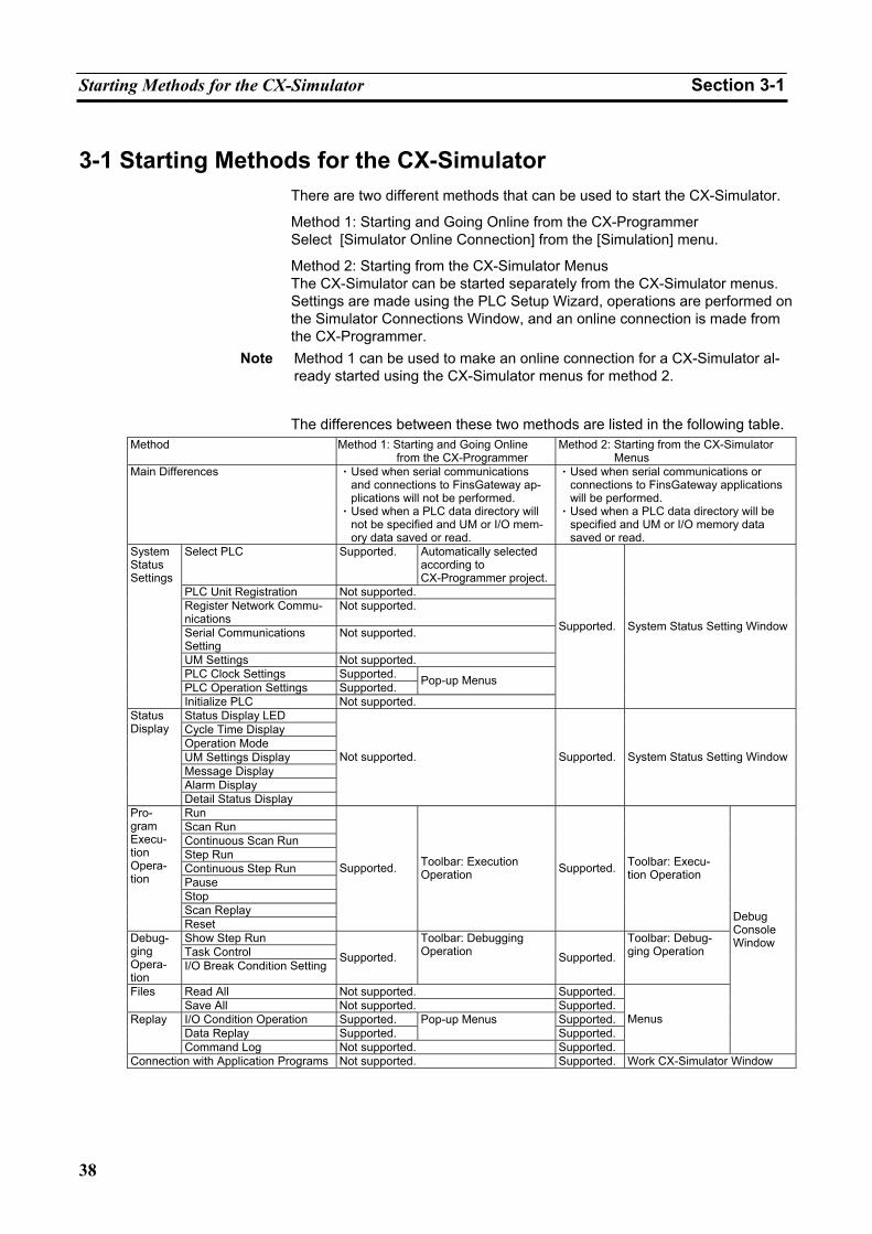
Starting Methods for the CX-Simulator Section 3-1
38
3-1 Starting Methods for the CX-Simulator There are two different methods that can be used to start the CX-Simulator.
Method 1: Starting and Going Online from the CX-Programmer Select [Simulator Online Connection] from the [Simulation] menu.
Method 2: Starting from the CX-Simulator Menus The CX-Simulator can be started separately from the CX-Simulator menus. Settings are made using the PLC Setup Wizard, operations are performed on the Simulator Connections Window, and an online connection is made from the CX-Programmer.
Note Method 1 can be used to make an online connection for a CX-Simulator al-ready started using the CX-Simulator menus for method 2.
The differences between these two methods are listed in the following table. Method Method 1: Starting and Going Online
from the CX-Programmer Method 2: Starting from the CX-Simulator
Menus Main Differences • Used when serial communications
and connections to FinsGateway ap-plications will not be performed.
• Used when a PLC data directory will not be specified and UM or I/O mem-ory data saved or read.
• Used when serial communications or connections to FinsGateway applications will be performed.
• Used when a PLC data directory will be specified and UM or I/O memory data saved or read.
Select PLC Supported. Automatically selected according to CX-Programmer project.
PLC Unit Registration Not supported. Register Network Commu-nications
Not supported.
Serial Communications Setting
Not supported.
UM Settings Not supported. PLC Clock Settings Supported. PLC Operation Settings Supported. Pop-up Menus
System Status Settings
Initialize PLC Not supported.
Supported. System Status Setting Window
Status Display LED Cycle Time Display Operation Mode UM Settings Display Message Display Alarm Display
Status Display
Detail Status Display
Not supported. Supported. System Status Setting Window
Run Scan Run Continuous Scan Run Step Run Continuous Step Run Pause Stop Scan Replay
Pro-gram Execu-tion Opera-tion
Reset
Supported. Toolbar: Execution Operation Supported. Toolbar: Execu-
tion Operation
Show Step Run Task Control
Debug-ging Opera-tion
I/O Break Condition Setting Supported.
Toolbar: Debugging Operation Supported.
Toolbar: Debug-ging Operation
Read All Not supported. Supported.Files Save All Not supported. Supported.I/O Condition Operation Supported. Supported.Data Replay Supported.
Pop-up Menus Supported.
Replay
Command Log Not supported. Supported.
Menus
Debug Console Window
Connection with Application Programs Not supported. Supported. Work CX-Simulator Window
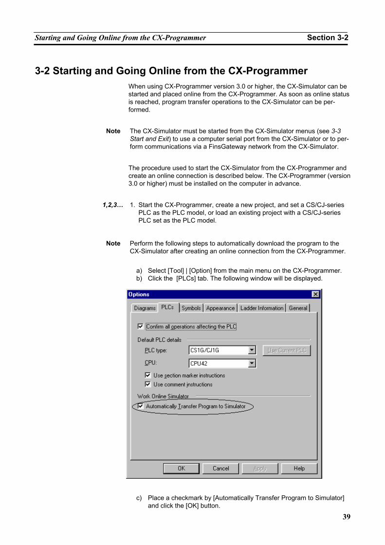
Starting and Going Online from the CX-Programmer Section 3-2
39
3-2 Starting and Going Online from the CX-Programmer When using CX-Programmer version 3.0 or higher, the CX-Simulator can be started and placed online from the CX-Programmer. As soon as online status is reached, program transfer operations to the CX-Simulator can be per-formed.
Note The CX-Simulator must be started from the CX-Simulator menus (see 3-3
Start and Exit) to use a computer serial port from the CX-Simulator or to per-form communications via a FinsGateway network from the CX-Simulator.
The procedure used to start the CX-Simulator from the CX-Programmer and create an online connection is described below. The CX-Programmer (version 3.0 or higher) must be installed on the computer in advance.
1,2,3… 1. Start the CX-Programmer, create a new project, and set a CS/CJ-series
PLC as the PLC model, or load an existing project with a CS/CJ-series PLC set as the PLC model.
Note Perform the following steps to automatically download the program to the
CX-Simulator after creating an online connection from the CX-Programmer.
a) Select [Tool] | [Option] from the main menu on the CX-Programmer. b) Click the [PLCs] tab. The following window will be displayed.
c) Place a checkmark by [Automatically Transfer Program to Simulator] and click the [OK] button.
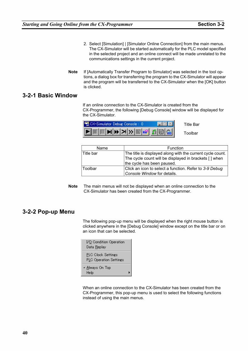
Starting and Going Online from the CX-Programmer Section 3-2
40
2. Select [Simulation] | [Simulator Online Connection] from the main menus.
The CX-Simulator will be started automatically for the PLC model specified in the selected project and an online connect will be made unrelated to the communications settings in the current project.
Note If [Automatically Transfer Program to Simulator] was selected in the tool op-
tions, a dialog box for transferring the program to the CX-Simulator will appear and the program will be transferred to the CX-Simulator when the [OK] button is clicked.
3-2-1 Basic Window If an online connection to the CX-Simulator is created from the CX-Programmer, the following [Debug Console] window will be displayed for the CX-Simulator.
Name Function
Title bar The title is displayed along with the current cycle count. The cycle count will be displayed in brackets [ ] when the cycle has been paused.
Toolbar Click an icon to select a function. Refer to 3-9 Debug Console Window for details.
Note The main menus will not be displayed when an online connection to the
CX-Simulator has been created from the CX-Programmer.
3-2-2 Pop-up Menu The following pop-up menu will be displayed when the right mouse button is clicked anywhere in the [Debug Console] window except on the title bar or on an icon that can be selected.
When an online connection to the CX-Simulator has been created from the CX-Programmer, this pop-up menu is used to select the following functions instead of using the main menus.
Title Bar
Toolbar
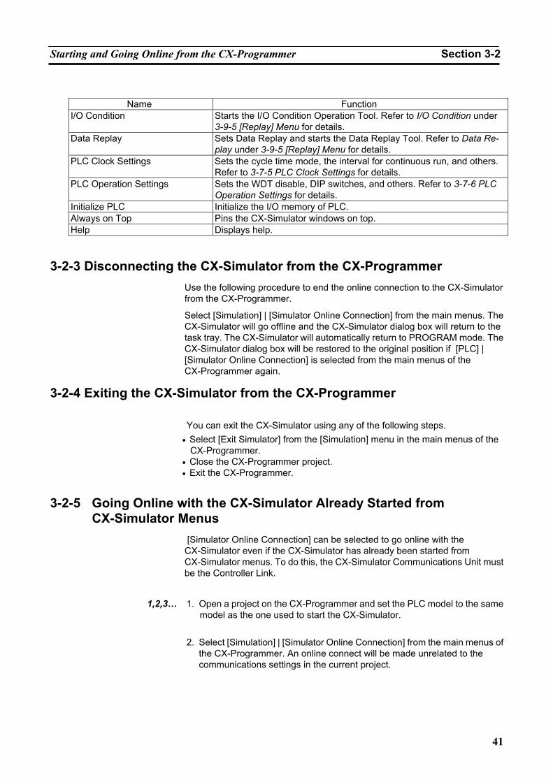
Starting and Going Online from the CX-Programmer Section 3-2
41
Name Function
I/O Condition Starts the I/O Condition Operation Tool. Refer to I/O Condition under 3-9-5 [Replay] Menu for details.
Data Replay Sets Data Replay and starts the Data Replay Tool. Refer to Data Re-play under 3-9-5 [Replay] Menu for details.
PLC Clock Settings Sets the cycle time mode, the interval for continuous run, and others. Refer to 3-7-5 PLC Clock Settings for details.
PLC Operation Settings Sets the WDT disable, DIP switches, and others. Refer to 3-7-6 PLC Operation Settings for details.
Initialize PLC Initialize the I/O memory of PLC. Always on Top Pins the CX-Simulator windows on top. Help Displays help.
3-2-3 Disconnecting the CX-Simulator from the CX-Programmer Use the following procedure to end the online connection to the CX-Simulator from the CX-Programmer.
Select [Simulation] | [Simulator Online Connection] from the main menus. The CX-Simulator will go offline and the CX-Simulator dialog box will return to the task tray. The CX-Simulator will automatically return to PROGRAM mode. The CX-Simulator dialog box will be restored to the original position if [PLC] | [Simulator Online Connection] is selected from the main menus of the CX-Programmer again.
3-2-4 Exiting the CX-Simulator from the CX-Programmer
You can exit the CX-Simulator using any of the following steps. • Select [Exit Simulator] from the [Simulation] menu in the main menus of the
CX-Programmer. • Close the CX-Programmer project. • Exit the CX-Programmer.
3-2-5 Going Online with the CX-Simulator Already Started from CX-Simulator Menus
[Simulator Online Connection] can be selected to go online with the CX-Simulator even if the CX-Simulator has already been started from CX-Simulator menus. To do this, the CX-Simulator Communications Unit must be the Controller Link.
1,2,3… 1. Open a project on the CX-Programmer and set the PLC model to the same
model as the one used to start the CX-Simulator.
2. Select [Simulation] | [Simulator Online Connection] from the main menus of the CX-Programmer. An online connect will be made unrelated to the communications settings in the current project.
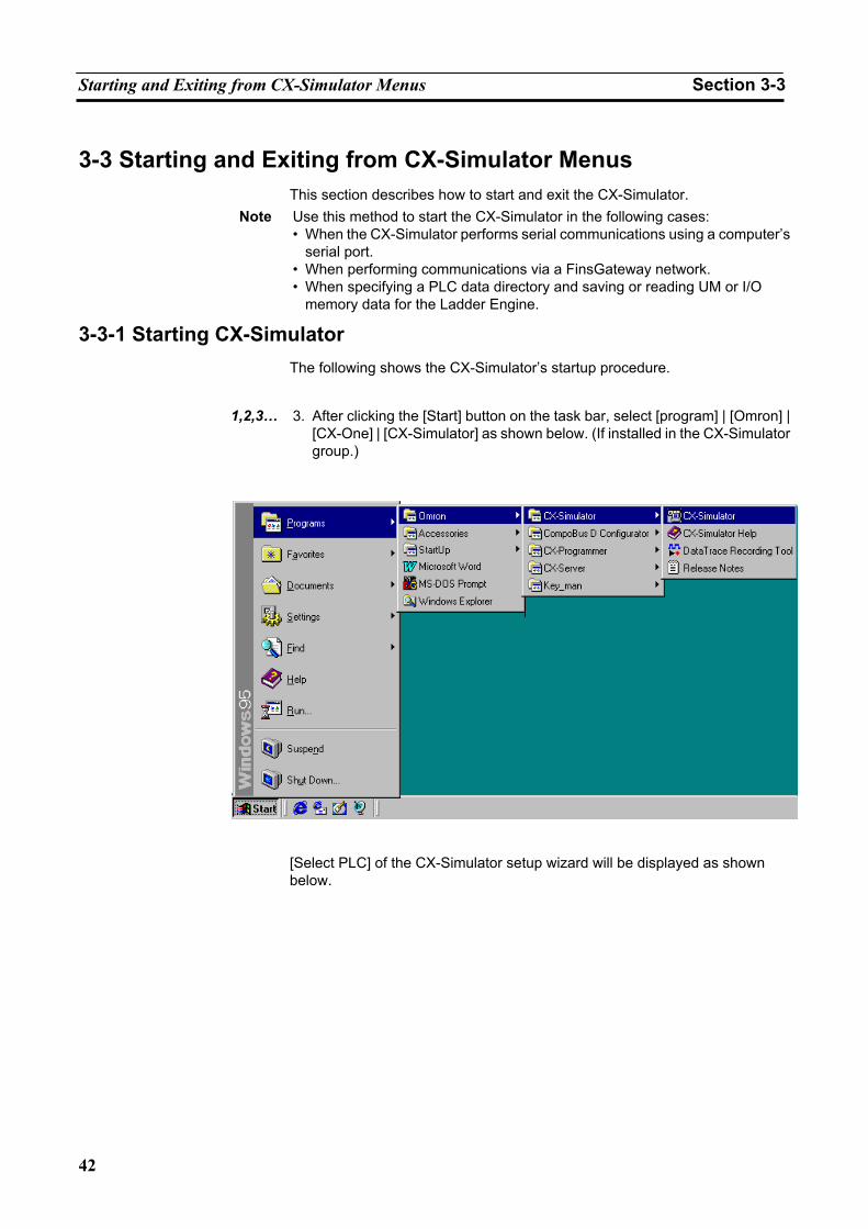
Starting and Exiting from CX-Simulator Menus Section 3-3
42
3-3 Starting and Exiting from CX-Simulator Menus This section describes how to start and exit the CX-Simulator.
Note Use this method to start the CX-Simulator in the following cases: • When the CX-Simulator performs serial communications using a computer’s
serial port. • When performing communications via a FinsGateway network. • When specifying a PLC data directory and saving or reading UM or I/O
memory data for the Ladder Engine.
3-3-1 Starting CX-Simulator The following shows the CX-Simulator’s startup procedure.
1,2,3… 3. After clicking the [Start] button on the task bar, select [program] | [Omron] |
[CX-One] | [CX-Simulator] as shown below. (If installed in the CX-Simulator group.)
[Select PLC] of the CX-Simulator setup wizard will be displayed as shown below.
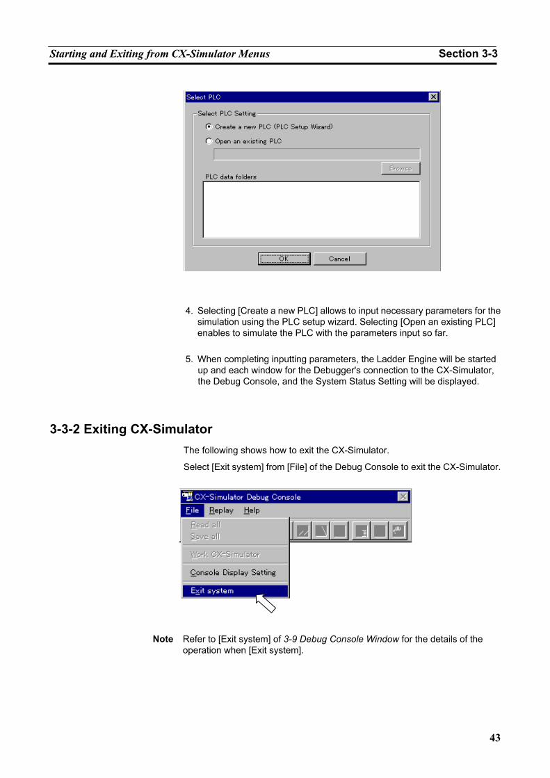
Starting and Exiting from CX-Simulator Menus Section 3-3
43
4. Selecting [Create a new PLC] allows to input necessary parameters for the simulation using the PLC setup wizard. Selecting [Open an existing PLC] enables to simulate the PLC with the parameters input so far.
5. When completing inputting parameters, the Ladder Engine will be started
up and each window for the Debugger's connection to the CX-Simulator, the Debug Console, and the System Status Setting will be displayed.
3-3-2 Exiting CX-Simulator The following shows how to exit the CX-Simulator.
Select [Exit system] from [File] of the Debug Console to exit the CX-Simulator.
Note Refer to [Exit system] of 3-9 Debug Console Window for the details of the
operation when [Exit system].
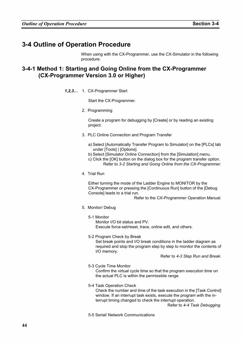
Outline of Operation Procedure Section 3-4
44
3-4 Outline of Operation Procedure When using with the CX-Programmer, use the CX-Simulator in the following procedure.
3-4-1 Method 1: Starting and Going Online from the CX-Programmer (CX-Programmer Version 3.0 or Higher)
1,2,3… 1. CX-Programmer Start
Start the CX-Programmer.
2. Programming Create a program for debugging by [Create] or by reading an existing project.
3. PLC Online Connection and Program Transfer
a) Select [Automatically Transfer Program to Simulator] on the [PLCs] tab under [Tools] | [Options].
b) Select [Simulator Online Connection] from the [Simulation] menu. c) Click the [OK] button on the dialog box for the program transfer option.
Refer to 3-2 Starting and Going Online from the CX-Programmer.
4. Trial Run
Either turning the mode of the Ladder Engine to MONITOR by the CX-Programmer or pressing the [Continuous Run] button of the [Debug Console] leads to a trial run.
Refer to the CX-Programmer Operation Manual.
5. Monitor/ Debug
5-1 Monitor Monitor I/O bit status and PV. Execute force-set/reset, trace, online edit, and others.
5-2 Program Check by Break
Set break points and I/O break conditions in the ladder diagram as required and stop the program step by step to monitor the contents of I/O memory.
Refer to 4-3 Step Run and Break.
5-3 Cycle Time Monitor Confirm the virtual cycle time so that the program execution time on the actual PLC is within the permissible range.
5-4 Task Operation Check
Check the number and time of the task execution in the [Task Control] window. If an interrupt task exists, execute the program with the in-terrupt timing changed to check the interrupt operation.
Refer to 4-4 Task Debugging.
5-5 Serial/ Network Communications
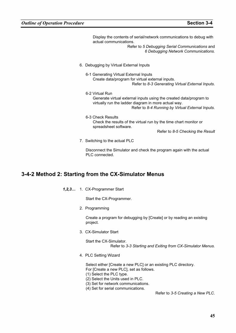
Outline of Operation Procedure Section 3-4
45
Display the contents of serial/network communications to debug with actual communications.
Refer to 5 Debugging Serial Communications and6 Debugging Network Communications.
6. Debugging by Virtual External Inputs
6-1 Generating Virtual External Inputs Create data/program for virtual external inputs.
Refer to 8-3 Generating Virtual External Inputs. 6-2 Virtual Run
Generate virtual external inputs using the created data/program to virtually run the ladder diagram in more actual way.
Refer to 8-4 Running by Virtual External Inputs. 6-3 Check Results
Check the results of the virtual run by the time chart monitor or spreadsheet software.
Refer to 8-5 Checking the Result
7. Switching to the actual PLC
Disconnect the Simulator and check the program again with the actual PLC connected.
3-4-2 Method 2: Starting from the CX-Simulator Menus
1,2,3… 1. CX-Programmer Start Start the CX-Programmer.
2. Programming Create a program for debugging by [Create] or by reading an existing project.
3. CX-Simulator Start
Start the CX-Simulator. Refer to 3-3 Starting and Exiting from CX-Simulator Menus.
4. PLC Setting Wizard
Select either [Create a new PLC] or an existing PLC directory. For [Create a new PLC], set as follows. (1) Select the PLC type. (2) Select the Units used in PLC. (3) Set for network communications. (4) Set for serial communications.
Refer to 3-5 Creating a New PLC.
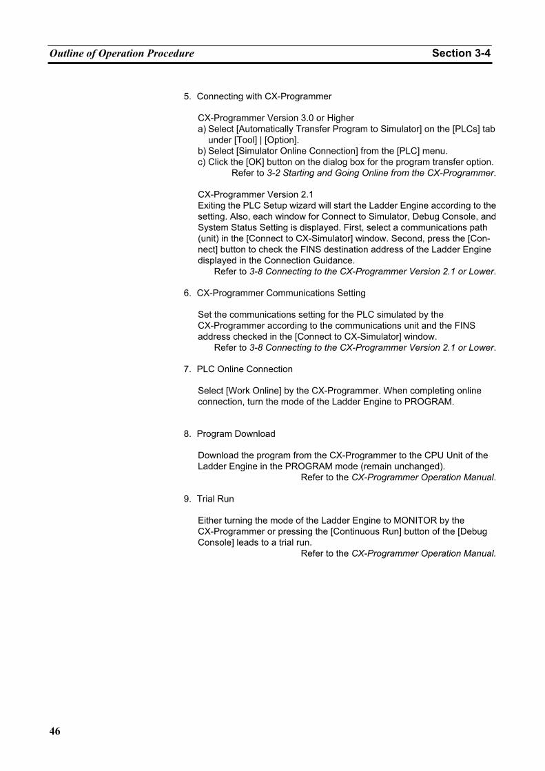
Outline of Operation Procedure Section 3-4
46
5. Connecting with CX-Programmer
CX-Programmer Version 3.0 or Higher a) Select [Automatically Transfer Program to Simulator] on the [PLCs] tab
under [Tool] | [Option]. b) Select [Simulator Online Connection] from the [PLC] menu. c) Click the [OK] button on the dialog box for the program transfer option.
Refer to 3-2 Starting and Going Online from the CX-Programmer.
CX-Programmer Version 2.1 Exiting the PLC Setup wizard will start the Ladder Engine according to the setting. Also, each window for Connect to Simulator, Debug Console, and System Status Setting is displayed. First, select a communications path (unit) in the [Connect to CX-Simulator] window. Second, press the [Con-nect] button to check the FINS destination address of the Ladder Engine displayed in the Connection Guidance.
Refer to 3-8 Connecting to the CX-Programmer Version 2.1 or Lower.
6. CX-Programmer Communications Setting
Set the communications setting for the PLC simulated by the CX-Programmer according to the communications unit and the FINS address checked in the [Connect to CX-Simulator] window.
Refer to 3-8 Connecting to the CX-Programmer Version 2.1 or Lower.
7. PLC Online Connection
Select [Work Online] by the CX-Programmer. When completing online connection, turn the mode of the Ladder Engine to PROGRAM.
8. Program Download
Download the program from the CX-Programmer to the CPU Unit of the Ladder Engine in the PROGRAM mode (remain unchanged).
Refer to the CX-Programmer Operation Manual.
9. Trial Run
Either turning the mode of the Ladder Engine to MONITOR by the CX-Programmer or pressing the [Continuous Run] button of the [Debug Console] leads to a trial run.
Refer to the CX-Programmer Operation Manual.
Outline of Operation Procedure Section 3-4
47
10. Monitor/ Debug
10-1 Monitor
Monitor I/O bit status and PV. Execute force-set/reset, trace, online edit, and others.
10-2 Program Check by Break
Set break points and I/O break conditions in the ladder diagram as required and stop the program step by step to monitor the contents of I/O memory.
Refer to 4-3 Step Run and Break.
10-3 Cycle Time Monitor Confirm the virtual cycle time so that the program execution time on the actual PLC is within the permissible range.
10-4 Task Operation Check
Check the number and time of the task execution in the [Task Con-trol] window. If an interrupt task exists, execute the program with the interrupt timing changed to check the interrupt operation.
Refer to 4-4 Task Debugging.
10-5 Serial/ Network Communications Display the contents of serial/network communications to debug with actual communications.
Refer to 5 Debugging Serial Communications and6 Debugging Network Communications.
11. Debugging by Virtual External Inputs
11-1 Generating Virtual External Inputs Create data/program for virtual external inputs.
Refer to 8-3 Generating Virtual External Inputs. 11-2 Virtual Run
Generate virtual external inputs using the created data/program to virtually run the ladder diagram in more actual way.
Refer to 8-4 Running by Virtual External Inputs. 11-3 Check Results
Check the results of the virtual run by the time chart monitor or spreadsheet software.
Refer to 8-5 Checking the Result
12. Switching to the actual PLC
Disconnect the Simulator and check the program again with the actual PLC connected.
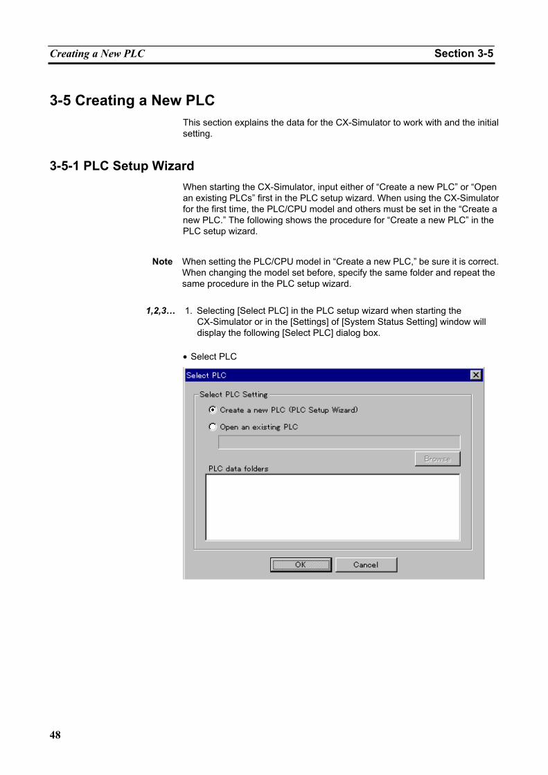
Creating a New PLC Section 3-5
48
3-5 Creating a New PLC This section explains the data for the CX-Simulator to work with and the initial setting.
3-5-1 PLC Setup Wizard When starting the CX-Simulator, input either of “Create a new PLC” or “Open an existing PLCs” first in the PLC setup wizard. When using the CX-Simulator for the first time, the PLC/CPU model and others must be set in the “Create a new PLC.” The following shows the procedure for “Create a new PLC” in the PLC setup wizard.
Note When setting the PLC/CPU model in “Create a new PLC,” be sure it is correct.
When changing the model set before, specify the same folder and repeat the same procedure in the PLC setup wizard.
1,2,3… 1. Selecting [Select PLC] in the PLC setup wizard when starting the
CX-Simulator or in the [Settings] of [System Status Setting] window will display the following [Select PLC] dialog box.
• Select PLC
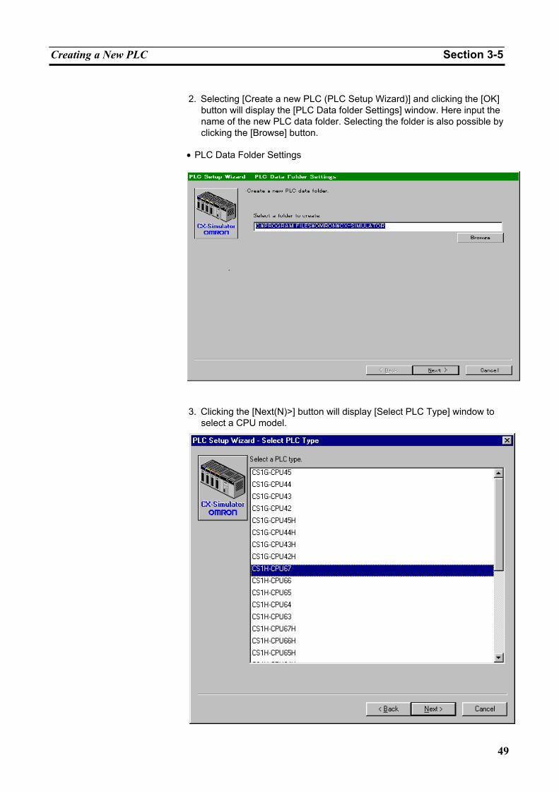
Creating a New PLC Section 3-5
49
2. Selecting [Create a new PLC (PLC Setup Wizard)] and clicking the [OK]
button will display the [PLC Data folder Settings] window. Here input the name of the new PLC data folder. Selecting the folder is also possible by clicking the [Browse] button.
• PLC Data Folder Settings
3. Clicking the [Next(N)>] button will display [Select PLC Type] window to
select a CPU model.
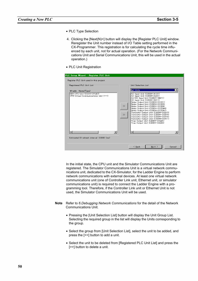
Creating a New PLC Section 3-5
50
• PLC Type Selection
4. Clicking the [Next(N)>] button will display the [Register PLC Unit] window. Reregister the Unit number instead of I/O Table setting performed in the CX-Programmer. This registration is for calculating the cycle time influ-enced by each unit, not for actual operation. (For the Network Communi-cations Unit and Serial Communications Unit, this will be used in the actual operation.)
• PLC Unit Registration
In the initial state, the CPU unit and the Simulator Communications Unit are registered. The Simulator Communications Unit is a virtual network commu-nications unit, dedicated to the CX-Simulator, for the Ladder Engine to perform network communications with external devices. At least one virtual network communications unit (one of Controller Link unit, Ethernet unit, or simulator communications unit) is required to connect the Ladder Engine with a pro-gramming tool. Therefore, if the Controller Link unit or Ethernet Unit is not used, the Simulator Communications Unit will be used.
Note Refer to 6.Debugging Network Communications for the detail of the Network
Communications Unit. • Pressing the [Unit Selection List] button will display the Unit Group List.
Selecting the required group in the list will display the Units corresponding to the group.
• Select the group from [Unit Selection List], select the unit to be added, and
press the [<<] button to add a unit.
• Select the unit to be deleted from [Registered PLC Unit List] and press the [>>] button to delete a unit.
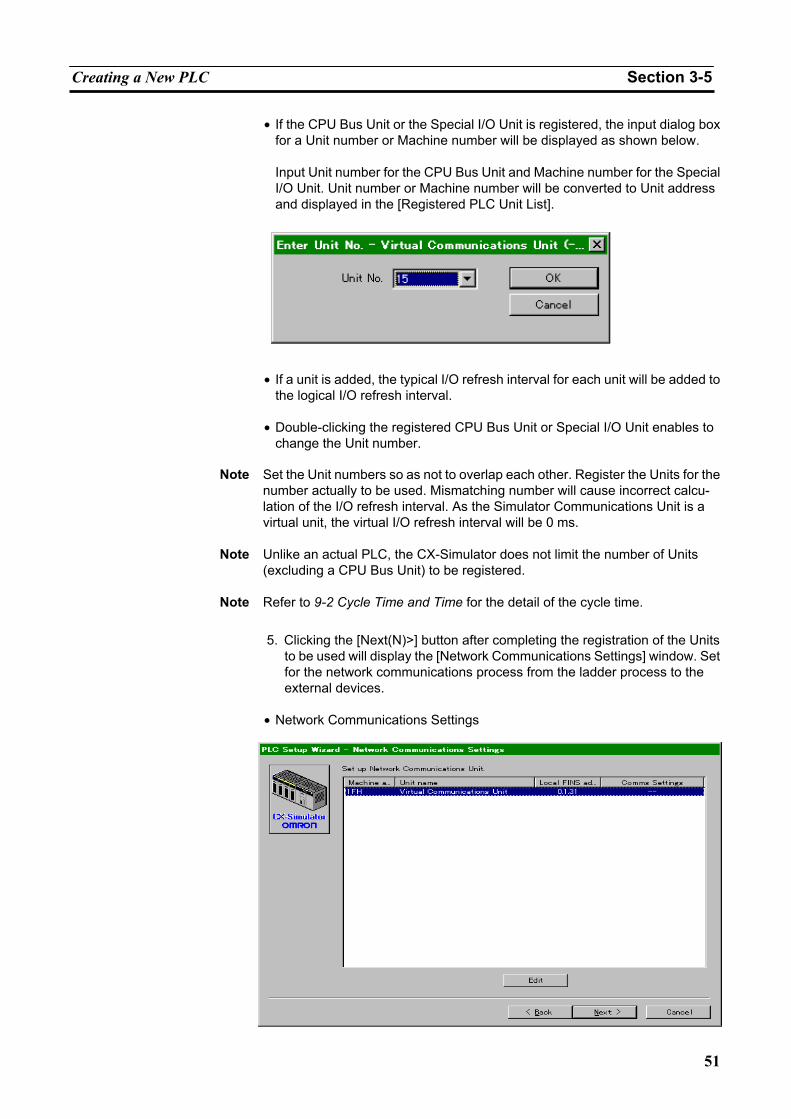
Creating a New PLC Section 3-5
51
• If the CPU Bus Unit or the Special I/O Unit is registered, the input dialog box for a Unit number or Machine number will be displayed as shown below.
Input Unit number for the CPU Bus Unit and Machine number for the Special I/O Unit. Unit number or Machine number will be converted to Unit address and displayed in the [Registered PLC Unit List].
• If a unit is added, the typical I/O refresh interval for each unit will be added to
the logical I/O refresh interval. • Double-clicking the registered CPU Bus Unit or Special I/O Unit enables to
change the Unit number.
Note Set the Unit numbers so as not to overlap each other. Register the Units for the number actually to be used. Mismatching number will cause incorrect calcu-lation of the I/O refresh interval. As the Simulator Communications Unit is a virtual unit, the virtual I/O refresh interval will be 0 ms.
Note Unlike an actual PLC, the CX-Simulator does not limit the number of Units (excluding a CPU Bus Unit) to be registered.
Note Refer to 9-2 Cycle Time and Time for the detail of the cycle time.
5. Clicking the [Next(N)>] button after completing the registration of the Units
to be used will display the [Network Communications Settings] window. Set for the network communications process from the ladder process to the external devices.
• Network Communications Settings
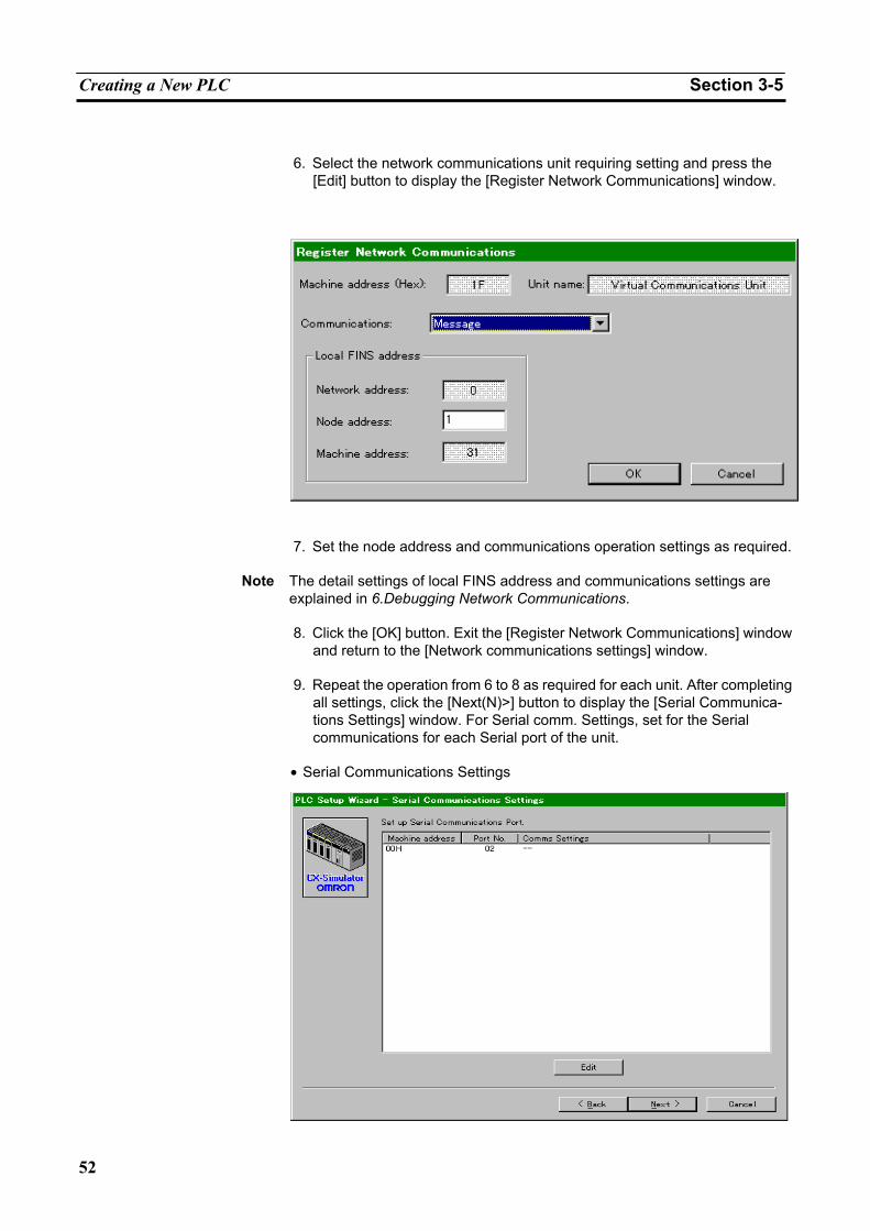
Creating a New PLC Section 3-5
52
6. Select the network communications unit requiring setting and press the
[Edit] button to display the [Register Network Communications] window.
7. Set the node address and communications operation settings as required.
Note The detail settings of local FINS address and communications settings are
explained in 6.Debugging Network Communications.
8. Click the [OK] button. Exit the [Register Network Communications] window and return to the [Network communications settings] window.
9. Repeat the operation from 6 to 8 as required for each unit. After completing
all settings, click the [Next(N)>] button to display the [Serial Communica-tions Settings] window. For Serial comm. Settings, set for the Serial communications for each Serial port of the unit.
• Serial Communications Settings
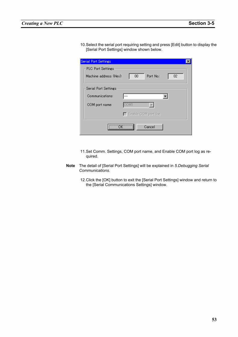
Creating a New PLC Section 3-5
53
10. Select the serial port requiring setting and press [Edit] button to display the
[Serial Port Settings] window shown below.
11. Set Comm. Settings, COM port name, and Enable COM port log as re-
quired.
Note The detail of [Serial Port Settings] will be explained in 5.Debugging Serial Communications.
12. Click the [OK] button to exit the [Serial Port Settings] window and return to
the [Serial Communications Settings] window.
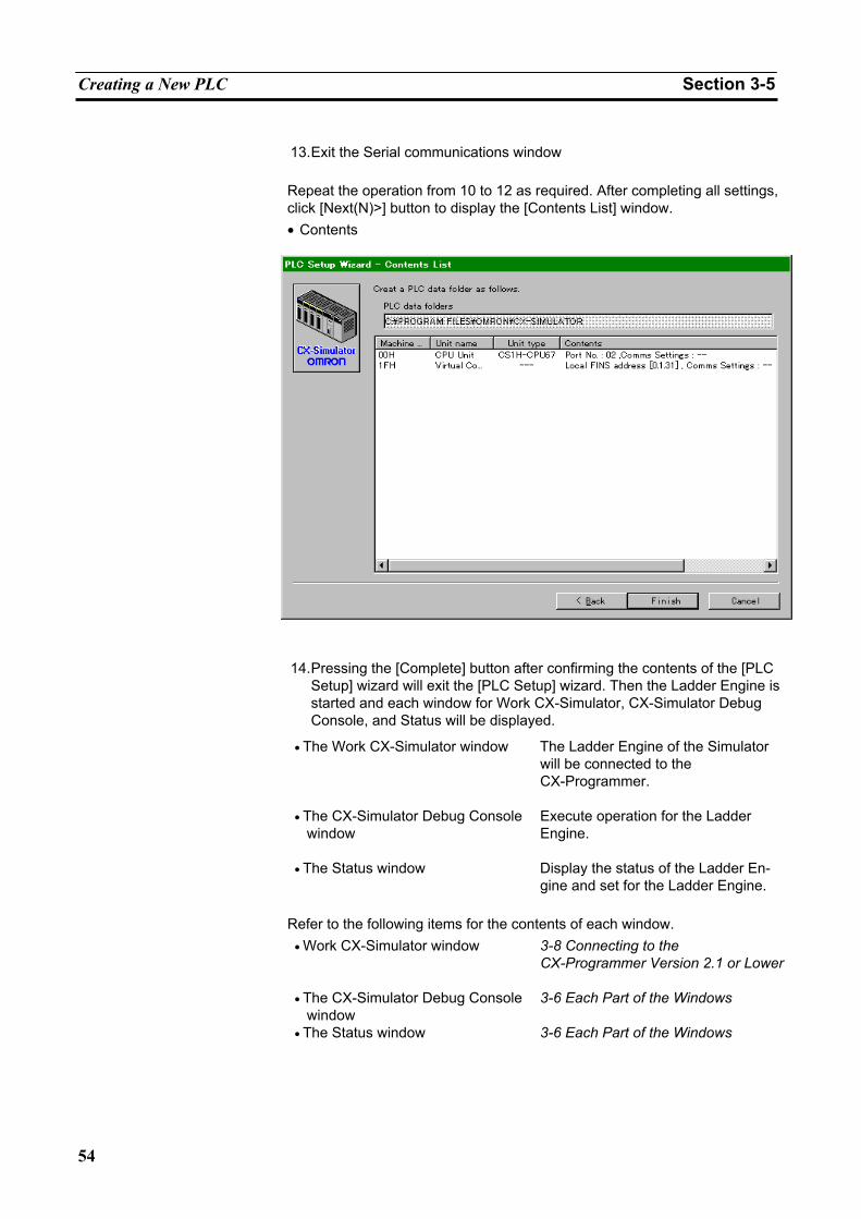
Creating a New PLC Section 3-5
54
13. Exit the Serial communications window
Repeat the operation from 10 to 12 as required. After completing all settings, click [Next(N)>] button to display the [Contents List] window. • Contents
14. Pressing the [Complete] button after confirming the contents of the [PLC
Setup] wizard will exit the [PLC Setup] wizard. Then the Ladder Engine is started and each window for Work CX-Simulator, CX-Simulator Debug Console, and Status will be displayed.
• The Work CX-Simulator window The Ladder Engine of the Simulator
will be connected to the CX-Programmer.
• The CX-Simulator Debug Console window
Execute operation for the Ladder Engine.
• The Status window Display the status of the Ladder En-gine and set for the Ladder Engine.
Refer to the following items for the contents of each window.
• Work CX-Simulator window 3-8 Connecting to the CX-Programmer Version 2.1 or Lower
• The CX-Simulator Debug Console window
3-6 Each Part of the Windows
• The Status window 3-6 Each Part of the Windows
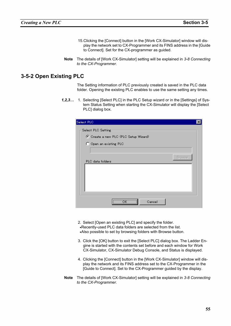
Creating a New PLC Section 3-5
55
15. Clicking the [Connect] button in the [Work CX-Simulator] window will dis-
play the network set to CX-Programmer and its FINS address in the [Guide to Connect]. Set for the CX-programmer as guided.
Note The details of [Work CX-Simulator] setting will be explained in 3-8 Connecting
to the CX-Programmer.
3-5-2 Open Existing PLC The Setting information of PLC previously created is saved in the PLC data folder. Opening the existing PLC enables to use the same setting any times.
1,2,3… 1. Selecting [Select PLC] in the PLC Setup wizard or in the [Settings] of Sys-
tem Status Setting when starting the CX-Simulator will display the [Select PLC] dialog box.
2. Select [Open an existing PLC] and specify the folder.
• Recently-used PLC data folders are selected from the list. • Also possible to set by browsing folders with Browse button.
3. Click the [OK] button to exit the [Select PLC] dialog box. The Ladder En-
gine is started with the contents set before and each window for Work CX-Simulator, CX-Simulator Debug Console, and Status is displayed.
4. Clicking the [Connect] button in the [Work CX-Simulator] window will dis-
play the network and its FINS address set to the CX-Programmer in the [Guide to Connect]. Set to the CX-Programmer guided by the display.
Note The details of [Work CX-Simulator] setting will be explained in 3-8 Connecting
to the CX-Programmer.
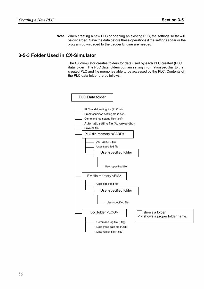
Creating a New PLC Section 3-5
56
Note When creating a new PLC or opening an existing PLC, the settings so far will
be discarded. Save the data before these operations if the settings so far or the program downloaded to the Ladder Engine are needed.
3-5-3 Folder Used in CX-Simulator The CX-Simulator creates folders for data used by each PLC created (PLC data folder). The PLC data folders contain setting information peculiar to the created PLC and file memories able to be accessed by the PLC. Contents of the PLC data folder are as follows:
PLC Data folder
PLC model setting file (PLC.ini)
Break condition setting file (*.bsf)
Command log setting file (*.csf)
Automatic setting file (Autoexec.dbg) Save-all file
PLC file memory <CARD>
AUTOEXEC file
User-specified file
User-specified folder
User-specified file
EM file memory <EM>
User-specified file
User-specified folder
User-specified file
Log folder <LOG>
Command log file (*.flg)
Data trace data file (*.cdt)
Data replay file (*.csv)
shows a folder. < > shows a proper folder name.
Creating a New PLC Section 3-5
57
PLC data folder Contain data files peculiar to each PLC used by the CX-Simulator. The fol-lowing files are contained as data files.
File Type Extension Contents
PLC Model Setting File ini PLC model and registered unit setting file Break Condition Setting File bsf I/O break condition setting data file Command Log Setting File csf Command log setting data file Automatic Setting File File created when exiting the system
Debugger Setting File dbg Debugger automatic setting file (AUTOEXEC.DBG)
I/O Memory File dat Automatic setting file for I/O memory con-sisting of multiple files (Memoryn.dat: the underlined part is a serial number)
Save-all File File created on the [Save all] of the [File] menu in the [Debug Console] window.
Debugger Setting File dbg Debugger setting file I/O Memory File dat I/O memory save file
Note A total size of the I/O Memory Files is about 10 MB.
The folder for the file memory
The folder for the file memory corresponds to CS/CJ/CP-series CPU Unit file memory function, which is fixedly allocated for each file system.
Name Root Folder Name Note
PLC file memory (Memory card)
CARD No limited capacity (following the capacity of the computer hard disk)
EM file memory EM Capacity limit following the PLC Setting
The file created as the file memory is compatible with the one for CS/CJ/CP-series CPU Unit. The operation to the folder for the file memory can be performed in the same way as the file memory for CS/CJ/CP-series CPU Unit.
Note 1. If the hard disk capacity of the computer is smaller than that of the file
memory, file write may fail.
2. Refer to Section 5 File Memory Functions of CS/CJ Series Programming Manual for the details on the file memory functions.
Log folder
The test data for the CX-Simulator is stored. The following data files for each use are available.
File type Extension Content
Command Log File flg The data file storing CX-Programmer's operation log
Data Trace File cdt The compatible data file with the CX-Programmer's data trace file
Data Replay File csv CSV-format text file
Note Refer to 8-3 Generating Virtual External Inputs for the data file in the log folder.
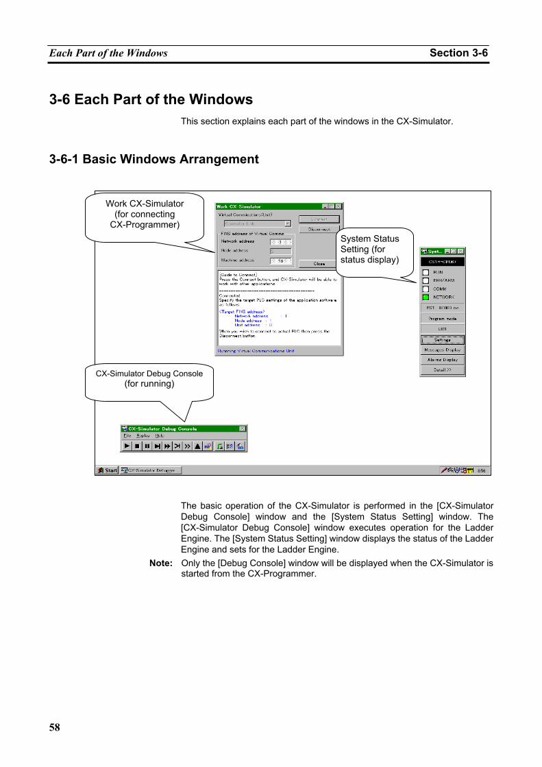
Each Part of the Windows Section 3-6
58
3-6 Each Part of the Windows This section explains each part of the windows in the CX-Simulator.
3-6-1 Basic Windows Arrangement
The basic operation of the CX-Simulator is performed in the [CX-Simulator Debug Console] window and the [System Status Setting] window. The [CX-Simulator Debug Console] window executes operation for the Ladder Engine. The [System Status Setting] window displays the status of the Ladder Engine and sets for the Ladder Engine.
Note: Only the [Debug Console] window will be displayed when the CX-Simulator is started from the CX-Programmer.
System Status Setting (for status display)
CX-Simulator Debug Console (for running)
Work CX-Simulator (for connecting
CX-Programmer)
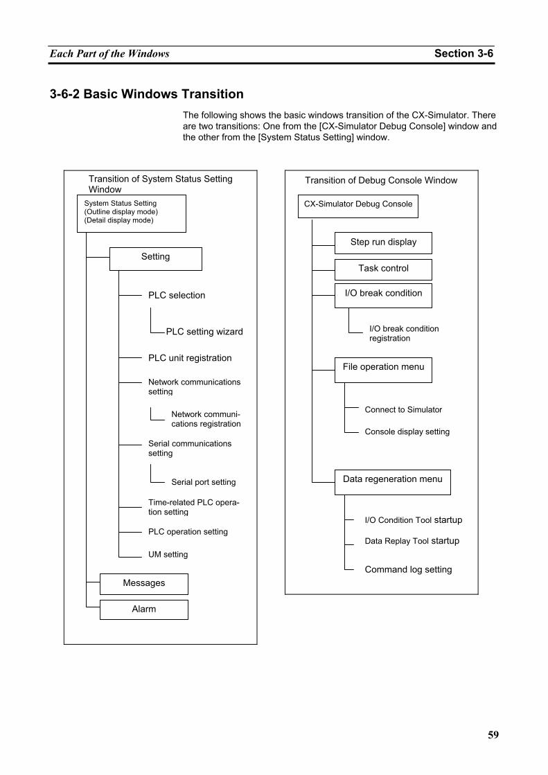
Each Part of the Windows Section 3-6
59
3-6-2 Basic Windows Transition The following shows the basic windows transition of the CX-Simulator. There are two transitions: One from the [CX-Simulator Debug Console] window and the other from the [System Status Setting] window.
Transition of System Status Setting
Window System Status Setting (Outline display mode) (Detail display mode)
Setting
PLC selection
PLC setting wizard
PLC unit registration
Network communications setting
Network communi-cations registration
Serial communications setting
Serial port setting
Time-related PLC opera-tion setting
UM setting
PLC operation setting
Messages
Alarm
Transition of Debug Console Window
CX-Simulator Debug Console
Step run display
Task control
I/O break condition
File operation menu
Data regeneration menu
I/O break condition registration
Connect to Simulator
Console display setting
PLC operation setting I/O Condition Tool startup
Data Replay Tool startup
Command log setting
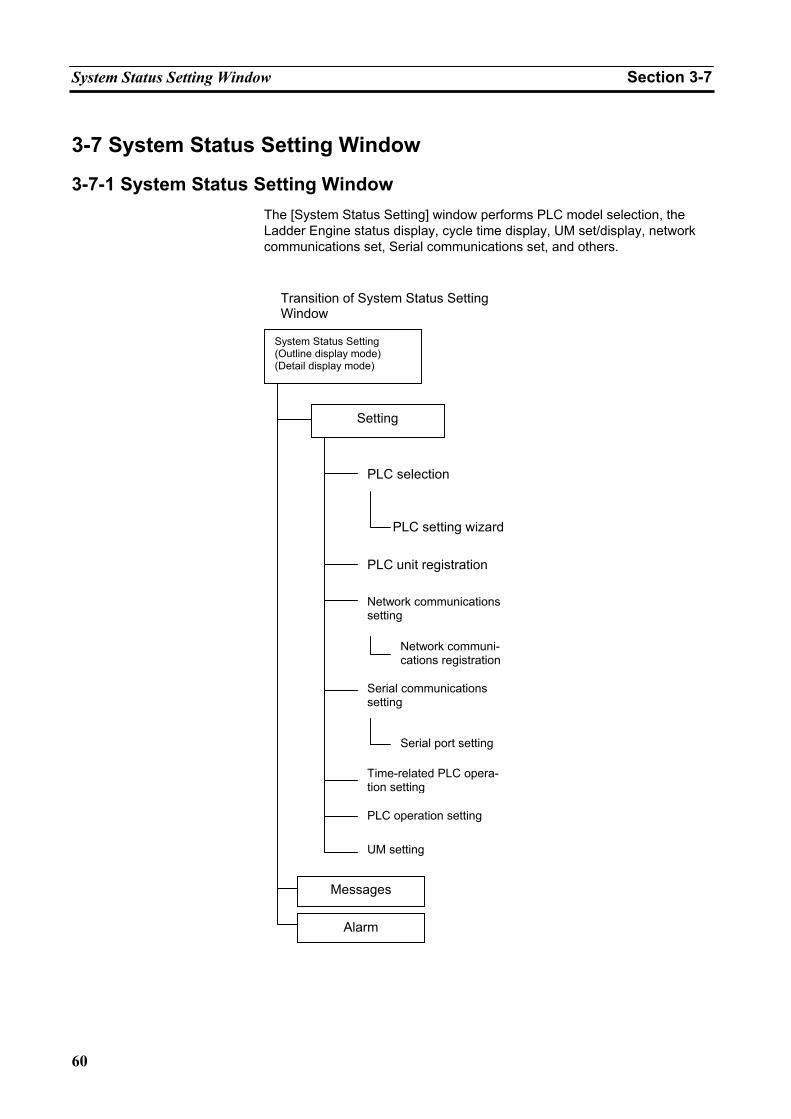
System Status Setting Window Section 3-7
60
3-7 System Status Setting Window
3-7-1 System Status Setting Window The [System Status Setting] window performs PLC model selection, the Ladder Engine status display, cycle time display, UM set/display, network communications set, Serial communications set, and others.
Transition of System Status Setting Window
System Status Setting (Outline display mode) (Detail display mode)
Setting
PLC selection
PLC setting wizard
PLC unit registration
Network communications setting
Network communi-cations registration
Serial communications setting
Serial port setting
Time-related PLC opera-tion setting
UM setting
PLC operation setting
Messages
Alarm
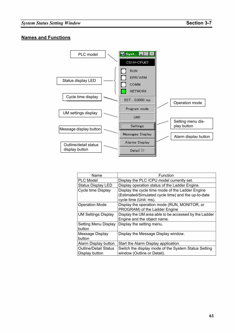
System Status Setting Window Section 3-7
61
Names and Functions
Name Function
PLC Model Display the PLC /CPU model currently set. Status Display LED Display operation status of the Ladder Engine. Cycle time Display
Display the cycle time mode of the Ladder Engine (Estimated/Simulated cycle time) and the up-to-date cycle time (Unit: ms).
Operation Mode Display the operation mode (RUN, MONITOR, or PROGRAM) of the Ladder Engine
UM Settings Display Display the UM area able to be accessed by the Ladder Engine and the object name.
Setting Menu Display button
Display the setting menu.
Message Display button
Display the Message Display window.
Alarm Display button Start the Alarm Display application. Outline/Detail Status Display button
Switch the display mode of the System Status Setting window (Outline or Detail).
PLC model
Status display LED
UM settings display
Message display button
Outline/detail statusdisplay button
Cycle time displayOperation mode
Setting menu dis-play button
Alarm display button
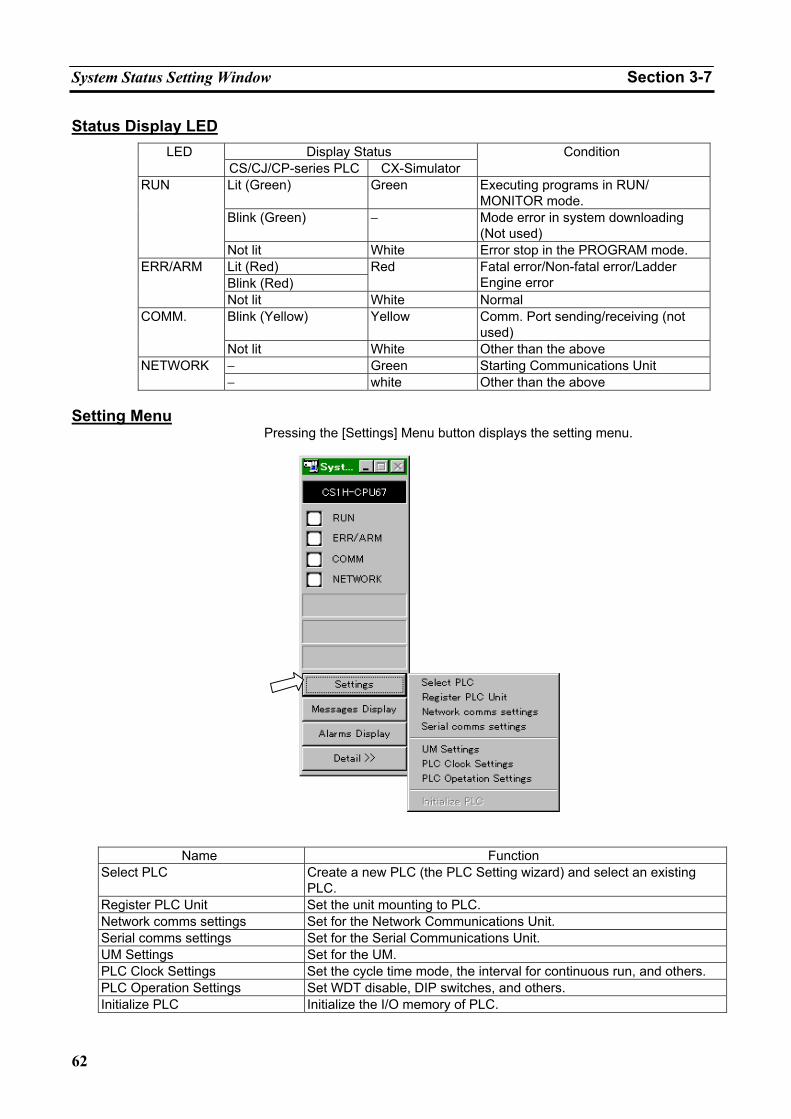
System Status Setting Window Section 3-7
62
Status Display LED Display Status LED
CS/CJ/CP-series PLC CX-Simulator Condition
Lit (Green) Green Executing programs in RUN/ MONITOR mode.
Blink (Green) − Mode error in system downloading (Not used)
RUN
Not lit White Error stop in the PROGRAM mode. Lit (Red) Blink (Red)
Red Fatal error/Non-fatal error/Ladder Engine error
ERR/ARM
Not lit White Normal Blink (Yellow) Yellow Comm. Port sending/receiving (not
used) COMM.
Not lit White Other than the above − Green Starting Communications Unit NETWORK − white Other than the above
Setting Menu
Pressing the [Settings] Menu button displays the setting menu.
Name Function
Select PLC Create a new PLC (the PLC Setting wizard) and select an existing PLC.
Register PLC Unit Set the unit mounting to PLC. Network comms settings Set for the Network Communications Unit. Serial comms settings Set for the Serial Communications Unit. UM Settings Set for the UM. PLC Clock Settings Set the cycle time mode, the interval for continuous run, and others. PLC Operation Settings Set WDT disable, DIP switches, and others. Initialize PLC Initialize the I/O memory of PLC.
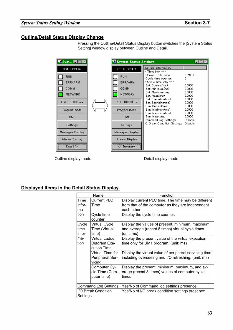
System Status Setting Window Section 3-7
63
Outline/Detail Status Display Change Pressing the Outline/Detail Status Display button switches the [System Status Setting] window display between Outline and Detail.
Displayed Items in the Detail Status Display. Name Function
Current PLC Time
Display current PLC time. The time may be different from that of the computer as they are independent each other.
Time infor-ma-tion Cycle time
counter Display the cycle time counter.
Virtual Cycle Time (Virtual time)
Display the values of present, minimum, maximum, and average (recent 8 times) virtual cycle times. (unit: ms)
Virtual Ladder Diagram Exe-cution Time
Display the present value of the virtual execution time only for UM1 program. (unit: ms)
Virtual Time for Peripheral Ser-vicing
Display the virtual value of peripheral servicing time including overseeing and I/O refreshing. (unit: ms)
Cycle time infor-ma-tion
Computer Cy-cle Time (Com-puter time)
Display the present, minimum, maximum, and av-erage (recent 8 times) values of computer cycle times
Command Log Settings Yes/No of Command log settings presence I/O Break Condition Settings
Yes/No of I/O break condition settings presence
Outline display mode Detail display mode
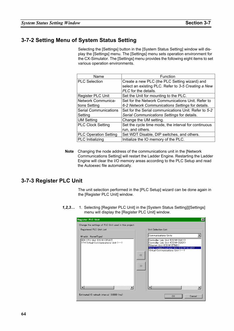
System Status Setting Window Section 3-7
64
3-7-2 Setting Menu of System Status Setting Selecting the [Settings] button in the [System Status Setting] window will dis-play the [Settings] menu. The [Settings] menu sets operation environment for the CX-Simulator. The [Settings] menu provides the following eight items to set various operation environments.
Name Function
PLC Selection Create a new PLC (the PLC Setting wizard) and select an existing PLC. Refer to 3-5 Creating a New PLC for the details.
Register PLC Unit Set the Unit for mounting to the PLC. Network Communica-tions Setting
Set for the Network Communications Unit. Refer to 6-2 Network Communications Settings for details.
Serial Communications Setting
Set for the Serial communications Unit. Refer to 5-2 Serial Communications Settings for details.
UM Setting Change the UM setting. PLC Clock Setting Set the cycle time mode, the interval for continuous
run, and others. PLC Operation Setting Set WDT Disable, DIP switches, and others. PLC Initializing Initialize the IO memory of the PLC.
Note Changing the node address of the communications unit in the [Network Communications Setting] will restart the Ladder Engine. Restarting the Ladder Engine will clear the I/O memory areas according to the PLC Setup and read the Autoexec file automatically.
3-7-3 Register PLC Unit The unit selection performed in the [PLC Setup] wizard can be done again in the [Register PLC Unit] window.
1,2,3… 1. Selecting [Register PLC Unit] in the [System Status Setting]|[Settings]
menu will display the [Register PLC Unit] window.
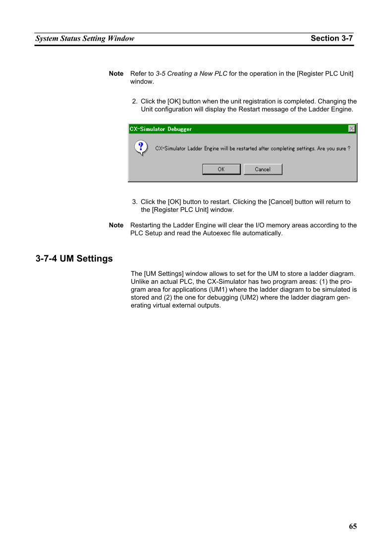
System Status Setting Window Section 3-7
65
Note Refer to 3-5 Creating a New PLC for the operation in the [Register PLC Unit]
window.
2. Click the [OK] button when the unit registration is completed. Changing the Unit configuration will display the Restart message of the Ladder Engine.
3. Click the [OK] button to restart. Clicking the [Cancel] button will return to
the [Register PLC Unit] window.
Note Restarting the Ladder Engine will clear the I/O memory areas according to the PLC Setup and read the Autoexec file automatically.
3-7-4 UM Settings The [UM Settings] window allows to set for the UM to store a ladder diagram. Unlike an actual PLC, the CX-Simulator has two program areas: (1) the pro-gram area for applications (UM1) where the ladder diagram to be simulated is stored and (2) the one for debugging (UM2) where the ladder diagram gen-erating virtual external outputs.
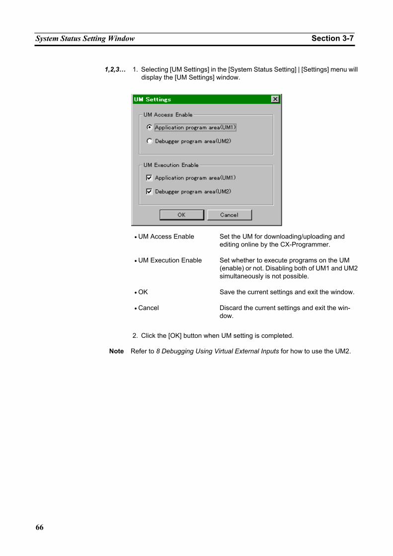
System Status Setting Window Section 3-7
66
1,2,3… 1. Selecting [UM Settings] in the [System Status Setting] | [Settings] menu will
display the [UM Settings] window.
• UM Access Enable Set the UM for downloading/uploading and editing online by the CX-Programmer.
• UM Execution Enable Set whether to execute programs on the UM (enable) or not. Disabling both of UM1 and UM2 simultaneously is not possible.
• OK Save the current settings and exit the window.
• Cancel Discard the current settings and exit the win-dow.
2. Click the [OK] button when UM setting is completed.
Note Refer to 8 Debugging Using Virtual External Inputs for how to use the UM2.
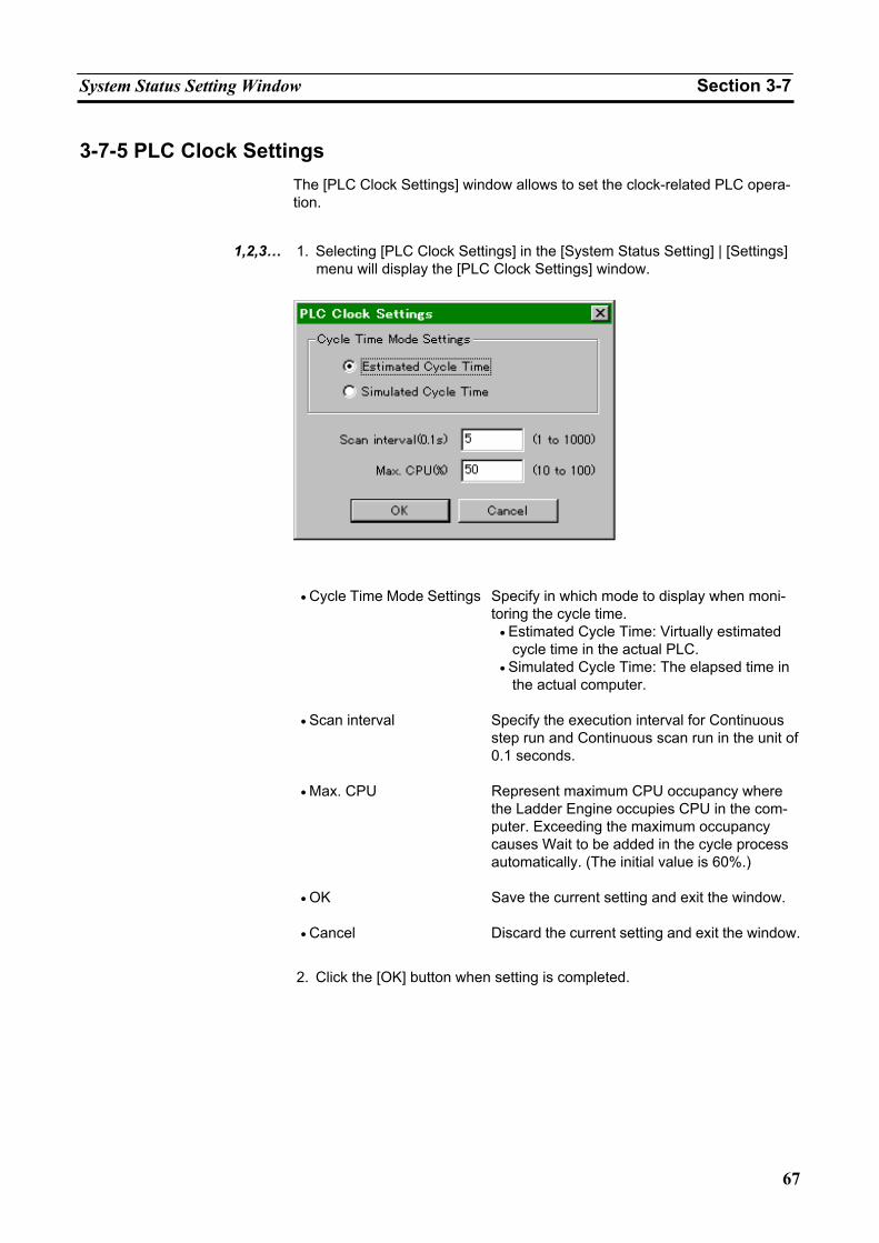
System Status Setting Window Section 3-7
67
3-7-5 PLC Clock Settings The [PLC Clock Settings] window allows to set the clock-related PLC opera-tion.
1,2,3… 1. Selecting [PLC Clock Settings] in the [System Status Setting] | [Settings]
menu will display the [PLC Clock Settings] window.
• Cycle Time Mode Settings Specify in which mode to display when moni-
toring the cycle time. • Estimated Cycle Time: Virtually estimated
cycle time in the actual PLC. • Simulated Cycle Time: The elapsed time in
the actual computer.
• Scan interval Specify the execution interval for Continuous step run and Continuous scan run in the unit of 0.1 seconds.
• Max. CPU Represent maximum CPU occupancy where the Ladder Engine occupies CPU in the com-puter. Exceeding the maximum occupancy causes Wait to be added in the cycle process automatically. (The initial value is 60%.)
• OK Save the current setting and exit the window.
• Cancel Discard the current setting and exit the window.
2. Click the [OK] button when setting is completed.
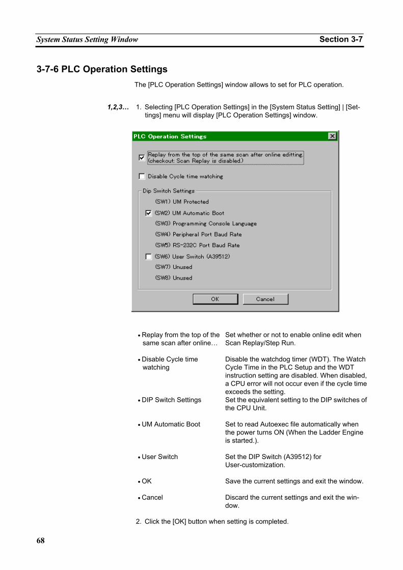
System Status Setting Window Section 3-7
68
3-7-6 PLC Operation Settings The [PLC Operation Settings] window allows to set for PLC operation.
1,2,3… 1. Selecting [PLC Operation Settings] in the [System Status Setting] | [Set-
tings] menu will display [PLC Operation Settings] window.
• Replay from the top of the
same scan after online…Set whether or not to enable online edit when Scan Replay/Step Run.
• Disable Cycle time watching
Disable the watchdog timer (WDT). The Watch Cycle Time in the PLC Setup and the WDT instruction setting are disabled. When disabled, a CPU error will not occur even if the cycle time exceeds the setting.
• DIP Switch Settings Set the equivalent setting to the DIP switches of the CPU Unit.
• UM Automatic Boot Set to read Autoexec file automatically when the power turns ON (When the Ladder Engine is started.).
• User Switch Set the DIP Switch (A39512) for User-customization.
• OK Save the current settings and exit the window.
• Cancel Discard the current settings and exit the win-dow.
2. Click the [OK] button when setting is completed.
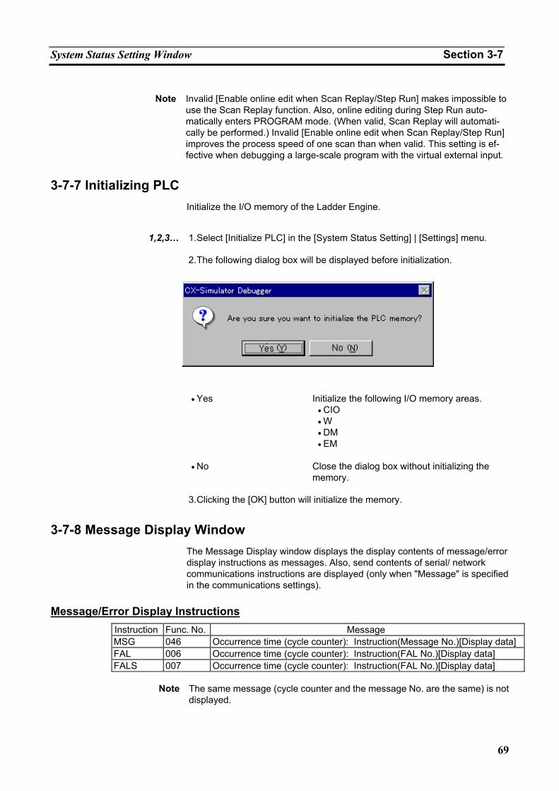
System Status Setting Window Section 3-7
69
Note Invalid [Enable online edit when Scan Replay/Step Run] makes impossible to
use the Scan Replay function. Also, online editing during Step Run auto-matically enters PROGRAM mode. (When valid, Scan Replay will automati-cally be performed.) Invalid [Enable online edit when Scan Replay/Step Run] improves the process speed of one scan than when valid. This setting is ef-fective when debugging a large-scale program with the virtual external input.
3-7-7 Initializing PLC Initialize the I/O memory of the Ladder Engine.
1,2,3… 1. Select [Initialize PLC] in the [System Status Setting] | [Settings] menu.
2. The following dialog box will be displayed before initialization.
• Yes Initialize the following I/O memory areas.
• CIO • W • DM • EM
• No Close the dialog box without initializing the memory.
3. Clicking the [OK] button will initialize the memory.
3-7-8 Message Display Window The Message Display window displays the display contents of message/error display instructions as messages. Also, send contents of serial/ network communications instructions are displayed (only when "Message" is specified in the communications settings).
Message/Error Display Instructions
Instruction Func. No. Message MSG 046 Occurrence time (cycle counter): Instruction(Message No.)[Display data] FAL 006 Occurrence time (cycle counter): Instruction(FAL No.)[Display data] FALS 007 Occurrence time (cycle counter): Instruction(FAL No.)[Display data]
Note The same message (cycle counter and the message No. are the same) is not
displayed.
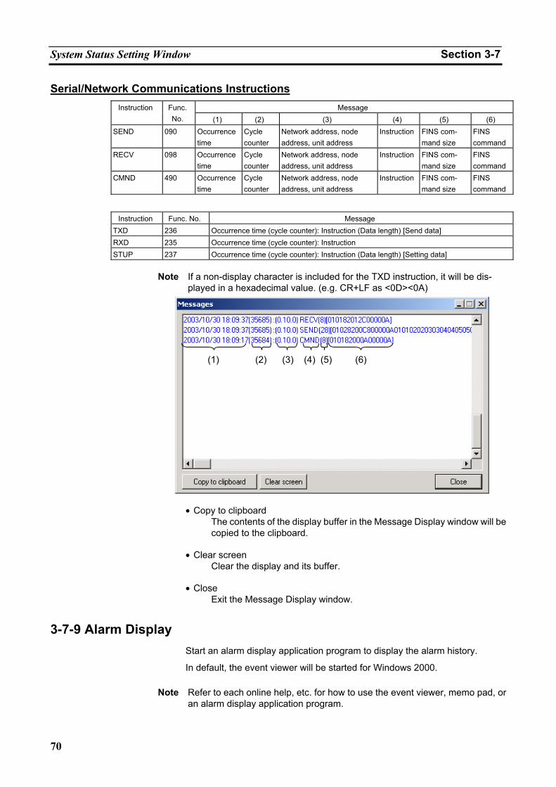
System Status Setting Window Section 3-7
70
Serial/Network Communications Instructions Message Instruction Func.
No. (1) (2) (3) (4) (5) (6) SEND 090 Occurrence
time Cycle counter
Network address, node address, unit address
Instruction FINS com-mand size
FINS command
RECV 098 Occurrence time
Cycle counter
Network address, node address, unit address
Instruction FINS com-mand size
FINS command
CMND 490 Occurrence time
Cycle counter
Network address, node address, unit address
Instruction FINS com-mand size
FINS command
Instruction Func. No. Message
TXD 236 Occurrence time (cycle counter): Instruction (Data length) [Send data] RXD 235 Occurrence time (cycle counter): Instruction STUP 237 Occurrence time (cycle counter): Instruction (Data length) [Setting data]
Note If a non-display character is included for the TXD instruction, it will be dis-
played in a hexadecimal value. (e.g. CR+LF as <0D><0A)
• Copy to clipboard
The contents of the display buffer in the Message Display window will be copied to the clipboard.
• Clear screen
Clear the display and its buffer.
• Close Exit the Message Display window.
3-7-9 Alarm Display Start an alarm display application program to display the alarm history.
In default, the event viewer will be started for Windows 2000.
Note Refer to each online help, etc. for how to use the event viewer, memo pad, or an alarm display application program.
(1) (2) (3) (4) (5) (6)
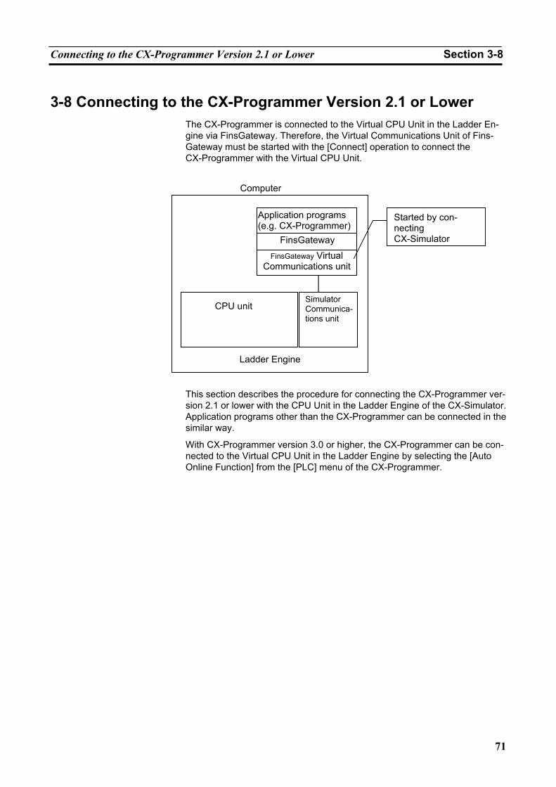
Connecting to the CX-Programmer Version 2.1 or Lower Section 3-8
71
3-8 Connecting to the CX-Programmer Version 2.1 or Lower The CX-Programmer is connected to the Virtual CPU Unit in the Ladder En-gine via FinsGateway. Therefore, the Virtual Communications Unit of Fins-Gateway must be started with the [Connect] operation to connect the CX-Programmer with the Virtual CPU Unit.
This section describes the procedure for connecting the CX-Programmer ver-sion 2.1 or lower with the CPU Unit in the Ladder Engine of the CX-Simulator. Application programs other than the CX-Programmer can be connected in the similar way.
With CX-Programmer version 3.0 or higher, the CX-Programmer can be con-nected to the Virtual CPU Unit in the Ladder Engine by selecting the [Auto Online Function] from the [PLC] menu of the CX-Programmer.
Computer
Application programs (e.g. CX-Programmer)
FinsGatewayFinsGateway Virtual
Communications unit
Simulator Communica-tions unit
CPU unit
Ladder Engine
Started by con-necting CX-Simulator
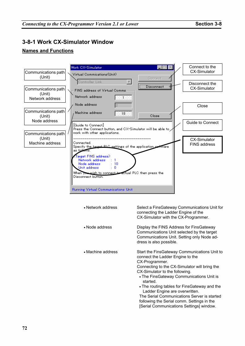
Connecting to the CX-Programmer Version 2.1 or Lower Section 3-8
72
3-8-1 Work CX-Simulator Window Names and Functions
• Network address Select a FinsGateway Communications Unit for
connecting the Ladder Engine of the CX-Simulator with the CX-Programmer.
• Node address Display the FINS Address for FinsGateway Communications Unit selected by the target Communications Unit. Setting only Node ad-dress is also possible.
• Machine address Start the FinsGateway Communications Unit to connect the Ladder Engine to the CX-Programmer. Connecting to the CX-Simulator will bring the CX-Simulator to the following.
• The FinsGateway Communications Unit is started.
• The routing tables for FinsGateway and the Ladder Engine are overwritten.
The Serial Communications Server is started following the Serial comm. Settings in the [Serial Communications Settings] window.
Communications path (Unit)
Communications path (Unit)
Network address
Communications path (Unit)
Node address
Communications path (Unit)
Machine address
Connect to the CX-Simulator
Disconnect the CX-Simulator
Close
Guide to Connect
CX-Simulator FINS address
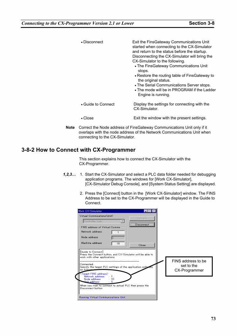
Connecting to the CX-Programmer Version 2.1 or Lower Section 3-8
73
• Disconnect Exit the FinsGateway Communications Unit
started when connecting to the CX-Simulator and return to the status before the startup. Disconnecting the CX-Simulator will bring the CX-Simulator to the following.
• The FinsGateway Communications Unit stops.
• Restore the routing table of FinsGateway to the original status.
• The Serial Communications Server stops. • The mode will be in PROGRAM if the Ladder
Engine is running.
• Guide to Connect Display the settings for connecting with the CX-Simulator.
• Close Exit the window with the present settings.
Note Correct the Node address of FinsGateway Communications Unit only if it overlaps with the node address of the Network Communications Unit when connecting to the CX-Simulator.
3-8-2 How to Connect with CX-Programmer This section explains how to connect the CX-Simulator with the CX-Programmer.
1,2,3… 1. Start the CX-Simulator and select a PLC data folder needed for debugging
application programs. The windows for [Work CX-Simulator], [CX-Simulator Debug Console], and [System Status Setting] are displayed.
2. Press the [Connect] button in the [Work CX-Simulator] window. The FINS
Address to be set to the CX-Programmer will be displayed in the Guide to Connect.
FINS address to be set to the
CX-Programmer
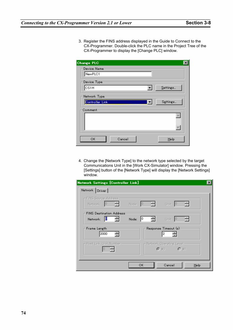
Connecting to the CX-Programmer Version 2.1 or Lower Section 3-8
74
3. Register the FINS address displayed in the Guide to Connect to the
CX-Programmer. Double-click the PLC name in the Project Tree of the CX-Programmer to display the [Change PLC] window.
4. Change the [Network Type] to the network type selected by the target
Communications Unit in the [Work CX-Simulator] window. Pressing the [Settings] button of the [Network Type] will display the [Network Settings] window.
Connecting to the CX-Programmer Version 2.1 or Lower Section 3-8
75
5. Change the settings of [Network] and [Node] for [FINS Destination Ad-
dress] to the network address and the node address for the FINS address displayed in the Guide to Connect.
• The routing table for FinsGateway must be changed if the Network address is to be changed.
1. Do not change the unit address for the FinsGateway Communications Unit
with FinsGateway setting tool, etc. Changing the unit address may cause the [Connect] operation to fail.
2. Do not set items to the local network table when setting the routing table to
the CX-Simulator. The local network table will automatically be changed when [Connect] is executed. If communications with the Ladder Engine can not be executed after setting the routing table, [Disconnect] and then [Connect] again.
Note
3. If a new FinsGateway Communications Unit with the same name is started by the FinsGateway service manager, etc. during [Connect], the new unit will fail to start. The Communications Unit with the same name can not be used simultaneously.
4. For instructions on changing the routing tables, refer to Section 3 of the
CX-Integrator Operation Manual (W445).
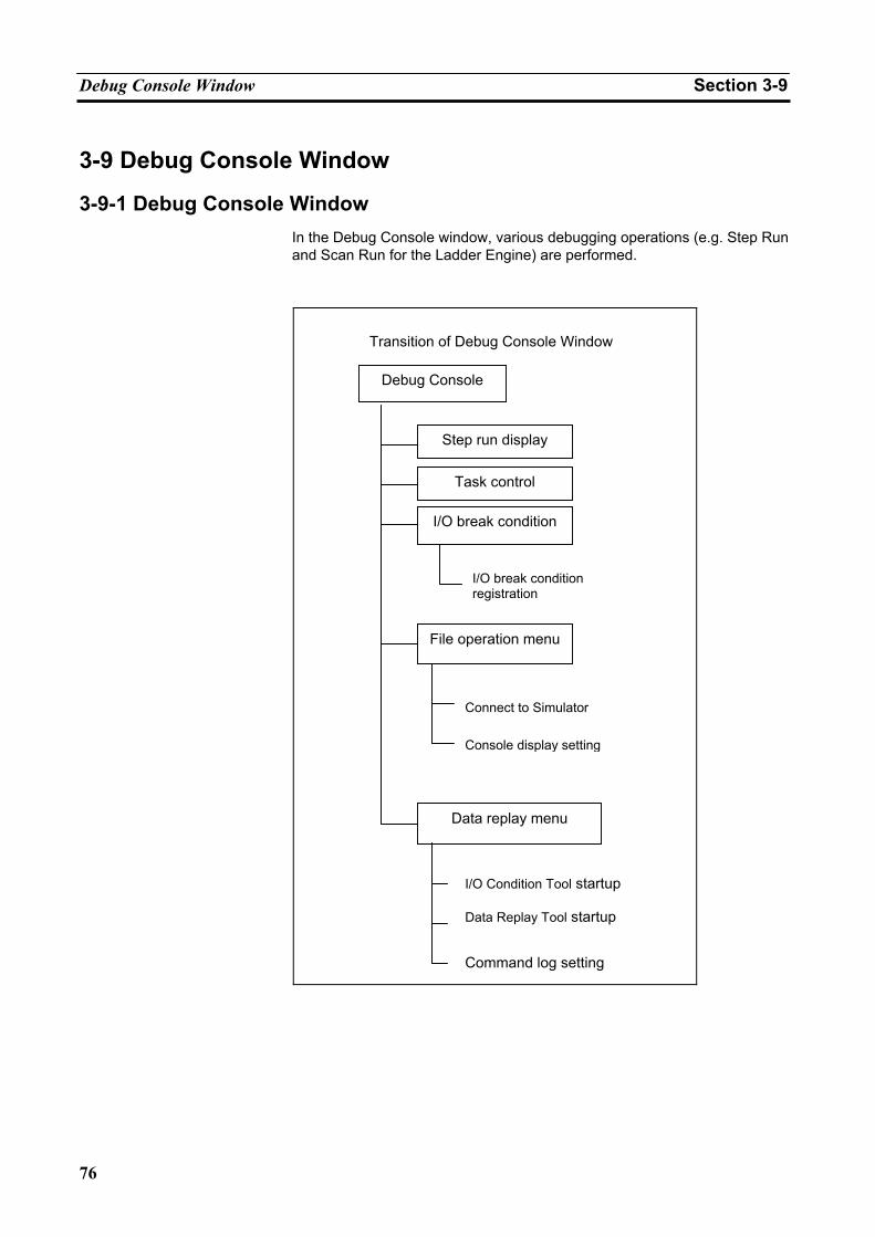
Debug Console Window Section 3-9
76
3-9 Debug Console Window
3-9-1 Debug Console Window In the Debug Console window, various debugging operations (e.g. Step Run and Scan Run for the Ladder Engine) are performed.
Transition of Debug Console Window
Debug Console
Step run display
Task control
I/O break condition
File operation menu
Data replay menu
I/O break condition registration
Connect to Simulator
Console display setting
PLC operation settingI/O Condition Tool startup
Data Replay Tool startup
Command log setting
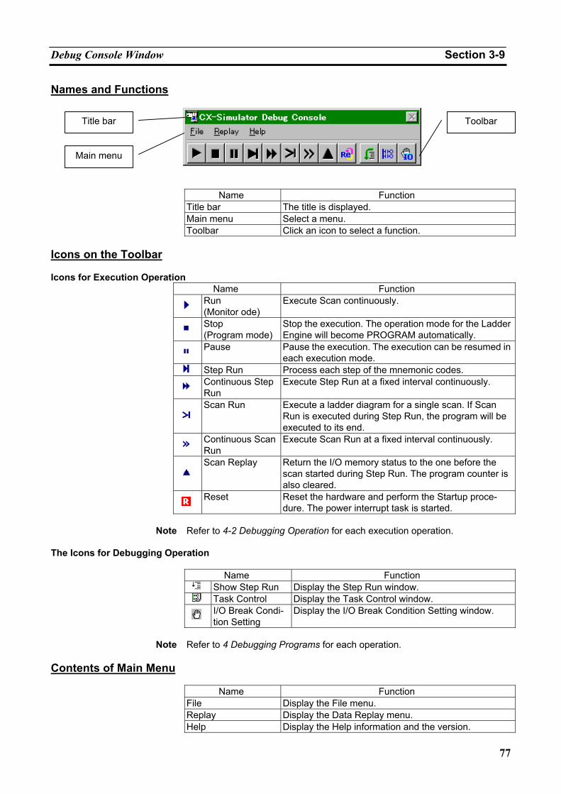
Debug Console Window Section 3-9
77
Names and Functions
Name Function
Title bar The title is displayed. Main menu Select a menu. Toolbar Click an icon to select a function.
Icons on the Toolbar Icons for Execution Operation
Name Function
Run (Monitor ode)
Execute Scan continuously.
Stop (Program mode)
Stop the execution. The operation mode for the Ladder Engine will become PROGRAM automatically.
Pause Pause the execution. The execution can be resumed in each execution mode.
Step Run Process each step of the mnemonic codes.
Continuous Step Run
Execute Step Run at a fixed interval continuously.
Scan Run Execute a ladder diagram for a single scan. If Scan
Run is executed during Step Run, the program will be executed to its end.
Continuous Scan Run
Execute Scan Run at a fixed interval continuously.
Scan Replay Return the I/O memory status to the one before the
scan started during Step Run. The program counter is also cleared.
Reset Reset the hardware and perform the Startup proce-dure. The power interrupt task is started.
Note Refer to 4-2 Debugging Operation for each execution operation.
The Icons for Debugging Operation
Name Function Show Step Run Display the Step Run window. Task Control Display the Task Control window.
I/O Break Condi-tion Setting
Display the I/O Break Condition Setting window.
Note Refer to 4 Debugging Programs for each operation.
Contents of Main Menu
Name Function File Display the File menu. Replay Display the Data Replay menu. Help Display the Help information and the version.
Title bar
Main menu
Toolbar
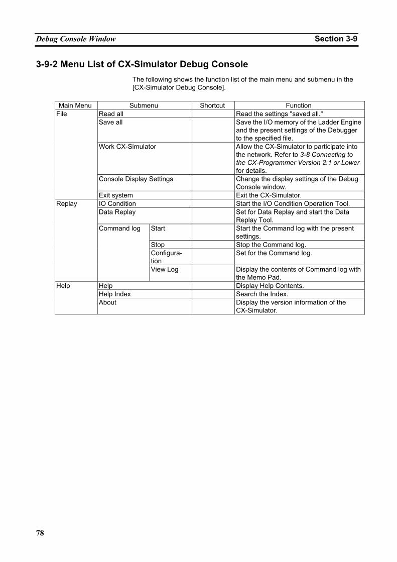
Debug Console Window Section 3-9
78
3-9-2 Menu List of CX-Simulator Debug Console The following shows the function list of the main menu and submenu in the [CX-Simulator Debug Console].
Main Menu Submenu Shortcut Function
Read all Read the settings "saved all." Save all Save the I/O memory of the Ladder Engine
and the present settings of the Debugger to the specified file.
Work CX-Simulator Allow the CX-Simulator to participate into the network. Refer to 3-8 Connecting to the CX-Programmer Version 2.1 or Lower for details.
Console Display Settings Change the display settings of the Debug Console window.
File
Exit system Exit the CX-Simulator. IO Condition Start the I/O Condition Operation Tool. Data Replay Set for Data Replay and start the Data
Replay Tool. Start Start the Command log with the present
settings. Stop Stop the Command log. Configura-tion
Set for the Command log.
Replay
Command log
View Log Display the contents of Command log with the Memo Pad.
Help Display Help Contents. Help Index Search the Index.
Help
About Display the version information of the CX-Simulator.
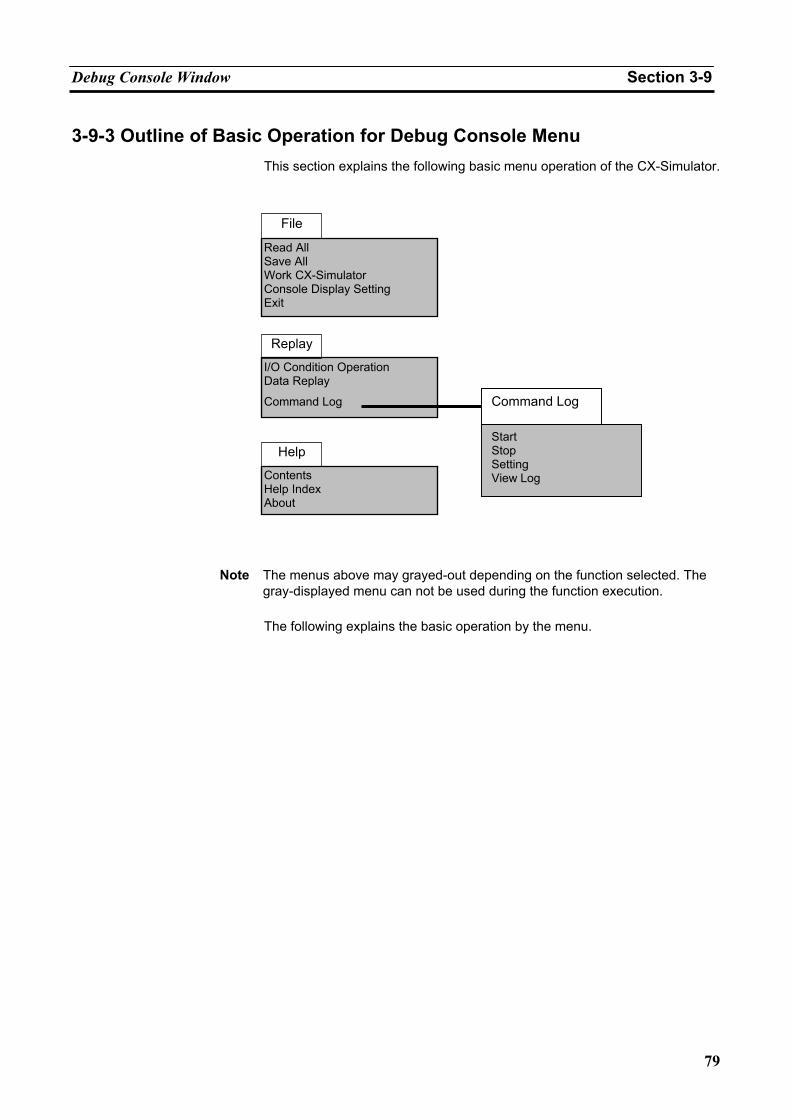
Debug Console Window Section 3-9
79
3-9-3 Outline of Basic Operation for Debug Console Menu This section explains the following basic menu operation of the CX-Simulator.
Note The menus above may grayed-out depending on the function selected. The
gray-displayed menu can not be used during the function execution.
The following explains the basic operation by the menu.
I/O Condition Operation Data Replay Command Log
Replay
Contents Help Index About
Help
Read All Save All Work CX-Simulator Console Display Setting Exit
File
Command Log
Start Stop Setting View Log
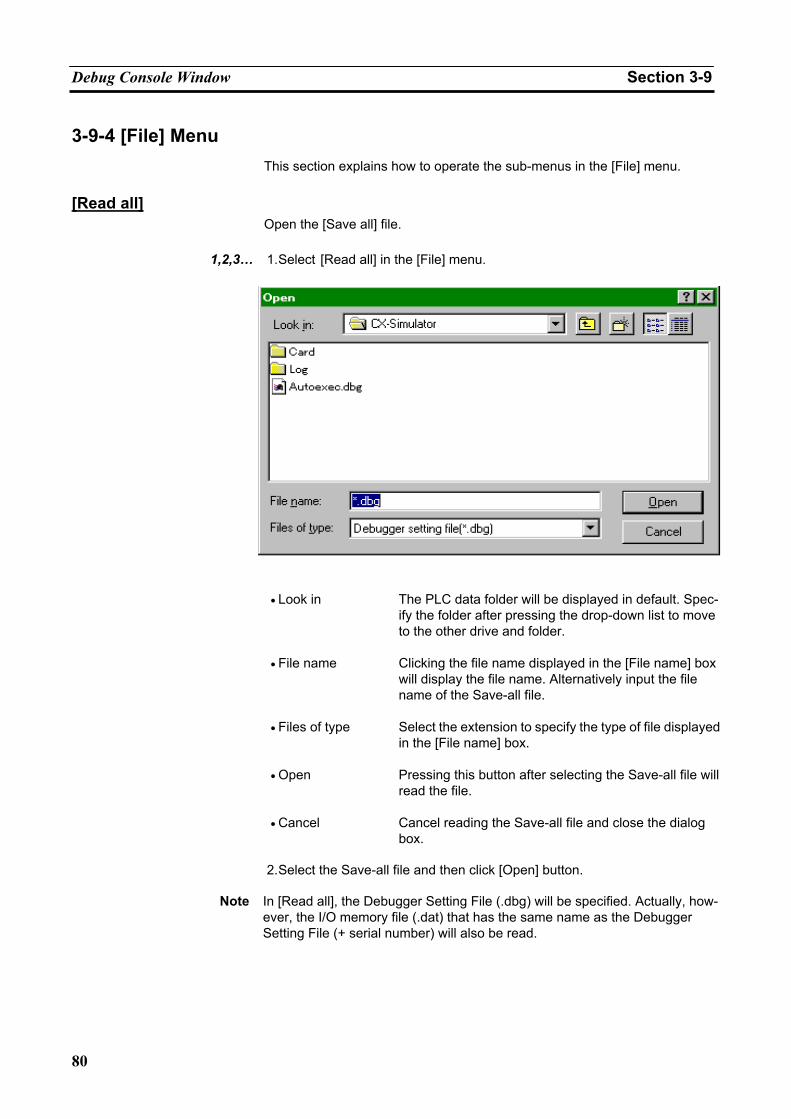
Debug Console Window Section 3-9
80
3-9-4 [File] Menu This section explains how to operate the sub-menus in the [File] menu.
[Read all]
Open the [Save all] file.
1,2,3… 1. Select [Read all] in the [File] menu.
• Look in The PLC data folder will be displayed in default. Spec-
ify the folder after pressing the drop-down list to move to the other drive and folder.
• File name Clicking the file name displayed in the [File name] box will display the file name. Alternatively input the file name of the Save-all file.
• Files of type Select the extension to specify the type of file displayed in the [File name] box.
• Open Pressing this button after selecting the Save-all file will read the file.
• Cancel Cancel reading the Save-all file and close the dialog box.
2. Select the Save-all file and then click [Open] button.
Note In [Read all], the Debugger Setting File (.dbg) will be specified. Actually, how-
ever, the I/O memory file (.dat) that has the same name as the Debugger Setting File (+ serial number) will also be read.
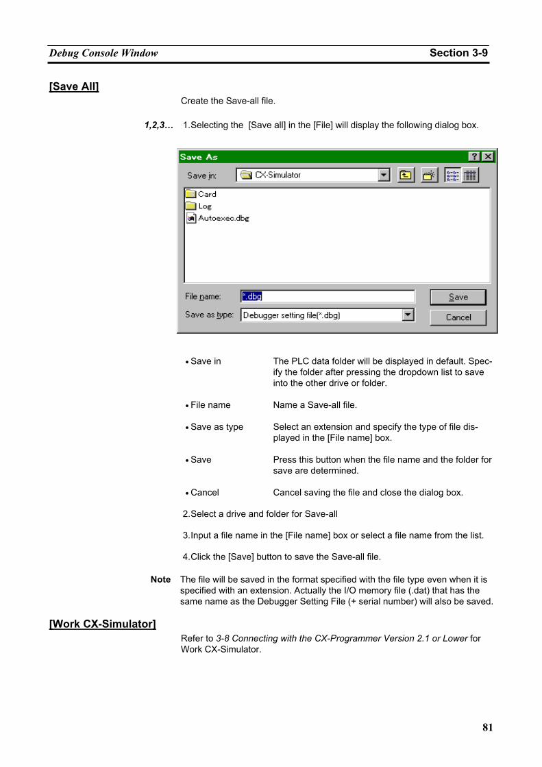
Debug Console Window Section 3-9
81
[Save All] Create the Save-all file.
1,2,3… 1. Selecting the [Save all] in the [File] will display the following dialog box.
• Save in The PLC data folder will be displayed in default. Spec-
ify the folder after pressing the dropdown list to save into the other drive or folder.
• File name Name a Save-all file.
• Save as type Select an extension and specify the type of file dis-played in the [File name] box.
• Save Press this button when the file name and the folder for save are determined.
• Cancel Cancel saving the file and close the dialog box.
2. Select a drive and folder for Save-all
3. Input a file name in the [File name] box or select a file name from the list.
4. Click the [Save] button to save the Save-all file.
Note The file will be saved in the format specified with the file type even when it is specified with an extension. Actually the I/O memory file (.dat) that has the same name as the Debugger Setting File (+ serial number) will also be saved.
[Work CX-Simulator]
Refer to 3-8 Connecting with the CX-Programmer Version 2.1 or Lower for Work CX-Simulator.
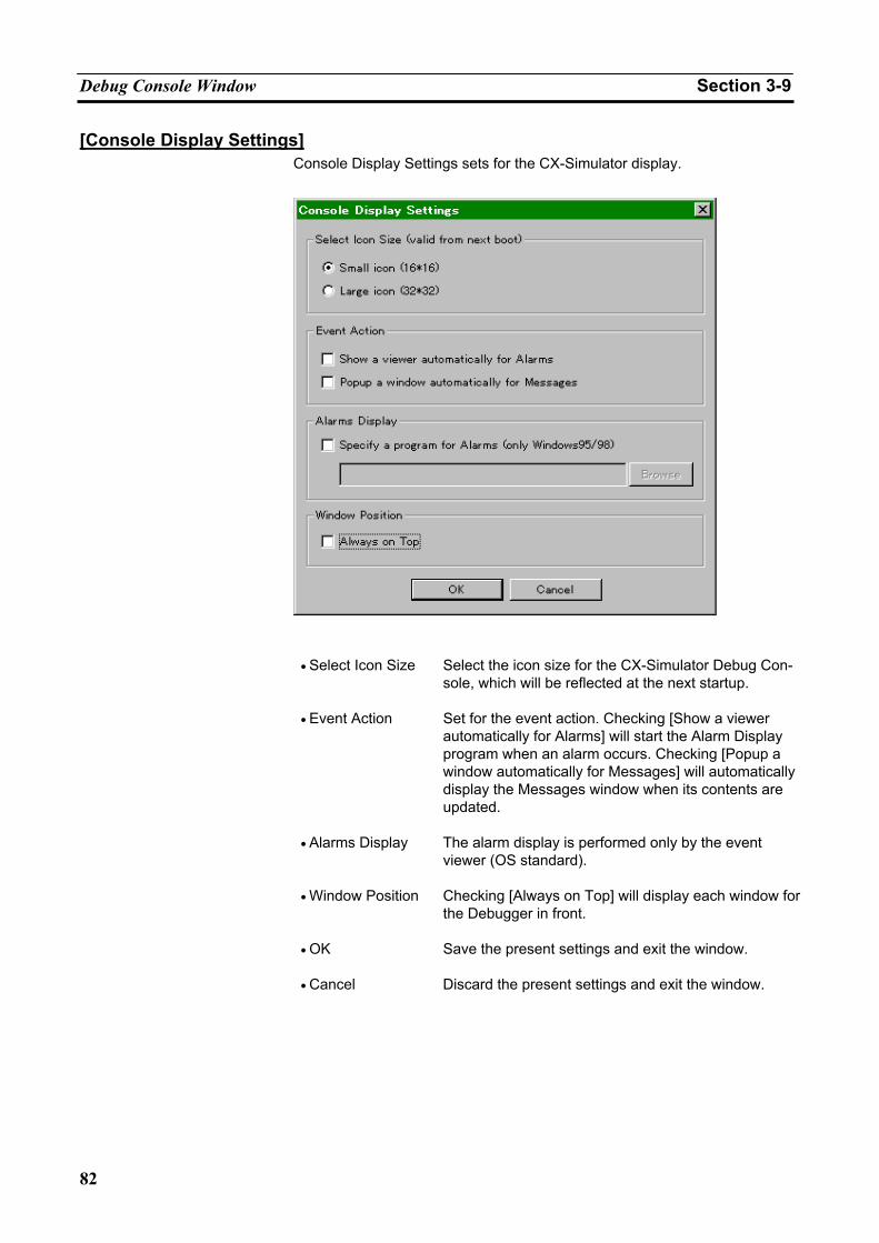
Debug Console Window Section 3-9
82
[Console Display Settings] Console Display Settings sets for the CX-Simulator display.
• Select Icon Size Select the icon size for the CX-Simulator Debug Con-
sole, which will be reflected at the next startup.
• Event Action Set for the event action. Checking [Show a viewer automatically for Alarms] will start the Alarm Display program when an alarm occurs. Checking [Popup a window automatically for Messages] will automatically display the Messages window when its contents are updated.
• Alarms Display The alarm display is performed only by the event viewer (OS standard).
• Window Position Checking [Always on Top] will display each window for the Debugger in front.
• OK Save the present settings and exit the window.
• Cancel Discard the present settings and exit the window.
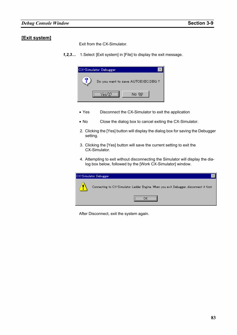
Debug Console Window Section 3-9
83
[Exit system] Exit from the CX-Simulator.
1,2,3… 1. Select [Exit system] in [File] to display the exit message.
• Yes Disconnect the CX-Simulator to exit the application
• No Close the dialog box to cancel exiting the CX-Simulator.
2. Clicking the [Yes] button will display the dialog box for saving the Debugger
setting.
3. Clicking the [Yes] button will save the current setting to exit the CX-Simulator.
4. Attempting to exit without disconnecting the Simulator will display the dia-
log box below, followed by the [Work CX-Simulator] window.
After Disconnect, exit the system again.
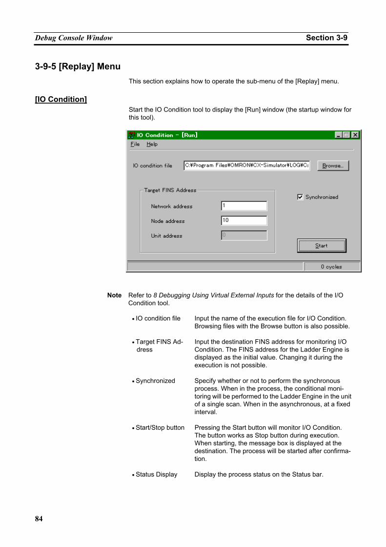
Debug Console Window Section 3-9
84
3-9-5 [Replay] Menu This section explains how to operate the sub-menu of the [Replay] menu.
[IO Condition]
Start the IO Condition tool to display the [Run] window (the startup window for this tool).
Note Refer to 8 Debugging Using Virtual External Inputs for the details of the I/O
Condition tool.
• IO condition file Input the name of the execution file for I/O Condition. Browsing files with the Browse button is also possible.
• Target FINS Ad-dress
Input the destination FINS address for monitoring I/O Condition. The FINS address for the Ladder Engine is displayed as the initial value. Changing it during the execution is not possible.
• Synchronized Specify whether or not to perform the synchronous process. When in the process, the conditional moni-toring will be performed to the Ladder Engine in the unit of a single scan. When in the asynchronous, at a fixed interval.
• Start/Stop button Pressing the Start button will monitor I/O Condition. The button works as Stop button during execution. When starting, the message box is displayed at the destination. The process will be started after confirma-tion.
• Status Display Display the process status on the Status bar.
Debug Console Window Section 3-9
85
• Cycle Count Dis-
play Display the cycle increase after starting monitoring. When in asynchronous process, display the count of monitoring operation.
• Destination Model Name
Display the model name of connecting destination in the title.
File • Open Input the execution file using Browse.
• Start Monitor the I/O Condition whose execution flag is D in
the set execution file. Not selectable if the execution file is not input.
• Stop Stop I/O condition monitoring. Not selectable unless monitoring is being executed.
• Configuration Display the I/O Condition Setting window.
• Exit Exit I/O Condition.
Help Menu • Help Contents Display Help Contents for Windows
• Help Index Display Help Index for Windows.
• About Display the version information.
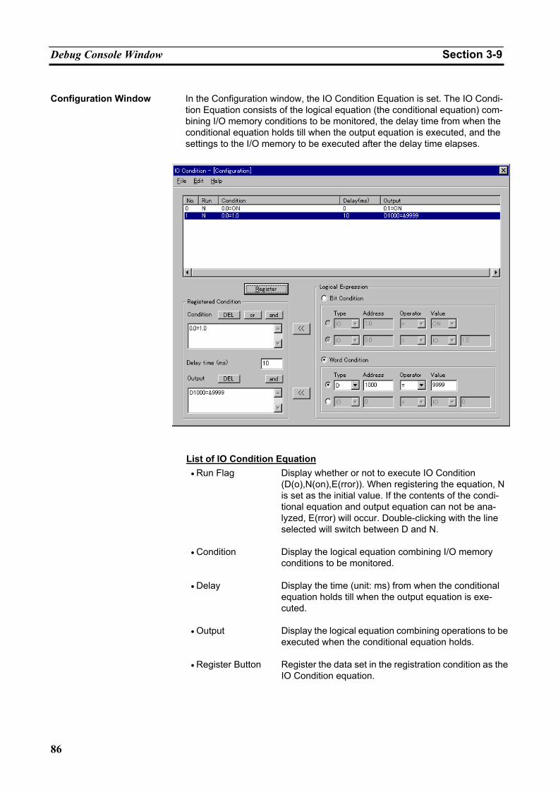
Debug Console Window Section 3-9
86
Configuration Window In the Configuration window, the IO Condition Equation is set. The IO Condi-
tion Equation consists of the logical equation (the conditional equation) com-bining I/O memory conditions to be monitored, the delay time from when the conditional equation holds till when the output equation is executed, and the settings to the I/O memory to be executed after the delay time elapses.
List of IO Condition Equation • Run Flag Display whether or not to execute IO Condition
(D(o),N(on),E(rror)). When registering the equation, N is set as the initial value. If the contents of the condi-tional equation and output equation can not be ana-lyzed, E(rror) will occur. Double-clicking with the line selected will switch between D and N.
• Condition Display the logical equation combining I/O memory conditions to be monitored.
• Delay Display the time (unit: ms) from when the conditional equation holds till when the output equation is exe-cuted.
• Output Display the logical equation combining operations to be executed when the conditional equation holds.
• Register Button Register the data set in the registration condition as the IO Condition equation.
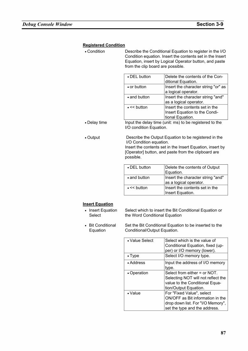
Debug Console Window Section 3-9
87
Registered Condition
Describe the Conditional Equation to register in the I/O Condition equation. Insert the contents set in the Insert Equation, insert by Logical Operator button, and paste from the clip board are possible.
• DEL button Delete the contents of the Con-ditional Equation.
• or button Insert the character string "or" as a logical operator.
• and button Insert the character string "and" as a logical operator.
• Condition
• << button Insert the contents set in the Insert Equation to the Condi-tional Equation.
• Delay time Input the delay time (unit: ms) to be registered to the I/O condition Equation. Describe the Output Equation to be registered in the I/O Condition equation.
Insert the contents set in the Insert Equation, insert by [Operator] button, and paste from the clipboard are possible.
• DEL button Delete the contents of Output Equation.
• and button Insert the character string "and" as a logical operator.
• Output
• << button Insert the contents set in the Insert Equation.
Insert Equation
• Insert Equation Select
Select which to insert the Bit Conditional Equation or the Word Conditional Equation Set the Bit Conditional Equation to be inserted to the Conditional/Output Equation.
• Value Select Select which is the value of Conditional Equation, fixed (up-per) or I/O memory (lower).
• Type Select I/O memory type.
• Address Input the address of I/O memory type.
• Operation Select from either = or NOT. Selecting NOT will not reflect the value to the Conditional Equa-tion/Output Equation.
• Bit Conditional Equation
• Value For "Fixed Value", select ON/OFF as Bit information in the drop down list. For "I/O Memory", set the type and the address.
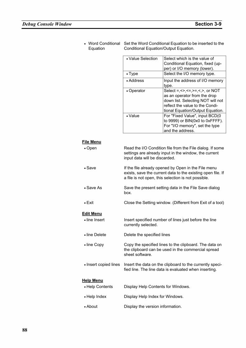
Debug Console Window Section 3-9
88
Set the Word Conditional Equation to be inserted to the Conditional Equation/Output Equation.
• Value Selection Select which is the value of Conditional Equation, fixed (up-per) or I/O memory (lower).
• Type Select the I/O memory type.
• Address Input the address of I/O memory type.
• Operator Select =,<>,<=,>=,<,>, or NOT as an operator from the drop down list. Selecting NOT will not reflect the value to the Condi-tional Equation/Output Equation.
• Word Conditional Equation
• Value For "Fixed Value", input BCD(0 to 9999) or BIN(0x0 to 0xFFFF). For "I/O memory", set the type and the address.
File Menu
• Open Read the I/O Condition file from the File dialog. If some settings are already input in the window, the current input data will be discarded.
• Save If the file already opened by Open in the File menu exists, save the current data to the existing open file. If a file is not open, this selection is not possible.
• Save As Save the present setting data in the File Save dialog box.
• Exit Close the Setting window. (Different from Exit of a tool)
Edit Menu • line Insert Insert specified number of lines just before the line
currently selected.
• line Delete Delete the specified lines
• line Copy Copy the specified lines to the clipboard. The data on the clipboard can be used in the commercial spread sheet software.
• Insert copied lines Insert the data on the clipboard to the currently speci-fied line. The line data is evaluated when inserting.
Help Menu
• Help Contents Display Help Contents for Windows.
• Help Index Display Help Index for Windows.
• About Display the version information.
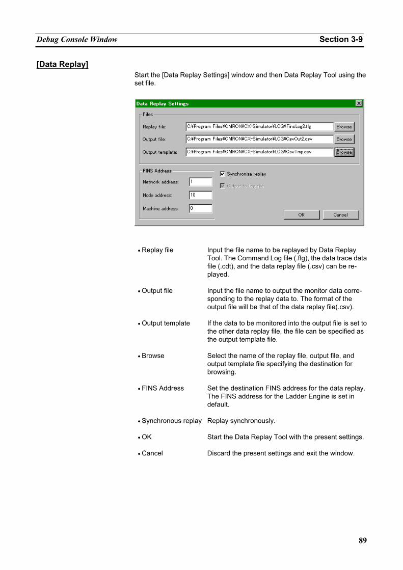
Debug Console Window Section 3-9
89
[Data Replay] Start the [Data Replay Settings] window and then Data Replay Tool using the set file.
• Replay file Input the file name to be replayed by Data Replay
Tool. The Command Log file (.flg), the data trace data file (.cdt), and the data replay file (.csv) can be re-played.
• Output file Input the file name to output the monitor data corre-sponding to the replay data to. The format of the output file will be that of the data replay file(.csv).
• Output template If the data to be monitored into the output file is set to the other data replay file, the file can be specified as the output template file.
• Browse Select the name of the replay file, output file, and output template file specifying the destination for browsing.
• FINS Address Set the destination FINS address for the data replay. The FINS address for the Ladder Engine is set in default.
• Synchronous replay Replay synchronously.
• OK Start the Data Replay Tool with the present settings.
• Cancel Discard the present settings and exit the window.
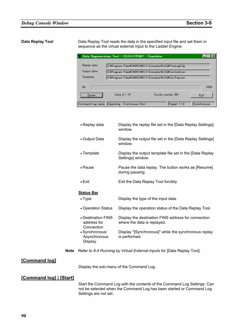
Debug Console Window Section 3-9
90
Data Replay Tool Data Replay Tool reads the data in the specified input file and set them in
sequence as the virtual external input to the Ladder Engine.
• Replay data Display the replay file set in the [Data Replay Settings]
window.
• Output Data Display the output file set in the [Data Replay Settings] window.
• Template Display the output template file set in the [Data Replay Settings] window.
• Pause Pause the data replay. The button works as [Resume] during pausing.
• Exit Exit the Data Replay Tool forcibly.
Status Bar • Type Display the type of the input data.
• Operation Status Display the operation status of the Data Replay Tool.
• Destination FINS
address for Connection
Display the destination FINS address for connection where the data is replayed.
• Synchronous/ Asynchronous Display
Display "[Synchronous]" while the synchronous replay is performed.
Note Refer to 8-4 Running by Virtual External Inputs for [Data Replay Tool].
[Command log]
Display the sub-menu of the Command Log. [Command log] | [Start]
Start the Command Log with the contents of the Command Log Settings. Can not be selected when the Command Log has been started or Command Log Settings are not set.
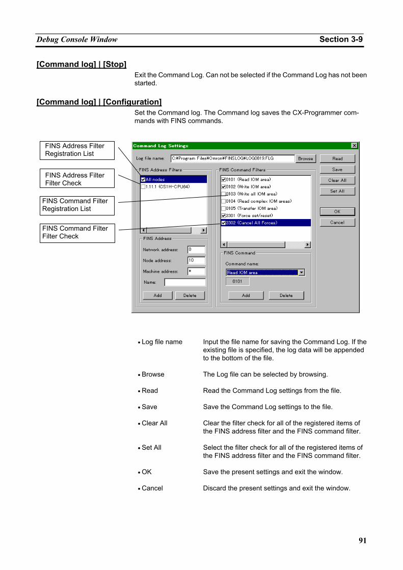
Debug Console Window Section 3-9
91
[Command log] | [Stop] Exit the Command Log. Can not be selected if the Command Log has not been started.
[Command log] | [Configuration]
Set the Command log. The Command log saves the CX-Programmer com-mands with FINS commands.
• Log file name Input the file name for saving the Command Log. If the
existing file is specified, the log data will be appended to the bottom of the file.
• Browse The Log file can be selected by browsing.
• Read Read the Command Log settings from the file.
• Save Save the Command Log settings to the file.
• Clear All Clear the filter check for all of the registered items of the FINS address filter and the FINS command filter.
• Set All Select the filter check for all of the registered items of the FINS address filter and the FINS command filter.
• OK Save the present settings and exit the window.
• Cancel Discard the present settings and exit the window.
FINS Address Filter Registration List
FINS Address Filter Filter Check
FINS Command Filter Registration List
FINS Command Filter Filter Check
Debug Console Window Section 3-9
92
FINS Address Filters • Registration List Display the FINS address selectable as the FINS ad-
dress filter. The [All local nodes] shows all FINS ad-dresses in the computer. Usually specify the [All local nodes] as the filter (registered as the initial value and can not be deleted).
• Filter Check Check here if selecting items in the Registration List.
• Add Add the FINS address to the Registration List.
• Delete Delete the selected items in the Registration List.
• Network address Specify the FINS network address to be added to the Registration List. Specifying "*" will target all of the network addresses.
• Node address Specify the FINS node address to be added to the Registration List. Specifying "*" will target all of the node addresses.
• Machine address Specify the FINS node address to be added to the Registration List. Specifying "*" will target all of the machine numbers.
• Name Specify the name of the FINS address to be added to the Registration List.
FINS Command Filters
• The Registration List
Display the filter of the FINS commands selectable as the FINS command filter. When selecting, compare from top of the FINS commands and save the matched commands as the log.
• Filter Check Check here if selecting the item in the Registration List.
• Add Add the filter of the FINS command to the Registration List.
• Delete Delete the selected items in the Registration List.
• Command name Display the list of FINS command filters registered in advance.
Note Refer to 8-3 Generating Virtual External Inputs for the details of the Command
Log setting. [Command log] | [View Log]
Display the contents of the saved Command Log. Display the content of the file set as the log file in the Command log Setting with the Memo Pad (OS stan-dard).
Debug Console Window Section 3-9
93
3-9-6 [Help] Menu This section explains how to operate the sub-menu of the [Help] menu.
[Help Contents]
Display the Help Contents of the CX-Simulator.
Select [Help Contents] in the [Help] menu to display the [Help Contents] dialog box.
• Help Contents Display the Help Contents of the CX-Simulator.
• Keyword Display the [Help Index] dialog box.
• Return Return to the window displayed just before.
• Print Print the selected topic.
[Help Index] Search for the topic in the online help using the keyword.
Select [Help Index] in the [Help] menu to display the [Help Index] dialog box. [About]
Select [About] in the [Help] menu to display the version information for the CX-Simulator.
• OK Close the [About] dialog box.
Note The license information is not displayed when upgrading from CX-Simulator Ver. 1.3 or higher.
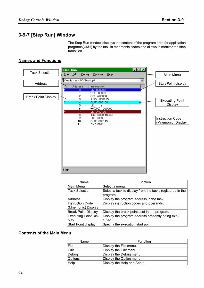
Debug Console Window Section 3-9
94
3-9-7 [Step Run] Window The Step Run window displays the content of the program area for application programs(UM1) by the task in mnemonic codes and allows to monitor the step transition.
Names and Functions
Name Function
Main Menu Select a menu. Task Selection Select a task to display from the tasks registered in the
program. Address Display the program address in the task. Instruction Code (Mnemonic) Display
Display instruction codes and operands.
Break Point Display Display the break points set in the program. Executing Point Dis-play
Display the program address presently being exe-cuted.
Start Point display Specify the execution start point. Contents of the Main Menu
Name Function File Display the File menu. Edit Display the Edit menu. Debug Display the Debug menu. Options Display the Option menu. Help Display the Help and About.
Task Selection
Address
Break Point Display
Main Menu
Start Point display
Executing Point Display
Instruction Code (Mnemonic) Display
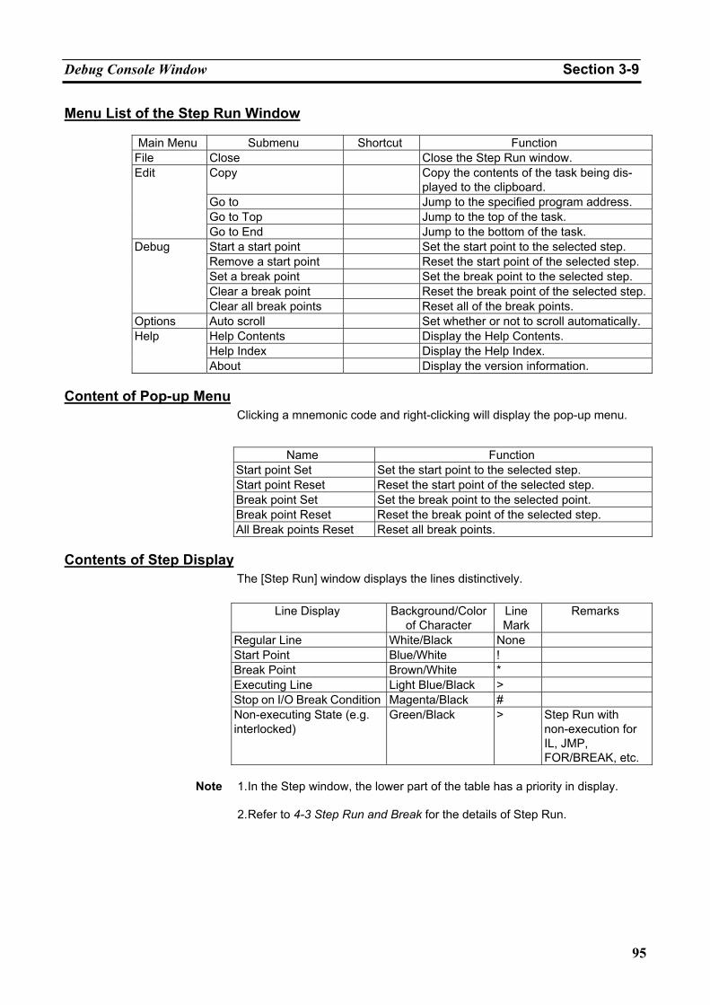
Debug Console Window Section 3-9
95
Menu List of the Step Run Window
Main Menu Submenu Shortcut Function File Close Close the Step Run window.
Copy Copy the contents of the task being dis-played to the clipboard.
Go to Jump to the specified program address. Go to Top Jump to the top of the task.
Edit
Go to End Jump to the bottom of the task. Start a start point Set the start point to the selected step. Remove a start point Reset the start point of the selected step. Set a break point Set the break point to the selected step. Clear a break point Reset the break point of the selected step.
Debug
Clear all break points Reset all of the break points. Options Auto scroll Set whether or not to scroll automatically.
Help Contents Display the Help Contents. Help Index Display the Help Index.
Help
About Display the version information. Content of Pop-up Menu
Clicking a mnemonic code and right-clicking will display the pop-up menu.
Name Function
Start point Set Set the start point to the selected step. Start point Reset Reset the start point of the selected step. Break point Set Set the break point to the selected point. Break point Reset Reset the break point of the selected step. All Break points Reset Reset all break points.
Contents of Step Display
The [Step Run] window displays the lines distinctively.
Line Display Background/Color of Character
Line Mark
Remarks
Regular Line White/Black None Start Point Blue/White ! Break Point Brown/White * Executing Line Light Blue/Black > Stop on I/O Break Condition Magenta/Black # Non-executing State (e.g. interlocked)
Green/Black > Step Run with non-execution for IL, JMP, FOR/BREAK, etc.
Note 1. In the Step window, the lower part of the table has a priority in display.
2. Refer to 4-3 Step Run and Break for the details of Step Run.
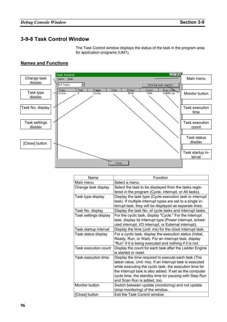
Debug Console Window Section 3-9
96
3-9-8 Task Control Window The Task Control window displays the status of the task in the program area for application programs (UM1).
Names and Functions
Name Function
Main menu Select a menu. Change task display Select the task to be displayed from the tasks regis-
tered in the program (Cycle, interrupt, or All tasks). Task type display Display the task type (Cycle execution task or interrupt
task). If multiple interrupt types are set to a single in-terrupt task, they will be displayed as separate lines.
Task No. display Display the task No. of cycle tasks and interrupt tasks.Task settings display For the cyclic task, display "Cycle." For the interrupt
task, display its interrupt type (Power interrupt, sched-uled interrupt, I/O interrupt, or External interrupt).
Task startup interval Display the time (unit: ms) for the clock interrupt task. Task status display For a cyclic task, display the execution status (Initial,
Ready, Run, or Wait). For an interrupt task, display “Run” if it is being executed and nothing if it is not.
Task execution count Display the count for each task after the Ladder Engine is started or reset.
Task execution time Display the time required to execute each task (The latest value, Unit: ms). If an interrupt task is executed while executing the cyclic task, the execution time for the interrupt task is also added. If set as the computer cycle time, the standby time for pausing with Step Run and Scan Run is added, too.
Monitor button Switch between update (monitoring) and not update (stop monitoring) of the window.
[Close] button Exit the Task Control window.
Change task display
Task type display
Task No. display
Task settings display
[Close] button
Main menu
Task execution time
Task execution count
Task status display
Task startup in-terval
Monitor button
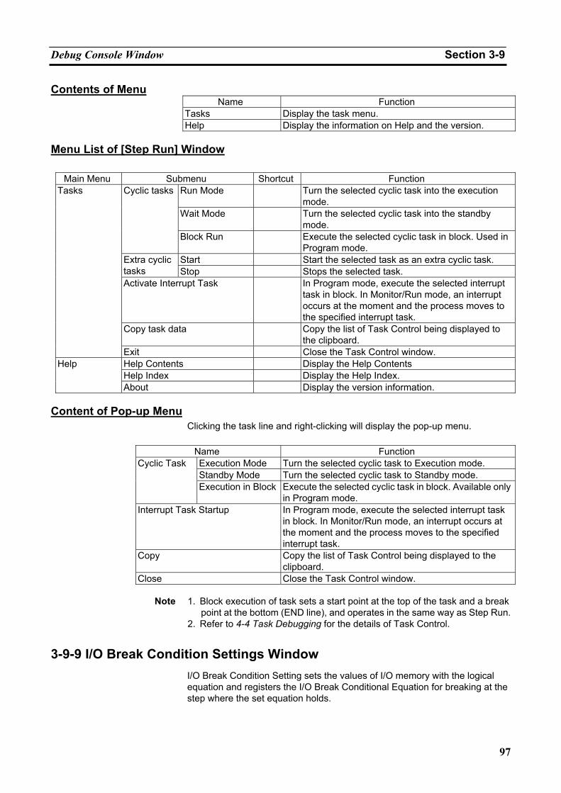
Debug Console Window Section 3-9
97
Contents of Menu Name Function
Tasks Display the task menu. Help Display the information on Help and the version.
Menu List of [Step Run] Window
Main Menu Submenu Shortcut Function
Run Mode Turn the selected cyclic task into the execution mode.
Wait Mode Turn the selected cyclic task into the standby mode.
Cyclic tasks
Block Run Execute the selected cyclic task in block. Used in Program mode.
Start Start the selected task as an extra cyclic task. Extra cyclic tasks Stop Stops the selected task. Activate Interrupt Task In Program mode, execute the selected interrupt
task in block. In Monitor/Run mode, an interrupt occurs at the moment and the process moves to the specified interrupt task.
Copy task data Copy the list of Task Control being displayed to the clipboard.
Tasks
Exit Close the Task Control window. Help Contents Display the Help Contents Help Index Display the Help Index.
Help
About Display the version information. Content of Pop-up Menu
Clicking the task line and right-clicking will display the pop-up menu.
Name Function Execution Mode Turn the selected cyclic task to Execution mode. Standby Mode Turn the selected cyclic task to Standby mode.
Cyclic Task
Execution in Block Execute the selected cyclic task in block. Available only in Program mode.
Interrupt Task Startup In Program mode, execute the selected interrupt task in block. In Monitor/Run mode, an interrupt occurs at the moment and the process moves to the specified interrupt task.
Copy Copy the list of Task Control being displayed to the clipboard.
Close Close the Task Control window.
Note 1. Block execution of task sets a start point at the top of the task and a break point at the bottom (END line), and operates in the same way as Step Run.
2. Refer to 4-4 Task Debugging for the details of Task Control.
3-9-9 I/O Break Condition Settings Window I/O Break Condition Setting sets the values of I/O memory with the logical equation and registers the I/O Break Conditional Equation for breaking at the step where the set equation holds.
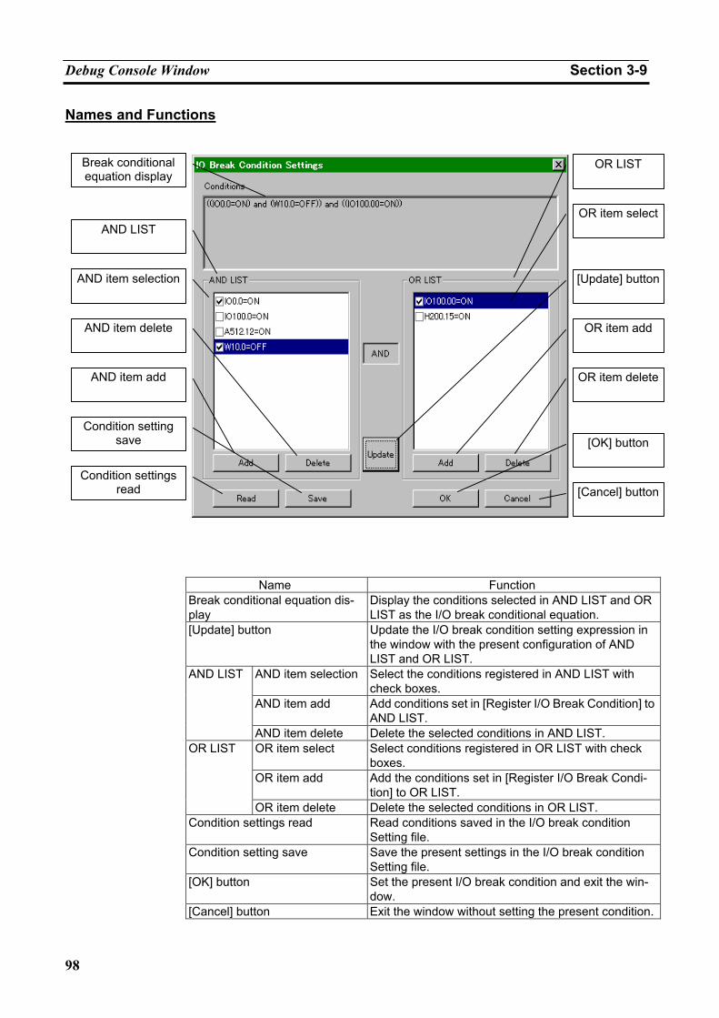
Debug Console Window Section 3-9
98
Names and Functions
Name Function
Break conditional equation dis-play
Display the conditions selected in AND LIST and OR LIST as the I/O break conditional equation.
[Update] button Update the I/O break condition setting expression in the window with the present configuration of AND LIST and OR LIST.
AND item selection Select the conditions registered in AND LIST with check boxes.
AND item add Add conditions set in [Register I/O Break Condition] to AND LIST.
AND LIST
AND item delete Delete the selected conditions in AND LIST. OR item select Select conditions registered in OR LIST with check
boxes. OR item add Add the conditions set in [Register I/O Break Condi-
tion] to OR LIST.
OR LIST
OR item delete Delete the selected conditions in OR LIST. Condition settings read Read conditions saved in the I/O break condition
Setting file. Condition setting save Save the present settings in the I/O break condition
Setting file. [OK] button Set the present I/O break condition and exit the win-
dow. [Cancel] button Exit the window without setting the present condition.
Break conditional equation display
AND LIST
AND item selection
AND item delete
AND item add
Condition setting save
Condition settings read
OR LIST
OR item select
[Update] button
OR item add
OR item delete
[OK] button
[Cancel] button
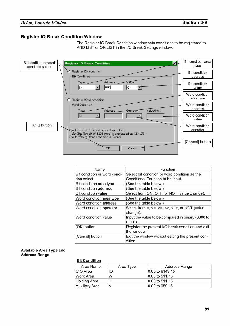
Debug Console Window Section 3-9
99
Register IO Break Condition Window The Register IO Break Condition window sets conditions to be registered to AND LIST or OR LIST in the I/O Break Settings window.
Name Function
Bit condition or word condi-tion select
Select bit condition or word condition as the Conditional Equation to be input.
Bit condition area type (See the table below.) Bit condition address (See the table below.) Bit condition value Select from ON, OFF, or NOT (value change). Word condition area type (See the table below.) Word condition address (See the table below.) Word condition operator Select from =, <=, >=, <>, <, >, or NOT (value
change). Word condition value Input the value to be compared in binary (0000 to
FFFF). [OK] button Register the present I/O break condition and exit
the window. [Cancel] button Exit the window without setting the present con-
dition. Available Area Type and Address Range
Bit Condition Area Name Area Type Address Range
CIO Area IO 0.00 to 6143.15 Work Area W 0.00 to 511.15 Holding Area H 0.00 to 511.15 Auxiliary Area A 0.00 to 959.15
Bit condition or word
condition select
[OK] button
Bit condition area type
Bit condition address
Bit condition value
Word condition area type
Word condition address
Word condition value
Word condition operator
[Cancel] button
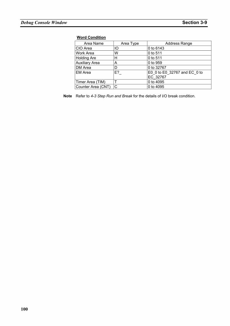
Debug Console Window Section 3-9
100
Word Condition Area Name Area Type Address Range
CIO Area IO 0 to 6143 Work Area W 0 to 511 Holding Are H 0 to 511 Auxiliary Area A 0 to 959 DM Area D 0 to 32767 EM Area E?_ E0_0 to E0_32767 and EC_0 to
EC_32767 Timer Area (TIM) T 0 to 4095 Counter Area (CNT) C 0 to 4095
Note Refer to 4-3 Step Run and Break for the details of I/O break condition.
101
SECTION 4 Debugging Programs
4-1 Debugging Using the CX-Programmer .................................................................................... 102 4-2 Debugging Operation................................................................................................................ 103
4-2-1 CS/CJ/CP-series PLC's Modes and Execution Mode................................................... 103 4-2-2 Scan Run ...................................................................................................................... 104 4-2-3 Step Run ....................................................................................................................... 104 4-2-4 Stop ( ) ....................................................................................................................... 105 4-2-5 Pause ( ) ..................................................................................................................... 106 4-2-6 Other Operation............................................................................................................ 106
4-3 Step Run and Break .................................................................................................................. 107 4-3-1 Operations for Step Run ............................................................................................... 107 4-3-2 Break Setting ................................................................................................................ 107 4-3-3 Break Point ................................................................................................................... 108 4-3-4 Start Point Setting......................................................................................................... 109 4-3-5 I/O Break Condition Setting......................................................................................... 110
4-4 Task Debugging........................................................................................................................ 115 4-4-1 Execution Time and Count of Task.............................................................................. 115 4-4-2 Task Execution Status .................................................................................................. 115 4-4-3 Executing Tasks Individually ....................................................................................... 116 4-4-4 Precautions when Debugging Task .............................................................................. 117
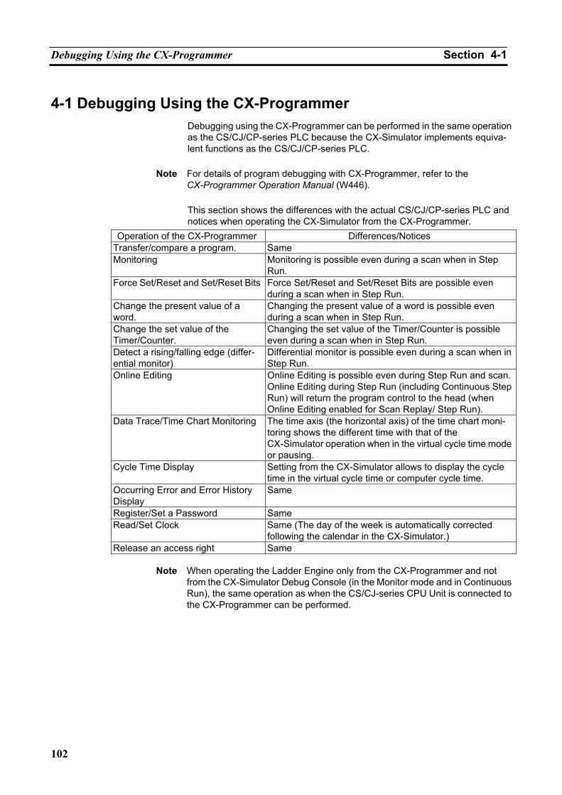
Debugging Using the CX-Programmer Section 4-1
102
4-1 Debugging Using the CX-Programmer Debugging using the CX-Programmer can be performed in the same operation as the CS/CJ/CP-series PLC because the CX-Simulator implements equiva-lent functions as the CS/CJ/CP-series PLC.
Note For details of program debugging with CX-Programmer, refer to the
CX-Programmer Operation Manual (W446).
This section shows the differences with the actual CS/CJ/CP-series PLC and notices when operating the CX-Simulator from the CX-Programmer.
Operation of the CX-Programmer Differences/Notices Transfer/compare a program. Same Monitoring Monitoring is possible even during a scan when in Step
Run. Force Set/Reset and Set/Reset Bits Force Set/Reset and Set/Reset Bits are possible even
during a scan when in Step Run. Change the present value of a word.
Changing the present value of a word is possible even during a scan when in Step Run.
Change the set value of the Timer/Counter.
Changing the set value of the Timer/Counter is possible even during a scan when in Step Run.
Detect a rising/falling edge (differ-ential monitor)
Differential monitor is possible even during a scan when in Step Run.
Online Editing Online Editing is possible even during Step Run and scan.Online Editing during Step Run (including Continuous Step Run) will return the program control to the head (when Online Editing enabled for Scan Replay/ Step Run).
Data Trace/Time Chart Monitoring The time axis (the horizontal axis) of the time chart moni-toring shows the different time with that of the CX-Simulator operation when in the virtual cycle time mode or pausing.
Cycle Time Display Setting from the CX-Simulator allows to display the cycle time in the virtual cycle time or computer cycle time.
Occurring Error and Error History Display
Same
Register/Set a Password Same Read/Set Clock Same (The day of the week is automatically corrected
following the calendar in the CX-Simulator.) Release an access right Same
Note When operating the Ladder Engine only from the CX-Programmer and not
from the CX-Simulator Debug Console (in the Monitor mode and in Continuous Run), the same operation as when the CS/CJ-series CPU Unit is connected to the CX-Programmer can be performed.
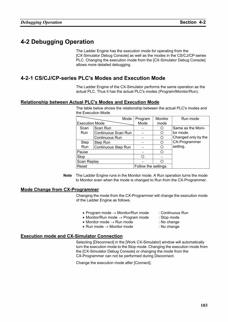
Debugging Operation Section 4-2
103
4-2 Debugging Operation The Ladder Engine has the execution mode for operating from the [CX-Simulator Debug Console] as well as the modes in the CS/CJ/CP-series PLC. Changing the execution mode from the [CX-Simulator Debug Console] allows more detailed debugging.
4-2-1 CS/CJ/CP-series PLC's Modes and Execution Mode The Ladder Engine of the CX-Simulator performs the same operation as the actual PLC. Thus it has the actual PLC's modes (Program/Monitor/Run).
Relationship between Actual PLC's Modes and Execution Mode
The table below shows the relationship between the actual PLC's modes and the Execution Mode
ModeExecution Mode
Program Mode
Monitor mode
Run mode
Scan Run − Continuous Scan Run −
Scan Run
Continuous Run − Step Run − Step
Run Continuous Step Run − Pause − Stop − Scan Replay − Reset Follow the settings.
Same as the Moni-tor mode. Changed only by the CX-Programmer setting.
Note The Ladder Engine runs in the Monitor mode. A Run operation turns the mode
to Monitor even when the mode is changed to Run from the CX-Programmer. Mode Change from CX-Programmer
Changing the mode from the CX-Programmer will change the execution mode of the Ladder Engine as follows.
• Program mode → Monitor/Run mode : Continuous Run • Monitor/Run mode → Program mode : Stop mode • Monitor mode → Run mode : No change • Run mode → Monitor mode : No change
Execution mode and CX-Simulator Connection
Selecting [Disconnect] in the [Work CX-Simulator] window will automatically turn the execution mode to the Stop mode. Changing the execution mode from the [CX-Simulator Debug Console] or changing the mode from the CX-Programmer can not be performed during Disconnect.
Change the execution mode after [Connect].
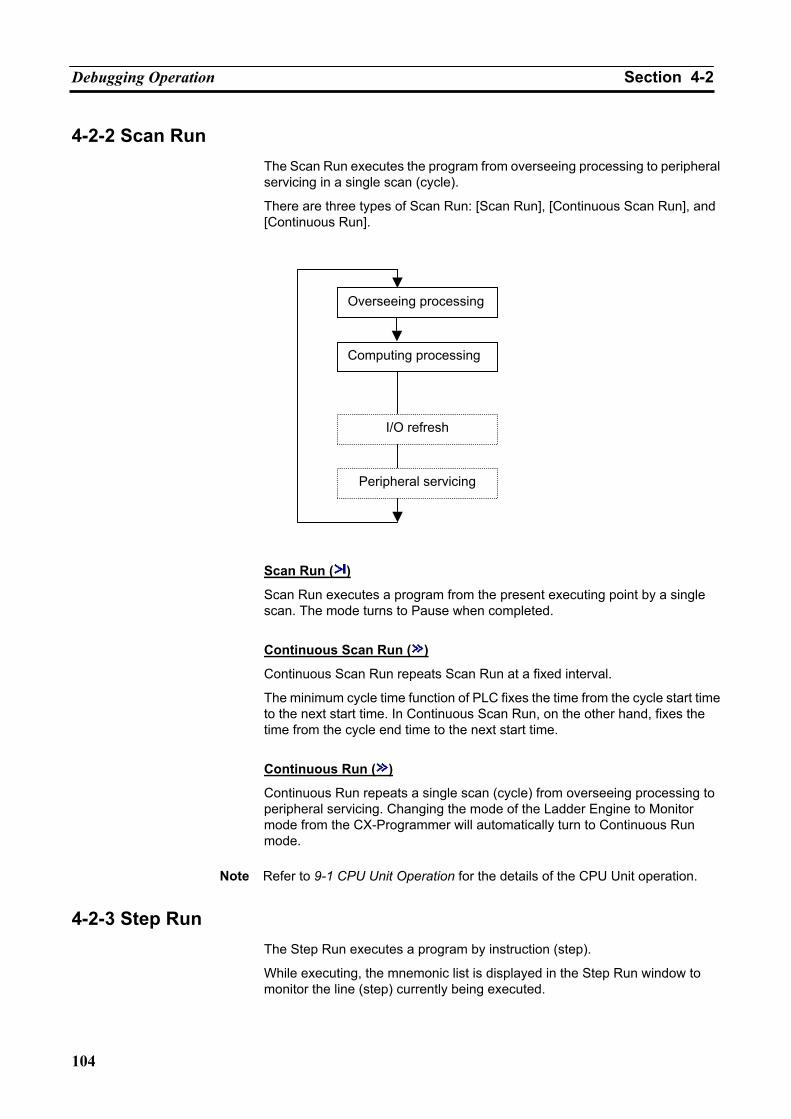
Debugging Operation Section 4-2
104
4-2-2 Scan Run The Scan Run executes the program from overseeing processing to peripheral servicing in a single scan (cycle).
There are three types of Scan Run: [Scan Run], [Continuous Scan Run], and [Continuous Run].
Scan Run ( )
Scan Run executes a program from the present executing point by a single scan. The mode turns to Pause when completed.
Continuous Scan Run ( )
Continuous Scan Run repeats Scan Run at a fixed interval.
The minimum cycle time function of PLC fixes the time from the cycle start time to the next start time. In Continuous Scan Run, on the other hand, fixes the time from the cycle end time to the next start time.
Continuous Run ( )
Continuous Run repeats a single scan (cycle) from overseeing processing to peripheral servicing. Changing the mode of the Ladder Engine to Monitor mode from the CX-Programmer will automatically turn to Continuous Run mode.
Note Refer to 9-1 CPU Unit Operation for the details of the CPU Unit operation.
4-2-3 Step Run The Step Run executes a program by instruction (step).
While executing, the mnemonic list is displayed in the Step Run window to monitor the line (step) currently being executed.
Overseeing processing
Computing processing
I/O refresh
Peripheral servicing
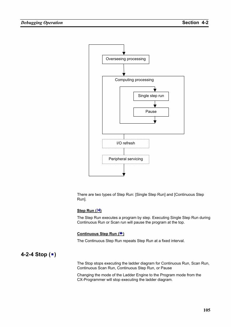
Debugging Operation Section 4-2
105
There are two types of Step Run: [Single Step Run] and [Continuous Step Run].
Step Run ( )
The Step Run executes a program by step. Executing Single Step Run during Continuous Run or Scan run will pause the program at the top.
Continuous Step Run ( )
The Continuous Step Run repeats Step Run at a fixed interval.
4-2-4 Stop ( ) The Stop stops executing the ladder diagram for Continuous Run, Scan Run, Continuous Scan Run, Continuous Step Run, or Pause
Changing the mode of the Ladder Engine to the Program mode from the CX-Programmer will stop executing the ladder diagram.
Overseeing processing
Single step run
Pause
Computing processing
I/O refresh
Peripheral servicing
Debugging Operation Section 4-2
106
4-2-5 Pause ( ) Pause pauses executing the ladder diagram.
The situation is also the same when the execution of the ladder program is stopping in Scan Run, Step Run, a break point, or an I/O break condition. While pausing, the peripheral servicing is performed.
4-2-6 Other Operation Scan Replay ( )
The Scan Replay returns the execution status to the first of the scan when pausing.
The Scan Replay returns all of the status including values changed by the program execution to that of the scan start.
As long as it is within a scan, monitoring can be done with conditions changed any times.
Reset ( )
The Reset simulates the process in the Ladder Engine when from power in-terruption to power on. The power interruption task is started at power inter-ruption to allow debugging the power interruption process (only when regis-tered).
Returning from the Reset turns the mode to Program.
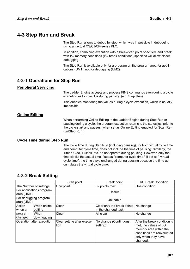
Step Run and Break Section 4-3
107
4-3 Step Run and Break The Step Run allows to debug by step, which was impossible in debugging using an actual CS/CJ/CP-series PLC.
In addition, combining execution with a break/start point specified, and break with I/O memory conditions (I/O break conditions) specified will allow closer debugging.
The Step Run is available only for a program on the program area for appli-cations (UM1), not for debugging (UM2).
4-3-1 Operations for Step Run Peripheral Servicing
The Ladder Engine accepts and process FINS commands even during a cycle execution as long as it is during pausing (e.g. Step Run).
This enables monitoring the values during a cycle execution, which is usually impossible.
Online Editing
When performing Online Editing to the Ladder Engine during Step Run or pausing during a cycle, the program execution returns to the status just prior to the cycle start and pauses (when set as Online Editing enabled for Scan Re-run/Step Run).
Cycle Time during Step Run
The cycle time during Step Run (including pausing), for both virtual cycle time and computer cycle time, does not include the time of pausing. Similarly, the Timer, Clock Pulses, etc. do not operate during pausing. However, only the time clocks the actual time if set as "computer cycle time." If set as " virtual cycle time", the time stays unchanged during pausing because the time ac-cumulates the virtual cycle time.
4-3-2 Break Setting Start point Break point I/O Break Condition
The Number of settings One point 32 points max One condition For applications program area (UM1) Usable
For debugging program area (UM2) Unusable
When online editing
Clear Clear only the break points in the changed task.
No change Action when a program changed
When downloading
Clear All clear No change
Operation after execution Clear setting after execu-tion
No change (Continuous setting)
After the break condition is met, the values of I/O memory area within the conditions are reevaluated only when they have changed.
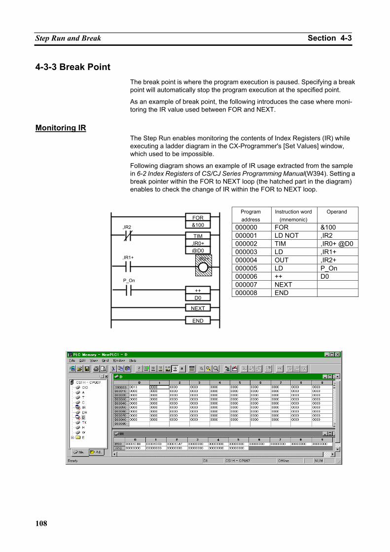
Step Run and Break Section 4-3
108
4-3-3 Break Point The break point is where the program execution is paused. Specifying a break point will automatically stop the program execution at the specified point.
As an example of break point, the following introduces the case where moni-toring the IR value used between FOR and NEXT.
Monitoring IR
The Step Run enables monitoring the contents of Index Registers (IR) while executing a ladder diagram in the CX-Programmer's [Set Values] window, which used to be impossible.
Following diagram shows an example of IR usage extracted from the sample in 6-2 Index Registers of CS/CJ Series Programming Manual(W394). Setting a break pointer within the FOR to NEXT loop (the hatched part in the diagram) enables to check the change of IR within the FOR to NEXT loop.
Program address
Instruction word (mnemonic)
Operand
000000 FOR &100 000001 LD NOT ,IR2 000002 TIM ,IR0+ @D0000003 LD ,IR1+ 000004 OUT ,IR2+ 000005 LD P_On 000006 ++ D0 000007 NEXT 000008 END
,IR1+
,IR2
,IR2+
P_On
END
NEXT
++D0
TIM,IR0+@D0
FOR&100
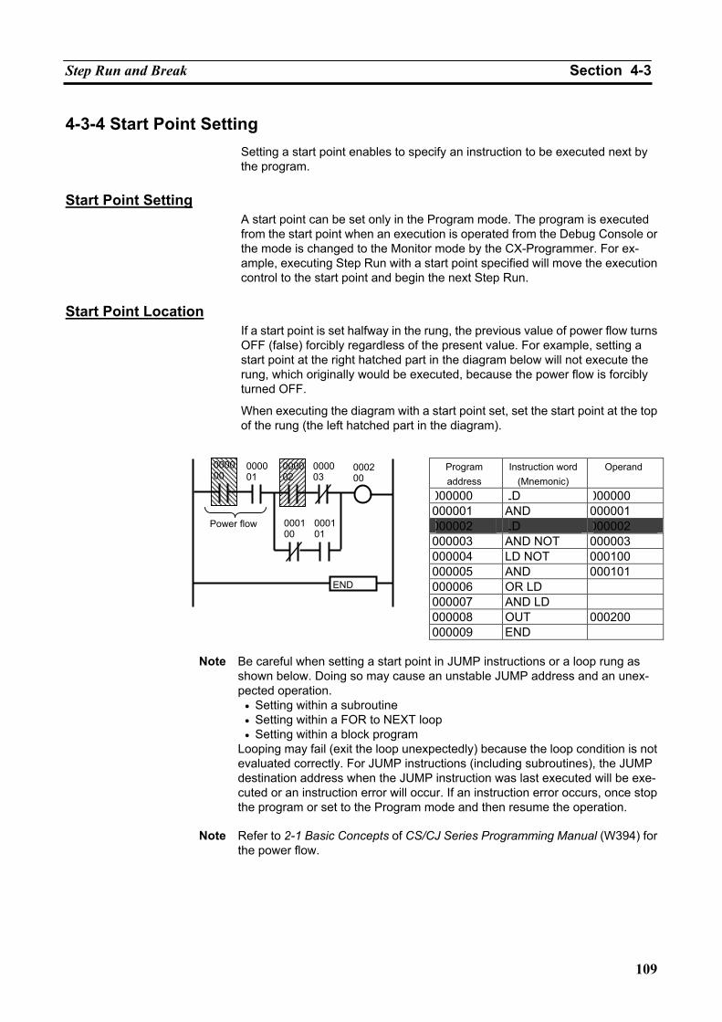
Step Run and Break Section 4-3
109
4-3-4 Start Point Setting Setting a start point enables to specify an instruction to be executed next by the program.
Start Point Setting
A start point can be set only in the Program mode. The program is executed from the start point when an execution is operated from the Debug Console or the mode is changed to the Monitor mode by the CX-Programmer. For ex-ample, executing Step Run with a start point specified will move the execution control to the start point and begin the next Step Run.
Start Point Location
If a start point is set halfway in the rung, the previous value of power flow turns OFF (false) forcibly regardless of the present value. For example, setting a start point at the right hatched part in the diagram below will not execute the rung, which originally would be executed, because the power flow is forcibly turned OFF.
When executing the diagram with a start point set, set the start point at the top of the rung (the left hatched part in the diagram).
Program address
Instruction word (Mnemonic)
Operand
000000 LD 000000 000001 AND 000001 000002 LD 000002 000003 AND NOT 000003 000004 LD NOT 000100 000005 AND 000101 000006 OR LD 000007 AND LD 000008 OUT 000200 000009 END
Note Be careful when setting a start point in JUMP instructions or a loop rung as
shown below. Doing so may cause an unstable JUMP address and an unex-pected operation.
• Setting within a subroutine • Setting within a FOR to NEXT loop • Setting within a block program
Looping may fail (exit the loop unexpectedly) because the loop condition is not evaluated correctly. For JUMP instructions (including subroutines), the JUMP destination address when the JUMP instruction was last executed will be exe-cuted or an instruction error will occur. If an instruction error occurs, once stop the program or set to the Program mode and then resume the operation.
Note Refer to 2-1 Basic Concepts of CS/CJ Series Programming Manual (W394) for
the power flow.
0000 00
0000 01
000002
000003
000200
000100
000101
END
Power flow
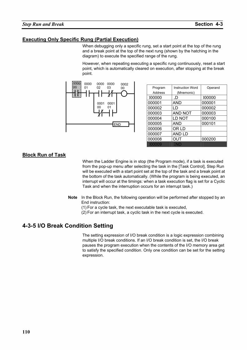
Step Run and Break Section 4-3
110
Executing Only Specific Rung (Partial Execution) When debugging only a specific rung, set a start point at the top of the rung and a break point at the top of the next rung (shown by the hatching in the diagram) to execute the specified range of the rung.
However, when repeating executing a specific rung continuously, reset a start point, which is automatically cleared on execution, after stopping at the break point.
Program Address
Instruction Word (Mnemonic)
Operand
000000 LD 000000 000001 AND 000001 000002 LD 000002 000003 AND NOT 000003 000004 LD NOT 000100 000005 AND 000101 000006 OR LD 000007 AND LD 000008 OUT 000200 000009 END
Block Run of Task
When the Ladder Engine is in stop (the Program mode), if a task is executed from the pop-up menu after selecting the task in the [Task Control], Step Run will be executed with a start point set at the top of the task and a break point at the bottom of the task automatically. (While the program is being executed, an interrupt will occur at the timings: when a task execution flag is set for a Cyclic Task and when the interruption occurs for an interrupt task.)
Note In the Block Run, the following operation will be performed after stopped by an
End instruction: (1) For a cycle task, the next executable task is executed, (2) For an interrupt task, a cyclic task in the next cycle is executed.
4-3-5 I/O Break Condition Setting The setting expression of I/O break condition is a logic expression combining multiple I/O break conditions. If an I/O break condition is set, the I/O break pauses the program execution when the contents of the I/O memory area get to satisfy the specified condition. Only one condition can be set for the setting expression.
0000 00
0000 01
000002
000003
000200
000100
000101
END
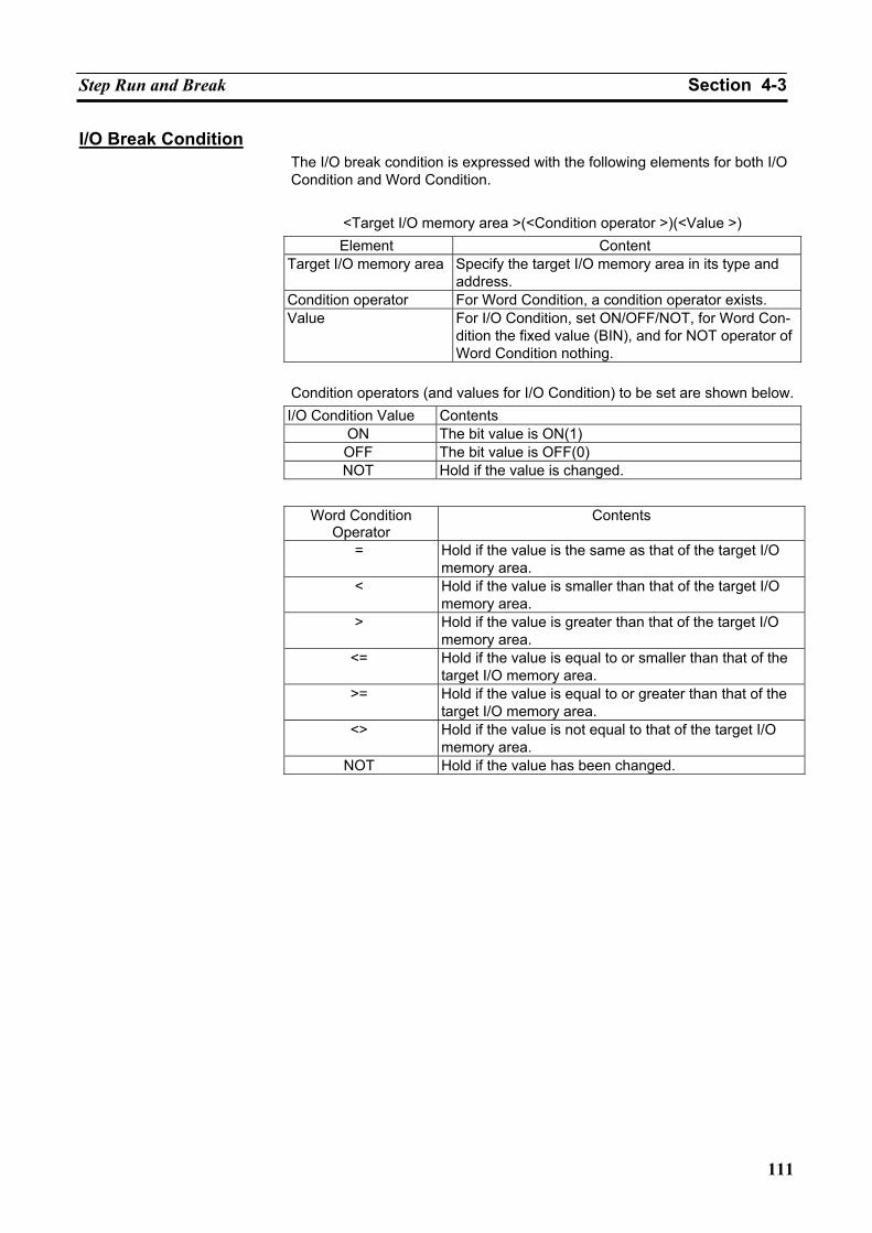
Step Run and Break Section 4-3
111
I/O Break Condition The I/O break condition is expressed with the following elements for both I/O Condition and Word Condition.
<Target I/O memory area >(<Condition operator >)(<Value >) Element Content
Target I/O memory area Specify the target I/O memory area in its type and address.
Condition operator For Word Condition, a condition operator exists. Value For I/O Condition, set ON/OFF/NOT, for Word Con-
dition the fixed value (BIN), and for NOT operator of Word Condition nothing.
Condition operators (and values for I/O Condition) to be set are shown below. I/O Condition Value Contents
ON The bit value is ON(1) OFF The bit value is OFF(0) NOT Hold if the value is changed.
Word Condition
Operator Contents
= Hold if the value is the same as that of the target I/O memory area.
< Hold if the value is smaller than that of the target I/O memory area.
> Hold if the value is greater than that of the target I/O memory area.
<= Hold if the value is equal to or smaller than that of the target I/O memory area.
>= Hold if the value is equal to or greater than that of the target I/O memory area.
<> Hold if the value is not equal to that of the target I/O memory area.
NOT Hold if the value has been changed.
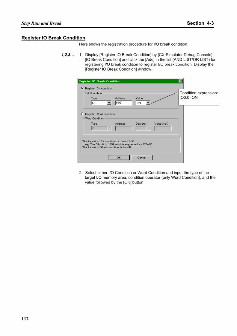
Step Run and Break Section 4-3
112
Register IO Break Condition Here shows the registration procedure for I/O break condition.
1,2,3… 1. Display [Register IO Break Condition] by [CX-Simulator Debug Console] |
[IO Break Condition] and click the [Add] in the list (AND LIST/OR LIST) for registering I/O break condition to register I/O break condition. Display the [Register IO Break Condition] window.
2. Select either I/O Condition or Word Condition and input the type of the target I/O memory area, condition operator (only Word Condition), and the value followed by the [OK] button.
Condition expression: IO0.0=ON
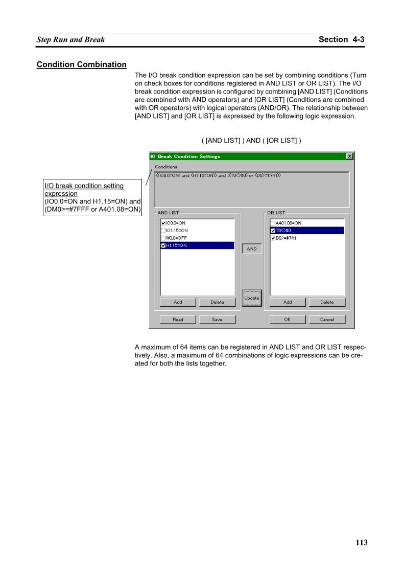
Step Run and Break Section 4-3
113
Condition Combination The I/O break condition expression can be set by combining conditions (Turn on check boxes for conditions registered in AND LIST or OR LIST). The I/O break condition expression is configured by combining [AND LIST] (Conditions are combined with AND operators) and [OR LIST] (Conditions are combined with OR operators) with logical operators (AND/OR). The relationship between [AND LIST] and [OR LIST] is expressed by the following logic expression.
( [AND LIST] ) AND ( [OR LIST] )
A maximum of 64 items can be registered in AND LIST and OR LIST respec-tively. Also, a maximum of 64 combinations of logic expressions can be cre-ated for both the lists together.
I/O break condition setting expression (IO0.0=ON and H1.15=ON) and(DM0>=#7FFF or A401.08=ON)
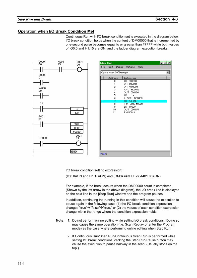
Step Run and Break Section 4-3
114
Operation when I/O Break Condition Met Continuous Run with I/O break condition set is executed in the diagram below. I/O break condition holds when the content of DM00000 that is incremented by one-second pulse becomes equal to or greater than #7FFF while both values of IO0.0 and H1.15 are ON, and the ladder diagram execution breaks.
I/O break condition setting expression:
(IO0.0=ON and H1.15=ON) and (DM0>=#7FFF or A401.08=ON)
For example, if the break occurs when the DM00000 count is completed (Shown by the left arrow in the above diagram), the I/O break line is displayed on the next line in the [Step Run] window and the program pauses.
In addition, continuing the running in this condition will cause the execution to pause again in the following case: (1) the I/O break condition expression changes "true" "false" "true," or (2) the values of each condition expression change within the range where the condition expression holds.
Note 1. Do not perform online editing while setting I/O break conditions. Doing so
may cause the same operation (i.e. Scan Replay or enter the Program mode) as the case where performing online editing when Step Run.
2. If Continuous Run/Scan Run/Continuous Scan Run is performed while
setting I/O break conditions, clicking the Step Run/Pause button may cause the execution to pause halfway in the scan. (Usually stops on the top.)
000000
000001
H00115
000100
END
W00000
++
1s
D0
TIM
A40108
0000#0020
T0000000115
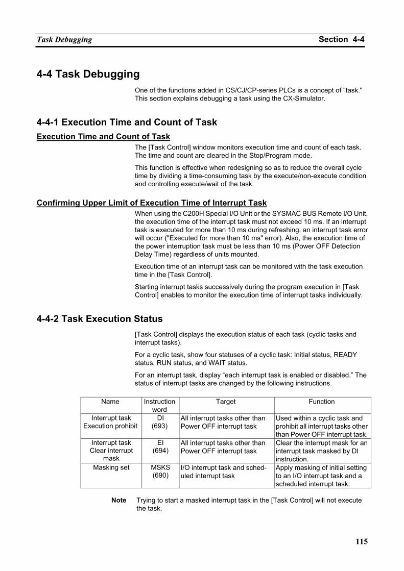
Task Debugging Section 4-4
115
4-4 Task Debugging One of the functions added in CS/CJ/CP-series PLCs is a concept of "task." This section explains debugging a task using the CX-Simulator.
4-4-1 Execution Time and Count of Task Execution Time and Count of Task
The [Task Control] window monitors execution time and count of each task. The time and count are cleared in the Stop/Program mode.
This function is effective when redesigning so as to reduce the overall cycle time by dividing a time-consuming task by the execute/non-execute condition and controlling execute/wait of the task.
Confirming Upper Limit of Execution Time of Interrupt Task
When using the C200H Special I/O Unit or the SYSMAC BUS Remote I/O Unit, the execution time of the interrupt task must not exceed 10 ms. If an interrupt task is executed for more than 10 ms during refreshing, an interrupt task error will occur ("Executed for more than 10 ms" error). Also, the execution time of the power interruption task must be less than 10 ms (Power OFF Detection Delay Time) regardless of units mounted.
Execution time of an interrupt task can be monitored with the task execution time in the [Task Control].
Starting interrupt tasks successively during the program execution in [Task Control] enables to monitor the execution time of interrupt tasks individually.
4-4-2 Task Execution Status [Task Control] displays the execution status of each task (cyclic tasks and interrupt tasks).
For a cyclic task, show four statuses of a cyclic task: Initial status, READY status, RUN status, and WAIT status.
For an interrupt task, display “each interrupt task is enabled or disabled.” The status of interrupt tasks are changed by the following instructions.
Name Instruction
word Target Function
Interrupt task Execution prohibit
DI (693)
All interrupt tasks other than Power OFF interrupt task
Used within a cyclic task and prohibit all interrupt tasks other than Power OFF interrupt task.
Interrupt task Clear interrupt
mask
EI (694)
All interrupt tasks other than Power OFF interrupt task
Clear the interrupt mask for an interrupt task masked by DI instruction.
Masking set MSKS (690)
I/O interrupt task and sched-uled interrupt task
Apply masking of initial setting to an I/O interrupt task and a scheduled interrupt task.
Note Trying to start a masked interrupt task in the [Task Control] will not execute
the task.
Task Debugging Section 4-4
116
4-4-3 Executing Tasks Individually [Task Control] displays the execution status of cyclic tasks and interrupt tasks and executes the tasks.
Change Execution Status of Cyclic Tasks
Selecting an execution status (enabled/wait) of a task in the pop-up menu al-lows to change the status.
The setting is reflected in the next cycle for Scan Run, in the same cycle if the task is to be executed after the currently executed task for Step Run, or in the next cycle if the task has already been executed.
Note Getting all cyclic tasks in wait will cause a program execution error.
Block Run of Cyclic Task
Selecting the Block Run of Cyclic Task in the pop-up menu will set a start point at the top of the selected task and a break point at the end (END instruction) of the task to execute [Step Run]. The break point at the end is a tentative setting, which is automatically cleared when the task is completed or in the Program mode. (In the [Step Run] window, the break point at the end is not displayed.)
The next cycle execution task is executed after the Block Run. Interrupt Task Execution
Execution of an interrupt task has two types depending on the program exe-cution status.
Executing an interrupt task during program execution from the [Task Control] pop-up menu will start the interrupt task to return to the original task after the interrupt task is completed. This process corresponds to the case where an interrupt task is started by an external factor in CS/CJ/CP-series CPU Units.
Executing an interrupt task during the program stop will cause a Block Run of the interrupt task. The Block Run runs in the same way as that of a cyclic task. In this case the regular execution will be performed from the top of the scan after the interrupt task is completed.
Note 1. If an interrupt task being disabled to execute is started from the [Task
Control], the task will not be executed. The power interrupt task will be started regardless of the setting of "Power OFF Interrupt Task En-abled/Disabled" of PC Setup.
2. If an interrupt task in the program area for applications (UM1) is started
while executing in that for debugging (UM2), the interrupt task will be executed. The control will return to the UM2 after the execution.
Task Debugging Section 4-4
117
4-4-4 Precautions when Debugging Task Display Task in Program Area for Debugging
No tasks other than ones used in the program area for applications are dis-played in the [Task Control].
Interrupt Factor for Interrupt Task
The interrupt factor for an interrupt task is identified by the task number if the task is started in the [Task Control].
Interrupt factor Task number
Power OFF interrupt task 1 Scheduled interrupt task 2,3 I/O interrupt task 100 to 131 External interrupt task The task numbers other
than the above. Starting I/O Interrupt Task
An I/O interrupt task will not be started even if Interrupt Input Unit is registered in the [Register PLC Unit] window and the I/O memory area corresponding to the input allocated to the Interrupt Input Unit is turned ON.

Task Debugging Section 4-4
118
119
SECTION 5 Debugging Serial Communications
5-1 Outline of Serial Communications............................................................................................ 120 5-2 Serial Communications Settings ............................................................................................... 123 5-3 Serial Communications Connection ......................................................................................... 127
5-3-1 Access from External Devices via Serial Communications ......................................... 127 5-3-2 Access to External Device Using Serial Communications........................................... 128 5-3-3 Precautions in Using Serial Communications .............................................................. 128
5-4 Connecting PT via NT Link ..................................................................................................... 130 5-5 Examples of Serial Communications Debugging ..................................................................... 131
5-5-1 Procedure for Debugging Serial Communications Instructions ................................... 131 5-5-2 Debugging by Message Display................................................................................... 132 5-5-3 Debugging by Serial Data File ..................................................................................... 132
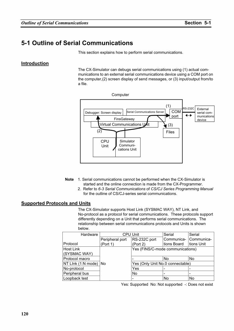
Outline of Serial Communications Section 5-1
120
5-1 Outline of Serial Communications This section explains how to perform serial communications.
Introduction
The CX-Simulator can debugs serial communications using (1) actual com-munications to an external serial communications device using a COM port on the computer,(2) screen display of send messages, or (3) input/output from/to a file.
Note 1. Serial communications cannot be performed when the CX-Simulator is
started and the online connection is made from the CX-Programmer. 2. Refer to 6-3 Serial Communications of CS/CJ Series Programming Manual
for the outline of CS/CJ-series serial communications. Supported Protocols and Units
The CX-Simulator supports Host Link (SYSMAC WAY), NT Link, and No-protocol as a protocol for serial communications. These protocols support differently depending on a Unit that performs serial communications. The relationship between serial communications protocols and Units is shown below.
CPU Unit Hardware
Protocol Peripheral port (Port 1)
RS-232C port (Port 2)
Serial Communica-tions Board
Serial Communica-tions Unit
Host Link (SYSMAC WAY)
Yes (FINS/C-mode communications)
Protocol macro - No No NT LInk (1:N mode) Yes (Only Unit No.0 connectable) No-protocol Yes - - Peripheral bus No - - Loopback test
No
- No No Yes: Supported No: Not supported -: Does not exist
Computer
Debugger: Screen display
FinsGateway
Simulator Communi-
cations Unit
CPU Unit
External serial com-munications device
RS-232C(1)
(3)
COM port
Files (2)Virtual Communications Unit
Serial Communications Server
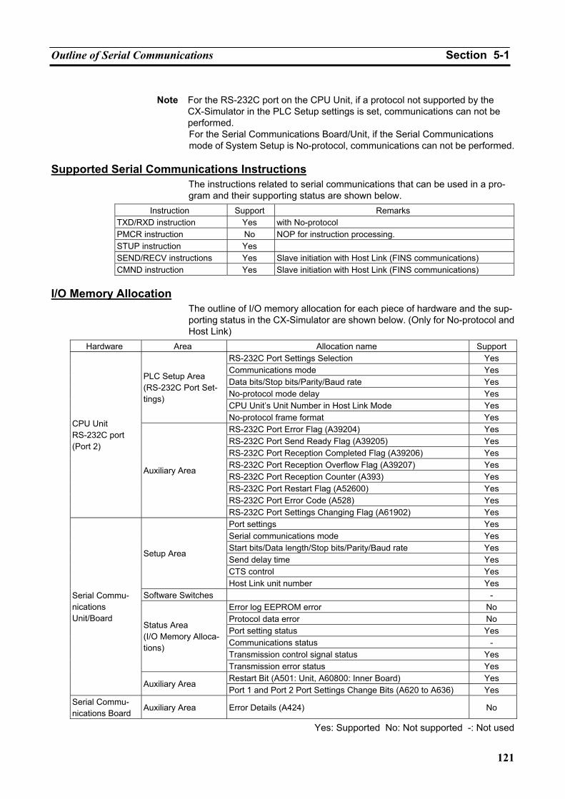
Outline of Serial Communications Section 5-1
121
Note For the RS-232C port on the CPU Unit, if a protocol not supported by the
CX-Simulator in the PLC Setup settings is set, communications can not be performed. For the Serial Communications Board/Unit, if the Serial Communications mode of System Setup is No-protocol, communications can not be performed.
Supported Serial Communications Instructions
The instructions related to serial communications that can be used in a pro-gram and their supporting status are shown below.
Instruction Support Remarks TXD/RXD instruction Yes with No-protocol PMCR instruction No NOP for instruction processing. STUP instruction Yes SEND/RECV instructions Yes Slave initiation with Host Link (FINS communications) CMND instruction Yes Slave initiation with Host Link (FINS communications)
I/O Memory Allocation
The outline of I/O memory allocation for each piece of hardware and the sup-porting status in the CX-Simulator are shown below. (Only for No-protocol and Host Link)
Hardware Area Allocation name Support RS-232C Port Settings Selection Yes Communications mode Yes Data bits/Stop bits/Parity/Baud rate Yes No-protocol mode delay Yes CPU Unit’s Unit Number in Host Link Mode Yes
PLC Setup Area (RS-232C Port Set-tings)
No-protocol frame format Yes RS-232C Port Error Flag (A39204) Yes RS-232C Port Send Ready Flag (A39205) Yes RS-232C Port Reception Completed Flag (A39206) Yes RS-232C Port Reception Overflow Flag (A39207) Yes RS-232C Port Reception Counter (A393) Yes RS-232C Port Restart Flag (A52600) Yes RS-232C Port Error Code (A528) Yes
CPU Unit RS-232C port (Port 2)
Auxiliary Area
RS-232C Port Settings Changing Flag (A61902) Yes Port settings Yes Serial communications mode Yes Start bits/Data length/Stop bits/Parity/Baud rate Yes Send delay time Yes CTS control Yes
Setup Area
Host Link unit number Yes Software Switches -
Error log EEPROM error No Protocol data error No Port setting status Yes Communications status - Transmission control signal status Yes
Status Area (I/O Memory Alloca-tions)
Transmission error status Yes Restart Bit (A501: Unit, A60800: Inner Board) Yes
Serial Commu-nications Unit/Board
Auxiliary Area Port 1 and Port 2 Port Settings Change Bits (A620 to A636) Yes
Serial Commu-nications Board
Auxiliary Area Error Details (A424) No
Yes: Supported No: Not supported -: Not used
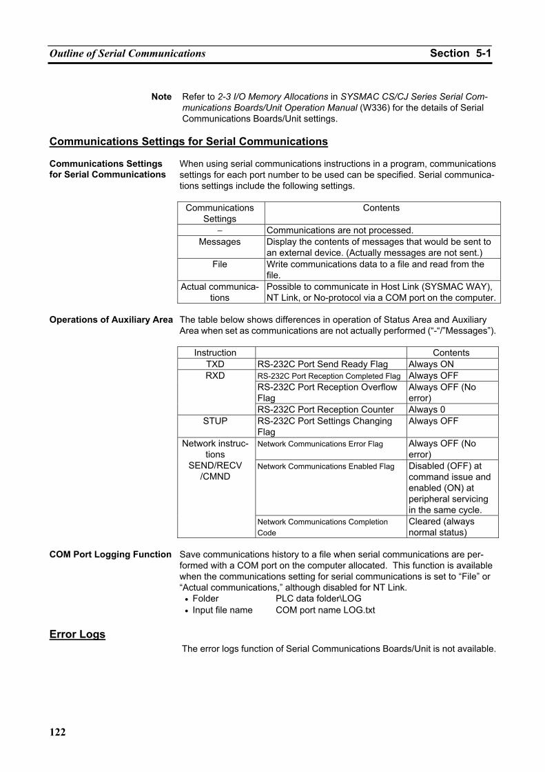
Outline of Serial Communications Section 5-1
122
Note Refer to 2-3 I/O Memory Allocations in SYSMAC CS/CJ Series Serial Com-
munications Boards/Unit Operation Manual (W336) for the details of Serial Communications Boards/Unit settings.
Communications Settings for Serial Communications Communications Settings for Serial Communications
When using serial communications instructions in a program, communications settings for each port number to be used can be specified. Serial communica-tions settings include the following settings.
Communications
Settings Contents
− Communications are not processed. Messages Display the contents of messages that would be sent to
an external device. (Actually messages are not sent.) File Write communications data to a file and read from the
file. Actual communica-
tions Possible to communicate in Host Link (SYSMAC WAY), NT Link, or No-protocol via a COM port on the computer.
Operations of Auxiliary Area The table below shows differences in operation of Status Area and Auxiliary
Area when set as communications are not actually performed (“-“/”Messages”).
Instruction Contents TXD RS-232C Port Send Ready Flag Always ON
RS-232C Port Reception Completed Flag Always OFF RS-232C Port Reception Overflow Flag
Always OFF (No error)
RXD
RS-232C Port Reception Counter Always 0 STUP RS-232C Port Settings Changing
Flag Always OFF
Network Communications Error Flag Always OFF (No error)
Network Communications Enabled Flag Disabled (OFF) at command issue and enabled (ON) at peripheral servicing in the same cycle.
Network instruc-tions
SEND/RECV /CMND
Network Communications Completion Code
Cleared (always normal status)
Save communications history to a file when serial communications are per-formed with a COM port on the computer allocated. This function is available when the communications setting for serial communications is set to “File” or “Actual communications,” although disabled for NT Link.
COM Port Logging Function
• Folder PLC data folder\LOG • Input file name COM port name LOG.txt Error Logs
The error logs function of Serial Communications Boards/Unit is not available.
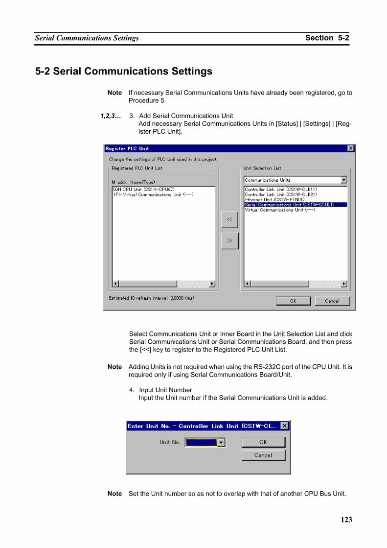
Serial Communications Settings Section 5-2
123
5-2 Serial Communications Settings
Note If necessary Serial Communications Units have already been registered, go to Procedure 5.
1,2,3… 3. Add Serial Communications Unit
Add necessary Serial Communications Units in [Status] | [Settings] | [Reg-ister PLC Unit].
Select Communications Unit or Inner Board in the Unit Selection List and click Serial Communications Unit or Serial Communications Board, and then press the [<<] key to register to the Registered PLC Unit List.
Note Adding Units is not required when using the RS-232C port of the CPU Unit. It is
required only if using Serial Communications Board/Unit.
4. Input Unit Number Input the Unit number if the Serial Communications Unit is added.
Note Set the Unit number so as not to overlap with that of another CPU Bus Unit.
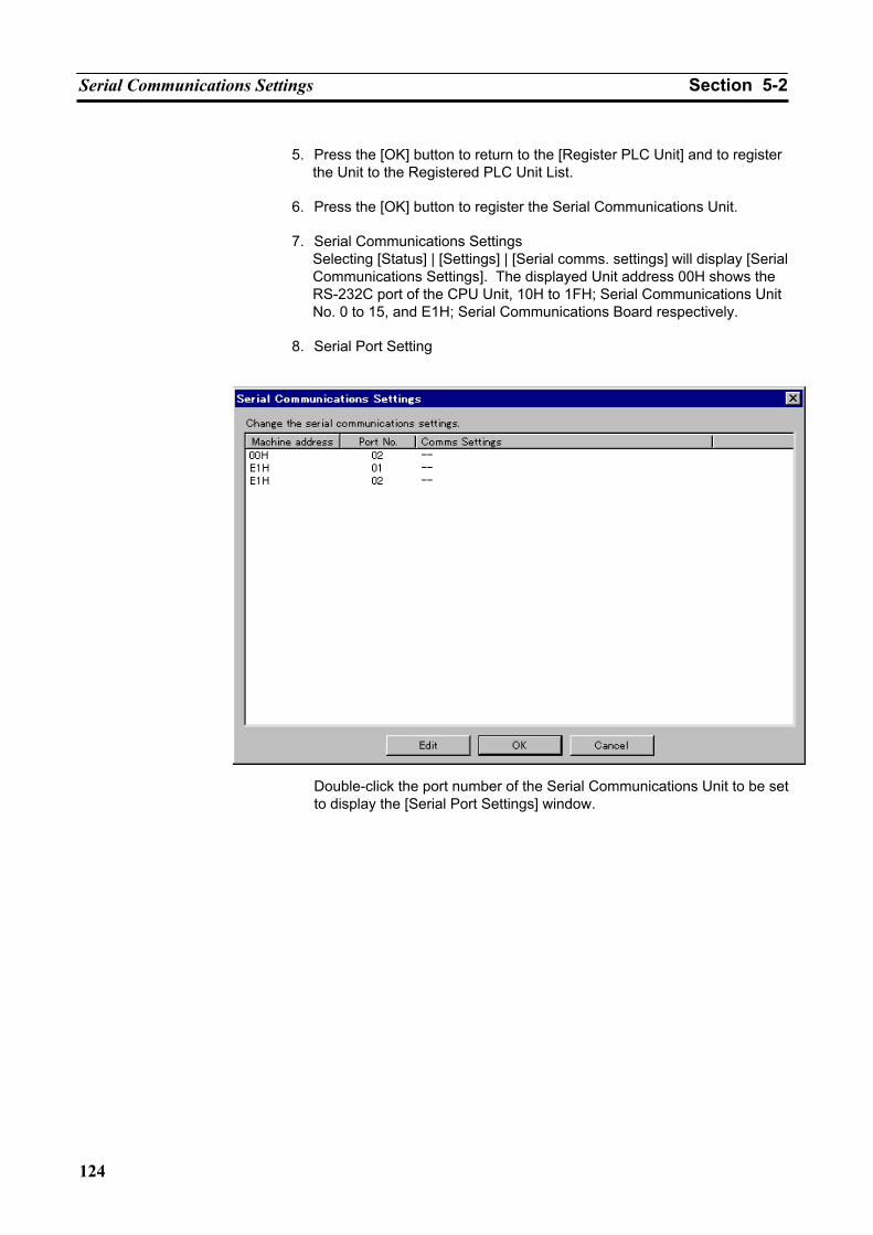
Serial Communications Settings Section 5-2
124
5. Press the [OK] button to return to the [Register PLC Unit] and to register
the Unit to the Registered PLC Unit List.
6. Press the [OK] button to register the Serial Communications Unit.
7. Serial Communications Settings Selecting [Status] | [Settings] | [Serial comms. settings] will display [Serial Communications Settings]. The displayed Unit address 00H shows the RS-232C port of the CPU Unit, 10H to 1FH; Serial Communications Unit No. 0 to 15, and E1H; Serial Communications Board respectively.
8. Serial Port Setting
Double-click the port number of the Serial Communications Unit to be set to display the [Serial Port Settings] window.
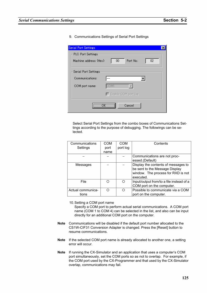
Serial Communications Settings Section 5-2
125
9. Communications Settings of Serial Port Settings
Select Serial Port Settings from the combo boxes of Communications Set-tings according to the purpose of debugging. The followings can be se-lected.
Communications
Settings COM port
name
COM port log
Contents
− − − Communications are not proc-essed.(Default)
Messages − − Display the contents of messages to be sent to the Message Display window. The process for RXD is not executed.
File Input/output from/to a file instead of a COM port on the computer.
Actual communica-tions
Possible to communicate via a COM port on the computer.
10. Setting a COM port name
Specify a COM port to perform actual serial communications. A COM port name (COM 1 to COM 4) can be selected in the list, and also can be input directly for an additional COM port on the computer.
Note Communications will be disabled if the default port number allocated to the
CS1W-CIF31 Conversion Adapter is changed. Press the [Reset] button to resume communications.
Note If the selected COM port name is already allocated to another one, a setting
error will occur.
Note If running the CX-Simulator and an application that uses a computer’s COM port simultaneously, set the COM ports so as not to overlap. For example, if the COM port used by the CX-Programmer and that used by the CX-Simulator overlap, communications may fail.
Serial Communications Settings Section 5-2
126
11. Press [OK] to exit the Serial Port Settings window and to return to Serial Communications Settings window.
12. Exit Serial Communications settings window
Repeat the procedures 5 to 9 as required. Press the [OK] button when completed.
13. System setup for serial communications
When an actual PLC performs serial communications, it is necessary to set communications parameters to the PLC’s I/O memory areas. Also for the CX-Simulator, use the CX-Programmer to set Serial Communications mode, Start bits, Data length, Stop bits, Parity, Baud rate, etc., according to the manuals for each Serial Communications Unit.
Note DIP switch setting for “RS-232C port communications parameters” (pin 5) is
fixed to “Use parameters set in the PLC Setup” (OFF). For CPU Unit’s RS-232C port (Port 2) settings, refer to 7-1-2 PC Setup in CS/CJ Series Operation Manual, and for Serial Communications Board/Unit settings, refer to 4-2 Setup Area Allocations in CS/CJ Series Serial Commu-nications Boards/Unit Operation Manual (W336).
Note When using the RS-232C port (Port 2) on the CPU Unit, if a protocol not sup-
ported by the CX-Simulator is set in PLC Setup, communications cannot be performed.
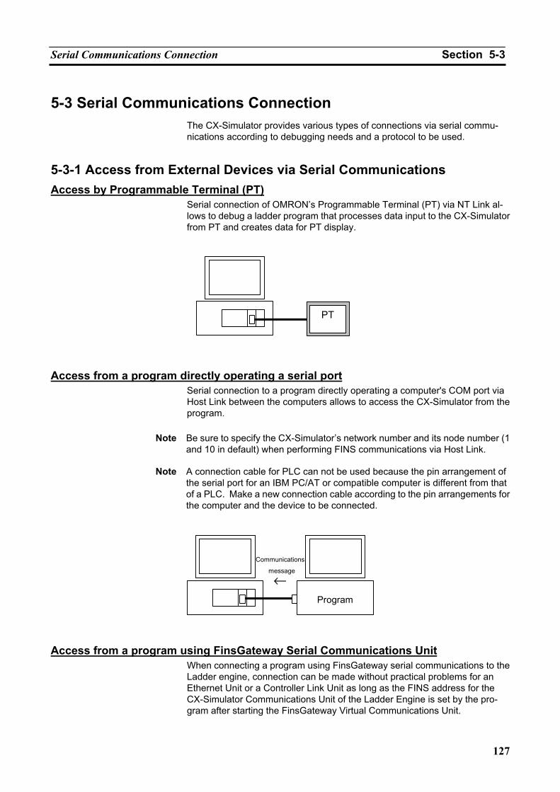
Serial Communications Connection Section 5-3
127
5-3 Serial Communications Connection The CX-Simulator provides various types of connections via serial commu-nications according to debugging needs and a protocol to be used.
5-3-1 Access from External Devices via Serial Communications Access by Programmable Terminal (PT)
Serial connection of OMRON’s Programmable Terminal (PT) via NT Link al-lows to debug a ladder program that processes data input to the CX-Simulator from PT and creates data for PT display.
Access from a program directly operating a serial port
Serial connection to a program directly operating a computer's COM port via Host Link between the computers allows to access the CX-Simulator from the program.
Note Be sure to specify the CX-Simulator’s network number and its node number (1
and 10 in default) when performing FINS communications via Host Link.
Note A connection cable for PLC can not be used because the pin arrangement of the serial port for an IBM PC/AT or compatible computer is different from that of a PLC. Make a new connection cable according to the pin arrangements for the computer and the device to be connected.
Access from a program using FinsGateway Serial Communications Unit
When connecting a program using FinsGateway serial communications to the Ladder engine, connection can be made without practical problems for an Ethernet Unit or a Controller Link Unit as long as the FINS address for the CX-Simulator Communications Unit of the Ladder Engine is set by the pro-gram after starting the FinsGateway Virtual Communications Unit.
PT
Program
Communications
message
←
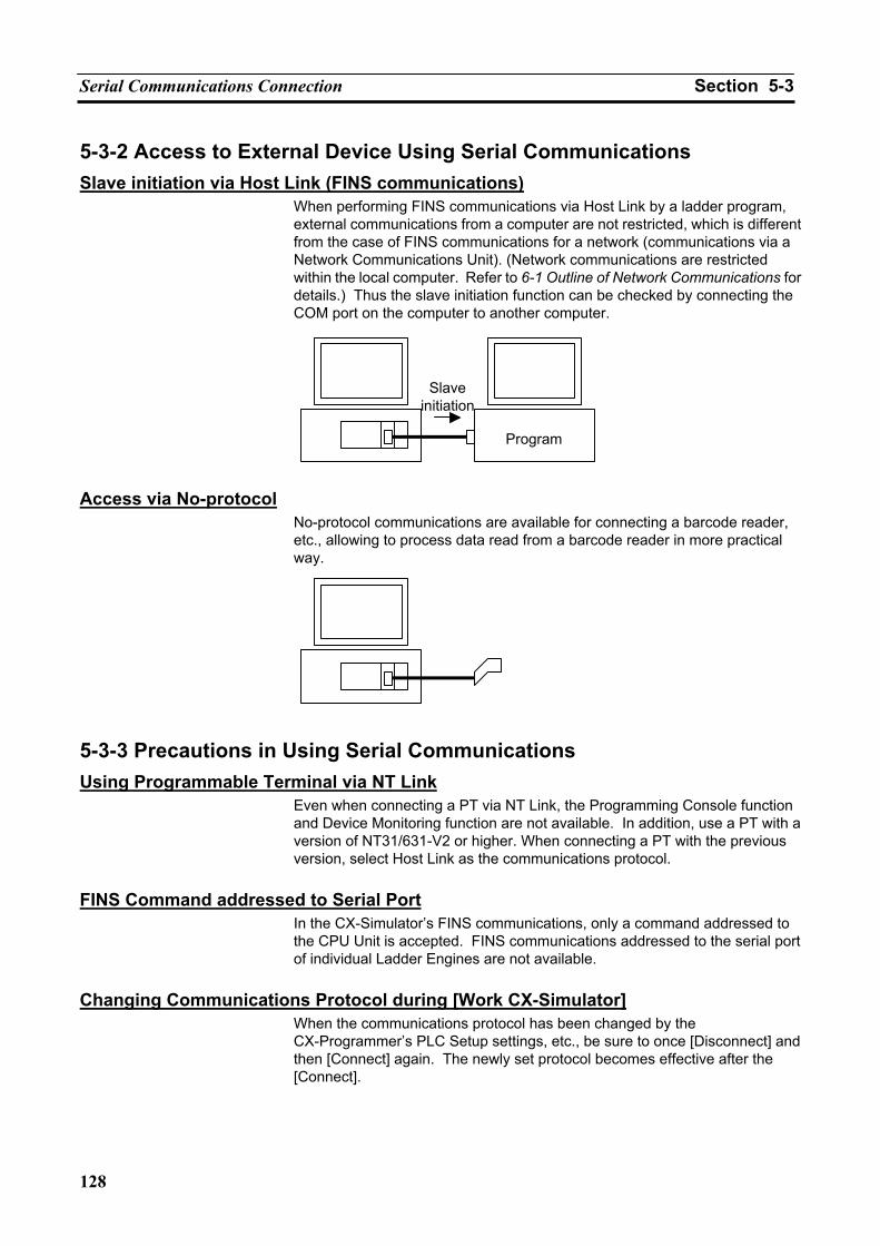
Serial Communications Connection Section 5-3
128
5-3-2 Access to External Device Using Serial Communications Slave initiation via Host Link (FINS communications)
When performing FINS communications via Host Link by a ladder program, external communications from a computer are not restricted, which is different from the case of FINS communications for a network (communications via a Network Communications Unit). (Network communications are restricted within the local computer. Refer to 6-1 Outline of Network Communications for details.) Thus the slave initiation function can be checked by connecting the COM port on the computer to another computer.
Access via No-protocol
No-protocol communications are available for connecting a barcode reader, etc., allowing to process data read from a barcode reader in more practical way.
5-3-3 Precautions in Using Serial Communications Using Programmable Terminal via NT Link
Even when connecting a PT via NT Link, the Programming Console function and Device Monitoring function are not available. In addition, use a PT with a version of NT31/631-V2 or higher. When connecting a PT with the previous version, select Host Link as the communications protocol.
FINS Command addressed to Serial Port
In the CX-Simulator’s FINS communications, only a command addressed to the CPU Unit is accepted. FINS communications addressed to the serial port of individual Ladder Engines are not available.
Changing Communications Protocol during [Work CX-Simulator]
When the communications protocol has been changed by the CX-Programmer’s PLC Setup settings, etc., be sure to once [Disconnect] and then [Connect] again. The newly set protocol becomes effective after the [Connect].
Program
Slave initiation
Serial Communications Connection Section 5-3
129
When Serial Communications on the CX-Simulator Become Disabled When Serial Communications on the CX-Simulator become disabled, for example, when the RS-232C Port Error Flag (A39204) in the Auxiliary area turns ON while executing serial communications on the CX-Simulator, either press [Reset] button in the [Debug Console], or once [Disconnect] and then [Connect] again.
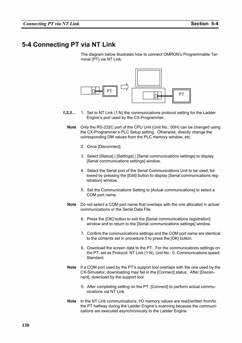
Connecting PT via NT Link Section 5-4
130
5-4 Connecting PT via NT Link The diagram below illustrates how to connect OMRON’s Programmable Ter-minal (PT) via NT Link.
1,2,3… 1. Set to NT Link (1:N) the communications protocol setting for the Ladder
Engine’s port used by the CX-Programmer.
Note Only the RS-232C port of the CPU Unit (Unit No.: 00H) can be changed using the CX-Programmer’s PLC Setup setting. Otherwise, directly change the corresponding DM values from the PLC memory window, etc.
2. Once [Disconnect].
3. Select [Status] | [Settings] | [Serial communications settings] to display
[Serial communications settings] window.
4. Select the Serial port of the Serial Communications Unit to be used, fol-lowed by pressing the [Edit] button to display [Serial communications reg-istration] window.
5. Set the Communications Setting to [Actual communications] to select a
COM port name.
Note Do not select a COM port name that overlaps with the one allocated in actual communications or the Serial Data File.
6. Press the [OK] button to exit the [Serial communications registration]
window and to return to the [Serial communications settings] window.
7. Confirm the communications settings and the COM port name are identical to the contents set in procedure 5 to press the [OK] button.
8. Download the screen data to the PT. For the communications settings on
the PT, set as Protocol: NT Link (1:N), Unit No.: 0, Communications speed: Standard.
Note If a COM port used by the PT’s support tool overlaps with the one used by the
CX-Simulator, downloading may fail in the [Connect] status. After [Discon-nect], download by the support tool.
9. After completing setting on the PT, [Connect] to perform actual commu-
nications via NT Link.
Note In the NT Link communications, I/O memory values are read/written from/to the PT halfway during the Ladder Engine’s scanning because the communi-cations are executed asynchronously to the Ladder Engine.
PTPT
Examples of Serial Communications Debugging Section 5-5
131
5-5 Examples of Serial Communications Debugging
5-5-1 Procedure for Debugging Serial Communications Instructions 1,2,3… 1. Set the communications settings of serial communications to "-" to debug
the portions unrelated to serial communications.
Display the [Serial Comm. Setting] window by [Status] | [Settings] | [Serial Comm. Setting]. Set the communications settings for all the Serial Communications Units to "-."
2. Set the communications settings of serial communications to "Messages"
to display send messages through actual serial communications. Check the contents of the send messages.
Display the [Serial Comm. Setting] window by [Status] | [Settings] | [Serial Comm. Setting]. Set the communications settings for the Serial Communications Units to be debugged to "Messages."
3. Set the communications settings of serial communications to "File" to debug the serial communications portion by file I/O instead of actual serial communications.
Display the [Serial Comm. Setting] window by [Status] | [Settings] | [Serial Comm. Setting]. Set the communications settings for the Serial Communications Units to be debugged to "File."
4. Set the communications settings of serial communications to "Actual communications." Connect the actual communications target to the computer’s COM port, and after confirming Setup for serial communica-tions with I/O Memory Allocation, debug operations with actual serial communications.
Display the [Serial Comm. Setting] window by [Status] | [Settings] | [Serial Comm. Setting]. Set the communications settings for the Serial Communications Units to be debugged to "Actual communications." Confirm the Setup of the Unit for serial communications with I/O Memory Allocation,
Caution Enabling serial communications function of the CX-Simulator may affect the operation of devices connected to the computer. When external devices are not being used, do not enable the serial communications function. Unex-pected operation of the external devices may cause an accident.
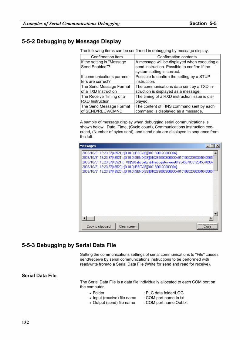
Examples of Serial Communications Debugging Section 5-5
132
5-5-2 Debugging by Message Display The following items can be confirmed in debugging by message display.
Confirmation item Confirmation contents If the setting is "Message Send Enabled"?
A message will be displayed when executing a send instruction. Possible to confirm if the system setting is correct.
If communications parame-ters are correct?
Possible to confirm the setting by a STUP instruction.
The Send Message Format of a TXD Instruction
The communications data sent by a TXD in-struction is displayed as a message.
The Receive Timing of a RXD Instruction
The timing of a RXD instruction issue is dis-played.
The Send Message Format of SEND/RECV/CMND
The content of FINS command sent by each command is displayed as a message.
A sample of message display when debugging serial communications is shown below. Date, Time, (Cycle count), Communications instruction exe-cuted, (Number of bytes sent), and send data are displayed in sequence from the left.
5-5-3 Debugging by Serial Data File Setting the communications settings of serial communications to "File" causes send/receive by serial communications instructions to be performed with read/write from/to a Serial Data File (Write for send and read for receive).
Serial Data File
The Serial Data File is a data file individually allocated to each COM port on the computer.
• Folder : PLC data folder\LOG • Input (receive) file name : COM port name In.txt • Output (send) file name : COM port name Out.txt
Examples of Serial Communications Debugging Section 5-5
133
The whole data in the file is read for a single receive operation. For send operation, send data is appended at the end of the file.
Use a commercial text editor or a binary editor to edit a Serial Data File. Creating and Using Serial Data Files
Example: Input (Receiving)
Use the following procedure to create and use a serial data file. 1,2,3… 1. Create a text file with a user-set name to be used for the receive data. 2. Input the receive data text in the text file created in step 1. 3. Copy the text input as receive data, and paste in the input (receive) file
(COM port name In.txt) under the Log Folder (LOG) in the PLC Data Folder. Text can also be input directly into an input (receive) file, omitting steps 1 and 2.
4. Save the input (receive) file. (The file’s update time will change, and be considered as a received file.)
5. All the data in the file is stored in the reception buffer of the virtual PLC. 6. Input is completed. This procedure can be used, for example, to receive data in the reception
buffer using the virtual PLC’s RXD instruction.
Note Read the whole data in the input (receive) file when the file update time changes, which is regarded as a receive operation.
Note For Host Link communications, a single issue of instruction causes a com-
mand send (write to the output file) and a response receive (read from the input file). In this case, it is necessary to create a response data in advance assuming a command to be sent.
Example of Debugging Program using Barcode reader
The followings show an example of debugging No-protocol communications using a Serial Data File.
1,2,3… 1. Display the [Serial Comm. Setting] window by [Status] | [Settings] | [Serial
Comm. Setting].
2. Select a serial port for the Serial Communications Unit to be used, fol-lowed by pressing [Edit] button to display [Serial Communications Regis-tration] window.
3. Set the communications settings to "File" to select a COM port name.
Note Select a COM port name that does not overlap with one allocated in actual
communications or another file. Also, a COM port name to be allocated to the Serial Data File can be one that does not actually exist.
4. Press the [OK] button to exit [Serial Communications Registration] win-
dow and to return to [Serial Communications Settings] window.
5. After confirming the communications settings and the COM port name are identical to the contents set in procedure 3, press the [OK] button.
6. Create receive data for debugging. Use a commercial text editor or a
binary editor to create data conforming to the format of data to be received from the barcode reader. Prepare multiple data according to debugging patterns.
Examples of Serial Communications Debugging Section 5-5
134
7. Copy the data file created in procedure 6 in the input file (COM port name In.txt).
8. Changing in the file update time causes automatic reception of data from
the input file.
9. Execute Step Run, etc. to confirm the process of data received.
10. Repeat the debugging procedures 7 to 9 depending on the contents of serial input data.
Note Escape sequences contained in the send/receive data are handled as ’\n’ (n is
a lower-case alphanumeric character.) in the file. For example, the delimiter for Host Link is ’\r’.
135
SECTION 6 Debugging Network Communications
6-1 Outline of Network Communications....................................................................................... 136 6-2 Network Communications Settings .......................................................................................... 139 6-3 Network Connection................................................................................................................. 142
6-3-1 Send FINS Commands to the External Devices via Network Communications .......... 142 6-3-2 Receive FINS Commands from the External Devices via Network Communications. 142 6-3-3 Precautions when Using Network Communications .................................................... 142
6-4 Example of Debugging Network Communications .................................................................. 143 6-4-1 Outline of Debugging Network Communications Instructions .................................... 143 6-4-2 Debugging with Display Messages .............................................................................. 144 6-4-3 Debugging with Local Communications...................................................................... 144
6-5 Available FINS Commands ...................................................................................................... 147 6-5-1 The List of Available FINS Commands ....................................................................... 147 6-5-2 Restrictions on FINS Commands ................................................................................. 148
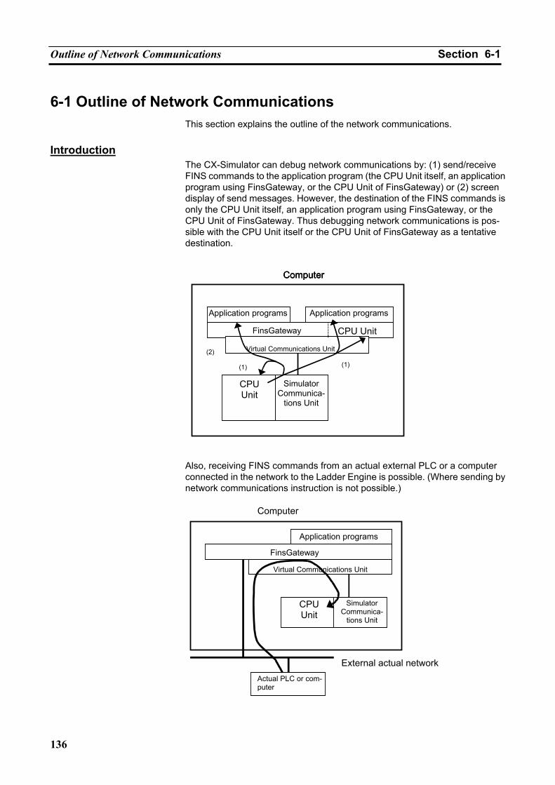
Outline of Network Communications Section 6-1
136
6-1 Outline of Network Communications This section explains the outline of the network communications.
Introduction
The CX-Simulator can debug network communications by: (1) send/receive FINS commands to the application program (the CPU Unit itself, an application program using FinsGateway, or the CPU Unit of FinsGateway) or (2) screen display of send messages. However, the destination of the FINS commands is only the CPU Unit itself, an application program using FinsGateway, or the CPU Unit of FinsGateway. Thus debugging network communications is pos-sible with the CPU Unit itself or the CPU Unit of FinsGateway as a tentative destination.
Also, receiving FINS commands from an actual external PLC or a computer connected in the network to the Ladder Engine is possible. (Where sending by network communications instruction is not possible.)
Computer
Computer
Application programs
FinsGateway
Simulator Communica-
tions Unit
CPU Unit
Virtual Communications Unit
Actual PLC or com-puter
External actual network
Computer Computer
(2)
Application programs Application programs
FinsGateway CPU Unit
Simulator Communica-
tions Unit
CPU Unit
Virtual Communications Unit (2)
(1) (1)
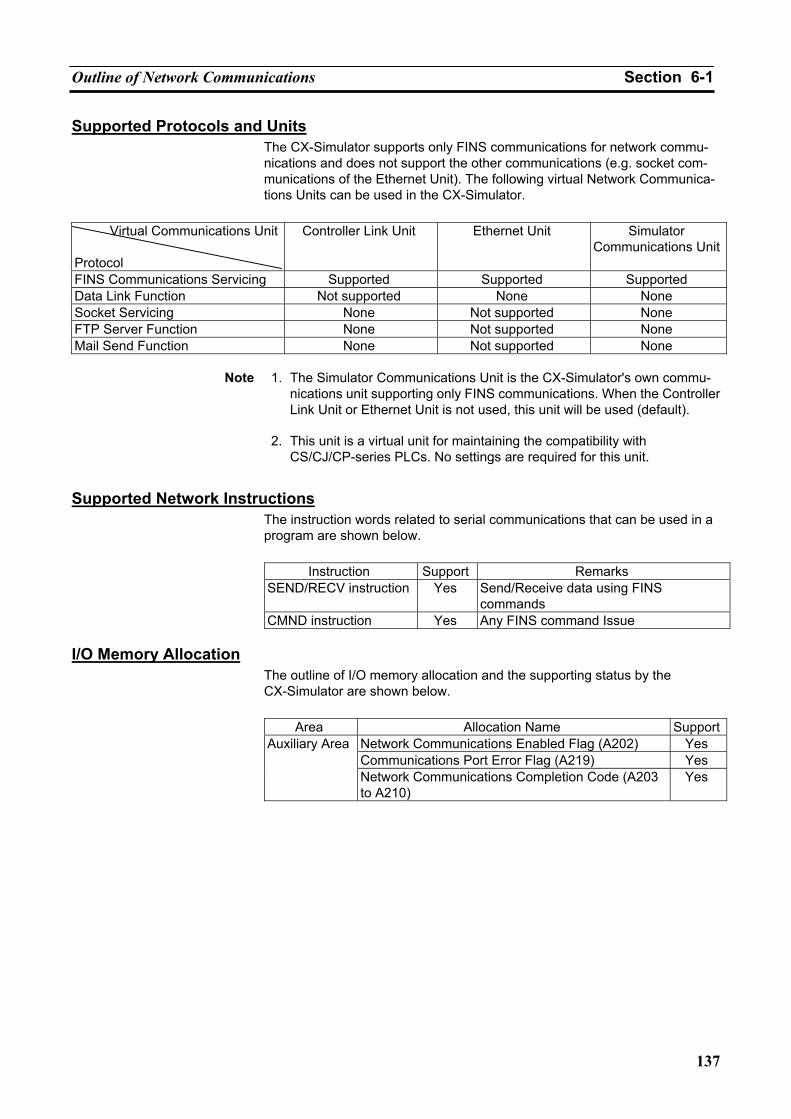
Outline of Network Communications Section 6-1
137
Supported Protocols and Units The CX-Simulator supports only FINS communications for network commu-nications and does not support the other communications (e.g. socket com-munications of the Ethernet Unit). The following virtual Network Communica-tions Units can be used in the CX-Simulator.
Virtual Communications Unit
Protocol
Controller Link Unit Ethernet Unit Simulator Communications Unit
FINS Communications Servicing Supported Supported Supported Data Link Function Not supported None None Socket Servicing None Not supported None FTP Server Function None Not supported None Mail Send Function None Not supported None
Note 1. The Simulator Communications Unit is the CX-Simulator's own commu-nications unit supporting only FINS communications. When the Controller Link Unit or Ethernet Unit is not used, this unit will be used (default).
2. This unit is a virtual unit for maintaining the compatibility with
CS/CJ/CP-series PLCs. No settings are required for this unit.
Supported Network Instructions The instruction words related to serial communications that can be used in a program are shown below.
Instruction Support Remarks
SEND/RECV instruction Yes Send/Receive data using FINS commands
CMND instruction Yes Any FINS command Issue I/O Memory Allocation
The outline of I/O memory allocation and the supporting status by the CX-Simulator are shown below.
Area Allocation Name Support
Network Communications Enabled Flag (A202) Yes Communications Port Error Flag (A219) Yes
Auxiliary Area
Network Communications Completion Code (A203 to A210)
Yes
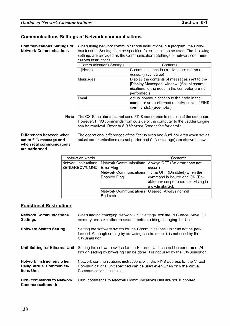
Outline of Network Communications Section 6-1
138
Communications Settings of Network communications Communications Settings of Network Communications
When using network communications instructions in a program, the Com-munications Settings can be specified for each Unit to be used. The following settings are provided as the Communications Settings of network communi-cations instructions.
Communications Settings Contents − (None) Communications instructions are not proc-
essed. (initial value) Messages Display the contents of messages sent to the
[Display Messages] window. (Actual commu-nications to the node in the computer are not performed.)
Local Actual communications to the node in the computer are performed (send/receive of FINS commands). (See note.)
Note The CX-Simulator does not send FINS commands to outside of the computer.
However, FINS commands from outside of the computer to the Ladder Engine can be received. Refer to 6-3 Network Connection for details.
Differences between when set to “−"/ message and when real communications are performed
The operational differences of the Status Area and Auxiliary Area when set as actual communications are not performed (“−"/ message) are shown below.
Instruction words Contents
Network CommunicationsError Flag
Always OFF (An error does not occur.)
Network CommunicationsEnabled Flag
Turns OFF (Disabled) when the command is issued and ON (En-abled) when peripheral servicing in a cycle started.
Network instructionsSEND/RECV/CMND
Network CommunicationsEnd code
Cleared (Always normal)
Functional Restrictions Network Communications Settings
When adding/changing Network Unit Settings, exit the PLC once. Save I/O memory and take other measures before adding/changing the Unit.
Software Switch Setting Setting the software switch for the Communications Unit can not be per-formed. Although setting by browsing can be done, it is not used by the CX-Simulator.
Unit Setting for Ethernet Unit Setting the software switch for the Ethernet Unit can not be performed. Al-though setting by browsing can be done, it is not used by the CX-Simulator.
Network Instructions when Using Virtual Communica-tions Unit
Network communications instructions with the FINS address for the Virtual Communications Unit specified can be used even when only the Virtual Communications Unit is set.
FINS commands to Network Communications Unit
FINS commands to Network Communications Unit are not supported.
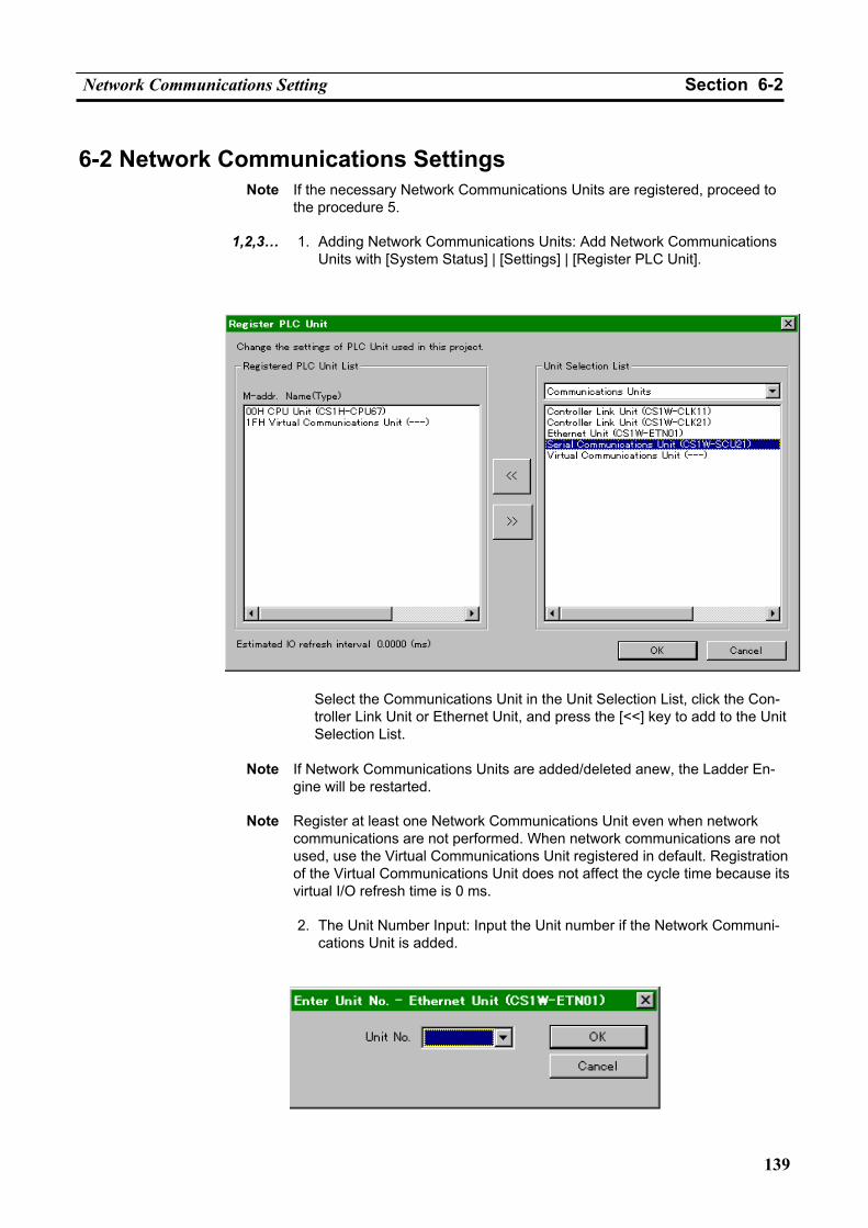
Network Communications Setting Section 6-2
139
6-2 Network Communications Settings Note If the necessary Network Communications Units are registered, proceed to
the procedure 5.
1,2,3… 1. Adding Network Communications Units: Add Network Communications Units with [System Status] | [Settings] | [Register PLC Unit].
Select the Communications Unit in the Unit Selection List, click the Con-troller Link Unit or Ethernet Unit, and press the [<<] key to add to the Unit Selection List.
Note If Network Communications Units are added/deleted anew, the Ladder En-gine will be restarted.
Note Register at least one Network Communications Unit even when network
communications are not performed. When network communications are not used, use the Virtual Communications Unit registered in default. Registration of the Virtual Communications Unit does not affect the cycle time because its virtual I/O refresh time is 0 ms.
2. The Unit Number Input: Input the Unit number if the Network Communi-
cations Unit is added.
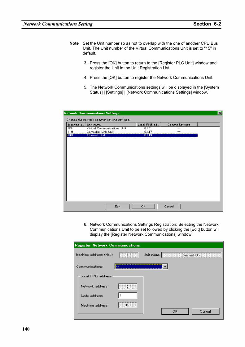
Network Communications Setting Section 6-2
140
Note Set the Unit number so as not to overlap with the one of another CPU Bus
Unit. The Unit number of the Virtual Communications Unit is set to "15" in default.
3. Press the [OK] button to return to the [Register PLC Unit] window and
register the Unit in the Unit Registration List.
4. Press the [OK] button to register the Network Communications Unit.
5. The Network Communications settings will be displayed in the [System Status] | [Settings] | [Network Communications Settings] window.
6. Network Communications Settings Registration: Selecting the Network
Communications Unit to be set followed by clicking the [Edit] button will display the [Register Network Communications] window.
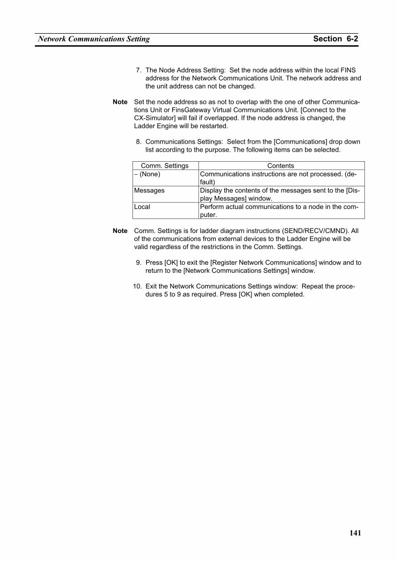
Network Communications Setting Section 6-2
141
7. The Node Address Setting: Set the node address within the local FINS
address for the Network Communications Unit. The network address and the unit address can not be changed.
Note Set the node address so as not to overlap with the one of other Communica-
tions Unit or FinsGateway Virtual Communications Unit. [Connect to the CX-Simulator] will fail if overlapped. If the node address is changed, the Ladder Engine will be restarted.
8. Communications Settings: Select from the [Communications] drop down
list according to the purpose. The following items can be selected.
Comm. Settings Contents − (None) Communications instructions are not processed. (de-
fault) Messages Display the contents of the messages sent to the [Dis-
play Messages] window. Local Perform actual communications to a node in the com-
puter.
Note Comm. Settings is for ladder diagram instructions (SEND/RECV/CMND). All of the communications from external devices to the Ladder Engine will be valid regardless of the restrictions in the Comm. Settings.
9. Press [OK] to exit the [Register Network Communications] window and to
return to the [Network Communications Settings] window.
10. Exit the Network Communications Settings window: Repeat the proce-dures 5 to 9 as required. Press [OK] when completed.
Network Connection Section 6-3
142
6-3 Network Connection
6-3-1 Send FINS Commands to the External Devices via Network Com-munications
FINS commands by the Network Communications instruction of the CX-Simulator can not be sent to the outside of the computer due to the CX-Simulator's restrictions.
FINS commands by the Network Communications instruction can be sent only within the computer. Therefore, communications with an application program using FinsGateway on the computer or the CPU Unit of FinsGateway are possible.
6-3-2 Receive FINS Commands from the External Devices via Network Communications
When sending FINS commands from the external devices to the Ladder En-gine via Network Communications, there are no special restrictions. The same network connection as actual CS/CJ/CP-series PLCs can be performed.
Create the Routing Table
The following operation is required because the network used by the CX-Simulator is different from the one connected to external devices. • Set the routing table for FinsGateway of the computer. • Set the relay network table for the Ladder Engine.
Note For instructions on setting the routing tables, refer to Section 3 of the CX-Integrator Operation Manual (W464).
6-3-3 Precautions when Using Network Communications Duplicate FINS Address
If the node address for the network communications unit of the Ladder Engine overlaps with the one of the FinsGateway Virtual Communications Unit when [Connect], communications can not be performed. To avoid this situation, change the FINS node address for either the network communications unit of the Ladder Engine or for the FinsGateway Virtual Communications Unit.
Update the Routing Table
Do not transfer the routing table (local network table) to the Ladder Engine. Doing so may disable an access from external devices depending on the set-ting contents of the own network table.
Even when the file saved by the other PLC is read, a similar trouble may occur depending on the setting contents of the PLC routing table.
If an access from external devices is disabled, perform [Disconnect] and then [Connect]. The routing table (local network table) will automatically be changed and an access from external devices will be enabled.
When reconnecting, set the FINS address displayed in the Guide to Connect of the [Work CX-Simulator] window to the CX-Programmer.
The relay network table will not be changed automatically. Set the relay net-work table as required.
Example of Debugging Network Communications Section 6-4
143
6-4 Example of Debugging Network Communications
6-4-1 Outline of Debugging Network Communications Instructions 1,2,3… 1. Set the Communications settings as "-" to debug a part unrelated to the
network.
• Select [System status] | [Settings] | [Network Communications Set-tings] to display the [Network Communications Settings] window.
• Set the Communications settings as "-" for all communications units.
2. Set the Communications settings as "Messages" for displaying the FINS commands to check the contents of the messages.
• Select [System status] | [Settings] | [Network Communications Set-
tings] to display the [Network Communications Settings] window. • Set the Communications settings as "Messages" for the communica-
tions unit to be debugged.
3. Set the Communications settings as "Local" followed by issuing SEND/RECV instructions to the CPU Unit of FinsGateway to check the FINS communications (only for DM and CIO).
• Select [System status] | [Settings] | [Network Communications Set-
tings] to display the [Network Communications Settings] window. • Set the Communications settings as "Local" for the communications
unit to be debugged. • Change the FINS address for the control data of SEND/RECV in-
struction to the one for the CPU Unit of FinsGateway.
Note Confirm that the target area is not used by other application programs when using a SEND instruction to the CPU Unit of FinsGateway.
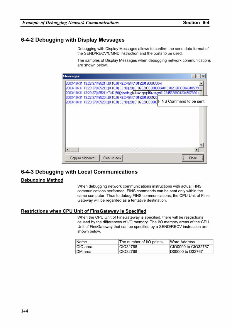
Example of Debugging Network Communications Section 6-4
144
6-4-2 Debugging with Display Messages Debugging with Display Messages allows to confirm the send data format of the SEND/RECV/CMND instruction and the ports to be used.
The samples of Display Messages when debugging network communications are shown below.
6-4-3 Debugging with Local Communications Debugging Method
When debugging network communications instructions with actual FINS communications performed, FINS commands can be sent only within the same computer. Thus to debug FINS communications, the CPU Unit of Fins-Gateway will be regarded as a tentative destination.
Restrictions when CPU Unit of FinsGateway Is Specified
When the CPU Unit of FinsGateway is specified, there will be restrictions caused by the differences of I/O memory. The I/O memory areas of the CPU Unit of FinsGateway that can be specified by a SEND/RECV instruction are shown below.
Name The number of I/O points Word Address CIO area CIO32768 CIO0000 to CIO32767 DM area CIO32768 D00000 to D32767
FINS Command to be sent
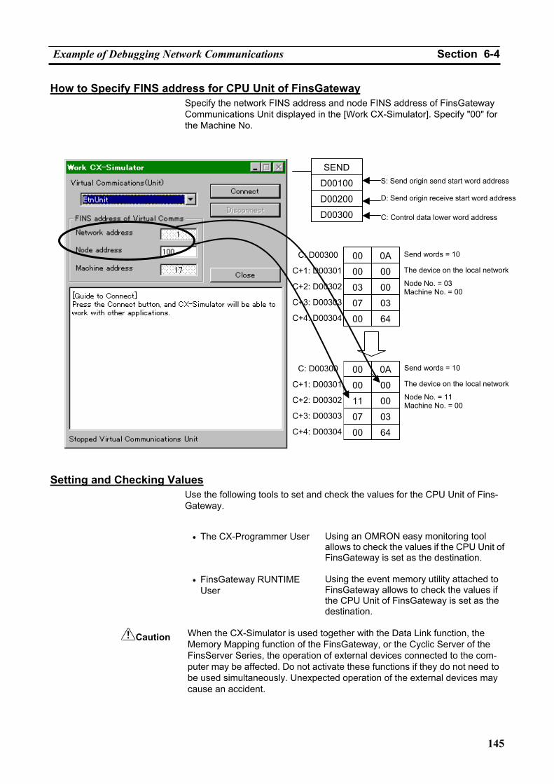
Example of Debugging Network Communications Section 6-4
145
How to Specify FINS address for CPU Unit of FinsGateway Specify the network FINS address and node FINS address of FinsGateway Communications Unit displayed in the [Work CX-Simulator]. Specify "00" for the Machine No.
Setting and Checking Values
Use the following tools to set and check the values for the CPU Unit of Fins-Gateway.
• The CX-Programmer User Using an OMRON easy monitoring tool
allows to check the values if the CPU Unit of FinsGateway is set as the destination.
• FinsGateway RUNTIME User
Using the event memory utility attached to FinsGateway allows to check the values if the CPU Unit of FinsGateway is set as the destination.
Caution When the CX-Simulator is used together with the Data Link function, the
Memory Mapping function of the FinsGateway, or the Cyclic Server of the FinsServer Series, the operation of external devices connected to the com-puter may be affected. Do not activate these functions if they do not need to be used simultaneously. Unexpected operation of the external devices may cause an accident.
SEND
D00100
D00300
D00200
S: Send origin send start word address
D: Send origin receive start word address
C: Control data lower word address
C: D00300
C+1: D00301
C+3: D00303
C+2: D00302
C+4: D00304
00
00
07
03
00
0A
00
03
00
64
Send words = 10
The device on the local network
Node No. = 03 Machine No. = 00
00
00
07
11
00
0A
00
03
00
64
C: D00300
C+1: D00301
C+3: D00303
C+2: D00302
C+4: D00304
Send words = 10
The device on the local network
Node No. = 11 Machine No. = 00

Example of Debugging Network Communications Section 6-4
146
Note Refer to FinsGateway Version2 RUNTIME Operation Manual for FinsGate-
way data link setting. Refer to the operation manuals attached to the hardware such as Controller Link support board for data link function itself. Refer to Section 5 FinsServer Series Common Functions Cyclic Server of FinsServer Series Handbook attached to FSV-Comm or DataFlowNavi for Access for the Cyclic Server of FinsServer Series.
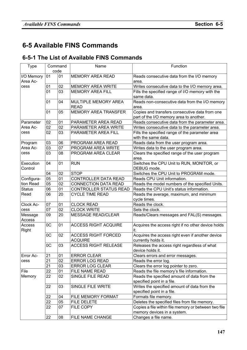
Available FINS Commands Section 6-5
147
6-5 Available FINS Commands
6-5-1 The List of Available FINS Commands Type Command
code Name Function
01 01 MEMORY AREA READ Reads consecutive data from the I/O memory area.
01 02 MEMORY AREA WRITE Writes consecutive data to the I/O memory area. 01 03 MEMORY AREA FILL Fills the specified range of I/O memory with the
same data. 01 04 MULTIPLE MEMORY AREA
READ Reads non-consecutive data from the I/O memory area.
I/O Memory Area Ac-cess
01 05 MEMORY AREA TRANSFER Copies and transfers consecutive data from one part of the I/O memory area to another.
02 01 PARAMETER AREA READ Reads consecutive data from the parameter area.02 02 PARAMETER AREA WRITE Writes consecutive data to the parameter area.
Parameter Area Ac-cess 02 03 PARAMETER AREA FILL Fills the specified range of the parameter area
with the same data. 03 06 PROGRAM AREA READ Reads data from the user program area. 03 07 PROGRAM AREA WRITE Writes data to the user program area.
Program Area Ac-cess 03 08 PROGRAM AREA CLEAR Clears the specified range of the user program
area. 04 01 RUN Switches the CPU Unit to RUN, MONITOR, or
DEBUG mode. Execution Control
04 02 STOP Switches the CPU Unit to PROGRAM mode. 05 01 CONTROLLER DATA READ Reads CPU Unit information. Configura-
tion Read 05 02 CONNECTION DATA READ Reads the model numbers of the specified Units. 06 01 CONTROLLER STATUS READ Reads the CPU Unit’s status information. Status
Read 06 20 CYCLE TIME READ Reads the average, maximum, and minimum cycle times.
07 01 CLOCK READ Reads the clock. Clock Ac-cess 07 02 CLOCK WRITE Sets the clock. Message Access
09 20 MESSAGE READ/CLEAR Reads/Clears messages and FAL(S) messages.
0C 01 ACCESS RIGHT ACQUIRE Acquires the access right if no other device holds it.
0C 02 ACCESS RIGHT FORCED ACQUIRE
Acquires the access right even if another device currently holds it.
Access Right
0C 03 ACCESS RIGHT RELEASE Releases the access right regardless of what device holds it.
21 01 ERROR CLEAR Clears errors and error messages. 21 02 ERROR LOG READ Reads the error log.
Error Ac-cess
21 03 ERROR LOG CLEAR Clears the error log pointer to zero. 22 01 FILE NAME READ Reads the file memory’s file information. 22 02 SINGLE FILE READ Reads the specified amount of data from the
specified point in a file. 22 03 SINGLE FILE WRITE Writes the specified amount of data from the
specified point in a file. 22 04 FILE MEMORY FORMAT Formats file memory. 22 05 FILE DELETE Deletes the specified files from file memory. 22 07 FILE COPY Copies a file within file memory or between two file
memory devices in a system.
File Memory
22 08 FILE NAME CHANGE Changes a file name.
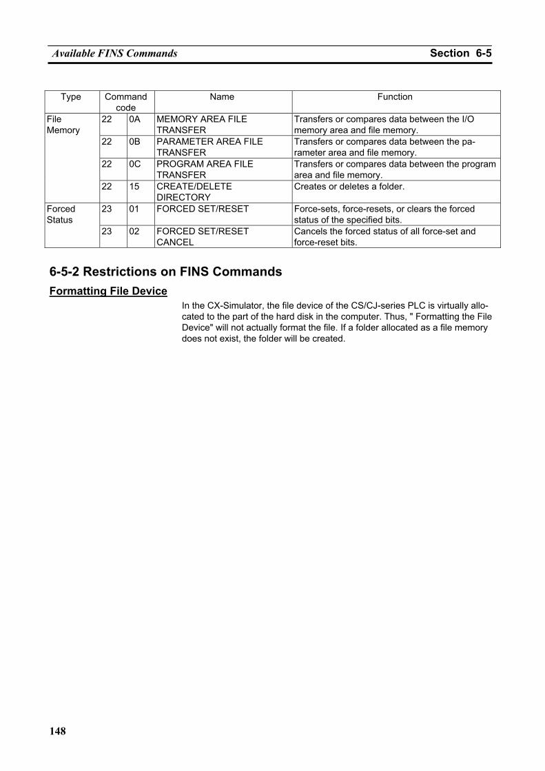
Available FINS Commands Section 6-5
148
Type Command
code Name Function
22 0A MEMORY AREA FILE TRANSFER
Transfers or compares data between the I/O memory area and file memory.
22 0B PARAMETER AREA FILE TRANSFER
Transfers or compares data between the pa-rameter area and file memory.
22 0C PROGRAM AREA FILE TRANSFER
Transfers or compares data between the program area and file memory.
File Memory
22 15 CREATE/DELETE DIRECTORY
Creates or deletes a folder.
23 01 FORCED SET/RESET Force-sets, force-resets, or clears the forced status of the specified bits.
Forced Status
23 02 FORCED SET/RESET CANCEL
Cancels the forced status of all force-set and force-reset bits.
6-5-2 Restrictions on FINS Commands Formatting File Device
In the CX-Simulator, the file device of the CS/CJ-series PLC is virtually allo-cated to the part of the hard disk in the computer. Thus, " Formatting the File Device" will not actually format the file. If a folder allocated as a file memory does not exist, the folder will be created.
149
SECTION 7 Connection with Application Programs
7-1 Outline of Connection............................................................................................................... 150 7-1-1 What is Connection with Application? ........................................................................ 150
7-2 Connection with Application Programs.................................................................................... 151 7-2-1 Connection Methods..................................................................................................... 151 7-2-2 Coexist in the Same Computer ..................................................................................... 151 7-2-3 Connection via Network............................................................................................... 153
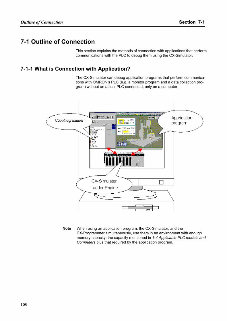
Outline of Connection Section 7-1
150
7-1 Outline of Connection This section explains the methods of connection with applications that perform communications with the PLC to debug them using the CX-Simulator.
7-1-1 What is Connection with Application? The CX-Simulator can debug application programs that perform communica-tions with OMRON's PLC (e.g. a monitor program and a data collection pro-gram) without an actual PLC connected, only on a computer.
Note When using an application program, the CX-Simulator, and the
CX-Programmer simultaneously, use them in an environment with enough memory capacity: the capacity mentioned in 1-4 Applicable PLC models and Computers plus that required by the application program.
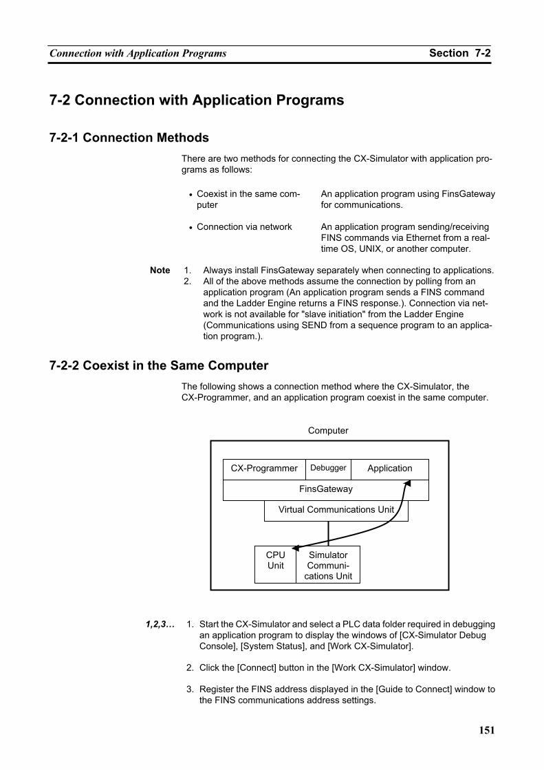
Connection with Application Programs Section 7-2
151
7-2 Connection with Application Programs
7-2-1 Connection Methods There are two methods for connecting the CX-Simulator with application pro-grams as follows:
• Coexist in the same com-
puter An application program using FinsGateway for communications.
• Connection via network An application program sending/receiving FINS commands via Ethernet from a real-time OS, UNIX, or another computer.
Note 1. Always install FinsGateway separately when connecting to applications.
2. All of the above methods assume the connection by polling from an application program (An application program sends a FINS command and the Ladder Engine returns a FINS response.). Connection via net-work is not available for "slave initiation" from the Ladder Engine (Communications using SEND from a sequence program to an applica-tion program.).
7-2-2 Coexist in the Same Computer The following shows a connection method where the CX-Simulator, the CX-Programmer, and an application program coexist in the same computer.
1,2,3… 1. Start the CX-Simulator and select a PLC data folder required in debugging
an application program to display the windows of [CX-Simulator Debug Console], [System Status], and [Work CX-Simulator].
2. Click the [Connect] button in the [Work CX-Simulator] window.
3. Register the FINS address displayed in the [Guide to Connect] window to
the FINS communications address settings.
Computer
CX-Programmer Debugger Application
FinsGateway
Virtual Communications Unit
CPUUnit
Simulator Communi-
cations Unit
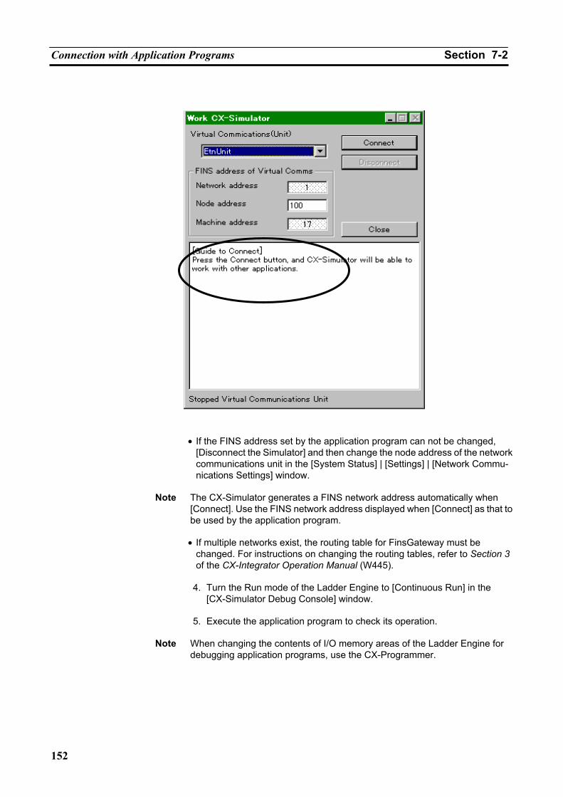
Connection with Application Programs Section 7-2
152
• If the FINS address set by the application program can not be changed,
[Disconnect the Simulator] and then change the node address of the network communications unit in the [System Status] | [Settings] | [Network Commu-nications Settings] window.
Note The CX-Simulator generates a FINS network address automatically when
[Connect]. Use the FINS network address displayed when [Connect] as that to be used by the application program.
• If multiple networks exist, the routing table for FinsGateway must be
changed. For instructions on changing the routing tables, refer to Section 3 of the CX-Integrator Operation Manual (W445).
4. Turn the Run mode of the Ladder Engine to [Continuous Run] in the
[CX-Simulator Debug Console] window.
5. Execute the application program to check its operation.
Note When changing the contents of I/O memory areas of the Ladder Engine for debugging application programs, use the CX-Programmer.
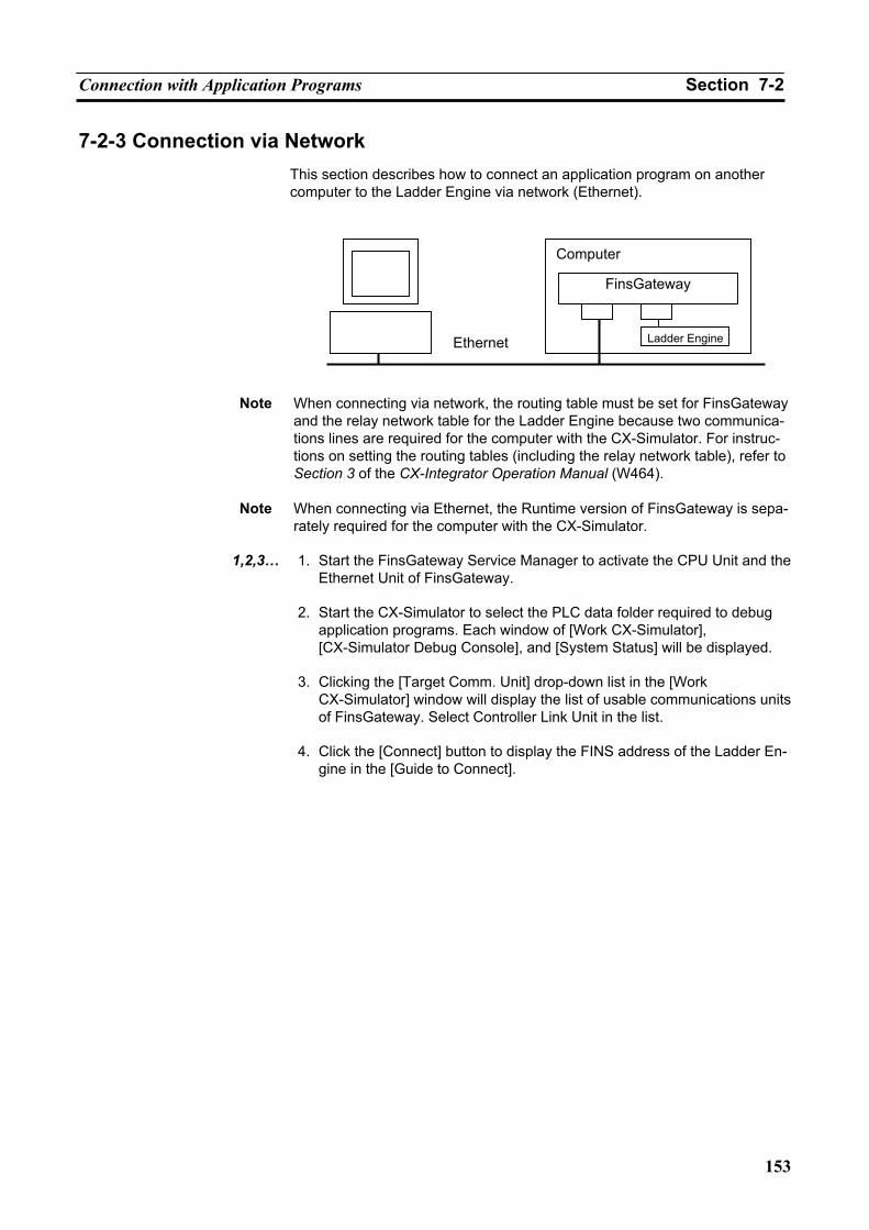
Connection with Application Programs Section 7-2
153
7-2-3 Connection via Network This section describes how to connect an application program on another computer to the Ladder Engine via network (Ethernet).
Note When connecting via network, the routing table must be set for FinsGateway
and the relay network table for the Ladder Engine because two communica-tions lines are required for the computer with the CX-Simulator. For instruc-tions on setting the routing tables (including the relay network table), refer to Section 3 of the CX-Integrator Operation Manual (W464).
Note When connecting via Ethernet, the Runtime version of FinsGateway is sepa-rately required for the computer with the CX-Simulator.
1,2,3… 1. Start the FinsGateway Service Manager to activate the CPU Unit and the
Ethernet Unit of FinsGateway.
2. Start the CX-Simulator to select the PLC data folder required to debug application programs. Each window of [Work CX-Simulator], [CX-Simulator Debug Console], and [System Status] will be displayed.
3. Clicking the [Target Comm. Unit] drop-down list in the [Work
CX-Simulator] window will display the list of usable communications units of FinsGateway. Select Controller Link Unit in the list.
4. Click the [Connect] button to display the FINS address of the Ladder En-
gine in the [Guide to Connect].
Computer
FinsGateway
Ethernet Ladder Engine
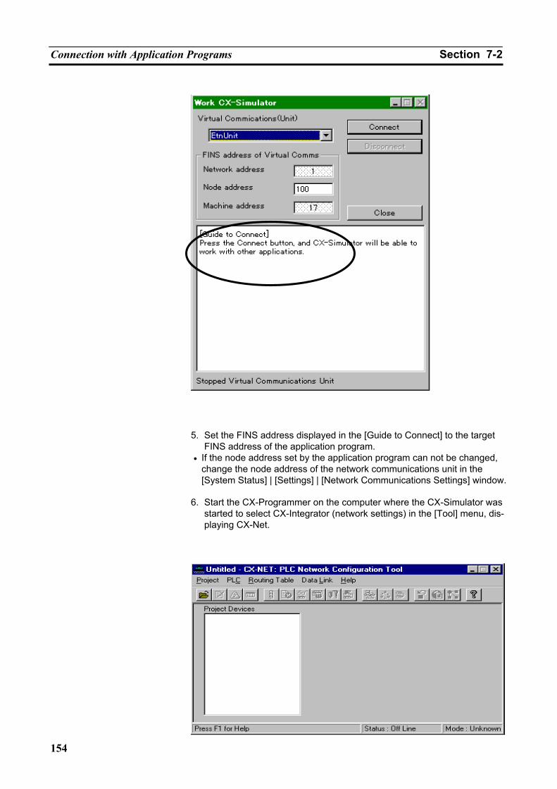
Connection with Application Programs Section 7-2
154
5. Set the FINS address displayed in the [Guide to Connect] to the target
FINS address of the application program. • If the node address set by the application program can not be changed,
change the node address of the network communications unit in the [System Status] | [Settings] | [Network Communications Settings] window.
6. Start the CX-Programmer on the computer where the CX-Simulator was
started to select CX-Integrator (network settings) in the [Tool] menu, dis-playing CX-Net.
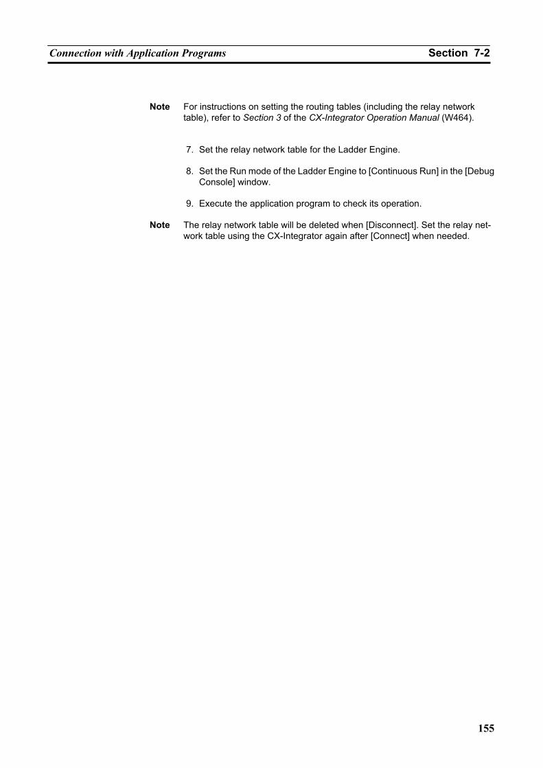
Connection with Application Programs Section 7-2
155
Note For instructions on setting the routing tables (including the relay network table), refer to Section 3 of the CX-Integrator Operation Manual (W464).
7. Set the relay network table for the Ladder Engine.
8. Set the Run mode of the Ladder Engine to [Continuous Run] in the [Debug Console] window.
9. Execute the application program to check its operation.
Note The relay network table will be deleted when [Disconnect]. Set the relay net-
work table using the CX-Integrator again after [Connect] when needed.

Connection with Application Programs Section 7-2
156
157
SECTION 8 Debugging Using Virtual External Inputs
8-1 Outline of Virtual External Input Function............................................................................... 158 8-1-1 Outline of Virtual External Input Function .................................................................. 158
8-2 Debugging Using Virtual External Inputs ................................................................................ 159 8-2-1 Outline of Debugging Using Virtual External Inputs................................................... 159
8-3 Generating Virtual External Inputs........................................................................................... 162 8-3-1 Command Log.............................................................................................................. 162 8-3-2 Data Trace File ............................................................................................................. 166 8-3-3 Data Replay File (CSV-format text file) ...................................................................... 167 8-3-4 Multipoint Data Collection Tool .................................................................................. 169 8-3-5 Messages Displayed in the Error history...................................................................... 172 8-3-6 I/O Condition Expressions ........................................................................................... 172 8-3-7 Ladder Program for Debugging ................................................................................... 175
8-4 Running by Virtual External Inputs.......................................................................................... 176 8-4-1 Running by Virtual External Inputs ............................................................................. 176 8-4-2 How to Run by Data Replay Tool ................................................................................ 176 8-4-3 Replay Using the I/O Condition Tool .......................................................................... 180 8-4-4 How to Replay Using the Program Area for Debugging.............................................. 182
8-5 Checking the Result .................................................................................................................. 184 8-5-1 Checking by Time Chart Monitor of the CX-Programmer .......................................... 184 8-5-2 Checking with Graphing by Excel Using the Data Replay File ................................... 185
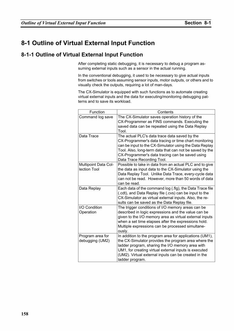
Outline of Virtual External Input Function Section 8-1
158
8-1 Outline of Virtual External Input Function
8-1-1 Outline of Virtual External Input Function After completing static debugging, it is necessary to debug a program as-suming external inputs such as a sensor in the actual running.
In the conventional debugging, it used to be necessary to give actual inputs from switches or tools assuming sensor inputs, motor outputs, or others and to visually check the outputs, requiring a lot of man-days.
The CX-Simulator is equipped with such functions as to automate creating virtual external inputs and the data for executing/monitoring debugging pat-terns and to save its workload.
Function Contents
Command log save The CX-Simulator saves operation history of the CX-Programmer as FINS commands. Executing the saved data can be repeated using the Data Replay Tool.
Data Trace The actual PLC's data trace data saved by the CX-Programmer's data tracing or time chart monitoring can be input to the CX-Simulator using the Data Replay Tool. Also, long-term data that can not be saved by the CX-Programmer's data tracing can be saved using Data Trace Recording Tool.
Multipoint Data Col-lection Tool
Possible to take in data from an actual PLC and to give the data as input data to the CX-Simulator using the Data Replay Tool. Unlike Data Trace, every-cycle data can not be read. However, more than 50 words of data can be read.
Data Replay Each data of the command log (.flg), the Data Trace file (.cdt), and Data Replay file (.cvs) can be input to the CX-Simulator as virtual external inputs. Also, the re-sults can be saved as the Data Replay file.
I/O Condition Operation
The trigger conditions of I/O memory areas can be described in logic expressions and the value can be given to the I/O memory area as virtual external inputs when a set time elapses after the expressions hold. Multiple expressions can be processed simultane-ously.
Program area for debugging (UM2)
In addition to the program area for applications (UM1), the CX-Simulator provides the program area where the ladder program, sharing the I/O memory area with UM1, for creating virtual external inputs is executed (UM2). Virtual external inputs can be created in the ladder program.
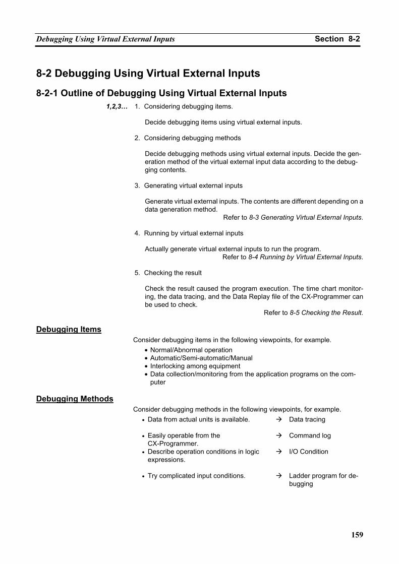
Debugging Using Virtual External Inputs Section 8-2
159
8-2 Debugging Using Virtual External Inputs
8-2-1 Outline of Debugging Using Virtual External Inputs 1,2,3… 1. Considering debugging items.
Decide debugging items using virtual external inputs.
2. Considering debugging methods
Decide debugging methods using virtual external inputs. Decide the gen-eration method of the virtual external input data according to the debug-ging contents.
3. Generating virtual external inputs
Generate virtual external inputs. The contents are different depending on a data generation method.
Refer to 8-3 Generating Virtual External Inputs.
4. Running by virtual external inputs
Actually generate virtual external inputs to run the program. Refer to 8-4 Running by Virtual External Inputs.
5. Checking the result
Check the result caused the program execution. The time chart monitor-ing, the data tracing, and the Data Replay file of the CX-Programmer can be used to check.
Refer to 8-5 Checking the Result. Debugging Items
Consider debugging items in the following viewpoints, for example. • Normal/Abnormal operation • Automatic/Semi-automatic/Manual • Interlocking among equipment • Data collection/monitoring from the application programs on the com-
puter Debugging Methods
Consider debugging methods in the following viewpoints, for example. • Data from actual units is available. Data tracing
• Easily operable from the
CX-Programmer. Command log
• Describe operation conditions in logic
expressions.
I/O Condition
• Try complicated input conditions. Ladder program for de-bugging
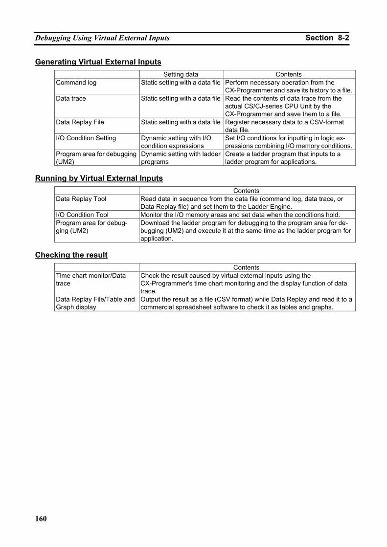
Debugging Using Virtual External Inputs Section 8-2
160
Generating Virtual External Inputs Setting data Contents
Command log Static setting with a data file Perform necessary operation from the CX-Programmer and save its history to a file.
Data trace Static setting with a data file Read the contents of data trace from the actual CS/CJ-series CPU Unit by the CX-Programmer and save them to a file.
Data Replay File Static setting with a data file Register necessary data to a CSV-format data file.
I/O Condition Setting Dynamic setting with I/O condition expressions
Set I/O conditions for inputting in logic ex-pressions combining I/O memory conditions.
Program area for debugging (UM2)
Dynamic setting with ladder programs
Create a ladder program that inputs to a ladder program for applications.
Running by Virtual External Inputs
Contents Data Replay Tool Read data in sequence from the data file (command log, data trace, or
Data Replay file) and set them to the Ladder Engine. I/O Condition Tool Monitor the I/O memory areas and set data when the conditions hold. Program area for debug-ging (UM2)
Download the ladder program for debugging to the program area for de-bugging (UM2) and execute it at the same time as the ladder program for application.
Checking the result
Contents Time chart monitor/Data trace
Check the result caused by virtual external inputs using the CX-Programmer's time chart monitoring and the display function of data trace.
Data Replay File/Table and Graph display
Output the result as a file (CSV format) while Data Replay and read it to a commercial spreadsheet software to check it as tables and graphs.
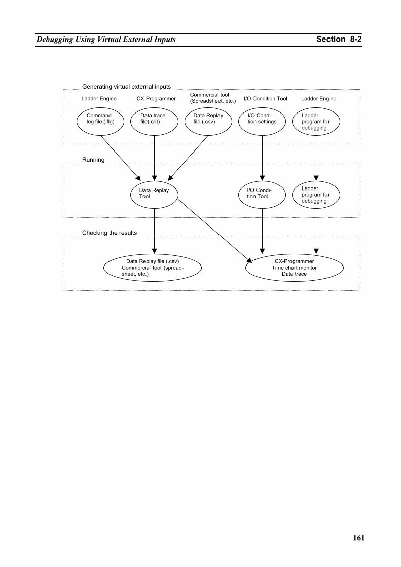
Debugging Using Virtual External Inputs Section 8-2
161
Generating virtual external inputs
Running
Checking the results
Ladder Engine CX-ProgrammerCommercial tool (Spreadsheet, etc.) I/O Condition Tool Ladder Engine
Command log file (.flg)
Data trace file(.cdt)
Data Replay Tool
I/O Condi-tion Tool
Ladder program for debugging
Data Replay file (.csv)Commercial tool (spread-sheet, etc.)
CX-Programmer Time chart monitor
Data trace
Data Replay file (.csv)
I/O Condi-tion settings
Ladder program for debugging
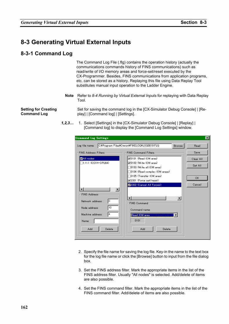
Generating Virtual External Inputs Section 8-3
162
8-3 Generating Virtual External Inputs
8-3-1 Command Log The Command Log File (.flg) contains the operation history (actually the communications commands history of FINS communications) such as read/write of I/O memory areas and force-set/reset executed by the CX-Programmer. Besides, FINS communications from application programs, etc. can be stored as a history. Replaying this file using Data Replay Tool substitutes manual input operation to the Ladder Engine.
Note Refer to 8-4 Running by Virtual External Inputs for replaying with Data Replay
Tool. Setting for Creating Command Log
Set for saving the command log in the [CX-Simulator Debug Console] | [Re-play] | [Command log] | [Settings].
1,2,3… 1. Select [Settings] in the [CX-Simulator Debug Console] | [Replay] |
[Command log] to display the [Command Log Settings] window.
2. Specify the file name for saving the log file. Key-in the name to the text box
for the log file name or click the [Browse] button to input from the file dialog box.
3. Set the FINS address filter. Mark the appropriate items in the list of the
FINS address filter. Usually "All nodes" is selected. Add/delete of items are also possible.
4. Set the FINS command filter. Mark the appropriate items in the list of the
FINS command filter. Add/delete of items are also possible.
Generating Virtual External Inputs Section 8-3
163
5. Click the [Set All] button if selecting all items registered in the FINS ad-
dress/command filter. Click the [Clear All] if clearing all check items.
6. Selecting the [OK] button will cause the settings valid. Command Log Save Start/Exit
Set the “Command Log Save Start” after setting the “Command log.”
Start the “Command Log Save” by [CX-Simulator Debug Console] | [Replay] | [Command log] | [Start]. If exiting or pausing the “Command Log Save,” select [Stop] in [Debug Console] | [Replay] | [Command log].
FINS Address Filter
Specify the FINS address filter if filtering by the FINS address.
Some FINS addresses for application programs on the computer change dynamically (FINS addresses of the CX-Programmer change, also.). So usu-ally use the CX-Simulator in the default setting (FINS address =*.*.*: All nodes).
When adding items to the list of FINS address filter, input the FINS address to be added (the network address, node address, and Machine address (Unit address)) and its name (tentative) followed by the [Add] button.
In specifying the address, an "*" can also be specified. For example, if an "*" is specified for the Machine address setting, the FINS command to/from the specified address will be saved as the command log.
When deleting the items in the list of FINS address filter, select the item to be deleted in the list and click the [Delete] button.
FINS Command Filter
Specify the FINS command filter when filtering by the FINS command. Filtering is performed by comparing the character string data (hex) from the top of the FINS command. For example, when writing to the EM area (common), the filtering pattern will be 01012, saving 010121 (EM area write (Bank 1), 01012A (EM area write (Bank 10), etc. to the Command Log File.
Refer to List of Usable FINS Command Filters and Data Replay Possible/Not possible for usable FINS command filters and whether the saved data is pos-sible to be replayed or not.
When adding items to the list of FINS command filter, select the items to be added (FINS command name) in the dropdown list of the FINS command filter.
When deleting items from the list of FINS command filter, select the items to be deleted in the list and click the [Delete] button of the FINS command filter.
Note At least one FINS address/command filter must be set respectively to create
the command log. An error will not occur in the Data Replay Tool even if a filter that can not be replayed is set.
Note The details for FINS commands are given in the Communications Commands
Reference Manual.
Note The upper limit of the command log file size is 30 MB. If exceeded, the log data will not be saved after that.
Generating Virtual External Inputs Section 8-3
164
List of Usable FINS Command Filters and Data Replay Possible/Not possible Access IOM area
MR SR FINS Command Replay possible01 01 Read IOM area Not possible 01 02 Write IOM area Possible 01 03 Write all IOM area Possible 01 04 Read complex IOM areas Not possible 01 05 Transfer IOM area Possible
Access parameter area
MR SR FINS Command Replay possible02 01 Read IOM area Not possible 02 02 Write IOM area Possible 02 03 Write all IOM area Possible
Execution controls
MR SR FINS Command Replay possible04 01 Execution Controls (Start) Possible 04 02 Execution Controls (Stop) Possible
Access time info
MR SR FINS Command Replay possible07 01 Read time info Not possible 07 02 Write time info Possible
Exchange messages
MR SR FINS Command Replay possible09 20 Message read/cancel Possible
Maintenance
MR SR FINS Command Replay possible21 01 Cancel Error Possible 21 02 Read Error log Not possible 21 03 Clear Error log Possible
Peripheral devices
MR SR FINS Command Replay possible22 0A IOM area File transfer Possible 22 0B Parameter File transfer Possible 22 0C IN-UM File transfer Possible
Debugging
MR SR FINS Command Replay possible23 01 Force set/reset Possible 23 02 Cancel All Forces Possible
Generating Virtual External Inputs Section 8-3
165
Read IOM area MR SR PM FINS Command Replay possible
01 01 30 Read CIO Area bits Not possible 01 01 31 Read Work Area bits Not possible 01 01 32 Read Hold Area bits Not possible 01 01 33 Read Auxiliary Area bits Not possible 01 01 B0 Read CIO Area words Not possible 01 01 B1 Read Work Area words Not possible 01 01 B2 Read Hold Area words Not possible 01 01 B3 Read Auxiliary Area words Not possible 01 01 09 Read Timer/Counter Completion Flag Not possible 01 01 89 Read Timer/Counter PV Not possible 01 01 02 Read DM bits Not possible 01 01 82 Read DM words Not possible 01 01 2 Read EM bits (common) Not possible 01 01 A Read EM words (common) Not possible 01 01 98 Read EM words (current bank) Not possible 01 01 BC Current EM Bank No. Not possible 01 01 06 Read task flag bit Not possible 01 01 46 Read task flag status Not possible 01 01 DC Read Index Register PV Not possible 01 01 BC Read Data Register PV Not possible 01 01 07 Read Clock/Condition bit Not possible
Write IOM area
MR SR PM FINS Command Replay possible01 02 30 Write CIO Area bits Possible 01 02 31 Write Work Area bits Possible 01 02 32 Write Hold Area bits Possible 01 02 33 Write Auxiliary Area bits Possible 01 02 B0 Write CIO Area words Possible 01 02 B1 Write Work Area words Possible 01 02 B2 Write Hold Area words Possible 01 02 B3 Write Auxiliary Area words Possible 01 02 89 Write Timer/Counter PV Possible 01 02 02 Write DM bits Possible 01 02 82 Write DM words Possible 01 02 2 Write EM bits (common) Possible 01 02 A Write EM words (common) Possible 01 02 98 Write EM words (current bank) Possible 01 02 BC Current EM Bank No. Possible 01 02 DC Write Index Register PV Possible 01 02 BC Write Data Register PV Possible
MR: Main, SR: Sub, PM: Parameter
Note If Replay is not possible, the I/O memory areas do not change although send/receive of data is executed when Replay.
Generating Virtual External Inputs Section 8-3
166
8-3-2 Data Trace File The time-series data (Data Trace File) of I/O memory area acquired from an actual PLC can be replayed on the Ladder Engine using the Data Replay Tool.
Note Refer to 8-4 Running by Virtual External Inputs for replaying by Data Replay
Tool. Create a Data Trace File using the data trace or the time chart monitor of the CX-Programmer, or Data Trace Recording Tool for long-term data.
Creating Data Trace Data using CX-Programmer
Use the Data Trace File (.cdt) created in the data trace or the time chart monitor of the CX-Programmer for the data of data trace.
Set necessary data using the CX-Programmer and execute the data trace or the time chart monitor on the CS/CJ/CP-series CPU Unit. The result will be saved as a file and operation by virtual external inputs will be performed.
Note 1. All data of the Data Trace File is regarded as data for input, fed to the
Ladder Engine. When setting for I/O memory areas that will be sampled in the CX-Programmer, make sure they can be used as inputs.
2. Refer to the Data Trace/Time Chart Monitoring of CHAPTER 4 - Refer-
ence of PART 1: CX-Programmer in the CX-Programmer Operation Manual (W446) for how to operate the data trace and time chart moni-toring.
Replaying Data of Data Trace
The data of the data trace differs in replay timing depending on the sampling setting when saving. In addition, all saved data is replayed regardless of the trigger setting. Replay timing
(Synchronous) Replay timing
(Asynchronous) Every cycle Every cycle Fixed interval Regular sampling Sampling interval Sampling interval Sampling by the TRSM Every cycle Fixed interval
Note Some data of the data trace with short sampling cycle can not be replayed in
the timing of the sampling cycle if replayed asynchronously. Furthermore, the data with a sampling cycle shorter than that when replaying can not be re-played.
Saving Long-term Data with Data Trace Recording Tool
A Data Trace File can contain up to 32,762 sets of data.
When more data or long-term trace data is required, it can be saved in multiple Data Trace Files by using the Data Trace Recording Tool attached to the CX-Simulator.
Note Refer to Appendix How to Use Data Trace Recording Tool for how to use the
Data Trace Recording Tool.
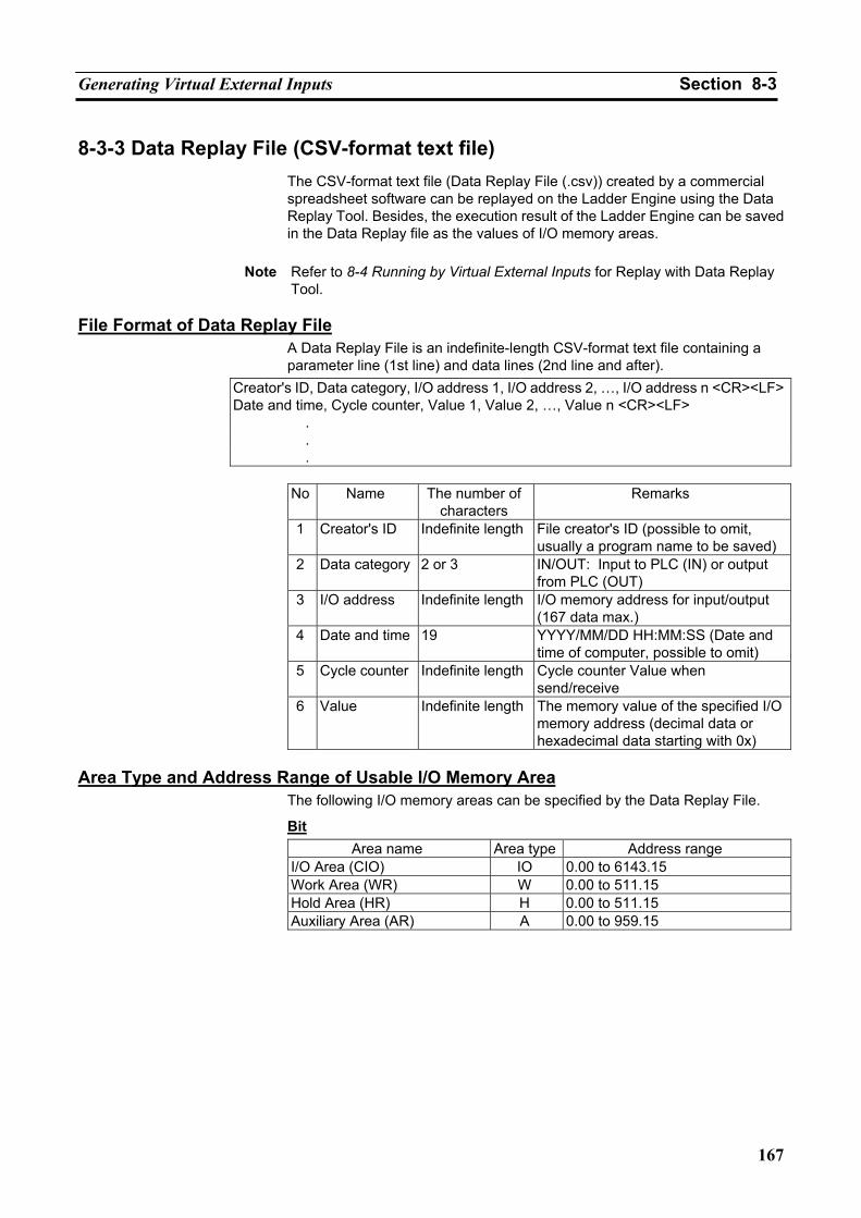
Generating Virtual External Inputs Section 8-3
167
8-3-3 Data Replay File (CSV-format text file) The CSV-format text file (Data Replay File (.csv)) created by a commercial spreadsheet software can be replayed on the Ladder Engine using the Data Replay Tool. Besides, the execution result of the Ladder Engine can be saved in the Data Replay file as the values of I/O memory areas.
Note Refer to 8-4 Running by Virtual External Inputs for Replay with Data Replay
Tool. File Format of Data Replay File
A Data Replay File is an indefinite-length CSV-format text file containing a parameter line (1st line) and data lines (2nd line and after).
Creator's ID, Data category, I/O address 1, I/O address 2, …, I/O address n <CR><LF>Date and time, Cycle counter, Value 1, Value 2, …, Value n <CR><LF> . . .
No Name The number of
characters Remarks
1 Creator's ID Indefinite length File creator's ID (possible to omit, usually a program name to be saved)
2 Data category 2 or 3 IN/OUT: Input to PLC (IN) or output from PLC (OUT)
3 I/O address Indefinite length I/O memory address for input/output (167 data max.)
4 Date and time 19 YYYY/MM/DD HH:MM:SS (Date and time of computer, possible to omit)
5 Cycle counter Indefinite length Cycle counter Value when send/receive
6 Value Indefinite length The memory value of the specified I/O memory address (decimal data or hexadecimal data starting with 0x)
Area Type and Address Range of Usable I/O Memory Area
The following I/O memory areas can be specified by the Data Replay File.
Bit Area name Area type Address range
I/O Area (CIO) IO 0.00 to 6143.15 Work Area (WR) W 0.00 to 511.15 Hold Area (HR) H 0.00 to 511.15 Auxiliary Area (AR) A 0.00 to 959.15
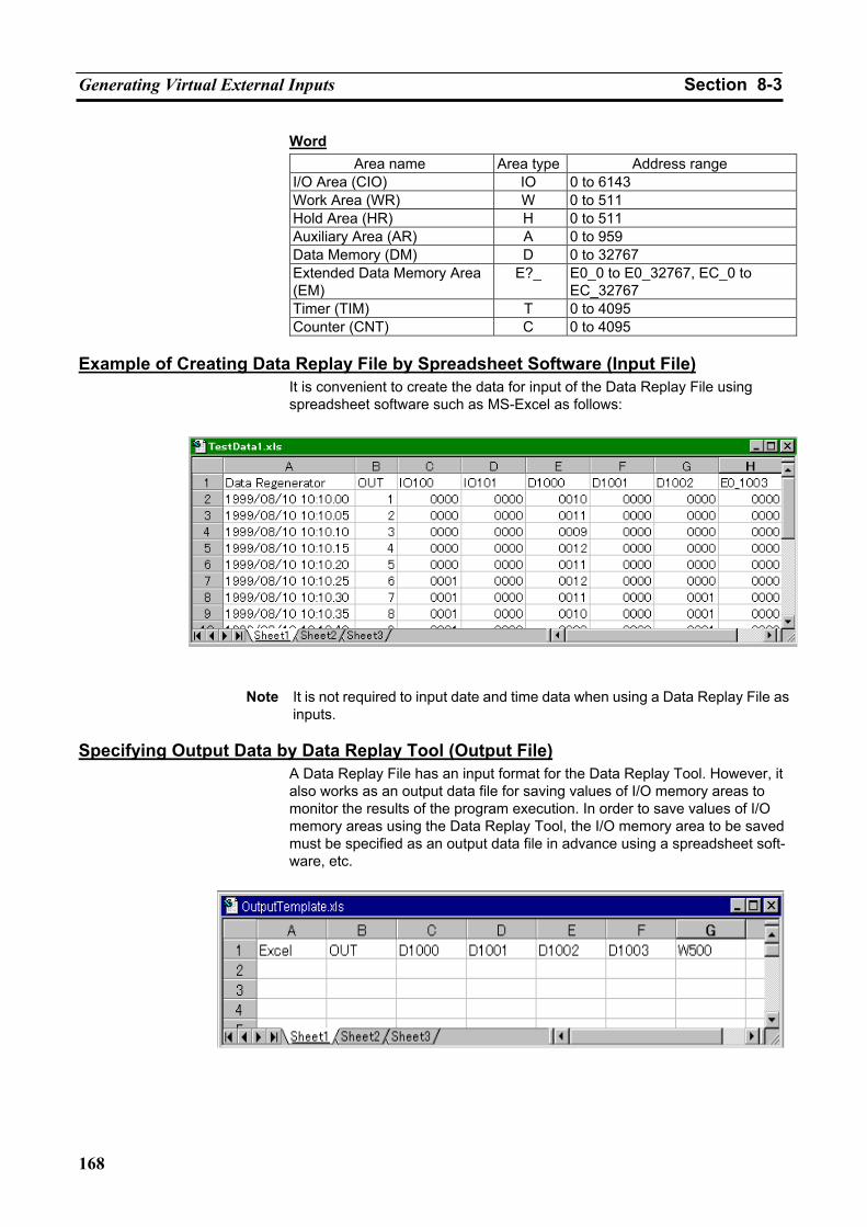
Generating Virtual External Inputs Section 8-3
168
Word Area name Area type Address range
I/O Area (CIO) IO 0 to 6143 Work Area (WR) W 0 to 511 Hold Area (HR) H 0 to 511 Auxiliary Area (AR) A 0 to 959 Data Memory (DM) D 0 to 32767 Extended Data Memory Area (EM)
E?_ E0_0 to E0_32767, EC_0 to EC_32767
Timer (TIM) T 0 to 4095 Counter (CNT) C 0 to 4095
Example of Creating Data Replay File by Spreadsheet Software (Input File)
It is convenient to create the data for input of the Data Replay File using spreadsheet software such as MS-Excel as follows:
Note It is not required to input date and time data when using a Data Replay File as
inputs. Specifying Output Data by Data Replay Tool (Output File)
A Data Replay File has an input format for the Data Replay Tool. However, it also works as an output data file for saving values of I/O memory areas to monitor the results of the program execution. In order to save values of I/O memory areas using the Data Replay Tool, the I/O memory area to be saved must be specified as an output data file in advance using a spreadsheet soft-ware, etc.
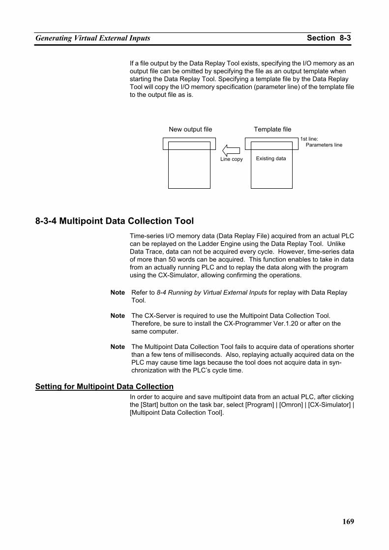
Generating Virtual External Inputs Section 8-3
169
If a file output by the Data Replay Tool exists, specifying the I/O memory as an output file can be omitted by specifying the file as an output template when starting the Data Replay Tool. Specifying a template file by the Data Replay Tool will copy the I/O memory specification (parameter line) of the template file to the output file as is.
8-3-4 Multipoint Data Collection Tool Time-series I/O memory data (Data Replay File) acquired from an actual PLC can be replayed on the Ladder Engine using the Data Replay Tool. Unlike Data Trace, data can not be acquired every cycle. However, time-series data of more than 50 words can be acquired. This function enables to take in data from an actually running PLC and to replay the data along with the program using the CX-Simulator, allowing confirming the operations.
Note Refer to 8-4 Running by Virtual External Inputs for replay with Data Replay
Tool.
Note The CX-Server is required to use the Multipoint Data Collection Tool. Therefore, be sure to install the CX-Programmer Ver.1.20 or after on the same computer.
Note The Multipoint Data Collection Tool fails to acquire data of operations shorter
than a few tens of milliseconds. Also, replaying actually acquired data on the PLC may cause time lags because the tool does not acquire data in syn-chronization with the PLC’s cycle time.
Setting for Multipoint Data Collection
In order to acquire and save multipoint data from an actual PLC, after clicking the [Start] button on the task bar, select [Program] | [Omron] | [CX-Simulator] | [Multipoint Data Collection Tool].
1st line: Parameters line
New output file
Existing data
Template file
Line copy
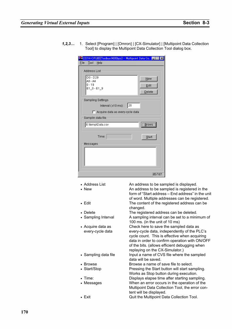
Generating Virtual External Inputs Section 8-3
170
1,2,3… 1. Select [Program] | [Omron] | [CX-Simulator] | [Multipoint Data Collection
Tool] to display the Multipoint Data Collection Tool dialog box.
• Address List An address to be sampled is displayed. • New An address to be sampled is registered in the
form of “Start address – End address” in the unit of word. Multiple addresses can be registered.
• Edit The content of the registered address can be changed.
• Delete The registered address can be deleted. • Sampling Interval A sampling interval can be set to a minimum of
100 ms. (in the unit of 10 ms) • Acquire data as
every-cycle data Check here to save the sampled data as every-cycle data, independently of the PLC’s cycle count. This is effective when acquiring data in order to confirm operation with ON/OFF of the bits. (allows efficient debugging when replaying on the CX-Simulator.)
• Sampling data file Input a name of CVS file where the sampled data will be saved.
• Browse Browse a name of save file to select. • Start/Stop Pressing the Start button will start sampling.
Works as Stop button during execution. • Time: Displays elapse time after starting sampling. • Messages When an error occurs in the operation of the
Multipoint Data Collection Tool, the error con-tent will be displayed.
• Exit Quit the Multipoint Data Collection Tool.
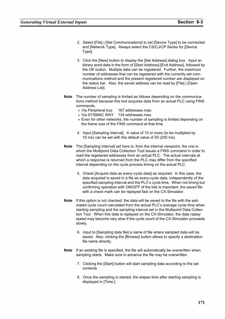
Generating Virtual External Inputs Section 8-3
171
2. Select [File] | [Set Communications] to set [Device Type] to be connected
and [Network Type]. Always select the CS/CJ/CP Series for [Device Type].
3. Click the [New] button to display the [Set Address] dialog box. Input ar-
bitrary word data in the form of [Start Address]-[End Address], followed by the OK button. Multiple data can be registered. Further, the maximum number of addresses that can be registered with the currently set com-munications method and the present registered number are displayed on the status bar. Also, the saved address can be read by [File] | [Open Address List].
Note The number of sampling is limited as follows depending on the communica-
tions method because this tool acquires data from an actual PLC using FINS commands.
• Via Peripheral bus 167 addresses max. • Via SYSMAC WAY 134 addresses max. • Even for other networks, the number of sampling is limited depending on
the frame size of the FINS command at that time.
4. Input [Sampling interval]. A value of 10 or more (to be multiplied by 10 ms) can be set with the default value of 20 (200 ms).
Note The [Sampling Interval] set here is, from the internal viewpoint, the one in
which the Multipoint Data Collection Tool issues a FINS command in order to read the registered addresses from an actual PLC. The actual intervals at which a response is returned from the PLC may differ from the specified interval depending on the cycle process timing on the actual PLC.
5. Check [Acquire data as every-cycle data] as required. In this case, the
data acquired is saved in a file as every-cycle data, independently of the specified sampling interval and the PLC’s cycle time. When not timing but confirming operation with ON/OFF of the bits is important, the saved file with a check mark can be replayed fast on the CX-Simulator.
Note If this option is not checked, the data will be saved to the file with the esti-
mated cycle count calculated from the actual PLC’s average cycle time when starting sampling and the sampling interval set in the Multipoint Data Collec-tion Tool. When this data is replayed on the CX-Simulator, the data replay speed may become very slow if the cycle count of the CX-Simulator proceeds slowly.
6. Input to [Sampling data file] a name of file where sampled data will be
saved. Also, clicking the [Browse] button allows to specify a destination file name directly.
Note If an existing file is specified, the file will automatically be overwritten when
sampling starts. Make sure in advance the file may be overwritten.
7. Clicking the [Start] button will start sampling data according to the set contents.
8. Once the sampling is started, the elapse time after starting sampling is
displayed in [Time:].
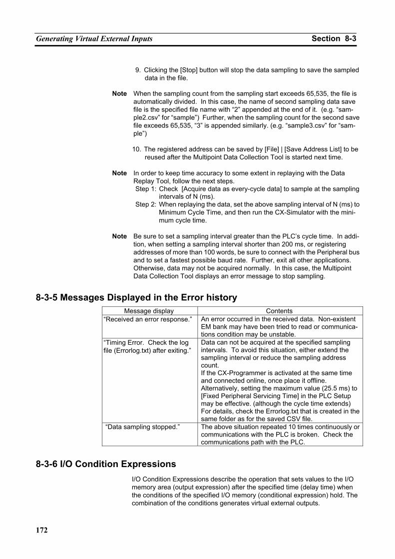
Generating Virtual External Inputs Section 8-3
172
9. Clicking the [Stop] button will stop the data sampling to save the sampled
data in the file.
Note When the sampling count from the sampling start exceeds 65,535, the file is automatically divided. In this case, the name of second sampling data save file is the specified file name with “2” appended at the end of it. (e.g. “sam-ple2.csv” for “sample”) Further, when the sampling count for the second save file exceeds 65,535, “3” is appended similarly. (e.g. “sample3.csv” for “sam-ple”)
10. The registered address can be saved by [File] | [Save Address List] to be
reused after the Multipoint Data Collection Tool is started next time.
Note In order to keep time accuracy to some extent in replaying with the Data Replay Tool, follow the next steps. Step 1: Check [Acquire data as every-cycle data] to sample at the sampling
intervals of N (ms). Step 2: When replaying the data, set the above sampling interval of N (ms) to
Minimum Cycle Time, and then run the CX-Simulator with the mini-mum cycle time.
Note Be sure to set a sampling interval greater than the PLC’s cycle time. In addi-
tion, when setting a sampling interval shorter than 200 ms, or registering addresses of more than 100 words, be sure to connect with the Peripheral bus and to set a fastest possible baud rate. Further, exit all other applications. Otherwise, data may not be acquired normally. In this case, the Multipoint Data Collection Tool displays an error message to stop sampling.
8-3-5 Messages Displayed in the Error history Message display Contents
“Received an error response.” An error occurred in the received data. Non-existent EM bank may have been tried to read or communica-tions condition may be unstable.
“Timing Error. Check the log file (Errorlog.txt) after exiting.”
Data can not be acquired at the specified sampling intervals. To avoid this situation, either extend the sampling interval or reduce the sampling address count. If the CX-Programmer is activated at the same time and connected online, once place it offline. Alternatively, setting the maximum value (25.5 ms) to [Fixed Peripheral Servicing Time] in the PLC Setup may be effective. (although the cycle time extends) For details, check the Errorlog.txt that is created in the same folder as for the saved CSV file.
“Data sampling stopped.” The above situation repeated 10 times continuously or communications with the PLC is broken. Check the communications path with the PLC.
8-3-6 I/O Condition Expressions I/O Condition Expressions describe the operation that sets values to the I/O memory area (output expression) after the specified time (delay time) when the conditions of the specified I/O memory (conditional expression) hold. The combination of the conditions generates virtual external outputs.
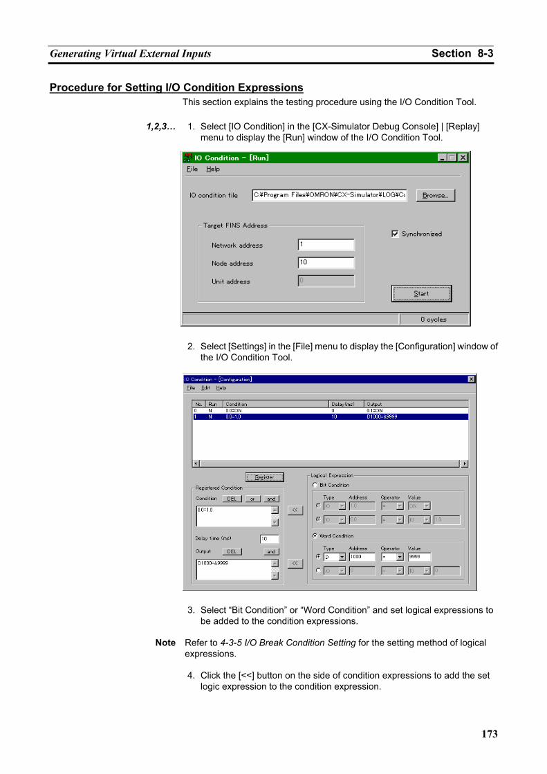
Generating Virtual External Inputs Section 8-3
173
Procedure for Setting I/O Condition Expressions This section explains the testing procedure using the I/O Condition Tool.
1,2,3… 1. Select [IO Condition] in the [CX-Simulator Debug Console] | [Replay]
menu to display the [Run] window of the I/O Condition Tool.
2. Select [Settings] in the [File] menu to display the [Configuration] window of
the I/O Condition Tool.
3. Select “Bit Condition” or “Word Condition” and set logical expressions to be added to the condition expressions.
Note Refer to 4-3-5 I/O Break Condition Setting for the setting method of logical
expressions.
4. Click the [<<] button on the side of condition expressions to add the set logic expression to the condition expression.
Generating Virtual External Inputs Section 8-3
174
5. When registering multiple logic expressions to the condition expression,
insert logic operators between logic expressions (Click the [or] or [and] button.).
6. Repeat 4 and 5 until completing the condition expression. Directly editing
the condition expression is also possible.
7. Input a delay time (unit: ms).
8. Select “Bit Condition” or “Word Condition” and set logic expressions to be added to the output expression.
Note In the output expressions, only [=] can be used as a condition operator and
only [and] as a logic operator. If other operators are used, the I/O Condition expression will cause an error ("E").
9. Click the [<<] button on the side of the output expressions to add the set
logic expression to the output expressions.
10. When registering multiple logic expressions to the output expression, insert logic operators between logic expressions (Click the [and] button.).
11. Repeat 9 and 10 until completing the output expression. Directly editing
the output expression is also possible.
12. Click the [Expression Registration] button to register the input condition expressions, the delay time, and the output expressions as the I/O Con-dition expression. The expression is evaluated when registered. "N" (o) is shown in the execution field for a valid input and "E"(rror) for an invalid input.
13. Repeat 3 to 12 until inputting necessary I/O Condition expressions com-
pletes.
14. When changing the input I/O Condition expression, left-click the relevant line in the list to reflect the selected I/O Condition expression to the reg-istration condition area. Correct it as required and click the [Expression Registration] button to re-register.
15. Double-click the expression where actually judging conditions out of the
registered I/O Condition expressions to change the display from "N" to "D"(o), showing judging conditions is possible. Also, repeating the same process will change the display from "D" to "N."
16. After making relevant I/O Condition expressions executable, select [Save
as] in the [File] menu to save the input I/O condition expressions.
17. Select [Close] in the [File] menu to return to the [Run] window. Restrictions
Up to 512 I/O Condition expressions can be registered.
Up to 6 combinations of logic expression can be registered for one condition expression.
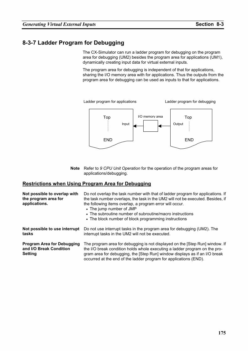
Generating Virtual External Inputs Section 8-3
175
8-3-7 Ladder Program for Debugging The CX-Simulator can run a ladder program for debugging on the program area for debugging (UM2) besides the program area for applications (UM1), dynamically creating input data for virtual external inputs.
The program area for debugging is independent of that for applications, sharing the I/O memory area with for applications. Thus the outputs from the program area for debugging can be used as inputs to that for applications.
Note Refer to 9 CPU Unit Operation for the operation of the program areas for applications/debugging.
Restrictions when Using Program Area for Debugging Not possible to overlap with the program area for applications.
Do not overlap the task number with that of ladder program for applications. If the task number overlaps, the task in the UM2 will not be executed. Besides, if the following items overlap, a program error will occur.
• The jump number of JMP • The subroutine number of subroutine/macro instructions • The block number of block programming instructions
Not possible to use interrupt tasks
Do not use interrupt tasks in the program area for debugging (UM2). The interrupt tasks in the UM2 will not be executed.
Program Area for Debugging and I/O Break Condition Setting
The program area for debugging is not displayed on the [Step Run] window. If the I/O break condition holds whole executing a ladder program on the pro-gram area for debugging, the [Step Run] window displays as if an I/O break occurred at the end of the ladder program for applications (END).
Ladder program for applications Ladder program for debugging
I/O memory areaTop Input
END END
Output
Top
Running by Virtual External Inputs Section 8-4
176
8-4 Running by Virtual External Inputs
8-4-1 Running by Virtual External Inputs How to Run by Virtual External Inputs
Perform running by virtual external inputs in the following 3 methods.
1. By Data Replay Tool
2. By the I/O Condition Tool
3. By the ladder program for debugging
Note Be careful when performing Run-mode operation from the [Debug Console] while executing the Data Replay Tool or I/O Condition Tool. If the [Continuous Run] button is pressed during a Synchronous process, synchronism may be lost temporarily. Also, if the [Pause] (, [Scan Run], or [Step Run]) button is pressed during an Asynchronous process, the virtual external input data will be replayed even if the ladder execution is interrupted temporarily.
Synchronous/Asynchronous Processes
In the Data Replay Tool and I/O Condition Tool, whether or not to perform synchronous process can be selected.
The Synchronous (Replay) process is a process where the Ladder Engine and each tool operate synchronously in the unit of a scan. If the Synchronous process is not performed (Asynchronous process), setting/monitoring of I/O memory values from each tool to the Ladder Engine are performed asyn-chronously with scan of the Ladder Engine. In this case, like operation to an actual PLC, scan from each tool to the Ladder Engine is will not be performed.
When using multiple tools at the same time, execute the synchronous process on one tool. Perform the other tools asynchronously.
Note Synchronous execution of multiple tools will lose synchronism in the unit of a
scan for each tool. Execute one tool synchronously and the others asyn-chronously or alternatively execute all tools asynchronously.
Virtual Cycle Time and Computer Cycle Time
When performing virtual external inputs, use the Simulator in the Computer Cycle Time. In the Synchronous process, the execution result will be the same for Virtual Cycle Time and Computer Cycle Time. In the Asynchronous proc-ess, on the other hand, the result will be different because the time elapses differently between the Ladder Engine and tools in Virtual Cycle Time and the timing of data setting is different from that of Computer Cycle Time.
8-4-2 How to Run by Data Replay Tool The [Data Replay Tool] reads the data of the specified replay file (Command log file, Data Trace file, or Data Replay file) and set the data to the Ladder Engine in sequence. Furthermore, the changes caused by setting of the data can be saved to an output file as monitor data.
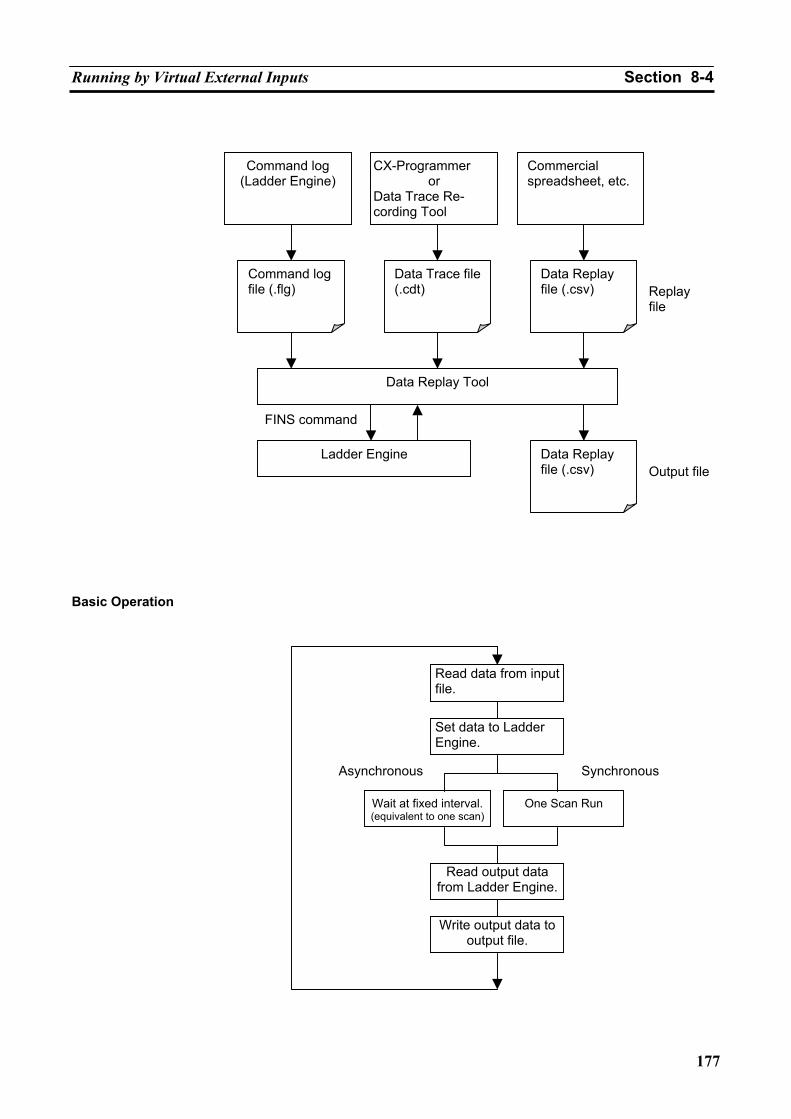
Running by Virtual External Inputs Section 8-4
177
Basic Operation
Command log(Ladder Engine)
Commercial spreadsheet, etc.
CX-Programmer or
Data Trace Re-cording Tool
Command log file (.flg)
Data Trace file (.cdt)
Data Replay file (.csv)
Data Replay Tool
Ladder Engine
Data Replay file (.csv)
FINS command
Replay file
Output file
Read data from input file.
Read output data from Ladder Engine.
Wait at fixed interval.(equivalent to one scan)
One Scan Run
Set data to Ladder Engine.
Asynchronous Synchronous
Write output data to output file.
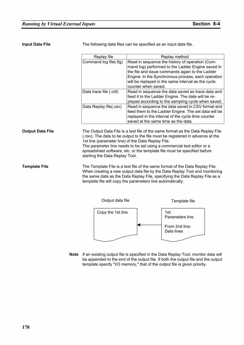
Running by Virtual External Inputs Section 8-4
178
Input Data File The following data files can be specified as an input data file.
Replay file Replay method
Command log file(.flg) Read in sequence the history of operation (Com-mand log) performed to the Ladder Engine saved in the file and issue commands again to the Ladder Engine. In the Synchronous process, each operation will be replayed in the same interval as the cycle counter when saved.
Data trace file (.cdt) Read in sequence the data saved as trace data and feed it to the Ladder Engine. The data will be re-played according to the sampling cycle when saved.
Data Replay file(.csv) Read in sequence the data saved in CSV format and feed them to the Ladder Engine. The set data will be replayed in the interval of the cycle time counter saved at the same time as the data.
Output Data File The Output Data File is a text file of the same format as the Data Replay File
(.csv). The data to be output to the file must be registered in advance at the 1st line (parameter line) of the Data Replay File. The parameter line needs to be set using a commercial text editor or a spreadsheet software, etc. or the template file must be specified before starting the Data Replay Tool.
Template File The Template File is a text file of the same format of the Data Replay File.
When creating a new output data file by the Data Replay Tool and monitoring the same data as the Data Replay File, specifying the Data Replay File as a template file will copy the parameters line automatically.
Note If an existing output file is specified in the Data Replay Tool, monitor data will
be appended to the end of the output file. If both the output file and the output template specify "I/O memory," that of the output file is given priority.
Copy the 1st line. 1st: Parameters line From 2nd line: Data lines
Output data file Template file
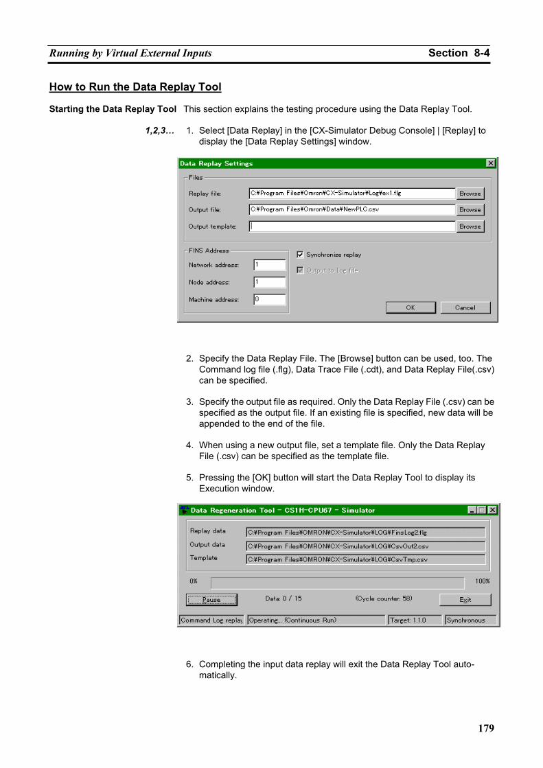
Running by Virtual External Inputs Section 8-4
179
How to Run the Data Replay Tool Starting the Data Replay Tool This section explains the testing procedure using the Data Replay Tool.
1,2,3… 1. Select [Data Replay] in the [CX-Simulator Debug Console] | [Replay] to display the [Data Replay Settings] window.
2. Specify the Data Replay File. The [Browse] button can be used, too. The
Command log file (.flg), Data Trace File (.cdt), and Data Replay File(.csv) can be specified.
3. Specify the output file as required. Only the Data Replay File (.csv) can be
specified as the output file. If an existing file is specified, new data will be appended to the end of the file.
4. When using a new output file, set a template file. Only the Data Replay
File (.csv) can be specified as the template file.
5. Pressing the [OK] button will start the Data Replay Tool to display its Execution window.
6. Completing the input data replay will exit the Data Replay Tool auto-
matically.
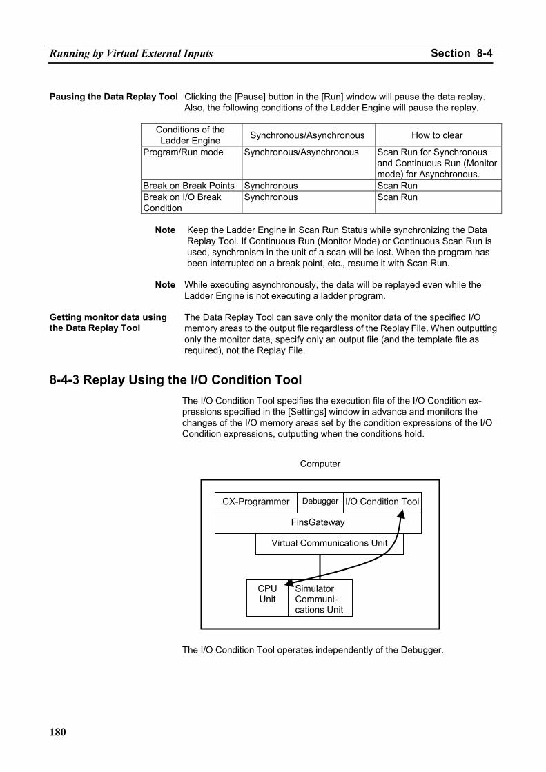
Running by Virtual External Inputs Section 8-4
180
Pausing the Data Replay Tool Clicking the [Pause] button in the [Run] window will pause the data replay.
Also, the following conditions of the Ladder Engine will pause the replay.
Conditions of the Ladder Engine Synchronous/Asynchronous How to clear
Program/Run mode Synchronous/Asynchronous Scan Run for Synchronous and Continuous Run (Monitor mode) for Asynchronous.
Break on Break Points Synchronous Scan Run Break on I/O Break Condition
Synchronous Scan Run
Note Keep the Ladder Engine in Scan Run Status while synchronizing the Data
Replay Tool. If Continuous Run (Monitor Mode) or Continuous Scan Run is used, synchronism in the unit of a scan will be lost. When the program has been interrupted on a break point, etc., resume it with Scan Run.
Note While executing asynchronously, the data will be replayed even while the
Ladder Engine is not executing a ladder program. Getting monitor data using the Data Replay Tool
The Data Replay Tool can save only the monitor data of the specified I/O memory areas to the output file regardless of the Replay File. When outputting only the monitor data, specify only an output file (and the template file as required), not the Replay File.
8-4-3 Replay Using the I/O Condition Tool The I/O Condition Tool specifies the execution file of the I/O Condition ex-pressions specified in the [Settings] window in advance and monitors the changes of the I/O memory areas set by the condition expressions of the I/O Condition expressions, outputting when the conditions hold.
The I/O Condition Tool operates independently of the Debugger.
Computer
CX-Programmer Debugger I/O Condition Tool
FinsGateway
Virtual Communications Unit
CPUUnit
Simulator Communi-cations Unit
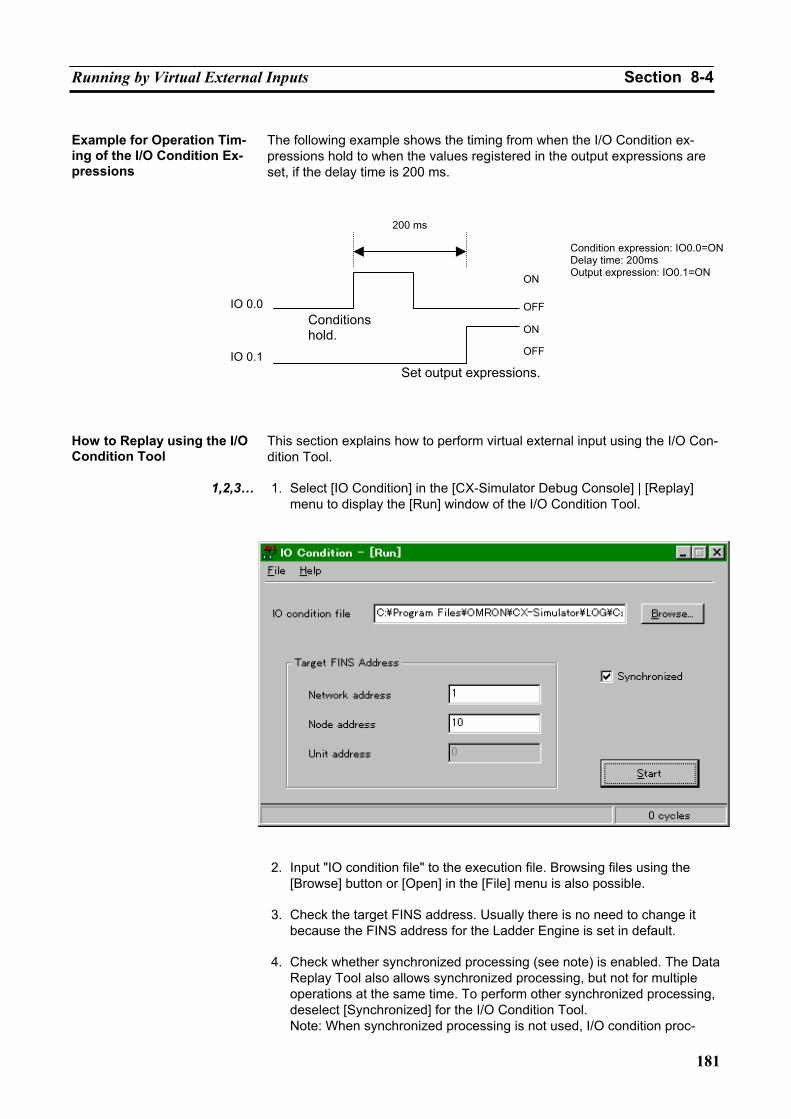
Running by Virtual External Inputs Section 8-4
181
Example for Operation Tim-ing of the I/O Condition Ex-pressions
The following example shows the timing from when the I/O Condition ex-pressions hold to when the values registered in the output expressions are set, if the delay time is 200 ms.
How to Replay using the I/O Condition Tool
This section explains how to perform virtual external input using the I/O Con-dition Tool.
1,2,3… 1. Select [IO Condition] in the [CX-Simulator Debug Console] | [Replay]
menu to display the [Run] window of the I/O Condition Tool.
2. Input "IO condition file" to the execution file. Browsing files using the
[Browse] button or [Open] in the [File] menu is also possible.
3. Check the target FINS address. Usually there is no need to change it because the FINS address for the Ladder Engine is set in default.
4. Check whether synchronized processing (see note) is enabled. The Data
Replay Tool also allows synchronized processing, but not for multiple operations at the same time. To perform other synchronized processing, deselect [Synchronized] for the I/O Condition Tool. Note: When synchronized processing is not used, I/O condition proc-
IO 0.0
IO 0.1
200 ms
Set output expressions.
ON
OFF
ON
OFF
Condition expression: IO0.0=ONDelay time: 200ms Output expression: IO0.1=ON
Conditions hold.
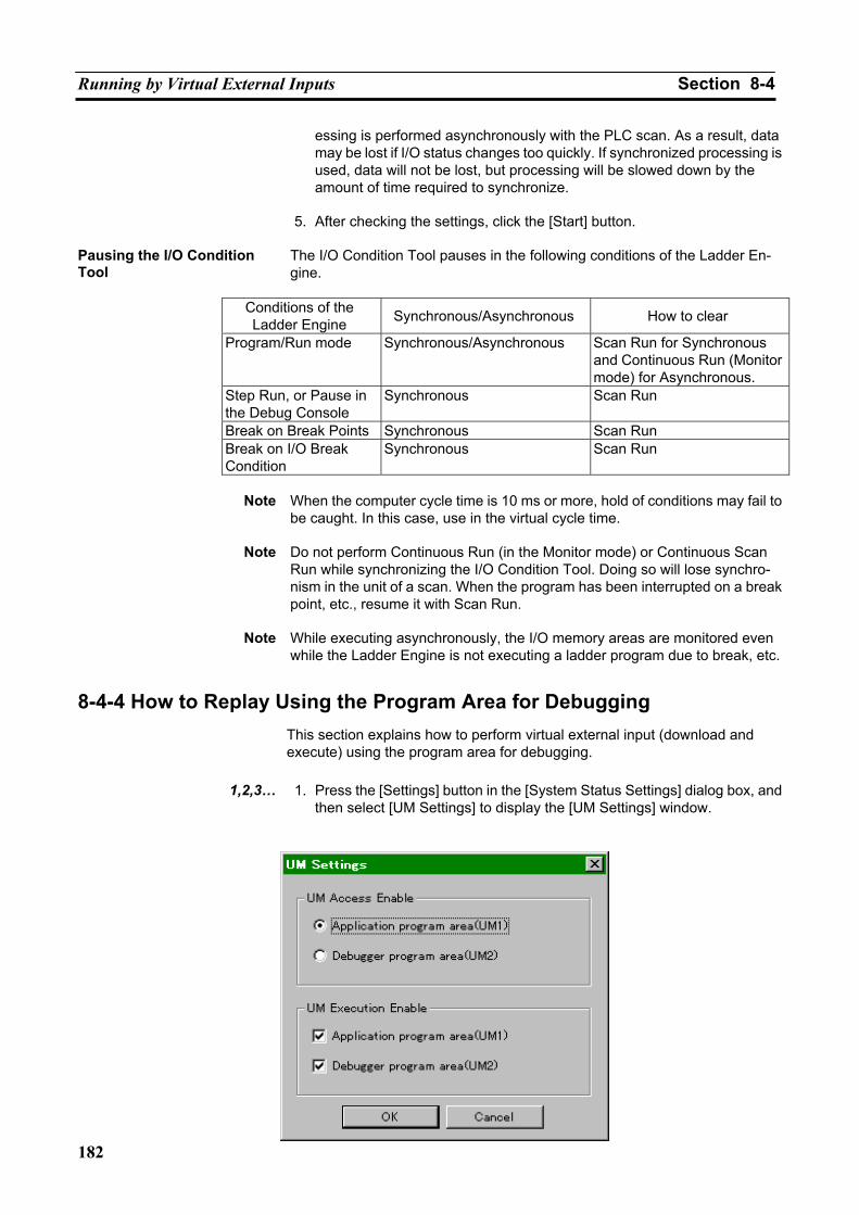
Running by Virtual External Inputs Section 8-4
182
essing is performed asynchronously with the PLC scan. As a result, data may be lost if I/O status changes too quickly. If synchronized processing is used, data will not be lost, but processing will be slowed down by the amount of time required to synchronize.
5. After checking the settings, click the [Start] button.
Pausing the I/O Condition Tool
The I/O Condition Tool pauses in the following conditions of the Ladder En-gine.
Conditions of the Ladder Engine Synchronous/Asynchronous How to clear
Program/Run mode Synchronous/Asynchronous Scan Run for Synchronous and Continuous Run (Monitor mode) for Asynchronous.
Step Run, or Pause in the Debug Console
Synchronous Scan Run
Break on Break Points Synchronous Scan Run Break on I/O Break Condition
Synchronous Scan Run
Note When the computer cycle time is 10 ms or more, hold of conditions may fail to
be caught. In this case, use in the virtual cycle time.
Note Do not perform Continuous Run (in the Monitor mode) or Continuous Scan Run while synchronizing the I/O Condition Tool. Doing so will lose synchro-nism in the unit of a scan. When the program has been interrupted on a break point, etc., resume it with Scan Run.
Note While executing asynchronously, the I/O memory areas are monitored even
while the Ladder Engine is not executing a ladder program due to break, etc.
8-4-4 How to Replay Using the Program Area for Debugging This section explains how to perform virtual external input (download and execute) using the program area for debugging.
1,2,3… 1. Press the [Settings] button in the [System Status Settings] dialog box, and
then select [UM Settings] to display the [UM Settings] window.
Running by Virtual External Inputs Section 8-4
183
2. Select [Debugger program area (UM2)] in [UM Access Enable] followed
by clicking the [OK] button.
3. After confirming that the CX-Simulator is connected in the [Work CX-Simulator] window, download the ladder program from the CX-Programmer.
4. After the download is completed, select [UM Settings] in [System Status] |
[Settings] again and select [Application program area (UM1)] in [UM Ac-cess Enable]. Also, check both boxes for [Application program area (UM1)] and [Debugger program area (UM2)] in [UM Execution Enable], followed by clicking the [OK] button.
5. Select [Save all] in the [CX-Simulator Debug Console] | [File] menu to
save the status before starting virtual external inputs.
6. Clicking the [Continuous Run] button from [CX-Simulator Debug Console] or turning the mode of the Ladder Engine to Monitor from the CX-Programmer will start running using virtual external inputs.
Note The CX-Simulator can not debug a ladder program in the program area for
debugging. Before downloading the ladder program to the program area for debugging, check it in the area for applications in advance.
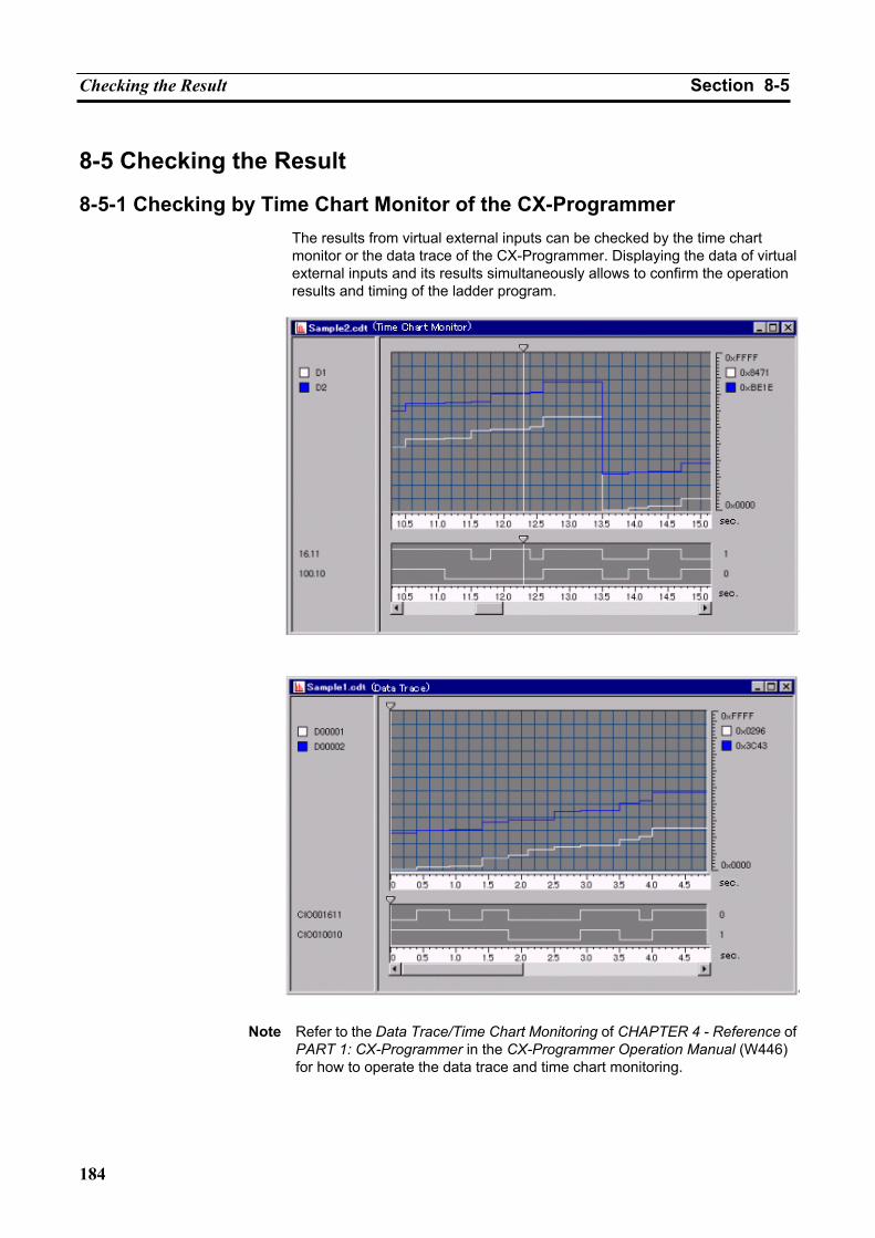
Checking the Result Section 8-5
184
8-5 Checking the Result
8-5-1 Checking by Time Chart Monitor of the CX-Programmer The results from virtual external inputs can be checked by the time chart monitor or the data trace of the CX-Programmer. Displaying the data of virtual external inputs and its results simultaneously allows to confirm the operation results and timing of the ladder program.
Note Refer to the Data Trace/Time Chart Monitoring of CHAPTER 4 - Reference of
PART 1: CX-Programmer in the CX-Programmer Operation Manual (W446) for how to operate the data trace and time chart monitoring.
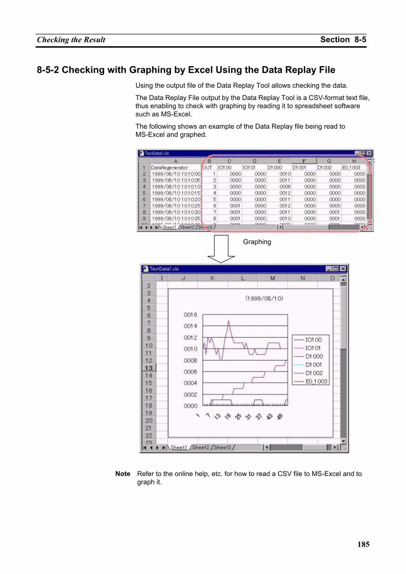
Checking the Result Section 8-5
185
8-5-2 Checking with Graphing by Excel Using the Data Replay File Using the output file of the Data Replay Tool allows checking the data.
The Data Replay File output by the Data Replay Tool is a CSV-format text file, thus enabling to check with graphing by reading it to spreadsheet software such as MS-Excel.
The following shows an example of the Data Replay file being read to MS-Excel and graphed.
Note Refer to the online help, etc. for how to read a CSV file to MS-Excel and to
graph it.
Graphing

Checking the Result Section 8-5
186
187
SECTION 9 CPU Unit Operation
9-1 CPU Unit Operation ................................................................................................................. 188 9-1-1 General Flow ................................................................................................................ 188 9-1-2 Startup (Initial) Process ................................................................................................ 189 9-1-3 Overseeing Processing ................................................................................................. 190 9-1-4 Computing Process....................................................................................................... 190 9-1-5 Details of I/O Refresh and Peripheral Servicing .......................................................... 191
9-2 Cycle Time and Time................................................................................................................ 192 9-2-1 Cycle Time ................................................................................................................... 192 9-2-2 Maximum CPU Occupancy and Execution Time ........................................................ 198 9-2-3 Differences with CS/CJ/CP Series ............................................................................... 199
9-3 I/O Memory Allocation ............................................................................................................ 200 9-3-1 PLC Setup Settings....................................................................................................... 200 9-3-2 Auxiliary Area (Read-only Area)................................................................................. 205 9-3-3 Auxiliary Area (Read/Write Area) ............................................................................... 230
9-4 Other Functions ........................................................................................................................ 237 9-4-1 Differences in CX-Programmer Operation................................................................... 237 9-4-2 Other Precautions ......................................................................................................... 237
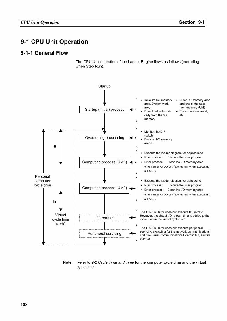
CPU Unit Operation Section 9-1
188
9-1 CPU Unit Operation
9-1-1 General Flow The CPU Unit operation of the Ladder Engine flows as follows (excluding when Step Run).
Note Refer to 9-2 Cycle Time and Time for the computer cycle time and the virtual
cycle time.
Personal computer cycle time
Startup
Startup (Initial) process
Overseeing processing
Computing process (UM1)
Computing process (UM2)
Virtual cycle time
(a+b)
b
a
• Initialize I/O memory area/System work area
• Download automati-cally from the file memory
• Monitor the DIP switch
• Back up I/O memory areas
• Execute the ladder diagram for applications • Run process: Execute the user program • Error process: Clear the I/O memory area
when an error occurs (excluding when executing a FALS)
• Clear I/O memory area and check the user memory area (UM)
• Clear force-set/reset, etc.
• Execute the ladder diagram for debugging • Run process: Execute the user program • Error process: Clear the I/O memory area
when an error occurs (excluding when executing a FALS)
The CX-Simulator does not execute I/O refresh. However, the virtual I/O refresh time is added to the cycle time in the virtual cycle time.
The CX-Simulator does not execute peripheral servicing excluding for the network communications unit, the Serial Communications Boards/Unit, and fileservice.
I/O refresh
Peripheral servicing
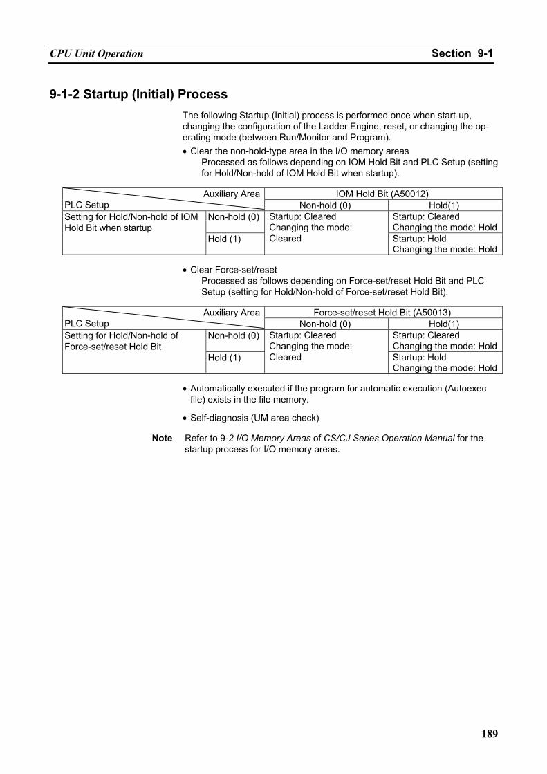
CPU Unit Operation Section 9-1
189
9-1-2 Startup (Initial) Process The following Startup (Initial) process is performed once when start-up, changing the configuration of the Ladder Engine, reset, or changing the op-erating mode (between Run/Monitor and Program). • Clear the non-hold-type area in the I/O memory areas
Processed as follows depending on IOM Hold Bit and PLC Setup (setting for Hold/Non-hold of IOM Hold Bit when startup).
IOM Hold Bit (A50012) Auxiliary Area
PLC Setup Non-hold (0) Hold(1) Non-hold (0) Startup: Cleared
Changing the mode: HoldSetting for Hold/Non-hold of IOM Hold Bit when startup
Hold (1)
Startup: Cleared Changing the mode: Cleared Startup: Hold
Changing the mode: Hold
• Clear Force-set/reset Processed as follows depending on Force-set/reset Hold Bit and PLC Setup (setting for Hold/Non-hold of Force-set/reset Hold Bit).
Force-set/reset Hold Bit (A50013) Auxiliary Area
PLC Setup Non-hold (0) Hold(1) Non-hold (0) Startup: Cleared
Changing the mode: HoldSetting for Hold/Non-hold of Force-set/reset Hold Bit
Hold (1)
Startup: Cleared Changing the mode: Cleared Startup: Hold
Changing the mode: Hold
• Automatically executed if the program for automatic execution (Autoexec file) exists in the file memory.
• Self-diagnosis (UM area check)
Note Refer to 9-2 I/O Memory Areas of CS/CJ Series Operation Manual for the
startup process for I/O memory areas.
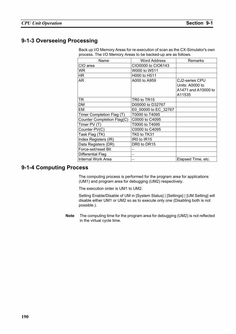
CPU Unit Operation Section 9-1
190
9-1-3 Overseeing Processing Back up I/O Memory Areas for re-execution of scan as the CX-Simulator's own process. The I/O Memory Areas to be backed-up are as follows.
Name Word Address Remarks CIO area CIO0000 to CIO6143 WR W000 to W511 HR H000 to H511 AR A000 to A959 CJ2-series CPU
Units: A0000 to A1471 and A10000 to A11535
TR TR0 to TR15 DM D00000 to D32767 EM E0_00000 to EC_32767 Timer Completion Flag (T) T0000 to T4095 Counter Completion Flag(C) C0000 to C4095 Timer PV (T) T0000 to T4095 Counter PV(C) C0000 to C4095 Task Flag (TK) TK0 to TK31 Index Registers (IR) IR0 to IR15 Data Registers (DR) DR0 to DR15 Force-set/reset Bit − Differential Flag − Internal Work Area − Elapsed Time, etc.
9-1-4 Computing Process The computing process is performed for the program area for applications (UM1) and program area for debugging (UM2) respectively.
The execution order is UM1 to UM2.
Setting Enable/Disable of UM in [System Status] | [Settings] | [UM Setting] will disable either UM1 or UM2 so as to execute only one (Disabling both is not possible.).
Note The computing time for the program area for debugging (UM2) is not reflected
in the virtual cycle time.
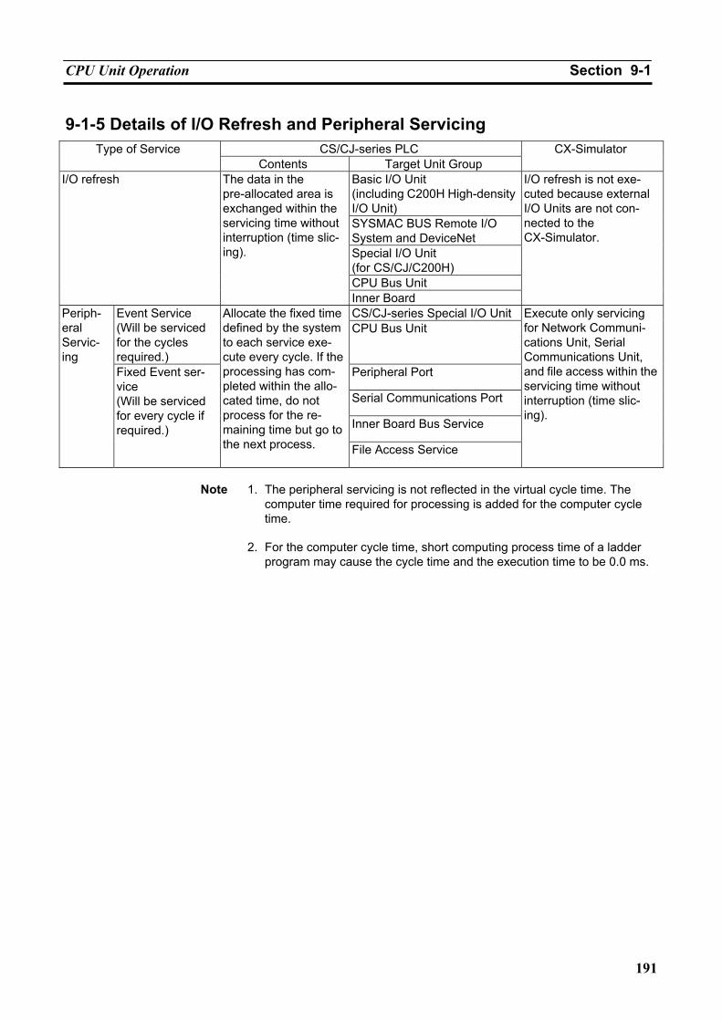
CPU Unit Operation Section 9-1
191
9-1-5 Details of I/O Refresh and Peripheral Servicing CS/CJ-series PLC Type of Service
Contents Target Unit Group CX-Simulator
Basic I/O Unit (including C200H High-density I/O Unit) SYSMAC BUS Remote I/O System and DeviceNet Special I/O Unit (for CS/CJ/C200H) CPU Bus Unit
I/O refresh The data in the pre-allocated area is exchanged within the servicing time without interruption (time slic-ing).
Inner Board
I/O refresh is not exe-cuted because external I/O Units are not con-nected to the CX-Simulator.
CS/CJ-series Special I/O Unit Event Service (Will be serviced for the cycles required.)
CPU Bus Unit
Peripheral Port
Serial Communications Port
Inner Board Bus Service
Periph-eral Servic-ing
Fixed Event ser-vice (Will be serviced for every cycle if required.)
Allocate the fixed time defined by the system to each service exe-cute every cycle. If the processing has com-pleted within the allo-cated time, do not process for the re-maining time but go to the next process. File Access Service
Execute only servicing for Network Communi-cations Unit, Serial Communications Unit, and file access within the servicing time without interruption (time slic-ing).
Note 1. The peripheral servicing is not reflected in the virtual cycle time. The
computer time required for processing is added for the computer cycle time.
2. For the computer cycle time, short computing process time of a ladder
program may cause the cycle time and the execution time to be 0.0 ms.
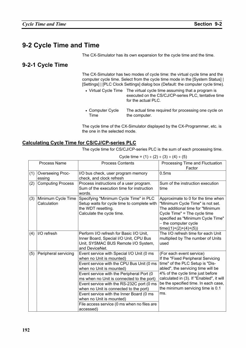
Cycle Time and Time Section 9-2
192
9-2 Cycle Time and Time The CX-Simulator has its own expansion for the cycle time and the time.
9-2-1 Cycle Time The CX-Simulator has two modes of cycle time: the virtual cycle time and the computer cycle time. Select from the cycle time mode in the [System Status] | [Settings] | [PLC Clock Settings] dialog box (Default: the computer cycle time).
• Virtual Cycle Time The virtual cycle time assuming that a program is executed on the CS/CJ/CP-series PLC, tentative time for the actual PLC.
• Computer Cycle Time
The actual time required for processing one cycle on the computer.
The cycle time of the CX-Simulator displayed by the CX-Programmer, etc. is the one in the selected mode.
Calculating Cycle Time for CS/CJ/CP-series PLC
The cycle time for CS/CJ/CP-series PLC is the sum of each processing time.
Cycle time = (1) + (2) + (3) + (4) + (5) Process Name Process Contents Processing Time and Fluctuation
Factor (1) Overseeing Proc-
essing I/O bus check, user program memory check, and clock refresh
0.5ms
(2) Computing Process Process instructions of a user program. Sum of the execution time for instruction words.
Sum of the instruction execution time
(3) Minimum Cycle Time Calculation
Specifying "Minimum Cycle Time" in PLC Setup waits for cycle time to complete with the WDT resetting. Calculate the cycle time.
Approximate to 0 for the time when "Minimum Cycle Time" is not set. The additional time for "Minimum Cycle Time" = The cycle time specified as "Minimum Cycle Time" − the computer cycle time((1)+(2)+(4)+(5))
(4) I/O refresh Perform I/O refresh for Basic I/O Unit, Inner Board, Special I/O Unit, CPU Bus Unit, SYSMAC BUS Remote I/O System, and DeviceNet.
The I/O refresh time for each Unit multiplied by The number of Units used
Event service with Special I/O Unit (0 ms when no Unit is mounted) Event service with the CPU Bus Unit (0 ms when no Unit is mounted) Event service with the Peripheral Port (0 ms when no Unit is connected to the port)Event service with the RS-232C port (0 ms when no Unit is connected to the port) Event service with the Inner Board (0 ms when no Unit is mounted)
(5) Peripheral servicing
File access service (0 ms when no files are accessed)
(For each event service) If the "Fixed Peripheral Servicing time" of the PLC Setup is "Dis-abled", the servicing time will be 4% of the cycle time just before calculated in (3). If "Enabled", it will be the specified time. In each case, the minimum servicing time is 0.1 ms.
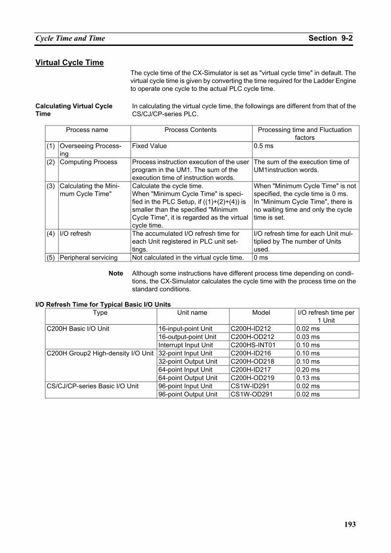
Cycle Time and Time Section 9-2
193
Virtual Cycle Time The cycle time of the CX-Simulator is set as "virtual cycle time" in default. The virtual cycle time is given by converting the time required for the Ladder Engine to operate one cycle to the actual PLC cycle time.
Calculating Virtual Cycle Time
In calculating the virtual cycle time, the followings are different from that of the CS/CJ/CP-series PLC.
Process name Process Contents Processing time and Fluctuation
factors (1) Overseeing Process-
ing Fixed Value 0.5 ms
(2) Computing Process Process instruction execution of the user program in the UM1. The sum of the execution time of instruction words.
The sum of the execution time of UM1instruction words.
(3) Calculating the Mini-mum Cycle Time"
Calculate the cycle time. When "Minimum Cycle Time" is speci-fied in the PLC Setup, if ((1)+(2)+(4)) is smaller than the specified "Minimum Cycle Time", it is regarded as the virtual cycle time.
When "Minimum Cycle Time" is not specified, the cycle time is 0 ms. In "Minimum Cycle Time", there is no waiting time and only the cycle time is set.
(4) I/O refresh The accumulated I/O refresh time for each Unit registered in PLC unit set-tings.
I/O refresh time for each Unit mul-tiplied by The number of Units used.
(5) Peripheral servicing Not calculated in the virtual cycle time. 0 ms
Note Although some instructions have different process time depending on condi-tions, the CX-Simulator calculates the cycle time with the process time on the standard conditions.
I/O Refresh Time for Typical Basic I/O Units
Type Unit name Model I/O refresh time per 1 Unit
16-input-point Unit C200H-ID212 0.02 ms 16-output-point Unit C200H-OD212 0.03 ms
C200H Basic I/O Unit
Interrupt Input Unit C200HS-INT01 0.10 ms 32-point Input Unit C200H-ID216 0.10 ms 32-point Output Unit C200H-OD218 0.10 ms 64-point Input Unit C200H-ID217 0.20 ms
C200H Group2 High-density I/O Unit
64-point Output Unit C200H-OD219 0.13 ms 96-point Input Unit CS1W-ID291 0.02 ms CS/CJ/CP-series Basic I/O Unit 96-point Output Unit CS1W-OD291 0.02 ms
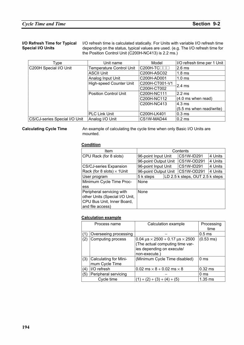
Cycle Time and Time Section 9-2
194
I/O Refresh Time for Typical Special I/O Units
I/O refresh time is calculated statically. For Units with variable I/O refresh time depending on the status, typical values are used. (e.g. The I/O refresh time for the Position Control Unit (C200H-NC413) is 2.2 ms.)
Type Unit name Model I/O refresh time per 1 Unit
Temperature Control Unit C200H-TC@@@ 2.6 ms ASCII Unit C200H-ASC02 1.8 ms Analog Input Unit C200H-AD001 1.0 ms
C200H-CT001-V1 High-speed Counter Unit C200H-CT002 2.4 ms
C200H-NC111 C200H-NC112
2.2 ms (4.0 ms when read)
Position Control Unit
C200H-NC413 4.3 ms (5.5 ms when read/write)
C200H Special I/O Unit
PLC Link Unit C200H-LK401 0.3 ms CS/CJ-series Special I/O Unit Analog I/O Unit CS1W-MAD44 0.2 ms
Calculating Cycle Time An example of calculating the cycle time when only Basic I/O Units are
mounted.
Condition Item Contents
96-point Input Unit CS1W-ID291 4 UnitsCPU Rack (for 8 slots) 96-point Output Unit CS1W-OD291 4 Units96-point Input Unit CS1W-ID291 4 UnitsCS/CJ-series Expansion
Rack (for 8 slots) × 1Unit 96-point Output Unit CS1W-OD291 4 UnitsUser program 5 k steps LD 2.5 k steps, OUT 2.5 k stepsMinimum Cycle Time Proc-ess
None
Peripheral servicing with other Units (Special I/O Unit, CPU Bus Unit, Inner Board, and file access)
None
Calculation example
Process name Calculation example Processingtime
(1) Overseeing processing − 0.5 ms (2) Computing process 0.04 µs × 2500 + 0.17 µs × 2500
(The actual computing time var-ies depending on execute/ non-execute.)
(0.53 ms)
(3) Calculating for Mini-mum Cycle Time
(Minimum Cycle Time disabled) 0 ms
(4) I/O refresh 0.02 ms × 8 + 0.02 ms × 8 0.32 ms (5) Peripheral servicing − 0 ms
Cycle time (1) + (2) + (3) + (4) + (5) 1.35 ms
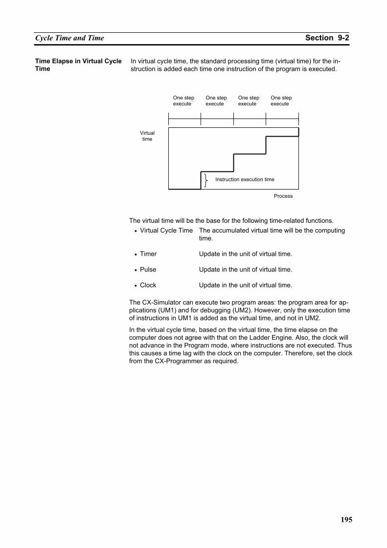
Cycle Time and Time Section 9-2
195
Time Elapse in Virtual Cycle Time
In virtual cycle time, the standard processing time (virtual time) for the in-struction is added each time one instruction of the program is executed.
The virtual time will be the base for the following time-related functions.
• Virtual Cycle Time The accumulated virtual time will be the computing time.
• Timer Update in the unit of virtual time.
• Pulse Update in the unit of virtual time.
• Clock Update in the unit of virtual time.
The CX-Simulator can execute two program areas: the program area for ap-plications (UM1) and for debugging (UM2). However, only the execution time of instructions in UM1 is added as the virtual time, and not in UM2.
In the virtual cycle time, based on the virtual time, the time elapse on the computer does not agree with that on the Ladder Engine. Also, the clock will not advance in the Program mode, where instructions are not executed. Thus this causes a time lag with the clock on the computer. Therefore, set the clock from the CX-Programmer as required.
Instruction execution time
Virtual time
One step execute
One step execute
One step execute
One step execute
Process
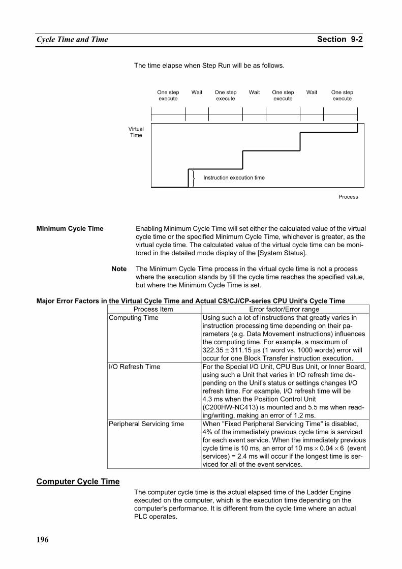
Cycle Time and Time Section 9-2
196
The time elapse when Step Run will be as follows.
Minimum Cycle Time Enabling Minimum Cycle Time will set either the calculated value of the virtual
cycle time or the specified Minimum Cycle Time, whichever is greater, as the virtual cycle time. The calculated value of the virtual cycle time can be moni-tored in the detailed mode display of the [System Status].
Note The Minimum Cycle Time process in the virtual cycle time is not a process
where the execution stands by till the cycle time reaches the specified value, but where the Minimum Cycle Time is set.
Major Error Factors in the Virtual Cycle Time and Actual CS/CJ/CP-series CPU Unit's Cycle Time
Process Item Error factor/Error range Computing Time Using such a lot of instructions that greatly varies in
instruction processing time depending on their pa-rameters (e.g. Data Movement instructions) influences the computing time. For example, a maximum of 322.35 ± 311.15 µs (1 word vs. 1000 words) error will occur for one Block Transfer instruction execution.
I/O Refresh Time For the Special I/O Unit, CPU Bus Unit, or Inner Board, using such a Unit that varies in I/O refresh time de-pending on the Unit's status or settings changes I/O refresh time. For example, I/O refresh time will be 4.3 ms when the Position Control Unit (C200HW-NC413) is mounted and 5.5 ms when read-ing/writing, making an error of 1.2 ms.
Peripheral Servicing time When "Fixed Peripheral Servicing Time" is disabled, 4% of the immediately previous cycle time is serviced for each event service. When the immediately previous cycle time is 10 ms, an error of 10 ms × 0.04 × 6 (event services) = 2.4 ms will occur if the longest time is ser-viced for all of the event services.
Computer Cycle Time
The computer cycle time is the actual elapsed time of the Ladder Engine executed on the computer, which is the execution time depending on the computer's performance. It is different from the cycle time where an actual PLC operates.
Virtual Time
Instruction execution time
One stepexecute
Wait One stepexecute
Wait One stepexecute
Wait One step execute
Process
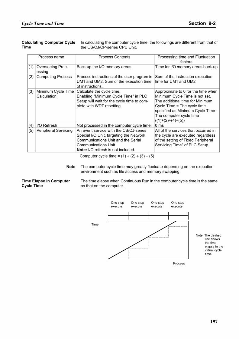
Cycle Time and Time Section 9-2
197
Calculating Computer Cycle Time
In calculating the computer cycle time, the followings are different from that of the CS/CJ/CP-series CPU Unit.
Process name Process Contents Processing time and Fluctuation
factors (1) Overseeing Proc-
essing Back up the I/O memory areas Time for I/O memory areas back-up
(2) Computing Process Process instructions of the user program in UM1 and UM2. Sum of the execution time of instructions.
Sum of the instruction execution time for UM1 and UM2
(3) Minimum Cycle Time Calculation
Calculate the cycle time. Enabling "Minimum Cycle Time" in PLC Setup will wait for the cycle time to com-plete with WDT resetting.
Approximate to 0 for the time when Minimum Cycle Time is not set. The additional time for Minimum Cycle Time = The cycle time specified as Minimum Cycle Time - The computer cycle time ((1)+(2)+(4)+(5))
(4) I/O Refresh Not processed in the computer cycle time. 0 ms (5) Peripheral Servicing An event service with the CS/CJ-series
Special I/O Unit, targeting the Network Communications Unit and the Serial Communications Unit. Note: I/O refresh is not included.
All of the services that occurred in the cycle are executed regardless of the setting of Fixed Peripheral Servicing Time" of PLC Setup.
Computer cycle time = (1) + (2) + (3) + (5)
Note The computer cycle time may greatly fluctuate depending on the execution environment such as file access and memory swapping.
Time Elapse in Computer Cycle Time
The time elapse when Continuous Run in the computer cycle time is the same as that on the computer.
Time
One step execute
One step execute
One step execute
One step execute
Process
Note: The dashed line shows the time elapse in the virtual cycle time.
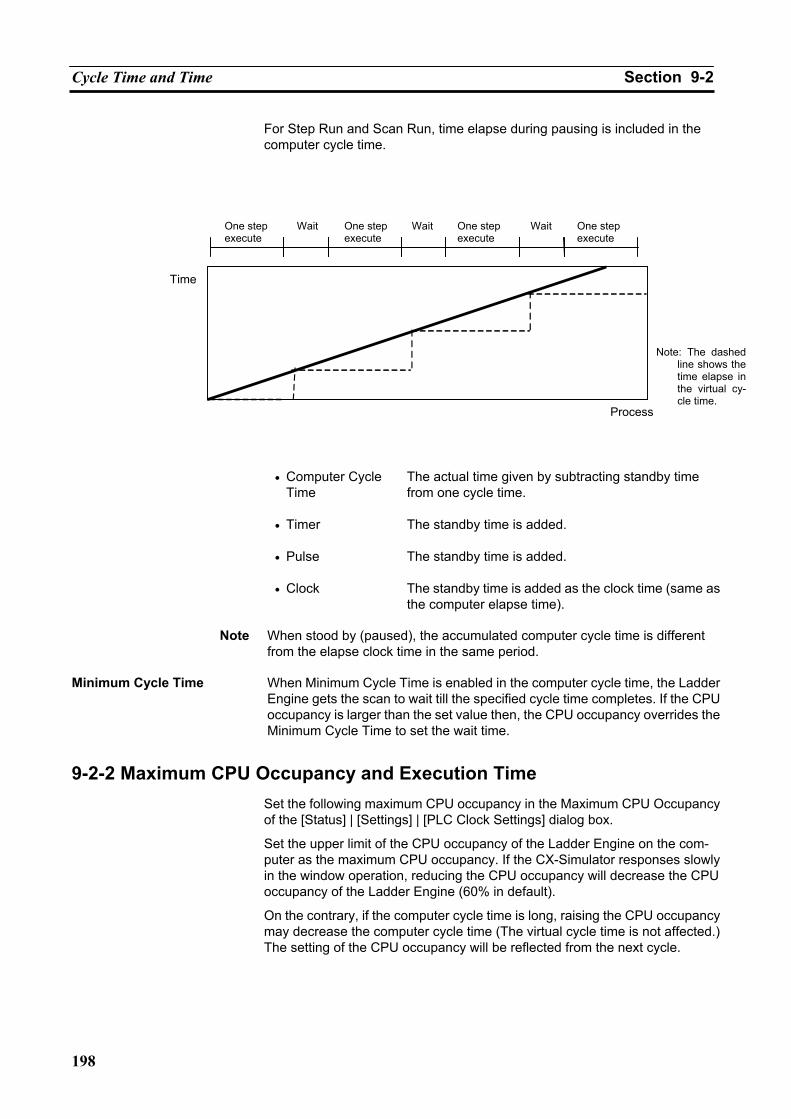
Cycle Time and Time Section 9-2
198
For Step Run and Scan Run, time elapse during pausing is included in the computer cycle time.
• Computer Cycle
Time The actual time given by subtracting standby time from one cycle time.
• Timer The standby time is added.
• Pulse The standby time is added.
• Clock The standby time is added as the clock time (same as the computer elapse time).
Note When stood by (paused), the accumulated computer cycle time is different
from the elapse clock time in the same period. Minimum Cycle Time When Minimum Cycle Time is enabled in the computer cycle time, the Ladder
Engine gets the scan to wait till the specified cycle time completes. If the CPU occupancy is larger than the set value then, the CPU occupancy overrides the Minimum Cycle Time to set the wait time.
9-2-2 Maximum CPU Occupancy and Execution Time Set the following maximum CPU occupancy in the Maximum CPU Occupancy of the [Status] | [Settings] | [PLC Clock Settings] dialog box.
Set the upper limit of the CPU occupancy of the Ladder Engine on the com-puter as the maximum CPU occupancy. If the CX-Simulator responses slowly in the window operation, reducing the CPU occupancy will decrease the CPU occupancy of the Ladder Engine (60% in default).
On the contrary, if the computer cycle time is long, raising the CPU occupancy may decrease the computer cycle time (The virtual cycle time is not affected.) The setting of the CPU occupancy will be reflected from the next cycle.
Time
WaitWait
Note: The dashed line shows the time elapse in the virtual cy-cle time.
WaitOne step execute
One step execute
One step execute
One step execute
Process
Cycle Time and Time Section 9-2
199
9-2-3 Differences with CS/CJ/CP Series Built-in Clock Function The clock of the Ladder Engine is the same as that of the computer when
startup. However, it will not synchronize with the clock of the computer be-cause it advances according to the virtual cycle time. So if synchronization is required, operate the CX-Simulator in the computer cycle time.
High-speed Timer When executing a program in the computer cycle time, the High-speed Timer and 1-ms Timer will not be guaranteed to operate correctly.
Interrupt Time when Online Editing
When editing online by the CX-Simulator, the cycle time will not be affected in the virtual cycle time. However, interrupt time will occur in the computer cycle time as well as the actual CS/CJ/CP-series PLC.
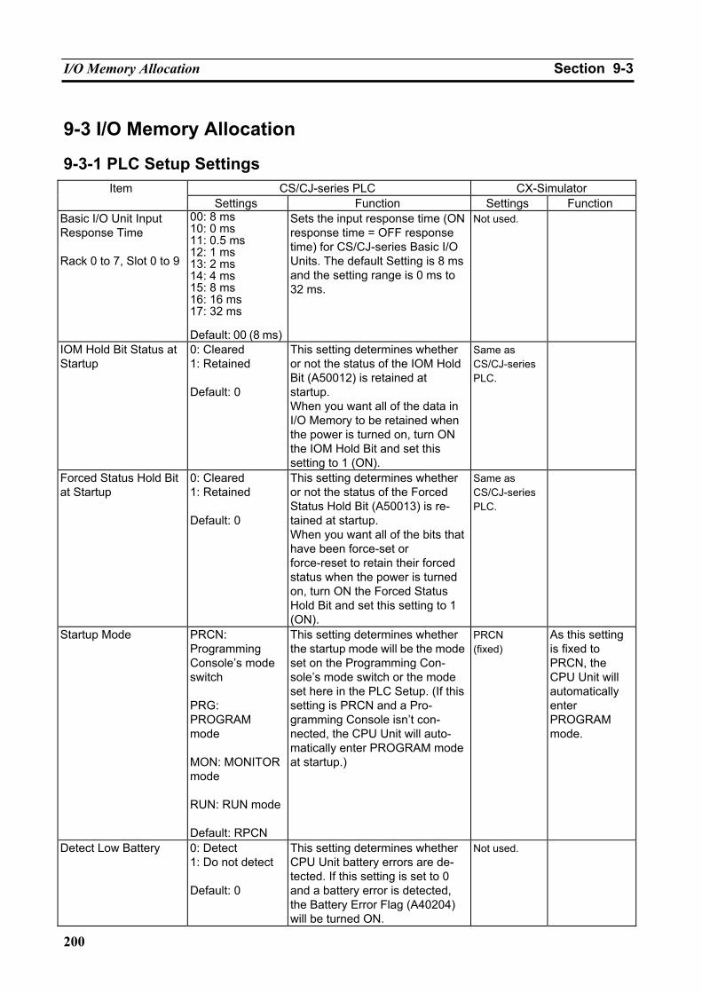
I/O Memory Allocation Section 9-3
200
9-3 I/O Memory Allocation
9-3-1 PLC Setup Settings CS/CJ-series PLC CX-Simulator Item
Settings Function Settings Function Basic I/O Unit Input Response Time Rack 0 to 7, Slot 0 to 9
00: 8 ms 10: 0 ms 11: 0.5 ms 12: 1 ms 13: 2 ms 14: 4 ms 15: 8 ms 16: 16 ms 17: 32 ms Default: 00 (8 ms)
Sets the input response time (ON response time = OFF response time) for CS/CJ-series Basic I/O Units. The default Setting is 8 ms and the setting range is 0 ms to 32 ms.
Not used.
IOM Hold Bit Status at Startup
0: Cleared 1: Retained Default: 0
This setting determines whether or not the status of the IOM Hold Bit (A50012) is retained at startup. When you want all of the data in I/O Memory to be retained when the power is turned on, turn ON the IOM Hold Bit and set this setting to 1 (ON).
Same as CS/CJ-series PLC.
Forced Status Hold Bit at Startup
0: Cleared 1: Retained Default: 0
This setting determines whether or not the status of the Forced Status Hold Bit (A50013) is re-tained at startup. When you want all of the bits that have been force-set or force-reset to retain their forced status when the power is turned on, turn ON the Forced Status Hold Bit and set this setting to 1 (ON).
Same as CS/CJ-series PLC.
Startup Mode PRCN: Programming Console’s mode switch PRG: PROGRAM mode MON: MONITOR mode RUN: RUN mode Default: RPCN
This setting determines whether the startup mode will be the mode set on the Programming Con-sole’s mode switch or the mode set here in the PLC Setup. (If this setting is PRCN and a Pro-gramming Console isn’t con-nected, the CPU Unit will auto-matically enter PROGRAM mode at startup.)
PRCN (fixed)
As this setting is fixed to PRCN, the CPU Unit will automatically enter PROGRAM mode.
Detect Low Battery 0: Detect 1: Do not detect Default: 0
This setting determines whether CPU Unit battery errors are de-tected. If this setting is set to 0 and a battery error is detected, the Battery Error Flag (A40204) will be turned ON.
Not used.
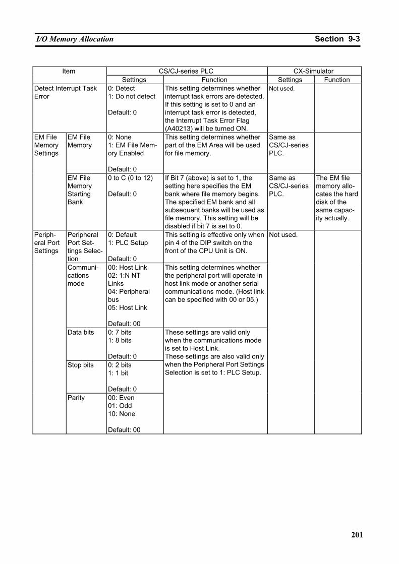
I/O Memory Allocation Section 9-3
201
CS/CJ-series PLC CX-Simulator Item
Settings Function Settings Function Detect Interrupt Task Error
0: Detect 1: Do not detect Default: 0
This setting determines whether interrupt task errors are detected. If this setting is set to 0 and an interrupt task error is detected, the Interrupt Task Error Flag (A40213) will be turned ON.
Not used.
EM File Memory
0: None 1: EM File Mem-ory Enabled Default: 0
This setting determines whether part of the EM Area will be used for file memory.
Same as CS/CJ-series PLC.
EM File Memory Settings
EM File Memory Starting Bank
0 to C (0 to 12) Default: 0
If Bit 7 (above) is set to 1, the setting here specifies the EM bank where file memory begins. The specified EM bank and all subsequent banks will be used as file memory. This setting will be disabled if bit 7 is set to 0.
Same as CS/CJ-series PLC.
The EM file memory allo-cates the hard disk of the same capac-ity actually.
Peripheral Port Set-tings Selec-tion
0: Default 1: PLC Setup Default: 0
This setting is effective only when pin 4 of the DIP switch on the front of the CPU Unit is ON.
Communi-cations mode
00: Host Link 02: 1:N NT Links 04: Peripheral bus 05: Host Link Default: 00
This setting determines whether the peripheral port will operate in host link mode or another serial communications mode. (Host link can be specified with 00 or 05.)
Data bits 0: 7 bits 1: 8 bits Default: 0
Stop bits 0: 2 bits 1: 1 bit Default: 0
Periph-eral Port Settings
Parity 00: Even 01: Odd 10: None Default: 00
These settings are valid only when the communications mode is set to Host Link. These settings are also valid only when the Peripheral Port Settings Selection is set to 1: PLC Setup.
Not used.
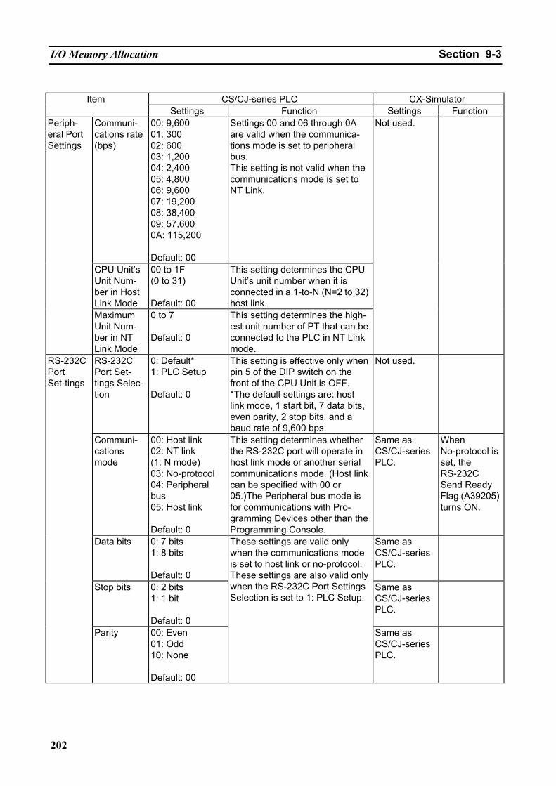
I/O Memory Allocation Section 9-3
202
CS/CJ-series PLC CX-Simulator Item
Settings Function Settings Function Communi-cations rate (bps)
00: 9,600 01: 300 02: 600 03: 1,200 04: 2,400 05: 4,800 06: 9,600 07: 19,200 08: 38,400 09: 57,600 0A: 115,200 Default: 00
Settings 00 and 06 through 0A are valid when the communica-tions mode is set to peripheral bus. This setting is not valid when the communications mode is set to NT Link.
CPU Unit’s Unit Num-ber in Host Link Mode
00 to 1F (0 to 31) Default: 00
This setting determines the CPU Unit’s unit number when it is connected in a 1-to-N (N=2 to 32) host link.
Periph-eral Port Settings
Maximum Unit Num-ber in NT Link Mode
0 to 7 Default: 0
This setting determines the high-est unit number of PT that can be connected to the PLC in NT Link mode.
Not used.
RS-232C Port Set-tings Selec-tion
0: Default*
1: PLC Setup Default: 0
This setting is effective only when pin 5 of the DIP switch on the front of the CPU Unit is OFF. *The default settings are: host link mode, 1 start bit, 7 data bits, even parity, 2 stop bits, and a baud rate of 9,600 bps.
Not used.
Communi-cations mode
00: Host link 02: NT link (1: N mode) 03: No-protocol 04: Peripheral bus 05: Host link Default: 0
This setting determines whether the RS-232C port will operate in host link mode or another serial communications mode. (Host link can be specified with 00 or 05.)The Peripheral bus mode is for communications with Pro-gramming Devices other than the Programming Console.
Same as CS/CJ-series PLC.
When No-protocol is set, the RS-232C Send Ready Flag (A39205) turns ON.
Data bits 0: 7 bits 1: 8 bits Default: 0
Same as CS/CJ-series PLC.
Stop bits 0: 2 bits 1: 1 bit Default: 0
Same as CS/CJ-series PLC.
RS-232C Port Set-tings
Parity 00: Even 01: Odd 10: None Default: 00
These settings are valid only when the communications mode is set to host link or no-protocol. These settings are also valid only when the RS-232C Port Settings Selection is set to 1: PLC Setup.
Same as CS/CJ-series PLC.
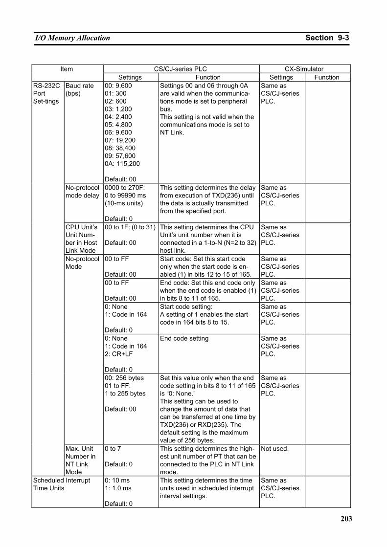
I/O Memory Allocation Section 9-3
203
CS/CJ-series PLC CX-Simulator Item
Settings Function Settings Function Baud rate (bps)
00: 9,600 01: 300 02: 600 03: 1,200 04: 2,400 05: 4,800 06: 9,600 07: 19,200 08: 38,400 09: 57,600 0A: 115,200 Default: 00
Settings 00 and 06 through 0A are valid when the communica-tions mode is set to peripheral bus. This setting is not valid when the communications mode is set to NT Link.
Same as CS/CJ-series PLC.
No-protocol mode delay
0000 to 270F: 0 to 99990 ms (10-ms units) Default: 0
This setting determines the delay from execution of TXD(236) until the data is actually transmitted from the specified port.
Same as CS/CJ-series PLC.
CPU Unit’s Unit Num-ber in Host Link Mode
00 to 1F: (0 to 31) Default: 00
This setting determines the CPU Unit’s unit number when it is connected in a 1-to-N (N=2 to 32) host link.
Same as CS/CJ-series PLC.
00 to FF Default: 00
Start code: Set this start code only when the start code is en-abled (1) in bits 12 to 15 of 165.
Same as CS/CJ-series PLC.
00 to FF Default: 00
End code: Set this end code only when the end code is enabled (1) in bits 8 to 11 of 165.
Same as CS/CJ-series PLC.
0: None 1: Code in 164 Default: 0
Start code setting: A setting of 1 enables the start code in 164 bits 8 to 15.
Same as CS/CJ-series PLC.
0: None 1: Code in 164 2: CR+LF Default: 0
End code setting
Same as CS/CJ-series PLC.
No-protocol Mode
00: 256 bytes 01 to FF: 1 to 255 bytes Default: 00
Set this value only when the end code setting in bits 8 to 11 of 165 is “0: None.” This setting can be used to change the amount of data that can be transferred at one time by TXD(236) or RXD(235). The default setting is the maximum value of 256 bytes.
Same as CS/CJ-series PLC.
RS-232C Port Set-tings
Max. Unit Number in NT Link Mode
0 to 7 Default: 0
This setting determines the high-est unit number of PT that can be connected to the PLC in NT Link mode.
Not used.
Scheduled Interrupt Time Units
0: 10 ms 1: 1.0 ms Default: 0
This setting determines the time units used in scheduled interrupt interval settings.
Same as CS/CJ-series PLC.
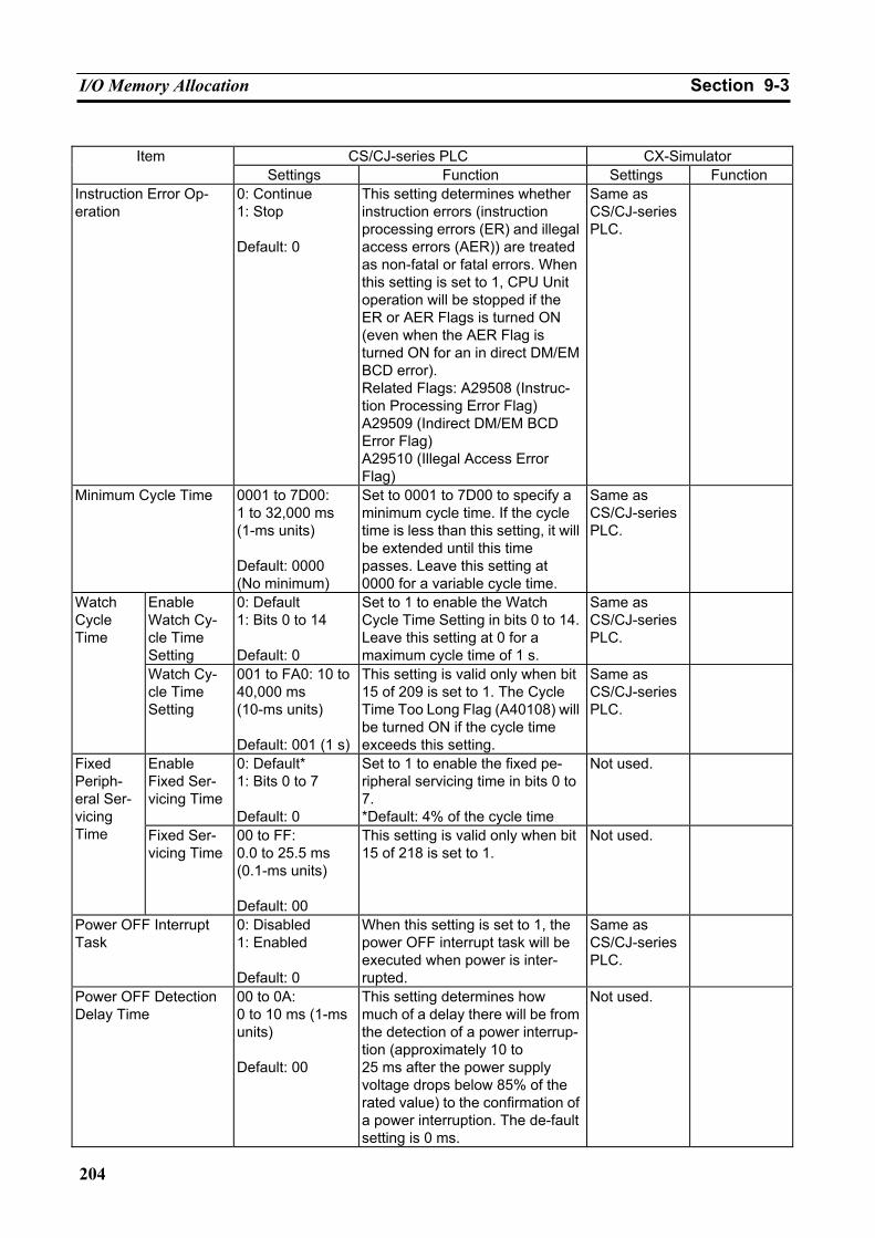
I/O Memory Allocation Section 9-3
204
CS/CJ-series PLC CX-Simulator Item
Settings Function Settings Function Instruction Error Op-eration
0: Continue 1: Stop Default: 0
This setting determines whether instruction errors (instruction processing errors (ER) and illegal access errors (AER)) are treated as non-fatal or fatal errors. When this setting is set to 1, CPU Unit operation will be stopped if the ER or AER Flags is turned ON (even when the AER Flag is turned ON for an in direct DM/EM BCD error). Related Flags: A29508 (Instruc-tion Processing Error Flag) A29509 (Indirect DM/EM BCD Error Flag) A29510 (Illegal Access Error Flag)
Same as CS/CJ-series PLC.
Minimum Cycle Time 0001 to 7D00: 1 to 32,000 ms (1-ms units) Default: 0000 (No minimum)
Set to 0001 to 7D00 to specify a minimum cycle time. If the cycle time is less than this setting, it will be extended until this time passes. Leave this setting at 0000 for a variable cycle time.
Same as CS/CJ-series PLC.
Enable Watch Cy-cle Time Setting
0: Default 1: Bits 0 to 14 Default: 0
Set to 1 to enable the Watch Cycle Time Setting in bits 0 to 14. Leave this setting at 0 for a maximum cycle time of 1 s.
Same as CS/CJ-series PLC.
Watch Cycle Time
Watch Cy-cle Time Setting
001 to FA0: 10 to 40,000 ms (10-ms units) Default: 001 (1 s)
This setting is valid only when bit 15 of 209 is set to 1. The Cycle Time Too Long Flag (A40108) will be turned ON if the cycle time exceeds this setting.
Same as CS/CJ-series PLC.
Enable Fixed Ser-vicing Time
0: Default* 1: Bits 0 to 7 Default: 0
Set to 1 to enable the fixed pe-ripheral servicing time in bits 0 to 7. *Default: 4% of the cycle time
Not used. Fixed Periph-eral Ser-vicing Time Fixed Ser-
vicing Time 00 to FF: 0.0 to 25.5 ms (0.1-ms units) Default: 00
This setting is valid only when bit 15 of 218 is set to 1.
Not used.
Power OFF Interrupt Task
0: Disabled 1: Enabled Default: 0
When this setting is set to 1, the power OFF interrupt task will be executed when power is inter-rupted.
Same as CS/CJ-series PLC.
Power OFF Detection Delay Time
00 to 0A: 0 to 10 ms (1-ms units) Default: 00
This setting determines how much of a delay there will be from the detection of a power interrup-tion (approximately 10 to 25 ms after the power supply voltage drops below 85% of the rated value) to the confirmation of a power interruption. The de-fault setting is 0 ms.
Not used.
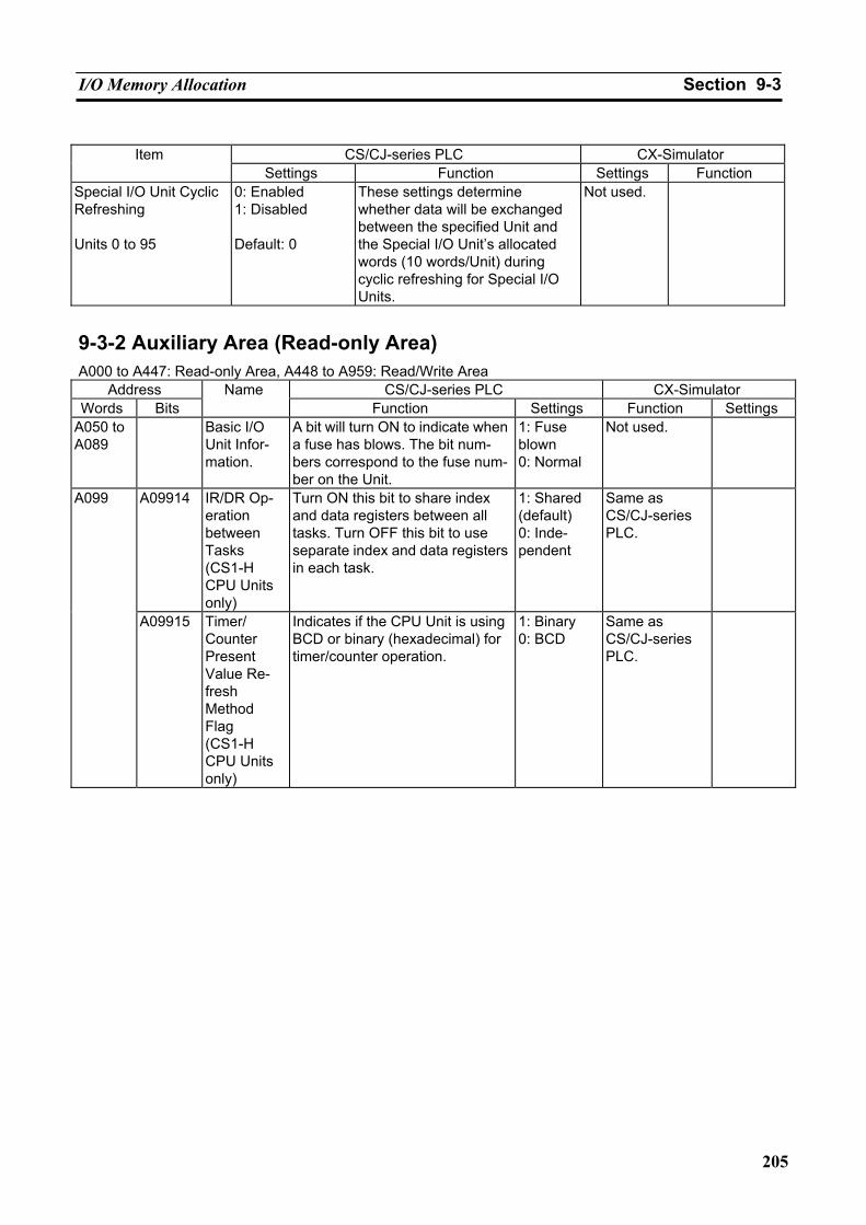
I/O Memory Allocation Section 9-3
205
CS/CJ-series PLC CX-Simulator Item
Settings Function Settings Function Special I/O Unit Cyclic Refreshing Units 0 to 95
0: Enabled 1: Disabled Default: 0
These settings determine whether data will be exchanged between the specified Unit and the Special I/O Unit’s allocated words (10 words/Unit) during cyclic refreshing for Special I/O Units.
Not used.
9-3-2 Auxiliary Area (Read-only Area) A000 to A447: Read-only Area, A448 to A959: Read/Write Area
Address CS/CJ-series PLC CX-Simulator Words Bits
Name Function Settings Function Settings
A050 to A089
Basic I/O Unit Infor-mation.
A bit will turn ON to indicate when a fuse has blows. The bit num-bers correspond to the fuse num-ber on the Unit.
1: Fuse blown 0: Normal
Not used.
A09914 IR/DR Op-eration between Tasks (CS1-H CPU Units only)
Turn ON this bit to share index and data registers between all tasks. Turn OFF this bit to use separate index and data registers in each task.
1: Shared (default) 0: Inde-pendent
Same as CS/CJ-series PLC.
A099
A09915 Timer/ Counter Present Value Re-fresh Method Flag (CS1-H CPU Units only)
Indicates if the CPU Unit is using BCD or binary (hexadecimal) for timer/counter operation.
1: Binary 0: BCD
Same as CS/CJ-series PLC.
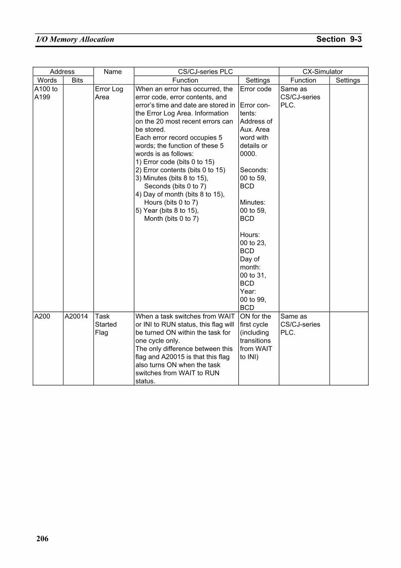
I/O Memory Allocation Section 9-3
206
Address CS/CJ-series PLC CX-Simulator
Words Bits Name
Function Settings Function Settings A100 to A199
Error Log Area
When an error has occurred, the error code, error contents, and error’s time and date are stored in the Error Log Area. Information on the 20 most recent errors can be stored. Each error record occupies 5 words; the function of these 5 words is as follows: 1) Error code (bits 0 to 15) 2) Error contents (bits 0 to 15) 3) Minutes (bits 8 to 15),
Seconds (bits 0 to 7) 4) Day of month (bits 8 to 15),
Hours (bits 0 to 7) 5) Year (bits 8 to 15),
Month (bits 0 to 7)
Error code Error con-tents: Address of Aux. Area word with details or 0000. Seconds: 00 to 59, BCD Minutes: 00 to 59, BCD Hours: 00 to 23, BCD Day of month: 00 to 31, BCD Year: 00 to 99, BCD
Same as CS/CJ-series PLC.
A200 A20014 Task Started Flag
When a task switches from WAIT or INI to RUN status, this flag will be turned ON within the task for one cycle only. The only difference between this flag and A20015 is that this flag also turns ON when the task switches from WAIT to RUN status.
ON for the first cycle (including transitions from WAIT to INI)
Same as CS/CJ-series PLC.
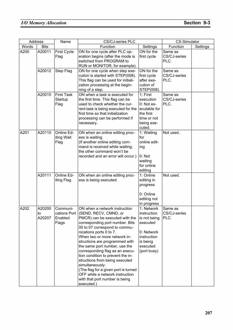
I/O Memory Allocation Section 9-3
207
Address CS/CJ-series PLC CX-Simulator
Words Bits Name
Function Settings Function Settings A20011 First Cycle
Flag ON for one cycle after PLC op-eration begins (after the mode is switched from PROGRAM to RUN or MONITOR, for example).
ON for the first cycle
Same as CS/CJ-series PLC.
A20012 Step Flag ON for one cycle when step exe-cution is started with STEP(008). This flag can be used for initiali-zation processing at the begin-ning of a step.
ON for the first cycle after exe-cution of STEP(008).
Same as CS/CJ-series PLC.
A200
A20015 First Task Startup Flag
ON when a task is executed for the first time. This flag can be used to check whether the cur-rent task is being executed for the first time so that initialization processing can be performed if necessary.
1: First execution 0: Not ex-ecutable for the first time or not being exe-cuted.
Same as CS/CJ-series PLC.
A20110 Online Ed-iting Wait Flag
ON when an online editing proc-ess is waiting. (If another online editing com-mand is received while waiting, the other command won’t be recorded and an error will occur.)
1: Waiting for online edit-ing 0: Not waiting for online editing
Not used. A201
A20111 Online Ed-iting Flag
ON when an online editing proc-ess is being executed.
1: Online editing in progress 0: Online editing not in progress
Not used.
A202 A20200 to A20207
Communi-cations Port Enabled Flags
ON when a network instruction (SEND, RECV, CMND, or PMCR) can be executed with the corresponding port number. Bits 00 to 07 correspond to commu-nications ports 0 to 7. When two or more network in-structions are programmed with the same port number, use the corresponding flag as an execu-tion condition to prevent the in-structions from being executed simultaneously. (The flag for a given port is turned OFF while a network instruction with that port number is being executed.)
1: Network instruction is not being executed 0: Network instruction is being executed (port busy)
Same as CS/CJ-series PLC.
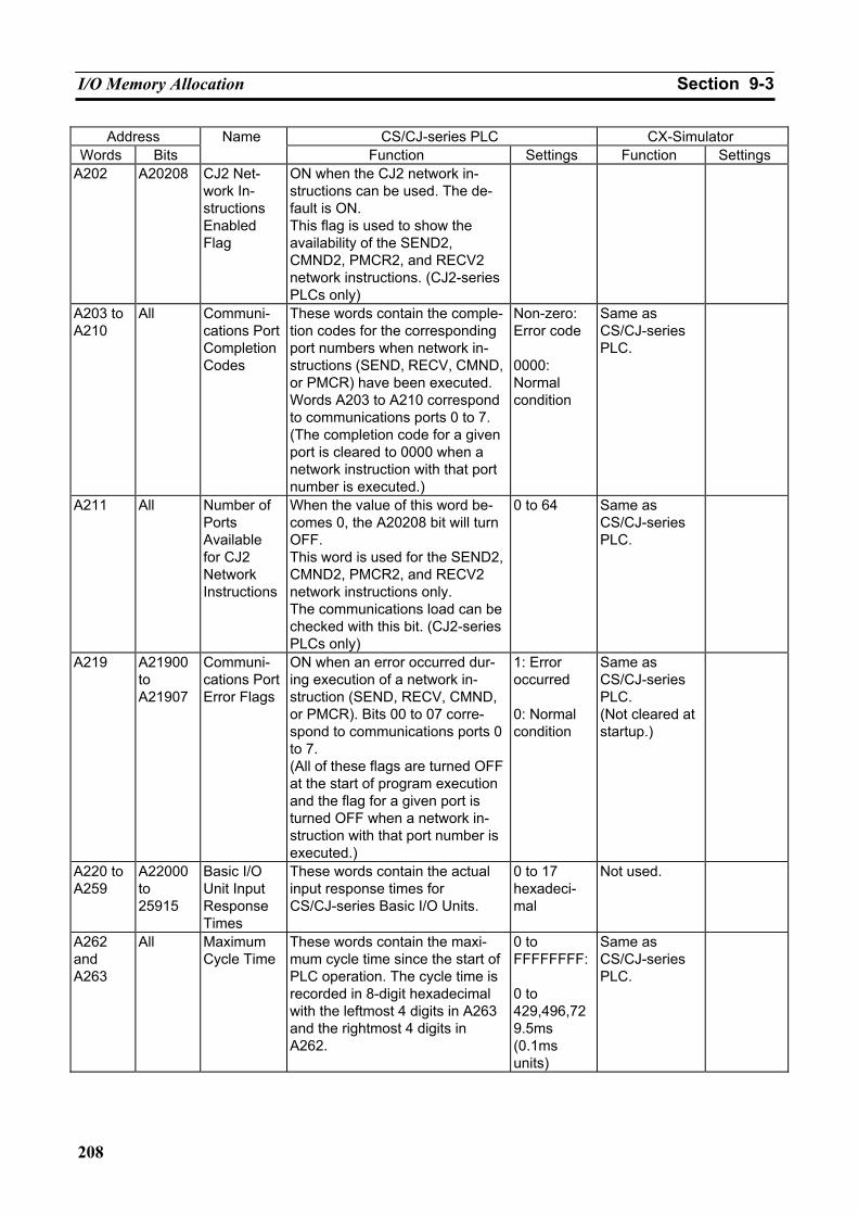
I/O Memory Allocation Section 9-3
208
Address CS/CJ-series PLC CX-Simulator Words Bits
Name Function Settings Function Settings
A202 A20208 CJ2 Net-work In-structions Enabled Flag
ON when the CJ2 network in-structions can be used. The de-fault is ON. This flag is used to show the availability of the SEND2, CMND2, PMCR2, and RECV2 network instructions. (CJ2-series PLCs only)
A203 to A210
All Communi-cations Port Completion Codes
These words contain the comple-tion codes for the corresponding port numbers when network in-structions (SEND, RECV, CMND, or PMCR) have been executed. Words A203 to A210 correspond to communications ports 0 to 7. (The completion code for a given port is cleared to 0000 when a network instruction with that port number is executed.)
Non-zero: Error code 0000: Normal condition
Same as CS/CJ-series PLC.
A211 All Number of Ports Available for CJ2 Network Instructions
When the value of this word be-comes 0, the A20208 bit will turn OFF. This word is used for the SEND2, CMND2, PMCR2, and RECV2 network instructions only. The communications load can be checked with this bit. (CJ2-series PLCs only)
0 to 64 Same as CS/CJ-series PLC.
A219 A21900 to A21907
Communi-cations Port Error Flags
ON when an error occurred dur-ing execution of a network in-struction (SEND, RECV, CMND, or PMCR). Bits 00 to 07 corre-spond to communications ports 0 to 7. (All of these flags are turned OFF at the start of program execution and the flag for a given port is turned OFF when a network in-struction with that port number is executed.)
1: Error occurred 0: Normal condition
Same as CS/CJ-series PLC. (Not cleared at startup.)
A220 to A259
A22000 to 25915
Basic I/O Unit Input Response Times
These words contain the actual input response times for CS/CJ-series Basic I/O Units.
0 to 17 hexadeci-mal
Not used.
A262 and A263
All Maximum Cycle Time
These words contain the maxi-mum cycle time since the start of PLC operation. The cycle time is recorded in 8-digit hexadecimal with the leftmost 4 digits in A263 and the rightmost 4 digits in A262.
0 to FFFFFFFF: 0 to 429,496,729.5ms (0.1ms units)
Same as CS/CJ-series PLC.
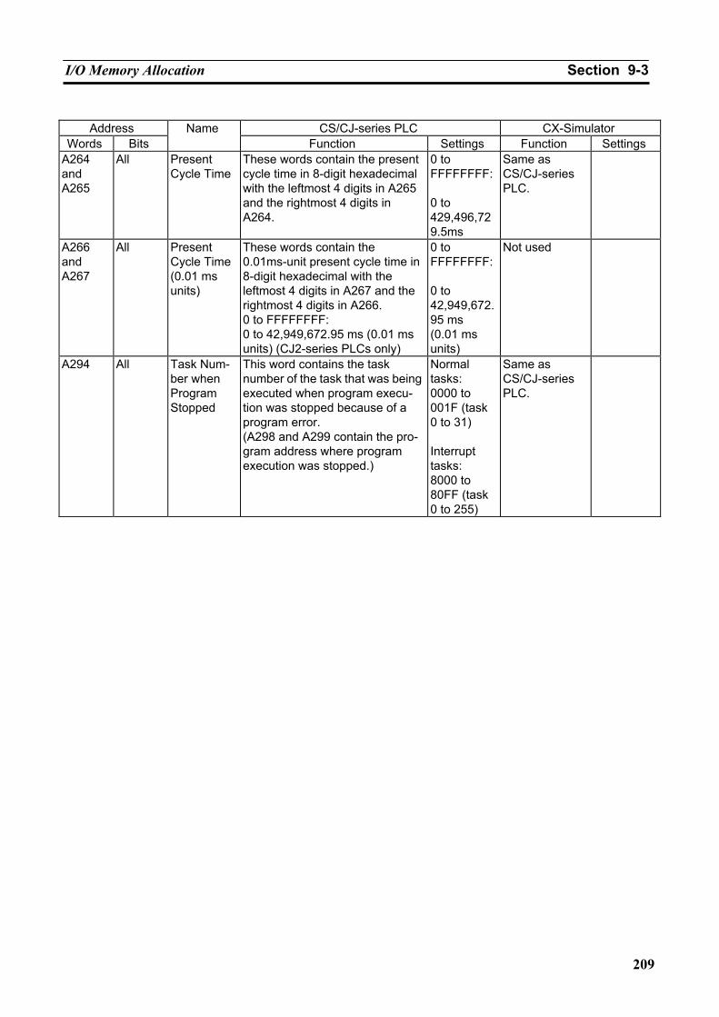
I/O Memory Allocation Section 9-3
209
Address CS/CJ-series PLC CX-Simulator
Words Bits Name
Function Settings Function Settings A264 and A265
All Present Cycle Time
These words contain the present cycle time in 8-digit hexadecimal with the leftmost 4 digits in A265 and the rightmost 4 digits in A264.
0 to FFFFFFFF: 0 to 429,496,729.5ms
Same as CS/CJ-series PLC.
A266 and A267
All Present Cycle Time (0.01 ms units)
These words contain the 0.01ms-unit present cycle time in 8-digit hexadecimal with the leftmost 4 digits in A267 and the rightmost 4 digits in A266. 0 to FFFFFFFF: 0 to 42,949,672.95 ms (0.01 ms units) (CJ2-series PLCs only)
0 to FFFFFFFF: 0 to 42,949,672.95 ms (0.01 ms units)
Not used
A294 All Task Num-ber when Program Stopped
This word contains the task number of the task that was being executed when program execu-tion was stopped because of a program error. (A298 and A299 contain the pro-gram address where program execution was stopped.)
Normal tasks: 0000 to 001F (task 0 to 31) Interrupt tasks: 8000 to 80FF (task 0 to 255)
Same as CS/CJ-series PLC.
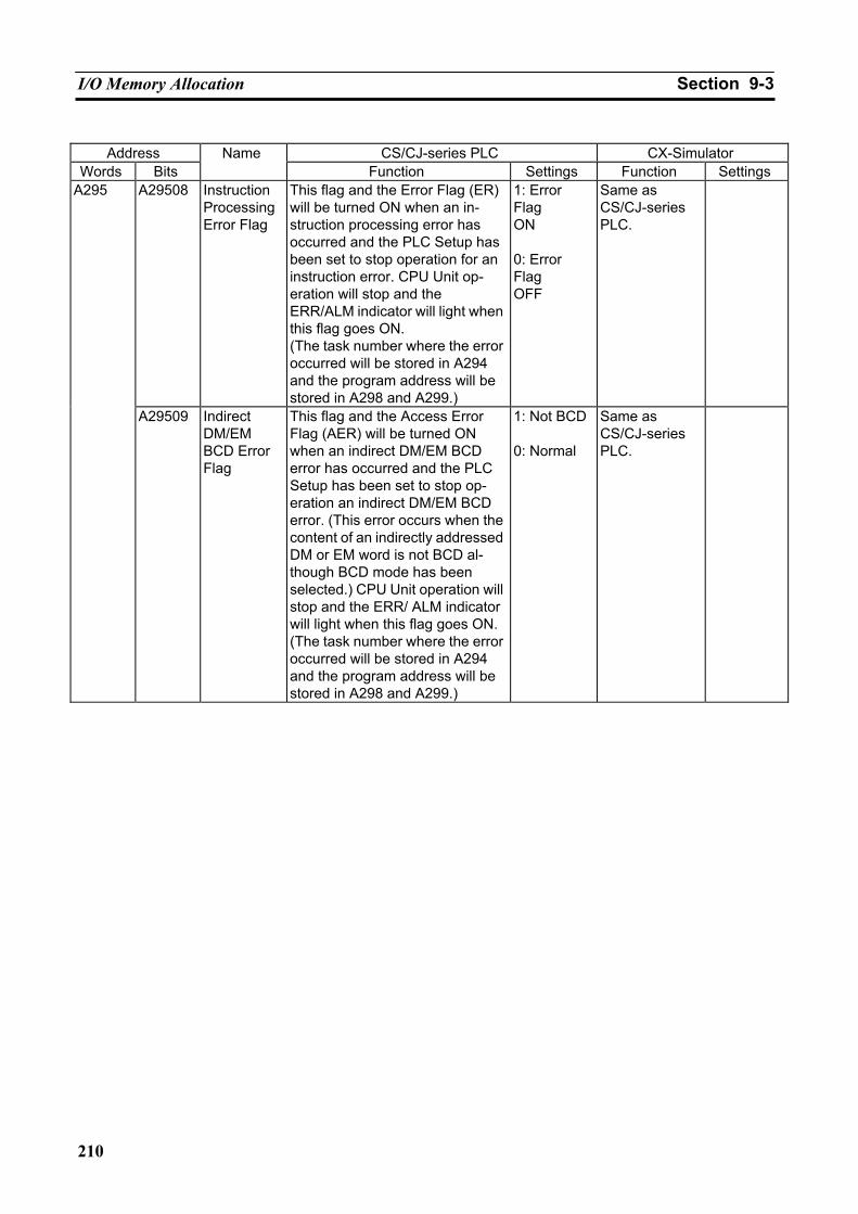
I/O Memory Allocation Section 9-3
210
Address CS/CJ-series PLC CX-Simulator
Words Bits Name
Function Settings Function Settings A29508 Instruction
Processing Error Flag
This flag and the Error Flag (ER) will be turned ON when an in-struction processing error has occurred and the PLC Setup has been set to stop operation for an instruction error. CPU Unit op-eration will stop and the ERR/ALM indicator will light when this flag goes ON. (The task number where the error occurred will be stored in A294 and the program address will be stored in A298 and A299.)
1: Error Flag ON 0: Error Flag OFF
Same as CS/CJ-series PLC.
A295
A29509 Indirect DM/EM BCD Error Flag
This flag and the Access Error Flag (AER) will be turned ON when an indirect DM/EM BCD error has occurred and the PLC Setup has been set to stop op-eration an indirect DM/EM BCD error. (This error occurs when the content of an indirectly addressed DM or EM word is not BCD al-though BCD mode has been selected.) CPU Unit operation will stop and the ERR/ ALM indicator will light when this flag goes ON.(The task number where the error occurred will be stored in A294 and the program address will be stored in A298 and A299.)
1: Not BCD 0: Normal
Same as CS/CJ-series PLC.
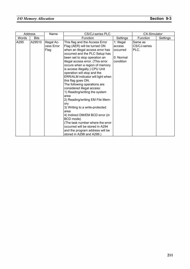
I/O Memory Allocation Section 9-3
211
Address CS/CJ-series PLC CX-Simulator
Words Bits Name
Function Settings Function Settings A295 A29510 Illegal Ac-
cess Error Flag
This flag and the Access Error Flag (AER) will be turned ON when an illegal access error has occurred and the PLC Setup has been set to stop operation an illegal access error. (This error occurs when a region of memory is access illegally.) CPU Unit operation will stop and the ERR/ALM indicator will light when this flag goes ON. The following operations are considered illegal access: 1) Reading/writing the system area 2) Reading/writing EM File Mem-ory 3) Writing to a write-protected area 4) Indirect DM/EM BCD error (in BCD mode) (The task number where the error occurred will be stored in A294 and the program address will be stored in A298 and A299.)
1: Illegal access occurred 0: Normal condition
Same as CS/CJ-series PLC.
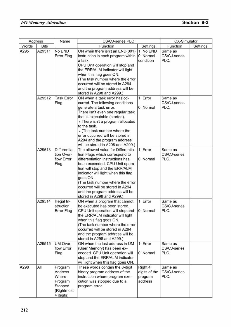
I/O Memory Allocation Section 9-3
212
Address CS/CJ-series PLC CX-Simulator
Words Bits Name
Function Settings Function Settings A29511 No END
Error Flag ON when there isn’t an END(001) instruction in each program within a task. CPU Unit operation will stop and the ERR/ALM indicator will light when this flag goes ON. (The task number where the error occurred will be stored in A294 and the program address will be stored in A298 and A299.)
1: No END 0: Normal condition
Same as CS/CJ-series PLC.
A29512 Task Error Flag
ON when a task error has oc-curred. The following conditions generate a task error. There isn’t even one regular task that is executable (started). • There isn’t a program allocated to the task. • (The task number where the error occurred will be stored in A294 and the program address will be stored in A298 and A299.)
1: Error 0: Normal
Same as CS/CJ-series PLC.
A29513 Differentia-tion Over-flow Error Flag
The allowed value for Differentia-tion Flags which correspond to differentiation instructions has been exceeded. CPU Unit opera-tion will stop and the ERR/ALM indicator will light when this flag goes ON. (The task number where the error occurred will be stored in A294 and the program address will be stored in A298 and A299.)
1: Error 0: Normal
Same as CS/CJ-series PLC.
A29514 Illegal In-struction Error Flag
ON when a program that cannot be executed has been stored. CPU Unit operation will stop and the ERR/ALM indicator will light when this flag goes ON. (The task number where the error occurred will be stored in A294 and the program address will be stored in A298 and A299.)
1: Error 0: Normal
Same as CS/CJ-series PLC.
A295
A29515 UM Over-flow Error Flag
ON when the last address in UM (User Memory) has been ex-ceeded. CPU Unit operation will stop and the ERR/ALM indicator will light when this flag goes ON.
1: Error 0: Normal
Same as CS/CJ-series PLC.
A298 All Program Address Where Program Stopped (Rightmost 4 digits)
These words contain the 8-digit binary program address of the instruction where program exe-cution was stopped due to a program error.
Right 4 digits of the program address
Same as CS/CJ-series PLC.
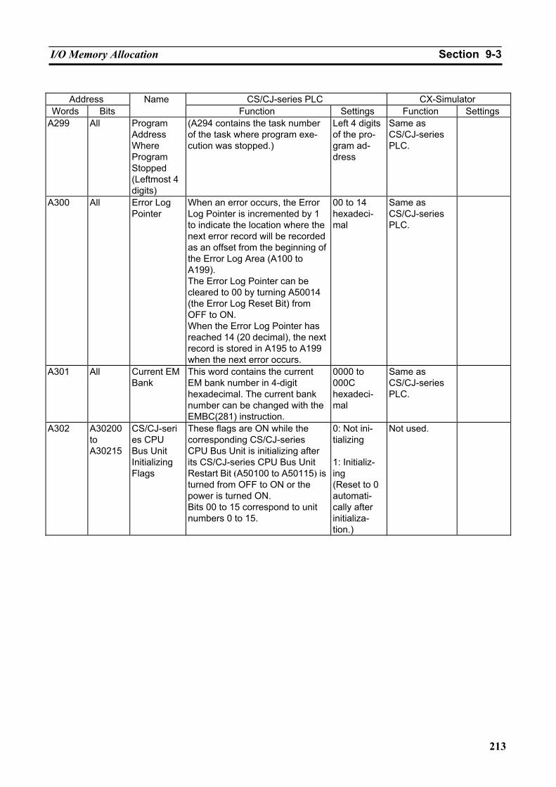
I/O Memory Allocation Section 9-3
213
Address CS/CJ-series PLC CX-Simulator
Words Bits Name
Function Settings Function Settings A299 All Program
Address Where Program Stopped (Leftmost 4 digits)
(A294 contains the task number of the task where program exe-cution was stopped.)
Left 4 digits of the pro-gram ad-dress
Same as CS/CJ-series PLC.
A300 All Error Log Pointer
When an error occurs, the Error Log Pointer is incremented by 1 to indicate the location where the next error record will be recorded as an offset from the beginning of the Error Log Area (A100 to A199). The Error Log Pointer can be cleared to 00 by turning A50014 (the Error Log Reset Bit) from OFF to ON. When the Error Log Pointer has reached 14 (20 decimal), the next record is stored in A195 to A199 when the next error occurs.
00 to 14 hexadeci-mal
Same as CS/CJ-series PLC.
A301 All Current EM Bank
This word contains the current EM bank number in 4-digit hexadecimal. The current bank number can be changed with the EMBC(281) instruction.
0000 to 000C hexadeci-mal
Same as CS/CJ-series PLC.
A302 A30200 to A30215
CS/CJ-series CPU Bus Unit Initializing Flags
These flags are ON while the corresponding CS/CJ-series CPU Bus Unit is initializing after its CS/CJ-series CPU Bus Unit Restart Bit (A50100 to A50115) is turned from OFF to ON or the power is turned ON. Bits 00 to 15 correspond to unit numbers 0 to 15.
0: Not ini-tializing 1: Initializ-ing (Reset to 0 automati-cally after initializa-tion.)
Not used.
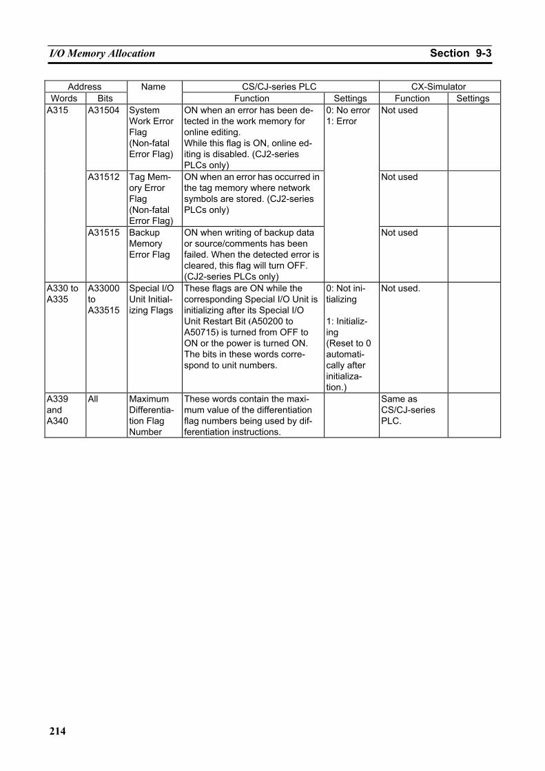
I/O Memory Allocation Section 9-3
214
Address CS/CJ-series PLC CX-Simulator Words Bits
Name Function Settings Function Settings
A31504 System Work Error Flag (Non-fatal Error Flag)
ON when an error has been de-tected in the work memory for online editing. While this flag is ON, online ed-iting is disabled. (CJ2-series PLCs only)
Not used
A31512 Tag Mem-ory Error Flag (Non-fatal Error Flag)
ON when an error has occurred in the tag memory where network symbols are stored. (CJ2-series PLCs only)
Not used
A315
A31515 Backup Memory Error Flag
ON when writing of backup data or source/comments has been failed. When the detected error is cleared, this flag will turn OFF. (CJ2-series PLCs only)
0: No error 1: Error
Not used
A330 to A335
A33000 to A33515
Special I/O Unit Initial-izing Flags
These flags are ON while the corresponding Special I/O Unit is initializing after its Special I/O Unit Restart Bit (A50200 to A50715) is turned from OFF to ON or the power is turned ON. The bits in these words corre-spond to unit numbers.
0: Not ini-tializing 1: Initializ-ing (Reset to 0 automati-cally after initializa-tion.)
Not used.
A339 and A340
All Maximum Differentia-tion Flag Number
These words contain the maxi-mum value of the differentiation flag numbers being used by dif-ferentiation instructions.
Same as CS/CJ-series PLC.
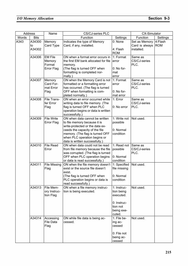
I/O Memory Allocation Section 9-3
215
Address CS/CJ-series PLC CX-Simulator
Words Bits Name
Function Settings Function Settings A34300 to A34302
Memory Card Type
Indicates the type of Memory Card, if any, installed.
0: None 4: Flash ROM
Set as Memory Card is always installed.
4:Flash ROM
A34306 EM File Memory Format Error Flag
ON when a format error occurs in the first EM bank allocated for file memory. (The flag is turned OFF when formatting is completed nor-mally.)
1: Format error 0: No for-mat error
Same as CS/CJ-series PLC.
A34307 Memory Card For-mat Error Flag
ON when the Memory Card is not formatted or a formatting error has occurred. (The flag is turned OFF when formatting is com-pleted normally.)
1: Format error 0: No for-mat error
Same as CS/CJ-series PLC.
A34308 File Trans-fer Error Flag
ON when an error occurred while writing data to file memory. (The flag is turned OFF when PLC operation begins or data is written successfully.)
1: Error 0: No error
Same as CS/CJ-series PLC.
A34309 File Write Error Flag
ON when data cannot be written to file memory because it is write-protected or the data ex-ceeds the capacity of the file memory. (The flag is turned OFF when PLC operation begins or data is written successfully.)
1: Write not possible 0: Normal condition
Not used.
A34310 File Read Error
ON when data could not be read from file memory because the file was corrupted. (The flag is turned OFF when PLC operation begins or data is read successfully.)
1: Read not possible 0: Normal condition
Same as CS/CJ-series PLC.
A34311 File Missing Flag
ON when the file memory doesn’t exist or the source file doesn’t exist. (The flag is turned OFF when PLC operation begins or data is read successfully.)
1: Specified file missing 0: Normal condition
Not used.
A34313 File Mem-ory Instruc-tion Flag
ON when a file memory instruc-tion is being executed.
1: Instruc-tion being executed. 0: Instruc-tion not being exe-cuted.
Not used.
A343
A34314 Accessing File Data Flag
ON while file data is being ac-cessed.
1: File be-ing ac-cessed 0: File not being ac-cessed
Not used.
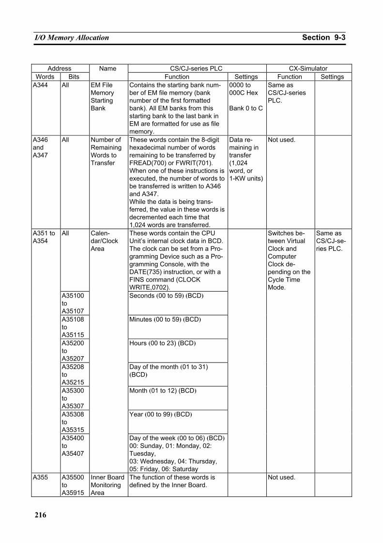
I/O Memory Allocation Section 9-3
216
Address CS/CJ-series PLC CX-Simulator
Words Bits Name
Function Settings Function Settings A344 All EM File
Memory Starting Bank
Contains the starting bank num-ber of EM file memory (bank number of the first formatted bank). All EM banks from this starting bank to the last bank in EM are formatted for use as file memory.
0000 to 000C Hex Bank 0 to C
Same as CS/CJ-series PLC.
A346 and A347
All Number of Remaining Words to Transfer
These words contain the 8-digit hexadecimal number of words remaining to be transferred by FREAD(700) or FWRIT(701). When one of these instructions is executed, the number of words to be transferred is written to A346 and A347. While the data is being trans-ferred, the value in these words is decremented each time that 1,024 words are transferred.
Data re-maining in transfer (1,024 word, or 1-KW units)
Not used.
All These words contain the CPU Unit’s internal clock data in BCD. The clock can be set from a Pro-gramming Device such as a Pro-gramming Console, with the DATE(735) instruction, or with a FINS command (CLOCK WRITE,0702).
A35100 to A35107
Seconds (00 to 59) (BCD)
A35108 to A35115
Minutes (00 to 59) (BCD)
A35200 to A35207
Hours (00 to 23) (BCD)
A35208 to A35215
Day of the month (01 to 31) (BCD)
A35300 to A35307
Month (01 to 12) (BCD)
A35308 to A35315
Year (00 to 99) (BCD)
A351 to A354
A35400 to A35407
Calen-dar/Clock Area
Day of the week (00 to 06) (BCD)00: Sunday, 01: Monday, 02: Tuesday, 03: Wednesday, 04: Thursday, 05: Friday, 06: Saturday
Switches be-tween Virtual Clock and Computer Clock de-pending on the Cycle Time Mode.
Same as CS/CJ-se-ries PLC.
A355 A35500 to A35915
Inner Board Monitoring Area
The function of these words is defined by the Inner Board.
Not used.
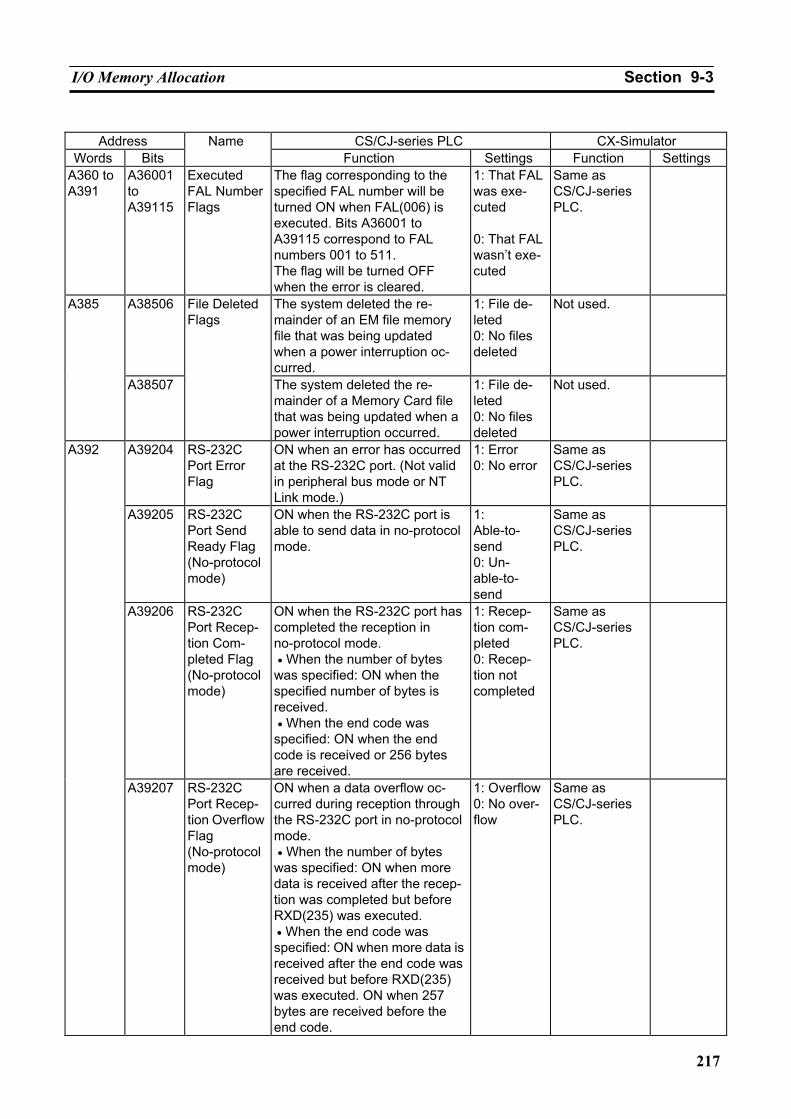
I/O Memory Allocation Section 9-3
217
Address CS/CJ-series PLC CX-Simulator
Words Bits Name
Function Settings Function Settings A360 to A391
A36001 to A39115
Executed FAL Number Flags
The flag corresponding to the specified FAL number will be turned ON when FAL(006) is executed. Bits A36001 to A39115 correspond to FAL numbers 001 to 511. The flag will be turned OFF when the error is cleared.
1: That FAL was exe-cuted 0: That FAL wasn’t exe-cuted
Same as CS/CJ-series PLC.
A38506 The system deleted the re-mainder of an EM file memory file that was being updated when a power interruption oc-curred.
1: File de-leted 0: No files deleted
Not used. A385
A38507
File Deleted Flags
The system deleted the re-mainder of a Memory Card file that was being updated when a power interruption occurred.
1: File de-leted 0: No files deleted
Not used.
A39204 RS-232C Port Error Flag
ON when an error has occurred at the RS-232C port. (Not valid in peripheral bus mode or NT Link mode.)
1: Error 0: No error
Same as CS/CJ-series PLC.
A39205 RS-232C Port Send Ready Flag (No-protocol mode)
ON when the RS-232C port is able to send data in no-protocol mode.
1: Able-to- send 0: Un-able-to- send
Same as CS/CJ-series PLC.
A39206 RS-232C Port Recep-tion Com-pleted Flag (No-protocol mode)
ON when the RS-232C port has completed the reception in no-protocol mode. • When the number of bytes was specified: ON when the specified number of bytes is received. • When the end code was specified: ON when the end code is received or 256 bytes are received.
1: Recep-tion com-pleted 0: Recep-tion not completed
Same as CS/CJ-series PLC.
A392
A39207 RS-232C Port Recep-tion Overflow Flag (No-protocol mode)
ON when a data overflow oc-curred during reception through the RS-232C port in no-protocol mode. • When the number of bytes was specified: ON when more data is received after the recep-tion was completed but before RXD(235) was executed. • When the end code was specified: ON when more data is received after the end code was received but before RXD(235) was executed. ON when 257 bytes are received before the end code.
1: Overflow0: No over-flow
Same as CS/CJ-series PLC.
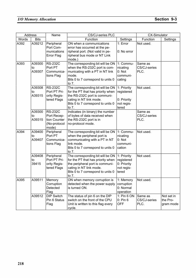
I/O Memory Allocation Section 9-3
218
Address CS/CJ-series PLC CX-Simulator
Words Bits Name
Function Settings Function Settings A392 A39212 Peripheral
Port Com-munications Error Flag
ON when a communications error has occurred at the pe-ripheral port. (Not valid in pe-ripheral bus mode or NT Link mode.)
1: Error 0: No error
Not used.
A39300 to A39307
RS-232C Port PT Communica-tions Flag
The corresponding bit will be ON when the RS-232C port is com-municating with a PT in NT link mode. Bits 0 to 7 correspond to units 0 to 7.
1: Commu-nicating 0: Not communi-cating
Same as CS/CJ-series PLC.
A39308 to A39315
RS-232C Port PT Pri-ority Regis-tered Flags
The corresponding bit will be ON for the PT that has priority when the RS-232C port is communi-cating in NT link mode. Bits 0 to 7 correspond to units 0 to 7.
1: Priority registered 0: Priority not regis-tered
Not used.
A393
A39300 to A39315
RS-232C Port Recep-tion Counter (No-protocol mode)
Indicates (in binary) the number of bytes of data received when the RS-232C port is in no-protocol mode.
Same as CS/CJ-series PLC.
A39400 to A39407
Peripheral Port PT Communica-tions Flag
The corresponding bit will be ON when the peripheral port is communicating with a PT in NT link mode. Bits 0 to 7 correspond to units 0 to 7.
1: Commu-nicating 0: Not communi-cation
Not used. A394
A39408 to 39415
Peripheral Port PT Pri-ority Regis-tered Flags
The corresponding bit will be ON for the PT that has priority when the peripheral port is communi-cating in NT link mode. Bits 0 to 7 correspond to units 0 to 7.
1: Priority registered 0: Priority not regis-tered
Not used.
A39511 Memory Corruption Detected Flag
ON when memory corruption is detected when the power supply is turned ON.
1: Memory corruption 0: Normal operation
Not used. A395
A39512 DIP Switch Pin 6 Status Flag
The status of pin 6 on the DIP switch on the front of the CPU Unit is written to this flag every cycle.
1: Pin 6 ON0: Pin 6 OFF
Same as CS/CJ-series PLC.
Not set in the Pro-gram mode
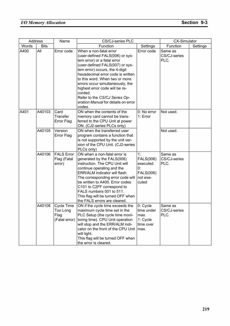
I/O Memory Allocation Section 9-3
219
Address CS/CJ-series PLC CX-Simulator
Words Bits Name
Function Settings Function Settings A400 All Error code When a non-fatal error
(user-defined FALS(006) or sys-tem error) or a fatal error (user-defined FALS(007) or sys-tem error) occurs, the 4-digit hexadecimal error code is written to this word. When two or more errors occur simultaneously, the highest error code will be re-corded. Refer to the CS/CJ Series Op-eration Manual for details on error codes.
Error code Same as CS/CJ-series PLC.
A40103 Card Transfer Error Flag
ON when the contents of the memory card cannot be trans-ferred to the CPU Unit at power ON. (CJ2-series PLCs only)
Not used.
A40105 Version Error Flag
ON when the transferred user program contains a function that is not supported by the unit ver-sion of the CPU Unit. (CJ2-series PLCs only)
0: No error 1: Error
Not used.
A40106 FALS Error Flag (Fatal error)
ON when a non-fatal error is generated by the FALS(006) instruction. The CPU Unit will continue operating and the ERR/ALM indicator will flash. The corresponding error code will be written to A400. Error codes C101 to C2FF correspond to FALS numbers 001 to 511. This flag will be turned OFF when the FALS errors are cleared.
1: FALS(006) executed 0: FALS(006) not exe-cuted
Same as CS/CJ-series PLC.
A401
A40108 Cycle Time Too Long Flag (Fatal error)
ON if the cycle time exceeds the maximum cycle time set in the PLC Setup (the cycle time moni-toring time). CPU Unit operation will stop and the ERR/ALM indi-cator on the front of the CPU Unit will light. This flag will be turned OFF when the error is cleared.
0: Cycle time under max. 1: Cycle time over max.
Same as CS/CJ-series PLC.
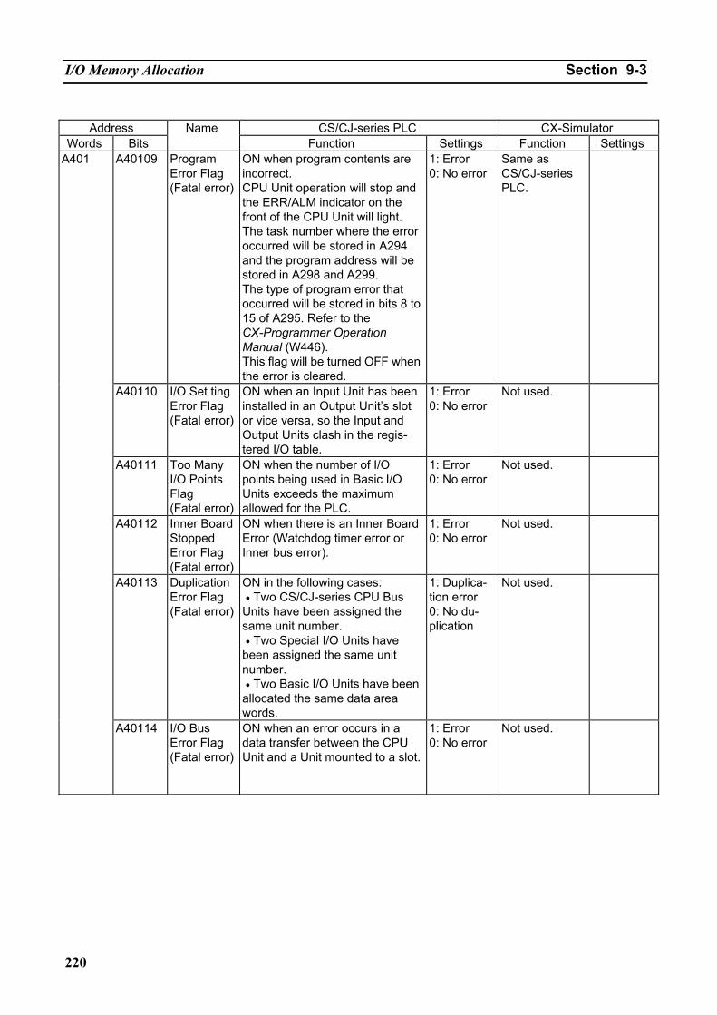
I/O Memory Allocation Section 9-3
220
Address CS/CJ-series PLC CX-Simulator
Words Bits Name
Function Settings Function Settings A40109 Program
Error Flag (Fatal error)
ON when program contents are incorrect. CPU Unit operation will stop and the ERR/ALM indicator on the front of the CPU Unit will light. The task number where the error occurred will be stored in A294 and the program address will be stored in A298 and A299. The type of program error that occurred will be stored in bits 8 to 15 of A295. Refer to the CX-Programmer Operation Manual (W446). This flag will be turned OFF when the error is cleared.
1: Error 0: No error
Same as CS/CJ-series PLC.
A40110 I/O Set ting Error Flag (Fatal error)
ON when an Input Unit has been installed in an Output Unit’s slot or vice versa, so the Input and Output Units clash in the regis-tered I/O table.
1: Error 0: No error
Not used.
A40111 Too Many I/O Points Flag (Fatal error)
ON when the number of I/O points being used in Basic I/O Units exceeds the maximum allowed for the PLC.
1: Error 0: No error
Not used.
A40112 Inner Board Stopped Error Flag (Fatal error)
ON when there is an Inner Board Error (Watchdog timer error or Inner bus error).
1: Error 0: No error
Not used.
A40113 Duplication Error Flag (Fatal error)
ON in the following cases: • Two CS/CJ-series CPU Bus Units have been assigned the same unit number. • Two Special I/O Units have been assigned the same unit number. • Two Basic I/O Units have been allocated the same data area words.
1: Duplica-tion error 0: No du-plication
Not used.
A401
A40114 I/O Bus Error Flag (Fatal error)
ON when an error occurs in a data transfer between the CPU Unit and a Unit mounted to a slot.
1: Error 0: No error
Not used.
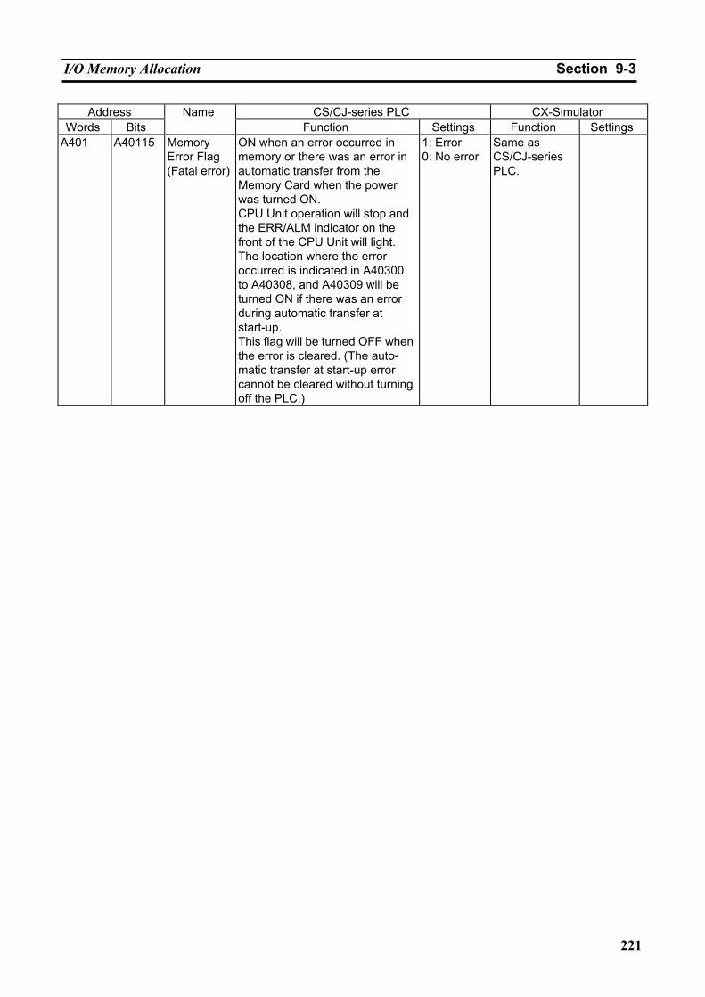
I/O Memory Allocation Section 9-3
221
Address CS/CJ-series PLC CX-Simulator Words Bits
Name Function Settings Function Settings
A401 A40115 Memory Error Flag (Fatal error)
ON when an error occurred in memory or there was an error in automatic transfer from the Memory Card when the power was turned ON. CPU Unit operation will stop and the ERR/ALM indicator on the front of the CPU Unit will light. The location where the error occurred is indicated in A40300 to A40308, and A40309 will be turned ON if there was an error during automatic transfer at start-up. This flag will be turned OFF when the error is cleared. (The auto-matic transfer at start-up error cannot be cleared without turning off the PLC.)
1: Error 0: No error
Same as CS/CJ-series PLC.
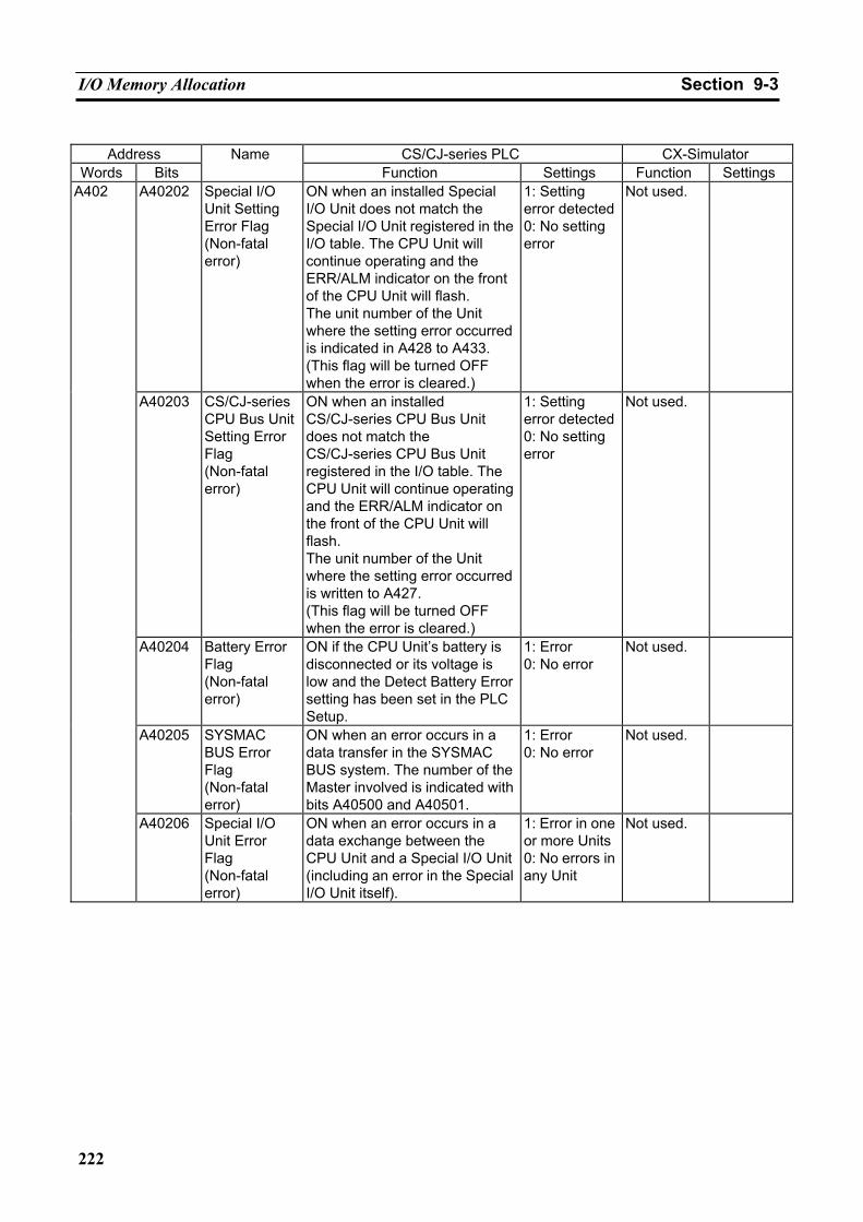
I/O Memory Allocation Section 9-3
222
Address CS/CJ-series PLC CX-Simulator
Words Bits Name
Function Settings Function Settings A40202 Special I/O
Unit Setting Error Flag (Non-fatal error)
ON when an installed Special I/O Unit does not match the Special I/O Unit registered in the I/O table. The CPU Unit will continue operating and the ERR/ALM indicator on the front of the CPU Unit will flash. The unit number of the Unit where the setting error occurred is indicated in A428 to A433. (This flag will be turned OFF when the error is cleared.)
1: Setting error detected 0: No setting error
Not used.
A40203 CS/CJ-series CPU Bus Unit Setting Error Flag (Non-fatal error)
ON when an installed CS/CJ-series CPU Bus Unit does not match the CS/CJ-series CPU Bus Unit registered in the I/O table. The CPU Unit will continue operating and the ERR/ALM indicator on the front of the CPU Unit will flash. The unit number of the Unit where the setting error occurred is written to A427. (This flag will be turned OFF when the error is cleared.)
1: Setting error detected 0: No setting error
Not used.
A40204 Battery Error Flag (Non-fatal error)
ON if the CPU Unit’s battery is disconnected or its voltage is low and the Detect Battery Error setting has been set in the PLC Setup.
1: Error 0: No error
Not used.
A40205 SYSMAC BUS Error Flag (Non-fatal error)
ON when an error occurs in a data transfer in the SYSMAC BUS system. The number of the Master involved is indicated with bits A40500 and A40501.
1: Error 0: No error
Not used.
A402
A40206 Special I/O Unit Error Flag (Non-fatal error)
ON when an error occurs in a data exchange between the CPU Unit and a Special I/O Unit (including an error in the Special I/O Unit itself).
1: Error in one or more Units 0: No errors in any Unit
Not used.
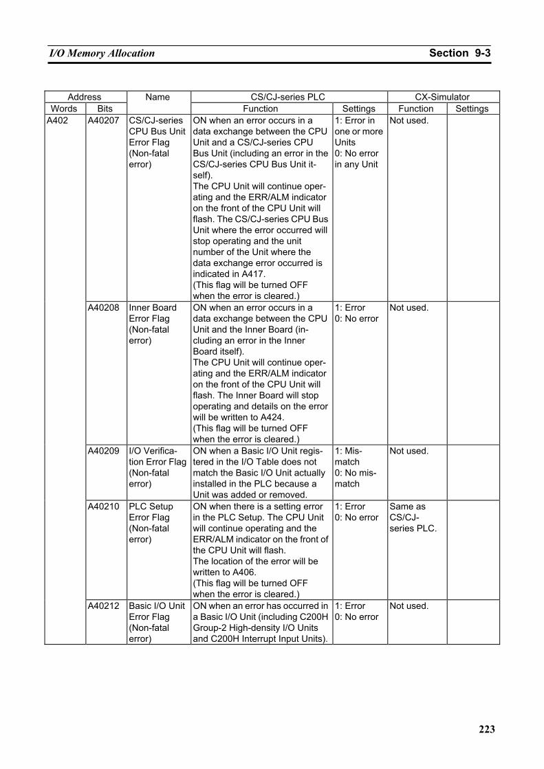
I/O Memory Allocation Section 9-3
223
Address CS/CJ-series PLC CX-Simulator
Words Bits Name
Function Settings Function Settings A40207 CS/CJ-series
CPU Bus Unit Error Flag (Non-fatal error)
ON when an error occurs in a data exchange between the CPU Unit and a CS/CJ-series CPU Bus Unit (including an error in the CS/CJ-series CPU Bus Unit it-self). The CPU Unit will continue oper-ating and the ERR/ALM indicator on the front of the CPU Unit will flash. The CS/CJ-series CPU Bus Unit where the error occurred will stop operating and the unit number of the Unit where the data exchange error occurred is indicated in A417. (This flag will be turned OFF when the error is cleared.)
1: Error in one or more Units 0: No error in any Unit
Not used.
A40208 Inner Board Error Flag (Non-fatal error)
ON when an error occurs in a data exchange between the CPU Unit and the Inner Board (in-cluding an error in the Inner Board itself). The CPU Unit will continue oper-ating and the ERR/ALM indicator on the front of the CPU Unit will flash. The Inner Board will stop operating and details on the error will be written to A424. (This flag will be turned OFF when the error is cleared.)
1: Error 0: No error
Not used.
A40209 I/O Verifica-tion Error Flag (Non-fatal error)
ON when a Basic I/O Unit regis-tered in the I/O Table does not match the Basic I/O Unit actually installed in the PLC because a Unit was added or removed.
1: Mis-match 0: No mis-match
Not used.
A40210 PLC Setup Error Flag (Non-fatal error)
ON when there is a setting error in the PLC Setup. The CPU Unit will continue operating and the ERR/ALM indicator on the front of the CPU Unit will flash. The location of the error will be written to A406. (This flag will be turned OFF when the error is cleared.)
1: Error 0: No error
Same as CS/CJ- series PLC.
A402
A40212 Basic I/O Unit Error Flag (Non-fatal error)
ON when an error has occurred in a Basic I/O Unit (including C200H Group-2 High-density I/O Units and C200H Interrupt Input Units).
1: Error 0: No error
Not used.
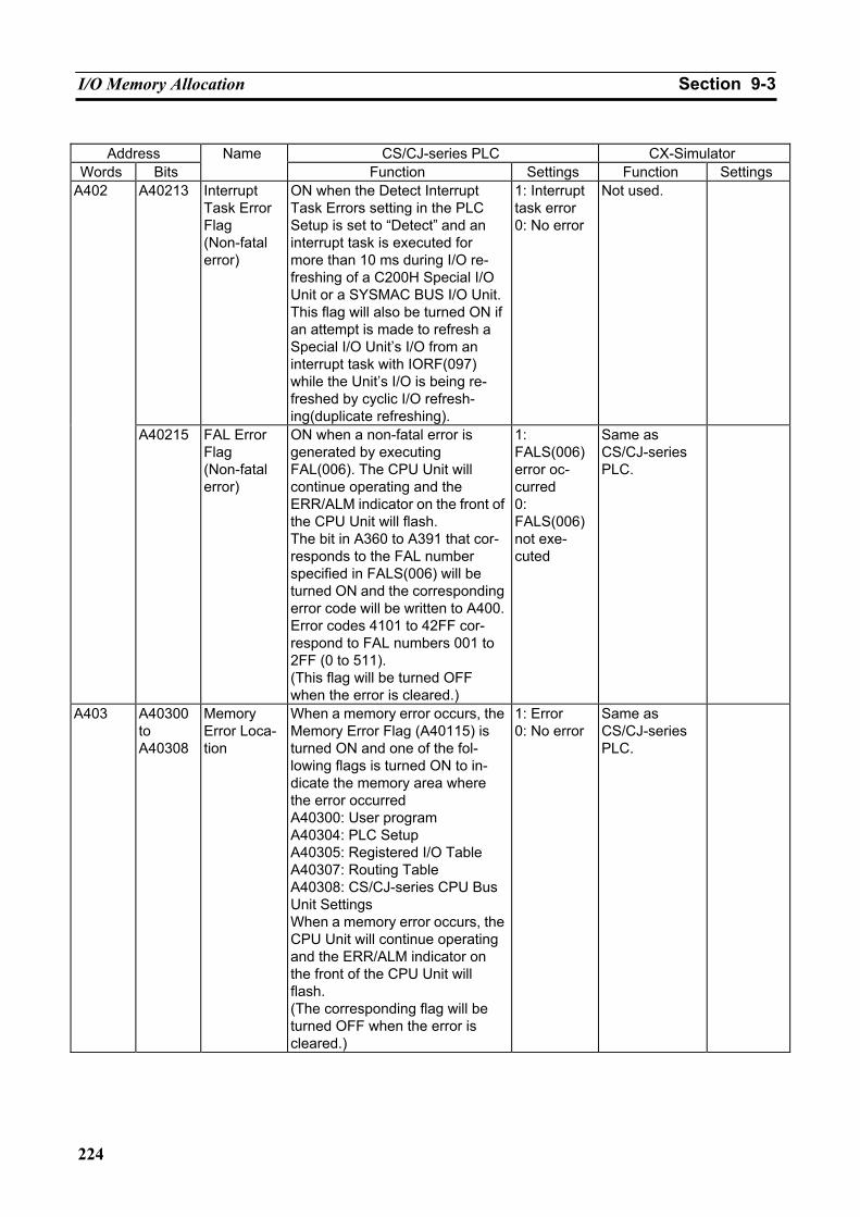
I/O Memory Allocation Section 9-3
224
Address CS/CJ-series PLC CX-Simulator
Words Bits Name
Function Settings Function Settings A40213 Interrupt
Task Error Flag (Non-fatal error)
ON when the Detect Interrupt Task Errors setting in the PLC Setup is set to “Detect” and an interrupt task is executed for more than 10 ms during I/O re-freshing of a C200H Special I/O Unit or a SYSMAC BUS I/O Unit.This flag will also be turned ON if an attempt is made to refresh a Special I/O Unit’s I/O from an interrupt task with IORF(097) while the Unit’s I/O is being re-freshed by cyclic I/O refresh-ing(duplicate refreshing).
1: Interrupt task error 0: No error
Not used. A402
A40215 FAL Error Flag (Non-fatal error)
ON when a non-fatal error is generated by executing FAL(006). The CPU Unit will continue operating and the ERR/ALM indicator on the front of the CPU Unit will flash. The bit in A360 to A391 that cor-responds to the FAL number specified in FALS(006) will be turned ON and the corresponding error code will be written to A400. Error codes 4101 to 42FF cor-respond to FAL numbers 001 to 2FF (0 to 511). (This flag will be turned OFF when the error is cleared.)
1: FALS(006) error oc-curred 0: FALS(006) not exe-cuted
Same as CS/CJ-series PLC.
A403 A40300 to A40308
Memory Error Loca-tion
When a memory error occurs, the Memory Error Flag (A40115) is turned ON and one of the fol-lowing flags is turned ON to in-dicate the memory area where the error occurred A40300: User program A40304: PLC Setup A40305: Registered I/O Table A40307: Routing Table A40308: CS/CJ-series CPU Bus Unit Settings When a memory error occurs, the CPU Unit will continue operating and the ERR/ALM indicator on the front of the CPU Unit will flash. (The corresponding flag will be turned OFF when the error is cleared.)
1: Error 0: No error
Same as CS/CJ-series PLC.
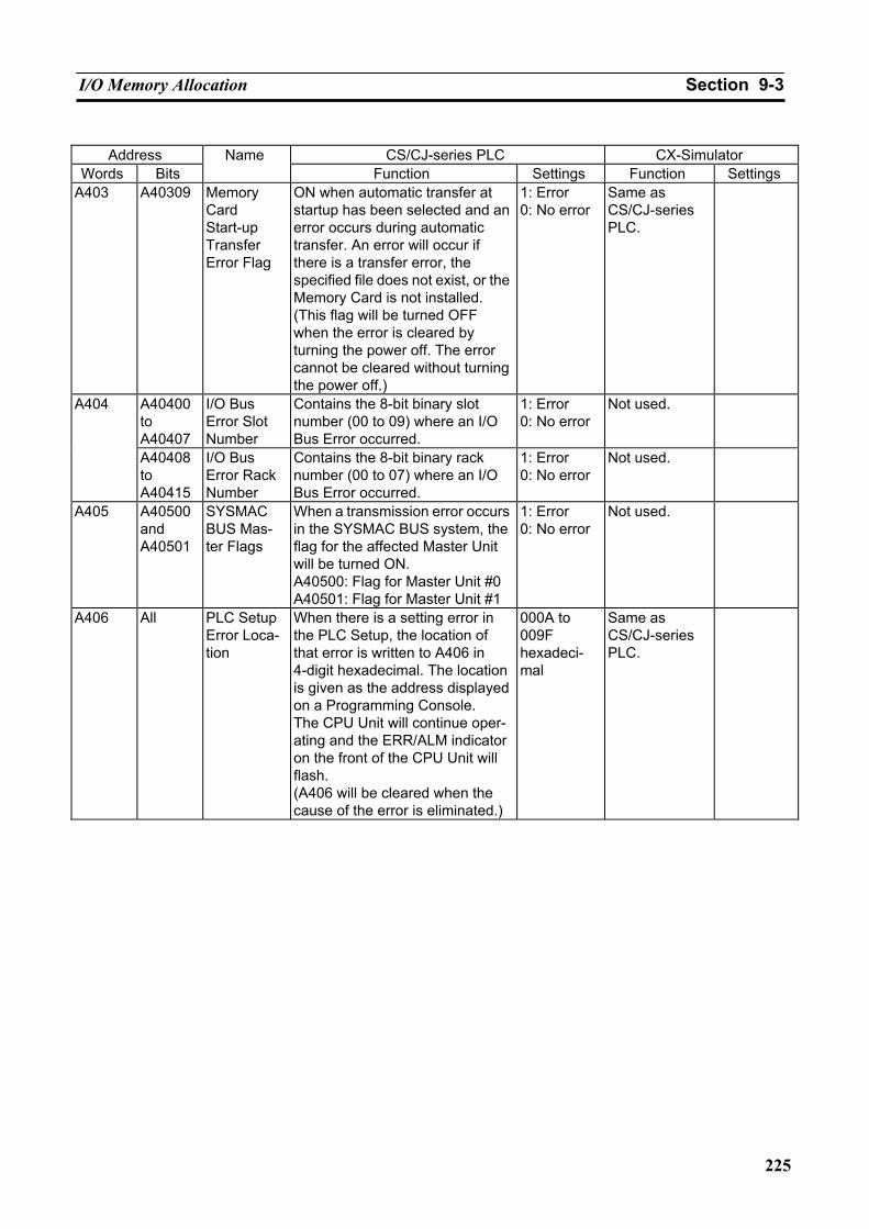
I/O Memory Allocation Section 9-3
225
Address CS/CJ-series PLC CX-Simulator
Words Bits Name
Function Settings Function Settings A403 A40309 Memory
Card Start-up Transfer Error Flag
ON when automatic transfer at startup has been selected and an error occurs during automatic transfer. An error will occur if there is a transfer error, the specified file does not exist, or the Memory Card is not installed. (This flag will be turned OFF when the error is cleared by turning the power off. The error cannot be cleared without turning the power off.)
1: Error 0: No error
Same as CS/CJ-series PLC.
A40400 to A40407
I/O Bus Error Slot Number
Contains the 8-bit binary slot number (00 to 09) where an I/O Bus Error occurred.
1: Error 0: No error
Not used. A404
A40408 to A40415
I/O Bus Error Rack Number
Contains the 8-bit binary rack number (00 to 07) where an I/O Bus Error occurred.
1: Error 0: No error
Not used.
A405 A40500 and A40501
SYSMAC BUS Mas-ter Flags
When a transmission error occurs in the SYSMAC BUS system, the flag for the affected Master Unit will be turned ON. A40500: Flag for Master Unit #0 A40501: Flag for Master Unit #1
1: Error 0: No error
Not used.
A406 All PLC Setup Error Loca-tion
When there is a setting error in the PLC Setup, the location of that error is written to A406 in 4-digit hexadecimal. The location is given as the address displayed on a Programming Console. The CPU Unit will continue oper-ating and the ERR/ALM indicator on the front of the CPU Unit will flash. (A406 will be cleared when the cause of the error is eliminated.)
000A to 009F hexadeci-mal
Same as CS/CJ-series PLC.
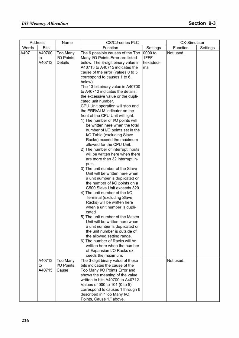
I/O Memory Allocation Section 9-3
226
Address CS/CJ-series PLC CX-Simulator
Words Bits Name
Function Settings Function Settings A40700 to A40712
Too Many I/O Points, Details
The 6 possible causes of the Too Many I/O Points Error are listed below. The 3-digit binary value in A40713 to A40715 indicates the cause of the error (values 0 to 5 correspond to causes 1 to 6, below). The 13-bit binary value in A40700 to A40712 indicates the details: the excessive value or the dupli-cated unit number. CPU Unit operation will stop and the ERR/ALM indicator on the front of the CPU Unit will light. 1) The number of I/O points will
be written here when the total number of I/O points set in the I/O Table (excluding Slave Racks) exceed the maximum allowed for the CPU Unit.
2) The number of interrupt inputs will be written here when there are more than 32 interrupt in-puts.
3) The unit number of the Slave Unit will be written here when a unit number is duplicated or the number of I/O points on a C500 Slave Unit exceeds 320.
4) The unit number of the I/O Terminal (excluding Slave Racks) will be written here when a unit number is dupli-cated
5) The unit number of the Master Unit will be written here when a unit number is duplicated or the unit number is outside of the allowed setting range.
6) The number of Racks will be written here when the number of Expansion I/O Racks ex-ceeds the maximum.
0000 to 1FFF hexadeci-mal
Not used. A407
A40713 to A40715
Too Many I/O Points, Cause
The 3-digit binary value of these bits indicates the cause of the Too Many I/O Points Error and shows the meaning of the value written to bits A40700 to A40712.Values of 000 to 101 (0 to 5) correspond to causes 1 through 6 described in “Too Many I/O Points, Cause 1,” above.
Not used.
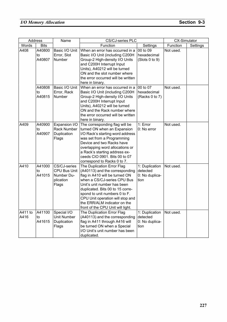
I/O Memory Allocation Section 9-3
227
Address CS/CJ-series PLC CX-Simulator
Words Bits Name
Function Settings Function Settings A40800 to A40807
Basic I/O Unit Error, Slot Number
When an error has occurred in a Basic I/O Unit (including C200H Group-2 High-density I/O Units and C200H Interrupt Input Units), A40212 will be turned ON and the slot number where the error occurred will be written here in binary.
00 to 09 hexadecimal (Slots 0 to 9)
Not used. A408
A40808 to A40815
Basic I/O Unit Error, Rack Number
When an error has occurred in a Basic I/O Unit (including C200H Group-2 High-density I/O Units and C200H Interrupt Input Units), A40212 will be turned ON and the Rack number where the error occurred will be written here in binary.
00 to 07 hexadecimal (Racks 0 to 7)
Not used.
A409 A40900 to A40907
Expansion I/O Rack Number Duplication Flags
The corresponding flag will be turned ON when an Expansion I/O Rack’s starting word address was set from a Programming Device and two Racks have overlapping word allocations or a Rack’s starting address ex-ceeds CIO 0901. Bits 00 to 07 correspond to Racks 0 to 7.
1: Error 0: No error
Not used.
A410 A41000 to A41015
CS/CJ-series CPU Bus Unit Number Du-plication Flags
The Duplication Error Flag (A40113) and the corresponding flag in A410 will be turned ON when a CS/CJ-series CPU Bus Unit’s unit number has been duplicated. Bits 00 to 15 corre-spond to unit numbers 0 to F. CPU Unit operation will stop and the ERR/ALM indicator on the front of the CPU Unit will light.
1: Duplication detected 0: No duplica-tion
Not used.
A411 to A416
A41100 to A41615
Special I/O Unit Number Duplication Flags
The Duplication Error Flag (A40113) and the corresponding flag in A411 through A416 will be turned ON when a Special I/O Unit’s unit number has been duplicated.
1: Duplication detected 0: No duplica-tion
Not used.
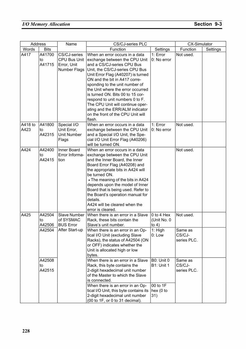
I/O Memory Allocation Section 9-3
228
Address CS/CJ-series PLC CX-Simulator
Words Bits Name
Function Settings Function Settings A417 A41700
to A41715
CS/CJ-series CPU Bus Unit Error, Unit Number Flags
When an error occurs in a data exchange between the CPU Unit and a CS/CJ-series CPU Bus Unit, the CS/CJ-series CPU Bus Unit Error Flag (A40207) is turned ON and the bit in A417 corre-sponding to the unit number of the Unit where the error occurred is turned ON. Bits 00 to 15 cor-respond to unit numbers 0 to F. The CPU Unit will continue oper-ating and the ERR/ALM indicator on the front of the CPU Unit will flash.
1: Error 0: No error
Not used.
A418 to A423
A41800 to A42315
Special I/O Unit Error, Unit Number Flags
When an error occurs in a data exchange between the CPU Unit and a Special I/O Unit, the Spe-cial I/O Unit Error Flag (A40206) will be turned ON.
1: Error 0: No error
Not used.
A424 A42400 to A42415
Inner Board Error Informa-tion
When an error occurs in a data exchange between the CPU Unit and the Inner Board, the Inner Board Error Flag (A40208) and the appropriate bits in A424 will be turned ON. • The meaning of the bits in A424 depends upon the model of Inner Board that is being used. Refer to the Board’s operation manual for details. A424 will be cleared when the error is cleared.
Not used.
A42504 to A42506
When there is an error in a Slave Rack, these bits contain the Slave’s unit number.
0 to 4 Hex (Unit No. 0 to 4)
Not used.
A42504 When there is an error in an Op-tical I/O Unit (excluding Slave Racks), the status of A42504 (ON or OFF) indicates whether the Unit is allocated high or low bytes.
1: High 0: Low
Same as CS/CJ- series PLC.
When there is an error in a Slave Rack, this byte contains the 2-digit hexadecimal unit number of the Master to which the Slave is connected.
B0: Unit 0 B1: Unit 1
A425
A42508 to A42515
Slave Number of SYSMAC BUS Error After Start-up
When there is an error in an Op-tical I/O Unit, this byte contains its 2-digit hexadecimal unit number (00 to 1F, or 0 to 31 decimal).
00 to 1F hex (0 to 31)
Same as CS/CJ- series PLC.
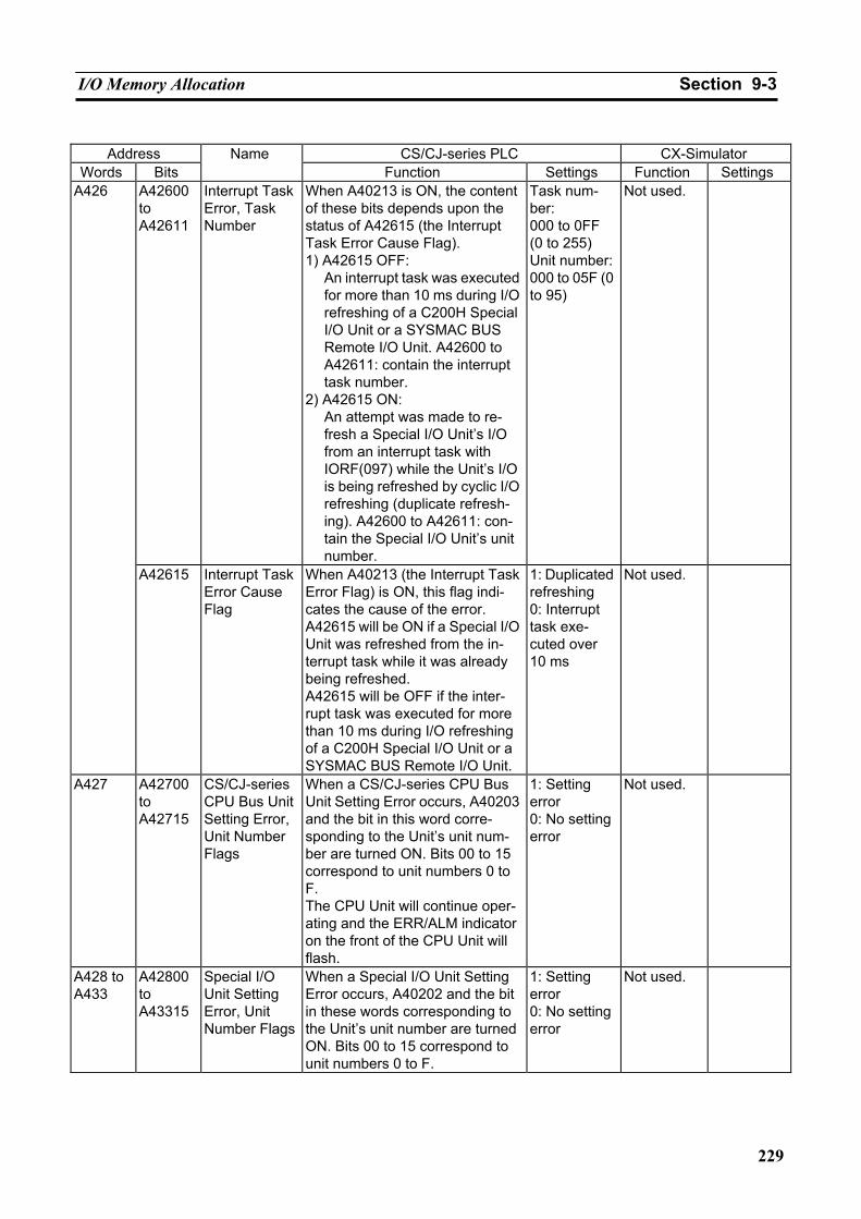
I/O Memory Allocation Section 9-3
229
Address CS/CJ-series PLC CX-Simulator
Words Bits Name
Function Settings Function Settings A42600 to A42611
Interrupt Task Error, Task Number
When A40213 is ON, the content of these bits depends upon the status of A42615 (the Interrupt Task Error Cause Flag). 1) A42615 OFF:
An interrupt task was executed for more than 10 ms during I/O refreshing of a C200H Special I/O Unit or a SYSMAC BUS Remote I/O Unit. A42600 to A42611: contain the interrupt task number.
2) A42615 ON: An attempt was made to re-fresh a Special I/O Unit’s I/O from an interrupt task with IORF(097) while the Unit’s I/O is being refreshed by cyclic I/O refreshing (duplicate refresh-ing). A42600 to A42611: con-tain the Special I/O Unit’s unit number.
Task num-ber: 000 to 0FF (0 to 255) Unit number: 000 to 05F (0 to 95)
Not used. A426
A42615 Interrupt Task Error Cause Flag
When A40213 (the Interrupt Task Error Flag) is ON, this flag indi-cates the cause of the error. A42615 will be ON if a Special I/O Unit was refreshed from the in-terrupt task while it was already being refreshed. A42615 will be OFF if the inter-rupt task was executed for more than 10 ms during I/O refreshing of a C200H Special I/O Unit or a SYSMAC BUS Remote I/O Unit.
1: Duplicated refreshing 0: Interrupt task exe-cuted over 10 ms
Not used.
A427 A42700 to A42715
CS/CJ-series CPU Bus Unit Setting Error, Unit Number Flags
When a CS/CJ-series CPU Bus Unit Setting Error occurs, A40203 and the bit in this word corre-sponding to the Unit’s unit num-ber are turned ON. Bits 00 to 15 correspond to unit numbers 0 to F. The CPU Unit will continue oper-ating and the ERR/ALM indicator on the front of the CPU Unit will flash.
1: Setting error 0: No setting error
Not used.
A428 to A433
A42800 to A43315
Special I/O Unit Setting Error, Unit Number Flags
When a Special I/O Unit Setting Error occurs, A40202 and the bit in these words corresponding to the Unit’s unit number are turned ON. Bits 00 to 15 correspond to unit numbers 0 to F.
1: Setting error 0: No setting error
Not used.
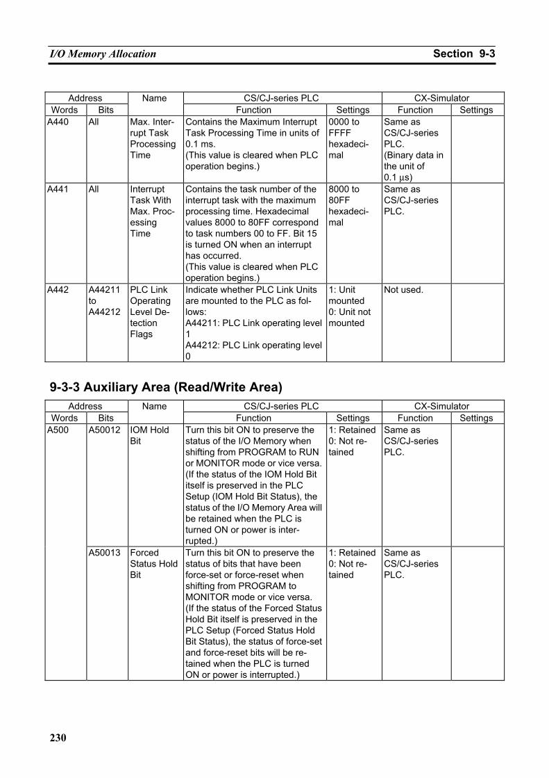
I/O Memory Allocation Section 9-3
230
Address CS/CJ-series PLC CX-Simulator
Words Bits Name
Function Settings Function Settings A440 All Max. Inter-
rupt Task Processing Time
Contains the Maximum Interrupt Task Processing Time in units of 0.1 ms. (This value is cleared when PLC operation begins.)
0000 to FFFF hexadeci-mal
Same as CS/CJ-series PLC. (Binary data in the unit of 0.1 µs)
A441 All Interrupt Task With Max. Proc-essing Time
Contains the task number of the interrupt task with the maximum processing time. Hexadecimal values 8000 to 80FF correspond to task numbers 00 to FF. Bit 15 is turned ON when an interrupt has occurred. (This value is cleared when PLC operation begins.)
8000 to 80FF hexadeci-mal
Same as CS/CJ-series PLC.
A442 A44211 to A44212
PLC Link Operating Level De-tection Flags
Indicate whether PLC Link Units are mounted to the PLC as fol-lows: A44211: PLC Link operating level 1 A44212: PLC Link operating level 0
1: Unit mounted 0: Unit not mounted
Not used.
9-3-3 Auxiliary Area (Read/Write Area) Address CS/CJ-series PLC CX-Simulator
Words Bits Name
Function Settings Function Settings A50012 IOM Hold
Bit Turn this bit ON to preserve the status of the I/O Memory when shifting from PROGRAM to RUN or MONITOR mode or vice versa. (If the status of the IOM Hold Bit itself is preserved in the PLC Setup (IOM Hold Bit Status), the status of the I/O Memory Area will be retained when the PLC is turned ON or power is inter-rupted.)
1: Retained0: Not re-tained
Same as CS/CJ-series PLC.
A500
A50013 Forced Status Hold Bit
Turn this bit ON to preserve the status of bits that have been force-set or force-reset when shifting from PROGRAM to MONITOR mode or vice versa. (If the status of the Forced Status Hold Bit itself is preserved in the PLC Setup (Forced Status Hold Bit Status), the status of force-set and force-reset bits will be re-tained when the PLC is turned ON or power is interrupted.)
1: Retained0: Not re-tained
Same as CS/CJ-series PLC.
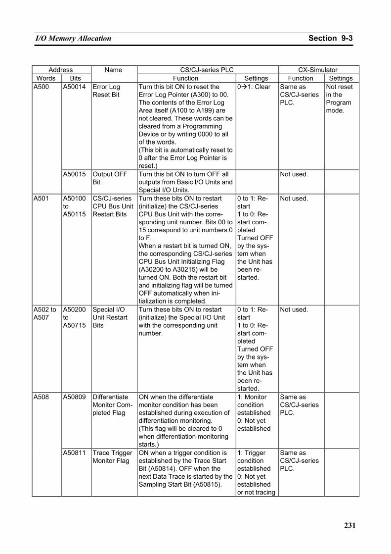
I/O Memory Allocation Section 9-3
231
Address CS/CJ-series PLC CX-Simulator
Words Bits Name
Function Settings Function Settings A50014 Error Log
Reset Bit Turn this bit ON to reset the Error Log Pointer (A300) to 00. The contents of the Error Log Area itself (A100 to A199) are not cleared. These words can be cleared from a Programming Device or by writing 0000 to all of the words. (This bit is automatically reset to 0 after the Error Log Pointer is reset.)
0 1: Clear Same as CS/CJ-series PLC.
Not reset in the Program mode.
A500
A50015 Output OFF Bit
Turn this bit ON to turn OFF all outputs from Basic I/O Units and Special I/O Units.
Not used.
A501 A50100 to A50115
CS/CJ-series CPU Bus Unit Restart Bits
Turn these bits ON to restart (initialize) the CS/CJ-series CPU Bus Unit with the corre-sponding unit number. Bits 00 to 15 correspond to unit numbers 0 to F. When a restart bit is turned ON, the corresponding CS/CJ-series CPU Bus Unit Initializing Flag (A30200 to A30215) will be turned ON. Both the restart bit and initializing flag will be turned OFF automatically when ini-tialization is completed.
0 to 1: Re-start 1 to 0: Re-start com-pleted Turned OFF by the sys-tem when the Unit has been re-started.
Not used.
A502 to A507
A50200 to A50715
Special I/O Unit Restart Bits
Turn these bits ON to restart (initialize) the Special I/O Unit with the corresponding unit number.
0 to 1: Re-start 1 to 0: Re-start com-pleted Turned OFF by the sys-tem when the Unit has been re-started.
Not used.
A50809 Differentiate Monitor Com-pleted Flag
ON when the differentiate monitor condition has been established during execution of differentiation monitoring. (This flag will be cleared to 0 when differentiation monitoring starts.)
1: Monitor condition established 0: Not yet established
Same as CS/CJ-series PLC.
A508
A50811 Trace Trigger Monitor Flag
ON when a trigger condition is established by the Trace Start Bit (A50814). OFF when the next Data Trace is started by the Sampling Start Bit (A50815).
1: Trigger condition established 0: Not yet established or not tracing
Same as CS/CJ-series PLC.
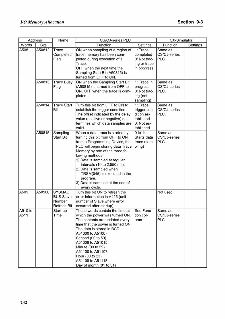
I/O Memory Allocation Section 9-3
232
Address CS/CJ-series PLC CX-Simulator
Words Bits Name
Function Settings Function Settings A50812 Trace
Completed Flag
ON when sampling of a region of trace memory has been com-pleted during execution of a Trace. OFF when the next time the Sampling Start Bit (A50815) is turned from OFF to ON.
1: Trace completed 0: Not trac-ing or trace in progress
Same as CS/CJ-series PLC.
A50813 Trace Busy Flag
ON when the Sampling Start Bit (A50815) is turned from OFF to ON. OFF when the trace is com-pleted.
1: Trace in progress 0: Not trac-ing (not sampling)
Same as CS/CJ-series PLC.
A50814 Trace Start Bit
Turn this bit from OFF to ON to establish the trigger condition. The offset indicated by the delay value (positive or negative) de-termines which data samples are valid.
1: Trace trigger con-dition es-tablished 0: Not es-tablished
Same as CS/CJ-series PLC.
A508
A50815 Sampling Start Bit
When a data trace is started by turning this bit from OFF to ON from a Programming Device, the PLC will begin storing data Trace Memory by one of the three fol-lowing methods: 1) Data is sampled at regular
intervals (10 to 2,550 ms). 2) Data is sampled when
TRSM(045) is executed in the program.
3) Data is sampled at the end of every cycle.
0 to 1: Starts data trace (sam-pling)
Same as CS/CJ-series PLC.
A509 A50900 SYSMAC BUS Slave Number Refresh Bit
Turn this bit ON to refresh the error information in A425 (unit number of Slave where error occurred after startup).
Not used.
A510 to A511
Start-up Time
These words contain the time at which the power was turned ON. The contents are updated every time that the power is turned ON. The data is stored in BCD. A51000 to A51007: Second (00 to 59) A51008 to A51015: Minute (00 to 59) A51100 to A51107: Hour (00 to 23) A51108 to A51115: Day of month (01 to 31)
See Func-tion col-umn.
Same as CS/CJ-series PLC.
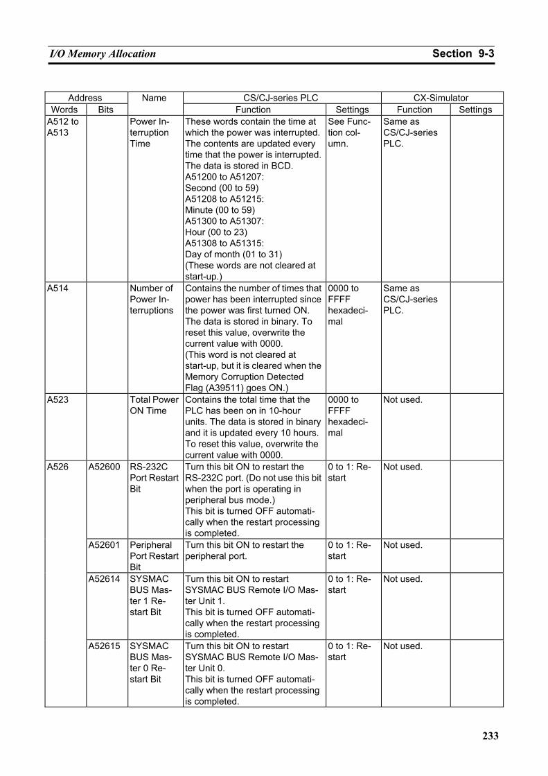
I/O Memory Allocation Section 9-3
233
Address CS/CJ-series PLC CX-Simulator
Words Bits Name
Function Settings Function Settings A512 to A513
Power In-terruption Time
These words contain the time at which the power was interrupted. The contents are updated every time that the power is interrupted. The data is stored in BCD. A51200 to A51207: Second (00 to 59) A51208 to A51215: Minute (00 to 59) A51300 to A51307: Hour (00 to 23) A51308 to A51315: Day of month (01 to 31) (These words are not cleared at start-up.)
See Func-tion col-umn.
Same as CS/CJ-series PLC.
A514 Number of Power In-terruptions
Contains the number of times that power has been interrupted since the power was first turned ON. The data is stored in binary. To reset this value, overwrite the current value with 0000. (This word is not cleared at start-up, but it is cleared when the Memory Corruption Detected Flag (A39511) goes ON.)
0000 to FFFF hexadeci-mal
Same as CS/CJ-series PLC.
A523 Total Power ON Time
Contains the total time that the PLC has been on in 10-hour units. The data is stored in binary and it is updated every 10 hours. To reset this value, overwrite the current value with 0000.
0000 to FFFF hexadeci-mal
Not used.
A52600 RS-232C Port Restart Bit
Turn this bit ON to restart the RS-232C port. (Do not use this bit when the port is operating in peripheral bus mode.) This bit is turned OFF automati-cally when the restart processing is completed.
0 to 1: Re-start
Not used.
A52601 Peripheral Port Restart Bit
Turn this bit ON to restart the peripheral port.
0 to 1: Re-start
Not used.
A52614 SYSMAC BUS Mas-ter 1 Re-start Bit
Turn this bit ON to restart SYSMAC BUS Remote I/O Mas-ter Unit 1. This bit is turned OFF automati-cally when the restart processing is completed.
0 to 1: Re-start
Not used.
A526
A52615 SYSMAC BUS Mas-ter 0 Re-start Bit
Turn this bit ON to restart SYSMAC BUS Remote I/O Mas-ter Unit 0. This bit is turned OFF automati-cally when the restart processing is completed.
0 to 1: Re-start
Not used.
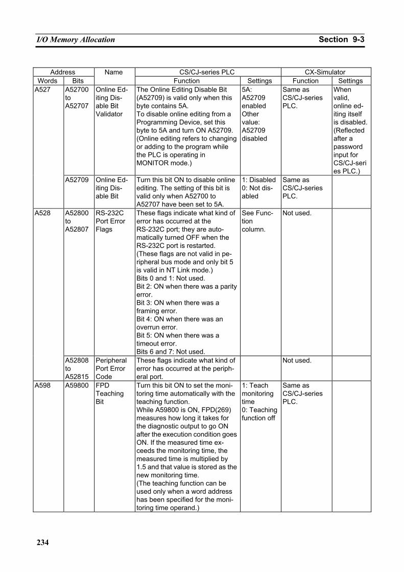
I/O Memory Allocation Section 9-3
234
Address CS/CJ-series PLC CX-Simulator
Words Bits Name
Function Settings Function Settings A52700 to A52707
Online Ed-iting Dis-able Bit Validator
The Online Editing Disable Bit (A52709) is valid only when this byte contains 5A. To disable online editing from a Programming Device, set this byte to 5A and turn ON A52709. (Online editing refers to changing or adding to the program while the PLC is operating in MONITOR mode.)
5A: A52709 enabled Other value: A52709 disabled
Same as CS/CJ-series PLC.
When valid, online ed-iting itself is disabled. (Reflected after a password input for CS/CJ-series PLC.)
A527
A52709 Online Ed-iting Dis-able Bit
Turn this bit ON to disable online editing. The setting of this bit is valid only when A52700 to A52707 have been set to 5A.
1: Disabled0: Not dis-abled
Same as CS/CJ-series PLC.
A52800 to A52807
RS-232C Port Error Flags
These flags indicate what kind of error has occurred at the RS-232C port; they are auto-matically turned OFF when the RS-232C port is restarted. (These flags are not valid in pe-ripheral bus mode and only bit 5 is valid in NT Link mode.) Bits 0 and 1: Not used. Bit 2: ON when there was a parity error. Bit 3: ON when there was a framing error. Bit 4: ON when there was an overrun error. Bit 5: ON when there was a timeout error. Bits 6 and 7: Not used.
See Func-tion column.
Not used. A528
A52808 to A52815
Peripheral Port Error Code
These flags indicate what kind of error has occurred at the periph-eral port.
Not used.
A598 A59800 FPD Teaching Bit
Turn this bit ON to set the moni-toring time automatically with the teaching function. While A59800 is ON, FPD(269) measures how long it takes for the diagnostic output to go ON after the execution condition goes ON. If the measured time ex-ceeds the monitoring time, the measured time is multiplied by 1.5 and that value is stored as the new monitoring time. (The teaching function can be used only when a word address has been specified for the moni-toring time operand.)
1: Teach monitoring time 0: Teaching function off
Same as CS/CJ-series PLC.
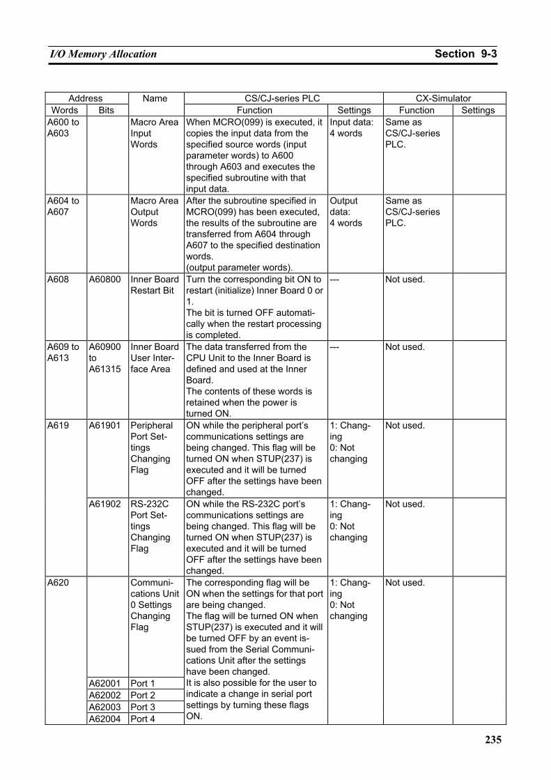
I/O Memory Allocation Section 9-3
235
Address CS/CJ-series PLC CX-Simulator
Words Bits Name
Function Settings Function Settings A600 to A603
Macro Area Input Words
When MCRO(099) is executed, it copies the input data from the specified source words (input parameter words) to A600 through A603 and executes the specified subroutine with that input data.
Input data: 4 words
Same as CS/CJ-series PLC.
A604 to A607
Macro Area Output Words
After the subroutine specified in MCRO(099) has been executed, the results of the subroutine are transferred from A604 through A607 to the specified destination words. (output parameter words).
Output data: 4 words
Same as CS/CJ-series PLC.
A608 A60800 Inner Board Restart Bit
Turn the corresponding bit ON to restart (initialize) Inner Board 0 or 1. The bit is turned OFF automati-cally when the restart processing is completed.
--- Not used.
A609 to A613
A60900 to A61315
Inner Board User Inter-face Area
The data transferred from the CPU Unit to the Inner Board is defined and used at the Inner Board. The contents of these words is retained when the power is turned ON.
--- Not used.
A61901 Peripheral Port Set-tings Changing Flag
ON while the peripheral port’s communications settings are being changed. This flag will be turned ON when STUP(237) is executed and it will be turned OFF after the settings have been changed.
1: Chang-ing 0: Not changing
Not used. A619
A61902 RS-232C Port Set-tings Changing Flag
ON while the RS-232C port’s communications settings are being changed. This flag will be turned ON when STUP(237) is executed and it will be turned OFF after the settings have been changed.
1: Chang-ing 0: Not changing
Not used.
Communi-cations Unit 0 Settings Changing Flag
A62001 Port 1 A62002 Port 2 A62003 Port 3
A620
A62004 Port 4
The corresponding flag will be ON when the settings for that port are being changed. The flag will be turned ON when STUP(237) is executed and it will be turned OFF by an event is-sued from the Serial Communi-cations Unit after the settings have been changed. It is also possible for the user to indicate a change in serial port settings by turning these flags ON.
1: Chang-ing 0: Not changing
Not used.
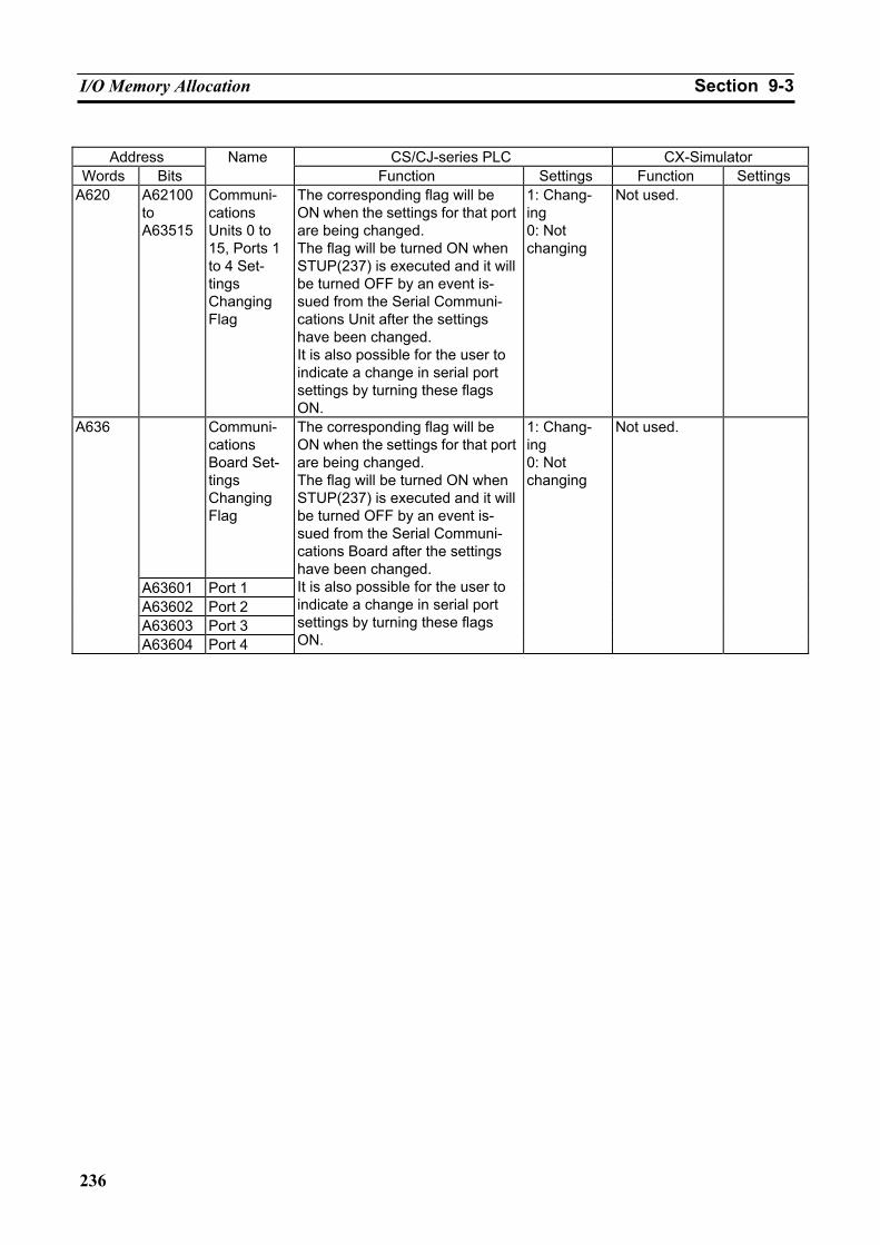
I/O Memory Allocation Section 9-3
236
Address CS/CJ-series PLC CX-Simulator
Words Bits Name
Function Settings Function Settings A620 A62100
to A63515
Communi-cations Units 0 to 15, Ports 1 to 4 Set-tings Changing Flag
The corresponding flag will be ON when the settings for that port are being changed. The flag will be turned ON when STUP(237) is executed and it will be turned OFF by an event is-sued from the Serial Communi-cations Unit after the settings have been changed. It is also possible for the user to indicate a change in serial port settings by turning these flags ON.
1: Chang-ing 0: Not changing
Not used.
Communi-cations Board Set-tings Changing Flag
A63601 Port 1 A63602 Port 2 A63603 Port 3
A636
A63604 Port 4
The corresponding flag will be ON when the settings for that port are being changed. The flag will be turned ON when STUP(237) is executed and it will be turned OFF by an event is-sued from the Serial Communi-cations Board after the settings have been changed. It is also possible for the user to indicate a change in serial port settings by turning these flags ON.
1: Chang-ing 0: Not changing
Not used.
Other Functions Section 9-4
237
9-4 Other Functions
9-4-1 Differences in CX-Programmer Operation I/O Table
The Ladder Engine, unlike actual PLCs, does not use the I/O tables. Thus the operation related to I/O tables in the CX-Programmer can not be used. If I/O tables are downloaded from the CX-Programmer, the tables will be set to the Ladder Engine. However, the set values are not referenced by the Ladder Engine. So the Units required must be registered in the [Register PLC Unit] window of the Debugger.
9-4-2 Other Precautions File Memory
In CS/CJ-series PLCs, the Memory Card and the specified range of the EM area can be used to store files. In the Ladder Engine, however, files are stored in the hard disk of the computer. The directory allocated to the hard disk as the EM file memory is limited by the capacity set in the PLC setup, and the one as the Memory Card is not (actually limited by the hard disk space).
In CS/CJ-series PLCs, the total length of the directory (including subdirecto-ries) is limited to 65 characters. In the Ladder Engine, the length of the whole directory from the directory (the Card of the PLC data directory or the EM di-rectory) allocated to the file system must be up to 65 characters.
Registering Alarm Display Applications
Alarm Display is given by the applications log of the event viewer in Windows NT and the system-standard Notepad.exe in Windows95/98. For Windows 95 and 98, an application for Alarm Display can be registered and used. As such an application, a general text editor and a text viewer can be used. (Where a file name must be able to be passed as an argument of the application.)
Operation of the Ladder Engine on Startup/Exit
If [Automatic transfer of the program at start-up] (pin 2) of the DIP switch set-ting is ON, the Auotexec file is read to the I/O memory area every time the Ladder Engine is started or restarted. Also, when the Ladder Engine is exited or restarted, the Power OFF Interrupt Task will not be started regardless of [Power OFF Interrupt Task Disabled/Enabled] of the PC Setup. It will be exe-cuted only when clicking the [Reset] button or starting the interrupt task from the [Task Control] window.

Other Functions Section 9-4
238
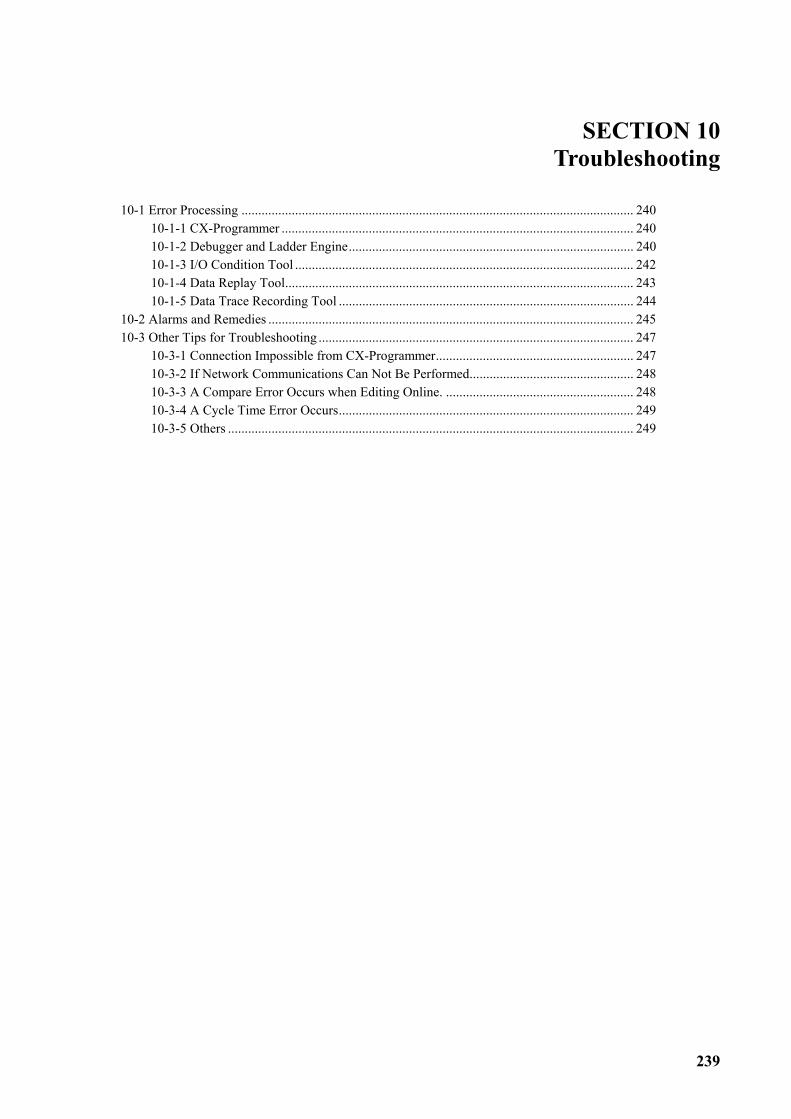
239
SECTION 10 Troubleshooting
10-1 Error Processing ..................................................................................................................... 240 10-1-1 CX-Programmer ......................................................................................................... 240 10-1-2 Debugger and Ladder Engine..................................................................................... 240 10-1-3 I/O Condition Tool ..................................................................................................... 242 10-1-4 Data Replay Tool........................................................................................................ 243 10-1-5 Data Trace Recording Tool ........................................................................................ 244
10-2 Alarms and Remedies ............................................................................................................. 245 10-3 Other Tips for Troubleshooting .............................................................................................. 247
10-3-1 Connection Impossible from CX-Programmer........................................................... 247 10-3-2 If Network Communications Can Not Be Performed................................................. 248 10-3-3 A Compare Error Occurs when Editing Online. ........................................................ 248 10-3-4 A Cycle Time Error Occurs........................................................................................ 249 10-3-5 Others ......................................................................................................................... 249
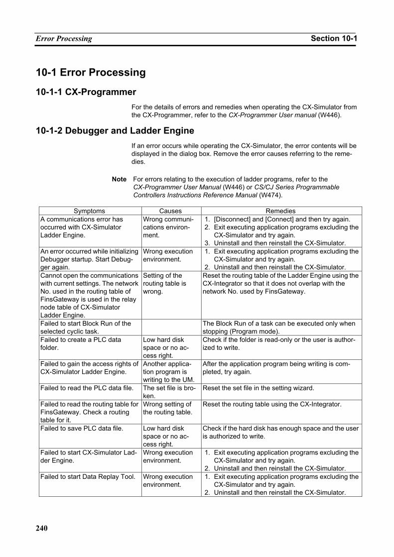
Error Processing Section 10-1
240
10-1 Error Processing
10-1-1 CX-Programmer For the details of errors and remedies when operating the CX-Simulator from the CX-Programmer, refer to the CX-Programmer User manual (W446).
10-1-2 Debugger and Ladder Engine If an error occurs while operating the CX-Simulator, the error contents will be displayed in the dialog box. Remove the error causes referring to the reme-dies.
Note For errors relating to the execution of ladder programs, refer to the
CX-Programmer User Manual (W446) or CS/CJ Series Programmable Controllers Instructions Reference Manual (W474).
Symptoms Causes Remedies
A communications error has occurred with CX-Simulator Ladder Engine.
Wrong communi-cations environ-ment.
1. [Disconnect] and [Connect] and then try again. 2. Exit executing application programs excluding the
CX-Simulator and try again. 3. Uninstall and then reinstall the CX-Simulator.
An error occurred while initializing Debugger startup. Start Debug-ger again.
Wrong execution environment.
1. Exit executing application programs excluding the CX-Simulator and try again.
2. Uninstall and then reinstall the CX-Simulator. Cannot open the communications with current settings. The network No. used in the routing table of FinsGateway is used in the relay node table of CX-Simulator Ladder Engine.
Setting of the routing table is wrong.
Reset the routing table of the Ladder Engine using the CX-Integrator so that it does not overlap with the network No. used by FinsGateway.
Failed to start Block Run of the selected cyclic task.
The Block Run of a task can be executed only when stopping (Program mode).
Failed to create a PLC data folder.
Low hard disk space or no ac-cess right.
Check if the folder is read-only or the user is author-ized to write.
Failed to gain the access rights of CX-Simulator Ladder Engine.
Another applica-tion program is writing to the UM.
After the application program being writing is com-pleted, try again.
Failed to read the PLC data file. The set file is bro-ken.
Reset the set file in the setting wizard.
Failed to read the routing table for FinsGateway. Check a routing table for it.
Wrong setting of the routing table.
Reset the routing table using the CX-Integrator.
Failed to save PLC data file. Low hard disk space or no ac-cess right.
Check if the hard disk has enough space and the user is authorized to write.
Failed to start CX-Simulator Lad-der Engine.
Wrong execution environment.
1. Exit executing application programs excluding the CX-Simulator and try again.
2. Uninstall and then reinstall the CX-Simulator. Failed to start Data Replay Tool. Wrong execution
environment. 1. Exit executing application programs excluding the
CX-Simulator and try again. 2. Uninstall and then reinstall the CX-Simulator.
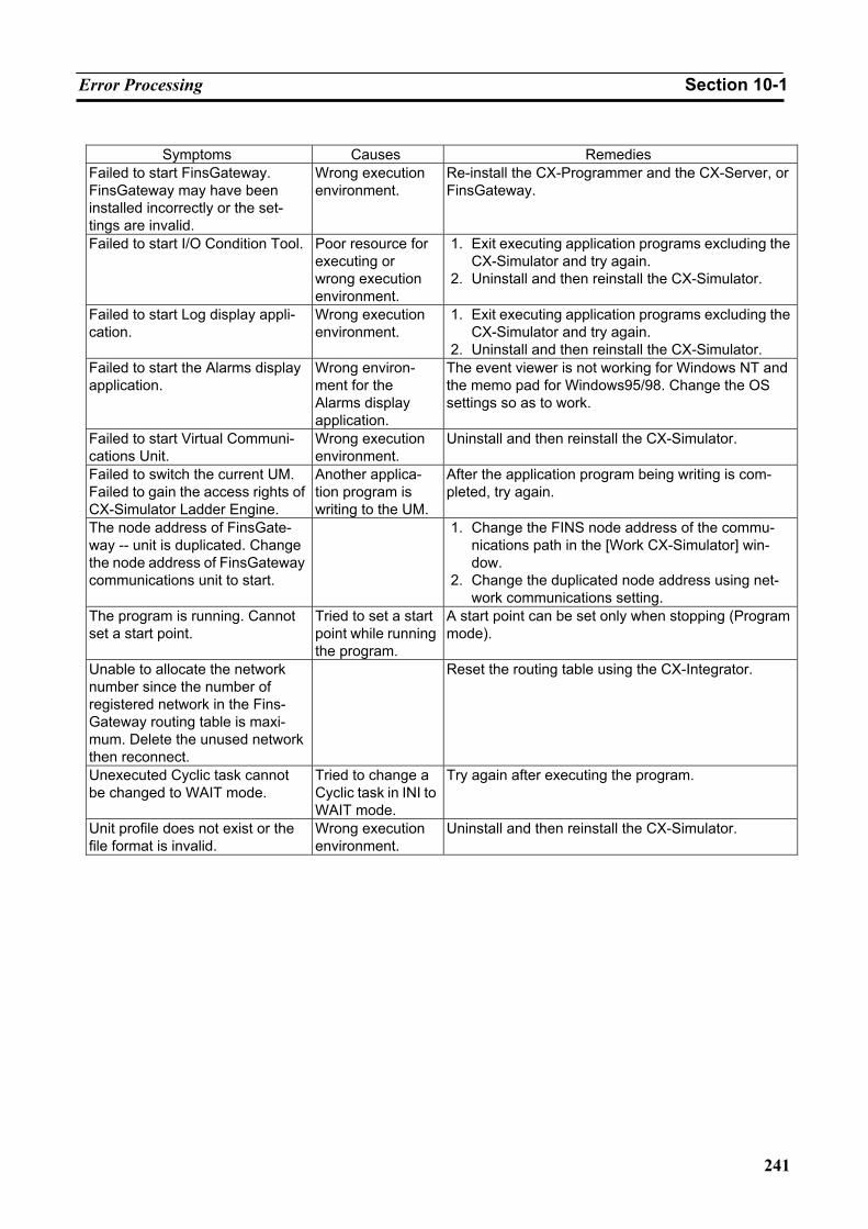
Error Processing Section 10-1
241
Symptoms Causes Remedies
Failed to start FinsGateway. FinsGateway may have been installed incorrectly or the set-tings are invalid.
Wrong execution environment.
Re-install the CX-Programmer and the CX-Server, or FinsGateway.
Failed to start I/O Condition Tool. Poor resource for executing or wrong execution environment.
1. Exit executing application programs excluding the CX-Simulator and try again.
2. Uninstall and then reinstall the CX-Simulator.
Failed to start Log display appli-cation.
Wrong execution environment.
1. Exit executing application programs excluding the CX-Simulator and try again.
2. Uninstall and then reinstall the CX-Simulator. Failed to start the Alarms display application.
Wrong environ-ment for the Alarms display application.
The event viewer is not working for Windows NT and the memo pad for Windows95/98. Change the OS settings so as to work.
Failed to start Virtual Communi-cations Unit.
Wrong execution environment.
Uninstall and then reinstall the CX-Simulator.
Failed to switch the current UM. Failed to gain the access rights of CX-Simulator Ladder Engine.
Another applica-tion program is writing to the UM.
After the application program being writing is com-pleted, try again.
The node address of FinsGate-way -- unit is duplicated. Change the node address of FinsGateway communications unit to start.
1. Change the FINS node address of the commu-nications path in the [Work CX-Simulator] win-dow.
2. Change the duplicated node address using net-work communications setting.
The program is running. Cannot set a start point.
Tried to set a start point while running the program.
A start point can be set only when stopping (Program mode).
Unable to allocate the network number since the number of registered network in the Fins-Gateway routing table is maxi-mum. Delete the unused network then reconnect.
Reset the routing table using the CX-Integrator.
Unexecuted Cyclic task cannot be changed to WAIT mode.
Tried to change a Cyclic task in INI to WAIT mode.
Try again after executing the program.
Unit profile does not exist or the file format is invalid.
Wrong execution environment.
Uninstall and then reinstall the CX-Simulator.
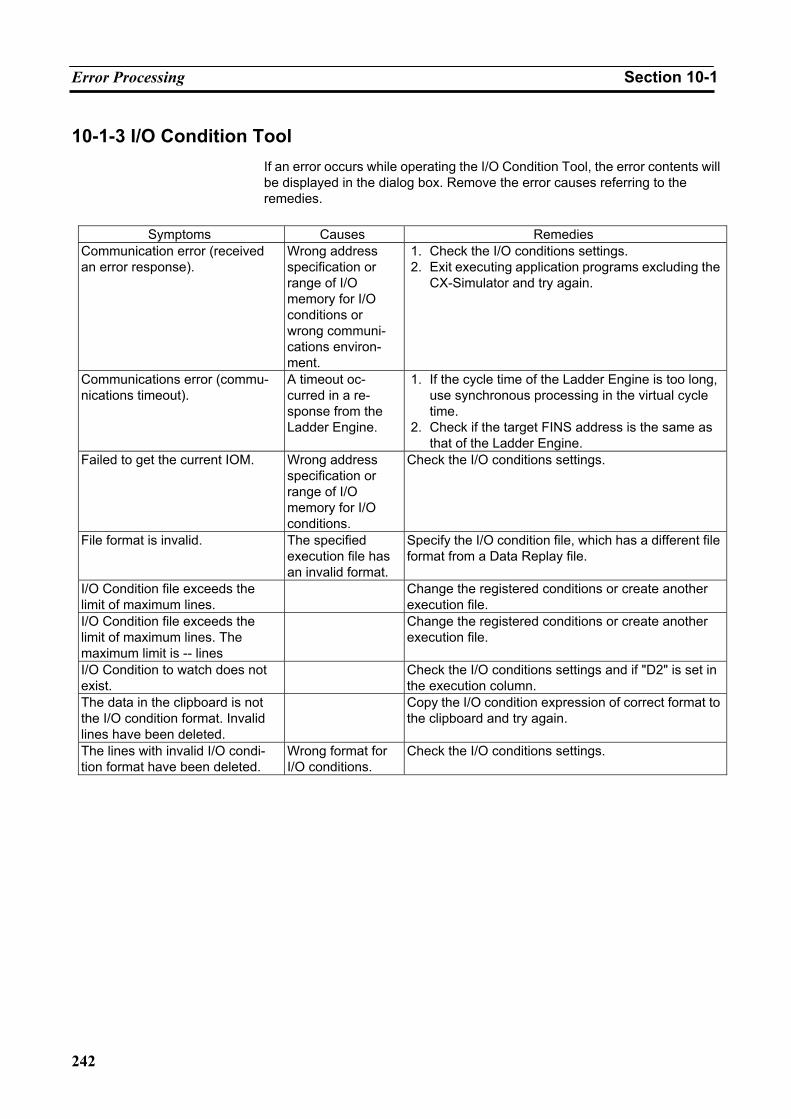
Error Processing Section 10-1
242
10-1-3 I/O Condition Tool If an error occurs while operating the I/O Condition Tool, the error contents will be displayed in the dialog box. Remove the error causes referring to the remedies.
Symptoms Causes Remedies
Communication error (received an error response).
Wrong address specification or range of I/O memory for I/O conditions or wrong communi-cations environ-ment.
1. Check the I/O conditions settings. 2. Exit executing application programs excluding the
CX-Simulator and try again.
Communications error (commu-nications timeout).
A timeout oc-curred in a re-sponse from the Ladder Engine.
1. If the cycle time of the Ladder Engine is too long, use synchronous processing in the virtual cycle time.
2. Check if the target FINS address is the same as that of the Ladder Engine.
Failed to get the current IOM. Wrong address specification or range of I/O memory for I/O conditions.
Check the I/O conditions settings.
File format is invalid. The specified execution file has an invalid format.
Specify the I/O condition file, which has a different file format from a Data Replay file.
I/O Condition file exceeds the limit of maximum lines.
Change the registered conditions or create another execution file.
I/O Condition file exceeds the limit of maximum lines. The maximum limit is -- lines
Change the registered conditions or create another execution file.
I/O Condition to watch does not exist.
Check the I/O conditions settings and if "D2" is set in the execution column.
The data in the clipboard is not the I/O condition format. Invalid lines have been deleted.
Copy the I/O condition expression of correct format to the clipboard and try again.
The lines with invalid I/O condi-tion format have been deleted.
Wrong format for I/O conditions.
Check the I/O conditions settings.
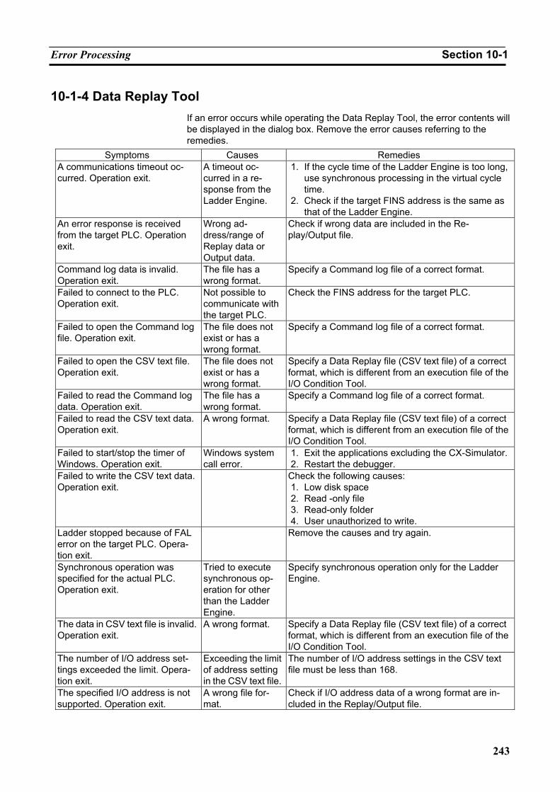
Error Processing Section 10-1
243
10-1-4 Data Replay Tool If an error occurs while operating the Data Replay Tool, the error contents will be displayed in the dialog box. Remove the error causes referring to the remedies.
Symptoms Causes Remedies A communications timeout oc-curred. Operation exit.
A timeout oc-curred in a re-sponse from the Ladder Engine.
1. If the cycle time of the Ladder Engine is too long, use synchronous processing in the virtual cycle time.
2. Check if the target FINS address is the same as that of the Ladder Engine.
An error response is received from the target PLC. Operation exit.
Wrong ad-dress/range of Replay data or Output data.
Check if wrong data are included in the Re-play/Output file.
Command log data is invalid. Operation exit.
The file has a wrong format.
Specify a Command log file of a correct format.
Failed to connect to the PLC. Operation exit.
Not possible to communicate with the target PLC.
Check the FINS address for the target PLC.
Failed to open the Command log file. Operation exit.
The file does not exist or has a wrong format.
Specify a Command log file of a correct format.
Failed to open the CSV text file. Operation exit.
The file does not exist or has a wrong format.
Specify a Data Replay file (CSV text file) of a correct format, which is different from an execution file of the I/O Condition Tool.
Failed to read the Command log data. Operation exit.
The file has a wrong format.
Specify a Command log file of a correct format.
Failed to read the CSV text data. Operation exit.
A wrong format. Specify a Data Replay file (CSV text file) of a correct format, which is different from an execution file of the I/O Condition Tool.
Failed to start/stop the timer of Windows. Operation exit.
Windows system call error.
1. Exit the applications excluding the CX-Simulator.2. Restart the debugger.
Failed to write the CSV text data. Operation exit.
Check the following causes: 1. Low disk space 2. Read -only file 3. Read-only folder 4. User unauthorized to write.
Ladder stopped because of FAL error on the target PLC. Opera-tion exit.
Remove the causes and try again.
Synchronous operation was specified for the actual PLC. Operation exit.
Tried to execute synchronous op-eration for other than the Ladder Engine.
Specify synchronous operation only for the Ladder Engine.
The data in CSV text file is invalid. Operation exit.
A wrong format. Specify a Data Replay file (CSV text file) of a correct format, which is different from an execution file of the I/O Condition Tool.
The number of I/O address set-tings exceeded the limit. Opera-tion exit.
Exceeding the limit of address setting in the CSV text file.
The number of I/O address settings in the CSV text file must be less than 168.
The specified I/O address is not supported. Operation exit.
A wrong file for-mat.
Check if I/O address data of a wrong format are in-cluded in the Replay/Output file.
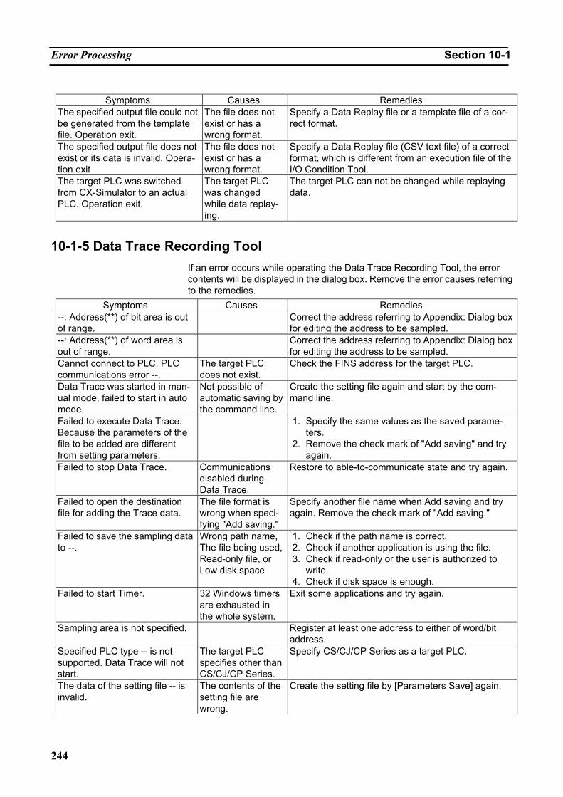
Error Processing Section 10-1
244
Symptoms Causes Remedies
The specified output file could not be generated from the template file. Operation exit.
The file does not exist or has a wrong format.
Specify a Data Replay file or a template file of a cor-rect format.
The specified output file does not exist or its data is invalid. Opera-tion exit
The file does not exist or has a wrong format.
Specify a Data Replay file (CSV text file) of a correct format, which is different from an execution file of the I/O Condition Tool.
The target PLC was switched from CX-Simulator to an actual PLC. Operation exit.
The target PLC was changed while data replay-ing.
The target PLC can not be changed while replaying data.
10-1-5 Data Trace Recording Tool If an error occurs while operating the Data Trace Recording Tool, the error contents will be displayed in the dialog box. Remove the error causes referring to the remedies.
Symptoms Causes Remedies --: Address(**) of bit area is out of range.
Correct the address referring to Appendix: Dialog box for editing the address to be sampled.
--: Address(**) of word area is out of range.
Correct the address referring to Appendix: Dialog box for editing the address to be sampled.
Cannot connect to PLC. PLC communications error --.
The target PLC does not exist.
Check the FINS address for the target PLC.
Data Trace was started in man-ual mode, failed to start in auto mode.
Not possible of automatic saving by the command line.
Create the setting file again and start by the com-mand line.
Failed to execute Data Trace. Because the parameters of the file to be added are different from setting parameters.
1. Specify the same values as the saved parame-ters.
2. Remove the check mark of "Add saving" and try again.
Failed to stop Data Trace. Communications disabled during Data Trace.
Restore to able-to-communicate state and try again.
Failed to open the destination file for adding the Trace data.
The file format is wrong when speci-fying "Add saving."
Specify another file name when Add saving and try again. Remove the check mark of "Add saving."
Failed to save the sampling data to --.
Wrong path name, The file being used, Read-only file, or Low disk space
1. Check if the path name is correct. 2. Check if another application is using the file. 3. Check if read-only or the user is authorized to
write. 4. Check if disk space is enough.
Failed to start Timer. 32 Windows timers are exhausted in the whole system.
Exit some applications and try again.
Sampling area is not specified. Register at least one address to either of word/bit address.
Specified PLC type -- is not supported. Data Trace will not start.
The target PLC specifies other than CS/CJ/CP Series.
Specify CS/CJ/CP Series as a target PLC.
The data of the setting file -- is invalid.
The contents of the setting file are wrong.
Create the setting file by [Parameters Save] again.
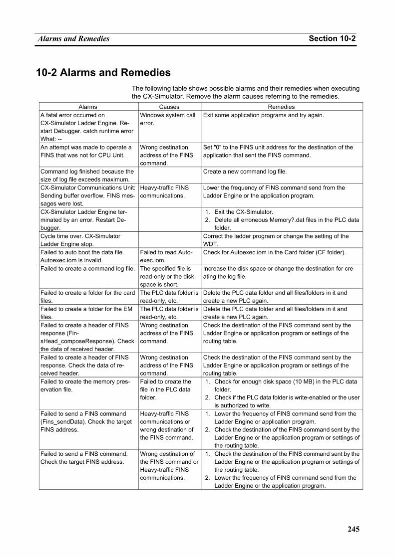
Alarms and Remedies Section 10-2
245
10-2 Alarms and Remedies The following table shows possible alarms and their remedies when executing the CX-Simulator. Remove the alarm causes referring to the remedies.
Alarms Causes Remedies A fatal error occurred on CX-Simulator Ladder Engine. Re-start Debugger. catch runtime error What: --
Windows system call error.
Exit some application programs and try again.
An attempt was made to operate a FINS that was not for CPU Unit.
Wrong destination address of the FINS command.
Set "0" to the FINS unit address for the destination of the application that sent the FINS command.
Command log finished because the size of log file exceeds maximum.
Create a new command log file.
CX-Simulator Communications Unit: Sending buffer overflow. FINS mes-sages were lost.
Heavy-traffic FINS communications.
Lower the frequency of FINS command send from the Ladder Engine or the application program.
CX-Simulator Ladder Engine ter-minated by an error. Restart De-bugger.
1. Exit the CX-Simulator. 2. Delete all erroneous Memory?.dat files in the PLC data
folder. Cycle time over. CX-Simulator Ladder Engine stop.
Correct the ladder program or change the setting of the WDT.
Failed to auto boot the data file. Autoexec.iom is invalid.
Failed to read Auto-exec.iom.
Check for Autoexec.iom in the Card folder (CF folder).
Failed to create a command log file. The specified file is read-only or the disk space is short.
Increase the disk space or change the destination for cre-ating the log file.
Failed to create a folder for the card files.
The PLC data folder is read-only, etc.
Delete the PLC data folder and all files/folders in it and create a new PLC again.
Failed to create a folder for the EM files.
The PLC data folder is read-only, etc.
Delete the PLC data folder and all files/folders in it and create a new PLC again.
Failed to create a header of FINS response (Fin-sHead_composeResponse). Check the data of received header.
Wrong destination address of the FINS command.
Check the destination of the FINS command sent by the Ladder Engine or application program or settings of the routing table.
Failed to create a header of FINS response. Check the data of re-ceived header.
Wrong destination address of the FINS command.
Check the destination of the FINS command sent by the Ladder Engine or application program or settings of the routing table.
Failed to create the memory pres-ervation file.
Failed to create the file in the PLC data folder.
1. Check for enough disk space (10 MB) in the PLC data folder.
2. Check if the PLC data folder is write-enabled or the user is authorized to write.
Failed to send a FINS command (Fins_sendData). Check the target FINS address.
Heavy-traffic FINS communications or wrong destination of the FINS command.
1. Lower the frequency of FINS command send from the Ladder Engine or application program.
2. Check the destination of the FINS command sent by the Ladder Engine or the application program or settings of the routing table.
Failed to send a FINS command. Check the target FINS address.
Wrong destination of the FINS command or Heavy-traffic FINS communications.
1. Check the destination of the FINS command sent by the Ladder Engine or the application program or settings of the routing table.
2. Lower the frequency of FINS command send from the Ladder Engine or the application program.
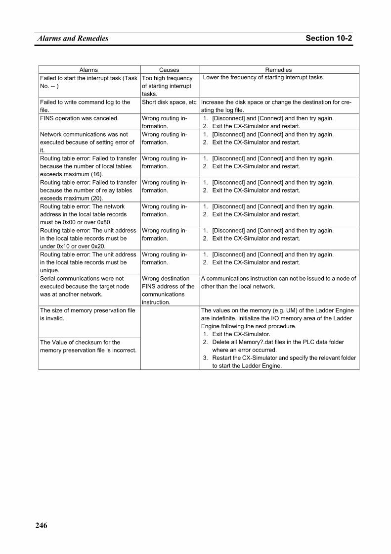
Alarms and Remedies Section 10-2
246
Alarms Causes Remedies
Failed to start the interrupt task (Task No. -- )
Too high frequency of starting interrupt tasks.
Lower the frequency of starting interrupt tasks.
Failed to write command log to the file.
Short disk space, etc Increase the disk space or change the destination for cre-ating the log file.
FINS operation was canceled. Wrong routing in-formation.
1. [Disconnect] and [Connect] and then try again. 2. Exit the CX-Simulator and restart.
Network communications was not executed because of setting error of it.
Wrong routing in-formation.
1. [Disconnect] and [Connect] and then try again. 2. Exit the CX-Simulator and restart.
Routing table error: Failed to transfer because the number of local tables exceeds maximum (16).
Wrong routing in-formation.
1. [Disconnect] and [Connect] and then try again. 2. Exit the CX-Simulator and restart.
Routing table error: Failed to transfer because the number of relay tables exceeds maximum (20).
Wrong routing in-formation.
1. [Disconnect] and [Connect] and then try again. 2. Exit the CX-Simulator and restart.
Routing table error: The network address in the local table records must be 0x00 or over 0x80.
Wrong routing in-formation.
1. [Disconnect] and [Connect] and then try again. 2. Exit the CX-Simulator and restart.
Routing table error: The unit address in the local table records must be under 0x10 or over 0x20.
Wrong routing in-formation.
1. [Disconnect] and [Connect] and then try again. 2. Exit the CX-Simulator and restart.
Routing table error: The unit address in the local table records must be unique.
Wrong routing in-formation.
1. [Disconnect] and [Connect] and then try again. 2. Exit the CX-Simulator and restart.
Serial communications were not executed because the target node was at another network.
Wrong destination FINS address of the communications instruction.
A communications instruction can not be issued to a node of other than the local network.
The size of memory preservation file is invalid.
The Value of checksum for the memory preservation file is incorrect.
The values on the memory (e.g. UM) of the Ladder Engine are indefinite. Initialize the I/O memory area of the Ladder Engine following the next procedure. 1. Exit the CX-Simulator. 2. Delete all Memory?.dat files in the PLC data folder
where an error occurred. 3. Restart the CX-Simulator and specify the relevant folder
to start the Ladder Engine.
Other Tips for Troubleshooting Section 10-3
247
10-3 Other Tips for Troubleshooting
10-3-1 Connection Impossible from CX-Programmer The CX-Simulator is disconnected.
Connect to the CX-Simulator.
Connection to the CX-Simulator does not end normally.
Duplicate FINS address?
Check the FINS addresses for each unit in the [Network Communications Settings] and that for the communications unit of FinsGateway displayed in the [Work CX-Simulator] window to dissolve the duplication.
The network LED for the system status does not change in color al-though the connection to the CX-Simulator ended normally.
In the following cases, communications may be disabled. • The other communications unit of FinsGateway was started after connecting
the CX-Simulator. • Read a Parameter Area File (.std) to the Ladder Engine. • Changed the routing table by the CX-Integrator. In the above cases, once disconnect the CX-Simulator and then connect again.
PLC connection is impossible although the network LED for the system status changes in color.
Check the settings of the application (e.g. the CX-Programmer) connected to the target FINS address displayed in [Guide to Connect] of [Work to CX-Simulator] is correct. For the CX-Programmer, check the communications unit for FinsGateway.
When the communications unit for FinsGateway is connected, once discon-nect and then connect again.
In the following cases, communications may be disabled. • Started the other communications unit of FinsGateway after connecting the
CX-Simulator. • Read a Parameter Area File (.std) to the Ladder Engine. • Changed the routing table by the CX-Integrator.
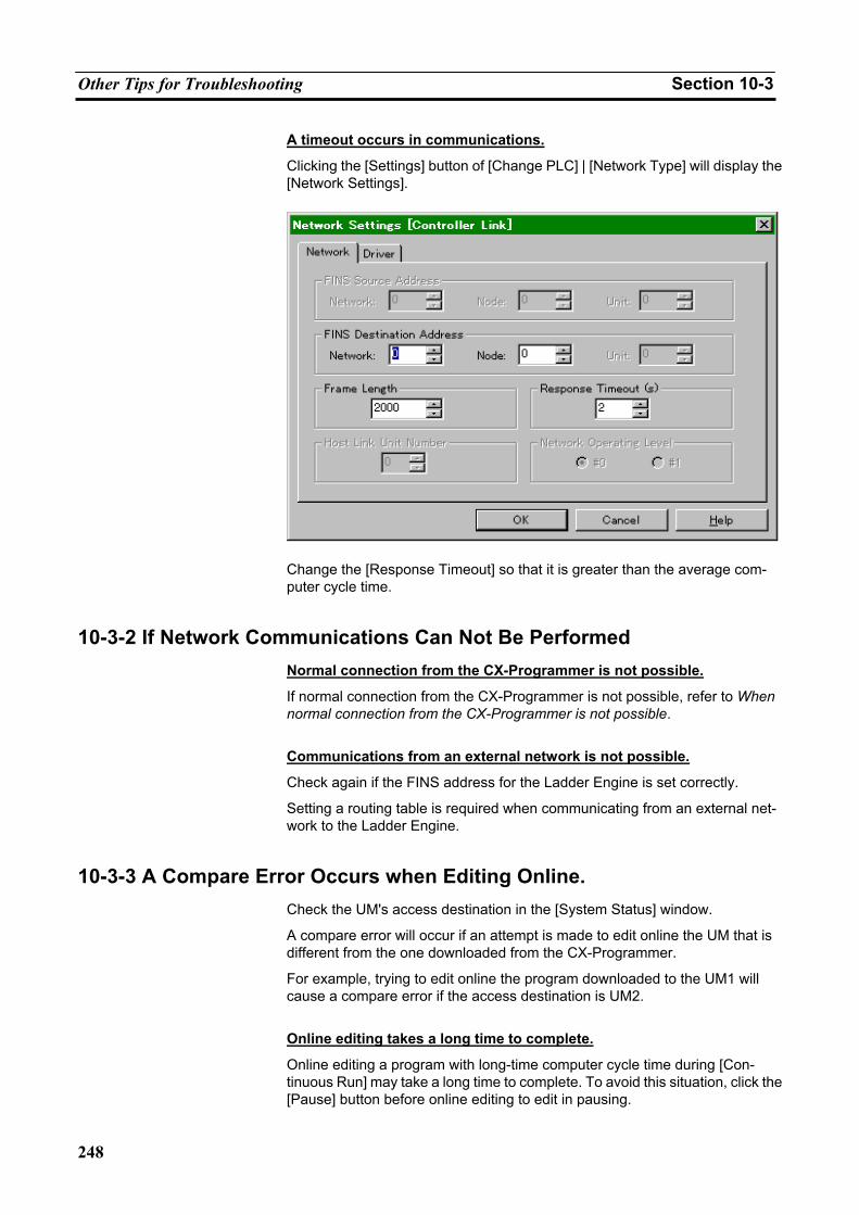
Other Tips for Troubleshooting Section 10-3
248
A timeout occurs in communications.
Clicking the [Settings] button of [Change PLC] | [Network Type] will display the [Network Settings].
Change the [Response Timeout] so that it is greater than the average com-puter cycle time.
10-3-2 If Network Communications Can Not Be Performed Normal connection from the CX-Programmer is not possible.
If normal connection from the CX-Programmer is not possible, refer to When normal connection from the CX-Programmer is not possible.
Communications from an external network is not possible.
Check again if the FINS address for the Ladder Engine is set correctly.
Setting a routing table is required when communicating from an external net-work to the Ladder Engine.
10-3-3 A Compare Error Occurs when Editing Online. Check the UM's access destination in the [System Status] window.
A compare error will occur if an attempt is made to edit online the UM that is different from the one downloaded from the CX-Programmer.
For example, trying to edit online the program downloaded to the UM1 will cause a compare error if the access destination is UM2.
Online editing takes a long time to complete.
Online editing a program with long-time computer cycle time during [Con-tinuous Run] may take a long time to complete. To avoid this situation, click the [Pause] button before online editing to edit in pausing.
Other Tips for Troubleshooting Section 10-3
249
10-3-4 A Cycle Time Error Occurs Even a short program sometimes causes a cycle time error.
A cycle time error can occur if a program is started running in the computer cycle time mode by the CX-Simulator on the computer with a low memory capacity or with a lot of application programs activated. This is because it takes a long time to acquire memory areas. To avoid this situation, try one of the following three measures: (1) Execute in the virtual cycle time, (2) Execute the program removing the check mark of [Return to the top of the program when online editing in Step Run] of [Status] | [Settings] | [PLC Operation Set-tings], or (3) Check [Disable Cycle Time Monitoring].
Change the cycle time monitoring time in PLC Setup.
Remove the check mark of [Cycle Time Monitoring Time] (default: 1,000 ms) of the [PLC] | [PLC Setup] | [Timer/Interrupt] tab to adjust the cycle time moni-toring time.
10-3-5 Others A gap occurs between the time of the Ladder Engine and that of the computer in spite of executing in the computer cycle time.
When in Step Run and Scan Run, etc., a gap can occur between the time of the Ladder Engine and that of the computer even when executing in the com-puter cycle time.
To avoid this situation, use the Ladder Engine in Continuous Run and in the computer time only.
Some files and folders are not displayed in the PLC file memory.
The CARD folders in the PLC data folder corresponds to a memory card of each PLC. Usually the CX-Programmer's memory card component can dis-play the contents of the CARD folder. However, it can not display files and folders with a different naming convention from that of CS/CJ Series. For CS/CJ Series naming convention, refer to CS/CJ Series Operation Manual.

Other Tips for Troubleshooting Section 10-3
250
251
Appendix How to Use Data Trace Recording Tool
Outline of Data Trace Recording Tool The Data Trace Recording Tool is a tool for automatically creating multiple Data Trace files, by setting only once, instead of saving values of I/O memory areas of an actual PLC to a Data Trace file (.cdt) through manual operation using the time chart monitoring or the data tracing of the CX-Programmer.
The Data Trace Recording Tool will run only on the CX-Simulator.
The Data Trace Recording Tool has the following advantages as compared to saving by the CX-Programmer.
• Automatically save data of the data trace. • Save long-term data to multiple files.
Note 1. The Data Trace Recording Tool does not support the Virtual Cycle Time
mode for the Ladder Engine. When using the tool for the Ladder Engine, perform Continuous Run in the Computer Cycle Time mode.
2. For the details of the data tracing, refer to Trace Memory Sampling:
TRSM(045) of CS/CJ Series Programming Manual. Restrictions on Data Trace Saving
There are following restrictions because the Data Trace Recording Tool uses the data tracing function of a PLC.
Number of Points to be Registered (Simultaneous Sampling Number)
• Bits 0 to 31 • Words 0 to 6
Sampling Number
Trace memory (A maximum number of buffers able to collect once): 2000 samples
327,767 samples per one file (Data Trace file: .cdt)
Restrictions by the Trace Memory
The data to be saved by the data tracing is temporarily stored in the trace memory of the PLC (Up to 2,000 samples are stored in the trace memory.). Trace data can not be picked up between this-time data read from the trace memory and next-time set of the data trace.
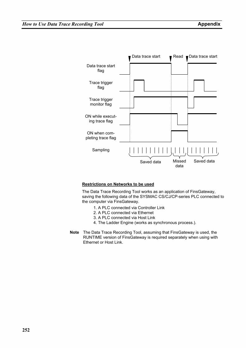
How to Use Data Trace Recording Tool Appendix
252
Restrictions on Networks to be used
The Data Trace Recording Tool works as an application of FinsGateway, saving the following data of the SYSMAC CS/CJ/CP-series PLC connected to the computer via FinsGateway.
1. A PLC connected via Controller Link 2. A PLC connected via Ethernet 3. A PLC connected via Host Link 4. The Ladder Engine (works as synchronous process.).
Note The Data Trace Recording Tool, assuming that FinsGateway is used, the
RUNTIME version of FinsGateway is required separately when using with Ethernet or Host Link.
Data trace start flag
Trace trigger flag
Trace trigger monitor flag
ON while execut-ing trace flag
Sampling
ON when com-pleting trace flag
Saved data Missed data
Saved data
Read Data trace startData trace start
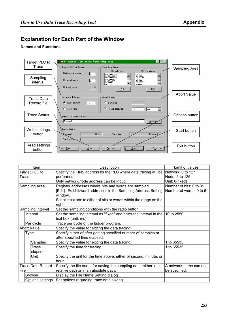
How to Use Data Trace Recording Tool Appendix
253
Explanation for Each Part of the Window Names and Functions
Item Description Limit of values
Target PLC to Trace
Specify the FINS address for the PLC where data tracing will be performed. Only network/node address can be input.
Network: 0 to 127 Node: 1 to 126 Unit: 0(fixed)
Sampling Area Register addresses where bits and words are sampled. [Edit]: Edit bit/word addresses in the Sampling Address Setting window. Set at least one to either of bits or words within the range on the right.
Number of bits: 0 to 31 Number of words: 0 to 6
Sampling interval Set the sampling conditions with the radio button. Interval Set the sampling interval as "fixed" and enter the interval in the
text box (unit: ms). 10 to 2550
Per cycle Trace per cycle of the ladder program. Abort Value Specify the value for exiting the data tracing. Type Specify either of after getting specified number of samples or
after specified time elapsed.
Samples Specify the value for exiting the data tracing. 1 to 65535 Trace
elapsed Specify the time for tracing. 1 to 65535
Unit Specify the unit for the time above: either of second, minute, or hour.
Trace Data Record File
Specify the file name for saving the sampling data: either in a relative path or in an absolute path.
A network name can not be specified.
Browse Display the File Name Setting dialog. Options settings Set options regarding trace data saving.
Target PLC to
Trace
Sampling interval
Trace Data Record file
Trace Status
Write settings button
Read settings button
Sampling Area
Abort Value
Start button
Exit button
Options button
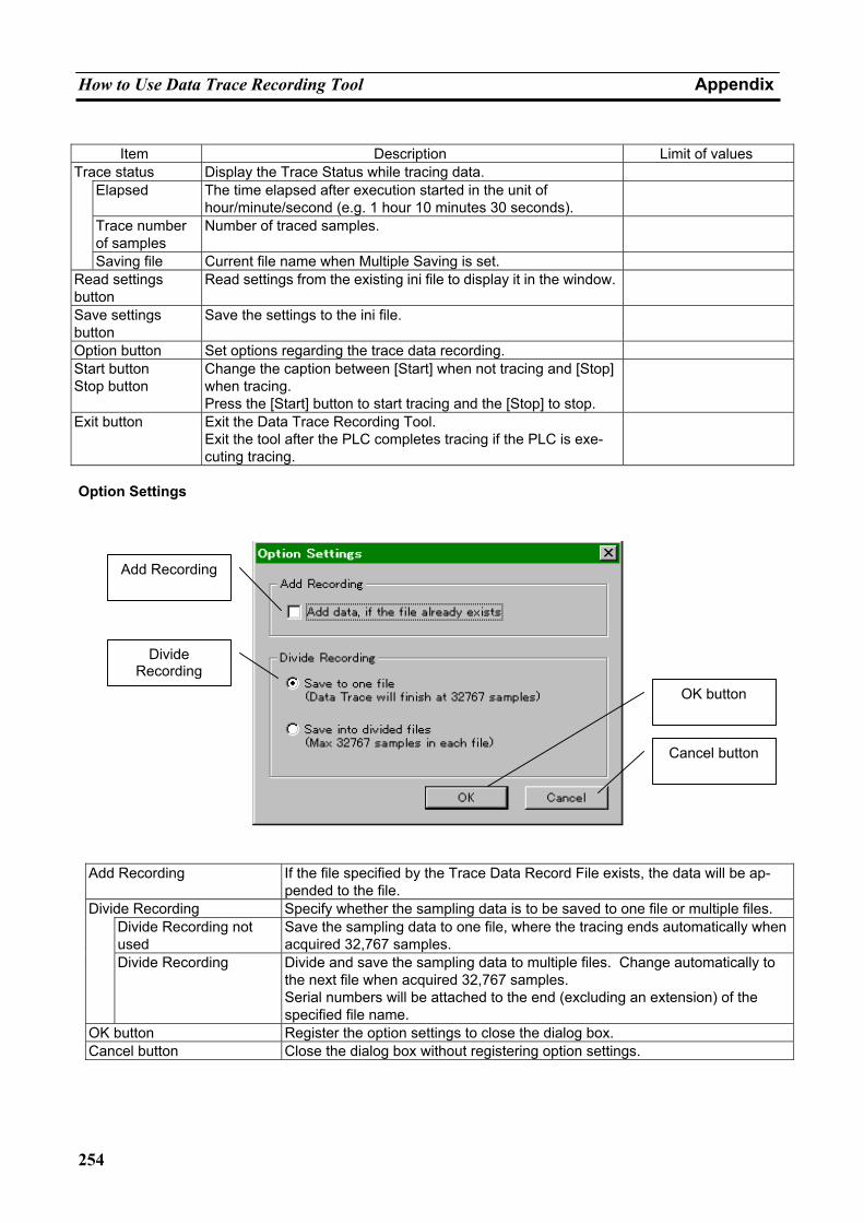
How to Use Data Trace Recording Tool Appendix
254
Item Description Limit of values
Trace status Display the Trace Status while tracing data. Elapsed The time elapsed after execution started in the unit of
hour/minute/second (e.g. 1 hour 10 minutes 30 seconds).
Trace number of samples
Number of traced samples.
Saving file Current file name when Multiple Saving is set. Read settings button
Read settings from the existing ini file to display it in the window.
Save settings button
Save the settings to the ini file.
Option button Set options regarding the trace data recording. Start button Stop button
Change the caption between [Start] when not tracing and [Stop] when tracing. Press the [Start] button to start tracing and the [Stop] to stop.
Exit button Exit the Data Trace Recording Tool. Exit the tool after the PLC completes tracing if the PLC is exe-cuting tracing.
Option Settings
Add Recording If the file specified by the Trace Data Record File exists, the data will be ap-
pended to the file. Divide Recording Specify whether the sampling data is to be saved to one file or multiple files. Divide Recording not
used Save the sampling data to one file, where the tracing ends automatically when acquired 32,767 samples.
Divide Recording Divide and save the sampling data to multiple files. Change automatically to the next file when acquired 32,767 samples. Serial numbers will be attached to the end (excluding an extension) of the specified file name.
OK button Register the option settings to close the dialog box. Cancel button Close the dialog box without registering option settings.
Add Recording
Divide Recording
OK button
Cancel button
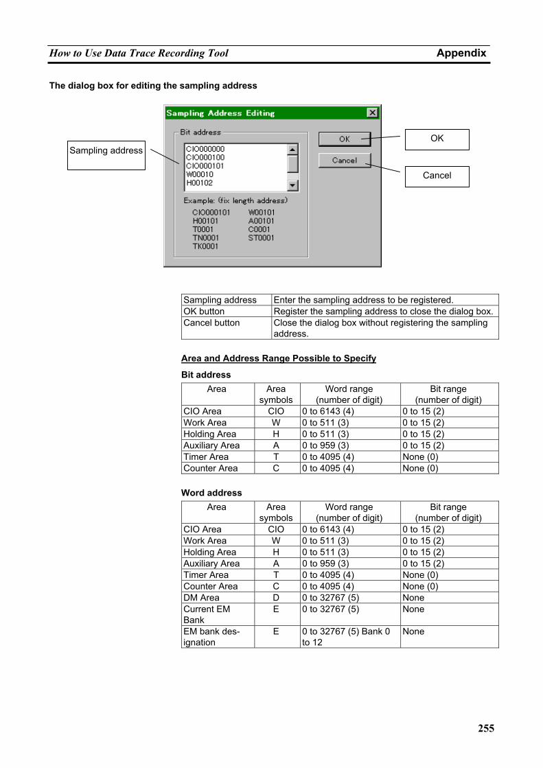
How to Use Data Trace Recording Tool Appendix
255
The dialog box for editing the sampling address
Sampling address Enter the sampling address to be registered. OK button Register the sampling address to close the dialog box.Cancel button Close the dialog box without registering the sampling
address.
Area and Address Range Possible to Specify
Bit address Area Area
symbolsWord range
(number of digit) Bit range
(number of digit) CIO Area CIO 0 to 6143 (4) 0 to 15 (2) Work Area W 0 to 511 (3) 0 to 15 (2) Holding Area H 0 to 511 (3) 0 to 15 (2) Auxiliary Area A 0 to 959 (3) 0 to 15 (2) Timer Area T 0 to 4095 (4) None (0) Counter Area C 0 to 4095 (4) None (0)
Word address
Area Area symbols
Word range (number of digit)
Bit range (number of digit)
CIO Area CIO 0 to 6143 (4) 0 to 15 (2) Work Area W 0 to 511 (3) 0 to 15 (2) Holding Area H 0 to 511 (3) 0 to 15 (2) Auxiliary Area A 0 to 959 (3) 0 to 15 (2) Timer Area T 0 to 4095 (4) None (0) Counter Area C 0 to 4095 (4) None (0) DM Area D 0 to 32767 (5) None Current EM Bank
E 0 to 32767 (5) None
EM bank des-ignation
E 0 to 32767 (5) Bank 0 to 12
None
Sampling address OK
Cancel
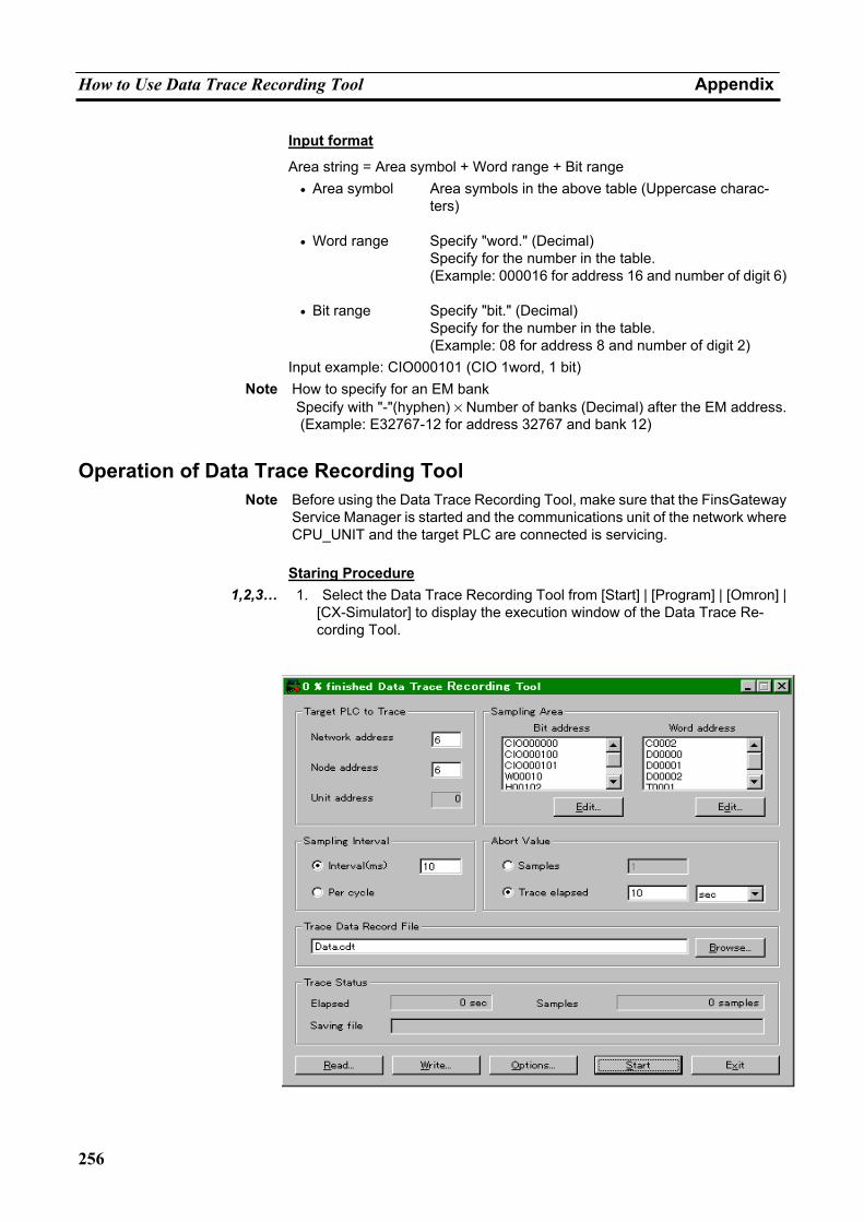
How to Use Data Trace Recording Tool Appendix
256
Input format
Area string = Area symbol + Word range + Bit range • Area symbol Area symbols in the above table (Uppercase charac-
ters)
• Word range Specify "word." (Decimal) Specify for the number in the table. (Example: 000016 for address 16 and number of digit 6)
• Bit range Specify "bit." (Decimal) Specify for the number in the table. (Example: 08 for address 8 and number of digit 2)
Input example: CIO000101 (CIO 1word, 1 bit) Note How to specify for an EM bank
Specify with "-"(hyphen) × Number of banks (Decimal) after the EM address.(Example: E32767-12 for address 32767 and bank 12)
Operation of Data Trace Recording Tool Note Before using the Data Trace Recording Tool, make sure that the FinsGateway
Service Manager is started and the communications unit of the network where CPU_UNIT and the target PLC are connected is servicing.
Staring Procedure
1,2,3… 1. Select the Data Trace Recording Tool from [Start] | [Program] | [Omron] | [CX-Simulator] to display the execution window of the Data Trace Re-cording Tool.
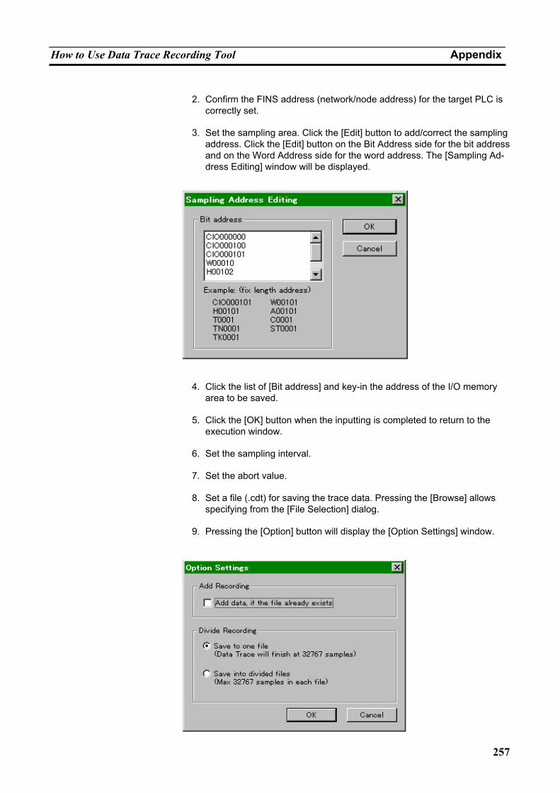
How to Use Data Trace Recording Tool Appendix
257
2. Confirm the FINS address (network/node address) for the target PLC is
correctly set.
3. Set the sampling area. Click the [Edit] button to add/correct the sampling address. Click the [Edit] button on the Bit Address side for the bit address and on the Word Address side for the word address. The [Sampling Ad-dress Editing] window will be displayed.
4. Click the list of [Bit address] and key-in the address of the I/O memory
area to be saved.
5. Click the [OK] button when the inputting is completed to return to the execution window.
6. Set the sampling interval.
7. Set the abort value.
8. Set a file (.cdt) for saving the trace data. Pressing the [Browse] allows
specifying from the [File Selection] dialog.
9. Pressing the [Option] button will display the [Option Settings] window.
How to Use Data Trace Recording Tool Appendix
258
10. Set options. The following settings are available.
• Add saving Add data to the existing file.
• Multiple Saving Divide and save the data to multiple files when the
number of sampling data exceeds the limit of the Data Trace file (.cdt).
11. Click the [OK] button when setting options completes to return to the ex-
ecution window.
12. When tracing with the same settings, click the [Add Recording] button to save the settings to the file (.ini).
13. Click the [Start] button when setting completes to register the setting
contents to the target PLC and to start tracing.
14. While tracing, the elapsed time after the execution started, the number of tracing samples, and the name of actually saved files (including serial numbers for multiple saving) will be displayed.
15. Holding of the abort value will automatically stop tracing. Click the [Stop]
button to forcibly stop tracing during execution.
Stating from the Command Line The [Data Trace Recording Tool] can be started from the command line of the MS-DOS command prompt, etc. with the setting file (.ini) specified that has been saved by the [Add Recording] button, as well as from [Start] | [Execute by Specifying File Name]. If a setting file is specified when starting, the [Data Trace Recording Tool] will automatically start the data trace.
Follow the next procedure to start from the command line.
Data Record [< Name of setting file >] Data Record Execution command
< Name of setting file > <Options> Specify a setting file for saving the traced data automatically. If a setting file is specified, tracing will be started according to the settings. If not or a non-existing file is specified, the data trace will not start.
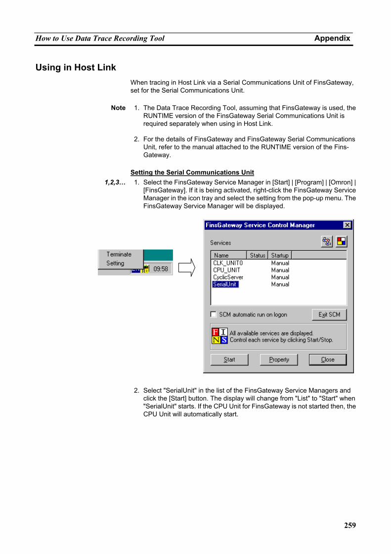
How to Use Data Trace Recording Tool Appendix
259
Using in Host Link When tracing in Host Link via a Serial Communications Unit of FinsGateway, set for the Serial Communications Unit.
Note 1. The Data Trace Recording Tool, assuming that FinsGateway is used, the
RUNTIME version of the FinsGateway Serial Communications Unit is required separately when using in Host Link.
2. For the details of FinsGateway and FinsGateway Serial Communications
Unit, refer to the manual attached to the RUNTIME version of the Fins-Gateway.
Setting the Serial Communications Unit
1,2,3… 1. Select the FinsGateway Service Manager in [Start] | [Program] | [Omron] | [FinsGateway]. If it is being activated, right-click the FinsGateway Service Manager in the icon tray and select the setting from the pop-up menu. The FinsGateway Service Manager will be displayed.
2. Select "SerialUnit" in the list of the FinsGateway Service Managers and
click the [Start] button. The display will change from "List" to "Start" when "SerialUnit" starts. If the CPU Unit for FinsGateway is not started then, the CPU Unit will automatically start.
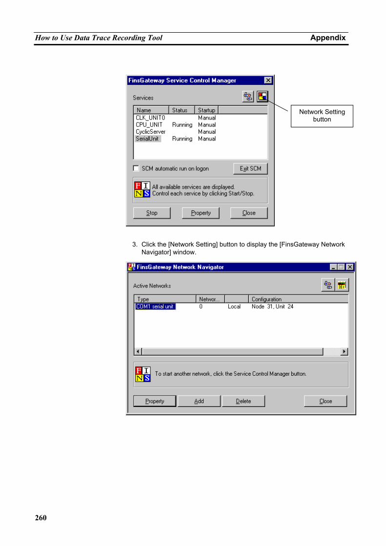
How to Use Data Trace Recording Tool Appendix
260
3. Click the [Network Setting] button to display the [FinsGateway Network
Navigator] window.
Network Setting button
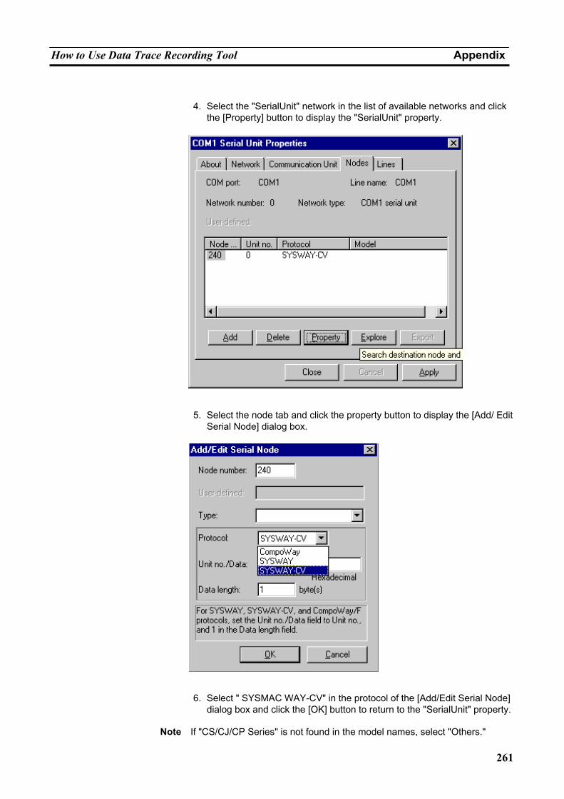
How to Use Data Trace Recording Tool Appendix
261
4. Select the "SerialUnit" network in the list of available networks and click
the [Property] button to display the "SerialUnit" property.
5. Select the node tab and click the property button to display the [Add/ Edit
Serial Node] dialog box.
6. Select " SYSMAC WAY-CV" in the protocol of the [Add/Edit Serial Node]
dialog box and click the [OK] button to return to the "SerialUnit" property.
Note If "CS/CJ/CP Series" is not found in the model names, select "Others."
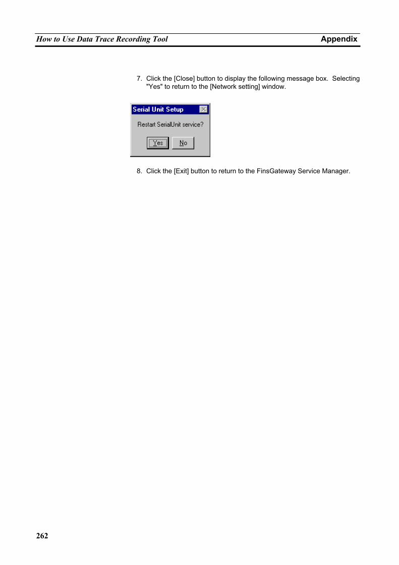
How to Use Data Trace Recording Tool Appendix
262
7. Click the [Close] button to display the following message box. Selecting "Yes" to return to the [Network setting] window.
8. Click the [Exit] button to return to the FinsGateway Service Manager.
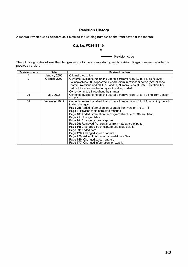
263
Revision History A manual revision code appears as a suffix to the catalog number on the front cover of the manual.
The following table outlines the changes made to the manual during each revision. Page numbers refer to the previous version.
Revision code Date Revised content 1 January 2000 Original production 2 October 2000 Contents revised to reflect the upgrade from version 1.0 to 1.1, as follows:
WindowsMe/2000 supported, Serial Communications function (Actual serial communications and NT Link) added, Numerous-point Data Collection Tool added, License number entry on installing added
Correction made throughout the manual. 03 May 2002 Contents revised to reflect the upgrade from version 1.1 to 1.2 and from version
1.2 to 1.3. 04 December 2003 Contents revised to reflect the upgrade from version 1.3 to 1.4, including the fol-
lowing changes. Page vii: Added information on upgrade from version 1.3 to 1.4. Page x: Revised table of related manuals. Page 18: Added information on program structure of CX-Simulator. Page 21: Changed table. Page 28: Changed screen capture. Page 29: Removed first sentence from note at top of page. Page 66: Changed screen capture and table details. Page 89: Added note. Page 128: Changed screen capture. Page 129: Added information on serial data files. Page 140: Changed screen capture. Page 177: Changed information for step 4.
Cat. No. W366-E1-10
Revision code
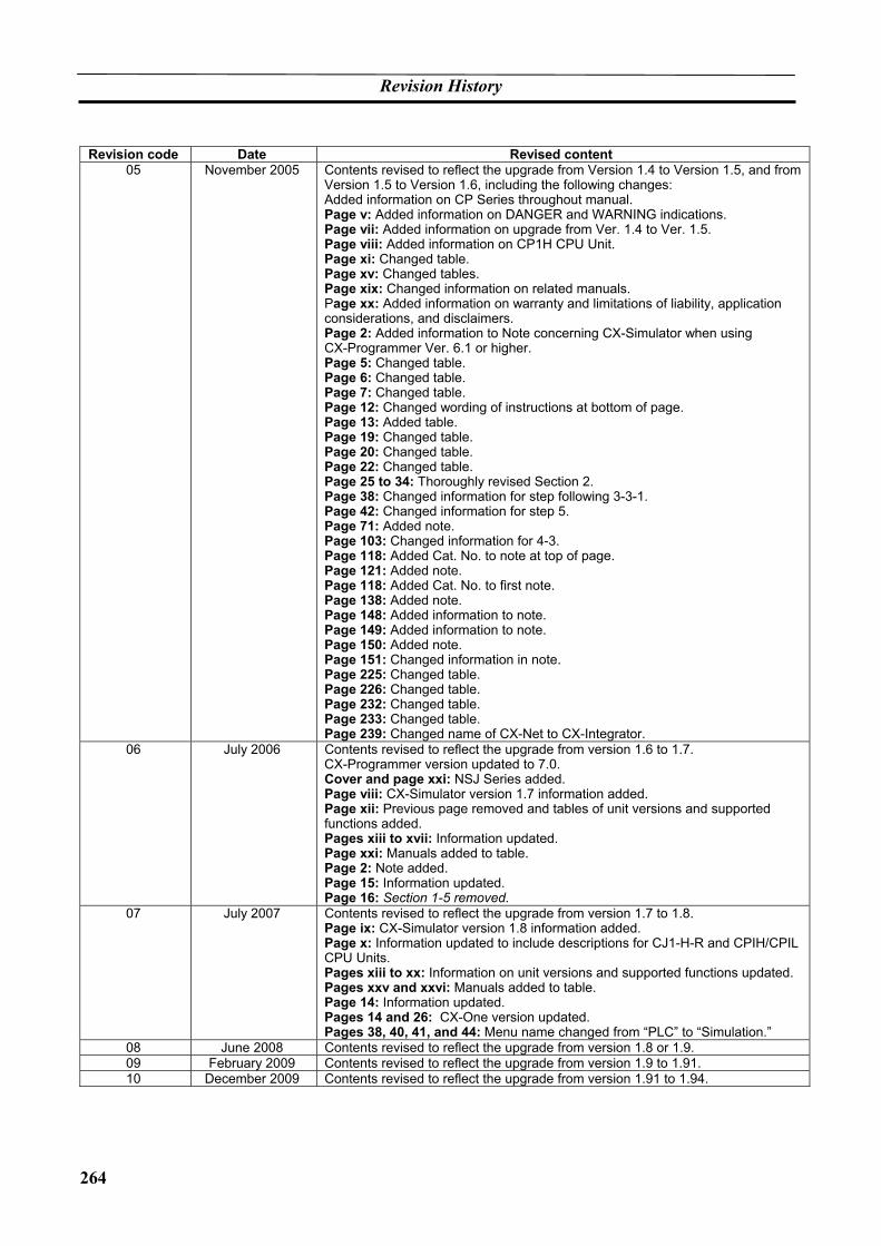
Revision History
264
Revision code Date Revised content
05 November 2005 Contents revised to reflect the upgrade from Version 1.4 to Version 1.5, and from Version 1.5 to Version 1.6, including the following changes: Added information on CP Series throughout manual. Page v: Added information on DANGER and WARNING indications. Page vii: Added information on upgrade from Ver. 1.4 to Ver. 1.5. Page viii: Added information on CP1H CPU Unit. Page xi: Changed table. Page xv: Changed tables. Page xix: Changed information on related manuals. Page xx: Added information on warranty and limitations of liability, application considerations, and disclaimers. Page 2: Added information to Note concerning CX-Simulator when using CX-Programmer Ver. 6.1 or higher. Page 5: Changed table. Page 6: Changed table. Page 7: Changed table. Page 12: Changed wording of instructions at bottom of page. Page 13: Added table. Page 19: Changed table. Page 20: Changed table. Page 22: Changed table. Page 25 to 34: Thoroughly revised Section 2. Page 38: Changed information for step following 3-3-1. Page 42: Changed information for step 5. Page 71: Added note. Page 103: Changed information for 4-3. Page 118: Added Cat. No. to note at top of page. Page 121: Added note. Page 118: Added Cat. No. to first note. Page 138: Added note. Page 148: Added information to note. Page 149: Added information to note. Page 150: Added note. Page 151: Changed information in note. Page 225: Changed table. Page 226: Changed table. Page 232: Changed table. Page 233: Changed table. Page 239: Changed name of CX-Net to CX-Integrator.
06 July 2006 Contents revised to reflect the upgrade from version 1.6 to 1.7. CX-Programmer version updated to 7.0. Cover and page xxi: NSJ Series added. Page viii: CX-Simulator version 1.7 information added. Page xii: Previous page removed and tables of unit versions and supported functions added. Pages xiii to xvii: Information updated. Page xxi: Manuals added to table. Page 2: Note added. Page 15: Information updated. Page 16: Section 1-5 removed.
07 July 2007 Contents revised to reflect the upgrade from version 1.7 to 1.8. Page ix: CX-Simulator version 1.8 information added. Page x: Information updated to include descriptions for CJ1-H-R and CPIH/CPIL CPU Units. Pages xiii to xx: Information on unit versions and supported functions updated. Pages xxv and xxvi: Manuals added to table. Page 14: Information updated. Pages 14 and 26: CX-One version updated. Pages 38, 40, 41, and 44: Menu name changed from “PLC” to “Simulation.”
08 June 2008 Contents revised to reflect the upgrade from version 1.8 or 1.9. 09 February 2009 Contents revised to reflect the upgrade from version 1.9 to 1.91. 10 December 2009 Contents revised to reflect the upgrade from version 1.91 to 1.94.