Embed Size (px)
Citation preview
D-Link Web Smart Switch User Manual
Table of Contents
Table of Contents ............................................................................................................................................. i
About This Guide............................................................................................................................................. 1
Terms/Usage.................................................................................................................................................. 1
Copyright and Trademarks ............................................................................................................................ 1
Product Introduction ....................................................................................................................................... 2
DES-1100-16 ................................................................................................................................................. 2
Front Panel ................................................................................................................................................. 2
Rear Panel.................................................................................................................................................. 2
DES-1100-24 ................................................................................................................................................. 2
Front Panel ................................................................................................................................................. 2
Rear Panel.................................................................................................................................................. 3
Hardware Installation ...................................................................................................................................... 4
Step 1: Unpacking.......................................................................................................................................... 4
Step 2: Switch Installation.............................................................................................................................. 4
Desktop or Shelf Installation....................................................................................................................... 4
Rack Installation ......................................................................................................................................... 4
Step 3 – Plugging in the AC Power Cord....................................................................................................... 6
Power Failure ............................................................................................................................................. 6
Grounding the Switch ................................................................................................................................. 6
Getting Started................................................................................................................................................. 7
Management Options..................................................................................................................................... 7
Using Web-based Management .................................................................................................................... 7
Supported Web Browsers .......................................................................................................................... 7
Connecting to the Switch............................................................................................................................ 7
Login Web-based Management ................................................................................................................. 8
SmartConsole Utility....................................................................................................................................... 8
SmartConsole Utility ..................................................................................................................................... 10
SmartConsole Settings ................................................................................................................................ 10
Utility Settings........................................................................................................................................... 10
Log............................................................................................................................................................ 11
Trap .......................................................................................................................................................... 11
File............................................................................................................................................................ 12
Help .......................................................................................................................................................... 12
Device Configuration.................................................................................................................................... 13
Add(+), Delete(-) and Discover the device ............................................................................................... 15
Device List.................................................................................................................................................... 16
Configuration ................................................................................................................................................. 18
Web-based Management............................................................................................................................. 18
Tool Bar > Save Menu ................................................................................................................................. 19
Save Configuration................................................................................................................................... 19
Tool Bar > Tool Menu .................................................................................................................................. 19
Reset System ........................................................................................................................................... 19
Reboot Device .......................................................................................................................................... 19
Firmware Upgrade.................................................................................................................................... 19
Configuration Backup & Restore .............................................................................................................. 20
Function Tree ............................................................................................................................................... 21
Device Information.................................................................................................................................... 21
ii
D-Link Web Smart Switch User Manual
iiii
System > System Settings ....................................................................................................................... 22
System > Port Settings............................................................................................................................. 23
System > Trap Settings For SmartConsole.............................................................................................. 23
System > Password Access Control ........................................................................................................ 24
L2 Features > Port Trunking..................................................................................................................... 24
L2 Features > IGMP Snooping................................................................................................................. 24
L2 Features > Port Mirroring .................................................................................................................... 25
L2 Features > Loopback Detection .......................................................................................................... 25
L2 Features > Statistics............................................................................................................................ 26
VLAN > 802.1Q VLAN.............................................................................................................................. 28
VLAN > Port-Base VLAN.......................................................................................................................... 30
QoS > 802.1p Default Priority................................................................................................................... 31
QoS > Storm Control ................................................................................................................................ 31
QoS > Bandwidth Control......................................................................................................................... 32
Security > MAC Address Table > Static MAC.......................................................................................... 33
Security > MAC Address Table > Dynamic Forwarding Table................................................................. 33
Appendix A - Ethernet Technology.............................................................................................................. 35
Gigabit Ethernet Technology ....................................................................................................................... 35
Fast Ethernet Technology............................................................................................................................ 35
Switching Technology .................................................................................................................................. 35
Appendix B - Technical Specifications ....................................................................................................... 62
Hardware Specifications .............................................................................................................................. 62
Key Components / Performance .............................................................................................................. 62
Port Functions .......................................................................................................................................... 62
Physical & Environment ........................................................................................................................... 62
Emission (EMI) Certifications ................................................................................................................... 62
Safety Certifications.................................................................................................................................. 62
Features ....................................................................................................................................................... 62
L2 Features .............................................................................................................................................. 62
VLAN ........................................................................................................................................................ 62
QoS (Quality of Service)........................................................................................................................... 62
Management............................................................................................................................................. 62
Appendix C – Rack mount Instructions ...................................................................................................... 63
D-Link Web Smart Switch User Manual
About This Guide
This guide provides instructions to install the D-Link Fast Ethernet EasySmart Switch DES-1100-16/24, how to use the Web Utility, and to configure Web-based Management step-by-step.
Note: The model you have purchased may appear slightly different from the illustrations shown in the document. Refer to the Product Instruction and Technical Specification sections for detailed information about your switch, its components, network connections, and technical specifications.
This guide is mainly divided into four parts:
1. Hardware Installation: Step-by-step hardware installation procedures.
2. Getting Started: A startup guide for basic switch installation and settings.
3. Smart Console Utility: An introduction to the central management system.
4. Configuration: Information about the function descriptions and configuration settings.
Terms/Usage
In this guide, the term “Switch” (first letter capitalized) refers to the EasySmart Switch, and “switch” (first letter lower case) refers to other Ethernet switches. Some technologies refer to terms “switch”, “bridge” and “switching hubs” interchangeably, and both are commonly accepted for Ethernet switches.
A NOTE indicates important information that helps a better use of the device.
A CAUTION indicates potential property damage or personal injury.
Copyright and Trademarks
Information in this document is subjected to change without notice.
© 2010 D-Link Corporation. All rights reserved.
Reproduction in any manner whatsoever without the written permission of D-Link Corporation is strictly forbidden.
Trademarks used in this text: D-Link and the D-LINK logo are trademarks of D-Link Corporation; Microsoft and Windows are registered trademarks of Microsoft Corporation.
Other trademarks and trade names may be used in this document to refer to either the entities claiming the marks and names or their products. D-Link Corporation disclaims any proprietary interest in trademarks and trade names other than its own.
1
D-Link Web Smart Switch User Manual
1 Product Introduction
Thank you and congratulations on your purchase of D-Link EasySmart Switch Products.
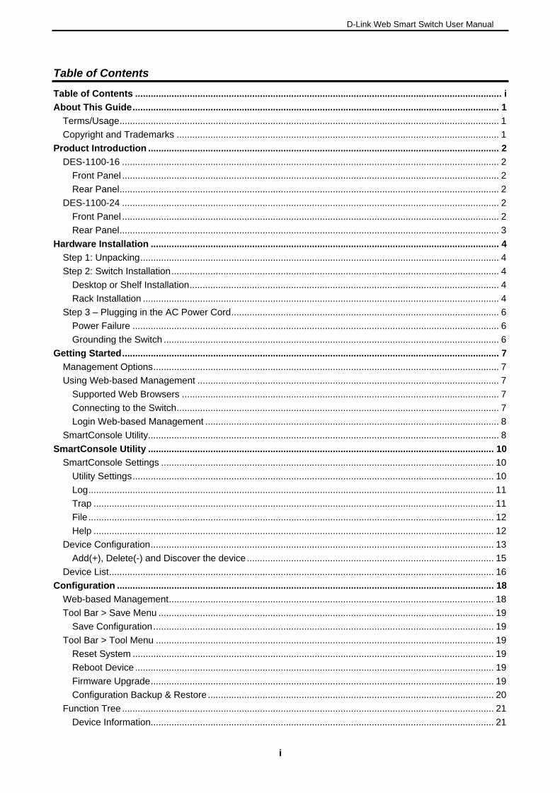
D-Link's next generation EasySmart Ethernet switch series blends plug-and-play simplicity with exceptional value and reliability for small and medium-sized business (SMB) networking. All models are housed in a new style rack-mount metal case with easy-to-view front panel diagnostic LEDs.
DES-1100-16
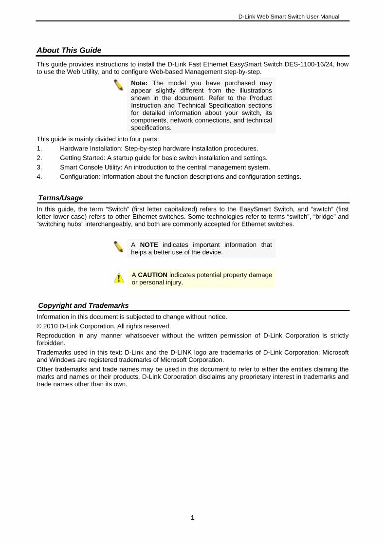
16-Port 10/100Mpbs EasySmart Switch
Front Panel
Figure 1 – DES-1100-16 Front Panel
Power LED: The Power LED lights up when the Switch is connected to a power source.
Link/Act/Speed LED (Ports 1-16):
Flashing: Indicates a network link through the corresponding port.
Blinking: Indicates that the Switch is either sending or receiving data to the port.
Green: Indicates that the port is running at 100M.
Light off: Indicates that the port is running at 10M.
Reset: By pressing the Reset button the Switch will change back to the default configuration and all changes will be lost.
Rear Panel
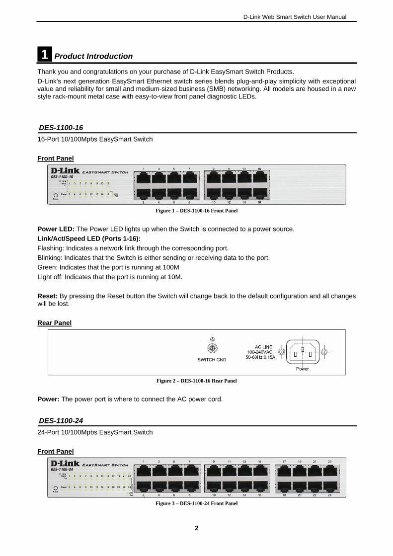
Figure 2 – DES-1100-16 Rear Panel
Power: The power port is where to connect the AC power cord.
DES-1100-24
24-Port 10/100Mpbs EasySmart Switch
Front Panel
Figure 3 – DES-1100-24 Front Panel
2
D-Link Web Smart Switch User Manual
Power LED: The Power LED lights up when the Switch is connected to a power source.
Link/Act/Speed LED (Ports 1-24):
Flashing: Indicates a network link through the corresponding port.
Blinking: Indicates that the Switch is either sending or receiving data to the port.
Green: Indicates that the port is running at 100M.
Light off: Indicates that the port is running at 10M.
Reset: Press the reset button to reset the Switch back to the default settings. All previous changes will be lost.
Rear Panel
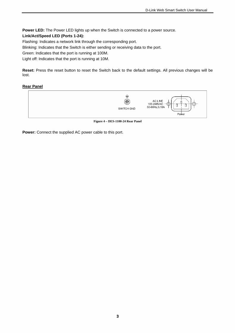
Figure 4 – DES-1100-24 Rear Panel
Power: Connect the supplied AC power cable to this port.
33
D-Link Web Smart Switch User Manual
2 Hardware Installation
This chapter provides unpacking and installation information for the D-Link EasySmart Switch.
Step 1: Unpacking
Open the shipping carton and carefully unpack its contents. Please consult the packing list located in the User Manual to make sure all items are present and undamaged. If any item is missing or damaged, please contact your local D-Link reseller for replacement.
One D-Link EasySmart Switch One AC power cord Four rubber feet Screws and two mounting brackets One accessory kit for a ground screw One Multi-lingual Getting Started Guide One CD with User Manual and SmartConsole Utility program
If any item is found missing or damaged, please contact the local reseller for replacement.
Step 2: Switch Installation
For safe switch installation and operation, it is recommended that you:
Visually inspect the power cord to see that it is secured fully to the AC power connector. Make sure that there is proper heat dissipation and adequate ventilation around the switch. Do not place heavy objects on the switch.
Desktop or Shelf Installation
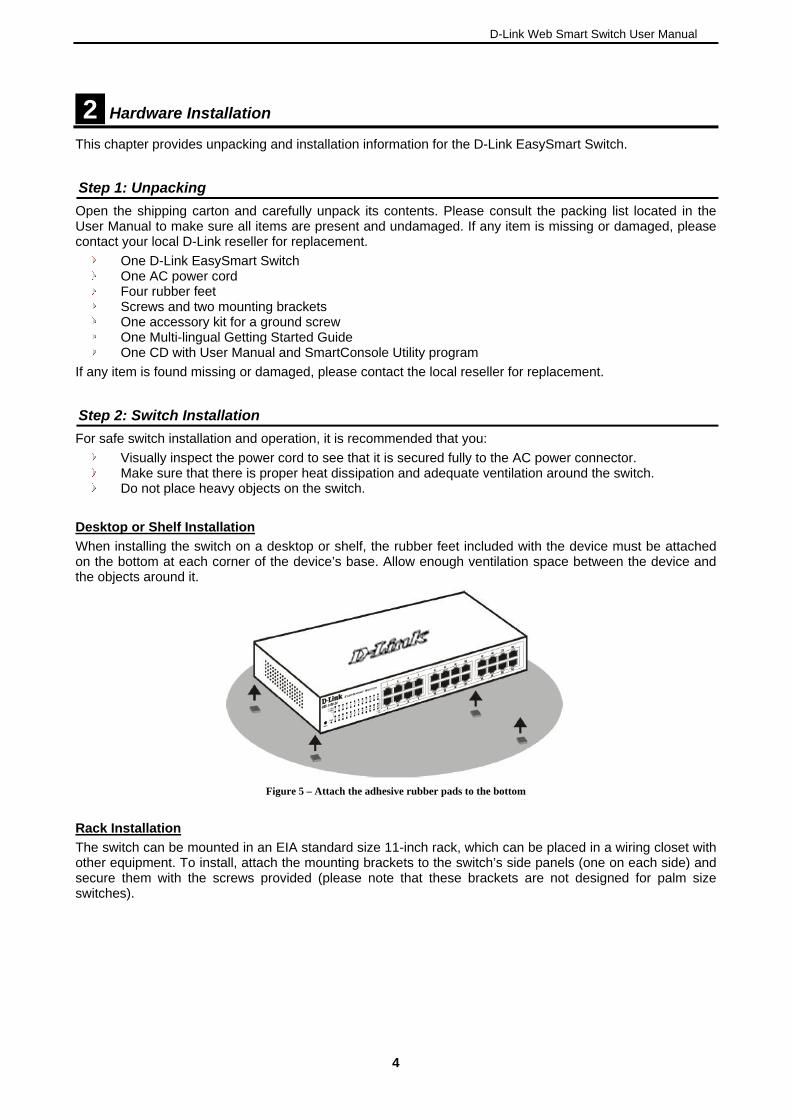
When installing the switch on a desktop or shelf, the rubber feet included with the device must be attached on the bottom at each corner of the device’s base. Allow enough ventilation space between the device and the objects around it.
Figure 5 – Attach the adhesive rubber pads to the bottom
Rack Installation
The switch can be mounted in an EIA standard size 11-inch rack, which can be placed in a wiring closet with other equipment. To install, attach the mounting brackets to the switch’s side panels (one on each side) and secure them with the screws provided (please note that these brackets are not designed for palm size switches).
4
D-Link Web Smart Switch User Manual
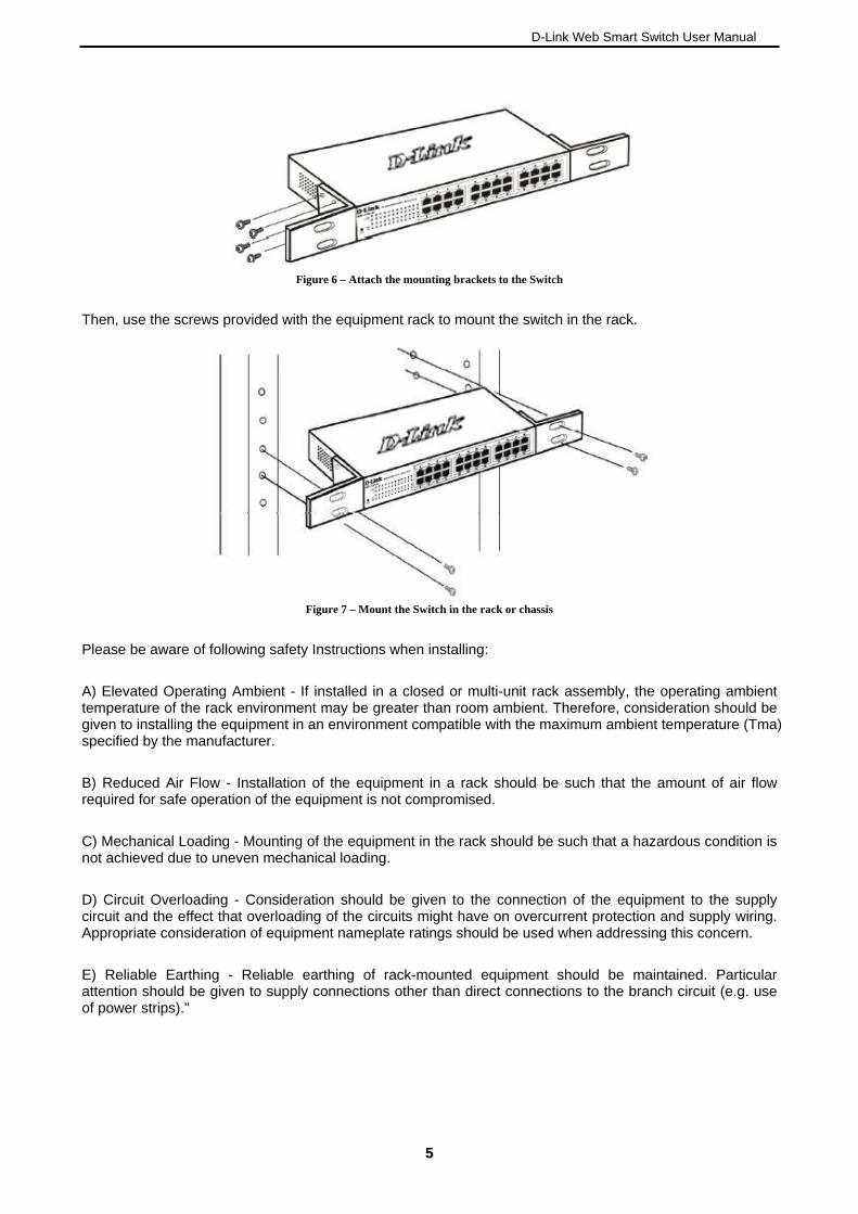
Figure 6 – Attach the mounting brackets to the Switch
Then, use the screws provided with the equipment rack to mount the switch in the rack.
Figure 7 – Mount the Switch in the rack or chassis
Please be aware of following safety Instructions when installing:
A) Elevated Operating Ambient - If installed in a closed or multi-unit rack assembly, the operating ambient temperature of the rack environment may be greater than room ambient. Therefore, consideration should be given to installing the equipment in an environment compatible with the maximum ambient temperature (Tma) specified by the manufacturer.
B) Reduced Air Flow - Installation of the equipment in a rack should be such that the amount of air flow required for safe operation of the equipment is not compromised.
C) Mechanical Loading - Mounting of the equipment in the rack should be such that a hazardous condition is not achieved due to uneven mechanical loading.
D) Circuit Overloading - Consideration should be given to the connection of the equipment to the supply circuit and the effect that overloading of the circuits might have on overcurrent protection and supply wiring. Appropriate consideration of equipment nameplate ratings should be used when addressing this concern.
E) Reliable Earthing - Reliable earthing of rack-mounted equipment should be maintained. Particular attention should be given to supply connections other than direct connections to the branch circuit (e.g. use of power strips)."
55
D-Link Web Smart Switch User Manual
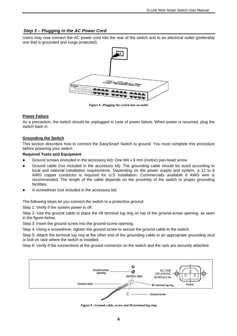
Step 3 – Plugging in the AC Power Cord
Users may now connect the AC power cord into the rear of the switch and to an electrical outlet (preferably one that is grounded and surge protected).
Figure 8 –Plugging the switch into an outlet
Power Failure
As a precaution, the switch should be unplugged in case of power failure. When power is resumed, plug the switch back in.
Grounding the Switch
This section describes how to connect the EasySmart Switch to ground. You must complete this procedure before powering your switch.
Required Tools and Equipment
Ground screws (included in the accessory kit): One M4 x 6 mm (metric) pan-head screw
Ground cable (not included in the accessory kit): The grounding cable should be sized according to local and national installation requirements. Depending on the power supply and system, a 12 to 6 AWG copper conductor is required for U.S installation. Commercially available 6 AWG wire is recommended. The length of the cable depends on the proximity of the switch to proper grounding facilities.
A screwdriver (not included in the accessory kit)
The following steps let you connect the switch to a protective ground:
Step 1: Verify if the system power is off.
Step 2: Use the ground cable to place the #8 terminal lug ring on top of the ground-screw opening, as seen in the figure below.
Step 3: Insert the ground screw into the ground-screw opening.
Step 4: Using a screwdriver, tighten the ground screw to secure the ground cable to the switch.
Step 5: Attach the terminal lug ring at the other end of the grounding cable to an appropriate grounding stud or bolt on rack where the switch is installed.
Step 6: Verify if the connections at the ground connector on the switch and the rack are securely attached.
Figure 9 –Ground cable, screw and #8 terminal lug ring
6
D-Link Web Smart Switch User Manual
3 Getting Started
This chapter introduces the management interface of D-Link EasySmart Switch.
Management Options
The D-Link EasySmart Switch can be managed through any port on the device by using the Web-based Management or through any PC using the SmartConsole Utility.
Each switch must be assigned its own IP Address, which is used for communication with Web-Based Management. The PC’s IP address should be in the same range as the switch. Each switch can allow only one user to access the Web-Based Management at a time.
The PC should have an IP address in the same range as the switch. Each switch can allow one user to access to the Web-Based Management at a time.
However, if you want to manage multiple D-Link EasySmart Switches, the SmartConsole Utility is a more convenient choice. By using the SmartConsole Utility, you do not need to change the IP address of your PC and it is easier to initialize multiple EasySmart Switches.
Please refer to the following installation instructions for the Web-based Management and the SmartConsole Utility.
Using Web-based Management
After a successful physical installation, you can configure the Switch, monitor the network status, and display statistics using a web browser.
Supported Web Browsers
The embedded Web-based Management currently supports the following web browsers:
Internet Explorer 6 or higher Netscape 8 or higher Mozilla Firefox 1.5/2.0 or higher
Connecting to the Switch
You will need the following equipment to begin the web configuration of your device:
1. A PC with a RJ-45 Ethernet connection
2. A standard Ethernet cable
Connect the Ethernet cable to any of the ports on the front panel of the switch and to the Ethernet port on the PC.
77
D-Link Web Smart Switch User Manual
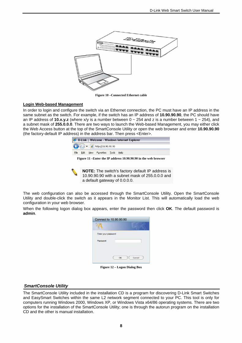
Figure 10 –Connected Ethernet cable
Login Web-based Management
In order to login and configure the switch via an Ethernet connection, the PC must have an IP address in the same subnet as the switch. For example, if the switch has an IP address of 10.90.90.90, the PC should have an IP address of 10.x.y.z (where x/y is a number between 0 ~ 254 and z is a number between 1 ~ 254), and a subnet mask of 255.0.0.0. There are two ways to launch the Web-based Management, you may either click the Web Access button at the top of the SmartConsole Utility or open the web browser and enter 10.90.90.90 (the factory-default IP address) in the address bar. Then press <Enter>.
Figure 11 –Enter the IP address 10.90.90.90 in the web browser
NOTE: The switch's factory default IP address is 10.90.90.90 with a subnet mask of 255.0.0.0 and a default gateway of 0.0.0.0.
The web configuration can also be accessed through the SmartConsole Utility. Open the SmartConsole Utility and double-click the switch as it appears in the Monitor List. This will automatically load the web configuration in your web browser.
When the following logon dialog box appears, enter the password then click OK. The default password is admin.
Figure 12 – Logon Dialog Box
SmartConsole Utility
The SmartConsole Utility included in the installation CD is a program for discovering D-Link Smart Switches and EasySmart Switches within the same L2 network segment connected to your PC. This tool is only for computers running Windows 2000, Windows XP, or Windows Vista x64/86 operating systems. There are two options for the installation of the SmartConsole Utility; one is through the autorun program on the installation CD and the other is manual installation.
8
D-Link Web Smart Switch User Manual
NOTE: Please be sure to uninstall any existing SmartConsole Utility from your PC before installing the latest SmartConsole Utility.
Option 1: Follow these steps to install the SmartConsole Utility via the autorun program on the installation CD.
1. Insert the Utility CD into your CD-Rom/DVD-Rom Drive.
2. The autorun program will appear automatically.
3. Click on the ”Install SmartConsole Utility” button and an installation wizard will guide you through the process.
4. After successfully installing the SmartConsole Utility, you can open the utility by clicking Start > Programs > D-Link SmartConsole Utility.
5. Connect the Smart Switch to the same L2 network segment of your PC and use the SmartConsole Utility to discover the Smart Switches.
Option 2: Follow these steps to install the SmartConsole Utility manually.
1. Insert the Utility CD into your CD-Rom/DVD-Rom Drive.
2. From the Start menu on the Windows desktop, click Run.
3. In the Run dialog box, type D:\D-Link SmartConsole Utility\setup.exe (where D:\ represents the drive letter of your CD-Rom or DVD-Rom) and click OK.
4. Follow the on-screen instructions to install the utility.
5. Upon completion, go to Start > Programs > D-Link SmartConsole Utility and open the SmartConsole Utility.
6. Connect the Smart Switch to the same L2 network segment of your PC and use the SmartConsole Utility to discover the Smart Switches.
For detailed explanations of SmartConsole’s functions, please refer to Chapter 4 SmartConsole Utility
99
D-Link Web Smart Switch User Manual
4 SmartConsole Utility
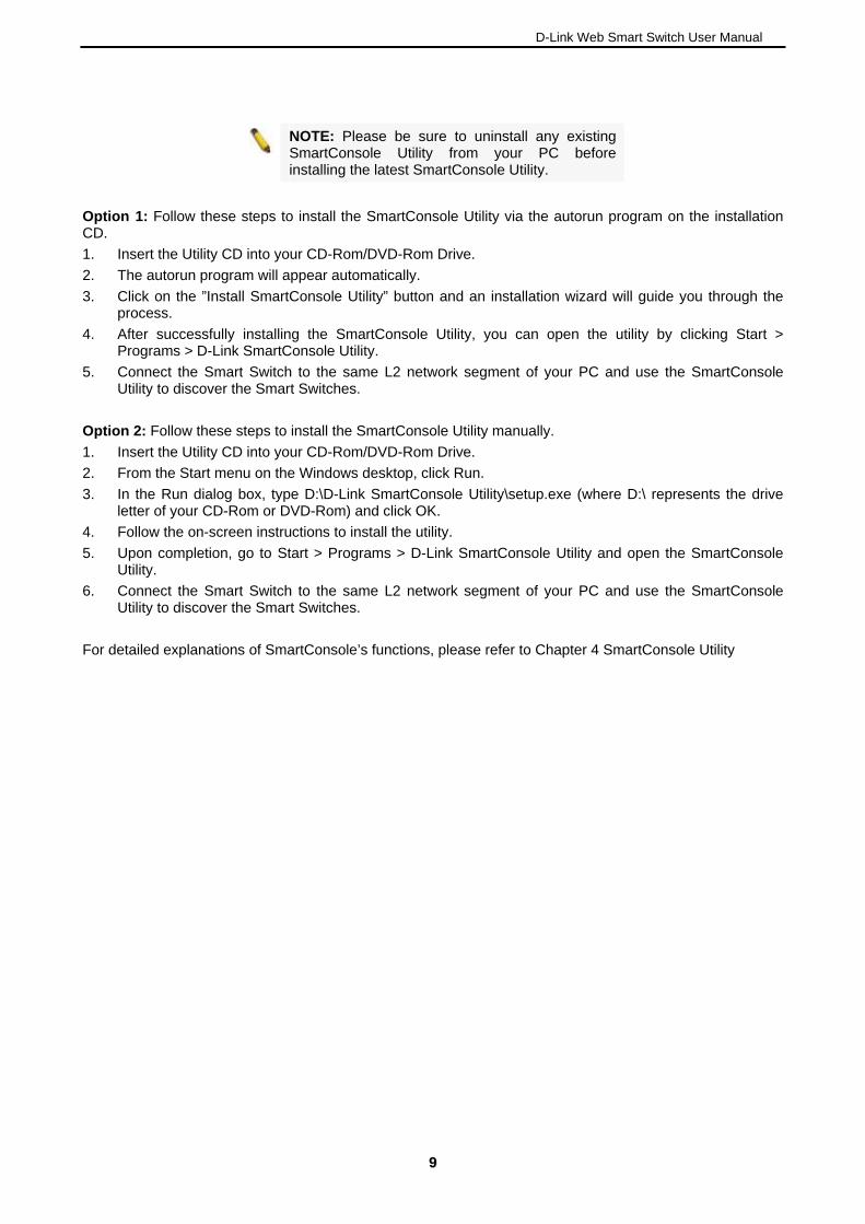
The D-Link SmartConsole Utility allows the administrator to quickly discover all D-Link Smart Switches and EasySmart Switches which are in the same domain of the PC, collect traps and log messages, and quick access to basic configurations of the switch.
The SmartConsole Utility consists of three parts, Device Configurations at the top, Device List as the main body, and SmartConsole Settings at the left.
Device Configuration
Settings
SmartConsole
Device List Figure 13 – SmartConsole Utility
SmartConsole Settings
The SmartConsole Settings at the left has five icons, Utility Settings, Log, Trap, File, and Help.
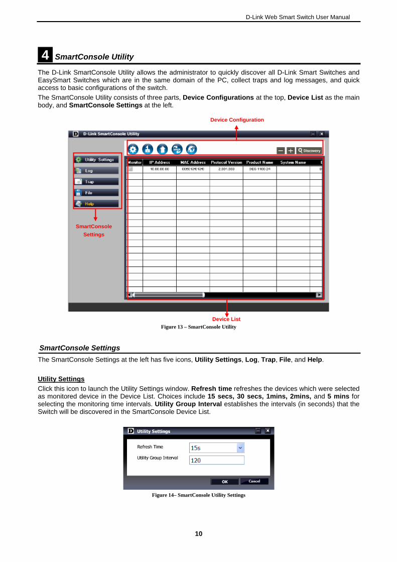
Utility Settings
Click this icon to launch the Utility Settings window. Refresh time refreshes the devices which were selected as monitored device in the Device List. Choices include 15 secs, 30 secs, 1mins, 2mins, and 5 mins for selecting the monitoring time intervals. Utility Group Interval establishes the intervals (in seconds) that the Switch will be discovered in the SmartConsole Device List.
Figure 14– SmartConsole Utility Settings
10
D-Link Web Smart Switch User Manual
NOTE: If the Group Interval is set to 0, IGMP Snooping must be disabled in the Switch or the switches will not be discovered.
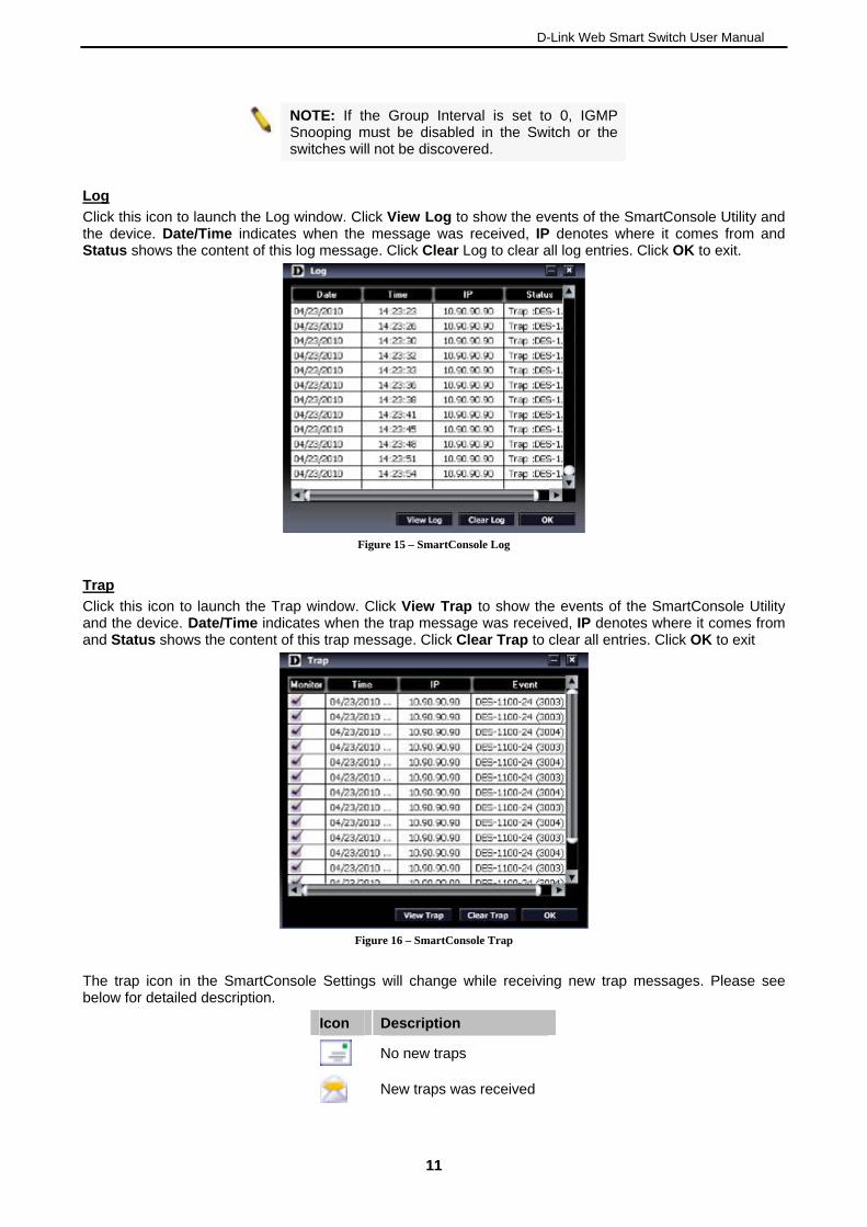
Log
Click this icon to launch the Log window. Click View Log to show the events of the SmartConsole Utility and the device. Date/Time indicates when the message was received, IP denotes where it comes from and Status shows the content of this log message. Click Clear Log to clear all log entries. Click OK to exit.
Figure 15 – SmartConsole Log
Trap
Click this icon to launch the Trap window. Click View Trap to show the events of the SmartConsole Utility and the device. Date/Time indicates when the trap message was received, IP denotes where it comes from and Status shows the content of this trap message. Click Clear Trap to clear all entries. Click OK to exit
Figure 16 – SmartConsole Trap
The trap icon in the SmartConsole Settings will change while receiving new trap messages. Please see below for detailed description.
Icon Description
No new traps
New traps was received
1111
D-Link Web Smart Switch User Manual
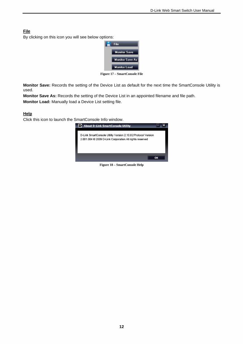
File
By clicking on this icon you will see below options:
Figure 17 – SmartConsole File
Monitor Save: Records the setting of the Device List as default for the next time the SmartConsole Utility is used.
Monitor Save As: Records the setting of the Device List in an appointed filename and file path.
Monitor Load: Manually load a Device List setting file.
Help
Click this icon to launch the SmartConsole Info window.
Figure 18 – SmartConsole Help
12
D-Link Web Smart Switch User Manual
Device Configuration
The Device Configuration in the SmartConsole Utility has five icons:
Device Settings
Device Password Manager
Multi Firmware Upgrade
DHCP Refresh
Web Access
and the , , device buttons for the Device List.
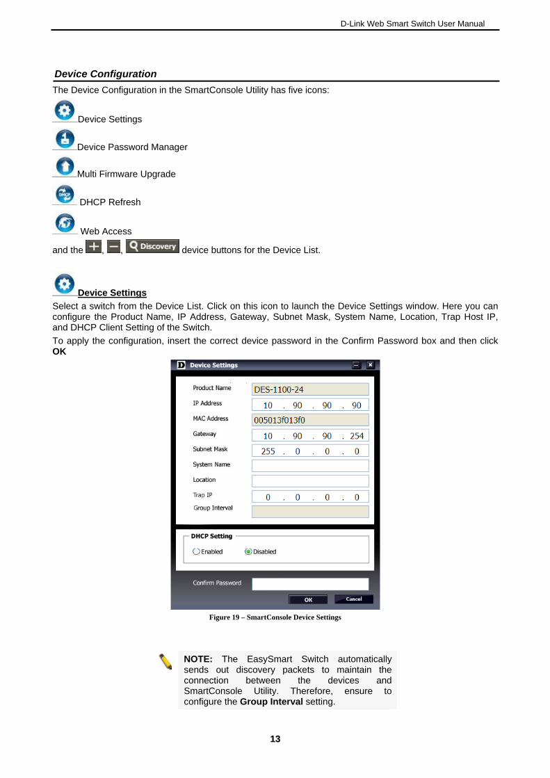
Device Settings
Select a switch from the Device List. Click on this icon to launch the Device Settings window. Here you can configure the Product Name, IP Address, Gateway, Subnet Mask, System Name, Location, Trap Host IP, and DHCP Client Setting of the Switch.
To apply the configuration, insert the correct device password in the Confirm Password box and then click OK
Figure 19 – SmartConsole Device Settings
NOTE: The EasySmart Switch automatically sends out discovery packets to maintain the connection between the devices and SmartConsole Utility. Therefore, ensure to configure the Group Interval setting.
1133

D-Link Web Smart Switch User Manual
14
D-Link Web Smart Switch User Manual
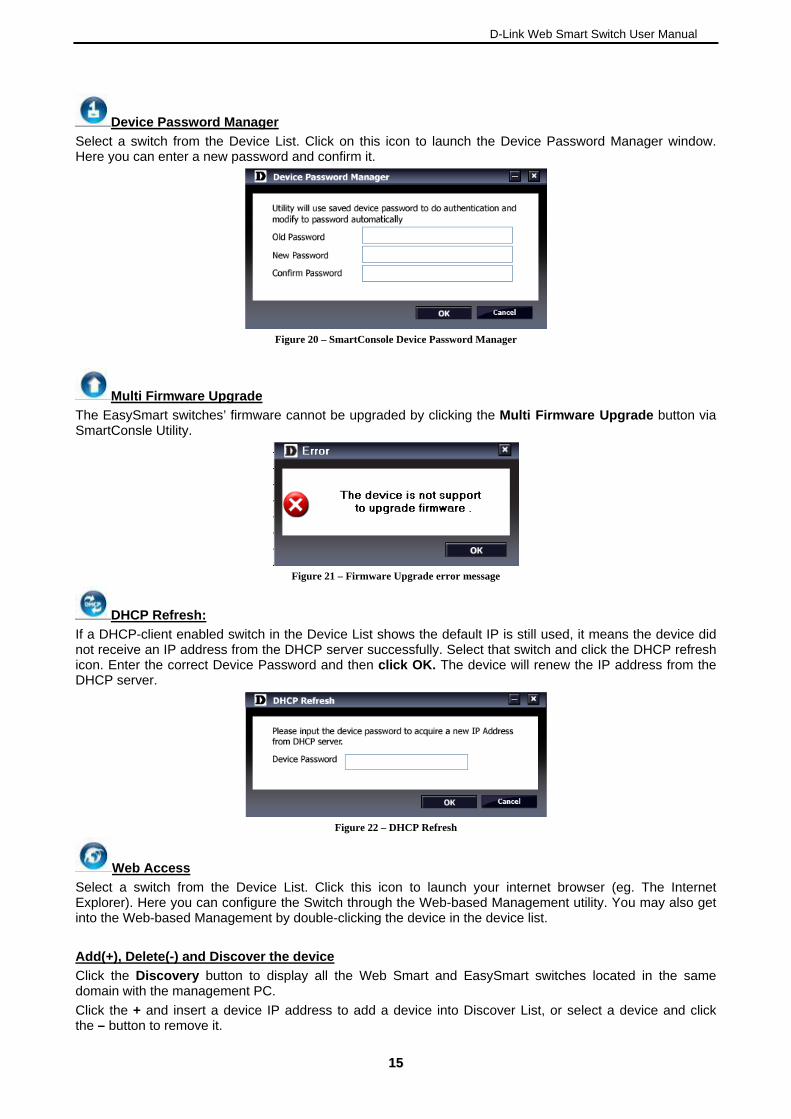
Device Password Manager
Select a switch from the Device List. Click on this icon to launch the Device Password Manager window. Here you can enter a new password and confirm it.
Figure 20 – SmartConsole Device Password Manager
Multi Firmware Upgrade
he EasySmart switches’ firmware cannot be upgraded by clicking the Multi Firmware Upgrade button via tility.
TSmartConsle U
Figure 21 – Firmware Upgrade error message
DHCP Refresh:
If a DHCP-client enabled switch in the Device List shows the default IP is still used, it means the device did not receive an IP address from the DHCP server successfully. Select that switch and click the DHCP refresh icon. Enter the correct Device Password and then click OK. The device will renew the IP address from the DHCP server.
Figure 22 – DHCP Refresh
Web Access
Select a switch from the Device List. Click this icon to launch your internet browser (eg. The Internet -based Management utility. You may also get
e device list. Explorer). Here you can configure the Switch through the Webinto the Web-based Management by double-clicking the device in th
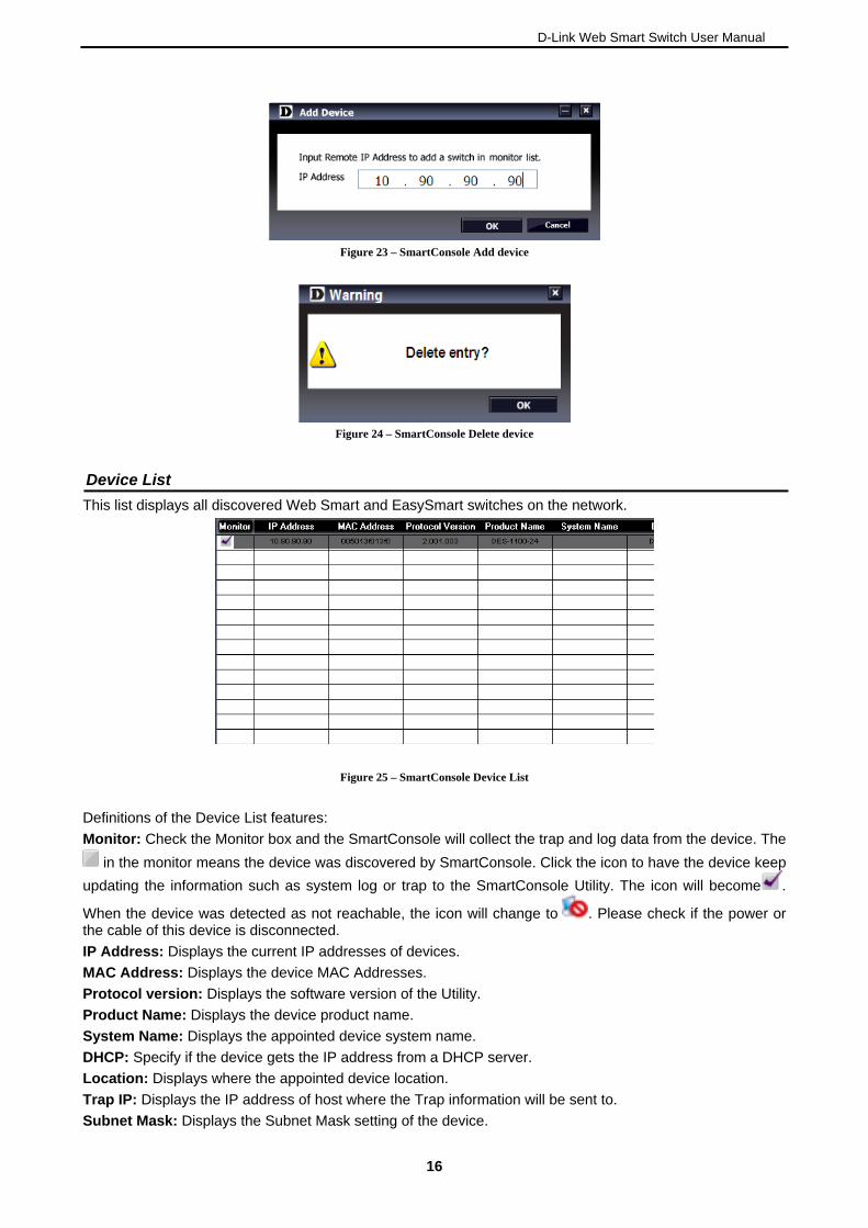
Add(+), Delete(-) and Discover the device
Click the Discovery button to display all the Web Smadomain with the management PC.
rt and EasySmart switches located in the same
elect a device and click Click the + and insert a device IP address to add a device into Discover List, or sthe – button to remove it.
1155
D-Link Web Smart Switch User Manual
Figure 23 – SmartConsole Add device
Figure 24 – SmartConsole Delete device
Device List
This list displays all discovered Web Smart and EasySmart switches on the network.
Figure 25 – SmartConsole Device List
Definitions of the Device List features:
Monitor: Check the Monitor box and the SmartConsole will collect the trap and log data from the device. The
in the monitor means the device was discovered by SmartConsole. Click the icon to have the device keep
g the information such as system log or trap to the SmartConsole Utility. The icon will becomupdatin e .
When the device was detected as not reachable, the icon will change to . Please check if the power or the cable of this device is disconnected.
IP Address: Displays the current IP addresses of devices.
MAC Address: Displays the device MAC Addresses.
Protocol version: Displays the software version of the Utility.
Product Name: Displays the device product name.
System Name: Displays the appointed device system name.
DHCP: Specify if the device gets the IP address from a DHCP server.
Location: Displays where the appointed device location.
Trap IP: Displays the IP address of host where the Trap information will be sent to.
Subnet Mask: Displays the Subnet Mask setting of the device.
16

D-Link Web Smart Switch User Manual
Gateway: Displays the Ga
Device Group Interva
teway setting of the device.
l: Displays the intervals (in seconds). This feature is not available for EasySmart
irmware version: Displays the current Firmware version of this device.
r Discovery Protocol) status of the device. This feature is available only witches.
not available for EasySmart switches.
switches.
F
LLDP: Displays the LLDP (Link Layefor PoE models of Web Smart s
SNMP: Displays the SNMP status of the device. This is
NOTE: If the devices e marked red in the device ar list, it means that the devices require upgrading
firmware again.
1177
D-Link Web Smart Switch User Manual
5 Configuration
The features and functions of the D-Link EasySmart Switch can be configured for optimum use through the Web-based Management Utility.
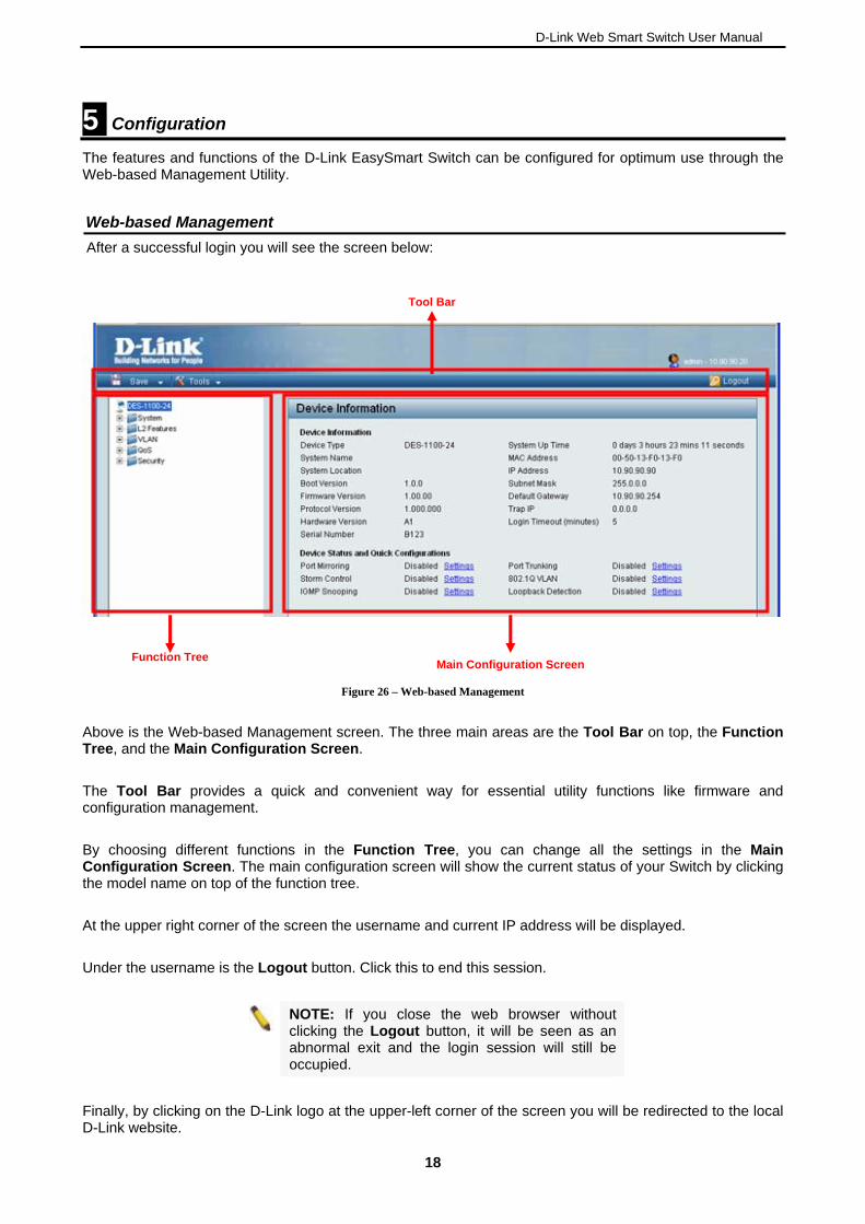
ement Web-based Manag
After a successful login you will see the screen below:
Tool Bar
Main Configuration Screen
Function Tree
Figure 26 – Web-based Management
Above is the Web-based Management screen. The three main areas are the Tool Bar on top, the Function Tree, and the Main Configuration Screen.
The Tool Bar provides a quick and convenient way for essential utility functions like firmware and configuration management.
ferent functions in the Function Tree, you can change all the settings in the Main tatus of your Switch by clicking
At the upper right corner of the screen the username and current IP address will be displayed.
Under the username is the Logout button. Click this to end this session.
By choosing difConfiguration Screen. The main configuration screen will show the current sthe model name on top of the function tree.
NOTE: If you close the web browser without clicking the Logout button, it will be seen as an
abnormal exit and the login session will still be occupied.
Finally, by clicking on the D-Link logo at the upper-left corner of the screen you will be redirected to the local D-Link website.
18
D-Link Web Smart Switch User Manual
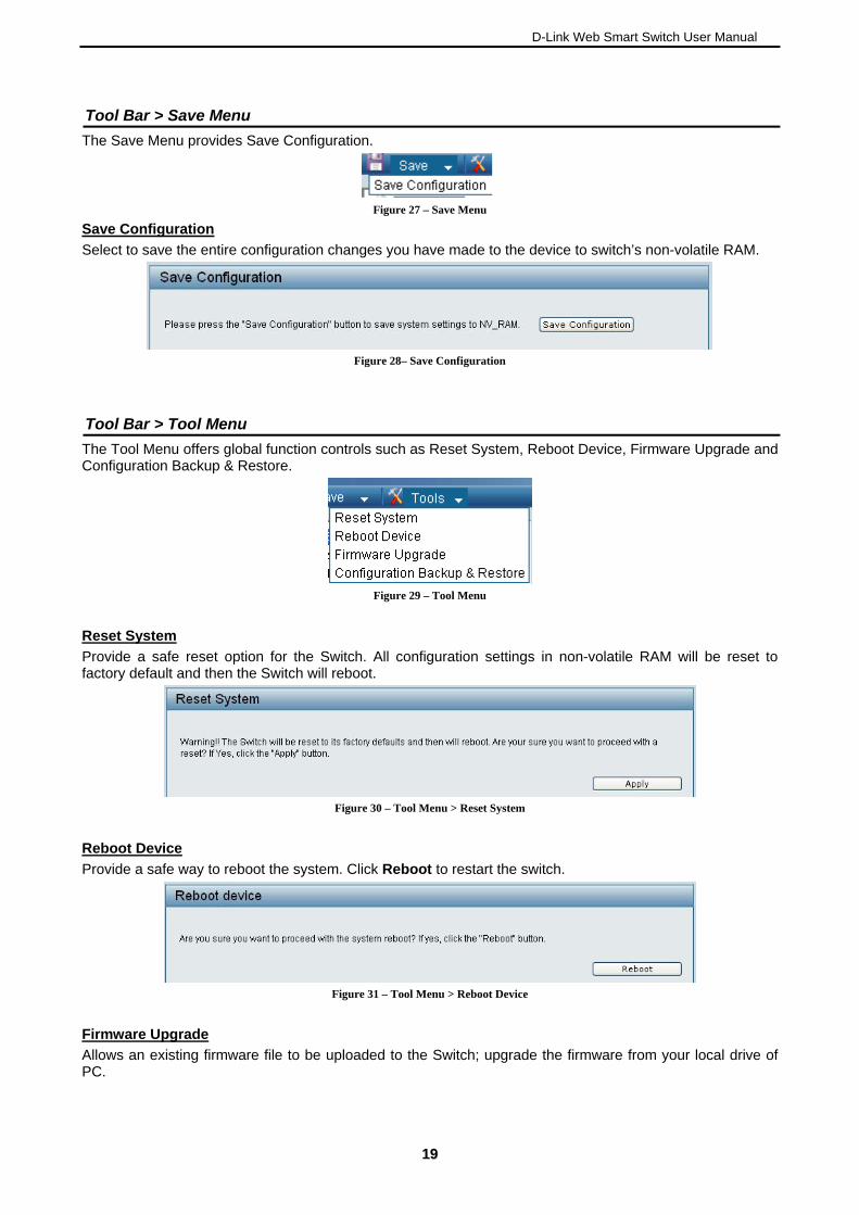
Tool Bar > Save Menu
The Save Menu provides Save Configuration.
Figure 27 – Save Menu
Save Configuration
elect to save the entire configuration changes you have made to the device to switch’s non-volatile RAM. S
Figure 28– Save Configuration
Tool Bar > Tool Menu
The Tool Menu offers global function controls such as Reset System, Reboot Device, Firmware Upgrade and Configuration Backup & Restore.
Figure 29 – Tool Menu
Reset System
Provide a safe reset option for the Switch. All configuration settings in non-volatile RAM will be reset to factory default and then the Switch will reboot.
Figure 30 – Tool Menu > Reset System
eboot Device
R
rovide a safe way to reboot the system. Click Reboot to restart the switch. P
Figure 31 – Tool Menu > Reboot Device
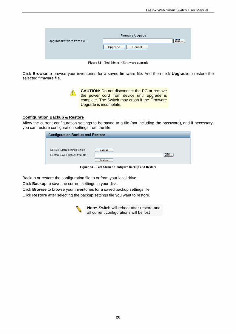
irmware Upgrade
F
llows an existing firmware file to be uploaded to the Switch; upgrade the firmware from your local drive of PC.
A
1199
D-Link Web Smart Switch User Manual
Figure 32 – Tool Menu > Firmware upgrade
Click Browse to browse your inventories for a saved firmware file. And then click Upgrade to restore the selected firmware file.
CAUTION: Do not disconnect the PC or remove the power cord from device until upgrade is
complete. The Switch may crash if the Firmware Upgrade is incomplete.
Configuration Backup & Restore
Allow the current configuration settings to be saved to a file (not including the password), and if necessary, you can restore configuration settings from the file.
Figure 33 – Tool Menu > Configure Backup and tore
iguration file to or from your local drive.
lick Restore after selecting the backup settings file you want to restore.
Res
Backup or restore the conf
Click Backup to save the current settings to your disk.
Click Browse to browse your inventories for a saved backup settings file.
C
Note: Switch will reboot after restore and all current configurations will be lost
20
D-Link Web Smart Switch User Manual
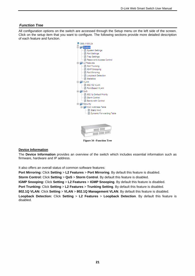
Function Tree
All configuration options on the switch are accessed through the Setup menu on the left side of the screen. Click on the setup item that you want to configure. The following sections provide more detailed description of each feature and function.
Figure 34 –Function Tree
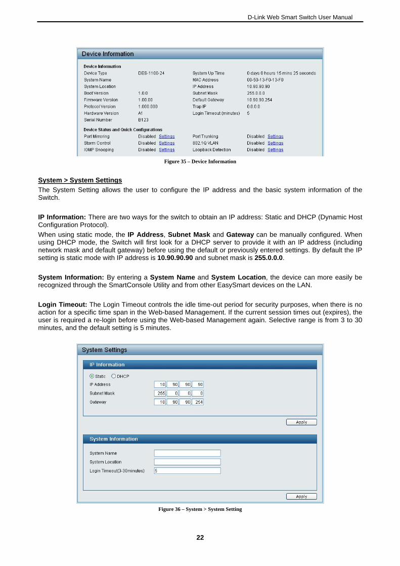
Device Information
The Device Information provides an overview of the switch which includes essential information such as firmware, hardware and IP address.
It also offers an overall status of common software features:
Port Mirroring: Click Setting > L2 Features > Port Mirroring. By default this feature is disabled.
Storm Control: Click Setting > QoS > Storm Control. By default this feature is disabled.
IGMP Snooping: Click Setting > L2 Features > IGMP Snooping. By default this feature is disabled.
Port Trunking: Click Setting > L2 Features > Trunking Setting. By default this feature is disabled.
802.1Q VLAN: Click Setting > VLAN > 802.1Q Management VLAN. By default this feature is disabled.
Loopback Detection: Click Setting > L2 Features > Loopback Detection. By default this feature is disabled.
2211
D-Link Web Smart Switch User Manual
Figure 35 – Device Information
System > System Settings
The System Setting allows the user to configure the IP address and the basic system information of the Switch.
IP Information: There are two ways for the switch to obtain an IP address: Static and DHCP (Dynamic Host Configuration Protocol).
When using static mode, the IP Address, Subnet Mask and Gateway can be manually configured. When using DHCP mode, the Switch will first look fo with an IP addre s (including network mask and default gateway) befo ously entered settings. By default the IP etting is static mode with IP address is 10.90.90.90 and subnet mask is 255.0.0.0.
Location, the device can more easily be recognized through the SmartCo e LAN.
Login Timeout: The Login Tim he idle time-out period for security purposes, when there is no rrent session times out (expires), the
ser is required a re-login before using the Web-based Management again. Selective range is from 3 to 30
r a DHCP server to provide it re using the default or previ
s
s
System Information: By entering a System Name and Systemnsole Utility and from other EasySmart devices on th
eout controls taction for a specific time span in the Web-based Management. If the cuuminutes, and the default setting is 5 minutes.
Figure 36 – System > System Setting
22
D-Link Web Smart Switch User Manual
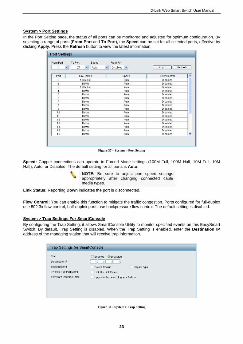
System > Port Settings
In the Port Setting page, the status of all ports can be monitored and adjusted for optimum configuration. By selectin e Speed can be set for all selected ports, effective by clicking
g a range of ports (From Port and To Port), th Apply. Press the Refresh button to view the latest information.
Figure 37 – System > Port Setting
Speed: gs (100M Full, 100M Half, 10M Full, 10M Half), Auto, or Disabled. The default setting for all ports is Auto.
Copper connections can operate in Forced Mode settin
NOTE: Be sure to adjust port speed settings appropriately after changing connected cable
media types.
Link Status: Reporting Down indicates the port is disconnected.
Flow Control: You can enable this function to mitigate the traffic congestion. Ports configured for full-duplex use 802.3x flow control, half-duplex ports use backpressure flow control. The default setting is disabled.
System > Trap Settings For SmartConsole
By configuring the Trap Setting, it allows SmartConsole Utility to monitor specified events on this EasySmart Switch. By default, Trap Setting is disabled. When the Trap Setting is enabled, enter the Destination IP address of the managing station that will receive trap information.
Figure 38 – System > Trap Setting
2233
D-Link Web Smart Switch User Manual
Select the event message(s) to be sent out to the managing station.
System Event: The system level messages contain:
Device Bootup - System boot-up information
Illegal Login - Events of incorrect password logins and records the IP of the source PC
Twisted pair Port Link Up/Link Down: Copper port connection information
Firmware Upgrade State: Information of firmware upgrade - success or failure
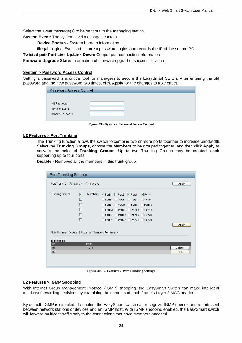
System > Password Access Control
Setting a password is a critical tool for managers to secure the EasySmart Switch. After entering the old password and the new password two times, click Apply for the changes to take effect.
Figure 39 – System > Password Access Control
L2 Features > Port Trunking
The Trunking function allows the switch to combine two or more ports together to increase bandwidth. Select the Trunking Groups, choose the Members to be grouped together, and then click Apply to activate the selected Trunking Groups. Up to two Trunking Groups may be created, each supporting up to four ports.
Disable - Removes all the members in this trunk group.
Figure 40- L2 Features > Port Trunking Settings
L2 Features > IGMP Snooping
nt Protocol (IGMP) snoopinWith Internet Group Manageme g, the EasySmart Switch can make intelligent ulticast forwarding decisions by examining the contents of each frame’s Layer 2 MAC header.
d, the EasySmart switch can recognize IGMP queries and reports sent
m
By default, IGMP is disabled. If enablebetween network stations or devices and an IGMP host. With IGMP snooping enabled, the EasySmart switch will forward multicast traffic only to the connections that have members attached.
24
D-Link Web Smart Switch User Manual
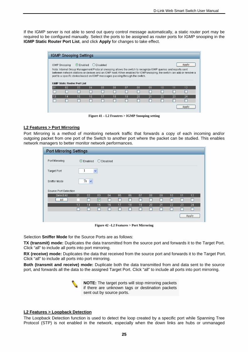
If the IGMP server is not able to send out query control message automatically, a static router port may be required to be configured manually. Select the ports to be assigned as router ports for IGMP snooping in the IGMP Static Router Port List, and click Apply for changes to take effect.
Figure 41 – L2 Feautres > IGMP Snooping setting
L2 Features > Port Mirroring
Port Mirroring is a method of monitoring network traffic that forwards a copy of each incoming and/or outgoing packet from one port of the Switch to another port where the packet can be studied. This enables network managers to better monitor network performances.
Figure 42 –L2 Features > Port Mirroring
the Source Ports are as follows:
cates the data that received from the source port and forwards it to the Target Port. ick “all” to include all ports into port mirroring.
Both (transmit and receive) mode: Duplicate both the data transmitted from and data sent to the source port, and forwards all the data to the assigned Target Port. Click “all” to include all ports into port mirroring.
Selection Sniffer Mode for
TX (transmit) mode: Duplicates the data transmitted from the source port and forwards it to the Target Port. Click “all” to include all ports into port mirroring.
RX (receive) mode: DupliCl
NOTE: The target ports will stop mirroring packets if there are unknown tags or destination packets
sent out by source ports.
L2 Features > Loopback Detection
The Loopback Detection function is used to detect the loop created by a specific port while Spanning Tree nmanaged Protocol (STP) is not enabled in the network, especially when the down links are hubs or u
2255
D-Link Web Smart Switch User Manual
switchs. The Switch will automatically shutdown the port and sends a log to the administrator. The Loopback Detection port will be unlocked when the Loopback Detection Recover Time times out. The Loopback Detection function can be implemented on a range of ports at a time. You may enable or disable this function using the pull-down menu.
Figure 43 – L2 Features > Loopback Detection
Loopback Detection State: Use the drop-down menu to enable or disable loopback detection. The default is Disabled.
Interval (1-32767): Set a Loop detection Interval between 1 and 32767 seconds. The default is 1 seconds.
Recover Time (0 or 60-1000000): Time allowed (in seconds) for recovery when a Loopback is detected. The Loop Detection Recover Time can be set at 0 seconds, or 60 to 1000000 seconds. Entering 0 will disable the Loop Detection Recover Time. The default is 60 seconds.
From Port: The beginning of a consecutive group of ports may be configured starting with the selected port.
To Port: The ending of a consecutive group of ports may be configured starting with the selected port.
State: Use the drop-down menu to toggle between Enabled and Disabled. Default is Disabled.
Click Apply to implement changes made.
L2 Features > Statistics
The Statistics screen displays the status of each port packet count. It offers several options such as Receive Packet & Transmit Packet, Transmit Packet & Collision, Receive Packet & Drop Packet and Receive Packet & CRC Packet.
Figure 44 – L2 Features > Statistics menu
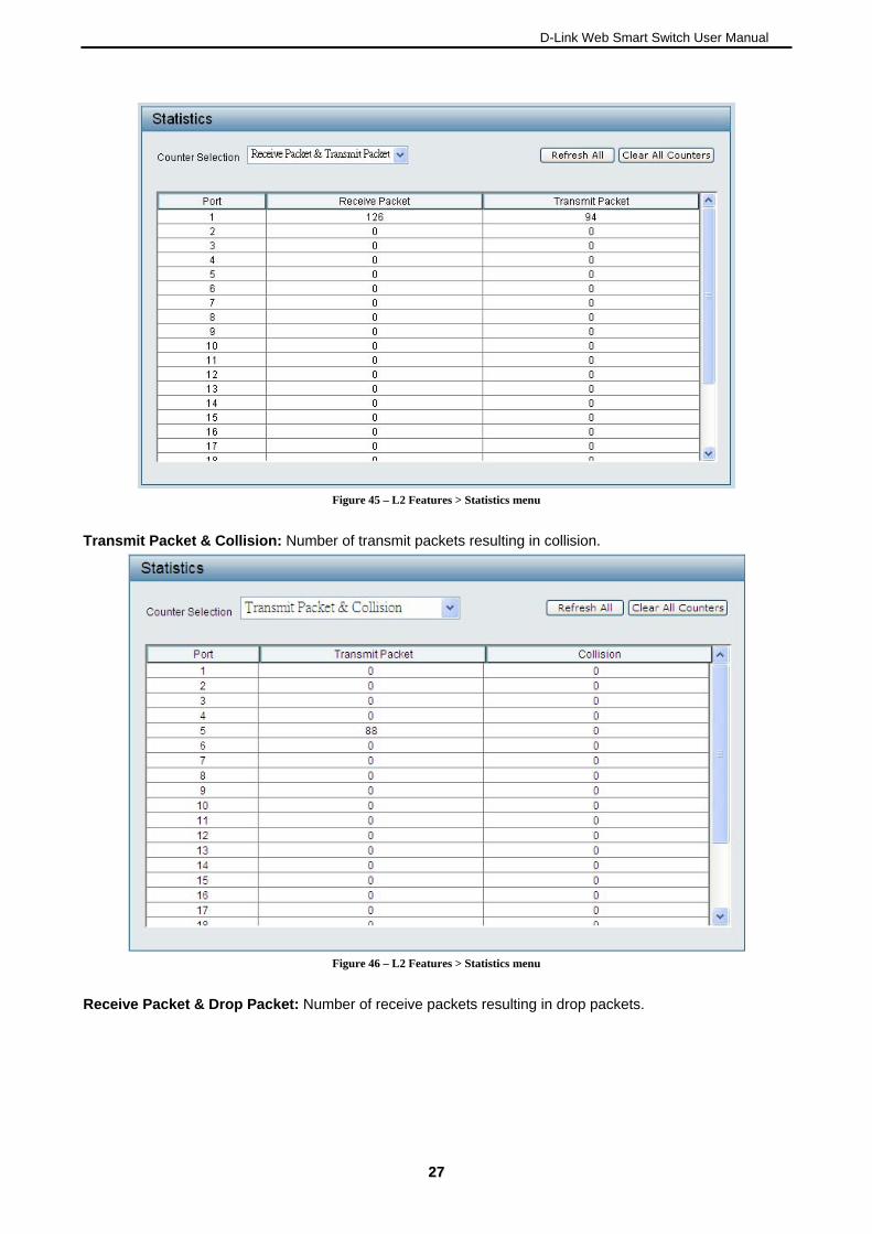
Receive Packet & Transmit Packet: Number of packets received and transmitted successfully.
26
D-Link Web Smart Switch User Manual
Figure 45 – L2 Features > Statistics menu
Transmit Packet & Collision: Number of transmit packets resulting in collision.
Figure 46 – L2 Features > Statistics menu
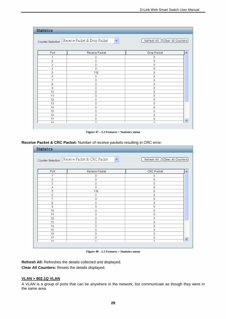
Receive Packet & Drop Packet: Number of receive packets resulting in drop packets.
2277
D-Link Web Smart Switch User Manual
Figure 47 – L2 Features > Statistics menu
Receive Packet & CRC Packet: Number of receive packets resulting in CRC error.
Figure 48 – L2 Features > Statistics menu
Refresh All: Refreshes the details collected and displayed.
Clear All Counters: Resets the details displayed.
VLAN > 802.1Q VLAN
A VLAN is a group of ports that can be anywhere in e network, but communicate as though they were in the same area.
th
28
D-Link Web Smart Switch User Manual
VLANs can be easily organized to reflect department groups (such as R&D, Marketing), usage groups (such pplications such as video conferencing), and therefore help to ers to m ve devices to a new VLAN without having to change
any physical connections.
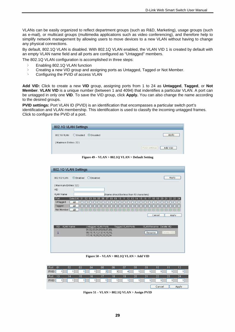
By default, 802.1Q VLAN is disabled. With 802.1Q VLAN enabled, the VLAN VID 1 is created by default with an empty VLAN name field and all ports are configured as “Untagged” members.
The 802.1Q VLAN configuration is accomplished in three steps:
as e-mail), or multicast groups (multimedia asimplify network management by allowing us o
Enabling 802.1Q VLAN function Creating a new VID group and assigning ports as Untagged, Tagged or Not Member. Configuring the PVID of access VLAN
Add VID: Click to create a new VID group, assigning ports from 1 to 24 as Untagged, Tagged, or Not Member. VLAN VID is a unique number (between 1 and 4094) that indentifies a particular VLAN. A port can be untagged in only one VID. To save the VID group, click Apply. You can also change the name according to the desired groups.
PVID settings: Port VLAN ID (PVID) is an identification that encompasses a particular switch port’s identification and VLAN membership. This identification is used to classify the incoming untagged frames. Click to configure the PVID of a port.
F
igure 49 – VLAN > 802.1Q VLAN > Default Setting
Figure 50 – VLAN > 802.1Q VLAN > Add VID
Figure 51 – VLAN > 802.1Q VLAN > Assign PVID
2299
D-Link Web Smart Switch User Manual
Rename: Click to rename the VLAN group.
Delete VID: Click to delete the VLAN group.
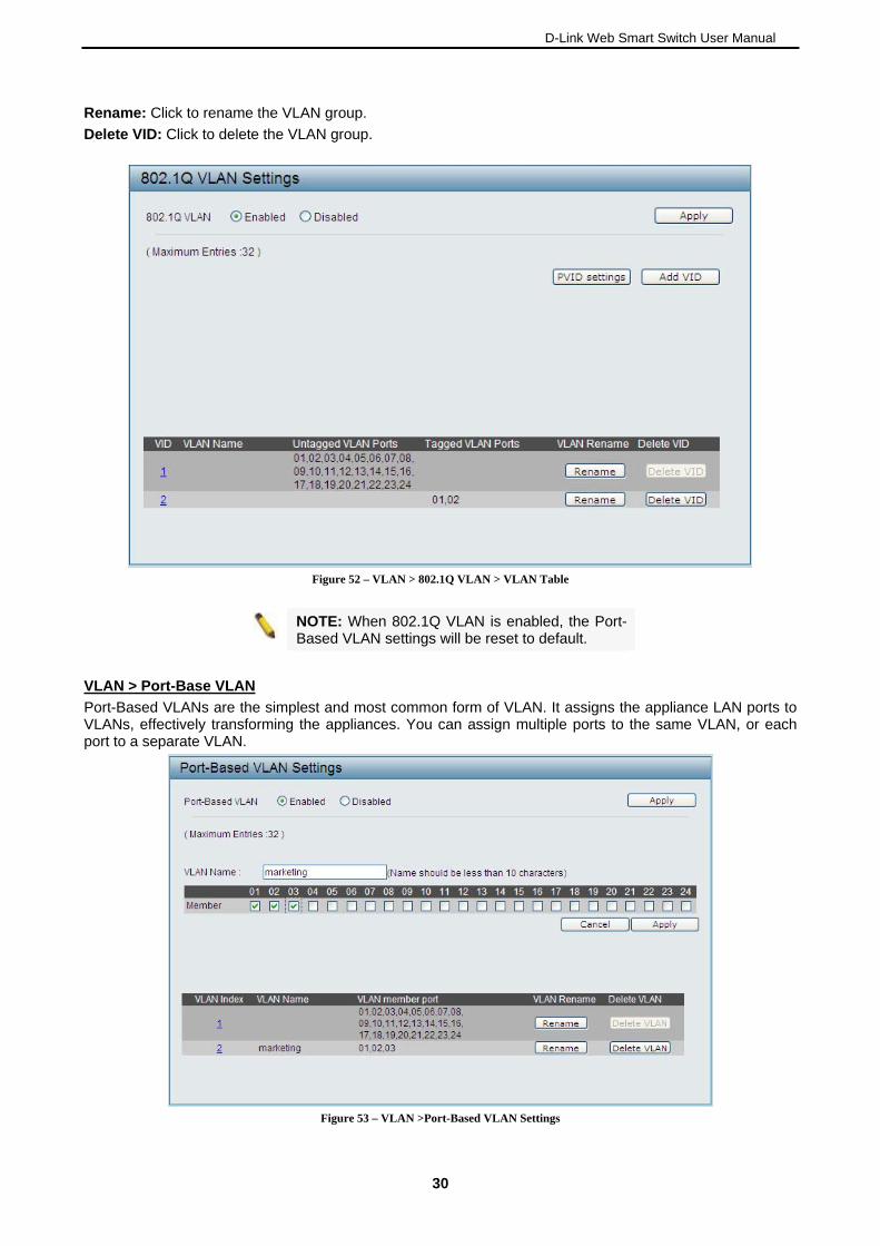
Figure 52 – VLAN > 802.1Q VLAN > VLAN Table
NOTE: When 802.1Q VLAN is enabled, the Port- Based VLAN settings will be reset to default.
VLAN > Port-Base VLAN
Port-Based VLANs are the simplest and most common form of VLAN. It assigns the appliance LAN ports to VLANs, effectively transforming the appliances. You can assign multiple ports to the same VLAN, or each port to a separate VLAN.
Figure 53 – VLAN >Port-Based VLAN Settings
30
D-Link Web Smart Switch User Manual
Add VLAN: Click to create a new VLAN name and to select VLAN ports. The VLAN name should be less than 10 characters. To save the members in a group, click Apply.
Rename: Click to rename the VLAN group.
Delete VID: Click to delete the VLAN group.
NOTE: When Port-Based VLAN is enabled, the 802.1Q VLAN settings will be reset to default. By
default, all ports are untagged.
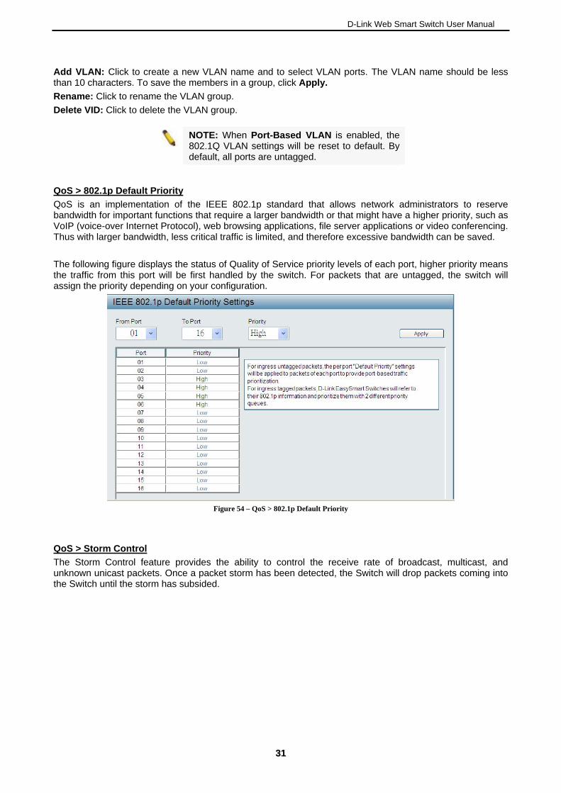
QoS > 802.1p Default Priority
QoS is an implementation of the IEEE 802.1p standard that allows network administrators to reserve bandwidth for important functions that require a larger bandwidth or that might have a higher priority, such as VoIP (voice-over Internet Protocol), web browsing applications, file server applications or video conferencing. Thus with larger bandwidth, less critical traffic is limited, and therefore excessive bandwidth can be saved.
The following figure displays the status of Quality of Service priority levels of each port, higher priority means the traffic from this port will be first handled by the switch. For packets that are untagged, the switch will assign the priority depending on your configuration.
Figure 54 – QoS > 802.1p Default Priority
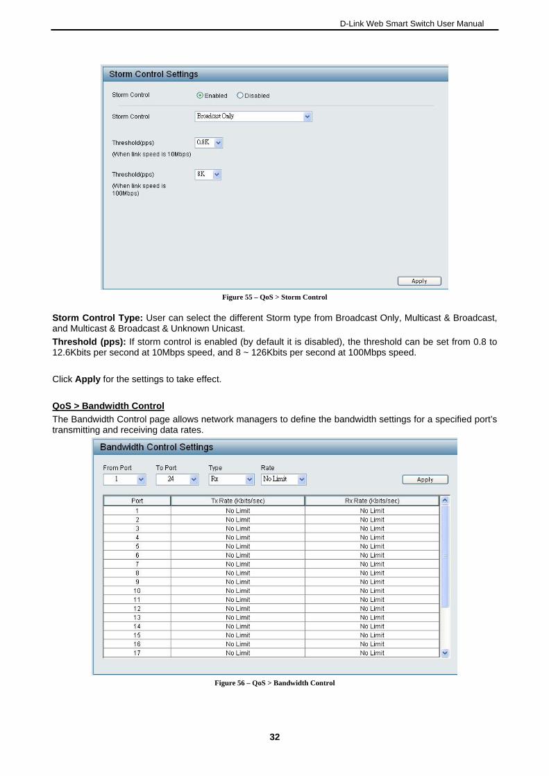
QoS > Storm Control
The Storm Control feature provides the ability to control the receive rate of broadcast, multicast, and unknown unicast packets. Once a packet storm has been detected, the Switch will drop packets coming into the Switch until the storm has subsided.
3311
D-Link Web Smart Switch User Manual
Figure 55 – QoS > Storm Control
Storm Control Type: User can select the different Storm type from Broadcast Only, Multicast & Broadcast, and Multicast & Broadcast & Unknown Unicast.
Threshold (pps): If storm control is enabled (by default it is disabled), the threshold can be set from 0.8 to 12.6Kbits per second at 10Mbps speed, and 8 ~ 126Kbits per second at 100Mbps speed.
Click Apply for the settings to take effect.
QoS > Bandwidth Control
The Bandwidth Control page allows network managers to define the bandwidth settings for a specified port’s transmitting and receiving data rates.
Figure 56 – QoS > Bandwidth Control
32
D-Link Web Smart Switch User Manual
From Port / To Port: A consecutive group of ports may be configured starting with the selected port.
Type: This drop-down menu allows you to select between RX (receive), TX (transmit), and Both. This
setting will determine whether the bandwidth ceiling is applied to receiving, transmitting, or both
receiving and transmitting packets.
No Limit: This drop-down menu allows you to specify that the selected port will have no bandwidth limit.
Enabled disables the limit.
Rate: This drop-down menu allows you to select data rate from 512Kbps to 65536Kbps.
Click Apply to set the bandwidth control for the selected ports.
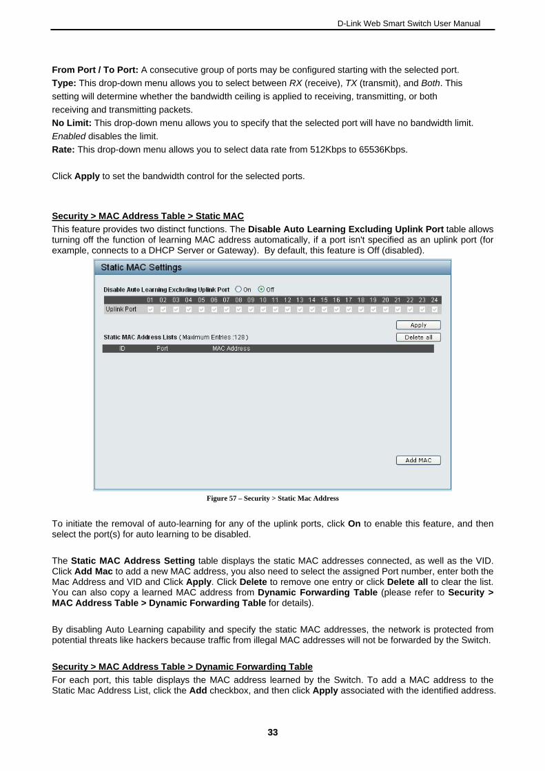
Security > MAC Address Table > Static MAC
This feature provides two distinct functions. The Disable Auto Learning Excluding Uplink Port table allows turning off the function of learning MAC address automatically, if a port isn't specified as an uplink port (for example, connects to a DHCP Server or Gateway). By default, this feature is Off (disabled).
Figure 57 – Security > Static Mac Address
To initiate the removal of auto-learning for any of the uplink ports, click On to enable this feature, and then select the port(s) for auto learning to be disabled.
The Static MAC Address Setting table displays the static MAC addresses connected, as well as the VID. Click Add Mac to add a new MAC address, you also need to select the assigned Port number, enter both the Mac Address and VID and Click Apply. Click Delete to remove one entry or click Delete all to clear the list. You can also copy a learned MAC address from Dynamic Forwarding Table (please refer to Security > MAC Address Table > Dynamic Forwarding Table for details).
By disabling Auto Learning capability and specify the static MAC addresses, the network is protected from potential threats like hackers because traffic from illegal MAC addresses will not be forwarded by the Switch.
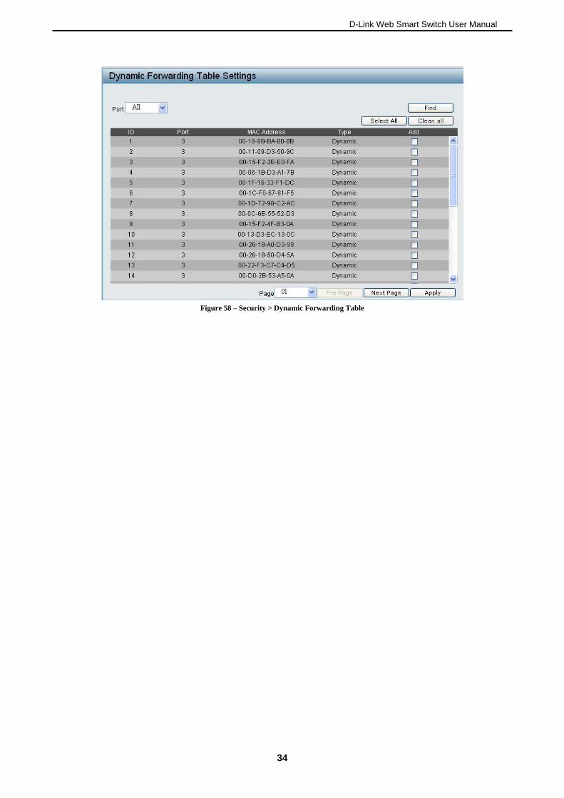
Security > MAC Address Table > Dynamic Forwarding Table
For each port, this table displays the MAC address learned by the Switch. To add a MAC address to the Static Mac Address List, click the Add checkbox, and then click Apply associated with the identified address.
3333
D-Link Web Smart Switch User Manual
Figure 58 – Security > Dynamic Forwarding Table
34
D-Link Web Smart Switch User Manual
3355
Appendix A - Ethernet Technology
This chapter will describe the features of the D-Link EasySmart Switch and provide some background information about Ethernet/Fast Ethernet/Gigabit Ethernet switching technology.
Gigabit Ethernet Technology
Gigabit Ethernet is an extension of IEEE 802.3 Ethernet utilizing the same packet structure, format, and support for CSMA/CD protocol, full duplex, and management objects, but with a tenfold increase in theoretical throughput of over 100-Mbps Fast Ethernet and a hundredfold increase over 10-Mbps Ethernet. Since it is compatible with all 10-Mbps and 100-Mbps Ethernet environments, Gigabit Ethernet provides a straightforward upgrade without wasting existing investments in hardware, software, or trained personnel.
The increased speed and extra bandwidth offered by Gigabit Ethernet is essential to help solving network bottlenecks that frequently develop as more advanced computer users and newer applications continue to demand greater network resources. Upgrading key components, such as backbone connections and servers to Gigabit Ethernet technology can greatly improve network response times as well as significantly speed up the traffic between subnets.
Gigabit Ethernet enables fast optical fiber connections to support video conferencing, complex imaging, and similar data-intensive applications. Likewise, since data transfers occur 10 times faster than Fast Ethernet, servers outfitted with Gigabit Ethernet NIC’s are able to perform 10 times the number of operations in the same amount of time.
In addition, the phenomenal bandwidth delivered by Gigabit Ethernet is the most cost-effective method to take advantage of today and tomorrow’s rapidly improving switching and routing internetworking technologies. And with expected advances in the coming years in silicon technology and digital signal processing that will enable Gigabit Ethernet to eventually operate over unshielded twisted-pair (UTP) cabling, outfitting your network with a powerful 1000-Mbps-capable backbone/server connection which will create a flexible foundation for the next generation of network technology products.
Fast Ethernet Technology
The growing importance of LANs and the increasing complexity of desktop computing applications are fueling the need for high performance networks. A number of high-speed LAN technologies have been proposed to provide greater bandwidth and improve client/server response times. Among them, 100BASE-T (Fast Ethernet) provides a non-disruptive, smooth evolution from the current 10BASE-T technology. The non-disruptive and smooth evolution nature, and the dominating potential market base, virtually guarantees cost-effective and high performance Fast Ethernet solutions.
100Mbps Fast Ethernet is a standard specified by the IEEE 802.3 LAN committee. It is an extension of the 10Mbps Ethernet standard with the ability to transmit and receive data at 100Mbps, while maintaining the CSMA/CD Ethernet protocol. Since the 100Mbps Fast Ethernet is compatible with all other 10Mbps Ethernet environments, it provides a straightforward upgrade and utilizes existing investments in hardware, software, and personnel training.
Switching Technology
Another approach to push beyond the limits of Ethernet technology is the development of switching technology. A switch bridges Ethernet packets at the MAC address level of the Ethernet protocol transmitting among connected Ethernet or Fast Ethernet LAN segments.
Switching is a cost-effective way of increasing the total network capacity available to users on a local area network. A switch increases capacity and decreases network loading by dividing a local area network into different segments which won’t compete with each other for network transmission capacity.
The switch acts as a high-speed selective bridge between the individual segments. The switch, without interfering with any other segments, automatically forwards traffic that needs to go from one segment to another. By doing this the total network capacity is multiplied, while still maintaining the same network cabling and adapter cards.
D-Link Web Smart Switch User Manual
Appendix B - Technical Specifications
Hardware Specifications
Key Components / Performance
Switching Capacity:
- DES-1100-16: 3.2Gbps
- DES-1100-24: 4.8Gbps
Max. Forwarding Rate
- DES-1100-16: 2.38Mpps
- DES-1100-24: 3.57Mpps
Forwarding Mode: Store and Forward Packet Buffer memory:1.75 Mbits Flash Memory: 2M Bytes
Port Functions
16/24 10/100BaseTX ports compliant with the following standards:
- IEEE 802.3
- IEEE 802.3u
- Supports Full/half-Duplex operations
Physical & Environment
AC input, 100~240 VAC, 50/60Hz, internal universal power supply
Acoustic Value:
- DES-1100-16/24: 0dB (Fan-less)
Operation Temperature 0~40°C Storage Temperature -10~70°C Operation Humidity: 10%~95% RH Storage Humidity: 5%~95% RH
Emission (EMI) Certifications
FCC class A CE Class A VCCI Class A
Safety Certifications
cUL, LVD
Features
L2 Features
Supports up to 8K MAC address IGMP snooping Loopback Detection Port Mirroring Port Trunking
VLAN
802.1Q VLAN standard (VLAN Tagging) Port-Based VLAN
QoS (Quality of Service)
802.1p priority,
Up to 2 queues per port Bandwidth Control Storm Control
Management
Web-based GUI or SmartConsole Utility Configuration backup / restoration via
Web-based management Firmware upgrade via Web-based
management Reset, Reboot system Factory reset by clicking reset button
62

D-Link Web Smart Switch User Manual
Appendix C – Rack mount Instructions
Safety Instructions - Rack Mount Instructions - The following or similar rack-mount instructions are included with the installation instructions:
A) Elevated Operating Ambient - If installed in a closed or multi-unit rack assembly, the operating ambient temperature of the rack environment may be greater than room ambient. Therefore, consideration should be given to installing the equipment in an environment compatible with the maximum ambient temperature (Tma) specified by the manufacturer.
B) Reduced Air Flow - Installation of the equipment in a rack should be such that the amount of air flow required for safe operation of the equipment is not compromised.
C) Mechanical Loading - Mounting of the equipment in the rack should be such that a hazardous condition is not achieved due to uneven mechanical loading.
D) Circuit Overloading - Consideration should be given to the connection of the equipment to the supply circuit and the effect that overloading of the circuits might have on overcurrent protection and supply wiring. Appropriate consideration of equipment nameplate ratings should be used when addressing this concern.
E) Reliable Earthing - Reliable earthing of rack-mounted equipment should be maintained. Particular attention should be given to supply connections other than direct connections to the branch circuit (e.g. use of power strips).
63


![[MS-SMB]: Server Message Block (SMB) Protocol Specificationdocshare01.docshare.tips/files/5883/58834888.pdf2 / 179 [MS-SMB] — v20110610 Server Message Block (SMB) Protocol Specification](https://img.pdfslide.net/doc/110x75/5eca5807c38f4e40c93e9f01/ms-smb-server-message-block-smb-protocol-spe-2-179-ms-smb-a-v20110610.jpg)