Embed Size (px)
DESCRIPTION
Manual de taller Daelim S3 125cc en inglés.Services Manual Daelim S3 125cc English language.
Citation preview
SM63-1010-01E
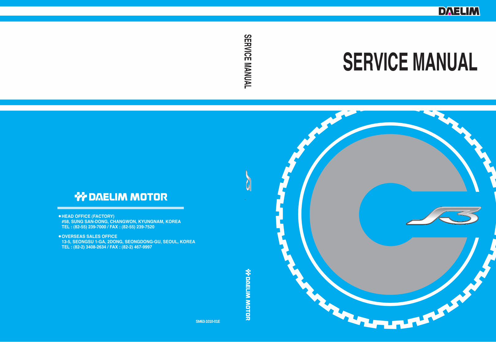
SERVICE INFORMATION
INSPECTION / ADJUSTMENT
EXTERNAL PARTS
LUBRICATION SYSTEM
EMS
COOLING SYSTEM
ENGINE REMOVAL/INSTALLATION
LH. CRANK CASE COVER / CONTINOUSLY VARIABLE TRANSMISSION
AC GENERATOR / FLY WHEEL
CYLINDER HEAD / VALVE
CYLINDER / PISTON
CRANKCASE / TRANSMISSION/ CRANK SHAFT
FRONT WHEEL / FRONT FORK / STEERING
REAR WHEEL / REAR CUSHION
BRAKES
CHARGING SYSTEM
IGNITION SYSTEM
STARTER SYSTEM
LIGHTS / SWITCHES / HORN
TROUBLE SHOOTING
WIRING DIAGRAM
EN
GIN
EF
RA
ME
ELEC
TRIC
ALSY
STEM
GE
NE
RA
L
Copyright 2010. DAERIM MOTOR Co., LTD.All Rights Reserved
SERVICE INFORMATION
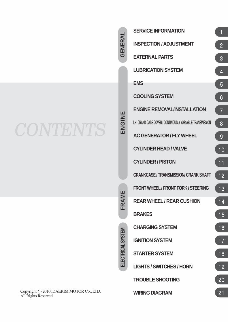
SERIAL NUMBER LOCATION 1-1
SPECIFICATION 1-2
TWIST TORQUE 1-4
SPECIAL TOOL 1-6
PARTS COMPOSITION MAP 1-8
SYMBOLS / ABBREVIATIONS 1-12
CAUTIONS AT WORK 1-13
CAUTIONS AT ASSEMBLY,
DISASSEMBLY 1-13
CAUTIONS AT WIRING 1-17
SERIAL NUMBER LOCATIONS
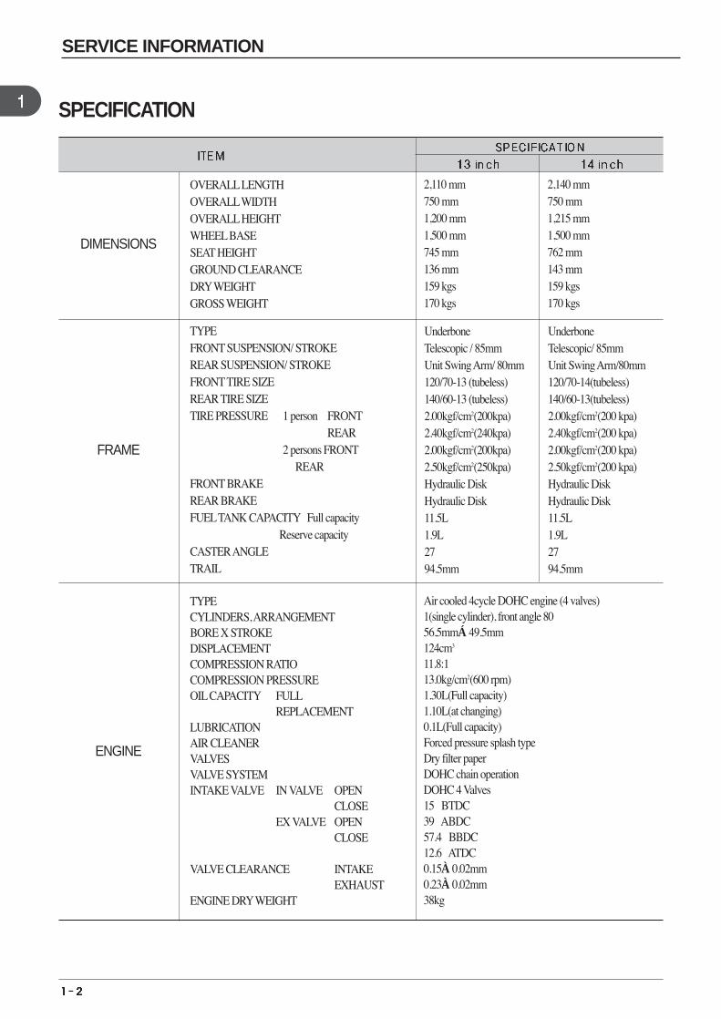
SPECIFICATION
DIMENSIONS
OVERALLLENGTHOVERALLWIDTHOVERALLHEIGHTWHEELBASESEAT HEIGHTGROUND CLEARANCE DRYWEIGHTGROSS WEIGHT
2,110 mm 750 mm1,200 mm1,500 mm745 mm136 mm159 kgs170 kgs
2,140 mm750 mm1,215 mm1,500 mm762 mm143 mm159 kgs170 kgs
FRAME
TYPEFRONT SUSPENSION/ STROKE REAR SUSPENSION/ STROKE FRONTTIRE SIZEREAR TIRE SIZETIRE PRESSURE 1 person FRONT
REAR2 persons FRONT
REAR FRONT BRAKE REAR BRAKE FUELTANK CAPACITY Full capacity
Reserve capacity CASTER ANGLETRAIL
Underbone Telescopic / 85mmUnit Swing Arm/ 80mm120/70-13 (tubeless)140/60-13 (tubeless)2.00kgf/cm2(200kpa)2.40kgf/cm2(240kpa)2.00kgf/cm2(200kpa)2.50kgf/cm2(250kpa)Hydraulic Disk Hydraulic Disk 11.5L1.9L27。94.5mm
UnderboneTelescopic/ 85mmUnit Swing Arm/80mm120/70-14(tubeless)140/60-13(tubeless)2.00kgf/cm2(200 kpa)2.40kgf/cm2(200 kpa)2.00kgf/cm2(200 kpa)2.50kgf/cm2(200 kpa)Hydraulic Disk Hydraulic Disk 11.5L1.9L27。94.5mm
ENGINE
TYPE CYLINDERS, ARRANGEMENTBORE X STROKE DISPLACEMENTCOMPRESSION RATIO COMPRESSION PRESSURE OILCAPACITY FULL
REPLACEMENTLUBRICATION AIR CLEANER VALVES VALVE SYSTEM INTAKE VALVE IN VALVE OPEN
CLOSEEX VALVE OPEN
CLOSE
VALVE CLEARANCE INTAKEEXHAUST
ENGINE DRYWEIGHT
Air cooled 4cycle DOHC engine (4 valves)1(single cylinder), front angle 80。56.5mm×49.5mm124cm3
11.8:113.0kg/cm2(600 rpm)1.30L(Full capacity)1.10L(at changing)0.1L(Full capacity)Forced pressure splash typeDry filter paper DOHC chain operationDOHC 4 Valves15。BTDC39。ABDC57.4。BBDC12.6。ATDC0.15±0.02mm0.23±0.02mm38kg
SERVICE INFORMATION
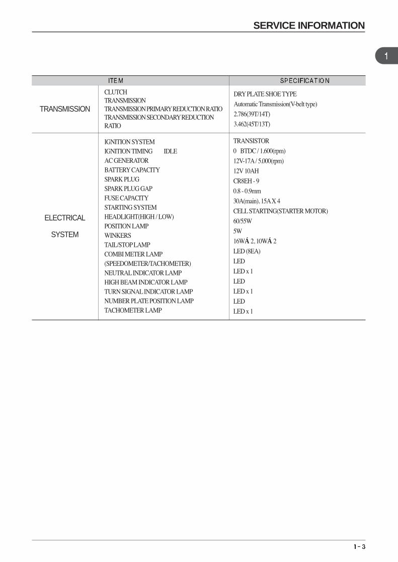
TRANSMISSION
CLUTCH TRANSMISSION TRANSMISSION PRIMARYREDUCTION RATIO TRANSMISSION SECONDARYREDUCTION RATIO
DRYPLATE SHOE TYPE
Automatic Transmission(V-belt type)
2.786(39T/14T)
3.462(45T/13T)
ELECTRICAL
SYSTEM
IGNITION SYSTEM IGNITION TIMING IDLE AC GENERATOR BATTERYCAPACITYSPARK PLUG SPARK PLUG GAPFUSE CAPACITYSTARTING SYSTEM HEADLIGHT(HIGH / LOW)POSITION LAMPWINKERSTAIL/STOPLAMPCOMBI METER LAMP(SPEEDOMETER/TACHOMETER)NEUTRALINDICATOR LAMPHIGH BEAM INDICATOR LAMPTURN SIGNALINDICATOR LAMPNUMBER PLATE POSITION LAMPTACHOMETER LAMP
TRANSISTOR
0。BTDC / 1,600(rpm)
12V-17A/ 5,000(rpm)
12V 10AH
CR8EH - 9
0.8 - 0.9mm
30A(main), 15AX 4
CELLSTARTING(STARTER MOTOR)
60/55W
5W
16W×2, 10W×2
LED (8EA)
LED
LED x 1
LED
LED x 1
LED
LED x 1
SERVICE INFORMATION
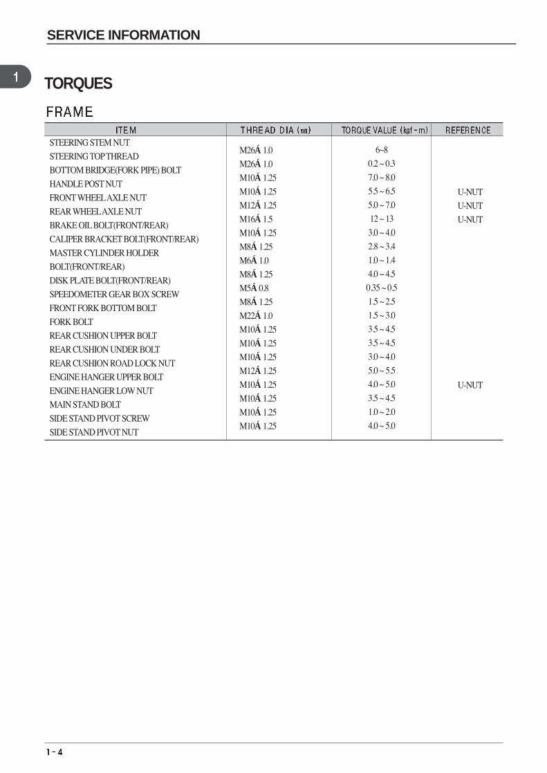
TORQUES
M26×1.0
M26×1.0
M10×1.25
M10×1.25
M12×1.25
M16×1.5
M10×1.25
M8×1.25
M6×1.0
M8×1.25
M5×0.8
M8×1.25
M22×1.0
M10×1.25
M10×1.25
M10×1.25
M12×1.25
M10×1.25
M10×1.25
M10×1.25
M10×1.25
U-NUT
U-NUT
U-NUT
U-NUT
6~8
0.2 ~ 0.3
7.0 ~ 8.0
5.5 ~ 6.5
5.0 ~ 7.0
12 ~ 13
3.0 ~ 4.0
2.8 ~ 3.4
1.0 ~ 1.4
4.0 ~ 4.5
0.35 ~ 0.5
1.5 ~ 2.5
1.5 ~ 3.0
3.5 ~ 4.5
3.5 ~ 4.5
3.0 ~ 4.0
5.0 ~ 5.5
4.0 ~ 5.0
3.5 ~ 4.5
1.0 ~ 2.0
4.0 ~ 5.0
STEERING STEM NUT
STEERING TOPTHREAD
BOTTOM BRIDGE(FORK PIPE) BOLT
HANDLE POST NUT
FRONTWHEELAXLE NUT
REAR WHEELAXLE NUT
BRAKE OILBOLT(FRONT/REAR)
CALIPER BRACKET BOLT(FRONT/REAR)
MASTER CYLINDER HOLDER
BOLT(FRONT/REAR)
DISK PLATE BOLT(FRONT/REAR)
SPEEDOMETER GEAR BOX SCREW
FRONT FORK BOTTOM BOLT
FORK BOLT
REAR CUSHION UPPER BOLT
REAR CUSHION UNDER BOLT
REAR CUSHION ROAD LOCK NUT
ENGINE HANGER UPPER BOLT
ENGINE HANGER LOW NUT
MAIN STAND BOLT
SIDE STAND PIVOT SCREW
SIDE STAND PIVOT NUT
SERVICE INFORMATION
M6×1.0
M6×1.0
M6×1.0
M10×1.25
M6×1.0
M10×1.0
M12×1.25
M6×1.0
M6×1.0
M6×1.0
M16 1.0
M8×1.25
M6×1.0
M6×1.0
M5
M30×1.5
M7×1.0
M12×1.25
M28
M12 1.25
M8×1.25
M8×1.25
M8×1.25
M8×1.25
M6×1.0
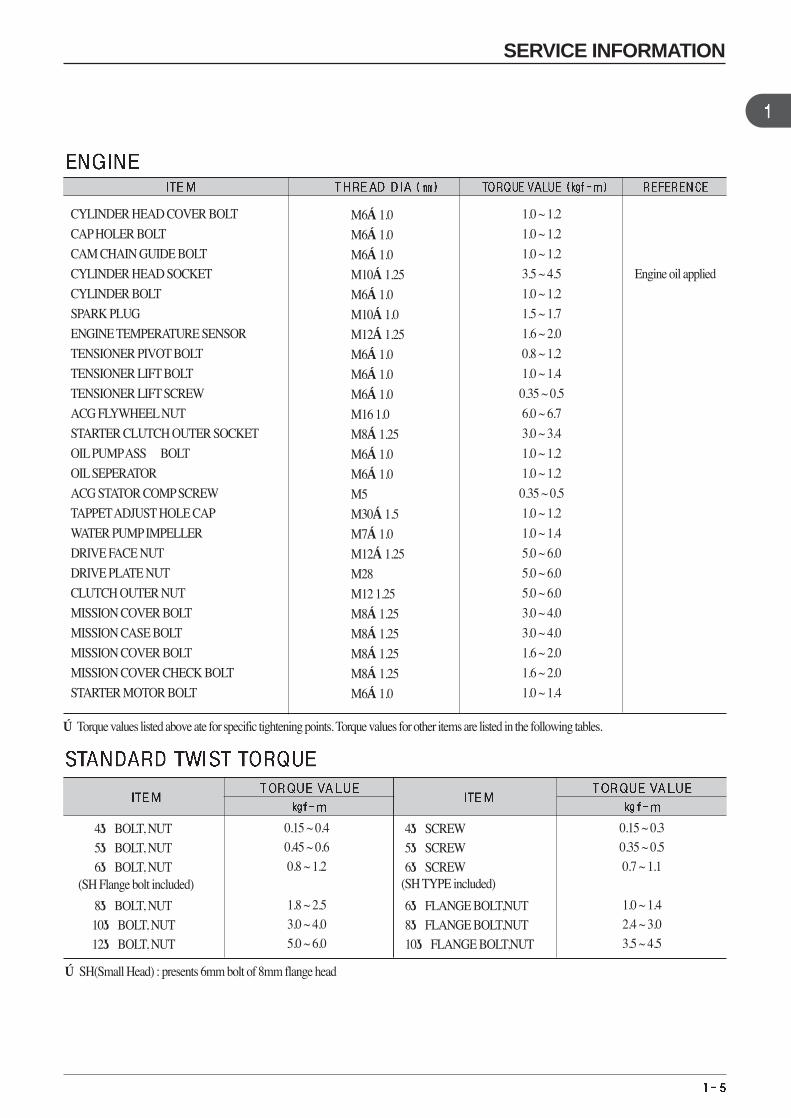
Engine oil applied
1.0 ~ 1.2
1.0 ~ 1.2
1.0 ~ 1.2
3.5 ~ 4.5
1.0 ~ 1.2
1.5 ~ 1.7
1.6 ~ 2.0
0.8 ~ 1.2
1.0 ~ 1.4
0.35 ~ 0.5
6.0 ~ 6.7
3.0 ~ 3.4
1.0 ~ 1.2
1.0 ~ 1.2
0.35 ~ 0.5
1.0 ~ 1.2
1.0 ~ 1.4
5.0 ~ 6.0
5.0 ~ 6.0
5.0 ~ 6.0
3.0 ~ 4.0
3.0 ~ 4.0
1.6 ~ 2.0
1.6 ~ 2.0
1.0 ~ 1.4
CYLINDER HEAD COVER BOLT
CAPHOLER BOLT
CAM CHAIN GUIDE BOLT
CYLINDER HEAD SOCKET
CYLINDER BOLT
SPARK PLUG
ENGINE TEMPERATURE SENSOR
TENSIONER PIVOT BOLT
TENSIONER LIFT BOLT
TENSIONER LIFT SCREW
ACG FLYWHEELNUT
STARTER CLUTCH OUTER SOCKET
OILPUMPASSBOLT
OILSEPERATOR
ACG STATOR COMPSCREW
TAPPETADJUST HOLE CAP
WATER PUMPIMPELLER
DRIVE FACE NUT
DRIVE PLATE NUT
CLUTCH OUTER NUT
MISSION COVER BOLT
MISSION CASE BOLT
MISSION COVER BOLT
MISSION COVER CHECK BOLT
STARTER MOTOR BOLT
※Torque values listed above ate for specific tightening points. Torque values for other items are listed in the following tables.
4BOLT, NUT 4SCREW5BOLT, NUT 5SCREW6BOLT, NUT 6SCREW
8BOLT, NUT 6FLANGE BOLT,NUT10BOLT, NUT 8FLANGE BOLT,NUT12BOLT, NUT 10FLANGE BOLT,NUT
※SH(Small Head) : presents 6mm bolt of 8mm flange head
0.15 ~ 0.40.45 ~ 0.60.8 ~ 1.2
1.8 ~ 2.53.0 ~ 4.05.0 ~ 6.0
0.15 ~ 0.30.35 ~ 0.50.7 ~ 1.1
1.0 ~ 1.42.4 ~ 3.03.5 ~ 4.5
(SH Flange bolt included) (SH TYPE included)
SERVICE INFORMATION
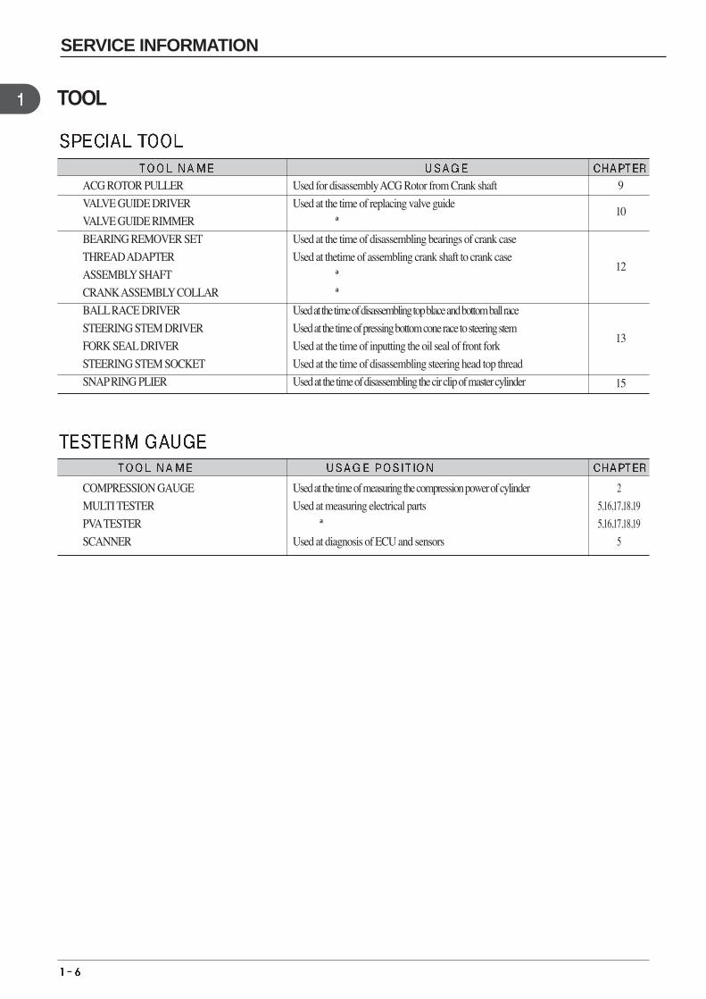
TOOL
ACG ROTOR PULLER
VALVE GUIDE DRIVER
VALVE GUIDE RIMMER
BEARING REMOVER SET
THREAD ADAPTER
ASSEMBLYSHAFT
CRANK ASSEMBLYCOLLAR
BALLRACE DRIVER
STEERING STEM DRIVER
FORK SEALDRIVER
STEERING STEM SOCKET
SNAPRING PLIER
Used for disassembly ACG Rotor from Crank shaft
Used at the time of replacing valve guide
〃
Used at the time of disassembling bearings of crank case
Used at thetime of assembling crank shaft to crank case
〃
〃
Used at the time of disassembling top blace and bottom ball race
Used at the time of pressing bottom cone race to steering stem
Used at the time of inputting the oil seal of front fork
Used at the time of disassembling steering head top thread
Used at the time of disassembling the cir clip of master cylinder 15
9
10
13
12
COMPRESSION GAUGE
MULTI TESTER
PVATESTER
SCANNER
Used at the time of measuring the compression power of cylinder
Used at measuring electrical parts
〃
Used at diagnosis of ECU and sensors
2
5,16,17,18,19
5,16,17,18,19
5
SERVICE INFORMATION
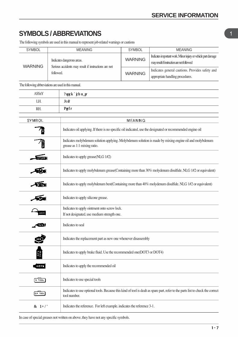
SYMBOL SYMBOLMEANING MEANING
Indicates dangerous areas.
Serious accidents may result if instructions are not
followed.
Indicates important work. Minor injury or vehicle part damage
may result if instruction are not followed
Indicates general cautions. Provides safety and
appropriate handling procedures.
The following symbols are used in this manual to represent job-related warnings or cautions
The following abbreviations are used in this manual.
ASS’Y
LH.
RH.
Assembled part
Left
Right
In case of special greases not written on above, they have not any specific symbols.
Indicates oil applying. If there is no specific oil indicated, use the designated or recommended engine oil
Indicates molybdenum solution applying. Molybdenum solution is made by mixing engine oil and molybdenumgrease as 1:1 mixing ratio.
Indicates to apply grease(NLG 1#2)
Indicates to apply molybdenum grease(Containing more than 30% molydenum disulfide, NLG 1#2 or equivalent)
Indicates to apply molybdenum best(Containing more than 40% molydenum disulfide, NLG 1#2 or equivalent)
Indicates to apply silicone grease.
Indicates to apply ointment onto screw lock.
If not designated, use medium strength one.
Indicates to seal
Indicates the replacement part as new one whenever disassembly
Indicates to apply brake fluid. Use the recommended one(DOT3 or DOT4)
Indicates to apply the recommended oil
Indicates to use special tools
Indicates to use optional tools. Because this kind of tool is dealt as spare part, refer to the parts list to check the correcttool number.
Indicates the reference. For left example, indicates the reference 3-1. ( 3-1)
SYMBOLS / ABBREVIATIONS
SERVICE INFORMATION
WARNING
WARNING
WARNING
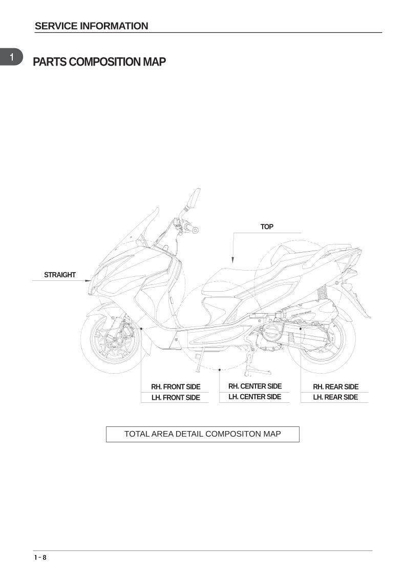
TOTAL AREA DETAIL COMPOSITON MAP
PARTS COMPOSITION MAP
LH. FRONT SIDE RH. FRONT SIDE
LH. CENTER SIDE RH. CENTER SIDE
LH. REAR SIDE RH. REAR SIDE
TOP
STRAIGHT
SERVICE INFORMATION
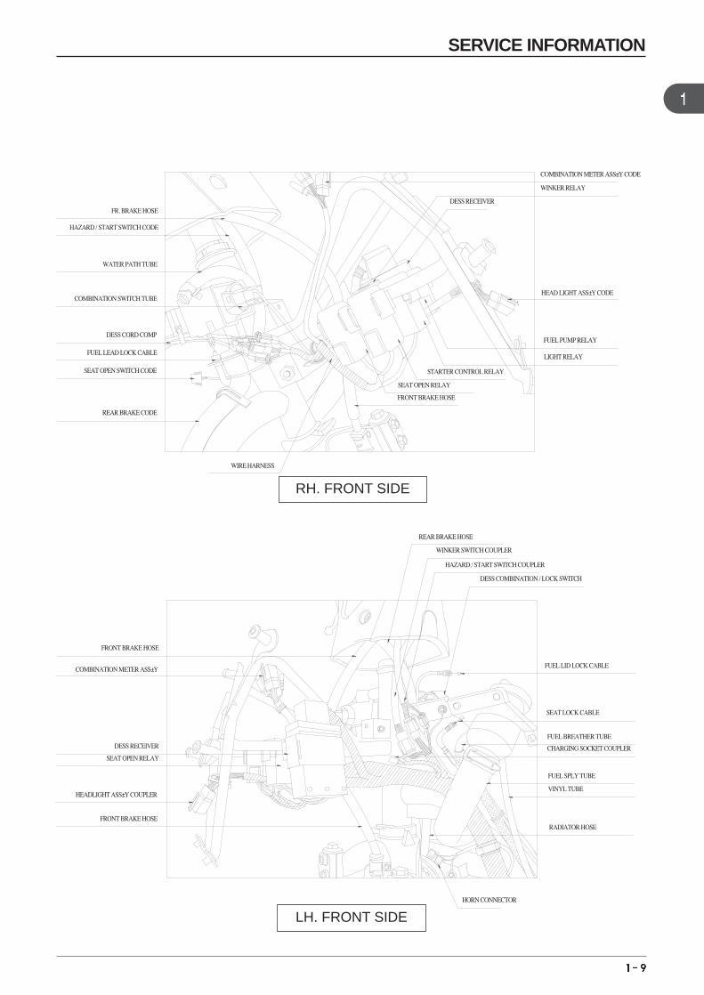
COMBINATION METER ASS’Y CODE
WINKER RELAY
DESS RECEIVER
HEAD LIGHT ASS’Y CODE
FUEL PUMP RELAY
LIGHT RELAY
STARTER CONTROL RELAY
SEAT OPEN RELAY
FRONT BRAKE HOSE
REAR BRAKE HOSE
WINKER SWITCH COUPLER
HAZARD / START SWITCH COUPLER
DESS COMBINATION / LOCK SWITCH
FUEL LID LOCK CABLE
SEAT LOCK CABLE
FUEL BREATHER TUBE
CHARGING SOCKET COUPLER
FUEL SPLY TUBE
VINYL TUBE
RADIATOR HOSE
HORN CONNECTOR
FR. BRAKE HOSE
HAZARD / START SWITCH CODE
WATER PATH TUBE
COMBINATION SWITCH TUBE
DESS CORD COMP
FUEL LEAD LOCK CABLE
SEAT OPEN SWITCH CODE
REAR BRAKE CODE
WIRE HARNESS
FRONT BRAKE HOSE
COMBINATION METER ASS’Y
DESS RECEIVER
SEAT OPEN RELAY
HEADLIGHT ASS’Y COUPLER
FRONT BRAKE HOSE
RH. FRONT SIDE
LH. FRONT SIDE
SERVICE INFORMATION
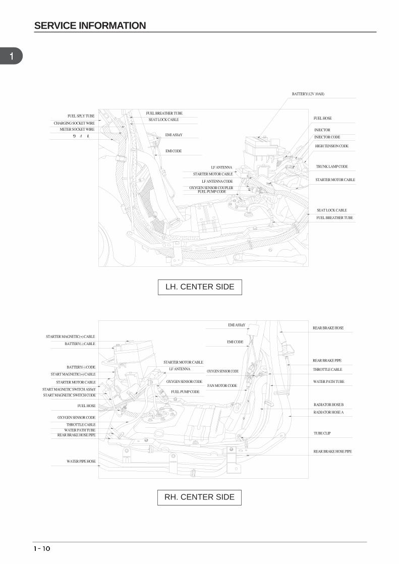
FUEL SPLY TUBE
CHARGING SOCKET WIRE
METER SOCKET WIRE
와이어하네스
LF ANTENNA
STARTER MOTOR CABLE
LF ANTENNA CODE
FUEL PUMP CODE
EMI ASS’Y
EMI CODE
OXYGEN SENSOR CODE
FAN MOTOR CODE
STARTER MAGNETIC(+) CABLE
BATTERY(-) CABLE
WATER PIPE HOSE
REAR BRAKE HOSE PIPE WATER PATH TUBE
THROTTLE CABLE
OXYGEN SENSOR CODE
FUEL HOSE
START MAGNETIC SWITCH CODE
START MAGNETIC SWITCH ASS’Y
STARTER MOTOR CABLE
START MAGNETIC(+) CABLE
BATTERY(-) CODE
OXYGEN SENSOR COUPLER
BATTERY(12V 10AH)
FUEL BREATHER TUBE
SEAT LOCK CABLE
EMI ASS’Y
EMI CODE
FUEL HOSE
INJECTOR
INJECTOR CODE
HIGH TENSION CODE
TRUNK LAMP CODE
STARTER MOTOR CABLE
SEAT LOCK CABLE
FUEL BREATHER TUBE
REAR BRAKE HOSE
STARTER MOTOR CABLE
LF ANTENNA
OXYGEN SENSOR CODE
FUEL PUMP CODE
REAR BRAKE PIPE
THROTTLE CABLE
WATER PATH TUBE
RADIATOR HOSE B
RADIATOR HOSE A
TUBE CLIP
REAR BRAKE HOSE PIPE
LH. CENTER SIDE
RH. CENTER SIDE
SERVICE INFORMATION
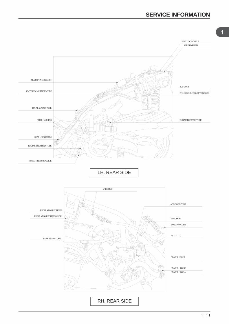
SEAT OPEN SOLENOID
SEAT OPEN SOLENOID CODE
TOTAL SENSOR WIRE
WIRE HARNESS
SEAT LOCK CABLE
ENGINE BREATHER TUBE
BREATHER TUBE GUIDE
REGULATOR RECTIFIER
REGULATOR RECTIFIER CODE
REAR BRAKE CODE
SEAT LOCK CABLE
WIRE HARNESS
ECU COMP
ECU GROUND CONNECTION CODE
ENGINE BREATHE TUBE
WIRE CLIP
ACG CODE COMP
FUEL HOSE
INJECTOR CODE
와이어하네스
WATER HOSE B
WATER HOSE C
WATER HOSE A
LH. REAR SIDE
RH. REAR SIDE
SERVICE INFORMATION
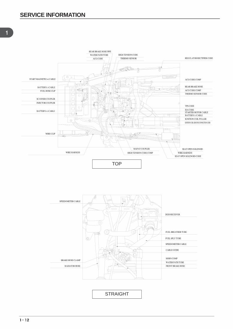
BATTERY(-) CABLE
REGULATOR RECTIFIER CODE
ACG CODE COMP
REAR BRAKE HOSE
ACG CODE COMP
THERMO SENSOR CODE
TPS CODE
ISA CODE STARTER MOTOR CABLE
IGNITION COIL PULLER
IGNITION COIL GROUND CONNECTION CODE
SEAT OPEN SOLENOID MAPAT COUPLER
HIGH TENSION CODE COMP
DESS RECEIVER
FUEL BREATHER TUBE
FUEL SPLY TUBE
SPEEDOMETER CABLE
CABLE GUIDE
HORN COMP
WATER PATH TUBE
FRONT BRAKE HOSE
HIGH TENSION CODE
THERMO SENSOR
WIRE HARNESS
SEAT OPEN SOLENOID CODE
REAR BRAKE HOSE PIPE
WATER PATH TUBE
ACG CODE
START MAGNETIC(+) CABLE
BATTERY(-) CABLE
FUEL HOSE CLIP
SCANNER COUPLER
INJECTOR COUPLER
BATTERY(+) CABLE
WIRE CLIP
WIRE HARNESS
SPEEDOMETER CABLE
BRAKE HOSE CLAMP
RADIATOR HOSE
STRAIGHT
TOP
SERVICE INFORMATION
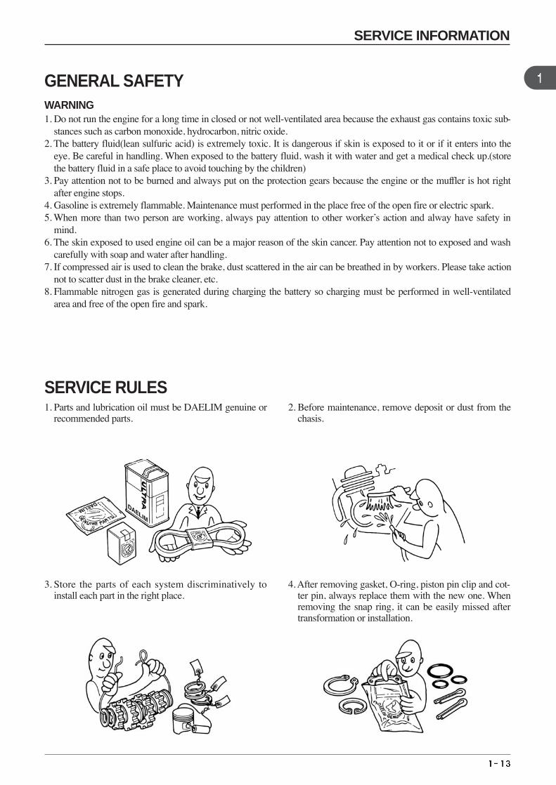
GENERAL SAFETYWARNING1. Do not run the engine for a long time in closed or not well-ventilated area because the exhaust gas contains toxic sub-
stances such as carbon monoxide, hydrocarbon, nitric oxide.2. The battery fluid(lean sulfuric acid) is extremely toxic. It is dangerous if skin is exposed to it or if it enters into the
eye. Be careful in handling. When exposed to the battery fluid, wash it with water and get a medical check up.(storethe battery fluid in a safe place to avoid touching by the children)
3. Pay attention not to be burned and always put on the protection gears because the engine or the muffler is hot rightafter engine stops.
4. Gasoline is extremely flammable. Maintenance must performed in the place free of the open fire or electric spark.5. When more than two person are working, always pay attention to other worker’s action and alway have safety in
mind.6. The skin exposed to used engine oil can be a major reason of the skin cancer. Pay attention not to exposed and wash
carefully with soap and water after handling.7. If compressed air is used to clean the brake, dust scattered in the air can be breathed in by workers. Please take action
not to scatter dust in the brake cleaner, etc.8. Flammable nitrogen gas is generated during charging the battery so charging must be performed in well-ventilated
area and free of the open fire and spark.
SERVICE RULES1. Parts and lubrication oil must be DAELIM genuine or
recommended parts.2. Before maintenance, remove deposit or dust from the
chasis.
3. Store the parts of each system discriminatively toinstall each part in the right place.
4. After removing gasket, O-ring, piston pin clip and cot-ter pin, always replace them with the new one. Whenremoving the snap ring, it can be easily missed aftertransformation or installation.
SERVICE INFORMATION
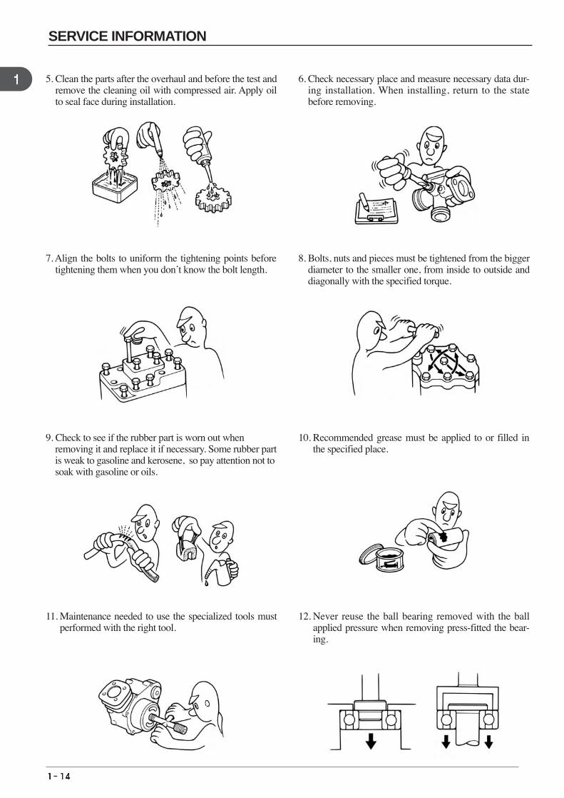
9. Check to see if the rubber part is worn out when removing it and replace it if necessary. Some rubber part is weak to gasoline and kerosene, so pay attention not tosoak with gasoline or oils.
10. Recommended grease must be applied to or filled inthe specified place.
7. Align the bolts to uniform the tightening points beforetightening them when you don’t know the bolt length.
8. Bolts, nuts and pieces must be tightened from the biggerdiameter to the smaller one, from inside to outside anddiagonally with the specified torque.
5. Clean the parts after the overhaul and before the test andremove the cleaning oil with compressed air. Apply oilto seal face during installation.
6. Check necessary place and measure necessary data dur-ing installation. When installing, return to the statebefore removing.
11. Maintenance needed to use the specialized tools mustperformed with the right tool.
12. Never reuse the ball bearing removed with the ballapplied pressure when removing press-fitted the bear-ing.
SERVICE INFORMATION
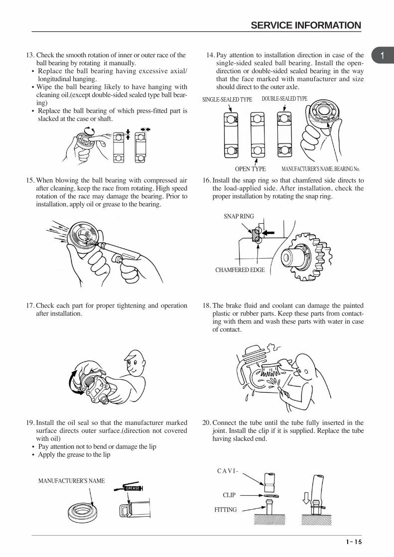
13. Check the smooth rotation of inner or outer race of the ball bearing by rotating it manually.
• Replace the ball bearing having excessive axial/longitudinal hanging.
•Wipe the ball bearing likely to have hanging withcleaning oil.(except double-sided sealed type ball bear-ing)
• Replace the ball bearing of which press-fitted part isslacked at the case or shaft.
14. Pay attention to installation direction in case of thesingle-sided sealed ball bearing. Install the open-direction or double-sided sealed bearing in the waythat the face marked with manufacturer and sizeshould direct to the outer axle.
15. When blowing the ball bearing with compressed airafter cleaning, keep the race from rotating. High speedrotation of the race may damage the bearing. Prior toinstallation, apply oil or grease to the bearing.
16. Install the snap ring so that chamfered side directs tothe load-applied side. After installation, check theproper installation by rotating the snap ring.
17. Check each part for proper tightening and operationafter installation.
18. The brake fluid and coolant can damage the paintedplastic or rubber parts. Keep these parts from contact-ing with them and wash these parts with water in caseof contact.
SINGLE-SEALED TYPE DOUBLE-SEALED TYPE
OPEN TYPE
SNAP RING
CHAMFERED EDGE
MANUFACTURER’S NAME, BEARING No.
19. Install the oil seal so that the manufacturer markedsurface directs outer surface.(direction not coveredwith oil)
• Pay attention not to bend or damage the lip•Apply the grease to the lip
20. Connect the tube until the tube fully inserted in thejoint. Install the clip if it is supplied. Replace the tubehaving slacked end.
MANUFACTURER’S NAME
C A V I -
CLIP
FITTING
SERVICE INFORMATION
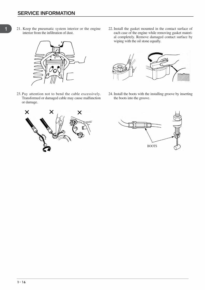
21. Keep the pneumatic system interior or the engine interior from the infiltration of dust.
22. Install the gasket mounted in the contact surface ofeach case of the engine while removing gasket materi-al completely. Remove damaged contact surface bywiping with the oil stone equally.
23. Pay attention not to bend the cable excessively.Transformed or damaged cable may cause malfunctionor damage.
24. Install the boots with the installing groove by insertingthe boots into the groove.
BOOTS
SERVICE INFORMATION
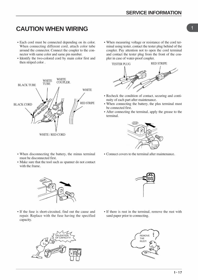
•Each cord must be connected depending on its color.When connecting different cord, attach color tubearound the connector. Connect the coupler to the con-nector with same color and same pin number.
•Identify the two-colored cord by main color first andthen striped color .
•When measuring voltage or resistance of the cord ter-minal using tester, contact the tester plug behind of thecoupler. Pay attention not to open the cord terminaland contact the tester plug from the front of the cou-pler in case of water-proof coupler.
•Recheck the condition of contact, securing and conti-nuity of each part after maintenance.
•When connecting the battery, the plus terminal mustbe connected first.
•After connecting the terminal, apply the grease to theterminal.
•When disconnecting the battery, the minus terminalmust be disconnected first.
•Make sure that the tool such as spanner do not contactwith the frame.
•Connect covers to the terminal after maintenance.
•If the fuse is short-circuited, find out the cause andrepair. Replace with the fuse having the specifiedcapacity.
•If there is rust in the terminal, remove the rust withsand paper prior to connecting.
CAUTION WHEN WIRING
BLACK CORD
WHITE COUPLER.
WHITE
RED STRIPE
RED STRIPE
WHITE / RED CORD
TESTER PLUG
WHITE TUBEBLACK TUBE
VALIDATIONOF CAPACITY!
REMOVETHERUST!
SERVICE INFORMATION
•Insert the lock of the coupler until the lock is fullysecured.
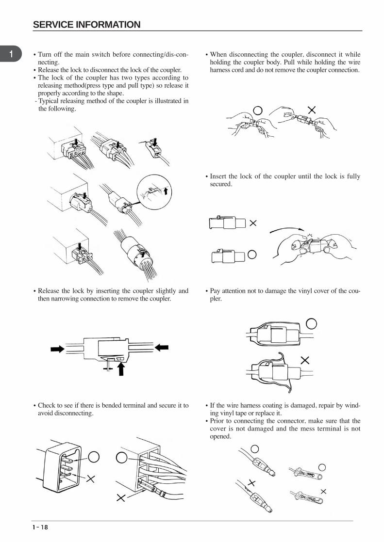
•Turn off the main switch before connecting/dis-con-necting.
•Release the lock to disconnect the lock of the coupler.•The lock of the coupler has two types according to
releasing method(press type and pull type) so release itproperly according to the shape.
- Typical releasing method of the coupler is illustrated inthe following.
•When disconnecting the coupler, disconnect it whileholding the coupler body. Pull while holding the wireharness cord and do not remove the coupler connection.
•Release the lock by inserting the coupler slightly andthen narrowing connection to remove the coupler.
•Pay attention not to damage the vinyl cover of the cou-pler.
•Check to see if there is bended terminal and secure it toavoid disconnecting.
•If the wire harness coating is damaged, repair by wind-ing vinyl tape or replace it.
•Prior to connecting the connector, make sure that thecover is not damaged and the mess terminal is notopened.
SERVICE INFORMATION
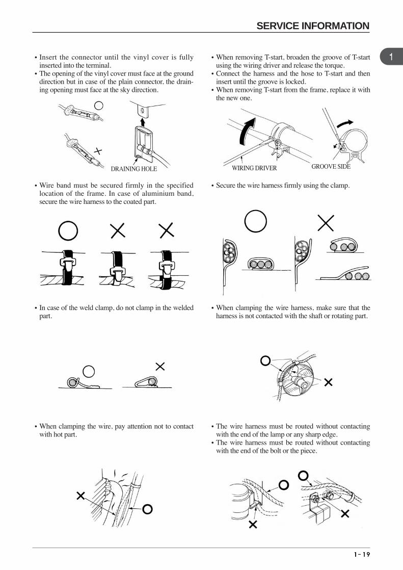
•Wire band must be secured firmly in the specifiedlocation of the frame. In case of aluminium band,secure the wire harness to the coated part.
•Secure the wire harness firmly using the clamp.
•Insert the connector until the vinyl cover is fullyinserted into the terminal.
•The opening of the vinyl cover must face at the grounddirection but in case of the plain connector, the drain-ing opening must face at the sky direction.
•When removing T-start, broaden the groove of T-startusing the wiring driver and release the torque.
•Connect the harness and the hose to T-start and theninsert until the groove is locked.
•When removing T-start from the frame, replace it withthe new one.
•In case of the weld clamp, do not clamp in the weldedpart.
•When clamping the wire harness, make sure that theharness is not contacted with the shaft or rotating part.
•When clamping the wire, pay attention not to contactwith hot part.
•The wire harness must be routed without contactingwith the end of the lamp or any sharp edge.
•The wire harness must be routed without contactingwith the end of the bolt or the piece.
WIRING DRIVERDRAINING HOLE GROOVE SIDE
SERVICE INFORMATION
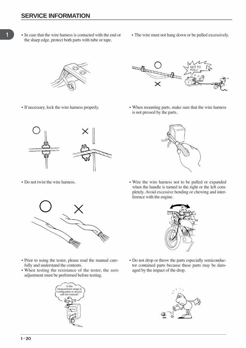
•If necessary, lock the wire harness properly. •When mounting parts, make sure that the wire harnessis not pressed by the parts.
•In case that the wire harness is contacted with the end orthe sharp edge, protect both parts with tube or tape.
•The wire must not hang down or be pulled excessively.
•Do not twist the wire harness. •Wire the wire harness not to be pulled or expandedwhen the handle is turned to the right or the left com-pletely. Avoid excessive bending or chewing and inter-ference with the engine.
•Prior to using the tester, please read the manual care-fully and understand the contents.
•When testing the resistance of the tester, the zeroadjustment must be performed before testing.
•Do not drop or throw the parts especially semiconduc-tor contained parts because these parts may be dam-aged by the impact of the drop.
NOT TO PULL!
Is this measurement range orconfiguration in accord
with the manual?
SERVICE INFORMATION
2. INSPECTIONS / ADJUSTMENTS
SERVICE INFORMATION
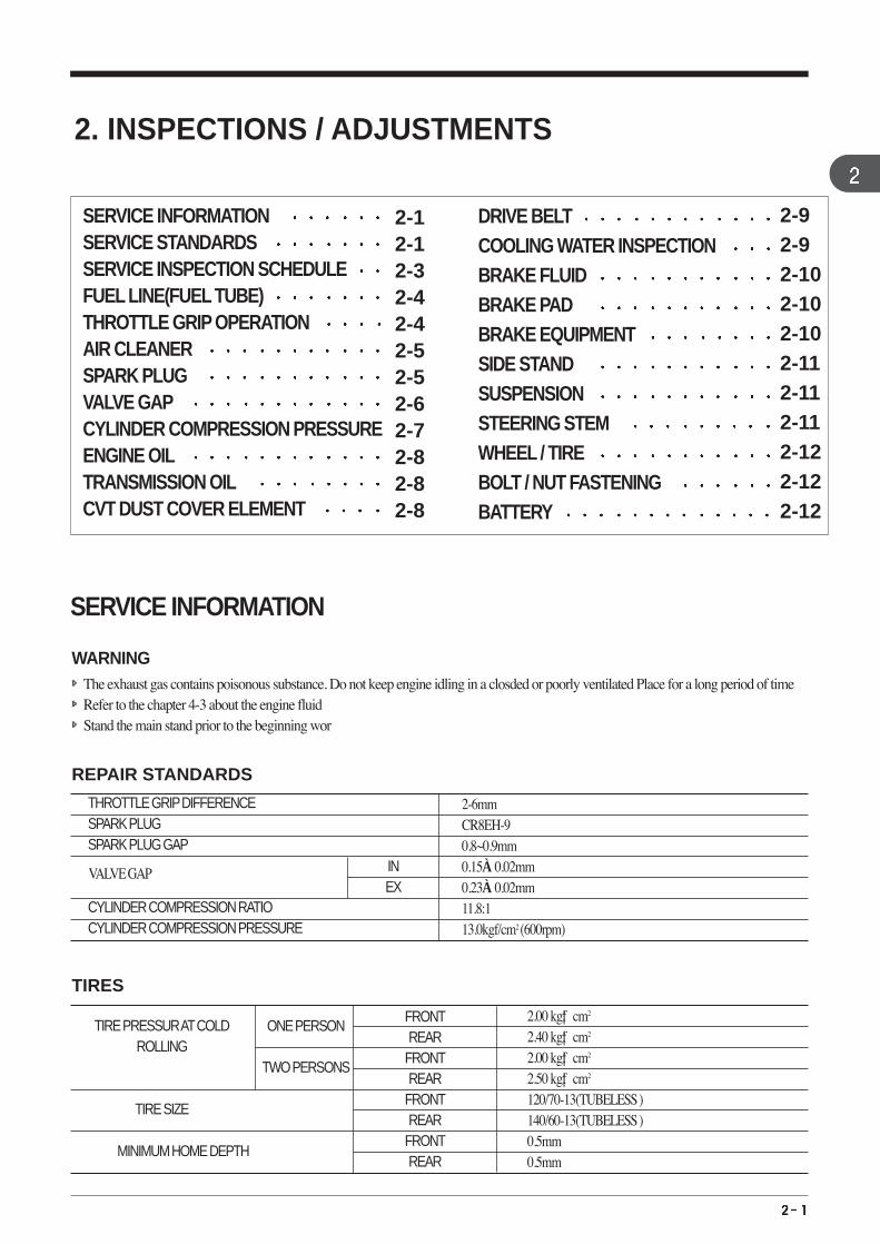
WARNING The exhaust gas contains poisonous substance. Do not keep engine idling in a closded or poorly ventilated Place for a long period of time Refer to the chapter 4-3 about the engine fluid Stand the main stand prior to the beginning wor
REPAIR STANDARDS
TIRES
THROTTLE GRIPDIFFERENCE SPARK PLUG SPARK PLUG GAP
CYLINDER COMPRESSION RATIOCYLINDER COMPRESSION PRESSURE
VALVE GAP
2-6mmCR8EH-90.8~0.9mm0.15±0.02mm0.23±0.02mm11.8:113.0kgf/cm2 (600rpm)
INEX
2.00 kgf·cm2
2.40 kgf·cm2
2.00 kgf·cm2
2.50 kgf·cm2
120/70-13(TUBELESS )140/60-13(TUBELESS )0.5mm0.5mm
FRONTREAR
FRONTREAR
FRONTREAR
FRONTREAR
ONE PERSON
TWO PERSONS
TIRE PRESSUR ATCOLDROLLING
TIRE SIZE
MINIMUM HOME DEPTH
2-12-12-32-42-42-52-52-62-72-82-82-8
SERVICE INFORMATIONSERVICE STANDARDSSERVICE INSPECTION SCHEDULE FUEL LINE(FUEL TUBE)THROTTLE GRIP OPERATIONAIR CLEANER SPARK PLUG VALVE GAPCYLINDER COMPRESSION PRESSUREENGINE OILTRANSMISSION OILCVT DUST COVER ELEMENT
DRIVE BELT COOLING WATER INSPECTION BRAKE FLUID BRAKE PAD BRAKE EQUIPMENT SIDE STAND SUSPENSIONSTEERING STEM WHEEL / TIREBOLT / NUT FASTENING BATTERY
2-92-92-102-102-102-112-112-112-122-122-12
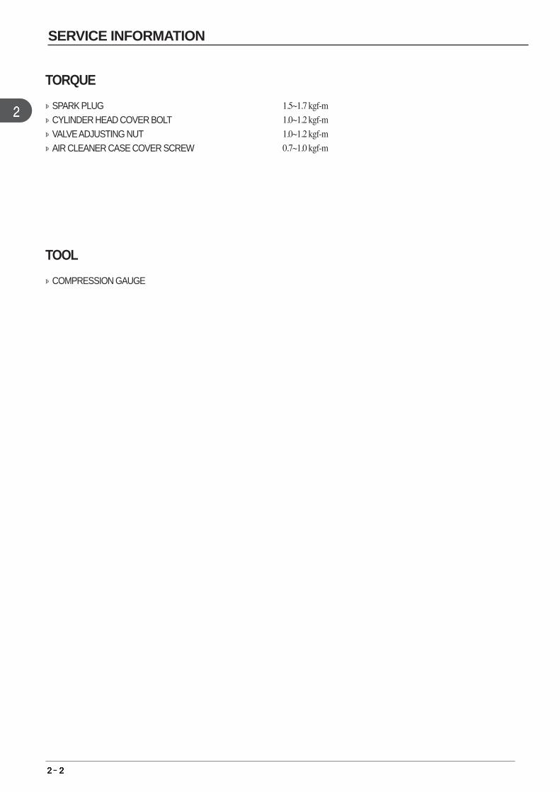
TORQUE
SPARK PLUG 1.5~1.7 kgf-m
CYLINDER HEAD COVER BOLT 1.0~1.2 kgf-m
VALVE ADJUSTING NUT 1.0~1.2 kgf-m
AIR CLEANER CASE COVER SCREW 0.7~1.0 kgf-m
TOOL
COMPRESSION GAUGE
SERVICE INFORMATION
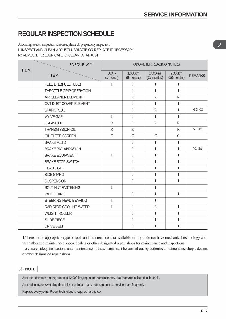
According to each inspection schedule, please do preparatory inspection.I : INSPECTAND CLEAN, ADJUST,LUBRICATE OR REPLACE IF NECESSARYR : REPLACE L : LUBRICATE C: CLEAN A: ADJUST
* If there are no appropriate type of tools and maintenance data available, or if you do not have mechanical technology con-tact authorized maintenance shops, dealers or other designated repair shops for maintenance and inspections. To ensure safety, inspections and maintenance of these parts must be carried out by authorized maintenance shops, dealersor other designated repair shops.
REGULAR INSPECTION SCHEDULE
FULE LINE(FUELTUBE)
THROTTLE GRIP OPERATION
AIR CLEANER ELEMENT
CVT DUST COVER ELEMENT
SPARK PLUG
VALVE GAP
ENGINE OIL
TRANSMISSION OIL
OILFILTER SCREEN
BRAKE FLUID
BRAKE PAD ABRASION
BRAKE EQUIPMENT
BRAKE STOP SWITCH
HEAD LIGHT
SIDE STAND
SUSPENSION
BOLT, NUT FASTENING
WHEEL/TIRE
STEERING HEAD BEARING
RADIATOR COOLING WATER
WEIGHT ROLLER
SLIDE PIECE
DRIVE BELT
ODOMETER READING(NOTE 1)
500 1,000km 1,500km 2,000kmREMARKS(1 month) (6 months) (12 months) (18 months)
*
*
*
*
**
*
*
*
*
**
**
I
I
R
R
C
I
I
I
I
I
I
R
I
I
I
R
R
C
I
I
I
I
I
I
I
I
I
I
I
I
I
I
R
I
R
I
R
C
I
I
I
I
I
I
I
I
I
I
R
I
I
I
I
I
R
I
I
I
R
R
C
I
I
I
I
I
I
I
I
I
I
I
I
After the odometer reading exceeds 12,000 km, repeat maintenance service at intervals indicated in the table.
After riding in areas with high humidity or pollution, carry out maintenance service more frequently.
Replace every years. Proper technology is required for this job.
NOTE 2
NOTE3
NOTE2
SERVICE INFORMATION
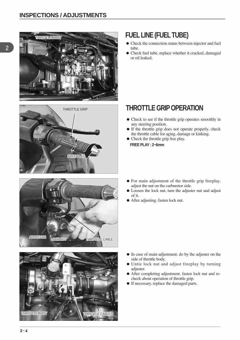
THROTTLE GRIP OPERATION Check to see if the throttle grip operates smoothly in
any steering position. If the throttle grip does not operate properly, check
the throttle cable for aging, damage or kinking. Check the throttle grip free play.
FREE PLAY : 2~6mm
For main adjustment of the throttle grip freeplay,adjust the nut on the carburetor side.
Loosen the lock nut, turn the adjuster nut and adjustof it.
After adjusting, fasten lock nut.
In case of main adjustment, do by the adjuster on theside of throttle body.
Untie lock nut and adjust freeplay by turningadjuster.
After completing adjustment, fasten lock nut and re-check about operation of throttle grip.
If necessary, replace the damaged parts.
THROTTLE BODYTHROTTLE BODYTHROTTLE BODYTHROTTLE BODYTHROTTLE BODYTHROTTLE BODYTHROTTLE BODYTHROTTLE BODYTHROTTLE BODYTHROTTLE BODYTHROTTLE BODYTHROTTLE BODYTHROTTLE BODYTHROTTLE BODYTHROTTLE BODYTHROTTLE BODYTHROTTLE BODYTHROTTLE BODYTHROTTLE BODYTHROTTLE BODYTHROTTLE BODYTHROTTLE BODYTHROTTLE BODYTHROTTLE BODYTHROTTLE BODYTHROTTLE BODYTHROTTLE BODY INJECTORINJECTORINJECTORINJECTORINJECTORINJECTORINJECTORINJECTORINJECTORINJECTORINJECTORINJECTORINJECTORINJECTORINJECTORINJECTORINJECTORINJECTORINJECTORINJECTORINJECTORINJECTORINJECTORINJECTORINJECTORINJECTORINJECTOR
FUEL HOSE
THROTTLE GRIP
FREE PLAYFREE PLAYFREE PLAYFREE PLAYFREE PLAYFREE PLAYFREE PLAYFREE PLAYFREE PLAYFREE PLAYFREE PLAYFREE PLAYFREE PLAYFREE PLAYFREE PLAYFREE PLAYFREE PLAYFREE PLAYFREE PLAYFREE PLAYFREE PLAYFREE PLAYFREE PLAYFREE PLAYFREE PLAYFREE PLAYFREE PLAY
ADJUSTORADJUSTORADJUSTORADJUSTORADJUSTORADJUSTORADJUSTORADJUSTORADJUSTORADJUSTORADJUSTORADJUSTORADJUSTORADJUSTORADJUSTORADJUSTORADJUSTORADJUSTORADJUSTORADJUSTORADJUSTORADJUSTORADJUSTORADJUSTORADJUSTORADJUSTORADJUSTOR LOCK NUTLOCK NUTLOCK NUTLOCK NUTLOCK NUTLOCK NUTLOCK NUTLOCK NUTLOCK NUTLOCK NUTLOCK NUTLOCK NUTLOCK NUTLOCK NUTLOCK NUTLOCK NUTLOCK NUTLOCK NUTLOCK NUTLOCK NUTLOCK NUTLOCK NUTLOCK NUTLOCK NUTLOCK NUTLOCK NUTLOCK NUT THROTTLE CABLETHROTTLE CABLETHROTTLE CABLETHROTTLE CABLETHROTTLE CABLETHROTTLE CABLETHROTTLE CABLETHROTTLE CABLETHROTTLE CABLETHROTTLE CABLETHROTTLE CABLETHROTTLE CABLETHROTTLE CABLETHROTTLE CABLETHROTTLE CABLETHROTTLE CABLETHROTTLE CABLETHROTTLE CABLETHROTTLE CABLETHROTTLE CABLETHROTTLE CABLETHROTTLE CABLETHROTTLE CABLETHROTTLE CABLETHROTTLE CABLETHROTTLE CABLETHROTTLE CABLE
THROTTLE BODYTHROTTLE BODYTHROTTLE BODYTHROTTLE BODYTHROTTLE BODYTHROTTLE BODYTHROTTLE BODYTHROTTLE BODYTHROTTLE BODYTHROTTLE BODYTHROTTLE BODYTHROTTLE BODYTHROTTLE BODYTHROTTLE BODYTHROTTLE BODYTHROTTLE BODYTHROTTLE BODYTHROTTLE BODYTHROTTLE BODYTHROTTLE BODYTHROTTLE BODYTHROTTLE BODYTHROTTLE BODYTHROTTLE BODYTHROTTLE BODYTHROTTLE BODYTHROTTLE BODY THROTTLE CABLETHROTTLE CABLETHROTTLE CABLETHROTTLE CABLETHROTTLE CABLETHROTTLE CABLETHROTTLE CABLETHROTTLE CABLETHROTTLE CABLETHROTTLE CABLETHROTTLE CABLETHROTTLE CABLETHROTTLE CABLETHROTTLE CABLETHROTTLE CABLETHROTTLE CABLETHROTTLE CABLETHROTTLE CABLETHROTTLE CABLETHROTTLE CABLETHROTTLE CABLETHROTTLE CABLETHROTTLE CABLETHROTTLE CABLETHROTTLE CABLETHROTTLE CABLETHROTTLE CABLE
FUEL LINE (FUEL TUBE) Check the connection status between injector and fuel
tube. Check fuel tube, replace whether it cracked, damaged
or oil leaked.
INSPECTIONS / ADJUSTMENTS
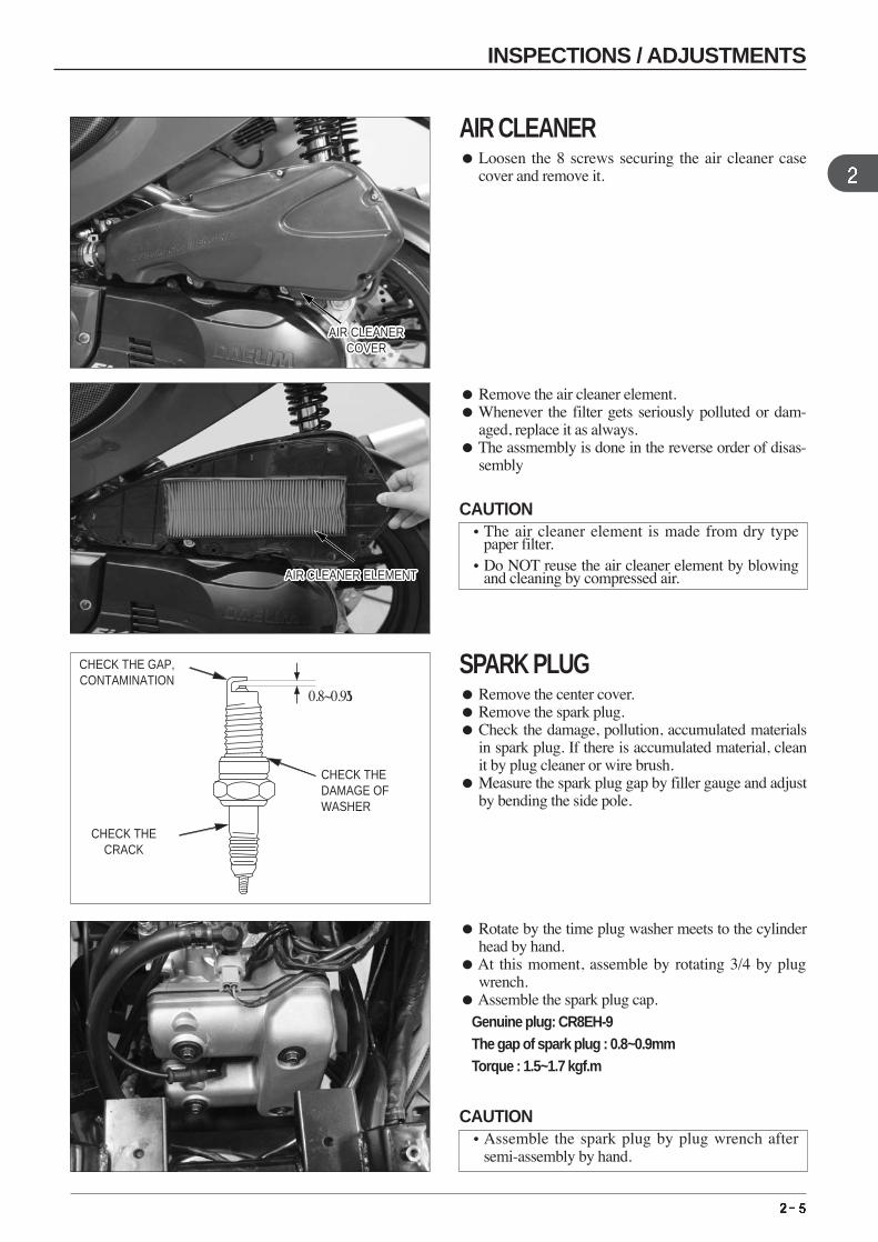
Remove the air cleaner element.Whenever the filter gets seriously polluted or dam-
aged, replace it as always. The assmembly is done in the reverse order of disas-
sembly
CHECK THE GAP,CONTAMINATION
0.8~0.9
CHECK THE DAMAGE OFWASHER
CHECK THECRACK
Rotate by the time plug washer meets to the cylinderhead by hand.
At this moment, assemble by rotating 3/4 by plugwrench.
Assemble the spark plug cap. Genuine plug: CR8EH-9The gap of spark plug : 0.8~0.9mmTorque : 1.5~1.7 kgf.m
AIR CLEANERCOVER
AIR CLEANERCOVER
AIR CLEANERCOVER
AIR CLEANERCOVER
AIR CLEANERCOVER
AIR CLEANERCOVER
AIR CLEANERCOVER
AIR CLEANERCOVER
AIR CLEANERCOVER
AIR CLEANERCOVER
AIR CLEANERCOVER
AIR CLEANERCOVER
AIR CLEANERCOVER
AIR CLEANERCOVER
AIR CLEANERCOVER
AIR CLEANERCOVER
AIR CLEANERCOVER
AIR CLEANERCOVER
AIR CLEANERCOVER
AIR CLEANERCOVER
AIR CLEANERCOVER
AIR CLEANERCOVER
AIR CLEANERCOVER
AIR CLEANERCOVER
AIR CLEANERCOVER
AIR CLEANERCOVER
AIR CLEANERCOVER
AIR CLEANER ELEMENTAIR CLEANER ELEMENTAIR CLEANER ELEMENTAIR CLEANER ELEMENTAIR CLEANER ELEMENTAIR CLEANER ELEMENTAIR CLEANER ELEMENTAIR CLEANER ELEMENTAIR CLEANER ELEMENTAIR CLEANER ELEMENTAIR CLEANER ELEMENTAIR CLEANER ELEMENTAIR CLEANER ELEMENTAIR CLEANER ELEMENTAIR CLEANER ELEMENTAIR CLEANER ELEMENTAIR CLEANER ELEMENTAIR CLEANER ELEMENTAIR CLEANER ELEMENTAIR CLEANER ELEMENTAIR CLEANER ELEMENTAIR CLEANER ELEMENTAIR CLEANER ELEMENTAIR CLEANER ELEMENTAIR CLEANER ELEMENTAIR CLEANER ELEMENTAIR CLEANER ELEMENT
AIR CLEANER Loosen the 8 screws securing the air cleaner case
cover and remove it.
SPARK PLUG Remove the center cover. Remove the spark plug. Check the damage, pollution, accumulated materials
in spark plug. If there is accumulated material, cleanit by plug cleaner or wire brush.
Measure the spark plug gap by filler gauge and adjustby bending the side pole.
INSPECTIONS / ADJUSTMENTS
CAUTION•The air cleaner element is made from dry type
paper filter.•Do NOT reuse the air cleaner element by blowing
and cleaning by compressed air.
CAUTION•Assemble the spark plug by plug wrench after
semi-assembly by hand.
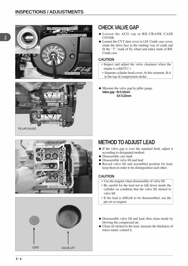
Measure the valve gap by piller gaugeValve gap : IN 0.15mm
EX 0.23mm
Disassemble valve lift and lead, then clean inside byblowing the compressed air.
Clean oil sticked to the lead, measure the thickness ofmirco meter, control it.
LEAD VALVE LIFT
INDEX ,MARK INDEX ,MARK INDEX ,MARK INDEX ,MARK INDEX ,MARK INDEX ,MARK INDEX ,MARK INDEX ,MARK INDEX ,MARK INDEX ,MARK INDEX ,MARK INDEX ,MARK INDEX ,MARK INDEX ,MARK INDEX ,MARK INDEX ,MARK INDEX ,MARK INDEX ,MARK INDEX ,MARK INDEX ,MARK INDEX ,MARK INDEX ,MARK INDEX ,MARK INDEX ,MARK INDEX ,MARK INDEX ,MARK INDEX ,MARK
LH. CRANK CASE CPVER LH. CRANK CASE CPVER LH. CRANK CASE CPVER LH. CRANK CASE CPVER LH. CRANK CASE CPVER LH. CRANK CASE CPVER LH. CRANK CASE CPVER LH. CRANK CASE CPVER LH. CRANK CASE CPVER LH. CRANK CASE CPVER LH. CRANK CASE CPVER LH. CRANK CASE CPVER LH. CRANK CASE CPVER LH. CRANK CASE CPVER LH. CRANK CASE CPVER LH. CRANK CASE CPVER LH. CRANK CASE CPVER LH. CRANK CASE CPVER LH. CRANK CASE CPVER LH. CRANK CASE CPVER LH. CRANK CASE CPVER LH. CRANK CASE CPVER LH. CRANK CASE CPVER LH. CRANK CASE CPVER LH. CRANK CASE CPVER LH. CRANK CASE CPVER LH. CRANK CASE CPVER
RH. CRANK CASE COVER RH. CRANK CASE COVER RH. CRANK CASE COVER RH. CRANK CASE COVER RH. CRANK CASE COVER RH. CRANK CASE COVER RH. CRANK CASE COVER RH. CRANK CASE COVER RH. CRANK CASE COVER RH. CRANK CASE COVER RH. CRANK CASE COVER RH. CRANK CASE COVER RH. CRANK CASE COVER RH. CRANK CASE COVER RH. CRANK CASE COVER RH. CRANK CASE COVER RH. CRANK CASE COVER RH. CRANK CASE COVER RH. CRANK CASE COVER RH. CRANK CASE COVER RH. CRANK CASE COVER RH. CRANK CASE COVER RH. CRANK CASE COVER RH. CRANK CASE COVER RH. CRANK CASE COVER RH. CRANK CASE COVER RH. CRANK CASE COVER
DRIVE FACE DRIVE FACE DRIVE FACE DRIVE FACE DRIVE FACE DRIVE FACE DRIVE FACE DRIVE FACE DRIVE FACE DRIVE FACE DRIVE FACE DRIVE FACE DRIVE FACE DRIVE FACE DRIVE FACE DRIVE FACE DRIVE FACE DRIVE FACE DRIVE FACE DRIVE FACE DRIVE FACE DRIVE FACE DRIVE FACE DRIVE FACE DRIVE FACE DRIVE FACE DRIVE FACE
PILLAR GAUGE
IN VALVEIN VALVEIN VALVEIN VALVEIN VALVEIN VALVEIN VALVEIN VALVEIN VALVEIN VALVEIN VALVEIN VALVEIN VALVEIN VALVEIN VALVEIN VALVEIN VALVEIN VALVEIN VALVEIN VALVEIN VALVEIN VALVEIN VALVEIN VALVEIN VALVEIN VALVEIN VALVE
EX. VALVEEX. VALVEEX. VALVEEX. VALVEEX. VALVEEX. VALVEEX. VALVEEX. VALVEEX. VALVEEX. VALVEEX. VALVEEX. VALVEEX. VALVEEX. VALVEEX. VALVEEX. VALVEEX. VALVEEX. VALVEEX. VALVEEX. VALVEEX. VALVEEX. VALVEEX. VALVEEX. VALVEEX. VALVEEX. VALVEEX. VALVE
EX VALVE LEAD EX VALVE LEAD EX VALVE LEAD EX VALVE LEAD EX VALVE LEAD EX VALVE LEAD EX VALVE LEAD EX VALVE LEAD EX VALVE LEAD EX VALVE LEAD EX VALVE LEAD EX VALVE LEAD EX VALVE LEAD EX VALVE LEAD EX VALVE LEAD EX VALVE LEAD EX VALVE LEAD EX VALVE LEAD EX VALVE LEAD EX VALVE LEAD EX VALVE LEAD EX VALVE LEAD EX VALVE LEAD EX VALVE LEAD EX VALVE LEAD EX VALVE LEAD EX VALVE LEAD
IN VALVE LEAD
CHECK VALVE GAP Loosen the ACG cap in RH CRANK CASE
COVER. Loosen the CVT dust cover in LH. Crank case cover,
rotate the drive face to the rotating way of crank andfit the ‘ T ‘ mark of fly wheel and index mark of RH.Crank case.
METHOD TO ADJUST LEAD If the valve gap is over the standard limit, adjust it
according to designated method. Disassemble cam shaft Disassemble valve lift and lead Record valve lift and assembled position for lead,
keep them in order to be distinguished each other.
INSPECTIONS / ADJUSTMENTS
CAUTION•Inspect and adjust the valve clearance when the
engine is cold(35)•Separate cylinder head cover. At this moment, fit it
to the top of compression stroke.
CAUTION•Use the magnet when disassembly of valve lift •Be careful for the lead not to fall down inside the
cylinder on condition that the valve lift sticked tovalve lift.
•If the lead is difficult to be disassembled, use thepin set or magnet.
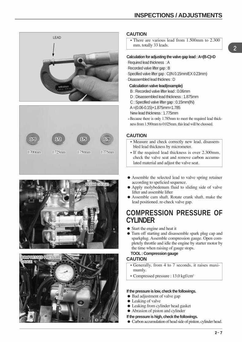
Calculation for adjusting the valve gap lead : A=(B-C)=D- Required lead thickness : A- Recorded valve lifter gap : B - Specified valve lifter gap : C(IN 0.15mm/EX 0.23mm) - Disassembled lead thicknes : D
Calculation valve lead(example) B : Recorded valve lifter lead : 0.06mmD : Disassembled lead thickness : 1.875mm C : Specified valve lifter gap : 0.15mm(IN)A=(0.06-0.15)+1.875mm=1.785New lead thickness : 1.775mm Because there is only 1.785mm to meet the required lead thick-ness from 1.500mm to 0.025mm, this lead will be choosed.
Assemble the selected lead to valve spring retaineraccording to speficied sequence.
Apply molybedenum fluid to sliding side of valvelifter and assemble lifter
Assemble cam shaft. Rotate crank shaft, make thelead positioned, re-check valve gap.
If the pressure is low, check the followings. Bad adjustment of valve gap Leaking of valve Leaking from cylinder head gasket Abrasion of piston and cylinderIf the pressure is high, check the followings. Carbon accumulation of head side of pistion, cylinder head.
LEAD
170170170170170170170170170170170170170170170170170170170170170170 172172172172172172172172172172172172172172172172172172172172172172 175175175175175175175175175175175175175175175175175175175175175175 178178178178178178178178178178178178178178178178178178178178178178
1.700mm1.700mm1.700mm1.700mm1.700mm1.700mm1.700mm1.700mm1.700mm1.700mm1.700mm1.700mm1.700mm1.700mm1.700mm1.700mm1.700mm1.700mm1.700mm1.700mm1.700mm1.700mm 1.725mm1.725mm1.725mm1.725mm1.725mm1.725mm1.725mm1.725mm1.725mm1.725mm1.725mm1.725mm1.725mm1.725mm1.725mm1.725mm1.725mm1.725mm1.725mm1.725mm1.725mm1.725mm 1.750mm1.750mm1.750mm1.750mm1.750mm1.750mm1.750mm1.750mm1.750mm1.750mm1.750mm1.750mm1.750mm1.750mm1.750mm1.750mm1.750mm1.750mm1.750mm1.750mm1.750mm1.750mm 1.775mm1.775mm1.775mm1.775mm1.775mm1.775mm1.775mm1.775mm1.775mm1.775mm1.775mm1.775mm1.775mm1.775mm1.775mm1.775mm1.775mm1.775mm1.775mm1.775mm1.775mm1.775mm
PILLAR GAUGEPILLAR GAUGEPILLAR GAUGEPILLAR GAUGEPILLAR GAUGEPILLAR GAUGEPILLAR GAUGEPILLAR GAUGEPILLAR GAUGEPILLAR GAUGEPILLAR GAUGEPILLAR GAUGEPILLAR GAUGEPILLAR GAUGEPILLAR GAUGEPILLAR GAUGEPILLAR GAUGEPILLAR GAUGEPILLAR GAUGEPILLAR GAUGEPILLAR GAUGEPILLAR GAUGEPILLAR GAUGEPILLAR GAUGEPILLAR GAUGEPILLAR GAUGEPILLAR GAUGE
COMPRESSED PRESSUREGAUGECOMPRESSED PRESSUREGAUGECOMPRESSED PRESSUREGAUGECOMPRESSED PRESSUREGAUGECOMPRESSED PRESSUREGAUGECOMPRESSED PRESSUREGAUGECOMPRESSED PRESSUREGAUGECOMPRESSED PRESSUREGAUGECOMPRESSED PRESSUREGAUGECOMPRESSED PRESSUREGAUGECOMPRESSED PRESSUREGAUGECOMPRESSED PRESSUREGAUGECOMPRESSED PRESSUREGAUGECOMPRESSED PRESSUREGAUGECOMPRESSED PRESSUREGAUGECOMPRESSED PRESSUREGAUGECOMPRESSED PRESSUREGAUGECOMPRESSED PRESSUREGAUGECOMPRESSED PRESSUREGAUGECOMPRESSED PRESSUREGAUGECOMPRESSED PRESSUREGAUGECOMPRESSED PRESSUREGAUGECOMPRESSED PRESSUREGAUGECOMPRESSED PRESSUREGAUGECOMPRESSED PRESSUREGAUGECOMPRESSED PRESSUREGAUGECOMPRESSED PRESSUREGAUGE
COMPRESSION PRESSURE OFCYLINDER Start the engine and heat it Turn off starting and disassemble spark plug cap and
sparkplug. Assemble compression gauge. Open com-pletely throttle and idle the engine by starter motor bythe time when raising of gauge stops. TOOL : Compression gauge
INSPECTIONS / ADJUSTMENTS
CAUTION•There are various lead from 1.500mm to 2.300
mm, totally 33 leads.
CAUTION•Measure and check correctly new lead, disassem-
bled lead thickness by micrometer. •If the required lead thickness is over 2.300mm,
check the valve seat and remove carbon accumu-lated material and adjust the valve seat.
CAUTION•Generally, from 4 to 7 seconds, it raises maxi-
mumly. •Compressed pressure : 13.0 kgf/cm2
UPPER LINEUPPER LINEUPPER LINEUPPER LINEUPPER LINEUPPER LINEUPPER LINEUPPER LINEUPPER LINEUPPER LINEUPPER LINEUPPER LINEUPPER LINEUPPER LINEUPPER LINEUPPER LINEUPPER LINEUPPER LINEUPPER LINEUPPER LINEUPPER LINEUPPER LINEUPPER LINEUPPER LINEUPPER LINEUPPER LINEUPPER LINE
LOWER LINELOWER LINELOWER LINELOWER LINELOWER LINELOWER LINELOWER LINELOWER LINELOWER LINELOWER LINELOWER LINELOWER LINELOWER LINELOWER LINELOWER LINELOWER LINELOWER LINELOWER LINELOWER LINELOWER LINELOWER LINELOWER LINELOWER LINELOWER LINELOWER LINELOWER LINELOWER LINE
OIL LEVEL GAUGEOIL LEVEL GAUGEOIL LEVEL GAUGEOIL LEVEL GAUGEOIL LEVEL GAUGEOIL LEVEL GAUGEOIL LEVEL GAUGEOIL LEVEL GAUGEOIL LEVEL GAUGEOIL LEVEL GAUGEOIL LEVEL GAUGEOIL LEVEL GAUGEOIL LEVEL GAUGEOIL LEVEL GAUGEOIL LEVEL GAUGEOIL LEVEL GAUGEOIL LEVEL GAUGEOIL LEVEL GAUGEOIL LEVEL GAUGEOIL LEVEL GAUGEOIL LEVEL GAUGEOIL LEVEL GAUGEOIL LEVEL GAUGEOIL LEVEL GAUGEOIL LEVEL GAUGEOIL LEVEL GAUGEOIL LEVEL GAUGE
OIL INLETOIL INLETOIL INLETOIL INLETOIL INLETOIL INLETOIL INLETOIL INLETOIL INLETOIL INLETOIL INLETOIL INLETOIL INLETOIL INLETOIL INLETOIL INLETOIL INLETOIL INLETOIL INLETOIL INLETOIL INLETOIL INLETOIL INLETOIL INLETOIL INLETOIL INLETOIL INLET
DRAIN BOLTDRAIN BOLTDRAIN BOLTDRAIN BOLTDRAIN BOLTDRAIN BOLTDRAIN BOLTDRAIN BOLTDRAIN BOLTDRAIN BOLTDRAIN BOLTDRAIN BOLTDRAIN BOLTDRAIN BOLTDRAIN BOLTDRAIN BOLTDRAIN BOLTDRAIN BOLTDRAIN BOLTDRAIN BOLTDRAIN BOLTDRAIN BOLTDRAIN BOLTDRAIN BOLTDRAIN BOLTDRAIN BOLTDRAIN BOLT
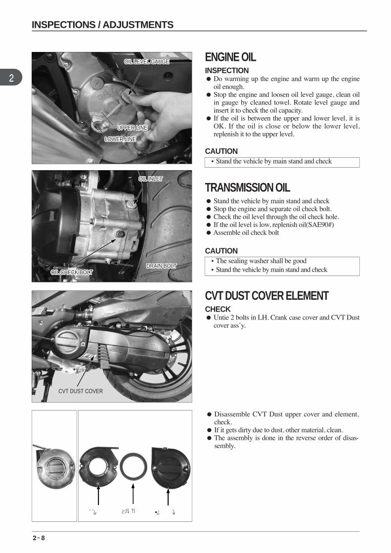
Disassemble CVT Dust upper cover and element,check.
If it gets dirty due to dust, other material, clean. The assembly is done in the reverse order of disas-
sembly.
OIL CHECK BOLTOIL CHECK BOLTOIL CHECK BOLTOIL CHECK BOLTOIL CHECK BOLTOIL CHECK BOLTOIL CHECK BOLTOIL CHECK BOLTOIL CHECK BOLTOIL CHECK BOLTOIL CHECK BOLTOIL CHECK BOLTOIL CHECK BOLTOIL CHECK BOLTOIL CHECK BOLTOIL CHECK BOLTOIL CHECK BOLTOIL CHECK BOLTOIL CHECK BOLTOIL CHECK BOLTOIL CHECK BOLTOIL CHECK BOLTOIL CHECK BOLTOIL CHECK BOLTOIL CHECK BOLTOIL CHECK BOLTOIL CHECK BOLT
CVT DUST COVER
¿⁄‚fi‚fi¿„ •¿ ¿„
INSPECTIONS / ADJUSTMENTS
ENGINE OILINSPECTION Do warming up the engine and warm up the engine
oil enough. Stop the engine and loosen oil level gauge, clean oil
in gauge by cleaned towel. Rotate level gauge andinsert it to check the oil capacity.
If the oil is between the upper and lower level, it isOK. If the oil is close or below the lower level,replenish it to the upper level.
TRANSMISSION OIL Stand the vehicle by main stand and check Stop the engine and separate oil check bolt. Check the oil level through the oil check hole. If the oil level is low, replenish oil(SAE90#) Assemble oil check bolt
CVT DUST COVER ELEMENT CHECK Untie 2 bolts in LH. Crank case cover and CVT Dust
cover ass’y.
CAUTION•Stand the vehicle by main stand and check
CAUTION•The sealing washer shall be good •Stand the vehicle by main stand and check
Replenish the cooling water to the reserve tank.
The capacity of cooling water : 1,500¡20cc
Start the engine and remove air of cooling water,check whether the level of cooling water is stable ornot.
Close the reserve tank cap.
DRIVE BOLTDRIVE BOLTDRIVE BOLTDRIVE BOLTDRIVE BOLTDRIVE BOLTDRIVE BOLTDRIVE BOLTDRIVE BOLTDRIVE BOLTDRIVE BOLTDRIVE BOLTDRIVE BOLTDRIVE BOLTDRIVE BOLTDRIVE BOLTDRIVE BOLTDRIVE BOLTDRIVE BOLTDRIVE BOLTDRIVE BOLTDRIVE BOLTDRIVE BOLTDRIVE BOLTDRIVE BOLTDRIVE BOLTDRIVE BOLT
HIGHHIGHHIGHHIGHHIGHHIGHHIGHHIGHHIGHHIGHHIGHHIGHHIGHHIGHHIGHHIGHHIGHHIGHHIGHHIGHHIGHHIGHHIGHHIGHHIGHHIGHHIGH
LOWERLOWERLOWERLOWERLOWERLOWERLOWERLOWERLOWERLOWERLOWERLOWERLOWERLOWERLOWERLOWERLOWERLOWERLOWERLOWERLOWERLOWERLOWERLOWERLOWERLOWERLOWER
COOLING WATERDRAIN BOLT
COOLING WATERDRAIN BOLT
COOLING WATERDRAIN BOLT
COOLING WATERDRAIN BOLT
COOLING WATERDRAIN BOLT
COOLING WATERDRAIN BOLT
COOLING WATERDRAIN BOLT
COOLING WATERDRAIN BOLT
COOLING WATERDRAIN BOLT
COOLING WATERDRAIN BOLT
COOLING WATERDRAIN BOLT
COOLING WATERDRAIN BOLT
COOLING WATERDRAIN BOLT
COOLING WATERDRAIN BOLT
COOLING WATERDRAIN BOLT
COOLING WATERDRAIN BOLT
COOLING WATERDRAIN BOLT
COOLING WATERDRAIN BOLT
COOLING WATERDRAIN BOLT
COOLING WATERDRAIN BOLT
COOLING WATERDRAIN BOLT
COOLING WATERDRAIN BOLT
COOLING WATERDRAIN BOLT
COOLING WATERDRAIN BOLT
COOLING WATERDRAIN BOLT
COOLING WATERDRAIN BOLT
COOLING WATERDRAIN BOLT
RESERVE TANKRESERVE TANKRESERVE TANKRESERVE TANKRESERVE TANKRESERVE TANKRESERVE TANKRESERVE TANKRESERVE TANKRESERVE TANKRESERVE TANKRESERVE TANKRESERVE TANKRESERVE TANKRESERVE TANKRESERVE TANKRESERVE TANKRESERVE TANKRESERVE TANKRESERVE TANKRESERVE TANKRESERVE TANKRESERVE TANKRESERVE TANKRESERVE TANKRESERVE TANKRESERVE TANK
INSPECTIONS / ADJUSTMENTS
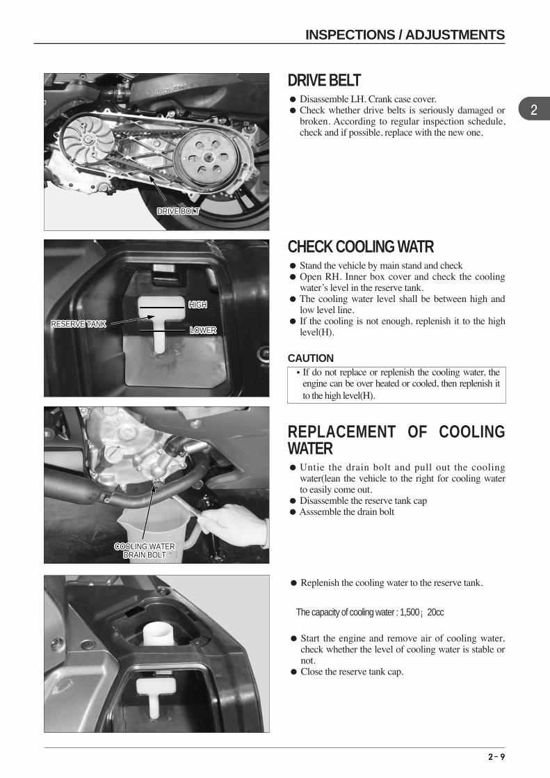
DRIVE BELT Disassemble LH. Crank case cover. Check whether drive belts is seriously damaged or
broken. According to regular inspection schedule,check and if possible, replace with the new one.
CHECK COOLING WATR Stand the vehicle by main stand and check Open RH. Inner box cover and check the cooling
water’s level in the reserve tank. The cooling water level shall be between high and
low level line. If the cooling is not enough, replenish it to the high
level(H).
REPLACEMENT OF COOLINGWATER Untie the drain bolt and pull out the cooling
water(lean the vehicle to the right for cooling waterto easily come out.
Disassemble the reserve tank cap Asssemble the drain bolt
CAUTION•If do not replace or replenish the cooling water, the
engine can be over heated or cooled, then replenish itto the high level(H).
CHECK CAPACITY OFBRAKEFLUID
CHECK CAPACITY OFBRAKEFLUID
CHECK CAPACITY OFBRAKEFLUID
CHECK CAPACITY OFBRAKEFLUID
CHECK CAPACITY OFBRAKEFLUID
CHECK CAPACITY OFBRAKEFLUID
CHECK CAPACITY OFBRAKEFLUID
CHECK CAPACITY OFBRAKEFLUID
CHECK CAPACITY OFBRAKEFLUID
CHECK CAPACITY OFBRAKEFLUID
CHECK CAPACITY OFBRAKEFLUID
CHECK CAPACITY OFBRAKEFLUID
CHECK CAPACITY OFBRAKEFLUID
CHECK CAPACITY OFBRAKEFLUID
CHECK CAPACITY OFBRAKEFLUID
CHECK CAPACITY OFBRAKEFLUID
CHECK CAPACITY OFBRAKEFLUID
CHECK CAPACITY OFBRAKEFLUID
CHECK CAPACITY OFBRAKEFLUID
CHECK CAPACITY OFBRAKEFLUID
CHECK CAPACITY OFBRAKEFLUID
CHECK CAPACITY OFBRAKEFLUID
CHECK CAPACITY OFBRAKEFLUID
CHECK CAPACITY OFBRAKEFLUID
CHECK CAPACITY OFBRAKEFLUID
CHECK CAPACITY OFBRAKEFLUID
CHECK CAPACITY OFBRAKEFLUID
BRAKEPAD
ABRASION LIMIT
BRAKEPAD
ABRASION LIMIT
10~20mm10~20mm10~20mm10~20mm10~20mm10~20mm10~20mm10~20mm10~20mm10~20mm10~20mm10~20mm10~20mm10~20mm10~20mm10~20mm10~20mm10~20mm10~20mm10~20mm10~20mm10~20mm10~20mm10~20mm10~20mm10~20mm10~20mm10~20mm10~20mm10~20mm10~20mm10~20mm10~20mm10~20mm10~20mm10~20mm10~20mmREAR BRAKE LEVERREAR BRAKE LEVERREAR BRAKE LEVERREAR BRAKE LEVERREAR BRAKE LEVERREAR BRAKE LEVERREAR BRAKE LEVERREAR BRAKE LEVERREAR BRAKE LEVERREAR BRAKE LEVERREAR BRAKE LEVERREAR BRAKE LEVERREAR BRAKE LEVERREAR BRAKE LEVERREAR BRAKE LEVERREAR BRAKE LEVERREAR BRAKE LEVERREAR BRAKE LEVERREAR BRAKE LEVERREAR BRAKE LEVERREAR BRAKE LEVERREAR BRAKE LEVERREAR BRAKE LEVERREAR BRAKE LEVERREAR BRAKE LEVERREAR BRAKE LEVERREAR BRAKE LEVER
BRAKE HOSEBRAKE HOSEBRAKE HOSEBRAKE HOSEBRAKE HOSEBRAKE HOSEBRAKE HOSEBRAKE HOSEBRAKE HOSEBRAKE HOSEBRAKE HOSEBRAKE HOSEBRAKE HOSEBRAKE HOSEBRAKE HOSEBRAKE HOSEBRAKE HOSEBRAKE HOSEBRAKE HOSEBRAKE HOSEBRAKE HOSEBRAKE HOSEBRAKE HOSEBRAKE HOSEBRAKE HOSEBRAKE HOSEBRAKE HOSE
OIL CUP CAP
FRONT CALIPERFRONT CALIPERFRONT CALIPERFRONT CALIPERFRONT CALIPERFRONT CALIPERFRONT CALIPERFRONT CALIPERFRONT CALIPERFRONT CALIPERFRONT CALIPERFRONT CALIPERFRONT CALIPERFRONT CALIPERFRONT CALIPERFRONT CALIPERFRONT CALIPERFRONT CALIPERFRONT CALIPERFRONT CALIPERFRONT CALIPERFRONT CALIPERFRONT CALIPERFRONT CALIPERFRONT CALIPERFRONT CALIPERFRONT CALIPER REAR CALIPERREAR CALIPERREAR CALIPERREAR CALIPERREAR CALIPERREAR CALIPERREAR CALIPERREAR CALIPERREAR CALIPERREAR CALIPERREAR CALIPERREAR CALIPERREAR CALIPERREAR CALIPERREAR CALIPERREAR CALIPERREAR CALIPERREAR CALIPERREAR CALIPERREAR CALIPERREAR CALIPERREAR CALIPERREAR CALIPERREAR CALIPERREAR CALIPERREAR CALIPERREAR CALIPER
INSPECTIONS / ADJUSTMENTS
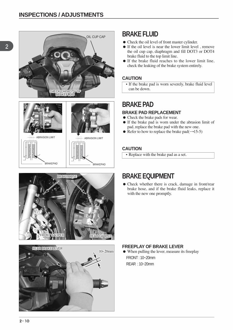
BRAKE FLUID Check the oil level of front master cylinder. If the oil level is near the lower limit level , remove
the oil cup cap, diaphragm and fill DOT3 or DOT4brake fluid to the top limit line.
If the brake fluid reaches to the lower limit line,check the leaking of the brake system entirely.
BRAKE PADBRAKE PAD REPLACEMENT Check the brake pads for wear. If the brake pad is worn under the abrasion limit of
pad, replace the brake pad with the new one. Refer to how to replace the brake pad( 15-5)
BRAKE EQUIPMENT Check whether there is crack, damage in front/rear
brake hose, and if the brake fluid leaks, replace itwith the new one promptly.
FREEPLAY OF BRAKE LEVER When pulling the lever, measure its freeplay
FRONT : 10~20mm
REAR : 10~20mm
CAUTION•If the brake pad is worn severely, brake fluid level
can be down.
CAUTION•Replace with the brake pad as a set.
INSPECTIONS / ADJUSTMENTS
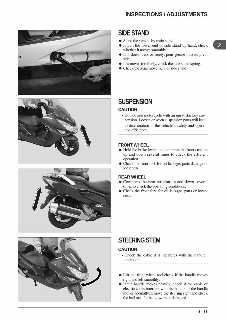
FRONT WHEEL Hold the brake lever, and compress the front cushion
up and down several times to check the efficientoperation.
Check the front fork for oil leakage, parts damage orlooseness.
REAR WHEEL Compress the near cushion up and down several
times to check the operating conditions. Check the front fork for oil leakage, parts or loose-
ness.
SIDE STAND Stand the vehicle by main stand If pull the lower end of side stand by hand, check
whether it moves smoothly. If it doesn’t move freely, pour grease into its pivot
side. If it moves too freely, check the side stand spring. Check the axial movement of side stand.
SUSPENSION
Lift the front wheel and check if the handle movesright and left smoothly.
If the handle moves heavily, check if the cable orelectric codes interfere with the handle. If the handlemoves normally, remove the steering stem and checkthe ball race for being worn or damaged.
STEERING STEM
CAUTION•Do not ride motorcycle with an unsatisfactory sus-
pension. Loosen or worn suspension parts will leadto deterioration in the vehicle’s safety and opera-tion efficiency.
CAUTION•Check the cable if it interferes with the handle
operation.
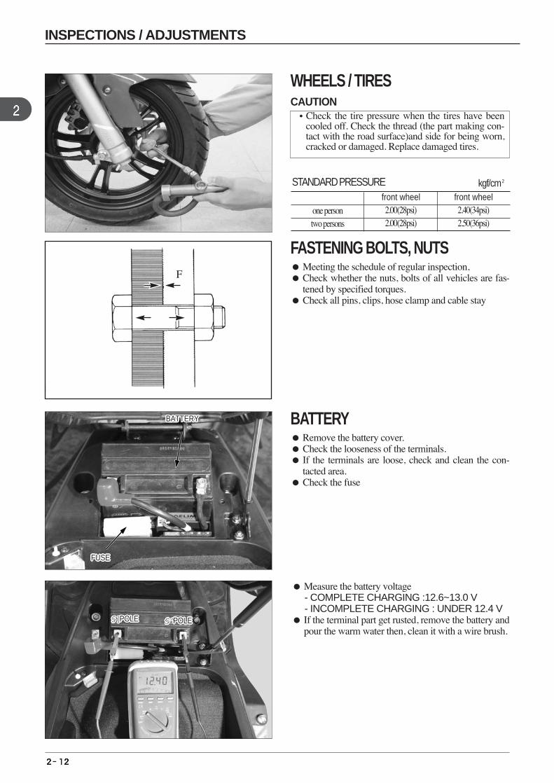
one persontwo persons
STANDARD PRESSURE kgf/cm2
front wheel2.00(28psi)2.00(28psi)
front wheel 2.40(34psi)2.50(36psi)
Measure the battery voltage - COMPLETE CHARGING :12.6~13.0 V- INCOMPLETE CHARGING : UNDER 12.4 V
If the terminal part get rusted, remove the battery andpour the warm water then, clean it with a wire brush.
F
F
BATTERYBATTERYBATTERYBATTERYBATTERYBATTERYBATTERYBATTERYBATTERYBATTERYBATTERYBATTERYBATTERYBATTERYBATTERYBATTERYBATTERYBATTERYBATTERYBATTERYBATTERYBATTERYBATTERYBATTERYBATTERYBATTERYBATTERY
FUSEFUSEFUSEFUSEFUSEFUSEFUSEFUSEFUSEFUSEFUSEFUSEFUSEFUSEFUSEFUSEFUSEFUSEFUSEFUSEFUSEFUSEFUSEFUSEFUSEFUSEFUSE
§]POLE§]POLE§]POLE§]POLE§]POLE§]POLE§]POLE§]POLE§]POLE§]POLE§]POLE§]POLE§]POLE§]POLE§]POLE§]POLE§]POLE§]POLE§]POLE§]POLE§]POLE§]POLE§]POLE§]POLE§]POLE§]POLE§]POLE § POLE§ POLE§ POLE§ POLE§ POLE§ POLE§ POLE§ POLE§ POLE§ POLE§ POLE§ POLE§ POLE§ POLE§ POLE§ POLE§ POLE§ POLE§ POLE§ POLE§ POLE§ POLE§ POLE§ POLE§ POLE§ POLE§ POLE
INSPECTIONS / ADJUSTMENTS
WHEELS / TIRES
FASTENING BOLTS, NUTS Meeting the schedule of regular inspection, Check whether the nuts, bolts of all vehicles are fas-
tened by specified torques. Check all pins, clips, hose clamp and cable stay
BATTERY Remove the battery cover. Check the looseness of the terminals. If the terminals are loose, check and clean the con-
tacted area. Check the fuse
CAUTION•Check the tire pressure when the tires have been
cooled off. Check the thread (the part making con-tact with the road surface)and side for being worn,cracked or damaged. Replace damaged tires.
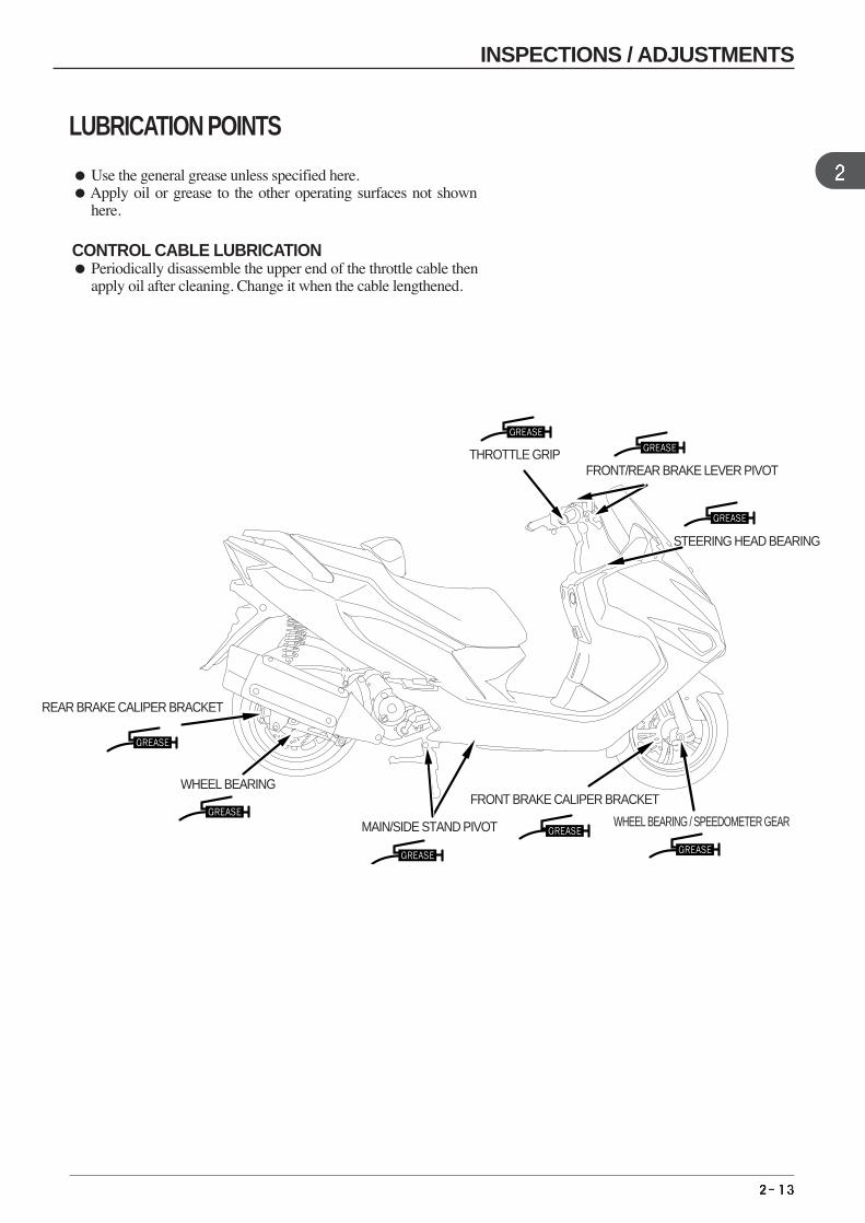
Use the general grease unless specified here.Apply oil or grease to the other operating surfaces not shown
here.
CONTROL CABLE LUBRICATION Periodically disassemble the upper end of the throttle cable then
apply oil after cleaning. Change it when the cable lengthened.
THROTTLE GRIP FRONT/REAR BRAKE LEVER PIVOT
STEERING HEAD BEARING
WHEEL BEARING / SPEEDOMETER GEAR
FRONT BRAKE CALIPER BRACKET
REAR BRAKE CALIPER BRACKET
MAIN/SIDE STAND PIVOT
WHEEL BEARING
INSPECTIONS / ADJUSTMENTS
LUBRICATION POINTS

MEMO
3. EXTERNAL PARTS
SERVICE INFORMATION
CAUTION
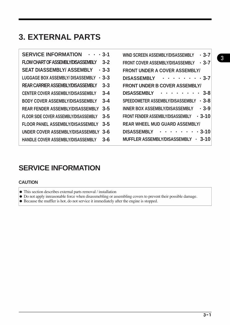
This section describes external parts removal / installation Do not apply inreasonable force when disassmebling or assembling covers to prevent their possible damage. Because the muffler is hot, do not service it immediately after the engine is stopped.
SERVICE INFORMATION ···3-1FLOW CHART OF ASSEMBLY/DISASSEMBLY 3-2SEAT DIASSEMBLY/ ASSEMBLY ·3-3LUGGAGE BOX ASSEMBLY/ DISASSEMBLY ·3-3REAR CARRIER ASSEMBLY/DISASSEMBLY 3-3CENTER COVER ASSEMBLY/DISASSEMBLY 3-4BODY COVER ASSEMBLY/DISASSEMBLY 3-4REAR FENDER ASSEMBLY/DISASSEMBLY 3-5FLOOR SIDE COVER ASSEMBLY/DISASSEMBLY 3-5FLOOR PANEL ASSEMBLY/DISASSEMBLY 3-5UNDER COVER ASSEMBLY/DISASSEMBLY 3-6HANDLE COVER ASSEMBLY/DISASSEMBLY 3-6
WIND SCREEN ASSEMBLY/DISASSEMBLY ·3-7FRONT COVER ASSEMBLY/DISASSEMBLY ·3-7FRONT UNDER A COVER ASSEMBLY/
DISASSEMBLY ········3-7FRONT UNDER B COVER ASSEMBLY/ DISASSEMBLY ········ 3-8SPEEDOMETER ASSEMBLY/DISASSEMBLY ·3-8INNER BOX ASSEMBLY/DISASSEMBLY ·3-9FRONT FENDER ASSEMBLY/DISASSEMBLY ·3-10REAR WHEEL MUD GUARD ASSEMBLY/
DISASSEMBLY ········3-10MUFFLER ASSEMBLY/DISASSEMBLY ·· 3-10
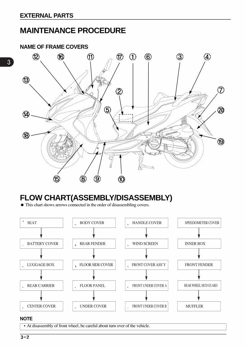
①SEAT
②BATTERY COVER
③LUGGAGE BOX
④REAR CARRIER
⑤CENTER COVER
⑥BODY COVER
⑦REAR FENDER
⑧FLOOR SIDE COVER
⑨FLOOR PANEL
⑩UNDER COVER
⑪HANDLE COVER
⑫WIND SCREEN
⑬FRONT COVER ASS’Y
⑭ FRONT UNDER COVER A
⑮ FRONT UNDER COVER B
⒃ SPEEDOMETER COVER
⒔ INNER BOX
⒕FRONT FENDER
⒖ REAR WHEEL MUD GUARD
⒗MUFFLER
This chart shows arrows connected in the order of disassembling covers. FLOW CHART(ASSEMBLY/DISASSEMBLY)
NOTE•At disassembly of front wheel, be careful about turn over of the vehicle.
EXTERNAL PARTS
MAINTENANCE PROCEDURE
NAME OF FRAME COVERS
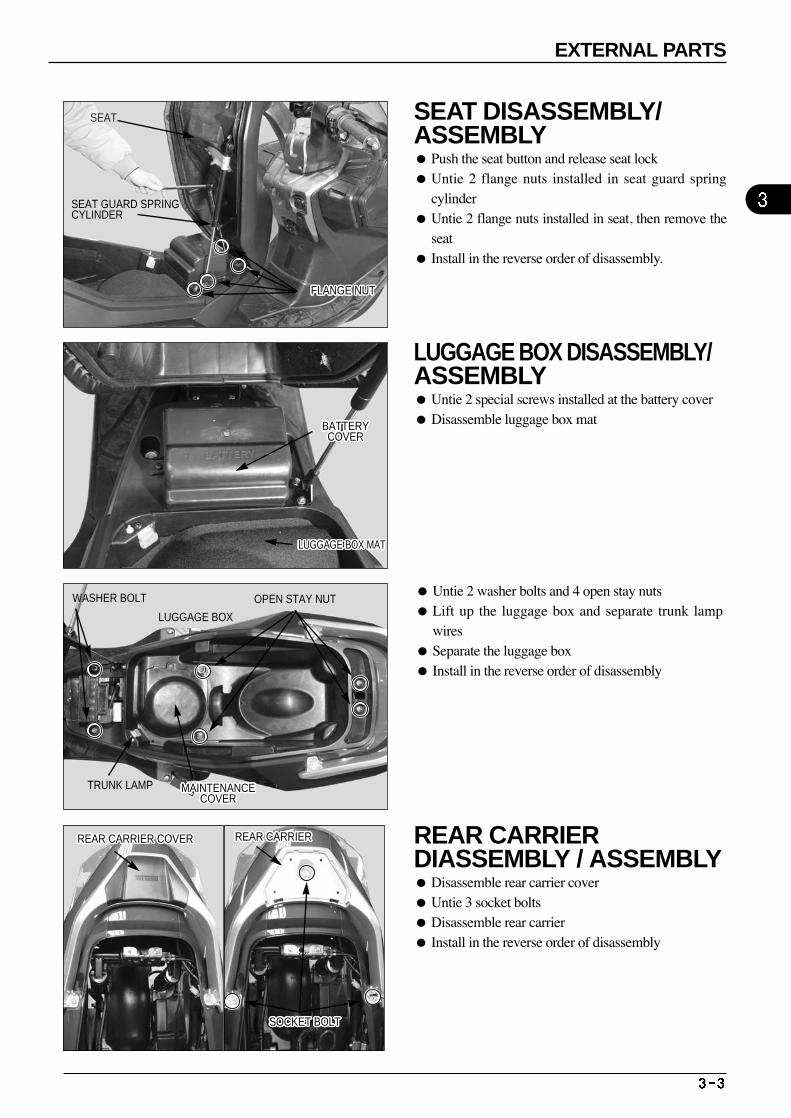
Untie 2 washer bolts and 4 open stay nuts Lift up the luggage box and separate trunk lamp
wires Separate the luggage box Install in the reverse order of disassembly
SEAT
FLANGE NUTFLANGE NUTFLANGE NUTFLANGE NUTFLANGE NUTFLANGE NUTFLANGE NUTFLANGE NUTFLANGE NUTFLANGE NUTFLANGE NUTFLANGE NUTFLANGE NUTFLANGE NUTFLANGE NUTFLANGE NUTFLANGE NUTFLANGE NUTFLANGE NUTFLANGE NUTFLANGE NUTFLANGE NUTFLANGE NUTFLANGE NUTFLANGE NUTFLANGE NUTFLANGE NUT
SEAT GUARD SPRINGCYLINDER
LUGGAGE BOX MATLUGGAGE BOX MATLUGGAGE BOX MATLUGGAGE BOX MATLUGGAGE BOX MATLUGGAGE BOX MATLUGGAGE BOX MATLUGGAGE BOX MATLUGGAGE BOX MATLUGGAGE BOX MATLUGGAGE BOX MATLUGGAGE BOX MATLUGGAGE BOX MATLUGGAGE BOX MATLUGGAGE BOX MATLUGGAGE BOX MATLUGGAGE BOX MATLUGGAGE BOX MATLUGGAGE BOX MATLUGGAGE BOX MATLUGGAGE BOX MATLUGGAGE BOX MATLUGGAGE BOX MATLUGGAGE BOX MATLUGGAGE BOX MATLUGGAGE BOX MATLUGGAGE BOX MAT
BATTERYCOVER
BATTERYCOVER
BATTERYCOVER
BATTERYCOVER
BATTERYCOVER
BATTERYCOVER
BATTERYCOVER
BATTERYCOVER
BATTERYCOVER
BATTERYCOVER
BATTERYCOVER
BATTERYCOVER
BATTERYCOVER
BATTERYCOVER
BATTERYCOVER
BATTERYCOVER
BATTERYCOVER
BATTERYCOVER
BATTERYCOVER
BATTERYCOVER
BATTERYCOVER
BATTERYCOVER
BATTERYCOVER
BATTERYCOVER
BATTERYCOVER
BATTERYCOVER
BATTERYCOVER
WASHER BOLT
LUGGAGE BOX
TRUNK LAMP MAINTENANCECOVER
MAINTENANCECOVER
MAINTENANCECOVER
MAINTENANCECOVER
MAINTENANCECOVER
MAINTENANCECOVER
MAINTENANCECOVER
MAINTENANCECOVER
MAINTENANCECOVER
MAINTENANCECOVER
MAINTENANCECOVER
MAINTENANCECOVER
MAINTENANCECOVER
MAINTENANCECOVER
MAINTENANCECOVER
MAINTENANCECOVER
MAINTENANCECOVER
MAINTENANCECOVER
MAINTENANCECOVER
MAINTENANCECOVER
MAINTENANCECOVER
MAINTENANCECOVER
MAINTENANCECOVER
MAINTENANCECOVER
MAINTENANCECOVER
MAINTENANCECOVER
MAINTENANCECOVER
REAR CARRIER COVERREAR CARRIER COVERREAR CARRIER COVERREAR CARRIER COVERREAR CARRIER COVERREAR CARRIER COVERREAR CARRIER COVERREAR CARRIER COVERREAR CARRIER COVERREAR CARRIER COVERREAR CARRIER COVERREAR CARRIER COVERREAR CARRIER COVERREAR CARRIER COVERREAR CARRIER COVERREAR CARRIER COVERREAR CARRIER COVERREAR CARRIER COVERREAR CARRIER COVERREAR CARRIER COVERREAR CARRIER COVERREAR CARRIER COVERREAR CARRIER COVERREAR CARRIER COVERREAR CARRIER COVERREAR CARRIER COVERREAR CARRIER COVER REAR CARRIERREAR CARRIERREAR CARRIERREAR CARRIERREAR CARRIERREAR CARRIERREAR CARRIERREAR CARRIERREAR CARRIERREAR CARRIERREAR CARRIERREAR CARRIERREAR CARRIERREAR CARRIERREAR CARRIERREAR CARRIERREAR CARRIERREAR CARRIERREAR CARRIERREAR CARRIERREAR CARRIERREAR CARRIERREAR CARRIERREAR CARRIERREAR CARRIERREAR CARRIERREAR CARRIER
SOCKET BOLTSOCKET BOLTSOCKET BOLTSOCKET BOLTSOCKET BOLTSOCKET BOLTSOCKET BOLTSOCKET BOLTSOCKET BOLTSOCKET BOLTSOCKET BOLTSOCKET BOLTSOCKET BOLTSOCKET BOLTSOCKET BOLTSOCKET BOLTSOCKET BOLTSOCKET BOLTSOCKET BOLTSOCKET BOLTSOCKET BOLTSOCKET BOLTSOCKET BOLTSOCKET BOLTSOCKET BOLTSOCKET BOLTSOCKET BOLT
OPEN STAY NUT
EXTERNAL PARTS
SEAT DISASSEMBLY/ ASSEMBLY Push the seat button and release seat lock Untie 2 flange nuts installed in seat guard spring
cylinder Untie 2 flange nuts installed in seat, then remove the
seat Install in the reverse order of disassembly.
LUGGAGE BOX DISASSEMBLY/ASSEMBLY Untie 2 special screws installed at the battery cover Disassemble luggage box mat
REAR CARRIER DIASSEMBLY / ASSEMBLY Disassemble rear carrier cover Untie 3 socket bolts Disassemble rear carrier Install in the reverse order of disassembly
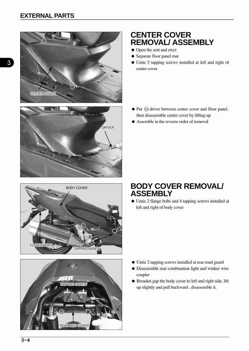
Put driver between center cover and floor panel,then disassemble center cover by lifting up
Assemble in the reverse order of removal
Untie 2 tapping screws installed at rear mud guard Disassemble rear combination light and winker wire
coupler Broaden gap the body cover to left and right side, lift
up slightly and pull backward , disassemble it.
CENTER COVERCENTER COVERCENTER COVERCENTER COVERCENTER COVERCENTER COVERCENTER COVERCENTER COVERCENTER COVERCENTER COVERCENTER COVERCENTER COVERCENTER COVERCENTER COVERCENTER COVERCENTER COVERCENTER COVERCENTER COVERCENTER COVERCENTER COVERCENTER COVERCENTER COVERCENTER COVERCENTER COVERCENTER COVERCENTER COVERCENTER COVER
BODY COVER
TAPPING SCREWTAPPING SCREWTAPPING SCREWTAPPING SCREWTAPPING SCREWTAPPING SCREWTAPPING SCREWTAPPING SCREWTAPPING SCREWTAPPING SCREWTAPPING SCREWTAPPING SCREWTAPPING SCREWTAPPING SCREWTAPPING SCREWTAPPING SCREWTAPPING SCREWTAPPING SCREWTAPPING SCREWTAPPING SCREWTAPPING SCREWTAPPING SCREWTAPPING SCREWTAPPING SCREWTAPPING SCREWTAPPING SCREWTAPPING SCREWFLANGE BOLTFLANGE BOLTFLANGE BOLTFLANGE BOLTFLANGE BOLTFLANGE BOLTFLANGE BOLTFLANGE BOLTFLANGE BOLTFLANGE BOLTFLANGE BOLTFLANGE BOLTFLANGE BOLTFLANGE BOLTFLANGE BOLTFLANGE BOLTFLANGE BOLTFLANGE BOLTFLANGE BOLTFLANGE BOLTFLANGE BOLTFLANGE BOLTFLANGE BOLTFLANGE BOLTFLANGE BOLTFLANGE BOLTFLANGE BOLT
TAPPING SCREWTAPPING SCREWTAPPING SCREWTAPPING SCREWTAPPING SCREWTAPPING SCREWTAPPING SCREWTAPPING SCREWTAPPING SCREWTAPPING SCREWTAPPING SCREWTAPPING SCREWTAPPING SCREWTAPPING SCREWTAPPING SCREWTAPPING SCREWTAPPING SCREWTAPPING SCREWTAPPING SCREWTAPPING SCREWTAPPING SCREWTAPPING SCREWTAPPING SCREWTAPPING SCREWTAPPING SCREWTAPPING SCREWTAPPING SCREW
REAR MUD GUARDREAR MUD GUARDREAR MUD GUARDREAR MUD GUARDREAR MUD GUARDREAR MUD GUARDREAR MUD GUARDREAR MUD GUARDREAR MUD GUARDREAR MUD GUARDREAR MUD GUARDREAR MUD GUARDREAR MUD GUARDREAR MUD GUARDREAR MUD GUARDREAR MUD GUARDREAR MUD GUARDREAR MUD GUARDREAR MUD GUARDREAR MUD GUARDREAR MUD GUARDREAR MUD GUARDREAR MUD GUARDREAR MUD GUARDREAR MUD GUARDREAR MUD GUARDREAR MUD GUARD
⊖DRIVER⊖DRIVER⊖DRIVER⊖DRIVER⊖DRIVER⊖DRIVER⊖DRIVER⊖DRIVER⊖DRIVER⊖DRIVER⊖DRIVER⊖DRIVER⊖DRIVER⊖DRIVER⊖DRIVER⊖DRIVER⊖DRIVER⊖DRIVER⊖DRIVER⊖DRIVER⊖DRIVER⊖DRIVER⊖DRIVER⊖DRIVER⊖DRIVER⊖DRIVER⊖DRIVER
EXTERNAL PARTS
CENTER COVER REMOVAL/ ASSEMBLY Open the seat and erect Separate floor panel mat Untie 5 tapping screws installed at left and right of
center cover
BODY COVER REMOVAL/ ASSEMBLY Untie 2 flange bolts and 4 tapping screws installed at
left and right of body cover
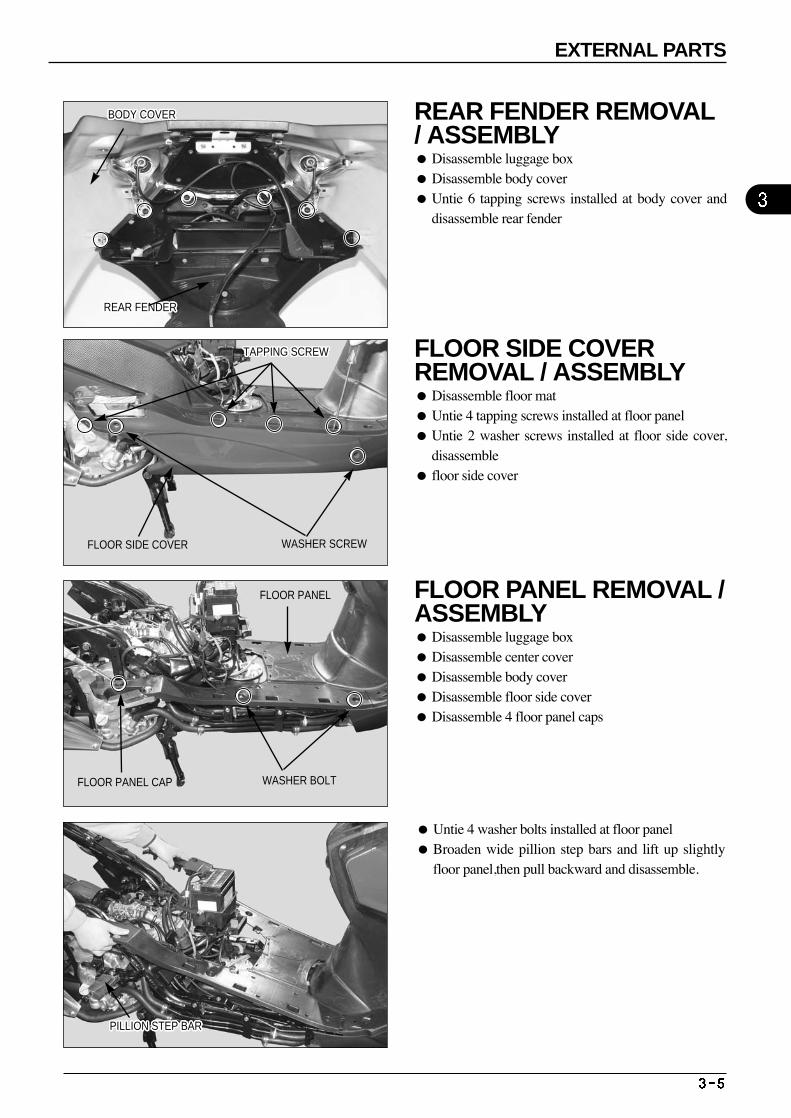
Untie 4 washer bolts installed at floor panel Broaden wide pillion step bars and lift up slightly
floor panel,then pull backward and disassemble.
REAR FENDERREAR FENDERREAR FENDERREAR FENDERREAR FENDERREAR FENDERREAR FENDERREAR FENDERREAR FENDERREAR FENDERREAR FENDERREAR FENDERREAR FENDERREAR FENDERREAR FENDERREAR FENDERREAR FENDERREAR FENDERREAR FENDERREAR FENDERREAR FENDERREAR FENDERREAR FENDERREAR FENDERREAR FENDERREAR FENDERREAR FENDER
BODY COVERBODY COVERBODY COVERBODY COVERBODY COVERBODY COVERBODY COVERBODY COVERBODY COVERBODY COVERBODY COVERBODY COVERBODY COVERBODY COVERBODY COVERBODY COVERBODY COVERBODY COVERBODY COVERBODY COVERBODY COVERBODY COVERBODY COVERBODY COVERBODY COVERBODY COVERBODY COVER
WASHER SCREW
WASHER BOLT
FLOOR SIDE COVER
TAPPING SCREWTAPPING SCREWTAPPING SCREWTAPPING SCREWTAPPING SCREWTAPPING SCREWTAPPING SCREWTAPPING SCREWTAPPING SCREWTAPPING SCREWTAPPING SCREWTAPPING SCREWTAPPING SCREWTAPPING SCREWTAPPING SCREWTAPPING SCREWTAPPING SCREWTAPPING SCREWTAPPING SCREWTAPPING SCREWTAPPING SCREWTAPPING SCREWTAPPING SCREWTAPPING SCREWTAPPING SCREWTAPPING SCREWTAPPING SCREW
FLOOR PANEL
FLOOR PANEL CAP
PILLION STEP BARPILLION STEP BARPILLION STEP BARPILLION STEP BARPILLION STEP BARPILLION STEP BARPILLION STEP BARPILLION STEP BARPILLION STEP BARPILLION STEP BARPILLION STEP BARPILLION STEP BARPILLION STEP BARPILLION STEP BARPILLION STEP BARPILLION STEP BARPILLION STEP BARPILLION STEP BARPILLION STEP BARPILLION STEP BARPILLION STEP BARPILLION STEP BARPILLION STEP BARPILLION STEP BARPILLION STEP BARPILLION STEP BARPILLION STEP BAR
EXTERNAL PARTS
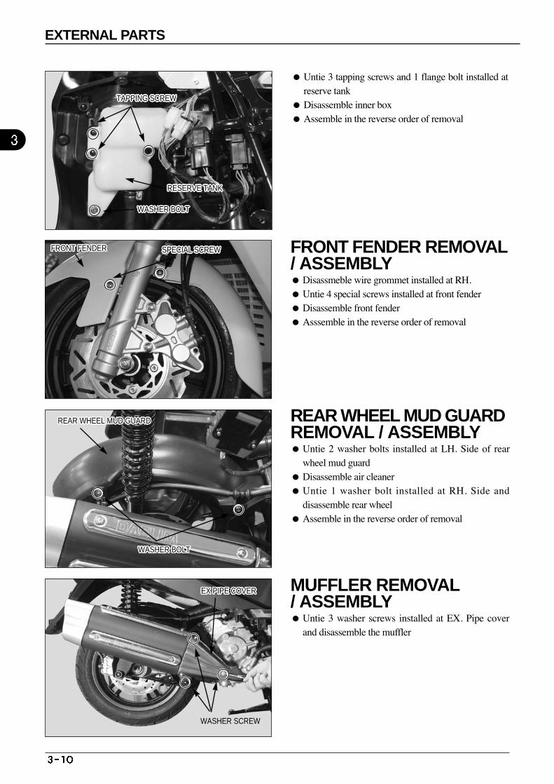
REAR FENDER REMOVAL / ASSEMBLY Disassemble luggage box Disassemble body cover Untie 6 tapping screws installed at body cover and
disassemble rear fender
FLOOR SIDE COVER REMOVAL / ASSEMBLY Disassemble floor mat Untie 4 tapping screws installed at floor panel Untie 2 washer screws installed at floor side cover,
disassemble floor side cover
FLOOR PANEL REMOVAL / ASSEMBLY Disassemble luggage box Disassemble center cover Disassemble body cover Disassemble floor side cover Disassemble 4 floor panel caps
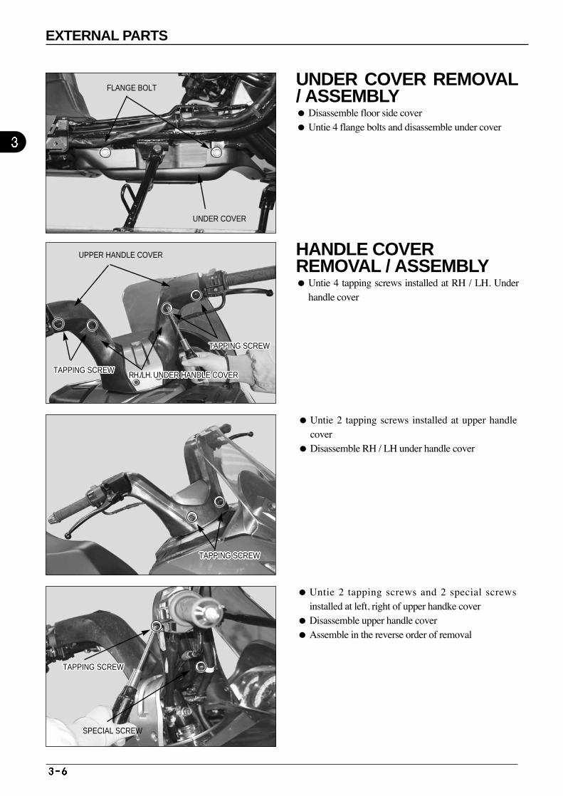
Untie 2 tapping screws installed at upper handlecover
Disassemble RH / LH under handle cover
Untie 2 tapping screws and 2 special screwsinstalled at left, right of upper handke cover
Disassemble upper handle cover Assemble in the reverse order of removal
SPECIAL SCREW
FLANGE BOLT
UNDER COVER
UPPER HANDLE COVER
TAPPING SCREWTAPPING SCREWTAPPING SCREWTAPPING SCREWTAPPING SCREWTAPPING SCREWTAPPING SCREWTAPPING SCREWTAPPING SCREWTAPPING SCREWTAPPING SCREWTAPPING SCREWTAPPING SCREWTAPPING SCREWTAPPING SCREWTAPPING SCREWTAPPING SCREWTAPPING SCREWTAPPING SCREWTAPPING SCREWTAPPING SCREWTAPPING SCREWTAPPING SCREWTAPPING SCREWTAPPING SCREWTAPPING SCREWTAPPING SCREWRH./LH. UNDER HANDLE COVERRH./LH. UNDER HANDLE COVERRH./LH. UNDER HANDLE COVERRH./LH. UNDER HANDLE COVERRH./LH. UNDER HANDLE COVERRH./LH. UNDER HANDLE COVERRH./LH. UNDER HANDLE COVERRH./LH. UNDER HANDLE COVERRH./LH. UNDER HANDLE COVERRH./LH. UNDER HANDLE COVERRH./LH. UNDER HANDLE COVERRH./LH. UNDER HANDLE COVERRH./LH. UNDER HANDLE COVERRH./LH. UNDER HANDLE COVERRH./LH. UNDER HANDLE COVERRH./LH. UNDER HANDLE COVERRH./LH. UNDER HANDLE COVERRH./LH. UNDER HANDLE COVERRH./LH. UNDER HANDLE COVERRH./LH. UNDER HANDLE COVERRH./LH. UNDER HANDLE COVERRH./LH. UNDER HANDLE COVERRH./LH. UNDER HANDLE COVERRH./LH. UNDER HANDLE COVERRH./LH. UNDER HANDLE COVERRH./LH. UNDER HANDLE COVERRH./LH. UNDER HANDLE COVER
TAPPING SCREWTAPPING SCREWTAPPING SCREWTAPPING SCREWTAPPING SCREWTAPPING SCREWTAPPING SCREWTAPPING SCREWTAPPING SCREWTAPPING SCREWTAPPING SCREWTAPPING SCREWTAPPING SCREWTAPPING SCREWTAPPING SCREWTAPPING SCREWTAPPING SCREWTAPPING SCREWTAPPING SCREWTAPPING SCREWTAPPING SCREWTAPPING SCREWTAPPING SCREWTAPPING SCREWTAPPING SCREWTAPPING SCREWTAPPING SCREW
TAPPING SCREWTAPPING SCREWTAPPING SCREWTAPPING SCREWTAPPING SCREWTAPPING SCREWTAPPING SCREWTAPPING SCREWTAPPING SCREWTAPPING SCREWTAPPING SCREWTAPPING SCREWTAPPING SCREWTAPPING SCREWTAPPING SCREWTAPPING SCREWTAPPING SCREWTAPPING SCREWTAPPING SCREWTAPPING SCREWTAPPING SCREWTAPPING SCREWTAPPING SCREWTAPPING SCREWTAPPING SCREWTAPPING SCREWTAPPING SCREW
TAPPING SCREWTAPPING SCREWTAPPING SCREWTAPPING SCREWTAPPING SCREWTAPPING SCREWTAPPING SCREWTAPPING SCREWTAPPING SCREWTAPPING SCREWTAPPING SCREWTAPPING SCREWTAPPING SCREWTAPPING SCREWTAPPING SCREWTAPPING SCREWTAPPING SCREWTAPPING SCREWTAPPING SCREWTAPPING SCREWTAPPING SCREWTAPPING SCREWTAPPING SCREWTAPPING SCREWTAPPING SCREWTAPPING SCREWTAPPING SCREW
EXTERNAL PARTS
UNDER COVER REMOVAL/ ASSEMBLY Disassemble floor side cover Untie 4 flange bolts and disassemble under cover
HANDLE COVER REMOVAL / ASSEMBLY Untie 4 tapping screws installed at RH / LH. Under
handle cover
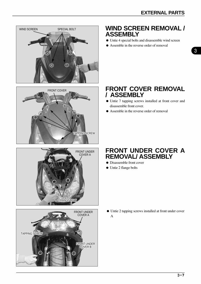
Untie 2 tapping screws installed at front under coverA
WIND SCREEN
FRONT COVER
TAPPING SCREWTAPPING SCREWTAPPING SCREWTAPPING SCREWTAPPING SCREWTAPPING SCREWTAPPING SCREWTAPPING SCREWTAPPING SCREWTAPPING SCREWTAPPING SCREWTAPPING SCREWTAPPING SCREWTAPPING SCREWTAPPING SCREWTAPPING SCREWTAPPING SCREWTAPPING SCREWTAPPING SCREWTAPPING SCREWTAPPING SCREWTAPPING SCREWTAPPING SCREWTAPPING SCREWTAPPING SCREWTAPPING SCREWTAPPING SCREW
FRONT UNDER COVER A
FRANGE BOLTFRANGE BOLTFRANGE BOLTFRANGE BOLTFRANGE BOLTFRANGE BOLTFRANGE BOLTFRANGE BOLTFRANGE BOLTFRANGE BOLTFRANGE BOLTFRANGE BOLTFRANGE BOLTFRANGE BOLTFRANGE BOLTFRANGE BOLTFRANGE BOLTFRANGE BOLTFRANGE BOLTFRANGE BOLTFRANGE BOLTFRANGE BOLTFRANGE BOLTFRANGE BOLTFRANGE BOLTFRANGE BOLTFRANGE BOLT
FRONT UNDER COVER A
FRONT UNDER COVER B
FRONT UNDER COVER B
FRONT UNDER COVER B
FRONT UNDER COVER B
FRONT UNDER COVER B
FRONT UNDER COVER B
FRONT UNDER COVER B
FRONT UNDER COVER B
FRONT UNDER COVER B
FRONT UNDER COVER B
FRONT UNDER COVER B
FRONT UNDER COVER B
FRONT UNDER COVER B
FRONT UNDER COVER B
FRONT UNDER COVER B
FRONT UNDER COVER B
FRONT UNDER COVER B
FRONT UNDER COVER B
FRONT UNDER COVER B
FRONT UNDER COVER B
FRONT UNDER COVER B
FRONT UNDER COVER B
FRONT UNDER COVER B
FRONT UNDER COVER B
FRONT UNDER COVER B
FRONT UNDER COVER B
FRONT UNDER COVER B
TAPPING SCREWTAPPING SCREWTAPPING SCREWTAPPING SCREWTAPPING SCREWTAPPING SCREWTAPPING SCREWTAPPING SCREWTAPPING SCREWTAPPING SCREWTAPPING SCREWTAPPING SCREWTAPPING SCREWTAPPING SCREWTAPPING SCREWTAPPING SCREWTAPPING SCREWTAPPING SCREWTAPPING SCREWTAPPING SCREWTAPPING SCREWTAPPING SCREWTAPPING SCREWTAPPING SCREWTAPPING SCREWTAPPING SCREWTAPPING SCREW
SPECIAL BOLT
EXTERNAL PARTS
WIND SCREEN REMOVAL /ASSEMBLY Untie 4 special bolts and disassemble wind screen Assemble in the reverse order of removal
FRONT COVER REMOVAL/ ASSEMBLY Untie 7 tapping screws installed at front cover and
disassemble front cover. Assemble in the reverse order of removal
FRONT UNDER COVER AREMOVAL/ ASSEMBLY Disassemble front cover Untie 2 flange bolts
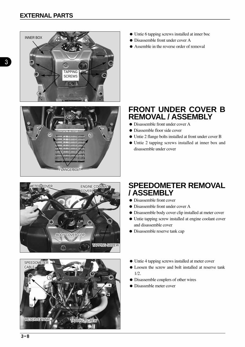
Untie 4 tapping screws installed at meter cover Loosen the screw and bolt installed at reserve tank
1/2. Disassemble couplers of other wires Disassmble meter cover
INNER BOX
TAPPING SCREWS
FLANGE BOLTFLANGE BOLTFLANGE BOLTFLANGE BOLTFLANGE BOLTFLANGE BOLTFLANGE BOLTFLANGE BOLTFLANGE BOLTFLANGE BOLTFLANGE BOLTFLANGE BOLTFLANGE BOLTFLANGE BOLTFLANGE BOLTFLANGE BOLTFLANGE BOLTFLANGE BOLTFLANGE BOLTFLANGE BOLTFLANGE BOLTFLANGE BOLTFLANGE BOLTFLANGE BOLTFLANGE BOLTFLANGE BOLTFLANGE BOLT
ENGINE COOLANT COVERENGINE COOLANT COVERENGINE COOLANT COVERENGINE COOLANT COVERENGINE COOLANT COVERENGINE COOLANT COVERENGINE COOLANT COVERENGINE COOLANT COVERENGINE COOLANT COVERENGINE COOLANT COVERENGINE COOLANT COVERENGINE COOLANT COVERENGINE COOLANT COVERENGINE COOLANT COVERENGINE COOLANT COVERENGINE COOLANT COVERENGINE COOLANT COVERENGINE COOLANT COVERENGINE COOLANT COVERENGINE COOLANT COVERENGINE COOLANT COVERENGINE COOLANT COVERENGINE COOLANT COVERENGINE COOLANT COVERENGINE COOLANT COVERENGINE COOLANT COVERENGINE COOLANT COVER
TAPPING SCREWTAPPING SCREWTAPPING SCREWTAPPING SCREWTAPPING SCREWTAPPING SCREWTAPPING SCREWTAPPING SCREWTAPPING SCREWTAPPING SCREWTAPPING SCREWTAPPING SCREWTAPPING SCREWTAPPING SCREWTAPPING SCREWTAPPING SCREWTAPPING SCREWTAPPING SCREWTAPPING SCREWTAPPING SCREWTAPPING SCREWTAPPING SCREWTAPPING SCREWTAPPING SCREWTAPPING SCREWTAPPING SCREWTAPPING SCREW
BODY COVER CLIPBODY COVER CLIPBODY COVER CLIPBODY COVER CLIPBODY COVER CLIPBODY COVER CLIPBODY COVER CLIPBODY COVER CLIPBODY COVER CLIPBODY COVER CLIPBODY COVER CLIPBODY COVER CLIPBODY COVER CLIPBODY COVER CLIPBODY COVER CLIPBODY COVER CLIPBODY COVER CLIPBODY COVER CLIPBODY COVER CLIPBODY COVER CLIPBODY COVER CLIPBODY COVER CLIPBODY COVER CLIPBODY COVER CLIPBODY COVER CLIPBODY COVER CLIPBODY COVER CLIP
SPEEDOMETER CABLESPEEDOMETER CABLESPEEDOMETER CABLESPEEDOMETER CABLESPEEDOMETER CABLESPEEDOMETER CABLESPEEDOMETER CABLESPEEDOMETER CABLESPEEDOMETER CABLESPEEDOMETER CABLESPEEDOMETER CABLESPEEDOMETER CABLESPEEDOMETER CABLESPEEDOMETER CABLESPEEDOMETER CABLESPEEDOMETER CABLESPEEDOMETER CABLESPEEDOMETER CABLESPEEDOMETER CABLESPEEDOMETER CABLESPEEDOMETER CABLESPEEDOMETER CABLESPEEDOMETER CABLESPEEDOMETER CABLESPEEDOMETER CABLESPEEDOMETER CABLESPEEDOMETER CABLE
RESERVE TANKRESERVE TANKRESERVE TANKRESERVE TANKRESERVE TANKRESERVE TANKRESERVE TANKRESERVE TANKRESERVE TANKRESERVE TANKRESERVE TANKRESERVE TANKRESERVE TANKRESERVE TANKRESERVE TANKRESERVE TANKRESERVE TANKRESERVE TANKRESERVE TANKRESERVE TANKRESERVE TANKRESERVE TANKRESERVE TANKRESERVE TANKRESERVE TANKRESERVE TANKRESERVE TANK TAPPING SCREWTAPPING SCREWTAPPING SCREWTAPPING SCREWTAPPING SCREWTAPPING SCREWTAPPING SCREWTAPPING SCREWTAPPING SCREWTAPPING SCREWTAPPING SCREWTAPPING SCREWTAPPING SCREWTAPPING SCREWTAPPING SCREWTAPPING SCREWTAPPING SCREWTAPPING SCREWTAPPING SCREWTAPPING SCREWTAPPING SCREWTAPPING SCREWTAPPING SCREWTAPPING SCREWTAPPING SCREWTAPPING SCREWTAPPING SCREW
EXTERNAL PARTS
Untie 6 tapping screws installed at inner boc Disassemble front under cover A Assemble in the reverse order of removal
FRONT UNDER COVER BREMOVAL / ASSEMBLY Disassemble front under cover A Diassemble floor side cover Untie 2 flange bolts installed at front under cover B Untie 2 tapping screws installed at inner box and
disassemble under cover
SPEEDOMETER REMOVAL/ ASSEMBLY Disassemble front cover Disassemble front under cover A Disassemble body cover clip installed at meter cover Untie tapping screw installed at engine coolant cover
and disassemble cover Disassemble reserve tank cap
METER COVERMETER COVERMETER COVERMETER COVERMETER COVERMETER COVERMETER COVERMETER COVERMETER COVERMETER COVERMETER COVERMETER COVERMETER COVERMETER COVERMETER COVERMETER COVERMETER COVERMETER COVERMETER COVERMETER COVERMETER COVERMETER COVERMETER COVERMETER COVERMETER COVERMETER COVERMETER COVER
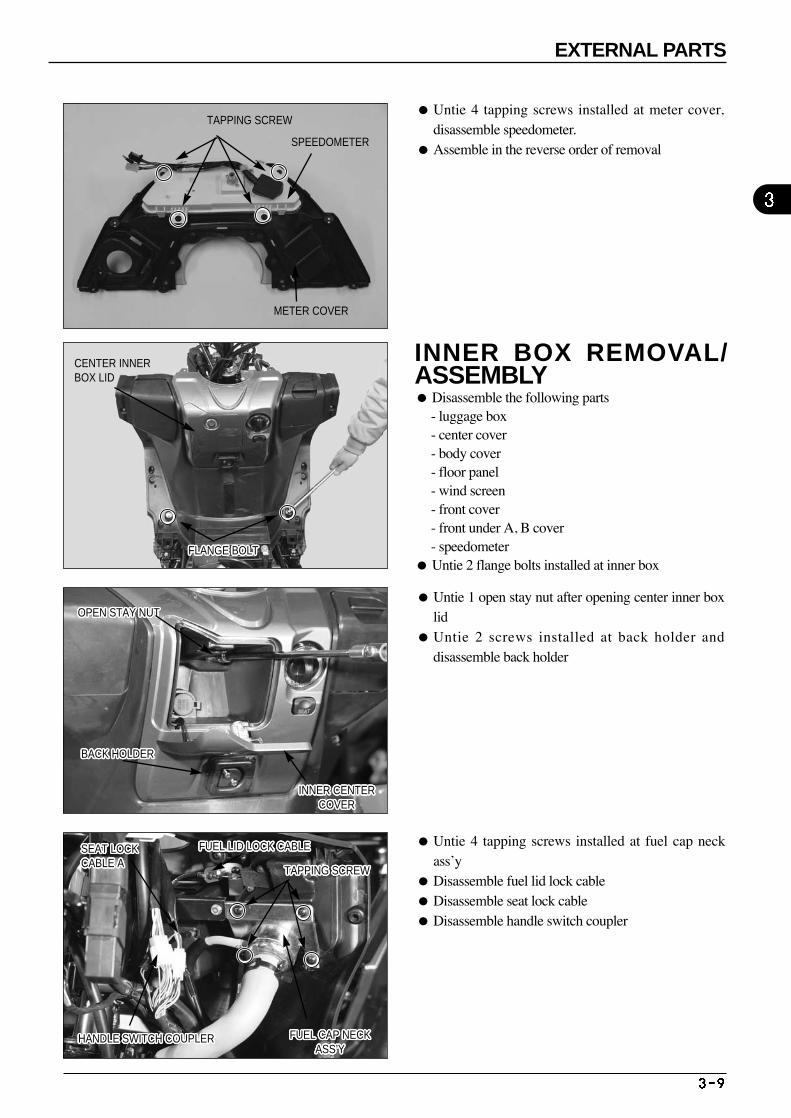
Untie 1 open stay nut after opening center inner boxlid
Untie 2 screws installed at back holder anddisassemble back holder
Untie 4 tapping screws installed at fuel cap neckass’y
Disassemble fuel lid lock cable Disassemble seat lock cable Disassemble handle switch coupler
TAPPING SCREW
SPEEDOMETER
METER COVER
CENTER INNER BOX LID
HANDLE SWITCH COUPLERHANDLE SWITCH COUPLERHANDLE SWITCH COUPLERHANDLE SWITCH COUPLERHANDLE SWITCH COUPLERHANDLE SWITCH COUPLERHANDLE SWITCH COUPLERHANDLE SWITCH COUPLERHANDLE SWITCH COUPLERHANDLE SWITCH COUPLERHANDLE SWITCH COUPLERHANDLE SWITCH COUPLERHANDLE SWITCH COUPLERHANDLE SWITCH COUPLERHANDLE SWITCH COUPLERHANDLE SWITCH COUPLERHANDLE SWITCH COUPLERHANDLE SWITCH COUPLERHANDLE SWITCH COUPLERHANDLE SWITCH COUPLERHANDLE SWITCH COUPLERHANDLE SWITCH COUPLERHANDLE SWITCH COUPLERHANDLE SWITCH COUPLERHANDLE SWITCH COUPLERHANDLE SWITCH COUPLERHANDLE SWITCH COUPLER
SEAT LOCK CABLE ASEAT LOCK CABLE ASEAT LOCK CABLE ASEAT LOCK CABLE ASEAT LOCK CABLE ASEAT LOCK CABLE ASEAT LOCK CABLE ASEAT LOCK CABLE ASEAT LOCK CABLE ASEAT LOCK CABLE ASEAT LOCK CABLE ASEAT LOCK CABLE ASEAT LOCK CABLE ASEAT LOCK CABLE ASEAT LOCK CABLE ASEAT LOCK CABLE ASEAT LOCK CABLE ASEAT LOCK CABLE ASEAT LOCK CABLE ASEAT LOCK CABLE ASEAT LOCK CABLE ASEAT LOCK CABLE ASEAT LOCK CABLE ASEAT LOCK CABLE ASEAT LOCK CABLE ASEAT LOCK CABLE ASEAT LOCK CABLE A
FUEL LID LOCK CABLEFUEL LID LOCK CABLEFUEL LID LOCK CABLEFUEL LID LOCK CABLEFUEL LID LOCK CABLEFUEL LID LOCK CABLEFUEL LID LOCK CABLEFUEL LID LOCK CABLEFUEL LID LOCK CABLEFUEL LID LOCK CABLEFUEL LID LOCK CABLEFUEL LID LOCK CABLEFUEL LID LOCK CABLEFUEL LID LOCK CABLEFUEL LID LOCK CABLEFUEL LID LOCK CABLEFUEL LID LOCK CABLEFUEL LID LOCK CABLEFUEL LID LOCK CABLEFUEL LID LOCK CABLEFUEL LID LOCK CABLEFUEL LID LOCK CABLEFUEL LID LOCK CABLEFUEL LID LOCK CABLEFUEL LID LOCK CABLEFUEL LID LOCK CABLEFUEL LID LOCK CABLE
TAPPING SCREWTAPPING SCREWTAPPING SCREWTAPPING SCREWTAPPING SCREWTAPPING SCREWTAPPING SCREWTAPPING SCREWTAPPING SCREWTAPPING SCREWTAPPING SCREWTAPPING SCREWTAPPING SCREWTAPPING SCREWTAPPING SCREWTAPPING SCREWTAPPING SCREWTAPPING SCREWTAPPING SCREWTAPPING SCREWTAPPING SCREWTAPPING SCREWTAPPING SCREWTAPPING SCREWTAPPING SCREWTAPPING SCREWTAPPING SCREW
FUEL CAP NECKASS’Y
FUEL CAP NECKASS’Y
FUEL CAP NECKASS’Y
FUEL CAP NECKASS’Y
FUEL CAP NECKASS’Y
FUEL CAP NECKASS’Y
FUEL CAP NECKASS’Y
FUEL CAP NECKASS’Y
FUEL CAP NECKASS’Y
FUEL CAP NECKASS’Y
FUEL CAP NECKASS’Y
FUEL CAP NECKASS’Y
FUEL CAP NECKASS’Y
FUEL CAP NECKASS’Y
FUEL CAP NECKASS’Y
FUEL CAP NECKASS’Y
FUEL CAP NECKASS’Y
FUEL CAP NECKASS’Y
FUEL CAP NECKASS’Y
FUEL CAP NECKASS’Y
FUEL CAP NECKASS’Y
FUEL CAP NECKASS’Y
FUEL CAP NECKASS’Y
FUEL CAP NECKASS’Y
FUEL CAP NECKASS’Y
FUEL CAP NECKASS’Y
FUEL CAP NECKASS’Y
FLANGE BOLTFLANGE BOLTFLANGE BOLTFLANGE BOLTFLANGE BOLTFLANGE BOLTFLANGE BOLTFLANGE BOLTFLANGE BOLTFLANGE BOLTFLANGE BOLTFLANGE BOLTFLANGE BOLTFLANGE BOLTFLANGE BOLTFLANGE BOLTFLANGE BOLTFLANGE BOLTFLANGE BOLTFLANGE BOLTFLANGE BOLTFLANGE BOLTFLANGE BOLTFLANGE BOLTFLANGE BOLTFLANGE BOLTFLANGE BOLT
OPEN STAY NUTOPEN STAY NUTOPEN STAY NUTOPEN STAY NUTOPEN STAY NUTOPEN STAY NUTOPEN STAY NUTOPEN STAY NUTOPEN STAY NUTOPEN STAY NUTOPEN STAY NUTOPEN STAY NUTOPEN STAY NUTOPEN STAY NUTOPEN STAY NUTOPEN STAY NUTOPEN STAY NUTOPEN STAY NUTOPEN STAY NUTOPEN STAY NUTOPEN STAY NUTOPEN STAY NUTOPEN STAY NUTOPEN STAY NUTOPEN STAY NUTOPEN STAY NUTOPEN STAY NUT
BACK HOLDERBACK HOLDERBACK HOLDERBACK HOLDERBACK HOLDERBACK HOLDERBACK HOLDERBACK HOLDERBACK HOLDERBACK HOLDERBACK HOLDERBACK HOLDERBACK HOLDERBACK HOLDERBACK HOLDERBACK HOLDERBACK HOLDERBACK HOLDERBACK HOLDERBACK HOLDERBACK HOLDERBACK HOLDERBACK HOLDERBACK HOLDERBACK HOLDERBACK HOLDERBACK HOLDER
INNER CENTERCOVER
INNER CENTERCOVER
INNER CENTERCOVER
INNER CENTERCOVER
INNER CENTERCOVER
INNER CENTERCOVER
INNER CENTERCOVER
INNER CENTERCOVER
INNER CENTERCOVER
INNER CENTERCOVER
INNER CENTERCOVER
INNER CENTERCOVER
INNER CENTERCOVER
INNER CENTERCOVER
INNER CENTERCOVER
INNER CENTERCOVER
INNER CENTERCOVER
INNER CENTERCOVER
INNER CENTERCOVER
INNER CENTERCOVER
INNER CENTERCOVER
INNER CENTERCOVER
INNER CENTERCOVER
INNER CENTERCOVER
INNER CENTERCOVER
INNER CENTERCOVER
INNER CENTERCOVER
EXTERNAL PARTS
Untie 4 tapping screws installed at meter cover,disassemble speedometer.
Assemble in the reverse order of removal
INNER BOX REMOVAL/ASSEMBLY Disassemble the following parts
- luggage box- center cover - body cover - floor panel - wind screen - front cover - front under A, B cover - speedometer
Untie 2 flange bolts installed at inner box
TAPPING SCREWTAPPING SCREWTAPPING SCREWTAPPING SCREWTAPPING SCREWTAPPING SCREWTAPPING SCREWTAPPING SCREWTAPPING SCREWTAPPING SCREWTAPPING SCREWTAPPING SCREWTAPPING SCREWTAPPING SCREWTAPPING SCREWTAPPING SCREWTAPPING SCREWTAPPING SCREWTAPPING SCREWTAPPING SCREWTAPPING SCREWTAPPING SCREWTAPPING SCREWTAPPING SCREWTAPPING SCREWTAPPING SCREWTAPPING SCREW
WASHER BOLTWASHER BOLTWASHER BOLTWASHER BOLTWASHER BOLTWASHER BOLTWASHER BOLTWASHER BOLTWASHER BOLTWASHER BOLTWASHER BOLTWASHER BOLTWASHER BOLTWASHER BOLTWASHER BOLTWASHER BOLTWASHER BOLTWASHER BOLTWASHER BOLTWASHER BOLTWASHER BOLTWASHER BOLTWASHER BOLTWASHER BOLTWASHER BOLTWASHER BOLTWASHER BOLT
FRONT FENDERFRONT FENDERFRONT FENDERFRONT FENDERFRONT FENDERFRONT FENDERFRONT FENDERFRONT FENDERFRONT FENDERFRONT FENDERFRONT FENDERFRONT FENDERFRONT FENDERFRONT FENDERFRONT FENDERFRONT FENDERFRONT FENDERFRONT FENDERFRONT FENDERFRONT FENDERFRONT FENDERFRONT FENDERFRONT FENDERFRONT FENDERFRONT FENDERFRONT FENDERFRONT FENDER SPECIAL SCREWSPECIAL SCREWSPECIAL SCREWSPECIAL SCREWSPECIAL SCREWSPECIAL SCREWSPECIAL SCREWSPECIAL SCREWSPECIAL SCREWSPECIAL SCREWSPECIAL SCREWSPECIAL SCREWSPECIAL SCREWSPECIAL SCREWSPECIAL SCREWSPECIAL SCREWSPECIAL SCREWSPECIAL SCREWSPECIAL SCREWSPECIAL SCREWSPECIAL SCREWSPECIAL SCREWSPECIAL SCREWSPECIAL SCREWSPECIAL SCREWSPECIAL SCREWSPECIAL SCREW
REAR WHEEL MUD GUARDREAR WHEEL MUD GUARDREAR WHEEL MUD GUARDREAR WHEEL MUD GUARDREAR WHEEL MUD GUARDREAR WHEEL MUD GUARDREAR WHEEL MUD GUARDREAR WHEEL MUD GUARDREAR WHEEL MUD GUARDREAR WHEEL MUD GUARDREAR WHEEL MUD GUARDREAR WHEEL MUD GUARDREAR WHEEL MUD GUARDREAR WHEEL MUD GUARDREAR WHEEL MUD GUARDREAR WHEEL MUD GUARDREAR WHEEL MUD GUARDREAR WHEEL MUD GUARDREAR WHEEL MUD GUARDREAR WHEEL MUD GUARDREAR WHEEL MUD GUARDREAR WHEEL MUD GUARDREAR WHEEL MUD GUARDREAR WHEEL MUD GUARDREAR WHEEL MUD GUARDREAR WHEEL MUD GUARDREAR WHEEL MUD GUARD
WASHER BOLTWASHER BOLTWASHER BOLTWASHER BOLTWASHER BOLTWASHER BOLTWASHER BOLTWASHER BOLTWASHER BOLTWASHER BOLTWASHER BOLTWASHER BOLTWASHER BOLTWASHER BOLTWASHER BOLTWASHER BOLTWASHER BOLTWASHER BOLTWASHER BOLTWASHER BOLTWASHER BOLTWASHER BOLTWASHER BOLTWASHER BOLTWASHER BOLTWASHER BOLTWASHER BOLT
EX PIPE COVEREX PIPE COVEREX PIPE COVEREX PIPE COVEREX PIPE COVEREX PIPE COVEREX PIPE COVEREX PIPE COVEREX PIPE COVEREX PIPE COVEREX PIPE COVEREX PIPE COVEREX PIPE COVEREX PIPE COVEREX PIPE COVEREX PIPE COVEREX PIPE COVEREX PIPE COVEREX PIPE COVEREX PIPE COVEREX PIPE COVEREX PIPE COVEREX PIPE COVEREX PIPE COVEREX PIPE COVEREX PIPE COVEREX PIPE COVER
WASHER SCREW
RESERVE TANKRESERVE TANKRESERVE TANKRESERVE TANKRESERVE TANKRESERVE TANKRESERVE TANKRESERVE TANKRESERVE TANKRESERVE TANKRESERVE TANKRESERVE TANKRESERVE TANKRESERVE TANKRESERVE TANKRESERVE TANKRESERVE TANKRESERVE TANKRESERVE TANKRESERVE TANKRESERVE TANKRESERVE TANKRESERVE TANKRESERVE TANKRESERVE TANKRESERVE TANKRESERVE TANK
EXTERNAL PARTS
Untie 3 tapping screws and 1 flange bolt installed atreserve tank
Disassemble inner box Assemble in the reverse order of removal
FRONT FENDER REMOVAL/ ASSEMBLY Disassmeble wire grommet installed at RH. Untie 4 special screws installed at front fender Disassemble front fender Asssemble in the reverse order of removal
REAR WHEEL MUD GUARDREMOVAL / ASSEMBLY Untie 2 washer bolts installed at LH. Side of rear
wheel mud guard Disassemble air cleaner Untie 1 washer bolt installed at RH. Side and
disassemble rear wheel Assemble in the reverse order of removal
MUFFLER REMOVAL / ASSEMBLY Untie 3 washer screws installed at EX. Pipe cover
and disassemble the muffler
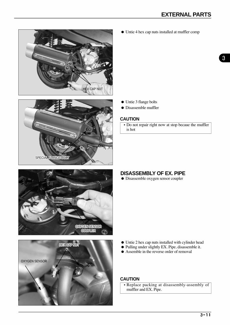
Untie 3 flange bolts Disassemble muffler
Untie 2 hex cap nuts installed with cylinder head Pulling under slightly EX. Pipe, disassemble it. Assemble in the reverse order of removal
DISASSEMBLY OF EX. PIPE Disassemble oxygen sensor coupler
HEX CAP NUT
SPECIAL FLANGE BOLTSPECIAL FLANGE BOLTSPECIAL FLANGE BOLTSPECIAL FLANGE BOLTSPECIAL FLANGE BOLTSPECIAL FLANGE BOLTSPECIAL FLANGE BOLTSPECIAL FLANGE BOLTSPECIAL FLANGE BOLTSPECIAL FLANGE BOLTSPECIAL FLANGE BOLTSPECIAL FLANGE BOLTSPECIAL FLANGE BOLTSPECIAL FLANGE BOLTSPECIAL FLANGE BOLTSPECIAL FLANGE BOLTSPECIAL FLANGE BOLTSPECIAL FLANGE BOLTSPECIAL FLANGE BOLTSPECIAL FLANGE BOLTSPECIAL FLANGE BOLTSPECIAL FLANGE BOLTSPECIAL FLANGE BOLTSPECIAL FLANGE BOLTSPECIAL FLANGE BOLTSPECIAL FLANGE BOLTSPECIAL FLANGE BOLT
OXYGEN SENSORCOUPLER
OXYGEN SENSORCOUPLER
OXYGEN SENSORCOUPLER
OXYGEN SENSORCOUPLER
OXYGEN SENSORCOUPLER
OXYGEN SENSORCOUPLER
OXYGEN SENSORCOUPLER
OXYGEN SENSORCOUPLER
OXYGEN SENSORCOUPLER
OXYGEN SENSORCOUPLER
OXYGEN SENSORCOUPLER
OXYGEN SENSORCOUPLER
OXYGEN SENSORCOUPLER
OXYGEN SENSORCOUPLER
OXYGEN SENSORCOUPLER
OXYGEN SENSORCOUPLER
OXYGEN SENSORCOUPLER
OXYGEN SENSORCOUPLER
OXYGEN SENSORCOUPLER
OXYGEN SENSORCOUPLER
OXYGEN SENSORCOUPLER
OXYGEN SENSORCOUPLER
OXYGEN SENSORCOUPLER
OXYGEN SENSORCOUPLER
OXYGEN SENSORCOUPLER
OXYGEN SENSORCOUPLER
OXYGEN SENSORCOUPLER
HEX CAP NUTHEX CAP NUTHEX CAP NUTHEX CAP NUTHEX CAP NUTHEX CAP NUTHEX CAP NUTHEX CAP NUTHEX CAP NUTHEX CAP NUTHEX CAP NUTHEX CAP NUTHEX CAP NUTHEX CAP NUTHEX CAP NUTHEX CAP NUTHEX CAP NUTHEX CAP NUTHEX CAP NUTHEX CAP NUTHEX CAP NUTHEX CAP NUTHEX CAP NUTHEX CAP NUTHEX CAP NUTHEX CAP NUTHEX CAP NUT
OXYGEN SENSOR
EXTERNAL PARTS
Untie 4 hex cap nuts installed at muffler comp
CAUTION•Do not repair right now at stop becaue the muffler
is hot
CAUTION•Replace packing at disassembly-assembly of
muffler and EX. Pipe.

M E M O
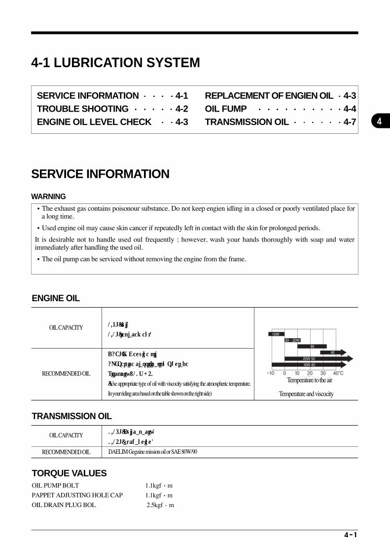
4-1 LUBRICATION SYSTEM
SERVICE INFORMATION
WARNING•The exhaust gas contains poisonour substance. Do not keep engien idling in a closed or poorly ventilated place for
a long time.
•Used engine oil may cause skin cancer if repeatedly left in contact with the skin for prolonged periods.
It is desirable not to handle used oul frequently ; however, wash your hands thoroughly with soap and waterimmediately after handling the used oil.
•The oil pump can be serviced without removing the engine from the frame.
SERVICE INFORMATION 4-1 TROUBLE SHOOTING 4-2 ENGINE OIL LEVEL CHECK 4-3
REPLACEMENT OF ENGIEN OIL 4-3OIL FUMP 4-4 TRANSMISSION OIL 4-7
ENGINE OIL
OIL CAPACITY
RECOMMENDED OIL
1.3L(full)
1.1L(replacement)
DAELIM Geguine oil
API Service classification SL grade
Viscocity : 10W-40
(Use appropriate type of oil with viscocity satisfying the atmospheric temperature.
In your riding area based on the table shown on the right side)
TRANSMISSION OIL
OIL CAPACITY
RECOMMENDED OIL
0.15L(Full capacity)
0.14L(at changing)
DAELIM Geguine mission oil or SAE 80W/90
OIL PUMP BOLT 1.1kgf m
PAPPET ADJUSTING HOLE CAP 1.1kgf m
OIL DRAIN PLUG BOL 2.5kgf m
TORQUE VALUES
Temperature and viscocity
Temperature to the air
LUBRICATION SYSTEM
TROUBLE SHOOTING Oil level low
Natural oil consumption External oil leaking Worn piston ring or incorrect piston ring installation Valve guide or stem seal abrasion
Oil contamination
Irregular engine oil replacement Damage of cylinder head gasket Piston ring abrasion Water inflows
Low or no oil pressure
Clogged oil strainer Abrasion or damage of oil pumpOil leakage inside engine Improper viscosity oil Low capacity oil Non-fitting of oil pump drive gear or sprocket
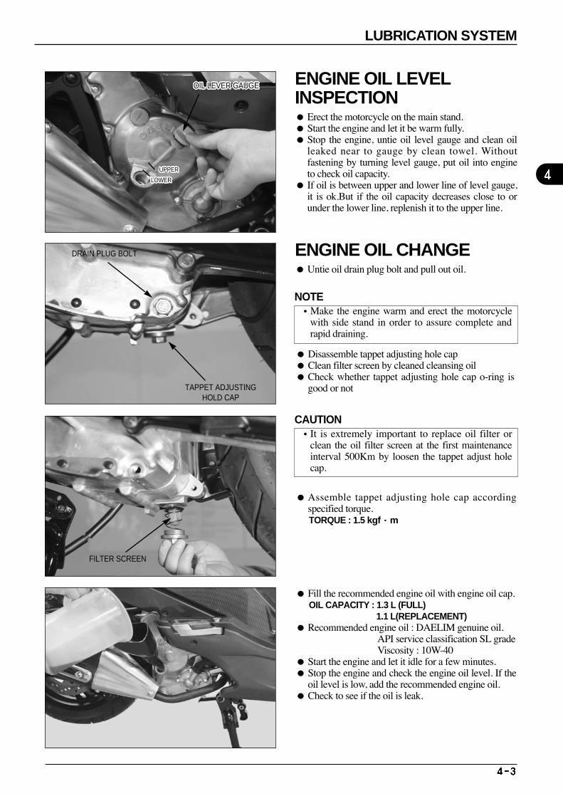
Disassemble tappet adjusting hole cap Clean filter screen by cleaned cleansing oil Check whether tappet adjusting hole cap o-ring is
good or not
Assemble tappet adjusting hole cap accordingspecified torque. TORQUE : 1.5 kgf·m
Fill the recommended engine oil with engine oil cap.OIL CAPACITY : 1.3 L (FULL)
1.1 L(REPLACEMENT) Recommended engine oil : DAELIM genuine oil.
API service classification SL gradeViscosity : 10W-40
Start the engine and let it idle for a few minutes. Stop the engine and check the engine oil level. If the
oil level is low, add the recommended engine oil. Check to see if the oil is leak.
OIL LEVER GAUGEOIL LEVER GAUGEOIL LEVER GAUGEOIL LEVER GAUGEOIL LEVER GAUGEOIL LEVER GAUGEOIL LEVER GAUGEOIL LEVER GAUGEOIL LEVER GAUGEOIL LEVER GAUGEOIL LEVER GAUGEOIL LEVER GAUGEOIL LEVER GAUGEOIL LEVER GAUGEOIL LEVER GAUGEOIL LEVER GAUGEOIL LEVER GAUGEOIL LEVER GAUGEOIL LEVER GAUGEOIL LEVER GAUGEOIL LEVER GAUGEOIL LEVER GAUGEOIL LEVER GAUGEOIL LEVER GAUGEOIL LEVER GAUGEOIL LEVER GAUGEOIL LEVER GAUGE
TAPPET ADJUSTINGHOLD CAP
FILTER SCREEN
DRAIN PLUG BOLT
UPPERUPPERUPPERUPPERUPPERUPPERUPPERUPPERUPPERUPPERUPPERUPPERUPPERUPPERUPPERUPPERUPPERUPPERUPPERUPPERUPPERUPPERUPPERUPPERUPPERUPPERUPPER
LOWERLOWERLOWERLOWERLOWERLOWERLOWERLOWERLOWERLOWERLOWERLOWERLOWERLOWERLOWERLOWERLOWERLOWERLOWERLOWERLOWERLOWERLOWERLOWERLOWERLOWERLOWER
LUBRICATION SYSTEM
ENGINE OIL LEVELINSPECTION Erect the motorcycle on the main stand. Start the engine and let it be warm fully. Stop the engine, untie oil level gauge and clean oil
leaked near to gauge by clean towel. Withoutfastening by turning level gauge, put oil into engineto check oil capacity.
If oil is between upper and lower line of level gauge,it is ok.But if the oil capacity decreases close to orunder the lower line, replenish it to the upper line.
ENGINE OIL CHANGE Untie oil drain plug bolt and pull out oil.
NOTE•Make the engine warm and erect the motorcycle
with side stand in order to assure complete andrapid draining.
CAUTION•It is extremely important to replace oil filter or
clean the oil filter screen at the first maintenanceinterval 500Km by loosen the tappet adjust holecap.
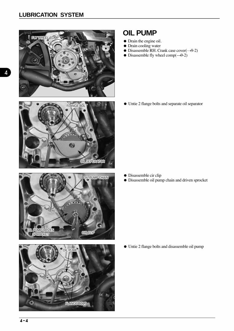
4
Untie 2 flange bolts and separate oil separator
Disassemble cir clip Disassemble oil pump chain and driven sprocket
Untie 2 flange bolts and disassemble oil pump
FLY WHEEL COMPFLY WHEEL COMPFLY WHEEL COMPFLY WHEEL COMPFLY WHEEL COMPFLY WHEEL COMPFLY WHEEL COMPFLY WHEEL COMPFLY WHEEL COMPFLY WHEEL COMPFLY WHEEL COMPFLY WHEEL COMPFLY WHEEL COMPFLY WHEEL COMPFLY WHEEL COMPFLY WHEEL COMPFLY WHEEL COMPFLY WHEEL COMPFLY WHEEL COMPFLY WHEEL COMPFLY WHEEL COMPFLY WHEEL COMPFLY WHEEL COMPFLY WHEEL COMPFLY WHEEL COMPFLY WHEEL COMPFLY WHEEL COMP
FLANGE BOLTFLANGE BOLTFLANGE BOLTFLANGE BOLTFLANGE BOLTFLANGE BOLTFLANGE BOLTFLANGE BOLTFLANGE BOLTFLANGE BOLTFLANGE BOLTFLANGE BOLTFLANGE BOLTFLANGE BOLTFLANGE BOLTFLANGE BOLTFLANGE BOLTFLANGE BOLTFLANGE BOLTFLANGE BOLTFLANGE BOLTFLANGE BOLTFLANGE BOLTFLANGE BOLTFLANGE BOLTFLANGE BOLTFLANGE BOLT
OIL SEPERATOROIL SEPERATOROIL SEPERATOROIL SEPERATOROIL SEPERATOROIL SEPERATOROIL SEPERATOROIL SEPERATOROIL SEPERATOROIL SEPERATOROIL SEPERATOROIL SEPERATOROIL SEPERATOROIL SEPERATOROIL SEPERATOROIL SEPERATOROIL SEPERATOROIL SEPERATOROIL SEPERATOROIL SEPERATOROIL SEPERATOROIL SEPERATOROIL SEPERATOROIL SEPERATOROIL SEPERATOROIL SEPERATOROIL SEPERATOR
OIL PUMP CHAINOIL PUMP CHAINOIL PUMP CHAINOIL PUMP CHAINOIL PUMP CHAINOIL PUMP CHAINOIL PUMP CHAINOIL PUMP CHAINOIL PUMP CHAINOIL PUMP CHAINOIL PUMP CHAINOIL PUMP CHAINOIL PUMP CHAINOIL PUMP CHAINOIL PUMP CHAINOIL PUMP CHAINOIL PUMP CHAINOIL PUMP CHAINOIL PUMP CHAINOIL PUMP CHAINOIL PUMP CHAINOIL PUMP CHAINOIL PUMP CHAINOIL PUMP CHAINOIL PUMP CHAINOIL PUMP CHAINOIL PUMP CHAIN
CIR CLIPCIR CLIPCIR CLIPCIR CLIPCIR CLIPCIR CLIPCIR CLIPCIR CLIPCIR CLIPCIR CLIPCIR CLIPCIR CLIPCIR CLIPCIR CLIPCIR CLIPCIR CLIPCIR CLIPCIR CLIPCIR CLIPCIR CLIPCIR CLIPCIR CLIPCIR CLIPCIR CLIPCIR CLIPCIR CLIPCIR CLIP
OIL PUMPOIL PUMPOIL PUMPOIL PUMPOIL PUMPOIL PUMPOIL PUMPOIL PUMPOIL PUMPOIL PUMPOIL PUMPOIL PUMPOIL PUMPOIL PUMPOIL PUMPOIL PUMPOIL PUMPOIL PUMPOIL PUMPOIL PUMPOIL PUMPOIL PUMPOIL PUMPOIL PUMPOIL PUMPOIL PUMPOIL PUMP
FLANGE BOLTFLANGE BOLTFLANGE BOLTFLANGE BOLTFLANGE BOLTFLANGE BOLTFLANGE BOLTFLANGE BOLTFLANGE BOLTFLANGE BOLTFLANGE BOLTFLANGE BOLTFLANGE BOLTFLANGE BOLTFLANGE BOLTFLANGE BOLTFLANGE BOLTFLANGE BOLTFLANGE BOLTFLANGE BOLTFLANGE BOLTFLANGE BOLTFLANGE BOLTFLANGE BOLTFLANGE BOLTFLANGE BOLTFLANGE BOLT
OIL PUMP DRIVENSPROCKET
OIL PUMP DRIVENSPROCKET
OIL PUMP DRIVENSPROCKET
OIL PUMP DRIVENSPROCKET
OIL PUMP DRIVENSPROCKET
OIL PUMP DRIVENSPROCKET
OIL PUMP DRIVENSPROCKET
OIL PUMP DRIVENSPROCKET
OIL PUMP DRIVENSPROCKET
OIL PUMP DRIVENSPROCKET
OIL PUMP DRIVENSPROCKET
OIL PUMP DRIVENSPROCKET
OIL PUMP DRIVENSPROCKET
OIL PUMP DRIVENSPROCKET
OIL PUMP DRIVENSPROCKET
OIL PUMP DRIVENSPROCKET
OIL PUMP DRIVENSPROCKET
OIL PUMP DRIVENSPROCKET
OIL PUMP DRIVENSPROCKET
OIL PUMP DRIVENSPROCKET
OIL PUMP DRIVENSPROCKET
OIL PUMP DRIVENSPROCKET
OIL PUMP DRIVENSPROCKET
OIL PUMP DRIVENSPROCKET
OIL PUMP DRIVENSPROCKET
OIL PUMP DRIVENSPROCKET
OIL PUMP DRIVENSPROCKET
LUBRICATION SYSTEM
OIL PUMP Drain the engine oil. Drain cooling water Disassemble RH. Crank case cover( 9-2) Disassemble fly wheel comp( 9-2)
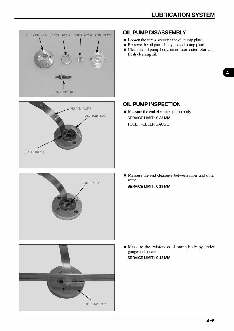
4
OIL PUMP DISASSEMBLY Loosen the screw securing the oil pump plate. Remove the oil pump body and oil pump plate. Clean the oil pump body, inner rotor, outer rotor with
fresh cleaning oil.
OIL PUMP INSPECTION Measure the end clearance pump body.
SERVICE LIMIT : 0.23 MM
TOOL : FEELER GAUGE
Measure the end clearance between inner and outerrotor.
SERVICE LIMIT : 0.18 MM
Measure the twisteness of pump body by feelergauge and square.
SERVICE LIMIT : 0.12 MM
OIL PUMP BODY OUTER ROTOR
OIL PUMP SHAFT
FEELER GAUGE
OIL PUMP BODY
OUTER ROTOR
INNER ROTOR
OIL PUMP BODY
INNER ROTOR PUMP PLATE
LUBRICATION SYSTEM
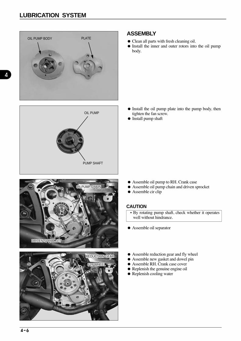
ASSEMBLY Clean all parts with fresh cleaning oil. Install the inner and outer rotors into the oil pump
body.
Assemble reduction gear and fly wheel Assemble new gasket and dowel pin Assemble RH. Crank case cover Replenish the genuine engine oil Replenish cooling water
Install the oil pump plate into the pump body, thentighten the fan screw.
Install pump shaft
Assemble oil pump to RH. Crank case Assemble oil pump chain and driven sprocket Assemble cir clip
Assemble oil separator
OIL PUMP BODY PLATE
OIL PUMP
PUMP SHAFT
DRIVEN SPROCKETDRIVEN SPROCKETDRIVEN SPROCKETDRIVEN SPROCKETDRIVEN SPROCKETDRIVEN SPROCKETDRIVEN SPROCKETDRIVEN SPROCKETDRIVEN SPROCKETDRIVEN SPROCKETDRIVEN SPROCKETDRIVEN SPROCKETDRIVEN SPROCKETDRIVEN SPROCKETDRIVEN SPROCKETDRIVEN SPROCKETDRIVEN SPROCKETDRIVEN SPROCKETDRIVEN SPROCKETDRIVEN SPROCKETDRIVEN SPROCKETDRIVEN SPROCKETDRIVEN SPROCKETDRIVEN SPROCKETDRIVEN SPROCKETDRIVEN SPROCKETDRIVEN SPROCKET
OILPUMP CHAINOILPUMP CHAINOILPUMP CHAINOILPUMP CHAINOILPUMP CHAINOILPUMP CHAINOILPUMP CHAINOILPUMP CHAINOILPUMP CHAINOILPUMP CHAINOILPUMP CHAINOILPUMP CHAINOILPUMP CHAINOILPUMP CHAINOILPUMP CHAINOILPUMP CHAINOILPUMP CHAINOILPUMP CHAINOILPUMP CHAINOILPUMP CHAINOILPUMP CHAINOILPUMP CHAINOILPUMP CHAINOILPUMP CHAINOILPUMP CHAINOILPUMP CHAINOILPUMP CHAIN
REDUCTION GEARREDUCTION GEARREDUCTION GEARREDUCTION GEARREDUCTION GEARREDUCTION GEARREDUCTION GEARREDUCTION GEARREDUCTION GEARREDUCTION GEARREDUCTION GEARREDUCTION GEARREDUCTION GEARREDUCTION GEARREDUCTION GEARREDUCTION GEARREDUCTION GEARREDUCTION GEARREDUCTION GEARREDUCTION GEARREDUCTION GEARREDUCTION GEARREDUCTION GEARREDUCTION GEARREDUCTION GEARREDUCTION GEARREDUCTION GEAR
FLY WHEELFLY WHEELFLY WHEELFLY WHEELFLY WHEELFLY WHEELFLY WHEELFLY WHEELFLY WHEELFLY WHEELFLY WHEELFLY WHEELFLY WHEELFLY WHEELFLY WHEELFLY WHEELFLY WHEELFLY WHEELFLY WHEELFLY WHEELFLY WHEELFLY WHEELFLY WHEELFLY WHEELFLY WHEELFLY WHEELFLY WHEEL
LUBRICATION SYSTEM
CAUTION•By rotating pump shaft, check whether it operates
well without hindrance.
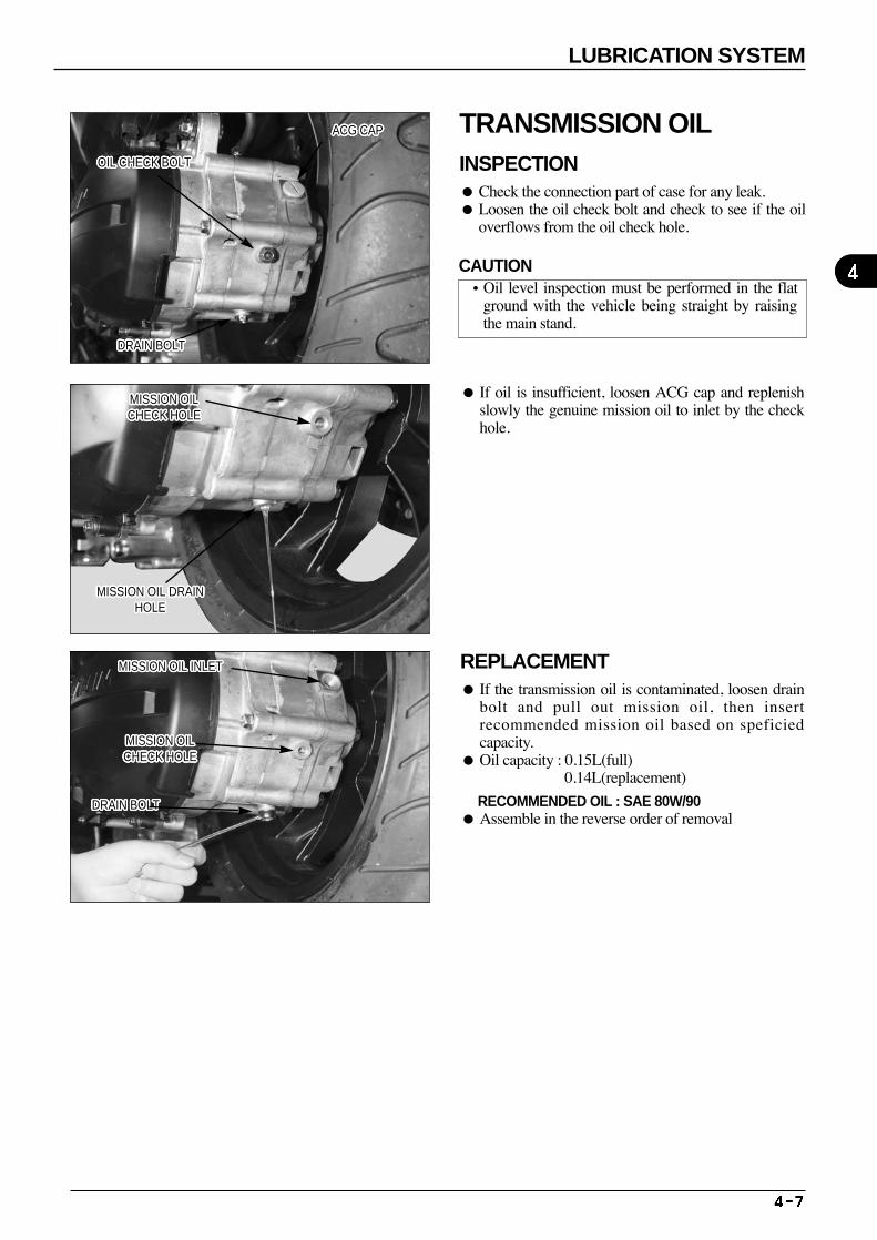
If oil is insufficient, loosen ACG cap and replenishslowly the genuine mission oil to inlet by the checkhole.
REPLACEMENT If the transmission oil is contaminated, loosen drain
bolt and pull out mission oil, then insertrecommended mission oil based on speficiedcapacity.
Oil capacity : 0.15L(full) 0.14L(replacement)
RECOMMENDED OIL : SAE 80W/90 Assemble in the reverse order of removal
OIL CHECK BOLTOIL CHECK BOLTOIL CHECK BOLTOIL CHECK BOLTOIL CHECK BOLTOIL CHECK BOLTOIL CHECK BOLTOIL CHECK BOLTOIL CHECK BOLTOIL CHECK BOLTOIL CHECK BOLTOIL CHECK BOLTOIL CHECK BOLTOIL CHECK BOLTOIL CHECK BOLTOIL CHECK BOLTOIL CHECK BOLTOIL CHECK BOLTOIL CHECK BOLTOIL CHECK BOLTOIL CHECK BOLTOIL CHECK BOLTOIL CHECK BOLTOIL CHECK BOLTOIL CHECK BOLTOIL CHECK BOLTOIL CHECK BOLT
ACG CAPACG CAPACG CAPACG CAPACG CAPACG CAPACG CAPACG CAPACG CAPACG CAPACG CAPACG CAPACG CAPACG CAPACG CAPACG CAPACG CAPACG CAPACG CAPACG CAPACG CAPACG CAPACG CAPACG CAPACG CAPACG CAPACG CAP
MISSION OIL CHECK HOLEMISSION OIL CHECK HOLEMISSION OIL CHECK HOLEMISSION OIL CHECK HOLEMISSION OIL CHECK HOLEMISSION OIL CHECK HOLEMISSION OIL CHECK HOLEMISSION OIL CHECK HOLEMISSION OIL CHECK HOLEMISSION OIL CHECK HOLEMISSION OIL CHECK HOLEMISSION OIL CHECK HOLEMISSION OIL CHECK HOLEMISSION OIL CHECK HOLEMISSION OIL CHECK HOLEMISSION OIL CHECK HOLEMISSION OIL CHECK HOLEMISSION OIL CHECK HOLEMISSION OIL CHECK HOLEMISSION OIL CHECK HOLEMISSION OIL CHECK HOLEMISSION OIL CHECK HOLEMISSION OIL CHECK HOLEMISSION OIL CHECK HOLEMISSION OIL CHECK HOLEMISSION OIL CHECK HOLEMISSION OIL CHECK HOLE
MISSION OIL DRAINHOLE
MISSION OIL DRAINHOLE
MISSION OIL DRAINHOLE
MISSION OIL DRAINHOLE
MISSION OIL DRAINHOLE
MISSION OIL DRAINHOLE
MISSION OIL DRAINHOLE
MISSION OIL DRAINHOLE
MISSION OIL DRAINHOLE
MISSION OIL DRAINHOLE
MISSION OIL DRAINHOLE
MISSION OIL DRAINHOLE
MISSION OIL DRAINHOLE
MISSION OIL DRAINHOLE
MISSION OIL DRAINHOLE
MISSION OIL DRAINHOLE
MISSION OIL DRAINHOLE
MISSION OIL DRAINHOLE
MISSION OIL DRAINHOLE
MISSION OIL DRAINHOLE
MISSION OIL DRAINHOLE
MISSION OIL DRAINHOLE
MISSION OIL DRAINHOLE
MISSION OIL DRAINHOLE
MISSION OIL DRAINHOLE
MISSION OIL DRAINHOLE
MISSION OIL DRAINHOLE
MISSION OIL INLETMISSION OIL INLETMISSION OIL INLETMISSION OIL INLETMISSION OIL INLETMISSION OIL INLETMISSION OIL INLETMISSION OIL INLETMISSION OIL INLETMISSION OIL INLETMISSION OIL INLETMISSION OIL INLETMISSION OIL INLETMISSION OIL INLETMISSION OIL INLETMISSION OIL INLETMISSION OIL INLETMISSION OIL INLETMISSION OIL INLETMISSION OIL INLETMISSION OIL INLETMISSION OIL INLETMISSION OIL INLETMISSION OIL INLETMISSION OIL INLETMISSION OIL INLETMISSION OIL INLET
MISSION OILCHECK HOLEMISSION OILCHECK HOLEMISSION OILCHECK HOLEMISSION OILCHECK HOLEMISSION OILCHECK HOLEMISSION OILCHECK HOLEMISSION OILCHECK HOLEMISSION OILCHECK HOLEMISSION OILCHECK HOLEMISSION OILCHECK HOLEMISSION OILCHECK HOLEMISSION OILCHECK HOLEMISSION OILCHECK HOLEMISSION OILCHECK HOLEMISSION OILCHECK HOLEMISSION OILCHECK HOLEMISSION OILCHECK HOLEMISSION OILCHECK HOLEMISSION OILCHECK HOLEMISSION OILCHECK HOLEMISSION OILCHECK HOLEMISSION OILCHECK HOLEMISSION OILCHECK HOLEMISSION OILCHECK HOLEMISSION OILCHECK HOLEMISSION OILCHECK HOLEMISSION OILCHECK HOLE
DRAIN BOLTDRAIN BOLTDRAIN BOLTDRAIN BOLTDRAIN BOLTDRAIN BOLTDRAIN BOLTDRAIN BOLTDRAIN BOLTDRAIN BOLTDRAIN BOLTDRAIN BOLTDRAIN BOLTDRAIN BOLTDRAIN BOLTDRAIN BOLTDRAIN BOLTDRAIN BOLTDRAIN BOLTDRAIN BOLTDRAIN BOLTDRAIN BOLTDRAIN BOLTDRAIN BOLTDRAIN BOLTDRAIN BOLTDRAIN BOLT
4
LUBRICATION SYSTEM
TRANSMISSION OIL INSPECTION Check the connection part of case for any leak. Loosen the oil check bolt and check to see if the oil
overflows from the oil check hole.
CAUTION•Oil level inspection must be performed in the flat
ground with the vehicle being straight by raisingthe main stand.
DRAIN BOLTDRAIN BOLTDRAIN BOLTDRAIN BOLTDRAIN BOLTDRAIN BOLTDRAIN BOLTDRAIN BOLTDRAIN BOLTDRAIN BOLTDRAIN BOLTDRAIN BOLTDRAIN BOLTDRAIN BOLTDRAIN BOLTDRAIN BOLTDRAIN BOLTDRAIN BOLTDRAIN BOLTDRAIN BOLTDRAIN BOLTDRAIN BOLTDRAIN BOLTDRAIN BOLTDRAIN BOLTDRAIN BOLTDRAIN BOLT

M E M O
5.EMS(ENGINE MANAGEMENT SYSTEM)
1. CAUTION WHEN REPARING THE EMS PARTS 5-2 2. THE COMPONENT PARTS OF THE EMS 5-3 3. TERMINAL ARRANGEMENT OF THE ECU 5-4 4. WIRING DIAGRAM OF THE ECU 5-5 5. AN ERROR CHECK LIST FOR EACH TERMINAL OF ECU 5-5 6. SELF-DIAGNOSTIC FUNCTION BY MIL
(MALFUNCTION INDICATOR LAMP) 5-61) SELF DIAGNOSTIC FUNCTION 5-6 2) FAIL SAFE FUNCTION 5-7 3) HOW TO CHECK THE FAULTY CODE 5-8 4) HOW TO SHOW THE FAULTY CODE 5-95) HOW TO READ THE FAULTY CODE 5-9 6) FAULTY CODE TABLE 5-10 7) HOW TO REMOVE THE FAULTY CODE 5-11 8) EMS TROUBLE SHOOTING 5-11
7. ECU(ELECTRONIC CONTROL UNIT) 5-12 8. THROTTLE BODY ASSEMBLY/DISASSEMBLY 5-139. INJECTOR 5-17 10. MAPAT SENSOR(INLET PRESSURE+INLET TEMPERATURE) 5-19 11.TPS(THROTTLE POSITION SENSOR) 5-23 12. ETS(ENGINE TEMPERATURE SENSOR) 5-26 13. ISA(IDLE SPEED ACTUATOR) 5-2914. O2 SENSOR(OXYGEN SENSOR) 5-32 15. CHECKING OF ESS CIRCIUT 5-35 16. CHECKING OF DIAGRAM OF ENGINE CHECK(CAUTION) LAMP 5-3617. CKP(CRANK POSITION SENSOR) 5-3718. FUEL PUMP 5-41 19. FUEL TANK 5-44
¡EFI (ELECTRIC FUEL INJECTION)
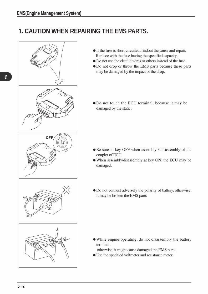
If the fuse is short-circuited, findout the cause and repair. Replace with the fuse having the specified capacity.
Do not use the electlic wires or others instead of the fuse.Do not drop or throw the EMS parts because these parts
may be damaged by the impact of the drop.
1. CAUTION WHEN REPAIRING THE EMS PARTS.
Be sure to key OFF when assembly / disassembly of thecoupler of ECU
When assembly/disassembly at key ON, the ECU may bedamaged.
Do not connect adversely the polarity of battery. otherwise,It may be broken the EMS parts
Do not touch the ECU terminal, because it may bedamaged by the static.
While engine operating, do not disassembly the batteryterminal.otherwise, it might cause damaged the EMS parts.
Use the specitied voltmeter and resistance meter.
EMS(Engine Management System)
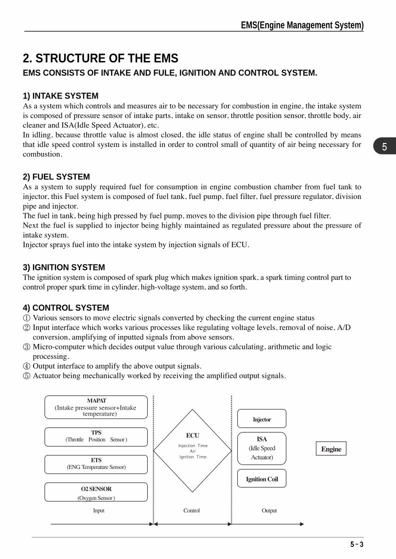
EMS(Engine Management System)
2. STRUCTURE OF THE EMSEMS CONSISTS OF INTAKE AND FULE, IGNITION AND CONTROL SYSTEM.
1) INTAKE SYSTEMAs a system which controls and measures air to be necessary for combustion in engine, the intake systemis composed of pressure sensor of intake parts, intake on sensor, throttle position sensor, throttle body, aircleaner and ISA(Idle Speed Actuator), etc.In idling, because throttle value is almost closed, the idle status of engine shall be controlled by meansthat idle speed control system is installed in order to control small of quantity of air being necessary forcombustion.
2) FUEL SYSTEMAs a system to supply required fuel for consumption in engine combustion chamber from fuel tank toinjector, this Fuel system is composed of fuel tank, fuel pump, fuel filter, fuel pressure regulator, divisionpipe and injector.The fuel in tank, being high pressed by fuel pump, moves to the division pipe through fuel filter. Next the fuel is supplied to injector being highly maintained as regulated pressure about the pressure ofintake system.Injector sprays fuel into the intake system by injection signals of ECU.
3) IGNITION SYSTEMThe ignition system is composed of spark plug which makes ignition spark, a spark timing control part tocontrol proper spark time in cylinder, high-voltage system, and so forth.
4) CONTROL SYSTEM① Various sensors to move electric signals converted by checking the current engine status② Input interface which works various processes like regulating voltage levels, removal of noise, A/D
conversion, amplifying of inputted signals from above sensors.③ Micro-computer which decides output value through various calculating, arithmetic and logic
processing.④ Output interface to amplify the above output signals.⑤ Actuator being mechanically worked by receiving the amplified output signals.
(Intake pressure sensor+Intake temperature)
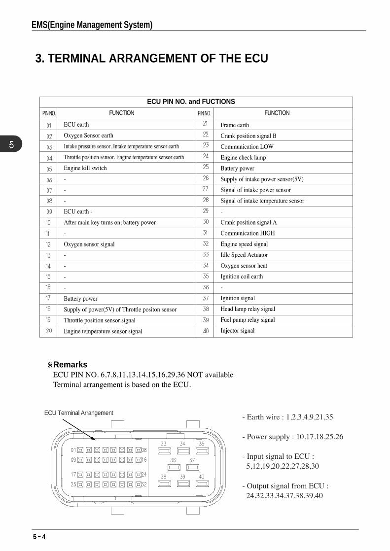
3. TERMINAL ARRANGEMENT OF THE ECU
RemarksECU PIN NO. 6,7,8,11,13,14,15,16,29,36 NOT availableTerminal arrangement is based on the ECU.
ECU Terminal Arrangement - Earth wire : 1,2,3,4,9,21,35
- Power supply : 10,17,18,25,26
- Input signal to ECU : 5,12,19,20,22,27,28,30
- Output signal from ECU : 24,32,33,34,37,38,39,40
PIN NO. FUNCTION
ECU earth
Oxygen Sensor earth
Intake pressure sensor, Intake temperature sensor earth
Throttle position sensor, Engine temperature sensor earth
Engine kill switch
-
-
-
ECU earth -
After main key turns on, battery power
-
Oxygen sensor signal
-
-
-
-
Battery power
Supply of power(5V) of Throttle positon sensor
Throttle position sensor signal
Engine temperature sensor signal
Frame earth
Crank position signal B
Communication LOW
Engine check lamp
Battery power
Supply of intake power sensor(5V)
Signal of intake power sensor
Signal of intake temperature sensor
-
Crank position signal A
Communication HIGH
Engine speed signal
Idle Speed Actuator
Oxygen sensor heat
Ignition coil earth
-
Ignition signal
Head lamp relay signal
Fuel pump relay signal
Injector signal
PIN NO. FUNCTION
ECU PIN NO. and FUCTIONS
EMS(Engine Management System)
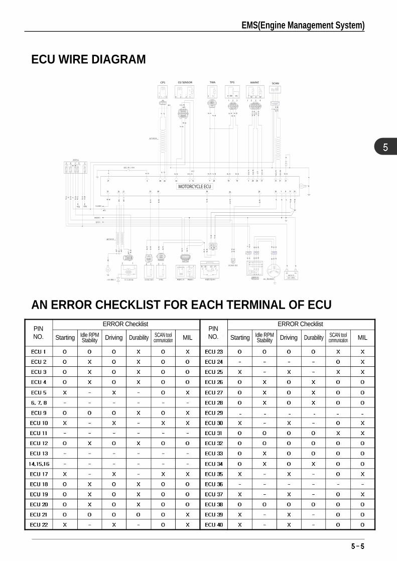
ECU WIRE DIAGRAM
AN ERROR CHECKLIST FOR EACH TERMINAL OF ECU
EMS(Engine Management System)
PIN NO.
ERROR Checklist
Starting Driving MILDurabilityIdle RPMStability
SCAN toolcommunication
PIN NO.
ERROR Checklist
Starting Driving MILDurabilityIdle RPMStability
SCAN toolcommunication
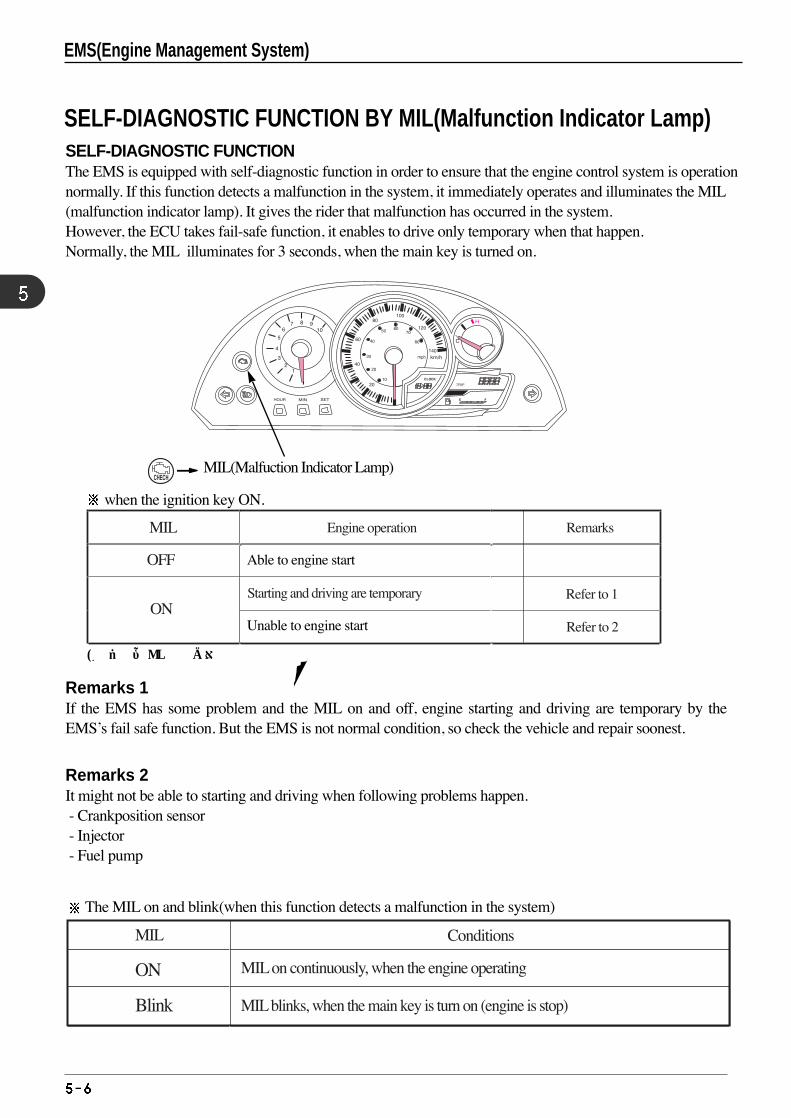
SELF-DIAGNOSTIC FUNCTION BY MIL(Malfunction Indicator Lamp)SELF-DIAGNOSTIC FUNCTIONThe EMS is equipped with self-diagnostic function in order to ensure that the engine control system is operationnormally. If this function detects a malfunction in the system, it immediately operates and illuminates the MIL(malfunction indicator lamp). It gives the rider that malfunction has occurred in the system.However, the ECU takes fail-safe function, it enables to drive only temporary when that happen. Normally, the MIL illuminates for 3 seconds, when the main key is turned on.
MIL(Malfuction Indicator Lamp)
* 시동키를ON했을경우임
Remarks 1If the EMS has some problem and the MIL on and off, engine starting and driving are temporary by theEMS’s fail safe function. But the EMS is not normal condition, so check the vehicle and repair soonest.
Remarks 2It might not be able to starting and driving when following problems happen.- Crankposition sensor- Injector- Fuel pump
EMS(Engine Management System)
when the ignition key ON.
MIL
OFF
ONStarting and driving are temporary
Unable
Able to engine start
Unable to engine start
The MIL on and blink(when this function detects a malfunction in the system)
MIL
ON
Blink
MIL on continuously, when the engine operating
MIL blinks, when the main key is turn on (engine is stop)
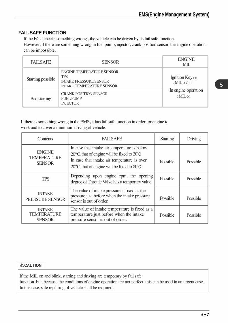
EMS(Engine Management System)
FAIL-SAFE FUNCTIONIf the ECU checks something wrong , the vehicle can be driven by its fail safe function.However, if there are something wrong in fuel pump, injector, crank position sensor, the engine operationcan be impossible.
: MIL on/offINTAKE
MIL
INTAKE
: MIL on
on
If there is something wrong in the EMS, it has fail safe function in order for engine towork and to cover a minimum driving of vehicle.
INTAKE
INTAKEThe value of intake pressure is fixed as the pressure just before when the intake pressure sensor is out of order.
intake
intake
The value of intake temperature is fixed as a temperature just before when the intake pressure sensor is out of order.
! CAUTION
If the MIL on and blink, starting and driving are temporary by fail safefunction, but, because the conditions of engine operation are not perfect, this can be used in an urgent case.In this case, safe repairing of vehicle shall be required.
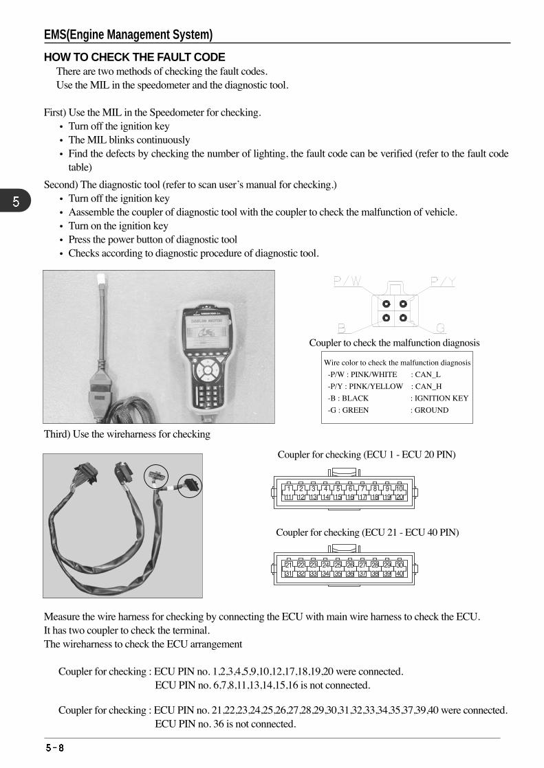
EMS(Engine Management System)
HOW TO CHECK THE FAULT CODEThere are two methods of checking the fault codes.Use the MIL in the speedometer and the diagnostic tool.
First) Use the MIL in the Speedometer for checking.• Turn off the ignition key• The MIL blinks continuously• Find the defects by checking the number of lighting, the fault code can be verified (refer to the fault code
table)
Second) The diagnostic tool (refer to scan user’s manual for checking.)• Turn off the ignition key• Aassemble the coupler of diagnostic tool with the coupler to check the malfunction of vehicle.• Turn on the ignition key• Press the power button of diagnostic tool• Checks according to diagnostic procedure of diagnostic tool.
Measure the wire harness for checking by connecting the ECU with main wire harness to check the ECU.It has two coupler to check the terminal.The wireharness to check the ECU arrangement
❶ Coupler for checking : ECU PIN no. 1,2,3,4,5,9,10,12,17,18,19,20 were connected.ECU PIN no. 6,7,8,11,13,14,15,16 is not connected.
❷ Coupler for checking : ECU PIN no. 21,22,23,24,25,26,27,28,29,30,31,32,33,34,35,37,39,40 were connected.ECU PIN no. 36 is not connected.
Wire color to check the malfunction diagnosis
-P/W : PINK/WHITE : CAN_L
-P/Y : PINK/YELLOW : CAN_H
-B : BLACK : IGNITION KEY
-G : GREEN : GROUND
Coupler to check the malfunction diagnosis
❶❷
Third) Use the wireharness for checking
❶ Coupler for checking (ECU 1 - ECU 20 PIN)
❷ Coupler for checking (ECU 21 - ECU 40 PIN)
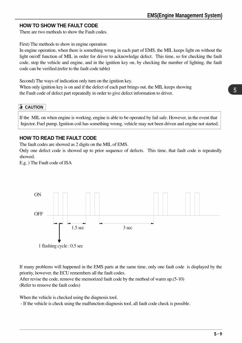
EMS(Engine Management System)
HOW TO SHOW THE FAULT CODEThere are two methods to show the Fault codes.
First) The methods to show in engine operationIn engine operation, when there is something wrong in each part of EMS, the MIL keeps light on without thelight on/off function of MIL in order for driver to acknowledge defect. This time, so for checking the faultcode, stop the vehicle and engine, and in the ignition key on, by checking the number of lighting, the faultcode can be verified.(refer to the fault code table)
Second) The ways of indication only turn on the ignition key.When only ignition key is on and if the defect of each part brings out, the MIL keeps showingthe Fault code of defect part repeatedly in order to give defect information to driver.
If the MIL on when engine is working, engine is able to be operated by fail safe. However, in the event thatInjector, Fuel pump, Ignition coil has something wrong, vehicle may not been driven and engine not started.
HOW TO READ THE FAULT CODEThe fault codes are showed as 2 digits on the MIL of EMS. Only one defect code is showed up to prior sequence of defects. This time, that fault code is repeatedlyshowed. E.g. ) The Fault code of ISA
If many problems will happened in the EMS parts at the same time, only one fault code is displayed by thepriority, however, the ECU remembers all the fault codes.After revise the code, remove the memorized fault code by the method of warm up.(5-10) (Refer to remove the fault codes)
When the vehicle is checked using the diagnosis tool.- If the vehicle is check using the malfunction diagnosis tool, all fault code check is possible.
1 flashing cycle : 0.5 sec
1.5 sec 3 sec
ON
OFF
! CAUTION
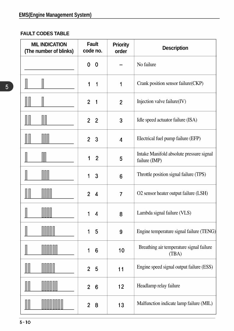
FAULT CODES TABLE
Faultcode no.
Priorityorder
DescriptionMIL INDICATION
(The number of blinks)
No failure
Injection valve failure(IV)
Idle speed actuator failure (ISA)
Electrical fuel pump failure (EFP)
Intake Manifold absolute pressure signal failure (IMP)
Throttle position signal failure (TPS)
O2 sensor heater output failure (LSH)
Lambda signal failure (VLS)
Engine temperature signal failure (TENG)
Breathing air temperature signal failure(TBA)
Engine speed signal output failure (ESS)
Headlamp relay failure
Malfunction indicate lamp failure (MIL)
Crank position sensor failure(CKP)
EMS(Engine Management System)
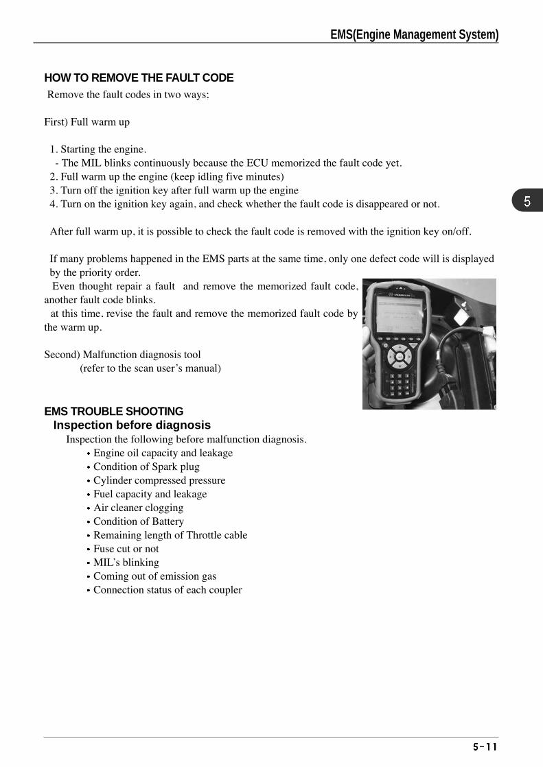
HOW TO REMOVE THE FAULT CODERemove the fault codes in two ways;
First) Full warm up
1. Starting the engine. - The MIL blinks continuously because the ECU memorized the fault code yet.
2. Full warm up the engine (keep idling five minutes)3. Turn off the ignition key after full warm up the engine4. Turn on the ignition key again, and check whether the fault code is disappeared or not.
After full warm up, it is possible to check the fault code is removed with the ignition key on/off.
If many problems happened in the EMS parts at the same time, only one defect code will is displayedby the priority order.Even thought repair a fault and remove the memorized fault code,
another fault code blinks. at this time, revise the fault and remove the memorized fault code by
the warm up.
Second) Malfunction diagnosis tool (refer to the scan user’s manual)
EMS TROUBLE SHOOTINGInspection before diagnosis
Inspection the following before malfunction diagnosis.Engine oil capacity and leakage Condition of Spark plug Cylinder compressed pressure Fuel capacity and leakage Air cleaner clogging Condition of Battery Remaining length of Throttle cable Fuse cut or not MIL’s blinking Coming out of emission gas Connection status of each coupler
EMS(Engine Management System)
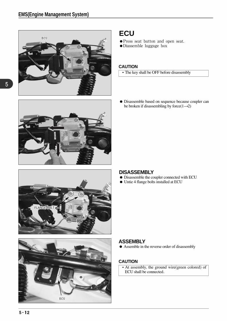
Disassemble based on sequence because coupler canbe broken if disassembling by force(1 2)
ASSEMBLY Assemble in the reverse order of disassembly
DISASSEMBLY Disassemble the coupler connected with ECU Untie 4 flange bolts installed at ECU
ECUECUECUECUECUECUECUECUECUECUECUECUECUECUECUECUECUECUECUECUECUECU
ECUECUECUECUECUECUECUECUECUECUECUECUECUECUECUECUECUECUECUECUECUECU
FLANGE BOLTFLANGE BOLTFLANGE BOLTFLANGE BOLTFLANGE BOLTFLANGE BOLTFLANGE BOLTFLANGE BOLTFLANGE BOLTFLANGE BOLTFLANGE BOLTFLANGE BOLTFLANGE BOLTFLANGE BOLTFLANGE BOLTFLANGE BOLTFLANGE BOLTFLANGE BOLTFLANGE BOLTFLANGE BOLTFLANGE BOLTFLANGE BOLTFLANGE BOLTFLANGE BOLTFLANGE BOLTFLANGE BOLTFLANGE BOLT
❶❶❶❶❶❶❶❶❶❶❶❶❶❶❶❶❶❶❶❶❶❶
❷❷❷❷❷❷❷❷❷❷❷❷❷❷❷❷❷❷❷❷❷❷
EMS(Engine Management System)
ECUPress seat button and open seat. Diassemble luggage box
CAUTION•The key shall be OFF before disassembly
CAUTION•At assembly, the ground wire(green colored) of
ECU shall be connected.
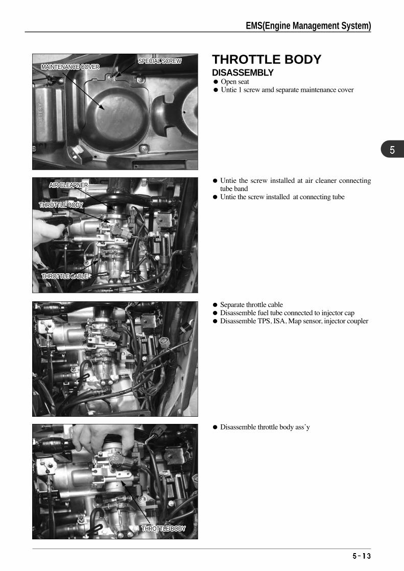
Untie the screw installed at air cleaner connectingtube band
Untie the screw installed at connecting tube
Separate throttle cable Disassemble fuel tube connected to injector cap Disassemble TPS, ISA, Map sensor, injector coupler
Disassemble throttle body ass’y
SPECIAL SCREWSPECIAL SCREWSPECIAL SCREWSPECIAL SCREWSPECIAL SCREWSPECIAL SCREWSPECIAL SCREWSPECIAL SCREWSPECIAL SCREWSPECIAL SCREWSPECIAL SCREWSPECIAL SCREWSPECIAL SCREWSPECIAL SCREWSPECIAL SCREWSPECIAL SCREWSPECIAL SCREWSPECIAL SCREWSPECIAL SCREWSPECIAL SCREWSPECIAL SCREWSPECIAL SCREWSPECIAL SCREWSPECIAL SCREWSPECIAL SCREWSPECIAL SCREWSPECIAL SCREWMAINTENANCE COVERMAINTENANCE COVERMAINTENANCE COVERMAINTENANCE COVERMAINTENANCE COVERMAINTENANCE COVERMAINTENANCE COVERMAINTENANCE COVERMAINTENANCE COVERMAINTENANCE COVERMAINTENANCE COVERMAINTENANCE COVERMAINTENANCE COVERMAINTENANCE COVERMAINTENANCE COVERMAINTENANCE COVERMAINTENANCE COVERMAINTENANCE COVERMAINTENANCE COVERMAINTENANCE COVERMAINTENANCE COVERMAINTENANCE COVERMAINTENANCE COVERMAINTENANCE COVERMAINTENANCE COVERMAINTENANCE COVERMAINTENANCE COVER
AIR CLEARNERAIR CLEARNERAIR CLEARNERAIR CLEARNERAIR CLEARNERAIR CLEARNERAIR CLEARNERAIR CLEARNERAIR CLEARNERAIR CLEARNERAIR CLEARNERAIR CLEARNERAIR CLEARNERAIR CLEARNERAIR CLEARNERAIR CLEARNERAIR CLEARNERAIR CLEARNERAIR CLEARNERAIR CLEARNERAIR CLEARNERAIR CLEARNERAIR CLEARNERAIR CLEARNERAIR CLEARNERAIR CLEARNERAIR CLEARNER
THROTTLE BODYTHROTTLE BODYTHROTTLE BODYTHROTTLE BODYTHROTTLE BODYTHROTTLE BODYTHROTTLE BODYTHROTTLE BODYTHROTTLE BODYTHROTTLE BODYTHROTTLE BODYTHROTTLE BODYTHROTTLE BODYTHROTTLE BODYTHROTTLE BODYTHROTTLE BODYTHROTTLE BODYTHROTTLE BODYTHROTTLE BODYTHROTTLE BODYTHROTTLE BODYTHROTTLE BODYTHROTTLE BODYTHROTTLE BODYTHROTTLE BODYTHROTTLE BODYTHROTTLE BODY
THROTTLE BODYTHROTTLE BODYTHROTTLE BODYTHROTTLE BODYTHROTTLE BODYTHROTTLE BODYTHROTTLE BODYTHROTTLE BODYTHROTTLE BODYTHROTTLE BODYTHROTTLE BODYTHROTTLE BODYTHROTTLE BODYTHROTTLE BODYTHROTTLE BODYTHROTTLE BODYTHROTTLE BODYTHROTTLE BODYTHROTTLE BODYTHROTTLE BODYTHROTTLE BODYTHROTTLE BODYTHROTTLE BODYTHROTTLE BODYTHROTTLE BODYTHROTTLE BODYTHROTTLE BODY
THROTTLE CABLETHROTTLE CABLETHROTTLE CABLETHROTTLE CABLETHROTTLE CABLETHROTTLE CABLETHROTTLE CABLETHROTTLE CABLETHROTTLE CABLETHROTTLE CABLETHROTTLE CABLETHROTTLE CABLETHROTTLE CABLETHROTTLE CABLETHROTTLE CABLETHROTTLE CABLETHROTTLE CABLETHROTTLE CABLETHROTTLE CABLETHROTTLE CABLETHROTTLE CABLETHROTTLE CABLETHROTTLE CABLETHROTTLE CABLETHROTTLE CABLETHROTTLE CABLETHROTTLE CABLE
EMS(Engine Management System)
THROTTLE BODYDISASSEMBLY Open seat Untie 1 screw amd separate maintenance cover
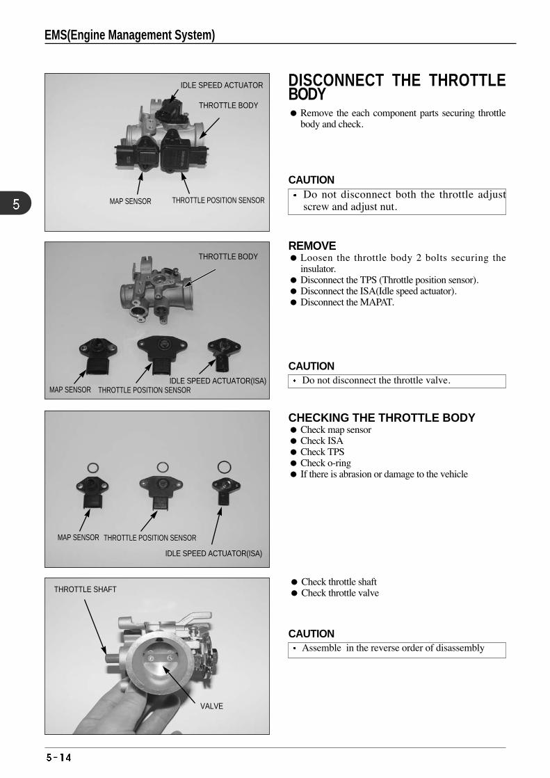
REMOVE Loosen the throttle body 2 bolts securing the
insulator. Disconnect the TPS (Throttle position sensor). Disconnect the ISA(Idle speed actuator). Disconnect the MAPAT.
CHECKING THE THROTTLE BODY Check map sensor Check ISA Check TPS Check o-ring If there is abrasion or damage to the vehicle
Check throttle shaft Check throttle valve
DISCONNECT THE THROTTLEBODY Remove the each component parts securing throttle
body and check.
MAP SENSOR THROTTLE POSITION SENSOR
IDLE SPEED ACTUATOR
VALVE
THROTTLE BODY
THROTTLE BODY
MAP SENSOR THROTTLE POSITION SENSORIDLE SPEED ACTUATOR(ISA)
MAP SENSOR THROTTLE POSITION SENSOR
IDLE SPEED ACTUATOR(ISA)
THROTTLE SHAFT
CAUTIONDo not disconnect both the throttle adjustscrew and adjust nut.
CAUTIONDo not disconnect the throttle valve.
CAUTIONAssemble in the reverse order of disassembly
EMS(Engine Management System)
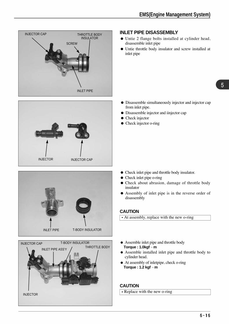
Assemble inlet pipe and throttle bodyTorque : 1.0kgf m
Assemble installed inlet pipe and throttle body tocylinder head.
At assembly of inletpipe, check o-ringTorque : 1.2 kgf m
Check inlet pipe and throttle body insulator. Check inlet pipe o-ring Check about abrasion, damage of throttle body
insulator Assembly of inlet pipe is in the reverse order of
disassembly
Disassemble simultaneously injector and injector capfrom inlet pipe.
Disassemble injector and iinjector cap Check injector Check injector o-ring
INLET PIPE DISASSEMBLY Untie 2 flange bolts installed at cylinder head,
disassemble inlet pipe Untie throttle body insulator and screw installed at
inlet pipe
INJECTOR CAP THROTTLE BODYINSULATOR
SCREW
INLET PIPE
INJECTOR INJECTOR CAP
INLET PIPE T-BODY INSULATOR
INJECTOR CAP
INJECTOR
INLET PIPE ASS’Y
T-BODY INSULATORTHROTTLE BODY
CAUTIONAt assembly, replace with the new o-ring
CAUTIONReplace with the new o-ring
EMS(Engine Management System)
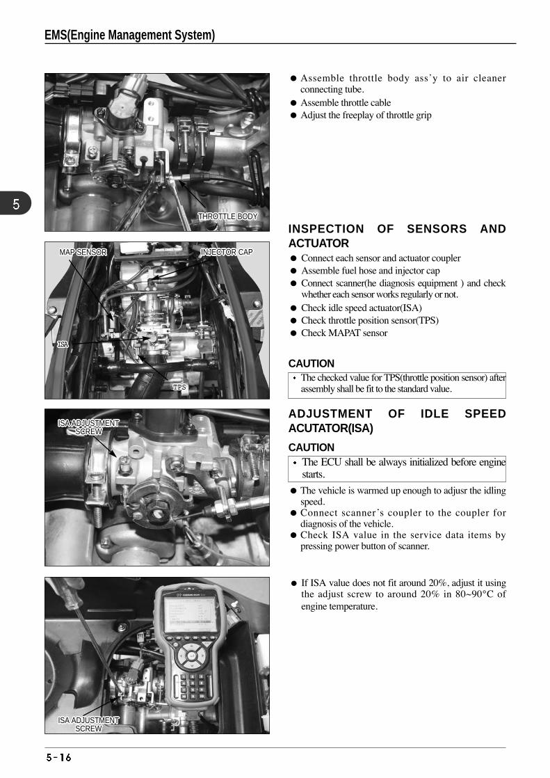
ADJUSTMENT OF IDLE SPEEDACUTATOR(ISA)
The vehicle is warmed up enough to adjusr the idlingspeed.
Connect scanner’s coupler to the coupler fordiagnosis of the vehicle.
Check ISA value in the service data items bypressing power button of scanner.
INSPECTION OF SENSORS ANDACTUATOR Connect each sensor and actuator coupler Assemble fuel hose and injector cap Connect scanner(he diagnosis equipment ) and check
whether each sensor works regularly or not. Check idle speed actuator(ISA) Check throttle position sensor(TPS) Check MAPAT sensor
Assemble throttle body ass’y to air cleanerconnecting tube.
Assemble throttle cable Adjust the freeplay of throttle grip
If ISA value does not fit around 20%, adjust it usingthe adjust screw to around 20% in 80~90°C ofengine temperature.
THROTTLE BODYTHROTTLE BODYTHROTTLE BODYTHROTTLE BODYTHROTTLE BODYTHROTTLE BODYTHROTTLE BODYTHROTTLE BODYTHROTTLE BODYTHROTTLE BODYTHROTTLE BODYTHROTTLE BODYTHROTTLE BODYTHROTTLE BODYTHROTTLE BODYTHROTTLE BODYTHROTTLE BODYTHROTTLE BODYTHROTTLE BODYTHROTTLE BODYTHROTTLE BODYTHROTTLE BODYTHROTTLE BODYTHROTTLE BODYTHROTTLE BODYTHROTTLE BODYTHROTTLE BODY
MAP SENSORMAP SENSORMAP SENSORMAP SENSORMAP SENSORMAP SENSORMAP SENSORMAP SENSORMAP SENSORMAP SENSORMAP SENSORMAP SENSORMAP SENSORMAP SENSORMAP SENSORMAP SENSORMAP SENSORMAP SENSORMAP SENSORMAP SENSORMAP SENSORMAP SENSORMAP SENSORMAP SENSORMAP SENSORMAP SENSORMAP SENSOR
ISAISAISAISAISAISAISAISAISAISAISAISAISAISAISAISAISAISAISAISAISAISA
TPSTPSTPSTPSTPSTPSTPSTPSTPSTPSTPSTPSTPSTPSTPSTPSTPSTPSTPSTPSTPSTPS
INJECTOR CAPINJECTOR CAPINJECTOR CAPINJECTOR CAPINJECTOR CAPINJECTOR CAPINJECTOR CAPINJECTOR CAPINJECTOR CAPINJECTOR CAPINJECTOR CAPINJECTOR CAPINJECTOR CAPINJECTOR CAPINJECTOR CAPINJECTOR CAPINJECTOR CAPINJECTOR CAPINJECTOR CAPINJECTOR CAPINJECTOR CAPINJECTOR CAPINJECTOR CAPINJECTOR CAPINJECTOR CAPINJECTOR CAPINJECTOR CAP
ISA ADJUSTMENTSCREW
ISA ADJUSTMENTSCREW
ISA ADJUSTMENTSCREW
ISA ADJUSTMENTSCREW
ISA ADJUSTMENTSCREW
ISA ADJUSTMENTSCREW
ISA ADJUSTMENTSCREW
ISA ADJUSTMENTSCREW
ISA ADJUSTMENTSCREW
ISA ADJUSTMENTSCREW
ISA ADJUSTMENTSCREW
ISA ADJUSTMENTSCREW
ISA ADJUSTMENTSCREW
ISA ADJUSTMENTSCREW
ISA ADJUSTMENTSCREW
ISA ADJUSTMENTSCREW
ISA ADJUSTMENTSCREW
ISA ADJUSTMENTSCREW
ISA ADJUSTMENTSCREW
ISA ADJUSTMENTSCREW
ISA ADJUSTMENTSCREW
ISA ADJUSTMENTSCREW
ISA ADJUSTMENTSCREW
ISA ADJUSTMENTSCREW
ISA ADJUSTMENTSCREW
ISA ADJUSTMENTSCREW
ISA ADJUSTMENTSCREW
EMS(Engine Management System)
CAUTIONThe checked value for TPS(throttle position sensor) afterassembly shall be fit to the standard value.
CAUTIONThe ECU shall be always initialized before enginestarts.
ISA ADJUSTMENTSCREW
ISA ADJUSTMENTSCREW
ISA ADJUSTMENTSCREW
ISA ADJUSTMENTSCREW
ISA ADJUSTMENTSCREW
ISA ADJUSTMENTSCREW
ISA ADJUSTMENTSCREW
ISA ADJUSTMENTSCREW
ISA ADJUSTMENTSCREW
ISA ADJUSTMENTSCREW
ISA ADJUSTMENTSCREW
ISA ADJUSTMENTSCREW
ISA ADJUSTMENTSCREW
ISA ADJUSTMENTSCREW
ISA ADJUSTMENTSCREW
ISA ADJUSTMENTSCREW
ISA ADJUSTMENTSCREW
ISA ADJUSTMENTSCREW
ISA ADJUSTMENTSCREW
ISA ADJUSTMENTSCREW
ISA ADJUSTMENTSCREW
ISA ADJUSTMENTSCREW
ISA ADJUSTMENTSCREW
ISA ADJUSTMENTSCREW
ISA ADJUSTMENTSCREW
ISA ADJUSTMENTSCREW
ISA ADJUSTMENTSCREW
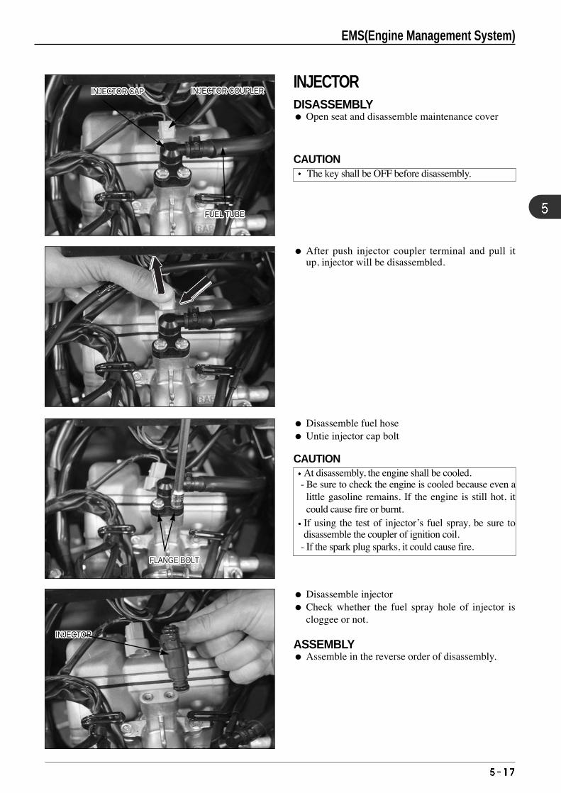
Disassemble fuel hose Untie injector cap bolt
Disassemble injector Check whether the fuel spray hole of injector is
cloggee or not.
ASSEMBLY Assemble in the reverse order of disassembly.
After push injector coupler terminal and pull itup, injector will be disassembled.
INJECTOR CAPINJECTOR CAPINJECTOR CAPINJECTOR CAPINJECTOR CAPINJECTOR CAPINJECTOR CAPINJECTOR CAPINJECTOR CAPINJECTOR CAPINJECTOR CAPINJECTOR CAPINJECTOR CAPINJECTOR CAPINJECTOR CAPINJECTOR CAPINJECTOR CAPINJECTOR CAPINJECTOR CAPINJECTOR CAPINJECTOR CAPINJECTOR CAPINJECTOR CAPINJECTOR CAPINJECTOR CAPINJECTOR CAPINJECTOR CAP INJECTOR COUPLERINJECTOR COUPLERINJECTOR COUPLERINJECTOR COUPLERINJECTOR COUPLERINJECTOR COUPLERINJECTOR COUPLERINJECTOR COUPLERINJECTOR COUPLERINJECTOR COUPLERINJECTOR COUPLERINJECTOR COUPLERINJECTOR COUPLERINJECTOR COUPLERINJECTOR COUPLERINJECTOR COUPLERINJECTOR COUPLERINJECTOR COUPLERINJECTOR COUPLERINJECTOR COUPLERINJECTOR COUPLERINJECTOR COUPLERINJECTOR COUPLERINJECTOR COUPLERINJECTOR COUPLERINJECTOR COUPLERINJECTOR COUPLER
FUEL TUBEFUEL TUBEFUEL TUBEFUEL TUBEFUEL TUBEFUEL TUBEFUEL TUBEFUEL TUBEFUEL TUBEFUEL TUBEFUEL TUBEFUEL TUBEFUEL TUBEFUEL TUBEFUEL TUBEFUEL TUBEFUEL TUBEFUEL TUBEFUEL TUBEFUEL TUBEFUEL TUBEFUEL TUBEFUEL TUBEFUEL TUBEFUEL TUBEFUEL TUBEFUEL TUBE
FLANGE BOLTFLANGE BOLTFLANGE BOLTFLANGE BOLTFLANGE BOLTFLANGE BOLTFLANGE BOLTFLANGE BOLTFLANGE BOLTFLANGE BOLTFLANGE BOLTFLANGE BOLTFLANGE BOLTFLANGE BOLTFLANGE BOLTFLANGE BOLTFLANGE BOLTFLANGE BOLTFLANGE BOLTFLANGE BOLTFLANGE BOLTFLANGE BOLTFLANGE BOLTFLANGE BOLTFLANGE BOLTFLANGE BOLTFLANGE BOLT
INJECTORINJECTORINJECTORINJECTORINJECTORINJECTORINJECTORINJECTORINJECTORINJECTORINJECTORINJECTORINJECTORINJECTORINJECTORINJECTORINJECTORINJECTORINJECTORINJECTORINJECTORINJECTORINJECTORINJECTORINJECTORINJECTORINJECTOR
❶❶❶❶❶❶❶❶❶❶❶❶❶❶❶❶❶❶❶❶❶❶
❷❷❷❷❷❷❷❷❷❷❷❷❷❷❷❷❷❷❷❷❷❷
EMS(Engine Management System)
CAUTIONThe key shall be OFF before disassembly.
CAUTIONAt disassembly, the engine shall be cooled.
- Be sure to check the engine is cooled because even alittle gasoline remains. If the engine is still hot, itcould cause fire or burnt.If using the test of injector’s fuel spray, be sure todisassemble the coupler of ignition coil.
- If the spark plug sparks, it could cause fire.
INJECTORDISASSEMBLY Open seat and disassemble maintenance cover
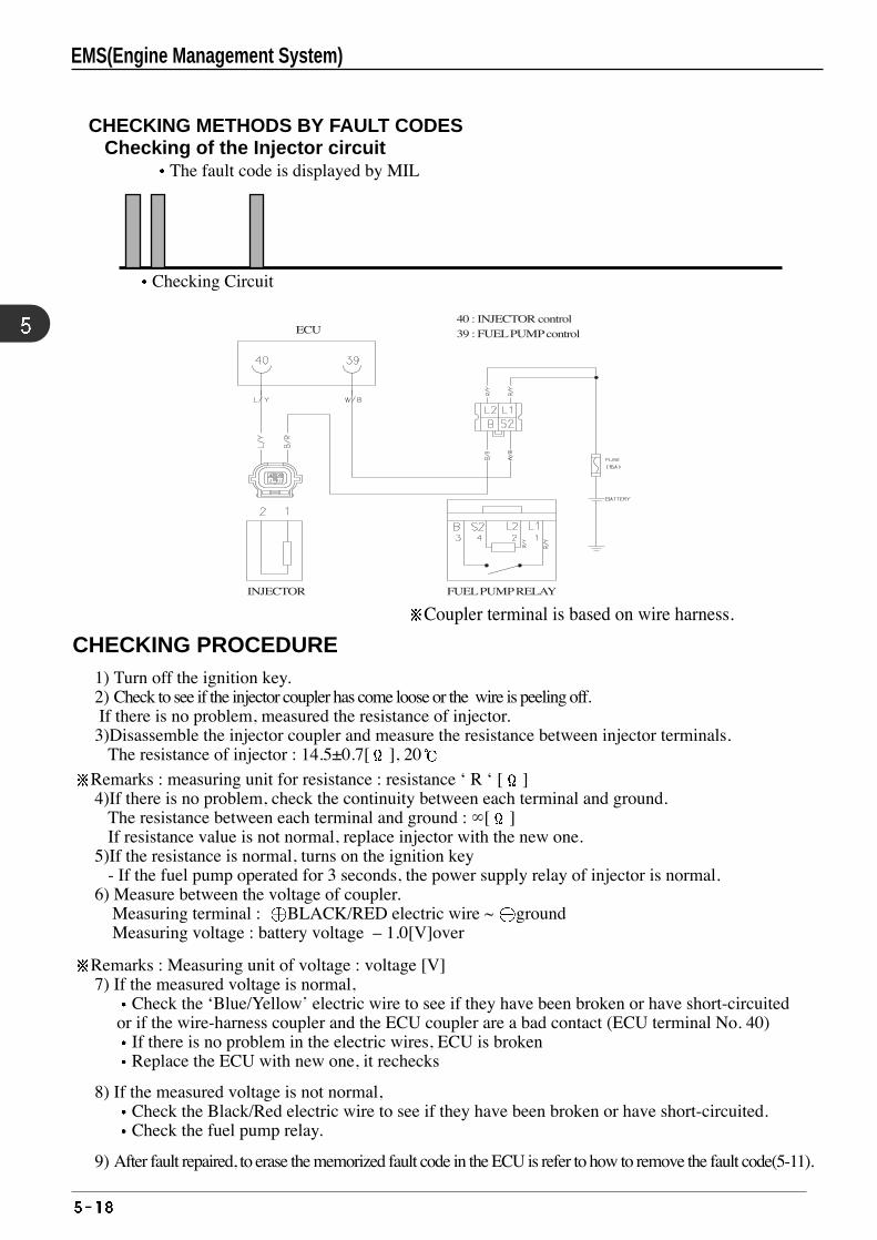
CHECKING METHODS BY FAULT CODESChecking of the Injector circuit
The fault code is displayed by MIL
Checking Circuit
INJECTOR FUEL PUMP RELAY
ECU 40 : INJECTOR control 39 : FUEL PUMP control
CHECKING PROCEDURE1) Turn off the ignition key.2) Check to see if the injector coupler has come loose or the wire is peeling off.If there is no problem, measured the resistance of injector.3)Disassemble the injector coupler and measure the resistance between injector terminals.
The resistance of injector : 14.5±0.7[ ], 20
Remarks : measuring unit for resistance : resistance ‘ R ‘ [ ]4)If there is no problem, check the continuity between each terminal and ground.
The resistance between each terminal and ground : ∞[ ]If resistance value is not normal, replace injector with the new one.
5)If the resistance is normal, turns on the ignition key - If the fuel pump operated for 3 seconds, the power supply relay of injector is normal.
6) Measure between the voltage of coupler.Measuring terminal : BLACK/RED electric wire ~ groundMeasuring voltage : battery voltage – 1.0[V]over
Remarks : Measuring unit of voltage : voltage [V] 7) If the measured voltage is normal,
Check the ‘Blue/Yellow’ electric wire to see if they have been broken or have short-circuited or if the wire-harness coupler and the ECU coupler are a bad contact (ECU terminal No. 40)
If there is no problem in the electric wires, ECU is broken Replace the ECU with new one, it rechecks
8) If the measured voltage is not normal, Check the Black/Red electric wire to see if they have been broken or have short-circuited.Check the fuel pump relay.
9) After fault repaired, to erase the memorized fault code in the ECU is refer to how to remove the fault code(5-11).
Coupler terminal is based on wire harness.
EMS(Engine Management System)
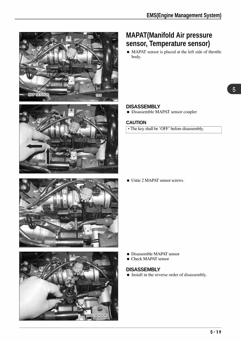
Untie 2 MAPAT sensor screws.
Disassemble MAPAT sensor Check MAPAT sensor
DISASSEMBLY Install in the reverse order of disassembly.
DISASSEMBLY Disassemble MAPAT sensor coupler
TPSTPSTPSTPSTPSTPSTPSTPSTPSTPSTPSTPSTPSTPSTPSTPSTPSTPSTPSTPSTPSTPS
ISAISAISAISAISAISAISAISAISAISAISAISAISAISAISAISAISAISAISAISAISAISA
MAP SENSORMAP SENSORMAP SENSORMAP SENSORMAP SENSORMAP SENSORMAP SENSORMAP SENSORMAP SENSORMAP SENSORMAP SENSORMAP SENSORMAP SENSORMAP SENSORMAP SENSORMAP SENSORMAP SENSORMAP SENSORMAP SENSORMAP SENSORMAP SENSORMAP SENSORMAP SENSORMAP SENSORMAP SENSORMAP SENSORMAP SENSOR
MAP SENSORMAP SENSORMAP SENSORMAP SENSORMAP SENSORMAP SENSORMAP SENSORMAP SENSORMAP SENSORMAP SENSORMAP SENSORMAP SENSORMAP SENSORMAP SENSORMAP SENSORMAP SENSORMAP SENSORMAP SENSORMAP SENSORMAP SENSORMAP SENSORMAP SENSORMAP SENSORMAP SENSORMAP SENSORMAP SENSORMAP SENSOR
❶❶❶❶❶❶❶❶❶❶❶❶❶❶❶❶❶❶❶❶❶❶
❷❷❷❷❷❷❷❷❷❷❷❷❷❷❷❷❷❷❷❷❷❷
MAPAT(Manifold Air pressuresensor, Temperature sensor) MAPAT sensor is placed at the left side of throttle
body.
CAUTIONThe key shall be ‘OFF’ before disassembly.
EMS(Engine Management System)
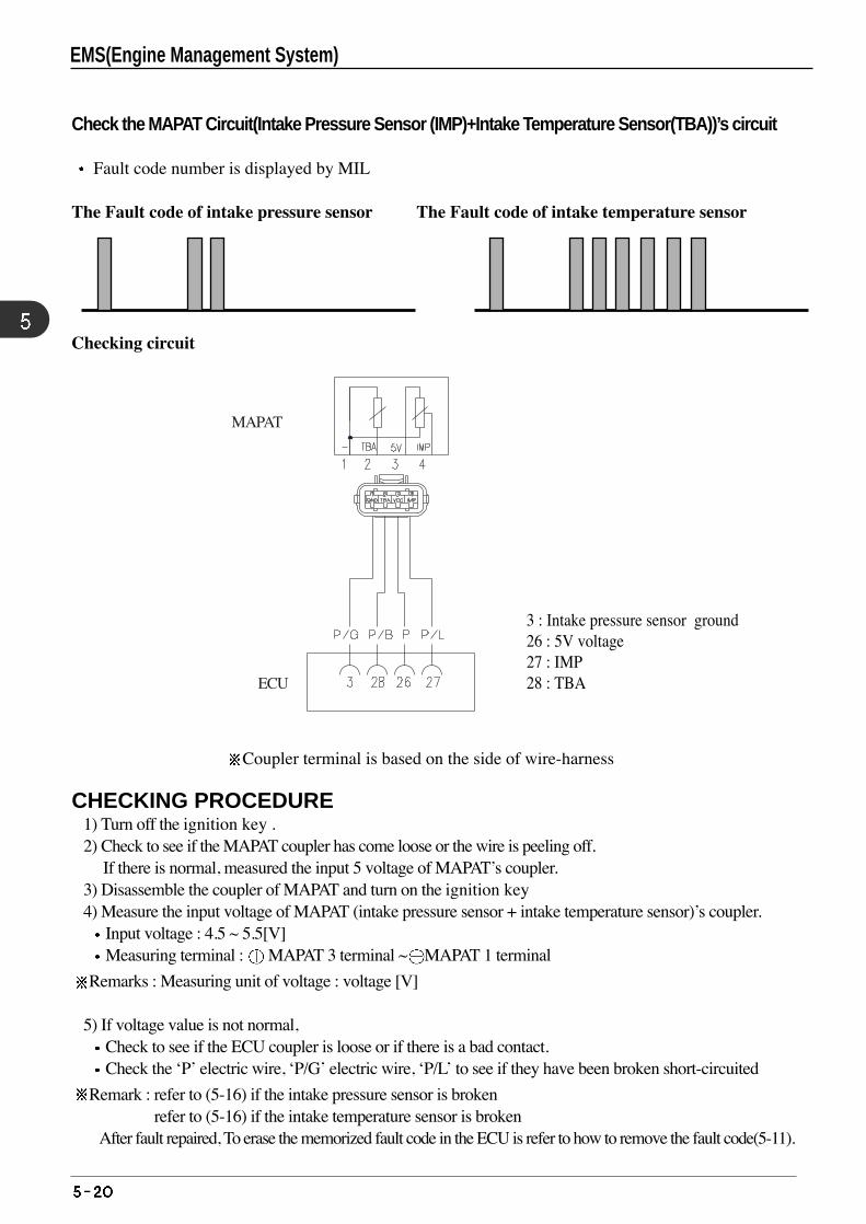
Check the MAPAT Circuit(Intake Pressure Sensor (IMP)+Intake Temperature Sensor(TBA))’s circuit
Fault code number is displayed by MIL
The Fault code of intake pressure sensor The Fault code of intake temperature sensor
Checking circuit
Coupler terminal is based on the side of wire-harness
CHECKING PROCEDURE1) Turn off the ignition key .2) Check to see if the MAPAT coupler has come loose or the wire is peeling off.
If there is normal, measured the input 5 voltage of MAPAT’s coupler.3) Disassemble the coupler of MAPAT and turn on the ignition key4) Measure the input voltage of MAPAT (intake pressure sensor + intake temperature sensor)’s coupler.
Input voltage : 4.5 ~ 5.5[V] Measuring terminal : MAPAT 3 terminal ~ MAPAT 1 terminal
Remarks : Measuring unit of voltage : voltage [V]
5) If voltage value is not normal,Check to see if the ECU coupler is loose or if there is a bad contact.Check the ‘P’ electric wire, ‘P/G’ electric wire, ‘P/L’ to see if they have been broken short-circuited
Remark : refer to (5-16) if the intake pressure sensor is brokenrefer to (5-16) if the intake temperature sensor is broken
After fault repaired, To erase the memorized fault code in the ECU is refer to how to remove the fault code(5-11).
ECU
MAPAT
3 : Inhalation pressure sensor GROUND 26 : 5V voltage 27 : IMP 28 : TBA
3 : Intake pressure sensor ground26 : 5V voltage 27 : IMP 28 : TBA
EMS(Engine Management System)
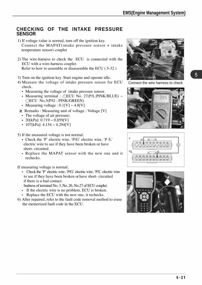
CHECKING OF THE INTAKE PRESSURESENSOR1) If voltage value is normal, turn off the ignition key.
Connect the MAPAT(intake pressure sensor + intaketemperature sensor) coupler
2) The wire-harness to check the ECU is connected with theECU with a wire-harness coupler. Refer to how to assemble or disassemble the ECU ( 5-32 )
3) Turn on the ignition key. Start engine and operate idle.4) Measure the voltage of intake pressure sensor for ECU
check.Measuring the voltage of intake pressure sensor.Measuring terminal : ECU No. 27(P/L:PINK/BLUE) ~
ECU No.3(P/G : PINK/GREEN)Measuring voltage : 0.1[V] ~ 4.8[V]Remarks : Measuring unit of voltage : Voltage [V] The voltage of air pressure;20[kPa]: 0.719 ~ 0.859[V]107[kPa]: 4.154 ~ 4.294[V]
5) If the measured voltage is not normal,Check the ‘P’ electric wire, ‘P/G’ electric wire, ‘P /L’
electric wire to see if they have been broken or have short- circuited. Replace the MAPAT sensor with the new one and itrechecks.
If measuring voltage is normal,Check the ‘P’ electric wire, ‘P/G’ electric wire, ‘P/L’ electric wire
to see if they have been broken or have short- circuited if there is a bad contact. badness of terminal No. 3, No. 26, No.27 of ECU coupler.
If the electric wire is no problem, ECU is broken. Replace the ECU with the new one, it rechecks.
6) After repaired, refer to the fault code removal method to erase the memorized fault code in the ECU.
¤
¤¤¤¤¤¤¤¤¤¤¤¤¤¤¤¤¤¤¤¤¤¤
¤Ł
¤Ł¤Ł¤Ł¤Ł¤Ł¤Ł¤Ł¤Ł¤Ł¤Ł¤Ł¤Ł¤Ł¤Ł¤Ł¤Ł¤Ł¤Ł¤Ł¤Ł¤Ł¤Ł
Connect the wire harness to check
EMS(Engine Management System)
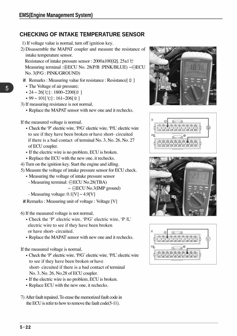
¤
¤Ł
CHECKING OF INTAKE TEMPERATURE SENSOR 1) If voltage value is normal, turn off ignition key. 2) Disassemble the MAPAT coupler and measure the resistance of
intake temperature sensor.Resistance of intake pressure sensor : 2000±100[Ω], 25±1Measuring terminal : ECU No. 28(P/B :PINK/BLUE) ~ ECUNo. 3(P/G : PINK/GROUND)
Remarks : Measuring value for resistance : Resistance[ ]The Voltage of air pressure;24 ~ 26[ ] : 1800~2200[ ]99 ~ 101[ ] : 161~206[ ]
3) If measuring resistance is not normal,Replace the MAPAT sensor with new one and it rechecks.
If the measured voltage is normal, Check the ‘P’ electric wire, ‘P/G’ electric wire, ‘P/L’ electric wire to see if they have been broken or have short- circuited if there is a bad contact of terminal No. 3, No. 26, No. 27 of ECU coupler. If the electric wire is no problem, ECU is broken. Replace the ECU with the new one, it rechecks.
4) Turn on the ignition key. Start the engine and idling. 5) Measure the voltage of intake pressure sensor for ECU check.
Measuring the voltage of intake pressure sensor - Measuring terminal: ECU No.28(TBA)
~ ECU No.3(IMP ground)- Measuring voltage: 0.1[V] ~ 4.9[V]
Remarks : Measuring unit of voltage : Voltage [V]
6) If the measured voltage is not normal,Check the ‘P’ electric wire, ‘P/G’ electric wire, ‘P /L’ electric wire to see if they have been brokenor have short- circuited.Replace the MAPAT sensor with new one and it rechecks.
If the measured voltage is normal, Check the ‘P’ electric wire, ‘P/G’ electric wire, ‘P/L’ electric wire to see if they have been broken or have short- circuited if there is a bad contact of terminal No. 3, No. 26, No.28 of ECU coupler. If the electric wire is no problem, ECU is broken. Replace ECU with the new one, it rechecks.
7) After fault repaired, To erase the memorized fault code in the ECU is refer to how to remove the fault code(5-11).
¤
¤Ł
¤¤¤¤¤¤¤¤¤¤¤¤¤¤¤¤¤¤¤¤¤¤
¤¤¤¤¤¤¤¤¤¤¤¤¤¤¤¤¤¤¤¤¤¤
¤Ł¤Ł¤Ł¤Ł¤Ł¤Ł¤Ł¤Ł¤Ł¤Ł¤Ł¤Ł¤Ł¤Ł¤Ł¤Ł¤Ł¤Ł¤Ł¤Ł¤Ł¤Ł
¤Ł¤Ł¤Ł¤Ł¤Ł¤Ł¤Ł¤Ł¤Ł¤Ł¤Ł¤Ł¤Ł¤Ł¤Ł¤Ł¤Ł¤Ł¤Ł¤Ł¤Ł¤Ł
EMS(Engine Management System)
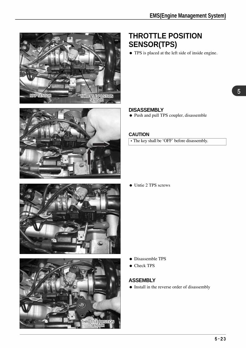
DISASSEMBLY Push and pull TPS coupler, disassemble
Untie 2 TPS screws
Disassemble TPS
Check TPS
ASSEMBLY Install in the reverse order of disassembly
THROTTLE POSITIONSENSOR
THROTTLE POSITIONSENSOR
THROTTLE POSITIONSENSOR
THROTTLE POSITIONSENSOR
THROTTLE POSITIONSENSOR
THROTTLE POSITIONSENSOR
THROTTLE POSITIONSENSOR
THROTTLE POSITIONSENSOR
THROTTLE POSITIONSENSOR
THROTTLE POSITIONSENSOR
THROTTLE POSITIONSENSOR
THROTTLE POSITIONSENSOR
THROTTLE POSITIONSENSOR
THROTTLE POSITIONSENSOR
THROTTLE POSITIONSENSOR
THROTTLE POSITIONSENSOR
THROTTLE POSITIONSENSOR
THROTTLE POSITIONSENSOR
THROTTLE POSITIONSENSOR
THROTTLE POSITIONSENSOR
THROTTLE POSITIONSENSOR
THROTTLE POSITIONSENSOR
THROTTLE POSITIONSENSOR
THROTTLE POSITIONSENSOR
THROTTLE POSITIONSENSOR
THROTTLE POSITIONSENSOR
THROTTLE POSITIONSENSOR
THROTTLE POSITIONSENSOR
THROTTLE POSITIONSENSOR
THROTTLE POSITIONSENSOR
THROTTLE POSITIONSENSOR
THROTTLE POSITIONSENSOR
THROTTLE POSITIONSENSOR
THROTTLE POSITIONSENSOR
THROTTLE POSITIONSENSOR
THROTTLE POSITIONSENSOR
THROTTLE POSITIONSENSOR
THROTTLE POSITIONSENSOR
THROTTLE POSITIONSENSOR
THROTTLE POSITIONSENSOR
THROTTLE POSITIONSENSOR
THROTTLE POSITIONSENSOR
THROTTLE POSITIONSENSOR
THROTTLE POSITIONSENSOR
THROTTLE POSITIONSENSOR
THROTTLE POSITIONSENSOR
THROTTLE POSITIONSENSOR
THROTTLE POSITIONSENSOR
THROTTLE POSITIONSENSOR
THROTTLE POSITIONSENSOR
THROTTLE POSITIONSENSOR
THROTTLE POSITIONSENSOR
THROTTLE POSITIONSENSOR
THROTTLE POSITIONSENSOR
MAP SENSORMAP SENSORMAP SENSORMAP SENSORMAP SENSORMAP SENSORMAP SENSORMAP SENSORMAP SENSORMAP SENSORMAP SENSORMAP SENSORMAP SENSORMAP SENSORMAP SENSORMAP SENSORMAP SENSORMAP SENSORMAP SENSORMAP SENSORMAP SENSORMAP SENSORMAP SENSORMAP SENSORMAP SENSORMAP SENSORMAP SENSOR
ISAISAISAISAISAISAISAISAISAISAISAISAISAISAISAISAISAISAISAISAISAISA
❶❶❶❶❶❶❶❶❶❶❶❶❶❶❶❶❶❶❶❶❶❶
❷❷❷❷❷❷❷❷❷❷❷❷❷❷❷❷❷❷❷❷❷❷
EMS(Engine Management System)
THROTTLE POSITION SENSOR(TPS) TPS is placed at the left side of inside engine.
CAUTIONThe key shall be ‘OFF’ before disassembly.
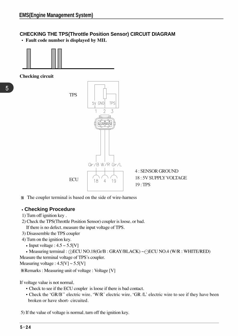
CHECKING THE TPS(Throttle Position Sensor) CIRCUIT DIAGRAM Fault code number is displayed by MIL
Checking circuit
The coupler terminal is based on the side of wire-harness
Checking Procedure1) Turn off ignition key .2) Check the TPS(Throttle Position Sensor) coupler is loose, or bad.
If there is no defect, measure the input voltage of TPS. 3) Disassemble the TPS coupler4) Turn on the ignition key.
Input voltage : 4.5 ~ 5.5[V] Measuring terminal : ECU NO.18(Gr/B : GRAY/BLACK) ~ ECU NO.4 (W/R : WHITE/RED)
Measure the terminal voltage of TPS’s coupler.Measuring voltage : 4.5[V] ~ 5.5[V]
Remarks : Measuring unit of voltage : Voltage [V]
If voltage value is not normal,Check to see if the ECU coupler is loose if there is bad contact.Check the ‘GR/B’’ electric wire, ‘W/R’ electric wire, ‘GR /L’ electric wire to see if they have beenbroken or have short- circuited.
5) If the value of voltage is normal, turn off the ignition key.
EMS(Engine Management System)
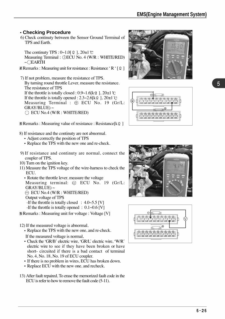
Checking Procedure6) Check continuty between the Sensor Ground Terminal of
TPS and Earth.
The continuty TPS : 0~1.0[ ], 20±1Measuring Terminal : ECU No. 4 (W/R : WHITE/RED)~ EARTH
Remarks : Measuring unit for resistance : Resistance ‘ R ‘ [ ]
7) If not problem, measure the resistance of TPS. By turning round throttle Lever, measure the resistance.The resistance of TPS If the throttle is totally closed : 0.9~1.6[k ], 20±1If the throttle is totally opened : 2.3~2.6[k ], 20±1Measuring Terminal : ECU No. 19 (Gr/L:GRAY/BLUE) ~
ECU No.4 (W/R : WHITE/RED)
Remarks : Measuring value of resistance : Resistance[k ]
8) If resistance and the continuty are not abnormal. Adjust correctly the position of TPS Replace the TPS with the new one and re-check.
9) If resistance and continuty are normal, connect thecoupler of TPS.
10) Turn on the ignition key. 11) Measure the TPS voltage of the wire-harness to check the
ECU. Rotate the throttle lever, measure the voltage
Measuring terminal: ECU No. 19 (Gr/L:GRAY/BLUE) ~
ECU No.4 (W/R : WHITE/RED)Output voltage of TPS-If the throttle is totally closed : 4.0~5.5 [V] -If the throttle is totally opened : 0.1~0.6 [V]
Remarks : Measuring unit for voltage : Voltage [V]
12) If the measured voltage is abnormal,Replace the TPS with the new one, and re-check.
If the measured voltage is normal, Check the ‘GR/B’ electric wire, ‘GR/L’ electric wire, ‘W/R’electric wire to see if they have been broken or haveshort- circuited if there is a bad contact of terminalNo. 4, No. 18, No. 19 of ECU coupler. If there is no problem in wires, ECU has broken down. Replace ECU with the new one, and recheck.
13) After fault repaired, To erase the memorized fault code in theECU is refer to how to remove the fault code (5-11).
EMS(Engine Management System)
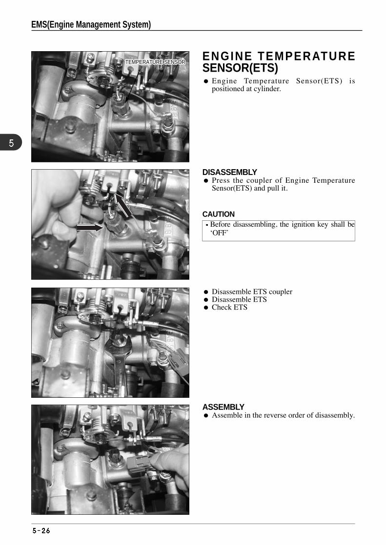
Disassemble ETS coupler Disassemble ETS Check ETS
ASSEMBLY Assemble in the reverse order of disassembly.
TEMPERATURE SENSORTEMPERATURE SENSORTEMPERATURE SENSORTEMPERATURE SENSORTEMPERATURE SENSORTEMPERATURE SENSORTEMPERATURE SENSORTEMPERATURE SENSORTEMPERATURE SENSORTEMPERATURE SENSORTEMPERATURE SENSORTEMPERATURE SENSORTEMPERATURE SENSORTEMPERATURE SENSORTEMPERATURE SENSORTEMPERATURE SENSORTEMPERATURE SENSORTEMPERATURE SENSORTEMPERATURE SENSORTEMPERATURE SENSORTEMPERATURE SENSORTEMPERATURE SENSORTEMPERATURE SENSORTEMPERATURE SENSORTEMPERATURE SENSORTEMPERATURE SENSORTEMPERATURE SENSOR
❶❶❶❶❶❶❶❶❶❶❶❶❶❶❶❶❶❶❶❶❶❶
❷❷❷❷❷❷❷❷❷❷❷❷❷❷❷❷❷❷❷❷❷❷
DISASSEMBLY Press the coupler of Engine Temperature
Sensor(ETS) and pull it.
ENGINE TEMPERATURESENSOR(ETS) Engine Temperature Sensor(ETS) is
positioned at cylinder.
CAUTIONBefore disassembling, the ignition key shall be‘OFF’
EMS(Engine Management System)
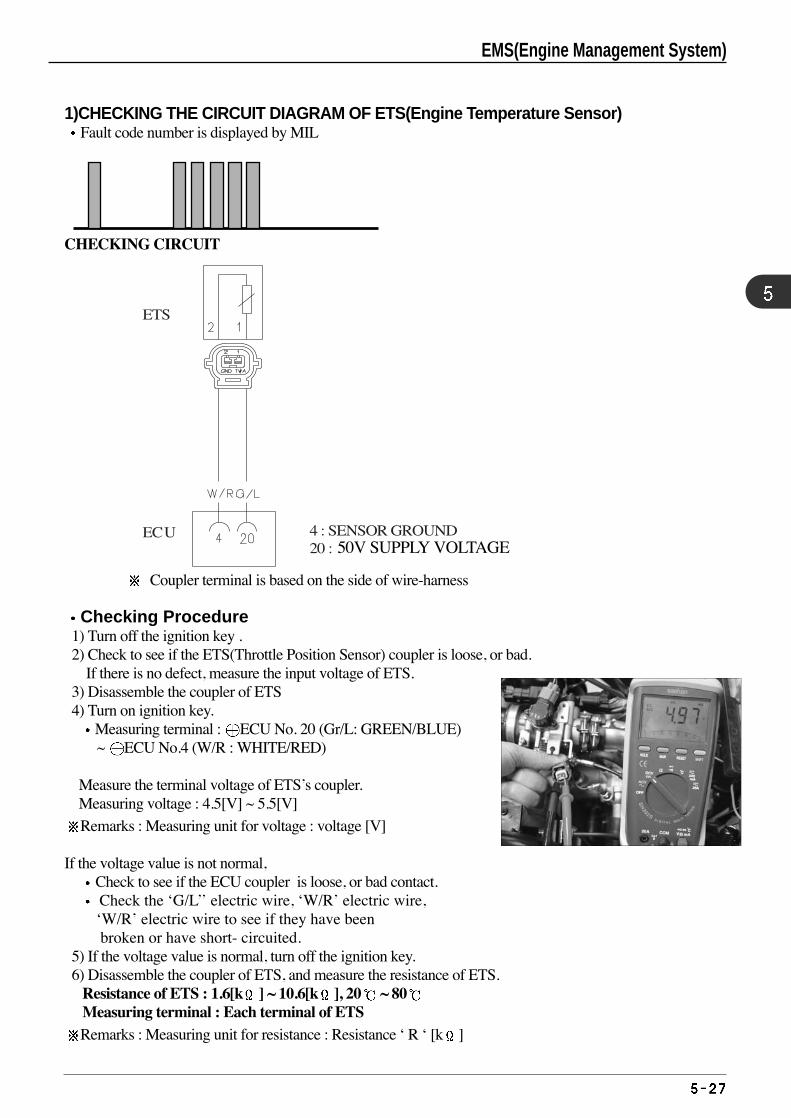
1)CHECKING THE CIRCUIT DIAGRAM OF ETS(Engine Temperature Sensor) Fault code number is displayed by MIL
CHECKING CIRCUIT
Coupler terminal is based on the side of wire-harness
Checking Procedure1) Turn off the ignition key .2) Check to see if the ETS(Throttle Position Sensor) coupler is loose, or bad.
If there is no defect, measure the input voltage of ETS.3) Disassemble the coupler of ETS4) Turn on ignition key.
Measuring terminal : ECU No. 20 (Gr/L: GREEN/BLUE) ~ ECU No.4 (W/R : WHITE/RED)
Measure the terminal voltage of ETS’s coupler.Measuring voltage : 4.5[V] ~ 5.5[V]
Remarks : Measuring unit for voltage : voltage [V]
If the voltage value is not normal,Check to see if the ECU coupler is loose, or bad contact.Check the ‘G/L’’ electric wire, ‘W/R’ electric wire, ‘W/R’ electric wire to see if they have beenbroken or have short- circuited.
5) If the voltage value is normal, turn off the ignition key.6) Disassemble the coupler of ETS, and measure the resistance of ETS.
Resistance of ETS : 1.6[k ] ~ 10.6[k ], 20 ~ 80Measuring terminal : Each terminal of ETSRemarks : Measuring unit for resistance : Resistance ‘ R ‘ [k ]
ECU 4 : SENSOR GROUND 20 : ETS
ETS
50V SUPPLY VOLTAGE
EMS(Engine Management System)
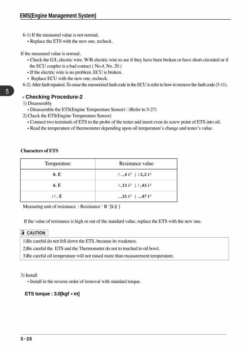
6-1) If the measured value is not normal, Replace the ETS with the new one, recheck.
If the measured value is normal, Check the G/L electric wire, W/R electric wire to see if they have been broken or have short-circuited or ifthe ECU coupler is a bad contact ( No.4, No. 20.)If the electric wire is no problem, ECU is broken. Replace ECU with the new one, recheck.
6-2) After fault repaired, To erase the memorized fault code in the ECU is refer to how to remove the fault code (5-11).
Checking Procedure-21) Disassembly
Disassemble the ETS(Engine Temperature Sensor) : (Refer to 5-27) 2) Check the ETS(Engine Temperature Sensor)
Connect two terminals of ETS to the probe of the tester and insert even its screw point of ETS into oil.Read the temperature of thermometer depending upon oil temperature’s change and tester’s value.
Temperature
20
80
110
Resistance value
10.6 kΩ~14.4 kΩ
1.35 kΩ~1.65 kΩ
0.57 kΩ~0.69 kΩ
Characters of ETS
Measuring unit of resistance : Resistance ‘ R ‘[k ]
If the value of resistance is high or out of the standard value, replace the ETS with the new one.
1)Be careful do not fell down the ETS, because its weakness.
2)Be careful the ETS and the Thermometer do not to touched to oil bowl.
3)Be careful oil temperature will not raised more than measurement temperature.
3) InstallInstall in the reverse order of removal with standard torque.
ETS torque : 3.0[kgf m]
! CAUTION
EMS(Engine Management System)
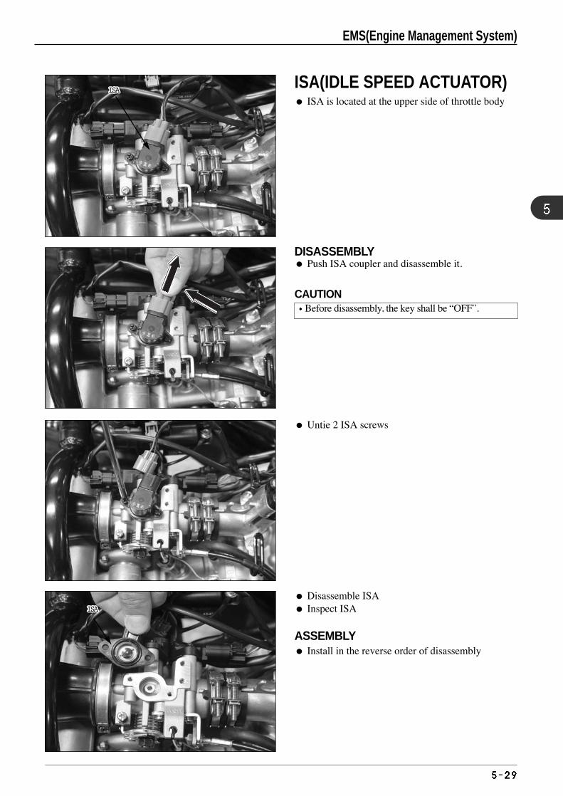
Disassemble ISA Inspect ISA
ASSEMBLY Install in the reverse order of disassembly
Untie 2 ISA screws
DISASSEMBLY Push ISA coupler and disassemble it.
ISAISAISAISAISAISAISAISAISAISAISAISAISAISAISAISAISAISAISAISAISAISA
ISAISAISAISAISAISAISAISAISAISAISAISAISAISAISAISAISAISAISAISAISAISA
❶❶❶❶❶❶❶❶❶❶❶❶❶❶❶❶❶❶❶❶❶❶❷❷❷❷❷❷❷❷❷❷❷❷❷❷❷❷❷❷❷❷❷❷
ISA(IDLE SPEED ACTUATOR) ISA is located at the upper side of throttle body
CAUTIONBefore disassembly, the key shall be “OFF”.
EMS(Engine Management System)
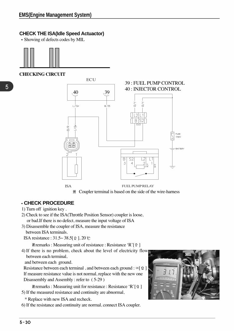
CHECK THE ISA(Idle Speed Actuactor)Showing of defects codes by MIL
CHECKING CIRCUIT
Coupler terminal is based on the side of the wire-harness
CHECK PROCEDURE1) Turn off ignition key .2) Check to see if the ISA(Throttle Position Sensor) coupler is loose,
or bad.If there is no defect, measure the input voltage of ISA 3) Disassemble the coupler of ISA, measure the resistance
between ISA terminals.ISA resistance : 31.5~ 38.5[ ], 20
remarks : Measuring unit of resistance : Resistance ‘R’[ ]4) If there is no problem, check about the level of electricity flow
between each terminal,and between each ground.Resistance between each terminal , and between each ground : ∞[ ] If measure resistance value is not normal, replace with the new one Disassembly and Assembly : refer to ( 5-29 )
remarks : Measuring unit for resistance : Resistance ‘R’[ ]5) If the measured resistance and continuity are abnormal,
* Replace with new ISA and recheck. 6) If the resistance and continuity are normal, connect ISA coupler.
ISA FUEL PUMP RELAY
ECU33 : ISA CONTROL 39:FUEL PUMP 39 : FUEL PUMP CONTROL40 : INJECTOR CONTROL
3940
ISAISAISAISAISAISAISAISAISAISAISAISAISAISAISAISAISAISAISAISAISAISA
EMS(Engine Management System)
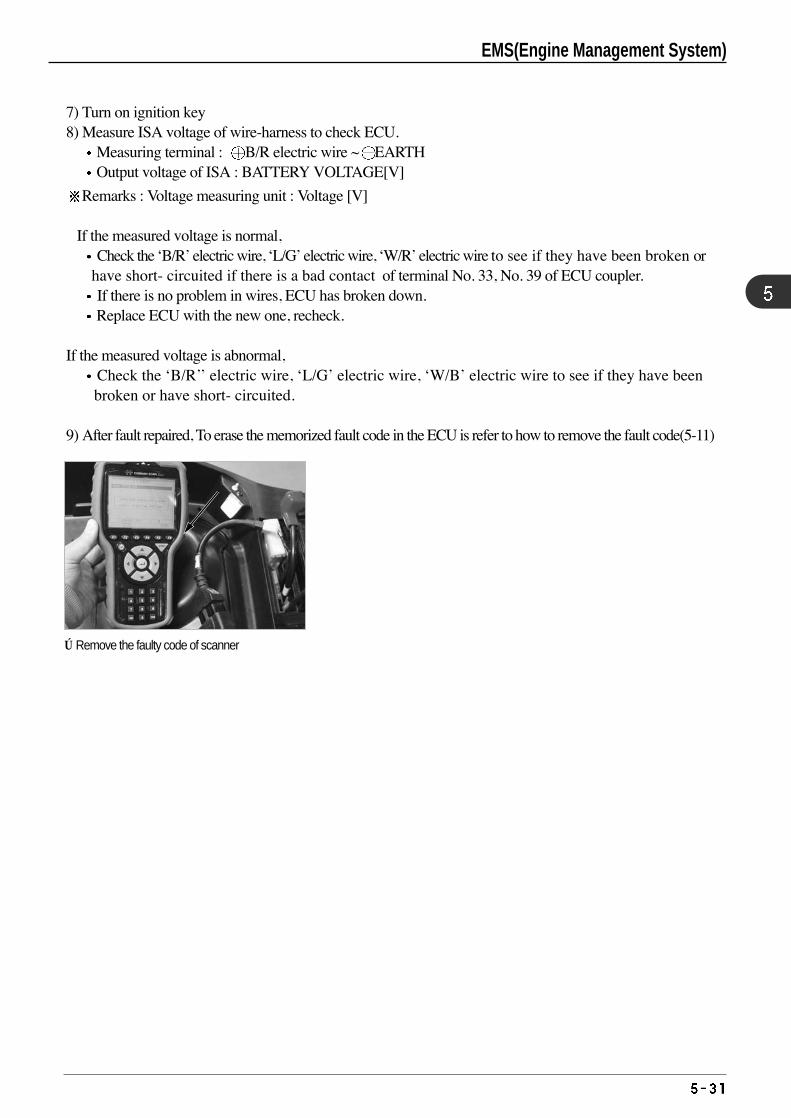
7) Turn on ignition key8) Measure ISA voltage of wire-harness to check ECU.
Measuring terminal : B/R electric wire ~ EARTHOutput voltage of ISA : BATTERY VOLTAGE[V]
Remarks : Voltage measuring unit : Voltage [V]
If the measured voltage is normal,Check the ‘B/R’ electric wire, ‘L/G’ electric wire, ‘W/R’ electric wire to see if they have been broken or
have short- circuited if there is a bad contact of terminal No. 33, No. 39 of ECU coupler. If there is no problem in wires, ECU has broken down. Replace ECU with the new one, recheck.
If the measured voltage is abnormal, Check the ‘B/R’’ electric wire, ‘L/G’ electric wire, ‘W/B’ electric wire to see if they have beenbroken or have short- circuited.
9) After fault repaired, To erase the memorized fault code in the ECU is refer to how to remove the fault code(5-11)
※Remove the faulty code of scanner
EMS(Engine Management System)
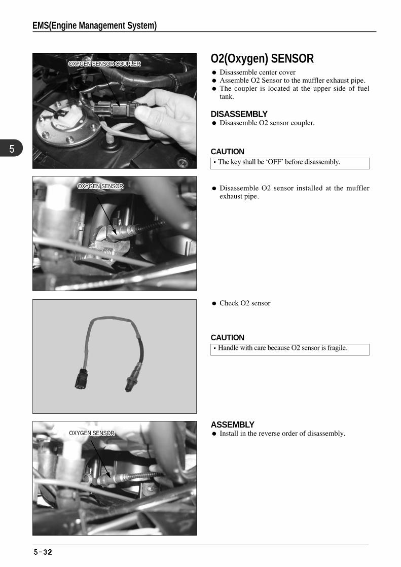
Disassemble O2 sensor installed at the mufflerexhaust pipe.
Check O2 sensor
ASSEMBLY Install in the reverse order of disassembly.
OXYGEN SENSOR COUPLEROXYGEN SENSOR COUPLEROXYGEN SENSOR COUPLEROXYGEN SENSOR COUPLEROXYGEN SENSOR COUPLEROXYGEN SENSOR COUPLEROXYGEN SENSOR COUPLEROXYGEN SENSOR COUPLEROXYGEN SENSOR COUPLEROXYGEN SENSOR COUPLEROXYGEN SENSOR COUPLEROXYGEN SENSOR COUPLEROXYGEN SENSOR COUPLEROXYGEN SENSOR COUPLEROXYGEN SENSOR COUPLEROXYGEN SENSOR COUPLEROXYGEN SENSOR COUPLEROXYGEN SENSOR COUPLEROXYGEN SENSOR COUPLEROXYGEN SENSOR COUPLEROXYGEN SENSOR COUPLEROXYGEN SENSOR COUPLEROXYGEN SENSOR COUPLEROXYGEN SENSOR COUPLEROXYGEN SENSOR COUPLEROXYGEN SENSOR COUPLEROXYGEN SENSOR COUPLER
OXYGEN SENSOR OXYGEN SENSOR OXYGEN SENSOR OXYGEN SENSOR OXYGEN SENSOR OXYGEN SENSOR OXYGEN SENSOR OXYGEN SENSOR OXYGEN SENSOR OXYGEN SENSOR OXYGEN SENSOR OXYGEN SENSOR OXYGEN SENSOR OXYGEN SENSOR OXYGEN SENSOR OXYGEN SENSOR OXYGEN SENSOR OXYGEN SENSOR OXYGEN SENSOR OXYGEN SENSOR OXYGEN SENSOR OXYGEN SENSOR OXYGEN SENSOR OXYGEN SENSOR OXYGEN SENSOR OXYGEN SENSOR OXYGEN SENSOR
OXYGEN SENSOR OXYGEN SENSOR OXYGEN SENSOR OXYGEN SENSOR OXYGEN SENSOR OXYGEN SENSOR OXYGEN SENSOR OXYGEN SENSOR OXYGEN SENSOR OXYGEN SENSOR OXYGEN SENSOR OXYGEN SENSOR OXYGEN SENSOR OXYGEN SENSOR OXYGEN SENSOR OXYGEN SENSOR OXYGEN SENSOR OXYGEN SENSOR OXYGEN SENSOR OXYGEN SENSOR OXYGEN SENSOR OXYGEN SENSOR OXYGEN SENSOR OXYGEN SENSOR OXYGEN SENSOR OXYGEN SENSOR OXYGEN SENSOR
O2(Oxygen) SENSOR Disassemble center cover Assemble O2 Sensor to the muffler exhaust pipe. The coupler is located at the upper side of fuel
tank.
DISASSEMBLY Disassemble O2 sensor coupler.
CAUTIONThe key shall be ‘OFF’ before disassembly.
CAUTIONHandle with care because O2 sensor is fragile.
EMS(Engine Management System)
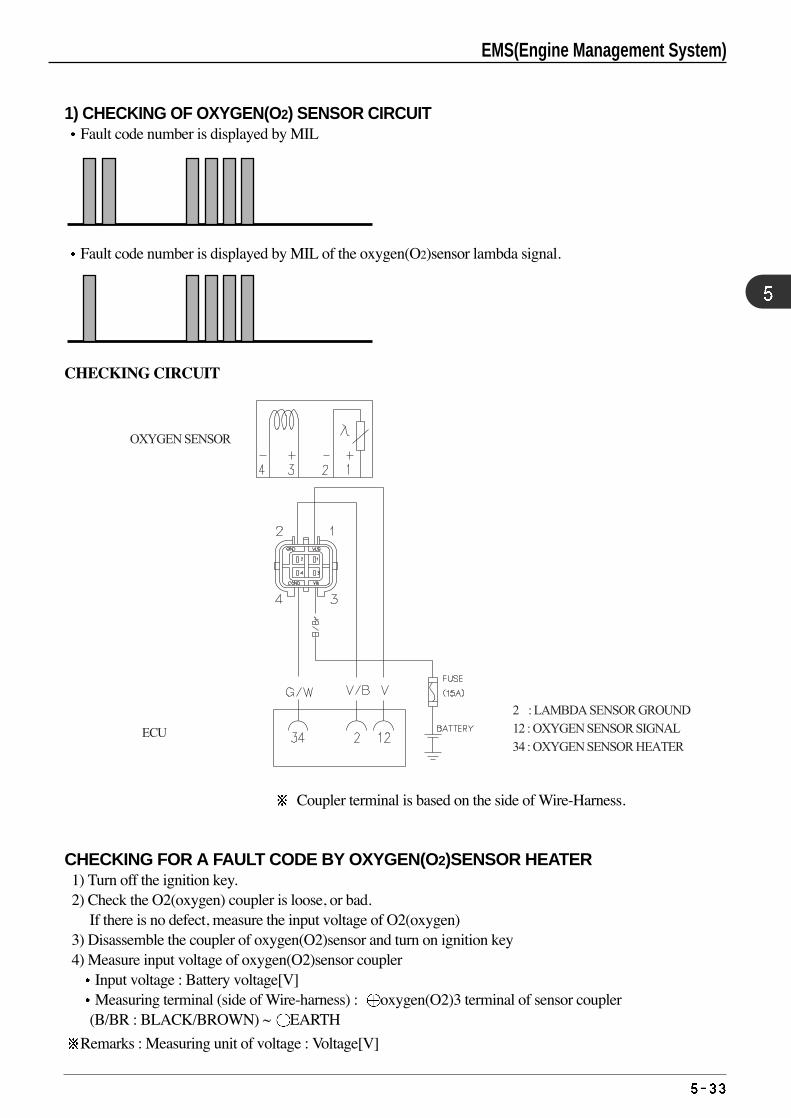
1) CHECKING OF OXYGEN(O2) SENSOR CIRCUIT Fault code number is displayed by MIL
Fault code number is displayed by MIL of the oxygen(O2)sensor lambda signal.
CHECKING CIRCUIT
Coupler terminal is based on the side of Wire-Harness.
CHECKING FOR A FAULT CODE BY OXYGEN(O2)SENSOR HEATER 1) Turn off the ignition key.2) Check the O2(oxygen) coupler is loose, or bad.
If there is no defect, measure the input voltage of O2(oxygen)3) Disassemble the coupler of oxygen(O2)sensor and turn on ignition key4) Measure input voltage of oxygen(O2)sensor coupler
Input voltage : Battery voltage[V] Measuring terminal (side of Wire-harness) : oxygen(O2)3 terminal of sensor coupler
(B/BR : BLACK/BROWN) ~ EARTH
Remarks : Measuring unit of voltage : Voltage[V]
ECU
OXYGEN SENSOR
2 : LAMBDA SENSOR GROUND 12 : OXYGEN SENSOR SIGNAL 34 : OXYGEN SENSOR HEATER
EMS(Engine Management System)
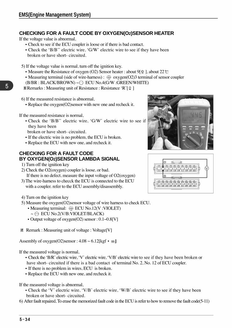
CHECKING FOR A FAULT CODE BY OXYGEN(O2)SENSOR HEATERIf the voltage value is abnormal,
Check to see if the ECU coupler is loose or if there is bad contact.Check the ‘B/B’’ electric wire, ‘G/W’ electric wire to see if they have beenbroken or have short- circuited.
5) If the voltage value is normal, turn off the ignition key. Measure the Resistance of oxygen (O2) Sensor heater : about 9[ ], about 22Measuring terminal (side of wire-harness) : oxygen(O2)3 terminal of sensor coupler
(B/BR : BLACK/BROWN) ~ ECU No.4(G/W :GREEN/WHITE)Remarks : Measuring unit of Resistance : Resistance ‘R’[ ]
6) If the measured resistance is abnormal, Replace the oxygen(O2)sensor with new one and recheck it.
If the measured resistance is normal, Check the ‘B/B’’ electric wire, ‘G/W’ electric wire to see ifthey have beenbroken or have short- circuited.If the electric wire is no problem, the ECU is broken. Replace the ECU with new one, and recheck it.
CHECKING FOR A FAULT CODEBY OXYGEN(O2)SENSOR LAMBDA SIGNAL1) Turn off the ignition key2) Check the O2(oxygen) coupler is loose, or bad.
If there is no defect, measure the input voltage of O2(oxygen) 3) The wire-harness to checck the ECU is connected to the ECU
with a coupler. refer to the ECU assembly/disassembly.
4) Turn on the ignition key5) Measure the oxygen(O2)sensor voltage of wire harness to check ECU.
Measuring terminal: ECU No.12(V :VIOLET) ~ ECU No.2(V/B:VIOLET/BLACK)Output voltage of oxygen(O2) sensor : 0.1~0.8[V]
Remark : Measuring unit of voltage : Voltage[V]
Assembly of oxygen(O2)sensor : 4.08 ~ 6.12[kgf
If the measured voltage is normal, Check the ‘B/R’ electric wire, ‘V’ electric wire, ‘V/B’ electric wire to see if they have been broken or
have short- circuited if there is a bad contact of terminal No. 2, No. 12 of ECU coupler. If there is no problem in wires, ECU is broken. Replace the ECU with new one, and recheck it.
If the measured voltage is abnormal,Check the ‘V’ electric wire, ‘V/B’ electric wire, ‘W/B’ electric wire to see if they have been
broken or have short- circuited.6) After fault repaired, To erase the memorized fault code in the ECU is refer to how to remove the fault code(5-11)
EMS(Engine Management System)
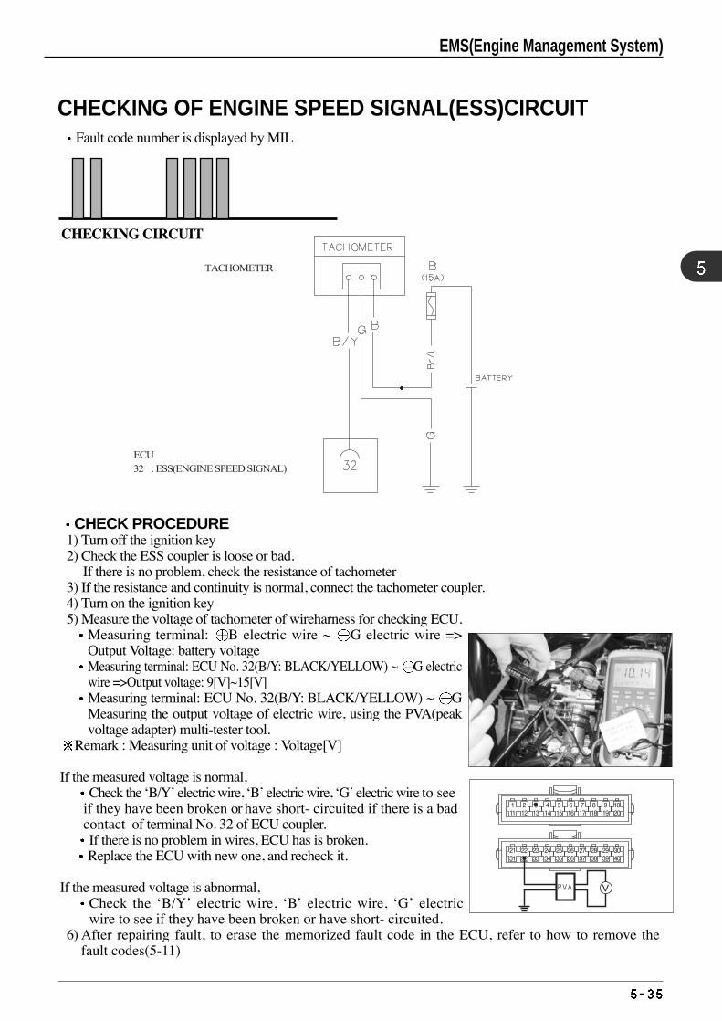
CHECKING OF ENGINE SPEED SIGNAL(ESS)CIRCUITFault code number is displayed by MIL
CHECKING CIRCUIT
CHECK PROCEDURE1) Turn off the ignition key 2) Check the ESS coupler is loose or bad.
If there is no problem, check the resistance of tachometer 3) If the resistance and continuity is normal, connect the tachometer coupler. 4) Turn on the ignition key 5) Measure the voltage of tachometer of wireharness for checking ECU.
Measuring terminal: B electric wire ~ G electric wire =>Output Voltage: battery voltageMeasuring terminal: ECU No. 32(B/Y: BLACK/YELLOW) ~ G electricwire =>Output voltage: 9[V]~15[V]Measuring terminal: ECU No. 32(B/Y: BLACK/YELLOW) ~ GMeasuring the output voltage of electric wire, using the PVA(peakvoltage adapter) multi-tester tool.
Remark : Measuring unit of voltage : Voltage[V]
If the measured voltage is normal,Check the ‘B/Y’ electric wire, ‘B’ electric wire, ‘G’ electric wire to see
if they have been broken or have short- circuited if there is a bad contact of terminal No. 32 of ECU coupler. If there is no problem in wires, ECU has is broken. Replace the ECU with new one, and recheck it.
If the measured voltage is abnormal,Check the ‘B/Y’ electric wire, ‘B’ electric wire, ‘G’ electricwire to see if they have been broken or have short- circuited.
6) After repairing fault, to erase the memorized fault code in the ECU, refer to how to remove thefault codes(5-11)
TACHOMETER
ECU 32 : ESS(ENGINE SPEED SIGNAL)
EMS(Engine Management System)
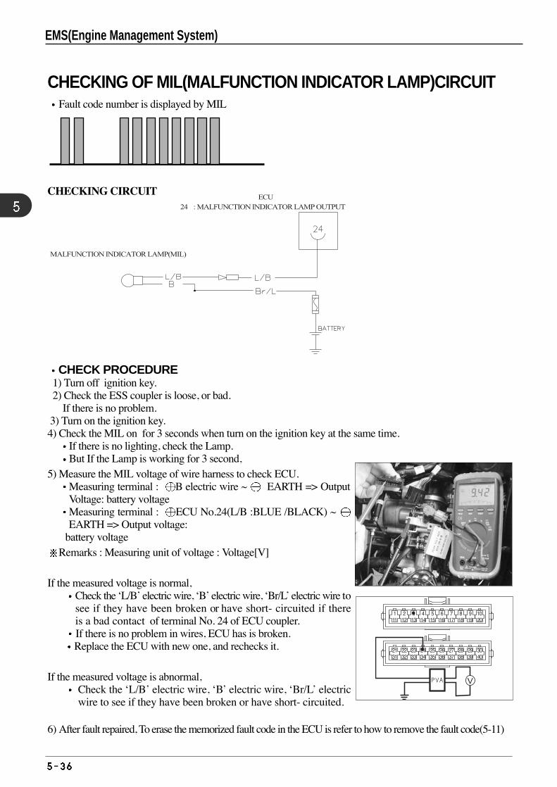
CHECKING OF MIL(MALFUNCTION INDICATOR LAMP)CIRCUITFault code number is displayed by MIL
CHECKING CIRCUIT
CHECK PROCEDURE1) Turn off ignition key.2) Check the ESS coupler is loose, or bad.
If there is no problem.3) Turn on the ignition key. 4) Check the MIL on for 3 seconds when turn on the ignition key at the same time.
If there is no lighting, check the Lamp.But If the Lamp is working for 3 second,
5) Measure the MIL voltage of wire harness to check ECU.Measuring terminal : B electric wire ~ EARTH => OutputVoltage: battery voltageMeasuring terminal : ECU No.24(L/B :BLUE /BLACK) ~ EARTH => Output voltage:
battery voltageRemarks : Measuring unit of voltage : Voltage[V]
If the measured voltage is normal,Check the ‘L/B’ electric wire, ‘B’ electric wire, ‘Br/L’ electric wire tosee if they have been broken or have short- circuited if thereis a bad contact of terminal No. 24 of ECU coupler. If there is no problem in wires, ECU has is broken. Replace the ECU with new one, and rechecks it.
If the measured voltage is abnormal,Check the ‘L/B’ electric wire, ‘B’ electric wire, ‘Br/L’ electricwire to see if they have been broken or have short- circuited.
6) After fault repaired, To erase the memorized fault code in the ECU is refer to how to remove the fault code(5-11)
MALFUNCTION INDICATOR LAMP(MIL)
ECU24 : MALFUNCTION INDICATOR LAMP OUTPUT
EMS(Engine Management System)
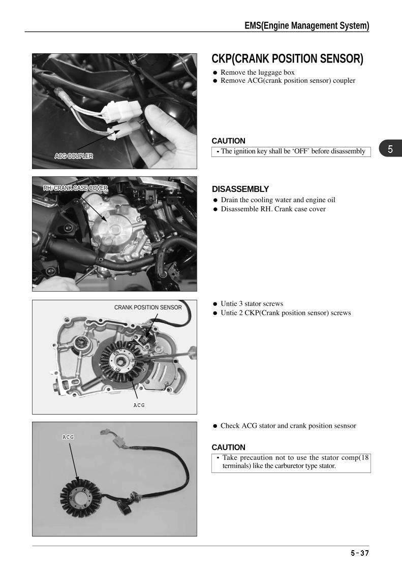
DISASSEMBLY Drain the cooling water and engine oil Disassemble RH. Crank case cover
ACG COUPLERACG COUPLERACG COUPLERACG COUPLERACG COUPLERACG COUPLERACG COUPLERACG COUPLERACG COUPLERACG COUPLERACG COUPLERACG COUPLERACG COUPLERACG COUPLERACG COUPLERACG COUPLERACG COUPLERACG COUPLERACG COUPLERACG COUPLERACG COUPLERACG COUPLERACG COUPLERACG COUPLERACG COUPLERACG COUPLERACG COUPLER
RH. CRANK CASE COVERRH. CRANK CASE COVERRH. CRANK CASE COVERRH. CRANK CASE COVERRH. CRANK CASE COVERRH. CRANK CASE COVERRH. CRANK CASE COVERRH. CRANK CASE COVERRH. CRANK CASE COVERRH. CRANK CASE COVERRH. CRANK CASE COVERRH. CRANK CASE COVERRH. CRANK CASE COVERRH. CRANK CASE COVERRH. CRANK CASE COVERRH. CRANK CASE COVERRH. CRANK CASE COVERRH. CRANK CASE COVERRH. CRANK CASE COVERRH. CRANK CASE COVERRH. CRANK CASE COVERRH. CRANK CASE COVERRH. CRANK CASE COVERRH. CRANK CASE COVERRH. CRANK CASE COVERRH. CRANK CASE COVERRH. CRANK CASE COVER
CRANK POSITION SENSOR
ACGACGACGACGACGACGACGACGACGACGACGACGACGACGACGACGACGACGACGACGACGACG
ACGACGACGACGACGACGACGACGACGACGACGACGACGACGACGACGACGACGACGACGACGACG
Untie 3 stator screws Untie 2 CKP(Crank position sensor) screws
Check ACG stator and crank position sesnsor
CKP(CRANK POSITION SENSOR) Remove the luggage box Remove ACG(crank position sensor) coupler
CAUTIONThe ignition key shall be ‘OFF’ before disassembly
CAUTIONTake precaution not to use the stator comp(18terminals) like the carburetor type stator.
EMS(Engine Management System)
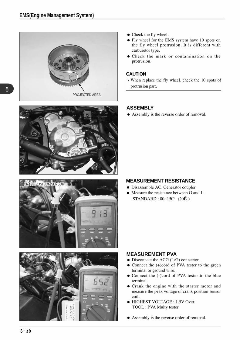
MEASUREMENT RESISTANCE Disassemble AC. Generator coupler Measure the resistance between G and L.
STANDARD : 80~150Ω(20)
MEASUREMENT PVA Disconnect the ACG (L/G) connector. Connect the (+)cord of PVA tester to the green
terminal or ground wire. Connect the (-)cord of PVA tester to the blue
terminal. Crank the engine with the starter motor and
measure the peak voltage of crank position sensorcoil.
HIGHEST VOLTAGE : 1.5V Over. TOOL : PVA Multy tester.
Assembly is the reverse order of removal.
Check the fly wheel. Fly wheel for the EMS system have 10 spots on
the fly wheel protrusion. It is different withcarburetor type.
Check the mark or contamination on theprotrusion.
ASSEMBLY Assembly is the reverse order of removal.
CRANK POSITION SENSORCRANK POSITION SENSORCRANK POSITION SENSORCRANK POSITION SENSORCRANK POSITION SENSORCRANK POSITION SENSORCRANK POSITION SENSORCRANK POSITION SENSORCRANK POSITION SENSORCRANK POSITION SENSORCRANK POSITION SENSORCRANK POSITION SENSORCRANK POSITION SENSORCRANK POSITION SENSORCRANK POSITION SENSORCRANK POSITION SENSORCRANK POSITION SENSORCRANK POSITION SENSORCRANK POSITION SENSORCRANK POSITION SENSORCRANK POSITION SENSORCRANK POSITION SENSORCRANK POSITION SENSORCRANK POSITION SENSORCRANK POSITION SENSORCRANK POSITION SENSORCRANK POSITION SENSOR
PROJECTED AREA
CAUTIONWhen replace the fly wheel, check the 10 spots ofprotrusion part.
EMS(Engine Management System)
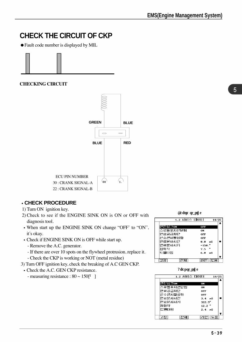
CHECK THE CIRCUIT OF CKPFault code number is displayed by MIL
CHECKING CIRCUIT
CHECK PROCEDURE1) Turn ON ignition key.2) Check to see if the ENGINE SINK ON is ON or OFF with
diagnosis tool.When start up the ENGINE SINK ON change “OFF’ to “ON”,it’s okay.Check if ENGINE SINK ON is OFF while start up.- Remove the A.C. generator.- If there are over 10 spots on the flywheel protrusion, replace it.- Check the CKP is working or NOT (metal residue)
3) Turn OFF ignition key, check the breaking of A.C GEN CKP.Check the A.C. GEN CKP resistance.- measuring resistance : 80 ~ 150[Ω]
ECU 핀 번호
30 : 크랭크 신호 _ A22 : 크랭크 신호 _ B
청색
22 30
적색
청색 녹색
ECU PIN NUMBER
30 : CRANK SIGNAL-A
22 : CRANK SIGNAL-B
GREEN BLUE
REDBLUE
Before starting
After starting
EMS(Engine Management System)
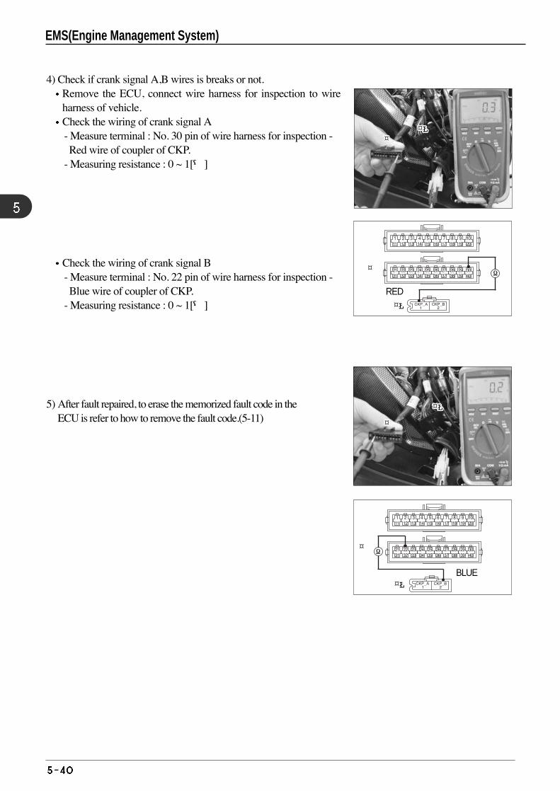
4) Check if crank signal A,B wires is breaks or not.Remove the ECU, connect wire harness for inspection to wireharness of vehicle.Check the wiring of crank signal A- Measure terminal : No. 30 pin of wire harness for inspection - Red wire of coupler of CKP.
- Measuring resistance : 0 ~ 1[Ω]
Check the wiring of crank signal B- Measure terminal : No. 22 pin of wire harness for inspection - Blue wire of coupler of CKP.
- Measuring resistance : 0 ~ 1[Ω]
5) After fault repaired, to erase the memorized fault code in the ECU is refer to how to remove the fault code.(5-11)
BLUE
RED
¤¤¤¤¤¤¤¤¤¤¤¤¤¤¤¤¤¤¤¤¤¤
¤¤¤¤¤¤¤¤¤¤¤¤¤¤¤¤¤¤¤¤¤¤¤Ł¤Ł¤Ł¤Ł¤Ł¤Ł¤Ł¤Ł¤Ł¤Ł¤Ł¤Ł¤Ł¤Ł¤Ł¤Ł¤Ł¤Ł¤Ł¤Ł¤Ł¤Ł
¤Ł¤Ł¤Ł¤Ł¤Ł¤Ł¤Ł¤Ł¤Ł¤Ł¤Ł¤Ł¤Ł¤Ł¤Ł¤Ł¤Ł¤Ł¤Ł¤Ł¤Ł¤Ł
¤
¤Ł
¤
¤Ł
EMS(Engine Management System)
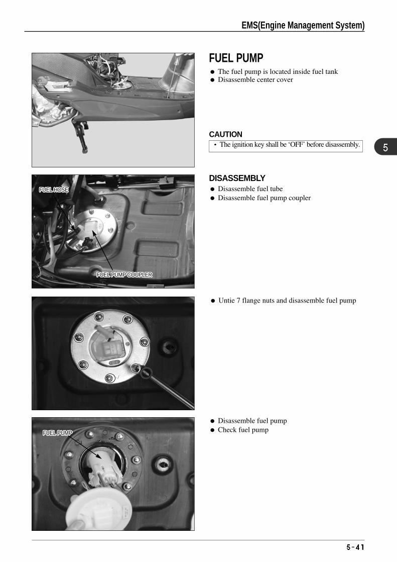
Untie 7 flange nuts and disassemble fuel pump
Disassemble fuel pump Check fuel pump
FUEL HOSEFUEL HOSEFUEL HOSEFUEL HOSEFUEL HOSEFUEL HOSEFUEL HOSEFUEL HOSEFUEL HOSEFUEL HOSEFUEL HOSEFUEL HOSEFUEL HOSEFUEL HOSEFUEL HOSEFUEL HOSEFUEL HOSEFUEL HOSEFUEL HOSEFUEL HOSEFUEL HOSEFUEL HOSEFUEL HOSEFUEL HOSEFUEL HOSEFUEL HOSEFUEL HOSE
FUEL PUMP COUPLERFUEL PUMP COUPLERFUEL PUMP COUPLERFUEL PUMP COUPLERFUEL PUMP COUPLERFUEL PUMP COUPLERFUEL PUMP COUPLERFUEL PUMP COUPLERFUEL PUMP COUPLERFUEL PUMP COUPLERFUEL PUMP COUPLERFUEL PUMP COUPLERFUEL PUMP COUPLERFUEL PUMP COUPLERFUEL PUMP COUPLERFUEL PUMP COUPLERFUEL PUMP COUPLERFUEL PUMP COUPLERFUEL PUMP COUPLERFUEL PUMP COUPLERFUEL PUMP COUPLERFUEL PUMP COUPLERFUEL PUMP COUPLERFUEL PUMP COUPLERFUEL PUMP COUPLERFUEL PUMP COUPLERFUEL PUMP COUPLER
FUEL PUMPFUEL PUMPFUEL PUMPFUEL PUMPFUEL PUMPFUEL PUMPFUEL PUMPFUEL PUMPFUEL PUMPFUEL PUMPFUEL PUMPFUEL PUMPFUEL PUMPFUEL PUMPFUEL PUMPFUEL PUMPFUEL PUMPFUEL PUMPFUEL PUMPFUEL PUMPFUEL PUMPFUEL PUMPFUEL PUMPFUEL PUMPFUEL PUMPFUEL PUMPFUEL PUMP
DISASSEMBLY Disassemble fuel tube Disassemble fuel pump coupler
FUEL PUMP The fuel pump is located inside fuel tank Disassemble center cover
CAUTIONThe ignition key shall be ‘OFF’ before disassembly.
EMS(Engine Management System)
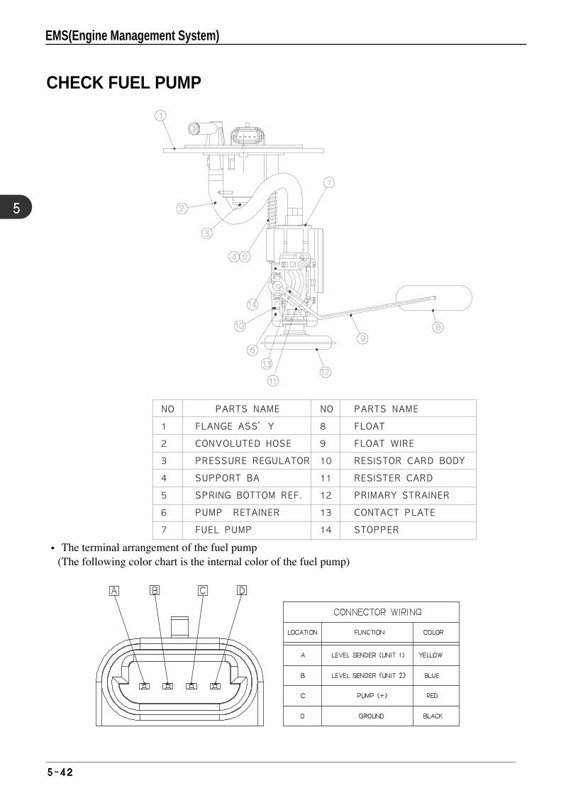
The terminal arrangement of the fuel pump(The following color chart is the internal color of the fuel pump)
CHECK FUEL PUMP
EMS(Engine Management System)
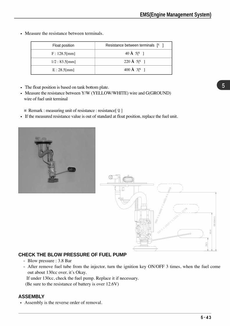
Float position
F : 128.5[mm]
1/2 : 83.5[mm]
E : 28.5[mm]
Resistance between terminals [Ω]
40 ± 5[Ω]
220 ± 5[Ω]
400 ± 3[Ω]
Measure the resistance between terminals.
The float position is based on tank bottom plate.Measure the resistance between Y/W (YELLOW/WHITE) wire and G(GROUND) wire of fuel unit terminal
※ Remark : measuring unit of resistance : resistance[Ω]If the measured resistance value is out of standard at float position, replace the fuel unit.
CHECK THE BLOW PRESSURE OF FUEL PUMP- Blow pressure : 3.8 Bar- After remove fuel tube from the injector, turn the ignition key ON/OFF 3 times, when the fuel come
out about 130cc over, it’s Okay.If under 130cc, check the fuel pump. Replace it if necessary.(Be sure to the resistance of battery is over 12.6V)
ASSEMBLYAssembly is the reverse order of removal.
EMS(Engine Management System)
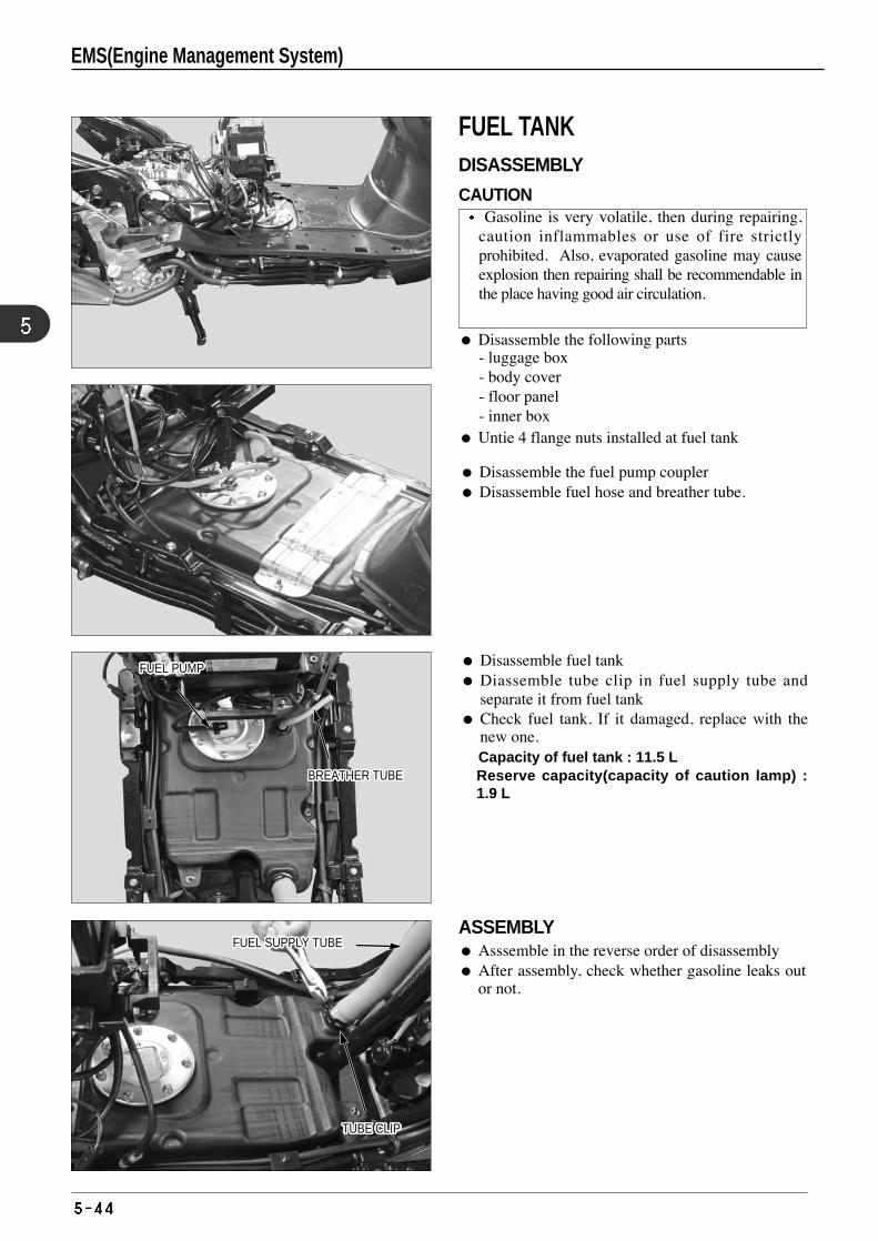
Disassemble the following parts - luggage box- body cover - floor panel - inner box
Untie 4 flange nuts installed at fuel tank
ASSEMBLY Asssemble in the reverse order of disassembly After assembly, check whether gasoline leaks out
or not.
Disassemble fuel tank Diassemble tube clip in fuel supply tube and
separate it from fuel tank Check fuel tank. If it damaged, replace with the
new one.Capacity of fuel tank : 11.5 L Reserve capacity(capacity of caution lamp) :1.9 L
Disassemble the fuel pump coupler Disassemble fuel hose and breather tube.
FUEL PUMPFUEL PUMPFUEL PUMPFUEL PUMPFUEL PUMPFUEL PUMPFUEL PUMPFUEL PUMPFUEL PUMPFUEL PUMPFUEL PUMPFUEL PUMPFUEL PUMPFUEL PUMPFUEL PUMPFUEL PUMPFUEL PUMPFUEL PUMPFUEL PUMPFUEL PUMPFUEL PUMPFUEL PUMPFUEL PUMPFUEL PUMPFUEL PUMPFUEL PUMPFUEL PUMP
BREATHER TUBEBREATHER TUBEBREATHER TUBEBREATHER TUBEBREATHER TUBEBREATHER TUBEBREATHER TUBEBREATHER TUBEBREATHER TUBEBREATHER TUBEBREATHER TUBEBREATHER TUBEBREATHER TUBEBREATHER TUBEBREATHER TUBEBREATHER TUBEBREATHER TUBEBREATHER TUBEBREATHER TUBEBREATHER TUBEBREATHER TUBEBREATHER TUBEBREATHER TUBEBREATHER TUBEBREATHER TUBEBREATHER TUBEBREATHER TUBE
FUEL SUPPLY TUBEFUEL SUPPLY TUBEFUEL SUPPLY TUBEFUEL SUPPLY TUBEFUEL SUPPLY TUBEFUEL SUPPLY TUBEFUEL SUPPLY TUBEFUEL SUPPLY TUBEFUEL SUPPLY TUBEFUEL SUPPLY TUBEFUEL SUPPLY TUBEFUEL SUPPLY TUBEFUEL SUPPLY TUBEFUEL SUPPLY TUBEFUEL SUPPLY TUBEFUEL SUPPLY TUBEFUEL SUPPLY TUBEFUEL SUPPLY TUBEFUEL SUPPLY TUBEFUEL SUPPLY TUBEFUEL SUPPLY TUBEFUEL SUPPLY TUBEFUEL SUPPLY TUBEFUEL SUPPLY TUBEFUEL SUPPLY TUBEFUEL SUPPLY TUBEFUEL SUPPLY TUBE
TUBE CLIPTUBE CLIPTUBE CLIPTUBE CLIPTUBE CLIPTUBE CLIPTUBE CLIPTUBE CLIPTUBE CLIPTUBE CLIPTUBE CLIPTUBE CLIPTUBE CLIPTUBE CLIPTUBE CLIPTUBE CLIPTUBE CLIPTUBE CLIPTUBE CLIPTUBE CLIPTUBE CLIPTUBE CLIPTUBE CLIPTUBE CLIPTUBE CLIPTUBE CLIPTUBE CLIP
FUEL TANK DISASSEMBLY
CAUTIONGasoline is very volatile, then during repairing,
caution inflammables or use of fire strictlyprohibited. Also, evaporated gasoline may causeexplosion then repairing shall be recommendable inthe place having good air circulation.
EMS(Engine Management System)

MEMO
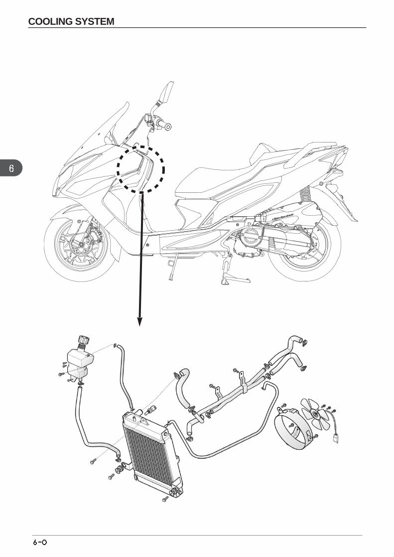
COOLING SYSTEM
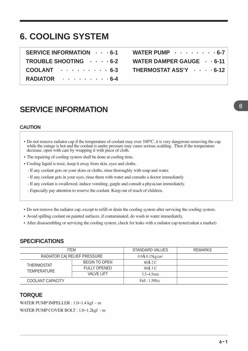
6. COOLING SYSTEM
SERVICE INFORMATION 6-1
TROUBLE SHOOTING 6-2
COOLANT 6-3
RADIATOR 6-4
WATER PUMP 6-7
WATER DAMPER GAUGE 6-11
THERMOSTAT ASS’Y 6-12
•Do not remove the radiator cap, except to refill or drain the cooling system after servicing the cooling system.
•Avoid spilling coolant on painted surfaces, if contaminated, do wash in water immediately.
•After disassembling or servicing the cooling system, check for leaks with a radiator cap tester(saleat a market)
SPECIFICATIONS
TORQUEWATER PUMP IMPELLER : 1.0~1.4 kgf m
WATER PUMP COVER BOLT : 1.0~1.2kgf m
SERVICE INFORMATION
•Do not remove radiator cap if the temperature of coolant may over 100°C, it is very dangerous removing the capwhile the eninge is hot and the coolant is under pressure may cause serious scalding. Then if the temperaturedecrease, open with care by wrapping it with piece of cloth.
•The repairing of cooling system shall be done at cooling time.
•Cooling liquid is toxic, keep it away from skin, eyes and cloths.
- If any coolant gets on your skins or cloths, rinse thoroughly with soap and water.
- If any coolant gets in your eyes, rinse them with water and consults a doctor immediately
- If any coolant is swallowed, induce vomiting, gargle and consult a physician immediately.
- Especially pay attention to reserve the coolant. Keep out of reach of children.
CAUTION
RADIATOR CA[ RELIEF PRESSURE
THERMOSTATTEMPERATURE
BEGIN TO OPENFULLY OPENED
VALVE LIFT
COOLANT CAPACITY Full : 1,500cc
80±2。C90±3。C
3.5~4.5mm
0.9±0.15kg/cm2
ITEM STANDARD VALUES REMARKS
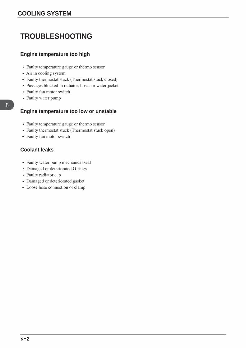
TROUBLESHOOTING
Engine temperature too high
Faulty temperature gauge or thermo sensorAir in cooling systemFaulty thermostat stuck (Thermostat stuck closed)Passages blocked in radiator, hoses or water jacketFaulty fan motor switchFaulty water pump
Engine temperature too low or unstable
Faulty temperature gauge or thermo sensorFaulty thermostat stuck (Thermostat stuck open)Faulty fan motor switch
Coolant leaks
Faulty water pump mechanical sealDamaged or deteriorated O-ringsFaulty radiator capDamaged or deteriorated gasketLoose hose connection or clamp
COOLING SYSTEM
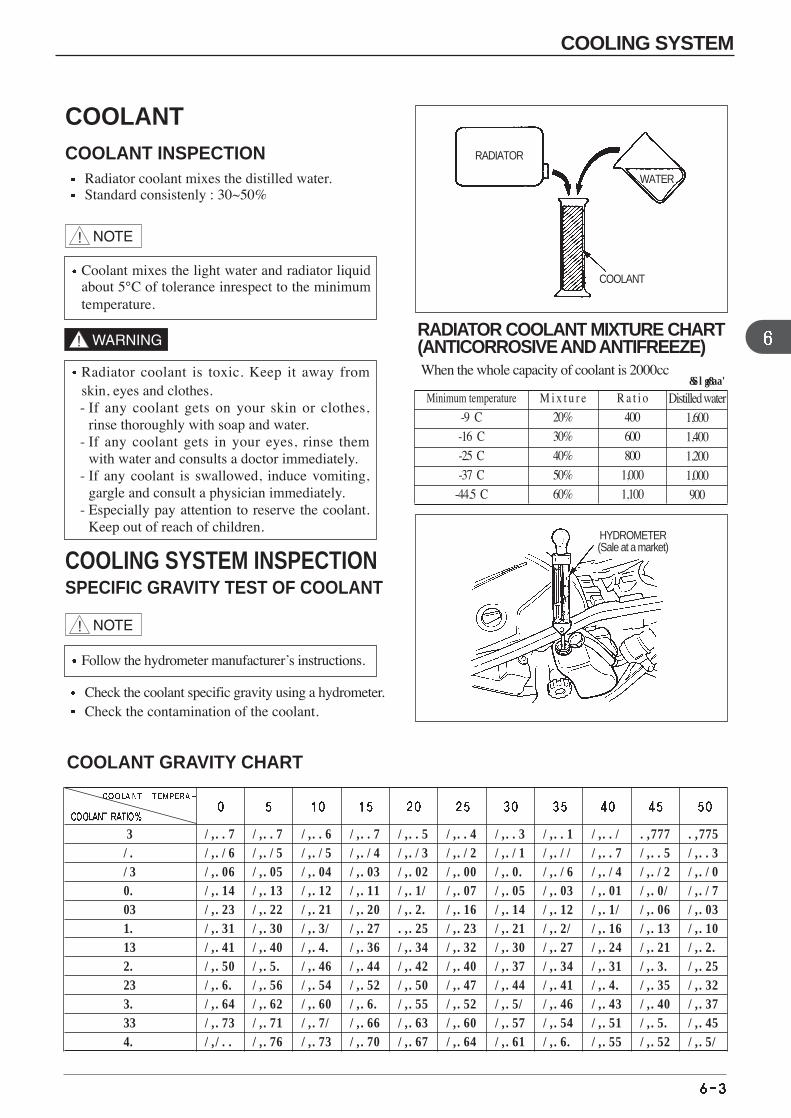
5
10
15
20
25
30
35
40
45
50
55
60
1.009
1.018
1.028
1.036
1.045
1.053
1.063
1.072
1.080
1.086
1.095
1.100
1.009
1.017
1.027
1.035
1.044
1.052
1.062
1.070
1.078
1.084
1.093
1.098
1.008
1.017
1.026
1.034
1.043
1.051
1.060
1.068
1.076
1.082
1.091
1.095
1.009
1.016
1.025
1.033
1.042
1.049
1.058
1.066
1.074
1.080
1.088
1.092
1.007
1.015
1.024
1.031
1.040
0.047
1.056
1.064
1.072
1.077
1.085
1.089
1.006
1.014
1.022
1.029
1.038
1.045
1.054
1.062
1.069
1.074
1.082
1.086
1.005
1.013
1.020
1.027
1.036
1.043
1.052
1.059
1.066
1.071
1.079
1.083
1.003
1.011
1.018
1.025
1.034
1.041
1.049
1.056
1.063
1.068
1.076
1.080
1.001
1.009
1.016
1.023
1.031
1.038
1.046
1.053
1.060
1.065
1.073
1.077
0.999
1.007
1.014
1.021
1.028
1.035
1.043
1.050
1.057
1.062
1.070
1.074
0.997
1.005
1.012
1.019
1.025
1.032
1.040
1.047
1.054
1.059
1.067
1.071
COOLANT GRAVITY CHART
RADIATOR COOLANT MIXTURE CHART(ANTICORROSIVE AND ANTIFREEZE)When the whole capacity of coolant is 2000cc
Minimum temperature
-9。C-16。C-25。C-37。C
-44.5。C
M i x t u r e
20%30%40%50%60%
R a t i o
400600800
1,0001,100
Distilled water1,6001,4001,2001,000900
(Unit:cc)Radiator coolant is toxic. Keep it away fromskin, eyes and clothes.- If any coolant gets on your skin or clothes,
rinse thoroughly with soap and water.- If any coolant gets in your eyes, rinse them
with water and consults a doctor immediately.- If any coolant is swallowed, induce vomiting,
gargle and consult a physician immediately.- Especially pay attention to reserve the coolant.
Keep out of reach of children.
Coolant mixes the light water and radiator liquidabout 5°C of tolerance inrespect to the minimumtemperature.
Follow the hydrometer manufacturer’s instructions.
RADIATOR
WATER
HYDROMETER(Sale at a market)
COOLANT
COOLANTCOOLANT INSPECTION
Radiator coolant mixes the distilled water.Standard consistenly : 30~50%
COOLING SYSTEM INSPECTIONSPECIFIC GRAVITY TEST OF COOLANT
Check the coolant specific gravity using a hydrometer.Check the contamination of the coolant.
COOLING SYSTEM
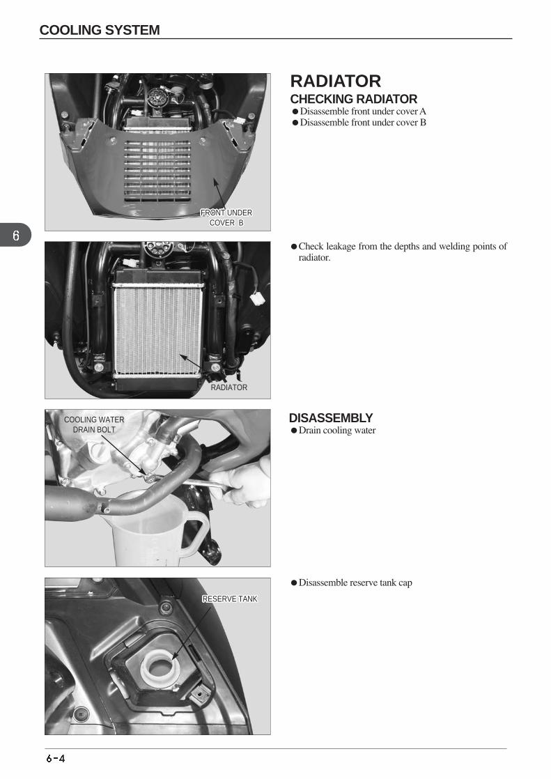
DISASSEMBLYDrain cooling water
Check leakage from the depths and welding points ofradiator.
Disassemble reserve tank cap
FRONT UNDERCOVER B
FRONT UNDERCOVER B
FRONT UNDERCOVER B
FRONT UNDERCOVER B
FRONT UNDERCOVER B
FRONT UNDERCOVER B
FRONT UNDERCOVER B
FRONT UNDERCOVER B
FRONT UNDERCOVER B
FRONT UNDERCOVER B
FRONT UNDERCOVER B
FRONT UNDERCOVER B
FRONT UNDERCOVER B
FRONT UNDERCOVER B
FRONT UNDERCOVER B
FRONT UNDERCOVER B
FRONT UNDERCOVER B
FRONT UNDERCOVER B
FRONT UNDERCOVER B
FRONT UNDERCOVER B
FRONT UNDERCOVER B
FRONT UNDERCOVER B
FRONT UNDERCOVER B
FRONT UNDERCOVER B
FRONT UNDERCOVER B
FRONT UNDERCOVER B
FRONT UNDERCOVER B
RADIATOR
COOLING WATERDRAIN BOLT
RESERVE TANKRESERVE TANKRESERVE TANKRESERVE TANKRESERVE TANKRESERVE TANKRESERVE TANKRESERVE TANKRESERVE TANKRESERVE TANKRESERVE TANKRESERVE TANKRESERVE TANKRESERVE TANKRESERVE TANKRESERVE TANKRESERVE TANKRESERVE TANKRESERVE TANKRESERVE TANKRESERVE TANKRESERVE TANKRESERVE TANKRESERVE TANKRESERVE TANKRESERVE TANKRESERVE TANK
COOLING SYSTEM
RADIATORCHECKING RADIATOR Disassemble front under cover ADisassemble front under cover B
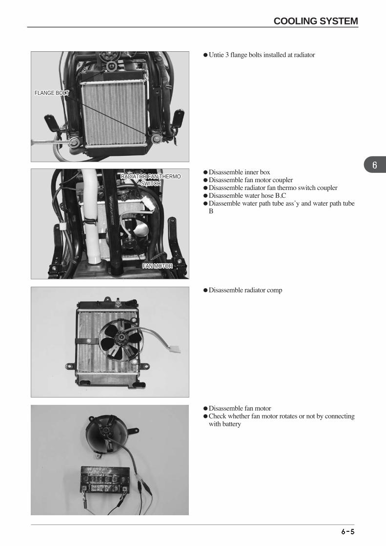
Untie 3 flange bolts installed at radiator
Disassemble inner box Disassemble fan motor coupler Disassemble radiator fan thermo switch coupler Disassemble water hose B,C Diassemble water path tube ass’y and water path tube
B
Disassemble radiator comp
RADIATOR FAN THERMOSWITCH
RADIATOR FAN THERMOSWITCH
RADIATOR FAN THERMOSWITCH
RADIATOR FAN THERMOSWITCH
RADIATOR FAN THERMOSWITCH
RADIATOR FAN THERMOSWITCH
RADIATOR FAN THERMOSWITCH
RADIATOR FAN THERMOSWITCH
RADIATOR FAN THERMOSWITCH
RADIATOR FAN THERMOSWITCH
RADIATOR FAN THERMOSWITCH
RADIATOR FAN THERMOSWITCH
RADIATOR FAN THERMOSWITCH
RADIATOR FAN THERMOSWITCH
RADIATOR FAN THERMOSWITCH
RADIATOR FAN THERMOSWITCH
RADIATOR FAN THERMOSWITCH
RADIATOR FAN THERMOSWITCH
RADIATOR FAN THERMOSWITCH
RADIATOR FAN THERMOSWITCH
RADIATOR FAN THERMOSWITCH
RADIATOR FAN THERMOSWITCH
RADIATOR FAN THERMOSWITCH
RADIATOR FAN THERMOSWITCH
RADIATOR FAN THERMOSWITCH
RADIATOR FAN THERMOSWITCH
RADIATOR FAN THERMOSWITCH
FAN MOTORFAN MOTORFAN MOTORFAN MOTORFAN MOTORFAN MOTORFAN MOTORFAN MOTORFAN MOTORFAN MOTORFAN MOTORFAN MOTORFAN MOTORFAN MOTORFAN MOTORFAN MOTORFAN MOTORFAN MOTORFAN MOTORFAN MOTORFAN MOTORFAN MOTORFAN MOTORFAN MOTORFAN MOTORFAN MOTORFAN MOTOR
Disassemble fan motor Check whether fan motor rotates or not by connecting
with battery
COOLING SYSTEM
FLANGE BOLTFLANGE BOLTFLANGE BOLTFLANGE BOLTFLANGE BOLTFLANGE BOLTFLANGE BOLTFLANGE BOLTFLANGE BOLTFLANGE BOLTFLANGE BOLTFLANGE BOLTFLANGE BOLTFLANGE BOLTFLANGE BOLTFLANGE BOLTFLANGE BOLTFLANGE BOLTFLANGE BOLTFLANGE BOLTFLANGE BOLTFLANGE BOLTFLANGE BOLTFLANGE BOLTFLANGE BOLTFLANGE BOLTFLANGE BOLT
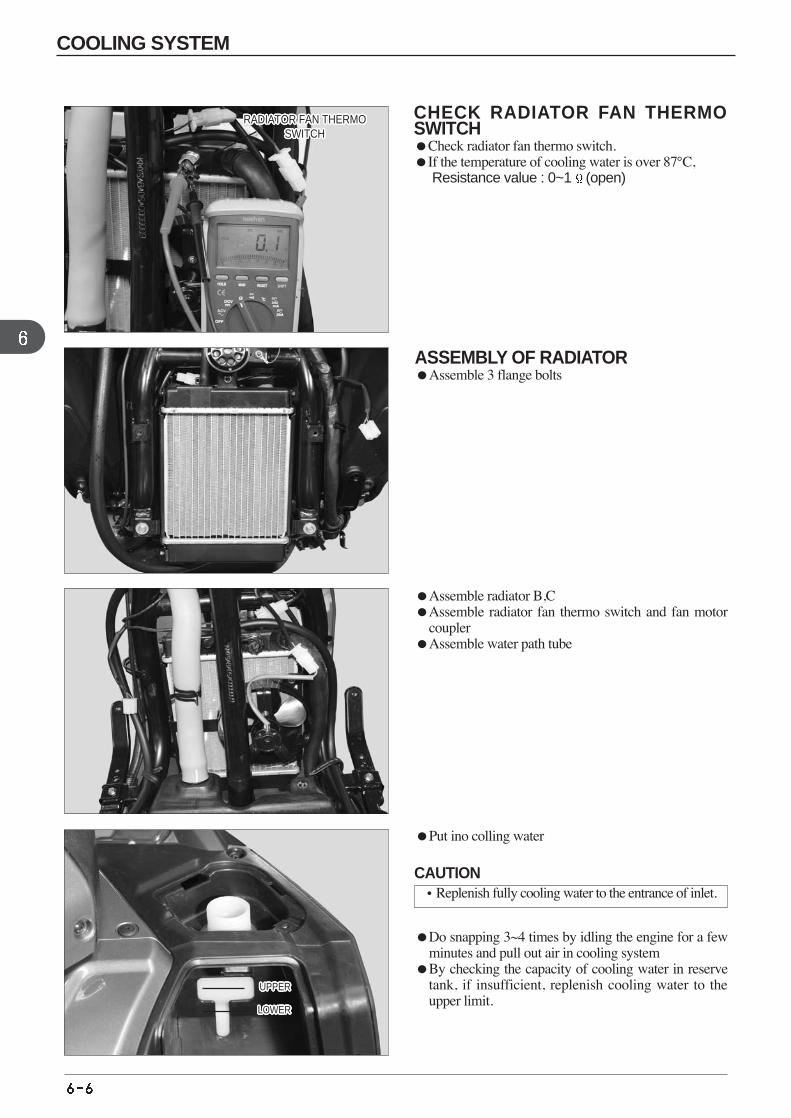
CHECK RADIATOR FAN THERMOSWITCH Check radiator fan thermo switch. If the temperature of cooling water is over 87°C,
Resistance value : 0~1 (open)
Assemble radiator B,CAssemble radiator fan thermo switch and fan motor
coupler Assemble water path tube
Put ino colling water
Do snapping 3~4 times by idling the engine for a fewminutes and pull out air in cooling system
By checking the capacity of cooling water in reservetank, if insufficient, replenish cooling water to theupper limit.
ASSEMBLY OF RADIATOR Assemble 3 flange bolts
RADIATOR FAN THERMOSWITCH
RADIATOR FAN THERMOSWITCH
RADIATOR FAN THERMOSWITCH
RADIATOR FAN THERMOSWITCH
RADIATOR FAN THERMOSWITCH
RADIATOR FAN THERMOSWITCH
RADIATOR FAN THERMOSWITCH
RADIATOR FAN THERMOSWITCH
RADIATOR FAN THERMOSWITCH
RADIATOR FAN THERMOSWITCH
RADIATOR FAN THERMOSWITCH
RADIATOR FAN THERMOSWITCH
RADIATOR FAN THERMOSWITCH
RADIATOR FAN THERMOSWITCH
RADIATOR FAN THERMOSWITCH
RADIATOR FAN THERMOSWITCH
RADIATOR FAN THERMOSWITCH
RADIATOR FAN THERMOSWITCH
RADIATOR FAN THERMOSWITCH
RADIATOR FAN THERMOSWITCH
RADIATOR FAN THERMOSWITCH
RADIATOR FAN THERMOSWITCH
RADIATOR FAN THERMOSWITCH
RADIATOR FAN THERMOSWITCH
RADIATOR FAN THERMOSWITCH
RADIATOR FAN THERMOSWITCH
RADIATOR FAN THERMOSWITCH
UPPERUPPERUPPERUPPERUPPERUPPERUPPERUPPERUPPERUPPERUPPERUPPERUPPERUPPERUPPERUPPERUPPERUPPERUPPERUPPERUPPERUPPERUPPERUPPERUPPERUPPERUPPER
LOWERLOWERLOWERLOWERLOWERLOWERLOWERLOWERLOWERLOWERLOWERLOWERLOWERLOWERLOWERLOWERLOWERLOWERLOWERLOWERLOWERLOWERLOWERLOWERLOWERLOWERLOWER
CAUTION•Replenish fully cooling water to the entrance of inlet.
COOLING SYSTEM
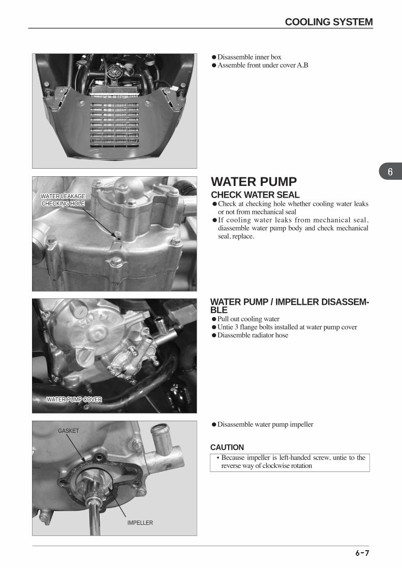
Disassemble inner box Assemble front under cover A,B
WATER PUMP / IMPELLER DISASSEM-BLE Pull out cooling water Untie 3 flange bolts installed at water pump coverDiassemble radiator hose
WATER LEAKAGECHECKING HOLEWATER LEAKAGECHECKING HOLEWATER LEAKAGECHECKING HOLEWATER LEAKAGECHECKING HOLEWATER LEAKAGECHECKING HOLEWATER LEAKAGECHECKING HOLEWATER LEAKAGECHECKING HOLEWATER LEAKAGECHECKING HOLEWATER LEAKAGECHECKING HOLEWATER LEAKAGECHECKING HOLEWATER LEAKAGECHECKING HOLEWATER LEAKAGECHECKING HOLEWATER LEAKAGECHECKING HOLEWATER LEAKAGECHECKING HOLEWATER LEAKAGECHECKING HOLEWATER LEAKAGECHECKING HOLEWATER LEAKAGECHECKING HOLEWATER LEAKAGECHECKING HOLEWATER LEAKAGECHECKING HOLEWATER LEAKAGECHECKING HOLEWATER LEAKAGECHECKING HOLEWATER LEAKAGECHECKING HOLEWATER LEAKAGECHECKING HOLEWATER LEAKAGECHECKING HOLEWATER LEAKAGECHECKING HOLEWATER LEAKAGECHECKING HOLEWATER LEAKAGECHECKING HOLE
Disassemble water pump impellerGASKET
IMPELLER
CAUTION•Because impeller is left-handed screw, untie to the
reverse way of clockwise rotation
WATER PUMPCHECK WATER SEALCheck at checking hole whether cooling water leaks
or not from mechanical seal If cooling water leaks from mechanical seal,
diassemble water pump body and check mechanicalseal, replace.
COOLING SYSTEM
WATER PUMP COVERWATER PUMP COVERWATER PUMP COVERWATER PUMP COVERWATER PUMP COVERWATER PUMP COVERWATER PUMP COVERWATER PUMP COVERWATER PUMP COVERWATER PUMP COVERWATER PUMP COVERWATER PUMP COVERWATER PUMP COVERWATER PUMP COVERWATER PUMP COVERWATER PUMP COVERWATER PUMP COVERWATER PUMP COVERWATER PUMP COVERWATER PUMP COVERWATER PUMP COVERWATER PUMP COVERWATER PUMP COVERWATER PUMP COVERWATER PUMP COVERWATER PUMP COVERWATER PUMP COVER
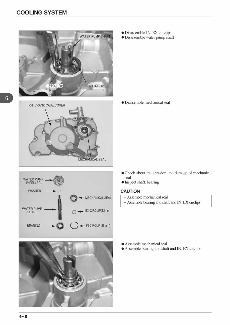
Disassemble IN, EX cir clips Disassemble water pump shaft
Diassemble mechanical seal
Check about the abrasion and damage of mechanicalseal
Inspect shaft, bearing
Assemble mechanical seal Assemble bearing and shaft and IN, EX circlips
RH. CRANK CASE COVER
WATER PUMP SHAFT
IN CIRCLIPEX CIRCLIPEX CIRCLIPEX CIRCLIPEX CIRCLIPEX CIRCLIPEX CIRCLIPEX CIRCLIPEX CIRCLIPEX CIRCLIPEX CIRCLIPEX CIRCLIPEX CIRCLIPEX CIRCLIPEX CIRCLIPEX CIRCLIPEX CIRCLIPEX CIRCLIPEX CIRCLIPEX CIRCLIPEX CIRCLIPEX CIRCLIPEX CIRCLIPEX CIRCLIPEX CIRCLIPEX CIRCLIPEX CIRCLIPEX CIRCLIP
MECHANICAL SEAL
MECHANICAL SEAL
EX CIRCLIP(12mm)
IN CIRCLIP(28mm)BEARING
WATER PUMPSHAFT
WASHER
WATER PUMPIMPELLER
CAUTION•Assemble mechanical seal •Assemble bearing and shaft and IN, EX circlips
COOLING SYSTEM
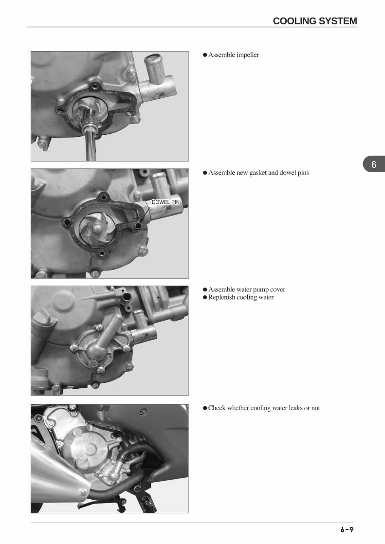
Assemble impeller
Assemble new gasket and dowel pins
Assemble water pump cover Replenish cooling water
Check whether cooling water leaks or not
DOWEL PINDOWEL PINDOWEL PINDOWEL PINDOWEL PINDOWEL PINDOWEL PINDOWEL PINDOWEL PINDOWEL PINDOWEL PINDOWEL PINDOWEL PINDOWEL PINDOWEL PINDOWEL PINDOWEL PINDOWEL PINDOWEL PINDOWEL PINDOWEL PINDOWEL PINDOWEL PINDOWEL PINDOWEL PINDOWEL PINDOWEL PIN
COOLING SYSTEM
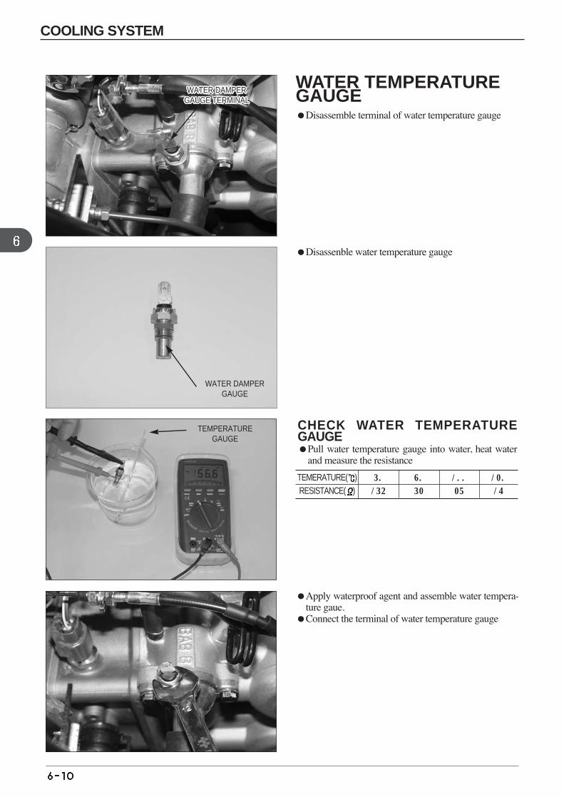
Disassenble water temperature gauge
Apply waterproof agent and assemble water tempera-ture gaue.
Connect the terminal of water temperature gauge
CHECK WATER TEMPERATUREGAUGE Pull water temperature gauge into water, heat water
and measure the resistance
120
16
100
27
80
52
50
154
TEMERATURE( )RESISTANCE( )
WATER DAMPERGAUGE
TEMPERATUREGAUGE
WATER TEMPERATUREGAUGE Disassemble terminal of water temperature gauge
COOLING SYSTEM
WATER DAMPERGAUGE TERMINALWATER DAMPER
GAUGE TERMINALWATER DAMPER
GAUGE TERMINALWATER DAMPER
GAUGE TERMINALWATER DAMPER
GAUGE TERMINALWATER DAMPER
GAUGE TERMINALWATER DAMPER
GAUGE TERMINALWATER DAMPER
GAUGE TERMINALWATER DAMPER
GAUGE TERMINALWATER DAMPER
GAUGE TERMINALWATER DAMPER
GAUGE TERMINALWATER DAMPER
GAUGE TERMINALWATER DAMPER
GAUGE TERMINALWATER DAMPER
GAUGE TERMINALWATER DAMPER
GAUGE TERMINALWATER DAMPER
GAUGE TERMINALWATER DAMPER
GAUGE TERMINALWATER DAMPER
GAUGE TERMINALWATER DAMPER
GAUGE TERMINALWATER DAMPER
GAUGE TERMINALWATER DAMPER
GAUGE TERMINALWATER DAMPER
GAUGE TERMINALWATER DAMPER
GAUGE TERMINALWATER DAMPER
GAUGE TERMINALWATER DAMPER
GAUGE TERMINALWATER DAMPER
GAUGE TERMINALWATER DAMPER
GAUGE TERMINAL
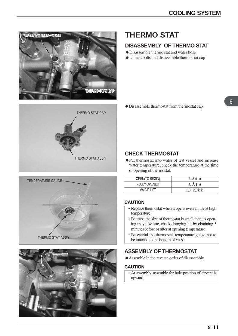
Disassemble thermostat from thermostat cap
ASSEMBLY OF THERMOSTAT Assemble in the reverse order of disassembly
CHECK THERMOSTAT Put thermostat into water of test vessel and increase
water temperature, check the temperature at the timeof opening of thermostat.
80±2。C
90±3。C
3.5~4.5mm
OPEN(TO BEGIN) FULLY OPENED
VALVE LIFT
WATER DAMPER GAUGEWATER DAMPER GAUGEWATER DAMPER GAUGEWATER DAMPER GAUGEWATER DAMPER GAUGEWATER DAMPER GAUGEWATER DAMPER GAUGEWATER DAMPER GAUGEWATER DAMPER GAUGEWATER DAMPER GAUGEWATER DAMPER GAUGEWATER DAMPER GAUGEWATER DAMPER GAUGEWATER DAMPER GAUGEWATER DAMPER GAUGEWATER DAMPER GAUGEWATER DAMPER GAUGEWATER DAMPER GAUGEWATER DAMPER GAUGEWATER DAMPER GAUGEWATER DAMPER GAUGEWATER DAMPER GAUGEWATER DAMPER GAUGEWATER DAMPER GAUGEWATER DAMPER GAUGEWATER DAMPER GAUGEWATER DAMPER GAUGE
THERMO STAT CAPTHERMO STAT CAPTHERMO STAT CAPTHERMO STAT CAPTHERMO STAT CAPTHERMO STAT CAPTHERMO STAT CAPTHERMO STAT CAPTHERMO STAT CAPTHERMO STAT CAPTHERMO STAT CAPTHERMO STAT CAPTHERMO STAT CAPTHERMO STAT CAPTHERMO STAT CAPTHERMO STAT CAPTHERMO STAT CAPTHERMO STAT CAPTHERMO STAT CAPTHERMO STAT CAPTHERMO STAT CAPTHERMO STAT CAPTHERMO STAT CAPTHERMO STAT CAPTHERMO STAT CAPTHERMO STAT CAPTHERMO STAT CAP
THERMO STAT CAP
THERMO STAT ASS’Y
THERMO STAT ASS’Y
TEMPERATURE GAUGE
THERMO STATDISASSEMBLY OF THERMO STAT Disassemble thermo stat and water hose Untie 2 bolts and disassemble thermo stat cap
CAUTION•Replace thermostat when it opens even a little at high
temperature•Because the size of thermostat is small then its open-
ing may take late, check changing lift by obtaining 5minutes before or after at opening temperature
•Be careful the thermostat, temperature gauge not tobe touched to the bottom of vessel
CAUTION•At assembly, assemble for hole position of airvent is
upward.
COOLING SYSTEM
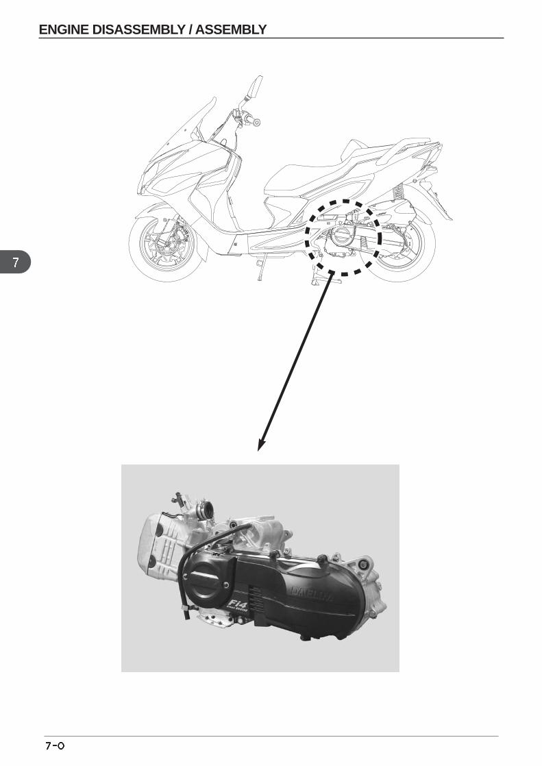
ENGINE DISASSEMBLY / ASSEMBLY
7. ENGINE DISASSEMBLY / ASSEMBLY
SERVICE INFORMATION
CAUTION
•Use a jack to remove or install the engine. Support the scooter with a jack firmly, taking precautions not to damagethe frame, engine, cable or harness.
•Attach the tape to the frame to protect it during the engine removal or installation.
•The following works can be done without disassembly of the engine.
- TRANSMISSION( chapter 12)
- OIL PUMP( chapter 4)
- AC. GENERATOR( chapter 9)
- CVT( chapter 8)
- CYLINDER HEAD, CYLINDER, PISTON( chapter 10,11)
- EX. MUFFLER( chapter 3)
- THROTTLE BODY( chapter 5)
- REAR SWING ARM( chapter 13)
•The following works is done after disassembly of the engine.
- CRANKSHAFT, CRANKSHAFT BEARING, CRANK CASE BEARING
•The capacity of engine oil : 1.3L(at disassembly)
TORQUE VALUES :
TORQUE(upper) 5.0~5.5kgf m(lower) 4.0~5.0kgf m
SERVICE INFORMATION 7-1 ENGINE DISASSEMBLY 7-2
ENGINE ASSEMBLY 7-3
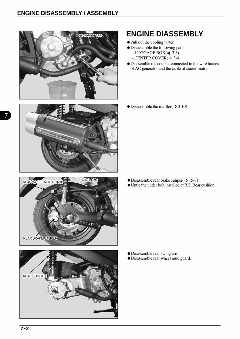
Disassemble the muffler( 3-10)
Disassemble rear brake caliper( 15-8) Untie the under bolt installed at RH. Rear cushion.
Disassemble rear swing arm Disassemble rear wheel mud guard.
RADIATOR HOSERADIATOR HOSERADIATOR HOSERADIATOR HOSERADIATOR HOSERADIATOR HOSERADIATOR HOSERADIATOR HOSERADIATOR HOSERADIATOR HOSERADIATOR HOSERADIATOR HOSERADIATOR HOSERADIATOR HOSERADIATOR HOSERADIATOR HOSERADIATOR HOSERADIATOR HOSERADIATOR HOSERADIATOR HOSERADIATOR HOSERADIATOR HOSERADIATOR HOSERADIATOR HOSERADIATOR HOSERADIATOR HOSERADIATOR HOSE
MUFFLER
SWING ARMSWING ARMSWING ARMSWING ARMSWING ARMSWING ARMSWING ARMSWING ARMSWING ARMSWING ARMSWING ARMSWING ARMSWING ARMSWING ARMSWING ARMSWING ARMSWING ARMSWING ARMSWING ARMSWING ARMSWING ARMSWING ARMSWING ARMSWING ARMSWING ARMSWING ARMSWING ARMREAR WHEEL MUD GUARDREAR WHEEL MUD GUARDREAR WHEEL MUD GUARDREAR WHEEL MUD GUARDREAR WHEEL MUD GUARDREAR WHEEL MUD GUARDREAR WHEEL MUD GUARDREAR WHEEL MUD GUARDREAR WHEEL MUD GUARDREAR WHEEL MUD GUARDREAR WHEEL MUD GUARDREAR WHEEL MUD GUARDREAR WHEEL MUD GUARDREAR WHEEL MUD GUARDREAR WHEEL MUD GUARDREAR WHEEL MUD GUARDREAR WHEEL MUD GUARDREAR WHEEL MUD GUARDREAR WHEEL MUD GUARDREAR WHEEL MUD GUARDREAR WHEEL MUD GUARDREAR WHEEL MUD GUARDREAR WHEEL MUD GUARDREAR WHEEL MUD GUARDREAR WHEEL MUD GUARDREAR WHEEL MUD GUARDREAR WHEEL MUD GUARD
REAR CUSHIONREAR CUSHIONREAR CUSHIONREAR CUSHIONREAR CUSHIONREAR CUSHIONREAR CUSHIONREAR CUSHIONREAR CUSHIONREAR CUSHIONREAR CUSHIONREAR CUSHIONREAR CUSHIONREAR CUSHIONREAR CUSHIONREAR CUSHIONREAR CUSHIONREAR CUSHIONREAR CUSHIONREAR CUSHIONREAR CUSHIONREAR CUSHIONREAR CUSHIONREAR CUSHIONREAR CUSHIONREAR CUSHIONREAR CUSHION
REAR BRAKE CALIPERREAR BRAKE CALIPERREAR BRAKE CALIPERREAR BRAKE CALIPERREAR BRAKE CALIPERREAR BRAKE CALIPERREAR BRAKE CALIPERREAR BRAKE CALIPERREAR BRAKE CALIPERREAR BRAKE CALIPERREAR BRAKE CALIPERREAR BRAKE CALIPERREAR BRAKE CALIPERREAR BRAKE CALIPERREAR BRAKE CALIPERREAR BRAKE CALIPERREAR BRAKE CALIPERREAR BRAKE CALIPERREAR BRAKE CALIPERREAR BRAKE CALIPERREAR BRAKE CALIPERREAR BRAKE CALIPERREAR BRAKE CALIPERREAR BRAKE CALIPERREAR BRAKE CALIPERREAR BRAKE CALIPERREAR BRAKE CALIPER
ENGINE DISASSEMBLY / ASSEMBLY
ENGINE DIASSEMBLYPull out the cooling water Disassemble the following parts
- LUGGAGE BOX( 3-3) - CENTER COVER( 3-4)
Diassemble the coupler connected to the wire harnessof AC generator and the cable of starter motor.
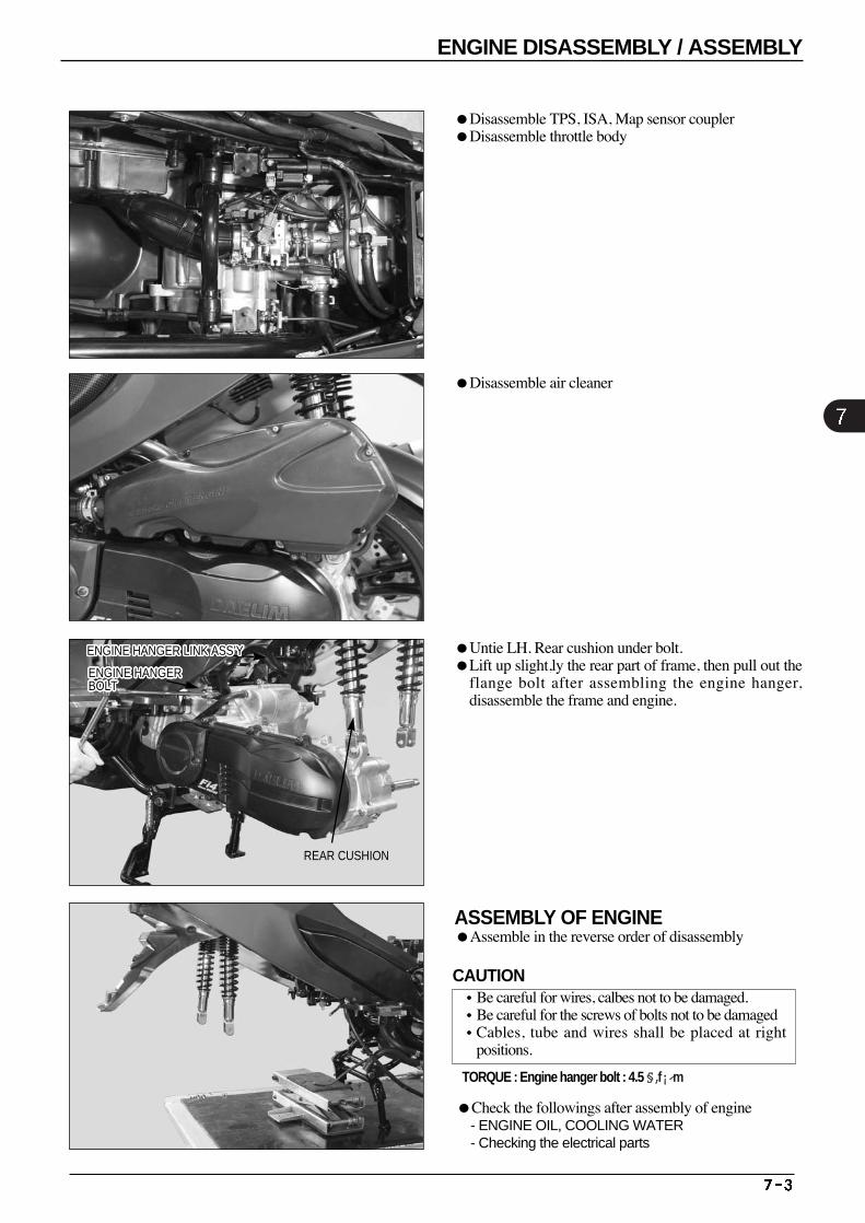
Disassemble TPS, ISA, Map sensor coupler Disassemble throttle body
Disassemble air cleaner
ASSEMBLY OF ENGINE Assemble in the reverse order of disassembly
Check the followings after assembly of engine - ENGINE OIL, COOLING WATER - Checking the electrical parts
TORQUE : Engine hanger bolt : 4.5 §‚f¡⁄m
Untie LH. Rear cushion under bolt. Lift up slight,ly the rear part of frame, then pull out the
flange bolt after assembling the engine hanger,disassemble the frame and engine.
ENGINE HANGERBOLTENGINE HANGERBOLTENGINE HANGERBOLTENGINE HANGERBOLTENGINE HANGERBOLTENGINE HANGERBOLTENGINE HANGERBOLTENGINE HANGERBOLTENGINE HANGERBOLTENGINE HANGERBOLTENGINE HANGERBOLTENGINE HANGERBOLTENGINE HANGERBOLTENGINE HANGERBOLTENGINE HANGERBOLTENGINE HANGERBOLTENGINE HANGERBOLTENGINE HANGERBOLTENGINE HANGERBOLTENGINE HANGERBOLTENGINE HANGERBOLTENGINE HANGERBOLTENGINE HANGERBOLTENGINE HANGERBOLTENGINE HANGERBOLTENGINE HANGERBOLTENGINE HANGERBOLT
REAR CUSHION
ENGINE DISASSEMBLY / ASSEMBLY
CAUTION•Be careful for wires, calbes not to be damaged. •Be careful for the screws of bolts not to be damaged•Cables, tube and wires shall be placed at right
positions.
ENGINE HANGER LINK ASS’YENGINE HANGER LINK ASS’YENGINE HANGER LINK ASS’YENGINE HANGER LINK ASS’YENGINE HANGER LINK ASS’YENGINE HANGER LINK ASS’YENGINE HANGER LINK ASS’YENGINE HANGER LINK ASS’YENGINE HANGER LINK ASS’YENGINE HANGER LINK ASS’YENGINE HANGER LINK ASS’YENGINE HANGER LINK ASS’YENGINE HANGER LINK ASS’YENGINE HANGER LINK ASS’YENGINE HANGER LINK ASS’YENGINE HANGER LINK ASS’YENGINE HANGER LINK ASS’YENGINE HANGER LINK ASS’YENGINE HANGER LINK ASS’YENGINE HANGER LINK ASS’YENGINE HANGER LINK ASS’YENGINE HANGER LINK ASS’YENGINE HANGER LINK ASS’YENGINE HANGER LINK ASS’YENGINE HANGER LINK ASS’YENGINE HANGER LINK ASS’YENGINE HANGER LINK ASS’Y
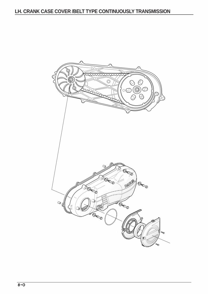
LH. CRANK CASE COVER /BELT TYPE CONTINUOUSLY TRANSMISSION
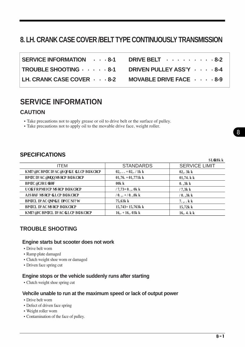
SPECIFICATIONS
ITEM STANDARDS SERVICE LIMIT MOVABLE DRIVE FACE BUSHING INNER DIAMETER
DRIVE FACE BOSS OUTER DIAMETER
DRIVE BELT WIDTH
WEIGHT ROLLER OUTER DIAMETER
CLUTCH OUTER INNER DIAMETER
DRIVEN FACE SPRING FREE PLAY
DRIVEN FACE OUTER DIAMETER
MOVABLE DRIVEN FACE INNER DIAMETER
24.000-24.013mm
23.980-23.993mm
22mm
19.95-20.02mm
120.0-120.2mm
97.85mm
37.965-37.985mm
38.0-38.025mm
24.05mm
23.960mm
20.5mm
19.5mm
120.5mm
90.00mm
37.94mm
38.060mm
UNIT : mm
8. LH. CRANK CASE COVER /BELT TYPE CONTINUOUSLY TRANSMISSION
SERVICE INFORMATIONCAUTION •Take precautions not to apply grease or oil to drive belt or the surface of pulley. •Take precautions not to apply oil to the movable drive face, weight roller.
SERVICE INFORMATION 8-1
TROUBLE SHOOTING 8-1
LH. CRANK CASE COVER 8-2
DRIVE BELT 8-2
DRIVEN PULLEY ASS’Y 8-4
MOVABLE DRIVE FACE 8-9
TROUBLE SHOOTING
Engine starts but scooter does not work •Drive belt worn •Ramp plate damaged •Clutch weight shoe worn or damaged •Driven face spring cut
Engine stops or the vehicle suddenly runs after starting •Clutch weight shoe spring cut
Vehcile unable to run at the maximum speed or lack of output power•Drive belt worn •Defect of driven face spring •Weight roller worn •Contamination of the face of pulley.
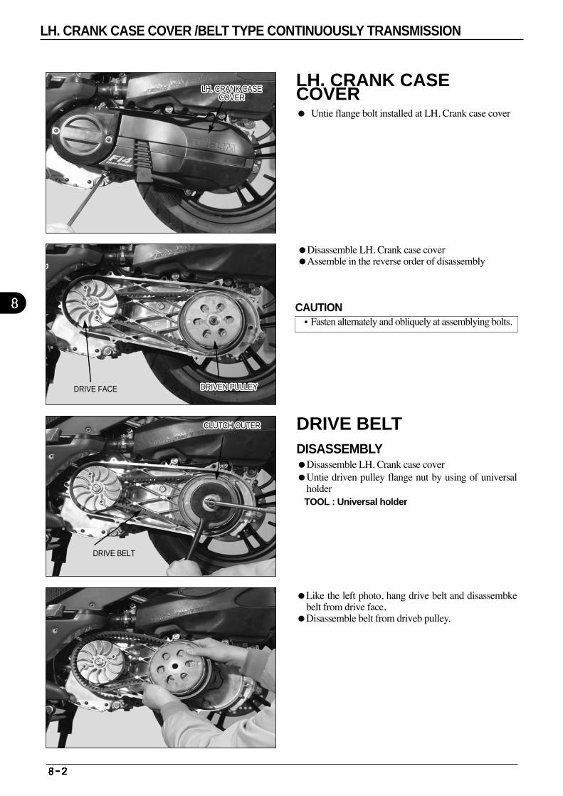
Like the left photo, hang drive belt and disassembkebelt from drive face.
Disassemble belt from driveb pulley.
Disassemble LH. Crank case coverAssemble in the reverse order of disassembly
DRIVE FACE DRIVEN PULLEYDRIVEN PULLEYDRIVEN PULLEYDRIVEN PULLEYDRIVEN PULLEYDRIVEN PULLEYDRIVEN PULLEYDRIVEN PULLEYDRIVEN PULLEYDRIVEN PULLEYDRIVEN PULLEYDRIVEN PULLEYDRIVEN PULLEYDRIVEN PULLEYDRIVEN PULLEYDRIVEN PULLEYDRIVEN PULLEYDRIVEN PULLEYDRIVEN PULLEYDRIVEN PULLEYDRIVEN PULLEYDRIVEN PULLEYDRIVEN PULLEYDRIVEN PULLEYDRIVEN PULLEYDRIVEN PULLEYDRIVEN PULLEY
CLUTCH OUTERCLUTCH OUTERCLUTCH OUTERCLUTCH OUTERCLUTCH OUTERCLUTCH OUTERCLUTCH OUTERCLUTCH OUTERCLUTCH OUTERCLUTCH OUTERCLUTCH OUTERCLUTCH OUTERCLUTCH OUTERCLUTCH OUTERCLUTCH OUTERCLUTCH OUTERCLUTCH OUTERCLUTCH OUTERCLUTCH OUTERCLUTCH OUTERCLUTCH OUTERCLUTCH OUTERCLUTCH OUTERCLUTCH OUTERCLUTCH OUTERCLUTCH OUTERCLUTCH OUTER
DRIVE BELT
CAUTION•Fasten alternately and obliquely at assemblying bolts.
LH. CRANK CASECOVER Untie flange bolt installed at LH. Crank case cover
DRIVE BELT DISASSEMBLYDisassemble LH. Crank case cover Untie driven pulley flange nut by using of universal
holder TOOL : Universal holder
LH. CRANK CASE COVER /BELT TYPE CONTINUOUSLY TRANSMISSION
LH. CRANK CASECOVER
LH. CRANK CASECOVER
LH. CRANK CASECOVER
LH. CRANK CASECOVER
LH. CRANK CASECOVER
LH. CRANK CASECOVER
LH. CRANK CASECOVER
LH. CRANK CASECOVER
LH. CRANK CASECOVER
LH. CRANK CASECOVER
LH. CRANK CASECOVER
LH. CRANK CASECOVER
LH. CRANK CASECOVER
LH. CRANK CASECOVER
LH. CRANK CASECOVER
LH. CRANK CASECOVER
LH. CRANK CASECOVER
LH. CRANK CASECOVER
LH. CRANK CASECOVER
LH. CRANK CASECOVER
LH. CRANK CASECOVER
LH. CRANK CASECOVER
LH. CRANK CASECOVER
LH. CRANK CASECOVER
LH. CRANK CASECOVER
LH. CRANK CASECOVER
LH. CRANK CASECOVER
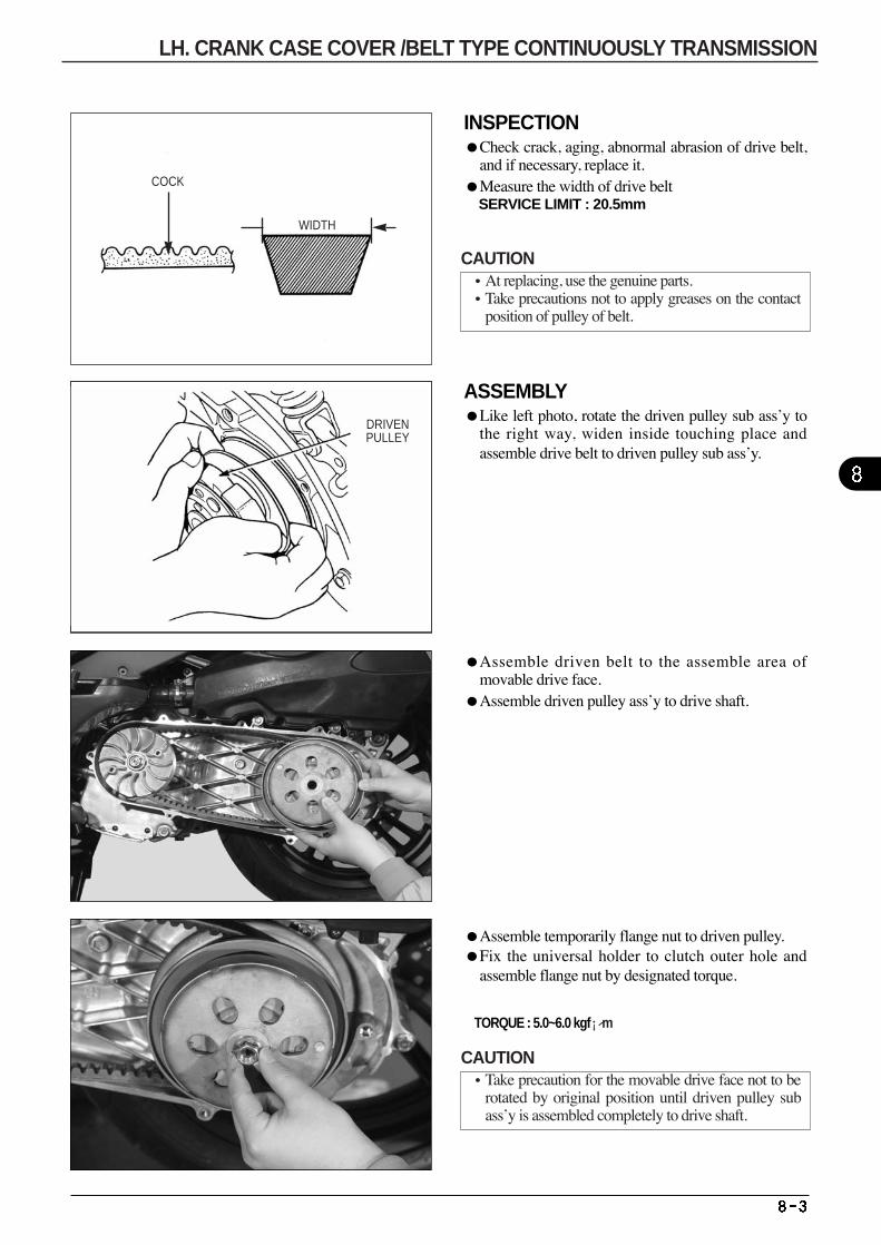
INSPECTIONCheck crack, aging, abnormal abrasion of drive belt,
and if necessary, replace it. Measure the width of drive belt
SERVICE LIMIT : 20.5mm
ASSEMBLYLike left photo, rotate the driven pulley sub ass’y to
the right way, widen inside touching place andassemble drive belt to driven pulley sub ass’y.
Assemble driven belt to the assemble area ofmovable drive face.
Assemble driven pulley ass’y to drive shaft.
Assemble temporarily flange nut to driven pulley. Fix the universal holder to clutch outer hole and
assemble flange nut by designated torque.
TORQUE : 5.0~6.0 kgf¡⁄m
COCK
WIDTH
DRIVENPULLEY
CAUTION•At replacing, use the genuine parts. •Take precautions not to apply greases on the contact
position of pulley of belt.
CAUTION•Take precaution for the movable drive face not to be
rotated by original position until driven pulley subass’y is assembled completely to drive shaft.
LH. CRANK CASE COVER /BELT TYPE CONTINUOUSLY TRANSMISSION
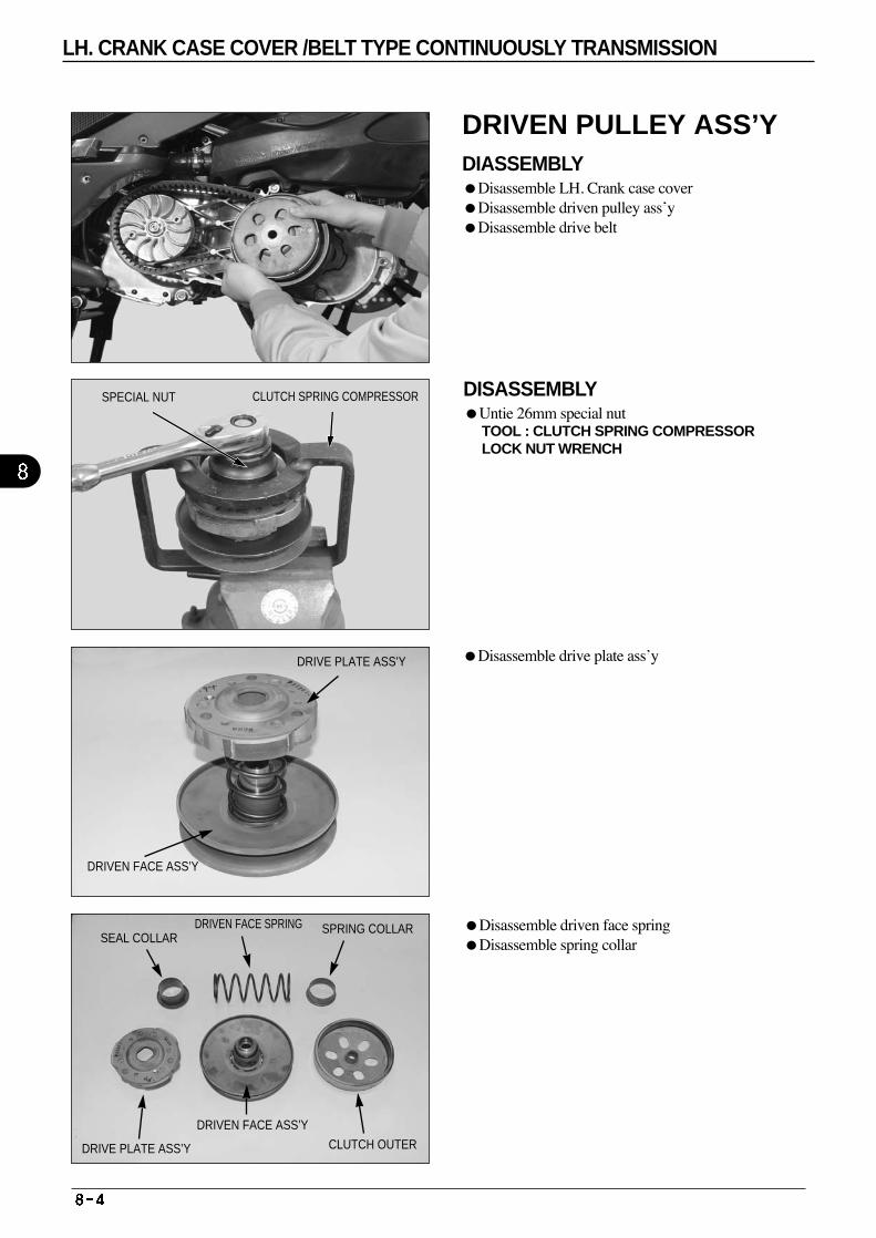
CLUTCH SPRING COMPRESSORSPECIAL NUT
DRIVEN FACE ASS’Y
SEAL COLLARDRIVEN FACE SPRING SPRING COLLAR
DRIVE PLATE ASS’Y
DRIVEN FACE ASS’Y
CLUTCH OUTER
DRIVE PLATE ASS’Y
DISASSEMBLY Untie 26mm special nut
TOOL : CLUTCH SPRING COMPRESSOR LOCK NUT WRENCH
Disassemble driven face spring Disassemble spring collar
Disassemble drive plate ass’y
DRIVEN PULLEY ASS’Y DIASSEMBLY Disassemble LH. Crank case cover Disassemble driven pulley ass’y Disassemble drive belt
LH. CRANK CASE COVER /BELT TYPE CONTINUOUSLY TRANSMISSION

Diassemble seal collar.
Disassemble roller guide pin
Disassemble movable driven face
Disassemble O-ring from movable driven face. Diassemble oil seal from movable driven face.
SEAL COLLAR
DRIVEN FACE ASS’Y
GUIDE PIN
DRIVEN FACE
ROLLER GUIDE PIN
OIL SEAL O-RING
MOVABLE DRIVEN FACE
GUIDE ROLLER PIN
GUIDE ROLLER
LH. CRANK CASE COVER /BELT TYPE CONTINUOUSLY TRANSMISSION
GUIDE PIN
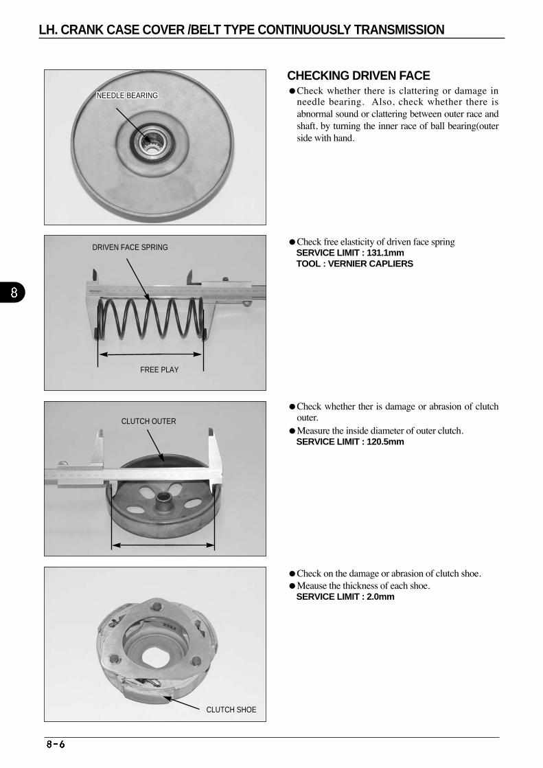
CHECKING DRIVEN FACE Check whether there is clattering or damage in
needle bearing. Also, check whether there isabnormal sound or clattering between outer race andshaft, by turning the inner race of ball bearing(outerside with hand.
Check free elasticity of driven face spring SERVICE LIMIT : 131.1mmTOOL : VERNIER CAPLIERS
Check whether ther is damage or abrasion of clutchouter.
Measure the inside diameter of outer clutch. SERVICE LIMIT : 120.5mm
Check on the damage or abrasion of clutch shoe. Meause the thickness of each shoe.
SERVICE LIMIT : 2.0mm
NEEDLE BEARINGNEEDLE BEARINGNEEDLE BEARINGNEEDLE BEARINGNEEDLE BEARINGNEEDLE BEARINGNEEDLE BEARINGNEEDLE BEARINGNEEDLE BEARINGNEEDLE BEARINGNEEDLE BEARINGNEEDLE BEARINGNEEDLE BEARINGNEEDLE BEARINGNEEDLE BEARINGNEEDLE BEARINGNEEDLE BEARINGNEEDLE BEARINGNEEDLE BEARINGNEEDLE BEARINGNEEDLE BEARINGNEEDLE BEARINGNEEDLE BEARINGNEEDLE BEARINGNEEDLE BEARINGNEEDLE BEARINGNEEDLE BEARING
DRIVEN FACE SPRING
FREE PLAY
CLUTCH OUTER
CLUTCH SHOE
LH. CRANK CASE COVER /BELT TYPE CONTINUOUSLY TRANSMISSION
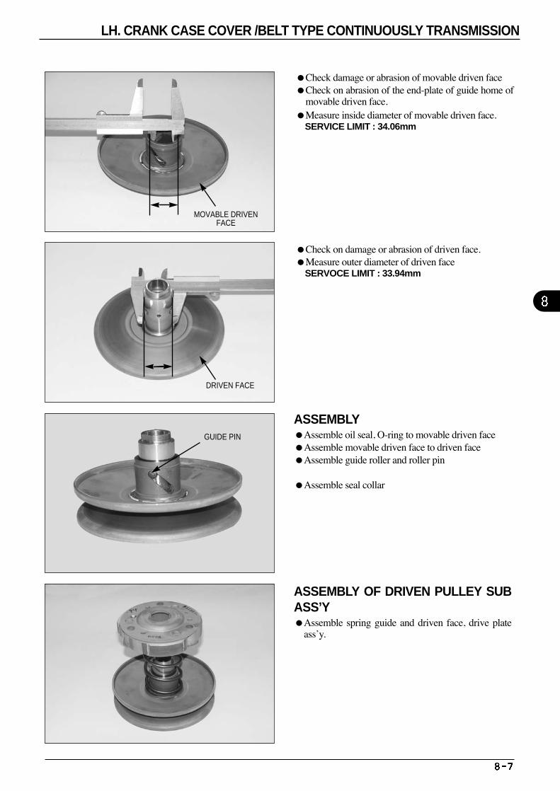
Check damage or abrasion of movable driven faceCheck on abrasion of the end-plate of guide home of
movable driven face.Measure inside diameter of movable driven face.
SERVICE LIMIT : 34.06mm
Check on damage or abrasion of driven face. Measure outer diameter of driven face
SERVOCE LIMIT : 33.94mm
ASSEMBLY Assemble oil seal, O-ring to movable driven face Assemble movable driven face to driven face Assemble guide roller and roller pin
Assemble seal collar
MOVABLE DRIVENFACE
DRIVEN FACE
GUIDE PIN
ASSEMBLY OF DRIVEN PULLEY SUBASS’Y Assemble spring guide and driven face, drive plate
ass’y.
LH. CRANK CASE COVER /BELT TYPE CONTINUOUSLY TRANSMISSION
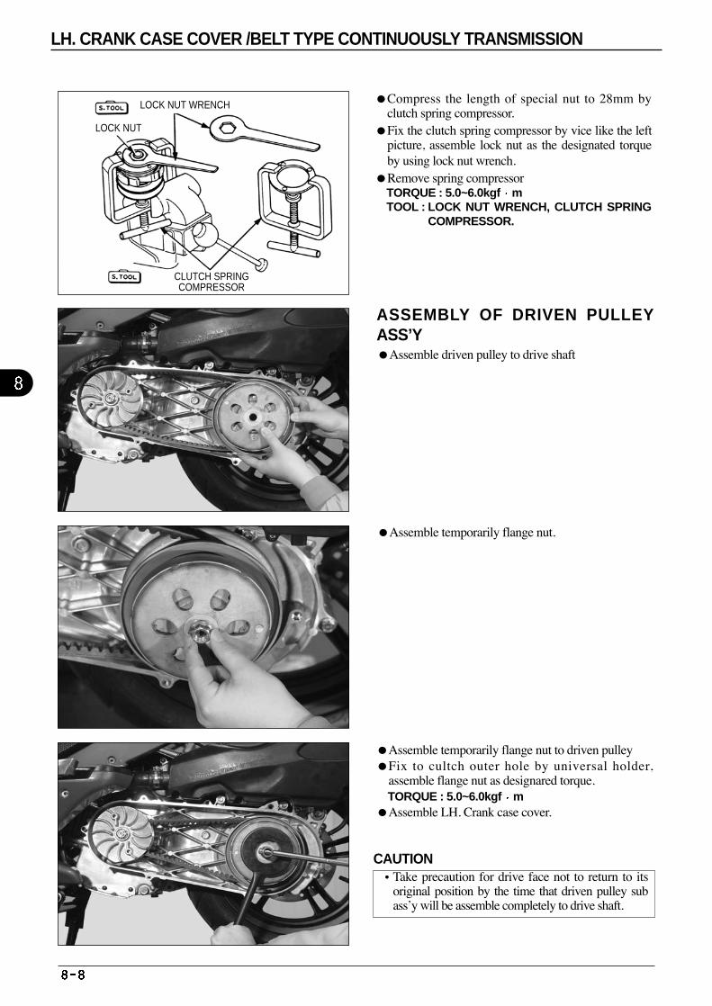
LOCK NUT WRENCH
LOCK NUT
CLUTCH SPRINGCOMPRESSOR
ASSEMBLY OF DRIVEN PULLEYASS’Y Assemble driven pulley to drive shaft
Assemble temporarily flange nut.
Compress the length of special nut to 28mm byclutch spring compressor.
Fix the clutch spring compressor by vice like the leftpicture, assemble lock nut as the designated torqueby using lock nut wrench.
Remove spring compressor TORQUE : 5.0~6.0kgf m TOOL : LOCK NUT WRENCH, CLUTCH SPRING
COMPRESSOR.
Assemble temporarily flange nut to driven pulley Fix to cultch outer hole by universal holder,
assemble flange nut as designared torque. TORQUE : 5.0~6.0kgf m
Assemble LH. Crank case cover.
CAUTION•Take precaution for drive face not to return to its
original position by the time that driven pulley subass’y will be assemble completely to drive shaft.
LH. CRANK CASE COVER /BELT TYPE CONTINUOUSLY TRANSMISSION
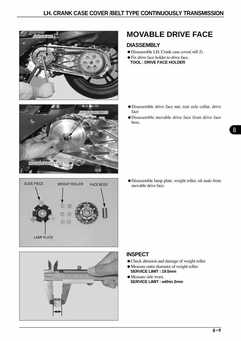
Disassemble lamp plate, weight roller, oil seals frommovable drive face.
Disassemble drive face nut, rear axle collar, driveface
Disassemble movable drive face from drive faceboss.
DRIVE FACE BOSSDRIVE FACE BOSSDRIVE FACE BOSSDRIVE FACE BOSSDRIVE FACE BOSSDRIVE FACE BOSSDRIVE FACE BOSSDRIVE FACE BOSSDRIVE FACE BOSSDRIVE FACE BOSSDRIVE FACE BOSSDRIVE FACE BOSSDRIVE FACE BOSSDRIVE FACE BOSSDRIVE FACE BOSSDRIVE FACE BOSSDRIVE FACE BOSSDRIVE FACE BOSSDRIVE FACE BOSSDRIVE FACE BOSSDRIVE FACE BOSSDRIVE FACE BOSSDRIVE FACE BOSSDRIVE FACE BOSSDRIVE FACE BOSSDRIVE FACE BOSSDRIVE FACE BOSS
DRIVE FACEDRIVE FACEDRIVE FACEDRIVE FACEDRIVE FACEDRIVE FACEDRIVE FACEDRIVE FACEDRIVE FACEDRIVE FACEDRIVE FACEDRIVE FACEDRIVE FACEDRIVE FACEDRIVE FACEDRIVE FACEDRIVE FACEDRIVE FACEDRIVE FACEDRIVE FACEDRIVE FACEDRIVE FACEDRIVE FACEDRIVE FACEDRIVE FACEDRIVE FACEDRIVE FACE
MOVABLE DRIVE FACEMOVABLE DRIVE FACEMOVABLE DRIVE FACEMOVABLE DRIVE FACEMOVABLE DRIVE FACEMOVABLE DRIVE FACEMOVABLE DRIVE FACEMOVABLE DRIVE FACEMOVABLE DRIVE FACEMOVABLE DRIVE FACEMOVABLE DRIVE FACEMOVABLE DRIVE FACEMOVABLE DRIVE FACEMOVABLE DRIVE FACEMOVABLE DRIVE FACEMOVABLE DRIVE FACEMOVABLE DRIVE FACEMOVABLE DRIVE FACEMOVABLE DRIVE FACEMOVABLE DRIVE FACEMOVABLE DRIVE FACEMOVABLE DRIVE FACEMOVABLE DRIVE FACEMOVABLE DRIVE FACEMOVABLE DRIVE FACEMOVABLE DRIVE FACEMOVABLE DRIVE FACE
SLIDE PIECE WEIGHT ROLLER FACE BOSS
LAMP PLATE
INSPECTCheck abrasion and damage of weight roller. Measure outer diameter of weight roller.
SERVICE LIMIT : 19.5mm Measure side worn.
SERVICE LIMIT : within 2mm
MOVABLE DRIVE FACE DIASSEMBLYDisassemble LH. Crank case cover( 8-2) Fix drive face holder to drive face.
TOOL : DRIVE FACE HOLDER
LH. CRANK CASE COVER /BELT TYPE CONTINUOUSLY TRANSMISSION
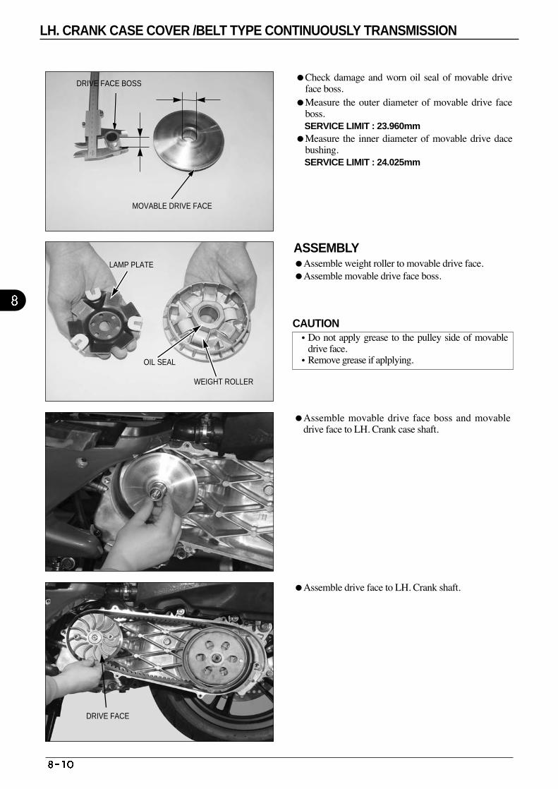
MOVABLE DRIVE FACE
DRIVE FACE BOSS
DRIVE FACE
LAMP PLATE
WEIGHT ROLLER
OIL SEAL
Check damage and worn oil seal of movable driveface boss.
Measure the outer diameter of movable drive faceboss. SERVICE LIMIT : 23.960mm
Measure the inner diameter of movable drive dacebushing. SERVICE LIMIT : 24.025mm
ASSEMBLY Assemble weight roller to movable drive face. Assemble movable drive face boss.
Assemble movable drive face boss and movabledrive face to LH. Crank case shaft.
Assemble drive face to LH. Crank shaft.
CAUTION•Do not apply grease to the pulley side of movable
drive face. •Remove grease if aplplying.
LH. CRANK CASE COVER /BELT TYPE CONTINUOUSLY TRANSMISSION
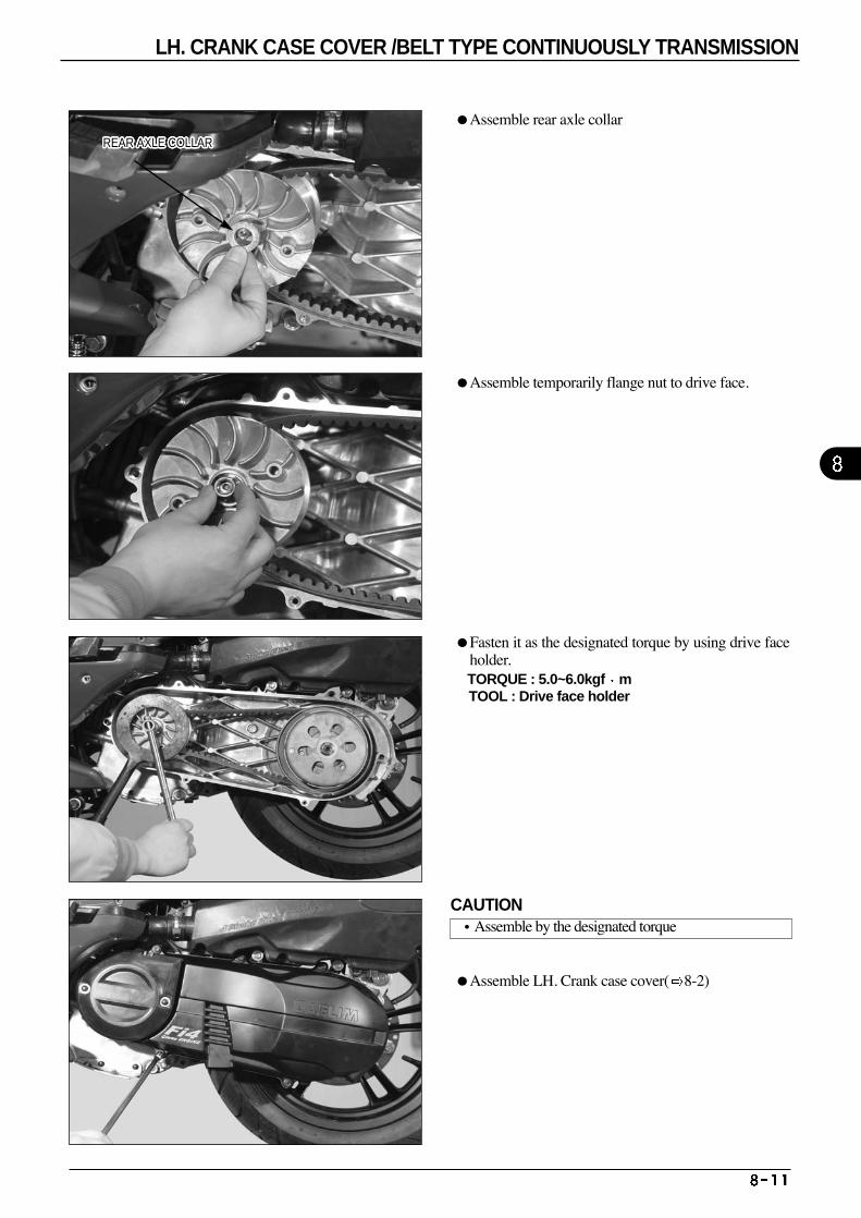
Assemble rear axle collar
Assemble temporarily flange nut to drive face.
Fasten it as the designated torque by using drive faceholder. TORQUE : 5.0~6.0kgf m TOOL : Drive face holder
Assemble LH. Crank case cover( 8-2)
REAR AXLE COLLARREAR AXLE COLLARREAR AXLE COLLARREAR AXLE COLLARREAR AXLE COLLARREAR AXLE COLLARREAR AXLE COLLARREAR AXLE COLLARREAR AXLE COLLARREAR AXLE COLLARREAR AXLE COLLARREAR AXLE COLLARREAR AXLE COLLARREAR AXLE COLLARREAR AXLE COLLARREAR AXLE COLLARREAR AXLE COLLARREAR AXLE COLLARREAR AXLE COLLARREAR AXLE COLLARREAR AXLE COLLARREAR AXLE COLLARREAR AXLE COLLARREAR AXLE COLLARREAR AXLE COLLARREAR AXLE COLLARREAR AXLE COLLAR
CAUTION•Assemble by the designated torque
LH. CRANK CASE COVER /BELT TYPE CONTINUOUSLY TRANSMISSION
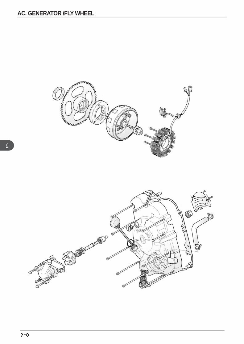
AC. GENERATOR /FLY WHEEL
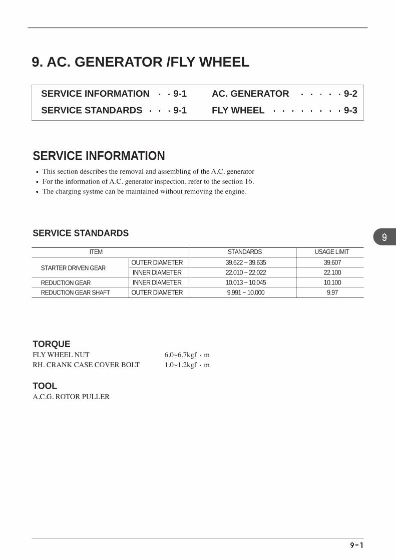
STARTER DRIVEN GEAR
REDUCTION GEAR
REDUCTION GEAR SHAFT
ITEM STANDARDS USAGE LIMIT
OUTER DIAMETER 39.622 ~ 39.635 39.607INNER DIAMETER 22.010 ~ 22.022 22.100 INNER DIAMETER 10.013 ~ 10.045 10.100 OUTER DIAMETER 9.991 ~ 10.000 9.97
9. AC. GENERATOR /FLY WHEEL
SERVICE INFORMATION 9-1
SERVICE STANDARDS 9-1
AC. GENERATOR 9-2
FLY WHEEL 9-3
SERVICE INFORMATIONThis section describes the removal and assembling of the A.C. generator For the information of A.C. generator inspection, refer to the section 16. The charging systme can be maintained without removing the engine.
SERVICE STANDARDS
TORQUEFLY WHEEL NUT 6.0~6.7kgf mRH. CRANK CASE COVER BOLT 1.0~1.2kgf m
TOOLA.C.G. ROTOR PULLER
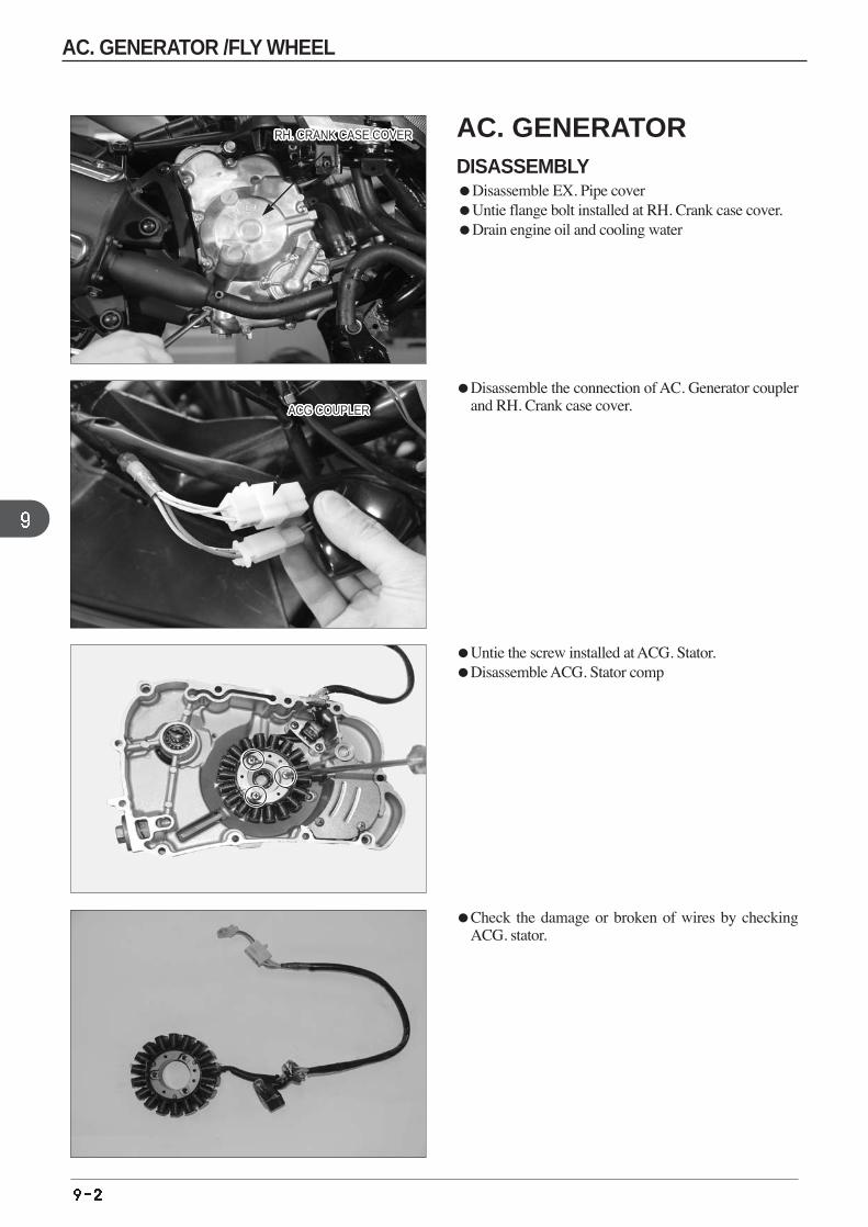
Disassemble the connection of AC. Generator couplerand RH. Crank case cover.
RH. CRANK CASE COVERRH. CRANK CASE COVERRH. CRANK CASE COVERRH. CRANK CASE COVERRH. CRANK CASE COVERRH. CRANK CASE COVERRH. CRANK CASE COVERRH. CRANK CASE COVERRH. CRANK CASE COVERRH. CRANK CASE COVERRH. CRANK CASE COVERRH. CRANK CASE COVERRH. CRANK CASE COVERRH. CRANK CASE COVERRH. CRANK CASE COVERRH. CRANK CASE COVERRH. CRANK CASE COVERRH. CRANK CASE COVERRH. CRANK CASE COVERRH. CRANK CASE COVERRH. CRANK CASE COVERRH. CRANK CASE COVERRH. CRANK CASE COVERRH. CRANK CASE COVERRH. CRANK CASE COVERRH. CRANK CASE COVERRH. CRANK CASE COVER
ACG COUPLERACG COUPLERACG COUPLERACG COUPLERACG COUPLERACG COUPLERACG COUPLERACG COUPLERACG COUPLERACG COUPLERACG COUPLERACG COUPLERACG COUPLERACG COUPLERACG COUPLERACG COUPLERACG COUPLERACG COUPLERACG COUPLERACG COUPLERACG COUPLERACG COUPLERACG COUPLERACG COUPLERACG COUPLERACG COUPLERACG COUPLER
Untie the screw installed at ACG. Stator. Disassemble ACG. Stator comp
Check the damage or broken of wires by checkingACG. stator.
AC. GENERATOR /FLY WHEEL
AC. GENERATOR DISASSEMBLYDisassemble EX. Pipe coverUntie flange bolt installed at RH. Crank case cover.Drain engine oil and cooling water
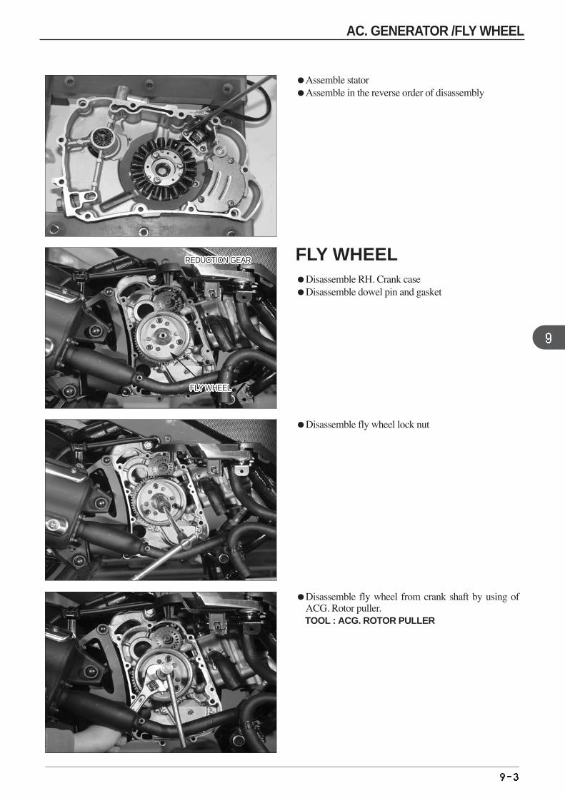
Disassemble fly wheel from crank shaft by using ofACG. Rotor puller. TOOL : ACG. ROTOR PULLER
Assemble stator Assemble in the reverse order of disassembly
Disassemble fly wheel lock nut
FLY WHEELDisassemble RH. Crank case Disassemble dowel pin and gasket
REDUCTION GEARREDUCTION GEARREDUCTION GEARREDUCTION GEARREDUCTION GEARREDUCTION GEARREDUCTION GEARREDUCTION GEARREDUCTION GEARREDUCTION GEARREDUCTION GEARREDUCTION GEARREDUCTION GEARREDUCTION GEARREDUCTION GEARREDUCTION GEARREDUCTION GEARREDUCTION GEARREDUCTION GEARREDUCTION GEARREDUCTION GEARREDUCTION GEARREDUCTION GEARREDUCTION GEARREDUCTION GEARREDUCTION GEARREDUCTION GEAR
FLY WHEELFLY WHEELFLY WHEELFLY WHEELFLY WHEELFLY WHEELFLY WHEELFLY WHEELFLY WHEELFLY WHEELFLY WHEELFLY WHEELFLY WHEELFLY WHEELFLY WHEELFLY WHEELFLY WHEELFLY WHEELFLY WHEELFLY WHEELFLY WHEELFLY WHEELFLY WHEELFLY WHEELFLY WHEELFLY WHEELFLY WHEEL
AC. GENERATOR /FLY WHEEL
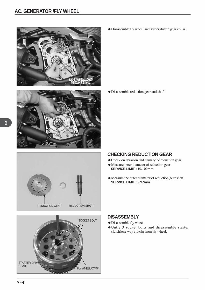
DISASSEMBLYDisassemble fly wheel Untie 3 socket bolts and disassemble starter
clutch(one way clutch) from fly wheel.
SOCKET BOLT
FLY WHEEL COMP
STARTER DRIVENGEAR
CHECKING REDUCTION GEARCheck on abrasion and damage of reduction gear Measure inner diameter of reduction gear
SERVICE LIMIT : 10.100mm
Measure the outer diameter of reduction gear shaft SERVICE LIMIT : 9.97mm
REDUCTION GEAR REDUCTION SHAFT
Disassemble fly wheel and starter driven gear collar
Disassemble reduction gear and shaft
STARTER DRIVENGEAR COLLAR
STARTER DRIVENGEAR COLLAR
STARTER DRIVENGEAR COLLAR
STARTER DRIVENGEAR COLLAR
STARTER DRIVENGEAR COLLAR
STARTER DRIVENGEAR COLLAR
STARTER DRIVENGEAR COLLAR
STARTER DRIVENGEAR COLLAR
STARTER DRIVENGEAR COLLAR
STARTER DRIVENGEAR COLLAR
STARTER DRIVENGEAR COLLAR
STARTER DRIVENGEAR COLLAR
STARTER DRIVENGEAR COLLAR
STARTER DRIVENGEAR COLLAR
STARTER DRIVENGEAR COLLAR
STARTER DRIVENGEAR COLLAR
STARTER DRIVENGEAR COLLAR
STARTER DRIVENGEAR COLLAR
STARTER DRIVENGEAR COLLAR
STARTER DRIVENGEAR COLLAR
STARTER DRIVENGEAR COLLAR
STARTER DRIVENGEAR COLLAR
STARTER DRIVENGEAR COLLAR
STARTER DRIVENGEAR COLLAR
STARTER DRIVENGEAR COLLAR
STARTER DRIVENGEAR COLLAR
STARTER DRIVENGEAR COLLAR
AC. GENERATOR /FLY WHEEL
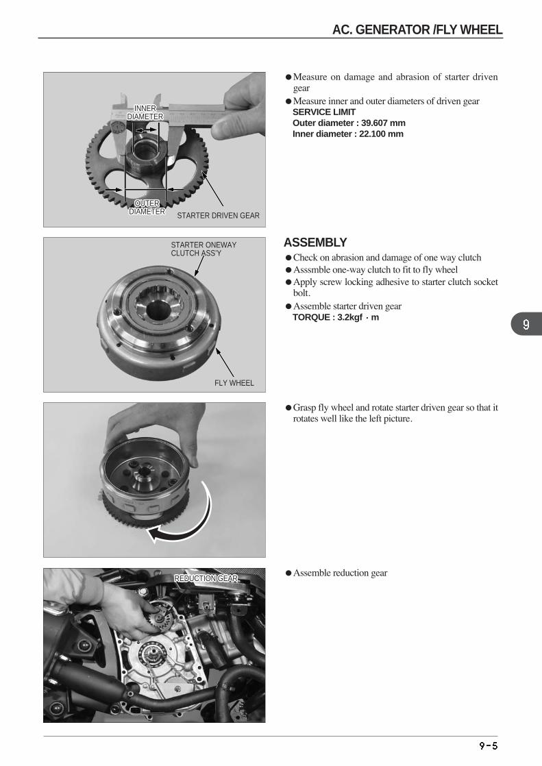
Assemble reduction gear
Grasp fly wheel and rotate starter driven gear so that itrotates well like the left picture.
Measure on damage and abrasion of starter drivengear
Measure inner and outer diameters of driven gear SERVICE LIMIT Outer diameter : 39.607 mm Inner diameter : 22.100 mm
ASSEMBLYCheck on abrasion and damage of one way clutch Asssmble one-way clutch to fit to fly wheel Apply screw locking adhesive to starter clutch socket
bolt. Assemble starter driven gear
TORQUE : 3.2kgf m
STARTER DRIVEN GEAR
STARTER ONEWAYCLUTCH ASS’Y
REDUCTION GEARREDUCTION GEARREDUCTION GEARREDUCTION GEARREDUCTION GEARREDUCTION GEARREDUCTION GEARREDUCTION GEARREDUCTION GEARREDUCTION GEARREDUCTION GEARREDUCTION GEARREDUCTION GEARREDUCTION GEARREDUCTION GEARREDUCTION GEARREDUCTION GEARREDUCTION GEARREDUCTION GEARREDUCTION GEARREDUCTION GEARREDUCTION GEARREDUCTION GEARREDUCTION GEARREDUCTION GEARREDUCTION GEARREDUCTION GEAR
OUTERDIAMETER
OUTERDIAMETER
OUTERDIAMETER
OUTERDIAMETER
OUTERDIAMETER
OUTERDIAMETER
OUTERDIAMETER
OUTERDIAMETER
OUTERDIAMETER
OUTERDIAMETER
OUTERDIAMETER
OUTERDIAMETER
OUTERDIAMETER
OUTERDIAMETER
OUTERDIAMETER
OUTERDIAMETER
OUTERDIAMETER
OUTERDIAMETER
OUTERDIAMETER
OUTERDIAMETER
OUTERDIAMETER
OUTERDIAMETER
OUTERDIAMETER
OUTERDIAMETER
OUTERDIAMETER
OUTERDIAMETER
OUTERDIAMETER
INNERDIAMETER
INNERDIAMETER
INNERDIAMETER
INNERDIAMETER
INNERDIAMETER
INNERDIAMETER
INNERDIAMETER
INNERDIAMETER
INNERDIAMETER
INNERDIAMETER
INNERDIAMETER
INNERDIAMETER
INNERDIAMETER
INNERDIAMETER
INNERDIAMETER
INNERDIAMETER
INNERDIAMETER
INNERDIAMETER
INNERDIAMETER
INNERDIAMETER
INNERDIAMETER
INNERDIAMETER
INNERDIAMETER
INNERDIAMETER
INNERDIAMETER
INNERDIAMETER
INNERDIAMETER
FLY WHEEL
AC. GENERATOR /FLY WHEEL
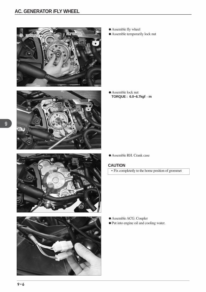
Assemble lock nut TORQUE : 6.0~6.7kgf m
Assemble RH. Crank case
Assemble fly wheel Assemble temporarily lock nut LOCK NUTLOCK NUTLOCK NUTLOCK NUTLOCK NUTLOCK NUTLOCK NUTLOCK NUTLOCK NUTLOCK NUTLOCK NUTLOCK NUTLOCK NUTLOCK NUTLOCK NUTLOCK NUTLOCK NUTLOCK NUTLOCK NUTLOCK NUTLOCK NUTLOCK NUTLOCK NUTLOCK NUTLOCK NUTLOCK NUTLOCK NUT
Assemble ACG. Coupler Put into engine oil and cooling water.
FLY WHEELFLY WHEELFLY WHEELFLY WHEELFLY WHEELFLY WHEELFLY WHEELFLY WHEELFLY WHEELFLY WHEELFLY WHEELFLY WHEELFLY WHEELFLY WHEELFLY WHEELFLY WHEELFLY WHEELFLY WHEELFLY WHEELFLY WHEELFLY WHEELFLY WHEELFLY WHEELFLY WHEELFLY WHEELFLY WHEELFLY WHEEL
CAUTION•Fix completetly to the home position of grommet
AC. GENERATOR /FLY WHEEL
MEMO
AC. GENERATOR /FLY WHEEL
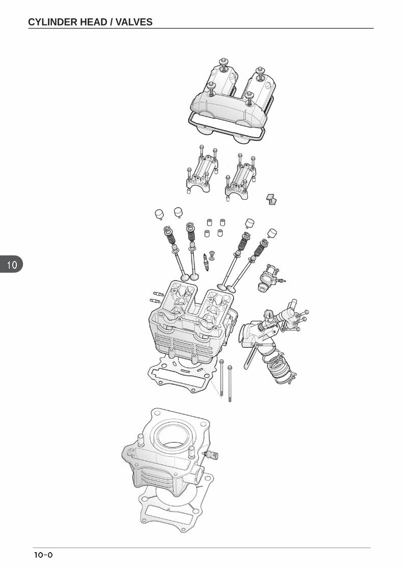
CYLINDER HEAD / VALVES
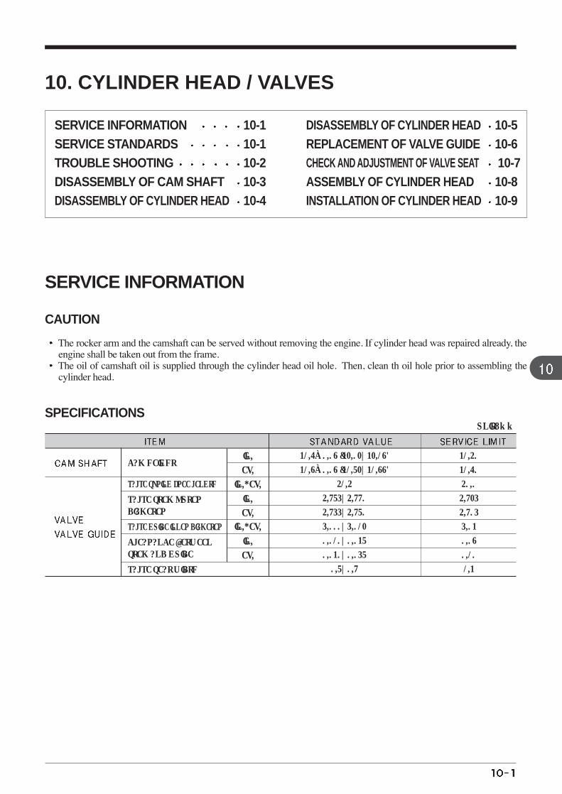
31.6±0.08 (32.02~32.18)
31.8±0.08 (31.72~31.88)
41.4
4.975~4.990
4.955~4.970
5.000~5.012
0.010~0.037
0.030~0.057
0.7~0.9
31.40
31.60
40.0
4.925
4.905
5.03
0.08
0.10
1.3
CAM HEIGHT
VALVE SPRING FREE LENGTH
VALVE STEM OUTER DIAMETER
VALVE GUIDE INNER DIAMETER
CLEARANCE BETWEENSTEM AND GUIDE
VALVE SEAT WIDTH
IN.
EX.
IN.
EX.
IN., EX.
IN.
EX.
IN., EX.
UNIT: mm
10. CYLINDER HEAD / VALVES
SERVICE INFORMATION 10-1 SERVICE STANDARDS 10-1 TROUBLE SHOOTING 10-2 DISASSEMBLY OF CAM SHAFT 10-3 DISASSEMBLY OF CYLINDER HEAD 10-4
DISASSEMBLY OF CYLINDER HEAD 10-5 REPLACEMENT OF VALVE GUIDE 10-6 CHECK AND ADJUSTMENT OF VALVE SEAT 10-7 ASSEMBLY OF CYLINDER HEAD 10-8 INSTALLATION OF CYLINDER HEAD 10-9
SERVICE INFORMATION
CAUTION
The rocker arm and the camshaft can be served without removing the engine. If cylinder head was repaired already, theengine shall be taken out from the frame. The oil of camshaft oil is supplied through the cylinder head oil hole. Then, clean th oil hole prior to assembling thecylinder head.
SPECIFICATIONS
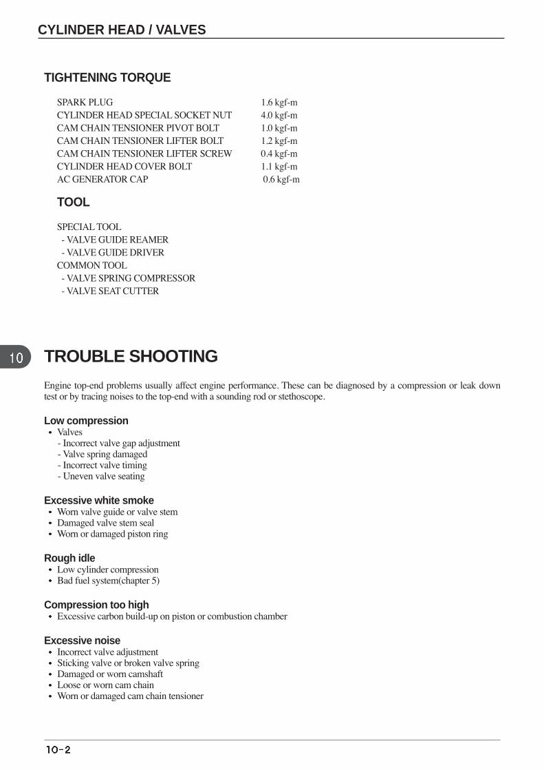
TIGHTENING TORQUE
SPARK PLUG 1.6 kgf-mCYLINDER HEAD SPECIAL SOCKET NUT 4.0 kgf-mCAM CHAIN TENSIONER PIVOT BOLT 1.0 kgf-mCAM CHAIN TENSIONER LIFTER BOLT 1.2 kgf-mCAM CHAIN TENSIONER LIFTER SCREW 0.4 kgf-mCYLINDER HEAD COVER BOLT 1.1 kgf-mAC GENERATOR CAP 0.6 kgf-m
TOOL
SPECIAL TOOL- VALVE GUIDE REAMER - VALVE GUIDE DRIVER
COMMON TOOL- VALVE SPRING COMPRESSOR - VALVE SEAT CUTTER
TROUBLE SHOOTING
Engine top-end problems usually affect engine performance. These can be diagnosed by a compression or leak downtest or by tracing noises to the top-end with a sounding rod or stethoscope.
Low compressionValves- Incorrect valve gap adjustment - Valve spring damaged - Incorrect valve timing - Uneven valve seating
Excessive white smoke Worn valve guide or valve stem Damaged valve stem seal Worn or damaged piston ring
Rough idle Low cylinder compression Bad fuel system(chapter 5)
Compression too high Excessive carbon build-up on piston or combustion chamber
Excessive noise Incorrect valve adjustment Sticking valve or broken valve spring Damaged or worn camshaft Loose or worn cam chain Worn or damaged cam chain tensioner
CYLINDER HEAD / VALVES
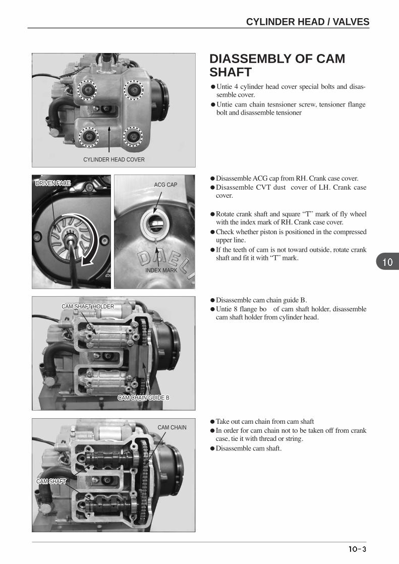
Disassemble ACG cap from RH. Crank case cover. Disassemble CVT dust cover of LH. Crank case
cover.
Rotate crank shaft and square “T” mark of fly wheelwith the index mark of RH. Crank case cover.
Check whether piston is positioned in the compressedupper line.
If the teeth of cam is not toward outside, rotate crankshaft and fit it with “T” mark.
Disassemble cam chain guide B. Untie 8 flange bo of cam shaft holder, disassemble
cam shaft holder from cylinder head.
CYLINDER HEAD COVER
Take out cam chain from cam shaft In order for cam chain not to be taken off from crank
case, tie it with thread or string. Disassemble cam shaft.
ACG CAP
INDEX MARK
CAM CHAIN GUIDE BCAM CHAIN GUIDE BCAM CHAIN GUIDE BCAM CHAIN GUIDE BCAM CHAIN GUIDE BCAM CHAIN GUIDE BCAM CHAIN GUIDE BCAM CHAIN GUIDE BCAM CHAIN GUIDE BCAM CHAIN GUIDE BCAM CHAIN GUIDE BCAM CHAIN GUIDE BCAM CHAIN GUIDE BCAM CHAIN GUIDE BCAM CHAIN GUIDE BCAM CHAIN GUIDE BCAM CHAIN GUIDE BCAM CHAIN GUIDE BCAM CHAIN GUIDE BCAM CHAIN GUIDE BCAM CHAIN GUIDE BCAM CHAIN GUIDE BCAM CHAIN GUIDE BCAM CHAIN GUIDE BCAM CHAIN GUIDE BCAM CHAIN GUIDE BCAM CHAIN GUIDE B
CAM SHAFT HOLDERCAM SHAFT HOLDERCAM SHAFT HOLDERCAM SHAFT HOLDERCAM SHAFT HOLDERCAM SHAFT HOLDERCAM SHAFT HOLDERCAM SHAFT HOLDERCAM SHAFT HOLDERCAM SHAFT HOLDERCAM SHAFT HOLDERCAM SHAFT HOLDERCAM SHAFT HOLDERCAM SHAFT HOLDERCAM SHAFT HOLDERCAM SHAFT HOLDERCAM SHAFT HOLDERCAM SHAFT HOLDERCAM SHAFT HOLDERCAM SHAFT HOLDERCAM SHAFT HOLDERCAM SHAFT HOLDERCAM SHAFT HOLDERCAM SHAFT HOLDERCAM SHAFT HOLDERCAM SHAFT HOLDERCAM SHAFT HOLDER
CAM CHAIN
DRIVEN FACEDRIVEN FACEDRIVEN FACEDRIVEN FACEDRIVEN FACEDRIVEN FACEDRIVEN FACEDRIVEN FACEDRIVEN FACEDRIVEN FACEDRIVEN FACEDRIVEN FACEDRIVEN FACEDRIVEN FACEDRIVEN FACEDRIVEN FACEDRIVEN FACEDRIVEN FACEDRIVEN FACEDRIVEN FACEDRIVEN FACEDRIVEN FACEDRIVEN FACEDRIVEN FACEDRIVEN FACEDRIVEN FACEDRIVEN FACE
CYLINDER HEAD / VALVES
DIASSEMBLY OF CAMSHAFTUntie 4 cylinder head cover special bolts and disas-
semble cover. Untie cam chain tesnsioner screw, tensioner flange
bolt and disassemble tensioner
CAM SHAFTCAM SHAFTCAM SHAFTCAM SHAFTCAM SHAFTCAM SHAFTCAM SHAFTCAM SHAFTCAM SHAFTCAM SHAFTCAM SHAFTCAM SHAFTCAM SHAFTCAM SHAFTCAM SHAFTCAM SHAFTCAM SHAFTCAM SHAFTCAM SHAFTCAM SHAFTCAM SHAFTCAM SHAFTCAM SHAFTCAM SHAFTCAM SHAFTCAM SHAFTCAM SHAFT
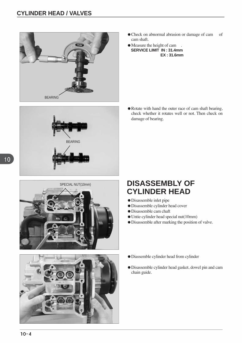
DISASSEMBLY OFCYLINDER HEADDisassemble inlet pipe Disassemble cylinder head cover Disassemble cam chaft Untie cylinder head special nut(10mm) Disassemble after marking the position of valve.
Check on abnormal abrasion or damage of cam ofcam shaft.
Measure the height of cam . SERVICE LIMIT IN : 31.4mm
EX : 31.6mm
Rotate with hand the outer race of cam shaft bearing,check whether it rotates well or not. Then check ondamage of bearing.
Diassemble cylinder head from cylinder
Disassemble cylinder head gasket, dowel pin and camchain guide.
BEARING
SPECIAL NUT(10mm)
CYLINDER HEAD / VALVES
BEARING
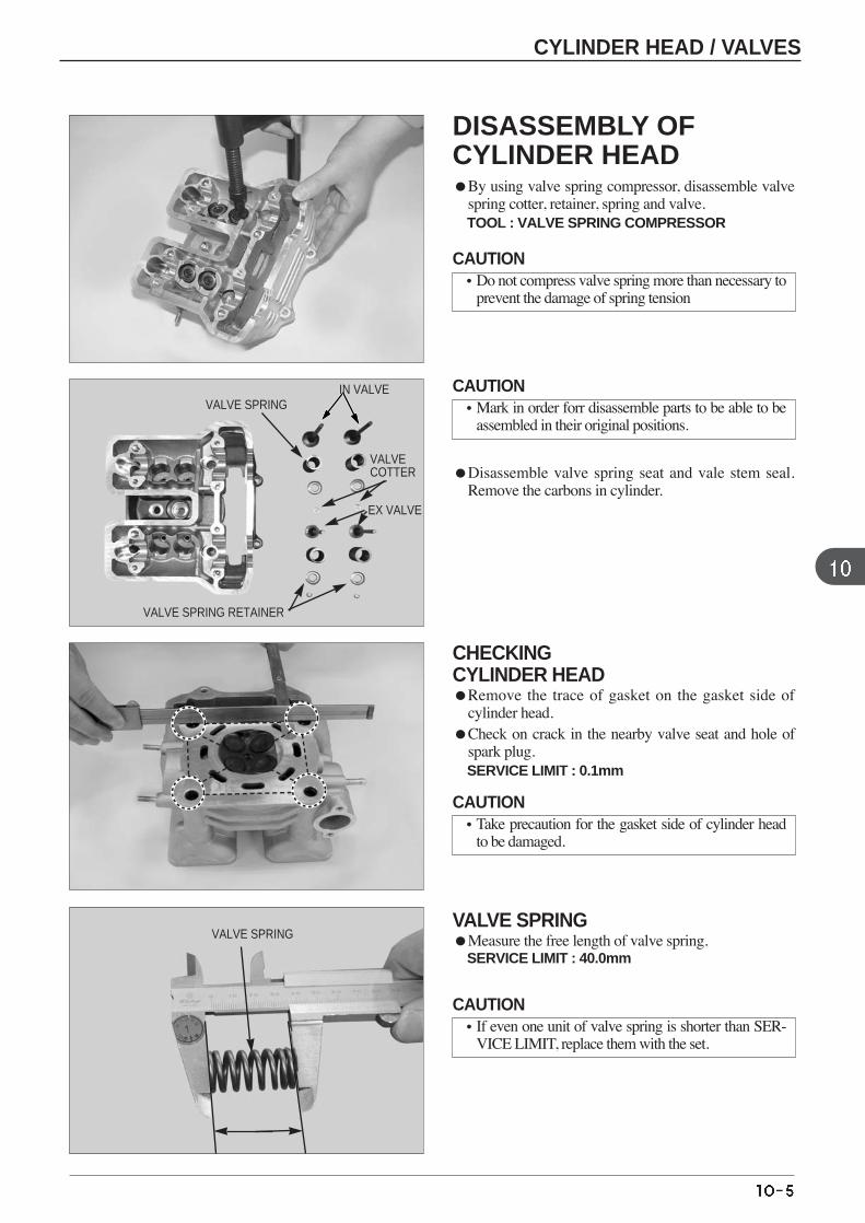
Disassemble valve spring seat and vale stem seal.Remove the carbons in cylinder.
CHECKING CYLINDER HEAD Remove the trace of gasket on the gasket side of
cylinder head. Check on crack in the nearby valve seat and hole of
spark plug. SERVICE LIMIT : 0.1mm
DISASSEMBLY OFCYLINDER HEAD By using valve spring compressor, disassemble valve
spring cotter, retainer, spring and valve. TOOL : VALVE SPRING COMPRESSOR
VALVE SPRING Measure the free length of valve spring.
SERVICE LIMIT : 40.0mm
EX VALVE
VALVE SPRING
VALVE SPRING RETAINER
VALVECOTTER
VALVE SPRING
CAUTION•Do not compress valve spring more than necessary to
prevent the damage of spring tension
CAUTION•Mark in order forr disassemble parts to be able to be
assembled in their original positions.
CAUTION•Take precaution for the gasket side of cylinder head
to be damaged.
CAUTION•If even one unit of valve spring is shorter than SER-
VICE LIMIT, replace them with the set.
CYLINDER HEAD / VALVES
IN VALVE
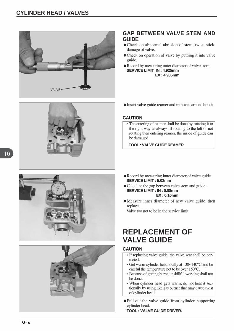
Insert valve guide reamer and remove carbon deposit.
Record by measuring inner diameter of valve guide. SERVICE LIMIT : 5.03mm
Calculate the gap between valve stem and guide. SERVICE LIMIT : IN : 0.08mm
EX : 0.10mmMeasure inner diameter of new valve guide, then
replace Valve too not to be in the service limit.
Pull out the valve guide from cylinder, supportingcylinder head. TOOL : VALVE GUIDE DRIVER.
GAP BETWEEN VALVE STEM ANDGUIDE Check on abnormal abrasion of stem, twist, stick,
damage of valve. Check on operation of valve by puttiing it into valve
guide. Record by measuring outer diameter of valve stem.
SERVICE LIMIT IN : 4.925mm EX : 4.905mm
VALVE
CAUTION•The entering of reamer shall be done by rotating it to
the right way as always. If rotating to the left or notrotating then entering reamer, the inside of guide canbe damaged.
TOOL : VALVE GUIDE REAMER.
CAUTION•If replacing valve guide, the valve seat shall be cor-
rected. •Get warm cylinder head totally at 130~140°C and be
careful the temperature not to be over 150°C. •Because of getting burnt, unskillful working shall not
be done.•When cylinder head gets warm, do not heat it sec-
tionally by using like gas burner that may cause twistof cylinder head.
REPLACEMENT OFVALVE GUIDE
CYLINDER HEAD / VALVES
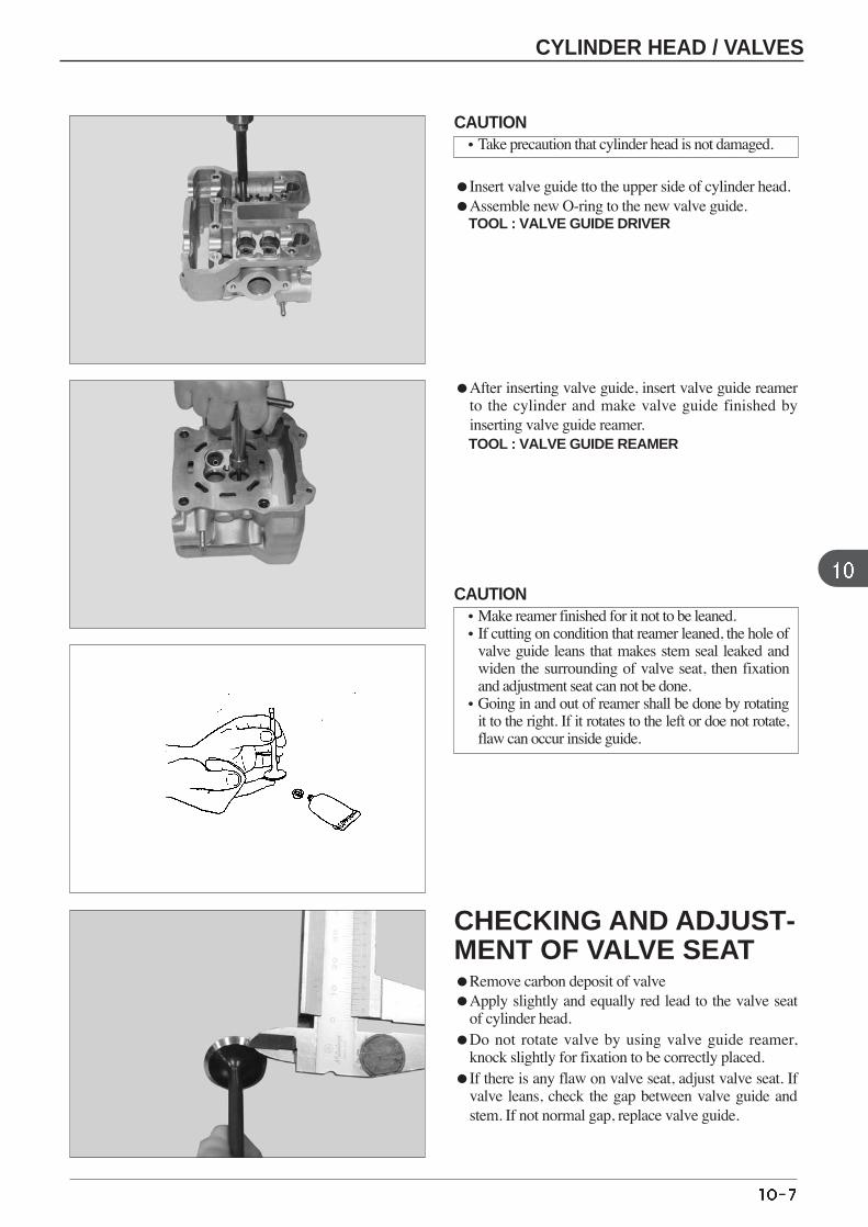
Insert valve guide tto the upper side of cylinder head. Assemble new O-ring to the new valve guide.
TOOL : VALVE GUIDE DRIVER
After inserting valve guide, insert valve guide reamerto the cylinder and make valve guide finished byinserting valve guide reamer.TOOL : VALVE GUIDE REAMER
CHECKING AND ADJUST-MENT OF VALVE SEATRemove carbon deposit of valve Apply slightly and equally red lead to the valve seat
of cylinder head. Do not rotate valve by using valve guide reamer,
knock slightly for fixation to be correctly placed. If there is any flaw on valve seat, adjust valve seat. If
valve leans, check the gap between valve guide andstem. If not normal gap, replace valve guide.
CAUTION•Take precaution that cylinder head is not damaged.
CAUTION•Make reamer finished for it not to be leaned. •If cutting on condition that reamer leaned, the hole of
valve guide leans that makes stem seal leaked andwiden the surrounding of valve seat, then fixationand adjustment seat can not be done.
•Going in and out of reamer shall be done by rotatingit to the right. If it rotates to the left or doe not rotate,flaw can occur inside guide.
CYLINDER HEAD / VALVES
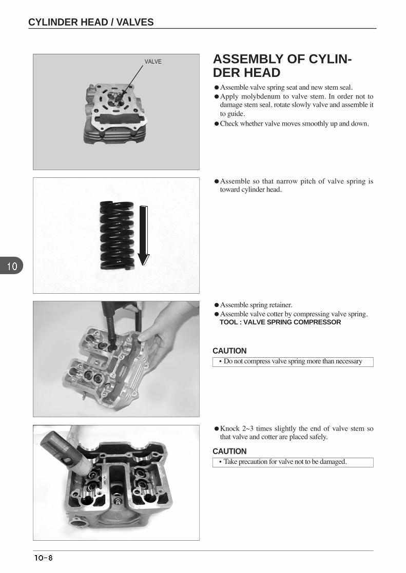
ASSEMBLY OF CYLIN-DER HEAD Assemble valve spring seat and new stem seal. Apply molybdenum to valve stem. In order not to
damage stem seal, rotate slowly valve and assemble itto guide.
Check whether valve moves smoothly up and down.
VALVE
Assemble so that narrow pitch of valve spring istoward cylinder head.
Assemble spring retainer. Assemble valve cotter by compressing valve spring.
TOOL : VALVE SPRING COMPRESSOR
Knock 2~3 times slightly the end of valve stem sothat valve and cotter are placed safely.
CAUTION•Do not compress valve spring more than necessary
CAUTION•Take precaution for valve not to be damaged.
CYLINDER HEAD / VALVES
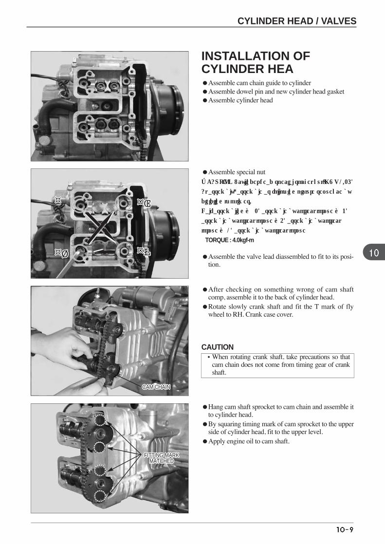
Assemble special nut ※CAUTION : cylinder head special socket nut(M8 X 1.25)
At assembly, assemble as following picture sequence by
dividiing two times.
Half assembling → 2) assemble by correct torque → 3)
assemble by correct torque →4) assemble by correct
torque → 1) assemble by correct torque
TORQUE : 4.0kgf-m
Assemble the valve lead diassembled to fit to its posi-tion.
After checking on something wrong of cam shaftcomp, assemble it to the back of cylinder head.
Rotate slowly crank shaft and fit the T mark of flywheel to RH. Crank case cover.
Hang cam shaft sprocket to cam chain and assemble itto cylinder head.
By squaring timing mark of cam sprocket to the upperside of cylinder head, fit to the upper level.
Apply engine oil to cam shaft.
INSTALLATION OFCYLINDER HEAAssemble cam chain guide to cylinder Assemble dowel pin and new cylinder head gasket Assemble cylinder head
CAM CHAINCAM CHAINCAM CHAINCAM CHAINCAM CHAINCAM CHAINCAM CHAINCAM CHAINCAM CHAINCAM CHAINCAM CHAINCAM CHAINCAM CHAINCAM CHAINCAM CHAINCAM CHAINCAM CHAINCAM CHAINCAM CHAINCAM CHAINCAM CHAINCAM CHAINCAM CHAINCAM CHAINCAM CHAINCAM CHAINCAM CHAIN
FITTING MARKMATCHED
FITTING MARKMATCHED
FITTING MARKMATCHED
FITTING MARKMATCHED
FITTING MARKMATCHED
FITTING MARKMATCHED
FITTING MARKMATCHED
FITTING MARKMATCHED
FITTING MARKMATCHED
FITTING MARKMATCHED
FITTING MARKMATCHED
FITTING MARKMATCHED
FITTING MARKMATCHED
FITTING MARKMATCHED
FITTING MARKMATCHED
FITTING MARKMATCHED
FITTING MARKMATCHED
FITTING MARKMATCHED
FITTING MARKMATCHED
FITTING MARKMATCHED
FITTING MARKMATCHED
FITTING MARKMATCHED
FITTING MARKMATCHED
FITTING MARKMATCHED
FITTING MARKMATCHED
FITTING MARKMATCHED
FITTING MARKMATCHED
¤¤¤¤¤¤¤¤¤¤¤¤¤¤¤¤¤¤¤¤¤¤
¤Ø¤Ø¤Ø¤Ø¤Ø¤Ø¤Ø¤Ø¤Ø¤Ø¤Ø¤Ø¤Ø¤Ø¤Ø¤Ø¤Ø¤Ø¤Ø¤Ø¤Ø¤Ø ¤Ł¤Ł¤Ł¤Ł¤Ł¤Ł¤Ł¤Ł¤Ł¤Ł¤Ł¤Ł¤Ł¤Ł¤Ł¤Ł¤Ł¤Ł¤Ł¤Ł¤Ł¤Ł
¤Œ¤Œ¤Œ¤Œ¤Œ¤Œ¤Œ¤Œ¤Œ¤Œ¤Œ¤Œ¤Œ¤Œ¤Œ¤Œ¤Œ¤Œ¤Œ¤Œ¤Œ¤Œ
CAUTION•When rotating crank shaft, take precautions so that
cam chain does not come from timing gear of crankshaft.
CYLINDER HEAD / VALVES
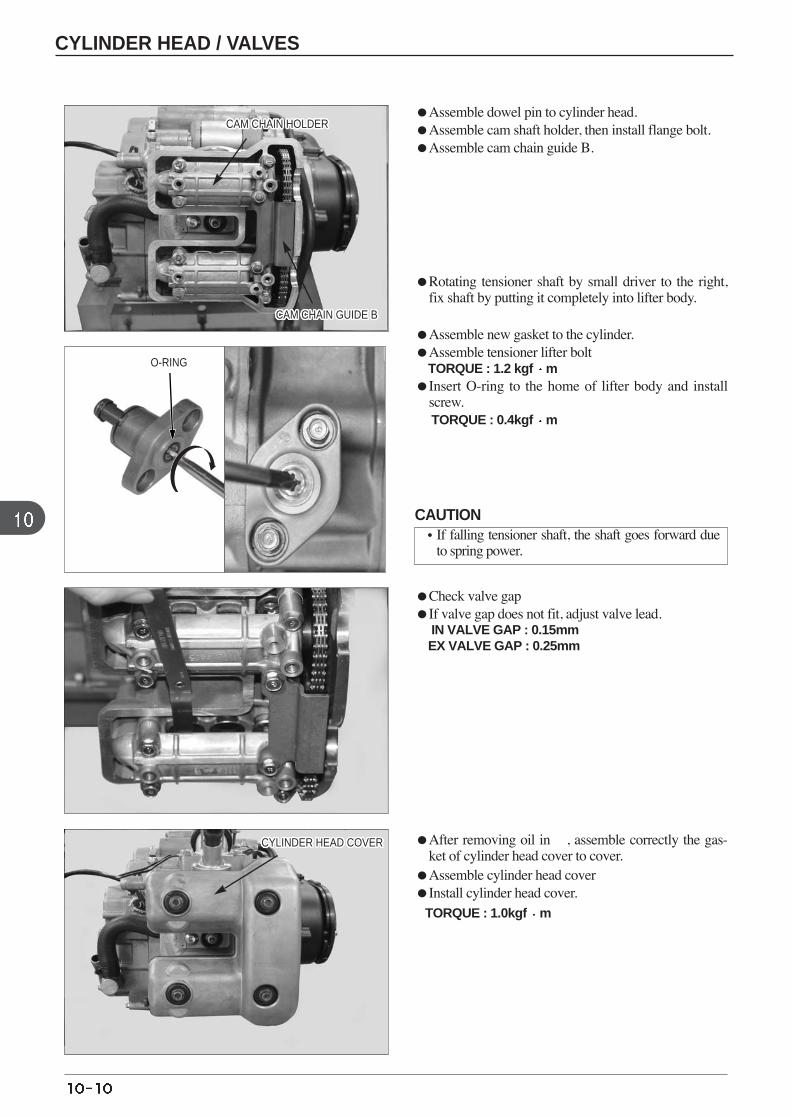
O-RING
Assemble dowel pin to cylinder head. Assemble cam shaft holder, then install flange bolt. Assemble cam chain guide B.
Rotating tensioner shaft by small driver to the right,fix shaft by putting it completely into lifter body.
Assemble new gasket to the cylinder. Assemble tensioner lifter bolt
TORQUE : 1.2 kgf mInsert O-ring to the home of lifter body and install
screw. TORQUE : 0.4kgf m
After removing oil in , assemble correctly the gas-ket of cylinder head cover to cover.
Assemble cylinder head cover Install cylinder head cover.
TORQUE : 1.0kgf m
Check valve gap If valve gap does not fit, adjust valve lead.
IN VALVE GAP : 0.15mm EX VALVE GAP : 0.25mm
CAM CHAIN HOLDERCAM CHAIN HOLDERCAM CHAIN HOLDERCAM CHAIN HOLDERCAM CHAIN HOLDERCAM CHAIN HOLDERCAM CHAIN HOLDERCAM CHAIN HOLDERCAM CHAIN HOLDERCAM CHAIN HOLDERCAM CHAIN HOLDERCAM CHAIN HOLDERCAM CHAIN HOLDERCAM CHAIN HOLDERCAM CHAIN HOLDERCAM CHAIN HOLDERCAM CHAIN HOLDERCAM CHAIN HOLDERCAM CHAIN HOLDERCAM CHAIN HOLDERCAM CHAIN HOLDERCAM CHAIN HOLDERCAM CHAIN HOLDERCAM CHAIN HOLDERCAM CHAIN HOLDERCAM CHAIN HOLDERCAM CHAIN HOLDER
CAM CHAIN GUIDE BCAM CHAIN GUIDE BCAM CHAIN GUIDE BCAM CHAIN GUIDE BCAM CHAIN GUIDE BCAM CHAIN GUIDE BCAM CHAIN GUIDE BCAM CHAIN GUIDE BCAM CHAIN GUIDE BCAM CHAIN GUIDE BCAM CHAIN GUIDE BCAM CHAIN GUIDE BCAM CHAIN GUIDE BCAM CHAIN GUIDE BCAM CHAIN GUIDE BCAM CHAIN GUIDE BCAM CHAIN GUIDE BCAM CHAIN GUIDE BCAM CHAIN GUIDE BCAM CHAIN GUIDE BCAM CHAIN GUIDE BCAM CHAIN GUIDE BCAM CHAIN GUIDE BCAM CHAIN GUIDE BCAM CHAIN GUIDE BCAM CHAIN GUIDE BCAM CHAIN GUIDE B
CYLINDER HEAD COVERCYLINDER HEAD COVERCYLINDER HEAD COVERCYLINDER HEAD COVERCYLINDER HEAD COVERCYLINDER HEAD COVERCYLINDER HEAD COVERCYLINDER HEAD COVERCYLINDER HEAD COVERCYLINDER HEAD COVERCYLINDER HEAD COVERCYLINDER HEAD COVERCYLINDER HEAD COVERCYLINDER HEAD COVERCYLINDER HEAD COVERCYLINDER HEAD COVERCYLINDER HEAD COVERCYLINDER HEAD COVERCYLINDER HEAD COVERCYLINDER HEAD COVERCYLINDER HEAD COVERCYLINDER HEAD COVERCYLINDER HEAD COVERCYLINDER HEAD COVERCYLINDER HEAD COVERCYLINDER HEAD COVERCYLINDER HEAD COVER
CAUTION•If falling tensioner shaft, the shaft goes forward due
to spring power.
CYLINDER HEAD / VALVES

MEMO
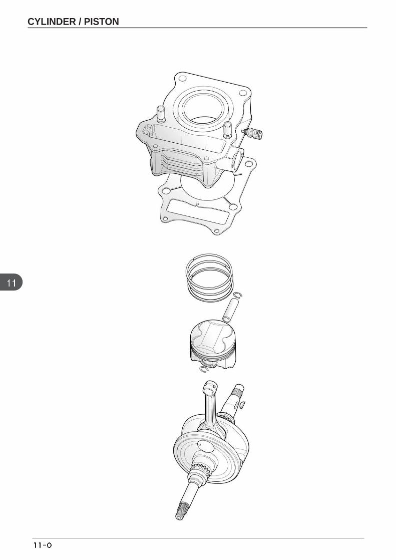
CYLINDER / PISTON
CYLINDER
INNER DIAMETER
TAPER
OUT-OF-ROUND
HEAD CONTACT WARPAGE
PISTON SKIRT OUTER DIAMETER
PISTON PIN HOLE INNER DIAMETER
PISTON PIN OUTER DIAMETER
PISTON-TO-PISTON PIN CLEARANCE
PISTON RING TOGROOVE CLEARANCEPISTON RING JOINT GAP
TOP
SECOND
TOP/SECOND
OIL(SIDE RAIL)
PISTON,
PISTON PIN,
PISTON
RINGS
CYLINDER-TO-PISTON CLEARANCE
CONNECTING ROD SMALL END INNER DIAMETER
GAP BETWEEN CONNECTING ROD SMALL END AND PISTON PIN
ITEM STANDARDS SERVICE LIMIT
56.505 ~ 56.565 56.6
- 0.1
- 0.05
- 0.1
56.450 ~ 56.470 56.35
15.002 ~ 15.008 15.04
14.994 ~ 15.000 14.96
0.002~0.014 0.02
0.015~0.050 0.09
0.015~0.045 0.09
0.35~0.45 0.5
0.2~0.7 1.1
0.035 ~ 0.065 0.30
15.010~15.028 15.06
0.010~0.034 0.04
unit : mm
11. CYLINDER / PISTON
SERVICE INFORMATION
GENERAL SAFETYBe careful not to damage the mating surfaces by using a screwdriver when disassembling the cylinder. Do not strikethe cylinder too hard during disassembly, even with a rubber or plastic mallet, to prevent the possibility of damage tothe cylinder pins. Take precautions not to damage the cylinder wall and piston
SPECIFICATIONS
SERVICE INFORMATION 11-1 SERVICE STANDARDS 11-1 TROUBLE SHOOTING 11-1
CYLINDER 11-2 PISTON 11-3 PISTON / ASSEMBLY OF CYLINDER 11-5
TROUBLE SHOOTING
Compression pressure too low Over heatedPiston worn Excessive carbon built up on top of piston Piston ring worn or damaged Cylinder worn
Abnormal engine noiseEmission of white gas from muffler Cylinder, piston worn
Cylinder, piston, piston rings worn Worn connecting rod small end bearing or piston pinsBad adjustment of piston rings Damaged piston ringsPiston, cylinder worn Excessive carbon built up on top of piston
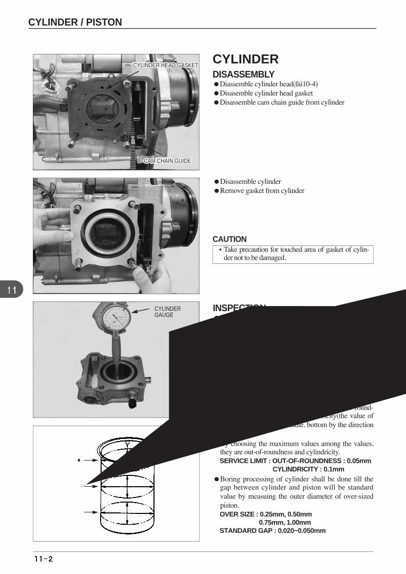
Disassemble cylinder Remove gasket from cylinder
INSPECTION Measure the inner diameter of cylinder from 6 posi-
tion of top, middle, bottom by the direction of pistonpin and by the rectangular direction(X-Y direction).
Be the maximum measured value to that of innerdiameter of cylinder. SERVICE LIMIT : 56.60mm
Measure the outer diameter of piston. Minusing the value of outer diameter of piston from
that of inner diameter of cylinder, measure the gapbetween cylinder and piston.
By each measured values, calculate the out-of-round-ness(X and Y direction) and cylindricity(the value ofinner diameter of top, middle, bottom by the directionof X or Y).
By choosing the maximum values among the values,they are out-of-roundness and cylindricity. SERVICE LIMIT : OUT-OF-ROUNDNESS : 0.05mm
CYLINDRICITY : 0.1mm Boring processing of cylinder shall be done till the
gap between cylinder and piston will be standardvalue by measuing the outer diameter of over-sizedpiston. OVER SIZE : 0.25mm, 0.50mm
0.75mm, 1.00mm STANDARD GAP : 0.020~0.050mm
상
중
하
CYLINDER HEAD GASKETCYLINDER HEAD GASKETCYLINDER HEAD GASKETCYLINDER HEAD GASKETCYLINDER HEAD GASKETCYLINDER HEAD GASKETCYLINDER HEAD GASKETCYLINDER HEAD GASKETCYLINDER HEAD GASKETCYLINDER HEAD GASKETCYLINDER HEAD GASKETCYLINDER HEAD GASKETCYLINDER HEAD GASKETCYLINDER HEAD GASKETCYLINDER HEAD GASKETCYLINDER HEAD GASKETCYLINDER HEAD GASKETCYLINDER HEAD GASKETCYLINDER HEAD GASKETCYLINDER HEAD GASKETCYLINDER HEAD GASKETCYLINDER HEAD GASKETCYLINDER HEAD GASKETCYLINDER HEAD GASKETCYLINDER HEAD GASKETCYLINDER HEAD GASKETCYLINDER HEAD GASKET
CAM CHAIN GUIDECAM CHAIN GUIDECAM CHAIN GUIDECAM CHAIN GUIDECAM CHAIN GUIDECAM CHAIN GUIDECAM CHAIN GUIDECAM CHAIN GUIDECAM CHAIN GUIDECAM CHAIN GUIDECAM CHAIN GUIDECAM CHAIN GUIDECAM CHAIN GUIDECAM CHAIN GUIDECAM CHAIN GUIDECAM CHAIN GUIDECAM CHAIN GUIDECAM CHAIN GUIDECAM CHAIN GUIDECAM CHAIN GUIDECAM CHAIN GUIDECAM CHAIN GUIDECAM CHAIN GUIDECAM CHAIN GUIDECAM CHAIN GUIDECAM CHAIN GUIDECAM CHAIN GUIDE
CYLINDERGAUGE
CYLINDER / PISTON
CYLINDERDISASSEMBLYDiassemble cylinder head(ßú10-4)Disasemble cylinder head gasketDisassemble cam chain guide from cylinder
CAUTION•Take precaution for touched area of gasket of cylin-
der not to be damaged.
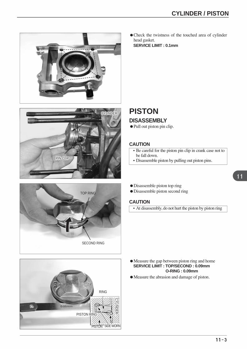
Check the twistness of the touched area of cylinderhead gasket. SERVICE LIMIT : 0.1mm
Disassemble piston top ring Disassemble piston second ring
Measure the gap between piston ring and home SERVICE LIMIT : TOP/SECOND : 0.09mm
O-RING : 0.09mm Measure the abrasion and damage of piston.
PISTON RINGPISTON RINGPISTON RINGPISTON RINGPISTON RINGPISTON RINGPISTON RINGPISTON RINGPISTON RINGPISTON RINGPISTON RINGPISTON RINGPISTON RINGPISTON RINGPISTON RINGPISTON RINGPISTON RINGPISTON RINGPISTON RINGPISTON RINGPISTON RINGPISTON RINGPISTON RINGPISTON RINGPISTON RINGPISTON RINGPISTON RING
RING
PISTON SIDE WORNSIDE WORNSIDE WORNSIDE WORNSIDE WORNSIDE WORNSIDE WORNSIDE WORNSIDE WORNSIDE WORNSIDE WORNSIDE WORNSIDE WORNSIDE WORNSIDE WORNSIDE WORNSIDE WORNSIDE WORNSIDE WORNSIDE WORNSIDE WORNSIDE WORNSIDE WORNSIDE WORNSIDE WORNSIDE WORNSIDE WORN
CYLIN
DER
CYLIN
DER
CYLIN
DER
CYLIN
DER
CYLIN
DER
CYLIN
DER
CYLIN
DER
CYLIN
DER
CYLIN
DER
CYLIN
DER
CYLIN
DER
CYLIN
DER
CYLIN
DER
CYLIN
DER
CYLIN
DER
CYLIN
DER
CYLIN
DER
CYLIN
DER
CYLIN
DER
CYLIN
DER
CYLIN
DER
CYLIN
DER
CYLIN
DER
CYLIN
DER
CYLIN
DER
CYLIN
DER
CYLIN
DER
CYLINDERCYLINDERCYLINDERCYLINDERCYLINDERCYLINDERCYLINDERCYLINDERCYLINDERCYLINDERCYLINDERCYLINDERCYLINDERCYLINDERCYLINDERCYLINDERCYLINDERCYLINDERCYLINDERCYLINDERCYLINDERCYLINDERCYLINDERCYLINDERCYLINDERCYLINDERCYLINDER
PIN CLIPPIN CLIPPIN CLIPPIN CLIPPIN CLIPPIN CLIPPIN CLIPPIN CLIPPIN CLIPPIN CLIPPIN CLIPPIN CLIPPIN CLIPPIN CLIPPIN CLIPPIN CLIPPIN CLIPPIN CLIPPIN CLIPPIN CLIPPIN CLIPPIN CLIPPIN CLIPPIN CLIPPIN CLIPPIN CLIPPIN CLIP
SECOND RING
TOP RING
CYLINDER / PISTON
PISTONDISASSEMBLYPull out piston pin clip.
CAUTION•Be careful for the piston pin clip in crank case not to
be fall down. •Disassemble piston by pulling out piston pins.
CAUTION•At disassembly, do not hurt the piston by piston ring
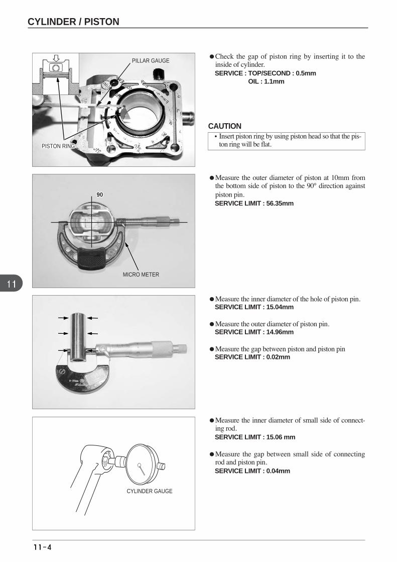
Check the gap of piston ring by inserting it to theinside of cylinder.SERVICE : TOP/SECOND : 0.5mm
OIL : 1.1mm
Measure the outer diameter of piston at 10mm fromthe bottom side of piston to the 90° direction againstpiston pin.SERVICE LIMIT : 56.35mm
Measure the inner diameter of the hole of piston pin.SERVICE LIMIT : 15.04mm
Measure the outer diameter of piston pin. SERVICE LIMIT : 14.96mm
Measure the gap between piston and piston pin SERVICE LIMIT : 0.02mm
Measure the inner diameter of small side of connect-ing rod. SERVICE LIMIT : 15.06 mm
Measure the gap between small side of connectingrod and piston pin. SERVICE LIMIT : 0.04mm
MICRO METER
CYLINDER GAUGE
PISTON RINGPISTON RINGPISTON RINGPISTON RINGPISTON RINGPISTON RINGPISTON RINGPISTON RINGPISTON RINGPISTON RINGPISTON RINGPISTON RINGPISTON RINGPISTON RINGPISTON RINGPISTON RINGPISTON RINGPISTON RINGPISTON RINGPISTON RINGPISTON RINGPISTON RINGPISTON RINGPISTON RINGPISTON RINGPISTON RINGPISTON RING
90。。90。。90。。90。。90。。90。。90。。90。。90。。90。。90。。90。。
PILLAR GAUGE
CAUTION•Insert piston ring by using piston head so that the pis-
ton ring will be flat.
CYLINDER / PISTON
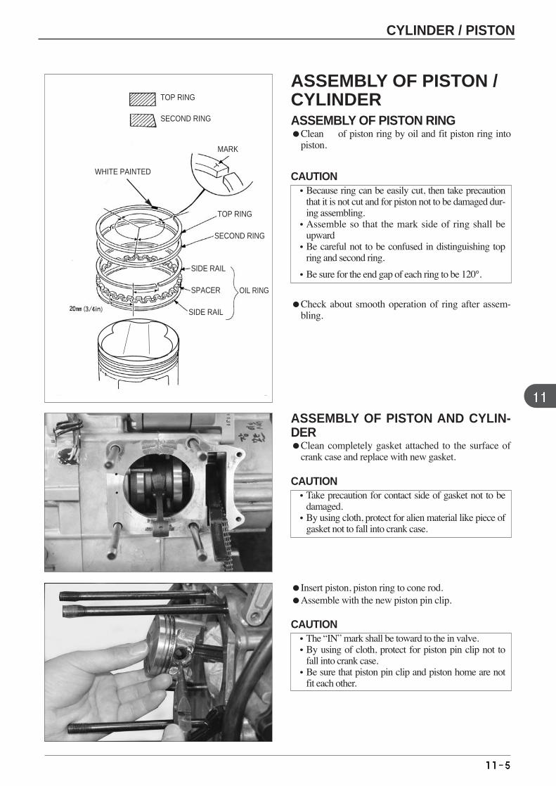
ASSEMBLY OF PISTON AND CYLIN-DER Clean completely gasket attached to the surface of
crank case and replace with new gasket.
Check about smooth operation of ring after assem-bling.
Insert piston, piston ring to cone rod. Assemble with the new piston pin clip.
TOP RING
SECOND RING
MARK
TOP RING
WHITE PAINTED
OIL RING
SIDE RAIL
SIDE RAIL
SPACER
SECOND RING
ASSEMBLY OF PISTON /CYLINDERASSEMBLY OF PISTON RING Clean of piston ring by oil and fit piston ring into
piston.
CAUTION•Because ring can be easily cut, then take precaution
that it is not cut and for piston not to be damaged dur-ing assembling.
•Assemble so that the mark side of ring shall beupward
•Be careful not to be confused in distinguishing topring and second ring.
•Be sure for the end gap of each ring to be 120°.
CAUTION•Take precaution for contact side of gasket not to be
damaged. •By using cloth, protect for alien material like piece of
gasket not to fall into crank case.
CAUTION•The “IN” mark shall be toward to the in valve. •By using of cloth, protect for piston pin clip not to
fall into crank case.•Be sure that piston pin clip and piston home are not
fit each other.
CYLINDER / PISTON
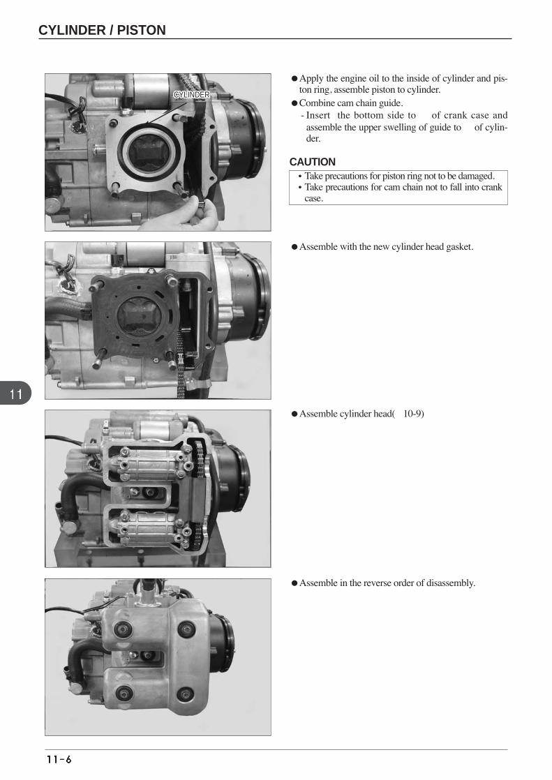
Apply the engine oil to the inside of cylinder and pis-ton ring, assemble piston to cylinder.
Combine cam chain guide. - Insert the bottom side to of crank case and
assemble the upper swelling of guide to of cylin-der.
Assemble with the new cylinder head gasket.
Assemble cylinder head(10-9)
Assemble in the reverse order of disassembly.
CYLINDERCYLINDERCYLINDERCYLINDERCYLINDERCYLINDERCYLINDERCYLINDERCYLINDERCYLINDERCYLINDERCYLINDERCYLINDERCYLINDERCYLINDERCYLINDERCYLINDERCYLINDERCYLINDERCYLINDERCYLINDERCYLINDERCYLINDERCYLINDERCYLINDERCYLINDERCYLINDER
CAUTION•Take precautions for piston ring not to be damaged. •Take precautions for cam chain not to fall into crank
case.
CYLINDER / PISTON

MEMO
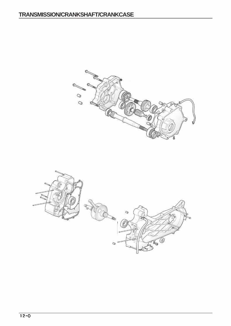
TRANSMISSION/CRANKSHAFT/CRANKCASE
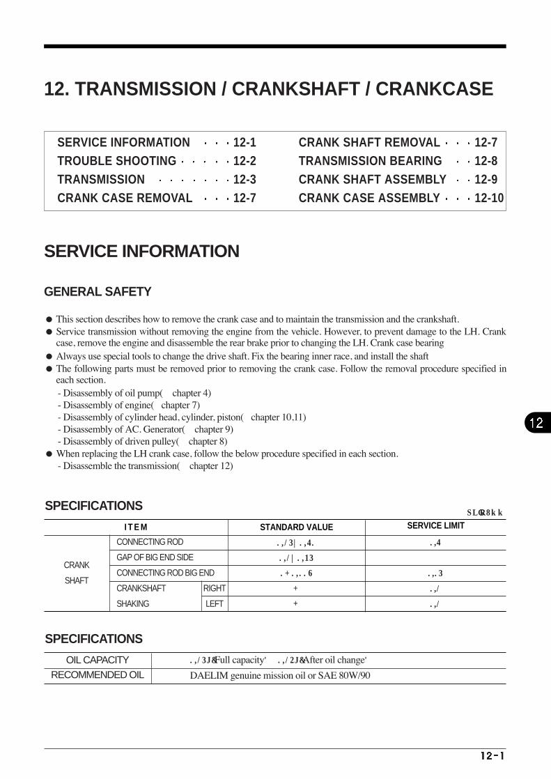
I T E M STANDARD VALUE SERVICE LIMIT
CRANK
SHAFT
CONNECTING ROD
GAP OF BIG END SIDE
CONNECTING ROD BIG END
CRANKSHAFT
SHAKING
RIGHT
LEFT
0.15~0.60
0.1~0.35
0-0.008
-
-
0.6
0.05
0.1
0.1
SPECIFICATIONS UNIT : mm
SPECIFICATIONS
OIL CAPACITY
RECOMMENDED OIL
0.15L(Full capacity) 0.14L(After oil change)
DAELIM genuine mission oil or SAE 80W/90
12. TRANSMISSION / CRANKSHAFT / CRANKCASE
SERVICE INFORMATION
GENERAL SAFETY
This section describes how to remove the crank case and to maintain the transmission and the crankshaft. Service transmission without removing the engine from the vehicle. However, to prevent damage to the LH. Crank
case, remove the engine and disassemble the rear brake prior to changing the LH. Crank case bearing Always use special tools to change the drive shaft. Fix the bearing inner race, and install the shaft The following parts must be removed prior to removing the crank case. Follow the removal procedure specified in
each section. - Disassembly of oil pump( chapter 4) - Disassembly of engine(chapter 7) - Disassembly of cylinder head, cylinder, piston(chapter 10,11) - Disassembly of AC. Generator( chapter 9) - Disassembly of driven pulley( chapter 8)
When replacing the LH crank case, follow the below procedure specified in each section. - Disassemble the transmission( chapter 12)
SERVICE INFORMATION 12-1 TROUBLE SHOOTING 12-2 TRANSMISSION 12-3 CRANK CASE REMOVAL 12-7
CRANK SHAFT REMOVAL 12-7 TRANSMISSION BEARING 12-8CRANK SHAFT ASSEMBLY 12-9 CRANK CASE ASSEMBLY 12-10
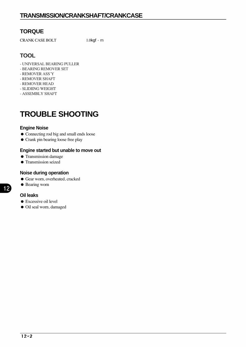
TRANSMISSION/CRANKSHAFT/CRANKCASE
Engine Noise Connecting rod big and small ends loose Crank pin bearing loose free play
Engine started but unable to move out Transmission damage Transmission seized
Noise during operation Gear worn, overheated, cracked Bearing worn
Oil leaks Excessive oil level Oil seal worn, damaged
TROUBLE SHOOTING
TORQUECRANK CASE BOLT 1.0kgf·m
TOOL- UNIVERSAL BEARING PULLER - BEARING REMOVER SET - REMOVER ASS’Y - REMOVER SHAFT - REMOVER HEAD - SLIDIING WEIGHT - ASSEMBLY SHAFT
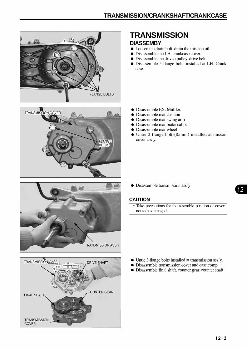
TRANSMISSION/CRANKSHAFT/CRANKCASE
Disassemble transmission ass’y
Disassemble EX. Muffler. Disassemble rear cushion Disassemble rear swing arm Disassemble rear brake caliper Disassemble rear wheel Untie 2 flange bolts(85mm) installed at misson
cover ass’y.
Untie 3 flange bolts installed at transmission ass’y. Disassemble transmission cover and case comp Disassemble final shaft, counter gear, counter shaft.
TRANSMISSIONCOVER
FLANGE BOLTS
FLANGEBOLTSFLANGEBOLTSFLANGEBOLTSFLANGEBOLTSFLANGEBOLTSFLANGEBOLTSFLANGEBOLTSFLANGEBOLTSFLANGEBOLTSFLANGEBOLTSFLANGEBOLTSFLANGEBOLTSFLANGEBOLTSFLANGEBOLTSFLANGEBOLTSFLANGEBOLTSFLANGEBOLTSFLANGEBOLTSFLANGEBOLTSFLANGEBOLTSFLANGEBOLTSFLANGEBOLTSFLANGEBOLTSFLANGEBOLTSFLANGEBOLTSFLANGEBOLTSFLANGEBOLTS
TRANSMISSION ASS’Y
TRANSMISSION CASETRANSMISSION CASETRANSMISSION CASETRANSMISSION CASETRANSMISSION CASETRANSMISSION CASETRANSMISSION CASETRANSMISSION CASETRANSMISSION CASETRANSMISSION CASETRANSMISSION CASETRANSMISSION CASETRANSMISSION CASETRANSMISSION CASETRANSMISSION CASETRANSMISSION CASETRANSMISSION CASETRANSMISSION CASETRANSMISSION CASETRANSMISSION CASETRANSMISSION CASETRANSMISSION CASETRANSMISSION CASETRANSMISSION CASETRANSMISSION CASETRANSMISSION CASETRANSMISSION CASE DRIVE SHAFT
COUNTER GEARFINAL SHAFT
TRANSMISSIONDIASSEMBY Loosen the drain bolt, drain the mission oil. Disassemble the LH. crankcase cover. Disassemble the driven pulley, drive belt. Disassemble 5 flange bolts installed at LH. Crank
case.
CAUTION•Take precautions for the assemble position of cover
not to be damaged.
TRANSMISSION COVERTRANSMISSION COVERTRANSMISSION COVERTRANSMISSION COVERTRANSMISSION COVERTRANSMISSION COVERTRANSMISSION COVERTRANSMISSION COVERTRANSMISSION COVERTRANSMISSION COVERTRANSMISSION COVERTRANSMISSION COVERTRANSMISSION COVERTRANSMISSION COVERTRANSMISSION COVERTRANSMISSION COVERTRANSMISSION COVERTRANSMISSION COVERTRANSMISSION COVERTRANSMISSION COVERTRANSMISSION COVERTRANSMISSION COVERTRANSMISSION COVERTRANSMISSION COVERTRANSMISSION COVERTRANSMISSION COVERTRANSMISSION COVER
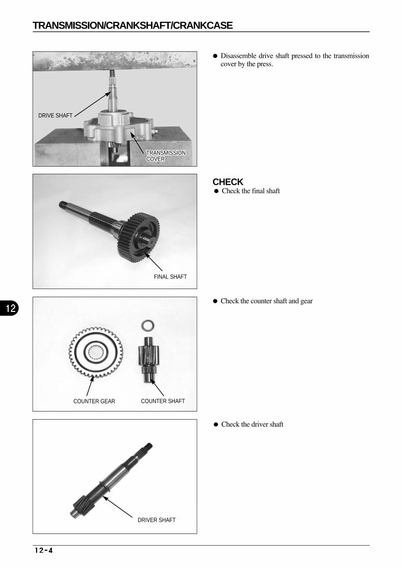
CHECK Check the final shaft
Check the counter shaft and gear
Disassemble drive shaft pressed to the transmissioncover by the press.
Check the driver shaft
FINAL SHAFT
TRANSMISSIONCOVERTRANSMISSIONCOVERTRANSMISSIONCOVERTRANSMISSIONCOVERTRANSMISSIONCOVERTRANSMISSIONCOVERTRANSMISSIONCOVERTRANSMISSIONCOVERTRANSMISSIONCOVERTRANSMISSIONCOVERTRANSMISSIONCOVERTRANSMISSIONCOVERTRANSMISSIONCOVERTRANSMISSIONCOVERTRANSMISSIONCOVERTRANSMISSIONCOVERTRANSMISSIONCOVERTRANSMISSIONCOVERTRANSMISSIONCOVERTRANSMISSIONCOVERTRANSMISSIONCOVERTRANSMISSIONCOVERTRANSMISSIONCOVERTRANSMISSIONCOVERTRANSMISSIONCOVERTRANSMISSIONCOVERTRANSMISSIONCOVER
DRIVE SHAFT
COUNTER GEAR COUNTER SHAFT
DRIVER SHAFT
TRANSMISSION/CRANKSHAFT/CRANKCASE
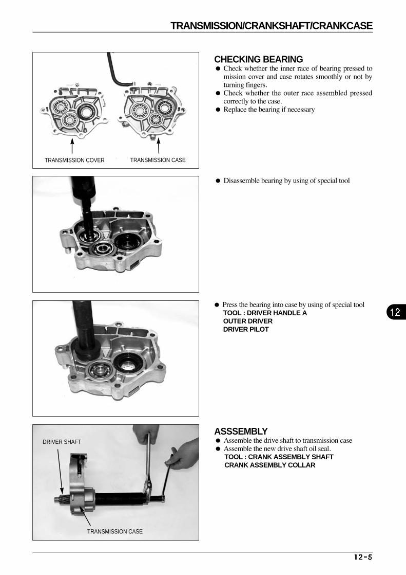
CHECKING BEARING Check whether the inner race of bearing pressed to
mission cover and case rotates smoothly or not byturning fingers.
Check whether the outer race assembled pressedcorrectly to the case.
Replace the bearing if necessary
ASSSEMBLY Assemble the drive shaft to transmission case Assemble the new drive shaft oil seal.
TOOL : CRANK ASSEMBLY SHAFT CRANK ASSEMBLY COLLAR
Press the bearing into case by using of special tool TOOL : DRIVER HANDLE A OUTER DRIVER DRIVER PILOT
Disassemble bearing by using of special tool
TRANSMISSION COVER TRANSMISSION CASE
TRANSMISSION CASE
DRIVER SHAFT
TRANSMISSION/CRANKSHAFT/CRANKCASE
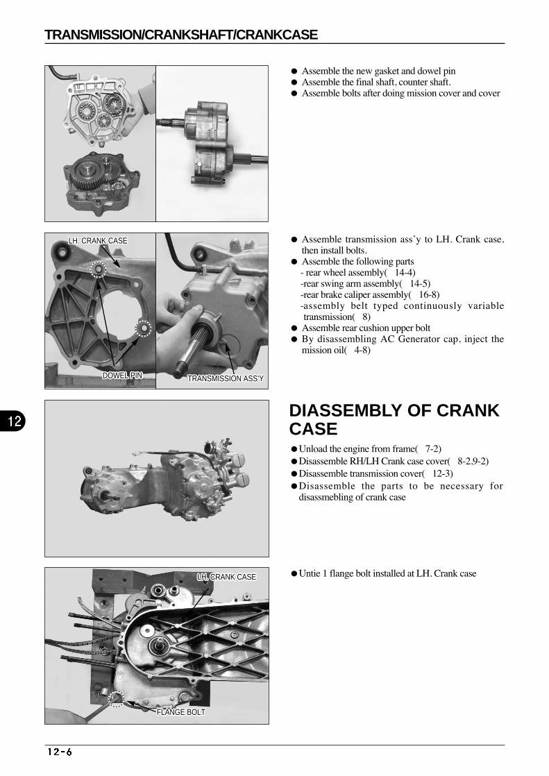
DIASSEMBLY OF CRANKCASE Unload the engine from frame(7-2) Disassemble RH/LH Crank case cover(8-2,9-2)Disassemble transmission cover(12-3) Disassemble the parts to be necessary for
disassmebling of crank case
Untie 1 flange bolt installed at LH. Crank case
Assemble the new gasket and dowel pin Assemble the final shaft, counter shaft. Assemble bolts after doing mission cover and cover
Assemble transmission ass’y to LH. Crank case,then install bolts.
Assemble the following parts - rear wheel assembly(14-4) -rear swing arm assembly(14-5) -rear brake caliper assembly(16-8) -assembly belt typed continuously variabletransmission(8)
Assemble rear cushion upper bolt By disassembling AC Generator cap, inject the
mission oil(4-8)
DOWEL PINDOWEL PINDOWEL PINDOWEL PINDOWEL PINDOWEL PINDOWEL PINDOWEL PINDOWEL PINDOWEL PINDOWEL PINDOWEL PINDOWEL PINDOWEL PINDOWEL PINDOWEL PINDOWEL PINDOWEL PINDOWEL PINDOWEL PINDOWEL PINDOWEL PINDOWEL PINDOWEL PINDOWEL PINDOWEL PINDOWEL PIN
LH. CRANK CASELH. CRANK CASELH. CRANK CASELH. CRANK CASELH. CRANK CASELH. CRANK CASELH. CRANK CASELH. CRANK CASELH. CRANK CASELH. CRANK CASELH. CRANK CASELH. CRANK CASELH. CRANK CASELH. CRANK CASELH. CRANK CASELH. CRANK CASELH. CRANK CASELH. CRANK CASELH. CRANK CASELH. CRANK CASELH. CRANK CASELH. CRANK CASELH. CRANK CASELH. CRANK CASELH. CRANK CASELH. CRANK CASELH. CRANK CASE
TRANSMISSION ASS’YTRANSMISSION ASS’YTRANSMISSION ASS’YTRANSMISSION ASS’YTRANSMISSION ASS’YTRANSMISSION ASS’YTRANSMISSION ASS’YTRANSMISSION ASS’YTRANSMISSION ASS’YTRANSMISSION ASS’YTRANSMISSION ASS’YTRANSMISSION ASS’YTRANSMISSION ASS’YTRANSMISSION ASS’YTRANSMISSION ASS’YTRANSMISSION ASS’YTRANSMISSION ASS’YTRANSMISSION ASS’YTRANSMISSION ASS’YTRANSMISSION ASS’YTRANSMISSION ASS’YTRANSMISSION ASS’YTRANSMISSION ASS’YTRANSMISSION ASS’YTRANSMISSION ASS’YTRANSMISSION ASS’YTRANSMISSION ASS’Y
LH. CRANK CASELH. CRANK CASELH. CRANK CASELH. CRANK CASELH. CRANK CASELH. CRANK CASELH. CRANK CASELH. CRANK CASELH. CRANK CASELH. CRANK CASELH. CRANK CASELH. CRANK CASELH. CRANK CASELH. CRANK CASELH. CRANK CASELH. CRANK CASELH. CRANK CASELH. CRANK CASELH. CRANK CASELH. CRANK CASELH. CRANK CASELH. CRANK CASELH. CRANK CASELH. CRANK CASELH. CRANK CASELH. CRANK CASELH. CRANK CASE
FLANGE BOLTFLANGE BOLTFLANGE BOLTFLANGE BOLTFLANGE BOLTFLANGE BOLTFLANGE BOLTFLANGE BOLTFLANGE BOLTFLANGE BOLTFLANGE BOLTFLANGE BOLTFLANGE BOLTFLANGE BOLTFLANGE BOLTFLANGE BOLTFLANGE BOLTFLANGE BOLTFLANGE BOLTFLANGE BOLTFLANGE BOLTFLANGE BOLTFLANGE BOLTFLANGE BOLTFLANGE BOLTFLANGE BOLTFLANGE BOLT
TRANSMISSION/CRANKSHAFT/CRANKCASE
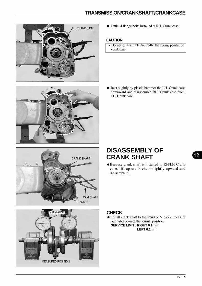
DISASSEMBLY OFCRANK SHAFTBecause crank shaft is installed to RH/LH Crank
case, lift up crank chast slightly upward anddiassemble it.
Beat slightly by plastic hammer the LH. Crank casedownward and disassemble RH. Crank case fromLH. Crank case.
Untie 4 flange bolts installed at RH. Crank case.
CRANK SHAFT
LH. CRANK CASE
CAM CHAIN
GASKET
CHECK Install crank shaft to the stand or V block, measure
and vibratioon of the journal position. SERVICE LIMIT : RIGHT 0.1mm
LEFT 0.1mm
DIAL GAUGEDIAL GAUGEDIAL GAUGEDIAL GAUGEDIAL GAUGEDIAL GAUGEDIAL GAUGEDIAL GAUGEDIAL GAUGEDIAL GAUGEDIAL GAUGEDIAL GAUGEDIAL GAUGEDIAL GAUGEDIAL GAUGEDIAL GAUGEDIAL GAUGEDIAL GAUGEDIAL GAUGEDIAL GAUGEDIAL GAUGEDIAL GAUGEDIAL GAUGEDIAL GAUGEDIAL GAUGEDIAL GAUGEDIAL GAUGE
MEASURED POSITION
CAUTION•Do not disassemble twistedly the fixing positin of
crank case.
TRANSMISSION/CRANKSHAFT/CRANKCASE
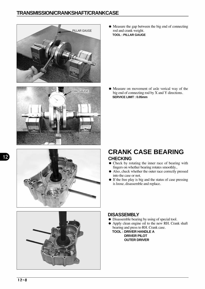
CRANK CASE BEARINGCHECKING Check by rotating the inner race of bearing with
fingers on whether bearing rotates smoothly., Also, check whether the outer race correctly pressed
into the case or not. If the free play is big and the status of case pressing
is loose, disassemble and replace.
Measure on movement of axle verical way of thebig end of connecting rod by X and Y directions. SERVICE LIMIT : 0.05mm
Measure the gap between the big end of connectingrod and crank weight.TOOL : PILLAR GAUGE
DISASSEMBLY Disassemble bearing by using of special tool. Apply clean engine oil to the new RH. Crank shaft
bearing and press to RH. Crank case. TOOL : DRIVER HANDLE A
DRIVER PILOT OUTER DRIVER
PILLAR GAUGE
DIAL GAUGEDIAL GAUGEDIAL GAUGEDIAL GAUGEDIAL GAUGEDIAL GAUGEDIAL GAUGEDIAL GAUGEDIAL GAUGEDIAL GAUGEDIAL GAUGEDIAL GAUGEDIAL GAUGEDIAL GAUGEDIAL GAUGEDIAL GAUGEDIAL GAUGEDIAL GAUGEDIAL GAUGEDIAL GAUGEDIAL GAUGEDIAL GAUGEDIAL GAUGEDIAL GAUGEDIAL GAUGEDIAL GAUGEDIAL GAUGE
TRANSMISSION/CRANKSHAFT/CRANKCASE
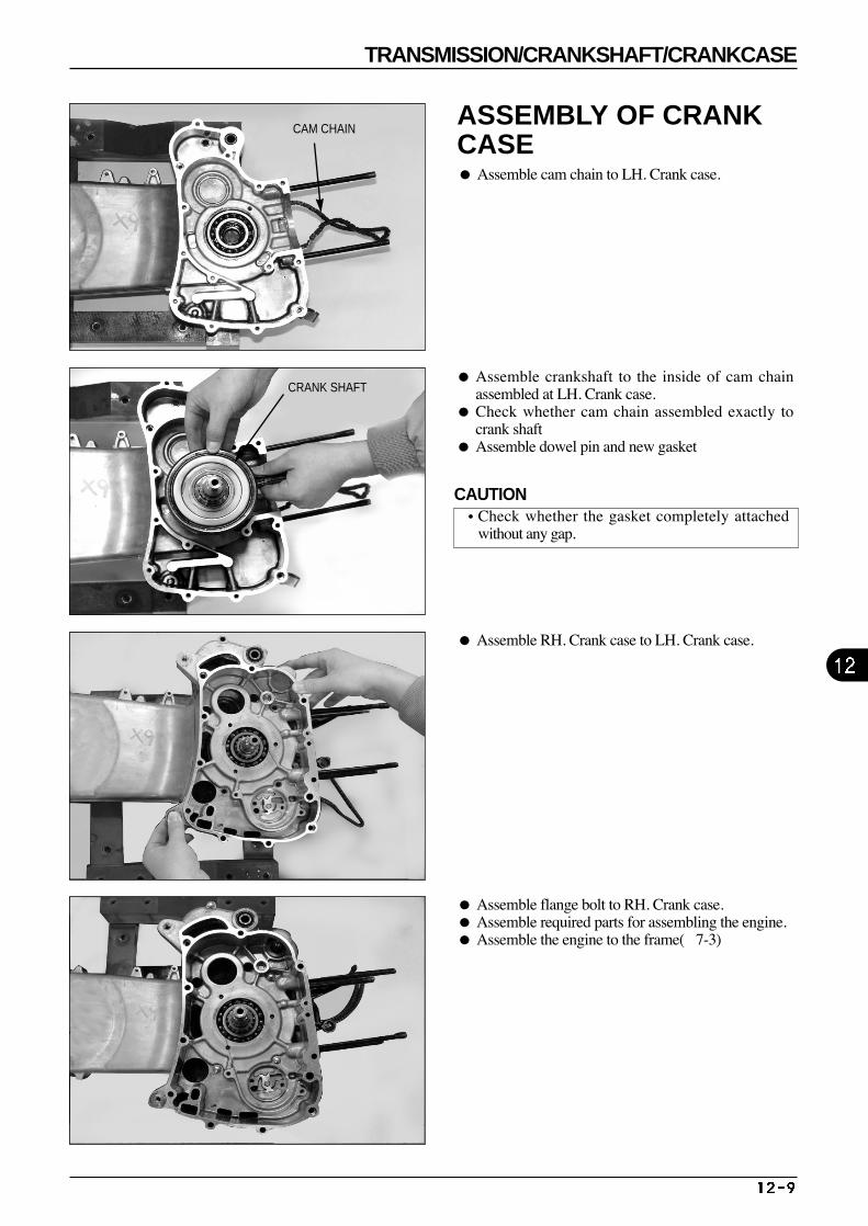
CAM CHAIN
CRANK SHAFT
ASSEMBLY OF CRANKCASE Assemble cam chain to LH. Crank case.
Assemble crankshaft to the inside of cam chainassembled at LH. Crank case.
Check whether cam chain assembled exactly tocrank shaft
Assemble dowel pin and new gasket
Assemble RH. Crank case to LH. Crank case.
Assemble flange bolt to RH. Crank case. Assemble required parts for assembling the engine. Assemble the engine to the frame(7-3)
CAUTION•Check whether the gasket completely attached
without any gap.
TRANSMISSION/CRANKSHAFT/CRANKCASE
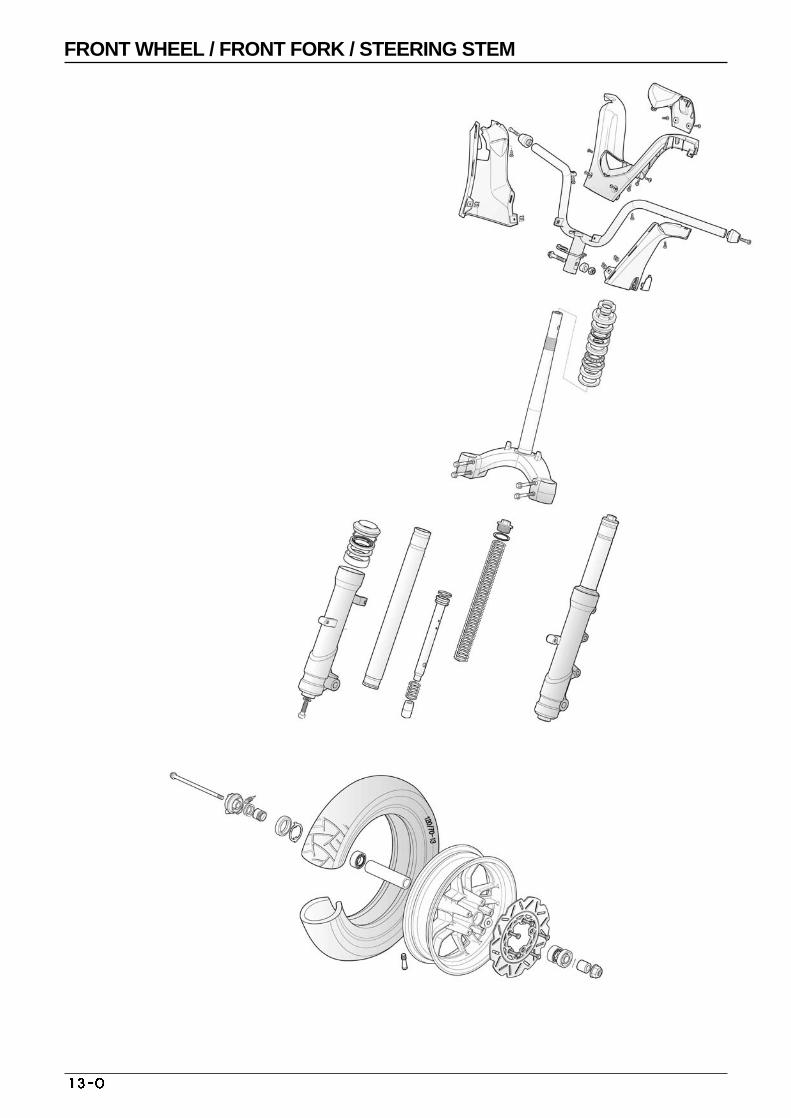
FRONT WHEEL / FRONT FORK / STEERING STEM
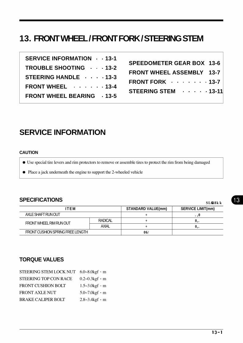
I T E MAXLE SHAFT RUN OUT
FRONT WHEEL RIM RUN OUT
FRONT CUSHION SPRING FREE LENGTH
RADICAL AXIAL
SERVICE LIMIT(mm) STANDARD VALUE(mm)
-
-
-
281
0.2
2.0
2.0
UNIT : mm
13. FRONT WHEEL / FRONT FORK / STEERING STEM
SERVICE INFORMATION
CAUTION
Use special tire levers and rim protectors to remove or assemble tires to protect the rim from being damaged
Place a jack underneath the engine to support the 2-wheeled vehicle
SPECIFICATIONS
SERVICE INFORMATION 13-1
TROUBLE SHOOTING 13-2
STEERING HANDLE 13-3
FRONT WHEEL 13-4
FRONT WHEEL BEARING 13-5
SPEEDOMETER GEAR BOX 13-6
FRONT WHEEL ASSEMBLY 13-7
FRONT FORK 13-7
STEERING STEM 13-11
TORQUE VALUES
STEERING STEM LOCK NUT 6.0~8.0kgf m
STEERING TOP CON RACE 0.2~0.3kgf m
FRONT CUSHION BOLT 1.5~3.0kgf m
FRONT AXLE NUT 5.0~7.0kgf m
BRAKE CALIPER BOLT 2.8~3.4kgf m
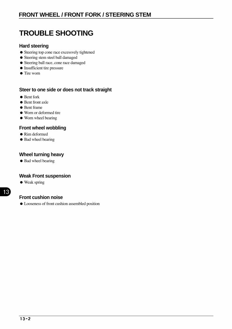
TROUBLE SHOOTING
Hard steeringSteering top cone race excessvely tightenedSteering stem steel ball damaged Steering ball race, cone race damaged Insufficient tire pressure Tire worn
Steer to one side or does not track straight Bent fork Bent front axle Bent frame Worn or deformed tire Worn wheel bearing
Front wheel wobblingRim deformed Bad wheel bearing
Wheel turning heavy Bad wheel bearing
Weak Front suspensionWeak spring
Front cushion noiseLooseness of front cushion assembled position
FRONT WHEEL / FRONT FORK / STEERING STEM
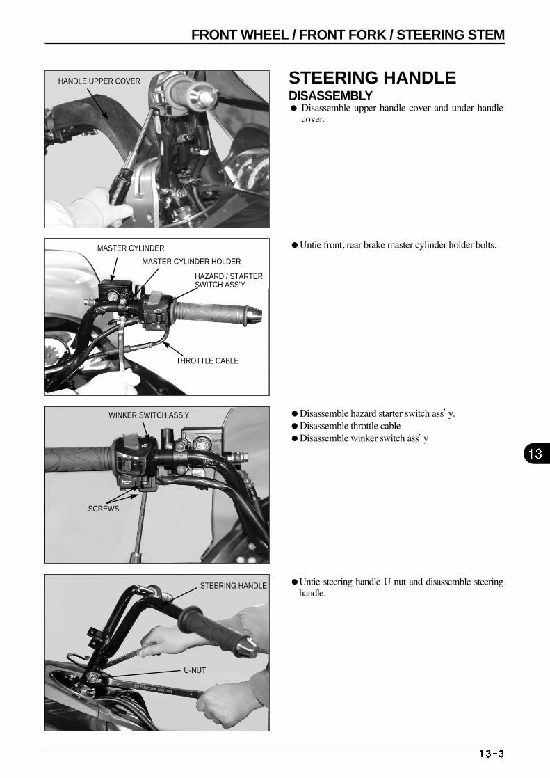
Disassemble hazard starter switch ass’y. Disassemble throttle cable Disassemble winker switch ass’y
Untie front, rear brake master cylinder holder bolts.
Untie steering handle U nut and disassemble steeringhandle.
HANDLE UPPER COVER
MASTER CYLINDER
MASTER CYLINDER HOLDER
HAZARD / STARTERSWITCH ASS’Y
THROTTLE CABLE
SCREWS
WINKER SWITCH ASS’Y
STEERING HANDLE
U-NUT
STEERING HANDLEDISASSEMBLY Disassemble upper handle cover and under handle
cover.
FRONT WHEEL / FRONT FORK / STEERING STEM
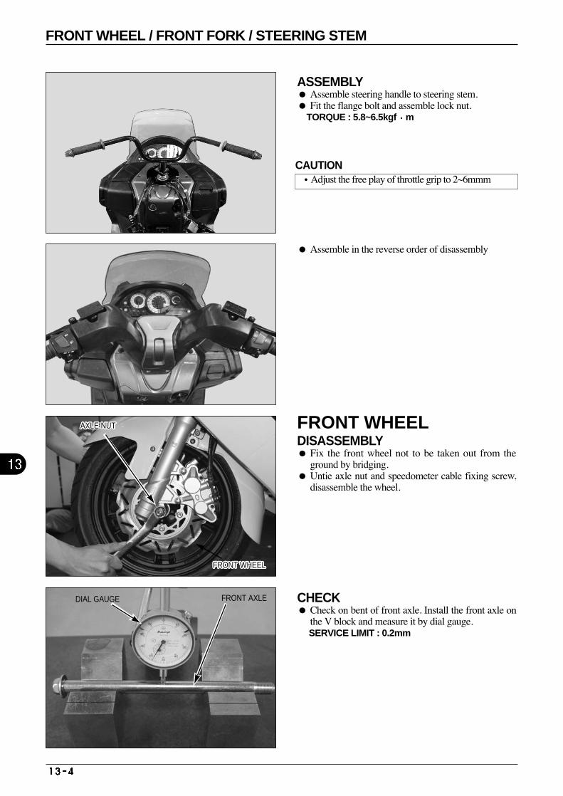
FRONT AXLE
ASSEMBLY Assemble steering handle to steering stem. Fit the flange bolt and assemble lock nut.
TORQUE : 5.8~6.5kgf m
Assemble in the reverse order of disassembly
FRONT WHEELDISASSEMBLY Fix the front wheel not to be taken out from the
ground by bridging. Untie axle nut and speedometer cable fixing screw,
disassemble the wheel.
CHECK Check on bent of front axle. Install the front axle on
the V block and measure it by dial gauge. SERVICE LIMIT : 0.2mm
AXLE NUTAXLE NUTAXLE NUTAXLE NUTAXLE NUTAXLE NUTAXLE NUTAXLE NUTAXLE NUTAXLE NUTAXLE NUTAXLE NUTAXLE NUTAXLE NUTAXLE NUTAXLE NUTAXLE NUTAXLE NUTAXLE NUTAXLE NUTAXLE NUTAXLE NUTAXLE NUTAXLE NUTAXLE NUTAXLE NUTAXLE NUT
DIAL GAUGE
FRONT WHEELFRONT WHEELFRONT WHEELFRONT WHEELFRONT WHEELFRONT WHEELFRONT WHEELFRONT WHEELFRONT WHEELFRONT WHEELFRONT WHEELFRONT WHEELFRONT WHEELFRONT WHEELFRONT WHEELFRONT WHEELFRONT WHEELFRONT WHEELFRONT WHEELFRONT WHEELFRONT WHEELFRONT WHEELFRONT WHEELFRONT WHEELFRONT WHEELFRONT WHEELFRONT WHEEL
CAUTION•Adjust the free play of throttle grip to 2~6mmm
FRONT WHEEL / FRONT FORK / STEERING STEM
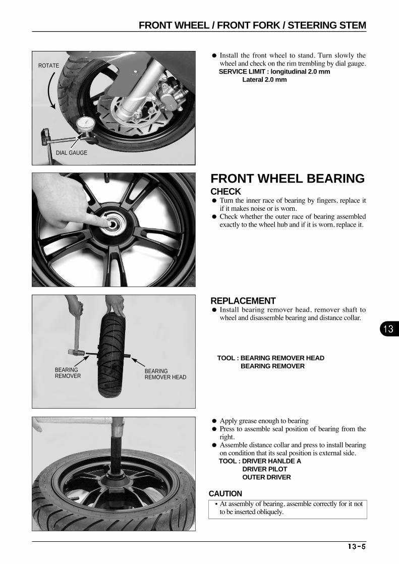
Install the front wheel to stand. Turn slowly thewheel and check on the rim trembling by dial gauge. SERVICE LIMIT : longitudinal 2.0 mm
Lateral 2.0 mm
REPLACEMENT Install bearing remover head, remover shaft to
wheel and disassemble bearing and distance collar.
TOOL : BEARING REMOVER HEAD BEARING REMOVER
FRONT WHEEL BEARINGCHECK Turn the inner race of bearing by fingers, replace it
if it makes noise or is worn. Check whether the outer race of bearing assembled
exactly to the wheel hub and if it is worn, replace it.
Apply grease enough to bearing Press to assemble seal position of bearing from the
right. Assemble distance collar and press to install bearing
on condition that its seal position is external side. TOOL : DRIVER HANLDE A
DRIVER PILOT OUTER DRIVER
DIAL GAUGE
ROTATE
BEARINGREMOVER HEAD
BEARINGREMOVER
CAUTION•At assembly of bearing, assemble correctly for it not
to be inserted obliquely.
FRONT WHEEL / FRONT FORK / STEERING STEM
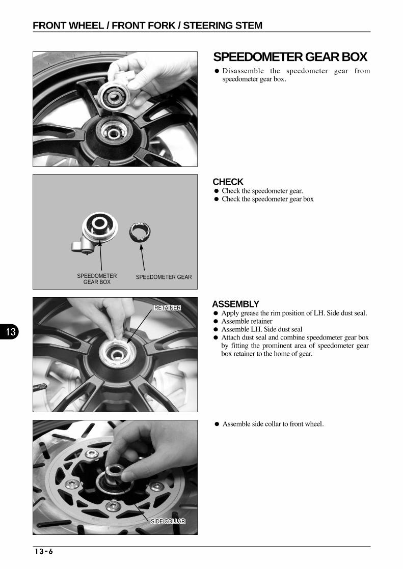
CHECK Check the speedometer gear. Check the speedometer gear box
ASSEMBLY Apply grease the rim position of LH. Side dust seal. Assemble retainer Assemble LH. Side dust seal Attach dust seal and combine speedometer gear box
by fitting the prominent area of speedometer gearbox retainer to the home of gear.
Assemble side collar to front wheel.
SPEEDOMETER GEAR BOX Disassemble the speedometer gear from
speedometer gear box.
RETAINERRETAINERRETAINERRETAINERRETAINERRETAINERRETAINERRETAINERRETAINERRETAINERRETAINERRETAINERRETAINERRETAINERRETAINERRETAINERRETAINERRETAINERRETAINERRETAINERRETAINERRETAINERRETAINERRETAINERRETAINERRETAINERRETAINER
SIDE COLLARSIDE COLLARSIDE COLLARSIDE COLLARSIDE COLLARSIDE COLLARSIDE COLLARSIDE COLLARSIDE COLLARSIDE COLLARSIDE COLLARSIDE COLLARSIDE COLLARSIDE COLLARSIDE COLLARSIDE COLLARSIDE COLLARSIDE COLLARSIDE COLLARSIDE COLLARSIDE COLLARSIDE COLLARSIDE COLLARSIDE COLLARSIDE COLLARSIDE COLLARSIDE COLLAR
SPEEDOMETERGEAR BOX
SPEEDOMETER GEAR
FRONT WHEEL / FRONT FORK / STEERING STEM
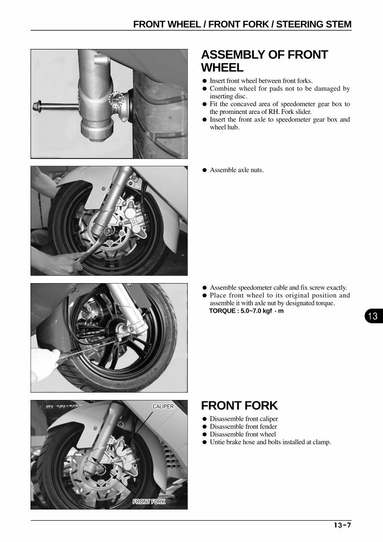
ASSEMBLY OF FRONTWHEEL Insert front wheel between front forks. Combine wheel for pads not to be damaged by
inserting disc. Fit the concaved area of speedometer gear box to
the prominent area of RH. Fork slider. Insert the front axle to speedometer gear box and
wheel hub.
Assemble speedometer cable and fix screw exactly. Place front wheel to its original position and
assemble it with axle nut by designated torque. TORQUE : 5.0~7.0 kgf m
Assemble axle nuts.
FRONT FORK Disassemble front caliper Disassemble front fender Disassemble front wheel Untie brake hose and bolts installed at clamp.
CALIPERCALIPERCALIPERCALIPERCALIPERCALIPERCALIPERCALIPERCALIPERCALIPERCALIPERCALIPERCALIPERCALIPERCALIPERCALIPERCALIPERCALIPERCALIPERCALIPERCALIPERCALIPERCALIPERCALIPERCALIPERCALIPERCALIPER
FRONT FORKFRONT FORKFRONT FORKFRONT FORKFRONT FORKFRONT FORKFRONT FORKFRONT FORKFRONT FORKFRONT FORKFRONT FORKFRONT FORKFRONT FORKFRONT FORKFRONT FORKFRONT FORKFRONT FORKFRONT FORKFRONT FORKFRONT FORKFRONT FORKFRONT FORKFRONT FORKFRONT FORKFRONT FORKFRONT FORKFRONT FORK
FRONT WHEEL / FRONT FORK / STEERING STEM
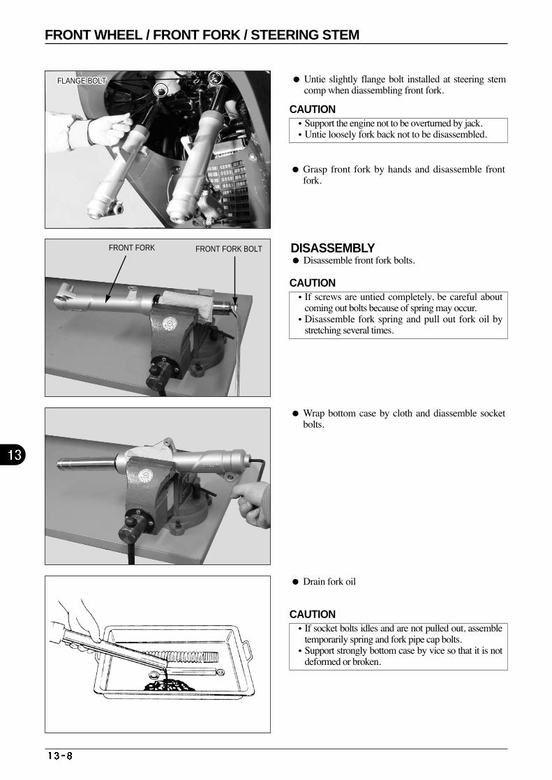
Untie slightly flange bolt installed at steering stemcomp when diassembling front fork.
Grasp front fork by hands and disassemble frontfork.
DISASSEMBLY Disassemble front fork bolts.
Wrap bottom case by cloth and diassemble socketbolts.
Drain fork oil
FLANGE BOLTFLANGE BOLTFLANGE BOLTFLANGE BOLTFLANGE BOLTFLANGE BOLTFLANGE BOLTFLANGE BOLTFLANGE BOLTFLANGE BOLTFLANGE BOLTFLANGE BOLTFLANGE BOLTFLANGE BOLTFLANGE BOLTFLANGE BOLTFLANGE BOLTFLANGE BOLTFLANGE BOLTFLANGE BOLTFLANGE BOLTFLANGE BOLTFLANGE BOLTFLANGE BOLTFLANGE BOLTFLANGE BOLTFLANGE BOLT
FRONT FORK FRONT FORK BOLT
CAUTION•Support the engine not to be overturned by jack. •Untie loosely fork back not to be disassembled.
CAUTION•If screws are untied completely, be careful about
coming out bolts because of spring may occur. •Disassemble fork spring and pull out fork oil by
stretching several times.
CAUTION•If socket bolts idles and are not pulled out, assemble
temporarily spring and fork pipe cap bolts. •Support strongly bottom case by vice so that it is not
deformed or broken.
FRONT WHEEL / FRONT FORK / STEERING STEM
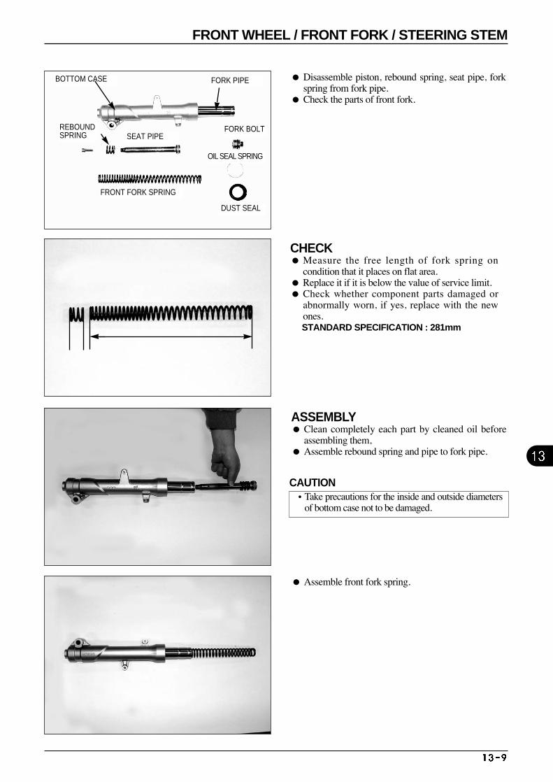
Disassemble piston, rebound spring, seat pipe, forkspring from fork pipe.
Check the parts of front fork.
CHECK Measure the free length of fork spring on
condition that it places on flat area. Replace it if it is below the value of service limit. Check whether component parts damaged or
abnormally worn, if yes, replace with the newones. STANDARD SPECIFICATION : 281mm
ASSEMBLY Clean completely each part by cleaned oil before
assembling them, Assemble rebound spring and pipe to fork pipe.
Assemble front fork spring.
BOTTOM CASE FORK PIPE
FORK BOLT
OIL SEAL SPRING
DUST SEAL
REBOUNDSPRING SEAT PIPE
FRONT FORK SPRING
CAUTION•Take precautions for the inside and outside diameters
of bottom case not to be damaged.
FRONT WHEEL / FRONT FORK / STEERING STEM
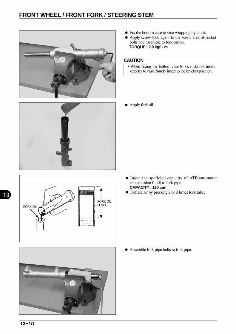
Fix the bottom case to vice wrapping by cloth. Apply screw lock agent to the screw area of socket
bolts and assemble to fork piston. TORQUE : 2.0 kgf m
Apply fork oil
Assemble fork pipe bolts to fork pipe.
Inject the speficied capacity of ATF(automatictransmission fluid) to fork pipe. CAPACITY : 130 cm2
Deflate air by pressing 2 or 3 times fork tube.
FORK OIL
FORK OILLEVEL
CAUTION•When fixing the bottom case to vice, do not insert
directly to case. Surely insert to the bracket position.
FRONT WHEEL / FRONT FORK / STEERING STEM
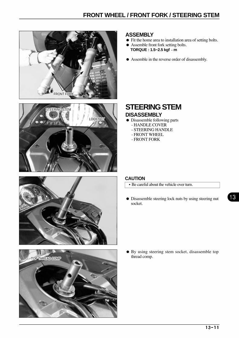
ASSEMBLY Fit the home area to installation area of setting bolts. Assemble front fork setting bolts.
TORQUE : 1.5~2.5 kgf m
Assemble in the reverse order of disassembly.
STEERING STEMDISASSEMBLY Disassemble following parts
- HANDLE COVER- STEERING HANDLE - FRONT WHEEL - FRONT FORK
By using steering stem socket, disassemble topthread comp.
Disassemble steering lock nuts by using steering nutsocket.
STEERING STEMSTEERING STEMSTEERING STEMSTEERING STEMSTEERING STEMSTEERING STEMSTEERING STEMSTEERING STEMSTEERING STEMSTEERING STEMSTEERING STEMSTEERING STEMSTEERING STEMSTEERING STEMSTEERING STEMSTEERING STEMSTEERING STEMSTEERING STEMSTEERING STEMSTEERING STEMSTEERING STEMSTEERING STEMSTEERING STEMSTEERING STEMSTEERING STEMSTEERING STEMSTEERING STEM
FRONT FORKFRONT FORKFRONT FORKFRONT FORKFRONT FORKFRONT FORKFRONT FORKFRONT FORKFRONT FORKFRONT FORKFRONT FORKFRONT FORKFRONT FORKFRONT FORKFRONT FORKFRONT FORKFRONT FORKFRONT FORKFRONT FORKFRONT FORKFRONT FORKFRONT FORKFRONT FORKFRONT FORKFRONT FORKFRONT FORKFRONT FORK
LOCK NUTLOCK NUTLOCK NUTLOCK NUTLOCK NUTLOCK NUTLOCK NUTLOCK NUTLOCK NUTLOCK NUTLOCK NUTLOCK NUTLOCK NUTLOCK NUTLOCK NUTLOCK NUTLOCK NUTLOCK NUTLOCK NUTLOCK NUTLOCK NUTLOCK NUTLOCK NUTLOCK NUTLOCK NUTLOCK NUTLOCK NUT
TOP THREAD COMPTOP THREAD COMPTOP THREAD COMPTOP THREAD COMPTOP THREAD COMPTOP THREAD COMPTOP THREAD COMPTOP THREAD COMPTOP THREAD COMPTOP THREAD COMPTOP THREAD COMPTOP THREAD COMPTOP THREAD COMPTOP THREAD COMPTOP THREAD COMPTOP THREAD COMPTOP THREAD COMPTOP THREAD COMPTOP THREAD COMPTOP THREAD COMPTOP THREAD COMPTOP THREAD COMPTOP THREAD COMPTOP THREAD COMPTOP THREAD COMPTOP THREAD COMPTOP THREAD COMP
CAUTION•Be careful about the vehicle over turn.
FRONT WHEEL / FRONT FORK / STEERING STEM
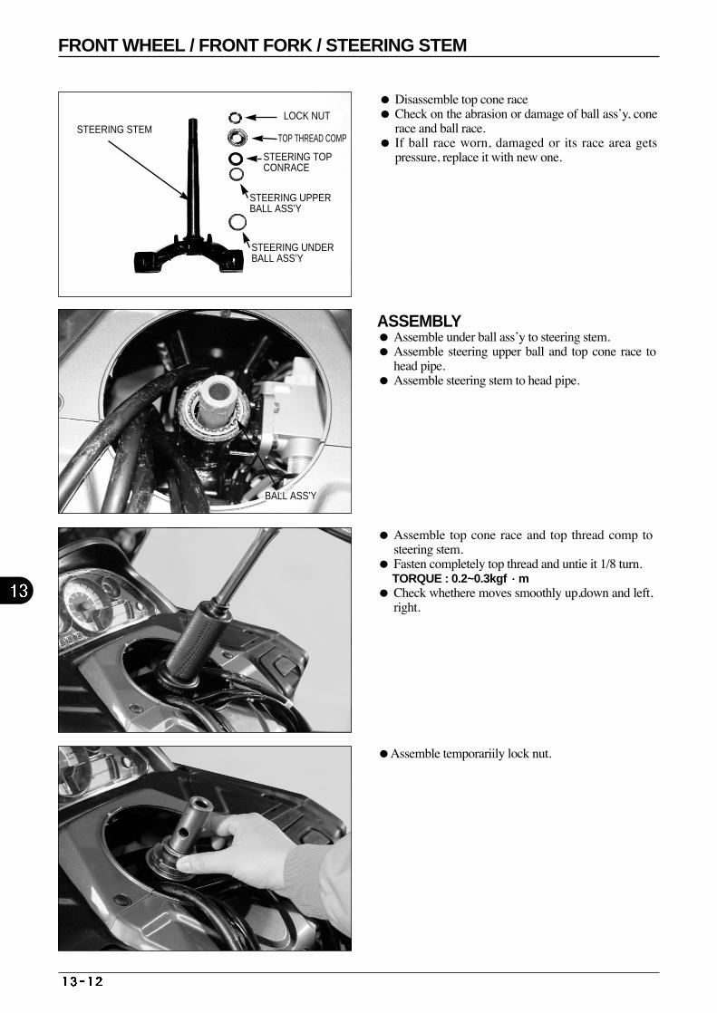
Disassemble top cone race Check on the abrasion or damage of ball ass’y, cone
race and ball race. If ball race worn, damaged or its race area gets
pressure, replace it with new one.
ASSEMBLY Assemble under ball ass’y to steering stem. Assemble steering upper ball and top cone race to
head pipe. Assemble steering stem to head pipe.
Assemble temporariily lock nut.
Assemble top cone race and top thread comp tosteering stem.
Fasten completely top thread and untie it 1/8 turn. TORQUE : 0.2~0.3kgf m
Check whethere moves smoothly up,down and left,right.
LOCK NUT
TOP THREAD COMP
STEERING TOPCONRACE
STEERING UPPERBALL ASS’Y
STEERING UNDERBALL ASS’Y
STEERING STEM
BALL ASS’YBALL ASS’YBALL ASS’YBALL ASS’YBALL ASS’YBALL ASS’YBALL ASS’YBALL ASS’YBALL ASS’YBALL ASS’YBALL ASS’YBALL ASS’YBALL ASS’YBALL ASS’YBALL ASS’YBALL ASS’YBALL ASS’YBALL ASS’YBALL ASS’YBALL ASS’YBALL ASS’YBALL ASS’YBALL ASS’YBALL ASS’YBALL ASS’YBALL ASS’YBALL ASS’Y
FRONT WHEEL / FRONT FORK / STEERING STEM
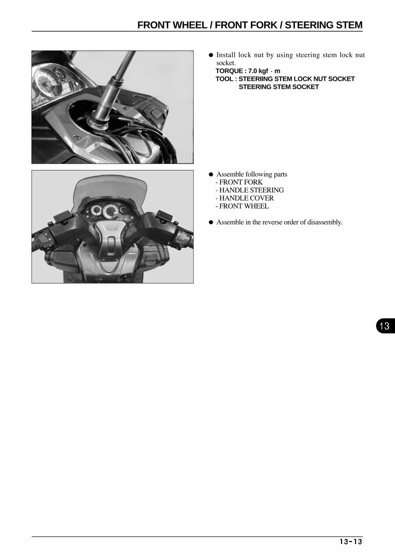
Install lock nut by using steering stem lock nutsocket. TORQUE : 7.0 kgf m TOOL : STEERIING STEM LOCK NUT SOCKET
STEERING STEM SOCKET
Assemble following parts - FRONT FORK - HANDLE STEERING - HANDLE COVER- FRONT WHEEL
Assemble in the reverse order of disassembly.
FRONT WHEEL / FRONT FORK / STEERING STEM
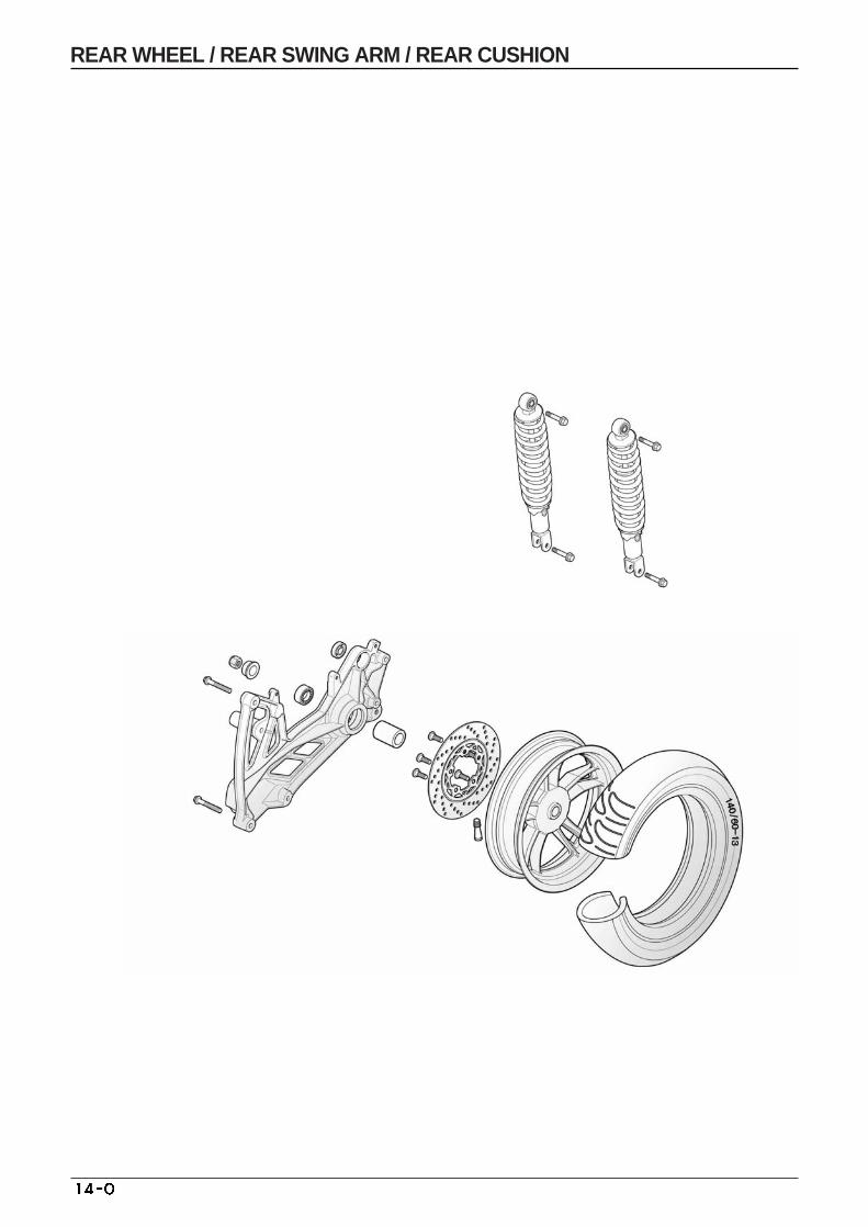
REAR WHEEL / REAR SWING ARM / REAR CUSHION

ITEM
REAR WHEEL RIM RUN OUT REAR CUSHION SRPING FREE LENGTH
SERVICE LIMITSTANDARD VALUE-
2472.0
242
14. REAR WHEEL / REAR SWING ARM / REAR CUSHION
SERVICE INFORMATION
GENERAL SAFETY
When disassembling or assembling tire from rim, use the exclusively used tire lever and rim protector in order forrim not to be damaged.
SPECIFICATIONS
TORQUE VALUES
REAR CUSHION UPPER BOLT 3.5~4.5kgf·m
REAR CUSHION UNDER BOLT 3.5~4.5kgf·m
REAR CUSHION ROD LOCK NUT 3.0~4.0kgf·m
REAR AXLE NUT 12~13kgf·m
SERVICE INFORMATION 14-1 TROUBLE SHOOTING 14-2 REAR WHEEL 14-3
REAR SWING ARM 14-5REAR CUSHION 14-6
13.2 TROUBLE SHOOTING Rear wheel wobbling or vibration Deformed wheel, rim
Bad tire
Axle bad fastening
Bad tire air pressure
Improper wheel balancing
Soft rear suspension Bad spring
Bad rear damper, oil leakage
Hard suspension Twisted damper rod
Bad tire air pressure
Rear cushion noise Looseness of fastening and assmbled points
REAR WHEEL / REAR SWING ARM / REAR CUSHION
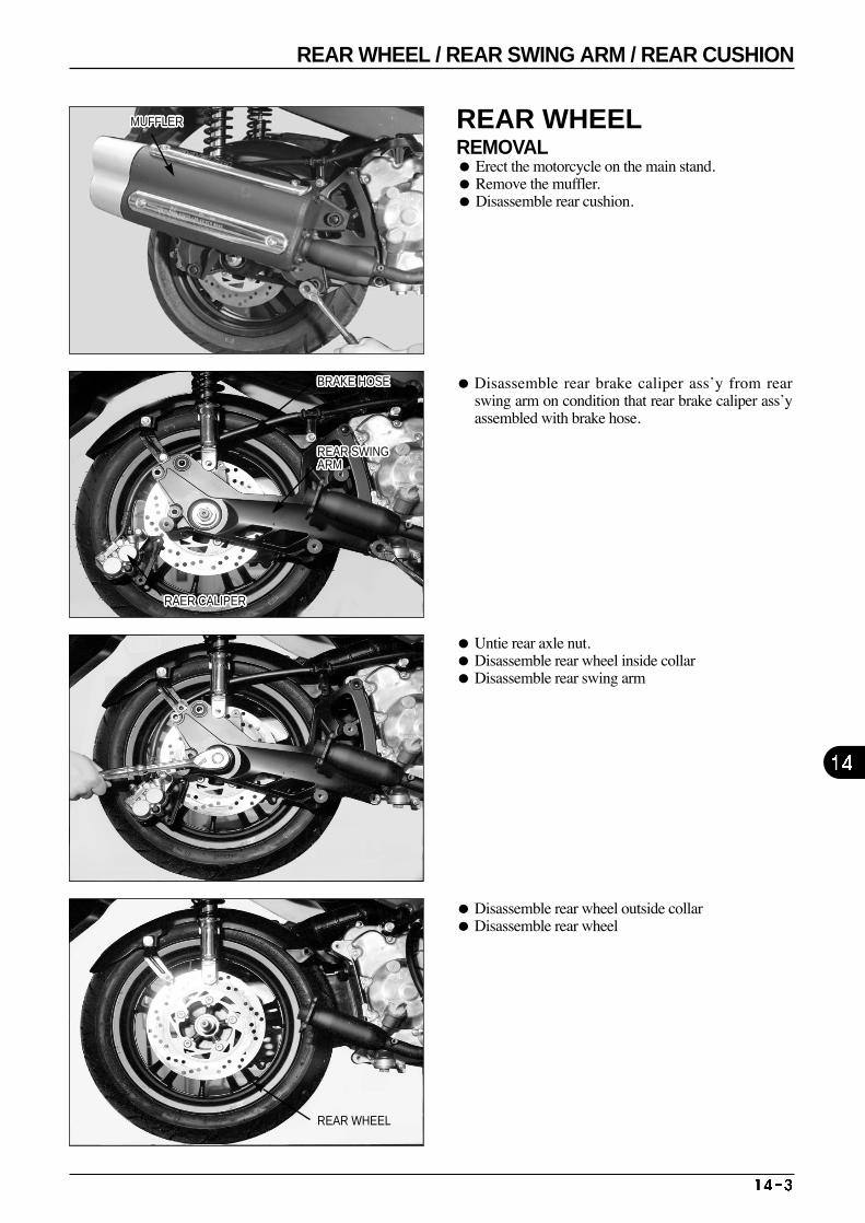
Untie rear axle nut. Disassemble rear wheel inside collar Disassemble rear swing arm
Disassemble rear wheel outside collar Disassemble rear wheel
Disassemble rear brake caliper ass’y from rearswing arm on condition that rear brake caliper ass’yassembled with brake hose.
REAR WHEEL REMOVAL Erect the motorcycle on the main stand. Remove the muffler. Disassemble rear cushion.
MUFFLERMUFFLERMUFFLERMUFFLERMUFFLERMUFFLERMUFFLERMUFFLERMUFFLERMUFFLERMUFFLERMUFFLERMUFFLERMUFFLERMUFFLERMUFFLERMUFFLERMUFFLERMUFFLERMUFFLERMUFFLERMUFFLERMUFFLERMUFFLERMUFFLERMUFFLERMUFFLER
RAER CALIPERRAER CALIPERRAER CALIPERRAER CALIPERRAER CALIPERRAER CALIPERRAER CALIPERRAER CALIPERRAER CALIPERRAER CALIPERRAER CALIPERRAER CALIPERRAER CALIPERRAER CALIPERRAER CALIPERRAER CALIPERRAER CALIPERRAER CALIPERRAER CALIPERRAER CALIPERRAER CALIPERRAER CALIPERRAER CALIPERRAER CALIPERRAER CALIPERRAER CALIPERRAER CALIPER
REAR SWINGARMREAR SWINGARMREAR SWINGARMREAR SWINGARMREAR SWINGARMREAR SWINGARMREAR SWINGARMREAR SWINGARMREAR SWINGARMREAR SWINGARMREAR SWINGARMREAR SWINGARMREAR SWINGARMREAR SWINGARMREAR SWINGARMREAR SWINGARMREAR SWINGARMREAR SWINGARMREAR SWINGARMREAR SWINGARMREAR SWINGARMREAR SWINGARMREAR SWINGARMREAR SWINGARMREAR SWINGARMREAR SWINGARMREAR SWINGARM
REAR WHEEL
BRAKE HOSEBRAKE HOSEBRAKE HOSEBRAKE HOSEBRAKE HOSEBRAKE HOSEBRAKE HOSEBRAKE HOSEBRAKE HOSEBRAKE HOSEBRAKE HOSEBRAKE HOSEBRAKE HOSEBRAKE HOSEBRAKE HOSEBRAKE HOSEBRAKE HOSEBRAKE HOSEBRAKE HOSEBRAKE HOSEBRAKE HOSEBRAKE HOSEBRAKE HOSEBRAKE HOSEBRAKE HOSEBRAKE HOSEBRAKE HOSE
REAR WHEEL / REAR SWING ARM / REAR CUSHION
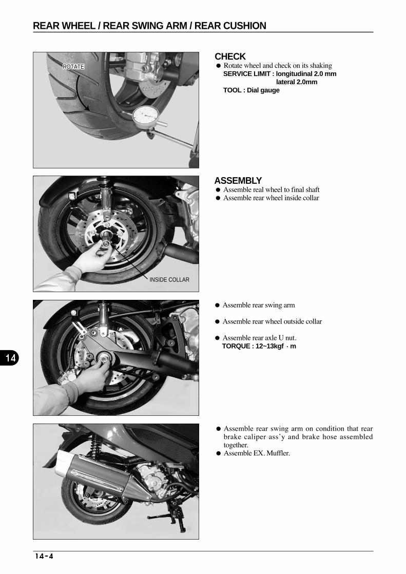
CHECK Rotate wheel and check on its shaking
SERVICE LIMIT : longitudinal 2.0 mm lateral 2.0mm
TOOL : Dial gauge
ASSEMBLY Assemble real wheel to final shaft Assemble rear wheel inside collar
Assemble rear swing arm
Assemble rear wheel outside collar
Assemble rear axle U nut. TORQUE : 12~13kgf m
Assemble rear swing arm on condition that rearbrake caliper ass’y and brake hose assembledtogether.
Assemble EX. Muffler.
INSIDE COLLAR
ROTATEROTATEROTATEROTATEROTATEROTATEROTATEROTATEROTATEROTATEROTATEROTATEROTATEROTATEROTATEROTATEROTATEROTATEROTATEROTATEROTATEROTATEROTATEROTATEROTATEROTATEROTATE
REAR WHEEL / REAR SWING ARM / REAR CUSHION
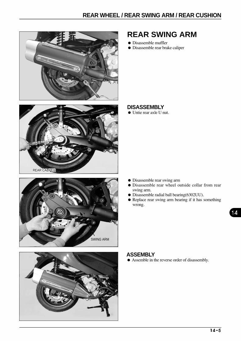
REAR SWING ARM Disassemble muffler Disassemble rear brake caliper
DISASSEMBLY Untie rear axle U nut.
Disassemble rear swing arm Disassemble rear wheel outside collar from rear
swing arm. Disassemble radial ball bearing(6302UU). Replace rear swing arm bearing if it has something
wrong.
ASSEMBLY Assemble in the reverse order of disassembly.
REAR CALIPERREAR CALIPERREAR CALIPERREAR CALIPERREAR CALIPERREAR CALIPERREAR CALIPERREAR CALIPERREAR CALIPERREAR CALIPERREAR CALIPERREAR CALIPERREAR CALIPERREAR CALIPERREAR CALIPERREAR CALIPERREAR CALIPERREAR CALIPERREAR CALIPERREAR CALIPERREAR CALIPERREAR CALIPERREAR CALIPERREAR CALIPERREAR CALIPERREAR CALIPERREAR CALIPER
SWING ARM
REAR WHEEL / REAR SWING ARM / REAR CUSHION
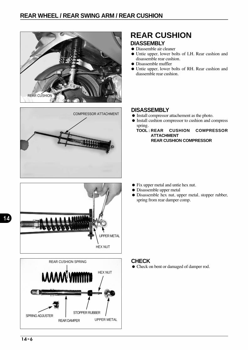
REAR CUSHION DIASSEMBLY Diassemble air cleaner Untie upper, lower bolts of LH. Rear cushion and
disassemble rear cushion. Disassemble muffler Untie upper, lower bolts of RH. Rear cushion and
diassemble rear cushion.
DISASSEMBLY Install compressor attachement as the photo. Install cushion compressor to cushion and compress
spring. TOOL : REAR CUSHION COMPRESSOR
ATTACHMENT REAR CUSHION COMPRESSOR
Fix upper metal and untie hex nut. Disassemble upper metal Disassemble hex nut, upper metal, stopper rubber,
spring from rear damper comp.
CHECK Check on bent or damaged of damper rod.
REAR CUSHION SPRING
REAR CUSHION
COMPRESSOR ATTACHMENT
UPPER METAL
HEX NUT
SPRING ADJUSTERREAR DAMPER
STOPPER RUBBER
HEX NUT
UPPER METAL
REAR WHEEL / REAR SWING ARM / REAR CUSHION
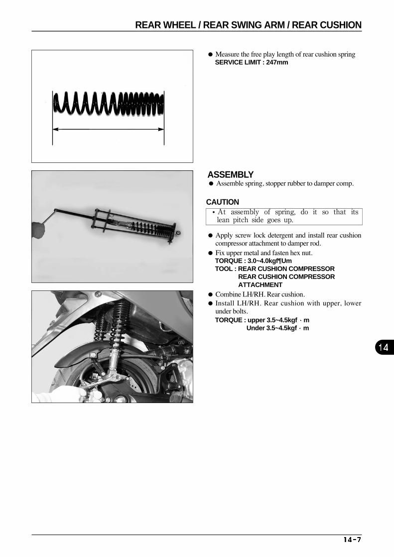
ASSEMBLY Assemble spring, stopper rubber to damper comp.
Measure the free play length of rear cushion spring SERVICE LIMIT : 247mm
Apply screw lock detergent and install rear cushioncompressor attachment to damper rod.
Fix upper metal and fasten hex nut. TORQUE : 3.0~4.0kgf¶Um TOOL : REAR CUSHION COMPRESSOR
REAR CUSHION COMPRESSOR ATTACHMENT
Combine LH/RH. Rear cushion. Install LH/RH. Rear cushion with upper, lower
under bolts. TORQUE : upper 3.5~4.5kgf m
Under 3.5~4.5kgf m
CAUTION•At assembly of spring, do it so that itslean pitch side goes up.
REAR WHEEL / REAR SWING ARM / REAR CUSHION
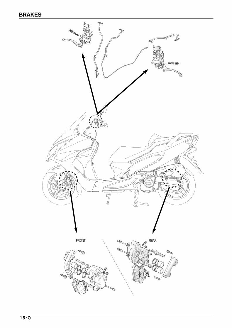
FRONT REAR
BRAKES
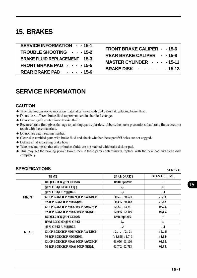
DESIGNATED BRAKE FLUID DOT3 or DOT4 -
BRAKE DISK THICKNESS 4.0 3.5
BRAKE DISK WOBBLING 0.1 0.3
INNER DIAMETER OF MASTER CYLINDER 12.700~12.743 12.755
OUTER DIAMETER OF PISTON 12.657~12.684 12.645
INNER DIAMETER OF CALIPER CYLINDER 24.440~25.410 25.420
OUTER DIAMETER OF CALIPER PISTON 24.278~24.328 24.270
UNIT : mm
DESIGNATED BRAKE FLUID DOT3 or DOT4 -
THICKNESS OF BRAKE DISK 4.0 3.0
BRAKE DISK WOBBLING 0.1 0.3
INNER DIAMETER OF MASTER CYLINDER 14.000~14.043 14.055
OUTER DIAMETER OF PISTON 113.878~13.905 13.866
INNER DIAMETER OF CALIPER CYLINDER 25.278~25.328 25.270
OUTER DIAMETER OF CALIPER PISTON 24.914~24.935 24.870
15. BRAKES
SERVICE INFORMATION
CAUTION Take precautions not to mix alien material or water with brake fluid at replacing brake fluid. Do not use different brake fluid to prevent certain chemical change. Do not use again contaminated brake fluid. Because brake fluid gives damage to painting, parts, plastics, rubbers, then take precautions that brake fluids does not
touch with these materials. Do not use again sealing washer. Clean diassembled parts with brake fluid and check whether these parts°Ø holes are not cogged. Deflate air at separating brake hose. Take precautions so that oils or brakes fluids are not stained with brake disk or pad. This may get the braking power lower, then if these parts contaminated, replace with the new pad and clean disk
completely.
SPECIFICATIONS
SERVICE INFORMATION 15-1 TROUBLE SHOOTING 15-2 BRAKE FLUID REPLACEMENT 15-3 FRONT BRAKE PAD 15-5 REAR BRAKE PAD 15-6
FRONT BRAKE CALIPER 15-6REAR BRAKE CALIPER 15-8 MASTER CYLINDER 15-11BRAKE DISK 15-13
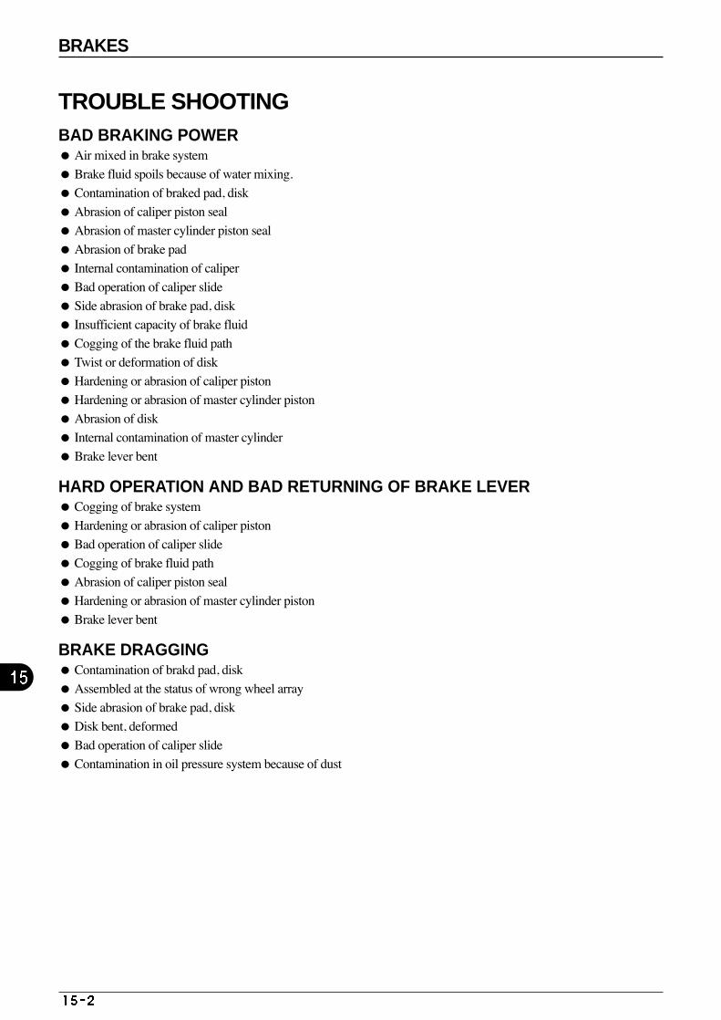
BRAKES
TROUBLE SHOOTING BAD BRAKING POWER Air mixed in brake system
Brake fluid spoils because of water mixing.
Contamination of braked pad, disk
Abrasion of caliper piston seal
Abrasion of master cylinder piston seal
Abrasion of brake pad
Internal contamination of caliper
Bad operation of caliper slide
Side abrasion of brake pad, disk
Insufficient capacity of brake fluid
Cogging of the brake fluid path
Twist or deformation of disk
Hardening or abrasion of caliper piston
Hardening or abrasion of master cylinder piston
Abrasion of disk
Internal contamination of master cylinder
Brake lever bent
HARD OPERATION AND BAD RETURNING OF BRAKE LEVER Cogging of brake system
Hardening or abrasion of caliper piston
Bad operation of caliper slide
Cogging of brake fluid path
Abrasion of caliper piston seal
Hardening or abrasion of master cylinder piston
Brake lever bent
BRAKE DRAGGING Contamination of brakd pad, disk
Assembled at the status of wrong wheel array
Side abrasion of brake pad, disk
Disk bent, deformed
Bad operation of caliper slide
Contamination in oil pressure system because of dust
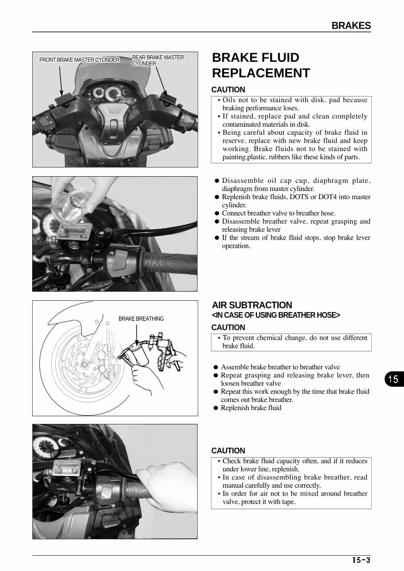
Disassemble oil cap cup, diaphragm plate,diaphragm from master cylinder.
Replenish brake fluids, DOTS or DOT4 into mastercylinder.
Connect breather valve to breather hose. Disassemble breather valve, repeat grasping and
releasing brake lever If the stream of brake fluid stops, stop brake lever
operation.
AIR SUBTRACTION <IN CASE OF USING BREATHER HOSE>
Assemble brake breather to breather valve Repeat grasping and releasing brake lever, then
loosen breather valve Repeat this work enough by the time that brake fluid
comes out brake breather. Replenish brake fluid
FRONT BRAKE MASTER CYLINDERFRONT BRAKE MASTER CYLINDERFRONT BRAKE MASTER CYLINDERFRONT BRAKE MASTER CYLINDERFRONT BRAKE MASTER CYLINDERFRONT BRAKE MASTER CYLINDERFRONT BRAKE MASTER CYLINDERFRONT BRAKE MASTER CYLINDERFRONT BRAKE MASTER CYLINDERFRONT BRAKE MASTER CYLINDERFRONT BRAKE MASTER CYLINDERFRONT BRAKE MASTER CYLINDERFRONT BRAKE MASTER CYLINDERFRONT BRAKE MASTER CYLINDERFRONT BRAKE MASTER CYLINDERFRONT BRAKE MASTER CYLINDERFRONT BRAKE MASTER CYLINDERFRONT BRAKE MASTER CYLINDERFRONT BRAKE MASTER CYLINDERFRONT BRAKE MASTER CYLINDERFRONT BRAKE MASTER CYLINDERFRONT BRAKE MASTER CYLINDERFRONT BRAKE MASTER CYLINDERFRONT BRAKE MASTER CYLINDERFRONT BRAKE MASTER CYLINDERFRONT BRAKE MASTER CYLINDERFRONT BRAKE MASTER CYLINDER REAR BRAKE MASTERCYLINDERREAR BRAKE MASTERCYLINDERREAR BRAKE MASTERCYLINDERREAR BRAKE MASTERCYLINDERREAR BRAKE MASTERCYLINDERREAR BRAKE MASTERCYLINDERREAR BRAKE MASTERCYLINDERREAR BRAKE MASTERCYLINDERREAR BRAKE MASTERCYLINDERREAR BRAKE MASTERCYLINDERREAR BRAKE MASTERCYLINDERREAR BRAKE MASTERCYLINDERREAR BRAKE MASTERCYLINDERREAR BRAKE MASTERCYLINDERREAR BRAKE MASTERCYLINDERREAR BRAKE MASTERCYLINDERREAR BRAKE MASTERCYLINDERREAR BRAKE MASTERCYLINDERREAR BRAKE MASTERCYLINDERREAR BRAKE MASTERCYLINDERREAR BRAKE MASTERCYLINDERREAR BRAKE MASTERCYLINDERREAR BRAKE MASTERCYLINDERREAR BRAKE MASTERCYLINDERREAR BRAKE MASTERCYLINDERREAR BRAKE MASTERCYLINDERREAR BRAKE MASTERCYLINDER
BRAKES
BRAKE FLUIDREPLACEMENT CAUTION•Oils not to be stained with disk, pad because
braking performance loses. •If stained, replace pad and clean completely
contaminated materials in disk. •Being careful about capacity of brake fluid in
reserve, replace with new brake fluid and keepworking. Brake fluids not to be stained withpainting,plastic, rubbers like these kinds of parts.
CAUTION•To prevent chemical change, do not use different
brake fluid.
CAUTION•Check brake fluid capacity often, and if it reduces
under lower line, replenish. •In case of disassembling brake breather, read
manual carefully and use correctly. •In order for air not to be mixed around breather
valve, protect it with tape.
BRAKE BREATHING
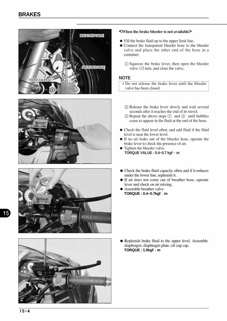
Check the brake fluid capacity often and if it reducesunder the lower line, replenish it.
If air does not come out of breather hose, operatelever and check on air mixing.
Assemble breather valve TORQUE : 0.4~0.7kgf m
Replenish brake fluid to the upper level. Assemblediaphragm, diaphragm plate, oil cup cap. TORQUE : 1.0kgf m
BREATHER VALVEBREATHER VALVEBREATHER VALVEBREATHER VALVEBREATHER VALVEBREATHER VALVEBREATHER VALVEBREATHER VALVEBREATHER VALVEBREATHER VALVEBREATHER VALVEBREATHER VALVEBREATHER VALVEBREATHER VALVEBREATHER VALVEBREATHER VALVEBREATHER VALVEBREATHER VALVEBREATHER VALVEBREATHER VALVEBREATHER VALVEBREATHER VALVEBREATHER VALVEBREATHER VALVEBREATHER VALVEBREATHER VALVEBREATHER VALVE
BREATHER HOSEBREATHER HOSEBREATHER HOSEBREATHER HOSEBREATHER HOSEBREATHER HOSEBREATHER HOSEBREATHER HOSEBREATHER HOSEBREATHER HOSEBREATHER HOSEBREATHER HOSEBREATHER HOSEBREATHER HOSEBREATHER HOSEBREATHER HOSEBREATHER HOSEBREATHER HOSEBREATHER HOSEBREATHER HOSEBREATHER HOSEBREATHER HOSEBREATHER HOSEBREATHER HOSEBREATHER HOSEBREATHER HOSEBREATHER HOSE
FRONT CALIPERFRONT CALIPERFRONT CALIPERFRONT CALIPERFRONT CALIPERFRONT CALIPERFRONT CALIPERFRONT CALIPERFRONT CALIPERFRONT CALIPERFRONT CALIPERFRONT CALIPERFRONT CALIPERFRONT CALIPERFRONT CALIPERFRONT CALIPERFRONT CALIPERFRONT CALIPERFRONT CALIPERFRONT CALIPERFRONT CALIPERFRONT CALIPERFRONT CALIPERFRONT CALIPERFRONT CALIPERFRONT CALIPERFRONT CALIPER
BRAKES
<When the brake bleeder is not available>
Fill the brake fluid up to the upper limit line. Connect the transparent bleeder hose to the bleeder
valve and place the other end of the hose in acontainer.
① Squeeze the brake lever, then open the bleedervalve 1/2 turn, and close the valve.
② Release the brake lever slowly and wait severalseconds after it reaches the end of its travel.
③ Repeat the above steps ① and ② until bubblescease to appear in the fluid at the end of the hose.
Check the fluid level often, and add fluid if the fluidlevel is near the lower level.
If no air leaks out of the bleeder hose, operate thebrake lever to check the presence of air.
Tighten the bleeder valve.TORQUE VALUE : 0.4~0.7 kgf·m
NOTE•Do not release the brake lever until the bleeder
valve has been closed.
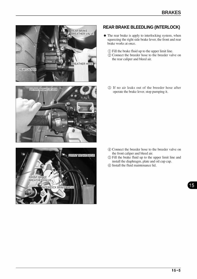
REAR BRAKEBREATHER VALVEREAR BRAKEBREATHER VALVEREAR BRAKEBREATHER VALVEREAR BRAKEBREATHER VALVEREAR BRAKEBREATHER VALVEREAR BRAKEBREATHER VALVEREAR BRAKEBREATHER VALVEREAR BRAKEBREATHER VALVEREAR BRAKEBREATHER VALVEREAR BRAKEBREATHER VALVEREAR BRAKEBREATHER VALVEREAR BRAKEBREATHER VALVEREAR BRAKEBREATHER VALVEREAR BRAKEBREATHER VALVEREAR BRAKEBREATHER VALVEREAR BRAKEBREATHER VALVEREAR BRAKEBREATHER VALVEREAR BRAKEBREATHER VALVEREAR BRAKEBREATHER VALVEREAR BRAKEBREATHER VALVEREAR BRAKEBREATHER VALVEREAR BRAKEBREATHER VALVEREAR BRAKEBREATHER VALVEREAR BRAKEBREATHER VALVEREAR BRAKEBREATHER VALVEREAR BRAKEBREATHER VALVEREAR BRAKEBREATHER VALVE
BREATHER HOSEBREATHER HOSEBREATHER HOSEBREATHER HOSEBREATHER HOSEBREATHER HOSEBREATHER HOSEBREATHER HOSEBREATHER HOSEBREATHER HOSEBREATHER HOSEBREATHER HOSEBREATHER HOSEBREATHER HOSEBREATHER HOSEBREATHER HOSEBREATHER HOSEBREATHER HOSEBREATHER HOSEBREATHER HOSEBREATHER HOSEBREATHER HOSEBREATHER HOSEBREATHER HOSEBREATHER HOSEBREATHER HOSEBREATHER HOSE
FR./RR. BRAKE LEVERFR./RR. BRAKE LEVERFR./RR. BRAKE LEVERFR./RR. BRAKE LEVERFR./RR. BRAKE LEVERFR./RR. BRAKE LEVERFR./RR. BRAKE LEVERFR./RR. BRAKE LEVERFR./RR. BRAKE LEVERFR./RR. BRAKE LEVERFR./RR. BRAKE LEVERFR./RR. BRAKE LEVERFR./RR. BRAKE LEVERFR./RR. BRAKE LEVERFR./RR. BRAKE LEVERFR./RR. BRAKE LEVERFR./RR. BRAKE LEVERFR./RR. BRAKE LEVERFR./RR. BRAKE LEVERFR./RR. BRAKE LEVERFR./RR. BRAKE LEVERFR./RR. BRAKE LEVERFR./RR. BRAKE LEVERFR./RR. BRAKE LEVERFR./RR. BRAKE LEVERFR./RR. BRAKE LEVERFR./RR. BRAKE LEVER
FRONT BRAKE HOSEFRONT BRAKE HOSEFRONT BRAKE HOSEFRONT BRAKE HOSEFRONT BRAKE HOSEFRONT BRAKE HOSEFRONT BRAKE HOSEFRONT BRAKE HOSEFRONT BRAKE HOSEFRONT BRAKE HOSEFRONT BRAKE HOSEFRONT BRAKE HOSEFRONT BRAKE HOSEFRONT BRAKE HOSEFRONT BRAKE HOSEFRONT BRAKE HOSEFRONT BRAKE HOSEFRONT BRAKE HOSEFRONT BRAKE HOSEFRONT BRAKE HOSEFRONT BRAKE HOSEFRONT BRAKE HOSEFRONT BRAKE HOSEFRONT BRAKE HOSEFRONT BRAKE HOSEFRONT BRAKE HOSEFRONT BRAKE HOSE
FRONT BRAKE BREATHER VALVEFRONT BRAKE BREATHER VALVEFRONT BRAKE BREATHER VALVEFRONT BRAKE BREATHER VALVEFRONT BRAKE BREATHER VALVEFRONT BRAKE BREATHER VALVEFRONT BRAKE BREATHER VALVEFRONT BRAKE BREATHER VALVEFRONT BRAKE BREATHER VALVEFRONT BRAKE BREATHER VALVEFRONT BRAKE BREATHER VALVEFRONT BRAKE BREATHER VALVEFRONT BRAKE BREATHER VALVEFRONT BRAKE BREATHER VALVEFRONT BRAKE BREATHER VALVEFRONT BRAKE BREATHER VALVEFRONT BRAKE BREATHER VALVEFRONT BRAKE BREATHER VALVEFRONT BRAKE BREATHER VALVEFRONT BRAKE BREATHER VALVEFRONT BRAKE BREATHER VALVEFRONT BRAKE BREATHER VALVEFRONT BRAKE BREATHER VALVEFRONT BRAKE BREATHER VALVEFRONT BRAKE BREATHER VALVEFRONT BRAKE BREATHER VALVEFRONT BRAKE BREATHER VALVE
INTERLOCK BRAKE HOSEINTERLOCK BRAKE HOSEINTERLOCK BRAKE HOSEINTERLOCK BRAKE HOSEINTERLOCK BRAKE HOSEINTERLOCK BRAKE HOSEINTERLOCK BRAKE HOSEINTERLOCK BRAKE HOSEINTERLOCK BRAKE HOSEINTERLOCK BRAKE HOSEINTERLOCK BRAKE HOSEINTERLOCK BRAKE HOSEINTERLOCK BRAKE HOSEINTERLOCK BRAKE HOSEINTERLOCK BRAKE HOSEINTERLOCK BRAKE HOSEINTERLOCK BRAKE HOSEINTERLOCK BRAKE HOSEINTERLOCK BRAKE HOSEINTERLOCK BRAKE HOSEINTERLOCK BRAKE HOSEINTERLOCK BRAKE HOSEINTERLOCK BRAKE HOSEINTERLOCK BRAKE HOSEINTERLOCK BRAKE HOSEINTERLOCK BRAKE HOSEINTERLOCK BRAKE HOSE
BRAKES
REAR CALIPERREAR CALIPERREAR CALIPERREAR CALIPERREAR CALIPERREAR CALIPERREAR CALIPERREAR CALIPERREAR CALIPERREAR CALIPERREAR CALIPERREAR CALIPERREAR CALIPERREAR CALIPERREAR CALIPERREAR CALIPERREAR CALIPERREAR CALIPERREAR CALIPERREAR CALIPERREAR CALIPERREAR CALIPERREAR CALIPERREAR CALIPERREAR CALIPERREAR CALIPERREAR CALIPER
REAR BRAKE BLEEDLING (INTERLOCK)
The rear brake is apply to interlocking system, whensqueezing the right side brake lever, the front and rearbrake works at once.
① Fill the brake fluid up to the upper limit line.② Connect the breeder hose to the breeder valve on
the rear caliper and bleed air.
③ If no air leaks out of the breeder hose afteroperate the brake lever, stop pumping it.
④ Connect the breeder hose to the breeder valve onthe front caliper and bleed air.
⑤ Fill the brake fluid up to the upper limit line andinstall the diaphragm, plate and oil cup cap.
⑥ Install the fluid maintenance lid.
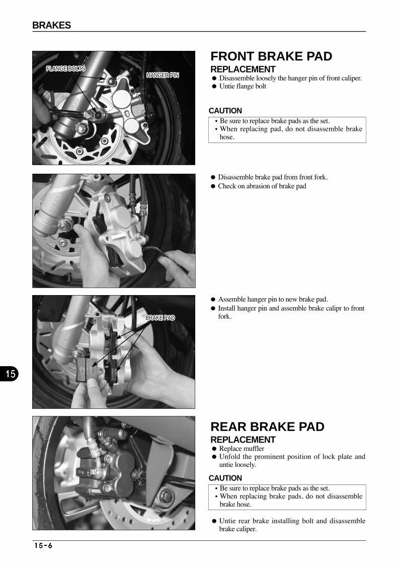
HANGER PINHANGER PINHANGER PINHANGER PINHANGER PINHANGER PINHANGER PINHANGER PINHANGER PINHANGER PINHANGER PINHANGER PINHANGER PINHANGER PINHANGER PINHANGER PINHANGER PINHANGER PINHANGER PINHANGER PINHANGER PINHANGER PINHANGER PINHANGER PINHANGER PINHANGER PINHANGER PINFLANGE BOLTSFLANGE BOLTSFLANGE BOLTSFLANGE BOLTSFLANGE BOLTSFLANGE BOLTSFLANGE BOLTSFLANGE BOLTSFLANGE BOLTSFLANGE BOLTSFLANGE BOLTSFLANGE BOLTSFLANGE BOLTSFLANGE BOLTSFLANGE BOLTSFLANGE BOLTSFLANGE BOLTSFLANGE BOLTSFLANGE BOLTSFLANGE BOLTSFLANGE BOLTSFLANGE BOLTSFLANGE BOLTSFLANGE BOLTSFLANGE BOLTSFLANGE BOLTSFLANGE BOLTS
BRAKE PADBRAKE PADBRAKE PADBRAKE PADBRAKE PADBRAKE PADBRAKE PADBRAKE PADBRAKE PADBRAKE PADBRAKE PADBRAKE PADBRAKE PADBRAKE PADBRAKE PADBRAKE PADBRAKE PADBRAKE PADBRAKE PADBRAKE PADBRAKE PADBRAKE PADBRAKE PADBRAKE PADBRAKE PADBRAKE PADBRAKE PAD
BRAKES
Assemble hanger pin to new brake pad. Install hanger pin and assemble brake calipr to front
fork.
FRONT BRAKE PAD REPLACEMENT Disassemble loosely the hanger pin of front caliper. Untie flange bolt
Disassemble brake pad from front fork. Check on abrasion of brake pad
REAR BRAKE PAD REPLACEMENT Replace muffler Unfold the prominent position of lock plate and
untie loosely.
Untie rear brake installing bolt and disassemblebrake caliper.
CAUTION•Be sure to replace brake pads as the set. •When replacing pad, do not disassemble brake
hose.
CAUTION•Be sure to replace brake pads as the set.•When replacing brake pads, do not disassemble
brake hose.
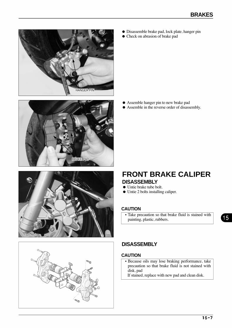
Disassemble brake pad, lock plate, hanger pin Check on abrasion of brake pad
FRONT BRAKE CALIPER DISASSEMBLY Untie brake tube bolt. Untie 2 bolts installing caliper.
DISASSEMBLY
Assemble hanger pin to new brake pad Assemble in the reverse order of disassembly.
HANGER PINHANGER PINHANGER PINHANGER PINHANGER PINHANGER PINHANGER PINHANGER PINHANGER PINHANGER PINHANGER PINHANGER PINHANGER PINHANGER PINHANGER PINHANGER PINHANGER PINHANGER PINHANGER PINHANGER PINHANGER PINHANGER PINHANGER PINHANGER PINHANGER PINHANGER PINHANGER PIN
BRAKE PADBRAKE PADBRAKE PADBRAKE PADBRAKE PADBRAKE PADBRAKE PADBRAKE PADBRAKE PADBRAKE PADBRAKE PADBRAKE PADBRAKE PADBRAKE PADBRAKE PADBRAKE PADBRAKE PADBRAKE PADBRAKE PADBRAKE PADBRAKE PADBRAKE PADBRAKE PADBRAKE PADBRAKE PADBRAKE PADBRAKE PAD
CAUTION•Take precaution so that brake fluid is stained with
painting, plastic, rubbers.
CAUTION•Because oils may lose braking performance, take
precaution so that brake fluid is not stained withdisk, pad If stained, replace with new pad and clean disk.
BRAKES
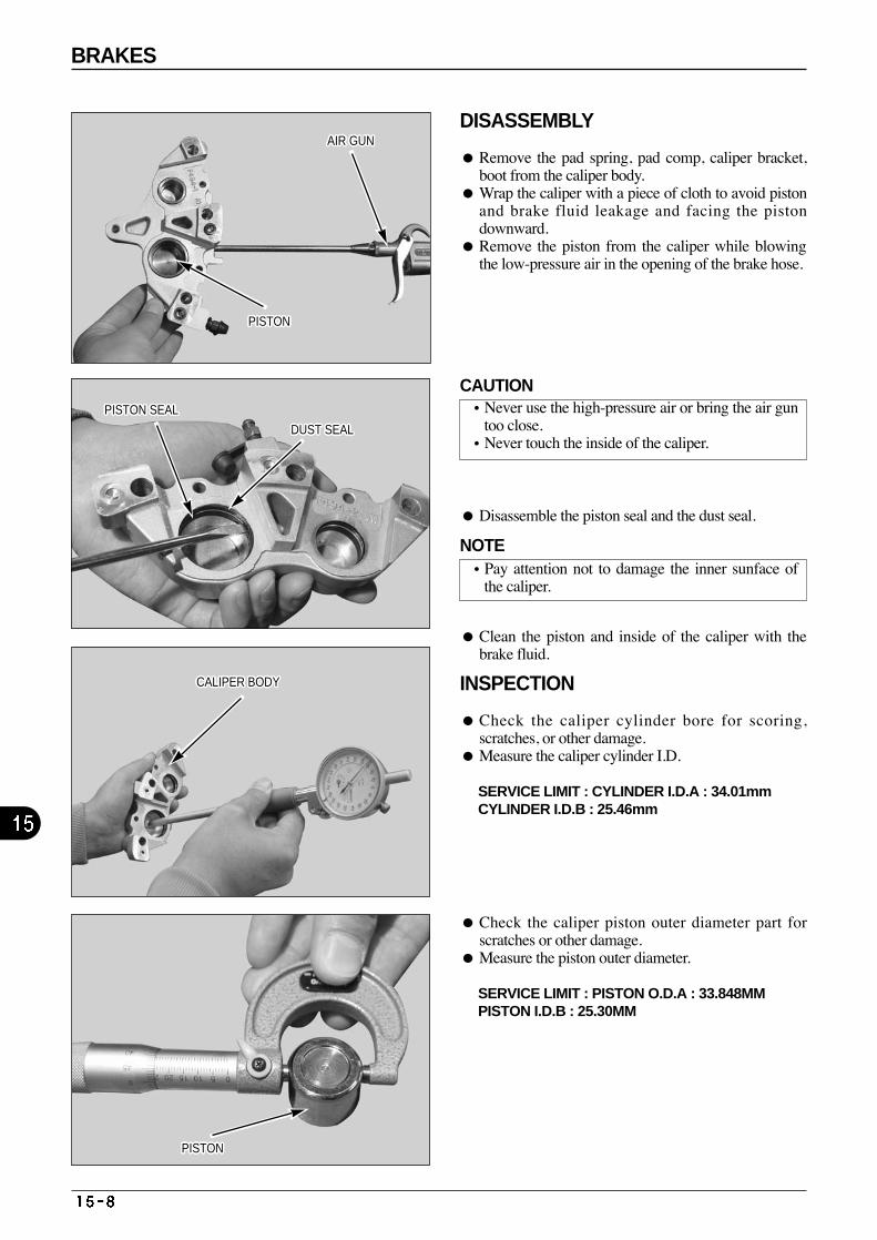
BRAKES
INSPECTION
Check the caliper cylinder bore for scoring,scratches, or other damage.
Measure the caliper cylinder I.D.
SERVICE LIMIT : CYLINDER I.D.A : 34.01mmCYLINDER I.D.B : 25.46mm
Check the caliper piston outer diameter part forscratches or other damage.
Measure the piston outer diameter.
SERVICE LIMIT : PISTON O.D.A : 33.848MMPISTON I.D.B : 25.30MM
PISTONPISTONPISTONPISTONPISTONPISTONPISTONPISTONPISTONPISTONPISTONPISTONPISTONPISTONPISTONPISTONPISTONPISTONPISTONPISTONPISTONPISTON
PISTON SEALPISTON SEALPISTON SEALPISTON SEALPISTON SEALPISTON SEALPISTON SEALPISTON SEALPISTON SEALPISTON SEALPISTON SEALPISTON SEALPISTON SEALPISTON SEALPISTON SEALPISTON SEALPISTON SEALPISTON SEALPISTON SEALPISTON SEALPISTON SEALPISTON SEAL
DUST SEALDUST SEALDUST SEALDUST SEALDUST SEALDUST SEALDUST SEALDUST SEALDUST SEALDUST SEALDUST SEALDUST SEALDUST SEALDUST SEALDUST SEALDUST SEALDUST SEALDUST SEALDUST SEALDUST SEALDUST SEALDUST SEAL
AIR GUNAIR GUNAIR GUNAIR GUNAIR GUNAIR GUNAIR GUNAIR GUNAIR GUNAIR GUNAIR GUNAIR GUNAIR GUNAIR GUNAIR GUNAIR GUNAIR GUNAIR GUNAIR GUNAIR GUNAIR GUNAIR GUN
CALIPER BODYCALIPER BODYCALIPER BODYCALIPER BODYCALIPER BODYCALIPER BODYCALIPER BODYCALIPER BODYCALIPER BODYCALIPER BODYCALIPER BODYCALIPER BODYCALIPER BODYCALIPER BODYCALIPER BODYCALIPER BODYCALIPER BODYCALIPER BODYCALIPER BODYCALIPER BODYCALIPER BODYCALIPER BODY
PISTONPISTONPISTONPISTONPISTONPISTONPISTONPISTONPISTONPISTONPISTONPISTONPISTONPISTONPISTONPISTONPISTONPISTONPISTONPISTONPISTONPISTON
DISASSEMBLY
Remove the pad spring, pad comp, caliper bracket,boot from the caliper body.
Wrap the caliper with a piece of cloth to avoid pistonand brake fluid leakage and facing the pistondownward.
Remove the piston from the caliper while blowingthe low-pressure air in the opening of the brake hose.
Disassemble the piston seal and the dust seal.
Clean the piston and inside of the caliper with thebrake fluid.
CAUTION•Never use the high-pressure air or bring the air gun
too close.•Never touch the inside of the caliper.
NOTE•Pay attention not to damage the inner sunface of
the caliper.
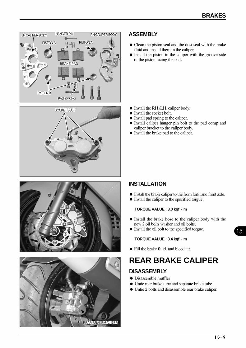
REAR BRAKE CALIPER DISASSEMBLY Disassemble muffler Untie rear brake tube and separate brake tube Untie 2 bolts and disassemble rear brake caliper.
REAR BRAKE CALIPERREAR BRAKE CALIPERREAR BRAKE CALIPERREAR BRAKE CALIPERREAR BRAKE CALIPERREAR BRAKE CALIPERREAR BRAKE CALIPERREAR BRAKE CALIPERREAR BRAKE CALIPERREAR BRAKE CALIPERREAR BRAKE CALIPERREAR BRAKE CALIPERREAR BRAKE CALIPERREAR BRAKE CALIPERREAR BRAKE CALIPERREAR BRAKE CALIPERREAR BRAKE CALIPERREAR BRAKE CALIPERREAR BRAKE CALIPERREAR BRAKE CALIPERREAR BRAKE CALIPERREAR BRAKE CALIPERREAR BRAKE CALIPERREAR BRAKE CALIPERREAR BRAKE CALIPERREAR BRAKE CALIPERREAR BRAKE CALIPER
BRAKES
LH CALIPER BODYLH CALIPER BODYLH CALIPER BODYLH CALIPER BODYLH CALIPER BODYLH CALIPER BODYLH CALIPER BODYLH CALIPER BODYLH CALIPER BODYLH CALIPER BODYLH CALIPER BODYLH CALIPER BODYLH CALIPER BODYLH CALIPER BODYLH CALIPER BODYLH CALIPER BODYLH CALIPER BODYLH CALIPER BODYLH CALIPER BODYLH CALIPER BODYLH CALIPER BODYLH CALIPER BODY
PISTON APISTON APISTON APISTON APISTON APISTON APISTON APISTON APISTON APISTON APISTON APISTON APISTON APISTON APISTON APISTON APISTON APISTON APISTON APISTON APISTON APISTON APISTON APISTON APISTON APISTON APISTON APISTON APISTON APISTON APISTON APISTON APISTON APISTON APISTON APISTON APISTON APISTON APISTON APISTON APISTON APISTON APISTON APISTON A
HANGER PINHANGER PINHANGER PINHANGER PINHANGER PINHANGER PINHANGER PINHANGER PINHANGER PINHANGER PINHANGER PINHANGER PINHANGER PINHANGER PINHANGER PINHANGER PINHANGER PINHANGER PINHANGER PINHANGER PINHANGER PINHANGER PIN RH CALIPER BODYRH CALIPER BODYRH CALIPER BODYRH CALIPER BODYRH CALIPER BODYRH CALIPER BODYRH CALIPER BODYRH CALIPER BODYRH CALIPER BODYRH CALIPER BODYRH CALIPER BODYRH CALIPER BODYRH CALIPER BODYRH CALIPER BODYRH CALIPER BODYRH CALIPER BODYRH CALIPER BODYRH CALIPER BODYRH CALIPER BODYRH CALIPER BODYRH CALIPER BODYRH CALIPER BODY
PISTON BPISTON BPISTON BPISTON BPISTON BPISTON BPISTON BPISTON BPISTON BPISTON BPISTON BPISTON BPISTON BPISTON BPISTON BPISTON BPISTON BPISTON BPISTON BPISTON BPISTON BPISTON B
PAD SPRINGPAD SPRINGPAD SPRINGPAD SPRINGPAD SPRINGPAD SPRINGPAD SPRINGPAD SPRINGPAD SPRINGPAD SPRINGPAD SPRINGPAD SPRINGPAD SPRINGPAD SPRINGPAD SPRINGPAD SPRINGPAD SPRINGPAD SPRINGPAD SPRINGPAD SPRINGPAD SPRINGPAD SPRING
SOCKET BOLTSOCKET BOLTSOCKET BOLTSOCKET BOLTSOCKET BOLTSOCKET BOLTSOCKET BOLTSOCKET BOLTSOCKET BOLTSOCKET BOLTSOCKET BOLTSOCKET BOLTSOCKET BOLTSOCKET BOLTSOCKET BOLTSOCKET BOLTSOCKET BOLTSOCKET BOLTSOCKET BOLTSOCKET BOLTSOCKET BOLTSOCKET BOLT
BRAKE PADBRAKE PADBRAKE PADBRAKE PADBRAKE PADBRAKE PADBRAKE PADBRAKE PADBRAKE PADBRAKE PADBRAKE PADBRAKE PADBRAKE PADBRAKE PADBRAKE PADBRAKE PADBRAKE PADBRAKE PADBRAKE PADBRAKE PADBRAKE PADBRAKE PAD
ASSEMBLY
Clean the piston seal and the dust seal with the brakefluid and install them in the caliper.
Install the piston in the caliper with the groove sideof the piston facing the pad.
INSTALLATION
Install the brake caliper to the from fork, and front axle. Install the caliper to the specified torgue.
TORQUE VALUE : 3.0 kgf·m
Install the brake hose to the caliper body with thenew 2 oil bolts washer and oil bolts.
Install the oil bolt to the specified torgue.
TORQUE VALUE : 3.4 kgf·m
Fill the brake fluid, and bleed air.
Install the RH./LH. caliper body. Install the socket bolt. Install pad spring to the caliper. Install caliper hanger pin bolt to the pad comp and
caliper bracket to the caliper body. Install the brake pad to the caliper.
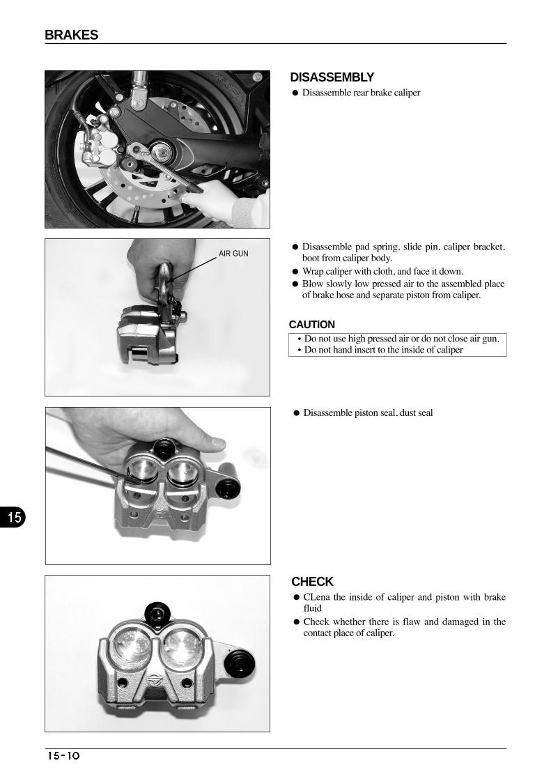
BRAKES
DISASSEMBLY Disassemble rear brake caliper
Disassemble pad spring, slide pin, caliper bracket,boot from caliper body.
Wrap caliper with cloth, and face it down. Blow slowly low pressed air to the assembled place
of brake hose and separate piston from caliper.
Disassemble piston seal, dust seal
CHECK CLena the inside of caliper and piston with brake
fluid Check whether there is flaw and damaged in the
contact place of caliper.
AIR GUN
CAUTION•Do not use high pressed air or do not close air gun.•Do not hand insert to the inside of caliper
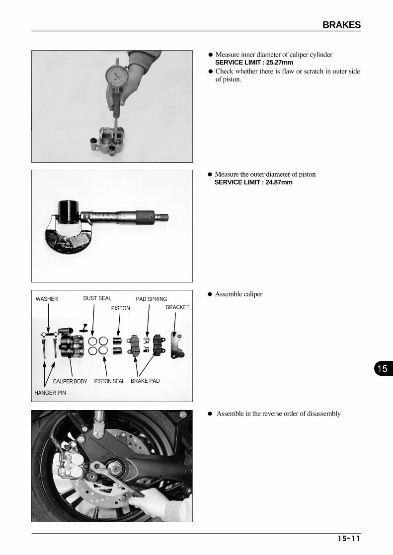
Measure inner diameter of caliper cylinder SERVICE LIMIT : 25.27mm
Check whether there is flaw or scratch in outer sideof piston.
Measure the outer diameter of piston SERVICE LIMIT : 24.87mm
Assemble in the reverse order of disassembly
Assemble caliper
HANGER PIN
WASHER
CALIPER BODY
DUST SEAL
PISTON
BRAKE PAD
PAD SPRINGBRACKET
PISTON SEAL
BRAKES
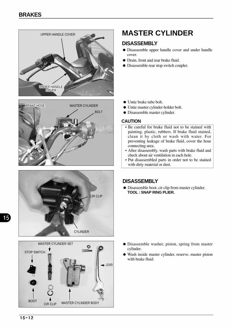
BRAKES
MASTER CYLINDER DISASSEMBLY Disassemble upper handle cover and under handle
cover. Drain, front and rear brake fluid. Disassemble rear stop switch coupler.
Untie brake tube bolt. Untie master cylinder holder bolt. Disassemble master cylinder.
DISASSEMBLY Disassemble boot, cir clip from master cylinder.
TOOL : SNAP RING PLIER.
Disassemble washer, piston, spring from mastercylinder.
Wash inside master cylinder, reserve, master pistonwith brake fluid.
MASTER CYLINDER SET
LEVER
MASTER CYLINDER BODYCIR CLIPBOOT
STOP SWITCH
CYLINDER
CIR CLIP
UNDER HANDLECOVER
UNDER HANDLECOVER
UNDER HANDLECOVER
UNDER HANDLECOVER
UNDER HANDLECOVER
UNDER HANDLECOVER
UNDER HANDLECOVER
UNDER HANDLECOVER
UNDER HANDLECOVER
UNDER HANDLECOVER
UNDER HANDLECOVER
UNDER HANDLECOVER
UNDER HANDLECOVER
UNDER HANDLECOVER
UNDER HANDLECOVER
UNDER HANDLECOVER
UNDER HANDLECOVER
UNDER HANDLECOVER
UNDER HANDLECOVER
UNDER HANDLECOVER
UNDER HANDLECOVER
UNDER HANDLECOVER
UNDER HANDLECOVER
UNDER HANDLECOVER
UNDER HANDLECOVER
UNDER HANDLECOVER
UNDER HANDLECOVER
UPPER HANDLE COVER
BRAKE HOSEBRAKE HOSEBRAKE HOSEBRAKE HOSEBRAKE HOSEBRAKE HOSEBRAKE HOSEBRAKE HOSEBRAKE HOSEBRAKE HOSEBRAKE HOSEBRAKE HOSEBRAKE HOSEBRAKE HOSEBRAKE HOSEBRAKE HOSEBRAKE HOSEBRAKE HOSEBRAKE HOSEBRAKE HOSEBRAKE HOSEBRAKE HOSEBRAKE HOSEBRAKE HOSEBRAKE HOSEBRAKE HOSEBRAKE HOSE MASTER CYLINDER
BOLT
CAUTION•Be careful for brake fluid not to be stained with
painting, plastic, rubbers. If brake fluid stained,clean it by cloth or wash with water. Forpreventing leakage of brake fluid, cover the hoseconnecting area.
•After disassembly, wash parts with brake fluid andcheck about air ventilation in each hole.
•Put disassembled parts in order not to be stainedwith dirty material or dust.
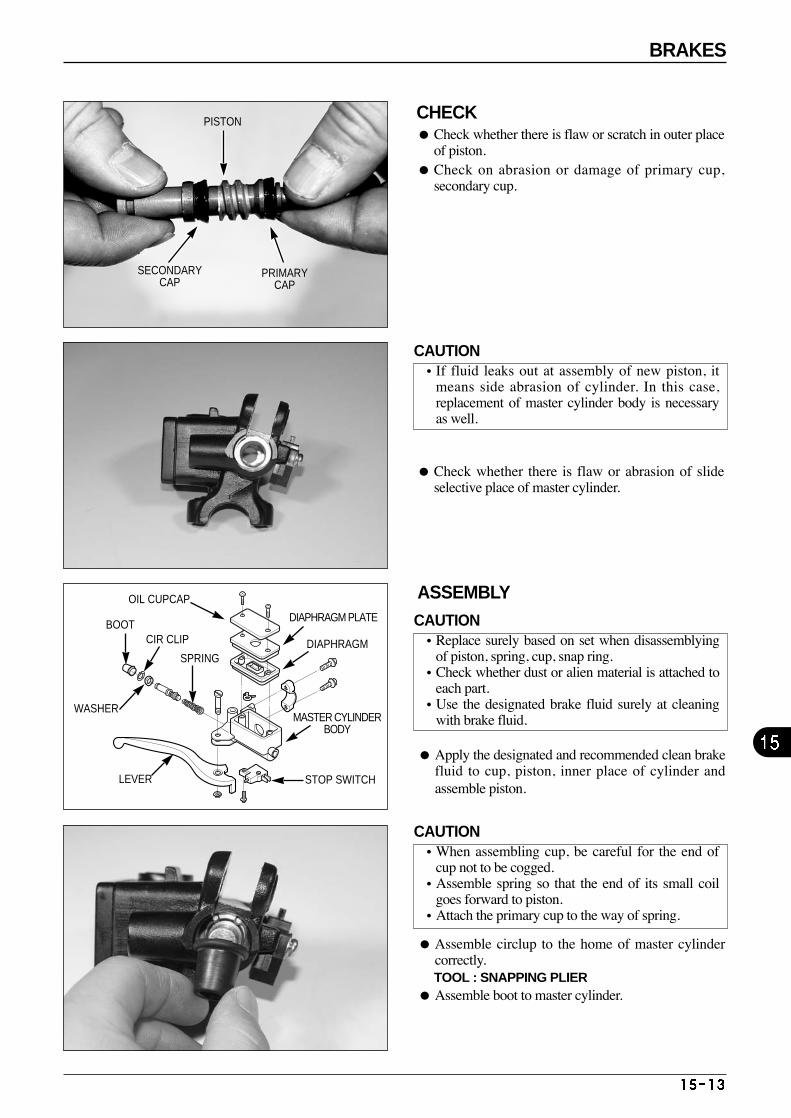
CHECK Check whether there is flaw or scratch in outer place
of piston. Check on abrasion or damage of primary cup,
secondary cup.
PISTON
SECONDARYCAP
PRIMARYCAP
ASSEMBLY
Apply the designated and recommended clean brakefluid to cup, piston, inner place of cylinder andassemble piston.
Assemble circlup to the home of master cylindercorrectly. TOOL : SNAPPING PLIER
Assemble boot to master cylinder.
Check whether there is flaw or abrasion of slideselective place of master cylinder.
OIL CUPCAP
BOOTCIR CLIP
WASHER
LEVER STOP SWITCH
MASTER CYLINDERBODY
DIAPHRAGM
DIAPHRAGM PLATE
SPRING
CAUTION•If fluid leaks out at assembly of new piston, it
means side abrasion of cylinder. In this case,replacement of master cylinder body is necessaryas well.
CAUTION•Replace surely based on set when disassemblying
of piston, spring, cup, snap ring. •Check whether dust or alien material is attached to
each part. •Use the designated brake fluid surely at cleaning
with brake fluid.
CAUTION•When assembling cup, be careful for the end of
cup not to be cogged. •Assemble spring so that the end of its small coil
goes forward to piston. •Attach the primary cup to the way of spring.
BRAKES
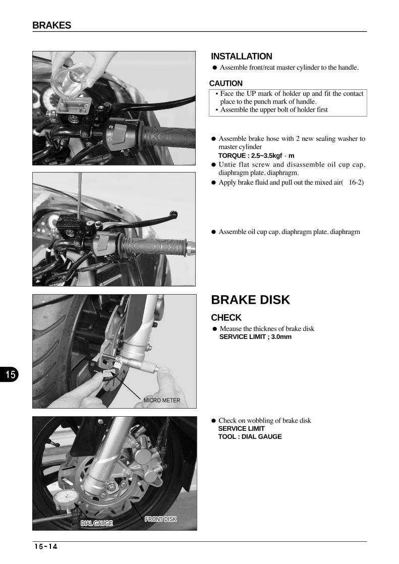
INSTALLATION Assemble front/reat master cylinder to the handle.
Assemble brake hose with 2 new sealing washer tomaster cylinderTORQUE : 2.5~3.5kgf m
Untie flat screw and disassemble oil cup cap,diaphragm plate, diaphragm.
Apply brake fluid and pull out the mixed air(16-2)
Assemble oil cup cap, diaphragm plate, diaphragm
Check on wobbling of brake disk SERVICE LIMIT TOOL : DIAL GAUGE
BRAKE DISK CHECK Meause the thicknes of brake disk
SERVICE LIMIT ; 3.0mm
DIAL GAUGEDIAL GAUGEDIAL GAUGEDIAL GAUGEDIAL GAUGEDIAL GAUGEDIAL GAUGEDIAL GAUGEDIAL GAUGEDIAL GAUGEDIAL GAUGEDIAL GAUGEDIAL GAUGEDIAL GAUGEDIAL GAUGEDIAL GAUGEDIAL GAUGEDIAL GAUGEDIAL GAUGEDIAL GAUGEDIAL GAUGEDIAL GAUGEDIAL GAUGEDIAL GAUGEDIAL GAUGEDIAL GAUGEDIAL GAUGEFRONT DISKFRONT DISKFRONT DISKFRONT DISKFRONT DISKFRONT DISKFRONT DISKFRONT DISKFRONT DISKFRONT DISKFRONT DISKFRONT DISKFRONT DISKFRONT DISKFRONT DISKFRONT DISKFRONT DISKFRONT DISKFRONT DISKFRONT DISKFRONT DISKFRONT DISKFRONT DISKFRONT DISKFRONT DISKFRONT DISKFRONT DISK
MICRO METER
CAUTION•Face the UP mark of holder up and fit the contact
place to the punch mark of handle. •Assemble the upper bolt of holder first
BRAKES

MEMO
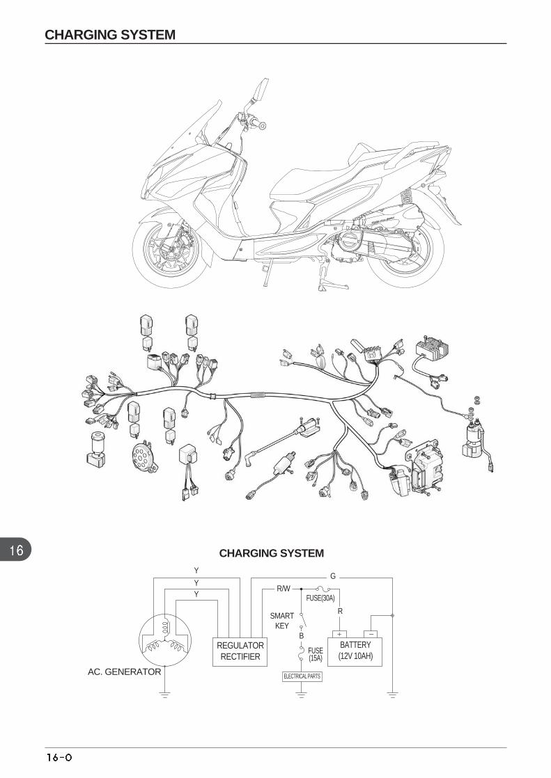
CHARGING SYSTEM
CHARGING SYSTEM
AC. GENERATOR
REGULATORRECTIFIER
BATTERY(12V 10AH)
SMART KEY
R/W
R
GY
YY
B
ELECTRICAL PARTS
FUSE(30A)
FUSE(15A)
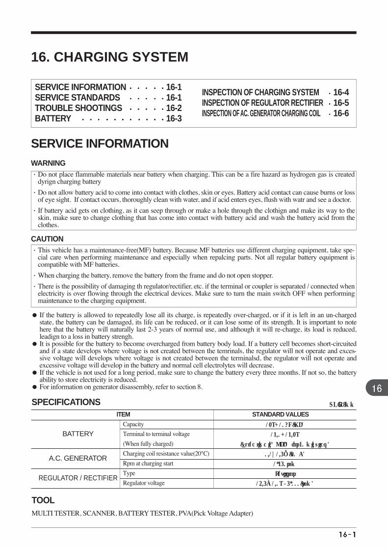
A.C. GENERATOR
BATTERY
REGULATOR / RECTIFIER
ITEM STANDARD VALUES
12V-10AH(MF)
13.0-13.2V
(at the time in ‘OFF ‘for 30 minuites )
0.1~1.5Ω(20。C)
1,350rpm
Thyristor
14.5±1.0V / 5,000(rpm)
Capacity
Terminal to terminal voltage
(When fully charged)
Charging coil resistance value(20°C)
Rpm at charging start
Type
Regulator voltage
UNIT :mm
MULTI TESTER, SCANNER, BATTERY TESTER, PVA(Pick Voltage Adapter)
SPECIFICATIONS
TOOL
16. CHARGING SYSTEM
SERVICE INFORMATIONWARNING·Do not place flammable materials near battery when charging. This can be a fire hazard as hydrogen gas is created
dyrign charging battery
·Do not allow battery acid to come into contact with clothes, skin or eyes. Battery acid contact can cause burns or lossof eye sight. If contact occurs, thoroughly clean with water, and if acid enters eyes, flush with watr and see a doctor.
·If battery acid gets on clothing, as it can seep through or make a hole through the clothign and make its way to theskin, make sure to change clothing that has come into contact with battery acid and wash the battery acid from theclothes.
CAUTION·This vehicle has a maintenance-free(MF) battery. Because MF batteries use different charging equipment, take spe-
cial care when performing maintenance and especially when repalcing parts. Not all regular battery equipment iscompatible with MF batteries.
·When charging the battery, remove the battery from the frame and do not open stopper.
·There is the possibility of damaging th regulator/rectifier, etc. if the terminal or coupler is separated / connected whenelectricity is over flowing through the electrical devices. Make sure to turn the main switch OFF when performingmaintenance to the charging equipment.
If the battery is allowed to repeatedly lose all its charge, is repeatedly over-charged, or if it is left in an un-chargedstate, the battery can be damaged, its life can be reduced, or it can lose some of its strength. It is important to notehere that the battery will naturally last 2-3 years of normal use, and although it will re-charge, its load is reduced,leadign to a loss in battery strengh.
It is possible for the battery to become overcharged from battery body load. If a battery cell becomes short-circuitedand if a state develops where voltage is not created between the temrinals, the regulator will not operate and exces-sive voltage will develops where voltage is not created between the terminalsd, the regulator will not operate andexcessive voltage will develop in the battery and normal cell electrolytes will decrease.
If the vehicle is not used for a long period, make sure to change the battery every three months. If not so, the batteryability to store electricity is reduced.
For information on generator disassembly, refer to section 8.
SERVICE INFORMATION 16-1 SERVICE STANDARDS 16-1TROUBLE SHOOTINGS 16-2 BATTERY 16-3
INSPECTION OF CHARGING SYSTEM 16-4INSPECTION OF REGULATOR RECTIFIER 16-5INSPECTION OF AC. GENERATOR CHARGING COIL 16-6
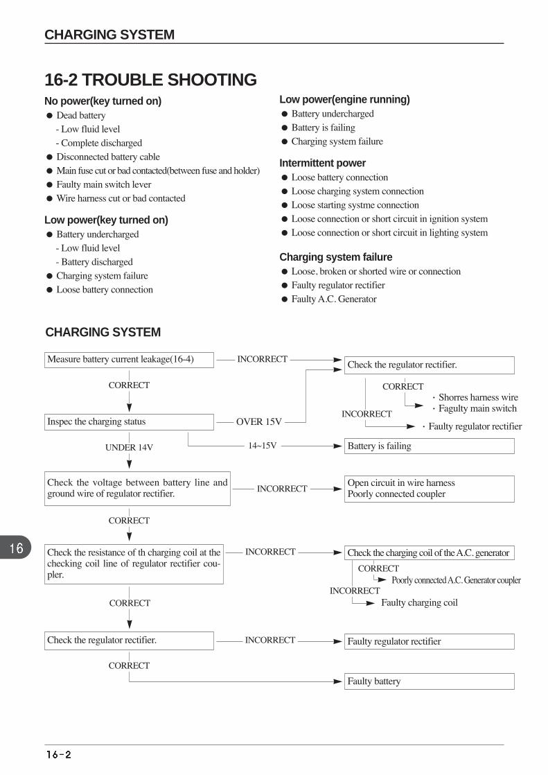
Measure battery current leakage(16-4) Check the regulator rectifier.
Battery is failing
Open circuit in wire harness Poorly connected coupler
·Shorres harness wire·Fagulty main switch
·Faulty regulator rectifier
Check the charging coil of the A.C. generator
Faulty regulator rectifier
Faulty battery
Inspec the charging status
Check the voltage between battery line andground wire of regulator rectifier.
Check the resistance of th charging coil at thechecking coil line of regulator rectifier cou-pler.
Check the regulator rectifier.
CORRECT
INCORRECT
INCORRECT
CORRECT
Poorly connected A.C. Generator coupler
Faulty charging coil INCORRECT
CORRECT
INCORRECT
INCORRECT
INCORRECT
OVER 15V
14~15VUNDER 14V
CORRECT
CORRECT
CORRECT
16-2 TROUBLE SHOOTINGNo power(key turned on) Dead battery
- Low fluid level - Complete discharged
Disconnected battery cable Main fuse cut or bad contacted(between fuse and holder) Faulty main switch lever Wire harness cut or bad contacted
Low power(key turned on) Battery undercharged
- Low fluid level - Battery discharged
Charging system failure Loose battery connection
Low power(engine running) Battery undercharged Battery is failing Charging system failure
Intermittent power Loose battery connection Loose charging system connection Loose starting systme connection Loose connection or short circuit in ignition system Loose connection or short circuit in lighting system
Charging system failure Loose, broken or shorted wire or connection Faulty regulator rectifier Faulty A.C. Generator
CHARGING SYSTEM
CHARGING SYSTEM
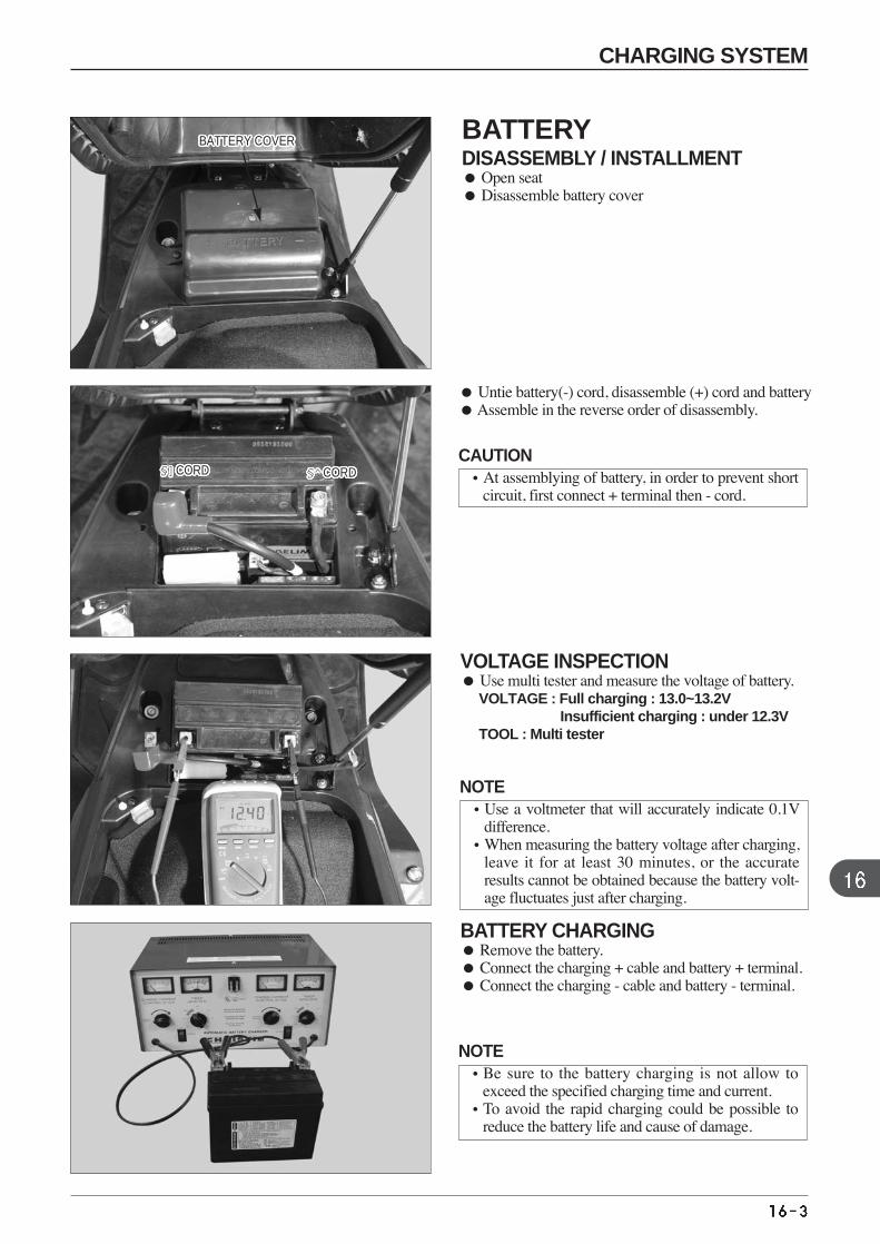
Untie battery(-) cord, disassemble (+) cord and batteryAssemble in the reverse order of disassembly.
VOLTAGE INSPECTION Use multi tester and measure the voltage of battery.
VOLTAGE : Full charging : 13.0~13.2V Insufficient charging : under 12.3V
TOOL : Multi tester
BATTERY CHARGING Remove the battery. Connect the charging + cable and battery + terminal. Connect the charging - cable and battery - terminal.
§]CORD§]CORD§]CORD§]CORD§]CORD§]CORD§]CORD§]CORD§]CORD§]CORD§]CORD§]CORD§]CORD§]CORD§]CORD§]CORD§]CORD§]CORD§]CORD§]CORD§]CORD§]CORD§]CORD§]CORD§]CORD§]CORD§]CORD §^CORD§^CORD§^CORD§^CORD§^CORD§^CORD§^CORD§^CORD§^CORD§^CORD§^CORD§^CORD§^CORD§^CORD§^CORD§^CORD§^CORD§^CORD§^CORD§^CORD§^CORD§^CORD§^CORD§^CORD§^CORD§^CORD§^CORD
BATTERY COVERBATTERY COVERBATTERY COVERBATTERY COVERBATTERY COVERBATTERY COVERBATTERY COVERBATTERY COVERBATTERY COVERBATTERY COVERBATTERY COVERBATTERY COVERBATTERY COVERBATTERY COVERBATTERY COVERBATTERY COVERBATTERY COVERBATTERY COVERBATTERY COVERBATTERY COVERBATTERY COVERBATTERY COVERBATTERY COVERBATTERY COVERBATTERY COVERBATTERY COVERBATTERY COVER
CHARGING SYSTEM
BATTERYDISASSEMBLY / INSTALLMENT Open seat Disassemble battery cover
CAUTION•At assemblying of battery, in order to prevent short
circuit, first connect + terminal then - cord.
NOTE•Use a voltmeter that will accurately indicate 0.1V
difference.•When measuring the battery voltage after charging,
leave it for at least 30 minutes, or the accurateresults cannot be obtained because the battery volt-age fluctuates just after charging.
NOTE•Be sure to the battery charging is not allow to
exceed the specified charging time and current.•To avoid the rapid charging could be possible to
reduce the battery life and cause of damage.
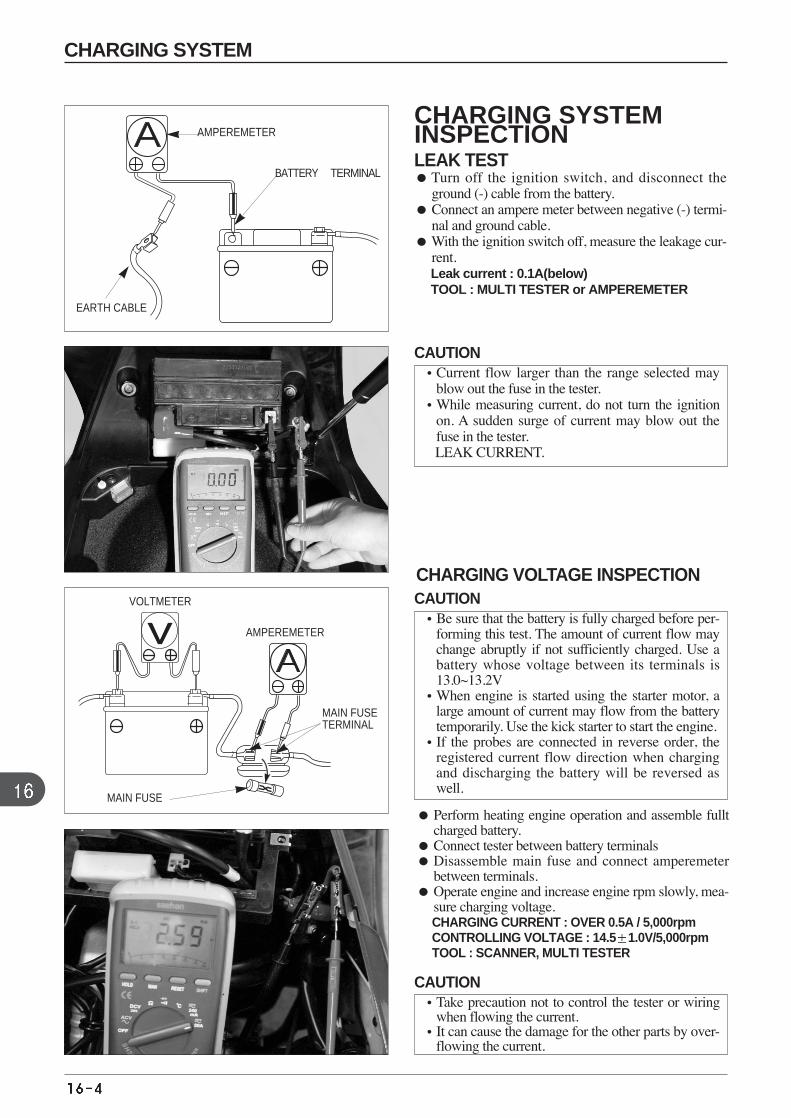
CHARGING VOLTAGE INSPECTION
Perform heating engine operation and assemble fulltcharged battery.
Connect tester between battery terminals Disassemble main fuse and connect amperemeter
between terminals. Operate engine and increase engine rpm slowly, mea-
sure charging voltage. CHARGING CURRENT : OVER 0.5A / 5,000rpm CONTROLLING VOLTAGE : 14.5 1.0V/5,000rpm TOOL : SCANNER, MULTI TESTER
AMPEREMETER
BATTERY⊖TERMINAL
EARTH CABLE
VOLTMETER
AMPEREMETER
MAIN FUSE
MAIN FUSETERMINAL
CHARGING SYSTEMINSPECTION LEAK TEST Turn off the ignition switch, and disconnect the
ground (-) cable from the battery. Connect an ampere meter between negative (-) termi-
nal and ground cable.With the ignition switch off, measure the leakage cur-
rent.Leak current : 0.1A(below)TOOL : MULTI TESTER or AMPEREMETER
CAUTION•Current flow larger than the range selected may
blow out the fuse in the tester.•While measuring current, do not turn the ignition
on. A sudden surge of current may blow out thefuse in the tester.LEAK CURRENT.
CAUTION•Be sure that the battery is fully charged before per-
forming this test. The amount of current flow maychange abruptly if not sufficiently charged. Use abattery whose voltage between its terminals is13.0~13.2V
•When engine is started using the starter motor, alarge amount of current may flow from the batterytemporarily. Use the kick starter to start the engine.
•If the probes are connected in reverse order, theregistered current flow direction when chargingand discharging the battery will be reversed aswell.
CAUTION•Take precaution not to control the tester or wiring
when flowing the current.•It can cause the damage for the other parts by over-
flowing the current.
CHARGING SYSTEM
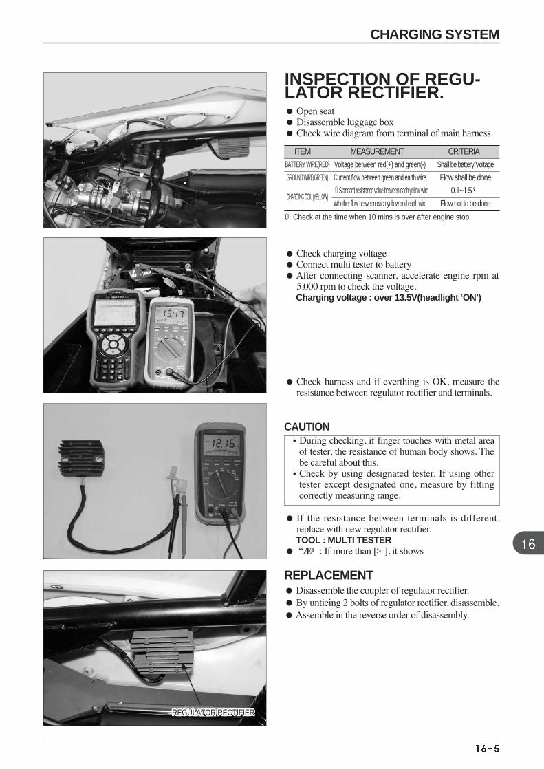
ITEM MEASUREMENT CRITERIA
INSPECTION OF REGU-LATOR RECTIFIER. Open seat Disassemble luggage box Check wire diagram from terminal of main harness.
Check harness and if everthing is OK, measure theresistance between regulator rectifier and terminals.
Check charging voltage Connect multi tester to battery After connecting scanner, accelerate engine rpm at
5,000 rpm to check the voltage. Charging voltage : over 13.5V(headlight ‘ON’)
BATTERY WIRE(RED) Voltage between red(+) and green(-) Shall be battery Voltage
GROUND WIRE(GREEN) Current flow between green and earth wire Flow shall be done
CHARGING COIL (YELLOW)※Standard resistance value between each yellow wire 0.1~1.5 Ω
Whether flow between each yellow and earth wire Flow not to be done
※ Check at the time when 10 mins is over after engine stop.
If the resistance between terminals is different,replace with new regulator rectifier. TOOL : MULTI TESTER
“∞”: If more than [], it shows
REGULATOR RECTIFIERREGULATOR RECTIFIERREGULATOR RECTIFIERREGULATOR RECTIFIERREGULATOR RECTIFIERREGULATOR RECTIFIERREGULATOR RECTIFIERREGULATOR RECTIFIERREGULATOR RECTIFIERREGULATOR RECTIFIERREGULATOR RECTIFIERREGULATOR RECTIFIERREGULATOR RECTIFIERREGULATOR RECTIFIERREGULATOR RECTIFIERREGULATOR RECTIFIERREGULATOR RECTIFIERREGULATOR RECTIFIERREGULATOR RECTIFIERREGULATOR RECTIFIERREGULATOR RECTIFIERREGULATOR RECTIFIERREGULATOR RECTIFIERREGULATOR RECTIFIERREGULATOR RECTIFIERREGULATOR RECTIFIERREGULATOR RECTIFIER
REPLACEMENT Disassemble the coupler of regulator rectifier. By untieing 2 bolts of regulator rectifier, disassemble. Assemble in the reverse order of disassembly.
CAUTION•During checking, if finger touches with metal area
of tester, the resistance of human body shows. Thebe careful about this.
•Check by using designated tester. If using othertester except designated one, measure by fittingcorrectly measuring range.
CHARGING SYSTEM
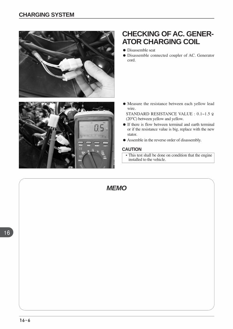
Measure the resistance between each yellow leadwire.
STANDARD RESISTANCE VALUE : 0.1~1.5(20°C) between yellow and yellow.
If there is flow between terminal and earth terminalor if the resistance value is big, replace with the newstator.
Assemble in the reverse order of disassembly.
MEMO
CHECKING OF AC. GENER-ATOR CHARGING COIL Disassemble seat Disassemble connected coupler of AC. Generator
cord.
CAUTION•This test shall be done on condition that the engine
installed to the vehicle.
CHARGING SYSTEM

MEMO
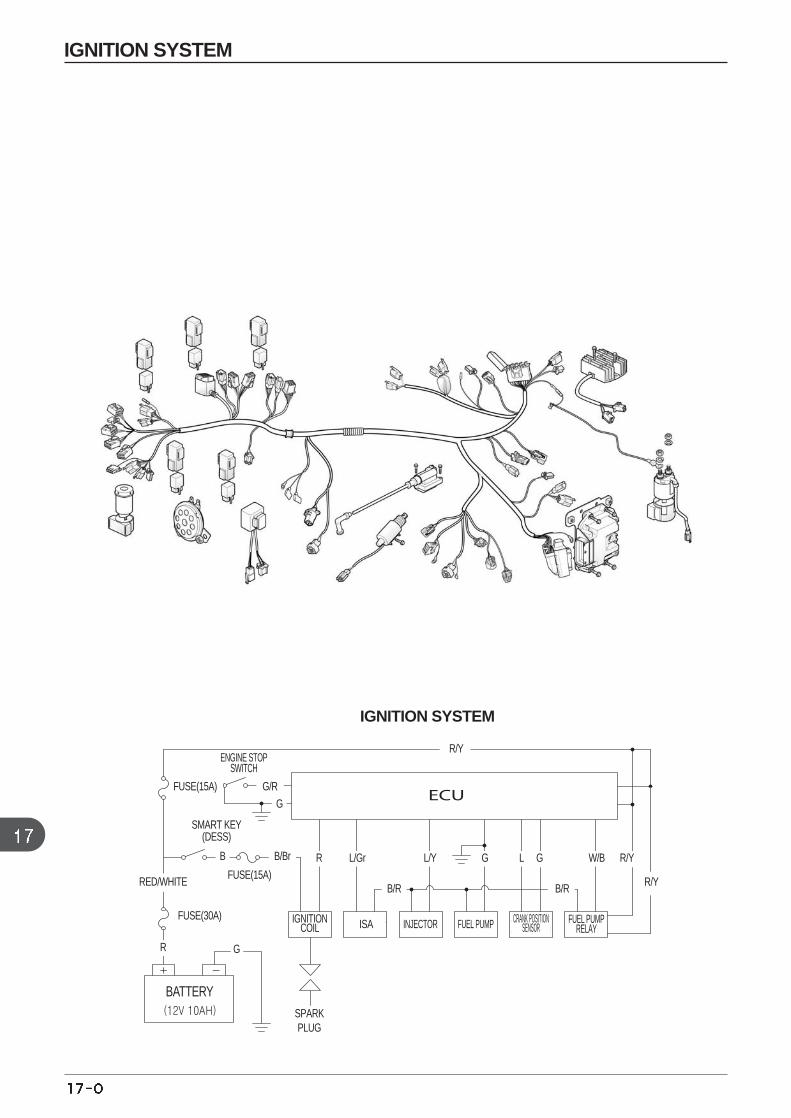
IGNITION SYSTEM
IGNITION SYSTEM
FUSE(15A) G/R
G
B R L/Gr L/Y G L G W/B R/Y
R/Y
R/Y
B/R B/R
B/BrB/Br
ISA INJECTOR FUEL PUMP CRANK POSITIONSENSOR
FUEL PUMPRELAY
ENGINE STOPSWITCH
FUSE(15A)
SPARKPLUG
SMART KEY(DESS)
IGNITIONCOIL
FUSE(30A)
RED/WHITE
R G
BATTERY
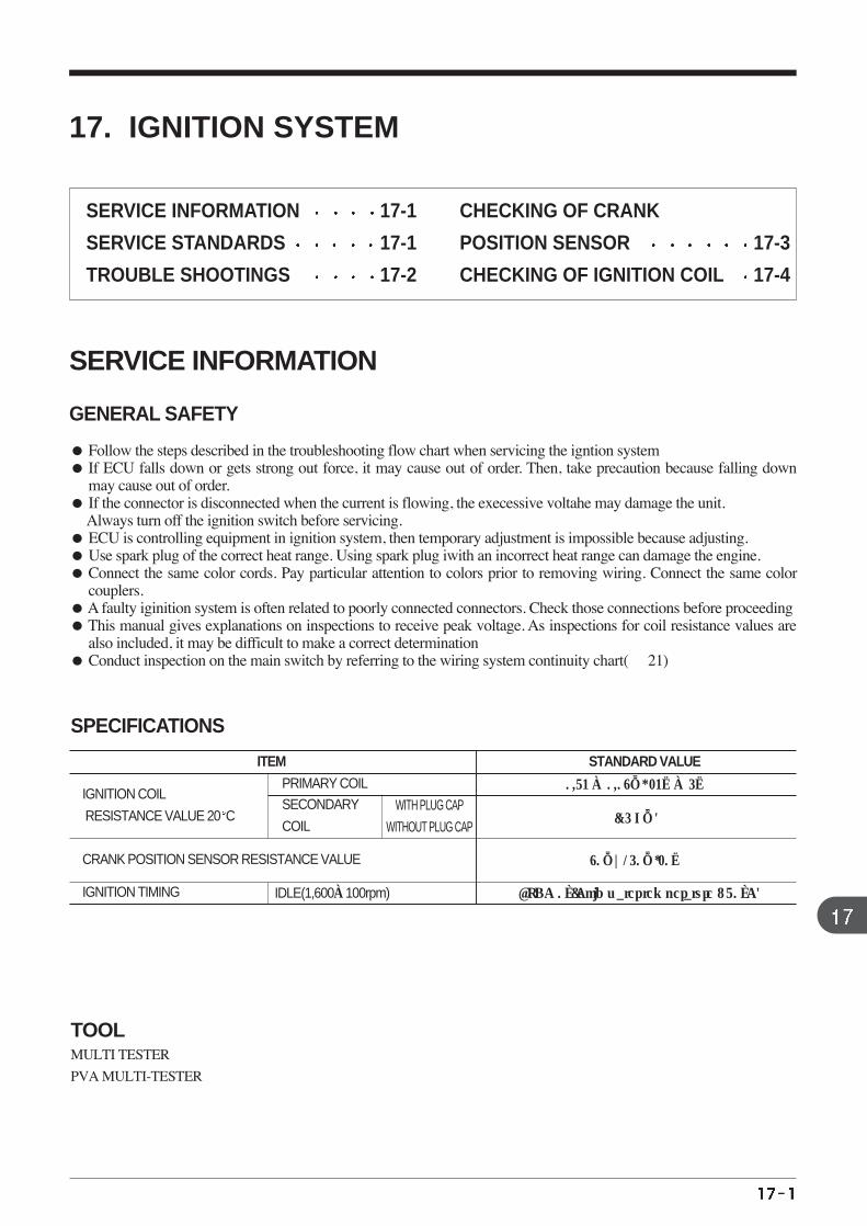
CRANK POSITION SENSOR RESISTANCE VALUE
IGNITION TIMING
IGNITION COIL
RESISTANCE VALUE 20 C
ITEM STANDARD VALUE
0.73 ±0.08Ω, 23±5
(15 KΩ)
80Ω~150Ω,20
PRIMARY COIL SECONDARY
COIL
IDLE(1,600±100rpm) BTDC 0°(Cold water temperature : 70°C)
WITH PLUG CAP
WITHOUT PLUG CAP
MULTI TESTER
PVA MULTI-TESTER
SPECIFICATIONS
TOOL
17. IGNITION SYSTEM
SERVICE INFORMATION
GENERAL SAFETY
Follow the steps described in the troubleshooting flow chart when servicing the igntion system If ECU falls down or gets strong out force, it may cause out of order. Then, take precaution because falling down
may cause out of order. If the connector is disconnected when the current is flowing, the execessive voltahe may damage the unit.
Always turn off the ignition switch before servicing. ECU is controlling equipment in ignition system, then temporary adjustment is impossible because adjusting. Use spark plug of the correct heat range. Using spark plug iwith an incorrect heat range can damage the engine. Connect the same color cords. Pay particular attention to colors prior to removing wiring. Connect the same color
couplers. A faulty iginition system is often related to poorly connected connectors. Check those connections before proceeding This manual gives explanations on inspections to receive peak voltage. As inspections for coil resistance values are
also included, it may be difficult to make a correct determination Conduct inspection on the main switch by referring to the wiring system continuity chart( 21)
SERVICE INFORMATION 17-1
SERVICE STANDARDS 17-1
TROUBLE SHOOTINGS 17-2
CHECKING OF CRANK
POSITION SENSOR 17-3
CHECKING OF IGNITION COIL 17-4
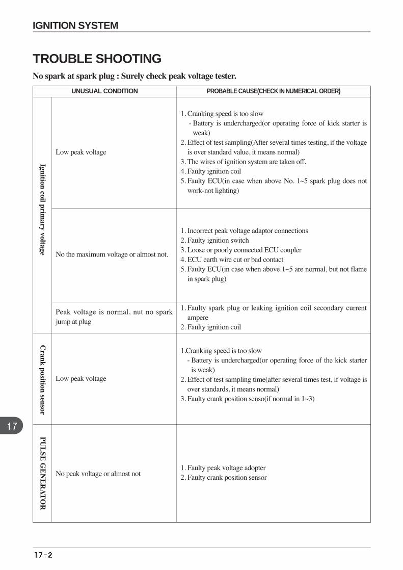
IGNITION SYSTEM
TROUBLE SHOOTING No spark at spark plug : Surely check peak voltage tester.
UNUSUAL CONDITION PROBABLE CAUSE(CHECK IN NUMERICAL ORDER)
1. Cranking speed is too slow - Battery is undercharged(or operating force of kick starter is
weak)2. Effect of test sampling(After several times testing, if the voltage
is over standard value, it means normal)3. The wires of ignition system are taken off. 4. Faulty ignition coil 5. Faulty ECU(in case when above No. 1~5 spark plug does not
work-not lighting)
1. Incorrect peak voltage adaptor connections 2. Faulty ignition switch 3. Loose or poorly connected ECU coupler4. ECU earth wire cut or bad contact5. Faulty ECU(in case when above 1~5 are normal, but not flame
in spark plug)
1.Cranking speed is too slow - Battery is undercharged(or operating force of the kick starter
is weak)2. Effect of test sampling time(after several times test, if voltage is
over standards, it means normal)3. Faulty crank position senso(if normal in 1~3)
1. Faulty spark plug or leaking ignition coil secondary currentampere
2. Faulty ignition coil
1. Faulty peak voltage adopter2. Faulty crank position sensor
Low peak voltage
No the maximum voltage or almost not.
Low peak voltage
Peak voltage is normal, nut no sparkjump at plug
No peak voltage or almost not
Ignition coil primary voltage
PU
LSE
GE
NE
RA
TO
RC
rank position sensor
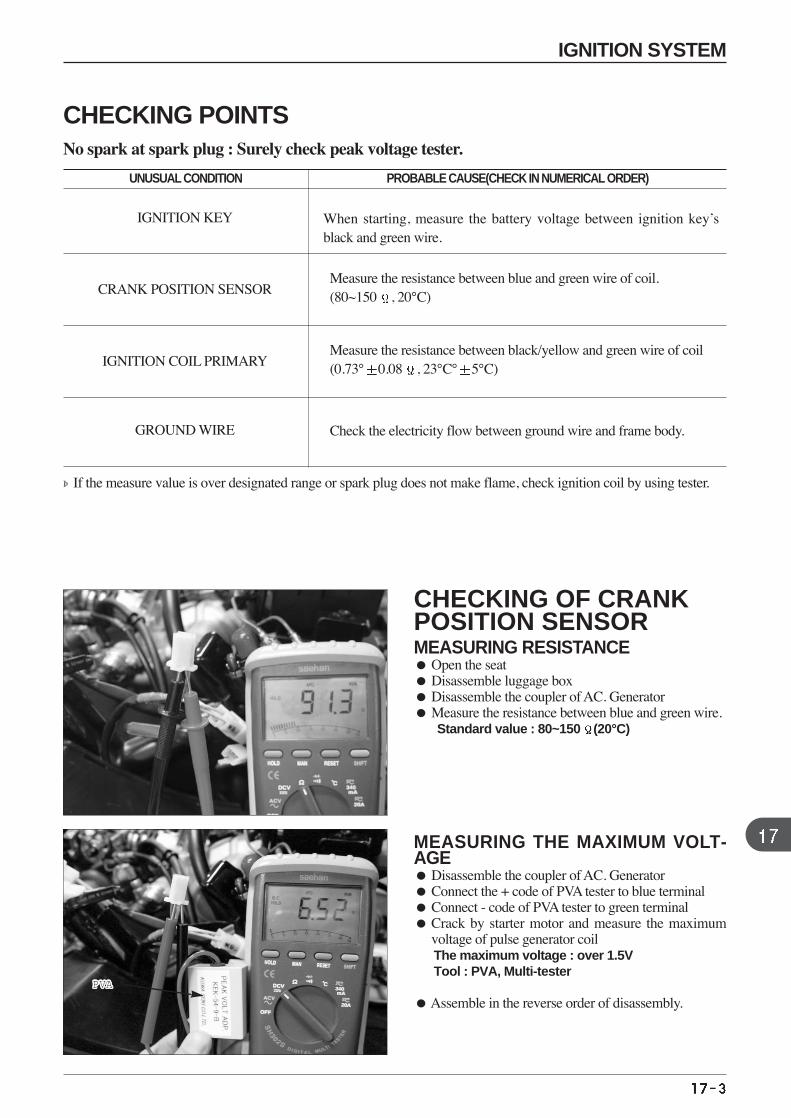
CHECKING OF CRANKPOSITION SENSOR MEASURING RESISTANCE Open the seat Disassemble luggage box Disassemble the coupler of AC. Generator Measure the resistance between blue and green wire.
Standard value : 80~150 (20°C)
MEASURING THE MAXIMUM VOLT-AGE Disassemble the coupler of AC. Generator Connect the + code of PVA tester to blue terminal Connect - code of PVA tester to green terminal Crack by starter motor and measure the maximum
voltage of pulse generator coil The maximum voltage : over 1.5VTool : PVA, Multi-tester
Assemble in the reverse order of disassembly.
If the measure value is over designated range or spark plug does not make flame, check ignition coil by using tester.
UNUSUAL CONDITION PROBABLE CAUSE(CHECK IN NUMERICAL ORDER)
When starting, measure the battery voltage between ignition key’sblack and green wire.
IGNITION KEY
Measure the resistance between blue and green wire of coil.(80~150 , 20°C)CRANK POSITION SENSOR
Measure the resistance between black/yellow and green wire of coil(0.73° 0.08 , 23°C° 5°C)IGNITION COIL PRIMARY
Check the electricity flow between ground wire and frame body.GROUND WIRE
PVAPVAPVAPVAPVAPVAPVAPVAPVAPVAPVAPVAPVAPVAPVAPVAPVAPVAPVAPVAPVAPVA
IGNITION SYSTEM
CHECKING POINTSNo spark at spark plug : Surely check peak voltage tester.
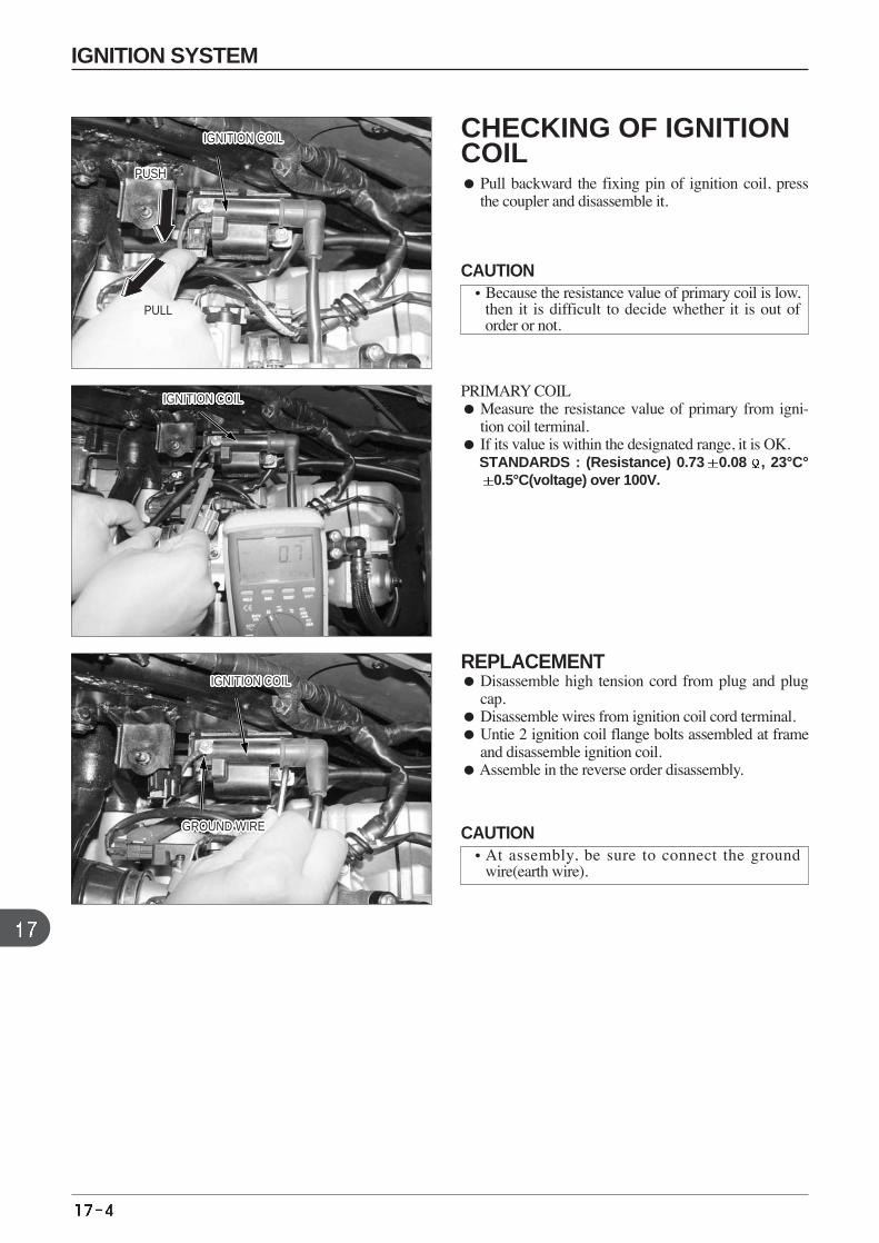
CHECKING OF IGNITIONCOIL Pull backward the fixing pin of ignition coil, press
the coupler and disassemble it.
PRIMARY COIL Measure the resistance value of primary from igni-
tion coil terminal. If its value is within the designated range, it is OK.
STANDARDS : (Resistance) 0.73 0.08 , 23°C°0.5°C(voltage) over 100V.
REPLACEMENT Disassemble high tension cord from plug and plug
cap. Disassemble wires from ignition coil cord terminal. Untie 2 ignition coil flange bolts assembled at frame
and disassemble ignition coil. Assemble in the reverse order disassembly.
PUSHPUSHPUSHPUSHPUSHPUSHPUSHPUSHPUSHPUSHPUSHPUSHPUSHPUSHPUSHPUSHPUSHPUSHPUSHPUSHPUSHPUSHPUSHPUSHPUSHPUSHPUSH
PULL
IGNITION COILIGNITION COILIGNITION COILIGNITION COILIGNITION COILIGNITION COILIGNITION COILIGNITION COILIGNITION COILIGNITION COILIGNITION COILIGNITION COILIGNITION COILIGNITION COILIGNITION COILIGNITION COILIGNITION COILIGNITION COILIGNITION COILIGNITION COILIGNITION COILIGNITION COILIGNITION COILIGNITION COILIGNITION COILIGNITION COILIGNITION COIL
IGNITION COILIGNITION COILIGNITION COILIGNITION COILIGNITION COILIGNITION COILIGNITION COILIGNITION COILIGNITION COILIGNITION COILIGNITION COILIGNITION COILIGNITION COILIGNITION COILIGNITION COILIGNITION COILIGNITION COILIGNITION COILIGNITION COILIGNITION COILIGNITION COILIGNITION COILIGNITION COILIGNITION COILIGNITION COILIGNITION COILIGNITION COIL
GROUND WIREGROUND WIREGROUND WIREGROUND WIREGROUND WIREGROUND WIREGROUND WIREGROUND WIREGROUND WIREGROUND WIREGROUND WIREGROUND WIREGROUND WIREGROUND WIREGROUND WIREGROUND WIREGROUND WIREGROUND WIREGROUND WIREGROUND WIREGROUND WIREGROUND WIREGROUND WIREGROUND WIREGROUND WIREGROUND WIREGROUND WIRE
IGNITION COILIGNITION COILIGNITION COILIGNITION COILIGNITION COILIGNITION COILIGNITION COILIGNITION COILIGNITION COILIGNITION COILIGNITION COILIGNITION COILIGNITION COILIGNITION COILIGNITION COILIGNITION COILIGNITION COILIGNITION COILIGNITION COILIGNITION COILIGNITION COILIGNITION COILIGNITION COILIGNITION COILIGNITION COILIGNITION COILIGNITION COIL
CAUTION•Because the resistance value of primary coil is low,
then it is difficult to decide whether it is out oforder or not.
CAUTION•At assembly, be sure to connect the ground
wire(earth wire).
IGNITION SYSTEM

MEMO
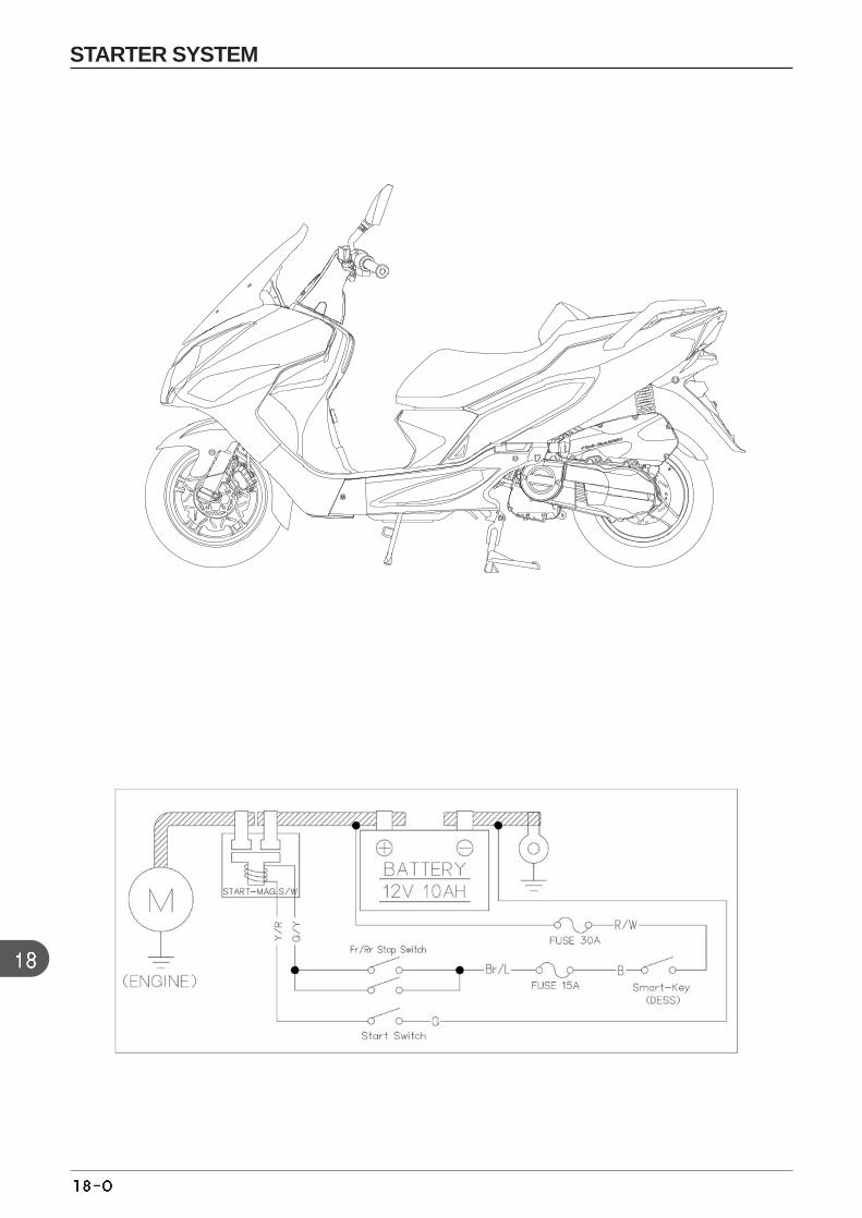
STARTER SYSTEM
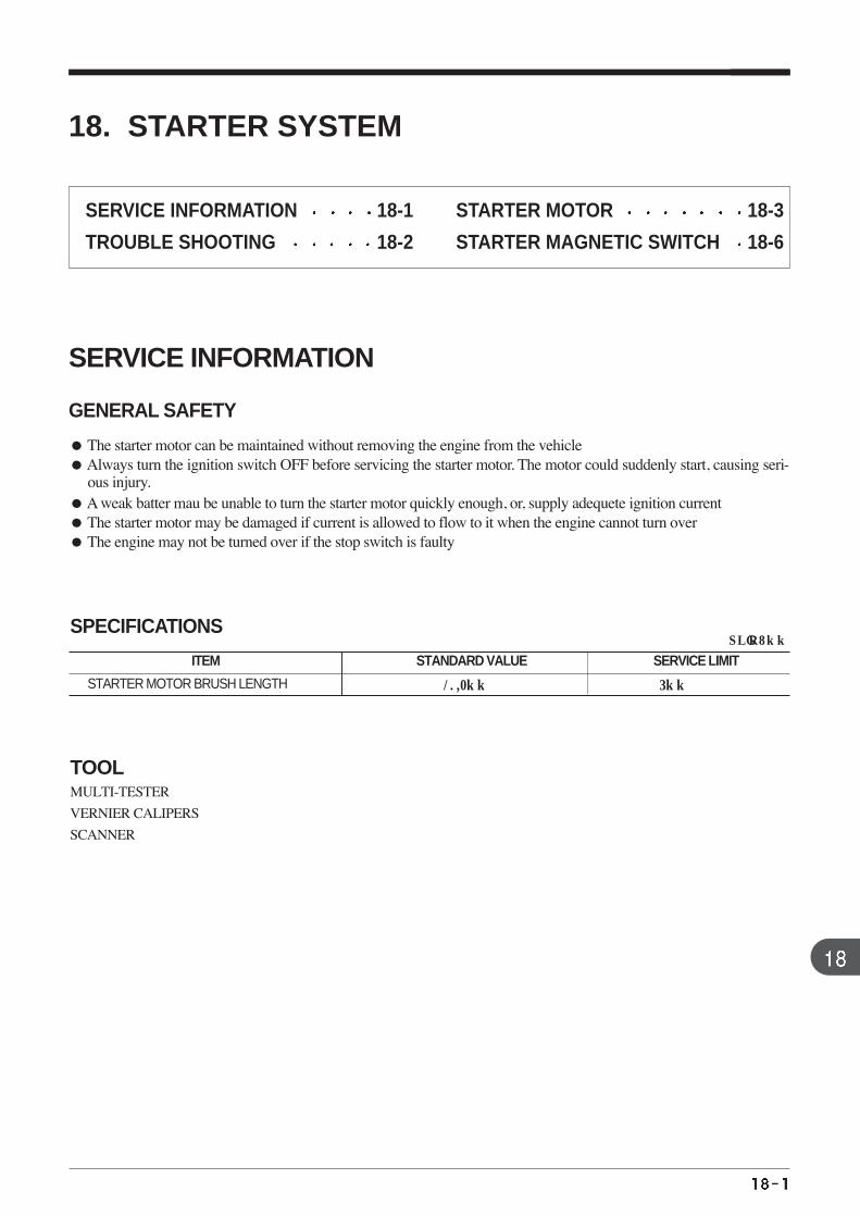
MULTI-TESTER
VERNIER CALIPERS
SCANNER
SPECIFICATIONS
TOOL
18. STARTER SYSTEM
SERVICE INFORMATION
GENERAL SAFETY
The starter motor can be maintained without removing the engine from the vehicle Always turn the ignition switch OFF before servicing the starter motor. The motor could suddenly start, causing seri-
ous injury.A weak batter mau be unable to turn the starter motor quickly enough, or, supply adequete ignition current The starter motor may be damaged if current is allowed to flow to it when the engine cannot turn overThe engine may not be turned over if the stop switch is faulty
SERVICE INFORMATION 18-1
TROUBLE SHOOTING 18-2
STARTER MOTOR 18-3
STARTER MAGNETIC SWITCH 18-6
STARTER MOTOR BRUSH LENGTH
ITEM STANDARD VALUE SERVICE LIMIT
10.2mm 5mm
UNIT : mm
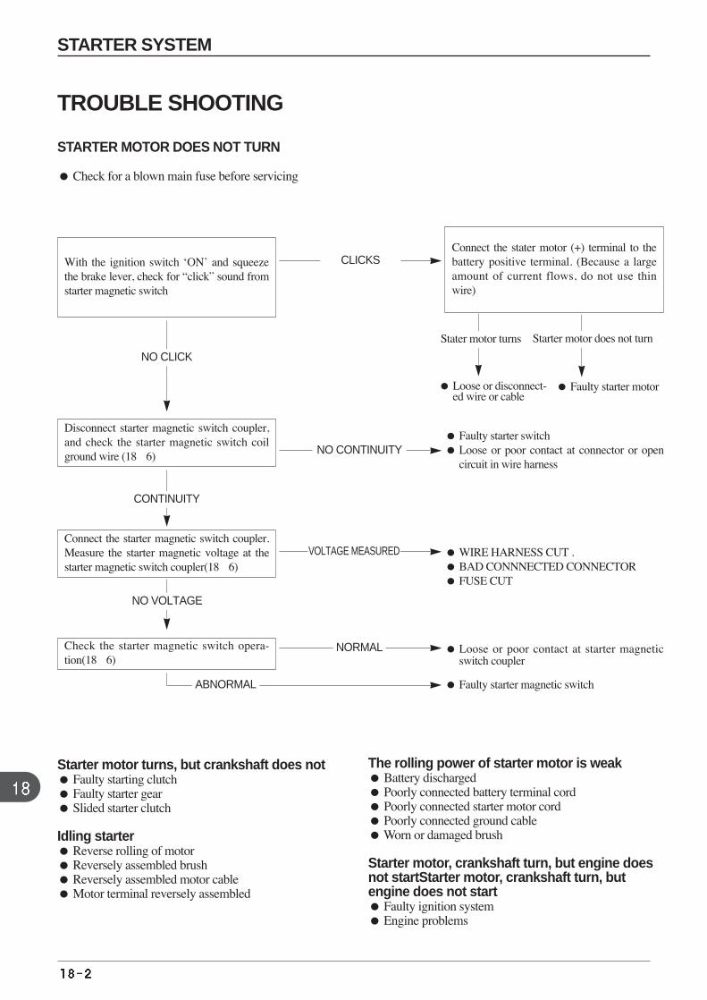
TROUBLE SHOOTING
STARTER MOTOR DOES NOT TURN
Check for a blown main fuse before servicing
With the ignition switch ‘ON’ and squeezethe brake lever, check for “click” sound fromstarter magnetic switch
Connect the stater motor (+) terminal to thebattery positive terminal. (Because a largeamount of current flows, do not use thinwire)
Faulty starter motor Loose or disconnect-ed wire or cable
Faulty starter switch Loose or poor contact at connector or open
circuit in wire harness
WIRE HARNESS CUT . BAD CONNNECTED CONNECTOR FUSE CUT
Loose or poor contact at starter magneticswitch coupler
Faulty starter magnetic switch
Disconnect starter magnetic switch coupler,and check the starter magnetic switch coilground wire (186)
Connect the starter magnetic switch coupler.Measure the starter magnetic voltage at thestarter magnetic switch coupler(186)
Check the starter magnetic switch opera-tion(186)
CLICKS
NO CLICK
Starter motor does not turnStater motor turns
CONTINUITY
NO VOLTAGE
NO CONTINUITY
VOLTAGE MEASURED
NORMAL
ABNORMAL
Starter motor turns, but crankshaft does not Faulty starting clutch Faulty starter gear Slided starter clutch
Idling starter Reverse rolling of motor Reversely assembled brush Reversely assembled motor cable Motor terminal reversely assembled
The rolling power of starter motor is weak Battery discharged Poorly connected battery terminal cord Poorly connected starter motor cord Poorly connected ground cable Worn or damaged brush
Starter motor, crankshaft turn, but engine doesnot startStarter motor, crankshaft turn, butengine does not start Faulty ignition system Engine problems
STARTER SYSTEM
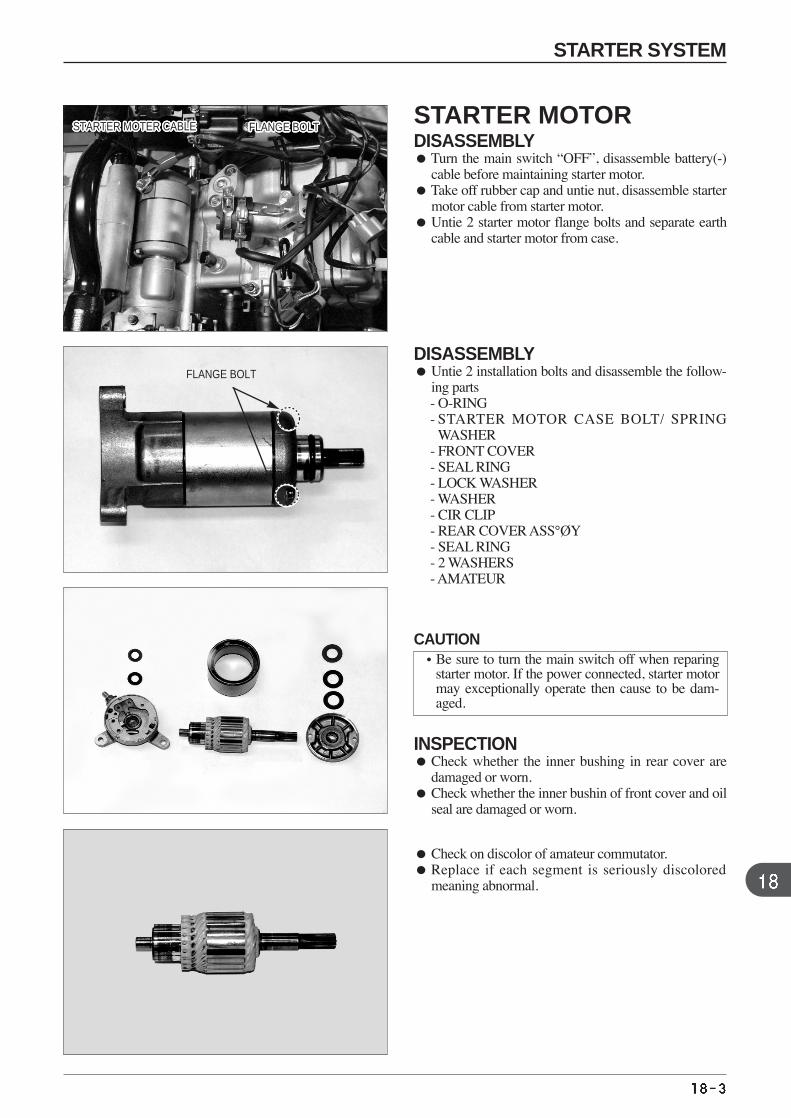
STARTER MOTOR DISASSEMBLYTurn the main switch “OFF”, disassemble battery(-)
cable before maintaining starter motor. Take off rubber cap and untie nut, disassemble starter
motor cable from starter motor. Untie 2 starter motor flange bolts and separate earth
cable and starter motor from case.
DISASSEMBLY Untie 2 installation bolts and disassemble the follow-
ing parts - O-RING - STARTER MOTOR CASE BOLT/ SPRING
WASHER - FRONT COVER - SEAL RING - LOCK WASHER - WASHER - CIR CLIP- REAR COVER ASS°ØY- SEAL RING - 2 WASHERS - AMATEUR
INSPECTION Check whether the inner bushing in rear cover are
damaged or worn. Check whether the inner bushin of front cover and oil
seal are damaged or worn.
FLANGE BOLT
FLANGE BOLTFLANGE BOLTFLANGE BOLTFLANGE BOLTFLANGE BOLTFLANGE BOLTFLANGE BOLTFLANGE BOLTFLANGE BOLTFLANGE BOLTFLANGE BOLTFLANGE BOLTFLANGE BOLTFLANGE BOLTFLANGE BOLTFLANGE BOLTFLANGE BOLTFLANGE BOLTFLANGE BOLTFLANGE BOLTFLANGE BOLTFLANGE BOLTFLANGE BOLTFLANGE BOLTFLANGE BOLTFLANGE BOLTFLANGE BOLTSTARTER MOTER CABLESTARTER MOTER CABLESTARTER MOTER CABLESTARTER MOTER CABLESTARTER MOTER CABLESTARTER MOTER CABLESTARTER MOTER CABLESTARTER MOTER CABLESTARTER MOTER CABLESTARTER MOTER CABLESTARTER MOTER CABLESTARTER MOTER CABLESTARTER MOTER CABLESTARTER MOTER CABLESTARTER MOTER CABLESTARTER MOTER CABLESTARTER MOTER CABLESTARTER MOTER CABLESTARTER MOTER CABLESTARTER MOTER CABLESTARTER MOTER CABLESTARTER MOTER CABLESTARTER MOTER CABLESTARTER MOTER CABLESTARTER MOTER CABLESTARTER MOTER CABLESTARTER MOTER CABLE
Check on discolor of amateur commutator. Replace if each segment is seriously discolored
meaning abnormal.
CAUTION•Be sure to turn the main switch off when reparing
starter motor. If the power connected, starter motormay exceptionally operate then cause to be dam-aged.
STARTER SYSTEM
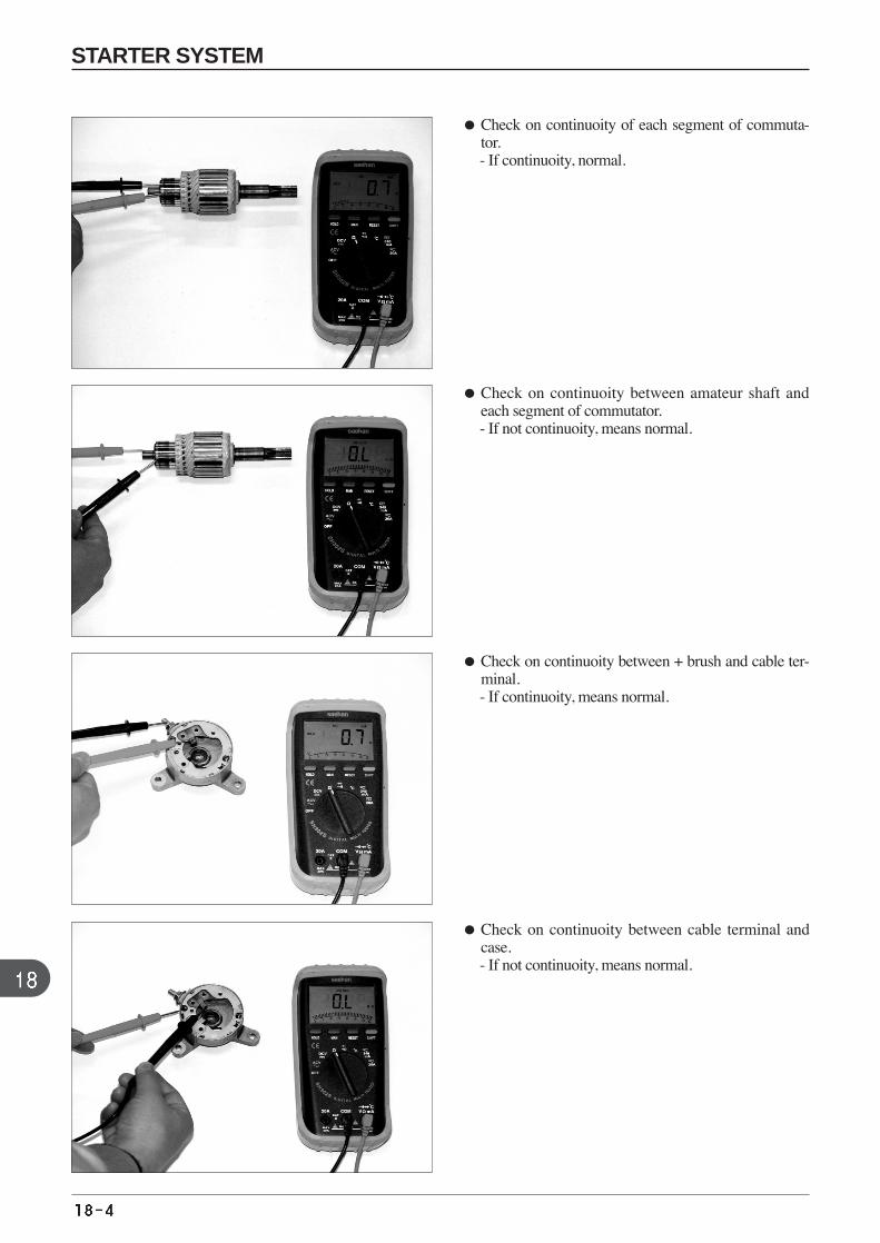
Check on continuoity of each segment of commuta-tor. - If continuoity, normal.
Check on continuoity between amateur shaft andeach segment of commutator. - If not continuoity, means normal.
Check on continuoity between + brush and cable ter-minal. - If continuoity, means normal.
Check on continuoity between cable terminal andcase. - If not continuoity, means normal.
STARTER SYSTEM
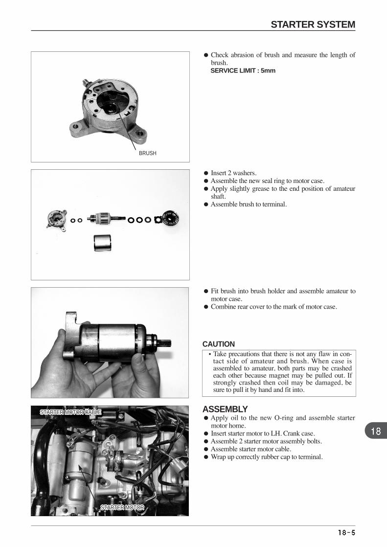
Check abrasion of brush and measure the length ofbrush. SERVICE LIMIT : 5mm
Insert 2 washers. Assemble the new seal ring to motor case. Apply slightly grease to the end position of amateur
shaft. Assemble brush to terminal.
Fit brush into brush holder and assemble amateur tomotor case.
Combine rear cover to the mark of motor case.
BRUSH
STARTER MOTOR CABLESTARTER MOTOR CABLESTARTER MOTOR CABLESTARTER MOTOR CABLESTARTER MOTOR CABLESTARTER MOTOR CABLESTARTER MOTOR CABLESTARTER MOTOR CABLESTARTER MOTOR CABLESTARTER MOTOR CABLESTARTER MOTOR CABLESTARTER MOTOR CABLESTARTER MOTOR CABLESTARTER MOTOR CABLESTARTER MOTOR CABLESTARTER MOTOR CABLESTARTER MOTOR CABLESTARTER MOTOR CABLESTARTER MOTOR CABLESTARTER MOTOR CABLESTARTER MOTOR CABLESTARTER MOTOR CABLESTARTER MOTOR CABLESTARTER MOTOR CABLESTARTER MOTOR CABLESTARTER MOTOR CABLESTARTER MOTOR CABLE
STARTER MOTORSTARTER MOTORSTARTER MOTORSTARTER MOTORSTARTER MOTORSTARTER MOTORSTARTER MOTORSTARTER MOTORSTARTER MOTORSTARTER MOTORSTARTER MOTORSTARTER MOTORSTARTER MOTORSTARTER MOTORSTARTER MOTORSTARTER MOTORSTARTER MOTORSTARTER MOTORSTARTER MOTORSTARTER MOTORSTARTER MOTORSTARTER MOTORSTARTER MOTORSTARTER MOTORSTARTER MOTORSTARTER MOTORSTARTER MOTOR
ASSEMBLYApply oil to the new O-ring and assemble starter
motor home. Insert starter motor to LH. Crank case. Assemble 2 starter motor assembly bolts. Assemble starter motor cable. Wrap up correctly rubber cap to terminal.
CAUTION•Take precautions that there is not any flaw in con-
tact side of amateur and brush. When case isassembled to amateur, both parts may be crashedeach other because magnet may be pulled out. Ifstrongly crashed then coil may be damaged, besure to pull it by hand and fit into.
STARTER SYSTEM
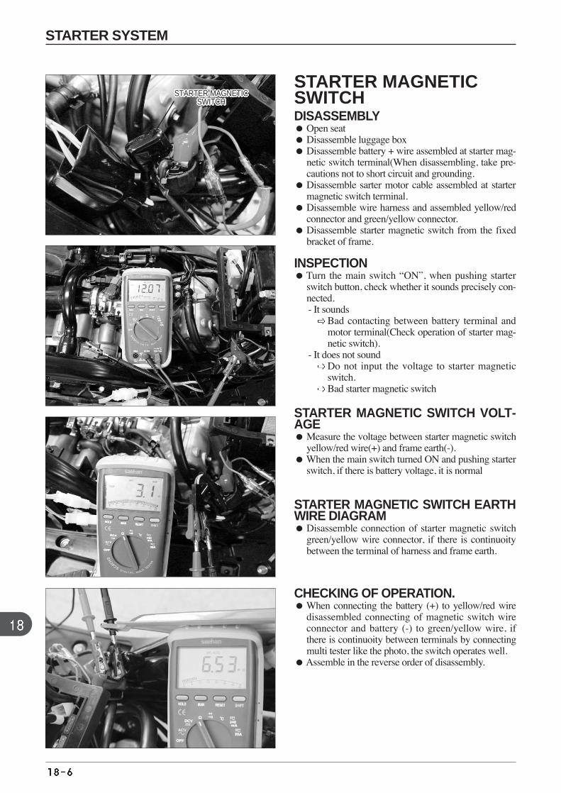
STARTER MAGNETICSWITCH DISASSEMBLY Open seat Disassemble luggage box Disassemble battery + wire assembled at starter mag-
netic switch terminal(When disassembling, take pre-cautions not to short circuit and grounding.
Disassemble sarter motor cable assembled at startermagnetic switch terminal.
Disassemble wire harness and assembled yellow/redconnector and green/yellow connector.
Disassemble starter magnetic switch from the fixedbracket of frame.
INSPECTION Turn the main switch “ON”, when pushing starter
switch button, check whether it sounds precisely con-nected. - It sounds
Bad contacting between battery terminal andmotor terminal(Check operation of starter mag-netic switch).
- It does not sound Do not input the voltage to starter magneticswitch. Bad starter magnetic switch
STARTER MAGNETIC SWITCH VOLT-AGE Measure the voltage between starter magnetic switch
yellow/red wire(+) and frame earth(-).When the main switch turned ON and pushing starter
switch, if there is battery voltage, it is normal
STARTER MAGNETIC SWITCH EARTHWIRE DIAGRAM Disassemble connection of starter magnetic switch
green/yellow wire connector, if there is continuoitybetween the terminal of harness and frame earth.
CHECKING OF OPERATION. When connecting the battery (+) to yellow/red wire
disassembled connecting of magnetic switch wireconnector and battery (-) to green/yellow wire, ifthere is continuoity between terminals by connectingmulti tester like the photo, the switch operates well.
Assemble in the reverse order of disassembly.
STARTER MAGNETICSWITCH
STARTER MAGNETICSWITCH
STARTER MAGNETICSWITCH
STARTER MAGNETICSWITCH
STARTER MAGNETICSWITCH
STARTER MAGNETICSWITCH
STARTER MAGNETICSWITCH
STARTER MAGNETICSWITCH
STARTER MAGNETICSWITCH
STARTER MAGNETICSWITCH
STARTER MAGNETICSWITCH
STARTER MAGNETICSWITCH
STARTER MAGNETICSWITCH
STARTER MAGNETICSWITCH
STARTER MAGNETICSWITCH
STARTER MAGNETICSWITCH
STARTER MAGNETICSWITCH
STARTER MAGNETICSWITCH
STARTER MAGNETICSWITCH
STARTER MAGNETICSWITCH
STARTER MAGNETICSWITCH
STARTER MAGNETICSWITCH
STARTER MAGNETICSWITCH
STARTER MAGNETICSWITCH
STARTER MAGNETICSWITCH
STARTER MAGNETICSWITCH
STARTER MAGNETICSWITCH
STARTER SYSTEM

MEMO
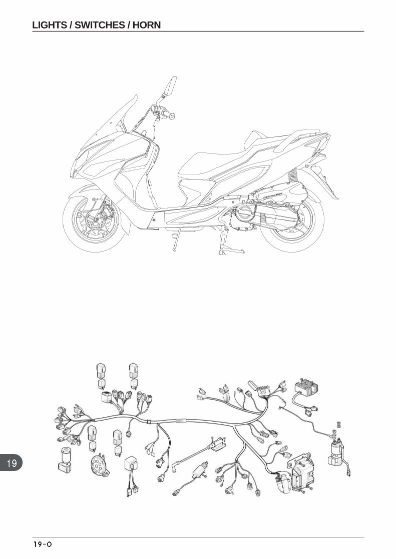
LIGHTS / SWITCHES / HORN
19. LIGHTS// SWITCHES / HORN
TROUBLE SHOOTING
Light not turned on when the main switch isON. Faulty light bulb Wire cut or faulty wires Faulty or disconnected wiring Fuse cut Battery discharged
Dim headlight Battery discharged Wiring and switch resistance high
Headlight Hi-low beam can not be charged Faulty light bulb Faulty dimmer switch
Fuel meter indicator malfunctioning Coupler separated Harness disconnected Float operation malfunction Fuel unit damaged
Fuel meter needle unstable Coupler loose Fuel unit damaged Meter damaged
SERVICE INFORMATION
GENERAL SAFETY
Connect the same color wires together. Connect couplers carrying the same color and the same number of pinstogether.
All couplers are equipped with tabs which can be locked. Remove these locks prior to disassembling ; and insertthese tabs all the way until locked when assembling
Carry out continuity test on circuits or parts to diagnose electric systems. The continuity test on normal parts can becarried out without removing the parts from the vehicle. Simply disconnect the wires and connect a continuity testeror and ohmmeter to the coupler terminal or connectors.
The continuity test is conducted to check if electric power is connected between 2 terminald. If these is coil resistancewithin circuits, or to check the large resistance resulting from the connector corrosion, an ohmmeter is required tocheck the circuit resistance value.
SERVICE INFORMATION 19-1 TROUBLE SHOOTINGS 19-1 HEAD LIGHT 19-2 FRONT WINKER 19-3 REAR COMBINATION LIGHT 19-3REAR WINKER 19-3 SPEEDOMETER 19-4
MAIN SWITCH 19-5 HANDLE BAR SWITCH 19-5 HORN SWITCH 19-6 FRONT/ REAR STOP SWITCH 19-6 SEAT SWITCH 19-7 SMART KEY SET(DESS) 19-7
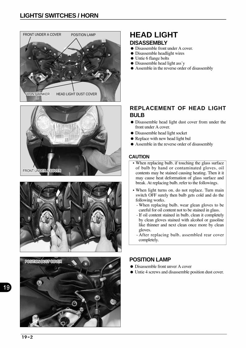
HEAD LIGHT DISASSEMBLY Disassemble front under A cover. Disassemble headlight wires Untie 6 flange bolts Disassemble head light ass’y Assemble in the reverse order of disassembly
REPLACEMENT OF HEAD LIGHTBULB Disassemble head light dust cover from under the
front under A cover. Disassemble head light socket Replace with new head light bul Assemble in the reverse order of disassembly
POSITION LAMP Disassemble front unver A cover Untie 4 screws and disassemble position dust cover.
FRONT UNDER A COVERFRONT UNDER A COVERFRONT UNDER A COVERFRONT UNDER A COVERFRONT UNDER A COVERFRONT UNDER A COVERFRONT UNDER A COVERFRONT UNDER A COVERFRONT UNDER A COVERFRONT UNDER A COVERFRONT UNDER A COVERFRONT UNDER A COVERFRONT UNDER A COVERFRONT UNDER A COVERFRONT UNDER A COVERFRONT UNDER A COVERFRONT UNDER A COVERFRONT UNDER A COVERFRONT UNDER A COVERFRONT UNDER A COVERFRONT UNDER A COVERFRONT UNDER A COVERFRONT UNDER A COVERFRONT UNDER A COVERFRONT UNDER A COVERFRONT UNDER A COVERFRONT UNDER A COVER
FRONT UNDER A COVER POSITION LAMP
FRONT WINKERFRONT WINKERFRONT WINKERFRONT WINKERFRONT WINKERFRONT WINKERFRONT WINKERFRONT WINKERFRONT WINKERFRONT WINKERFRONT WINKERFRONT WINKERFRONT WINKERFRONT WINKERFRONT WINKERFRONT WINKERFRONT WINKERFRONT WINKERFRONT WINKERFRONT WINKERFRONT WINKERFRONT WINKERFRONT WINKERFRONT WINKERFRONT WINKERFRONT WINKERFRONT WINKER HEAD LIGHT DUST COVER
POSITION DUST COVERPOSITION DUST COVERPOSITION DUST COVERPOSITION DUST COVERPOSITION DUST COVERPOSITION DUST COVERPOSITION DUST COVERPOSITION DUST COVERPOSITION DUST COVERPOSITION DUST COVERPOSITION DUST COVERPOSITION DUST COVERPOSITION DUST COVERPOSITION DUST COVERPOSITION DUST COVERPOSITION DUST COVERPOSITION DUST COVERPOSITION DUST COVERPOSITION DUST COVERPOSITION DUST COVERPOSITION DUST COVERPOSITION DUST COVERPOSITION DUST COVERPOSITION DUST COVERPOSITION DUST COVERPOSITION DUST COVERPOSITION DUST COVER
LIGHTS/ SWITCHES / HORN
CAUTION•When replacing bulb, if touching the glass surface
of bulb by hand or contaminated gloves, oilcontents may be stained causing heating. Then it itmay cause heat deformation of glass surface andbreak. At replacing bulb, refer to the followings.
•When light turns on, do not replace. Turn mainswitch OFF surely then bulb gets cold and do thefollowing works. - When replacing bulb, wear glean gloves to be
careful for oil content not to be stained in glass. - If oil content stained in bulb, clean it completely
by clean gloves stained with alcohol or gasolinelike thinner and next clean once more by cleangloves.
- After replacing bulb, assembled rear covercompletely.
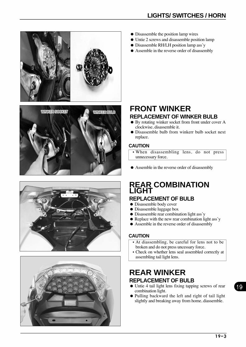
FRONT WINKER REPLACEMENT OF WINKER BULB By rotating winker socket from front under cover A
clockwise, disassemble it. Disassemble bulb from winkerr bulb socket next
replace.
Assemble in the reverse order of disassembly
REAR COMBINATIONLIGHT REPLACEMENT OF BULB Disassemble body cover Disassemble luggage box Disassemble rear combination light ass’y Replace with the new rear combination light ass’y Assemble in the reverse order of disassembly
Disassemble the position lamp wires Untie 2 screws and disassemble position lamp Disassemble RH/LH position lamp ass’y Assemble in the reverse order of disassembly
REAR WINKER REPLACEMENT OF BULB Untie 4 tail light lens fixing tapping screws of rear
combination light. Pulling backward the left and right of tail light
slightly and breaking away from home, diassemble.
WINKER SOCKETWINKER SOCKETWINKER SOCKETWINKER SOCKETWINKER SOCKETWINKER SOCKETWINKER SOCKETWINKER SOCKETWINKER SOCKETWINKER SOCKETWINKER SOCKETWINKER SOCKETWINKER SOCKETWINKER SOCKETWINKER SOCKETWINKER SOCKETWINKER SOCKETWINKER SOCKETWINKER SOCKETWINKER SOCKETWINKER SOCKETWINKER SOCKETWINKER SOCKETWINKER SOCKETWINKER SOCKETWINKER SOCKETWINKER SOCKET WINKER BULBWINKER BULBWINKER BULBWINKER BULBWINKER BULBWINKER BULBWINKER BULBWINKER BULBWINKER BULBWINKER BULBWINKER BULBWINKER BULBWINKER BULBWINKER BULBWINKER BULBWINKER BULBWINKER BULBWINKER BULBWINKER BULBWINKER BULBWINKER BULBWINKER BULBWINKER BULBWINKER BULBWINKER BULBWINKER BULBWINKER BULB
LIGHTS/ SWITCHES / HORN
CAUTION•When disassembling lens, do not press
unnecessary force.
CAUTION•At diassembling, be careful for lens not to be
broken and do not press uncessary force. •Check on whether lens seal assembled correctly at
assembling tail light lens.
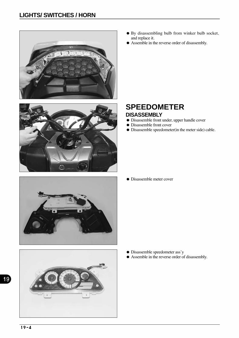
SPEEDOMETER DISASSEMBLY Disassemble front under, upper handle cover Disassemble front cover Disassemble speedometer(in the meter side) cable.
Disassemble meter cover
Disassemble speedometer ass’y Assemble in the reverse order of disassembly.
By disassembling bulb from winker bulb socket,and replace it.
Assemble in the reverse order of disassembly.
LIGHTS/ SWITCHES / HORN
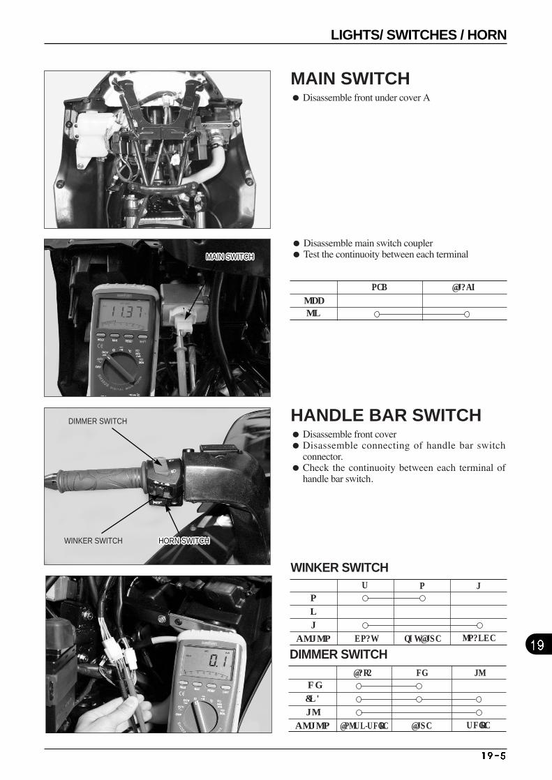
HI
(N)
LO
COLOR
DIMMER SWITCHBAT4 HI LO
BROWN/WHITE BLUE WHITE
MAIN SWITCH Disassemble front under cover A
HANDLE BAR SWITCH Disassemble front cover Disassemble connecting of handle bar switch
connector. Check the continuoity between each terminal of
handle bar switch.
OFFON
RED BLACK
R
N
L
COLOR
WINKER SWITCHW
GRAY SKY BLUE ORANGE
R L
Disassemble main switch coupler Test the continuoity between each terminal
DIMMER SWITCH
WINKER SWITCH HORN SWITCHHORN SWITCHHORN SWITCHHORN SWITCHHORN SWITCHHORN SWITCHHORN SWITCHHORN SWITCHHORN SWITCHHORN SWITCHHORN SWITCHHORN SWITCHHORN SWITCHHORN SWITCHHORN SWITCHHORN SWITCHHORN SWITCHHORN SWITCHHORN SWITCHHORN SWITCHHORN SWITCHHORN SWITCHHORN SWITCHHORN SWITCHHORN SWITCHHORN SWITCHHORN SWITCH
MAIN SWITCHMAIN SWITCHMAIN SWITCHMAIN SWITCHMAIN SWITCHMAIN SWITCHMAIN SWITCHMAIN SWITCHMAIN SWITCHMAIN SWITCHMAIN SWITCHMAIN SWITCHMAIN SWITCHMAIN SWITCHMAIN SWITCHMAIN SWITCHMAIN SWITCHMAIN SWITCHMAIN SWITCHMAIN SWITCHMAIN SWITCHMAIN SWITCHMAIN SWITCHMAIN SWITCHMAIN SWITCHMAIN SWITCHMAIN SWITCH
LIGHTS/ SWITCHES / HORN
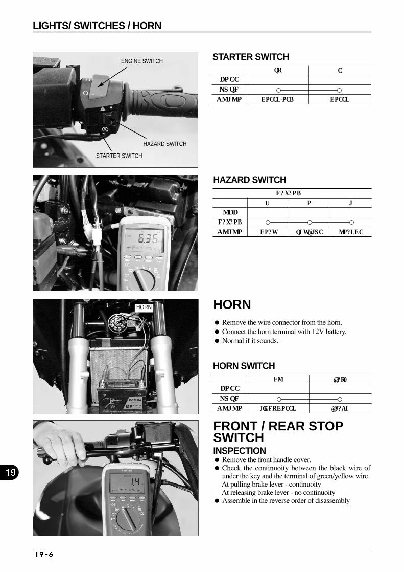
HORN Remove the wire connector from the horn. Connect the horn terminal with 12V battery. Normal if it sounds.
FREE
PUSH
COLOR
HORN SWITCHHO
LIGHT GREEN BLACK
BAT2
FRONT / REAR STOPSWITCH INSPECTION Remove the front handle cover. Check the continuoity between the black wire of
under the key and the terminal of green/yellow wire.At pulling brake lever - continuoity At releasing brake lever - no continuoity
Assemble in the reverse order of disassembly
FREE
PUSH
COLOR
STARTER SWITCHST
GREEN/RED GREEN
E
ENGINE SWITCH
OFF
HAZARD
COLOR
HAZARD SWITCHHAZARD
W R L
GRAY SKY BLUE ORANGE
STARTER SWITCH
HAZARD SWITCH
HORN
LIGHTS/ SWITCHES / HORN
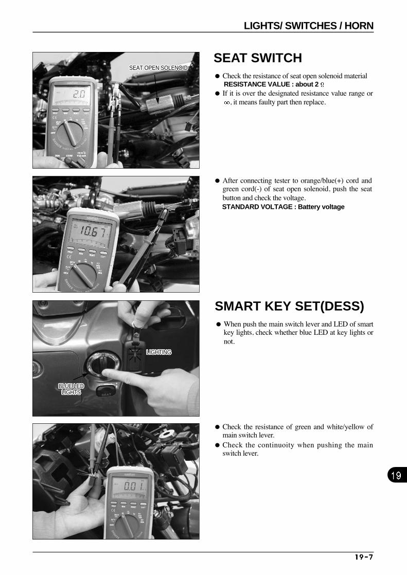
SMART KEY SET(DESS) When push the main switch lever and LED of smart
key lights, check whether blue LED at key lights ornot.
After connecting tester to orange/blue(+) cord andgreen cord(-) of seat open solenoid, push the seatbutton and check the voltage. STANDARD VOLTAGE : Battery voltage
Check the resistance of green and white/yellow ofmain switch lever.
Check the continuoity when pushing the mainswitch lever.
SEAT SWITCH Check the resistance of seat open solenoid material
RESISTANCE VALUE : about 2 If it is over the designated resistance value range or
, it means faulty part then replace.
SEAT OPEN SOLENOIDSEAT OPEN SOLENOIDSEAT OPEN SOLENOIDSEAT OPEN SOLENOIDSEAT OPEN SOLENOIDSEAT OPEN SOLENOIDSEAT OPEN SOLENOIDSEAT OPEN SOLENOIDSEAT OPEN SOLENOIDSEAT OPEN SOLENOIDSEAT OPEN SOLENOIDSEAT OPEN SOLENOIDSEAT OPEN SOLENOIDSEAT OPEN SOLENOIDSEAT OPEN SOLENOIDSEAT OPEN SOLENOIDSEAT OPEN SOLENOIDSEAT OPEN SOLENOIDSEAT OPEN SOLENOIDSEAT OPEN SOLENOIDSEAT OPEN SOLENOIDSEAT OPEN SOLENOIDSEAT OPEN SOLENOIDSEAT OPEN SOLENOIDSEAT OPEN SOLENOIDSEAT OPEN SOLENOIDSEAT OPEN SOLENOID
LIGHTINGLIGHTINGLIGHTINGLIGHTINGLIGHTINGLIGHTINGLIGHTINGLIGHTINGLIGHTINGLIGHTINGLIGHTINGLIGHTINGLIGHTINGLIGHTINGLIGHTINGLIGHTINGLIGHTINGLIGHTINGLIGHTINGLIGHTINGLIGHTINGLIGHTINGLIGHTINGLIGHTINGLIGHTINGLIGHTINGLIGHTING
BLUE LEDLIGHTS
BLUE LEDLIGHTS
BLUE LEDLIGHTS
BLUE LEDLIGHTS
BLUE LEDLIGHTS
BLUE LEDLIGHTS
BLUE LEDLIGHTS
BLUE LEDLIGHTS
BLUE LEDLIGHTS
BLUE LEDLIGHTS
BLUE LEDLIGHTS
BLUE LEDLIGHTS
BLUE LEDLIGHTS
BLUE LEDLIGHTS
BLUE LEDLIGHTS
BLUE LEDLIGHTS
BLUE LEDLIGHTS
BLUE LEDLIGHTS
BLUE LEDLIGHTS
BLUE LEDLIGHTS
BLUE LEDLIGHTS
BLUE LEDLIGHTS
BLUE LEDLIGHTS
BLUE LEDLIGHTS
BLUE LEDLIGHTS
BLUE LEDLIGHTS
BLUE LEDLIGHTS
LIGHTS/ SWITCHES / HORN
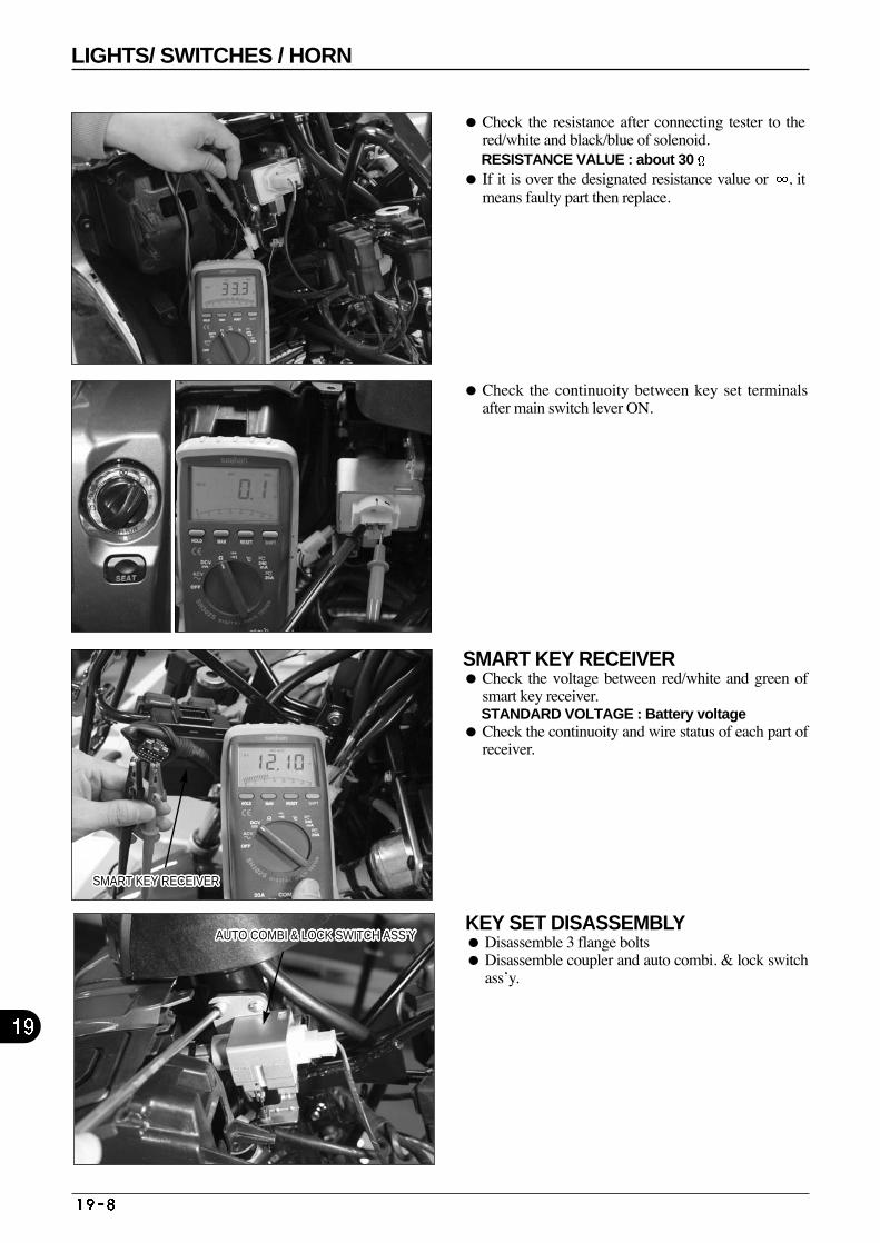
Check the resistance after connecting tester to thered/white and black/blue of solenoid. RESISTANCE VALUE : about 30
If it is over the designated resistance value or , itmeans faulty part then replace.
Check the continuoity between key set terminalsafter main switch lever ON.
SMART KEY RECEIVER Check the voltage between red/white and green of
smart key receiver. STANDARD VOLTAGE : Battery voltage
Check the continuoity and wire status of each part ofreceiver.
SMART KEY RECEIVERSMART KEY RECEIVERSMART KEY RECEIVERSMART KEY RECEIVERSMART KEY RECEIVERSMART KEY RECEIVERSMART KEY RECEIVERSMART KEY RECEIVERSMART KEY RECEIVERSMART KEY RECEIVERSMART KEY RECEIVERSMART KEY RECEIVERSMART KEY RECEIVERSMART KEY RECEIVERSMART KEY RECEIVERSMART KEY RECEIVERSMART KEY RECEIVERSMART KEY RECEIVERSMART KEY RECEIVERSMART KEY RECEIVERSMART KEY RECEIVERSMART KEY RECEIVERSMART KEY RECEIVERSMART KEY RECEIVERSMART KEY RECEIVERSMART KEY RECEIVERSMART KEY RECEIVER
AUTO COMBI & LOCK SWITCH ASS’YAUTO COMBI & LOCK SWITCH ASS’YAUTO COMBI & LOCK SWITCH ASS’YAUTO COMBI & LOCK SWITCH ASS’YAUTO COMBI & LOCK SWITCH ASS’YAUTO COMBI & LOCK SWITCH ASS’YAUTO COMBI & LOCK SWITCH ASS’YAUTO COMBI & LOCK SWITCH ASS’YAUTO COMBI & LOCK SWITCH ASS’YAUTO COMBI & LOCK SWITCH ASS’YAUTO COMBI & LOCK SWITCH ASS’YAUTO COMBI & LOCK SWITCH ASS’YAUTO COMBI & LOCK SWITCH ASS’YAUTO COMBI & LOCK SWITCH ASS’YAUTO COMBI & LOCK SWITCH ASS’YAUTO COMBI & LOCK SWITCH ASS’YAUTO COMBI & LOCK SWITCH ASS’YAUTO COMBI & LOCK SWITCH ASS’YAUTO COMBI & LOCK SWITCH ASS’YAUTO COMBI & LOCK SWITCH ASS’YAUTO COMBI & LOCK SWITCH ASS’YAUTO COMBI & LOCK SWITCH ASS’YAUTO COMBI & LOCK SWITCH ASS’YAUTO COMBI & LOCK SWITCH ASS’YAUTO COMBI & LOCK SWITCH ASS’YAUTO COMBI & LOCK SWITCH ASS’YAUTO COMBI & LOCK SWITCH ASS’YKEY SET DISASSEMBLY Disassemble 3 flange bolts Disassemble coupler and auto combi. & lock switch
ass’y.
LIGHTS/ SWITCHES / HORN
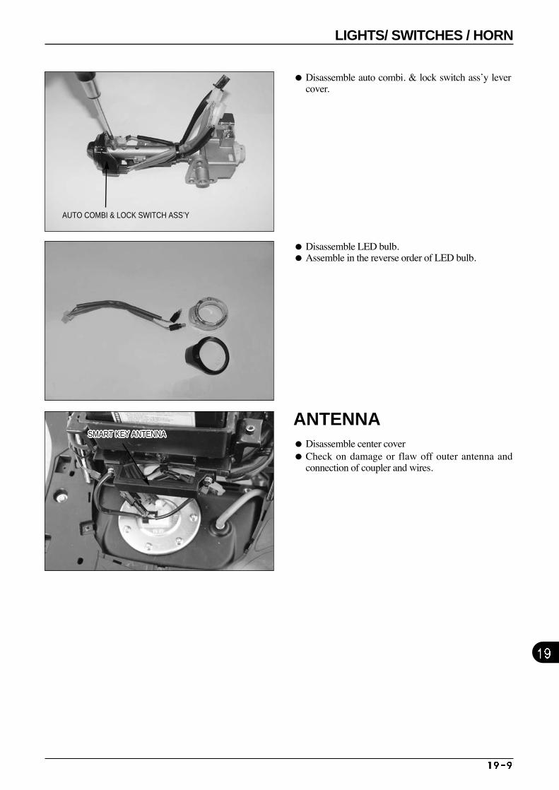
AUTO COMBI & LOCK SWITCH ASS’Y
SMART KEY ANTENNASMART KEY ANTENNASMART KEY ANTENNASMART KEY ANTENNASMART KEY ANTENNASMART KEY ANTENNASMART KEY ANTENNASMART KEY ANTENNASMART KEY ANTENNASMART KEY ANTENNASMART KEY ANTENNASMART KEY ANTENNASMART KEY ANTENNASMART KEY ANTENNASMART KEY ANTENNASMART KEY ANTENNASMART KEY ANTENNASMART KEY ANTENNASMART KEY ANTENNASMART KEY ANTENNASMART KEY ANTENNASMART KEY ANTENNASMART KEY ANTENNASMART KEY ANTENNASMART KEY ANTENNASMART KEY ANTENNASMART KEY ANTENNA
Disassemble auto combi. & lock switch ass’y levercover.
Disassemble LED bulb. Assemble in the reverse order of LED bulb.
ANTENNA Disassemble center cover Check on damage or flaw off outer antenna and
connection of coupler and wires.
LIGHTS/ SWITCHES / HORN

M E M O
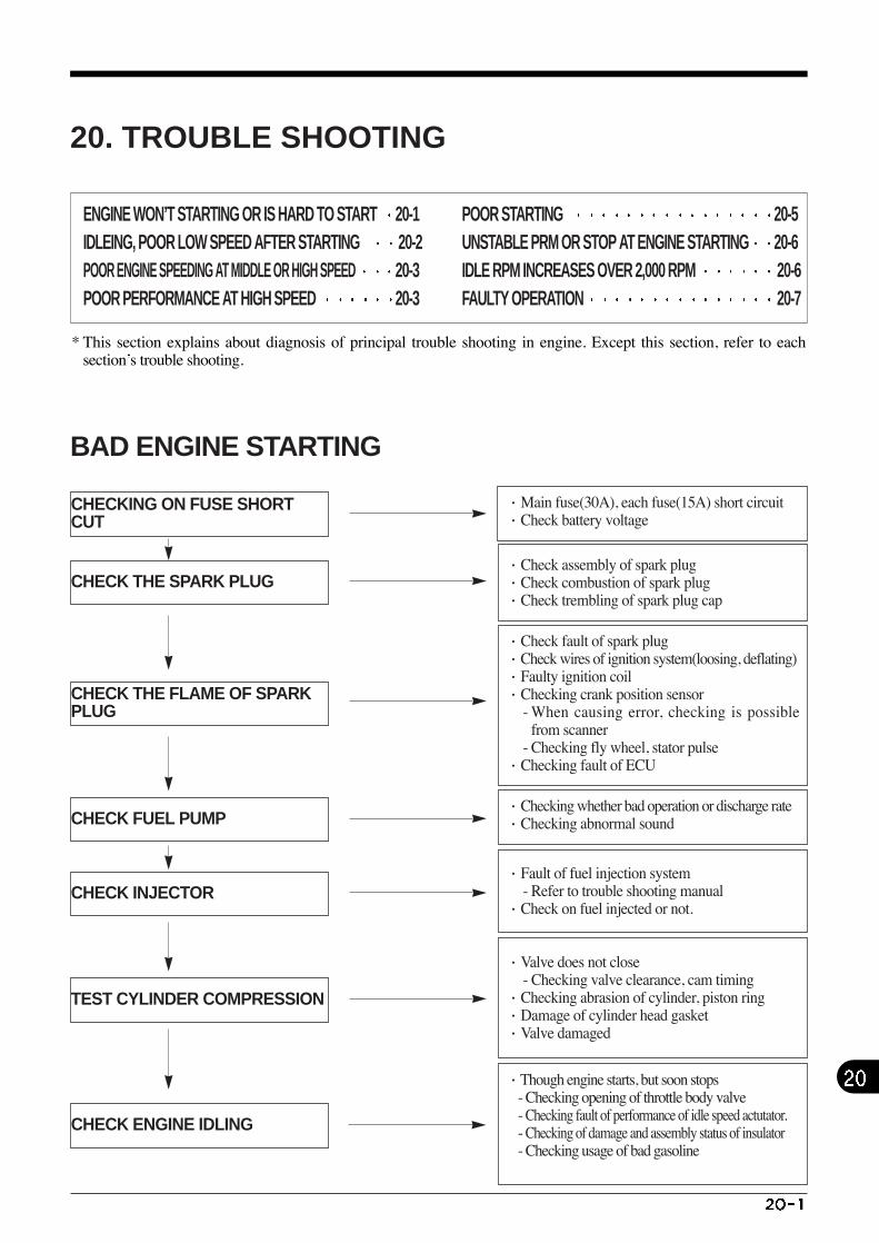
* This section explains about diagnosis of principal trouble shooting in engine. Except this section, refer to eachsection’s trouble shooting.
·Main fuse(30A), each fuse(15A) short circuit ·Check battery voltage
CHECKING ON FUSE SHORTCUT
CHECK THE SPARK PLUG
CHECK THE FLAME OF SPARKPLUG
CHECK FUEL PUMP
TEST CYLINDER COMPRESSION
CHECK INJECTOR
CHECK ENGINE IDLING
·Check assembly of spark plug ·Check combustion of spark plug·Check trembling of spark plug cap
·Check fault of spark plug·Check wires of ignition system(loosing, deflating)·Faulty ignition coil ·Checking crank position sensor
- When causing error, checking is possiblefrom scanner
- Checking fly wheel, stator pulse·Checking fault of ECU
·Checking whether bad operation or discharge rate·Checking abnormal sound
·Though engine starts, but soon stops - Checking opening of throttle body valve - Checking fault of performance of idle speed actutator.- Checking of damage and assembly status of insulator- Checking usage of bad gasoline
·Fault of fuel injection system - Refer to trouble shooting manual
·Check on fuel injected or not.
·Valve does not close - Checking valve clearance, cam timing
·Checking abrasion of cylinder, piston ring ·Damage of cylinder head gasket ·Valve damaged
20. TROUBLE SHOOTING
BAD ENGINE STARTING
ENGINE WON’T STARTING OR IS HARD TO START 20-1 IDLEING, POOR LOW SPEED AFTER STARTING 20-2 POOR ENGINE SPEEDING AT MIDDLE OR HIGH SPEED 20-3 POOR PERFORMANCE AT HIGH SPEED 20-3
POOR STARTING 20-5UNSTABLE PRM OR STOP AT ENGINE STARTING 20-6 IDLE RPM INCREASES OVER 2,000 RPM 20-6 FAULTY OPERATION 20-7
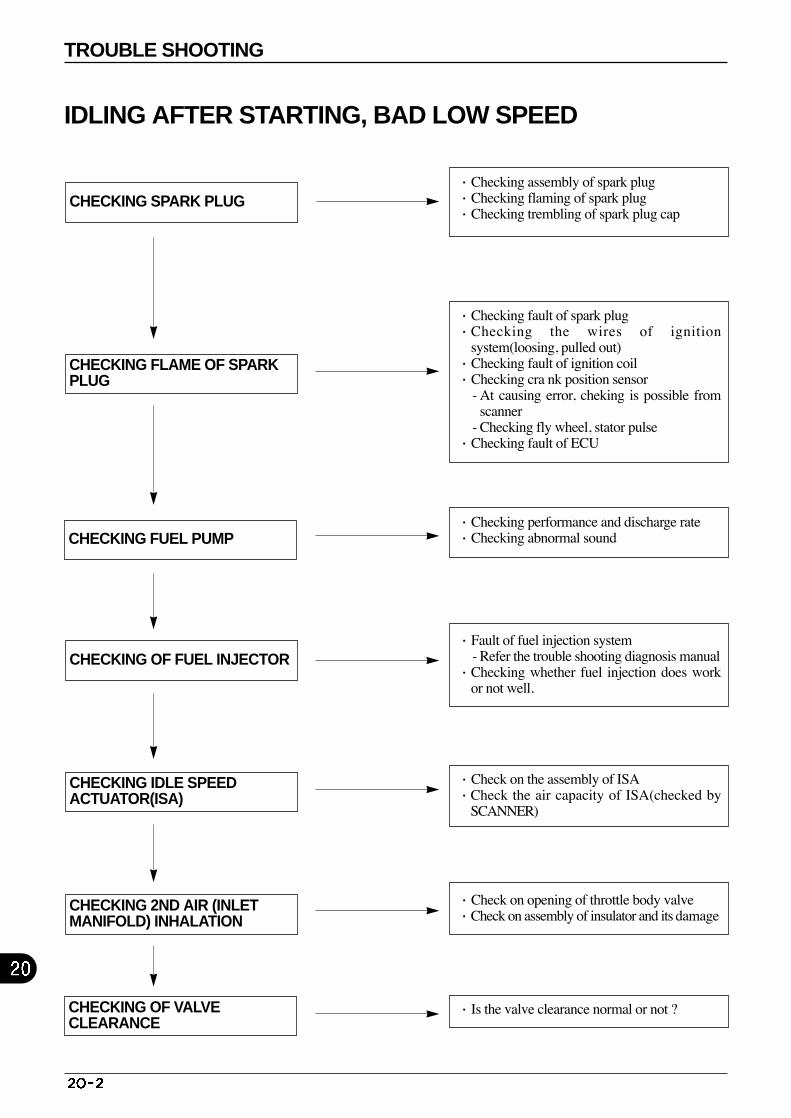
·Check on the assembly of ISA·Check the air capacity of ISA(checked by
SCANNER)
CHECKING SPARK PLUG
CHECKING FLAME OF SPARKPLUG
CHECKING FUEL PUMP
CHECKING OF FUEL INJECTOR
CHECKING 2ND AIR (INLETMANIFOLD) INHALATION
CHECKING IDLE SPEED ACTUATOR(ISA)
CHECKING OF VALVE CLEARANCE
·Checking assembly of spark plug ·Checking flaming of spark plug·Checking trembling of spark plug cap
·Checking fault of spark plug·Checking the wires of ignition
system(loosing, pulled out) ·Checking fault of ignition coil·Checking cra nk position sensor
- At causing error, cheking is possible fromscanner
- Checking fly wheel, stator pulse ·Checking fault of ECU
·Checking performance and discharge rate·Checking abnormal sound
·Is the valve clearance normal or not ?
·Fault of fuel injection system- Refer the trouble shooting diagnosis manual
·Checking whether fuel injection does workor not well.
·Check on opening of throttle body valve·Check on assembly of insulator and its damage
IDLING AFTER STARTING, BAD LOW SPEED
TROUBLE SHOOTING
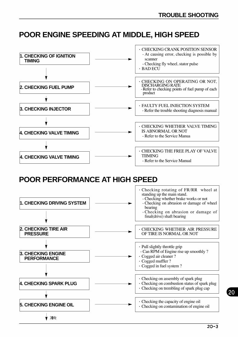
·CHECKING THE FREE PLAY OF VALVETIIMING - Refer to the Service Manual
1. CHECKING OF IGNITIONTIMING
2. CHECKING FUEL PUMP
3. CHECKING INJECTOR
4. CHECKING VALVE TIMING
4. CHECKING VALVE TIMING
·CHECKING CRANK POSITION SENSOR - At causing error, checking is possible by
scanner - Checking fly wheel, stator pulse
·BAD ECU
·CHECKING WHETHER VALVE TIMINGIS ABNORMAL OR NOT- Refer to the Service Manua
·FAULTY FUEL INJECTION SYSTEM - Refer the trouble shooting diagnosis manual
·CHECKING ON OPERATING OR NOT,DISCHARGING RATE- Refer to checking points of fuel pump of eachproduct
·Checking the capacity of engine oil·Checking on contamination of engine oil
1. CHECKING DRIVING SYSTEM
2. CHECKING TIRE AIRPRESSURE
3. CHECKING ENGINEPERFORMANCE
4. CHECKING SPARK PLUG
5. CHECKING ENGINE OIL
·Checking rotating of FR/RR wheel atstanding up the main stand.- Checking whether brake works or not - Checking on abrasion or damage of wheel
bearing - Checking on abrasion or damage of
final(drive) shaft bearing
·CHECKING WHETHER AIR PRESSUREOF TIRE IS NORMAL OR NOT
·Checking on assembly of spark plug ·Checking on combustion status of spark plug·Checking on trembling of spark plug cap
·Pull slightly throttle grip - Can RPM of Engine rise up smoothly ?
·Cogged air cleaner ?·Cogged muffler ? ·Cogged in fuel system ?
POOR ENGINE SPEEDING AT MIDDLE, HIGH SPEED
POOR PERFORMANCE AT HIGH SPEED
TROUBLE SHOOTING
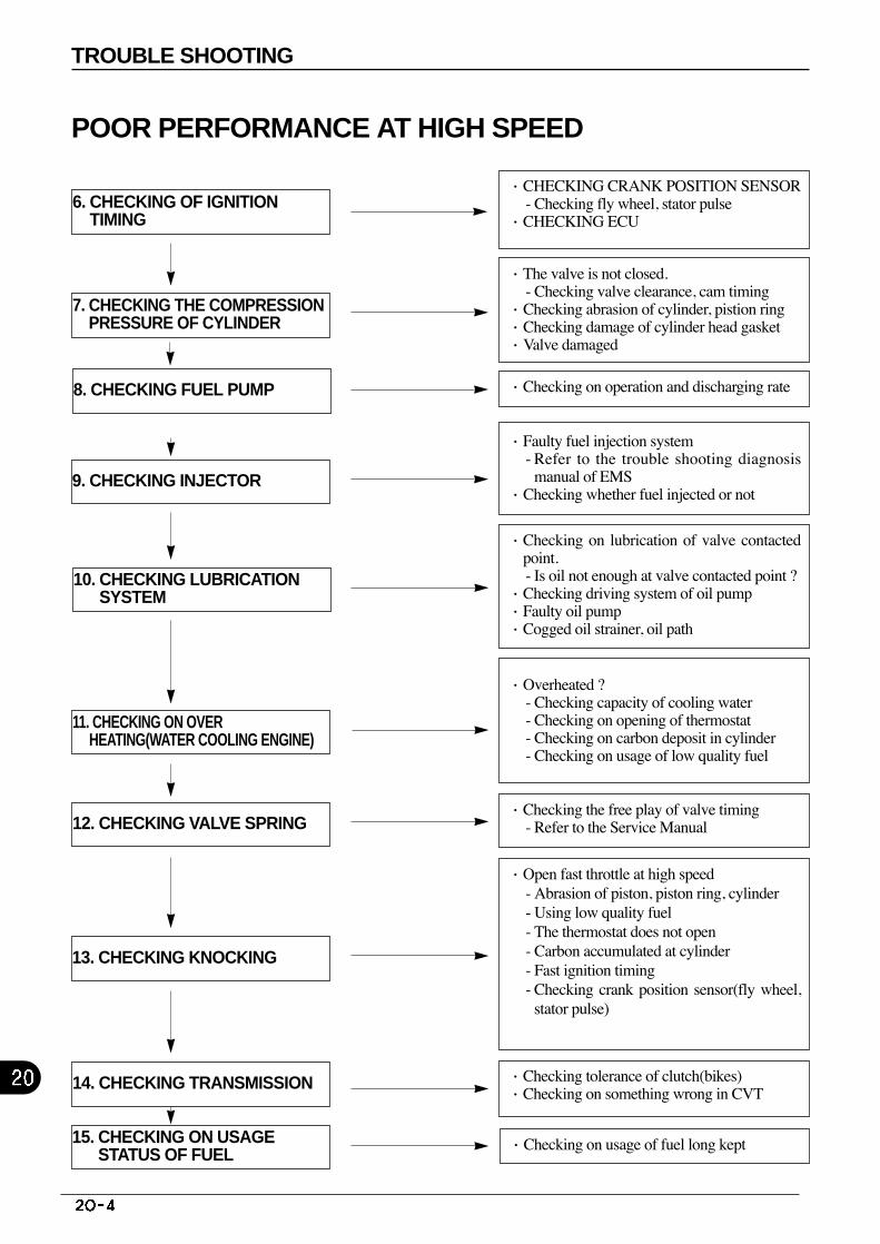
·Checking the free play of valve timing- Refer to the Service Manual
6. CHECKING OF IGNITIONTIMING
7. CHECKING THE COMPRESSIONPRESSURE OF CYLINDER
8. CHECKING FUEL PUMP
9. CHECKING INJECTOR
10. CHECKING LUBRICATIONSYSTEM
·CHECKING CRANK POSITION SENSOR - Checking fly wheel, stator pulse
·CHECKING ECU
·Checking on operation and discharging rate
·Checking on lubrication of valve contactedpoint.- Is oil not enough at valve contacted point ?
·Checking driving system of oil pump·Faulty oil pump·Cogged oil strainer, oil path
·Faulty fuel injection system- Refer to the trouble shooting diagnosis
manual of EMS·Checking whether fuel injected or not
·Checking on usage of fuel long kept
11. CHECKING ON OVERHEATING(WATER COOLING ENGINE)
12. CHECKING VALVE SPRING
13. CHECKING KNOCKING
14. CHECKING TRANSMISSION
15. CHECKING ON USAGESTATUS OF FUEL
·Open fast throttle at high speed- Abrasion of piston, piston ring, cylinder- Using low quality fuel- The thermostat does not open- Carbon accumulated at cylinder- Fast ignition timing- Checking crank position sensor(fly wheel,
stator pulse)
·Checking tolerance of clutch(bikes) ·Checking on something wrong in CVT
·Overheated ?- Checking capacity of cooling water - Checking on opening of thermostat- Checking on carbon deposit in cylinder- Checking on usage of low quality fuel
·The valve is not closed. - Checking valve clearance, cam timing
·Checking abrasion of cylinder, pistion ring ·Checking damage of cylinder head gasket ·Valve damaged
POOR PERFORMANCE AT HIGH SPEED
TROUBLE SHOOTING
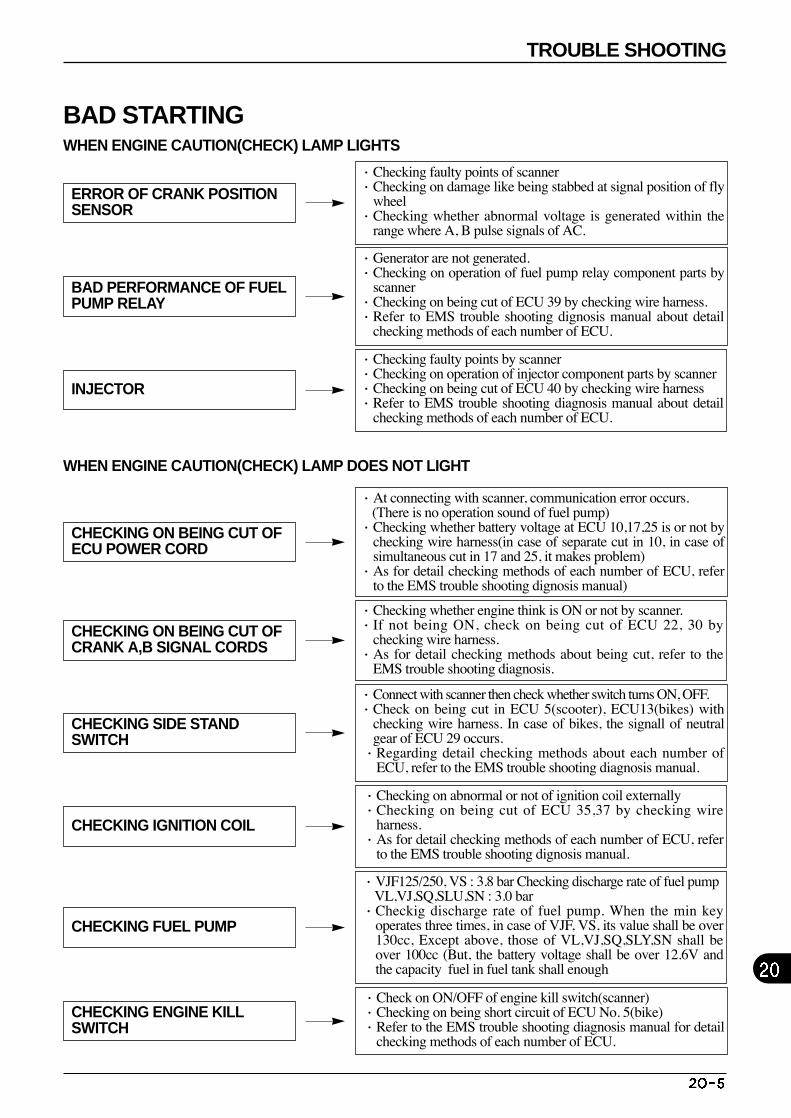
ERROR OF CRANK POSITIONSENSOR
BAD PERFORMANCE OF FUELPUMP RELAY
INJECTOR
CHECKING ON BEING CUT OFECU POWER CORD
CHECKING ON BEING CUT OFCRANK A,B SIGNAL CORDS
CHECKING SIDE STANDSWITCH
CHECKING IGNITION COIL
CHECKING FUEL PUMP
CHECKING ENGINE KILLSWITCH
·Checking faulty points of scanner·Checking on damage like being stabbed at signal position of fly
wheel·Checking whether abnormal voltage is generated within the
range where A, B pulse signals of AC.
·Generator are not generated.·Checking on operation of fuel pump relay component parts by
scanner·Checking on being cut of ECU 39 by checking wire harness.·Refer to EMS trouble shooting dignosis manual about detail
checking methods of each number of ECU.
·Checking faulty points by scanner·Checking on operation of injector component parts by scanner·Checking on being cut of ECU 40 by checking wire harness·Refer to EMS trouble shooting diagnosis manual about detail
checking methods of each number of ECU.
·At connecting with scanner, communication error occurs. (There is no operation sound of fuel pump)
·Checking whether battery voltage at ECU 10,17,25 is or not bychecking wire harness(in case of separate cut in 10, in case ofsimultaneous cut in 17 and 25, it makes problem)
·As for detail checking methods of each number of ECU, referto the EMS trouble shooting dignosis manual)
·Checking whether engine think is ON or not by scanner.·If not being ON, check on being cut of ECU 22, 30 by
checking wire harness.·As for detail checking methods about being cut, refer to the
EMS trouble shooting diagnosis.
·Connect with scanner then check whether switch turns ON, OFF.·Check on being cut in ECU 5(scooter), ECU13(bikes) with
checking wire harness. In case of bikes, the signall of neutralgear of ECU 29 occurs.
·Regarding detail checking methods about each number ofECU, refer to the EMS trouble shooting diagnosis manual.
·Checking on abnormal or not of ignition coil externally·Checking on being cut of ECU 35,37 by checking wire
harness.·As for detail checking methods of each number of ECU, refer
to the EMS trouble shooting dignosis manual.
·Check on ON/OFF of engine kill switch(scanner) ·Checking on being short circuit of ECU No. 5(bike) ·Refer to the EMS trouble shooting diagnosis manual for detail
checking methods of each number of ECU.
WHEN ENGINE CAUTION(CHECK) LAMP LIGHTS
WHEN ENGINE CAUTION(CHECK) LAMP DOES NOT LIGHT
·VJF125/250, VS : 3.8 bar Checking discharge rate of fuel pumpVL,VJ,SQ,SLU,SN : 3.0 bar
·Checkig discharge rate of fuel pump. When the min keyoperates three times, in case of VJF, VS, its value shall be over130cc, Except above, those of VL,VJ,SQ,SLY,SN shall beover 100cc (But, the battery voltage shall be over 12.6V andthe capacity fuel in fuel tank shall enough
BAD STARTING
TROUBLE SHOOTING
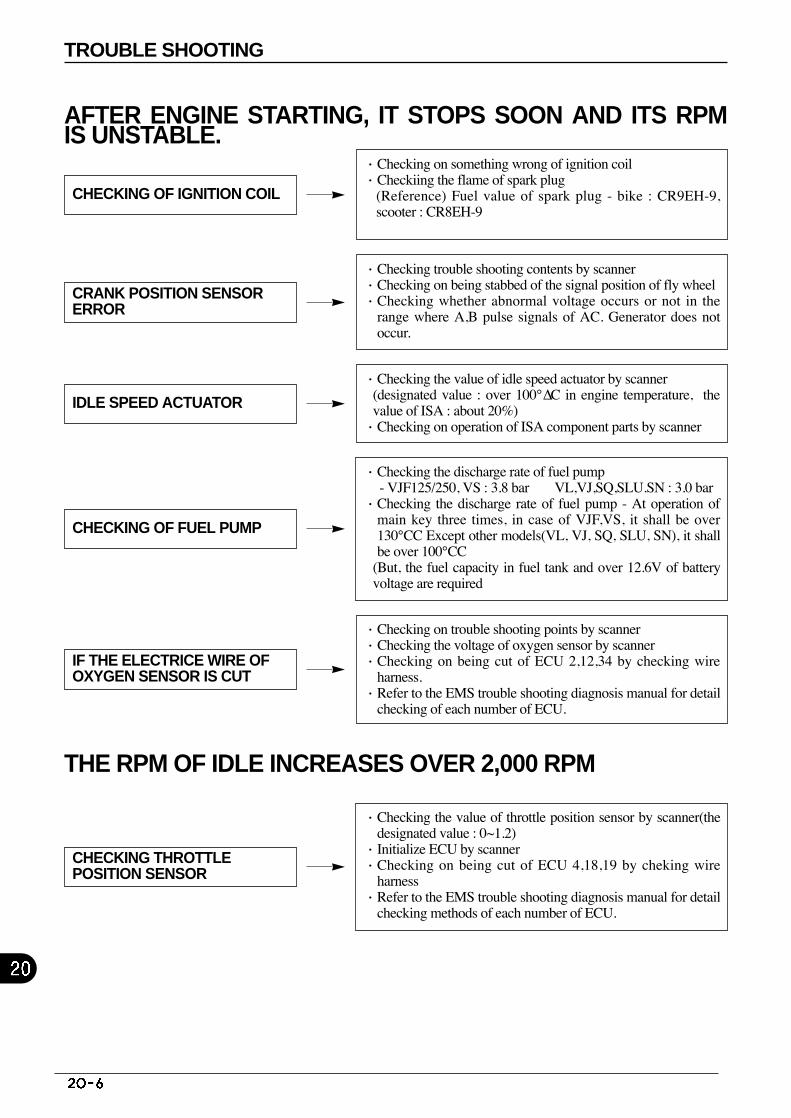
AFTER ENGINE STARTING, IT STOPS SOON AND ITS RPMIS UNSTABLE.
THE RPM OF IDLE INCREASES OVER 2,000 RPM
CHECKING OF IGNITION COIL
CRANK POSITION SENSORERROR
IDLE SPEED ACTUATOR
CHECKING OF FUEL PUMP
IF THE ELECTRICE WIRE OFOXYGEN SENSOR IS CUT
CHECKING THROTTLEPOSITION SENSOR
·Checking trouble shooting contents by scanner ·Checking on being stabbed of the signal position of fly wheel·Checking whether abnormal voltage occurs or not in the
range where A,B pulse signals of AC. Generator does notoccur.
·Checking the value of idle speed actuator by scanner(designated value : over 100°ΔC in engine temperature, thevalue of ISA : about 20%)
·Checking on operation of ISA component parts by scanner
·Checking on trouble shooting points by scanner ·Checking the voltage of oxygen sensor by scanner ·Checking on being cut of ECU 2,12,34 by checking wire
harness.·Refer to the EMS trouble shooting diagnosis manual for detail
checking of each number of ECU.
·Checking the value of throttle position sensor by scanner(thedesignated value : 0~1.2)
·Initialize ECU by scanner ·Checking on being cut of ECU 4,18,19 by cheking wire
harness·Refer to the EMS trouble shooting diagnosis manual for detail
checking methods of each number of ECU.
·Checking the discharge rate of fuel pump- VJF125/250, VS : 3.8 bar VL,VJ,SQ,SLU.SN : 3.0 bar
·Checking the discharge rate of fuel pump - At operation ofmain key three times, in case of VJF,VS, it shall be over130°CC Except other models(VL, VJ, SQ, SLU, SN), it shallbe over 100°CC
(But, the fuel capacity in fuel tank and over 12.6V of batteryvoltage are required
·Checking on something wrong of ignition coil·Checkiing the flame of spark plug
(Reference) Fuel value of spark plug - bike : CR9EH-9,scooter : CR8EH-9
TROUBLE SHOOTING
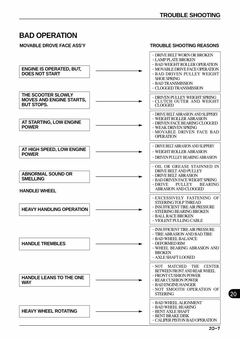
MOVABLE DROVE FACE ASS’Y
HANDLE/ WHEEL
TROUBLE SHOOTING REASONS
BAD OPERATION
ENGINE IS OPERATED, BUT,DOES NOT START
THE SCOOTER SLOWLYMOVES AND ENGINE STARTS,BUT STOPS.
AT STARTING, LOW ENGINEPOWER
AT HIGH SPEED, LOW ENGINEPOWER
ABNORMAL SOUND ORSMELLING
HEAVY HANDLING OPERATION
HANDLE TREMBLES
HANDLE LEANS TO THE ONEWAY
HEAVY WHEEL ROTATING
·DRIVE BELT WORN OR BROKEN ·LAMP PLATE BROKEN ·BAD WEIGHT ROLLER OPERATION·MOVABLE DRIVE FACE OPERATION·BAD DRIVEN PULLEY WEIGHT
SHOE SPRING ·BAD TRANSMISSION ·CLOGGED TRANSMISSION
·DRIVEN PULLEY WEIGHT SPRING ·CLUTCH OUTER AND WEIGHT
CLOGGED
·DRIVE BELT ABRASION AND SLIPPERY·WEIGHT ROLLER ABRASION ·DRIVEN FACE BEARING CLOGGED ·WEAK DRIVEN SPRING·MOVABLE DRIVEN FACE BAD
OPERATION
·DRIVE BELT ABRASION AND SLIPPERY·WEIGHT ROLLER ABRASION·DRIVEN PULLEY BEARING ABRASION
·OIL OR GREASE STAINNED INDRIVE BELT AND PULLEY
·DRIVE BELT ABRASION·BAD DRIVEN FACE WEIGHT SPRING·DRIVE PULLEY BEARING
ABRASION AND CLOGGED
·EXCESSIVELY FASTENING OFSTEERING TOLP THREAD
·INSUFFICIENT TIRE AIR PRESSURE·STEERING BEARING BROKEN·BALL RACE BROKEN·VIOLENT PULLING CABLE
·INSUFFICIENT TIRE AIR PRESSURE·TIRE ABRASION AND BAD TIRE·BAD WHEEL BALANCE·DEFORMED RIM·WHEEL BEARING ABRASION AND
BROKEN·AXLE SHAFT LOOSED
·NOT MATCHED THE CENTERBETWEEN FRONT AND REAR WHEEL
·FRONT CUSHION POWER·REAR CUSHION POWER·BAD ENGINE HANGER·NOT SMOOTH OPERATION OF
STEERING
·BAD WHEEL ALIGNMENT ·BAD WHEEL BEARING·BENT AXLE SHAFT·BENT BRAKE DISK·CALIPER PISTON BAD OPERATION
TROUBLE SHOOTING

M E M O

M E M O

M E M O

M E M O

M E M O
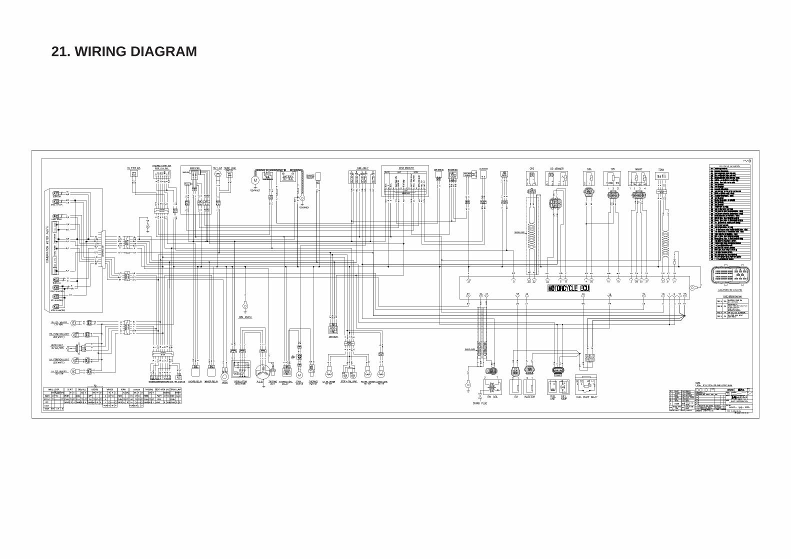
21. WIRING DIAGRAM

2010. 10 PRINTED2010. 10 PUBLICATION
CCOOPPYY PPRROOHHIIBBIITT
SERVICE MANUAL


![Daelim VJF250 - Service Manual[1]](https://img.pdfslide.net/doc/110x75/55cf9cb0550346d033aab349/daelim-vjf250-service-manual1.jpg)