Embed Size (px)
Citation preview
Daredevil: Indoor Location Using Sound
Ionut Constandache†, Sharad Agarwal‡, Ivan Tashev‡, Romit Roy Choudhury?†Duke University, ‡Microsoft Research, ?University of Illinois at Urbana-Champaign†[email protected], ‡{sagarwal,ivantash}@microsoft.com, [email protected]
Abstract
A variety of techniques have been used by prior workon the problem of smartphone location. In this paper,we propose a novel approach using sound source lo-calization (SSL) with microphone arrays to determinewhere in a room a smartphone is located. In our sys-tem called Daredevil, smartphones emit sound at par-ticular times and frequencies, which are received bymicrophone arrays. Using SSL that we modified forour purposes, we can calculate the angle between thecenter of each microphone array and the phone, andthereby triangulate the phone’s position. In this earlywork, we demonstrate the feasibility of our approachand present initial results. Daredevil can locate smart-phones in a room with an average precision of 3.19feet. We identify a number of challenges in realiz-ing the system in large deployments, and we hope thiswork will benefit researchers who pursue such tech-niques.
I. Introduction
Making indoor location available ubiquitously is dif-ficult. There are many challenges, including achiev-ing accuracy with off-the-shelf phones, relying solelyon existing infrastructure such as Wi-Fi access points,and scaling any human effort such as fingerprinting.However, there are specific situations where tailoredindoor location solutions are valuable and one or moreof these constraints do not apply. For instance, fire-fighters may be willing to carry custom equipment forindoor location but will require the solution to workin any burning building. A retail chain store may bewilling to deploy custom equipment in their stores, butmay want location to work with off-the-shelf phonesthat users carry.
In this work, we focus on the retail scenario as ourmotivation. A store owner may want to provide indoorlocation to shoppers for a variety of reasons. She maywant shoppers to efficiently find items on their shop-ping list with minimal clerk assistance. She may wantto entice shoppers with special discounts or productreviews depending on what product the shopper islooking at. In doing so, the store owner wants to min-
imize the burden on the shopper and not require any-thing custom on the end user devices beyond an appfor the store. She may be willing to deploy customequipment inside the store. While we focus on theretail scenario, our techniques are equally applicableto any scenario where user phones with a custom appneed to be located in a large indoor room where theroom can be augmented with additional equipment.
Prior work has considered a variety of ways to ad-dress such scenarios, including sensing ambient mag-netic fields [4], fingerprinting Wi-Fi [1] and finger-printing FM radio transmissions [3]. In this work,we focus on sound, either audible or ultrasound. Thechoice of sound comes with its own advantages anddisadvantages. There are transducers on all phones(speakers and microphones) and sound is generallyunaffected by changes in the store layout or humanpresence (unlike magnetic fields and Wi-Fi signalstrength). However, depending on the frequency, am-plitude and duration, it can be overheard by humans,and there is a lot of ambient noise that can interferewith the detection of the intended signal.
In this work, we attempt to accurately locate usersindoors by detecting the angle of arrival of audiochirps emitted by smartphones. We examine how welloff-the-shelf phones can emit such chirps, at a varietyof different frequencies and amplitudes. We examinehow we can encode small amounts of information inthese chirps to distinguish different phones. To cal-culate the angle of arrival, we build microphone ar-rays that can be used in conjunction with SSL (soundsource localization) algorithms [17] that we have cus-tomized for our use.
The novelty of our work is in applying SSL to lo-cate smartphones. Shopkick is a company that has de-ployed sound-based location in stores. However, intheir system the phone is detecting sound emitted bya custom device in the store, and only detects whetherthe phone is in the store, not where in the store thephone is. SSL techniques have been explored in depthin prior work, and are in use in products such as Mi-crosoft Kinect, for distinguishing different humansspeaking at the same time. In this work, we applythose techniques to locating phones, which has unique
challenges.
Our system, called Daredevil, operates at least twomicrophone arrays, and by calculating the angle fromeach array to the phone emitting a tone, can trian-gulate the user’s location. In this paper, we presentthe design of the system and hardware and feasibilityexperiments in § III, evaluation results in § IV, andrelevant prior work in § V. This early work demon-strates a working system that achieves low error – onaverage 3.8◦, or approximately 3.2 feet on average.However, we also identify limitations of current hard-ware on smartphones that prevent us from deployingDaredevil in practical scenarios, and we point to fu-ture work in this space in § VI.
II. Motivation
We envision Daredevil to be deployed in retail storeswhere pairs of microphone arrays are mounted onwalls or ceilings. Unmodified phones running an appcan be identified and located using sound that theyemit. There are several open questions that we needto answer when building such a system.
It is important to understand how well off-the-shelfsmartphones can emit high frequency audio tones.This is partly a function of the speakers they have,audio processing hardware, and the software platformon the phones. A related question is how loud thesetones are, or at what distance they can be heard usingmicrophones. The longer the distance is, the fewer mi-crophone arrays are needed, but higher is the potentialfor interference between multiple phones. The higherthe frequency, the lower is the chance for interferencefrom human voice.
The cost and robustness of our microphone arraydesign are two more key factors. An inexpensive ar-ray can allow for more arrays to be deployed in the in-door environment. The array has to be robust enoughto pick up audio tones from phones from a variety ofangles and distances.
The ultimate question is how accurately the micro-phone arrays can detect the angle of incidence fromphones, and subsequently the location of each phoneby triangulation from a pair of arrays. Additionalquestions are how quickly tones can be generated andphones located, and how that impacts the scalabilityof the system in how many phones can be located andhow frequently.
βmic2
(Xmic1 ,Ymic1) (Xmic2 ,Ymic2)
(X ,Y)
αmic1
Mic 2 Mic 1
Server
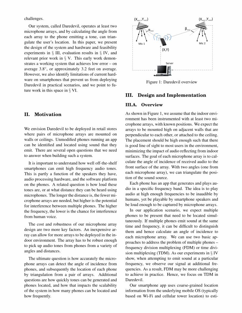
Figure 1: Daredevil overview
III. Design and Implementation
III.A. Overview
As shown in Figure 1, we assume that the indoor envi-ronment has been instrumented with at least two mi-crophone arrays, with known positions. We expect thearrays to be mounted high on adjacent walls that areperpendicular to each other, or attached to the ceiling.The placement should be high enough such that thereis good line of sight to most users in the environment,minimizing the impact of audio reflecting from indoorsurfaces. The goal of each microphone array is to cal-culate the angle of incidence of received audio to thefront surface of the array. With two angles (one fromeach microphone array), we can triangulate the posi-tion of the sound source.
Each phone has an app that generates and plays au-dio in a specific frequency band. The idea is to playaudio at high enough frequencies to be inaudible byhumans, yet be playable by smartphone speakers andbe loud enough to be captured by microphone arrays.
In our application scenario, we expect multiplephones to be present that need to be located simul-taneously. If multiple phones emit sound at the sametime and frequency, it can be difficult to distinguishthem and hence calculate an angle of incidence toeach microphone array. We can use two basic ap-proaches to address the problem of multiple phones –frequency division multiplexing (FDM) or time divi-sion multiplexing (TDM). As our experiments in § IVshow, when attempting to emit sound at a particularfrequency, we observe our signal at additional fre-quencies. As a result, FDM may be more challengingto achieve in practice. Hence, we focus on TDM inDaredevil.
Our smartphone app uses coarse-grained locationinformation from the underlying mobile OS (typicallybased on Wi-Fi and cellular tower location) to esti-
mate which Daredevil-enabled store the user is in.The app will then receive a schedule from the Dare-devil server (shown in Figure 1) that tells it when itcan emit sound and in what frequency band. The appuses amplitude modulation to encode a unique phoneID in the sound it emits. Clock drift between phonesand servers will limit how quickly multiple phonescan be located.
Each phone registers with the Daredevil server andretrieves the common tone frequency, a unique phoneID, and the TDM schedule assigned to it. The phoneconstructs the audio in software and plays it at the as-signed schedule. The microphone arrays stream au-dio to the server. SSL software running at the serveridentifies the tone, decodes the phone ID, and com-putes the tone angle of arrival at each of the two mi-crophone arrays (angles αmic1 and βmic2 in Figure1). The microphone array coordinates (Xmic1, Ymic1)and (Xmic2, Ymic2) are static values provided to thethe server software as configuration values at deploy-ment time. Using the microphone array positions andthe tone angles of arrivals, the server computes thephone coordinates through triangulation. The phonecoordinates (X,Y ) are returned to the app, or pro-cessed further for higher-level services (such as pro-viding directions on top of an indoor map, or sendinga discount coupon).
The phone location is updated periodically, eachtime the app on the phone plays sound at the sched-uled times. The schedule periodicity can be madeadaptive based on the number of phones present in theenvironment. Additional factors, including the max-imum user speed, and limits on user movement bywalls and aisles, can be also used to dynamically ad-just the schedule for different phones.
III.B. Sound Source Localization
Locating sounds using microphone arrays is a well es-tablished area in signal processing. One of the firstapplications was pointing a pan-tilt-zoom camera to-ward the current speaker in a conference room [21].
Direction estimation with a pair of microphonesis done by computing the delay between the tworeceived signals, and using the known speed ofsound and the distance between the two microphones:θ = arcsin(τν/δ). Here θ is the direction angle, τis the estimated time delay, ν is the speed of sound,and δ is the distance between the two microphones. τis computed using the Generalized Cross-Correlationfunction [10], typically with PHAT weighting.
Using more than two microphones improves preci-sion, but increases the complexity of the estimation.
The naive approach of combining angles from all pos-sible pairs does not work well. Instead, Steered Re-sponse Power (SRP) algorithms are often used. Thoseare based on evaluating multiple angles and pickingthe one that maximizes certain criteria (power of thesignal from the sound source [18], spatial probabil-ity [17], eigenvalues [14], etc.). In Daredevil, we usea modified and improved version of the algorithm de-scribed in [17]. On every audio processing frame werun a Voice Activity Detector (VAD), like the one de-scribed in [15] but modified for the type of audio wegenerate, and engage the sound source localizer onlyif there is a signal (real signal or interfering signal)present.
The audio frames with signal present are convertedto frequency domain using short-term Fourier Trans-formation, and only the frequency bins containing thesignal frequency band are processed. For each fre-quency bin k of audio frame n, the probability of ithaving a signal as a function of the direction p(n)k (θ)is estimated using the IDOA approach [17]. The prob-abilities from the frequency bins of interest are aver-aged to receive the probability of sound source pre-sented as function of the direction p(n)(θ) . A confi-dence level is estimated as the proportion of the dif-ference between the maximum and minimum valuesof the probability, divided by the probability average.If the confidence level is below a given threshold, theresult from this audio frame is discarded, otherwisethe direction angle is considered where the probabil-ity peaks. The time stamped angle, accompanied bythe confidence level, is sent up the stack for furtherprocessing.
The angular precision based on a single audio framewith duration 10-30 ms is not high and hence we usepost-processors. Their purpose is to remove outliersand reflections and to increase location precision byaveraging and interpolating sound source trajectoryover small time windows. A variety of methods can beused, including Kalman filtering [9], clustering [16]and particle filtering [22]. In Daredevil, we use theclustering algorithm described in chapter 6 of [16].The output of the sound source localizer is a set ofdirections toward all sound sources tracked, each ac-companied by a confidence level.
In addition to localizing sounds, signals from themicrophones can be combined into one signal, whichis equivalent of a highly directive microphone - anoperation called beamforming. Commonly the beam-forming happens in frequency domain, where we al-ready converted the audio signal to perform soundsource localization. In this domain the beamform-
ing output is defined as a weighted sum with direc-tion dependent weight. The output signal containsless reverberation and noise, allowing us to processmore easily the chirps from a phone. The beamform-ing operation requires knowledge of the direction tothe desired sound source, which is obtained from thesound source localizer. In Daredevil, we use a timeinvariant steerable beamformer [16]. It consists of 21pre-computed tables of weight coefficients for direc-tions from -50◦ to +50◦ pointing at every 5◦. Usingthe list of sound sources, obtained from the soundsource localizer, for each of the tracked sound sourceswe snap the direction to the closest pre-computed an-gle and then compute the beamformer output. Thismeans that we apply the beamforming procedure asmany times as sound sources we track. The outputof each beamformer contains the sound from the cor-responding phone, while the other signals and noisesare attenuated. It is used further for decoding the in-formation coming from that particular phone.
Each microphone array works in the range of±50◦.In the ideal case we should be able to reject any soundsource that is out of this angle and out of the line ofsight. Otherwise we will get fake directions for soundsources. We mitigate this problem in the followingways:
• We use VAD to select only those audio frameswhere we have strong signals, presumably reject-ing these that are out of the monitored zone or notin the direct sight of the array.
• We scan for sound sources only in the directionsof the range above.
• After processing each frame we compute a confi-dence level ((max-min)/average) and reject all ofthe frames with confidence level below a thresh-old.
• We cluster the sound source localizations, andtrack only sound sources with presence in sev-eral frames. We then compute a confidence levelfor each sound source.
• We compute the beamformer toward a directiononly when the confidence level after clustering isabove a threshold.
Again, the key is to reject directions toward sporadicsound sources, reflections from walls and ceilings,and noise. This is part of the reason why we do notdetect real sound sources at larger distances – withour thresholds we cannot distinguish those from softsounds from nearby noise. Further tuning can be done
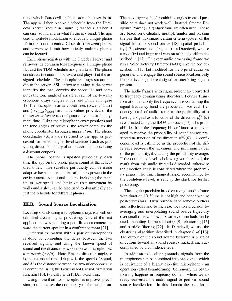
Figure 2: Spectrogram from Adobe Audition softwareof 18 kHz audio played on a HTC Surround phone andrecorded on a microphone array
to the thresholds to increase the detection range asmuch as possible while still keeping false positives atacceptable low levels.
III.C. Audio Frequency Band
In our application scenario, the store owner is will-ing to deploy hardware in the store but cannot ex-pect users to modify their phones beyond installingan app. Ideally, we want the audio emitted by phonesto be well beyond human perceptible ranges. Medicalliterature indicates that human hearing can recognizesounds up to 20 kHz. Unfortunately, speakers on mostsmartphones are not designed to operate beyond hu-man hearing ranges, and our experiments on a numberof phone models (Apple iPhone 4, Samsung Focus,Asus E600, and HTC Surround) verified that expec-tation. As the emitted sound frequency approaches21 kHz, the sound amplitude drops off quickly. Mostphones are capable of achieving 18 kHz at loud vol-umes. It is well known that the upper range of audiofrequencies detectable by the human ear varies withage. In a small experiment using 10 test users aged20 and higher, playing audio on a PC with high endspeakers, we observed no user perception of frequen-cies higher than 17 kHz. For this paper, we focus on18 kHz, realizing that the short audio chirps that ourapp emits may be perceptible by children.
Phone loudspeakers at maximum volume producesubstantial non-linear distortions. For 18 kHz sound,the second, third, and higher harmonics are above onehalf of the sampling rate and should be removed by theanti-aliasing filter integrated into the ADC. However,due to the high amplitude of these non-linear distor-tions, they still bleed over and are mirrored as signalswith lower frequency. The spectrogram in Figure 2
Tone
TSLOT
tPLAY tGUARD tTONE
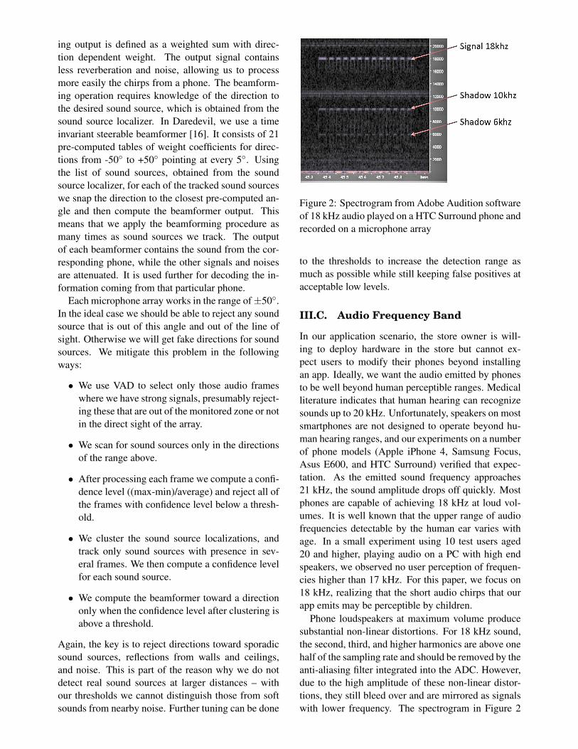
Figure 3: TDM time slot
shows these additional signals with frequencies of 6and 10 kHz. While these two shadow frequencies arewithin the human audible range, their amplitudes aremuch lower than the primary signal which is clearlyvisible at 18 kHz. We have observed this behavioron multiple phones and we believe this is a limitationof the speakers built into phones. We observe simi-lar spectrograms for frequency bands ranging from 18kHz to 21 kHz.
Our findings are consistent with prior work. Recentwork [5] investigated the feasibility of playing ultra-sonic sounds on mobile phones. The authors testedfour commercial phones (HTC G1, HTC Hero, AppleiPhone 3GS, and Nokia 6210 Navigator) playing tonesat frequencies between 17 kHz and 22 kHz. They ob-serve that all phones were capable of generating thesehigh frequencies. While noise appeared at some otherfrequencies when the volume of the phone’s speak-ers are set to maximum, there exists a combination ofvolume settings for each phone such that the noise isminimal.
III.D. Locating Multiple Phones
Using FDM to allocate distinct frequencies to differ-ent phones is possible, but complicated by the shadowfrequency problem we observe. We instead use TDM.However, for a TDM approach to work, we need toensure that the slots do not overlap. This is challeng-ing because different phones and the Daredevil servermay not have good time synchronization with eachother. In addition, scheduling and processing over-head in smartphone OSes may introduce variable de-lay between our app issuing a command to play audioand it coming out of the phone’s speaker.
Figure 3 represents a time slot in the Dare-devil TDM schedule. We denote the length of the slotwith TSLOT . This represents the time interval allo-cated to a phone to play the tone of length tTONE
(tTONE < TSLOT ). We mark with tPLAY the de-lay between the request to play the tone and the phoneactually playing it, and tGUARD a guard time delayto account for clock drift. Parameter tGUARD ensuresthat the next scheduled phone does not play the toneconcurrently with the current phone due to poor clocksynchronization.
To measure the time delay tPLAY between issuing
the play tone command and the tone coming out of thephone speaker, we ran a small experiment. We instru-mented the Daredevil app on a phone to timestampwhen tone play is requested by the OS. In parallel,the phone recorded sound through its microphone. Inthis way, we are able to estimate tPLAY which is thedifference in time between the app issuing the playcommand and the audio containing the expected fre-quency. After running this experiment 10 times ondifferent phone models, we observed a maximum de-lay of 100ms. Hence we use a tPLAY of 100ms.
We empirically evaluated a number of values fortTONE , while measuring (i) tone detection and (ii)angle estimation accuracy. Both these values sufferwhen the tone length is short. If the tone length is tooshort, our SSL algorithm does not have enough sam-ples to remove noise from angle estimates. In our ex-periments, 500ms was an adequate length, and hencewe set tTONE to 500ms.
To pick tGUARD we ran experiments with twophones that were configured to synchronize theirclocks with cellular towers. We attached both phonesto a PC using USB cables and recorded on the PCthe time reported by both phones at multiple pointsthroughput the day. The two sets of reported timeswere very close to each other, and remained below150ms, which is the value we pick for tGUARD.
Putting together the values for tPLAY , tTONE andtGUARD, we have 750ms for the value of TSLOT .Hence, with a single frequency band, we can locate upto 40 phones every 30 seconds, in the coverage area ofa pair of microphone arrays.
III.E. Hardware and Software Imple-mentation
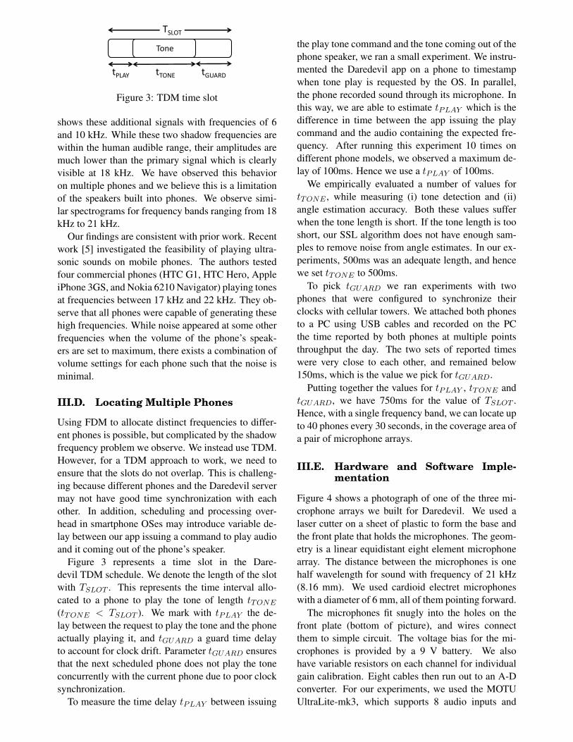
Figure 4 shows a photograph of one of the three mi-crophone arrays we built for Daredevil. We used alaser cutter on a sheet of plastic to form the base andthe front plate that holds the microphones. The geom-etry is a linear equidistant eight element microphonearray. The distance between the microphones is onehalf wavelength for sound with frequency of 21 kHz(8.16 mm). We used cardioid electret microphoneswith a diameter of 6 mm, all of them pointing forward.
The microphones fit snugly into the holes on thefront plate (bottom of picture), and wires connectthem to simple circuit. The voltage bias for the mi-crophones is provided by a 9 V battery. We alsohave variable resistors on each channel for individualgain calibration. Eight cables then run out to an A-Dconverter. For our experiments, we used the MOTUUltraLite-mk3, which supports 8 audio inputs and
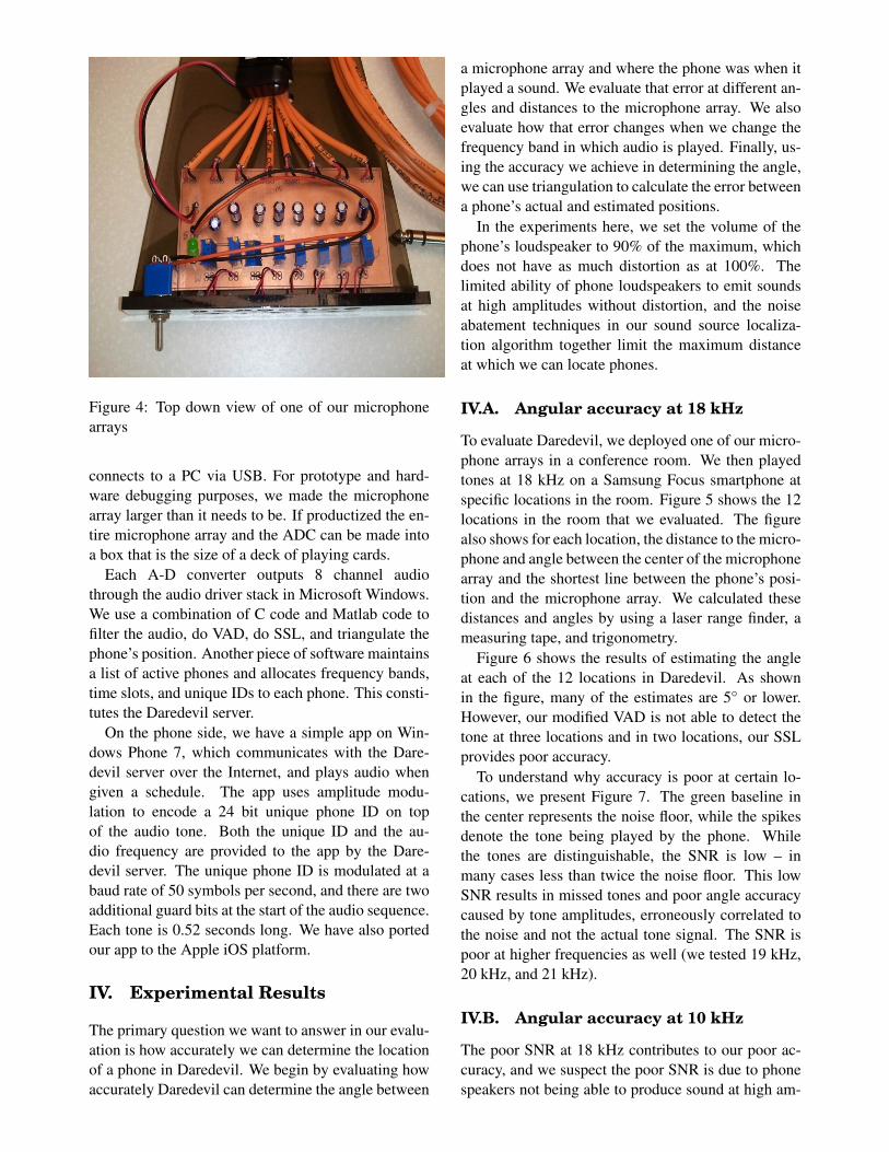
Figure 4: Top down view of one of our microphonearrays
connects to a PC via USB. For prototype and hard-ware debugging purposes, we made the microphonearray larger than it needs to be. If productized the en-tire microphone array and the ADC can be made intoa box that is the size of a deck of playing cards.
Each A-D converter outputs 8 channel audiothrough the audio driver stack in Microsoft Windows.We use a combination of C code and Matlab code tofilter the audio, do VAD, do SSL, and triangulate thephone’s position. Another piece of software maintainsa list of active phones and allocates frequency bands,time slots, and unique IDs to each phone. This consti-tutes the Daredevil server.
On the phone side, we have a simple app on Win-dows Phone 7, which communicates with the Dare-devil server over the Internet, and plays audio whengiven a schedule. The app uses amplitude modu-lation to encode a 24 bit unique phone ID on topof the audio tone. Both the unique ID and the au-dio frequency are provided to the app by the Dare-devil server. The unique phone ID is modulated at abaud rate of 50 symbols per second, and there are twoadditional guard bits at the start of the audio sequence.Each tone is 0.52 seconds long. We have also portedour app to the Apple iOS platform.
IV. Experimental Results
The primary question we want to answer in our evalu-ation is how accurately we can determine the locationof a phone in Daredevil. We begin by evaluating howaccurately Daredevil can determine the angle between
a microphone array and where the phone was when itplayed a sound. We evaluate that error at different an-gles and distances to the microphone array. We alsoevaluate how that error changes when we change thefrequency band in which audio is played. Finally, us-ing the accuracy we achieve in determining the angle,we can use triangulation to calculate the error betweena phone’s actual and estimated positions.
In the experiments here, we set the volume of thephone’s loudspeaker to 90% of the maximum, whichdoes not have as much distortion as at 100%. Thelimited ability of phone loudspeakers to emit soundsat high amplitudes without distortion, and the noiseabatement techniques in our sound source localiza-tion algorithm together limit the maximum distanceat which we can locate phones.
IV.A. Angular accuracy at 18 kHz
To evaluate Daredevil, we deployed one of our micro-phone arrays in a conference room. We then playedtones at 18 kHz on a Samsung Focus smartphone atspecific locations in the room. Figure 5 shows the 12locations in the room that we evaluated. The figurealso shows for each location, the distance to the micro-phone and angle between the center of the microphonearray and the shortest line between the phone’s posi-tion and the microphone array. We calculated thesedistances and angles by using a laser range finder, ameasuring tape, and trigonometry.
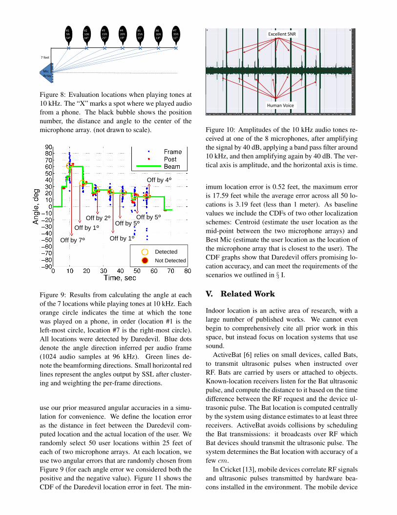
Figure 6 shows the results of estimating the angleat each of the 12 locations in Daredevil. As shownin the figure, many of the estimates are 5◦ or lower.However, our modified VAD is not able to detect thetone at three locations and in two locations, our SSLprovides poor accuracy.
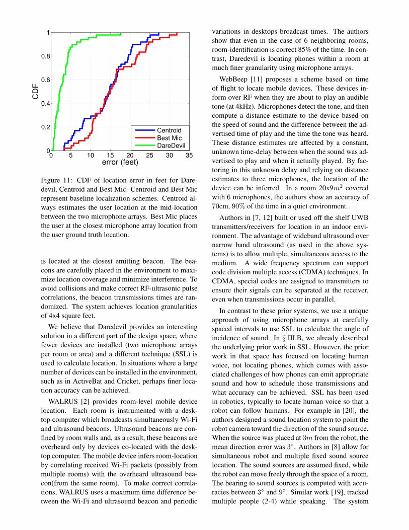
To understand why accuracy is poor at certain lo-cations, we present Figure 7. The green baseline inthe center represents the noise floor, while the spikesdenote the tone being played by the phone. Whilethe tones are distinguishable, the SNR is low – inmany cases less than twice the noise floor. This lowSNR results in missed tones and poor angle accuracycaused by tone amplitudes, erroneously correlated tothe noise and not the actual tone signal. The SNR ispoor at higher frequencies as well (we tested 19 kHz,20 kHz, and 21 kHz).
IV.B. Angular accuracy at 10 kHz
The poor SNR at 18 kHz contributes to our poor ac-curacy, and we suspect the poor SNR is due to phonespeakers not being able to produce sound at high am-
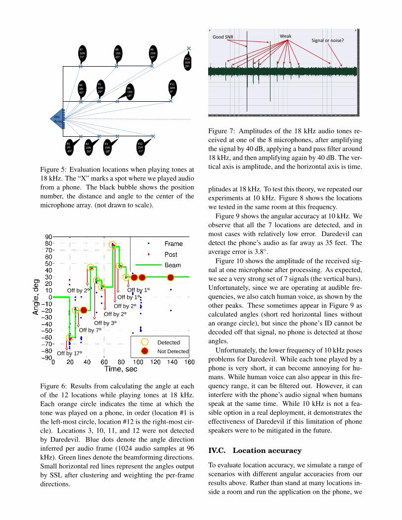
MicArray
#15ft-450
#210ft-260
#315ft-180
#1225ft-110
#45ft450
#510ft260
#615ft180
#710ft710
#815ft450
#925ft300
#1130ft90
#1235ft290
Figure 5: Evaluation locations when playing tones at18 kHz. The “X” marks a spot where we played audiofrom a phone. The black bubble shows the positionnumber, the distance and angle to the center of themicrophone array. (not drawn to scale).
Not Detected
Detected
Off by 17º
Off by 7º
Off by 2º
Off by 3º
Off by 2ºOff by 2º
Off by 1ºOff by 1º
Figure 6: Results from calculating the angle at eachof the 12 locations while playing tones at 18 kHz.Each orange circle indicates the time at which thetone was played on a phone, in order (location #1 isthe left-most circle, location #12 is the right-most cir-cle). Locations 3, 10, 11, and 12 were not detectedby Daredevil. Blue dots denote the angle directioninferred per audio frame (1024 audio samples at 96kHz). Green lines denote the beamforming directions.Small horizontal red lines represent the angles outputby SSL after clustering and weighting the per-framedirections.
WeakSignal or noise?
Good SNR
Figure 7: Amplitudes of the 18 kHz audio tones re-ceived at one of the 8 microphones, after amplifyingthe signal by 40 dB, applying a band pass filter around18 kHz, and then amplifying again by 40 dB. The ver-tical axis is amplitude, and the horizontal axis is time.
plitudes at 18 kHz. To test this theory, we repeated ourexperiments at 10 kHz. Figure 8 shows the locationswe tested in the same room at this frequency.
Figure 9 shows the angular accuracy at 10 kHz. Weobserve that all the 7 locations are detected, and inmost cases with relatively low error. Daredevil candetect the phone’s audio as far away as 35 feet. Theaverage error is 3.8◦.
Figure 10 shows the amplitude of the received sig-nal at one microphone after processing. As expected,we see a very strong set of 7 signals (the vertical bars).Unfortunately, since we are operating at audible fre-quencies, we also catch human voice, as shown by theother peaks. These sometimes appear in Figure 9 ascalculated angles (short red horizontal lines withoutan orange circle), but since the phone’s ID cannot bedecoded off that signal, no phone is detected at thoseangles.
Unfortunately, the lower frequency of 10 kHz posesproblems for Daredevil. While each tone played by aphone is very short, it can become annoying for hu-mans. While human voice can also appear in this fre-quency range, it can be filtered out. However, it caninterfere with the phone’s audio signal when humansspeak at the same time. While 10 kHz is not a fea-sible option in a real deployment, it demonstrates theeffectiveness of Daredevil if this limitation of phonespeakers were to be mitigated in the future.
IV.C. Location accuracy
To evaluate location accuracy, we simulate a range ofscenarios with different angular accuracies from ourresults above. Rather than stand at many locations in-side a room and run the application on the phone, we
7 feet
#15ft540
#210ft340
#315ft250
#420ft190
#525ft150
#630ft130
#735ft110
MicArray
Figure 8: Evaluation locations when playing tones at10 kHz. The “X” marks a spot where we played audiofrom a phone. The black bubble shows the positionnumber, the distance and angle to the center of themicrophone array. (not drawn to scale).
Detected
Not Detected
Off by 7º
Off by 1º
Off by 2º
Off by 1º
Off by 5ºOff by 5º
Off by 4º
Figure 9: Results from calculating the angle at eachof the 7 locations while playing tones at 10 kHz. Eachorange circle indicates the time at which the tonewas played on a phone, in order (location #1 is theleft-most circle, location #7 is the right-most circle).All locations were detected by Daredevil. Blue dotsdenote the angle direction inferred per audio frame(1024 audio samples at 96 kHz). Green lines de-note the beamforming directions. Small horizontal redlines represent the angles output by SSL after cluster-ing and weighting the per-frame directions.
use our prior measured angular accuracies in a simu-lation for convenience. We define the location erroras the distance in feet between the Daredevil com-puted location and the actual location of the user. Werandomly select 50 user locations within 25 feet ofeach of two microphone arrays. At each location, weuse two angular errors that are randomly chosen fromFigure 9 (for each angle error we considered both thepositive and the negative value). Figure 11 shows theCDF of the Daredevil location error in feet. The min-
Excellent SNR
Human Voice
Figure 10: Amplitudes of the 10 kHz audio tones re-ceived at one of the 8 microphones, after amplifyingthe signal by 40 dB, applying a band pass filter around10 kHz, and then amplifying again by 40 dB. The ver-tical axis is amplitude, and the horizontal axis is time.
imum location error is 0.52 feet, the maximum erroris 17.59 feet while the average error across all 50 lo-cations is 3.19 feet (less than 1 meter). As baselinevalues we include the CDFs of two other localizationschemes: Centroid (estimate the user location as themid-point between the two microphone arrays) andBest Mic (estimate the user location as the location ofthe microphone array that is closest to the user). TheCDF graphs show that Daredevil offers promising lo-cation accuracy, and can meet the requirements of thescenarios we outlined in § I.
V. Related Work
Indoor location is an active area of research, with alarge number of published works. We cannot evenbegin to comprehensively cite all prior work in thisspace, but instead focus on location systems that usesound.
ActiveBat [6] relies on small devices, called Bats,to transmit ultrasonic pulses when instructed overRF. Bats are carried by users or attached to objects.Known-location receivers listen for the Bat ultrasonicpulse, and compute the distance to it based on the timedifference between the RF request and the device ul-trasonic pulse. The Bat location is computed centrallyby the system using distance estimates to at least threereceivers. ActiveBat avoids collisions by schedulingthe Bat transmissions: it broadcasts over RF whichBat devices should transmit the ultrasonic pulse. Thesystem determines the Bat location with accuracy of afew cm.
In Cricket [13], mobile devices correlate RF signalsand ultrasonic pulses transmitted by hardware bea-cons installed in the environment. The mobile device
0 5 10 15 20 25 30 350
0.2
0.4
0.6
0.8
1
error (feet)
CD
F
CentroidBest MicDareDevil
Figure 11: CDF of location error in feet for Dare-devil, Centroid and Best Mic. Centroid and Best Micrepresent baseline localization schemes. Centroid al-ways estimates the user location at the mid-locationbetween the two microphone arrays. Best Mic placesthe user at the closest microphone array location fromthe user ground truth location.
is located at the closest emitting beacon. The bea-cons are carefully placed in the environment to maxi-mize location coverage and minimize interference. Toavoid collisions and make correct RF-ultrasonic pulsecorrelations, the beacon transmissions times are ran-domized. The system achieves location granularitiesof 4x4 square feet.
We believe that Daredevil provides an interestingsolution in a different part of the design space, wherefewer devices are installed (two microphone arraysper room or area) and a different technique (SSL) isused to calculate location. In situations where a largenumber of devices can be installed in the environment,such as in ActiveBat and Cricket, perhaps finer loca-tion accuracy can be achieved.
WALRUS [2] provides room-level mobile devicelocation. Each room is instrumented with a desk-top computer which broadcasts simultaneously Wi-Fiand ultrasound beacons. Ultrasound beacons are con-fined by room walls and, as a result, these beacons areoverheard only by devices co-located with the desk-top computer. The mobile device infers room-locationby correlating received Wi-Fi packets (possibly frommultiple rooms) with the overheard ultrasound bea-con(from the same room). To make correct correla-tions, WALRUS uses a maximum time difference be-tween the Wi-Fi and ultrasound beacon and periodic
variations in desktops broadcast times. The authorsshow that even in the case of 6 neighboring rooms,room-identification is correct 85% of the time. In con-trast, Daredevil is locating phones within a room atmuch finer granularity using microphone arrays.
WebBeep [11] proposes a scheme based on timeof flight to locate mobile devices. These devices in-form over RF when they are about to play an audibletone (at 4kHz). Microphones detect the tone, and thencompute a distance estimate to the device based onthe speed of sound and the difference between the ad-vertised time of play and the time the tone was heard.These distance estimates are affected by a constant,unknown time-delay between when the sound was ad-vertised to play and when it actually played. By fac-toring in this unknown delay and relying on distanceestimates to three microphones, the location of thedevice can be inferred. In a room 20x9m2 coveredwith 6 microphones, the authors show an accuracy of70cm, 90% of the time in a quiet environment.
Authors in [7, 12] built or used off the shelf UWBtransmitters/receivers for location in an indoor envi-ronment. The advantage of wideband ultrasound overnarrow band ultrasound (as used in the above sys-tems) is to allow multiple, simultaneous access to themedium. A wide frequency spectrum can supportcode division multiple access (CDMA) techniques. InCDMA, special codes are assigned to transmitters toensure their signals can be separated at the receiver,even when transmissions occur in parallel.
In contrast to these prior systems, we use a uniqueapproach of using microphone arrays at carefullyspaced intervals to use SSL to calculate the angle ofincidence of sound. In § III.B, we already describedthe underlying prior work in SSL. However, the priorwork in that space has focused on locating humanvoice, not locating phones, which comes with asso-ciated challenges of how phones can emit appropriatesound and how to schedule those transmissions andwhat accuracy can be achieved. SSL has been usedin robotics, typically to locate human voice so that arobot can follow humans. For example in [20], theauthors designed a sound location system to point therobot camera toward the direction of the sound source.When the source was placed at 3m from the robot, themean direction error was 3◦. Authors in [8] allow forsimultaneous robot and multiple fixed sound sourcelocation. The sound sources are assumed fixed, whilethe robot can move freely through the space of a room.The bearing to sound sources is computed with accu-racies between 3◦ and 9◦. Similar work [19], trackedmultiple people (2-4) while speaking. The system
used a combination of beamforming and particle fil-tering to distinguish between multiple sound sourcesin the environment. The authors showed direction ac-curacies of 10◦ when the sound source is up to 7maway from the robot.
VI. Conclusions
Daredevil is a system for locating phones in an indoorenvironment that has been instrumented with smallmicrophone arrays. Each array can be as small as apack of playing cards. Our system uses sound sourcelocalization to calculate the angle between a phoneand each microphone array, and then triangulation tocalculate the position. We use time-division multi-plexing to schedule multiple phones that want to belocated. Our implementation and evaluation demon-strate that low error can be achieved: 3.8◦, or approx-imately 3.2 feet on average.
Our current implementation is limited by the qual-ity of audio speakers on modern smartphones. At fre-quencies higher than 18 kHz, the amplitude of soundthat these speakers generate is too low compared to theambient noise floor. At human audible ranges, suffi-cient amplitude can be achieved. Our hope is that bet-ter speakers will be available on smartphones in thefuture. Nonetheless, at frequencies above 18 kHz, itis unknown what the impact will be on animals, espe-cially service animals for the blind. One possibility ofusing audible frequencies such as 10 kHz is to embedour unique audio signal into music or sounds that theUI of an app may play while the user is interactingwith the app.
There are two directions for future work in thisspace that we believe are promising. In this paper, wedid not address the problem of segmenting the floorplan of a large room (such as a large department store)into squares, where each square is served by a pair ofmicrophone arrays. In such a configuration, the sched-ule of audio transmissions by phones in one squarewould need to be coordinated with those in adjacentsquares – a traditional coloring problem that wouldneed to be solved. A second direction that we did notexplore in this work is reversing the direction of audio.If we had wall mounted speakers that are transmittingat inaudible, high frequencies, can a microphone arrayon a phone determine its location? In such a scheme,no scheduling is needed since the same signal wouldbe useful by all phones in the vicinity. Some mod-ern smartphones have multiple microphones, primar-ily for noise cancellation during audio calls. If eachaudio stream from each microphone were exposed to
the software stack on the phone, potentially SSL couldbe applied.
VII. Acknowledgments
We thank Mike Sinclair (MSR) for letting us use hishardware lab and helping us with the laser cutter, andwe thank Bruce Cleary (MSR) for help with circuitboards.
References
[1] P. Bahl and V. Padmanabhan. RADAR: An In-Building RF-based User Location and TrackingSystem. In IEEE INFOCOM, 2000.
[2] G. Borriello, A. Liu, T. Offer, C. Palistrant, andR. Sharp. WALRUS: wireless acoustic locationwith room-level resolution using ultrasound. InACM MobiSys, 2005.
[3] Y. Chen, D. Lymberopoulos, J. Liu, andB. Priyantha. FM-based Indoor Localization. InACM MobiSys, 2012.
[4] I. Constandache, R. R. Choudhury, and I. Rhee.CompAcc: Using Mobile Phone Compasses andAccelerometers for Localization. In IEEE IN-FOCOM, 2010.
[5] V. Filonenko, C. Cullen, and J. Carswell. InIPIN, Sept. 2010.
[6] A. Harter, A. Hopper, P. Steggles, A. Ward, andP. Webster. The anatomy of a context-aware ap-plication. In ACM MobiCom, 1999.
[7] M. Hazas and A. Hopper. Broadband ultrasoniclocation systems for improved indoor position-ing. IEEE Transactions on Mobile Computing,5:536–547, 2006.
[8] J.-S. Hu, C.-Y. Chan, C.-K. Wang, and C.-C. Wang. Simultaneous localization of mobilerobot and multiple sound sources using micro-phone array. In IEEE ICRA, 2009.
[9] S. Julier and J. Uhlmann. A new extension of theKalman filter to nonlinear systems. In Interna-tional Symposium on Aerospace/Defense Sens-ing, Simulation and Controls, 1997.
[10] C. Knapp and G. Carter. The generalized cor-relation method for estimation of time delay. InIEEE TASSP, Aug. 1976.
[11] C. V. Lopes, A. Haghighat, A. Mandal, T. Givar-gis, and P. Baldi. Localization of off-the-shelfmobile devices using audible sound: architec-tures, protocols and performance assessment. InACM MC2R, April 2006.
[12] K. Muthukrishnan and M. Hazas. Position Esti-mation from UWB Pseudorange and Angle-of-Arrival: A Comparison of Non-linear Regres-sion and Kalman Filtering. In LoCA, pages 222–239, 2009.
[13] N. B. Priyantha, A. Chakraborty, and H. Balakr-ishnan. The cricket location-support system. InACM MobiCom, 2000.
[14] R. Schmidt. Multiple emitter location and signalparameter estimation. In IEEE Transactions onAntennas and Propagation, 1986.
[15] J. Sohn, N. Kim, and W. Sung. A statisticalmodel based voice activity detector. In IEEESignal Processing Letters, Jan. 1999.
[16] I. Tashev. Sound capture and processing: Practi-cal approaches. In John Wiley and Sons, 2009.
[17] I. Tashev and A. Acero. Microphone array post-processor using instantaneous direction of ar-rival. In IWAENC, 2006.
[18] H. V. Trees. Optimum Array Processing. Part IVof Detection, Estimation and Modulation The-ory. In John Wiley and Sons, 2002.
[19] J.-M. Valin, F. Michaud, and J. Rouat. Robustlocalization and tracking of simultaneous mov-ing sound sources using beamforming and parti-cle filtering. Robotics and Autonomous Systems,55(3):216–228, 2007.
[20] J.-M. Valin, F. Michaud, J. Rouat, and D. Le-tourneau. Robust sound source localization us-ing a microphone array on a mobile robot. InIEEE IROS, 2003.
[21] H. Wang and P. Chu. Voice source localizationfor automatic camera pointing in videoconfer-encing. In ICASSP, 1997.
[22] D. Ward and R. Williamson. Particle filter beam-forming for acoustic source localization in rever-berant environment. In ICASSP, 2002.