Embed Size (px)
Citation preview

Hardware Installation and User Manual
Data Logger
Data Logger
1GB Chatter Hardware Manual 100416

Declaration of Conformity
Data Logger
Data Logger
Konformitetserklæring
Vi, MJK Automation A/S, DK-2850 Nærum, påtager os det fulde ansvar for at produktet
som denne erklæring angår, er i overensstemmelse med følgende standard(er) eller andre normdokument(er).
EN61000-6-3/-4:2001, EN61000-6-1/-2:1999
efter bestemmelserne i direktiv
89/336/EEC; 92/31/EEC
Declaration of Conformity
We, MJK Automation A/S, DK-2850 Nærum, declare un-der our sole responsibility that the product
to which this declaration relates is in conformity with the following standard(s) or other normative document(s).
EN61000-6-3/-4:2001, EN61000-6-1/-2:1999
following the provisions of Directive
89/336/EEC; 92/31/EEC
Konformitätserklärung
Wir, MJK Automation A/S, DK-2850 Nærum, erklären in alleiniger Verantwortung, dass das Produkt
auf das sich diese Erklärung bezieht mit der/den folgenden Nor me(en) oder normativen Dokument(en) übereinstimmt.
EN61000-6-3/-4:2001, EN61000-6-1/-2:1999
Gemäss den Bestimmungen der Richtlinie
89/336/EEC; 92/31/EEC
Declaration de conformite
Nous, MJK Automation A/S, DK-2850 Nærum, déclarons sous notre seule responsabilité que le produit
auquel se réfère cette déclaration est conforme á la (aux) norme(s) ou autre(s) document(s) normatif(s)
EN61000-6-3/-4:2001, EN61000-6-1/-2:1999
conformément aux dispositions de Directive
89/336/EEC; 92/31/EEC
Dichiarazione di conformità
Noi, MJK Automation A/S, DK-2850 Nærum, dichiariamo sotto la nostra esclusiva re-sponsabilità che l’apparecchio
al quale questa dichiarazione si riferisce, è conforme alla seguente normativa(e) stan-dard o ad altri documenti di normativa(e)
EN61000-6-3/-4:2001, EN61000-6-1/-2:1999
conformemente alla disposizioni della Direzione
89/336/EEC; 92/31/EEC
Declaración de Conformidad
Nosotros, MJK Automation A/S, DK-2850 Nærum, decla-ramos bajo nuestra única re-sponsabilidad que el producto
al cual se refiere esta decla-ración, está en conformidad con la(s) siguente(e) norma(s) u otros documentos normativos
EN61000-6-3/-4:2001, EN61000-6-1/-2:1999
según las disposiciones de la(s) directiva(s)
89/336/EEC; 92/31/EEC
Data Logger
2GB Chatter Hardware Manual 100416

Data Logger
3
Table of Contents1. Introduction 5
2. Safety and Repair 6Safery Instructions . . . . . . . . . . . . . . . . . . . . . . . . . . . . . . . . . . . . . . . . . . . . . . . . . . . 6Physical installation . . . . . . . . . . . . . . . . . . . . . . . . . . . . . . . . . . . . . . . . . . . . . . . . . . . 6Repair . . . . . . . . . . . . . . . . . . . . . . . . . . . . . . . . . . . . . . . . . . . . . . . . . . . . . . . . . . . . . 6
3. Specifications, Order Numbers and Accessories 7Specifications . . . . . . . . . . . . . . . . . . . . . . . . . . . . . . . . . . . . . . . . . . . . . . . . . . . . . . . 7Order Numbers . . . . . . . . . . . . . . . . . . . . . . . . . . . . . . . . . . . . . . . . . . . . . . . . . . . . . . 8Accessories . . . . . . . . . . . . . . . . . . . . . . . . . . . . . . . . . . . . . . . . . . . . . . . . . . . . . . . . . 8
4. Electrical Connections 9Digital Inputs (1) . . . . . . . . . . . . . . . . . . . . . . . . . . . . . . . . . . . . . . . . . . . . . . . . . . . . . 10Analog Inputs (2) . . . . . . . . . . . . . . . . . . . . . . . . . . . . . . . . . . . . . . . . . . . . . . . . . . . . 11USB Connector (3) . . . . . . . . . . . . . . . . . . . . . . . . . . . . . . . . . . . . . . . . . . . . . . . . . . 11Voltage Outputs (4) . . . . . . . . . . . . . . . . . . . . . . . . . . . . . . . . . . . . . . . . . . . . . . . . . . 11Serial Data Communication for Modbus (5) . . . . . . . . . . . . . . . . . . . . . . . . . . . . . . . 12Other Main Components on the Circuit Board . . . . . . . . . . . . . . . . . . . . . . . . . . . . . 12
Battery (6) . . . . . . . . . . . . . . . . . . . . . . . . . . . . . . . . . . . . . . . . . . . . . . . . . . . . . . . . 12Jumper (7) . . . . . . . . . . . . . . . . . . . . . . . . . . . . . . . . . . . . . . . . . . . . . . . . . . . . . . . 12Booster Capacitor (8) . . . . . . . . . . . . . . . . . . . . . . . . . . . . . . . . . . . . . . . . . . . . . . . 12SIM Card (9) . . . . . . . . . . . . . . . . . . . . . . . . . . . . . . . . . . . . . . . . . . . . . . . . . . . . . . 12Antenna Connector ANT.1 (10) . . . . . . . . . . . . . . . . . . . . . . . . . . . . . . . . . . . . . . . . 13Antenna Connector ANT.3 (12) . . . . . . . . . . . . . . . . . . . . . . . . . . . . . . . . . . . . . . . . 13TEST SW (13) . . . . . . . . . . . . . . . . . . . . . . . . . . . . . . . . . . . . . . . . . . . . . . . . . . . . . 13
5. Mounting 155.1 Pipe Mounting . . . . . . . . . . . . . . . . . . . . . . . . . . . . . . . . . . . . . . . . . . . . . .155.2 Wall Mounting . . . . . . . . . . . . . . . . . . . . . . . . . . . . . . . . . . . . . . . . . . . . . .20
6. Gain Access to SIM Card and Battery 216.1 Pipe Mounting . . . . . . . . . . . . . . . . . . . . . . . . . . . . . . . . . . . . . . . . . . . . . .216.2 Wall Mounting . . . . . . . . . . . . . . . . . . . . . . . . . . . . . . . . . . . . . . . . . . . . . .23
7. Internal Installation in the Chatter Unit 257.1 Inserting a SIM Card . . . . . . . . . . . . . . . . . . . . . . . . . . . . . . . . . . . . . . . . .257.2 Battery Change . . . . . . . . . . . . . . . . . . . . . . . . . . . . . . . . . . . . . . . . . . . . .27
8. Connection Examples 298.1 MJK Chatter and MJK Expert Transmitter . . . . . . . . . . . . . . . . . . . . . . . .298.2 MJK Chatter and Digital Input . . . . . . . . . . . . . . . . . . . . . . . . . . . . . . . . . .30
9. Physical Activation 31
10. Mechanic Dimensions 33Chatter Unit for Pipe Mounting . . . . . . . . . . . . . . . . . . . . . . . . . . . . . . . . . . . .33Chatter Unit for Wall Mounting . . . . . . . . . . . . . . . . . . . . . . . . . . . . . . . . . . . . .33
11. Maintenance 35Service Agreement . . . . . . . . . . . . . . . . . . . . . . . . . . . . . . . . . . . . . . . . . . . . . . . . . . 35
Appendix A. Frontpanel Cut-Out Template 37
Appendix B. Calculation of Battery Lifetime 39Calculation Template . . . . . . . . . . . . . . . . . . . . . . . . . . . . . . . . . . . . . . . . . . . . . . . . . 39Calculation Example 1 . . . . . . . . . . . . . . . . . . . . . . . . . . . . . . . . . . . . . . . . . . . . . . . . 40Calculation Example 2 . . . . . . . . . . . . . . . . . . . . . . . . . . . . . . . . . . . . . . . . . . . . . . . . 40Calculation Example 3 . . . . . . . . . . . . . . . . . . . . . . . . . . . . . . . . . . . . . . . . . . . . . . . . 41
Appendix C. Calculation of WLD- and Ref. Datum 43
Index Index-1
Chatter™ is a trademark of MJK Automation A/S, Denmark.
Data Logger
4GB Chatter Hardware Manual 100416

1. IntroductionThank you for choosing MJK Chatter™ Data Logger. We have done our best to design and produce a quality data logger to meet your requirements.
Chatter is easy to install, calibrate and set into operation. To ensure the best result MJK recommends that the user reads this manual to become familiar with all features, functions and details of the Chatter data logger.
Use and treat the equipment as instructed by the manufacturer, MJK Auto-mation A/S, to ensure reliable operation and accurate measurements.
Chatter is available in two different versions: one for pipe mounting and one for wall mounting.
You can always get in touch with your supplier or with an MJK support hotline for advice and guidance:
• Europe Tlf.: +45 45 56 06 56 E-mail: [email protected]
• Denmark Tlf.: +45 45 56 06 56 E-mail: [email protected]
• Norway Tlf.: +47 69 20 60 70 E-mail: [email protected]
• Sweden Tlf.: +46 53 31 77 50 E-mail: [email protected]
• Netherlands Tlf.: +31 251 672171 E-mail: [email protected]
• Ireland Tlf.:+353 8795 35625 E-mail: [email protected]
• USA Tlf.: +1 847 482 8655 E-mail: [email protected]
• Australia Tlf.: +61 3 9758 8533 E-mail: [email protected]
Visit our website www.mjk.com to read more about MJK Automation A/S, our other products and the people behind.
1. Introduction
Data Logger
5

2. Safety and Repair
Safery Instructions• Read this manual thoroughly
• Be aware of the environment at the installation site. Be sure to use the necessary safety equipment and to comply with all applicable safety con-ditions and rules.
• WARNING: Improper or inadequate installation or use may lead to physi-cal injury and/or damaged equipment !
Physical installationDO NOT install the MJK Chatter data logger in areas with danger of explo-sion.
RepairRepair through MJK or by MJK appointed repair firm only.
Data Logger
6GB Chatter Hardware Manual 100416
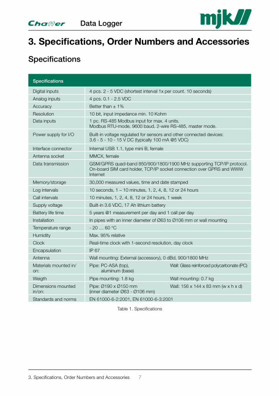
3. Specifications, Order Numbers and Accessories
Specifications
Specifications
Digital inputs 4 pcs. 2 - 5 VDC (shortest interval 1x per count. 10 seconds)
Analog inputs 4 pcs. 0.1 - 2.5 VDC
Accuracy Better than ± 1%
Resolution 10 bit, input impedance min. 10 Kohm
Data inputs 1 pc. RS-485 Modbus input for max. 4 units.Modbus RTU-mode, 9600 baud, 2-wire RS-485, master mode.
Power supply for I/O Built-in voltage regulated for sensors and other connected devices: 3.6 - 5 - 10 - 15 V DC (typically 100 mA @5 VDC)
Interface connector Internal USB 1.1, type mini B, female
Antenna socket MMCX, female
Data transmission
GSM/GPRS quad-band 850/900/1800/1900 MHz supporting TCP/IP protocol. On-board SIM card holder, TCP/IP socket connection over GPRS and WWW Internet
Memory/storage 30,000 measured values, time and date stamped
Log intervals 10 seconds, 1 – 10 minutes, 1, 2, 4, 8, 12 or 24 hours
Call intervals 10 minutes, 1, 2, 4, 8, 12 or 24 hours, 1 week
Supply voltage Built-in 3.6 VDC, 17 Ah lithium battery
Battery life time 5 years @1 measurement per day and 1 call per day
Installation In pipes with an inner diameter of Ø63 to Ø106 mm or wall mounting
Temperature range - 20 … 60 °C
Humidity Max. 95% relative
Clock Real-time clock with 1-second resolution, day clock
Encapsulation IP 67
Antenna Wall mounting: External (accessory), 0 dBd, 900/1800 MHz
Materials mounted in/on:
Pipe: PC-ASA (top), aluminum (base)
Wall: Glass reinforced polycarbonate (PC)
Weigth Pipe mounting: 1.8 kg Wall mounting: 0.7 kg
Dimensions mounted in/on:
Pipe: Ø190 x Ø150 mm (inner diameter Ø63 - Ø106 mm)
Wall: 156 x 144 x 83 mm (w x h x d)
Standards and norms EN 61000-6-2:2001, EN 61000-6-3:2001
Table 1. Specifications
3. Specifications, Order Numbers and Accessories
Data Logger
7
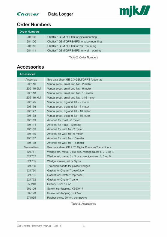
Order NumbersOrder Numbers
204105 Chatter™ GSM / GPRS for pipe mounting
204106 Chatter™ GSM/GPRS/GPS for pipe mounting
204110 Chatter™ GSM / GPRS for wall mounting
204111 Chatter™ GSM/GPRS/GPS for wall mounting
Table 2. Order Numbers
AccessoriesAccessories
Antennas See data sheet GB 6.3 GSM/GPRS Antennas
205116 Vandal proof, small and flat - 2 meter
205116-6M Vandal proof, small and flat - 6 meter
205118 Vandal proof, small and flat - 15 meter
205116-XM Vandal proof, small and flat - >15 meter
205175 Vandal proof, big and flat - 2 meter
205176 Vandal proof, big and flat - 6 meter
205177 Vandal proof, big and flat - 10 meter
205178 Vandal proof, big and flat - 15 meter
205119 Antenna for mast - 6 meter
205114 Antenna for mast - 10 meter
205185 Antenna for wall, fin - 2 meter
205186 Antenna for wall, fin - 6 meter
205187 Antenna for wall, fin - 10 meter
205188 Antenne for wall, fin - 15 meter
Transmitters See data sheet GB 2.76 Digital Pressure Transmitters
521751 Wedge set, metal, 3 x 3 pcs., wedge sizes: 1, 2, 3 og 4
521752 Wedge set, metal, 3 x 3 pcs., wedge sizes: 4, 5 og 6
521755 Wedge screws, set of 3 pcs.
521756 Threaded inserts for plastic wedges
521760 Gasket for Chatter™ base/pipe
521761 Gasket for Chatter™ top/base
521762 Gasket for Chatter™ panel
550246 Battery 3.6 V, 17 Ah
569108 Screw, self-tapping, KB50x14
569123 Screw, self-tapping, KB35x7
571055 Rubber band, 60mm, compound
Table 3. Accessories
Data Logger
8GB Chatter Hardware Manual 100416
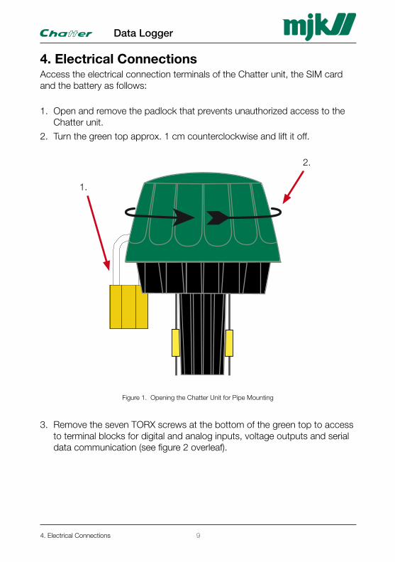
4. Electrical ConnectionsAccess the electrical connection terminals of the Chatter unit, the SIM card and the battery as follows:
1. Open and remove the padlock that prevents unauthorized access to the Chatter unit.
2. Turn the green top approx. 1 cm counterclockwise and lift it off.
1.
2.
Figure 1. Opening the Chatter Unit for Pipe Mounting
3. Remove the seven TORX screws at the bottom of the green top to access to terminal blocks for digital and analog inputs, voltage outputs and serial data communication (see figure 2 overleaf).
4. Electrical Connections
Data Logger
9
USB
TESTSW
USB
SIM card
ON OFF
Battery
ANT.1
ANT.2 ANT.3
DI 1
DI 2
DI 3
DI 4
AI 1
AI 2
AI 3
AI 4
GN
D
GN
D
+5/
10/
15V
GN
D
3V6-
A
GN
D
GN
D
A B GN
D
3V6-
B
GN
D
RS485
1 2 3 4 5
3.6 VDC battery
MJK order no. 550246
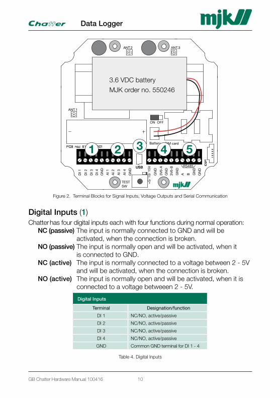
Figure 2. Terminal Blocks for Signal Inputs, Voltage Outputs and Serial Communication
Digital Inputs (1)Chatter has four digital inputs each with four functions during normal operation: NC (passive) The input is normally connected to GND and will be activated, when the connection is broken. NO (passive) The input is normally open and will be activated, when it is connected to GND. NC (active) The input is normally connected to a voltage between 2 - 5V and will be activated, when the connection is broken. NO (active) The input is normally open and will be activated, when it is connected to a voltage betweeen 2 - 5V.
Digital Inputs
Terminal Designation/function
DI 1 NC/NO, active/passive
DI 2 NC/NO, active/passive
DI 3 NC/NO, active/passive
DI 4 NC/NO, active/passive
GND Common GND terminal for DI 1 - 4
Table 4. Digital Inputs
Data Logger
10GB Chatter Hardware Manual 100416
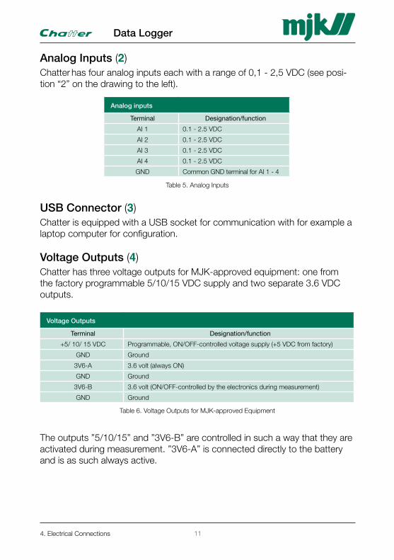
Analog Inputs (2)Chatter has four analog inputs each with a range of 0,1 - 2,5 VDC (see posi-tion “2” on the drawing to the left).
Analog inputs
Terminal Designation/function
AI 1 0.1 - 2.5 VDC
AI 2 0.1 - 2.5 VDC
AI 3 0.1 - 2.5 VDC
AI 4 0.1 - 2.5 VDC
GND Common GND terminal for AI 1 - 4
Table 5. Analog Inputs
USB Connector (3)Chatter is equipped with a USB socket for communication with for example a laptop computer for configuration.
Voltage Outputs (4)Chatter has three voltage outputs for MJK-approved equipment: one from the factory programmable 5/10/15 VDC supply and two separate 3.6 VDC outputs.
Voltage Outputs
Terminal Designation/function
+5/ 10/ 15 VDC Programmable, ON/OFF-controlled voltage supply (+5 VDC from factory)
GND Ground
3V6-A 3.6 volt (always ON)
GND Ground
3V6-B 3.6 volt (ON/OFF-controlled by the electronics during measurement)
GND Ground
Table 6. Voltage Outputs for MJK-approved Equipment
The outputs ”5/10/15” and ”3V6-B” are controlled in such a way that they are activated during measurement. ”3V6-A” is connected directly to the battery and is as such always active.
4. Electrical Connections
Data Logger
11
Serial Data Communication for Modbus (5)Chatter is equipped with RS-485 serial data communications. See position “5” in Figure 2.
RS-485 Serial Data Communication for Modbus
Terminal Designation/function
A (RS485) Signal A
B (RS485) Signal B
GND (RS485) Ground
GND Ground
Table 7. RS-485 Serial Data Communication
Other Main Components on the Circuit Board
Battery (6)The battery is located on top of the Chatter PCB (see Figure 3). Connec-tion is through a connector placed in the middle of the circuit board (“Bat-tery”, red and black wires).Please note that the battery can be replaced without first setting the Chat-ter unit in ”OFF” position. See section 6. Gain Access to SIM Card and Battery and section 7. Internal Installation in the Chatter Unit for gaining access to and chang-ing the battery.
Jumper (7)A jumper is placed right below the battery with two positions: ON and OFF. In ON position the Chatter incl. pressure transmitter is powered (acti-vated), and in OFF position it is disconnected (switched off).
Booster Capacitor (8)The booster capacitor delivers current during data transmissions.
SIM Card (9)The SIM card facilitate communication via the GSM/GPRS network. See also the procedure for inserting/changing the SIM card in section 7. Internal Installation in the Chatter Unit on page 25.
Data Logger
12GB Chatter Hardware Manual 100416
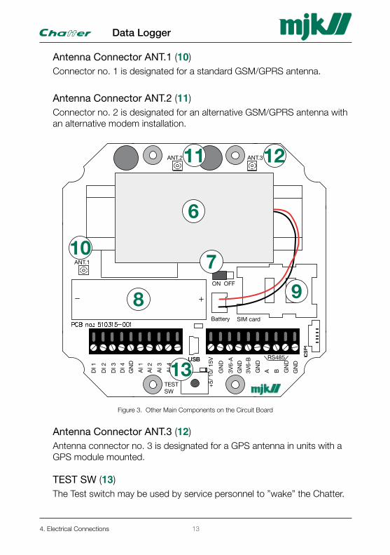
Antenna Connector ANT .1 (10)Connector no. 1 is designated for a standard GSM/GPRS antenna.
Antenna Connector ANT .2 (11)Connector no. 2 is designated for an alternative GSM/GPRS antenna with an alternative modem installation.
USB
TESTSW
USB
SIM card
ON OFF
Battery
ANT.1
ANT.2 ANT.3
DI 1
DI 2
DI 3
DI 4
AI 1
AI 2
AI 3
AI 4
GN
D
GN
D
+5/
10/
15V
GN
D
3V6-
A
GN
D
GN
D
A B GN
D
3V6-
B
GN
D
RS485
6
7
98
10
11 12
13
Figure 3. Other Main Components on the Circuit Board
Antenna Connector ANT .3 (12)Antenna connector no. 3 is designated for a GPS antenna in units with a GPS module mounted.
TEST SW (13)The Test switch may be used by service personnel to ”wake” the Chatter.
4. Electrical Connections
Data Logger
13

This page is left blank.
Data Logger
14GB Chatter Hardware Manual 100416
5. MountingMJK Chatter data logger is supplied in two different mounting versions: one for pipe mounting and one for wall mounting (mounting on wall or cabinet).
5.1 Pipe MountingNecessary tools and parts:
• Wedge set to fit pipe diameter
• Socket spanner, 7 mm
1. Activate the Chatter unit(s) as described in section 9. Physical Activation on page 31.
2. Re-assemble the Chatter unit(s) as described in section 6.2 Wall Mounting on page 23.
3. Prepare the Chatter base with wedges to fit the pipe diameter:
Wedge From inner diameter ----> to inner diameter
Wedge 1 Ø63 mm Ø71 mm
Wedge 2 Ø70 mm Ø78 mm
Wedge 3 Ø77 mm Ø85 mm
Wedge 4 Ø84 mm Ø92 mm
Wedge 5 Ø91 mm Ø99 mm
Wedge 6 Ø98 mm Ø106 mm
Table 8. Wedge Sizes
5. Mounting
Data Logger
15
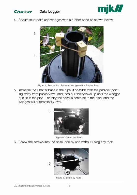
4. Secure stud bolts and wedges with a rubber band as shown below.
3.
4.
Figure 4. Secure Stud Bolts and Wedges with a Rubber Band
5. Immerse the Chatter base in the pipe (if possible with the padlock point-ing away from public view), and then pull the screws up until the wedges buckle in the pipe. Thereby the base is centered in the pipe, and the wedges will automatically level.
5.
Figure 5. Center the Base
6. Screw the screws into the base, one by one without using any tool:
6.
Figure 6. Screw by Hand
Data Logger
16GB Chatter Hardware Manual 100416
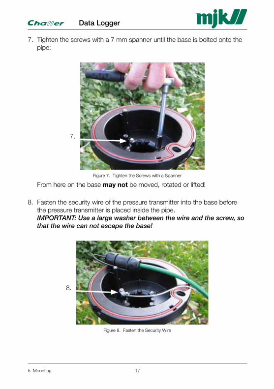
7. Tighten the screws with a 7 mm spanner until the base is bolted onto the pipe:
7.
Figure 7. Tighten the Screws with a Spanner
From here on the base may not be moved, rotated or lifted!
8. Fasten the security wire of the pressure transmitter into the base before the pressure transmitter is placed inside the pipe. IMPORTANT: Use a large washer between the wire and the screw, so that the wire can not escape the base!
8.
Figure 8. Fasten the Security Wire
5. Mounting
Data Logger
17
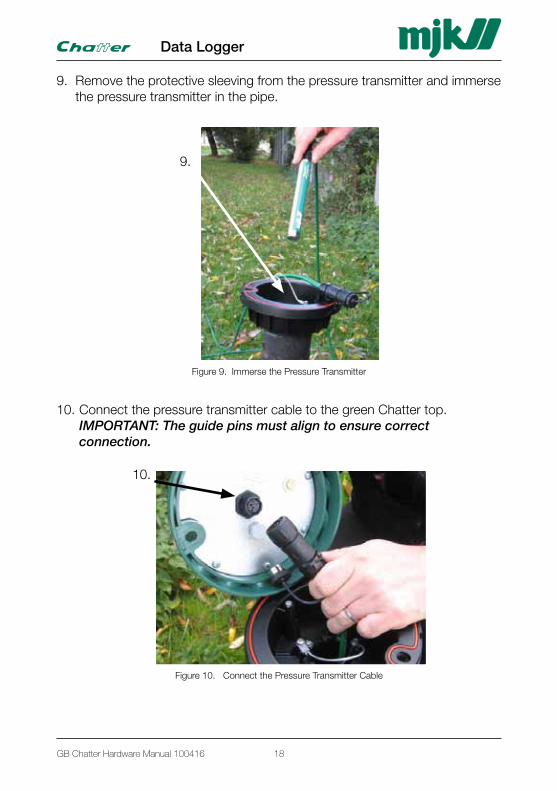
9. Remove the protective sleeving from the pressure transmitter and immerse the pressure transmitter in the pipe.
9.
Figure 9. Immerse the Pressure Transmitter
10. Connect the pressure transmitter cable to the green Chatter top. IMPORTANT: The guide pins must align to ensure correct connection.
10.
Figure 10. Connect the Pressure Transmitter Cable
Data Logger
18GB Chatter Hardware Manual 100416
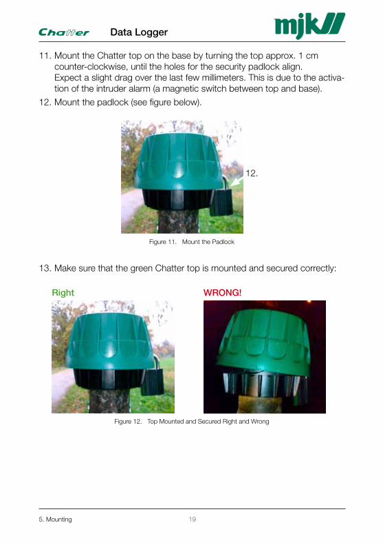
11. Mount the Chatter top on the base by turning the top approx. 1 cm counter-clockwise, until the holes for the security padlock align. Expect a slight drag over the last few millimeters. This is due to the activa-tion of the intruder alarm (a magnetic switch between top and base).
12. Mount the padlock (see figure below).
12.
Figure 11. Mount the Padlock
13. Make sure that the green Chatter top is mounted and secured correctly:
Right WRONG!
Figure 12. Top Mounted and Secured Right and Wrong
5. Mounting
Data Logger
19
5.2 Wall Mounting1. Mount the cabinet on the wall.
2. Connect the pressure transmitter(s) according to the example in section 8.1 MJK Chatter and MJK Expert Transmitter on page 29.
3. Connect the relevant in- and outputs.
4. Aktivate the Chatter unit(s) as described in section 9. Physical Activation on page 31.
5. Close the Chatter unit(s) as described in section 6.2 Wall Mounting on page 23.
Data Logger
20GB Chatter Hardware Manual 100416
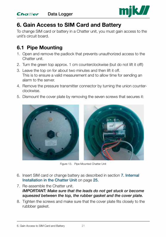
6. Gain Access to SIM Card and BatteryTo change SIM card or battery in a Chatter unit, you must gain access to the unit’s circuit board.
6.1 Pipe Mounting1. Open and remove the padlock that prevents unauthorized access to the
Chatter unit.
2. Turn the green top approx. 1 cm counterclockwise (but do not lift it off!)
3. Leave the top on for about two minutes and then lift it off. This is to ensure a valid measurement and to allow time for sending an alarm to the server.
4. Remove the pressure transmitter connector by turning the union counter-clockwise.
5. Dismount the cover plate by removing the seven screws that secures it:
Figure 13. Pipe Mounted Chatter Unit
6. Insert SIM card or change battery as described in section 7. Internal Installation in the Chatter Unit on page 25.
7. Re-assemble the Chatter unit. IMPORTANT: Make sure that the leads do not get stuck or become squeezed between the top, the rubber gasket and the cover plate.
8. Tighten the screws and make sure that the cover plate fits closely to the rubbber gasket.
6. Gain Access to SIM Card and Battery
Data Logger
21
9. Re-connect the pressure transmitter connector by turning the union clock-wise.
10. Immerse the pressure transmitter into the pipe, and make sure that the cable and the security wire hang freely inside the pipe to ensure reliable measurements.
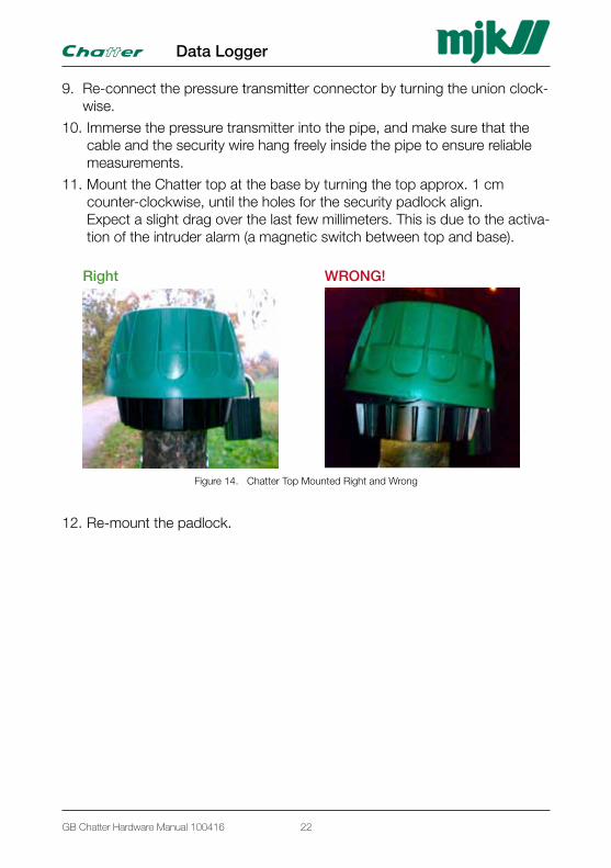
11. Mount the Chatter top at the base by turning the top approx. 1 cm counter-clockwise, until the holes for the security padlock align. Expect a slight drag over the last few millimeters. This is due to the activa-tion of the intruder alarm (a magnetic switch between top and base).
Right WRONG!
Figure 14. Chatter Top Mounted Right and Wrong
12. Re-mount the padlock.
Data Logger
22GB Chatter Hardware Manual 100416
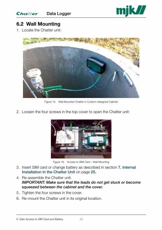
6.2 Wall Mounting1. Locate the Chatter unit:
Figure 15. Wall Mounted Chatter in Custom-designed Cabinet
2. Loosen the four screws in the top cover to open the Chatter unit:
Figure 16. Access to SIM Card - Wall Mounting
3. Insert SIM card or change battery as described in section 7. Internal Installation in the Chatter Unit on page 25.
4. Re-assemble the Chatter unit. IMPORTANT: Make sure that the leads do not get stuck or become squeezed between the cabinet and the cover.
5. Tighten the four screws in the cover.
6. Re-mount the Chatter unit in its original location.
6. Gain Access to SIM Card and Battery
Data Logger
23

This page is left blank.
Data Logger
24GB Chatter Hardware Manual 100416
7. Internal Installation in the Chatter Unit
7.1 Inserting a SIM Card
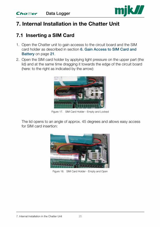
1. Open the Chatter unit to gain accesss to the circuit board and the SIM card holder as described in section 6. Gain Access to SIM Card and Battery on page 21.
2. Open the SIM card holder by applying light pressure on the upper part (the lid) and at the same time dragging it towards the edge of the circuit board (here: to the right as indicated by the arrow):
Figure 17. SIM Card Holder - Empty and Locked
The lid opens to an angle of approx. 45 degrees and allows easy access for SIM card insertion:
Figure 18. SIM Card Holder - Empty and Open
7. Internal Installation in the Chatter Unit
Data Logger
25
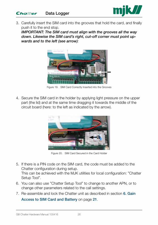
3. Carefully insert the SIM card into the grooves that hold the card, and finally push it to the end stop. IMPORTANT: The SIM card must align with the grooves all the way down. Likewise the SIM card’s right, cut-off corner must point up-wards and to the left (see arrow):
Figure 19. SIM Card Correctly Inserted into the Grooves
4. Secure the SIM card in the holder by applying light pressure on the upper part (the lid) and at the same time dragging it towards the middle of the circuit board (here: to the left as indicated by the arrow).
Figure 20. SIM Card Secured in the Card Holder
5. If there is a PIN code on the SIM card, the code must be added to the Chatter configuration during setup. This can be achieved with the MJK utilities for local configuration: ”Chatter Setup Tool”.
6. You can also use ”Chatter Setup Tool” to change to another APN, or to change other parameters related to the call settings.
7. Re-assemble and lock the Chatter unit as described in section 6. Gain
Access to SIM Card and Battery on page 21.
Data Logger
26GB Chatter Hardware Manual 100416
7.2 Battery Change
1. Open the Chatter unit to gain accesss to the circuit board and the bat-tery as described in section 6. Gain Access to SIM Card and Battery on page 21.
2. Carefully push the battery sidewards to free it from the cable strap that holds the battery. Alternatively you can cut the cable strap (this requires, however, that you use a new strap for the new battery).
3. Disconnect the battery leads (red and black) from the Chatter circuit board by pulling out the “Batt” plug.
4. Connect the new battery’s leads to the “Batt” connector.
5. Push the new battery into the old cable strap (or, if cut, secure the new battery with a new cable strap).
6. Re-assemble og lock the Chatter unit as described in section 6. Gain Ac-cess to SIM Card and Battery on page 21.
7. Internal Installation in the Chatter Unit
Data Logger
27

This page is left blank.
Data Logger
28GB Chatter Hardware Manual 100416
8. Connection Examples
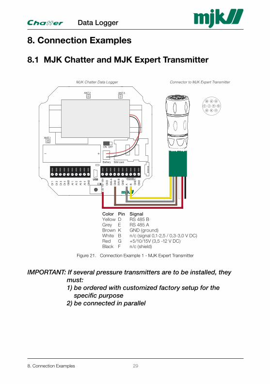
8.1 MJK Chatter and MJK Expert Transmitter
DK 2.76 Expert 7060/7070 090120 www.mjk.comDK: +45 45 56 06 56NO: +47 69 20 60 70SE: +46 53 31 77 50NL: +31 251 672171USA: +1 847 482 8655AUS: +61 3 9758 8533
Datablad
Elektrisk tilslutning
MJK Expert™ 7060 og 7070 hydrostatiske digital/analog niveau tryktransmittere er præcisions-transmittere med indbygget Modbus protokol for udlæsning af målinger og fjernkalibrering under drift, og de erudviklet til installationer med krav om lavt energiforbrug og sammenkobling med MJK Chatter Datalogger.
MJK Expert™ 7060 Niveau Transmitter er en robust all-round transmitter ideel til niveaumåling i opbe-varingstanke, vådkilder og pumpestationer i både drikkevand- og spildevandsanlæg.
MJK Expert™ 7070 Niveau Transmitter har de samme specifikationer som 7060-transmitteren, men har derudover en meget lille ydre diameter og er fremstillet i 316L syrefast, rustfrit stål. Transmit-teren er specielt udviklet til niveaumålinger i boringer, brønde og drikkevandsbeholdere.
Transmitterne leveres med piezo-resistivt målesy-stem og hhv. direkte lufttrykskompensation (relativ) via et integreret ventilationsrør i kablet og indbygget temperatur kompensation samt som ABS (absolute) og SG (sealed gauge) versioner.
MJK Chatter Data Logger
Generelt
C J K G
D E F
B A H
Color Pin Signal Yellow D RS 485 B Grey E RS 485 A Brown K GND (ground) White B n/c (signal 0,1-2,5 / 0,3-3,0 V DC) Red G +5/10/15V (3,5 -12 V DC) Black F n/c (shield)
Connector to MJK Expert Transmitter
MJK Expert™ 7060 / 7070Hydrostatisk digital/analog niveau tryktransmitter
Da vore produkter løbende udvikles, forbeholder vi os ret til ændringer i mål og specifikationer.
2.76
USBUSB
SIM card
ON OFF
Battery
ANT.1
ANT.2 ANT.3
DI 1
DI 2
DI 3
DI 4
AI 1
AI 2
AI 3
AI 4
GN
D
GN
D
+5/
10/
15V
GN
D
3V6-
A
GN
D
GN
D
A B GN
D
3V6-
B
GN
D
RS485
Figure 21. Connection Example 1 - MJK Expert Transmitter
IMPORTANT: If several pressure transmitters are to be installed, they must: 1) be ordered with customized factory setup for the specific purpose 2) be connected in parallel
8. Connection Examples
Data Logger
29
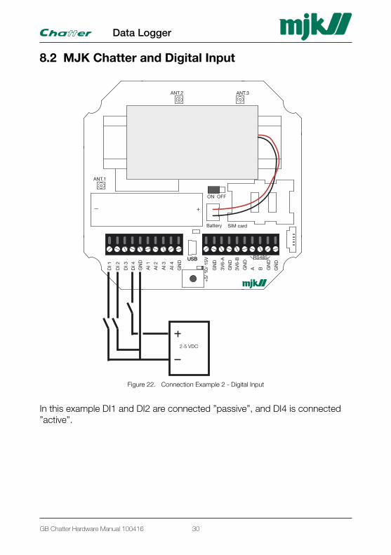
8.2 MJK Chatter and Digital Input
USBUSB
SIM card
ON OFF
Battery
ANT.1
ANT.2 ANT.3
DI 1
DI 2
DI 3
DI 4
AI 1
AI 2
AI 3
AI 4
GN
D
GN
D
+5/
10/
15V
GN
D
3V6-
A
GN
D
GN
D
A B GN
D
3V6-
B
GN
D
RS485
2-5 VDC
Figure 22. Connection Example 2 - Digital Input
In this example DI1 and DI2 are connected ”passive”, and DI4 is connected ”active”.
Data Logger
30GB Chatter Hardware Manual 100416
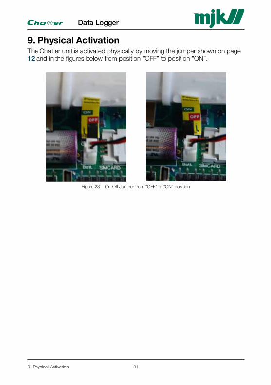
9. Physical ActivationThe Chatter unit is activated physically by moving the jumper shown on page 12 and in the figures below from position ”OFF” to position ”ON”.
Figure 23. On-Off Jumper from ”OFF” to ”ON” position
9. Physical Activation
Data Logger
31

This page is left blank.
Data Logger
32GB Chatter Hardware Manual 100416
10. Mechanic Dimensions
Chatter Unit for Pipe Mounting
150 mm
101 mm
190 mm
Ø 63 - 106 mmIndre rørdiameter
190
150
101
Inner pipe diameterØ63 - Ø106
Figure 24. Mechanic Dimensions - Pipe Mounted
Chatter Unit for Wall Mounting
144
156
83 79
Figure 25. Mechanic Dimensions - Wall Mounted
10. Mechanic Dimensions
Data Logger
33

This page is left blank.
Data Logger
34GB Chatter Hardware Manual 100416

11. Maintenance The MJK Chatter Data Logger requires no maintenance.
Service AgreementA service agreement guaranties the equipment’s long term reliability and accuracy. Contact one of MJK’s national sales- or service representatives to make a service agreement with regular service visits.
11. Maintenance
Data Logger
35

This page is left blank.
Appendix A. Frontpanel Cut-Out TemplateThe dotted lines indicate the front panel contour and measures 155 x 145 mm.
Cut
-out
are
a
Frontpanel outline
Up
Data Logger
36GB Chatter Hardware Manual 100416
Appendix A. Frontpanel Cut-Out TemplateThe dotted lines indicate the front panel contour and measures 155 x 145 mm.
Cut
-out
are
a
Frontpanel outlineU
p
Appendix A. Frontpanel Cut-Out Template
Data Logger
37

This page is left blank.
Data Logger
38GB Chatter Hardware Manual 100416
Appendix B. Calculation of Battery Lifetime
The battery in the MJK Chatter unit is of the lithium-trionyl-ion-trotyl type which is characterized by a high energy density, a low self-discharge, and a long lifetime. The energy density is 17 Ah nominal and guarantied 15 Ah (15.000 mAh). Depending on the use of the Chatter unit you can estimate the battery lifetime.
The Chatter will, depending on the setup, execute one control call every 25th. hour (if a shorter interval has not been selected). This ensures that you can always make changes to the setup efter 25 hours. MJK recommends that you perform a call every 24 hours (once a day) or more frequent.
The lifetime calculation is simple for usages with a fixed log interval, whereas usages with event log require a time estimation for the event logs.
Calculation TemplateChatter basic consumption per day (fixed) = 1.0
No. of logs per day @sensor consump.=2mA ? x 0.1 = -
No. of logs per day @sensor consump. =4mA ? x 0.2 = -
No. of event logs per day @sensor consump.=2mA ? x 0.1 = -
No. of event logs per day @sensor consump. =4mA ? x 0.2 = -
No. of calls per day ? x 3 = -
No. of alarm calls per day ? x 3 = -
Consumption per day (total): -
Battery lifetime in days: 15000/consump. per day [day] = -
Battery lifetime in months: Battery lifetime [days]/30 [months] = -
Battery lifetime in years: Battery lifetime [months]/12 [years] = -
=====
Appendix B. Calculation of Battery Lifetime
Data Logger
39
Calculation Example 1 Chatter basic consumption per day (fixed) = 1.0
No. of logs per day @sensor consump.=2mA 1 x 0.1 = 0.1
No. of logs per day @sensor consump. =4mA - x 0.2 = -
No. of event logs per day @sensor consump.=2mA - x 0.1 = -
No. of event logs per day @sensor consump. =4mA - x 0.2 = -
No. of calls per day 1 x 3 = 3.0
No. of alarm calls per day 0.01 x 3 = 0.03
Consumption per day (total): 4.13
Battery lifetime in days: 15000/consump. per day [day] = 3632.1
Battery lifetime in months: Battery lifetime [days]/30 [months] = 121.1
Battery lifetime in years: Battery lifetime [months]/12 [years] = 10.0 yrs
=======
Calculation Example 2 Chatter basic consumption per day (fixed) = 1.0
No. of logs per day @sensor consump.=2mA 24 x 0.1 = 2.4
No. of logs per day @sensor consump. =4mA - x 0.2 = -
No. of event logs per day @sensor consump.=2mA 60 x 0.1 = 6.0
No. of event logs per day @sensor consump. =4mA - x 0.2 = -
No. of calls per day - x 3 = -
No. of alarm calls per day - x 3 = -
Consumption per day (total): 9.4
Battery lifetime in days: 15000/consump. per day [day] = 1595.7
Battery lifetime in months: Battery lifetime [days]/30 [months] = 53.2
Battery lifetime in years: Battery lifetime [months]/12 [years] = 4.4 yrs
=======
Data Logger
40GB Chatter Hardware Manual 100416
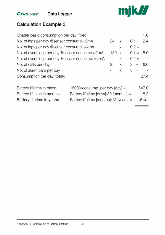
Calculation Example 3 Chatter basic consumption per day (fixed) = 1.0
No. of logs per day @sensor consump.=2mA 24 x 0.1 = 2.4
No. of logs per day @sensor consump. =4mA - x 0.2 = -
No. of event logs per day @sensor consump.=2mA 180 x 0.1 = 18.0
No. of event logs per day @sensor consump. =4mA - x 0.2 = -
No. of calls per day 2 x 3 = 6.0
No. of alarm calls per day - x 3 = -
Consumption per day (total): 27.4
Battery lifetime in days: 15000/consump. per day [day] = 547.0
Battery lifetime in months: Battery lifetime [days]/30 [months] = 18.2
Battery lifetime in years: Battery lifetime [months]/12 [years] = 1.5 yrs
=======
Appendix B. Calculation of Battery Lifetime
Data Logger
41

This page is left blank.
Data Logger
42GB Chatter Hardware Manual 100416
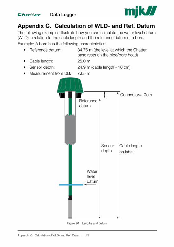
Appendix C. Calculation of WLD- and Ref. DatumThe following examples illustrate how you can calculate the water level datum (WLD) in relation to the cable length and the reference datum of a bore.
Example: A bore has the following characteristics:
• Reference datum: 34.76 m (the level at which the Chatter base rests on the pipe/bore head)
• Cable length: 25.0 m
• Sensor depth: 24.9 m (cable length - 10 cm)
• Measurement from DB: 7.65 m
Reference datum
Water level datum
Connector=10cm
Sensor depth
Cable length
on label
Figure 26. Lengths and Datum
Appendix C. Calculation of WLD- and Ref. Datum
Data Logger
43
The water level datum (WLD) in this example: 34.76 - 24.9 + 7.65 => 17.51 m
The following figures/numbers for the bore are required as entries to the data base to achieve a valid calculation of the water level datum.
Sensor depth from top of bore
1. Sensor depth from the top of the bore = total cable length – 10cm.
2. “Total cable length” is printed on a label near the cable connector (example: cable length = 11.86 m).
3. To get the sensor depth in relation to the top of the bore, you must sub-tract 10 cm due to the cable connector length (11.86 - 0.1 = 11.76 m).
4. This is also the sensor depth that you use in calculations and write into the Chatter database (written to the server from the Chatter Link ”Modbus” tab in the field ”Sensor depth”).
Data Logger
44GB Chatter Hardware Manual 100416
List of FiguresFigure 1. Opening the Chatter Unit for Pipe Mounting 9Figure 2. Terminal Blocks for Signal Inputs, Voltage Outputs and Serial Communication 10Figure 3. Other Main Components on the Circuit Board 13Figure 4. Secure Stud Bolts and Wedges with a Rubber Band 16Figure 5. Center the Base 16Figure 6. Screw by Hand 16Figure 7. Tighten the Screws with a Spanner 17Figure 8. Fasten the Security Wire 17Figure 9. Immerse the Pressure Transmitter 18Figure 10. Connect the Pressure Transmitter Cable 18Figure 11. Mount the Padlock 19Figure 12. Top Mounted and Secured Right and Wrong 19Figure 13. Pipe Mounted Chatter Unit 21Figure 14. Chatter Top Mounted Right and Wrong 22Figure 15. Wall Mounted Chatter in Custom-designed Cabinet 23Figure 16. Access to SIM Card - Wall Mounting 23Figure 17. SIM Card Holder - Empty and Locked 25Figure 18. SIM Card Holder - Empty and Open 25Figure 19. SIM Card Correctly Inserted into the Grooves 26Figure 20. SIM Card Secured in the Card Holder 26Figure 21. Connection Example 1 - MJK Expert Transmitter 29Figure 22. Connection Example 2 - Digital Input 30Figure 23. On-Off Jumper from ”OFF” to ”ON” position 31Figure 24. Mechanic Dimensions - Pipe Mounted 33Figure 25. Mechanic Dimensions - Wall Mounted 33Figure 26. Lengths and Datum 43
List of TablesTable 1. Specifications 7Table 2. Order Numbers 8Table 3. Accessories 8Table 4. Digital Inputs 10Table 5. Analog Inputs 11Table 6. Voltage Outputs for MJK-approved Equipment 11Table 7. RS-485 Serial Data Communication 12Table 8. Wedge Sizes 15
Appendix C. Calculation of WLD- and Ref. Datum
Data Logger
45

This page is left blank.
Data Logger
46GB Chatter Hardware Manual 100416

Index
Aaccesssories . . . . . . . . . . . . . . . . . . 8
accuracy . . . . . . . . . . . . . . . . . . . . . 7
activation . . . . . . . . . . . . . . . . . . . . 31
alarm . . . . . . . . . . . . . . . . . . . . . . . 21
analog inputs . . . . . . . . . . . . . . . 7, 11
antenna connector . . . . . . . . . . . 7, 13
antennas . . . . . . . . . . . . . . . . . . . . . 7
Bbattery . . . . . . . . . . . . . . . . . . . . . . 12
battery lifetime . . . . . . . . . . . . . . . . 39
baud rate . . . . . . . . . . . . . . . . . . . . . 7
booster capacitor . . . . . . . . . . . . . . 12
Ccable length . . . . . . . . . . . . . . . 43, 44
call intervals . . . . . . . . . . . . . . . . . . . 7
circuit board . . . . . . . . . . . . . . . 12, 21
clock . . . . . . . . . . . . . . . . . . . . . . . . 7
conformity . . . . . . . . . . . . . . . . . . . . 2
Ddatum . . . . . . . . . . . . . . . . . . . . . . . 43
digital inputs . . . . . . . . . . . . . . . . 7, 10
dimensions . . . . . . . . . . . . . . . . . . . 33
Eexamples . . . . . . . . . . . . . . . . . . . . 29
Ffront panel . . . . . . . . . . . . . . . . . . . 37
Ggasket . . . . . . . . . . . . . . . . . . . . 8, 21
GPRS . . . . . . . . . . . . . . . . . . . . . . . . 7
GPS . . . . . . . . . . . . . . . . . . . . . . . . 13
GSM . . . . . . . . . . . . . . . . . . . . . . . . . 7
Iinputs . . . . . . . . . . . . . . . . . . . . . . . . 7
interface connector . . . . . . . . . . . . . . 7
intruder . . . . . . . . . . . . . . . . . . . . . . 22
Jjumper . . . . . . . . . . . . . . . . . . . 12, 31
Llog intervals . . . . . . . . . . . . . . . . . . . 7
Mmaintenance . . . . . . . . . . . . . . . . . . 35
mechanic dimensions . . . . . . . . . . . 33
memory/storage . . . . . . . . . . . . . . . . 7
MMCX . . . . . . . . . . . . . . . . . . . . . . . 7
modem installation . . . . . . . . . . . . . 13
Oorder numbers . . . . . . . . . . . . . . . . . 8
Ppadlock . . . . . . . . . . . . . . . . . . 19, 22
pipe mounting . . . . . . . . . . . . . 15, 21
power supply . . . . . . . . . . . . . . . . . 11
Rreference datum . . . . . . . . . . . . . . . 43
repair . . . . . . . . . . . . . . . . . . . . . . . . 6
RTU . . . . . . . . . . . . . . . . . . . . . . . . . 7
rubber band . . . . . . . . . . . . . . . . . . . 8
Ssafety . . . . . . . . . . . . . . . . . . . . . . . . 6
safety instructions . . . . . . . . . . . . . . . 6
sensor depth . . . . . . . . . . . . . . . . . 44
serial data communication . . . . . . . 12
Index
Data Logger
Index-1
service agreement . . . . . . . . . . . . . 35
SIM card . . . . . . . . . . . . . 7, 12, 21, 25
specifications . . . . . . . . . . . . . . . . . . 7
strap . . . . . . . . . . . . . . . . . . . . . . . . 27
stud bolts . . . . . . . . . . . . . . . . . . . . 16
switch . . . . . . . . . . . . . . . . . . . . . . . 19
TTCP/IP . . . . . . . . . . . . . . . . . . . . . . . 7
temperature range . . . . . . . . . . . . . . 7
template . . . . . . . . . . . . . . . . . . . . . 37
terminal blocks . . . . . . . . . . . . . . 9, 10
test switch . . . . . . . . . . . . . . . . . . . 13
TORX . . . . . . . . . . . . . . . . . . . . . . . . 9
Uunion . . . . . . . . . . . . . . . . . . . . . . . 21
USB connector . . . . . . . . . . . . . . . . 11
Vvoltage outputs . . . . . . . . . . . . . . . . 11
VSP . . . . . . . . . . . . . . . . . . . . . . . . 43
Wwall mounting . . . . . . . . . . . . . . 20, 23
WARNING . . . . . . . . . . . . . . . . . . . . 6
washer . . . . . . . . . . . . . . . . . . . . . . 17
water level datum . . . . . . . . . . . . . . 43
wedge sizes . . . . . . . . . . . . . . . . 8, 15
weight . . . . . . . . . . . . . . . . . . . . . . . 7
wires . . . . . . . . . . . . . . . . . . . . . . . . 12
Data Logger
Index-2GB Chatter Hardware Manual 100416

This page is left blank.
Data Logger
Index-3GB Chatter Hardware Manual 100416
LiabilityMJK Automation A/S are liable to the common rules of Da-nish law on product liability, however, the liability is reduced to coverage of our public liability insurance of products. To the extent where nothing else follows in lines of invariable rules of law, we are not liable for loss of profits and working deficits or other indirect losses.
ChangesAs our products are developed continuously, we reserve the right to make any alterations without prior notice.
DK: +45 45 56 06 56NO: +47 69 20 60 70SE: +46 53 31 77 50NL: +31 251 672171IRL: +353 879535625USA: +1 847 482 8655AUS: +61 3 9758 8533
MJK Automation A/S
GB Chatter Hardware Manual 100416
Data Logger