Embed Size (px)
Citation preview
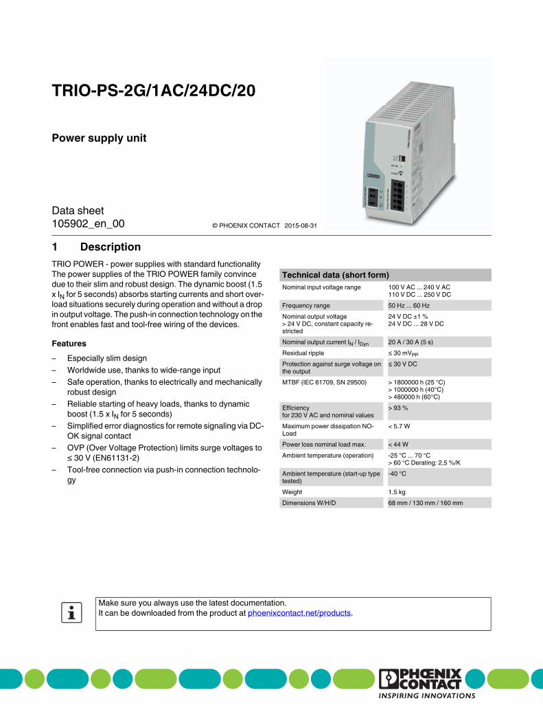
1 Description
Power supply unit
TRIO-PS-2G/1AC/24DC/20
© PHOENIX CONTACT
Data sheet
TRIO POWER - power supplies with standard functionality
The power supplies of the TRIO POWER family convince
due to their slim and robust design. The dynamic boost (1.5
x IN for 5 seconds) absorbs starting currents and short over-
load situations securely during operation and without a drop
in output voltage. The push-in connection technology on the
front enables fast and tool-free wiring of the devices.
Features
– Especially slim design
– Worldwide use, thanks to wide-range input
– Safe operation, thanks to electrically and mechanically
robust design
– Reliable starting of heavy loads, thanks to dynamic
boost (1.5 x IN for 5 seconds)
– Simplified error diagnostics for remote signaling via DC-
OK signal contact
– OVP (Over Voltage Protection) limits surge voltages to
≤ 30 V (EN61131-2)
– Tool-free connection via push-in connection technolo-
gy
Technical data (short form)
Nominal input voltage range 100 V AC ... 240 V AC
110 V DC ... 250 V DC
Frequency range 50 Hz ... 60 Hz
Nominal output voltage
> 24 V DC, constant capacity re-
stricted
24 V DC ±1 %
24 V DC ... 28 V DC
Nominal output current IN / IDyn 20 A / 30 A (5 s)
Residual ripple ≤ 30 mVPP
Protection against surge voltage on
the output
≤ 30 V DC
MTBF (IEC 61709, SN 29500) > 1800000 h (25 °C)
> 1000000 h (40°C)
> 480000 h (60°C)
Efficiency
for 230 V AC and nominal values
> 93 %
Maximum power dissipation NO-
Load
< 5.7 W
Power loss nominal load max. < 44 W
Ambient temperature (operation) -25 °C ... 70 °C
> 60 °C Derating: 2,5 %/K
Ambient temperature (start-up type
tested)
-40 °C
Weight 1.5 kg
Dimensions W/H/D 68 mm / 130 mm / 160 mm
Make sure you always use the latest documentation.
It can be downloaded from the product at phoenixcontact.net/products.
105902_en_00 2015-08-31
TRIO-PS-2G/1AC/24DC/20
105902_en_00 PHOENIX CONTACT 2
2 Table of contents
1 Description .............................................................................................................................. 1
2 Table of contents ..................................................................................................................... 2
3 Ordering data .......................................................................................................................... 3
4 Technical data ......................................................................................................................... 3
5 Safety regulations and installation notes.................................................................................. 7
6 Basic circuit diagram ............................................................................................................... 7
7 Structure.................................................................................................................................. 8
8 Cooling .................................................................................................................................... 8
9 Mounting position and dimensions .......................................................................................... 9
9.1 Mounting position ................................................................................................................ 9
9.2 Device dimensions............................................................................................................. 10
10 Mounting/removal.................................................................................................................. 11
10.1 Assembly......................................................................................................................... 11
10.2 Removal.......................................................................................................................... 11
11 Device connection terminal blocks ........................................................................................ 11
11.1 Push-in connection technology ............................................................................................. 11
12 Input ...................................................................................................................................... 12
12.1 Position of input terminals .................................................................................................... 12
12.2 Protection of the primary side ............................................................................................... 12
13 Output.................................................................................................................................... 13
13.1 Position of output terminals .................................................................................................. 13
13.2 Protection of the secondary side............................................................................................ 13
13.3 Output characteristic curve................................................................................................... 13
14 Dynamic boost....................................................................................................................... 14
15 Signaling................................................................................................................................ 14
15.1 DC OK-LED ..................................................................................................................... 14
15.2 Floating signal contact ........................................................................................................ 14
16 Derating................................................................................................................................. 15
16.1 Temperature-dependent derating .......................................................................................... 15
16.2 Position-dependent derating................................................................................................. 16
17 Operating modes................................................................................................................... 19
17.1 Series operation ................................................................................................................ 19
17.2 Parallel operation............................................................................................................... 19
17.3 Redundant operation .......................................................................................................... 19
17.4 Increasing power ............................................................................................................... 20
TRIO-PS-2G/1AC/24DC/20
105902_en_00 PHOENIX CONTACT 3
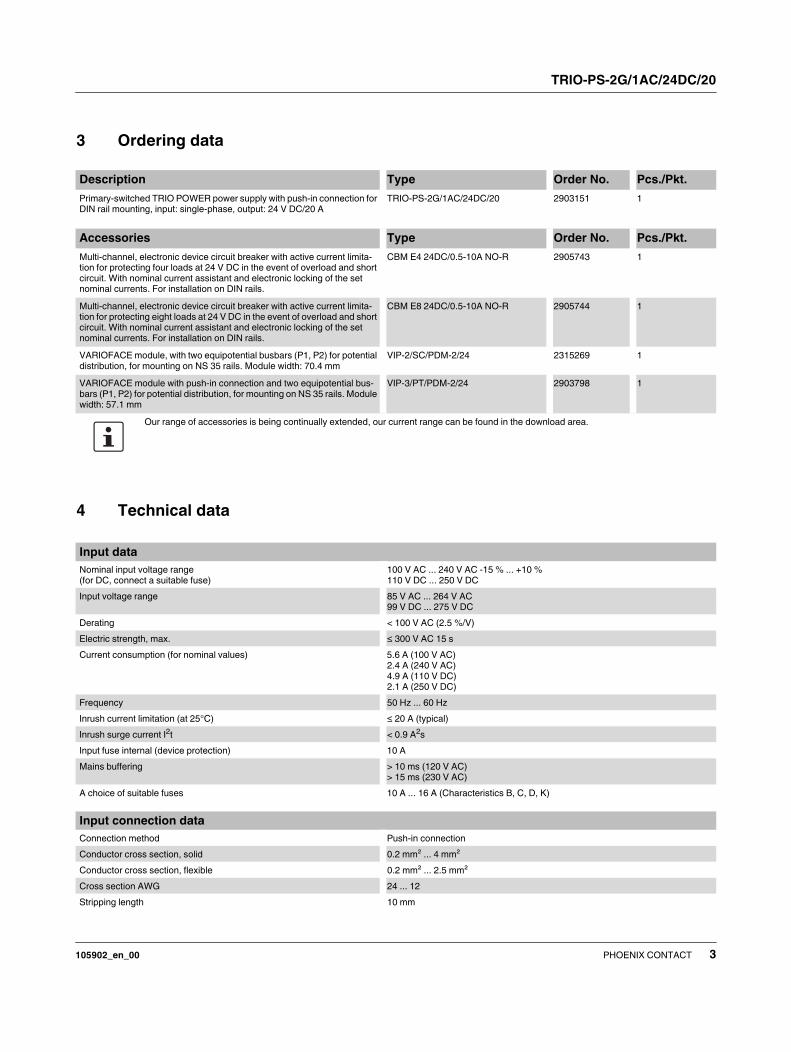
Description Type Order No. Pcs./Pkt.
Primary-switched TRIO POWER power supply with push-in connection for
DIN rail mounting, input: single-phase, output: 24 V DC/20 A
TRIO-PS-2G/1AC/24DC/20 2903151 1
3 Ordering data
Accessories Type Order No. Pcs./Pkt.
Multi-channel, electronic device circuit breaker with active current limita-
tion for protecting four loads at 24 V DC in the event of overload and short
circuit. With nominal current assistant and electronic locking of the set
nominal currents. For installation on DIN rails.
CBM E4 24DC/0.5-10A NO-R 2905743 1
Multi-channel, electronic device circuit breaker with active current limita-
tion for protecting eight loads at 24 V DC in the event of overload and short
circuit. With nominal current assistant and electronic locking of the set
nominal currents. For installation on DIN rails.
CBM E8 24DC/0.5-10A NO-R 2905744 1
VARIOFACE module, with two equipotential busbars (P1, P2) for potential
distribution, for mounting on NS 35 rails. Module width: 70.4 mm
VIP-2/SC/PDM-2/24 2315269 1
VARIOFACE module with push-in connection and two equipotential bus-
bars (P1, P2) for potential distribution, for mounting on NS 35 rails. Module
width: 57.1 mm
VIP-3/PT/PDM-2/24 2903798 1
Our range of accessories is being continually extended, our current range can be found in the download area.
4 Technical data
Input data
Nominal input voltage range
(for DC, connect a suitable fuse)
100 V AC ... 240 V AC -15 % ... +10 %
110 V DC ... 250 V DC
Input voltage range 85 V AC ... 264 V AC
99 V DC ... 275 V DC
Derating < 100 V AC (2.5 %/V)
Electric strength, max. ≤ 300 V AC 15 s
Current consumption (for nominal values) 5.6 A (100 V AC)
2.4 A (240 V AC)
4.9 A (110 V DC)
2.1 A (250 V DC)
Frequency 50 Hz ... 60 Hz
Inrush current limitation (at 25°C) ≤ 20 A (typical)
Inrush surge current I2t < 0.9 A
2s
Input fuse internal (device protection) 10 A
Mains buffering > 10 ms (120 V AC)
> 15 ms (230 V AC)
A choice of suitable fuses 10 A ... 16 A (Characteristics B, C, D, K)
Input connection data
Connection method Push-in connection
Conductor cross section, solid 0.2 mm² ... 4 mm²
Conductor cross section, flexible 0.2 mm² ... 2.5 mm²
Cross section AWG 24 ... 12
Stripping length 10 mm
TRIO-PS-2G/1AC/24DC/20
105902_en_00 PHOENIX CONTACT 4
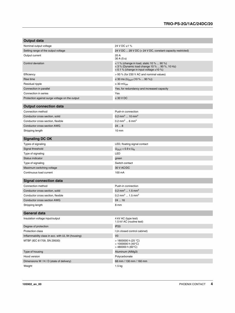
Output data
Nominal output voltage 24 V DC ±1 %
Setting range of the output voltage 24 V DC ... 28 V DC (> 24 V DC, constant capacity restricted)
Output current 20 A
30 A (5 s)
Control deviation < 1 % (change in load, static 10 % ... 90 %)
< 3 % (Dynamic load change 10 % ... 90 %, 10 Hz)
< 0.1 % (change in input voltage ±10 %)
Efficiency > 93 % (for 230 V AC and nominal values)
Rise time ≤ 30 ms (UOUT (10 % ... 90 %))
Residual ripple ≤ 30 mVPP
Connection in parallel Yes, for redundancy and increased capacity
Connection in series Yes
Protection against surge voltage on the output ≤ 30 V DC
Output connection data
Connection method Push-in connection
Conductor cross section, solid 0.2 mm² ... 10 mm²
Conductor cross section, flexible 0.2 mm² ... 6 mm²
Conductor cross section AWG 24 ... 8
Stripping length 10 mm
Signaling DC OK
Types of signaling LED, floating signal contact
Signal threshold UOUT < 0.9 x UN
Type of signaling LED
Status indicator green
Type of signaling Switch contact
Maximum switching voltage 30 V AC/DC
Continuous load current 100 mA
Signal connection data
Connection method Push-in connection
Conductor cross section, solid 0.2 mm² ... 1.5 mm²
Conductor cross section, flexible 0.2 mm² ... 1.5 mm²
Conductor cross section AWG 24 ... 16
Stripping length 8 mm
General data
Insulation voltage input/output 4 kV AC (type test)
1.5 kV AC (routine test)
Degree of protection IP20
Protection class I (in closed control cabinet)
Inflammability class in acc. with UL 94 (housing) V0
MTBF (IEC 61709, SN 29500) > 1800000 h (25 °C)
> 1000000 h (40°C)
> 480000 h (60°C)
Type of housing Aluminum (AlMg3)
Hood version Polycarbonate
Dimensions W / H / D (state of delivery) 68 mm / 130 mm / 160 mm
Weight 1.5 kg
TRIO-PS-2G/1AC/24DC/20
105902_en_00 PHOENIX CONTACT 5
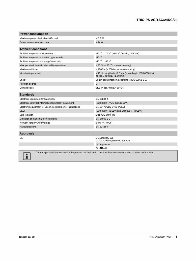
Power consumption
Maximum power dissipation NO-Load < 5.7 W
Power loss nominal load max. < 44 W
Ambient conditions
Ambient temperature (operation) -25 °C ... 70 °C (> 60 °C Derating: 2,5 %/K)
Ambient temperature (start-up type tested) -40 °C
Ambient temperature (storage/transport) -40 °C ... 85 °C
Max. permissible relative humidity (operation) ≤ 95 % (at 25 °C, non-condensing)
Maximum altitude ≤ 4000 m (> 2000 m, observe derating)
Vibration (operation) < 15 Hz, amplitude ±2.5 mm (according to IEC 60068-2-6)
15 Hz ... 150 Hz, 4g, 90 min.
Shock 30g in each direction, according to IEC 60068-2-27
Pollution degree 2
Climatic class 3K3 (in acc. with EN 60721)
Standards
Electrical Equipment for Machinery EN 60204-1
Electrical safety (of information technology equipment) IEC 60950-1/VDE 0805 (SELV)
Electronic equipment for use in electrical power installations EN 50178/VDE 0160 (PELV)
SELV IEC 60950-1 (SELV) and EN 60204-1 (PELV)
Safe isolation DIN VDE 0100-410
Limitation of mains harmonic currents EN 61000-3-2
Network version/undervoltage Semi F47-0706
Rail applications EN 50121-4
Approvals
UL UL Listed UL 508
UL/C-UL Recognized UL 60950-1
GL applied for
Current approvals/permissions for the product can be found in the download area under phoenixcontact.net/products.
TRIO-PS-2G/1AC/24DC/20
105902_en_00 PHOENIX CONTACT 6
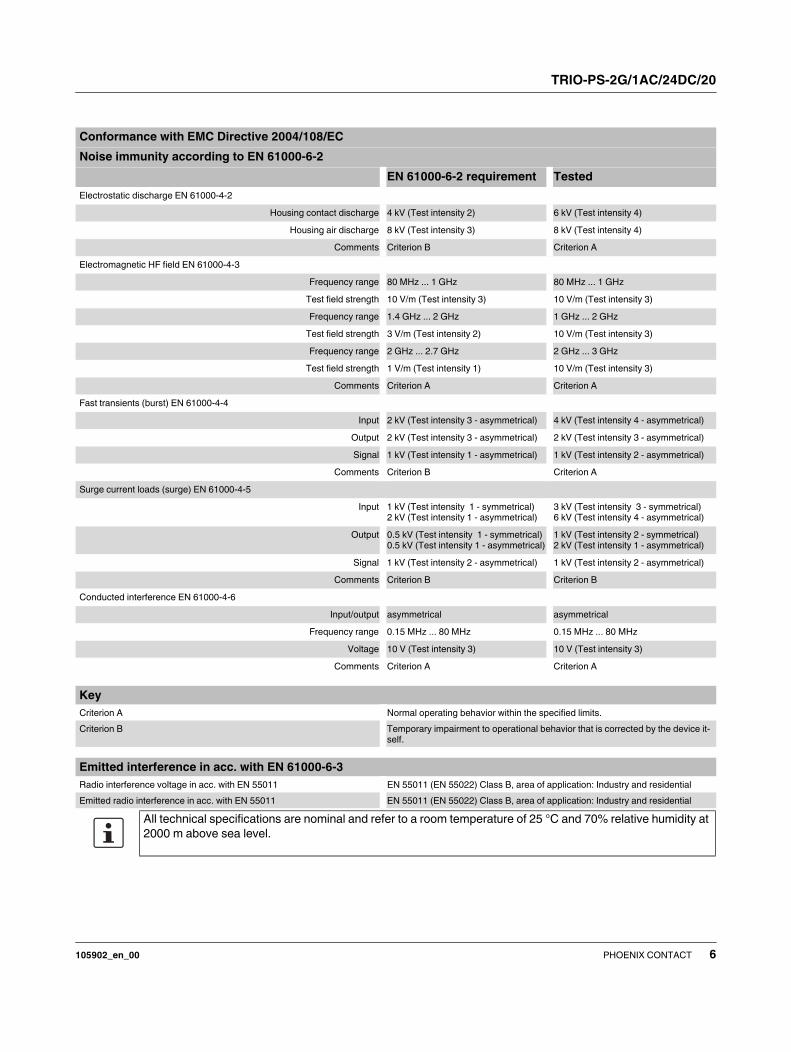
Conformance with EMC Directive 2004/108/EC
Noise immunity according to EN 61000-6-2
EN 61000-6-2 requirement Tested
Electrostatic discharge EN 61000-4-2
Housing contact discharge 4 kV (Test intensity 2) 6 kV (Test intensity 4)
Housing air discharge 8 kV (Test intensity 3) 8 kV (Test intensity 4)
Comments Criterion B Criterion A
Electromagnetic HF field EN 61000-4-3
Frequency range 80 MHz ... 1 GHz 80 MHz ... 1 GHz
Test field strength 10 V/m (Test intensity 3) 10 V/m (Test intensity 3)
Frequency range 1.4 GHz ... 2 GHz 1 GHz ... 2 GHz
Test field strength 3 V/m (Test intensity 2) 10 V/m (Test intensity 3)
Frequency range 2 GHz ... 2.7 GHz 2 GHz ... 3 GHz
Test field strength 1 V/m (Test intensity 1) 10 V/m (Test intensity 3)
Comments Criterion A Criterion A
Fast transients (burst) EN 61000-4-4
Input 2 kV (Test intensity 3 - asymmetrical) 4 kV (Test intensity 4 - asymmetrical)
Output 2 kV (Test intensity 3 - asymmetrical) 2 kV (Test intensity 3 - asymmetrical)
Signal 1 kV (Test intensity 1 - asymmetrical) 1 kV (Test intensity 2 - asymmetrical)
Comments Criterion B Criterion A
Surge current loads (surge) EN 61000-4-5
Input 1 kV (Test intensity 1 - symmetrical)
2 kV (Test intensity 1 - asymmetrical)
3 kV (Test intensity 3 - symmetrical)
6 kV (Test intensity 4 - asymmetrical)
Output 0.5 kV (Test intensity 1 - symmetrical)
0.5 kV (Test intensity 1 - asymmetrical)
1 kV (Test intensity 2 - symmetrical)
2 kV (Test intensity 1 - asymmetrical)
Signal 1 kV (Test intensity 2 - asymmetrical) 1 kV (Test intensity 2 - asymmetrical)
Comments Criterion B Criterion B
Conducted interference EN 61000-4-6
Input/output asymmetrical asymmetrical
Frequency range 0.15 MHz ... 80 MHz 0.15 MHz ... 80 MHz
Voltage 10 V (Test intensity 3) 10 V (Test intensity 3)
Comments Criterion A Criterion A
Key
Criterion A Normal operating behavior within the specified limits.
Criterion B Temporary impairment to operational behavior that is corrected by the device it-
self.
Emitted interference in acc. with EN 61000-6-3
Radio interference voltage in acc. with EN 55011 EN 55011 (EN 55022) Class B, area of application: Industry and residential
Emitted radio interference in acc. with EN 55011 EN 55011 (EN 55022) Class B, area of application: Industry and residential
All technical specifications are nominal and refer to a room temperature of 25 °C and 70% relative humidity at
2000 m above sea level.
TRIO-PS-2G/1AC/24DC/20
105902_en_00 PHOENIX CONTACT 7
5 Safety regulations and installation
notes
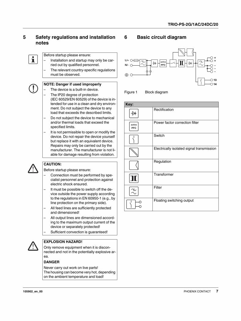
6 Basic circuit diagram
Figure 1 Block diagram
Before startup please ensure:
– Installation and startup may only be car-
ried out by qualified personnel.
– The relevant country-specific regulations
must be observed.
NOTE: Danger if used improperly
– The device is a built-in device.
– The IP20 degree of protection
(IEC 60529/EN 60529) of the device is in-
tended for use in a clean and dry environ-
ment. Do not subject the device to any
load that exceeds the described limits.
– Do not subject the device to mechanical
and/or thermal loads that exceed the
specified limits.
– It is not permissible to open or modify the
device. Do not repair the device yourself
but replace it with an equivalent device.
Repairs may only be carried out by the
manufacturer. The manufacturer is not li-
able for damage resulting from violation.
CAUTION:
Before startup please ensure:
– Connection must be performed by spe-
cialist personnel and protection against
electric shock ensured.
– It must be possible to switch off the de-
vice outside the power supply according
to the regulations in EN 60950-1 (e.g., by
line protection on the primary side).
– All feed lines are sufficiently protected
and dimensioned!
– All output lines are dimensioned accord-
ing to the maximum output current of the
device or separately protected!
– Sufficient convection is guaranteed!
EXPLOSION HAZARD!
Only remove equipment when it is discon-
nected and not in the potentially explosive ar-
ea.
DANGER
Never carry out work on live parts!
The housing can become very hot, depending
on the ambient temperature and load!
Key:
Rectification
Power factor correction filter
Switch
Electrically isolated signal transmission
Regulation
Transformer
Filter
Floating switching output
14
13
active
PFC
L/+
N/-
13
14
++
---
active
PFC
TRIO-PS-2G/1AC/24DC/20
105902_en_00 PHOENIX CONTACT 8
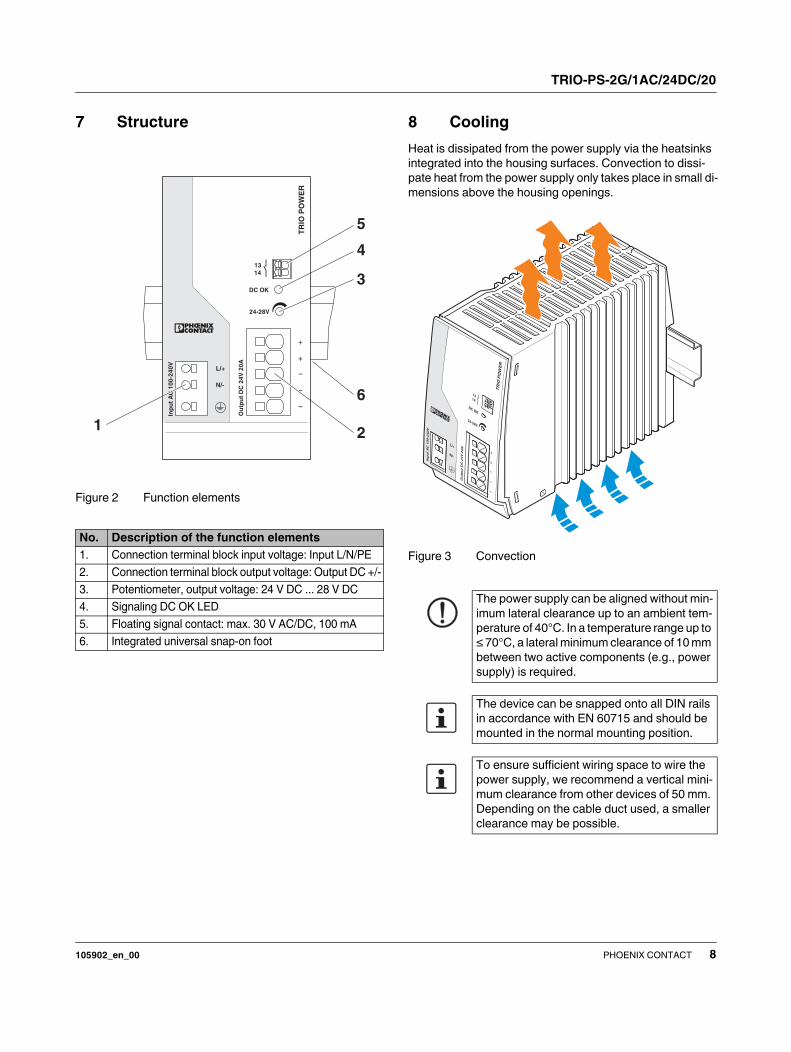
7 Structure
Figure 2 Function elements
8 Cooling
Heat is dissipated from the power supply via the heatsinks
integrated into the housing surfaces. Convection to dissi-
pate heat from the power supply only takes place in small di-
mensions above the housing openings.
Figure 3 Convection
No. Description of the function elements
1. Connection terminal block input voltage: Input L/N/PE
2. Connection terminal block output voltage: Output DC +/-
3. Potentiometer, output voltage: 24 V DC ... 28 V DC
4. Signaling DC OK LED
5. Floating signal contact: max. 30 V AC/DC, 100 mA
6. Integrated universal snap-on foot
TR
IO P
OW
ER
24-28V
DC OK
13
14
+
+
-
-
-
Ou
tpu
t D
C 2
4V
20
A
L/+
N/-
Inp
ut
AC
10
0-2
40
V
6
21
5
3
4
The power supply can be aligned without min-
imum lateral clearance up to an ambient tem-
perature of 40°C. In a temperature range up to
≤ 70°C, a lateral minimum clearance of 10 mm
between two active components (e.g., power
supply) is required.
The device can be snapped onto all DIN rails
in accordance with EN 60715 and should be
mounted in the normal mounting position.
To ensure sufficient wiring space to wire the
power supply, we recommend a vertical mini-
mum clearance from other devices of 50 mm.
Depending on the cable duct used, a smaller
clearance may be possible.
TRIO-PS-2G/1AC/24DC/20
105902_en_00 PHOENIX CONTACT 9
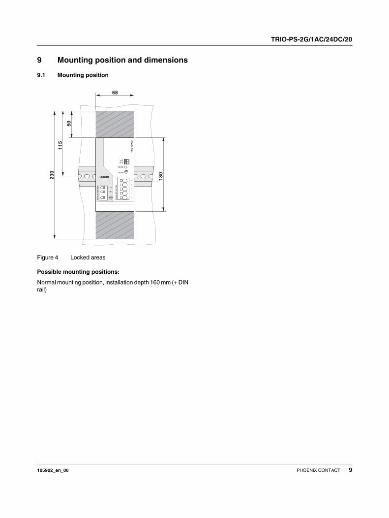
9 Mounting position and dimensions
9.1 Mounting position
Figure 4 Locked areas
Possible mounting positions:
Normal mounting position, installation depth 160 mm (+ DIN
rail)
68
50
11
5
23
0
13
0
TR
IO P
OW
ER
24-28V
DC OK
13
14
+
+
-
-
-
Ou
tpu
tD
C 2
4V
20
A
L/+
N/-
Inp
ut
AC
10
0-2
40
V
TRIO-PS-2G/1AC/24DC/20
105902_en_00 PHOENIX CONTACT 10
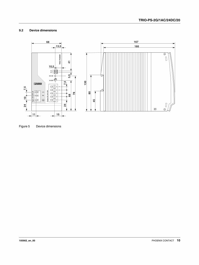
9.2 Device dimensions
Figure 5 Device dimensions
TR
IO P
OW
ER
24-28V
DC OK
13
14
+
+
-
-
-
Ou
tpu
t D
C 2
4V
20
A
L/+
N/-
Inp
ut
AC
10
0-2
40
V
10
24
13,5
68 7
8
11
24
68
7,5
41
3,5
10,5
7,5
Inp
ut
10
0-2
40
V A
C
15
-
+
+
-
-
160
167
13
0
45
80

TRIO-PS-2G/1AC/24DC/20
105902_en_00 PHOENIX CONTACT 11
10 Mounting/removal
10.1 Assembly
Position the module with the DIN rail guide on the upper
edge of the DIN rail, and snap it in with a downward motion.
Figure 6 Assembly on standard DIN rail
10.2 Removal
Pull the snap lever open with the aid of a screwdriver and
slide the module out at the lower edge of the DIN rail.
Figure 7 Removing the DIN rail
11 Device connection terminal blocks
11.1 Push-in connection technology
All connection terminal blocks on the power supply have
push-in connection technology on the front. The power sup-
ply is wired by simply plugging in the connecting cables, no
tools are required. For the necessary connection parame-
ters for the terminal blocks, please refer to the technical
data.
11.1.1 Plug in connecting cable
The wiring is carried out by simply plugging the connecting
cable into the contact opening provided. Insert the connect-
ing cable as far as it will go.
Figure 8 Insert connecting cable (push-in connection
technology)
11.1.2 Loosen the connecting cable
To disconnect the wiring, take a suitable screwdriver and in-
sert it into the opening for release. Then carefully pull the
connecting cable out of the contact opening.
Figure 9 Release connecting cable (push-in connection
technology)
B
A
BA
C
D
A
A
B
TRIO-PS-2G/1AC/24DC/20
105902_en_00 PHOENIX CONTACT 12
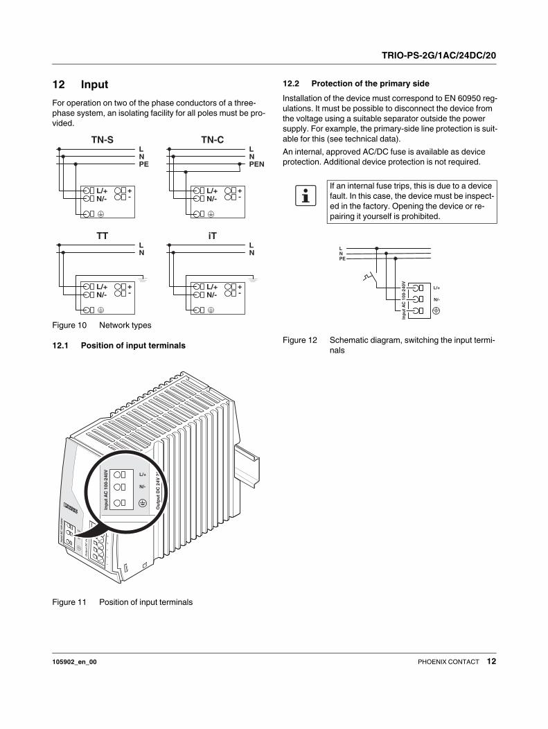
12 Input
For operation on two of the phase conductors of a three-
phase system, an isolating facility for all poles must be pro-
vided.
Figure 10 Network types
12.1 Position of input terminals
Figure 11 Position of input terminals
12.2 Protection of the primary side
Installation of the device must correspond to EN 60950 reg-
ulations. It must be possible to disconnect the device from
the voltage using a suitable separator outside the power
supply. For example, the primary-side line protection is suit-
able for this (see technical data).
An internal, approved AC/DC fuse is available as device
protection. Additional device protection is not required.
Figure 12 Schematic diagram, switching the input termi-
nals
-+
N/-L/+
LNPE
TN-S
-+
N/-L/+
LNPEN
TN-C
-+
N/-L/+
LN
TT
-+
N/-L/+
LN
iT
Ou
tpu
t D
C 2
4V
20
A
L/+
N/-
Inp
ut
AC
10
0-2
40
V
If an internal fuse trips, this is due to a device
fault. In this case, the device must be inspect-
ed in the factory. Opening the device or re-
pairing it yourself is prohibited.
N/-
L/+
LNPE
Inp
ut
AC
10
0-2
40
V
TRIO-PS-2G/1AC/24DC/20
105902_en_00 PHOENIX CONTACT 13
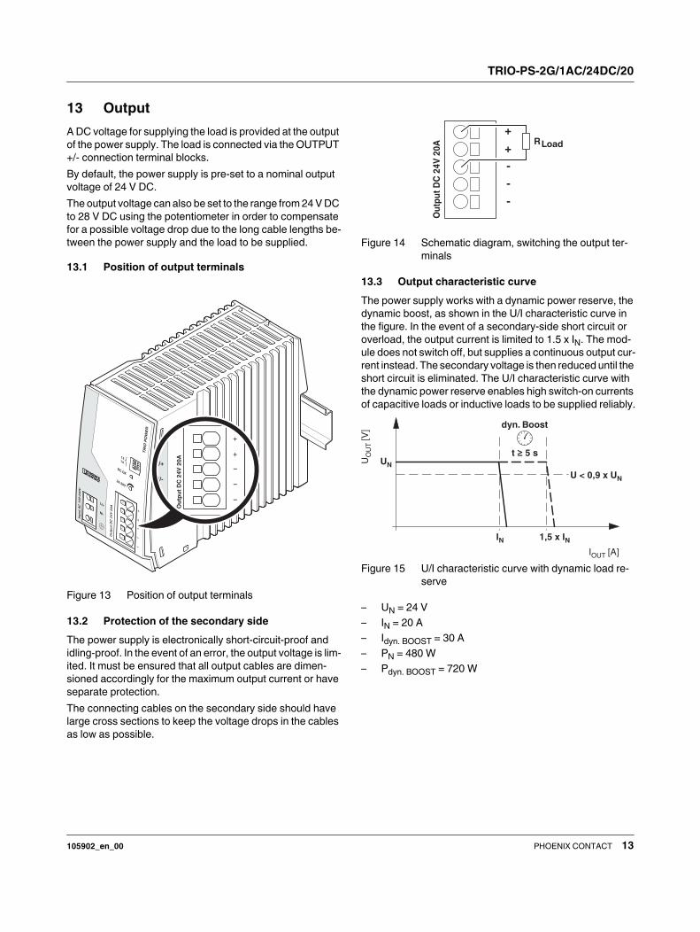
13 Output
A DC voltage for supplying the load is provided at the output
of the power supply. The load is connected via the OUTPUT
+/- connection terminal blocks.
By default, the power supply is pre-set to a nominal output
voltage of 24 V DC.
The output voltage can also be set to the range from 24 V DC
to 28 V DC using the potentiometer in order to compensate
for a possible voltage drop due to the long cable lengths be-
tween the power supply and the load to be supplied.
13.1 Position of output terminals
Figure 13 Position of output terminals
13.2 Protection of the secondary side
The power supply is electronically short-circuit-proof and
idling-proof. In the event of an error, the output voltage is lim-
ited. It must be ensured that all output cables are dimen-
sioned accordingly for the maximum output current or have
separate protection.
The connecting cables on the secondary side should have
large cross sections to keep the voltage drops in the cables
as low as possible.
Figure 14 Schematic diagram, switching the output ter-
minals
13.3 Output characteristic curve
The power supply works with a dynamic power reserve, the
dynamic boost, as shown in the U/I characteristic curve in
the figure. In the event of a secondary-side short circuit or
overload, the output current is limited to 1.5 x IN. The mod-
ule does not switch off, but supplies a continuous output cur-
rent instead. The secondary voltage is then reduced until the
short circuit is eliminated. The U/I characteristic curve with
the dynamic power reserve enables high switch-on currents
of capacitive loads or inductive loads to be supplied reliably.
Figure 15 U/I characteristic curve with dynamic load re-
serve
– UN = 24 V
– IN = 20 A
– Idyn. BOOST = 30 A
– PN = 480 W
– Pdyn. BOOST = 720 W
+
+
-
-
-
Ou
tpu
t D
C 2
4V
20
A
L/+
N/-
+
+
-
-
-
RLoad
Ou
tpu
t D
C 2
4V
20
A
I [A]OUT
U[V
]O
UT
UN
IN
U < 0,9 x UN
t ≥ 5 s
1,5 x IN
dyn. Boost
TRIO-PS-2G/1AC/24DC/20
105902_en_00 PHOENIX CONTACT 14
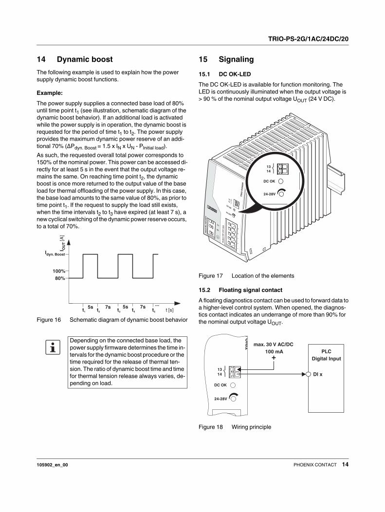
14 Dynamic boost
The following example is used to explain how the power
supply dynamic boost functions.
Example:
The power supply supplies a connected base load of 80%
until time point t1 (see illustration, schematic diagram of the
dynamic boost behavior). If an additional load is activated
while the power supply is in operation, the dynamic boost is
requested for the period of time t1 to t2. The power supply
provides the maximum dynamic power reserve of an addi-
tional 70% (ΔPdyn. Boost = 1.5 x IN x UN - PInitial load).
As such, the requested overall total power corresponds to
150% of the nominal power. This power can be accessed di-
rectly for at least 5 s in the event that the output voltage re-
mains the same. On reaching time point t2, the dynamic
boost is once more returned to the output value of the base
load for thermal offloading of the power supply. In this case,
the base load amounts to the same value of 80%, as prior to
time point t1. If the request to supply the load still exists,
when the time intervals t2 to t3 have expired (at least 7 s), a
new cyclical switching of the dynamic power reserve occurs,
to a total of 70%.
Figure 16 Schematic diagram of dynamic boost behavior
15 Signaling
15.1 DC OK-LED
The DC OK-LED is available for function monitoring. The
LED is continuously illuminated when the output voltage is
> 90 % of the nominal output voltage UOUT (24 V DC).
Figure 17 Location of the elements
15.2 Floating signal contact
A floating diagnostics contact can be used to forward data to
a higher-level control system. When opened, the diagnos-
tics contact indicates an underrange of more than 90% for
the nominal output voltage UOUT.
Figure 18 Wiring principle
Depending on the connected base load, the
power supply firmware determines the time in-
tervals for the dynamic boost procedure or the
time required for the release of thermal ten-
sion. The ratio of dynamic boost time and time
for thermal tension release always varies, de-
pending on load.
t [s]t1
...5s 7s 5s 7s
t2 t3 t4 t5
I OU
T[A
]
Idyn. Boost
80%
100%
24-28V
DC OK
13
14
TR
IOP
24-28V
DC OK
13
14
PLC
Digital Input
DI x
max. 30 V AC/DC
100 mA
+
TRIO-PS-2G/1AC/24DC/20
105902_en_00 PHOENIX CONTACT 15
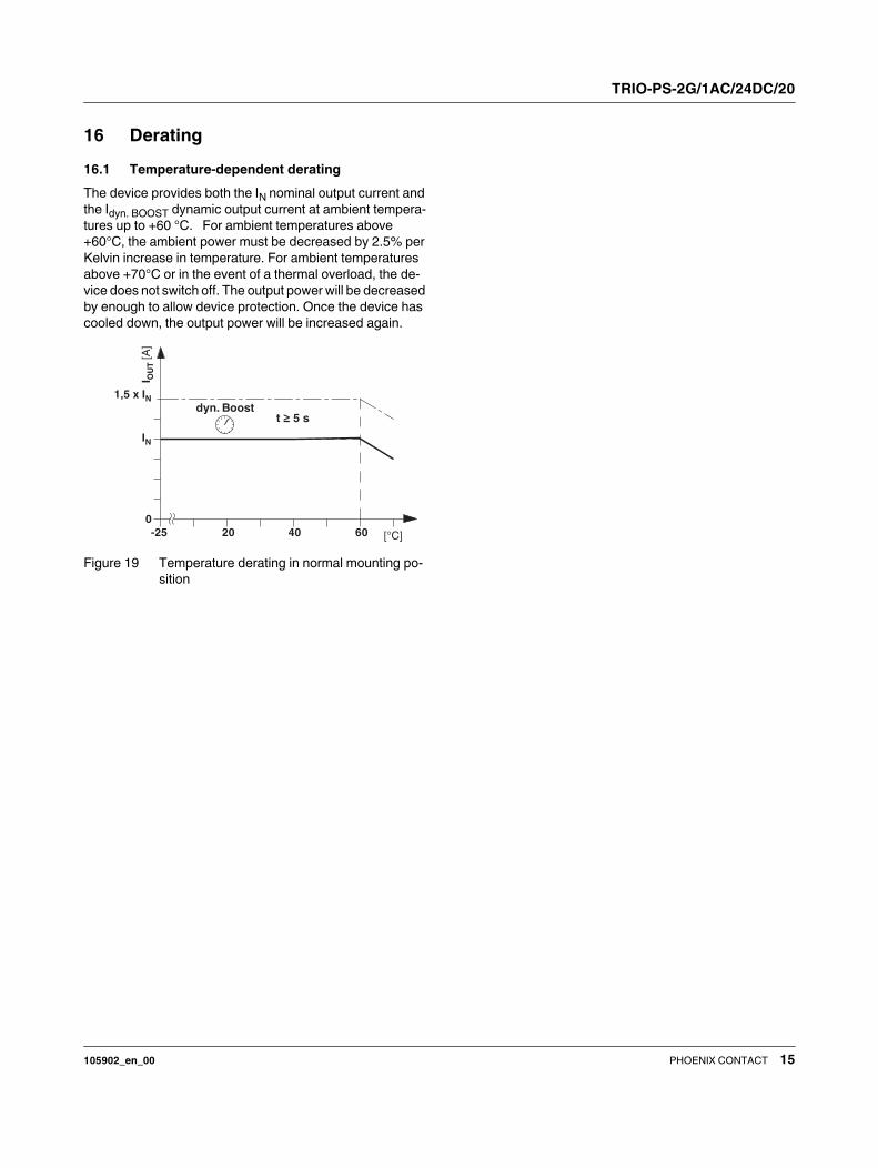
16 Derating
16.1 Temperature-dependent derating
The device provides both the IN nominal output current and
the Idyn. BOOST dynamic output current at ambient tempera-
tures up to +60 °C. For ambient temperatures above
+60°C, the ambient power must be decreased by 2.5% per
Kelvin increase in temperature. For ambient temperatures
above +70°C or in the event of a thermal overload, the de-
vice does not switch off. The output power will be decreased
by enough to allow device protection. Once the device has
cooled down, the output power will be increased again.
Figure 19 Temperature derating in normal mounting po-
sition
I OU
T[A
]
[°C]-25
0
40 6020
1,5 x IN
IN
t ≥ 5 sdyn. Boost
TRIO-PS-2G/1AC/24DC/20
105902_en_00 PHOENIX CONTACT 16
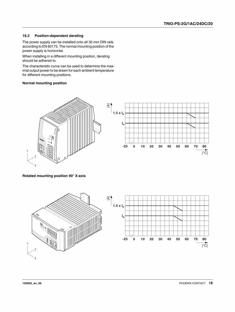
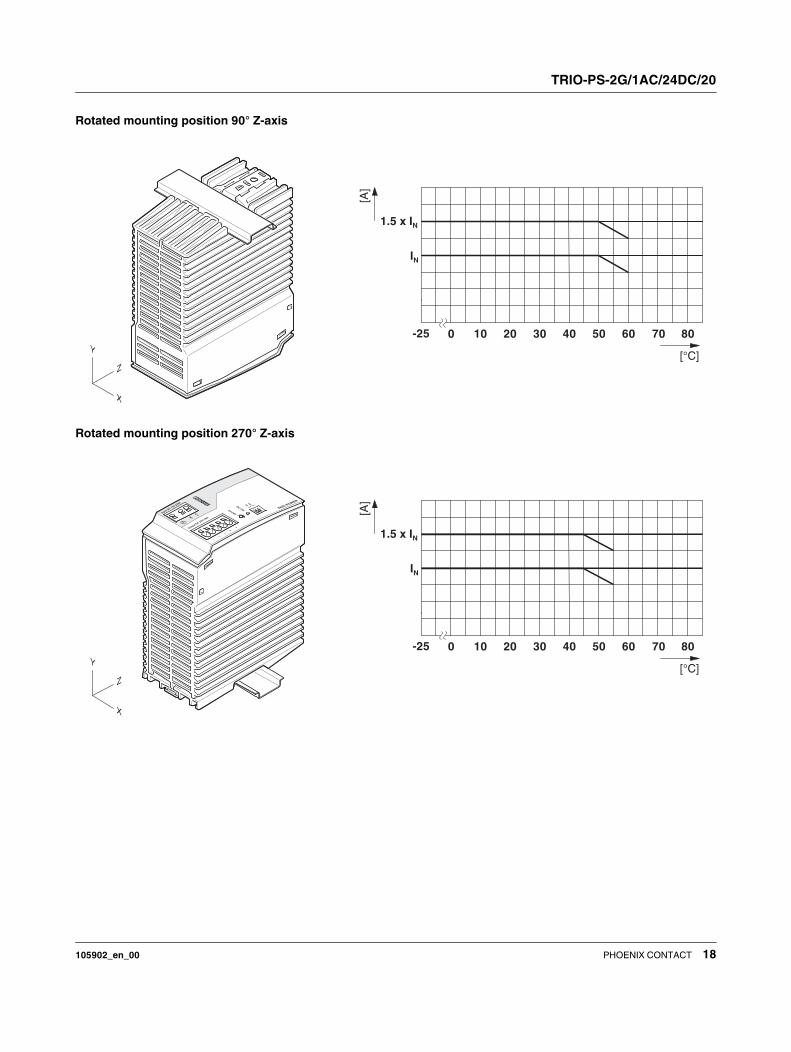
16.2 Position-dependent derating
The power supply can be installed onto all 35 mm DIN rails
according to EN 60175. The normal mounting position of the
power supply is horizontal.
When installing in a different mounting position, derating
should be adhered to.
The characteristic curve can be used to determine the max-
imal output power to be drawn for each ambient temperature
for different mounting positions.
Normal mounting position
Rotated mounting position 90° X-axis
TRIO-PS-2G/1AC/24DC/20
105902_en_00 PHOENIX CONTACT 17
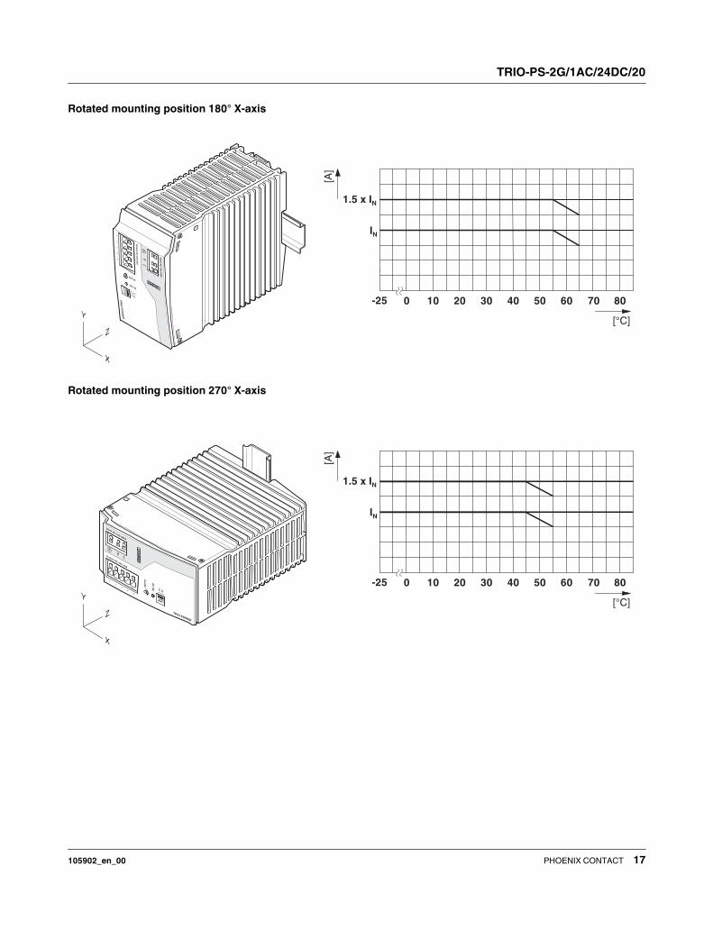
Rotated mounting position 180° X-axis
Rotated mounting position 270° X-axis
TRIO-PS-2G/1AC/24DC/20
105902_en_00 PHOENIX CONTACT 18
Rotated mounting position 90° Z-axis
Rotated mounting position 270° Z-axis
TRIO-PS-2G/1AC/24DC/20
105902_en_00 PHOENIX CONTACT 19
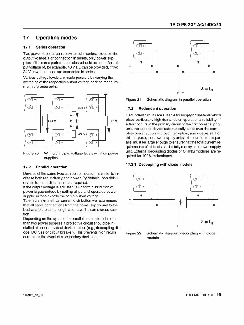
17 Operating modes
17.1 Series operation
Two power supplies can be switched in series, to double the
output voltage. For connection in series, only power sup-
plies of the same performance class should be used. An out-
put voltage of, for example, 48 V DC can be provided, if two
24 V power supplies are connected in series.
Various voltage levels are made possible by varying the
switching of the respective output voltage and the measure-
ment reference point.
Figure 20 Wiring principle, voltage levels with two power
supplies
17.2 Parallel operation
Devices of the same type can be connected in parallel to in-
crease both redundancy and power. By default upon deliv-
ery, no further adjustments are required.
If the output voltage is adjusted, a uniform distribution of
power is guaranteed by setting all parallel operated power
supply units to exactly the same output voltage.
To ensure symmetrical current distribution we recommend
that all cable connections from the power supply unit to the
busbar are the same length and have the same cross sec-
tion.
Depending on the system, for parallel connection of more
than two power supplies a protective circuit should be in-
stalled at each individual device output (e.g., decoupling di-
ode, DC fuse or circuit breaker). This prevents high return
currents in the event of a secondary device fault.
Figure 21 Schematic diagram in parallel operation
17.3 Redundant operation
Redundant circuits are suitable for supplying systems which
place particularly high demands on operational reliability. If
a fault occurs in the primary circuit of the first power supply
unit, the second device automatically takes over the com-
plete power supply without interruption, and vice versa. For
this purpose, the power supply units to be connected in par-
allel must be large enough to ensure that the total current re-
quirements of all loads can be fully met by one power supply
unit. External decoupling diodes or ORING modules are re-
quired for 100% redundancy.
17.3.1 Decoupling with diode module
Figure 22 Schematic diagram, decoupling with diode
module
-48 V
-
+
-
+
+24 V
-24 V
-
+
-
+
+48 V
-
+
-
+
Σ = IN
+
–
+ –
-
+
IN
-
+
IN
Σ = IN
+
–
+ –
-
+
IN
-
+
IN
TRIO-PS-2G/1AC/24DC/20
105902_en_00 20PHOENIX CONTACT GmbH & Co. KG • 32823 Blomberg • Germany
phoenixcontact.com
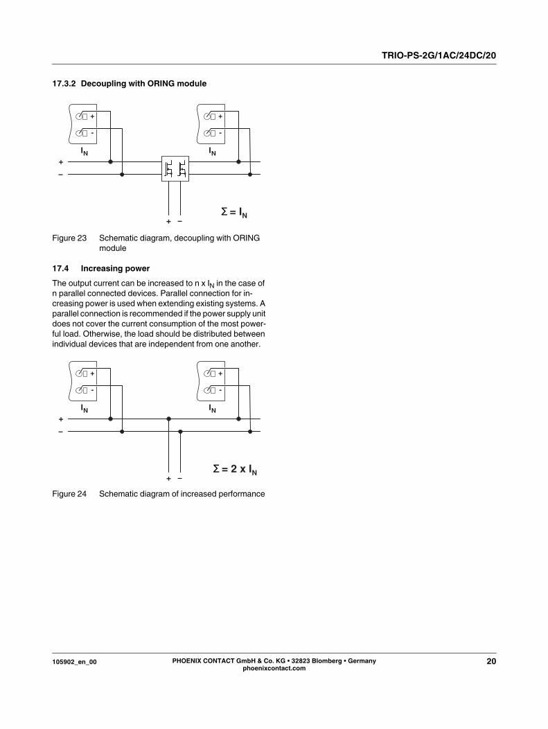
17.3.2 Decoupling with ORING module
Figure 23 Schematic diagram, decoupling with ORING
module
17.4 Increasing power
The output current can be increased to n x IN in the case of
n parallel connected devices. Parallel connection for in-
creasing power is used when extending existing systems. A
parallel connection is recommended if the power supply unit
does not cover the current consumption of the most power-
ful load. Otherwise, the load should be distributed between
individual devices that are independent from one another.
Figure 24 Schematic diagram of increased performance
Σ = IN
+
–
+ –
-
+
IN
-
+
IN
+
–
+ –Σ = 2 x IN
-
+
IN
-
+
IN