Embed Size (px)
Citation preview
MMRRCCFF
INDUSTRIA RESISTENZE ELETTRICHE S.r.l. - Via Valtellina, 2 - 20027 Rescaldina (MI) - Tel: 0331.577833 - Fax: 0331.577832 - [email protected] - www.ireresistor.com
ddaattaa sshheeeett
Resistori protetti per frenatura Protected braking resistors
24/07/2014 - Con riserva di modifiche tecniche - Specifications subject to change without notice.
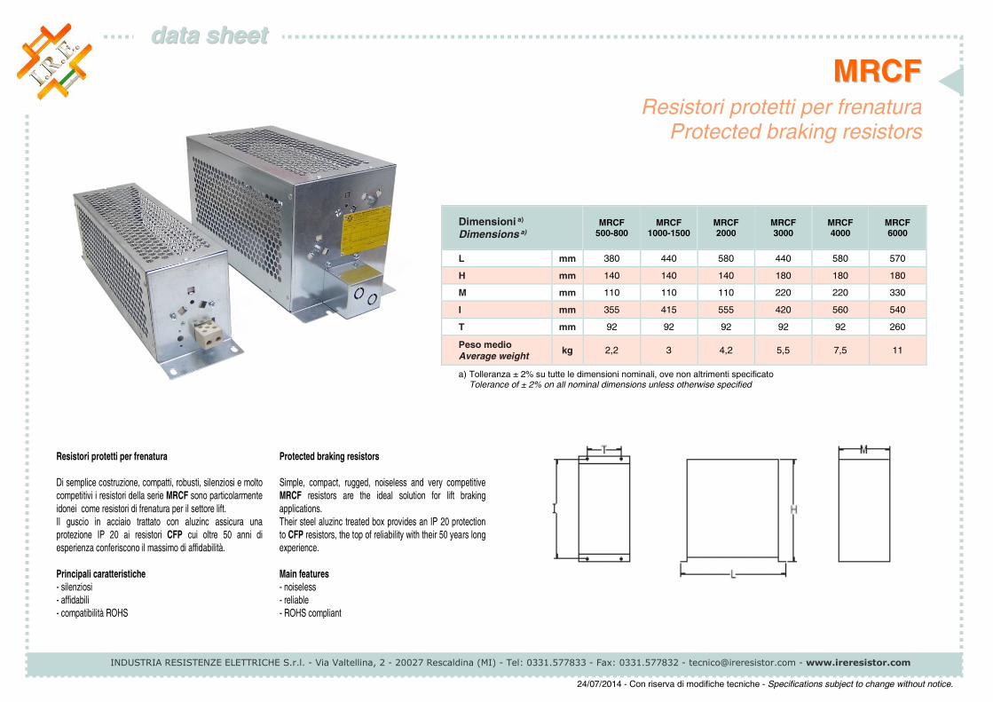
Dimensioni a) Dimensions a)
MRCF 500-800
MRCF 1000-1500
MRCF 2000
MRCF 3000
MRCF 4000
MRCF 6000
L mm 380 440 580 440 580 570
H mm 140 140 140 180 180 180
M mm 110 110 110 220 220 330
I mm 355 415 555 420 560 540
T mm 92 92 92 92 92 260
Peso medio Average weight
kg 2,2 3 4,2 5,5 7,5 11
a) Tolleranza ± 2% su tutte le dimensioni nominali, ove non altrimenti specificato Tolerance of ± 2% on all nominal dimensions unless otherwise specified
Resistori protetti per frenatura
Di semplice costruzione, compatti, robusti, silenziosi e molto
competitivi i resistori della serie MRCF sono particolarmente
idonei come resistori di frenatura per il settore lift.
Il guscio in acciaio trattato con aluzinc assicura una
protezione IP 20 ai resistori CFP cui oltre 50 anni di
esperienza conferiscono il massimo di affidabilità.
Principali caratteristiche
- silenziosi
- affidabili
- compatibilità ROHS
Protected braking resistors
Simple, compact, rugged, noiseless and very competitive
MRCF resistors are the ideal solution for lift braking
applications.
Their steel aluzinc treated box provides an IP 20 protection
to CFP resistors, the top of reliability with their 50 years long
experience.
Main features
- noiseless
- reliable
- ROHS compliant
MMRRCCFF
INDUSTRIA RESISTENZE ELETTRICHE S.r.l. - Via Valtellina, 2 - 20027 Rescaldina (MI) - Tel: 0331.577833 - Fax: 0331.577832 - [email protected] - www.ireresistor.com
ddaattaa sshheeeett
Resistori protetti per frenatura Protected braking resistors
24/07/2014 - Con riserva di modifiche tecniche - Specifications subject to change without notice.
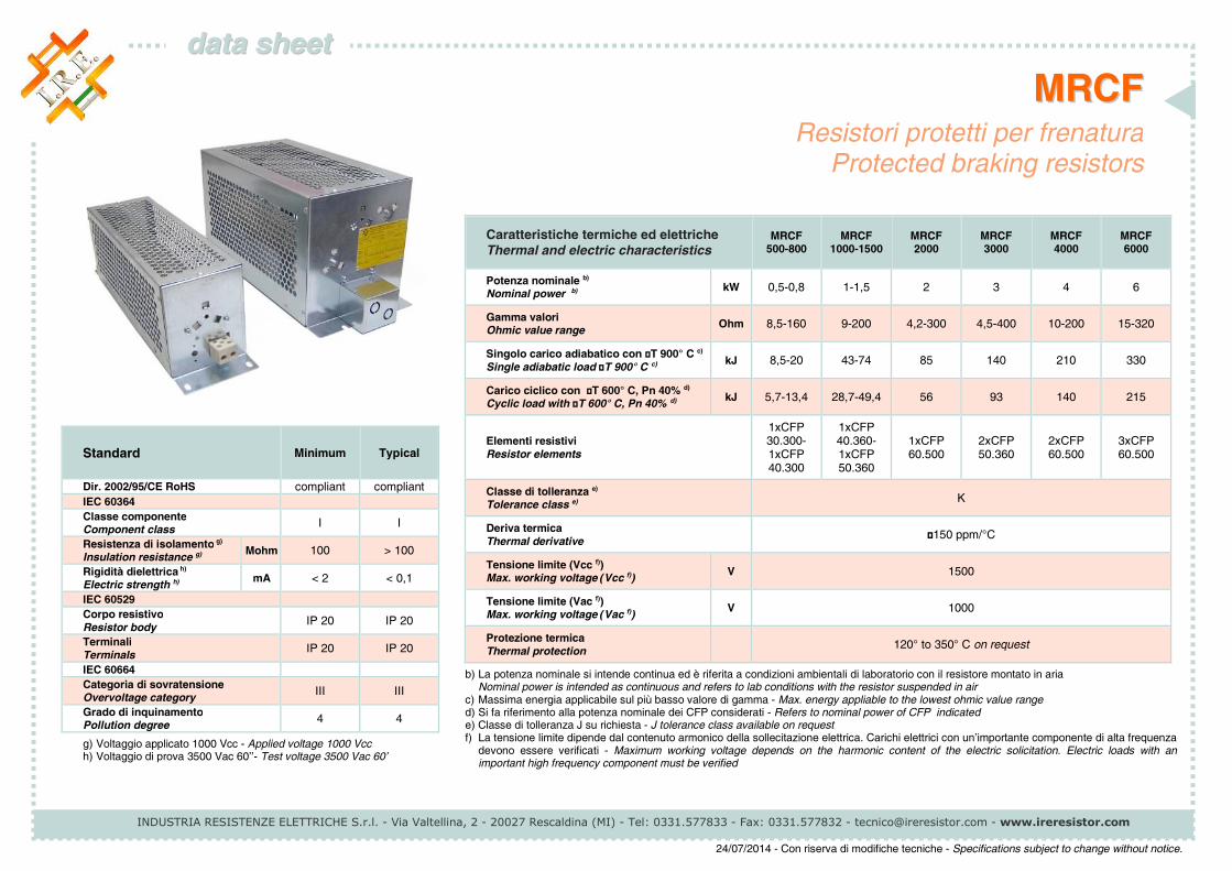
Caratteristiche termiche ed elettriche Thermal and electric characteristics
MRCF 500-800
MRCF 1000-1500
MRCF 2000
MRCF 3000
MRCF 4000
MRCF 6000
Potenza nominale b) Nominal power b)
kW 0,5-0,8 1-1,5 2 3 4 6
Gamma valori Ohmic value range
Ohm 8,5-160 9-200 4,2-300 4,5-400 10-200 15-320
Singolo carico adiabatico con ΔT 900° C c) Single adiabatic load ΔT 900° C c)
kJ 8,5-20 43-74 85 140 210 330
Carico ciclico con ΔT 600° C, Pn 40% d) Cyclic load with ΔT 600° C, Pn 40% d)
kJ 5,7-13,4 28,7-49,4 56 93 140 215
Elementi resistivi Resistor elements
1xCFP 30.300- 1xCFP 40.300
1xCFP 40.360- 1xCFP 50.360
1xCFP 60.500
2xCFP 50.360
2xCFP 60.500
3xCFP 60.500
Classe di tolleranza e)
Tolerance class e) K
Deriva termica Thermal derivative
≤150 ppm/°C
Tensione limite (Vcc f)) Max. working voltage (Vcc f))
V 1500
Tensione limite (Vac f)) Max. working voltage (Vac f))
V 1000
Protezione termica Thermal protection
120° to 350° C on request
b) La potenza nominale si intende continua ed è riferita a condizioni ambientali di laboratorio con il resistore montato in aria Nominal power is intended as continuous and refers to lab conditions with the resistor suspended in air c) Massima energia applicabile sul più basso valore di gamma - Max. energy appliable to the lowest ohmic value range d) Si fa riferimento alla potenza nominale dei CFP considerati - Refers to nominal power of CFP indicated e) Classe di tolleranza J su richiesta - J tolerance class available on request f) La tensione limite dipende dal contenuto armonico della sollecitazione elettrica. Carichi elettrici con un’importante componente di alta frequenza
devono essere verificati - Maximum working voltage depends on the harmonic content of the electric solicitation. Electric loads with an important high frequency component must be verified
Standard Minimum Typical
Dir. 2002/95/CE RoHS compliant compliant
IEC 60364
Classe componente Component class
I I
Resistenza di isolamento g) Insulation resistance g)
Mohm 100 > 100
Rigidità dielettrica h) Electric strength h)
mA < 2 < 0,1
IEC 60529
Corpo resistivo Resistor body
IP 20 IP 20
Terminali Terminals
IP 20 IP 20
IEC 60664
Categoria di sovratensione Overvoltage category
III III
Grado di inquinamento Pollution degree
4 4
g) Voltaggio applicato 1000 Vcc - Applied voltage 1000 Vcc h) Voltaggio di prova 3500 Vac 60’’- Test voltage 3500 Vac 60’
INDUSTRIA RESISTENZE ELETTRICHE S.r.l. - Via Valtellina, 2 - 20027 Rescaldina (MI) - Tel: 0331.577833 - Fax: 0331.577832 - [email protected] - www.ireresistor.com
24/07/2014 - Con riserva di modifiche tecniche - Specifications subject to change without notice.
MMRRCCFF
iissttrruuzziioonnii
Grazie per aver scelto un resistore di frenatura IRE. Le
seguenti istruzioni forniscono informazioni e precauzioni
utili alla corretta installazione, operatività e manutenzione
del resistore. Si prega di rendere disponibile questo foglio
di istruzioni all’utilizzatore finale. Un impiego non corretto
può causare danni alle persone o guasti inattesi al
resistore e alle apparecchiature ad esso collegate e può far
decadere la garanzia.
AVVERTENZA
Questo resistore deve essere installato e utilizzato
unicamente da personale specializzato, al corrente delle
principali norme di sicurezza. Nel luogo di installazione e
utilizzo devono essere presenti i dispositivi di sicurezza
necessari per la prevenzione degli incidenti,
conformemente con la legislazione localmente vigente.
ISTRUZIONI DI INSTALLAZIONE
• Questo dispositivo deve sempre essere conservato in
luogo chiuso, asciutto, al riparo da vibrazioni e polvere.
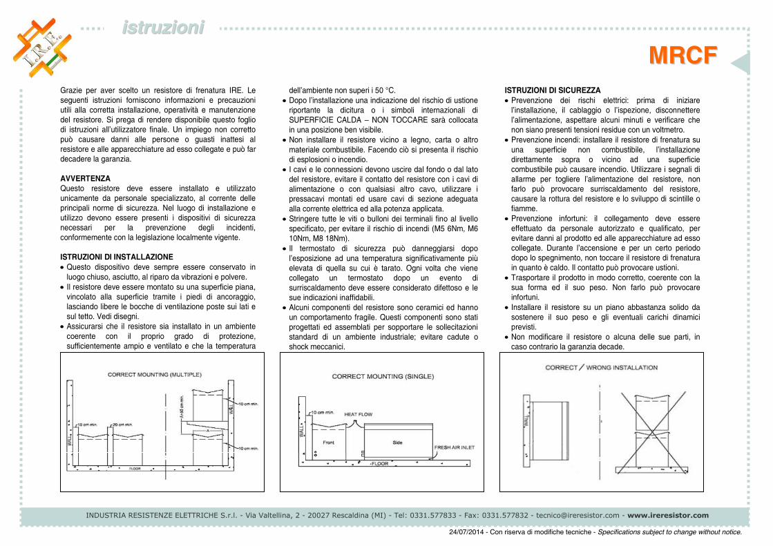
• Il resistore deve essere montato su una superficie piana,
vincolato alla superficie tramite i piedi di ancoraggio,
lasciando libere le bocche di ventilazione poste sui lati e
sul tetto. Vedi disegni.
• Assicurarsi che il resistore sia installato in un ambiente
coerente con il proprio grado di protezione,
sufficientemente ampio e ventilato e che la temperatura
dell’ambiente non superi i 50 °C.
• Dopo l’installazione una indicazione del rischio di ustione
riportante la dicitura o i simboli internazionali di
SUPERFICIE CALDA – NON TOCCARE sarà collocata
in una posizione ben visibile.
• Non installare il resistore vicino a legno, carta o altro
materiale combustibile. Facendo ciò si presenta il rischio
di esplosioni o incendio.
• I cavi e le connessioni devono uscire dal fondo o dal lato
del resistore, evitare il contatto del resistore con i cavi di
alimentazione o con qualsiasi altro cavo, utilizzare i
pressacavi montati ed usare cavi di sezione adeguata
alla corrente elettrica ed alla potenza applicata.
• Stringere tutte le viti o bulloni dei terminali fino al livello
specificato, per evitare il rischio di incendi (M5 6Nm, M6
10Nm, M8 18Nm).
• Il termostato di sicurezza può danneggiarsi dopo
l’esposizione ad una temperatura significativamente più
elevata di quella su cui è tarato. Ogni volta che viene
collegato un termostato dopo un evento di
surriscaldamento deve essere considerato difettoso e le
sue indicazioni inaffidabili.
• Alcuni componenti del resistore sono ceramici ed hanno
un comportamento fragile. Questi componenti sono stati
progettati ed assemblati per sopportare le sollecitazioni
standard di un ambiente industriale; evitare cadute o
shock meccanici.
ISTRUZIONI DI SICUREZZA
• Prevenzione dei rischi elettrici: prima di iniziare
l’installazione, il cablaggio o l’ispezione, disconnettere
l’alimentazione, aspettare alcuni minuti e verificare che
non siano presenti tensioni residue con un voltmetro.
• Prevenzione incendi: installare il resistore di frenatura su
una superficie non combustibile, l’installazione
direttamente sopra o vicino ad una superficie
combustibile può causare incendio. Utilizzare i segnali di
allarme per togliere l’alimentazione del resistore, non
farlo può provocare surriscaldamento del resistore,
causare la rottura del resistore e lo sviluppo di scintille o
fiamme.
• Prevenzione infortuni: il collegamento deve essere
effettuato da personale autorizzato e qualificato, per
evitare danni al prodotto ed alle apparecchiature ad esso
collegate. Durante l’accensione e per un certo periodo
dopo lo spegnimento, non toccare il resistore di frenatura
in quanto è caldo. Il contatto può provocare ustioni.
• Trasportare il prodotto in modo corretto, coerente con la
sua forma ed il suo peso. Non farlo può provocare
infortuni.
• Installare il resistore su un piano abbastanza solido da
sostenere il suo peso e gli eventuali carichi dinamici
previsti.
• Non modificare il resistore o alcuna delle sue parti, in
caso contrario la garanzia decade.
INDUSTRIA RESISTENZE ELETTRICHE S.r.l. - Via Valtellina, 2 - 20027 Rescaldina (MI) - Tel: 0331.577833 - Fax: 0331.577832 - [email protected] - www.ireresistor.com
24/07/2014 - Con riserva di modifiche tecniche - Specifications subject to change without notice.
MMRRCCFF
iinnssttrruuccttiioonnss
Thank you for choosing this IRE product. These
instructions must be followed to ensure safe and proper
installation, operation and maintenance of the equipment.
They should be brought to the attention of anyone who
installs, operates or maintains this equipment. Ignoring
these instructions can result in serious or fatal injury,
damage to the product or related equipment and may
invalidate the warranty.
WARNINGS
This equipment is intended for installation and use by
qualified personnel, familiar with relevant safety
requirements. Safety equipment necessary for the
prevention of accidents at the installation and operating site
must be provided in accordance with local regulations.
INSTALLATION INSTRUCTIONS
• This equipment should always be stored indoor, in a dry,
vibration free and dust free place.
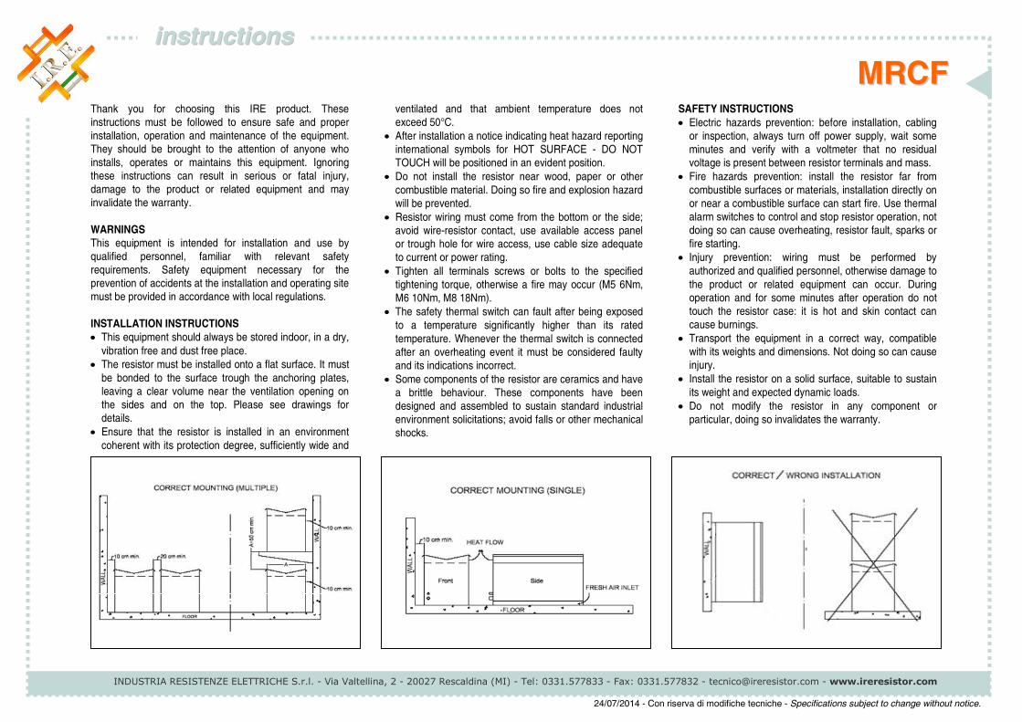
• The resistor must be installed onto a flat surface. It must
be bonded to the surface trough the anchoring plates,
leaving a clear volume near the ventilation opening on
the sides and on the top. Please see drawings for
details.
• Ensure that the resistor is installed in an environment
coherent with its protection degree, sufficiently wide and
ventilated and that ambient temperature does not
exceed 50°C.
• After installation a notice indicating heat hazard reporting
international symbols for HOT SURFACE - DO NOT
TOUCH will be positioned in an evident position.
• Do not install the resistor near wood, paper or other
combustible material. Doing so fire and explosion hazard
will be prevented.
• Resistor wiring must come from the bottom or the side;
avoid wire-resistor contact, use available access panel
or trough hole for wire access, use cable size adequate
to current or power rating.
• Tighten all terminals screws or bolts to the specified
tightening torque, otherwise a fire may occur (M5 6Nm,
M6 10Nm, M8 18Nm).
• The safety thermal switch can fault after being exposed
to a temperature significantly higher than its rated
temperature. Whenever the thermal switch is connected
after an overheating event it must be considered faulty
and its indications incorrect.
• Some components of the resistor are ceramics and have
a brittle behaviour. These components have been
designed and assembled to sustain standard industrial
environment solicitations; avoid falls or other mechanical
shocks.
SAFETY INSTRUCTIONS
• Electric hazards prevention: before installation, cabling
or inspection, always turn off power supply, wait some
minutes and verify with a voltmeter that no residual
voltage is present between resistor terminals and mass.
• Fire hazards prevention: install the resistor far from
combustible surfaces or materials, installation directly on
or near a combustible surface can start fire. Use thermal
alarm switches to control and stop resistor operation, not
doing so can cause overheating, resistor fault, sparks or
fire starting.
• Injury prevention: wiring must be performed by
authorized and qualified personnel, otherwise damage to
the product or related equipment can occur. During
operation and for some minutes after operation do not
touch the resistor case: it is hot and skin contact can
cause burnings.
• Transport the equipment in a correct way, compatible
with its weights and dimensions. Not doing so can cause
injury.
• Install the resistor on a solid surface, suitable to sustain
its weight and expected dynamic loads.
• Do not modify the resistor in any component or
particular, doing so invalidates the warranty.