Embed Size (px)
Citation preview
1 Description
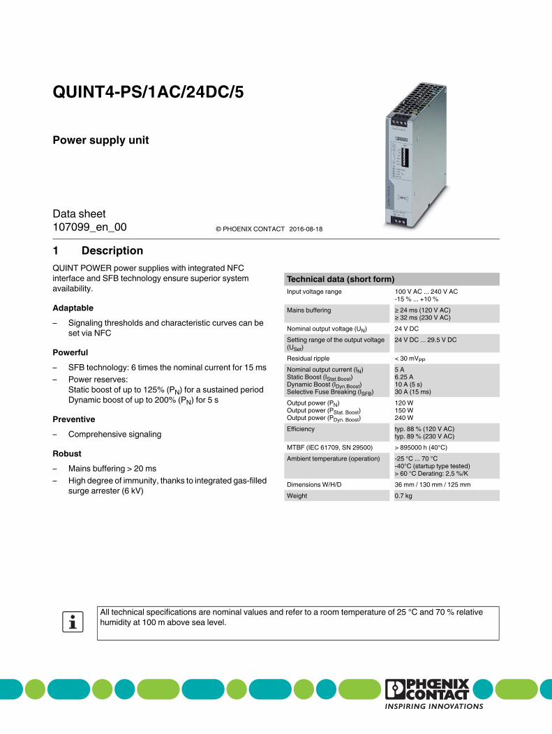
Power supply unit
QUINT4-PS/1AC/24DC/5
© PHOENIX CONTACT
Data sheet
QUINT POWER power supplies with integrated NFC
interface and SFB technology ensure superior system
availability.
Adaptable
– Signaling thresholds and characteristic curves can be
set via NFC
Powerful
– SFB technology: 6 times the nominal current for 15 ms
– Power reserves:
Static boost of up to 125% (PN) for a sustained period
Dynamic boost of up to 200% (PN) for 5 s
Preventive
– Comprehensive signaling
Robust
– Mains buffering > 20 ms
– High degree of immunity, thanks to integrated gas-filled
surge arrester (6 kV)
Technical data (short form)
Input voltage range 100 V AC ... 240 V AC
-15 % ... +10 %
Mains buffering ≥ 24 ms (120 V AC)
≥ 32 ms (230 V AC)
Nominal output voltage (UN) 24 V DC
Setting range of the output voltage
(USet)
24 V DC ... 29.5 V DC
Residual ripple < 30 mVPP
Nominal output current (IN)
Static Boost (IStat.Boost)
Dynamic Boost (IDyn.Boost)
Selective Fuse Breaking (ISFB)
5 A
6.25 A
10 A (5 s)
30 A (15 ms)
Output power (PN)
Output power (PStat. Boost)
Output power (PDyn. Boost)
120 W
150 W
240 W
Efficiency typ. 88 % (120 V AC)
typ. 89 % (230 V AC)
MTBF (IEC 61709, SN 29500) > 895000 h (40°C)
Ambient temperature (operation) -25 °C ... 70 °C
-40°C (startup type tested)
> 60 °C Derating: 2,5 %/K
Dimensions W/H/D 36 mm / 130 mm / 125 mm
Weight 0.7 kg
All technical specifications are nominal values and refer to a room temperature of 25 °C and 70 % relative
humidity at 100 m above sea level.
107099_en_00 2016-08-18
QUINT4-PS/1AC/24DC/5
107099_en_00 PHOENIX CONTACT 2 / 38
2 Table of contents
1 Description .............................................................................................................................. 1
2 Table of contents ..................................................................................................................... 2
3 Ordering data .......................................................................................................................... 4
4 Technical data ......................................................................................................................... 5
5 Safety and installation notes..................................................................................................... 14
6 High-voltage test (HIPOT) ........................................................................................................ 15
6.1 High-voltage dielectric test (dielectric strength test) and why must it be performed? ............................ 15
6.2 High-voltage dielectric test during the manufacturing process........................................................ 15
6.3 High-voltage dielectric test performed by the customer ...............................................................................15
6.3.1 Performing high-voltage testing........................................................................................................16
6.3.2 Disconnecting the gas-filled surge arrester ......................................................................................16
7 Structure of the power supply ................................................................................................... 17
7.1 Function elements .............................................................................................................. 17
7.2 Device dimensions and keepout areas ........................................................................................................17
7.3 Block diagram..............................................................................................................................................18
8 Mounting/removing the power supply....................................................................................... 19
8.1 Mounting the power supply unit.............................................................................................. 19
8.2 Removing the power supply unit............................................................................................. 19
8.3 Retrofitting the universal DIN rail adapter.................................................................................. 19
8.3.1 Disassembling the universal DIN rail adapter ...................................................................................19
8.3.2 Mounting the universal DIN rail adapter............................................................................................20
8.4 Retrofitting the universal wall adapter ...................................................................................... 20
8.4.1 Mounting the UWA 182/52 universal wall adapter ............................................................................20
8.4.2 Mounting the UWA 130 2-piece universal wall adapter ....................................................................21
9 Device connection terminal blocks ........................................................................................... 21
9.1 Input ............................................................................................................................... 21
9.2 Protection of the primary side ......................................................................................................................22
9.3 Output..........................................................................................................................................................22
9.4 Protection of the secondary side ............................................................................................ 22
10 Output characteristic curves..................................................................................................... 23
10.1 U/I Advanced output characteristic curve ....................................................................................................23
10.2 Smart HICCUP output characteristic curve ............................................................................... 24
10.3 FUSE MODE output characteristic curve.....................................................................................................24
11 Configuring the power supply ................................................................................................... 25
11.1 Configuration with PC software .............................................................................................. 25
11.2 Configuring the power supply ................................................................................................ 25
11.3 Configuration with NFC-capable mobile terminal device............................................................... 26
11.4 Ordering a configured power supply........................................................................................ 26
QUINT4-PS/1AC/24DC/5
107099_en_00 PHOENIX CONTACT 3 / 38
12 SFB technology.................................................................................................................................................... 26
12.1 Tripping circuit breakers ............................................................................................................................... 26
12.2 Tripping a fuse.............................................................................................................................................. 26
12.3 SFB configuration......................................................................................................................................... 27
12.4 Maximum distance between the power supply and load .............................................................................. 27
12.4.1 Thermomagnetic device circuit breaker, type: Phoenix Contact CB TM1 SFB.................................. 27
12.4.2 Thermomagnetic circuit breaker, type: Siemens 5SY, ABB S200 ..................................................... 28
12.4.3 Fuse, type: Cooper Bussmann GMA xA, GMC xA ............................................................................ 29
13 Signaling....................................................................................................................................30
13.1 Location and function of the signaling elements ........................................................................................... 30
13.2 Description of signaling ................................................................................................................................ 32
13.2.1 Output voltage................................................................................................................................... 32
13.2.2 Output current ................................................................................................................................... 32
13.2.3 Output power .................................................................................................................................... 32
13.2.4 Operating hours ................................................................................................................................ 32
13.2.5 Early warning of high temperature..................................................................................................... 32
13.2.6 Voltage limitation active .................................................................................................................... 32
13.2.7 Input voltage OK ............................................................................................................................... 33
13.2.8 Remote input..................................................................................................................................... 33
13.3 LED status indicators ................................................................................................................................... 33
13.4 Signaling for U/I Advanced characteristic curves ......................................................................................... 34
13.5 Signaling for Smart HICCUP characteristic curves....................................................................................... 34
13.6 Signalisierung FUSE MODE-Kennlinie......................................................................................................... 35
13.7 SLEEP MODE signaling ............................................................................................................................... 35
14 Operating modes .......................................................................................................................36
14.1 Series operation ........................................................................................................................................... 36
14.2 Parallel operation ......................................................................................................................................... 36
14.2.1 Redundancy operation...................................................................................................................... 37
14.2.2 Increased power ............................................................................................................................... 37
15 Derating .....................................................................................................................................38
15.1 Ambient temperature.................................................................................................................................... 38
15.2 Input voltage................................................................................................................................................. 38
15.3 Installation height ......................................................................................................................................... 38
QUINT4-PS/1AC/24DC/5
107099_en_00 PHOENIX CONTACT 4 / 38
Description Type Order No. Pcs./Pkt.
Primary-switched QUINT POWER power supply for DIN
rail mounting with free choice of output characteristic
curve and SFB (Selective Fuse Breaking) technology,
input: 1-phase, output: 24 V DC / 5 A
QUINT4-PS/1AC/24DC/5 2904600 1
Customer-specifically programmed version of the
primary-switched QUINT POWER power supply for DIN
rail mounting with free choice of output characteristic
curve and SFB (Selective Fuse Breaking) technology,
input: 1-phase, output: 24 V DC / 5 A
QUINT4-PS/1AC/24DC/5/... 2907866 1
3 Ordering data
Accessories Type Order No. Pcs./Pkt.
Universal wall adapter for securely mounting the power
supply in the event of strong vibrations. The power supply
is screwed directly onto the mounting surface. The
universal wall adapter is attached at the top/bottom.
UWA 182/52 2938235 1
2-piece universal wall adapter for securely mounting the
power supply in the event of strong vibrations. The profiles
that are screwed onto the side of the power supply are
screwed directly onto the mounting surface. The universal
wall adapter is attached on the left/right.
UWA 130 2901664 1
Assembly adapter for QUINT-PS... power supply on S7-
300 rail
QUINT-PS-ADAPTERS7/1 2938196 1
Near Field Communication (NFC) programming adapter
with USB interface for the wireless configuration of NFC-
capable products from PHOENIX CONTACT with
software. No separate USB driver is required.
TWN4 MIFARE NFC USB
ADAPTER
2909681 1
Pluggable device protection, according to type 3/class III,
for 1-phase power supply networks with separate N and
PE (3-conductor system: L1, N, PE), with integrated
surge-proof fuse and remote indication contact. Also
suitable for DC applications.
PLT-SEC-T3-230-FM 2905229 1
The range of accessories is being continuously extended. The current range of accessories can be found in
the download area for the product.
QUINT4-PS/1AC/24DC/5
107099_en_00 PHOENIX CONTACT 5 / 38
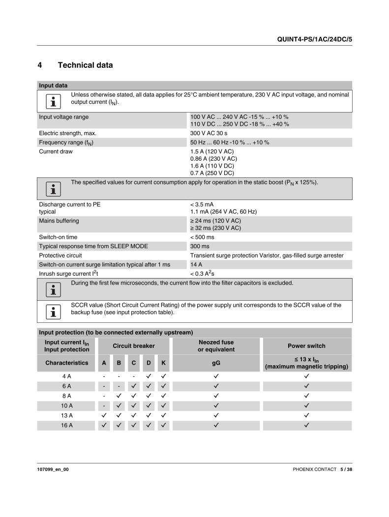
4 Technical data
Input data
Unless otherwise stated, all data applies for 25°C ambient temperature, 230 V AC input voltage, and nominal
output current (IN).
Input voltage range 100 V AC ... 240 V AC -15 % ... +10 %
110 V DC ... 250 V DC -18 % ... +40 %
Electric strength, max. 300 V AC 30 s
Frequency range (fN) 50 Hz ... 60 Hz -10 % ... +10 %
Current draw 1.5 A (120 V AC)
0.86 A (230 V AC)
1.6 A (110 V DC)
0.7 A (250 V DC)
The specified values for current consumption apply for operation in the static boost (PN x 125%).
Discharge current to PE
typical
< 3.5 mA
1.1 mA (264 V AC, 60 Hz)
Mains buffering ≥ 24 ms (120 V AC)
≥ 32 ms (230 V AC)
Switch-on time < 500 ms
Typical response time from SLEEP MODE 300 ms
Protective circuit Transient surge protection Varistor, gas-filled surge arrester
Switch-on current surge limitation typical after 1 ms 14 A
Inrush surge current I2t < 0.3 A
2s
During the first few microseconds, the current flow into the filter capacitors is excluded.
SCCR value (Short Circuit Current Rating) of the power supply unit corresponds to the SCCR value of the
backup fuse (see input protection table).
Input protection (to be connected externally upstream)
Input current IIn
Input protectionCircuit breaker
Neozed fuse
or equivalentPower switch
Characteristics A B C D K gG≤ 13 x IIn
(maximum magnetic tripping)
4 A - - -
6 A - -
8 A -
10 A -
13 A
16 A
QUINT4-PS/1AC/24DC/5
107099_en_00 PHOENIX CONTACT 6 / 38
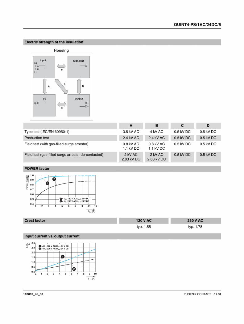
Electric strength of the insulation
A B C D
Type test (IEC/EN 60950-1) 3.5 kV AC 4 kV AC 0.5 kV DC 0.5 kV DC
Production test 2.4 kV AC 2.4 kV AC 0.5 kV DC 0.5 kV DC
Field test (with gas-filled surge arrester) 0.8 kV AC
1.1 kV DC
0.8 kV AC
1.1 kV DC
0.5 kV DC 0.5 kV DC
Field test (gas-filled surge arrester de-contacted) 2 kV AC
2.83 kV DC
2 kV AC
2.83 kV DC
0.5 kV DC 0.5 kV DC
Housing
OutputPE
Input Signaling
C
AB
D
B
L
N
(+)
(-)
+
POWER factor
0,4
0,5
0,6
0,7
0,8
0,9
1,0
I [A]Out
Po
we
r F
ac
tor
1 2 3 4 5 6 7 8 9 10
= U : 120 V AC/U : 24 V DCIn Out
= U : 230 V AC/U : 24 V DCIn Out
Crest factor 120 V AC 230 V AC
typ. 1.55 typ. 1.78
Input current vs. output current
0,0
0,5
1,0
1,5
2,0
2,5
3,0
0 1 2 4 6 8 10
I [A]Out
I[A
]In = U : 120 V AC/U : 24 V DCIn Out
= U : 230 V AC/U : 24 V DCIn Out
3 5 7 9
QUINT4-PS/1AC/24DC/5
107099_en_00 PHOENIX CONTACT 7 / 38
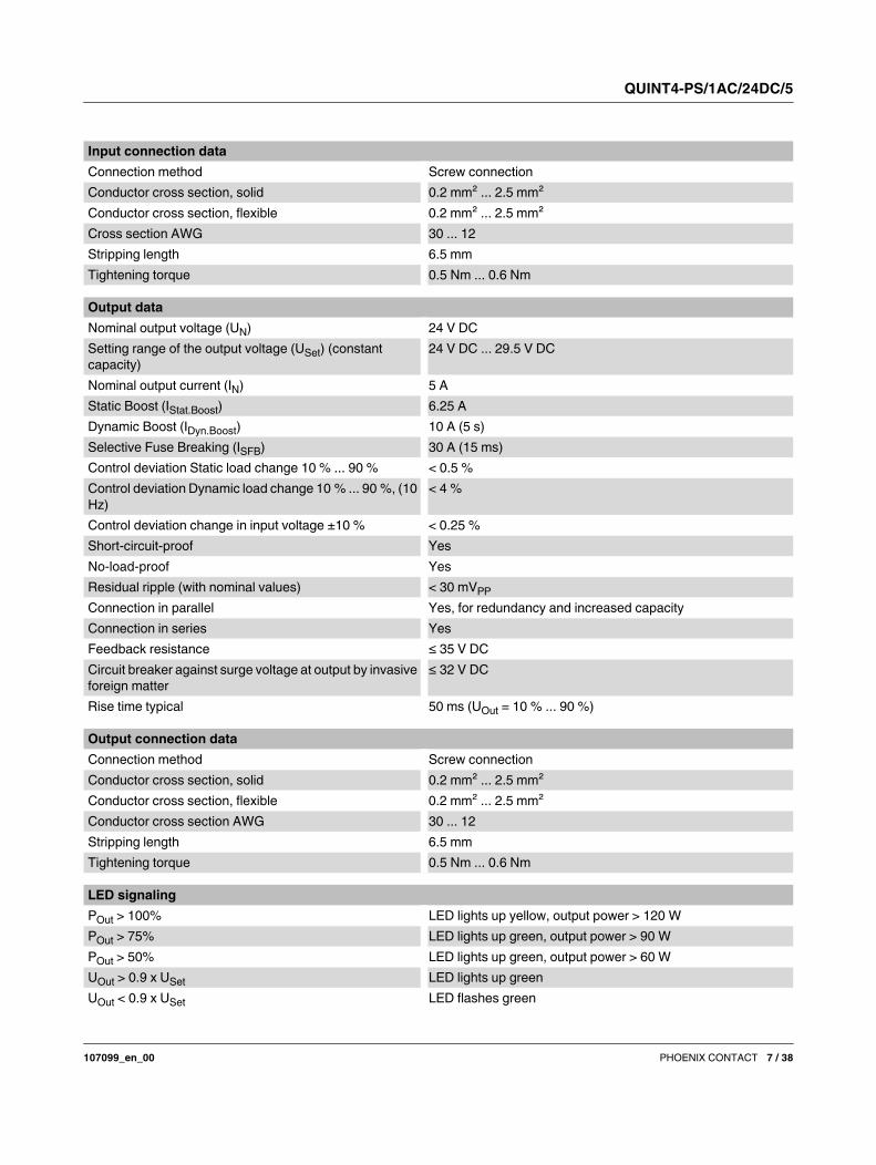
Input connection data
Connection method Screw connection
Conductor cross section, solid 0.2 mm² ... 2.5 mm²
Conductor cross section, flexible 0.2 mm² ... 2.5 mm²
Cross section AWG 30 ... 12
Stripping length 6.5 mm
Tightening torque 0.5 Nm ... 0.6 Nm
Output data
Nominal output voltage (UN) 24 V DC
Setting range of the output voltage (USet) (constant
capacity)
24 V DC ... 29.5 V DC
Nominal output current (IN) 5 A
Static Boost (IStat.Boost) 6.25 A
Dynamic Boost (IDyn.Boost) 10 A (5 s)
Selective Fuse Breaking (ISFB) 30 A (15 ms)
Control deviation Static load change 10 % ... 90 % < 0.5 %
Control deviation Dynamic load change 10 % ... 90 %, (10
Hz)
< 4 %
Control deviation change in input voltage ±10 % < 0.25 %
Short-circuit-proof Yes
No-load-proof Yes
Residual ripple (with nominal values) < 30 mVPP
Connection in parallel Yes, for redundancy and increased capacity
Connection in series Yes
Feedback resistance ≤ 35 V DC
Circuit breaker against surge voltage at output by invasive
foreign matter
≤ 32 V DC
Rise time typical 50 ms (UOut = 10 % ... 90 %)
Output connection data
Connection method Screw connection
Conductor cross section, solid 0.2 mm² ... 2.5 mm²
Conductor cross section, flexible 0.2 mm² ... 2.5 mm²
Conductor cross section AWG 30 ... 12
Stripping length 6.5 mm
Tightening torque 0.5 Nm ... 0.6 Nm
LED signaling
POut > 100% LED lights up yellow, output power > 120 W
POut > 75% LED lights up green, output power > 90 W
POut > 50% LED lights up green, output power > 60 W
UOut > 0.9 x USet LED lights up green
UOut < 0.9 x USet LED flashes green
QUINT4-PS/1AC/24DC/5
107099_en_00 PHOENIX CONTACT 8 / 38
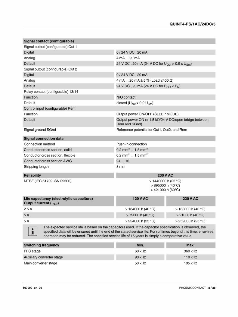
Signal contact (configurable)
Signal output (configurable) Out 1
Digital 0 / 24 V DC , 20 mA
Analog 4 mA ... 20 mA
Default 24 V DC , 20 mA (24 V DC for UOut > 0.9 x USet)
Signal output (configurable) Out 2
Digital 0 / 24 V DC , 20 mA
Analog 4 mA ... 20 mA 5 % (Load ≤400 )
Default 24 V DC , 20 mA (24 V DC for POut < PN)
Relay contact (configurable) 13/14
Function N/O contact
Default closed (Uout > 0.9 USet)
Control input (configurable) Rem
Function Output power ON/OFF (SLEEP MODE)
Default Output power ON (> 1.5 kΩ/24 V DC/open bridge between
Rem and SGnd)
Signal ground SGnd Reference potential for Out1, Out2, and Rem
Signal connection data
Connection method Push-in connection
Conductor cross section, solid 0.2 mm² ... 1.5 mm²
Conductor cross section, flexible 0.2 mm² ... 1.5 mm²
Conductor cross section AWG 24 ... 16
Stripping length 8 mm
Reliability 230 V AC
MTBF (IEC 61709, SN 29500) > 1440000 h (25 °C)
> 895000 h (40°C)
> 421000 h (60°C)
Life expectancy (electrolytic capacitors)
Output current (IOut)
120 V AC 230 V AC
2.5 A > 184000 h (40 °C) > 183000 h (40 °C)
5 A > 79000 h (40 °C) > 91000 h (40 °C)
5 A > 224000 h (25 °C) > 259000 h (25 °C)
The expected service life is based on the capacitors used. If the capacitor specification is observed, the
specified data will be ensured until the end of the stated service life. For runtimes beyond this time, error-free
operation may be reduced. The specified service life of 15 years is simply a comparative value.
Switching frequency Min. Max.
PFC stage 60 kHz 360 kHz
Auxiliary converter stage 90 kHz 110 kHz
Main converter stage 50 kHz 195 kHz
QUINT4-PS/1AC/24DC/5
107099_en_00 PHOENIX CONTACT 9 / 38
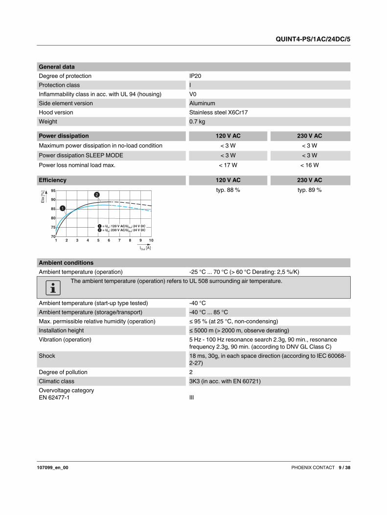
General data
Degree of protection IP20
Protection class I
Inflammability class in acc. with UL 94 (housing) V0
Side element version Aluminum
Hood version Stainless steel X6Cr17
Weight 0.7 kg
Power dissipation 120 V AC 230 V AC
Maximum power dissipation in no-load condition < 3 W < 3 W
Power dissipation SLEEP MODE < 3 W < 3 W
Power loss nominal load max. < 17 W < 16 W
Efficiency 120 V AC 230 V AC
typ. 88 % typ. 89 %
70
75
80
85
90
95
I [A]Out
Eta
[%
]
= U : 120 V AC/U : 24 V DCIn Out
= U : 230 V AC/U : 24 V DCIn Out
1 2 3 4 5 6 7 8 9 10
Ambient conditions
Ambient temperature (operation) -25 °C ... 70 °C (> 60 °C Derating: 2,5 %/K)
The ambient temperature (operation) refers to UL 508 surrounding air temperature.
Ambient temperature (start-up type tested) -40 °C
Ambient temperature (storage/transport) -40 °C ... 85 °C
Max. permissible relative humidity (operation) ≤ 95 % (at 25 °C, non-condensing)
Installation height ≤ 5000 m (> 2000 m, observe derating)
Vibration (operation) 5 Hz - 100 Hz resonance search 2.3g, 90 min., resonance
frequency 2.3g, 90 min. (according to DNV GL Class C)
Shock 18 ms, 30g, in each space direction (according to IEC 60068-
2-27)
Degree of pollution 2
Climatic class 3K3 (in acc. with EN 60721)
Overvoltage category
EN 62477-1 III
QUINT4-PS/1AC/24DC/5
107099_en_00 PHOENIX CONTACT 10 / 38
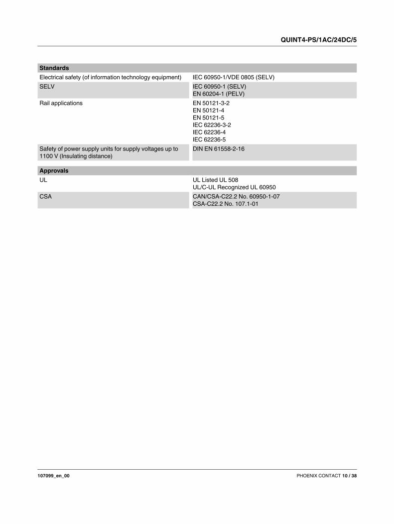
Standards
Electrical safety (of information technology equipment) IEC 60950-1/VDE 0805 (SELV)
SELV IEC 60950-1 (SELV)
EN 60204-1 (PELV)
Rail applications EN 50121-3-2
EN 50121-4
EN 50121-5
IEC 62236-3-2
IEC 62236-4
IEC 62236-5
Safety of power supply units for supply voltages up to
1100 V (Insulating distance)
DIN EN 61558-2-16
Approvals
UL UL Listed UL 508
UL/C-UL Recognized UL 60950
CSA CAN/CSA-C22.2 No. 60950-1-07
CSA-C22.2 No. 107.1-01
QUINT4-PS/1AC/24DC/5
107099_en_00 PHOENIX CONTACT 11 / 38
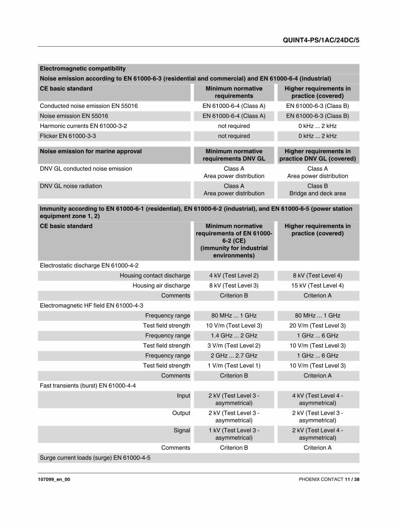
Electromagnetic compatibility
Noise emission according to EN 61000-6-3 (residential and commercial) and EN 61000-6-4 (industrial)
CE basic standard Minimum normative
requirements
Higher requirements in
practice (covered)
Conducted noise emission EN 55016 EN 61000-6-4 (Class A) EN 61000-6-3 (Class B)
Noise emission EN 55016 EN 61000-6-4 (Class A) EN 61000-6-3 (Class B)
Harmonic currents EN 61000-3-2 not required 0 kHz ... 2 kHz
Flicker EN 61000-3-3 not required 0 kHz ... 2 kHz
Noise emission for marine approval Minimum normative
requirements DNV GL
Higher requirements in
practice DNV GL (covered)
DNV GL conducted noise emission Class A
Area power distribution
Class A
Area power distribution
DNV GL noise radiation Class A
Area power distribution
Class B
Bridge and deck area
Immunity according to EN 61000-6-1 (residential), EN 61000-6-2 (industrial), and EN 61000-6-5 (power station
equipment zone 1, 2)
CE basic standard Minimum normative
requirements of EN 61000-
6-2 (CE)
(immunity for industrial
environments)
Higher requirements in
practice (covered)
Electrostatic discharge EN 61000-4-2
Housing contact discharge 4 kV (Test Level 2) 8 kV (Test Level 4)
Housing air discharge 8 kV (Test Level 3) 15 kV (Test Level 4)
Comments Criterion B Criterion A
Electromagnetic HF field EN 61000-4-3
Frequency range 80 MHz ... 1 GHz 80 MHz ... 1 GHz
Test field strength 10 V/m (Test Level 3) 20 V/m (Test Level 3)
Frequency range 1.4 GHz ... 2 GHz 1 GHz ... 6 GHz
Test field strength 3 V/m (Test Level 2) 10 V/m (Test Level 3)
Frequency range 2 GHz ... 2.7 GHz 1 GHz ... 6 GHz
Test field strength 1 V/m (Test Level 1) 10 V/m (Test Level 3)
Comments Criterion B Criterion A
Fast transients (burst) EN 61000-4-4
Input 2 kV (Test Level 3 -
asymmetrical)
4 kV (Test Level 4 -
asymmetrical)
Output 2 kV (Test Level 3 -
asymmetrical)
2 kV (Test Level 3 -
asymmetrical)
Signal 1 kV (Test Level 3 -
asymmetrical)
2 kV (Test Level 4 -
asymmetrical)
Comments Criterion B Criterion A
Surge current loads (surge) EN 61000-4-5
QUINT4-PS/1AC/24DC/5
107099_en_00 PHOENIX CONTACT 12 / 38
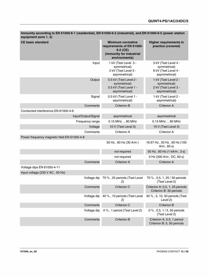
Input 1 kV (Test Level 3 -
symmetrical)
2 kV (Test Level 3 -
asymmetrical)
3 kV (Test Level 4 -
symmetrical)
6 kV (Test Level 4 -
asymmetrical)
Output 0.5 kV (Test Level 2 -
symmetrical)
0.5 kV (Test Level 1 -
asymmetrical)
1 kV (Test Level 2 -
symmetrical)
2 kV (Test Level 3 -
asymmetrical)
Signal 0.5 kV (Test Level 1 -
asymmetrical)
1 kV (Test Level 2 -
asymmetrical)
Comments Criterion B Criterion A
Conducted interference EN 61000-4-6
Input/Output/Signal asymmetrical asymmetrical
Frequency range 0.15 MHz ... 80 MHz 0.15 MHz ... 80 MHz
Voltage 10 V (Test Level 3) 10 V (Test Level 3)
Comments Criterion A Criterion A
Power frequency magnetic field EN 61000-4-8
50 Hz , 60 Hz (30 A/m ) 16.67 Hz , 50 Hz , 60 Hz (100
A/m , 60 s)
not required 50 Hz , 60 Hz (1 kA/m , 3 s)
not required 0 Hz (300 A/m , DC, 60 s)
Comments Criterion A Criterion A
Voltage dips EN 61000-4-11
Input voltage (230 V AC , 50 Hz)
Voltage dip 70 % , 25 periods (Test Level
2)
70 % , 0,5, 1, 25 / 30 periods
(Test Level 2)
Comments Criterion C Criterion A: 0,5, 1, 25 periods
Criterion B: 30 periods
Voltage dip 40 % , 10 periods (Test Level
2)
40 % , 5, 10, 50 periods (Test
Level 2)
Comments Criterion C Criterion B
Voltage dip 0 % , 1 period (Test Level 2) 0 % , 0.5, 1 / 5, 50 periods
(Test Level 2)
Comments Criterion B Criterion A: 0.5, 1 period
Criterion B: 5, 50 periods
Immunity according to EN 61000-6-1 (residential), EN 61000-6-2 (industrial), and EN 61000-6-5 (power station
equipment zone 1, 2)
CE basic standard Minimum normative
requirements of EN 61000-
6-2 (CE)
(immunity for industrial
environments)
Higher requirements in
practice (covered)
QUINT4-PS/1AC/24DC/5
107099_en_00 PHOENIX CONTACT 13 / 38
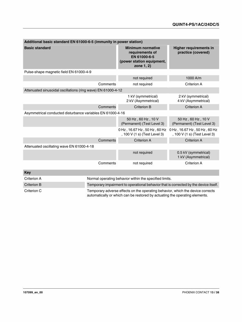
Additional basic standard EN 61000-6-5 (immunity in power station)
Basic standard Minimum normative
requirements of
EN 61000-6-5
(power station equipment,
zone 1, 2)
Higher requirements in
practice (covered)
Pulse-shape magnetic field EN 61000-4-9
not required 1000 A/m
Comments not required Criterion A
Attenuated sinusoidal oscillations (ring wave) EN 61000-4-12
1 kV (symmetrical)
2 kV (Asymmetrical)
2 kV (symmetrical)
4 kV (Asymmetrical)
Comments Criterion B Criterion A
Asymmetrical conducted disturbance variables EN 61000-4-16
50 Hz , 60 Hz , 10 V
(Permanent) (Test Level 3)
50 Hz , 60 Hz , 10 V
(Permanent) (Test Level 3)
0 Hz , 16.67 Hz , 50 Hz , 60 Hz
, 100 V (1 s) (Test Level 3)
0 Hz , 16.67 Hz , 50 Hz , 60 Hz
, 100 V (1 s) (Test Level 3)
Comments Criterion A Criterion A
Attenuated oscillating wave EN 61000-4-18
not required 0.5 kV (symmetrical)
1 kV (Asymmetrical)
Comments not required Criterion A
Key
Criterion A Normal operating behavior within the specified limits.
Criterion B Temporary impairment to operational behavior that is corrected by the device itself.
Criterion C Temporary adverse effects on the operating behavior, which the device corrects
automatically or which can be restored by actuating the operating elements.
QUINT4-PS/1AC/24DC/5
107099_en_00 PHOENIX CONTACT 14 / 38
5 Safety and installation notes
Only qualified electricians may install, start up, and operate
the device. Observe the national safety and accident
prevention regulations.
The specified technical characteristics relate to the factory
setting of the standard device.
Configured devices may have different technical
characteristics. The device behavior may also differ from the
documentation.
Check the device for damage before startup.
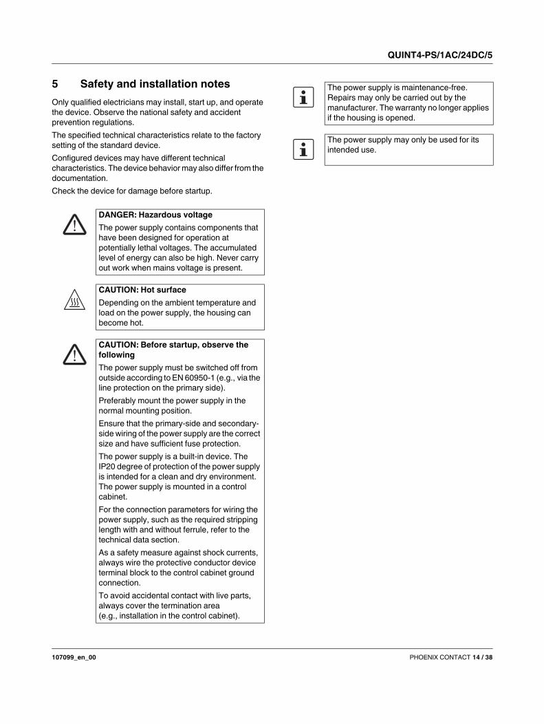
DANGER: Hazardous voltage
The power supply contains components that
have been designed for operation at
potentially lethal voltages. The accumulated
level of energy can also be high. Never carry
out work when mains voltage is present.
CAUTION: Hot surface
Depending on the ambient temperature and
load on the power supply, the housing can
become hot.
CAUTION: Before startup, observe the
following
The power supply must be switched off from
outside according to EN 60950-1 (e.g., via the
line protection on the primary side).
Preferably mount the power supply in the
normal mounting position.
Ensure that the primary-side and secondary-
side wiring of the power supply are the correct
size and have sufficient fuse protection.
The power supply is a built-in device. The
IP20 degree of protection of the power supply
is intended for a clean and dry environment.
The power supply is mounted in a control
cabinet.
For the connection parameters for wiring the
power supply, such as the required stripping
length with and without ferrule, refer to the
technical data section.
As a safety measure against shock currents,
always wire the protective conductor device
terminal block to the control cabinet ground
connection.
To avoid accidental contact with live parts,
always cover the termination area
(e.g., installation in the control cabinet).
The power supply is maintenance-free.
Repairs may only be carried out by the
manufacturer. The warranty no longer applies
if the housing is opened.
The power supply may only be used for its
intended use.
QUINT4-PS/1AC/24DC/5
107099_en_00 PHOENIX CONTACT 15 / 38
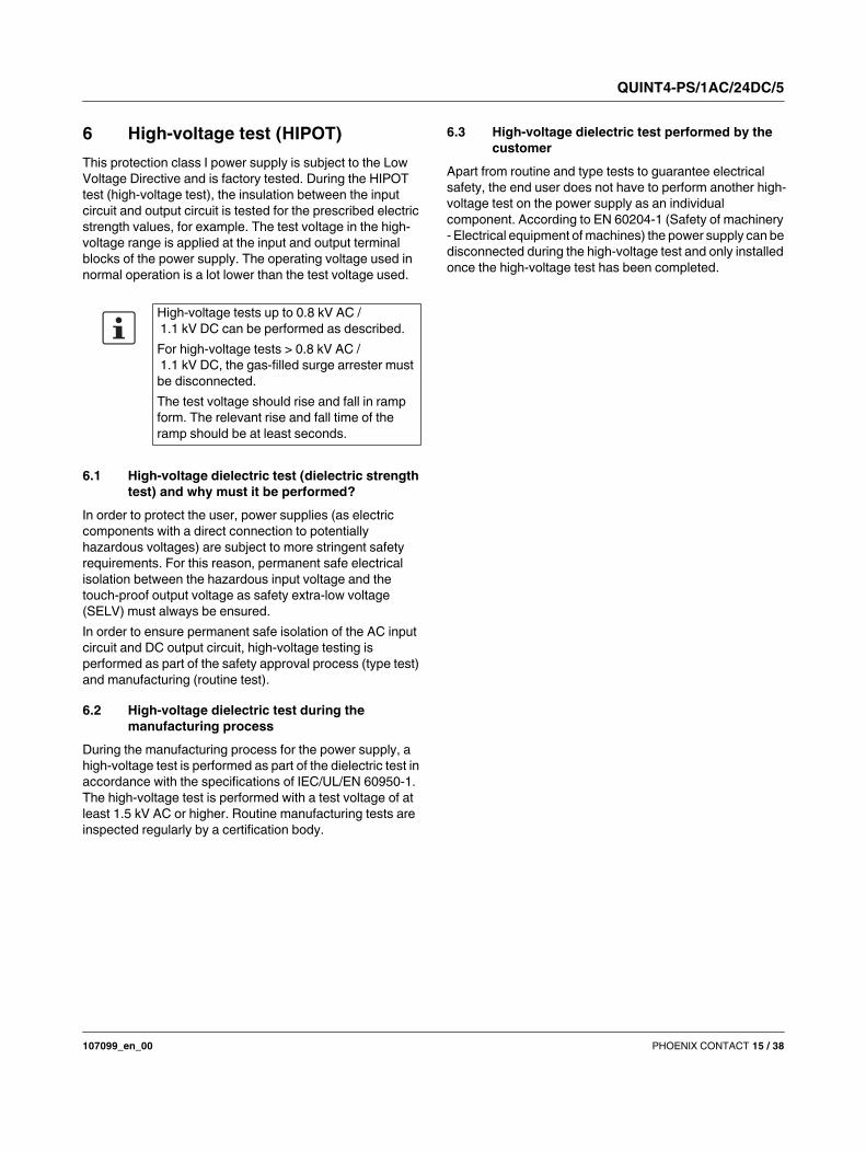
6 High-voltage test (HIPOT)
This protection class I power supply is subject to the Low
Voltage Directive and is factory tested. During the HIPOT
test (high-voltage test), the insulation between the input
circuit and output circuit is tested for the prescribed electric
strength values, for example. The test voltage in the high-
voltage range is applied at the input and output terminal
blocks of the power supply. The operating voltage used in
normal operation is a lot lower than the test voltage used.
6.1 High-voltage dielectric test (dielectric strength
test) and why must it be performed?
In order to protect the user, power supplies (as electric
components with a direct connection to potentially
hazardous voltages) are subject to more stringent safety
requirements. For this reason, permanent safe electrical
isolation between the hazardous input voltage and the
touch-proof output voltage as safety extra-low voltage
(SELV) must always be ensured.
In order to ensure permanent safe isolation of the AC input
circuit and DC output circuit, high-voltage testing is
performed as part of the safety approval process (type test)
and manufacturing (routine test).
6.2 High-voltage dielectric test during the
manufacturing process
During the manufacturing process for the power supply, a
high-voltage test is performed as part of the dielectric test in
accordance with the specifications of IEC/UL/EN 60950-1.
The high-voltage test is performed with a test voltage of at
least 1.5 kV AC or higher. Routine manufacturing tests are
inspected regularly by a certification body.
6.3 High-voltage dielectric test performed by the
customer
Apart from routine and type tests to guarantee electrical
safety, the end user does not have to perform another high-
voltage test on the power supply as an individual
component. According to EN 60204-1 (Safety of machinery
- Electrical equipment of machines) the power supply can be
disconnected during the high-voltage test and only installed
once the high-voltage test has been completed.
High-voltage tests up to 0.8 kV AC /
1.1 kV DC can be performed as described.
For high-voltage tests > 0.8 kV AC /
1.1 kV DC, the gas-filled surge arrester must
be disconnected.
The test voltage should rise and fall in ramp
form. The relevant rise and fall time of the
ramp should be at least seconds.
QUINT4-PS/1AC/24DC/5
107099_en_00 PHOENIX CONTACT 16 / 38
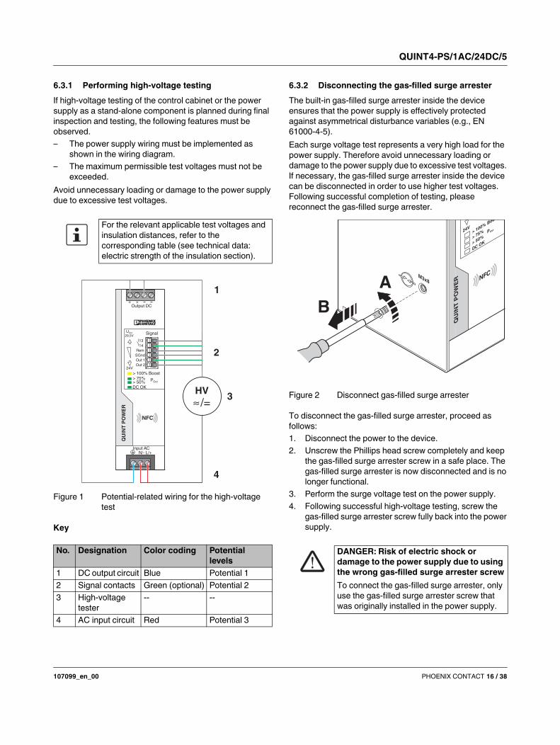
6.3.1 Performing high-voltage testing
If high-voltage testing of the control cabinet or the power
supply as a stand-alone component is planned during final
inspection and testing, the following features must be
observed.
– The power supply wiring must be implemented as
shown in the wiring diagram.
– The maximum permissible test voltages must not be
exceeded.
Avoid unnecessary loading or damage to the power supply
due to excessive test voltages.
Figure 1 Potential-related wiring for the high-voltage
test
Key
6.3.2 Disconnecting the gas-filled surge arrester
The built-in gas-filled surge arrester inside the device
ensures that the power supply is effectively protected
against asymmetrical disturbance variables (e.g., EN
61000-4-5).
Each surge voltage test represents a very high load for the
power supply. Therefore avoid unnecessary loading or
damage to the power supply due to excessive test voltages.
If necessary, the gas-filled surge arrester inside the device
can be disconnected in order to use higher test voltages.
Following successful completion of testing, please
reconnect the gas-filled surge arrester.
Figure 2 Disconnect gas-filled surge arrester
To disconnect the gas-filled surge arrester, proceed as
follows:
1. Disconnect the power to the device.
2. Unscrew the Phillips head screw completely and keep
the gas-filled surge arrester screw in a safe place. The
gas-filled surge arrester is now disconnected and is no
longer functional.
3. Perform the surge voltage test on the power supply.
4. Following successful high-voltage testing, screw the
gas-filled surge arrester screw fully back into the power
supply.
For the relevant applicable test voltages and
insulation distances, refer to the
corresponding table (see technical data:
electric strength of the insulation section).
No. Designation Color coding Potential
levels
1 DC output circuit Blue Potential 1
2 Signal contacts Green (optional) Potential 2
3 High-voltage
tester
-- --
4 AC input circuit Red Potential 3
NFC
> 100% Boost> 75%> 50%
Pout
DC OK
Uout29,5V
24V
QU
INT
PO
WE
R
Output DC 24V 5A+ +
Input AC 400-500 V
L1/ L2 L3/+
13
14
Rem
SGnd
Out 1
Out 2 Sig
na
l G
rou
nd
NFC
> 100% Boost> 75%> 50%
POut
DC OK
UOut
29,5V
24V
QU
INT
PO
WE
R
Output DC+ +
Input AC
13
14
Rem
SGnd
Out 1
Out 2
N/- L/+
Signal
HV
/=
1
2
3
4
DANGER: Risk of electric shock or
damage to the power supply due to using
the wrong gas-filled surge arrester screw
To connect the gas-filled surge arrester, only
use the gas-filled surge arrester screw that
was originally installed in the power supply.
M3x8 NFC
QU
INT
PO
WE
R
POut
> 75%
> 50%
DCOK
> 100%24V
A
B
QUINT4-PS/1AC/24DC/5
107099_en_00 PHOENIX CONTACT 17 / 38
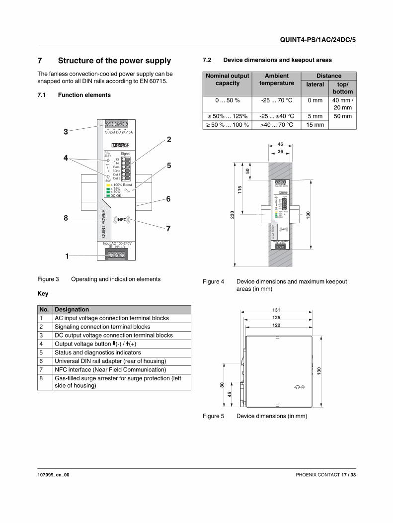
7 Structure of the power supply
The fanless convection-cooled power supply can be
snapped onto all DIN rails according to EN 60715.
7.1 Function elements
Figure 3 Operating and indication elements
Key
7.2 Device dimensions and keepout areas
Figure 4 Device dimensions and maximum keepout
areas (in mm)
Figure 5 Device dimensions (in mm)
No. Designation
1 AC input voltage connection terminal blocks
2 Signaling connection terminal blocks
3 DC output voltage connection terminal blocks
4 Output voltage button (-) / (+)
5 Status and diagnostics indicators
6 Universal DIN rail adapter (rear of housing)
7 NFC interface (Near Field Communication)
8 Gas-filled surge arrester for surge protection (left
side of housing)
NFC
> 100% Boost> 75%> 50%
Pout
DC OK
Uout29,5V
24V
QU
INT
PO
WE
R
Output DC 24V 5A+ +
Input AC 400-500 V
L1/ L2 L3/+
8
4
3
5
7
6
13
14
Rem
SGnd
Out 1
Out 2 Sig
na
l G
rou
nd
NFC
> 100% Boost> 75%> 50%
POut
DC OK
UOut
29,5V
24V
QU
INT
PO
WE
R
Output DC 24V 5A+ +
Input AC 100-240V
4
32
7
13
14
Rem
SGnd
Out 1
Out 2
N/- L/+
1
4Signal
Nominal output
capacity
Ambient
temperature
Distance
lateral top/
bottom
0 ... 50 % -25 ... 70 °C 0 mm 40 mm /
20 mm
≥ 50% ... 125% -25 ... ≤40 °C 5 mm 50 mm
≥ 50 % ... 100 % >40 ... 70 °C 15 mm
46
50
11
5
23
0
13
0
36
NFC
> 100% Boost> 75%> 50%
Pout
DC OK
Uout29,5V
24V
QU
INT
PO
WE
R
Output DC 24V 5A+ +
Input AC 400-500 V
L1/ L2 L3/+
13
14
Rem
SGnd
Out 1
Out 2 Sig
na
l G
rou
nd
NFC
> 100% Boost> 75%> 50%
POut
DC OK
UOut
29,5V
24V
QU
INT
PO
WE
R
Output DC 24V 5A+ +
13
14
Rem
SGnd
Out 1
Out 2
Signal
Input AC 100-240 VN/- L/+
122
1251
30
80
45
131
QUINT4-PS/1AC/24DC/5
107099_en_00 PHOENIX CONTACT 18 / 38
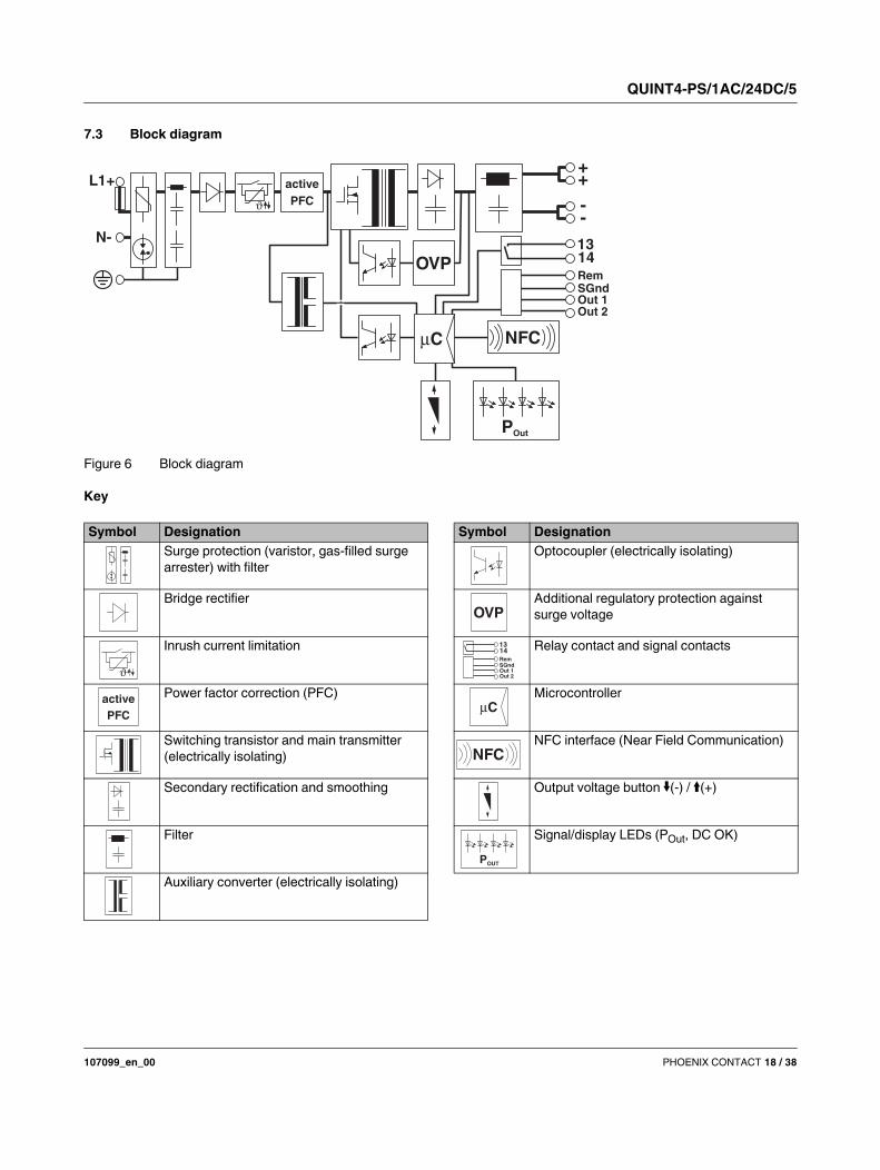
7.3 Block diagram
Figure 6 Block diagram
Key
NFC
POut
OVP
C
++
--
1314RemSGndOut 1Out 2
active
PFC
L1+
N-
Symbol Designation
Surge protection (varistor, gas-filled surge
arrester) with filter
Bridge rectifier
Inrush current limitation
Power factor correction (PFC)
Switching transistor and main transmitter
(electrically isolating)
Secondary rectification and smoothing
Filter
Auxiliary converter (electrically isolating)
active
PFC
Symbol Designation
Optocoupler (electrically isolating)
Additional regulatory protection against
surge voltage
Relay contact and signal contacts
Microcontroller
NFC interface (Near Field Communication)
Output voltage button (-) / (+)
Signal/display LEDs (POut, DC OK)
OVP
1314RemSGndOut 1Out 2
C
NFC
POUT
QUINT4-PS/1AC/24DC/5
107099_en_00 PHOENIX CONTACT 19 / 38
8 Mounting/removing the power
supply
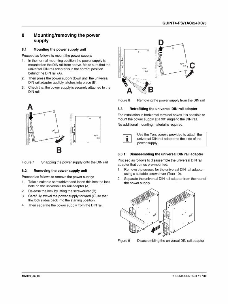
8.1 Mounting the power supply unit
Proceed as follows to mount the power supply:
1. In the normal mounting position the power supply is
mounted on the DIN rail from above. Make sure that the
universal DIN rail adapter is in the correct position
behind the DIN rail (A).
2. Then press the power supply down until the universal
DIN rail adapter audibly latches into place (B).
3. Check that the power supply is securely attached to the
DIN rail.
Figure 7 Snapping the power supply onto the DIN rail
8.2 Removing the power supply unit
Proceed as follows to remove the power supply:
1. Take a suitable screwdriver and insert this into the lock
hole on the universal DIN rail adapter (A).
2. Release the lock by lifting the screwdriver (B).
3. Carefully swivel the power supply forward (C) so that
the lock slides back into the starting position.
4. Then separate the power supply from the DIN rail.
Figure 8 Removing the power supply from the DIN rail
8.3 Retrofitting the universal DIN rail adapter
For installation in horizontal terminal boxes it is possible to
mount the power supply at a 90° angle to the DIN rail.
No additional mounting material is required.
8.3.1 Disassembling the universal DIN rail adapter
Proceed as follows to disassemble the universal DIN rail
adapter that comes pre-mounted:
1. Remove the screws for the universal DIN rail adapter
using a suitable screwdriver (Torx 10).
2. Separate the universal DIN rail adapter from the rear of
the power supply.
Figure 9 Disassembling the universal DIN rail adapter
B
A
Use the Torx screws provided to attach the
universal DIN rail adapter to the side of the
power supply.
BA
D
C
M3x8
M3x8
QUINT4-PS/1AC/24DC/5
107099_en_00 PHOENIX CONTACT 20 / 38
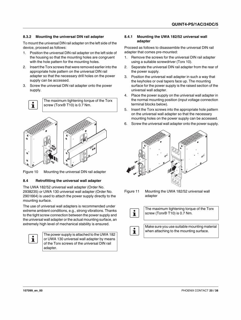
8.3.2 Mounting the universal DIN rail adapter
To mount the universal DIN rail adapter on the left side of the
device, proceed as follows:
1. Position the universal DIN rail adapter on the left side of
the housing so that the mounting holes are congruent
with the hole pattern for the mounting holes.
2. Insert the Torx screws that were removed earlier into the
appropriate hole pattern on the universal DIN rail
adapter so that the necessary drill holes on the power
supply can be accessed.
3. Screw the universal DIN rail adapter onto the power
supply.
Figure 10 Mounting the universal DIN rail adapter
8.4 Retrofitting the universal wall adapter
The UWA 182/52 universal wall adapter (Order No.
2938235) or UWA 130 universal wall adapter (Order No.
2901664) is used to attach the power supply directly to the
mounting surface.
The use of universal wall adapters is recommended under
extreme ambient conditions, e.g., strong vibrations. Thanks
to the tight screw connection between the power supply and
the universal wall adapter or the actual mounting surface, an
extremely high level of mechanical stability is ensured.
8.4.1 Mounting the UWA 182/52 universal wall
adapter
Proceed as follows to disassemble the universal DIN rail
adapter that comes pre-mounted:
1. Remove the screws for the universal DIN rail adapter
using a suitable screwdriver (Torx 10).
2. Separate the universal DIN rail adapter from the rear of
the power supply.
3. Position the universal wall adapter in such a way that
the keyholes or oval tapers face up. The mounting
surface for the power supply is the raised section of the
universal wall adapter.
4. Place the power supply on the universal wall adapter in
the normal mounting position (input voltage connection
terminal blocks below).
5. Insert the Torx screws into the appropriate hole pattern
on the universal wall adapter so that the necessary
mounting holes on the power supply can be accessed.
6. Screw the universal wall adapter onto the power supply.
Figure 11 Mounting the UWA 182/52 universal wall
adapter
The maximum tightening torque of the Torx
screw (Torx® T10) is 0.7 Nm.
The power supply is attached to the UWA 182
or UWA 130 universal wall adapter by means
of the Torx screws of the universal DIN rail
adapter.
M3x8M3x8
The maximum tightening torque of the Torx
screw (Torx® T10) is 0.7 Nm.
Make sure you use suitable mounting material
when attaching to the mounting surface.
M3x8
M3x8
QUINT4-PS/1AC/24DC/5
107099_en_00 PHOENIX CONTACT 21 / 38
8.4.2 Mounting the UWA 130 2-piece universal wall
adapter
Proceed as follows to disassemble the universal DIN rail
adapter that comes pre-mounted:
1. Remove the screws for the universal DIN rail adapter
using a suitable screwdriver (Torx 10).
2. Separate the universal DIN rail adapter from the rear of
the power supply.
3. Position the universal wall adapter. The mounting
surface for the power supply is the raised section of the
universal wall adapter.
4. Place the power supply on the universal wall adapter in
the normal mounting position (input voltage connection
terminal blocks below).
5. Insert the Torx screws into the appropriate hole pattern
on the universal wall adapter so that the necessary
mounting holes in the side flanges of the power supply
can be accessed.
6. Screw the two-piece universal wall adapter onto the
power supply.
Figure 12 Mounting the UWA 130 universal wall adapter
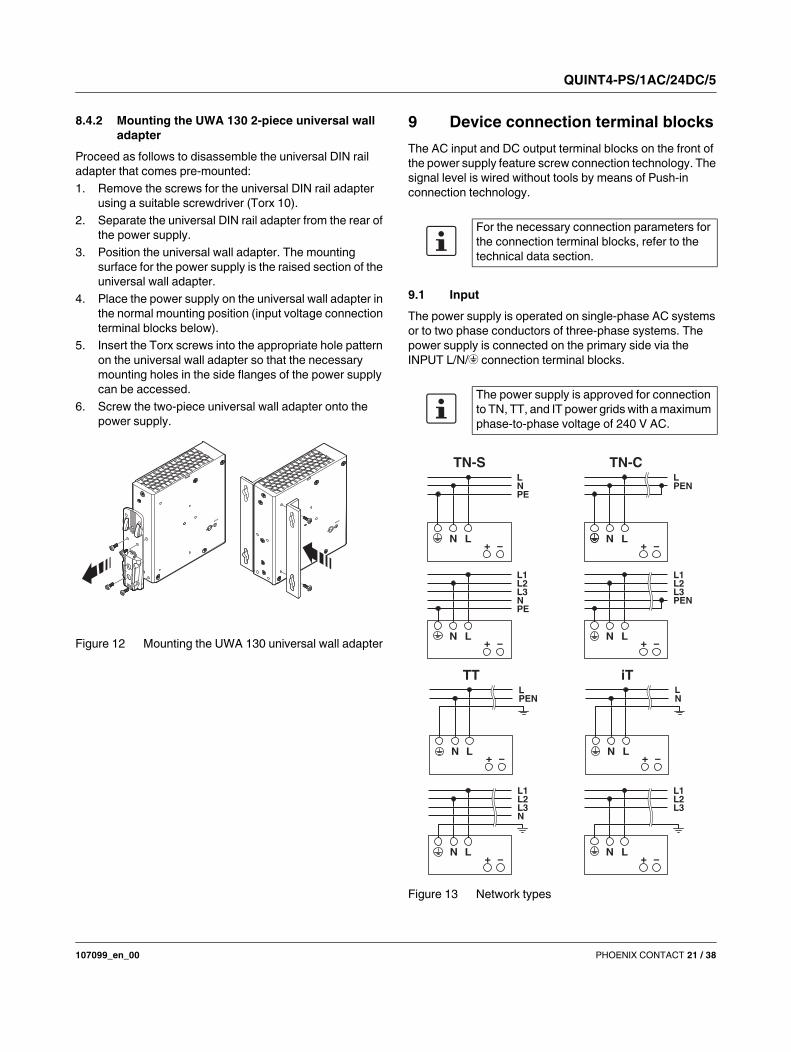
9 Device connection terminal blocks
The AC input and DC output terminal blocks on the front of
the power supply feature screw connection technology. The
signal level is wired without tools by means of Push-in
connection technology.
9.1 Input
The power supply is operated on single-phase AC systems
or to two phase conductors of three-phase systems. The
power supply is connected on the primary side via the
INPUT L/N/ connection terminal blocks.
Figure 13 Network types
M3x8
M3x8
For the necessary connection parameters for
the connection terminal blocks, refer to the
technical data section.
The power supply is approved for connection
to TN, TT, and IT power grids with a maximum
phase-to-phase voltage of 240 V AC.
L
PENL3L2L1
+N
−
iT
NL
+LN
−
TT
PENL
+L
−N
L
L3L2L1
+N
−L
NL3L2L1
+N
−
L
PENL3L2L1
+N
−
TN-C
PENL
+LN
−
PENL
+LN
−
TN-S
QUINT4-PS/1AC/24DC/5
107099_en_00 PHOENIX CONTACT 22 / 38
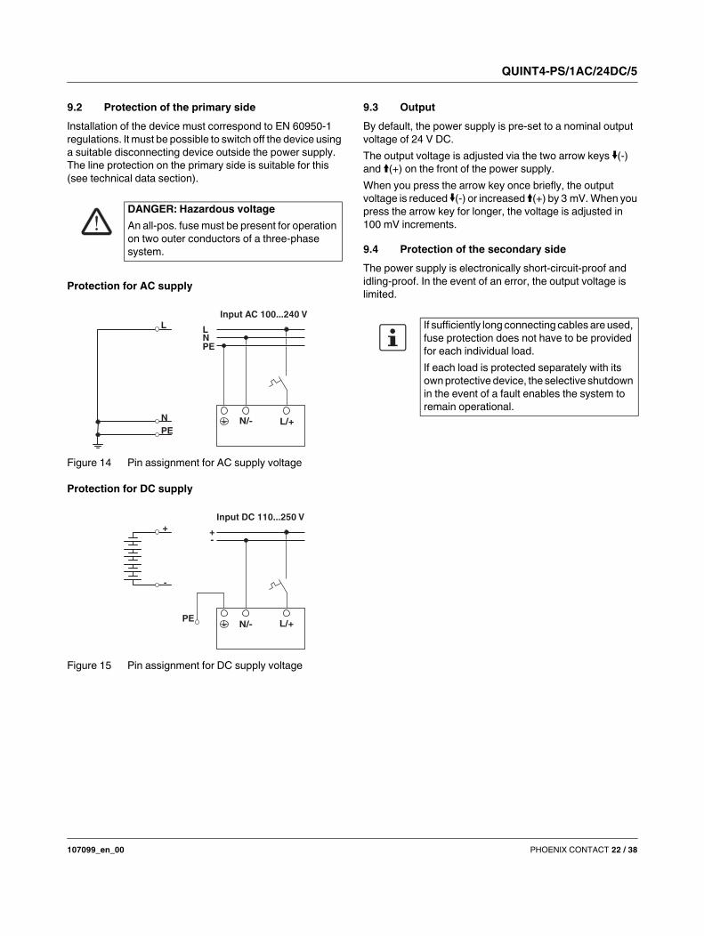
9.2 Protection of the primary side
Installation of the device must correspond to EN 60950-1
regulations. It must be possible to switch off the device using
a suitable disconnecting device outside the power supply.
The line protection on the primary side is suitable for this
(see technical data section).
Protection for AC supply
Figure 14 Pin assignment for AC supply voltage
Protection for DC supply
Figure 15 Pin assignment for DC supply voltage
9.3 Output
By default, the power supply is pre-set to a nominal output
voltage of 24 V DC.
The output voltage is adjusted via the two arrow keys (-) and (+) on the front of the power supply.
When you press the arrow key once briefly, the output
voltage is reduced (-) or increased (+) by 3 mV. When you
press the arrow key for longer, the voltage is adjusted in
100 mV increments.
9.4 Protection of the secondary side
The power supply is electronically short-circuit-proof and
idling-proof. In the event of an error, the output voltage is
limited.
DANGER: Hazardous voltage
An all-pos. fuse must be present for operation
on two outer conductors of a three-phase
system.
N/- L/+
NPE
L
Input AC 100...240 VL
L2
N
PE
+
-
PEN/- L/+
L2-+
Input DC 110...250 V
If sufficiently long connecting cables are used,
fuse protection does not have to be provided
for each individual load.
If each load is protected separately with its
own protective device, the selective shutdown
in the event of a fault enables the system to
remain operational.
QUINT4-PS/1AC/24DC/5
107099_en_00 PHOENIX CONTACT 23 / 38
10 Output characteristic curves
This section describes the various output characteristic
curves together with their areas of application for
customization to your specific application. The U/I
Advanced characteristic curve is set by default.
Key
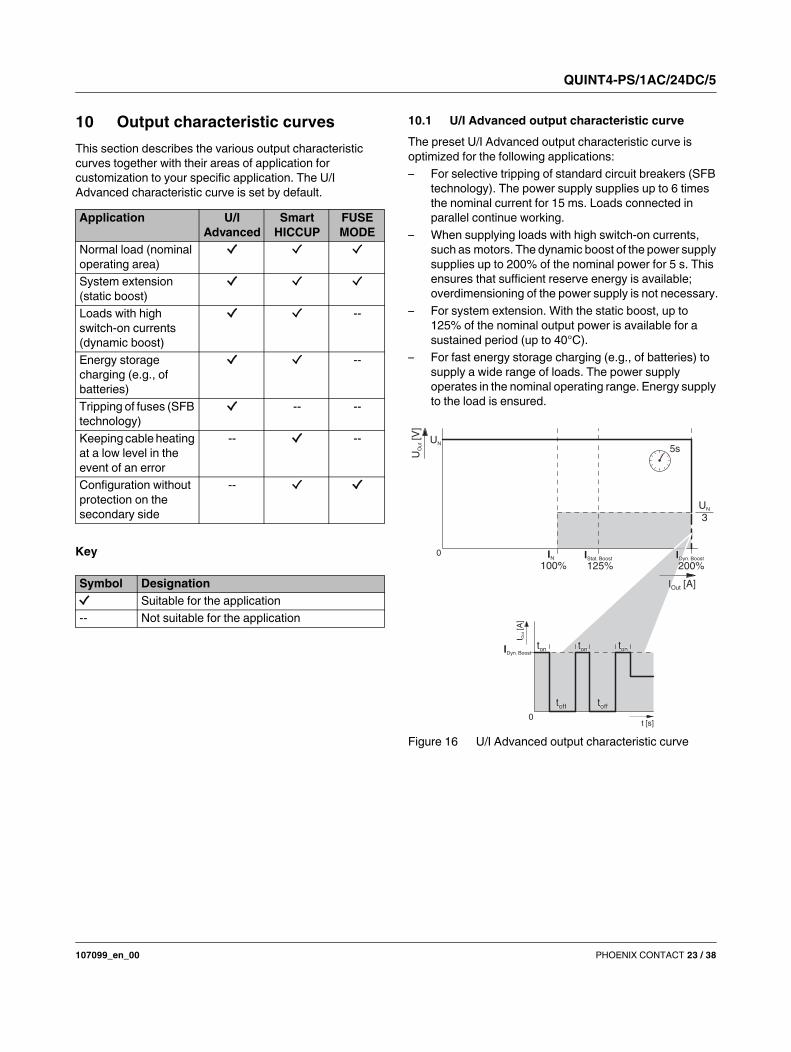
10.1 U/I Advanced output characteristic curve
The preset U/I Advanced output characteristic curve is
optimized for the following applications:
– For selective tripping of standard circuit breakers (SFB
technology). The power supply supplies up to 6 times
the nominal current for 15 ms. Loads connected in
parallel continue working.
– When supplying loads with high switch-on currents,
such as motors. The dynamic boost of the power supply
supplies up to 200% of the nominal power for 5 s. This
ensures that sufficient reserve energy is available;
overdimensioning of the power supply is not necessary.
– For system extension. With the static boost, up to
125% of the nominal output power is available for a
sustained period (up to 40°C).
– For fast energy storage charging (e.g., of batteries) to
supply a wide range of loads. The power supply
operates in the nominal operating range. Energy supply
to the load is ensured.
Figure 16 U/I Advanced output characteristic curve
Application U/I
Advanced
Smart
HICCUP
FUSE
MODE
Normal load (nominal
operating area)
System extension
(static boost)
Loads with high
switch-on currents
(dynamic boost)
--
Energy storage
charging (e.g., of
batteries)
--
Tripping of fuses (SFB
technology)
-- --
Keeping cable heating
at a low level in the
event of an error
-- --
Configuration without
protection on the
secondary side
--
Symbol Designation
Suitable for the application
-- Not suitable for the application
I[A
]O
ut
t [s]
IDyn. Boost
U[V
]O
ut
IN IStat. Boost
UN
3
5sUN
100% 125% 200%
ton
0
0
QUINT4-PS/1AC/24DC/5
107099_en_00 PHOENIX CONTACT 24 / 38
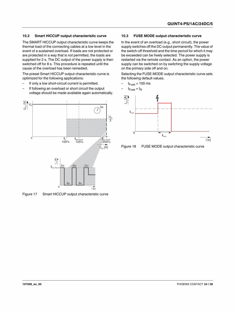
10.2 Smart HICCUP output characteristic curve
The SMART HICCUP output characteristic curve keeps the
thermal load of the connecting cables at a low level in the
event of a sustained overload. If loads are not protected or
are protected in a way that is not permitted, the loads are
supplied for 2 s. The DC output of the power supply is then
switched off for 8 s. This procedure is repeated until the
cause of the overload has been remedied.
The preset Smart HICCUP output characteristic curve is
optimized for the following applications:
– If only a low short-circuit current is permitted.
– If following an overload or short circuit the output
voltage should be made available again automatically.
Figure 17 Smart HICCUP output characteristic curve
10.3 FUSE MODE output characteristic curve
In the event of an overload (e.g., short circuit), the power
supply switches off the DC output permanently. The value of
the switch-off threshold and the time period for which it may
be exceeded can be freely selected. The power supply is
restarted via the remote contact. As an option, the power
supply can be switched on by switching the supply voltage
on the primary side off and on.
Selecting the FUSE MODE output characteristic curve sets
the following default values.
– tFuse = 100 ms
– IFuse = IN
Figure 18 FUSE MODE output characteristic curve
I[A
]O
ut
t [s]
2sIDyn. Boost
U[V
]O
ut
IN IStat. Boost
UN
2
5sUN
100% 125% 200%
0
0t [s]
I Ou
t[A
]
IFuse
tFuse
0
QUINT4-PS/1AC/24DC/5
107099_en_00 PHOENIX CONTACT 25 / 38
11 Configuring the power supply
With the fourth generation of the QUINT POWER power
supply, it is now possible for the first time to adapt the
behavior of the power supply. In addition to setting the
output voltage and selecting the output characteristic
curves, you can configure signal outputs Out 1, Out 2, and
floating signal contact 13/14, for example. Configuration of
the remote input for controlling the power supply or
specification of signal options and signal thresholds also
extend the range of possible applications.
The power supply is configured via the device's internal NFC
(near field communication) interface.
11.1 Configuration with PC software
In order to configure the power supply via the NFC interface,
the following hardware and software requirements must be
met:
– PC or notebook (as of Windows 7, Microsoft.Net
Framework 4.5, USB 2.0 interface, 50 MB hard disk
capacity, QUINT POWER software).
– Programming adapter:
TWN4 MIFARE NFC USB ADAPTER (Order No.
2909681) is plugged into the USB interface.
– Programming software: the QUINT POWER software
has been successfully installed.
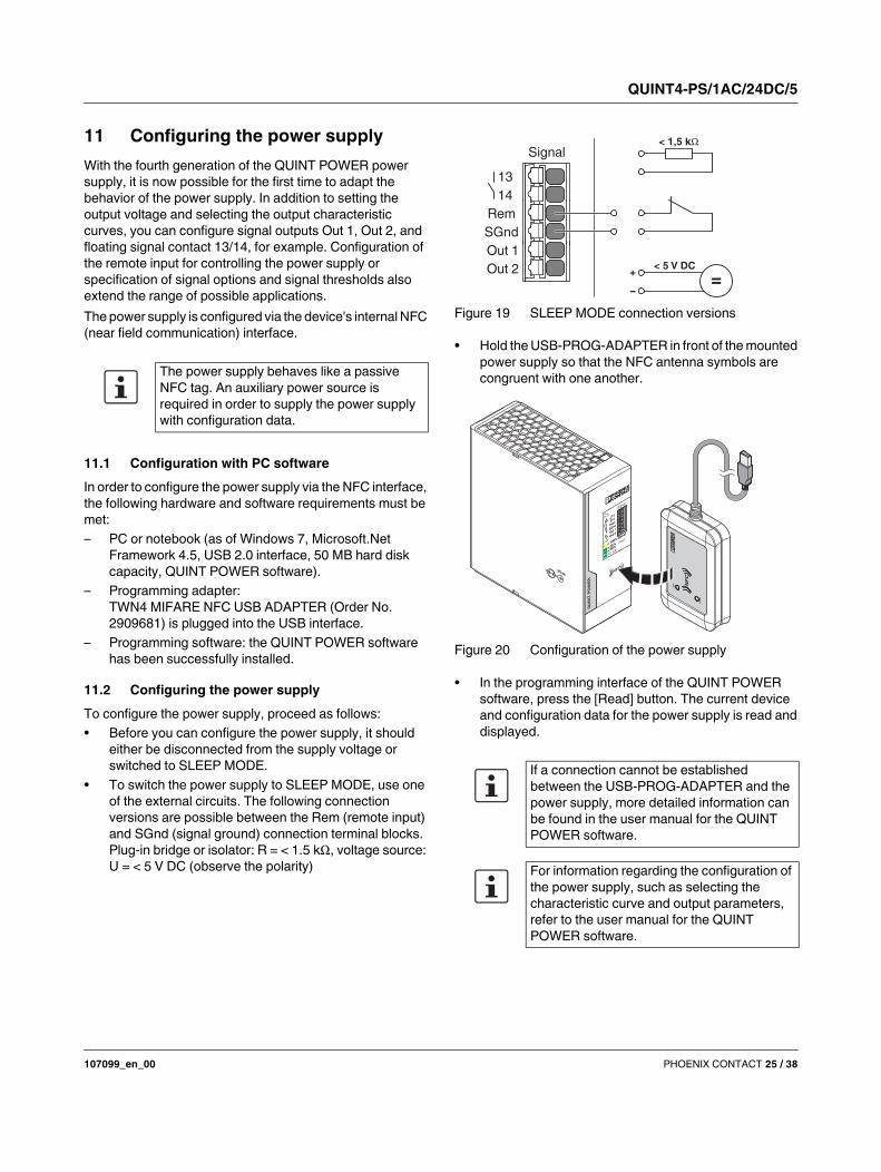
11.2 Configuring the power supply
To configure the power supply, proceed as follows:
• Before you can configure the power supply, it should
either be disconnected from the supply voltage or
switched to SLEEP MODE.
• To switch the power supply to SLEEP MODE, use one
of the external circuits. The following connection
versions are possible between the Rem (remote input)
and SGnd (signal ground) connection terminal blocks.
Plug-in bridge or isolator: R = < 1.5 k, voltage source:
U = < 5 V DC (observe the polarity)
Figure 19 SLEEP MODE connection versions
• Hold the USB-PROG-ADAPTER in front of the mounted
power supply so that the NFC antenna symbols are
congruent with one another.
Figure 20 Configuration of the power supply
• In the programming interface of the QUINT POWER
software, press the [Read] button. The current device
and configuration data for the power supply is read and
displayed.
The power supply behaves like a passive
NFC tag. An auxiliary power source is
required in order to supply the power supply
with configuration data.
If a connection cannot be established
between the USB-PROG-ADAPTER and the
power supply, more detailed information can
be found in the user manual for the QUINT
POWER software.
For information regarding the configuration of
the power supply, such as selecting the
characteristic curve and output parameters,
refer to the user manual for the QUINT
POWER software.
13
14
Rem
SGnd
Out 1
Out 2
Signal< 1,5 k
< 5 V DC
=+
-
NF
C
DA
T
CO
NN
NFC
QU
INT
PO
WE
R
M3x8
> 100% Boost
> 75%
> 50%
Pout
13
14
Rem
SGnd
Out 1
Out 2
> 100% Boost
> 75%
> 50%
DC OK
UOut
29,5V
24V
13
14
Rem
SGnd
Out 1
Out 2
Signal
QUINT4-PS/1AC/24DC/5
107099_en_00 PHOENIX CONTACT 26 / 38
11.3 Configuration with NFC-capable mobile
terminal device
The QUINT POWER app enables you to conveniently
configure the power supply using a mobile terminal device,
such as a smartphone.
In order to configure the power supply via the NFC interface,
the following hardware and software requirements must be
met:
– NFC-capable mobile terminal device with Android
operating system as of Version 4.1.x (Jelly Bean)
– QUINT POWER app (Google Play Store)
11.4 Ordering a configured power supply
Customer-specified QUINT POWER power supplies are
ordered as a KMAT item (configurable material) and are
configured during the production process in the factory. The
power supply is therefore supplied ready to connect for your
specific application.
12 SFB technology
SFB (selective fuse breaking) technology can be used to trip
circuit breakers and fuses connected on the secondary side
quickly and reliably. In the event of a short circuit on the
secondary side, the power supply supplies up to 6 times the
nominal current for 15 ms. The faulty load circuit is switched
off selectively.
Loads that are connected in parallel are still supplied with
energy. Operation of these system parts is ensured. In order
to always enable the reliable tripping of circuit breakers and
fuses, certain framework conditions must be observed (see
SFB configuration section).
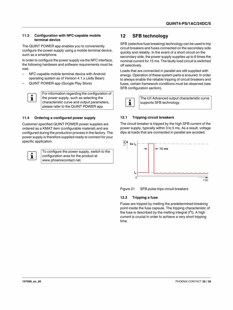
12.1 Tripping circuit breakers
The circuit breaker is tripped by the high SFB current of the
power supply, typically within 3 to 5 ms. As a result, voltage
dips at loads that are connected in parallel are avoided.
Figure 21 SFB pulse trips circuit breakers
12.2 Tripping a fuse
Fuses are tripped by melting the predetermined breaking
point inside the fuse capsule. The tripping characteristic of
the fuse is described by the melting integral (I²t). A high
current is crucial in order to achieve a very short tripping
time.
For information regarding the configuration of
the power supply, such as selecting the
characteristic curve and output parameters,
please refer to the QUINT POWER app.
To configure the power supply, switch to the
configuration area for the product at
www.phoenixcontact.net.
The U/I Advanced output characteristic curve
supports SFB technology.
6x IN
IN
15 ms
0
I [A
]
t [s]
QUINT4-PS/1AC/24DC/5
107099_en_00 PHOENIX CONTACT 27 / 38
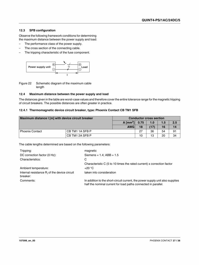
12.3 SFB configuration
Observe the following framework conditions for determining
the maximum distance between the power supply and load:
– The performance class of the power supply.
– The cross section of the connecting cable.
– The tripping characteristic of the fuse component.
Figure 22 Schematic diagram of the maximum cable
length
12.4 Maximum distance between the power supply and load
The distances given in the table are worst-case values and therefore cover the entire tolerance range for the magnetic tripping
of circuit breakers. The possible distances are often greater in practice.
12.4.1 Thermomagnetic device circuit breaker, type: Phoenix Contact CB TM1 SFB
The cable lengths determined are based on the following parameters:
-
+
-
+
l
LoadPower supply unit
Maximum distance l [m] with device circuit breaker Conductor cross section
A [mm²] 0.75 1.0 1.5 2.5
AWG 18 (17) 16 14
Phoenix Contact CB TM1 1A SFB P 27 36 54 91
CB TM1 2A SFB P 10 13 20 34
Tripping: magnetic
DC correction factor (0 Hz): Siemens = 1.4; ABB = 1.5
Characteristics: C
Characteristic C (5 to 10 times the rated current) x correction factor
Ambient temperature: +20 °C
Internal resistance Ri of the device circuit
breaker:
taken into consideration
Comments: In addition to the short-circuit current, the power supply unit also supplies
half the nominal current for load paths connected in parallel.
QUINT4-PS/1AC/24DC/5
107099_en_00 PHOENIX CONTACT 28 / 38
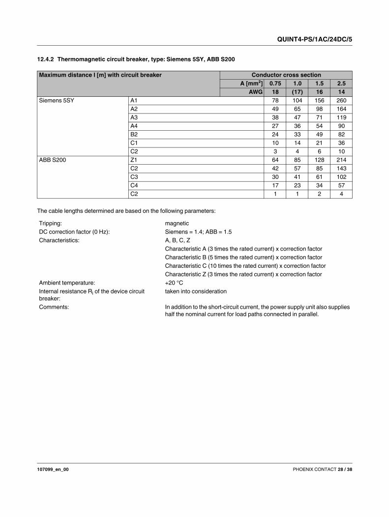
12.4.2 Thermomagnetic circuit breaker, type: Siemens 5SY, ABB S200
The cable lengths determined are based on the following parameters:
Maximum distance l [m] with circuit breaker Conductor cross section
A [mm²] 0.75 1.0 1.5 2.5
AWG 18 (17) 16 14
Siemens 5SY A1 78 104 156 260
A2 49 65 98 164
A3 38 47 71 119
A4 27 36 54 90
B2 24 33 49 82
C1 10 14 21 36
C2 3 4 6 10
ABB S200 Z1 64 85 128 214
C2 42 57 85 143
C3 30 41 61 102
C4 17 23 34 57
C2 1 1 2 4
Tripping: magnetic
DC correction factor (0 Hz): Siemens = 1.4; ABB = 1.5
Characteristics: A, B, C, Z
Characteristic A (3 times the rated current) x correction factor
Characteristic B (5 times the rated current) x correction factor
Characteristic C (10 times the rated current) x correction factor
Characteristic Z (3 times the rated current) x correction factor
Ambient temperature: +20 °C
Internal resistance Ri of the device circuit
breaker:
taken into consideration
Comments: In addition to the short-circuit current, the power supply unit also supplies
half the nominal current for load paths connected in parallel.
QUINT4-PS/1AC/24DC/5
107099_en_00 PHOENIX CONTACT 29 / 38
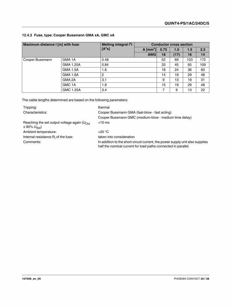
12.4.3 Fuse, type: Cooper Bussmann GMA xA, GMC xA
The cable lengths determined are based on the following parameters:
Maximum distance l [m] with fuse Melting integral I²t
[A²s]
Conductor cross section
A [mm²] 0.75 1.0 1.5 2.5
AWG 18 (17) 16 14
Cooper Bussmann GMA 1A 0.48 52 69 103 172
GMA 1.25A 0.84 33 45 65 109
GMA 1.5A 1.6 18 24 36 60
GMA 1.6A 2 14 19 29 48
GMA 2A 3.1 9 13 19 31
GMC 1A 1.8 15 19 29 48
GMC 1.25A 3.4 7 9 13 22
Tripping: thermal
Characteristics: Cooper Bussmann GMA (fast-blow - fast acting)
Cooper Bussmann GMC (medium-blow - medium time delay)
Reaching the set output voltage again (UOut
≤ 90% USet)
<10 ms
Ambient temperature: +20 °C
Internal resistance Ri of the fuse: taken into consideration
Comments: In addition to the short-circuit current, the power supply unit also supplies
half the nominal current for load paths connected in parallel.
QUINT4-PS/1AC/24DC/5
107099_en_00 PHOENIX CONTACT 30 / 38
13 Signaling
A floating signal contact is available for preventive function
monitoring of the power supply. Depending on the
configuration of the power supply, two digital outputs or one
digital and one analog output can be selected.
The current device status of the power supply is signaled
using four LED status indicators. The function of each LED
status indicator is assigned to a fixed event and cannot be
modified.
In addition, the power supply can be switched off and on via
an external circuit.
The signal outputs are configured on the software side using
the QUINT POWER software or the QUINT POWER app.
Upon delivery, the power supply is pre-allocated a default
configuration for the signal outputs.
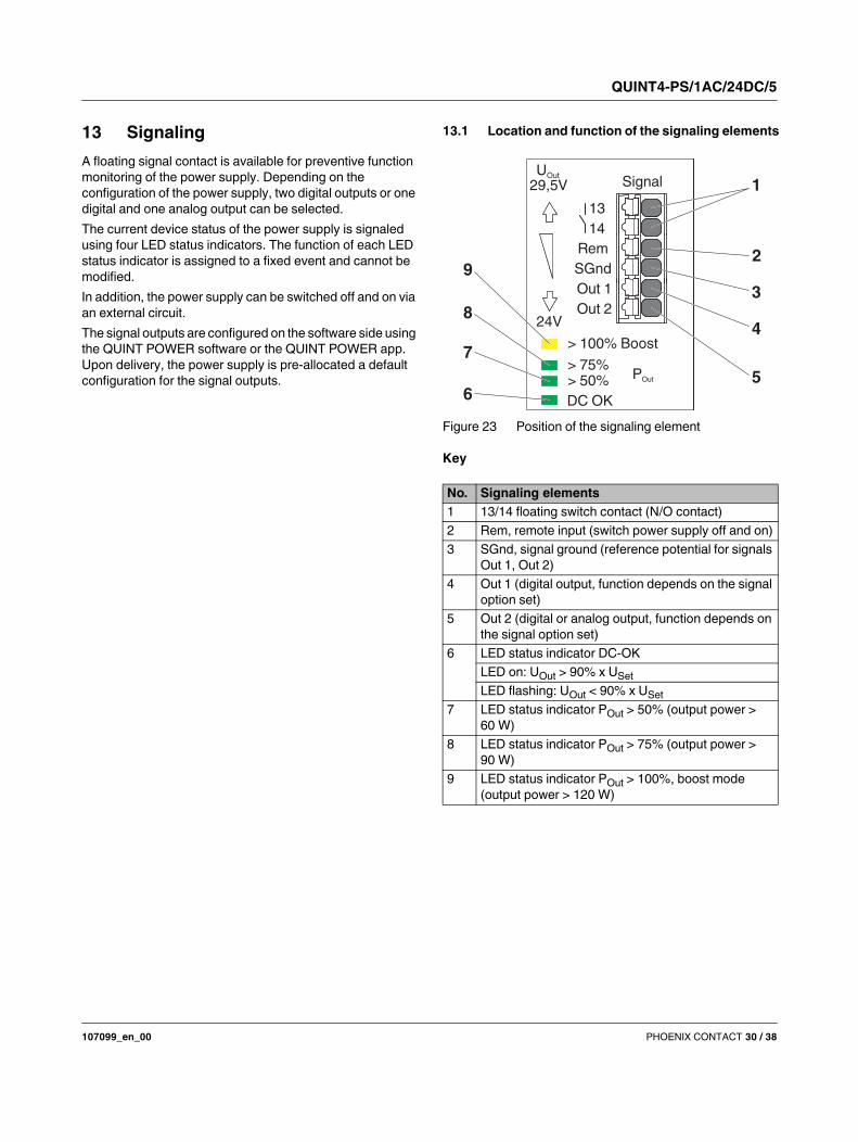
13.1 Location and function of the signaling elements
Figure 23 Position of the signaling element
Key
No. Signaling elements
1 13/14 floating switch contact (N/O contact)
2 Rem, remote input (switch power supply off and on)
3 SGnd, signal ground (reference potential for signals
Out 1, Out 2)
4 Out 1 (digital output, function depends on the signal
option set)
5 Out 2 (digital or analog output, function depends on
the signal option set)
6 LED status indicator DC-OK
LED on: UOut > 90% x USet
LED flashing: UOut < 90% x USet
7 LED status indicator POut > 50% (output power >
60 W)
8 LED status indicator POut > 75% (output power >
90 W)
9 LED status indicator POut > 100%, boost mode
(output power > 120 W)
> 100% Boost
> 75%> 50% POut
UOut
29,5V
24V
13
14
Rem
SGnd
Out 1
Out 2
DC OK
Signal 1
2
3
4
56
7
8
9
QUINT4-PS/1AC/24DC/5
107099_en_00 PHOENIX CONTACT 31 / 38
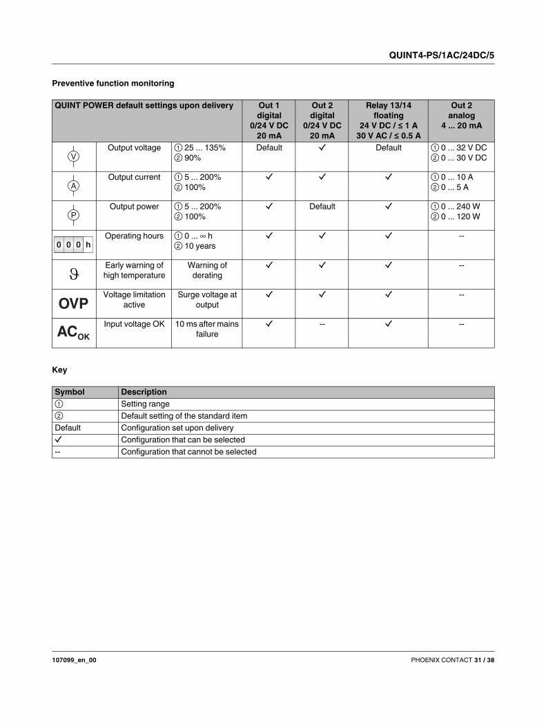
Preventive function monitoring
Key
QUINT POWER default settings upon delivery Out 1
digital
0/24 V DC
20 mA
Out 2
digital
0/24 V DC
20 mA
Relay 13/14
floating
24 V DC / ≤ 1 A
30 V AC / ≤ 0.5 A
Out 2
analog
4 ... 20 mA
Output voltage ① 25 ... 135%
② 90%
Default Default ① 0 ... 32 V DC
② 0 ... 30 V DC
Output current ① 5 ... 200%
② 100%
① 0 ... 10 A
② 0 ... 5 A
Output power ① 5 ... 200%
② 100%
Default ① 0 ... 240 W
② 0 ... 120 W
Operating hours ① 0 ... h
② 10 years
--
Early warning of
high temperature
Warning of
derating
--
Voltage limitation
active
Surge voltage at
output
--
Input voltage OK 10 ms after mains
failure
-- --
V
A
P
0 0 0 h
OVP
ACOK
Symbol Description
① Setting range
② Default setting of the standard item
Default Configuration set upon delivery
Configuration that can be selected
-- Configuration that cannot be selected
QUINT4-PS/1AC/24DC/5
107099_en_00 PHOENIX CONTACT 32 / 38
13.2 Description of signaling
In contrast to the default signaling set upon delivery, you can
customize the signaling to the specific needs of the system.
The following signal options can be selected to signal
system states.
13.2.1 Output voltage
Signals whether the output voltage is in the preset range. If
the output voltage of the power supply falls below the set
threshold value, the signal state changes.
Example of use
Indicates whether connected loads are being supplied.
Used to quickly detect a load circuit that is not being
supplied (e.g., in the event of mains failure or short circuit in
the supply line).
13.2.2 Output current
If the output current of the power supply exceeds the set
threshold value, the signal state changes.
Example of use
In the case of system extensions, loads are added. This
increases the utilization of the power supply. Preventive
function monitoring detects critical operating states in good
time. Action can be taken before system downtime occurs.
13.2.3 Output power
If the output power of the power supply exceeds the set
threshold value, the signal state changes.
Example of use
In the case of system extensions, loads are added. This
increases the utilization of the power supply. Preventive
function monitoring detects critical operating states in good
time. Appropriate measures can be taken before system
downtime can occur.
13.2.4 Operating hours
If the preset operating time of the power supply is exceeded,
the signal state changes.
Example of use
For systems with a very long operating time, such as wind
turbine generators or refineries, maintenance intervals are
planned. You can even schedule the maintenance date
during configuration based on the ambient temperature and
utilization of the power supply (see service life section).
13.2.5 Early warning of high temperature
Before the power supply protects itself through power
derating in the event of an overtemperature, the signal state
changes.
Example of use
Outdoor control cabinets can reach a high internal
temperature depending on the position of the sun. The same
is true if a control cabinet fan or cooling system fails. In the
event of any form of overtemperature, the power supply
provides a warning by means of this signal, well before the
supply of the loads is in any danger.
13.2.6 Voltage limitation active
If the circuit inside the device for protecting against surge
voltages is activated at the output, the signal state changes.
Example of use
Normative requirements stipulate that an upper voltage limit
must be observed at the output in the event of an error. It
must therefore be ensured, for example, that safety-related
controllers are not supplied with an output voltage that
exceeds 32 V DC, even in the event of an error. If foreign
bodies (ferrules, screws, etc.) enter the power supply and
generate an error, the signal state changes.
The simultaneous control of multiple signal
outputs by means of one signal option is
possible, as is the use of logic operations to
link multiple signal options to one control. The
power supply is configured using the QUINT
POWER software or the QUINT POWER app.
QUINT4-PS/1AC/24DC/5
107099_en_00 PHOENIX CONTACT 33 / 38
13.2.7 Input voltage OK
If the input voltage of the power supply is interrupted for
10 ms, the signal state changes.
Example of use
In the event of mains failure, the power supply continues to
supply the load with energy for at least 20 ms. Failure of the
input voltage is signaled after just 10 ms, which means that
this information is provided to the higher-level controller at
an early stage. System states can therefore be stored
promptly without any loss of data as a result of the
unexpected failure of the supply voltage.
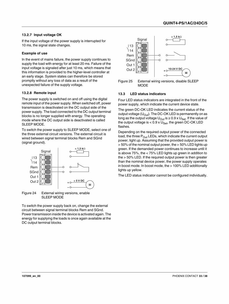
13.2.8 Remote input
The power supply is switched on and off using the digital
remote input of the power supply. When switched off, power
transmission is deactivated on the DC output side of the
power supply. The load connected to the DC output terminal
blocks is no longer supplied with energy. The operating
mode where the DC output side is deactivated is called
SLEEP MODE.
To switch the power supply to SLEEP MODE, select one of
the three external circuit versions. The external circuit is
wired between signal terminal blocks Rem and SGnd
(signal ground).
Figure 24 External wiring versions, enable
SLEEP MODE
To switch the power supply back on, change the external
circuit between signal terminal blocks Rem and SGnd.
Power transmission inside the device is activated again. The
energy for supplying the loads is once again available at the
DC output terminal blocks.
Figure 25 External wiring versions, disable SLEEP
MODE
13.3 LED status indicators
Four LED status indicators are integrated in the front of the
power supply, which indicate the current device state.
The green DC-OK LED indicates the current status of the
output voltage (UOut). The DC-OK LED is permanently on as
long as the output voltage UOut is ≥ 0.9 x USet. If the value of
the output voltage is < 0.9 x USet, the green DC-OK LED
flashes.
Depending on the required output power of the connected
load, the three POut LEDs, which indicate the current output
power, light up. Assuming that the provided output power is
> 50% of the nominal output power, the > 50% LED lights up
green. If the demanded power continues to increase until it
is above 75%, the < 75% LED lights up green in addition to
the > 50% LED. If the required output power is then greater
than the nominal device power, the power supply operates
in boost mode. In boost mode, the > 100% LED additionally
lights up yellow.
The LED status indicator cannot be configured individually.
13
14
Rem
SGnd
Out 1
Out 2
Signal< 1,5 k
< 5 V DC
=+
-
13
14
Rem
SGnd
Out 1
Out 2
Signal> 1,5 k
10-24 V DC
=+
-
QUINT4-PS/1AC/24DC/5
107099_en_00 PHOENIX CONTACT 34 / 38
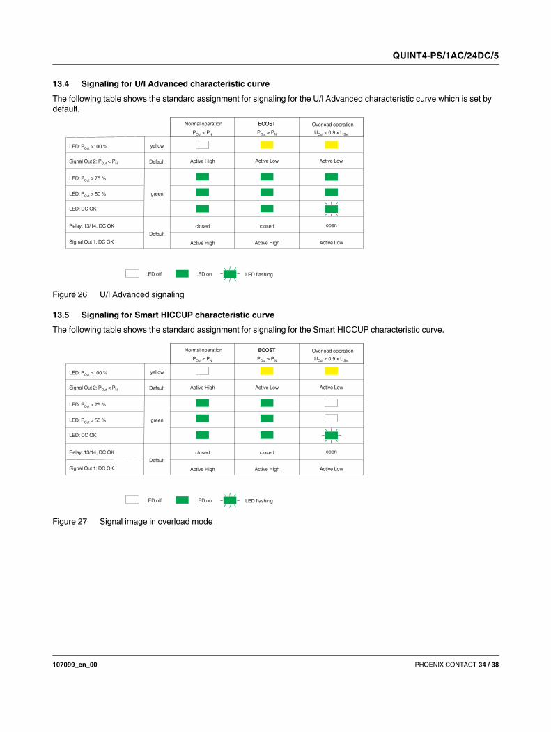
13.4 Signaling for U/I Advanced characteristic curve
The following table shows the standard assignment for signaling for the U/I Advanced characteristic curve which is set by
default.
Figure 26 U/I Advanced signaling
13.5 Signaling for Smart HICCUP characteristic curve
The following table shows the standard assignment for signaling for the Smart HICCUP characteristic curve.
Figure 27 Signal image in overload mode
LED: DC OK
LED: P >100 %Out
Signal Out 2: P < POut N
Relay: 13/14, DC OK
LED: P > 50 %Out
Default
Default
P < POut N U < 0.9 x UOut Set
Signal Out 1: DC OK
LED: P > 75 %Out
Active High
Active High
Active High Active Low
Active Low Active Low
P > POut N
BOOST
green
yellow
closed closed open
Normal operation BOOST Overload operation
LED flashingLED off LED on
QUINT4-PS/1AC/24DC/5
107099_en_00 PHOENIX CONTACT 35 / 38
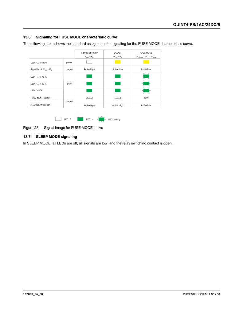
13.6 Signaling for FUSE MODE characteristic curve
The following table shows the standard assignment for signaling for the FUSE MODE characteristic curve.
Figure 28 Signal image for FUSE MODE active
13.7 SLEEP MODE signaling
In SLEEP MODE, all LEDs are off, all signals are low, and the relay switching contact is open.
LED: DC OK
LED: P >100 %Out
Signal Out 2: P < POut N
Relay: 13/14, DC OK
LED: P > 50 %Out
Default
Default
P < POut N I > I t > tFuse Fuse
Signal Out 1: DC OK
LED: P > 75 %Out
Active High
Active High
Active High Active Low
Active Low
FUSE MODE
P > POut N
BOOST
Active Low
green
yellow
closed closed open
Normal operation
LED flashingLED off LED on
for
QUINT4-PS/1AC/24DC/5
107099_en_00 PHOENIX CONTACT 36 / 38
14 Operating modes
Depending on the intended use, the power supply can be
run in series or parallel operation.
14.1 Series operation
To double the output voltage, connect two power supplies in
series. Only use power supplies with the same performance
class and configuration for series operation. If two 24 V DC
power supplies are connected in series, an output voltage of
48 V DC is available to supply the loads.
Figure 29 Schematic diagrams in series operation
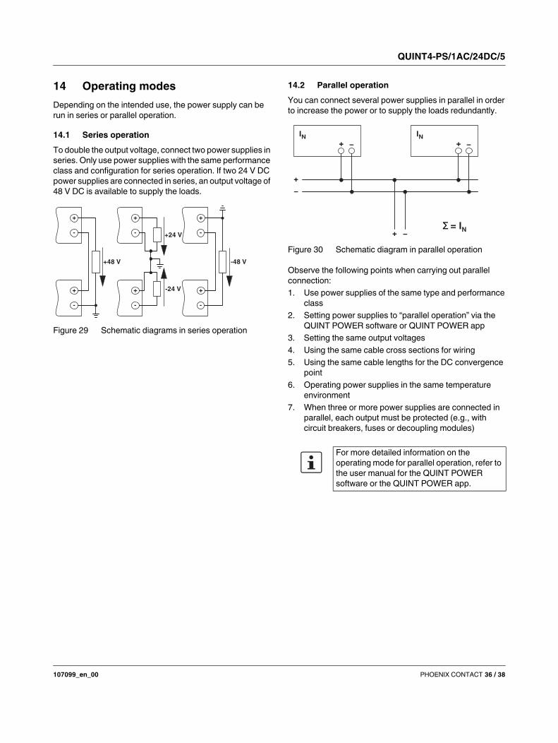
14.2 Parallel operation
You can connect several power supplies in parallel in order
to increase the power or to supply the loads redundantly.
Figure 30 Schematic diagram in parallel operation
Observe the following points when carrying out parallel
connection:
1. Use power supplies of the same type and performance
class
2. Setting power supplies to “parallel operation” via the
QUINT POWER software or QUINT POWER app
3. Setting the same output voltages
4. Using the same cable cross sections for wiring
5. Using the same cable lengths for the DC convergence
point
6. Operating power supplies in the same temperature
environment
7. When three or more power supplies are connected in
parallel, each output must be protected (e.g., with
circuit breakers, fuses or decoupling modules)
+48 V -48 V
+24 V
-24 V+
-
+
-
+
-
+
-
+
-
+
-
For more detailed information on the
operating mode for parallel operation, refer to
the user manual for the QUINT POWER
software or the QUINT POWER app.
+
IN− +
IN−
+
+
−
−Σ = IN
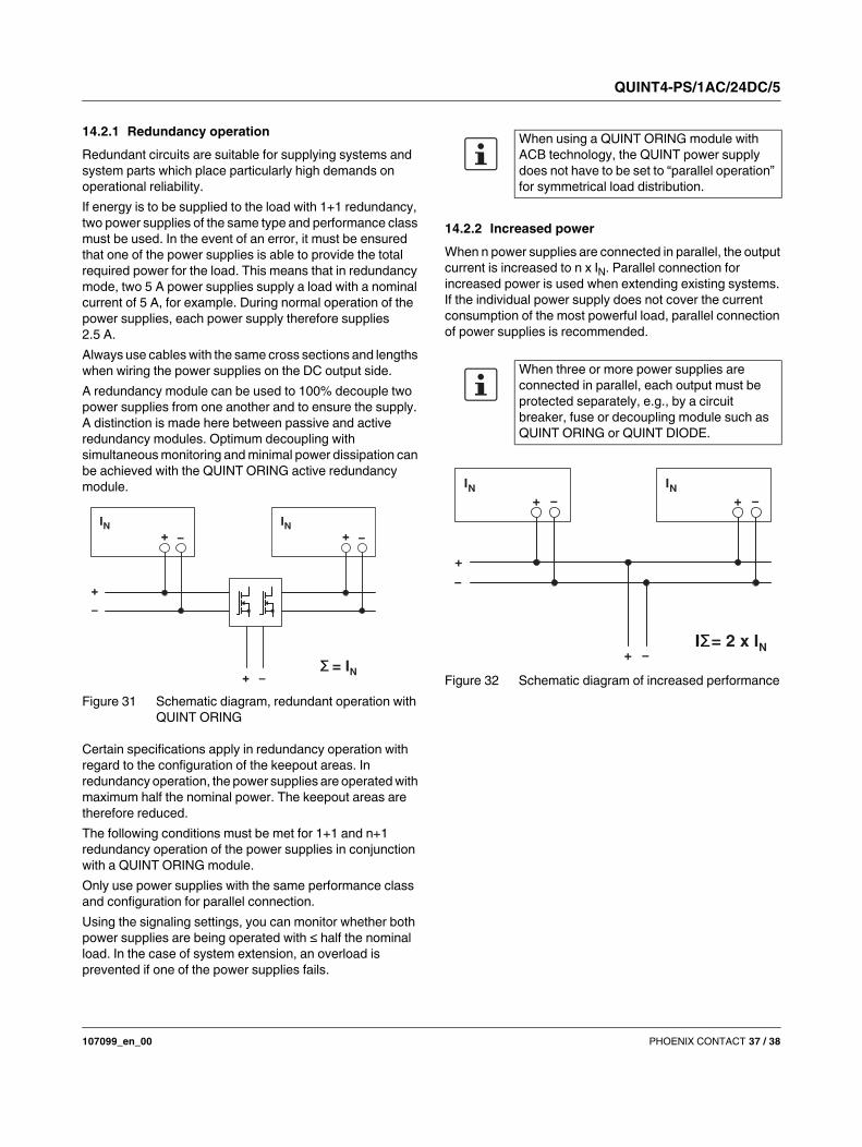
QUINT4-PS/1AC/24DC/5
107099_en_00 PHOENIX CONTACT 37 / 38
14.2.1 Redundancy operation
Redundant circuits are suitable for supplying systems and
system parts which place particularly high demands on
operational reliability.
If energy is to be supplied to the load with 1+1 redundancy,
two power supplies of the same type and performance class
must be used. In the event of an error, it must be ensured
that one of the power supplies is able to provide the total
required power for the load. This means that in redundancy
mode, two 5 A power supplies supply a load with a nominal
current of 5 A, for example. During normal operation of the
power supplies, each power supply therefore supplies
2.5 A.
Always use cables with the same cross sections and lengths
when wiring the power supplies on the DC output side.
A redundancy module can be used to 100% decouple two
power supplies from one another and to ensure the supply.
A distinction is made here between passive and active
redundancy modules. Optimum decoupling with
simultaneous monitoring and minimal power dissipation can
be achieved with the QUINT ORING active redundancy
module.
Figure 31 Schematic diagram, redundant operation with
QUINT ORING
Certain specifications apply in redundancy operation with
regard to the configuration of the keepout areas. In
redundancy operation, the power supplies are operated with
maximum half the nominal power. The keepout areas are
therefore reduced.
The following conditions must be met for 1+1 and n+1
redundancy operation of the power supplies in conjunction
with a QUINT ORING module.
Only use power supplies with the same performance class
and configuration for parallel connection.
Using the signaling settings, you can monitor whether both
power supplies are being operated with ≤ half the nominal
load. In the case of system extension, an overload is
prevented if one of the power supplies fails.
14.2.2 Increased power
When n power supplies are connected in parallel, the output
current is increased to n x IN. Parallel connection for
increased power is used when extending existing systems.
If the individual power supply does not cover the current
consumption of the most powerful load, parallel connection
of power supplies is recommended.
Figure 32 Schematic diagram of increased performance
+
IN− +
IN−
+
+
−
−Σ = IN
When using a QUINT ORING module with
ACB technology, the QUINT power supply
does not have to be set to “parallel operation”
for symmetrical load distribution.
When three or more power supplies are
connected in parallel, each output must be
protected separately, e.g., by a circuit
breaker, fuse or decoupling module such as
QUINT ORING or QUINT DIODE.
+ –
IN+ –
IN
+
–
+ –IΣ= 2 x IN
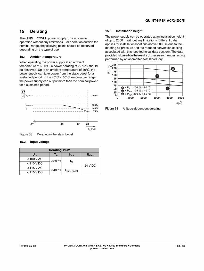
QUINT4-PS/1AC/24DC/5
107099_en_00 38 / 38PHOENIX CONTACT GmbH & Co. KG • 32823 Blomberg • Germany
phoenixcontact.com
15 Derating
The QUINT POWER power supply runs in nominal
operation without any limitations. For operation outside the
nominal range, the following points should be observed
depending on the type of use.
15.1 Ambient temperature
When operating the power supply at an ambient
temperature of > 60°C, a power derating of 2.5%/K should
be observed. Up to an ambient temperature of 40°C, the
power supply can take power from the static boost for a
sustained period. In the 40°C to 60°C temperature range,
the power supply can output more than the nominal power
for a sustained period.
Figure 33 Derating in the static boost
15.2 Input voltage
15.3 Installation height
The power supply can be operated at an installation height
of up to 2000 m without any limitations. Different data
applies for installation locations above 2000 m due to the
differing air pressure and the reduced convection cooling
associated with this (see technical data section). The data
provided is based on the results of pressure chamber testing
performed by an accredited test laboratory.
Figure 34 Altitude-dependent derating
Derating 1%/V
UIn TA IOut UOut
< 100 V AC≤ 60 °C IN
24 V DC< 110 V DC
< 115 V AC≤ 40 °C IStat. Boost
< 110 V DC
T [°C]A
P[W
]O
ut
40 60 70
PDyn. Boost
PStat. Boost
PN 100%
125%
200%
75%
-25
H [m]
[%]
025
50
75
100
125
150
175
200
225
PO
ut
= P 125 % 40 °CStat. = PDyn. 200 % 60 °C
= PN 100 % 60 °C
0 1000 2000 3000 4000 5000