Embed Size (px)
Citation preview
Contents Overview…………………………………………………………………………………… page 2 Applications………………………………………………..……………………………… page 2 Different types of orifice plates…………………………………………………………. page 3 Concentric orifice plates…………………………………………………..……. page 3 Non-concentric orifice plates…………………………………………………… page 4 RF and RTJ orifice plates………………………………………………………. page 6 Pressure taps……………………………………………………………………………… page 6 Technical specifications……………………………………..…………………………. page 8 Ordering information page 11
Datasheet Rev.4 Jan 2015
Orifice plate - Overview
Orifice plate design based on ISO5167, BS1042, ASME.MFC.3M and ISO TR15377 :2007 industry standards
Accuracy, repeatability and reliability of the flow element
Use for custody transfer metering
Easy and quick installation and commissioning
Very long life-time product Cost-effective and maintenance-free
system
Different types of orifice plates available depending on the application
Overview
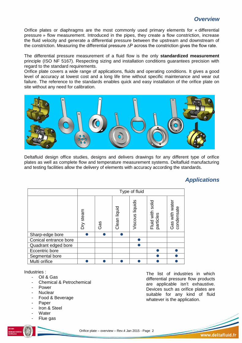
Orifice plates or diaphragms are the most commonly used primary elements for « differential pressure » flow measurement. Introduced in the pipes, they create a flow constriction, increase the fluid velocity and generate a differential pressure between the upstream and downstream of the constriction. Measuring the differential pressure ∆P across the constriction gives the flow rate. The differential pressure measurement of a fluid flow is the only standardized measurement principle (ISO NF 5167). Respecting sizing and installation conditions guarantees precision with regard to the standard requirements. Orifice plate covers a wide range of applications, fluids and operating conditions. It gives a good level of accuracy at lowest cost and a long life time without specific maintenance and wear out failure. The reference to the standards enables quick and easy installation of the orifice plate on site without any need for calibration.
Deltafluid design office studies, designs and delivers drawings for any different type of orifice plates as well as complete flow and temperature measurement systems. Deltafluid manufacturing and testing facilities allow the delivery of elements with accuracy according the standards.
Applications
Type of fluid
Dry
ste
am
Gas
Cle
an li
quid
Visc
ous
liqui
ds
Flui
d w
ith s
olid
pa
rticl
es
Gas
with
wat
er
cond
ensa
te
Sharp-edge bore Conical entrance bore Quadrant edged bore Eccentric bore Segmental bore Multi orifice
Industries :
- Oil & Gas - Chemical & Petrochemical - Power - Nuclear - Food & Beverage - Paper - Iron & Steel - Water - Flue gas
The list of industries in which differential pressure flow products are applicable isn’t exhaustive. Devices such as orifice plates are suitable for any kind of fluid whatever is the application.
Orifice plate – overview – Rev.4 Jan 2015 - Page 2
Different types of orifice plates
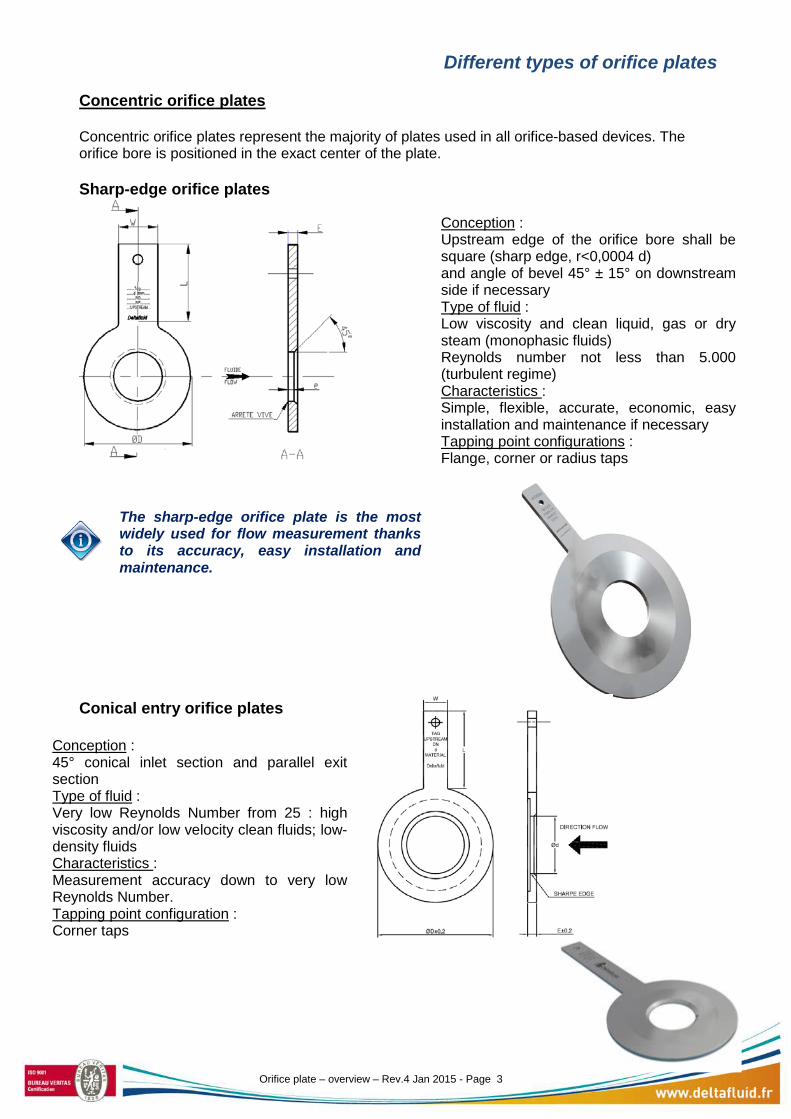
Concentric orifice plates Concentric orifice plates represent the majority of plates used in all orifice-based devices. The orifice bore is positioned in the exact center of the plate. Sharp-edge orifice plates
Conical entry orifice plates
The sharp-edge orifice plate is the most widely used for flow measurement thanks to its accuracy, easy installation and maintenance.
Conception : Upstream edge of the orifice bore shall be square (sharp edge, r<0,0004 d) and angle of bevel 45° ± 15° on downstream side if necessary Type of fluid : Low viscosity and clean liquid, gas or dry steam (monophasic fluids) Reynolds number not less than 5.000 (turbulent regime) Characteristics : Simple, flexible, accurate, economic, easy installation and maintenance if necessary Tapping point configurations : Flange, corner or radius taps
Conception : 45° conical inlet section and parallel exit section Type of fluid : Very low Reynolds Number from 25 : high viscosity and/or low velocity clean fluids; low-density fluids Characteristics : Measurement accuracy down to very low Reynolds Number. Tapping point configuration : Corner taps
Orifice plate – overview – Rev.4 Jan 2015 - Page 3
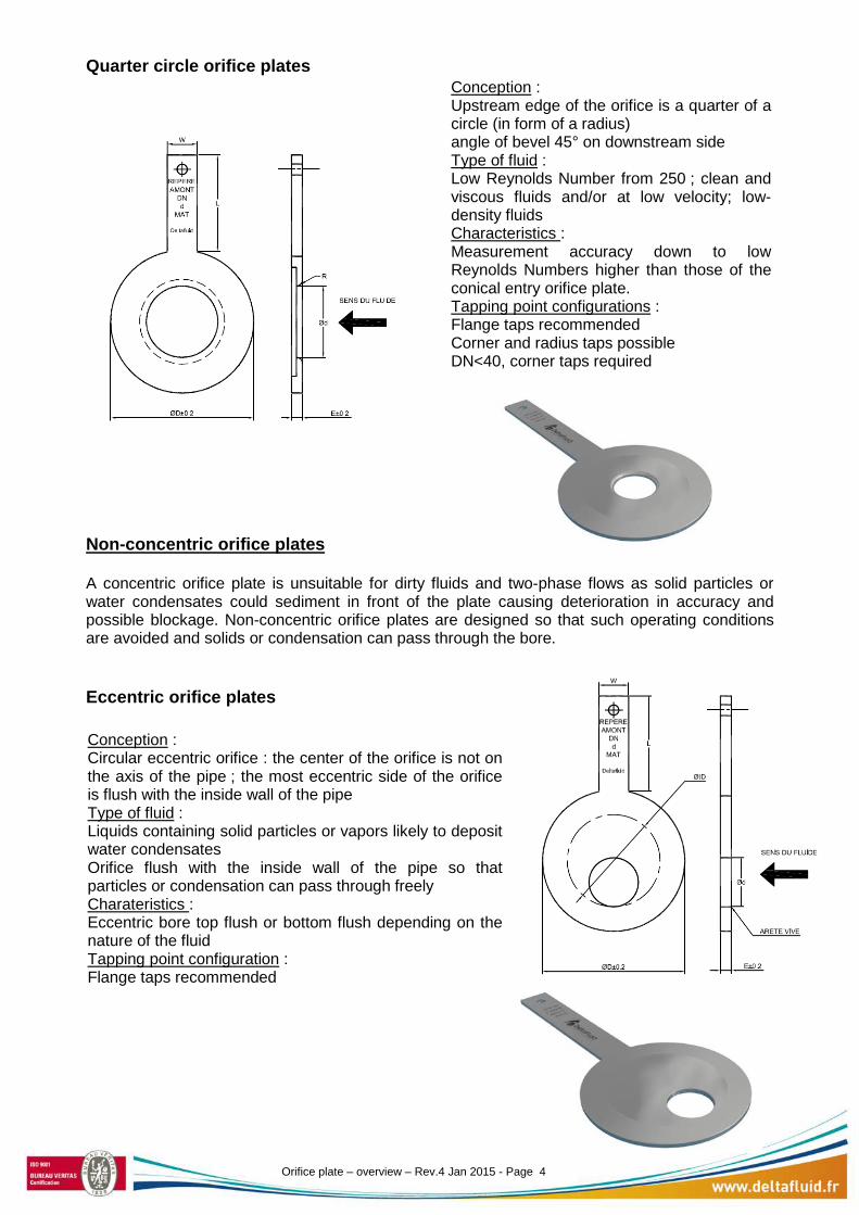
Quarter circle orifice plates
Non-concentric orifice plates A concentric orifice plate is unsuitable for dirty fluids and two-phase flows as solid particles or water condensates could sediment in front of the plate causing deterioration in accuracy and possible blockage. Non-concentric orifice plates are designed so that such operating conditions are avoided and solids or condensation can pass through the bore. Eccentric orifice plates
Conception : Upstream edge of the orifice is a quarter of a circle (in form of a radius) angle of bevel 45° on downstream side Type of fluid : Low Reynolds Number from 250 ; clean and viscous fluids and/or at low velocity; low-density fluids Characteristics : Measurement accuracy down to low Reynolds Numbers higher than those of the conical entry orifice plate. Tapping point configurations : Flange taps recommended Corner and radius taps possible DN<40, corner taps required
Conception : Circular eccentric orifice : the center of the orifice is not on the axis of the pipe ; the most eccentric side of the orifice is flush with the inside wall of the pipe Type of fluid : Liquids containing solid particles or vapors likely to deposit water condensates Orifice flush with the inside wall of the pipe so that particles or condensation can pass through freely Charateristics : Eccentric bore top flush or bottom flush depending on the nature of the fluid Tapping point configuration : Flange taps recommended
Orifice plate – overview – Rev.4 Jan 2015 - Page 4
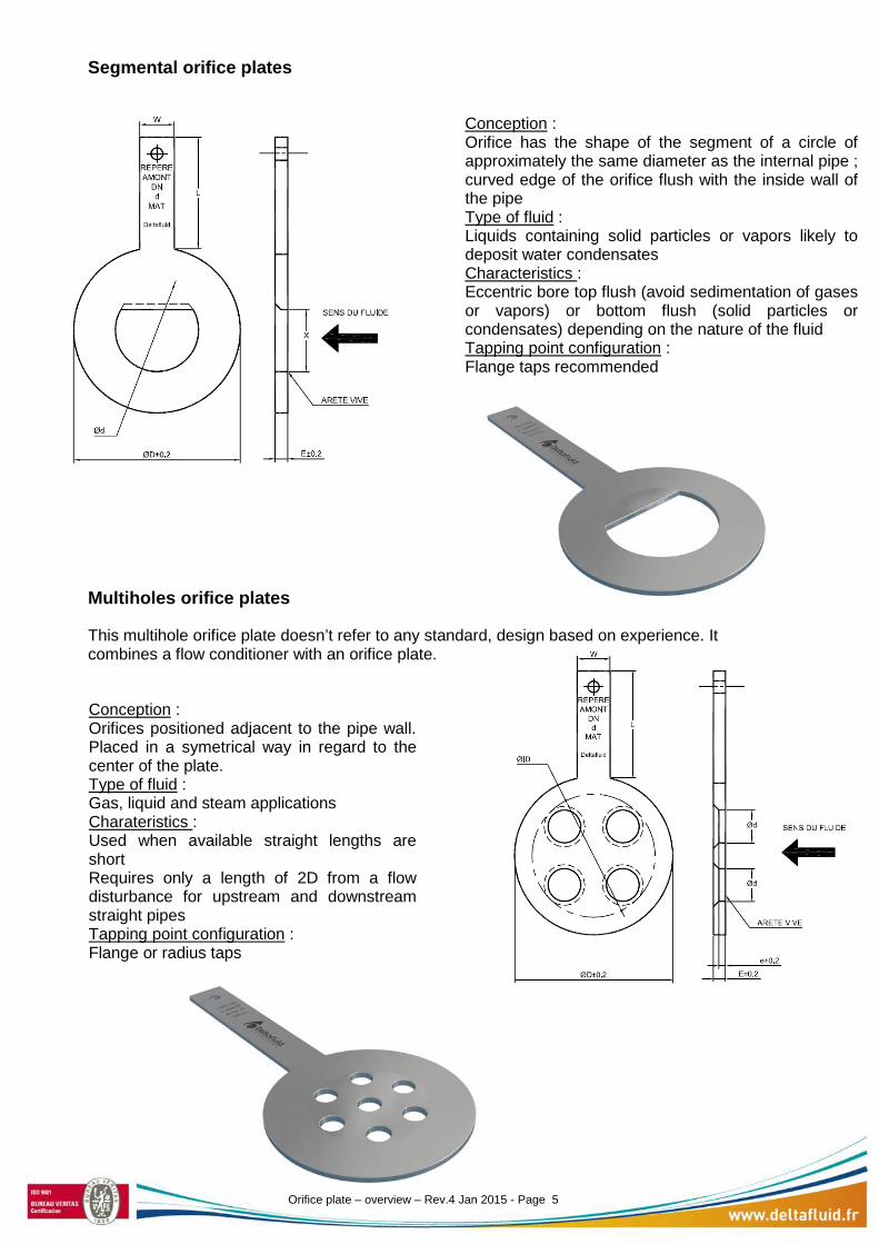
Segmental orifice plates
Multiholes orifice plates
This multihole orifice plate doesn’t refer to any standard, design based on experience. It combines a flow conditioner with an orifice plate.
Conception : Orifice has the shape of the segment of a circle of approximately the same diameter as the internal pipe ; curved edge of the orifice flush with the inside wall of the pipe Type of fluid : Liquids containing solid particles or vapors likely to deposit water condensates Characteristics : Eccentric bore top flush (avoid sedimentation of gases or vapors) or bottom flush (solid particles or condensates) depending on the nature of the fluid Tapping point configuration : Flange taps recommended
Conception : Orifices positioned adjacent to the pipe wall. Placed in a symetrical way in regard to the center of the plate. Type of fluid : Gas, liquid and steam applications Charateristics : Used when available straight lengths are short Requires only a length of 2D from a flow disturbance for upstream and downstream straight pipes Tapping point configuration : Flange or radius taps
Orifice plate – overview – Rev.4 Jan 2015 - Page 5
RF and RTJ orifice plates types The above mentionned orifice plates are RF type (raised face). Flat or spiral wound gaskets are needed to seal the flange assembly. The RTJ (ring tongue joint) assembly is a metallic sealing system. The RTJ orifice plate is specifically designed to fit between RTJ flanges to prevent leakage of fluid. Female groove type or male type are available depending on the flange. The orifice flange can be machined from one piece or it can also be screwed to an RTJ plate holder; in this way, the RTJ holder material is softer than the flange’s so that it can improve sealing. The RTJ orifice plate is suitable for a high pressure and high temperature fluid.
Pressure taps
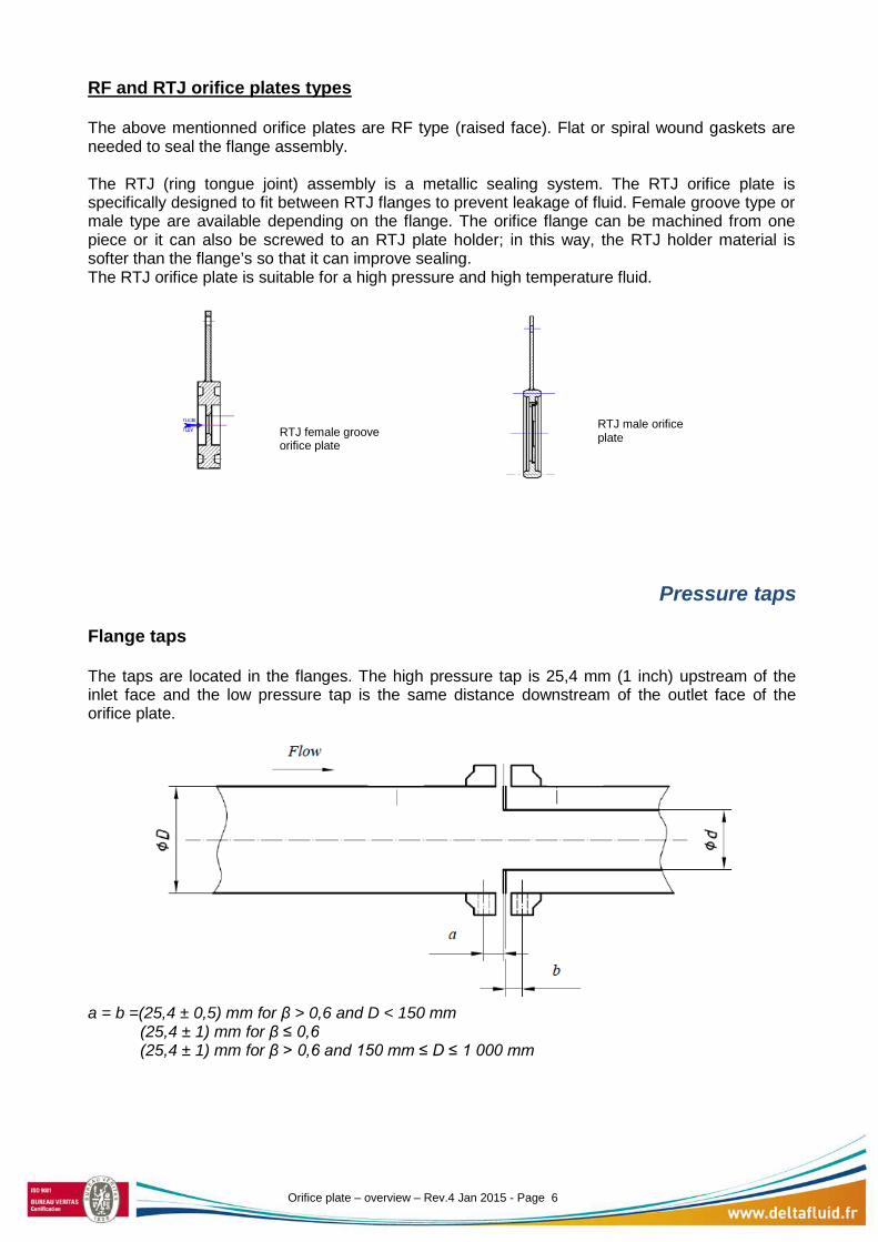
Flange taps The taps are located in the flanges. The high pressure tap is 25,4 mm (1 inch) upstream of the inlet face and the low pressure tap is the same distance downstream of the outlet face of the orifice plate.
a = b =(25,4 ± 0,5) mm for β > 0,6 and D < 150 mm (25,4 ± 1) mm for β ≤ 0,6 (25,4 ± 1) mm for β > 0,6 and 150 mm ≤ D ≤ 1 000 mm
RTJ female groove orifice plate
RTJ male orifice plate
Orifice plate – overview – Rev.4 Jan 2015 - Page 6
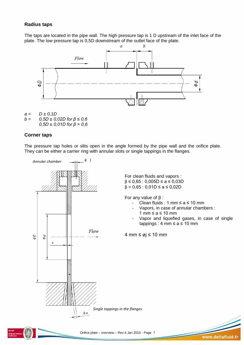
Radius taps The taps are located in the pipe wall. The high pressure tap is 1 D upstream of the inlet face of the plate. The low pressure tap is 0,5D downstream of the outlet face of the plate.
a = D ± 0,1D b = 0,5D ± 0,02D for β ≤ 0,6 0,5D ± 0,01D for β > 0,6 Corner taps The pressure tap holes or slits open in the angle formed by the pipe wall and the orifice plate. They can be either a carrier ring with annular slots or single tappings in the flanges.
Annular chamber
Single tappings in the flanges
For clean fluids and vapors : β ≤ 0,65 : 0,005D ≤ a ≤ 0,03D β > 0,65 : 0,01D ≤ a ≤ 0,02D For any value of β :
- Clean fluids : 1 mm ≤ a ≤ 10 mm - Vapors, in case of annular chambers :
1 mm ≤ a ≤ 10 mm - Vapor and liquefied gases, in case of single
tappings : 4 mm ≤ a ≤ 10 mm 4 mm ≤ øj ≤ 10 mm
j
Orifice plate – overview – Rev.4 Jan 2015 - Page 7
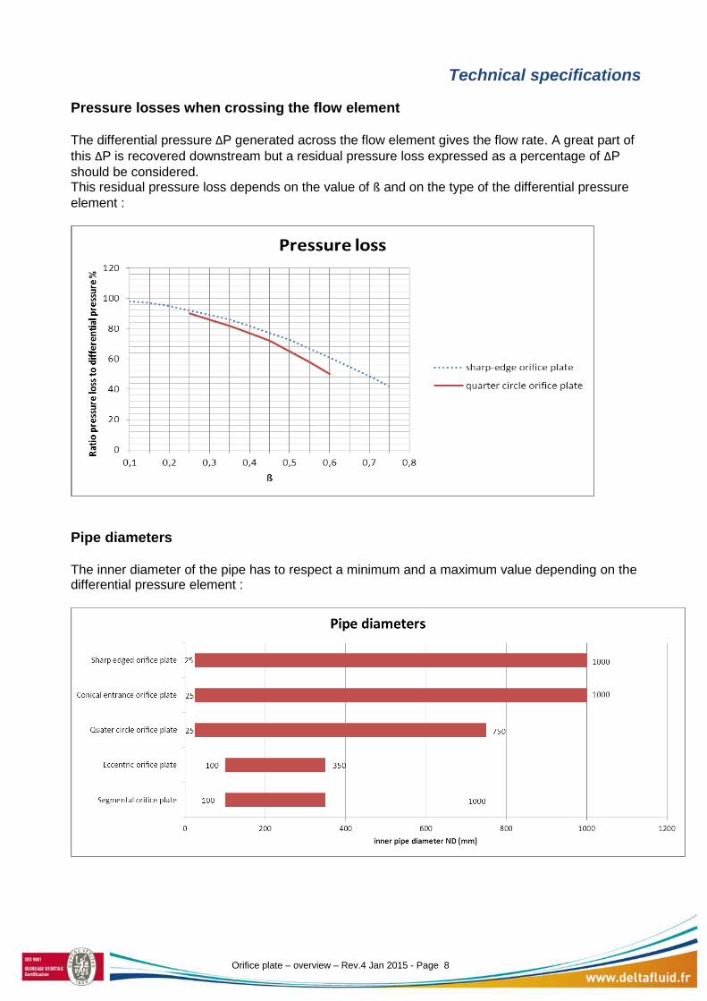
Technical specifications Pressure losses when crossing the flow element The differential pressure ΔP generated across the flow element gives the flow rate. A great part of this ΔP is recovered downstream but a residual pressure loss expressed as a percentage of ΔP should be considered. This residual pressure loss depends on the value of ß and on the type of the differential pressure element :
Pipe diameters The inner diameter of the pipe has to respect a minimum and a maximum value depending on the differential pressure element :
Orifice plate – overview – Rev.4 Jan 2015 - Page 8
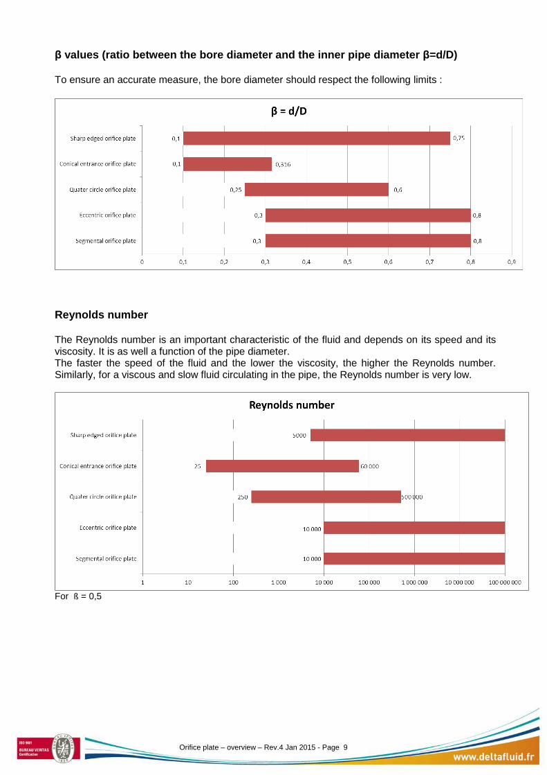
β values (ratio between the bore diameter and the inner pipe diameter β=d/D) To ensure an accurate measure, the bore diameter should respect the following limits :
Reynolds number The Reynolds number is an important characteristic of the fluid and depends on its speed and its viscosity. It is as well a function of the pipe diameter. The faster the speed of the fluid and the lower the viscosity, the higher the Reynolds number. Similarly, for a viscous and slow fluid circulating in the pipe, the Reynolds number is very low.
For ß = 0,5 Orifice plate – overview – Rev.4 Jan 2015 - Page 9
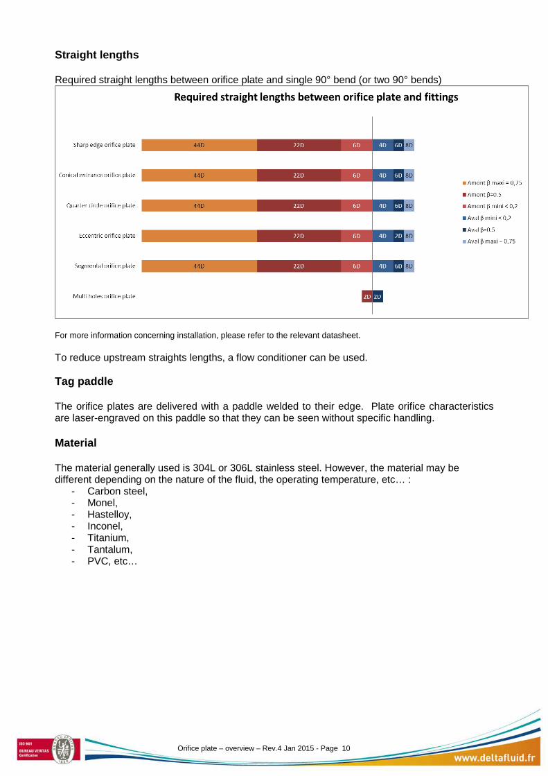
Straight lengths Required straight lengths between orifice plate and single 90° bend (or two 90° bends)
For more information concerning installation, please refer to the relevant datasheet. To reduce upstream straights lengths, a flow conditioner can be used. Tag paddle The orifice plates are delivered with a paddle welded to their edge. Plate orifice characteristics are laser-engraved on this paddle so that they can be seen without specific handling. Material The material generally used is 304L or 306L stainless steel. However, the material may be different depending on the nature of the fluid, the operating temperature, etc… :
- Carbon steel, - Monel, - Hastelloy, - Inconel, - Titanium, - Tantalum, - PVC, etc…
Orifice plate – overview – Rev.4 Jan 2015 - Page 10
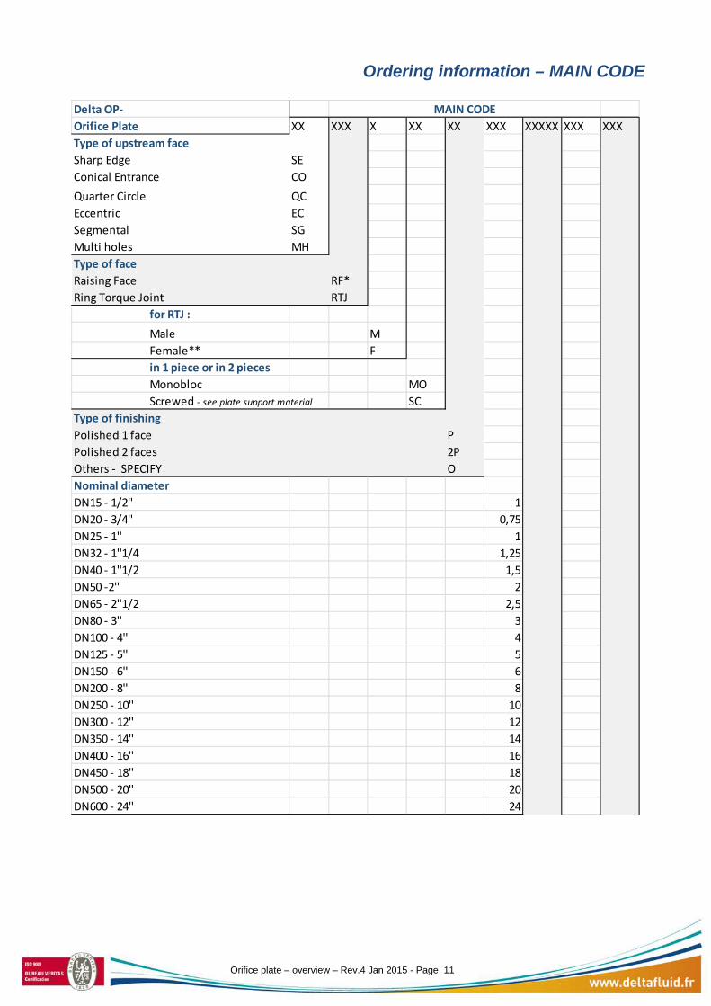
Ordering information – MAIN CODE
Delta OP-Orifice Plate XX XXX X XX XX XXX XXXXX XXX XXXType of upstream face Sharp Edge SEConical Entrance COQuarter Circle QCEccentric ECSegmental SGMulti holes MHType of faceRaising Face RF*Ring Torque Joint RTJ for RTJ : Male M Female** F in 1 piece or in 2 pieces Monobloc MO Screwed - see plate support material SCType of finishingPolished 1 face PPolished 2 faces 2POthers - SPECIFY ONominal diameterDN15 - 1/2'' 1DN20 - 3/4'' 0,75DN25 - 1'' 1DN32 - 1''1/4 1,25DN40 - 1''1/2 1,5DN50 -2'' 2DN65 - 2''1/2 2,5DN80 - 3'' 3DN100 - 4'' 4DN125 - 5'' 5DN150 - 6'' 6DN200 - 8'' 8DN250 - 10'' 10DN300 - 12'' 12DN350 - 14'' 14DN400 - 16'' 16DN450 - 18'' 18DN500 - 20'' 20DN600 - 24'' 24
MAIN CODE
Orifice plate – overview – Rev.4 Jan 2015 - Page 11

XX XXX X XX XX XXX XXXXX XXX XXXRating150# A150300# A300600# A600900# A9001500# A15002500# A2500PN10 D10PN16 D16PN25 D25PN40 D40PN63 D63PN100 D100Plate materialStainless steel 304 SS4Stainless steel 316 SS6Inconel INCMonel MONHastelloy HLYPTFE PTFDuplex DPXSuperduplex SDXOthers - SPECIFY OPlate support material for OP RTJ screwed
Stainless steel 304 SS4Stainless steel 316 SS6carbon steel CSSoft iron SIOthers - SPECIFY O
* OP-XX-RF can be assembled with simple or double & male or female facing depending on the flange** Pipe schedule or inner diameter ID to be specified
MAIN CODE
Orifice plate – overview – Rev.4 Jan 2015 - Page 12

Ordering information – OPTIONS
OPTIONAL CODE XX XX XXX XXX XXX X XX XX XX X XMountingpressure taps 0/0 - annular chamber 0pressure taps 25/25 - orifice flange 25pressure taps D - D/2 DFlanges*(1)
Welding neck WNOrifice welding neck WOSlip on SOOthers OFlanges materialASTM A105 105A350LF2 350Carbon steel*(2) CSTStainless steel 304 SS4Stainless steel 316 SS6Inconel INCMonel MONHastelloy HLYPTFE PTFDuplex DPXSuperduplex SDXOther OPipe Schedule5-5S 510-10S 1020 2030 3040S-Std STD40 4060 60XS-80S XS80 80100 100120 120140 140160 160XXS XXSAnnular chamber materialCarbon steel CSStainless steel 304 SS4Stainless steel 316 SS6Other OGasketsFlat FGraphite GSpiral wound SPTFE POthers OBoltings materialCarbon steel CSStainless steel SSOthers O
Orifice plate – overview – Rev.4 Jan 2015 - Page 13
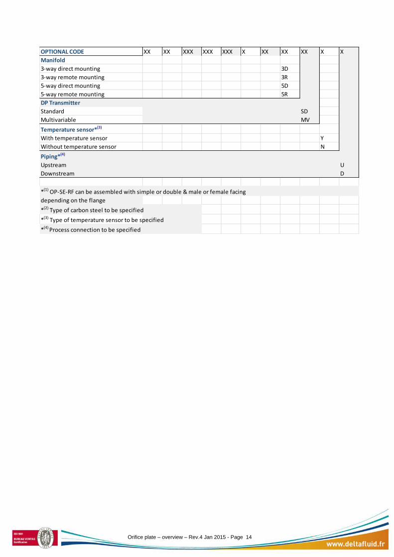
OPTIONAL CODE XX XX XXX XXX XXX X XX XX XX X XManifold3-way direct mounting 3D3-way remote mounting 3R5-way direct mounting 5D5-way remote mounting 5RDP TransmitterStandard SDMultivariable MVTemperature sensor*(3)
With temperature sensor YWithout temperature sensor NPiping*(4)
Upstream UDownstream D
depending on the flange*(2) Type of carbon steel to be specified*(3) Type of temperature sensor to be specified*(4) Process connection to be specified
*(1) OP-SE-RF can be assembled with simple or double & male or female facing
Orifice plate – overview – Rev.4 Jan 2015 - Page 14