Embed Size (px)
Citation preview
Using the Lynx Design System to Lower the Cost of Bring-
ing up a New Flow on a New Node
Simone Borri, Pierre-Marie Signe, Christian Eichrodt *
Riccardo Giordani #
* Abilis Systems
3 Chemin du Pre-Fleuri,
CH-1228 Plan-Les-Ouates
http://www.abilis.com
# Synopsys GmbH
Kar-Hammerschmidt str. 34
D-85609 Aschheim-Dornach
http://www.synopsys.com
ABSTRACT
Competitive performance and schedule pressures often drive semiconductor companies to
migrate to smaller technology nodes.
These migrations are usually expensive in terms of time and resources and pose risks to criti-
cal projects because they require specialized skills and flow development in parallel with
chip development.
In this paper, we will take you through the process of migrating to full Synopsys-based RTL-
to-GDSII flow from the prospective of a company focused on controlling design costs, evalu-
ating different process technologies, quickly integrating third-party IP, getting to a stable
flow deployed to the design team as quickly as possible, and maximizing the performance of
the design.
We will discuss the key aspects of Lynx that allowed us to achieve our goals on a recent digi-
tal TV chip project, including the integration of analog tools such as Custom Designer into
the flow.
SNUG 2013 2 Using Lynx Design System to Lower the Cost
Table of Contents
1. Introduction ...................................................................................................................... 4
2. Design Challenges ........................................................................................................... 5 DESIGN DESCRIPTION .............................................................................................................. 5 IP/TECHNOLOGY EVALUATION................................................................................................ 6
3. Lynx Design System Deployment ................................................................................... 6 SCHEDULE, TRAINING AND SUPPORT MODEL ............................................................................ 6
SCHEDULE EXECUTION ............................................................................................................ 8
4. Lynx Chip Implementation .............................................................................................. 9 TECHNICAL SUMMARY ............................................................................................................ 9
LYNX TECHNOLOGY PLUGIN .................................................................................................... 9 FLOW CUSTOMIZATION AND USABILITY ................................................................................. 10 IMPLEMENTATION DEBUGGING CAPABILITIES ........................................................................ 11 LYNX HIERARCHICAL FLOW AND DATA MANAGEMENT .......................................................... 12
5. Third-Party Tool Integration .......................................................................................... 15
CALIBRE INTEGRATION .......................................................................................................... 15
6. ICV Chip Finishing Flow............................................................................................... 17
7. Analog Design Flow ...................................................................................................... 20 GOALS ................................................................................................................................... 20
DESIGN FLOW ........................................................................................................................ 20 CUSTOM DESIGNER MIGRATION ............................................................................................ 21
8. Next Steps ...................................................................................................................... 22 ICV ....................................................................................................................................... 22
PRIMERAIL ............................................................................................................................ 22 GALAXY CONSTRAINT ANALYZER (GCA) ............................................................................ 23
ICC-CD INTERFACE .............................................................................................................. 23
9. Conclusion ..................................................................................................................... 24
10. Acknowledgments.......................................................................................................... 24
Table of Figures
Figure 1: Transport Bridge Processor IC Layout ....................................................................... 5
Figure 2: Project Schedule ......................................................................................................... 8
Figure 3: Advanced error checking.......................................................................................... 11
Figure 4: Lynx Execution Monitor in a hierarchical flow ....................................................... 13
Figure 5: Hierarchical Flow Example ...................................... Error! Bookmark not defined.
Figure 6: Release (left) and restore (right) mechanisms .......................................................... 14
Figure 7. Insertion of a new step using a new registered tool .................................................. 15
Figure 8: Changes to the variable files .................................................................................... 16
Figure 9. Chip finishing flow ................................................................................................... 17
Figure 10: Metal and cell filling flow ...................................................................................... 18
Figure 11: Final IC physical verification flow ......................................................................... 19
SNUG 2013 3 Using Lynx Design System to Lower the Cost
Figure 12: Analog Design Flow ............................................................................................... 21
Figure 13: Prime Rail Sign-off Flow ....................................................................................... 23
Figure 14: Galaxy Constraint Analyser integration ................................................................. 23
Figure 15: Additional ICC-CD interface steps ........................................................................ 24
SNUG 2013 4 Using Lynx Design System to Lower the Cost
1. Introduction
In recent years, the transition from analog to digital TV caused a major disruption in the TV
ecosystem. Several stakeholders in the TV business were concerned by the so-called "analog
switch-off", such as governmental regulation agencies, consumer electronics manufacturers
and retailers, cable and satellite TV service providers, set-top-box (STB) manufacturers, local
and national TV broadcasters from commercial and public domain, TV advertising agencies,
as well as final content consumers & end users.
Together with its associated challenges, the digital transition has brought a huge potential for
market growth in terms of new applications, new devices for distributing video content and
new way of consuming it.
As an early provider of integrated solutions for digital TV, Abilis Systems has pioneered the
introduction of monolithic RF CMOS TV receivers and provides leading RF modulators and
digital silicon tuners & demodulators for the consumer electronic market.
Abilis also actively cooperates with conditional access system (CAS) providers to develop
highly secured systems for pay-tv applications and has recently launched a new transport
bridge processor IC family, intended for headless gateway platforms for multi-screen home
distribution.
To address such a dynamic market environment, time-to-market is the key challenge for any
new product development with the target of achieving high product margins and ensuring a
good return on investment.
Indeed, during the IC design cycle, product requirements change continuously and it is not
unusual to be confronted to a time-to-tapeout (i.e. from requirement freeze to GDSII) of less
than 4 months.
In this context the main challenges to be addressed by today's IC design process are:
1. The ability to quickly evaluate several technology nodes to get the best
cost/performance/schedule trade-off for a given set of requirement.
2. The ability to address requirement changes by quickly switching from one technology
node to another, while keeping a minimum impact on the project schedule.
3. The possibility to reuse and integrate in the SoC the largest possible number of exist-
ing IPs in the most cost-effective way with the goal to limit project risk and schedule
impact.
In this paper, we will describe how Abilis and Synopsys successfully cooperated throughout
the design of a recent Abilis’ chip to achieve the aforementioned goals.
In particular we will show how the Synopsys’ Lynx Design System was deployed to ensure a
quick and smooth technology process transition and how the quality and richness of Synop-
sys IP portfolio has dramatically contributed to the success of the new SoC design, which was
achieved within a short time and with a very limited amount of resources.
SNUG 2013 5 Using Lynx Design System to Lower the Cost
2. Design Challenges
Design Description
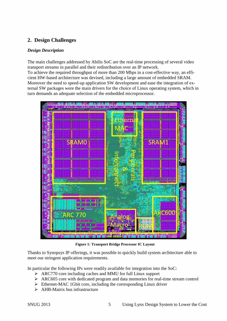
The main challenges addressed by Abilis SoC are the real-time processing of several video
transport streams in parallel and their redistribution over an IP network.
To achieve the required throughput of more than 200 Mbps in a cost-effective way, an effi-
cient HW-based architecture was devised, including a large amount of embedded SRAM.
Moreover the need to speed-up application SW development and ease the integration of ex-
ternal SW packages were the main drivers for the choice of Linux operating system, which in
turn demands an adequate selection of the embedded microprocessor.
Thanks to Synopsys IP offerings, it was possible to quickly build system architecture able to
meet our stringent application requirements.
In particular the following IPs were readily available for integration into the SoC:
ARC770 core including caches and MMU for full Linux support
ARC605 core with dedicated program and data memories for real-time stream control
Ethernet-MAC 1Gbit core, including the corresponding Linux driver
AHB-Matrix bus infrastructure
ARC 770 ARC600AnalogMacro
EthernetMAC
ROM
Periph
erals &
Interco
nn
ect
SRAM1SRAM0
Figure 1: Transport Bridge Processor IC Layout
SNUG 2013 6 Using Lynx Design System to Lower the Cost
Several DesignWare interface modules, such as UART, I2C, SPI.
Several hard-IPs block, such as:
o Speed-optimized memories, with associated memory-BIST logic
o 9-Track / 12-Track standard-cells for optimal area/performance trade-off
The IC also included an internally developed analog IP. Being a relatively small macro, the
top-level chip integration flow was rather digital-centric. Synopsys CustomDesigner was
used to generate the needed views and allowed a smooth integration of the analog macro into
IC Compiler digital flow.
IP/Technology Evaluation
Several evaluations were performed during the system study phase to choose the most suita-
ble technology and IPs. One key criterion was the possibility to reach an ARC7 processor
speed of 600 MHz in a low-power technology in order to provide the required number of
MIPS. Another criterion was that the technology choice should not imply a new flow devel-
opment and add minimum penalty to the schedule; it should be similar to technologies al-
ready in use within our company, without implying additional setup or correlation work. In
other words it was not only a question of selecting a technology but also a complete setup of
the associated implementation flow in order to meet the time-to-tapeout requirement. The
third criterion was die cost, which drove the technology choice to reach an optimal trade-off
between core size and pad size.
The performance requirements implied that the IC should include high-speed SRAMs already
qualified for production and able to meet the 600MHz clock frequency constraint. Moreover,
the standard cells library had to allow optimization between speed and power consumption
through the use of LVT devices.
Finally the constraint concerning the immediate design flow availability oriented the decision
for TSMC 65LP, a technology already available in the Lynx technology plug-in and allowing
to meet the performance requirements.
3. Lynx Design System Deployment
Schedule, training and support model
The tapeout schedule was constrained by the IBC 2012 conference in September 2012, and
the goal was to present a prototype during that event.
The project was characterized by a long investigation of the technology and IP performances,
and the system and application software requirements.
These activities reduced the time available for the design implementation. Moreover, the im-
plementation team was limited to one designer for the backend implementation and one de-
signer for STA and SDC verification.
Several aspects of the Lynx flow provided a key support to the aggressive design schedule,
consequence of the pre-design investigations:
SNUG 2013 7 Using Lynx Design System to Lower the Cost
1. The ability to support more than one foundry process which helped in the selection of
the most cost effective technology node.
2. A very fast deployment phase and designer training.
The Lynx solution comes with one week of included design service. Abilis purchased three
additional weeks to overcome resource limitations and ensure a smooth transition to the new
flow. This resulted in a very effective way to train designers on the new flow while also help-
ing them address the new technology challenges.
In order to optimize the migration activity, the 4-weeks on-site consulting package was divid-
ed into two parts: the first two weeks were dedicated to initial installation and setup including
the basic trainings, while the remaining two weeks were delivered later as on-site support.
Further help was provided by a Lynx product specialist who was able to speed up Lynx intro-
duction, providing answers to advanced questions and additional training. The product spe-
cialist helped in the areas of: management cockpit installation, versioning system customiza-
tion, hierarchical flow setup and other advanced topics.
This working model helped the on-site consultant to focus not only on the training aspects,
but also on special customer requirements or customizations.
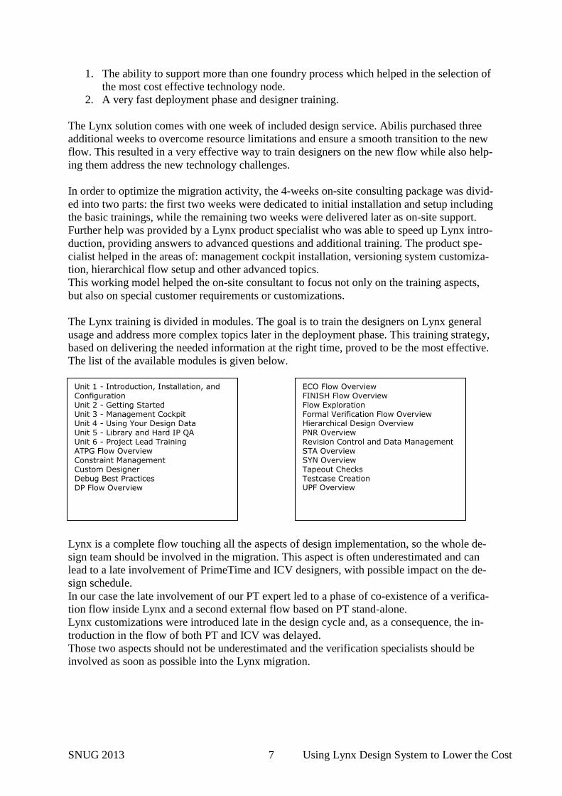
The Lynx training is divided in modules. The goal is to train the designers on Lynx general
usage and address more complex topics later in the deployment phase. This training strategy,
based on delivering the needed information at the right time, proved to be the most effective.
The list of the available modules is given below.
Lynx is a complete flow touching all the aspects of design implementation, so the whole de-
sign team should be involved in the migration. This aspect is often underestimated and can
lead to a late involvement of PrimeTime and ICV designers, with possible impact on the de-
sign schedule.
In our case the late involvement of our PT expert led to a phase of co-existence of a verifica-
tion flow inside Lynx and a second external flow based on PT stand-alone.
Lynx customizations were introduced late in the design cycle and, as a consequence, the in-
troduction in the flow of both PT and ICV was delayed.
Those two aspects should not be underestimated and the verification specialists should be
involved as soon as possible into the Lynx migration.
Unit 1 - Introduction, Installation, and Configuration Unit 2 - Getting Started Unit 3 - Management Cockpit Unit 4 - Using Your Design Data Unit 5 - Library and Hard IP QA Unit 6 - Project Lead Training ATPG Flow Overview Constraint Management Custom Designer Debug Best Practices DP Flow Overview
ECO Flow Overview FINISH Flow Overview Flow Exploration Formal Verification Flow Overview Hierarchical Design Overview PNR Overview Revision Control and Data Management STA Overview SYN Overview Tapeout Checks Testcase Creation UPF Overview
SNUG 2013 8 Using Lynx Design System to Lower the Cost
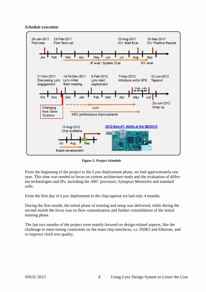
Schedule execution
From the beginning of the project to the Lynx deployment phase, we had approximately one
year. This time was needed to focus on system architecture study and the evaluation of differ-
ent technologies and IPs, including the ARC processor, Synopsys Memories and standard
cells.
From the first day of Lynx deployment to the chip tapeout we had only 4 months.
During the first month, the initial phase of training and setup was delivered, while during the
second month the focus was on flow customization and further consolidation of the initial
training phase.
The last two months of the project were mainly focused on design-related aspects, like the
challenge to meet timing constraints on the main chip interfaces, i.e. DDR2 and Ethernet, and
to improve clock tree quality.
Figure 2: Project Schedule
SNUG 2013 9 Using Lynx Design System to Lower the Cost
4. Lynx Chip Implementation
Technical Summary
Abilis had an existing internal physical implementation flow valid down to 90nm but not for
65nm. However one major requirement for the new flow deployment was to avoid a complete
reshuffle of the implementation, especially concerning the source data structure.
The pending decision concerning the migration to 40nm or 65nm was also adding further
uncertainty to the project and to the associated design flow.
In this respect, the structure of Lynx provides several major technical advantages:
a global flow ready for block-level and chip-level implementation with common
scripts
a script structure that allows customization to be done before and after the task execu-
tion thanks to pre-processing and post-processing script
a clear directory structure allowing to easily find objects, delete steps and run them
individually
an editable flow allowing the user to easily customize it for a specific need, and to
easily integrate third-party tools inside the existing flow
tool settings aligned to the recommended usage of the tools for each of their versions,
following the evolution of variables settings and STARs workarounds
a strict run time warnings and errors management
Indeed the adoption of Lynx in place of an internal custom flow does not limit the freedom of
the flow. Lynx global scripts only perform data management and the main step operations,
without limiting the user who keeps the possibility to put his intelligence in the pre- and post-
scripts, or add customization variables normally called TEV variables.
Lynx allowed us to leverage and even increase the power of our flow by benefiting from a
tool usage recommended by Synopsys through the correct sequence of operations and
adapted variables settings while keeping the design-related operations as powerful as before
through the custom part of the scripts.
By adopting the Lynx flow, Abilis did not have to modify its existing environment for RTL
files, timing constraints, floor-planning or CTS scripts. The flow structure and customizabil-
ity allowed a smooth integration of our custom scripts with Lynx internal scripts and directo-
ry structure. For example it was quite straightforward to integrate in Lynx our RTL reading
flow, timing constraints scripts and the final Calibre verification step (DRC and LVS).
The non-automated part of the flow concerns the set-up of the technology definition file
called common.tcl. This set-up may be automated by putting in place a system of library and
tech files registry that allows getting information easily and generating it into the common.tcl
file. This set-up phase is usually necessary in any custom flow.
Lynx technology plugin
One of the key steps in the Lynx flow installation as for any other flow is the setup of the
technology design kit and process libraries. The various technology library models need to be
defined prior to the implementation. The common setup file (common.tcl) contains all this
SNUG 2013 10 Using Lynx Design System to Lower the Cost
information depending on the user's choice of technology and libraries. If the foundry or li-
brary vendors do not provide a Lynx setup file then this needs to be created by the user.
We created an internal tool to generate the common setup file, so to have the capability to
quickly change a library type and version, or add new libraries or IPs. This tool controls the
setup file generation thanks to a graphical interface that allows the user to choose among
available technologies and IPs.
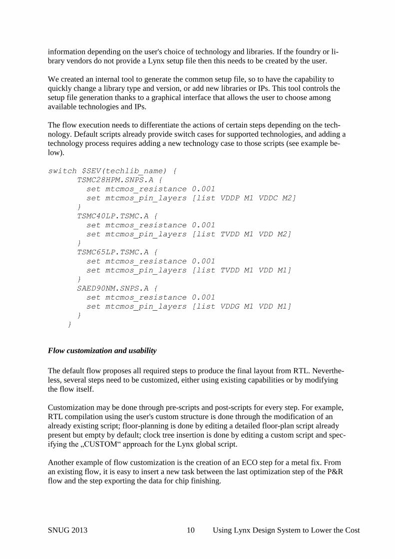
The flow execution needs to differentiate the actions of certain steps depending on the tech-
nology. Default scripts already provide switch cases for supported technologies, and adding a
technology process requires adding a new technology case to those scripts (see example be-
low).
switch $SEV(techlib_name) {
TSMC28HPM.SNPS.A {
set mtcmos_resistance 0.001
set mtcmos_pin_layers [list VDDP M1 VDDC M2]
}
TSMC40LP.TSMC.A {
set mtcmos_resistance 0.001
set mtcmos_pin_layers [list TVDD M1 VDD M2]
}
TSMC65LP.TSMC.A {
set mtcmos_resistance 0.001
set mtcmos_pin_layers [list TVDD M1 VDD M1]
}
SAED90NM.SNPS.A {
set mtcmos_resistance 0.001
set mtcmos_pin_layers [list VDDG M1 VDD M1]
}
}
Flow customization and usability
The default flow proposes all required steps to produce the final layout from RTL. Neverthe-
less, several steps need to be customized, either using existing capabilities or by modifying
the flow itself.
Customization may be done through pre-scripts and post-scripts for every step. For example,
RTL compilation using the user's custom structure is done through the modification of an
already existing script; floor-planning is done by editing a detailed floor-plan script already
present but empty by default; clock tree insertion is done by editing a custom script and spec-
ifying the „CUSTOM“ approach for the Lynx global script.
Another example of flow customization is the creation of an ECO step for a metal fix. From
an existing flow, it is easy to insert a new task between the last optimization step of the P&R
flow and the step exporting the data for chip finishing.
SNUG 2013 11 Using Lynx Design System to Lower the Cost
Furthermore, since a given version of the Lynx flow is qualified for given versions of the
tools, the usage of Lynx as a set of scripts ensures that the methodology implemented in the
scripts is suitable for each tool version. Hence, when upgrading to a new flow version, we
immediately get the benefits of the new tools features for which the flow was updated. How-
ever it is always possible to use new tool versions within old Lynx releases with minimal
changes.
An interesting aspect of Lynx is the introduction of advanced methodologies into the flow.
Lynx often offers the option of adopting new methodologies even in their early adoption
stage. For example, the Transparent Interface Optimization feature (TIO) was already availa-
ble in the old Lynx version we were using (2011.09) and it was possible to migrate the com-
plete flow from ILM to TIO methodology by changing one single variable.
Implementation debugging capabilities
Whenever an error occurs during execution, the flow may be set to halt or to automatically
waive errors. The second situation may be interesting for going quickly through the whole
flow for a rapid check; however the most used option was to halt the flow at the first error
encountered. To help debugging the failing step, a summary file shows the reported errors
which can then be easily found in the tool log file.
For debugging, the step was executed in interactive and GUI mode (don't run and don't exit)
in order to copy-paste script lines one by one until the failure occurs.
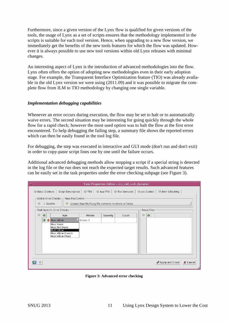
Additional advanced debugging methods allow stopping a script if a special string is detected
in the log file or the run does not reach the expected target results. Such advanced features
can be easily set in the task properties under the error checking subpage (see Figure 3).
Figure 3: Advanced error checking
SNUG 2013 12 Using Lynx Design System to Lower the Cost
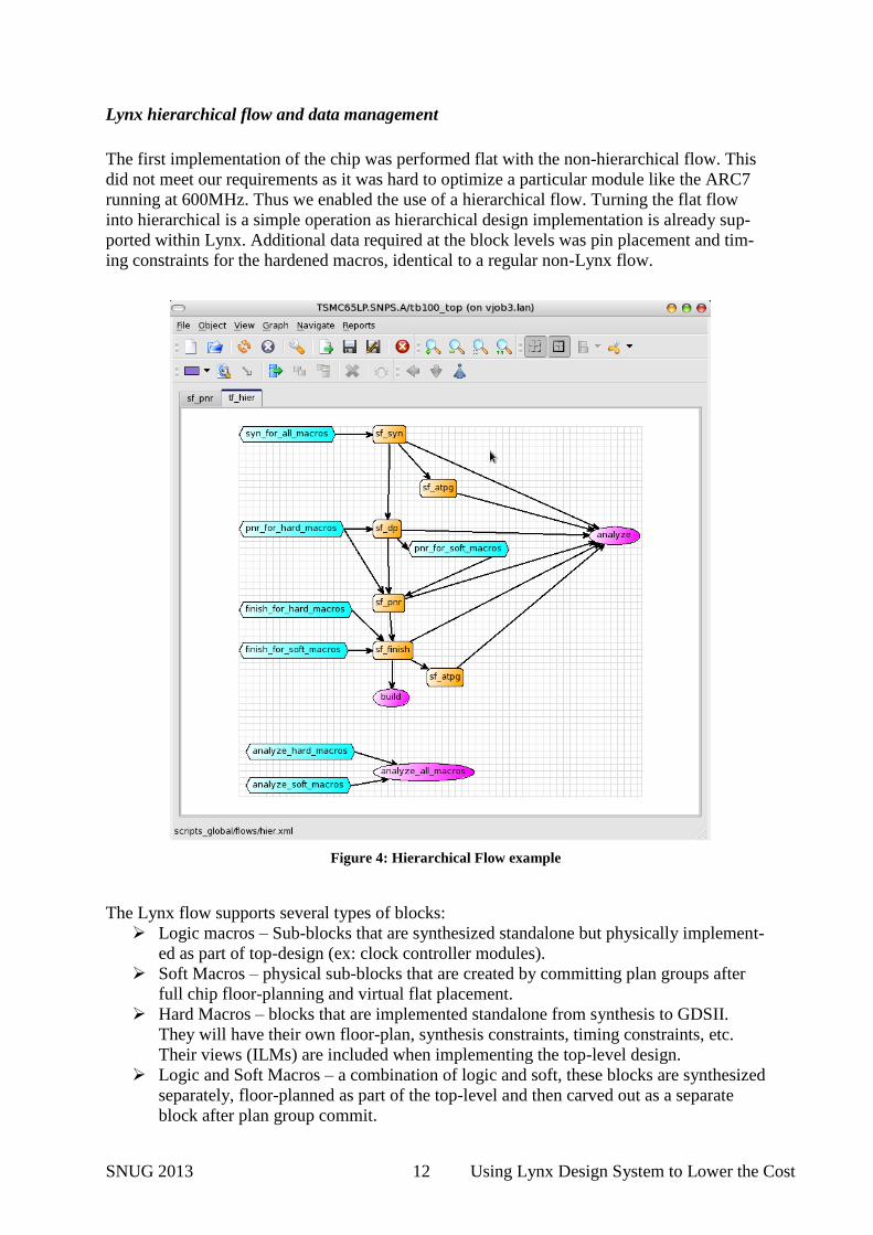
Lynx hierarchical flow and data management
The first implementation of the chip was performed flat with the non-hierarchical flow. This
did not meet our requirements as it was hard to optimize a particular module like the ARC7
running at 600MHz. Thus we enabled the use of a hierarchical flow. Turning the flat flow
into hierarchical is a simple operation as hierarchical design implementation is already sup-
ported within Lynx. Additional data required at the block levels was pin placement and tim-
ing constraints for the hardened macros, identical to a regular non-Lynx flow.
The Lynx flow supports several types of blocks:
Logic macros – Sub-blocks that are synthesized standalone but physically implement-
ed as part of top-design (ex: clock controller modules).
Soft Macros – physical sub-blocks that are created by committing plan groups after
full chip floor-planning and virtual flat placement.
Hard Macros – blocks that are implemented standalone from synthesis to GDSII.
They will have their own floor-plan, synthesis constraints, timing constraints, etc.
Their views (ILMs) are included when implementing the top-level design.
Logic and Soft Macros – a combination of logic and soft, these blocks are synthesized
separately, floor-planned as part of the top-level and then carved out as a separate
block after plan group commit.
Figure 4: Hierarchical Flow example
SNUG 2013 13 Using Lynx Design System to Lower the Cost
Our design had 3 macros:
1. The clock controller
2. The ARC7
3. The ARC6
We used top-down approach to get a good floor-plan for the sub-blocks and then switched
over blocks to hard-macros for bottom-up implementation. In Lynx setup, we described the
aspects of the sub-blocks that will configure the hierarchical flow including:
1. Names of the block modules and instance names
2. Type of macro (logic, soft, hard)
3. Type of views for the block to use at the top-level (ILMs or Abstracts)
Based on this information, the flow will configure the runs appropriately. For example, when
running the top-level setup, the flow will automatically set up the sub-block ILMs as part of
the MW reference libraries. Another example: the flow would set don’t touch on logic mac-
ros when running top-level synthesis. Another advantage of Lynx is that the flow is “aware”
of all the (standardized) file names and paths of all blocks, hence it automatically imports all
the necessary block-level files into the top-level and vice versa.
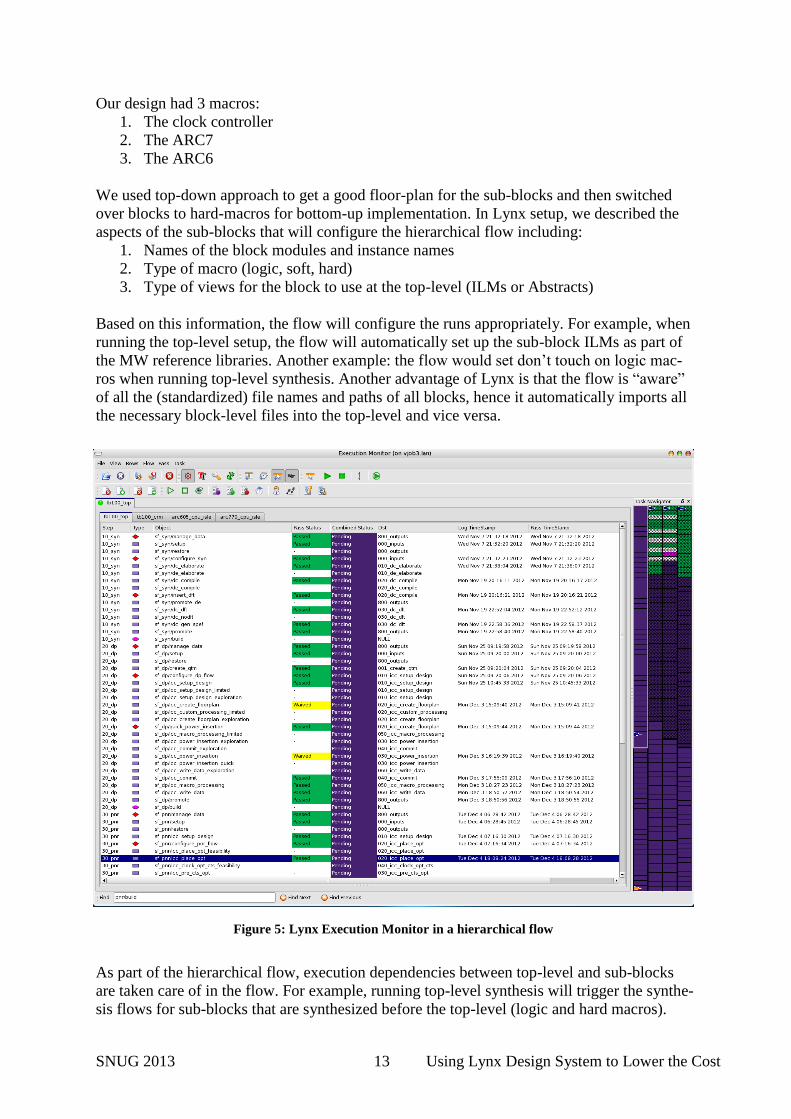
As part of the hierarchical flow, execution dependencies between top-level and sub-blocks
are taken care of in the flow. For example, running top-level synthesis will trigger the synthe-
sis flows for sub-blocks that are synthesized before the top-level (logic and hard macros).
Figure 5: Lynx Execution Monitor in a hierarchical flow
SNUG 2013 14 Using Lynx Design System to Lower the Cost
Only once blocks synthesis is complete will the top-level synthesis run. At that time, the top-
level will use the views for the blocks. This same top-block execution dependency approach
is applied to the whole flow.
Since multiple engineers were working on the same project, there was a need to transfer
blocks between them. There were 2 PD engineers to implement blocks and top-level, 1 DFT
engineer and 1 STA engineer. For hierarchical designs especially, this split of functions
means that block design data is transferred regularly between users as the design progresses
through the flow. On top of that, we had to do these transfers for every run/RTL drop. This is
quite challenging and time-consuming in regular projects.
In Lynx, we relied on the release/restore mechanism to reliably transfer design data between
designers. Release/Restore is like revision control for design data. Every time a designer had
completed a block run, he/she would “release” the design data with a particular tag name.
Another engineer can “restore” the data with the same tag name and continue with the flow.
An example at the block-level would be:
1. Engineer A runs basic synthesis and releases data with a tag “RTLDROP-JUN21”
2. Engineer B restores “RTLDROP-JUN21” synthesis database, runs DFT insertion and
releases with the same tag “RTLDROP-JUN21”
3. Engineer C restores back the post-DFT database using the tag, runs physical design
and releases the post-route data
4. Engineer D restores the post-route database, runs extraction and timing analysis.
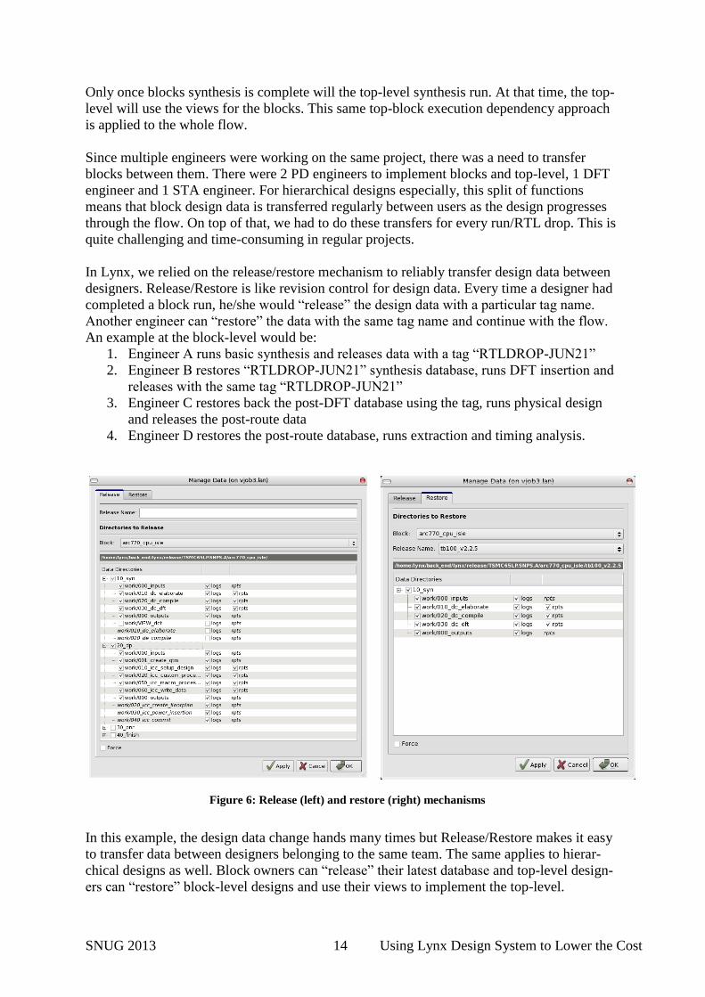
In this example, the design data change hands many times but Release/Restore makes it easy
to transfer data between designers belonging to the same team. The same applies to hierar-
chical designs as well. Block owners can “release” their latest database and top-level design-
ers can “restore” block-level designs and use their views to implement the top-level.
Figure 6: Release (left) and restore (right) mechanisms
SNUG 2013 15 Using Lynx Design System to Lower the Cost
5. Third-Party Tool Integration
Adding a third-party tool is sometimes needed for various reasons, such as compatibility with
legacy flows. Integration of a third-party tool is quite straightforward in Lynx. It is important
to register the tool inside Lynx to have it listed among the available tools; it is also necessary
to add its support to the “module” environment. Both aspects are addressed by modifying the
rtm_init.tcl file.
Calibre integration
The following changes to the rtm_init.tcl file are needed to integrate Calibre:
set SEV(cmd_cal) calibre
.....
switch $options(-tools) {
....
cal {
set cmd „$SEV(cmd_cal) ARGS“
set primary_module $SEV(ver_cal)
}
......
#### tool ver_var xml_support view_support
set item_list [list \
.......
{cal ver_cal 1 0 }
}
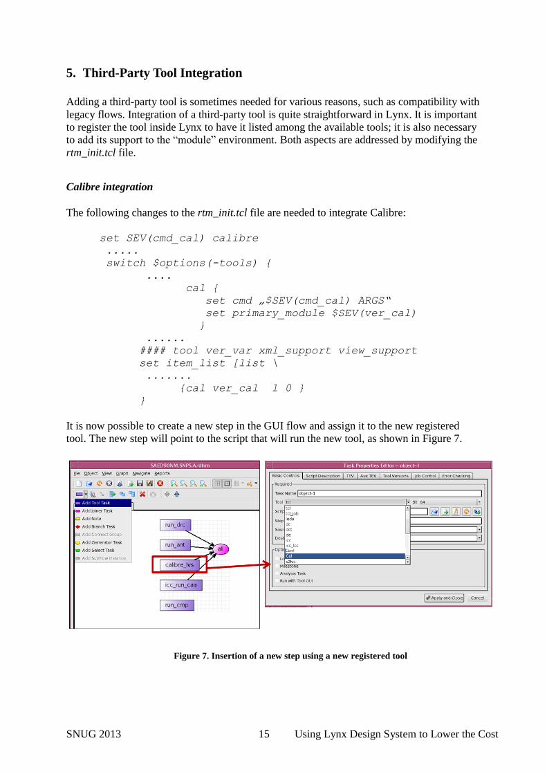
It is now possible to create a new step in the GUI flow and assign it to the new registered
tool. The new step will point to the script that will run the new tool, as shown in Figure 7.
Figure 7. Insertion of a new step using a new registered tool
SNUG 2013 16 Using Lynx Design System to Lower the Cost
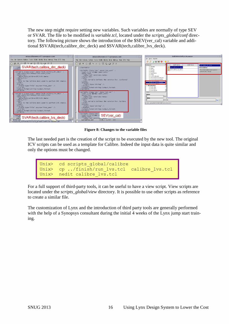
The new step might require setting new variables. Such variables are normally of type SEV
or SVAR. The file to be modified is variable.tcl, located under the scripts_global/conf direc-
tory. The following picture shows the introduction of the $SEV(ver_cal) variable and addi-
tional $SVAR(tech,calibre_drc_deck) and $SVAR(tech,calibre_lvs_deck).
The last needed part is the creation of the script to be executed by the new tool. The original
ICV scripts can be used as a template for Calibre. Indeed the input data is quite similar and
only the options must be changed.
For a full support of third-party tools, it can be useful to have a view script. View scripts are
located under the scripts_global/view directory. It is possible to use other scripts as reference
to create a similar file.
The customization of Lynx and the introduction of third party tools are generally performed
with the help of a Synopsys consultant during the initial 4 weeks of the Lynx jump start train-
ing.
Unix> cd scripts_global/calibre Unix> cp ../finish/run_lvs.tcl calibre_lvs.tcl Unix> nedit calibre_lvs.tcl
Figure 8: Changes to the variable files
SNUG 2013 17 Using Lynx Design System to Lower the Cost
6. ICV Chip Finishing Flow
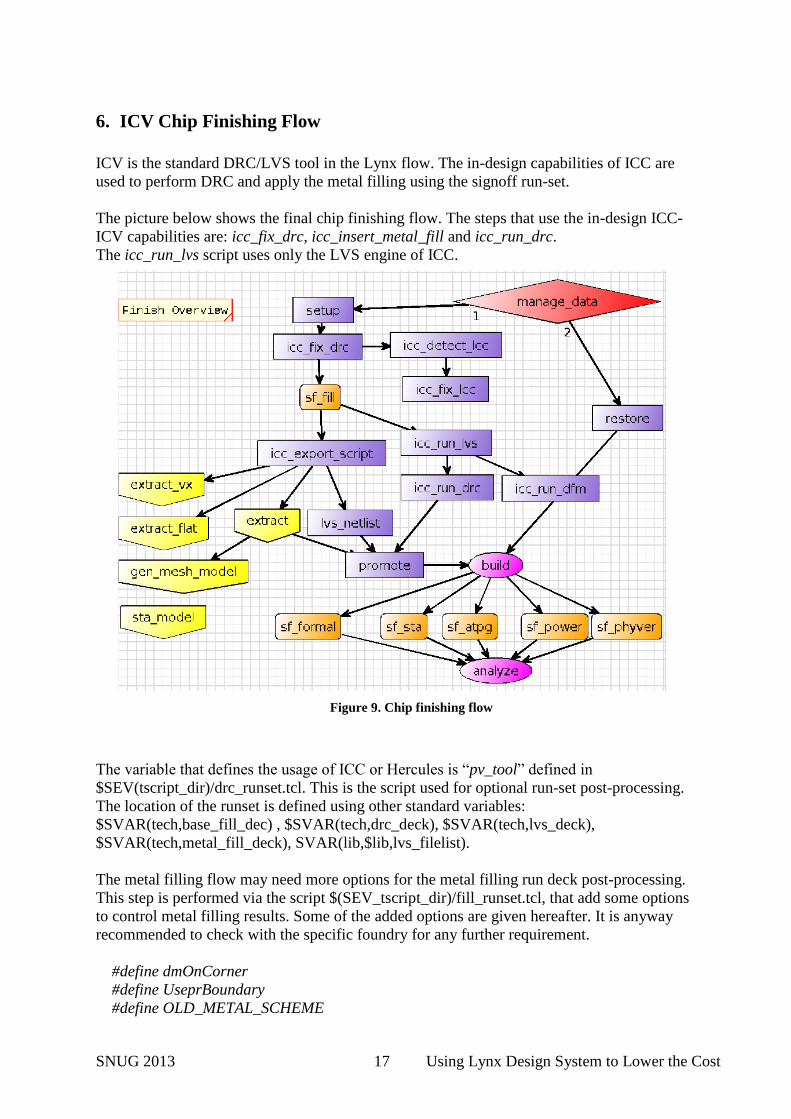
ICV is the standard DRC/LVS tool in the Lynx flow. The in-design capabilities of ICC are
used to perform DRC and apply the metal filling using the signoff run-set.
The picture below shows the final chip finishing flow. The steps that use the in-design ICC-
ICV capabilities are: icc_fix_drc, icc_insert_metal_fill and icc_run_drc.
The icc_run_lvs script uses only the LVS engine of ICC.
The variable that defines the usage of ICC or Hercules is “pv_tool” defined in
$SEV(tscript_dir)/drc_runset.tcl. This is the script used for optional run-set post-processing.
The location of the runset is defined using other standard variables:
$SVAR(tech,base_fill_dec) , $SVAR(tech,drc_deck), $SVAR(tech,lvs_deck),
$SVAR(tech,metal_fill_deck), SVAR(lib,$lib,lvs_filelist).
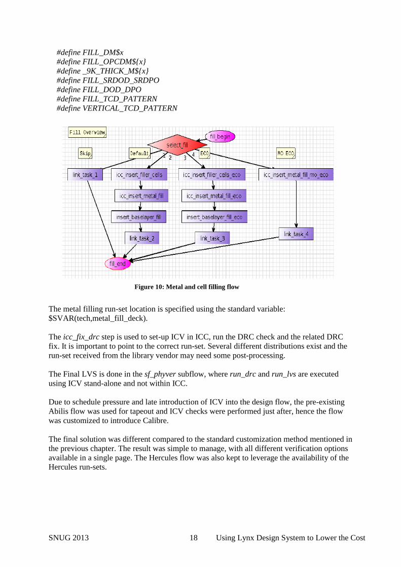
The metal filling flow may need more options for the metal filling run deck post-processing.
This step is performed via the script $(SEV_tscript_dir)/fill_runset.tcl, that add some options
to control metal filling results. Some of the added options are given hereafter. It is anyway
recommended to check with the specific foundry for any further requirement.
#define dmOnCorner
#define UseprBoundary
#define OLD_METAL_SCHEME
Figure 9. Chip finishing flow
SNUG 2013 18 Using Lynx Design System to Lower the Cost
#define FILL_DM$x
#define FILL_OPCDM${x}
#define _9K_THICK_M${x}
#define FILL_SRDOD_SRDPO
#define FILL_DOD_DPO
#define FILL_TCD_PATTERN
#define VERTICAL_TCD_PATTERN
The metal filling run-set location is specified using the standard variable:
$SVAR(tech,metal_fill_deck).
The icc_fix_drc step is used to set-up ICV in ICC, run the DRC check and the related DRC
fix. It is important to point to the correct run-set. Several different distributions exist and the
run-set received from the library vendor may need some post-processing.
The Final LVS is done in the sf_phyver subflow, where run_drc and run_lvs are executed
using ICV stand-alone and not within ICC.
Due to schedule pressure and late introduction of ICV into the design flow, the pre-existing
Abilis flow was used for tapeout and ICV checks were performed just after, hence the flow
was customized to introduce Calibre.
The final solution was different compared to the standard customization method mentioned in
the previous chapter. The result was simple to manage, with all different verification options
available in a single page. The Hercules flow was also kept to leverage the availability of the
Hercules run-sets.
Figure 10: Metal and cell filling flow
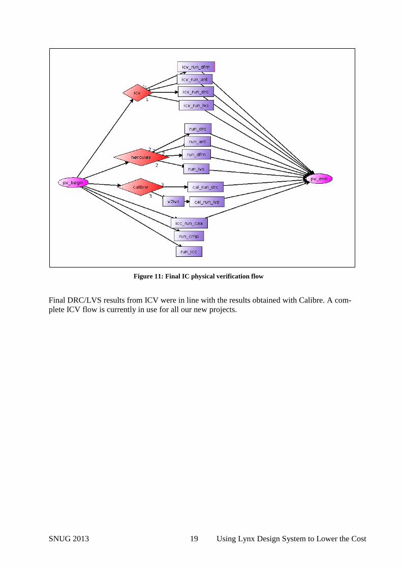
SNUG 2013 19 Using Lynx Design System to Lower the Cost
Final DRC/LVS results from ICV were in line with the results obtained with Calibre. A com-
plete ICV flow is currently in use for all our new projects.
Figure 11: Final IC physical verification flow
SNUG 2013 20 Using Lynx Design System to Lower the Cost
7. Analog Design Flow
Goals
The IC required several standard analog functions common in any SoC, among which 3
PLLs, 2DLLs, Crystal Oscillator, Power-On-Reset and various sensors.
Overall requirements were driven from digital functional needs. Area optimization was a
major concern. Analog functions (usually) do not follow Moore’s law and thus their cost
tends to increase on lower nodes. To minimize analog footprint we had to go through detailed
analysis of performance requirements on largest block (PLLs).
To ease integration, we reduced the input/output interface to a strict minimum. Analog pins
were limited to 2 (crystal pins). All other interface pins including in-between analog modules
were digital. The interface was designed so that most pins are insensitive to timing. The re-
maining timing sensitive outputs (e.g. the PLL output) were carefully described and load
driving capability specified.
We chose to embed calibration state machines (for VCO or DLL tuning for example) inside
analog macros, which allowed to avoid requiring lengthy co-simulation verification and kick
start design ahead of digital starting. The downside was we had to keep calibration algorithm
complexity to a minimum which would otherwise explode simulation time (for example sim-
ple linear search).
Regarding production testing we chose to rely only on digital standard methods such as
boundary scan test. To achieve this purpose we added on chip low cost design for test struc-
tures such as delta-sigma D2A and frequency comparator which control was wrapped by
scan-chain. This method allowed to save both on development and production cost. Indeed by
doing so, test vector development was done and pre-validated during design. Tester time was
optimized through simulation down to micro-second. Last but not least, significant test time
could be further saved by fast sequencing, which is easily possible since ‘pass/fail’ decision
are done on-chip.
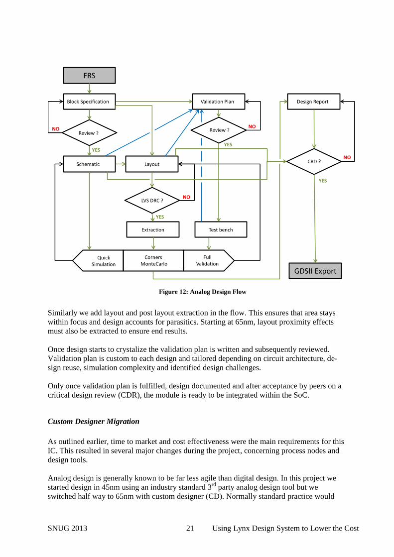
Design Flow
We used the design flow shown in Figure 12. It goes as follow.
First functional requirements specifications (FRS) are gathered from key stake owner and
turned into design specification. After review, designer can start, usually from an embryonic
design which can be quickly simulated. As design progresses, complexity is added in both
modelization, simulation space and use cases.
Early-on, Monte Carlo simulation is added within the simulation loop varying as many pa-
rameters as possible (process and mismatch, temperature, supply and control). In our design
flow, we deliberately skip corner simulation. Experience proved it to be incomplete, time
consuming and weak on checking design robustness.
SNUG 2013 21 Using Lynx Design System to Lower the Cost
Similarly we add layout and post layout extraction in the flow. This ensures that area stays
within focus and design accounts for parasitics. Starting at 65nm, layout proximity effects
must also be extracted to ensure end results.
Once design starts to crystalize the validation plan is written and subsequently reviewed.
Validation plan is custom to each design and tailored depending on circuit architecture, de-
sign reuse, simulation complexity and identified design challenges.
Only once validation plan is fulfilled, design documented and after acceptance by peers on a
critical design review (CDR), the module is ready to be integrated within the SoC.
Custom Designer Migration
As outlined earlier, time to market and cost effectiveness were the main requirements for this
IC. This resulted in several major changes during the project, concerning process nodes and
design tools.
Analog design is generally known to be far less agile than digital design. In this project we
started design in 45nm using an industry standard 3rd
party analog design tool but we
switched half way to 65nm with custom designer (CD). Normally standard practice would
FRS
GDSII Export
Block SpecificationS Validation PlanS Design ReportS
Extraction Test bench
SchematicS Layout
CornersMonteCarlo
Review ?Review ?
CRD ?
LVS DRC ?
FullValidation
QuickSimulation
NO NO
NO
NO
YES
YESYES
YES
Figure 12: Analog Design Flow
SNUG 2013 22 Using Lynx Design System to Lower the Cost
advise changing only one thing at a time, but after careful benchmarking we concluded that
the risk was worth taking.
The main motivations for switching were:
the overall similarity in design tools;
SAE-Hspice simulator efficiency, in particular for Monte Carlo multi-thread simula-
tion;
open environment allowing to change/customize any internal tool function (netlisting
for instance). Design flow and methodology was given and inherited from previous
projects. Changing it during the design phase was not an option. Thus the tool had to
adapt to our flow;
TCL as scripting language. We had many internal scripts for extraction, post pro-
cessing and automatic schematic generation which we needed to port. TCL was al-
ready widely used within Abilis for scripting, thus we were able to migrate them very
efficiently.
The end result was positive and migrating to CD was a risk worth taking. Analog design was
started early on in 45nm to avoid any impact on tape-out. It implied freezing interface and
model prior to finishing the design and delivering final GDS within BEOL digital design
starting (4 months before tape-out). During the course we switched to 65nm and adopted CD.
The latest migration was transparent in the overall SOC design cycle. Tape-out schedule was
not impacted and the whole analog block worked fully as expected.
8. Next Steps
As Lynx covers a lot of different aspects and tools, it was difficult to migrate all steps of the
design flow in such a short time. Some areas of interest not exercised during our first IC
tapeout were: ICV LVS, PrimeRail, GCA, integration of ICC-AMS.
ICV
ICV setup is currently being finalized and ICV will become the sign-off finishing tool for our
next projects.
PrimeRail
The setup of Primerail is in progress with focus on optimal trade-off between accuracy,
runtime and complexity. Proper memory models must be generated and tuned to get the right
trade-off. The data preparation is the most challenging part of the flow, as often not all the
needed information is present in the Milkyway library database.
SNUG 2013 23 Using Lynx Design System to Lower the Cost
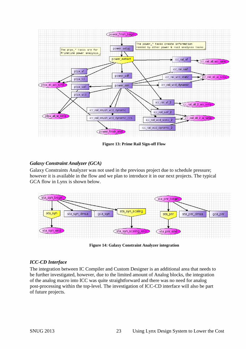
Galaxy Constraint Analyzer (GCA)
Galaxy Constraints Analyzer was not used in the previous project due to schedule pressure;
however it is available in the flow and we plan to introduce it in our next projects. The typical
GCA flow in Lynx is shown below.
F
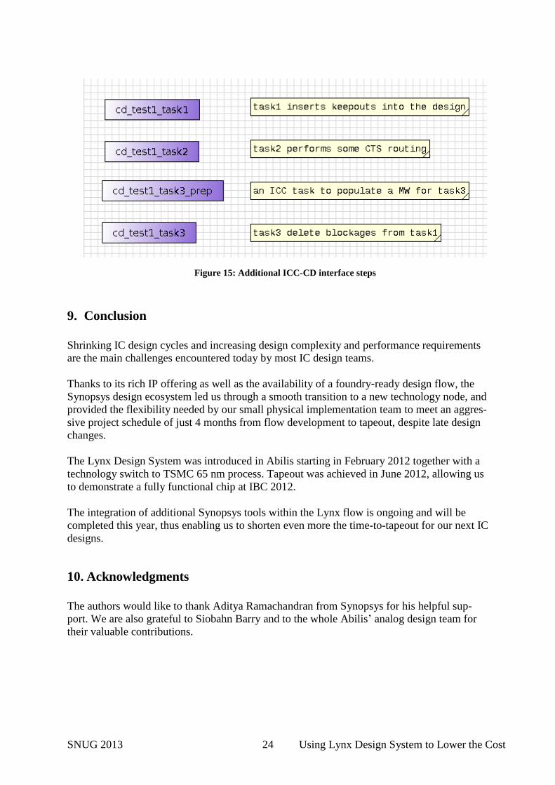
ICC-CD Interface
The integration between IC Compiler and Custom Designer is an additional area that needs to
be further investigated, however, due to the limited amount of Analog blocks, the integration
of the analog macro into ICC was quite straightforward and there was no need for analog
post-processing within the top-level. The investigation of ICC-CD interface will also be part
of future projects.
Figure 14: Galaxy Constraint Analyzer integration
Figure 13: Prime Rail Sign-off Flow
SNUG 2013 24 Using Lynx Design System to Lower the Cost
9. Conclusion
Shrinking IC design cycles and increasing design complexity and performance requirements
are the main challenges encountered today by most IC design teams.
Thanks to its rich IP offering as well as the availability of a foundry-ready design flow, the
Synopsys design ecosystem led us through a smooth transition to a new technology node, and
provided the flexibility needed by our small physical implementation team to meet an aggres-
sive project schedule of just 4 months from flow development to tapeout, despite late design
changes.
The Lynx Design System was introduced in Abilis starting in February 2012 together with a
technology switch to TSMC 65 nm process. Tapeout was achieved in June 2012, allowing us
to demonstrate a fully functional chip at IBC 2012.
The integration of additional Synopsys tools within the Lynx flow is ongoing and will be
completed this year, thus enabling us to shorten even more the time-to-tapeout for our next IC
designs.
10. Acknowledgments
The authors would like to thank Aditya Ramachandran from Synopsys for his helpful sup-
port. We are also grateful to Siobahn Barry and to the whole Abilis’ analog design team for
their valuable contributions.
Figure 15: Additional ICC-CD interface steps