Embed Size (px)
Citation preview
NIGHT CHAIRDAY CHAIR
ANNALISA BOSLOUGH ME263 THE CHAIR W18
CONCEPT
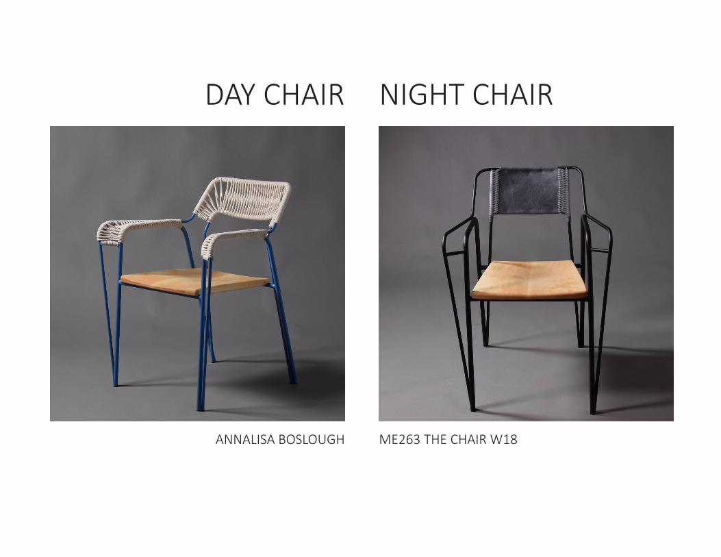
A steel-frame desk chair for working.
The frame is defined by continuous lines and curves joining to enclose spaces for the seat, arms, and back.
The frame serves as a skeleton for expression; such that the finishing detailing of the seat, back and arms define the chair’s character.
Originally, the goal was to make one chair, but the repeatable nature of tube bending, welding, and CNC machining lended itself well to making two chairs that demonstrate different final expressions starting from the same original frame concept.
The Day Chair is colorful and surprising, where the Night chair is more spartan and elegant. Together, both chairs create
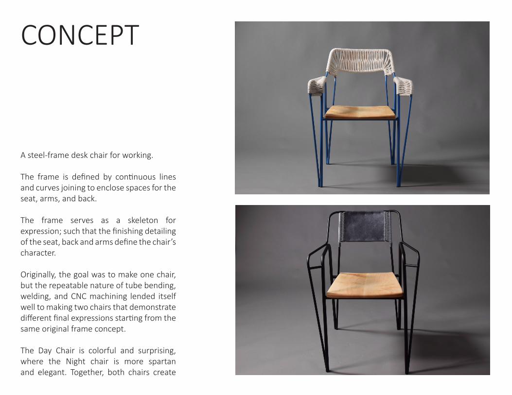
INSPIRATIONIn determining my frame geometry, I did almost no research of other designers’ chairs because I found it distracting. Instead my inspiration came from drawing a lot; mainly line profiles, which I then dimensionalized with wire and in CAD. The most memorable part of this process was sitting down and drawing chairs with a friend when I was stuck on the idea of making a rocking chair. He asked if I would even use a rocking chair, and I realized I would not; rarely do I lounge around. However I do not own a good work chair so with this realization I found a design direction I was stoked about.
While this sort of design inspiration is less explicit than researching other designers’ designs, talking to people I am close to whom I respect was more helpful in getting myself to designing something I actually wanted and would use. Craig and John are great resources in this area- my advice to future students is to keep them infomed and be open to their suggestions when stuck!
Pictured: concept sketches, CAD model, lack of work chairs in my life
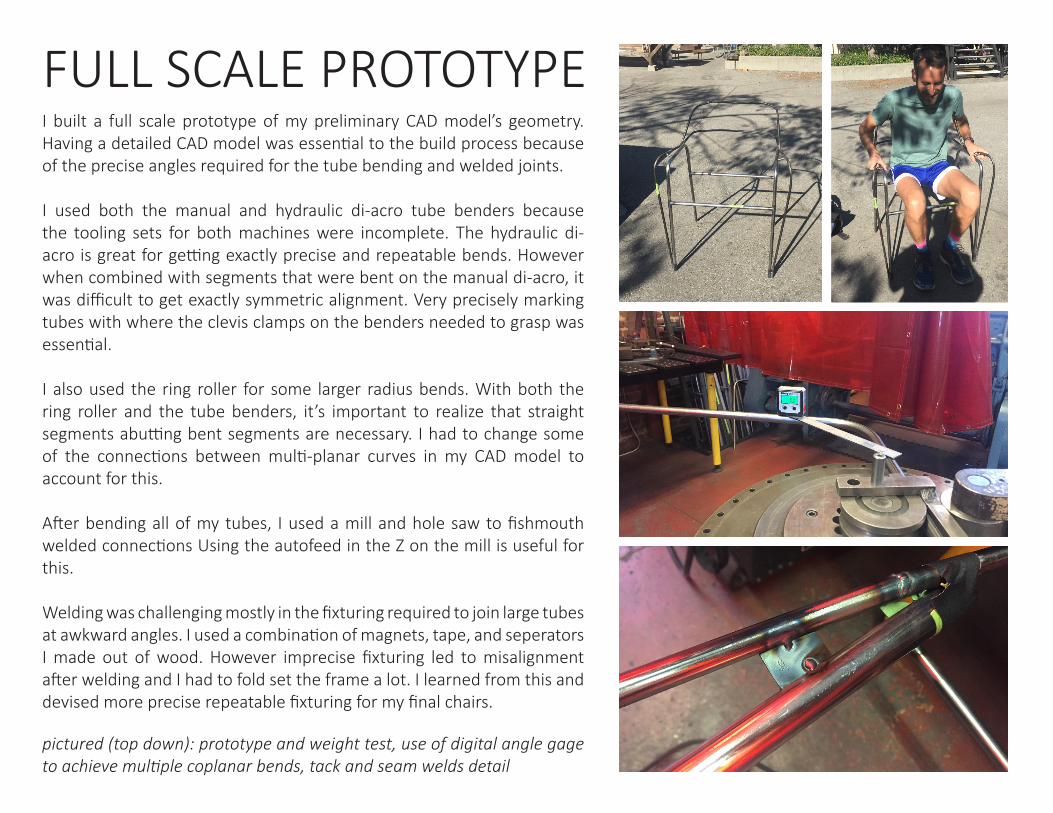
pictured (top down): prototype and weight test, use of digital angle gage to achieve multiple coplanar bends, tack and seam welds detail
I built a full scale prototype of my preliminary CAD model’s geometry. Having a detailed CAD model was essential to the build process because of the precise angles required for the tube bending and welded joints.
I used both the manual and hydraulic di-acro tube benders because the tooling sets for both machines were incomplete. The hydraulic di-acro is great for getting exactly precise and repeatable bends. However when combined with segments that were bent on the manual di-acro, it was difficult to get exactly symmetric alignment. Very precisely marking tubes with where the clevis clamps on the benders needed to grasp was essential.
I also used the ring roller for some larger radius bends. With both the ring roller and the tube benders, it’s important to realize that straight segments abutting bent segments are necessary. I had to change some of the connections between multi-planar curves in my CAD model to account for this.
After bending all of my tubes, I used a mill and hole saw to fishmouth welded connections Using the autofeed in the Z on the mill is useful for this.
Welding was challenging mostly in the fixturing required to join large tubes at awkward angles. I used a combination of magnets, tape, and seperators I made out of wood. However imprecise fixturing led to misalignment after welding and I had to fold set the frame a lot. I learned from this and devised more precise repeatable fixturing for my final chairs.
FULL SCALE PROTOTYPE
AND OTHER PRELIMINARY FABRICATIONTUBE BENDING
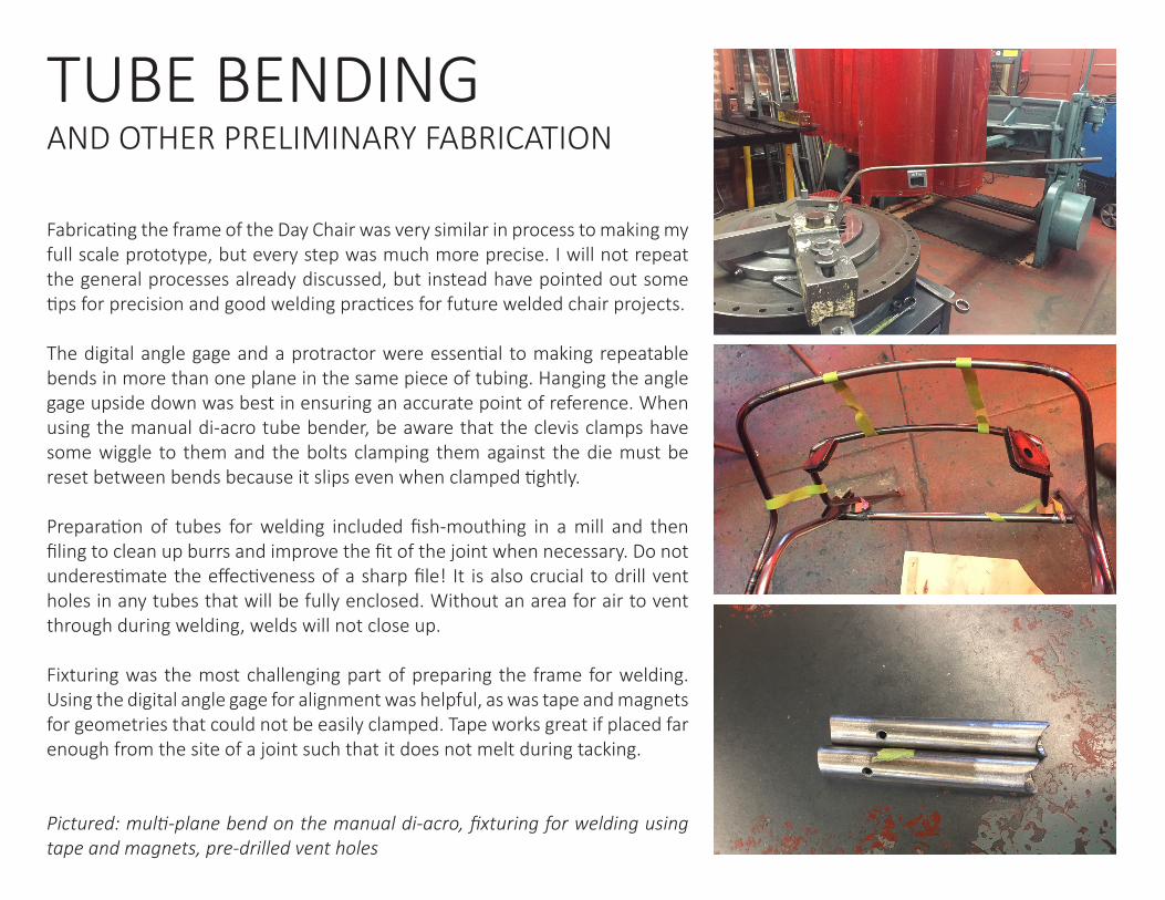
Fabricating the frame of the Day Chair was very similar in process to making my full scale prototype, but every step was much more precise. I will not repeat the general processes already discussed, but instead have pointed out some tips for precision and good welding practices for future welded chair projects.
The digital angle gage and a protractor were essential to making repeatable bends in more than one plane in the same piece of tubing. Hanging the angle gage upside down was best in ensuring an accurate point of reference. When using the manual di-acro tube bender, be aware that the clevis clamps have some wiggle to them and the bolts clamping them against the die must be reset between bends because it slips even when clamped tightly.
Preparation of tubes for welding included fish-mouthing in a mill and then filing to clean up burrs and improve the fit of the joint when necessary. Do not underestimate the effectiveness of a sharp file! It is also crucial to drill vent holes in any tubes that will be fully enclosed. Without an area for air to vent through during welding, welds will not close up. Fixturing was the most challenging part of preparing the frame for welding. Using the digital angle gage for alignment was helpful, as was tape and magnets for geometries that could not be easily clamped. Tape works great if placed far enough from the site of a joint such that it does not melt during tacking.
Pictured: multi-plane bend on the manual di-acro, fixturing for welding using tape and magnets, pre-drilled vent holes
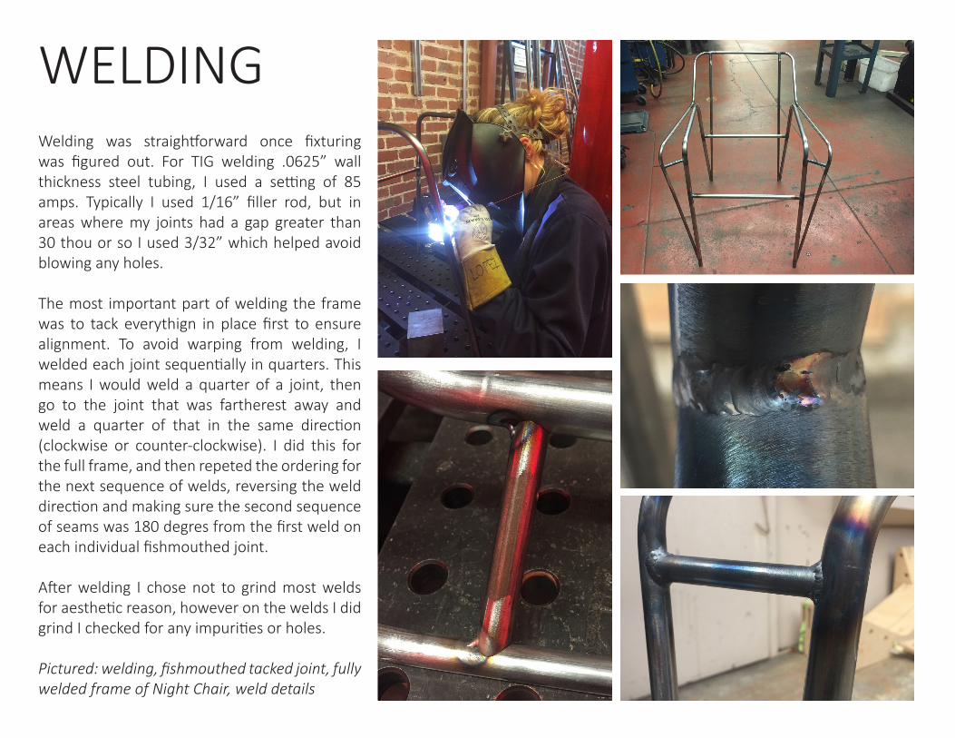
Welding was straightforward once fixturing was figured out. For TIG welding .0625” wall thickness steel tubing, I used a setting of 85 amps. Typically I used 1/16” filler rod, but in areas where my joints had a gap greater than 30 thou or so I used 3/32” which helped avoid blowing any holes.
The most important part of welding the frame was to tack everythign in place first to ensure alignment. To avoid warping from welding, I welded each joint sequentially in quarters. This means I would weld a quarter of a joint, then go to the joint that was fartherest away and weld a quarter of that in the same direction (clockwise or counter-clockwise). I did this for the full frame, and then repeted the ordering for the next sequence of welds, reversing the weld direction and making sure the second sequence of seams was 180 degres from the first weld on each individual fishmouthed joint.
After welding I chose not to grind most welds for aesthetic reason, however on the welds I did grind I checked for any impurities or holes.
Pictured: welding, fishmouthed tacked joint, fully welded frame of Night Chair, weld details
WELDING
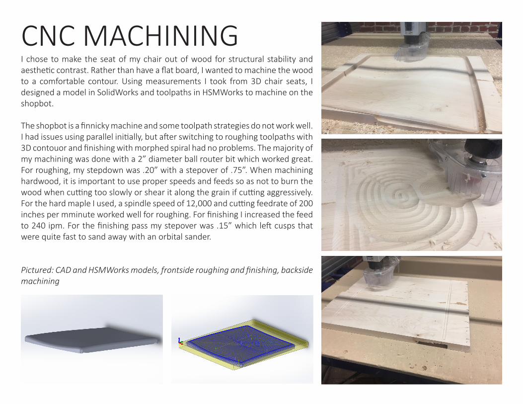
I chose to make the seat of my chair out of wood for structural stability and aesthetic contrast. Rather than have a flat board, I wanted to machine the wood to a comfortable contour. Using measurements I took from 3D chair seats, I designed a model in SolidWorks and toolpaths in HSMWorks to machine on the shopbot.
The shopbot is a finnicky machine and some toolpath strategies do not work well. I had issues using parallel initially, but after switching to roughing toolpaths with 3D contouor and finishing with morphed spiral had no problems. The majority of my machining was done with a 2” diameter ball router bit which worked great. For roughing, my stepdown was .20” with a stepover of .75”. When machining hardwood, it is important to use proper speeds and feeds so as not to burn the wood when cutting too slowly or shear it along the grain if cutting aggressively. For the hard maple I used, a spindle speed of 12,000 and cutting feedrate of 200 inches per mminute worked well for roughing. For finishing I increased the feed to 240 ipm. For the finishing pass my stepover was .15” which left cusps that were quite fast to sand away with an orbital sander.
Pictured: CAD and HSMWorks models, frontside roughing and finishing, backside machining
CNC MACHINING
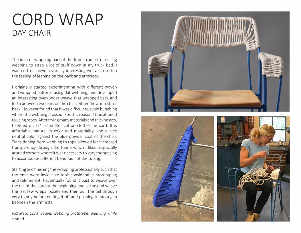
The idea of wrapping part of the frame came from using webbing to strap a lot of stuff down in my truck bed. I wanted to achieve a visually interesting weave to soften the feeling of leaning on the back and armrests.
I originally started experimenting with different woven and wrapped patterns using flat webbing, and developed an interesting over/under weave that wrapped back and forth between two bars on the chair, either the armrests or back. However found that it was difficult to avoid bunching where the webbing crossed. For this reason I transitioned to using ropes. After trying many materials and thicknesses, I settled on 1/4” diameter cotton clothesline cord. It is affordable, natural in color and materiality, and a nice neutral color against the blue powder coat of the chair. Transitioning from webbing to rope allowed for increased transparency through the frame which I liked, especially around corners where it was necessary to vary the spacing to accomodate different bend radii of the tubing.
Starting and finishing the wrapping professionally such that the ends were invidisible took considerable prototyping and refinement. I eventually found it best to weave over the tail of the cord at the beginning,and at the end weave the last few wraps loosely and then pull the tail through very tightly before cutting it off and pushing it into a gap between the armrests.
Pictured: Cord weave, webbing prototype, weaving while seated
CORD WRAPDAY CHAIR
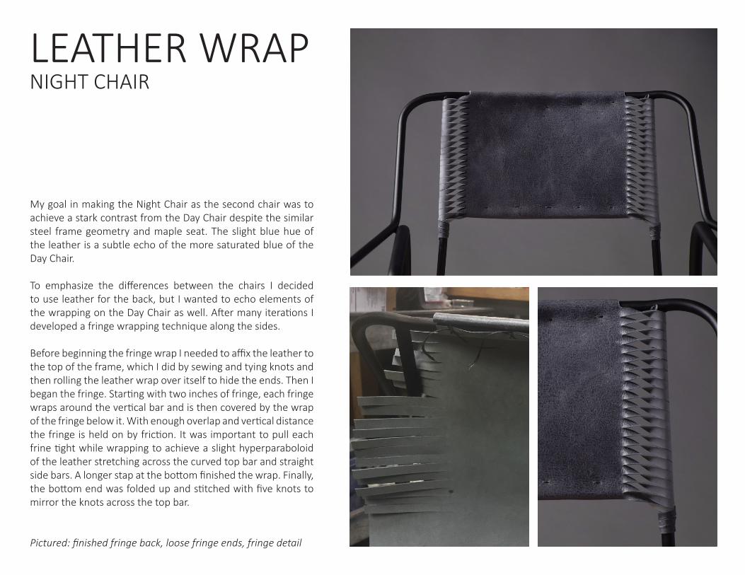
My goal in making the Night Chair as the second chair was to achieve a stark contrast from the Day Chair despite the similar steel frame geometry and maple seat. The slight blue hue of the leather is a subtle echo of the more saturated blue of the Day Chair.
To emphasize the differences between the chairs I decided to use leather for the back, but I wanted to echo elements of the wrapping on the Day Chair as well. After many iterations I developed a fringe wrapping technique along the sides.
Before beginning the fringe wrap I needed to affix the leather to the top of the frame, which I did by sewing and tying knots and then rolling the leather wrap over itself to hide the ends. Then I began the fringe. Starting with two inches of fringe, each fringe wraps around the vertical bar and is then covered by the wrap of the fringe below it. With enough overlap and vertical distance the fringe is held on by friction. It was important to pull each frine tight while wrapping to achieve a slight hyperparaboloid of the leather stretching across the curved top bar and straight side bars. A longer stap at the bottom finished the wrap. Finally, the bottom end was folded up and stitched with five knots to mirror the knots across the top bar.
Pictured: finished fringe back, loose fringe ends, fringe detail
LEATHER WRAPNIGHT CHAIR
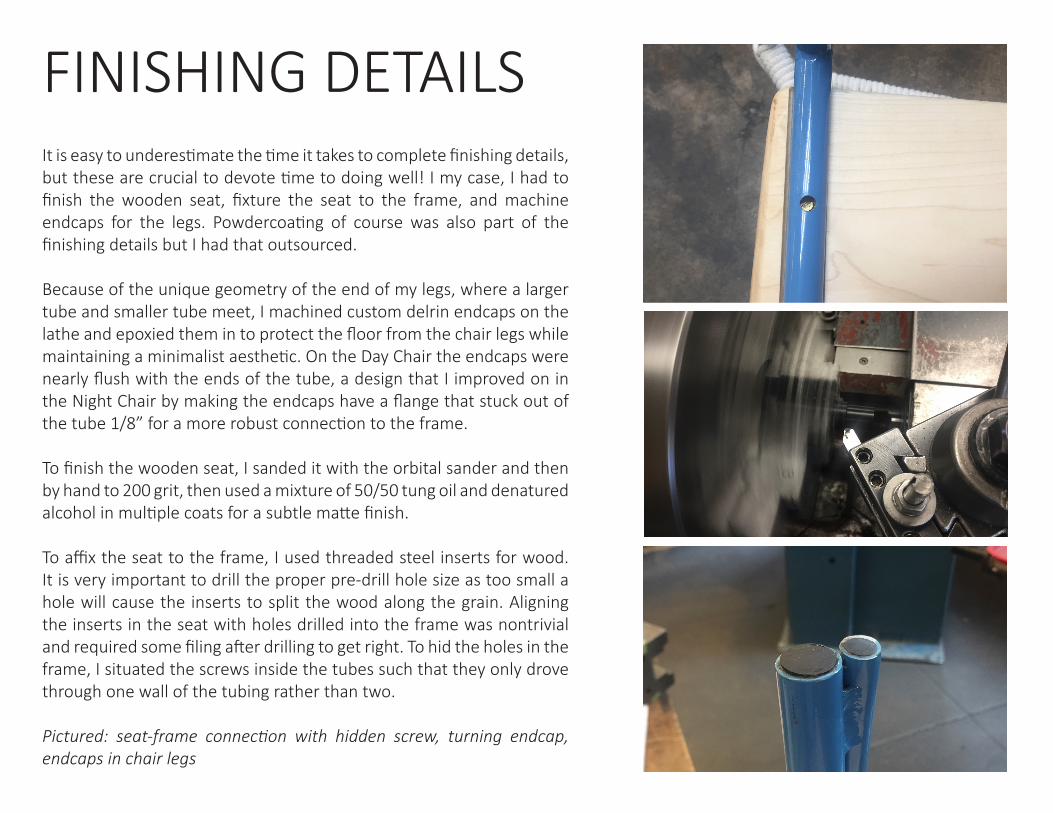
It is easy to underestimate the time it takes to complete finishing details, but these are crucial to devote time to doing well! I my case, I had to finish the wooden seat, fixture the seat to the frame, and machine endcaps for the legs. Powdercoating of course was also part of the finishing details but I had that outsourced.
Because of the unique geometry of the end of my legs, where a larger tube and smaller tube meet, I machined custom delrin endcaps on the lathe and epoxied them in to protect the floor from the chair legs while maintaining a minimalist aesthetic. On the Day Chair the endcaps were nearly flush with the ends of the tube, a design that I improved on in the Night Chair by making the endcaps have a flange that stuck out of the tube 1/8” for a more robust connection to the frame.
To finish the wooden seat, I sanded it with the orbital sander and then by hand to 200 grit, then used a mixture of 50/50 tung oil and denatured alcohol in multiple coats for a subtle matte finish.
To affix the seat to the frame, I used threaded steel inserts for wood. It is very important to drill the proper pre-drill hole size as too small a hole will cause the inserts to split the wood along the grain. Aligning the inserts in the seat with holes drilled into the frame was nontrivial and required some filing after drilling to get right. To hid the holes in the frame, I situated the screws inside the tubes such that they only drove through one wall of the tubing rather than two.
Pictured: seat-frame connection with hidden screw, turning endcap, endcaps in chair legs
FINISHING DETAILS
My main motivation for taking The Chair was to push myself as a designer, particularily in teh area of aesthetics. Prior to this class, my design projects have largely started from engineering a function, with aesthetics being more of an afterthought. In designing a chair, my goal was to reverse this order and begin with an aesthetic vivsion, then figure out how best to engineer it. Although eventually I succeeded in this approach, I struggled a lot to design a form with an aesthetic I was excited about. In doing the inspiration assignments for the first few weeks of the course, I found myself getting stuck on chair designs done by other people and incapable of coming up with something new myself. The design for my supposed to be final chair concept was a rocking chair that felt like a shallow combination of things I’d seen on the internet and in books. I coudl not get excited about the design because it felt inauthentic. Although I felt stuck and uninspired creatively, I planned to move forward with fabricating my design for fear of running out of time otherwise. Outside of Chair class, I was also learning from Craig as the CA for ME318, where a large emphasis is placed on lateral thinking. In the case of my chair, it took me reaching this design roadblock to finally take the advice from ME318 and think laterally to resolve a problem. One day my boyfriend pointed out that I might not even use a rocking chair because I don’t lounge around. His observation forced me to abandon my supposedly final chair design and restart from a position of lateral thinking to quickly get to a final chair design I would actually use. Returning to my original goal of starting with aesthetics and then devising the engineering, I focused on form which allowed me much more room for lateral thinking. I spent the rest of that day drawing ideas for work chairs. I did not look at a single book or website for inspiration, and as a result the final form I developed felt creative and authentic. While my frame design was finalized, at that point I decided to leave some other details as unknowns; specifically the seat and back of the chair. My reasoning for this was that it was difficult to determine the functionality of the woven parts of the chair without extensive prototyping. While it might seem to be poor planning to leave important details up in the air, my approach in doing this allowed me more time to test different weaves and was ultimately a venue for excercising a lot more lateral thinking. It
also took seeing the fully welded steel chair frame for me to truly feel inspired about the form of the weave geometry. While I think continuous experimentatin regarding the weave allowed me to thoroughly explore all options, perhaps it also fueled my habit of being indecisive as I tended to make final decisions at the last possible moment. With the large amount of prototyping and testing I did for both chairs, this worked well because I felt I had enough different options to choose from. However my indecisiveness was also a key driver in my decision to make two chairs, becuase for the first I could not choose between the aesthetics of weaving the Day Chair or the leatherwork on the Night Chair. I once again felt unhappy with my design direction because I felt I had too many exciting options to choose from to just pick one. I had a great time building both chairs but I realize that in other areas of my life this indecisiveness can certainly be a hindrance. The biggest learning I will take away from building not one, but two chairs, is project scoping. I had a well-scoped and manageable manufacturing plan with just building the Day Chair. However I loved welding my first frame so much and felt overwhelmed with the many exciting ideas I had for how to finish it; weave, leather, wood... that I decided to make a second frame. I learned a lot the second time around through iterating on my manufacturing process, and am nvery happy with how different both chairs turned out. However, I was not living my usual balanced life during as I was totally consumed by how much time the additional fabrication of a second chair took. In many was I was excited to be so deeply involved in a design project because it came from a place of passion, but the last weeks were overwhelming and not conducive to a healthy lifestyle. In reflecting on my process, I now have a greater value for the difficulty of elegantly scoping my work for a given amount of time and resources such that I will not spend unreasonable amounts of time on it and still be happy with the end result. Even after building two chairs there are countless things I would do differently a third time around. However the answer to these thoughts is not to build a third chair. Rather it is recognizing the possibilities that one design has in inspiring many, and this is exactly how chair class began; with a search of history for future inspiration. Now while I have two chairs I am proud of, I am most happy to have grown my ability to find inspiration and create authentic designs.
INTROSPECTION
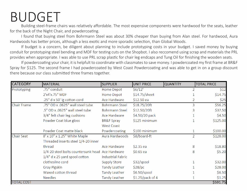
Building steel-frame chairs was relatively affordable. The most expensive components were hardwood for the seats, leather for the back of the Night Chair, and powdercoating. I found that buying steel from Bohrmann Steel was about 30% cheaper than buying from Alan steel. For hardwood, Aura Hardwoods has better prices, although a less exotic and more sporadic selection, than Global Woods. If budget is a concern, be diligent about planning to include prototyping costs in your budget. I saved money by buying conduit for prototyping steel bending and MDF for testing cuts on the Shopbot. I also reccomend using scrap and materials the PRL provides when appropriate. I was able to use PRL scrap plastic for chair leg endcaps and Tung Oil for finishing the wooden seats. If powdercoating your chair, it is helpfult to coordinate with classmates to save money. I powdercoated my first frame at BR&F Spray for $125. The second frame I had powdercoated by West Coast Powdercoating and was able to get in on a group discount there because our class submitted three frames together.
BUDGET
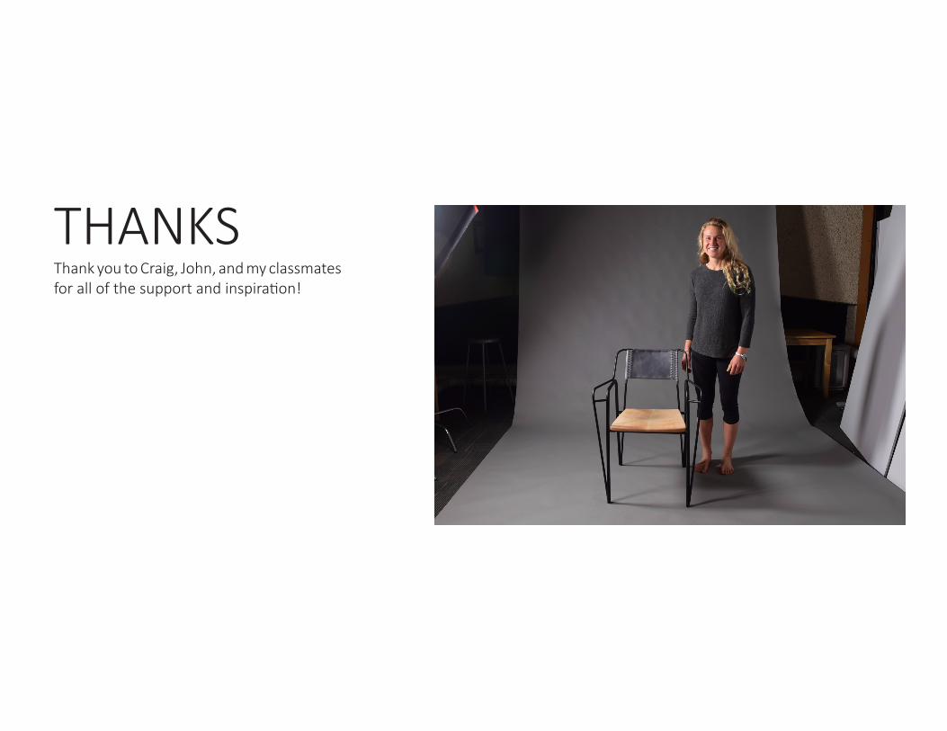
THANKS Thank you to Craig, John, and my classmates for all of the support and inspiration!