Embed Size (px)
Citation preview

Electricity and New Energy
DC Power Electronics
Courseware Sample 86356-F0

Order no.: 86356-10
Revision level: 12/2014
By the staff of Festo Didactic
© Festo Didactic Ltée/Ltd, Quebec, Canada 2010
Internet: www.festo-didactic.com
e-mail: [email protected]
Printed in Canada
All rights reserved
ISBN 978-2-89640-395-0 (Printed version)
ISBN 978-2-89747-237-5 (CD-ROM)
Legal Deposit – Bibliothèque et Archives nationales du Québec, 2010
Legal Deposit – Library and Archives Canada, 2010
The purchaser shall receive a single right of use which is non-exclusive, non-time-limited and limited
geographically to use at the purchaser's site/location as follows.
The purchaser shall be entitled to use the work to train his/her staff at the purchaser's site/location and
shall also be entitled to use parts of the copyright material as the basis for the production of his/her own
training documentation for the training of his/her staff at the purchaser's site/location with
acknowledgement of source and to make copies for this purpose. In the case of schools/technical
colleges, training centers, and universities, the right of use shall also include use by school and college
students and trainees at the purchaser's site/location for teaching purposes.
The right of use shall in all cases exclude the right to publish the copyright material or to make this
available for use on intranet, Internet and LMS platforms and databases such as Moodle, which allow
access by a wide variety of users, including those outside of the purchaser's site/location.
Entitlement to other rights relating to reproductions, copies, adaptations, translations, microfilming and
transfer to and storage and processing in electronic systems, no matter whether in whole or in part, shall
require the prior consent of Festo Didactic GmbH & Co. KG.
Information in this document is subject to change without notice and does not represent a commitment on
the part of Festo Didactic. The Festo materials described in this document are furnished under a license
agreement or a nondisclosure agreement.
Festo Didactic recognizes product names as trademarks or registered trademarks of their respective
holders.
All other trademarks are the property of their respective owners. Other trademarks and trade names may
be used in this document to refer to either the entity claiming the marks and names or their products.
Festo Didactic disclaims any proprietary interest in trademarks and trade names other than its own.
© Festo Didactic 86356-10 III
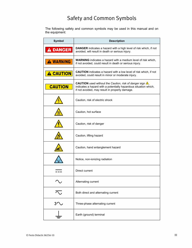
Safety and Common Symbols
The following safety and common symbols may be used in this manual and on the equipment:
Symbol Description
DANGER indicates a hazard with a high level of risk which, if not avoided, will result in death or serious injury.
WARNING indicates a hazard with a medium level of risk which, if not avoided, could result in death or serious injury.
CAUTION indicates a hazard with a low level of risk which, if not avoided, could result in minor or moderate injury.
CAUTION used without the Caution, risk of danger sign , indicates a hazard with a potentially hazardous situation which, if not avoided, may result in property damage.
Caution, risk of electric shock
Caution, hot surface
Caution, risk of danger
Caution, lifting hazard
Caution, hand entanglement hazard
Notice, non-ionizing radiation
Direct current
Alternating current
Both direct and alternating current
Three-phase alternating current
Earth (ground) terminal
Safety and Common Symbols
IV © Festo Didactic 86356-10
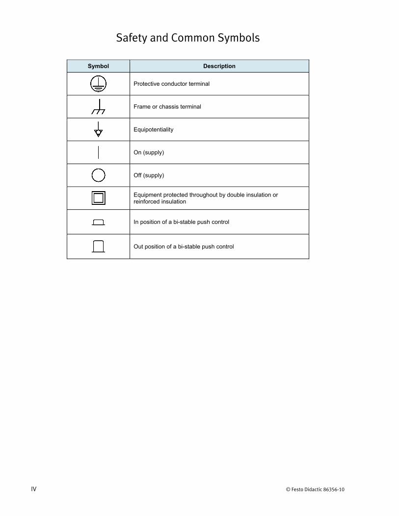
Symbol Description
Protective conductor terminal
Frame or chassis terminal
Equipotentiality
On (supply)
Off (supply)
Equipment protected throughout by double insulation or reinforced insulation
In position of a bi-stable push control
Out position of a bi-stable push control

© Festo Didactic 86356-10 V
Table of Contents
Preface .................................................................................................................. IX
About This Manual ................................................................................................ XI
To the Instructor .................................................................................................. XIII
Introduction DC Power Electronics .................................................................. 1
DISCUSSION OF FUNDAMENTALS ....................................................... 1
Exercise 1 The Diode and Switching Transistor .......................................... 3
DISCUSSION ..................................................................................... 3 Description of a diode .............................................................. 3 Operating principles of a diode ................................................ 4 Characteristic voltage-current curve of a diode ....................... 6 Description of a transistor ........................................................ 7 Using a transistor as a switch .................................................. 7 Cycle, period, and frequency ................................................... 9 Duty cycle and pulse width modulation .................................. 10 Average value ........................................................................ 10 Safety rules ............................................................................ 12
PROCEDURE ................................................................................... 12 Setup and connections .......................................................... 12 Forward-biased diode in a simple circuit ............................... 14 Reverse-biased diode in a simple circuit ............................... 15 Switching Transistor ............................................................... 16
Setup and connection ............................................................... 16 Static control of a switching transistor ...................................... 18 Dynamic control of a switching transistor ................................. 21 Frequency and duty cycle ......................................................... 22 Average value .......................................................................... 23
Exercise 2 The Buck Chopper ...................................................................... 27
DISCUSSION ................................................................................... 27 The buck chopper .................................................................. 27 Operation of a buck chopper with a resistive load ................. 28 High-side versus low-side switching ...................................... 29
PROCEDURE ................................................................................... 30 Setup and connections .......................................................... 30 Output voltage versus duty cycle ........................................... 32 Output voltage versus switching frequency ........................... 35 Low-side and high-side switching .......................................... 37

Table of Contents
VI © Festo Didactic 86356-10
Exercise 3 Introduction to High-Speed Power Switching ......................... 41
DISCUSSION ................................................................................... 41 High-speed power switching circuits ...................................... 41 Voltage-type circuit................................................................. 41 Current-type circuit ................................................................. 42 Free-wheeling diodes ............................................................. 43 Power efficiency ..................................................................... 44 Interconnecting voltage-type and current-type circuits .......... 44
PROCEDURE ................................................................................... 45 Setup and connections .......................................................... 45 Voltage-type circuit................................................................. 47 Connecting a voltage-type circuit to a current-type circuit via an electronic switch without a free-wheeling diode .......... 49 Connecting a voltage-type circuit to a current-type circuit via an electronic switch with a free-wheeling diode ............... 51 Power efficiency ..................................................................... 53 Interconnecting two voltage-type circuits via an electronic switch ..................................................................................... 56
Exercise 4 Ripple in Choppers ..................................................................... 61
DISCUSSION ................................................................................... 61 Ripple ..................................................................................... 61 Ripple versus inductance / capacitance ................................ 62 Ripple versus switching frequency ......................................... 64
PROCEDURE ................................................................................... 64 Setup and connections .......................................................... 64 Current ripple versus switching frequency and inductance ... 66
Current ripple versus frequency ................................................ 67 Current ripple versus inductance .............................................. 71
Voltage ripple versus switching frequency and capacitance ............................................................................ 74
Exercise 5 The Lead-Acid Battery Charger ................................................ 83
DISCUSSION ................................................................................... 83 Battery fundamentals ............................................................. 83 Lead-acid battery charger fundamentals ............................... 84 Implementing a lead-acid battery charger using a buck chopper with feedback loops ................................................. 85
Table of Contents
© Festo Didactic 86356-10 VII
PROCEDURE ................................................................................... 88 Setup and connections .......................................................... 88 Voltage regulation .................................................................. 90 Current regulation .................................................................. 94 Partially discharging the batteries in the Lead-Acid Battery Pack ........................................................................... 97 The lead-acid battery charger ................................................ 98
Initial stage of a lead-acid battery fast-charging – Constant
current charge .......................................................................... 98 Middle stage of a lead-acid battery fast-charging –
Constant voltage charge at gassing voltage ........................... 102 Finishing stage of a lead-acid battery fast-charging –
Constant voltage charge at float level..................................... 103
Exercise 6 The Boost Chopper .................................................................. 105
DISCUSSION ................................................................................. 105 The boost chopper ............................................................... 105 Power efficiency ................................................................... 107
PROCEDURE ................................................................................. 108 Setup and connections ........................................................ 108 Output voltage versus duty cycle ......................................... 110 Output voltage versus switching frequency ......................... 113 Power efficiency ................................................................... 114
Exercise 7 The Buck/Boost Chopper ........................................................ 117
DISCUSSION ................................................................................. 117 The Buck/Boost Chopper ..................................................... 117
PROCEDURE ................................................................................. 120 Setup and connections ........................................................ 120 Switching control signals of a buck/boost chopper .............. 122 Operation of a buck/boost chopper ...................................... 124
Exercise 8 The Four-Quadrant Chopper ................................................... 129
DISCUSSION ................................................................................. 129 The Four-Quadrant Chopper ............................................... 129
PROCEDURE ................................................................................. 132 Setup and connections ........................................................ 132 Switching control signals of a four-quadrant chopper .......... 134 Operation of a four-quadrant chopper ................................. 136 Partially discharging the batteries in the Lead-Acid Battery Pack ......................................................................... 139 Demonstrating four-quadrant operation ............................... 139
Appendix A Equipment Utilization Chart .................................................... 145
Table of Contents
VIII © Festo Didactic 86356-10
Appendix B Resistance Table for the Resistive Load Module .................. 147
Appendix C Preparation of the Lead-Acid Battery Pack ........................... 149 Charging procedure ............................................................. 149 Sulfation test ........................................................................ 150 Battery maintenance ............................................................ 151
Appendix D Glossary of New Terms ............................................................ 153
Appendix E Circuit Diagram Symbols ......................................................... 155
Index of New Terms ........................................................................................... 161
Acronyms ........................................................................................................... 163
Bibliography ....................................................................................................... 165

© Festo Didactic 86356-10 IX
Preface
The production of energy using renewable natural resources such as wind, sunlight, rain, tides, geothermal heat, etc., has gained much importance in recent years as it is an effective means of reducing greenhouse gas (GHG) emissions. The need for innovative technologies to make the grid smarter has recently emerged as a major trend, as the increase in electrical power demand observed worldwide makes it harder for the actual grid in many countries to keep up with demand. Furthermore, electric vehicles (from bicycles to cars) are developed and marketed with more and more success in many countries all over the world.
To answer the increasingly diversified needs for training in the wide field of electrical energy, the Electric Power Technology Training Program was developed as a modular study program for technical institutes, colleges, and universities. The program is shown below as a flow chart, with each box in the flow chart representing a course.
The Electric Power Technology Training Program.

Preface
X © Festo Didactic 86356-10
The program starts with a variety of courses providing in-depth coverage of basic topics related to the field of electrical energy such as ac and dc power circuits, power transformers, rotating machines, ac power transmission lines, and power electronics. The program then builds on the knowledge gained by the student through these basic courses to provide training in more advanced subjects such as home energy production from renewable resources (wind and sunlight), large-scale electricity production from hydropower, large-scale electricity production from wind power (doubly-fed induction generator [DFIG], synchronous generator, and asynchronous generator technologies), smart-grid technologies (SVC, STATCOM, HVDC transmission, etc.), storage of electrical energy in batteries, and drive systems for small electric vehicles and cars.
Do you have suggestions or criticism regarding this manual?
If so, send us an e-mail at [email protected].
The authors and Festo Didactic look forward to your comments.
© Festo Didactic 86356-10 XI
About This Manual
This course covers power electronic components and circuits (choppers) required to manage dc power, such as dc power stored in batteries or produced from wind power or solar power. The course presents the diode and the switching transistor, two semiconductor components that are widely used in power electronics. The course also provides in-depth coverage of various types of chopper, a power electronics device used in many DC power circuits (e.g., dc motor drives, battery chargers, dc-to-dc converters, etc.).
Manual objectives
When you have completed this manual, you will be familiar with the main types of choppers. You will also be familiar with high-speed power switching (voltage-type and current-type circuits, free-wheeling diodes, etc.). Finally, you will know how to control ripple in choppers, and to build a battery charger using a buck chopper.
Safety considerations
Safety symbols that may be used in this manual and on the equipment are listed in the Safety Symbols table at the beginning of the manual.
Safety procedures related to the tasks that you will be asked to perform are indicated in each exercise.
Make sure that you are wearing appropriate protective equipment when performing the tasks. You should never perform a task if you have any reason to think that a manipulation could be dangerous for you or your teammates.
Prerequisite
As a prerequisite to this course, you should have read the manual titled DC Power Circuits, part number 86350.
Systems of units
Units are expressed using the International System of Units (SI) followed by the units expressed in the U.S. customary system of units (between parentheses).


© Festo Didactic 86356-10 XIII
To the Instructor
You will find in this Instructor Guide all the elements included in the Student Manual together with the answers to all questions, results of measurements, graphs, explanations, suggestions, and, in some cases, instructions to help you guide the students through their learning process. All the information that applies to you is placed between markers and appears in red.
Accuracy of measurements
The numerical results of the hands-on exercises may differ from one student to another. For this reason, the results and answers given in this manual should be considered as a guide. Students who correctly performed the exercises should expect to demonstrate the principles involved and make observations and measurements similar to those given as answers.
Equipment installation
In order for students to be able to perform the exercises in the Student Manual, the Electric Power Technology Training Equipment must have been properly installed, according to the instructions given in the user guide Electric Power Technology Training Equipment, part number 38486-E.


Sample Exercise
Extracted from
the Student Manual
and the Instructor Guide

© Festo Didactic 86356-10 83
When you have completed this exercise, you will be familiar with the operation of a lead-acid battery charger implemented using a buck chopper with feedback loops.
The Discussion of this exercise covers the following points:
Battery fundamentals Lead-acid battery charger fundamentals Implementing a lead-acid battery charger using a buck chopper with
feedback loops
Battery fundamentals
A battery is a device that converts chemical energy into electric energy by means of an electrochemical reaction. When a load such as a resistor or a small light bulb, is connected to the terminals of a battery, a chemical reaction starts and electricity is produced and consumed by the load. When no load is connected to the battery terminals, no chemical reaction occurs and no electrical energy is produced.
There are three major types of batteries: primary (single use), secondary (rechargeable), and reserve (for long storage periods). The primary batteries are discarded when discharged. They are commonly used as a power source for portable electronic and electrical devices. The secondary batteries can be electrically recharged. They can be used as an energy-storage device, which is usually electrically connected to and charged by an energy source that delivers energy to a load on demand, as in automotive applications, emergency systems, and stationary energy storage systems. The lead-acid batteries are secondary batteries.
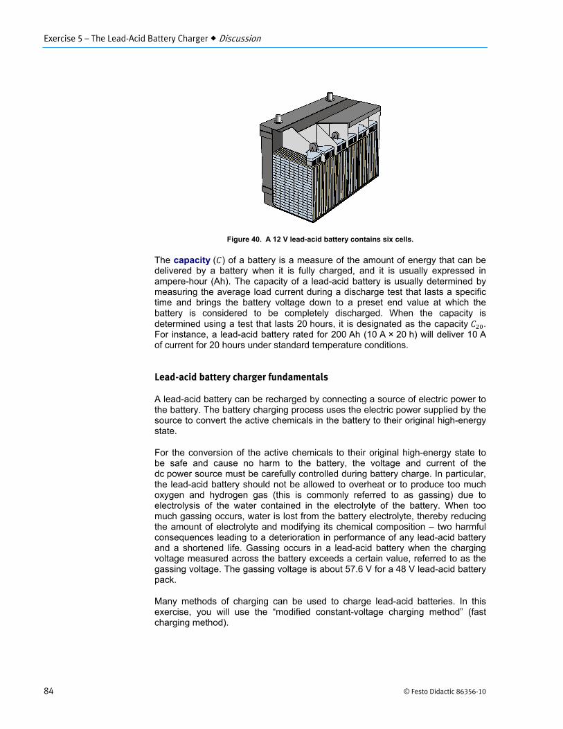
The basic electrochemical unit that produces electric energy is referred to as a cell. A battery consists of a series/parallel arrangement of several cells. For example, the 12 V lead-acid battery shown in Figure 40 and used in any internal-combustion engine (ICE) car for starting, lighting, and ignition (SLI battery) consists of six cells connected in series, each cell having a nominal output voltage (voltage under load) of about 2 V. The Lead-Acid Battery Pack of your training system consists of four 12 V batteries connected in series, each battery containing 6 cells.
The Lead-Acid Battery Charger
Exercise 5
EXERCISE OBJECTIVE
DISCUSSION OUTLINE
DISCUSSION
Schematic symbol
of a battery
Exercise 5 – The Lead-Acid Battery Charger Discussion
84 © Festo Didactic 86356-10
Figure 40. A 12 V lead-acid battery contains six cells.
The capacity ( ) of a battery is a measure of the amount of energy that can be delivered by a battery when it is fully charged, and it is usually expressed in ampere-hour (Ah). The capacity of a lead-acid battery is usually determined by measuring the average load current during a discharge test that lasts a specific time and brings the battery voltage down to a preset end value at which the battery is considered to be completely discharged. When the capacity is determined using a test that lasts 20 hours, it is designated as the capacity . For instance, a lead-acid battery rated for 200 Ah (10 A × 20 h) will deliver 10 A of current for 20 hours under standard temperature conditions.
Lead-acid battery charger fundamentals
A lead-acid battery can be recharged by connecting a source of electric power to the battery. The battery charging process uses the electric power supplied by the source to convert the active chemicals in the battery to their original high-energy state.
For the conversion of the active chemicals to their original high-energy state to be safe and cause no harm to the battery, the voltage and current of the dc power source must be carefully controlled during battery charge. In particular, the lead-acid battery should not be allowed to overheat or to produce too much oxygen and hydrogen gas (this is commonly referred to as gassing) due to electrolysis of the water contained in the electrolyte of the battery. When too much gassing occurs, water is lost from the battery electrolyte, thereby reducing the amount of electrolyte and modifying its chemical composition – two harmful consequences leading to a deterioration in performance of any lead-acid battery and a shortened life. Gassing occurs in a lead-acid battery when the charging voltage measured across the battery exceeds a certain value, referred to as the gassing voltage. The gassing voltage is about 57.6 V for a 48 V lead-acid battery pack.
Many methods of charging can be used to charge lead-acid batteries. In this exercise, you will use the “modified constant-voltage charging method” (fast charging method).
Exercise 5 – The Lead-Acid Battery Charger Discussion
© Festo Didactic 86356-10 85
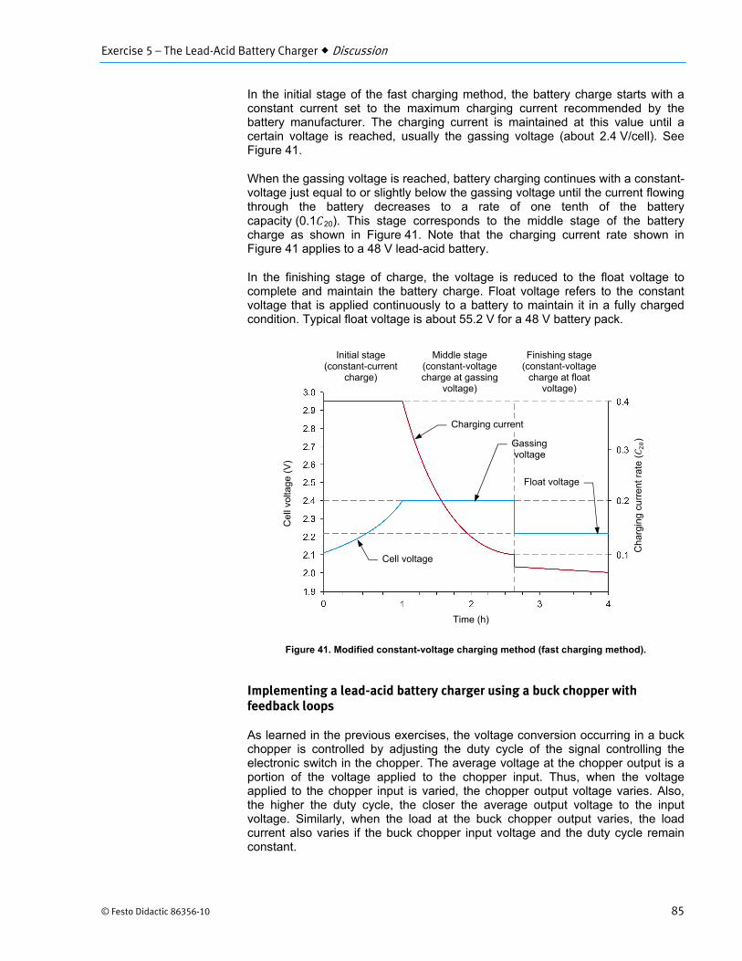
In the initial stage of the fast charging method, the battery charge starts with a constant current set to the maximum charging current recommended by the battery manufacturer. The charging current is maintained at this value until a certain voltage is reached, usually the gassing voltage (about 2.4 V/cell). See Figure 41.
When the gassing voltage is reached, battery charging continues with a constant-voltage just equal to or slightly below the gassing voltage until the current flowing through the battery decreases to a rate of one tenth of the battery capacity (0.1 20). This stage corresponds to the middle stage of the battery charge as shown in Figure 41. Note that the charging current rate shown in Figure 41 applies to a 48 V lead-acid battery.
In the finishing stage of charge, the voltage is reduced to the float voltage to complete and maintain the battery charge. Float voltage refers to the constant voltage that is applied continuously to a battery to maintain it in a fully charged condition. Typical float voltage is about 55.2 V for a 48 V battery pack.
Figure 41. Modified constant-voltage charging method (fast charging method).
Implementing a lead-acid battery charger using a buck chopper with feedback loops
As learned in the previous exercises, the voltage conversion occurring in a buck chopper is controlled by adjusting the duty cycle of the signal controlling the electronic switch in the chopper. The average voltage at the chopper output is a portion of the voltage applied to the chopper input. Thus, when the voltage applied to the chopper input is varied, the chopper output voltage varies. Also, the higher the duty cycle, the closer the average output voltage to the input voltage. Similarly, when the load at the buck chopper output varies, the load current also varies if the buck chopper input voltage and the duty cycle remain constant.
Initial stage (constant-current
charge)
Middle stage (constant-voltage charge at gassing
voltage)
Finishing stage (constant-voltage
charge at float voltage)
Cha
rgin
g cu
rren
t rat
e (
)
Cel
l vol
tage
(V
)
Time (h)
Charging current
Float voltage
Cell voltage
Gassing voltage
Exercise 5 – The Lead-Acid Battery Charger Discussion
86 © Festo Didactic 86356-10
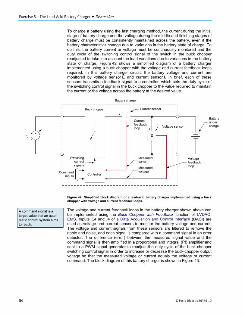
To charge a battery using the fast charging method, the current during the initial stage of battery charge and the voltage during the middle and finishing stages of battery charge must be consistently maintained across the battery, even if the battery characteristics change due to variations in the battery state of charge. To do this, the battery current or voltage must be continuously monitored and the duty cycle of the switching control signal of the switch in the buck chopper readjusted to take into account the load variations due to variations in the battery state of charge. Figure 42 shows a simplified diagram of a battery charger implemented using a buck chopper with the voltage and current feedback loops required. In this battery charger circuit, the battery voltage and current are monitored by voltage sensor E and current sensor I. In brief, each of these sensors transmits a feedback signal to a controller, which sets the duty cycle of the switching control signal in the buck chopper to the value required to maintain the current or the voltage across the battery at the desired value.
Figure 42. Simplified block diagram of a lead-acid battery charger implemented using a buck chopper with voltage and current feedback loops.
The voltage and current feedback loops in the battery charger shown above can be implemented using the Buck Chopper with Feedback function of LVDAC-EMS. Inputs E4 and I4 of a Data Acquisition and Control Interface (DACI) are used as voltage and current sensors to monitor the battery voltage and current. The voltage and current signals from these sensors are filtered to remove the ripple and noise, and each signal is compared with a command signal in an error detector. The difference (error) between the measured signal value and the command signal is then amplified in a proportional and integral (PI) amplifier and sent to a PWM signal generator to readjust the duty cycle of the buck-chopper switching control signal in order to increase or decrease the buck-chopper output voltage so that the measured voltage or current equals the voltage or current command. The block diagram of this battery charger is shown in Figure 43.
A command signal is a target value that an auto-matic control system aims to reach.
Controller
Battery charger
Buck chopper Current sensor
Voltage sensor
Battery under charge
Measured current
Switchingcontrolsignals
Measured voltage
Voltage feedback loop
Current feedback loop
Commandinputs
Exercise 5 – The Lead-Acid Battery Charger Discussion
© Festo Didactic 86356-10 87
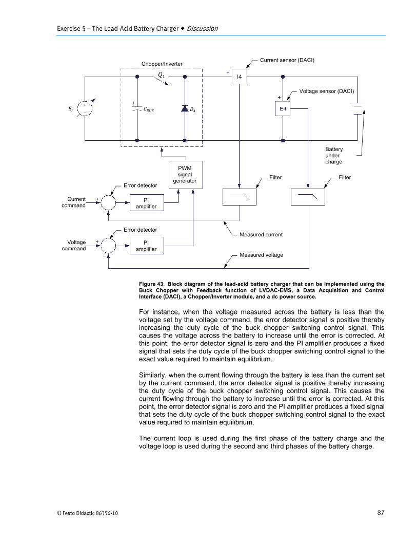
Figure 43. Block diagram of the lead-acid battery charger that can be implemented using the Buck Chopper with Feedback function of LVDAC-EMS, a Data Acquisition and Control Interface (DACI), a Chopper/Inverter module, and a dc power source.
For instance, when the voltage measured across the battery is less than the voltage set by the voltage command, the error detector signal is positive thereby increasing the duty cycle of the buck chopper switching control signal. This causes the voltage across the battery to increase until the error is corrected. At this point, the error detector signal is zero and the PI amplifier produces a fixed signal that sets the duty cycle of the buck chopper switching control signal to the exact value required to maintain equilibrium.
Similarly, when the current flowing through the battery is less than the current set by the current command, the error detector signal is positive thereby increasing the duty cycle of the buck chopper switching control signal. This causes the current flowing through the battery to increase until the error is corrected. At this point, the error detector signal is zero and the PI amplifier produces a fixed signal that sets the duty cycle of the buck chopper switching control signal to the exact value required to maintain equilibrium.
The current loop is used during the first phase of the battery charge and the voltage loop is used during the second and third phases of the battery charge.
PI amplifier
PI amplifier
PWM signal
generator
Chopper/Inverter
Filter
Error detector
Currentcommand
Voltagecommand
Error detector Measured current
Measured voltage
Current sensor (DACI)
Voltage sensor (DACI)
Filter
Battery under charge

Exercise 5 – The Lead-Acid Battery Charger Procedure Outline
88 © Festo Didactic 86356-10
The Procedure is divided into the following sections:
Setup and connections Voltage regulation Current regulation Partially discharging the batteries in the Lead-Acid Battery Pack The lead-acid battery charger
High voltages are present in this laboratory exercise. Do not make or modify any banana jack connections with the power on unless otherwise specified.
Setup and connections
a Before beginning this exercise, measure the open-circuit voltage across the Lead-Acid Battery Pack, Model 8802, using a multimeter. If the open-circuit voltage is lower than 51 V, ask your instructor for assistance as the Lead-Acid Battery Pack is probably not fully charged. Appendix C of this manual indicates how to prepare (charge) the Lead-Acid Battery Pack before each laboratory period.
In this part of the exercise, you will set up and connect the equipment.
1. Refer to the Equipment Utilization Chart in Appendix A to obtain the list of equipment required to perform this exercise.
Install the required equipment in the Workstation.
2. Connect the Power Input of the Data Acquisition and Control Interface to a 24 V ac power supply.
Connect the Low Power Input of the IGBT Chopper/Inverter to the Power Input of the Data Acquisition and Control Interface. Turn the 24 V ac power supply on.
3. Connect the USB port of the Data Acquisition and Control Interface to a USB port of the host computer.
Connect the USB port of the Four-Quadrant Dynamometer/Power Supply to a USB port of the host computer.
PROCEDURE OUTLINE
PROCEDURE
Exercise 5 – The Lead-Acid Battery Charger Procedure
© Festo Didactic 86356-10 89
4. Make sure that the main power switch of the Four-Quadrant Dynamometer/ Power Supply is set to O (off), then connect the Power Input to an ac power outlet.
Set the Operating Mode switch of the Four-Quadrant Dynamometer/Power Supply to Power Supply.
Turn the Four-Quadrant Dynamometer/Power Supply on by setting the main power switch to I (on).
5. Connect the Digital Outputs of the Data Acquisition and Control Interface (DACI) to the Switching Control Inputs of the IGBT Chopper/Inverter using a DB9 connector cable.
6. Turn the host computer on, then start the LVDAC-EMS software.
In the LVDAC-EMS Start-Up window, make sure that the Data Acquisition and Control Interface and the Four-Quadrant Dynamometer/Power Supply are detected. Make sure that the Computer-Based Instrumentation and Chopper/Inverter Control functions for the Data Acquisition and Control Interface are available, as well as the Standard Functions (C.B. control) for the Four-Quadrant Dynamometer/Power Supply. Select the network voltage and frequency that correspond to the voltage and frequency of your local ac power network, then click the OK button to close the LVDAC-EMS Start-Up window.
7. Set up the circuit shown in Figure 44. In this circuit, inputs E4 and I4 are used by LVDAC-EMS as feedback inputs for the buck chopper. Note that when inputs E4 and I4 are used by LVDAC-EMS as feedback inputs, they are no longer available for the LVDAC-EMS instrumentation, i.e., the Metering, Oscilloscope, Phasor Analyzer, and Harmonic Analyzer. Other voltage and current inputs of the DACI must be used to measure and observe the voltage and current sensed by inputs E4 and I4.
Exercise 5 – The Lead-Acid Battery Charger Procedure
90 © Festo Didactic 86356-10
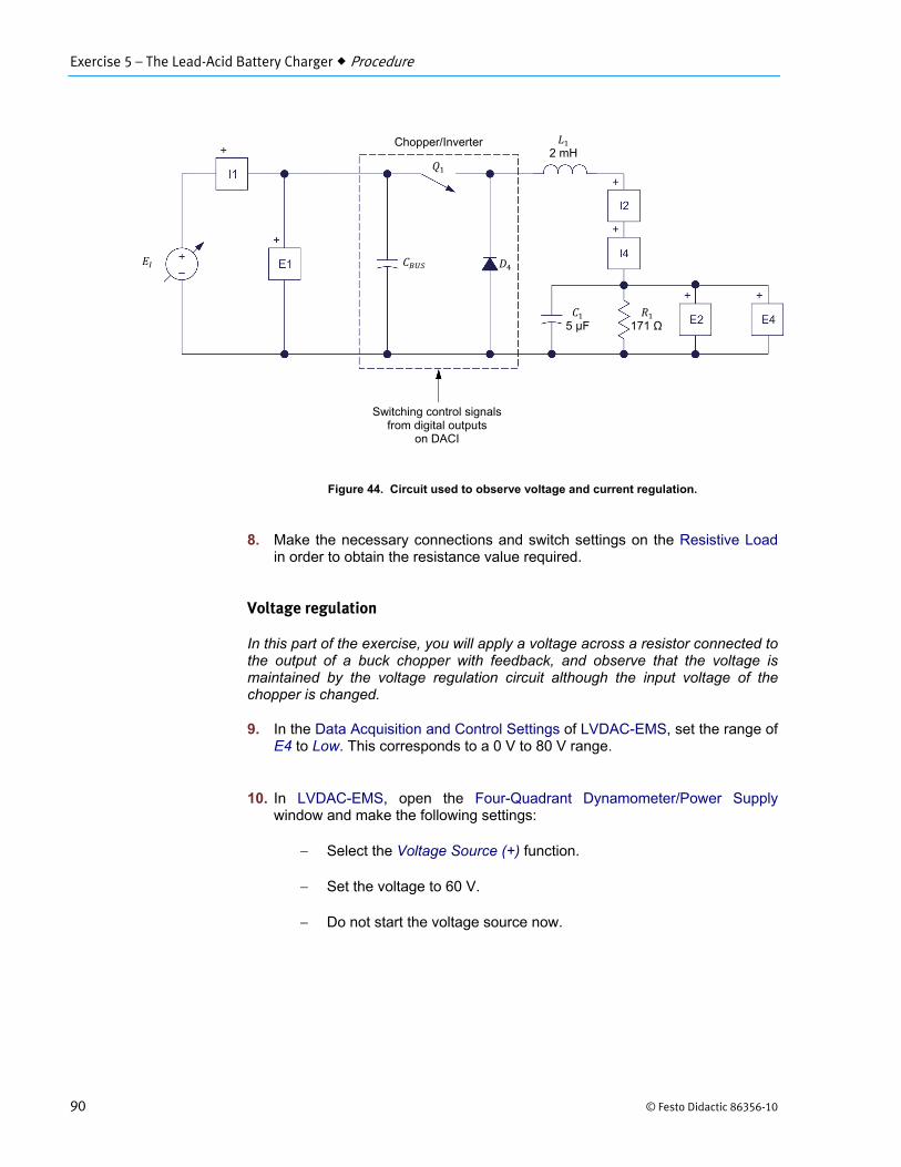
Figure 44. Circuit used to observe voltage and current regulation.
8. Make the necessary connections and switch settings on the Resistive Load in order to obtain the resistance value required.
Voltage regulation
In this part of the exercise, you will apply a voltage across a resistor connected to the output of a buck chopper with feedback, and observe that the voltage is maintained by the voltage regulation circuit although the input voltage of the chopper is changed.
9. In the Data Acquisition and Control Settings of LVDAC-EMS, set the range of E4 to Low. This corresponds to a 0 V to 80 V range.
10. In LVDAC-EMS, open the Four-Quadrant Dynamometer/Power Supply window and make the following settings:
Select the Voltage Source (+) function.
Set the voltage to 60 V.
Do not start the voltage source now.
Switching control signals from digital outputs
on DACI
2 mH
171 Ω
Chopper/Inverter
5 µF
Exercise 5 – The Lead-Acid Battery Charger Procedure
© Festo Didactic 86356-10 91
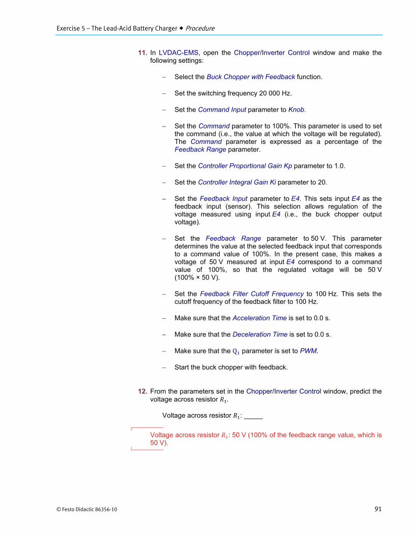
11. In LVDAC-EMS, open the Chopper/Inverter Control window and make the following settings:
Select the Buck Chopper with Feedback function.
Set the switching frequency 20 000 Hz.
Set the Command Input parameter to Knob.
Set the Command parameter to 100%. This parameter is used to set the command (i.e., the value at which the voltage will be regulated). The Command parameter is expressed as a percentage of the Feedback Range parameter.
Set the Controller Proportional Gain Kp parameter to 1.0.
Set the Controller Integral Gain Ki parameter to 20.
Set the Feedback Input parameter to E4. This sets input E4 as the feedback input (sensor). This selection allows regulation of the voltage measured using input E4 (i.e., the buck chopper output voltage).
Set the Feedback Range parameter to 50 V. This parameter determines the value at the selected feedback input that corresponds to a command value of 100%. In the present case, this makes a voltage of 50 V measured at input E4 correspond to a command value of 100%, so that the regulated voltage will be 50 V (100% × 50 V).
Set the Feedback Filter Cutoff Frequency to 100 Hz. This sets the cutoff frequency of the feedback filter to 100 Hz.
Make sure that the Acceleration Time is set to 0.0 s.
Make sure that the Deceleration Time is set to 0.0 s.
Make sure that the Q parameter is set to PWM.
Start the buck chopper with feedback.
12. From the parameters set in the Chopper/Inverter Control window, predict the voltage across resistor .
Voltage across resistor : _____
Voltage across resistor : 50 V (100% of the feedback range value, which is 50 V).
Exercise 5 – The Lead-Acid Battery Charger Procedure
92 © Festo Didactic 86356-10
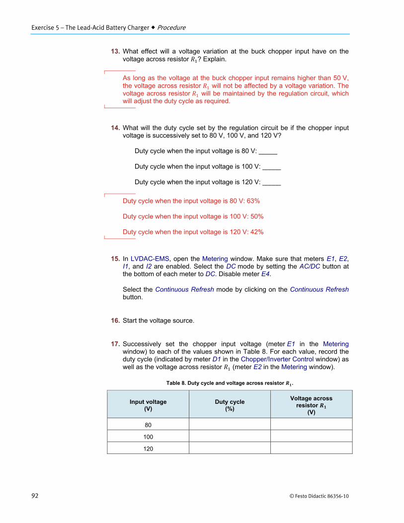
13. What effect will a voltage variation at the buck chopper input have on the voltage across resistor ? Explain.
As long as the voltage at the buck chopper input remains higher than 50 V, the voltage across resistor will not be affected by a voltage variation. The voltage across resistor will be maintained by the regulation circuit, which will adjust the duty cycle as required.
14. What will the duty cycle set by the regulation circuit be if the chopper input voltage is successively set to 80 V, 100 V, and 120 V?
Duty cycle when the input voltage is 80 V: _____
Duty cycle when the input voltage is 100 V: _____
Duty cycle when the input voltage is 120 V: _____
Duty cycle when the input voltage is 80 V: 63%
Duty cycle when the input voltage is 100 V: 50%
Duty cycle when the input voltage is 120 V: 42%
15. In LVDAC-EMS, open the Metering window. Make sure that meters E1, E2, I1, and I2 are enabled. Select the DC mode by setting the AC/DC button at the bottom of each meter to DC. Disable meter E4.
Select the Continuous Refresh mode by clicking on the Continuous Refresh button.
16. Start the voltage source.
17. Successively set the chopper input voltage (meter E1 in the Metering window) to each of the values shown in Table 8. For each value, record the duty cycle (indicated by meter D1 in the Chopper/Inverter Control window) as well as the voltage across resistor (meter E2 in the Metering window).
Table 8. Duty cycle and voltage across resistor .
Input voltage (V)
Duty cycle (%)
Voltage across resistor
(V)
80
100
120

Exercise 5 – The Lead-Acid Battery Charger Procedure
© Festo Didactic 86356-10 93
Table 8. Duty cycle and voltage across resistor R1.
Input voltage (V)
Duty cycle (%)
Voltage across resistor
(V)
80 63 50
100 50 50
120 42 50
18. Do your measurements confirm the predictions you made in step 14?
Yes No
Yes
19. What will the duty cycle and the voltage across resistor be if the input voltage were set to a value lower than the expected regulated voltage such as 40 V?
Duty cycle: _____
Voltage across resistor : _____
Duty cycle: 100%
Voltage across resistor : approximately 40 V
20. In the Four-Quadrant Dynamometer/Power Supply window, set the source voltage to 40 V and validate your predictions made in the previous step. Are your predictions confirmed?
Yes No
Yes
21. Stop the buck chopper and the voltage source.
Exercise 5 – The Lead-Acid Battery Charger Procedure
94 © Festo Didactic 86356-10
Current regulation
In this part of the exercise, you will make a current flow through a resistor connected to the output of a buck chopper with feedback, and observe that the current is maintained by the current regulation circuit although the resistor value is changed. You will also observe that the current remains constant even when the voltage at the buck chopper input is changed.
22. In the Data Acquisition and Control Settings window of LVDAC-EMS, make sure that the range of input E4 is set to Low.
Make sure that the range of input I4 is set to Low. This corresponds to a range of 0 A to 4 A.
23. Make sure that the connections and the switches on the Resistive Load are set to obtain 171 Ω as the resistance value for .
24. In the Four-Quadrant Dynamometer/Power Supply window, make the following setting:
Set the source voltage to 100 V.
25. In the Chopper/Inverter Control window, make the following settings:
Make sure that the Buck Chopper with Feedback function is selected.
Make sure that the Switching Frequency is set to 20 000 Hz.
Make sure that the Command Input parameter is set to Knob.
Make sure that the Command parameter is set to 100%. This sets the regulated output current to 100% of the Feedback Range parameter value.
Make sure that the Controller Proportional Gain Kp parameter is set to 1.0
Make sure that the Controller Integral Gain Ki parameter is set to 20.
Set the Feedback Input parameter to I4. This sets input I4 as the feedback input (sensor). This selection allows regulation of the current measured using input I4 (i.e., the buck chopper output current).
Set the Feedback Range parameter to 0.5 A. This makes a current of 0.5 A measured using input I4 correspond to a command value of 100%.
Make sure that the Feedback Filter Cutoff Frequency is set to 100 Hz.
Exercise 5 – The Lead-Acid Battery Charger Procedure
© Festo Didactic 86356-10 95
Make sure that the Acceleration Time is set to 0.0 s.
Make sure that the Deceleration Time is set to 0.0 s.
Make sure that the Q parameter is set to PWM.
Start the buck chopper with feedback.
26. From the parameters set in the Chopper/Inverter Control window, what will the current flowing through resistor be?
Current flowing through resistor : _____
Current flowing through resistor : 0.5 A (100% of 0.5 A)
27. What effect will reducing the value of resistor have on the current flowing through resistor ? Explain.
The current flowing through resistor will not vary. It will be maintained by the regulation circuit, which will adjust the duty cycle of the buck chopper as required.
28. What effect will increasing the voltage at the buck chopper input have on the current flowing through resistor ? Explain.
The current flowing through resistor will not vary. It will be maintained by the regulation circuit, which will adjust the duty cycle of the buck chopper as required.
29. In the Metering window of LVDAC-EMS, make sure that meters E1, E2, I1, and I2 are enabled, and that the DC mode is selected on each meter. Make sure that meter I4 is disabled.
Make sure that the Continuous Refresh mode is selected.

Exercise 5 – The Lead-Acid Battery Charger Procedure
96 © Festo Didactic 86356-10
30. Start the voltage source.
Successively set the resistance of resistor to each of the values shown in Table 9. For each value, record the duty cycle (meter D1 in the Chopper/Inverter Control window) as well as the current flowing through resistor (meter I2 in the Metering window).
Table 9. Duty cycle and current flowing through resistor .
Resistance (Ω)
Duty cycle (%)
Current flowing through resistor
(A)
171
86
57
Table 9. Duty cycle and current flowing through resistor R .
Resistance (Ω)
Duty cycle (%)
Current flowing through resistor
(A)
171 89.2 0.50
86 44.5 0.50
57 30.1 0.50
31. Do your measurements confirm your predictions made in step 26 and step 27?
Yes No
Yes
32. Increase the source voltage to 140 V. Record the duty cycle (meter D1 in the Chopper/Inverter Control window) as well as the current flowing through resistor (meter I2 in the Metering window).
Duty cycle: _____
Current flowing through resistor : _____
Duty cycle: 25.5%
Current flowing through resistor : approximately 0.5 A
Exercise 5 – The Lead-Acid Battery Charger Procedure
© Festo Didactic 86356-10 97
33. Do your measurements confirm your predictions made in step 28?
Yes No
Yes
34. What will the current flowing through resistor be if the Command parameter is set to 80%?
Current flowing through resistor : _____
Current flowing through resistor : 0.4 A (80% of the feedback range value, which is 0.5 A).
35. In the Chopper/Inverter Control window, set the Command parameter to 80% and validate your prediction made in the previous step. Is your prediction confirmed?
Yes No
Yes
36. Stop the buck chopper and the voltage source.
Partially discharging the batteries in the Lead-Acid Battery Pack
In this part of the exercise, you will partially discharge the batteries in the Lead-Acid Battery Pack to obtain the operating conditions required in the next part of the exercise.
37. Disconnect the Four-Quadrant Dynamometer/Power Supply from the current circuit by disconnecting the leads at the yellow and white terminals. The rest of the circuit will be used later in the exercise.
Connect the positive (red) terminal of the Lead-Acid Battery Pack to the Power Supply yellow terminal of the Four-Quadrant Dynamometer/Power Supply. Connect the negative (black) terminal of the Lead-Acid Battery Pack to the Power Supply white terminal of the Four-Quadrant Dynamometer/ Power Supply.
Exercise 5 – The Lead-Acid Battery Charger Procedure
98 © Festo Didactic 86356-10
38. In the Four-Quadrant Dynamometer/Power Supply window of LVDAC-EMS, make the following settings:
Set the Function parameter to Battery Discharger (Constant-Current Timed Discharge with Voltage Cutoff). When this function is selected, the Four-Quadrant Dynamometer/Power Supply operates as a negative current source whose operation is controlled by parameters associated with battery discharge.
Set the Discharge Current parameter to 4 A. This sets the discharge current of the battery discharger to 4 A.
Set the Discharge Duration parameter to 20 min. This sets the discharge duration to 30 minutes.
Set the Cutoff Voltage parameter to 40 V. This sets the minimum value (40 V) to which the battery voltage is allowed to decrease during discharge. This limits battery discharging to prevent damage to the batteries.
Start the Battery Discharger by setting the Status parameter to Started or by clicking on the Start/Stop button.
a During battery discharging, the time left is indicated at the bottom of the Four-Quadrant Dynamometer/Power Supply window. Once battery discharge is completed, the Battery Discharger automatically stops and the Status parameter is set to Stopped.
Once battery discharge is completed, disconnect the Power Supply terminals of the Four-Quadrant Dynamometer/Power Supply from the Lead-Acid Battery Pack and proceed with the next part of the exercise.
a Make sure that the Battery Discharger is stopped (i.e., make sure that the Status parameter is set to Stopped) before proceeding with the next part of the exercise.
The lead-acid battery charger
In this part of the exercise, you will perform the initial stage and the middle stage of the modified constant-voltage charging method (fast charging method) for lead-acid batteries, which are illustrated in Figure 41.
Initial stage of a lead-acid battery fast-charging – Constant current charge
In the initial stage of the battery charge, you will make the maximum recommended charge current flow through the Lead-Acid Battery Pack, and maintain this current using automatic regulation until the voltage measured across the terminals of the Lead-Acid Battery Pack reaches the gassing voltage (57.6 V).
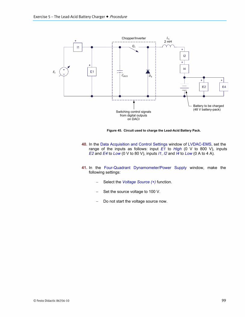
39. Set up the circuit shown in Figure 45. In this circuit, the voltage and current supplied to the Lead-Acid Battery Pack are measured using inputs E2 and I2. Inputs E4 and I4 are used by LVDAC-EMS as feedback inputs for regulation purposes.
Exercise 5 – The Lead-Acid Battery Charger Procedure
© Festo Didactic 86356-10 99
Figure 45. Circuit used to charge the Lead-Acid Battery Pack.
40. In the Data Acquisition and Control Settings window of LVDAC-EMS, set the range of the inputs as follows: input E1 to High (0 V to 800 V), inputs E2 and E4 to Low (0 V to 80 V), inputs I1, I2 and I4 to Low (0 A to 4 A).
41. In the Four-Quadrant Dynamometer/Power Supply window, make thefollowing settings:
Select the Voltage Source (+) function.
Set the source voltage to 100 V.
Do not start the voltage source now.
Switching control signals from digital outputs
on DACI
2 mH
Chopper/Inverter
Battery to be charged (48 V battery-pack)
Exercise 5 – The Lead-Acid Battery Charger Procedure
100 © Festo Didactic 86356-10
42. In the Chopper/Inverter Control window, make the following settings:
Make sure that the Buck Chopper with Feedback function is selected.
Make sure that the Switching Frequency parameter is set to 20 000 Hz.
Make sure that the Command Input parameter is set to Knob.
Make sure that the Command parameter is set to 100%. This sets the regulated output current to 100% of the Feedback Range parameter value.
Set the Controller Proportional Gain Kp parameter to 1.0.
Set the Controller Integral Gain Ki parameter to 20.0.
Set the Feedback Input parameter is set to I4. This sets input I4 as the feedback input. This selection allows regulation of the current measured using input I4 (i.e., the battery charging current).
Set the Feedback Range parameter to the maximum charge current value of the Lead-Acid Battery Pack. When this current is measured at input I4, it corresponds to a command value of 100%.
Make sure that the Feedback Filter Cutoff Frequency is set to 100 Hz.
Make sure that the Acceleration Time is set to 0.0 s.
Make sure that the Deceleration Time is set to 0.0 s.
Make sure that the Q parameter is set to PWM.
Start the buck chopper.
43. In the Metering window, make the following settings:
Make sure that meters E1, E2, I1, and I2 are enabled, and the DC mode is selected on each meter.
Make sure that meters E4 and I4 are disabled.
Make sure that the Continuous Refresh mode is selected.
44. Start the voltage source and immediately record the duty cycle displayed by the Duty Cycle meter in the Chopper/Inverter Control window.
Duty cycle: _____
Exercise 5 – The Lead-Acid Battery Charger Procedure
© Festo Didactic 86356-10 101
Duty cycle: approximately 57% (the current duty cycle depends on the state of charge of the Lead-Acid Battery Pack).
45. Record the voltage across the Lead-Acid Battery Pack (meter E2 in the Metering window).
Voltage across the Lead-Acid Battery Pack: _____
Voltage across the Lead-Acid Battery Pack: approximately 54 V
46. Record the current flowing through the Lead-Acid Battery Pack (meter I2 in the Metering window).
Current flowing through the Lead-Acid Battery Pack: _____
Current flowing through the Lead-Acid Battery Pack: 2.8 A
47. Does the current flowing through the Lead-Acid Battery Pack correspond to the parameters set in the Chopper/Inverter Control window?
Yes No
Yes
48. Observe the voltage across the Lead-Acid Battery Pack displayed by meter E2. The voltage should slowly increase. Once the voltage has reached the gassing voltage (57.6 V), record the duty cycle displayed by the Duty Cycle meter in the Chopper/Inverter Control window, and immediately stop the buck chopper with feedback. Permanent damage to the batteries in the Lead-Acid Battery Pack may occur if the voltage exceeds the gassing voltage significantly.
a The duty cycle value displayed is slightly higher than the theoretical value, due to voltage drops across transistor of the Chopper/Inverter and inductor .
Duty cycle: _____
Duty cycle: 61%
49. Compare the duty cycle measured at the beginning of the initial stage of battery charge (step 44) with the duty cycle measured at the end of the initial stage (step 48).
You should observe that the duty cycle has increased slightly to maintain the charge current constant despite the increase in the battery-pack voltage.
Exercise 5 – The Lead-Acid Battery Charger Procedure
102 © Festo Didactic 86356-10
Middle stage of a lead-acid battery fast-charging – Constant voltage charge at gassing voltage
In the middle stage of the battery charge, you will apply a voltage of 57 V (a little below the gassing voltage) across the Lead-Acid Battery Pack and maintain this voltage constant using automatic regulation until the current flowing through the battery pack has decreased to a value corresponding to 0.1 20.
50. Do not modify the settings in the Data Acquisition and Control Settings, Four-Quadrant Dynamometer/Power Supply window, and Metering window.
Make the following settings in the Chopper/Inverter Control window:
Set the Feedback Input parameter to E4. This sets input E4 as the feedback input, and allows regulation of the voltage measured using input E4 (i.e., the battery charging voltage).
Set the Feedback Range parameter to 57.0 V. This makes a voltage of 57.0 V measured at input E4 correspond to a command value of 100%.
Do not modify the settings of the other parameters in the Chopper/Inverter Control window.
Do not start the buck chopper with feedback for now.
51. From the settings made in LVDAC-EMS, determine the duty cycle which the regulation circuit will use at the beginning of the middle stage of the battery charge.
Duty cycle at the beginning of the middle stage of battery charge: _____
Duty cycle at the beginning of the middle stage of battery charge: approximately 57.6%
52. Start the buck chopper with feedback. Wait for the duty cycle displayed by the Duty Cycle meter in the Chopper/Inverter Control window to stabilize, then record the value.
Duty cycle: _____
Duty cycle: 61%
53. Does the measured duty cycle confirm your prediction in step 51?
Yes No
Yes
Exercise 5 – The Lead-Acid Battery Charger Conclusion
© Festo Didactic 86356-10 103
54. Record the voltage across the Lead-Acid Battery Pack (meter E2 in the Metering window).
Voltage across the Lead-Acid Battery Pack: _____
Voltage across the Lead-Acid Battery Pack: 57.6 V
55. Wait about 10 minutes for the battery charge to progress.
In the Four-Quadrant Dynamometer/Power Supply window, decrease the voltage to 80 V.
Does the voltage measured across the Lead-Acid Battery Pack decrease when the voltage is decreased? Explain why.
No. The voltage measured across the Lead-Acid Battery Pack is maintained by the voltage regulation loop of the buck chopper with feedback.
56. Observe the current flowing through the Lead-Acid Battery Pack displayed by meter I2. The current should decrease slowly. Once the current flowing through the battery pack has decreased to a value corresponding to a value of 0.1 , stop the voltage source and the buck chopper with feedback. This completes the middle stage of the battery charge.
Finishing stage of a lead-acid battery fast-charging – Constant voltage charge at float level
At this point, most of the energy supplied by the Lead-Acid Battery Pack during the discharge has been returned to the battery pack. To complete and maintain the battery charge, the voltage applied to the battery pack should be reduced to the float voltage value (52.2 V) and maintained at this value indefinitely. During the finishing stage, the current flowing through the battery pack decreases to a very low value. You do not have to perform this stage of battery charging.
57. Close LVDAC-EMS, turn off all equipment, and remove all leads and cables.
In this exercise, you were introduced to lead-acid batteries and learned how to charge a lead-acid battery using the modified constant-voltage charging method (also called fast charging method). You were also introduced to the buck chopper with feedback, an automatic regulation system which uses a voltage or current sensor to return a feedback signal to a controller in order to maintain the voltage or current equal to the command value. You implemented a lead-acid battery charger using a buck chopper with feedback and charged a 48 V lead-acid battery pack using the fast charging method.
CONCLUSION
Exercise 5 – The Lead-Acid Battery Charger Review Questions
104 © Festo Didactic 86356-10
1. What is the basic electrochemical unit that produces electric energy in a battery (fast charging method)?
The cell.
2. Briefly describe the three stages of the modified constant-voltage charging method (fast charging method).
In the initial stage of the modified constant-voltage charging method, battery charging starts with a constant current set to the maximum charging current recommended by the battery manufacturer. The current is maintained at this value until a certain voltage is reached, usually the gassing voltage. In the middle stage, battery charging continues with a constant-voltage just equal to or slightly below the gassing voltage until the current flowing through the battery, decreases to a rate of one tenth of the battery capacity (0.1 20). In the finishing stage of charge, the battery voltage is reduced to the float voltage to complete and maintain the battery charge.
3. Explain how the voltage at the output of a buck chopper can be maintained to a fixed value despite changes in the load current or the input voltage.
The voltage at the output of a buck chopper is continuously monitored by a sensor. The sensor transmits a feedback signal to a controller, which automatically sets the duty cycle of the switching control signal to the value required to maintain the buck chopper output voltage constant.
4. How does the duty cycle of the switching control signal vary when the voltage at the input of a buck chopper with feedback is doubled?
The duty cycle halves.
5. Briefly describe the gassing voltage and the float voltage.
The gassing voltage corresponds to the voltage at which the lead-acid battery starts to produce gases due to electrolysis of the water contained in the electrolyte of the battery. The float voltage corresponds to the constant voltage that is applied to a battery to maintain it in a fully charged condition.
REVIEW QUESTIONS

© Festo Didactic 86356-10 165
Bibliography
Jackson, Herbert W, Introduction to Electric Circuits, 8th ed. Oxford: Oxford University Press, 2008, ISBN 0-19-542310-0
Linden, David, and Reddy, Thomas B., Handbook of Batteries, 3rd ed. New York: McGraw-Hill, 2002, ISBN 0-07-135978-8.
Wildi, Theodore, Electrical Machines, Drives, and Power Systems, 6th ed. New Jersey: Pearson Prentice Hall, 2006, ISBN 0-13-177691-6