Embed Size (px)
Citation preview
DC Readout Experiment at the Caltech 40m
Prototype Interferometer
RL Ward1, R Adhikari1, B Abbott1, R Abbott1, D Barron5, R
Bork1, T Fricke4, V Frolov2, J Heefner1, A Ivanov1, O
Miyakawa1, K McKenzie3, B Slagmolen3, M Smith1, R Taylor1,
S Vass1, S Waldman1, A Weinstein1
1 LIGO Caltech 18-34, Pasadena CA 91125, USA2 LIGO Livingston Observatory, Livingston, Louisiana, USA3 Australian National University, Canberra, NSW, AUSTRALIA4 University of Rochester, Rochester, NY, USA5 University of Illinois at Urbana-Champaign, Urbana, Illinois, USA
E-mail: [email protected]
Abstract. The Laser Interferometer Gravitational Wave Observatory (LIGO)operates a 40 meter prototype interferometer on the Caltech campus. The primarymission of the prototype is to serve as an experimental testbed for upgrades tothe LIGO interferometers and for gaining experience with advanced interferometrictechniques, including detuned resonant sideband extraction (i.e., signal recycling)and DC Readout (optical homodyne detection). The former technique will beemployed in Advanced LIGO, and the latter in both Enhanced and Advanced LIGO.Using DC Readout for gravitational wave signal extraction has several technicaladvantages, including reduced laser and oscillator noise couplings as well as reducedshot noise, when compared to the traditional RF readout technique (optical heterodynedetection) currently in use in large scale ground based interferometric gravitationalwave detectors. A DC Readout system requires the use of an optical filter cavityat the interferometer’s signal readout port, and the associated controls and optics toensure that the filter cavity is optimally coupled to the interferometer. The Caltech40m Laboratory is currently prototyping a DC Readout system for a fully suspendedinterferometric gravitational wave detector. We present the results of measurementsto characterize noise couplings in RF and DC Readout using this system.
PACS numbers: 04.80.Nn
DC Readout Experiment at the Caltech 40m Prototype Interferometer 2
1. Introduction
There is now underway a worldwide effort to detect gravitational waves, ripples in
spacetime which carry information about astrophysical events. Detection of these waves
will not only provide greater confirmation of Einstein’s theory of general relativity, but
it will open a new window on the universe by ushering in an era of gravitational wave
astronomy. The currently running kilometer-scale gravitational wave detectors (LIGO
[1], VIRGO [2], GEO[3], and TAMA[4]) have demonstrated an unprecedented sensitivity
to strain (the squeezing and stretching of space which is the local effect of a gravitational
wave), reaching ≈ 10−22 at 100Hz in the case of LIGO. Achieving such a sensitivity has
been the result of significant effort to reduce, mitigate, and avoid, the multitudinous
sources of noise which can mask the effect of gravitational waves. Future detectors,
including Enhanced LIGO[5] (online in 2009) and Advanced LIGO[6] (online in 2014)
plan to use a technique known as DC Readout which is expected to provide technical
advantages in avoiding several sources of noise.
We have undertaken an experiment to characterize a DC Readout scheme using the
Caltech 40m prototype interferometric gravitational wave detector, which is used to test
systems integration and advanced interferometric techniques for future LIGO detectors.
It is a fully instrumented prototype, with sensing and control systems (including optical
and electronic hardware) as similar as possible to those used in LIGO. It is equipped
with a LIGO-style pre-stabilized laser (PSL)[8], the core optics of the interferometer
are suspended from single pendulums, and most of the many control loops (≈ 65)
are implemented in a highly flexible and integrated digital system[9]. This digital
control system allows us to operate the interferometer in multiple configurations (i.e.,
RF and DC Readout) with a minimal switching overhead, and provides the ability to
measure multiple transfer functions (e.g., noise couplings) simultaneously. We have
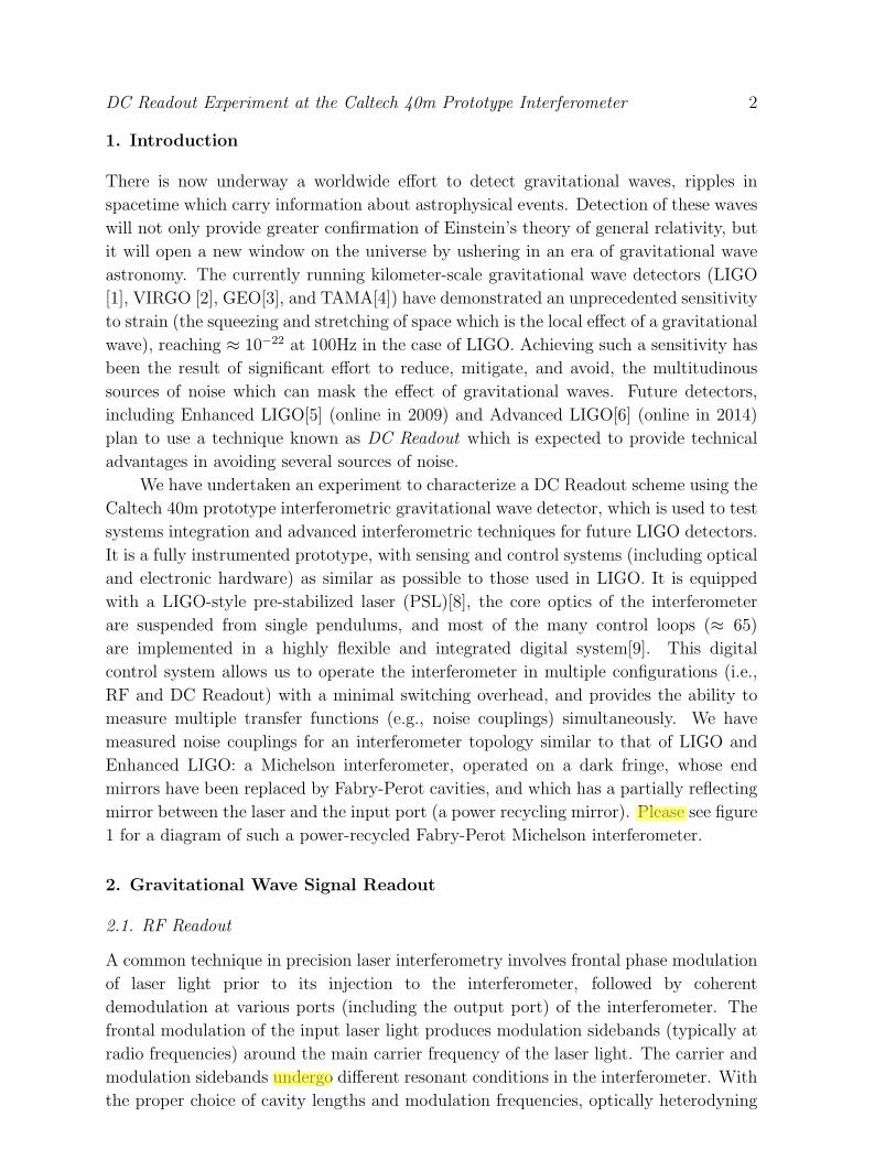
measured noise couplings for an interferometer topology similar to that of LIGO and
Enhanced LIGO: a Michelson interferometer, operated on a dark fringe, whose end
mirrors have been replaced by Fabry-Perot cavities, and which has a partially reflecting
mirror between the laser and the input port (a power recycling mirror). Please see figure
1 for a diagram of such a power-recycled Fabry-Perot Michelson interferometer.
2. Gravitational Wave Signal Readout
2.1. RF Readout
A common technique in precision laser interferometry involves frontal phase modulation
of laser light prior to its injection to the interferometer, followed by coherent
demodulation at various ports (including the output port) of the interferometer. The
frontal modulation of the input laser light produces modulation sidebands (typically at
radio frequencies) around the main carrier frequency of the laser light. The carrier and
modulation sidebands undergo different resonant conditions in the interferometer. With
the proper choice of cavity lengths and modulation frequencies, optically heterodyning
DC Readout Experiment at the Caltech 40m Prototype Interferometer 3
Figure 1. Schematic representation of the interferometer configuration. The 40minterferometer is currently configured as a detuned resonant sideband extractioninterferometer similar to the projected configuration for Advanced LIGO, and is thusequipped with a signal recycling mirror (SRM) at the asymmetric port. For the resultsin this paper, we purposely mis-aligned the SRM in such a way that it behaves as alarge loss without otherwise affecting the dynamics of the interferometer; the resultsthus apply to power-recycled Fabry-Perot Michelson interferometers, such as LIGOand Enhanced LIGO.
these light fields permits the extraction of non-degenerate signals containing information
about the state of an interferometer, in particular the various length degrees of freedom
[10]. In this paper, the term RF Readout will refer to the use of this technique for
sensing the differntial arm (DARM) degree of freedom, which is the degree of freedom
sensitive to gravitational wave strain. For audio frequency gravitational waves incident
on the interferometer, the gravitational wave signal takes the form of audio sidebands
around the laser carrier light at the output port. At the photodetector, these sidebands
then beat against the RF modulation sidebands, which serve as a local oscillator.
The gravitational wave signal sidebands are then present in the photocurrent as audio
frequency sidebands around the RF modulation frequency. This RF photocurrent is
electronically mixed down to baseband before being acquired digitally. A more detailed
discussion of this control scheme can be found in [11], and an analysis of the effects of
laser and RF oscillator noise in power-recycled Fabry-Perot Michelson interferometers
in [12].
2.2. DC Readout
A complementary technique for gravitational wave signal readout is to arrange the optics
of the interferometer in such a way that the power present at the output port of the
interferometer is directly proportional to gravitational wave strain. This technique is
DC Readout Experiment at the Caltech 40m Prototype Interferometer 4
a form of optical homodyne detection known as DC Readout, in which laser carrier
light that has circulated in the interferometer serves as a local oscillator, rather than
RF modulation sidebands. In the case of kilometer-scale gravitational wave detectors,
DC Readout can provide a significant advantage in terms of reducing susceptibility
to two sources of technical noise: laser noise and RF oscillator noise. The reason for
this advantage is the different behaviour of the RF modulation sidebands and the laser
carrier light in the interferometer: the carrier light enters the kilometer scale arm cavities
and thus undergoes a stage of passive low-pass filtering by the interferometer, while
the modulation sidebands do not experience any significant filtering[13]. Any noise on
the modulation sidebands (whether from the laser itself or the modulator) thus passes
essentially unchanged to the detection port of the interferometer, where it can pollute
the signal when the modulation sidebands are used as a local oscillator. Additionally,
as both the local oscillator and the signal are coming from the same place (i.e., the arm
cavities of the interferometer), they are in the same transverse spatial mode and thus
have perfect spatial overlap at the photodetector. In its simplest form, DC Readout
involves intentionally causing a small offset in the DARM degree of freedom, which
slightly spoils the destructive interference at the output port of the interferometer,
allowing a small amount of light to leak out for use as a local oscillator. For small
deviations from the controlled setpoint of DARM, the power at the output port is
linearly proportional to deviations from resonance, and is thus sensitive to tiny changes
in the lengths of the arm cavities. An analytical comparison of susceptibility to laser
noise in RF/DC Readout schemes was carried out in [14]
3. DC Readout Experiment
3.1. Methods and Equipment
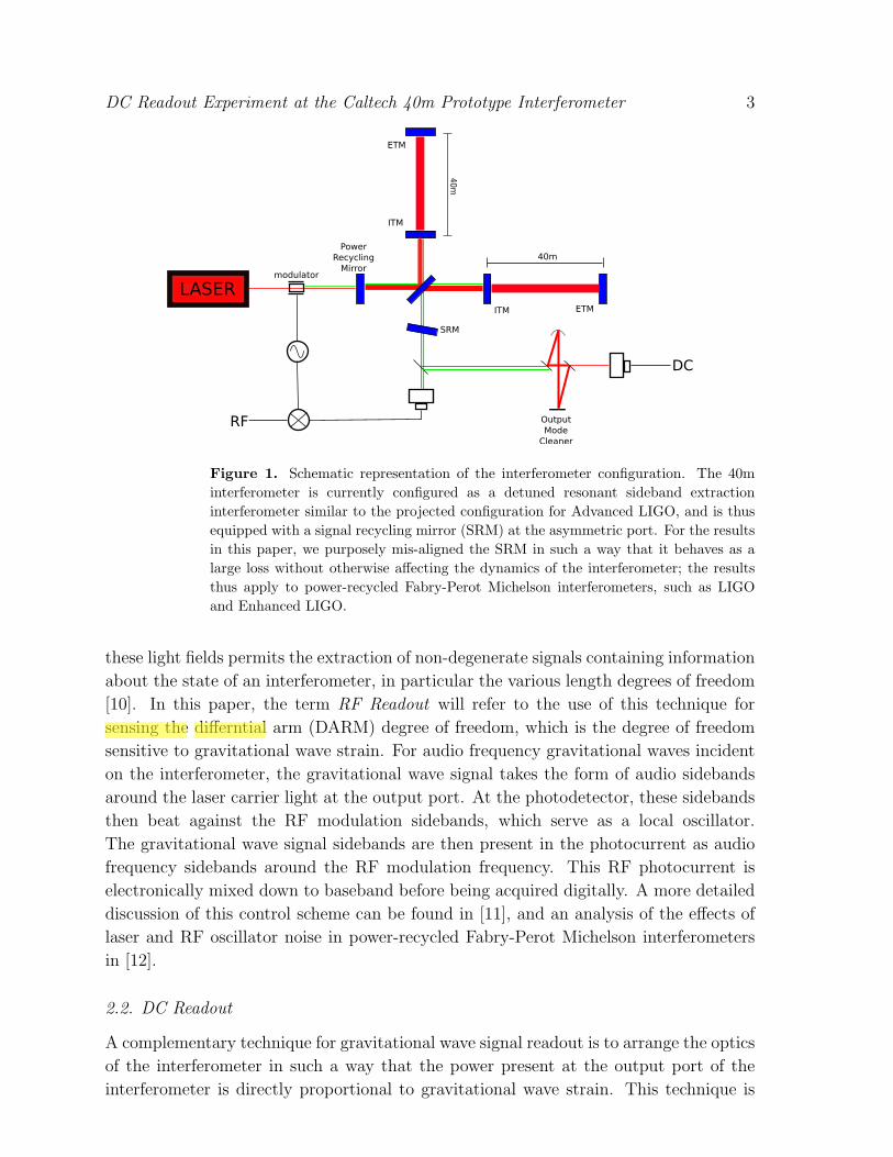
For the DC Readout chain (figure 2), we use a monolithic, four-mirror bowtie shaped
travelling wave cavity as a mode cleaning cavity for the output port of the interferometer.
This output mode cleaner (OMC) serves to reject the RF modulation sidebands and
’junk light’ exiting the dark port of the interferometer, both of which contribute noise
but not signal. The output mode cleaner is kept on resonance with the interferometer
carrier light via PZT length actuation; the OMC length is dithered at a frequency
outside of the gravitational wave band for sensing this length degree of freedom. The
angular degrees of freedom of the OMC (beam tilt and displacement relative to the
mode of interferometer) are controlled by a pair of PZT actuated steering mirrors
situated between the output port of the interferometer and the OMC; sensing of these
degrees of freedom is also via dithering. Limitations on the actuators require that this
dithering remain in the detection band. There is a fixed, adjustable mode-matching
telescope between the interferometer and the OMC. Light transmitted through the
OMC is directed to a pair of photodetectors; the photodetectors are each wired in series
with transimpedance resistors, and the voltage across the resistors is amplified and
DC Readout Experiment at the Caltech 40m Prototype Interferometer 5
whitened by a low-noise circuit. All of the equipment described above is enclosed in the
same vacuum envelope as the main interferometer, and mounted on optical tables atop
seismic isolation stacks (see figure 2. The amplified photodetector signal is acquired
digitally for use in the digital control system and measurement of transfer functions.
The DC Readout sensing chain receives 60% of the light exiting the dark port of the
interferometer; the remaining 40% is sent to a traditional RF Readout sensing chain to be
used for lock acquisition, signal extraction of auxilliary degrees of freedom, and DC/RF
comparisons. The digital control system used for the DC Readout chain (consisting
primarily of OMC length and alignment controls) is of the type projected for use in
Advanced LIGO. The successful integration of this system with the rest of our LIGO-
style electronic infrastructure represents a significant milestone for Enhanced LIGO,
which will employ a similar mixture.
Figure 2. The DC Readout sensing chain. Visible on the table are one PZT steeringmirror, the mode matching telescope, the output mode cleaner, the DC photodetectorsand other optics.
3.2. Results and Modeling
We model the interferometer response using a frequency-domain interferometer
simulation tool[15] which includes the effects of radiation pressure, and compare the
results from this model for laser frequency and intensity noise with the measured
transfer functions from the interferometer in both a DC Readout configuration and
an RF Readout configuration. The design parameters for the input test mass and
power recycling mirror reflectivities, which most affect the interferometer dynamics, are
TITM = 0.005 and TPRM = 0.07. For modeling laser noise couplings, of greatest interest
are the mismatches between the two arm cavities. The round trip loss mismatch has
been independently measured to be 35ppm (from an average of 160ppm) and the ITM
DC Readout Experiment at the Caltech 40m Prototype Interferometer 6
transmissivity mismatch been determined to be 10% by a fit to the data. We also present
the results of measurements of oscillator phase and amplitude noise couplings, but we
do not currently have modeling tools for these.
3.2.1. Laser Frequency Noise The 40m interferometer is equipped with a Common
Mode Servo, which alters the frequency of the primary laser light in order to match
the length of the common mode arm length (CARM). The coupling of laser frequency
noise to the gravitational wave signal is minimized by the designed symmetries of the
interferometer; however, imbalances in the two arms of the interferometer can allow
laser noise to leak through from the input port to the output port. The noise coupling
was measured in this case by injecting a signal at the error point of the Common Mode
Servo, inducing a frequency mismatch between the laser light and the CARM degree of
freedom; the signal was then coherently demodulated in the gravitational wave channel
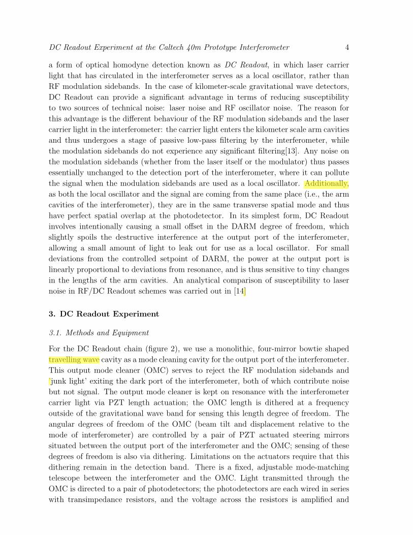
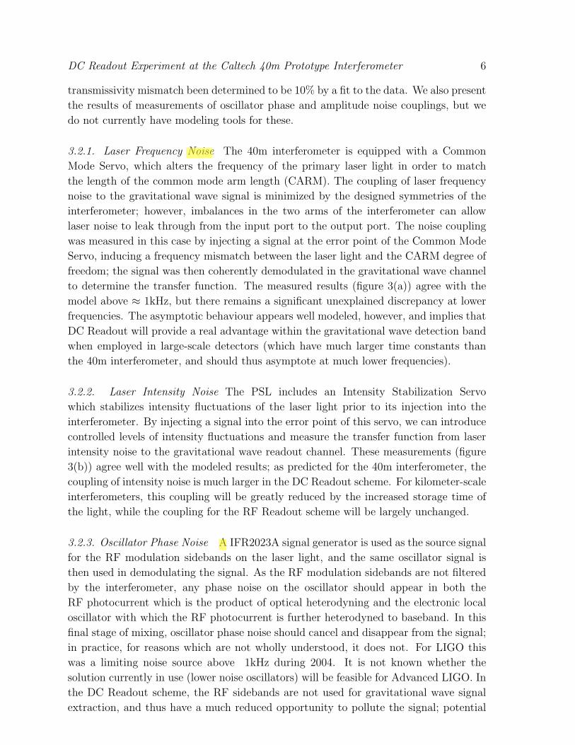
to determine the transfer function. The measured results (figure 3(a)) agree with the
model above ≈ 1kHz, but there remains a significant unexplained discrepancy at lower
frequencies. The asymptotic behaviour appears well modeled, however, and implies that
DC Readout will provide a real advantage within the gravitational wave detection band
when employed in large-scale detectors (which have much larger time constants than
the 40m interferometer, and should thus asymptote at much lower frequencies).
3.2.2. Laser Intensity Noise The PSL includes an Intensity Stabilization Servo
which stabilizes intensity fluctuations of the laser light prior to its injection into the
interferometer. By injecting a signal into the error point of this servo, we can introduce
controlled levels of intensity fluctuations and measure the transfer function from laser
intensity noise to the gravitational wave readout channel. These measurements (figure
3(b)) agree well with the modeled results; as predicted for the 40m interferometer, the
coupling of intensity noise is much larger in the DC Readout scheme. For kilometer-scale
interferometers, this coupling will be greatly reduced by the increased storage time of
the light, while the coupling for the RF Readout scheme will be largely unchanged.
3.2.3. Oscillator Phase Noise A IFR2023A signal generator is used as the source signal
for the RF modulation sidebands on the laser light, and the same oscillator signal is
then used in demodulating the signal. As the RF modulation sidebands are not filtered
by the interferometer, any phase noise on the oscillator should appear in both the
RF photocurrent which is the product of optical heterodyning and the electronic local
oscillator with which the RF photocurrent is further heterodyned to baseband. In this
final stage of mixing, oscillator phase noise should cancel and disappear from the signal;
in practice, for reasons which are not wholly understood, it does not. For LIGO this
was a limiting noise source above 1kHz during 2004. It is not known whether the
solution currently in use (lower noise oscillators) will be feasible for Advanced LIGO. In
the DC Readout scheme, the RF sidebands are not used for gravitational wave signal
extraction, and thus have a much reduced opportunity to pollute the signal; potential
DC Readout Experiment at the Caltech 40m Prototype Interferometer 7
102 103 10410−16
10−15
10−14
10−13
f (Hz)
m/H
z
DC ReadoutRF ReadoutDC ModelRF Model
(a) Frequency noise coupling
102 103 10410−13
10−12
10−11
f (Hz)
m/R
IN
DC ReadoutRF ReadoutDC ModelRF Model
(b) Intensity noise coupling
Figure 3. Laser frequency and intensity noise coupling for the 40m Fabry-PerotMichelson interferometer with power recycling. The dots indicate experimental datawhile the dashed lines indicate the results of numerical simulation.
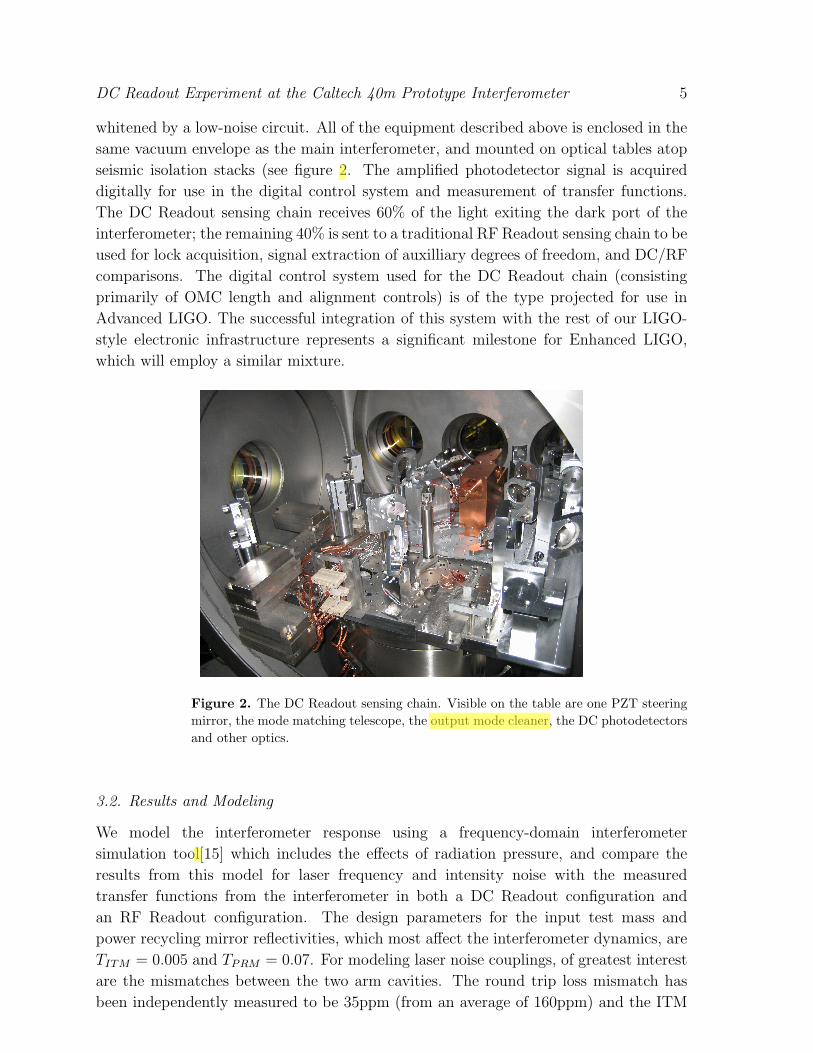
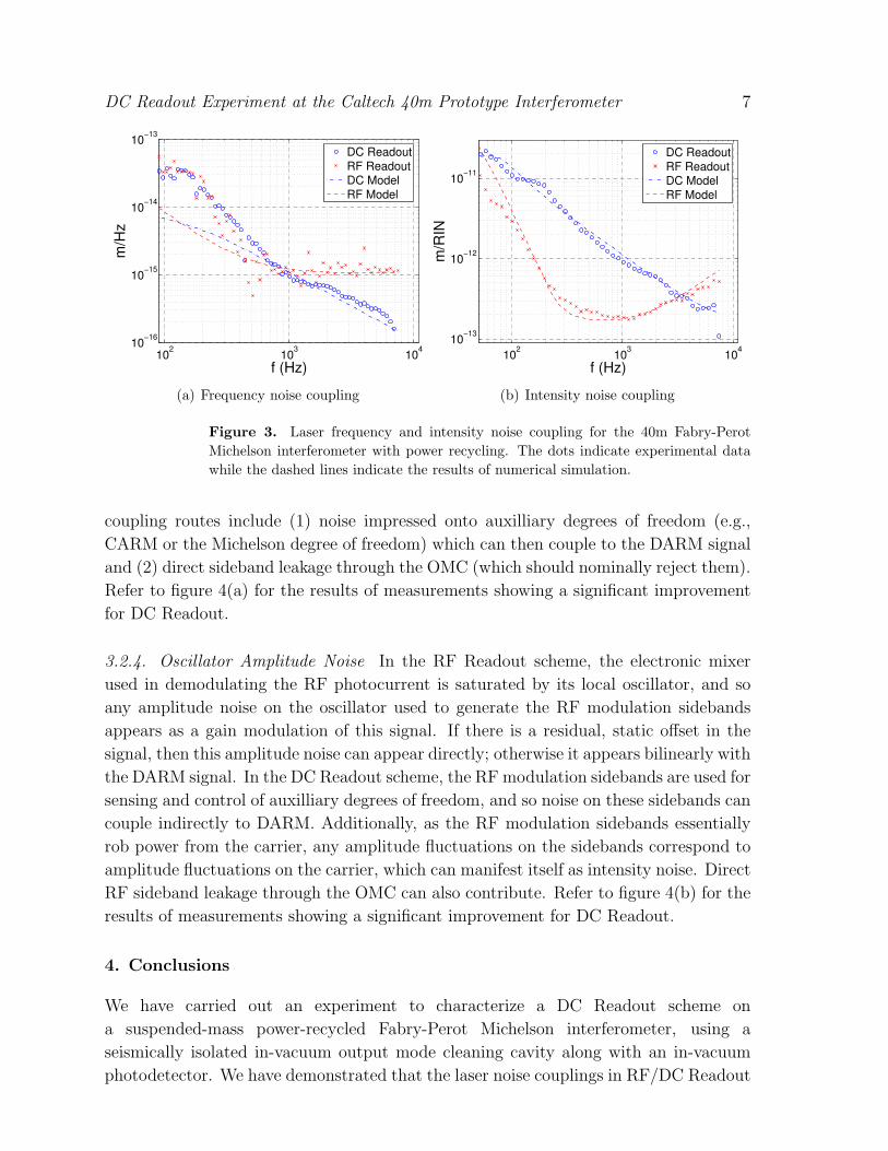
coupling routes include (1) noise impressed onto auxilliary degrees of freedom (e.g.,
CARM or the Michelson degree of freedom) which can then couple to the DARM signal
and (2) direct sideband leakage through the OMC (which should nominally reject them).
Refer to figure 4(a) for the results of measurements showing a significant improvement
for DC Readout.
3.2.4. Oscillator Amplitude Noise In the RF Readout scheme, the electronic mixer
used in demodulating the RF photocurrent is saturated by its local oscillator, and so
any amplitude noise on the oscillator used to generate the RF modulation sidebands
appears as a gain modulation of this signal. If there is a residual, static offset in the
signal, then this amplitude noise can appear directly; otherwise it appears bilinearly with
the DARM signal. In the DC Readout scheme, the RF modulation sidebands are used for
sensing and control of auxilliary degrees of freedom, and so noise on these sidebands can
couple indirectly to DARM. Additionally, as the RF modulation sidebands essentially
rob power from the carrier, any amplitude fluctuations on the sidebands correspond to
amplitude fluctuations on the carrier, which can manifest itself as intensity noise. Direct
RF sideband leakage through the OMC can also contribute. Refer to figure 4(b) for the
results of measurements showing a significant improvement for DC Readout.
4. Conclusions
We have carried out an experiment to characterize a DC Readout scheme on
a suspended-mass power-recycled Fabry-Perot Michelson interferometer, using a
seismically isolated in-vacuum output mode cleaning cavity along with an in-vacuum
photodetector. We have demonstrated that the laser noise couplings in RF/DC Readout
DC Readout Experiment at the Caltech 40m Prototype Interferometer 8
102 103 104
10−16
10−15
10−14
10−13
10−12
f (Hz)
m/ra
d
DC ReadoutRF Readout
(a) Oscillator phase noise coupling
102 103 10410−14
10−13
10−12
10−11
f (Hz)
m/R
IN
DC ReadoutRF Readout
(b) Oscillator amplitude noise coupling
Figure 4. Oscillator phase and amplitude noise coupling for a Fabry-Perot Michelsoninterferometer with power recycling. The dots indicate experimental data.
schemes behave as expected and that oscillator noise couplings are significantly reduced
in the DC Readout scheme. These results represent an important test of the DC Readout
system planned for Enhanced LIGO and Advanced LIGO.
Acknowledgments
LIGO was constructed by the California Institute of Technology and Massachusetts
Institute of Technology with funding from the National Science Foundation and operates
under cooperative agreement PHY-0107417. This paper has LIGO Document Number
LIGO-P070125-00-Z.
References
[1] Abramovici A et al. 1992 , Science 256, 325-333.[2] Acernese F et al, 2002 Class. Quantum, Grav. 19, 1421.[3] Willke Bet al, 2002 Class. Quantum, Grav. 19, 1377.[4] Ando M and the TAMA Collaboration 2002, Class. Quantum, Grav. 19, 1409.[5] Adhikari R, Fritschel P and Waldman S 2006 LIGO Report No. LIGO-T060156-01.[6] Fritschel P 2003, Proc. SPIE-Int. Soc. Opt. Eng. 4856, 282.[7] Fritschel P 2003, LIGO Report No. LIGO-G030460-00 R.[8] Savage R, King P and Seel S1998, Laser Phys 8, 679-685.[9] Bork R, Abbott R, Barker D and Heefner J 2001, Proceedings ICALEPCS 19-23.
[10] Regehr M 1994, Ph.D. Thesis, California Institute of Technology, LIGO Report No. LIGO-P940002-00-I.
[11] Fritschel P et al. 2001, Appl. Opt. 40, 4988-4998.[12] Camp J et al. 2000, J. Opt. Soc. Am. A 17, 120.[13] Sigg D and the ISC group 1997, LIGO Report No. LIGO-T970084-00 D.[14] Somiya K 2006 et al. Phys. Rev. D 73, 122005.[15] Evans M 2007, LIGO Report No. LIGO-T070260-00.