Embed Size (px)
DESCRIPTION
DC/DC Converters 101. Understanding Power Supply Basics and Terminology. Agenda. Lecture Overview Linear Regulators Switching Power Supplies Topologies Synchronous vs. Non-synchronous Controller vs. Converter Selecting the Best Power Solution. Why should I care about power?. - PowerPoint PPT Presentation
Citation preview
Brian King
DC/DC Converters 101
Understanding Power Supply Basics and Terminology
Agenda• Lecture
• Overview
• Linear Regulators
• Switching Power Supplies
• Topologies
• Synchronous vs. Non-synchronous
• Controller vs. Converter
• Selecting the Best Power Solution
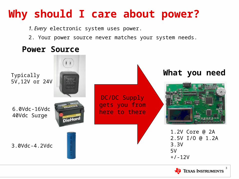
Why should I care about power?
3
1. Every electronic system uses power.
2. Your power source never matches your system needs.
3.0Vdc-4.2Vdc
Power Source
What you need
1.2V Core @ 2A2.5V I/O @ 1.2A3.3V5V+/-12V
DC/DC Supplygets you fromhere to there6.0Vdc-16Vdc
40Vdc Surge
Typically5V,12V or 24V
Linear Regulators vs. Switching Supplies
4
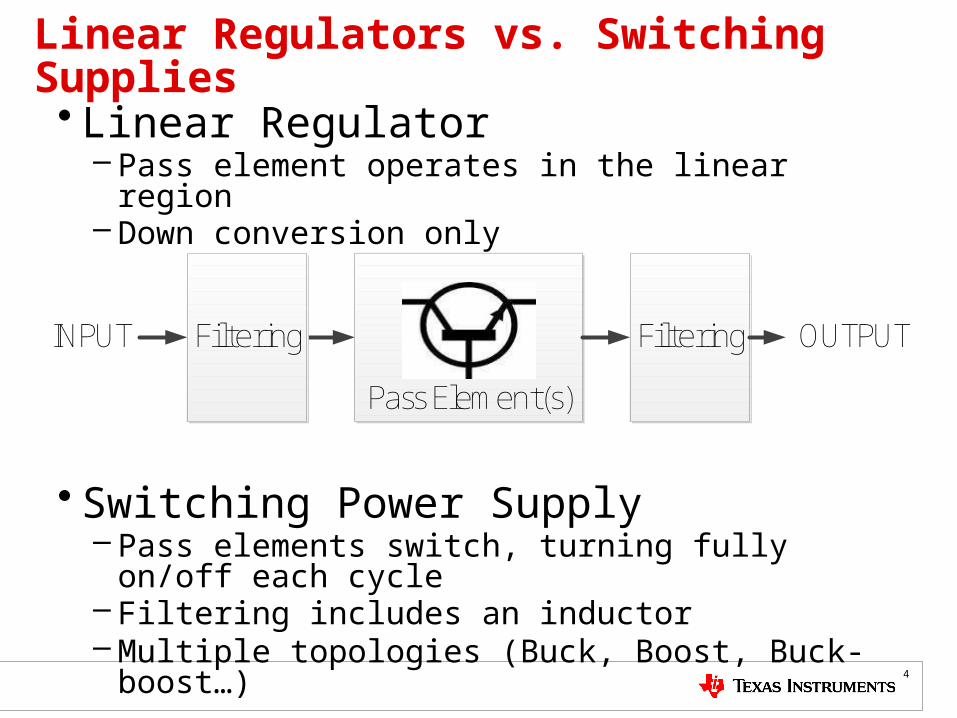
• Linear Regulator– Pass element operates in the linear region– Down conversion only
• Switching Power Supply – Pass elements switch, turning fully on/off each cycle– Filtering includes an inductor– Multiple topologies (Buck, Boost, Buck-boost…)
Pass Element(s)
Filtering FilteringINPUT OUTPUT
Linear Regulator
5
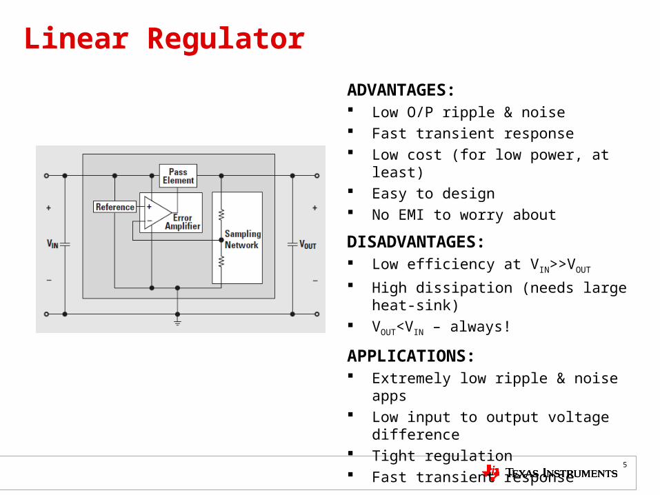
ADVANTAGES: Low O/P ripple & noise Fast transient response Low cost (for low power, at least) Easy to design No EMI to worry about
DISADVANTAGES: Low efficiency at VIN>>VOUT
High dissipation (needs large heat-sink) VOUT<VIN – always!
APPLICATIONS: Extremely low ripple & noise apps Low input to output voltage difference Tight regulation Fast transient response
Dropout Voltage
6
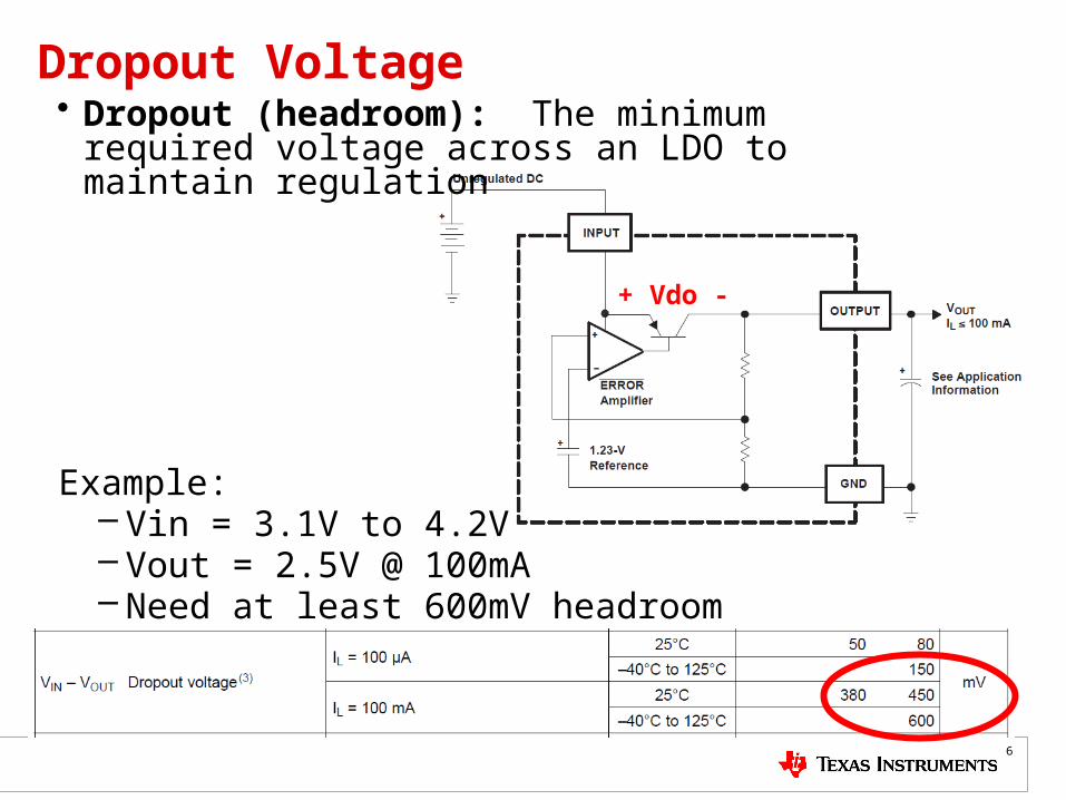
• Dropout (headroom): The minimum required voltage across an LDO to maintain regulation
Example:– Vin = 3.1V to 4.2V– Vout = 2.5V @ 100mA– Need at least 600mV headroom
+ Vdo -
Linear Regulator vs LDO
7
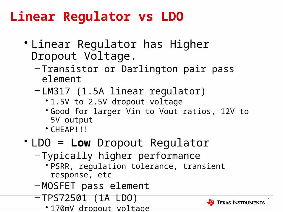
• Linear Regulator has Higher Dropout Voltage.– Transistor or Darlington pair pass element– LM317 (1.5A linear regulator)
• 1.5V to 2.5V dropout voltage• Good for larger Vin to Vout ratios, 12V to 5V output• CHEAP!!!
• LDO = Low Dropout Regulator– Typically higher performance
• PSRR, regulation tolerance, transient response, etc– MOSFET pass element– TPS72501 (1A LDO)
• 170mV dropout voltage• Good for 3.3V to 3.0V output
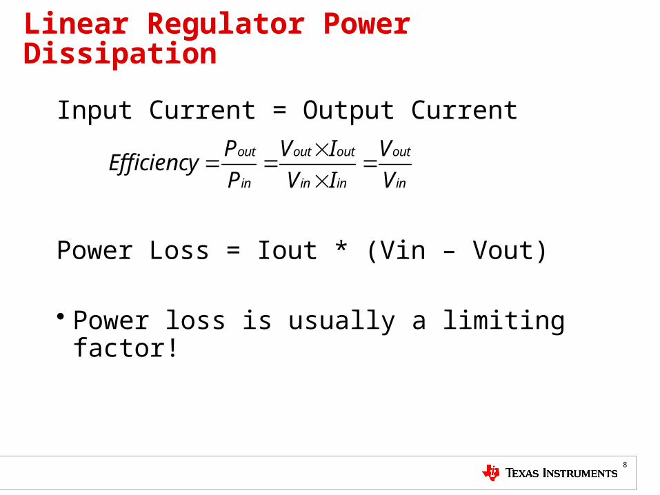
Input Current = Output Current
Power Loss = Iout * (Vin – Vout)
• Power loss is usually a limiting factor!
Linear Regulator Power Dissipation
8
in
out
inin
outout
in
out
V
V
IV
IV
P
PEfficiency
Linear Regulator vs Switcher
9
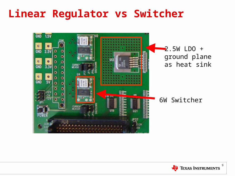
2.5W LDO + ground plane as heat sink
6W Switcher
Switcher
10
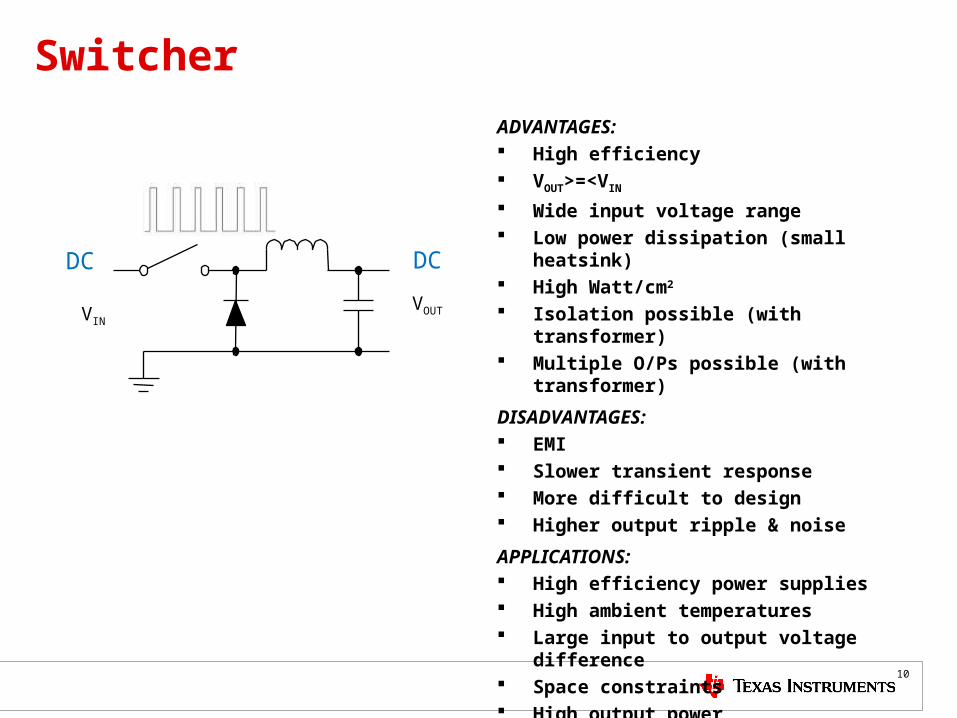
ADVANTAGES: High efficiency VOUT>=<VIN
Wide input voltage range Low power dissipation (small heatsink) High Watt/cm2
Isolation possible (with transformer) Multiple O/Ps possible (with transformer)
DISADVANTAGES: EMI Slower transient response More difficult to design Higher output ripple & noise
APPLICATIONS: High efficiency power supplies High ambient temperatures Large input to output voltage difference Space constraints High output power
VIN
VOUT
DC DC
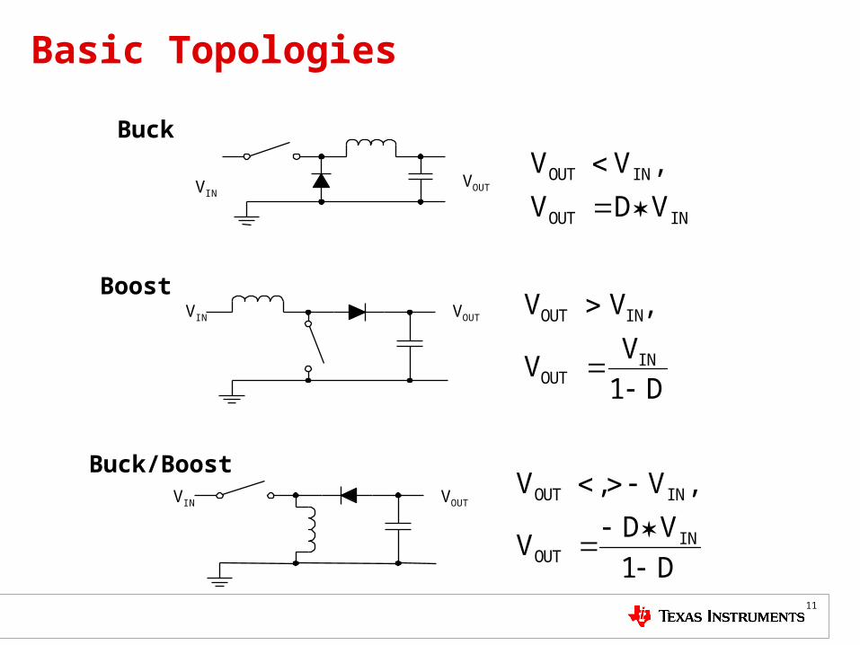
Basic Topologies
11
INOUT
INOUT
VDV
,VV
D1
VDV
,V,V
INOUT
INOUT
Buck
VINVOUT
VIN VOUT
D1
VV
,VV
INOUT
INOUT
Boost
Buck/Boost
VIN VOUT
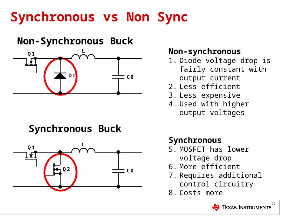
Synchronous vs Non Sync
12
Non-Synchronous Buck
Synchronous Buck
Non-synchronous1. Diode voltage drop is fairly
constant with output current2. Less efficient3. Less expensive4. Used with higher output
voltages
Synchronous5. MOSFET has lower voltage
drop6. More efficient7. Requires additional control
circuitry8. Costs more
Q1L
C0D1
Q1L
C0Q2
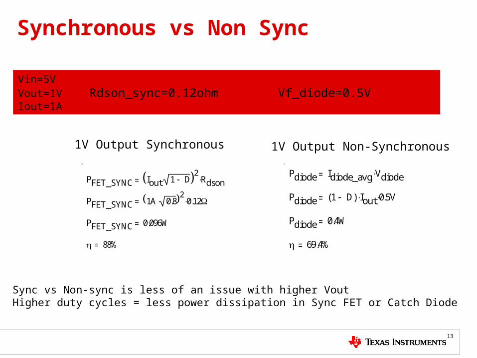
Synchronous vs Non Sync
13
1V Output Non-Synchronous1V Output Synchronous
Vin=5VVout=1V Rdson_sync=0.12ohm Vf_diode=0.5VIout=1A
PFET_SYNC Iout 1 D 2 Rdson
PFET_SYNC 1A 0.8 2 0.12
PFET_SYNC 0.096W
88%
Pdiode Idiode_avg Vdiode
Pdiode 1 D( ) Iout 0.5 V
Pdiode 0.4W
69.4%
Sync vs Non-sync is less of an issue with higher VoutHigher duty cycles = less power dissipation in Sync FET or Catch Diode
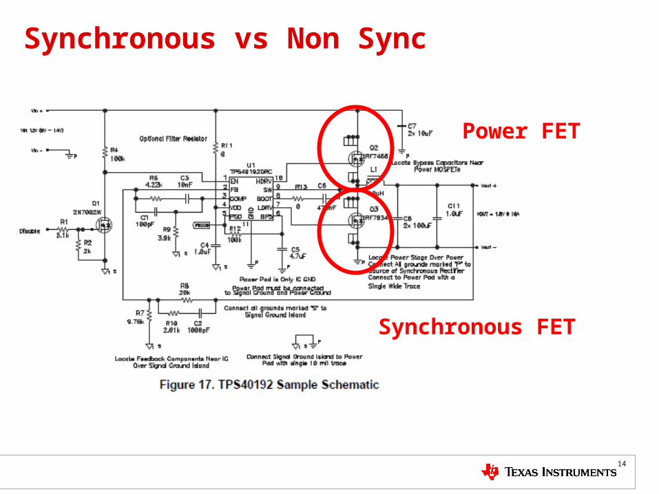
Synchronous vs Non Sync
14
Power FET
Synchronous FET
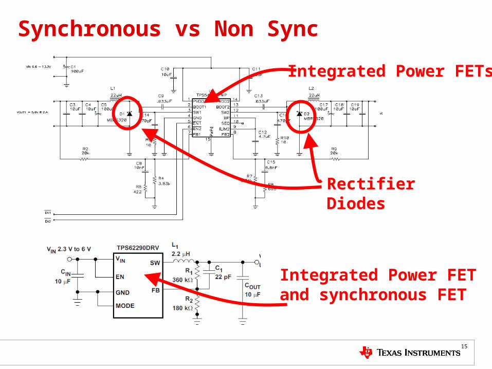
Synchronous vs Non Sync
15
Rectifier Diodes
Integrated Power FETs
Integrated Power FETand synchronous FET
Controller vs Converter
16
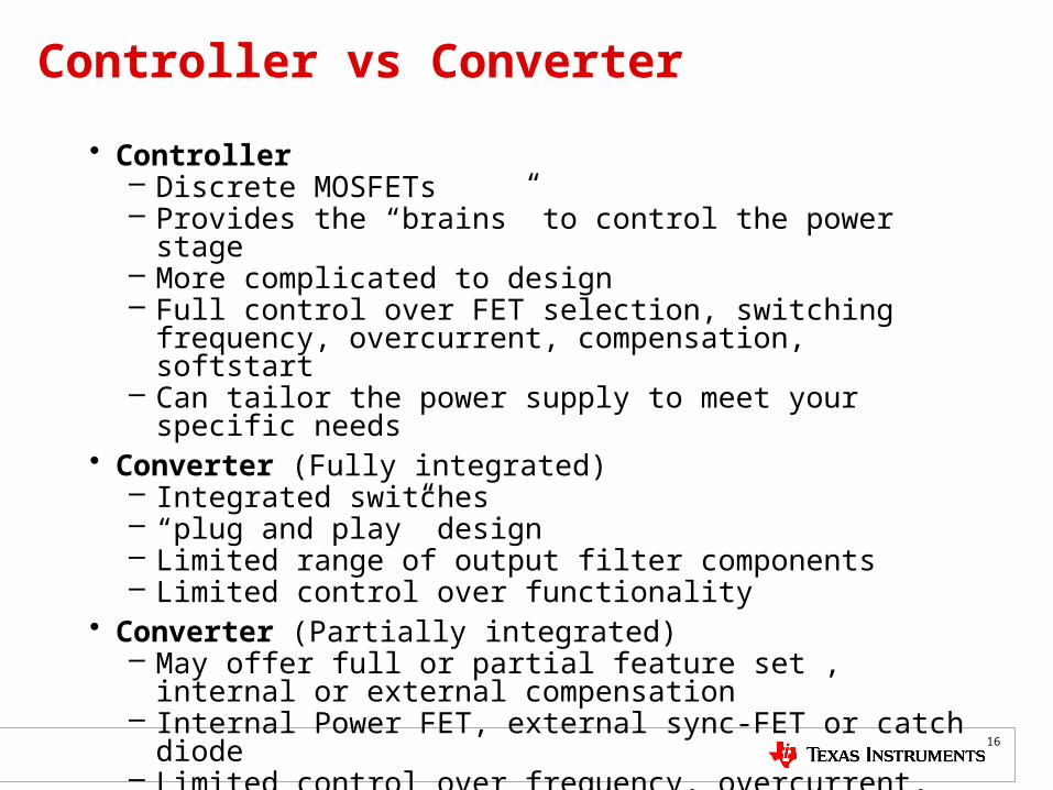
• Controller– Discrete MOSFETs– Provides the “brains” to control the power stage– More complicated to design– Full control over FET selection, switching frequency,
overcurrent, compensation, softstart– Can tailor the power supply to meet your specific needs
• Converter (Fully integrated)– Integrated switches– “plug and play” design– Limited range of output filter components– Limited control over functionality
• Converter (Partially integrated)– May offer full or partial feature set , internal or external
compensation– Internal Power FET, external sync-FET or catch diode– Limited control over frequency, overcurrent, softstart, etc– Allows wider range of output filter components
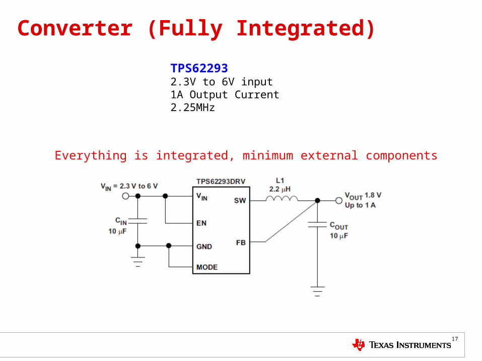
Converter (Fully Integrated)
17
TPS622932.3V to 6V input1A Output Current2.25MHz
Everything is integrated, minimum external components
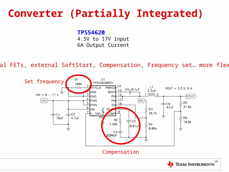
Converter (Partially Integrated)
18
TPS546204.5V to 17V input6A Output Current
Internal FETs, external SoftStart, Compensation, Frequency set… more flexibility
Set frequency
Compensation
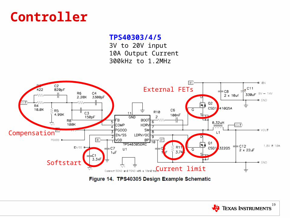
Controller
19
TPS40303/4/53V to 20V input10A Output Current300kHz to 1.2MHz
External FETs
Current limitSoftstart
Compensation
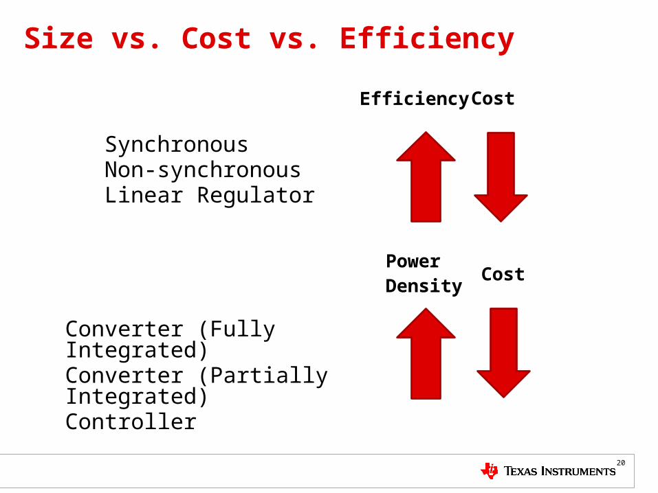
Size vs. Cost vs. Efficiency
20
Cost
SynchronousNon-synchronousLinear Regulator
Efficiency
Cost
Converter (Fully Integrated)Converter (Partially Integrated)Controller
PowerDensity
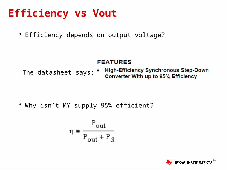
Efficiency vs Vout
21
• Efficiency depends on output voltage?
• Why isn’t MY supply 95% efficient?
The datasheet says:
Efficiency vs Vout
22
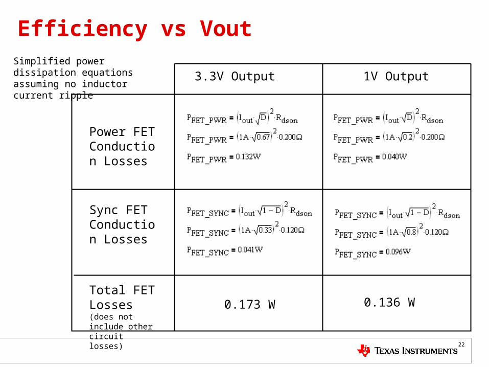
3.3V Output 1V Output
Power FET Conduction Losses
Sync FET Conduction Losses
Total FET Losses(does not include other circuit losses)
0.173 W 0.136 W
Simplified power dissipation equations assuming no inductor current ripple
Efficiency vs Vout
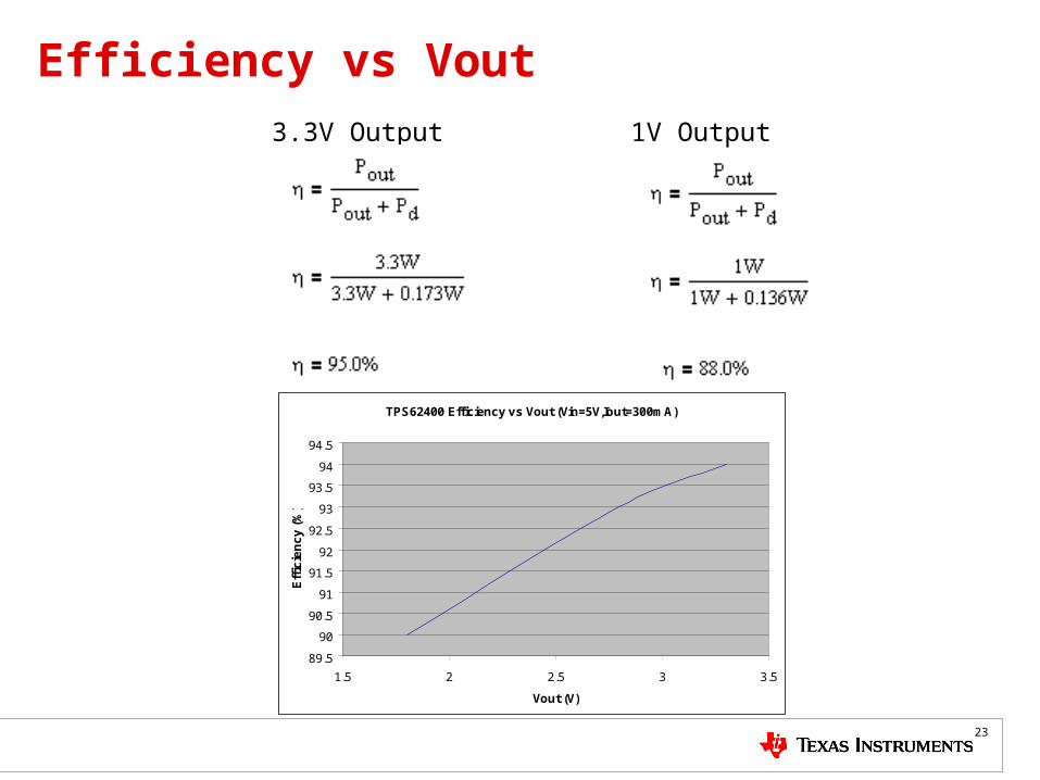
23
3.3V Output 1V Output
TPS62400 Efficiency vs Vout (Vin=5V,Iout=300mA)
89.5
90
90.5
91
91.5
92
92.5
93
93.5
94
94.5
1.5 2 2.5 3 3.5
Vout (V)
Eff
icie
nc
y (
%)
PWM vs PFM
24
• Pulse Width Modulation– Constant frequency– Low output voltage ripple– Used with high output currents
• Pulse Frequency Modulation– Varying frequency with Vin and load– Very high efficiency at very light loads– Higher output voltage ripple– Potential operation in audio range
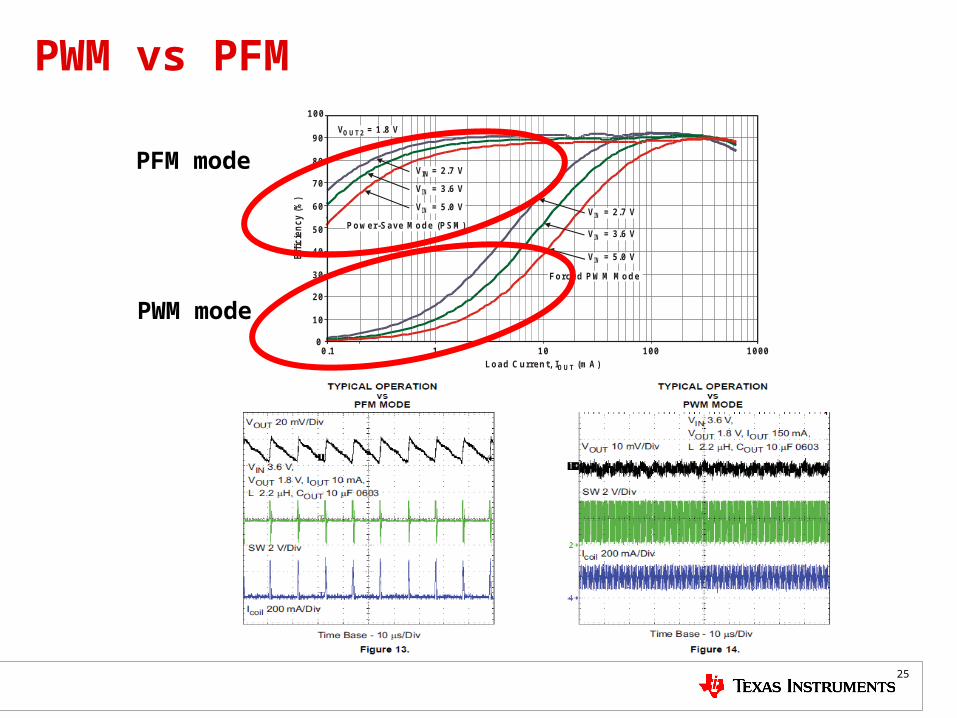
PWM vs PFM
25
0
10
20
30
40
50
60
70
80
90
100
0.1 1 10 100 1000
VOUT2 = 1.8 V
VIN = 2.7 V
VIN = 2.7 VVIN = 5.0 V
VIN = 5.0 V
VIN = 3.6 V
VIN = 3.6 VPower-Save Mode (PSM)
Forced PW M Mode
Load Current, I (m A)OUT
Eff
icie
ncy
(%
)
PFM mode
PWM mode
Startup - Softstart
26
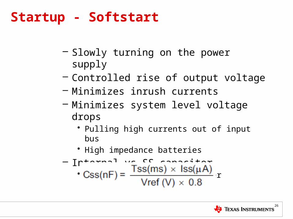
– Slowly turning on the power supply– Controlled rise of output voltage– Minimizes inrush currents– Minimizes system level voltage drops
• Pulling high currents out of input bus• High impedance batteries
– Internal vs SS capacitor• Larger SS capacitor = longer softstart time
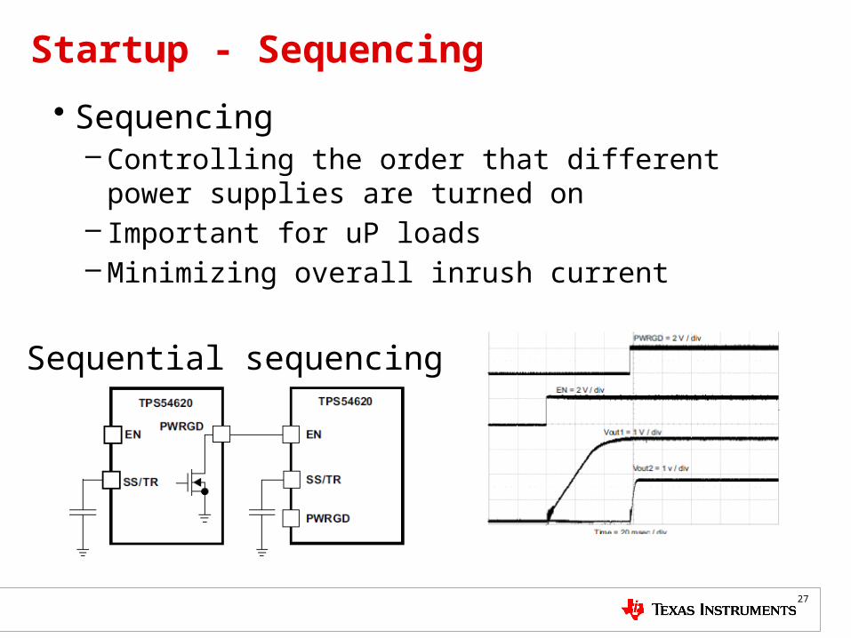
Startup - Sequencing
27
• Sequencing– Controlling the order that different power supplies
are turned on– Important for uP loads– Minimizing overall inrush current
Sequential sequencing
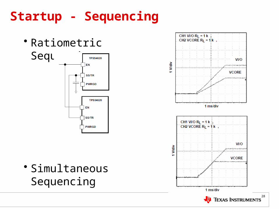
Startup - Sequencing
28
• Ratiometric Sequencing
• Simultaneous Sequencing
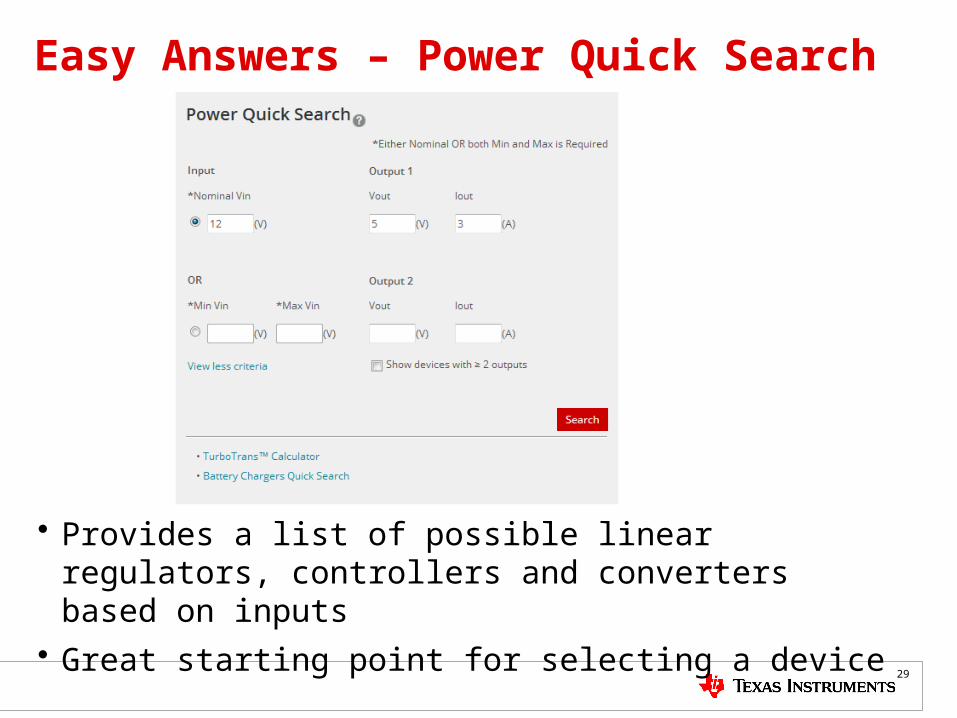
Easy Answers – Power Quick Search
29
• Provides a list of possible linear regulators, controllers and converters based on inputs
• Great starting point for selecting a device
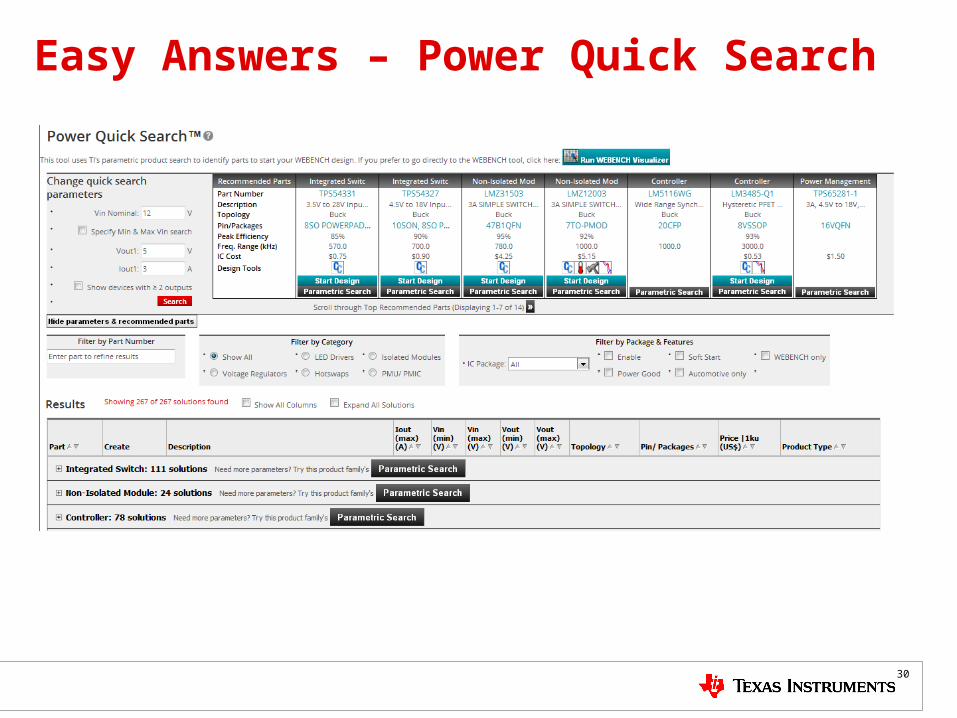
Easy Answers – Power Quick Search
30
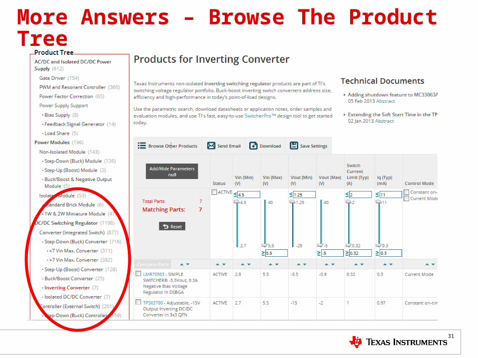
More Answers – Browse The Product Tree
31
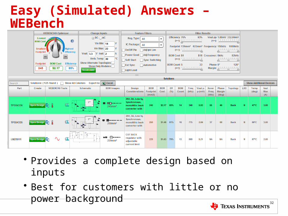
Easy (Simulated) Answers – WEBench
32
• Provides a complete design based on inputs• Best for customers with little or no power background
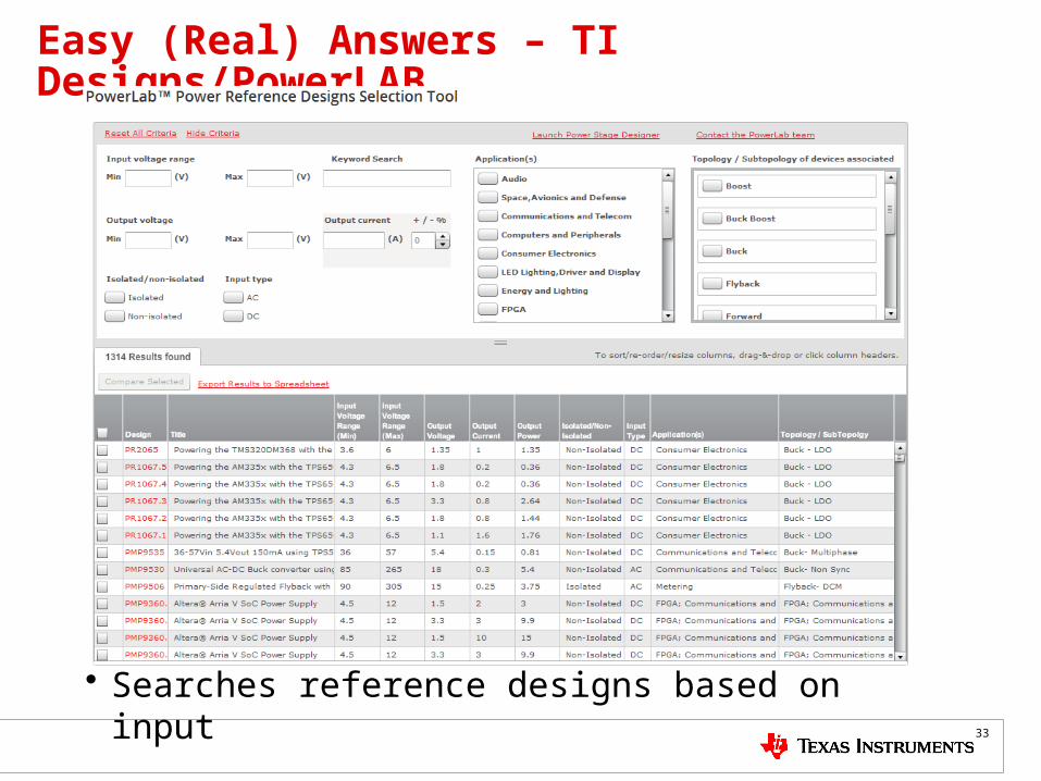
Easy (Real) Answers – TI Designs/PowerLAB
33
• Searches reference designs based on input