Embed Size (px)
Citation preview
Converted by Andreas Bertelmann for ABBUC - www.abbuc.de
De Re Atari
PrefaceIntroduction
by enter value here
This manual is about the ATARI Home Computer. It covers both the ATARI 400TMand the ATARI 800TM Computers. These two computers are electrically identical,differing only in mechanical features such as the keyboards and cartridge slots. Thepurpose of this manual is to explain in detail how to use all the features of theATARI Computer. Because this is a complex and powerful machine, theexplanations are accordingly rather long. Furthermore, they demand some expertExpertise on the part of the reader. This book is not intended for the beginningprogrammer. The reader should be thoroughly familiar with the BASIC ReferenceManual, which is provided with the computer. Familiarity with assembly language isalso essential. A glossary in the back defines and explains some of the lesscommonly encountered jargon. However, this glossary does not include terms thatevery serious personal computer programmer should already know.
Written as a training manual for professional programmers who use the ATARIHome Computer, this book may be modified for general use at some later date. Itdoes not supplant the technical reference manual (ATARI part number C016555),which is a reference for programmers who already understand the system. Thisbook is intended to be a tutorial that explains ideas and possibilities rather thandefining registers and control codes.
The title, DE RE ATARI, is pronounced "Day Ray Atari". It is an obscure literaryreference. Some Latin manuscripts in Roman and medieval times were entitled "DeRe This" or "De Re That". Thus, "De Re Rustica" was a poem on farming and "DeRe Metallica" described metallurgy. Loosely translated, "De Re" means "All About".
Most of the word processing for the book was carried out with Atari computers. Asource file editor was used for text editing, and a modified version of FORMS(available from the Atari Program Exchange) was used to format and print the text.A letter-quality printer was used for output. Some sections were developed with aconventional word processor.
The Software Development Support Group wrote this book. Chris Crawford wroteSections 1 through 6 and Appendices A and B. Lane Winner wrote Section 10 andAppendix D with assistance from Jim Cox. Amy Chen wrote Appendix C. JimDunion wrote Sections 8 and 9. Kathleen Pitta wrote Appendix E. Bob Fraser wroteSection 7. Gus Makreas prepared the Glossary. The final result has many flaws, butwe are proud of it.
IContent
I
Converted by Andreas Bertelmann for ABBUC - www.abbuc.de
Content
Chapter I System Overview 3
Chapter II Antic and the display list 7
Chapter III Graphics indirection 15
Chapter IV Player-Missile graphics 22
Chapter V Display list interrupts 31
Chapter VI Scrolling 39
Chapter VII Sound 45
Chapter VIII The Operating System 63
Chapter IX The Disk Operating System 99
Chapter X Atari Basic 110
Chapter XI Appendix A. Memory utilization 124
Chapter XII Appendix B. Human engineering 127
Chapter XIII Appendix C. The Atari Cassette 138
Chapter XIVAppendix D. Television Artifacts 153
Chapter XV Appendix E. GTIA 156
Chapter XVIGlossary 161
Index 0
Converted by Andreas Bertelmann for ABBUC - www.abbuc.de
SystemOverview
Chapter
I
3System Overview
Converted by Andreas Bertelmann for ABBUC - www.abbuc.de
1 System Overview
The ATARI Home Computer is a second-generation personal computer. First and foremost, it is aconsumer computer. The thrust of the design is to make the consumer comfortable with thecomputer. This consumer orientation manifests itself in many ways. First, the machine is proofedagainst consumer mistakes stakes by such things as polarized connectors that will not go in thewrong way, a power interlock on the lid to the internal electronics, and a pair of plastic shieldsprotecting the SYSTEM RESET key. Second, the machine has a great deal of graphics power;people respond to pictures much more readily than to text. Third, the machine has strong soundcapabilities. Again, people respond to direct sensory input better than to indirect textual messages.Finally, the computer has joysticks and paddles for more direct tactile input than is possible withkeyboards. The point here is not that the computer has lots of features but rather that the featuresare all part of a consistent design philosophy aimed directly at the consumer. The designer whodoes not appreciate this fundamental fact will find himself working against the grain of the system.
The internal layout of the ATARI 400/800Tm Computer is very different from other systems. It ofcourse has a microprocessor (a 6502), RAM, ROM, and a (PIA). However, it also has threespecial- purpose (LSI) chips known as ANTIC, CTIA, and POKEY. These chips were designed byAtari engineers primarily to take much of the burden of housekeeping off of the 6502, therebyfreeing the 6502 to concentrate on computations. While they were at it, they designed a great dealof power into these chips. Each of these chips is almost as big (in terms of silicon area) as a 6502,so the three of them together provide a tremendous amount of power. Mastering the ATARI400/800 Computers is primarily a matter of mastering these three chips.
ANTIC is a microprocessor dedicated to the television display. It is a true microprocessor; it has aninstruction set, a program (called the display list), and data. The display list and the display dataare written into RAM by the 6502. ANTIC retrieves this information from RAM using direct memoryaccess (DMA). It processes the higher level instructions in the display list and translates theseinstructions into a real-time stream of simple instructions to CTIA.
CTIA is a television interface chip. ANTIC directly controls most of CTIA's operations, but the 6502can be programmed to intercede and control some or all of CTIA's functions. CTIA converts thedigital commands from ANTIC (or the 6502) into the signal that goes to the television. CTIA alsoadds some factors of its own, such as colour values, player-missile graphics, and col- lisiondetection.
POKEY is a digital input/output (I/O) chip. It handles such disparate tasks as the serial I/O bus,audio generation, keyboard scan, and random number generation. It also digitizes the resistivepaddle inputs and controls maskable interrupt (IRQ) requests from peripherals.
All four of these LSI chips function simultaneously. Careful separation of their functions in thedesign phase has minimized conflicts between the chips. The only hardware level conflict betweenany two chips in the system occurs when ANTIC needs to use the address and data buses to fetchits display information. To do this, it halts the 6502 and takes control of the buses.
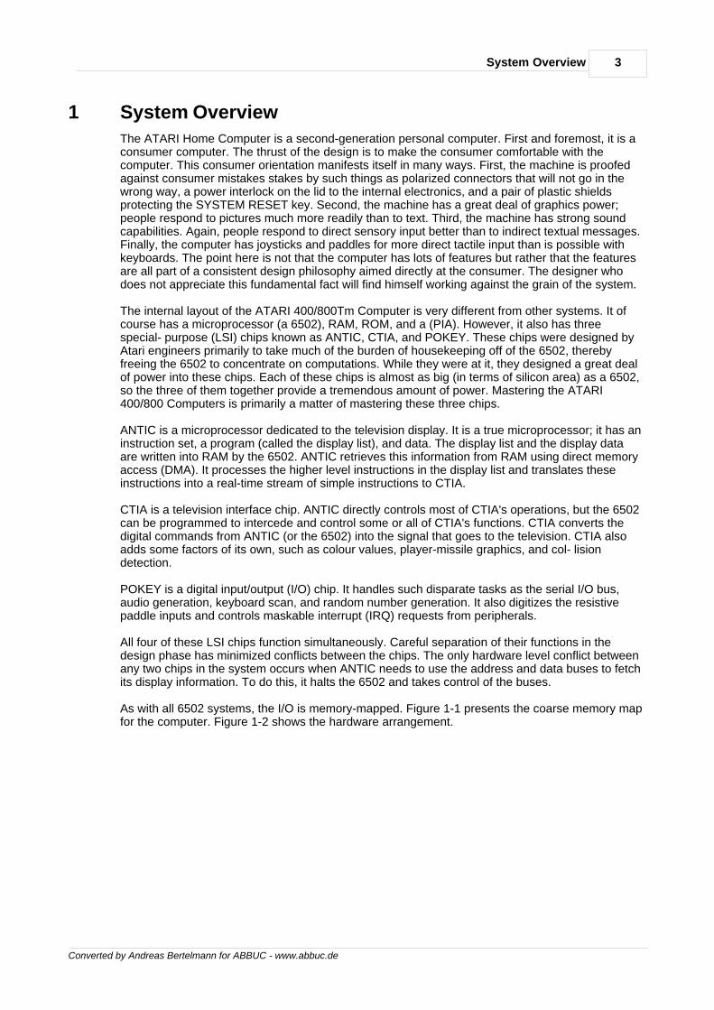
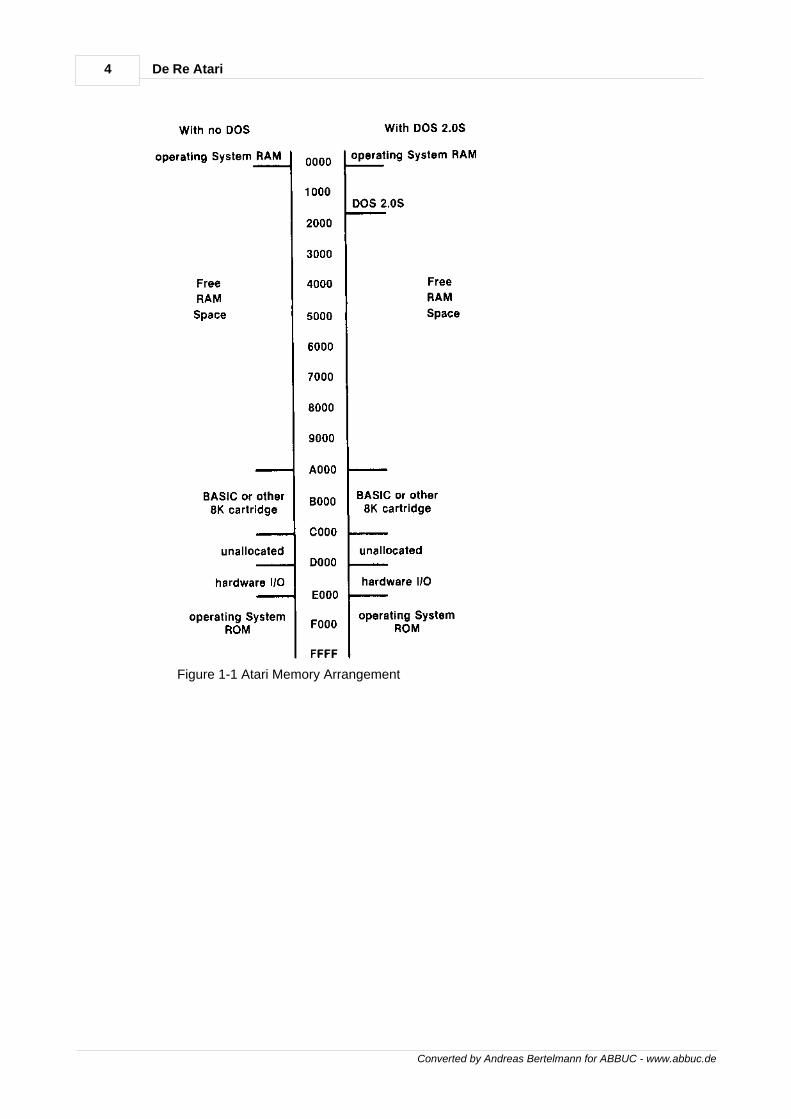
As with all 6502 systems, the I/O is memory-mapped. Figure 1-1 presents the coarse memory mapfor the computer. Figure 1-2 shows the hardware arrangement.
4 De Re Atari
Converted by Andreas Bertelmann for ABBUC - www.abbuc.de
Figure 1-1 Atari Memory Arrangement
5System Overview
Converted by Andreas Bertelmann for ABBUC - www.abbuc.de
Figure 1-2 Atari Hardware Arrangement

Converted by Andreas Bertelmann for ABBUC - www.abbuc.de
Antic and thedisplay list
Chapter
II
7Antic and the display list
Converted by Andreas Bertelmann for ABBUC - www.abbuc.de
2 Antic and the display list
TELEVISION DISPLAYSTo understand the graphics capabilities of the ATARI Home Computer, one must first understandthe rudiments of how a television set works. Television sets use what is called a raster scandisplay system. An electron beam is generated at the rear of the television tube and shot towardthe television screen. Along the way, it passes between sets of horizontal and vertical coils which,if energized, can deflect the beam. In this way the beam can be made to strike any point on thescreen. The electronics inside the television set cause the beam to sweep across the televisionscreen in a regular fashion. The beam's intensity can also be controlled. If you make the beammore intense, the spot in the screen that it strikes will glow brightly; if you make it less intense, thespot will glow dimly or not at all
The beam starts at the top-left corner of the screen and traces horizontally across the screen. As itsweeps across the screen, its changes in intensity paint an image on the screen. When it reachesthe right edge of the screen, it is turned off and brought back to the left side of the screen. At thesame time it is moved down just a notch. It then turns back on and sweeps across the screenagate. This process is repeated for a total of 262 sweeps across the screen. (There are actually525 sweeps across the screen in an alternating system known as "interlace." We will ignoreinterlace and act as if the television has only 262 lines.) These 262 lines fill the screen from top tobottom. At the bottom of the screen (after the 262nd line is drawn), the electron beam is turned offand returned to the upper left corner of the screen. Then it starts the cycle all over agate. Thisentire cycle happens 60 times every second.
Now for some Jargon: a single trace of the beam across the screen is called a "horizontal scanline." A horizontal scan line is the fundamental unit of measurement of vertical distance on thescreen. You state the height of an image by specifying the number of horizontal scan lines itspans. The period during which the beam returns from the right edge to the left edge is called the"horizontal blank." The period during which the beam returns to the top of the screen is called the"vertical blank." The entire process of drawing a screen takes 16,684 microseconds. The verticalblank period is about 1400 microseconds. The horizontal blank takes 14 microseconds. A singlehorizontal line takes 64 microseconds.
Most television sets are designed with "overscan"; that means they spread the image out so thepicture edges are off the edge of the television tube. This guarantees that you have no unsightlyborders in your television picture. It is very bad for computers, though, because screen informationthat is off the edge of the picture does you no good. For tints reason the picture that the computerputs out must be somewhat smaller than the television can theoretically display. Therefore, only192 horizontal scan lines are normally used by the ATARI display. Thus, the normal limit ofresolution of a television set used with this computer is 192 pixels vertically.
The standard unit of horizontal distance is the "color clock." You specify the width of an image bystating how many color clocks wide it Is. There are 228 color clocks in a single horizontal scan line,of which a maximum of 176 are actually visible. Thus, the ultimate limit for full-color horizontalresolution with a standard color television is 176 pixels. It is possible with the ATARI HomeComputer System to go even finer and control individual half- clocks. This gives a horizontalresolution ton of 352 pixels. However, use of tints feature will produce interesting color effectsknown as color artifacts. Color artifacts can be a nuisance if they are not desired; they can be aboon to the programmer who desires additional color and is not fazed by their restrictions.
COMPUTERS AND TELEVISIONSThe fundamental problem any microcomputer has In using a raster scan television for displaypurposes is that the television display is a dynamic process; because of this, the television doesnot remember the image. Consequently, the computer must remember the screen Image andconstantly send a signal to the television telling it what to display. This process of sending in formatton to the television is a continuous process and it requires full-time attention For tints reason mostmicrocomputers have special hardware circuits that handle the television The basic arrangementis the same on virtually all systems:
microprocessor-->screen RAM--->video hardware--->TV screen
8 De Re Atari
Converted by Andreas Bertelmann for ABBUC - www.abbuc.de
The microprocessor writes information to the screen RAM area that holds the screen data. Thevideo hardware is constantly dipping into this RAM area, gettting screen data that it converts intotelevision signals These signals go to the television which then displays the information. Thescreen memory is mapped onto the screen in the same order that it follows in RAM. That is, thefirst byte in the screen memory maps to the top-left corner of the screen, the second byte mapsone position to the right, then the third, the fourth, and so on to the last byte which is mapped tothe lower right corner of the screen.
The quality of the Image that gets to the screen depends on two factors: the quality of the videohardware, and the quantity of screen RAM used for the display The simplest arrangement is thatused by TRS- 80 and PET. (TRS-80) is a trademark of Radio Shack Co; PET is a trademark ofCommodore Business Machines.) Both of these machines allocate a specific 1K of RAM asscreen memory. The video hardware circuits imply pull data out of tints area, Interpret it ascharacters (using a character set in ROM), and put the resulting characters onto the screen. Eachbyte represents one character, allowing a choice of 256 different characters in the character set.With 1K of screen RAM, one thousand characters can be displayed on the screen. There isn'tmuch that can be done with tints arrangement. The Apple uses more advanced video hardware.(Apple is a trademark of Apple Computers.) Three graphics modes are provided: text, lo-resolutton graphics, and hi- resolution graphics. The text graphics mode operates in much thesame way that the PET and TRS-80 displays operate. In the low-resolution graphics mode, thevideo hardware reaches into screen memory and interprets it differently. Instead of interpretingeach byte as a character, each byte is interpreted as a pair of color nibbles. The value of eachnibble specifies the color of a single pixel. In the high-resolution graphics mode each bit in screenmemory is mapped to a single pixel. If the bit is on, the pixel gets color in It; if the bit is off, the pixelstays dark. The situation is complicated by a variety of design nuances in the Apple, but that is thebasic idea. The important idea is that the Apple has three display modes; three completelydifferent ways of interpreting the data in screen memory. The Apple video hardware is smartenough to interpret a screen memory byte as either an 8-bit character (text mode), two 4-bit colornybbles (lo-resolution mode), or 7 individual bits for a bit map hi-resolution mode).
ANTIC, A VIDEO MICROPROCESSORThe ATARI 400/800 display list system represents a generalization of these systems. Where PETand TRS-80 have one mode and Apple has three modes, the ATARI 400/800 has 14 modes. Thesecond important difference is that display modes can be mixed on the screen. That is, the user isnot restricted to a choice between a screen ful of text or a screenful of graphics. Any collection ofthe 14 graphics. modes can be displayed on the screen. The third important difference is that thescreen RAM can be located anywhere in the address space of the computer and moved aroundwhile the program is running, while the other machines use fixed-screen RAM areas.
All of this generality is made possible by a video microprocessor called ANTIC. Where the earliersystems used rather simple video circuitry, Atari designed a full-scale microprocessor just tohandle the intricacies of the television display. ANTIC is a true microprocessor; it has an instructionset, a program, and data. The program for ANTIC is called the display list. The display list specifiesthree things: where the screen data may be found, what display modes to use to Interpret thescreen data, and what special display options (if any) should be implemented. When (using thedisplay list, it is important to shed the old view of a screen as a homogeneous image in a singlemode and see it instead as a stack of "mode lines." A mode line is a collection of horizontal scanlines. It stretches horizontally all the way across the screen. A Graphics 2 mode line is 16horizontal scan lines high, while a Graphics 7 mode line is only two scan lines high. Many graphics.modes available from BASIC are homogeneous; an entire screen of a single mode is set up. Donot limit your imagination to this pattern; with the display list you can create any sequence of modelines down the screen. The display list is a collection of code bytes that specify that sequence.
ANTIC'S instruction set is rather simple. There are four classes of instructions: map mode,character mode, blank line and jump. Map mode instructions cause ANTIC to display a mode linewith simple colored pixels (no characters). Character mode instructions cause ANTIC to display amode line with characters in it. Blank line instructions cause ANTIC to display a number ofhorizontal scan lines with solid background color. Jump instructions are analogous to a 6502 JMPinstruction; they reload ANTIC's program counter.
There are also four special options that can sometimes be specified by setting a designated bit in
9Antic and the display list
Converted by Andreas Bertelmann for ABBUC - www.abbuc.de
the ANTIC instruction. These options are: display list Interrupt (DLI), load memory scan (LMS),vertical scroll, and horizontal scroll.
Map mode instructions cause ANTIC to display a mode line containing pixels with solid color inthem. The color displayed comes from a color register. The choice of color register is specified bythe value of the screen data. In four-color map modes (BASIC modes 3, 5, and 7, and ANTICmodes 8, A, D, and E), a pair of bits is required to specify a color:
Value of Bit Pair Color Register Used 00 0 COLBAK 01 1 COLPFO 10 2 COLPF1 11 3 COLPF2
Since only two bits are needed to specify one pixel, 4 pixels are encoded in each screen data byte.For example, a byte of screen data containing the value $1B would display 4 pixels; the first wouldbe the background, the second would be color register 0, the third would be color register 1, andthe fourth would be color register 2:
$1B = 00011011 = 00 01 10 11
In two-color map modes (BASIC modes 4, 6, and 8, and ANTIC modes 9, B. C, and F) each bitspecifies one of two color registers. A bit value of 0 selects background color for the pixel and a bitvalue of 1 selects color register 0 for the pixel. Eight pixels can be stored in one screen data byte.
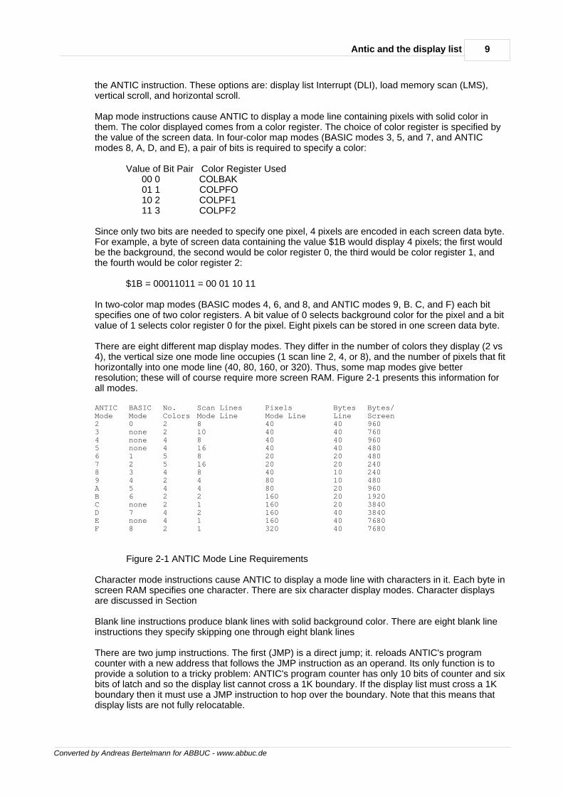
There are eight different map display modes. They differ in the number of colors they display (2 vs4), the vertical size one mode line occupies (1 scan line 2, 4, or 8), and the number of pixels that fithorizontally into one mode line (40, 80, 160, or 320). Thus, some map modes give betterresolution; these will of course require more screen RAM. Figure 2-1 presents this information forall modes.
ANTIC BASIC No. Scan Lines Pixels Bytes Bytes/Mode Mode Colors Mode Line Mode Line Line Screen2 0 2 8 40 40 9603 none 2 10 40 40 7604 none 4 8 40 40 9605 none 4 16 40 40 4806 1 5 8 20 20 4807 2 5 16 20 20 2408 3 4 8 40 10 2409 4 2 4 80 10 480A 5 4 4 80 20 960B 6 2 2 160 20 1920C none 2 1 160 20 3840D 7 4 2 160 40 3840E none 4 1 160 40 7680F 8 2 1 320 40 7680
Figure 2-1 ANTIC Mode Line Requirements
Character mode instructions cause ANTIC to display a mode line with characters in it. Each byte inscreen RAM specifies one character. There are six character display modes. Character displaysare discussed in Section
Blank line instructions produce blank lines with solid background color. There are eight blank lineinstructions they specify skipping one through eight blank lines
There are two jump instructions. The first (JMP) is a direct jump; it. reloads ANTIC's programcounter with a new address that follows the JMP instruction as an operand. Its only function is toprovide a solution to a tricky problem: ANTIC's program counter has only 10 bits of counter and sixbits of latch and so the display list cannot cross a 1K boundary. If the display list must cross a 1Kboundary then it must use a JMP instruction to hop over the boundary. Note that this means thatdisplay lists are not fully relocatable.
10 De Re Atari
Converted by Andreas Bertelmann for ABBUC - www.abbuc.de
The second jump instruction (JVB) is more commonly used. It reloads the program counter withthe value in the operand and waits for the television to perform a vertical blank. This instruction isnormally used to terminate a display list by jumping back up to the top of the display list Jumpingup to the top of the display list turns it into an infinite loop; waiting for vertical blank ensures that theinfinite loop is synchronized to the display cycle of the television. Both JMP and JVB are 3-byteinstructions the first byte is the opcode, the second and third bytes are the address to jump to (lowthen high).
The four special options mentioned previously will be discussed in Sections 5 and 6. The loadmemory scan (LMS) option must have a preliminary explanation. This option is selected by settingbit 6 of a map mode or a character mode instruction byte. When ANTIC encounters such aninstruction, it will load its memory scan counter with the following 2 bytes. This memory scancounter tells ANTIC where the screen RAM is. It will begin fetching display data from this area. TheLMS instruction is a 3- byte instruction: 1 byte opcode followed by 2 bytes of operand. In simpledisplay lists the LMS instruction Is used only once, at the beginning of the display list. It maysometimes be necessary to use a second LMS instruction. The need arises when the screen RAMarea crosses a 4K boundary. The memory scan counter has only 12 bits of counter and 4 bits oflatch; thus, the display data cannot cross a 4K boundary. In this case an LMS instruction must beused to jump the memory scan counter over the boundary. Note that this means that display datais not fully relocatable. LMS instructions have wider uses which will be discussed later.
BUILDING DISPLAY LISTSEvery display list should start off with three "blank 8 lines" instructions. This is to defeat verticaloverscan by bringing the beginning of the display 24 scan lines down. After this is done, the firstdisplay line should be specified. Simultaneously, the LMS should be used to tell ANTIC where it willfind the screen RAM. Then follows the display list proper, which lists the display bytes for the modelines on the screen. The total number of horizontal scan lines produced by the display list shouldalways be 192 or less; ANTIC does not maintain the screen timing requirements of the television. Ifyou give ANTIC too many scan lines to display it will do so, but the television screen will probablyroll. Displaying fewer than 192 scan lines will cause no problems; indeed, it will decrease 6502execution time by reducing the number of cycles stolen by ANTIC. The programmer must calculatethe sum of the horizontal scan lines produced by the display list and verify it. The display listterminates with a JVB instruction. Here is a typical display list for a standard BASIC Graphicsmode 0 display (all values are in hexadecimal):
70 Blank 8 lines 70 Blank 8 lines 70 Blank 8 lines 42 display ANTIC mode 2 (BASIC mode0) 20 Also, screen memory starts at7C20 7C 02 Display Antic Mode 2 02 02 02 02 02 02 02 02 02 02 02 02 02 02 02 02 02 02 02
11Antic and the display list
Converted by Andreas Bertelmann for ABBUC - www.abbuc.de
02 02 02 41 Jump and watt for vertical E0 blank to display list which 7B starts at $7BEO
As you can see, This display list is short---only 32 bytes. Most display lists are less than 100 byteslong. Furthermore, they are quite simple in structure and easy to set up.
To implement your own display list you must first design the display format. This is best done onpaper. Lay out the screen image and translate it. into a sequence of mode lines Keep track of thescan line count of your display by looking up the scan line Requirements of the various modes inFigure 2-1. Translate the sequence of mode lines into a sequence of ANTIC mode bytes. Put three"blank 8 lines bytes ($70) at the top of the list Set bit 6 of the first display byte (that is make theupper nybble a 4). This makes a load memory scan command. Follow with 2 bytes which specifythe address of the screen RAM (low then high). Then follow with the rest of the display bytes. Atthe end of your display list put in the JVB instruction ($41) and the address of the top of the displaylist Now store all of these bytes into RAM. They can be anywhere you want; just make sure theydon't overlay something else and your JVB points to the top of the display list The display list mustnot cross a 1K address boundary. If you absolutely must have it. cross such a boundary, insert aJMP instruction just in front of the boundary. The JMP instructions's operand is the address of thefirst byte on the other side of the boundary. Next you must turn off ANTIC for a fraction of a secondwhile you rewrite its display list pointer. Do this by writing a 0 into SDMCTL at location $22F. Thenstore the address of the new display list into $230 and $231 (low then high). Lastly, turn ANTICback on with a $22 into SDMCTL. During the vertical blank, while ANTIC is quiet, the operatingsystem (OS) will reload ANTIC's program counter with these values.
WRITING TO A CUSTOM DISPLAY LIST SCREENScreen memory can be placed anywhere in the address space of the computer. Normally thedisplay list specifies the beginning of the screen memory with the first display instruction---theinitial LMS instruction However, ANTIC can execute a new LMS instruction with each display lineof the display list if this is desired. In This way information from all over the address space of thecomputer can be displayed on a single screen. This can be of value in setting up independent textwindows.
There are several restrictions in your placement of the screen memory. First screen memorycannot cross a 4K address boundary. If you cannot avoid crossing a 4K boundary (as would be thecase in BASIC mode 8, which uses 8K of RAM) you must reload the memory scan counter with anew LMS instruction. Second, if you wish to use any of the operating system screen routines youmust abide by the conventions the OS uses. This can be particularly difficult when using a modifieddisplay list in a BASIC program. If you alter a standard display list from a BASIC program and thenattempt to PRINT or PLOT to the screen, the OS will do so under the assumption that the displaylist is unchanged. This will probably result in a garbled display
There are three ways the display can fall when you attempt this. First BASIC may refuse to carryout a screen operation because it is impossible to do in the graphics. mode that the OS thinks it isin. The OS stores the value of the graphics mode that it thinks is on the screen in address $57.You can fool the OS into cooperating by poking a different value there. Poke the BASIC modenumber, not the ANTIC mode number.
The second failure you might get arises when you mix mode lines with different screen memorybyte Requirements. Some mode lines require 40 bytes per line some require 20 bytes per line andsome require only 10 bytes per line. Let's say that you insert one 20-byte mode line into a displaylist with 40 byte mode lines. Then you PRINT text to the display. Everything above the interloperline is fine, but below it. the characters are shifted 20 spaces to the right. This is because the OSassumed that each line would require 40 bytes and positioned the characters accordingly. ButANTIC, when it encountered the interloper line took only 20 bytes of what the OS thought shouldbe a 40-byte line ANTIC interpreted the other 20 bytes as belonging to the next line and displayedthem there. This resulted in the next line and all later lines being shifted 20 spaces to the right.

12 De Re Atari
Converted by Andreas Bertelmann for ABBUC - www.abbuc.de
The only absolute way around This problem is to refrain from (using BASIC PRINTs and PLOTs tooutput to a custom display list screen. The quick-and-dirty solution is to organize the screen intoline groups that contain integer multiples of the standard byte requirement. That is, do not insert a20-byte mode line into a 40- byte display instead insert two 20-byte lines or one 20-byte line andtwo 10-byte lines So long as you retain the proper integer multiples, the horizontal shift will beavoided.
This solution accentuates the third problem with indexed display lists and BASIC: vertical shifts.The OS positions screen material vertically by calculating the number of bytes to skip down fromthe top of the screen. In a standard 40-byte line display, BASIC would position the characters ontothe tenth line by skipping 360 bytes from the beginning. If you have inserted four 10-byte linesBASIC will end up three lines further down the screen than you would otherwise expect.Furthermore, different mode lines consume different numbers of scan lines, so the position on thescreen will not be quite what you expected if you do not take scan line costs into account.
As you can see, mixed mode displays can be difficult to use in conjunction with the OS. Often youmust fool the OS to make such displays work. To PRINT or PLOT to a mode window, POKE theBASIC mode number of that window to address $57, then POKE the address of the top left pixel ofthe mode window into locations $58 and $59 (low then high). In character modes, execute aPOSITION 0,0 to home the cursor to the top-left corner of the mode window. In map modes, allPLOTs and DRAWTOs will be made using the top-left corner of the mode window as the origin ofthe coordinate system.
The display list system can be used to produce appealing screen displays. Its most obvious use isfor mixing text and graphics. For example, you could prepare a screen with a bold BASIC mode 2title, a medium size BASIC mode 1 subtitle, and small BASIC mode 0 fine print. You could thenthrow in a BASIC mode 8 picture in the middle with some more text at the bottom. A good exampleof this technique is provided by the display in the ATARI States and Capitals program.
The aforementioned problems will discourage the extensive use of such techniques from BASIC.with assembly language routines, modified display lists are best used by organizing the screen intoa series of windows, each window having its own LMS instruction and its own independent RAMarea.
APPLICATIONS OF DISPLAY LISTSOne simple application of display list modifications is to vertically space lines on the screen byinserting blank line bytes. This will add some vertical spacing which will highlight critical messagesand enhance the readability of some displays.
Another important use of display list manipulations is in providing access to features not availablefrom BASIC. There are three text modes supported by ANTIC that BASIC does not support. Onlydisplay list manipulations gain the user access to these modes. There are also display list interruptand fine scrolling capabilities that are only available after the display list is modified. Thesefeatures are the subjects of Sections 5 and 6.
Manipulations with the LMS instruction and its operand offer many possibilities to the creativeprogrammer. For example, by changing the LMS during vertical blank, the programmer canalternate screen images. This can be done at slow speed to change between predrawn displayswithout having to redraw each one. Each display would continue to reside in (and consume) RAMeven while it. is not in use, but it. would be available almost instantly. This technique can also beused for animation. By flipping through a sequence of displays cyclic animation can be achieved.The program to do this would manipulate only 2 address bytes to display many thousands of bytesof RAM.
It is also possible to superimpose images by flipping screens at high speed. The human eye has atime resolution; of about 1/16 of a second, so a program can cycle between four images, oneevery 1/60 of a second, so that each repeats every 1/15 of a second. In This way, up to fourimages can appear to reside simultaneously on the screen. Of course, there are some drawbacksto This method. first four separate displays may well cost a lot of RAM. Second, each displayimage will be washed out because it. only shows up one quarter of the time. This means that thebackground of all displays must be black, and each image must be bright. Furthermore, there will
13Antic and the display list
Converted by Andreas Bertelmann for ABBUC - www.abbuc.de
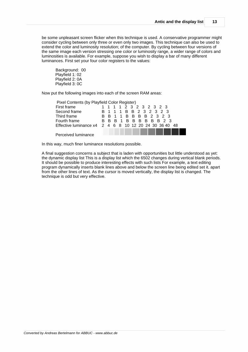
be some unpleasant screen flicker when this technique is used. A conservative programmer mightconsider cycling between only three or even only two images. This technique can also be used toextend the color and luminosity resolution; of the computer. By cycling between four versions ofthe same image each version stressing one color or luminosity range, a wider range of colors andluminosities is available. For example, suppose you wish to display a bar of many differentluminances. First set your four color registers to the values:
Background: 00 Playfield 1: 02 Playfield 2: 0A Playfield 3: 0C
Now put the following images into each of the screen RAM areas:
Pixel Contents (by Playfield Color Register) First frame 1 1 1 1 2 3 2 3 2 3 2 3 Second frame B 1 1 1 B B 2 3 2 3 2 3 Third frame B B 1 1 B B B B 2 3 2 3 Fourth frame B B B 1 B B B B B B 2 3 Effective luminance x4 2 4 6 8 10 12 20 24 30 36 40 48
Perceived luminance
In this way, much finer luminance resolutions possible.
A final suggestion concerns a subject that is laden with opportunities but little understood as yet:the dynamic display list This is a display list which the 6502 changes during vertical blank periods.It should be possible to produce interesting effects with such lists For example, a text editingprogram dynamically inserts blank lines above and below the screen line being edited set it. apartfrom the other lines of text. As the cursor is moved vertically, the display list is changed. Thetechnique is odd but very effective.
Converted by Andreas Bertelmann for ABBUC - www.abbuc.de
Graphicsindirection
Chapter
III
15Graphics indirection
Converted by Andreas Bertelmann for ABBUC - www.abbuc.de
3 Graphics indirection
(COLOR REGISTERS AND CHARACTER SETS)Indirection is a powerful concept in programming. In 6502 assembly language, there are threelevels of indirection in referring to numbers. The first and most direct level is the immediateaddressing mode In which the number itself is directly stated:
LDA #$F4
The second level of indirection is reached when the program refers to a memory location thatholds the number:
LDA $0602
The third and highest level of indirection with the 6502 is attained when the program refers to apair of memory locations which together contain the address of the memory location that holds thenumber. In the 6502, this indirection is complicated by the addition of an index:
LDA ($D0),Y
Indirection provides a greater degree of generality (and hence power) to the programmer. Insteadof trucking out the same old numbers every time you want to get something done, you can simplypoint to them. By changing the pointer, you can change the behaviour of the program. Indirection isobviously an important capability.
COLOR REGISTERSGraphics indirection is built into the ATARI Home Computer in two ways: with color registers andwith character sets. Programmers first approaching this computer after programming othersystems often think in terms of direct colors. A color register is a more complex beast than a color.A color specifies a permanent value. A color register is indirect; it holds any color value. Thedifference between the two is analogous to the difference between a box-end wrench and a socketwrench. The box-end wrench comes in one size only but a socket wrench can hold almost any sizesocket. A socket wrench is more flexible but takes a little more skill to use properly. Similarly, acolor register is more flexible than a color but takes more skill to use effectively.
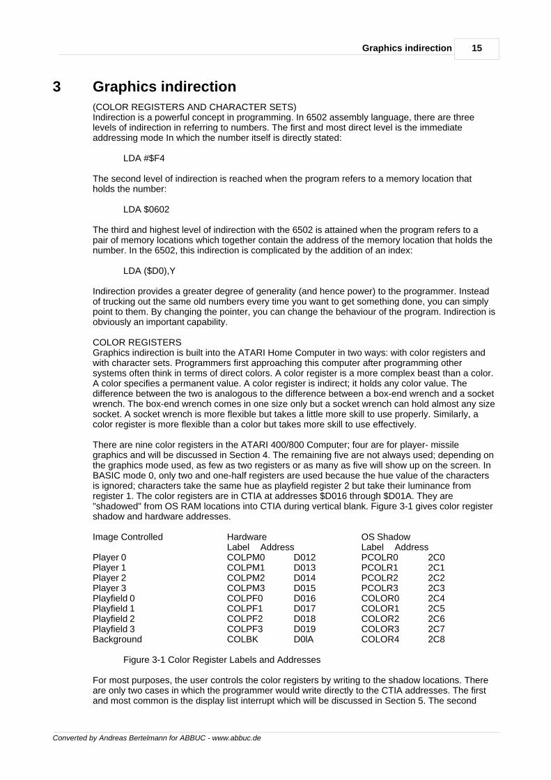
There are nine color registers in the ATARI 400/800 Computer; four are for player- missilegraphics and will be discussed in Section 4. The remaining five are not always used; depending onthe graphics mode used, as few as two registers or as many as five will show up on the screen. InBASIC mode 0, only two and one-half registers are used because the hue value of the charactersis ignored; characters take the same hue as playfield register 2 but take their luminance fromregister 1. The color registers are in CTIA at addresses $D016 through $D01A. They are"shadowed" from OS RAM locations into CTIA during vertical blank. Figure 3-1 gives color registershadow and hardware addresses.
Image Controlled HardwareLabel Address
OS ShadowLabel Address
Player 0Player 1Player 2Player 3Playfield 0Playfield 1Playfield 2Playfield 3Background
COLPM0 D012COLPM1 D013COLPM2 D014COLPM3 D015COLPF0 D016COLPF1 D017COLPF2 D018COLPF3 D019COLBK D0lA
PCOLR0 2C0PCOLR1 2C1PCOLR2 2C2PCOLR3 2C3COLOR0 2C4COLOR1 2C5COLOR2 2C6COLOR3 2C7COLOR4 2C8
Figure 3-1 Color Register Labels and Addresses
For most purposes, the user controls the color registers by writing to the shadow locations. Thereare only two cases in which the programmer would write directly to the CTIA addresses. The firstand most common is the display list interrupt which will be discussed in Section 5. The second
16 De Re Atari
Converted by Andreas Bertelmann for ABBUC - www.abbuc.de
arises when the user disables the OS vertical blank interrupt routines that move the shadow valuesInto CTIA. Vertical blank interrupts are discussed in Section 8.
Colors are encoded in a color register by a simple formula. The upper nybble gives the hue value,which is identical to the second parameter of the BASIC SETCOLOR command. Table 9-3 of theBASIC Reference Manual lists hue values. The lower nybble in the color register gives theluminance value of the color. It is the same as the third parameter in the BASIC SETCOLORcommand. The lowest order bit of this nybble is not significant. Thus, there are eight luminancesfor each hue. There are a total of 128 colors from which to choose (8 luminances times 16 hues).In this book, the term `color' denotes a hue- luminance combination.
Once a color is encoded into a color register, it is mapped onto the screen by referring to the colorregister that holds it. In map display modes which support four color registers the screen dataspecifies which color register is to be mapped onto the screen. Since there are four color registersit takes only two bits to encode one pixel. Thus, each screen data byte holds data for four pixels.The value in each pair of bits specifies which color register provides the color for that pixel.
In text display modes (BASIC's GRAPHICS modes 1 and 2) the selection of color registers ismade by the top two bits of the character code. This leaves only six bits for defining the character,which is why these two modes have only 64 characters available.
Color register indirection gives you four special capabilities. First, you can choose from 128different colors for your displays. This allows you to choose the color that most nearly meets yourneeds.
Second, you can manipulate the color registers in real time to produce pretty effects. The simplestversion of this is demonstrated by the following BASIC line:
FOR I=0 TO 254 STEP 2:POKE 712,I:NEXT I
This line simply cycles the border color through all possible colors. The effect is quite pleasing andcertainly grabs attention. The fundamental technique can be extended in a variety of ways. Aspecial variation of this is to create simple cyclic animation by drawing a figure in four colors andthen cycle the colors through the color registers rather than redrawing the figure. The followingprogram illustrates the idea:
10 GRAPHICS 23 20 FOR X=0 TO 39 30 FOR l=0 TO 3 40 COLOR I 50 PLOT 4*X+I,O 60 DRAWTO 4*X+1,95 70 NEXT I 80 NEXT X 90 A=PEEK(712) 100 POKE 712,PEEK(710) 110 POKE 710,PEEK(709) 120 POKE 709,PEEK(708) 130 POKE 708,A 140 GOTO 90
The third application of color registers is to logically key colors to situations. For example, a pagedmenu system can be made more understandable by changing the background color or the bordercolor for each page in the menu. Perhaps the screen could flash red when an illegal key ispressed. The use of the color characters available in BASIC Graphics modes 1 and 2 can greatlyextend the impact of textual material. An account sum could be shown in red if the account is inthe red, or black if the account is in the black. Important words or phrases can be shown in specialcolors to make them stand out. The use of colors in map modes (no text) can also improve theutility of such graphics. A single graphics image (a monster, a boat, or whatever) could bepresented in several different colors to represent several different versions of the same thing. Itcosts a great deal of RAM to store an image, but it costs very little to change the color of an
17Graphics indirection
Converted by Andreas Bertelmann for ABBUC - www.abbuc.de
existing image. For example, it would be much easier to show three different boats by presentingone boat shape in three different colors than three different boat shapes.
The fourth and most important application of color registers Is used with display list interrupts. Asingle color register can be used to put up to 128 colors onto a single screen. This very Importantcapability will be discussed in Sect ton 5.
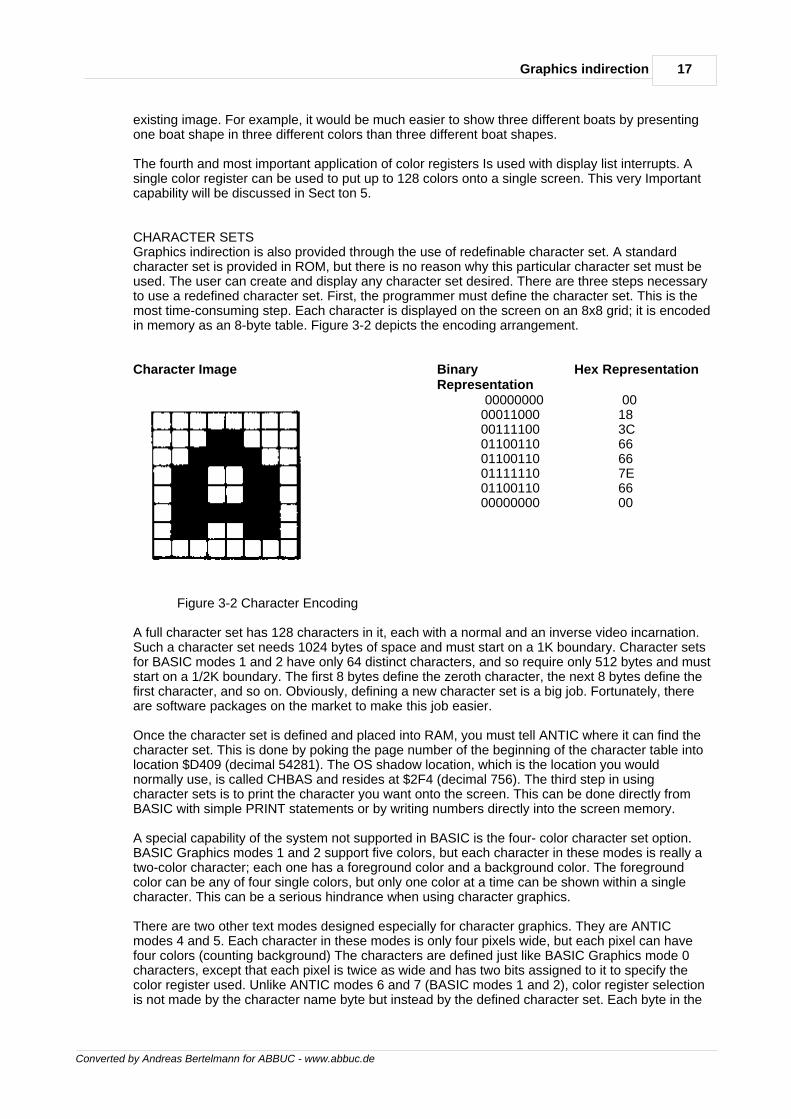
CHARACTER SETSGraphics indirection is also provided through the use of redefinable character set. A standardcharacter set is provided in ROM, but there is no reason why this particular character set must beused. The user can create and display any character set desired. There are three steps necessaryto use a redefined character set. First, the programmer must define the character set. This is themost time-consuming step. Each character is displayed on the screen on an 8x8 grid; it is encodedin memory as an 8-byte table. Figure 3-2 depicts the encoding arrangement.
Character Image BinaryRepresentation
Hex Representation
00000000 00011000 00111100 01100110 01100110 01111110 01100110 00000000
00 18 3C 66 66 7E 66 00
Figure 3-2 Character Encoding
A full character set has 128 characters in it, each with a normal and an inverse video incarnation.Such a character set needs 1024 bytes of space and must start on a 1K boundary. Character setsfor BASIC modes 1 and 2 have only 64 distinct characters, and so require only 512 bytes and muststart on a 1/2K boundary. The first 8 bytes define the zeroth character, the next 8 bytes define thefirst character, and so on. Obviously, defining a new character set is a big job. Fortunately, thereare software packages on the market to make this job easier.
Once the character set is defined and placed into RAM, you must tell ANTIC where it can find thecharacter set. This is done by poking the page number of the beginning of the character table intolocation $D409 (decimal 54281). The OS shadow location, which is the location you wouldnormally use, is called CHBAS and resides at $2F4 (decimal 756). The third step in usingcharacter sets is to print the character you want onto the screen. This can be done directly fromBASIC with simple PRINT statements or by writing numbers directly into the screen memory.
A special capability of the system not supported in BASIC is the four- color character set option.BASIC Graphics modes 1 and 2 support five colors, but each character in these modes is really atwo-color character; each one has a foreground color and a background color. The foregroundcolor can be any of four single colors, but only one color at a time can be shown within a singlecharacter. This can be a serious hindrance when using character graphics.
There are two other text modes designed especially for character graphics. They are ANTICmodes 4 and 5. Each character in these modes is only four pixels wide, but each pixel can havefour colors (counting background) The characters are defined just like BASIC Graphics mode 0characters, except that each pixel is twice as wide and has two bits assigned to it to specify thecolor register used. Unlike ANTIC modes 6 and 7 (BASIC modes 1 and 2), color register selectionis not made by the character name byte but instead by the defined character set. Each byte in the
18 De Re Atari
Converted by Andreas Bertelmann for ABBUC - www.abbuc.de
character table is broken into four bit pairs, each of which selects the color for a pixel. (This is whythere are only four horizontal pixels per character.) The highest bit (D7) of the character name bytemodifies the color register used. Color register selection is made according to Figure 3-3:
bit pair incharacter defn
D7 = 0 D7 = 1
00 01 10 11
COLBAK PFO PF1 PF2
COLBAK PFO PF1 PF3
Figure 3-3 Color Register Selection for Characters
Using these text modes, multicolored graphics characters can be put onto the screen.
Another interesting ANTIC character mode is the lowercase descenders mode (ANTIC mode 3).This mode displays 10 scan lines per mode line, but since characters use only eight bytesvertically, the lower two scan lines are normally left empty. If a character in the last quarter of thecharacter set is displayed, the top two scan lines of the character will be left empty; the data thatshould have been displayed there will instead be shown on the bottom two lines. This allows theuser to create lowercase characters with descenders.
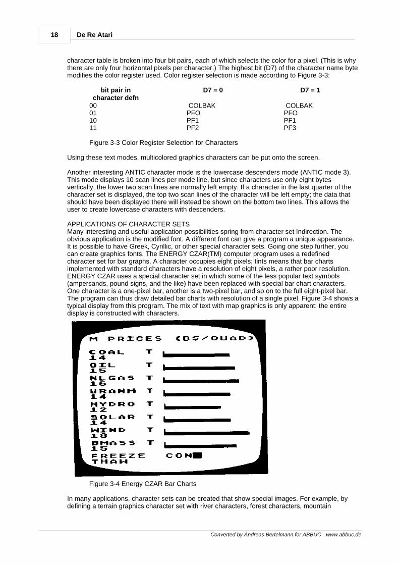
APPLICATIONS OF CHARACTER SETSMany interesting and useful application possibilities spring from character set Indirection. Theobvious application is the modified font. A different font can give a program a unique appearance.It is possible to have Greek, Cyrillic, or other special character sets. Going one step further, youcan create graphics fonts. The ENERGY CZAR(TM) computer program uses a redefinedcharacter set for bar graphs. A character occupies eight pixels; tints means that bar chartsimplemented with standard characters have a resolution of eight pixels, a rather poor resolution.ENERGY CZAR uses a special character set in which some of the less popular text symbols(ampersands, pound signs, and the like) have been replaced with special bar chart characters.One character is a one-pixel bar, another is a two-pixel bar, and so on to the full eight-pixel bar.The program can thus draw detailed bar charts with resolution of a single pixel. Figure 3-4 shows atypical display from this program. The mix of text with map graphics is only apparent; the entiredisplay is constructed with characters.
Figure 3-4 Energy CZAR Bar Charts
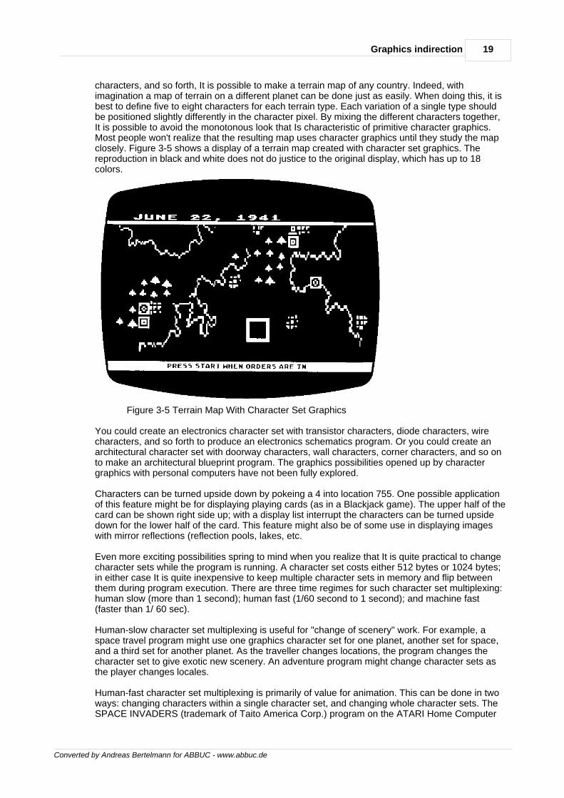
In many applications, character sets can be created that show special images. For example, bydefining a terrain graphics character set with river characters, forest characters, mountain
19Graphics indirection
Converted by Andreas Bertelmann for ABBUC - www.abbuc.de
characters, and so forth, It is possible to make a terrain map of any country. Indeed, withimagination a map of terrain on a different planet can be done just as easily. When doing this, it isbest to define five to eight characters for each terrain type. Each variation of a single type shouldbe positioned slightly differently in the character pixel. By mixing the different characters together,It is possible to avoid the monotonous look that Is characteristic of primitive character graphics.Most people won't realize that the resulting map uses character graphics until they study the mapclosely. Figure 3-5 shows a display of a terrain map created with character set graphics. Thereproduction in black and white does not do justice to the original display, which has up to 18colors.
Figure 3-5 Terrain Map With Character Set Graphics
You could create an electronics character set with transistor characters, diode characters, wirecharacters, and so forth to produce an electronics schematics program. Or you could create anarchitectural character set with doorway characters, wall characters, corner characters, and so onto make an architectural blueprint program. The graphics possibilities opened up by charactergraphics with personal computers have not been fully explored.
Characters can be turned upside down by pokeing a 4 into location 755. One possible applicationof this feature might be for displaying playing cards (as in a Blackjack game). The upper half of thecard can be shown right side up; with a display list interrupt the characters can be turned upsidedown for the lower half of the card. This feature might also be of some use in displaying imageswith mirror reflections (reflection pools, lakes, etc.
Even more exciting possibilities spring to mind when you realize that It is quite practical to changecharacter sets while the program is running. A character set costs either 512 bytes or 1024 bytes;in either case It is quite inexpensive to keep multiple character sets in memory and flip betweenthem during program execution. There are three time regimes for such character set multiplexing:human slow (more than 1 second); human fast (1/60 second to 1 second); and machine fast(faster than 1/ 60 sec).
Human-slow character set multiplexing is useful for "change of scenery" work. For example, aspace travel program might use one graphics character set for one planet, another set for space,and a third set for another planet. As the traveller changes locations, the program changes thecharacter set to give exotic new scenery. An adventure program might change character sets asthe player changes locales.
Human-fast character set multiplexing is primarily of value for animation. This can be done in twoways: changing characters within a single character set, and changing whole character sets. TheSPACE INVADERS (trademark of Taito America Corp.) program on the ATARI Home Computer
20 De Re Atari
Converted by Andreas Bertelmann for ABBUC - www.abbuc.de
uses the former technique. The invaders are actually characters. By rapidly changing thecharacters, the programmer was able to animate them. This was easy because there are only sixdifferent monsters; each has four different Incarnations.
High-speed cyclic animation of an entire screen is possible by setting up a number of charactersets, drawing the screen image, and then simply cycling through the character sets. If eachcharacter has a slightly different incarnation in each of the character sets, that character will gothrough an animated sequence as the character sets are changed. In this way a screen full ofobjects could be made to cyclically move with a very simple loop. Once the character set data is inplace and the screen has been drawn, the code to animate the screen would be this simple:
1000 FOR 1=1 TO 10 1010 POKE 756,CHARBASE(I) 1020 NEXT I 1030 GOTO 1000
Computer-fast character set animation is used to put multiple character sets onto a single screen.This makes use of the display list interrupt capability of the computer. Display list interrupts arediscussed in Sect ton 5.
The use of character sets for graphics and animation has many advantages and some limitations.The biggest advantage is that it costs very little RAM to produce detailed displays. A graphicsdisplay using BASIC mode 2 characters (such as the one shown in Figure 3-5) can give as muchdetail and one more color than a BASIC mode 7 display. Yet the character Image will cost 200bytes while the map image will cost 4000 bytes. The RAM cost for multiple character sets is only512 bytes per set, so It Is inexpensive to have multiple character sets. Screen manipulations withcharacter graphics are much faster because you have less data to manipulate. However, charactergraphics are not as flexible as map graphics. You cannot put anything you want anywhere on thescreen. This limitation would preclude the use of character graphics in some applications.However, there remain many graphics applications for which the program need display only alimited number of predefined shapes in fixed locations. In these cases, character graphics providegreat utility.

Converted by Andreas Bertelmann for ABBUC - www.abbuc.de
Player-Missilegraphics
Chapter
IV
22 De Re Atari
Converted by Andreas Bertelmann for ABBUC - www.abbuc.de
4 Player-Missile graphics
DIFFICULTIES WITH HIGH-SPEED ANIMATIONAnimation is an important capability of any home computer system. Activity on the screen cangreatly add to the excitement and realism of any program. Certainly animation is crucial to theappeal of many computer games. More importantly, an animated image can convey informationwith more impact and clarity than a static image. It can draw attention to an item or event ofimportance. It can directly show a dynamic process rather than indirectly talk about it. Animationmust accordingly be regarded as an important element of the graphics capabilities of any computersystem.
The conventional way to effect animation with home computers is to move the image data throughthe screen RAM area. This requires a two-step process. First, the program must erase the oldimage by writing background values to the RAM containing the current image. Then the programmust write the image data to the RAM corresponding to the new position of the image. Byrepeating this process over and over, the image will appear to move on the screen.
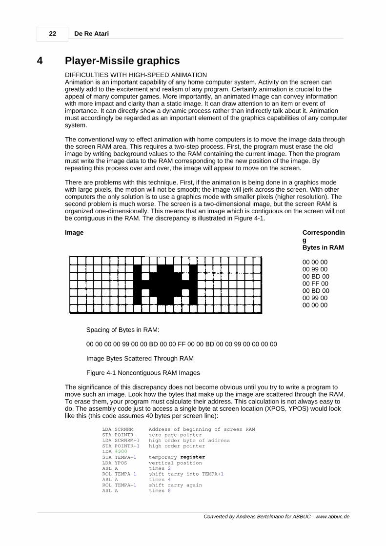
There are problems with this technique. First, if the animation is being done in a graphics modewith large pixels, the motion will not be smooth; the image will jerk across the screen. With othercomputers the only solution is to use a graphics mode with smaller pixels (higher resolution). Thesecond problem is much worse. The screen is a two-dimensional image, but the screen RAM isorganized one-dimensionally. This means that an image which is contiguous on the screen will notbe contiguous in the RAM. The discrepancy is illustrated in Figure 4-1.
Image CorrespondingBytes in RAM
00 00 0000 99 0000 BD 0000 FF 0000 BD 0000 99 0000 00 00
Spacing of Bytes in RAM:
00 00 00 00 99 00 00 BD 00 00 FF 00 00 BD 00 00 99 00 00 00 00
Image Bytes Scattered Through RAM
Figure 4-1 Noncontiguous RAM Images
The significance of this discrepancy does not become obvious until you try to write a program tomove such an image. Look how the bytes that make up the image are scattered through the RAM.To erase them, your program must calculate their address. This calculation is not always easy todo. The assembly code just to access a single byte at screen location (XPOS, YPOS) would looklike this (this code assumes 40 bytes per screen line):
LDA SCRNRM Address of beginning of screen RAM STA POINTR zero page pointer LDA SCRNRM+1 high order byte of address STA POINTR+1 high order pointer LDA #$00 STA TEMPA+1 temporary register LDA YPOS vertical position ASL A times 2 ROL TEMPA+1 shift carry into TEMPA+1 ASL A times 4 ROL TEMPA+1 shift carry again ASL A times 8
23Player-Missile graphics
Converted by Andreas Bertelmann for ABBUC - www.abbuc.de
ROL TEMPA+1 shift again LDX TEMPA+1 save YPOS*8 STX TEMPB+1 into TEMPB STA TEMPB low byte ASL A times 16 ROL TEMPA+1 ASL A times 32 ROL TEMPA+1 CLC ADC TEMPB add YPOS*8 to get YPOS*40 STA TEMPB LDA TEMPA+1 now do high order byte ADC TEMPB+1 STA TEMPB+1 LDA TEMPB TEMPB contains the offset from the top of screen to pixel CLC ADC POINTR STA POINTR LDA TEMPB+1 ADC POINTR+1 STA POINTR+1 LDY XPOS LDA (POINTR),Y
Clearly, this code to access a screen location is too cumbersome. This is certainly not the mostelegant or fastest code to solve the problem. Certainly a good programmer could take advantageof special circumstances to make the code more compact. The point is that accessing pixels on ascreen takes a lot of computing. The above routine takes about 100 machine cycles to access asingle byte on the screen. To move an image that occupies, say, 50 bytes, would require 100accesses or about 10,000 machine cycles or roughly 10 milliseconds. This may not sound likemuch, but if you want to achieve smooth motion, you have to move the object every 17milliseconds. If there are other objects to move or any calculations to carry out there isn't muchprocessor time left to devote to them. What this means is that this type of animation (called"playfield animation") is too slow for many purposes. You can still get animation this way, but youare limited to few objects or small objects or slow motion or few calculations between motion. Thetrade-offs that a programmer must make in using such animation are too restrictive.
PLAYER-MISSILE FUNDAMENTALSThe ATARI Home Computer solution to this problem is player-missile graphics. In order tounderstand player-missile graphics, it is important to understand the essence of the problem ofplayfield animation: the screen image is two-dimensional while the RAM image is one-dimensional.The solution was to create a graphics object that is one-dimensional on the screen as well asone-dimensional in RAM. This object (called a player) appears in RAM as a table that is either 128or 256 bytes long. The table is mapped directly to the screen. It appears as a vertical bandstretching from the top of the screen to the bottom. Each byte in the table is mapped into eitherone or two horizontal scan lines, with the choice between the two made by the programmer. Thescreen image is a simple bit-map of the data in the table. If a bit is on, then the corresponding pixelin the vertical column is lit; if the bit is off, then the corresponding pixel is off. Thus, the playerimage is not strictly one-dimensional; it is actually eight bits wide.
Drawing a player image on the screen is quite simple. First you draw a picture of the desired imageon graph paper. The image must be no more than eight pixels wide. You then translate the imageinto binary code, substituting ones for illuminated pixels and zeros for empty ones. Then youtranslate the resulting binary number into decimal or hexadecimal, depending on which is moreconvenient. Then you store zeros into the player RAM to clear the image. Next, store the imagedata into the player RAM, with the byte at the top of the player image going first, followed by theother image bytes in top to bottom sequence. The further down in RAM you place you place data,the lower the image will appear on the screen.VERTICAL MOTIONAnimating this image is very easy. Vertical motion is obtained by moving the image data throughthe player RAM. This is, in principle, the same method used in playfield animation, but there is abig difference in practice; the move routine for vertical motion is a one-dimensional move insteadof a two-dimensional move. The program does not need to multiply by 40 and it often does notneed to use indirection. It could be as simple as:
LDX $01 LOOP LDA PLAYER,X
24 De Re Atari
Converted by Andreas Bertelmann for ABBUC - www.abbuc.de
STA PLAYER-1,X INX BNE LOOP
This routine takes about 4 milliseconds to move the entire player, about half as long as theplayfield animation routine which actually moves only 50 bytes where this one moves 256 bytes. Ifhigh speed is necessary, the loop can be trimmed to move only the image bytes themselves ratherthan the whole player; then the loop would easily run in about 100-200 microseconds. The pointhere is that vertical motion with players is both simpler and faster than motion with playfieldobjects.
HORIZONTAL MOTIONHorizontal motion is even easier than vertical motion. There is a register for the player called thehorizontal position register. The value in this register sets the horizontal position of the player onthe screen. All you do is store a number into this register and the player jumps to that horizontalposition. To move the player horizontally simply change the number stored in the horizontalposition register. That's all there is to it.
Horizontal and vertical motion are independent; you can combine them in any fashion you choose.
The scale for the horizontal position register is one color clock per unit. Thus, adding one to thehorizontal position register will move the player one color clock to the right. There are only 228color clocks in a singe scan line; furthermore, some of these are not displayed because ofoverscan. The horizontal position register can hold 256 positions; some of these are off the left orright edge of the screen. Position 47 corresponds to the left edge of the standard playfield; position208 corresponds to the right edge of the standard playfield. Thus, the visible region of the of theplayer is in horizontal positions 47 through 208. Remember, however, that this may vary fromtelevision to television due to differences in overscan. A conservative range of values is from 60 to200. This coordinate range can sometimes be clumsy to use, but it does offer a nice feature: asimple way to remove a player from the screen is to set the player's horizontal position to zero.With a single load and store in assembly (or a singe POKE in BASIC), the player will disappear.
OTHER PLAYER-MISSILE FEATURESThe system described so far makes it possible to produce high-speed animation. There are anumber of embellishments which greatly add to its overall utility. The first embellishment is thatthere are four individual players to use. These players all have their own sets of control registersand RAM area; thus their operation is completely independent. They are labelled P0 through P3.They can be used side by side to give up to 32 bits of horizontal resolution, or they can be usedindependently to give four movable objects.
Each player has its own color register; this color register is completely independent of the playfieldcolor registers. The player color registers are called COLP(X) and are shadowed at PCOLR(X).This gives you the capability to put much more color onto the screen. However, each player hasonly one color; multicolored players are not possible without display list interrupts (display listinterrupts are discussed in Section 5).
Each player has a controllable width; you can set it to have normal width, double width, orquadruple width with the SIZEP(X) registers. This is useful for making players take on differentsizes. You also have the option of choosing the vertical resolution of the players. You can usesingle-line resolution, in which each byte in the player table occupies one horizontal scan line, ordouble-line resolution, in which each byte occupies two horizontal scan lines. With single-lineresolution, each player bit-map table is 256 bytes long; with double-line resolution each table is128 bytes long. This is the only case where player properties are not independent; the selection ofvertical resolution applies to all players. Player vertical resolution is controlled by bit D4 of theDMACTL register. In single-line resolution, the first 32 bytes in the player table area lie above thestandard playfield. The last 32 bytes lie below the standard playfield. In double-line resolution, 16bytes lie above and 16 bytes lie below the standard playfield.
MISSILESThe next embellishment is the provision of missiles. These are 2-bit wide graphics objectsassociated with the players. There is one missile assigned to each player; it takes its color from theplayer's color register. Missile shape data comes from the missile bit-map table in RAM just in front

25Player-Missile graphics
Converted by Andreas Bertelmann for ABBUC - www.abbuc.de
of the player's table. All four missiles are packed into the same table (four missiles times 2 bits permissile gives 8 bits). Missiles can move independently of players; they have their own horizontalposition registers. Missiles have their own size register, SIZEM, which can set the horizontal widthjust like the SIZEP(X) registers do for players. However, missiles cannot be set to different sizes;they are all set together. Missiles are useful as bullets or for skinny vertical lines on the screen. Ifdesired, the missiles can be grouped together into a fifth player, in which case they take the colorof playfield color register 3. This is done by setting bit D4 of the priority control register (PRIOR).Note that missiles can still move independently when this option is in effect; their horizontalpositions are set by their horizontal position registers. The fifth player enable bit only affects thecolor of the missiles.
You move a missile vertically the same way that you move a player: by moving the missile imagedata through the missile RAM area. This can be difficult to do because missiles are grouped intothe same RAM table. To access a single missile, you must mask out the bits for the other missiles.
PLAYFIELD AND PLAYFIELD PRIORITIESAn important feature of player-missile graphics is that players and missiles are completelyindependent of the playfield. You can mix them with any graphics mode, text or map. This raises aproblem: what happens if a player ends up on top of some playfield image? Which image haspriority? You have the option to define the priorities used in displaying players. If you wish, allplayers can have priority over all playfield color registers. Or you can set all playfield color registers(except background) to have priority over all players. Or you can set player 0 and player 1(henceforth referred to as P0 and P1) to have priority over all playfield color registers, with P2 andP3 having less priority than the playfield. Or you can set playfield color registers 0 and 1 (PF0 andPF1) the have priority over all players, which then have priority over PF2 and PF3. These prioritiesare selected with the priority control register (PRIOR) which is shadowed at GPRIOR. Thiscapability allows a player to pass in front of one image and behind another, allowingthree-dimensional effects.
HARDWARE COLLISION DETECTIONThe final embellishment is the provision for hardware collision detection. This is primarily of valuefor games. You can check if any graphic object (player or missile) has collided with anything else.Specifically, you can check for missile-player collisions, missile-playfield collisions, player-playercollisions, and player-playfield collisions. There are 54 possible collisions, and each one has a bitassigned to it that can be checked. If the bit is set, a collision has occurred. These bits are mappedinto 15 registers in CTIA (only the lower 4 bits are used and some are not meaningful). These areread only registers; they cannot be cleared by writing zeros to them. The registers can be clearedfor further collision detection by writing any value to register HITCLR. All collision registers arecleared by this command.
In hardware terms, a collision occurs when a player image coincides with another image; thus, thecollision bit will not be set until the part of the screen showing the collision is drawn. This meansthat collision detection might not occur until as much as 16 milliseconds have elapsed since theplayer was moved. The preferred solution is to execute player motion and collision detection duringthe vertical blank interrupt routine (see Section 8 for a discussion of vertical blank interrupts). Inthis case, collision detection should be checked first, then collisions cleared, then players moved.Another solution is to wait at least 16 milliseconds after moving a player before checking for acollision involving that player.
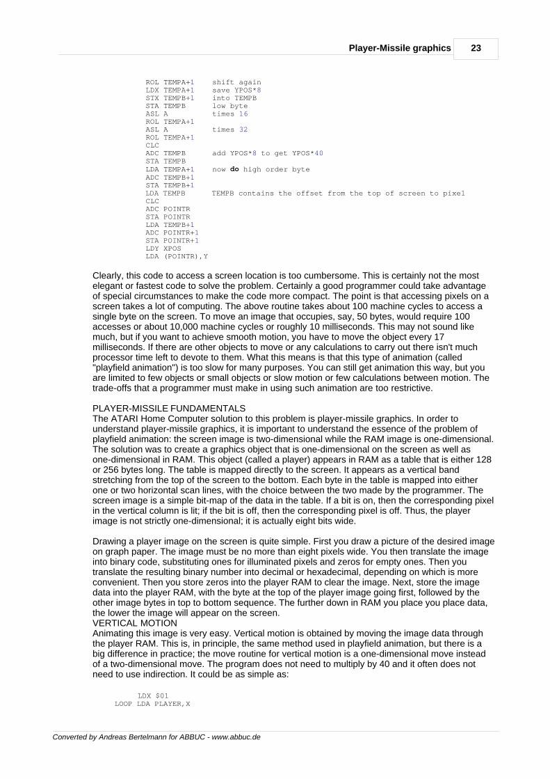
There are a number of steps necessary to use player-missile graphics. First you must set aside aplayer-missile RAM area and tell the computer where it is. If you use single-line resolution, thisRAM area will be 1280 bytes long; if you use double-line resolution it will be 640 bytes long. A goodpractice is to use the RAM area just in front of the display area at the top of RAM. The layout of theplayer-missile area is shown in Figure 4-2.
26 De Re Atari
Converted by Andreas Bertelmann for ABBUC - www.abbuc.de
Figure 4-2 Player-Missile RAM Area Layout
The pointer to the beginning of the player-missile area is labelled PMBASE. Because of internallimitations of ANTIC, PMBASE must be on a 2K address boundary for single-line resolution, or a1K address boundary for double-line resolution. If you elect not to use all of the players or none ofthe missiles, the areas of RAM set aside for the unused objects may be used for other purposes.Once you have decided where your player-missile RAM area will be, you inform ANTIC of this bystoring the page number of PMBASE into the PMBASE register in ANTIC. Note that the addressboundary restrictions on PMBASE preclude vertical motion of players by modifying PMBASE.
The next step is to clear the player and missile RAM by storing zeros into all locations in theplayer-missile RAM area. Then draw the players and missiles by storing image data into theappropriate locations in the player-missile RAM area.
Next, set the player parameters by setting the player color, horizontal position, and width registersto their initial values. If necessary, set the player/playfield priorities. Inform ANTIC of the verticalresolution you desire by setting bit D4 of register DMACTL (shadowed at SDMCTL) for single-lineresolution, and clearing the bit for double-line resolution. Finally, enable the players by setting thePM DMA enable bit in DMACTL. Be careful not to disturb the other bits in DMACTL. A sampleBASIC program for setting up a player and moving it with the joystick is given below:
1 PMBASE=54279:REM Player-missile base pointer 2 RAMTOP=106:REM OS top of RAM pointer 3 SDMCTL=559:REM RAM shadow of DMACTL register 4 GRACTL=53277:REM CTIA graphics control register 5 HPOSP0=53248:REM Horizontal position of P0 6 PCOLR0=704:REM Shadow of player 0 color 10 GRAPHICS 0: SETCOLOR 2,0,0:REM Set background color to black 20 X=0:REM BASIC's player horizontal position 30 Y=48:REM BASIC's player vertical position 40 A=PEEK(RAMTOP)-8:REM Get RAM 2K below top of RAM 50 POKE PMBASE,A:REM Tell ANTIC where PM RAM is 60 MYPMBASE=256*A:REM Keep track of PM RAM address 70 POKE SDMCTL,46:REM Enable PM DMA with 2-line res 80 POKE GRACTL,3:REM Enable PM display 90 POKE HPOSP0,100:REM Declare horizontal position 100 FOR I=MYPMBASE+512 TO MYPMBASE+640:REM this loop clears player 110 POKE I,0 120 NEXT I 130 FOR I=MYPMBASE+512+Y to MYPMBASE+518+Y 140 READ A:REM This loop draws the player 150 POKE I,A 160 NEXT I 170 DATA 8,17,35,255,32,16,8 180 POKE PCOLR0,88:REM Make the player pink
27Player-Missile graphics
Converted by Andreas Bertelmann for ABBUC - www.abbuc.de
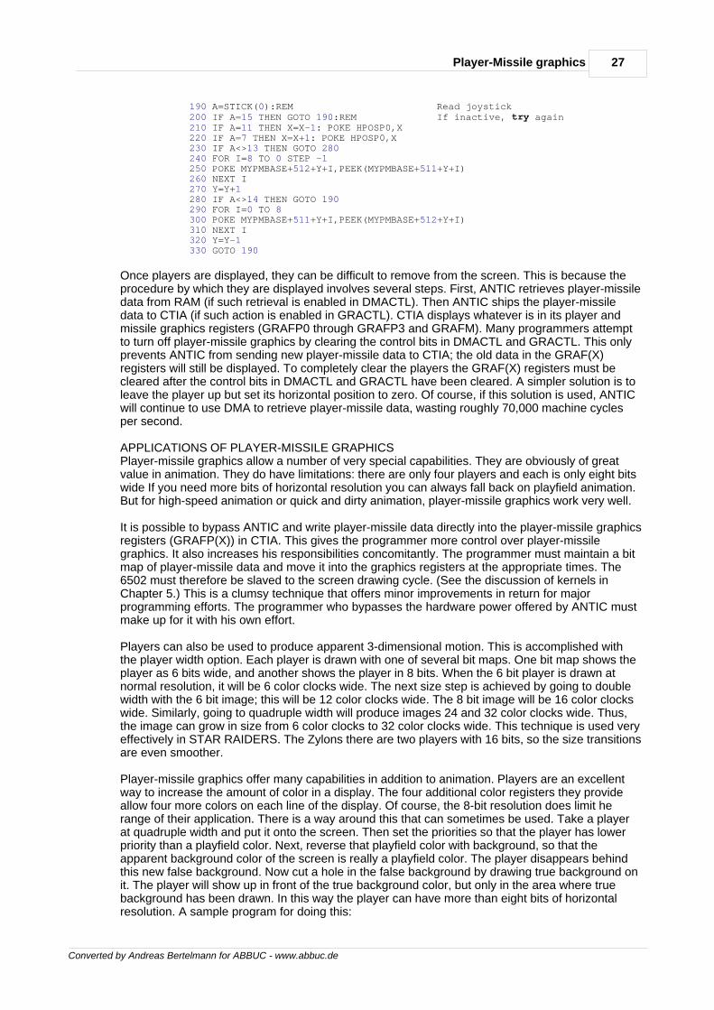
190 A=STICK(0):REM Read joystick 200 IF A=15 THEN GOTO 190:REM If inactive, try again 210 IF A=11 THEN X=X-1: POKE HPOSP0,X 220 IF A=7 THEN X=X+1: POKE HPOSP0,X 230 IF A<>13 THEN GOTO 280 240 FOR I=8 TO 0 STEP -1 250 POKE MYPMBASE+512+Y+I,PEEK(MYPMBASE+511+Y+I) 260 NEXT I 270 Y=Y+1 280 IF A<>14 THEN GOTO 190 290 FOR I=0 TO 8 300 POKE MYPMBASE+511+Y+I,PEEK(MYPMBASE+512+Y+I) 310 NEXT I 320 Y=Y-1 330 GOTO 190
Once players are displayed, they can be difficult to remove from the screen. This is because theprocedure by which they are displayed involves several steps. First, ANTIC retrieves player-missiledata from RAM (if such retrieval is enabled in DMACTL). Then ANTIC ships the player-missiledata to CTIA (if such action is enabled in GRACTL). CTIA displays whatever is in its player andmissile graphics registers (GRAFP0 through GRAFP3 and GRAFM). Many programmers attemptto turn off player-missile graphics by clearing the control bits in DMACTL and GRACTL. This onlyprevents ANTIC from sending new player-missile data to CTIA; the old data in the GRAF(X)registers will still be displayed. To completely clear the players the GRAF(X) registers must becleared after the control bits in DMACTL and GRACTL have been cleared. A simpler solution is toleave the player up but set its horizontal position to zero. Of course, if this solution is used, ANTICwill continue to use DMA to retrieve player-missile data, wasting roughly 70,000 machine cyclesper second.
APPLICATIONS OF PLAYER-MISSILE GRAPHICSPlayer-missile graphics allow a number of very special capabilities. They are obviously of greatvalue in animation. They do have limitations: there are only four players and each is only eight bitswide If you need more bits of horizontal resolution you can always fall back on playfield animation.But for high-speed animation or quick and dirty animation, player-missile graphics work very well.
It is possible to bypass ANTIC and write player-missile data directly into the player-missile graphicsregisters (GRAFP(X)) in CTIA. This gives the programmer more control over player-missilegraphics. It also increases his responsibilities concomitantly. The programmer must maintain a bitmap of player-missile data and move it into the graphics registers at the appropriate times. The6502 must therefore be slaved to the screen drawing cycle. (See the discussion of kernels inChapter 5.) This is a clumsy technique that offers minor improvements in return for majorprogramming efforts. The programmer who bypasses the hardware power offered by ANTIC mustmake up for it with his own effort.
Players can also be used to produce apparent 3-dimensional motion. This is accomplished withthe player width option. Each player is drawn with one of several bit maps. One bit map shows theplayer as 6 bits wide, and another shows the player in 8 bits. When the 6 bit player is drawn atnormal resolution, it will be 6 color clocks wide. The next size step is achieved by going to doublewidth with the 6 bit image; this will be 12 color clocks wide. The 8 bit image will be 16 color clockswide. Similarly, going to quadruple width will produce images 24 and 32 color clocks wide. Thus,the image can grow in size from 6 color clocks to 32 color clocks wide. This technique is used veryeffectively in STAR RAIDERS. The Zylons there are two players with 16 bits, so the size transitionsare even smoother.
Player-missile graphics offer many capabilities in addition to animation. Players are an excellentway to increase the amount of color in a display. The four additional color registers they provideallow four more colors on each line of the display. Of course, the 8-bit resolution does limit herange of their application. There is a way around this that can sometimes be used. Take a playerat quadruple width and put it onto the screen. Then set the priorities so that the player has lowerpriority than a playfield color. Next, reverse that playfield color with background, so that theapparent background color of the screen is really a playfield color. The player disappears behindthis new false background. Now cut a hole in the false background by drawing true background onit. The player will show up in front of the true background color, but only in the area where truebackground has been drawn. In this way the player can have more than eight bits of horizontalresolution. A sample program for doing this:
28 De Re Atari
Converted by Andreas Bertelmann for ABBUC - www.abbuc.de
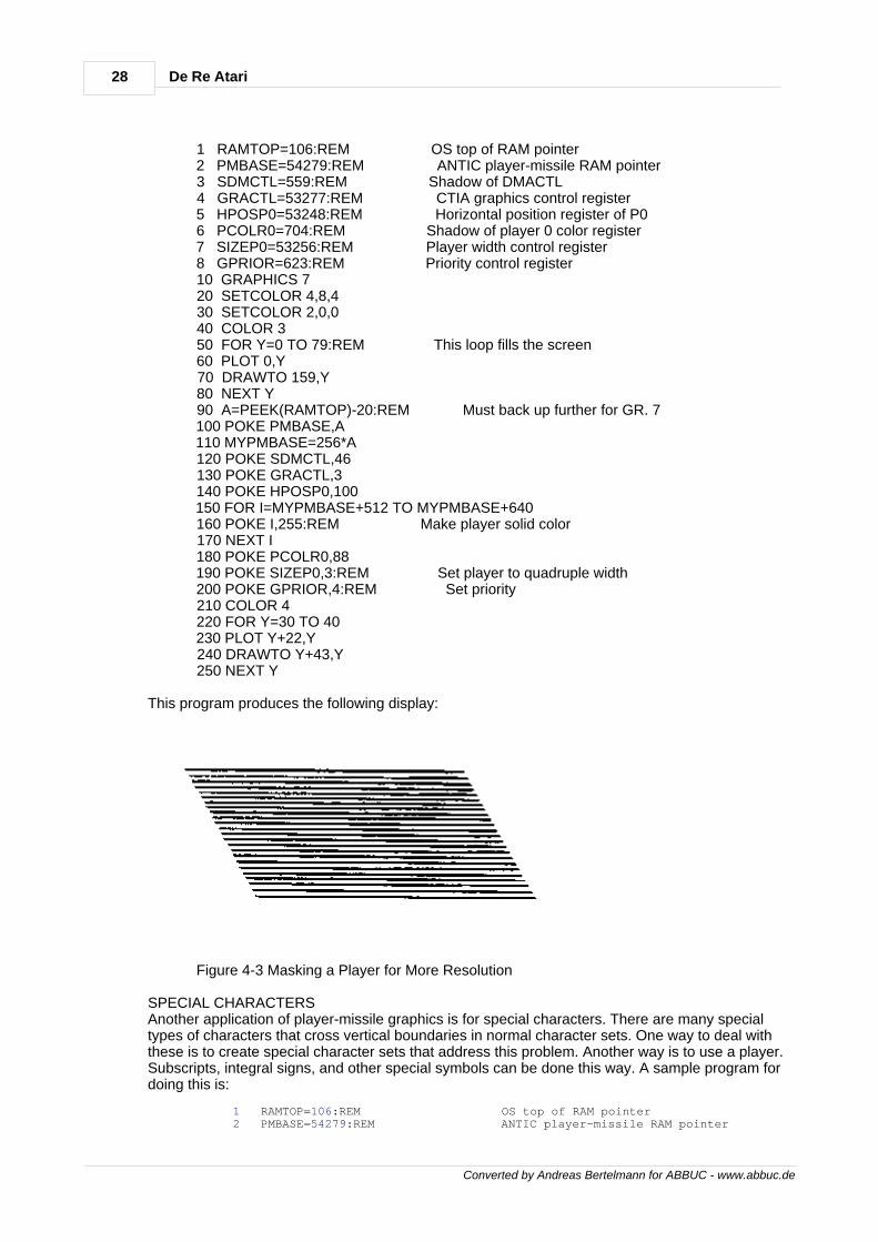
1 RAMTOP=106:REM OS top of RAM pointer 2 PMBASE=54279:REM ANTIC player-missile RAM pointer 3 SDMCTL=559:REM Shadow of DMACTL 4 GRACTL=53277:REM CTIA graphics control register 5 HPOSP0=53248:REM Horizontal position register of P0 6 PCOLR0=704:REM Shadow of player 0 color register 7 SIZEP0=53256:REM Player width control register 8 GPRIOR=623:REM Priority control register 10 GRAPHICS 7 20 SETCOLOR 4,8,4 30 SETCOLOR 2,0,0 40 COLOR 3 50 FOR Y=0 TO 79:REM This loop fills the screen 60 PLOT 0,Y 70 DRAWTO 159,Y 80 NEXT Y 90 A=PEEK(RAMTOP)-20:REM Must back up further for GR. 7 100 POKE PMBASE,A 110 MYPMBASE=256*A 120 POKE SDMCTL,46 130 POKE GRACTL,3 140 POKE HPOSP0,100 150 FOR I=MYPMBASE+512 TO MYPMBASE+640 160 POKE I,255:REM Make player solid color 170 NEXT I 180 POKE PCOLR0,88 190 POKE SIZEP0,3:REM Set player to quadruple width 200 POKE GPRIOR,4:REM Set priority 210 COLOR 4 220 FOR Y=30 TO 40 230 PLOT Y+22,Y 240 DRAWTO Y+43,Y 250 NEXT Y
This program produces the following display:
Figure 4-3 Masking a Player for More Resolution
SPECIAL CHARACTERSAnother application of player-missile graphics is for special characters. There are many specialtypes of characters that cross vertical boundaries in normal character sets. One way to deal withthese is to create special character sets that address this problem. Another way is to use a player.Subscripts, integral signs, and other special symbols can be done this way. A sample program fordoing this is:
1 RAMTOP=106:REM OS top of RAM pointer 2 PMBASE=54279:REM ANTIC player-missile RAM pointer
29Player-Missile graphics
Converted by Andreas Bertelmann for ABBUC - www.abbuc.de
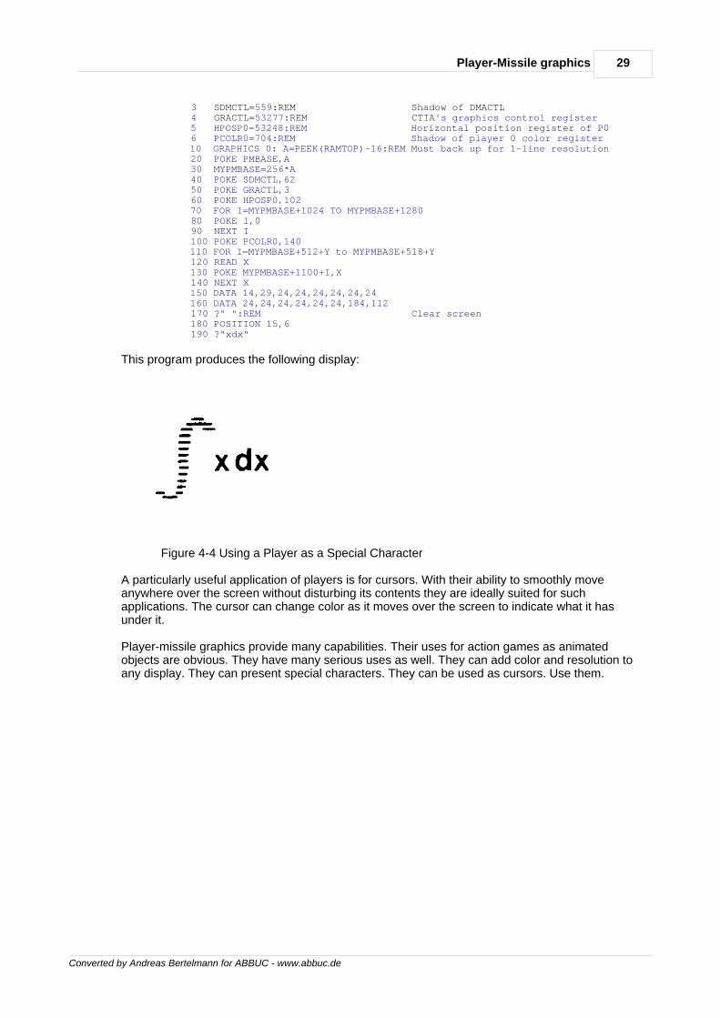
3 SDMCTL=559:REM Shadow of DMACTL 4 GRACTL=53277:REM CTIA's graphics control register 5 HPOSP0=53248:REM Horizontal position register of P0 6 PCOLR0=704:REM Shadow of player 0 color register 10 GRAPHICS 0: A=PEEK(RAMTOP)-16:REM Must back up for 1-line resolution 20 POKE PMBASE,A 30 MYPMBASE=256*A 40 POKE SDMCTL,62 50 POKE GRACTL,3 60 POKE HPOSP0,102 70 FOR I=MYPMBASE+1024 TO MYPMBASE+1280 80 POKE I,0 90 NEXT I 100 POKE PCOLR0,140 110 FOR I=MYPMBASE+512+Y to MYPMBASE+518+Y 120 READ X 130 POKE MYPMBASE+1100+I,X 140 NEXT X 150 DATA 14,29,24,24,24,24,24,24 160 DATA 24,24,24,24,24,24,184,112 170 ?" ":REM Clear screen 180 POSITION 15,6 190 ?"xdx"
This program produces the following display:
Figure 4-4 Using a Player as a Special Character
A particularly useful application of players is for cursors. With their ability to smoothly moveanywhere over the screen without disturbing its contents they are ideally suited for suchapplications. The cursor can change color as it moves over the screen to indicate what it hasunder it.
Player-missile graphics provide many capabilities. Their uses for action games as animatedobjects are obvious. They have many serious uses as well. They can add color and resolution toany display. They can present special characters. They can be used as cursors. Use them.

Converted by Andreas Bertelmann for ABBUC - www.abbuc.de
Display listinterrupts
Chapter
V
31Display list interrupts
Converted by Andreas Bertelmann for ABBUC - www.abbuc.de
5 Display list interrupts
The display list interrupt (DLI) is one of the most powerful capabilities built into the ATARI HomeComputer. It is also one of the least accessible features of the system, requiring a firmunderstanding of assembly language as well as all of the other characteristics of the machine.Display list interrupts all by themselves provide no additional capabilities; they must be used inconjunction with the other features of the system such as player-missile graphics, character setindirection, or color register indirection. With display list interrupts the full power of these featurescan be deployed.
THEORY OF OPERATIONDisplay list interrupts take advantage of the sequential nature of the raster scan television display.The television draws the screen image in a time sequence. It draws images from the top of thescreen to the bottom. This drawing process takes about 17,000 microseconds, which looksinstantaneous to the human eye, but is a long time in the time scale that the computer works in.The computer has plenty of time to change the parameters of the screen display while it is beingdrawn. Of course, it must effect each change each time the screen is drawn, which is 60 times persecond. Also (and this is the tricky part), it must change the parameter in question at exactly thesame time each time the screen is drawn. That is, the cycle of changing screen parameters mustbe synchronized to the screen drawing cycle. One way to do this might be to lock the 6502 up intoa tight timing loop whose execution frequency is exactly 60 Hertz. This would make it very difficultto carry out any computations other than the screen display computations. It would also be atedious job. A much better way would be to interrupt the 6502 just before the time has come tochange the screen parameters. The 6502 responds to the interrupt, changes the screenparameters, and returns to its normal business. The interrupt to do this must be precisely timed tooccur at exactly the same time during the screen drawing process. This specially timed interrupt isprovided by the ANTIC chip; it is called a display list interrupt (DLI).
The timing and execution of any interrupt process can be intricate; therefore we will first narratethe sequence of events in a properly working DLI. The process begins when the ANTIC chipencounters a display list instruction with its interrupt bit (bit D7) set. ANTIC waits until the last scanline of the mode line it is currently displaying. ANTIC then refers to its NMIEN register to see ifdisplay list interrupts have been enabled. If the enable bit is clear, ANTIC ignores the interrupt andcontinues its regular tasks. If the enable bit is set, ANTIC pulls down the NMI line on the 6502.ANTIC then goes back to its normal display activities. The 6502 vectors through the NMI vector toan interrupt service routine in the OS. This routine first determines the cause of the interrupt. If theinterrupt is indeed a DLI, the routine vectors through addresses $0200, $0201 (low then high) to aDLI service routine. The DLI routine changes one or more of the graphics registers which controlthe display. Then the 6502 RTIs to resume its mainline program.
There are a number of steps involved in setting up a DLI. The very first thing you must do is writethe DLI routine itself. The routine must push any 6502 registers that will be altered onto the stack,as the OS interrupt poll routine saves no registers. (The 6502 does automatically push theProcessor Status Register onto the stack.) The routine should be short and fast; it should onlychange registers related to the display. It should end by restoring any 6502 registers pushed ontothe stack. Next you must place the DLI service routine somewhere in memory. Page 6 is an idealplace. Set the vector at $0200, $0201 to point to your routine. Determine the vertical point on thescreen where you want the DLI to occur, then go to the corresponding display list instruction andset bit D7 of the previous instruction. Finally, enable the DLI by setting bit D7 of the NMIEN registerat $D40E. The DLI will immediately begin functioning.DLI TIMINGAs with any interrupt service routine, timing considerations can be critical. ANTIC does not sendthe interrupt to the 6502 immediately upon encountering an interrupt instruction; it delays this untilthe last scan line of the interrupting mode line. There are a number of processing delays before theDLI reaches your service routine. Thus, your DLI service routine will begin executing while theelectron beam is partway across the screen in the last scan line of the interrupting mode line. Forexample, if such a DLI routine changes a color register, the old color will be displayed on the lefthalf of the screen and the new color will show up on the right half of the screen. Because ofuncertain timing in the response of the 6502 to an interrupt, the border between them will not besharp but will jiggle back and forth irritatingly.
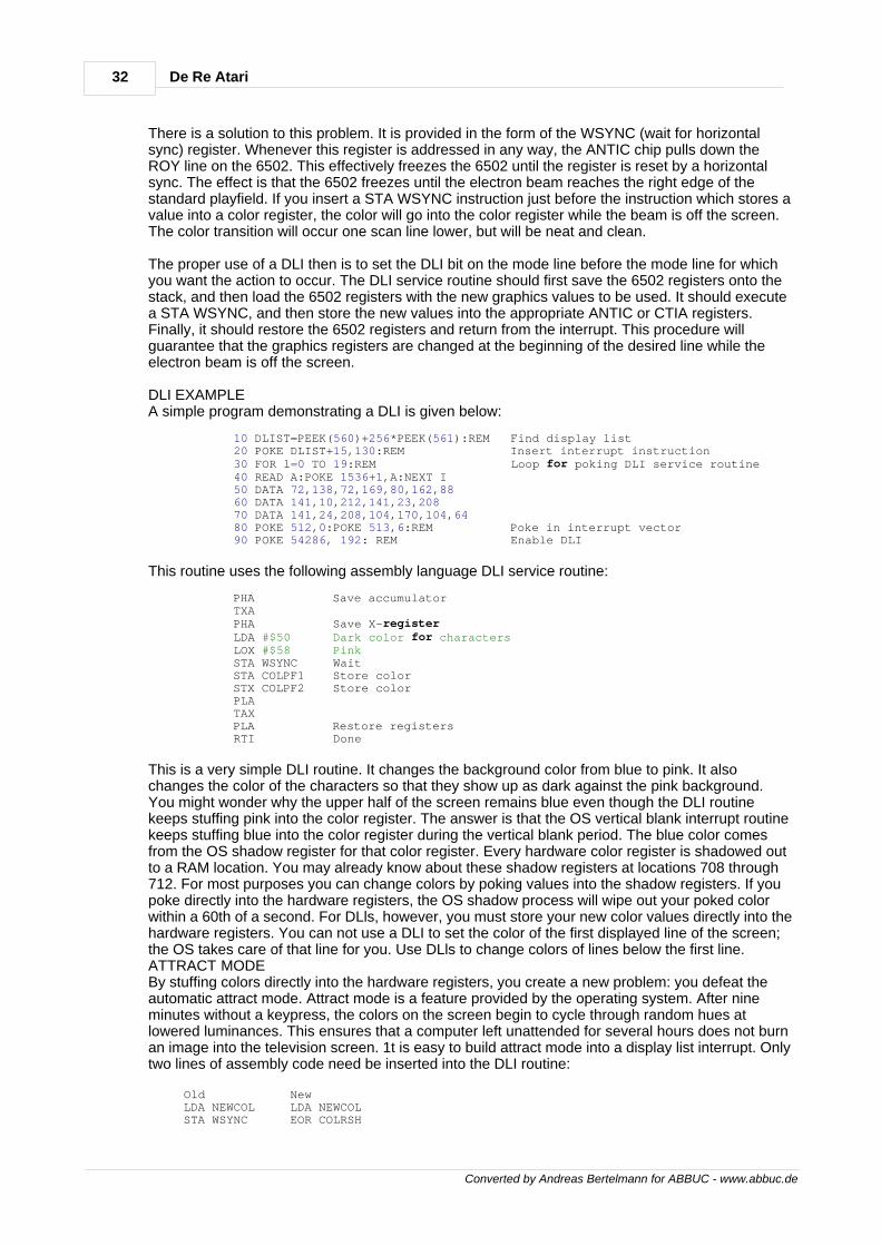
32 De Re Atari
Converted by Andreas Bertelmann for ABBUC - www.abbuc.de
There is a solution to this problem. It is provided in the form of the WSYNC (wait for horizontalsync) register. Whenever this register is addressed in any way, the ANTIC chip pulls down theROY line on the 6502. This effectively freezes the 6502 until the register is reset by a horizontalsync. The effect is that the 6502 freezes until the electron beam reaches the right edge of thestandard playfield. If you insert a STA WSYNC instruction just before the instruction which stores avalue into a color register, the color will go into the color register while the beam is off the screen.The color transition will occur one scan line lower, but will be neat and clean.
The proper use of a DLI then is to set the DLI bit on the mode line before the mode line for whichyou want the action to occur. The DLI service routine should first save the 6502 registers onto thestack, and then load the 6502 registers with the new graphics values to be used. It should executea STA WSYNC, and then store the new values into the appropriate ANTIC or CTIA registers.Finally, it should restore the 6502 registers and return from the interrupt. This procedure willguarantee that the graphics registers are changed at the beginning of the desired line while theelectron beam is off the screen.
DLI EXAMPLEA simple program demonstrating a DLI is given below:
10 DLIST=PEEK(560)+256*PEEK(561):REM Find display list 20 POKE DLIST+15,130:REM Insert interrupt instruction 30 FOR l=0 TO 19:REM Loop for poking DLI service routine 40 READ A:POKE 1536+1,A:NEXT I 50 DATA 72,138,72,169,80,162,88 60 DATA 141,10,212,141,23,208 70 DATA 141,24,208,104,170,104,64 80 POKE 512,0:POKE 513,6:REM Poke in interrupt vector 90 POKE 54286, 192: REM Enable DLI
This routine uses the following assembly language DLI service routine:
PHA Save accumulator TXA PHA Save X-register LDA #$50 Dark color for characters LOX #$58 Pink STA WSYNC Wait STA COLPF1 Store color STX COLPF2 Store color PLA TAX PLA Restore registers RTI Done
This is a very simple DLI routine. It changes the background color from blue to pink. It alsochanges the color of the characters so that they show up as dark against the pink background.You might wonder why the upper half of the screen remains blue even though the DLI routinekeeps stuffing pink into the color register. The answer is that the OS vertical blank interrupt routinekeeps stuffing blue into the color register during the vertical blank period. The blue color comesfrom the OS shadow register for that color register. Every hardware color register is shadowed outto a RAM location. You may already know about these shadow registers at locations 708 through712. For most purposes you can change colors by poking values into the shadow registers. If youpoke directly into the hardware registers, the OS shadow process will wipe out your poked colorwithin a 60th of a second. For DLls, however, you must store your new color values directly into thehardware registers. You can not use a DLI to set the color of the first displayed line of the screen;the OS takes care of that line for you. Use DLls to change colors of lines below the first line.ATTRACT MODEBy stuffing colors directly into the hardware registers, you create a new problem: you defeat theautomatic attract mode. Attract mode is a feature provided by the operating system. After nineminutes without a keypress, the colors on the screen begin to cycle through random hues atlowered luminances. This ensures that a computer left unattended for several hours does not burnan image into the television screen. 1t is easy to build attract mode into a display list interrupt. Onlytwo lines of assembly code need be inserted into the DLI routine:
Old New LDA NEWCOL LDA NEWCOL STA WSYNC EOR COLRSH
33Display list interrupts
Converted by Andreas Bertelmann for ABBUC - www.abbuc.de
STA COLPF2 AND DRKMSK STA WSYNC STA COLPF2
DRKMSK and COLRSH are zero page locations ($4E and $4F) set up and updated by the OSduring vertical blank interrupt. When attract mode is not in force, COLRSH takes a value of 00 andDRKMSK takes $FF. When attract mode is in force, COLRSH is given a new random value every4 seconds and DRKMSK holds a value of $F6. Thus, COLRSH scrambles the color and DRKMSKlops off the highest luminance bit.DETAILED TIMING CONSIDERATIONSThe implementation of attract mode in DLls exacerbates an already difficult problem: the shortageof execution time during a DLI. A description of DLI timing will make the problem more obvious.DLI execution is broken into three phases: - Phase One covers the period from the beginning ofthe DLI to the STA WSYNC instruction. During Phase One the electron beam is drawing the lastscan line of the interrupting mode line. - Phase Two covers the period from the STA WSYNCinstruction to the appearance of the beam on the television screen. Phase Two corresponds tohorizontal blank; all graphics changes should be made during Phase Two. - Phase Three coversthe period from the appearance of the beam on the screen to the end of the DLI service routine.The timing of Phase Three is not critical.
One horizontal scan line takes 114 processor clock cycles of real time. A DLI reaches the 6502 oncycle number 8. The 6502 takes from 8 to 14 cycles to respond to the interrupt. The OS routine toservice the interrupt and vector it on to the DLI service routine takes 11 machine cycles. Duringthis time from 1 to 3 cycles wi11 be stolen for memory refresh DMA. Thus, the DLI service routineis not reached until from 28 to 36 clock cycles have elapsed. For planning purposes we mustassume the worst case and program as if the DLI service routine is reached on cycle number 36.Furthermore, the
STA WSYNC instruction must be reached by cycle number 100; this reduces the time available inPhase One by 14 cycles. Finally, ANTIC's DMA will steal some of the remaining clock cycles fromthe 6502. Nine cycles will be lost to memory refresh DMA. This leaves an absolute maximum of 55cycles available for Phase One. This maximum is achieved only with blank line mode lines.Character and map mode instructions will result in the loss of one cycle for each byte of displaydata. The worst case arises with BASIC modes 0, 7, and 8, which require 40 bytes per line. Only15 machine cycles are available to Phase One in such modes. Thus, a Phase One routine willhave from 15 to 55 machine cycles of execution time available to it.
Phase Two, the critical phase, extends over 27 clock cycles of real time. As with Phase One, someof these cycles are lost to cycle stealing DMA. Player-missile graphics will cost five cycles if theyare used. The display instruction will cost one cycle; if the LMS option is used, two more cycles willbe stolen. Finally, one or two cycles may be lost to memory refresh or display data retrieval. Thus,from 17 to 26 machine cycles are available to Phase Two.
The problems of DLI timing now become obvious. To load, attract and store a single color willconsume 14 cycles. Saving A, X, and Y onto the stack and then loading, attracting, and savingthree colors into A, X, and Y will cost 47 cycles, most if not all of Phase One. Obviously, theprogrammer who wishes to use DLI for extensive graphics changes will expend much effort on thetiming of the DLI. Fortunately, the beginning programmer need not be concerned with extensivetiming calculations. If only single color changes or simple graphics operations are to be performed,cycle counting and speed optimization are unnecessary. These considerations are only importantfor high-performance situations.
There are no simple options for the programmer who needs to change more than three colorregisters in a single DLI. It might be possible to load, attract, and store a fourth color early in PhaseThree if that color is not displayed on the left edge of the screen. Similarly, a color not showing upon the right side of the screen could be changed during Phase One. Another approach is to breakone overactive DLI into two less ambitious DLls, each doing half the work of the original. Thesecond DLI could be provided by inserting a single scan line blank instruction (with DLI bit set) intothe display list just below the main interrupting mode line. This will consume some screen space.
Another partial solution is to perform the attract chores during vertical blank periods. To do this,two tables of colors must be kept in RAM. The first table contains color values intended to be
34 De Re Atari
Converted by Andreas Bertelmann for ABBUC - www.abbuc.de
displayed by the DLI routines. The second table contains the attracted values of these colors.During vertical blank, a user-supplied interrupt service routine fetches each color from the firsttable, attracts it, and stores the attracted color to the second table. The DLI routine then retrievesvalues directly from the second table without paying the time penalty for attract.
MULTIPLE DLlsIt is often desirable to have a number of DLls occurring at several vertical positions on the screen.This is an important way to add color to a display. Unfortunately, there is only one DLI vector; ifmultiple DLls are to be implemented then the vectoring to the appropriate DLI must beimplemented, in the DLI routine itself. There are several ways to do this. If the DLI routine does thesame process with different values then it can be table-driven. On each pass through the DLIroutine, a counter is incremented and used as an index to a table of values. A sample DLI routinefor doing this is as follows:
PHA TXA PHA INC COUNTR LDX COUNTR LDA COLTAB,X Use page two for color table STA WSYNC Wait STA COLBAK CPX #$4F Last line? BNE ENDDLI No, exit LDA #$00 Yes, reset counter STA COUNTR ENDDLI PLA TAX PLA Restore accumulator RTI
The BASIC program to call this routine is:
10 GRAPHICS 7 20 DLIST=PEEK(560)+256*PEEK(561):REM Find display list 30 FOR J=6 TO 84:REM Give every mode line a DLI 40 POKE DLIST+J,141:REM BASIC mode 7 with DLI bit set 50 NEXT J 60 FOR J=0 TO 30 70 READ A:POKE 1536+J,A:NEXTJ:REM Poke in DLI service routine 80 DATA 72,138,72,238,32,6,175,32,6 90 DATA 189,0,240,141,10,212,141,26,208 100 DATA 224,79,208,5,169,0 110 DATA 141,32,6,104,170,104,64 120 POKE 512,0:POKE 513,6:REM Vector to DLI service routine 130 POKE 54286,192:REM Enable DLI
This program will put 80 different colors onto the screen.
There are other ways to implement multiple DLls. One way is to use a DLI counter as a test forbranching through the DLI service routines to the proper DLI service routine. This slows down theresponse of all the DLls, particularly the ones at the end of the test sequence. A better way is tohave each DLI service routine write the address of the next routine into the DLI vector at $200,$201. This should be done during Phase Three. This is the most general solution to the problem ofmultiple DLls. It has the additional advantage that vectoring logic is performed after the time criticalportion of the DLI, not before.
The OS keyboard click routine interferes with the function of the DLI. Whenever a key is pressedand acknowledged, the onboard speaker is clicked. The timing for this click is provided by severalSTA WSYNC instructions. This can throw off the timing of a DLI routine and cause the screencolors to jump downward by one scan line for a fraction of a second. There is no easy solution tothis problem. One possible solution involves the VCOUNT register, a read-only register in ANTICwhich tells what scan line ANTIC is displaying. A DLI routine could examine this register to decidewhen to change a color. Another solution is to disable the OS keyboard service routine and provideyour own keyboard routine. This would be a tedious job. The final solution is to accept no inputsfrom the keyboard. If key presses are-not acknowledged, the screen jiggle does not occur.
KERNELS
35Display list interrupts
Converted by Andreas Bertelmann for ABBUC - www.abbuc.de
The DLI was designed to replace a more primitive software/hardware technique called a kernel. Akernel is a 6502 program loop which is precisely timed to the display cycle of the television set. Bymonitoring the VCOUNT register and consulting a table of screen changes catalogued as afunction of VCOUNT values, the 6502 can arbitrarily control all graphics values for the entirescreen. A high price is paid for this power: the 6502 is not available for computations during thescreen display time, which is about 75 percent of the time. Furthermore, no computation mayconsume more than the 4000 or so machine cycles available during vertical blank and overscanperiods. This restriction means that kernels can only be used with programs requiring littlecomputation, such as certain skill and action games. For example, the BASKETBALL program forthe ATARI 400/800 Computers uses a kernel; the program requires little computation but muchcolor. The multicolored players in this game could not be done with display list interrupts, becauseDLls are keyed to playfield vertical positions, not player positions.
It is possible to extend the kernel idea right into a single scan line and change graphics registerson the fly. In this way a single color register can present several colors on a single scan line. Thehorizontal position of the color change is determined by the amount of time that elapses before thechange goes in. Thus, by carefully counting machine cycles, the programmer can get moregraphics onto the screen. Unfortunately, this is extremely difficult to achieve in practice. WithANTIC DMAing the 6502, it is very difficult to know exactly how many cycles have really elapsed; asimple count of 6502 cycles is not adequate. If ANTIC's DMA Is turned off, the 6502 can assumefull control of the display but must then perform all the work that ANTIC normally does. For thesereasons horizontal kernels are seldom worth the effort. However, if the two images to be displayedin different colors are widely separated, say by 20 color clocks or more, the separation shouldcover up the timing uncertainties and render this technique feasible.
APPLICATIONS OF DISPLAY LIST INTERRUPTSThe tremendous value of graphics indirection and all those modifiable registers in the hardwarenow becomes obvious. With display list interrupts, every one of those registers can be changed onthe fly. You can put lots of color, graphics, and special effects onto the screen. The most obviousapplication of DLls is to put more color onto the screen. Each color register can be changed asmany times as you have DLls. This applies to both playfield color registers and player colorregisters. Thus, you have up to nine color registers, each of which can display up to 128 differentcolors. Is that enough color for you? Of course, a normal program would not lend itself toeffectively using all of those colors. Too many DLls start slowing down the whole program.Sometimes the screen layout cannot accommodate lots of DLls. In practice, a dozen colors iseasy, two dozen requires careful planning, and more than that requires a contrived situation.
Display list interrupts can give more than color; they can also be used to extend the power ofplayer-missile graphics. The horizontal position of a player can be changed by a DLI. In this way aplayer can be repositioned partway down the screen. A single player can have several incarnationson the screen. If you imagine a player as a vertical column with images drawn on it, a DLIbecomes a pair of scissors with which you can snip the column and reposition sections of it on thescreen. Of course, no two sections of the player can be on the same horizontal line, so twoincarnations of the player cannot be on the same horizontal line. If your display needs allowgraphics objects that will never be on the same horizontal line, a single player can do the job.
Another way to use DLls in conjunction with players is to change their width or priority. This wouldmost often be used along with the priority masking trick described in Section 4.
The last application of DLls is the changing of character sets partway down the screen. This allowsa program to use character graphics in a large window and regular text in a text window. Multiplecharacter set changes are possible; a program might use one graphics character set at the top ofthe screen, another graphics character set in the middle of the screen, and a regular text characterset at the bottom. A `Rosetta Stone' program would also be possible, showing different text fontson the same screen. The vertical reflect bit can be changed with a DLI routine, allowing some textto be rightside up and other text to be upside down.
The proper use of the DLI requires careful layout of the screen display. The designer must giveclose consideration to the vertical architecture of display. The raster scan television system is nottwo-dimensionally symmetric; it has far more vertical structure than horizontal structure. This isbecause the pace for horizontal screen drawing is 262 times faster than the pace for vertical
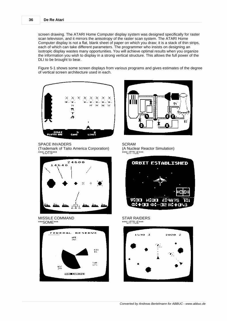
36 De Re Atari
Converted by Andreas Bertelmann for ABBUC - www.abbuc.de
screen drawing. The ATARI Home Computer display system was designed specifically for rasterscan television, and it mirrors the anisotropy of the raster scan system. The ATARI HomeComputer display is not a flat, blank sheet of paper on which you draw; it is a stack of thin strips,each of which can take different parameters. The programmer who insists on designing anisotropic display wastes many opportunities. You will achieve optimal results when you organizethe information you wish to display in a strong vertical structure. This allows the full power of theDLI to be brought to bear.
Figure 5-1 shows some screen displays from various programs and gives estimates of the degreeof vertical screen architecture used in each.
SPACE INVADERS(Trademark of Taito America Corporation)***LOTS***
SCRAM(A Nuclear Reactor Simulation)***LITTLE***
MISSILE COMMAND***SOME***
STAR RAIDERS***LITTLE***

37Display list interrupts
Converted by Andreas Bertelmann for ABBUC - www.abbuc.de
GRAPH IT***NONE***
ASTEROIDS***NONE***
Figure 5-1 Examples of Vertical Screen Architecture

Converted by Andreas Bertelmann for ABBUC - www.abbuc.de
Scrolling
Chapter
VI
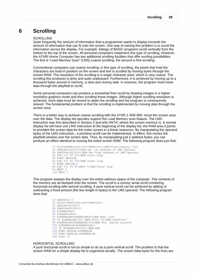
39Scrolling
Converted by Andreas Bertelmann for ABBUC - www.abbuc.de
6 Scrolling
SCROLLINGQuite frequently the amount of information that a programmer wants to display exceeds theamount of information that can fit onto the screen. One way of solving this problem is to scroll theinformation across the display. For example, listings of BASIC programs scroll vertically from thebottom to the top of the screen. All personal computers implement this type of scrolling. However,the ATARI Home Computer has two additional scrolling facilities that offer exciting possibilities.The first is "Load Memory Scan" (LMS) coarse scrolling; the second is fine scrolling.
Conventional computers use coarse scrolling; in this type of scrolling, the pixels that hold thecharacters are fixed in position on the screen and text is scrolled by moving bytes through thescreen RAM. The resolution of the scrolling is a single character pixel, which is very coarse. Thescrolling this produces is jerky and quite unpleasant. Furthermore, it is achieved by moving up to athousand bytes around in memory, a slow and clumsy task. In essence, the program must movedata through the playfield to scroll.
Some personal computers can produce a somewhat finer scroll by drawing images in a higherresolution graphics mode and then scrolling these images. Although higher scrolling resolution isachieved, more data must be moved to attain the scrolling and the program is consequentlyslowed. The fundamental problem is that the scrolling is implemented by moving data through thescreen area.
There is a better way to achieve coarse scrolling with the ATAR.1 400/ 800: move the screen areaover the data. The display list opcodes support the Load Memory scan feature. The LMSinstruction was first described in Section 2 and tells ANTIC where the screen memory is. A normaldisplay list will have one LMS instruction at the beginning of the display list; the RAM area it pointsto provides the screen data for the entire screen in a linear sequence. By manipulating the operandbytes of the LMS instruction., a primitive scroll can be Implemented. In effect, this moves theplayfield window over the screen data. Thus, by manipulating just 2 address bytes, you canproduce an effect identical to moving the entire screen RAM. The following program does just that:
10 DLIST=PEEK(560)+256*PEEK(561):REM Find display list 20 LMSLOW=DLIST+4:REM Get low address of LMS operand 30 LMSHIGH=DLIST+5:REM Get high address of LMS operand 40 FOR 1=0 TO 255:REM Outer loop 50 POKE LMSHIGH, 60 FOR J=O TO 255:REM Inner loop 70 POKE LMSLOW,J 80 FOR Y=1 TO 50:NEXT Y:REM Delay loop 90 NEXT J 100 NEXT 1
This program sweeps the display over the entire address space of the computer. The contents ofthe memory are all dumped onto the screen. The scroll is a clumsy serial scroll combininghorizontal scrolling with vertical scrolling. A pure vertical scroll can be achieved by adding orsubtracting a fixed amount (the line length in bytes) to the LMS operand. The following programdoes that:
10 GRAPHICS 0 20 DLIST=PEEK(560)+256*PEEK(561) 30 LMSLOW=DLIST+4 40 LMSHIGH=DLIST+5 50 SCREENLOW=0 60 SCREENHIGH=0 70 SCREENLOW=SCREENLOW+40:REM Next line 80 IF SCREENLOW<256 THEN GOTO 120:REM Overflow? 90 SCREENLOW=SCREENLOW-256:REM Yes, adjust pointer 100 SCREENHIGH=SCREENHIGH+1 110 IF SCREENHIGH=256 THEN END 120 POKE LMSLOW,SCREENLOW 130 POKE LMSHIGH,SCREENHIGH 140 GOTO 70
HORIZONTAL SCROLLINGA pure horizontal scroll is not so simple to do as a pure vertical scroll. The problem is that thescreen RAM for a simple display list is organIzed serially. The screen data bytes for the lines are
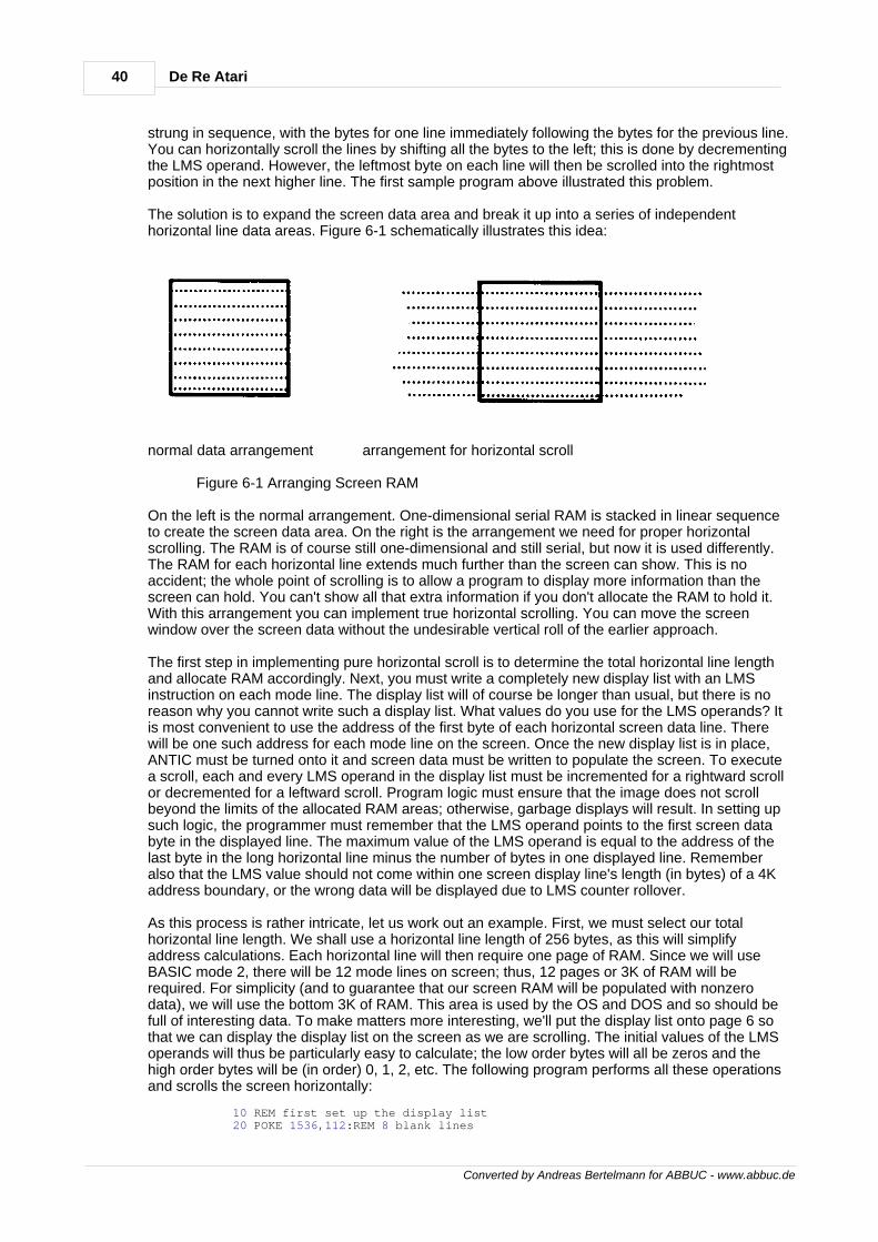
40 De Re Atari
Converted by Andreas Bertelmann for ABBUC - www.abbuc.de
strung in sequence, with the bytes for one line immediately following the bytes for the previous line.You can horizontally scroll the lines by shifting all the bytes to the left; this is done by decrementingthe LMS operand. However, the leftmost byte on each line will then be scrolled into the rightmostposition in the next higher line. The first sample program above illustrated this problem.
The solution is to expand the screen data area and break it up into a series of independenthorizontal line data areas. Figure 6-1 schematically illustrates this idea:
normal data arrangement arrangement for horizontal scroll
Figure 6-1 Arranging Screen RAM
On the left is the normal arrangement. One-dimensional serial RAM is stacked in linear sequenceto create the screen data area. On the right is the arrangement we need for proper horizontalscrolling. The RAM is of course still one-dimensional and still serial, but now it is used differently.The RAM for each horizontal line extends much further than the screen can show. This is noaccident; the whole point of scrolling is to allow a program to display more information than thescreen can hold. You can't show all that extra information if you don't allocate the RAM to hold it.With this arrangement you can implement true horizontal scrolling. You can move the screenwindow over the screen data without the undesirable vertical roll of the earlier approach.
The first step in implementing pure horizontal scroll is to determine the total horizontal line lengthand allocate RAM accordingly. Next, you must write a completely new display list with an LMSinstruction on each mode line. The display list will of course be longer than usual, but there is noreason why you cannot write such a display list. What values do you use for the LMS operands? Itis most convenient to use the address of the first byte of each horizontal screen data line. Therewill be one such address for each mode line on the screen. Once the new display list is in place,ANTIC must be turned onto it and screen data must be written to populate the screen. To executea scroll, each and every LMS operand in the display list must be incremented for a rightward scrollor decremented for a leftward scroll. Program logic must ensure that the image does not scrollbeyond the limits of the allocated RAM areas; otherwise, garbage displays will result. In setting upsuch logic, the programmer must remember that the LMS operand points to the first screen databyte in the displayed line. The maximum value of the LMS operand is equal to the address of thelast byte in the long horizontal line minus the number of bytes in one displayed line. Rememberalso that the LMS value should not come within one screen display line's length (in bytes) of a 4Kaddress boundary, or the wrong data will be displayed due to LMS counter rollover.
As this process is rather intricate, let us work out an example. First, we must select our totalhorizontal line length. We shall use a horizontal line length of 256 bytes, as this will simplifyaddress calculations. Each horizontal line will then require one page of RAM. Since we will useBASIC mode 2, there will be 12 mode lines on screen; thus, 12 pages or 3K of RAM will berequired. For simplicity (and to guarantee that our screen RAM will be populated with nonzerodata), we will use the bottom 3K of RAM. This area is used by the OS and DOS and so should befull of interesting data. To make matters more interesting, we'll put the display list onto page 6 sothat we can display the display list on the screen as we are scrolling. The initial values of the LMSoperands will thus be particularly easy to calculate; the low order bytes will all be zeros and thehigh order bytes will be (in order) 0, 1, 2, etc. The following program performs all these operationsand scrolls the screen horizontally:
10 REM first set up the display list 20 POKE 1536,112:REM 8 blank lines
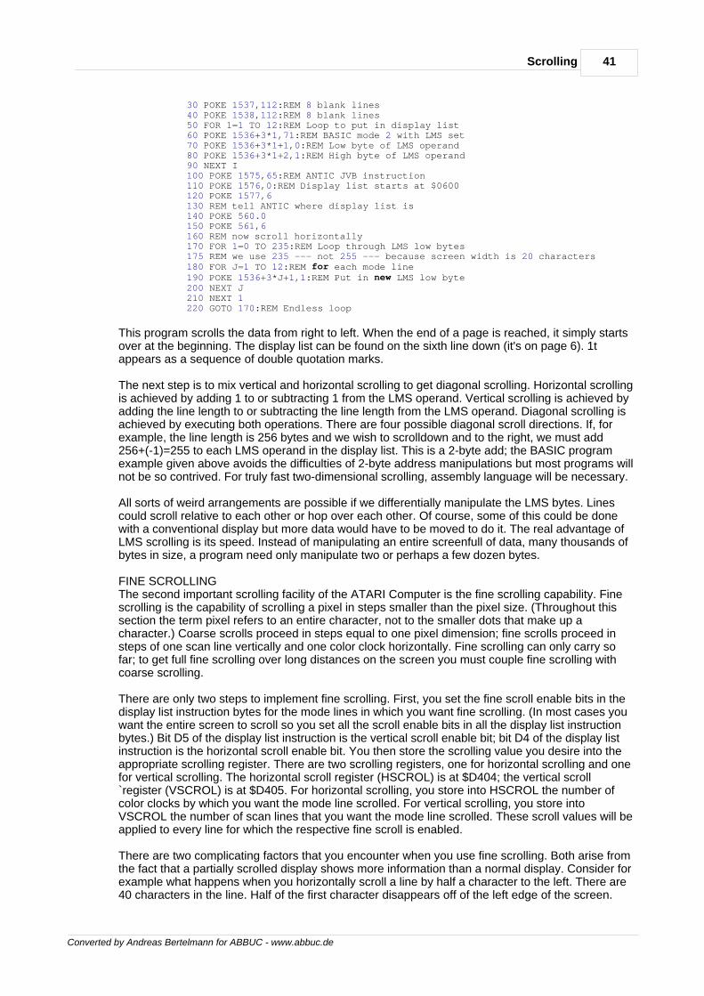
41Scrolling
Converted by Andreas Bertelmann for ABBUC - www.abbuc.de
30 POKE 1537,112:REM 8 blank lines 40 POKE 1538,112:REM 8 blank lines 50 FOR 1=1 TO 12:REM Loop to put in display list 60 POKE 1536+3*1,71:REM BASIC mode 2 with LMS set 70 POKE 1536+3*1+1,0:REM Low byte of LMS operand 80 POKE 1536+3*1+2,1:REM High byte of LMS operand 90 NEXT I 100 POKE 1575,65:REM ANTIC JVB instruction 110 POKE 1576,0:REM Display list starts at $0600 120 POKE 1577,6 130 REM tell ANTIC where display list is 140 POKE 560.0 150 POKE 561,6 160 REM now scroll horizontally 170 FOR 1=0 TO 235:REM Loop through LMS low bytes 175 REM we use 235 --- not 255 --- because screen width is 20 characters 180 FOR J=1 TO 12:REM for each mode line 190 POKE 1536+3*J+1,1:REM Put in new LMS low byte 200 NEXT J 210 NEXT 1 220 GOTO 170:REM Endless loop
This program scrolls the data from right to left. When the end of a page is reached, it simply startsover at the beginning. The display list can be found on the sixth line down (it's on page 6). 1tappears as a sequence of double quotation marks.
The next step is to mix vertical and horizontal scrolling to get diagonal scrolling. Horizontal scrollingis achieved by adding 1 to or subtracting 1 from the LMS operand. Vertical scrolling is achieved byadding the line length to or subtracting the line length from the LMS operand. Diagonal scrolling isachieved by executing both operations. There are four possible diagonal scroll directions. If, forexample, the line length is 256 bytes and we wish to scrolldown and to the right, we must add256+(-1)=255 to each LMS operand in the display list. This is a 2-byte add; the BASIC programexample given above avoids the difficulties of 2-byte address manipulations but most programs willnot be so contrived. For truly fast two-dimensional scrolling, assembly language will be necessary.
All sorts of weird arrangements are possible if we differentially manipulate the LMS bytes. Linescould scroll relative to each other or hop over each other. Of course, some of this could be donewith a conventional display but more data would have to be moved to do it. The real advantage ofLMS scrolling is its speed. Instead of manipulating an entire screenfull of data, many thousands ofbytes in size, a program need only manipulate two or perhaps a few dozen bytes.
FINE SCROLLINGThe second important scrolling facility of the ATARI Computer is the fine scrolling capability. Finescrolling is the capability of scrolling a pixel in steps smaller than the pixel size. (Throughout thissection the term pixel refers to an entire character, not to the smaller dots that make up acharacter.) Coarse scrolls proceed in steps equal to one pixel dimension; fine scrolls proceed insteps of one scan line vertically and one color clock horizontally. Fine scrolling can only carry sofar; to get full fine scrolling over long distances on the screen you must couple fine scrolling withcoarse scrolling.
There are only two steps to implement fine scrolling. First, you set the fine scroll enable bits in thedisplay list instruction bytes for the mode lines in which you want fine scrolling. (In most cases youwant the entire screen to scroll so you set all the scroll enable bits in all the display list instructionbytes.) Bit D5 of the display list instruction is the vertical scroll enable bit; bit D4 of the display listinstruction is the horizontal scroll enable bit. You then store the scrolling value you desire into theappropriate scrolling register. There are two scrolling registers, one for horizontal scrolling and onefor vertical scrolling. The horizontal scroll register (HSCROL) is at $D404; the vertical scroll`register (VSCROL) is at $D405. For horizontal scrolling, you store into HSCROL the number ofcolor clocks by which you want the mode line scrolled. For vertical scrolling, you store intoVSCROL the number of scan lines that you want the mode line scrolled. These scroll values will beapplied to every line for which the respective fine scroll is enabled.
There are two complicating factors that you encounter when you use fine scrolling. Both arise fromthe fact that a partially scrolled display shows more information than a normal display. Consider forexample what happens when you horizontally scroll a line by half a character to the left. There are40 characters in the line. Half of the first character disappears off of the left edge of the screen.
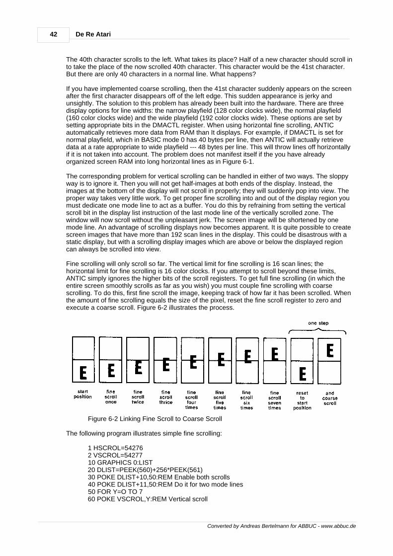
42 De Re Atari
Converted by Andreas Bertelmann for ABBUC - www.abbuc.de
The 40th character scrolls to the left. What takes its place? Half of a new character should scroll into take the place of the now scrolled 40th character. This character would be the 41st character.But there are only 40 characters in a normal line. What happens?
If you have implemented coarse scrolling, then the 41st character suddenly appears on the screenafter the first character disappears off of the left edge. This sudden appearance is jerky andunsightly. The solution to this problem has already been built into the hardware. There are threedisplay options for line widths: the narrow playfield (128 color clocks wide), the normal playfield(160 color clocks wide) and the wide playfield (192 color clocks wide). These options are set bysetting appropriate bits in the DMACTL register. When using horizontal fine scrolling, ANTICautomatically retrieves more data from RAM than It displays. For example, if DMACTL is set fornormal playfield, which in BASIC mode 0 has 40 bytes per line, then ANTIC will actually retrievedata at a rate appropriate to wide playfield --- 48 bytes per line. This will throw lines off horizontallyif it is not taken into account. The problem does not manifest itself if the you have alreadyorganized screen RAM into long horizontal lines as in Figure 6-1.
The corresponding problem for vertical scrolling can be handled in either of two ways. The sloppyway is to ignore it. Then you will not get half-images at both ends of the display. Instead, theimages at the bottom of the display will not scroll in properly; they will suddenly pop into view. Theproper way takes very little work. To get proper fine scrolling into and out of the display region youmust dedicate one mode line to act as a buffer. You do this by refraining from setting the verticalscroll bit in the display list instruction of the last mode line of the vertically scrolled zone. Thewindow will now scroll without the unpleasant jerk. The screen image will be shortened by onemode line. An advantage of scrolling displays now becomes apparent. It is quite possible to createscreen images that have more than 192 scan lines in the display. This could be disastrous with astatic display, but with a scrolling display images which are above or below the displayed regioncan always be scrolled into view.
Fine scrolling will only scroll so far. The vertical limit for fine scrolling is 16 scan lines; thehorizontal limit for fine scrolling is 16 color clocks. If you attempt to scroll beyond these limits,ANTIC simply ignores the higher bits of the scroll registers. To get full fine scrolling (in which theentire screen smoothly scrolls as far as you wish) you must couple fine scrolling with coarsescrolling. To do this, first fine scroll the image, keeping track of how far it has been scrolled. Whenthe amount of fine scrolling equals the size of the pixel, reset the fine scroll register to zero andexecute a coarse scroll. Figure 6-2 illustrates the process.
Figure 6-2 Linking Fine Scroll to Coarse Scroll
The following program illustrates simple fine scrolling:
1 HSCROL=54276 2 VSCROL=54277 10 GRAPHICS 0:LIST 20 DLIST=PEEK(560)+256*PEEK(561) 30 POKE DLIST+10,50:REM Enable both scrolls 40 POKE DLIST+11,50:REM Do it for two mode lines 50 FOR Y=O TO 7 60 POKE VSCROL,Y:REM Vertical scroll
43Scrolling
Converted by Andreas Bertelmann for ABBUC - www.abbuc.de
70 GOSUB 200:REM Delay 80 NEXT Y 90 FOR X=0 TO 3 100 POKE HSCROL,X:REM Horizontal scroll 110 GOSUB 200:REM Delay 120 NEXT X 130 GOTO 40 200 FOR J=1 TO 200 210 NEXT J:RETURN
This program shows fine scrolling taking place at very slow speed. it demonstrates severalproblems that arise when using fine scrolling. First, the display lines below the scrolled window areshifted to the right. This is due to ANTIC's automatically retrieving 48 bytes per line instead of 40.The problem arises only in unrealistic demonstration programs such as this one. In real scrollingapplications, the arrangement of the screen data (as shown in Figure 6-1) precludes this problem.The second, more serious problem arises when the scroll registers are modified while- ANTIC is inthe middle of its display process. This confuses ANTIC and causes the screen to jerk. The solutionis to change the scroll registers only during vertical blank periods. This can only be done withassembly language routines. Thus, fine scrolling normally requires the use of assembly language.
APPLICATIONS OF SCROLLINGThe applications of full fine scrolling for graphics are numerous. The obvious application is forlarge maps that are created with character graphics. Using BASIC Graphics mode 2, 1 havecreated a very large map of Russia which contains about 10 screenfuls of image. The screenbecomes a window to the map. The user can scroll about the entire map with a joystick. Thesystem is very memory efficient; the entire map program plus data plus display list and characterset definitions requires a total of about 4K of RAM.
There are many other applications of this technique. Any very large image that can be drawn withcharacter graphics is amenable to this system. (Scrolling does not require character graphics. Mapgraphics are less desirable for scrolling applications because of their large memory requirements.)Large electronic schematics could be presented in this way. The joystick could be used both toscroll around the schematic and to indicate particular components that the user wishes to address.Large blueprints or architectural diagrams could also be displayed with this technique. Any bigimage that need not be seen in Its entirety can be presented with this system.
Large blocks of text are also usable here, although it might not be practical to read continuousblocks of text by scrolling the image. This system is more suited to presenting blocks ofindependent text. One particularly `exciting idea is to apply this system to menus. The programstarts by presenting a welcome sign on the screen with signs indicating submenus pointing to otherregions of the larger image. "This way to addition" could point up while "this way to subtraction"might point down. The user scrolls around the menu with the joystick, perusing his options. Whenhe wishes to make a choice, he places a cursor on the option and presses the red button.Although this system could not be applied to all programs, it could be of great value to certaintypes of programs.
There are two "blue sky" applications of fine scrolling which have not yet been fully explored. Thefirst is selective fine scrolling, in which different mode lines of the display have different scroll bitsenabled. Normally you would want the entire screen to scroll, but it is not necessary, to do so. Youcould select one line for horizontal scrolling only, another line for vertical scrolling only, and soforth. The second blue sky feature is the prospect of using display list interrupts to change theHSCROL or VSCROL registers on the fly. However, changing VSCROL on the fly is a trickyoperation; it would probably confuse ANTIC and produce undesirable results. Changing HSCROLis also tricky but might be easier.
Converted by Andreas Bertelmann for ABBUC - www.abbuc.de
Sound
Chapter
VII
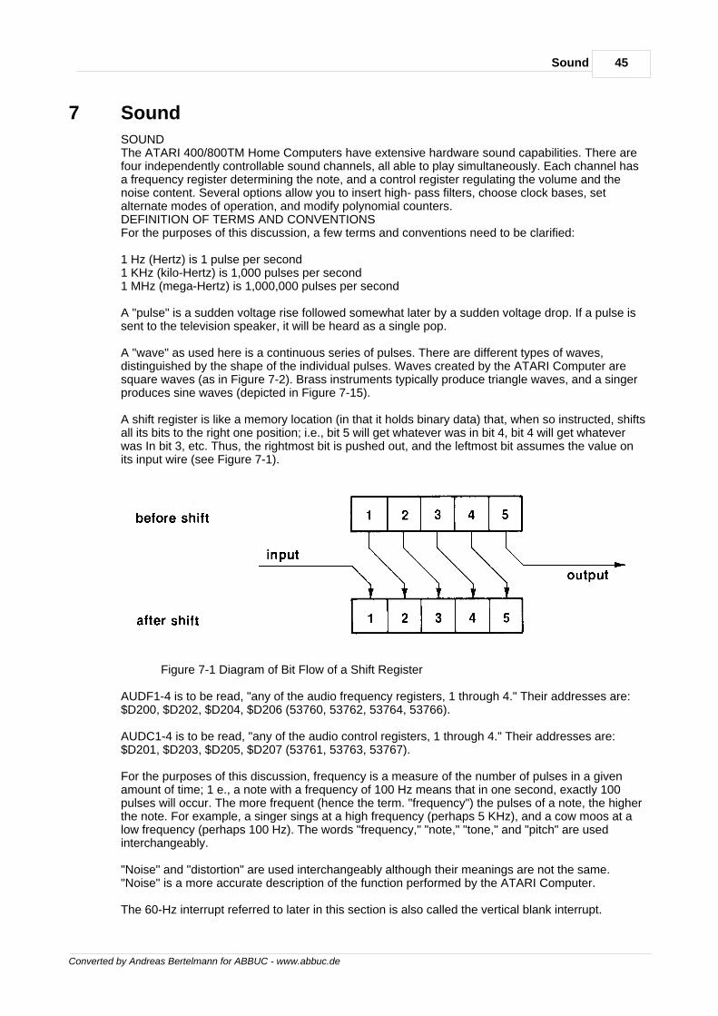
45Sound
Converted by Andreas Bertelmann for ABBUC - www.abbuc.de
7 Sound
SOUNDThe ATARI 400/800TM Home Computers have extensive hardware sound capabilities. There arefour independently controllable sound channels, all able to play simultaneously. Each channel hasa frequency register determining the note, and a control register regulating the volume and thenoise content. Several options allow you to insert high- pass filters, choose clock bases, setalternate modes of operation, and modify polynomial counters.DEFINITION OF TERMS AND CONVENTIONSFor the purposes of this discussion, a few terms and conventions need to be clarified:
1 Hz (Hertz) is 1 pulse per second1 KHz (kilo-Hertz) is 1,000 pulses per second1 MHz (mega-Hertz) is 1,000,000 pulses per second
A "pulse" is a sudden voltage rise followed somewhat later by a sudden voltage drop. If a pulse issent to the television speaker, it will be heard as a single pop.
A "wave" as used here is a continuous series of pulses. There are different types of waves,distinguished by the shape of the individual pulses. Waves created by the ATARI Computer aresquare waves (as in Figure 7-2). Brass instruments typically produce triangle waves, and a singerproduces sine waves (depicted in Figure 7-15).
A shift register is like a memory location (in that it holds binary data) that, when so instructed, shiftsall its bits to the right one position; i.e., bit 5 will get whatever was in bit 4, bit 4 will get whateverwas In bit 3, etc. Thus, the rightmost bit is pushed out, and the leftmost bit assumes the value onits input wire (see Figure 7-1).
Figure 7-1 Diagram of Bit Flow of a Shift Register
AUDF1-4 is to be read, "any of the audio frequency registers, 1 through 4." Their addresses are:$D200, $D202, $D204, $D206 (53760, 53762, 53764, 53766).
AUDC1-4 is to be read, "any of the audio control registers, 1 through 4." Their addresses are:$D201, $D203, $D205, $D207 (53761, 53763, 53767).
For the purposes of this discussion, frequency is a measure of the number of pulses in a givenamount of time; 1 e., a note with a frequency of 100 Hz means that in one second, exactly 100pulses will occur. The more frequent (hence the term. "frequency") the pulses of a note, the higherthe note. For example, a singer sings at a high frequency (perhaps 5 KHz), and a cow moos at alow frequency (perhaps 100 Hz). The words "frequency," "note," "tone," and "pitch" are usedinterchangeably.
"Noise" and "distortion" are used interchangeably although their meanings are not the same."Noise" is a more accurate description of the function performed by the ATARI Computer.
The 60-Hz interrupt referred to later in this section is also called the vertical blank interrupt.
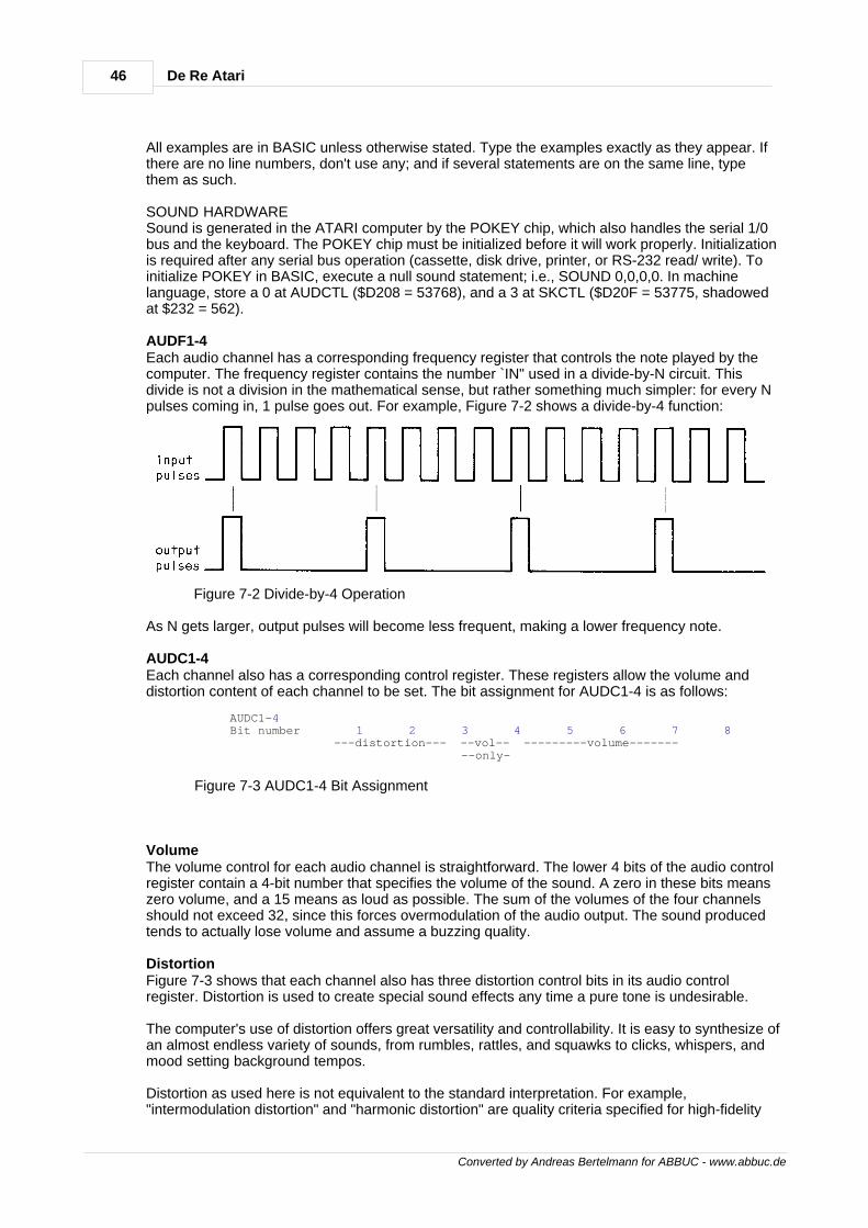
46 De Re Atari
Converted by Andreas Bertelmann for ABBUC - www.abbuc.de
All examples are in BASIC unless otherwise stated. Type the examples exactly as they appear. Ifthere are no line numbers, don't use any; and if several statements are on the same line, typethem as such.
SOUND HARDWARESound is generated in the ATARI computer by the POKEY chip, which also handles the serial 1/0bus and the keyboard. The POKEY chip must be initialized before it will work properly. Initializationis required after any serial bus operation (cassette, disk drive, printer, or RS-232 read/ write). Toinitialize POKEY in BASIC, execute a null sound statement; i.e., SOUND 0,0,0,0. In machinelanguage, store a 0 at AUDCTL ($D208 = 53768), and a 3 at SKCTL ($D20F = 53775, shadowedat $232 = 562).
AUDF1-4Each audio channel has a corresponding frequency register that controls the note played by thecomputer. The frequency register contains the number `IN" used in a divide-by-N circuit. Thisdivide is not a division in the mathematical sense, but rather something much simpler: for every Npulses coming in, 1 pulse goes out. For example, Figure 7-2 shows a divide-by-4 function:
Figure 7-2 Divide-by-4 Operation
As N gets larger, output pulses will become less frequent, making a lower frequency note.
AUDC1-4Each channel also has a corresponding control register. These registers allow the volume anddistortion content of each channel to be set. The bit assignment for AUDC1-4 is as follows:
AUDC1-4 Bit number 1 2 3 4 5 6 7 8 ---distortion--- --vol-- ---------volume------- --only-
Figure 7-3 AUDC1-4 Bit Assignment
VolumeThe volume control for each audio channel is straightforward. The lower 4 bits of the audio controlregister contain a 4-bit number that specifies the volume of the sound. A zero in these bits meanszero volume, and a 15 means as loud as possible. The sum of the volumes of the four channelsshould not exceed 32, since this forces overmodulation of the audio output. The sound producedtends to actually lose volume and assume a buzzing quality.
DistortionFigure 7-3 shows that each channel also has three distortion control bits in its audio controlregister. Distortion is used to create special sound effects any time a pure tone is undesirable.
The computer's use of distortion offers great versatility and controllability. It is easy to synthesize ofan almost endless variety of sounds, from rumbles, rattles, and squawks to clicks, whispers, andmood setting background tempos.
Distortion as used here is not equivalent to the standard interpretation. For example,"intermodulation distortion" and "harmonic distortion" are quality criteria specified for high-fidelity
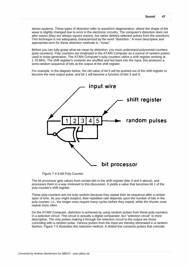
47Sound
Converted by Andreas Bertelmann for ABBUC - www.abbuc.de
stereo systems. These types of distortion refer to waveform degeneration, where the shape of thewave is slightly changed due to error in the electronic circuitry. The computer's distortion does notalter waves (they are always square waves), but rather deletes selected pulses from the waveform.This technique is not adequately characterized by the word "distortion." A more descriptive andappropriate term for these distortion methods is. "noise".
Before you can fully grasp what we mean by distortion, you must understand polynomial counters(poly-counters). Poly counters are employed in the ATARI Computer as a source of random pulsesused in noise generation. The ATARI Computer's poly-counters utilize a shift register working at1.79 MHz. The shift register's contents are shuffled and fed back into the input; this produces asemi-random sequence of bits at the output of the shift register.
For example, in the diagram below, the old value of bit 5 will be pushed out of the shift register tobecome the next output pulse, and bit 1 will become a function of bits 3 and 5:
Figure 7-4 5-Bit Poly-Counter
The bit processor gets values from certain bits in the shift register (bits 3 and 5 above), andprocesses them in a way irrelevant to this discussion. It yields a value that becomes bit 1 of thepoly-counter's shift register.
These poly-counters are not truly random because they repeat their bit sequence after a certainspan of time. As you might suspect, their repetition rate depends upon the number of bits in thepoly-counter; i.e., the longer ones require many cycles before they repeat, while the shorter onesrepeat more often.
On the ATARI Computer, distortion is achieved by using random pulses from these poly-countersin a selection circuit. This circuit is actually a digital comparator, but "selection circuit" is moredescriptive. The only pulses making it through the selection circuit to the output are thosecoinciding with a random pulse. Various pulses from the input are thereby eliminated in a randomfashion. Figure 7-5 illustrates this selection method. A dotted line connects pulses that coincide.
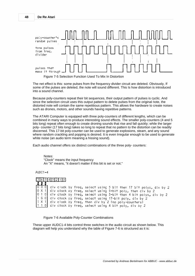
48 De Re Atari
Converted by Andreas Bertelmann for ABBUC - www.abbuc.de
Figure 7-5 Selection Function Used To Mix In Distortion
The net effect is this: some pulses from the frequency divider circuit are deleted. Obviously, Ifsome of the pulses are deleted, the note will sound different. This Is how distortion is introducedinto a sound channel.
Because poly-counters repeat their bit sequences, their output pattern of pulses is cyclic. Andsince the selection circuit uses this output pattern to delete pulses from the original note, thedistorted note will contain the same repetitious pattern. This allows the hardware to create noisessuch as drones, motors, and other sounds having repetitive patterns.
The ATARI Computer is equipped with three poly-counters of different lengths, which can becombined in many ways to produce interesting sound effects. The smaller poly-counters (4 and 5bits long) repeat often enough to create droning sounds that rise and fall quickly; while the largerpoly- counter (17 bits long) takes so long to repeat that no pattern to the distortion can be readilydiscerned. This 17-bit poly-counter can be used to generate explosions, steam, and any soundwhere random crackling and popping is desired. It is even Irregular enough to be used to generatewhite noise (an audio term meaning a hissing sound).
Each audio channel offers six distinct combinations of the three poly- counters:
Notes: "Clock" means the input frequency An "X" means, "it doesn't matter if this bit is set or not."
Figure 7-6 Available Poly-Counter Combinations
These upper AUDC1-4 bits control three switches in the audio circuit as shown below. Thisdiagram will help you understand why the table of Figure 7-6 is structured as it is:
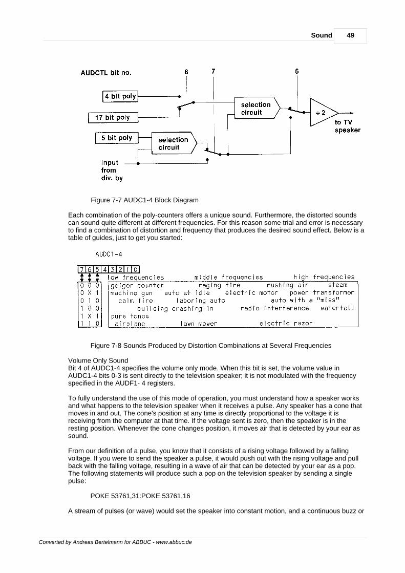
49Sound
Converted by Andreas Bertelmann for ABBUC - www.abbuc.de
Figure 7-7 AUDC1-4 Block Diagram
Each combination of the poly-counters offers a unique sound. Furthermore, the distorted soundscan sound quite different at different frequencies. For this reason some trial and error is necessaryto find a combination of distortion and frequency that produces the desired sound effect. Below is atable of guides, just to get you started:
Figure 7-8 Sounds Produced by Distortion Combinations at Several Frequencies
Volume Only SoundBit 4 of AUDC1-4 specifies the volume only mode. When this bit is set, the volume value inAUDC1-4 bits 0-3 is sent directly to the television speaker; it is not modulated with the frequencyspecified in the AUDF1- 4 registers.
To fully understand the use of this mode of operation, you must understand how a speaker worksand what happens to the television speaker when it receives a pulse. Any speaker has a cone thatmoves in and out. The cone's position at any time is directly proportional to the voltage it isreceiving from the computer at that time. If the voltage sent is zero, then the speaker is in theresting position. Whenever the cone changes position, it moves air that is detected by your ear assound.
From our definition of a pulse, you know that it consists of a rising voltage followed by a fallingvoltage. If you were to send the speaker a pulse, it would push out with the rising voltage and pullback with the falling voltage, resulting in a wave of air that can be detected by your ear as a pop.The following statements will produce such a pop on the television speaker by sending a singlepulse:
POKE 53761,31:POKE 53761,16
A stream of pulses (or wave) would set the speaker into constant motion, and a continuous buzz or
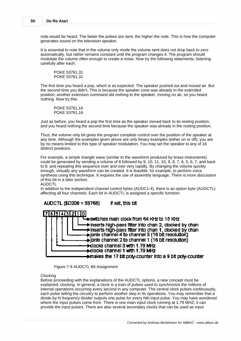
50 De Re Atari
Converted by Andreas Bertelmann for ABBUC - www.abbuc.de
note would be heard. The faster the pulses are sent, the higher the note. This is how the computergenerates sound on the television speaker.
It is essential to note that in the volume only mode the volume sent does not drop back to zeroautomatically, but rather remains constant until the program changes it. The program shouldmodulate the volume often enough to create a noise. Now try the following statements, listeningcarefully after each:
POKE 53761,31 POKE 53761,31
The first time you heard a pop, which is as expected. The speaker pushed out and moved air. Butthe second time you didn't. This is because the speaker cone was already In the extendedposition; another extension command did nothing to the speaker, moving no air, so you heardnothing. Now try this:
POKE 53761,16 POKE 53761,16
Just as before, you heard a pop the first time as the speaker moved back to its resting position,and you heard nothing the second time because the speaker was already in the resting position.
Thus, the volume only bit gives the program complete control over the position of the speaker atany time. Although the examples given above are only binary examples (either on or off), you areby no means limited to this type of speaker modulation. You may set the speaker to any of 16distinct positions.
For example, a simple triangle wave (similar to the waveform produced by brass instruments)could be generated by sending a volume of 8 followed by 9, 10, 11, 10, 9, 8, 7, 6, 5, 6, 7, and backto 8, and repeating this sequence over and over very rapidly. By changing the volume quicklyenough, virtually any waveform can be created. It is feasible, for example, to perform voicesynthesis using this technique. It requires the use of assembly language. There is more discussionof this bit in a later section.AUDCTLIn addition to the independent channel control bytes (AUDC1-4), there is an option byte (AUDCTL)affecting all four channels. Each bit in AUDCTL is assigned a specific function:
Figure 7-9 AUDCTL Bit Assignment
ClockingBefore proceeding with the explanations of the AUDCTL options, a new concept must beexplained: clocking. In general, a clock is a train of pulses used to synchronize the millions ofinternal operations occurring every second in any computer. The central clock pulses continuously,each pulse telling the circuitry to perform another step in its operations. You may remember that adivide-by-N frequency divider outputs one pulse for every Nth input pulse. You may have wonderedwhere the input pulses come from. There is one main input clock running at 1.79 MHZ; it canprovide the input pulses. There are also several secondary clocks that can be used as input
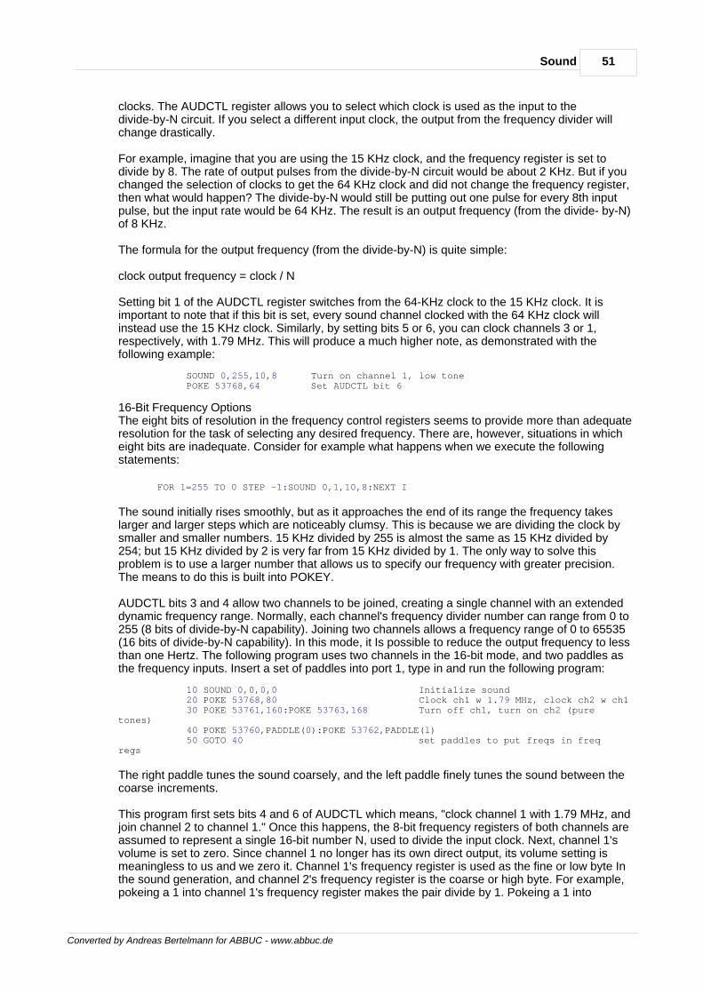
51Sound
Converted by Andreas Bertelmann for ABBUC - www.abbuc.de
clocks. The AUDCTL register allows you to select which clock is used as the input to thedivide-by-N circuit. If you select a different input clock, the output from the frequency divider willchange drastically.
For example, imagine that you are using the 15 KHz clock, and the frequency register is set todivide by 8. The rate of output pulses from the divide-by-N circuit would be about 2 KHz. But if youchanged the selection of clocks to get the 64 KHz clock and did not change the frequency register,then what would happen? The divide-by-N would still be putting out one pulse for every 8th inputpulse, but the input rate would be 64 KHz. The result is an output frequency (from the divide- by-N)of 8 KHz.
The formula for the output frequency (from the divide-by-N) is quite simple:
clock output frequency = clock / N
Setting bit 1 of the AUDCTL register switches from the 64-KHz clock to the 15 KHz clock. It isimportant to note that if this bit is set, every sound channel clocked with the 64 KHz clock willinstead use the 15 KHz clock. Similarly, by setting bits 5 or 6, you can clock channels 3 or 1,respectively, with 1.79 MHz. This will produce a much higher note, as demonstrated with thefollowing example:
SOUND 0,255,10,8 Turn on channel 1, low tone POKE 53768,64 Set AUDCTL bit 6
16-Bit Frequency OptionsThe eight bits of resolution in the frequency control registers seems to provide more than adequateresolution for the task of selecting any desired frequency. There are, however, situations in whicheight bits are inadequate. Consider for example what happens when we execute the followingstatements:
FOR 1=255 TO 0 STEP -1:SOUND 0,1,10,8:NEXT I
The sound initially rises smoothly, but as it approaches the end of its range the frequency takeslarger and larger steps which are noticeably clumsy. This is because we are dividing the clock bysmaller and smaller numbers. 15 KHz divided by 255 is almost the same as 15 KHz divided by254; but 15 KHz divided by 2 is very far from 15 KHz divided by 1. The only way to solve thisproblem is to use a larger number that allows us to specify our frequency with greater precision.The means to do this is built into POKEY.
AUDCTL bits 3 and 4 allow two channels to be joined, creating a single channel with an extendeddynamic frequency range. Normally, each channel's frequency divider number can range from 0 to255 (8 bits of divide-by-N capability). Joining two channels allows a frequency range of 0 to 65535(16 bits of divide-by-N capability). In this mode, it Is possible to reduce the output frequency to lessthan one Hertz. The following program uses two channels in the 16-bit mode, and two paddles asthe frequency inputs. Insert a set of paddles into port 1, type in and run the following program:
10 SOUND 0,0,0,0 Initialize sound 20 POKE 53768,80 Clock ch1 w 1.79 MHz, clock ch2 w ch1 30 POKE 53761,160:POKE 53763,168 Turn off ch1, turn on ch2 (puretones) 40 POKE 53760,PADDLE(0):POKE 53762,PADDLE(l) 50 GOTO 40 set paddles to put freqs in freqregs
The right paddle tunes the sound coarsely, and the left paddle finely tunes the sound between thecoarse increments.
This program first sets bits 4 and 6 of AUDCTL which means, "clock channel 1 with 1.79 MHz, andjoin channel 2 to channel 1." Once this happens, the 8-bit frequency registers of both channels areassumed to represent a single 16-bit number N, used to divide the input clock. Next, channel 1'svolume is set to zero. Since channel 1 no longer has its own direct output, its volume setting ismeaningless to us and we zero it. Channel 1's frequency register is used as the fine or low byte Inthe sound generation, and channel 2's frequency register is the coarse or high byte. For example,pokeing a 1 into channel 1's frequency register makes the pair divide by 1. Pokeing a 1 into
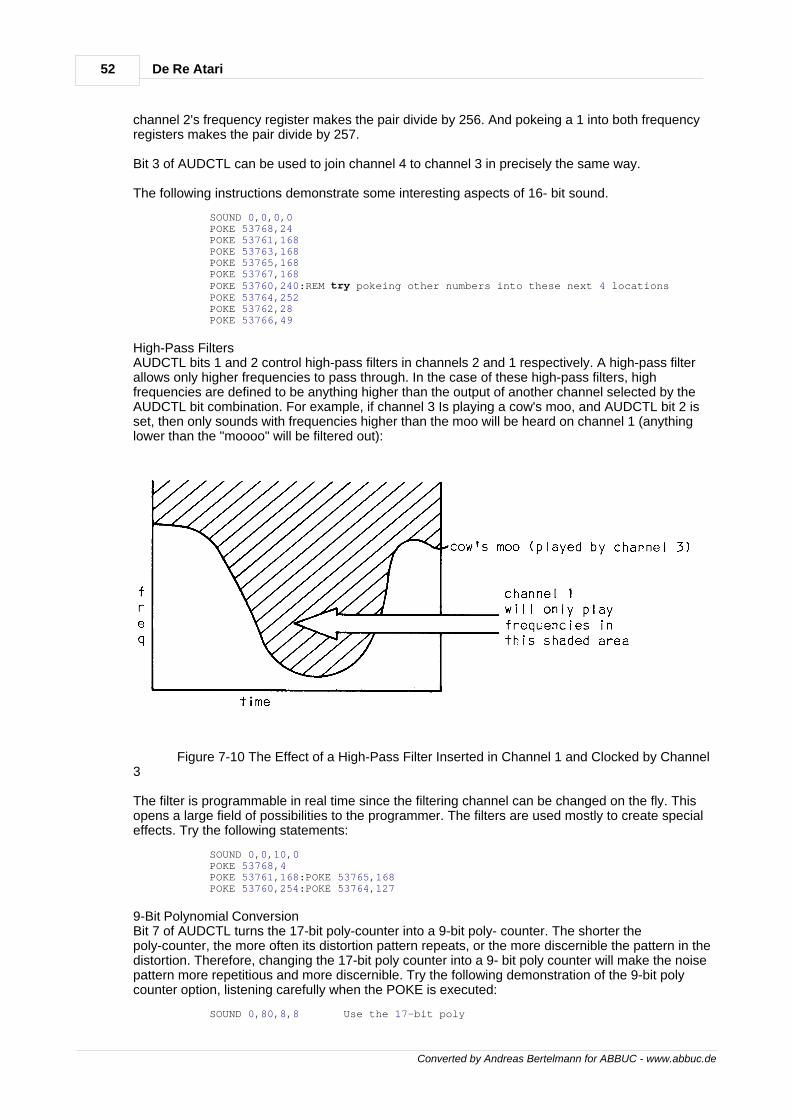
52 De Re Atari
Converted by Andreas Bertelmann for ABBUC - www.abbuc.de
channel 2's frequency register makes the pair divide by 256. And pokeing a 1 into both frequencyregisters makes the pair divide by 257.
Bit 3 of AUDCTL can be used to join channel 4 to channel 3 in precisely the same way.
The following instructions demonstrate some interesting aspects of 16- bit sound.
SOUND 0,0,0,0 POKE 53768,24 POKE 53761,168 POKE 53763,168 POKE 53765,168 POKE 53767,168 POKE 53760,240:REM try pokeing other numbers into these next 4 locations POKE 53764,252 POKE 53762,28 POKE 53766,49
High-Pass FiltersAUDCTL bits 1 and 2 control high-pass filters in channels 2 and 1 respectively. A high-pass filterallows only higher frequencies to pass through. In the case of these high-pass filters, highfrequencies are defined to be anything higher than the output of another channel selected by theAUDCTL bit combination. For example, if channel 3 Is playing a cow's moo, and AUDCTL bit 2 isset, then only sounds with frequencies higher than the moo will be heard on channel 1 (anythinglower than the "moooo" will be filtered out):
Figure 7-10 The Effect of a High-Pass Filter Inserted in Channel 1 and Clocked by Channel3
The filter is programmable in real time since the filtering channel can be changed on the fly. Thisopens a large field of possibilities to the programmer. The filters are used mostly to create specialeffects. Try the following statements:
SOUND 0,0,10,0 POKE 53768,4 POKE 53761,168:POKE 53765,168 POKE 53760,254:POKE 53764,127
9-Bit Polynomial ConversionBit 7 of AUDCTL turns the 17-bit poly-counter into a 9-bit poly- counter. The shorter thepoly-counter, the more often its distortion pattern repeats, or the more discernible the pattern in thedistortion. Therefore, changing the 17-bit poly counter into a 9- bit poly counter will make the noisepattern more repetitious and more discernible. Try the following demonstration of the 9-bit polycounter option, listening carefully when the POKE is executed:
SOUND 0,80,8,8 Use the 17-bit poly
53Sound
Converted by Andreas Bertelmann for ABBUC - www.abbuc.de
POKE 53768,128 Change to the 9-bit poly
SOUND GENERATION SOFTWARE TECHNIQUES
There are two basic ways to use the ATARI Computer sound system: static and dynamic. Staticsound generation is the simpler of the two; the program sets a few sound generators, turns toother activities for a while, and then turns them off. Dynamic sound generation is more difficult; thecomputer must continuously update the sound generators during program execution. For example:
Static Sound Dynamic Sound SOUND 0,120,8,8 FOR X=0 TO 255 SOUND 0,X,8,8 NEXT X
Static SoundStatic sound is normally limited to beeps, clicks, and buzzes. There are exceptions. Two examplesare the programs given as special effects in the sections on high-pass filters and 16 bit sound.Another way to obtain interesting effects is to use interference, as in this example:
SOUND 0,255,10,8 SOUND 1,254,10,8
The strange effect is a result of closely phased peaks and valleys. Examine Figure 7-11. It showstwo channels independently running sine waves at slightly different frequencies, and their sum.The sum curve shows the strange interference pattern created when these two channels areadded.
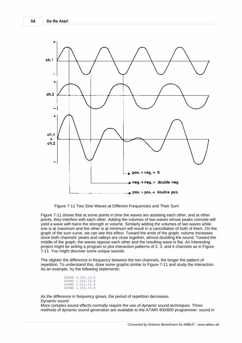
54 De Re Atari
Converted by Andreas Bertelmann for ABBUC - www.abbuc.de
Figure 7-11 Two Sine Waves at Different Frequencies and Their Sum
Figure 7-11 shows that at some points in time the waves are assisting each other, and at otherpoints, they interfere with each other. Adding the volumes of two waves whose peaks coincide willyield a wave with twice the strength or volume. Similarly adding the volumes of two waves whileone is at maximum and the other is at minimum will result In a cancellation of both of them. On thegraph of the sum curve, we can see this effect. Toward the ends of the graph, volume Increasessince both channels' peaks and valleys are close together, almost doubling the sound. Toward themiddle of the graph, the waves oppose each other and the resulting wave Is flat. An Interestingproject might be writing a program to plot interaction patterns of 2, 3, and 4 channels as in Figure7-11. You might discover some unique sounds.
The slighter the difference in frequency between the two channels, the longer the pattern ofrepetition. To understand this, draw some graphs similar to Figure 7-11 and study the Interaction.As an example, try the following statements:
SOUND 0,255,10,8 SOUND 1,254,10,8 SOUND 1,253,10,8 SOUND 1,252,10,8
As the difference in frequency grows, the period of repetition decreases.Dynamic soundMore complex sound effects normally require the use of dynamic sound techniques. Threemethods of dynamic sound generation are available to the ATARI 400/800 programmer: sound in
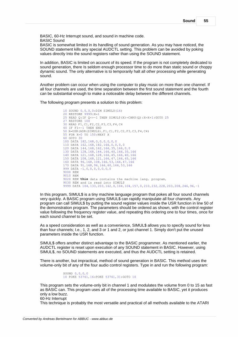
55Sound
Converted by Andreas Bertelmann for ABBUC - www.abbuc.de
BASIC, 60-Hz Interrupt sound, and sound in machine code.BASIC SoundBASIC is somewhat limited in its handling of sound generation. As you may have noticed, theSOUND statement kills any special AUDCTL setting. This problem can be avoided by pokingvalues directly Into the sound registers rather than using the SOUND statement.
In addition, BASIC is limited on account of its speed. If the program is not completely dedicated tosound generation, there Is seldom enough processor time to do more than static sound or choppydynamic sound. The only alternative is to temporarily halt all other processing while generatingsound.
Another problem can occur when using the computer to play music on more than one channel. Ifall four channels are used, the time separation between the first sound statement and the fourthcan be substantial enough to make a noticeable delay between the different channels.
The following program presents a solution to this problem:
10 SOUND 0,0,0,0:DIM SIMUL$(16) 20 RESTORE 9999:X=1 25 READ Q:IF Q<>-1 THEN SIMUL$(X)=CHR$(Q):X=X+1:GOTO 25 27 RESTORE 100 30 READ F1,C1,F2,C2,F3,C3,F4,C4 40 IF F1=-1 THEN END 50 X=USR(ADR(SIMUL$),Fl,Cl,F2,C2,F3,C3,F4,C4) 55 FOR X=0 TO 150:NEXT X 60 GOTO 30 100 DATA 182,168,0,0,0,0,0,0 110 DATA 162,168,182,166,0,0,0,0 120 DATA 144,168,162,166,35,166,0,0 130 DATA 128,168,144,166,40,166,35,166 140 DATA 121,168,128,166,45,166,40,166 150 DATA 108,168,121,166,47,166,45,166 160 DATA 96,168,108,166,53,166,47,166 170 DATA 91,168,96,166,60,166,53,166 999 DATA -1,0,0,0,0,0,0,0 9000 REM 9010 REM 9020 REM this data contains the machine lang. program, 9030 REM and is read into SIMUL$ 9999 DATA 104,133,203,162,0,104,104,157,0,210,232,228,203,208,246,96,-1
In this program, SIMUL$ is a tiny machine language program that pokes all four sound channelsvery quickly. A BASIC program using SIMUL$ can rapidly manipulate all four channels. Anyprogram can call SIMUL$ by putting the sound register values inside the USR function in line 50 ofthe demonstration program. The parameters should be ordered as shown, with the control registervalue following the frequency register value, and repeating this ordering one to four times, once foreach sound channel to be set.
As a speed consideration as well as a convenience, SIMUL$ allows you to specify sound for lessthan four channels; I.e., 1, 2, and 3 or 1 and 2, or just channel 1. Simply don't put the unusedparameters inside the USR function.
SIMUL$ offers another distinct advantage to the BASIC programmer. As mentioned earlier, theAUDCTL register is reset upon execution of any SOUND statement in BASIC. However, usingSIMUL$, no SOUND statements are executed, and thus the AUDCTL setting is retained.
There is another, but impractical, method of sound generation in BASIC. This method uses thevolume-only bit of any of the four audio control registers. Type in and run the following program:
SOUND 0,0,0,0 10 POKE 53761,16:POKE 53761,31:GOTO 10
This program sets the volume-only bit in channel 1 and modulates the volume from 0 to 15 as fastas BASIC can. This program uses all of the processing time available to BASIC, yet it producesonly a low buzz.60-Hz InterruptThis technique is probably the most versatile and practical of all methods available to the ATARI
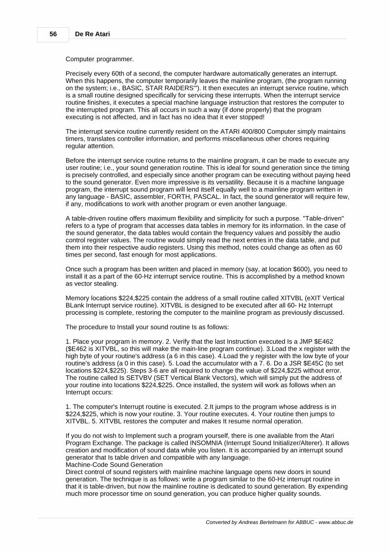
56 De Re Atari
Converted by Andreas Bertelmann for ABBUC - www.abbuc.de
Computer programmer.
Precisely every 60th of a second, the computer hardware automatically generates an interrupt.When this happens, the computer temporarily leaves the mainline program, (the program runningon the system; i.e., BASIC, STAR RAIDERS'"). It then executes an interrupt service routine, whichis a small routine designed specifically for servicing these interrupts. When the interrupt serviceroutine finishes, it executes a special machine language instruction that restores the computer tothe interrupted program. This all occurs in such a way (if done properly) that the programexecuting is not affected, and in fact has no idea that it ever stopped!
The interrupt service routine currently resident on the ATARI 400/800 Computer simply maintainstimers, translates controller information, and performs miscellaneous other chores requiringregular attention.
Before the interrupt service routine returns to the mainline program, it can be made to execute anyuser routine; i.e., your sound generation routine. This is ideal for sound generation since the timingis precisely controlled, and especially since another program can be executing without paying heedto the sound generator. Even more impressive is its versatility. Because it is a machine languageprogram, the interrupt sound program will lend itself equally well to a mainline program written inany language - BASIC, assembler, FORTH, PASCAL. In fact, the sound generator will require few,if any, modifications to work with another program or even another language.
A table-driven routine offers maximum flexibility and simplicity for such a purpose. "Table-driven"refers to a type of program that accesses data tables in memory for its information. In the case ofthe sound generator, the data tables would contain the frequency values and possibly the audiocontrol register values. The routine would simply read the next entries in the data table, and putthem into their respective audio registers. Using this method, notes could change as often as 60times per second, fast enough for most applications.
Once such a program has been written and placed in memory (say, at location $600), you need toinstall it as a part of the 60-Hz interrupt service routine. This is accomplished by a method knownas vector stealing.
Memory locations $224,$225 contain the address of a small routine called XITVBL (eXIT VerticalBLank Interrupt service routine). XITVBL is designed to be executed after all 60- Hz Interruptprocessing is complete, restoring the computer to the mainline program as previously discussed.
The procedure to Install your sound routine Is as follows:
1. Place your program in memory. 2. Verify that the last Instruction executed Is a JMP $E462($E462 is XITVBL, so this will make the main-line program continue). 3.Load the x register with thehigh byte of your routine's address (a 6 in this case). 4.Load the y register with the low byte of yourroutine's address (a 0 in this case). 5. Load the accumulator with a 7. 6. Do a JSR $E45C (to setlocations $224,$225). Steps 3-6 are all required to change the value of $224,$225 without error.The routine called Is SETVBV (SET Vertical Blank Vectors), which will simply put the address ofyour routine into locations $224,$225. Once installed, the system will work as follows when anInterrupt occurs:
1. The computer's Interrupt routine is executed. 2.It jumps to the program whose address is in$224,$225, which is now your routine. 3. Your routine executes. 4. Your routine then jumps toXITVBL. 5. XITVBL restores the computer and makes It resume normal operation.
If you do not wish to Implement such a program yourself, there is one available from the AtariProgram Exchange. The package is called INSOMNIA (Interrupt Sound Initializer/Alterer). It allowscreation and modification of sound data while you listen. It is accompanied by an interrupt soundgenerator that Is table driven and compatible with any language.Machine-Code Sound GenerationDirect control of sound registers with mainline machine language opens new doors in soundgeneration. The technique is as follows: write a program similar to the 60-Hz interrupt routine inthat it is table-driven, but now the mainline routine is dedicated to sound generation. By expendingmuch more processor time on sound generation, you can produce higher quality sounds.
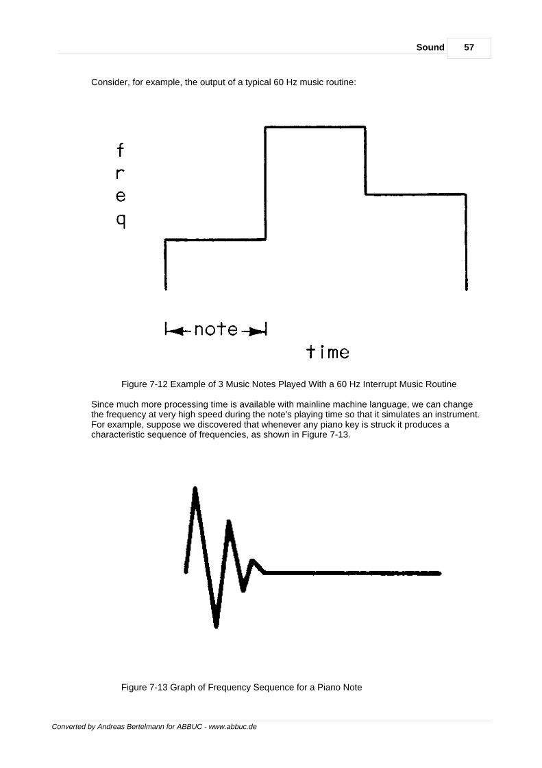
57Sound
Converted by Andreas Bertelmann for ABBUC - www.abbuc.de
Consider, for example, the output of a typical 60 Hz music routine:
Figure 7-12 Example of 3 Music Notes Played With a 60 Hz Interrupt Music Routine
Since much more processing time is available with mainline machine language, we can changethe frequency at very high speed during the note's playing time so that it simulates an instrument.For example, suppose we discovered that whenever any piano key is struck it produces acharacteristic sequence of frequencies, as shown in Figure 7-13.
Figure 7-13 Graph of Frequency Sequence for a Piano Note
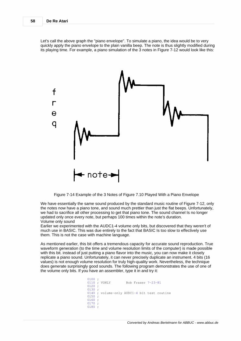
58 De Re Atari
Converted by Andreas Bertelmann for ABBUC - www.abbuc.de
Let's call the above graph the "piano envelope". To simulate a piano, the idea would be to veryquickly apply the piano envelope to the plain vanilla beep. The note is thus slightly modified duringits playing time. For example, a piano simulation of the 3 notes in Figure 7-12 would look like this:
Figure 7-14 Example of the 3 Notes of Figure 7.10 Played With a Piano Envelope
We have essentially the same sound produced by the standard music routine of Figure 7-12, onlythe notes now have a piano tone, and sound much prettier than just the flat beeps. Unfortunately,we had to sacrifice all other processing to get that piano tone. The sound channel Is no longerupdated only once every note, but perhaps 100 times within the note's duration.Volume only soundEarlier we experimented with the AUDC1-4 volume only bits, but discovered that they weren't ofmuch use in BASIC. This was due entirely to the fact that BASIC Is too slow to effectively usethem. This is not the case with machine language.
As mentioned earlier, this bit offers a tremendous capacity for accurate sound reproduction. Truewaveform generation (to the time and volume resolution limits of the computer) is made possiblewith this bit. instead of just putting a piano flavor into the music, you can now make it closelyreplicate a piano sound. Unfortunately, it can never precisely duplicate an instrument. 4 bits (16values) is not enough volume resolution for truly high-quality work. Nevertheless, the techniquedoes generate surprisingly good sounds. The following program demonstrates the use of one ofthe volume only bits. If you have an assembler, type it in and try it:
0100 ; 0110 ; VONLY Bob Fraser 7-23-81 0120 ; 0130 ; 0140 ; volume-only AUDC1-4 bit test routine 0150 ; 0160 ; 0170 ; 0180 ;
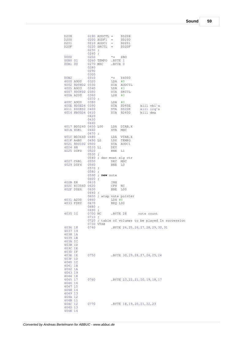
59Sound
Converted by Andreas Bertelmann for ABBUC - www.abbuc.de
D208 0190 AUDCTL = $D208 D200 0200 AUDF1 = $D200 D201 0210 AUDC1 = $D201 D20F 0220 SKCTL = $D20F 0230 ; 0240 ; 0000 0250 *= $BO 00B0 01 0260 TEMPO .BYTE 1 00B1 00 0270 MSC .BYTE 0 0280 0290 0300 00B2 0310 *= $4000 4000 A900 0320 LDA #0 4002 8D08D2 0330 STA AUDCTL 4005 A903 0340 LDA #3 4007 8D0FD2 0350 STA SKCTL 400A A200 0360 LDX #0 0370 ; 400C A900 0380 LDA #0 400E 8D0ED4 0390 STA $D40E kill vbi's 4011 800ED2 0400 STA $D20E kill irq's 4014 8B00D4 0410 STA $D400 kill dma 0420 0430 0440 4017 BD5240 0450 L00 LDA DTAB,X 401A 85B1 0460 STA MSC 0470 ; 401C BD3640 0480 LDA VTAB,X 401F A4B0 0490 L0 LDY TEMPO 4021 8D01D2 0500 STA AUDC1 4024 88 0510 L1 DEY 4025 D0FD 0520 BNE L1 0530 ; 0540 ; dec most sig ctr 4027 C6B1 0550 DEC MSC 4029 D0F4 0560 BNE L0 0570 ; 0580 ; 0590 ; new note 0600 ; 402B E8 0610 INX 402C EC3540 0620 CPX NC 402F D0E6 0630 BNE L00 0640 ; 0650 ; wrap note pointer 4031 A200 0660 LDX #0 4033 F0E2 0670 BEQ L00 0680 ; 0690 ; 4035 1C 0700 NC .BYTE 28 note count 0710 ; 0720 ; table of volumes to be played In succession 0730 VTAB 4036 18 0740 .BYTE 24,25,26,27,28,29,30,31 4037 19 4038 1A 4039 1B 403A IC 403B ID 403C 1E 403D IF 403E 1E 0750 .BYTE 30,29,28,27,26,25,24 403F 1D 4040 1C 4041 1B 4042 1A 4043 19 4044 18 4045 17 0760 .BYTE 23,22,21,20,19,18,17 4046 16 4047 15 4048 14 4049 13 404A 12 404B 11 404C 12 0770 .BYTE 18,19,20,21,22,23 404D 13 404E 14
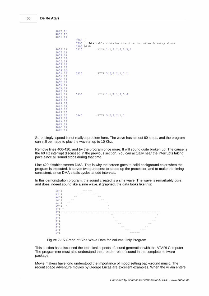
60 De Re Atari
Converted by Andreas Bertelmann for ABBUC - www.abbuc.de
404F 15 4050 16 4051 17 0780 ; 0790 ; this table contains the duration of each entry above 0800 DTAB 4052 01 0810 .BYTE 1,1,1,2,2,2,3,6 4053 01 4054 01 4055 02 4056 02 4057 02 4058 03 4059 06 405A 03 0820 .BYTE 3,2,2,2,1,1,1 405B 02 405C 02 405D 02 405E 01 405F 01 4060 01 4061 01 0830 .BYTE 1,1,2,2,2,3,6 4062 01 4063 02 4064 02 4065 02 4066 03 4067 06 4068 03 0840 .BYTE 3,2,2,2,1,1 4069 02 406A 02 406B 02 406C 01 406D 01
Surprisingly, speed is not really a problem here. The wave has almost 60 steps, and the programcan still be made to play the wave at up to 10 Khz.
Remove lines 400-410, and try the program once more. It will sound quite broken up. The cause isthe 60 Hz interrupt discussed In the previous section. You can actually hear the interrupts takingpace since all sound stops during that time.
Line 420 disables screen DMA. This is why the screen goes to solid background color when theprogram is executed. It serves two purposes: to speed up the processor, and to make the timingconsistent, since DMA steals cycles at odd intervals.
In this demonstration program, the sound created is a sine wave. The wave is remarkably pure,and does indeed sound like a sine wave. if graphed, the data looks like this:
15-I ------ 14-I --- --- 13-I -- -- 12-I -- -- 11-I -- -- 10-I - - 9-I - - 8=I----------------------------------------------------------- 7-I - - 6-I - - 5-I -- -- 4-I -- -- 3-I -- -- 2-I --- --- 1-I ------
Figure 7-15 Graph of Sine Wave Data for Volume Only Program
This section has discussed the technical aspects of sound generation with the ATARI Computer.The programmer must also understand the broader role of sound in the complete softwarepackage.
Movie makers have long understood the importance of mood setting background music. Therecent space adventure movies by George Lucas are excellent examples. When the villain enters
61Sound
Converted by Andreas Bertelmann for ABBUC - www.abbuc.de
the room you know immediately to fear and hate him from the menacing background rhythmsaccompanying his entry. You gleefully clap your hands when the hero saves the princess whilegallant music plays in the background. Likewise, horror films can frighten you by merely playingeerie music, even though the action may be completely ordinary.
SPACE INVADERS (trademark of Taito America Corp) issues a personal threat to its player andvictim with its echoing stomp. As the tempo increases, knuckles whiten and teeth grind. When aZylon from STAR RAIDERS'" fires a photon torpedo you push frantically on the control to avoidimpact. As it bores straight for your forehead, time slows and you hear it hissing louder and louderas it approaches. Just before impact, you duck and dislodge yourself from your armchair.
Impressionistic sounds affect our subconscious and our state of mind. This Is due possibly to thefact that sounds, if present, are continuously entering our mind whether or not we are activelylistening. Visual inputs, on the other hand, require the user's attention. If we are distracted from theTV set, we cease to concentrate on the picture and the image leaves our mind. Sound thereforeoffers the programmer a direct path to the user's mind - bypassing his thought processes andzeroing in on his emotions.
Converted by Andreas Bertelmann for ABBUC - www.abbuc.de
The OperatingSystem
Chapter
VIII
63The Operating System
Converted by Andreas Bertelmann for ABBUC - www.abbuc.de
8 The Operating System
INTRODUCTIONWith every ATARI Home Computer System comes an ATARI 10K Operating System Cartridge.The importance of this cartridge is often overlooked. Without it, you have a lot of potential, butabsolutely nothing else! This situation is not unique to the ATARI Home Computer System; It isencountered with all computers. A computer is, after all, merely a collection of hardware devices. Auser must manage these resources to accomplish any task. If all programmers had to start fromscratch on each program, we would have an even larger software shortage than we have today.The solution that has evolved over the years is to build in a program that manages the resourcesavailable to the system, and eases the programming burden required to control them. Thisprogram is known by various names: Operating System, Master Control Program, SystemExecutive, System Monitor, etc. In the ATARI Home Computer System it is known as theOperating System or OS.
The first task facing the student of the Operating System, is to take an inventory of exactly whatresources are available to the OS. These are:
6502 Microprocessor RAM Memory (various amounts) ANTIC LSI Integrated Circuit CTIA LSI Integrated Circuit POKEY LSI Integrated Circuit PIA Peripheral Interface Adapter Integrated Circuit
By using these resources, the OS can interact with and control a wide variety of external hardwaredevices, including a television receiver/ monitor, keyboard, console speaker, console switches,joysticks, paddles, cassette recorder, disk drive, printers, RS-232 interface and modem.
The remainder of this subsection briefly lists the main elements of the OS. These elements aredescribed in detail in following subsections.
MONITOR. The OS monitor is the system routine that is executed when the computer is turned onor the SYSTEM RESET] button is pressed. Through this routine the OS takes control of thesystem; It does not relinquish control unless control is taken away from it by the programmer. TheMonitor sets up the memory management system, initializes the I/O subsystem, sets up systemvectors and selects the execution environment after initialization is complete.
INTERRUPT PROCESSING STRUCTURE. The computer utilizes the standard interruptprocessing structure of the 6502 microprocessor, with some external augmentation for enhancedflexibility. Interrupts are generated by numerous events, including keyboard keystrokes, the**BREAK** keystroke, some serial bus events, system timer timeouts, and the vertical blankinterval on the television.
OS SYSTEM VECTORS. The system vectors provide a mechanism that allows users to accesssystem routines, or customize the OS for special needs. The most frequent uses of the vectors areto call I/O system routines, set timers, and transfer control to different execution environments.System routines may be vectored to in one of two ways. ROM vectors are locations that containJMP instructions to system routines and cannot be altered. RAM vectors are RAM locations thatcontain alterable addresses of system routines. The locations of both types of vectors areguaranteed to remain the same in future releases of the OS.
INPUT/OUTPUT SUBSYSTEM. The OS gives an application programmer access to the fullcapabilities of the computer's peripherals. The Input/Output subsystem is a set of routines that linkhigh level I/O operations with device handlers that control the physical I/O hardware.
REAL TIME PROGRAMMING. The ATARI Home Computer is well equipped to deal with problemsin the "real time domain". To facilitate this feature, the OS has two types of timers: hardware timersand system software timers. Hardware timers are countdown timers that can be used to timeevents with durations that range from half a microsecond to several seconds. System timers aresoftware timers that tick at 60 Hertz, and can be used for applications as diverse as serial bus
64 De Re Atari
Converted by Andreas Bertelmann for ABBUC - www.abbuc.de
timing and sound effect generation.
ROM CHARACTER SET. The computer is equipped with what is known as a "soft character set",i.e., It can be changed. The ROM-based character set is used to provide a standard character setat power-up.
FLOATING POINT PACKAGE. The floating point package is a set of mathematical routines thatextend the arithmetic capability of the system. The routines use binary coded decimal (BCD)arithmetic to provide standard mathematical functions (+, -, *, /), exponential and logarithmicfunctions as well as conversion from ATASCII to BCD and BCD to ATASCII.THE MONITORThe OS monitor is that portion of the OS ROM that handles both the power-up and SYSTEMRESET sequences. These sequences allow the OS to gain Initial control of the computer andensure that everything is properly initialized before releasing partial control to an applicationprogram. Both sequences are similar in function and in fact share much of the same code.
The power-up routine (also known as Coldstart) is invoked either by turning on the computer or byjumping to COLDSV ($E477), a system routine vector. Important items to remember about thepower-up sequence are:
1. ALL of RAM memory is cleared except locations $0000-$000F.
2. Both a cassette and disk boot are attempted. BOOT? ($0009) is a flag that indicates thesuccess or failure of the boots. Bit 0 = 1 for a successful cassette boot; Bit 1 = 1 for a successfuldisk boot.
3. COLDST ($0244) is a flag that tells the Monitor that it is in the middle of power-up.COLDST=0 means the [SYSTEM RESET] key has been pressed, whereas COLDST<>O indicatesinitial power-up. The COLDST flag can be used to gain a certain amount of program security. IfCOLDST is set to a non-zero value during program execution, then pressing [SYSTEM RESET]will initiate the power-up sequence. This will prevent the user from gaining control of the computerwhile the program is running.
Pressing the [SYSTEM RESET] key causes a SYSTEM RESET (also known as Warmstart). Someof the key facts to remember about the SYSTEM RESET sequence are:
1. The OS RAM vectors are downloaded from ROM during both SYSTEM RESET andpower-up sequences. If you wish to "steal" a vector, some provision must be made to handleSYSTEM RESET. See the MEMORY MANAGEMENT subsection of this section for suggestionson how this is done.
2. MEMLO, MEMTOP, APPMHI, RAMSIZ and RAMTOP are reset during System Reset. Ifyou wish to alter these RAM pointers to reserve some space for assembler modules called byBASIC, you must make some provision for handling SYSTEM RESET. Figure 8-3 provides anexample of how to do this.
The next few pages present a detailed flowchart for the power-up and SYSTEM RESETsequences.
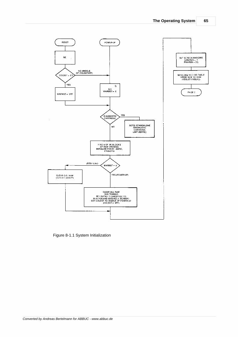
65The Operating System
Converted by Andreas Bertelmann for ABBUC - www.abbuc.de
Figure 8-1.1 System Initialization

66 De Re Atari
Converted by Andreas Bertelmann for ABBUC - www.abbuc.de
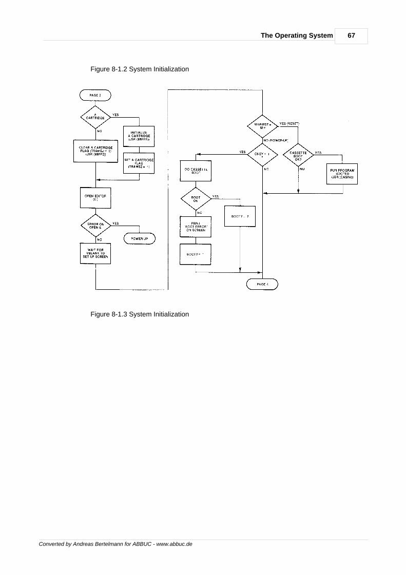
67The Operating System
Converted by Andreas Bertelmann for ABBUC - www.abbuc.de
Figure 8-1.2 System Initialization
Figure 8-1.3 System Initialization
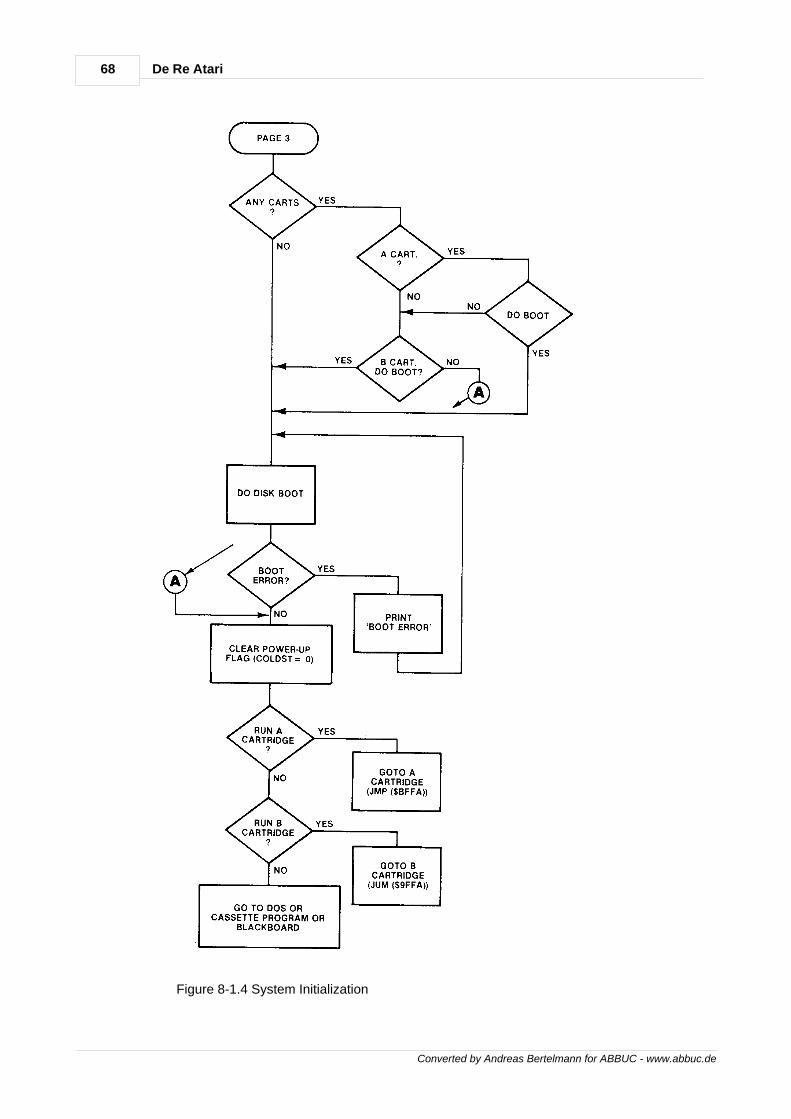
68 De Re Atari
Converted by Andreas Bertelmann for ABBUC - www.abbuc.de
Figure 8-1.4 System Initialization
69The Operating System
Converted by Andreas Bertelmann for ABBUC - www.abbuc.de
MEMORY MANAGEMENTThe fact that the OS is written for a 6502 microprocessor dictates a number of overall memorymanagement decisions. In the 6502, there are three special regions in the memory address space.Page zero has crucial significance in that the use of data values on this page will result in tighter,faster executing code. Indeed, there are instructions that absolutely require page zero locations towork. Page one is special because it is used for the 6502 stack. Addresses $FFFA - $FFFF arealso special because they are reserved for hardware reset and interrupt vectors.
Thus, the first task of memory management is to assign the OS ROM to the highest part ofmemory address space. The OS resides in the address space from $D800 to $FFFF. Just underthis area is the space reserved for the hardware registers in ANTIC, CTIA, and POKEY. Thesereside in the $D000-$DFFF range.
At the other end of memory address space, the OS reserves half of page zero for its own use.Pages two, three, four and five are also reserved for OS usage. From a programming viewpoint,the usable memory area runs from $0600 to $BFFF.
When the system is powered-up, one of the first actions taken by the OS is to determine howmuch RAM memory is present. This is accomplished by checking the first byte of each 4K block ofmemory starting at $1000. The contents of this byte are read, complemented and an attempt ismade to store the complemented value back out. If this attempt is successful, the temporarymemory size counter is incremented by 4K. This process continues until a location is found thatcannot be changed. Two variables, RAMTOP and RAMSIZ contain the number of RAM pagespresent. In addition to these locations, pointers MEMLO, MEMTOP, and APPMHI are maintainedby the OS memory management routines. The relationships between these pointers are shown inFigure 8-2, a simple memory map.
MEMLO is a 2-byte location that the OS uses to indicate where an application program may begin.You can modify MEMLO to create reserved areas for assembly language routines that may becalled from BASIC. BASIC uses the value In MEMLO to determine the starting location of aprogram (see Section 10 for a discussion of the structure of a BASIC program). If the value ofMEMLO is changed to a higher address, it must be done before control is transferred to the BASICcartridge. This is a tricky operation, because MEMLO is reset by both power-up and SYSTEMRESET.
If an application program is running in a disk drive environment, the AUTORUN.SYS facility can beused to change MEMLO to reserve space. However, DOS is also initialized during SYSTEMRESET via the DOSINI vector ($000C). This vector contains the address of the DOS initializationcode called as part of the monitor system initialization. DOSINI is also the only point at which youcan "trap" the SYSTEM RESET sequence. Since the DOS initialization must occur regardless ofwhat is done to the MEMLO pointer, you must allow the normal initialization to occur before"stealing" the DOSINI vector. This may be done by moving the contents of DOSINI into the 2-byteaddress of a JSR information on the AUTORUN.SYS feature). Just after the JSR instruction, placethe code which sets MEMLO to a new value. Follow this with a RTS instruction. DOSINI must thenbe reset to the address of the JSR instruction. When a SYSTEM RESET occurs, the new codesequence is called and the first instruction, JSR OLDDOSINI, initializes DOS. The remaining codeis then executed which sets MEMLO to its new value and then rejoins the rest of the initializationsequence. Figure 8-3 presents an example showing how to do this.
The above technique can also be used with MEMTOP, the user high memory pointer. This pointerindicates the highest RAM address accessible to an application program. This RAM addressdiffers from the highest physical RAM address because the OS allocates some RAM at the verytop of RAM for its display list and display data. Space for assembly language modules and datacan be set aside by lowering MEMTOP from the values set by power-up and SYSTEM RESET.Using MEMTOP instead of MEMLO to reserve space does create one problem. The value ofMEMTOP depends on both the amount of RAM in the system and the graphics mode of thedisplay. This makes it difficult to predict its value before actually examining the location unless youmake assumptions about the system configuration. This uncertainty over the final location of themachine code forces the programmer to use only relocatable code.
APPMHI is a location that contains an address specifying the lowest address to which the display
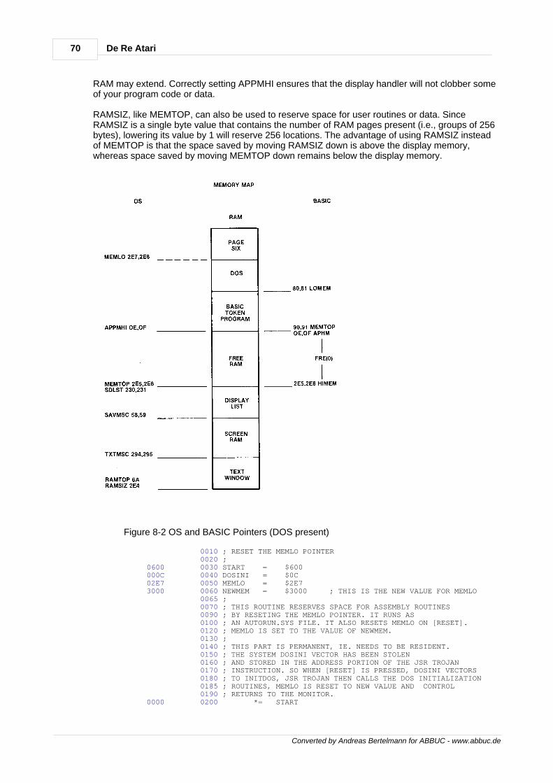
70 De Re Atari
Converted by Andreas Bertelmann for ABBUC - www.abbuc.de
RAM may extend. Correctly setting APPMHI ensures that the display handler will not clobber someof your program code or data.
RAMSIZ, like MEMTOP, can also be used to reserve space for user routines or data. SinceRAMSIZ is a single byte value that contains the number of RAM pages present (i.e., groups of 256bytes), lowering its value by 1 will reserve 256 locations. The advantage of using RAMSIZ insteadof MEMTOP is that the space saved by moving RAMSIZ down is above the display memory,whereas space saved by moving MEMTOP down remains below the display memory.
Figure 8-2 OS and BASIC Pointers (DOS present)
0010 ; RESET THE MEMLO POINTER 0020 ; 0600 0030 START = $600 000C 0040 DOSINI = $0C 02E7 0050 MEMLO = $2E7 3000 0060 NEWMEM = $3000 ; THIS IS THE NEW VALUE FOR MEMLO 0065 ; 0070 ; THIS ROUTINE RESERVES SPACE FOR ASSEMBLY ROUTINES 0090 ; BY RESETING THE MEMLO POINTER. IT RUNS AS 0100 ; AN AUTORUN.SYS FILE. IT ALSO RESETS MEMLO ON [RESET]. 0120 ; MEMLO IS SET TO THE VALUE OF NEWMEM. 0130 ; 0140 ; THIS PART IS PERMANENT, IE. NEEDS TO BE RESIDENT. 0150 ; THE SYSTEM DOSINI VECTOR HAS BEEN STOLEN 0160 ; AND STORED IN THE ADDRESS PORTION OF THE JSR TROJAN 0170 ; INSTRUCTION. SO WHEN [RESET] IS PRESSED, DOSINI VECTORS 0180 ; TO INITDOS, JSR TROJAN THEN CALLS THE DOS INITIALIZATION 0185 ; ROUTINES, MEMLO IS RESET TO NEW VALUE AND CONTROL 0190 ; RETURNS TO THE MONITOR. 0000 0200 *= START
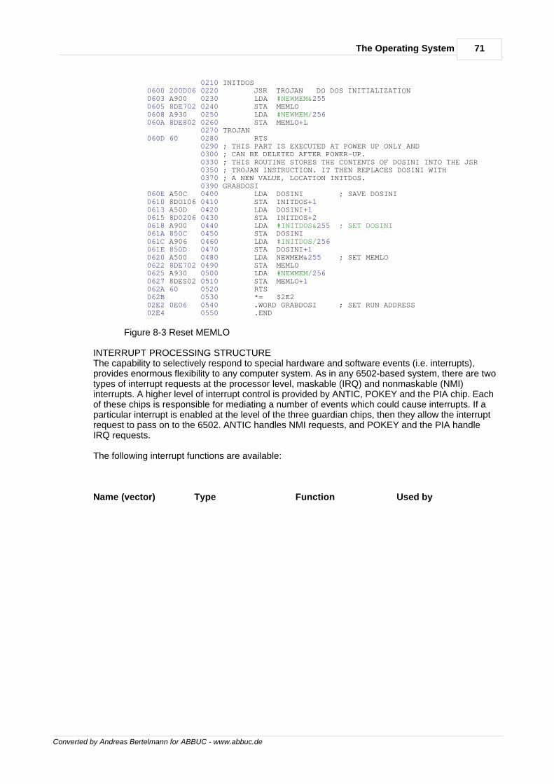
71The Operating System
Converted by Andreas Bertelmann for ABBUC - www.abbuc.de
0210 INITDOS 0600 200D06 0220 JSR TROJAN DO DOS INITIALIZATION 0603 A900 0230 LDA #NEWMEM&255 0605 8DE702 0240 STA MEMLO 0608 A930 0250 LDA #NEWMEM/256 060A 8DE802 0260 STA MEMLO+L 0270 TROJAN 060D 60 0280 RTS 0290 ; THIS PART IS EXECUTED AT POWER UP ONLY AND 0300 ; CAN BE DELETED AFTER POWER-UP. 0330 ; THIS ROUTINE STORES THE CONTENTS OF DOSINI INTO THE JSR 0350 ; TROJAN INSTRUCTION. IT THEN REPLACES DOSINI WITH 0370 ; A NEW VALUE, LOCATION INITDOS. 0390 GRABDOSI 060E A50C 0400 LDA DOSINI ; SAVE DOSINI 0610 8DO106 0410 STA INITDOS+1 0613 A50D 0420 LDA DOSINI+1 0615 8D0206 0430 STA INITDOS+2 0618 A900 0440 LDA #INITDOS&255 ; SET DOSINI 061A 850C 0450 STA DOSINI 061C A906 0460 LDA #INITDOS/256 061E 850D 0470 STA DOSINI+1 0620 A500 0480 LDA NEWMEM&255 ; SET MEMLO 0622 8DE702 0490 STA MEMLO 0625 A930 0500 LDA #NEWMEM/256 0627 8DES02 0510 STA MEMLO+1 062A 60 0520 RTS 062B 0530 *= $2E2 02E2 0E06 0540 .WORD GRABDOSI ; SET RUN ADDRESS 02E4 0550 .END
Figure 8-3 Reset MEMLO
INTERRUPT PROCESSING STRUCTUREThe capability to selectively respond to special hardware and software events (i.e. interrupts),provides enormous flexibility to any computer system. As in any 6502-based system, there are twotypes of interrupt requests at the processor level, maskable (IRQ) and nonmaskable (NMI)interrupts. A higher level of interrupt control is provided by ANTIC, POKEY and the PIA chip. Eachof these chips is responsible for mediating a number of events which could cause interrupts. If aparticular interrupt is enabled at the level of the three guardian chips, then they allow the interruptrequest to pass on to the 6502. ANTIC handles NMI requests, and POKEY and the PIA handleIRQ requests.
The following interrupt functions are available:
Name (vector) Type Function Used by
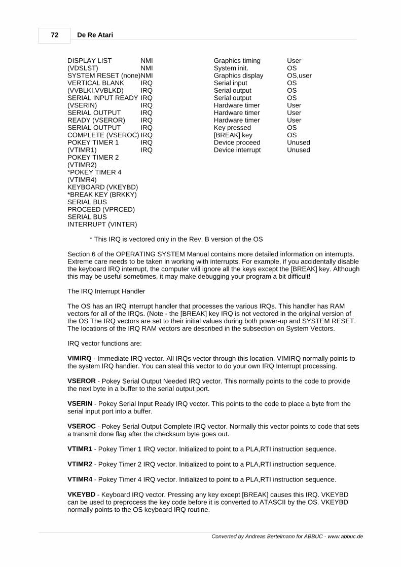
72 De Re Atari
Converted by Andreas Bertelmann for ABBUC - www.abbuc.de
DISPLAY LIST(VDSLST)SYSTEM RESET (none)VERTICAL BLANK(VVBLKI,VVBLKD)SERIAL INPUT READY(VSERIN)SERIAL OUTPUTREADY (VSEROR)SERIAL OUTPUTCOMPLETE (VSEROC)POKEY TIMER 1(VTIMR1)POKEY TIMER 2(VTIMR2)*POKEY TIMER 4(VTIMR4)KEYBOARD (VKEYBD)*BREAK KEY (BRKKY)SERIAL BUSPROCEED (VPRCED)SERIAL BUSINTERRUPT (VINTER)
NMINMINMIIRQIRQIRQIRQIRQIRQIRQIRQIRQIRQ
Graphics timingSystem init.Graphics displaySerial inputSerial outputSerial outputHardware timerHardware timerHardware timerKey pressed[BREAK] keyDevice proceedDevice interrupt
UserOSOS,userOSOSOSUserUserUserOSOSUnusedUnused
* This IRQ is vectored only in the Rev. B version of the OS
Section 6 of the OPERATING SYSTEM Manual contains more detailed information on interrupts.Extreme care needs to be taken in working with interrupts. For example, if you accidentally disablethe keyboard IRQ interrupt, the computer will ignore all the keys except the [BREAK] key. Althoughthis may be useful sometimes, it may make debugging your program a bit difficult!
The IRQ Interrupt Handler
The OS has an IRQ interrupt handler that processes the various IRQs. This handler has RAMvectors for all of the IRQs. (Note - the [BREAK] key IRQ is not vectored in the original version ofthe OS The IRQ vectors are set to their initial values during both power-up and SYSTEM RESET.The locations of the IRQ RAM vectors are described in the subsection on System Vectors.
IRQ vector functions are:
VIMIRQ - Immediate IRQ vector. All IRQs vector through this location. VIMIRQ normally points tothe system IRQ handier. You can steal this vector to do your own IRQ Interrupt processing.
VSEROR - Pokey Serial Output Needed IRQ vector. This normally points to the code to providethe next byte in a buffer to the serial output port.
VSERIN - Pokey Serial Input Ready IRQ vector. This points to the code to place a byte from theserial input port into a buffer.
VSEROC - Pokey Serial Output Complete IRQ vector. Normally this vector points to code that setsa transmit done flag after the checksum byte goes out.
VTIMR1 - Pokey Timer 1 IRQ vector. Initialized to point to a PLA,RTI instruction sequence.
VTIMR2 - Pokey Timer 2 IRQ vector. Initialized to point to a PLA,RTI instruction sequence.
VTIMR4 - Pokey Timer 4 IRQ vector. Initialized to point to a PLA,RTI instruction sequence.
VKEYBD - Keyboard IRQ vector. Pressing any key except [BREAK] causes this IRQ. VKEYBDcan be used to preprocess the key code before it is converted to ATASCII by the OS. VKEYBDnormally points to the OS keyboard IRQ routine.
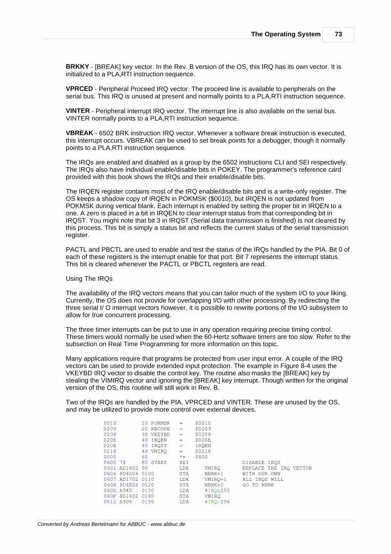
73The Operating System
Converted by Andreas Bertelmann for ABBUC - www.abbuc.de
BRKKY - [BREAK] key vector. In the Rev. B version of the OS, this IRQ has its own vector. It isinitialized to a PLA,RTI instruction sequence.
VPRCED - Peripheral Proceed IRQ vector. The proceed line is available to peripherals on theserial bus. This IRQ is unused at present and normally points to a PLA,RTI instruction sequence.
VINTER - Peripheral interrupt IRQ vector. The interrupt line is also available on the serial bus.VINTER normally points to a PLA,RTI instruction sequence.
VBREAK - 6502 BRK instruction IRQ vector. Whenever a software break instruction is executed,this interrupt occurs. VBREAK can be used to set break points for a debugger, though it normallypoints to a PLA,RTI instruction sequence.
The IRQs are enabled and disabled as a group by the 6502 instructions CLI and SEI respectively.The IRQs also have individual enable/disable bits in POKEY. The programmer's reference cardprovided with this book shows the IRQs and their enable/disable bits.
The IRQEN register contains most of the IRQ enable/disable bits and is a write-only register. TheOS keeps a shadow copy of IRQEN in POKMSK ($0010), but IRQEN is not updated fromPOKMSK during vertical blank. Each interrupt is enabled by setting the proper bit in IRQEN to aone. A zero is placed in a bit in IRQEN to clear interrupt status from that corresponding bit inIRQST. You might note that bit 3 in IRQST (Serial data transmission is finished) is not cleared bythis process. This bit is simply a status bit and reflects the current status of the serial transmissionregister.
PACTL and PBCTL are used to enable and test the status of the IRQs handled by the PIA. Bit 0 ofeach of these registers is the interrupt enable for that port. Bit 7 represents the interrupt status.This bit is cleared whenever the PACTL or PBCTL registers are read.
Using The IRQs
The availability of the IRQ vectors means that you can tailor much of the system I/O to your liking.Currently, the OS does not provide for overlapping I/O with other processing. By redirecting thethree serial I/ O interrupt vectors however, it is possible to rewrite portions of the I/O subsystem toallow for true concurrent processing.
The three timer interrupts can be put to use in any operation requiring precise timing control.These timers would normally be used when the 60-Hertz software timers are too slow. Refer to thesubsection on Real Time Programming for more information on this topic.
Many applications require that programs be protected from user input error. A couple of the IRQvectors can be used to provide extended input protection. The example in Figure 8-4 uses theVKEYBD IRQ vector to disable the control key. The routine also masks the [BREAK] key bystealing the VIMIRQ vector and ignoring the [BREAK] key interrupt. Though written for the originalversion of the OS, this routine will still work in Rev. B.
Two of the IRQs are handled by the PIA, VPRCED and VINTER. These are unused by the OS,and may be utilized to provide more control over external devices.
0010 10 POKMSK = $0010 D209 20 KBCODE = $D209 0208 30 VKEYBD = $0208 D20E 40 IRQEN = $D20E D20E 45 IRQST = IRQEN 0216 46 VMIRQ = $0216 0000 60 *= $600 0600 78 80 START SEI DISABLE IRQS 0601 AD1602 90 LDA VMIRQ REPLACE THE IRQ VECTOR 0604 8D4D06 0100 STA NBRK+1 WITH OUR OWN 0607 AD1702 0110 LDA VMIRQ+1 ALL IRQS WILL 060A 8D4E06 0120 STA NBRK+2 GO TO NBRK 060D A945 0130 LDA #IRQ&255 060F 8Dl602 0140 STA VMIRQ 0612 A906 0150 LDA #IRQ/256
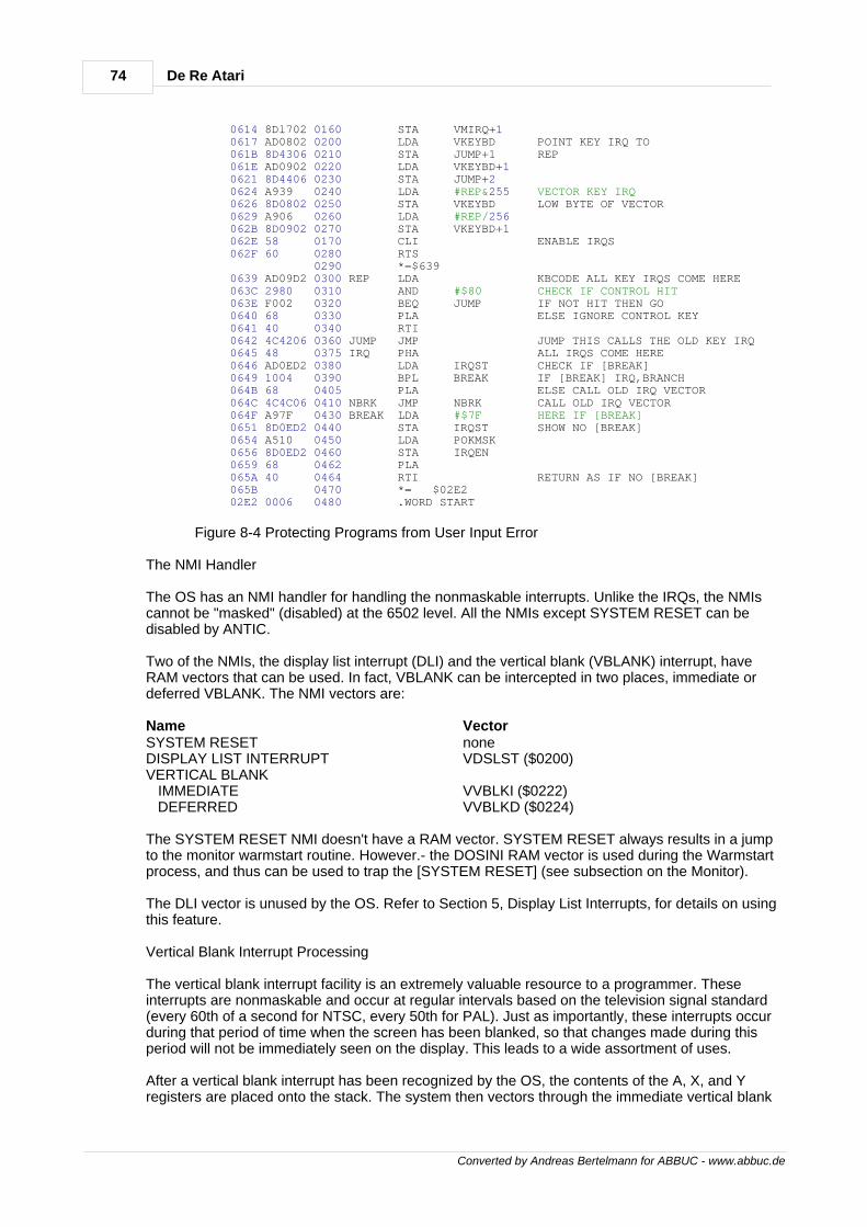
74 De Re Atari
Converted by Andreas Bertelmann for ABBUC - www.abbuc.de
0614 8Dl702 0160 STA VMIRQ+1 0617 AD0802 0200 LDA VKEYBD POINT KEY IRQ TO 061B 8D4306 0210 STA JUMP+1 REP 061E AD0902 0220 LDA VKEYBD+1 0621 8D4406 0230 STA JUMP+2 0624 A939 0240 LDA #REP&255 VECTOR KEY IRQ 0626 8D0802 0250 STA VKEYBD LOW BYTE OF VECTOR 0629 A906 0260 LDA #REP/256 062B 8D0902 0270 STA VKEYBD+1 062E 58 0170 CLI ENABLE IRQS 062F 60 0280 RTS 0290 *=$639 0639 AD09D2 0300 REP LDA KBCODE ALL KEY IRQS COME HERE 063C 2980 0310 AND #$80 CHECK IF CONTROL HIT 063E F002 0320 BEQ JUMP IF NOT HIT THEN GO 0640 68 0330 PLA ELSE IGNORE CONTROL KEY 0641 40 0340 RTI 0642 4C4206 0360 JUMP JMP JUMP THIS CALLS THE OLD KEY IRQ 0645 48 0375 IRQ PHA ALL IRQS COME HERE 0646 AD0ED2 0380 LDA IRQST CHECK IF [BREAK] 0649 1004 0390 BPL BREAK IF [BREAK] IRQ,BRANCH 064B 68 0405 PLA ELSE CALL OLD IRQ VECTOR 064C 4C4C06 0410 NBRK JMP NBRK CALL OLD IRQ VECTOR 064F A97F 0430 BREAK LDA #$7F HERE IF [BREAK] 0651 8D0ED2 0440 STA IRQST SHOW NO [BREAK] 0654 A510 0450 LDA POKMSK 0656 8D0ED2 0460 STA IRQEN 0659 68 0462 PLA 065A 40 0464 RTI RETURN AS IF NO [BREAK] 065B 0470 *= $02E2 02E2 0006 0480 .WORD START
Figure 8-4 Protecting Programs from User Input Error
The NMI Handler
The OS has an NMI handler for handling the nonmaskable interrupts. Unlike the IRQs, the NMIscannot be "masked" (disabled) at the 6502 level. All the NMIs except SYSTEM RESET can bedisabled by ANTIC.
Two of the NMIs, the display list interrupt (DLI) and the vertical blank (VBLANK) interrupt, haveRAM vectors that can be used. In fact, VBLANK can be intercepted in two places, immediate ordeferred VBLANK. The NMI vectors are:
Name VectorSYSTEM RESETDISPLAY LIST INTERRUPTVERTICAL BLANK IMMEDIATE DEFERRED
noneVDSLST ($0200)
VVBLKI ($0222)VVBLKD ($0224)
The SYSTEM RESET NMI doesn't have a RAM vector. SYSTEM RESET always results in a jumpto the monitor warmstart routine. However.- the DOSINI RAM vector is used during the Warmstartprocess, and thus can be used to trap the [SYSTEM RESET] (see subsection on the Monitor).
The DLI vector is unused by the OS. Refer to Section 5, Display List Interrupts, for details on usingthis feature.
Vertical Blank Interrupt Processing
The vertical blank interrupt facility is an extremely valuable resource to a programmer. Theseinterrupts are nonmaskable and occur at regular intervals based on the television signal standard(every 60th of a second for NTSC, every 50th for PAL). Just as importantly, these interrupts occurduring that period of time when the screen has been blanked, so that changes made during thisperiod will not be immediately seen on the display. This leads to a wide assortment of uses.
After a vertical blank interrupt has been recognized by the OS, the contents of the A, X, and Yregisters are placed onto the stack. The system then vectors through the immediate vertical blank
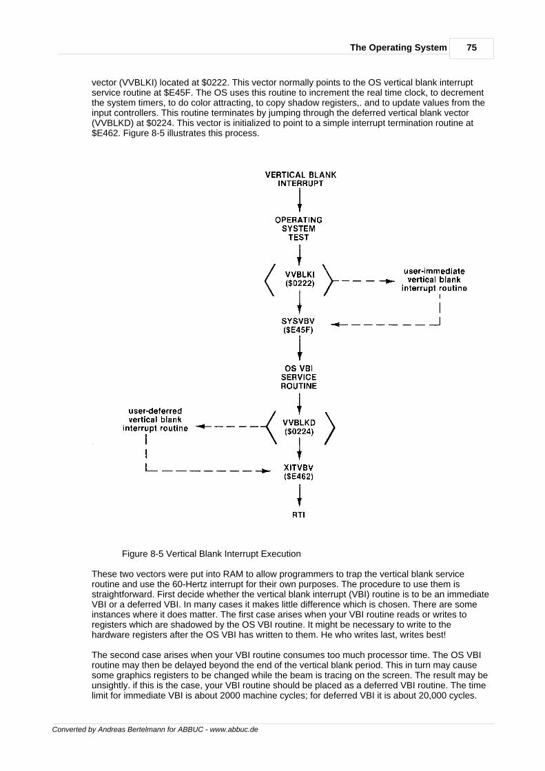
75The Operating System
Converted by Andreas Bertelmann for ABBUC - www.abbuc.de
vector (VVBLKI) located at $0222. This vector normally points to the OS vertical blank interruptservice routine at $E45F. The OS uses this routine to increment the real time clock, to decrementthe system timers, to do color attracting, to copy shadow registers,. and to update values from theinput controllers. This routine terminates by jumping through the deferred vertical blank vector(VVBLKD) at $0224. This vector is initialized to point to a simple interrupt termination routine at$E462. Figure 8-5 illustrates this process.
Figure 8-5 Vertical Blank Interrupt Execution
These two vectors were put into RAM to allow programmers to trap the vertical blank serviceroutine and use the 60-Hertz interrupt for their own purposes. The procedure to use them isstraightforward. First decide whether the vertical blank interrupt (VBI) routine is to be an immediateVBI or a deferred VBI. In many cases it makes little difference which is chosen. There are someinstances where it does matter. The first case arises when your VBI routine reads or writes toregisters which are shadowed by the OS VBI routine. It might be necessary to write to thehardware registers after the OS VBI has written to them. He who writes last, writes best!
The second case arises when your VBI routine consumes too much processor time. The OS VBIroutine may then be delayed beyond the end of the vertical blank period. This in turn may causesome graphics registers to be changed while the beam is tracing on the screen. The result may beunsightly. if this is the case, your VBI routine should be placed as a deferred VBI routine. The timelimit for immediate VBI is about 2000 machine cycles; for deferred VBI it is about 20,000 cycles.
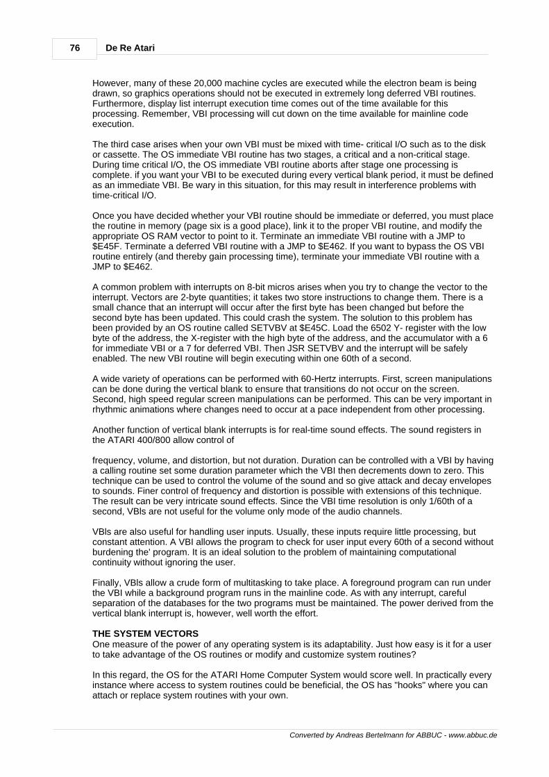
76 De Re Atari
Converted by Andreas Bertelmann for ABBUC - www.abbuc.de
However, many of these 20,000 machine cycles are executed while the electron beam is beingdrawn, so graphics operations should not be executed in extremely long deferred VBI routines.Furthermore, display list interrupt execution time comes out of the time available for thisprocessing. Remember, VBI processing will cut down on the time available for mainline codeexecution.
The third case arises when your own VBI must be mixed with time- critical I/O such as to the diskor cassette. The OS immediate VBI routine has two stages, a critical and a non-critical stage.During time critical I/O, the OS immediate VBI routine aborts after stage one processing iscomplete. if you want your VBI to be executed during every vertical blank period, it must be definedas an immediate VBI. Be wary in this situation, for this may result in interference problems withtime-critical I/O.
Once you have decided whether your VBI routine should be immediate or deferred, you must placethe routine in memory (page six is a good place), link it to the proper VBI routine, and modify theappropriate OS RAM vector to point to it. Terminate an immediate VBI routine with a JMP to$E45F. Terminate a deferred VBI routine with a JMP to $E462. If you want to bypass the OS VBIroutine entirely (and thereby gain processing time), terminate your immediate VBI routine with aJMP to $E462.
A common problem with interrupts on 8-bit micros arises when you try to change the vector to theinterrupt. Vectors are 2-byte quantities; it takes two store instructions to change them. There is asmall chance that an interrupt will occur after the first byte has been changed but before thesecond byte has been updated. This could crash the system. The solution to this problem hasbeen provided by an OS routine called SETVBV at $E45C. Load the 6502 Y- register with the lowbyte of the address, the X-register with the high byte of the address, and the accumulator with a 6for immediate VBI or a 7 for deferred VBI. Then JSR SETVBV and the interrupt will be safelyenabled. The new VBI routine will begin executing within one 60th of a second.
A wide variety of operations can be performed with 60-Hertz interrupts. First, screen manipulationscan be done during the vertical blank to ensure that transitions do not occur on the screen.Second, high speed regular screen manipulations can be performed. This can be very important inrhythmic animations where changes need to occur at a pace independent from other processing.
Another function of vertical blank interrupts is for real-time sound effects. The sound registers inthe ATARI 400/800 allow control of
frequency, volume, and distortion, but not duration. Duration can be controlled with a VBI by havinga calling routine set some duration parameter which the VBI then decrements down to zero. Thistechnique can be used to control the volume of the sound and so give attack and decay envelopesto sounds. Finer control of frequency and distortion is possible with extensions of this technique.The result can be very intricate sound effects. Since the VBI time resolution is only 1/60th of asecond, VBls are not useful for the volume only mode of the audio channels.
VBls are also useful for handling user inputs. Usually, these inputs require little processing, butconstant attention. A VBI allows the program to check for user input every 60th of a second withoutburdening the' program. It is an ideal solution to the problem of maintaining computationalcontinuity without ignoring the user.
Finally, VBls allow a crude form of multitasking to take place. A foreground program can run underthe VBI while a background program runs in the mainline code. As with any interrupt, carefulseparation of the databases for the two programs must be maintained. The power derived from thevertical blank interrupt is, however, well worth the effort.
THE SYSTEM VECTORSOne measure of the power of any operating system is its adaptability. Just how easy is it for a userto take advantage of the OS routines or modify and customize system routines?
In this regard, the OS for the ATARI Home Computer System would score well. In practically everyinstance where access to system routines could be beneficial, the OS has "hooks" where you canattach or replace system routines with your own.
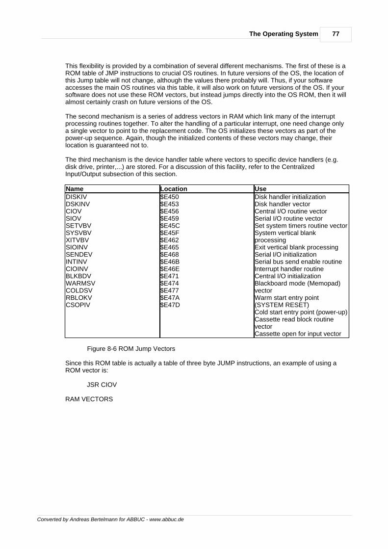
77The Operating System
Converted by Andreas Bertelmann for ABBUC - www.abbuc.de
This flexibility is provided by a combination of several different mechanisms. The first of these is aROM table of JMP instructions to crucial OS routines. In future versions of the OS, the location ofthis Jump table will not change, although the values there probably will. Thus, if your softwareaccesses the main OS routines via this table, it will also work on future versions of the OS. If yoursoftware does not use these ROM vectors, but instead jumps directly into the OS ROM, then it willalmost certainly crash on future versions of the OS.
The second mechanism is a series of address vectors in RAM which link many of the interruptprocessing routines together. To alter the handling of a particular interrupt, one need change onlya single vector to point to the replacement code. The OS initializes these vectors as part of thepower-up sequence. Again, though the initialized contents of these vectors may change, theirlocation is guaranteed not to.
The third mechanism is the device handler table where vectors to specific device handlers (e.g.disk drive, printer,...) are stored. For a discussion of this facility, refer to the CentralizedInput/Output subsection of this section.
Name Location UseDISKIVDSKINVCIOVSIOVSETVBVSYSVBVXITVBVSIOINVSENDEVINTINVCIOINVBLKBDVWARMSVCOLDSVRBLOKVCSOPIV
$E450$E453$E456$E459$E45C$E45F$E462$E465$E468$E46B$E46E$E471$E474$E477$E47A$E47D
Disk handler initializationDisk handler vectorCentral I/O routine vectorSerial I/O routine vectorSet system timers routine vectorSystem vertical blankprocessingExit vertical blank processingSerial I/O initializationSerial bus send enable routineInterrupt handler routineCentral I/O initializationBlackboard mode (Memopad)vectorWarm start entry point(SYSTEM RESET)Cold start entry point (power-up)Cassette read block routinevectorCassette open for input vector
Figure 8-6 ROM Jump Vectors
Since this ROM table is actually a table of three byte JUMP instructions, an example of using aROM vector is:
JSR CIOV
RAM VECTORS
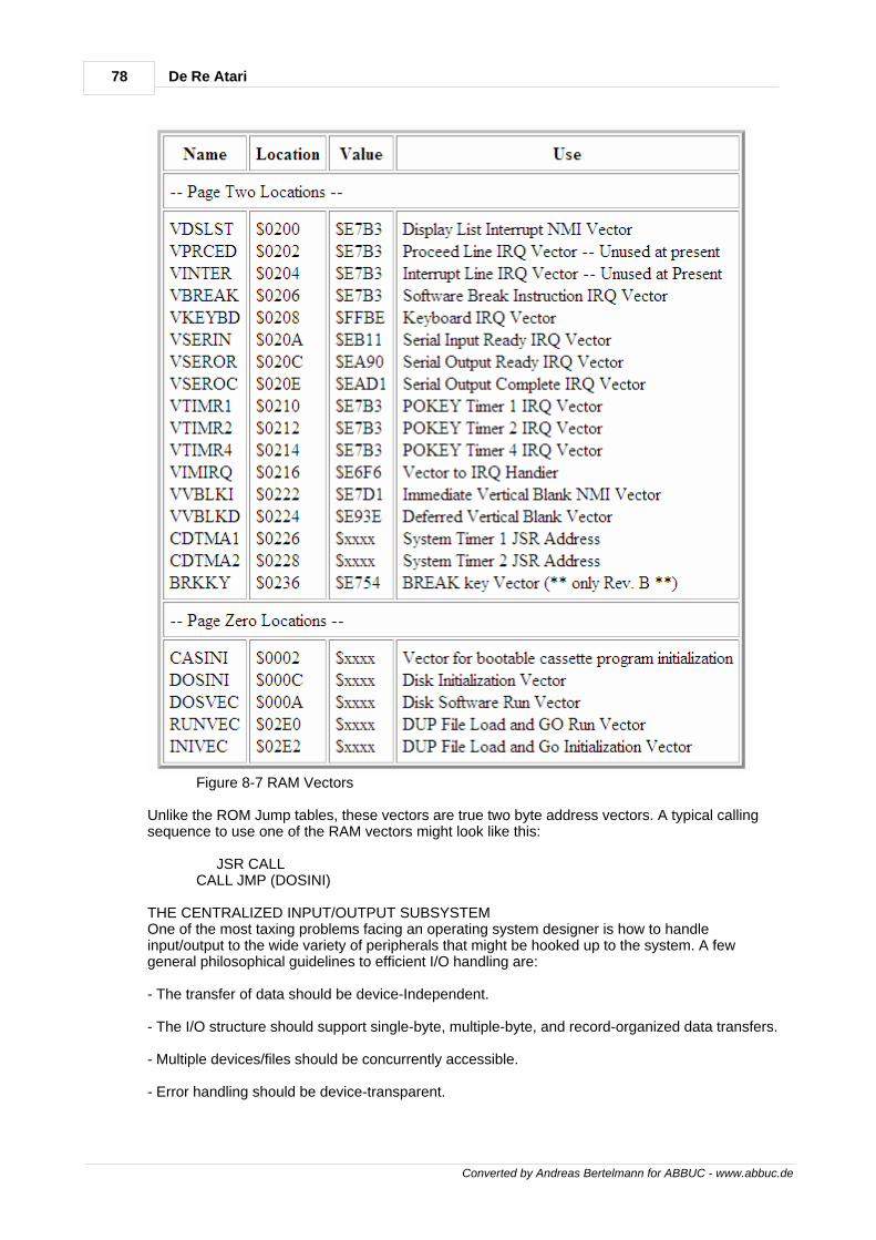
78 De Re Atari
Converted by Andreas Bertelmann for ABBUC - www.abbuc.de
Figure 8-7 RAM Vectors
Unlike the ROM Jump tables, these vectors are true two byte address vectors. A typical callingsequence to use one of the RAM vectors might look like this:
JSR CALL CALL JMP (DOSINI)
THE CENTRALIZED INPUT/OUTPUT SUBSYSTEMOne of the most taxing problems facing an operating system designer is how to handleinput/output to the wide variety of peripherals that might be hooked up to the system. A fewgeneral philosophical guidelines to efficient I/O handling are:
- The transfer of data should be device-Independent.
- The I/O structure should support single-byte, multiple-byte, and record-organized data transfers.
- Multiple devices/files should be concurrently accessible.
- Error handling should be device-transparent.
79The Operating System
Converted by Andreas Bertelmann for ABBUC - www.abbuc.de
- The addition of new device handlers should be possible without having to change the OS ROM.
The ATARI 400/800 OPERATING SYSTEM (OS) was designed to provide exactly thesecapabilities. The ATARI 400/800 OS uses a table- driven centralized input/output subsystem. Fromthe OS standpoint, I/O is organized around the IOCB, or Input/Output Control Block. An IOCB is astandard table that specifies one complete input or output operation. Any of eight standard I/Ooperations can be executed through an IOCB. By changing an entry in the IOCB, the user canchange the nature of the input/output operation, even the physical device which is the target of theI/O. Thus, a user can easily perform I/O to completely different devices such as the disk drive andthe printer without having to worry about hardware details. Most I/O requires only that the user setup an IOCB with control data, and then pass control to the I/O subsystem.
Two types of elements make up the I/O subsystem: I/O system routines and I/O system controlblocks. The I/O system routines include the central I/O routine (CIO), the device handlers (E:, K:,S:, P:, C:, D:, R:) and the serial I/O routine (SIO). The Handler Address Table (HATABS) plays amajor role in linking CIO with the individual device handlers. The system I/O control blocks containcontrol data that is routed to the I/O subsystem. The user interface is the same for all devices(e.g., the commands to output a line to the printer (P:) or to the display editor (E:) are very similar).
Understanding the structure of the I/O subsystem will enhance your use of it. Figure 8-8 shows therelationship of the I/O system routines and the I/O system control blocks.
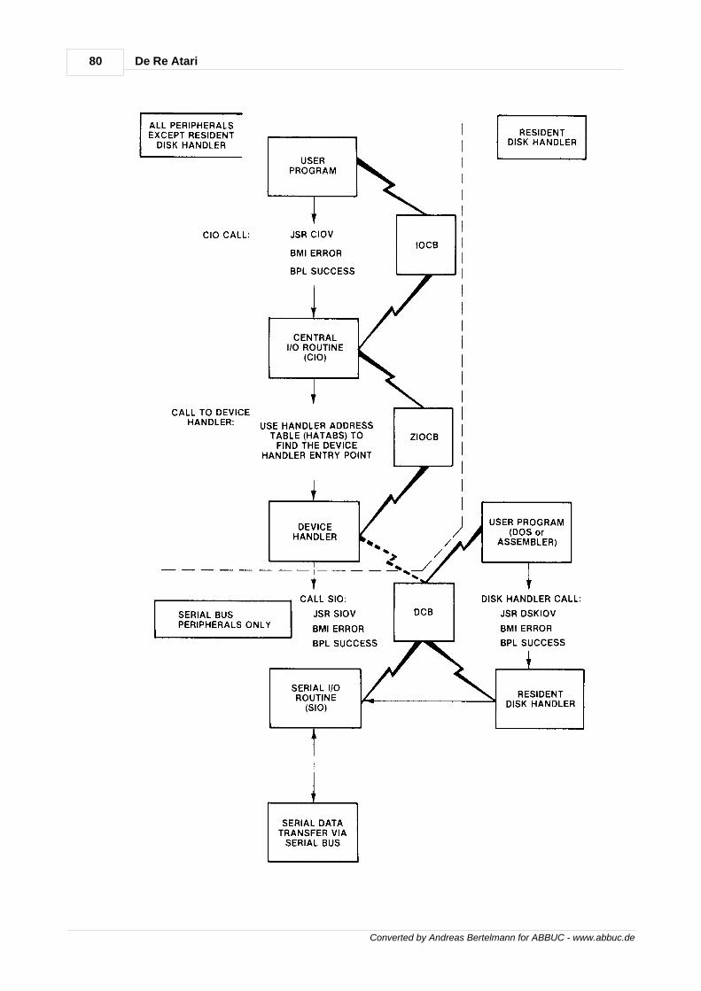
80 De Re Atari
Converted by Andreas Bertelmann for ABBUC - www.abbuc.de
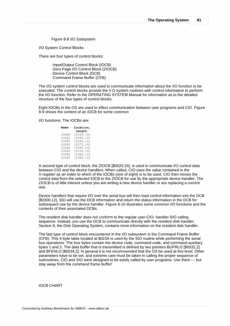
81The Operating System
Converted by Andreas Bertelmann for ABBUC - www.abbuc.de
Figure 8-8 I/O Subsystem
I/O System Control Blocks
There are four types of control blocks:
-Input/Output Control Block (IOCB) -Zero-Page I/O Control Block (ZIOCB) -Device Control Block (DCB) -Command Frame Buffer (CFB)
The I/O system control blocks are used to communicate information about the I/O function to beexecuted. The control blocks provide the I/ O system routines with control information to performthe I/O function. Refer to the OPERATING SYSTEM Manual for information as to the detailedstructure of the four types of control blocks.
Eight IOCBs in the OS are used to effect communication between user programs and CIO. Figure8-9 shows the content of an IOCB for some common
I/O functions. The IOCBs are:
Name Location, Length IOCB0 [$340,16] IOCB1 [$350,16] IOCB2 [$360,16] IOCB3 [$370,16] IOCB4 [$380,16] IOCB5 [$390,16] IOCB6 [$3A0,16] IOCB7 [$3B0,16]
A second type of control block, the ZIOCB [$0020,16], is used to communicate I/O control databetween CIO and the device handlers. When called, CIO uses the value contained in theX-register as an index to which of the IOCBs (one of eight) is to be used. CIO then moves thecontrol data from the selected IOCB to the ZIOCB for use by the appropriate device handler. TheZIOCB is of little interest unless you are writing a new device handler or are replacing a currentone.
Device handlers that require I/O over the serial bus will then load control information into the DCB[$0300,12]. SIO will use the DCB information and return the status information in the DCB forsubsequent use by the device handler. Figure 8-10 illustrates some common I/O functions and thecontents of their associated DCBs.
The resident disk handler does not conform to the regular user-CIO- handler-SIO callingsequence. Instead, you use the DCB to communicate directly with the resident disk handler.Section 9, the Disk Operating System, contains more information on the resident disk handler.
The last type of control block encountered in the I/O subsystem is the Command Frame Buffer(CFB). This 4-byte table located at $023A is used by the SIO routine while performing the serialbus operations. The four bytes contain the device code, command code, and command auxiliarybytes 1 and 2. The data buffer that is transmitted is defined by two pointers BUFRLO [$0032,2]and BFENLO [$0034,2]. In general it is not recommended that the OS be used at this level. Otherparameters have to be set, and extreme care must be taken in calling the proper sequence ofsubroutines. CIO and SIO were designed to be easily called by user programs. Use them --- butstay away from the command frame buffer!
IOCB CHART
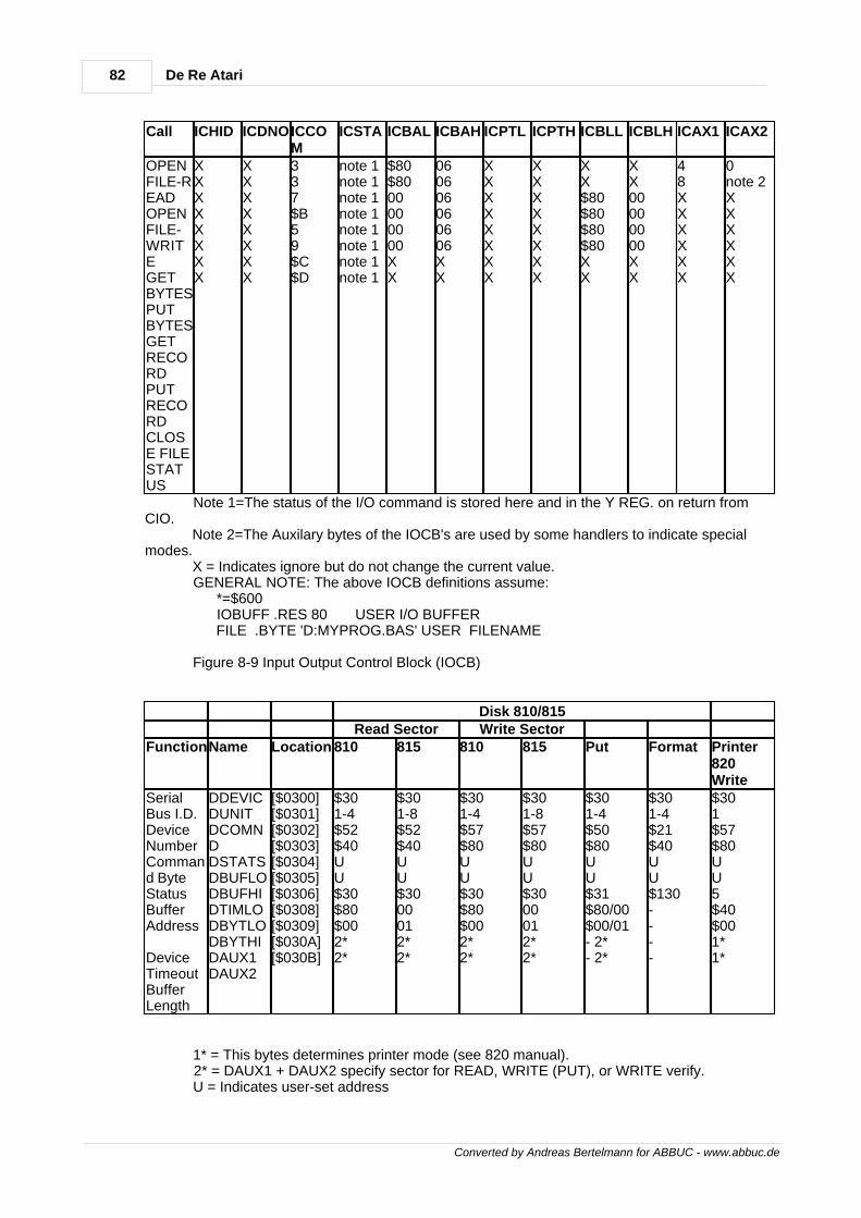
82 De Re Atari
Converted by Andreas Bertelmann for ABBUC - www.abbuc.de
Call ICHID ICDNOICCOM
ICSTA ICBAL ICBAH ICPTL ICPTH ICBLL ICBLH ICAX1 ICAX2
OPENFILE-READOPENFILE-WRITEGETBYTESPUTBYTESGETRECORDPUTRECORDCLOSE FILESTATUS
XXXXXXXX
XXXXXXXX
337$B59$C$D
note 1note 1note 1note 1note 1note 1note 1note 1
$80$8000000000XX
060606060606XX
XXXXXXXX
XXXXXXXX
XX$80$80$80$80XX
XX00000000XX
48XXXXXX
0note 2XXXXXX
Note 1=The status of the I/O command is stored here and in the Y REG. on return fromCIO. Note 2=The Auxilary bytes of the IOCB's are used by some handlers to indicate specialmodes. X = Indicates ignore but do not change the current value. GENERAL NOTE: The above IOCB definitions assume: *=$600 IOBUFF .RES 80 USER I/O BUFFER FILE .BYTE 'D:MYPROG.BAS' USER FILENAME
Figure 8-9 Input Output Control Block (IOCB)
Disk 810/815Read Sector Write Sector
FunctionName Location 810 815 810 815 Put Format Printer820Write
SerialBus I.D.DeviceNumberCommand ByteStatusBufferAddress
DeviceTimeoutBufferLength
DDEVICDUNITDCOMNDDSTATSDBUFLODBUFHIDTIMLODBYTLODBYTHIDAUX1DAUX2
[$0300][$0301][$0302][$0303][$0304][$0305][$0306][$0308][$0309][$030A][$030B]
$301-4$52$40UU$30$80$002*2*
$301-8$52$40UU$3000012*2*
$301-4$57$80UU$30$80$002*2*
$301-8$57$80UU$3000012*2*
$301-4$50$80UU$31$80/00$00/01- 2*- 2*
$301-4$21$40UU$130----
$301$57$80UU5$40$001*1*
1* = This bytes determines printer mode (see 820 manual). 2* = DAUX1 + DAUX2 specify sector for READ, WRITE (PUT), or WRITE verify. U = Indicates user-set address
83The Operating System
Converted by Andreas Bertelmann for ABBUC - www.abbuc.de
- = Indicates ignored
Figure 8-10 Device Control Block (DCB)
Central I/O System Routine
The main function of CIO is to take control data from an IOCB and ensure that it is routed to thespecific device handler needed, and then to pass control to that handler. CIO also acts as apipeline for most I/O in the system. Most of the OS I/O functions use CIO as a common entrypoint, and all handlers exit via CIO. For example, BASIC will call CIO when performing an OPENor a GRAPHICS statement. CIO supports the following functions:
OPENCLOSEGET CHARSREAD RECORDPUT CHARSWRITE RECORDSTATUSSPECIAL
Device/file openDevice/file closeRead N charactersRead next recordWrite N charactersWrite next recordGet device statusDevice handler specific (e.g., NOTE for FMS)
You may wish to make your own CIO calls. The calling sequence for CIO is:
;rem user has already set up IOCB LDX #IOCBNUM ;set the IOCB index (IOCB * 16) JSR CIOV ;system routine vector to CIO BMI ERROR if branch taken then CIO returned ;error code in Y-register
As shown in the above call, one of the IOCBs is used to communicate control data to CIO. Youmay use any one of the eight IOCBS. CIO expects the IOCB index to be in the X-register. Notethat this value must be the IOCB number multiplied by 16. The reason is that CIO uses this valueas a true index into the various IOCBs, and each IOCB is 16 bytes. Upon return, the sign bit of the6502 is set to indicate success or error in the I/O operation. If the N-bit is clear (i.e., a zero) the I/Owas done successfully, and the Y-register will contain a 1. If the N-bit is set, the I/O requestresulted in an error; in that case the Y-register will contain the error code number. A BMIinstruction to an error routine is the usual way to test for operational success. The error/successvalue is also returned in the IOCB byte ICSTA (see IOCB definition). Chapter 5 of theOPERATING SYSTEM Manual has a sample program segment that calls CIO to OPEN a disk file,READ some records., then CLOSE the file.
CIO copies the control data from the selected IOCB to the page zero ZIOCB. CIO then determinesthe device handler entry point and vectors to the appropriate device handler routine. Figure 8-11 isa flowchart of the CIO system routine.
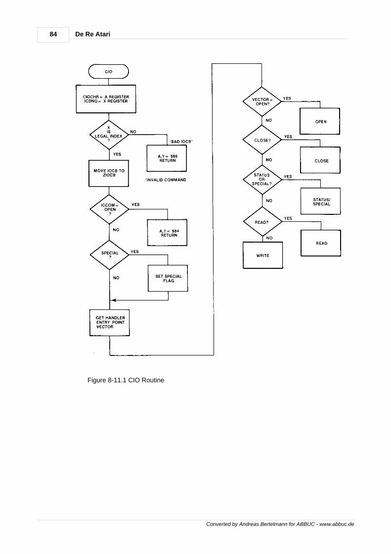
84 De Re Atari
Converted by Andreas Bertelmann for ABBUC - www.abbuc.de
Figure 8-11.1 CIO Routine
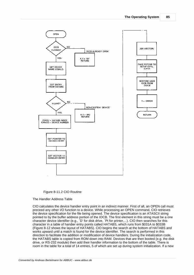
85The Operating System
Converted by Andreas Bertelmann for ABBUC - www.abbuc.de
Figure 8-11.2 CIO Routine
The Handler Address Table
CIO calculates the device handier entry point in an indirect manner. First of all, an OPEN call mustpreceed any other I/O function to a device. While processing an OPEN command, CIO retrievesthe device specification for the file being opened. The device specification is an ATASCII stringpointed to by the buffer address portion of the IOCB. The first element in this string must be a onecharacter device identifier (e.g., `D' for disk drive, `Pt for printer,...). CIO then searches for thischaracter in a table of handier entry points called HATABS, which runs from $031A to $033B(Figure 8-12 shows the layout of HATABS). CIO begins the search at the bottom of HATABS andworks upward until a match is found for the device identifier. The search is performed in thisdirection to facilitate the addition or modification of device handlers. During the initialization code,the HATABS table is copied from ROM down into RAM. Devices that are then booted (e.g. the diskdrive, or RS-232 module) then add their handler information to the bottom of the table. There isroom in the table for a total of 14 entries, 5 of which are set up during system initialization. If a new
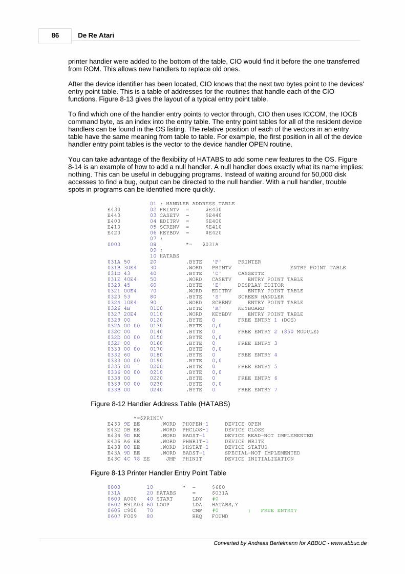
86 De Re Atari
Converted by Andreas Bertelmann for ABBUC - www.abbuc.de
printer handier were added to the bottom of the table, CIO would find it before the one transferredfrom ROM. This allows new handlers to replace old ones.
After the device identifier has been located, CIO knows that the next two bytes point to the devices'entry point table. This is a table of addresses for the routines that handle each of the CIOfunctions. Figure 8-13 gives the layout of a typical entry point table.
To find which one of the handier entry points to vector through, CIO then uses ICCOM, the IOCBcommand byte, as an index into the entry table. The entry point tables for all of the resident devicehandlers can be found in the OS listing. The relative position of each of the vectors in an entrytable have the same meaning from table to table. For example, the first position in all of the devicehandler entry point tables is the vector to the device handler OPEN routine.
You can take advantage of the flexibility of HATABS to add some new features to the OS. Figure8-14 is an example of how to add a null handler. A null handler does exactly what its name implies:nothing. This can be useful in debugging programs. Instead of waiting around for 50,000 diskaccesses to find a bug, output can be directed to the null handier. With a null handler, troublespots in programs can be identified more quickly.
01 ; HANDLER ADDRESS TABLE E430 02 PRINTV = $E430 E440 03 CASETV = $E440 E400 04 EDITRV = $E400 E410 05 SCRENV = $E410 E420 06 KEYBDV = $E420 07 ; 0000 08 *= $031A 09 ; 10 HATABS 031A 50 20 .BYTE 'P' PRINTER 031B 30E4 30 .WORD PRINTV ENTRY POINT TABLE 031D 43 40 .BYTE 'C' CASSETTE 031E 40E4 50 .WORD CASETV ENTRY POINT TABLE 0320 45 60 .BYTE 'E' DISPLAY EDITOR 0321 00E4 70 .WORD EDITRV ENTRY POINT TABLE 0323 53 80 .BYTE 'S' SCREEN HANDLER 0324 10E4 90 .WORD SCRENV ENTRY POINT TABLE 0326 4B 0100 .BYTE 'K' KEYBOARD 0327 20E4 0110 .WORD KEYBDV ENTRY POINT TABLE 0329 00 0120 .BYTE 0 FREE ENTRY 1 (DOS) 032A 00 00 0130 .BYTE 0,0 032C 00 0140 .BYTE 0 FREE ENTRY 2 (850 MODULE) 032D 00 00 0150 .BYTE 0,0 032F 00 0160 .BYTE 0 FREE ENTRY 3 0330 00 00 0170 .BYTE 0,0 0332 60 0180 .BYTE 0 FREE ENTRY 4 0333 00 00 0190 .BYTE 0,0 0335 00 0200 .BYTE 0 FREE ENTRY 5 0336 00 00 0210 .BYTE 0,0 0338 00 0220 .BYTE 0 FREE ENTRY 6 0339 00 00 0230 .BYTE 0,0 033B 00 0240 .BYTE 0 FREE ENTRY 7
Figure 8-12 Handier Address Table (HATABS)
*=$PRINTV E430 9E EE .WORD PHOPEN-1 DEVICE OPEN E432 DB EE .WORD PHCLOS-1 DEVICE CLOSE E434 9D EE .WORD BADST-1 DEVICE READ-NOT IMPLEMENTED E436 A6 EE .WORD PHWRIT-1 DEVICE WRITE E438 80 EE .WORD PHSTAT-1 DEVICE STATUS E43A 9D EE .WORD BADST-1 SPECIAL-NOT IMPLEMENTED E43C 4C 78 EE JMP PHINIT DEVICE INITIALIZATION
Figure 8-13 Printer Handler Entry Point Table
0000 10 * = $600 031A 20 HATABS = $031A 0600 A000 40 START LDY #0 0602 B91A03 60 LOOP LDA HATABS,Y 0605 C900 70 CMP #0 ; FREE ENTRY? 0607 F009 80 BEQ FOUND
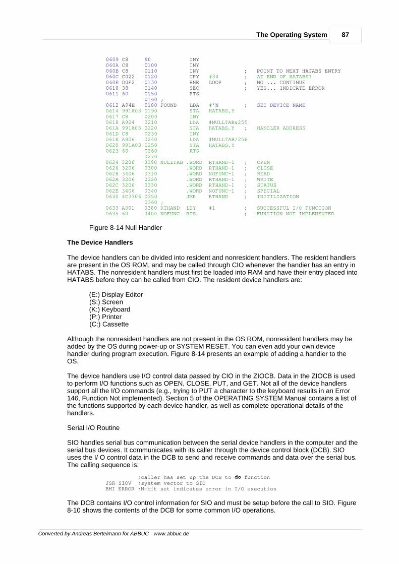
87The Operating System
Converted by Andreas Bertelmann for ABBUC - www.abbuc.de
0609 C8 90 INY 060A C8 0100 INY 060B C8 0110 INY ; POINT TO NEXT HATABS ENTRY 060C C022 0120 CPY #34 ; AT END OF HATABS? 060E D0F2 0130 BNE LOOP ; NO ... CONTINUE 0610 38 0140 SEC ; YES... INDICATE ERROR 0611 60 0150 RTS 0160 ; 0612 A94E 0180 FOUND LDA #'N ; SET DEVICE NAME 0614 991A03 0190 STA HATABS,Y 0617 C8 0200 INY 0618 A924 0210 LDA #NULLTAB&255 061A 991A03 0220 STA HATABS,Y ; HANDLER ADDRESS 061D C8 0230 INY 061E A906 0240 LDA #NULLTAB/256 0620 991A03 0250 STA HATABS,Y 0623 60 0260 RTS 0270 0624 3206 0290 NULLTAB .WORD RTHAND-1 ; OPEN 0626 3206 0300 .WORD RTHAND-1 ; CLOSE 0628 3406 0310 .WORD NOFUNC-1 ; READ 062A 3206 0320 .WORD RTHAND-1 ; WRITE 062C 3206 0330 .WORD RTHAND-1 ; STATUS 062E 3406 0340 .WORD NOFUNC-1 ; SPECIAL 0630 4C3306 0350 JMP RTHAND ; INITILIZATION 0360 ; 0633 A001 0380 RTHAND LDY #1 ; SUCCESSFUL I/O FUNCTION 0635 60 0400 NOFUNC RTS ; FUNCTION NOT IMPLEMENTED
Figure 8-14 Null Handler
The Device Handlers
The device handlers can be divided into resident and nonresident handlers. The resident handlersare present in the OS ROM, and may be called through CIO whenever the handier has an entry inHATABS. The nonresident handlers must first be loaded into RAM and have their entry placed intoHATABS before they can be called from CIO. The resident device handlers are:
(E:) Display Editor (S:) Screen (K:) Keyboard (P:) Printer (C:) Cassette
Although the nonresident handlers are not present in the OS ROM, nonresident handlers may beadded by the OS during power-up or SYSTEM RESET. You can even add your own devicehandier during program execution. Figure 8-14 presents an example of adding a handier to theOS.
The device handlers use I/O control data passed by CIO in the ZIOCB. Data in the ZIOCB is usedto perform I/O functions such as OPEN, CLOSE, PUT, and GET. Not all of the device handlerssupport all the I/O commands (e.g., trying to PUT a character to the keyboard results in an Error146, Function Not implemented). Section 5 of the OPERATING SYSTEM Manual contains a list ofthe functions supported by each device handler, as well as complete operational details of thehandlers.
Serial I/O Routine
SIO handles serial bus communication between the serial device handlers in the computer and theserial bus devices. It communicates with its caller through the device control block (DCB). SIOuses the I/ O control data in the DCB to send and receive commands and data over the serial bus.The calling sequence is:
;caller has set up the DCB to do function JSR SIOV ;system vector to SIO BMI ERROR ;N-bit set indicates error in I/O execution
The DCB contains I/O control information for SIO and must be setup before the call to SIO. Figure8-10 shows the contents of the DCB for some common I/O operations.
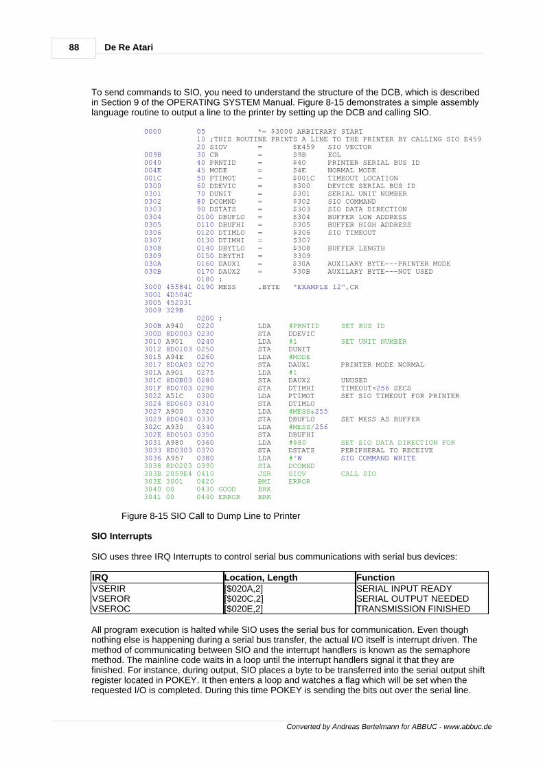
88 De Re Atari
Converted by Andreas Bertelmann for ABBUC - www.abbuc.de
To send commands to SIO, you need to understand the structure of the DCB, which is describedin Section 9 of the OPERATING SYSTEM Manual. Figure 8-15 demonstrates a simple assemblylanguage routine to output a line to the printer by setting up the DCB and calling SIO.
0000 05 *= $3000 ARBITRARY START 10 ;THIS ROUTINE PRINTS A LINE TO THE PRINTER BY CALLING SIO E459 20 SIOV = $E459 SIO VECTOR 009B 30 CR = $9B EOL 0040 40 PRNTID = $40 PRINTER SERIAL BUS ID 004E 45 MODE = $4E NORMAL MODE 001C 50 PTIMOT = $001C TIMEOUT LOCATION 0300 60 DDEVIC = $300 DEVICE SERIAL BUS ID 0301 70 DUNIT = $301 SERIAL UNIT NUMBER 0302 80 DCOMND = $302 SIO COMMAND 0303 90 DSTATS = $303 SIO DATA DIRECTION 0304 0100 DBUFLO = $304 BUFFER LOW ADDRESS 0305 0110 DBUFHI = $305 BUFFER HIGH ADDRESS 0306 0120 DTIMLO = $306 SIO TIMEOUT 0307 0130 DTIMHI = $307 0308 0140 DBYTLO = $308 BUFFER LENGTH 0309 0150 DBYTHI = $309 030A 0160 DAUX1 = $30A AUXILARY BYTE---PRINTER MODE 030B 0170 DAUX2 = $30B AUXILARY BYTE---NOT USED 0180 ; 3000 455841 0190 MESS .BYTE "EXAMPLE 12",CR 3001 4D504C 3005 452031 3009 329B 0200 ; 300B A940 0220 LDA #PRNTID SET BUS ID 300D 8D0003 0230 STA DDEVIC 3010 A901 0240 LDA #1 SET UNIT NUMBER 3012 8D0103 0250 STA DUNIT 3015 A94E 0260 LDA #MODE 3017 8D0A03 0270 STA DAUX1 PRINTER MODE NORMAL 301A A901 0275 LDA #1 301C 8D0B03 0280 STA DAUX2 UNUSED 301F 8D0703 0290 STA DTIMHI TIMEOUT<256 SECS 3022 A51C 0300 LDA PTIMOT SET SIO TIMEOUT FOR PRINTER 3024 8D0603 0310 STA DTIMLO 3027 A900 0320 LDA #MESS&255 3029 8D0403 0330 STA DBUFLO SET MESS AS BUFFER 302C A930 0340 LDA #MESS/256 302E 8D0503 0350 STA DBUFHI 3031 A980 0360 LDA #$80 SET SIO DATA DIRECTION FOR 3033 8D0303 0370 STA DSTATS PERIPHERAL TO RECEIVE 3036 A957 0380 LDA #'W SIO COMMAND WRITE 3038 8D0203 0390 STA DCOMND 303B 2059E4 0410 JSR SIOV CALL SIO 303E 3001 0420 BMI ERROR 3040 00 0430 GOOD BRK 3041 00 0440 ERROR BRK
Figure 8-15 SIO Call to Dump Line to Printer
SIO Interrupts
SIO uses three IRQ Interrupts to control serial bus communications with serial bus devices:
IRQ Location, Length FunctionVSERIRVSERORVSEROC
[$020A,2][$020C,2][$020E,2]
SERIAL INPUT READYSERIAL OUTPUT NEEDEDTRANSMISSION FINISHED
All program execution is halted while SIO uses the serial bus for communication. Even thoughnothing else is happening during a serial bus transfer, the actual I/O itself is interrupt driven. Themethod of communicating between SIO and the interrupt handlers is known as the semaphoremethod. The mainline code waits in a loop until the interrupt handlers signal it that they arefinished. For instance, during output, SIO places a byte to be transferred into the serial output shiftregister located in POKEY. It then enters a loop and watches a flag which will be set when therequested I/O is completed. During this time POKEY is sending the bits out over the serial line.
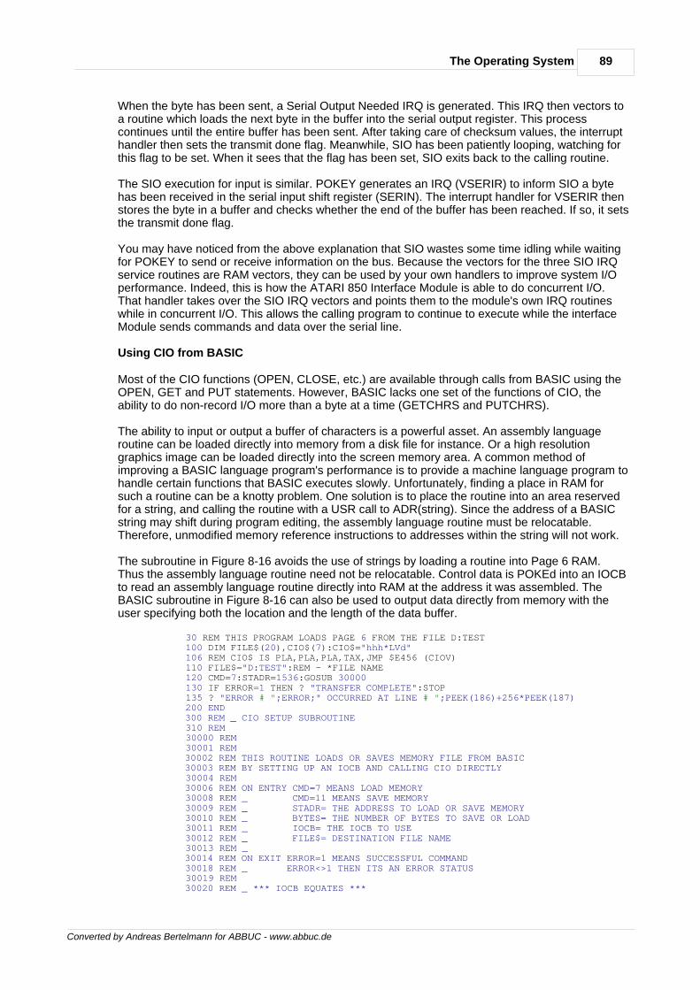
89The Operating System
Converted by Andreas Bertelmann for ABBUC - www.abbuc.de
When the byte has been sent, a Serial Output Needed IRQ is generated. This IRQ then vectors toa routine which loads the next byte in the buffer into the serial output register. This processcontinues until the entire buffer has been sent. After taking care of checksum values, the interrupthandler then sets the transmit done flag. Meanwhile, SIO has been patiently looping, watching forthis flag to be set. When it sees that the flag has been set, SIO exits back to the calling routine.
The SIO execution for input is similar. POKEY generates an IRQ (VSERIR) to inform SIO a bytehas been received in the serial input shift register (SERIN). The interrupt handler for VSERIR thenstores the byte in a buffer and checks whether the end of the buffer has been reached. If so, it setsthe transmit done flag.
You may have noticed from the above explanation that SIO wastes some time idling while waitingfor POKEY to send or receive information on the bus. Because the vectors for the three SIO IRQservice routines are RAM vectors, they can be used by your own handlers to improve system I/Operformance. Indeed, this is how the ATARI 850 Interface Module is able to do concurrent I/O.That handler takes over the SIO IRQ vectors and points them to the module's own IRQ routineswhile in concurrent I/O. This allows the calling program to continue to execute while the interfaceModule sends commands and data over the serial line.
Using CIO from BASIC
Most of the CIO functions (OPEN, CLOSE, etc.) are available through calls from BASIC using theOPEN, GET and PUT statements. However, BASIC lacks one set of the functions of CIO, theability to do non-record I/O more than a byte at a time (GETCHRS and PUTCHRS).
The ability to input or output a buffer of characters is a powerful asset. An assembly languageroutine can be loaded directly into memory from a disk file for instance. Or a high resolutiongraphics image can be loaded directly into the screen memory area. A common method ofimproving a BASIC language program's performance is to provide a machine language program tohandle certain functions that BASIC executes slowly. Unfortunately, finding a place in RAM forsuch a routine can be a knotty problem. One solution is to place the routine into an area reservedfor a string, and calling the routine with a USR call to ADR(string). Since the address of a BASICstring may shift during program editing, the assembly language routine must be relocatable.Therefore, unmodified memory reference instructions to addresses within the string will not work.
The subroutine in Figure 8-16 avoids the use of strings by loading a routine into Page 6 RAM.Thus the assembly language routine need not be relocatable. Control data is POKEd into an IOCBto read an assembly language routine directly into RAM at the address it was assembled. TheBASIC subroutine in Figure 8-16 can also be used to output data directly from memory with theuser specifying both the location and the length of the data buffer.
30 REM THIS PROGRAM LOADS PAGE 6 FROM THE FILE D:TEST 100 DIM FILE$(20),CIO$(7):CIO$="hhh*LVd" 106 REM CIO$ IS PLA,PLA,PLA,TAX,JMP $E456 (CIOV) 110 FILE$="D:TEST":REM - *FILE NAME 120 CMD=7:STADR=1536:GOSUB 30000 130 IF ERROR=1 THEN ? "TRANSFER COMPLETE":STOP 135 ? "ERROR # ";ERROR;" OCCURRED AT LINE # ";PEEK(186)+256*PEEK(187) 200 END 300 REM _ CIO SETUP SUBROUTINE 310 REM 30000 REM 30001 REM 30002 REM THIS ROUTINE LOADS OR SAVES MEMORY FILE FROM BASIC 30003 REM BY SETTING UP AN IOCB AND CALLING CIO DIRECTLY 30004 REM 30006 REM ON ENTRY CMD=7 MEANS LOAD MEMORY 30008 REM _ CMD=11 MEANS SAVE MEMORY 30009 REM _ STADR= THE ADDRESS TO LOAD OR SAVE MEMORY 30010 REM _ BYTES= THE NUMBER OF BYTES TO SAVE OR LOAD 30011 REM _ IOCB= THE IOCB TO USE 30012 REM _ FILE$= DESTINATION FILE NAME 30013 REM _ 30014 REM ON EXIT ERROR=1 MEANS SUCCESSFUL COMMAND 30018 REM _ ERROR<>1 THEN ITS AN ERROR STATUS 30019 REM 30020 REM _ *** IOCB EQUATES ***
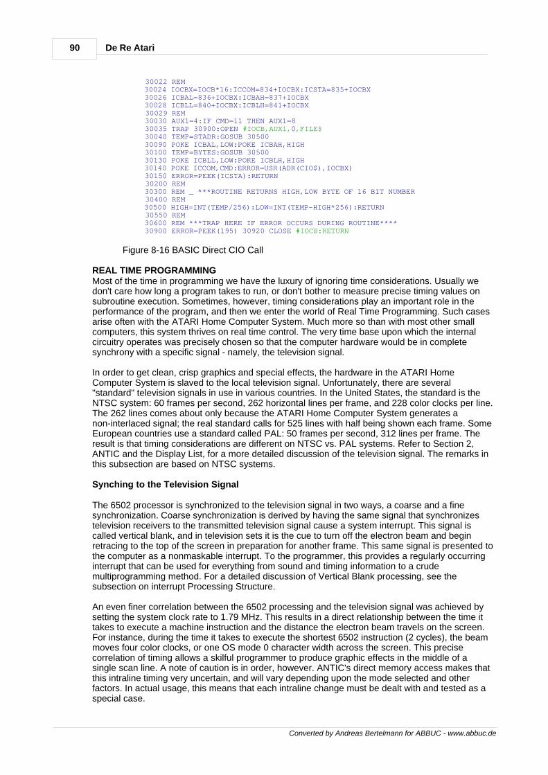
90 De Re Atari
Converted by Andreas Bertelmann for ABBUC - www.abbuc.de
30022 REM 30024 IOCBX=IOCB*16:ICCOM=834+IOCBX:ICSTA=835+IOCBX 30026 ICBAL=836+IOCBX:ICBAH=837+IOCBX 30028 ICBLL=840+IOCBX:ICBLH=841+IOCBX 30029 REM 30030 AUX1=4:IF CMD=11 THEN AUX1=8 30035 TRAP 30900:OPEN #IOCB,AUX1,0,FILE$ 30040 TEMP=STADR:GOSUB 30500 30090 POKE ICBAL,LOW:POKE ICBAH,HIGH 30100 TEMP=BYTES:GOSUB 30500 30130 POKE ICBLL,LOW:POKE ICBLH,HIGH 30140 POKE ICCOM,CMD:ERROR=USR(ADR(CIO$),IOCBX) 30150 ERROR=PEEK(ICSTA):RETURN 30200 REM 30300 REM _ ***ROUTINE RETURNS HIGH,LOW BYTE OF 16 BIT NUMBER 30400 REM 30500 HIGH=INT(TEMP/256):LOW=INT(TEMP-HIGH*256):RETURN 30550 REM 30600 REM ***TRAP HERE IF ERROR OCCURS DURING ROUTINE**** 30900 ERROR=PEEK(195) 30920 CLOSE #IOCB:RETURN
Figure 8-16 BASIC Direct CIO Call
REAL TIME PROGRAMMINGMost of the time in programming we have the luxury of ignoring time considerations. Usually wedon't care how long a program takes to run, or don't bother to measure precise timing values onsubroutine execution. Sometimes, however, timing considerations play an important role in theperformance of the program, and then we enter the world of Real Time Programming. Such casesarise often with the ATARI Home Computer System. Much more so than with most other smallcomputers, this system thrives on real time control. The very time base upon which the internalcircuitry operates was precisely chosen so that the computer hardware would be in completesynchrony with a specific signal - namely, the television signal.
In order to get clean, crisp graphics and special effects, the hardware in the ATARI HomeComputer System is slaved to the local television signal. Unfortunately, there are several"standard" television signals in use in various countries. In the United States, the standard is theNTSC system: 60 frames per second, 262 horizontal lines per frame, and 228 color clocks per line.The 262 lines comes about only because the ATARI Home Computer System generates anon-interlaced signal; the real standard calls for 525 lines with half being shown each frame. SomeEuropean countries use a standard called PAL: 50 frames per second, 312 lines per frame. Theresult is that timing considerations are different on NTSC vs. PAL systems. Refer to Section 2,ANTIC and the Display List, for a more detailed discussion of the television signal. The remarks inthis subsection are based on NTSC systems.
Synching to the Television Signal
The 6502 processor is synchronized to the television signal in two ways, a coarse and a finesynchronization. Coarse synchronization is derived by having the same signal that synchronizestelevision receivers to the transmitted television signal cause a system interrupt. This signal iscalled vertical blank, and in television sets it is the cue to turn off the electron beam and beginretracing to the top of the screen in preparation for another frame. This same signal is presented tothe computer as a nonmaskable interrupt. To the programmer, this provides a regularly occurringinterrupt that can be used for everything from sound and timing information to a crudemultiprogramming method. For a detailed discussion of Vertical Blank processing, see thesubsection on interrupt Processing Structure.
An even finer correlation between the 6502 processing and the television signal was achieved bysetting the system clock rate to 1.79 MHz. This results in a direct relationship between the time ittakes to execute a machine instruction and the distance the electron beam travels on the screen.For instance, during the time it takes to execute the shortest 6502 instruction (2 cycles), the beammoves four color clocks, or one OS mode 0 character width across the screen. This precisecorrelation of timing allows a skilful programmer to produce graphic effects in the middle of asingle scan line. A note of caution is in order, however. ANTIC's direct memory access makes thatthis intraline timing very uncertain, and will vary depending upon the mode selected and otherfactors. In actual usage, this means that each intraline change must be dealt with and tested as aspecial case.
91The Operating System
Converted by Andreas Bertelmann for ABBUC - www.abbuc.de
Hardware Timers
There are four countdown timers built into the POKEY chip. They function as reusable "hardwaresubroutines". The most common use of these timers is in conjunction with the audio channels forproducing sound effects (see Section 7, Sound). They may also be used as straight countdowntimers, since they generate an IRQ interrupt (see subsection on Interrupt Processing Structure).Each timer is associated with a frequency register which holds the initial value for the timer. Whenthe hardware register STIMER is written to, this initial value is loaded and the countdown timerstarted. When the timer counts down to zero, an IRQ Interrupt request is generated. It is importantto note that only timers 1, 2 and 4 have interrupt vectors for processing. The following steps mustbe taken to activate any of the timers.
Step 1. Set AUDCTL [$D208] with proper value to select clocking frequency for the desired timer.Step 2. Set the volume output to 0 for the audio channel associated with the selected timer(AUDC1, AUDC2, AUDC4 [$D201, $D203, $D207]).Step 3. Set AUDF1 , AUDF2 or AUDF4 [$D200, $D202, $D206] with the desired number of clockintervals to count.Step 4. Set up routine to process timer interrupt.Step 5. Change timer interrupt vector to point to processing code (VTIMR1, VTIMR2, VTIMR4[$0210, $0212, $0214]). *** Note. Due to a bug in the source code, the original version of theoperating system will never vector through VTIMR4. This has been fixed in Rev. B.Step 6. Set bits 0, 1 or 2 in IRQEN and the OS shadow POKMSK [$D20E and $0010] to enableinterrupts from timers 1, 2 or 4.Step 7. Write any value to register STIMER [$D209] to load and start the count down timers.
One complication of working with these timers is that the 6502's response to them will bepre-empted and possibly delayed by ANTIC's direct memory access, display list interrupts orvertical blank processing.
Software Timers
There are 6 system software timers:
Name Location Vector or FlagRTCLOKCDTMV1CDTMV2CDTMV3CDTMV4CDTMV5
[$0012,3][$0218,2][$021A,2][$021C,2][$021E,2][$0220,2]
noneCDTMA1 [$0226,2]CDTMA2 [$0228,2]CDTMF3 [$022A,1]CDTMF4 [$022C,1]CDTMF5 [$022E,1]
All of the system timers are decremented as part of the vertical blank (VBLANK) process. If theVBLANK process is disabled or intercepted, the timers will not be updated.
The real time clock (RTCLOK) and system timer 1 (CDTMV1) are updated during immediateVBLANK, Stage 1. RTCLOK counts up from 0 and is a three-byte value. When RTCLOK reachesits maximum value (16,777,216) it will be reset to zero. RTCLOK can be used as a real. time clockas Figure 8-17 shows.
Because the system timers are updated as part of the VBLANK process, special care is needed toset them correctly. A system routine called SETVBV [$E45C] is used to set them. The call toSETVBV is:
REG : X contains the timer value high byte Y contains the timer value low byte A contains the timer number 1-5
Example:
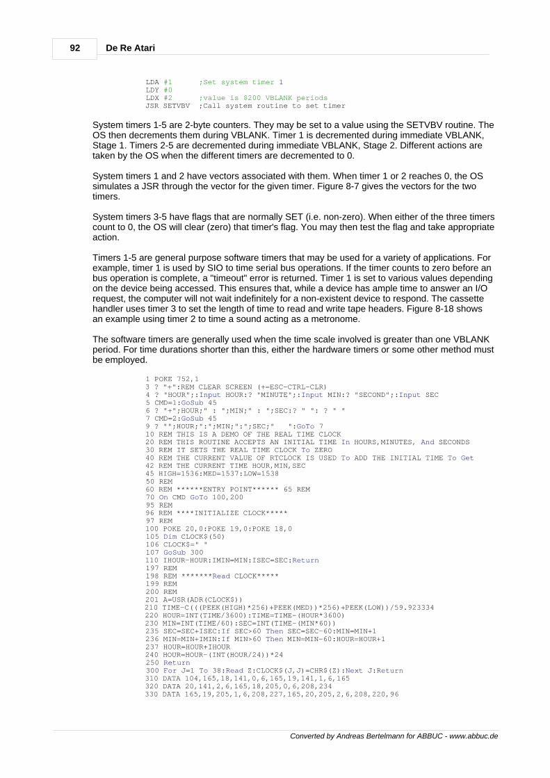
92 De Re Atari
Converted by Andreas Bertelmann for ABBUC - www.abbuc.de
LDA #1 ;Set system timer 1 LDY #0 LDX #2 ;value is $200 VBLANK periods JSR SETVBV ;Call system routine to set timer
System timers 1-5 are 2-byte counters. They may be set to a value using the SETVBV routine. TheOS then decrements them during VBLANK. Timer 1 is decremented during immediate VBLANK,Stage 1. Timers 2-5 are decremented during immediate VBLANK, Stage 2. Different actions aretaken by the OS when the different timers are decremented to 0.
System timers 1 and 2 have vectors associated with them. When timer 1 or 2 reaches 0, the OSsimulates a JSR through the vector for the given timer. Figure 8-7 gives the vectors for the twotimers.
System timers 3-5 have flags that are normally SET (i.e. non-zero). When either of the three timerscount to 0, the OS will clear (zero) that timer's flag. You may then test the flag and take appropriateaction.
Timers 1-5 are general purpose software timers that may be used for a variety of applications. Forexample, timer 1 is used by SIO to time serial bus operations. If the timer counts to zero before anbus operation is complete, a "timeout" error is returned. Timer 1 is set to various values dependingon the device being accessed. This ensures that, while a device has ample time to answer an I/Orequest, the computer will not wait indefinitely for a non-existent device to respond. The cassettehandler uses timer 3 to set the length of time to read and write tape headers. Figure 8-18 showsan example using timer 2 to time a sound acting as a metronome.
The software timers are generally used when the time scale involved is greater than one VBLANKperiod. For time durations shorter than this, either the hardware timers or some other method mustbe employed.
1 POKE 752,1 3 ? "+":REM CLEAR SCREEN (+=ESC-CTRL-CLR) 4 ? "HOUR";:Input HOUR:? "MINUTE";:Input MIN:? "SECOND";:Input SEC 5 CMD=1:GoSub 45 6 ? "+";HOUR;" : ";MIN;" : ";SEC:? " ": ? " " 7 CMD=2:GoSub 45 9 ? "";HOUR;":";MIN;":";SEC;" ":GoTo 7 10 REM THIS IS A DEMO OF THE REAL TIME CLOCK 20 REM THIS ROUTINE ACCEPTS AN INITIAL TIME In HOURS,MINUTES, And SECONDS 30 REM IT SETS THE REAL TIME CLOCK To ZERO 40 REM THE CURRENT VALUE OF RTCLOCK IS USED To ADD THE INITIAL TIME To Get 42 REM THE CURRENT TIME HOUR,MIN,SEC 45 HIGH=1536:MED=1537:LOW=1538 50 REM 60 REM ******ENTRY POINT****** 65 REM 70 On CMD GoTo 100,200 95 REM 96 REM ****INITIALIZE CLOCK***** 97 REM 100 POKE 20,0:POKE 19,0:POKE 18,0 105 Dim CLOCK$(50) 106 CLOCK$=" " 107 GoSub 300 110 IHOUR-HOUR:IMIN=MIN:ISEC=SEC:Return 197 REM 198 REM *******Read CLOCK***** 199 REM 200 REM 201 A=USR(ADR(CLOCK$)) 210 TIME-C(((PEEK(HIGH)*256)+PEEK(MED))*256)+PEEK(LOW))/59.923334 220 HOUR=INT(TIME/3600):TIME=TIME-(HOUR*3600) 230 MIN=INT(TIME/60):SEC=INT(TIME-(MIN*60)) 235 SEC=SEC+ISEC:If SEC>60 Then SEC=SEC-60:MIN=MIN+1 236 MIN=MIN+IMIN:If MIN>60 Then MIN=MIN-60:HOUR=HOUR+1 237 HOUR=HOUR+IHOUR 240 HOUR=HOUR-(INT(HOUR/24))*24 250 Return 300 For J=l To 38:Read Z:CLOCK$(J,J)=CHR$(Z):Next J:Return 310 DATA 104,165,18,141,0,6,165,19,141,1,6,165 320 DATA 20,141,2,6,165,18,205,0,6,208,234 330 DATA 165,19,205,1,6,208,227,165,20,205,2,6,208,220,96
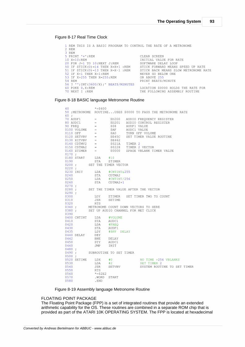
93The Operating System
Converted by Andreas Bertelmann for ABBUC - www.abbuc.de
Figure 8-17 Real Time Clock
1 REM THIS IS A BASIC PROGRAM TO CONTROL THE RATE OF A METRONOME 2 REM 3 REM 5 PRINT "+":REM CLEAR SCREEN 10 X=10:REM INITIAL VALUE FOR RATE 20 FOR J=1 TO 10:NEXT J:REM SOFTWARE DELAY LOOP 50 IF STICK(0)=14 THEN X=X+1 :REM STICK FORWARD MEANS SPEED UP RATE 51 IF STICK(0)=13 THEN X=X-1 :REM STICK BACK MEANS SLOW METRONOME RATE 52 IF X<1 THEN X=1:REM NEVER GO BELOW ONE 53 IF X>255 THEN X=255:REM OR ABOVE 255 54 REM PRINT BEATS/MINUTE 56 ? "";INT(3600/X);" BEATS/MINUTES " 60 POKE 0,X:REM LOCATION $0000 HOLDS THE RATE FOR 70 NEXT I :REM THE FOLLOWING ASSEMBLY ROUTINE
Figure 8-18 BASIC language Metronome Routine
40 *=$600 50 ;METRONOME ROUTINE...USES $0000 TO PASS THE METRONOME RATE 60 ; 70 AUDF1 = $D200 AUDIO FREQUENCY REGISTER 80 AUDC1 = $D201 AUDIO CONTROL REGISTER 90 FREQ = $08 AUDF1 VALUE 0100 VOLUME = $AF AUDC1 VALUE 0110 OFF = $A0 TURN OFF VOLUME 0120 SETVBV = $E45C SET TIMER VALUE ROUTINE 0130 XITVBV = $E462 0140 CDTMV2 = $021A TIMER 2 0150 CDTMA2 = $0228 TIMER 2 VECTOR 0160 ZTIMER = $0000 ZPAGE VBLANK TIMER VALUE 0170 ; 0180 START LDA #10 0190 STA ZTIMER 0200 ; SET THE TIMER VECTOR 0220 ; 0230 INIT LDA #CNTINT&255 0240 STA CDTMA2 0250 LDA #CNTINT/256 0260 STA CDTMA2+1 0270 ; 0280 ; SET THE TIMER VALUE AFTER THE VECTOR 0290 ; 0300 LDY ZTIMER SET TIMER TWO TO COUNT 0310 JSR SETIME 0320 RTS 0340 ; METRONOME COUNT DOWN VECTORS TO HERE 0380 ; SET UP AUDIO CHANNEL FOR MET CLICK 0390 0400 CNTINT LDA #VOLUME 0410 STA AUDC1 0420 LDA #FREQ 0430 STA AUDF1 0435 LDY #$FF DELAY 0440 DELAY DEY 0442 BNE DELAY 0450 STY AUDC1 0460 JMP INIT 0480 ; 0490 ; SUBROUTINE TO SET TIMER 0500 ; 0520 SETIME LDX #0 NO TIME >256 VBLANKS 0530 LDA #2 SET TIMER 2 0540 JSR SETVBV SYSTEM ROUTINE TO SET TIMER 0550 RTS 0560 *=$2E2 0570 .WORD START 0580 .END
Figure 8-19 Assembly language Metronome Routine
FLOATING POINT PACKAGEThe Floating Point Package (FPP) is a set of integrated routines that provide an extendedarithmetic capability for the OS. These routines are combined in a separate ROM chip that isprovided as part of the ATARI 10K OPERATING SYSTEM. The FPP is located at hexadecimal
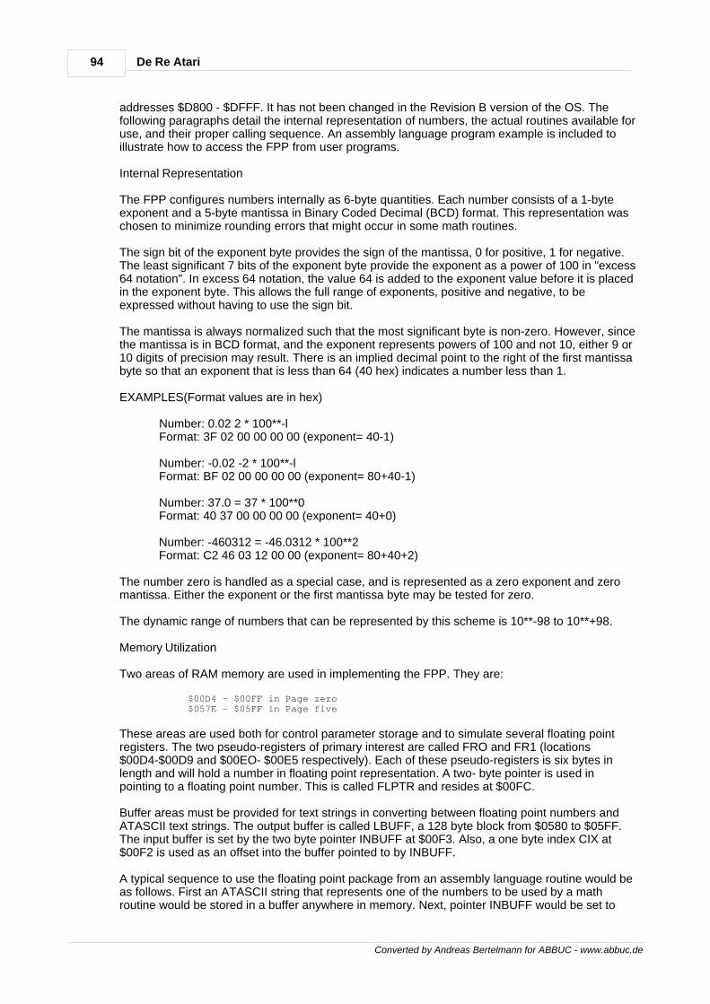
94 De Re Atari
Converted by Andreas Bertelmann for ABBUC - www.abbuc.de
addresses $D800 - $DFFF. It has not been changed in the Revision B version of the OS. Thefollowing paragraphs detail the internal representation of numbers, the actual routines available foruse, and their proper calling sequence. An assembly language program example is included toillustrate how to access the FPP from user programs.
Internal Representation
The FPP configures numbers internally as 6-byte quantities. Each number consists of a 1-byteexponent and a 5-byte mantissa in Binary Coded Decimal (BCD) format. This representation waschosen to minimize rounding errors that might occur in some math routines.
The sign bit of the exponent byte provides the sign of the mantissa, 0 for positive, 1 for negative.The least significant 7 bits of the exponent byte provide the exponent as a power of 100 in "excess64 notation". In excess 64 notation, the value 64 is added to the exponent value before it is placedin the exponent byte. This allows the full range of exponents, positive and negative, to beexpressed without having to use the sign bit.
The mantissa is always normalized such that the most significant byte is non-zero. However, sincethe mantissa is in BCD format, and the exponent represents powers of 100 and not 10, either 9 or10 digits of precision may result. There is an implied decimal point to the right of the first mantissabyte so that an exponent that is less than 64 (40 hex) indicates a number less than 1.
EXAMPLES(Format values are in hex)
Number: 0.02 2 * 100**-l Format: 3F 02 00 00 00 00 (exponent= 40-1)
Number: -0.02 -2 * 100**-l Format: BF 02 00 00 00 00 (exponent= 80+40-1)
Number: 37.0 = 37 * 100**0 Format: 40 37 00 00 00 00 (exponent= 40+0)
Number: -460312 = -46.0312 * 100**2 Format: C2 46 03 12 00 00 (exponent= 80+40+2)
The number zero is handled as a special case, and is represented as a zero exponent and zeromantissa. Either the exponent or the first mantissa byte may be tested for zero.
The dynamic range of numbers that can be represented by this scheme is 10**-98 to 10**+98.
Memory Utilization
Two areas of RAM memory are used in implementing the FPP. They are:
$00D4 - $00FF in Page zero $057E - $05FF in Page five
These areas are used both for control parameter storage and to simulate several floating pointregisters. The two pseudo-registers of primary interest are called FRO and FR1 (locations$00D4-$00D9 and $00EO- $00E5 respectively). Each of these pseudo-registers is six bytes inlength and will hold a number in floating point representation. A two- byte pointer is used inpointing to a floating point number. This is called FLPTR and resides at $00FC.
Buffer areas must be provided for text strings in converting between floating point numbers andATASCII text strings. The output buffer is called LBUFF, a 128 byte block from $0580 to $05FF.The input buffer is set by the two byte pointer INBUFF at $00F3. Also, a one byte index CIX at$00F2 is used as an offset into the buffer pointed to by INBUFF.
A typical sequence to use the floating point package from an assembly language routine would beas follows. First an ATASCII string that represents one of the numbers to be used by a mathroutine would be stored in a buffer anywhere in memory. Next, pointer INBUFF would be set to
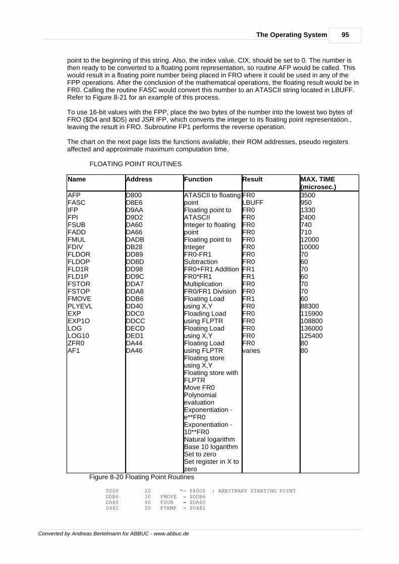
95The Operating System
Converted by Andreas Bertelmann for ABBUC - www.abbuc.de
point to the beginning of this string. Also, the index value, CIX, should be set to 0. The number isthen ready to be converted to a floating point representation, so routine AFP would be called. Thiswould result in a floating point number being placed in FRO where it could be used in any of theFPP operations. After the conclusion of the mathematical operations, the floating result would be inFR0. Calling the routine FASC would convert this number to an ATASCII string located in LBUFF.Refer to Figure 8-21 for an example of this process.
To use 16-bit values with the FPP, place the two bytes of the number into the lowest two bytes ofFRO ($D4 and $D5) and JSR IFP, which converts the integer to its floating point representation.,leaving the result in FRO. Subroutine FP1 performs the reverse operation.
The chart on the next page lists the functions available, their ROM addresses, pseudo registersaffected and approximate maximum computation time.
FLOATING POINT ROUTINES
Name Address Function Result MAX. TIME(microsec.)
AFPFASCIFPFPIFSUBFADDFMULFDIVFLDORFLDOPFLD1RFLD1PFSTORFSTOPFMOVEPLYEVLEXPEXP1OLOGLOG10ZFR0AF1
D800D8E6D9AAD9D2DA60DA66DADBDB28DD89DD8DDD98DD9CDDA7DDA8DDB6DD40DDC0DDCCDECDDED1DA44DA46
ATASCII to floatingpointFloating point toATASCIIInteger to floatingpointFloating point toIntegerFR0-FR1SubtractionFR0+FR1 AdditionFR0*FR1MultiplicationFR0/FR1 DivisionFloating Loadusing X,YFloading Loadusing FLPTRFloating Loadusing X,YFloating Loadusing FLPTRFloating storeusing X,YFloating store withFLPTRMove FR0PolynomialevaluationExponentiation -e**FR0Exponentiation -10**FR0Natural logarithmBase 10 logarithmSet to zeroSet register in X tozero
FR0LBUFFFR0FR0FR0FR0FR0FR0FR0FR0FR1FR1FR0FR0FR1FR0FR0FR0FR0FR0FR0varies
350095013302400740710120001000070607060707060883001159001088001360001254008080
Figure 8-20 Floating Point Routines
0000 20 *= $4000 ; ARBITRARY STARTING POINT DDB6 30 FMOVE = $DDB6 DA60 40 FSUB = $DA60 0482 50 FTEMP = $0482
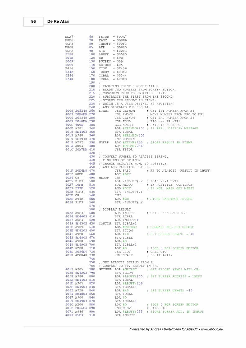
96 De Re Atari
Converted by Andreas Bertelmann for ABBUC - www.abbuc.de
DDA7 60 FSTOR = $DDA7 D8E6 70 FASC = $D8E6 0OF3 80 INBUFF = $00F3 D800 85 AFP = $D800 0OF2 90 CIX = $00F2 0580 100 LBUFF = $0580 009B 120 CR = $9B 0009 130 PUTREC = $09 0005 140 GETREC = $05 E456 150 CIOV = $E456 0342 160 ICCOM = $0342 0344 170 ICBAL = $0344 0348 180 ICBLL = $0348 190 ; 200 ; FLOATING POINT DEMONSTRATION 210 ; READS TWO NUMBERS FROM SCREEN EDITOR, 215 ; CONVERTS THEM TO FLOATING POINT, 220 ; SUBTRACTS THE FIRST FROM THE SECOND, 225 ; STORES THE RESULT IN FTEMP, 230 ; WHICH IS A USER DEFINED FP REGISTER, 240 ; AND DISPLAYS THE RESULT. 4000 205340 260 START JSR GETNUM ; GET 1ST NUMBER FROM E: 4003 20B6DD 270 JSR FMOVE ; MOVE NUMBER FROM FRO TO FR1 4006 205340 280 JSR GETNUM ; GET 2ND NUMBER FROM E: 4009 2060DA 290 JSR FSUB ; FRO <-- FR0-FR1 400C 900A 300 BCC NOERR ; SKIP IF NO ERROR 400E A981 340 LDA #ERRMSG&255 ; IF ERR., DISPLAY MESSAGE 4010 8D4403 350 STA ICBAL 4013 A940 360 LDA #ERRMSG/256 4015 4C3940 370 JMP CONTIN 4018 A282 390 NOERR LDX #FTEMP&255 ; STORE RESULT IN FTEMP 401A A004 400 LDY #FTEMP/256 401C 20A7DD 410 JSR FSTOR 420 ; 430 ; CONVERT NUMBER TO ATACSII STRING. 440 ; FIND END OF STRING, 445 ; CHANGE NEGATIVE NUM. TO POSITIVE, 450 ; AND ADD CARRIAGE RETURN. 401F 20E6D8 470 JSR FASC ; FP TO ATASCII, RESULT IN LBUFF 4022 A0FF 480 LDY #$FF 4024 C8 490 MLOOP INY 4025 B1F3 500 LDA (INBUFF),Y ; LOAD NEXT BYTE 4027 10FB 510 BPL MLOOP ; IF POSITIVE, CONTINUE 4029 297F 520 AND #$7F ; IF NOT, MASK OFF MSBIT 402B 9lF3 530 STA (INBUFF),Y 402D C8 540 INY 402E A99B 550 LDA #CR ; STORE CARRIAGE RETURN 4030 9lF3 560 STA (INBUFF),Y 570 ; 580 ; DISPLAY RESULT 4032 A5F3 600 LDA INBUFF ; GET BUFFER ADDRESS 4034 8D4403 610 STA ICBAL 4037 A5F4 620 LDA INBUFF+1 4039 8D4503 630 CONTIN STA ICBAL+1 403C A909 640 LDA #PUTREC ; COMMAND FOR PUT RECORD 403E 8D4203 650 STA ICCOM 4041 A928 660 LDA #40 ; SET BUFFER LENGTH = 40 4043 8D4803 670 STA ICBLL 4046 A900 690 LDA #0 4048 8D4903 700 STA ICBLL+1 404B A200 710 LDX #0 ; IOCB 0 FOR SCREEN EDITOR 404D 2056E4 720 JSR CIOV ; CALL CIO 4050 4CO040 730 JMP START ; DO IT AGAIN 740 750 ; GET ATASCII STRING FROM E: 755 ; CONVERT TO FP, RESULT IN FR0 4053 A905 780 GETNUM LDA #GETREC ; GET RECORD (ENDS WITH CR) 4055 8D4203 790 STA ICCOM 4058 A980 800 LDA #LBUFF&255 ; SET BUFFER ADDRESS = LBUFF 405A 8D4403 810 STA ICBAL 405D A905 820 LDA #LBUFF/256 405F 8D4503 830 STA ICBAL+1 4062 A928 840 LDA #40 ; SET BUFFER LENGTH =40 4064 8D4803 850 STA ICBLL 4067 A900 860 LDA #0 4069 8D4903 870 STA ICBLL+1 406C A200 880 LDX #0 ; IOCB 0 FOR SCREEN EDITOR 406E 2056E4 890 JSR CIOV ; CALL CIO 4071 A980 900 LDA #LBUFF&255 ; STORE BUFFER ADD. IN INBUFF 4073 85F3 910 STA INBUFF
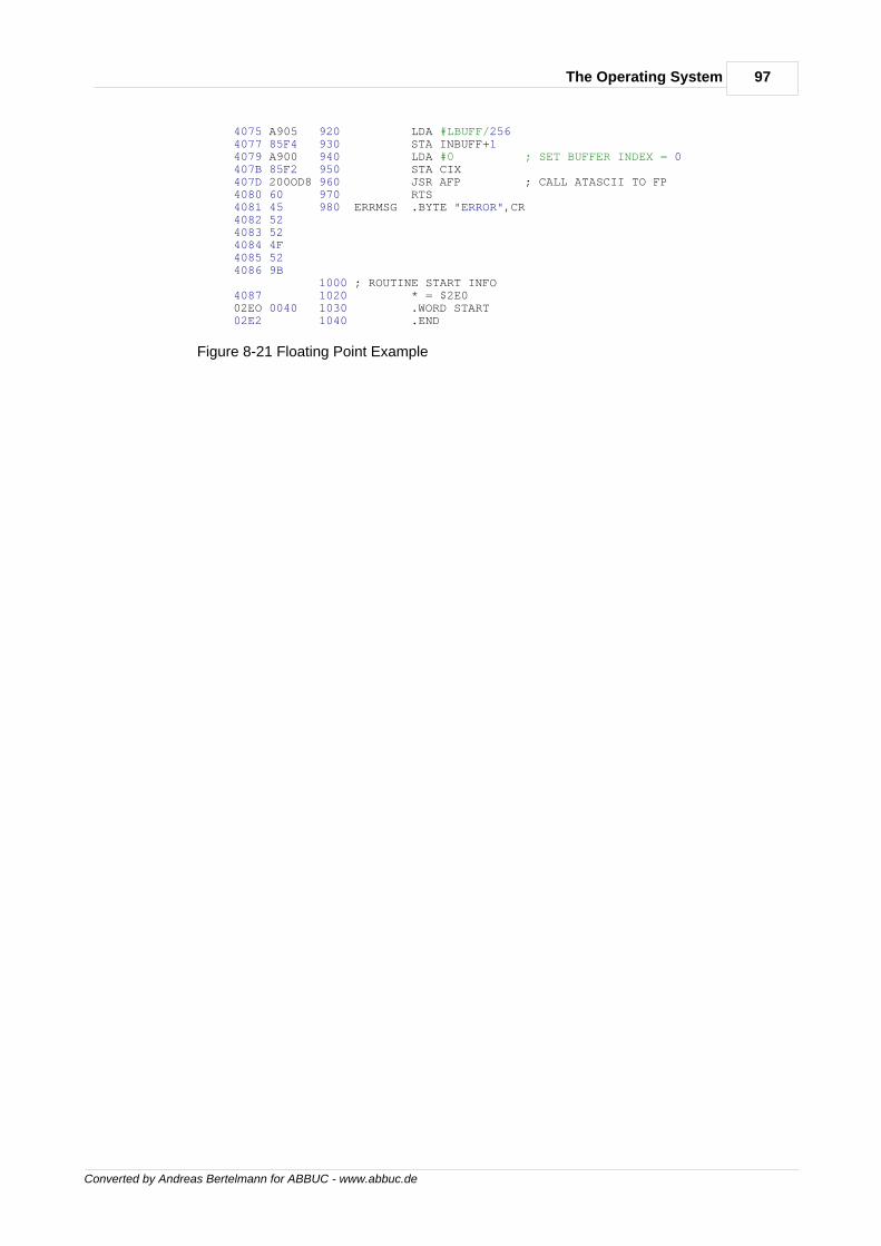
97The Operating System
Converted by Andreas Bertelmann for ABBUC - www.abbuc.de
4075 A905 920 LDA #LBUFF/256 4077 85F4 930 STA INBUFF+1 4079 A900 940 LDA #0 ; SET BUFFER INDEX = 0 407B 85F2 950 STA CIX 407D 200OD8 960 JSR AFP ; CALL ATASCII TO FP 4080 60 970 RTS 4081 45 980 ERRMSG .BYTE "ERROR",CR 4082 52 4083 52 4084 4F 4085 52 4086 9B 1000 ; ROUTINE START INFO 4087 1020 * = $2E0 02EO 0040 1030 .WORD START 02E2 1040 .END
Figure 8-21 Floating Point Example
Converted by Andreas Bertelmann for ABBUC - www.abbuc.de
The DiskOperating
System
Chapter
IX
99The Disk Operating System
Converted by Andreas Bertelmann for ABBUC - www.abbuc.de
9 The Disk Operating System
The Disk Operating System (DOS) is an extension of the OS that allows you to access the ATARI810' Disk Drive mass storage device as you would access any of the other input/out devices. DOShas three primary components, the resident disk handier, the File Management System (FMS),and the Disk Utility Package (DUP). The resident disk handler is the only part of DOS provided inthe OS ROM. FMS and DUP both reside on diskette, with FMS being loaded ("booted") intomemory at power-up. DUP is not automatically loaded at power up, but requires an explicit requestfrom an application program. If the BASIC language cartridge is present, for instance, DUP is notloaded until a DOS statement is issued. The following subsections describe each of thesecomponents in more detail and present other related topics necessary for effective utilization ofDOS. You should note that the comments in this section refer to version 2.0S of the DiskOperating System, which is substantially different from earlier versions of DOS. For completetechnical details regarding DOS, you should also refer to the OPERATING SYSTEM Manual, andthe DISK OPERATING SYSTEM II Manual.
The Resident Disk HandlerThe resident disk handler is the simplest part of DOS. The disk handier does not conform to thenormal CIO calling sequence as observed by other Device Handlers (see section 8, the OperatingSystem, for details on using the Centralized Input/Output Subsystem). In DOS 2.0S, the residentdisk handler is used only during the initial boot process. From then on, additional code in the FMSis used in accessing the disk drives. The relationship of the disk handier to the I/O subsystem isshown in Figure 8-8 of this manual.
The Device Control Block (DCB) is used to communicate with the disk handler. Figure 8-10illustrates the structure of the DCB. The calling sequence for the disk handler is:
;caller has already set up DCB JSR DSKINV ;system routine Vector to the resident Disk Handler BPL OKAY ;Branch if success, Y Reg. = 1 ;Else y reg. = error status (DCBSTA also has error)
The disk handler is a subroutine that is used to support the physical transfers of data between the6502 inside the ATARI Home Computer System, and another processor located inside the ATARI810 Disk Drive. This data transfer occurs over the serial input/output bus. The OS resident diskhandier supports four functions:
FORMAT Issue a Format command to the disk controller READ SECTOR Read a specified sector WRITE/VERIFY SECTOR Write sector; check sector to see if written STATUS Ask the disk controller for its status
The FORMAT command clears all the tracks on the diskette and writes sector addresses onto thetracks. No file structure is put on the diskette by this command. The data portion of each sector isset to all zeros, and the initial Volume Table of Contents and the File Directory are established. Formore information on the physical layout of data on a diskette, refer to the OPERATING SYSTEMManual and the subsection on FMS Disk Utilization.
You should note that all I/O from the disk handier is sector-oriented. The sector I/O commands canbe used to read and write any sector on the diskette. You can use them to implement your own filestructure. Section 10 of the OPERATING SYSTEM Manual has an example of using the diskhandler to write a boot tile.
The STATUS function is used to determine the status of the disk drive. This command causes thedisk drive to transmit four bytes that define its current status. These bytes are loaded into DVSTAT[$02EA,4]. The first byte is a command status byte and contains the following status bits:
Bit-0 = 1 indicates an invalid command frame was received. Bit-1 = 1 indicates an invalid data frame was received. Bit-2 = 1 indicates that a PUT operation was unsuccessful. Bit-3 = 1 indicates that the disk is write protected. Bit-4 = 1 indicates active/standby.
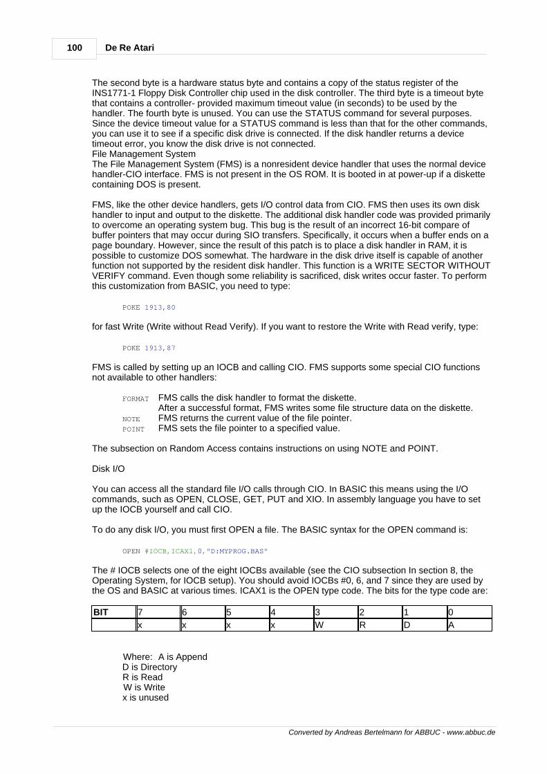
100 De Re Atari
Converted by Andreas Bertelmann for ABBUC - www.abbuc.de
The second byte is a hardware status byte and contains a copy of the status register of theINS1771-1 Floppy Disk Controller chip used in the disk controller. The third byte is a timeout bytethat contains a controller- provided maximum timeout value (in seconds) to be used by thehandler. The fourth byte is unused. You can use the STATUS command for several purposes.Since the device timeout value for a STATUS command is less than that for the other commands,you can use it to see if a specific disk drive is connected. If the disk handler returns a devicetimeout error, you know the disk drive is not connected.File Management SystemThe File Management System (FMS) is a nonresident device handler that uses the normal devicehandler-CIO interface. FMS is not present in the OS ROM. It is booted in at power-up if a diskettecontaining DOS is present.
FMS, like the other device handlers, gets I/O control data from CIO. FMS then uses its own diskhandler to input and output to the diskette. The additional disk handler code was provided primarilyto overcome an operating system bug. This bug is the result of an incorrect 16-bit compare ofbuffer pointers that may occur during SIO transfers. Specifically, it occurs when a buffer ends on apage boundary. However, since the result of this patch is to place a disk handler in RAM, it ispossible to customize DOS somewhat. The hardware in the disk drive itself is capable of anotherfunction not supported by the resident disk handler. This function is a WRITE SECTOR WITHOUTVERIFY command. Even though some reliability is sacrificed, disk writes occur faster. To performthis customization from BASIC, you need to type:
POKE 1913,80
for fast Write (Write without Read Verify). If you want to restore the Write with Read verify, type:
POKE 1913,87
FMS is called by setting up an IOCB and calling CIO. FMS supports some special CIO functionsnot available to other handlers:
FORMAT FMS calls the disk handler to format the diskette. After a successful format, FMS writes some file structure data on the diskette.
NOTE FMS returns the current value of the file pointer. POINT FMS sets the file pointer to a specified value.
The subsection on Random Access contains instructions on using NOTE and POINT.
Disk I/O
You can access all the standard file I/O calls through CIO. In BASIC this means using the I/Ocommands, such as OPEN, CLOSE, GET, PUT and XIO. In assembly language you have to setup the IOCB yourself and call CIO.
To do any disk I/O, you must first OPEN a file. The BASIC syntax for the OPEN command is:
OPEN #IOCB,ICAX1,0,"D:MYPROG.BAS"
The # IOCB selects one of the eight IOCBs available (see the CIO subsection In section 8, theOperating System, for IOCB setup). You should avoid IOCBs #0, 6, and 7 since they are used bythe OS and BASIC at various times. ICAX1 is the OPEN type code. The bits for the type code are:
BIT 7 6 5 4 3 2 1 0
x x x x W R D A
Where: A is Append D is Directory R is Read W is Write x is unused
101The Disk Operating System
Converted by Andreas Bertelmann for ABBUC - www.abbuc.de
Figure 9-1 Auxiliary Byte Layout for the OPEN Command
The various values for ICAX1 are discussed in Section 5 of the OPERATING SYSTEM Manual.Some of the key things to note about the various OPEN modes are:
ICAX1=6 This is used to OPEN the diskette directory. Records READ are thediskette directory entries. ICAX1=4 READ mode. ICAX1=8 WRITE mode. Any existing file opened in this mode is first deleted.
The first bytes written will be at the start of the file. ICAX1=9 WRITE APPEND mode. The file is left intact.
Bytes written to this file are put at the end of the file. ICAX1=12 UPDATE mode. This mode allows both READ and WRITE to the file.
Bytes read and written start at the first byte in the file. ICAX1=13 Not supported.
There are two types of I/O you can use to transfer data between your program and the disk, recordor character.
Character I/O means that the data In a file is a sequential string of bytes. DOS interprets this list ofbytes as data, with none of the values being interpreted as control characters. An example ofcharacter data (all values are in Hex):
00 23 4F 55 FF 34 21.
Record I/O means that data in a file is made up of a set of records. A record is a group of bytesfollowed by an End of Line (EOL) character with the value $9B. An example of two records is:
00 23 4F 55 FF 34 9B 21 34 44 9B | record 1 | record 2 |
Record and character I/O to files can be done in any arbitrary order. Indeed, data created asrecords can be read as characters, and file data created as characters can be read as records.The only difference between character and record I/O is that records must end with a $9B value.$9B is treated as ordinary data when using character I/O.
BASIC supports record I/O quite well. The commands PRINT and INPUT can be used to write andread records from files. BASIC does not completely support character I/O. The commands GETand PUT allow you to read and write a single byte at a time. However, the OS has the ability toread and write blocks of characters. This ability is not used by BASIC. In using this feature in theOS, you must specify the length and address of the data block to be transferred. To use thecharacter block mode of the OS from BASIC, you can write an assembly language module to becalled from BASIC by the USR function. Figure 8-16 has an example of a subroutine to docharacter block I/O.
The XIO command in BASIC is a general Input/Output statement that allows for directcommunication with CIO from BASIC., It is described in more detail in the following subsection.Disk Utility PackageThe Disk Utility Package (DUP) is a set of utilities for diskette management, familiarly seen as theDOS menu. DUP executes commands by calling FMS through CIO. The commands are:
A. DIRECTORY B. RUN CARTRIDGE C. COPY FILES D. DELETE FILES E. RENAME FILES F. LOCK FILES G. UNLOCK FILES H. WRITE DOS FILES I. FORMAT DISK J. DUPLICATE DISK K. SAVE BINARY FILE
102 De Re Atari
Converted by Andreas Bertelmann for ABBUC - www.abbuc.de
L. LOAD BINARY FILE M. RUN AT ADDRESS N. WRITE MEM.SAV FILE O. DUPLICATE FILE
The following subsections describe each of these functions. However, for complete information onthese functions, refer to the DISK OPERATING SYSTEM II Manual.
Wild Cards
Many of the DUP commands require a filename specification. DOS recognizes two "wild cards"that you can substitute for characters in a filename. Wild cards are represented by the specialcharacters, question mark (?) and asterisk (*).
These characters are used in filename descriptors where, for whatever reason, there exists someuncertainty as to the exact filename. An example of this would be when a filename extension is notknown, for instance. Another example would be when you want to copy only files with a specificextension such as OBJ.
The question mark (?) may be substituted for a single character. The asterisk (*) can stand for anyvalid combination of characters or number of characters. The following examples illustrate the useof these characters in a Directory command.
*.BAS will list all files on a diskette in Drive 1 that end in BAS. D2:*.* will list all the program files on the Drive 2 diskette. PRO*.BAS will list all the program files on diskette in Drive 1 that begin with PRO andhave BAS as the extender. TEST?? will list all the program files on diskette in Drive 1 that begin with TESTand have any combination of
letters or numbers for the last two characters.
Disk Directory (A)
The Disk Directory contains a list of all the files on a diskette. This command will list the filenames,the extender, and the number of sectors that the file occupies on the diskette. A partial list can begenerated by entering specific filename parameters. Wild cards can be used in the parameters.
RUN CARTRIDGE (B)
The 'B' command, Run Cartridge, is typed, DOS gives control of the system to whichever cartridgeis inserted. The response from that point on is dependent upon specific cartridges. BASIC, forinstance, will respond by printing READY on the screen.
If the diskette in drive 1 has not been changed since the DUP was loaded, and if a MEM.SAV file ispresent on the diskette, then the contents of this file is copied back into RAM before control isreleased to the cartridge. This file normally is used to store the contents of the portion of RAM thatDUP occupies when it is loaded. However, this file must already exist on the diskette when a call isissued to load DUP. Before DUP is loaded, the RAM contents are written out to the diskette forlater retrieval. You can think of MEM.SAV and DUP as swapping places between the diskette andRAM.
Copy File (C)
The Copy File command ('C'), is used to copy a file from a diskette in one disk drive to anotherdiskette in a second disk drive. You will be prompted to give file specifications for the file toCOPY-FROM, TO. The first file specification may contain wild cards, and can be used to indicate aseries of files to be copied. The second parameter is also generally a file specification, but mayalso be a destination device such as E: (screen) or P: (printer). The second parameter may befollowed with a '/A? option, which indicates that the first named file should be appended to thesecond file. This option should not be used with tokenized Basic files.

103The Disk Operating System
Converted by Andreas Bertelmann for ABBUC - www.abbuc.de
Delete File (D)
This option allows you to delete one or more files from a diskette. Wildcards can be used in filespecification names. You can avoid having to respond to the delete verification promt byappending a '/N' option to the file specification.
Rename File (E)
This option allows you to change the name of an existing file on a diskette. You must provide twoparameters, OLD NAME and NEW. The first parameter must be a complete file specification, butthe second is just the new file name. Wild cards are permitted for both names. If no devicespecification is included, D1: is assumed. An error will be generated if the first file name doesn'texist on the diskette, if the file is locked, or if the diskette is write protected.
Lock File (F)
This command is used to prevent a file from being inadvertently erased or modified. A locked file isindicated by an asterisk (*) preceding its name in the directory. Note however, that the Formatcommand pays no attention to the Lock status of any file on a diskette.
Unlock File (G)
This option is used to Unlock a file that has been previously Locked. Both this and the Lockcommands may use wild cards.
Write DOS File (H)
This option must be used to create a copy of DOS on a formatted diskette, since they can't becopied with a Copy command.
Format Diskette (I)
This option is used to create the sector and track information on a blank diskette so that it may beused by DOS. If a bad sector is encountered during the formatting process, DOS will not continue.A diskette with a bad sector cannot be formatted, and is useless. WARNING! Be very careful withthis command, for it will wipe out any existing file on the diskette.
Duplicate Disk (J)
This menu option is used to create an exact duplicate of any diskette that has been created andmaintained by DOS. This option can be used with either single or multiple drive systems.Duplicating on a single drive system does require repeated manual swapping of the source and thedestination diskettes.
The duplication process occurs on a sector-by-sector basis. However, only those sectors that aremarked as in use by the Volume Table of Contents are copied.
Care should be taken in using this command, for it destroyes any files that may have resided onthe destination diskette. A good policy would be to place a write protect tab on the source disketteto preclude a catastrophic mistake by typing the source and destination values in reverse order.
Binary Save (K)
This command is use to save the contents of memory locations in an object file (binary) format.This format is also used by the ATARI Editor Assembler Cartridge. This format consists of twoheader bytes of $FF, two bytes for the starting load address, and two bytes for the ending loadaddress. The remainder of the file is actual load data. You will be prompted to enter a filename andthe starting and ending addresses for the load. There is also two additional address values thatmay optionally be entered. These are values that upon load will be placed In locations known asINIT [$02EO,2] and RUN [$02E2,2]. If these locations are updated during a load, then the codepointed to by the values in these locations will be executed.
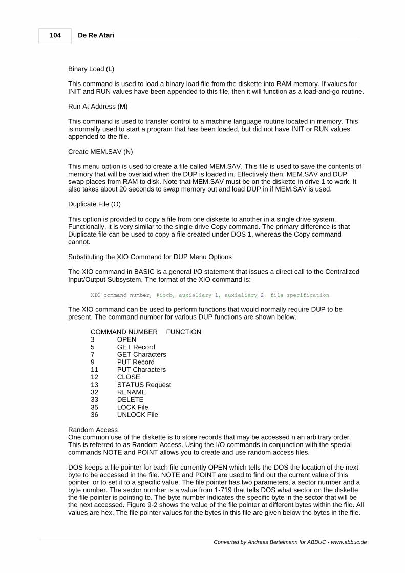
104 De Re Atari
Converted by Andreas Bertelmann for ABBUC - www.abbuc.de
Binary Load (L)
This command is used to load a binary load file from the diskette into RAM memory. If values forINIT and RUN values have been appended to this file, then it will function as a load-and-go routine.
Run At Address (M)
This command is used to transfer control to a machine language routine located in memory. Thisis normally used to start a program that has been loaded, but did not have INIT or RUN valuesappended to the file.
Create MEM.SAV (N)
This menu option is used to create a file called MEM.SAV. This file is used to save the contents ofmemory that will be overlaid when the DUP is loaded in. Effectively then, MEM.SAV and DUPswap places from RAM to disk. Note that MEM.SAV must be on the diskette in drive 1 to work. Italso takes about 20 seconds to swap memory out and load DUP in if MEM.SAV is used.
Duplicate File (O)
This option is provided to copy a file from one diskette to another in a single drive system.Functionally, it is very similar to the single drive Copy command. The primary difference is thatDuplicate file can be used to copy a file created under DOS 1, whereas the Copy commandcannot.
Substituting the XIO Command for DUP Menu Options
The XIO command in BASIC is a general I/O statement that issues a direct call to the CentralizedInput/Output Subsystem. The format of the XIO command is:
XIO command number, #iocb, auxialiary 1, auxialiary 2, file specification
The XIO command can be used to perform functions that would normally require DUP to bepresent. The command number for various DUP functions are shown below.
COMMAND NUMBER FUNCTION 3 OPEN 5 GET Record 7 GET Characters 9 PUT Record 11 PUT Characters 12 CLOSE 13 STATUS Request 32 RENAME 33 DELETE 35 LOCK File 36 UNLOCK File
Random AccessOne common use of the diskette is to store records that may be accessed n an arbitrary order.This is referred to as Random Access. Using the I/O commands in conjunction with the specialcommands NOTE and POINT allows you to create and use random access files.
DOS keeps a file pointer for each file currently OPEN which tells the DOS the location of the nextbyte to be accessed in the file. NOTE and POINT are used to find out the current value of thispointer, or to set it to a specific value. The file pointer has two parameters, a sector number and abyte number. The sector number is a value from 1-719 that tells DOS what sector on the diskettethe file pointer is pointing to. The byte number indicates the specific byte in the sector that will bethe next accessed. Figure 9-2 shows the value of the file pointer at different bytes within the file. Allvalues are hex. The file pointer values for the bytes in this file are given below the bytes in the file.
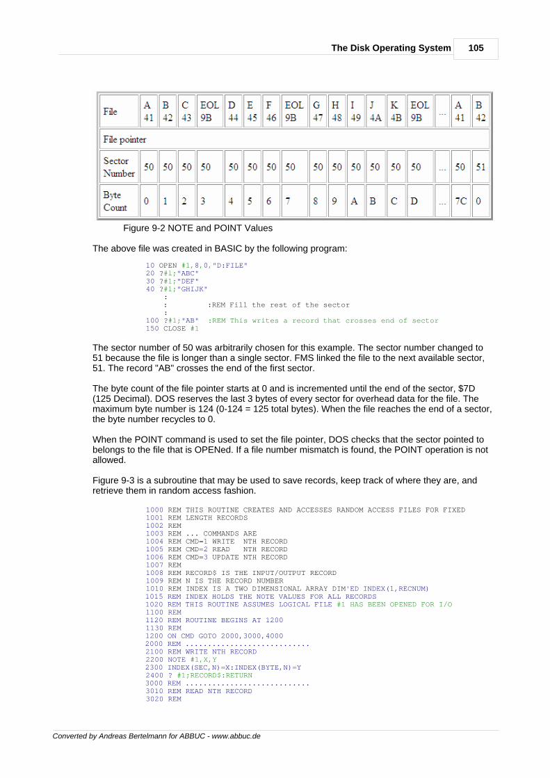
105The Disk Operating System
Converted by Andreas Bertelmann for ABBUC - www.abbuc.de
Figure 9-2 NOTE and POINT Values
The above file was created in BASIC by the following program:
10 OPEN #1,8,0,"D:FILE" 20 ?#l;"ABC" 30 ?#1;"DEF" 40 ?#1;"GHIJK" : : :REM Fill the rest of the sector : 100 ?#1;"AB" :REM This writes a record that crosses end of sector 150 CLOSE #1
The sector number of 50 was arbitrarily chosen for this example. The sector number changed to51 because the file is longer than a single sector. FMS linked the file to the next available sector,51. The record "AB" crosses the end of the first sector.
The byte count of the file pointer starts at 0 and is incremented until the end of the sector, $7D(125 Decimal). DOS reserves the last 3 bytes of every sector for overhead data for the file. Themaximum byte number is 124 (0-124 = 125 total bytes). When the file reaches the end of a sector,the byte number recycles to 0.
When the POINT command is used to set the file pointer, DOS checks that the sector pointed tobelongs to the file that is OPENed. If a file number mismatch is found, the POINT operation is notallowed.
Figure 9-3 is a subroutine that may be used to save records, keep track of where they are, andretrieve them in random access fashion.
1000 REM THIS ROUTINE CREATES AND ACCESSES RANDOM ACCESS FILES FOR FIXED 1001 REM LENGTH RECORDS 1002 REM 1003 REM ... COMMANDS ARE 1004 REM CMD=1 WRITE NTH RECORD 1005 REM CMD=2 READ NTH RECORD 1006 REM CMD=3 UPDATE NTH RECORD 1007 REM 1008 REM RECORD$ IS THE INPUT/OUTPUT RECORD 1009 REM N IS THE RECORD NUMBER 1010 REM INDEX IS A TWO DIMENSIONAL ARRAY DIM'ED INDEX(1,RECNUM) 1015 REM INDEX HOLDS THE NOTE VALUES FOR ALL RECORDS 1020 REM THIS ROUTINE ASSUMES LOGICAL FILE #1 HAS BEEN OPENED FOR I/O 1100 REM 1120 REM ROUTINE BEGINS AT 1200 1130 REM 1200 ON CMD GOTO 2000,3000,4000 2000 REM ............................ 2100 REM WRITE NTH RECORD 2200 NOTE #1,X,Y 2300 INDEX(SEC,N)=X:INDEX(BYTE,N)=Y 2400 ? #1;RECORD$:RETURN 3000 REM ............................ 3010 REM READ NTH RECORD 3020 REM
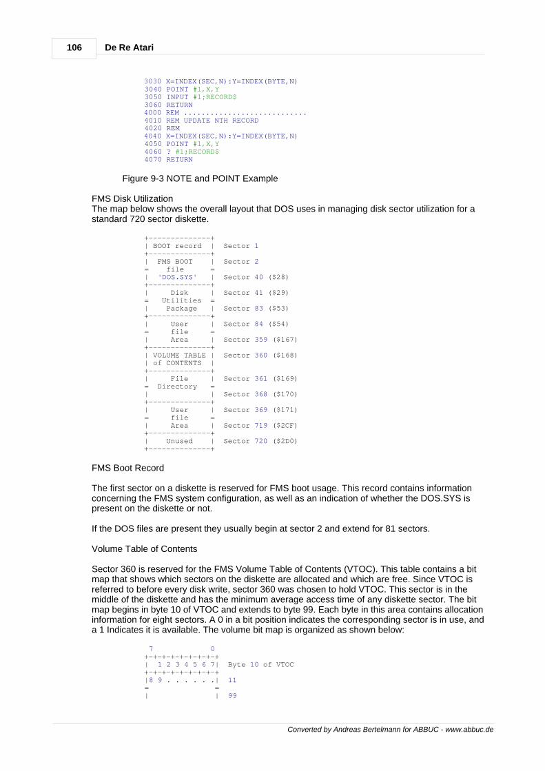
106 De Re Atari
Converted by Andreas Bertelmann for ABBUC - www.abbuc.de
3030 X=INDEX(SEC,N):Y=INDEX(BYTE,N) 3040 POINT #1,X,Y 3050 INPUT #1;RECORD$ 3060 RETURN 4000 REM ............................ 4010 REM UPDATE NTH RECORD 4020 REM 4040 X=INDEX(SEC,N):Y=INDEX(BYTE,N) 4050 POINT #1,X,Y 4060 ? #1;RECORD$ 4070 RETURN
Figure 9-3 NOTE and POINT Example
FMS Disk UtilizationThe map below shows the overall layout that DOS uses in managing disk sector utilization for astandard 720 sector diskette.
+--------------+ | BOOT record | Sector 1 +--------------+ | FMS BOOT | Sector 2 = file = | 'DOS.SYS' | Sector 40 ($28) +--------------+ | Disk | Sector 41 ($29) = Utilities = | Package | Sector 83 ($53) +--------------+ | User | Sector 84 ($54) = file = | Area | Sector 359 ($167) +--------------+ | VOLUME TABLE | Sector 360 ($168) | of CONTENTS | +--------------+ | File | Sector 361 ($169) = Directory = | | Sector 368 ($170) +--------------+ | User | Sector 369 ($171) = file = | Area | Sector 719 ($2CF) +--------------+ | Unused | Sector 720 ($2D0) +--------------+
FMS Boot Record
The first sector on a diskette is reserved for FMS boot usage. This record contains informationconcerning the FMS system configuration, as well as an indication of whether the DOS.SYS ispresent on the diskette or not.
If the DOS files are present they usually begin at sector 2 and extend for 81 sectors.
Volume Table of Contents
Sector 360 is reserved for the FMS Volume Table of Contents (VTOC). This table contains a bitmap that shows which sectors on the diskette are allocated and which are free. Since VTOC isreferred to before every disk write, sector 360 was chosen to hold VTOC. This sector is in themiddle of the diskette and has the minimum average access time of any diskette sector. The bitmap begins in byte 10 of VTOC and extends to byte 99. Each byte in this area contains allocationinformation for eight sectors. A 0 in a bit position indicates the corresponding sector is in use, anda 1 Indicates it is available. The volume bit map is organized as shown below:
7 0 +-+-+-+-+-+-+-+-+ | 1 2 3 4 5 6 7| Byte 10 of VTOC +-+-+-+-+-+-+-+-+ |8 9 . . . . . .| 11 = = | | 99
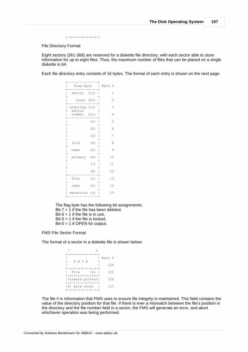
107The Disk Operating System
Converted by Andreas Bertelmann for ABBUC - www.abbuc.de
+-+-+-+-+-+-+-+-+
File Directory Format
Eight sectors (361-368) are reserved for a diskette file directory, with each sector able to storeinformation for up to eight files. Thus, the maximum number of files that can be placed on a singlediskette is 64.
Each file directory entry consists of 16 bytes. The format of each entry is shown on the next page.
+---------------+ | flag byte | Byte 0 +---------------+ | sector (lo) | 1 + + | count (hi) | 2 +---------------+ | starting (lo) | 3 + sector + | number (hi) | 4 +---------------+ | (1) | 5 + + | (2) | 6 + + | (3) | 7 + + | file (4) | 8 + + | name (5) | 9 + + | primary (6) | 10 + + | (7) | 11 + + | (8) | 12 +---------------+ | file (1) | 13 + + | name (2) | 14 + + | extension (3) | 15 +---------------+
The flag byte has the following bit assignments: Bit-7 = 1 if the file has been deleted. Bit-6 = 1 if the file is in use. Bit-5 = 1 if the file is locked. Bit-0 = 1 if OPEN for output.
FMS File Sector Format
The format of a sector in a diskette file is shown below:
7 0 +-+-+-+-+-+-+-+-+ | | Byte 0 = D A T A = | | 124 +-+-+-+-+-+-+-+-+ | file |hi | 125 +-+-+-+-+-+-+-+-+ |forward pointer| 126 +-+-+-+-+-+-+-+-+ |S| byte count | 127 +-+-+-+-+-+-+-+-+
The file # is information that FMS uses to ensure file integrity is maintained. This field contains thevalue of the directory position for that file. If there is ever a mismatch between the file's position inthe directory and the file number field in a sector, the FMS will generate an error, and abortwhichever operation was being performed.
108 De Re Atari
Converted by Andreas Bertelmann for ABBUC - www.abbuc.de
The forward pointer is a 10-bit pointer that indicates the next sector in a file. This is described as aforward linked list, with the forward pointer of the last sector equal to 0.
If the S bit is set (i.e., equal to 1), then the sector is a "short sector" and contains less than 125data bytes.
The byte count field contains the number of bytes in the sector.
THE AUTORUN.SYS FILEDOS contains a feature that allows a special file to be loaded into memory each time the system ispowered-up. This can be data to customize features of the system such as setting up differentmargin values, or changing the default colors. If desired this can be a machine language programto be executed before the normal DOS boot process occurs.
This file must be 6 binary load file with the name AUTORUN.SYS. To make this an executable file,an address value must be loaded into the INIT [$02E0,2] or the RUN [$02E2,2] locations. Thedifference between these two parameters is that the code pointed to by INIT will be executed assoon as that location is loaded, whereas code pointed to by RUN will only be executed after theload process is complete. To return control to DOS after executing an AUTORUN.SYS file,terminate your code with an RTS.
The AUTORUN.SYS file can be extremely useful in setting up "load- and-go" assembly languageroutines. It also provides a method of reconfiguring the OS by "stealing" certain of the systemvectors before DOS has a chance to be initialized. Among other things, this feature can be used toprovide a certain measure of diskette protection. Refer to Figure 8-3 for an example of setting upan AUTORUN.SYS file to reset the MEMLO pointer.
Converted by Andreas Bertelmann for ABBUC - www.abbuc.de
Atari Basic
Chapter
X
110 De Re Atari
Converted by Andreas Bertelmann for ABBUC - www.abbuc.de
10 Atari Basic
WHAT IS ATARI BASIC?ATARI BASIC is an interpreted language. This means programs can be run when they are enteredwithout intermediate stages of compilation and linking. The ATARI BASIC interpreter resides in an8K ROM cartridge in the left slot of the computer. It encompasses addresses A000 through BFFF.At least 8K of RAM is required to run BASIC.
To use ATARI BASIC effectively, you must know its strengths and weaknesses. With thisinformation, programs can be written that make good use of the assets and features of ATARIBASIC.
Strengths of ATARI BASIC
· It supports the operating system graphics - Simple graphics calls can be made to displayinformation on the screen.
· It supports the hardware - Such calls as SOUND, STICK and PADDLE are simpleinterfaces to the hardware of the computer.
· Simple assembly interface - The USR function allows easy user access to assemblylanguage routines.
· ROM based interpreter - The BASIC interpreter is in ROM, which prevents accidentalmodification by the user program.
· DOS support - Specialized calls such as NOTE and POINT (DOS 2.0S) allow the user torandomly access a disk through the disk operating system.
· Peripheral support - Any peripheral recognized by the operating system can be accessedfrom a BASIC program.
Weaknesses of ATARI BASIC
· No support of integers - All numbers are stored as 6- byte BCD floating point numbers.· Slow math package - Since all numbers are six bytes long, math operations become rather
slow.· No string arrays - Only one-dimensional strings can be created.
HOW ATARI BASIC WORKSThe workings of the BASIC interpreter are summarized as follows:
· BASIC gets a line of input from the user and converts it into a tokenized form.· It then puts this line into a token program.· This program is then executed.
The details of these operations are discussed in the following four sections.· The Tokenizing Process· The Token File Structure· The Program Execution Process· System Interaction
THE TOKENIZING PROCESSIn simple terms, the tokenization of a line of code in BASIC looks like this: 1. BASIC gets a line of input 2. It then checks for legal syntax 3. During syntax checking it is tokenized 4. The tokenized line is moved into the token program 5. If the line is in immediate mode it is executed
To better understand the tokenizing process, some terms must first be defined:
Token An 8-bit byte containing a particularinterpretable code.
111Atari Basic
Converted by Andreas Bertelmann for ABBUC - www.abbuc.de
Statement The first executable token of a statement thattells BASIC tointerpret the tokens that follow in aparticular way.
Line A complete "sentence" of tokens that causesBASIC to performsome meaningful task. In LIST form,statements are separated bycolons.
Command One or more statements preceded either by aline number in therange of 0 to 32767 or an immediate modeline with no number.
Variable A token that is an indirect pointer to itsactual value;can be changed without changing the token.
Constant A 6-byte BCD value preceeded by a specialtoken. This valueremains unchanged throughout programexecution.
Operator Any one of 46 tokens that in some waymove or modify the values that follow them.
Function A token that when executed returns a valueto the program.
EOL End of Line. A character with the value 9Bhex.
BCD Binary code decimal. A number that uses the6502 decimal mode.
BASIC begins the tokenizing process by getting a line of input. This input will be obtained from oneof the handlers of the operating system. Normally it is from the screen editor; however with theENTER command, any device can be specified. The call BASIC issues is a GET RECORDcommand, and the data returned is ATASCII information terminated by an EOL. This data is storedby CIO into the BASIC Input Line Buffer from 580 to 5FF hex.
After the record is returned, the syntax checking and tokenizing processes begin. First BASIClooks for a line number. If one is found, it is converted into a 2- byte integer. If no line number ispresent, it is assumed to be in immediate mode and the line-number 8000 hex is assigned to it.These will be the first two tokens of the tokenized line. This line is built in the token output bufferthat is 256 bytes long and resides at the end of the reserved operating system RAM.
The next token is a dummy byte reserved for the byte count (or offset) from the start of this line tothe start of the next line. Following that is another dummy byte for the count of the start of this lineto the start of the next statement. These values will be set when tokenization is complete for theline and the statement respectively. The use of these values is discussed in the program executionprocess section.
BASIC now looks for the command of the first statement of the input line. A check is made todetermine if this is a valid command by scanning a list of legal commands in ROM. If a match isfound, then the next byte in the token line becomes the number of the entry in the ROM list thatmatched. If no match is found, a syntax error token is assigned to that byte and BASIC stopstokenizing, copies the rest of the input buffer in ATASCII format to the token output buffer, andprints the error line.
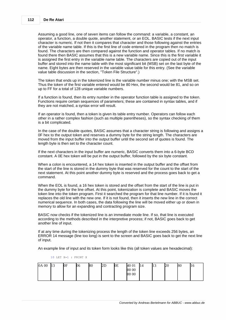
112 De Re Atari
Converted by Andreas Bertelmann for ABBUC - www.abbuc.de
Assuming a good line, one of seven items can follow the command: a variable, a constant, anoperator, a function, a double quote, another statement, or an EOL. BASIC tests if the next inputcharacter is numeric. If not then it compares that character and those following against the entriesof the variable name table. If this is the first line of code entered in the program then no match isfound. The characters are then compared against the function and operator tables. If no match isfound there then BASIC assumes that this is a new variable name. Since this is the first variable itis assigned the first entry in the variable name table. The characters are copied out of the inputbuffer and stored into the name table with the most significant bit (MSB) set on the last byte of thename. Eight bytes are then reserved in the variable value table for this entry. (See the variablevalue table discussion in the section, "Token File Structure".)
The token that ends up in the tokenized line is the variable number minus one; with the MSB set.Thus the token of the first variable entered would be 80 Hex, the second would be 81, and so onup to FF for a total of 128 unique variable numbers.
If a function is found, then its entry number in the operator function table is assigned to the token.Functions require certain sequences of parameters; these are contained in syntax tables, and ifthey are not matched, a syntax error will result.
If an operator is found, then a token is given its table entry number. Operators can follow eachother in a rather complex fashion (such as multiple parentheses), so the syntax checking of themis a bit complicated.
In the case of the double quotes, BASIC assumes that a character string is following and assigns a0F hex to the output token and reserves a dummy byte for the string length. The characters aremoved from the input buffer into the output buffer until the second set of quotes is found. Thelength byte is then set to the character count.
If the next characters in the input buffer are numeric, BASIC converts them into a 6-byte BCDconstant. A 0E hex token will be put in the output buffer, followed by the six byte constant.
When a colon is encountered, a 14 hex token is inserted in the output buffer and the offset fromthe start of the line is stored in the dummy byte that was reserved for the count to the start of thenext statement. At this point another dummy byte is reserved and the process goes back to get acommand.
When the EOL is found, a 16 hex token is stored and the offset from the start of the line is put inthe dummy byte for the line offset. At this point, tokenization is complete and BASIC moves thetoken line into the token program. First it searched the program for that line number. If it is found itreplaces the old line with the new one. If it is not found, then it inserts the new line in the correctnumerical sequence. In both cases, the data following the line will be moved either up or down inmemory to allow for an expanding and contracting program size.
BASIC now checks if the tokenized line is an immediate mode line. If so, that line is executedaccording to the methods described in the interpretive process; if not, BASIC goes back to getanother line of input.
If at any time during the tokenizing process the length of the token line exceeds 256 bytes, anERROR 14 message (line too long) is sent to the screen and BASIC goes back to get the next lineof input.
An example line of input and its token form looks like this (all token values are hexadecimal):
10 LET X=1 : PRINT X
0A 00 13 0F 06 80 2D 0E 40 0100 0000 00
14 13 20 80 16
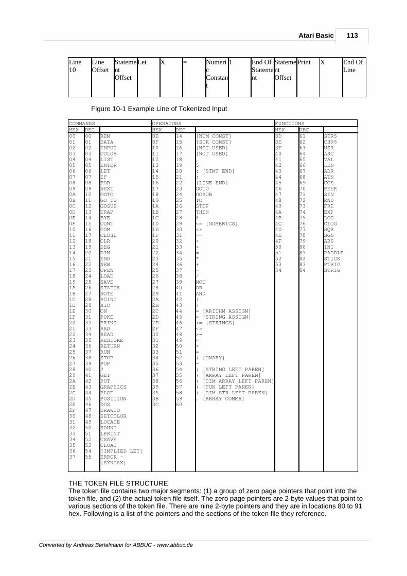
113Atari Basic
Converted by Andreas Bertelmann for ABBUC - www.abbuc.de
Line10
LineOffset
StatementOffset
Let X = NumericConstant
1 End OfStatement
StatementOffset
Print X End OfLine
Figure 10-1 Example Line of Tokenized Input
COMMANDS OPERATORS FUNCTIONSHEX DEC HEX DEC HEX DEC000102030405060708090A0B0C0D0E0F101112131415161718191A1B1C1D1E1F202122232425262728292A2B2C2D2E2F3031323334353637
0001020304050607080910111213141516171819202122232425262728293031323334353637383940414243444546474849505152535455
REMDATAINPUTCOLORLISTENTERLETIFFORNEXTGOTOGO TOGOSUBTRAPBYECONTCOMCLOSECLRDEGDIMENDNEWOPENLOADSAVESTATUSNOTEPOINTXIOONPOKEPRINTRADREADRESTORERETURNRUNSTOPPOP?GETPUTGRAPHICSPLOTPOSITIONDOSDRAWTOSETCOLORLOCATESOUNDLPRINTCSAVECLOAD[IMPLIED LET]ERROR -[SYNTAX]
0E0F101112131415161718191A1B1C1D1E1F202122232425262728292A2B2C2D2E2F303132333435363738393A3B3C
1415161718192021222324252627282930313233343536373839404142434445464748495051525354555657585960
[NUM CONST][STR CONST][NOT USED][NOT USED],$: [STMT END];[LINE END]GOTOGOSUBTOSTEPTHEN#<= [NUMERICS]<>>=<>=*+-/NOTORAND()= [ARITHM ASSIGN]= [STRING ASSIGN]<= [STRINGS]<>>=<>=+ [UNARY]-( [STRING LEFT PAREN]( [ARRAY LEFT PAREN]( [DIM ARRAY LEFT PAREN]( [FUN LEFT PAREN]( [DIM STR LEFT PAREN], [ARRAY COMMA]
3D3E3F404142434445464748494A4B4C4D4E4F5051525354
616263646566676869707172737475767778798081828384
STR$CHR$USRASCVALLENADRATNCOSPEEKSINRNDFREEXPLOGCLOGSQRSGNABSINTPADDLESTICKPTRIGSTRIG
THE TOKEN FILE STRUCTUREThe token file contains two major segments: (1) a group of zero page pointers that point into thetoken file, and (2) the actual token file itself. The zero page pointers are 2-byte values that point tovarious sections of the token file. There are nine 2-byte pointers and they are in locations 80 to 91hex. Following is a list of the pointers and the sections of the token file they reference.
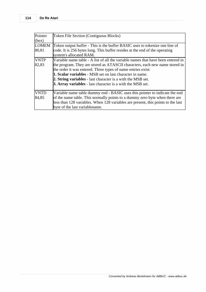
114 De Re Atari
Converted by Andreas Bertelmann for ABBUC - www.abbuc.de
Pointer(hex)
Token File Section (Contiguous Blocks)
LOMEM80,81
Token output buffer - This is the buffer BASIC uses to tokenize one line ofcode. It is 256 bytes long. This buffer resides at the end of the operatingsystem's allocated RAM.
VNTP82,83
Variable name table - A list of all the variable names that have been entered inthe program. They are stored as ATASCII characters, each new name stored inthe order it was entered. Three types of name entries exist:1. Scalar variables - MSB set on last character in name.2. String variables - last character is a with the MSB set.3. Array variables - last character is a with the MSB set.
VNTD84,85
Variable name table dummy end - BASIC uses this pointer to indicate the endof the name table. This normally points to a dummy zero byte when there areless than 128 variables. When 128 variables are present, this points to the lastbyte of the last variablename.
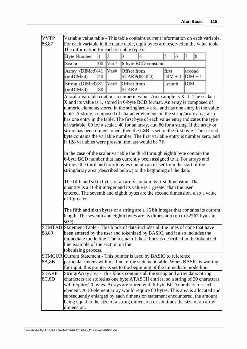
115Atari Basic
Converted by Andreas Bertelmann for ABBUC - www.abbuc.de
VVTP86,87
Variable value table - This table contains current information on each variable.For each variable in the name table, eight bytes are reserved in the value table.The information for each variable type is:
A scalar variable contains a numeric value. An example is X=1. The scalar isX and its value is 1, stored in 6-byte BCD format. An array is composed ofnumeric elements stored in the string/array area and has one entry in the valuetable. A string, composed of character elements in the string/array area, alsohas one entry in the table. The first byte of each value entry indicates the typeof variable: 00 for a scalar, 40 for an array, and 80 for a string. If the array orstring has been dimensioned, then the LSB is set on the first byte. The secondbyte contains the variable number. The first variable entry is number zero, andif 128 variables were present, the last would be 7F.
In the case of the scalar variable the third through eighth byte contain the6-byte BCD number that has currently been assigned to it. For arrays andstrings, the third and fourth bytes contain an offset from the start of thestring/array area (described below) to the beginning of the data.
The fifth and sixth bytes of an array contain its first dimension. Thequantity is a 16-bit integer and its value is 1 greater than the userentered. The seventh and eighth bytes are the second dimension, also a valueof 1 greater.
The fifth and sixth bytes of a string are a 16 bit integer that contains its currentlength. The seventh and eighth bytes are its dimension (up to 32767 bytes insize).
STMTAB88,89
Statement Table - This block of data includes all the lines of code that havebeen entered by the user and tokenized by BASIC, and it also includes theimmediate mode line. The format of these lines is described in the tokenizedline example of the section on thetokenizing process.
STMCUR8A,8B
Current Statement - This pointer is used by BASIC to referenceparticular tokens within a line of the statement table. When BASIC is waitingfor input, this pointer is set to the beginning of the immediate mode line.
STARP8C,8D
String/Array area - This block contains all the string and array data. Stringcharacters are stored as one byte ATASCII entries, so a string of 20 characterswill require 20 bytes. Arrays are stored with 6-byte BCD numbers for eachelement. A 10-element array would require 60 bytes. This area is allocated andsubsequently enlarged by each dimension statement encountered, the amountbeing equal to the size of a string dimension or six times the size of an arraydimension.
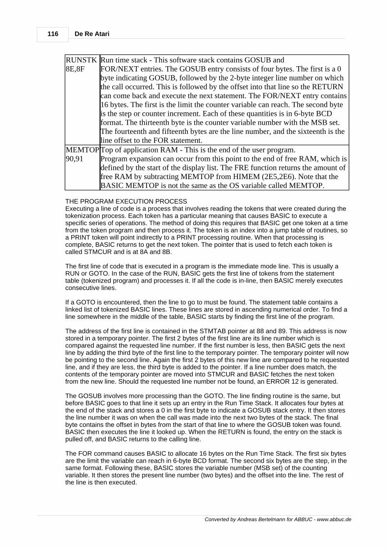
116 De Re Atari
Converted by Andreas Bertelmann for ABBUC - www.abbuc.de
RUNSTK8E,8F
Run time stack - This software stack contains GOSUB andFOR/NEXT entries. The GOSUB entry consists of four bytes. The first is a 0byte indicating GOSUB, followed by the 2-byte integer line number on whichthe call occurred. This is followed by the offset into that line so the RETURNcan come back and execute the next statement. The FOR/NEXT entry contains16 bytes. The first is the limit the counter variable can reach. The second byteis the step or counter increment. Each of these quantities is in 6-byte BCDformat. The thirteenth byte is the counter variable number with the MSB set.The fourteenth and fifteenth bytes are the line number, and the sixteenth is theline offset to the FOR statement.
MEMTOP90,91
Top of application RAM - This is the end of the user program.Program expansion can occur from this point to the end of free RAM, which isdefined by the start of the display list. The FRE function returns the amount offree RAM by subtracting MEMTOP from HIMEM (2E5,2E6). Note that theBASIC MEMTOP is not the same as the OS variable called MEMTOP.
THE PROGRAM EXECUTION PROCESSExecuting a line of code is a process that involves reading the tokens that were created during thetokenization process. Each token has a particular meaning that causes BASIC to execute aspecific series of operations. The method of doing this requires that BASIC get one token at a timefrom the token program and then process it. The token is an index into a jump table of routines, soa PRINT token will point indirectly to a PRINT processing routine. When that processing iscomplete, BASIC returns to get the next token. The pointer that is used to fetch each token iscalled STMCUR and is at 8A and 8B.
The first line of code that is executed in a program is the immediate mode line. This is usually aRUN or GOTO. In the case of the RUN, BASIC gets the first line of tokens from the statementtable (tokenized program) and processes it. If all the code is in-line, then BASIC merely executesconsecutive lines.
If a GOTO is encountered, then the line to go to must be found. The statement table contains alinked list of tokenized BASIC lines. These lines are stored in ascending numerical order. To find aline somewhere in the middle of the table, BASIC starts by finding the first line of the program.
The address of the first line is contained in the STMTAB pointer at 88 and 89. This address is nowstored in a temporary pointer. The first 2 bytes of the first line are its line number which iscompared against the requested line number. If the first number is less, then BASIC gets the nextline by adding the third byte of the first line to the temporary pointer. The temporary pointer will nowbe pointing to the second line. Again the first 2 bytes of this new line are compared to he requestedline, and if they are less, the third byte is added to the pointer. If a line number does match, thecontents of the temporary pointer are moved into STMCUR and BASIC fetches the next tokenfrom the new line. Should the requested line number not be found, an ERROR 12 is generated.
The GOSUB involves more processing than the GOTO. The line finding routine is the same, butbefore BASIC goes to that line it sets up an entry in the Run Time Stack. It allocates four bytes atthe end of the stack and stores a 0 in the first byte to indicate a GOSUB stack entry. It then storesthe line number it was on when the call was made into the next two bytes of the stack. The finalbyte contains the offset in bytes from the start of that line to where the GOSUB token was found.BASIC then executes the line it looked up. When the RETURN is found, the entry on the stack ispulled off, and BASIC returns to the calling line.
The FOR command causes BASIC to allocate 16 bytes on the Run Time Stack. The first six bytesare the limit the variable can reach in 6-byte BCD format. The second six bytes are the step, in thesame format. Following these, BASIC stores the variable number (MSB set) of the countingvariable. It then stores the present line number (two bytes) and the offset into the line. The rest ofthe line is then executed.
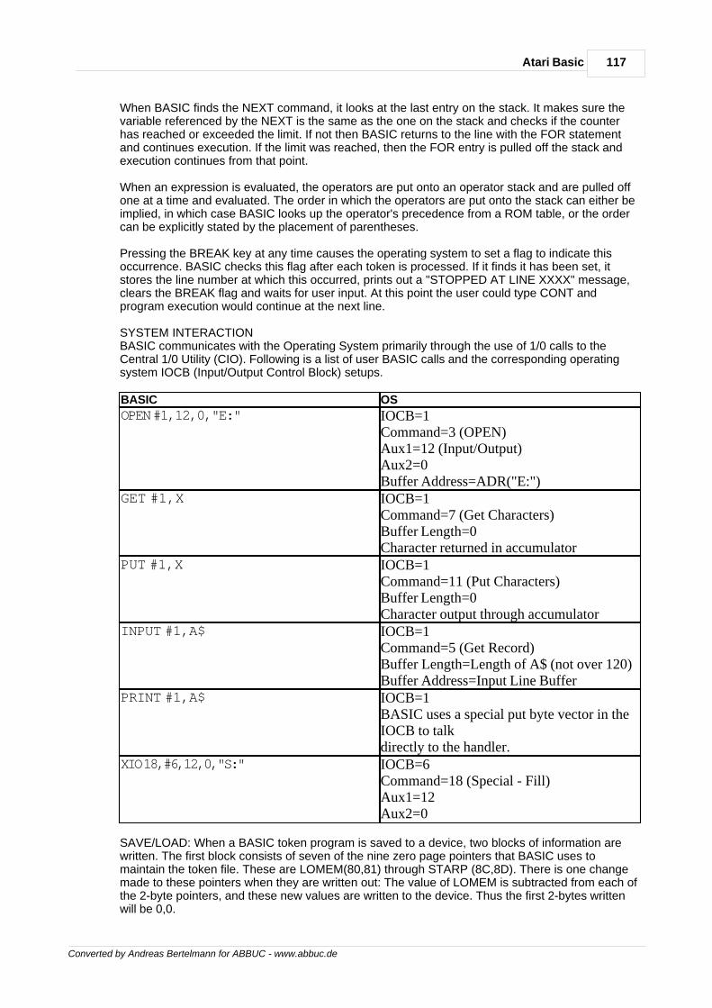
117Atari Basic
Converted by Andreas Bertelmann for ABBUC - www.abbuc.de
When BASIC finds the NEXT command, it looks at the last entry on the stack. It makes sure thevariable referenced by the NEXT is the same as the one on the stack and checks if the counterhas reached or exceeded the limit. If not then BASIC returns to the line with the FOR statementand continues execution. If the limit was reached, then the FOR entry is pulled off the stack andexecution continues from that point.
When an expression is evaluated, the operators are put onto an operator stack and are pulled offone at a time and evaluated. The order in which the operators are put onto the stack can either beimplied, in which case BASIC looks up the operator's precedence from a ROM table, or the ordercan be explicitly stated by the placement of parentheses.
Pressing the BREAK key at any time causes the operating system to set a flag to indicate thisoccurrence. BASIC checks this flag after each token is processed. If it finds it has been set, itstores the line number at which this occurred, prints out a "STOPPED AT LINE XXXX" message,clears the BREAK flag and waits for user input. At this point the user could type CONT andprogram execution would continue at the next line.
SYSTEM INTERACTIONBASIC communicates with the Operating System primarily through the use of 1/0 calls to theCentral 1/0 Utility (CIO). Following is a list of user BASIC calls and the corresponding operatingsystem IOCB (Input/Output Control Block) setups.
BASIC OS
OPEN #1,12,0,"E:" IOCB=1Command=3 (OPEN)Aux1=12 (Input/Output)Aux2=0Buffer Address=ADR("E:")
GET #1,X IOCB=1Command=7 (Get Characters)Buffer Length=0Character returned in accumulator
PUT #1,X IOCB=1Command=11 (Put Characters)Buffer Length=0Character output through accumulator
INPUT #1,A$ IOCB=1Command=5 (Get Record)Buffer Length=Length of A$ (not over 120)Buffer Address=Input Line Buffer
PRINT #1,A$ IOCB=1BASIC uses a special put byte vector in theIOCB to talkdirectly to the handler.
XIO 18,#6,12,0,"S:" IOCB=6Command=18 (Special - Fill)Aux1=12Aux2=0
SAVE/LOAD: When a BASIC token program is saved to a device, two blocks of information arewritten. The first block consists of seven of the nine zero page pointers that BASIC uses tomaintain the token file. These are LOMEM(80,81) through STARP (8C,8D). There is one changemade to these pointers when they are written out: The value of LOMEM is subtracted from each ofthe 2-byte pointers, and these new values are written to the device. Thus the first 2-bytes writtenwill be 0,0.

118 De Re Atari
Converted by Andreas Bertelmann for ABBUC - www.abbuc.de
The second block of information written consists of the following token file sections: (1) Thevariable name table, (2) the variable value table, (3) the token program, and (4) the immediatemode line.
When this program is loaded into memory, BASIC looks at the OS variable MEMLO (2E7,2E8) andadds its value to each of the 2-byte zero page pointers as they are read from the device. Thesepointers are placed back on page zero and then the values of RUNSTK(8E,8F) and MEMTOP(90,91) are set to the value in STARP.
Next, 256 bytes are reserved in memory above the value of MEMLO to allocate space for thetoken output buffer. Then the token file information, consisting of the variable name table throughthe immediate mode line, is read in. This data is placed in memory immediately following the tokenoutput buffer.
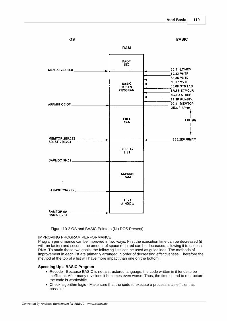
119Atari Basic
Converted by Andreas Bertelmann for ABBUC - www.abbuc.de
Figure 10-2 OS and BASIC Pointers (No DOS Present)
IMPROVING PROGRAM PERFORMANCEProgram performance can be improved in two ways. First the execution time can be decreased (itwill run faster) and second, the amount of space required can be decreased, allowing it to use lessRNA. To attain these two goals, the following lists can be used as guidelines. The methods ofimprovement in each list are primarily arranged in order of decreasing effectiveness. Therefore themethod at the top of a list will have more impact than one on the bottom.
Speeding Up a BASIC Program
· Recode - Because BASIC is not a structured language, the code written in it tends to beinefficient. After many revisions it becomes even worse. Thus, the time spend to restructurethe code is worthwhile.
· Check algorithm logic - Make sure that the code to execute a process is as efficient aspossible.
120 De Re Atari
Converted by Andreas Bertelmann for ABBUC - www.abbuc.de
· Put frequently called subroutines and FOR/NEXT loops at the start of the program - BASICstarts at the beginning of a program to look for a line number, so any line references nearthe end will take longer to reach.
· For frequently called operations within a loop use in-line code rather than subroutines - Theprogram speed can be improved here since BASIC spends time adding and removingentries from the run time stack.
· Make the most frequently changing loop of a nested set the deepest - In this way, the runtime stack will be altered the fewest number of times.
· Simplify floating point calculations within the loop - if a result is obtained by multiplying aconstant by a counter, time could be saved by changing the operation to an add of aconstant.
· Set up loops as multiple statements on one line - In this way the BASIC interpreter will nothave to get the next line to continue the loop.
· Disable the screen display - If visual information is not important for a period of time, up to a30 percent time savings can be made with a POKE 559,0.
· Use a faster graphics mode or a short display list - If a full screen display is not necessarythen up to 25 percent time savings can be made.
· Use assembly code - Time savings can be made by encoding loops in assembler and usingthe USR function.
Saving Space In A BASIC Program
· Recode - As mentioned previously, restructuring the program will make it more efficient. Itwill also save space.
· Remove remarks - Remarks are stored as ATASCII data and merely take up space in therunning program.
· Replace a constant used three times or more with a variable BASIC allocates seven bytesfor a constant but only one for a variable reference, so six bytes can be saved each time aconstant is replaced with a variable assigned to that constant's value.
· Initialize variables with a read statement - A data statement is stored in ATASCII code, onebyte per character, whereas an assignment statement requires seven bytes for oneconstant.
· Try to convert numbers used once and twice to operations of predefined variables - Anexample is to define Z1 to equal 1, Z2 to equal 2, and if the number 3 is required, replace itwith the expression Z1 + Z2.
· Set frequently used line numbers (in GOSUB and GOTO) to predefined variables - If theline 100 is referenced 50 times, approximately 300 bytes can be saved by equating Z100 to100 and referencing Z100
· Keep the number of variables to a minimum - Each new variable entry requires 8 morebytes in the variable value table plus a few bytes for its name.
· Clean up the value and name tables - Variable entries are not deleted from the value andname tables even after all references to them are removed from the program. To delete theentries LIST the program to disk or cassette, type NEW, then ENTER the program.
· Keep variable names as short as possible - Each variable name is stored in the name tableas ATASCII information. The shorter the names, the shorter the table.
· Replace text used repeatedly with strings - On screens with a lot of text, space can besaved by assigning a string to a commonly used set of characters.
· Initialize strings with assignment statements - An assignment of a string with data in quotesrequires less space than a READ statement and a CHR$ function.
· Concatenate lines into multiple statements - Three bytes can be saved each time two linesare converted into two statements on one line.
· Replace once used subroutines with in-line code - The GOSUB and RETURN statementswaste bytes if used only once.
· Replace numeric arrays with strings if the data values do not exceed 255 - Numeric arrayentries require six bytes each, whereas string elements only need one.
· Replace SETCOLOR statements with POKE commands - This will save 8 bytes.· Use cursor control characters rather than POSITION statements The POSITION statement
requires 15 bytes for the X,Y parameters whereas the cursor editing characters are onebyte each.
· Delete lines of code via program control - See the advanced programming techniques
121Atari Basic
Converted by Andreas Bertelmann for ABBUC - www.abbuc.de
section.· Modify the string/array pointer to load predefined data - By changing the value in STARP,
string and array information can be saved.· Small assembly routines can be stored in USR calls - For example
X=USR(ADR("hhh*LVd"),16).· Chain programs - An example would be an initialization routine that is run first and then
loads and executes the main program.
ADVANCED PROGRAMMING TECHNIQUESAn understanding of fundamentals of ATARI BASIC makes it possible to write some interestingapplications. These can be strictly BASIC operations, or they can also involve features of theoperating system.
Example 1 - String Initialization - This program will set all the bytes of a string of any length to thesame value. BASIC copies the first byte of the source string into the first byte of the destinationstring, then the second, third, and so on. By making the destination string the second byte of thesource, the same character can be stored throughout the entire string.
10 REM STRING INITIALIZATION 20 DIM A$(1000) 30 A$(l)="A":A$(1000)="A" 40 A$(2)=A$
Example 2 - Delete Lines Of Code - By using a feature of the operating system, a program candelete or modify lines of code within itself. The screen editor can be set to accept data from thescreen without user input. Thus by first setting up the screen, positioning the cursor to the top, andthen stopping the program, BASIC will be getting the commands that have been printed on thescreen.
10 REM DELETE LINE EXAMPLE 20 GRAPHICS 0:POSITION 2,4 30 ? 70:? 80:? 90:? "CONT" 40 POSITION 2,0 50 POKE 842,13:STOP 60 POKE 842,12 70 REM THESE LINES 80 REM WILL BE 90 REM DELETED
Example 3 - Player/Missile (P/M) Graphics With Strings - A fast way to move player/missilegraphics data is shown in this example. A dimensioned string has its string/array area offset valuechanged to point to the P/M graphics area. Writing to this string with an assignment statement willnow write data into the P/M area at assembly language rates.
100 REM PLAYER/MISSILE EXAMPLE 110 DIM A$(512),B$(20) 120 X=X+1:READ A:IF A<>-l THEN B$(X,X)=CHR$(A):GOTO 120 130 DATA 0,255,129,129,129,129,129,129,129,129,255,0,-1 2000 POKE 559,62:POKE 704,88 2020 I=PEEK(106)-16:POKE 54279,I 2030 POKE 53277,3:POKE 710,224 2040 VTAB=PEEK(134)+PEEK(135)*256 2050 ATAB=PEEK(140)+PEEK(141)*256 2060 OFFS=I*256+1024-ATAB 2070 HI=INT(OFFS/256):LO=OFFS-HI*256 2090 POKE VTAB+2,LO:POKE VTAB+3,HI 3000 Y=60:Z=100:V=1:H=1 4000 A$(Y,Y+11)=B$:POKE 53248,Z 4010 Y=Y+V:Z=Z+H 4020 IF Y>213 OR Y<33 THEN V=-V 4030 IF Z>206 OR Z<49 THEN H=-H

122 De Re Atari
Converted by Andreas Bertelmann for ABBUC - www.abbuc.de
4420 GOTO 4000
Converted by Andreas Bertelmann for ABBUC - www.abbuc.de
Appendix A.Memory
utilization
Chapter
XI
124 De Re Atari
Converted by Andreas Bertelmann for ABBUC - www.abbuc.de
11 Appendix A. Memory utilization
Memory utilization with the Atari Home Computer can be difficult. Much of the memory iscommandeered by the operating system, the resident cartridge, or the DOS, leaving very littleunder the direct control of the programmer. This gives the programmer very little freedom in layingout memory utilization for a program. With proper planning this need not be a serious problem.
PAGE ZERO
The most important RAM for any assembly language programmer is page zero. Page zero isabsolutely essential for pointers and is very useful for heavily used variables, because code writtenfor page zero variables is more compact and runs faster. Hence the assembly languageprogrammer wants to know how many locations on page zero can be stolen for his own use. Thisappendix will not cover the use of page zero locations as they are defined and used by firmware.Instead, it will address only their use when the firmware's function is disabled or ignored.
The lower half of page zero (addresses $00-$80) is reserved for use by the operating system. The128 bytes here are required for the entire array of services that the operating system provides.Most programs will use only a portion of those services. Thus, many locations in this region will notbe used by the operating system during the program's execution. In particular, the 43 bytes from$50 to $7A are used only by the screen editor and display handler. Most programs will use customdisplay lists with their own display handlers. These 43 bytes would then become available duringprogram execution. Similar reasoning applied to other locations dedicated to special functionswould free even more.
Unfortunately, there is a major flaw in this reasoning. The software department at Atari isconstantly evaluating the performance of the operating system and making changes in the code.There are now two versions of the operating system -- Rev A and Rev B. They are functionallyalmost identical; software that runs under Rev A will almost certainly run under Rev B. Morerevisions are contemplated and it is highly probable that the under utilization of those 43 bytes willbe corrected in future revisions of the operating system. Thus, any software packages that stealthose 43 bytes, or any other bytes from the lower half of page zero, will probably malfunction if rununder a future operating system. Therefore, commercially offered software should not steal anybytes from the lower half of page zero.
The programmer must look to the upper half of page zero for free bytes. These 128 bytes arereserved for use by the cartridge. If no cartridge is in place, they are free. If a cartridge is in place,some bytes will be reserved for the programmer. The BASIC cartridge leaves only 7 bytes for theuse of the programmer -- $CB through $D1. The programmer who must have more page zerobytes has only one option: the bytes used by the floating point package ($D4 to $FF). These 44bytes may be taken if the floating point package is not used by the programmer's routines and ifthose routines do not themselves call the floating point package. The programmer does not haveunlimited use of these bytes; they must not be used by any interrupt routines, as such routinesmight strike during a floating point operation called by BASIC. There are no other bytes on theupper half of page zero usable by the programmer.
The programmer working in the BASIC environment is seldom interested in the high performanceand compactness that page zero offers; after all, if high speed and compactness were primaryconcerns, the programmer would not have chosen BASIC as a delivery language. Theprogrammer most interested in large amounts of page zero is the assembly languageprogrammer. A pure assembly language program does not need any cartridge installed to run;therefore it should have access to all 128 bytes of the upper half of page zero. In practice this isnot quite so simple, for an assembly language program must be debugged, and the onlyconvenient way to do this at present is with the debugger in the Atari Assembler-Editor cartridge.Assembly language programmers will note with chagrin that this cartridge only reserves 32 bytesfor their own use. While this is entirely adequate for virtually any program it is not enough to satethe appetite of a high-performance program. There are 30 more bytes that are not used by thedebugger portion of the cartridge. These are: $A4, $A5, $AD, $AE, $DB through $E5, $EA through$F1, $F5, $F6, $F9 through $FB, $FE, and $FF. If these bytes are used the programmer must notreturn to the Editor or the Assembler or bad things may happen. Furthermore, the mini-assemblerinside the debugger must not be used.
125Appendix A. Memory utilization
Converted by Andreas Bertelmann for ABBUC - www.abbuc.de
If you use other cartridges or disk based languages, you are on your own. Many of these systemsuse even more of page zero.
ABSOLUTE RAM
Another problem the programmer faces is presented by the DOS. It is very desirable to writeprograms that run on either 16K cassette systems or 48K diskette systems. Unfortunately, suchsystems have very little free RAM in common, for the DOS and DUP would almost fill the RAM ofthe 16K system. There are several solutions to this problem. One is to produce two differentversions of the code, a disk version and a cassette version. The two programs would be orged todifferent locations. This means that customers who buy the cassette version will not be able totransport it to a diskette if they upgrade their systems.
There is another way. Page six is common free RAM for all systems. Variables and vectors can beplaced on page six and used by cassette-based software or diskette-based software. A directory ofroutine addresses can be computed and placed at run-time onto page six. Machine languageroutines can then jump through the page six directory to the routines elsewhere in RAM. Thetechnique can be difficult to execute; it is not recommended for large assembly language projects.Its greatest value is with medium-size machine language routines (about 1K-2K) embedded insideBASIC programs.
Converted by Andreas Bertelmann for ABBUC - www.abbuc.de
Appendix B.Human
engineering
Chapter
XII
127Appendix B. Human engineering
Converted by Andreas Bertelmann for ABBUC - www.abbuc.de
12 Appendix B. Human engineering
The ATARI Home Computer is first and foremost a consumer computer. The hardware wasdesigned to make this computer easy for consumers to use. Many of the hardware features protectthe consumer from inadvertent errors. Software written for this computer should reflect an equalconcern for the consumer. The average consumer is unfamiliar with the conventions and traditionsof the computer world. Once he understands a program he will use it well most of the time.Occasionally he will be careless and make mistakes. It is the programmer's responsibility to try toprotect the consumer from his own mistakes.
The current state of software human engineering in the personal computer industry is dismal. Agreat many programs are being sold that contain very poor human engineering. The worstoffenders are written by amateur programmers, but even software written at some of the largestfirms shows occasional lapses in human engineering.
Human engineering is an art, not a science. It demands great technical skill but it also requiresinsight and feel. As such it is a highly subjective field devoid of absolutes. This appendix is thework of one hand, and so betrays the subjectivities of its author. A proper regard for the widevariety of opinions on the subject would have inflated this appendix beyond all reasonable limits oflength. Furthermore, a complete presentation of all points of view would only confuse the readerwith its many assertions, qualifications, counterpoints, and contradictions. I therefore chose thesimpler task of presenting only my own point of view, giving weak lip service to the most seriousobjections. The result is contradictory enough to satisfy even the most academic of readers.
THE COMPUTER AS SENTIENT BEINGAn instructive way of viewing the problem of human engineering is to cast the programmer assorcerer, conjuring up an intelligent being, a homunculus, within the innards of the computer. Thiscreature lacks physical embodiment, but possesses intellectual traits, specifically, the ability toprocess and organize information. The user of the program enters into a relationship with thishomunculus. The two sentient beings think differently; the human's thought patterns areassociative, integrated, and diffuse, while the program's thought processes are direct, analytical,and specific. These differences are complementary and productive because the homunculus cando well what the human cannot. Unfortunately, these differences also create a communicationsbarrier between the human and the homunculus. They have so much to say to each other becausethey are so different, but because they are different they cannot communicate well. The centralproblem in good programming must therefore be to provide for better communications betweenthe user and the homunculus. Sad to say, many programmers expend the greater part of theirefforts on expanding and improving the processing power of their programs. This only produces amore intelligent being with no eyes to see and no mouth to speak.
The current crop of personal computers have attained throughputs which make them capable ofsustaining programs intelligent enough to meet many of the average consumer's needs. Theprimary limiting factor is no longer clock speed or resident memory; the primary limiting factor isthe thin pipeline connecting our now-intelligent homunculus with his human user. Each canprocess information rapidly and efficiently; only the narrow pipeline between them slows down theinteraction.COMMUNICATION BETWEEN HUMAN AND MACHINEHow can we widen the pipeline between the two thinkers? We must focus on the language withwhich they communicate. Like any language, a man-machine language is restricted by the physicalmeans of expression available to the speakers. Because the computer and the human arephysically different, their modes of expression are physically different. This forces us to create alanguage which is not bidirectional (as human languages are). Instead, a man- machine languagewill have two channels, an input channel and an output channel. Just as we study human languageby first studying the sounds that the human vocal tract can generate, we begin by examining thephysical components of the man-machine interface.
OUTPUT (FROM COMPUTER TO HUMAN)
There are two primary output channels from the computer to the user. The first is the televisionscreen; the second is the television speaker. Fortunately, these are flexible devices which permit abroad range of expression. The main body of this book describes the features available from the
128 De Re Atari
Converted by Andreas Bertelmann for ABBUC - www.abbuc.de
computer's point of view. For the purposes of this appendix, it is more useful to discuss thesedevices in terms of the human point of view. Of the two devices (screen and speaker) the displayscreen is easily the more expressive and powerful device. The human eye is a more finelydeveloped information gathering device than the human ear. In electrical engineering terms, it hasmore bandwidth than the ear. The eye can process three major forms of visual information:shapes, color, and animation.
Shapes
Shapes are an ideal means for presenting information to the human. The human retina isespecially adept at recognizing shapes. The most direct use of shapes is for direct depiction ofobjects. If you want the program to tell the user about something, draw a picture of it. A picture isdirect, obvious, and immediate.
The second use of shapes is for symbols. Some concepts in the human lexicon defy directdepiction. Concepts like love, infinity, and direction cannot be shown with pictures. They mustinstead be conveyed with symbols, such as a heart, a horizontal figure 8, or an arrow. These are afew of the many symbols that we all recognize and use. Sometimes you can create an ad hocsymbol for limited use in your program. Most people can pick up such an ad hoc symbol quitereadily. Symbols are a compact way to express an idea but they should not be used in place ofpictures unless compactness is essential. A symbol is an indirect expression; a picture is a directexpression. The picture conveys the idea more forcefully.
The third and most common use of shapes is for text. A letter is a symbol; we put letters togetherto form words. The language we thereby produce is extremely rich in its expressive power. Truly isit said, "If you can't say it, you don't know it." This expressive power is gained at a price: extremeindirection. The word that expresses an idea has no sensory or emotional connection with the idea.The human is forced to carry out extensive mental gymnastics to decipher the word. Of course, wedo it so often that we have become quite fluent at translating strings of letters into ideas. We donot notice the effort. The important point is that the indirection detracts from the immediacy andforcefulness of the communication.
There is a school of thought that maintains that text is superior to graphics for communicationspurposes. The gist of the argument is that text encourages freer use of the reader's richimagination. The argument does not satisfy me, for if the reader must use his imagination, he issupplying information that is not inherent in the communication itself. An equal exercise ofimagination with graphics would provide even greater results. A more compelling argument for textis that its indirection allows it to pack a considerable amount of information into a small space. Thespace constraints on any real communication make text's greater compactness valuable.Nevertheless, this does not make text superior to graphics; it makes text more economical.Graphics requires more space, time, memory, or money, but it also communicates better than text.To some extent, the choice between graphics and text is a matter of taste, and the taste of thebuying public is beyond question. Compare the popularity of television with that of radio, or movieswith books. Graphics beats text easily.
Color
Color is another vehicle for conveying information. It is less powerful than shape, and so normallyplays a secondary role to shape in visual presentations. Its most frequent use is to differentiatebetween otherwise indistinguishable shapes. It also plays an important role in providing cues to theuser. Good color can salvage an otherwise ambiguous shape. For example, a tree represented asa character must fit inside an 8x8 pixel grid. The grid is too small to draw a recognizable tree;however, by coloring the tree green, the Image becomes much easier to recognize. Color is alsouseful for attracting attention or signalling important material. Hot colors attract attention. Coloralso provides aesthetic enhancement. Colored images are more pleasing to look at than black andwhite images.
Animation
I use the term "animation" here to designate any visual change. Animation includes changingcolors, changing shapes, moving foreground objects, or moving the background. Animation's
129Appendix B. Human engineering
Converted by Andreas Bertelmann for ABBUC - www.abbuc.de
primary value is for showing dynamic processes. Indeed, graphic animation is the only way tosuccessfully present highly active events. The value of animation is most forcefully demonstratedby a game like STAR RAIDERS. Can you imagine what the game would be like without animation?For that matter, can you imagine what it would be like in pure text? The value of animation extendsfar beyond games. Animation allows the designer to clearly show dynamic, changing events.Animation is one of the major advantages that computers have over paper as an informationtechnology. Finally, animation is very powerful in sensory terms. The human eye is organized torespond strongly to changes in the visual field. Animation can attract the eye's attention andincrease the user's involvement in the program.
Sound
Graphics images must be looked at to have effect. Sound can reach the user even when the useris not paying direct attention to the sound. Sound therefore has great value as an annunciator orwarning cue. A wide variety of beeps, tones, and grunts can be used to signal feedback to theuser. Correct actions can be answered with a pleasant bell tone. Incorrect actions can beanswered with a raspberry. Warning conditions can be noted with a honk.
Sound has a second use: providing realistic sound effects. Quality sound effects can greatly add tothe impact of a program because the sound provides a second channel of information flow that iseffective even when the user is visually occupied.
Sound is ill-suited for conveying straight factual information; most people do not have the auralacuity to distinguish fine tone differences. Sound is much more effective for conveying emotionalstates or responses. Most people have a large array of associations of sounds with emotionalstates. A descending sequence of notes implies deteriorating circumstances. An explosion sounddenotes destruction. A fanfare announces an important arrival. Certain note sequences fromwidely recognized popular songs are immediately associated with particular feelings. For example,in ENERGY CZAR, a funeral dirge tells the user that his energy mismanagement had ruinedAmerica's energy situation, and a fragment of "Happy Days Are Here Again" indicates success.
INPUT DEVICES (FROM HUMAN TO COMPUTER)
There are three input devices most commonly used with the ATARI Home Computer. These arethe keyboard, joystick, and paddles.
Keyboard
The keyboard is easily the most powerful input device available to the designer. It has over 50direct keystrokes immediately available. Use of the CONTROL and SHIFT keys more than doublesthe number of distinguishable entries the user can make. The CAPS/LOWR and ATARI keysextend the expressive range of the keyboard even further. Thus, with a single keystroke the usercan-designate one of 125 commands. A pair of keystrokes can address more than 15,000selections. Obviously, this device is very expressive; it can easily handle the communicationsneeds of any program. For this reason the keyboard is the input device of choice amongprogrammers.
While the strengths of the keyboard are undeniable, its weaknesses are seldom recognized. Itsfirst weakness is that not many people know how to use it well. Programmers use keyboardsheavily in their daily work; consequently, they are fast typists. The average consumer is not socomfortable with a keyboard. He can easily press the wrong key. The very existence of all thosekeys and the knowledge that one must press the correct key is itself intimidating to most people.
A second weakness of the keyboard is its indirection. It is very hard to attach direct meaning to akeyboard. A keyboard has no obvious emotional or sensory significance. The new user has greatdifficulty linking to it. All work with the keyboard is symbolic, using buttons which are marked withsymbols which are assigned meaning by the circumstances. The indirection of it all can be mostconfusing to the beginner. Keyboards also suffer from their natural association with text displays; Ihave already discussed the weaknesses of text as a medium for information transfer.
Another property of the keyboard that the designer must keep in mind is its digital nature. The
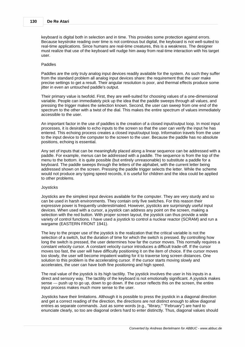
130 De Re Atari
Converted by Andreas Bertelmann for ABBUC - www.abbuc.de
keyboard is digital both in selection and in time. This provides some protection against errors.Because keystroke reading over time is not continous but digital, the keyboard is not well-suited toreal-time applications. Since humans are real-time creatures, this is a weakness. The designermust realize that use of the keyboard will nudge him away from real-time interaction with his targetuser.
Paddles
Paddles are the only truly analog input devices readily available for the system. As such they sufferfrom the standard problem all analog input devices share: the requirement that the user makeprecise settings to get a result. Their angular resolution is poor, and thermal effects produce somejitter in even an untouched paddle's output.
Their primary value is twofold. First, they are well-suited for choosing values of a one-dimensionalvariable. People can immediately pick up the idea that the paddle sweeps through all values, andpressing the trigger makes the selection known. Second, the user can sweep from one end of thespectrum to the other with a twist of the dial. This makes the entire spectrum of values immediatelyaccessible to the user.
An important factor in the use of paddles is the creation of a closed input/output loop. In most inputprocesses, it is desirable to echo inputs to the screen so that the user can verify the input he hasentered. This echoing process creates a closed input/output loop. Information travels from the userto the input device to the computer to the screen to the user. Because the paddle has no absolutepositions, echoing is essential.
Any set of inputs that can be meaningfully placed along a linear sequence can be addressed with apaddle. For example, menus can be addressed with a paddle. The sequence is from the top of themenu to the bottom. it is quite possible (but entirely unreasonable) to substitute a paddle for akeyboard. The paddle sweeps through the letters of the alphabet, with the current letter beingaddressed shown on the screen. Pressing the paddle trigger selects the letter. While the schemewould not produce any typing speed records, it is useful for children and the idea could be appliedto other problems.
Joysticks
Joysticks are the simplest input devices available for the computer. They are very sturdy and socan be used in harsh environments. They contain only five switches. For this reason theirexpressive power is frequently underestimated. However, joysticks are surprisingly useful inputdevices. When used with a cursor, a joystick can address any point on the screen, making aselection with the red button. With proper screen layout, the joystick can thus provide a widevariety of control functions. I have used a joystick to control a nuclear reactor (SCRAM) and run awargame (EASTERN FRONT 1941).
The key to the proper use of the joystick is the realization that the critical variable is not theselection of a switch, but the duration of time for which the switch is pressed. By controlling howlong the switch is pressed, the user determines how far the cursor moves. This normally requires aconstant velocity cursor. A constant velocity cursor introduces a difficult trade-off. If the cursormoves too fast, the user will have difficulty positioning it on the item of choice. If the cursor movestoo slowly, the user will become impatient waiting for it to traverse long screen distances. Onesolution to this problem is the accelerating cursor. If the cursor starts moving slowly andaccelerates, the user can have both fine positioning and high speed.
The real value of the joystick is its high tactility. The joystick involves the user in his inputs in adirect and sensory way. The tactility of the keyboard is not emotionally significant. A joystick makessense --- push up to go up, down to go down. If the cursor reflects this on the screen, the entireinput process makes much more sense to the user.
Joysticks have their limitations. Although it is possible to press the joystick in a diagonal directionand get a correct reading of the direction, the directions are not distinct enough to allow diagonalentries as separate commands. Just as some words (e.g., "library," "February") are hard toenunciate clearly, so too are diagonal orders hard to enter distinctly. Thus, diagonal values should
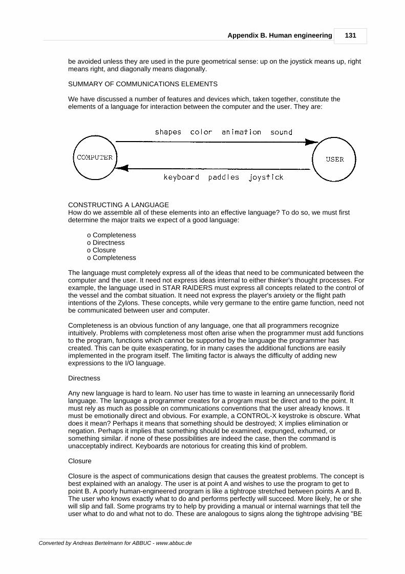
131Appendix B. Human engineering
Converted by Andreas Bertelmann for ABBUC - www.abbuc.de
be avoided unless they are used in the pure geometrical sense: up on the joystick means up, rightmeans right, and diagonally means diagonally.
SUMMARY OF COMMUNICATIONS ELEMENTS
We have discussed a number of features and devices which, taken together, constitute theelements of a language for interaction between the computer and the user. They are:
CONSTRUCTING A LANGUAGEHow do we assemble all of these elements into an effective language? To do so, we must firstdetermine the major traits we expect of a good language:
o Completeness o Directness o Closure o Completeness
The language must completely express all of the ideas that need to be communicated between thecomputer and the user. It need not express ideas internal to either thinker's thought processes. Forexample, the language used in STAR RAIDERS must express all concepts related to the control ofthe vessel and the combat situation. It need not express the player's anxiety or the flight pathintentions of the Zylons. These concepts, while very germane to the entire game function, need notbe communicated between user and computer.
Completeness is an obvious function of any language, one that all programmers recognizeintuitively. Problems with completeness most often arise when the programmer must add functionsto the program, functions which cannot be supported by the language the programmer hascreated. This can be quite exasperating, for in many cases the additional functions are easilyimplemented in the program itself. The limiting factor is always the difficulty of adding newexpressions to the I/O language.
Directness
Any new language is hard to learn. No user has time to waste in learning an unnecessarily floridlanguage. The language a programmer creates for a program must be direct and to the point. Itmust rely as much as possible on communications conventions that the user already knows. Itmust be emotionally direct and obvious. For example, a CONTROL-X keystroke is obscure. Whatdoes it mean? Perhaps it means that something should be destroyed; X implies elimination ornegation. Perhaps it implies that something should be examined, expunged, exhumed, orsomething similar. if none of these possibilities are indeed the case, then the command isunacceptably indirect. Keyboards are notorious for creating this kind of problem.
Closure
Closure is the aspect of communications design that causes the greatest problems. The concept isbest explained with an analogy. The user is at point A and wishes to use the program to get topoint B. A poorly human-engineered program is like a tightrope stretched between points A and B.The user who knows exactly what to do and performs perfectly will succeed. More likely, he or shewill slip and fall. Some programs try to help by providing a manual or internal warnings that tell theuser what to do and what not to do. These are analogous to signs along the tightrope advising "BE
132 De Re Atari
Converted by Andreas Bertelmann for ABBUC - www.abbuc.de
CAREFUL" and "DON'T FALL." I have seen several programs that place signs underneath thetightrope, so that the user can at least see why he failed as he plummets. A somewhat better classof programs provide masks against illegal entries. These are equivalent to guardrails alongside thetightrope. These are much nicer, but they must be very well constructed to ensure that the userdoes not thwart them. Some programs have nasty messages that bark at the errant user, warningagainst making certain entries. These are analogous to scowling monitors in the school halls, andare useful only for making an adult feel like a child. The ideal program is like a tunnel boredthrough solid rock. There is but one path, the path leading to success. The user has no options butto succeed.
The essence of closure is the narrowing of options, the elimination of possibilities, the placementof rock solid walls around the user. Good design is not an accumulative process of piling lots offeatures onto a basic architecture; good design requires the programmer to strip away minorfeatures, petty options, and general trivia.
This thesis clashes with the values of many programmers. Programmers crave complete freedomto exercise power over the computer. Their most common complaint against a program is that itsomehow restricts their options. Thus, deliberate advocacy of closure is met with shockedincredulity. Why would anyone be so foolish as to restrict the power of this wonderful tool?
The answer lies in the difference between the consumer and the programmer. The programmerdevotes his life to the computer; the consumer is a casual acquaintance at best. The programmeruses the computer so heavily that it is cost-effective to take the time to learn to use a morepowerful tool. The consumer does not have the time to lavish on the machine. He wants to get topoint B as quickly as possible. He does not care for the fine points that occupy a programmer's life.Bells and whistles cherished by programmers are only trivia to him. You as a programmer may notshare the consumer's values, but if you want to maintain your livelihood you had better cater tothem.
Closure is obtained by creating inputs and outputs that do not admit illegal values. This isextremely difficult to do with a keyboard, for a keyboard always allows more entries than any realprogram would need. This is an excellent argument against the use of the keyboard. A joystick ismuch better, because you can do so little with it. Because it can do so little, it is easier toconceptually exclude bad inputs. The ideal is achieved when all necessary options are expressiblewith the joystick, and no further options will fit. In this case the user cannot make a bad entrybecause it doesn't exist. More important, like Newspeak in Orwell's "1984", the user cannot evenconceive bad thoughts because no words (inputs) for them even exist.
Closure is much more than masking out bad inputs. Masking makes bad inputs conceivable andexpressible, but not functional. For example, a keyboard might be used with the "M" key disabledbecause it is meaningless. The user can still see the key, he can imagine pressing it, and he canwonder what would happen if he did press it --- all wasted effort. The user can waste even moretime by pressing it and wondering why nothing happened. The waste is compounded by theprogrammer imagining the user doing all these wasteful things and putting in code to stop thesymptoms without eliminating the disease. By contrast, a properly closed input structure uses aninput device which can express only the entries necessary to run the program, and nothing more.The user can't waste time messing with something that isn't there.
The advantages that accrue when closure is properly applied are manifold. Code is tighter andruns faster because there need be no input error checking; such errors are obsolete in the newprogram. The user requires less time to learn the program and has fewer problems with it.
The primary problem with closure is the design effort that must be expended to achieve goodclosure. The entire relationship between the user and the program must be carefully analysed todetermine the minimum vocabulary necessary for the two to communicate. Numerous schemes ofcommunication must be examined and discarded before the true minimum scheme is found. In theprocess, many bells and whistles that the programmer wanted to add will have to be eliminated. Ifthe programmer objectively looks beyond his own values, he will often conclude that the bells andwhistles are more clutter than chrome.
CONCLUSIONS
133Appendix B. Human engineering
Converted by Andreas Bertelmann for ABBUC - www.abbuc.de
The design of the language of communication between the user and the program will be the mostdifficult part of the design process in consumer software. The designer must carefully weigh thecapabilities of the machine and the needs of the user. He must precisely define the informationthat must flow between the two sentient beings. He must then design his language to maximize theclarity (not the quantity) of information flowing to the user while minimizing the effort the user mustexpend to communicate with the computer. His language must utilize the machine's features anddevices effectively while maintaining its own completeness, directness, and closure.SOME COMMON PROBLEMS IN HUMAN ENGINEERINGHaving discussed the problems of human engineering in theoretical terms, we now turn to discussspecific application problems in human engineering. The list of problems is not exhaustive; itmerely covers some of the problems common to almost all programs.
DELAY TIMES
Many programs require extensive computations. Indeed, almost all programs execute at sometime computations that take more than a few seconds to perform. What does the user experiencewhile these computations are executed? Too many programs simply stop the dialogue with theuser for the duration of the computation. The user is left with an inactive screen and no sign of lifefrom the computer. The computer does not respond to the user's inputs. If human engineering iscreated by the language of communication between the computer and the user, then this completeabsence of communication can only be regarded as a total lack of human engineering. Leaving theuser in the lurch like this is absolutely unforgivable.
Separate Processes
The best way to deal with the problem of reconciling computations with attentiveness is to separatethe input process from the computational process. The user should be able to make inputs whilethe computations are proceeding. This is technically achievable; by using vertical blank interruptsthe programmer can multitask input processing with mainline processing. The technique is used inEASTERN FRONT 1941. The real problem with the technique is that many problems areintrinsically sequential in nature. It is essential that the user input a value or choice before thecomputation can proceed to the next step. This makes it difficult to separate input processing fromthe mainline processing. However it is possible with clever design to perform anticipatorycalculations that will determine Intermediate values so that as soon as the critical data is entered,the result might be more quickly obtained. Application of such techniques can surely reduce thedelay times that the user experiences.
Speed up the Program
Another means of dealing with this problem is to speed up the program itself. Critical code canoften be rewritten to decrease execution time. Proper nesting of loops (the loop with moreiterations should be inside the loop with fewer iterations) can reduce execution time. Carefulattention to the details of execution can yield further time reductions. Major gains can be made byconverting BASIC to assembly language. Assembly is from 10 to 1000 times faster than BASIC.Assembly's advantage is greatest for memory move routines and graphics and least for floatingpoint calculations. By masking out vertical blank interrupts, more 6502 execution time can be freedfor mainline processing. Other gains can be accomplished by reducing the DMA overhead ANTICimposes. This can be done by going to a simple graphics mode (BASIC mode 3 is best).Shortening the display list is another way to reduce DMA costs. Turning off ANTIC altogether is adrastic route which only creates the additional problem of presenting the user with a blank screen.
Entertain the User
The third way to deal with delay times is to occupy the user during the computation. A countdownis one such method. The user sees a countdown on the screen. When the countdown reacheszero, the program is back in business. Another way is to draw random graphics on the screen. Thedelay period should always start with a courteous message advising the user of the delay. It shouldalso be terminated with a bell or other annunciator. You should not expect the user to keep hiseyes on the screen for an arbitrary period of time. Entertaining the user during delays is a poor wayto deal with delays that shouldn't have been there in the first place, but it's better than abandoning
134 De Re Atari
Converted by Andreas Bertelmann for ABBUC - www.abbuc.de
the user.
DEALING WITH BAD USER INPUTS
The most serious problem with present consumer software is the inadequate way that bad userinputs are handled. Good designs preclude this problem by providing input languages that do notmake any bad entries available. As I pointed out earlier, this is most easily accomplished with ajoystick. However, there are applications (primarily text-intensive ones) that require a keyboard.Furthermore, even joysticks occasionally introduce problems with user input. How are such badinputs to be dealt with when they cannot be expunged? Several suggestions follow. It is imperativethat any protection system be applied uniformly throughout the entire program. Once the userencounters protection, he will expect it in all cases. The lack of such protection creates a gapthrough which the user, thinking himself secure, will surely plunge.
Flag the Error and Suggest Solution
The most desirable approach in this unpleasant situation is to flag the user's error on the screen inplain language and suggest a correct entry. Three things must be included in the computer'sresponse. First, the user's entry must be echoed back so he knows what he did that caused theproblem. Second, the offending component of the entry must be clearly marked and explained sothat the user knows why it is wrong. Third, an alternate legal entry must be suggested so that theuser does not become frustrated by the feeling that he has encountered a brick wall. For example,an appropriate response to a bad keystroke entry might read thusly: "You pressed CONTROL-A,which is an autopsy request. I cannot perform autopsies on living people. I suggest you kill thesubject first."
This method is obviously very expensive in terms of program size and programming time. That isthe price one pays for bad design. There are less expensive and less effective methods.
Masking out Bad Keys
One common solution to keyboard input problems is to mask out all bad entries. If the userpresses a bad key, nothing happens. No keyboard click is generated and no character appears onthe screen. The program only hears what it wants to hear. This solution is secure in that it preventsprogram crashes, but it does not protect the user from confusion. The user would only press a keyif he felt that it would do something for him. Masking out the key cannot correct the user'smistaken impression. It can only lead him to the conclusion that something is seriously wrong withhis computer. We don't want to do this to our users.
A variant on this scheme is to add a nasty buzzer or raspberry to chastise the user for hisfoolishness. Indeed, some amateurish programs go so far as to heap textual abuse on the user.Such techniques are highly questionable. There may indeed be cases requiring dangerouskeystroke entries which are guarded by fierce and nasty messages; such cases are quite rare.Corrective messages should always conform to high standards of civility.
Error Messages
An even cheaper solution is to simply post an error message on the screen. The user is told onlythat he did something wrong. In many cases, the error message is cryptic and does not help theuser in the least. ATARI BASIC is an extreme example of this. Error messages are provided bynumber only. This can be justified only when the program must operate under very tight memoryconstraints.
In most cases, the designer chooses to sacrifice human engineering features such as meaningfulerror messages for some additional technical power. As pointed out in the beginning of thisappendix, we are reaching the stage in which additional technical power is no longer a limitingfactor to consumers, but human engineering is a limiting factor. Thus, the trade-off is lessjustifiable.
Protection/Power Trade-Offs
135Appendix B. Human engineering
Converted by Andreas Bertelmann for ABBUC - www.abbuc.de
One objection to many human engineering features is that they slow down the user's interactionwith the computer. Programmers tire of Incessant "ARE YOU SURE?" requests and similarrestrictions. One solution to this problem is to provide variable protection/power ratios. Forexample, a program can default to a highly protected state on initialization. All entries are carefullychecked and echoed to the user for confirmation. The user has an option to shed protection andwork in high-speed mode. This option is not obvious from the screen --- it is only described in thedocumentation. Thus, the intensive user can work at a fast pace and the casual user can haveadequate protection.MENUS AND SELECTION TECHNIQUESMenus are standard devices for making the user aware of the options available. They areespecially useful for beginning users. Command-oriented schemes preferred by programmersconfuse beginners who cannot afford the time investment to learn the lexicon of commands usedby a command-oriented program. We will discuss several common problems associated with theuse of menus.
Menu Size
How many entries should be on a menu? The obvious upper limit is dictated by the size of thescreen, but this limit is too large, for a BASIC mode 0 screen could hold up to 48 entries (24 lineswith two choices per line). My guess is that seven entries is the desired upper limit on menu size.This allows plenty of screen space to separate the entries, provide a menu title, and some sort ofprompt.
Multiple Menus
Frequently a program will require several menus to fully cover all of the options it offers. It is veryimportant that multiple menus be organized in a clear manner. The user can easily get lostwandering around through such menu mazes. One way is to have a main menu that is prominentlymarked as such, and provide each secondary menu with an option to return to the main menu.Another way is to nest menus in a hierarchical structure. When using such methods, theprogrammer must provide color and sound cues to help the user ascertain his position in the menustructure. Each menu or menu level should have a distinctive note or color assigned to it. The notefrequency should be associated with the position in the hierarchy.
Selection Methods
Once the user has seen his options, how does he make his choice known to the computer? Themost common way is to label each entry on the menu with a letter or number; the user makes hisselection by pressing the corresponding key on the keyboard. This is a clumsy solution involvingunnecessary indirection. There are a number of better methods. Most of them use the same basicscheme: a movable pointer addresses an option, and a trigger selects it. One scheme highlightsthe option being addressed in inverse video. The SELECT button changes the pointer to addressthe next menu selection, with full wraparound from the end of the menu to the beginning. TheSTART button engages a menu option. Another program automatically rotated the pointer throughthe menu options; the user need only push a button at the correct moment when his desired optionwas being addressed (not an impressive method). Paddles and joysticks are very well suited formenu selection. Either one can be used to sweep the pointer through the menu selections, with thered trigger button making the selection. My pet scheme for menu selection uses a cursor on alarge scrolling menu. The user moves the cursor with a joystick. Signposts can direct her todifferent regions of the menu. The user makes a selection by placing the cursor directly on top ofan option and pressing the trigger button.
MANUALS VERSUS ON-BOARD TEXTA common problem with menus, error messages, prompts, and other messages is that suchmaterial can easily consume a large amount of memory --- memory that could well be used forother features. Such material could be placed in a reference document, but doing so would detractfrom the quality of the program's human engineering. The designer must decide how muchmaterial should go into the program and how much should be relegated to the manual. Withdisk-based programs it is possible to store some of the material on the diskette; this lessens theharshness of the trade-off. When the problem is approached only from the human engineeringpoint of view, it is easily answered: all material should be included In the program, or at least on a
136 De Re Atari
Converted by Andreas Bertelmann for ABBUC - www.abbuc.de
diskette. Economic and technical considerations argue against this. It is my personal view thateach technology should be used for the things it does best. While the computer can handle statictext, its forte is dynamic information processing. Paper and ink handle static information morecheaply and often more clearly than a computer. I therefore prefer to put static information into amanual and let the program refer the user to the manual. I still include critical information within theprogram; my dividing line bends with local needs.MEASURES OF SUCCESSHow can a designer determine the success of his human engineering? There are severalindicators that provide valuable feedback. The first is the minimum length of the manual. If youexclude background material and isolate only the material in the manual that is absolutelynecessary to describe how to use the program, then the length of this material is a good measureof your human engineering. The more material, the worse you've done. A well-designed programshould require very little explanation. This should not be construed as an argument against properdocumentation. Documentation should always describe the program in more detail than isabsolutely necessary. A long, lavish manual is good; a program that demands such a manual isnot.
Another measure is the amount of time that a first-time user expends to learn to use the programsatisfactorily. Good programs can be used in a matter of minutes.
A third measure is the amount of thinking a user must do to use the program. A well-designedprogram should require no cognitive effort to use. This does not mean that the user does not thinkat all while using such a program. Rather, he thinks about the content of the program rather thanthe mechanics of the program. He should concentrate on what he is doing, not how he does it.
The well-engineered program eliminates mental distance between the user and the computer. Thetwo thinking beings achieve a mental syntony, an intellectual communion.
Converted by Andreas Bertelmann for ABBUC - www.abbuc.de
Appendix C.The AtariCassette
Chapter
XIII
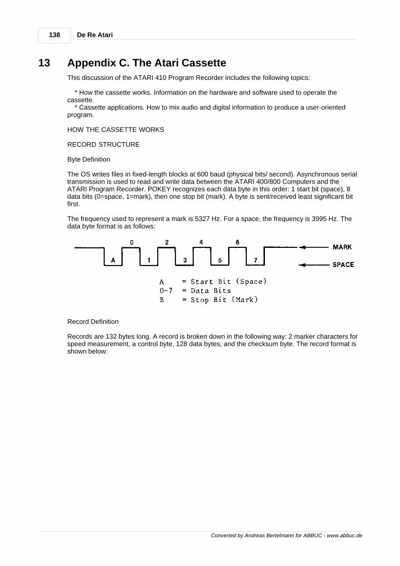
138 De Re Atari
Converted by Andreas Bertelmann for ABBUC - www.abbuc.de
13 Appendix C. The Atari Cassette
This discussion of the ATARI 410 Program Recorder includes the following topics:
* How the cassette works. Information on the hardware and software used to operate thecassette. * Cassette applications. How to mix audio and digital information to produce a user-orientedprogram.
HOW THE CASSETTE WORKS
RECORD STRUCTURE
Byte Definition
The OS writes files in fixed-length blocks at 600 baud (physical bits/ second). Asynchronous serialtransmission is used to read and write data between the ATARI 400/800 Computers and theATARI Program Recorder. POKEY recognizes each data byte in this order: 1 start bit (space), 8data bits (0=space, 1=mark), then one stop bit (mark). A byte is sent/received least significant bitfirst.
The frequency used to represent a mark is 5327 Hz. For a space, the frequency is 3995 Hz. Thedata byte format is as follows:
Record Definition
Records are 132 bytes long. A record is broken down in the following way: 2 marker characters forspeed measurement, a control byte, 128 data bytes, and the checksum byte. The record format isshown below:
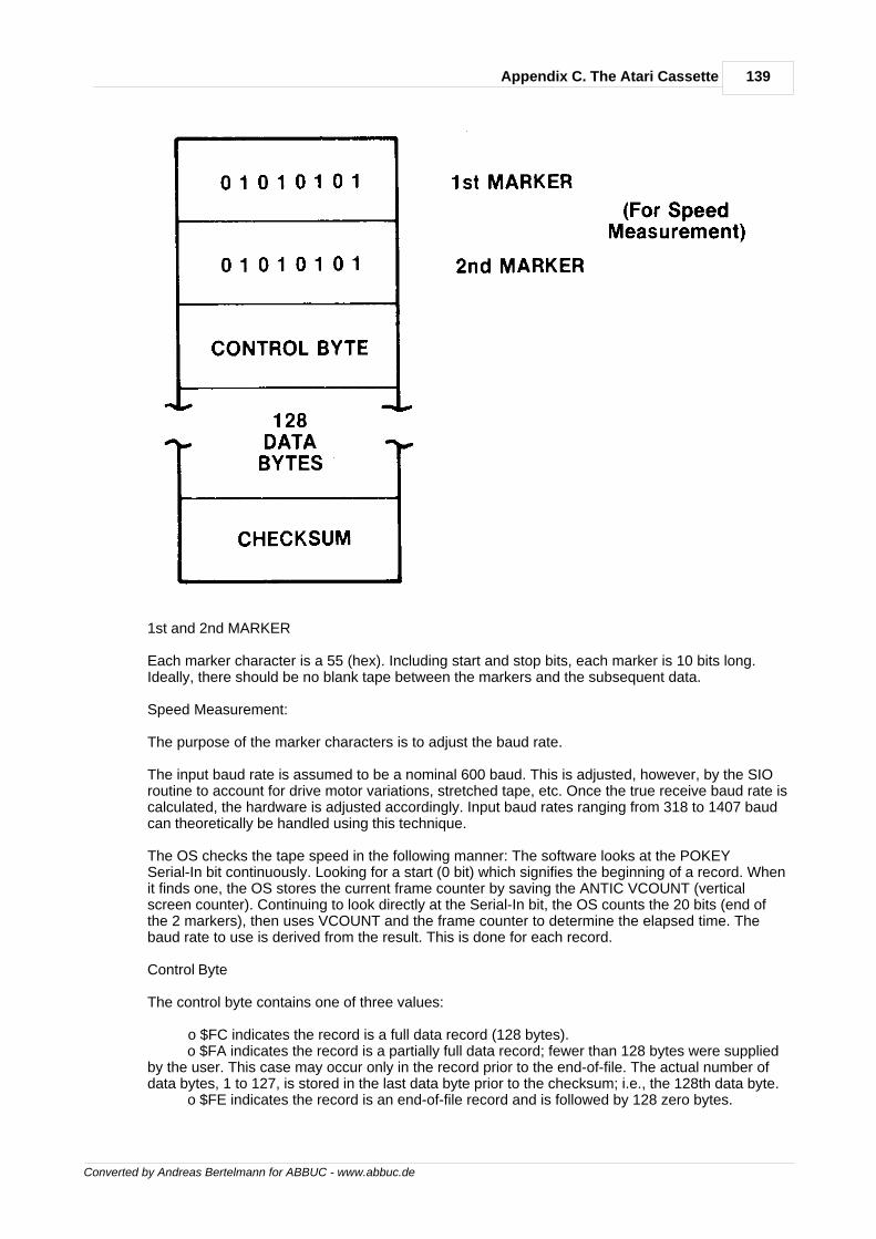
139Appendix C. The Atari Cassette
Converted by Andreas Bertelmann for ABBUC - www.abbuc.de
1st and 2nd MARKER
Each marker character is a 55 (hex). Including start and stop bits, each marker is 10 bits long.Ideally, there should be no blank tape between the markers and the subsequent data.
Speed Measurement:
The purpose of the marker characters is to adjust the baud rate.
The input baud rate is assumed to be a nominal 600 baud. This is adjusted, however, by the SIOroutine to account for drive motor variations, stretched tape, etc. Once the true receive baud rate iscalculated, the hardware is adjusted accordingly. Input baud rates ranging from 318 to 1407 baudcan theoretically be handled using this technique.
The OS checks the tape speed in the following manner: The software looks at the POKEYSerial-In bit continuously. Looking for a start (0 bit) which signifies the beginning of a record. Whenit finds one, the OS stores the current frame counter by saving the ANTIC VCOUNT (verticalscreen counter). Continuing to look directly at the Serial-In bit, the OS counts the 20 bits (end ofthe 2 markers), then uses VCOUNT and the frame counter to determine the elapsed time. Thebaud rate to use is derived from the result. This is done for each record.
Control Byte
The control byte contains one of three values:
o $FC indicates the record is a full data record (128 bytes). o $FA indicates the record is a partially full data record; fewer than 128 bytes were suppliedby the user. This case may occur only in the record prior to the end-of-file. The actual number ofdata bytes, 1 to 127, is stored in the last data byte prior to the checksum; i.e., the 128th data byte. o $FE indicates the record is an end-of-file record and is followed by 128 zero bytes.
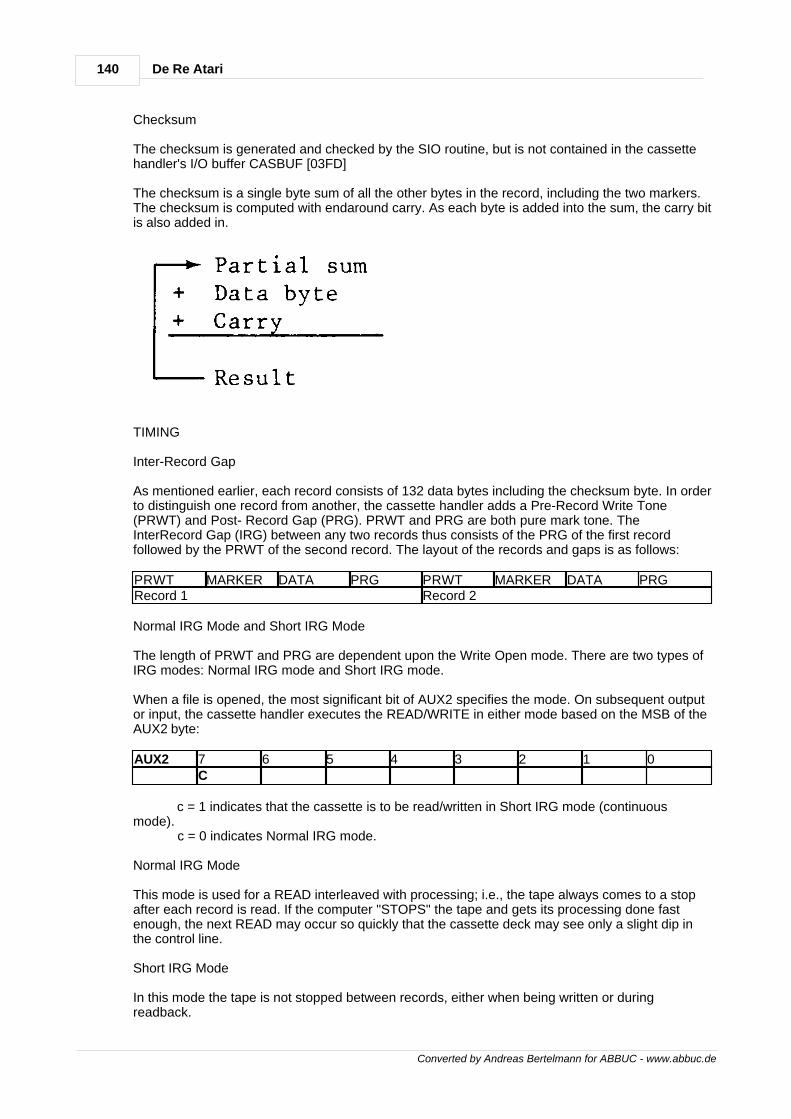
140 De Re Atari
Converted by Andreas Bertelmann for ABBUC - www.abbuc.de
Checksum
The checksum is generated and checked by the SIO routine, but is not contained in the cassettehandler's I/O buffer CASBUF [03FD]
The checksum is a single byte sum of all the other bytes in the record, including the two markers.The checksum is computed with endaround carry. As each byte is added into the sum, the carry bitis also added in.
TIMING
Inter-Record Gap
As mentioned earlier, each record consists of 132 data bytes including the checksum byte. In orderto distinguish one record from another, the cassette handler adds a Pre-Record Write Tone(PRWT) and Post- Record Gap (PRG). PRWT and PRG are both pure mark tone. TheInterRecord Gap (IRG) between any two records thus consists of the PRG of the first recordfollowed by the PRWT of the second record. The layout of the records and gaps is as follows:
PRWT MARKER DATA PRG PRWT MARKER DATA PRGRecord 1 Record 2
Normal IRG Mode and Short IRG Mode
The length of PRWT and PRG are dependent upon the Write Open mode. There are two types ofIRG modes: Normal IRG mode and Short IRG mode.
When a file is opened, the most significant bit of AUX2 specifies the mode. On subsequent outputor input, the cassette handler executes the READ/WRITE in either mode based on the MSB of theAUX2 byte:
AUX2 7 6 5 4 3 2 1 0C
c = 1 indicates that the cassette is to be read/written in Short IRG mode (continuousmode). c = 0 indicates Normal IRG mode.
Normal IRG Mode
This mode is used for a READ interleaved with processing; i.e., the tape always comes to a stopafter each record is read. If the computer "STOPS" the tape and gets its processing done fastenough, the next READ may occur so quickly that the cassette deck may see only a slight dip inthe control line.
Short IRG Mode
In this mode the tape is not stopped between records, either when being written or duringreadback.
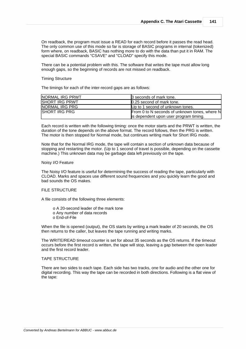
141Appendix C. The Atari Cassette
Converted by Andreas Bertelmann for ABBUC - www.abbuc.de
On readback, the program must issue a READ for each record before it passes the read head.The only common use of this mode so far is storage of BASIC programs in internal (tokenized)form where, on readback, BASIC has nothing more to do with the data than put it in RAM. Thespecial BASIC commands "CSAVE" and "CLOAD" specify this mode.
There can be a potential problem with this. The software that writes the tape must allow longenough gaps, so the beginning of records are not missed on readback.
Timing Structure
The timings for each of the inter-record gaps are as follows:
NORMAL IRG PRWT 3 seconds of mark tone.SHORT IRG PRWT 0.25 second of mark tone.NORMAL IRG PRG Up to 1 second of unknown tones.SHORT IRG PRG From 0 to N seconds of unknown tones, where N
is dependent upon user program timing.
Each record is written with the following timing: once the motor starts and the PRWT is written, theduration of the tone depends on the above format. The record follows, then the PRG is written.The motor is then stopped for Normal mode, but continues writing mark for Short IRG mode.
Note that for the Normal IRG mode, the tape will contain a section of unknown data because ofstopping and restarting the motor. (Up to 1 second of travel is possible, depending on the cassettemachine.) This unknown data may be garbage data left previously on the tape.
Noisy I/O Feature
The Noisy I/O feature is useful for determining the success of reading the tape, particularly withCLOAD. Marks and spaces use different sound frequencies and you quickly learn the good andbad sounds the OS makes.
FILE STRUCTURE
A file consists of the following three elements:
o A 20-second leader of the mark tone o Any number of data records o End-of-File
When the file is opened (output), the OS starts by writing a mark leader of 20 seconds, the OSthen returns to the caller, but leaves the tape running and writing marks.
The WRITE/READ timeout counter is set for about 35 seconds as the OS returns. If the timeoutoccurs before the first record is written, the tape will stop, leaving a gap between the open leaderand the first record leader.
TAPE STRUCTURE
There are two sides to each tape. Each side has two tracks, one for audio and the other one fordigital recording. This way the tape can be recorded in both directions. Following is a flat view ofthe tape:
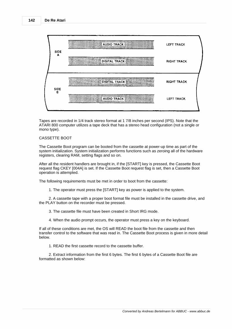
142 De Re Atari
Converted by Andreas Bertelmann for ABBUC - www.abbuc.de
Tapes are recorded in 1/4 track stereo format at 1 7/8 inches per second (IPS). Note that theATARI 800 computer utilizes a tape deck that has a stereo head configuration (not a single ormono type).
CASSETTE BOOT
The Cassette Boot program can be booted from the cassette at power-up time as part of thesystem initialization. System initialization performs functions such as zeroing all of the hardwareregisters, clearing RAM, setting flags and so on.
After all the resident handlers are brought in, if the [START] key is pressed, the Cassette Bootrequest flag CKEY [004A] is set. If the Cassette Boot request flag is set, then a Cassette Bootoperation is attempted.
The following requirements must be met in order to boot from the cassette:
1. The operator must press the [START] key as power is applied to the system.
2. A cassette tape with a proper boot format file must be installed in the cassette drive, andthe PLAY button on the recorder must be pressed.
3. The cassette file must have been created in Short IRG mode.
4. When the audio prompt occurs, the operator must press a key on the keyboard.
If all of these conditions are met, the OS will READ the boot file from the cassette and thentransfer control to the software that was read in. The Cassette Boot process is given in more detailbelow.
1. READ the first cassette record to the cassette buffer.
2. Extract information from the first 6 bytes. The first 6 bytes of a Cassette Boot file areformatted as shown below:
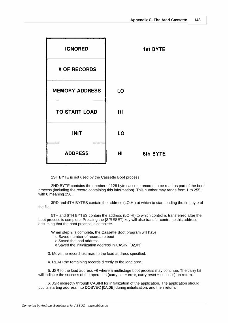
143Appendix C. The Atari Cassette
Converted by Andreas Bertelmann for ABBUC - www.abbuc.de
1ST BYTE is not used by the Cassette Boot process.
2ND BYTE contains the number of 128 byte cassette records to be read as part of the bootprocess (including the record containing this information). This number may range from 1 to 255,with 0 meaning 256.
3RD and 4TH BYTES contain the address (LO,HI) at which to start loading the first byte ofthe file.
5TH and 6TH BYTES contain the address (LO,HI) to which control is transferred after theboot process is complete. Pressing the [S/RESET] key will also transfer control to this addressassuming that the boot process is complete.
When step 2 is complete, the Cassette Boot program will have: o Saved number of records to boot o Saved the load address o Saved the initialization address in CASINI [02,03]
3. Move the record just read to the load address specified.
4. READ the remaining records directly to the load area.
5. JSR to the load address +6 where a multistage boot process may continue. The carry bitwill indicate the success of the operation (carry set = error, carry reset = success) on return.
6. JSR indirectly through CASINI for initialization of the application. The application shouldput its starting address into DOSVEC [0A,0B] during initialization, and then return.
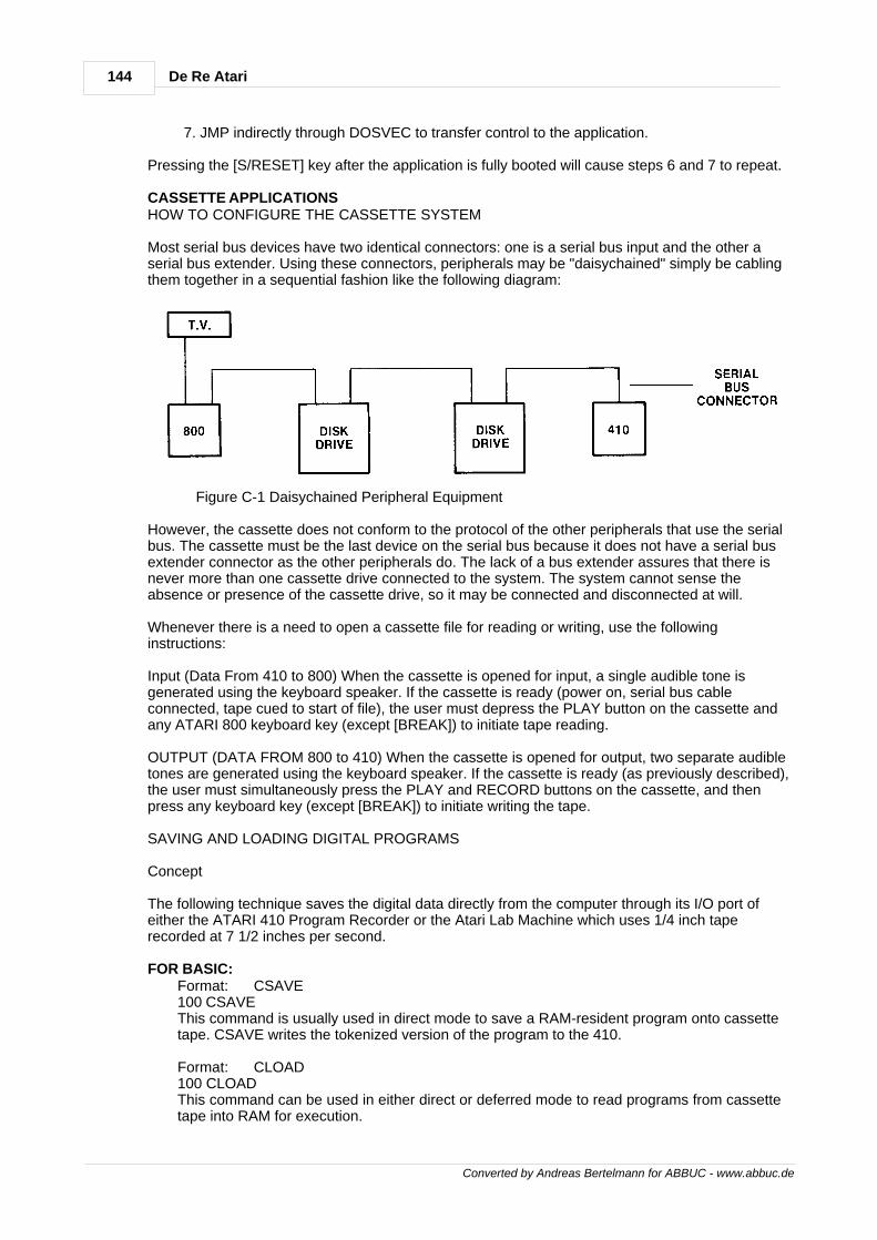
144 De Re Atari
Converted by Andreas Bertelmann for ABBUC - www.abbuc.de
7. JMP indirectly through DOSVEC to transfer control to the application.
Pressing the [S/RESET] key after the application is fully booted will cause steps 6 and 7 to repeat.
CASSETTE APPLICATIONSHOW TO CONFIGURE THE CASSETTE SYSTEM
Most serial bus devices have two identical connectors: one is a serial bus input and the other aserial bus extender. Using these connectors, peripherals may be "daisychained" simply be cablingthem together in a sequential fashion like the following diagram:
Figure C-1 Daisychained Peripheral Equipment
However, the cassette does not conform to the protocol of the other peripherals that use the serialbus. The cassette must be the last device on the serial bus because it does not have a serial busextender connector as the other peripherals do. The lack of a bus extender assures that there isnever more than one cassette drive connected to the system. The system cannot sense theabsence or presence of the cassette drive, so it may be connected and disconnected at will.
Whenever there is a need to open a cassette file for reading or writing, use the followinginstructions:
Input (Data From 410 to 800) When the cassette is opened for input, a single audible tone isgenerated using the keyboard speaker. If the cassette is ready (power on, serial bus cableconnected, tape cued to start of file), the user must depress the PLAY button on the cassette andany ATARI 800 keyboard key (except [BREAK]) to initiate tape reading.
OUTPUT (DATA FROM 800 to 410) When the cassette is opened for output, two separate audibletones are generated using the keyboard speaker. If the cassette is ready (as previously described),the user must simultaneously press the PLAY and RECORD buttons on the cassette, and thenpress any keyboard key (except [BREAK]) to initiate writing the tape.
SAVING AND LOADING DIGITAL PROGRAMS
Concept
The following technique saves the digital data directly from the computer through its I/O port ofeither the ATARI 410 Program Recorder or the Atari Lab Machine which uses 1/4 inch taperecorded at 7 1/2 inches per second.
FOR BASIC:Format: CSAVE100 CSAVEThis command is usually used in direct mode to save a RAM-resident program onto cassettetape. CSAVE writes the tokenized version of the program to the 410.
Format: CLOAD100 CLOADThis command can be used in either direct or deferred mode to read programs from cassettetape into RAM for execution.
145Appendix C. The Atari Cassette
Converted by Andreas Bertelmann for ABBUC - www.abbuc.de
FOR ASSEMBLY LANGUAGE:Source Program
Format: LIST#C:[,XX,YY]This command is used to write assembly source code. The items in the optional brackets[,XX,YY] mean to transfer only lines XX to YY to cassette. If line numbers are not provided,the whole program is listed to cassette.
Format: ENTER#C:This command reads source code from the cassette.
Object ProgramFormat: SAVE#C:The contents of a block of memory, locations XXXX to YYYY, is saved onto cassette.
Format: LOAD#C:This command will load memory with the material that was previously saved. The range ofmemory locations that are filled will be the same as those given in the original SAVEcommand.
SAVING DIGITAL PROGRAMS WITH AUDIO AS BACKGROUND
Concept
This recording technique does not allow any program control over the audio. The audio playspurely as background to help time pass during the monotonous loading process.
Step 1: Follow the digital writing instructions indicated in 2.2 for BASIC and assembly programs;except, this time ATARI standard cassette tape (1 7/8 inches per second) is not used. Because itis hard later for an individual to record audio onto the program recorder, we have to use the ATARIrecording lab machine, which uses 7 1/2 inches per second master tape. The lab machine is amuch more sophisticated recording machine able to record data onto a specified track.
On the lab machine, the recording mode is switched to ON for the right track, so digital is savedonto the right track of the 7 1/2 inch tape.Step 2: Use Step 1 for audio recording, but first rewind the tape to the beginning of the programthen switch the recording mode to ON for left track. This way the audio is recorded onto the lefttrack of the 7 1/2 inch tape.DIGITAL PROGRAMS, AUDIO, SYNC MARK, AND SCREEN MANAGEMENT
Sync Mark Concept
There is no efficient way for the program to detect an audio segment when the cassette is playing.To solve the synchronization problem, Sync Mark is used to carry the signal to inform the programthat an audio segment has been played (an audio segment can be either a piece of music or aninstruction, depending on the application).
More precisely, since audio data has no record structure, Sync Mark recorded on the digital trackis more or less like End-of-Record Mark for audio. For example, once the program senses theSync Mark, the program can decide what to do next, like stop the cassette motor for lengthyprocessing or continue to play the next audio segment.
Step 1: The programmer figures out an audio script for FROG. The script is like this:
(MUSIC) TODAY I AM GOING TO TELL YOU A FAIRY-TALE NAMED "THE PRINCESS ANDTHE FROG." IT IS A SWEET STORY SO DON'T GO AWAY. /
(MUSIC) BEFORE I START MY STORY, I WOULD LIKE TO KNOW WHO I AM TALKINGTO. WHAT IS YOUR NAME? TYPE YOUR NAME AND PRESS CARRIAGE RETURN.(PAUSE)
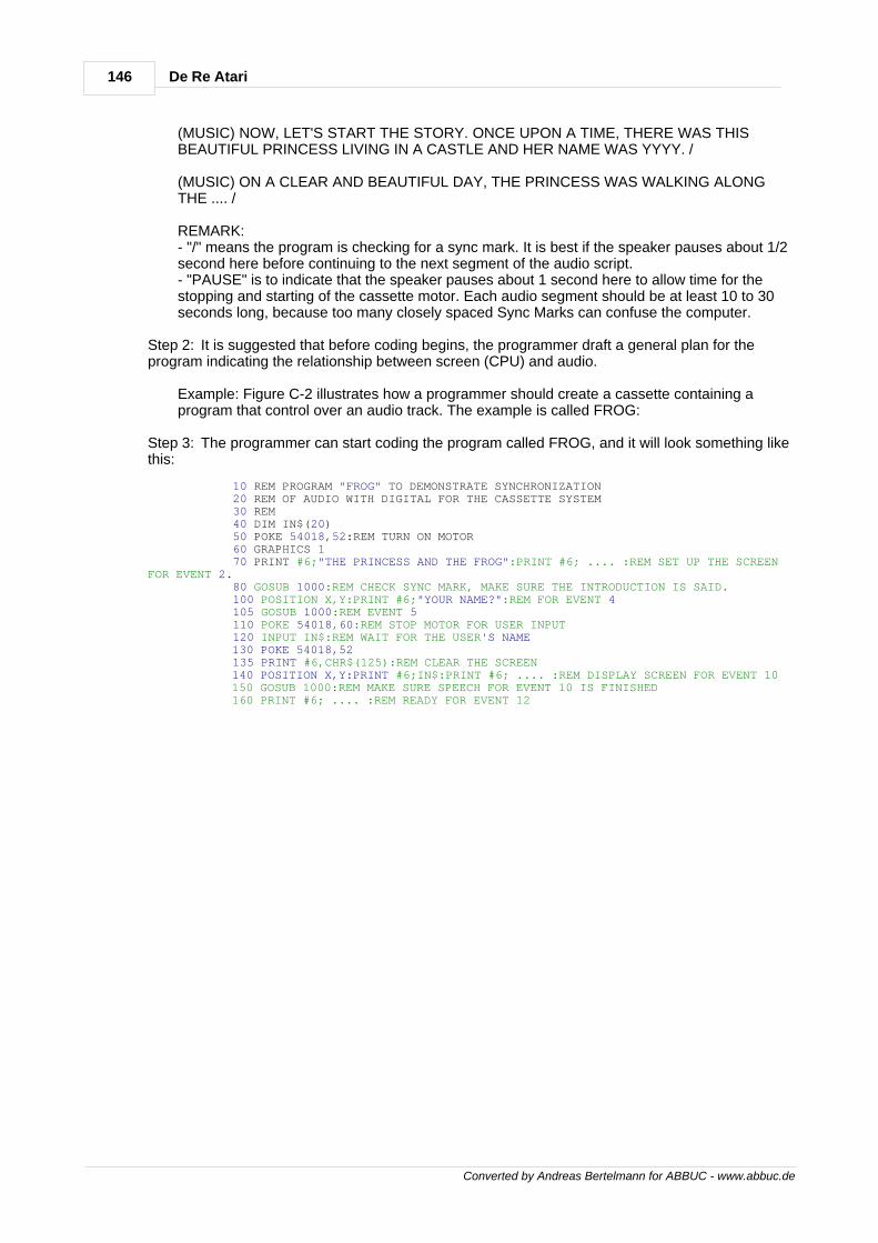
146 De Re Atari
Converted by Andreas Bertelmann for ABBUC - www.abbuc.de
(MUSIC) NOW, LET'S START THE STORY. ONCE UPON A TIME, THERE WAS THISBEAUTIFUL PRINCESS LIVING IN A CASTLE AND HER NAME WAS YYYY. /
(MUSIC) ON A CLEAR AND BEAUTIFUL DAY, THE PRINCESS WAS WALKING ALONGTHE .... /
REMARK:- "/" means the program is checking for a sync mark. It is best if the speaker pauses about 1/2second here before continuing to the next segment of the audio script.- "PAUSE" is to indicate that the speaker pauses about 1 second here to allow time for thestopping and starting of the cassette motor. Each audio segment should be at least 10 to 30seconds long, because too many closely spaced Sync Marks can confuse the computer.
Step 2: It is suggested that before coding begins, the programmer draft a general plan for theprogram indicating the relationship between screen (CPU) and audio.
Example: Figure C-2 illustrates how a programmer should create a cassette containing aprogram that control over an audio track. The example is called FROG:
Step 3: The programmer can start coding the program called FROG, and it will look something likethis:
10 REM PROGRAM "FROG" TO DEMONSTRATE SYNCHRONIZATION 20 REM OF AUDIO WITH DIGITAL FOR THE CASSETTE SYSTEM 30 REM 40 DIM IN$(20) 50 POKE 54018,52:REM TURN ON MOTOR 60 GRAPHICS 1 70 PRINT #6;"THE PRINCESS AND THE FROG":PRINT #6; .... :REM SET UP THE SCREENFOR EVENT 2. 80 GOSUB 1000:REM CHECK SYNC MARK, MAKE SURE THE INTRODUCTION IS SAID. 100 POSITION X,Y:PRINT #6;"YOUR NAME?":REM FOR EVENT 4 105 GOSUB 1000:REM EVENT 5 110 POKE 54018,60:REM STOP MOTOR FOR USER INPUT 120 INPUT IN$:REM WAIT FOR THE USER'S NAME 130 POKE 54018,52 135 PRINT #6,CHR$(125):REM CLEAR THE SCREEN 140 POSITION X,Y:PRINT #6;IN$:PRINT #6; .... :REM DISPLAY SCREEN FOR EVENT 10 150 GOSUB 1000:REM MAKE SURE SPEECH FOR EVENT 10 IS FINISHED 160 PRINT #6; .... :REM READY FOR EVENT 12
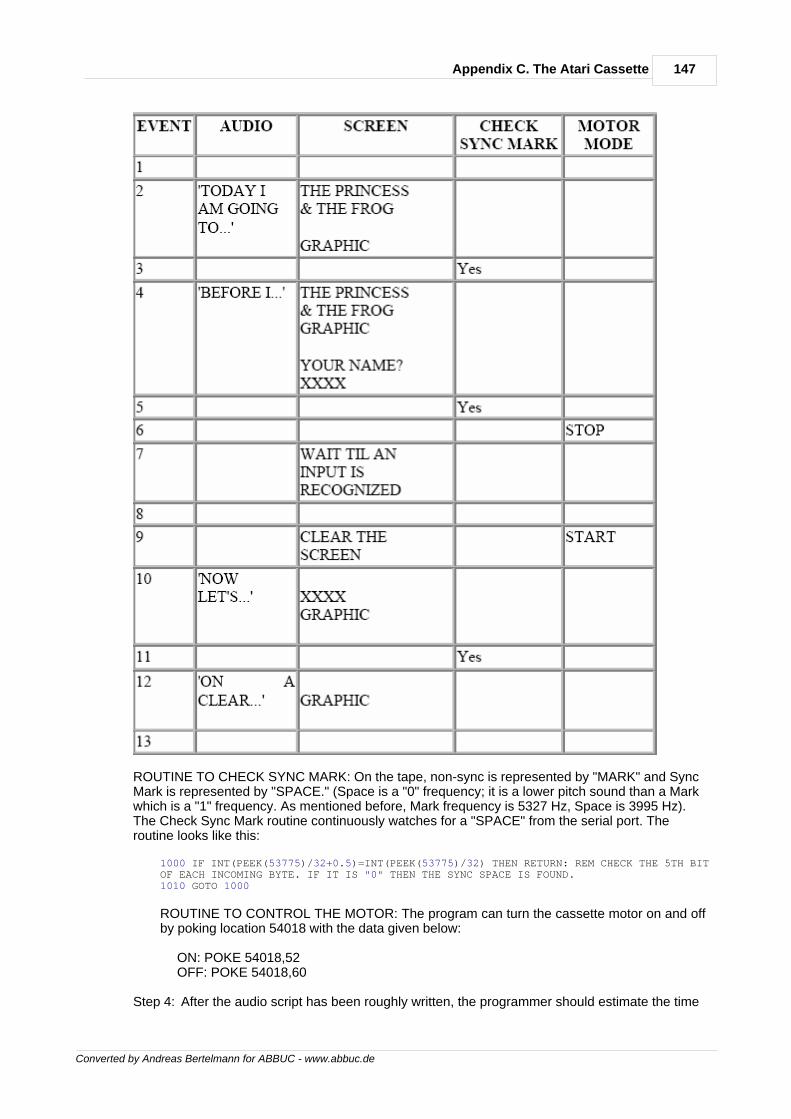
147Appendix C. The Atari Cassette
Converted by Andreas Bertelmann for ABBUC - www.abbuc.de
ROUTINE TO CHECK SYNC MARK: On the tape, non-sync is represented by "MARK" and SyncMark is represented by "SPACE." (Space is a "0" frequency; it is a lower pitch sound than a Markwhich is a "1" frequency. As mentioned before, Mark frequency is 5327 Hz, Space is 3995 Hz).The Check Sync Mark routine continuously watches for a "SPACE" from the serial port. Theroutine looks like this:
1000 IF INT(PEEK(53775)/32+0.5)=INT(PEEK(53775)/32) THEN RETURN: REM CHECK THE 5TH BITOF EACH INCOMING BYTE. IF IT IS "0" THEN THE SYNC SPACE IS FOUND.1010 GOTO 1000
ROUTINE TO CONTROL THE MOTOR: The program can turn the cassette motor on and offby poking location 54018 with the data given below:
ON: POKE 54018,52 OFF: POKE 54018,60
Step 4: After the audio script has been roughly written, the programmer should estimate the time
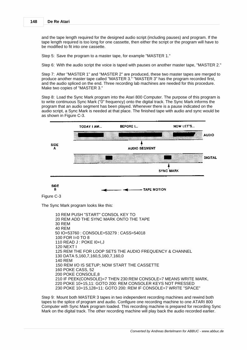
148 De Re Atari
Converted by Andreas Bertelmann for ABBUC - www.abbuc.de
and the tape length required for the designed audio script (including pauses) and program. If thetape length required is too long for one cassette, then either the script or the program will have tobe modified to fit into one cassette.
Step 5: Save the program to a master tape, for example "MASTER 1."
Step 6: With the audio script the voice is taped with pauses on another master tape, "MASTER 2."
Step 7: After "MASTER 1" and "MASTER 2" are produced, these two master tapes are merged toproduce another master tape called "MASTER 3." "MASTER 3" has the program recorded first,and the audio spliced on the end. Three recording lab machines are needed for this procedure.Make two copies of "MASTER 3."
Step 8: Load the Sync Mark program into the Atari 800 Computer. The purpose of this program isto write continuous Sync Mark ("0" frequency) onto the digital track. The Sync Mark informs theprogram that an audio segment has been played. Whenever there is a pause indicated on theaudio script, a Sync Mark is needed at that place. The finished tape with audio and sync would beas shown in Figure C-3.
Figure C-3
The Sync Mark program looks like this:
10 REM PUSH "START" CONSOL KEY TO 20 REM ADD THE SYNC MARK ONTO THE TAPE 30 REM 40 REM 50 IO=53760 : CONSOLE=53279 : CASS=54018 100 FOR I=0 TO 8 110 READ J : POKE I0+I,J 120 NEXT I 125 REM THE FOR LOOP SETS THE AUDIO FREQUENCY & CHANNEL 130 DATA 5,160,7,160,5,160,7,160,0 140 REM 150 REM I/O IS SETUP; NOW START THE CASSETTE 160 POKE CASS, 52 200 POKE CONSOLE,8 210 IF PEEK(CONSOLE)=7 THEN 230:REM CONSOLE=7 MEANS WRITE MARK, 220 POKE 10+15,11: GOTO 200: REM CONSOLER KEYS NOT PRESSED 230 POKE 10+15,128+11: GOTO 200: REM IF CONSOLE=7 WRITE "SPACE"
Step 9: Mount both MASTER 3 tapes in two independent recording machines and rewind bothtapes to the splice of program and audio. Configure one recording machine to one ATARI 800Computer with Sync Mark program loaded. This recording machine is prepared for recording SyncMark on the digital track. The other recording machine will play back the audio recorded earlier.
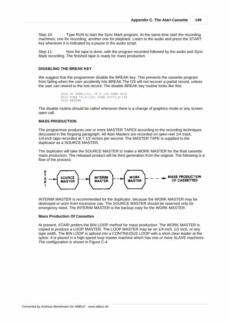
149Appendix C. The Atari Cassette
Converted by Andreas Bertelmann for ABBUC - www.abbuc.de
Step 10: Type RUN to start the Sync Mark program. At the same time start the recordingmachines, one for recording, another one for playback. Listen to the audio and press the STARTkey whenever it is indicated by a pause in the audio script.
Step 11: Now the tape is done, with the program recorded followed by the audio and SyncMark recording. The finished tape is ready for mass production.
DISABLING THE BREAK KEY
We suggest that the programmer disable the BREAK key. This prevents the cassette programfrom failing when the user accidently hits BREAK The OS will not recover a partial record, unlessthe user can rewind to the lost record. The disable BREAK key routine looks like this:
4000 X= PEEK(16): IF X 128 THEN 4020 4010 POKE 16,X-128: POKE 53774,X-128 4020 RETURN
The disable routine should be called whenever there is a change of graphics mode or any screenopen call.
MASS PRODUCTION
The programmer produces one or more MASTER TAPES according to the recording techniquesdiscussed in the forgoing paragraph. All Atari Masters are recorded on open-reel 1/4 track,1/4-inch tape recorded at 7 1/2 inches per second. The MASTER TAPE is supplied to theduplicator as a SOURCE MASTER.
The duplicator will take the SOURCE MASTER to make a WORK MASTER for the final cassettemass production. The released product will be third generation from the original. The following is aflow of the process:
INTERIM MASTER is recommended for the duplicator, because the WORK MASTER may bedestroyed or worn from excessive use. The SOURCE MASTER should be reserved only foremergency need. The INTERIM MASTER is the backup copy for the WORK MASTER.
Mass Production Of Cassettes
At present, ATARI prefers the BIN LOOP method for mass production: The WORK MASTER iscopied to produce a LOOP MASTER. The LOOP MASTER may be on 1/4 inch, 1/2 inch, or anytape width. The BIN LOOP is spliced into a CONTINUOUS LOOP with a short clear leader at thesplice. It is placed in a high-speed loop master machine which has one or more SLAVE machines.The configuration is shown in Figure C-4
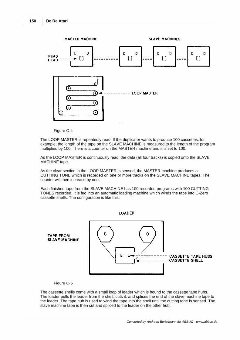
150 De Re Atari
Converted by Andreas Bertelmann for ABBUC - www.abbuc.de
Figure C-4
The LOOP MASTER is repeatedly read. If the duplicator wants to produce 100 cassettes, forexample, the length of the tape on the SLAVE MACHINE is measured to the length of the programmultiplied by 100. There is a counter on the MASTER machine and it is set to 100.
As the LOOP MASTER is continuously read, the data (all four tracks) is copied onto the SLAVEMACHINE tape.
As the clear section in the LOOP MASTER is sensed, the MASTER machine produces aCUTTING TONE which is recorded on one or more tracks on the SLAVE MACHINE tapes. Thecounter will then increase by one.
Each finished tape from the SLAVE MACHINE has 100 recorded programs with 100 CUTTINGTONES recorded. It is fed into an automatic loading machine which winds the tape into C-Zerocassette shells. The configuration is like this:
Figure C-5
The cassette shells come with a small loop of leader which is bound to the cassette tape hubs.The loader pulls the leader from the shell, cuts it, and splices the end of the slave machine tape tothe leader. The tape hub is used to wind the tape into the shell until the cutting tone is sensed. Theslave machine tape is then cut and spliced to the leader on the other hub.

151Appendix C. The Atari Cassette
Converted by Andreas Bertelmann for ABBUC - www.abbuc.de
The cassette shell is removed either manually or mechanically from the loader and the tape in thecassette shell is fully wound. The next cassette shell is loaded by the same process.
Quality Control Testing
Any time that a production run is created, samples must be taken from it and verified before it isapproved and released.The QC testing is done normally by taking the first and the last cassette produced. Atari mustreceive at least 10 samples from each mass production for each master released.

Converted by Andreas Bertelmann for ABBUC - www.abbuc.de
Appendix D.Television
Artifacts
Chapter
XIV
153Appendix D. Television Artifacts
Converted by Andreas Bertelmann for ABBUC - www.abbuc.de
14 Appendix D. Television Artifacts
This section discusses how to get multiple colors out of a single color graphics mode through theuse of television artifacts.
The ANTIC modes with which this can be accomplished are 2,3, and 15. ANTIC mode 2corresponds to BASIC mode 0, ANTIC mode 15 is BASIC mode 8, and ANTIC mode 3 has nocorresponding BASIC mode. Each of these modes has a pixel resolution of one half color clock byone scan line. They are generally considered to have one color and two luminances. With the useof artifacts, pixels of four different colors can be displayed on the screen in each of these modes.
The term TV artifacts refers to a spot or "pixel" on the screen that displays a different color thanthe one assigned to it.
A simple example of artifacts using the ATARI Computer is shown by entering the following lines:
GRAPHICS 8 COLOR 1 POKE 710,0 PLOT 60,60 PLOT 63,60
These statements will plot two points on a black background; however each pixel will have adifferent color.
To understand the cause of these differing colors one must first understand that all the displayinformation for the television display is contained in a modulated television signal.
The two major components of this signal are the luminance, or brightness, and the color, or tint.The luminance information is the primary signal, containing not only the brightness data but alsothe horizontal and vertical syncs and blanks. The color signal contains the color information and iscombined or modulated into the luminance waveform.
The luminance of a pixel on the screen is directly dependent on the amplitude of the luminancesignal at that point. The higher the amplitude of the signal, the brighter the pixel.
The color information, however, is a phase shifted signal. A phaseshifted signal is a constantlyoscillating waveform that has been delayed by some amount of time relative to a reference signal,and this time delay is translated into the color.
The color signal oscillates at a constant rate of about 3.579 MHz, thus defining the highesthorizontal color resolution of a television set. This appears on the screen in the form of 160 visiblecolor cycles across one scan line. (There are actually 228 color cycles including the horizontalblank and sync, and any overscan.)
The term "color clock" refers to one color cycle and is the term generally used throughout theATARI documentation to describe units of measurement across the screen. The graphics mode 7is an example of one color clock resolution, where each color clock pixel can be a different color.(There are microprocessor limitations though.)
Atari also offers a "high resolution" mode (GRAPHICS 8) that displays 320 pixels across one line.This is generated by varying the amplitude of the luminance signal at about 7.16 MHz, which istwice the color frequency.
Since the two signals are theoretically independent, one should be able to assign a "background"color to be displayed and then merely vary the luminance on a pixel-by-pixel basis. This in fact isthe way mode 8 works, the "background" color coming from playfield register 2, and theluminances coming from both playfield registers 1 and 2.
The problem is that in practice the color and luminance signals are not independent. They are partof a modulated signal that must be demodulated to be used. Since the luminance is the primarysignal, whenever it changes, it also forces a change in the color phase shift. For one or more color
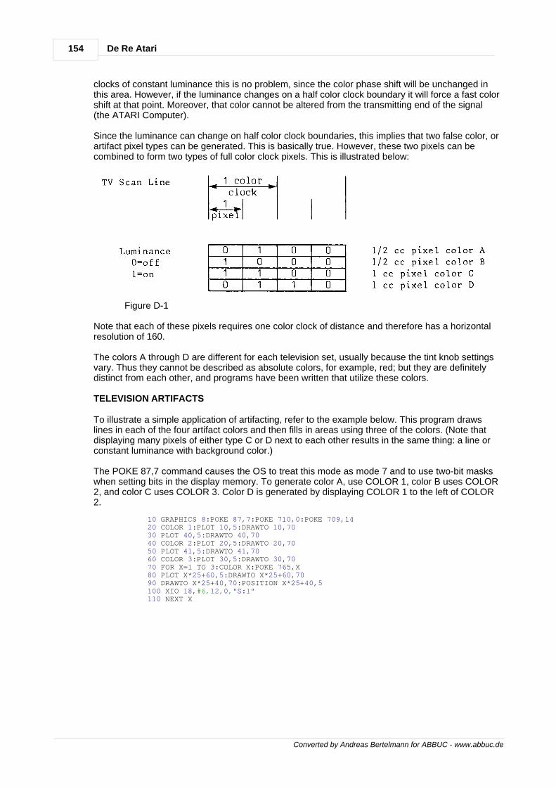
154 De Re Atari
Converted by Andreas Bertelmann for ABBUC - www.abbuc.de
clocks of constant luminance this is no problem, since the color phase shift will be unchanged inthis area. However, if the luminance changes on a half color clock boundary it will force a fast colorshift at that point. Moreover, that color cannot be altered from the transmitting end of the signal(the ATARI Computer).
Since the luminance can change on half color clock boundaries, this implies that two false color, orartifact pixel types can be generated. This is basically true. However, these two pixels can becombined to form two types of full color clock pixels. This is illustrated below:
Figure D-1
Note that each of these pixels requires one color clock of distance and therefore has a horizontalresolution of 160.
The colors A through D are different for each television set, usually because the tint knob settingsvary. Thus they cannot be described as absolute colors, for example, red; but they are definitelydistinct from each other, and programs have been written that utilize these colors.
TELEVISION ARTIFACTS
To illustrate a simple application of artifacting, refer to the example below. This program drawslines in each of the four artifact colors and then fills in areas using three of the colors. (Note thatdisplaying many pixels of either type C or D next to each other results in the same thing: a line orconstant luminance with background color.)
The POKE 87,7 command causes the OS to treat this mode as mode 7 and to use two-bit maskswhen setting bits in the display memory. To generate color A, use COLOR 1, color B uses COLOR2, and color C uses COLOR 3. Color D is generated by displaying COLOR 1 to the left of COLOR2.
10 GRAPHICS 8:POKE 87,7:POKE 710,0:POKE 709,14 20 COLOR 1:PLOT 10,5:DRAWTO 10,70 30 PLOT 40,5:DRAWTO 40,70 40 COLOR 2:PLOT 20,5:DRAWTO 20,70 50 PLOT 41,5:DRAWTO 41,70 60 COLOR 3:PLOT 30,5:DRAWTO 30,70 70 FOR X=l TO 3:COLOR X:POKE 765,X 80 PLOT X*25+60,5:DRAWTO X*25+60,70 90 DRAWTO X*25+40,70:POSITION X*25+40,5 100 XIO 18,#6,12,0,"S:l" 110 NEXT X

Converted by Andreas Bertelmann for ABBUC - www.abbuc.de
Appendix E.GTIA
Chapter
XV
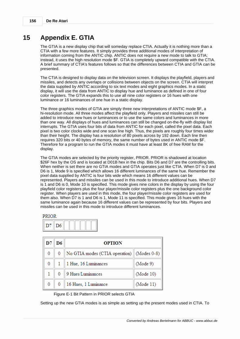
156 De Re Atari
Converted by Andreas Bertelmann for ABBUC - www.abbuc.de
15 Appendix E. GTIA
The GTIA is a new display chip that will someday replace CTIA. Actually it is nothing more than aCTIA with a few more features. It simply provides three additional modes of interpretation ofinformation coming from the ANTIC chip. ANTIC does not require a new mode to talk to GTIA;instead, it uses the high resolution mode $F. GTIA is completely upward compatible with the CTIA.A brief summary of CTIA's features follows so that the differences between CTIA and GTIA can bepresented.
The CTIA is designed to display data on the television screen. It displays the playfield, players andmissiles, and detects any overlaps or collisions between objects on the screen. CTIA will interpretthe data supplied by ANTIC according to six text modes and eight graphics modes. In a staticdisplay, it will use the data from ANTIC to display hue and luminance as defined in one of fourcolor registers. The GTIA expands this to use all nine color registers or 16 hues with oneluminance or 16 luminances of one hue in a static display.
The three graphics modes of GTIA are simply three new interpretations of ANTIC mode $F, ahi-resolution mode. All three modes affect the playfield only. Players and missiles can still beadded to introduce new hues or luminances or to use the same colors and luminances in morethan one way. All displays of hues and luminances can still be changed on-the-fly with display listinterrupts. The GTIA uses four bits of data from ANTIC for each pixel, called the pixel data. Eachpixel is two color clocks wide and one scan line high. Thus, the pixels are roughly four times widerthan their height. The display has a resolution of 80 pixels across by 192 down. Each line thenrequires 320 bits or 40 bytes of memory, the same number of bytes used in ANTIC mode $F.Therefore for a program to run the GTIA modes it must have at least 8K of free RAM for thedisplay.
The GTIA modes are selected by the priority register, PRIOR. PRIOR is shadowed at location$26F hex by the OS and is located at D01B hex in the chip. Bits D6 and D7 are the controlling bits.When neither is set there are no GTIA modes and GTIA operates just like CTIA. When D7 is 0 andD6 is 1, Mode 9 is specified which allows 16 different luminances of the same hue. Remember thepixel data supplied by ANTIC is four bits wide which means 16 different values can berepresented. Players and missiles can be used in this mode to introduce additional hues. When D7is 1 and D6 is 0, Mode 10 is specified. This mode gives nine colors in the display by using the fourplayfield color registers plus the four player/missile color registers plus the one background colorregister. When players are used in this mode, the four player/missile color registers are used forthem also. When D7 is 1 and D6 is 1, Mode 11 is specified. This mode gives 16 hues with thesame luminance again because 16 different values can be represented by four bits. Players andmissiles can be used in this mode to introduce different luminances.
Figure E-1 Bit Pattern in PRIOR selects GTIA
Setting up the new GTIA modes is as simple as setting up the present modes used in CTIA. To
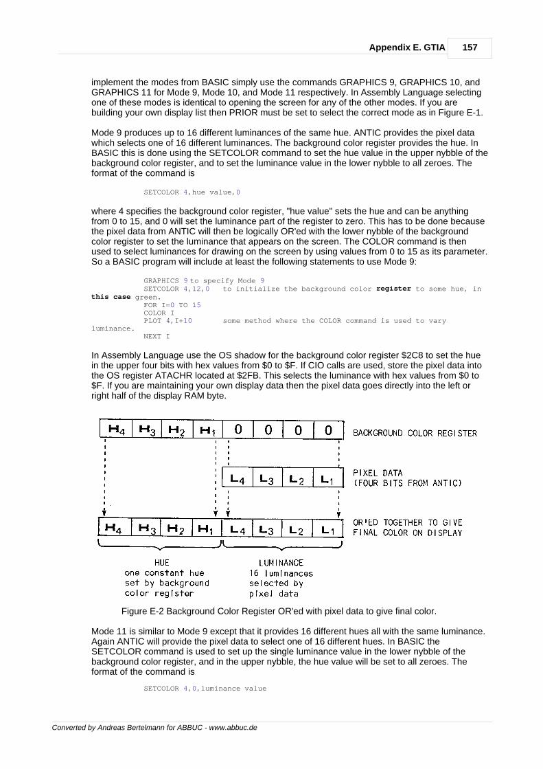
157Appendix E. GTIA
Converted by Andreas Bertelmann for ABBUC - www.abbuc.de
implement the modes from BASIC simply use the commands GRAPHICS 9, GRAPHICS 10, andGRAPHICS 11 for Mode 9, Mode 10, and Mode 11 respectively. In Assembly Language selectingone of these modes is identical to opening the screen for any of the other modes. If you arebuilding your own display list then PRIOR must be set to select the correct mode as in Figure E-1.
Mode 9 produces up to 16 different luminances of the same hue. ANTIC provides the pixel datawhich selects one of 16 different luminances. The background color register provides the hue. InBASIC this is done using the SETCOLOR command to set the hue value in the upper nybble of thebackground color register, and to set the luminance value in the lower nybble to all zeroes. Theformat of the command is
SETCOLOR 4,hue value,0
where 4 specifies the background color register, "hue value" sets the hue and can be anythingfrom 0 to 15, and 0 will set the luminance part of the register to zero. This has to be done becausethe pixel data from ANTIC will then be logically OR'ed with the lower nybble of the backgroundcolor register to set the luminance that appears on the screen. The COLOR command is thenused to select luminances for drawing on the screen by using values from 0 to 15 as its parameter.So a BASIC program will include at least the following statements to use Mode 9:
GRAPHICS 9 to specify Mode 9 SETCOLOR 4,12,0 to initialize the background color register to some hue, inthis case green. FOR I=0 TO 15 COLOR I PLOT 4,I+10 some method where the COLOR command is used to varyluminance. NEXT I
In Assembly Language use the OS shadow for the background color register $2C8 to set the huein the upper four bits with hex values from $0 to $F. If CIO calls are used, store the pixel data intothe OS register ATACHR located at $2FB. This selects the luminance with hex values from $0 to$F. If you are maintaining your own display data then the pixel data goes directly into the left orright half of the display RAM byte.
Figure E-2 Background Color Register OR'ed with pixel data to give final color.
Mode 11 is similar to Mode 9 except that it provides 16 different hues all with the same luminance.Again ANTIC will provide the pixel data to select one of 16 different hues. In BASIC theSETCOLOR command is used to set up the single luminance value in the lower nybble of thebackground color register, and in the upper nybble, the hue value will be set to all zeroes. Theformat of the command is
SETCOLOR 4,0,luminance value
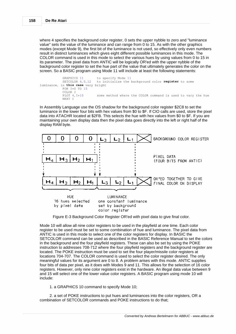
158 De Re Atari
Converted by Andreas Bertelmann for ABBUC - www.abbuc.de
where 4 specifies the background color register, 0 sets the upper nybble to zero and "luminancevalue" sets the value of the luminance and can range from 0 to 15. As with the other graphicsmodes (except Mode 9), the first bit of the luminance is not used, so effectively only even numbersresult in distinct luminances which gives eight different possible luminances in this mode. TheCOLOR command is used in this mode to select the various hues by using values from 0 to 15 inits parameter. The pixel data from ANTIC will be logically OR'ed with the upper nybble of thebackground color register to set the hue part of the value that ultimately generates the color on thescreen. So a BASIC program using Mode 11 will include at least the following statements:
GRAPHICS 11 to specify Mode 11 SETCOLOR 4,0,12 to initialize the background color register to someluminance, in this case very bright FOR I=0 TO 15 COLOR I PLOT 4,I+10 some method where the COLOR command is used to vary the hue NEXT I
In Assembly Language use the OS shadow for the background color register $2C8 to set theluminance in the lower four bits with hex values from $0 to $F. If CIO calls are used, store the pixeldata into ATACHR located at $2FB. This selects the hue with hex values from $0 to $F. If you aremaintaining your own display data then the pixel data goes directly into the left or right half of thedisplay RAM byte.
Figure E-3 Background Color Register OR'ed with pixel data to give final color.
Mode 10 will allow all nine color registers to be used in the playfield at one time. Each colorregister to be used must be set to some combination of hue and luminance. The pixel data fromANTIC is used in this mode to select one of the color registers for display. In BASIC theSETCOLOR command can be used as described in the BASIC Reference Manual to set the colorsin the background and the four playfield registers. These can also be set by using the POKEinstruction to addresses 708-712 where the four playfield registers and the background register arelocated. The POKE instruction must be used to set the four player/missile color registers atlocations 704-707. The COLOR command is used to select the color register desired. The onlymeaningful values for its argument are 0 to 8. A problem arises with this mode. ANTIC suppliesfour bits of data per pixel, as it does with Modes 9 and 11. This allows for the selection of 16 colorregisters. However, only nine color registers exist in the hardware. An illegal data value between 9and 15 will select one of the lower value color registers. A BASIC program using mode 10 willinclude:
1. a GRAPHICS 10 command to specify Mode 10;
2. a set of POKE instructions to put hues and luminances into the color registers, OR acombination of SETCOLOR commands and POKE instructions to do that;
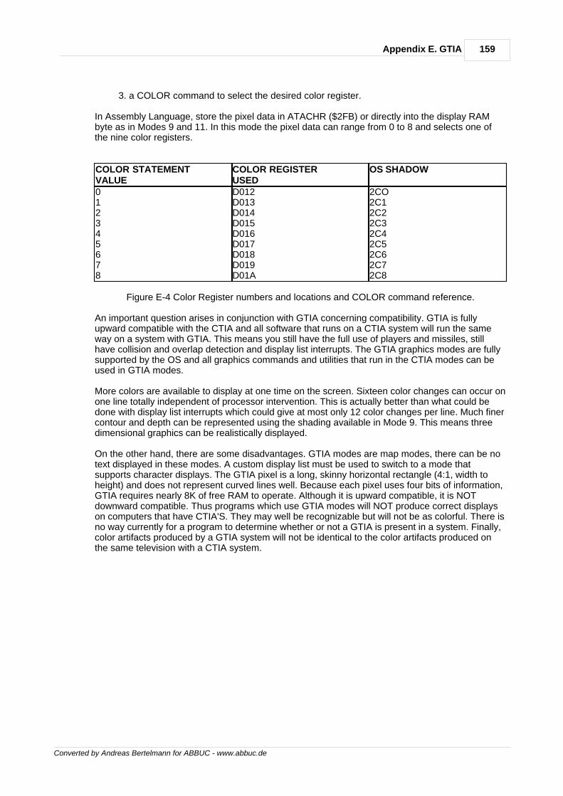
159Appendix E. GTIA
Converted by Andreas Bertelmann for ABBUC - www.abbuc.de
3. a COLOR command to select the desired color register.
In Assembly Language, store the pixel data in ATACHR ($2FB) or directly into the display RAMbyte as in Modes 9 and 11. In this mode the pixel data can range from 0 to 8 and selects one ofthe nine color registers.
COLOR STATEMENTVALUE
COLOR REGISTERUSED
OS SHADOW
012345678
D012D013D014D015D016D017D018D019D01A
2CO2C12C22C32C42C52C62C72C8
Figure E-4 Color Register numbers and locations and COLOR command reference.
An important question arises in conjunction with GTIA concerning compatibility. GTIA is fullyupward compatible with the CTIA and all software that runs on a CTIA system will run the sameway on a system with GTIA. This means you still have the full use of players and missiles, stillhave collision and overlap detection and display list interrupts. The GTIA graphics modes are fullysupported by the OS and all graphics commands and utilities that run in the CTIA modes can beused in GTIA modes.
More colors are available to display at one time on the screen. Sixteen color changes can occur onone line totally independent of processor intervention. This is actually better than what could bedone with display list interrupts which could give at most only 12 color changes per line. Much finercontour and depth can be represented using the shading available in Mode 9. This means threedimensional graphics can be realistically displayed.
On the other hand, there are some disadvantages. GTIA modes are map modes, there can be notext displayed in these modes. A custom display list must be used to switch to a mode thatsupports character displays. The GTIA pixel is a long, skinny horizontal rectangle (4:1, width toheight) and does not represent curved lines well. Because each pixel uses four bits of information,GTIA requires nearly 8K of free RAM to operate. Although it is upward compatible, it is NOTdownward compatible. Thus programs which use GTIA modes will NOT produce correct displayson computers that have CTIA'S. They may well be recognizable but will not be as colorful. There isno way currently for a program to determine whether or not a GTIA is present in a system. Finally,color artifacts produced by a GTIA system will not be identical to the color artifacts produced onthe same television with a CTIA system.

Converted by Andreas Bertelmann for ABBUC - www.abbuc.de
Glossary
Chapter
XVI
161Glossary
Converted by Andreas Bertelmann for ABBUC - www.abbuc.de
16 Glossary
$This symbol in front of a number indicates that the number should be interpreted as hexadecimal.
ANTICThis is a separate microprocessor, contained within the ATARI 400/800 Computers, which isdedicated to the television display. ANTIC is user- programmable with an instruction set, aprogram (the "display list"), and data (the "display memory").
ATTRACT MODEThis is a feature provided by the operating system which, after nine minutes without a key beingpressed, cycles the colors on the screen through random hues at lowered luminances. Thisensures that a computer left unattended for several hours doesn't burn a static image into thetelevision screen.
BACKGROUNDThe area of the television screen display upon which player-missile graphics objects or playfieldobjects and/or text are projected. Background has its own user-definable color.
BCDAcronym for Binary Coded Decimal. A numbering system in which each number is broken into asequence of decimal digits. These decimal digits are then coded into binary, a task which requiresfour bits per digit, and stored in the resultant form. In the ATARI Computer, two such digits arestored in each 8-bit byte.
BORDERIn BASIC Mode 0, this is the area of the television screen display which is formed by the fouredges of the screen. The border takes background color.
BRKKEYA flag set when the OS senses that the BREAK key is typed. BRKKEY'S normal value is $FF -- if itchanges, then the BREAK key has been pressed.
BYTE COUNTThis is the file pointer's position within a sector on diskette.
CASSETTE BOOT FILEA standard or user-created file which boots from cassette at power-up or SYSTEM RESET.
CHARACTER GRAPHICSThe technique of redefining the individual characters of a character set to form graphics imagesinstead of text characters.
CHARACTER IMAGEThe unique 8 X 8 pixel grid which defines a particular character's shape.
CHARACTER MODEThis is a specific type of ANTIC display mode which displays screen display memory data bytes ascharacters, using a character set. There are six ANTIC character modes, three of which areaccessible from BASIC.
CHARACTER NAME BYTEA one-byte ANTIC display memory value which selects a unique character within the currentcharacter set using the character's sequential position in that set.
CHARACTER SET INDIRECTIONThe technique of specifying to ANTIC a particular character set to be used by placing that set'sbeginning page address into CHBAS.
CHBAS
162 De Re Atari
Converted by Andreas Bertelmann for ABBUC - www.abbuc.de
The OS shadow location which ANTIC uses to find the current character set which is to be usedfor character display modes. CHBAS is at decimal address 756.
CHECKSUMThis is a single byte sum of all the bytes in a record (either disk I/O or cassette I/O). For cassetteI/O, this includes addition of the two marker characters, computed with end-around carry.
CIOAcronym for Central I/O system routine. CIO routes I/O control data to the correct device handlerand then passes control to the handler. CIO is also the common entry point for most of the OS I/Ofunctions.
COARSE SCROLLINGThe process of altering the display list LMS (Load Memory Scan) address bytes in order tovertically or horizontally scroll the screen image, one byte at a time. This is accomplished byadding 1 to or subtracting 1 from the LMS address bytes.
COLDSTARTSynonym for the power-up process which performs a series of system database initializationswhen the computer power switch is turned on. After coldstart, the system surrenders control to theuser.
COLLISIONThis occurs when a player or missile image coincides with another image. There are 60 possiblecollisions and each one has a bit assigned to it that can be checked. These bits are mapped into16 registers in CTIA (with only the lower 4 bits used).
COLOROne of 128 values obtained from a hue-luminance combination which is stored in a color register.
COLOR CLOCKThe standard unit of horizontal distance on the television screen. There are 228 color clocks in ahorizontal scan line, but only 160 are displayed in a normal width playfield.
COLOR REGISTERA hardware register (with corresponding OS shadow location) used to define the color for variousportions of the screen display. There are nine color registers available on the ATARI HomeComputer.
COLOR REGISTER INDIRECTIONThe technique of specifying a particular color by pointing to its color register rather than directlyspecifying it.
COLOR SIGNALThis contains the color information which is combined with the primary signal to form themodulating television signal. The color signal oscillates at 3.579 Mhz.
COLRSHA zero-page location ($4F) set up and updated by the OS during vertical blank interrupts forATTRACT mode processing. When ATTRACT mode is in force, COLRSH is given a new randomvalue every 4 seconds.
COMMANDIn BASIC, this is the first executable token of a BASIC statement that tells BASIC to interpret thetokens that follow in a particular way.
CONSTANTIn BASIC, this is a 6-byte BCD value preceded by a special token. This value remains unchangedthroughout the program execution.
CONTROL BYTE
163Glossary
Converted by Andreas Bertelmann for ABBUC - www.abbuc.de
In cassette I/O, this is part of every record. It contains one of three possible values.
CTIAA television interface chip which is controlled primarily by ANTIC. CTIA converts ANTIC's digitalcommands into a signal that is sent to the television.
CURRENT STATEMENTIn BASIC, this is the current token within a line of the Statement Table.
CYCLE STEALINGThis occurs when ANTIC halts 6502 processing in order to perform DMA functions for memoryrefresh and screen display purposes.
CYCLIC ANIMATIONThe technique of repetitively flipping through colors, graphics images, or character graphics sets toanimate screen images.
DCBAcronym for Device Control Block. The DCB is used by the I/O subsystem to communicatebetween the device handier and SIO.
DEVICE HANDLERSRoutines present in OS ROM which are called through CIO (as long as the handler has an entry inHATABS) to communicate with particular devices. Currently supported are the display editor, thescreen, the keyboard, the printer, and the cassette. More handlers can automatically boot in duringpower-up.
DEVICE SPECA special HATABS code which specifies a particular I/O device.
DIAGONAL SCROLLINGThis results from the combination of horizontal and vertical scrolling of the screen image.
DISPLAY LISTANTIC's "program" defined by the user or provided automatically (through a GRAPHICScommand) by BASIC. The display list specifies where the screen data may be found, what displaymodes to use to interpret screen data, and what special display options (if any) should beimplemented.
DISPLAY LIST INTERRUPTA special ANTIC display list instruction which interrupts the 6502 microprocessor during thedrawing of the screen image, allowing the 6502 to change the screen parameters.
DISPLAY MODEEither a BASIC or ANTIC methodology for interpreting text or map data bytes in screen memoryand displaying them on the screen. ANTIC provides 15 display modes; BASIC, through the OS,supports only 9 of these modes.
DLI VECTORThis is a 2-byte vector (low byte, high byte) to the Display List Interrupt service routine. This vectoris set by the user and is located at [512,513] decimal.
DMADirect Memory Access. This occurs when ANTIC halts the 6502 and takes control of the systembuses to fetch an instruction or data byte from memory.
DMACTLThe hardware register whose bit settings control the use of DMA by the ANTIC chip. This affects,among other things, player vertical resolution and player-missile graphics enabling.
DOS
164 De Re Atari
Converted by Andreas Bertelmann for ABBUC - www.abbuc.de
Acronym for Disk Operating System which is an extension of the OS that allows the user to accessdisk drive mass storage as files.
DOUBLE-LINE RESOLUTIONA unit of vertical resolution for a player in player-missile graphics. Each player byte occupies twohorizontal scan lines on the screen, and each player table is 128 bytes long.
DRKMSKA zero-page ($4E) location set up and updated by the OS during vertical blank interrupts forATTRACT mode process color register's value. This ensures a low luminance for ATTRACTmode.
DUPAcronym for Disk Utility Package. DUP is a set of utilities for disk drive usage, familiarly seen asthe DOS menu. DUP executes commands by calling FMS through CIO.
DYNAMIC DISPLAY LISTThis is an ANTIC display list which the 6502 changes during vertical blank periods, allowing foreven greater flexibility in the screen display.
EOLIn BASIC, "End-of-Line", a character with the value $9B.
FILEIn cassette I/O, this consists of a 20-second leader of the mark tone plus any number of databytes, and end-of-file. In diskette I/O, this consists of a number of sectors linked by pointers (125data bytes per sector).
FILE POINTERFor diskette I/O, this is a value which indicates the current position in a file by specifying the SectorNumber and the Byte Count. DOS keeps a file pointer for every file currently open.
FINE SCROLLINGThe process of horizontally or vertically scrolling a screen image in color clock or scan lineincrements. The horizontal scrolling and vertical scrolling hardware registers must be used to finescroll.
FMSFile Manager System. FMS is a nonresident device handler which supports some special CIOfunctions.
FONTA collection of characters which constitutes a character set. These characters can be either text orgraphics images.
FOREGROUNDEquivalent to playfield, the area of the screen which directly overlays the background of the screen.Foreground is formed by map displays and/or text.
FORMATA resident disk handler command that clears all the tracks on diskette.
FUNCTIONIn BASIC, a token that when executed returns a value to the program.
GRAPHICS INDIRECTIONA special feature of the ATARI Computer which allows color register and character set generalityby using indirect pointers to color and character set values.
HATABSThe device handler entry point table which is used by CIO. HATABS is located at $031A.
165Glossary
Converted by Andreas Bertelmann for ABBUC - www.abbuc.de
HORIZONTAL BLANKThis is the period during which the electron beam (as it draws the screen image) turns off andreturns from the right edge of the screen to the left edge.
HORIZONTAL POSITION REGISTERA special register which contains a user-definable value for the horizontal position of a player inplayer-missile graphics. This value is measured in units of color clocks.
HORIZONTAL SCAN LINEThe fundamental unit of measurement of vertical distance on the screen. The scan line is formedby a single trace of the electron beam across the screen.
HORIZONTAL SCROLL ENABLE BITThis is bit D6 of the ANTIC display instruction which enables horizontal scrolling through theHSCROL register.
HORIZONTAL SCROLLINGThis is the process of sliding the screen window to the left or right over display memory in order todisplay more information than could be seen with a static screen. Both coarse and fine horizontalscrolling and available.
HSCROLThis is the horizontal fine scrolling register located at $D404, containing the number of color clocksby which a line is to be horizontally scrolled.
HUEThe upper nybble value of a color register's color. There are 16 possible hues ($0 to $F) which incombination with a luminance value constitute distinct colors. Examples of hues are black, red,and gold.
IMMEDIATE MODEIn BASIC, the mode where the input line is not preceded by a line number. BASIC immediatelyexecutes the line.
INPUT BAUD RATEFor cassette I/O, this is assumed to be a nominal 600 baud (physical bits per second). However,this rate is adjusted by SIO to account for drive motor variations, stretched tape, etc.
INPUT LINE BUFFERIn BASIC, from $580 to $5FF.
INTER-RECORD GAPFor cassette I/O records, this consists of the Post-record Gap of a given record followed by thePre-record Write Tone of the next record.
I/OInput/Output.
IOCBAcronym for Input/Output Control Block. There are eight of these whose function is tocommunicate between the user program and CIO.
IRQMaskable (can be enabled or disabled by the 6502) interrupts such as the Break Key IRQ.
IRQENThe write-only register that contains the IRQ enable/disable bits. IRQEN is shadowed at POKMSK.
KERNELA primitive software/hardware technique which consists of a 6502 program loop which is precisely
166 De Re Atari
Converted by Andreas Bertelmann for ABBUC - www.abbuc.de
timed to the display cycle of the television set. The kernel code monitors the VCOUNT register andconsults a table of screen changes catalogued as a function of VCOUNT values so that the 6502can arbitrarily control all graphics values for the entire screen.
LINEIn BASIC, a line consists of one or more BASIC statements preceded either by a line number inthe range of 0 to 32767, or an immediate mode line with no line number.
LOMEMIn BASIC, this is the pointer ([80,81] decimal) to a buffer used to tokenize one line of code. Thebuffer is 256 bytes long, residing at the end of the operating system's allocated RAM.
LSIAcronym for Large Scale Integration. This refers to a technology for manufacturing silicon chips.LSI chips are the largest and most powerful chips in mass production; they contain manythousands of components.
LUMINANCEThe lower nybble of a color register's color. There are eight even- numbered values for luminance($0 to $F, even values only) which in combination with hue values produce the 128 colors availableon the ATARI 400/800 Computer.
MAP MODEThis is a specific type of ANTIC display mode using simple colored screen pixels instead ofcharacters for the screen display. There are eight ANTIC map modes, with varying degrees ofresolution. Six of these are callable from BASIC.
MARKFor cassette I/O, this is a 5327-Hz frequency.
MARKER CHARACTERFor cassette I/O, this is a 55 (hex) value whose purpose is for adjusting the baud rate. Includingthe start and stop bits, each marker character is 10 bits long.
MEMTOPIn BASIC, a pointer ([90,91] decimal) to the top of application RAM, the end of the user program.Program expansion can occur from this point to the end of free RAM, which is defined by the startof the display list. This MEMTOP is not the same as the OS variable called MEMTOP.
MISSILEA one-dimensional image in RAM used in player-missile graphics which is 2 bits wide. There is amaximum of four missiles, one for each player.
MODE LINEA collection of horizontal scan lines for screen displays. Depending upon the BASIC or ANTICdisplay mode in effect, a mode line will be composed of varying numbers of scan lines. By thesame token, depending upon the display mode, a screen image will be composed of varyingnumbers of mode lines.
MONITORA program in ROM that handles both the system power-up and SYSTEM RESET sequences.
NARROW PLAYFIELDA screen display width option equal to a width of 128 color clocks.
NMINon-Maskable Interrupt (i.e., cannot be disabled by the 6502). The Display List Interrupt and theVertical Blank Interrupt are both NMIs. These can be disabled with the ANTIC NMIEN register.
NMIENThe Non-Maskable Interrupt Enable register which controls enabling of various NMI interrupts such
167Glossary
Converted by Andreas Bertelmann for ABBUC - www.abbuc.de
as the Display List Interrupt (DLI).
NORMAL IRG MODEIn cassette I/O, this is a mode where the tape always comes to a stop after each record is read. Ifthe computer stops the tape and gets its processing done fast enough, then the next read mayoccur so quickly that the cassette deck may see only a slight dip in the control line.
NORMAL PLAYFIELDA screen display width option equal to a width of 160 color clocks.
OPERATORIn BASIC, any one of the 46 tokens that in some way move or modify the values that follow them.
OPERATOR STACKIn BASIC, a software stack where operators are placed when an arithmetic BASIC expression isbeing evaluated.
OVERSCANThe "spreading out" of a television image by the raster scan method of display so that the edges ofthe picture are off the edge of the television tube. This guarantees no unsightly borders in thetelevision picture.
PIAAcronym for Peripheral Interface Adaptor. This is an LSI chip which interfaces the 6502 withexternal devices. The joystick pins of the four user ports are connected to a PIA inside thecomputer.
PIXELThe smallest screen graphics unit addressable in a particular display mode. It is a square whosesize depends on the display mode.
PLAYERA one-dimensional RAM image used in player-missile graphics which can be 128 bytes(double-line resolution) or 256 bytes (single-line resolution) long. The player appears as a verticalband 8 pixels wide stretching from the top of the screen to the bottom. There is a maximum of fourindependent players.
PLAYER COLORThe color of a player in player-missile graphics. Each of the four independent players has its owncolor stored in its associated color register.
PLAYER-MISSILE AREAA RAM area that contains the images of the four players and four missiles of player- missilegraphics, as well as some extra RAM. The player-missile area must be on a 1K boundary forsingle-line resolution players or a 2K boundary for double-line resolution players.
PLAYER-MISSILE GRAPHICSAtari's solution for simplifying animation by creating an image (a player or missile) which isone-dimensional in RAM but two- dimensional on the screen.
PLAYFIELDThe area of the screen which directly overlays the background of the screen. Map graphics and/ortext form this playfield.
PLAYFIELD ANIMATIONThe technique of animating an object by moving its image bytes to new locations in screenmemory, and then erasing the bytes of the old image before displaying the new image.
PMBASA register that points to the beginning of the player-missile area.
168 De Re Atari
Converted by Andreas Bertelmann for ABBUC - www.abbuc.de
POKEYA digital I/O chip that handles the serial I/O bus, audio generation, keyboard scan-, and randomnumber generation. POKEY also digitizes the resistive paddle inputs and controls maskableInterrupt (IRQ) requests.
POKEY TIMERSThese are hardware timers within POKEY. Unlike System Timers, which are maintained by the OSsoftware and are fixed, the POKEY chip timers are clocked by frequencies set by the user.
POST-RECORD GAPA pure mark tone frequency used as a post-record delimiter in cassette I/O.
PRE-RECORD WRITE TONEA pure mark tone frequency used as a pre-record delimiter in cassette I/O.
PRIMARY SIGNALThis contains the luminance information -- brightness data, horizontal and vertical syncs andblanks -- of the modulated television signal.
PRIORITY-CONTROL REGISTERAlso known as PRIOR, and shadowed at GPRIOR. This register specifies which playfield, player,or background images have priority in the case of image overlaps during the screen displayprocess.
RAM VECTORAlterable system vector that contains 2-byte addresses to system routines, handler entry pointers,or to initialization routines. RAM vectors are initialized at power-up and SYSTEM RESET.
RASTER SCANA television display system that uses an electron beam generated at the rear of the television tube.The beam sweeps across the screen in a regular left-to-right, top-to-bottom fashion.
RECORDFor diskette I/O, a group of bytes delimited by EOLs ($9B). For cassette I/O, this is a group of 132bytes which is composed of two marker characters for cassette speed measurement, a controlbyte, 128 data bytes, and the checksum byte.
RESIDENT DISK HANDLERThe fundamental software in the OS ROM containing the absolutely essential disk handlerroutines. This software performs five important low- level disk I/O functions such as FORMAT,READ SECTOR, WRITE SECTOR, WRITE/VERIFY SECTOR, and STATUS.
ROM VECTORUnalterable system vector that contains JMP instructions to system routines. The ROM vectorallows a programmer to write software that uses the OS routines without running the risk of theroutines being made unworkable by new releases of the OS ROM.
RTCLOKOne of the system timers which is 3 bytes in length and is updated during immediate VBLANK.RTCLOK can be used as a reference clock for an application program.
RUNSTKIn BASIC, a pointer ([8E,8F] decimal) to the Run Time Stack.
RUN TIME STACKIn BASIC, a software stack that contains GOSUB and FOR/NEXT return address entries.
SCREEN MEMORYA RAM area used by the 6502 to store bytes of data that will be fetched (by DMA) by ANTIC to beinterpreted and eventually displayed as images on the screen.
169Glossary
Converted by Andreas Bertelmann for ABBUC - www.abbuc.de
SECTOROn a diskette, this is a 128-byte physical area. The diskette contains 40 tracks with. 18 sectors pertrack.
SECTOR NUMBERA value from 1 to 719 that specifies the sector to which the file pointer is currently pointing.
SETVBVA system routine that sets the system timers and sets user-definable interrupt vector addresseswithout danger of crashes due to interrupts in mid-process.
SHADOWINGA process in which values are moved between hardware locations and RAM locations, therebyallowing the program to monitor the contents of write-only hardware registers or check the inputsform read-only hardware registers.
SHORT IRG MODEIn cassette I/O, this means the tape is not stopped between records. The BASIC commands"CSAVE" and "CLOAD" both specify this mode.
SINGLE-LINE RESOLUTIONA unit of vertical resolution for a player in player-missile graphics. Each player byte occupies onehorizontal scan line on the screen, and each player table is 256 bytes long.
SIOSerial I/O system routine which handles communication between the serial device handlers in thecomputer and devices on the serial bus (cassette, printer, disk drive, and RS-232).
SIO INTERRUPTSThese are three IRQ interrupts used by SIO to send and receive serial bus communications toserial bus devices. These three are VSERIR (Serial Input Ready), VSEROR (Serial OutputNeeded), and VSEROC (Transmission Finished).
SOUND REGISTERAudio-producing hardware in the ATARI Home Computer System which contains frequency,volume, and distortion information, but not duration.
SPACEFor cassette I/O, this is a 3995-Hz frequency output to the cassette tape as a delimiter inconjunction with mark tones.
STARPIn BASIC, the pointer ([8C,8D] decimal) to the String Array Area.
STATEMENTIn BASIC, this is a complete "sentence" of tokens that causes BASIC to perform some meaningfultask. In LIST form, statements are separated by colons.
STATEMENT TABLEIn BASIC, this is a block of data that includes all the lines of code that have been entered by theuser and tokenized by BASIC. This table also includes the immediate mode line.
STMCURIn BASIC, the pointer ([8A,8B] decimal) to the current BASIC statement.
STMTABIn BASIC, this is the pointer ([88,89] decimal) to the Statement Table.
STRING ARRAY AREAIn BASIC, this block contains all the string and array data.
170 De Re Atari
Converted by Andreas Bertelmann for ABBUC - www.abbuc.de
SYNC MARKThis is a 3995-Hz space frequency used as a sort of "end-of-record" marker for audio tracks onthe cassette. In applications software it is useful for synchronizing the computer screen displaywith cassette audio.
SYSTEM. DATABASEThis is an area that occupies RAM pages 0 through 4, containing many locations that storeinformation of importance to the operating system.
SYSTEM TIMERA timer provided by the ATARI 400/800 Computers that runs at the frequency of the televisionframe which for North American televisions (NTSC) is 59.923334 Hz. European (PAL) televisionsrun at 50 Hz. There are six system timers, and they are clocked as part of the vertical blankprocess.
TELEVISION ARTIFACTA pixel on an NTSC screen, one color clock wide, that contains color not assigned by thecomputer. This color is derived from internal oddities of color television displays. Artifacting ispossible in ANTIC modes 2,3, and 15 which correspond to BASIC modes 0, no mode, and 8.
TEXT WINDOWOn a screen display, this is a two-dimensional area set aside for character displays.
TOKENIn BASIC, an 8-bit byte containing a particular execution code.
TOKENIZINGIn BASIC, this is the process of getting a line of ATASCII character input and creating a series of8-bit bytes which contain tokens, meaningful execution codes.
VARIABLEIn BASIC, a token that is an indirect pointer to an entries in variable tables that contain the variablename and the variable value.
VARIABLE NAME TABLEIn BASIC, this is the table containing a list of all the variable names that have been entered in aprogram.
VARIABLE VALUE TABLEIn BASIC, this table contains the numerical value of each variable.
VBREAKThis is the 6502 BRK instruction IRQ vector. Whenever a $00 opcode (the software breakinstruction) is executed, this interrupt occurs. VBREAK normally points to an RTI instruction.
VCOUNT REGISTERThe ANTIC register which keeps track of which horizontal scan line ANTIC is displaying.
VDSLSTThis is the Display List Interrupt NMI vector located at [$0200,$0201].
VERTICAL BLANKThe period during which the electron beam (as it draws the screen image) returns from the bottomof the screen to the top. This period is about 1400 microseconds in duration.
VERTICAL BLANK INTERRUPTA non-maskable interrupt which occurs every 60th of a second during the vertical blank time of thetelevision display. In responding to this interrupt, the OS performs various housekeeping functionssuch as shadowing color registers.
VERTICAL SCROLL ENABLE BIT
171Glossary
Converted by Andreas Bertelmann for ABBUC - www.abbuc.de
This is bit D5 of the ANTIC display list instruction byte which enables vertical fine scrolling throughVSCROL ($D405), the vertical fine scroll register.
VERTICAL SCROLLINGThe process of vertically "rolling" the display screen "window" over a larger amount of screen datain display memory than can be displayed by a static screen window. Both coarse and fine verticalscrolling are available on the ATARI 400/800 Computers.
VIMIRQThis is the immediate IRQ vector. All IRQs vector through this location. VIMIRQ normally points tothe IRQ handier. This vector can be "stolen" to do user IRQ processing.
VINTERThis is the Peripheral Interrupt IRQ vector. The interrupt line is also available on the serial bus.VINTER normally points to an RTI instruction.
VKEYBDThis is the keyboard IRQ vector which is activated by pressing any key except BREAK. This vectornormally points to the OS's own keyboard IRQ routine.
VNTDIn BASIC, this is the pointer ([84,85] decimal) to the Variable Name Table Dummy end. BASICuses this pointer to indicate the end of the name table. This pointer normally points to a dummyzero byte when there are less than 128 variables. When 128 variables are present, this points tothe last byte of the last variable name.
VNTPIn BASIC, the pointer ([82,83] decimal) to the Variable Name Table.
VPRCEDThis is the Peripheral Proceed IRQ vector. The proceed line is available to peripherals on the serialbus. This IRQ is unused at the present and normally points to an RTI instruction.
VSCROLThis is the vertical fine scroll register located at $D405. Into VSCROL the user stuffs the number ofscan lines by which the screen line is to be vertically scrolled.
VSERINThis is the POKEY serial Input Ready IRQ vector.
VSERORThis is the POKEY serial Output Ready IRQ vector.
VTIMR1This is the POKEY timer 1 IRQ vector.
VTIMR2This is the POKEY timer 2 IRQ vector.
VTIMR4This is the POKEY timer 4 IRQ vector.
VVBLKDThis is the Vertical Blank Deferred NMI interrupt vector located at [$0224,$0225].
VVBLKIThis is the Vertical Blank Immediate NMI interrupt vector located at [$0222,$0223].
VVTPIn BASIC, this is the pointer ([86,87] decimal) to the Variable Value Table.
172 De Re Atari
Converted by Andreas Bertelmann for ABBUC - www.abbuc.de
WARMSTARTAnother name for SYSTEM RESET routine. The warmstart initializes most of the system vectorsbut does not check RAM size.
WIDE PLAYFIELDA screen display width option equal to a width of 192 color clocks.
WSYNCWait for Horizontal Sync of the electron beam which is drawing the screen image. The WSYNCregister, when written to in any way, pulls down the RDY line on the 6502 microprocessor, freezingthe 6502 until the electron beam drawing the screen image returns to the left edge of the screen.
ZERO-PAGEIn the ATARI Home Computer System, this is the stretch of memory which spans locations $0000to $00FF.
ZIOCBZero-page I/O Control Block is used to communicate I/O control data between CIO and the devicehandlers.

Back Cover