Embed Size (px)
Citation preview
Joint Interoperability Test Command (JTE) 25 JUL 14
MEMORANDUM FOR DISTRIBUTION
SUBJECT: Joint Interoperability Certification of the Cisco Systems, Catalyst 3850 Series,
software release IOS XE 3.3.0SE
References: (a) Department of Defense Instruction 8100.04, "DoD Unified Capabilities (UC),"
9 December 2010
(b) DoD CIO, Memorandum, "Interim Guidance for Interoperability of Information
Technology (IT) and National Security Systems (NSS)," 27 March 2012
(c) through (e), see Enclosure 1
1. Certification Authority. References (a) and (b) establish the Joint Interoperability Test
Command (JITC) as the Joint Interoperability Certification Authority for the Unified Capabilities
(UC) products.
2. Conditions of Certification. The Cisco Systems, Catalyst 3850 Series, software release IOS
XE 3.3.0SE, hereinafter referred to as the System Under Test (SUT), meets all of the critical
requirements of the Unified Capabilities Requirements (UCR), Reference (c), and is certified for
joint use as an Assured Services Local Area Network (ASLAN) Layer 2/3 Access switch. The
SUT was tested in a stacked configuration with four switches. Each component of the SUT
supports 24 or 48 users and may be configured in a stack of up to nine devices to support 432
users. This certification expires upon changes that affect interoperability, but no later than three
years from the date of the UC Approved Products List (APL) memorandum.
DEFENSE INFORMATION SYSTEMS AGENCY P. O. BOX 549
FORT MEADE, MARYLAND 20755-0549
IN REPLY REFER TO:
JITC Memo, JTE, Joint Interoperability Certification of the Cisco Systems, Catalyst 3850 Series,
Software Release IOS XE 3.3.0SE
2
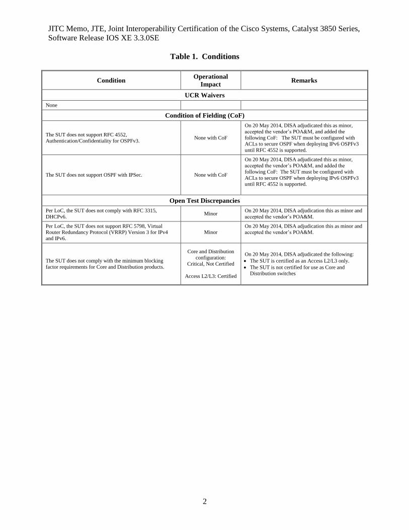
Table 1. Conditions
Condition Operational
Impact Remarks
UCR Waivers
None
Condition of Fielding (CoF)
The SUT does not support RFC 4552,
Authentication/Confidentiality for OSPFv3. None with CoF
On 20 May 2014, DISA adjudicated this as minor,
accepted the vendor’s POA&M, and added the
following CoF: The SUT must be configured with ACLs to secure OSPF when deploying IPv6 OSPFv3
until RFC 4552 is supported.
The SUT does not support OSPF with IPSec. None with CoF
On 20 May 2014, DISA adjudicated this as minor, accepted the vendor’s POA&M, and added the
following CoF: The SUT must be configured with
ACLs to secure OSPF when deploying IPv6 OSPFv3 until RFC 4552 is supported.
Open Test Discrepancies
Per LoC, the SUT does not comply with RFC 3315,
DHCPv6. Minor
On 20 May 2014, DISA adjudication this as minor and
accepted the vendor’s POA&M.
Per LoC, the SUT does not support RFC 5798, Virtual Router Redundancy Protocol (VRRP) Version 3 for IPv4
and IPv6.
Minor On 20 May 2014, DISA adjudication this as minor and accepted the vendor’s POA&M.
The SUT does not comply with the minimum blocking
factor requirements for Core and Distribution products.
Core and Distribution
configuration:
Critical, Not Certified
Access L2/L3: Certified
On 20 May 2014, DISA adjudicated the following:
The SUT is certified as an Access L2/L3 only.
The SUT is not certified for use as Core and Distribution switches
JITC Memo, JTE, Joint Interoperability Certification of the Cisco Systems, Catalyst 3850 Series,
Software Release IOS XE 3.3.0SE
3
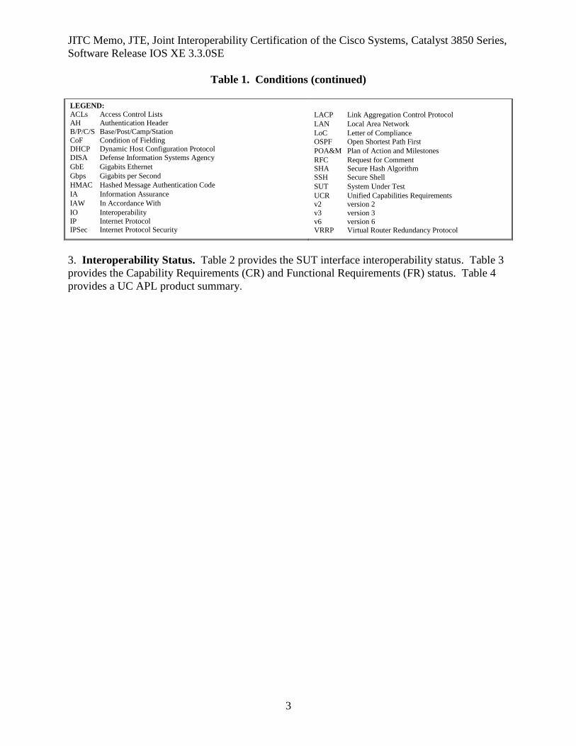
Table 1. Conditions (continued) LEGEND: ACLs Access Control Lists AH Authentication Header
B/P/C/S Base/Post/Camp/Station
CoF Condition of Fielding DHCP Dynamic Host Configuration Protocol
DISA Defense Information Systems Agency
GbE Gigabits Ethernet
Gbps Gigabits per Second
HMAC Hashed Message Authentication Code
IA Information Assurance
IAW In Accordance With
IO Interoperability
IP Internet Protocol IPSec Internet Protocol Security
LACP Link Aggregation Control Protocol
LAN Local Area Network
LoC Letter of Compliance OSPF Open Shortest Path First
POA&M Plan of Action and Milestones
RFC Request for Comment SHA Secure Hash Algorithm
SSH Secure Shell
SUT System Under Test
UCR Unified Capabilities Requirements v2 version 2
v3 version 3
v6 version 6 VRRP Virtual Router Redundancy Protocol
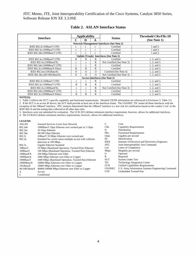
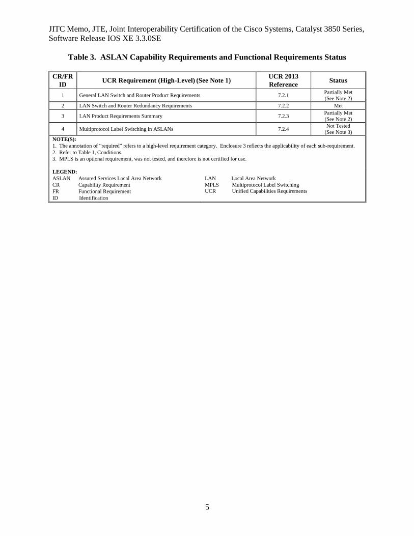
3. Interoperability Status. Table 2 provides the SUT interface interoperability status. Table 3
provides the Capability Requirements (CR) and Functional Requirements (FR) status. Table 4
provides a UC APL product summary.
JITC Memo, JTE, Joint Interoperability Certification of the Cisco Systems, Catalyst 3850 Series,
Software Release IOS XE 3.3.0SE
4
Table 2. ASLAN Interface Status
Interface Applicability
Status Threshold CRs/FRs ID
(See Note 1) C D A Network Management Interfaces (See Note 2)
IEEE 802.3i (10BaseT UTP) c c c Certified 1 and 3.
IEEE 802.3u (100BaseT UTP) c c c Certified 1 and 3.
IEEE 802.3ab (1000BaseT UTP) c c c Certified 1 and 3.
Uplink (Trunk) Interfaces (See Note 2)
IEEE 802.3u (100BaseT UTP) R R R Certified 1, 2, and 3.
IEEE 802.3u (100BaseFX) c c R Not Certified (See Note 3) 1, 2, and 3.
IEEE 802.3ab (1000BaseT UTP) c c R Certified 1, 2, and 3.
IEEE 802.3z (1000BaseX Fiber) R R R Certified 1, 2, and 3.
IEEE 802.3ae (10GBaseX) O O O Certified (See Note 4) 1, 2, and 3.
IEEE 802.3ba (40/100GBaseX) O O O Not Certified (See Note 3) 1, 2, and 3.
Access Interfaces (See Note 2)
IEEE 802.3i (10BaseT UTP) c c R Certified 1, 2, and 3.
IEEE 802.3u (100BaseT UTP) R R R Certified 1, 2, and 3.
IEEE 802.3u (100BaseFX) c c R Not Certified (See Note 3) 1, 2, and 3.
IEEE 802.3ab (1000BaseT UTP) c c R Certified 1, 2, and 3.
IEEE 802.3z (1000BaseX Fiber) R R R Certified 1, 2, and 3.
NOTE(S): 1. Table 3 reflects the SUT’s specific capability and functional requirements. Detailed CR/FR information are referenced in Enclosure 3, Table 3-5.
2. If the SUT is an access IP device, the SUT shall provide at least one of the interfaces listed. The USAISEC TIC tested all these interfaces with the exception of the 10BaseT interface. JITC analysis determined that the 10BaseT interface is a low risk for certification based on the vendor’s LoC to the
IEEE 802.3i and the testing data collected at all other data rates.
3. Interfaces were not submitted for evaluation. The UCR 2013 defines minimum interface requirement, however, allows for additional interfaces. 4. The UCR2013 defines minimum interface requirements, however, allows for additional interfaces.
LEGEND:
ASLAN Assured Services Local Area Network
802.3ab 1000BaseT Gbps Ethernet over twisted pair at 1 Gbps
802.3ae 10 Gbps Ethernet
802.3ba 40/100 Gbps Ethernet 802.3i 10BaseT 10 Mbps Ethernet over twisted pair
802.3u Standard for carrier sense multiple access with collision detection at 100 Mbps
802.3z Gigabit Ethernet Standard
10BaseT 10 Mbps (Baseband Operation, Twisted Pair) Ethernet 100BaseT 100 Mbps (Baseband Operation, Twisted Pair) Ethernet
100BaseFX 100 Mbps Ethernet over Fiber
1000BaseX 1000 Mbps Ethernet over Fiber or Copper 1000BaseT 1000 Mbps (Baseband Operation, Twisted Pair) Ethernet
10000BaseX 10000 Mbps Ethernet over Fiber or Copper
10GBaseX 10000 Mbps Ethernet over Fiber or Copper 40/100GBaseX 40000/100000 Mbps Ethernet over Fiber or Copper
A Access
C Conditional
C Core
CRs Capability Requirements
D Distribution FRs Functional Requirements
Gbps Gigabits per second
ID Identification
IEEE Institute of Electrical and Electronics Engineers
JITC Joint Interoperability Test Command LoC Letter of Compliance
Mbps Megabits per second
O Optional R Required
SUT System Under Test
TIC Technology Integration Center UCR Unified Capabilities Requirements
USAISEC U.S. Army Information Systems Engineering Command
UTP Unshielded Twisted Pair
JITC Memo, JTE, Joint Interoperability Certification of the Cisco Systems, Catalyst 3850 Series,
Software Release IOS XE 3.3.0SE
5
Table 3. ASLAN Capability Requirements and Functional Requirements Status
CR/FR
ID UCR Requirement (High-Level)
(See Note 1)
UCR 2013
Reference Status
1 General LAN Switch and Router Product Requirements 7.2.1 Partially Met
(See Note 2)
2 LAN Switch and Router Redundancy Requirements 7.2.2 Met
3 LAN Product Requirements Summary 7.2.3 Partially Met (See Note 2)
4 Multiprotocol Label Switching in ASLANs 7.2.4 Not Tested
(See Note 3)
NOTE(S):
1. The annotation of “required” refers to a high-level requirement category. Enclosure 3 reflects the applicability of each sub-requirement.
2. Refer to Table 1, Conditions.
3. MPLS is an optional requirement, was not tested, and therefore is not certified for use.
LEGEND:
ASLAN Assured Services Local Area Network
CR Capability Requirement
FR Functional Requirement
ID Identification
LAN Local Area Network
MPLS Multiprotocol Label Switching UCR Unified Capabilities Requirements
JITC Memo, JTE, Joint Interoperability Certification of the Cisco Systems, Catalyst 3850 Series,
Software Release IOS XE 3.3.0SE
6
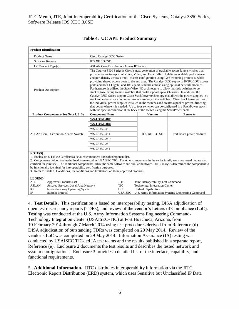
Table 4. UC APL Product Summary
Product Identification
Product Name Cisco Catalyst 3850 Series
Software Release IOS XE 3.3.0SE
UC Product Type(s) ASLAN Core/Distribution/Access IP Switch
Product Description
The Catalyst 3850 Series is Cisco’s next-generation of stackable access layer switches that
provide secure transport of Voice, Video, and Data traffic. It delivers scalable performance and port density across a multi-chassis configuration using L2/3 switching protocols, while
providing shared access ports to the end user. The Catalyst 3850 supports 10/100/1000 access
ports and both 1 Gigabit and 10 Gigabit Ethernet uplinks using optional network modules. Furthermore, it utilizes the StackWise-480 architecture to allow multiple switches to be
stacked together up to nine switches that could support up to 432 users. In addition, the
Catalyst 3850 Series support Cisco StackPower technology that allows the power supplies in a stack to be shared as a common resource among all the switches. Cisco StackPower unifies
the individual power supplies installed in the switches and creates a pool of power, directing
that power where it is needed. Up to four switches can be configured in a StackPower stack with the special connector at the back of the switch using the StackPower cable.
Product Components (See Note 1, 2, 3) Component Name Version Remarks
ASLAN Core/Distribution/Access Switch
WS-C3850-48F
IOS XE 3.3.0SE Redundant power modules
WS-C3850-48U
WS-C3850-48P
WS-C3850-48T
WS-C3850-24U
WS-C3850-24P
WS-C3850-24T
NOTE(S):
1. Enclosure 3, Table 3-3 reflects a detailed component and subcomponent list. 2. Components bolded and underlined were tested by USAISEC TIC. The other components in the series family were not tested but are also
certified for joint use. The additional components utilize the same software and similar hardware. JITC analysis determined the component to
be functionally identical for interoperability certification purposes.
3. Refer to Table 1, Conditions, for conditions and limitations on these approved products.
LEGEND:
APL Approved Products List
ASLAN Assured Services Local Area Network
IOS Internetworking Operating System IP Internet Protocol
JITC Joint Interoperability Test Command
TIC Technology Integration Center
UC Unified Capabilities USAISEC U.S. Army Information Systems Engineering Command
4. Test Details. This certification is based on interoperability testing, DISA adjudication of
open test discrepancy reports (TDRs), and review of the vendor’s Letters of Compliance (LoC).
Testing was conducted at the U.S. Army Information Systems Engineering Command-
Technology Integration Center (USAISEC-TIC) at Fort Huachuca, Arizona, from
10 February 2014 through 7 March 2014 using test procedures derived from Reference (d).
DISA adjudication of outstanding TDRs was completed on 20 May 2014. Review of the
vendor’s LoC was completed on 29 May 2014. Information Assurance (IA) testing was
conducted by USAISEC TIC-led IA test teams and the results published in a separate report,
Reference (e). Enclosure 2 documents the test results and describes the tested network and
system configurations. Enclosure 3 provides a detailed list of the interface, capability, and
functional requirements.
5. Additional Information. JITC distributes interoperability information via the JITC
Electronic Report Distribution (ERD) system, which uses Sensitive but Unclassified IP Data
JITC Memo, JTE, Joint Interoperability Certification of the Cisco Systems, Catalyst 3850 Series,
Software Release IOS XE 3.3.0SE
7
(formerly known as NIPRNet) e-mail. Interoperability status information is available via the
JITC System Tracking Program (STP). STP is accessible by .mil/.gov users at
https://stp.fhu.disa.mil/. Test reports, lessons learned, and related testing documents and
references are on the JITC Joint Interoperability Tool (JIT) at https://jit.fhu.disa.mil/. Due to the
sensitivity of the information, the Information Assurance Accreditation Package (IAAP) that
contains the approved configuration and deployment guide must be requested directly from the
Unified Capabilities Certification Office (UCCO), e-mail: disa.meade.ns.list.unified-
[email protected]. All associated information is available on the DISA
UCCO website located at http://www.disa.mil/Services/Network-Services/UCCO.
6. Point of Contact (POC). The testing point of contact is Mr. James Hatch, commercial
telephone (520) 533-2860, DSN telephone 821-2860; e-mail address
[email protected]. The JITC point of contact is Ms. Anita Brown, commercial
telephone (520) 538-5164, DSN telephone 879-5164, FAX DSN 879-4347; e-mail address
[email protected]; mailing address Joint Interoperability Test Command, ATTN:
JTE (Ms. Anita Brown) P.O. Box 12798, Fort Huachuca, AZ 85670-2798. The UCCO tracking
number for the SUT is 1323101.
FOR THE COMMANDER:
3 Enclosures a/s for RIC HARRISON
Chief
Networks/Communications and UC Portfolio
JITC Memo, JTE, Joint Interoperability Certification of the Cisco Systems, Catalyst 3850 Series,
Software Release IOS XE 3.3.0SE
8
Distribution (electronic mail):
DoD CIO
Joint Staff J-6, JCS
USD(AT&L)
ISG Secretariat, DISA, JTA
U.S. Strategic Command, J665
US Navy, OPNAV N2/N6FP12
US Army, DA-OSA, CIO/G-6 ASA(ALT), SAIS-IOQ
US Air Force, A3CNN/A6CNN
US Marine Corps, MARCORSYSCOM, SIAT, A&CE Division
US Coast Guard, CG-64
DISA/TEMC
DIA, Office of the Acquisition Executive
NSG Interoperability Assessment Team
DOT&E, Netcentric Systems and Naval Warfare
Medical Health Systems, JMIS IV&V
HQUSAISEC, AMSEL-IE-IS
UCCO
Enclosure 1
ADDITIONAL REFERENCES
(c) Office of the Department of Defense Chief Information Officer, “Department of Defense
Unified Capabilities Requirements 2013,” January 2013
(d) Joint Interoperability Test Command, “Unified Capabilities Test Plan (UCTP),” Draft
(e) Joint Interoperability Test Command, “Information Assurance (IA) Assessment of Cisco
Catalyst 3850 Series (Tracking Number 1323101),” 21 May 2014
Enclosure 2
CERTIFICATION SUMMARY
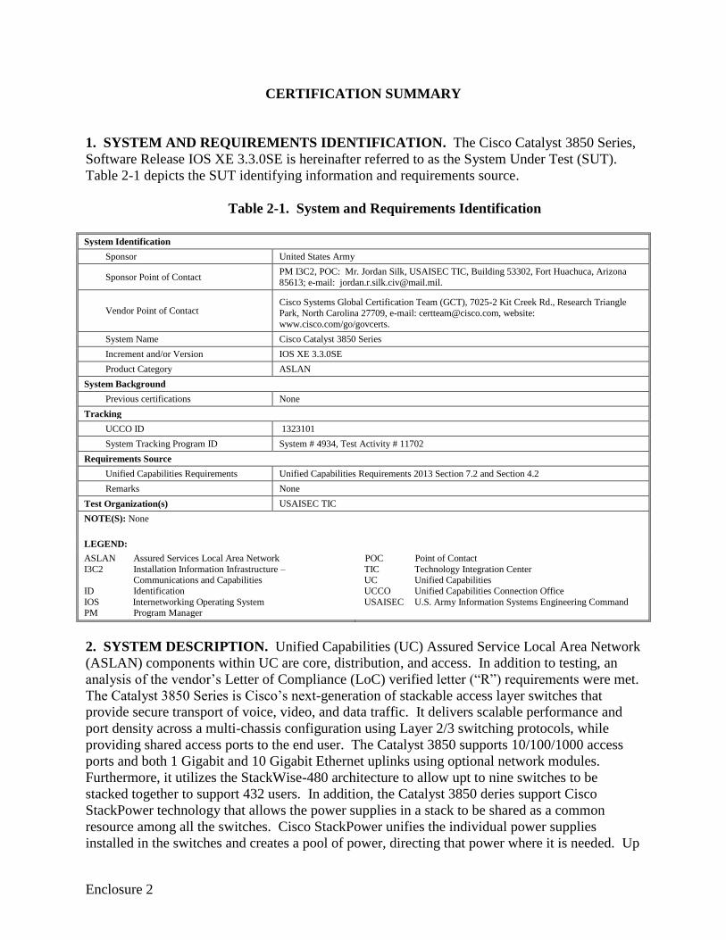
1. SYSTEM AND REQUIREMENTS IDENTIFICATION. The Cisco Catalyst 3850 Series,
Software Release IOS XE 3.3.0SE is hereinafter referred to as the System Under Test (SUT).
Table 2-1 depicts the SUT identifying information and requirements source.
Table 2-1. System and Requirements Identification
System Identification
Sponsor United States Army
Sponsor Point of Contact PM I3C2, POC: Mr. Jordan Silk, USAISEC TIC, Building 53302, Fort Huachuca, Arizona
85613; e-mail: [email protected].
Vendor Point of Contact Cisco Systems Global Certification Team (GCT), 7025-2 Kit Creek Rd., Research Triangle
Park, North Carolina 27709, e-mail: [email protected], website:
www.cisco.com/go/govcerts.
System Name Cisco Catalyst 3850 Series
Increment and/or Version IOS XE 3.3.0SE
Product Category ASLAN
System Background
Previous certifications None
Tracking
UCCO ID 1323101
System Tracking Program ID System # 4934, Test Activity # 11702
Requirements Source
Unified Capabilities Requirements Unified Capabilities Requirements 2013 Section 7.2 and Section 4.2
Remarks None
Test Organization(s) USAISEC TIC
NOTE(S): None
LEGEND:
ASLAN Assured Services Local Area Network
I3C2 Installation Information Infrastructure – Communications and Capabilities
ID Identification
IOS Internetworking Operating System PM Program Manager
POC Point of Contact
TIC Technology Integration Center UC Unified Capabilities
UCCO Unified Capabilities Connection Office
USAISEC U.S. Army Information Systems Engineering Command
2. SYSTEM DESCRIPTION. Unified Capabilities (UC) Assured Service Local Area Network
(ASLAN) components within UC are core, distribution, and access. In addition to testing, an
analysis of the vendor’s Letter of Compliance (LoC) verified letter (“R”) requirements were met.
The Catalyst 3850 Series is Cisco’s next-generation of stackable access layer switches that
provide secure transport of voice, video, and data traffic. It delivers scalable performance and
port density across a multi-chassis configuration using Layer 2/3 switching protocols, while
providing shared access ports to the end user. The Catalyst 3850 supports 10/100/1000 access
ports and both 1 Gigabit and 10 Gigabit Ethernet uplinks using optional network modules.
Furthermore, it utilizes the StackWise-480 architecture to allow upt to nine switches to be
stacked together to support 432 users. In addition, the Catalyst 3850 deries support Cisco
StackPower technology that allows the power supplies in a stack to be shared as a common
resource among all the switches. Cisco StackPower unifies the individual power supplies
installed in the switches and creates a pool of power, directing that power where it is needed. Up
2-2
to four switches can be configured in a StackPower stack using a StackPower cable. The
Catalyst 3850 fits well with Voice-over-IP, video, and data traffic. See Enclosure 3, Table 3-3
for a list of individual components and descriptions.
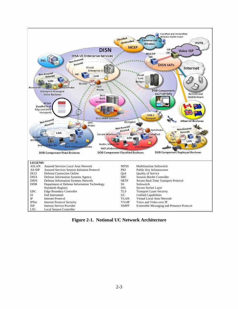
3. OPERATIONAL ARCHITECTURE. The UC architecture is a two-level network
hierarchy consisting of Department of Defense Information Network (DoDIN) backbone
switches and Service/Agency installation switches. The Department of Defense (DoD) Chief
Information Officer (CIO) and Joint Staff policy and subscriber mission requirements determine
which type of switch can be used at a particular location. The UC architecture, therefore,
consists of several categories of switches. Figure 2-1 depicts the notional operational UC
architecture.
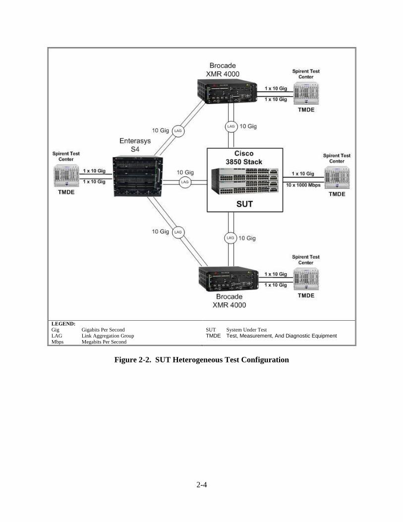
4. TEST CONFIGURATION. The SUT was tested at USAISEC TIC, Fort Huachuca, Arizona
in a manner and configuration similar to that of a notional operational environment. The
system’s required functions and features were tested using the test configurations depicted in
Figure 2-2. Information Assurance testing was conducted using the same configuration.
5. METHODOLOGY. Testing of the ASLAN components was conducted in the
heterogeneous testing phase only. Figure 2-2 depicts a test network configuration used for
heterogeneous testing. These tests are performed by placing the ASLAN SUT components into
an ASLAN that are produced by different manufacturers. SUT testing completed during
heterogeneous testing will verify the interoperability of the ASLAN components within Voice
and Video over IP network (VVoIP).
2-3
LEGEND:
ASLAN Assured Services Local Area Network
AS-SIP Assured Services Session Initiation Protocol
DCO Defense Connection Online DISA Defense Information Systems Agency
DISN Defense Information Systems Network
DISR Department of Defense Information Technology Standards Registry
EBC Edge Boundary Controller
EI End Instrument IP Internet Protocol
IPSec Internet Protocol Security
ISP Internet Service Provider LSC Local Session Controller
MFSS Multifunction Softswitch
PKI Public Key Infrastructure
QoS Quality of Service SBC Session Border Controller
SRTP Secure Real-Time Transport Protocol
SS Softswitch SSL Secure Socket Layer
TLS Transport Layer Security
UC Unified Capabilities VLAN Virtual Local Area Network
VVoIP Voice and Video over IP
XMPP Extensible Messaging and Presence Protocol
Figure 2-1. Notional UC Network Architecture
2-4
LEGEND:
Gig Gigabits Per Second LAG Link Aggregation Group
Mbps Megabits Per Second
SUT System Under Test
TMDE Test, Measurement, And Diagnostic Equipment
Figure 2-2. SUT Heterogeneous Test Configuration
2-5
6. INTEROPERABILITY REQUIREMENTS, RESULTS, AND ANALYSIS. The
interface, Capability Requirements (CR) and Functional Requirements (FR), Information
Assurance (IA), and other requirements for UC ASLAN are established by UCR 2013,
sections 4, and 5, and 7.2.
a. General LAN Switch and Router Product Requirements. The Core, Distribution,
and Access products shall be capable of meeting the following parameters:
(1) Non-blocking. All Core, Distribution, and Access products shall be non-blocking
for their ports based on the following traffic engineering. Non-blocking is defined as the
capability to send and receive a mixture of 64 to 1518 byte packets at full duplex rates from
ingress ports to egress ports through the component’s backplane without losing any packets. In a
non-blocking switch, all ports can run at full wire speed without any loss of packets or cells.
Blocking factor is defined as the ratio of all traffic to non-blocked traffic (i.e., a blocking factor
of 8-to-1 means that 12.5 percent of the traffic must be non-blocking). The Cisco Catalyst 3850
Series was submitted for ASLAN Core, Distribution, and Layer 2/3 Access IP Switch testing.
The SUT does not comply with the minimum blocking factor requirement for core and
distribution products. On 20 May 2014, DISA adjudicated this as Critical for APL. Therefore,
the SUT is certified as an Access L2/3 switch only. This requirement was verified through
vendor LoC and testing. See Table 3-3 for a list of individual components and descriptions.
(2) Latency. All Core, Distribution, and Access products shall have the capability to
transport prioritized packets (media and signaling) as follows. The latency shall be achievable
over any 5-minute period measured from ingress ports to egress ports under congested
conditions. A congested condition is defined as 100 percent bandwidth utilization. Prioritized
packets are defined as packets having a service class above best effort. The E2E SUT Voice
latency was measured at 0.032 ms, which met the E2E requirement of no more than 6 ms.
Therefore, the SUT also meets the Voice component latency requirement of 2 ms. This
requirement was met through testing. The SUT is certified as an Access L2/3 switch only.
(3) Jitter. All Core, Distribution, and Access products shall have the capability to
transport prioritized packets (media and signaling) as follows. The jitter shall be achievable over
any 5-minute period measured from ingress ports to egress ports under congested conditions.
Congested condition is defined as 100 percent bandwidth utilization. The E2E SUT Voice Jitter
was measured at 0.005 ms, which met the E2E requirement of no more than 3 ms. Therefore, the
SUT also meets the voice component jitter requirement of 1 ms. This requirement was met
through testing. The SUT is certified as an Access L2/3 switch only.
(4) Packet Loss. All Core, Distribution and Access products shall have the capability
to transport prioritized packets (media and signaling) as follows. The packet loss shall be
achievable over any 5-minute period measured from ingress ports to egress ports under
congested conditions. Congested condition is defined as 100 percent bandwidth utilization. The
E2E SUT Voice packet loss was measured at 0.00 percent, which met the E2E requirement of no
more than 0.045 percent. Therefore, the SUT also meets the Voice component packet loss
requirement of 0.015 percent. This requirement was met through testing. The SUT is certified
as an Access L2/3 switch only.
2-6
b. Port Interface Rates Requirements
(1) Minimally, Core and Distribution products shall support the following interface
rates (other rates and Institute of Electronics and Electrical Engineers (IEEE) standards may be
provided as optional interfaces). Rates specified are the theoretical maximum data bit rate
specified for Ethernet; link capacity and effective throughput is influenced by many factors. For
calculation purposes, link capacities are to be calculated IAW definitions contained in Request
for Comments (RFC) 2330 and RFC 5136. Network Management (NM) interfaces are defined
in Section 2.19. These requirements were met through vendor LoC and testing. The SUT is
certified as an Access L2/3 switch only. The product must minimally support the following
interfaces for interconnection between the core to WAN, distribution-core, and distribution-
access:
100 megabits per second (Mbps) in accordance with (IAW) IEEE 802.3u.
1000 Mbps IAW IEEE 802.3z.
(2) Minimally, Access products shall provide one of the following user-side interface
rates (other rates and IEEE standards may be provided as optional interfaces). These
requirements were met through vendor LoC and testing:
10 Mbps IAW IEEE 802.3i.
10 Mbps IAW IEEE 802.3j.
100 Mbps IAW IEEE 802.3u.
1000 Mbps IAW IEEE 802.3z.
1000 Mbps IAW IEEE 802.3ab.
(3) Minimally, Access products shall provide one of the following trunk-side interface
rates (other rates and IEEE standards may be provided as optional interfaces). These
requirements were met through vendor LoC and testing:
100 Mbps IAW IEEE 802.3u.
1000 Mbps IAW IEEE 802.3z.
(4) The Core, Distribution, and Access products may provide a fibre channel interface
IAW American National Standards Institute (ANSI) International Committee for Information
Technology Standards (INCITS) T11.2 and T11.3 (previously known as X3T9.3). Fibre channel
was not submitted for certification. If provided, the interface must meet the following:
RFC 4338, Transmission of IPv6, IPv4, and Address Resolution Protocol
(ARP) Packets over Fibre Channel.
RFC 4044, Fibre Channel Management.
(5) The Core, Distribution, and Access products may provide one or more of the
following wireless LAN interface rates. Wireless interfaces were not submitted for certification:
54 Mbps IAW IEEE 802.11a.
2-7
11 Mbps IAW IEEE 802.11b.
54 Mbps IAW IEEE 802.11g.
300–600 Mbps IAW IEEE 802.11n.
IEEE 802.16-2012: Broadband wireless communications standards for
MANs.
Other approved IEEE wireless interfaces may be implemented as optional
interfaces.
(5) If any of the above wireless interfaces are provided, then the interfaces must
support the requirements of Section 7.3, Wireless LAN.
c. Port Parameter Requirements. The Core, Distribution, and Access products shall
provide the following parameters on a per port basis as specified:
(1) Auto-negotiation IAW IEEE 802.3. This requirement was met through vendor
LoC and testing. The SUT is certified as an Access L2/3 switch only.
(2) Force mode IAW IEEE 802.3. This requirement was met through vendor LoC and
testing. The SUT is certified as an Access L2/3 switch only.
(3) Flow control IAW IEEE 802.3x (Optional: Core). This requirement was met
through vendor LoC. The SUT is certified as an Access L2/3 switch only.
(4) Filtering IAW appropriate RFC 1812 sections (sections applying to filtering).
This requirement was met through vendor LoC. The SUT is certified as an Access L2/3 switch
only.
(5) Link Aggregation IAW IEEE 802.1AX (applies to output/egress trunk-side ports
only) (Optional Access). This requirement was met through vendor LoC and testing. The SUT
is certified as an Access L2/3 switch only.
(6) Spanning Tree Protocol IAW IEEE 802.1D (Optional: Core). This requirement
was met through vendor LoC and testing. The SUT is certified as an Access L2/3 switch only.
(7) Multiple Spanning Tree IAW IEEE 802.1s (Optional: Core). This requirement
was met through vendor LoC and testing. The SUT is certified as an Access L2/3 switch only.
(8) Rapid Reconfiguration of Spanning Tree IAW IEEE 802.1w (Optional: Core).
This requirement was met through vendor LoC. The SUT is certified as an Access L2/3 switch
only.
(9) Port-Based Access Control IAW IEEE 802.1x (Optional: Core, Distribution, and
Access). This requirement was met through vendor LoC. The SUT is certified as an Access
L2/3 switch only.
2-8
(10) Link Layer Discovery Protocol (LLDP) IAW IEEE 802.1AB (Optional Core,
Distribution, and Access). This requirement was met through vendor LoC. The SUT is certified
as an Access L2/3 switch only.
(11) Link Layer Discovery – Media Endpoint Discovery IAW ANSI/
Telecommunications Industry Association (TIA)-1057 (Optional Core, Distribution, and
Access). This requirement was met through vendor LoC. The SUT is certified as an Access
L2/3 switch only.
(12) Power over Ethernet (PoE) IAW either 802.3af-2003 or 802.3at-2009. (Required
only for VVoIP solutions; for data applications or non-Assured Services (AS) solutions, PoE is
optionally required.) PoE requirement was met through vendor LoC. The SUT is certified as an
Access L2/3 switch only.
d. Class of Service Markings Requirements
(1) The Core, Distribution, and Access products shall support Differentiated Services
Code Points (DSCPs) IAW RFC 2474 for both Internet Protocol (IP) IPv4 and IPv6 Packets, as
follows:
(a) The Core and Distribution products shall be capable of accepting any packet
tagged with a DSCP value (0-63) on an ingress port and assign that packet to a Quality of
Service (QoS) behavior listed in Section 7.2.1.6, Quality of Service Features. The SUT is not
certified as a core or distribution switch.
(b) The Core and Distribution products shall be capable of accepting any packet
tagged with a DSCP value (0-63) on an ingress port and reassign that packet to any new DSCP
value (0-63). Current DSCP values are provided in Section 6.2.2, Differentiated Service Code
Point. (Optional: Access products). The SUT is not certified as a core or distribution switch.
(c) The Core and Distribution products must be able to support the prioritization
of aggregate service classes with queuing according to Section 7.2.1.6, Quality of Service
Features. The SUT is not certified as a core or distribution switch.
(d) Access products (including Passive Optical Network) shall be capable of
supporting the prioritization of aggregate service classes with queuing according to Section
7.2.1.6, Quality of Service Features. This requirement was met through vendor LoC and testing.
(2) The Core, Distribution, and Access products may support the 3-bit user priority
field of the IEEE 802.1Q 2-byte Tag Control Information (TCI) field (see Figure 7.2-1, IEEE
802.1Q Tagged Frame for Ethernet, and Figure 7.2-2, TCI Field Description). Default values are
provided in Table 7.2-1, 802.1Q Default Values. If provided, the following Class of Service
(CoS) requirements apply:
(a) The Core, Distribution, and Access products shall be capable of accepting any
frame tagged with a user priority value (0–7) on an ingress port and assign that frame to a QoS
2-9
behavior listed in Section 7.2.1.6, Quality of Service Features. This requirement was met
through vendor LoC. The SUT is certified as an Access L2/3 switch only.
(b) The Core and Distribution products shall be capable of accepting any frame
tagged with a user priority value (0-7) on an ingress port and reassign that frame to any new user
priority value (0-7) (Optional: Distribution and Access). This requirement was met through
vendor LoC. The SUT is certified as an Access L2/3 switch only.
e. Virtual LAN Capabilities Requirements
(1) The Core, Distribution, and Access products shall be capable of the following:
(a) Accepting Virtual Local Area Network (VLAN) tagged frames according to
IEEE 802.1Q (see Figure 7.2-1, IEEE 802.1Q Tagged Frame for Ethernet, and Figure 7.2-2, TCI
Field Description). This requirement was met through vendor LoC and testing. The SUT is
certified as an Access L2/3 switch only.
(b) Configuring VLAN IDs (VIDs). VIDs on an ingress port shall be
configurable to any of the 4094 values (except 0 and 4095). This requirement was met through
vendor LoC and testing. The SUT is certified as an Access L2/3 switch only.
(c) Supporting VLANs types IAW IEEE 802.1Q. This requirement was met
through vendor LoC and testing. The SUT is certified as an Access L2/3 switch only.
(2) The Unified Capabilities (UC) products must be capable of accepting VLAN
tagged frames and assigning them to the VLAN identified in the 802.1Q VID field (see Figure
7.2-4, IEEE 802.1Q-Based VLANs). This requirement was met through vendor LoC and testing.
The SUT is certified as an Access L2/3 switch only.
f. Protocols Requirements. The Core, Distribution, and Access products shall meet
protocol requirements for IPv4 and IPv6. RFC requirements are listed in Table 7.2-2, ASLAN
Infrastructure RFC Requirements. Additional IPv6 requirements by product profile are listed in
Section 5, IPv6. These RFCs are not meant to conflict with Department of Defense (DoD)
Information Assurance (IA) policy 9[e.g., Security Technical Implementation Guidelines
(STIGs)). Whenever a conflict occurs, DoD IA policy takes precedence. If there are conflicts
with Section 5, RFCs applicable to IPv6 in Section 5 take precedence. All protocols are
supported with the exceptions of the following as indicated through the vendor LoC and testing:
(1) Cisco Catalyst 3850 Series does not support RFC 5798, Virtual Router
Redundancy Protocol (VRRP) Version 3 for IPv4 and IPv6. On 20 May 2014, DISA adjudicated
this as minor and accepted the vendor’s POA&M .
(2) Cisco Catalyst 3850 does not comply with OSPFv3 RFC 4552 . On 20 May 2014,
DISA adjudicated this as minor, accepted the vendor’s POA&M, and added the following CoF:
The SUT must be configured with ACLs to secure OSPF when deploying IPv6 OSPFv3 until
RFC 4552 is supported.
2-10
(3) Cisco Catalyst 3850 does not comply with RFC 3315, DHCPv6. On 20 May
2014, DISA adjudication this as minor and accepted the vendor’s POA&M.
(4) Cisco Catalyst 3850 does not comply with OSPF with IPSec. On 20 May 2014,
DISA adjudicated this as minor, accepted the vendor’s POA&M, and added the following CoF:
The SUT must be configured with ACLs to secure OSPF when deploying IPv6 OSPFv3 until
RFC 4552 is supported.
g. Quality of Service Features Requirements
(1) The Core, Distribution, and Access products shall be capable of the following QoS
Features:
(a) Providing a minimum of four queues. This requirement was met through
vendor LoC and testing, that proved the SUT supports four queues. The SUT is certified as an
Access L2/3 switch only.
(b) Assigning any incoming access/user-side “tagged” session to any of the
queues for prioritization onto the egress (trunk-side/network-side) interface. This requirement
was met through vendor LoC and testing. The SUT is certified as an Access L2/3 switch only.
(c) Supporting Differentiated Services (DS), Per-Hop Behaviors (PHBs), and
traffic conditioning IAW RFCs 2474, 2597, and 3246. This requirement was met through
vendor LoC and testing. The SUT is certified as an Access L2/3 switch only.
(d) All queues shall be capable of having a bandwidth (BW) assigned (i.e., queue
1: 200 Kbps, queue 2: 500 kbps) or percentage of traffic (queue 1: 25 percent, queue 2: 25
percent). The BW or traffic percentage shall be fully configurable per queue from 0 to full BW
or 0 to 100 percent. The sum of configured queues shall not exceed full BW or 100 percent of
traffic. This requirement was met through vendor LoC and testing. The SUT is certified as an
Access L2/3 switch only.
(e) Core, Distribution, and Access products shall meet the traffic conditioning
(policing) requirements of Section 6.2.4. This requirement was met through vendor LoC and
testing. The SUT is certified as an Access L2/3 switch only.
(2) The product shall support the Differentiated Services Code Point (DSCP) plan, as
shown in Table 7.2-3, DSCP Assignments. DSCP assignments shall be software configurable
for the full range of 6-bit values (0-63 Base10) for backwards compatibility with IP precedence
environments that may be configured to use the Type of Service (TOS) field in the IP header but
do not support DSCP. This requirement was met through vendor LoC. The SUT is certified as
an Access L2/3 switch only.
h. Network Monitoring Requirements. The Core, Distribution, and Access products
shall support the following network monitoring features:
2-11
(1) Simple Network Management Protocol Version 3 (SNMPv3) IAW RFCs 3411,
3412, 3413, 3414, 3415, 3416, and 3417. The SilverCreek SNMP Test Suite was used to capture
SNMP traps. This requirement was met through vendor LoC and testing. The SUT is certified
as an Access L2/3 switch only.
(2) Remote Monitoring (RMON) IAW RFC 2819. This requirement was met through
vendor LoC. The SUT is certified as an Access L2/3 switch only.
(3) Coexistence between Version 1, Version 2, and Version 3 of the Internet-standard
Network Management Framework IAW RFC 3584. This requirement was met through vendor
LoC. The SUT is certified as an Access L2/3 switch only.
(4) The Advanced encryption Standard (AES) Cipher Algorithm in the SNMP User-
based Security Model IAW RFC 3826. Security was tested by USAISEC TIC-led IA test teams,
and the results were published in a separate report, Reference (e).
i. Security Requirements. The Core, Distribution, and Access products shall meet the
security protocol requirements listed in Section 4, Information Assurance (IA), as follows: Core
and Distribution products shall meet all requirements annotated as Router (R) and LAN Switch
(LS). Access switches shall meet the IA requirements annotated for LS. In addition to wireless
IA requirements previously specified, Wireless Local Area Network Access Systems (WLASs)
and Wireless Access Bridges (WABs) shall meet all IA requirements for LSs. Wireless End
Instruments (WEIs) shall meet all IA requirements annotated for End Instruments (EIs). When
conflicts exist between the Unified Capabilities Requirements (UCR) and Security Technical
Implementation Guides (STIGs) requirements, the STIGs requirements will take precedence.
Security was tested by the USAISEC TIC-led IA test team and results are published in a separate
report, Reference (e). All Security Requirements are supported with the exceptions of the
following as indicated through the vendor LoC:
Cisco Catalyst 3850 does not comply with SSHv2 IAW 4.2.8 IA-067000. This is an
informational-only. The SUT permits HMAC-SHA1-96, but allows SSH clients to negotiate
usage of other HMACs. This discrepancy was adjudicated and accepted by DISA on 20 May
2014 as an informational-only.
j. LAN Switch and Router Redundancy Requirements. The ASLAN (High and
Medium) shall have no single point of failure that can cause an outage of more than 96 IP
telephony subscribers. A single point of failure up to and including 96 subscribers is acceptable;
however, to support mission-critical needs, FLASH/FLASH OVERRIDE (F/FO) subscribers
should be engineered for maximum availability. To meet the availability requirements, all
switching/routing platforms that offer service to more than 96 telephony subscribers shall
provide redundancy in either of two ways:
The product itself (Core, Distribution, or Access) provides redundancy internally.
A secondary product is added to the ASLAN to provide redundancy to the primary
product (redundant connectivity required).
2-12
(1) Single Product Redundancy Requirements. If a single product is used to meet the
redundancy requirements, then the following requirements are applicable to the product:
Dual Power Supplies
Dual Processors (Control Supervisors)
Termination Sparing
Redundancy Protocol
No Single Failure Point
Switch Fabric or Backplane Redundancy
(2) Dual Product Redundancy Requirements. If the System Under Test (SUT)
provides redundancy through dual products, then the following requirements are applicable:
The failover over to the secondary product must not result in any lost calls. The
secondary product may be in “standby mode” or “active mode,” regardless of the mode of
operation the traffic engineering of the links between primary and secondary must meet the
requirements provided in Section 7.5.19, Traffic Engineering. NOTE: In the event of a primary
product failure, all calls that are active shall not be disrupted (loss of existing connection
requiring redialing) and the failover to the secondary product must be restored within 5 seconds.
This requirement was met through vendor LoC and testing. The SUT is certified as an Access
L2/3 switch only.
c. LAN Product Requirements Summary. Table 7.2-4 summarizes the LAN product
requirements. These requirements were verified via a combination of Letter of Compliance
(LoC) and testing and are addressed in other sections of this document. The SUT is certified as
an Access L2/3 switch only.
d. Multiprotocol Label Switching Requirements in ASLANs. The implementation of
ASLANs sometimes may cover a large geographical area. For large ASLANs, a data transport
technique referred to as Multiprotocol Label Switching (MPLS) may be used to improve the
performance of the ASLAN core layer. MPLS was not submitted for certification.
e. Hardware/Software/Firmware Version Identification: Enclosure 3, Table 3-3 lists
the SUT components’ hardware, software version, and firmware version tested. The USAISEC
TIC tested the SUT in an operationally realistic environment to determine its interoperability
capability with associated network devices and network traffic. Enclosure 3, Table 3-4 lists the
hardware, software version, and firmware version of the components used in the test
infrastructure.
7. TESTING LIMITATIONS. None.
8. CONCLUSION(S). The SUT meets the critical interoperability requirements for an Access
L2/3 switch only in accordance with the UCR and is certified for joint use with other UC
Products listed on the Approved Products List (APL). The SUT meets the interoperability
requirements for the interfaces listed in Enclosure 3, Table 3-1.
Enclosure 3
DATA TABLES
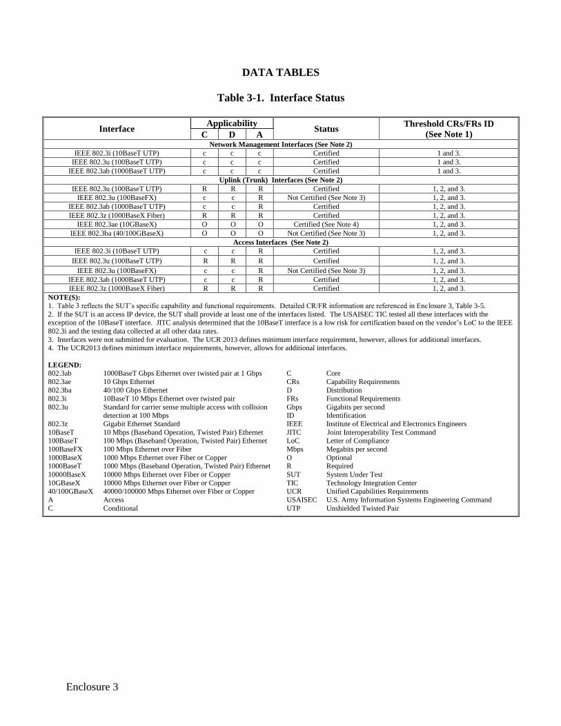
Table 3-1. Interface Status
Interface Applicability
Status Threshold CRs/FRs ID
(See Note 1) C D A Network Management Interfaces (See Note 2)
IEEE 802.3i (10BaseT UTP) c c c Certified 1 and 3.
IEEE 802.3u (100BaseT UTP) c c c Certified 1 and 3.
IEEE 802.3ab (1000BaseT UTP) c c c Certified 1 and 3.
Uplink (Trunk) Interfaces (See Note 2)
IEEE 802.3u (100BaseT UTP) R R R Certified 1, 2, and 3.
IEEE 802.3u (100BaseFX) c c R Not Certified (See Note 3) 1, 2, and 3.
IEEE 802.3ab (1000BaseT UTP) c c R Certified 1, 2, and 3.
IEEE 802.3z (1000BaseX Fiber) R R R Certified 1, 2, and 3.
IEEE 802.3ae (10GBaseX) O O O Certified (See Note 4) 1, 2, and 3.
IEEE 802.3ba (40/100GBaseX) O O O Not Certified (See Note 3) 1, 2, and 3.
Access Interfaces (See Note 2)
IEEE 802.3i (10BaseT UTP) c c R Certified 1, 2, and 3.
IEEE 802.3u (100BaseT UTP) R R R Certified 1, 2, and 3.
IEEE 802.3u (100BaseFX) c c R Not Certified (See Note 3) 1, 2, and 3.
IEEE 802.3ab (1000BaseT UTP) c c R Certified 1, 2, and 3.
IEEE 802.3z (1000BaseX Fiber) R R R Certified 1, 2, and 3.
NOTE(S): 1. Table 3 reflects the SUT’s specific capability and functional requirements. Detailed CR/FR information are referenced in Enclosure 3, Table 3-5.
2. If the SUT is an access IP device, the SUT shall provide at least one of the interfaces listed. The USAISEC TIC tested all these interfaces with the exception of the 10BaseT interface. JITC analysis determined that the 10BaseT interface is a low risk for certification based on the vendor’s LoC to the IEEE
802.3i and the testing data collected at all other data rates.
3. Interfaces were not submitted for evaluation. The UCR 2013 defines minimum interface requirement, however, allows for additional interfaces. 4. The UCR2013 defines minimum interface requirements, however, allows for additional interfaces.
LEGEND:
802.3ab 1000BaseT Gbps Ethernet over twisted pair at 1 Gbps
802.3ae 10 Gbps Ethernet
802.3ba 40/100 Gbps Ethernet
802.3i 10BaseT 10 Mbps Ethernet over twisted pair
802.3u Standard for carrier sense multiple access with collision detection at 100 Mbps
802.3z Gigabit Ethernet Standard
10BaseT 10 Mbps (Baseband Operation, Twisted Pair) Ethernet 100BaseT 100 Mbps (Baseband Operation, Twisted Pair) Ethernet
100BaseFX 100 Mbps Ethernet over Fiber
1000BaseX 1000 Mbps Ethernet over Fiber or Copper 1000BaseT 1000 Mbps (Baseband Operation, Twisted Pair) Ethernet
10000BaseX 10000 Mbps Ethernet over Fiber or Copper
10GBaseX 10000 Mbps Ethernet over Fiber or Copper 40/100GBaseX 40000/100000 Mbps Ethernet over Fiber or Copper
A Access
C Conditional
C Core
CRs Capability Requirements
D Distribution
FRs Functional Requirements
Gbps Gigabits per second ID Identification
IEEE Institute of Electrical and Electronics Engineers
JITC Joint Interoperability Test Command LoC Letter of Compliance
Mbps Megabits per second
O Optional R Required
SUT System Under Test
TIC Technology Integration Center UCR Unified Capabilities Requirements
USAISEC U.S. Army Information Systems Engineering Command
UTP Unshielded Twisted Pair
3-2
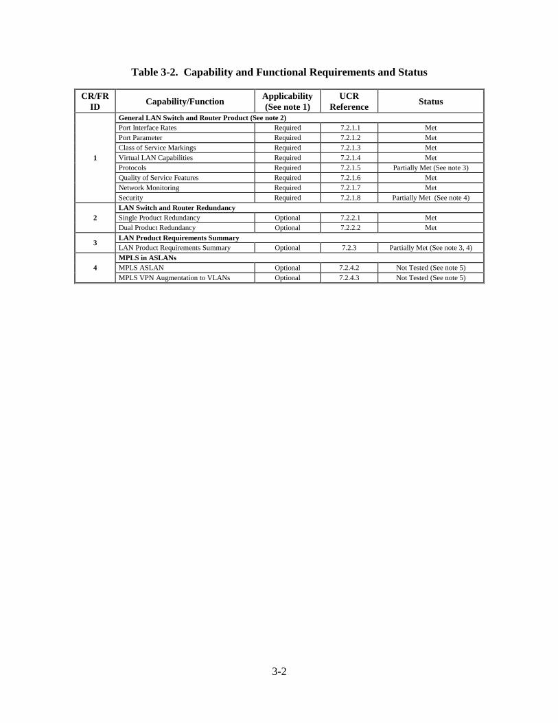
Table 3-2. Capability and Functional Requirements and Status
CR/FR
ID Capability/Function
Applicability
(See note 1)
UCR
Reference Status
1
General LAN Switch and Router Product (See note 2)
Port Interface Rates Required 7.2.1.1 Met
Port Parameter Required 7.2.1.2 Met
Class of Service Markings Required 7.2.1.3 Met
Virtual LAN Capabilities Required 7.2.1.4 Met
Protocols Required 7.2.1.5 Partially Met (See note 3)
Quality of Service Features Required 7.2.1.6 Met
Network Monitoring Required 7.2.1.7 Met
Security Required 7.2.1.8 Partially Met (See note 4)
2
LAN Switch and Router Redundancy
Single Product Redundancy Optional 7.2.2.1 Met
Dual Product Redundancy Optional 7.2.2.2 Met
3 LAN Product Requirements Summary
LAN Product Requirements Summary Optional 7.2.3 Partially Met (See note 3, 4)
4
MPLS in ASLANs
MPLS ASLAN Optional 7.2.4.2 Not Tested (See note 5)
MPLS VPN Augmentation to VLANs Optional 7.2.4.3 Not Tested (See note 5)
3-3
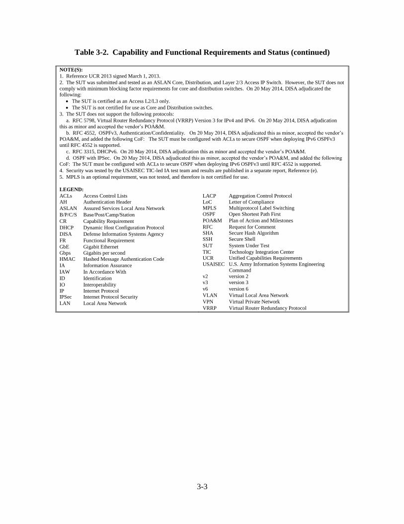
Table 3-2. Capability and Functional Requirements and Status (continued)
NOTE(S):
1. Reference UCR 2013 signed March 1, 2013.
2. The SUT was submitted and tested as an ASLAN Core, Distribution, and Layer 2/3 Access IP Switch. However, the SUT does not
comply with minimum blocking factor requirements for core and distribution switches. On 20 May 2014, DISA adjudicated the following:
The SUT is certified as an Access L2/L3 only.
The SUT is not certified for use as Core and Distribution switches.
3. The SUT does not support the following protocols:
a. RFC 5798, Virtual Router Redundancy Protocol (VRRP) Version 3 for IPv4 and IPv6. On 20 May 2014, DISA adjudication
this as minor and accepted the vendor’s POA&M.
b. RFC 4552, OSPFv3, Authentication/Confidentiality. On 20 May 2014, DISA adjudicated this as minor, accepted the vendor’s
POA&M, and added the following CoF: The SUT must be configured with ACLs to secure OSPF when deploying IPv6 OSPFv3
until RFC 4552 is supported.
c. RFC 3315, DHCPv6. On 20 May 2014, DISA adjudication this as minor and accepted the vendor’s POA&M.
d. OSPF with IPSec. On 20 May 2014, DISA adjudicated this as minor, accepted the vendor’s POA&M, and added the following
CoF: The SUT must be configured with ACLs to secure OSPF when deploying IPv6 OSPFv3 until RFC 4552 is supported.
4. Security was tested by the USAISEC TIC-led IA test team and results are published in a separate report, Reference (e).
5. MPLS is an optional requirement, was not tested, and therefore is not certified for use.
LEGEND:
ACLs Access Control Lists
AH Authentication Header
ASLAN Assured Services Local Area Network
B/P/C/S Base/Post/Camp/Station
CR Capability Requirement
DHCP Dynamic Host Configuration Protocol
DISA Defense Information Systems Agency
FR Functional Requirement
GbE Gigabit Ethernet
Gbps Gigabits per second
HMAC Hashed Message Authentication Code
IA Information Assurance
IAW In Accordance With
ID Identification
IO Interoperability
IP Internet Protocol IPSec Internet Protocol Security
LAN Local Area Network
LACP Aggregation Control Protocol
LoC Letter of Compliance MPLS Multiprotocol Label Switching
OSPF Open Shortest Path First
POA&M Plan of Action and Milestones
RFC Request for Comment SHA Secure Hash Algorithm
SSH Secure Shell
SUT System Under Test
TIC Technology Integration Center UCR Unified Capabilities Requirements
USAISEC U.S. Army Information Systems Engineering
Command v2 version 2
v3 version 3
v6 version 6
VLAN Virtual Local Area Network
VPN Virtual Private Network
VRRP Virtual Router Redundancy Protocol
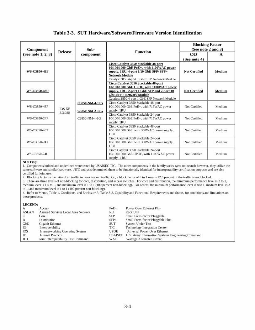
3-4
Table 3-3. SUT Hardware/Software/Firmware Version Identification
Component
(See note 1, 2, 3) Release
Sub-
component Function
Blocking Factor
(See note 2 and 3)
C/D
(See note 4)
A
WS-C3850-48F
IOS XE
3.3.0SE
C3850-NM-4-10G
C3850-NM-2-10G
C3850-NM-4-1G
Cisco Catalyst 3850 Stackable 48-port
10/100/1000 GbE PoE+, with 1100WAC power
supply, 1RU, 4-port 1/10 GbE SFP/ SFP+
Network Module
Catalyst 3850 4-port 1 GbE SFP Network Module
Not Certified Medium
WS-C3850-48U
Cisco Catalyst 3850 Stackable 48-port
10/100/1000 GbE UPOE, with 1100WAC power
supply, 1RU, 2-port 1 GbE SFP and 2-port 10
GbE SFP+ Network Module
Catalyst 3850 4-port 1 GbE SFP Network Module
Not Certified Medium
WS-C3850-48P
Cisco Catalyst 3850 Stackable 48-port
10/100/1000 GbE PoE+, with 715WAC power
supply, 1RU
Not Certified Medium
WS-C3850-24P
Cisco Catalyst 3850 Stackable 24-port 10/100/1000 GbE PoE+, with 715WAC power
supply, 1RU
Not Certified Medium
WS-C3850-48T
Cisco Catalyst 3850 Stackable 48-port
10/100/1000 GbE, with 350WAC power supply, 1RU
Not Certified Medium
WS-C3850-24T
Cisco Catalyst 3850 Stackable 24-port
10/100/1000 GbE, with 350WAC power supply, 1RU
Not Certified Medium
WS-C3850-24U
Cisco Catalyst 3850 Stackable 24-port
10/100/1000 GbE UPOE, with 1100WAC power supply, 1 RU
Not Certified Medium
NOTE(S):
1. Components bolded and underlined were tested by USAISEC TIC. The other components in the family series were not tested; however, they utilize the
same software and similar hardware. JITC analysis determined them to be functionally identical for interoperability certification purposes and are also certified for joint use.
2. Blocking factor is the ratio of all traffic to non-blocked traffic; i.e., a block factor of 8 to 1 means 12.5 percent of the traffic is not blocked.
3. There are three levels of non-blocking for core, distribution, and access switches. For core and distribution, the minimum performance level is 2 to 1, medium level is 1.5 to 1, and maximum level is 1 to 1 (100 percent non-blocking). For access, the minimum performance level is 8 to 1, medium level is 2
to 1, and maximum level is 1 to 1 (100 percent non-blocking).
4. Refer to Memo, Table 1, Conditions, and Enclosure 3, Table 3-2, Capability and Functional Requirements and Status, for conditions and limitations on
these products.
LEGEND:
A Access
ASLAN Assured Services Local Area Network
C Core D Distribution
GbE Gigabit Ethernet
IO Interoperability IOS Internetworking Operating System
IP Internet Protocol
JITC Joint Interoperability Test Command
PoE+ Power Over Ethernet Plus
RU Rack Unit
SFP Small Form-factor Pluggable SFP+ Small Form-factor Pluggable Plus
SUT System Under Test
TIC Technology Integration Center UPOE Universal Power Over Ethernet
USAISEC U.S. Army Information Systems Engineering Command
WAC Wattage Alternate Current
3-5
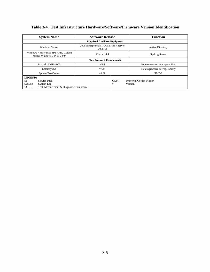
Table 3-4. Test Infrastructure Hardware/Software/Firmware Version Identification
System Name Software Release Function
Required Ancillary Equipment
Windows Server 2008 Enterprise SP1 UGM Army Server
2008R2 Active Directory
Windows 7 Enterprise SP1 Army Golden
Master Windows 7 Pilot 2.0.0 Kiwi v1.4.4 SysLog Server
Test Network Components
Brocade XMR-4000 v5.4 Heterogeneous Interoperability
Enterasys S4 v7.41 Heterogeneous Interoperability
Spirent TestCenter v4.38 TMDE
LEGEND:
SP Service Pack SysLog System Log
TMDE Test, Measurement & Diagnostic Equipment
UGM Universal Golden Master v Version
3-6
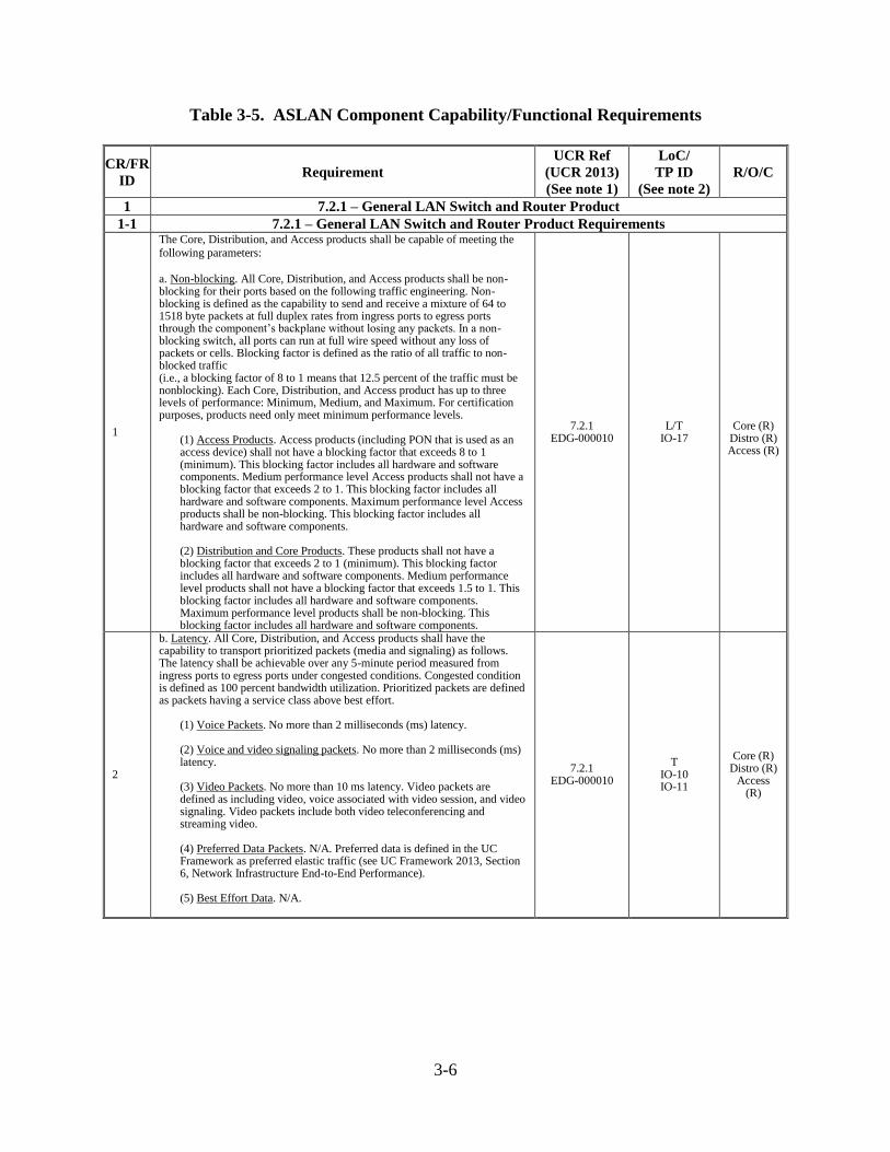
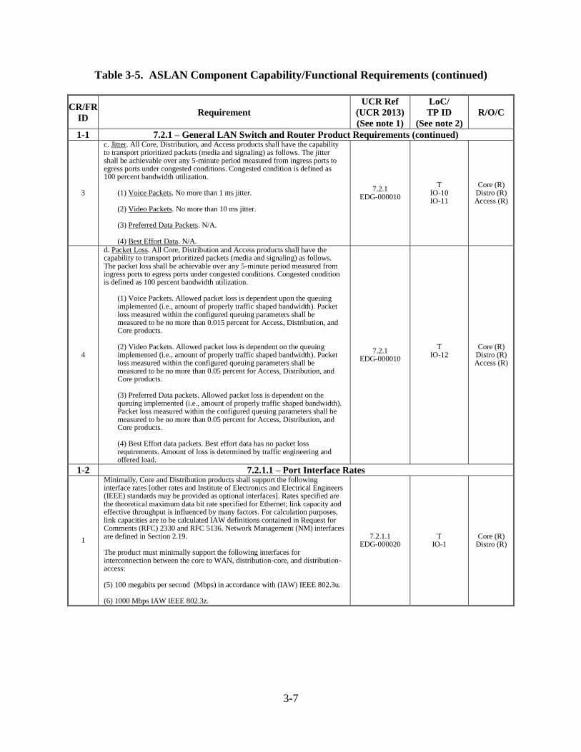
Table 3-5. ASLAN Component Capability/Functional Requirements
CR/FR
ID Requirement
UCR Ref
(UCR 2013)
(See note 1)
LoC/
TP ID
(See note 2)
R/O/C
1 7.2.1 – General LAN Switch and Router Product
1-1 7.2.1 – General LAN Switch and Router Product Requirements
1
The Core, Distribution, and Access products shall be capable of meeting the
following parameters: a. Non-blocking. All Core, Distribution, and Access products shall be non-blocking for their ports based on the following traffic engineering. Non-blocking is defined as the capability to send and receive a mixture of 64 to 1518 byte packets at full duplex rates from ingress ports to egress ports through the component’s backplane without losing any packets. In a non-blocking switch, all ports can run at full wire speed without any loss of packets or cells. Blocking factor is defined as the ratio of all traffic to non-blocked traffic (i.e., a blocking factor of 8 to 1 means that 12.5 percent of the traffic must be nonblocking). Each Core, Distribution, and Access product has up to three levels of performance: Minimum, Medium, and Maximum. For certification purposes, products need only meet minimum performance levels.
(1) Access Products. Access products (including PON that is used as an access device) shall not have a blocking factor that exceeds 8 to 1 (minimum). This blocking factor includes all hardware and software components. Medium performance level Access products shall not have a blocking factor that exceeds 2 to 1. This blocking factor includes all hardware and software components. Maximum performance level Access products shall be non-blocking. This blocking factor includes all hardware and software components. (2) Distribution and Core Products. These products shall not have a blocking factor that exceeds 2 to 1 (minimum). This blocking factor includes all hardware and software components. Medium performance level products shall not have a blocking factor that exceeds 1.5 to 1. This blocking factor includes all hardware and software components. Maximum performance level products shall be non-blocking. This blocking factor includes all hardware and software components.
7.2.1 EDG-000010
L/T IO-17
Core (R)
Distro (R) Access (R)
2
b. Latency. All Core, Distribution, and Access products shall have the capability to transport prioritized packets (media and signaling) as follows. The latency shall be achievable over any 5-minute period measured from ingress ports to egress ports under congested conditions. Congested condition is defined as 100 percent bandwidth utilization. Prioritized packets are defined as packets having a service class above best effort.
(1) Voice Packets. No more than 2 milliseconds (ms) latency. (2) Voice and video signaling packets. No more than 2 milliseconds (ms) latency. (3) Video Packets. No more than 10 ms latency. Video packets are defined as including video, voice associated with video session, and video signaling. Video packets include both video teleconferencing and streaming video. (4) Preferred Data Packets. N/A. Preferred data is defined in the UC Framework as preferred elastic traffic (see UC Framework 2013, Section 6, Network Infrastructure End-to-End Performance). (5) Best Effort Data. N/A.
7.2.1 EDG-000010
T IO-10 IO-11
Core (R) Distro (R)
Access (R)
3-7
Table 3-5. ASLAN Component Capability/Functional Requirements (continued)
CR/FR
ID Requirement
UCR Ref
(UCR 2013)
(See note 1)
LoC/
TP ID
(See note 2)
R/O/C
1-1 7.2.1 – General LAN Switch and Router Product Requirements (continued)
3
c. Jitter. All Core, Distribution, and Access products shall have the capability to transport prioritized packets (media and signaling) as follows. The jitter shall be achievable over any 5-minute period measured from ingress ports to egress ports under congested conditions. Congested condition is defined as 100 percent bandwidth utilization.
(1) Voice Packets. No more than 1 ms jitter. (2) Video Packets. No more than 10 ms jitter. (3) Preferred Data Packets. N/A. (4) Best Effort Data. N/A.
7.2.1 EDG-000010
T IO-10 IO-11
Core (R) Distro (R) Access (R)
4
d. Packet Loss. All Core, Distribution and Access products shall have the capability to transport prioritized packets (media and signaling) as follows. The packet loss shall be achievable over any 5-minute period measured from ingress ports to egress ports under congested conditions. Congested condition is defined as 100 percent bandwidth utilization.
(1) Voice Packets. Allowed packet loss is dependent upon the queuing implemented (i.e., amount of properly traffic shaped bandwidth). Packet loss measured within the configured queuing parameters shall be measured to be no more than 0.015 percent for Access, Distribution, and Core products. (2) Video Packets. Allowed packet loss is dependent on the queuing implemented (i.e., amount of properly traffic shaped bandwidth). Packet loss measured within the configured queuing parameters shall be measured to be no more than 0.05 percent for Access, Distribution, and Core products. (3) Preferred Data packets. Allowed packet loss is dependent on the queuing implemented (i.e., amount of properly traffic shaped bandwidth). Packet loss measured within the configured queuing parameters shall be measured to be no more than 0.05 percent for Access, Distribution, and Core products. (4) Best Effort data packets. Best effort data has no packet loss requirements. Amount of loss is determined by traffic engineering and offered load.
7.2.1 EDG-000010
T IO-12
Core (R) Distro (R) Access (R)
1-2 7.2.1.1 – Port Interface Rates
1
Minimally, Core and Distribution products shall support the following interface rates [other rates and Institute of Electronics and Electrical Engineers (IEEE) standards may be provided as optional interfaces]. Rates specified are the theoretical maximum data bit rate specified for Ethernet; link capacity and effective throughput is influenced by many factors. For calculation purposes, link capacities are to be calculated IAW definitions contained in Request for Comments (RFC) 2330 and RFC 5136. Network Management (NM) interfaces are defined in Section 2.19. The product must minimally support the following interfaces for interconnection between the core to WAN, distribution-core, and distribution-access: (5) 100 megabits per second (Mbps) in accordance with (IAW) IEEE 802.3u. (6) 1000 Mbps IAW IEEE 802.3z.
7.2.1.1 EDG-000020
T IO-1
Core (R) Distro (R)
3-8
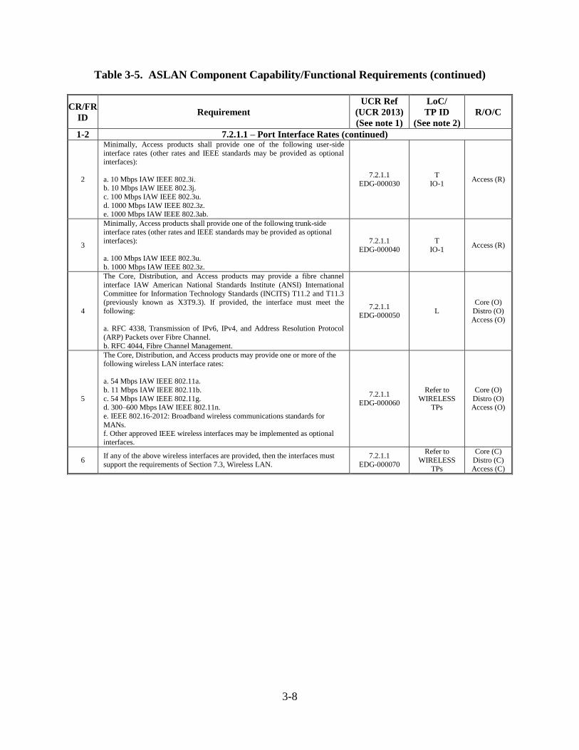
Table 3-5. ASLAN Component Capability/Functional Requirements (continued)
CR/FR
ID Requirement
UCR Ref
(UCR 2013)
(See note 1)
LoC/
TP ID
(See note 2)
R/O/C
1-2 7.2.1.1 – Port Interface Rates (continued)
2
Minimally, Access products shall provide one of the following user-side
interface rates (other rates and IEEE standards may be provided as optional interfaces):
a. 10 Mbps IAW IEEE 802.3i. b. 10 Mbps IAW IEEE 802.3j.
c. 100 Mbps IAW IEEE 802.3u.
d. 1000 Mbps IAW IEEE 802.3z. e. 1000 Mbps IAW IEEE 802.3ab.
7.2.1.1
EDG-000030
T
IO-1 Access (R)
3
Minimally, Access products shall provide one of the following trunk-side
interface rates (other rates and IEEE standards may be provided as optional
interfaces):
a. 100 Mbps IAW IEEE 802.3u.
b. 1000 Mbps IAW IEEE 802.3z.
7.2.1.1
EDG-000040
T
IO-1 Access (R)
4
The Core, Distribution, and Access products may provide a fibre channel
interface IAW American National Standards Institute (ANSI) International
Committee for Information Technology Standards (INCITS) T11.2 and T11.3 (previously known as X3T9.3). If provided, the interface must meet the
following:
a. RFC 4338, Transmission of IPv6, IPv4, and Address Resolution Protocol
(ARP) Packets over Fibre Channel.
b. RFC 4044, Fibre Channel Management.
7.2.1.1 EDG-000050
L
Core (O)
Distro (O)
Access (O)
5
The Core, Distribution, and Access products may provide one or more of the
following wireless LAN interface rates:
a. 54 Mbps IAW IEEE 802.11a.
b. 11 Mbps IAW IEEE 802.11b.
c. 54 Mbps IAW IEEE 802.11g.
d. 300–600 Mbps IAW IEEE 802.11n.
e. IEEE 802.16-2012: Broadband wireless communications standards for
MANs. f. Other approved IEEE wireless interfaces may be implemented as optional
interfaces.
7.2.1.1
EDG-000060
Refer to
WIRELESS
TPs
Core (O)
Distro (O)
Access (O)
6 If any of the above wireless interfaces are provided, then the interfaces must
support the requirements of Section 7.3, Wireless LAN.
7.2.1.1
EDG-000070
Refer to
WIRELESS TPs
Core (C)
Distro (C) Access (C)
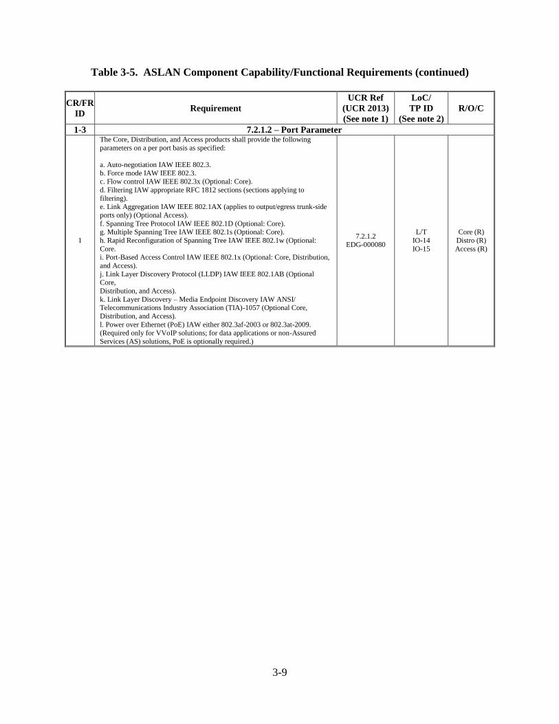
3-9
Table 3-5. ASLAN Component Capability/Functional Requirements (continued)
CR/FR
ID Requirement
UCR Ref
(UCR 2013)
(See note 1)
LoC/
TP ID
(See note 2)
R/O/C
1-3 7.2.1.2 – Port Parameter
1
The Core, Distribution, and Access products shall provide the following
parameters on a per port basis as specified:
a. Auto-negotiation IAW IEEE 802.3.
b. Force mode IAW IEEE 802.3. c. Flow control IAW IEEE 802.3x (Optional: Core).
d. Filtering IAW appropriate RFC 1812 sections (sections applying to
filtering). e. Link Aggregation IAW IEEE 802.1AX (applies to output/egress trunk-side
ports only) (Optional Access).
f. Spanning Tree Protocol IAW IEEE 802.1D (Optional: Core). g. Multiple Spanning Tree IAW IEEE 802.1s (Optional: Core).
h. Rapid Reconfiguration of Spanning Tree IAW IEEE 802.1w (Optional:
Core. i. Port-Based Access Control IAW IEEE 802.1x (Optional: Core, Distribution,
and Access).
j. Link Layer Discovery Protocol (LLDP) IAW IEEE 802.1AB (Optional Core,
Distribution, and Access).
k. Link Layer Discovery – Media Endpoint Discovery IAW ANSI/ Telecommunications Industry Association (TIA)-1057 (Optional Core,
Distribution, and Access).
l. Power over Ethernet (PoE) IAW either 802.3af-2003 or 802.3at-2009. (Required only for VVoIP solutions; for data applications or non-Assured
Services (AS) solutions, PoE is optionally required.)
7.2.1.2 EDG-000080
L/T
IO-14
IO-15
Core (R)
Distro (R)
Access (R)
3-10
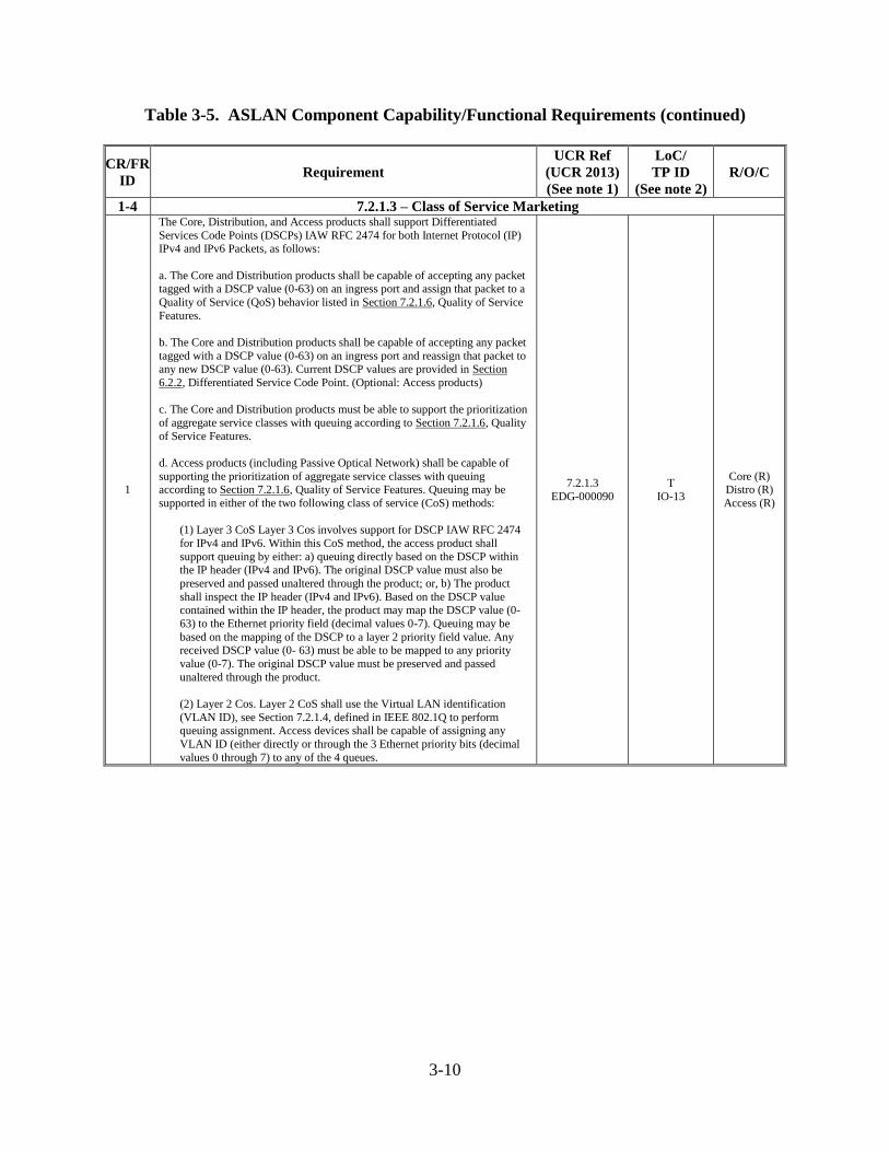
Table 3-5. ASLAN Component Capability/Functional Requirements (continued)
CR/FR
ID Requirement
UCR Ref
(UCR 2013)
(See note 1)
LoC/
TP ID
(See note 2)
R/O/C
1-4 7.2.1.3 – Class of Service Marketing
1
The Core, Distribution, and Access products shall support Differentiated
Services Code Points (DSCPs) IAW RFC 2474 for both Internet Protocol (IP) IPv4 and IPv6 Packets, as follows:
a. The Core and Distribution products shall be capable of accepting any packet tagged with a DSCP value (0-63) on an ingress port and assign that packet to a
Quality of Service (QoS) behavior listed in Section 7.2.1.6, Quality of Service
Features.
b. The Core and Distribution products shall be capable of accepting any packet
tagged with a DSCP value (0-63) on an ingress port and reassign that packet to any new DSCP value (0-63). Current DSCP values are provided in Section
6.2.2, Differentiated Service Code Point. (Optional: Access products)
c. The Core and Distribution products must be able to support the prioritization
of aggregate service classes with queuing according to Section 7.2.1.6, Quality
of Service Features.
d. Access products (including Passive Optical Network) shall be capable of
supporting the prioritization of aggregate service classes with queuing according to Section 7.2.1.6, Quality of Service Features. Queuing may be
supported in either of the two following class of service (CoS) methods:
(1) Layer 3 CoS Layer 3 Cos involves support for DSCP IAW RFC 2474
for IPv4 and IPv6. Within this CoS method, the access product shall
support queuing by either: a) queuing directly based on the DSCP within the IP header (IPv4 and IPv6). The original DSCP value must also be
preserved and passed unaltered through the product; or, b) The product
shall inspect the IP header (IPv4 and IPv6). Based on the DSCP value contained within the IP header, the product may map the DSCP value (0-
63) to the Ethernet priority field (decimal values 0-7). Queuing may be
based on the mapping of the DSCP to a layer 2 priority field value. Any received DSCP value (0- 63) must be able to be mapped to any priority
value (0-7). The original DSCP value must be preserved and passed
unaltered through the product.
(2) Layer 2 Cos. Layer 2 CoS shall use the Virtual LAN identification
(VLAN ID), see Section 7.2.1.4, defined in IEEE 802.1Q to perform queuing assignment. Access devices shall be capable of assigning any
VLAN ID (either directly or through the 3 Ethernet priority bits (decimal
values 0 through 7) to any of the 4 queues.
7.2.1.3
EDG-000090
T
IO-13
Core (R) Distro (R)
Access (R)
3-11
Table 3-5. ASLAN Component Capability/Functional Requirements (continued)
CR/FR
ID Requirement
UCR Ref
(UCR 2013)
(See note 1)
LoC/
TP ID
(See note 2)
R/O/C
1-4 7.2.1.3 – Class of Service Marketing (continued)
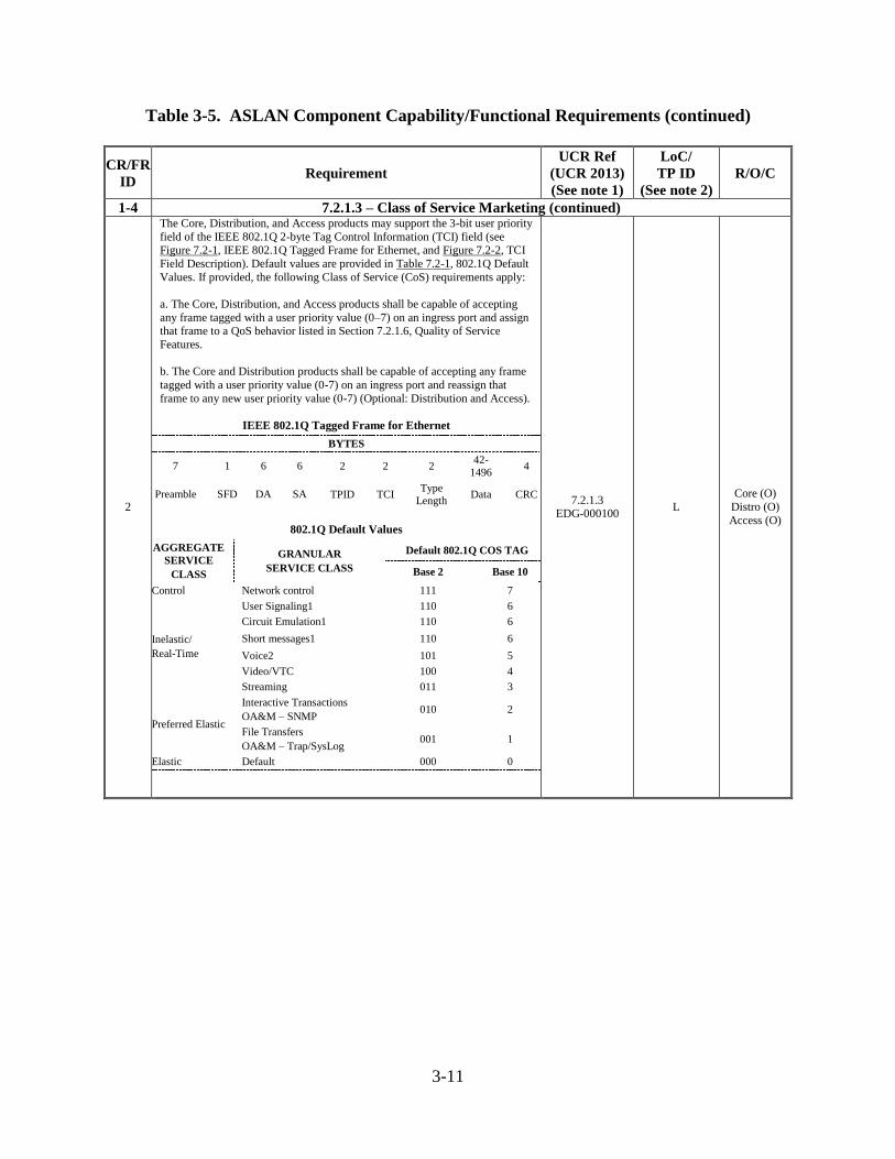
2
The Core, Distribution, and Access products may support the 3-bit user priority
field of the IEEE 802.1Q 2-byte Tag Control Information (TCI) field (see Figure 7.2-1, IEEE 802.1Q Tagged Frame for Ethernet, and Figure 7.2-2, TCI
Field Description). Default values are provided in Table 7.2-1, 802.1Q Default
Values. If provided, the following Class of Service (CoS) requirements apply:
a. The Core, Distribution, and Access products shall be capable of accepting
any frame tagged with a user priority value (0–7) on an ingress port and assign that frame to a QoS behavior listed in Section 7.2.1.6, Quality of Service
Features.
b. The Core and Distribution products shall be capable of accepting any frame
tagged with a user priority value (0-7) on an ingress port and reassign that
frame to any new user priority value (0-7) (Optional: Distribution and Access).
IEEE 802.1Q Tagged Frame for Ethernet
BYTES
7 1 6 6 2 2 2 42-
1496 4
Preamble SFD DA SA TPID TCI Type
Length Data CRC
802.1Q Default Values
AGGREGATE
SERVICE
CLASS
GRANULAR
SERVICE CLASS
Default 802.1Q COS TAG
Base 2 Base 10
Control Network control 111 7
Inelastic/
Real-Time
User Signaling1 110 6
Circuit Emulation1 110 6
Short messages1 110 6
Voice2 101 5
Video/VTC 100 4
Streaming 011 3
Preferred Elastic
Interactive Transactions
OA&M – SNMP 010 2
File Transfers
OA&M – Trap/SysLog 001 1
Elastic Default 000 0
7.2.1.3 EDG-000100
L
Core (O)
Distro (O)
Access (O)
3-12
Table 3-5. ASLAN Component Capability/Functional Requirements (continued)
CR/FR
ID Requirement
UCR Ref
(UCR 2013)
(See note 1)
LoC/
TP ID
(See note 2)
R/O/C
1-5 7.2.1.4 – Virtual LAN Capabilities
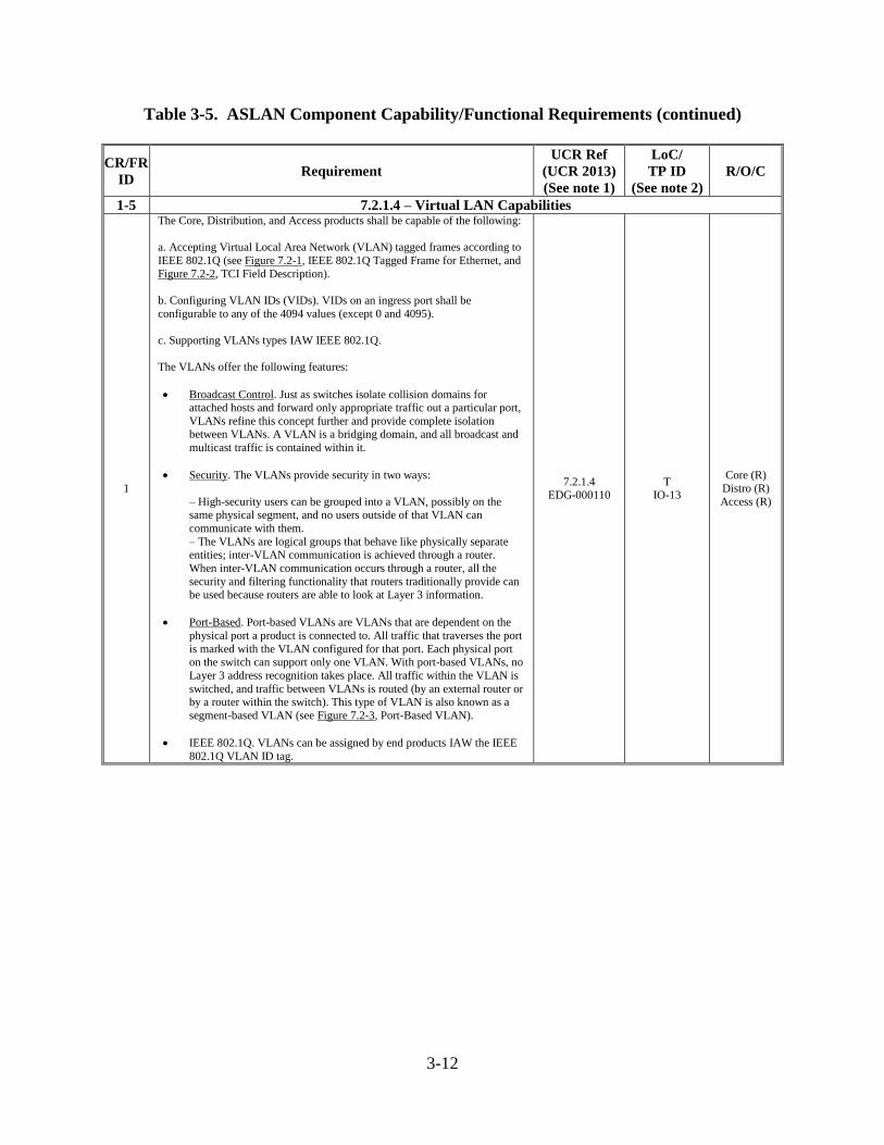
1
The Core, Distribution, and Access products shall be capable of the following:
a. Accepting Virtual Local Area Network (VLAN) tagged frames according to
IEEE 802.1Q (see Figure 7.2-1, IEEE 802.1Q Tagged Frame for Ethernet, and
Figure 7.2-2, TCI Field Description).
b. Configuring VLAN IDs (VIDs). VIDs on an ingress port shall be
configurable to any of the 4094 values (except 0 and 4095).
c. Supporting VLANs types IAW IEEE 802.1Q.
The VLANs offer the following features:
Broadcast Control. Just as switches isolate collision domains for attached hosts and forward only appropriate traffic out a particular port,
VLANs refine this concept further and provide complete isolation between VLANs. A VLAN is a bridging domain, and all broadcast and
multicast traffic is contained within it.
Security. The VLANs provide security in two ways:
– High-security users can be grouped into a VLAN, possibly on the same physical segment, and no users outside of that VLAN can
communicate with them.
– The VLANs are logical groups that behave like physically separate entities; inter-VLAN communication is achieved through a router.
When inter-VLAN communication occurs through a router, all the
security and filtering functionality that routers traditionally provide can be used because routers are able to look at Layer 3 information.
Port-Based. Port-based VLANs are VLANs that are dependent on the
physical port a product is connected to. All traffic that traverses the port
is marked with the VLAN configured for that port. Each physical port on the switch can support only one VLAN. With port-based VLANs, no
Layer 3 address recognition takes place. All traffic within the VLAN is
switched, and traffic between VLANs is routed (by an external router or by a router within the switch). This type of VLAN is also known as a
segment-based VLAN (see Figure 7.2-3, Port-Based VLAN).
IEEE 802.1Q. VLANs can be assigned by end products IAW the IEEE
802.1Q VLAN ID tag.
7.2.1.4 EDG-000110
T IO-13
Core (R)
Distro (R)
Access (R)
3-13
Table 3-5. ASLAN Component Capability/Functional Requirements (continued)
CR/FR
ID Requirement
UCR Ref
(UCR 2013)
(See note 1)
LoC/
TP ID
(See note 2)
R/O/C
1-5 7.2.1.4 – Virtual LAN Capabilities (continued)
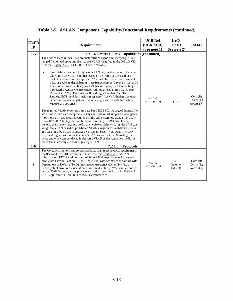
2
The Unified Capabilities (UC) products must be capable of accepting VLAN
tagged frames and assigning them to the VLAN identified in the 802.1Q VID field (see Figure 7.2-4, IEEE 802.1Q-Based VLANs).
User-Defined Value. This type of VLAN is typically the most flexible, allowing VLANs to be defined based on the value of any field in a
packet or frame. For example, VLANs could be defined on a protocol
basis or could be dependent on a particular address (Layer 2 or Layer 3). The simplest form of this type of VLAN is to group users according to
their Media Access Control (MAC) addresses (see Figure 7.2-5, User-
Defined VLANs). The LAN shall be designed so that Real-Time Services (RTS) and data reside in separate VLANs. Whether a product
is performing converged services or a single service will decide how VLANs are designed.
The required VLAN types are port-based and IEEE 802.1Q tagged frames. For VoIP, video, and data end products, any end system that supports convergence
(i.e., more than one media) requires that the end-system pre-assign the VLAN
using IEEE 802.1Q tags before the frames entering the ASLAN. For end-systems that support just one media (i.e., voice or video or data), the LAN can
assign the VLAN based on port-based VLAN assignment. Real-time services
and data must be placed in separate VLANs for security purpose. The LAN may be designed with more than one VLAN per media type. Signaling for
voice and video can be placed in the same VLAN as the respective media, or
placed in an entirely different signaling VLAN.
7.2.1.4
EDG-000120
T
IO-13
Core (R)
Distro (R)
Access (R)
1-6 7.2.1.5 – Protocols
1
The Core, Distribution, and Access products shall meet protocol requirements for IPv4 and IPv6. RFC requirements are listed in Table 7.2-2, ASLAN
Infrastructure RFC Requirements. Additional IPv6 requirements by product
profile are listed in Section 5, IPv6. These RFCs are not meant to conflict with
Department of Defense (DoD) Information Assurance (IA) policy (e.g.,
Security Technical Implementation Guidelines [STIGs]). Whenever a conflict
occurs, DoD IA policy takes precedence. If there are conflicts with Section 5, RFCs applicable to IPv6 in Section 5 take precedence.
7.2.1.5
EDG-000130
L/T
(refer to
Table 3)
Core (R)
Distro (R)
Access (R)
3-14
Table 3-5. ASLAN Component Capability/Functional Requirements (continued)
CR/FR
ID Requirement
UCR Ref
(UCR 2013)
(See note 1)
LoC/
TP ID
(See note 2)
R/O/C
1-7 7.2.1.6 – Quality of Service Features
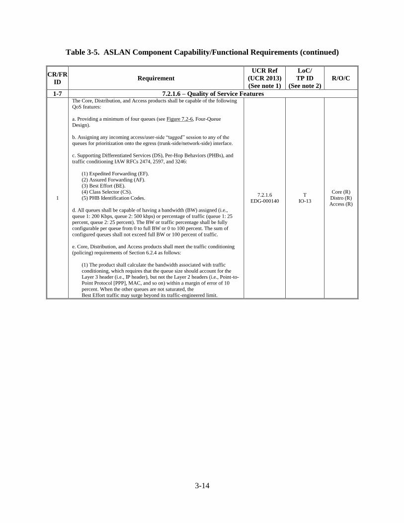
1
The Core, Distribution, and Access products shall be capable of the following
QoS features:
a. Providing a minimum of four queues (see Figure 7.2-6, Four-Queue
Design).
b. Assigning any incoming access/user-side “tagged” session to any of the
queues for prioritization onto the egress (trunk-side/network-side) interface.
c. Supporting Differentiated Services (DS), Per-Hop Behaviors (PHBs), and
traffic conditioning IAW RFCs 2474, 2597, and 3246:
(1) Expedited Forwarding (EF).
(2) Assured Forwarding (AF). (3) Best Effort (BE).
(4) Class Selector (CS).
(5) PHB Identification Codes.
d. All queues shall be capable of having a bandwidth (BW) assigned (i.e.,
queue 1: 200 Kbps, queue 2: 500 kbps) or percentage of traffic (queue 1: 25 percent, queue 2: 25 percent). The BW or traffic percentage shall be fully
configurable per queue from 0 to full BW or 0 to 100 percent. The sum of
configured queues shall not exceed full BW or 100 percent of traffic.
e. Core, Distribution, and Access products shall meet the traffic conditioning
(policing) requirements of Section 6.2.4 as follows:
(1) The product shall calculate the bandwidth associated with traffic
conditioning, which requires that the queue size should account for the Layer 3 header (i.e., IP header), but not the Layer 2 headers (i.e., Point-to-
Point Protocol [PPP], MAC, and so on) within a margin of error of 10
percent. When the other queues are not saturated, the Best Effort traffic may surge beyond its traffic-engineered limit.
7.2.1.6
EDG-000140
T
IO-13
Core (R)
Distro (R) Access (R)
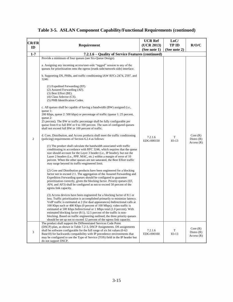
3-15
Table 3-5. ASLAN Component Capability/Functional Requirements (continued)
CR/FR
ID Requirement
UCR Ref
(UCR 2013)
(See note 1)
LoC/
TP ID
(See note 2)
R/O/C
1-7 7.2.1.6 – Quality of Service Features (continued)
2
Provide a minimum of four queues (see Six-Queue Design).
a. Assigning any incoming access/user-side “tagged” session to any of the
queues for prioritization onto the egress (trunk-side/network-side) interface.
b. Supporting DS, PHBs, and traffic conditioning IAW RFCs 2474, 2597, and
3246:
(1) Expedited Forwarding (EF).
(2) Assured Forwarding (AF).
(3) Best Effort (BE). (4) Class Selector (CS).
(5) PHB Identification Codes.
c. All queues shall be capable of having a bandwidth (BW) assigned (i.e.,
queue 1:
200 Kbps, queue 2: 500 kbps) or percentage of traffic (queue 1: 25 percent, queue 2:
25 percent). The BW or traffic percentage shall be fully configurable per
queue from 0 to full BW or 0 to 100 percent. The sum of configured queues shall not exceed full BW or 100 percent of traffic.
d. Core, Distribution, and Access products shall meet the traffic conditioning (policing) requirements of Section 6.2.4 as follows:
(1) The product shall calculate the bandwidth associated with traffic conditioning in accordance with RFC 3246, which requires that the queue
size should account for the Layer 3 header (i.e., IP header), but not the
Layer 2 headers (i.e., PPP, MAC, etc.) within a margin of error of 10 percent. When the other queues are not saturated, the Best Effort traffic
may surge beyond its traffic-engineered limit.
(2) Core and Distribution products have been engineered for a blocking
factor not to exceed 2:1. The aggregation of the Assured Forwarding and
Expedition Forwarding queues should be configured to guarantee prioritization correctly, given the blocking factor. Priority queues (EF,
AF4, and AF3) shall be configured as not to exceed 50 percent of the
egress link capacity.
(3) Access devices have been engineered for a blocking factor of 8:1 or
less. Traffic prioritization is accomplished primarily to minimize latency. VoIP traffic is estimated at 2 (for dual appearances) bidirectional calls at
100 Kbps each or 400 Kbps (0 percent of 100 Mbps); video traffic is
estimated at 500 Kbps bidirectional or 1 Mbps total (1.0 percent). With estimated blocking factor (8:1), 12.5 percent of the traffic is non-
blocking. Based on traffic engineering outlined, the three priority queues should be set up not to exceed 12 percent of the egress link capacity.
7.2.1.6
EDG-000150
T
IO-13
Core (R) Distro (R)
Access (R)
3
The product shall support the Differentiated Services Code Point
(DSCP) plan, as shown in Table 7.2-3, DSCP Assignments. DS assignments
shall be software configurable for the full range of six bit values (0-63 Base10) for backwards compatibility with IP precedence environments that
may be configured to use the Type of Service (TOS) field in the IP header but
do not support DSCP.
7.2.1.6 EDG-000160
T IO-13
Core (R)
Distro (R)
Access (R)
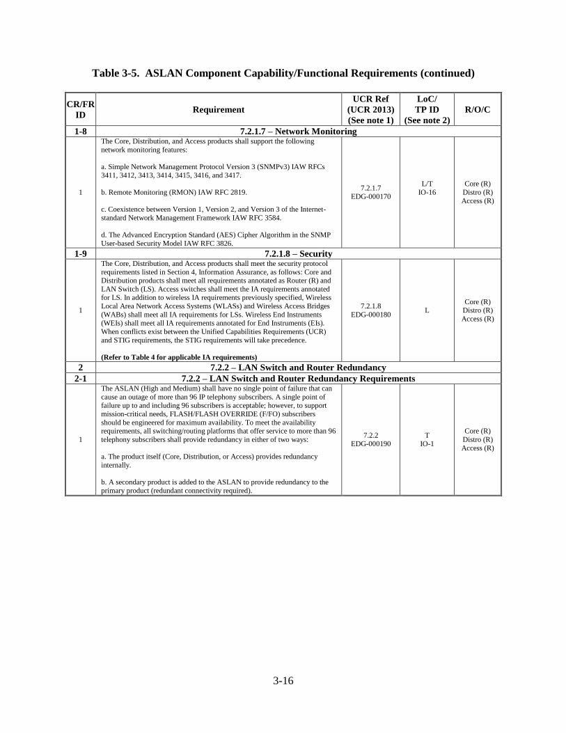
3-16
Table 3-5. ASLAN Component Capability/Functional Requirements (continued)
CR/FR
ID Requirement
UCR Ref
(UCR 2013)
(See note 1)
LoC/
TP ID
(See note 2)
R/O/C
1-8 7.2.1.7 – Network Monitoring
1
The Core, Distribution, and Access products shall support the following
network monitoring features:
a. Simple Network Management Protocol Version 3 (SNMPv3) IAW RFCs
3411, 3412, 3413, 3414, 3415, 3416, and 3417.
b. Remote Monitoring (RMON) IAW RFC 2819.
c. Coexistence between Version 1, Version 2, and Version 3 of the Internet-
standard Network Management Framework IAW RFC 3584.
d. The Advanced Encryption Standard (AES) Cipher Algorithm in the SNMP
User-based Security Model IAW RFC 3826.
7.2.1.7 EDG-000170
L/T
IO-16
Core (R)
Distro (R)
Access (R)
1-9 7.2.1.8 – Security
1
The Core, Distribution, and Access products shall meet the security protocol
requirements listed in Section 4, Information Assurance, as follows: Core and Distribution products shall meet all requirements annotated as Router (R) and
LAN Switch (LS). Access switches shall meet the IA requirements annotated for LS. In addition to wireless IA requirements previously specified, Wireless
Local Area Network Access Systems (WLASs) and Wireless Access Bridges
(WABs) shall meet all IA requirements for LSs. Wireless End Instruments (WEIs) shall meet all IA requirements annotated for End Instruments (EIs).
When conflicts exist between the Unified Capabilities Requirements (UCR)
and STIG requirements, the STIG requirements will take precedence.
(Refer to Table 4 for applicable IA requirements)
7.2.1.8
EDG-000180 L
Core (R) Distro (R)
Access (R)
2 7.2.2 – LAN Switch and Router Redundancy
2-1 7.2.2 – LAN Switch and Router Redundancy Requirements
1
The ASLAN (High and Medium) shall have no single point of failure that can
cause an outage of more than 96 IP telephony subscribers. A single point of
failure up to and including 96 subscribers is acceptable; however, to support
mission-critical needs, FLASH/FLASH OVERRIDE (F/FO) subscribers
should be engineered for maximum availability. To meet the availability requirements, all switching/routing platforms that offer service to more than 96
telephony subscribers shall provide redundancy in either of two ways:
a. The product itself (Core, Distribution, or Access) provides redundancy
internally.
b. A secondary product is added to the ASLAN to provide redundancy to the
primary product (redundant connectivity required).
7.2.2 EDG-000190
T IO-1
Core (R)
Distro (R)
Access (R)
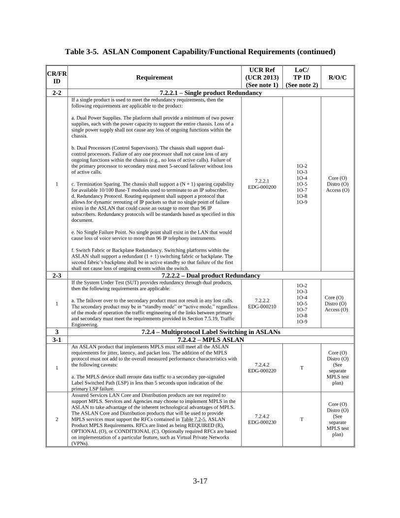
3-17
Table 3-5. ASLAN Component Capability/Functional Requirements (continued)
CR/FR
ID Requirement
UCR Ref
(UCR 2013)
(See note 1)
LoC/
TP ID
(See note 2)
R/O/C
2-2 7.2.2.1 – Single product Redundancy
1
If a single product is used to meet the redundancy requirements, then the
following requirements are applicable to the product:
a. Dual Power Supplies. The platform shall provide a minimum of two power
supplies, each with the power capacity to support the entire chassis. Loss of a single power supply shall not cause any loss of ongoing functions within the
chassis.
b. Dual Processors (Control Supervisors). The chassis shall support dual-
control processors. Failure of any one processor shall not cause loss of any
ongoing functions within the chassis (e.g., no loss of active calls). Failure of the primary processor to secondary must meet 5-second failover without loss
of active calls.
c. Termination Sparing. The chassis shall support a (N + 1) sparing capability
for available 10/100 Base-T modules used to terminate to an IP subscriber.
d. Redundancy Protocol. Routing equipment shall support a protocol that allows for dynamic rerouting of IP packets so that no single point of failure
exists in the ASLAN that could cause an outage to more than 96 IP
subscribers. Redundancy protocols will be standards based as specified in this document.
e. No Single Failure Point. No single point shall exist in the LAN that would cause loss of voice service to more than 96 IP telephony instruments.
f. Switch Fabric or Backplane Redundancy. Switching platforms within the ASLAN shall support a redundant (1 + 1) switching fabric or backplane. The
second fabric’s backplane shall be in active standby so that failure of the first
shall not cause loss of ongoing events within the switch.
7.2.2.1
EDG-000200
1O-2
1O-3
1O-4 1O-5
1O-7
1O-8 1O-9
Core (O) Distro (O)
Access (O)
2-3 7.2.2.2 – Dual product Redundancy
1
If the System Under Test (SUT) provides redundancy through dual products,
then the following requirements are applicable:
a. The failover over to the secondary product must not result in any lost calls.
The secondary product may be in “standby mode” or “active mode,” regardless
of the mode of operation the traffic engineering of the links between primary and secondary must meet the requirements provided in Section 7.5.19, Traffic
Engineering.
7.2.2.2
EDG-000210
1O-2 1O-3
1O-4
1O-5 1O-7
1O-8
1O-9
Core (O)
Distro (O) Access (O)
3 7.2.4 – Multiprotocol Label Switching in ASLANs
3-1 7.2.4.2 – MPLS ASLAN
1
An ASLAN product that implements MPLS must still meet all the ASLAN
requirements for jitter, latency, and packet loss. The addition of the MPLS protocol must not add to the overall measured performance characteristics with
the following caveats:
a. The MPLS device shall reroute data traffic to a secondary pre-signaled
Label Switched Path (LSP) in less than 5 seconds upon indication of the primary LSP failure.
7.2.4.2 EDG-000220
T
Core (O) Distro (O)
(See separate
MPLS test
plan)
2
Assured Services LAN Core and Distribution products are not required to
support MPLS. Services and Agencies may choose to implement MPLS in the
ASLAN to take advantage of the inherent technological advantages of MPLS. The ASLAN Core and Distribution products that will be used to provide
MPLS services must support the RFCs contained in Table 7.2-5, ASLAN
Product MPLS Requirements. RFCs are listed as being REQUIRED (R), OPTIONAL (O), or CONDITIONAL (C). Optionally required RFCs are based
on implementation of a particular feature, such as Virtual Private Networks
(VPNs).
7.2.4.2 EDG-000230
T
Core (O)
Distro (O)
(See separate
MPLS test
plan)
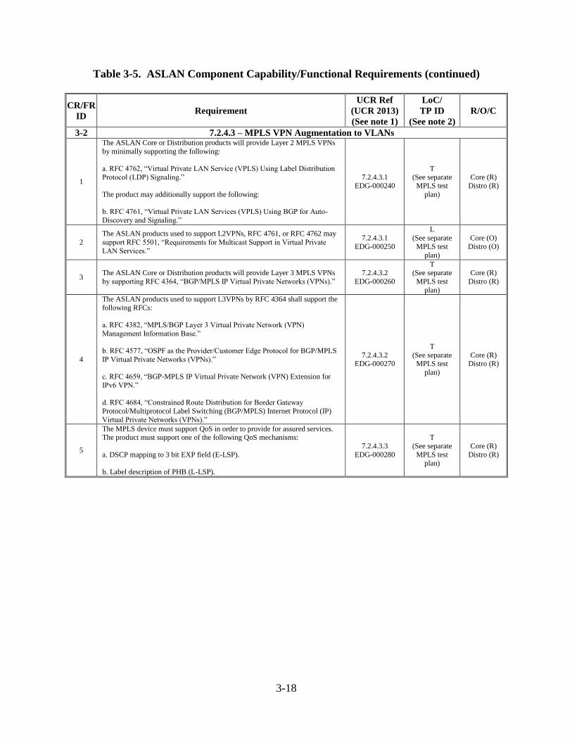
3-18
Table 3-5. ASLAN Component Capability/Functional Requirements (continued)
CR/FR
ID Requirement
UCR Ref
(UCR 2013)
(See note 1)
LoC/
TP ID
(See note 2)
R/O/C
3-2 7.2.4.3 – MPLS VPN Augmentation to VLANs
1
The ASLAN Core or Distribution products will provide Layer 2 MPLS VPNs
by minimally supporting the following:
a. RFC 4762, “Virtual Private LAN Service (VPLS) Using Label Distribution
Protocol (LDP) Signaling.”
The product may additionally support the following:
b. RFC 4761, “Virtual Private LAN Services (VPLS) Using BGP for Auto-
Discovery and Signaling.”
7.2.4.3.1 EDG-000240
T
(See separate MPLS test
plan)
Core (R) Distro (R)
2
The ASLAN products used to support L2VPNs, RFC 4761, or RFC 4762 may
support RFC 5501, “Requirements for Multicast Support in Virtual Private
LAN Services.”
7.2.4.3.1
EDG-000250
L
(See separate
MPLS test
plan)
Core (O)
Distro (O)
3 The ASLAN Core or Distribution products will provide Layer 3 MPLS VPNs
by supporting RFC 4364, “BGP/MPLS IP Virtual Private Networks (VPNs).”
7.2.4.3.2
EDG-000260
T (See separate
MPLS test
plan)
Core (R)
Distro (R)
4
The ASLAN products used to support L3VPNs by RFC 4364 shall support the
following RFCs:
a. RFC 4382, “MPLS/BGP Layer 3 Virtual Private Network (VPN)
Management Information Base.”
b. RFC 4577, “OSPF as the Provider/Customer Edge Protocol for BGP/MPLS
IP Virtual Private Networks (VPNs).”
c. RFC 4659, “BGP-MPLS IP Virtual Private Network (VPN) Extension for
IPv6 VPN.”
d. RFC 4684, “Constrained Route Distribution for Border Gateway
Protocol/Multiprotocol Label Switching (BGP/MPLS) Internet Protocol (IP)
Virtual Private Networks (VPNs).”
7.2.4.3.2 EDG-000270
T
(See separate MPLS test
plan)
Core (R) Distro (R)
5
The MPLS device must support QoS in order to provide for assured services. The product must support one of the following QoS mechanisms:
a. DSCP mapping to 3 bit EXP field (E-LSP).
b. Label description of PHB (L-LSP).
7.2.4.3.3
EDG-000280
T
(See separate
MPLS test plan)
Core (R)
Distro (R)
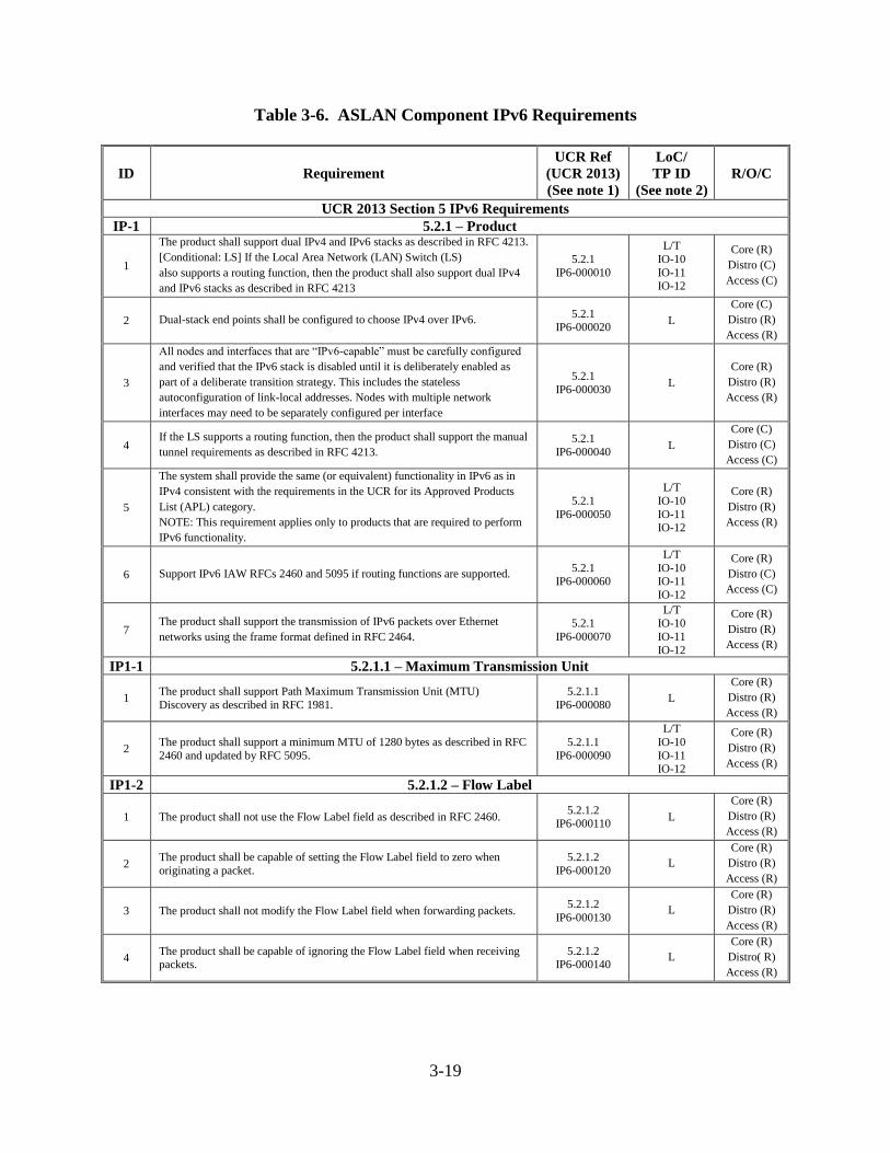
3-19
Table 3-6. ASLAN Component IPv6 Requirements
ID Requirement
UCR Ref
(UCR 2013)
(See note 1)
LoC/
TP ID
(See note 2)
R/O/C
UCR 2013 Section 5 IPv6 Requirements
IP-1 5.2.1 – Product
1
The product shall support dual IPv4 and IPv6 stacks as described in RFC 4213.
[Conditional: LS] If the Local Area Network (LAN) Switch (LS)
also supports a routing function, then the product shall also support dual IPv4
and IPv6 stacks as described in RFC 4213
5.2.1
IP6-000010
L/T
IO-10
IO-11 IO-12
Core (R)
Distro (C)
Access (C)
2 Dual-stack end points shall be configured to choose IPv4 over IPv6. 5.2.1
IP6-000020 L
Core (C)
Distro (R)
Access (R)
3
All nodes and interfaces that are “IPv6-capable” must be carefully configured
and verified that the IPv6 stack is disabled until it is deliberately enabled as
part of a deliberate transition strategy. This includes the stateless
autoconfiguration of link-local addresses. Nodes with multiple network
interfaces may need to be separately configured per interface
5.2.1
IP6-000030 L
Core (R)
Distro (R)
Access (R)
4 If the LS supports a routing function, then the product shall support the manual
tunnel requirements as described in RFC 4213.
5.2.1
IP6-000040 L
Core (C)
Distro (C)
Access (C)
5
The system shall provide the same (or equivalent) functionality in IPv6 as in
IPv4 consistent with the requirements in the UCR for its Approved Products
List (APL) category.
NOTE: This requirement applies only to products that are required to perform
IPv6 functionality.
5.2.1
IP6-000050
L/T
IO-10
IO-11 IO-12
Core (R)
Distro (R)
Access (R)
6 Support IPv6 IAW RFCs 2460 and 5095 if routing functions are supported. 5.2.1
IP6-000060
L/T
IO-10 IO-11
IO-12
Core (R)
Distro (C)
Access (C)
7 The product shall support the transmission of IPv6 packets over Ethernet
networks using the frame format defined in RFC 2464.
5.2.1
IP6-000070
L/T IO-10
IO-11
IO-12
Core (R)
Distro (R)
Access (R)
IP1-1 5.2.1.1 – Maximum Transmission Unit
1 The product shall support Path Maximum Transmission Unit (MTU)
Discovery as described in RFC 1981.
5.2.1.1
IP6-000080 L
Core (R)
Distro (R)
Access (R)
2 The product shall support a minimum MTU of 1280 bytes as described in RFC
2460 and updated by RFC 5095.
5.2.1.1
IP6-000090
L/T
IO-10
IO-11 IO-12
Core (R)
Distro (R)
Access (R)
IP1-2 5.2.1.2 – Flow Label
1 The product shall not use the Flow Label field as described in RFC 2460. 5.2.1.2
IP6-000110 L
Core (R)
Distro (R)
Access (R)
2 The product shall be capable of setting the Flow Label field to zero when
originating a packet.
5.2.1.2
IP6-000120 L
Core (R)
Distro (R)
Access (R)
3 The product shall not modify the Flow Label field when forwarding packets. 5.2.1.2
IP6-000130 L
Core (R)
Distro (R)
Access (R)
4 The product shall be capable of ignoring the Flow Label field when receiving packets.
5.2.1.2 IP6-000140
L Core (R)
Distro( R)
Access (R)
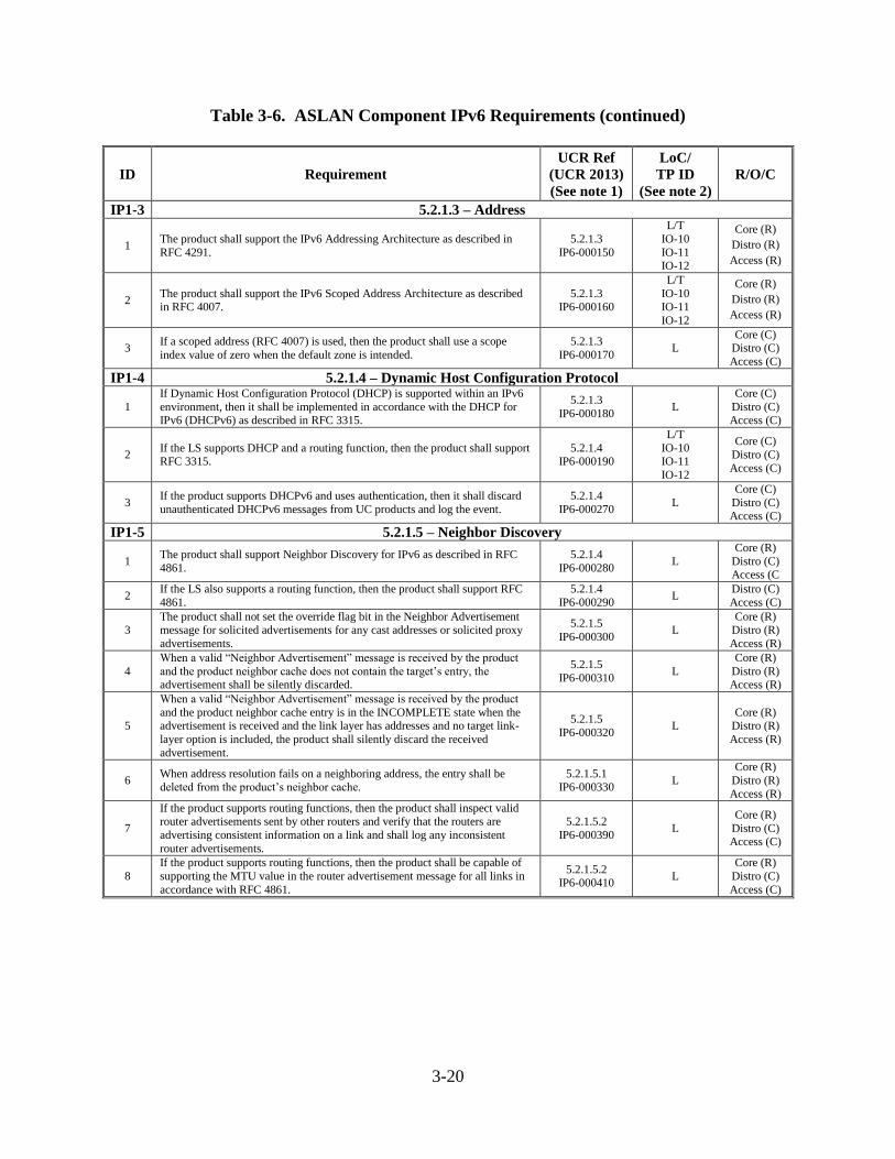
3-20
Table 3-6. ASLAN Component IPv6 Requirements (continued)
ID Requirement
UCR Ref
(UCR 2013)
(See note 1)
LoC/
TP ID
(See note 2)
R/O/C
IP1-3 5.2.1.3 – Address
1 The product shall support the IPv6 Addressing Architecture as described in
RFC 4291.
5.2.1.3
IP6-000150
L/T
IO-10
IO-11 IO-12
Core (R)
Distro (R)
Access (R)
2 The product shall support the IPv6 Scoped Address Architecture as described in RFC 4007.
5.2.1.3 IP6-000160
L/T
IO-10 IO-11
IO-12
Core (R)
Distro (R)
Access (R)
3 If a scoped address (RFC 4007) is used, then the product shall use a scope
index value of zero when the default zone is intended.
5.2.1.3
IP6-000170 L
Core (C) Distro (C)
Access (C)
IP1-4 5.2.1.4 – Dynamic Host Configuration Protocol
1
If Dynamic Host Configuration Protocol (DHCP) is supported within an IPv6
environment, then it shall be implemented in accordance with the DHCP for IPv6 (DHCPv6) as described in RFC 3315.
5.2.1.3
IP6-000180 L
Core (C)
Distro (C) Access (C)
2 If the LS supports DHCP and a routing function, then the product shall support RFC 3315.
5.2.1.4 IP6-000190
L/T
IO-10 IO-11
IO-12
Core (C)
Distro (C)
Access (C)
3 If the product supports DHCPv6 and uses authentication, then it shall discard
unauthenticated DHCPv6 messages from UC products and log the event.
5.2.1.4
IP6-000270 L
Core (C)
Distro (C) Access (C)
IP1-5 5.2.1.5 – Neighbor Discovery
1 The product shall support Neighbor Discovery for IPv6 as described in RFC
4861.
5.2.1.4
IP6-000280 L
Core (R)
Distro (C) Access (C
2 If the LS also supports a routing function, then the product shall support RFC
4861.
5.2.1.4
IP6-000290 L
Distro (C)
Access (C)
3
The product shall not set the override flag bit in the Neighbor Advertisement
message for solicited advertisements for any cast addresses or solicited proxy
advertisements.
5.2.1.5
IP6-000300 L
Core (R)
Distro (R)
Access (R)
4
When a valid “Neighbor Advertisement” message is received by the product
and the product neighbor cache does not contain the target’s entry, the advertisement shall be silently discarded.
5.2.1.5
IP6-000310 L
Core (R)
Distro (R) Access (R)
5
When a valid “Neighbor Advertisement” message is received by the product
and the product neighbor cache entry is in the INCOMPLETE state when the advertisement is received and the link layer has addresses and no target link-
layer option is included, the product shall silently discard the received
advertisement.
5.2.1.5
IP6-000320 L
Core (R) Distro (R)
Access (R)
6 When address resolution fails on a neighboring address, the entry shall be deleted from the product’s neighbor cache.
5.2.1.5.1 IP6-000330
L
Core (R)
Distro (R)
Access (R)
7
If the product supports routing functions, then the product shall inspect valid router advertisements sent by other routers and verify that the routers are
advertising consistent information on a link and shall log any inconsistent
router advertisements.
5.2.1.5.2
IP6-000390 L
Core (R)
Distro (C) Access (C)
8
If the product supports routing functions, then the product shall be capable of
supporting the MTU value in the router advertisement message for all links in
accordance with RFC 4861.
5.2.1.5.2
IP6-000410 L
Core (R)
Distro (C)
Access (C)
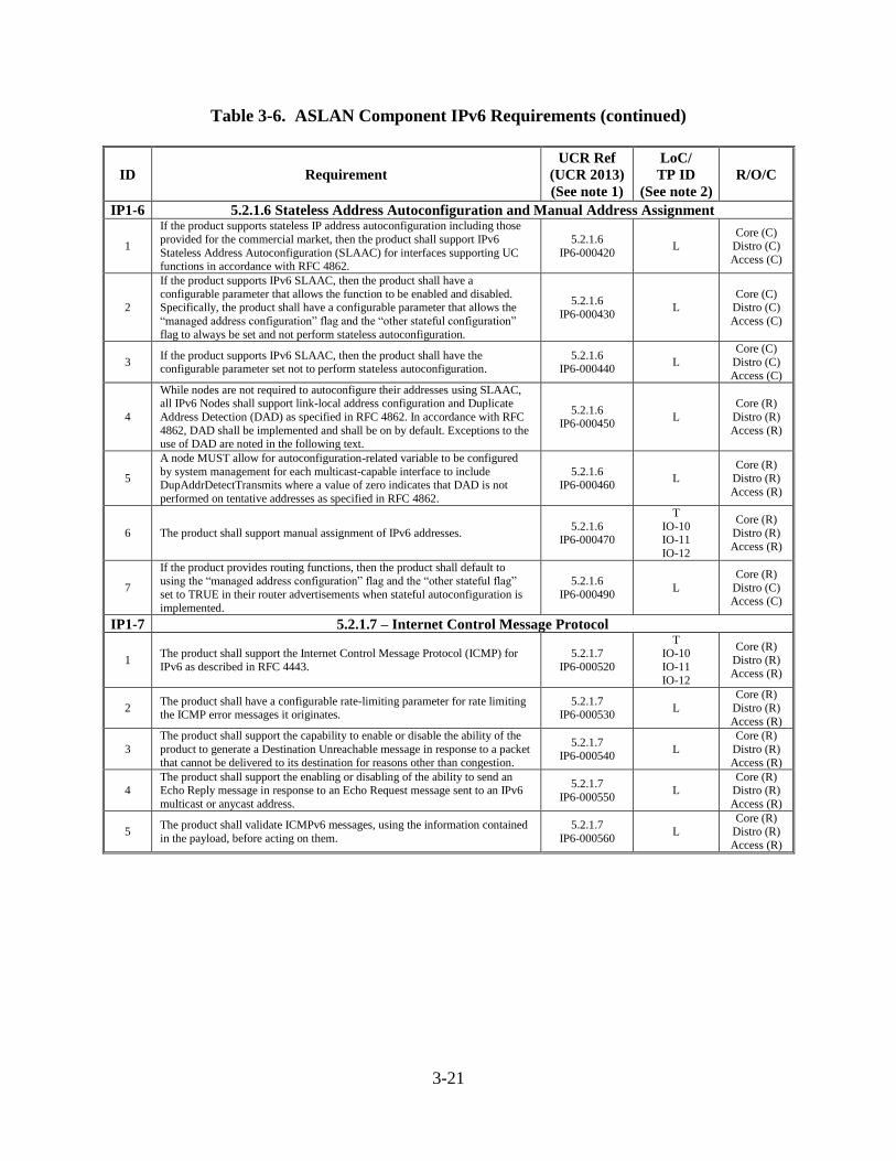
3-21
Table 3-6. ASLAN Component IPv6 Requirements (continued)
ID Requirement
UCR Ref
(UCR 2013)
(See note 1)
LoC/
TP ID
(See note 2)
R/O/C
IP1-6 5.2.1.6 Stateless Address Autoconfiguration and Manual Address Assignment
1
If the product supports stateless IP address autoconfiguration including those
provided for the commercial market, then the product shall support IPv6
Stateless Address Autoconfiguration (SLAAC) for interfaces supporting UC functions in accordance with RFC 4862.
5.2.1.6
IP6-000420 L
Core (C) Distro (C)
Access (C)
2
If the product supports IPv6 SLAAC, then the product shall have a
configurable parameter that allows the function to be enabled and disabled. Specifically, the product shall have a configurable parameter that allows the
“managed address configuration” flag and the “other stateful configuration”
flag to always be set and not perform stateless autoconfiguration.
5.2.1.6
IP6-000430 L
Core (C) Distro (C)
Access (C)
3 If the product supports IPv6 SLAAC, then the product shall have the configurable parameter set not to perform stateless autoconfiguration.
5.2.1.6 IP6-000440
L
Core (C)
Distro (C)
Access (C)
4
While nodes are not required to autoconfigure their addresses using SLAAC, all IPv6 Nodes shall support link-local address configuration and Duplicate
Address Detection (DAD) as specified in RFC 4862. In accordance with RFC
4862, DAD shall be implemented and shall be on by default. Exceptions to the use of DAD are noted in the following text.
5.2.1.6 IP6-000450
L
Core (R)
Distro (R)
Access (R)
5
A node MUST allow for autoconfiguration-related variable to be configured
by system management for each multicast-capable interface to include DupAddrDetectTransmits where a value of zero indicates that DAD is not
performed on tentative addresses as specified in RFC 4862.
5.2.1.6 IP6-000460
L
Core (R)
Distro (R)
Access (R)
6 The product shall support manual assignment of IPv6 addresses. 5.2.1.6
IP6-000470
T
IO-10 IO-11
IO-12
Core (R)
Distro (R)
Access (R)
7
If the product provides routing functions, then the product shall default to using the “managed address configuration” flag and the “other stateful flag”
set to TRUE in their router advertisements when stateful autoconfiguration is
implemented.
5.2.1.6
IP6-000490 L
Core (R)
Distro (C) Access (C)
IP1-7 5.2.1.7 – Internet Control Message Protocol
1 The product shall support the Internet Control Message Protocol (ICMP) for
IPv6 as described in RFC 4443.
5.2.1.7
IP6-000520
T IO-10
IO-11
IO-12
Core (R)
Distro (R) Access (R)
2 The product shall have a configurable rate-limiting parameter for rate limiting the ICMP error messages it originates.
5.2.1.7 IP6-000530
L
Core (R)
Distro (R)
Access (R)
3
The product shall support the capability to enable or disable the ability of the
product to generate a Destination Unreachable message in response to a packet
that cannot be delivered to its destination for reasons other than congestion.
5.2.1.7 IP6-000540
L
Core (R)
Distro (R)
Access (R)
4 The product shall support the enabling or disabling of the ability to send an Echo Reply message in response to an Echo Request message sent to an IPv6
multicast or anycast address.
5.2.1.7
IP6-000550 L
Core (R) Distro (R)
Access (R)
5 The product shall validate ICMPv6 messages, using the information contained
in the payload, before acting on them.
5.2.1.7
IP6-000560 L
Core (R) Distro (R)
Access (R)
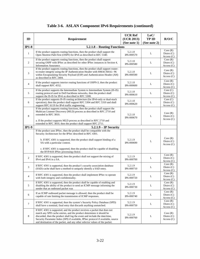
3-22
Table 3-6. ASLAN Component IPv6 Requirements (continued)
ID Requirement
UCR Ref
(UCR 2013)
(See note 1)
LoC/
TP ID
(See note 2)
R/O/C
IP1-8 5.2.1.8 – Routing Functions
1 If the product supports routing functions, then the product shall support the Open Shortest Path First (OSPF) for IPv6 as described in RFC 5340.
5.2.1.8 IP6-000570
L
Core (R)
Distro (C)
Access (C)
2
If the product supports routing functions, then the product shall support
securing OSPF with IPSec as described for other IPSec instances in Section 4,
Information Assurance.
5.2.1.8 IP6-000580
L
Core (R)
Distro (C)
Access (C)
3
If the product supports routing functions, then the product shall support router-to-router integrity using the IP Authentication Header with HMACSHA1- 96
within Encapsulating Security Payload (ESP) and Authentication Header (AH) as described in RFC 2404.
5.2.1.8
IP6-000590 L
Core (R)
Distro (C) Access (C)
4 If the product supports interior routing functions of OSPFv3, then the product
shall support RFC 4552.
5.2.1.8
IP6-000600 L
Core (R)
Distro (C)
Access (C)
5
If the product supports the Intermediate System to Intermediate System (IS-IS)
routing protocol used in DoD backbone networks, then the product shall
support the IS-IS for IPv6 as described in RFC 5308.
5.2.1.8 IP6-000610
L
Core (C)
Distro (C)
Access (C)
6 If the product supports IS-IS routing architecture (for IPv6-only or dual-stack operation), then the product shall support RFC 5304 and RFC 5310 and shall
support RFC 6119 for IPv6 traffic engineering.
5.2.1.8
IP6-000620 L
Core (C) Distro (C)
Access (C)
8
If the product supports routing functions, then the product shall support the Multicast Listener Discovery (MLD) process as described in RFC 2710 and
extended in RFC 3810.
a. If the product supports MLD process as described in RFC 2710 and
extended in RFC 3810, then the product shall support RFC 2711.
5.2.1.8
IP6-000670 L
Core (R) Distro (C)
Access (C)
IP1-9 5.2.1.9 – IP Security
1
If the product uses IPSec, then the product shall be compatible with the
Security Architecture for the IPSec described in RFC 4301.
b. If RFC 4301 is supported, then the product shall support binding of a
SA with a particular context.
c. If RFC 4301 is supported, then the product shall be capable of disabling
the BYPASS IPSec processing choice.
5.2.1.9
IP6-000690 L
Core (R)
Distro (C)
Access (C)
2 If RFC 4301 is supported, then the product shall not support the mixing of IPv4 and IPv6 in a SA.
5.2.1.9 IP6-000700
L
Core (R)
Distro (C)
Access (C)
3 If RFC 4301 is supported, then the product’s security association database (SAD) cache shall have a method to uniquely identify a SAD entry.
5.2.1.9 IP6-000710
L
Core (R)
Distro (C)
Access (C)
4 If RFC 4301 is supported, then the product shall implement IPSec to operate
with both integrity and confidentiality.
5.2.1.9
IP6-000720 L
Core (R) Distro (C)
Access (C)
5 If RFC 4301 is supported, then the product shall be capable of enabling and disabling the ability of the product to send an ICMP message informing the
sender that an outbound packet was
5.2.1.9
IP6-000730 L
Core (R) Distro (C)
Access (C)
6 If an ICMP outbound packet message is allowed, then the product shall be
capable of rate limiting the transmission of ICMP responses.
5.2.1.9
IP6-000740 L
Core (R)
Distro (C)
Access (C)
7 If RFC 4301 is supported, then the system’s Security Policy Database (SPD)
shall have a nominal, final entry that discards anything unmatched.
5.2.1.9
IP6-000750 L
Core (R)
Distro (C) Access (C)
8
If RFC 4301 is supported, and the product receives a packet that does not
match any SPD cache entries, and the product determines it should be
discarded, then the product shall log the event and include the date/time, Security Parameter Index (SPI) if available, IPSec protocol if available, source
and destination of the packet, and any other selector values of the packet.
5.2.1.9
IP6-000760 L
Core (R)
Distro (C) Access (C)
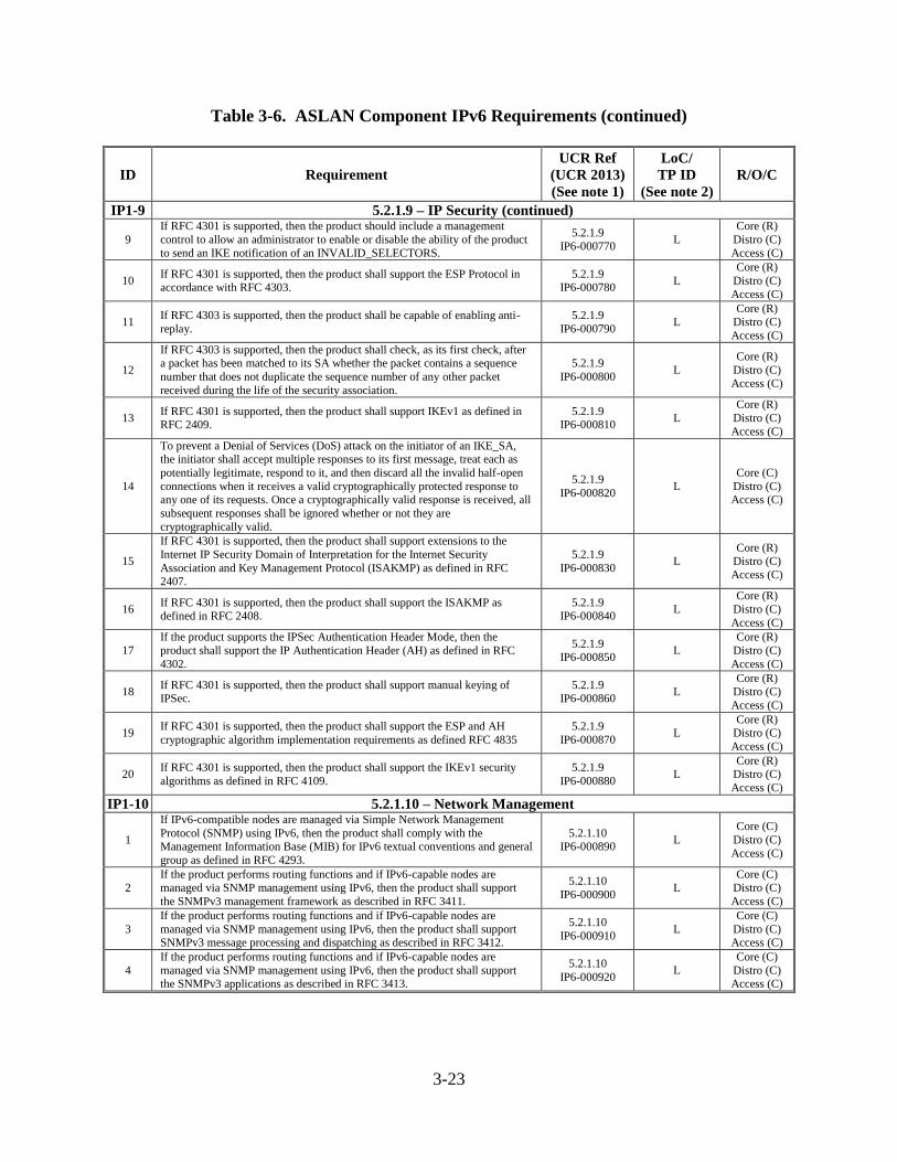
3-23
Table 3-6. ASLAN Component IPv6 Requirements (continued)
ID Requirement
UCR Ref
(UCR 2013)
(See note 1)
LoC/
TP ID
(See note 2)
R/O/C
IP1-9 5.2.1.9 – IP Security (continued)
9
If RFC 4301 is supported, then the product should include a management
control to allow an administrator to enable or disable the ability of the product
to send an IKE notification of an INVALID_SELECTORS.
5.2.1.9 IP6-000770
L
Core (R)
Distro (C)
Access (C)
10 If RFC 4301 is supported, then the product shall support the ESP Protocol in accordance with RFC 4303.
5.2.1.9 IP6-000780
L
Core (R)
Distro (C)
Access (C)
11 If RFC 4303 is supported, then the product shall be capable of enabling anti-
replay.
5.2.1.9
IP6-000790 L
Core (R) Distro (C)
Access (C)
12
If RFC 4303 is supported, then the product shall check, as its first check, after a packet has been matched to its SA whether the packet contains a sequence
number that does not duplicate the sequence number of any other packet
received during the life of the security association.
5.2.1.9
IP6-000800 L
Core (R)
Distro (C)
Access (C)
13 If RFC 4301 is supported, then the product shall support IKEv1 as defined in RFC 2409.
5.2.1.9 IP6-000810
L
Core (R)
Distro (C)
Access (C)
14
To prevent a Denial of Services (DoS) attack on the initiator of an IKE_SA, the initiator shall accept multiple responses to its first message, treat each as
potentially legitimate, respond to it, and then discard all the invalid half-open
connections when it receives a valid cryptographically protected response to any one of its requests. Once a cryptographically valid response is received, all
subsequent responses shall be ignored whether or not they are
cryptographically valid.
5.2.1.9
IP6-000820 L
Core (C)
Distro (C) Access (C)
15
If RFC 4301 is supported, then the product shall support extensions to the
Internet IP Security Domain of Interpretation for the Internet Security
Association and Key Management Protocol (ISAKMP) as defined in RFC 2407.
5.2.1.9
IP6-000830 L
Core (R) Distro (C)
Access (C)
16 If RFC 4301 is supported, then the product shall support the ISAKMP as defined in RFC 2408.
5.2.1.9 IP6-000840
L
Core (R)
Distro (C)
Access (C)
17
If the product supports the IPSec Authentication Header Mode, then the
product shall support the IP Authentication Header (AH) as defined in RFC
4302.
5.2.1.9 IP6-000850
L
Core (R)
Distro (C)
Access (C)
18 If RFC 4301 is supported, then the product shall support manual keying of IPSec.
5.2.1.9 IP6-000860
L Core (R)
Distro (C)
Access (C)
19 If RFC 4301 is supported, then the product shall support the ESP and AH
cryptographic algorithm implementation requirements as defined RFC 4835
5.2.1.9
IP6-000870 L
Core (R) Distro (C)
Access (C)
20 If RFC 4301 is supported, then the product shall support the IKEv1 security
algorithms as defined in RFC 4109.
5.2.1.9
IP6-000880 L
Core (R) Distro (C)
Access (C)
IP1-10 5.2.1.10 – Network Management
1
If IPv6-compatible nodes are managed via Simple Network Management
Protocol (SNMP) using IPv6, then the product shall comply with the Management Information Base (MIB) for IPv6 textual conventions and general
group as defined in RFC 4293.
5.2.1.10 IP6-000890
L
Core (C)
Distro (C)
Access (C)
2
If the product performs routing functions and if IPv6-capable nodes are
managed via SNMP management using IPv6, then the product shall support
the SNMPv3 management framework as described in RFC 3411.
5.2.1.10
IP6-000900 L
Core (C)
Distro (C)
Access (C)
3
If the product performs routing functions and if IPv6-capable nodes are
managed via SNMP management using IPv6, then the product shall support SNMPv3 message processing and dispatching as described in RFC 3412.
5.2.1.10
IP6-000910 L
Core (C)
Distro (C) Access (C)
4
If the product performs routing functions and if IPv6-capable nodes are
managed via SNMP management using IPv6, then the product shall support the SNMPv3 applications as described in RFC 3413.
5.2.1.10
IP6-000920 L
Core (C)
Distro (C) Access (C)
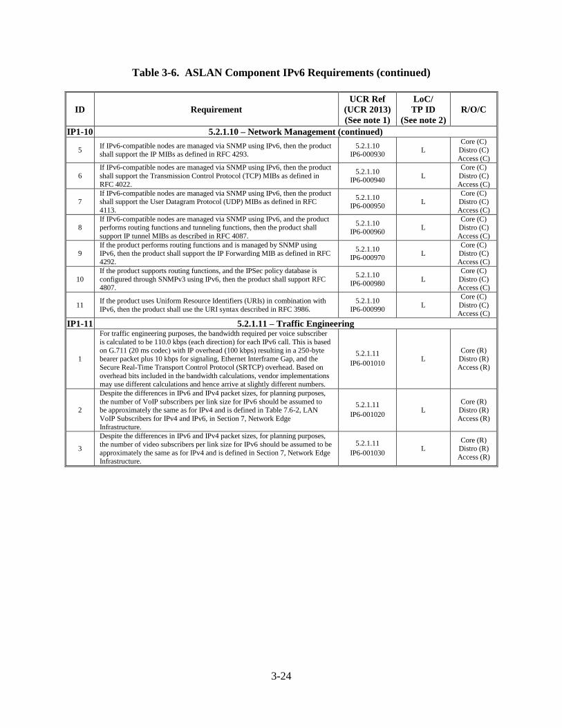
3-24
Table 3-6. ASLAN Component IPv6 Requirements (continued)
ID Requirement
UCR Ref
(UCR 2013)
(See note 1)
LoC/
TP ID
(See note 2)
R/O/C
IP1-10 5.2.1.10 – Network Management (continued)
5 If IPv6-compatible nodes are managed via SNMP using IPv6, then the product shall support the IP MIBs as defined in RFC 4293.
5.2.1.10 IP6-000930
L
Core (C)
Distro (C)
Access (C)
6
If IPv6-compatible nodes are managed via SNMP using IPv6, then the product
shall support the Transmission Control Protocol (TCP) MIBs as defined in
RFC 4022.
5.2.1.10 IP6-000940
L
Core (C)
Distro (C)
Access (C)
7 If IPv6-compatible nodes are managed via SNMP using IPv6, then the product shall support the User Datagram Protocol (UDP) MIBs as defined in RFC
4113.
5.2.1.10
IP6-000950 L
Core (C) Distro (C)
Access (C)
8 If IPv6-compatible nodes are managed via SNMP using IPv6, and the product performs routing functions and tunneling functions, then the product shall
support IP tunnel MIBs as described in RFC 4087.
5.2.1.10
IP6-000960 L
Core (C) Distro (C)
Access (C)
9 If the product performs routing functions and is managed by SNMP using IPv6, then the product shall support the IP Forwarding MIB as defined in RFC
4292.
5.2.1.10
IP6-000970 L
Core (C) Distro (C)
Access (C)
10
If the product supports routing functions, and the IPSec policy database is
configured through SNMPv3 using IPv6, then the product shall support RFC 4807.
5.2.1.10
IP6-000980 L
Core (C)
Distro (C) Access (C)
11 If the product uses Uniform Resource Identifiers (URIs) in combination with
IPv6, then the product shall use the URI syntax described in RFC 3986.
5.2.1.10
IP6-000990 L
Core (C)
Distro (C) Access (C)
IP1-11 5.2.1.11 – Traffic Engineering
1
For traffic engineering purposes, the bandwidth required per voice subscriber
is calculated to be 110.0 kbps (each direction) for each IPv6 call. This is based
on G.711 (20 ms codec) with IP overhead (100 kbps) resulting in a 250-byte bearer packet plus 10 kbps for signaling, Ethernet Interframe Gap, and the
Secure Real-Time Transport Control Protocol (SRTCP) overhead. Based on
overhead bits included in the bandwidth calculations, vendor implementations may use different calculations and hence arrive at slightly different numbers.
5.2.1.11
IP6-001010 L
Core (R) Distro (R)
Access (R)
2
Despite the differences in IPv6 and IPv4 packet sizes, for planning purposes,
the number of VoIP subscribers per link size for IPv6 should be assumed to be approximately the same as for IPv4 and is defined in Table 7.6-2, LAN
VoIP Subscribers for IPv4 and IPv6, in Section 7, Network Edge
Infrastructure.
5.2.1.11
IP6-001020 L
Core (R) Distro (R)
Access (R)
3
Despite the differences in IPv6 and IPv4 packet sizes, for planning purposes,
the number of video subscribers per link size for IPv6 should be assumed to be
approximately the same as for IPv4 and is defined in Section 7, Network Edge Infrastructure.
5.2.1.11
IP6-001030 L
Core (R) Distro (R)
Access (R)
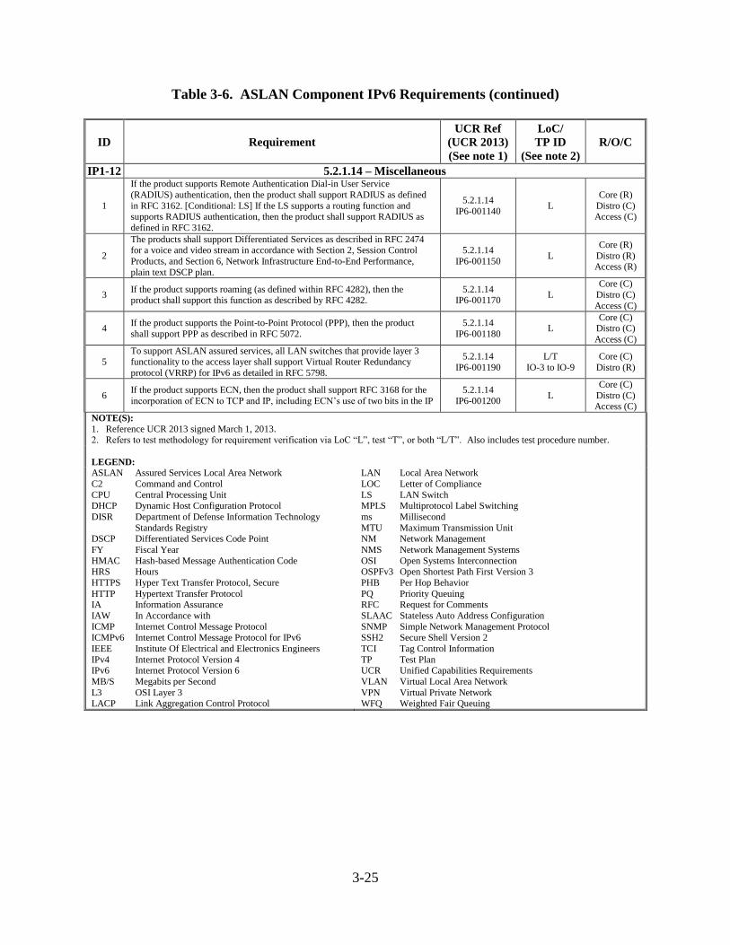
3-25
Table 3-6. ASLAN Component IPv6 Requirements (continued)
ID Requirement
UCR Ref
(UCR 2013)
(See note 1)
LoC/
TP ID
(See note 2)
R/O/C
IP1-12 5.2.1.14 – Miscellaneous
1
If the product supports Remote Authentication Dial-in User Service
(RADIUS) authentication, then the product shall support RADIUS as defined
in RFC 3162. [Conditional: LS] If the LS supports a routing function and supports RADIUS authentication, then the product shall support RADIUS as
defined in RFC 3162.
5.2.1.14
IP6-001140 L
Core (R)
Distro (C) Access (C)
2
The products shall support Differentiated Services as described in RFC 2474 for a voice and video stream in accordance with Section 2, Session Control
Products, and Section 6, Network Infrastructure End-to-End Performance,
plain text DSCP plan.
5.2.1.14
IP6-001150 L
Core (R)
Distro (R) Access (R)
3 If the product supports roaming (as defined within RFC 4282), then the product shall support this function as described by RFC 4282.
5.2.1.14 IP6-001170
L
Core (C)
Distro (C)
Access (C)
4 If the product supports the Point-to-Point Protocol (PPP), then the product
shall support PPP as described in RFC 5072.
5.2.1.14
IP6-001180 L
Core (C) Distro (C)
Access (C)
5 To support ASLAN assured services, all LAN switches that provide layer 3 functionality to the access layer shall support Virtual Router Redundancy
protocol (VRRP) for IPv6 as detailed in RFC 5798.
5.2.1.14
IP6-001190
L/T
IO-3 to IO-9
Core (C)
Distro (R)
6 If the product supports ECN, then the product shall support RFC 3168 for the
incorporation of ECN to TCP and IP, including ECN’s use of two bits in the IP
5.2.1.14
IP6-001200 L
Core (C)
Distro (C) Access (C)
NOTE(S):
1. Reference UCR 2013 signed March 1, 2013. 2. Refers to test methodology for requirement verification via LoC “L”, test “T”, or both “L/T”. Also includes test procedure number.
LEGEND: ASLAN Assured Services Local Area Network
C2 Command and Control
CPU Central Processing Unit DHCP Dynamic Host Configuration Protocol
DISR Department of Defense Information Technology
Standards Registry DSCP Differentiated Services Code Point
FY Fiscal Year
HMAC Hash-based Message Authentication Code HRS Hours
HTTPS Hyper Text Transfer Protocol, Secure
HTTP Hypertext Transfer Protocol IA Information Assurance
IAW In Accordance with
ICMP Internet Control Message Protocol ICMPv6 Internet Control Message Protocol for IPv6
IEEE Institute Of Electrical and Electronics Engineers
IPv4 Internet Protocol Version 4 IPv6 Internet Protocol Version 6
MB/S Megabits per Second
L3 OSI Layer 3 LACP Link Aggregation Control Protocol
LAN Local Area Network
LOC Letter of Compliance
LS LAN Switch MPLS Multiprotocol Label Switching
ms Millisecond
MTU Maximum Transmission Unit NM Network Management
NMS Network Management Systems
OSI Open Systems Interconnection OSPFv3 Open Shortest Path First Version 3
PHB Per Hop Behavior
PQ Priority Queuing RFC Request for Comments
SLAAC Stateless Auto Address Configuration
SNMP Simple Network Management Protocol SSH2 Secure Shell Version 2
TCI Tag Control Information
TP Test Plan UCR Unified Capabilities Requirements
VLAN Virtual Local Area Network
VPN Virtual Private Network WFQ Weighted Fair Queuing
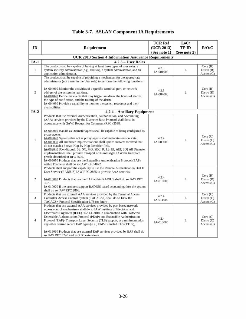
3-26
Table 3-7. ASLAN Component IA Requirements
ID Requirement
UCR Ref
(UCR 2013)
(See note 1)
LoC/
TP ID
(See note 2)
R/O/C
UCR 2013 Section 4 Information Assurance Requirements
IA-1 4.2.3 – User Roles
1
The product shall be capable of having at least three types of user roles: a
system security administrator (e.g., auditor), a system administrator, and an application administrator.
4.2.3
IA-001000 L
Core (R)
Distro (R) Access (C)
2
The product shall be capable of providing a mechanism for the appropriate
administrator (not a user in the User role) to perform the following functions:
IA-004010 Monitor the activities of a specific terminal, port, or network
address of the system in real time.
IA-004020 Define the events that may trigger an alarm, the levels of alarms, the type of notification, and the routing of the alarm.
IA-004030 Provide a capability to monitor the system resources and their
availabilities.
4.2.3 IA-004000
L
Core (R)
Distro (R)
Access (C)
IA-2 4.2.4 – Ancillary Equipment
1
Products that use external Authentication, Authorization, and Accounting
(AAA) services provided by the Diameter Base Protocol shall do so in
accordance with (IAW) Request for Comment (RFC) 3588.
IA-009010 that act as Diameter agents shall be capable of being configured as
proxy agents. IA-009020 Systems that act as proxy agents shall maintain session state.
IA-009030 All Diameter implementations shall ignore answers received that
do not match a known Hop-by-Hop Identifier field. IA-009040 [Conditional: SS, SC, MG, SBC, R, LS, EI, AEI, SD] All Diameter
implementations shall provide transport of its messages IAW the transport
profile described in RFC 3539. IA-009050 Products that use the Extensible Authentication Protocol (EAP)
within Diameter shall do so IAW RFC 4072.
4.2.4
IA-009000 L
Core (C)
Distro (C) Access (C)
2
Products shall support the capability to use the Remote Authentication Dial In User Service (RADIUS) IAW RFC 2865 to provide AAA services.
IA-010010 Products that use the EAP within RADIUS shall do so IAW RFC 3579.
IA-010020 If the products support RADIUS based accounting, then the system
shall do so IAW RFC 2866.
4.2.4
IA-010000 L
Core (R)
Distro (R) Access (C)
3 Products that use external AAA services provided by the Terminal Access Controller Access Control System (TACACS+) shall do so IAW the
TACACS+ Protocol Specification 1.78 (or later).
4.2.4
IA-011000 L
Core (C) Distro (C)
Access (C)
4
Products that use external AAA services provided by port based network access control mechanisms shall do so IAW Institute of Electrical and
Electronics Engineers (IEEE) 802.1X-2010 in combination with Protected
Extensible Authentication Protocol (PEAP) and Extensible Authentication Protocol (EAP)- Transport Layer Security (TLS) support, at a minimum, plus
any other desired secure EAP types [e.g., EAP-Tunneled TLS (TTLS)].
IA-013010 Products that use external EAP services provided by EAP shall do
so IAW RFC 3748 and its RFC extensions.
4.2.4
IA-013000 L
Core (C) Distro (C)
Access (C)
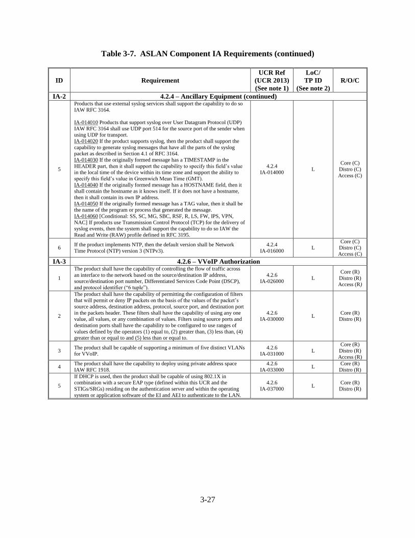
3-27
Table 3-7. ASLAN Component IA Requirements (continued)
ID Requirement
UCR Ref
(UCR 2013)
(See note 1)
LoC/
TP ID
(See note 2)
R/O/C
IA-2 4.2.4 – Ancillary Equipment (continued)
5
Products that use external syslog services shall support the capability to do so
IAW RFC 3164.
IA-014010 Products that support syslog over User Datagram Protocol (UDP)
IAW RFC 3164 shall use UDP port 514 for the source port of the sender when using UDP for transport.
IA-014020 If the product supports syslog, then the product shall support the
capability to generate syslog messages that have all the parts of the syslog packet as described in Section 4.1 of RFC 3164.
IA-014030 If the originally formed message has a TIMESTAMP in the
HEADER part, then it shall support the capability to specify this field’s value in the local time of the device within its time zone and support the ability to
specify this field’s value in Greenwich Mean Time (GMT).
IA-014040 If the originally formed message has a HOSTNAME field, then it shall contain the hostname as it knows itself. If it does not have a hostname,
then it shall contain its own IP address.
IA-014050 If the originally formed message has a TAG value, then it shall be the name of the program or process that generated the message.
IA-014060 [Conditional: SS, SC, MG, SBC, RSF, R, LS, FW, IPS, VPN,
NAC] If products use Transmission Control Protocol (TCP) for the delivery of syslog events, then the system shall support the capability to do so IAW the
Read and Write (RAW) profile defined in RFC 3195.
4.2.4 IA-014000
L
Core (C)
Distro (C)
Access (C)
6 If the product implements NTP, then the default version shall be Network
Time Protocol (NTP) version 3 (NTPv3).
4.2.4
IA-016000 L
Core (C) Distro (C)
Access (C)
IA-3 4.2.6 – VVoIP Authorization
1
The product shall have the capability of controlling the flow of traffic across
an interface to the network based on the source/destination IP address, source/destination port number, Differentiated Services Code Point (DSCP),
and protocol identifier (“6 tuple”).
4.2.6 IA-026000
L
Core (R)
Distro (R)
Access (R)
2
The product shall have the capability of permitting the configuration of filters that will permit or deny IP packets on the basis of the values of the packet’s
source address, destination address, protocol, source port, and destination port
in the packets header. These filters shall have the capability of using any one value, all values, or any combination of values. Filters using source ports and
destination ports shall have the capability to be configured to use ranges of
values defined by the operators (1) equal to, (2) greater than, (3) less than, (4) greater than or equal to and (5) less than or equal to.
4.2.6 IA-030000
L Core (R)
Distro (R)
3 The product shall be capable of supporting a minimum of five distinct VLANs for VVoIP.
4.2.6 IA-031000
L
Core (R)
Distro (R)
Access (R)
4 The product shall have the capability to deploy using private address space
IAW RFC 1918.
4.2.6
IA-033000 L
Core (R)
Distro (R)
5
If DHCP is used, then the product shall be capable of using 802.1X in combination with a secure EAP type (defined within this UCR and the
STIGs/SRGs) residing on the authentication server and within the operating
system or application software of the EI and AEI to authenticate to the LAN.
4.2.6
IA-037000 L
Core (R)
Distro (R)
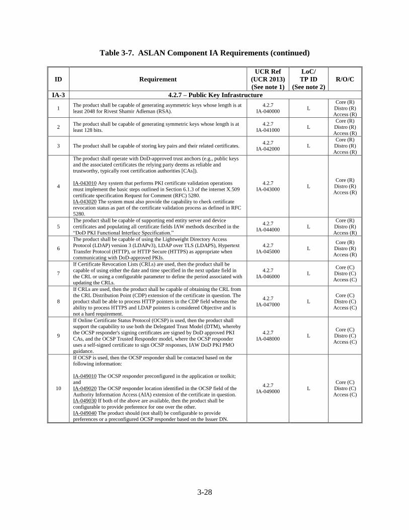
3-28
Table 3-7. ASLAN Component IA Requirements (continued)
ID Requirement
UCR Ref
(UCR 2013)
(See note 1)
LoC/
TP ID
(See note 2)
R/O/C
IA-3 4.2.7 – Public Key Infrastructure
1 The product shall be capable of generating asymmetric keys whose length is at
least 2048 for Rivest Shamir Adleman (RSA).
4.2.7
IA-040000 L
Core (R)
Distro (R) Access (R)
2 The product shall be capable of generating symmetric keys whose length is at least 128 bits.
4.2.7 IA-041000
L
Core (R)
Distro (R)
Access (R)
3 The product shall be capable of storing key pairs and their related certificates. 4.2.7
IA-042000 L
Core (R)
Distro (R)
Access (R)
4
The product shall operate with DoD-approved trust anchors (e.g., public keys and the associated certificates the relying party deems as reliable and
trustworthy, typically root certification authorities [CAs]).
IA-043010 Any system that performs PKI certificate validation operations
must implement the basic steps outlined in Section 6.1.3 of the internet X.509
certificate specification Request for Comment (RFC) 5280. IA-043020 The system must also provide the capability to check certificate
revocation status as part of the certificate validation process as defined in RFC 5280.
4.2.7
IA-043000 L
Core (R)
Distro (R) Access (R)
5
The product shall be capable of supporting end entity server and device
certificates and populating all certificate fields IAW methods described in the
“DoD PKI Functional Interface Specification.”
4.2.7 IA-044000
L
Core (R)
Distro (R)
Access (R)
6
The product shall be capable of using the Lightweight Directory Access
Protocol (LDAP) version 3 (LDAPv3), LDAP over TLS (LDAPS), Hypertext
Transfer Protocol (HTTP), or HTTP Secure (HTTPS) as appropriate when communicating with DoD-approved PKIs.
4.2.7
IA-045000 L
Core (R) Distro (R)
Access (R)
7
If Certificate Revocation Lists (CRLs) are used, then the product shall be
capable of using either the date and time specified in the next update field in
the CRL or using a configurable parameter to define the period associated with updating the CRLs.
4.2.7
IA-046000 L
Core (C) Distro (C)
Access (C)
8
If CRLs are used, then the product shall be capable of obtaining the CRL from
the CRL Distribution Point (CDP) extension of the certificate in question. The product shall be able to process HTTP pointers in the CDP field whereas the
ability to process HTTPS and LDAP pointers is considered Objective and is
not a hard requirement.
4.2.7
IA-047000 L
Core (C) Distro (C)
Access (C)
9
If Online Certificate Status Protocol (OCSP) is used, then the product shall support the capability to use both the Delegated Trust Model (DTM), whereby
the OCSP responder's signing certificates are signed by DoD approved PKI
CAs, and the OCSP Trusted Responder model, where the OCSP responder uses a self-signed certificate to sign OCSP responses, IAW DoD PKI PMO
guidance.
4.2.7
IA-048000 L
Core (C) Distro (C)
Access (C)
10
If OCSP is used, then the OCSP responder shall be contacted based on the following information:
IA-049010 The OCSP responder preconfigured in the application or toolkit; and
IA-049020 The OCSP responder location identified in the OCSP field of the
Authority Information Access (AIA) extension of the certificate in question. IA-049030 If both of the above are available, then the product shall be
configurable to provide preference for one over the other.
IA-049040 The product should (not shall) be configurable to provide preferences or a preconfigured OCSP responder based on the Issuer DN.
4.2.7 IA-049000
L
Core (C)
Distro (C)
Access (C)
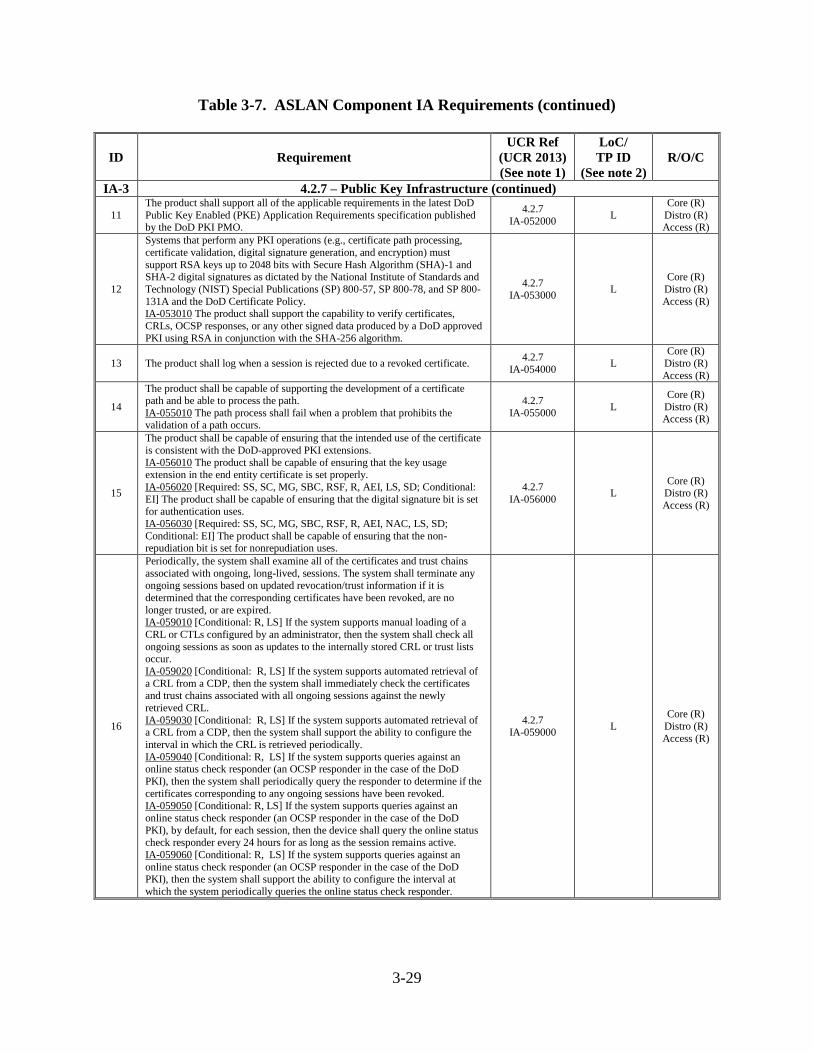
3-29
Table 3-7. ASLAN Component IA Requirements (continued)
ID Requirement
UCR Ref
(UCR 2013)
(See note 1)
LoC/
TP ID
(See note 2)
R/O/C
IA-3 4.2.7 – Public Key Infrastructure (continued)
11
The product shall support all of the applicable requirements in the latest DoD
Public Key Enabled (PKE) Application Requirements specification published by the DoD PKI PMO.
4.2.7
IA-052000 L
Core (R)
Distro (R) Access (R)
12
Systems that perform any PKI operations (e.g., certificate path processing,
certificate validation, digital signature generation, and encryption) must
support RSA keys up to 2048 bits with Secure Hash Algorithm (SHA)-1 and SHA-2 digital signatures as dictated by the National Institute of Standards and
Technology (NIST) Special Publications (SP) 800-57, SP 800-78, and SP 800-
131A and the DoD Certificate Policy. IA-053010 The product shall support the capability to verify certificates,
CRLs, OCSP responses, or any other signed data produced by a DoD approved
PKI using RSA in conjunction with the SHA-256 algorithm.
4.2.7 IA-053000
L
Core (R)
Distro (R)
Access (R)
13 The product shall log when a session is rejected due to a revoked certificate. 4.2.7
IA-054000 L
Core (R)
Distro (R)
Access (R)
14
The product shall be capable of supporting the development of a certificate path and be able to process the path.
IA-055010 The path process shall fail when a problem that prohibits the validation of a path occurs.
4.2.7
IA-055000 L
Core (R)
Distro (R) Access (R)
15
The product shall be capable of ensuring that the intended use of the certificate
is consistent with the DoD-approved PKI extensions.
IA-056010 The product shall be capable of ensuring that the key usage extension in the end entity certificate is set properly.
IA-056020 [Required: SS, SC, MG, SBC, RSF, R, AEI, LS, SD; Conditional:
EI] The product shall be capable of ensuring that the digital signature bit is set for authentication uses.
IA-056030 [Required: SS, SC, MG, SBC, RSF, R, AEI, NAC, LS, SD;
Conditional: EI] The product shall be capable of ensuring that the non-repudiation bit is set for nonrepudiation uses.
4.2.7
IA-056000 L
Core (R) Distro (R)
Access (R)
16
Periodically, the system shall examine all of the certificates and trust chains
associated with ongoing, long-lived, sessions. The system shall terminate any ongoing sessions based on updated revocation/trust information if it is
determined that the corresponding certificates have been revoked, are no
longer trusted, or are expired. IA-059010 [Conditional: R, LS] If the system supports manual loading of a
CRL or CTLs configured by an administrator, then the system shall check all
ongoing sessions as soon as updates to the internally stored CRL or trust lists occur.
IA-059020 [Conditional: R, LS] If the system supports automated retrieval of
a CRL from a CDP, then the system shall immediately check the certificates and trust chains associated with all ongoing sessions against the newly
retrieved CRL.
IA-059030 [Conditional: R, LS] If the system supports automated retrieval of a CRL from a CDP, then the system shall support the ability to configure the
interval in which the CRL is retrieved periodically.
IA-059040 [Conditional: R, LS] If the system supports queries against an online status check responder (an OCSP responder in the case of the DoD
PKI), then the system shall periodically query the responder to determine if the
certificates corresponding to any ongoing sessions have been revoked.
IA-059050 [Conditional: R, LS] If the system supports queries against an
online status check responder (an OCSP responder in the case of the DoD
PKI), by default, for each session, then the device shall query the online status check responder every 24 hours for as long as the session remains active.
IA-059060 [Conditional: R, LS] If the system supports queries against an
online status check responder (an OCSP responder in the case of the DoD PKI), then the system shall support the ability to configure the interval at
which the system periodically queries the online status check responder.
4.2.7 IA-059000
L
Core (R)
Distro (R)
Access (R)
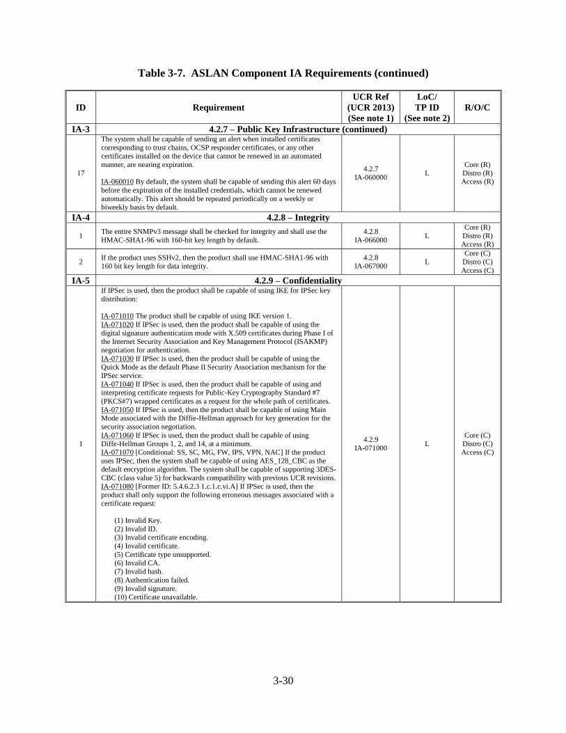
3-30
Table 3-7. ASLAN Component IA Requirements (continued)
ID Requirement
UCR Ref
(UCR 2013)
(See note 1)
LoC/
TP ID
(See note 2)
R/O/C
IA-3 4.2.7 – Public Key Infrastructure (continued)
17
The system shall be capable of sending an alert when installed certificates
corresponding to trust chains, OCSP responder certificates, or any other certificates installed on the device that cannot be renewed in an automated
manner, are nearing expiration.
IA-060010 By default, the system shall be capable of sending this alert 60 days
before the expiration of the installed credentials, which cannot be renewed
automatically. This alert should be repeated periodically on a weekly or biweekly basis by default.
4.2.7
IA-060000 L
Core (R)
Distro (R) Access (R)
IA-4 4.2.8 – Integrity
1 The entire SNMPv3 message shall be checked for integrity and shall use the
HMAC-SHA1-96 with 160-bit key length by default.
4.2.8
IA-066000 L
Core (R)
Distro (R)
Access (R)
2 If the product uses SSHv2, then the product shall use HMAC-SHA1-96 with 160 bit key length for data integrity.
4.2.8 IA-067000
L
Core (C)
Distro (C)
Access (C)
IA-5 4.2.9 – Confidentiality
1
If IPSec is used, then the product shall be capable of using IKE for IPSec key
distribution:
IA-071010 The product shall be capable of using IKE version 1.
IA-071020 If IPSec is used, then the product shall be capable of using the
digital signature authentication mode with X.509 certificates during Phase I of the Internet Security Association and Key Management Protocol (ISAKMP)
negotiation for authentication.
IA-071030 If IPSec is used, then the product shall be capable of using the Quick Mode as the default Phase II Security Association mechanism for the
IPSec service.
IA-071040 If IPSec is used, then the product shall be capable of using and interpreting certificate requests for Public-Key Cryptography Standard #7
(PKCS#7) wrapped certificates as a request for the whole path of certificates.
IA-071050 If IPSec is used, then the product shall be capable of using Main Mode associated with the Diffie-Hellman approach for key generation for the
security association negotiation.
IA-071060 If IPSec is used, then the product shall be capable of using Diffe-Hellman Groups 1, 2, and 14, at a minimum.
IA-071070 [Conditional: SS, SC, MG, FW, IPS, VPN, NAC] If the product
uses IPSec, then the system shall be capable of using AES_128_CBC as the default encryption algorithm. The system shall be capable of supporting 3DES-
CBC (class value 5) for backwards compatibility with previous UCR revisions.
IA-071080 [Former ID: 5.4.6.2.3 1.c.1.c.vi.A] If IPSec is used, then the product shall only support the following erroneous messages associated with a
certificate request:
(1) Invalid Key.
(2) Invalid ID. (3) Invalid certificate encoding.
(4) Invalid certificate.
(5) Certificate type unsupported.
(6) Invalid CA.
(7) Invalid hash.
(8) Authentication failed. (9) Invalid signature.
(10) Certificate unavailable.
4.2.9
IA-071000 L
Core (C) Distro (C)
Access (C)
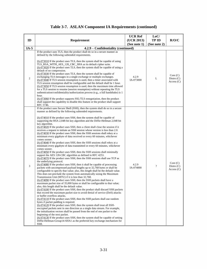
3-31
Table 3-7. ASLAN Component IA Requirements (continued)
ID Requirement
UCR Ref
(UCR 2013)
(See note 1)
LoC/
TP ID
(See note 2)
R/O/C
IA-5 4.2.9 – Confidentiality (continued)
2
If the product uses TLS, then the product shall do so in a secure manner as
defined by the following subtended requirements.
IA-073010 If the product uses TLS, then the system shall be capable of using
TLS_RSA_WITH_AES_128_CBC_SHA as its default cipher suite. IA-073020 If the product uses TLS, then the system shall be capable of using a
default of no compression.
IA-073030 If the product uses TLS, then the system shall be capable of exchanging TLS messages in a single exchange or multiple exchanges.
IA-073040 If TLS session resumption is used, then a timer associated with
TLS session resumption shall be configurable and the default shall be 1 hour. IA-073050 If TLS session resumption is used, then the maximum time allowed
for a TLS session to resume (session resumption) without repeating the TLS
authentication/confidentiality/authorization process (e.g., a full handshake) is 1 hour.
IA-073060 If the product supports SSL/TLS renegotiation, then the product
shall support the capability to disable this feature or the product shall support RFC 5746.
4.2.9
IA-073000 L
Core (C)
Distro (C) Access (C)
3
If the product uses Secure Shell (SSH), then the system shall do so in a secure
manner as defined by the following subtended requirements.
IA-074010 If the product uses SSH, then the system shall be capable of
supporting the RSA 2,048-bit key algorithm and the Diffie-Hellman 2,048 bit key algorithm.
IA-074020 If the product uses SSH, then a client shall close the session if it
receives a request to initiate an SSH session whose version is less than 2.0. IA-074030 If the product uses SSH, then the SSH sessions shall rekey at a
minimum every gigabyte of data received or every 60 minutes, whichever
comes sooner. IA-074040 If the product uses SSH, then the SSH sessions shall rekey at a
minimum every gigabyte of data transmitted or every 60 minutes, whichever
comes sooner. IA-074050 If the product uses SSH, then the SSH sessions shall minimally
support the AES 128-CBC algorithm as defined in RFC 4253.
IA-074070 If the product uses SSH, then the SSH sessions shall use TCP as the underlying protocol.
IA-074080 If the product uses SSH, then it shall be capable of processing
packets with uncompressed payload lengths up to 32,768 bytes or shall be configurable to specify that value; also, this length shall be the default value.
This does not preclude the system from automatically sizing the Maximum
Transmission Unit (MTU) if it is less than 32,768. IA-074090 If the product uses SSH, then the SSH packets shall have a
maximum packet size of 35,000 bytes or shall be configurable to that value;
also, this length shall be the default value. IA-074100 If the product uses SSH, then the product shall discard SSH packets
that exceed the maximum packet size to avoid denial of service (DoS) attacks
or buffer overflow attacks. IA-074110 If the product uses SSH, then the SSH packets shall use random
bytes if packet padding is required.
IA-074120 If the product uses SSH, then the system shall treat all SSH-encrypted packets sent in one direction as a single data stream. For example,
the initialization vectors shall be passed from the end of one packet to the
beginning of the next packet. IA-074130 If the product uses SSH, then the system shall be capable of setting
Diffie-Hellman-Group14-SHA1 as the preferred key exchange mechanism for
SSH.
4.2.9
IA-074000 ?
Core (C) Distro (C)
Access (C)
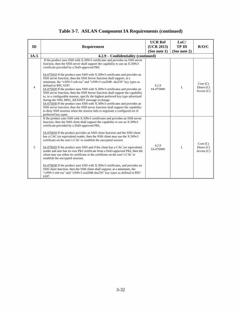
3-32
Table 3-7. ASLAN Component IA Requirements (continued)
ID Requirement
UCR Ref
(UCR 2013)
(See note 1)
LoC/
TP ID
(See note 2)
R/O/C
IA-5 4.2.9 – Confidentiality (continued)
4
If the product uses SSH with X.509v3 certificates and provides an SSH server
function, then the SSH server shall support the capability to use an X.509v3 certificate provided by a DoD-approved PKI.
IA-075010 If the product uses SSH with X.509v3 certificates and provides an SSH server function, then the SSH Server function shall support, at a
minimum, the “x509v3-ssh-rsa” and "x509v3-rsa2048- sha256” key types as
defined in RFC 6187. IA-075020 If the product uses SSH with X.509v3 certificates and provides an
SSH server function, then the SSH Server function shall support the capability
to, in a configurable manner, specify the highest preferred key type advertised during the SSH_MSG_KEXINIT message exchange.
IA-075030 If the product uses SSH with X.509v3 certificates and provides an
SSH server function, then the SSH server function shall support the capability to deny SSH sessions when the session fails to negotiate a configured set of
preferred key types.
4.2.9 IA-075000
L
Core (C)
Distro (C)
Access (C)
5
If the product uses SSH with X.509v3 certificates and provides an SSH server
function, then the SSH client shall support the capability to use an X.509v3 certificate provided by a DoD-approved PKI.
IA-076010 If the product provides an SSH client function and the SSH client
has a CAC (or equivalent) reader, then the SSH client may use the X.509v3
certificate on the user’s CAC to establish the encrypted session.
IA-076020 If the product uses SSH and if the client has a CAC (or equivalent)
reader and also has its own PKI certificate from a DoD-approved PKI, then the client may use either its certificate or the certificate on the user’s CAC to
establish the encrypted sessions.
IA-076030 If the product uses SSH with X.509v3 certificates, and provides an
SSH client function, then the SSH client shall support, at a minimum, the
“x509v3-ssh-rsa” and "x509v3-rsa2048-sha256” key types as defined in RFC 6187.
4.2.9 IA-076000
L
Core (C)
Distro (C)
Access (C)
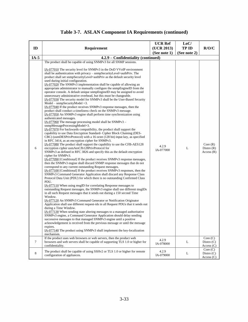
3-33
Table 3-7. ASLAN Component IA Requirements (continued)
ID Requirement
UCR Ref
(UCR 2013)
(See note 1)
LoC/
TP ID
(See note 2)
R/O/C
IA-5 4.2.9 – Confidentiality (continued)
6
The product shall be capable of using SNMPv3 for all SNMP sessions.
IA-077010 The security level for SNMPv3 in the DoD VVoIP environment
shall be authentication with privacy – snmpSecurityLevel=authPriv. The
product shall set snmpSecurityLevel=authPriv as the default security level used during initial configuration.
IA-077020 The SNMPv3 implementation shall be capable of allowing an
appropriate administrator to manually configure the snmpEngineID from the operator console. A default unique snmpEngineID may be assigned to avoid
unnecessary administrative overhead, but this must be changeable.
IA-077030 The security model for SNMPv3 shall be the User-Based Security Model – snmpSecurityModel =3.
IA-077040 If the product receives SNMPv3 response messages, then the
product shall conduct a timeliness check on the SNMPv3 message. IA-077050 An SNMPv3 engine shall perform time synchronization using
authenticated messages.
IA-077060 The message processing model shall be SNMPv3 – snmpMessageProcessingModel=3.
IA-077070 For backwards compatibility, the product shall support the
capability to use Data Encryption Standard- Cipher Block Chaining (DES-CBC) (usmDESPrivProtocol) with a 16 octet (128 bit) input key, as specified
in RFC 3414, as an encryption cipher for SNMPv3.
IA-077080 The product shall support the capability to use the CFB-AES128 encryption cipher usmAesCfb128PrivProtocol for
SNMPv3 as defined in RFC 3826 and specify this as the default encryption
cipher for SNMPv3. IA-077090 [Conditional] If the product receives SNMPv3 response messages,
then the SNMPv3 engine shall discard SNMP response messages that do not
correspond to any current outstanding Request messages. IA-077100 [Conditional] If the product receives SNMPv3 responses, then the
SNMPv3 Command Generator Application shall discard any Response Class
Protocol Data Unit (PDU) for which there is no outstanding Confirmed Class PDU.
IA-077110 When using msgID for correlating Response messages to
outstanding Request messages, the SNMPv3 engine shall use different msgIDs in all such Request messages that it sends out during a 150 second Time
Window.
IA-077120 An SNMPv3 Command Generator or Notification Originator Application shall use different request-ids in all Request PDUs that it sends out
during a Time Window.
IA-077130 When sending state altering messages to a managed authoritative SNMPv3 engine, a Command Generator Application should delay sending
successive messages to that managed SNMPv3 engine until a positive
acknowledgement is received from the previous message or until the message expires.
IA-077140 The product using SNMPv3 shall implement the key-localization mechanism.
4.2.9
IA-077000 L
Core (R) Distro (R)
Access (R)
7
If the product uses web browsers or web servers, then the product web
browsers and web servers shall be capable of supporting TLS 1.0 or higher for
confidentiality.
4.2.9 IA-078000
L
Core (C)
Distro (C)
Access (C)
8 The product shall be capable of using SSHv2 or TLS 1.0 or higher for remote configuration of appliances.
4.2.9 IA-079000
L
Core (C)
Distro (C)
Access (C)
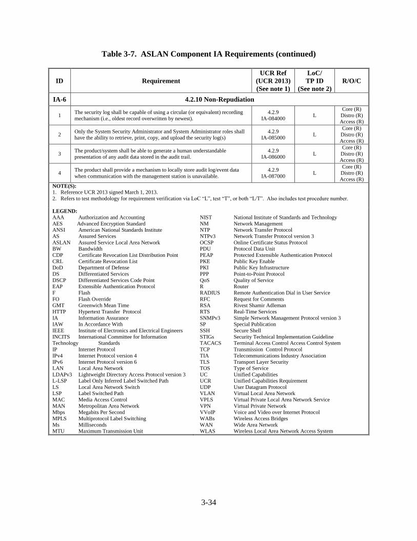
3-34
Table 3-7. ASLAN Component IA Requirements (continued)
ID Requirement
UCR Ref
(UCR 2013)
(See note 1)
LoC/
TP ID
(See note 2)
R/O/C
IA-6 4.2.10 Non-Repudiation
1 The security log shall be capable of using a circular (or equivalent) recording
mechanism (i.e., oldest record overwritten by newest).
4.2.9
IA-084000 L
Core (R)
Distro (R) Access (R)
2 Only the System Security Administrator and System Administrator roles shall have the ability to retrieve, print, copy, and upload the security log(s)
4.2.9 IA-085000
L
Core (R)
Distro (R)
Access (R)
3 The product/system shall be able to generate a human understandable presentation of any audit data stored in the audit trail.
4.2.9 IA-086000
L
Core (R)
Distro (R)
Access (R)
4 The product shall provide a mechanism to locally store audit log/event data
when communication with the management station is unavailable.
4.2.9
IA-087000 L
Core (R) Distro (R)
Access (R)
NOTE(S):
1. Reference UCR 2013 signed March 1, 2013.
2. Refers to test methodology for requirement verification via LoC “L”, test “T”, or both “L/T”. Also includes test procedure number.
LEGEND:
AAA Authorization and Accounting
AES Advanced Encryption Standard ANSI American National Standards Institute
AS Assured Services
ASLAN Assured Service Local Area Network BW Bandwidth
CDP Certificate Revocation List Distribution Point
CRL Certificate Revocation List DoD Department of Defense
DS Differentiated Services
DSCP Differentiated Services Code Point EAP Extensible Authentication Protocol
F Flash
FO Flash Override GMT Greenwich Mean Time
HTTP Hypertext Transfer Protocol
IA Information Assurance IAW In Accordance With
IEEE Institute of Electronics and Electrical Engineers
INCITS International Committee for Information Technology Standards
IP Internet Protocol
IPv4 Internet Protocol version 4 IPv6 Internet Protocol version 6
LAN Local Area Network
LDAPv3 Lightweight Directory Access Protocol version 3 L-LSP Label Only Inferred Label Switched Path
LS Local Area Network Switch LSP Label Switched Path
MAC Media Access Control
MAN Metropolitan Area Network
Mbps Megabits Per Second
MPLS Multiprotocol Label Switching
Ms Milliseconds MTU Maximum Transmission Unit
NIST National Institute of Standards and Technology
NM Network Management NTP Network Transfer Protocol
NTPv3 Network Transfer Protocol version 3
OCSP Online Certificate Status Protocol PDU Protocol Data Unit
PEAP Protected Extensible Authentication Protocol
PKE Public Key Enable PKI Public Key Infrastructure
PPP Point-to-Point Protocol
QoS Quality of Service R Router
RADIUS Remote Authentication Dial in User Service
RFC Request for Comments RSA Rivest Shamir Adleman
RTS Real-Time Services
SNMPv3 Simple Network Management Protocol version 3 SP Special Publication
SSH Secure Shell
STIGs Security Technical Implementation Guideline TACACS Terminal Access Control Access Control System
TCP Transmission Control Protocol
TIA Telecommunications Industry Association TLS Transport Layer Security
TOS Type of Service
UC Unified Capabilities UCR Unified Capabilities Requirement
UDP User Datagram Protocol VLAN Virtual Local Area Network
VPLS Virtual Private Local Area Network Service
VPN Virtual Private Network
VVoIP Voice and Video over Internet Protocol
WABs Wireless Access Bridges
WAN Wide Area Network WLAS Wireless Local Area Network Access System