Embed Size (px)
Citation preview
K
Joint Interoperability Test Command (JTE) 25 Jun 12
MEMORANDUM FOR DISTRIBUTION
SUBJECT: Special Interoperability Test Certification of the Nokia Siemens Networks (NSN)
hiT7300, Dense Wavelength Division Multiplexing (DWDM), Fixed Network
Element (F-NE), with Software Release Version 4.30
References: (a) Department of Defense Directive 4630.05, “Interoperability and Supportability
of Information Technology (IT) and National Security Systems (NSS),”
5 May 2004
(b) Department of Defense Instruction 8100.04, "DoD Unified Capabilities (UC),"
9 December 2010
(c) through (e), see Enclosure 1
1. References (a) and (b) establish the Joint Interoperability Test Command (JITC), as the
responsible organization for interoperability test certification.
2. The NSN hiT7300, DWDM, with Software Release Version 4.30, is hereinafter referred to as
the System Under Test (SUT). The SUT meets all its critical interoperability requirements and
JITC certifies the SUT for joint use in the Defense Information Systems Network (DISN) as an
F-NE. The SUT provides additional optical transport interfaces and functional capabilities.
JITC evaluated and certifies the SUT for optical transport for the Optical Carrier interfaces
detailed in Table 1. Additional sponsor functional capabilities are addressed in Table 2. The
operational status of the SUT will be verified during deployment. Any new discrepancies that
are discovered in the operational environment will be evaluated for impact and adjudicated to the
satisfaction of the Defense Information Systems Agency (DISA) via a vendor Plan of Action and
Milestones to address the concern(s) within 120 days of identification. JITC conducted testing
using F-NE requirements within the Unified Capabilities Requirements (UCR) 2008, Change 1,
Reference (c), and other sponsor requested requirements. The JITC tested the SUT using F-NE
test procedures, Reference (d) and test procedures developed to address the sponsor unique
requirements. JITC does not certify any other configurations, features, or functions, except those
cited within this memorandum. This certification expires upon changes that affect
interoperability, but no later than three years from the date of this memorandum.
3. This finding is based on interoperability testing conducted by JITC, review of the Vendor’s
Letter of Compliance and Information Assurance (IA) Certification Authority (CA) approval of
the IA configuration. JITC conducted Interoperability testing at the Indian Head, Maryland, Test
Facility from 30 August through 19 November 2010. The DISA IA CA reviewed the JITC
published IA Assessment Report for the SUT, Reference (e), and provided a positive
recommendation of the IA configuration on 5 April 2011. The acquiring agency or site will be
IN REPLY
REFER TO:
DEFENSE INFORMATION SYSTEMS AGENCY P. O. BOX 549
FORT MEADE, MARYLAND 20755-0549
JITC Memo, JTE, Special Interoperability Test Certification of the Nokia Siemens Networks
(NSN) hiT7300, Dense Wavelength Division Multiplexing (DWDM), Fixed Network Element
(F-NE), with Software Release Version 4.30
2
responsible for the DoD Information Assurance Certification and Accreditation Process
(DIACAP) accreditation. The Army originally submitted the SUT as a DISN Optical Transport
System under UCR 2008 Section 5.5. Based on DISA guidance received 18 January 2012, this
product was re-evaluated as an F-NE. Enclosure 2 documents the test results and describes the
tested network and system configurations. Enclosure 3, System Functional and Capability
Requirements, lists the F-NE Capability Requirements (CR) and Functional Requirements (FR).
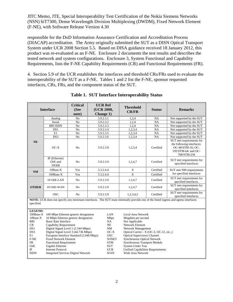
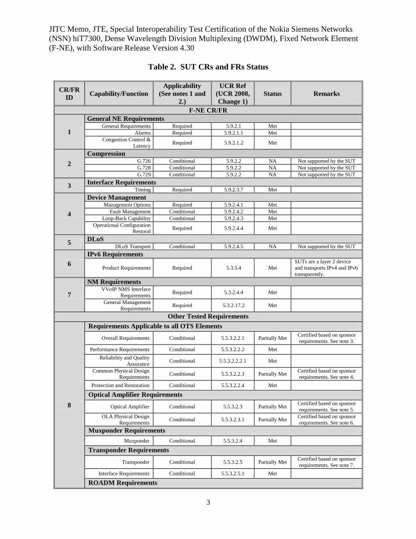
4. Section 5.9 of the UCR establishes the interfaces and threshold CRs/FRs used to evaluate the
interoperability of the SUT as a F-NE. Tables 1 and 2 list the F-NE, sponsor requested
interfaces, CRs, FRs, and the component status of the SUT.
Table 1. SUT Interface Interoperability Status
Interface
Critical
(See
note)
UCR Ref
(UCR 2008,
Change 1)
Threshold
CR/FR Status Remarks
NE
Analog No 5.9.2.3.1 1,2,4 NA Not supported by the SUT
Serial No 5.9.2.3.2 1,2,4 NA Not supported by the SUT
BRI ISDN No 5.9.2.3.3 1,2,4 NA Not supported by the SUT
DS1 No 5.9.2.3.4 1,2,3,4 NA Not supported by the SUT
E1 No 5.9.2.3.5 1,2,3,4 NA Not supported by the SUT
DS3 No 5.9.2.3.6 1,2,3,4 NA Not supported by the SUT
OC-X No 5.9.2.3.8 1,2,3,4 Certified
SUT met requirements for
the following interfaces: OC-48/STM-16; OC-
192/STM-64; and OC-
768/STM-256
IP (Ethernet) GbE and
10GbE
No 5.9.2.3.9 1,2,4,7 Certified SUT met requirements for
specified interfaces
NM 10Base-X Yes 5.3.2.4.4 8 Certified SUT met NM requirements
for specified interfaces 100Base-X Yes 5.3.2.4.4 8 Certified
OTHER
10 GbE-LAN No 5.9.2.3.9 1,2,4,7 Certified SUT met requirements for
specified interfaces.
10 GbE-WAN No 5.9.2.3.9 1,2,4,7 Certified SUT met requirements for
specified interfaces
OSC No 5.9.2.3.9 1,2,3,4,5 Certified SUT met requirements for
specified interfaces
NOTE: UCR does not specify any minimum interfaces. The SUT must minimally provide one of the listed ingress and egress interfaces
specified.
LEGEND:
100Base-X 100 Mbps Ethernet generic designation
10Base-X 10 Mbps Ethernet generic designation BRI Basic Rate Interface
CR Capability Requirement
DS1 Digital Signal Level 1 (1.544 Mbps)
DS3 Digital Signal Level 3 (44.736 Mbps)
E1 European Interface Standard (2.048 Mbps)
F-NE Fixed Network Element FR Functional Requirement
GbE Gigabit Ethernet
IP Internet Protocol ISDN Integrated Services Digital Network
LAN Local Area Network
Mbps Megabits per second NA Not Applicable
NE Network Element
NM Network Management
OC-X Optical Carrier - X (OC-3, OC-12, etc.,)
OSC Optical Supervisory Channel
SONET Synchronous Optical Network STM Synchronous Transport Module
SUT System Under Test
UCR Unified Capabilities Requirements WAN Wide Area Network
JITC Memo, JTE, Special Interoperability Test Certification of the Nokia Siemens Networks
(NSN) hiT7300, Dense Wavelength Division Multiplexing (DWDM), Fixed Network Element
(F-NE), with Software Release Version 4.30
3
Table 2. SUT CRs and FRs Status
CR/FR
ID Capability/Function
Applicability
(See notes 1 and
2.)
UCR Ref
(UCR 2008,
Change 1)
Status Remarks
F-NE CR/FR
1
General NE Requirements General Requirements Required 5.9.2.1 Met
Alarms Required 5.9.2.1.1 Met
Congestion Control &
Latency Required 5.9.2.1.2 Met
2
Compression G.726 Conditional 5.9.2.2 NA Not supported by the SUT
G.728 Conditional 5.9.2.2 NA Not supported by the SUT
G.729 Conditional 5.9.2.2 NA Not supported by the SUT
3 Interface Requirements
Timing Required 5.9.2.3.7 Met
4
Device Management Management Options Required 5.9.2.4.1 Met
Fault Management Conditional 5.9.2.4.2 Met
Loop-Back Capability Conditional 5.9.2.4.3 Met
Operational Configuration Restoral
Required 5.9.2.4.4 Met
5 DLoS
DLoS Transport Conditional 5.9.2.4.5 NA Not supported by the SUT
6
IPv6 Requirements
Product Requirements Required 5.3.5.4 Met
SUTs are a layer 2 device
and transports IPv4 and IPv6
transparently.
7
NM Requirements VVoIP NMS Interface
Requirements Required 5.3.2.4.4 Met
General Management
Requirements Required 5.3.2.17.2 Met
Other Tested Requirements
8
Requirements Applicable to all OTS Elements
Overall Requirements Conditional 5.5.3.2.2.1 Partially Met Certified based on sponsor requirements. See note 3.
Performance Requirements Conditional 5.5.3.2.2.2 Met
Reliability and Quality
Assurance Conditional 5.5.3.2.2.2.1 Met
Common Physical Design Requirements
Conditional 5.5.3.2.2.3 Partially Met Certified based on sponsor requirements. See note 4.
Protection and Restoration Conditional 5.5.3.2.2.4 Met
Optical Amplifier Requirements
Optical Amplifier Conditional 5.5.3.2.3 Partially Met Certified based on sponsor
requirements. See note 5.
OLA Physical Design
Requirements Conditional 5.5.3.2.3.1 Partially Met
Certified based on sponsor
requirements. See note 6.
Muxponder Requirements
Muxponder Conditional 5.5.3.2.4 Met
Transponder Requirements
Transponder Conditional 5.5.3.2.5 Partially Met Certified based on sponsor
requirements. See note 7.
Interface Requirements Conditional 5.5.3.2.5.1 Met
ROADM Requirements
JITC Memo, JTE, Special Interoperability Test Certification of the Nokia Siemens Networks
(NSN) hiT7300, Dense Wavelength Division Multiplexing (DWDM), Fixed Network Element
(F-NE), with Software Release Version 4.30
4
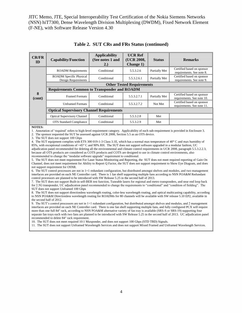
Table 2. SUT CRs and FRs Status (continued)
CR/FR
ID Capability/Function
Applicability
(See notes 1 and
2.)
UCR Ref
(UCR 2008,
Change 1)
Status Remarks
8
(cont)
ROADM Requirements Conditional 5.5.3.2.6 Partially Met Certified based on sponsor
requirements. See note 8.
ROADM Specific Physical
Design Requirements Conditional 5.5.3.2.6.1 Partially Met
Certified based on sponsor
requirements. See note 9.
Other Tested Requirements
Requirements Common to Transponder and ROADM
Framed Formats Conditional 5.5.3.2.7.1 Partially Met Certified based on sponsor requirements. See note 10.
Unframed Formats Conditional 5.5.3.2.7.2 Not Met Certified based on sponsor
requirements. See note 11.
Optical Supervisory Channel Requirements
Optical Supervisory Channel Conditional 5.5.3.2.8 Met
OTS Standard Compliance Conditional 5.5.3.2.9 Met
NOTES:
1. Annotation of ‘required’ refers to high-level requirement category. Applicability of each sub-requirement is provided in Enclosure 3. 2. The sponsor requested the SUT be assessed against UCR 2008, Section 5.5 as an OTS device.
3. The SUT does not support 100 Gbps
4. The SUT equipment complies with ETS 300 019-1-3 Class 3.1E, which has a normal max temperature of 40° C and max humidity of 85%, with exceptional conditions of +45° C and 90% RH. The SUT does not support software upgraded in a modular fashion, UC
adjudication panel recommended for deleting all the environmental and climate control requirements in UCR 2008, paragraph 5.5.3.2.2.3,
because all OTS products are considered as COTS products and COTS are designed to use in climate control environments, also recommended to change the “modular software upgrade” requirement to conditional.
5. The SUT does not meet requirement For Laser Status Monitoring and Reporting, the SUT does not meet required reporting of Gain On
Channel, does not meet requirement for Ability to Report Q Factor, the SUT does not support requirement to Show Eye Diagram, and does not support requirement for OSNR.
6. The SUT control processors are not in 1+1 redundant configuration, but distributed amongst shelves and modules, and two management
interfaces are provided on each NE Controller card. There is 1 fan shelf supporting multiple fans according to NSN POA&M Redundant control processors are planned to be introduced with SW Release 5.25 in the second half of 2013.
7. The SUT does not support Built-in self-BER test function, Tuneable lasers for regional and metro transponders, and near end loop back for 2.5G transponder, UC adjudication panel recommended to change the requirements to “conditional” and “condition of fielding”. The
SUT does not support Unframed 100 Gbps
8. The SUT does not support directionless wavelength routing, color-less wavelength routing, and optical multicasting capability, according to NSN POA&M Directionless wavelength routing for ROADMs for 80 channels will be available with SW release 5.10 EP2, available in
the second half of 2012.
9. The SUT’s control processors are not in 1+1 redundant configuration, but distributed amongst shelves and modules, and 2 management interfaces are provided on each NE Controller card. There is one fan shelf supporting multiple fans, and fully configured PCX will require
more than one full 84" rack, according to NSN POA&M alternative variety of fan tray is available (SRS-S or SRS-19) supporting four
separate fan trays each with two fans are planned to be introduced with SW Release 5.25 in the second half of 2013. UC adjudication panel recommended to delete 84" rack requirement.
10. The SUT does not meet required 10:1 Muxponder, and does not support 100 Gbps (STD TBD) Signals.
11. The SUT does not support Unframed Wavelength Services and does not support Mixed Framed and Unframed Wavelength Services.
JITC Memo, JTE, Special Interoperability Test Certification of the Nokia Siemens Networks
(NSN) hiT7300, Dense Wavelength Division Multiplexing (DWDM), Fixed Network Element
(F-NE), with Software Release Version 4.30
5
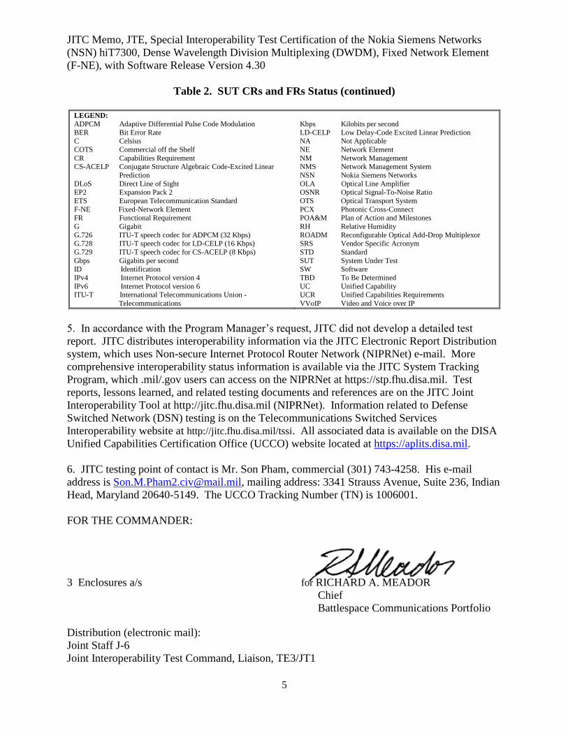
Table 2. SUT CRs and FRs Status (continued)
LEGEND:
ADPCM Adaptive Differential Pulse Code Modulation
BER Bit Error Rate C Celsius
COTS Commercial off the Shelf
CR Capabilities Requirement CS-ACELP Conjugate Structure Algebraic Code-Excited Linear
Prediction
DLoS Direct Line of Sight EP2 Expansion Pack 2
ETS European Telecommunication Standard
F-NE Fixed-Network Element FR Functional Requirement
G Gigabit
G.726 ITU-T speech codec for ADPCM (32 Kbps)
G.728 ITU-T speech codec for LD-CELP (16 Kbps)
G.729 ITU-T speech codec for CS-ACELP (8 Kbps)
Gbps Gigabits per second ID Identification
IPv4 Internet Protocol version 4
IPv6 Internet Protocol version 6 ITU-T International Telecommunications Union -
Telecommunications
Kbps Kilobits per second
LD-CELP Low Delay-Code Excited Linear Prediction NA Not Applicable
NE Network Element
NM Network Management NMS Network Management System
NSN Nokia Siemens Networks
OLA Optical Line Amplifier OSNR Optical Signal-To-Noise Ratio
OTS Optical Transport System
PCX Photonic Cross-Connect POA&M Plan of Action and Milestones
RH Relative Humidity
ROADM Reconfigurable Optical Add-Drop Multiplexor
SRS Vendor Specific Acronym
STD Standard
SUT System Under Test SW Software
TBD To Be Determined
UC Unified Capability UCR Unified Capabilities Requirements
VVoIP Video and Voice over IP
5. In accordance with the Program Manager’s request, JITC did not develop a detailed test
report. JITC distributes interoperability information via the JITC Electronic Report Distribution
system, which uses Non-secure Internet Protocol Router Network (NIPRNet) e-mail. More
comprehensive interoperability status information is available via the JITC System Tracking
Program, which .mil/.gov users can access on the NIPRNet at https://stp.fhu.disa.mil. Test
reports, lessons learned, and related testing documents and references are on the JITC Joint
Interoperability Tool at http://jitc.fhu.disa.mil (NIPRNet). Information related to Defense
Switched Network (DSN) testing is on the Telecommunications Switched Services
Interoperability website at http://jitc.fhu.disa.mil/tssi. All associated data is available on the DISA
Unified Capabilities Certification Office (UCCO) website located at https://aplits.disa.mil.
6. JITC testing point of contact is Mr. Son Pham, commercial (301) 743-4258. His e-mail
address is [email protected], mailing address: 3341 Strauss Avenue, Suite 236, Indian
Head, Maryland 20640-5149. The UCCO Tracking Number (TN) is 1006001.
FOR THE COMMANDER:
3 Enclosures a/s for RICHARD A. MEADOR
Chief
Battlespace Communications Portfolio
Distribution (electronic mail):
Joint Staff J-6
Joint Interoperability Test Command, Liaison, TE3/JT1
JITC Memo, JTE, Special Interoperability Test Certification of the Nokia Siemens Networks
(NSN) hiT7300, Dense Wavelength Division Multiplexing (DWDM), Fixed Network Element
(F-NE), with Software Release Version 4.30
6
Office of Chief of Naval Operations, CNO N6F2
Headquarters U.S. Air Force, Office of Warfighting Integration & CIO, AF/XCIN (A6N)
Department of the Army, Office of the Secretary of the Army, DA-OSA CIO/G-6 ASA (ALT),
SAIS-IOQ
U.S. Marine Corps MARCORSYSCOM, SIAT, MJI Division I
DOT&E, Net-Centric Systems, and Naval Warfare
U.S. Coast Guard, CG-64
Defense Intelligence Agency
National Security Agency, DT
Defense Information Systems Agency, TEMC
Office of Assistant Secretary of Defense (NII)/DoD CIO
U.S. Joint Forces Command, Net-Centric Integration, Communication, and Capabilities
Division, J68
HQUSAISEC, AMSEL-IE-IS
Enclosure 1
ADDITIONAL REFERENCES
(c) Office of the Assistant Secretary of Defense, “Department of Defense Unified Capabilities
Requirements 2008, Change-2,” December 2010
(d) Joint Interoperability Test Command Document, “Unified Capabilities Interoperability Test
Plan,” 4 February 2010
(e) Joint Interoperability Test Command, “Information Assurance (IA) Assessment of Nokia
Siemens Networks hiT7300, Software Release version 4.30, (TN1006001),”
February 2010

1-2
(This page intentionally left blank.)
Enclosure 2
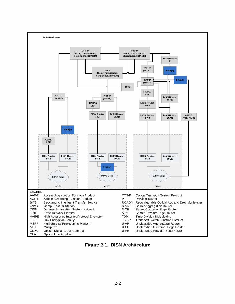
CERTIFICATION TESTING SUMMARY 1. SYSTEM TITLE. Nokia Siemens Networks (NSN) hiT7300, Dense Wavelength Division Multiplexing (DWDM) platform, Fixed Network Element (F-NE) with Software Release Version 4.30. 2. SPONSOR. Mr. Jordan Silk, Program Manager, HQUSAISEC, AMSEL-IE-IS, Building 53302, Fort Huachuca, AZ 85613, Email: [email protected]. 3. SYSTEM POC. Mr. Paul Shrubshall, NSN, 6000 Connection Drive, Building 4, Irving, TX 75039, e-mail: [email protected]. 4. TESTER. Joint Interoperability Test Command (JITC), Indian Head, Maryland. 5. SYSTEM DESCRIPTION. The Defense Information Systems Network (DISN) Optical Transport System (OTS) multiplexes optical signals from various sources (e.g., router, transport switch function, Channel Access Grooming) at the optical core layer. The OTS consists of the following components: Terminal, Reconfigurable Optical Add and Drop Multiplexer (ROADM), and Optical Line Amplifier. An Optical Supervisory Channel runs between these components. The terminal is composed of two elements: the transponder and the muxponder. The SUT with Software Release Version 4.30 is a DWDM-based ROADM OTS. The NSN Telecommunication Network Management System (NMS) with Software Release Version 12.6 and NSN TransNet DWDM System Network Planning Tool, with Software Release Version 7.0 are used for configuration purposes and therefore are not certified under the SUT. 6. OPERATIONAL ARCHITECTURE. JITC tested the SUT under the F-NE Unified Capabilities Requirements (UCR) product category. A high-level Defense Information System Network (DISN) node architecture, as depicted in Figure 2-1, displays the F-NE devices. The SUT as F-NE can be deployed to transport DISN services in the Wide Area Network (WAN) and on a camp, post, or station within the Local Area Network (LAN) infrastructure. The SUT solution meets the UCR requirements and can be used to augment WAN or LAN infrastructures.
2-2
C/P/SC/P/SC/P/S
OTS-P
(OLA, Transponder,
Muxponder, ROADM)
OTS
(OLA, Transponder,
Muxponder, ROADM)
OTS-P
(OLA, Transponder,
Muxponder, ROADM)
TSF-P
(ODXC)
AGF-P
(MSPP)
DISN Router
P
DISN Router
U-PE
DISN Router
U-CE
DISN Router
U-ARAAF-P
(TDM MUX)
DISN Router
S-CE
C/P/S Edge
DISN Backbone
DISN Router
U-CE
DISN Router
S-CE
C/P/S Edge
DISN Router
S-AR
AGF-P
(MSPP)
HAIPE/
LEF
DISN Router
U-CE
DISN Router
S-CE
DISN Router
U-AR
DISN Router
S-AR
DISN Router
S-PE
AGF-P
(MSPP)
HAIPE/
LEF
HAIPE/
LEF
C/P/S Edge
BITS
F-NE(s)
F-NE(s)
F-NE(s)
F-NE(s)
LEGEND: AAF-P Access Aggregation Function Product AGF-P Access Grooming Function Product BITS Background Intelligent Transfer Service C/P/S Camp, Post, or Station DISN Defense Information System Network F-NE Fixed Network Element HAIPE High Assurance Internet Protocol Encryptor LEF Link Encryption Family MSPP Multi-Service Provisioning Platform MUX Multiplexer ODXC Optical Digital Cross Connect OLA Optical Line Amplifier
OTS-P Optical Transport System Product P Provider Router ROADM Reconfigurable Optical Add and Drop Multiplexer S-AR Secret Aggregation Router S-CE Secret Customer Edge Router S-PE Secret Provider Edge Router TDM Time Division Multiplexing TSF-P Transport Switch Function Product U-AR Unclassified Aggregation Router U-CE Unclassified Customer Edge Router U-PE Unclassified Provider Edge Router
Figure 2-1. DISN Architecture
2-3
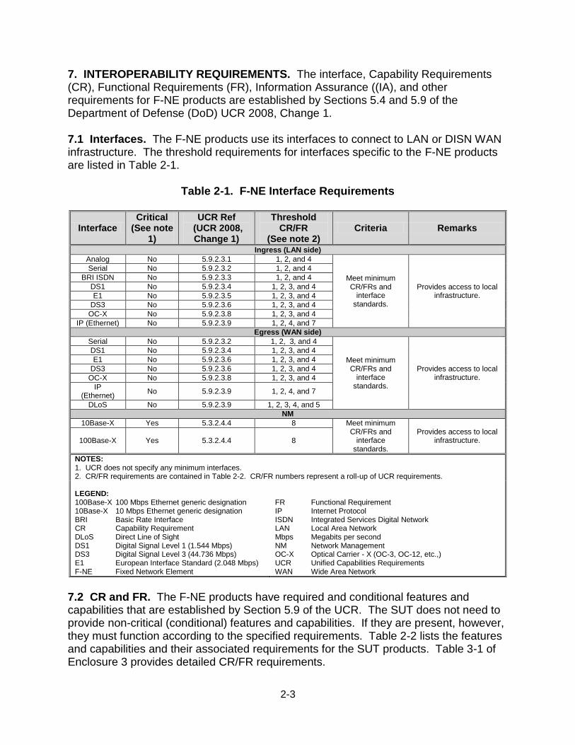
7. INTEROPERABILITY REQUIREMENTS. The interface, Capability Requirements (CR), Functional Requirements (FR), Information Assurance ((IA), and other requirements for F-NE products are established by Sections 5.4 and 5.9 of the Department of Defense (DoD) UCR 2008, Change 1. 7.1 Interfaces. The F-NE products use its interfaces to connect to LAN or DISN WAN infrastructure. The threshold requirements for interfaces specific to the F-NE products are listed in Table 2-1.
Table 2-1. F-NE Interface Requirements
Interface Critical
(See note 1)
UCR Ref (UCR 2008, Change 1)
Threshold CR/FR
(See note 2) Criteria Remarks
Ingress (LAN side)
Analog No 5.9.2.3.1 1, 2, and 4
Meet minimum CR/FRs and
interface standards.
Provides access to local infrastructure.
Serial No 5.9.2.3.2 1, 2, and 4
BRI ISDN No 5.9.2.3.3 1, 2, and 4
DS1 No 5.9.2.3.4 1, 2, 3, and 4
E1 No 5.9.2.3.5 1, 2, 3, and 4
DS3 No 5.9.2.3.6 1, 2, 3, and 4
OC-X No 5.9.2.3.8 1, 2, 3, and 4
IP (Ethernet) No 5.9.2.3.9 1, 2, 4, and 7
Egress (WAN side)
Serial No 5.9.2.3.2 1, 2, 3, and 4
Meet minimum CR/FRs and
interface standards.
Provides access to local infrastructure.
DS1 No 5.9.2.3.4 1, 2, 3, and 4
E1 No 5.9.2.3.6 1, 2, 3, and 4
DS3 No 5.9.2.3.6 1, 2, 3, and 4
OC-X No 5.9.2.3.8 1, 2, 3, and 4
IP (Ethernet)
No 5.9.2.3.9 1, 2, 4, and 7
DLoS No 5.9.2.3.9 1, 2, 3, 4, and 5
NM
10Base-X Yes 5.3.2.4.4 8 Meet minimum CR/FRs and
interface standards.
Provides access to local infrastructure. 100Base-X Yes 5.3.2.4.4 8
NOTES: 1. UCR does not specify any minimum interfaces. 2. CR/FR requirements are contained in Table 2-2. CR/FR numbers represent a roll-up of UCR requirements. LEGEND: 100Base-X 100 Mbps Ethernet generic designation 10Base-X 10 Mbps Ethernet generic designation BRI Basic Rate Interface CR Capability Requirement DLoS Direct Line of Sight DS1 Digital Signal Level 1 (1.544 Mbps) DS3 Digital Signal Level 3 (44.736 Mbps) E1 European Interface Standard (2.048 Mbps) F-NE Fixed Network Element
FR Functional Requirement IP Internet Protocol ISDN Integrated Services Digital Network LAN Local Area Network Mbps Megabits per second NM Network Management OC-X Optical Carrier - X (OC-3, OC-12, etc.,) UCR Unified Capabilities Requirements WAN Wide Area Network
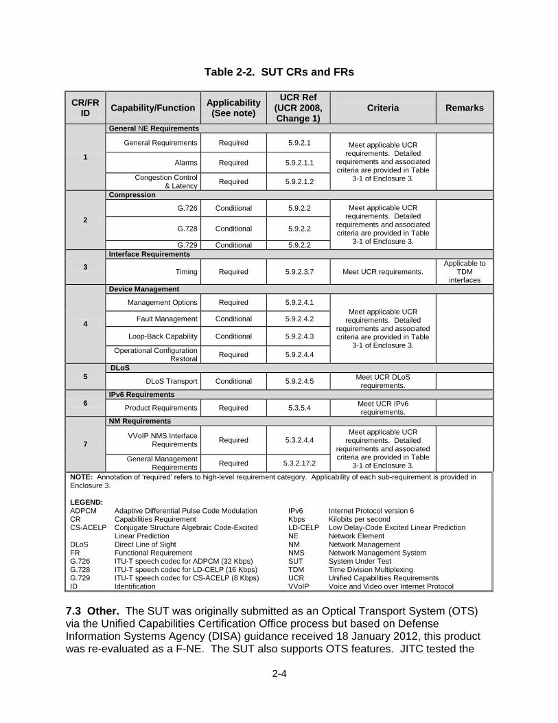
7.2 CR and FR. The F-NE products have required and conditional features and capabilities that are established by Section 5.9 of the UCR. The SUT does not need to provide non-critical (conditional) features and capabilities. If they are present, however, they must function according to the specified requirements. Table 2-2 lists the features and capabilities and their associated requirements for the SUT products. Table 3-1 of Enclosure 3 provides detailed CR/FR requirements.
2-4
Table 2-2. SUT CRs and FRs
CR/FR ID
Capability/Function Applicability (See note)
UCR Ref (UCR 2008, Change 1)
Criteria Remarks
1
General NE Requirements
General Requirements Required 5.9.2.1 Meet applicable UCR requirements. Detailed
requirements and associated criteria are provided in Table
3-1 of Enclosure 3.
Alarms Required 5.9.2.1.1
Congestion Control & Latency
Required 5.9.2.1.2
2
Compression
G.726 Conditional 5.9.2.2 Meet applicable UCR requirements. Detailed
requirements and associated criteria are provided in Table
3-1 of Enclosure 3.
G.728 Conditional 5.9.2.2
G.729 Conditional 5.9.2.2
3
Interface Requirements
Timing Required 5.9.2.3.7 Meet UCR requirements. Applicable to
TDM interfaces
4
Device Management
Management Options Required 5.9.2.4.1
Meet applicable UCR requirements. Detailed
requirements and associated criteria are provided in Table
3-1 of Enclosure 3.
Fault Management Conditional 5.9.2.4.2
Loop-Back Capability Conditional 5.9.2.4.3
Operational Configuration Restoral
Required 5.9.2.4.4
5
DLoS
DLoS Transport Conditional 5.9.2.4.5 Meet UCR DLoS
requirements.
6
IPv6 Requirements
Product Requirements Required 5.3.5.4 Meet UCR IPv6 requirements.
7
NM Requirements
VVoIP NMS Interface Requirements
Required 5.3.2.4.4 Meet applicable UCR
requirements. Detailed requirements and associated criteria are provided in Table
3-1 of Enclosure 3.
General Management Requirements
Required 5.3.2.17.2
NOTE: Annotation of ‘required’ refers to high-level requirement category. Applicability of each sub-requirement is provided in Enclosure 3. LEGEND: ADPCM Adaptive Differential Pulse Code Modulation CR Capabilities Requirement CS-ACELP Conjugate Structure Algebraic Code-Excited
Linear Prediction DLoS Direct Line of Sight FR Functional Requirement G.726 ITU-T speech codec for ADPCM (32 Kbps) G.728 ITU-T speech codec for LD-CELP (16 Kbps) G.729 ITU-T speech codec for CS-ACELP (8 Kbps) ID Identification
IPv6 Internet Protocol version 6 Kbps Kilobits per second LD-CELP Low Delay-Code Excited Linear Prediction NE Network Element NM Network Management NMS Network Management System SUT System Under Test TDM Time Division Multiplexing UCR Unified Capabilities Requirements VVoIP Voice and Video over Internet Protocol
7.3 Other. The SUT was originally submitted as an Optical Transport System (OTS) via the Unified Capabilities Certification Office process but based on Defense Information Systems Agency (DISA) guidance received 18 January 2012, this product was re-evaluated as a F-NE. The SUT also supports OTS features. JITC tested the
2-5
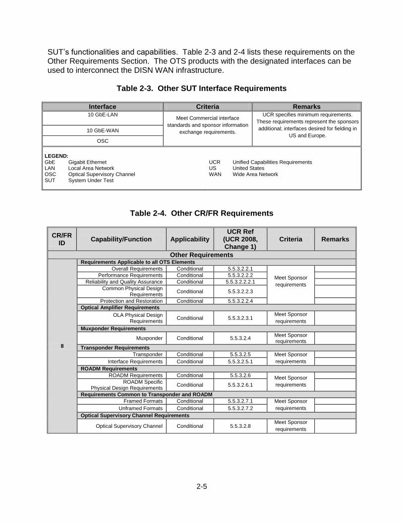
SUT’s functionalities and capabilities. Table 2-3 and 2-4 lists these requirements on the Other Requirements Section. The OTS products with the designated interfaces can be used to interconnect the DISN WAN infrastructure.
Table 2-3. Other SUT Interface Requirements
Interface Criteria Remarks 10 GbE-LAN
Meet Commercial interface
standards and sponsor information
exchange requirements.
UCR specifies minimum requirements.
These requirements represent the sponsors
additional; interfaces desired for fielding in
US and Europe. 10 GbE-WAN
OSC
LEGEND: GbE Gigabit Ethernet LAN Local Area Network OSC Optical Supervisory Channel SUT System Under Test
UCR Unified Capabilities Requirements US United States WAN Wide Area Network
Table 2-4. Other CR/FR Requirements
CR/FR ID
Capability/Function Applicability UCR Ref
(UCR 2008, Change 1)
Criteria Remarks
Other Requirements
8
Requirements Applicable to all OTS Elements
Overall Requirements Conditional 5.5.3.2.2.1
Meet Sponsor
requirements
Performance Requirements Conditional 5.5.3.2.2.2
Reliability and Quality Assurance Conditional 5.5.3.2.2.2.1
Common Physical Design Requirements
Conditional 5.5.3.2.2.3
Protection and Restoration Conditional 5.5.3.2.2.4
Optical Amplifier Requirements
OLA Physical Design Requirements
Conditional 5.5.3.2.3.1 Meet Sponsor
requirements
Muxponder Requirements
Muxponder Conditional 5.5.3.2.4 Meet Sponsor requirements
Transponder Requirements
Transponder Conditional 5.5.3.2.5 Meet Sponsor
requirements
Interface Requirements Conditional 5.5.3.2.5.1
ROADM Requirements
ROADM Requirements Conditional 5.5.3.2.6 Meet Sponsor
requirements
ROADM Specific Physical Design Requirements
Conditional 5.5.3.2.6.1
Requirements Common to Transponder and ROADM
Framed Formats Conditional 5.5.3.2.7.1 Meet Sponsor
requirements
Unframed Formats Conditional 5.5.3.2.7.2
Optical Supervisory Channel Requirements
Optical Supervisory Channel Conditional 5.5.3.2.8 Meet Sponsor
requirements
2-6
Table 2-4. Other CR/FR Requirements (continued)
LEGEND: CR Capabilities Requirement FR Functional Requirement ID Identification OLA Optical Line Amplifier
OTS Optical Transport System ROADM Reconfigurable Optical Add Drop Multiplexor UCR Unified Capabilities Requirements
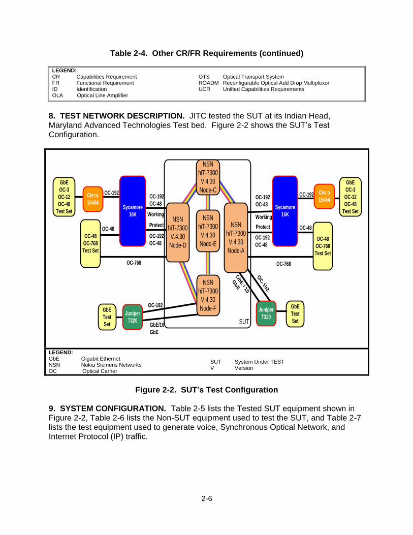
8. TEST NETWORK DESCRIPTION. JITC tested the SUT at its Indian Head, Maryland Advanced Technologies Test bed. Figure 2-2 shows the SUT’s Test Configuration.
OC-192
OC-192
OC-48
OC-192
OC-48
Working
Protect
Cisco
15454
GbE
OC-3
OC-12
OC-48
Test Set
OC-192
GbE
Test
Set
Juniper
T320
Sycamore
16K
OC-192
OC-48
OC-192
OC-48
Working
Protect
Cisco
15454
GbE
OC-3
OC-12
OC-48
Test Set
OC-192
Sycamore
16K
OC-192
GbE
Test
SetGbE/10
GbE
GbE / 10
GbE
Juniper
T320
NSN
hiT-7300
V.4.30
Node-E
SUT
NSN
hiT-7300
V.4.30
Node-F
NSN
hiT-7300
V.4.30
Node-C
OC-768OC-768
OC-48
OC-48
OC-768
Test Set
OC-48NSN
hiT-7300
V.4.30
Node-A
NSN
hiT-7300
V.4.30
Node-D
OC-48
OC-768
Test Set
LEGEND: GbE Gigabit Ethernet NSN Nokia Siemens Networks OC Optical Carrier
SUT System Under TEST V Version
Figure 2-2. SUT’s Test Configuration
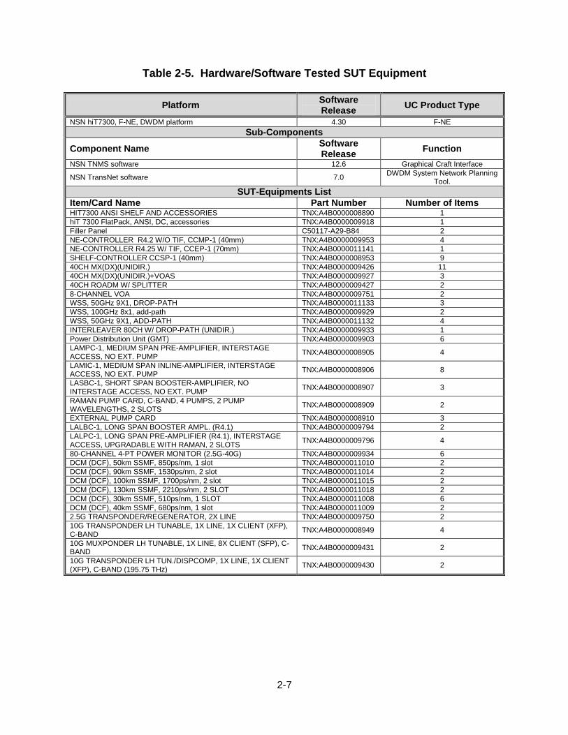
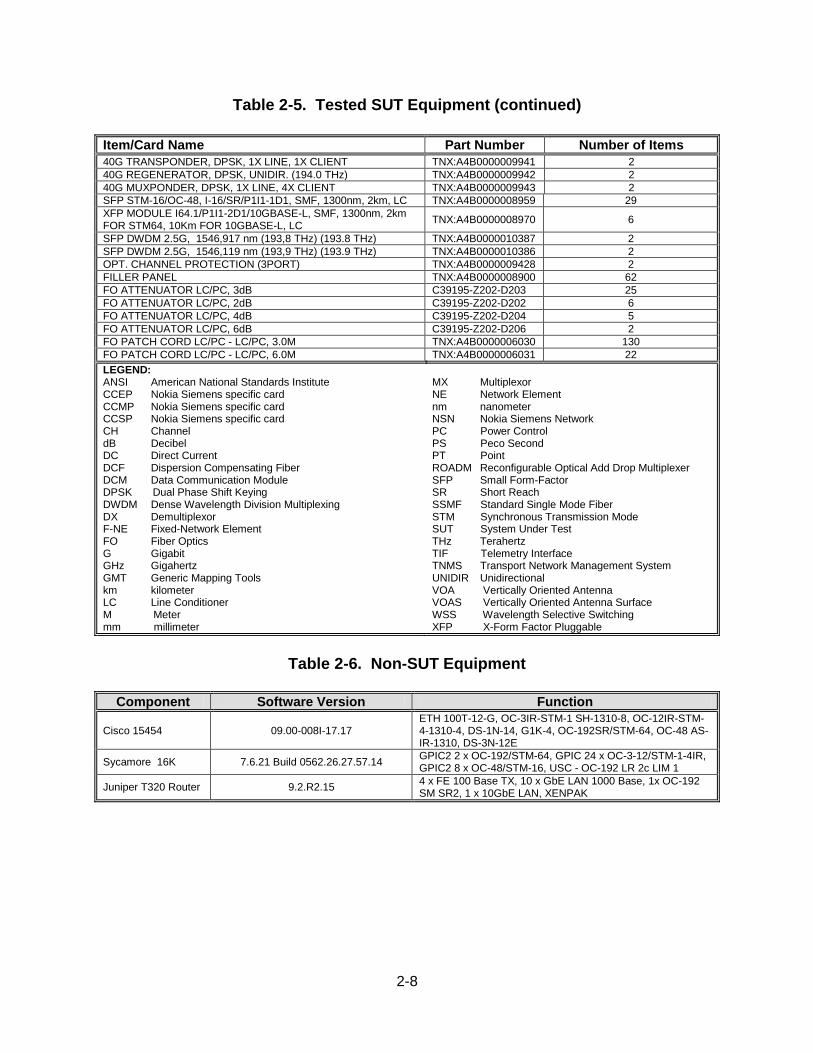
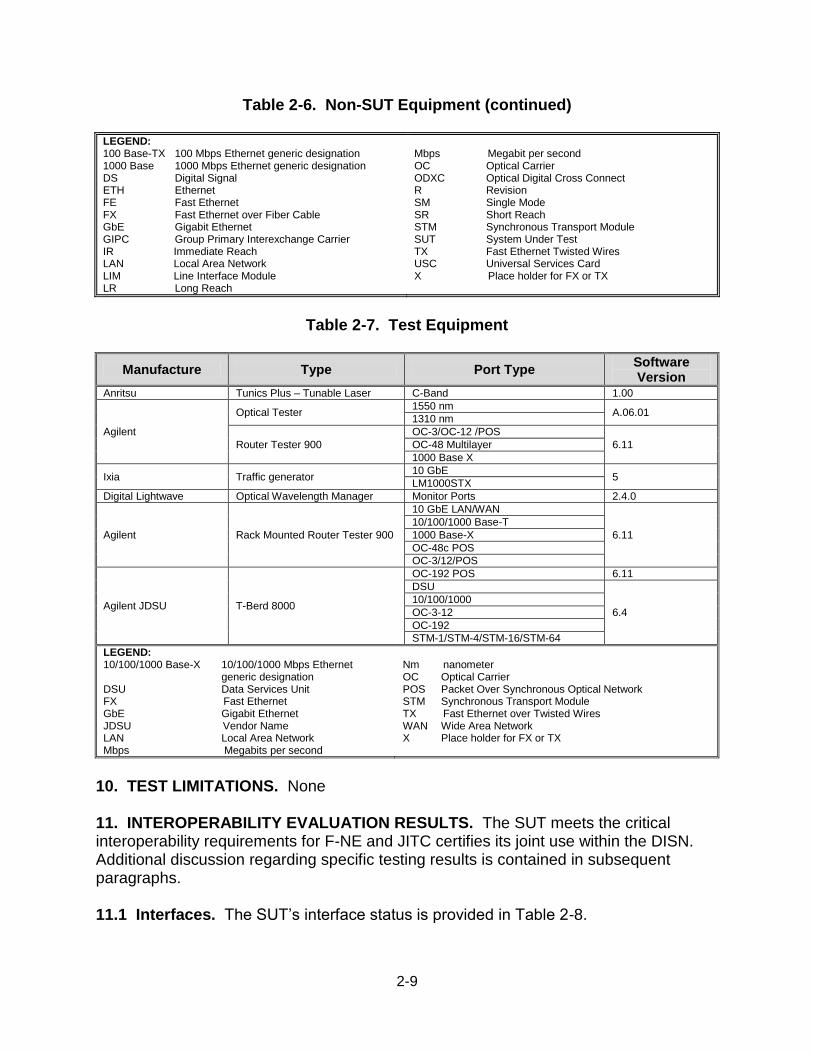
9. SYSTEM CONFIGURATION. Table 2-5 lists the Tested SUT equipment shown in Figure 2-2, Table 2-6 lists the Non-SUT equipment used to test the SUT, and Table 2-7 lists the test equipment used to generate voice, Synchronous Optical Network, and Internet Protocol (IP) traffic.
2-7
Table 2-5. Hardware/Software Tested SUT Equipment
Platform Software Release
UC Product Type
NSN hiT7300, F-NE, DWDM platform 4.30 F-NE
Sub-Components
Component Name Software Release
Function
NSN TNMS software 12.6 Graphical Craft Interface
NSN TransNet software 7.0 DWDM System Network Planning
Tool.
SUT-Equipments List
Item/Card Name Part Number Number of Items HIT7300 ANSI SHELF AND ACCESSORIES TNX:A4B0000008890 1
hiT 7300 FlatPack, ANSI, DC, accessories TNX:A4B0000009918 1
Filler Panel C50117-A29-B84 2
NE-CONTROLLER R4.2 W/O TIF, CCMP-1 (40mm) TNX:A4B0000009953 4
NE-CONTROLLER R4.25 W/ TIF, CCEP-1 (70mm) TNX:A4B0000011141 1
SHELF-CONTROLLER CCSP-1 (40mm) TNX:A4B0000008953 9
40CH MX(DX)(UNIDIR.) TNX:A4B0000009426 11
40CH MX(DX)(UNIDIR.)+VOAS TNX:A4B0000009927 3
40CH ROADM W/ SPLITTER TNX:A4B0000009427 2
8-CHANNEL VOA TNX:A4B0000009751 2
WSS, 50GHz 9X1, DROP-PATH TNX:A4B0000011133 3
WSS, 100GHz 8x1, add-path TNX:A4B0000009929 2
WSS, 50GHz 9X1, ADD-PATH TNX:A4B0000011132 4
INTERLEAVER 80CH W/ DROP-PATH (UNIDIR.) TNX:A4B0000009933 1
Power Distribution Unit (GMT) TNX:A4B0000009903 6
LAMPC-1, MEDIUM SPAN PRE-AMPLIFIER, INTERSTAGE ACCESS, NO EXT. PUMP
TNX:A4B0000008905 4
LAMIC-1, MEDIUM SPAN INLINE-AMPLIFIER, INTERSTAGE ACCESS, NO EXT. PUMP
TNX:A4B0000008906 8
LASBC-1, SHORT SPAN BOOSTER-AMPLIFIER, NO INTERSTAGE ACCESS, NO EXT. PUMP
TNX:A4B0000008907 3
RAMAN PUMP CARD, C-BAND, 4 PUMPS, 2 PUMP WAVELENGTHS, 2 SLOTS
TNX:A4B0000008909 2
EXTERNAL PUMP CARD TNX:A4B0000008910 3
LALBC-1, LONG SPAN BOOSTER AMPL. (R4.1) TNX:A4B0000009794 2
LALPC-1, LONG SPAN PRE-AMPLIFIER (R4.1), INTERSTAGE ACCESS, UPGRADABLE WITH RAMAN, 2 SLOTS
TNX:A4B0000009796 4
80-CHANNEL 4-PT POWER MONITOR (2.5G-40G) TNX:A4B0000009934 6
DCM (DCF), 50km SSMF, 850ps/nm, 1 slot TNX:A4B0000011010 2
DCM (DCF), 90km SSMF, 1530ps/nm, 2 slot TNX:A4B0000011014 2
DCM (DCF), 100km SSMF, 1700ps/nm, 2 slot TNX:A4B0000011015 2
DCM (DCF), 130km SSMF, 2210ps/nm, 2 SLOT TNX:A4B0000011018 2
DCM (DCF), 30km SSMF, 510ps/nm, 1 SLOT TNX:A4B0000011008 6
DCM (DCF), 40km SSMF, 680ps/nm, 1 slot TNX:A4B0000011009 2
2.5G TRANSPONDER/REGENERATOR, 2X LINE TNX:A4B0000009750 2
10G TRANSPONDER LH TUNABLE, 1X LINE, 1X CLIENT (XFP), C-BAND
TNX:A4B0000008949 4
10G MUXPONDER LH TUNABLE, 1X LINE, 8X CLIENT (SFP), C-BAND
TNX:A4B0000009431 2
10G TRANSPONDER LH TUN./DISPCOMP, 1X LINE, 1X CLIENT (XFP), C-BAND (195.75 THz)
TNX:A4B0000009430 2
2-8
Table 2-5. Tested SUT Equipment (continued)
Item/Card Name Part Number Number of Items
40G TRANSPONDER, DPSK, 1X LINE, 1X CLIENT TNX:A4B0000009941 2
40G REGENERATOR, DPSK, UNIDIR. (194.0 THz) TNX:A4B0000009942 2
40G MUXPONDER, DPSK, 1X LINE, 4X CLIENT TNX:A4B0000009943 2
SFP STM-16/OC-48, I-16/SR/P1I1-1D1, SMF, 1300nm, 2km, LC TNX:A4B0000008959 29
XFP MODULE I64.1/P1I1-2D1/10GBASE-L, SMF, 1300nm, 2km FOR STM64, 10Km FOR 10GBASE-L, LC
TNX:A4B0000008970 6
SFP DWDM 2.5G, 1546,917 nm (193,8 THz) (193.8 THz) TNX:A4B0000010387 2
SFP DWDM 2.5G, 1546,119 nm (193,9 THz) (193.9 THz) TNX:A4B0000010386 2
OPT. CHANNEL PROTECTION (3PORT) TNX:A4B0000009428 2
FILLER PANEL TNX:A4B0000008900 62
FO ATTENUATOR LC/PC, 3dB C39195-Z202-D203 25
FO ATTENUATOR LC/PC, 2dB C39195-Z202-D202 6
FO ATTENUATOR LC/PC, 4dB C39195-Z202-D204 5
FO ATTENUATOR LC/PC, 6dB C39195-Z202-D206 2
FO PATCH CORD LC/PC - LC/PC, 3.0M TNX:A4B0000006030 130
FO PATCH CORD LC/PC - LC/PC, 6.0M TNX:A4B0000006031 22
LEGEND: ANSI American National Standards Institute CCEP Nokia Siemens specific card CCMP Nokia Siemens specific card CCSP Nokia Siemens specific card CH Channel dB Decibel DC Direct Current DCF Dispersion Compensating Fiber DCM Data Communication Module DPSK Dual Phase Shift Keying DWDM Dense Wavelength Division Multiplexing DX Demultiplexor F-NE Fixed-Network Element FO Fiber Optics G Gigabit GHz Gigahertz GMT Generic Mapping Tools km kilometer LC Line Conditioner M Meter mm millimeter
MX Multiplexor NE Network Element nm nanometer NSN Nokia Siemens Network PC Power Control PS Peco Second PT Point ROADM Reconfigurable Optical Add Drop Multiplexer SFP Small Form-Factor SR Short Reach SSMF Standard Single Mode Fiber STM Synchronous Transmission Mode SUT System Under Test THz Terahertz TIF Telemetry Interface TNMS Transport Network Management System UNIDIR Unidirectional VOA Vertically Oriented Antenna VOAS Vertically Oriented Antenna Surface WSS Wavelength Selective Switching XFP X-Form Factor Pluggable
Table 2-6. Non-SUT Equipment
Component Software Version Function
Cisco 15454 09.00-008I-17.17 ETH 100T-12-G, OC-3IR-STM-1 SH-1310-8, OC-12IR-STM-4-1310-4, DS-1N-14, G1K-4, OC-192SR/STM-64, OC-48 AS-IR-1310, DS-3N-12E
Sycamore 16K 7.6.21 Build 0562.26.27.57.14 GPIC2 2 x OC-192/STM-64, GPIC 24 x OC-3-12/STM-1-4IR, GPIC2 8 x OC-48/STM-16, USC - OC-192 LR 2c LIM 1
Juniper T320 Router 9.2.R2.15 4 x FE 100 Base TX, 10 x GbE LAN 1000 Base, 1x OC-192 SM SR2, 1 x 10GbE LAN, XENPAK
2-9
Table 2-6. Non-SUT Equipment (continued)
LEGEND: 100 Base-TX 100 Mbps Ethernet generic designation 1000 Base 1000 Mbps Ethernet generic designation DS Digital Signal ETH Ethernet FE Fast Ethernet FX Fast Ethernet over Fiber Cable GbE Gigabit Ethernet GIPC Group Primary Interexchange Carrier IR Immediate Reach LAN Local Area Network LIM Line Interface Module LR Long Reach
Mbps Megabit per second OC Optical Carrier ODXC Optical Digital Cross Connect R Revision SM Single Mode SR Short Reach STM Synchronous Transport Module SUT System Under Test TX Fast Ethernet Twisted Wires USC Universal Services Card X Place holder for FX or TX
Table 2-7. Test Equipment
Manufacture Type Port Type Software Version
Anritsu Tunics Plus – Tunable Laser C-Band 1.00
Agilent
Optical Tester 1550 nm
A.06.01 1310 nm
Router Tester 900
OC-3/OC-12 /POS
6.11 OC-48 Multilayer
1000 Base X
Ixia Traffic generator 10 GbE
5 LM1000STX
Digital Lightwave Optical Wavelength Manager Monitor Ports 2.4.0
Agilent Rack Mounted Router Tester 900
10 GbE LAN/WAN
6.11
10/100/1000 Base-T
1000 Base-X
OC-48c POS
OC-3/12/POS
Agilent JDSU T-Berd 8000
OC-192 POS 6.11
DSU
6.4
10/100/1000
OC-3-12
OC-192
STM-1/STM-4/STM-16/STM-64
LEGEND: 10/100/1000 Base-X 10/100/1000 Mbps Ethernet
generic designation DSU Data Services Unit FX Fast Ethernet GbE Gigabit Ethernet JDSU Vendor Name LAN Local Area Network Mbps Megabits per second
Nm nanometer OC Optical Carrier POS Packet Over Synchronous Optical Network STM Synchronous Transport Module TX Fast Ethernet over Twisted Wires WAN Wide Area Network X Place holder for FX or TX
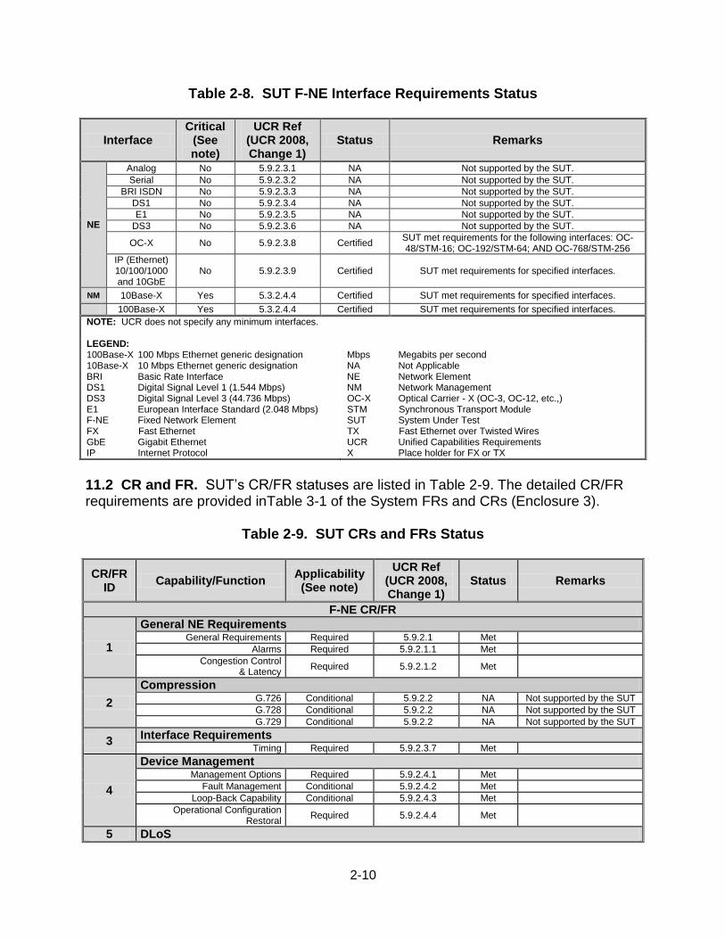
10. TEST LIMITATIONS. None 11. INTEROPERABILITY EVALUATION RESULTS. The SUT meets the critical interoperability requirements for F-NE and JITC certifies its joint use within the DISN. Additional discussion regarding specific testing results is contained in subsequent paragraphs. 11.1 Interfaces. The SUT’s interface status is provided in Table 2-8.
2-10
Table 2-8. SUT F-NE Interface Requirements Status
Interface Critical
(See note)
UCR Ref (UCR 2008, Change 1)
Status Remarks
NE
Analog No 5.9.2.3.1 NA Not supported by the SUT.
Serial No 5.9.2.3.2 NA Not supported by the SUT.
BRI ISDN No 5.9.2.3.3 NA Not supported by the SUT.
DS1 No 5.9.2.3.4 NA Not supported by the SUT.
E1 No 5.9.2.3.5 NA Not supported by the SUT.
DS3 No 5.9.2.3.6 NA Not supported by the SUT.
OC-X No 5.9.2.3.8 Certified SUT met requirements for the following interfaces: OC-48/STM-16; OC-192/STM-64; AND OC-768/STM-256
IP (Ethernet) 10/100/1000 and 10GbE
No 5.9.2.3.9 Certified SUT met requirements for specified interfaces.
NM 10Base-X Yes 5.3.2.4.4 Certified SUT met requirements for specified interfaces.
100Base-X Yes 5.3.2.4.4 Certified SUT met requirements for specified interfaces.
NOTE: UCR does not specify any minimum interfaces. LEGEND: 100Base-X 100 Mbps Ethernet generic designation 10Base-X 10 Mbps Ethernet generic designation BRI Basic Rate Interface DS1 Digital Signal Level 1 (1.544 Mbps) DS3 Digital Signal Level 3 (44.736 Mbps) E1 European Interface Standard (2.048 Mbps) F-NE Fixed Network Element FX Fast Ethernet GbE Gigabit Ethernet IP Internet Protocol
Mbps Megabits per second NA Not Applicable NE Network Element NM Network Management OC-X Optical Carrier - X (OC-3, OC-12, etc.,) STM Synchronous Transport Module SUT System Under Test TX Fast Ethernet over Twisted Wires UCR Unified Capabilities Requirements X Place holder for FX or TX
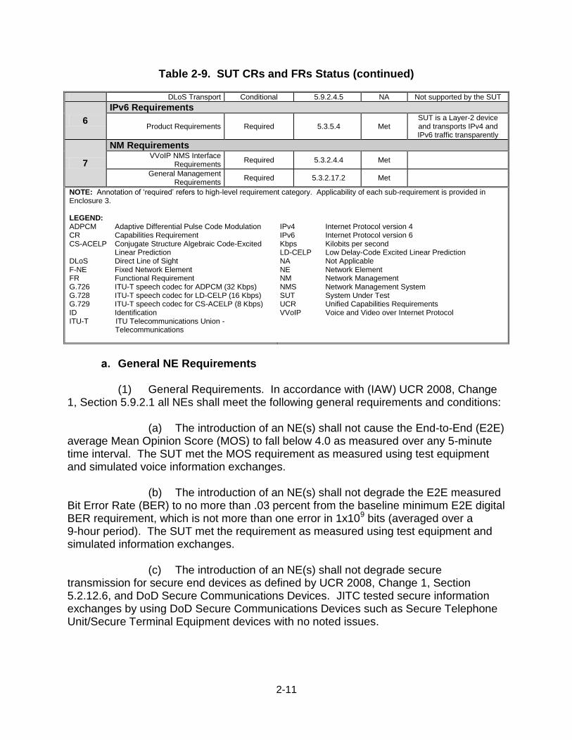
11.2 CR and FR. SUT’s CR/FR statuses are listed in Table 2-9. The detailed CR/FR requirements are provided inTable 3-1 of the System FRs and CRs (Enclosure 3).
Table 2-9. SUT CRs and FRs Status
CR/FR ID
Capability/Function Applicability
(See note)
UCR Ref (UCR 2008, Change 1)
Status Remarks
F-NE CR/FR
1
General NE Requirements General Requirements Required 5.9.2.1 Met
Alarms Required 5.9.2.1.1 Met
Congestion Control & Latency
Required 5.9.2.1.2 Met
2
Compression G.726 Conditional 5.9.2.2 NA Not supported by the SUT
G.728 Conditional 5.9.2.2 NA Not supported by the SUT
G.729 Conditional 5.9.2.2 NA Not supported by the SUT
3 Interface Requirements
Timing Required 5.9.2.3.7 Met
4
Device Management Management Options Required 5.9.2.4.1 Met
Fault Management Conditional 5.9.2.4.2 Met
Loop-Back Capability Conditional 5.9.2.4.3 Met
Operational Configuration Restoral
Required 5.9.2.4.4 Met
5 DLoS
2-11
Table 2-9. SUT CRs and FRs Status (continued)
DLoS Transport Conditional 5.9.2.4.5 NA Not supported by the SUT
6
IPv6 Requirements
Product Requirements Required 5.3.5.4 Met SUT is a Layer-2 device and transports IPv4 and IPv6 traffic transparently
7
NM Requirements VVoIP NMS Interface
Requirements Required 5.3.2.4.4 Met
General Management Requirements
Required 5.3.2.17.2 Met
NOTE: Annotation of ‘required’ refers to high-level requirement category. Applicability of each sub-requirement is provided in Enclosure 3. LEGEND: ADPCM Adaptive Differential Pulse Code Modulation CR Capabilities Requirement CS-ACELP Conjugate Structure Algebraic Code-Excited
Linear Prediction DLoS Direct Line of Sight F-NE Fixed Network Element FR Functional Requirement G.726 ITU-T speech codec for ADPCM (32 Kbps) G.728 ITU-T speech codec for LD-CELP (16 Kbps) G.729 ITU-T speech codec for CS-ACELP (8 Kbps) ID Identification ITU-T ITU Telecommunications Union - Telecommunications
IPv4 Internet Protocol version 4 IPv6 Internet Protocol version 6 Kbps Kilobits per second LD-CELP Low Delay-Code Excited Linear Prediction NA Not Applicable NE Network Element NM Network Management NMS Network Management System SUT System Under Test UCR Unified Capabilities Requirements VVoIP Voice and Video over Internet Protocol
a. General NE Requirements
(1) General Requirements. In accordance with (IAW) UCR 2008, Change
1, Section 5.9.2.1 all NEs shall meet the following general requirements and conditions:
(a) The introduction of an NE(s) shall not cause the End-to-End (E2E) average Mean Opinion Score (MOS) to fall below 4.0 as measured over any 5-minute time interval. The SUT met the MOS requirement as measured using test equipment and simulated voice information exchanges.
(b) The introduction of an NE(s) shall not degrade the E2E measured Bit Error Rate (BER) to no more than .03 percent from the baseline minimum E2E digital BER requirement, which is not more than one error in 1x109 bits (averaged over a 9-hour period). The SUT met the requirement as measured using test equipment and simulated information exchanges.
(c) The introduction of an NE(s) shall not degrade secure transmission for secure end devices as defined by UCR 2008, Change 1, Section 5.2.12.6, and DoD Secure Communications Devices. JITC tested secure information exchanges by using DoD Secure Communications Devices such as Secure Telephone Unit/Secure Terminal Equipment devices with no noted issues.
2-12
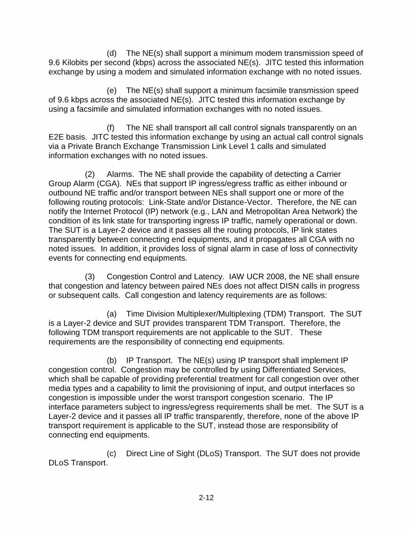
(d) The NE(s) shall support a minimum modem transmission speed of 9.6 Kilobits per second (kbps) across the associated NE(s). JITC tested this information exchange by using a modem and simulated information exchange with no noted issues.
(e) The NE(s) shall support a minimum facsimile transmission speed of 9.6 kbps across the associated NE(s). JITC tested this information exchange by using a facsimile and simulated information exchanges with no noted issues.
(f) The NE shall transport all call control signals transparently on an E2E basis. JITC tested this information exchange by using an actual call control signals via a Private Branch Exchange Transmission Link Level 1 calls and simulated information exchanges with no noted issues.
(2) Alarms. The NE shall provide the capability of detecting a Carrier Group Alarm (CGA). NEs that support IP ingress/egress traffic as either inbound or outbound NE traffic and/or transport between NEs shall support one or more of the following routing protocols: Link-State and/or Distance-Vector. Therefore, the NE can notify the Internet Protocol (IP) network (e.g., LAN and Metropolitan Area Network) the condition of its link state for transporting ingress IP traffic, namely operational or down. The SUT is a Layer-2 device and it passes all the routing protocols, IP link states transparently between connecting end equipments, and it propagates all CGA with no noted issues. In addition, it provides loss of signal alarm in case of loss of connectivity events for connecting end equipments.
(3) Congestion Control and Latency. IAW UCR 2008, the NE shall ensure that congestion and latency between paired NEs does not affect DISN calls in progress or subsequent calls. Call congestion and latency requirements are as follows:
(a) Time Division Multiplexer/Multiplexing (TDM) Transport. The SUT is a Layer-2 device and SUT provides transparent TDM Transport. Therefore, the following TDM transport requirements are not applicable to the SUT. These requirements are the responsibility of connecting end equipments.
(b) IP Transport. The NE(s) using IP transport shall implement IP congestion control. Congestion may be controlled by using Differentiated Services, which shall be capable of providing preferential treatment for call congestion over other media types and a capability to limit the provisioning of input, and output interfaces so congestion is impossible under the worst transport congestion scenario. The IP interface parameters subject to ingress/egress requirements shall be met. The SUT is a Layer-2 device and it passes all IP traffic transparently, therefore, none of the above IP transport requirement is applicable to the SUT, instead those are responsibility of connecting end equipments.
(c) Direct Line of Sight (DLoS) Transport. The SUT does not provide DLoS Transport.
2-13
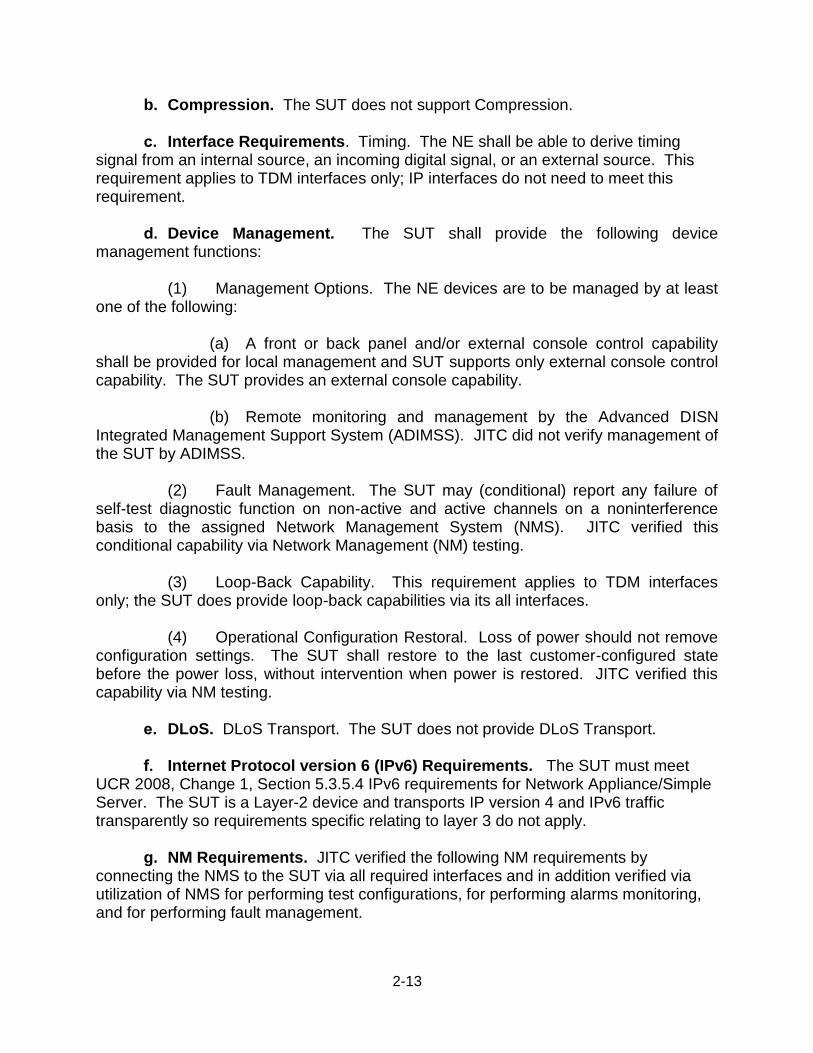
b. Compression. The SUT does not support Compression.
c. Interface Requirements. Timing. The NE shall be able to derive timing signal from an internal source, an incoming digital signal, or an external source. This requirement applies to TDM interfaces only; IP interfaces do not need to meet this requirement.
d. Device Management. The SUT shall provide the following device management functions:
(1) Management Options. The NE devices are to be managed by at least one of the following:
(a) A front or back panel and/or external console control capability shall be provided for local management and SUT supports only external console control capability. The SUT provides an external console capability.
(b) Remote monitoring and management by the Advanced DISN Integrated Management Support System (ADIMSS). JITC did not verify management of the SUT by ADIMSS.
(2) Fault Management. The SUT may (conditional) report any failure of self-test diagnostic function on non-active and active channels on a noninterference basis to the assigned Network Management System (NMS). JITC verified this conditional capability via Network Management (NM) testing.
(3) Loop-Back Capability. This requirement applies to TDM interfaces only; the SUT does provide loop-back capabilities via its all interfaces.
(4) Operational Configuration Restoral. Loss of power should not remove configuration settings. The SUT shall restore to the last customer-configured state before the power loss, without intervention when power is restored. JITC verified this capability via NM testing.
e. DLoS. DLoS Transport. The SUT does not provide DLoS Transport.
f. Internet Protocol version 6 (IPv6) Requirements. The SUT must meet UCR 2008, Change 1, Section 5.3.5.4 IPv6 requirements for Network Appliance/Simple Server. The SUT is a Layer-2 device and transports IP version 4 and IPv6 traffic transparently so requirements specific relating to layer 3 do not apply. g. NM Requirements. JITC verified the following NM requirements by connecting the NMS to the SUT via all required interfaces and in addition verified via utilization of NMS for performing test configurations, for performing alarms monitoring, and for performing fault management.
2-14
(1) Voice and Video over Internet Protocol (VVoIP) NMS Interface Requirements. The physical interface between the DISA VVoIP Element Management System (EMS) and the network components (i.e., Local Session Controller, Multifunction Soft Switch, Edge Boundary Controller, Customer Edge Router is a 10/100 Megabits per second Ethernet interface. The interface will work in either of the two following modes using auto-negotiation: Institute of Electrical and Electronics Engineers (IEEE), Ethernet Standard 802.3, 1993; or IEEE, Fast Ethernet Standard 802.3u, 1995.
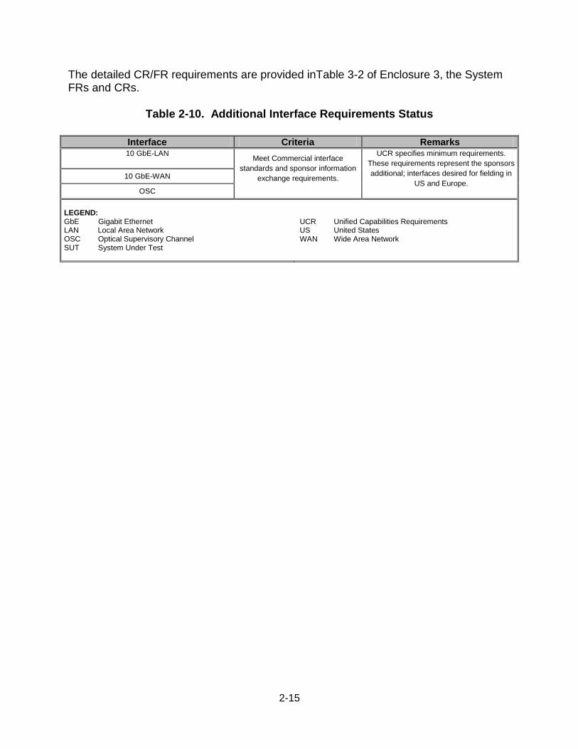
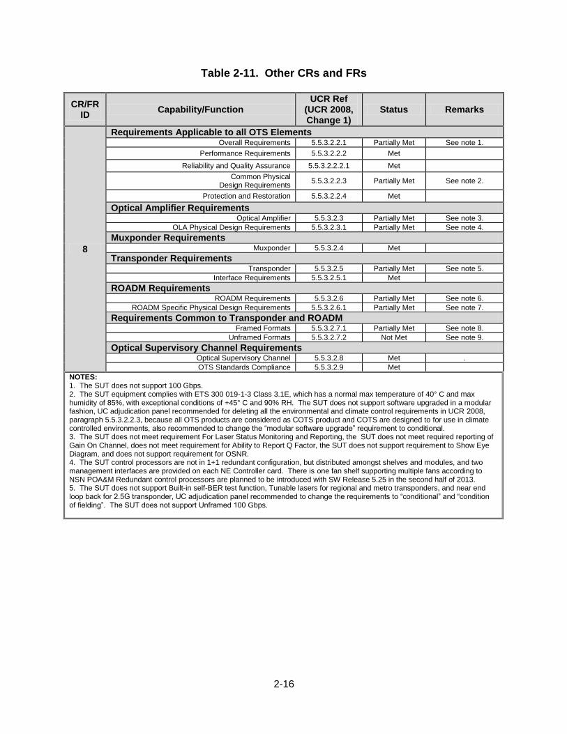
(2) General Management Requirements. The SUT must support Simple Network Management Protocol v3 format. A network appliance shall have Operations interfaces that provide a standard means by which management systems can directly or indirectly communicate with and, thus, manage the various network appliances in the DISN. The physical interface between the Local EMS and the VVoIP network components shall be an Ethernet connection IAW UCR 2008, Change 1, paragraph 5.3.2.4.4, VoIP NMS Interface Requirements. The physical interface between the VVoIP EMS and the VVoIP network components shall also be an Ethernet connection IAW UCR 2008, Change-2, paragraph 5.3.2.4.4. There shall be a local craftsperson interface (Craft Input Device for Operations Administration & Management) for all VVoIP network components. 11.3 Other. JITC has conducted additional tests on the SUT. Table 2-10 shows the Additional Interface Requirements under UCR 2008, Change 1, Section 5.5.3.4, and the results. The SUT’s CR/FR status under OTS requirements are listed in Table 2-11. The SUT met the minimum standards for the following UCR 2008, Change 1, Section 5.5.3.2, with the following exceptions:
(a) Requirements Applicable to all OTS Elements/Overall Requirements – Sub-Paragraph: (5.5.3.2.) 2.1.7.
(b) Requirements Applicable to all OTS Elements/Common Physical Design Requirements – Sub-Paragraphs: (5.5.3.2.) 2.3.32, 2.3.33, 2.3.34, 2.3.38, 2.3.44.
(c) Optical Amplifier Requirements/Optical Amplifier – Sub-Paragraphs: (5.5.3.2.) 3.3, 3.23, 3.24, 3.25, 3.26.
(d) Optical Amplifier Requirements/OLA Physical Design Requirements – Sub-Paragraph: (5.5.3.2.) 3.1.2.
(e) Transponder Requirements/Transponder – Sub Paragraphs: (5.5.3.2.) 5.2, 5.3, 5.4, 5.12.
(f) ROADM Requirements/ROADM Requirements – Sub-Paragraphs: (5.5.3.2.) 6.1, 6.2, 6.3, 6.22.
(g) ROADM Requirements/ROADM Specific Physical Design Requirements – Sub-Paragraphs: (5.5.3.2.) 6.1.3, 6.1.6.
(h) Requirements Common to Transponder and ROADM/Framed Formats – Sub-Paragraphs: (5.5.3.2.) 7.1.2, 7.1.7.
(i) Requirements Common to Transponder and ROADM/Unframed Formats – Sub-Paragraphs: (5.5.3.2.) 7.2.1, 7.2.2.
2-15
The detailed CR/FR requirements are provided inTable 3-2 of Enclosure 3, the System FRs and CRs.
Table 2-10. Additional Interface Requirements Status
Interface Criteria Remarks 10 GbE-LAN
Meet Commercial interface
standards and sponsor information
exchange requirements.
UCR specifies minimum requirements.
These requirements represent the sponsors
additional; interfaces desired for fielding in
US and Europe. 10 GbE-WAN
OSC
LEGEND: GbE Gigabit Ethernet LAN Local Area Network OSC Optical Supervisory Channel SUT System Under Test
UCR Unified Capabilities Requirements US United States WAN Wide Area Network
2-16
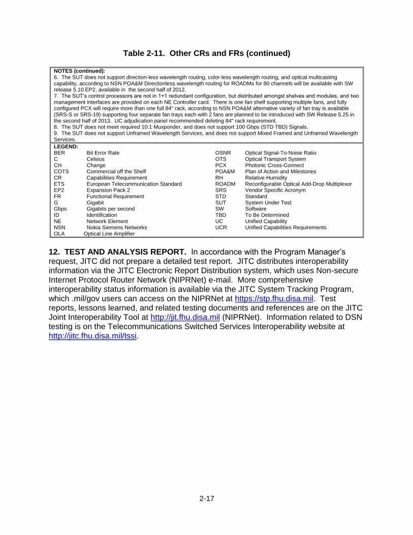
Table 2-11. Other CRs and FRs
CR/FR ID
Capability/Function UCR Ref
(UCR 2008, Change 1)
Status Remarks
8
Requirements Applicable to all OTS Elements Overall Requirements 5.5.3.2.2.1 Partially Met See note 1.
Performance Requirements 5.5.3.2.2.2 Met Reliability and Quality Assurance 5.5.3.2.2.2.1 Met
Common Physical Design Requirements
5.5.3.2.2.3 Partially Met See note 2.
Protection and Restoration 5.5.3.2.2.4 Met Optical Amplifier Requirements
Optical Amplifier 5.5.3.2.3 Partially Met See note 3.
OLA Physical Design Requirements 5.5.3.2.3.1 Partially Met See note 4. Muxponder Requirements
Muxponder 5.5.3.2.4 Met
Transponder Requirements Transponder 5.5.3.2.5 Partially Met See note 5.
Interface Requirements 5.5.3.2.5.1 Met
ROADM Requirements ROADM Requirements 5.5.3.2.6 Partially Met See note 6.
ROADM Specific Physical Design Requirements 5.5.3.2.6.1 Partially Met See note 7.
Requirements Common to Transponder and ROADM Framed Formats 5.5.3.2.7.1 Partially Met See note 8.
Unframed Formats 5.5.3.2.7.2 Not Met See note 9. Optical Supervisory Channel Requirements
Optical Supervisory Channel 5.5.3.2.8 Met .
OTS Standards Compliance 5.5.3.2.9 Met
NOTES: 1. The SUT does not support 100 Gbps. 2. The SUT equipment complies with ETS 300 019-1-3 Class 3.1E, which has a normal max temperature of 40° C and max humidity of 85%, with exceptional conditions of +45° C and 90% RH. The SUT does not support software upgraded in a modular fashion, UC adjudication panel recommended for deleting all the environmental and climate control requirements in UCR 2008, paragraph 5.5.3.2.2.3, because all OTS products are considered as COTS product and COTS are designed to for use in climate controlled environments, also recommended to change the “modular software upgrade” requirement to conditional. 3. The SUT does not meet requirement For Laser Status Monitoring and Reporting, the SUT does not meet required reporting of Gain On Channel, does not meet requirement for Ability to Report Q Factor, the SUT does not support requirement to Show Eye Diagram, and does not support requirement for OSNR. 4. The SUT control processors are not in 1+1 redundant configuration, but distributed amongst shelves and modules, and two management interfaces are provided on each NE Controller card. There is one fan shelf supporting multiple fans according to NSN POA&M Redundant control processors are planned to be introduced with SW Release 5.25 in the second half of 2013. 5. The SUT does not support Built-in self-BER test function, Tunable lasers for regional and metro transponders, and near end loop back for 2.5G transponder, UC adjudication panel recommended to change the requirements to “conditional” and “condition of fielding”. The SUT does not support Unframed 100 Gbps.
2-17
Table 2-11. Other CRs and FRs (continued)
NOTES (continued): 6. The SUT does not support direction-less wavelength routing, color-less wavelength routing, and optical multicasting capability, according to NSN POA&M Directionless wavelength routing for ROADMs for 80 channels will be available with SW release 5.10 EP2, available in the second half of 2012. 7. The SUT’s control processors are not in 1+1 redundant configuration, but distributed amongst shelves and modules, and two management interfaces are provided on each NE Controller card. There is one fan shelf supporting multiple fans, and fully configured PCX will require more than one full 84" rack, according to NSN POA&M alternative variety of fan tray is available (SRS-S or SRS-19) supporting four separate fan trays each with 2 fans are planned to be introduced with SW Release 5.25 in the second half of 2013. UC adjudication panel recommended deleting 84" rack requirement. 8. The SUT does not meet required 10:1 Muxponder, and does not support 100 Gbps (STD TBD) Signals. 9. The SUT does not support Unframed Wavelength Services, and does not support Mixed Framed and Unframed Wavelength Services.
LEGEND: BER Bit Error Rate C Celsius CH Change COTS Commercial off the Shelf CR Capabilities Requirement ETS European Telecommunication Standard EP2 Expansion Pack 2 FR Functional Requirement G Gigabit Gbps Gigabits per second ID Identification NE Network Element NSN Nokia Siemens Networks OLA Optical Line Amplifier
OSNR Optical Signal-To-Noise Ratio OTS Optical Transport System PCX Photonic Cross-Connect POA&M Plan of Action and Milestones RH Relative Humidity ROADM Reconfigurable Optical Add-Drop Multiplexor SRS Vendor Specific Acronym STD Standard SUT System Under Test SW Software TBD To Be Determined UC Unified Capability UCR Unified Capabilities Requirements
12. TEST AND ANALYSIS REPORT. In accordance with the Program Manager’s request, JITC did not prepare a detailed test report. JITC distributes interoperability information via the JITC Electronic Report Distribution system, which uses Non-secure Internet Protocol Router Network (NIPRNet) e-mail. More comprehensive interoperability status information is available via the JITC System Tracking Program, which .mil/gov users can access on the NIPRNet at https://stp.fhu.disa.mil. Test reports, lessons learned, and related testing documents and references are on the JITC Joint Interoperability Tool at http://jit.fhu.disa.mil (NIPRNet). Information related to DSN testing is on the Telecommunications Switched Services Interoperability website at http://jitc.fhu.disa.mil/tssi.
Enclosure 3
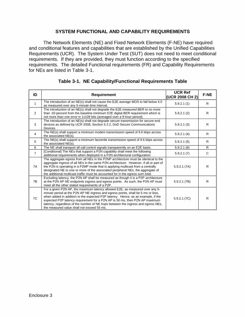
SYSTEM FUNCTIONAL AND CAPABILITY REQUIREMENTS The Network Elements (NE) and Fixed Network Elements (F-NE) have required
and conditional features and capabilities that are established by the Unified Capabilities Requirements (UCR). The System Under Test (SUT) does not need to meet conditional requirements. If they are provided, they must function according to the specified requirements. The detailed Functional requirements (FR) and Capability Requirements for NEs are listed in Table 3-1.
Table 3-1. NE Capability/Functional Requirements Table
ID Requirement UCR Ref
(UCR 2008 CH 2) F-NE
1 The introduction of an NE(s) shall not cause the E2E average MOS to fall below 4.0 as measured over any 5-minute time interval.
5.9.2.1 (1) R
2 The introduction of an NE(s) shall not degrade the E2E measured BER to no more than .03 percent from the baseline minimum E2E digital BER requirement which is not more than one error in 1x109 bits (averaged over a 9-hour period).
5.9.2.1 (2) R
3 The introduction of an NE(s) shall not degrade secure transmission for secure end devices as defined by UCR 2008, Section 5.2.2, DoD Secure Communications Devices.
5.9.2.1 (3) R
4 The NE(s) shall support a minimum modem transmission speed of 9.6 kbps across the associated NE(s).
5.9.2.1 (4) R
5 The NE(s) shall support a minimum facsimile transmission speed of 9.6 kbps across the associated NE(s).
5.9.2.1 (5) R
6 The NE shall transport all call control signals transparently on an E2E basis. 5.9.2.1 (6) R
7 [Conditional] The NEs that support a P2N capability shall meet the following additional requirements when deployed in a P2N architectural configuration:
5.9.2.1 (7) C
7A
The aggregate egress from all NEs in the P2NP architecture must be identical to the aggregate ingress of all NEs in the same P2N architecture. However, if all or part of the P2N is operating in a P2MP mode that is applying multicast from a centrally designated NE to one or more of the associated peripheral NEs, the aggregate of the additional multicast traffic must be accounted for in the egress sum total.
5.9.2.1 (7A) R
7B Excluding latency, the P2N AP shall be measured as though it is a P2P architecture at the P2N AP NE endpoints ingress and egress points. As such, the P2N AP must meet all the other stated requirements of a P2P.
5.9.2.1 (7B) R
7C
For a given P2N AP, the maximum latency allowed E2E, as measured over any 5-minute period at the P2N AP NE ingress and egress points, shall be 5 ms or less, when added in addition to the expected P2P latency. Hence, as an example, if the expected P2P latency requirement for a P2N AP is 50 ms, then P2N AP maximum latency, regardless of the number of NE hops between the ingress and egress NEs, the measured value shall not exceed 55 ms.
5.9.2.1 (7C) R
3-2
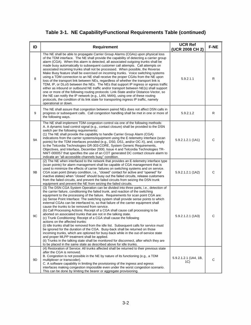
Table 3-1. NE Capability/Functional Requirements Table (continued)
ID Requirement UCR Ref
(UCR 2008 CH 2) F-NE
8
The NE shall be able to propagate Carrier Group Alarms (CGAs) upon physical loss of the TDM interface. The NE shall provide the capability of detecting a carrier group alarm (CGA). When this alarm is detected, all associated outgoing trunks shall be made busy automatically to subsequent customer call attempts. Call attempts on associated incoming trunks shall not be processed. When possible, the Reverse Make Busy feature shall be exercised on incoming trunks. Voice switching systems using a TDM connection to an NE shall receive the proper CGAs from the NE upon loss of the transport link between NEs, regardless of whether the transport link is TDM, IP, or DLoS between the NEs. The NEs that support IP ingress or egress traffic either as inbound or outbound NE traffic and/or transport between NE(s) shall support one or more of the following routing protocols: Link-State and/or Distance-Vector, so the NE can notify the IP network (e.g., LAN, MAN), using one of these routing protocols, the condition of its link state for transporting ingress IP traffic, namely operational or down.
5.9.2.1.1 R
9 The NE shall assure that congestion between paired NEs does not affect DSN calls in progress or subsequent calls. Call congestion handling shall be met in one or more of the following ways.
5.9.2.1.2 R
9A
The NE shall implement TDM congestion control via one of the following methods: A. A dynamic load control signal (e.g., contact closure) shall be provided to the DSN switch per the following requirements: (1) The NE shall provide the capability to handle Carrier Group Alarm (CGA) indications from the carrier systems/equipment using the E-telemetry interface (scan points) for the TDM interfaces provided (e.g., DS0, DS1, and/or OC-X), and, comply to the Telcordia Technologies GR-303-CORE, System Generic Requirements, Objectives, and Interface, December 2000, Issue 4 and Telcordia Technologies TR-NWT-000057 that specifies the use of an COT generated DC contact closure alarm to indicate an “all-accessible-channels busy” condition.
5.9.2.1.2.1 (1A1) C
9B
(2) The NE when interfaced to the network that provides an E-telemetry interface type (scan points) for alarm management shall be capable of CGA management that is used to minimize the effects of carrier failures on switching systems and on service. CGA scan point (binary condition, i.e., “closed” contact for active and “opened” for inactive states) when “closed” should busy out the failed circuits, release customers from the failed circuits, and prevent the failed circuits from seizing the DSN trunk equipment and prevent the NE from seizing the failed circuits.
5.9.2.1.2.1 (1A2) C
9C
(3) The DSN CGA System Operation can be divided into three parts, i.e., detection of the carrier failure, conditioning the failed trunk, and reaction of the switching equipment to the processing of the failure. Requirements for scan point CGA are: (a) Sense Point Interface: The switching system shall provide sense points to which external CGAs can be interfaced to, so that failure of the carrier equipment shall cause the trunks to be removed from service. (b) Call Processing Actions: Receipt of a CGA shall cause call processing to be aborted on associated trunks that are not in the talking state. (c) Trunk Conditioning: Receipt of a CGA shall cause the following actions on the affected trunks: (i) Idle trunks shall be removed from the idle list. Subsequent calls for service must be ignored for the duration of the CGA. Busy-back shall be returned on those incoming trunks, which are optioned for busy-back while in the out-of-service state and proper MLPP treatment shall be applied. (ii) Trunks in the talking state shall be monitored for disconnect, after which they are to be placed in the same state as described above for idle trunks.
5.9.2.1.2.1 (1A3) C
9D
(4) Restoration of Service: All trunks affected shall be returned to their previous state after the CGA is removed. B. Congestion is not possible in the NE by nature of its functioning (e.g., a TDM multiplexer or transcoder). C. A software capability in limiting the provisioning of the ingress and egress interfaces making congestion impossible even under the worst congestion scenario. This can be done by limiting the bearer or aggregate provisioning.
5.9.2.1.2.1 (1A4, 1B, 1C)
C
3-3
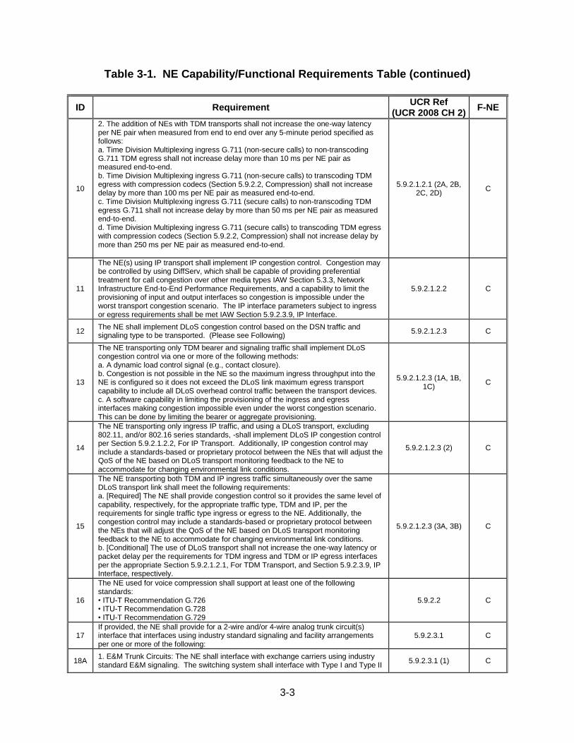
Table 3-1. NE Capability/Functional Requirements Table (continued)
ID Requirement UCR Ref
(UCR 2008 CH 2) F-NE
10
2. The addition of NEs with TDM transports shall not increase the one-way latency per NE pair when measured from end to end over any 5-minute period specified as follows: a. Time Division Multiplexing ingress G.711 (non-secure calls) to non-transcoding G.711 TDM egress shall not increase delay more than 10 ms per NE pair as measured end-to-end. b. Time Division Multiplexing ingress G.711 (non-secure calls) to transcoding TDM egress with compression codecs (Section 5.9.2.2, Compression) shall not increase delay by more than 100 ms per NE pair as measured end-to-end. c. Time Division Multiplexing ingress G.711 (secure calls) to non-transcoding TDM egress G.711 shall not increase delay by more than 50 ms per NE pair as measured end-to-end. d. Time Division Multiplexing ingress G.711 (secure calls) to transcoding TDM egress with compression codecs (Section 5.9.2.2, Compression) shall not increase delay by more than 250 ms per NE pair as measured end-to-end.
5.9.2.1.2.1 (2A, 2B, 2C, 2D)
C
11
The NE(s) using IP transport shall implement IP congestion control. Congestion may be controlled by using DiffServ, which shall be capable of providing preferential treatment for call congestion over other media types IAW Section 5.3.3, Network Infrastructure End-to-End Performance Requirements, and a capability to limit the provisioning of input and output interfaces so congestion is impossible under the worst transport congestion scenario. The IP interface parameters subject to ingress or egress requirements shall be met IAW Section 5.9.2.3.9, IP Interface.
5.9.2.1.2.2 C
12 The NE shall implement DLoS congestion control based on the DSN traffic and signaling type to be transported. (Please see Following)
5.9.2.1.2.3 C
13
The NE transporting only TDM bearer and signaling traffic shall implement DLoS congestion control via one or more of the following methods: a. A dynamic load control signal (e.g., contact closure). b. Congestion is not possible in the NE so the maximum ingress throughput into the NE is configured so it does not exceed the DLoS link maximum egress transport capability to include all DLoS overhead control traffic between the transport devices. c. A software capability in limiting the provisioning of the ingress and egress interfaces making congestion impossible even under the worst congestion scenario. This can be done by limiting the bearer or aggregate provisioning.
5.9.2.1.2.3 (1A, 1B, 1C)
C
14
The NE transporting only ingress IP traffic, and using a DLoS transport, excluding 802.11, and/or 802.16 series standards, -shall implement DLoS IP congestion control per Section 5.9.2.1.2.2, For IP Transport. Additionally, IP congestion control may include a standards-based or proprietary protocol between the NEs that will adjust the QoS of the NE based on DLoS transport monitoring feedback to the NE to accommodate for changing environmental link conditions.
5.9.2.1.2.3 (2) C
15
The NE transporting both TDM and IP ingress traffic simultaneously over the same DLoS transport link shall meet the following requirements: a. [Required] The NE shall provide congestion control so it provides the same level of capability, respectively, for the appropriate traffic type, TDM and IP, per the requirements for single traffic type ingress or egress to the NE. Additionally, the congestion control may include a standards-based or proprietary protocol between the NEs that will adjust the QoS of the NE based on DLoS transport monitoring feedback to the NE to accommodate for changing environmental link conditions. b. [Conditional] The use of DLoS transport shall not increase the one-way latency or packet delay per the requirements for TDM ingress and TDM or IP egress interfaces per the appropriate Section 5.9.2.1.2.1, For TDM Transport, and Section 5.9.2.3.9, IP Interface, respectively.
5.9.2.1.2.3 (3A, 3B) C
16
The NE used for voice compression shall support at least one of the following standards: • ITU-T Recommendation G.726 • ITU-T Recommendation G.728 • ITU-T Recommendation G.729
5.9.2.2 C
17 If provided, the NE shall provide for a 2-wire and/or 4-wire analog trunk circuit(s) interface that interfaces using industry standard signaling and facility arrangements per one or more of the following:
5.9.2.3.1 C
18A 1. E&M Trunk Circuits: The NE shall interface with exchange carriers using industry standard E&M signaling. The switching system shall interface with Type I and Type II
5.9.2.3.1 (1) C
3-4
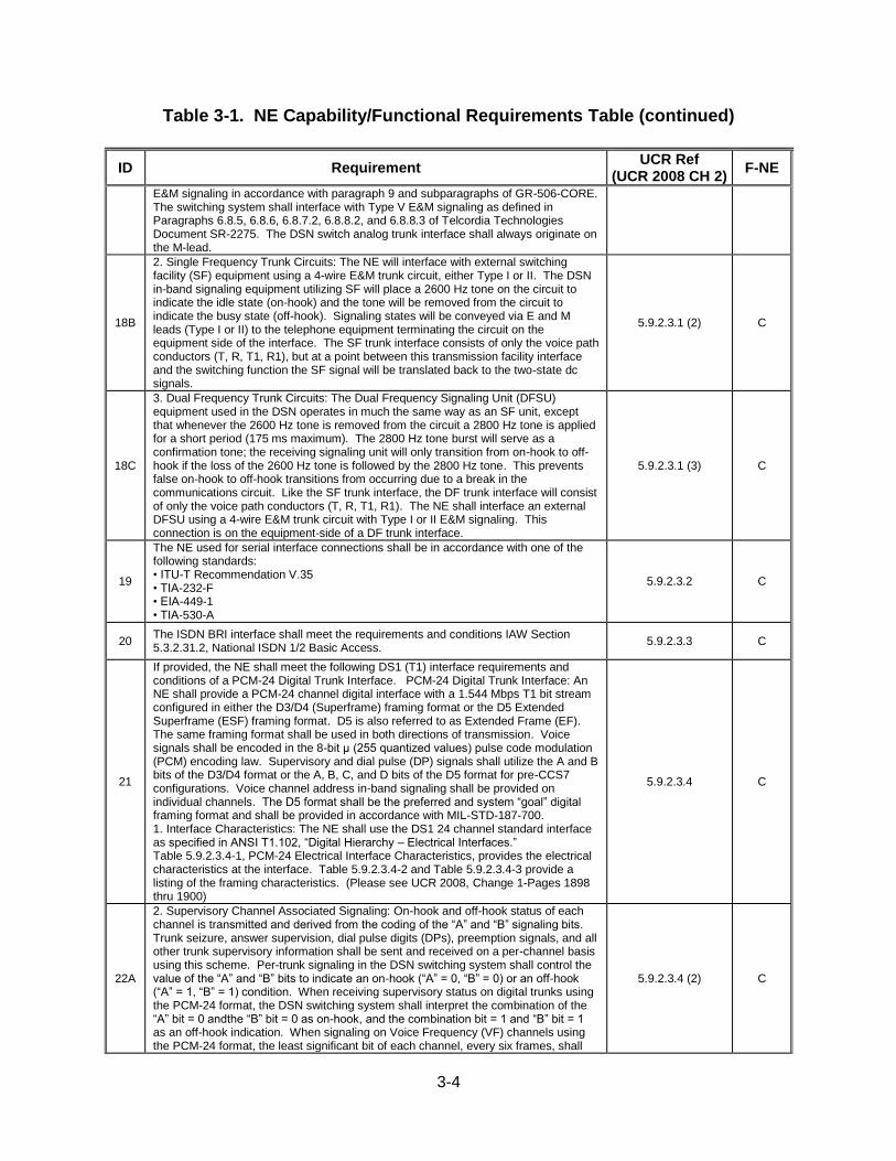
Table 3-1. NE Capability/Functional Requirements Table (continued)
ID Requirement UCR Ref
(UCR 2008 CH 2) F-NE
E&M signaling in accordance with paragraph 9 and subparagraphs of GR-506-CORE. The switching system shall interface with Type V E&M signaling as defined in Paragraphs 6.8.5, 6.8.6, 6.8.7.2, 6.8.8.2, and 6.8.8.3 of Telcordia Technologies Document SR-2275. The DSN switch analog trunk interface shall always originate on the M-lead.
18B
2. Single Frequency Trunk Circuits: The NE will interface with external switching facility (SF) equipment using a 4-wire E&M trunk circuit, either Type I or II. The DSN in-band signaling equipment utilizing SF will place a 2600 Hz tone on the circuit to indicate the idle state (on-hook) and the tone will be removed from the circuit to indicate the busy state (off-hook). Signaling states will be conveyed via E and M leads (Type I or II) to the telephone equipment terminating the circuit on the equipment side of the interface. The SF trunk interface consists of only the voice path conductors (T, R, T1, R1), but at a point between this transmission facility interface and the switching function the SF signal will be translated back to the two-state dc signals.
5.9.2.3.1 (2) C
18C
3. Dual Frequency Trunk Circuits: The Dual Frequency Signaling Unit (DFSU) equipment used in the DSN operates in much the same way as an SF unit, except that whenever the 2600 Hz tone is removed from the circuit a 2800 Hz tone is applied for a short period (175 ms maximum). The 2800 Hz tone burst will serve as a confirmation tone; the receiving signaling unit will only transition from on-hook to off-hook if the loss of the 2600 Hz tone is followed by the 2800 Hz tone. This prevents false on-hook to off-hook transitions from occurring due to a break in the communications circuit. Like the SF trunk interface, the DF trunk interface will consist of only the voice path conductors (T, R, T1, R1). The NE shall interface an external DFSU using a 4-wire E&M trunk circuit with Type I or II E&M signaling. This connection is on the equipment-side of a DF trunk interface.
5.9.2.3.1 (3) C
19
The NE used for serial interface connections shall be in accordance with one of the following standards: • ITU-T Recommendation V.35 • TIA-232-F • EIA-449-1 • TIA-530-A
5.9.2.3.2 C
20 The ISDN BRI interface shall meet the requirements and conditions IAW Section 5.3.2.31.2, National ISDN 1/2 Basic Access.
5.9.2.3.3 C
21
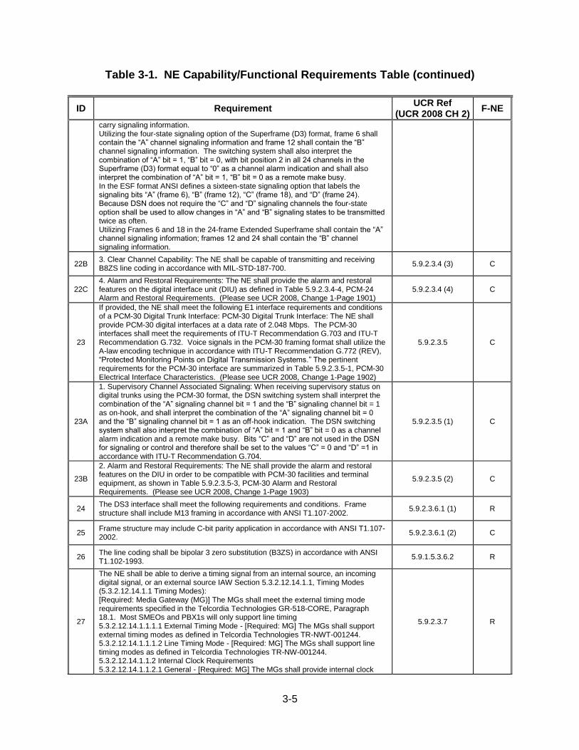
If provided, the NE shall meet the following DS1 (T1) interface requirements and conditions of a PCM-24 Digital Trunk Interface. PCM-24 Digital Trunk Interface: An NE shall provide a PCM-24 channel digital interface with a 1.544 Mbps T1 bit stream configured in either the D3/D4 (Superframe) framing format or the D5 Extended Superframe (ESF) framing format. D5 is also referred to as Extended Frame (EF). The same framing format shall be used in both directions of transmission. Voice signals shall be encoded in the 8-bit μ (255 quantized values) pulse code modulation (PCM) encoding law. Supervisory and dial pulse (DP) signals shall utilize the A and B bits of the D3/D4 format or the A, B, C, and D bits of the D5 format for pre-CCS7 configurations. Voice channel address in-band signaling shall be provided on individual channels. The D5 format shall be the preferred and system “goal” digital framing format and shall be provided in accordance with MIL-STD-187-700. 1. Interface Characteristics: The NE shall use the DS1 24 channel standard interface as specified in ANSI T1.102, “Digital Hierarchy – Electrical Interfaces.” Table 5.9.2.3.4-1, PCM-24 Electrical Interface Characteristics, provides the electrical characteristics at the interface. Table 5.9.2.3.4-2 and Table 5.9.2.3.4-3 provide a listing of the framing characteristics. (Please see UCR 2008, Change 1-Pages 1898 thru 1900)
5.9.2.3.4 C
22A
2. Supervisory Channel Associated Signaling: On-hook and off-hook status of each channel is transmitted and derived from the coding of the “A” and “B” signaling bits. Trunk seizure, answer supervision, dial pulse digits (DPs), preemption signals, and all other trunk supervisory information shall be sent and received on a per-channel basis using this scheme. Per-trunk signaling in the DSN switching system shall control the value of the “A” and “B” bits to indicate an on-hook (“A” = 0, “B” = 0) or an off-hook (“A” = 1, “B” = 1) condition. When receiving supervisory status on digital trunks using the PCM-24 format, the DSN switching system shall interpret the combination of the “A” bit = 0 andthe “B” bit = 0 as on-hook, and the combination bit = 1 and “B” bit = 1 as an off-hook indication. When signaling on Voice Frequency (VF) channels using the PCM-24 format, the least significant bit of each channel, every six frames, shall
5.9.2.3.4 (2) C
3-5
Table 3-1. NE Capability/Functional Requirements Table (continued)
ID Requirement UCR Ref
(UCR 2008 CH 2) F-NE
carry signaling information. Utilizing the four-state signaling option of the Superframe (D3) format, frame 6 shall contain the “A” channel signaling information and frame 12 shall contain the “B” channel signaling information. The switching system shall also interpret the combination of “A” bit = 1, “B” bit = 0, with bit position 2 in all 24 channels in the Superframe (D3) format equal to “0” as a channel alarm indication and shall also interpret the combination of “A” bit = 1, “B” bit = 0 as a remote make busy. In the ESF format ANSI defines a sixteen-state signaling option that labels the signaling bits “A” (frame 6), “B” (frame 12), “C” (frame 18), and “D” (frame 24). Because DSN does not require the “C” and “D” signaling channels the four-state option shall be used to allow changes in “A” and “B” signaling states to be transmitted twice as often. Utilizing Frames 6 and 18 in the 24-frame Extended Superframe shall contain the “A” channel signaling information; frames 12 and 24 shall contain the “B” channel signaling information.
22B 3. Clear Channel Capability: The NE shall be capable of transmitting and receiving B8ZS line coding in accordance with MIL-STD-187-700.
5.9.2.3.4 (3) C
22C 4. Alarm and Restoral Requirements: The NE shall provide the alarm and restoral features on the digital interface unit (DIU) as defined in Table 5.9.2.3.4-4, PCM-24 Alarm and Restoral Requirements. (Please see UCR 2008, Change 1-Page 1901)
5.9.2.3.4 (4) C
23
If provided, the NE shall meet the following E1 interface requirements and conditions of a PCM-30 Digital Trunk Interface: PCM-30 Digital Trunk Interface: The NE shall provide PCM-30 digital interfaces at a data rate of 2.048 Mbps. The PCM-30 interfaces shall meet the requirements of ITU-T Recommendation G.703 and ITU-T Recommendation G.732. Voice signals in the PCM-30 framing format shall utilize the A-law encoding technique in accordance with ITU-T Recommendation G.772 (REV), “Protected Monitoring Points on Digital Transmission Systems.” The pertinent requirements for the PCM-30 interface are summarized in Table 5.9.2.3.5-1, PCM-30 Electrical Interface Characteristics. (Please see UCR 2008, Change 1-Page 1902)
5.9.2.3.5 C
23A
1. Supervisory Channel Associated Signaling: When receiving supervisory status on digital trunks using the PCM-30 format, the DSN switching system shall interpret the combination of the “A” signaling channel bit = 1 and the “B” signaling channel bit = 1 as on-hook, and shall interpret the combination of the “A” signaling channel bit = 0 and the “B” signaling channel bit = 1 as an off-hook indication. The DSN switching system shall also interpret the combination of “A” bit = 1 and “B” bit = 0 as a channel alarm indication and a remote make busy. Bits “C” and “D” are not used in the DSN for signaling or control and therefore shall be set to the values “C” = 0 and “D” =1 in accordance with ITU-T Recommendation G.704.
5.9.2.3.5 (1) C
23B
2. Alarm and Restoral Requirements: The NE shall provide the alarm and restoral features on the DIU in order to be compatible with PCM-30 facilities and terminal equipment, as shown in Table 5.9.2.3.5-3, PCM-30 Alarm and Restoral Requirements. (Please see UCR 2008, Change 1-Page 1903)
5.9.2.3.5 (2) C
24 The DS3 interface shall meet the following requirements and conditions. Frame structure shall include M13 framing in accordance with ANSI T1.107-2002.
5.9.2.3.6.1 (1) R
25 Frame structure may include C-bit parity application in accordance with ANSI T1.107-2002.
5.9.2.3.6.1 (2) C
26 The line coding shall be bipolar 3 zero substitution (B3ZS) in accordance with ANSI T1.102-1993.
5.9.1.5.3.6.2 R
27
The NE shall be able to derive a timing signal from an internal source, an incoming digital signal, or an external source IAW Section 5.3.2.12.14.1.1, Timing Modes (5.3.2.12.14.1.1 Timing Modes): [Required: Media Gateway (MG)] The MGs shall meet the external timing mode requirements specified in the Telcordia Technologies GR-518-CORE, Paragraph 18.1. Most SMEOs and PBX1s will only support line timing 5.3.2.12.14.1.1.1.1 External Timing Mode - [Required: MG] The MGs shall support external timing modes as defined in Telcordia Technologies TR-NWT-001244. 5.3.2.12.14.1.1.1.2 Line Timing Mode - [Required: MG] The MGs shall support line timing modes as defined in Telcordia Technologies TR-NW-001244. 5.3.2.12.14.1.1.2 Internal Clock Requirements 5.3.2.12.14.1.1.2.1 General - [Required: MG] The MGs shall provide internal clock
5.9.2.3.7 R
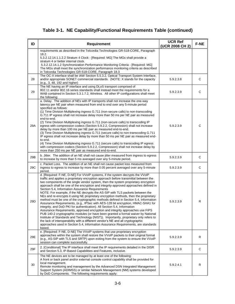
3-6
Table 3-1. NE Capability/Functional Requirements Table (continued)
ID Requirement UCR Ref
(UCR 2008 CH 2) F-NE
requirements as described in the Telcordia Technologies GR-518-CORE, Paragraph 18.2. 5.3.2.12.14.1.1.2.2 Stratum 4 Clock - [Required: MG] The MGs shall provide a stratum 4 or better internal clock. 5.3.2.12.14.1.2 Synchronization Performance Monitoring Criteria - [Required: MG] The MGs shall meet the synchronization performance monitoring criteria as described in Telcordia Technologies GR-518-CORE, Paragraph 18.3
28 The OC-X interface shall be IAW Section 5.5.3.2, Optical Transport System Interface, and/or appropriate SONET commercial standards. (NOTE: X stands for the capacity (e.g., 3, 48, 192 and higher)
5.9.2.3.8 C
29
The NE having an IP interface and using DLoS transport comprised of 802.11 and/or 802.16 series standards shall instead meet the requirements for a WAB contained in Section 5.3.1.7.2, Wireless. All other IP configurations shall meet the following:
5.9.2.3.9 C
29A
a. Delay. The addition of NEs with IP transports shall not increase the one-way latency per NE pair when measured from end to end over any 5-minute period specified as follows: (1) Time Division Multiplexing ingress G.711 (non-secure calls) to non-transcoding G.711 IP egress shall not increase delay more than 50 ms per NE pair as measured end-to-end. (2) Time Division Multiplexing ingress G.711 (non-secure calls) to transcoding IP egress with compression codecs (Section 5.9.2.2, Compression) shall not increase delay by more than 100 ms per NE pair as measured end-to-end. (3) Time Division Multiplexing ingress G.711 (secure calls) to non-transcoding G.711 IP egress shall not increase delay by more than 50 ms per NE pair as measured end-to-end. (4) Time Division Multiplexing ingress G.711 (secure calls) to transcoding IP egress with compression codecs (Section 5.9.2.2, Compression) shall not increase delay by more than 250 ms per NE pair as measured end-to-end.
5.9.2.3.9 C
29B b. Jitter. The addition of an NE shall not cause jitter measured from ingress to egress to increase by more than 5 ms averaged over any 5-minute period.
5.9.2.3.9 C
29C c. Packet Loss. The addition of an NE shall not cause packet loss measured from ingress to egress to increase by more than 0.05 percent averaged over any 5-minute period.
5.9.2.3.9 C
29D
d. [Required: F-NE, D-NE] For VVoIP systems, if the system decrypts the VVoIP traffic and applies a proprietary encryption approach before transmittal between the two components of the single vendor system, then the system proprietary encryption approach shall be one of the encryption and integrity-approved approaches defined in Section 5.4, Information Assurance Requirements NOTE: For example, if the NE decrypts the AS-SIP with TLS packets between the NEs and re-encrypts it using NE proprietary encryption methods, then the proprietary method must be one of the cryptographic methods defined in Section 5.4, Information Assurance Requirements, (e.g., IPSec with AES-128 bit encryption, HMAC-SHA1 for integrity, and DoD PKI for authentication). All Section 5.4, Information Assurance Requirements, approved encryption and integrity approaches use FIPS PUB 140-2 cryptographic modules (or have been granted a formal waiver by National Institute of Standards and Technology (NIST)). Importantly, proprietary only refers to the lack of interoperability with a different vendor’s NE and all cryptographic approaches used in Section 5.4, Information Assurance Requirements, are standards based.
5.9.2.3.9 R
29E
e. [Required: F-NE, D-NE] The VVoIP systems that use proprietary encryption approaches within the system shall restore the VVoIP packets to their original format (e.g., AS-SIP with TLS and SRTP) upon exiting from the system to ensure the VVoIP session can complete successfully.
5.9.2.3.9 R
29F 2. [Conditional] The IP interface shall meet the IP requirements detailed in the DISR and Section 5.3, IP-Based Capabilities and Features, inclusive.
5.9.2.3.9 C
30
The NE devices are to be managed by at least one of the following: A front or back panel and/or external console control capability shall be provided for local management. Remote monitoring and management by the Advanced DSN Integrated Management Support System (ADIMSS) or similar Network Management (NM) systems developed by DoD Components. The following requirements apply:
5.9.2.4.1 R
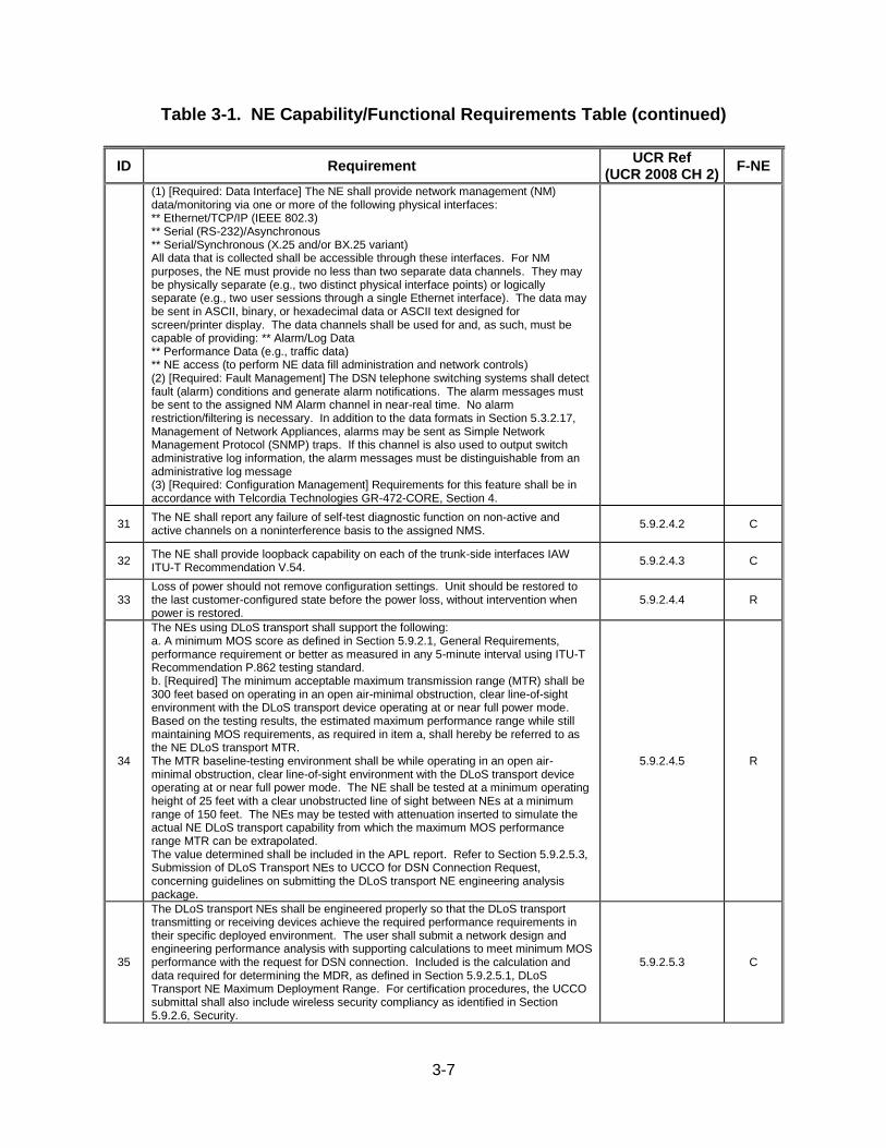
3-7
Table 3-1. NE Capability/Functional Requirements Table (continued)
ID Requirement UCR Ref
(UCR 2008 CH 2) F-NE
(1) [Required: Data Interface] The NE shall provide network management (NM) data/monitoring via one or more of the following physical interfaces: ** Ethernet/TCP/IP (IEEE 802.3) ** Serial (RS-232)/Asynchronous ** Serial/Synchronous (X.25 and/or BX.25 variant) All data that is collected shall be accessible through these interfaces. For NM purposes, the NE must provide no less than two separate data channels. They may be physically separate (e.g., two distinct physical interface points) or logically separate (e.g., two user sessions through a single Ethernet interface). The data may be sent in ASCII, binary, or hexadecimal data or ASCII text designed for screen/printer display. The data channels shall be used for and, as such, must be capable of providing: ** Alarm/Log Data ** Performance Data (e.g., traffic data) ** NE access (to perform NE data fill administration and network controls) (2) [Required: Fault Management] The DSN telephone switching systems shall detect fault (alarm) conditions and generate alarm notifications. The alarm messages must be sent to the assigned NM Alarm channel in near-real time. No alarm restriction/filtering is necessary. In addition to the data formats in Section 5.3.2.17, Management of Network Appliances, alarms may be sent as Simple Network Management Protocol (SNMP) traps. If this channel is also used to output switch administrative log information, the alarm messages must be distinguishable from an administrative log message (3) [Required: Configuration Management] Requirements for this feature shall be in accordance with Telcordia Technologies GR-472-CORE, Section 4.
31 The NE shall report any failure of self-test diagnostic function on non-active and active channels on a noninterference basis to the assigned NMS.
5.9.2.4.2 C
32 The NE shall provide loopback capability on each of the trunk-side interfaces IAW ITU-T Recommendation V.54.
5.9.2.4.3 C
33 Loss of power should not remove configuration settings. Unit should be restored to the last customer-configured state before the power loss, without intervention when power is restored.
5.9.2.4.4 R
34
The NEs using DLoS transport shall support the following: a. A minimum MOS score as defined in Section 5.9.2.1, General Requirements, performance requirement or better as measured in any 5-minute interval using ITU-T Recommendation P.862 testing standard. b. [Required] The minimum acceptable maximum transmission range (MTR) shall be 300 feet based on operating in an open air-minimal obstruction, clear line-of-sight environment with the DLoS transport device operating at or near full power mode. Based on the testing results, the estimated maximum performance range while still maintaining MOS requirements, as required in item a, shall hereby be referred to as the NE DLoS transport MTR. The MTR baseline-testing environment shall be while operating in an open air-minimal obstruction, clear line-of-sight environment with the DLoS transport device operating at or near full power mode. The NE shall be tested at a minimum operating height of 25 feet with a clear unobstructed line of sight between NEs at a minimum range of 150 feet. The NEs may be tested with attenuation inserted to simulate the actual NE DLoS transport capability from which the maximum MOS performance range MTR can be extrapolated. The value determined shall be included in the APL report. Refer to Section 5.9.2.5.3, Submission of DLoS Transport NEs to UCCO for DSN Connection Request, concerning guidelines on submitting the DLoS transport NE engineering analysis package.
5.9.2.4.5 R
35
The DLoS transport NEs shall be engineered properly so that the DLoS transport transmitting or receiving devices achieve the required performance requirements in their specific deployed environment. The user shall submit a network design and engineering performance analysis with supporting calculations to meet minimum MOS performance with the request for DSN connection. Included is the calculation and data required for determining the MDR, as defined in Section 5.9.2.5.1, DLoS Transport NE Maximum Deployment Range. For certification procedures, the UCCO submittal shall also include wireless security compliancy as identified in Section 5.9.2.6, Security.
5.9.2.5.3 C
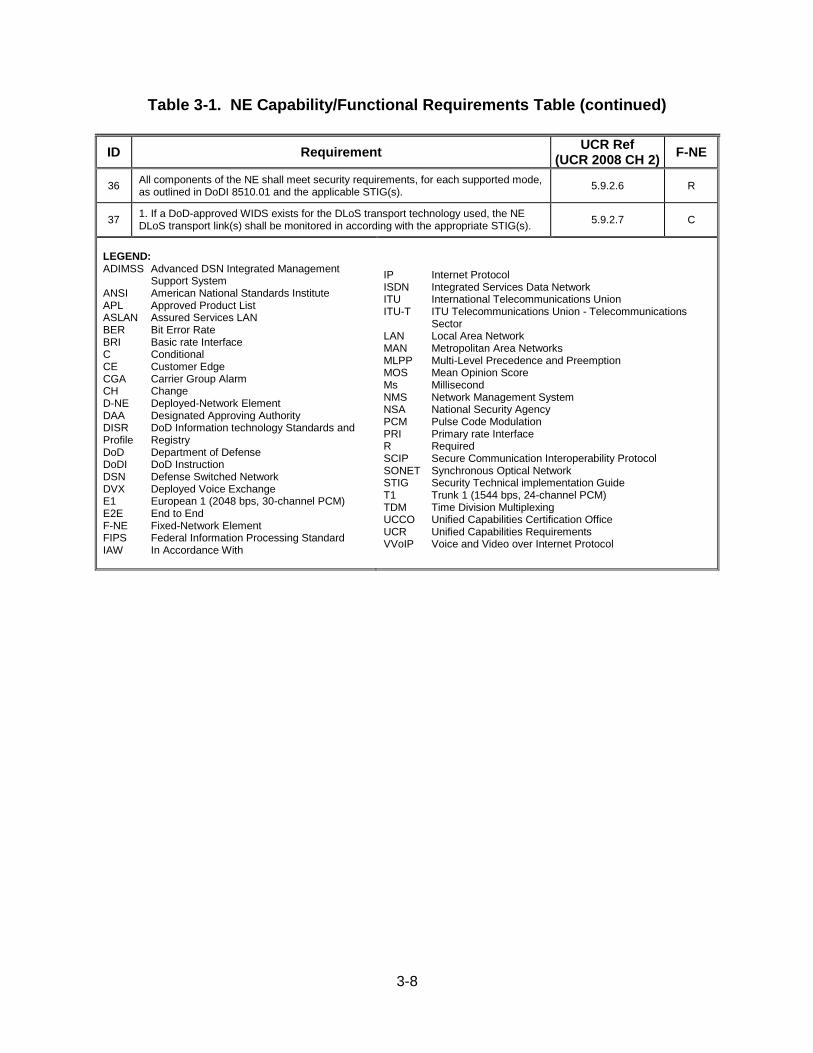
3-8
Table 3-1. NE Capability/Functional Requirements Table (continued)
ID Requirement UCR Ref
(UCR 2008 CH 2) F-NE
36 All components of the NE shall meet security requirements, for each supported mode, as outlined in DoDI 8510.01 and the applicable STIG(s).
5.9.2.6 R
37 1. If a DoD-approved WIDS exists for the DLoS transport technology used, the NE DLoS transport link(s) shall be monitored in according with the appropriate STIG(s).
5.9.2.7 C
LEGEND: ADIMSS Advanced DSN Integrated Management
Support System ANSI American National Standards Institute APL Approved Product List ASLAN Assured Services LAN BER Bit Error Rate BRI Basic rate Interface C Conditional CE Customer Edge CGA Carrier Group Alarm CH Change D-NE Deployed-Network Element DAA Designated Approving Authority DISR DoD Information technology Standards and Profile Registry DoD Department of Defense DoDI DoD Instruction DSN Defense Switched Network DVX Deployed Voice Exchange E1 European 1 (2048 bps, 30-channel PCM) E2E End to End F-NE Fixed-Network Element FIPS Federal Information Processing Standard IAW In Accordance With
IP Internet Protocol ISDN Integrated Services Data Network ITU International Telecommunications Union ITU-T ITU Telecommunications Union - Telecommunications
Sector LAN Local Area Network MAN Metropolitan Area Networks MLPP Multi-Level Precedence and Preemption MOS Mean Opinion Score Ms Millisecond NMS Network Management System NSA National Security Agency PCM Pulse Code Modulation PRI Primary rate Interface R Required SCIP Secure Communication Interoperability Protocol SONET Synchronous Optical Network STIG Security Technical implementation Guide T1 Trunk 1 (1544 bps, 24-channel PCM) TDM Time Division Multiplexing UCCO Unified Capabilities Certification Office UCR Unified Capabilities Requirements VVoIP Voice and Video over Internet Protocol
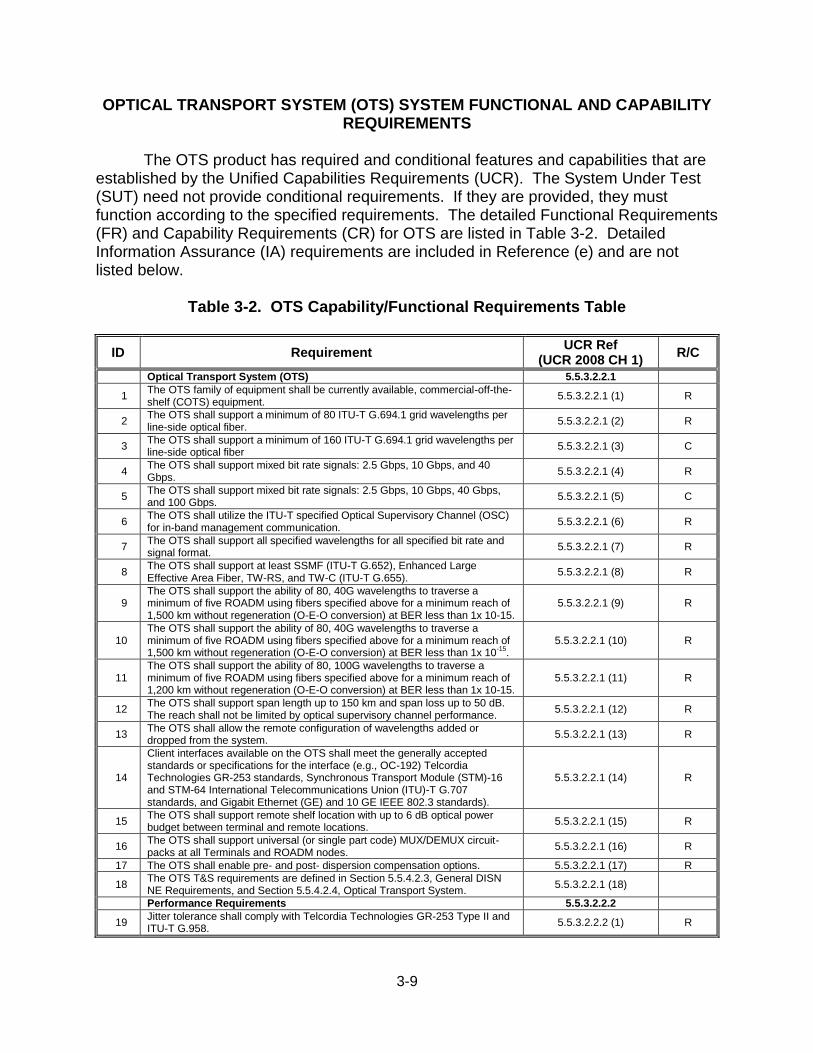
3-9
OPTICAL TRANSPORT SYSTEM (OTS) SYSTEM FUNCTIONAL AND CAPABILITY REQUIREMENTS
The OTS product has required and conditional features and capabilities that are
established by the Unified Capabilities Requirements (UCR). The System Under Test (SUT) need not provide conditional requirements. If they are provided, they must function according to the specified requirements. The detailed Functional Requirements (FR) and Capability Requirements (CR) for OTS are listed in Table 3-2. Detailed Information Assurance (IA) requirements are included in Reference (e) and are not listed below.
Table 3-2. OTS Capability/Functional Requirements Table
ID Requirement UCR Ref
(UCR 2008 CH 1) R/C
Optical Transport System (OTS) 5.5.3.2.2.1
1 The OTS family of equipment shall be currently available, commercial-off-the-shelf (COTS) equipment.
5.5.3.2.2.1 (1) R
2 The OTS shall support a minimum of 80 ITU-T G.694.1 grid wavelengths per line-side optical fiber.
5.5.3.2.2.1 (2) R
3 The OTS shall support a minimum of 160 ITU-T G.694.1 grid wavelengths per line-side optical fiber
5.5.3.2.2.1 (3) C
4 The OTS shall support mixed bit rate signals: 2.5 Gbps, 10 Gbps, and 40 Gbps.
5.5.3.2.2.1 (4) R
5 The OTS shall support mixed bit rate signals: 2.5 Gbps, 10 Gbps, 40 Gbps, and 100 Gbps.
5.5.3.2.2.1 (5) C
6 The OTS shall utilize the ITU-T specified Optical Supervisory Channel (OSC) for in-band management communication.
5.5.3.2.2.1 (6) R
7 The OTS shall support all specified wavelengths for all specified bit rate and signal format.
5.5.3.2.2.1 (7) R
8 The OTS shall support at least SSMF (ITU-T G.652), Enhanced Large Effective Area Fiber, TW-RS, and TW-C (ITU-T G.655).
5.5.3.2.2.1 (8) R
9 The OTS shall support the ability of 80, 40G wavelengths to traverse a minimum of five ROADM using fibers specified above for a minimum reach of 1,500 km without regeneration (O-E-O conversion) at BER less than 1x 10-15.
5.5.3.2.2.1 (9) R
10 The OTS shall support the ability of 80, 40G wavelengths to traverse a minimum of five ROADM using fibers specified above for a minimum reach of 1,500 km without regeneration (O-E-O conversion) at BER less than 1x 10
-15.
5.5.3.2.2.1 (10) R
11 The OTS shall support the ability of 80, 100G wavelengths to traverse a minimum of five ROADM using fibers specified above for a minimum reach of 1,200 km without regeneration (O-E-O conversion) at BER less than 1x 10-15.
5.5.3.2.2.1 (11) R
12 The OTS shall support span length up to 150 km and span loss up to 50 dB. The reach shall not be limited by optical supervisory channel performance.
5.5.3.2.2.1 (12) R
13 The OTS shall allow the remote configuration of wavelengths added or dropped from the system.
5.5.3.2.2.1 (13) R
14
Client interfaces available on the OTS shall meet the generally accepted standards or specifications for the interface (e.g., OC-192) Telcordia Technologies GR-253 standards, Synchronous Transport Module (STM)-16 and STM-64 International Telecommunications Union (ITU)-T G.707 standards, and Gigabit Ethernet (GE) and 10 GE IEEE 802.3 standards).
5.5.3.2.2.1 (14) R
15 The OTS shall support remote shelf location with up to 6 dB optical power budget between terminal and remote locations.
5.5.3.2.2.1 (15) R
16 The OTS shall support universal (or single part code) MUX/DEMUX circuit-packs at all Terminals and ROADM nodes.
5.5.3.2.2.1 (16) R
17 The OTS shall enable pre- and post- dispersion compensation options. 5.5.3.2.2.1 (17) R
18 The OTS T&S requirements are defined in Section 5.5.4.2.3, General DISN NE Requirements, and Section 5.5.4.2.4, Optical Transport System.
5.5.3.2.2.1 (18)
Performance Requirements 5.5.3.2.2.2
19 Jitter tolerance shall comply with Telcordia Technologies GR-253 Type II and ITU-T G.958.
5.5.3.2.2.2 (1) R
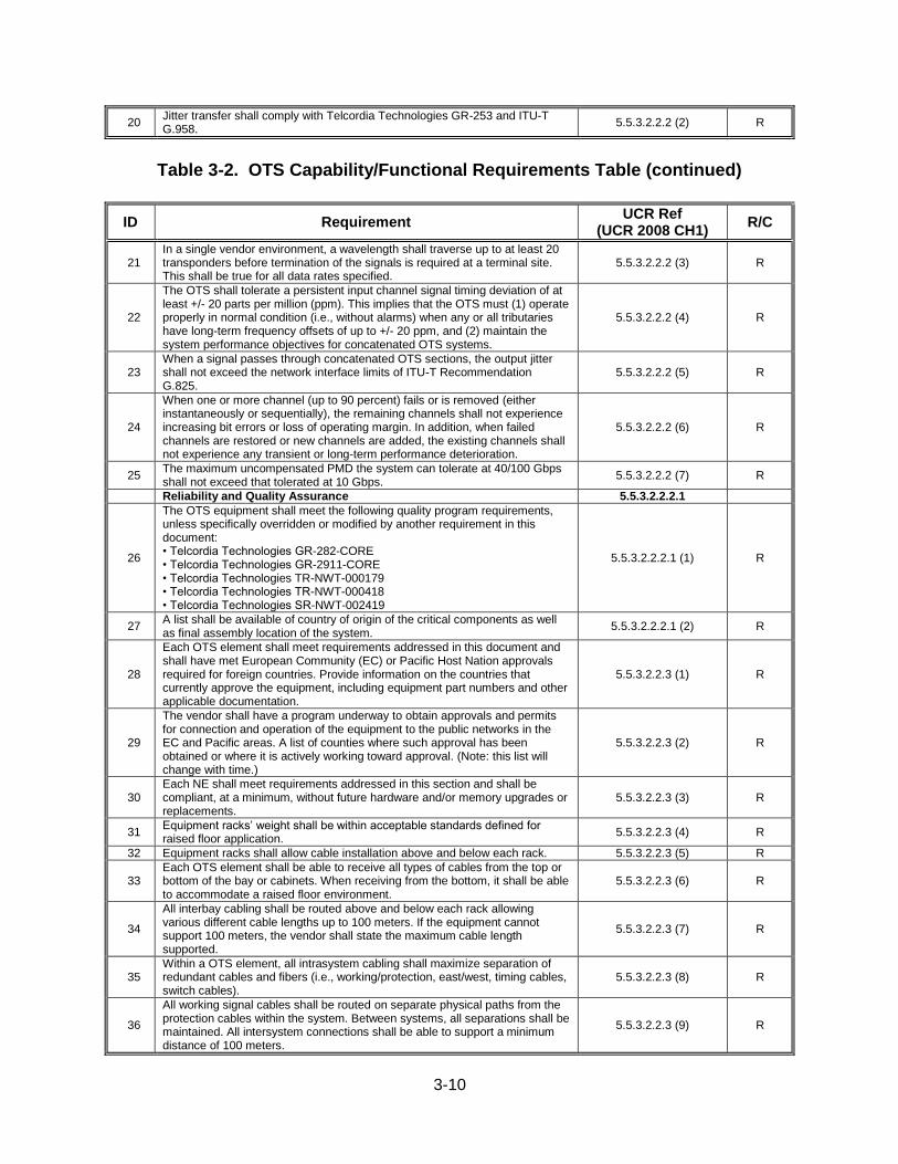
3-10
20 Jitter transfer shall comply with Telcordia Technologies GR-253 and ITU-T G.958.
5.5.3.2.2.2 (2) R
Table 3-2. OTS Capability/Functional Requirements Table (continued)
ID Requirement UCR Ref
(UCR 2008 CH1) R/C
21 In a single vendor environment, a wavelength shall traverse up to at least 20 transponders before termination of the signals is required at a terminal site. This shall be true for all data rates specified.
5.5.3.2.2.2 (3) R
22
The OTS shall tolerate a persistent input channel signal timing deviation of at least +/- 20 parts per million (ppm). This implies that the OTS must (1) operate properly in normal condition (i.e., without alarms) when any or all tributaries have long-term frequency offsets of up to +/- 20 ppm, and (2) maintain the system performance objectives for concatenated OTS systems.
5.5.3.2.2.2 (4) R
23 When a signal passes through concatenated OTS sections, the output jitter shall not exceed the network interface limits of ITU-T Recommendation G.825.
5.5.3.2.2.2 (5) R
24
When one or more channel (up to 90 percent) fails or is removed (either instantaneously or sequentially), the remaining channels shall not experience increasing bit errors or loss of operating margin. In addition, when failed channels are restored or new channels are added, the existing channels shall not experience any transient or long-term performance deterioration.
5.5.3.2.2.2 (6) R
25 The maximum uncompensated PMD the system can tolerate at 40/100 Gbps shall not exceed that tolerated at 10 Gbps.
5.5.3.2.2.2 (7) R
Reliability and Quality Assurance 5.5.3.2.2.2.1
26
The OTS equipment shall meet the following quality program requirements, unless specifically overridden or modified by another requirement in this document: • Telcordia Technologies GR-282-CORE • Telcordia Technologies GR-2911-CORE • Telcordia Technologies TR-NWT-000179 • Telcordia Technologies TR-NWT-000418 • Telcordia Technologies SR-NWT-002419
5.5.3.2.2.2.1 (1) R
27 A list shall be available of country of origin of the critical components as well as final assembly location of the system.
5.5.3.2.2.2.1 (2) R
28
Each OTS element shall meet requirements addressed in this document and shall have met European Community (EC) or Pacific Host Nation approvals required for foreign countries. Provide information on the countries that currently approve the equipment, including equipment part numbers and other applicable documentation.
5.5.3.2.2.3 (1) R
29
The vendor shall have a program underway to obtain approvals and permits for connection and operation of the equipment to the public networks in the EC and Pacific areas. A list of counties where such approval has been obtained or where it is actively working toward approval. (Note: this list will change with time.)
5.5.3.2.2.3 (2) R
30 Each NE shall meet requirements addressed in this section and shall be compliant, at a minimum, without future hardware and/or memory upgrades or replacements.
5.5.3.2.2.3 (3) R
31 Equipment racks’ weight shall be within acceptable standards defined for raised floor application.
5.5.3.2.2.3 (4) R
32 Equipment racks shall allow cable installation above and below each rack. 5.5.3.2.2.3 (5) R
33 Each OTS element shall be able to receive all types of cables from the top or bottom of the bay or cabinets. When receiving from the bottom, it shall be able to accommodate a raised floor environment.
5.5.3.2.2.3 (6) R
34
All interbay cabling shall be routed above and below each rack allowing various different cable lengths up to 100 meters. If the equipment cannot support 100 meters, the vendor shall state the maximum cable length supported.
5.5.3.2.2.3 (7) R
35 Within a OTS element, all intrasystem cabling shall maximize separation of redundant cables and fibers (i.e., working/protection, east/west, timing cables, switch cables).
5.5.3.2.2.3 (8) R
36
All working signal cables shall be routed on separate physical paths from the protection cables within the system. Between systems, all separations shall be maintained. All intersystem connections shall be able to support a minimum distance of 100 meters.
5.5.3.2.2.3 (9) R
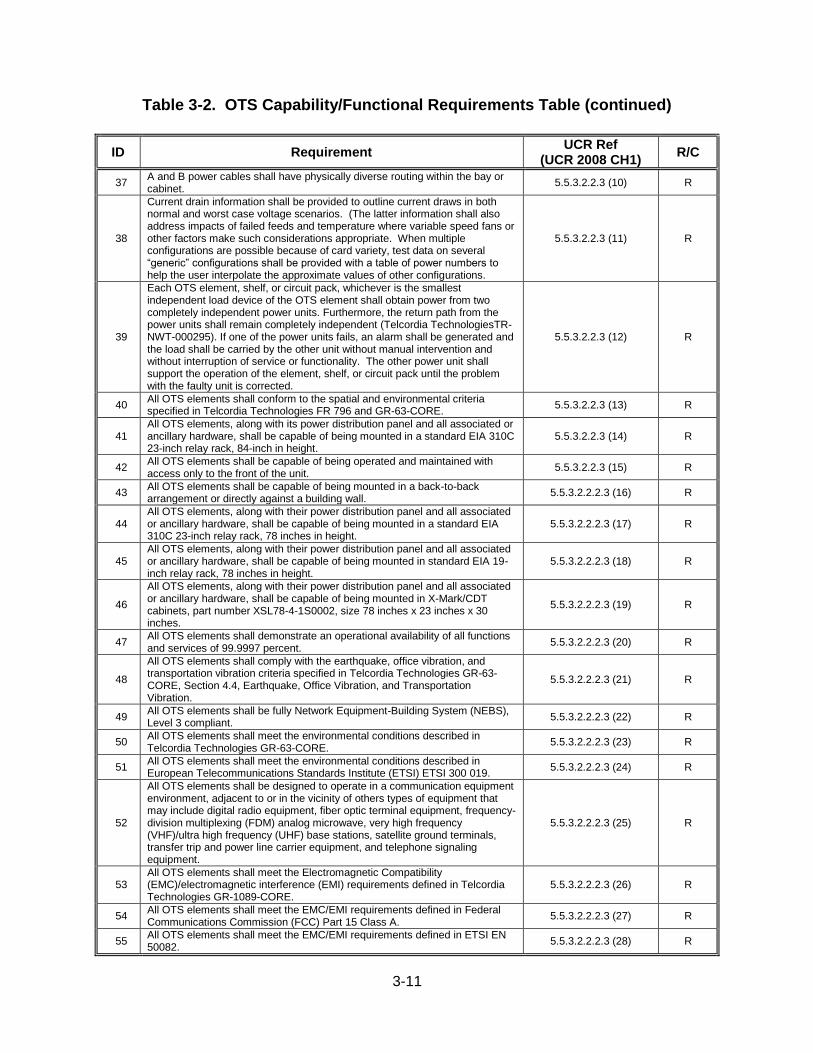
3-11
Table 3-2. OTS Capability/Functional Requirements Table (continued)
ID Requirement UCR Ref
(UCR 2008 CH1) R/C
37 A and B power cables shall have physically diverse routing within the bay or cabinet.
5.5.3.2.2.3 (10) R
38
Current drain information shall be provided to outline current draws in both normal and worst case voltage scenarios. (The latter information shall also address impacts of failed feeds and temperature where variable speed fans or other factors make such considerations appropriate. When multiple configurations are possible because of card variety, test data on several “generic” configurations shall be provided with a table of power numbers to help the user interpolate the approximate values of other configurations.
5.5.3.2.2.3 (11) R
39
Each OTS element, shelf, or circuit pack, whichever is the smallest independent load device of the OTS element shall obtain power from two completely independent power units. Furthermore, the return path from the power units shall remain completely independent (Telcordia TechnologiesTR-NWT-000295). If one of the power units fails, an alarm shall be generated and the load shall be carried by the other unit without manual intervention and without interruption of service or functionality. The other power unit shall support the operation of the element, shelf, or circuit pack until the problem with the faulty unit is corrected.
5.5.3.2.2.3 (12) R
40 All OTS elements shall conform to the spatial and environmental criteria specified in Telcordia Technologies FR 796 and GR-63-CORE.
5.5.3.2.2.3 (13) R
41 All OTS elements, along with its power distribution panel and all associated or ancillary hardware, shall be capable of being mounted in a standard EIA 310C 23-inch relay rack, 84-inch in height.
5.5.3.2.2.3 (14) R
42 All OTS elements shall be capable of being operated and maintained with access only to the front of the unit.
5.5.3.2.2.3 (15) R
43 All OTS elements shall be capable of being mounted in a back-to-back arrangement or directly against a building wall.
5.5.3.2.2.2.3 (16) R
44 All OTS elements, along with their power distribution panel and all associated or ancillary hardware, shall be capable of being mounted in a standard EIA 310C 23-inch relay rack, 78 inches in height.
5.5.3.2.2.2.3 (17) R
45 All OTS elements, along with their power distribution panel and all associated or ancillary hardware, shall be capable of being mounted in standard EIA 19-inch relay rack, 78 inches in height.
5.5.3.2.2.2.3 (18) R
46
All OTS elements, along with their power distribution panel and all associated or ancillary hardware, shall be capable of being mounted in X-Mark/CDT cabinets, part number XSL78-4-1S0002, size 78 inches x 23 inches x 30 inches.
5.5.3.2.2.2.3 (19) R
47 All OTS elements shall demonstrate an operational availability of all functions and services of 99.9997 percent.
5.5.3.2.2.2.3 (20) R
48
All OTS elements shall comply with the earthquake, office vibration, and transportation vibration criteria specified in Telcordia Technologies GR-63-CORE, Section 4.4, Earthquake, Office Vibration, and Transportation Vibration.
5.5.3.2.2.2.3 (21) R
49 All OTS elements shall be fully Network Equipment-Building System (NEBS), Level 3 compliant.
5.5.3.2.2.2.3 (22) R
50 All OTS elements shall meet the environmental conditions described in Telcordia Technologies GR-63-CORE.
5.5.3.2.2.2.3 (23) R
51 All OTS elements shall meet the environmental conditions described in European Telecommunications Standards Institute (ETSI) ETSI 300 019.
5.5.3.2.2.2.3 (24) R
52
All OTS elements shall be designed to operate in a communication equipment environment, adjacent to or in the vicinity of others types of equipment that may include digital radio equipment, fiber optic terminal equipment, frequency-division multiplexing (FDM) analog microwave, very high frequency (VHF)/ultra high frequency (UHF) base stations, satellite ground terminals, transfer trip and power line carrier equipment, and telephone signaling equipment.
5.5.3.2.2.2.3 (25) R
53 All OTS elements shall meet the Electromagnetic Compatibility (EMC)/electromagnetic interference (EMI) requirements defined in Telcordia Technologies GR-1089-CORE.
5.5.3.2.2.2.3 (26) R
54 All OTS elements shall meet the EMC/EMI requirements defined in Federal Communications Commission (FCC) Part 15 Class A.
5.5.3.2.2.2.3 (27) R
55 All OTS elements shall meet the EMC/EMI requirements defined in ETSI EN 50082.
5.5.3.2.2.2.3 (28) R
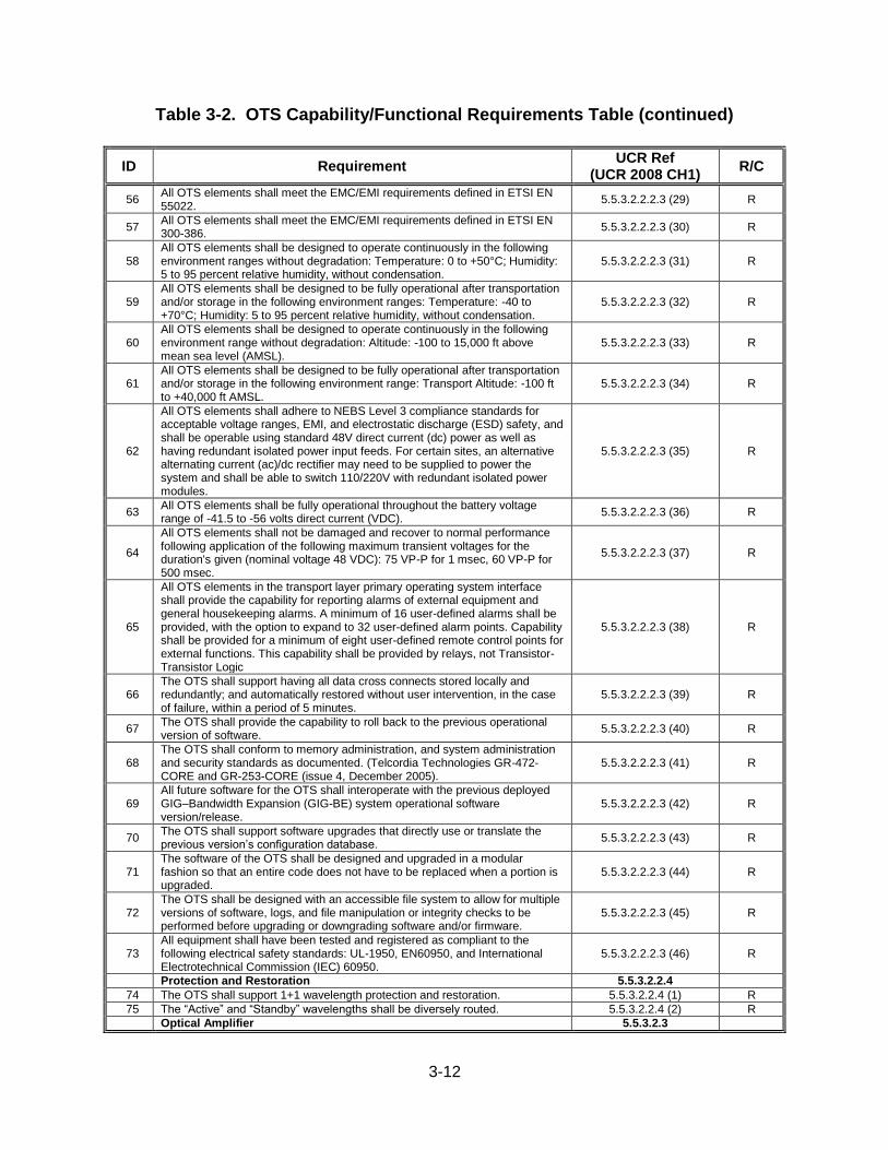
3-12
Table 3-2. OTS Capability/Functional Requirements Table (continued)
ID Requirement UCR Ref
(UCR 2008 CH1) R/C
56 All OTS elements shall meet the EMC/EMI requirements defined in ETSI EN 55022.
5.5.3.2.2.2.3 (29) R
57 All OTS elements shall meet the EMC/EMI requirements defined in ETSI EN 300-386.
5.5.3.2.2.2.3 (30) R
58 All OTS elements shall be designed to operate continuously in the following environment ranges without degradation: Temperature: 0 to +50°C; Humidity: 5 to 95 percent relative humidity, without condensation.
5.5.3.2.2.2.3 (31) R
59 All OTS elements shall be designed to be fully operational after transportation and/or storage in the following environment ranges: Temperature: -40 to +70°C; Humidity: 5 to 95 percent relative humidity, without condensation.
5.5.3.2.2.2.3 (32) R
60 All OTS elements shall be designed to operate continuously in the following environment range without degradation: Altitude: -100 to 15,000 ft above mean sea level (AMSL).
5.5.3.2.2.2.3 (33) R
61 All OTS elements shall be designed to be fully operational after transportation and/or storage in the following environment range: Transport Altitude: -100 ft to +40,000 ft AMSL.
5.5.3.2.2.2.3 (34) R
62
All OTS elements shall adhere to NEBS Level 3 compliance standards for acceptable voltage ranges, EMI, and electrostatic discharge (ESD) safety, and shall be operable using standard 48V direct current (dc) power as well as having redundant isolated power input feeds. For certain sites, an alternative alternating current (ac)/dc rectifier may need to be supplied to power the system and shall be able to switch 110/220V with redundant isolated power modules.
5.5.3.2.2.2.3 (35) R
63 All OTS elements shall be fully operational throughout the battery voltage range of -41.5 to -56 volts direct current (VDC).
5.5.3.2.2.2.3 (36) R
64
All OTS elements shall not be damaged and recover to normal performance following application of the following maximum transient voltages for the duration's given (nominal voltage 48 VDC): 75 VP-P for 1 msec, 60 VP-P for 500 msec.
5.5.3.2.2.2.3 (37) R
65
All OTS elements in the transport layer primary operating system interface shall provide the capability for reporting alarms of external equipment and general housekeeping alarms. A minimum of 16 user-defined alarms shall be provided, with the option to expand to 32 user-defined alarm points. Capability shall be provided for a minimum of eight user-defined remote control points for external functions. This capability shall be provided by relays, not Transistor-Transistor Logic
5.5.3.2.2.2.3 (38) R
66 The OTS shall support having all data cross connects stored locally and redundantly; and automatically restored without user intervention, in the case of failure, within a period of 5 minutes.
5.5.3.2.2.2.3 (39) R
67 The OTS shall provide the capability to roll back to the previous operational version of software.
5.5.3.2.2.2.3 (40) R
68 The OTS shall conform to memory administration, and system administration and security standards as documented. (Telcordia Technologies GR-472-CORE and GR-253-CORE (issue 4, December 2005).
5.5.3.2.2.2.3 (41) R
69 All future software for the OTS shall interoperate with the previous deployed GIG–Bandwidth Expansion (GIG-BE) system operational software version/release.
5.5.3.2.2.2.3 (42) R
70 The OTS shall support software upgrades that directly use or translate the previous version’s configuration database.
5.5.3.2.2.2.3 (43) R
71 The software of the OTS shall be designed and upgraded in a modular fashion so that an entire code does not have to be replaced when a portion is upgraded.
5.5.3.2.2.2.3 (44) R
72 The OTS shall be designed with an accessible file system to allow for multiple versions of software, logs, and file manipulation or integrity checks to be performed before upgrading or downgrading software and/or firmware.
5.5.3.2.2.2.3 (45) R
73 All equipment shall have been tested and registered as compliant to the following electrical safety standards: UL-1950, EN60950, and International Electrotechnical Commission (IEC) 60950.
5.5.3.2.2.2.3 (46) R
Protection and Restoration 5.5.3.2.2.4
74 The OTS shall support 1+1 wavelength protection and restoration. 5.5.3.2.2.4 (1) R
75 The “Active” and “Standby” wavelengths shall be diversely routed. 5.5.3.2.2.4 (2) R
Optical Amplifier 5.5.3.2.3
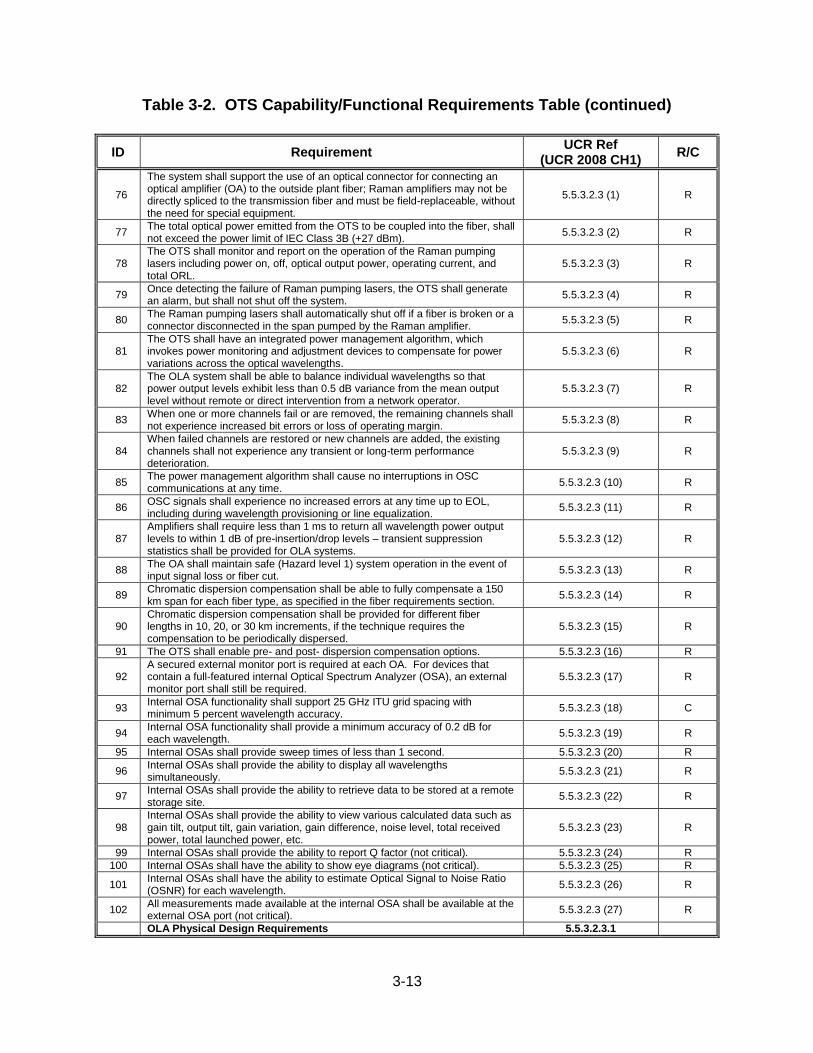
3-13
Table 3-2. OTS Capability/Functional Requirements Table (continued)
ID Requirement UCR Ref
(UCR 2008 CH1) R/C
76
The system shall support the use of an optical connector for connecting an optical amplifier (OA) to the outside plant fiber; Raman amplifiers may not be directly spliced to the transmission fiber and must be field-replaceable, without the need for special equipment.
5.5.3.2.3 (1) R
77 The total optical power emitted from the OTS to be coupled into the fiber, shall not exceed the power limit of IEC Class 3B (+27 dBm).
5.5.3.2.3 (2) R
78 The OTS shall monitor and report on the operation of the Raman pumping lasers including power on, off, optical output power, operating current, and total ORL.
5.5.3.2.3 (3) R
79 Once detecting the failure of Raman pumping lasers, the OTS shall generate an alarm, but shall not shut off the system.
5.5.3.2.3 (4) R
80 The Raman pumping lasers shall automatically shut off if a fiber is broken or a connector disconnected in the span pumped by the Raman amplifier.
5.5.3.2.3 (5) R
81 The OTS shall have an integrated power management algorithm, which invokes power monitoring and adjustment devices to compensate for power variations across the optical wavelengths.
5.5.3.2.3 (6) R
82 The OLA system shall be able to balance individual wavelengths so that power output levels exhibit less than 0.5 dB variance from the mean output level without remote or direct intervention from a network operator.
5.5.3.2.3 (7) R
83 When one or more channels fail or are removed, the remaining channels shall not experience increased bit errors or loss of operating margin.
5.5.3.2.3 (8) R
84 When failed channels are restored or new channels are added, the existing channels shall not experience any transient or long-term performance deterioration.
5.5.3.2.3 (9) R
85 The power management algorithm shall cause no interruptions in OSC communications at any time.
5.5.3.2.3 (10) R
86 OSC signals shall experience no increased errors at any time up to EOL, including during wavelength provisioning or line equalization.
5.5.3.2.3 (11) R
87 Amplifiers shall require less than 1 ms to return all wavelength power output levels to within 1 dB of pre-insertion/drop levels – transient suppression statistics shall be provided for OLA systems.
5.5.3.2.3 (12) R
88 The OA shall maintain safe (Hazard level 1) system operation in the event of input signal loss or fiber cut.
5.5.3.2.3 (13) R
89 Chromatic dispersion compensation shall be able to fully compensate a 150 km span for each fiber type, as specified in the fiber requirements section.
5.5.3.2.3 (14) R
90 Chromatic dispersion compensation shall be provided for different fiber lengths in 10, 20, or 30 km increments, if the technique requires the compensation to be periodically dispersed.
5.5.3.2.3 (15) R
91 The OTS shall enable pre- and post- dispersion compensation options. 5.5.3.2.3 (16) R
92 A secured external monitor port is required at each OA. For devices that contain a full-featured internal Optical Spectrum Analyzer (OSA), an external monitor port shall still be required.
5.5.3.2.3 (17) R
93 Internal OSA functionality shall support 25 GHz ITU grid spacing with minimum 5 percent wavelength accuracy.
5.5.3.2.3 (18) C
94 Internal OSA functionality shall provide a minimum accuracy of 0.2 dB for each wavelength.
5.5.3.2.3 (19) R
95 Internal OSAs shall provide sweep times of less than 1 second. 5.5.3.2.3 (20) R
96 Internal OSAs shall provide the ability to display all wavelengths simultaneously.
5.5.3.2.3 (21) R
97 Internal OSAs shall provide the ability to retrieve data to be stored at a remote storage site.
5.5.3.2.3 (22) R
98 Internal OSAs shall provide the ability to view various calculated data such as gain tilt, output tilt, gain variation, gain difference, noise level, total received power, total launched power, etc.
5.5.3.2.3 (23) R
99 Internal OSAs shall provide the ability to report Q factor (not critical). 5.5.3.2.3 (24) R
100 Internal OSAs shall have the ability to show eye diagrams (not critical). 5.5.3.2.3 (25) R
101 Internal OSAs shall have the ability to estimate Optical Signal to Noise Ratio (OSNR) for each wavelength.
5.5.3.2.3 (26) R
102 All measurements made available at the internal OSA shall be available at the external OSA port (not critical).
5.5.3.2.3 (27) R
OLA Physical Design Requirements 5.5.3.2.3.1
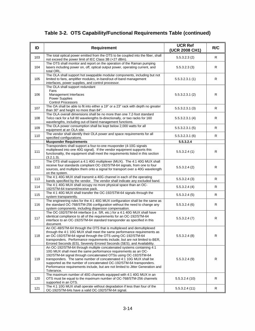
3-14
Table 3-2. OTS Capability/Functional Requirements Table (continued)
ID Requirement UCR Ref
(UCR 2008 CH1) R/C
103 The total optical power emitted from the OTS to be coupled into the fiber, shall not exceed the power limit of IEC Class 3B (+27 dBm).
5.5.3.2.3 (2) R
104 The OTS shall monitor and report on the operation of the Raman pumping lasers including power on, off, optical output power, operating current, and total ORL.
5.5.3.2.3 (3) R
105 The OLA shall support hot swappable modular components, including but not limited to fans, amplifier modules, in-band/out-of-band management interfaces, power supplies, and control processor.
5.5.3.2.3.1 (1) R
106
The OLA shall support redundant Fans Management Interfaces Power Supplies Control Processors
5.5.3.2.3.1 (2) R
107 The OA shall be able to fit into either a 19" or a 23" rack with depth no greater than 30" and height no more than 84".
5.5.3.2.3.1 (3) R
108 The OLA overall dimensions shall be no more than one 7.2-foot standard Telco rack for a full 80 wavelengths bi-directionally, or two racks for 160 wavelengths, including out-of-band management functions.
5.5.3.2.3.1 (4) R
109 The OLA power consumption shall be kept below 2,000 watts for all equipment at an OLA site.
5.5.3.2.3.1 (5) R
110 The vendor shall identify their OLA power and space requirements for all specified configurations.
5.5.3.2.3.1 (6) R
Muxponder Requirements 5.5.3.2.4
111
Transponders shall support a four-to-one muxponder (4-10G signals multiplexed into one 40G signal). If the vendor equipment supports this functionality, the equipment shall meet the requirements listed in this section (3.2.1.3).
5.5.3.2.4 (1) R
112
The OTS shall support a 4:1 40G multiplexer (MUX). The 4:1 40G MUX shall receive four standards compliant OC-192/STM-64 signals, from one to four sources, and multiplex them onto a signal for transport over a 40G wavelength on the system.
5.5.3.2.4 (2) R
113 The 4:1 40G MUX shall transmit a 40G channel in each of the operating bands specified by the vendor. The vendor shall indicate any excluded band.
5.5.3.2.4 (3) R
114 The 4:1 40G MUX shall occupy no more physical space than an OC-192/STM-64 transmit/receive pack.
5.5.3.2.4 (4) R
115 The 4:1 40G MUX shall transfer the OC-192/STM-64 signals through the system transparently.
5.5.3.2.4 (5) R
116 The engineering rules for the 4:1 40G MUX configuration shall be the same as the standard OC-768/STM-256 configuration without the need to change any system components, including dispersion compensation.
5.5.3.2.4 (6) R
117
The OC-192/STM-64 interface (i.e. SR, etc.) for a 4:1 40G MUX shall have identical compliance to all of the requirements for an OC-192/STM-64 interface to an OC-192/STM-64 standard transponder as specified in this document.
5.5.3.2.4 (7) R
118
An OC-48/STM-64 through the OTS that is multiplexed and demultiplexed through the 4:1 10G MUX shall meet the same performance requirements as an OC-192/STM-64 signal through the OTS using OC-192/STM-64 transponders. Performance requirements include, but are not limited to BER, Errored Seconds (ES), Severely Errored Seconds (SES), and Availability.
5.5.3.2.4 (8) R
119
An OC-192/STM-64 through multiple concatenated systems containing 4:1 10G MUX shall meet the same performance requirements as an OC-192/STM-64 signal through concatenated OTSs using OC-192/STM-64 transponders. The same number of concatenated 4:1 10G MUX shall be supported as the number of concatenated OC-192/STM-64 transponders. Performance requirements include, but are not limited to Jitter Generation and Tolerance.
5.5.3.2.4 (9) R
120 The maximum number of 40G channels equipped with 4:1 40G MUX in an OTS must be equal to the maximum number of OC-768/STM-256 channels supported in an OTS.
5.5.3.2.4 (10) R
121 The 4:1 10G MUX shall operate without degradation if less than four of the OC-192/STM-64s have a valid OC-192/STM-64 signal.
5.5.3.2.4 (11) R
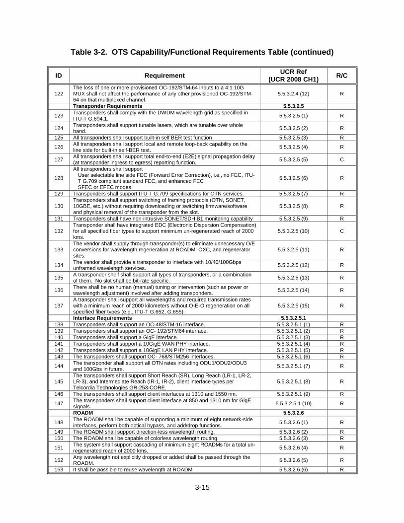
3-15
Table 3-2. OTS Capability/Functional Requirements Table (continued)
ID Requirement UCR Ref
(UCR 2008 CH1) R/C
122 The loss of one or more provisioned OC-192/STM-64 inputs to a 4:1 10G MUX shall not affect the performance of any other provisioned OC-192/STM-64 on that multiplexed channel.
5.5.3.2.4 (12) R
Transponder Requirements 5.5.3.2.5
123 Transponders shall comply with the DWDM wavelength grid as specified in ITU-T G.694.1.
5.5.3.2.5 (1) R
124 Transponders shall support tunable lasers, which are tunable over whole band.
5.5.3.2.5 (2) R
125 All transponders shall support built-in self BER test function 5.5.3.2.5 (3) R
126 All transponders shall support local and remote loop-back capability on the line side for built-in self-BER test.
5.5.3.2.5 (4) R
127 All transponders shall support total end-to-end (E2E) signal propagation delay (at transponder ingress to egress) reporting function.
5.5.3.2.5 (5) C
128
All transponders shall support User selectable line side FEC (Forward Error Correction), i.e., no FEC, ITU-T G.709 compliant standard FEC, and enhanced FEC SFEC or EFEC modes.
5.5.3.2.5 (6) R
129 Transponders shall support ITU-T G.709 specifications for OTN services. 5.5.3.2.5 (7) R
130 Transponders shall support switching of framing protocols (OTN, SONET, 10GBE, etc.) without requiring downloading or switching firmware/software and physical removal of the transponder from the slot.
5.5.3.2.5 (8) R
131 Transponders shall have non-intrusive SONET/SDH B1 monitoring capability 5.5.3.2.5 (9) R
132 Transponder shall have integrated EDC (Electronic Dispersion Compensation) for all specified fiber types to support minimum un-regenerated reach of 2000 kms.
5.5.3.2.5 (10) C
133 The vendor shall supply through-transponder(s) to eliminate unnecessary O/E conversions for wavelength regeneration at ROADM, OXC, and regenerator sites.
5.5.3.2.5 (11) R
134 The vendor shall provide a transponder to interface with 10/40/100Gbps unframed wavelength services.
5.5.3.2.5 (12) R
135 A transponder shelf shall support all types of transponders, or a combination of them. No slot shall be bit-rate specific.
5.5.3.2.5 (13) R
136 There shall be no human (manual) tuning or intervention (such as power or wavelength adjustment) involved after adding transponders.
5.5.3.2.5 (14) R
137 A transponder shall support all wavelengths and required transmission rates with a minimum reach of 2000 kilometers without O-E-O regeneration on all specified fiber types (e.g., ITU-T G.652, G.655).
5.5.3.2.5 (15) R
Interface Requirements 5.5.3.2.5.1
138 Transponders shall support an OC-48/STM-16 interface. 5.5.3.2.5.1 (1) R
139 Transponders shall support an OC- 192/STM64 interface. 5.5.3.2.5.1 (2) R
140 Transponders shall support a GigE interface. 5.5.3.2.5.1 (3) R
141 Transponders shall support a 10GigE WAN PHY interface. 5.5.3.2.5.1 (4) R
142 Transponders shall support a 10GigE LAN PHY interface. 5.5.3.2.5.1 (5) R
143 The transponders shall support OC- 768/STM256 interfaces. 5.5.3.2.5.1 (6) R
144 The transponder shall support all OTN rates including ODU1/ODU2/ODU3 and 100Gbs in future.
5.5.3.2.5.1 (7) R
145 The transponders shall support Short Reach (SR), Long Reach (LR-1, LR-2, LR-3), and Intermediate Reach (IR-1, IR-2), client interface types per Telcordia Technologies GR-253-CORE.
5.5.3.2.5.1 (8) R
146 The transponders shall support client interfaces at 1310 and 1550 nm. 5.5.3.2.5.1 (9) R
147 The transponders shall support client interface at 850 and 1310 nm for GigE signals.
5.5.3.2.5.1 (10) R
ROADM 5.5.3.2.6
148 The ROADM shall be capable of supporting a minimum of eight network-side interfaces, perform both optical bypass, and add/drop functions.
5.5.3.2.6 (1) R
149 The ROADM shall support direction-less wavelength routing. 5.5.3.2.6 (2) R
150 The ROADM shall be capable of colorless wavelength routing. 5.5.3.2.6 (3) R
151 The system shall support cascading of minimum eight ROADMs for a total un-regenerated reach of 2000 kms.
5.5.3.2.6 (4) R
152 Any wavelength not explicitly dropped or added shall be passed through the ROADM.
5.5.3.2.6 (5) R
153 It shall be possible to reuse wavelength at ROADM. 5.5.3.2.6 (6) R
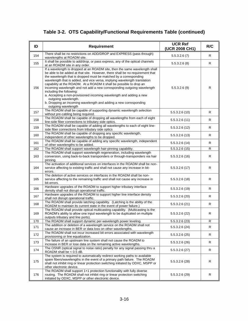
3-16
Table 3-2. OTS Capability/Functional Requirements Table (continued)
ID Requirement UCR Ref
(UCR 2008 CH1) R/C
154 There shall be no restrictions on ADD/DROP and EXPRESS (pass through) wavelengths at ROADM site.
5.5.3.2.6 (7) R
155 It shall be possible to add/drop, or pass express, any of the optical channels at an ROADM site in any order.
5.5.3.2.6 (8) R
156
If a wavelength is dropped at an ROADM site, then the same wavelength shall be able to be added at that site. However, there shall be no requirement that the wavelength that is dropped must be matched by a corresponding wavelength that is added, and vice versa, implying wavelength translation capability at the ROADM. At a ROADM it shall be possible to drop an incoming wavelength and not add a new corresponding outgoing wavelength including the following: a. Accepting a non-provisioned incoming wavelength and adding a new
outgoing wavelength. b. Dropping an incoming wavelength and adding a new corresponding
outgoing wavelength
5.5.3.2.6 (9) R
157 The ROADM shall be capable of supporting dynamic wavelength selection without pre-cabling being required.
5.5.3.2.6 (10) R
158 The ROADM shall be capable of dropping all wavelengths from each of eight line-side fiber connections to tributary side optics.
5.5.3.2.6 (11) R
159 The ROADM shall be capable of adding all wavelengths to each of eight line-side fiber connections from tributary side optics
5.5.3.2.6 (12) R
160 The ROADM shall be capable of dropping any specific wavelength, independent of other wavelengths to be dropped.
5.5.3.2.6 (13) R
161 The ROADM shall be capable of adding any specific wavelength, independent of other wavelengths to be added.
5.5.3.2.6 (14) R
162 The ROADM shall support wavelength hair-pinning capability. 5.5.3.2.6 (15) R
163 The ROADM shall support wavelength regeneration, including wavelength conversion, using back-to-back transponders or through-transponders via hair pinning.
5.5.3.2.6 (16) R
164 The activation of additional services on interfaces in the ROADM shall be non-service affecting to existing traffic and shall not cause any increase in bit-errors.
5.5.3.2.6 (17) R
165 The deletion of active services on interfaces in the ROADM shall be non-service affecting to the remaining traffic and shall not cause any increase in bit-errors.
5.5.3.2.6 (18) R
166 Hardware upgrades of the ROADM to support higher tributary interface density shall not disrupt operational traffic.
5.5.3.2.6 (19) R
167 Hardware upgrades of the ROADM to support higher line interface density shall not disrupt operational traffic.
5.5.3.2.6 (20) R
168 The ROADM shall provide latching capability. (Latching is the ability of the ROADM to maintain its current state in the event of power failure.)
5.5.3.2.6 (21) R
169 The ROADM shall provide optical multicasting capability. (Multicasting is the ROADM’s ability to allow one input wavelength to be duplicated on multiple outputs tributary and line ports).
5.5.3.2.6 (22) R
170 The ROADM shall support dynamic per-wavelength power leveling. 5.5.3.2.6 (23) R
171 The addition or deletion of a wavelength service on the ROADM shall not cause an increase in BER or data loss on other wavelengths.
5.5.3.2.6 (24) R
172 The ROADM shall not incur increased bit errors associated with wavelength provisioning or line equalization.
5.5.3.2.6 (25) R
173 The failure of an upstream line system shall not cause the ROADM to increase in BER or lose data on the remaining active wavelengths.
5.5.3.2.6 (26) R
174 The OSNR (optical signal to noise ratio) penalty for any signal passing thru a ROADM shall be < 0.5 dB.
5.5.3.2.6 (27) R
175
The system is required to automatically redirect working paths to available spare fibers/wavelengths in the event of a primary path failure. The ROADM shall not inhibit ring or linear protection switching initiated by ODXC, MSPP or other electronic device.
5.5.3.2.6 (28) R
176 The ROADM shall support 1+1 protection functionality with fully diverse routing. The ROADM shall not inhibit ring or linear protection switching initiated by ODXC, MSPP or other electronic device.
5.5.3.2.6 (29) R
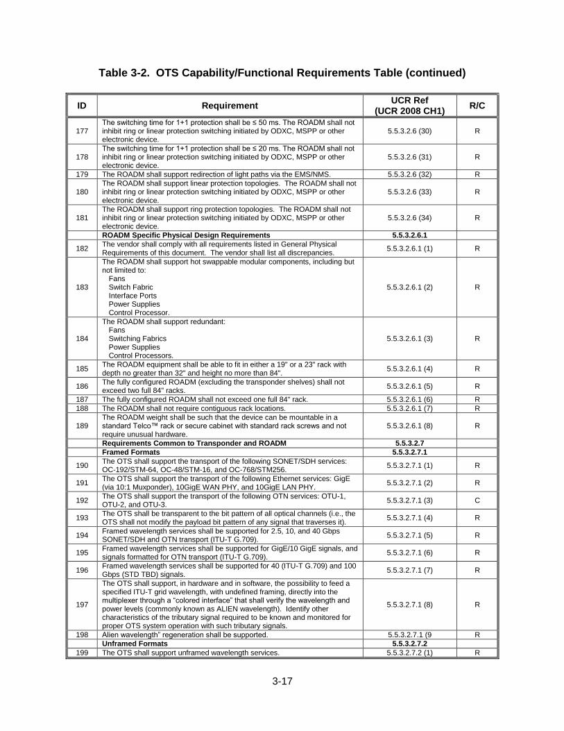
3-17
Table 3-2. OTS Capability/Functional Requirements Table (continued)
ID Requirement UCR Ref
(UCR 2008 CH1) R/C
177 The switching time for 1+1 protection shall be ≤ 50 ms. The ROADM shall not inhibit ring or linear protection switching initiated by ODXC, MSPP or other electronic device.
5.5.3.2.6 (30) R
178 The switching time for 1+1 protection shall be ≤ 20 ms. The ROADM shall not inhibit ring or linear protection switching initiated by ODXC, MSPP or other electronic device.
5.5.3.2.6 (31) R
179 The ROADM shall support redirection of light paths via the EMS/NMS. 5.5.3.2.6 (32) R
180 The ROADM shall support linear protection topologies. The ROADM shall not inhibit ring or linear protection switching initiated by ODXC, MSPP or other electronic device.
5.5.3.2.6 (33) R
181 The ROADM shall support ring protection topologies. The ROADM shall not inhibit ring or linear protection switching initiated by ODXC, MSPP or other electronic device.
5.5.3.2.6 (34) R
ROADM Specific Physical Design Requirements 5.5.3.2.6.1
182 The vendor shall comply with all requirements listed in General Physical Requirements of this document. The vendor shall list all discrepancies.
5.5.3.2.6.1 (1) R
183
The ROADM shall support hot swappable modular components, including but not limited to:
Fans Switch Fabric Interface Ports Power Supplies Control Processor.
5.5.3.2.6.1 (2) R
184
The ROADM shall support redundant: Fans Switching Fabrics Power Supplies Control Processors.
5.5.3.2.6.1 (3) R
185 The ROADM equipment shall be able to fit in either a 19" or a 23" rack with depth no greater than 32" and height no more than 84".
5.5.3.2.6.1 (4) R
186 The fully configured ROADM (excluding the transponder shelves) shall not exceed two full 84" racks.
5.5.3.2.6.1 (5) R
187 The fully configured ROADM shall not exceed one full 84" rack. 5.5.3.2.6.1 (6) R
188 The ROADM shall not require contiguous rack locations. 5.5.3.2.6.1 (7) R
189 The ROADM weight shall be such that the device can be mountable in a standard Telco™ rack or secure cabinet with standard rack screws and not require unusual hardware.
5.5.3.2.6.1 (8) R
Requirements Common to Transponder and ROADM 5.5.3.2.7
Framed Formats 5.5.3.2.7.1
190 The OTS shall support the transport of the following SONET/SDH services: OC-192/STM-64, OC-48/STM-16, and OC-768/STM256.
5.5.3.2.7.1 (1) R
191 The OTS shall support the transport of the following Ethernet services: GigE (via 10:1 Muxponder), 10GigE WAN PHY, and 10GigE LAN PHY.
5.5.3.2.7.1 (2) R
192 The OTS shall support the transport of the following OTN services: OTU-1, OTU-2, and OTU-3.
5.5.3.2.7.1 (3) C
193 The OTS shall be transparent to the bit pattern of all optical channels (i.e., the OTS shall not modify the payload bit pattern of any signal that traverses it).
5.5.3.2.7.1 (4) R
194 Framed wavelength services shall be supported for 2.5, 10, and 40 Gbps SONET/SDH and OTN transport (ITU-T G.709).
5.5.3.2.7.1 (5) R
195 Framed wavelength services shall be supported for GigE/10 GigE signals, and signals formatted for OTN transport (ITU-T G.709).
5.5.3.2.7.1 (6) R
196 Framed wavelength services shall be supported for 40 (ITU-T G.709) and 100 Gbps (STD TBD) signals.
5.5.3.2.7.1 (7) R
197
The OTS shall support, in hardware and in software, the possibility to feed a specified ITU-T grid wavelength, with undefined framing, directly into the multiplexer through a “colored interface” that shall verify the wavelength and power levels (commonly known as ALIEN wavelength). Identify other characteristics of the tributary signal required to be known and monitored for proper OTS system operation with such tributary signals.
5.5.3.2.7.1 (8) R
198 Alien wavelength” regeneration shall be supported. 5.5.3.2.7.1 (9 R
Unframed Formats 5.5.3.2.7.2
199 The OTS shall support unframed wavelength services. 5.5.3.2.7.2 (1) R
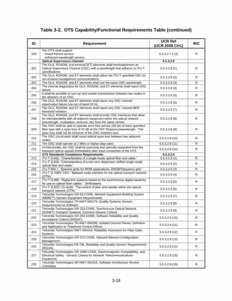
3-18
Table 3-2. OTS Capability/Functional Requirements Table (continued)
ID Requirement UCR Ref
(UCR 2008 CH1) R/C
200 The OTS shall support
mixed framed service unframed wavelength service
5.5.3.2.7.2 (2) R
Optical Supervisory Channel 5.5.3.2.8
201 The OLA, ROADM, end terminal (ET) elements shall terminate/insert an Optical Supervisory Channel (OSC) with a wavelength that adheres to ITU-T specifications.
5.5.3.2.8 (1) R
202 The OLA, ROADM, and ET elements shall utilize the ITU-T specified OSC for out-of-band management communications.
5.5.3.2.8 (2) R
203 The OLA, ROADM, and ET elements shall use the same OSC wavelength. 5.5.3.2.8 (3) R
204 The internal diagnostics for OLA, ROADM, and ET elements shall report OSC failure.
5.5.3.2.8 (4) R
205 It shall be possible to turn-up and sustain transmission between two nodes in the absence of an OSC.
5.5.3.2.8 (5) R
206 The OLA, ROADM, and ET elements shall report any OSC channel input/output failure (via out-of-band DCN).
5.5.3.2.8 (6) R
207 The OLA, ROADM, and ET elements shall report any OSC channel BER threshold violation.
5.5.3.2.8 (7) R
208 The OLA, ROADM, and ET elements shall provide OSC interfaces that allow for interoperability with all adjacent equipment within the optical network (wavelength, modulation, protocol, etc) from the same vendor.
5.5.3.2.8 (8) R
209 The OSC shall be able to operate error-free across 150 km of each specified fiber type with a span loss of 50 dB at the OSC frequency/wavelength. The span loss shall not be inclusive of the OSC insertion loss.
5.5.3.2.8 (9) R
210 The OSC circuit-pack shall report optical span-loss between two adjacent nodes.
5.5.3.2.8 (10) R
211 The OSC shall operate at 2 Mb/s or higher data rates. 5.5.3.2.8 (11) R
212 Architecturally, the OSC shall be passively and optically separated from the transport optical signals immediately after input connection of the OTS.
5.5.3.2.8 (12) R
OTS Standards Compliance Requirements 5.5.3.2.9
213 ITU-T G.652, “Characteristics of a single-mode optical fiber and cable.” 5.5.3.2.9 (1) R
214 ITU-T G.655, “Characteristics of a non-zero dispersion-shifted single-mode optical fiber and cable.”
5.5.3.2.9 (2) R
215 ITU-T 694.1, “Spectral grids for WDM applications: DWDM frequency grid.” 5.5.3.2.9 (3) R
216 ITU-T G.709/Y.1331, “Network node interface for the optical transport network (OTN).”
5.5.3.2.9 (4) R
217 ITU-T G.958, “Digital line systems based on the synchronous digital hierarchy for use on optical fiber cables.” [Withdrawn]
5.5.3.2.9 (5) R
218 ITU-T G.8251 (G.otnjit), “The control of jitter and wander within the optical transport network (OTN).”
5.5.3.2.9 (6) R
219 Telcordia Technologies GR-63-CORE, Network Equipment-Building System (NEBS™) Generic Equipment Requirements.
5.5.3.2.9 (7) R
220 Telcordia Technologies TR-NWT-000179, Quality Systems Generic Requirements for Software.
5.5.3.2.9 (8) R
221 Telcordia Technologies GR-253-CORE, Synchronous Optical Network (SONET) Transport Systems: Common Generic Criteria.
5.5.3.2.9 (9) R
222 Telcordia Technologies GR-282-CORE, Software Reliability and Quality Acceptance Criteria (SRQAC).
5.5.3.2.9 (10) R
223 Telcordia Technologies TR-NWT-000295, Isolated Ground Planes: Definition and Application to Telephone Central Offices.
5.5.3.2.9 (11) R
224 Telcordia Technologies NWT-000418, Reliability Assurance for Fiber Optic Systems.
5.5.3.2.9 (12) R
225 Telcordia Technologies GR-472-CORE, Network Element Configuration Management.
5.5.3.2.9 (13) R
226 Telcordia Technologies FR-796, Reliability and Quality Generic Requirements (RQGR).
5.5.3.2.9 (14) R
227 Telcordia Technologies GR-1089-CORE, Electromagnetic Compatibility, and Electrical Safety - Generic Criteria for Network Telecommunications Equipment.
5.5.3.2.9 (15) R
228 Telcordia Technologies SR-NWT-002419, Software Architecture Review Checklists.
5.5.3.2.9 (16) R
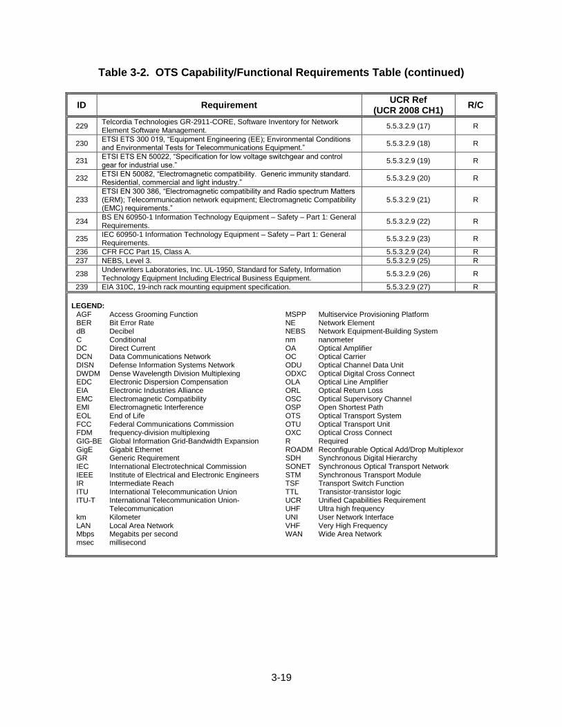
3-19
Table 3-2. OTS Capability/Functional Requirements Table (continued)
ID Requirement UCR Ref
(UCR 2008 CH1) R/C
229 Telcordia Technologies GR-2911-CORE, Software Inventory for Network Element Software Management.
5.5.3.2.9 (17) R
230 ETSI ETS 300 019, “Equipment Engineering (EE); Environmental Conditions and Environmental Tests for Telecommunications Equipment.”
5.5.3.2.9 (18) R
231 ETSI ETS EN 50022, “Specification for low voltage switchgear and control gear for industrial use.”
5.5.3.2.9 (19) R
232 ETSI EN 50082, “Electromagnetic compatibility. Generic immunity standard. Residential, commercial and light industry.”
5.5.3.2.9 (20) R
233 ETSI EN 300 386, “Electromagnetic compatibility and Radio spectrum Matters (ERM); Telecommunication network equipment; Electromagnetic Compatibility (EMC) requirements.”
5.5.3.2.9 (21) R
234 BS EN 60950-1 Information Technology Equipment – Safety – Part 1: General Requirements.
5.5.3.2.9 (22) R
235 IEC 60950-1 Information Technology Equipment – Safety – Part 1: General Requirements.
5.5.3.2.9 (23) R
236 CFR FCC Part 15, Class A. 5.5.3.2.9 (24) R
237 NEBS, Level 3. 5.5.3.2.9 (25) R
238 Underwriters Laboratories, Inc. UL-1950, Standard for Safety, Information Technology Equipment Including Electrical Business Equipment.
5.5.3.2.9 (26) R
239 EIA 310C, 19-inch rack mounting equipment specification. 5.5.3.2.9 (27) R
LEGEND:
AGF Access Grooming Function BER Bit Error Rate dB Decibel C Conditional DC Direct Current DCN Data Communications Network DISN Defense Information Systems Network DWDM Dense Wavelength Division Multiplexing EDC Electronic Dispersion Compensation EIA Electronic Industries Alliance EMC Electromagnetic Compatibility EMI Electromagnetic Interference EOL End of Life FCC Federal Communications Commission FDM frequency-division multiplexing GIG-BE Global Information Grid-Bandwidth Expansion GigE Gigabit Ethernet GR Generic Requirement IEC International Electrotechnical Commission IEEE Institute of Electrical and Electronic Engineers IR Intermediate Reach ITU International Telecommunication Union ITU-T International Telecommunication Union-
Telecommunication km Kilometer LAN Local Area Network Mbps Megabits per second msec millisecond
MSPP Multiservice Provisioning Platform NE Network Element NEBS Network Equipment-Building System nm nanometer OA Optical Amplifier OC Optical Carrier ODU Optical Channel Data Unit ODXC Optical Digital Cross Connect OLA Optical Line Amplifier ORL Optical Return Loss OSC Optical Supervisory Channel OSP Open Shortest Path OTS Optical Transport System OTU Optical Transport Unit OXC Optical Cross Connect R Required ROADM Reconfigurable Optical Add/Drop Multiplexor SDH Synchronous Digital Hierarchy SONET Synchronous Optical Transport Network STM Synchronous Transport Module TSF Transport Switch Function TTL Transistor-transistor logic UCR Unified Capabilities Requirement UHF Ultra high frequency UNI User Network Interface VHF Very High Frequency WAN Wide Area Network

3-20
(This page intentionally left blank.)