Embed Size (px)
Citation preview
CR-187123/ ,
L J
; / ,-
/
Contract Number NAS3-23773Task E.6-Final Report
Definition, Technology Readiness and DevelopmentCost of the Orbit Transfer Vehicle Engine
Integrated Control and Health Monitoring SystemElements
By: I. Cannon, S. Balcer, M. Cochran, J. Klop, So Peterson
Rocketdyne DivisionRockwell International
October 1991
(NASA-CR-187123) DEFINITION, T-_-CHNOL OGYREADINESS, AND 0EVELOPME,N]F COST OF THE DR."IT
TRANSFER VEHICL_ _NGIN_ Ir_TEGRATE.q CO_JTROL
ANO HEALTH MONITURING SYSTEM FLEMENTb Fin_]
Report, Mar. - Oct. 1990 (_ockw_'| lI; 3/2O
N92-11132
Uncles0048220
Prepared for NASA-Lewis Research Center
https://ntrs.nasa.gov/search.jsp?R=19920001914 2018-06-14T10:48:05+00:00Z

N/ ANallon31 Ae,onauhc$ _md
S_ace Admm_s_,a_!on
Report Documentation Page
1. Report No.
CR187123
4. Title and Subtitle
2, Government Accession No. 3. Recip_ent's Catalog NO.
5, Report Date
Orbit Transfer Rocket Engine Technology Program-Task E.6 Final Report, Definition, TechnologyReadiness and Development Cost Estimate of the OTVEIntegrated Control and Health Monitoring System Element_
7. Author(s)
I. Cannon, S. galcer, M. Cochran, J. Klop, S. Peterson
9. Performing Organization Name and Address
Rocketdyne Division, Rockwell International6633 Canoga Ave.Canoga Park, CA 91303
12, Sponsoring Agency Name and Address
NASA-Lewis Research Center, Space Vehicle PropulsionBranch, 21000 Brookpark Rd. Mail Stop SPDT-2Cleveland, Ohio 44135
October 1991
6. Performing Organization Code
8. Performing Organization Report No.
RI/RD91-150
10 Work Unit No
11. Contract or Grant No.
NAS3-23773
13. Type of Report and Period Covered
Final Report, 3-90 to I0-. C14. Sponsoring Agency Code
15. Supplementary Notes
Project Manager, M.G. Millis, NASA-Lewis Research Center, Cleveland, Ohio
16, Abstract
An Integrated Control and Health Monitoring (ICHM) system was conceived for use ona 20Klb thrust baseline Orbit Transfer Vehicle (OTV) engine. Considered for spaceuse, the ICHM was defined for reusability requirements for an OTV engine servicefree life of 20 missions, with 100 starts and a total engine operational timeof 4 hours. Functions were derived by flowing down requirements from NASA guidelirprevious OTV engine or ICHM documents, and related contracts. The elements ofan ICHM were identified and listed, and these elements were described insufficient detail to allow estimation of their technology readiness levels.These elements were assessed in terms of technology readiness level, and support-ing rationale for these assessments presented. The remaining cost for developmentof a minimal ICHM system to technology readiness level 6 was estimated. Theestimates are within an accuracy range of plus or minus 20%. The cost estimatescover what is needed to prepare an ICHM system for use on a focussed testbedfor an expander cycle engine, excluding support to the actual test firings.
17. Key Words (Suggested by Author(s))
Controls, Health MonitoringCondition Monitoring, Chemical PropulsionOrbit Transfer Vehicle
19. Securi_Classif.(ofthisreporf)
none
I Distribution Statement
T
20. Security Classif. (of this page) }21. No of pages
none [ 66
22. Price"
0
es,
NASA FORM_2_ CCTa6 "For sale by the National Technical Information Service, Springfield, Virginia 22161
CR-187123
FINAL REPORT TASK E.6
Definition, Technology Readiness
and Development Cost Estimate of the
Orbital Transfer Vehicle Engine
Integrated Control and Health Monitoring
System Elements
Rocketdyne Division, Rockwell International
6633 Canoga Ave., Canoga Park, CA. 91303
October 1991
Prepared for NASA-Lewis Research Center
Authors:
I. Cannon, M. Cochran, S. Balcer, J. Klop, S. Peterson
Approved: __
R. P. Pauckert, Program Manager
RI/RD91-150
1.0
1.1
1.2
2.0
2.1
2.2
2.2.1
2.3
2.3.1
2.3.2
2.3.3
2.3.4
2.4
2.4.1
2.4.1.1
2.4.2
2.4.2.1
2.4.2.2
2.4.3
3.0
4.0
Table of Contents
INTRODUCTION
Requirements Flowdown
Derivation of ICHM Functions
ICHM ELEMENT DESCRIPTIONS AND LISTS
Sensors
Effectors
Effector Design Description
Electronics
Input Electronics
Controller Processor
Engine Vehicle Interface and Power Supply
Output Electronics
Algorithms and Software
Engine Control
System Condition Monitoring
Condition Monitoring
Component Condition Monitoring
Processing and Diagnosis
Executive
ELEMENT TECHNOLOGY READINESS
FOR MINIMAL SYSTEM
ESTIMATE REMAINING DEVELOPMENT COSTS
FOR MINIMAL SYSTEM
CONCLUSION
REFERENCES
APPENDIX 1, Electronics Design Ground Rules
APPENDIX 2, Excerpts from Rocketdyne Drawing
Requirements Manual
Page
1
4
6
10
10
20
27
29
30
32
34
34
38
40
40
40
40
41
41
42
51
58
59
61
65
RI/RD 91-150
Rocketdyno Division
Rockwell International Corporation
6633 Canoga Avenue
Canoga Park, California 91303
Telex: 698478
ROCKETDYN CNPK
04 November 1991
RockwellInternational
In reply refer to 91RC12801
National Aeronautics and Space Administration
Lewis Research Center
Cleveland, OH 44135
Attn: Contracting Officer, MS 500-305
Subject: NAS3-23773, "Orbit Transfer Rocket Engine Technology
Program', Part Ill, Section 3, Paragraph C of the Reports ofWork and Task E.6
Gentlemen:
We are transmitting an enclosure+in accordance with the subject contract
for your information and retention.
Very truly yours,
ROCKWELL INTERNATIONAL
Rocketdyne Division
P. R. Wesley _/
Manager
Configuration and Data Management
G.O. 95285
Encl. One copy of Task E.6 APPROVED FINAL REPORT, "Definition,
Technology Readiness and Oevlopment Cost of the Orbit
Transfer Vehicle Engine Integrated Control and Health
Monitoring System Elements', RI/RD 91-150, dated October
1991, CR-187123
CC: See attached distribution
98870
DISTRIBUTION LIST FOR
Definition, Technology Readiness
and Development Cost Estimate of the
Orbit Transfer Vehicle Engine
Integrated Controls & Health Monitoring
System ElementsCR-187123
i
Orbit Transfer Rocket Engine Technology Program
Contract NAS3-23773
No. of Copies
National Aeronautics & Space Administration
Lewis Research Center
21000 Brookpark Road
Cleveland, Ohio 44135
Attn: Contracting Officer, MS 500--305
S. B. Foust, MS 500-200
Technical Utilization Office, MS 7-3
Report Control Office, MS 60-1
AFSC Liaison Office, MS 501-3
Library, MS 60-3
G. P° Richter, MS 500-220
M° G. Millis, MS 500-220
J. F. Zakrajsek, MS 500-219
F. D. Berkopec, MS 500-220
S. H. Gorland, MS 500-219
C. F. Lorenzo, MS 77-1
W. C. Nieberding, MS 77-1
W. C. Merrill, MS 77-1
National Aeronautics & Space Administration
Headquarters
Washington, D. C. 20546
Attn= Director, Advanced Program Development/MD
Director, Propulsion Power & Energy Div./RP
G. M. Reck/RS
W. J. Escher/RP
J. DeBattista/RC
National Aeronautics & Space Administration
Ames Research Center
Moffett Field, CA 94035
Attn: Library
National Aeronautics & SpaceAdministrationFlight Research CenterP. O. Box 273Edwards, CA 93523Attn: Library
National Aeronautics & SpaceAdministrationGeorge C. Marshall SpaceFlight CenterHuntsville, Alabama 35812Attn: Library
H. W. Garrett/EE-21O. K. Goetz/EE21C. McLeod/EP52J. Cramer/EP53B. Foster/EP53R. Richmond/ER01J. F. Thompson/PDl3C. F. Huffaker/PT-31J. P. Sumrall/PT-41
National Aeronautics & SpaceAdministrationGoddardSpace Flight CenterGreenbelt, Maryland 20771Attn: Library
National Aeronautics & SpaceAdministrationJohn F. KennedySpace CenterKennedySpace Center, Florida 32899Attn: Library
R. E. Rhodes/THI-716W. J. Dickenson/PT-FLS
National Aeronautics & Space AdministrationLyndon B. Johnson SpaceCenterHouston, Texas 77058Attn: Library
J. W. Griffin/EP4C. Teixeira/ET2H. O. Erwin/IEJ. W. Brown/SPD. Cooke/XAJ. Carpenter/XED. Weaver/XM
National Aeronautics & SpaceAdministrationLangley Research CenterLangley StationHampton, Virginia 23665Attn: Library
ii1
iiIiiiI1
NASAScientific & Technical Information FacilityP. O. Box 8757Baltimore-Washington International AirportBaltimore, Maryland 21240Attn: Accessing Department I0
Jet Propulsion Laboratory4800 OakGrove DrivePasadena,CA 91103Attn: Library
JSCWhite SandsTest FacilityP. O. Drawer MMLas Cruces, NM 88004Attn: D.B. Harris
Stennis Space CenterSSC,MS39529Attn: D. Chenevert
Defense Documentation CenterCameronStationBuilding 55010 Duke StreetAlexandria, Virginia 22314Attn: TISlA
Defense AdvancedResearch Projects Agency1400Wilson Blvd.Washington, D. C. 22209Attn: Library
Aeronautical System DivisionAir Force Systems CommandWright-Patterson Air Force BaseDayton, OhioAttn: Library
Air Force Phillips Laboratory Systems CommandEdwards, CA 93523-5000Attn: Library
LKD/R. L. WiswellLKDA/M.HugginsLKDB/M.ConnallyLKDS/W.Pritz
iIiii
HQ/SpaceDivision/CFPlans & Project OfficeP. O. Box 92960Los Angeles Air Force Station, CAAttn: Library
90009i
Bureau of Naval WeaponsDepartment of the NavyWashington, D. C.Attn= Library
Picatinny ArsenalDover, NewJerseyAttn: Library
07801
U. S. Naval Research LaboratoryWashington, D. C. 20390Attn: Library
John Hopkins UniversityApplied Physics LaboratoryJohn Hopkins RoadLaurel, Maryland 20810Attn: Library
Martin Marietta Corp.-DenverP. Box Box 179Denver, CO 80201Attn: J. Keeley/DC5060
Martin Marietta MannedSpace SystemsP. O. Box 9008Marshall Space Flight Cetner, AL 35812Attn: D. Vaughan
J. Cornelius
Martin-Marietta Astronautics Corp.8100 East MaplewoodAve.Englewood, CO 80111Attn: Library
D. Wilks/G680J. W. Robinson/G5041B. Wilcockson
Martin Marietta Corp.1450 South Rolling RoadBaltimore, MD 21227-3898Attn: S.B. Johnson
McDonnell Douglas Astronautics5301 Bosa AvenueHuntington Beach, CA 92647Attn: Library
Pratt &Whitney Aircraft GroupP° O. Box 109600West Palm Beach, FL 33410Attn: Library
C R. Joyner MS715-75S Hagar, MS731-60L Witherup MS731-62J Brown, MS731-66J Baker, MS731-90D Southwick, MS731-94C Limerick MS731-95D Riccardi, MS731-98
United Technologies Research CenterEast Hartford, CN 06108Attn: Library
R. Williams
RocketdyneDivisionRockwell International6633 CanogaAvenueCanogaPark, CA 91303Attn: Library
R. P. PauckertC° EricksonA. MartinezT. J. HarmonS. BarkhoudarianA° M. NormanI. Cannon
1IiIiI1i
Space DivisionA Division of Rockwell International12214LakewoodBlvd.Downey,CA 90241Attn: Library I
Honeywell, Inc.3660 Technology DriveMinneapolis, Mlq 55418Attn: Library
J. WaldB. SawamuraG. HaveyR. Copa
Rocket Research CorporationWillow Roadat ll6th StreetRedmond,Washington 98052Attn: Library
Boeing Aerospace CompanyP. O. Box 3999Seattle, Washington 98124Attn= Library
T° Vinopal/SK°02B. Boutan/SK-52
Boeing Aerospace-Huntsville499 Boeing Blvd.P.O. Box 24002Huntsville, AL 35824Attn: G. Woodcock/JX23
B. Duffy/JA59
General DynamicsSpace SystemsDivision5001 Kearny Villa Rd.SanDiego, CA 92123Attn: J.G. Johnson, MS23-8380
General Dynamics700 Boulevard South, Suite 203Huntsville, AL 35802Attn: D. Comstock
General DynamicsP.O. Box 859905001 Kearny Villa Rd.SanDiego, CA 92138Attn: J. Duffey/MZCi-7106
K. Nelson/MZDC-7104
U. S. Army Missile CommandRedstone Scientific Information CenterRedstoneArsenal, Alabama 35808Attn: DocumentSection
U. S. Naval Air StationPoint Mugu, CA 93041Attn: Technical Library i
U. S. Naval WeaponsCenterChina Lake, CA 93557Attn: Library i
Aerospace CorporationP. O. Box 92957Los Angeles, CA 90009Attn: Library
G. Hoffman, MSM4/970E. McNally, MSM4/969
IIi
Aerojet Propulsion DivisionP. O. Box 13222Sacramento, CA 95813-6000Attn: Library
R. BickfordM. GageD. MorganE. Thomas
I2iiI
Bell Aerospace TextronBox IBuffalo, NewYork 14240Attn: Library i
Sundstrand Aviations Operations4747 Harrison AvenueP. O. Box 7002Rockford, Illinois 61125Attn: Library i
TRWSystemsGroupi Space ParkRedondoBeach, CA 90278Attn: Library
L. B. Mattson/Bldg. Oi-Rm. 2250
Center for Space Propulsion Health MonitoringUniversity of CincinnatiMail Location 627Cincinnati, OH 45221-0627Attn: Library
L. CooperB. Walker
Center for Space PropulsionPennsylvania State UniversityMechanical Engineering Dept.University Park, PA 16802Attn: Library
University of TennesseeSpaceInstituteTullahoma, TN 37388Attn: Library
Arnold Air Force StationTullahoma, TN 37389Attn: R.H. Kohl, EL3/MS-900
Orbital Technologies Corporation
402 Gammon Place, Suite i0
Madison, WI 53719
Attn= R.R. Teeter
Aerospace Engineering
The University of Alabama
Box 870280
Tuscaloosa, AL 35487-0280
Attn: J.A. Martin
Office of Tech Transfer
Martin Marietta
Energy Systems Inc.
P.O. Box 2009
Oak Ridge, TN 37831
Attn: L. Dickens
Systems Control Technology, Inc.
2300 Geng Rd.
P.O. Box 10180
Palo Alto, CA 94303-0888
Attn: R. Anex
R. DeHoff
List of Figures
Figure
1
2
3
4
5
6
7
8
9
10
11
12
13
14
14
Advanced Expander Cycle Engine
OTV Engine Schematic
Requirements and Corresponding Functions
ICHM Elements
OTVE ICHM Element Architecture
ICHM Measurement List
OTV Engine Balance: On-Design Values
OTV Engine Balance: Off-Design Values (1)
OTV Engine Balance: Off-Design Values (2)
OTV Engine with Sensor Locations
Control System Overview
Input Processing Block Diagram (Single Channel)
Control Processing Block Diagram (Single Channel)
Output Processing Block Diagram #1 (Single Channel)
Output Processing Block Diagram #2 (Single Channel)
Page
2
3
8
9
11
12- 14
17
18
19
23
31"
33
35
36
37
List of Tables
Table
1
2
3
4
5
6
7
8
9
10
11
Measurement List Reduction Rationale
Engine Balance Operating Points
Sensor Selections
Sensor Technology Selections
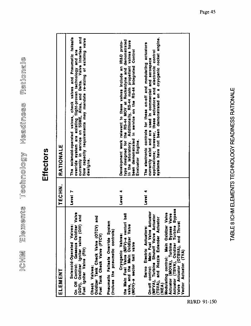
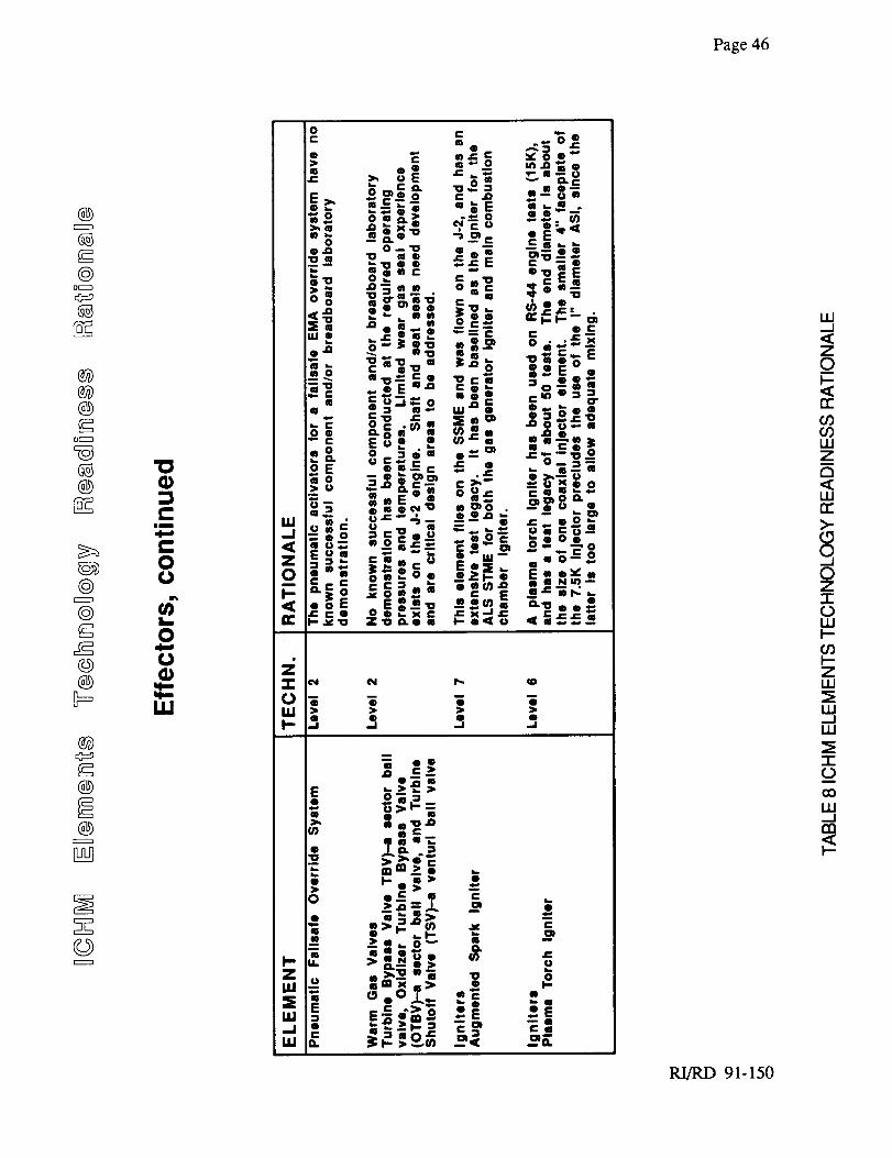
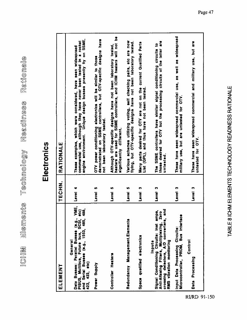
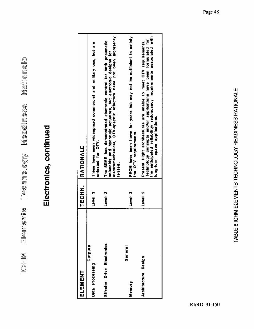
Effectors
ICHM Software Element Breakdown
Technology Readiness Levels: Defi ifion
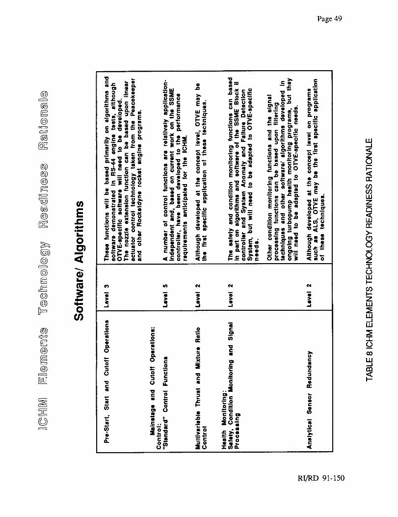
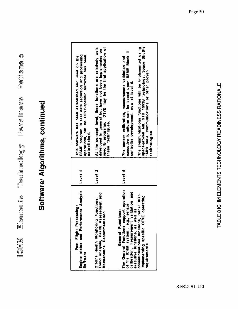
ICHM Elements Technology Readiness Rationale
OTV-ICHM Cost Estimate Summary
ICHM Sensor Cost Estimate
ICHM Effector Cost Estimate
4 -
Page
15
16
16
22
24
39
43
50
52
54
55
iiRI/RD 91-150
PRECEDING PAGE BLANK NOT FILMED
Page 1
1.0 INTRODUCTION
The Integrated Control and Health Monitoring System (ICHM), provides comprehensive control
and monitoring capabilities in support of overall Orbital Transfer Vehicle Engine (OTVE) mission
requirements. The OTVE is considered for space-based missions including Lunar/Mars and orbital
transfer. Such missions would include requirements for long duration space exposure, multiple,
zero gravity engine starts, as well as the capability for deep throttling for landings. Reusability
requirements dictate a service-free life of 20 missions, with 100 starts and a total engine operational
time of 4 hours. The overall system life (with service) requirement is established as 100 missions,
with 500 starts and engine operational time of 20 hours.
The ICHM system includes control and condition monitoring electronics, sensing elements,
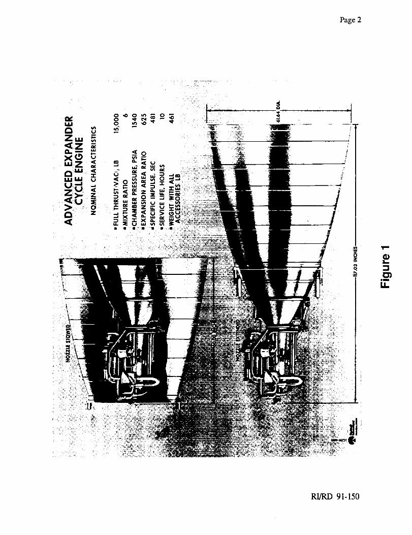
software/algorithms and effectors. Effectors are those components of the ICHM which are
commanded by the controller electronics to operate the OTV engine. These include valve actuators,
nozzle extension and gimballing actuators and igniters. An artists rendering of the 7.5Klb thrust
OTVE is shown in Figure 1.
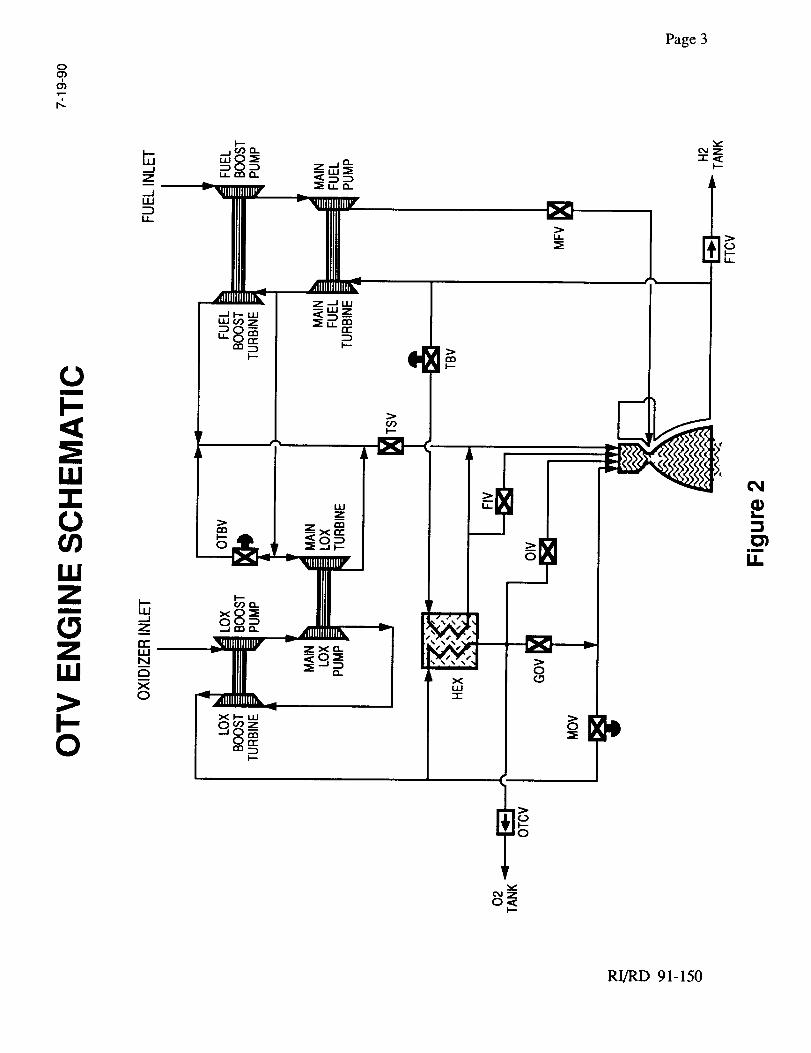
The ICHM system was conceived around the 20Klb thrust baseline OTV engine. This thrust level
was selected because Rocketdyne had available power balance model data at off-design conditions
of; 5% thrust, representative of 20:1 throttling (at mixture ratio 6:1), and full thrust at a mixture
ratio of 5:1. Power balance model data at the on-design condition of 20Klb thrust at a mixture ratio
of 6:1 was also used. The overall ICHM definition was not impacted by the use of the 20Klb
thrust baseline, and only a minor effector change (igniter style) would be considered to adapt the
ICHM results to the 7.5Klb version of the OTVE. The alternate igniter was considered in the
identification of ICHM elements, and the related cost estimate. The schematic diagram of this
OTVE configuration is shown in Figure 2.
Task E6, "Technical Readiness and Development Costs", entailed the definition of the ICHM
system for the OTV engine. The minimal ICHM system was derived from a flowdown of engine
requirements into system functions which, evaluated, and translated into a minimal set of ICHM
elements (sensors, actuators, electronics, and software) to meet requirements with maximal
technology readiness. A baseline design for each of these elements was described in enough detail
to estimate the technology readiness and development costs of the minimal system.
RI/RD 91-150
Page2
x....
me
tt
RI/RD 91-150
Page 3
RI/RD 91-150
Page4
The details of this selectionand estimationprocessare outlined below, beginning with the
requirementsflowdown processanddescriptionof minimal ICHM functions,continuingwith adefinition anddescriptionof theelementsandsub-elementsof the minimal ICHM system,and
concludingwith discussionsof theseelements'technologyreadinessandestimateddevelopmentCOSTS.
1.1 Requirements Flowdown
Given an input of general, programmatic requirements, the functions of any particular sub-system
can be derived through a flowdown process. The requirements driving ICHM elements came from
surveys of NASA Lewis representatives (program monitors) connected with the Earth to Orbit and
OTV programs, examination of relevant NASA-LeRC briefings and previous reports, discussions
with Rocketdyne personnel experienced in controls / monitoring and engine systems development,
review of previous reports on health monitoring systems (OTV-ICHM, HMRSE, ICS, SAFD,
Mass Data Storage, etc.), and discussions with control and monitoring system component
vendors.
The inputs for the flowdown analysis of engine requirements were; A) baseline assumptions, B)
engine system operability characteristics.
Baseline assumptions:
A 1. Operation in space environment
(in particular, the ambient conditions over the range of mission profiles)
A2. Mission characteristics
(in particular, the number of engine starts, the time between starts, and the
duration of each engine engagement)
A3. Controlled features of external engine structure
(gimballing of engines by actuation, retractable nozzle, etc.)
A4. Engine cycle and capabilities
(specifically, a continuously throttleable to 20:1, hydrogen-oxygen open
expander cycle, using electromeehanical actuation (with pneumatic failsafe
overrides and having approximately 20 Klbs thrust and Isp of 485 seconds with
the extendable nozzle)
A5. Use of redundant/backup systems
(desired for sensors, valves, actuators, processor, electronics, harnesses,
software, etc. where practicable)
RI/RD 91-150
Page5
A6.
A7.
Minimal ICHM weight
(flight-weight valves, sensors, electronics, etc.)
Expandable system design
(after the minimal system elements are defined, potential growth modes are to be
specified and prioritized.)
In particular the features prioritized during customer discussions (see Appendix
2), with less than a priority value of 10 (on a scale of 1 to 10, where 10 is
highest) are:
• Robust engine-out capability (data was uncertain, but treated as "10" and
thereby included in the minimal ICHM system, this may be a vehicle function)
• Automated diagnostics to determine ability to complete mission (8)
• Incorporation of advanced monitoring and/or control techniques as they
become sufficiently developed and/or available((6)
• Real-time diagnostics and prognostics tied to adaptive controls/knowledge
based systems (6)
° Automated pre-mission checkout, includes inspection (4)
• Extended operation at LOX-rich mixture ratios (3)
° Automated life prediction (2)
All of these ICHM-relevant "inputs" can be consolidated and formulated into general and
fundamental, programmatic, "operability" requirements as follows:
En_ne System Ope_rability Characteristics
B1. Performanc_ (incorporates A4 and A6)
This represents the need to maintain the specified envelope of thrusts and
mixture ratios to a specified accuracy.
B2. Flexibility (incorporates A7)
This translates into a requirement for an engine controller to actively govern
engine operations during all mission phases: Automated Start/Restart in Zero-
G (Vehicular Pre-Start Readiness Check, etc.), Tank Head Start/Idle, Steady
State (throttling control, gimballing, etc.), Normal and Fail-safe Shutdown in
Zero-G, Post-Mission (automated post-shutdown diagnostics for "engine OK/
not OK"), and Between-Mission (possibly with nozzle retraction).
RI/RD 91-150
Page6
B3. Maintainabili_ (incorporates A4 and A7)
This is the capability for automated engine condition diagnosis, via a health
monitoring system ensuring the space-based engine has a service-free life.
B4. Reliabilit-y/Safety (incorporates A5, A6, and A7)
This requirement is enhanced by health (condition plus safety) monitoring,
suitable sensor and electronics redundancies (for single and dual engine
reliability), and appropriate engine control (fail operational / failsafe)
capabilities.
B5. Reusability (incorporates A 1, A2, and A3)
This requires the engine to function properly in a space environment with the
given life, start and duration characteristics.
As an initial step, these operability requirements were applied to the most recent baseline engine
schematic being used in current power balance runs, yielding an updated engine schematic. This
update was annotated to show parametric values for states spanning the operating range of thrust
levels and mixture ratios.
1.2 Derivation of ICHM Functions
Each requirement was evaluated for its impact upon the ICHM, and a condensed subset of the
requirements emerged which could be mapped to corresponding minimum functions for the ICHM
to perform.
Condensed Requirement Set: (Quantification based upon NASA-LeRC CTP-ICHM NASA-
Contractor Videoconference Briefing, 1990)
• Nominal Engine Operation Control
• Start and Cutoff Control in a Zero-G Environment
• Throttling Capability - 10:1
• Performance Control within +1% for Thrust and Mixture Ratio (MR), based on the
expected mission prof'de and current capabilities
• Single Engine Reliability - fail op/fail safe (0.9975)
• Dual Engine Reliability - fail op/fail safe (0.99958)
• Service Free Life - 100 starts, 4 hours of operation
RI/RD 91-150
Page7
• Space Based Operations - no EVA
• Robust Engine Out Capability.
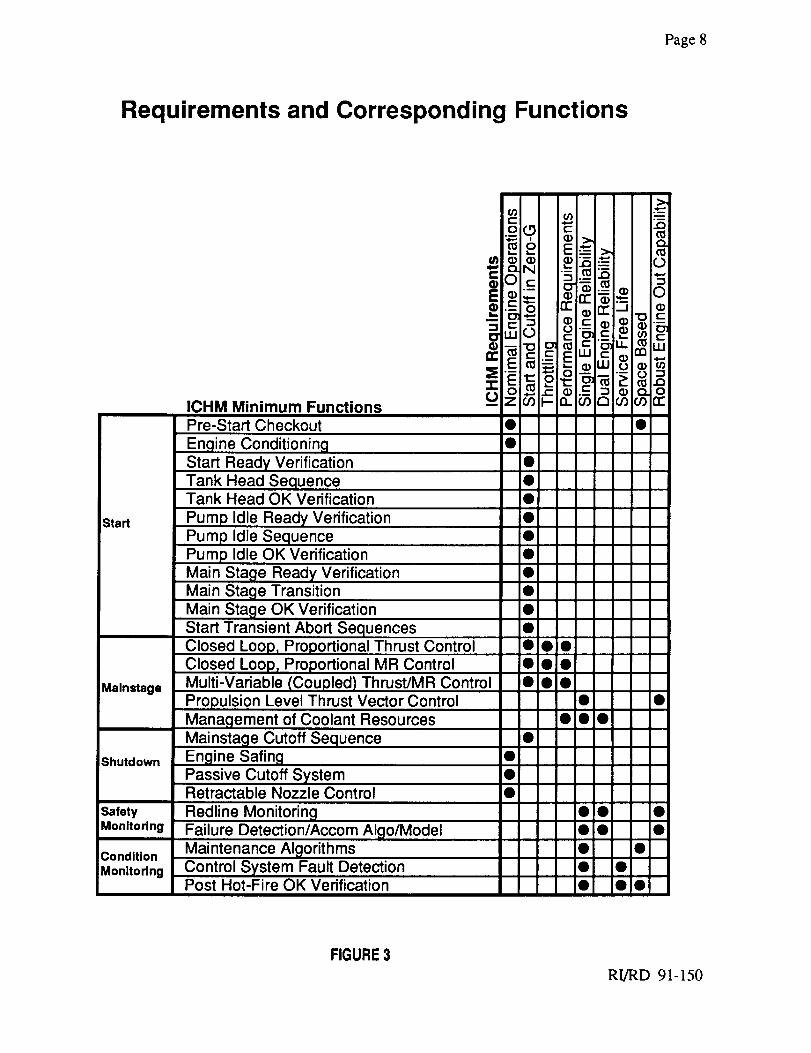
Each of the OTVE system requirements listed above were evaluated by control system and engine
system engineers in order to determine the minimum ICHM functions needed to meet each
requirement. The requirements were mapped to the corresponding minimum functions which the
ICHM must perform. The results of this evaluation are shown in Figure 3. The dots represent
which OTVE system requirements are fulfilled by the function. The resulting ICHM minimum
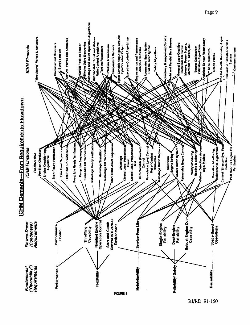
functions were grouped by engine operation phase. In addition, Figure 3 shows the Safety
Monitoring Functions which are active during all engine phases and the Engine Diagnostics
Functions, which are active between missions. Figure 4 depicts element definition from
requirements.
RI/RD 91-150
Page8
Requirements and Corresponding Functions
Start
Mainstage
Shutdown
SafetyMonitoring
Condition
Monitoring
ICHM Minimum Functions
Pre-Start Checkout
Engine Conditioning
Start Ready VerificationTank Head SequenceTank Head OK Verification
Pump Idle Ready Verification
Pump Idle Sequence
Pump Idle OK Verification
Main Stage Ready Verification
Main Stage Transition
Main Stage OK Verification
Start Transient Abort SequencesClosed Loop, Proportional Thrust ControlClosed Loop, Proportional MR Control
Multi-Variable (Coupled) Thrust/MR Control
Propulsion Level Thrust Vector Control
Management of Coolant Resources
Mainstage Cutoff SequenceEngine Sating
Passive Cutoff SystemRetractable Nozzle Control
Redline MonitoringFailure Detection/Accom Algo/Model
Maintenance Algorithms
Control System Fault DetectionPost Hot-Fire OK Verification
=E,1-tj
il
loglog
log
OO0
O0
O0
iO
,O
O0
FIGURE 3
RI/RD 91-150
Page9
F_URE4
RI/RD 91-150
Page10
2.0 ICHM ELEMENT DESCRIPTIONS AND LISTS
In this section, the element selections and associated rationales are presented along with summary
lists and descriptions of the sensor, actuator, electronic hardware and software elements and sub-
elements. In selecting many of the system sub-elements, several valid alternative technical
approaches, representing different levels of technology readiness and desirable
performance/physical characteristics, were considered. Where applicable, these alternatives are
discussed as well as the assumptions and criteria underlying the baseline element selections.
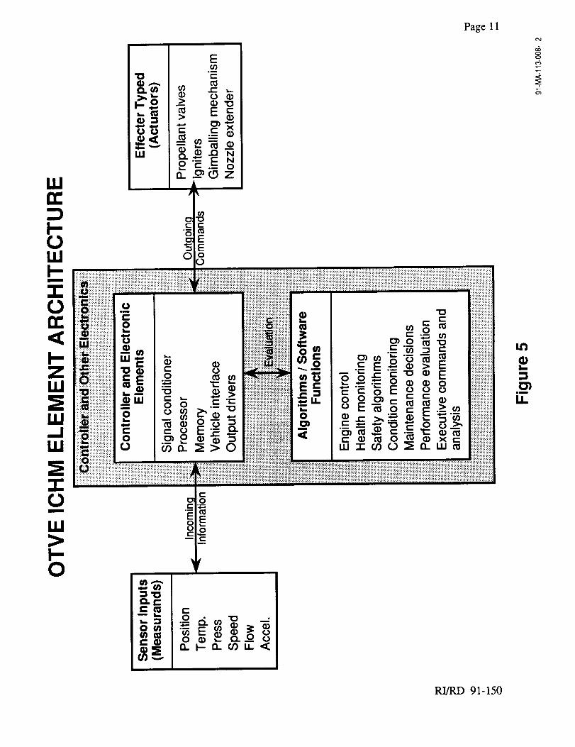
The ICHM system elements can be categorized into four distinct areas, see Figure 5:
I. Sensors
II. Effectors (valves, actuators, igniters)
III. Electronics (controller, data storage, harnesses)
IV. Algorithms and software (control algorithms, health monitoring software)
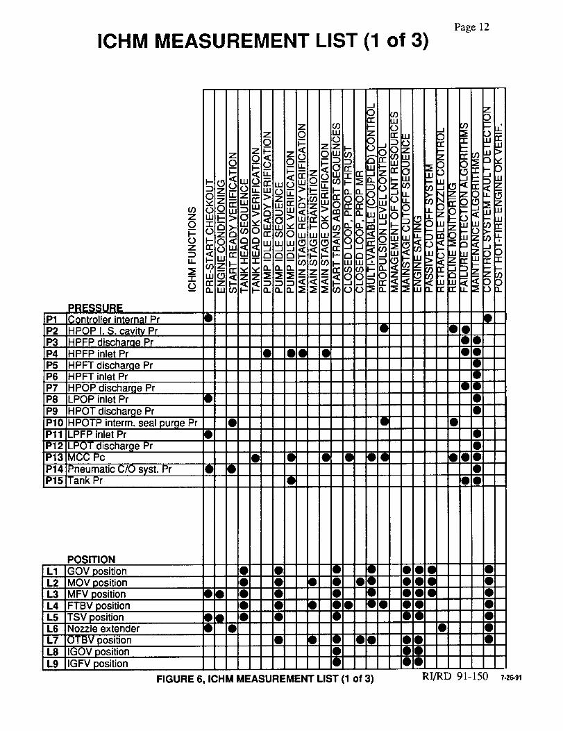
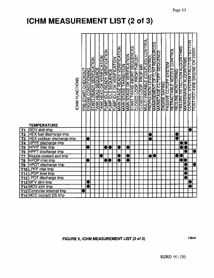
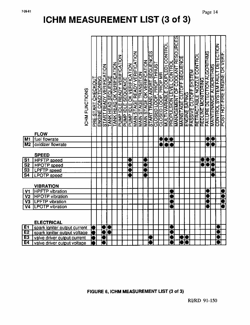
2.1 Sensors
After the functions were determined, a list of sensors needed to perform the functions was
generated. The measurements were correlated to the function(s) they serve, as shown in Figure 6.
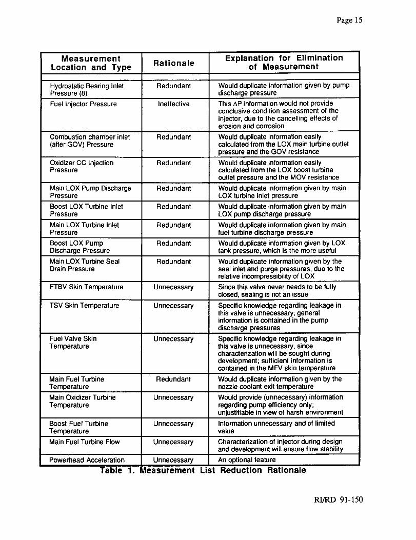
Experienced engine systems personnel participated in the effort to minimize the number of
recommended measurements. The eliminated measurements, the rationale for elimination and a
brief explanation is given in Table 1. Figure 6 does not include the eliminated sensors.
There are seven basic types of measurements used in the minimum ICHM system:
1. Static pressure
2. Static temperature
3. Flow
4. Speed
5. Displacement (Continuous)
6. Position (On/Off)
7. Acceleration
The operating ranges for each sensor type in the measurements matrix were obtained through
engine balance data. This data was examined for three "operating points", shown in Table 2.
RI/RD 91-150
=
E
•_ (D'O,
i.u _-F'_z .flf= J_
I--0111
m
0
'4,111
_o ._
I--0 _¢
_._.-__.._-o__
Page 11
tt_
L.
im
Li=
¢M
00
.k
RI/RD 91-150
ICHM MEASUREMENT LIST (1 of 3)Page 12
P1P2P3P4P5P6P7P8P9P10PllP12P13iP14P15
PRESSUREController internal PrHPOP I. S. cavity Pr
HPFP discharqe PrHPFP inlet Pr
HPFT discharge PrHPFT inlet Pr
HPOP discharge PrLPOP inlet Pr •
HPOT discharge PrHPOTP interm, seal purge PrLPFP inlet Pr •LPOT discharge PrMCC PcPneumatic C/O s ,st. Pr •Tank Pr
• qlO •
• • • • Oql
O0
O0
OO0
!O:O
L1L2L3L4L5L6L7L8L9
POSITION
GOV positionMOV positionMFV positionFTBV positionTSV positionNozzle extender
OTBV positionIGOV positionIGFV position
•O
•q)
• • • Oi• • • • OiOi• • • 0_• • • O000• • •
• • • • O!
FIGURE 6, ICHM MEASUREMENT LIST (1 of 3)
OO0 •OO0 •OO0 •O0 •OO •
• •Of• •O!OOO
RI/RD 91-150 7-26-91
Page 13
ICHM MEASUREMENT LIST (2 of 3)
1- IIZ
n- Z_D
T1T2T3T4T5T61"7
T_"1"9T10TllT12T13T14T15T16
TEMPERATURE
GOV skin tmpHEX fuel discharge tmpHEX oxidizer discharge tmpHPFP discharge tmpHPFP inlet tmpHPFT discharge tmpNozzle coolant exit tmpHPOP inlet tmpHPOT discharge trnpILPFP inlet tmpLPOP inlet tmpILPOT discharge tmpMFV skin tmpMOV skin tmpController internal tmpMCC coolant DS tmp
O
• • • O!
• • • gOOO • •
O0O0
O0O0
O!
O_
!O_
FIGURE 6, ICHM MEASUREMENT LIST (2 of 3) 7-26-91
RI/RD 91-150
7-26-91
ICHM MEASUREMENT LIST (3 of 3)Page 14
FLOW
M1 ]fuel flowrateM2 I°xidizer flowrate
SPEED
$1 HPFTP speed$2 HPOTP speed$3 LPFTP speed$4 LPOTP speed
V1V2V3V4
VIBRATIONHPFTP vibrationHPOTP vibrationLPFTP vibrationLPOTP vibration
ELECTRICALspark i.qniter output currentspark i.qniter output voltagevalve driver output currentvalve driver output volta.qe
U3LU
zl _ _ _, _ -,,.
• D• • •
• •I DID
• O• •
_1 • •• • •i1 • •• • •
E1E2E3E4
• • •• • •
• • • • O0• • • • O0
FIGURE 6, ICHM MEASUREMENT LIST (3 of 3)
RI/RD 91-150
Page 15
Measurement
Location and TypeRationale
Hydrostatic Bearing Inlet Redundant Would duplicate information given by pumpPressure (8) discharge pressure
Fuel Injector Pressure Ineffective This AP information would not provideconclusive condition assessment of theinjector, due to the cancelling effects oferosion and corrosion
Combustion chamber inlet Redundant Would duplicate information easily(after GOV) Pressure calculated from the LOX main turbine outlet
pressure and the GOV resistance
Oxidizer CC Injection Redundant Would duplicate information easilyPressure calculated from the LOX boost turbine
outlet pressure and the MOV resistance
Main LOX Pump Discharge Redundant Would duplicate information given by mainPressure LOX turbine inlet pressure
Boost LOX Turbine Inlet Redundant Would duplicate information given by mainPressure LOX pump discharge pressure
Main LOX Turbine Inlet Redundant Would duplicate information given by mainPressure fuel turbine discharge pressure
Boost LOX Pump Redundant Would duplicate information given by I_OXDischarge Pressure tank pressure, which is the more useful
Main LOX Turbine Seal Redundant Would duplicate information given by theDrain Pressure seal inlet and purge pressures, due to the
relative incompressibility of LOX
FTBV Skin Temperature Unnecessary Since this valve never needs to be fullyclosed, sealing is not an issue
TSV Skin Temperature Unnecessary Specific knowledge regarding leakage inthis valve is unnecessary; generalinformation is contained in the pumpdischarge pressures
UnnecessaryFuel Valve SkinTemperature
Explanation for Eliminationof Measurement
Table 1. Measurement
Specific knowledge regarding leakage inthis valve is unnecessary, sincecharacterization will be sought duringdevelopment; sufficient information iscontained in the MFV skin temperature
Main Fuel Turbine Redundant Would duplicate information given by theTemperature nozzle coolant exit temperature
Main Oxidizer Turbine Unnecessary Would provide (unnecessary) informationTemperature regarding pump efficiency only;
unjustifiable in view of harsh environment
Boost Fuel Turbine Unnecessary Information unnecessary and of limitedTemperature value
Main Fuel Turbine Flow Unnecessary Characterization of injector during designand development will ensure flow stability
Powerhead Acceleration Unnecessary An optional feature
List Reduction Rationale
RI/RD 91-150
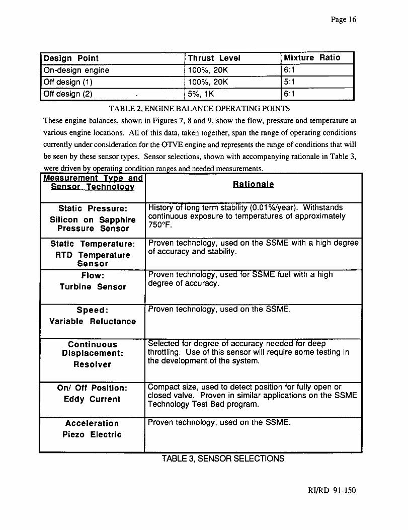
Page 16
Design Point Thrust Level
On-design engine 100%, 20K 6:1
Off design (1) 100%, 20K 5:1
6:1Off design (2) 5%, 1K
Mixture Ratio
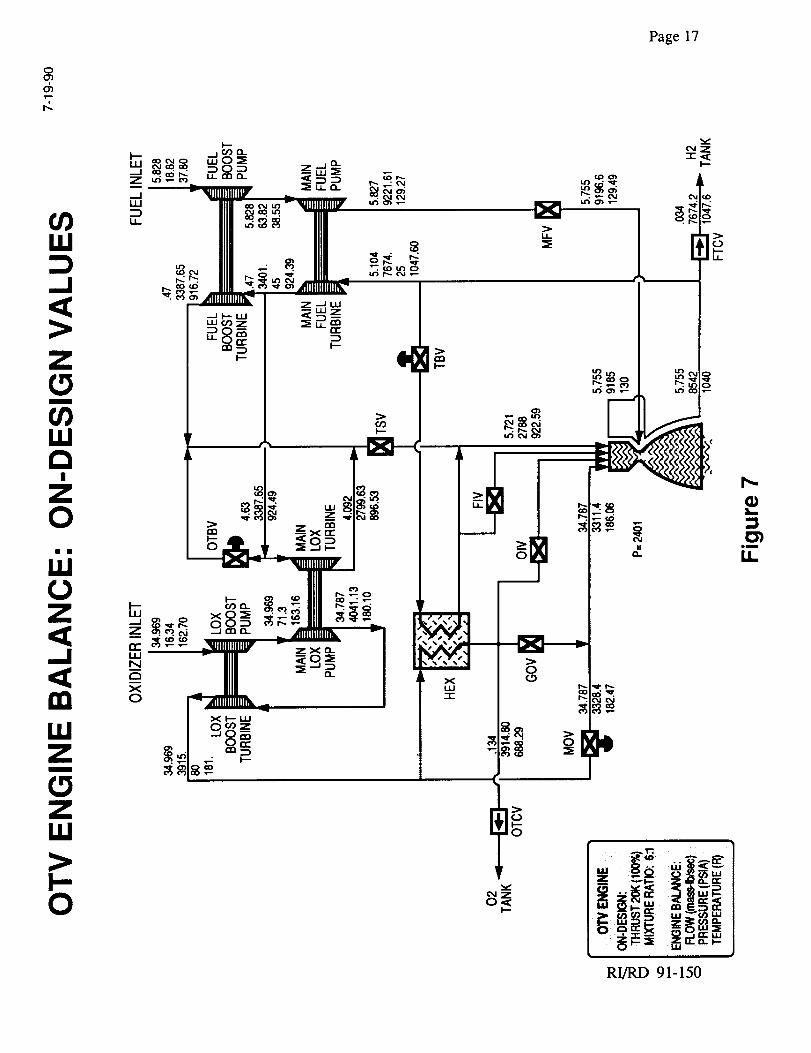
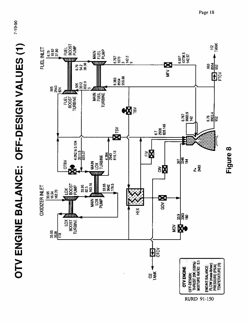
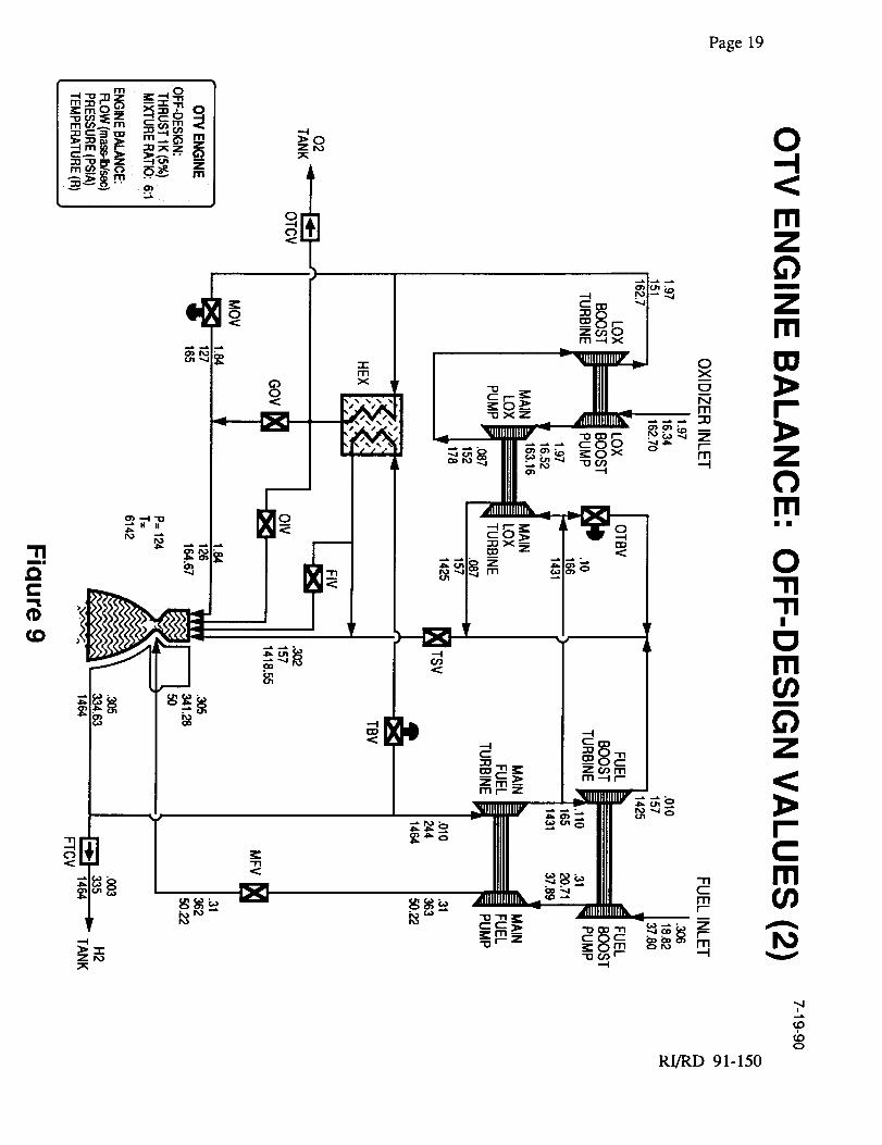
TABLE 2, ENGINE BALANCE OPERATING POINTS
These engine balances, shown in Figures 7, 8 and 9, show the flow, pressure and temperature at
various engine locations. All of this data, taken together, span the range of operating conditions
currently under consideration for the OTVE engine and represents the range of conditions that will
be seen by these sensor types. Sensor selections, shown with accompanying rationale in Table 3,
were driven by operatin_ condition ranges and needed measurements.Measurement Tvoe and
Sensor TechnOlogy Rationale
Static Pressure:
Silicon on SapphirePressure Sensor
Static Temperature:
RTD TemperatureSensor
Flow:
Turbine Sensor
Speed:
Variable Reluctance
Continuous
Displacement:
Resolver
On/ Off Position:
Eddy Current
Acceleration
Piezo Electric
History of long term stability (0.01%/year). Withstandscontinuous exposure to temperatures of approximately750°F.
Proven technology, used on the SSME with a high degreeof accuracy and stability.
Proven technology, used for SSME fuel with a highdegree of accuracy.
Proven technology, used on the SSME.
Selected for degree of accuracy needed for deepthrottling. Use of this sensor will require some testing inthe development of the system.
Compact size, used to detect position for fully open orclosed valve. Proven in similar applications on the SSMETechnology Test Bed program.
Proven technology, used on the SSME.
TABLE 3, SENSOR SELECTIONS
RI/RD 91-150
Page 17
oO'Jd_
iii
>
O_
/ .+
Ill to,-.. _ mg:_14.J--.mM++=_Mm
RI/RD 91-150
Page 18
¢_o wO'5 .ta..o-_ c_. a:l. --j 0 .-_ Z._J_z_ ""_" _
_---'_" =_. _ _ _ _IIII _, _ _llllllllllllilV _ _ _ _ _
-: _ ao AfllilllillllFl_ II Z -'J LU
I -J_"' I _-_I uJ¢_z I =_LL_
I > _1_ __I _ / z×_ "
PI _ _-- OI ('%1 "_, __ _,=___ .....,
I O__Z
__1-'8__l _
O0
L.
:301
it
i!
UJ
p.0 ¢,I z
O_I---
uu ., o_ua
_ige
i
RI/RD 91-150
Page19
-rlm|
Qt,-"'1
¢,D
I _.-omN _._o o_
m r"- . :_mO _ ,.a-
m rd).,_ m " ¢,_ ;'_'
oo
0
--t_l> "-rz r,,._
-T'I
1o
6!11m
'--I
RI/RD 91-150
,,.ptOo
Page 20
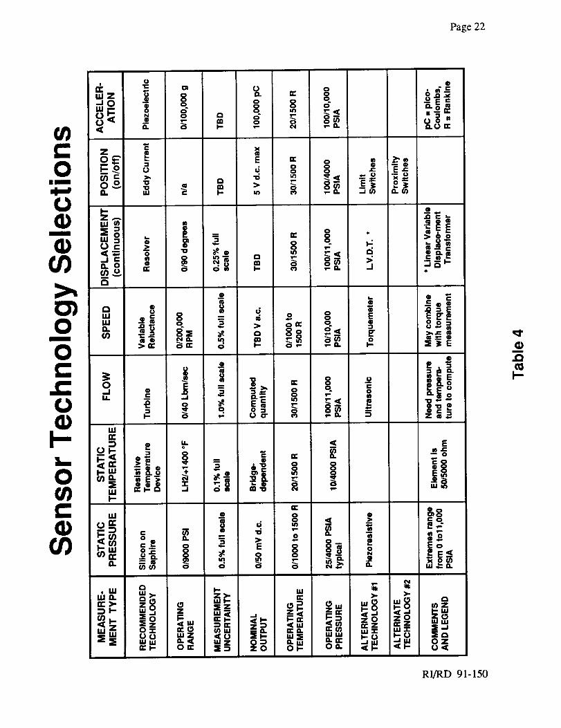
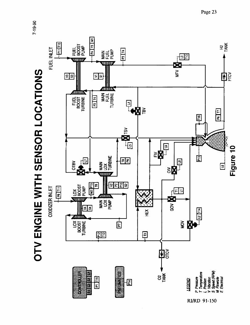
Table 4 shows the selected sensors, the operating ranges, and the several optional sensors. The
locations of the sensors on the engine are shown in Figure 10.
2.2 Effectors
The basis for the effector element selection compares available or emerging designs and the
requirements of a particular application. Rocketdyne's ongoing development efforts are included
in the valve and actuator technologies. A particular goal is a reliable, accurate, easily maintainable
electric actuated propellant valve capable of deep throttling. Commencing with the Advanced
Space Engine (ASE), an IR&D task was started in 1982 to evaluate and develop electric actuated
main propellant valves for orbital transfer vehicles (OTV). This work resulted in design and
characterization of a prototype main oxidizer valve for the 15K thrust RS-44 expander cycle
engine. An advanced propellant valve based on the prototype main oxidizer valve design is
recommended for the OTV engine.
It is assumed that the following elements are supplied by the vehicle contractor:
I° Propellant tank pressure regulation components (regulator/relief valves)
Fuel Tank Pressurization System using autogenous gas from engine
Oxidizer Tank Pressurization System- using autogenous gas from engine
II. Inlet Propellant Valves
Fuel Inlet Valve
Oxidizer Inlet Valve
(The propellant tank isolation check valves are considered as part of the engine system as they are
contained within the engine to tank pressurization lines. In order to provide a more complete
design description, system requirements will need to be established for these check valves as well
as the nozzle extender and thrust vector actuators).
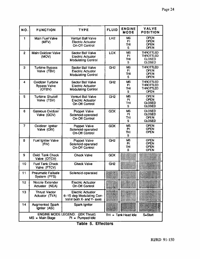
The ICHM has the following propellant valves and components for engine control (component
types and positions are identified in Table 5):
1. Main fuel valve (MFV)
2. Main oxidizer valve (MOV)
RI/RD 91-150
Page21
3. Turbinebypassvalve(TBV)
4. Oxidizerturbinebypassvalve(OTBV)5. Turbineshutoffvalve(TSV)
6. Gaseousoxidizervalve(GOV)
7. Oxidizerignitervalve(OIV)
8. Fuelignitervalve(FIV)9. Oxidizertankcheckvalve(OTCV)
10. Fueltankcheckvalve(FTCV)
11. Pneumaticfail-safesystem(PFS)12. Nozzleextenderactuator(NEA)
13. Thrustvectoractuator(TVA)
14. Augmentedsparkigniter (ASI)
RI/RD 91-150
Page22
(Dmini
.OcOI-
RI/RD 91-150
Page 23
O
@
17,
On
O
I""Ill_dZ
..._1
Iii
I.,I-
I--0
_Z
0,_I--
RI/RD 91-150
Page24
NO.
1
2
3
4
FUNCTION
Main Fuel Valve(MFV)
Main Oxidizer Valve(MOV)
Turbine BypassValve (TBV)
Oxidizer TurbineBypass Valve
(OTBV)
TYPE
Venturi Ball ValveElectric ActuatorOn-Off Control
Sector Ball ValveElectdc Actuator
Modulating Control
Sector Ball ValveElectric Actuator
Modulating Control
Sector Ball ValveElectric Actuator
Modulating Control
FLUID
LH2
LOX
GH2
GH2
ENGINEMODE
MSPI
THIS
MSPI
THIS
MSPI
TillS
MSPI
THIS
VALVEPOSITION
OPENOPENOPENOPEN
THROI-FLEDTHROTI'LED
CLOSEDCLOSED
THROTll_EDOPENOPENOPEN
THROTTLEDTHROTTLEDTHROI-II..ED
OPEN
5 Turbine Shutoff Venturi Ball Valve GH2 MS OPENValve (TSV) Electric Actuator PI OPEN
On-Off Control THI CLOSEDS CLOSED
6 Gaseous Oxidizer Poppet Valve GOX MS CLOSEDValve (GOV) Solenoid-operated PI CLOSED
On-Off Control THI OPENS CLOSED
7 Oxidizer Igniter Poppet Valve GOX MS OPENValve (OIV) Solenoid-operated PI OPEN
On-Off Control THI OPENS
8 Fuel Igniter Valve Poppet Valve GH2 MS OPEN(FIV) Solenoid-operated PI OPEN
On-Off Control THI OPENS OPEN
................................_..'..__,..'..!__ t.,'._:::.'.:__t.}_9 Oxid. Tank Check Check Valve GOX _ :!:i_::E:i_,i:i:i:i:i:i:i:i:i:i::-,,:.,::._::::..:::._:.._::.,:.::_.:,,..,:._, ::::::::::::::::::::::::::::::::::::::::::::::::::::::::::::::: ::. :::::::::::::Valve (OTCV) _ ::i::i::iiii::_iii::Jiiiii:;i::i_i::i;iiii::i_.l_!.i?:_._!_,__,#_i#._
10 Fuel Tank Check Check Valve GH2 _ ::::::::::::::::::::::::::::::_i_;::.;.i..-:i_,_:,,,'_Valve (FTCV) _ _.;_:_,;:_ ,:.,;:;,;__i;:_:_:
11 Pneumatic Failsafe Solenoid-operated _{_i_ _:"_*"_:__ _:'':__:_:'_'_i__'__!_._.,,_:_.:..'.ze.::_:::::::::::::::::::_i!ifi_'':'_ _::_._'."_).'i_i_i_*;';.'i......................................:.,._._.: -_._:_:._:System (PFS) "._'_e'.'.'.':::"::_..'.' ..............................,..,._:,._,._i
12 Nozzle Extender Electric Actuator ,..',':.'..'.:::_:_::..'e.'.:_._.:_::_!/_i_,:iI!__ =_-_:;-_::'-':'_";/_':__ii/_i_i_';_/i_'_i_li_;i
_._.__:::::::::::::::::::::- _: ::: ._:Actuator (NEA) On-Off Control _,..._ _,_<_,:_,.._:_
_ ..........._.,_.. ......_13 Thrust Vector Electric Actuator _l!_i!_ll;'lil _i,_:_.:::,.:_%:_.,.:
Actuator (TVA) 6-15 deg Modulating Con- _ti_;l_ '_:::!_'_;'_:'::::::_......, _,_:_::,,:._,_,(_._::_:_:._!trol in both X- and Y- axes _i_!_:.._i _{i_.<.','._il_-_.'.i#_i_i_
i
14 Augmentedlgniter(Asl)Spark Spark Igniter _1_"._i. _i
ENGINE MODE LEGEND: (20K Thrust) THI = Tank Head Idle S=StartMS = Main Stage PI = Pumped-Idle
Table 5. Effectors
RI/RD 91-150
Page 25
A brief discussion of the control valve functions during engine start, tank head idle, pumped idle,
and main stage operation is presented on the following pages.
Main Fuel Valve (MFV)
The MFV is an electric actuated on/off cryogenic valve which opens fully to permit fuel flow at
engine start and remains open throughout all of the engine operational modes. Minimum pressure
drop in the fuel circuit is required along with capability for tight shutoff.
Main Oxidizer Valve (MOV)
The MOV is a fully modulating cryogenic valve responsible for mixture ratio control. During start
and tank head idle the valve is fully closed forcing LOX through the GOX heat exchanger. At
pumped idle the valve is ramped, open loop, to an intermediate position providing limited oxidizer
flow to the engine. At main stage the valve opens more fully and is under closed loop control on
mixture ratio. This valve must be capable of tight shutoff.
Turbine Byp_ass Valve CI'BV)
The TBV is a modulating valve with no tight shutoff requirement which controls engine thrust
by throttling fuel flow to the turbines. During start and tank head idle this valve is full open
allowing fuel from the nozzle to bypass the turbines and flow through the GOX heat
exchanger to provide gaseous oxygen flow to the igniter and combustor. During pumped idle
the TBV is maintained full open as the turbine shutoff valve (TSV) is opened which results in
some fuel flow to the turbines. At mainstage the TBV is in its most throttled position
modulating under closed loop control on thrust.
Oxidizer Turbine Bypass Valve (OTBV)
The OTBV is similar to the TBV in that it is also a modulating valve with no tight shutoff
requirements. Its primary purpose is to balance the oxidizer and fuel pump turbines. During start
and tank head idle the valve is at full open or an intermediate position but does not control any flow
as the TSV is closed. During pumped idle (with the TSV open) the OTBV is ramped, open loop,
to an intermediate position which forces some fuel through the oxidizer main pump turbine. At
mainstage the OTBV is in its most throttled position under closed loop control on pump turbine
balance.
RI/RD 91-150
Page26
Turbine Shutoff Valve (TSV)
The TSV is an on/off valve which is closed during start and tank head idle mode with minimal
turbine gas flow such that the turbines do not spin. The valve is ramped to full open during
pumped idle and remains open at main stage. Like the MFV, a minimum pressure drop is
required.
Gaseous Oxidizer Valve (GOV)
The GOV is a two way (on/off) direct or pilot operated solenoid valve, open only during tank head
idle operation providing gaseous oxygen flow to the combustor. During the transition to pumped
idle the valve is closed.
Igniter Valves (OIV. FIV)
The igniter valves are two way (on/off) solenoid valves which provide gaseous oxidizer and fuel to
the igniter throughout all engine operational modes.
Propellant Tank Check Valves (FTCV. OTCV)
The FTCV and OTCV prevent backflow from the cryogenic propellant tanks to the turbines when
the engine is inactive. The check valves also serve to isolate propellant between each engine.
Nozzle Extender Actuator (NEA)
The NEA is a linear electrically actuated system which extends a radiation cooled nozzle.
Following engine shutdown, the NEA retracts the nozzle back to the stowed position when
required.
Thrust Vector Actuator (TVA)
The TVA consists of two linear electric actuators which provide gimballing control. The TVA will
provide 6 to 15 degrees modulating control in both x and y axes.
Augmented Spark Igniter (ASI)
Two Augmented Spark Igniters (ASI) will be used to ensure reliability. The components for the
igniter include:
1. Electronic ignition exciter (2)
2. High-voltage cable (2)
3. Spark igniter plug (2)
4. Ignitor injector/precombustor
RI/RD 91-150
Page27
All of the componentsareseparable.Sparkignitersandtheigniter injector are installedusing
threadedjoints. Electronic componentsaredual redundant. Failure of any single electrical
componentwill notcauseignition failure. Ignition is accomplishedby activatingthesparksystem
andintroducingpropellantsinto theigniter. Thesepropellantsareinjectedin apatternthatprovides
cold fuel surroundingtheoxidizer. This patternensurescooling so anadditional supplemental
cooling systemis not required. The ignition systemis reusableandrestartswithout componentreplacementor servicing.
2.2.1. Effector Desien Description
Three types of propellant control valves are proposed for the OTV engine: 1) sector ball valve, 2)
venturi ball valve and 3) solenoid operated poppet valves. The sector ball valve will be used for
low torque applications. For low pressure drop the venturi ball valve will be used. Low flow
ignition and control applications will employ either direct or pilot operated solenoid valves.
Electric Actuated Cryogenic Propellant Control Valves.
The electric actuated MOV consists of a sector ball gate to throttle flow that is supported on integral
shafts by a pair of ball bearings, and positioned by an electromechanical actuator with closed loop
position feedback from a resolver off the ball shaft. The gate configuration is basically one-half of
a spherical shell. Sealing is provided by shaft seals and ball seals of DuPont Vespel. Modular
construction permits easy disassembly of the actuator, valve module and seat package from a single
valve housing flange. The valve housing can therefore remain attached to the propellant ducts.
A key feature of the Rocketdyne sector valve is the continuous-contact seat seal design. This
design is basically similar to the very successful SSME shaft seal subsequently used in the ASE
and RS-44 integrated component evaluator (ICE) propellant valves. These designs maintain micro
inch level of leakage gap under extremely high bearing loads which is achieved through the unique
characteristics of DuPont Vespel SP-211, a combination of polyimide, graphite, and Teflon. The
material has demonstrated compatibility with LOX and LH2 over the full range of expected
operating conditions. Leakage can be held to less than 10 scim helium, however, higher limits are
recommended because system allowances are considerably greater and lower costs result. All
external valve leakage can be collected by use of redundant shaft seals and two static flange seals
with the intermediate cavities connected to a single housing port for safe venting overboard. This
feature permits potential "growth" instrumentation for health monitoring of each valve for external
leakage before, during and after each engine firing.
RI/RD 91-150
Page28
The seatsealpackageis a modularassemblycomprisedof a retainer,snapring, wave springs,loader,andseal.Thewavespringsprovideloadto sealatlow pressureandalsoovercomefriction
forcesat cryogenictemperature.All sealdesignparametersareanchoredby testdataanddefined
by computeranalysiswhich permitsdefinition of anoptimal design.Equationsfor sealreactionforcesconsiderthermalcontraction,radial sealclearanceor interference,pressuredifferential,
loaderforce,frictionandsealmaterialelasticparameters.
Couplingthevalve shaftto theactuatoris a metalbellowswhich providesfor thermally induced
axialmotion,is radially stiff, andhasnofreeplay. Thevalveandactuationsystemis designedto
maintainbacklashandelasticwindupto lessthan0.3degreeundermaximumload. Responsewillbelessthan1.0secondfull travelundermaximumloadwith capabilityof lessthan0.2secondat
reducedor aidingloadsto permitfastshutdownasrequired.
TheMFV requiresa largerflow areathantheMOV dueto lowerpressuredroprequirements.Afull ball with venturi inlet andoutletflow sectionsto reducedeltaP will beusedwith theMFV to
permitacommonvalvesizewith theMOV. ThustheMFV will be identicalwith theMOV exceptfor thenotedvariationsin closureandflow geometryto providelow pressuredrop with nearly
commoncryogenicpropellantvalves.
Turbine Gas Valve Design
Turbine gas valves (OTBV, TBV, TSV) are patterned after the MOV but with several variations.
Valve body, gate and bearing materials must withstand temperatures to 950 degrees F and
pressures to 7674 psia. Although stringent leakage requirements are not required for the seat seal,
the shaft seal may see high temperature. Consequently, two paths will be followed to address
function of the shaft seal:
1) A carbon/graphite seal will be designed for operation at 950 degrees F, but with the
actuator both insulated and thermally isolated from the valve.
2) As backup, polyimide shaft seals will be thermally isolated from the valve with the
actuator to prevent seal temperatures exceeding 350 degrees F.
The TSV will have the same full ball venturi flow geometry as the MFV to provide low pressure
drop. Additionally the TSV has a requirement to shut-off sufficient turbine gas flow such that the
turbines do not spin during tank head idle. Two alternative seat seal designs considered are: 1) an
RI/RD 91-150
Page29
all metal dry film lubricated seat seal as used on the RS-44 TBV and OTBV, and 2) a
carbon/graphitedesignmatedwith a molybdenumseattubeinsertwhich providesa very close
matchin thermalexpansionwith thecarbonsealmaterial. Fortunately,this sealneedsto operateonly atrelativelylow pressuredifferentialwith liberalleakageallowance.Primaryparametersto be
consideredin designarethereforelonglife andreliability.
Solenoid Operated Valves
The GOV, IGOV and IGFV are two-way solenoid operated valves providing on/off control of
GOX and GH2 propellants at low flow rates. Key features are rugged simplicity providing high
reliability and low cost. Dual coils can be provided for electrical redundancy as required.
Check Valves
Propellant tank isolation between the OTV engines will be provided by the OTCV and FTCV.
These are poppet-type check valves which can be used in series for redundancy as required.
Pneumatic Fail-safe System Components
The pneumatic fail-safe system consists of a regulated pneumatic supply, pneumatic control
assembly (PCA) and fail-safe actuators mounted to the necessary engine control valves needed to
effect a safe engine shutdown. All control components will have redundant electrical actuator
systems such that upon any electrical failure the secondary system can provide fall-operation of the
OTV engine. Upon failure of the secondary system, the actuator will lock in position until the
pneumatic fail-safe system is energized from the PCA to provide a sequenced valve deactuation that
will safely shutdown the engine.
Nozzle Extender and Thrust Vector Actuatol_
These components are electromechanically actuated with dual electrical redundancy.
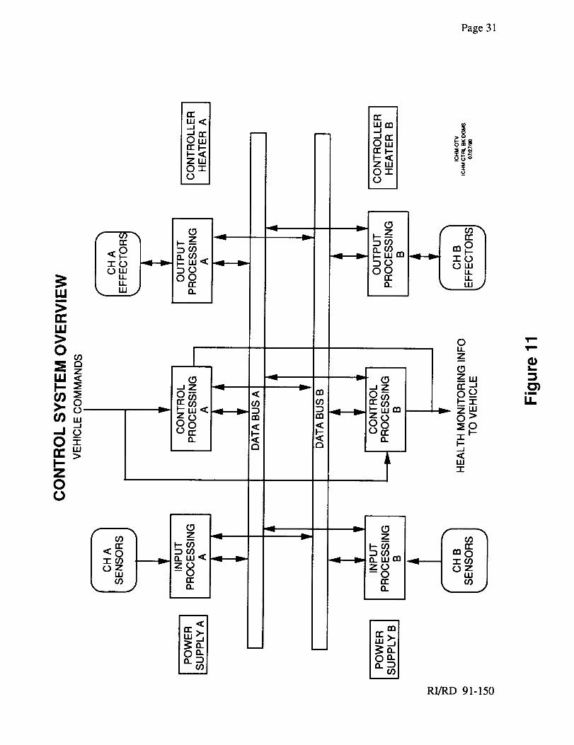
2.3 Electronics
The intent of the control system block diagram is to indicate the features which will satisfy the
stated requirements and perform the minimum functions necessary for successful OTV operation.
A dual channel architecture is the baseline, with additional redundancy possible, each with its own
power supply and heater. The architecture will be modular to accommodate additional capability,
new technologies, or increased redundancy.
RI/RD 91-150
Page30
Single channelcontroller functions arebrokendown into threemain areas;input processing,
control processing,andoutputprocessing.Input processingcontainsthe interfacebetweenthe
sensors( temperature,pressure,speed,flow, and acceleration)and the controller. Controlprocessingcontainstheinterfaceto thevehicle( telemetryinformationandvehiclecommands),
performshigh level control like thrust / mixture ratio control, and any real-time algorithms.
Finally, the output processing section contains the effector control drivers (solenoids, igniters, and
closed loop actuators) and receives all valve positions (RVDT and LVDT). All functional areas
connect to the data interconnect busses which will be standardized types of parallel busses.
Functional areas may be made up of several circuit cards, each with a separate interface to the
parallel data busses.
Channels are complete with their own separate power supply and heater. Power supplies are
responsible for all power for their respective channel including sensors and valves and will be
electrically isolated. The heater is necessary to keep electronics from becoming cold enough to,
among other things, crack solder joints or deteriorate capacitors. If enough electrical activity is
present in the vehicle between missions, for example by telemetry, heaters may be eliminated.
Each of the three main functional areas will be linked to the other channel(s) via the data busses.
The type and extent of redundancy management has yet to be determined. However, an up front
goal will be to minimize software complexity by simplifying the channel interaction. Technological
advances in VLSI should improve channel reliability.
A preliminary schematic of the controller architecture is shown in Figure 11.
2.3.1 Innut Electronics
The function of the Input Electronic module is to condition and convert engine sensor data to digital
data for processing. Data to be measured includes temperatures, pressures, speeds, flows and
acceleration.
For cryogenic temperature measurements, RTD's are best suited because the signal output levels
are higher. A constant current supply will provide an accurate reference with the voltage drop
across the RTD being directly proportional to resistance. For hot gas temperature measurement,
thermocouples may be used because of their inherent structural ruggedness. Use of thermocouples
will require additional circuitry to amplify the low level signals and provide ice point referencing.
RI/RD 91-150
Page 31
rr"
,....I 17r-A
•_,_ _t.uu-
ZW0 T
u
>0
I_1<l--m
0>'o_w
>I-Z00
n C_OI--W<
O.
I-JZ
I c>_I1"(/,)
Q.
|
M -.
v0Cl
CO
o<
/
m
n-
171'-A
tu
u._
I.m
o-r0
_o
(D__zDO')O.O9__.wmDO
_Z
o__wm
t
OiiZ
___w
_d
wT
.2 Z
D__.W en
---8E
RI/RD 91-150
mm
It.

Page 32
Pressure sensors require an accurate voltage reference from the Input Electronics and provide a
differential bridge output. The output of the bridge is filtered and amplified and converted to a digital
value for scaling in the Input Electronics Micro-controller (IEMC).
Speed and flow processing are handled in a similar manner. An EMF generated by a rotating
magnetic field is picked up in a coil and the period of the generated waveform is measured using a
time measurement counter. A zero crossing detector is employed to determine beginning and
ending of a measurement period.
Signal Conditioning will consist of passive input filters on all inputs to reject EMI followed by a
low pass filter for anti-aliasing and buffering where required. Temperature and pressure data
together with any other analog data will be multiplexed into a 12 bit A-D converter for conversion
to digital data.
The IEMC will perform reasonableness test based on engine model data to determine the condition
of the engine sensors. Scenarios considered to accommodate unreasonable sensors include;
excluding that sensor from calculations and using the channel B sensor, or possibly using a
"weighted sum of system health parameters" model, with weightings adjusted to compensate for
lack of the unreasonable sensor value. The IEMC will also control self test of the Input Electronics
to ensure the validity of all data reported to the Controller Bus. It will perform the necessary
scaling of data and report it on the Controller Bus for all users, such as the Engine Controller or the
Condition Monitor.
The IEMC will consist of a 32-bit processor with a fixed program memory (PROM) and static
memory (RAM) for working memory. Because its operation is critical to the input electronics, the
IEMC will be a self checking controller and the memory will be an error detection and correction
memory. It will provide the protocol to communicate to the Controller Bus as well as do
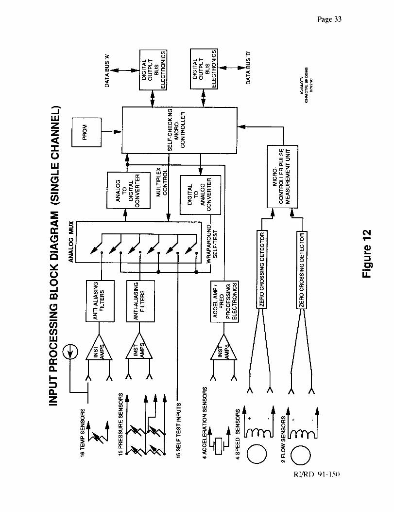
processing. The input processing block diagram is shown in Figure 12.
2.3.2 Controller Processor
The function of the Control Processor (CP) is to receive vehicle commands such as engine
checkout, start, throttle or cutoff and control the engine operation. Mixture ratio and throttle
control will be done in the CP using data from the input electronics and the output electronics and
sending valve position commands to the output electronics. Engine data will be stored in a bulk
memory during engine operation for processing after cutoff. Fifty two measurements have been
RI/RD 91-150
Page33
l
__oo
RI/RD 91-15()
T"
L
iim
I!
Page 34
identified and fifty measurements per second will require about 1.5 Mbytes of memory for 10
minutes of engine operation. Data which requires a higher update rate, such as tracking filters or
other special processing must be supported by special purpose processors to pre-process data for
storage in the bulk memory, input and output electronics data received in the CP has been fully
qualified and can be used without further reasonableness testing.
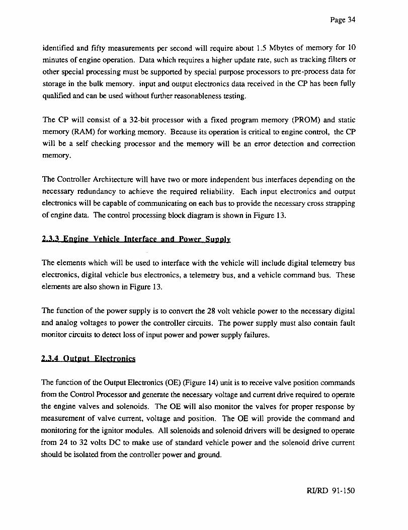
The CP will consist of a 32-bit processor with a fixed program memory (PROM) and static
memory (RAM) for working memory. Because its operation is critical to engine control, the CP
will be a self checking processor and the memory will be an error detection and correction
memory.
The Controller Architecture will have two or more independent bus interfaces depending on the
necessary redundancy to achieve the required reliability. Each input electronics and output
electronics will be capable of communicating on each bus to provide the necessary cross strapping
of engine data. The control processing block diagram is shown in Figure 13.
2.3.3 Engine Vehicle Interface and Power Supply
The elements which will be used to interface with the vehicle will include digital telemetry bus
electronics, digital vehicle bus electronics, a telemetry bus, and a vehicle command bus. These
elements are also shown in Figure 13.
The function of the power supply is to convert the 28 volt vehicle power to the necessary digital
and analog voltages to power the controller circuits. The power supply must also contain fault
monitor circuits to detect loss of input power and power supply failures.
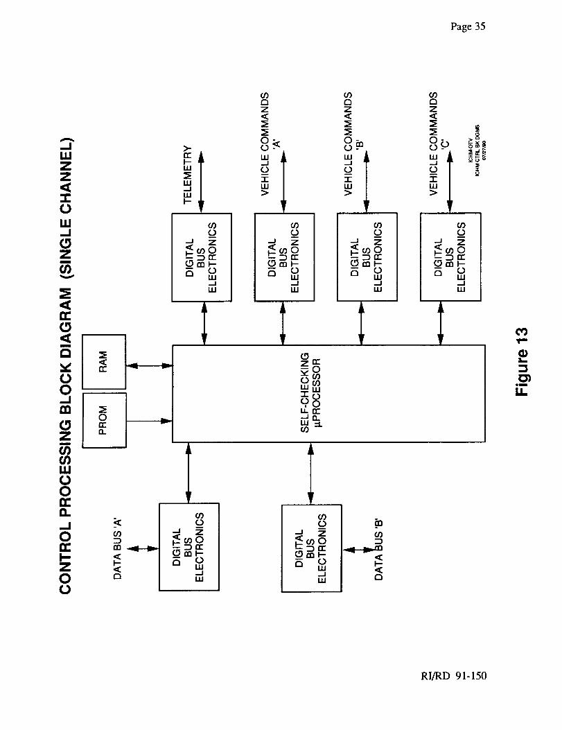
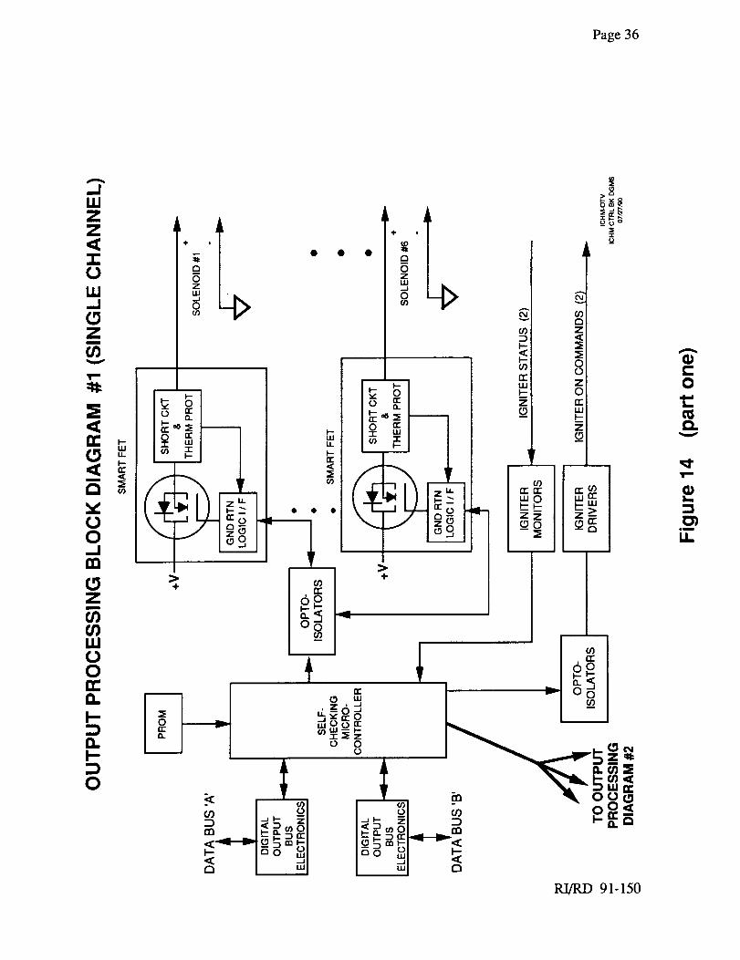
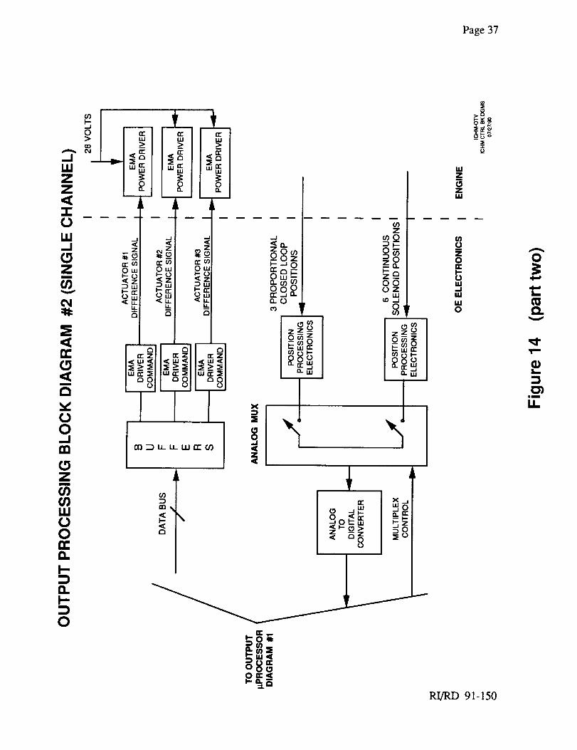
2.3.40utnut Electronics
The function of the Output Electronics (OE) (Figure 14) unit is to receive valve position commands
from the Control Processor and generate the necessary voltage and current drive required to operate
the engine valves and solenoids. The OE will also monitor the valves for proper response by
measurement of valve current, voltage and position. The OE will provide the command and
monitoring for the ignitor modules. All solenoids and solenoid drivers will be designed to operate
from 24 to 32 volts DC to make use of standard vehicle power and the solenoid drive current
should be isolated from the controller power and ground.
RI/RD 91-150
Page35
0
mm
u_
RI/RD 91-150
Page36
,.dLIJ
0
v00_!
Z
_OVJ
00
0..p.
O.
0
÷
. J
E
"1 z• • Q
_÷ . _
i
+
RI/RD 91-150
t'-O
t_
V
T"
L.
im
ki.
Page37
--7:--i ,,- _oo_
a-u) _ r-- _ "" z _n- _w 0 _a.Ow Ow __ I::Z:a -- I--_0 I.-o 0 I-- a.._z _ = _ O0 ,,o,,--_ i-- I-a: r.J, 0 u OZ
ow (3 t.,u CC._J Wno {°-"A-- u.. u_
/ / 1-._ r o8_'---EE zZ--/ / -_o _
_1 II " _o-- LLI CC I--
___ o o o --LU II"i:Z E Z E Z (/) S (/) I--
_, j,,_ _LU _C .{LLI_: £81. u 80_;_>_ :__> :_ 2,,-_
IW i : :_11W a: zel pu _: _1 I "" '" I I _-u.J
° I I
8 _
?,
0
RI/RD 91-150
Page38
Valve drivers must drive bothon-off andproportionalvalveswith high efficiency if thedesign
goalsof thecontrol systemareto bemet. New valvedriversbeingdevelopedfor theautomotive
industry offer efficient operationandhavebuilt in self test features. Electromagneticactuator
driverspresenta challengebothin circuit designandpackaging.High efficiencyamplifierdesign
mustbedevelopedfor increasedefficiency.
Measurementof valve position in the pasthasemployedRVDT'S andLVDT'S, which arenot
capableof betteraccuracythan1%to 2%. Moreaccuracyisrequiredandothertechniquessuchas
radiometric RVDT'S, optical position encoders,and resolverscan provide 0.1% accuracy.
Monolithicintegratedcircuitsareavailablefor circuitimplementationof all thesetechniques.
Spark ignitor control and monitoring may be provided in the output electronics. To detect
degradationin thesparkignitor, it will benecessaryto designa monitor circuit which measures
the sparkenergyandcomparesit to nominal values. A review of SSME experiencewill be
conductedto determinethenecessityof thischeck.
TheOE functionswill becontrolled by anoutputelectronicsmicro-controller (OEMC) with astoredmemoryprogram.Datasuchasvalvepositioncommandswill bereceivedin theOEMC via
theControllerBus. TheOEMC will convertthecommandto a form requiredby thevalvedriver
andverify thatthevalveresponded.Monitoringof thevalvedriverswill alsoprovideinformationaboutfaultydriversor opencoils andthis will beputon thebusfor thehealthmonitoringfunction.
The OEMC will consistof a 32-bit processorwith a fixed programmemory (PROM)and static
memory(RAM) for workingmemory.Becauseits operationis criticalto theoutputelectronicsself
testfunctiontheOEMCwill bea selfcheckingprocessorandthememorywill beanerrordetectionandcorrectionmemory.
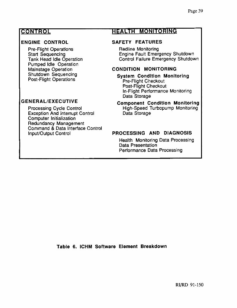
2.4 Algorithms and Software
The ICHM software can be broken down into three categories: Engine control (includes both
performance regulation and implementation of health monitoring decisions), Health Monitoring
(Safety monitoring,Condition Monitoring, including Maintenance assessments), and General/
Executive functions (those which support operation of the ICHM system rather than implementing
specific OTVE operating requirements and includes sensor calibration, measurement validation,
and communications functions). Table 6 describe the software sub-elements organized into these
categories.
RI/RD 91-150
Page 39
ENGINE CONTROL
Pre-Flight OperationsStart SequencingTank Head Idle OperationPumped Idle OperationMainstage OperationShutdown SequencingPost-Flight Operations
G EN ERAL/EXEC UTIVE
Processing Cycle ControlException And Interrupt ControlComputer InitializationRedundancy ManagementCommand & Data Interface Control
Input/Output Control
SAFETY FEATURES
Redline MonitoringEngine Fault Emergency ShutdownControl Failure Emergency Shutdown
CONDITION MONITORING
System Condition MonitoringPre-Flight CheckoutPost-Flight CheckoutIn-Flight Performance MonitoringData Storage
Component Condition MonitoringHigh-Speed Turbopump MonitoringData Storage
PROCESSING AND DIAGNOSIS
Health Monitoring Data ProcessingData PresentationPerformance Data Processing
Table 6. ICHM Software Element Breakdown
RI/RD 91-150
Page 40
Preliminary software functions for the minimal ICHM system are defined based on the ICHM
functional requirements previously identified. In most cases, specific requirements cannot be
established until the OTVE design is further defined. Therefore, the list of software functions is
intended to be representative of the software expected for a minimal ICHM rather than an all
inclusive baseline. In general, the development of the ICHM System algorithms and software
should be straightforward, with low risk in terms of cost and schedule.
2.4.1 En_,ine Control
Engine control includes the code for execution of the operating sequence and closed loop control
algorithms in controlling the engine through all its modes of nominal operation.
Engine safety includes the code for monitoring of engine redlines and for executing the appropriate
emergency engine shutdown depending on whether and engine fault or a computer control failure
had occurred.
2,4.1.1 System Condition Monitoring The system health monitoring code checks the pre-
flight health and readiness of the engine and ICHM system. It also performs limited in-flight
monitoring of system health. System health monitoring requirements for the minimum system
include at least: continuous in-flight and pre-flight checkout; engine system readiness/health
assessment; limited continuous monitoring of the ICHM system health; and transfer of monitoring
data to the vehicle for storage and/or telemetry. Pre-flight checkout may be considered as "post-
flight", in that any pre-flight checkout after the initial mission should recognize problems caused by
the previous use.
2.4.2 Condition Monitoring,
2.4.2.1 Component Condition Monitoring The component health monitoring code
monitors operation of the high-speed turbopumps. In conjunction with signal
processing/conditioning hardware, it extracts health indication signature information from sensor
data and prepares it for data transmission. At this time, it appears that the high speed turbopumps
are the leading candidates for component health monitoring. No other engine system components
appear to have a significant probability of failure or major degradation during the specified service
RI/RD 91-150
Page41
free life. The minimal systemwill therefore include the sensors,signal conditioning and
failure/degradationsoftwarefor monitoringthehigh-speedfuelandoxidizerturbopumps.If futureanalysisor testof otherenginecomponentsrevealsignificantwearor otherdegradation/failure
mechanism,appropriatesensors,signalprocessingandmonitoringalgorithmswill bedeveloped.
2.4.2.2 Processin_ and Diaenosis Maintenance decision and performance evaluation code
operates in general purpose computers to process monitoring data and present it in a meaningful
form for analysis by logistics and engine performance experts.
2.4.3 Executive
Real-time executive code manages the operation of all other software and provides "housekeeping"
services. It includes processing cycle control, exception/interrupt handling and computer
initialization. In addition the executive manages the redundancy of all control system elements,
controls the command and data interface with the vehicle and and controls the sensor input and
actuator output channels.
RI/RD 91-150
Page42
3.0 ELEMENT TECHNOLOGY READINESS FOR MINIMAL SYSTEM
ICHM functions and ICHM system elements were defined in previous subtasks.
elements which emerge from the ICHM functions fall into the following categories:
1. Sensors
2.
3.
4.
The ICHM
Effectors
Electronics (harnessing and controller hardware)
Software/Algorithms
A. Engine control algorithms (feedback control loops of valve position measurement/
control and free-tuning of performance)
B. Safety algorithms/advanced redline control algorithms done in real-time and used
for control decisions
C. Condition monitoring (life prediction/ maintenance analysis/ component
diagnosis) algorithms not necessarily in real-time
Items B and C, taken together constitute Health Monitoring algorithms. A, B, and C: Integrated
Control and Health Monitoring algorithms. All elements together make up the ICHM system
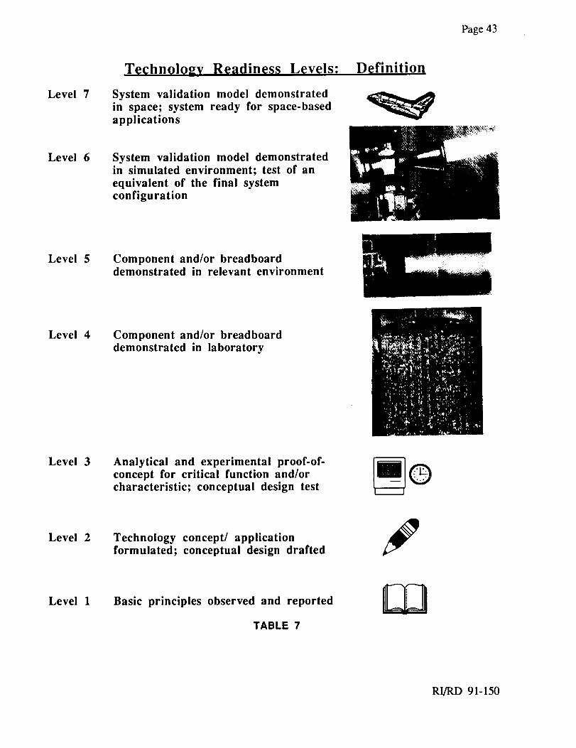
Table 7 presents the technology readiness levels definitions, from 1 to 7, as furnished by NASA in
the task work statement. Technical readiness was determined by review of the technical staff, with
specific element expertise. Elements were separated into four categories: sensors, electronics,
effectors, and software/algorithms. A summary of the element categories, technologies or
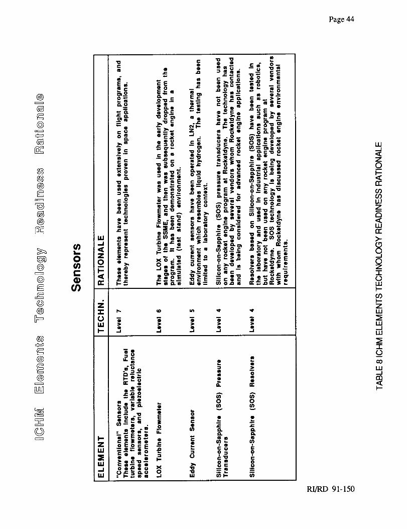
functional types, and element readiness levels is shown in Table 8 on the following pages.
RI/RD 91-150
Page43
Level 7
Technolo2v Readiness Levels;
System validation model demonstrated
in space; system ready for space-based
applications
Definition
Level 6 System validation model demonstrated
in simulated environment; test of an
equivalent of the final system
configuration
Level 5 Component and/or breadboarddemonstrated in relevant environment
Level 4 Component and/or breadboard
demonstrated in laboratory
Level 3 Analytical and experimental proof-of-
concept for critical function and/or
characteristic; conceptual design test@
Level 2 Technology concept/ application
formulated; conceptual design drafted
Level 1 Basic principles observed and reported
TABLE 7
RI/RD 91-150
Page44
@
F-¢@
Q_
8S
@@@r-<
OCZZ_
@
@
@r-d
@@
@
@
®
lUq
S_©(_
u')
0U)t-(1)(/)
_e
._._ _" _-.l=J=
--e 0 0
--Q ' 0 • J: J=
_cE_ n. n.°=°CE e u),-,. v).
=c®=®o ,. cu =; ,,,,.. _ = o.., ,o
o. o_ e_'_ 4111 :e,, f,,l I:o.,_ e o "o --LLJ 0"- = _.o "o --_ --
RI/RD 91-150
tJ.II-.--
C.)
Page 45
@
@
@@@
D(_3
@
@tZZZZ3
@
©@IM
@
®
®
©
(ns,_
0(3
ql,,,,
LU
RI/RD 91-150
O
rr
Z
O
Page46
@CZZZD
@DCZ:_)
@@®
o[zz]
@
@[ZZZ3
@
@@[M
@
@
®
©
q_
RI/RD 91-150
(3
rr
LLI
O
m
Page 47
@[2Z:22_
@O(Z:D
@@@
®
©
@g
@@
@
@
@
©
cn¢,j
im
e,-0L_
0m
l,LI
,. ®= __= .-.= g "_==.= ®_ _ ®>, 3- "i =__=_>, '_= >,® ¢)=- .-. ="-_o® .o - _=. , ="
e-m_ O_ ,.-.Din0 ),--* .,- _0• c - _;=.-; _._ _.,= = = o_.
• " ¢D _ r.(.1:DCD_ m.
eo= "e" "®;=" _ --o- _) "6>=>= ,,=" .." ="=_.; _.; =-o =. _.o E'-o--. == =_= == g_ oso_,..-,.°° =_ ==== ,_ -E=. .
==.= ==..Eo,- === °= : .="_-o _==, _==_ N= _= .=_=-- =._ _. _,
_=e_=" =°_"o _'-® .o== __o _ _ .='e'E _ =; ='_== = =' 9- _ .- ,->
= ..= =o= ..- |o_ ,_ _.0 -=_ .=o=.=o o=o '='* ®="0(= 0"0 ,..
=< ._ =-- = °-.-. .: |o®.- == _:_" =®_"'_• .=>=x_® _=.==- ='=e .-_=
_'0 m "u "T' " >'Om_W _ . _oa.0 . • =-_._ =. ,.,=.-= >,,... _.= ®... .-=o®- o= ==,"=eE= E,,.. *_-? =n" _-o® u'== >= :_ "; _-.: _-E
I,U" ...=,.,= :o_>;,r ";" 0.
vu) c_==.
_=.= =- _ "_,_ = ,=
_=-.--- . = =.- .= ==_., O a-
" "® =-os = ===.=e -" _= _ o,'r_ o,:":" : = e= __*..e, __ o >', __ "_
_=-'_" _ ; =- =- ¢3==.= '== o"=' =" _ _' 0
.=: . _ ;<.; .o== .v, _.__ _-U,J r', _., u ,_ =,.
0
rr
,=,,
L__0=,m
RI/RD 91-150
Page 48
@
r-d@
Q C:::Z:_
8S
@@@
0 I:z:zI
_g@ra"-d
@
@
@@
@¢::=s
r_@
®
ssS3©
o
0
0
u.I
E o o
OQ_ 0
Oor"
_CQ00>
m 0 Q
• f.lQ
• _'o . _--_
(_.1=
U,I 0 >_-.o ..=_" . -
_.! " c. _ • _0.so; o.
> > >
,.I -I ,,.J
m u
•.s c
" 2g0 •
n
o_ I_1
_>Q
o
mq.,.
a uJ
Qeaeo
k. n. tm
mc:_ oO_m
._u_
:o:_Eco_,-_
s- 0o ";"
I fJ Q iC
I.,I
Im
e
Q
_3
EO
=i
t-O)
0
2
f,)t,.
w
<_Zo_F--
_C
W
_7
W_C>-
80
7-0t._F--
l'-:7W
w_.1w
-r"0
unl
RI/RD 91-150
Page 49
@
@
@@@
Q[:_Zl
co
@
@
@
@@
@
®
®
©
=,
0
rr
LU
L_
=,co
RI/RD 91-150
Page 50
@
©OEZZ_
r_
@@®
D_
@
@@
@
@@
@
@
®
©
--cO
|o,. = -_OI C .0,, e "Jr._e-Q "00=,-O= =_ ¢/)
=.E_. " -eoe _.e "-:E =(n==.3. _: =®_ _o,. "__
too. _o o
. ."_ "0 _- L. L.
"0 _ ; . c-= > ,.-,,_ -- 0 ia.
"===o ";" o- ._.
(D _j "_" Q _-'0 =_ (D °,.=__ =.o,, ®®_ _.I*- (l_ ,*d t,.
_mO
_o._=
i-_.:! '._-_0 o (_ _= I--=ol0 = _ etU)._
_ r- = o_.,:_ _ =,', o_11=--c.- o ." 0 0 =--'E
. I: O) r" _ (D I: _" .
_,. o__-o _-- o,- ,-_'o = ®'_ "_.o'=u o s: __--- c_
_.w__ _ m "" F.Q. lt'_
:_;_ >®® ®®= ®e=..=_ "e .,_,_ o..- ..c x o _ _-=' oi"¢/) 0 • _. ,., w.,.., I-- 0 0 I-- _,r".,..
O "o
. .0 I= *"_
.._[ Q'_- 0 I0k. h,._0 00,., O0
CO)O _ _,. "'-- w- m It-¢= Q"O'i;; _'0 I0" 0
,..o =<'_O_E ,,-= -ECru
_ _S o,-..==ol. 0 0 _= ="_---• c m"- o_ o.
"'o " °'O: *'m-oce_=,, ;=E _== =.;=- ---=-
• _ -=- Eoo.--= E0,, ®"= ®-=>=0.=_ _=_=_ ,-- --- -- = .-
,"o ..=.,. euxosoUJG r) J-,. 0 (J o o-- ,,..
m,
,-<,,
0
RI/RD 91-150
Page 51
4.0 ESTIMATE REMAINING DEVELOPMENT COSTS FOR MINIMAL SYSTEM
Cost estimates were developed based on similar component or system development efforts. A
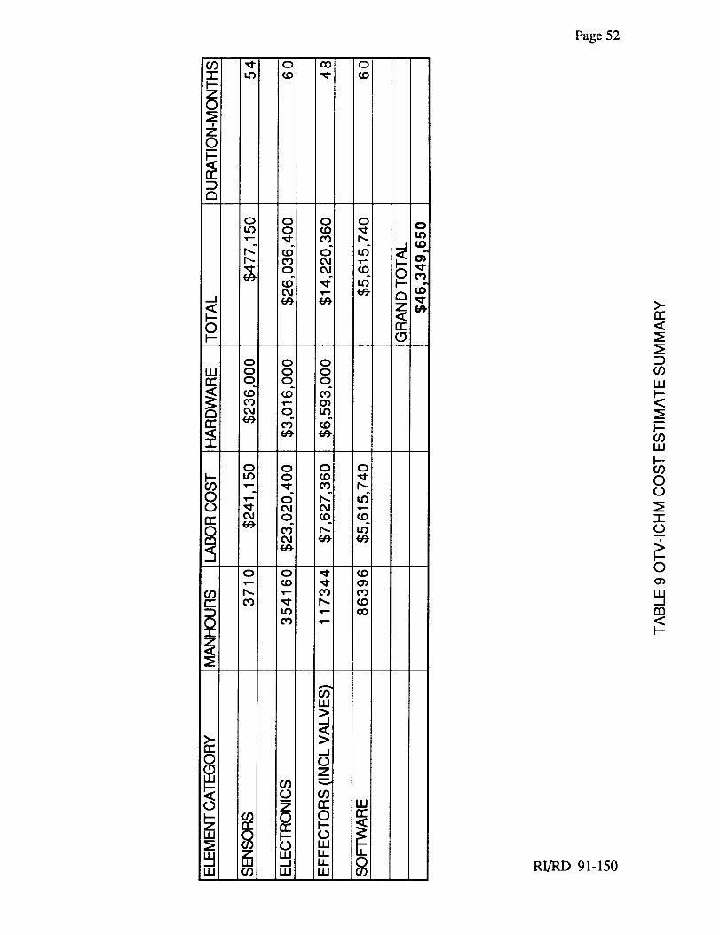
summary of the estimating results is presented in Table 9. A brief basis of estimate is stated for
each category of ICHM elements, followed by general assumptions or detailed estimating
guidelines used in the respective estimates. These estimates are considered accurate to +/- 20%.
An important underlying assumption is based on discussions with NASA-LeRC; that is that the
level 6 validation testing engine/test stand support will be provided by NASA. This means that the
Rocketdyne level 6 efforts encompass required on-site support to testing, analysis, and actions
based on results of that testing. No Rocketdyne labor is estimated for running the engine in the test
stand.
Controller Electronics Hardware
The controller and associated electronics were based on the SSME controller, a full authority
digital rocket engine controller, which is the closest existing similar hardware program available.
The entire list of non-recurring tasks portion of the basis of estimate index for the SSME Controller
Block II proposal was examined and complexity factors were applied to extrapolate ICHM
controller electronics estimates. Additionally a set of design ground rules was established which
are presented in Appendix 1, and general assumptions were made. The electronics labor cost
estimate is about $23M, and related hardware is $3M. This portion of the effort is one requiring
the longest development schedule, 60 months.
General Assumptions
1. Utilize a standardized bus such as, VME, MULTIBUS, Future Bus, 1553
2. Utilize a standardized single board computer with integrated bus interfaces. The design will be
brought up to a space-rated qualification.
3. Extensively use hybrids or VLSI to reduce size and weight.
4. Assume the same close technical and cost control by NASA as done during the development
efforts on SSME Block I, Block II controllers.
RURD 91-150
Page 52
RI/RD 91-150
Page 53
Sensors
Sensors development cost estimates were based several program efforts. These include the
Peacekeeper Stage IV, the SSME 'I'FBE and Kinetic Energy Weapons programs. For each sensor
selection considered, the program with the most up to date applicable cost data was used as a cost
basis. A summary of the sensor cost estimates is presented in Table 10.
Sensor Estimating Guidelines
The basis for bringing a sensor to technology readiness level 5 involves qualification. This proves
the sensor design in a simulated environment. This activity would require 6 manmonths of effort
per sensor, over a duration of 9 months.
To get to level 6 certification from level 5 requires proving the design in a test stand green run.
Going to level 6 assumes engine availability for 17 tests at 300 seconds each. Certification time is
5000 seconds. To recertify a currently certified sensor to a new engine requires manpower of 510
hours (30 hours per test for 17 tests). The adaptation of a level 7 sensor to the target application
requires 20 hours per sensor.
Effectors
The valve actuator estimates were based on actual hardware development experience in similar
technology applications (eg electromechanical or pneumatic driven). The nozzle extension and
gimbal actuators estimates were based on engineering judgement, experience, and operational
requirement interpretation. The igniter estimates were based on applications in similar-sized
injectors from recent and ongoing hardware development programs. The Space Transportation
Main Engine (STME) gas generator (adapted from the SSME program) is used as the basis for the
augmented spark ignitor, and the subscale liquid oxygen/hydrocarbon propellant injector is used as
the basis for the plasma torch ignitor. A summary of the effector cost estimates is presented in
Table 11.
Effector Estimating Guidelines
Valves: The philosophy to this approach is to design the valves with the eventual flight application
in mind. Granted, a flightweight valve is not required in a Focused Test Bed environment, but
overall program cost (to get to the ultimate flight article) are significantly reduced by eliminating a
second design iteration to go from a heavy, large envelope breadboard valve to the flight-sized
RI/RD 91-150
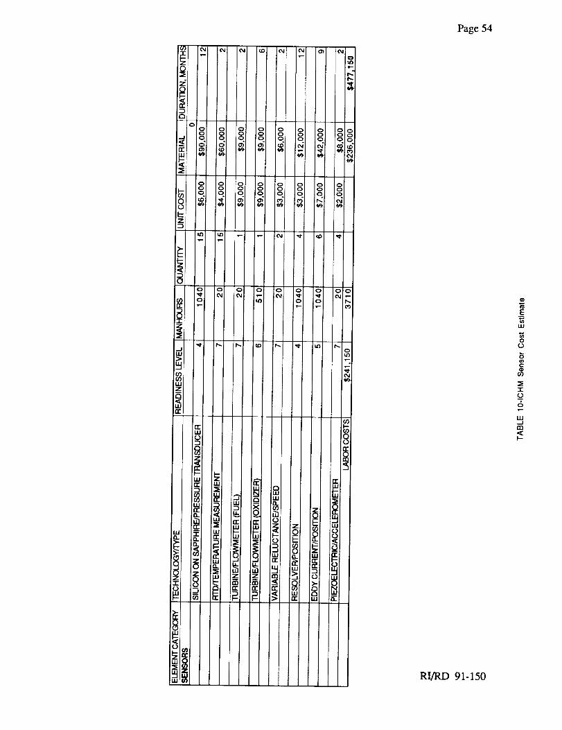
Page54
RI/RD 91-150
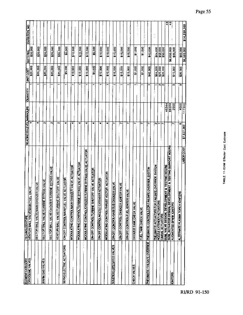
Page55
t.t.I
u
iii
"I-
1--.
RI/RD 91-150
Page56
article. This approachdid, however, consider applying an "experimental" hardware method
(7R drawings, Category VII) to the design process. This facilitates the development process by
requiring substantially fewer reviews and signatures, and far less processing, for the
implementation of iterative design changes through the development process. 7R drawings are
engineering drawings used for experimental hardware. They do not undergo full configuration
management and control, and do not go through the formal engineering release process like 9R
(Category II) drawings do. A more detailed explanation of these drawing types is found in
Appendix II, Engineering Drawings, Categories and Uses. This experimental, 7R drawing
estimating basis is appropriate and was adopted as a result of discussions with LeRC during the
course of this program. The sum estimate of valve design and design verification testing (DVT)
labor for all valves and the pneumatic control assembly is 45,344 hours.
Actuators: This cost is based on the SSME actuator evolution from conceptual design to
development test for a deliverable product. In this case an outside vendor designed, developed and
tested the actuators, and Rocketdyne provided support. The team worked on a man-rated design
that met the fail-op/fail safe requirements which are found on the ICHM program. Although the
subject SSME actuator is hydraulic, hydraulic actuator technology at the start of that development
is comparable with today's commercially existing EMA technology. The estimated cost was $6M
for the ICHM effort, reflecting the reduced complexity of design (and related design verification
testing) change implementation realized when going from NASA development to NASA
experimental hardware production. The $6M is treated as hardware for costing purposes, since it
is a commodity purchased out-of-house. The estimate of Rocketdyne actuator design and design
verification testing (DVT) "support to vendor" labor for actuators is 66,000 hours. Both the valve
and the actuator efforts are estimated to require 48 months of schedule.
Ignitors: Ignitor costs considered a parallel effort of preparing two styles of ignitors for the target
ICHM application. This is considered since 2 different thrust levels are being considered for the
OTVE implementation, and different styles of ignitors are better suited for each respective thrust
level. A 20Klb configuration would accommodate an augmented spark ignitor (ASI)
configuration, where the smaller injector faceplate and injector element diameters of the 7.5Klb
OTVE would require a plasma torch ignitor. For either style ignitor, a three unit basis was used
for material estimating, two for the main combustion chamber redundant ignitor configuration, and
one spare. For the ASI, $15,000 each was used for material cost, plus 2000 hours to adapt the
current level 7 design. For the plasma torch ignitor, material basis was $20,000 each, plus 4000
hours for adapting the current level 6 article design. The time duration required for either ignitor
development is 12 months.
RI/RD 91-150
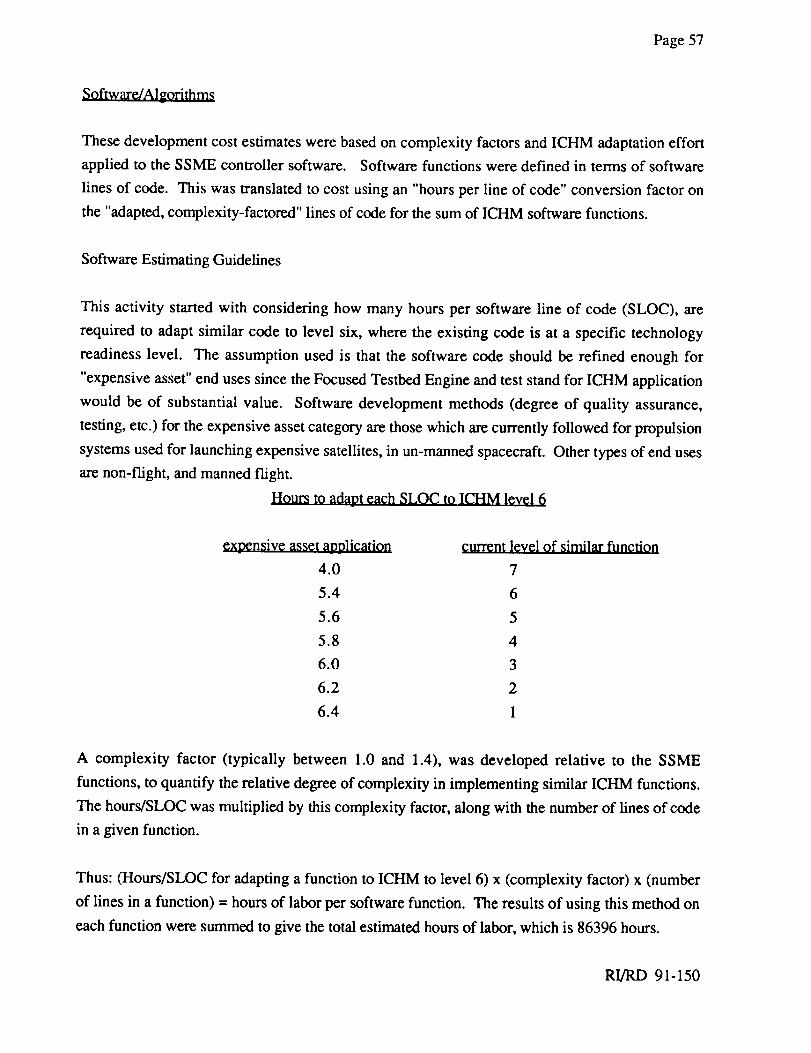
Page57
Software/Algorithrrl_
These development cost estimates were based on complexity factors and ICHM adaptation effort
applied to the SSME controller software. Software functions were defined in terms of software
lines of code. This was translated to cost using an "hours per line of code" conversion factor on
the "adapted, complexity-factored" lines of code for the sum of ICHM software functions.
Software Estimating Guidelines
This activity started with considering how many hours per software line of code (SLOC), are
required to adapt similar code to level six, where the existing code is at a specific technology
readiness level. The assumption used is that the software code should be refined enough for
"expensive asset" end uses since the Focused Testbed Engine and test stand for ICHM application
would be of substantial value. Software development methods (degree of quality assurance,
testing, etc.) for the expensive asset category are those which are currently followed for propulsion
systems used for launching expensive satellites, in un-manned spacecraft. Other types of end uses
are non-flight, and manned flight.
Hours to adapt each SLOC to ICHM level 6
expensive asset application current level of similar function
4.0 7
5.4 6
5.6 5
5.8 4
6.0 3
6.2 2
6.4 1
A complexity factor (typically between 1.0 and 1.4), was developed relative to the SSME
functions, to quantify the relative degree of complexity in implementing similar ICHM functions.
The hours/SLOC was multiplied by this complexity factor, along with the number of lines of code
in a given function.
Thus: (Hours/SLOC for adapting a function to ICHM to level 6) x (complexity factor) x (number
of lines in a function) = hours of labor per software function. The results of using this method on
each function were summed to give the total estimated hours of labor, which is 86396 hours.
RI/RD 91-150
Page58
CONCLUSION
An ICHM system was conceived for use on a 20Klb thrust baseline OTV engine. The approach to
this conception was to provide the requisite ICHM functions in a configuration with minimal
elements and applying current technologies wherever possible.
This report described how the ICHM functions were derived from flowing down requirements
from the statement of work and other OTV engine or ICHM documents. The elements of an
ICHM were identified and listed, and these elements were described in sufficient detail to allow
estimation of their technology readiness levels.
The ICHM elements were assessed in terms of technology readiness level, and supporting rationale
for these assessments was presented.
The remaining development cost for development of the minimal ICHM system to technology
readiness level 6 were estimated. The estimates were based on similar program activities and are
within an accuracy range of plus or minus 20%. The cost estimates cover what is needed to
prepare an ICHM system for use on a focussed test bed for an expander cycle engine, excluding
support to the actual test bed f'wings.
The system which was described represents a minimal system, with potential for future growth in
both capability and incorporation of advances. The estimated cost represents a reasonable amount
of resources which could be applied to allow a demonstration of the ICHM by the year 2000.
RI/RD 91-150
Page59
REFERENCES
1) AIAA-90-2751 Integrated Contr91_ and Health Monitoring for Chemical Transfer
Propulsion. Marc G. Millis, NASA LeRC and Michael Binder, Sverdrup Technology, Inc.
presented at 26th Joint Propulsion Conference, July 16-18, 1990, Orlando, FLA.
2) NASA-LeRC Final Report NASA CR 182275 (RI/RD89-214) Orbit Transfer Rocket Engine
Technology Program, OTVE Turbopump Condition Monitoring-Subtask II, Task E.5,
Contract NAS3-23773, P. Coleman, J. Collins, August 1989
3) NASA-LeRC Final Report NASA CR 182274 (RI/RD89-212) Orbit Transfer Rocket Engine
Technology Program, Combustor Wall Condition Monitoring-Subtask II, Task E.5,
Contract NAS3-23773, B. Szemenyei, August 1989
4) NASA-LeRC Interim Report NASA CR 175084 (RI/RD86-116) Orbit Transfer Rocket
Engine Technology Program, Advanced Engine Study Task D.1/D.3, Contract NAS3-
23773, A. Martinez, C. Erickson, B. Hines, January 1986
5) NASA-LeRC Interim Report NASA CR 179602 (RI/RD87-126) Orbit Transfer Rocket
Engine Technology Program, Advanced Engine Study Task D.4, Contract NAS3-23773, A.
Martinez, C. Erickson, B. Hines, February 1987
6) NASA-LeRC Monthly Technical Progress Narrative Nos. 21, 23, 24 ASR85-0378P Orbit
Transfer Rocket Engine Technology Program, Advanced Engine Study Task D.1/D.3,
Contract NAS3-23773,
7) General Philosophy of the ICHM Self-Adaptive Control System, Bram Horstin, 6-14-1985
8) Integrated Health Monitoring System Proposal RI/RD88-185, Prepared for General
Dynamics Space Systems Division in response to RFP 0838-805791
9) Notes of R. Pauckert covering time periods 1984 to 1987
10) Trip report to A. Darby by T. J. Harmon "Space Vehicle Health Management Workshop"
12/12 and 12/13/90
RI/RD 91-150
Page60
11) Chemical Transfer Propulsion Integrated Controls and Health Monitoring (CTP-ICHM)
NASA/CONTRACTOR VIDEOCONFERENCE by Marc G. Millis, NASA LeRC
Cleveland, Ohio and Michael P. Binder, Sverdrup Technology Inc. LeRC Group, Cleveland,
Ohio
12) Results, reports, ongoing efforts of SSME contracts NAS8-27980 and NAS8-40000
13) AIAA-90-1889 Progress Toward an Automated Visual Inspection System. P. Coleman,
S. Nelson, J. Maram, A. Norman. presented at 26th Joint Propulsion Conference, July 16-
18, 1990, Orlando, FLA.
14) AIAA-90-1991 Development of a Health Monitoring Algorithm. E. Nemeth and
A. M. Norman, Jr. presented at 26th Joint Propulsion Conference, July 16-18, 1990,
Orlando, FLA.
15) AIAA-90-1992 Implementation of the SAFD Algorithm in a Testbed System,
B. W. Maynard, Jr., D.O. O'Reilly and A. M. Norman, Jr. presented at 26th Joint
Propulsion Conference, July 16-18, 1990, Orlando, FLA.
16) AIAA-90-2138 Validation Requirements for a Rocket Engine Control and Monitoring
A. M. Norman, Jr., J. Maram and A. Weiss presented at 26th Joint Propulsion
Conference, July 16-18, 1990, Orlando, FLA.
17) AIAA-88-3242 Application of SSME Launch Processine Lessons Learned to Second
Generation Reusable Rocket Engines Including Condition Monitoring. I. Cannon,
A. Norman and M. J. Olsasky,. presented at 24th Joint Propulsion Conference, July 11-13,
1988, Boston, MA
18) Pratt & Whitney AETB Monthly Report FR-21318-1
RI/RD 91-150
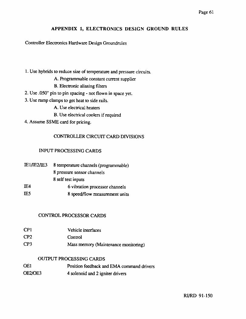
Page61
APPENDIX 1, ELECTRONICS DESIGN GROUND RULES
Controller Electronics Hardware Design Groundrules
1. Use hybrids to reduce size of temperature and pressure circuits.
A. Programmable constant current supplier
B. Electronic aliasing f'dters
2. Use .050" pin to pin spacing - not flown in space yet.
3. Use ramp clamps to get heat to side rails.
A. Use electrical heaters
B. Use electrical coolers if required
4. Assume SSME card for pricing.
CONTROLLER CIRCUIT CARD DIVISIONS
INPUT PROCESSING CARDS
IE1/IE2/IE3
IE4
IE5
8 temperature channels (programmable)
8 pressure sensor channels
8 self test inputs
6 vibration processor channels
8 speed/flow measurement units
CONTROL PROCESSOR CARDS
CP1
CP2
CP3
Vehicle interfaces
Control
Mass memory (Maintenance monitoring)
OUTPUT PROCESSING CARDS
OE1 Position feedback and EMA command drivers
OE2K)E3 4 solenoid and 2 igniter drivers
RI/RD 91-150
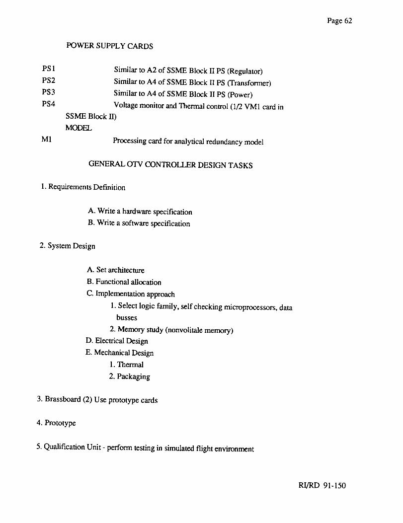
Page62
POWERSUPPLYCARDS
PS1
PS2PS3
PS4
M1
Similarto A2 of SSMEBlock II PS(Regulator)Similar to A4 of SSMEBlock IIPS (Transformer)
Similarto A4 of SSMEBlock IIPS (Power)
VoltagemonitorandThermalcontrol(1/2VM1 cardin
SSMEBlock II)MODEL
Processingcardfor analyticalredundancymodel
GENERALOTV CONTROLLERDESIGNTASKS
1.RequirementsDefinition
A. Write ahardwarespecification
B.Write asoftwarespecification
2. SystemDesign
A. Setarchitecture
B.Functionalallocation
C.Implementationapproach
1.Selectlogic family, selfcheckingmicroprocessors,databusses
2. Memorystudy(nonvolitalememory)
D. ElectricalDesign
E.MechanicalDesign1.Thermal
2.Packaging
3. Brassboard(2) Useprototypecards
4. Prototype
5.QualificationUnit - performtestingin simulatedflight environment
RI/RD 91-150
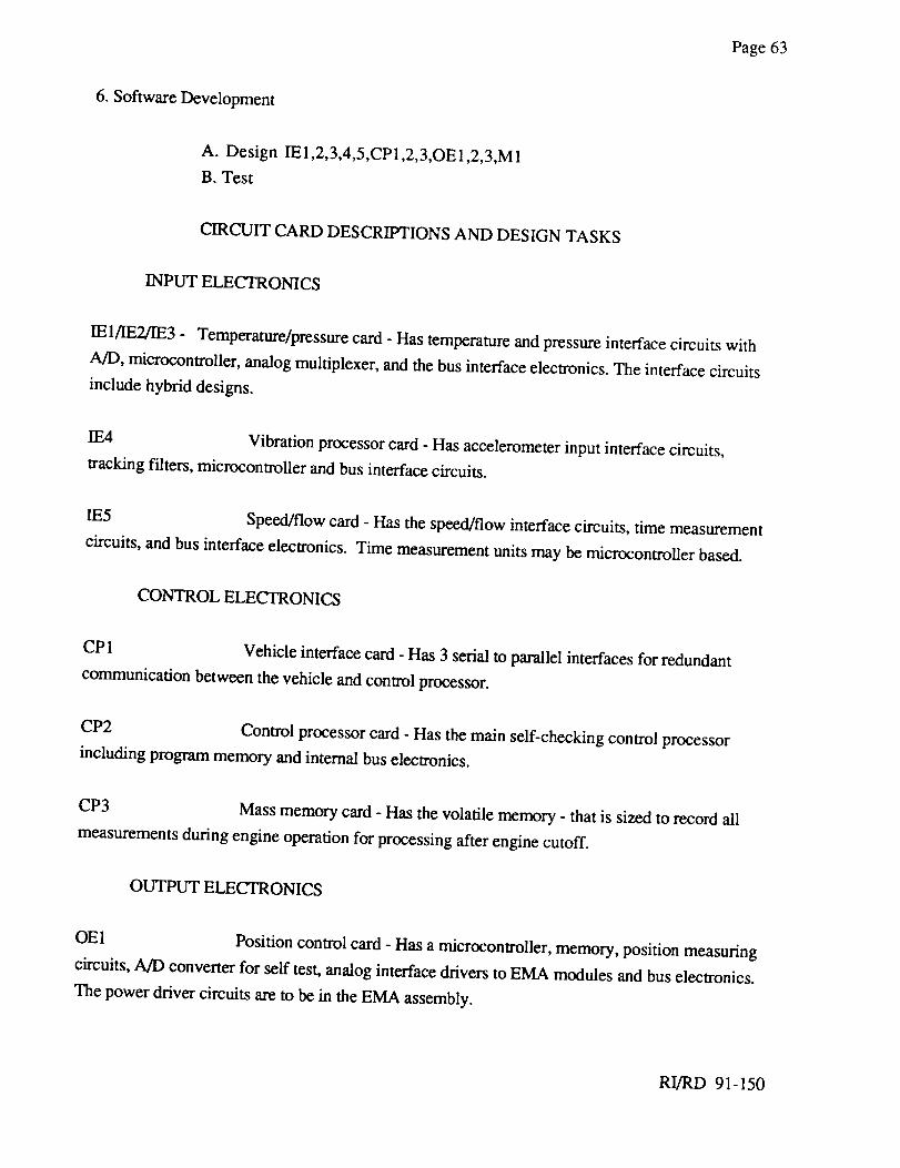
Page63
6. SoftwareDevelopment
A. Design IE1,2,3,4,5,CP1,2,3,OE1,2,3,M1B. Test
CIRCUIT CARDDESCRIPTIONSAND DESIGNTASKS
INPUT ELECTRONICS
IE1/IE2/IE3 - Temperature/pressure card - Has temperature and pressure interface circuits with
A/D, microcontroller, analog multiplexer, and the bus interface electronics. The interface circuits
include hybrid designs.
IE4 Vibration processor card - Has accelerometer input interface circuits,
tracking filters, microcontroller and bus interface circuits.
IE5 Speed/flow card - Has the speed/flow interface circuits, time measurement
circuits, and bus interface electronics. Time measurement units may be microcontroller based.
CONTROL ELECTRONICS
CP1 Vehicle interface card - Has 3 serial to parallel interfaces for redundant
communication between the vehicle and control processor.
CP2 Control processor card - Has the main self-checking control processor
including program memory and internal bus electronics.
CP3 Mass memory card - Has the volatile memory - that is sized to record all
measurements during engine operation for processing after engine cutoff.
OUTPUT ELECTRONICS
OE1 Position control card - Has a microcontroller, memory, position measuring
circuits, A/D converter for self test, analog interface drivers to EMA modules and bus electronics.
The power driver circuits are to be in the EMA assembly.
RI/RD 91-150
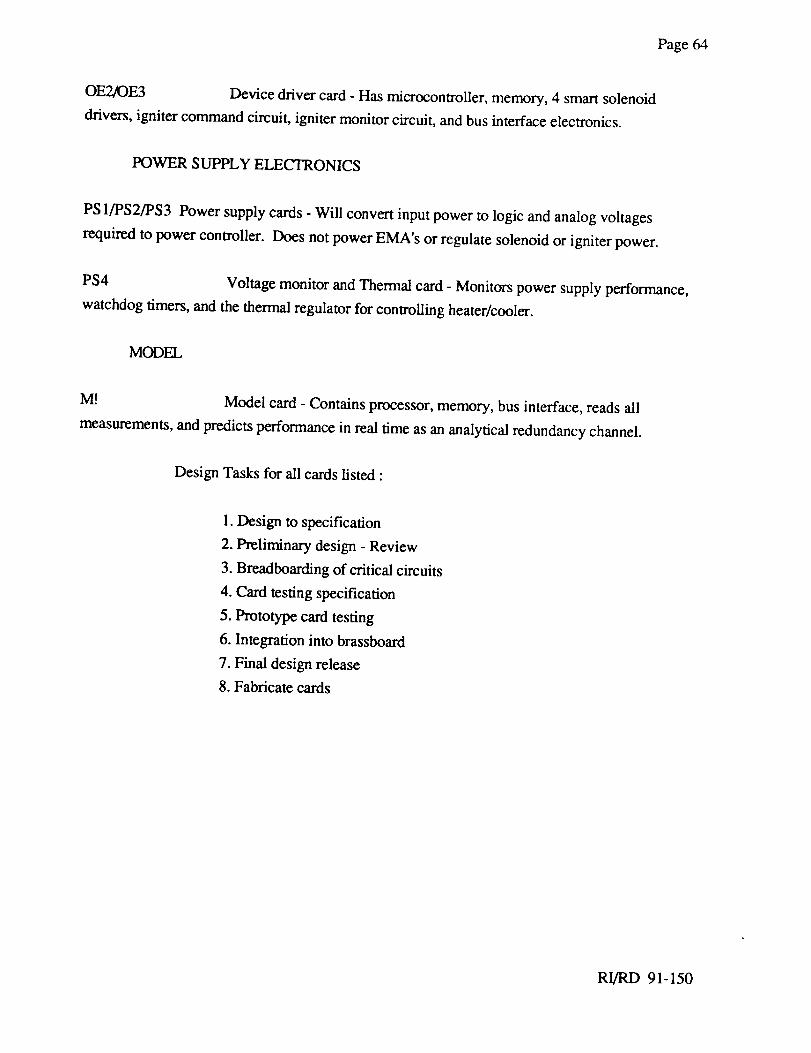
Page64
OE2/OE3 Devicedriver card- Hasrnicrocontroller,memory,4 smartsolenoid
drivers,ignitercommandcircuit, ignitermonitorcircuit,andbusinterfaceelectronics.
POWERSUPPLYELECTRONICS
PS1/PS2/PS3Powersupplycards- Will convertinputpowerto logicandanalogvoltages
requiredto powercontroller. DoesnotpowerEMA's or regulatesolenoidor igniterpower.
PS4 VoltagemonitorandThermalcard- Monitorspowersupplyperformance,
watchdogtimers,andthethermalregulatorfor controllingheater/cooler.
MODEL
M! Model card - Contains processor, memory, bus interface, reads all
measurements, and predicts performance in real time as an analytical redundancy channel.
Design Tasks for all cards listed :
1. Design to specification
2. Preliminary design - Review
3. Breadboarding of critical circuits
4. Card testing specification
5. Prototype card testing
6. Integration into brassboard
7. Final design release
8. Fabricate cards
RI/RD 91-150
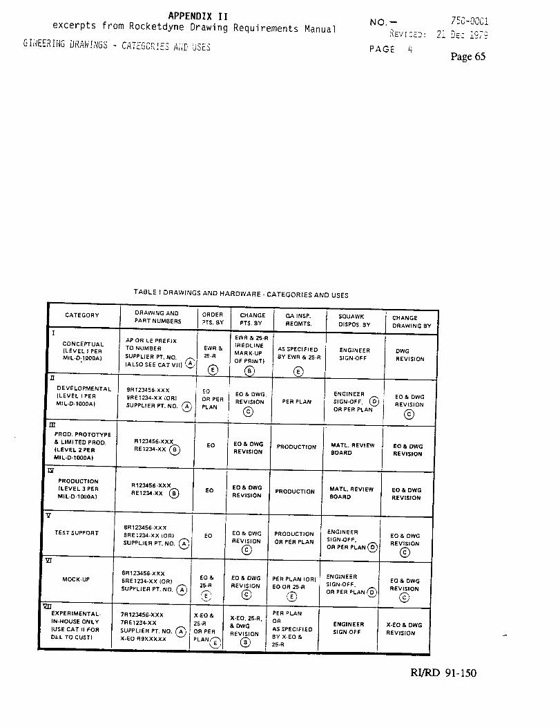
APPENDIX II
excerpts from Rocketdyne Drawing
GIiIEERIi_GDRA_[NG_ - CATEGORr_S AIVD_Sc_
Requirements ManualNO._
PAGE q
750-0001
_l DEC ___:
Page 65
TABLE t DRAWINGS AND HARDWARE - CATEGORIES AND USES
CATEGORY
I
CONCEPTUAL
(LEVELIPER
MIL,O-t0OOA,
DEVELOPMENTAL
(LEVEL I PER
MIL-D-10OOA)
rrr
PROD. PROTOTYPE
& LIMITED PROD.
(LEVEL 2 PER
MIL-D-10OOA)
"9"
PRODUCTION
(LEVEL 3 PER
MIL-D-10OOA)
TEST SUPPORT
MOCK-UP
_Z_
EXPERIMENTAL-
IN.HOUSE ONLY
IUSE CAT II FOR
DEL TO CUST)
DRAWING AND
PART NUMBERS
AP OR LE PREFIX
TO NUMBER
SUPPLIER PT. NO.
(ALSO SEE CAT VII) (,_
9R 123456-XXX
9RE 1234.XX (ORI
SUPPLIER PT. NO. ('_A)
R123456-XXX
RE 1234oXX @
R123456-XXX
RE1234-XX (_
8R 123456-XXX
l]R E 1234-XX IOR)
SUPPLIER PT. NO. (A'_
6R 123456-XXX
5RE 1234-XX (OR)
SUPPLIER PT. NO. (A_
7R 123456-XXX
7RE1234-XX
SUPPLIER PT, NO. _A'_
X-EO R9XXXXX
ORDER
PTS. BY
EO
OR PER
PLAN
EO
EO
EO
EO &
25-R
@
X-EO &
25-R
OR PER
PLAN@
CHANGE
PTS. BY
EWR & 25.R
(REDLINE
MARK*UP
OF PRINT)
EO & DWG.
REVISION
@
EO & DWG
REVISION
EO & DWG
REVISION
EO & DWG
REVISION
@
EO & DWG
REVISION
©
X-EO, 25-R,
& DWG
REVISION
®
QA INSP.
REQMTS.
AS SPECIFIED
BY EWR & 25-R
®
PER PLAN
PRODUCTION
PRODUCTION
PRODUCTION
OR PER PLAN
PER PLAN (OR)
EO OR 25-R
®PER PLAN
OR
AS SPECIFIED
BY X.EO &
25,R
SQUAWK
DISPOS. BY
ENGINEER
SIGN-OFF
ENGINEER
SIGN-OFF, @
OR PER PLAN
MATL. REVIEW
BOARD
MATL. REVIEW
BOARD
ENGINEER
SIGN-OFF.
OR PER PLAN (D_v
ENGINEER
SIGN-OFF,
OR PER PLAN _D)
ENGINEER
SIGN-OFF
CHANGE
DRAWING BY
DWG
REVISION
EO & DWG
REVISION
@
EO & DWG
REVISION
EO & DWG
REVISION
EO & DWG
REVISION
©
EO & DWG
REVISION
©
X.EO & DWG
REVISION
RI/RD 91-150
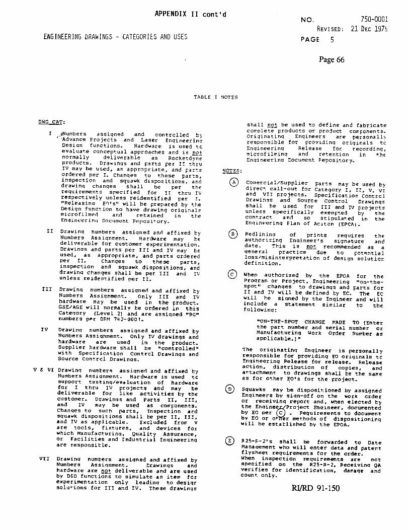
APPENDIX II cont'd
ENGINEERINGDRAWINGS - CATEGORIES AND USES
NO. 750-0001
REVISED: 21 DEC 197_-
PAGE 5
Page 66
TABLE I NOTES
DWG CAT:
I #Numbers assigned and contrclled b>
' Advance Projects and Laser Engineerina
Design functions. Hardware is used tc
evaluate conceptual approaches and is n__o_
normally deliverable as Rocketdyne
products. Drawings and Tarts _er I! :hru
IV may be used, as appropriate, and Tarts
ordered per I. Changes to these parts,
inspection and squawk dispositions, and
drawing changes shall be per the
requirements specified for II thru IV
respectively unless reidentified per !.
"Releasina EO's,, will be prepared by the
Design function to have drawing oriqinals
microfilmed and retained in the
Engineering Docllment Rui)osi_ory.
II Drawinq numbers assigned and affixed ty
Numbers Assignment. Hardware may hE
deliverable for customer experimentation.
Drawings and parts per Ill and IV may bE
used, as appropriate, and parts ordered
per If. Changes to these parts,
inspection and squawk dispositions, and
drawing changes shall be per III and !_
unless reidentified per If.
Ill Drawing numbers assigned and affixed by
Numbers Assignment. Only Ill and I_
hardware may be used in the _roduct.
GSE/AGE will normally be ordered An this
Category (Level 2) and are assigned "_G"
numbers per DFbl 7_2-0001.
IV Drawing numbers assigned and affixed by
Numbers Assignment. Only IV drawings and
hardware are used in the _roduct.
Supplier hardware shall be "controlled"
with Specification Contrcl Drawings and
source Contrcl Drawings.
V E VI Drawing numbers assigned and affixed hy
Numbers Assignment. Hardware is used tc
support testing/evaluation of hardware
for I thru IV projects and may be
deliverable for like activities by the
customer. Drawings and Parts II, III,
and IV may be used as cor_onents.
Changes to such parts, Inspection and
squawk dispositions shall _e per II, Ill,
and IV as applicable. Excluded fro_ V
are tools, fixtures, and devices for
which Manufacturing, Quality Assurance,
or Facilities and Industrial Engineering
are responsible.
VII Drawing numbers assiqned and affixed by
Numbers Assignment. Erawings and
hardware are n_o_ deliverable and are used
by DED functions to simulate an item fez
experimentation only leading to desigr
solutions for III and IV. These drawings
NOTES :
®
shall no_ be used to define and fabricate
complete products or product components.
Originating Engineers are personally
responsible for providing originals tc
Enqineerinq Release for recording,
microfilming and retention in th_
Engineering _ocument Pepository.
Comercial/Supplier parts may be used by
direct call-out for Category I, If, V, VI
and VII projects. Specification Contrcl
Drawings and Source Control Drawings
shall be used for III and IV projects
unless specifically exempted hy the
contract and so stipulated in the
Engineering Flan Of Acitcn (EPCA).
of prints requires thePedlininq
authorizing Engineer,s signature and
date. This is n_o_ recommended as a
general practice due to _otential
loss/misinterpretation of design soluticr
definition.
Q When authorized by the EPOA for the
Program or Project, Engineering "on-the-
spot" changes to drawings and _arts for
II and Iv will be defined hy EC. The EC
will he signed by the Engineer and will
include a statement similar to the
following:
"ON-THE-SPOT CHANGE MADE TO (Enter
the part number and serial number cr
Manufacturing Work Order Number as
applicable.)"
The originating Engineer is personally
responsible for providing EO originals tc
Engineering Release for release. Release
action, distribution of copies, and
a_tachment to drawings shall be the sa_e
as for other EO's for the project.
Q Squawks may be dispositioned by assigned
Engineers by sign-off on the work order
or receivinq report and, when elected by
the Enqinee/_Project Engineer, documented
by EO per [C) . peguire=ents to document
by EO or otlTer methods of dispositioning
will be established by the EPOA.
Q shall be forwarded to DateB25-F-2' S
Manaaement who will enter data and patert
flysheet requirements for the order.
When inspection requirements are nct
specified on the R25-R-2, Receivino QA
verifies for identification, damage and
count only.
RI/RD 91-150