Embed Size (px)
Citation preview
DeHavilland Park - Phases 1 & 2Drainage Strategy and Maintenance Statement
13535-CRH-ZZ-XX-RP-C-0002_DS DeHavilland Park Phase 1 & 2~Planning.doc 18
Figure 5.2: EA Updated Flood Map for Risk of Flooding from Surface Water
5.5. Groundwater Flood Risk
5.5.1. A review of the WHBC Strategic Flood Risk Assessment (SFRA) Groundwater Flood Mapindicates that the north of the site is less than 25% susceptible to groundwater floodingwhereas the east of the site is between 25% and 50% susceptible.
5.5.2. The bedrock geology of the site is Lewes Nodular Chalk Formation and Seaford Chalk Formation(undifferentiated) – Chalk and is likely permeable in nature.
5.5.3. However, the Ground Investigations undertaken by Harrison Group International in July 2021(contained in Appendix D) show a range of groundwater levels between 17.2m BGL and 19.5mBGL in boreholes BH103 and BH301 respectively.
5.5.4. Therefore, the risk of groundwater flooding is considered to be low.
5.6. Sewer Flood Risk
DeHavilland Park - Phases 1 & 2Drainage Strategy and Maintenance Statement
13535-CRH-ZZ-XX-RP-C-0002_DS DeHavilland Park Phase 1 & 2~Planning.doc 19
5.6.1. Welwyn Hatfield District Council SFRA contains a brief summary of the recorded incidents ofsewer flooding across the borough. Historic incidents of flooding are detailed by Thames Waterthrough their DG5 register. This database records incidents of flooding relating to public foul,combined or surface water sewers. According to the DG5 register no incidents of sewer floodingwere recorded within the AL7 2 postcode area.
5.6.2. The risk of sewer flooding for the proposed development is therefore deemed to be low.
5.7. Artificial Flood Risk
5.7.1. Information available from the EA for risk of inundation from reservoirs indicates that the site isat Very Low risk of flooding from this source.
5.8. Flood Risk Summary
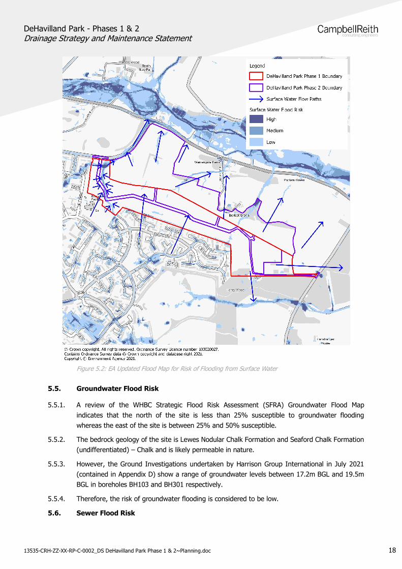
Table 5.1: Summary of existing flood risk
Flood Risk Level of Risk
Fluvial Low
Tidal Very Low
Surface Water Low
Groundwater Low
Sewer Low
Artificial Very Low
5.8. Climate Change Impact
5.8.1. Climate change must be considered as an integral part of any site specific FRA in order tominimise the impact of future flooding and allow adequate consideration for resilience toalleviate the burden on potential future users of the proposed development.
5.8.2. A upper end climate change allowance of 40% has been included for the 1 in 100 year returnperiod rainfall event.
DeHavilland Park - Phases 1 & 2Drainage Strategy and Maintenance Statement
13535-CRH-ZZ-XX-RP-C-0002_DS DeHavilland Park Phase 1 & 2~Planning.doc 20
6.0 SURFACE WATER
6.1. Overview
6.1.1. The surface water drainage system has been designed in accordance with the NPPF and theaccompanying Guidance and Technical Standards for SuDS. It also complies with therequirements under Building Regulations Part H.
6.1.2. In line with the SuDS hierarchy under paragraph 80 of the PPG, surface water should bemanaged by:
1.) Infiltration to the maximum extent that is practical – where it is safe and acceptable to doso
2.) Discharge to watercourses
3.) Discharge to surface water sewer, highway drain or another drainage system
4.) Discharge to combined sewers (last resort)
6.2. Site Constraints
6.2.1. A review of the site characteristics has informed the following site constraints:
There are a number of existing services on the site including Thames Water foul andsurface water sewers.
There are no surface water bodies or watercourses within the site boundaries.
The site generally falls from south to north, and from the high point near the centre ofthe site in an easterly and westerly direction. Due to the topography of the site and theposition of existing sewers, a number of outfall points and connections will be requiredto convey foul and surface water off the phase 1 and phase 2 sites. Thames Waterhave been engaged and discussion are ongoing on this subject.
Taking account of the proposed phased implementation of the DeHavilland Parkdevelopment, consideration must be given to conveyance of flows between differentparcels. This will ensure that the proposed drainage infrastructure can be fullyimplemented to have a complete source pathway receptor connection. Crossing pointsand ducting are to be provided where required to facilitate future parcel development.
The Mimram River north of the site is the nearest main river. However the river lieswithin third party land and attempts to engage with landowners to obtain permission toconstruct an outfall to the river have proven unsuccessful.
The presence of Chalk Dissolution limits the use of infiltration within the layout. Toachieve the specified 20m standoff from structures, areas suitable for infiltrationfeatures are therefore limited without having a detrimental impacts on the overalllayout.
6.3. Proposed Surface Water Runoff Rates
6.3.1. As previously mentioned in 4.7.4. the surface water catchment has been analysed and theGreenfield runoff rate (Qbar) calculated. The proposed discharge rates for the development areto be restricted to Qbar at 3.5 l/s/ha to best mimic current flows off the site.
DeHavilland Park - Phases 1 & 2Drainage Strategy and Maintenance Statement
13535-CRH-ZZ-XX-RP-C-0002_DS DeHavilland Park Phase 1 & 2~Planning.doc 21
6.4. Surface Water Volume
6.4.1. Surface water storage volumes for the Phase 1 Spine Road works have been calculated basedon facilitating the overall development. Development parcels are to be restricted to a maximumdischarge rate of 2l/s with future developers responsible for providing suitable attenuationwithin individual parcels. This is to discourage the reliance on ‘end of pipe’ solutions andencourage the use of source control measures within the development parcels.
6.4.2. In addition to the restricted flow to be received from developer parcels, the Phase 1 Spine Roadrepresents the majority of the surface water catchment area, the surface water volume requiredacross the Phase 1 combined infrastructure works in total is estimated to be approximately10,000m3.
6.4.3. Due to site topography, the distribution of storage volume across the site does not follow thephasing boundaries, with attenuation for areas of Phase 1 being located within Phase 2. Theprimary reason for this was to avoid then need for excessively deep or tanked attenuationfeatures with a preference for shallower surface features within the landscaped area to thenorth of the site.
6.4.4. It should be noted that no allowance has been made for urban creep as the application areaconsists of mainly new carriageway and associated infrastructure.
6.5. SuDS Strategy
6.5.1. The proposed drainage strategy layout presented in Appendix I, illustrates the SuDS featuresproposed to manage the surface water runoff from the site.
6.5.2. The surface water drainage strategy aims to control runoff from impermeable areas at sourceand attenuate through SuDS features.
6.5.3. The development is split into three catchments each discharging to different locations, and viadifferent methods. To see an overview of these catchments, please refer to the surface watercatchment (ref: 13535-CRH-XX-XX-DR-C-5070) plan presented in Appendix I which illustratesthe SuDS features proposed to manage the surface water runoff from the site.
6.5.4. Following discussions and a Flood Risk and Drainage Pre-Application meeting with HertfordshireCounty Council, it was agreed in principle to outfall Phase 1 drainage via the wider site withpermission of the landowner. This method has been pursued to maximise the use of surfaceSuDS for conveyance, and produce a more rationalised strategy. A copy of the approval letterfrom the landowner is contained in Appendix I.
6.5.5. Furthermore the approach outlined above, simplifies the delivery of the surface water strategyby providing future connection points for all future development parcel phases. This avoids theneed for returning to site in the future to facilitate development for future parcels.
6.5.6. The proposed drainage strategy for the three catchments is presented on drawings 13535-CRH-XX-XX-DR-C-5051 – 5059 contained in Appendix I.
Catchment 1
DeHavilland Park - Phases 1 & 2Drainage Strategy and Maintenance Statement
13535-CRH-ZZ-XX-RP-C-0002_DS DeHavilland Park Phase 1 & 2~Planning.doc 22
6.5.7. Catchment, located to the west of totalling a combined catchment of 5.92 hectares. Thiscatchment discharges at a controlled rate of 20l/s, a slightly lower figure than QBar’s value of20.72l/s. The network discharges to a 300mm diameter offsite sewer approximately 165m inlength, which discharges into the 900mm Thames Water surface water sewer along Herns Lane.
6.5.8. The spine road is drained via kerb openings allowing runoff to enter a shallow swale and Frenchdrain feature before entering the main surface water sewer network. This SuDS feature willprovide source control, slowing the conveyance of water into the main piped network, as wellas aid in the removal of pollutants and contaminants.
6.5.9. Flows are conveyed northward towards Herns Lane where they enter Basin 1 before dischargingat a controlled rate into the offsite sewer. Basin 1 is proposed to be an impermeable feature soas not to increase the risk to nearby dwellings and roads due to chalk dissolution. The basinconsists of a dry basin with an underlying permeable sub-base into which the pipework outfalls.Large diameter ring soakaways within the sub-base will diffuse flows into the sub-base, beforesurcharging to the surface and the basin above. The reason for this was to avoid excessivelydeep SuDs features that would present an increased Health and Safety risk to nearby roadusers and residents.
6.5.10. Catchment 1 also receives the overland flows discussed previously in section 3.9. Postdevelopment, the site levels will differ to their pre-development state, therefore overland flowswill not follow the current route. The majority of overland flows will be intercepted by the roadnetwork and contained within the kerbing, additional offline storage has been provided withinthe network to accommodate the full volume of overland flow below ground, calculated to be1859m3 during the 1 in 30 year storm event. The offline tank totalling 1900m3 will only beginsurcharging once water levels within the main basin reach flood levels. Flows will enter the tankvia a weir within manhole S1-13 set to the 1 in 100 year + 40% climate change water level.This will ensure that the offline tank will only be utilised during extreme rainfall events whenoverland flows from offsite risk overwhelming the onsite drainage and attenuation features.These flows will then be stored before discharging with flows from the site.
Catchment 2
6.5.11. Catchment 2, located across the central portion of the site totalling a combined catchment of20.51 hectares. This catchment includes areas of the proposed phase 2 development and isdischarges at a total controlled rate of 71.5l/s. The network outfalls via Phase 2 into the 900mmThames Water Surface Water trunk sewer that crosses south to north through the middle of thesite.
6.5.12. 2a - Similar to catchment 1, flows from the spine road will be intercepted by kerb drainage andallowed to enter a shallow swale and French drain located in the verge. This feature will aidpollutant and contaminant removal as well as an aspect of storage. Flows entering the Frenchdrain will then enter the main network before flowing towards Basin 2 located in the greenspace at the centre of the site. Basin 2 will also receive parcels located with Parcel 2a, each ofwhich will be restricted to 2l/s discharge into the main sewer network. Flows from Basin 2 arerestricted to 9l/s, a rate less than QBar, in order to maximise the use of the Spine Road swalesand the main attenuation basin.
6.5.13. 2b - Due to prevailing ground levels, catchment 2b located to the east near to Halifax Way willoutfall to a carrier drain that is routed to the north of Phase 2. To avoid excessively deep
DeHavilland Park - Phases 1 & 2Drainage Strategy and Maintenance Statement
13535-CRH-ZZ-XX-RP-C-0002_DS DeHavilland Park Phase 1 & 2~Planning.doc 23
drainage, it was preferred to route the connection via the lower levels to the north of the site.The landowner has also confirmed their preference for this route and approval for constructionoutside of the outline Phase 1 boundary.
6.5.14. Flows from this area will attenuated within Basin 3 before discharging at a controlled 35l/s intothe wider catchment 2 network that connects to the outfall via Phase 2. It should be noted thatCatchment 2b exceeds the QBar rate, as a proportion of the attenuation volume is providedwithin the SuDs features located within Phase 2. This option has been pursued to maximiseonline storage and the volume available in conveyance features, as well as avoid the need forexcessively deep offline SuDs features.
6.5.15. 2c – Catchment 2c includes a combination on Phase 1 and Phase 2 areas. Due to the sitetopography, level raising would have been necessary to convey flows from the northern extentsof Phase 1 into Basin 2. Following a cut/fill exercise, this would have resulted in circa 55,000m3
of additional material fill that would need to be imported to the site. The environmental cost ofthis was considered to be too high in comparison to re-locating a proportion of the attenuationvolume outside of the Phase 1 boundary.
6.5.16. Whilst no Spine Road is routed through catchment 2c, allowance has been made for the mainshared access roads within the masterplan. These roads contribute the vast majority of theflows within 2c, with individual parcels restricted to 2l/s each. Flows are conveyed northwardseither into the piped sewers, or the swales that run within the landscaping corridor along thenorth of the site.
6.5.17. Flows are restricted at a manhole to the north east of Phase 2 close to where the catchmentoutfalls in the Thames Water sewer. The discharge rate at this point is limited to 71.61l/s, theQBar total for the whole of catchment 2. This utilises the online attenuation features mostefficiently and limits the maximum water level meaning 500mm of freeboard is retained duringthe 1 in 100 + 40% climate change rainfall event.
Catchment 3
6.5.18. Catchment 3, located to the east of the site totalling a combined area of 7.66ha. The catchmentoutfalls to an infiltration basin, located within the north east of corner of the site. Due to sitetopography, it was not possible to route drainage from the eastern most areas of the sitetowards the west without excessively deep pipework, or significant level raising. The basin hasbeen located with the landscaping belt, and a minimum of 20m from the nearest dwelling in linewith the recommendations of CIRIA C574 for engineering in chalk, and the use of infiltrationfeatures in areas of chalk dissolution.
6.5.19. It is proposed to capture runoff from the spine road within sump-less gullies that will outfalldirectly into the swale that runs parallel with the spine road. The swale will be lined to preventinfiltration, with check dams every 100 metres to slow the conveyance of water and tomaximise the removal of highway pollutants. In addition to the highway, the ‘gypsy andtraveller’ (G+T) site located in the south east corner of the site will freely discharge into thisswale based on a 50% impermeable area. The reasoning for this was to avoid the need fortanks or attenuation features within the G+T site.
6.5.20. The parcels within catchment 3 will discharge into the shared infrastructure sewers at arestricted rate of 2l/s per parcel. Flows from the school will discharge into the infiltration basin
DeHavilland Park - Phases 1 & 2Drainage Strategy and Maintenance Statement
13535-CRH-ZZ-XX-RP-C-0002_DS DeHavilland Park Phase 1 & 2~Planning.doc 24
also at a restricted rate of 10l/s. It is proposed that future developers will consider their ownspecific source control and attenuation features within these allocated plots.
6.5.21. An infiltration rate of 1.28x10⁻⁵ m/second has been used in the calculations with a safety factorof 2. This is the lowest recorded figure from the 2021 Ground Investigation by HarrisonGeotechnical Engineering.
6.5.22. As an additional level of redundancy, an overflow has also been incorporated into the infiltrationbasin set to the freeboard level, 300mm below the top of bank. This overflow weir outfalls to a225mm sewer that connects to the 225mm Thames Water foul sewer that runs south to northfrom the existing development by Halifax Way. This overflow will rarely be used, andcalculations show it will remain dry during the 1 in 100 year + 40% storm event. The intentionis for the overflow to act as an early warning sign should the infiltration become less effectiveover time, or if an extreme rainfall event that exceeds the 1 in 100 year should occur.
Catchment 4
6.5.23. Catchment 4 comprises an isolated parcel located to the north west of the site. Measuring anarea of 0.34ha, QBar for this parcel would measure 1.19l/s. In line with SuDS guidance, aminimum trickle rate of 2l/s has been utilised to ensure the reliability and longevity of thenetwork. This reflects a similar approach to the development parcels for the wider site, all ofwhich have been restricted to 2l/s. The parcel lies immediately next to the 900mm diameterThames Water surface water sewer that bisects the site, a direct connection into this sewer isproposed when construction of the parcel commences. It is not proposed to facilitate aconnection for this parcel as part of the Phase 1 infrastructure works.
6.5.24. The following SuDS features have been considered within the proposed surface water drainagestrategy:
Impermeable Swales
Attenuation Basins
Infiltration Basins
Infiltration Swales
French Drains
Geocellular Attenuation Tanks
6.5.25. All non-infiltration SuDS features will be lined with an impermeable liner to prevent infiltrationinto the ground to mitigate any risks associated with chalk dissolution.
6.5.26. The proposed surface water drainage system can effectively control all runoff generated withinthe site and maintain pre-development Greenfield runoff, without increasing flood riskelsewhere.
6.5.27. The maintenance of SuDS is vital ensuring that they work as efficiently as they set out to doand is discussed in Chapter 7.
6.6. Exceedance Flow Routes
6.6.1. An exceedance flow route plan is presented in Appendix I. The proposed drainage strategyexperiences small volumes of flooding during the 1 in 100 year + 40% CC storm event. Thisflooding is limited to 7.5m3 in the worst case scenario from pipe no. 32.001 to the south east of
DeHavilland Park - Phases 1 & 2Drainage Strategy and Maintenance Statement
13535-CRH-ZZ-XX-RP-C-0002_DS DeHavilland Park Phase 1 & 2~Planning.doc 25
the site. This is due to pipe capacity, and not the volume of attenuation within the network. Inthis scenario flows will eastwards where they will enter road gullies before entering the swaleand attenuation basin.
6.6.2. Four other minor flooding events occur throughout the site during the 1 in 100 year + 40% CCstorm event. These range from 0.3m3 to 3.6m3 in this scenario flows will be routed along theroad network, contained within the kerbing before re-entering the sewer network via gullies.Flooding during the 1 in 100 year + 40% CC storm event is considered minor and will remaincontained within the kerbing and available capacity of the proposed road and sewer system.
6.6.3. In the event of storm events exceeding the 1 in 100 year + 40% CC, flows are generallydirected northward away from dwellings. Should water levels exceed the height of the kerbing,flows will follow the existing flow routes north of the site as dictated by the topography.
6.7. Surface Water Quality
6.7.1. The SuDS components within the surface water drainage strategy have been designed inaccordance with the guidance set-out in the SuDS Manual.
6.7.2. Treatment within SuDS components is essential for frequent low intensity and duration rainfallevents, where urban contaminants are being mobilised and washed off urban surfaces and theaggregated contribution to the total pollutant load to the receiving surface water body ispotentially high. For rainfall events greater than the 1 in 1 return period, the pollutants becomediluted and the environmental risks will be reduced which means that the SuDS treatmentprocess becomes less crucial. Treatment effectiveness is strongly linked to the hydraulic controlof runoff, in particular velocity control and retention time.
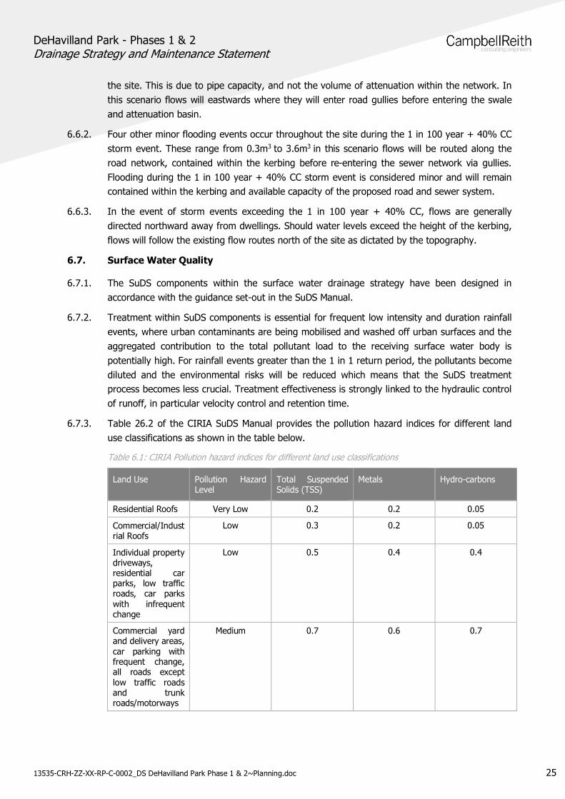
6.7.3. Table 26.2 of the CIRIA SuDS Manual provides the pollution hazard indices for different landuse classifications as shown in the table below.
Table 6.1: CIRIA Pollution hazard indices for different land use classifications
Land Use Pollution HazardLevel
Total SuspendedSolids (TSS)
Metals Hydro-carbons
Residential Roofs Very Low 0.2 0.2 0.05
Commercial/Industrial Roofs
Low 0.3 0.2 0.05
Individual propertydriveways,residential carparks, low trafficroads, car parkswith infrequentchange
Low 0.5 0.4 0.4
Commercial yardand delivery areas,car parking withfrequent change,all roads exceptlow traffic roadsand trunkroads/motorways
Medium 0.7 0.6 0.7
DeHavilland Park - Phases 1 & 2Drainage Strategy and Maintenance Statement
13535-CRH-ZZ-XX-RP-C-0002_DS DeHavilland Park Phase 1 & 2~Planning.doc 26
6.7.4. The level of pollution for the site can be classified medium due to the runoff being primarilyhighway drainage and the high number of vehicles expected to use the spine road.
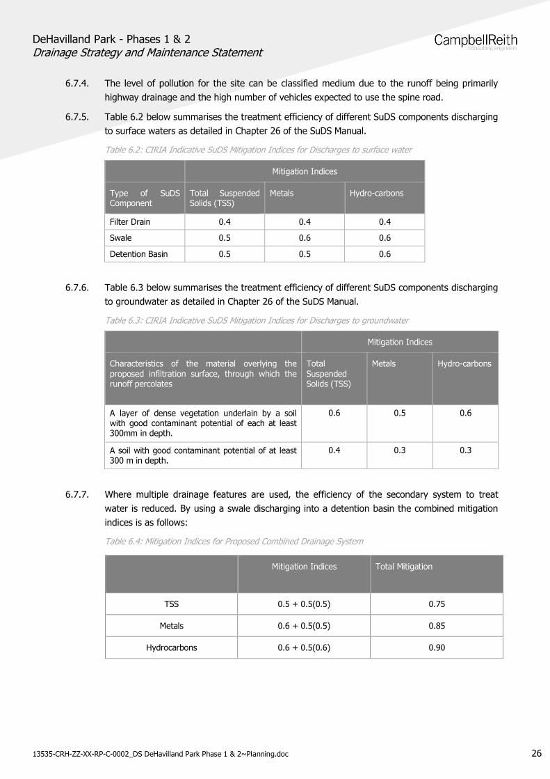
6.7.5. Table 6.2 below summarises the treatment efficiency of different SuDS components dischargingto surface waters as detailed in Chapter 26 of the SuDS Manual.
Table 6.2: CIRIA Indicative SuDS Mitigation Indices for Discharges to surface water
Mitigation Indices
Type of SuDSComponent
Total SuspendedSolids (TSS)
Metals Hydro-carbons
Filter Drain 0.4 0.4 0.4
Swale 0.5 0.6 0.6
Detention Basin 0.5 0.5 0.6
6.7.6. Table 6.3 below summarises the treatment efficiency of different SuDS components dischargingto groundwater as detailed in Chapter 26 of the SuDS Manual.
Table 6.3: CIRIA Indicative SuDS Mitigation Indices for Discharges to groundwater
Mitigation Indices
Characteristics of the material overlying theproposed infiltration surface, through which therunoff percolates
TotalSuspendedSolids (TSS)
Metals Hydro-carbons
A layer of dense vegetation underlain by a soilwith good contaminant potential of each at least300mm in depth.
0.6 0.5 0.6
A soil with good contaminant potential of at least300 m in depth.
0.4 0.3 0.3
6.7.7. Where multiple drainage features are used, the efficiency of the secondary system to treatwater is reduced. By using a swale discharging into a detention basin the combined mitigationindices is as follows:
Table 6.4: Mitigation Indices for Proposed Combined Drainage System
Mitigation Indices Total Mitigation
TSS 0.5 + 0.5(0.5) 0.75
Metals 0.6 + 0.5(0.5) 0.85
Hydrocarbons 0.6 + 0.5(0.6) 0.90
DeHavilland Park - Phases 1 & 2Drainage Strategy and Maintenance Statement
13535-CRH-ZZ-XX-RP-C-0002_DS DeHavilland Park Phase 1 & 2~Planning.doc 27
6.8. Foul Water Strategy
6.8.1. The National Planning Guidance and Building Regulations Approved Document H provide ahierarchy of drainage options which must be considered and subsequently discounted in thefollowing order:
Connection to the public sewer
Package Treatment Plant
Septic Tank
Cesspool
Given the size of the development and close proximity to a number of public sewers aconnection to the public sewer is considered the only viable option.
6.8.2. A number of new connections will be made to a number of different public sewers in order toprovide the most economical foul drainage solution for the proposed development when takinginto account all current known site constraints.
6.8.3. As noted in Section 4.7, the incumbent foul drainage provider is Thames Water.
6.8.4. Sewer records indicate that there are two sewers running adjacent to the north western siteboundary (300/375mm dia) and one sewer running across the south eastern part of the site(225mm dia).
6.8.5. It is proposed to split the site foul water drainage into four catchments and make four separateconnections to the public sewers. Two of the connections will be made to the 300 and 375mmdiameter sewers to the North West with the remaining two connections being made to the225mm diameter sewer running through the south eastern part of the site.
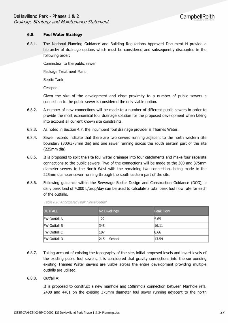
6.8.6. Following guidance within the Sewerage Sector Design and Construction Guidance (DCG), adaily peak load of 4,000 L/prop/day can be used to calculate a total peak foul flow rate for eachof the outfalls.
Table 6.6: Anticipated Peak Flows/Outfall
OUTFALL No Dwellings Peak Flow
FW Outfall A 122 5.65
FW Outfall B 348 16.11
FW Outfall C 187 8.66
FW Outfall D 215 + School 13.54
6.8.7. Taking account of existing the topography of the site, initial proposed levels and invert levels ofthe existing public foul sewers, it is considered that gravity connections into the surroundingexisting Thames Water sewers are viable across the entire development providing multipleoutfalls are utilised.
6.8.8. Outfall A:
It is proposed to construct a new manhole and 150mmdia connection between Manhole refs.2408 and 4401 on the existing 375mm diameter foul sewer running adjacent to the north
DeHavilland Park - Phases 1 & 2Drainage Strategy and Maintenance Statement
13535-CRH-ZZ-XX-RP-C-0002_DS DeHavilland Park Phase 1 & 2~Planning.doc 28
western site boundary. The new network will serve circa 122 residential properties throughoutPhase B of the development located within the western part of the site.
6.8.9. Outfall B:
Outfall B comprises of a new 300mm diameter connection into existing manhole ref. 5403located on the existing 300mm diameter foul sewer running adjacent to the north western siteboundary. This new network will eventually serve both Phase 1 and Phase 2 of the proposeddevelopment. The new network will serve circa 348 residential properties and a care homeacross Phases B, D and the north western part of Phase E which are located within the northernand central part of the site.
6.8.10. Outfall C
Outfall C comprises a new 225mm diameter connection into an existing Thames Water manholeat approx. grid ref. 527363, 213123 located on the existing 225mm diameter sewer runningthrough the south eastern part of the site. This network will take flows to the west of theexisting 225mm diameter sewer from the southern and eastern areas of Phase E. In totalOutfall C will serve circa 187 residential properties.
6.8.11. Outfall D
Outfall D comprises a new 225mm diameter connection into an existing Thames Water manholeat approx. grid ref. 527313, 213085 located on the existing 225mm diameter sewer runningthrough the south eastern part of the site. The new pipe takes flows from the east of theexisting sewer from phase F, a proposed school and traveller settlement. In total Outfall D willserve circa 215 residential properties along with a school (proposed occupancy 420 pupils) andtraveller settlement (comprising 12no. caravan/mobile homes).
6.8.12. CampbellReith drawings 13535-CRH-XX-XX-DR-C-5051-5059 located in Appendix I providesfurther details of the foul drainage strategy across both phases of the development.
6.8.13. The proposed new connections to the public sewer will all be subject to a Section 106agreement which will need to be entered into with Thames Water.
6.8.14. Following changes brought by Ofwat, where the proposed development site can communicatedirectly to an existing public sewer system at no more than the existing pipe diameter, there isno requirement to undertake any capacity survey and the proposed new connection would besubject to the infrastructure charges.
6.8.15. Thames Water publishes their revised infrastructure charges annually and this would have to beagreed with Thames Water at the time of the application, together with the proposeddevelopment delivery schedule.
6.8.16. The DeHavilland Park development is to be phased over a number of years and therefore not allareas will require drainage provision immediately. The main spine road through the site locatedwithin Phase 1 will be constructed prior to the surrounding development parcels. Constructionwill generally begin at the western end of the development within Phases B and D and with theexception of the school (located at the far eastern end of the spine road) will progress fromwest to east. Construction of Phases E and F in the western part of the site will commencetowards the completion of Phases B and D. It is assumed that individual development parcelswill follow once the main infrastructure in the respective phases is complete.
DeHavilland Park - Phases 1 & 2Drainage Strategy and Maintenance Statement
13535-CRH-ZZ-XX-RP-C-0002_DS DeHavilland Park Phase 1 & 2~Planning.doc 29
6.8.17. As each parcel/area comes online, the required downstream drainage infrastructure must be inplace to receive the foul flows. The installation of the foul water infrastructure is to becoordinated with Thames Water to enable any reinforcement works required to the public seweras a result of the new development to be undertaken in advance of the new on site drainagecoming online.
6.8.18. Following completion it is proposed that the foul drainage will be adopted under a Section 104agreement and as such the future ownership and maintenance responsibility will be with theStatutory Drainage Undertaker.
The foul water strategy and calculations are presented in the Proposed Drainage Strategy and iscontained in Appendix I.
DeHavilland Park - Phases 1 & 2Drainage Strategy and Maintenance Statement
13535-CRH-ZZ-XX-RP-C-0002_DS DeHavilland Park Phase 1 & 2~Planning.doc 30
7.0 SCHEDULE OF MAINTENANCE
7.1. Introduction
7.1.1. The maintenance of SuDS features is vital ensuring that they work as efficiently as they set outto do. Maintenance activities can be broadly defined as:
Regular maintenance – basic tasks carried out regularly;
Occasional maintenance – tasks that are required periodically but on a much lessfrequent basis; and
Remedial maintenance – tasks required when a fault needs rectifying and often includesunforeseen events.
7.1.2. Subject to formal agreement with Thames Water, the surface water network is to be offered foradoption under Section 104 agreement up to and including the outfalls into the attenuationbasins and swales. The below ground SuDs components (not including any on plot devices)including gullies, French drains, and connecting pipework will be offered for adoption by theHighway Authority under Section 38 agreement. Regular inspection of drainage assets will beresponsibility of the Highway Authority and Thames Water.
7.1.3. The basins, swales, outfalls and flow control devices will be maintained by Homes England ortheir approved Maintenance Agent.
7.1.4. The foul drainage will be offered for adoption to Thames Water under Section 104 agreement.
7.1.5. During construction, it is the responsibility of the Principal Contractor to ensure the relevantmanagement and maintenance requirements outlined below are implemented. The principalcontractor will retain responsibility during construction up to the handing over.
7.1.6. Maintenance requirements for each SuDS feature has been outlined below.
7.2. Filter Drains
Construction
7.2.1. During construction it is important to prevent muddy water from flowing into the system. Wherepossible, construction should be undertaken during dry periods. The filter drains should beconstructed with adequate fall to ensure the area drains efficiently. During construction thecontractor must ensure the designed width and depth are correct and the geotextile has thespecified porosity.
Maintenance Schedule
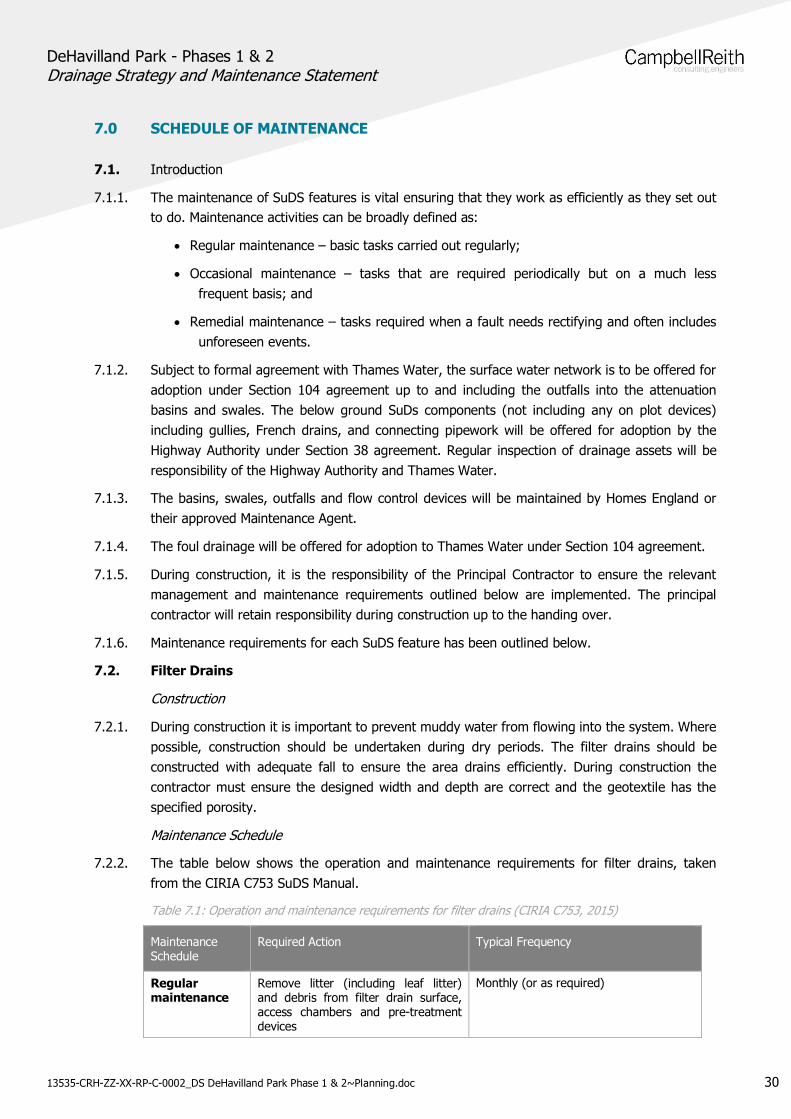
7.2.2. The table below shows the operation and maintenance requirements for filter drains, takenfrom the CIRIA C753 SuDS Manual.
Table 7.1: Operation and maintenance requirements for filter drains (CIRIA C753, 2015)
MaintenanceSchedule
Required Action Typical Frequency
Regularmaintenance
Remove litter (including leaf litter)and debris from filter drain surface,access chambers and pre-treatmentdevices
Monthly (or as required)
DeHavilland Park - Phases 1 & 2Drainage Strategy and Maintenance Statement
13535-CRH-ZZ-XX-RP-C-0002_DS DeHavilland Park Phase 1 & 2~Planning.doc 31
Inspect filter drain surface, inlet/outletpipework and control systems forblockages, clogging, standing waterand structural damage.
Monthly
Inspect pre-treatment systems, inletsand perforated pipework for siltaccumulation, and establishappropriate silt removal frequencies
Six monthly
Remove sediment from pre-treatmentdevices
Six monthly, or as required
Occasionalmaintenance
Remove or control tree roots whenthey are encroaching the sides of thefilter drain, using recommendedmethods (egg NJUG, 2007 or BS3998:2010)
As required
Clear perforate pipework or blockages As required
7.3. Swales
Construction
7.3.1. Construction vehicles and equipment not directly involved in the construction of the rills andswales should be kept away from these areas. Excavations for the swales should aim to beundertaken in times of dry weather, when possible, to prevent mobilisation of sediments fromexposed surfaces. Exposed surfaces after rill or swale excavations should be stabilised as soonas possible with grass seed and straw mulch. Perimeter controls should be installed prior toconstruction to protect watercourses.
Maintenance Schedule
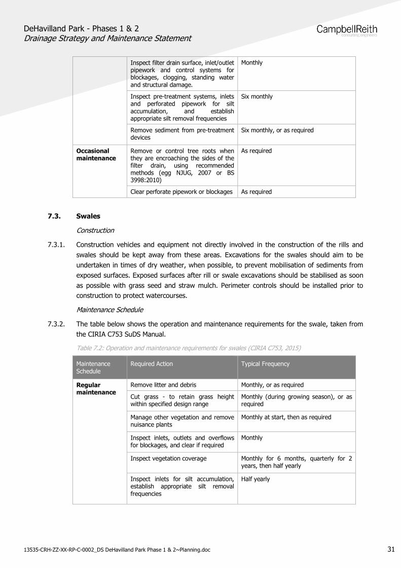
7.3.2. The table below shows the operation and maintenance requirements for the swale, taken fromthe CIRIA C753 SuDS Manual.
Table 7.2: Operation and maintenance requirements for swales (CIRIA C753, 2015)
MaintenanceSchedule
Required Action Typical Frequency
Regularmaintenance
Remove litter and debris Monthly, or as required
Cut grass - to retain grass heightwithin specified design range
Monthly (during growing season), or asrequired
Manage other vegetation and removenuisance plants
Monthly at start, then as required
Inspect inlets, outlets and overflowsfor blockages, and clear if required
Monthly
Inspect vegetation coverage Monthly for 6 months, quarterly for 2years, then half yearly
Inspect inlets for silt accumulation,establish appropriate silt removalfrequencies
Half yearly
DeHavilland Park - Phases 1 & 2Drainage Strategy and Maintenance Statement
13535-CRH-ZZ-XX-RP-C-0002_DS DeHavilland Park Phase 1 & 2~Planning.doc 32
Inspect check dams for blockages andfailure.
Half yearly
Occasionalmaintenance
Reseed areas of poor vegetationgrowth, alter plant types to better suitconditions, if required
As required or if bare soil is exposedover 10% or more of the swaletreatment area
Remedialactions
Repair erosion or other damage by re-turning or reseeding
As required
Relevel uneven surfaces and reinstatedesign levels
As required
Remove and dispose of oils or petrolresidues using safe standard practices
As required
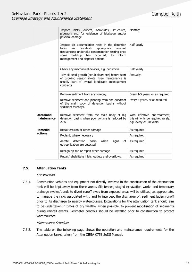
7.4. Detention Basins
Construction
7.4.1. Construction vehicles and equipment not directly involved in the construction of the detentionbasin will be kept away from these areas. Silt fences, staged excavation works and temporarydrainage swales/bunds to divert runoff away from exposed areas will be utilised, as appropriate,to manage the risks associated with, and to intercept the discharge of, sediment laden runoffprior to its discharge to nearby watercourses. Excavations for the detention basin should aim tobe undertaken in times of dry weather when possible, to prevent mobilisation of sediments,during rainfall events. Surfaces exposed as part of the detention basin construction should bestabilised as soon as possible, by the use of hydroseeding or an alternative approved approach.Perimeter controls should be installed prior to construction to protect watercourses. Perimetercontrols should be installed prior to construction to protect watercourses.
Maintenance Schedule
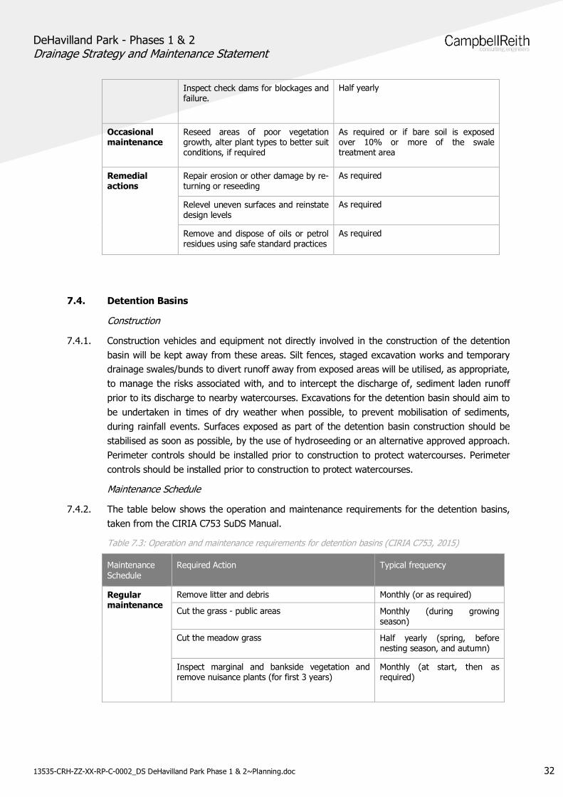
7.4.2. The table below shows the operation and maintenance requirements for the detention basins,taken from the CIRIA C753 SuDS Manual.
Table 7.3: Operation and maintenance requirements for detention basins (CIRIA C753, 2015)
MaintenanceSchedule
Required Action Typical frequency
Regularmaintenance
Remove litter and debris Monthly (or as required)
Cut the grass - public areas Monthly (during growingseason)
Cut the meadow grass Half yearly (spring, beforenesting season, and autumn)
Inspect marginal and bankside vegetation andremove nuisance plants (for first 3 years)
Monthly (at start, then asrequired)
DeHavilland Park - Phases 1 & 2Drainage Strategy and Maintenance Statement
13535-CRH-ZZ-XX-RP-C-0002_DS DeHavilland Park Phase 1 & 2~Planning.doc 33
Inspect inlets, outlets, banksides, structures,pipework etc. for evidence of blockage and/orphysical damage
Monthly
Inspect silt accumulation rates in the detentionbasin and establish appropriate removalfrequencies; undertake contamination testing oncesome build-up has occurred, to informmanagement and disposal options
Half yearly
Check any mechanical devices, e.g. penstocks Half yearly
Tidy all dead growth (scrub clearance) before startof growing season (Note: tree maintenance isusually part of overall landscape managementcontract)
Annually
Remove sediment from any forebay. Every 1-5 years, or as required
Remove sediment and planting from one quadrantof the main body of detention basins withoutsediment forebays.
Every 5 years, or as required
Occasionalmaintenance
Remove sediment from the main body of bigdetention basins when pool volume is reduced by20%
With effective pre-treatment,this will only be required rarely,e.g. every 25-50 years
Remedialactions
Repair erosion or other damage As required
Replant, where necessary As required
Aerate detention basin when signs ofeutrophication are detected
As required
Realign rip-rap or repair other damage As required
Repair/rehabilitate inlets, outlets and overflows. As required
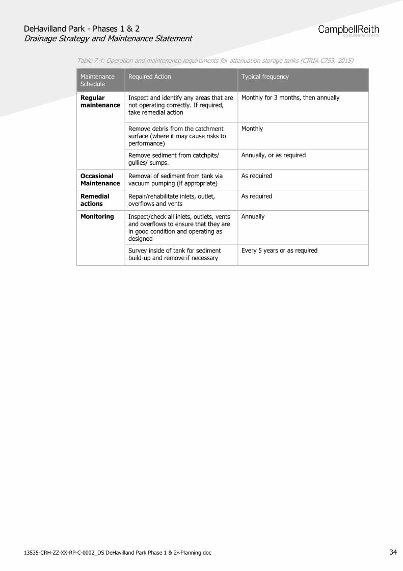
7.5. Attenuation Tanks
Construction
7.5.1. Construction vehicles and equipment not directly involved in the construction of the attenuationtank will be kept away from these areas. Silt fences, staged excavation works and temporarydrainage swales/bunds to divert runoff away from exposed areas will be utilised, as appropriate,to manage the risks associated with, and to intercept the discharge of, sediment laden runoffprior to its discharge to nearby watercourses. Excavations for the attenuation tank should aimto be undertaken in times of dry weather when possible, to prevent mobilisation of sedimentsduring rainfall events. Perimeter controls should be installed prior to construction to protectwatercourses.
Maintenance Schedule
7.5.2. The table on the following page shows the operation and maintenance requirements for theAttenuation tanks, taken from the CIRIA C753 SuDS Manual.
DeHavilland Park - Phases 1 & 2Drainage Strategy and Maintenance Statement
13535-CRH-ZZ-XX-RP-C-0002_DS DeHavilland Park Phase 1 & 2~Planning.doc 34
Table 7.4: Operation and maintenance requirements for attenuation storage tanks (CIRIA C753, 2015)
MaintenanceSchedule
Required Action Typical frequency
Regularmaintenance
Inspect and identify any areas that arenot operating correctly. If required,take remedial action
Monthly for 3 months, then annually
Remove debris from the catchmentsurface (where it may cause risks toperformance)
Monthly
Remove sediment from catchpits/gullies/ sumps.
Annually, or as required
OccasionalMaintenance
Removal of sediment from tank viavacuum pumping (if appropriate)
As required
Remedialactions
Repair/rehabilitate inlets, outlet,overflows and vents
As required
Monitoring Inspect/check all inlets, outlets, ventsand overflows to ensure that they arein good condition and operating asdesigned
Annually
Survey inside of tank for sedimentbuild-up and remove if necessary
Every 5 years or as required
DeHavilland Park - Phases 1 & 2Drainage Strategy and Maintenance Statement
13535-CRH-ZZ-XX-RP-C-0002_DS DeHavilland Park Phase 1 & 2~Planning.doc 35
8.0 CONCLUSION
7.5.3. The CampbellReith has prepared this drainage strategy and maintenance statement in supportof an application for reserved matters for Phase 1 and outline planning application for Phase 2of the proposed DeHavilland Park development. The extant Planning Permission refers to OPADevelopment under 6/2018/0873/OUTLNE. This statement has been based on the approvedFlood Risk Assessment and addendum reports produced by Price & Myers.
7.5.4. The topographical survey has shown the site to be relatively flat with a general fall from southto north, towards the River Mimram beyond the northern boundary of the site.
7.5.5. The Environment Agency Flood Maps for Planning (Rivers and Seas) indicates that the site islocated within Flood Zone 1 (Low Risk) with a 0.1% chance of flooding from rivers (fluvialflooding) or the sea (tidal flooding) in any given year.
7.5.6. The Environment Agency Risk of Surface Water Flood Maps show that the site is generally atvery low risk of surface water flooding. However there are some small areas on the site that areat an increased surface water flood risk. Overall, the existing risk of surface water flooding isconsidered low.
7.5.7. The British geological Survey Online Geology Viewer notes the underlying bedrock of the site asLewes Nodular Chalk Formation and Seaford Chalk Formation (undifferentiated) – Chalk andnotes the superficial deposits as Kesgrave Catchment Subgroup - Sand And Gravel. This wasconfirmed by ground investigations performed in July 2021 by Harrison GeotechnicalEngineering.
7.5.8. Infiltration testing undertaken to BRE 365 has confirmed that infiltration as a method of surfacewater discharge is viable for the majority of the site. However the GI identified ChalkDissolution throughout the site, therefore in line CIRIA C574, all point infiltration featuresshould observe a minimum standoff of 20m from any dwelling.
7.5.9. Surface water runoff from the proposed development can be efficiently managed onsite. Theproposed surface water discharge will be limited to Qbar, including a 40% allowance for climatechange. Surface water runoff from the development will be discharged to three locations, theexisting Thames Water sewer along the B1000, the existing Thames Water sewer passingthrough the centre site and via infiltration.
7.5.10. The proposed surface water drainage strategy incorporates Sustainable Drainage Systems,including swales and infiltration basins. In accordance with CIRIA Pollution Hazard Indices, theproposed development is considered to be medium risk, the proposed SuDs features areconsidered to provide an effective level of treatment of pollutants for the proposed nature ofthe development.
7.5.11. As approved in the Price & Myers Drainage Strategy, the existing overland flow that crosses thewestern extent of the site is to be attenuated within the surface water network. An offline1900m3 geocellular attenuation tank will begin filling once, water levels within the developmentreach a level that risks surface flooding.
7.5.12. The foul water sewers for the development will be conveyed under gravity to a four outfalls thatdischarge into the existing Thames Water foul sewers.
DeHavilland Park - Phases 1 & 2Drainage Strategy and Maintenance Statement
13535-CRH-ZZ-XX-RP-C-0002_DS DeHavilland Park Phase 1 & 2~Planning.doc 36
7.5.13. The proposed development can be drained effectively for all storm return periods includingclimate change and does not affect flood risk outside of the site.
The proposed drainage system to service the application site is in accordance with the approvedstrategy set under Price & Myers Flood Risk Assessment. The proposed drainage systemeffectively caters for all rainfall events up to and including the 1 in 100 year storm event plusclimate change allowance without any increase in flood risk elsewhere.
DeHavilland Park - Phase 1Drainage Strategy and Maintenance Statement
13535-CRH-ZZ-XX-RP-C-0002_DS DeHavilland Park Phase 1 & 2~Planning.doc Appendix
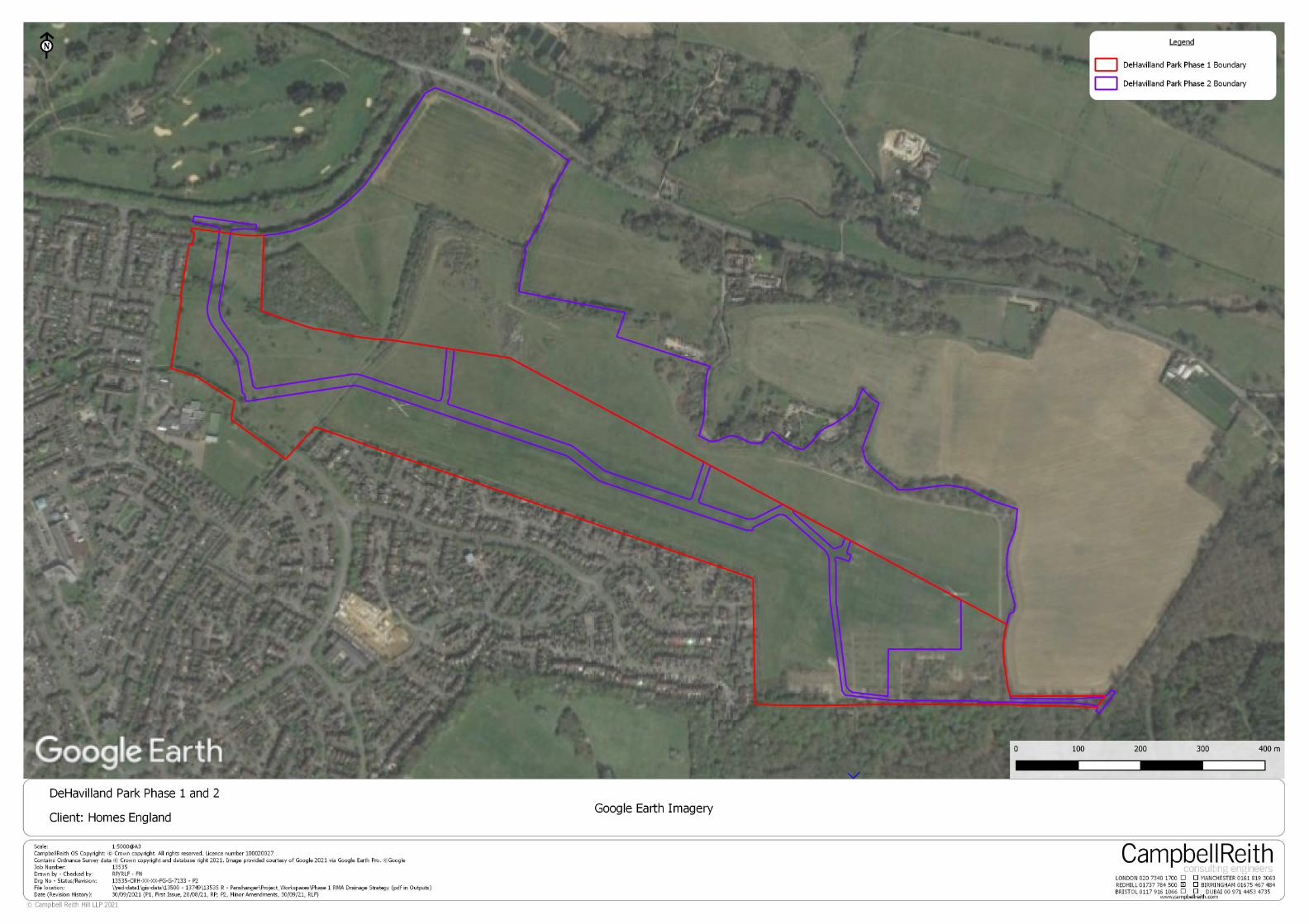
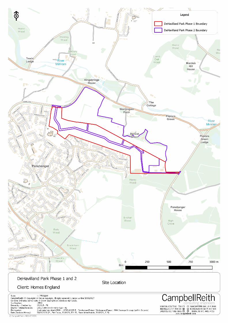
Appendix A: Site Location
13535-CRH-XX-XX-FG-G-706013535-CRH-XX-XX-FG-G-7133
DeHavilland Park - Phase 1Drainage Strategy and Maintenance Statement
13535-CRH-ZZ-XX-RP-C-0002_DS DeHavilland Park Phase 1 & 2~Planning.doc Appendix
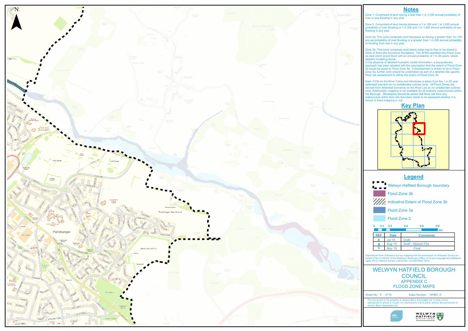
Appendix B: SFRA Map Extracts
Flood Zone MapSurface water Flood MapGroundwater Flood Map
¯
WELWYN HATFIELD BOROUGHCOUNCILAPPENDIX C
FLOOD ZONE MAPS
This document is the property of Jeremy Benn Associates Ltd. It shall not bereproduced in whole or in part, nor disclosed to a third party, without the permission ofJeremy Benn Associates Ltd.
Sheet No: Index Number:
Legend
Key Plan
Notes
WHBC_6 of 16
Zone 1: Comprised of land having a less than 1 in 1,000 annual probability ofriver or sea flooding in any year.Zone 2: Comprised of land having between a 1 in 100 and 1 in 1,000 annualprobability of river flooding or 1 in 200 and 1 in 1,000 annual probability of seaflooding in any year.Zone 3a: This zone comprises land assessed as having a greater than 1in 100annual probability of river flooding or a greater than 1 in 200 annual probabilityof flooding from sea in any year.Zone 3b: This zone comprises land where water has to flow or be stored intimes of flood (the functional floodplain). The SFRA identified this Flood Zoneas land which would flood with an annual probability of 1 in 20 years, wheredetailed modelling exists.In the absence of detailed hydraulic model information, a precautionaryapproach has been adopted with the assumption that the extent of Flood Zone3b would be equal to Flood Zone 3a. If development is shown to be in FloodZone 3a, further work should be undertaken as part of a detailed site specificflood risk assessment to define the extent of Flood Zone 3b.Note: FZ3b on the River Colne and tributaries is taken from the 1 in 20 yeardefended scenario as no undefended outlines exist. All Flood Zones arederived from defended scenarios on the River Lee as no undefended outlinesexist. Additionally, mapping is not available for all ordinary watercourses withinthe Borough. Developers should be aware that flood risk from anywatercourse within their site boundary needs to be assessed whether it isshown in flood mapping or not.
Welwyn Hatfield Borough boundaryFlood Zone 3bIndicative Extent of Flood Zone 3bFlood Zone 3aFlood Zone 2
0 0.2 0.4 0.6 0.80.1km
CommentsDateREFDraftJul 15A
BC
Reproduced from Ordnance Survey mapping with the permission of Ordnance Survey on behalf of the Controller of Her Majesty's Stationary Office. © Crown copyright and database rights 2015 Ordance Survey Licence No. LA100019547 2015.
6
Draft - Altered FZsAug 15FinalNov 15