Embed Size (px)
Citation preview
®
Dell® Hardware Instrumentation Package v2.2
for Intel® LANDesk
® Server Manager 2.52
User’s Guide
Information in this document is subject to change without notice.
© 1994-1997 Dell Computer Corporation. All rights reserved.
Reproduction in any manner whatsoever without the written permission of Dell Computer Corporation is strictly forbidden.
Trademarks used in this text: Dell, the DELL logo, and PowerEdge are registered trademarks of Dell Computer Corporation; Novell and NetWare are registered trademarks of Novell, Inc.; Microsoft, Windows, and Windows NT are registered trademarks of Microsoft Corporation; Intel and LANDesk are registered trademarks of Intel Corporation.
Other trademarks and trade names may be used in this document to refer to either the entities claiming the marks and names or their products. Dell Computer Corporation disclaims any proprietary interest in trademarks and trade names other than its own.
April 1997 P/N 89616
Preface
to
.
d ur
tes
u-
-
About This GuideThis guide is intended for anyone who uses version 2.2 or higher of the Dell Hardware Instrumentation Package (HIP) server management application program. It can be used by both new and experienced users who want to learn about the HIP features, installation, and operation. The chapters and appendixes are summarized as follows:
• Chapter 1, “Introduction,” gives an overview of the product’s features and provides information on obtaining technical assistance.
• Chapter 2, “Installation and Upgrade Procedures,” lists system requirements and provides software installation and upgrade procedures.
• Chapter 3, “Using the Dell HIP,” describes how to access and use the Dell HIP and configure HIP alert actions. It also provides an introduction to the pro-gram’s online help, your main source of information on how to use Dell HIP icons, menus, and screens.
• Appendix A, “Dell HIP Messages” contains a com-plete listing of alert log and system messages and suggests corrective actions where possible.
• Appendix B, “Adaptec and APC Component Instru-mentation,” contains a listing of the Adaptec small computer system interface (SCSI) and American Power Conversion (APC) uninterruptible power sup-ply (UPS) instrumentation available in the Dell HIP installation.
• Appendix C, “DMI-SNMP Translator,” describes the translator that is used to integrate Desktop Manage-ment Interface (DMI) management with Simple Network Management Protocol (SNMP).
• The Glossary provides definitions of terms, acro-nyms, and abbreviations used in this guide.
Other Documents You May NeedIn addition to this User’s Guide and your Intel LANDesk Server Manager documentation, you may need to referthe following Dell documentation:
• Your system User’s Guide or Installation and Troubleshooting Guide provides an overview of system features, hardware installation guidelines, and safety information that may be useful when installing the Dell HIP.
• The Diagnostics and Troubleshooting Guide or Installation and Troubleshooting Guide includes troubleshooting procedures and instructions for using the diagnostics to test your computer system
NOTE: Documentation updates are sometimes includewith your system or software to describe changes to yosystem or software. Always read these updates before consulting any other documentation because the updaoften contain the latest information.
You may also have one or more of the following documents:
• Operating system documentation is included if youordered your operating system from Dell. This docmentation describes how to install (if necessary), configure, and use your operating system.
• Documentation is included with any options you purchase separately from your system. This docu-mentation includes information that you need to configure and install these options in your Dell computer. Installation instructions for most options available from Dell are included in your Dell docu-mentation—your system User’s Guide or Installation and Troubleshooting Guide. However, to install some options, you may need to refer to accompanying documentation from the option manufacturer.
v
r-ed
w
e ti-
ld.
nt.
a
• Technical information files—usually called “readme” files—may be provided on your installa-tion CD to provide last-minute updates about technical changes to your system or advanced tech-nical reference material intended for experienced users or technicians.
Notational ConventionsThe following subsections list notational conventions used in this document.
Warnings, Cautions, and NotesThroughout this guide, there may be blocks of text printed in bold type within boxes or in italic type. These blocks are warnings, cautions, and notes, and they are used as follows:
NOTE: A NOTE indicates important information that helps you make better use of your computer system.
Typographical ConventionsThe following list defines (where appropriate) and illus-trates typographical conventions used as visual cues for specific elements of text throughout this document:
• Keycaps, the labeling that appears on the keys on a keyboard, are enclosed in angle brackets.
Example: <Enter>
• Key combinations are series of keys to be pressed simultaneously (unless otherwise indicated) to per-form a single function.
Example: <Ctrl><Alt><Enter>
• Commands presented in lowercase bold are for refeence purposes only and are not intended to be typwhen referenced.
Example: “Use the format command to . . . .”
In contrast, commands presented in the Courier Nefont are part of an instruction and intended to be typed.
Example: “Type format a: to format the diskette in drive A.”
• Filenames and directory names are presented in lowercase bold.
Examples: autoexec.bat and c:\windows
• Syntax lines consist of a command and all its possiblparameters. Commands are displayed in lowercasebold; variable parameters (those for which you substute a value) are displayed in lowercase italics; constant parameters are displayed in lowercase boThe brackets indicate items that are optional.
Example: del [drive:] [path] filename [/p]
• Command lines consist of a command and may include one or more of the command’s possible parameters. Command lines are presented in the Courier New font.
Example: del c:\myfile.doc
• Screen text is text that appears on the screen of yourmonitor or display. It can be a system message, forexample, or it can be text that you are instructed to type as part of a command (referred to as a command line). Screen text is presented in the Courier New fo
Example: The message No boot device available appears on your screen.
Example: “Type d:\hip\disk1 and click the OK button.”
• Variables are placeholders for which you substitute value. They are presented in italics.
Example: Novell NetWare 3.x (where x represents the version number of the software)
WARNING: A WARNING indicates the potentialfor bodily harm and tells you how to avoid theproblem.
CAUTION: A CAUTION indicates either poten-tial damage to hardware or loss of data and tellsyou how to avoid the problem.
vi
Contents
-1
-1
2
-1
2
2
1
2
3
3
4
4
5
Chapter 1Introduction . . . . . . . . . . . . . . . . . . . . . . . . . . . . . . . . . . . . . . . . . . . 1-1
Seamless Integration . . . . . . . . . . . . . . . . . . . . . . . . . . . . . . . . . . . . . . . . . . . . . . . . . . 1
HIP Features . . . . . . . . . . . . . . . . . . . . . . . . . . . . . . . . . . . . . . . . . . . . . . . . . . . . . . . . 1
Getting Help . . . . . . . . . . . . . . . . . . . . . . . . . . . . . . . . . . . . . . . . . . . . . . . . . . . . . . . . 1-
Chapter 2Installation and Upgrade Procedures . . . . . . . . . . . . . . . . . . . . . . 2-1
General System Requirements for Network Servers. . . . . . . . . . . . . . . . . . . . . . . . . . 2
Installing the Dell HIP Software . . . . . . . . . . . . . . . . . . . . . . . . . . . . . . . . . . . . . . . . . 2-1
Reinstalling the Dell HIP . . . . . . . . . . . . . . . . . . . . . . . . . . . . . . . . . . . . . . . . . . . 2-1
Performing the Installation. . . . . . . . . . . . . . . . . . . . . . . . . . . . . . . . . . . . . . . . . . 2-
Using the Uninstall Program . . . . . . . . . . . . . . . . . . . . . . . . . . . . . . . . . . . . . . . . . . . . 2-
Configuring a Modem for the Dell Remote Assistant. . . . . . . . . . . . . . . . . . . . . . . . . 2-3
HP OpenView for Windows Option . . . . . . . . . . . . . . . . . . . . . . . . . . . . . . . . . . . . . . 2-3
Chapter 3Using the Dell HIP . . . . . . . . . . . . . . . . . . . . . . . . . . . . . . . . . . . . . . 3-1
Accessing the Dell HIP . . . . . . . . . . . . . . . . . . . . . . . . . . . . . . . . . . . . . . . . . . . . . . . . 3-
HIP Security . . . . . . . . . . . . . . . . . . . . . . . . . . . . . . . . . . . . . . . . . . . . . . . . . . . . . . . . 3-
How to Use the Dell HIP. . . . . . . . . . . . . . . . . . . . . . . . . . . . . . . . . . . . . . . . . . . . . . . 3-
HIP Symbols . . . . . . . . . . . . . . . . . . . . . . . . . . . . . . . . . . . . . . . . . . . . . . . . . . . . 3-
Configuring HIP-Generated Alert Actions . . . . . . . . . . . . . . . . . . . . . . . . . . . . . . . . . 3-4
HIP Baseboard Agent Alert Actions . . . . . . . . . . . . . . . . . . . . . . . . . . . . . . . . . . 3-4
HIP SNMP Traps . . . . . . . . . . . . . . . . . . . . . . . . . . . . . . . . . . . . . . . . . . . . . . . . . 3-
Local Server Actions . . . . . . . . . . . . . . . . . . . . . . . . . . . . . . . . . . . . . . . . . . . . . . 3-
Dell Remote Assistant Alert Actions . . . . . . . . . . . . . . . . . . . . . . . . . . . . . . . . . . 3-5
Windows NT Alerts Sent to the Windows NT Event Log. . . . . . . . . . . . . . . . . . 3-5
Using the Dell HIP Help . . . . . . . . . . . . . . . . . . . . . . . . . . . . . . . . . . . . . . . . . . . . . . . 3-
vii
. . A-1
. . A-7
. . B-1
. . B-2
3-1
. 3-2
. 3-6
. 2-3
. 3-3
. A-2
. . A-7
. B-1
. B-2
Appendix ADell HIP Messages . . . . . . . . . . . . . . . . . . . . . . . . . . . . . . . . . . . . . . A-1
Alert Messages . . . . . . . . . . . . . . . . . . . . . . . . . . . . . . . . . . . . . . . . . . . . . . . . . . . .
System Messages . . . . . . . . . . . . . . . . . . . . . . . . . . . . . . . . . . . . . . . . . . . . . . . . . .
Appendix BAdaptec and APC Component Instrumentation . . . . . . . . . . . . . . B-1
Adaptec SCSI . . . . . . . . . . . . . . . . . . . . . . . . . . . . . . . . . . . . . . . . . . . . . . . . . . . . .
APC UPS . . . . . . . . . . . . . . . . . . . . . . . . . . . . . . . . . . . . . . . . . . . . . . . . . . . . . . . .
Appendix CDMI-SNMP Translator . . . . . . . . . . . . . . . . . . . . . . . . . . . . . . . . . . . C-1
Glossary
Index
FiguresFigure 3-1. Dell HIP Structure Within Server Manager. . . . . . . . . . . . . . . . . . . .
Figure 3-2. Configure Menu . . . . . . . . . . . . . . . . . . . . . . . . . . . . . . . . . . . . . . . .
Figure 3-3. Contents of the Dell HIP Help . . . . . . . . . . . . . . . . . . . . . . . . . . . . .
TablesTable 2-1. Modem Switch Settings . . . . . . . . . . . . . . . . . . . . . . . . . . . . . . . . . .
Table 3-1. Device Symbols . . . . . . . . . . . . . . . . . . . . . . . . . . . . . . . . . . . . . . . .
Table A-1. Alert Messages. . . . . . . . . . . . . . . . . . . . . . . . . . . . . . . . . . . . . . . . .
Table A-2. System Messages . . . . . . . . . . . . . . . . . . . . . . . . . . . . . . . . . . . . . .
Table B-1. Adaptec SCSI Instrumentation . . . . . . . . . . . . . . . . . . . . . . . . . . . .
Table B-2. APC UPS Instrumentation . . . . . . . . . . . . . . . . . . . . . . . . . . . . . . . .
viii
Chapter 1Introduction
e) -
of to -
ap-
to
s:
:
-
The Dell® Hardware Instrumentation Package (HIP) server management application program enhances your capability to monitor your Dell server environment. Dell HIP version 2.2 is packaged with, and designed to run under, version 2.52 of the Intel® LANDesk® Server Manager (a component of the Intel LANDesk Manage-ment Suite).
Integrating the Dell HIP software into LANDesk Server Manager greatly increases your monitoring and manage-ment capabilities for Dell-based Novell® NetWare® and Microsoft® Windows NT® server systems:
• Through managed instrumentation of hardware com-ponents specific to Dell systems, the HIP allows you to access status information about Dell Power-Edge® 6100, 4xxx, and 2xxx systems as well as Dell PowerEdge Scalable Disk System 100 (SDS 100) storage systems.
• For PowerEdge 4xxx systems and Dell Remote Assistance Card (DRAC)-equipped PowerEdge 2xxx systems, the Dell HIP supports out-of-band (via dial-up modem) status retrieval and management operations.
NOTES: For Dell PowerEdge 6100 systems, out-of-band support is available through the optional Server Monitor Module (SMM) card. For more information, see the SMM information in your Intel LANDesk documentation.
This version of HIP has been enhanced to provide support previously provided by the LANDesk Server Control components. This version of HIP will no longer install the LANDesk Server Control on the server, but will install the required console compo-nents to allow you to monitor older PowerEdge 6100 servers that have LANDesk Server Control installed from the previous HIP release.
For more detail on these and other features, see “HIP Features” found later in this chapter.
Seamless IntegrationThe HIP uses a Microsoft Windows® interface (consistent with the interface used by the Server Manager softwarand adds a custom, user-friendly interface for the hardware subsystem information. Consistent interface and data formats help assure virtually seamless integrationthe HIP within Server Manager, as does the capability configure HIP alerts in Server Manager’s Alert Management System2 (AMS2).
HIP installation occurs during the LANDesk Server Manager installation on your client workstation and server. To install the Server Manager/Dell HIP, see Chter 2, “Installation and Upgrade Procedures.”
HIP Features For Dell systems, the HIP brings the following features Server Manager:
• Support for the following console operating systemWindows 95 and Windows NT for Workstations 3.51and 4.0
• Support for the following server operating systemsNovell NetWare 3.12, 4.10, and 4.11; and Windows NT Server 3.51 and 4.0
NOTE: NetWare 4.10 SMP is not supported in the Dell HIP version 2.2. In addition, the HIP is not supported on non-English-based operating systems.
• Its own comprehensive online help
Introduction 1-1
d -
d
s
-ot
m-
ge-
n-
l -
• Active display of the following information:
— For Dell PowerEdge 6100 systems, temperature, voltage, and fan on/off status for the system board, and temperature probes for the small computer system interface (SCSI) backplane board are provided. Also included are current probes for the top and bottom power supplies as well as voltage probes for the top, bottom, and system power supplies and for the SCSI back-plane board. Power supply subsystem status and revolutions per minute (rpm) status for the power supply fans are also provided.
— For Dell PowerEdge 4xxx systems, temperature, voltage, and fan status of the system board is provided. For systems with the optional power-supply paralleling board (PSPB) installed, sys-tem current and power supply status is also provided.
— For Dell PowerEdge 2xxx systems, temperature, voltage, and fan status of the system board is provided.
— For Dell PowerEdge SDS 100 storage systems, temperature probes for the SCSI backplane board and the control panel are provided, as well as voltage probes, fan status, and unique identi-fiers for the SCSI backplane and the optional PSPB. A chassis intrusion indicator is also pro-vided. For PSPB-equipped SDS 100 storage systems, power supply voltage and current are displayed. Power utilization percentage for each power supply and the system, as well as power supply presence, are also provided.
— Adaptec SCSI and American Power Conversion (APC) uninterruptible power supply (UPS) active Desktop Management Interface (DMI) instrumentation display through the Manage-ment Information Format (MIF) browser is provided.
• Alert subsystem:
— Alert message generation and data logging
— User-settable thresholds for voltage and temper-ature probes
— Ability to receive fan alerts from systems with fan probes
— User-settable thresholds for current probes anpower supply utilization in Dell PowerEdge systems with PSPBs installed
• Management capability:
— Users can set warning thresholds for monitoreparameters.
— Users can configure automatic local server actions in response to certain conditions. Usercan also configure local server actions for cer-tain conditions in installed Adaptec SCSI controllers and APC UPSs.
— Embedded server management lets users perform remote system reset and unattended reboof a hung server (password protected). The power-off function is also available, with an option to shut down the operating system first.For DRAC-equipped PowerEdge 2xxx systems and all PowerEdge 4xxx systems, users can per-form remote power-cycling operations.
— For PowerEdge 4xxx systems and DRAC-equipped PowerEdge 2xxx systems, a callback security feature helps prevent unauthorized tapering with remote servers.
— For PowerEdge 4xxx systems and DRAC-equipped PowerEdge 2xxx systems, users can receive status information, view power-on self-test (POST) code and embedded server manament (ESM) event log information, and performcertain operations on a hung server via the cosole modem connection.
— For PSPB-equipped PowerEdge systems and PSPB-equipped PowerEdge SDS 100 storagesystems, users can turn the power supplies onand off.
Getting Help If you receive an error message, see Appendix A, “DelHIP Messages,” and perform the corrective actions recommended. If the problem persists, see “Contacting Dell” in the online Dell HIP Help for instructions on obtaining technical assistance.
1-2 Dell Hardware Instrumentation Package v2.2 for Intel LANDesk Server Manager 2.52 User’s Guide
Chapter 2Installation and Upgrade Procedures
n
, l
n-
ll op -
e
in
This chapter lists the system requirements for running the Dell Hardware Instrumentation Package (HIP) and provides the software installation and upgrade instructions.
General System Requirements for Network Servers The following are the general system requirements for monitoring a network server using the Dell HIP.
NOTE: If you are connecting a PowerEdge Scalable Disk System 100 (SDS 100) storage system, perform the steps described in “Connecting the SDS 100 to the Host Com-puter” in the Dell PowerEdge SDS 100 Storage System Installation and Service Guide before continuing with this chapter.
• Correct basic input/output system (BIOS) version:
Check the HIP readme file (hipread.txt) for infor-mation on the BIOS version required for your system and instructions on downloading the correct version if necessary. FlashBIOS revisions and instructions for updating are available for each Dell PowerEdge server model through the Service and Support sec-tion of the Dell World Wide Web site at http://www.dell.com/.
The hipread.txt file is located in the sm252 direc-tory on the Intel LANDesk Server Manager 2.52 and Dell Hardware Instrumentation Package v2.2 CD (d:\sm252\hipread.txt, assuming your CD-ROM drive is designated as drive D).
• A USRobotics Sportster 28.8 or 33.6 Data/Fax exter-nal modem to support the Dell Remote Assistant feature available on Dell PowerEdge 4xxx systems
and Dell PowerEdge 2xxx systems with installed Dell Remote Assistant Cards (DRACs).
NOTES: For information on configuring and using the modem with these systems, see “Configuring aModem for the Dell Remote Assistant” found later ithis chapter.
The Dell PowerEdge 6100 can support out-of-bandmodem dial-up operation through the optional InteServer Monitor Module (SMM) card. For informa-tion on system requirements, see your Intel documentation.
Installing the Dell HIP Software The Dell HIP installs automatically during the Server Maager installation.
NOTE: If you want to manage your server with a sup-ported third-party console (such as HP OpenView for Windows), you must install the Server Manager and DeHIP agents on your server. Doing so enables the DesktManagement Interface (DMI) and Simple Network Management Protocol (SNMP) interfaces for third-party consoles.
Reinstalling the Dell HIP Before reinstalling or upgrading the HIP, always use thUninstall program provided with your currently installedsoftware to remove the existing HIP software from the system. See “Using the Uninstall Program” found later this chapter for instructions.
Installation and Upgrade Procedures 2-1
,
5
Performing the InstallationYou must install the Dell HIP on each console and each server in your network. Select all applicable components from the LANDesk Server Manager Setup screen, includ-ing the console and/or the service (server).
Perform the following steps to install the Dell HIP:
1. Check the Dell HIP readme file on your Server Manager/Dell HIP CD for any last-minute updates to these instructions.
The HIP readme file (hipread.txt) is located in the sm252 directory on the CD (d:\sm252\hipread.txt, assuming a CD-ROM drive designated as drive D).
NOTE: After HIP installation, the hipread.txt file is also available in the directory where you installed the HIP software.
2. Follow the instructions on the screen to accept the license agreement.
3. If prompted to do so, select the directory path(s) where you want to install the software, and click Continue.
NOTE: Before installing the HIP to a NetWare server, you must map a drive to the NetWare system volume.
4. The Dell HIP 2.2 Installation dialog box prompts you to select any or all of the following choices: console, Windows NT server, and/or NetWare server. Select one or more items and click OK.
The Setup program copies the files from the Server Manager/Dell HIP CD to the directory or directories you specified in step 3. During this procedure, you may need to follow some directions on the screen to complete the installation.
5. If a message notifies you that Setup must tempo-rarily shut down certain system components, click Continue.
6. If Setup prompts you for a program group name, accept the default name (LANDesk Server Man-ager) or type a new name. Then select a group type (personal or common) and click Continue.
The Setup program places the new LANDesk Server Manager icon(s) on your desktop.
For additional installation information, refer to the LANDesk Server Manager installation instructions for your operating system platform.
NOTES: If you want the Dell HIP NetWare loadable modules (NLMs) on a NetWare server to automaticallyload when the server boots, you must edit out the rem portions of the rem dc_auto.ncf and the rem sm_auto.ncf statements that were inserted into the server’s autoexec.ncf file. The autoexec.ncf file is located in the NetWare server’s system directory. See your NetWare documentation for instructions on editing the autoexec.ncf file.
To load the NLMs manually, at the system prompt typesm_auto and press <Enter>. Then type dc_auto and press <Enter>.
Using the Uninstall Program To remove the Server Manager/Dell HIP from a systemuse the Uninstall program (uninstal.exe) as follows:
1. From the client workstation, log onto the server (for a Windows NT server, you must have admin-istrator or administrator-equivalent rights).
2. If you are uninstalling the Server Manager/Dell HIP from a NetWare server, perform the following steps at the NetWare system console prompt:
a. Type dc_unld to shut down the HIP NetWare services.
b. Type load dcunmif and load dcremove to remove bindery information.
c. Type un_sm.ncf to stop the NLMs.
3. Close any open application programs.
4. Insert the Server Manager/Dell HIP CD provided with your currently installed software and run uninstal.exe from the sm252\disk1 directory on the CD.
To access the CD-ROM drive from the Windows 9or Windows NT 4.0 operating system, double-clickthe My Computer icon and then the icon for your CD-ROM. To access the CD-ROM drive from the Windows NT 3.51 operating system, use the File Manager.
2-2 Dell Hardware Instrumentation Package v2.2 for Intel LANDesk Server Manager 2.52 User’s Guide
-
l
rts
NOTE: When uninstalling the Dell HIP from a Win-dows NT client or console, you may experience a pause of a few seconds as the Server Manager Unin-stall program shuts down certain Windows NT services.
5. At the Dell HIP 2.2 Uninstall dialog box, select the component(s) you want to remove and click OK.
The Setup program removes the Dell HIP from your hard-disk drive. During this procedure, you may need to follow some directions on the screen to com-plete the uninstall process.
6. If a message notifies you that Setup must tempo-rarily shut down certain system components, click Continue.
7. At the message notifying you that to complete the uninstall process you must reboot the operating system, click OK.
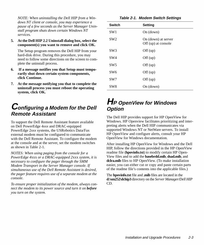
Configuring a Modem for the Dell Remote Assistant To support the Dell Remote Assistant feature available on Dell PowerEdge 4xxx and DRAC-equipped PowerEdge 2xxx systems, the USRobotics Data/Fax external modem must be configured to communicate with the Dell Remote Assistant. To configure the modem at the console and at the server, set the modem switches as shown in Table 2-1.
NOTES: When using paging from the console for a PowerEdge 4xxx or a DRAC-equipped 2xxx system, it is necessary to configure the pager through the SMM Modem Transport in the Server Manager console. If simultaneous use of the Dell Remote Assistant is desired, the pager feature requires use of a separate modem at the console.
To ensure proper initialization of the modem, always con-nect the modem to its power source and turn it on before you turn on the system.
HP OpenView for Windows Option The Dell HIP provides support for HP OpenView for Windows. HP Openview facilitates prioritizing and interpreting alerts when the Dell HIP communicates via supported Windows NT or NetWare servers. To install HP OpenView and configure alerts, consult your HP OpenView for Windows documentation.
After installing HP OpenView for Windows and the DelHIP, follow the directions provided in the HP OpenViewreadme file (hpovinfo.txt) to modify certain HP Open-View files and to add the basebrdd.mib, dsad.mib, and dclra.mib files to HP OpenView. (To make installation easier, you can either cut or copy and paste certain paof the readme file’s contents into the applicable files.)
The hpovinfo.txt file and .mib files are located in the d:\sm252\dchip3 directory on the Server Manager/Dell HIP CD.
Table 2-1. Modem Switch Settings
Switch Setting
SW1 On (down)
SW2 On (down) at serverOff (up) at console
SW3 Off (up)
SW4 Off (up)
SW5 Off (up)
SW6 Off (up)
SW7 Off (up)
SW8 On (down)
Installation and Upgrade Procedures 2-3

2-4 Dell Hardware Instrumentation Package v2.2 for Intel LANDesk Server Manager 2.52 User’s Guide
Chapter 3Using the Dell HIP
e
The Dell Hardware Instrumentation Package (HIP) works within the Intel Server Manager to help you moni-tor your Dell server environment. For a complete list of HIP capabilities by system, see “HIP Features” in Chap-ter 1.
This chapter describes how to access the Dell HIP and introduces the structure of the program and the symbols it uses. It also covers the Dell HIP Help, to which you can refer while using the program. The online help provides detailed explanations of the Dell HIP menus and instruc-tions on performing common tasks, such as connecting or repairing a device.
Accessing the Dell HIP The Dell HIP uses the same Windows-type interface as does the Intel Server Manager. Once the Dell HIP has been installed under Server Manager for a particular sys-tem, you can access it as follows:
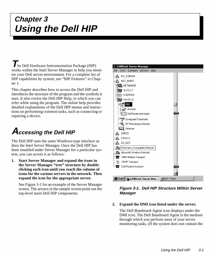
1. Start Server Manager and expand the icons in the Server Manager “tree” structure by double-clicking each icon until you reach the column of icons for the various servers in the network. Then expand the icon for the appropriate server.
See Figure 3-1 for an example of the Server Manager screen. The arrows in the sample screen point out the top-level main Dell HIP components.
Figure 3-1. Dell HIP Structure Within Server Manager
2. Expand the DMI icon listed under the server.
The Dell Baseboard Agent icon displays under theDMI icon. The Dell Baseboard Agent is the mediumthrough which you perform most of your server monitoring tasks. (If the system does not contain th
Using the Dell HIP 3-1
ld
r s-
e
correct Baseboard hardware, the Dell Baseboard icon displays a red “not” symbol [see Table 3-1]).
3. To access the system logs (available for Dell PowerEdge 4xxx and Dell Remote Assistant Card [DRAC]-equipped PowerEdge 2xxx systems only), expand the Dell Baseboard Agent icon, and then expand the System Logs icon.
The POST Code Log displays all events detected while the basic input/output system (BIOS) is start-ing up. Providing this information to a technical support representative can be useful in isolating system problems.
The ESM Event Log displays events such as failure threshold violations and run-time BIOS events, including bus time-outs.
4. To access the Dell Remote Assistant, expand the Dell Remote Assistant icon.
The Dell Remote Assistant is available on Windows NT and Windows 95 consoles for connect-ing to Dell PowerEdge 4xxx and DRAC-equipped PowerEdge 2xxx systems. It lets you remotely moni-tor and manage nonstorage components in Dell servers via a modem or direct serial connection.
5. Double-click any of the Dell icons to display the individual monitoring and task-related icons available under them.
For information on HIP symbols, see “HIP Sym-bols” found later in this chapter.
For information on using the Dell HIP options, see the Dell HIP Help. For more information on the online help, see “Using the Dell HIP Help” found later in this chapter.
NOTE: If you experience problems viewing all of the Dell HIP data when expanding agents in the console, you may be experiencing time-out problems. Try increasing your communications time-outs to at least 10 seconds with two retries. To do so, select Communications from the Config-ure menu and enter the new values. If you need more information, refer to the section on the Configure menu in your Server Manager documentation.
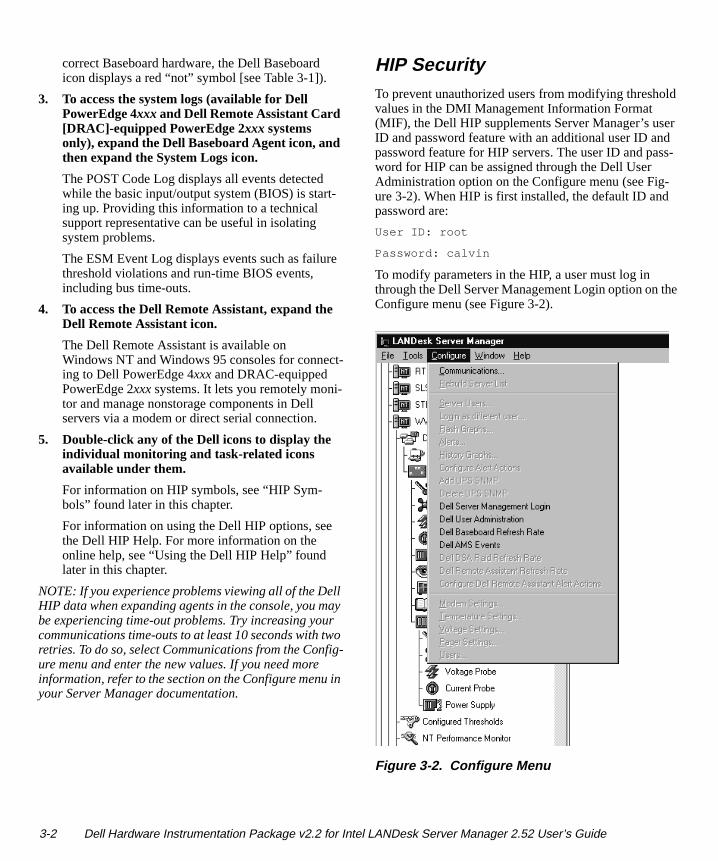
HIP SecurityTo prevent unauthorized users from modifying threshovalues in the DMI Management Information Format (MIF), the Dell HIP supplements Server Manager’s useID and password feature with an additional user ID andpassword feature for HIP servers. The user ID and pasword for HIP can be assigned through the Dell User Administration option on the Configure menu (see Fig-ure 3-2). When HIP is first installed, the default ID andpassword are:
User ID: root
Password: calvin
To modify parameters in the HIP, a user must log in through the Dell Server Management Login option on thConfigure menu (see Figure 3-2).
Figure 3-2. Configure Menu
3-2 Dell Hardware Instrumentation Package v2.2 for Intel LANDesk Server Manager 2.52 User’s Guide
How to Use the Dell HIP As with Server Manager, HIP monitoring tasks require that you know how to perform the following Microsoft Windows functions:
• Choosing and selecting items
• Selecting and closing menus
• Choosing menu commands
• Working with windows
• Using dialog, text, list, and check boxes
For information on how to use these Windows features, see the documentation that came with your Windows software or use the online Windows Help.
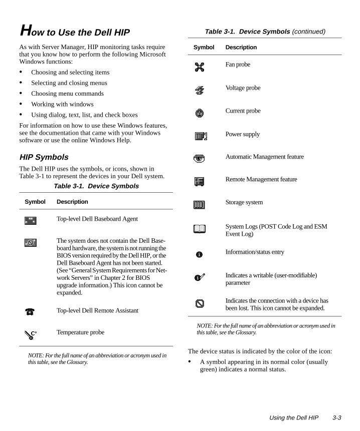
HIP Symbols The Dell HIP uses the symbols, or icons, shown in Table 3-1 to represent the devices in your Dell system.
The device status is indicated by the color of the icon:
• A symbol appearing in its normal color (usually green) indicates a normal status.
Table 3-1. Device Symbols
Symbol Description
Top-level Dell Baseboard Agent
The system does not contain the Dell Base-board hardware, the system is not running the BIOS version required by the Dell HIP, or the Dell Baseboard Agent has not been started. (See “General System Requirements for Net-work Servers” in Chapter 2 for BIOS upgrade information.) This icon cannot be expanded.
Top-level Dell Remote Assistant
Temperature probe
NOTE: For the full name of an abbreviation or acronym used in this table, see the Glossary.
Fan probe
Voltage probe
Current probe
Power supply
Automatic Management feature
Remote Management feature
Storage system
System Logs (POST Code Log and ESM Event Log)
Information/status entry
Indicates a writable (user-modifiable) parameter
Indicates the connection with a device has been lost. This icon cannot be expanded.
Table 3-1. Device Symbols (continued)
Symbol Description
NOTE: For the full name of an abbreviation or acronym used inthis table, see the Glossary.
Using the Dell HIP 3-3
-
-I)
-
r.
• A yellow symbol indicates a warning condition, such as a voltage, current, temperature, or fan reading that has exceeded a warning threshold.
• A red symbol indicates that the device has failed or has crossed a failure threshold and may fail.
Configuring HIP-Generated Alert Actions The following subsections cover configuring alert actions through the HIP Baseboard Agent, through Simple Net-work Management Protocol (SNMP) traps, for local server response, and through the Dell Remote Assistant.
HIP Baseboard Agent Alert ActionsTo configure HIP-generated Baseboard Agent alert actions from the console, perform the following steps:
1. Select the Dell Baseboard Agent icon.
2. Select Dell AMS Events from the Configure menu.
3. Double-click any alert listed in the Configure AMS Events window to display the Select Alert Action dia-log box.
4. Refer to the chapter on configuring parameter alerts in your LANDesk Server Manager User’s Guide. Locate the section on the specific action you wish to configure (such as message box or pager), and use that information to configure the Alert Management System (AMS) action(s) to be taken for the selected alert.
The action(s) configured in this manner are specific to the server.
HIP SNMP TrapsIf the SNMP service is installed on your server and con-sole, you can configure AMS event actions for SNMP alerts received at the console. To configure AMS actions for SNMP traps, perform the following steps:
1. Double-click the SNMP Transport icon.
2. Double-click the SNMP Trap Receiver icon.
3. Double-click the desired enterprise icon to dis-play the SNMP Trap Log window.
4. Select Configure Alert Actions from the Config-ure menu.
5. Double-click any alert listed in the Manage Alerts window to display the Select Alert Action dialog box.
6. Refer to the chapter on configuring parameter alerts in your LANDesk Server Manager User’s Guide. Locate the section on the specific action you wish to configure (such as message box or pager), and use that information to configure the AMS action(s) to be taken for the selected alert.
The action(s) configured in this manner are specific to the console.
Local Server ActionsFor certain HIP-generated alerts, the Dell HIP also provides the capability to configure local server actions. Actions may additionally be configured for some conditions of Adaptec small computer system interface (SCScontrollers and American Power Conversion (APC) uninterruptible power supplies (UPSs). To configure localserver actions from the console, perform the following steps:
1. Double-click the Dell Baseboard Agent icon.
2. Double-click the Automatic Management icon to display the Local Events window.
3. Double-click any event listed to display the Config-ure Local Actions dialog box.
4. Refer to the Dell HIP Help for information on configuring server actions. See “Using the Dell HIP Help” found later in this chapter for instruc-tions on accessing help.
NOTE: For NetWare servers configured for broad-cast action, the Dell HIP will automatically broadcast to every computer attached to the serve
3-4 Dell Hardware Instrumentation Package v2.2 for Intel LANDesk Server Manager 2.52 User’s Guide
-
n m
the
. e
n
d
t-
Dell Remote Assistant Alert ActionsOn both Windows NT and Windows 95 consoles, Dell Remote Assistant alerts are automatically sent to the AMS. (On a Windows NT console, Dell Remote Assis-tant alerts are also sent to the Windows NT event log on the console). To configure Dell Remote Assistant alerts from the console, perform the following steps:
1. Select the Dell Remote Assistant icon.
2. Select Configure Dell Remote Assistant Alerts from the Configure menu.
3. Double-click any alert listed in the Configure AMS Events window to display the Select Alert Action dia-log box.
4. Refer to the chapter on configuring parameter alerts in your LANDesk Server Manager User’s Guide. Locate the section on the specific action you wish to configure (such as message box or pager), and use that information to configure the AMS action(s) to be taken for the selected alert.
Windows NT Alerts Sent to the Windows NT Event LogAll alerts generated by a Windows NT server are sent to the Windows NT event log on that server. HIP-generated events appear with Dell Baseboard Agent indicated as the source in the Windows NT system log and Dell Local Response Agent as the source in the appli-cation log on the server. The Dell Remote Assistant events are sent to the Windows NT application log on the console.
Using the Dell HIP HelpComprehensive online help is available to aid you in using the Dell HIP components—the icons, messages, menu options, help screens, and dialog boxes—to monitor and manage your server environment.
You can display context-sensitive help as you use the Dell HIP program. To do so, either select a HIP component in the Server Manager tree or display a Dell HIP dialog box, and then press <F1>.
To access the main contents of the Dell HIP Help (seeFigure 3-3), select one of the HIP components and theselect Contents from Server Manager’s Help menu. Frothe Contents, click a topic or its icon to display a list ofsubtopics; then click a subtopic to display the desired information.
Other hints on using the online help:
• You can use the Search button in the button bar at top of the online help window to find information onparticular subjects.
• To return to the Contents, click the Contents buttonTo return to the last topic you were reading, click thBack button.
• To display a list of the last 40 topics you have viewed, click the History button. To return to a listedtopic, double-click the topic name in the list.
• To browse forward and backward through a sectioof topics, click one of the browse buttons. When either of these buttons is grayed, you have reachethe start or end of a browse sequence.
• Click the Glossary button to display a list of techni-cal terms, abbreviations, and acronyms.
• To exit the online help at any time, click the Exit buton in the button bar at the top of the window.
For more information on using the online help, select “How to Use This Help” from the Contents.
Using the Dell HIP 3-5
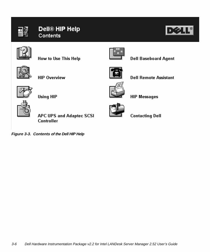
Figure 3-3. Contents of the Dell HIP Help
3-6 Dell Hardware Instrumentation Package v2.2 for Intel LANDesk Server Manager 2.52 User’s Guide
Appendix A Dell HIP Messages
ot
ge-
i-
,
. y
at d our
a-
-
This appendix details the alert messages and system messages you may encounter while using the Dell Hard-ware Instrumentation Package (HIP) to monitor the status of your network environment.
This appendix does not cover messages you may receive from options such as the American Power Conversion (APC) uninterruptible power supply (UPS), an Adaptec controller card, or a Dell PowerEdge Expandable RAID Controller (PERC).
Messages prefaced with UPS are generated by the APC UPS. For information about these messages, refer to your APC documentation.
If you have an Adaptec-based system or a system with a PERC installed and you receive a message not docu-mented in this appendix and not prefaced with UPS, it may be from the Adaptec controller or the PERC. For more information, refer to your Adaptec documentation and/or your Dell PowerEdge Expandable RAID Control-ler User’s Guide.
NOTE: If a red “not” symbol appears on the Dell Base-board Agent in the Server Manager “tree” structure, there is no communication with the Baseboard hardware. A red “not” icon appearing by itself when the Dell Base-board Agent icon is expanded indicates the connection with a device has been lost. See “HIP Symbols” in chap-ter 3.
Alert MessagesHIP-generated alerts appear in the SNMP Trap Log win-dow, which lists the alerts that have occurred on attached enterprises. To view the trap log, select any enterprise under the SNMP Trap Receiver icon. (More information about the SNMP Trap Log window and its fields is pro-vided in the Dell HIP Help.)
NOTE: The SNMP trap receive log only displays SNMPtraps received while the log window is open. Although SNMP traps are still received when the log window is nactive, they are not recorded in the trap log.
HIP-generated alerts are also passed to the Alert Manament System2 (AMS2) and may be configured from the Dell Baseboard Agent. You can also configure local server actions in response to some of these alert condtions, as well as certain Adaptec and APC UPS alerts.
Alert messages consist of information, status, warningand failure messages for drive, temperature, fan, and power conditions. Location information is also providedThey can assist you with identifying a problem and maprovide you with information to help you resolve the problem.
Table A-1 alphabetically lists the HIP alert messages thcan be generated, along with their probable causes anrecommended actions. Alert messages for which localserver actions may be configured are indicated. See ysystem User’s Guide, Installation and Troubleshooting Guide, or Service Manual for instructions on working inside your computer. Table A-1 does not list the APC UPS and Adaptec controller alert messages for which local server actions may be configured. See the applicble hardware documentation for further information onAPC and Adaptec alerts.
If a problem persists after you have attempted a corrective action, if you are not able to perform the correctiveaction, or if you need a replacement part to resolve a problem, see the chapter titled “Getting Help” in your system Diagnostics and Troubleshooting Guide, Installa-tion and Troubleshooting Guide, or Service Manual for instructions on obtaining technical assistance.
Dell HIP Messages A-1
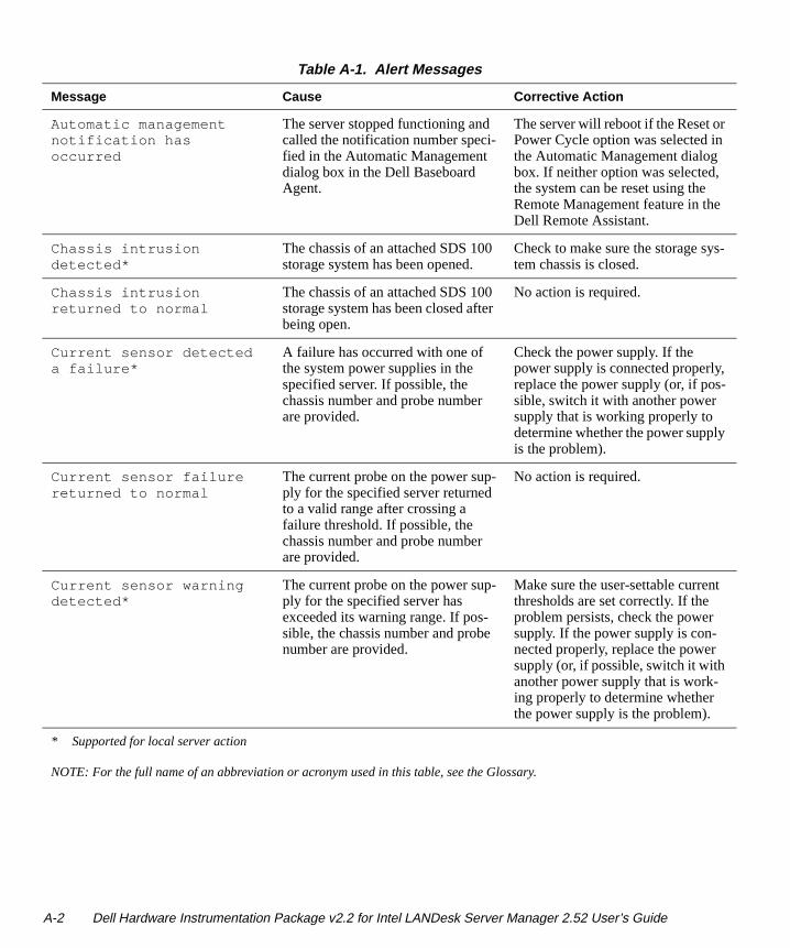
Table A-1. Alert Messages
Message Cause Corrective Action
Automatic management notification has occurred
The server stopped functioning and called the notification number speci-fied in the Automatic Management dialog box in the Dell Baseboard Agent.
The server will reboot if the Reset or Power Cycle option was selected in the Automatic Management dialog box. If neither option was selected, the system can be reset using the Remote Management feature in the Dell Remote Assistant.
Chassis intrusion detected*
The chassis of an attached SDS 100 storage system has been opened.
Check to make sure the storage sys-tem chassis is closed.
Chassis intrusion returned to normal
The chassis of an attached SDS 100 storage system has been closed after being open.
No action is required.
Current sensor detected a failure*
A failure has occurred with one of the system power supplies in the specified server. If possible, the chassis number and probe number are provided.
Check the power supply. If the power supply is connected properly, replace the power supply (or, if pos-sible, switch it with another power supply that is working properly to determine whether the power supply is the problem).
Current sensor failure returned to normal
The current probe on the power sup-ply for the specified server returned to a valid range after crossing a failure threshold. If possible, the chassis number and probe number are provided.
No action is required.
Current sensor warning detected*
The current probe on the power sup-ply for the specified server has exceeded its warning range. If pos-sible, the chassis number and probe number are provided.
Make sure the user-settable current thresholds are set correctly. If the problem persists, check the power supply. If the power supply is con-nected properly, replace the power supply (or, if possible, switch it with another power supply that is work-ing properly to determine whether the power supply is the problem).
* Supported for local server action
NOTE: For the full name of an abbreviation or acronym used in this table, see the Glossary.
A-2 Dell Hardware Instrumentation Package v2.2 for Intel LANDesk Server Manager 2.52 User’s Guide
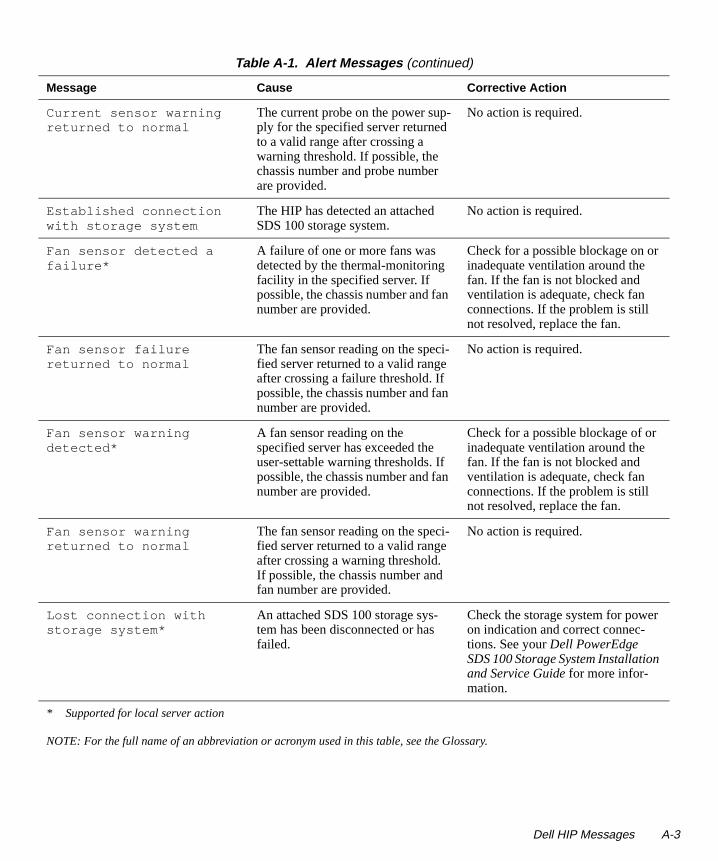
Current sensor warning returned to normal
The current probe on the power sup-ply for the specified server returned to a valid range after crossing a warning threshold. If possible, the chassis number and probe number are provided.
No action is required.
Established connection with storage system
The HIP has detected an attached SDS 100 storage system.
No action is required.
Fan sensor detected a failure*
A failure of one or more fans was detected by the thermal-monitoring facility in the specified server. If possible, the chassis number and fan number are provided.
Check for a possible blockage on or inadequate ventilation around the fan. If the fan is not blocked and ventilation is adequate, check fan connections. If the problem is still not resolved, replace the fan.
Fan sensor failure returned to normal
The fan sensor reading on the speci-fied server returned to a valid range after crossing a failure threshold. If possible, the chassis number and fan number are provided.
No action is required.
Fan sensor warning detected*
A fan sensor reading on the specified server has exceeded the user-settable warning thresholds. If possible, the chassis number and fan number are provided.
Check for a possible blockage of or inadequate ventilation around the fan. If the fan is not blocked and ventilation is adequate, check fan connections. If the problem is still not resolved, replace the fan.
Fan sensor warning returned to normal
The fan sensor reading on the speci-fied server returned to a valid range after crossing a warning threshold. If possible, the chassis number and fan number are provided.
No action is required.
Lost connection with storage system*
An attached SDS 100 storage sys-tem has been disconnected or has failed.
Check the storage system for power on indication and correct connec-tions. See your Dell PowerEdge SDS 100 Storage System Installation and Service Guide for more infor-mation.
Table A-1. Alert Messages (continued)
Message Cause Corrective Action
* Supported for local server action
NOTE: For the full name of an abbreviation or acronym used in this table, see the Glossary.
Dell HIP Messages A-3
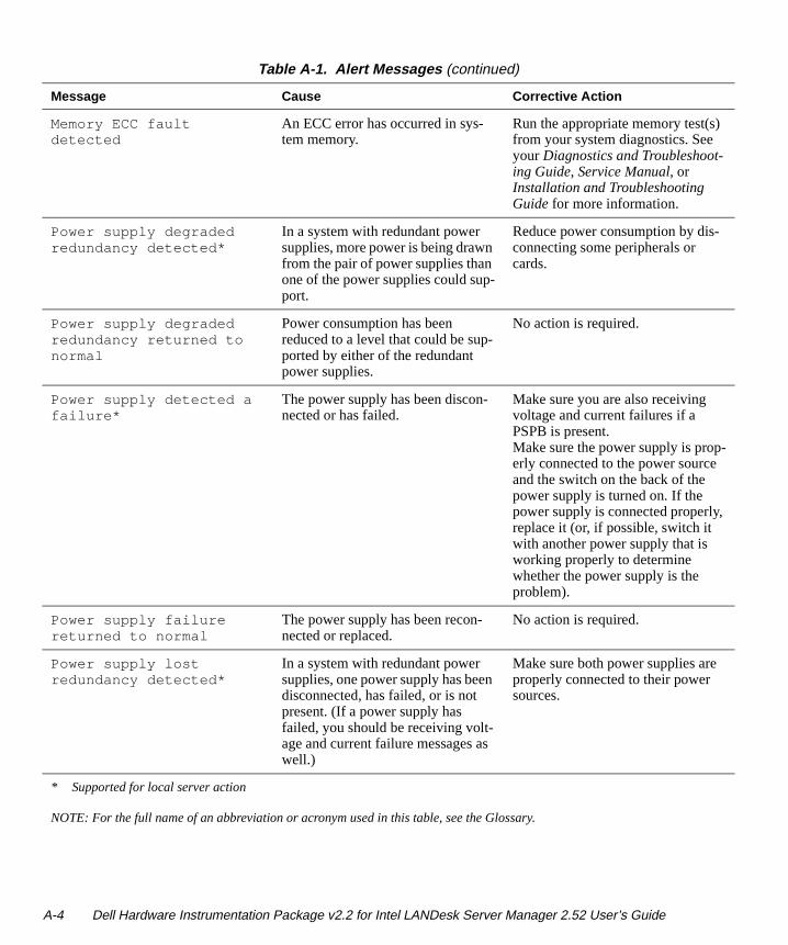
Memory ECC fault detected
An ECC error has occurred in sys-tem memory.
Run the appropriate memory test(s) from your system diagnostics. See your Diagnostics and Troubleshoot-ing Guide, Service Manual, or Installation and Troubleshooting Guide for more information.
Power supply degraded redundancy detected*
In a system with redundant power supplies, more power is being drawn from the pair of power supplies than one of the power supplies could sup-port.
Reduce power consumption by dis-connecting some peripherals or cards.
Power supply degraded redundancy returned to normal
Power consumption has been reduced to a level that could be sup-ported by either of the redundant power supplies.
No action is required.
Power supply detected a failure*
The power supply has been discon-nected or has failed.
Make sure you are also receiving voltage and current failures if a PSPB is present.Make sure the power supply is prop-erly connected to the power source and the switch on the back of the power supply is turned on. If the power supply is connected properly, replace it (or, if possible, switch it with another power supply that is working properly to determine whether the power supply is the problem).
Power supply failure returned to normal
The power supply has been recon-nected or replaced.
No action is required.
Power supply lost redundancy detected*
In a system with redundant power supplies, one power supply has been disconnected, has failed, or is not present. (If a power supply has failed, you should be receiving volt-age and current failure messages as well.)
Make sure both power supplies are properly connected to their power sources.
Table A-1. Alert Messages (continued)
Message Cause Corrective Action
* Supported for local server action
NOTE: For the full name of an abbreviation or acronym used in this table, see the Glossary.
A-4 Dell Hardware Instrumentation Package v2.2 for Intel LANDesk Server Manager 2.52 User’s Guide
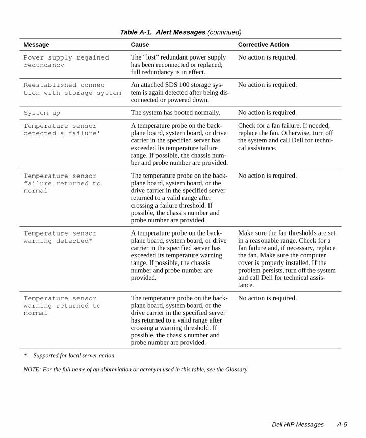
Power supply regained redundancy
The “lost” redundant power supply has been reconnected or replaced; full redundancy is in effect.
No action is required.
Reestablished connec-tion with storage system
An attached SDS 100 storage sys-tem is again detected after being dis-connected or powered down.
No action is required.
System up The system has booted normally. No action is required.
Temperature sensor detected a failure*
A temperature probe on the back-plane board, system board, or drive carrier in the specified server has exceeded its temperature failure range. If possible, the chassis num-ber and probe number are provided.
Check for a fan failure. If needed, replace the fan. Otherwise, turn off the system and call Dell for techni-cal assistance.
Temperature sensor failure returned to normal
The temperature probe on the back-plane board, system board, or the drive carrier in the specified server returned to a valid range after crossing a failure threshold. If possible, the chassis number and probe number are provided.
No action is required.
Temperature sensor warning detected*
A temperature probe on the back-plane board, system board, or drive carrier in the specified server has exceeded its temperature warning range. If possible, the chassis number and probe number are provided.
Make sure the fan thresholds are set in a reasonable range. Check for a fan failure and, if necessary, replace the fan. Make sure the computer cover is properly installed. If the problem persists, turn off the system and call Dell for technical assis-tance.
Temperature sensor warning returned to normal
The temperature probe on the back-plane board, system board, or the drive carrier in the specified server has returned to a valid range after crossing a warning threshold. If possible, the chassis number and probe number are provided.
No action is required.
Table A-1. Alert Messages (continued)
Message Cause Corrective Action
* Supported for local server action
NOTE: For the full name of an abbreviation or acronym used in this table, see the Glossary.
Dell HIP Messages A-5
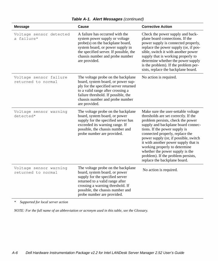
Voltage sensor detected a failure*
A failure has occurred with the system power supply or voltage probe(s) on the backplane board, system board, or power supply in the specified server. If possible, the chassis number and probe number are provided.
Check the power supply and back-plane board connections. If thepower supply is connected properly, replace the power supply (or, if pos-sible, switch it with another power supply that is working properly to determine whether the power supply is the problem). If the problem per-sists, replace the backplane board.
Voltage sensor failure returned to normal
The voltage probe on the backplane board, system board, or power sup-ply for the specified server returned to a valid range after crossing a failure threshold. If possible, the chassis number and probe number are provided.
No action is required.
Voltage sensor warning detected*
The voltage probe on the backplane board, system board, or power supply for the specified server has exceeded its warning range. If possible, the chassis number and probe number are provided.
Make sure the user-settable voltage thresholds are set correctly. If the problem persists, check the power supply and backplane board connec-tions. If the power supply is connected properly, replace the power supply (or, if possible, switch it with another power supply that is working properly to determine whether the power supply is the problem). If the problem persists, replace the backplane board.
Voltage sensor warning returned to normal
The voltage probe on the backplane board, system board, or power supply for the specified server returned to a valid range after crossing a warning threshold. If possible, the chassis number and probe number are provided.
No action is required.
Table A-1. Alert Messages (continued)
Message Cause Corrective Action
* Supported for local server action
NOTE: For the full name of an abbreviation or acronym used in this table, see the Glossary.
A-6 Dell Hardware Instrumentation Package v2.2 for Intel LANDesk Server Manager 2.52 User’s Guide
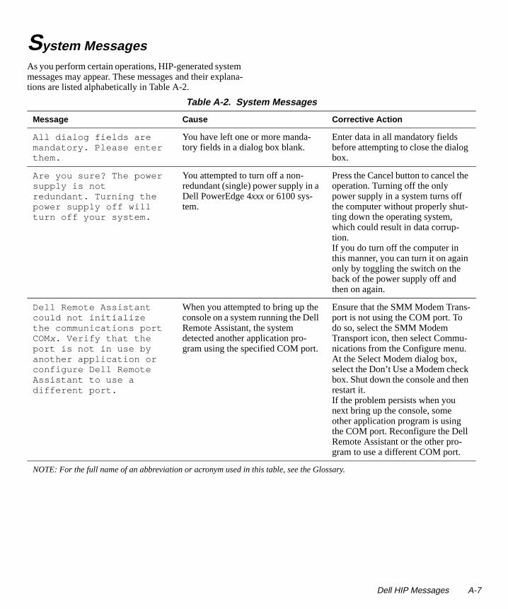
System MessagesAs you perform certain operations, HIP-generated system messages may appear. These messages and their explana-tions are listed alphabetically in Table A-2.
Table A-2. System Messages
Message Cause Corrective Action
All dialog fields are mandatory. Please enter them.
You have left one or more manda-tory fields in a dialog box blank.
Enter data in all mandatory fields before attempting to close the dialog box.
Are you sure? The power supply is not redundant. Turning the power supply off will turn off your system.
You attempted to turn off a non-redundant (single) power supply in a Dell PowerEdge 4xxx or 6100 sys-tem.
Press the Cancel button to cancel the operation. Turning off the only power supply in a system turns off the computer without properly shut-ting down the operating system, which could result in data corrup-tion.If you do turn off the computer in this manner, you can turn it on again only by toggling the switch on the back of the power supply off and then on again.
Dell Remote Assistant could not initialize the communications port COMx. Verify that the port is not in use by another application or configure Dell Remote Assistant to use a different port.
When you attempted to bring up the console on a system running the Dell Remote Assistant, the system detected another application pro-gram using the specified COM port.
Ensure that the SMM Modem Trans-port is not using the COM port. To do so, select the SMM Modem Transport icon, then select Commu-nications from the Configure menu. At the Select Modem dialog box, select the Don’t Use a Modem check box. Shut down the console and then restart it. If the problem persists when you next bring up the console, some other application program is using the COM port. Reconfigure the Dell Remote Assistant or the other pro-gram to use a different COM port.
NOTE: For the full name of an abbreviation or acronym used in this table, see the Glossary.
Dell HIP Messages A-7
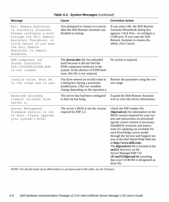
Dell Remote Assistant is currently disabled. Please configure a port through the Dell Remote Assistant Phonebook, or click Cancel if you want the Dell Remote Assistant to remain disabled.
You attempted to connect to a server after the Dell Remote Assistant was disabled at startup.
If you select OK, the Dell Remote Assistant Phonebook dialog box appears. Click Port... to configure a COM port. If you want the Dell Remote Assistant to remain dis-abled, click Cancel.
ESM component not found; therefore SYS:\SYSTEM\DCESM.NLM is not loaded.
The dcesm.nlm file has unloaded itself because it did not find the ESM component hardware in the system. In the absence of ESM hard-ware, this file is not required.
No action is required.
Invalid value. Must be in the range xxx to xxx .
You have entered an invalid value in a dialog box during a parameter modification. (The xxx variables change depending on the operation.)
Reenter the parameter using the cor-rect range.
Received watchdog timeout callback from server x.
The server that had been configured to dial out has hung.
Expand the Dell Remote Assistant icon to view the server information.
Server Management firmware version is out of date. Please upgrade your system’s BIOS.
The server’s BIOS is not the version required by HIP 2.2.
Check the HIP readme file (hipread.txt) for information on the BIOS version required for your sys-tem and instructions on download-ing the correct version if necessary. FlashBIOS revisions and instruc-tions for updating are available for each PowerEdge server model through the Service and Support sec-tion of the Dell World Wide Web site at http://www.dell.com/.The hipread.txt file is located in the sm252 directory on the Server Manager/HIP CD (d:\sm252\hipread.txt assuming that your CD-ROM is designated as drive D).
Table A-2. System Messages (continued)
Message Cause Corrective Action
NOTE: For the full name of an abbreviation or acronym used in this table, see the Glossary.
A-8 Dell Hardware Instrumentation Package v2.2 for Intel LANDesk Server Manager 2.52 User’s Guide
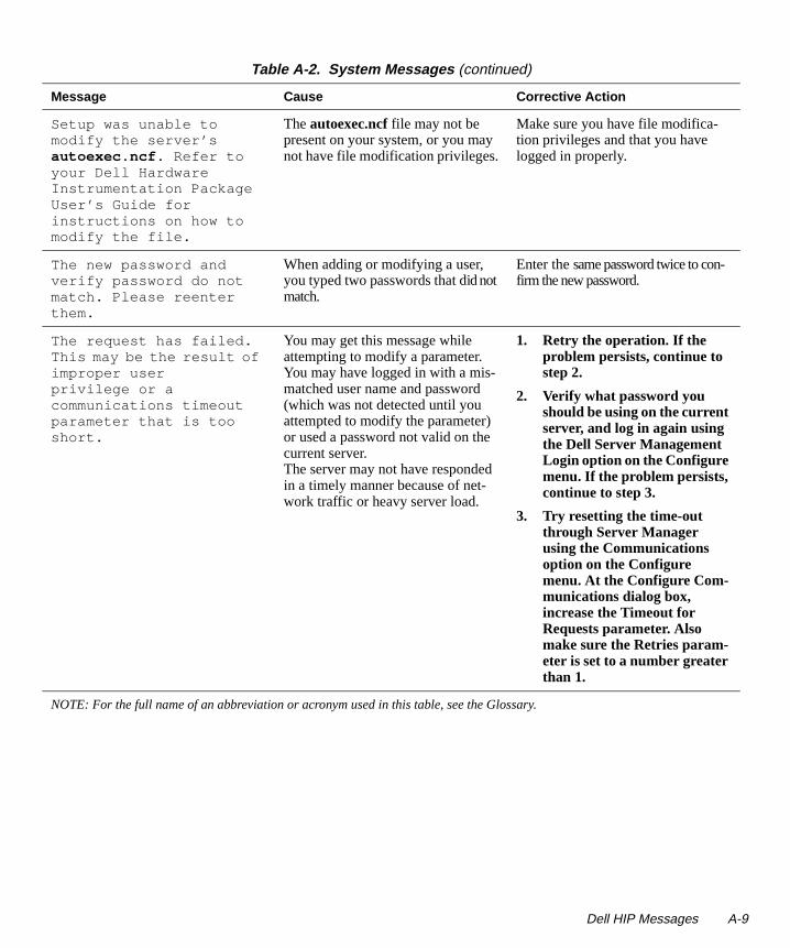
Setup was unable to modify the server’s autoexec.ncf . Refer to your Dell Hardware Instrumentation Package User’s Guide for instructions on how to modify the file.
The autoexec.ncf file may not be present on your system, or you may not have file modification privileges.
Make sure you have file modifica-tion privileges and that you have logged in properly.
The new password and verify password do not match. Please reenter them.
When adding or modifying a user, you typed two passwords that did not match.
Enter the same password twice to con-firm the new password.
The request has failed. This may be the result of improper user privilege or a communications timeout parameter that is too short.
You may get this message while attempting to modify a parameter.You may have logged in with a mis-matched user name and password (which was not detected until you attempted to modify the parameter) or used a password not valid on the current server. The server may not have responded in a timely manner because of net-work traffic or heavy server load.
1. Retry the operation. If the problem persists, continue to step 2.
2. Verify what password you should be using on the current server, and log in again using the Dell Server Management Login option on the Configure menu. If the problem persists, continue to step 3.
3. Try resetting the time-out through Server Manager using the Communications option on the Configure menu. At the Configure Com-munications dialog box, increase the Timeout for Requests parameter. Also make sure the Retries param-eter is set to a number greater than 1.
Table A-2. System Messages (continued)
Message Cause Corrective Action
NOTE: For the full name of an abbreviation or acronym used in this table, see the Glossary.
Dell HIP Messages A-9
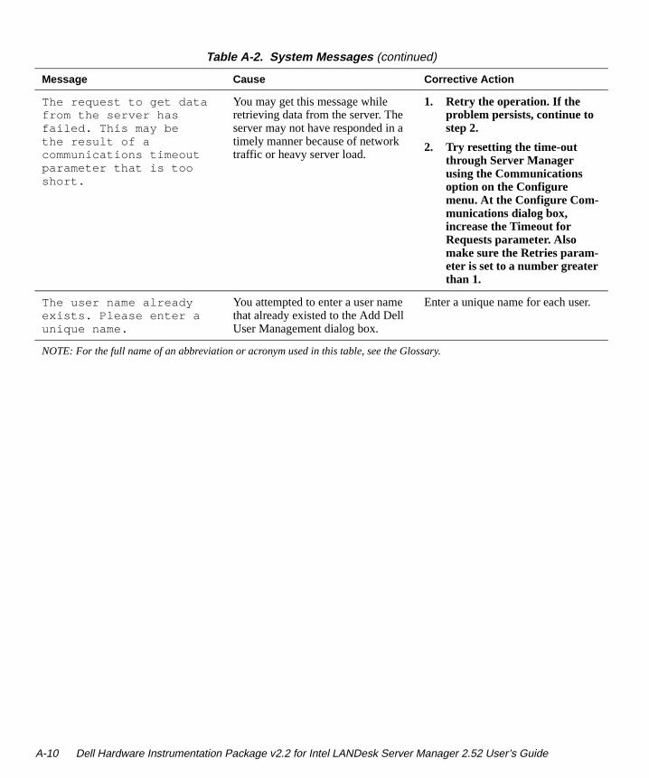
The request to get data from the server has failed. This may be the result of a communications timeout parameter that is too short.
You may get this message while retrieving data from the server. The server may not have responded in a timely manner because of network traffic or heavy server load.
1. Retry the operation. If the problem persists, continue to step 2.
2. Try resetting the time-out through Server Manager using the Communications option on the Configure menu. At the Configure Com-munications dialog box, increase the Timeout for Requests parameter. Also make sure the Retries param-eter is set to a number greater than 1.
The user name already exists. Please enter a unique name.
You attempted to enter a user name that already existed to the Add Dell User Management dialog box.
Enter a unique name for each user.
Table A-2. System Messages (continued)
Message Cause Corrective Action
NOTE: For the full name of an abbreviation or acronym used in this table, see the Glossary.
A-10 Dell Hardware Instrumentation Package v2.2 for Intel LANDesk Server Manager 2.52 User’s Guide
Appendix B Adaptec and APC Component Instrumentation
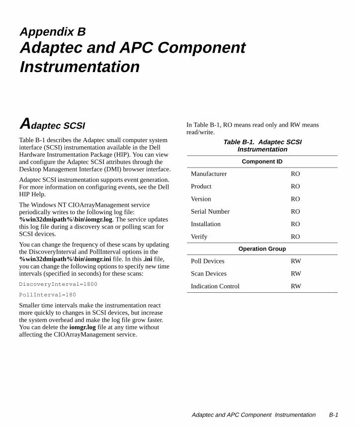
Adaptec SCSITable B-1 describes the Adaptec small computer system interface (SCSI) instrumentation available in the Dell Hardware Instrumentation Package (HIP). You can view and configure the Adaptec SCSI attributes through the Desktop Management Interface (DMI) browser interface.
Adaptec SCSI instrumentation supports event generation. For more information on configuring events, see the Dell HIP Help.
The Windows NT CIOArrayManagement service periodically writes to the following log file: %win32dmipath%\bin\iomgr.log . The service updates this log file during a discovery scan or polling scan for SCSI devices.
You can change the frequency of these scans by updating the DiscoveryInterval and PollInterval options in the %win32dmipath%\bin\iomgr.ini file. In this .ini file, you can change the following options to specify new time intervals (specified in seconds) for these scans:
DiscoveryInterval=1800
PollInterval=180
Smaller time intervals make the instrumentation react more quickly to changes in SCSI devices, but increase the system overhead and make the log file grow faster. You can delete the iomgr.log file at any time without affecting the CIOArrayManagement service.
In Table B-1, RO means read only and RW means read/write.
Table B-1. Adaptec SCSI Instrumentation
Component ID
Manufacturer RO
Product RO
Version RO
Serial Number RO
Installation RO
Verify RO
Operation Group
Poll Devices RW
Scan Devices RW
Indication Control RW
Adaptec and APC Component Instrumentation B-1
-
d/
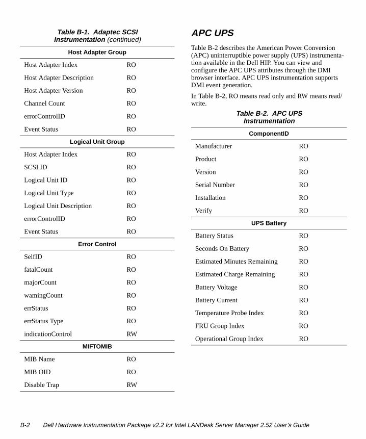
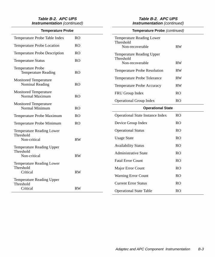
APC UPSTable B-2 describes the American Power Conversion (APC) uninterruptible power supply (UPS) instrumentation available in the Dell HIP. You can view and configure the APC UPS attributes through the DMI browser interface. APC UPS instrumentation supportsDMI event generation.
In Table B-2, RO means read only and RW means reawrite.
Host Adapter Group
Host Adapter Index RO
Host Adapter Description RO
Host Adapter Version RO
Channel Count RO
errorControlID RO
Event Status RO
Logical Unit Group
Host Adapter Index RO
SCSI ID RO
Logical Unit ID RO
Logical Unit Type RO
Logical Unit Description RO
errorControlID RO
Event Status RO
Error Control
SelfID RO
fatalCount RO
majorCount RO
wamingCount RO
errStatus RO
errStatus Type RO
indicationControl RW
MIFTOMIB
MIB Name RO
MIB OID RO
Disable Trap RW
Table B-1. Adaptec SCSI Instrumentation (continued)
Table B-2. APC UPS Instrumentation
ComponentID
Manufacturer RO
Product RO
Version RO
Serial Number RO
Installation RO
Verify RO
UPS Battery
Battery Status RO
Seconds On Battery RO
Estimated Minutes Remaining RO
Estimated Charge Remaining RO
Battery Voltage RO
Battery Current RO
Temperature Probe Index RO
FRU Group Index RO
Operational Group Index RO
B-2 Dell Hardware Instrumentation Package v2.2 for Intel LANDesk Server Manager 2.52 User’s Guide
Temperature Probe
Temperature Probe Table Index RO
Temperature Probe Location RO
Temperature Probe Description RO
Temperature Status RO
Temperature ProbeTemperature Reading RO
Monitored TemperatureNominal Reading RO
Monitored TemperatureNormal Maximum RO
Monitored TemperatureNormal Minimum RO
Temperature Probe Maximum RO
Temperature Probe Minimum RO
Temperature Reading Lower Threshold
Non-critical RW
Temperature Reading Upper Threshold
Non-critical RW
Temperature Reading Lower Threshold
Critical RW
Temperature Reading Upper Threshold
Critical RW
Table B-2. APC UPS Instrumentation (continued)
Temperature Probe (continued)
Temperature Reading Lower Threshold
Non-recoverable RW
Temperature Reading Upper Threshold
Non-recoverable RW
Temperature Probe Resolution RW
Temperature Probe Tolerance RW
Temperature Probe Accuracy RW
FRU Group Index RO
Operational Group Index RO
Operational State
Operational State Instance Index RO
Device Group Index RO
Operational Status RO
Usage State RO
Availability Status RO
Administrative State RO
Fatal Error Count RO
Major Error Count RO
Warning Error Count RO
Current Error Status RO
Operational State Table RO
Table B-2. APC UPS Instrumentation (continued)
Adaptec and APC Component Instrumentation B-3
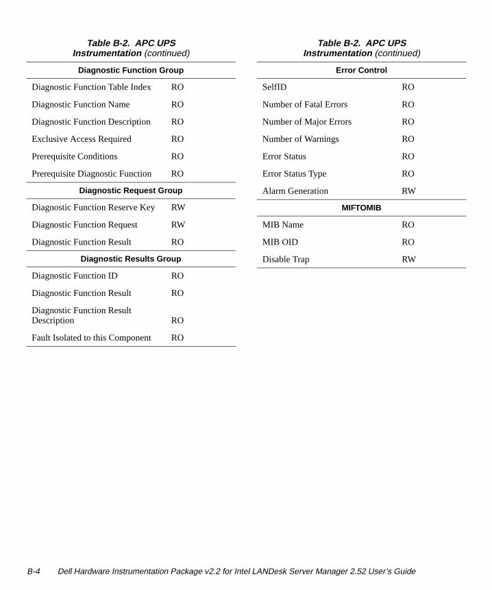
Diagnostic Function Group
Diagnostic Function Table Index RO
Diagnostic Function Name RO
Diagnostic Function Description RO
Exclusive Access Required RO
Prerequisite Conditions RO
Prerequisite Diagnostic Function RO
Diagnostic Request Group
Diagnostic Function Reserve Key RW
Diagnostic Function Request RW
Diagnostic Function Result RO
Diagnostic Results Group
Diagnostic Function ID RO
Diagnostic Function Result RO
Diagnostic Function Result Description RO
Fault Isolated to this Component RO
Table B-2. APC UPS Instrumentation (continued)
Error Control
SelfID RO
Number of Fatal Errors RO
Number of Major Errors RO
Number of Warnings RO
Error Status RO
Error Status Type RO
Alarm Generation RW
MIFTOMIB
MIB Name RO
MIB OID RO
Disable Trap RW
Table B-2. APC UPS Instrumentation (continued)
B-4 Dell Hardware Instrumentation Package v2.2 for Intel LANDesk Server Manager 2.52 User’s Guide
Appendix C DMI-SNMP Translator
r
re
ys-
-
a-e
If you use Simple Network Management Protocol (SNMP) to manage your network, you can use the Desk-top Management Interface (DMI)-SNMP Translator to integrate DMI management with SNMP. The DMI-SNMP Translator attaches directly to the network operat-ing system’s SNMP agent and to the DMI service layer by registering as a management application. The Transla-tor’s role is to translate management requests from SNMP to DMI and responses from DMI to SNMP. In addition, DMI indications are translated into SNMP traps.
The DMI-SNMP Translator supports translation of the Adaptec small computer system interface (SCSI) man-agement information format (MIF) and the American Power Conversion (APC) uninterruptible power supply (UPS) MIF.
The DMI-SNMP Translator raises an enterprise-specific trap when a DMI indication is received. The DMI-SNMP Translator does not support configured actions. This alerting mechanism works independently of the config-ured local server actions.
For the DMI-SNMP Translator to work correctly, it is important that the SNMP agent on the managed serveoperating system be working correctly. For example, both the Windows NT and NetWare SNMP agent needsome configuration to enable the server to send SNMPtraps to specific SNMP management consoles. For modetails on configuring the SNMP agent on the server, refer to the documentation supplied by the operating stem vendor.
To manage the DMI information supplied by the Dell Hardware Instrumentation Package (HIP) software through the SNMP management workstation, the Dell-supplied .mib files must be compiled on the SNMP console. These .mib files are in the \sm252\dchip3 directory on the Intel LANDesk Server Manager 2.52 and Dell Hardware Instrumentation Package v2.2 CD.
The procedure for compiling these .mib files depends on the SNMP console being used. Refer to the documenttion supplied with your SNMP console software for morinformation.
DMI-SNMP Translator C-1

C-2 Dell Hardware Instrumentation Package v2.2 for Intel LANDesk Server Manager 2.52 User’s Guide
Glossary
s S
s
ng rd-
r nit
o-ion th ed ss
cro-
The following list defines or identifies technical terms, abbreviations, and acronyms used in Dell user documents.
NOTE: Unless otherwise specified, these definitions may not apply to operating systems other than Windows 95 or Windows NT.
ACAbbreviation for alternating current.
AHA-154x emulationThe Adaptec AHA-154x is a SCSI host bus adapter widely supported by PC-compatible operating systems.
AMSAbbreviation for Alert Management System.
APCAbbreviation for American Power Conversion.
backupA copy of a program or data file. As a precaution, you should back up your computer’s hard-disk drive on a reg-ular basis. Before making a change to the configuration of your computer, you should back up important start-up files, such as win.ini and system.ini for Windows 95.
BBSAbbreviation for bulletin board service.
BIOSAcronym for basic input/output system. Your computer’BIOS contains programs stored on a ROM chip. The BIOcontrols the following:
• Communications between the microprocessor andperipheral devices, such as the keyboard and the video adapter
• Miscellaneous functions, such as system message
The BIOS is a layer of software that isolates the operatisystem and application programs from the system’s haware. By using the BIOS, the compatibility of these programs is enhanced.
blockA typical unit of disk storage consisting of a small numbeof sectors. This term usually refers to the fundamental uof storage provided by an operating system. See also block size and striping .
block sizeThe size of a block. See also block and striping .
busA bus forms an information pathway between the compnents of a computer. Your computer contains an expansbus that allows the microprocessor to communicate wicontrollers for all the various peripheral devices connectto the computer. Your computer also contains an addrebus and a data bus for communications between the miprocessor and RAM.
Glossary 1
a
.
m-oot
ed
n-are d ort
I ou-.
.
byteEight contiguous bits of information, the basic data unit used by your computer.
cacheTo facilitate quicker data retrieval, a storage area for keep-ing a copy of data or instructions. For example, your computer’s BIOS may cache ROM code in faster RAM. Or, a disk-cache utility may reserve RAM in which to store frequently accessed information from your computer’s disk drives; when a program makes a request to a disk drive for data that is in the cache, the disk-cache utility can re-trieve the data from RAM faster than from the disk drive.
CD-ROMAbbreviation for compact disc read-only memory. CD-ROM drives use optical technology to read data from CDs. CDs are read-only storage devices; you cannot write new data to a CD with standard CD-ROM drives.
CI/OAbbreviation for comprehensive input/output.
coerceA feature that takes a drive of a larger capacity and makes it appear to the array as a smaller drive to become part of a composite.
controllerA chip or expansion card that controls the transfer of data between the microprocessor and a peripheral, such as a disk drive or the keyboard.
CPUAbbreviation for central processing unit.
device driverA device driver allows the operating system or a program to interface correctly with a peripheral, such as a printer or network card. Some device drivers—such as network drivers—must be loaded from initialization files or as memory-resident programs. Others—such as video drivers—must load when you start the program for which they were designed.
diagnosticsSee diskette-based diagnostics.
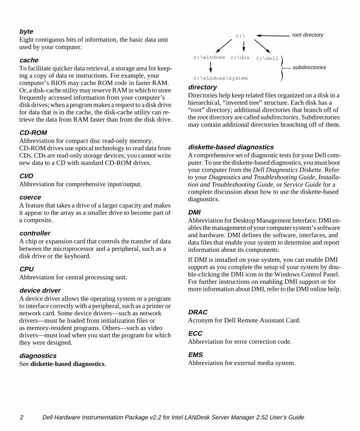
directoryDirectories help keep related files organized on a disk inhierarchical, “inverted tree” structure. Each disk has a “root” directory; additional directories that branch off ofthe root directory are called subdirectories. Subdirectories may contain additional directories branching off of them
diskette-based diagnosticsA comprehensive set of diagnostic tests for your Dell coputer. To use the diskette-based diagnostics, you must byour computer from the Dell Diagnostics Diskette. Refer to your Diagnostics and Troubleshooting Guide, Installa-tion and Troubleshooting Guide, or Service Guide for a complete discussion about how to use the diskette-basdiagnostics.
DMIAbbreviation for Desktop Management Interface. DMI eables the management of your computer system’s softwand hardware. DMI defines the software, interfaces, andata files that enable your system to determine and repinformation about its components.
If DMI is installed on your system, you can enable DMsupport as you complete the setup of your system by dble-clicking the DMI icon in the Windows Control PanelFor further instructions on enabling DMI support or for more information about DMI, refer to the DMI online help
DRACAcronym for Dell Remote Assistant Card.
ECCAbbreviation for error correction code.
EMSAbbreviation for external media system.
c:\
c:\dellc:\windows
c:\windows\system
c:\dos
root directory
subdirectories
2 Dell Hardware Instrumentation Package v2.2 for Intel LANDesk Server Manager 2.52 User’s Guide
le
r, n -t is f
y s,
4 to an
ves to ed nd ee
enterpriseA systems-management software product that is either a source or a receiver of SNMP traps.
ESMAbbreviation for embedded server management.
firmwareSoftware that resides permanently in a computer system’s hardware. Some firmware can be updated by diskette be-cause it is stored in a flash memory chip.
formatTo prepare a hard-disk drive or diskette for storing files. An unconditional format deletes all data stored on the disk.
FTPAbbreviation for file transport protocol.
GBAbbreviation for gigabyte. A gigabyte equals 1024 MB or 1,073,741,824 bytes.
guardingA type of data redundancy that uses a set of physical drives to store data and a single, additional drive to store parity data. Using guarding, the user’s data is protected from the loss of a single drive. Guarding is sometimes preferred over mirroring because it is more cost effective in systems with a very high storage capacity. However, guarded con-figurations are significantly slower for applications that frequently write to the array, because each attempt to write to the array requires multiple read and write commands to maintain the parity information. If this is a problem, mir-roring or duplexing is a better choice. See also mirroring , RAID 4, and RAID 5.
HIPAcronym for the Dell Hardware Instrumentation Package. HIP provides seamless integration with the Intel LANDesk Server Manager. Together, HIP and LANDesk Server Manager allow you to monitor your Dell servers and track status information about Dell server components.
host adapterA host adapter implements communication between the computer’s bus and the controller for a peripheral. (Hard-disk drive controller subsystems include integrated host adapter circuitry.) To add a SCSI expansion bus to your system, you must install the appropriate host adapter.
IDAbbreviation for identification.
in bandCommunication across the network between the consoand server.
I/OAbbreviation for input/output. The keyboard and a printefor example, are I/O devices. In general, I/O activity cabe differentiated from computational activity. For example, when a program sends a document to the printer, iengaging in I/O activity; when the program sorts a list oterms, it is engaging in computational activity.
KBAbbreviation for kilobyte(s), 1,024 bytes.
LANAcronym for local area network. A LAN system is usuallconfined to the same building or a few nearby buildingwith all equipment linked by wiring dedicated specificallyto the LAN.
LEDAbbreviation for light-emitting diode. An electronic de-vice that lights up when a current is passed through it.
MBAbbreviation for megabyte(s). A megabyte equals 1,02kilobytes or 1,048,576 bytes; however, when referring hard-disk drive storage, the term is often rounded to me1,000,000 bytes.
MIBAcronym for management information base.
MIFAbbreviation for management information format.
mirroringA type of data redundancy that uses a set of physical drito store data and one or more sets of additional drivesstore duplicate copies of the data. Mirroring is the preferrdata redundancy technique in lower-capacity systems ain systems where performance is extremely important. Salso guarding, RAID 1, and RAID 10.
mVAbbreviation for millivolt(s).
Glossary 3
g
th-h of ve w.
h t as
ncy r-t lso
f -r
e ata
nd ty s-
a f a
s rs
NLMAcronym for NetWare loadable module.
NVRAMAbbreviation for nonvolatile random-access memory. Memory that does not lose its contents when you turn off your computer. NVRAM is used for maintaining the date, time, and system setup options.
ODIAbbreviation for Open Data-link Interface.
out-of-bandCommunications that do not use the network but are passed via modem. The out-of-band path is used for remote man-agement of a server or for accessing server information when the server or network is down.
parameterA value or option that you specify to a program. A param-eter is sometimes called a switch or an argument.
passthrough drivePassthrough drives are hard-disk drives that are used in AHA-154x emulation mode rather than as DSA drives.
PERCAbbreviation for Dell PowerEdge Expandable RAID Controller.
peripheral deviceAn internal or external device—such as a printer, a disk drive, or a keyboard—connected to a computer.
physical driveA hard-disk drive connected to the controller card.
POSTAcronym for power-on self-test. Before the operating sys-tem loads when you turn on your computer, the POST tests various system components such as RAM, the disk drives, and the keyboard.
PSPBAbbreviation for power-supply paralleling board.
RAIDAn acronym for Redundant Array of Inexpensive Disks. This phrase was introduced by David Patterson, Garth Gibson, and Randy Katz at the University of California at
Berkeley in 1987. The goal of RAID is to use multiple small, inexpensive disk drives to provide high storage capacity and performance while maintaining or improvinthe reliability of the disk subsystem.
Patterson, Gibson, and Katz described five different meods, which are known as RAID levels 1 through 5. Eaclevel uses one or more extra drives to provide a meansrecovering data lost when a disk fails, so that the effectifailure rate of the whole disk subsystem becomes very lo
Recently, Katz has defined a sixth method, RAID 6, whicimproves reliability even further, and a configuration thaprovides no data recovery has popularly become knownRAID 0.
RAID 0RAID 0 is commonly called striping. This was not origi-nally defined as a RAID level but has since come into popular use. In this array configuration, data is written sequentially across the available disks and no redundais provided. RAID 0 configurations provide very high peformance but relatively low reliability. RAID 0 is the beschoice when DSA controller cards are duplexed. See astriping .
RAID 1RAID 1 is commonly called mirroring. RAID 1 also uses striping, so RAID 1 may be regarded as the mirroring oRAID 0 configurations. RAID 1 is the best choice in highavailability applications that require high performance orelatively low data capacity. See also mirroring , RAID 10, striping .
RAID 4RAID 4 is commonly called guarding. It uses data striping, like RAID 0, but adds a single, dedicated parity drive. Thparity data stored on this drive can be used to recover dlost from a single failed drive. RAID 4 configurations writedata slowly because parity data has to be generated awritten to the parity drive, and the generation of the paridata frequently requires reading data from multiple phyical drives. See also guarding, striping .
RAID 5RAID 5, like RAID 4, is commonly called guarding. RAID 5 is identical to RAID 4, except that the parity datis distributed evenly across all physical drives instead oparity drive. In configurations using a large number of physical drives in which a large number of simultaneousmall write operations are being performed, RAID 5 offe
4 Dell Hardware Instrumentation Package v2.2 for Intel LANDesk Server Manager 2.52 User’s Guide
n-
l.
r
e lled f
ck e. ce to -lso
r
g
in-
d.
potentially higher performance than RAID 4. RAID 4 and RAID 5 configurations are appropriate in high-availability applications where performance is less critical or where high data capacity is required. See also guarding.
RAID 10RAID 10 is a mirroring technique in which data is dupli-cated across two identical RAID 0 arrays or hard-disk drives. All data on a physical drive in one array is dupli-cated, or mirrored, on a drive in the second array. Mirroring offers complete redundancy of data for greater data secu-rity. See also mirroring , RAID 1, striping.
RAMAcronym for random-access memory. The computer’s pri-mary temporary storage area for program instructions and data. Each location in RAM is identified by a number called a memory address. Any information stored in RAM is lost when you turn off your computer.
rebuildThe process of reconstructing data on a new physical drive. This process is necessary when a physical drive fails in a mirrored composite drive and is replaced by a new physical drive.
ROMAcronym for read-only memory. Your computer contains some programs essential to its operation in ROM code. Unlike RAM, a ROM chip retains its contents even after you turn off your computer. Examples of code in ROM include the program that initiates your computer’s boot routine and the POST.
rpmAcronym for revolutions per minute.
SCSIAcronym for small computer system interface. An I/O bus interface with faster data transmission rates than standard ports. You can connect up to 7 devices (15 for some newer SCSI types) to one SCSI interface.
SDSAbbreviation for Scalable Disk System.
sectorThe fundamental unit of data access for a hard-disk drive. For PC-compatible systems, a sector is usually 512 bytes. See also block and block size.
SMBAcronym for system management bus.
SMMAbbreviation for server monitor module. An ISA add-incard that provides a modem interface for out-of-band moitoring and control of a server.
SMPAbbreviation for Symmetric Multiprocessing.
SNMPAbbreviation for Simple Network Management Protoco
spare driveA physical drive reserved for use as a backup if anothephysical drive fails in a mirrored or guarded array.
stripingIn composite drives with two or more physical drives, thdrive array subsystem uses a method of data storage castriping. With this method, data is divided into a series opieces called blocks and each data block is stored on a different physical drive. When each drive contains a bloof data, the process starts over with the first physical drivBy carefully selecting the size of the data block, the chanthat the information needed can be read from or writtenmultiple physical drives at once is increased, greatly increasing the performance of the composite drive. See ablock, block size, and RAID .
syntaxThe rules that dictate how you must type a command oinstruction so that the computer will understand it.
system memorySystem memory is a synonym for RAM.
system.ini fileWhen you start Windows, it consults the system.ini file to determine a variety of options for the Windows operatinenvironment. Among other things, the system.ini file records which video, mouse, and keyboard drivers arestalled for Windows.
Running the Control Panel or Windows Setup programmay change options in the system.ini file. On other occa-sions, you may need to change or add options to the system.ini file manually with a text editor, such as Notepa
Glossary 5
-
ry,
g
e p-re
TCP/IPAbbreviation for Transmission Control Protocol/Internet Protocol.
terminationSome devices (such as the last device at each end of a SCSI cable) must be terminated to prevent reflections and spu-rious signals in the cable. When such devices are connected in a series, you may need to enable or disable the termina-tion on these devices by changing jumper or switch settings on the devices or by changing settings in the configuration software for the devices.
text editorAn application program for editing text files consisting exclusively of ASCII characters. Notepad (in Windows) is a text editor, for example. Most word processors use pro-prietary file formats containing binary characters, although some can read and write text files.
trapAn alert, error, or system message from a server reporting an exception (for example, a device failure or a threshold violation) in a server.
UDPAbbreviation for User Datagram Protocol.
UPSAbbreviation for uninterruptible power supply. A batterypowered unit that automatically supplies power to yourcomputer in the event of an electrical failure.
utilityA program used to manage system resources— memodisk drives, or printers, for example.
VAbbreviation for volt(s).
win.ini fileWhen you start Windows, it consults the win.ini file to determine a variety of options for the Windows operatinenvironment. Among other things, the win.ini file records what printer(s) and fonts are installed for Windows. Thwin.ini file also usually includes sections that contain otional settings for Windows application programs that ainstalled on the hard-disk drive.
6 Dell Hardware Instrumentation Package v2.2 for Intel LANDesk Server Manager 2.52 User’s Guide
Index
Aalert messages, A-1
alertsconfiguring actions, 3-4
assistancetechnical, 1-2
Ddefault HIP server password, 3-2
Dell Baseboard Agentabout, 3-1configuring alerts, 3-4
Dell Remote Assistantabout, 3-2configuring a modem for, 2-3configuring alerts, 3-5
device symbols, 3-3
EESM Event Log, 3-2
Ffeatures of HIP, 1-1
HHardware Instrumentation Package. See HIP
helpobtaining technical assistance from Dell, 1-2online help with HIP, 3-5
HIPabout, 1-1, 3-1accessing, 3-1configuring alert actions, 3-4Dell systems supported, 1-1features, 1-1icons, list of, 3-3installing, 2-1reinstalling, 2-1Security, 3-2system requirements, 2-1technical assistance, 1-2uninstalling, 2-2using, 3-3
HP OpenView support, 2-3
Iicons
list of, 3-3
installingHIP software, 2-1
Index 1
Mmessages
alert, A-1system, A-6
modem, configuring for the Dell Remote Assistant, 2-3
Nnotational conventions, vi
PPOST Code Log, 3-2
Rreinstalling the HIP, 2-1
SSecurity, 3-2
serversrequirements for HIP, 2-1
symbolsdevice, 3-3
system messages, A-6
Ttroubleshooting the HIP, 1-2, A-1
typographical conventions, vi
Uuninstalling the HIP, 2-2
2 Dell Hardware Instrumentation Package v2.2 for Intel LANDesk Server Manager 2.52 User’s Guide