Embed Size (px)
Citation preview
Schematic Diagram
Service Manual12-1
This Document can not be used without Samsung’s authorization.
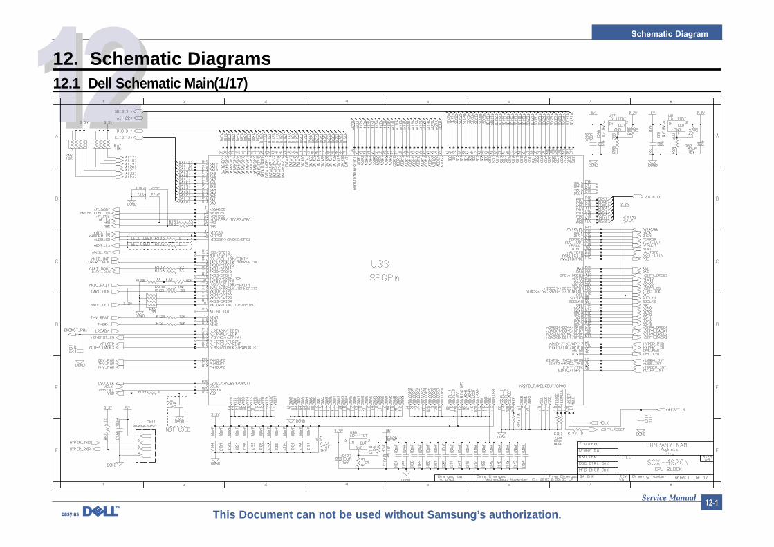
121212. Schematic Diagrams12.1 Dell Schematic Main(1/17)
Schematic Diagram
Service Manual12-2
This Document can not be used without Samsung’s authorization.
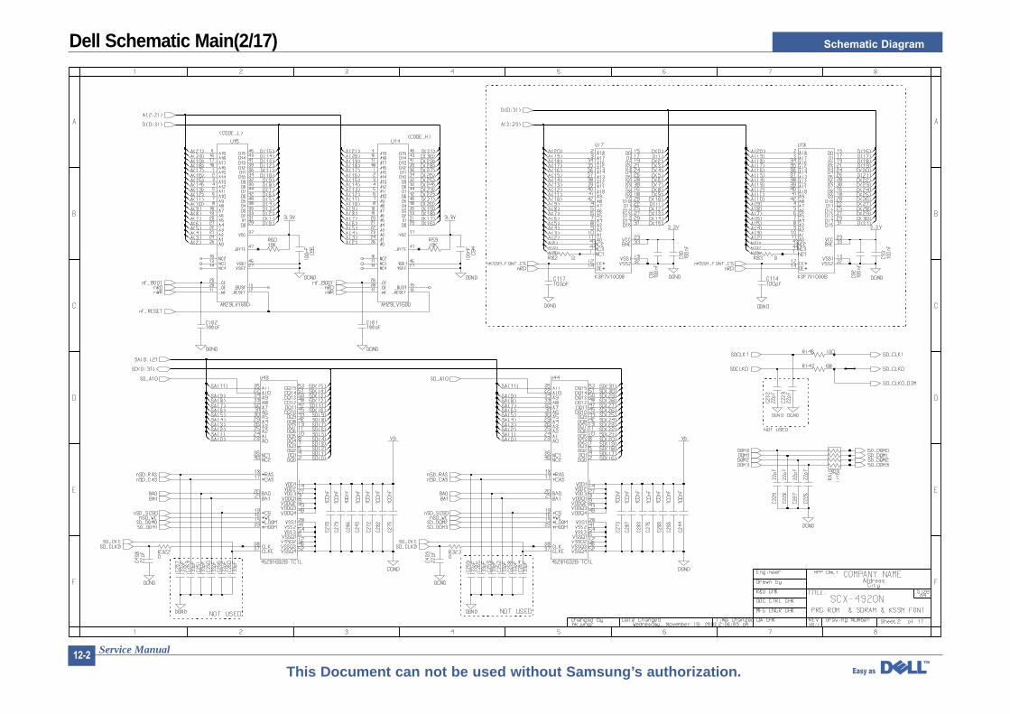
Dell Schematic Main(2/17)
Schematic Diagram
Service Manual12-3
This Document can not be used without Samsung’s authorization.
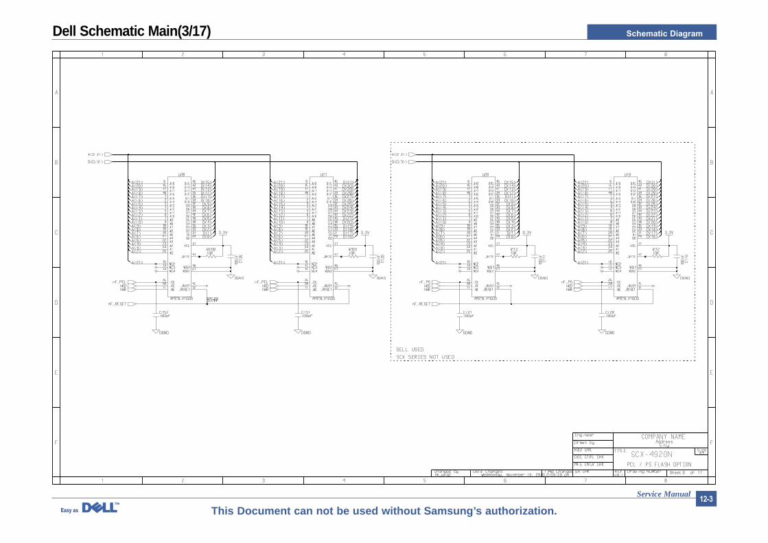
Dell Schematic Main(3/17)
Schematic Diagram
Service Manual12-4
This Document can not be used without Samsung’s authorization.
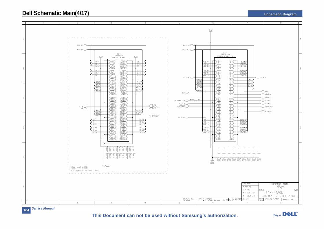
Dell Schematic Main(4/17)
Schematic Diagram
Service Manual12-5
This Document can not be used without Samsung’s authorization.
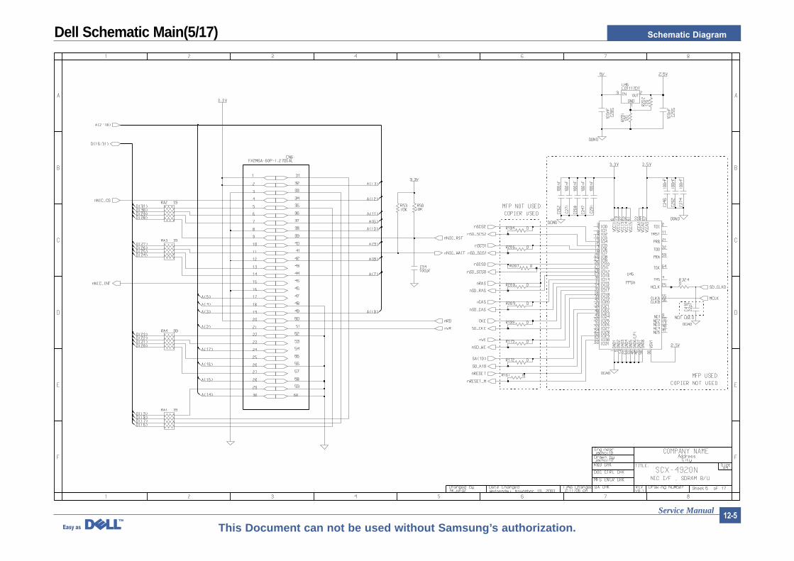
Dell Schematic Main(5/17)
Schematic Diagram
Service Manual12-6
This Document can not be used without Samsung’s authorization.
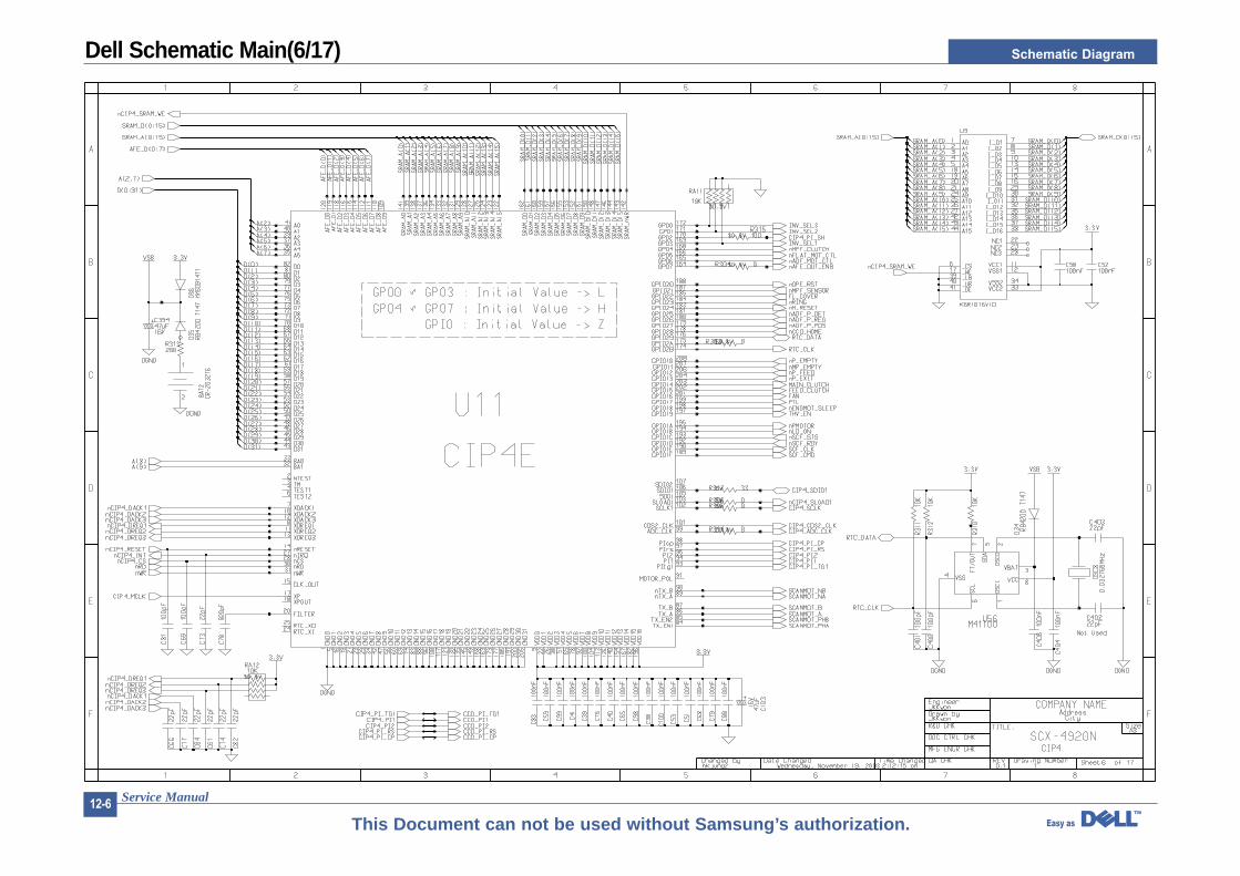
Dell Schematic Main(6/17)
Schematic Diagram
Service Manual12-7
This Document can not be used without Samsung’s authorization.
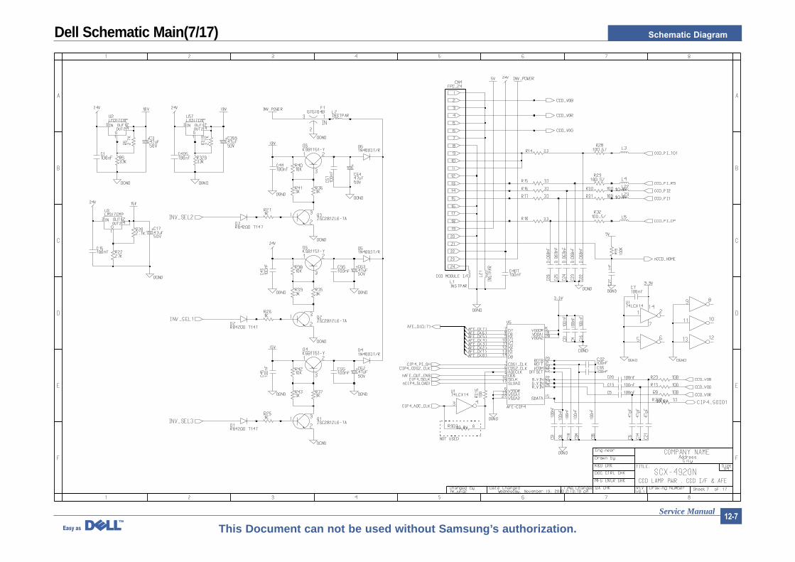
Dell Schematic Main(7/17)
Schematic Diagram
Service Manual12-8
This Document can not be used without Samsung’s authorization.
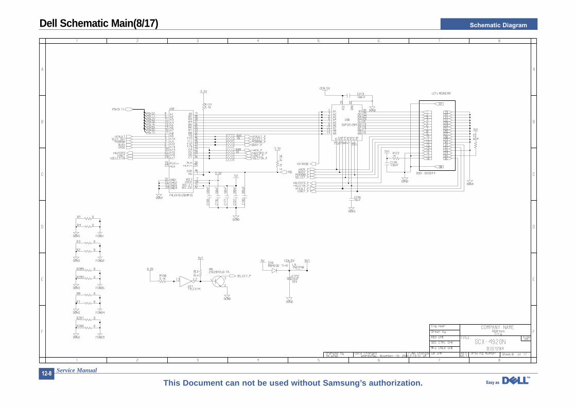
Dell Schematic Main(8/17)

Schematic Diagram
Service Manual12-9
This Document can not be used without Samsung’s authorization.
Dell Schematic Main(9/17)
Schematic Diagram
Service Manual12-10
This Document can not be used without Samsung’s authorization.
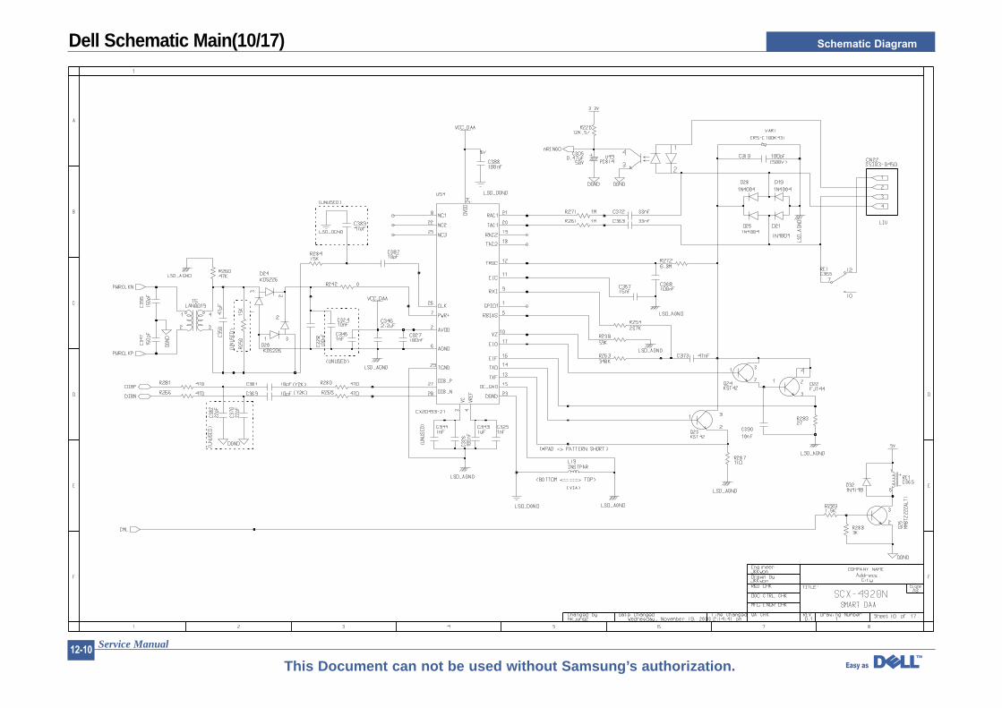
Dell Schematic Main(10/17)
Schematic Diagram
Service Manual12-11
This Document can not be used without Samsung’s authorization.
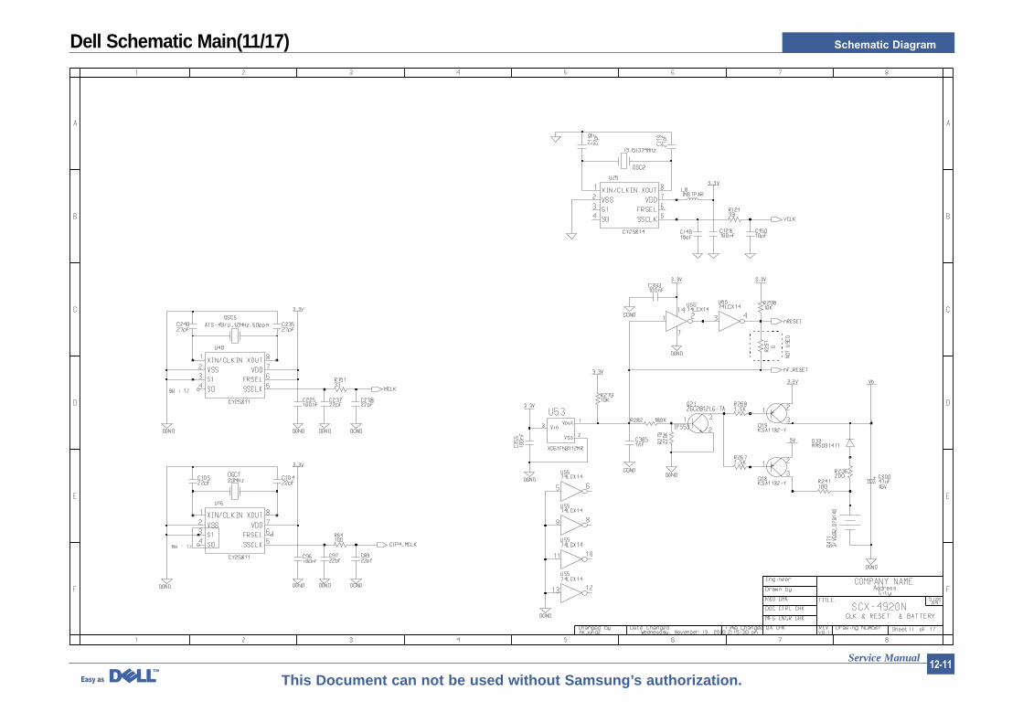
Dell Schematic Main(11/17)
Schematic Diagram
Service Manual12-12
This Document can not be used without Samsung’s authorization.
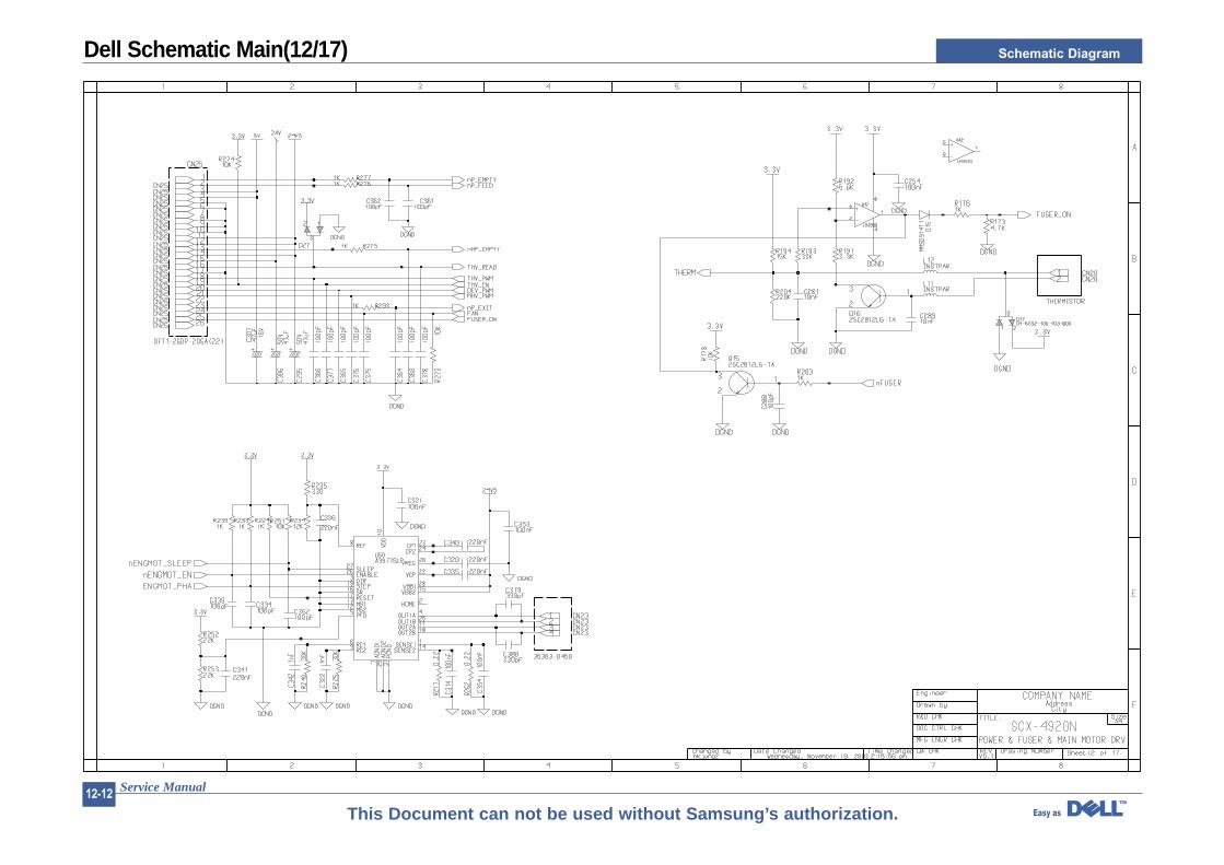
Dell Schematic Main(12/17)
Schematic Diagram
Service Manual12-13
This Document can not be used without Samsung’s authorization.
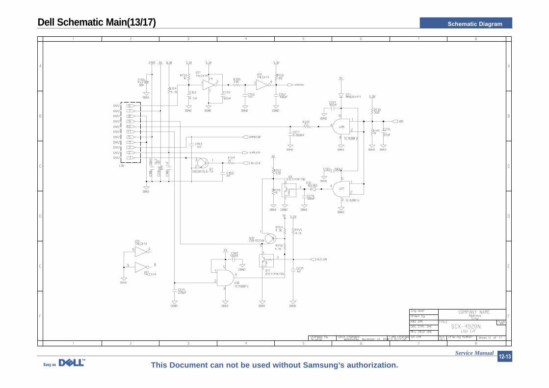
Dell Schematic Main(13/17)
Schematic Diagram
Service Manual12-14
This Document can not be used without Samsung’s authorization.
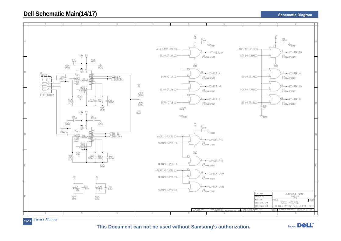
Dell Schematic Main(14/17)
Schematic Diagram
Service Manual12-15
This Document can not be used without Samsung’s authorization.
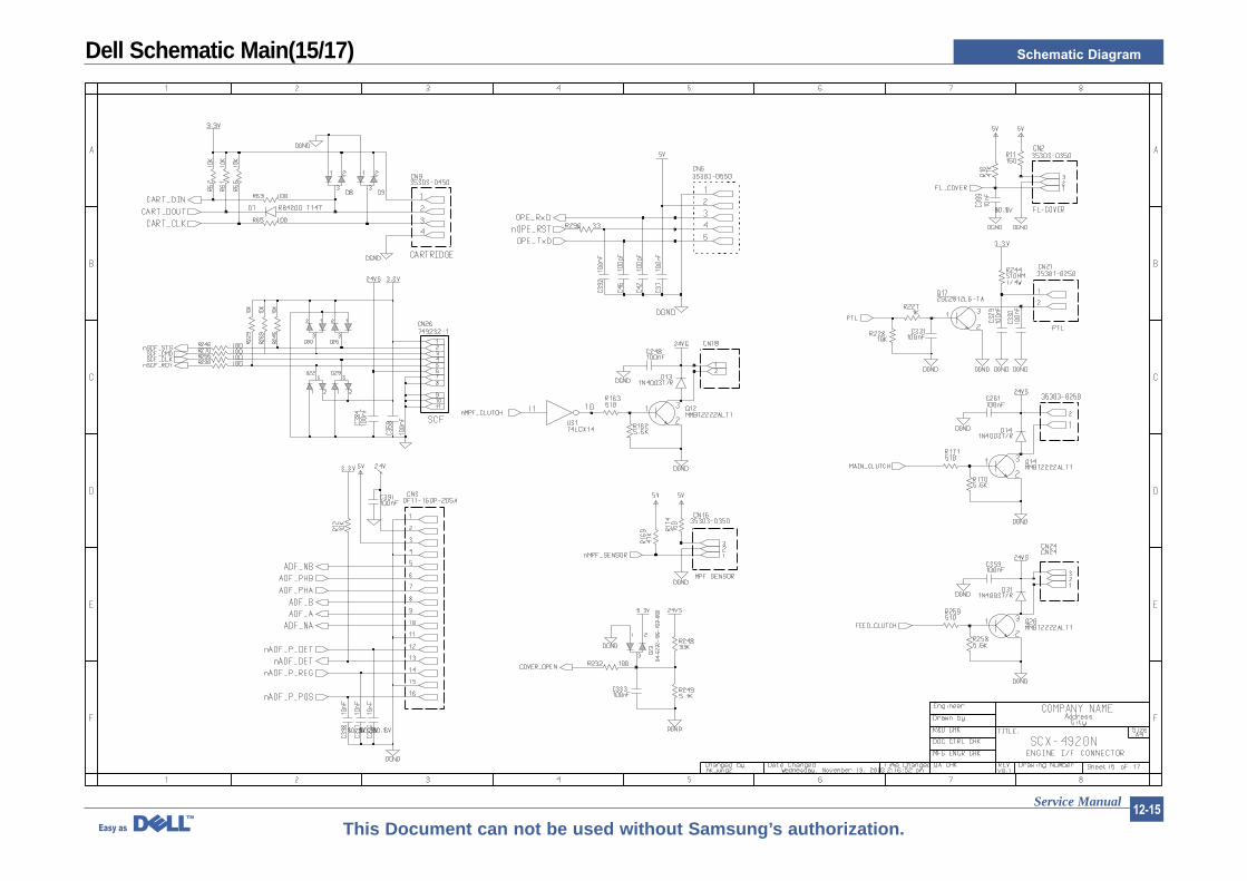
Dell Schematic Main(15/17)
Schematic Diagram
Service Manual12-16
This Document can not be used without Samsung’s authorization.
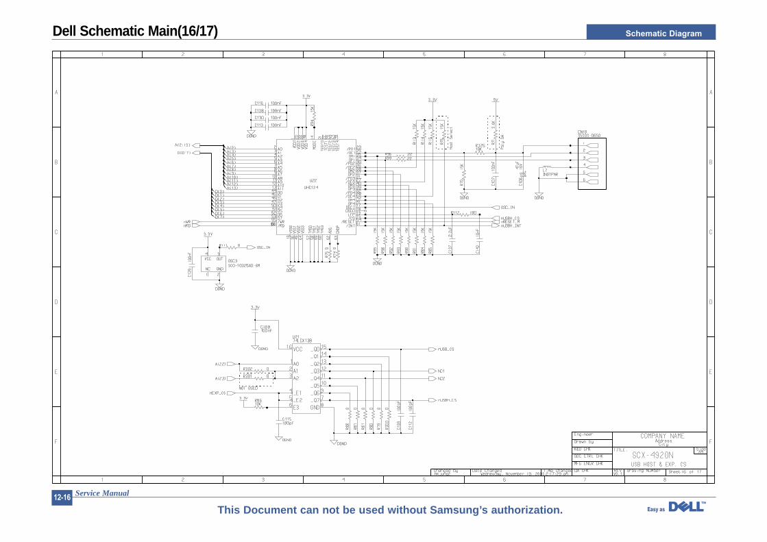
Dell Schematic Main(16/17)
Schematic Diagram
Service Manual12-17
This Document can not be used without Samsung’s authorization.
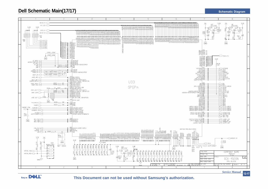
Dell Schematic Main(17/17)
Schematic Diagram
Service Manual12-18
This Document can not be used without Samsung’s authorization.
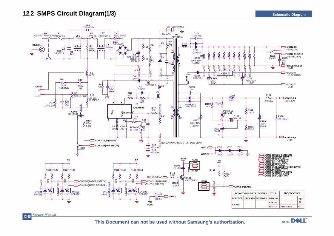
12.2 SMPS Circuit Diagram(1/3)
+24VS(2.5A)
+5V(1.5A)
GND
12
7
GND
EER3435V
9
3
4
6
10
NO MARKING RESISTOR 1/8W-J(5%)
+24V(0.7A)
250V2A
TITLE
DRW. NO
REF. NO
SIZE A4 DATE 03/12/22
ROCKY2-V1
REV.
0.0
1OF1
DESIGNED CHECKED APPROVED
DONGYANG INSTRUMENTS
C.S.BAE
KA78L1213
2
GND
+12V(0.05A)
U105
5
9
11
30*30
4
3
1
2
1
SO
FT-S
TAR
T
56
I-SENSOR
GA
TE
GN
D
F/B
VC
C
7 32
ICE2BS01U2
4
1
2
3
4
1 3
42
5V
1
2
3
4
1 3
42
5V 24VS
5268-03A
CON3
DGND
CON4
5V
F1125V 8A
TNR110D221K C1
474
LF1TR1512V
D5
UF
4007
C6
1KV
103
R53W
47K
U1BTA12-600B
L1AY70
C10
630V333
R11
1W 47FUSIBLE
R131/4W 100
R121W 180FUSIBLE
R1141/2W1.5K
F2125V 5A
R14
1/4W330K
C1150V104
PT1
PC101-A817M-B
L101
5uH
R109N/U
R1101K
R1112.7K-F
C10850V1uF
C1011KV 222
C106102
D101200V10A
R2
1W68K
F101
CON1
1
2
Q102C1008-Y
D102,10340V 3A*2
C3
472MAA
INLET1
SW2SS-5GL
D104200V1A
C10335V47uF
C104KMG 25V
10uF
SW13024-P3T4DBKBKR2
C9
1KV
471
R16220
C15222
R17300
R7200
C8105
C13472MAA
C12472MAA
R11/2W560K
C4224
LF2CH925130
AR1DSS-601M
PC101-B817M-B
C14333
D6UF4007
B1
R3
1W68K
R9
W.W
1N 0.33
SP
A07N
60C3
Q1
D71N4148
C735V
47uF
R8N/U
R1022
R61/4W 33-J
R129
1/2W 3.3K
R106
1/2W 3.3K
R104
1/2W 3.3K
R1122.6K-F
R130
1/2W 3.3K
R105
1/2W 3.3K
R113
1/2W 3.3K
R103
1/2W 3.3K
C102NXB 35V
1500uF
C10910V
470uFR
1021/2W
3.3K
C10550V1uF
C107NXB 10V1500uF
R131
1/2W 3.3K
R107
1/2W 3.3K
R1081W 150-J
C2 472MAA
U101TL431
23
1
PC102TLP3061F
R125
1/4W 150 M
INI
R126
47K
OP104SG-288
R127
1/4W 150 M
INI
R128
47K
OP103KPI-512
R115
1/4W 150 M
INI
R116
47K
OP101KPI-512
R117
1/4W 150 M
INI
R118
47K
OP102KPI-512
Q101KSC1008-Y
D1051N4003
R1192.2K
R1205.6K
TNR101
7D561
TH1DSC 8D-13
R15
1/4W330K
BD1D3SBA60
- +
C5SMH 200V
680uF
B101
R132
1/4W 150 M
INI
R13347K
ZD3
200V
ZD2
200V
ZD1
200V
CON2-11,12(24VS)
CON2-26(FUSER-ON)
CON2-3,4
CON2-16
CON2-11,12,13
CON2-8
CON2-7
CON2-5,6
CON2-9,10,18
CON2-1(FEED SENSOR)
CON2-2(PAPER EMPTY)CON2-25(EXIT)CON2-14(MANUAL)
CON2-23(FAN)
13
OPC1
321
2
GND1
CON2-24(EXIT)
GND2
CON2-20(THV-EA)
CON2-14(MANUAL)CON2-15(THV-READ)CON2-19(BIAS-PWM)
CON2-23(FAN)CON2-25(NIKE2 EXIT)CON2-26(FUSER-ON)
CON2-2(PAPER-EMPTY)CON2-1(FEED-SENSOR)
CON2-17(THV PWM)
CON2-24(ROCKY2 EXIT)CON2-22(MHV-PWM)CON2-21(N.C/LED TONER SAVE)
Schematic Diagram
Service Manual12-19
This Document can not be used without Samsung’s authorization.
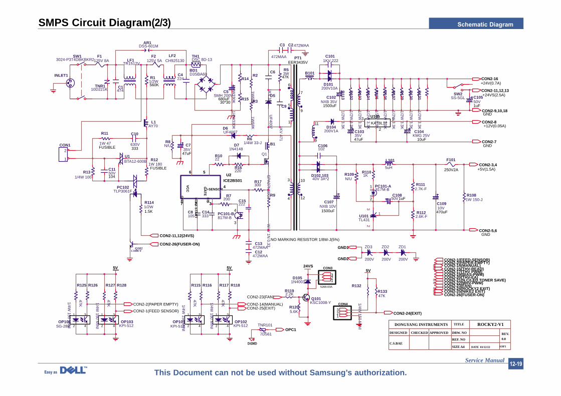
SMPS Circuit Diagram(2/3)
+24VS(2.5A)
+5V(1.5A)
GND
12
7
GND
EER3435V
9
3
4
6
10
NO MARKING RESISTOR 1/8W-J(5%)
+24V(0.7A)
250V2A
TITLE
DRW. NO
REF. NO
SIZE A4 DATE 03/12/22
ROCKY2-V1
REV.
0.0
1OF1
DESIGNED CHECKED APPROVED
DONGYANG INSTRUMENTS
C.S.BAE
KA78L1213
2
GND
+12V(0.05A)
U105
5
9
11
30*30
4
3
1
2
1
SO
FT-S
TAR
T
56
I-SENSOR
GA
TE
GN
D
F/B
VC
C
7 32
ICE2BS01U2
4
1
2
3
4
1 3
42
5V
1
2
3
4
1 3
42
5V 24VS
5268-03A
CON3
DGND
CON4
5V
F1125V 8A
TNR110D221K C1
474
LF1TR1512V
D5
UF
4007
C6
1KV
103
R53W
47K
U1BTA12-600B
L1AY70
C10
630V333
R11
1W 47FUSIBLE
R131/4W 100
R121W 180FUSIBLE
R1141/2W1.5K
F2125V 5A
R14
1/4W330K
C1150V104
PT1
PC101-A817M-B
L101
5uH
R109N/U
R1101K
R1112.7K-F
C10850V1uF
C1011KV 222
C106102
D101200V10A
R2
1W68K
F101
CON1
1
2
Q102C1008-Y
D102,10340V 3A*2
C3
472MAA
INLET1
SW2SS-5GL
D104200V1A
C10335V47uF
C104KMG 25V
10uF
SW13024-P3T4DBKBKR2
C9
1KV
471
R16220
C15222
R17300
R7200
C8105
C13472MAA
C12472MAA
R11/2W560K
C4224
LF2CH925130
AR1DSS-601M
PC101-B817M-B
C14333
D6UF4007
B1
R3
1W68K
R9
W.W
1N 0.33
SP
A07N
60C3
Q1
D71N4148
C735V
47uF
R8N/U
R1022
R61/4W 33-J
R129
1/2W 3.3K
R106
1/2W 3.3K
R104
1/2W 3.3K
R1122.6K-F
R130
1/2W 3.3K
R105
1/2W 3.3K
R113
1/2W 3.3K
R103
1/2W 3.3K
C102NXB 35V
1500uF
C10910V
470uFR
1021/2W
3.3K
C10550V1uF
C107NXB 10V1500uF
R131
1/2W 3.3K
R107
1/2W 3.3K
R1081W 150-J
C2 472MAA
U101TL431
23
1
PC102TLP3061F
R125
1/4W 150 M
INI
R126
47K
OP104SG-288
R127
1/4W 150 M
INI
R128
47K
OP103KPI-512
R115
1/4W 150 M
INI
R116
47K
OP101KPI-512
R117
1/4W 150 M
INI
R118
47K
OP102KPI-512
Q101KSC1008-Y
D1051N4003
R1192.2K
R1205.6K
TNR101
7D561
TH1DSC 8D-13
R15
1/4W330K
BD1D3SBA60
- +
C5SMH 200V
680uF
B101
R132
1/4W 150 M
INI
R13347K
ZD3
200V
ZD2
200V
ZD1
200V
CON2-11,12(24VS)
CON2-26(FUSER-ON)
CON2-3,4
CON2-16
CON2-11,12,13
CON2-8
CON2-7
CON2-5,6
CON2-9,10,18
CON2-1(FEED SENSOR)
CON2-2(PAPER EMPTY)CON2-25(EXIT)CON2-14(MANUAL)
CON2-23(FAN)
13
OPC1
321
2
GND1
CON2-24(EXIT)
GND2
CON2-20(THV-EA)
CON2-14(MANUAL)CON2-15(THV-READ)CON2-19(BIAS-PWM)
CON2-23(FAN)CON2-25(NIKE2 EXIT)CON2-26(FUSER-ON)
CON2-2(PAPER-EMPTY)CON2-1(FEED-SENSOR)
CON2-17(THV PWM)
CON2-24(ROCKY2 EXIT)CON2-22(MHV-PWM)CON2-21(N.C/LED TONER SAVE)

Schematic Diagram
Service Manual12-20
This Document can not be used without Samsung’s authorization.
SMPS Circuit Diagram(3/3)
+24VS(2.5A)
+5V(1.5A)
GND
12
7
GND
EER3435V
9
3
4
6
10
NO MARKING RESISTOR 1/8W-J(5%)
+24V(0.7A)
250V2A
TITLE
DRW. NO
REF. NO
SIZE A4 DATE 03/12/22
ROCKY2-V1
REV.
0.0
1OF1
DESIGNED CHECKED APPROVED
DONGYANG INSTRUMENTS
C.S.BAE
KA78L1213
2
GND
+12V(0.05A)
U105
5
9
11
30*30
4
3
1
2
1
SO
FT-S
TAR
T
56
I-SENSOR
GA
TE
GN
D
F/B
VC
C
7 32
ICE2BS01U2
4
1
2
3
4
1 3
42
5V
1
2
3
4
1 3
42
5V 24VS
5268-03A
CON3
DGND
CON4
5V
F1125V 8A
TNR110D221K C1
474
LF1TR1512V
D5
UF
4007
C6
1KV
103
R53W
47K
U1BTA12-600B
L1AY70
C10
630V333
R11
1W 47FUSIBLE
R131/4W 100
R121W 180FUSIBLE
R1141/2W1.5K
F2125V 5A
R14
1/4W330K
C1150V104
PT1
PC101-A817M-B
L101
5uH
R109N/U
R1101K
R1112.7K-F
C10850V1uF
C1011KV 222
C106102
D101200V10A
R2
1W68K
F101
CON1
1
2
Q102C1008-Y
D102,10340V 3A*2
C3
472MAA
INLET1
SW2SS-5GL
D104200V1A
C10335V47uF
C104KMG 25V
10uF
SW13024-P3T4DBKBKR2
C9
1KV
471
R16220
C15222
R17300
R7200
C8105
C13472MAA
C12472MAA
R11/2W560K
C4224
LF2CH925130
AR1DSS-601M
PC101-B817M-B
C14333
D6UF4007
B1
R3
1W68K
R9
W.W
1N 0.33
SP
A07N
60C3
Q1
D71N4148
C735V
47uF
R8N/U
R1022
R61/4W 33-J
R129
1/2W 3.3K
R106
1/2W 3.3K
R104
1/2W 3.3K
R1122.6K-F
R130
1/2W 3.3K
R105
1/2W 3.3K
R113
1/2W 3.3K
R103
1/2W 3.3K
C102NXB 35V
1500uF
C10910V
470uFR
1021/2W
3.3K
C10550V1uF
C107NXB 10V1500uF
R131
1/2W 3.3K
R107
1/2W 3.3K
R1081W 150-J
C2 472MAA
U101TL431
23
1
PC102TLP3061F
R125
1/4W 150 M
INI
R126
47K
OP104SG-288
R127
1/4W 150 M
INI
R128
47K
OP103KPI-512
R115
1/4W 150 M
INI
R116
47K
OP101KPI-512
R117
1/4W 150 M
INI
R118
47K
OP102KPI-512
Q101KSC1008-Y
D1051N4003
R1192.2K
R1205.6K
TNR101
7D561
TH1DSC 8D-13
R15
1/4W330K
BD1D3SBA60
- +
C5SMH 200V
680uF
B101
R132
1/4W 150 M
INI
R13347K
ZD3
200V
ZD2
200V
ZD1
200V
CON2-11,12(24VS)
CON2-26(FUSER-ON)
CON2-3,4
CON2-16
CON2-11,12,13
CON2-8
CON2-7
CON2-5,6
CON2-9,10,18
CON2-1(FEED SENSOR)
CON2-2(PAPER EMPTY)CON2-25(EXIT)CON2-14(MANUAL)
CON2-23(FAN)
13
OPC1
321
2
GND1
CON2-24(EXIT)
GND2
CON2-20(THV-EA)
CON2-14(MANUAL)CON2-15(THV-READ)CON2-19(BIAS-PWM)
CON2-23(FAN)CON2-25(NIKE2 EXIT)CON2-26(FUSER-ON)
CON2-2(PAPER-EMPTY)CON2-1(FEED-SENSOR)
CON2-17(THV PWM)
CON2-24(ROCKY2 EXIT)CON2-22(MHV-PWM)CON2-21(N.C/LED TONER SAVE)
Schematic Diagram
Service Manual12-21
This Document can not be used without Samsung’s authorization.
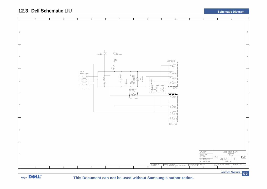
12.3 Dell Schematic LIU
![[1] DESCRIPTION OF SCHEMATIC DIAGRAM - Sharp 9 – 1 LC32M400MBK CHAPTER 9. SCHEMATIC DIAGRAM Service Manual [1] DESCRIPTION OF SCHEMATIC DIAGRAM 1. VOLTAGE MEASUREMENT CONDITION:](https://img.pdfslide.net/doc/110x75/5abbca057f8b9a24028d0558/1-description-of-schematic-diagram-9-1-lc32m400mbk-chapter-9-schematic.jpg)