Embed Size (px)
Citation preview
Dell Shared PowerEdge RAID Controller 8 Cards For Dell PowerEdge VRTX SystemsUser’s Guide
Regulatory Model: UCPM-800
Notes, cautions, and warnings
NOTE: A NOTE indicates important information that helps you make better use of your product.
CAUTION: A CAUTION indicates either potential damage to hardware or loss of data and tells you how to avoid the problem.
WARNING: A WARNING indicates a potential for property damage, personal injury, or death.
© 2017 - 2018 Dell Inc. or its subsidiaries. All rights reserved. Dell, EMC, and other trademarks are trademarks of Dell Inc. or its subsidiaries. Other trademarks may be trademarks of their respective owners.
2018 - 02
Rev. A07
Contents
1 About the Shared PERC 8 card...................................................................................................................... 6Configurations of the Shared PERC 8 card.................................................................................................................... 7Specifications of a Shared PERC 8 card.........................................................................................................................8
Operating temperature of a Shared PERC 8 card................................................................................................... 9Supported operating systems...........................................................................................................................................9Best practices for Shared PERC 8................................................................................................................................. 10Documentation matrix......................................................................................................................................................10
2 Shared PERC 8 card features....................................................................................................................... 12Physical disk power management...................................................................................................................................12Consistency Checks......................................................................................................................................................... 12Virtual disk initialization.................................................................................................................................................... 13
Background Initialization of virtual disks.................................................................................................................. 13Full Initialization of virtual disks................................................................................................................................. 13Fast Initialization of virtual disks............................................................................................................................... 13
Physical disk roaming....................................................................................................................................................... 13Using physical disk roaming....................................................................................................................................... 14
FastPath.............................................................................................................................................................................14Virtual disk migration........................................................................................................................................................ 14
Migrating virtual disks if the target system is turned off....................................................................................... 15Migrating virtual disks if the target system is turned on....................................................................................... 15
Virtual disk cache policies................................................................................................................................................ 15Virtual disk write cache policies................................................................................................................................ 15Write-back .................................................................................................................................................................. 16Conditions under which write-back is employed.................................................................................................... 16Conditions under which forced write-back with no battery is employed............................................................ 16Write-through..............................................................................................................................................................16Conditions under which write-through is employed...............................................................................................16Virtual disk read cache policies................................................................................................................................. 16
Physical disk write cache policy...................................................................................................................................... 17Fault tolerance...................................................................................................................................................................17
The SMART feature....................................................................................................................................................17Auto replace member................................................................................................................................................. 18Patrol Read.................................................................................................................................................................. 18Physical disk failure detection................................................................................................................................... 19Physical disk hot swapping........................................................................................................................................19Shared PERC 8 card cache preservation................................................................................................................ 19Battery Transparent Learn Cycle............................................................................................................................. 20The controller failover feature.................................................................................................................................. 20
Multipath support............................................................................................................................................................ 20
3 Deploying the Shared PERC 8 card.............................................................................................................. 21Safety instructions............................................................................................................................................................21
Contents 3
Installing a new Shared PERC 8 Internal card...............................................................................................................21Replacing a Shared PERC 8 Internal card......................................................................................................................21
Prerequisites for removing the Shared PERC 8 Internal card.............................................................................. 22Removing the Shared PERC 8 Internal card.......................................................................................................... 22Installing the Shared PERC 8 Internal card.............................................................................................................23Postinstallation tasks for the Shared PERC 8 Internal card................................................................................. 24
Installing a new Shared PERC 8 External card.............................................................................................................24Replacing a Shared PERC 8 External card....................................................................................................................24
Prerequisites for removing the Shared PERC 8 External card.............................................................................25Removing the Shared PERC 8 External card......................................................................................................... 26Installing the Shared PERC 8 External card............................................................................................................27Postinstallation tasks for the Shared PERC 8 External card................................................................................ 32
Prerequisites for transition scenarios.............................................................................................................................33Transition scenarios......................................................................................................................................................... 33
Single controller nonfault tolerance to dual controller fault tolerance................................................................. 33Two existing non-fault tolerant controllers to fault tolerant configuration..........................................................34
4 Firmware and driver installation................................................................................................................... 35Downloading drivers and firmware for Shared PERC 8 from the Dell support website for all operating systems............................................................................................................................................................................. 35Downloading drivers from the Dell Systems Service and Diagnostic Tools media for Windows............................36Installing or updating Windows drivers for Shared PERC 8....................................................................................... 36Installing or updating Linux drivers for Shared PERC 8...............................................................................................37
Installing or updating the driver package on RHEL using KMOD support.......................................................... 37Installing or updating the driver package on SLES using KMP support..............................................................37
Installing or updating VMware drivers for Shared PERC 8.........................................................................................38Firmware installation or update...................................................................................................................................... 38
Updating firmware..................................................................................................................................................... 38
5 Multipath and clustering setup.................................................................................................................... 39Configuring multipath support in Windows.................................................................................................................. 39Multipath setup in Windows...........................................................................................................................................39
Clustering setup in Windows.................................................................................................................................... 40Configuring multipath support in VMware....................................................................................................................40Multipath and clustering setup in VMware...................................................................................................................40Multipath and clustering support for Linux....................................................................................................................41
Installing multipath in Linux........................................................................................................................................41Multipath configuration in SLES............................................................................................................................... 41Multipath configuration in RHEL..............................................................................................................................42Multipath files for Linux multipath configuration................................................................................................... 43Clustering setup in Linux........................................................................................................................................... 47General recommendations for Multipath setup in a Linux environment..............................................................47
6 Management applications for Shared PERC 8 card......................................................................................48
7 Security key and RAID management............................................................................................................ 49Security key implementation.......................................................................................................................................... 49
4 Contents
Configuration and management of SED capable hard drives...............................................................................49Troubleshooting security key errors...............................................................................................................................50
Secured foreign import errors.................................................................................................................................. 50Failure to select or configure non self-encrypting disks........................................................................................50Failure to delete security key....................................................................................................................................50Failure to cryptograhic erase task on physical disks..............................................................................................50
8 Troubleshooting............................................................................................................................................51General issues................................................................................................................................................................... 51
Shared PERC 8 card not seen in Device Manager.................................................................................................51Critical errors or disk warning messages seen in the Windows Event log...........................................................51Shared PERC 8 cards fail to function......................................................................................................................52Fatal error or data corruption reported................................................................................................................... 52EMM failure message seen after EMM firmware update..................................................................................... 52Erratic drive LED behavior after EMM Firmware update......................................................................................52Performance variations between write-back and write-through cache modes................................................ 52
Physical disk issues..........................................................................................................................................................53Physical disk in failed state....................................................................................................................................... 53Capable speed of a drive being shown as blank.................................................................................................... 53Physical disk displayed as Blocked by management application.......................................................................... 53Multiple disks become inaccessible......................................................................................................................... 53Rebuilding a Failed physical disk...............................................................................................................................54Foreign dedicated hot spare shown as global hot spare in CMC’s foreign configuration preview before foreign configuration import..................................................................................................................................... 54Physical disk takes a long time to rebuild................................................................................................................54SMART Errors............................................................................................................................................................ 54Auto Replacement Member errors.......................................................................................................................... 55
Virtual disks issues...........................................................................................................................................................56Degraded state of virtual disks.................................................................................................................................56Unable to rebuild a fault tolerant virtual disk.......................................................................................................... 56Virtual disk fails during rebuild using a global hot spare........................................................................................ 56Virtual disk fails during rebuild using a dedicated hot spare................................................................................. 56Virtual disk cannot be added to a disk group undergoing rebuild........................................................................ 56
Driver issues..................................................................................................................................................................... 56Shared PERC 8 card has yellow exclamation mark in device manager...............................................................57Incorrect number of virtual disks displayed in Windows Disk Manager...............................................................57
Controller issues............................................................................................................................................................... 57Controller cache issues..............................................................................................................................................57Shared PERC 8 card boots into safe mode............................................................................................................ 58
Hard drive indicator codes..............................................................................................................................................59
9 Getting help................................................................................................................................................. 61Contacting Dell..................................................................................................................................................................61Locating Service Tag of your system............................................................................................................................. 61
Contents 5
About the Shared PERC 8 cardNOTE: Unless noted otherwise, all references to Shared PERC 8 throughout the document see both Internal and External Shared PERC 8 cards.
The Dell Shared PowerEdge RAID controller (PERC) 8 card is a storage controller designed specifically for the Dell PowerEdge VRTX System. The Shared PERC 8 card supports Single Root Input Output Virtualization (SR-IOV), which allows multiple systems to share available hardware resources.
The controller allows four server modules to access a local storage. Each server module's operating system (OS) loads a Virtual Function (VF) driver that allows the server module to communicate with the Shared PERC 8 firmware. Virtual disks on the shared storage can then be mapped to a server module. From a single-server module, you can only access the virtual disks that are mapped to that server module. Storage domains are independent on Shared PERC 8 Internal and External cards. That is, the Internal card cannot access disks connected to an External card and vice versa. However, migration of disks from Shared PERC 8 Internal to External cards is possible as long as they have the same firmware.
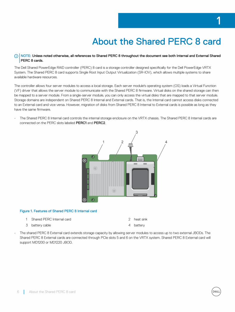
• The Shared PERC 8 Internal card controls the internal storage enclosure on the VRTX chassis. The Shared PERC 8 Internal cards are connected on the PERC slots labeled PERC1 and PERC2.
Figure 1. Features of Shared PERC 8 Internal card
1 Shared PERC Internal card 2 heat sink
3 battery cable 4 battery
• The shared PERC 8 External card extends storage capacity by allowing server modules to access up to two external JBODs. The Shared PERC 8 External cards are connected through PCIe slots 5 and 6 on the VRTX system. Shared PERC 8 External card will support MD1200 or MD1220 JBOD.
1
6 About the Shared PERC 8 card
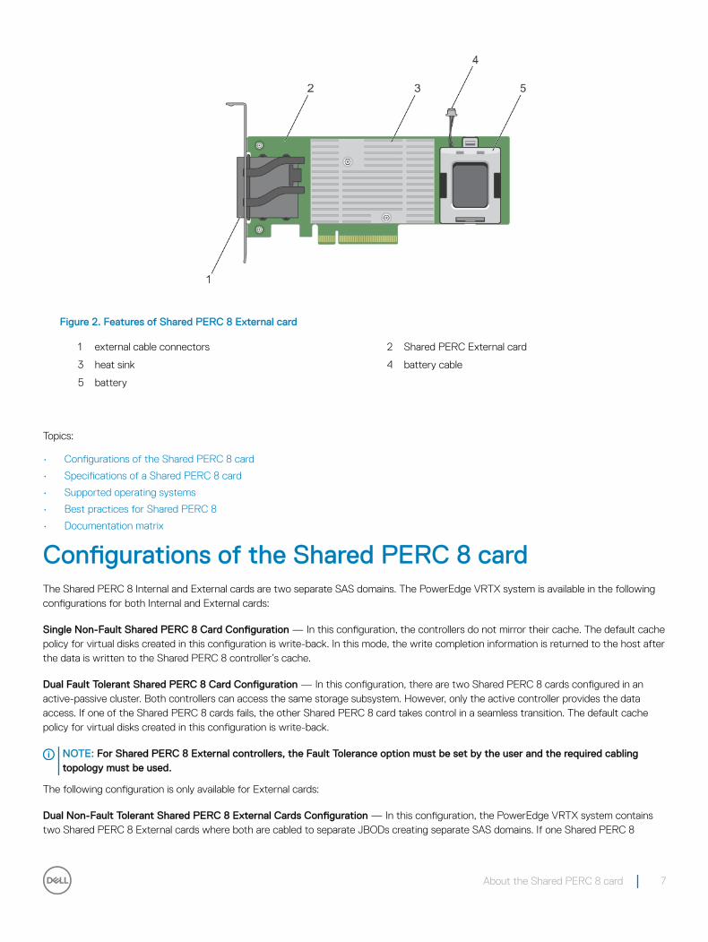
Figure 2. Features of Shared PERC 8 External card
1 external cable connectors 2 Shared PERC External card
3 heat sink 4 battery cable
5 battery
Topics:
• Configurations of the Shared PERC 8 card
• Specifications of a Shared PERC 8 card
• Supported operating systems
• Best practices for Shared PERC 8
• Documentation matrix
Configurations of the Shared PERC 8 cardThe Shared PERC 8 Internal and External cards are two separate SAS domains. The PowerEdge VRTX system is available in the following configurations for both Internal and External cards:
Single Non-Fault Shared PERC 8 Card Configuration — In this configuration, the controllers do not mirror their cache. The default cache policy for virtual disks created in this configuration is write-back. In this mode, the write completion information is returned to the host after the data is written to the Shared PERC 8 controller’s cache.
Dual Fault Tolerant Shared PERC 8 Card Configuration — In this configuration, there are two Shared PERC 8 cards configured in an active-passive cluster. Both controllers can access the same storage subsystem. However, only the active controller provides the data access. If one of the Shared PERC 8 cards fails, the other Shared PERC 8 card takes control in a seamless transition. The default cache policy for virtual disks created in this configuration is write-back.
NOTE: For Shared PERC 8 External controllers, the Fault Tolerance option must be set by the user and the required cabling topology must be used.
The following configuration is only available for External cards:
Dual Non-Fault Tolerant Shared PERC 8 External Cards Configuration — In this configuration, the PowerEdge VRTX system contains two Shared PERC 8 External cards where both are cabled to separate JBODs creating separate SAS domains. If one Shared PERC 8
About the Shared PERC 8 card 7
External card fails, access to the storage subsystem attached to that card is lost. This configuration option is not available for Shared PERC 8 Internal cards.
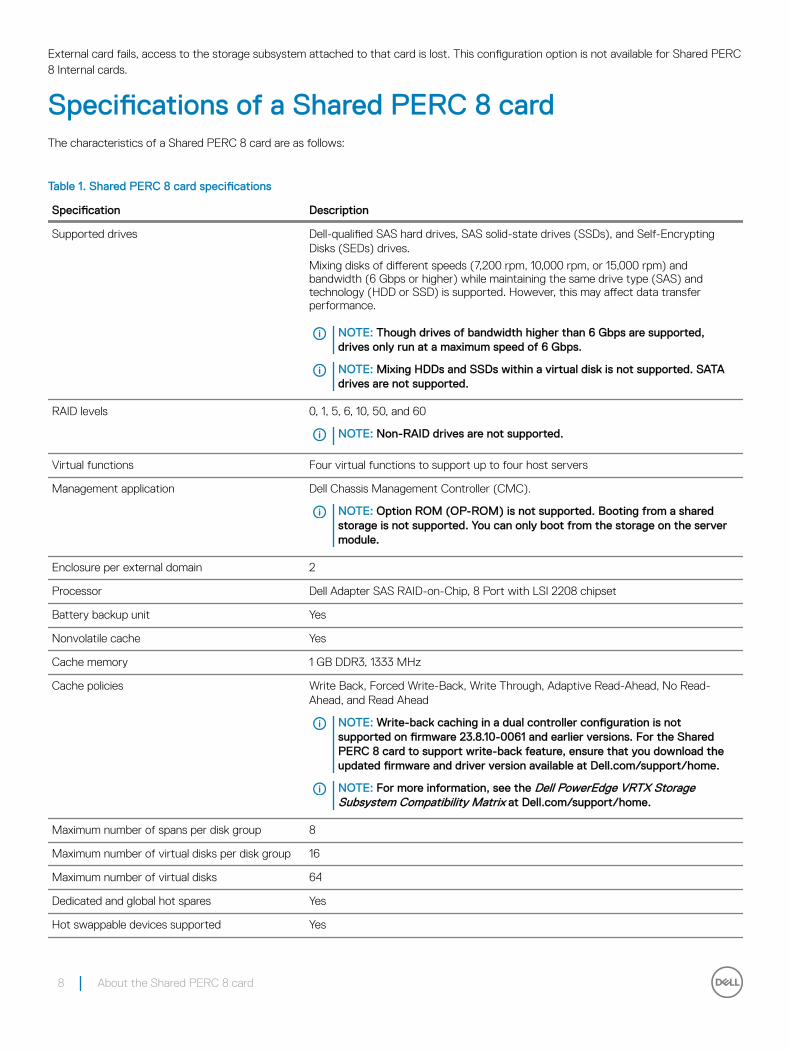
Specifications of a Shared PERC 8 cardThe characteristics of a Shared PERC 8 card are as follows:
Table 1. Shared PERC 8 card specifications
Specification Description
Supported drives Dell-qualified SAS hard drives, SAS solid-state drives (SSDs), and Self-Encrypting Disks (SEDs) drives.
Mixing disks of different speeds (7,200 rpm, 10,000 rpm, or 15,000 rpm) and bandwidth (6 Gbps or higher) while maintaining the same drive type (SAS) and technology (HDD or SSD) is supported. However, this may affect data transfer performance.
NOTE: Though drives of bandwidth higher than 6 Gbps are supported, drives only run at a maximum speed of 6 Gbps.
NOTE: Mixing HDDs and SSDs within a virtual disk is not supported. SATA drives are not supported.
RAID levels 0, 1, 5, 6, 10, 50, and 60
NOTE: Non-RAID drives are not supported.
Virtual functions Four virtual functions to support up to four host servers
Management application Dell Chassis Management Controller (CMC).
NOTE: Option ROM (OP-ROM) is not supported. Booting from a shared storage is not supported. You can only boot from the storage on the server module.
Enclosure per external domain 2
Processor Dell Adapter SAS RAID-on-Chip, 8 Port with LSI 2208 chipset
Battery backup unit Yes
Nonvolatile cache Yes
Cache memory 1 GB DDR3, 1333 MHz
Cache policies Write Back, Forced Write-Back, Write Through, Adaptive Read-Ahead, No Read-Ahead, and Read Ahead
NOTE: Write-back caching in a dual controller configuration is not supported on firmware 23.8.10-0061 and earlier versions. For the Shared PERC 8 card to support write-back feature, ensure that you download the updated firmware and driver version available at Dell.com/support/home.
NOTE: For more information, see the Dell PowerEdge VRTX Storage Subsystem Compatibility Matrix at Dell.com/support/home.
Maximum number of spans per disk group 8
Maximum number of virtual disks per disk group 16
Maximum number of virtual disks 64
Dedicated and global hot spares Yes
Hot swappable devices supported Yes
8 About the Shared PERC 8 card
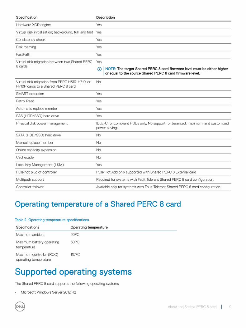
Specification Description
Hardware XOR engine Yes
Virtual disk initialization; background, full, and fast Yes
Consistency check Yes
Disk roaming Yes
FastPath Yes
Virtual disk migration between two Shared PERC 8 cards
Yes
NOTE: The target Shared PERC 8 card firmware level must be either higher or equal to the source Shared PERC 8 card firmware level.
Virtual disk migration from PERC H310, H710, or H710P cards to a Shared PERC 8 card
No
SMART detection Yes
Patrol Read Yes
Automatic replace member Yes
SAS (HDD/SSD) hard drive Yes
Physical disk power management IDLE-C for compliant HDDs only. No support for balanced, maximum, and customized power savings.
SATA (HDD/SSD) hard drive No
Manual replace member No
Online capacity expansion No
Cachecade No
Local Key Management (LKM) Yes
PCIe hot plug of controller PCIe Hot Add only supported with Shared PERC 8 External card
Multipath support Required for systems with Fault Tolerant Shared PERC 8 card configuration.
Controller failover Available only for systems with Fault Tolerant Shared PERC 8 card configuration.
Operating temperature of a Shared PERC 8 card
Table 2. Operating temperature specifications
Specifications Operating temperature
Maximum ambient 60°C
Maximum battery operating temperature
60°C
Maximum controller (ROC) operating temperature
115°C
Supported operating systemsThe Shared PERC 8 card supports the following operating systems:
• Microsoft Windows Server 2012 R2
About the Shared PERC 8 card 9
• Microsoft Windows Server 2012
• Microsoft Windows Server 2008 R2
• Red Hat Enterprise Linux (RHEL) 6 Update 5
• RHEL 6 Update 6
• RHEL 6 Update 7
• RHEL 7.1
• SUSE Enterprise Linux (SLES) 11 SP4
• SLES 11 SP3
• SLES 12
• VMware ESXi 5.5
• VMware ESXi 6.0 and later
NOTE: For information on supported software and hardware for the PowerEdge VRTX system, see PowerEdge VRTX Storage Subsystem Compatibility Matrix at Dell.com/support/manuals.
Best practices for Shared PERC 8• Always use the latest firmware and drivers from Dell.com/support/drivers.
• Always keep a copy of your virtual disk configuration and server node mapping information. To document your virtual drive configuration and mapping information, perform the following steps:
a Open CLI terminal and run the command racadm raid get vdisks –o. Take a screen shot of the results page and save the captured screen shot to a location of choice, or write down the information and store it in a safe, secure location.
b Click Chassis Overview → Storage → Virtual Disks → Assign to view the virtual disk mapping by the CMC GUI. Take a screen shot of the results page and save the captured screen shot to a location of choice, or write down the information and store it in a safe, secure location.
c Click Chassis Overview → Storage → Virtual Disks to get the virtual disk configuration information by the CMC GUI. Take a screen shot of the results page and save the captured screen shot to a location of choice, or write down the information and store it in a safe, secure location.
Documentation matrixThe documentation matrix provides information on documents that you can see, for setting up and managing your system.
Table 3. Documentation matrix
To... See the...
Set up your system and know the system technical specifications Dell PowerEdge VRTX Getting Started With Your System that shipped with your system or see at Dell.com/poweredgemanuals
Know the minimum driver and firmware requirements for the components of the Dell PowerEdge VRTX storage subsystem.
Dell PowerEdge VRTX Storage Subsystem Compatibility Matrix at Dell.com/poweredgemanuals
Set up and configure your system Setup placemat
Know the server module features, remove and install server module components, troubleshoot server module components
Dell PowerEdge VRTX Enclosure Owner's Manual at Dell.com/poweredgemanuals
Update the M1000e server modules to be used in the VRTX chassis Preparing Dell PowerEdge Blade Servers for Migration Between PowerEdge M1000e and PowerEdge VRTX Chassis at Dell.com/poweredgemanuals
Install your system into a rack Rack documentation included with your rack solution
Know about I/O module features, configure the I/O module and additional I/O module information
I/O module documentation at Dell.com/poweredgemanuals
10 About the Shared PERC 8 card
To... See the...
Install, configure, and use the Chassis Management Controller (CMC)
Dell Chassis Management Controller for Dell PowerEdge VRTX User’s Guide at Dell.com/poweredgemanuals
See the error and event messages generated by the firmware or other agents that monitor system components
Dell PowerEdge VRTX Chassis Management Controller Firmware Event Message Reference Guide at Dell.com/poweredgemanuals
See the instructions for the current page on the CMC web interface
The CMC Online Help. To access the Online Help, click Help on the CMC web interface.
Configure and log in to iDRAC, set up managed and management system, know the iDRAC features and troubleshoot using iDRAC
Integrated Dell Remote Access Controller User's Guide at Dell.com/idracmanuals
Get an overview of the Dell Systems Management offerings Dell OpenManage Systems Management Overview Guide at Dell.com/openmanagemanuals > OpenManage software
Know the features of the storage controller cards, deploy the cards, and manage the storage subsystem
Storage controller documentation at Dell.com/storagecontrollermanuals
Set up, use, and troubleshoot OpenManage Server Administrator Dell OpenManage Server Administrator User’s Guide at Dell.com/openmanagemanuals > OpenManage Server Administrator
Install, use and troubleshoot OpenManage Essentials Dell OpenManage Essentials User’s Guide at Dell.com/openmanagemanuals
Know about the RACADM subcommands and supported RACADM interfaces
RACADM Command-Line Reference Guide for iDRAC and CMC at Dell.com/idracmanuals
Use Lifecycle Controller Remote Services Dell Lifecycle Controller Remote Services Quick Start Guide at Dell.com/idracmanuals
Launch, enable and disable Lifecycle Controller, know the features, use and troubleshoot Lifecycle Controller
Dell Lifecycle Controller User’s Guide at Dell.com/esmmanuals
Upgrade PowerEdge VRTX to support shared storage expansion Upgrading PowerEdge VRTX to Support Shared Storage Expansion at Dell.com/poweredgemanuals
NOTE: Always check for updates on Dell.com/support/manuals and read the updates first because they often supersede information in other documents.
About the Shared PERC 8 card 11
Shared PERC 8 card featuresSome of the features of the Shared PERC 8 card are as follows:
• Physical disk power management
• Consistency checks
• Virtual disk initialization
• Disk roaming
• FastPath
• Virtual disk migration
• Virtual disk cache policies
• Fault tolerance
• Patrol read
• Multipath support
• Supports controller level encryption
Topics:
• Physical disk power management
• Consistency Checks
• Virtual disk initialization
• Physical disk roaming
• FastPath
• Virtual disk migration
• Virtual disk cache policies
• Physical disk write cache policy
• Fault tolerance
• Multipath support
Physical disk power managementPhysical disk power management is a power-saving feature of the Shared PERC 8 card. Idle-C feature, as defined by the T10 organization, is autoenabled for physical disk power management. Physical disks that support Idle-C feature, spin at lower RPMs upon timer expiration when there is no I/O activity.
NOTE: There is a delay to I/O operations when a configured disk is being spun up.
NOTE: For detailed information about power management, see the Dell Chassis Management Controller for Dell PowerEdge VRTX User’s Guide at Dell.com/poweredgemanuals.
Consistency ChecksConsistency Check (CC) is a background operation that verifies and corrects the mirror or parity data for fault tolerant virtual disks. Dell recommends that you periodically run a CC on virtual disks. You can manually start a CC in the Dell Chassis Management Controller (CMC).
NOTE: For more information about consistency checks, see the Dell Chassis Management Controller for Dell PowerEdge VRTX Online Help.
2
12 Shared PERC 8 card features
Virtual disk initializationYou can initialize virtual disks as described in the following sections.
Background Initialization of virtual disksBoth Consistency Check (CC) and Background Initialization (BGI) correct parity errors. However, CC reports data inconsistencies through an event notification, whereas BGI is an automatic process.
BGI does not run on RAID 0 virtual disks. You cannot disable BGI permanently. If you cancel BGI, it automatically restarts within five minutes. Unlike Full or Fast Initialization of virtual disks, BGI does not clear data from the physical disks. CC and BGI typically cause some loss in performance until the operation completes.
NOTE: In systems with Fault Tolerant Shared PERC 8 card configuration, in the event of controller failover, a BGI starts automatically on each virtual disk. If a BGI operation was in progress at the time of controller failover, then the BGI resumes on the new active Shared PERC 8 controller from the last recorded checkpoint.
Full Initialization of virtual disksCAUTION: Performing a Full Initialization on a virtual disk destroys any data that previously existed on the virtual disk.
A Full Initialization of a virtual disk overwrites all blocks and destroys any data that previously existed on the virtual disk. Full Initialization of a virtual disk eliminates the need for the virtual disk to undergo a BGI. Full Initialization is often performed immediately after the creation of a virtual disk.
During Full Initialization, the host is not able to access the virtual disk. You can start a Full Initialization on a virtual disk in the CMC.
In the event of a controller failover in systems with a Fault Tolerant Shared PERC 8 card configuration, Full Initialization does not continue on the active controller. You must start Full Initialization again through CMC. For more information on virtual disk initialization, see the Dell Chassis Management Controller for Dell PowerEdge VRTX User’s Guide at Dell.com/poweredgemanuals and the Dell Chassis Management Controller for Dell PowerEdge VRTX Online Help.
In the event of controller failover or system reboot during a Full Initialization, the operation terminates and a BGI begins on the virtual disk.
NOTE: Performing a Full Initialization prevents a BGI from starting automatically on virtual disks.
Fast Initialization of virtual disksCAUTION: Performing a Fast Initialization on a virtual disk destroys any data that previously existed on the virtual disk.
A Fast Initialization on a virtual disk overwrites the first and last 8 MB of the virtual disk, clearing any boot records or partition information. The operation takes only 2-3 seconds to complete and is recommended when you are recreating virtual disks. You can perform a Fast Initialization in the CMC.
NOTE: A BGI starts five minutes after the Fast Initialization is completed.
Physical disk roamingPhysical disk roaming is moving the physical disks from one backplane slot to another on the same controller. The controller automatically recognizes the relocated physical disks and logically places them in the virtual disks that are part of the disk group. You can perform disk roaming only when the system is turned off.
Shared PERC 8 card features 13
NOTE: If you are moving an entire just a bunch of disks (JBOD) enclosure, make sure to turn off the JBOD before cabling to the new controller.
Using physical disk roamingPerform the following steps to use disk roaming:
1 Turn off the power to the system, physical disks, enclosures, and system components.
2 Disconnect power cables from the system.
3 Move the physical disks to the required positions on the backplane or the enclosure.
4 Perform a safety check. Make sure the physical disks are inserted properly.
5 Turn on the system.
The controller detects the RAID configuration from the configuration data on the physical disks.
FastPathThe Shared PERC 8 card supports FastPath feature, which improves application performance by delivering high I/O per second (IOPS).
Under specific conditions with FastPath, the I/O bypasses the controller cache and is committed directly to the physical disk from the host memory or directly from the physical disk. All simple nonspanned virtual disks configured with Write-Through write-cache policy and No Read-Ahead read-cache policy can utilize FastPath.
Workloads on SSD volumes provide the most performance improvement with FastPath.
The following conditions support FastPath:
• Random workloads with small blocks.
• I/O block sizes smaller than virtual disk’s stripe size.
• Sequential read workloads on unspanned RAID volumes (RAID 0, RAID 1, RAID 5, and RAID 6).
• Sequential read and write workloads on RAID 0 virtual disks.
The following conditions do not support FastPath:
• Virtual disks running background operations such as rebuild, initialization, and so on.
• Spanned RAID volumes like RAID 10, RAID 50, and RAID 60.
Virtual disk migrationThe Shared PERC 8 card supports migration of virtual disks from one controller to another without taking the target controller offline. The controller can import RAID virtual disks in optimal, degraded, or partially degraded states. Migration of virtual disks from Shared PERC internal to Shared PERC external is supported.
The Shared PERC 8 card does not support virtual disk migration:
• Where the virtual disk is in a failed state.
• When the virtual disk is removed while the source system is turned on.
• From any other PERC cards such as PERC H310, H700, H710, H800, and H810.
The Shared PERC 8 card supports virtual disk migration:
• From a similar Shared PERC 8 card.
• From the Single Shared PERC 8 card configuration to the Fault Tolerant Shared PERC 8 card configuration, but not from a newer firmware version to an older firmware version system.
14 Shared PERC 8 card features
• From another system's Shared PERC 8 controller when the target system is either turned on or off.
NOTE: When a controller detects a physical disk with an existing configuration, it flags the physical disk as a foreign disk and generates an alert indicating that a foreign disk was detected.
Migrating virtual disks if the target system is turned off1 If installed, remove the front bezel (optional) from the PowerEdge VRTX enclosure.
2 Power down the server module using the operating system commands or the CMC, and ensure that the server module's power is off.
3 Turn off the chassis using CMC.
NOTE: For information about the chassis shutdown, see the Dell Chassis Management Controller for Dell PowerEdge VRTX User’s Guide at Dell.com/esmmanuals.
4 Move the appropriate physical disks from the source system to the target system with a similar Shared PERC 8 controller.
NOTE: If you are moving an entire just a bunch of disks (JBOD) enclosure, make sure to turn off the JBOD before cabling to the new controller.
5 Turn on the target system.
The system discovers and automatically imports the detected foreign configuration.
Migrating virtual disks if the target system is turned on1 Turn off the source system.
2 Move the appropriate physical disks from the source system to the target system with a similar Shared PERC 8 card.
NOTE: If you are moving an entire JBOD enclosure, make sure to turn off the JBOD before cabling to the new controller.
3 Access the Dell Chassis Management Controller (CMC) to import and clear the foreign configuration.
NOTE: For more information on importing or clearing the foreign configuration, see the Dell Chassis Management Controller for Dell PowerEdge VRTX User’s Guide at Dell.com/poweredgemanuals.
NOTE: If write cache is enabled for these virtual disks, ensure that all cache is flushed to the hard drives on the source system before removing them. This can be accomplished by stopping all applications, powering down the blades, and waiting 30 seconds before powering down the chassis.
Virtual disk cache policiesThe following virtual disk cache policies are supported on Shared PERC 8:
• Virtual disk write cache policies
• Virtual disk read cache policies
Virtual disk write cache policiesThe write cache policy of a virtual disk determines how the controller handles writes to the virtual disk. Write-back and write-through are the two write cache policies that can be set on virtual disks individually.
All RAID volumes are presented as write-through to the operating system independent of the actual write cache policy of the virtual disk. The Shared PERC 8 cards manage data in the cache independently of the operating system or any applications.
NOTE: Use the Dell Chassis Management Controller (CMC) to view and manage virtual disk cache settings.
Shared PERC 8 card features 15
Write-back In Write-back caching, the controller sends a data transfer completion signal to the host when the controller cache has received all the data in a transaction. The controller then writes the cached data to the storage device in the background.
The risk of using write-back cache is that the cached data can be lost if there is a power failure during or when the data is written to the storage device. This risk is mitigated by using a battery-backed non-volatile cache on the Shared PERC 8 card. See Shared PERC 8 card cache preservation for further information.
NOTE: The default cache setting for virtual disks in single and dual controller systems is write-back caching.
Conditions under which write-back is employedWrite-back caching is the default caching mode for single and dual Shared PERC 8 card configurations. Write-back caching can be configured under all conditions in which the battery is present and in good condition.
If a virtual disk is already created on the VRTX system with the firmware version that does not support write-back caching, then the default will remain as write-through. The virtual disk must be manually changed to write-back before it goes to write-back mode, even if the system has been updated to a write-back supported firmware version.
Conditions under which forced write-back with no battery is employed
CAUTION: It is recommended that you use a power backup system when forced write-back is enabled to ensure there is no loss of data if the system loses power.
Forced write-back mode may be enabled to allow the virtual disk to operate in write-back mode even if the battery is not present or not functioning properly.
Write-throughIn write-through caching, the controller sends a data transfer completion signal to the host system when the disk subsystem has received all the data in a transaction.
NOTE: Most configurations and workloads experience some reduction in performance when configured with Write-Through cache, as compared to Write-Back cache.
Conditions under which write-through is employedWrite-through caching is used under conditions in which the battery fails or is not present. Write-Through is also enabled when the controller has pinned cache.
Virtual disk read cache policiesThe read policy of a virtual disk determines how the controller handles reads to that virtual disk. The read policies are:
• Read Ahead — Allows the controller to read sequentially ahead of the requested data and store the additional data in cache memory. This speeds up reads for sequential data, but there is little improvement when accessing random data.
16 Shared PERC 8 card features
• No Read Ahead — Disables the Read-Ahead capability.
• Adaptive Read Ahead — Read Ahead Mode is used when the two most recent disk accesses occurred in sequential sectors, otherwise the controller reverts to No Read Ahead mode.
NOTE: The default read cache setting for virtual disks is Adaptive Read Ahead.
Physical disk write cache policyManagement utilities provide the option to modify disk cache policies for physical disks associated with a virtual disk. The following options are available for the Shared PERC controller:
Option Description
Enabled Enables physical disk cache for drives associated with the selected virtual disk.
Disabled Disables physical disk cache for drives associated with the selected virtual disk.
Default The default cache policy on the physical disk is used. See the physical disk documentation for details on the default setting.
WARNING: Enabling physical disk cache is not recommended for disks with critical data as a power failure may result in the loss of data prior to it being flushed to the persistent media.
NOTE: Any change to the physical disk cache applies to all virtual disks in an entire disk group. It is not possible to have different cache policies on virtual disks from the same disk group.
Fault toleranceThe fault tolerance features of Shared PERC 8 are as follows:
• Support for Self Monitoring and Reporting Technology (SMART)
• Support for Patrol Read
• Physical disk failure detection
• Physical disk rebuild using hot spares
• Controller Cache Preservation
• Battery and non-volatile cache backup of controller cache to protect data
• Detection of batteries with low charge after boot up
• Support for controller failover in systems with Fault Tolerant Shared PERC 8 card configuration.
The following sections describe some methods to achieve fault tolerance.
The SMART featureThe SMART feature monitors certain physical aspects of all motors, heads, and physical disk electronics to help detect predictable physical disk failures. Data on SMART-compliant physical disks can be monitored to identify changes in values and determine whether the values are within threshold limits. Many mechanical and electrical failures display some degradation in performance before failure.
A SMART failure is also referred to as predicted failure. There are numerous factors that are predicted physical disk failures, such as a bearing failure, a broken read/write head, and changes in spin-up rate. In addition, there are factors related to read/write surface failure, such as seek error rate and excessive bad sectors.
NOTE: For detailed information on SCSI interface specifications, see t10.org and for detailed information on SATA interface specifications, see t13.org.
Shared PERC 8 card features 17
Auto replace memberThe automatic Replace Member functionality allows a previously commissioned hot spare to be reverted to a usable hot spare. When a disk failure occurs within a virtual disk, an assigned hot spare (dedicated or global) is commissioned and begins rebuilding until the virtual disk is optimal. After the failed physical disk is replaced (in the same slot) and the rebuild is complete, the Shared PERC 8 card automatically starts to copy data from the commissioned hot spare to the newly inserted disk. After the data is copied, the new disk is a part of the virtual disk and the hot spare is reverted to a ready hot spare. This allows hot spares to remain in specific enclosure slots. While the Shared PERC 8 card is reverting the hot spare, the virtual disk remains optimal.
The physical disk with the SMART error is marked as Failed only after the successful completion of the Replace Member. This avoids putting the array in degraded status. If an automatic Replace Member occurs using a source disk that was originally a hot spare (that was used in a rebuild), and a new disk added for the Replace Member operation as the target disk, the hot spare reverts to the hot spare state after a successful Replace Member operation.
NOTE: The Shared PERC 8 card automatically reverts a hot spare only if the failed disk is replaced with a new disk in the same slot.
NOTE: A Replace Member operation typically has a temporary impact on disk performance. After the operation completes, the disk performance returns to normal.
NOTE: To enable the automatic Replace Member, use the Dell OpenManage storage management application. For more information about automatic Replace Member, see the topic Dell OpenManage Storage Management. For information on manual Replace Member, see the topic Replacing An Online Physical Disk.
Patrol ReadThe Patrol Read feature is designed as a preventive measure to ensure physical disk health and data integrity. Patrol Read scans for and resolves potential problems on configured physical disks. The Dell Chassis Management Controller (CMC) can be used to start and control the features of Patrol Read.
The following is an overview of Patrol Read:
• Patrol Read runs on all disks on the controller that are configured as part of a virtual disk, including hot spares.
• Patrol Read does not run on physical disks that are not part of a virtual disk or are in Ready state.
• Patrol Read adjusts the amount of controller resources dedicated to Patrol Read operations based on outstanding disk I/O. For example, if the system is busy processing I/O operation, then Patrol Read uses fewer resources to allow the I/O to take a higher priority.
• Patrol Read does not run on disks involved in any of the following operations:
• Rebuild
• Replace Member
• Full or Background Initialization
• Consistency Check (CC)
NOTE: By default, Patrol Read automatically runs every seven days on configured SAS hard drives. Patrol Read is not necessary on SSD and is disabled by default.
NOTE: In the event of a controller failover in systems with Fault Tolerant Shared PERC 8 card configuration, Patrol Read does not continue on the active controller. You must start Patrol Read again through CMC. If you do not start Patrol Read, it automatically starts on the active controller within seven days of the failover.
For more information on Patrol Read, see the Dell Chassis Management Controller for PowerEdge VRTX Online Help.
18 Shared PERC 8 card features
Physical disk failure detectionFailed physical disks are detected and rebuilds automatically start to new disks that are inserted into the same slot. Automatic rebuilds can also occur with hot spares. If you have configured hot spares, the controllers automatically try to use them to rebuild failed physical disks.
Physical disk hot swappingNOTE: Shared PERC 8 supports physical disk hot-swapping, however this should only be implemented for unconfigured or failed drives.
Hot swapping is the manual replacement of a disk while the Shared PERC 8 card is online and performing the normal functions. The following requirements must be fulfilled before performing a hot swap of a physical disk:
• The replacement disk must be of the same protocol and disk technology. For example, only a SAS hard drive can replace a SAS hard drive.
• The replacement disk must be of equal or greater capacity than the one it is replacing.
Shared PERC 8 card cache preservationThe Shared PERC 8 card is capable of preserving its cache in the event of a system power outage or improper system shutdown. The Shared PERC 8 card is attached to a Battery Backup Unit (BBU) that provides backup power to transfer contents of the DRAM to the Non-Volatile Cache (NVC) during system power loss.
Cache Preservation With Non-Volatile Cache
The Cache Preservation With Non-Volatile Cache (NVC) module allows controller cache data to be stored indefinitely. If the controller has data in the cache memory during a power outage or improper system shutdown, a small amount of power from the battery is used to transfer cache data to a non-volatile flash storage where it remains until power is restored and the system is booted.
Recovering cache data
If a system power loss or improper system shutdown has occurred:
1 Ensure that all online physical disks are still connected.
2 Restore the system power.
3 Boot the system.
Virtual disks are automatically imported and preserved cache (if any) are flushed to the physical disks of appropriate virtual disks. If preserved cache is still present, there could be situations preventing the flushing of preserved cache data.
NOTE: For more information on recovering the cache data, see the Dell Chassis Management Controller for Dell PowerEdge VRTX User’s Guide at Dell.com/poweredgemanuals.
NOTE: If there is preserved cache in Shared PERC 8, you can clear the preserved cache in the CMC. If there is no preserved cache, this option is not displayed in CMC which indicates that the preserved cache data is recovered and written to the physical disks successfully.
NOTE: If preserved cache is discarded, preserved cache data is not written to the physical disks. Ensure that the preserved cache data is not critical before discarding.
Shared PERC 8 card features 19
Battery Transparent Learn CycleA transparent learn cycle is a periodic operation that calculates the charge that is remaining in the battery to ensure there is sufficient energy. The operation runs automatically, and causes no impact to the system or Shared PERC 8 card performance. The Shared PERC 8 card automatically performs the Transparent Learn Cycle (TLC) on the battery to calibrate and gauge its charge capacity once every 90 days.
NOTE: Virtual disks stay in Write-Back mode, if enabled, during transparent learn cycle. If the TLC completes, the Shared PERC 8 card sets the next TLC to +90 days.
TLC time frame
The time frame for completion of a learn cycle is a function of the battery charge capacity and the discharge and charge currents used. For the Shared PERC 8 card, the expected time frame for completion of a learn cycle is approximately seven hours.
Conditions for replacing the battery
The Shared PERC 8 battery is marked Failed in the Battery Status in the CMC, when the state or health of the battery is declared bad. If battery is declared failed, then the firmware runs learn cycles in subsequent reboots until the battery is replaced. After the battery is replaced, the virtual disk then transitions to write-back mode.
The controller failover featureThe dual-controller configuration of the VRTX system has two shared-PERC controllers configured in an active-passive mode. A single active controller is responsible for all the storage related processes. When the active controller stops functioning, the passive controller acts as a hot-spare, and takes over the functions of the active controller.During a controller failover, there may be some temporary performance impact in the course of the failover.
Multipath supportMultipathing solutions use redundant physical path components such as adapters, cables, and switches to create logical paths between the server and the storage device. When one or more of these components fails, multipathing logic uses an alternate path for I/O so that applications can still access their data.
In the Fault Tolerant Shared PERC 8 card configuration, the PowerEdge VRTX system has two Shared PERC 8 cards in an active-passive mode. In this configuration, each host server can access the same virtual disk through both cards. In the absence of a multipath driver, the operating system identifies the single disk as two identical disks. The multipath driver aggregates the two disks into a single disk with redundant access that is then presented to the operating system. The operating system’s multipath functionality determines the path chosen for any I/O sent to the virtual disk. Any I/O directed to the passive card is internally redirected to the active card for completion.
For instructions on how to set up multipath for supported operating systems, see Multipath and clustering setup.
20 Shared PERC 8 card features
Deploying the Shared PERC 8 cardFollow the documentation in this section to remove or install Shared PERC 8 Internal and External cards under different scenarios.
Safety instructionsWARNING: Whenever you need to lift the system, get others to assist you. To avoid injury, do not attempt to lift the system by yourself.
WARNING: Opening or removing the system cover while the system is powered on may expose you to a risk of electric shock.
CAUTION: Do not operate the system without the cover for a duration exceeding five minutes.
CAUTION: Many repairs may only be done by a certified service technician. You should only perform troubleshooting and simple repairs as authorized in your product documentation, or as directed by the online or telephone service and support team. Damage due to servicing that is not authorized by Dell is not covered by your warranty. Read and follow the safety instructions that are shipped with your product.
CAUTION: Operating the system without the system cover can result in component damage.
NOTE: Dell recommends that you always use a static mat and static strap while working on components inside the system.
NOTE: To ensure proper operation and cooling, all bays in the system and system fans must be populated always with either a component or with a blank.
Installing a new Shared PERC 8 Internal cardTo install a new Shared PERC 8 Internal card in the PowerEdge system, perform the following steps:
1 Install the Shared PERC 8 Internal card. SeeInstalling the Shared PERC 8 Internal card.
2 Postinstallation tasks for the Shared PERC 8 Internal card. SeePostinstallation tasks for the Shared PERC 8 Internal card.
Replacing a Shared PERC 8 Internal cardWhen replacing an existing Shared PERC 8 Internal card in the PowerEdge VRTX system, perform the following steps to ensure proper functionality of the shared storage after the replacement process is complete.
1 Prerequisites for removing the Shared PERC Internal card. SeePrerequisites for removing the Shared PERC 8 Internal card.
2 Remove the Shared PERC Internal card. SeeRemoving the Shared PERC 8 Internal card.
3 Install the Shared PERC Internal card. SeeInstalling the Shared PERC 8 Internal card.
4 Postinstallation tasks for the Shared PERC Internal card. SeePostinstallation tasks for the Shared PERC 8 Internal card.
CAUTION: Shared PERC 8 Internal cards are not hot-swappable. Do not remove or install Shared PERC 8 Internal cards from the system board while the PowerEdge VRTX system is powered on.
In the Single Shared PERC 8 Internal card configuration, the shared PERC slot is labeled as PERC1 on the PowerEdge VRTX system board. In the Fault Tolerant Shared PERC 8 Internal card configuration, the shared PERC slots are labeled as PERC1 and PERC2 on the PowerEdge VRTX system board. To locate the Shared PERC slots, see System Board Connectors in the Dell PowerEdge VRTX Enclosure Owner's Manual at Dell.com/poweredgemanuals.
Controller firmware package 23.8.10-0059 is the minimum firmware package version required for fault tolerant Shared PERC 8 Internal card configurations on PowerEdge VRTX.
3
Deploying the Shared PERC 8 card 21
NOTE: Write-back caching in a fault tolerant configuration is not supported with firmware version 23.8.10-0061 and the earlier versions.
NOTE: For write-back caching capability, ensure that all the storage solution components are updated with the latest firmware.
For more information, see the storage subsystem compatibility matrix document at Dell.com/support/home.
For information on removing and reinstalling system parts, see the VRTX Enclosure Owner's Manual of the system at Dell.com/poweredgemanuals.
Prerequisites for removing the Shared PERC 8 Internal cardCAUTION: Many repairs may only be done by a certified service technician. You should only perform troubleshooting and simple repairs as authorized in your product documentation, or as directed by the online or telephone service and support team. Damage due to servicing that is not authorized by Dell is not covered by your warranty. Read and follow the safety instructions that came with the system.
Perform the following steps to enable recovery in the event the part replacement process fails:
1 Follow the operating system procedure to back up all data from the shared storage drives
CAUTION: The part replacement procedure is complex and can put your data at risk if mistakes are made. It is imperative that critical data is backed up prior to starting the procedure.
2 Document your virtual drive configuration and mapping information by performing the following steps:
a Open CLI terminal and run the command racadm raid get vdisks –o. Take a screen shot of the results page and save the captured screen shot to a location of choice, or write down the information and store it in a safe, secure location.
b Click Chassis Overview → Storage → Virtual Disks → Assign to view the virtual disk mapping by the CMC GUI. Take a screen shot of the results page and save the captured screen shot to a location of choice, or write down the information and store it in a safe, secure location.
c Click Chassis Overview → Storage → Virtual Disks to get the virtual disk configuration information by the CMC GUI. Take a screen shot of the results page and save the captured screen shot to a location of choice, or write down the information and store it in a safe, secure location.
3 Click Chassis Overview → Storage → Controllers to view the firmware version of the current Shared PERC 8 Internal card. If your system has two Shared PERC 8 Internal cards installed, the firmware version must be the same for both the cards.
4 Turn off the server modules using operating system commands or the CMC.
5 Turn off the enclosure, including any attached peripherals, and disconnect the enclosure from the electrical outlet and peripherals.
6 Remove the server modules and the shared storage hard drives from the PowerEdge VRTX system.
WARNING: To prevent damage to system components, do not stack system components together after removal. For information on electrostatic discharge (ESD) compliance, see Dell.com/regulatory_compliance.
NOTE: Label all server modules and hard drives before removal so that they can be replaced in the same slots.
7 If applicable, rotate the system feet inward and place the system on its side on a flat surface, with the cover release latch side on top.
8 Open the system.
Related links
Replacing a Shared PERC 8 Internal card
Removing the Shared PERC 8 Internal cardCAUTION: Many repairs may only be done by a certified service technician. You should only perform troubleshooting and simple repairs as authorized in your product documentation, or as directed by the online or telephone service and support team. Damage due to servicing that is not authorized by Dell is not covered by your warranty. Read and follow the safety instructions that came with the system.
22 Deploying the Shared PERC 8 card
CAUTION: Shared PERC 8 Internal cards are not hot-swappable. Do not remove or install the Shared PERC 8 Internal cards from the system board while the PowerEdge VRTX system is turned on.
1 Push the release levers at the edge of the Shared PERC 8 Internal card to disengage the card from the card holder.
2 Orient the card so that the other end of the card disengages from the card holder on the system board.
CAUTION: When removing or replacing the Shared PERC 8 Internal card, hold the card by its edges. Do not handle the card while holding the battery or the heat sink.
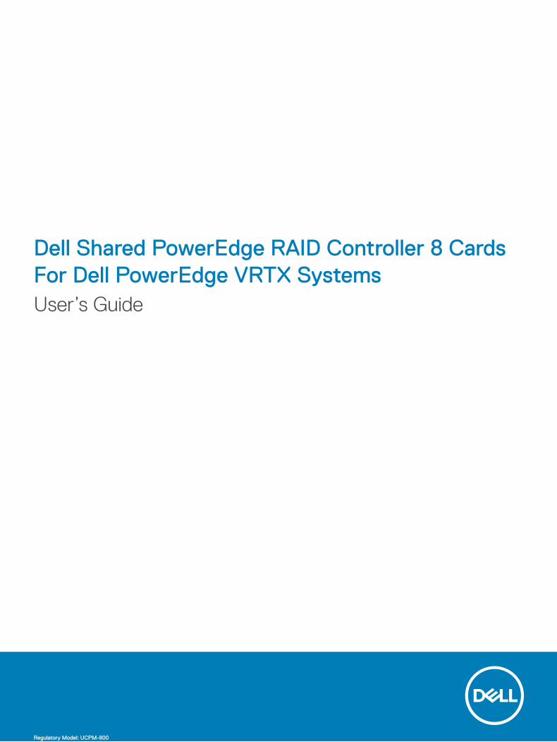
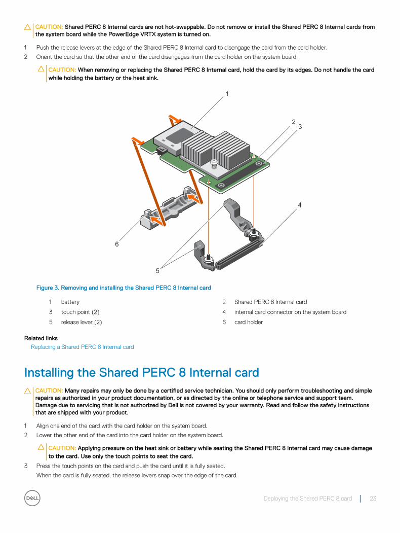
Figure 3. Removing and installing the Shared PERC 8 Internal card
1 battery 2 Shared PERC 8 Internal card
3 touch point (2) 4 internal card connector on the system board
5 release lever (2) 6 card holder
Related links
Replacing a Shared PERC 8 Internal card
Installing the Shared PERC 8 Internal cardCAUTION: Many repairs may only be done by a certified service technician. You should only perform troubleshooting and simple repairs as authorized in your product documentation, or as directed by the online or telephone service and support team. Damage due to servicing that is not authorized by Dell is not covered by your warranty. Read and follow the safety instructions that are shipped with your product.
1 Align one end of the card with the card holder on the system board.
2 Lower the other end of the card into the card holder on the system board.
CAUTION: Applying pressure on the heat sink or battery while seating the Shared PERC 8 Internal card may cause damage to the card. Use only the touch points to seat the card.
3 Press the touch points on the card and push the card until it is fully seated.
When the card is fully seated, the release levers snap over the edge of the card.
Deploying the Shared PERC 8 card 23
NOTE: Before closing the system, ensure that the release levers have snapped over the edge of the card.
4 Close the system.
Related links
Installing a new Shared PERC 8 Internal card
Replacing a Shared PERC 8 Internal card
Postinstallation tasks for the Shared PERC 8 Internal card
1 Turn on the PowerEdge VRTX system without hard drives and server modules inserted.
NOTE: It may take up to 25 minutes for the PowerEdge VRTX storage subsystem to completely power on.
2 Log in to the CMC GUI.
3 Click Overview → Power → Control, and view the Power State to ensure that it is ON.
4 Click Chassis Overview → Storage → Controllers to view the firmware version of the replaced Shared PERC 8 Internal card.
The firmware version must be same for both the cards.
NOTE: If the Shared PERC 8 Internal cards have different versions of their firmware, download and update the firmware to the latest version from Dell.com/drivers.
5 If the system has two Shared PERC 8 Internal cards, ensure that the Fault Tolerance Status is Healthy/Normal. This is necessary to ensure that any new firmware has been initialized and is compatible before you reinsert the shared hard drives and modular servers.
6 Turn off the PowerEdge VRTX system.
7 Insert the shared storage hard drives that you had removed earlier. Insert the shared hard drives in the original slots.
8 Turn on the PowerEdge VRTX system.
9 Check the Virtual Disk Layout and the Virtual Disk Assignments in the CMC GUI. If the virtual disks are not imported, not present, or the virtual disk assignments are not present or are incorrect, contact Dell Technical Support.
10 Turn off the PowerEdge VRTX system.
11 Insert the server modules that you had removed earlier. Insert the server modules in the original slots.
12 Turn on the PowerEdge VRTX system.
13 Turn on the server modules.
Related links
Installing a new Shared PERC 8 Internal card
Replacing a Shared PERC 8 Internal card
Installing a new Shared PERC 8 External cardTo install a new Shared PERC 8 External card in the PowerEdge system, perform the following steps:
1 Install the Shared PERC 8 External card. SeeInstalling the Shared PERC 8 External card.
2 Postinstallation tasks for the Shared PERC External card. SeePostinstallation tasks for the Shared PERC 8 External card.
Replacing a Shared PERC 8 External cardWhen replacing an existing Shared PERC 8 External card in the PowerEdge VRTX system, perform the following steps to ensure proper functionality of the shared storage after the replacement process is complete.
1 Prerequisites for removing the Shared PERC External card. SeePrerequisites for removing the Shared PERC 8 External card.
2 Remove the Shared PERC External card. SeeRemoving the Shared PERC 8 External card.
3 Install the Shared PERC External card. SeeInstalling the Shared PERC 8 External card.
4 Postinstallation tasks for the Shared PERC External card. SeePostinstallation tasks for the Shared PERC 8 External card.
24 Deploying the Shared PERC 8 card
CAUTION: Shared PERC 8 External cards are hot add supported, but are not hot remove supported. Do not remove Shared PERC 8 External cards from the system board while the PowerEdge VRTX system is turned on.
In the Single Shared PERC 8 External card configuration, the shared PERC External slot is labeled as Slot 5 or Slot 6 (either can be used) on the PowerEdge VRTX system board. In the Fault Tolerant Shared PERC 8 External card configuration, the shared PERC External slots are labeled as Slot 5 and Slot 6 on the PowerEdge VRTX system board.
To locate the Shared PERC slots, see System Board Connectors in the Dell PowerEdge VRTX Enclosure Owner's Manual at Dell.com/poweredgemanuals.
For more information, see the storage subsystem compatibility matrix document at Dell.com/support/home.
For information on removing and reinstalling system parts, see the VRTX Enclosure Owner's Manual of the system at Dell.com/poweredgemanuals.
Prerequisites for removing the Shared PERC 8 External cardCAUTION: Many repairs may only be done by a certified service technician. You should only perform troubleshooting and simple repairs as authorized in your product documentation, or as directed by the online or telephone service and support team. Damage due to servicing that is not authorized by Dell is not covered by your warranty. Read and follow the safety instructions that came with the system.
Perform the following steps to enable recovery in the event the part replacement process fails:
1 Follow the operating system procedure to back up all data from the shared storage drives.
CAUTION: The part replacement procedure is complex and can put your data at risk if mistakes are made. It is imperative that critical data is backed up prior to starting the procedure.
2 Document your virtual drive configuration and mapping information by performing the following steps:
a Open CLI terminal and run the command racadm raid get vdisks –o. Take a screen shot of the results page and save the captured screen shot to a location of choice, or write down the information and store it in a safe, secure location.
b Click Chassis Overview → Storage → Virtual Disks → Assign to view the virtual disk mapping by the CMC GUI. Take a screen shot of the results page and save the captured screen shot to a location of choice, or write down the information and store it in a safe, secure location.
c Click Chassis Overview → Storage → Virtual Disks to get the virtual disk configuration information by the CMC GUI. Take a screen shot of the results page and save the captured screen shot to a location of choice, or write down the information and store it in a safe, secure location.
3 Click Chassis Overview → Storage → Controllers to view the firmware version of the current Shared PERC 8 External card.
4 Turn off the server modules using operating system commands or the CMC.
5 Turn off the enclosure, including any attached peripherals, and disconnect the enclosure from the electrical outlet and peripherals.
6 Remove the server modules and the shared storage hard drives from the PowerEdge VRTX system.
WARNING: To prevent damage to system components, do not stack system components together after removal. For information on electrostatic discharge (ESD) compliance, see Dell.com/regulatory_compliance.
NOTE: Label all server modules and hard drives before removal so that they can be replaced in the same slots.
7 If applicable, rotate the system feet inward and place the system on its side on a flat surface, with the cover release latch side on top.
8 Open the system.
Related links
Replacing a Shared PERC 8 External card
Deploying the Shared PERC 8 card 25
Removing the Shared PERC 8 External cardCAUTION: Many repairs may only be done by a certified service technician. You should only perform troubleshooting and simple repairs as authorized in your product documentation, or as directed by the online or telephone service and support team. Damage due to servicing that is not authorized by Dell is not covered by your warranty. Read and follow the safety instructions that came with the system.
CAUTION: Shared PERC 8 External cards are not hot-removable. Do not remove the Shared PERC 8 External cards from the system board while the PowerEdge VRTX system is turned on.
1 Press the release tab of the expansion card latch to lift the latch out of the slot.
NOTE: Do not bend the card connectors.
CAUTION: When removing or replacing the Shared PERC 8 External card, hold the card by its edges. Do not handle the card while holding the battery or the heat sink.
2 Hold the external card by its edges, and remove it from the card connector on the system board.
3 If you are removing the card permanently, install a metal filler bracket over the empty slot opening and close the expansion card latch.
NOTE: You must install a filler bracket over an empty expansion slot to maintain Federal Communications Commission (FCC) certification of the system. The brackets also keep dust and dirt out of the system and aid in proper cooling and airflow inside the system.
26 Deploying the Shared PERC 8 card
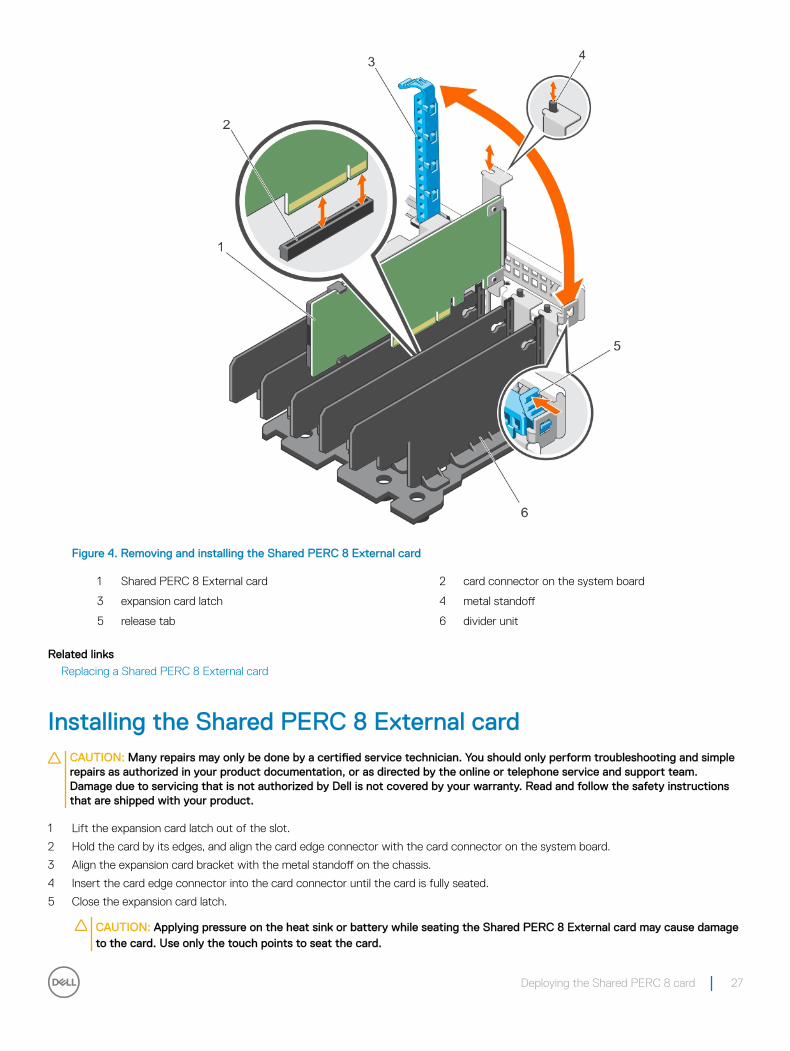
Figure 4. Removing and installing the Shared PERC 8 External card
1 Shared PERC 8 External card 2 card connector on the system board
3 expansion card latch 4 metal standoff
5 release tab 6 divider unit
Related links
Replacing a Shared PERC 8 External card
Installing the Shared PERC 8 External cardCAUTION: Many repairs may only be done by a certified service technician. You should only perform troubleshooting and simple repairs as authorized in your product documentation, or as directed by the online or telephone service and support team. Damage due to servicing that is not authorized by Dell is not covered by your warranty. Read and follow the safety instructions that are shipped with your product.
1 Lift the expansion card latch out of the slot.
2 Hold the card by its edges, and align the card edge connector with the card connector on the system board.
3 Align the expansion card bracket with the metal standoff on the chassis.
4 Insert the card edge connector into the card connector until the card is fully seated.
5 Close the expansion card latch.
CAUTION: Applying pressure on the heat sink or battery while seating the Shared PERC 8 External card may cause damage to the card. Use only the touch points to seat the card.
Deploying the Shared PERC 8 card 27
Related links
Replacing a Shared PERC 8 External card
Installing a new Shared PERC 8 External card
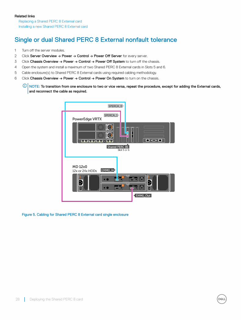
Single or dual Shared PERC 8 External nonfault tolerance
1 Turn off the server modules.
2 Click Server Overview → Power → Control → Power Off Server for every server.
3 Click Chassis Overview → Power → Control → Power Off System to turn off the chassis.
4 Open the system and install a maximum of two Shared PERC 8 External cards in Slots 5 and 6.
5 Cable enclosure(s) to Shared PERC 8 External cards using required cabling methodology.
6 Click Chassis Overview → Power → Control → Power On System to turn on the chassis.
NOTE: To transition from one enclosure to two or vice versa, repeat the procedure, except for adding the External cards, and reconnect the cable as required.
Figure 5. Cabling for Shared PERC 8 External card single enclosure
28 Deploying the Shared PERC 8 card
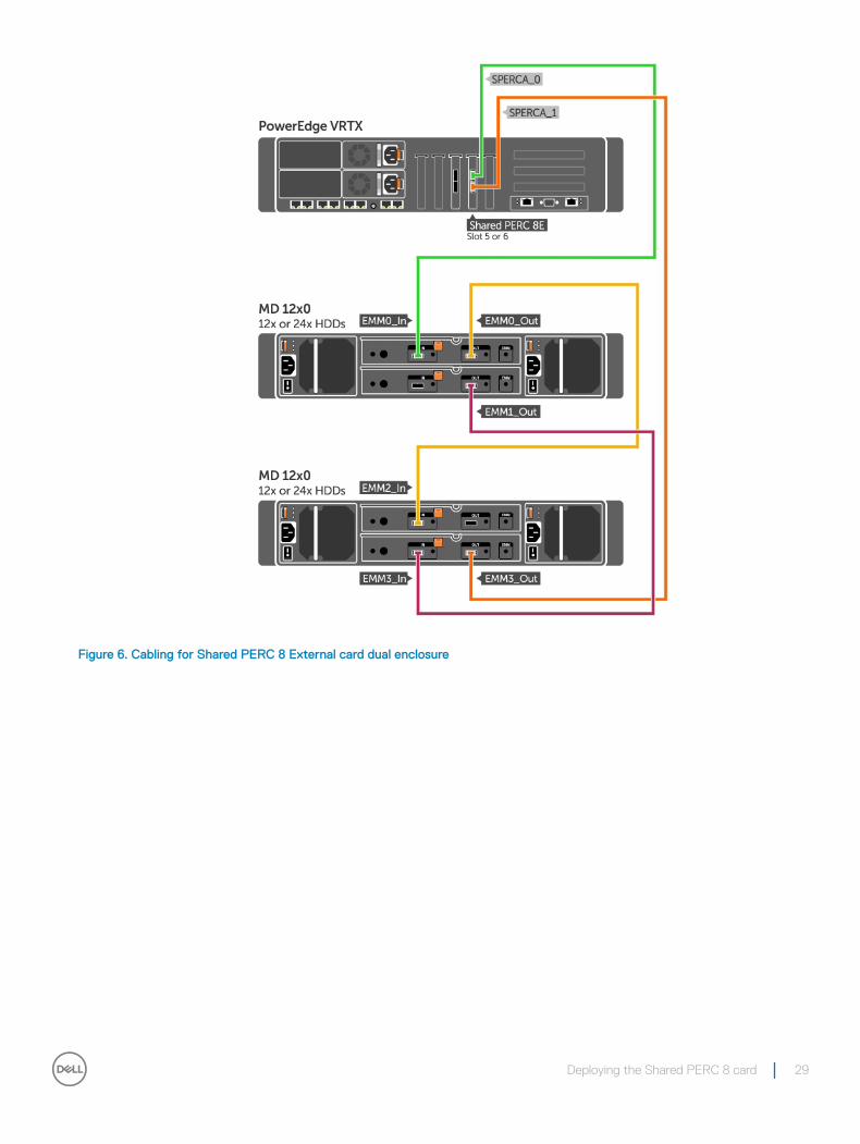
Figure 6. Cabling for Shared PERC 8 External card dual enclosure
Deploying the Shared PERC 8 card 29
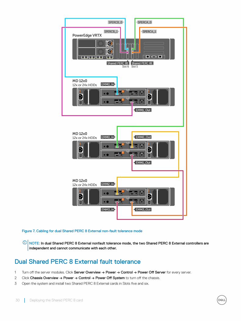
Figure 7. Cabling for dual Shared PERC 8 External non-fault tolerance mode
NOTE: In dual Shared PERC 8 External nonfault tolerance mode, the two Shared PERC 8 External controllers are independent and cannot communicate with each other.
Dual Shared PERC 8 External fault tolerance
1 Turn off the server modules. Click Server Overview → Power → Control → Power Off Server for every server.
2 Click Chassis Overview → Power → Control → Power Off System to turn off the chassis.
3 Open the system and install two Shared PERC 8 External cards in Slots five and six.
30 Deploying the Shared PERC 8 card
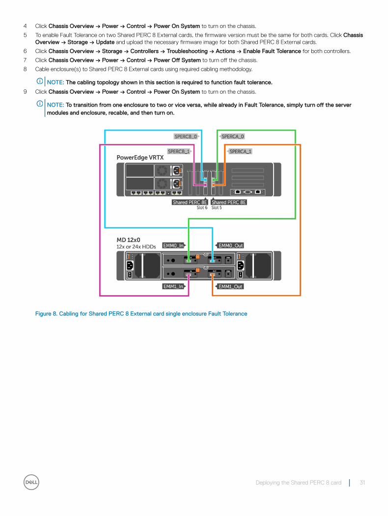
4 Click Chassis Overview → Power → Control → Power On System to turn on the chassis.
5 To enable Fault Tolerance on two Shared PERC 8 External cards, the firmware version must be the same for both cards. Click Chassis Overview → Storage → Update and upload the necessary firmware image for both Shared PERC 8 External cards.
6 Click Chassis Overview → Storage → Controllers → Troubleshooting → Actions → Enable Fault Tolerance for both controllers.
7 Click Chassis Overview → Power → Control → Power Off System to turn off the chassis.
8 Cable enclosure(s) to Shared PERC 8 External cards using required cabling methodology.
NOTE: The cabling topology shown in this section is required to function fault tolerance.
9 Click Chassis Overview → Power → Control → Power On System to turn on the chassis.
NOTE: To transition from one enclosure to two or vice versa, while already in Fault Tolerance, simply turn off the server modules and enclosure, recable, and then turn on.
Figure 8. Cabling for Shared PERC 8 External card single enclosure Fault Tolerance
Deploying the Shared PERC 8 card 31
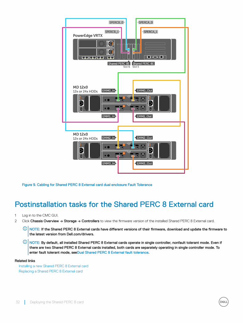
Figure 9. Cabling for Shared PERC 8 External card dual enclosure Fault Tolerance
Postinstallation tasks for the Shared PERC 8 External card1 Log in to the CMC GUI.
2 Click Chassis Overview → Storage → Controllers to view the firmware version of the installed Shared PERC 8 External card.
NOTE: If the Shared PERC 8 External cards have different versions of their firmware, download and update the firmware to the latest version from Dell.com/drivers.
NOTE: By default, all installed Shared PERC 8 External cards operate in single controller, nonfault tolerant mode. Even if there are two Shared PERC 8 External cards installed, both cards are separately operating in single controller mode. To enter fault tolerant mode, seeDual Shared PERC 8 External fault tolerance.
Related links
Installing a new Shared PERC 8 External card
Replacing a Shared PERC 8 External card
32 Deploying the Shared PERC 8 card
Prerequisites for transition scenariosCAUTION: Many repairs may only be done by a certified service technician. You should only perform troubleshooting and simple repairs as authorized in your product documentation, or as directed by the online or telephone service and support team. Damage due to servicing that is not authorized by Dell is not covered by your warranty. Read and follow the safety instructions that came with the system.
Perform the following steps to enable recovery in the event the part replacement process fails:
1 Follow the operating system procedure to back up all data from the shared storage drives.
CAUTION: This procedure is complex and can put your data at risk if mistakes are made. Ensure to back up all the critical data prior to starting the procedure.
2 Document your virtual drive configuration and mapping information by performing the following steps:
a Open CLI terminal and run the command racadm raid get vdisks –o.
Take a screen shot of the results page and save the captured screen shot to a location of choice, or write down the information and store it in a safe, secure location.
b Click Chassis Overview → Storage → Virtual Disks → Assign to view the virtual disk mapping by the CMC GUI.
Take a screen shot of the results page and save the captured screen shot to a location of choice, or write down the information and store it in a safe, secure location.
c Click Chassis Overview → Storage → Virtual Disks to get the virtual disk configuration information by the CMC GUI.
Take a screen shot of the results page and save the captured screen shot to a location of choice, or write down the information and store it in a safe, secure location.
3 Click Chassis Overview → Storage → Controllers to view the firmware version of the current Shared PERC 8 internal card. If your system has two Shared PERC 8 internal cards installed, the firmware version must be the same for both the cards.
Transition scenariosThe following section contains the procedures of common transition scenarios.
Single controller nonfault tolerance to dual controller fault tolerance
CAUTION: Before performing the transition, back up all data and complete the steps outlined in prerequisites for transition scenarios section. SeePrerequisites for transition scenarios.
1 Turn off the server modules. Click Server Overview → Power → Control → Power Off Server for every server.
2 Click Chassis Overview → Power → Control → Power Off System to turn off the chassis.
3 Open the system and install a second Shared PERC 8 External card in either Slots five or six.
4 Click Chassis Overview → Power → Control → Power On System to turn on the chassis.
5 Click Chassis Overview → Storage → Controllers → Troubleshooting → Actions → Enable Fault Tolerance to enable Fault Tolerance for both controllers.
6 Click Chassis Overview → Power → Control → Power Off System to turn on the chassis.
7 Cable enclosure(s) to Shared PERC 8 External cards using required cabling methodology.
NOTE: This cabling topology is required for fault tolerance to function.
8 Click Chassis Overview → Power → Control → Power On System to turn off the chassis.
Deploying the Shared PERC 8 card 33
Two existing non-fault tolerant controllers to fault tolerant configurationTwo existing non-fault tolerant controllers (connected to two enclosures each) to fault tolerant configuration.
NOTE: In a dual controller fault tolerant configuration, a maximum of two enclosures are supported. This scenario results in a loss of two enclosures.
CAUTION: Before performing the transition, back up all data and complete the steps outlined in prerequisites for transition scenarios section. See Prerequisites for transition scenarios.
1 Turn off the server modules. Click Server Overview → Power → Control → Power Off Server for every server.
2 Click Chassis Overview → Storage → Controllers → Troubleshooting → Actions → Enable Fault Tolerance to enable Enable Fault Tolerance for both controllers.
An error message appears stating that the controllers are not Fault Tolerant because the peer controller is not available. This is expected.
3 Click Chassis Overview → Power → Control → Power Off System to turn off the chassis.
4 Cable enclosure(s) to Shared PERC 8 External cards using required cabling methodology.
NOTE: Only two enclosures are supported in a dual controller fault tolerant configuration.
NOTE: This cabling topology is required for fault tolerance to function.
5 Click Chassis Overview → Power → Control → Power On System to turn on the chassis.
34 Deploying the Shared PERC 8 card
Firmware and driver installationThe Dell Shared PowerEdge RAID Controller (PERC) 8 card requires software drivers to operate with the supported operating systems.
This chapter contains the procedures for installing the drivers for the Shared PERC 8 card.
NOTE: To check operating system compatibility, see Dell.com/ossupport.
NOTE: The Shared PERC 8 does not support booting to the shared storage.
NOTE: Only one software driver per operating system is required for both Internal and External Shared PERC 8 cards. Separate driver installation is not required.
Topics:
• Downloading drivers and firmware for Shared PERC 8 from the Dell support website for all operating systems
• Downloading drivers from the Dell Systems Service and Diagnostic Tools media for Windows
• Installing or updating Windows drivers for Shared PERC 8
• Installing or updating Linux drivers for Shared PERC 8
• Installing or updating VMware drivers for Shared PERC 8
• Firmware installation or update
Downloading drivers and firmware for Shared PERC 8 from the Dell support website for all operating systems1 Go to Dell.com/drivers.
2 In the Identify your product section, enter the Service Tag of your system in the Enter a Service Tag or Express Service Code field.
NOTE: If you do not have the service tag, select Automatically detect my Service Tag for me to allow the system to automatically detect your service tag, or select Choose from a list of all Dell products to select your product from the Product Selection page.
NOTE: To download the latest firmware and drivers for a server module (for example Dell PowerEdge M520, M620, and M820), enter the service tag or the model number of the server module. To download the latest firmware and driver for components inside the PowerEdge VRTX chassis (for example Shared PERC 8 firmware and driver), enter the service tag or the model number of the PowerEdge VRTX chassis.
3 Select the Operating System, Category, Release Date, and Importance from the respective drop-down lists.
The drivers that are applicable to your selection are displayed.
4 Download the drivers that you require to a diskette drive, USB drive, CD, or DVD.
5 During the operating system installation, use the media that you created with the Load Driver option to load mass storage drivers. For more information on reinstalling the operating system, see the operating system document at Dell.com/operatingsystemmanuals.
4
Firmware and driver installation 35
Downloading drivers from the Dell Systems Service and Diagnostic Tools media for WindowsTo download drivers from the Dell Systems Service and Diagnostic Tools media:
1 Insert the Dell Systems Service and Diagnostics Tools media in a system.
The Welcome to Dell Service and Diagnostic Utilities screen is displayed.
2 Select your system model and operating system.
For the list of supported operating systems, see Supported Operating Systems.
3 Click Continue.
4 From the list of drivers displayed, select the driver you require.
5 Select the self-extracting zip file and click Run.
6 Copy the driver to a diskette drive, CD, DVD, or USB drive.
Repeat this step for all the drivers you require.
7 During the operating system installation, use the media that you created with the Load Driver option to load mass storage drivers.
For more information on reinstalling the operating system, see the relevant document at Dell.com/support/home.
Installing or updating Windows drivers for Shared PERC 8This procedure is applicable for updating the drivers for supported Windows operating systems.
NOTE: PERC H310/H710/H710P/H810 controllers use the same driver as Shared PERC 8 and do not require separate driver installations.
NOTE: For more information, see the PowerEdge VRTX Storage Subsystem Compatibility Matrix at Dell.com/support/home.
NOTE: Close all applications on your system before you update the driver.
1 Insert the media (CD, DVD, or USB drive) containing the driver.
2 Select Start > Settings > Control Panel > System.
The System Properties screen is displayed.
NOTE: The path to System Properties may vary depending on the operating system family.
3 Click on the Hardware tab.
4 Click Device Manager.
The Device Manager screen is displayed.
NOTE: The path to Device Manager may vary depending on the operating system family.
5 Expand SCSI and RAID Controllers by double-clicking the entry or by clicking the plus symbol next to SCSI and RAID Controller.
NOTE: In Windows Server 2012 or Windows Server 2008, the Shared PERC 8 card is listed under Storage Controllers.
6 Double-click the RAID controller for which you want to update the driver.
7 Click the Driver tab and click Update Driver.
The screen to update the device driver wizard is displayed.
8 Select Install from a list or specific location.
9 Click Next.
10 Follow the steps in the wizard and browse to the location of the driver files.
11 Select the INF file from the driver media (CD, DVD, or other media).
12 Click Next and continue with the installation steps in the wizard.
13 Click Finish to exit the wizard and reboot the system for the changes to take place.
36 Firmware and driver installation
NOTE: Dell provides the Dell Update Package (DUP) to update drivers on systems running Windows Server 2012/2012 R2 or Window Server 2008/2008 R2 operating systems. DUP is an executable application that updates drivers for specific devices. DUP supports command line interface and silent execution. For more information, see Dell.com/support.
Installing or updating Linux drivers for Shared PERC 8Use the procedures in this section to update the driver for supported Red Hat and SUSE Linux distributions. To ensure that you have the current version of the driver, download the updated Linux driver from Dell.com/support.
NOTE: PERC H310/H710/H710P/H810 controllers use the same driver as Shared PERC 8 and do not require separate driver installations.
Installing or updating the driver package on RHEL using KMOD support
NOTE: This procedure is applicable for Red Hat Enterprise Linux 6 SP5, 6.6, 6.7 and 7.1.
Perform the following steps to install the RPM package with KMOD support:
1 Uncompress the zipped tarball driver release package using the command tar vxzf <driver name>.
2 Install the driver package using the command rpm –ihv kmod-megaraid_ sas-<version>.x86_64.rpm.
NOTE: Use rpm -Uvh <package name> when upgrading an existing package.
3 Reboot the system for the updated driver to take effect.
4 Verify that the driver has been loaded using the command modinfo megaraid_sas.
5 View the list of controllers installed on your system using the command lspci | grep IOV.
Installing or updating the driver package on SLES using KMP support
NOTE: This procedure is applicable for SUSE Enterprise Linux 11 SP3, 12 and 13.
Perform the following steps to install the RPM package with KMP support:
1 Uncompress the zipped tarball driver release package using the command tar vxzf <driver name>.
2 Install the driver package using the command rpm –ihv lsi-megaraid_ sas-<version>.x86_64.rpm.
NOTE: Use rpm -Uvh <package name> when updating an existing package.
3 Reboot the system for the updated driver to take effect.
4 Verify that the driver is loaded using the command modinfo megaraid_sas.
5 View the list of controllers installed on your system using the command lspci | grep IOV.
Firmware and driver installation 37
Installing or updating VMware drivers for Shared PERC 8For information on how to install drivers on VMware ESXi 5.1, 5.5, and 6.0, see kb.vmware.com/kb/2005205. For information on VMware ESXi drivers, see the VMware ESXi documentation at Dell.com/virtualizationsolutions.
Firmware installation or updateThe VRTX storage subsystem includes of Shared PERC firmware, drivers, Chassis Infrastructure firmware and the CMC. When updating any of these components, make sure that all the component versions are at a compatible baseline.
NOTE: For more information, see the PowerEdge VRTX Storage Subsystem Compatibility Matrix at Dell.com/support/home.
NOTE: Separate firmware image files are required to update the Shared PERC Internal and External cards.
Updating firmwareBefore you begin, download the Dell Update Package for the firmware.
1 Log in to the VRTX CMC.
2 Make sure that you turn off all the server modules.
3 Navigate to Storage and click the Update tab.
4 Browse to the location where you downloaded the file and select the new file.
5 Click Upload.
6 After the file transfer, select the check box next to the release version, and click Update.
NOTE: Shared PERC8 firmware can only be updated from the VRTX Chassis Management Controller. The firmware DUP does not respond if it is run in Windows from a server.
NOTE: The firmware upgrade may fail if the RAID controller in the system is performing an I/O background task (that is, consistency check, background initialization, rebuild, or reconstruction). Ensure that you allow the background task to complete before attempting to upgrade the firmware.
NOTE: Patrol Read tasks are not affect a firmware upgrade.
38 Firmware and driver installation
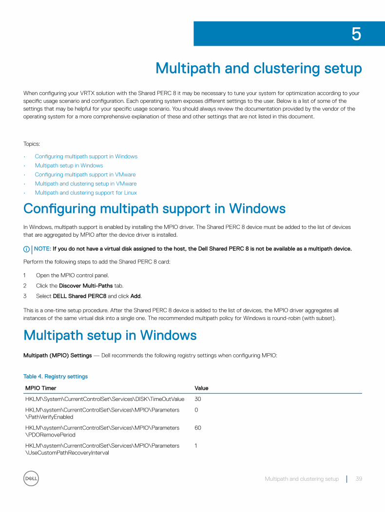
Multipath and clustering setup
When configuring your VRTX solution with the Shared PERC 8 it may be necessary to tune your system for optimization according to your specific usage scenario and configuration. Each operating system exposes different settings to the user. Below is a list of some of the settings that may be helpful for your specific usage scenario. You should always review the documentation provided by the vendor of the operating system for a more comprehensive explanation of these and other settings that are not listed in this document.
Topics:
• Configuring multipath support in Windows
• Multipath setup in Windows
• Configuring multipath support in VMware
• Multipath and clustering setup in VMware
• Multipath and clustering support for Linux
Configuring multipath support in WindowsIn Windows, multipath support is enabled by installing the MPIO driver. The Shared PERC 8 device must be added to the list of devices that are aggregated by MPIO after the device driver is installed.
NOTE: If you do not have a virtual disk assigned to the host, the Dell Shared PERC 8 is not be available as a multipath device.
Perform the following steps to add the Shared PERC 8 card:
1 Open the MPIO control panel.
2 Click the Discover Multi-Paths tab.
3 Select DELL Shared PERC8 and click Add.
This is a one-time setup procedure. After the Shared PERC 8 device is added to the list of devices, the MPIO driver aggregates all instances of the same virtual disk into a single one. The recommended multipath policy for Windows is round-robin (with subset).
Multipath setup in WindowsMultipath (MPIO) Settings — Dell recommends the following registry settings when configuring MPIO:
Table 4. Registry settings
MPIO Timer Value
HKLM\System\CurrentControlSet\Services\DISK\TimeOutValue 30
HKLM\system\CurrentControlSet\Services\MPIO\Parameters\PathVerifyEnabled
0
HKLM\system\CurrentControlSet\Services\MPIO\Parameters\PDORemovePeriod
60
HKLM\system\CurrentControlSet\Services\MPIO\Parameters\UseCustomPathRecoveryInterval
1
5
Multipath and clustering setup 39
MPIO Timer Value
HKLM\system\CurrentControlSet\Services\MPIO\Parameters\PathRecoveryInterval
25
CAUTION: Always back up your registry files (system.dat and user.dat) before editing the registry.
CAUTION: Using Registry Editor incorrectly can cause serious problems that may require you to reinstall Windows. Dell cannot guarantee that problems resulting from the incorrect use of Registry Editor can be solved. Use Registry Editor at your own risk.
For information on how to edit the registry, see the Changing Keys And Values online help topic in Registry Editor (regedit.exe).
Clustering setup in Windows
The following registry entries are required on each node of the cluster to enable them to see the drives on the Shared PERC 8:
Table 5. Registry entries
Location Entry type Property Value
HKLM\SYSTEM\CurrentControlSet\Services\ClusDisk\Parameters
DWORD AllowBusTypeRAID 0X01
Cluster Setting: QuorumArbitrationTimeMax = 90
This value shall be increased to 90 from a default value of 20. This allows the clustered solution to tolerate a controller failover, which can sometimes take up to 80 seconds.
To change the QuorumArbitrationTimeMax registry value using PowerShell for Windows Server 2012 and Windows Server 2012 R2, do the following:
1 From a cluster node, open an elevated PowerShell prompt.
2 Run the following command with the appropriate value:
Get-Cluster | %{ $_. QuorumArbitrationTimeMax = 90}3 To confirm the QuorumArbitrationTimeMax value has changed on the cluster run:
Get-Cluster | fl *
For more details on setting up clustering in Windows environments, see Building Microsoft Windows Server 2012 Clusters on the Dell PowerEdge VRTX.
Configuring multipath support in VMwareIn VMware, multipath support is automatically enabled using Native Multipathing (NMP) for all Shared PERC 8 cards in Dell versions of the ESXi operating systems.
NOTE: The recommended multipath policy is Most Recently Used (MRU).
Multipath and clustering setup in VMwareMultipath Settings—No recommended settings beyond the default settings
Cluster Settings:
In VMware, LUN contention can be an issue with large cluster deployments. Below are some guidelines and settings Dell recommends that you use when configuring a cluster with shared storage:
40 Multipath and clustering setup
1 If possible have more than one LUN for data storage to reduce LUN contention and reservation conflicts.
2 High numbers of VMs per LUN can also increase LUN contention. Due to varying workloads it is difficult to identify precise guidelines for VMs per LUN, but it is good practice not to exceed 64 virtual machines per LUN for proper optimization of your particular solution.
3 The following values are recommended for LUN Queue Depth Throttling:
queuefullsamplesize: 32queuefullthresholdesize: 8Consult VMware documentation for more details on these settings and how to modify them.
For more information, see the VMware Knowledgebase article, “Controlling LUN queue depth throttling in VMware ESX/ESXi” (1008113).
4 Setting the Maximum Outstanding Disk Requests for virtual machines:
Dell recommends the following value for Maximum Outstanding Disk Requests From Competing Worlds:
NoOfOutstandingIOsWithCompetingWorlds: 128Ensure that you use 128 or the lesser value for maximum outstanding disk requests that supports the latest VMware version available.
Consult the VMware documentation for more details on this setting and how to modify it.
For more information, see the VMware Knowledgebase article, “Setting the Maximum Outstanding Disk Requests for virtual machines” (1268).
5 DiskReservationThreshold:
• VMware defines this value as the “time window within which recounted reservations on a device are permitted (in msec).” This setting can be used to increase the fairness of LUN reservations from multiple hosts. This setting can be found in the vSphere GUI.
Dell recommends the following Disk Reservation Threshold:
DiskReservationThreshold 1 6 To help determine if you are getting reservation conflicts and to get an additional logging to diagnose storage contention issues, the
following log settings can be helpful:
ReservationBacktrace: 1 Scsi.LogScsiAborts: 1Scsi.LogCmdErrors: 1
NOTE: Some reservation conflicts are expected, and not all command errors signify a failure. Consult the VMware documentation for additional information.
Multipath and clustering support for Linux
Installing multipath in Linux
In Linux, multipathing is supported using the device-mapper multipath module.
The device-mapper module should be installed if not part of the default install: device-mapper-multipath-<version>(RHEL) and device-mapper-<version>(SLES). This can be installed using any of the update manager tools like yum or yast.
Multipath configuration in SLES
1 Modify the multipath.conf file at /etc/multipath.conf with the parameters as suggested inMultipath files for Linux multipath configuration. If copying the file from Windows, please use dos2unix multipath.conf file once you have copied it over.
2 To start multipath services and enable them to start at reboot:
chkconfig multipathd on
Multipath and clustering setup 41
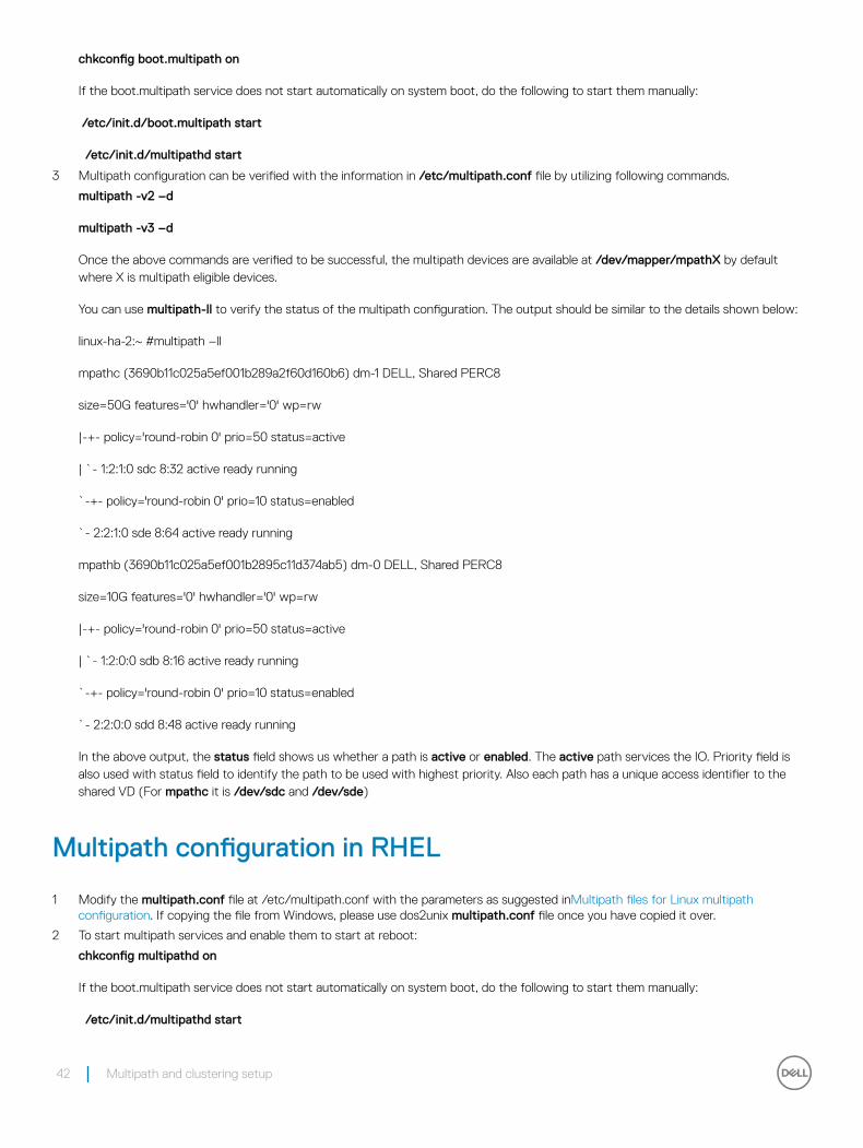
chkconfig boot.multipath on
If the boot.multipath service does not start automatically on system boot, do the following to start them manually:
/etc/init.d/boot.multipath start
/etc/init.d/multipathd start
3 Multipath configuration can be verified with the information in /etc/multipath.conf file by utilizing following commands.
multipath -v2 –d
multipath -v3 –d
Once the above commands are verified to be successful, the multipath devices are available at /dev/mapper/mpathX by default where X is multipath eligible devices.
You can use multipath-ll to verify the status of the multipath configuration. The output should be similar to the details shown below:
linux-ha-2:~ #multipath –ll
mpathc (3690b11c025a5ef001b289a2f60d160b6) dm-1 DELL, Shared PERC8
size=50G features='0' hwhandler='0' wp=rw
|-+- policy='round-robin 0' prio=50 status=active
| `- 1:2:1:0 sdc 8:32 active ready running
`-+- policy='round-robin 0' prio=10 status=enabled
`- 2:2:1:0 sde 8:64 active ready running
mpathb (3690b11c025a5ef001b2895c11d374ab5) dm-0 DELL, Shared PERC8
size=10G features='0' hwhandler='0' wp=rw
|-+- policy='round-robin 0' prio=50 status=active
| `- 1:2:0:0 sdb 8:16 active ready running
`-+- policy='round-robin 0' prio=10 status=enabled
`- 2:2:0:0 sdd 8:48 active ready running
In the above output, the status field shows us whether a path is active or enabled. The active path services the IO. Priority field is also used with status field to identify the path to be used with highest priority. Also each path has a unique access identifier to the shared VD (For mpathc it is /dev/sdc and /dev/sde)
Multipath configuration in RHEL
1 Modify the multipath.conf file at /etc/multipath.conf with the parameters as suggested inMultipath files for Linux multipath configuration. If copying the file from Windows, please use dos2unix multipath.conf file once you have copied it over.
2 To start multipath services and enable them to start at reboot:
chkconfig multipathd on
If the boot.multipath service does not start automatically on system boot, do the following to start them manually:
/etc/init.d/multipathd start
42 Multipath and clustering setup
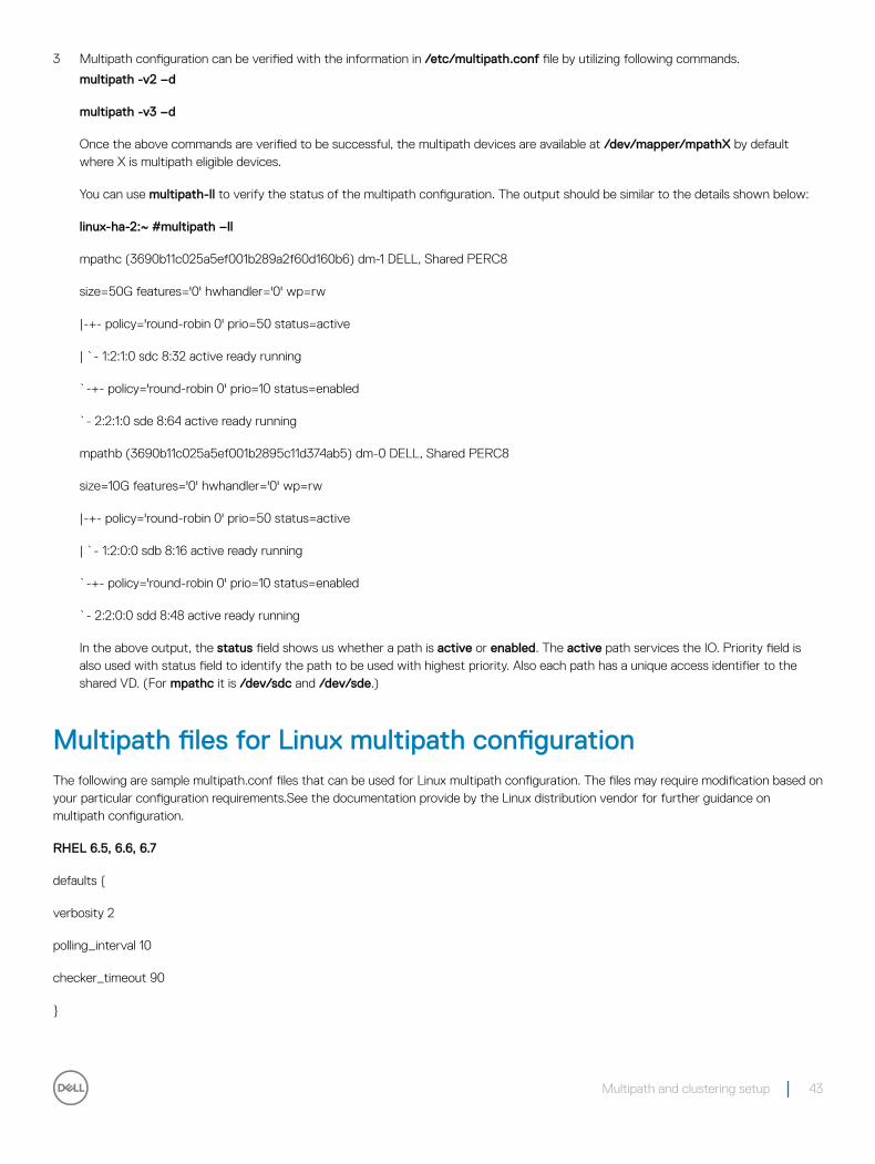
3 Multipath configuration can be verified with the information in /etc/multipath.conf file by utilizing following commands.
multipath -v2 –d
multipath -v3 –d
Once the above commands are verified to be successful, the multipath devices are available at /dev/mapper/mpathX by default where X is multipath eligible devices.
You can use multipath-ll to verify the status of the multipath configuration. The output should be similar to the details shown below:
linux-ha-2:~ #multipath –ll
mpathc (3690b11c025a5ef001b289a2f60d160b6) dm-1 DELL, Shared PERC8
size=50G features='0' hwhandler='0' wp=rw
|-+- policy='round-robin 0' prio=50 status=active
| `- 1:2:1:0 sdc 8:32 active ready running
`-+- policy='round-robin 0' prio=10 status=enabled
`- 2:2:1:0 sde 8:64 active ready running
mpathb (3690b11c025a5ef001b2895c11d374ab5) dm-0 DELL, Shared PERC8
size=10G features='0' hwhandler='0' wp=rw
|-+- policy='round-robin 0' prio=50 status=active
| `- 1:2:0:0 sdb 8:16 active ready running
`-+- policy='round-robin 0' prio=10 status=enabled
`- 2:2:0:0 sdd 8:48 active ready running
In the above output, the status field shows us whether a path is active or enabled. The active path services the IO. Priority field is also used with status field to identify the path to be used with highest priority. Also each path has a unique access identifier to the shared VD. (For mpathc it is /dev/sdc and /dev/sde.)
Multipath files for Linux multipath configurationThe following are sample multipath.conf files that can be used for Linux multipath configuration. The files may require modification based on your particular configuration requirements.See the documentation provide by the Linux distribution vendor for further guidance on multipath configuration.
RHEL 6.5, 6.6, 6.7
defaults {
verbosity 2
polling_interval 10
checker_timeout 90
}
Multipath and clustering setup 43
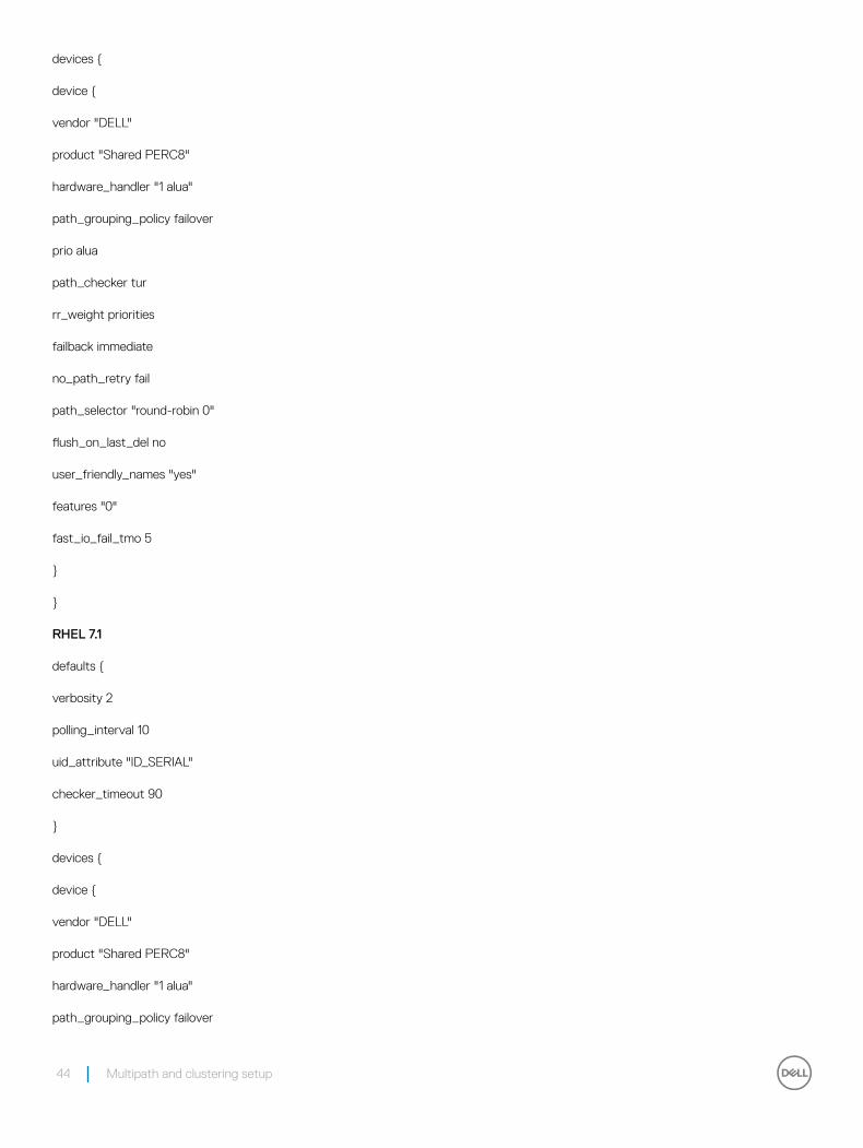
devices {
device {
vendor "DELL"
product "Shared PERC8"
hardware_handler "1 alua"
path_grouping_policy failover
prio alua
path_checker tur
rr_weight priorities
failback immediate
no_path_retry fail
path_selector "round-robin 0"
flush_on_last_del no
user_friendly_names "yes"
features "0"
fast_io_fail_tmo 5
}
}
RHEL 7.1
defaults {
verbosity 2
polling_interval 10
uid_attribute "ID_SERIAL"
checker_timeout 90
}
devices {
device {
vendor "DELL"
product "Shared PERC8"
hardware_handler "1 alua"
path_grouping_policy failover
44 Multipath and clustering setup
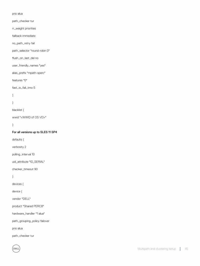
prio alua
path_checker tur
rr_weight priorities
failback immediate
no_path_retry fail
path_selector "round-robin 0"
flush_on_last_del no
user_friendly_names "yes"
alias_prefix "mpath-sperc"
features "0"
fast_io_fail_tmo 5
}
}
blacklist {
wwid "<WWID of OS VD>"
}
For all versions up to SLES 11 SP4
defaults {
verbosity 2
polling_interval 10
uid_attribute "ID_SERIAL"
checker_timeout 90
}
devices {
device {
vendor "DELL"
product "Shared PERC8"
hardware_handler "1 alua"
path_grouping_policy failover
prio alua
path_checker tur
Multipath and clustering setup 45
rr_weight priorities
failback immediate
no_path_retry fail
path_selector "round-robin 0"
flush_on_last_del no
user_friendly_names "yes"
alias_prefix "mpath-sperc"
features "0"
fast_io_fail_tmo 5
}
}
SLES 12
defaults {
verbosity 2
polling_interval 10
uid_attribute "ID_SERIAL"
checker_timeout 90
}
devices {
device {
vendor "DELL"
product "Shared PERC8"
hardware_handler "1 alua"
path_grouping_policy failover
prio alua
path_checker tur
rr_weight priorities
failback immediate
no_path_retry fail
path_selector "round-robin 0"
flush_on_last_del no
46 Multipath and clustering setup
user_friendly_names "yes"
alias_prefix "mpath-sperc"
features "0"
fast_io_fail_tmo 5
}
}
blacklist {
wwid "<WWID of OS VD>"
}
Clustering setup in Linux
• When configuring STONITH sbd devices, ensure that the Message Timeout is set to 120 seconds and the Watchdog Timer is set to at least 60 seconds. This is to ensure that the SPERC controller functions correctly.
General recommendations for Multipath setup in a Linux environment
• Additional information can be obtained at the following links:
• https://www.suse.com/documentation/sles11/singlehtml/stor_admin/stor_admin.html#multipathing
• https://access.redhat.com/documentation/en-US/Red_Hat_Enterprise_Linux/7/pdf/DM_Multipath/Red_Hat_Enterprise_Linux-7-DM_Multipath-en-US.pdf
• https://access.redhat.com/documentation/en-US/Red_Hat_Enterprise_Linux/6/html-single/DM_Multipath/
• Dell recommends that you use user-friendly names (/dev/mapper/mpathx instead of /dev/dm-n). The latter is intended for internal use only.
• In some cases, it may be desired that the multipath module not be used to aggregate local or USB disks. For these devices, the following steps can be used to blacklist them from device-mapper:
a Use /lib/udev/scsi_id –g –u /dev/sdx to find the wwid of the local disk
Example:
/lib/udev/scsi_id –g –u /dev/sda
36d4ae52092e175001ab9d33c2941385a [Local Disk wwid]
b Modify the multi path.conf file provided and black list the wwid of all local disks from above
Example:
blacklist {
wwid "36d4ae52092e175001ab9d33c2941385a"
}
Multipath and clustering setup 47
Management applications for Shared PERC 8 card
The Dell Chassis Management Controller (CMC) allows you to:
• Configure the shared RAID system
• Create and manage multiple disk groups
• Control and monitor multiple RAID systems
• Enable LKM on Shared PERC
• Provide online maintenance through a web interface or Command Line Interface (CLI)
NOTE: Dell OpenManage Storage Management, BIOS Configuration Utility (Ctrl+L), or Unified Extensible Firmware Interface (UEFI) RAID Configuration Utility does not support the Shared PERC 8 and may only be used to manage nonshared PERC cards. For nonshared PERC cards, see the system-specific PERC User's Guide at Dell.com/storagecontrollermanuals.
For more information on the CMC web interface or CLI commands available for Shared PERC 8, see the Dell Chassis Management Controller for Dell PowerEdge VRTX User’s Guide at Dell.com/esmmanuals.
NOTE: Ensure that all the software components are upgraded to the latest versions. For information on the latest supported firmware and driver versions, see the Drivers and Downloads link on Dell.com/support/drivers for your system.
6
48 Management applications for Shared PERC 8 card
Security key and RAID managementNOTE: PERC H310 does not support any security implementations.
Topics:
• Security key implementation
• Troubleshooting security key errors
Security key implementationThe Dell Shared PowerEdge RAID Controller 8 (SPERC8) internal and external cards support Self-Encrypting Disks (SED) for protection of data against loss or theft of SEDs. Protection is achieved by the use of encryption technology on the drives. There is one security key per controller. The security key is used by the controller to lock and unlock access to encryption-capable physical disks. In order to take advantage of this feature, you must:
1 Have SEDs in your system.
2 Create a security key.
NOTE: Security key implementation requires a firmware that enables LKM on Shared PERC.
3 Encrypt virtual disks.
NOTE: When SPERC8 controllers operate in Fault-Tolerant mode, the security key on the controllers must match.
Configuration and management of SED capable hard drivesConfiguration and management of SED capable hard drives include the following features:
• Local Key Management (LKM)
• Creating a security Key
• Modifying the security key
• Deleting a security key
• Creating secured virtual disks
• Securing pre-existing virtual disks
• Importing or clearing secured foreign configurations and secure disk migration
• Cryptographic erase
NOTE: For more information about security key management, see the Dell Chassis Management Controller for Dell PowerEdge VRTX User’s Guide at Dell.com/poweredgemanuals.
7
Security key and RAID management 49
Troubleshooting security key errors
Secured foreign import errorsA foreign configuration is a RAID configuration that already exists on a replacement physical disk that you install in a system. A secured foreign configuration is a RAID configuration that was created under a different security key.
There are two scenarios in which a secured foreign import fails:
• The passphrase authentication fails—A VD secured with a security key different from the current controller security key cannot be imported without authentication of the original passphrase used to secure them. Supply the correct passphrase to import the secured foreign configuration. If you have lost or forgotten the passphrase, the secured foreign disks remain locked (inaccessible) until the appropriate passphrase is entered or if they are cryptograhically erased.
• The secured VD is in an offline state after supplying the correct passphrase—You must check to determine why the virtual disk failed and correct the problem. See the topic Troubleshooting.
Failure to select or configure non self-encrypting disksA virtual disk can be either secured or unsecured depending on how it was configured when created. In order to create a secured virtual disk, the controller must have a security key present and the VD must be contained on SEDs only. In order to select or configure non-SED, you must create an unsecured virtual disk. You can create an unsecured virtual disk even if there is a security key. Select the Secure VD option as No in the Create New VD menu.
NOTE: For more information about creating unsecured virtual disks, see the Dell Chassis Management Controller for Dell PowerEdge VRTX User’s Guide at Dell.com/poweredgemanuals.
Failure to delete security keyA security key is used to lock or unlock access to a security-enabled component. This key is not utilized in the actual encryption of data. If a security key is present, both secured and unsecured virtual disks may exist.
To delete the security key, you must have a previously established security key present on the controller and there cannot be any configured secured disks. If there are configured secured virtual disks, remove or delete them.
Failure to cryptograhic erase task on physical disksCryptograhic Erase is the process of securely erasing all data permanently on an encryption-capable physical disk and resetting the security attributes. It is used in a couple of scenarios such as deleting a foreign configuration in the event of a forgotten or lost passphrase or unlocking a disk that had been previously locked.
Cryptograhic Erase can be executed only on encryption-capable disks as long as the disks are not hot spares and are not configured (part of a virtual disk). Ensure that the conditions are met.
50 Security key and RAID management
TroubleshootingTo get help with your Dell Shared PowerEdge RAID Controller Shared (PERC) 8 card, you can contact your Dell Technical Service representative or see Dell.com/contactdell.
Topics:
• General issues
• Physical disk issues
• Virtual disks issues
• Driver issues
• Controller issues
• Hard drive indicator codes
General issues
Shared PERC 8 card not seen in Device Manager
Issue: The device does not appear in the Device Manager.
Corrective Action: In the Dell Chassis Management Controller (CMC) application, verify if the Shared PERC 8 is correctly mapped to the server module. For more information on assigning virtual adapters to server slots, see the Dell Chassis Management Controller for Dell PowerEdge VRTX User’s Guide at Dell.com/poweredgemanuals.
NOTE: Make changes to Virtual Adapter to Server Slot mapping only when the server modules are turned off.
If the Virtual Adapter to Server Slot mapping is correct and the device still does not appear in the Device Manager, turn off the system and reseat the Shared PERC 8 card.
Critical errors or disk warning messages seen in the Windows Event log
Issue: Error messages such as Critical Event11, PERCSAS2The driver detected a controller error on \Device\RaidPort...
or,
Warning event: Event 153, Disk
The IO operation at logical block address xxxxxx for Disk x was retried
Referring the PercSAS2 driver is seen in the Windows Event log.
8
Troubleshooting 51
Corrective Action: These error messages may be triggered under some noncritical cases. See the system status and the CMC logs to identify any persistent failures.
NOTE: Event 153 or Event 11 seen in the Windows Event log do not require any corrective action.
Shared PERC 8 cards fail to function
Issue: Shared PERC 8 cards fail to function in systems with the Fault Tolerant Shared PERC 8 card configuration.
Corrective Action: This issue may occur if the Shared PERC 8 card property settings between the two Shared PERC 8 cards is not compatible. Make sure that the firmware packages are identical for both the Shared PERC 8 cards.
Fatal error or data corruption reported
Issue: Fatal error(s) or data corruption(s) is reported when accessing virtual disks.
Corrective Action: Contact Dell Technical Support.
EMM failure message seen after EMM firmware update
Issue: CMC shows error message immediately after an enclosure update that the EMM has failed.
Corrective Action: After an EMM update, turn off and restart the VRTX chassis.
Erratic drive LED behavior after EMM Firmware update
Issue: After updating EMM firmware drive Status, LED blink patterns may lose synchronization.
Description: During an EMM update if the EMM controllers lose synchronization, the Drive Status LED may be updated by both EMMs out of sequence causing an unidentifiable blink pattern.
NOTE: The normal state of the status LED is solid green, which would not be affected. Turn off and restart the enclosure or chassis to correct this condition. If an external enclosure is turned off and restarted, the VRTX chassis needs to be shutdown first.
Corrective Action: Turn off and restart the enclosure or chassis.
Performance variations between write-back and write-through cache modes
Issue: Performance is highly variable across configurations, drive type, applications and IO workloads. The write performance of write-through mode is typically lower than that of write-back mode. Some configurations and workloads exhibit significant performance deltas.
Corrective Action: Evaluate your needs for maximum I/O performance (a single Shared PERC 8 configuration) versus maximum data protection (a Fault Tolerant Shared PERC 8 configuration).
52 Troubleshooting
Physical disk issues
Physical disk in failed state
Issue: One of the physical disks in the disk array is in the failed state.
Corrective Action: Update the Shared PERC 8 cards to the latest firmware available at Dell.com/support. Replace the physical disk with a working one which is compatible with the old physical disk and is of equal or greater capacity.
Capable speed of a drive being shown as blank
Issue: Capable Speed under Physical Disk → Properties is Blank for 12 Gbps SAS drives.
Corrective Action: The drive is functional and is operating at 6 Gbps SAS speeds. For further details contact Dell Technical Support. For more information, see Getting help.
Physical disk displayed as Blocked by management application
Issue: One or more physical disks are displayed as Blocked and cannot be configured.
Corrective Action: Ensure that the physical disk is supported by SCSI-3 Persistent Reservation (PR). Update the physical disk and Shared PERC 8 to the latest firmware available on Dell.com/support.
NOTE: If you are using the Dell Update Package (DUP) to update the physical disk, shutdown all the server modules and power cycle the chassis after the update is completed.
Multiple disks become inaccessible
Issue: Multiple disks become simultaneously inaccessible.
Corrective Action: Multiple physical disk errors in a single array indicate a failure in cabling or connection and can involve loss of data. Perform the following steps to recover the virtual disk:
CAUTION: Follow the safety precautions to prevent electrostatic discharge.
1 Turn off the system, check the cable connections, and reseat the physical disks.
2 Ensure that all the disks are present in the enclosure.
3 Turn on the system and enter the Chassis Management Controller (CMC).
4 Use the CMC to import the foreign configuration that is detected or clear the foreign configuration.
NOTE: For information about importing or clearing foreign configuration, see the Dell Chassis Management Controller for Dell PowerEdge VRTX User’s Guide at Dell.com/poweredgemanuals.
If the virtual disk is redundant and transitioned to Degraded state before going Offline, a rebuild operation starts automatically after the configuration is imported. If the virtual disk has gone directly to the Offline state due to a cable pull or power loss situation, the virtual disk is imported in its Optimal state without a rebuild occurring.
Troubleshooting 53
Rebuilding a Failed physical disk
Issue: Rebuilding a physical disk after one of them is in a failed state.
Corrective Action: If you have configured hot spares, the Shared PERC 8 card automatically tries to rebuild a physical disk that is in a failed state. The automatic rebuild is not available if there is no hot spare with enough capacity to rebuild the failed physical disk. You must make sure a physical disk with enough storage in the subsystem is set as a hot spare for rebuilding the physical disk.
Foreign dedicated hot spare shown as global hot spare in CMC’s foreign configuration preview before foreign configuration import
Issue: When a drive assigned as a dedicated hot-spare becomes foreign, the preview of that drive in CMC GUI, under Storage → Controller → Setup shows that the drive is Global Hot-spare.
Corrective Action: The foreign configuration can be imported and it is assigned as dedicated hot-spare to the array it was assigned.
NOTE: For more information on importing or clearing the foreign configuration, see Dell Chassis Management Controller for Dell PowerEdge VRTX User’s Guide at Dell.com/poweredgemanuals.
Physical disk takes a long time to rebuild
Issue: A physical disk is taking longer than expected to rebuild.
Description: A physical disk takes longer to rebuild when under high stress. There is only one rebuild I/O operation for every five host I/O operations.
Corrective Action: If possible, reduce stress on the physical disk.
SMART ErrorsSelf Monitoring and Reporting Technology (SMART) monitors the internal performance of all motors, heads, and physical disk electronics and detects predictable physical disk failures.
NOTE: For information about where to find reports of SMART errors that can indicate hardware failure, see the Dell Chassis Management Controller for Dell PowerEdge VRTX User’s Guide at dell.com/esmmanuals.
SMART error detected on a physical disk in a redundant virtual disk
Issue: A SMART error is detected on a physical disk in a redundant virtual disk.
Corrective Action: Perform the following steps:
1 Back up your data.
2 Physically remove the physical disk that detected the SMART error.
NOTE: If a hot spare is present, the rebuild starts with the hot spare after the disk is removed.
3 Replace the disk with a new physical disk of equal or higher capacity.
54 Troubleshooting
4 Perform the Auto Replacement of a Virtual Disk operation.
NOTE: The Auto Replacement of Virtual Disk operation allows you to copy data from a source physical disk of a virtual disk to a target physical disk that is not a part of the virtual disk. For more information about the Auto Replacement feature, seeAuto replace member.
SMART error detected on a physical disk in a nonredundant virtual disk
Issue: A SMART error is detected on a physical disk in a nonredundant virtual disk.
Corrective Action: Perform the following steps:
1 Back up your data.
2 Physically remove the physical disk that detected the SMART error.
NOTE: The virtual disk will be in a Failed state after the physical disk is removed. Ensure you back up your data before performing this operation.
3 Replace the affected physical disk with a new physical disk of equal or higher capacity.
4 Delete the failed virtual disk and recreate the virtual disk with the same members.
NOTE: For information on creating and deleting virtual disks, see the Dell Chassis Management Controller for Dell PowerEdge VRTX User’s Guide at Dell.com/esmmanuals.
5 Restore from the backup.
Auto Replacement Member errorsNOTE: For more information about the Auto Replacement Member feature, see Auto replace member.
Source Disk Fails
Issue: The source disk fails during the Auto Replacement Member operation.
Description: If the source data is available from other disks in the virtual disk, the rebuild begins automatically on the target disk, using the data from the other disks.
Corrective Action: No corrective action
Target disk fails
Issue: The target disk fails.
Description: If the target disk fails, the Auto Replacement Member operation is terminated.
Corrective Action: No corrective action
General disk fails
Issue: A general disk fails.
Description: If the target disk fails and the Auto Replacement Member operation terminates but the source data is still available, then the Auto Replacement Member operation continues as Auto Replacement Member.
Troubleshooting 55
Corrective Action: No corrective action
Virtual disks issues
Degraded state of virtual disks
Issue: A redundant virtual disk is in a degraded state when one or more physical disks have failed or are inaccessible. For example, if a RAID 1 virtual disk consists of two physical disks and one of them fails or becomes inaccessible, the virtual disk becomes degraded.
Corrective Action: To recover a virtual disk from a degraded state, you must replace the failed physical disk and rebuild it. After the rebuilding process is complete, the virtual disk state changes from degraded to optimal.
Unable to rebuild a fault tolerant virtual disk
Issue: Cannot rebuild a fault tolerant virtual disk. For more information, see the alert log for virtual disks.
Corrective Action: The replacement disk is too small or not compatible with the virtual disk. Replace the failed disk with a compatible good physical disk with equal or greater capacity.
Virtual disk fails during rebuild using a global hot spare
Issue: A virtual disk fails during rebuild while using a global hot spare. The global hot spare reverts to Hotspare state and the virtual disk is in Failed state.
Corrective Action: Check whether the original virtual disk has failed or has been removed.
Virtual disk fails during rebuild using a dedicated hot spare
Issue: A virtual disk fails during rebuild while using a dedicated hot spare. The dedicated hot spare goes to Ready state and the virtual disk goes to Failed state.
Corrective Action: Check whether the original virtual disk has failed or has been removed.
Virtual disk cannot be added to a disk group undergoing rebuild
Issue: A second virtual disk cannot be added to a disk group undergoing a rebuild.
Description: This issue is working as designed. The firmware does not allow the creation of a virtual disk using the free space available in a disk group if a physical disk in a virtual disk group is undergoing a rebuild operation.
Corrective Action: No corrective action
Driver issues
56 Troubleshooting
Shared PERC 8 card has yellow exclamation mark in device manager
Issue: The device is displayed in Device Manager but has a yellow exclamation mark (!).
Corrective Action: Reinstall the driver. For more information on reinstalling drivers, see Driver Installation. If reinstalling the driver does not resolve the yellow exclamation mark, perform a shutdown of all server modules and power cycle the chassis.
Incorrect number of virtual disks displayed in Windows Disk Manager
Issue: The number of disks displayed in Windows Disk Manager is more than the actual number of virtual disks assigned to the server.
Corrective Action: This issue occurs if the MPIO feature is not installed in systems with the Fault Tolerant Shared PERC 8 card configuration. Install MPIO services from the list of features that can be installed on the server. For instructions on how to install MPIO, see Installing and Configuring MPIO at technet.microsoft.com.
Controller issues
Controller cache issuesFor certain conditions virtual drives are either not configured to write back caching or if configured, it transitions to write-through caching. The status of write-back caching can be viewed through CMC storage logs.
The following table details the conditions and the corrective actions.
Table 6. Conditions and the corrective actions
Conditions Actions
Peer controllers reporting incompatibility due to mismatched controller settings
When the active controller does not have any native configurations and imports a foreign configuration, the active controller inherits the controller configuration settings stored with the virtual disk. These settings may differ from the settings present on the peer controller, which triggers the incompatibility due to controller setting mis-match.
It is recommended to manually reconcile the difference in settings to resolve the issue.
During the VRTX power on with no failing conditions, the virtual drive temporarily transitions to write-through as part of the Shared PERC 8 firmware initialization. After the system power-on, the virtual drive transitions back to write back.
There is no intervention required.
During VRTX power on or reset, unresolved pinned cache is present.
Perform the following:
• Insert the drives that caused the virtual drive to go offline, that resulted in the cache being pinned to recover the virtual drive.OR
Troubleshooting 57
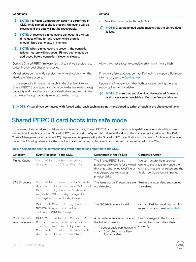
Conditions Actions
NOTE: If a Reset Configuration action is performed in CMC while pinned cache is present, the cache will be cleared and the data will not be recoverable.
NOTE: Unresolved pinned cache can occur if a virtual drive goes offline for any reason while there is uncommitted cache data in memory.
NOTE: When pinned cache is present, the controller failover feature will not occur. Pinned cache must be addressed before controller failover is allowed.
• Clear the pinned cache through CMC.
NOTE: Clearing pinned cache means that the pinned data is lost.
During a Shared PERC firmware flash, virtual drive transitions to write-through until chassis is recycled.
Allow the chassis reset to complete after the firmware flash.
Virtual drives permanently transition to write-through when the Hardware failure occurs.
If hardware failure occurs, contact Dell technical support. For more information, see the Getting help.
In the event of a firmware mismatch, in the dual fault tolerant Shared PERC 8 configurations, if one controller has write-through capability and the other does not, virtual drives on the controller with write-through capability reverts to write-through.
Update the firmware such that both cards are running the latest supported versions available.
NOTE: Ensure that you download the updated firmware and driver version available at Dell.com/support/home.
NOTE: Virtual drives configured with forced write-back caching are not transitioned to write-through in the above conditions.
Shared PERC 8 card boots into safe modeIn the event of some failure conditions encountered at boot, Shared PERC 8 boots with restricted capability in safe mode without user intervention. In such a condition Shared PERC 8 reports all configured disk drives as Foreign to the management application. The Dell Chassis Management Controller (CMC) displays events generated by the Shared PERC 8 card indicating the reason for booting into safe mode. The following table details the conditions and the corresponding event notifications that are reported to the CMC.
Table 7. Conditions and the corresponding event notifications reported to the CMC
Category Event Reported To the CMC Description of the Failure Corrective Action
Pinned Cache Controller cache pinned for missing or offline VDs: %s
The Shared PERC 8 card preserves dirty cache for a virtual disk that transitioned to offline or was deleted due to missing physical disks.
You can restore the preserved cache to the virtual disk once the original drives are reinserted and the foreign configuration is imported.
SAS Discovery Controller booted to safe mode due to critical errors Critical Error during boot - On-board expander FW or mfg image is corrupted - reflash image
This issue occurs if expanders are not detected.
Reseat the expanders, and connect the cables.
Critical Error during boot - NVDATA image is invalid - reflash NVDATA image
The NVData image is invalid. Contact Dell Technical Support. For more information, seeGetting help.
Controller is in safe mode event
RAID Controller in Chassis Slot X has entered safe mode with limited functionality due to Controller booted to safe mode due to critical errorsRAID
A controller enters safe mode for the following reasons:
• Incorrect cable configurations• Controllers with a Fault
Tolerant cable
See the images in the Installation section to connect the cables correctly.
58 Troubleshooting
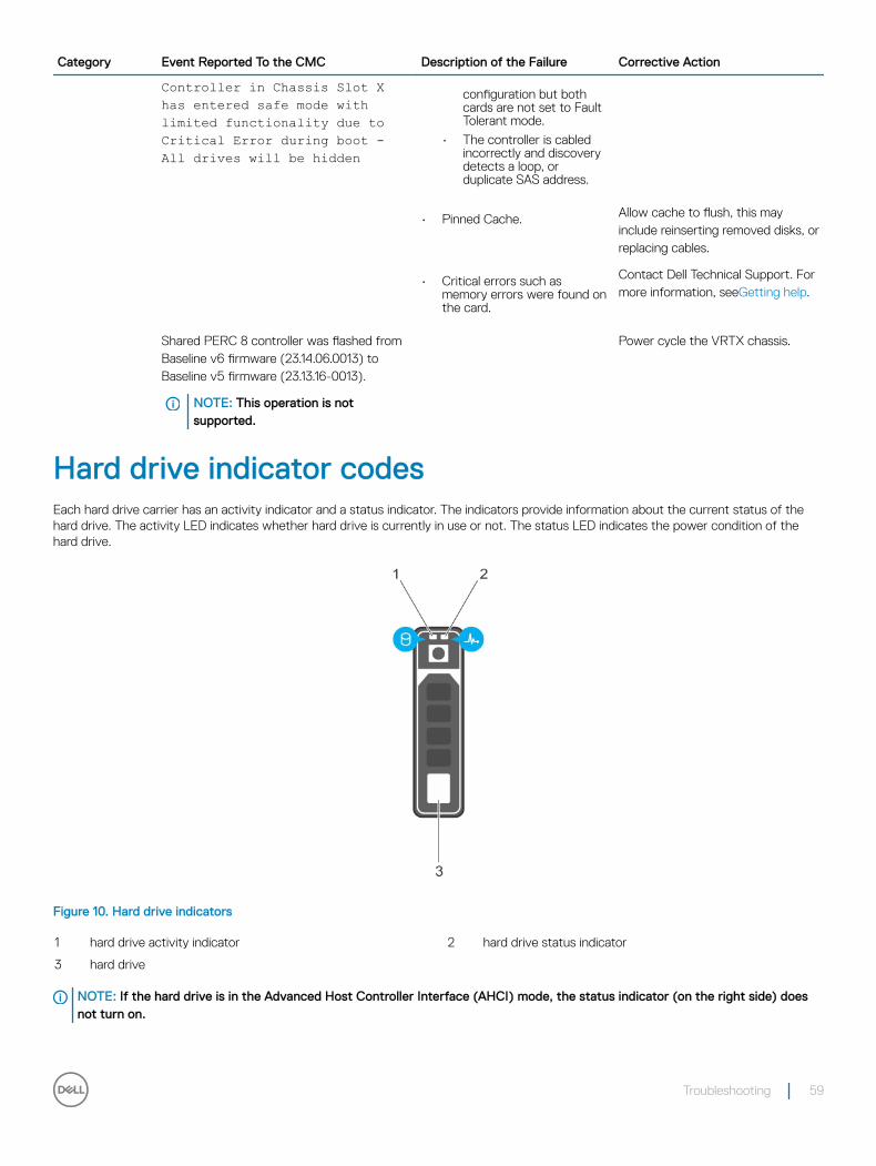
Category Event Reported To the CMC Description of the Failure Corrective Action
Controller in Chassis Slot X has entered safe mode with limited functionality due to Critical Error during boot - All drives will be hidden
configuration but both cards are not set to Fault Tolerant mode.
• The controller is cabled incorrectly and discovery detects a loop, or duplicate SAS address.
• Pinned Cache. Allow cache to flush, this may include reinserting removed disks, or replacing cables.
• Critical errors such as memory errors were found on the card.
Contact Dell Technical Support. For more information, seeGetting help.
Shared PERC 8 controller was flashed from Baseline v6 firmware (23.14.06.0013) to Baseline v5 firmware (23.13.16-0013).
NOTE: This operation is not supported.
Power cycle the VRTX chassis.
Hard drive indicator codesEach hard drive carrier has an activity indicator and a status indicator. The indicators provide information about the current status of the hard drive. The activity LED indicates whether hard drive is currently in use or not. The status LED indicates the power condition of the hard drive.
Figure 10. Hard drive indicators
1 hard drive activity indicator 2 hard drive status indicator
3 hard drive
NOTE: If the hard drive is in the Advanced Host Controller Interface (AHCI) mode, the status indicator (on the right side) does not turn on.
Troubleshooting 59
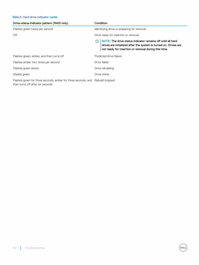
Table 8. Hard drive indicator codes
Drive-status indicator pattern (RAID only) Condition
Flashes green twice per second Identifying drive or preparing for removal.
Off Drive ready for insertion or removal.
NOTE: The drive status indicator remains off until all hard drives are initialized after the system is turned on. Drives are not ready for insertion or removal during this time.
Flashes green, amber, and then turns off Predicted drive failure
Flashes amber four times per second Drive failed
Flashes green slowly Drive rebuilding
Steady green Drive online
Flashes green for three seconds, amber for three seconds, and then turns off after six seconds
Rebuild stopped
60 Troubleshooting
Getting help
Topics:
• Contacting Dell
• Locating Service Tag of your system
Contacting DellDell provides several online and telephone based support and service options. If you do not have an active internet connection, you can find contact information about your purchase invoice, packing slip, bill, or Dell product catalog. Availability varies by country and product, and some services may not be available in your area. To contact Dell for sales, technical assistance, or customer service issues:
1 Go to Dell.com/support.
2 Select your country from the drop-down menu on the lower right corner of the page.
3 For customized support:
a Enter your system Service Tag in the Enter your Service Tag field.b Click Submit.
The support page that lists the various support categories is displayed.
4 For general support:
a Select your product category.b Select your product segment.c Select your product.
The support page that lists the various support categories is displayed.
5 For contact details of Dell Global Technical Support:
a Click Global Technical Support.b The Contact Technical Support page is displayed with details to call, chat, or e-mail the Dell Global Technical Support team.
Locating Service Tag of your systemYour system is identified by a unique Express Service Code and Service Tag number. The Express Service Code is and Service Tag are found on the front of the system by pulling out the information tag. Alternatively, the information may be on a sticker on the chassis of the system. This information is used by Dell to route support calls to the appropriate personnel.
9
Getting help 61